Embed Size (px)
Citation preview
Offshore Weapon Scoring Using Rapidly Deployed Realtime Acoustic Sensors
Miguel A. Cardoza, Trident Research LLC Jack R. Kayser, Trident Research LLC 11921 N. Mopac Expressway, Suite 310
Austin, Texas 78759
William F. Wade, USAF 46th Test Wing Richard L. Bennett, USAF 46th Test Wing
John H. Merts, USAF 46th Test Wing David R. Casey, Sverdrup Technology
303 N. 7th Street, Suite 108, Building 22 Eglin AFB, Florida 32542
Biography Miguel Cardoza is a Senior Program Manager with Trident Research LLC, and possesses over 18 years of experience in the design, development and fielding of tactical systems for the DOD. Formerly at Applied Research Lab, Mr. Cardoza led the design and development of two Portable Impact Location System (PILS) at-sea weapons scoring systems for the US Navy. He also served as Program Manager for the implementation of mm-level GPS survey technologies at the White Sands Missile Range, realtime kinematic cm-level positioning technology for the US Navy, and other GPS-based systems for the DOD. Mr. Cardoza received his Bachelors and Masters degrees in Aerospace Engineering from the University of Texas at Austin, and is a graduate of the Defense Systems Management College (DSMC). Jack Kayser P.E., Ph.D. is a consulting Systems Engineer with Trident Research, as well as a Dam Safety Engineer for the State of Texas. While an Engineering Scientist at the Applied Research Lab (ARL), he developed optical and acoustical instrumentation for the Navy Mobile Instrumentation System (NMIS). At Trident Research, he has developed and implemented acoustical techniques for interpreting weapon impacts as well as the detection of marine mammals. Dr. Kayser has published and presented research in the areas of reliability, instrumentation, structures, and construction. He received his Ph.D. in Civil Engineering from the University of Michigan in 1988. Bill Wade has worked in the Department of Defense for thirty years developing weapon systems for Air Force aircraft. Mr. Wade has worked on numerous weapon developments and has carried two major weapon systems from concept through development, production, and employment. He currently manages the Offshore Test and Training Area (OTTA) program at Eglin AFB, Florida, which is developing and building the instrumentation and infrastructure for the Eglin Gulf Range. Mr. Wade received his Bachelor of Science in Mechanical Engineering from the University of Nebraska in 1974 and his Master of Business Administration from the University of West Florida in 1980.
- 1 -
Richard Bennett is a retired USAF test pilot with 15 years experience in flight test, and 8 years experience as a weapons certification test pilot at Eglin AFB. He was the Chief test pilot integrating the AMRAAM missile on the F-15, and was an initial cadre test pilot certifying weapons on the F-15E Strike Eagle. Mr Bennett was working in program management and test execution in the OTTA office during this test, and currently works as a Senior Engineering Consultant for Weapons Integration with Lockheed Martin and KAI on the Republic of Korea’s new fighter/trainer, the T-50 Golden Eagle. Mr Bennett earned his Bachelor of Science in Astronautical Engineering from the USAF Academy in 1979, and earned (2) Master’s of Science Degrees in Astronautical and in Aeronautical Engineering from the Air Force Institute of Technology in 1991. John H. Merts started employment with the 46th Test Wing at Eglin AFB in 1982 as an Electronics Design Engineer. Mr. Merts is a previous member of the Range Commanders Council Electronic Trajectory Measurements Group and consults with the group on GPS issues. He is the co-author of a patent on the GPS application of missile / target end-game scoring. His current research topics include precision Time Space Position Information for high dynamic test aircraft, missile end game scoring using GPS raw measurements on missile and target aircraft, and post-mission correction of GPS carrier phase measurements for wrap around antennae effects on missiles. Mr. Merts received his Bachelor of Science in Physics from Florida State University in 1979. David R. Casey has worked in the Department of Defense and as an engineering support contractor for over 42 years, acquiring and fielding U.S. Air Force weapons systems. Mr. Casey now manages the engineering activities of the 46th Test Wing Offshore Test and Training Area (OTTA), which encompasses the assessment of Large Footprint Weapons (LFW) in the Gulf of Mexico. Mr. Casey received his Master of Science degree from Georgia College in 1976 and his Physical Science degree from the University of Northern Colorado in 1962. Abstract An all-weather, day/night underwater acoustic based system for scoring weapons impact has been developed for use at the 46th Test Wing Offshore Testing and Training Area (OTTA), at Eglin Air Force Base. The Tactical Acoustic Realtime Geolocation and Training (TARGT) system is composed of an array of acoustic buoy sensors, a shipboard command and control system (CCS), and a ground based differential GPS reference system (DRS). In operation, the TARGT sensors detect and relay the time of a weapon impact to the shipboard CCS. Impact time, along with GPS positions from each sensor, are processed in realtime to provide a score within eight meters accuracy to the test operators within seconds after weapon impact. Post-mission processing allows for positioning accuracies within four meters. TARGT provides a realtime metric for evaluating weapon performance that is independent from scoring results provided by optical and radar-scoring systems on the Eglin OTTA test range, and is capable of providing a weapon score even if the weapon fails to strike the instrumented target platform. Because the TARGT sensors are comprised of COTS components, and are both compact and lightweight, logistics support, deployment and recovery efforts are minimized. During recent Eglin OTTA testing, one operator performed sensor deployment and recovery in less than 1 hour.
- 2 -
The COTS aspect of the system has also resulted in a relatively low cost sensor, allowing for abandonment in circumstances where recovery becomes dangerous or would require excessive ship expense. Further, the modular architecture design and scalability of compact COTS components allows TARGT sensors to be adapted to serve other functions, such as communications relay, marine mammal detection, and bottom impact localization, providing flexibility to support new mission requirements when needed. Concept of a Weapon Scoring System Background The US Navy conducted some of the early acoustic-based weapon impact scoring in the mid to late 1970’s. These systems, such as the Sonobuoy Missile Impact Location System (SMILS) and the Barking Sands Tactical Underwater Range (BARSTUR), commonly used an array of transducers mounted to the sea floor. These transducers were surveyed into a geodetic reference frame using special ship-mounted acoustic survey equipment that tracked early TRANSIT and later GPS satellites. In operation, a weapon impact on the surface would emit acoustic energy that was received at these transducer locations and recorded. In the case of SMILS, a two-step process was used. The sea floor transducers acted as localization pingers, injecting a specific frequency acoustic ping into the water. An array of standard anti-submarine warfare (ASW) sonobuoys would capture these localization pings and locate them on the surface by noting the frequency associated with each bottom transducer and its survey position. Then, the array of drifting sonobuoys would be used to geolocate the acoustic energy released by the weapon impact on the surface. In either case, the data was analyzed and processed post-mission to produce a position of the weapon impact with accuracies approaching 10 meters. With the advent of GPS, there have been significant advances in acoustic based scoring. Two prominent systems developed by the Navy include an aircraft deployed broad ocean area scoring system [Saunders] and a ship-deployed version of this same system that utilized a self-propelled autonomous surface vehicle [Cardoza]. Though both of these systems significantly improved the performance and reduced the cost of weapons scoring, they both remain principally data collection systems, providing weapon impact score after post-mission processing. Further, the currently fielded system utilizes an autonomous surface vehicle that weighs in excess of 300 pounds, requiring a shipboard crane, and significant time and manpower for deployment and recovery. Concept of Operation The Tactical Acoustic Realtime Geolocation and Training (TARGT) acoustic scoring system was designed from the ground up for rapid deployment and recovery from even small support boats, thus minimizing manpower and ship costs. Further, while the acoustic sensor retains the precise positioning and timing characteristics of GPS, it merges low-cost OEM modules with custom electronics to supplement the capabilities of the COTS components. In this manner, a realtime weapons impact scoring capability is achieved in a cost effective, small form factor, highly portable package. In addition, since the principal sensor for determining the coordinates of the weapon strike are based upon the principals of underwater acoustic propagation, the
- 3 -
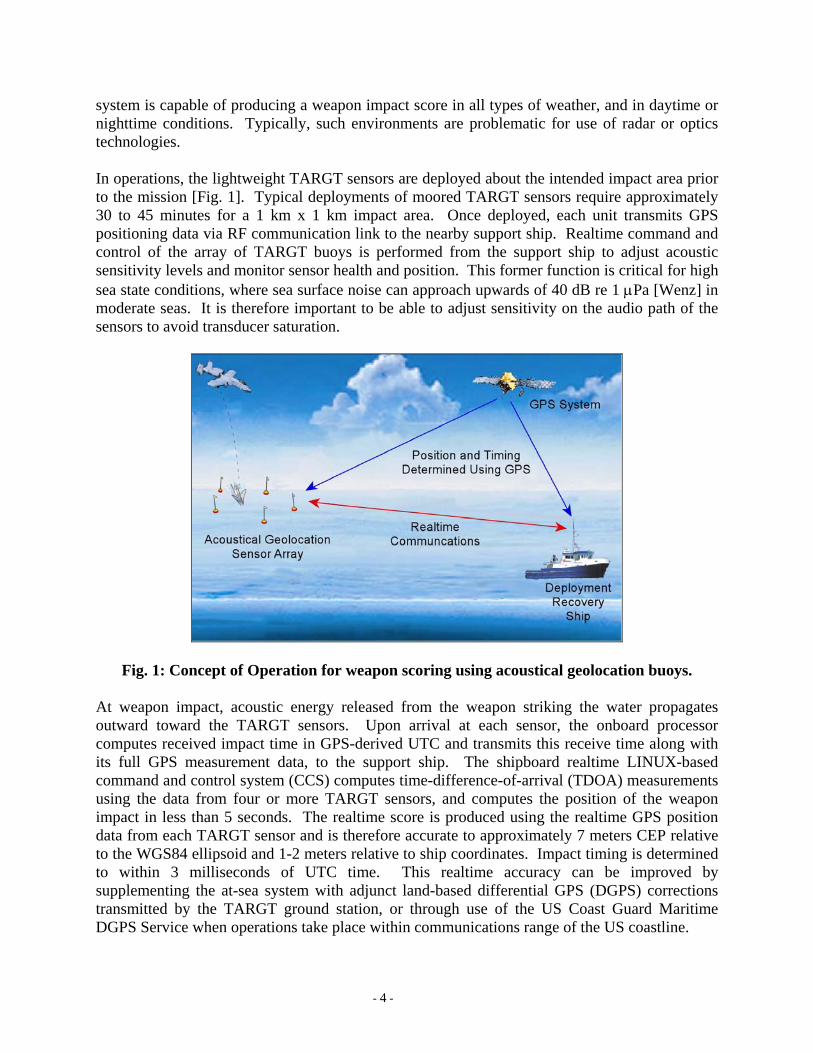
system is capable of producing a weapon impact score in all types of weather, and in daytime or nighttime conditions. Typically, such environments are problematic for use of radar or optics technologies. In operations, the lightweight TARGT sensors are deployed about the intended impact area prior to the mission [Fig. 1]. Typical deployments of moored TARGT sensors require approximately 30 to 45 minutes for a 1 km x 1 km impact area. Once deployed, each unit transmits GPS positioning data via RF communication link to the nearby support ship. Realtime command and control of the array of TARGT buoys is performed from the support ship to adjust acoustic sensitivity levels and monitor sensor health and position. This former function is critical for high sea state conditions, where sea surface noise can approach upwards of 40 dB re 1 µPa [Wenz] in moderate seas. It is therefore important to be able to adjust sensitivity on the audio path of the sensors to avoid transducer saturation.
Fig. 1: Concept of Operation for weapon scoring using acoustical geolocation buoys. At weapon impact, acoustic energy released from the weapon striking the water propagates outward toward the TARGT sensors. Upon arrival at each sensor, the onboard processor computes received impact time in GPS-derived UTC and transmits this receive time along with its full GPS measurement data, to the support ship. The shipboard realtime LINUX-based command and control system (CCS) computes time-difference-of-arrival (TDOA) measurements using the data from four or more TARGT sensors, and computes the position of the weapon impact in less than 5 seconds. The realtime score is produced using the realtime GPS position data from each TARGT sensor and is therefore accurate to approximately 7 meters CEP relative to the WGS84 ellipsoid and 1-2 meters relative to ship coordinates. Impact timing is determined to within 3 milliseconds of UTC time. This realtime accuracy can be improved by supplementing the at-sea system with adjunct land-based differential GPS (DGPS) corrections transmitted by the TARGT ground station, or through use of the US Coast Guard Maritime DGPS Service when operations take place within communications range of the US coastline.
- 4 -
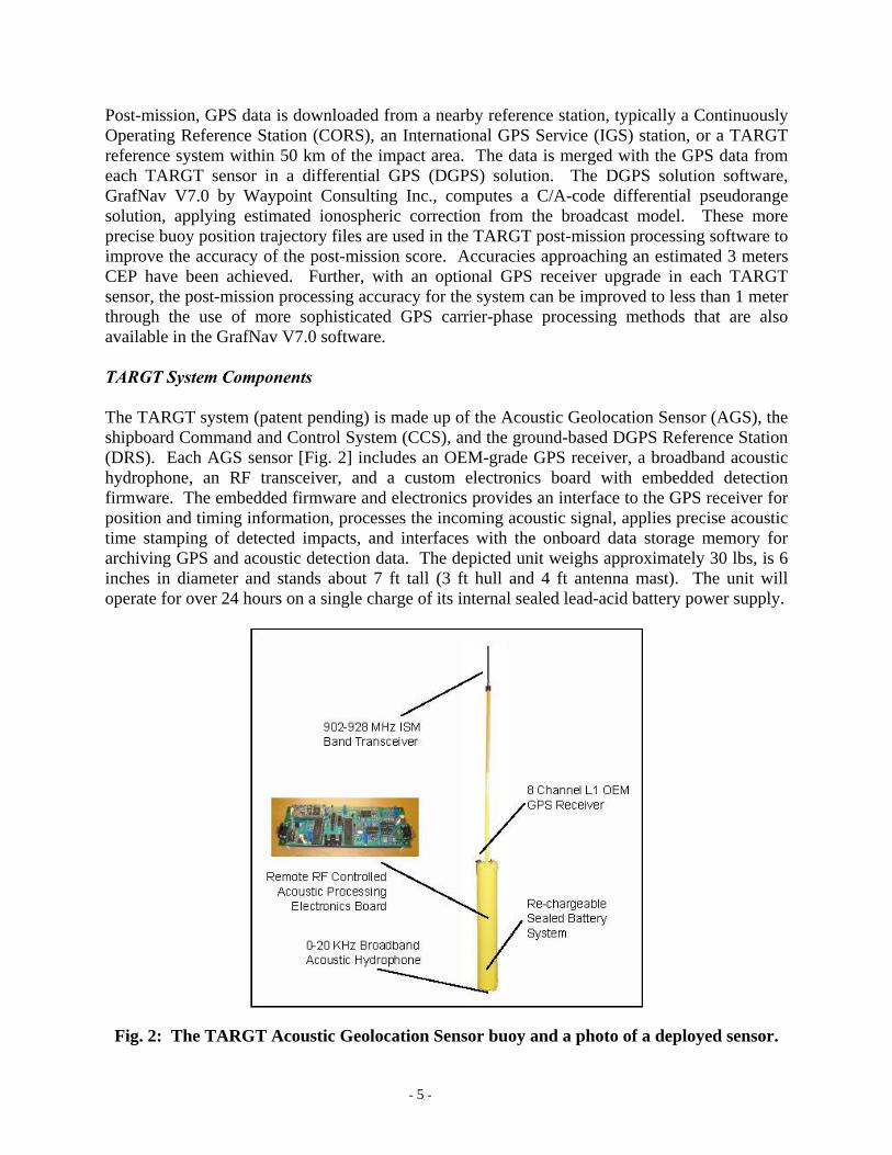
Post-mission, GPS data is downloaded from a nearby reference station, typically a Continuously Operating Reference Station (CORS), an International GPS Service (IGS) station, or a TARGT reference system within 50 km of the impact area. The data is merged with the GPS data from each TARGT sensor in a differential GPS (DGPS) solution. The DGPS solution software, GrafNav V7.0 by Waypoint Consulting Inc., computes a C/A-code differential pseudorange solution, applying estimated ionospheric correction from the broadcast model. These more precise buoy position trajectory files are used in the TARGT post-mission processing software to improve the accuracy of the post-mission score. Accuracies approaching an estimated 3 meters CEP have been achieved. Further, with an optional GPS receiver upgrade in each TARGT sensor, the post-mission processing accuracy for the system can be improved to less than 1 meter through the use of more sophisticated GPS carrier-phase processing methods that are also available in the GrafNav V7.0 software. TARGT System Components The TARGT system (patent pending) is made up of the Acoustic Geolocation Sensor (AGS), the shipboard Command and Control System (CCS), and the ground-based DGPS Reference Station (DRS). Each AGS sensor [Fig. 2] includes an OEM-grade GPS receiver, a broadband acoustic hydrophone, an RF transceiver, and a custom electronics board with embedded detection firmware. The embedded firmware and electronics provides an interface to the GPS receiver for position and timing information, processes the incoming acoustic signal, applies precise acoustic time stamping of detected impacts, and interfaces with the onboard data storage memory for archiving GPS and acoustic detection data. The depicted unit weighs approximately 30 lbs, is 6 inches in diameter and stands about 7 ft tall (3 ft hull and 4 ft antenna mast). The unit will operate for over 24 hours on a single charge of its internal sealed lead-acid battery power supply.
Fig. 2: The TARGT Acoustic Geolocation Sensor buoy and a photo of a deployed sensor.
- 5 -
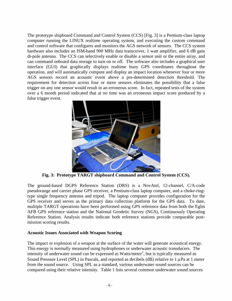
The prototype shipboard Command and Control System (CCS) [Fig. 3] is a Pentium-class laptop computer running the LINUX realtime operating system, and executing the custom command and control software that configures and monitors the AGS network of sensors. The CCS system hardware also includes an ISM-band 900 MHz data transceiver, 1 watt amplifier, and 6 dB gain di-pole antenna. The CCS can selectively enable or disable a sensor unit or the entire array, and can command onboard data storage to turn on or off. The software also includes a graphical user interface (GUI) that graphically displays realtime buoy GPS coordinates throughout the operation, and will automatically compute and display an impact location whenever four or more AGS sensors record an acoustic event above a pre-determined detection threshold. The requirement for detection across four or more sensors eliminates the possibility that a false trigger on any one sensor would result in an erroneous score. In fact, repeated tests of the system over a 6 month period indicated that at no time was an erroneous impact score produced by a false trigger event.
Fig. 3: Prototype TARGT shipboard Command and Control System (CCS).
The ground-based DGPS Reference Station (DRS) is a NovAtel, 12-channel, C/A-code pseudorange and carrier phase GPS receiver, a Pentium-class laptop computer, and a choke-ring-type single frequency antenna and tripod. The laptop computer provides configuration for the GPS receiver and serves as the primary data collection platform for the GPS data. To date, multiple TARGT operations have been performed using GPS reference data from both the Eglin AFB GPS reference station and the National Geodetic Survey (NGS), Continuously Operating Reference Station. Analysis results indicate both reference stations provide comparable post-mission scoring results. Acoustic Issues Associated with Weapon Scoring The impact or explosion of a weapon at the surface of the water will generate acoustical energy. This energy is normally measured using hydrophones or underwater acoustic transducers. The intensity of underwater sound can be expressed as Watts/meter2, but is typically measured as Sound Pressure Level (SPL) in Pascals, and reported as decibels (dB) relative to 1 µPa at 1 meter from the sound source. Using SPL as a standard, various underwater sound sources can be compared using their relative intensity. Table 1 lists several common underwater sound sources
- 6 -
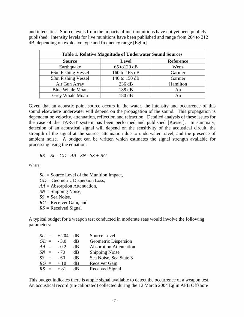
and intensities. Source levels from the impacts of inert munitions have not yet been publicly published. Intensity levels for live munitions have been published and range from 204 to 212 dB, depending on explosive type and frequency range [Eglin].
Table 1. Relative Magnitude of Underwater Sound Sources Source Level Reference
Earthquake 65 to120 dB Wenz 66m Fishing Vessel 160 to 165 dB Garnier 53m Fishing Vessel 140 to 150 dB Garnier
Air Gun Array 236 dB Hamilton Blue Whale Moan 188 dB Au Grey Whale Moan 180 dB Au
Given that an acoustic point source occurs in the water, the intensity and occurrence of this sound elsewhere underwater will depend on the propagation of the sound. This propagation is dependent on velocity, attenuation, reflection and refraction. Detailed analysis of these issues for the case of the TARGT system has been performed and published [Kayser]. In summary, detection of an acoustical signal will depend on the sensitivity of the acoustical circuit, the strength of the signal at the source, attenuation due to underwater travel, and the presence of ambient noise. A budget can be written which estimates the signal strength available for processing using the equation: RS = SL - GD - AA - SN - SS + RG Where,
SL = Source Level of the Munition Impact, GD = Geometric Dispersion Loss, AA = Absorption Attenuation, SN = Shipping Noise, SS = Sea Noise, RG = Receiver Gain, and RS = Received Signal
A typical budget for a weapon test conducted in moderate seas would involve the following parameters:
SL = + 204 dB Source Level GD = - 3.0 dB Geometric Dispersion AA = - 0.2 dB Absorption Attenuation SN = - 70 dB Shipping Noise SS = - 60 dB Sea Noise, Sea State 3 RG = + 10 dB Receiver Gain RS = + 81 dB Received Signal
This budget indicates there is ample signal available to detect the occurrence of a weapon test. An acoustical record (un-calibrated) collected during the 12 March 2004 Eglin AFB Offshore
- 7 -
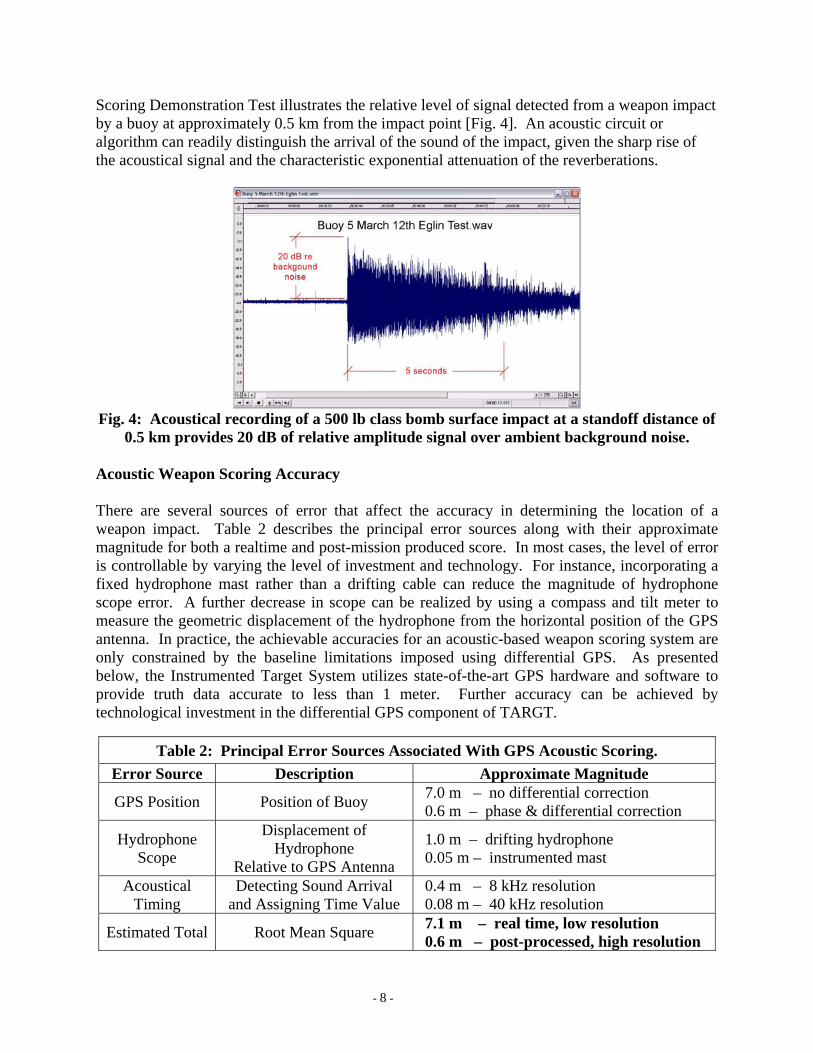
Scoring Demonstration Test illustrates the relative level of signal detected from a weapon impact by a buoy at approximately 0.5 km from the impact point [Fig. 4]. An acoustic circuit or algorithm can readily distinguish the arrival of the sound of the impact, given the sharp rise of the acoustical signal and the characteristic exponential attenuation of the reverberations.
Fig. 4: Acoustical recording of a 500 lb class bomb surface impact at a standoff distance of
0.5 km provides 20 dB of relative amplitude signal over ambient background noise. Acoustic Weapon Scoring Accuracy There are several sources of error that affect the accuracy in determining the location of a weapon impact. Table 2 describes the principal error sources along with their approximate magnitude for both a realtime and post-mission produced score. In most cases, the level of error is controllable by varying the level of investment and technology. For instance, incorporating a fixed hydrophone mast rather than a drifting cable can reduce the magnitude of hydrophone scope error. A further decrease in scope can be realized by using a compass and tilt meter to measure the geometric displacement of the hydrophone from the horizontal position of the GPS antenna. In practice, the achievable accuracies for an acoustic-based weapon scoring system are only constrained by the baseline limitations imposed using differential GPS. As presented below, the Instrumented Target System utilizes state-of-the-art GPS hardware and software to provide truth data accurate to less than 1 meter. Further accuracy can be achieved by technological investment in the differential GPS component of TARGT.
Table 2: Principal Error Sources Associated With GPS Acoustic Scoring. Error Source Description Approximate Magnitude
GPS Position Position of Buoy 7.0 m – no differential correction 0.6 m – phase & differential correction
Hydrophone Scope
Displacement of Hydrophone
Relative to GPS Antenna
1.0 m – drifting hydrophone 0.05 m – instrumented mast
Acoustical Timing
Detecting Sound Arrival and Assigning Time Value
0.4 m – 8 kHz resolution 0.08 m – 40 kHz resolution
Estimated Total Root Mean Square 7.1 m – real time, low resolution 0.6 m – post-processed, high resolution
- 8 -
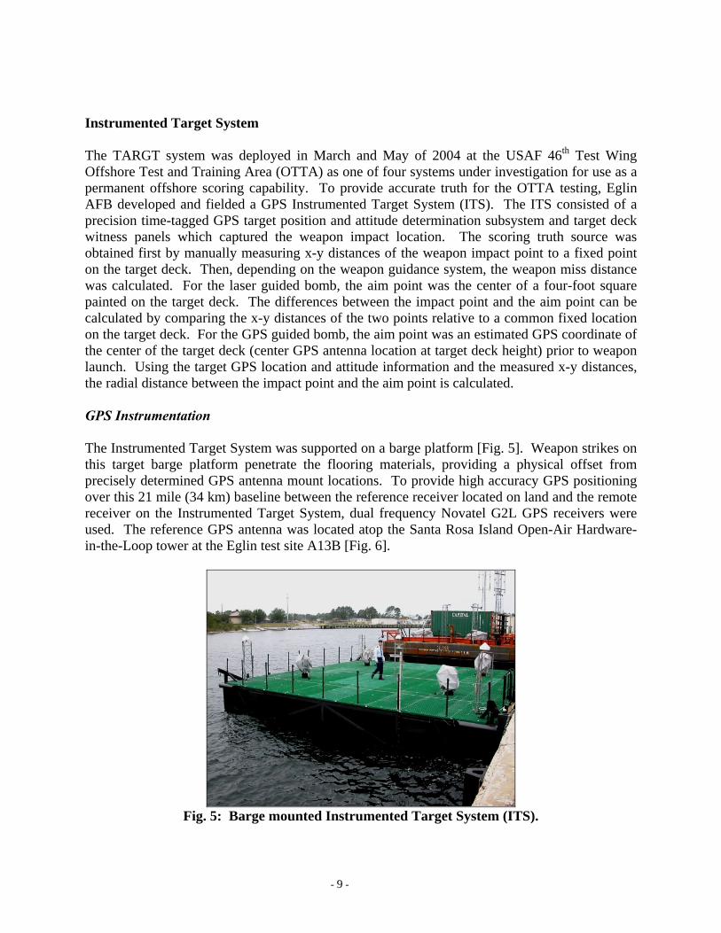
Instrumented Target System The TARGT system was deployed in March and May of 2004 at the USAF 46th Test Wing Offshore Test and Training Area (OTTA) as one of four systems under investigation for use as a permanent offshore scoring capability. To provide accurate truth for the OTTA testing, Eglin AFB developed and fielded a GPS Instrumented Target System (ITS). The ITS consisted of a precision time-tagged GPS target position and attitude determination subsystem and target deck witness panels which captured the weapon impact location. The scoring truth source was obtained first by manually measuring x-y distances of the weapon impact point to a fixed point on the target deck. Then, depending on the weapon guidance system, the weapon miss distance was calculated. For the laser guided bomb, the aim point was the center of a four-foot square painted on the target deck. The differences between the impact point and the aim point can be calculated by comparing the x-y distances of the two points relative to a common fixed location on the target deck. For the GPS guided bomb, the aim point was an estimated GPS coordinate of the center of the target deck (center GPS antenna location at target deck height) prior to weapon launch. Using the target GPS location and attitude information and the measured x-y distances, the radial distance between the impact point and the aim point is calculated. GPS Instrumentation The Instrumented Target System was supported on a barge platform [Fig. 5]. Weapon strikes on this target barge platform penetrate the flooring materials, providing a physical offset from precisely determined GPS antenna mount locations. To provide high accuracy GPS positioning over this 21 mile (34 km) baseline between the reference receiver located on land and the remote receiver on the Instrumented Target System, dual frequency Novatel G2L GPS receivers were used. The reference GPS antenna was located atop the Santa Rosa Island Open-Air Hardware-in-the-Loop tower at the Eglin test site A13B [Fig. 6].
Fig. 5: Barge mounted Instrumented Target System (ITS).
- 9 -
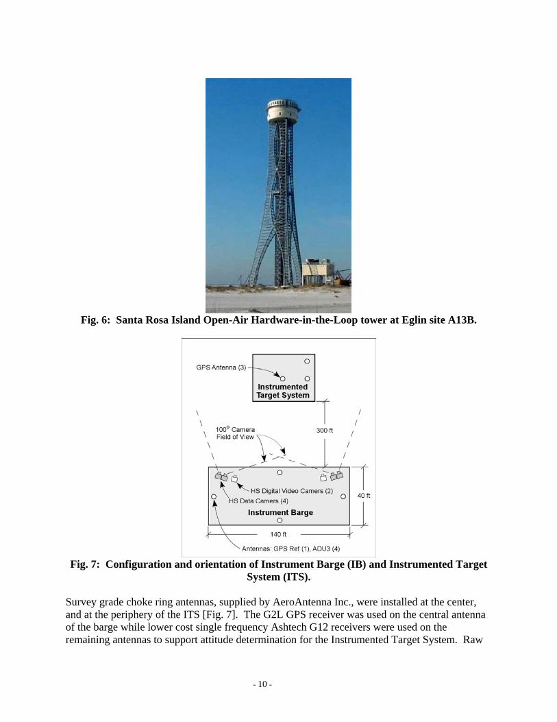
Fig. 6: Santa Rosa Island Open-Air Hardware-in-the-Loop tower at Eglin site A13B.
Fig. 7: Configuration and orientation of Instrument Barge (IB) and Instrumented Target
System (ITS). Survey grade choke ring antennas, supplied by AeroAntenna Inc., were installed at the center, and at the periphery of the ITS [Fig. 7]. The G2L GPS receiver was used on the central antenna of the barge while lower cost single frequency Ashtech G12 receivers were used on the remaining antennas to support attitude determination for the Instrumented Target System. Raw
- 10 -
GPS measurements were down linked from the Instrumented Target System to site A13B via a wireless LAN modem provided by the 46th Test Wing Electronics Design Branch.
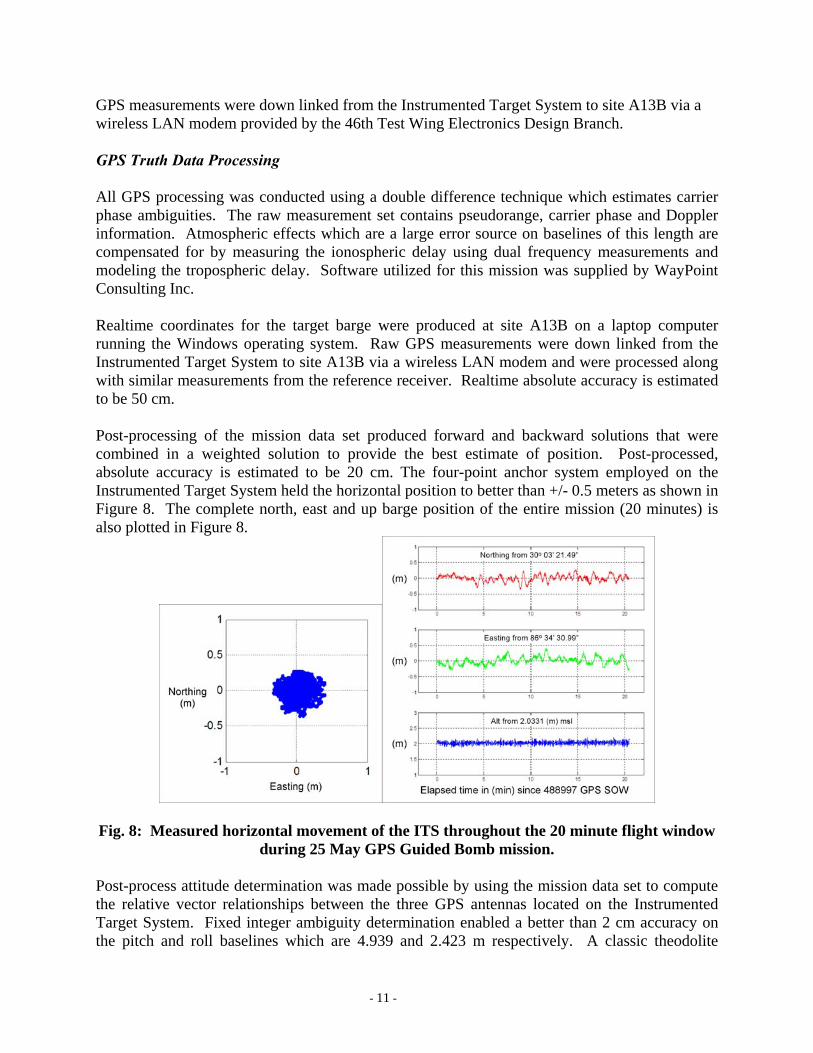
GPS Truth Data Processing All GPS processing was conducted using a double difference technique which estimates carrier phase ambiguities. The raw measurement set contains pseudorange, carrier phase and Doppler information. Atmospheric effects which are a large error source on baselines of this length are compensated for by measuring the ionospheric delay using dual frequency measurements and modeling the tropospheric delay. Software utilized for this mission was supplied by WayPoint Consulting Inc. Realtime coordinates for the target barge were produced at site A13B on a laptop computer running the Windows operating system. Raw GPS measurements were down linked from the Instrumented Target System to site A13B via a wireless LAN modem and were processed along with similar measurements from the reference receiver. Realtime absolute accuracy is estimated to be 50 cm. Post-processing of the mission data set produced forward and backward solutions that were combined in a weighted solution to provide the best estimate of position. Post-processed, absolute accuracy is estimated to be 20 cm. The four-point anchor system employed on the Instrumented Target System held the horizontal position to better than +/- 0.5 meters as shown in Figure 8. The complete north, east and up barge position of the entire mission (20 minutes) is also plotted in Figure 8.
Fig. 8: Measured horizontal movement of the ITS throughout the 20 minute flight window during 25 May GPS Guided Bomb mission.
Post-process attitude determination was made possible by using the mission data set to compute the relative vector relationships between the three GPS antennas located on the Instrumented Target System. Fixed integer ambiguity determination enabled a better than 2 cm accuracy on the pitch and roll baselines which are 4.939 and 2.423 m respectively. A classic theodolite
- 11 -
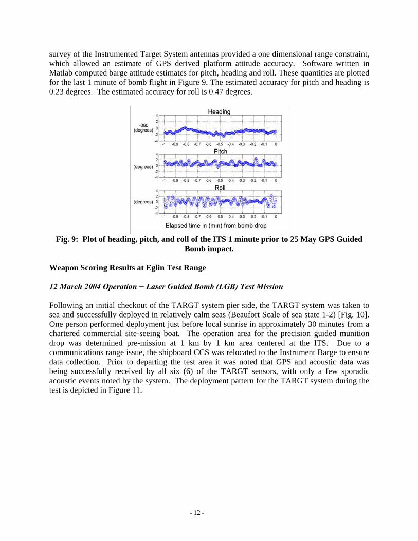
survey of the Instrumented Target System antennas provided a one dimensional range constraint, which allowed an estimate of GPS derived platform attitude accuracy. Software written in Matlab computed barge attitude estimates for pitch, heading and roll. These quantities are plotted for the last 1 minute of bomb flight in Figure 9. The estimated accuracy for pitch and heading is 0.23 degrees. The estimated accuracy for roll is 0.47 degrees.
Fig. 9: Plot of heading, pitch, and roll of the ITS 1 minute prior to 25 May GPS Guided
Bomb impact. Weapon Scoring Results at Eglin Test Range 12 March 2004 Operation − Laser Guided Bomb (LGB) Test Mission Following an initial checkout of the TARGT system pier side, the TARGT system was taken to sea and successfully deployed in relatively calm seas (Beaufort Scale of sea state 1-2) [Fig. 10]. One person performed deployment just before local sunrise in approximately 30 minutes from a chartered commercial site-seeing boat. The operation area for the precision guided munition drop was determined pre-mission at 1 km by 1 km area centered at the ITS. Due to a communications range issue, the shipboard CCS was relocated to the Instrument Barge to ensure data collection. Prior to departing the test area it was noted that GPS and acoustic data was being successfully received by all six (6) of the TARGT sensors, with only a few sporadic acoustic events noted by the system. The deployment pattern for the TARGT system during the test is depicted in Figure 11.
- 12 -
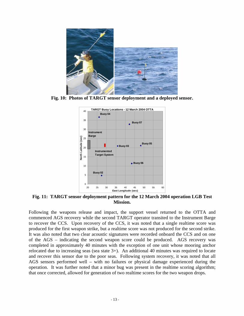
Fig. 10: Photos of TARGT sensor deployment and a deployed sensor.
TARGT Buoy Locations - 12 March 2004 OTTA
0
5
10
15
20
25
30
35
40
20 25 30 35 40 45 50 55 60East Longitude (sec)
Nor
th L
atitu
de (s
ec)
Buoy 04
Buoy 07
Buoy 05
Buoy 06
Buoy 02
Buoy 03
InstrumentBarge
InstrumentedTarget System
Fig. 11: TARGT sensor deployment pattern for the 12 March 2004 operation LGB Test
Mission. Following the weapons release and impact, the support vessel returned to the OTTA and commenced AGS recovery while the second TARGT operator transited to the Instrument Barge to recover the CCS. Upon recovery of the CCS, it was noted that a single realtime score was produced for the first weapon strike, but a realtime score was not produced for the second strike. It was also noted that two clear acoustic signatures were recorded onboard the CCS and on one of the AGS – indicating the second weapon score could be produced. AGS recovery was completed in approximately 40 minutes with the exception of one unit whose mooring anchor relocated due to increasing seas (sea state 3+). An additional 40 minutes was required to locate and recover this sensor due to the poor seas. Following system recovery, it was noted that all AGS sensors performed well – with no failures or physical damage experienced during the operation. It was further noted that a minor bug was present in the realtime scoring algorithm; that once corrected, allowed for generation of two realtime scores for the two weapon drops.
- 13 -
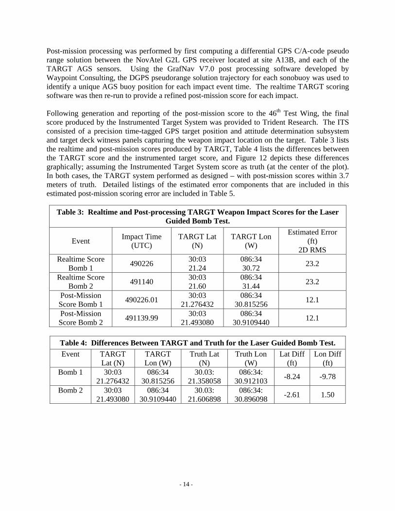
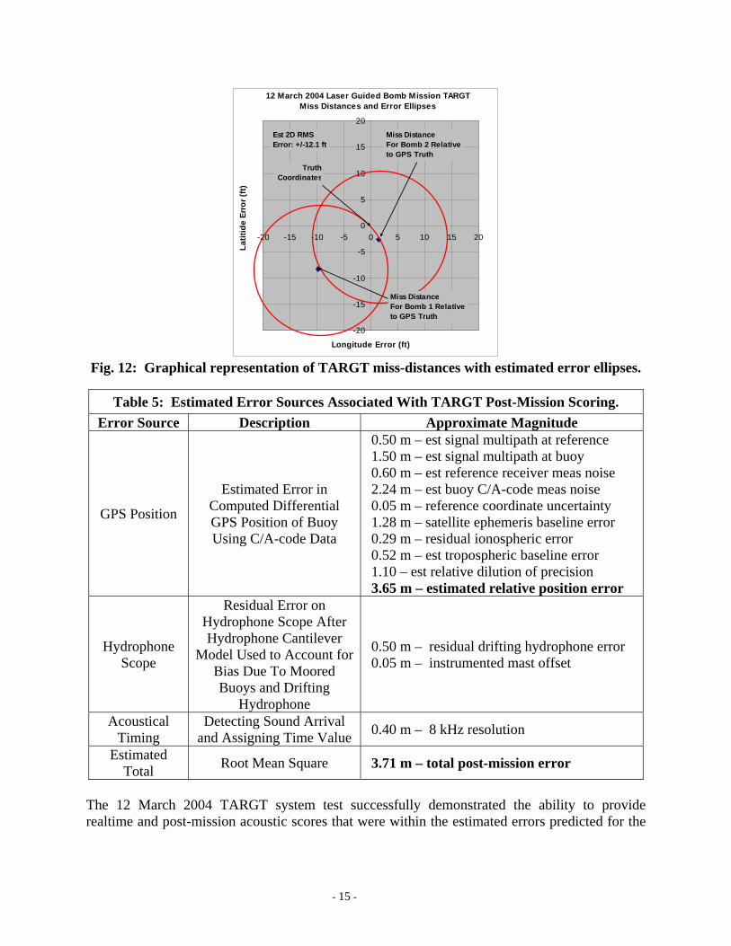
Post-mission processing was performed by first computing a differential GPS C/A-code pseudo range solution between the NovAtel G2L GPS receiver located at site A13B, and each of the TARGT AGS sensors. Using the GrafNav V7.0 post processing software developed by Waypoint Consulting, the DGPS pseudorange solution trajectory for each sonobuoy was used to identify a unique AGS buoy position for each impact event time. The realtime TARGT scoring software was then re-run to provide a refined post-mission score for each impact. Following generation and reporting of the post-mission score to the 46th Test Wing, the final score produced by the Instrumented Target System was provided to Trident Research. The ITS consisted of a precision time-tagged GPS target position and attitude determination subsystem and target deck witness panels capturing the weapon impact location on the target. Table 3 lists the realtime and post-mission scores produced by TARGT, Table 4 lists the differences between the TARGT score and the instrumented target score, and Figure 12 depicts these differences graphically; assuming the Instrumented Target System score as truth (at the center of the plot). In both cases, the TARGT system performed as designed – with post-mission scores within 3.7 meters of truth. Detailed listings of the estimated error components that are included in this estimated post-mission scoring error are included in Table 5.
Table 3: Realtime and Post-processing TARGT Weapon Impact Scores for the Laser Guided Bomb Test.
Event Impact Time (UTC)
TARGT Lat (N)
TARGT Lon (W)
Estimated Error (ft)
2D RMS Realtime Score
Bomb 1 490226 30:03 21.24
086:34 30.72 23.2
Realtime Score Bomb 2 491140 30:03
21.60 086:34 31.44 23.2
Post-Mission Score Bomb 1 490226.01 30:03
21.276432 086:34
30.815256 12.1
Post-Mission Score Bomb 2 491139.99 30:03
21.493080 086:34
30.9109440 12.1
Table 4: Differences Between TARGT and Truth for the Laser Guided Bomb Test. Event TARGT
Lat (N) TARGT Lon (W)
Truth Lat (N)
Truth Lon (W)
Lat Diff (ft)
Lon Diff (ft)
Bomb 1 30:03 21.276432
086:34 30.815256
30.03: 21.358058
086:34: 30.912103 -8.24 -9.78
Bomb 2 30:03 21.493080
086:34 30.9109440
30.03: 21.606898
086:34: 30.896098 -2.61 1.50
- 14 -
12 March 2004 Laser Guided Bomb Mission TARGT Miss Distances and Error Ellipses
-20
-15
-10
-5
0
5
10
15
20
-20 -15 -10 -5 0 5 10 15 20
Longitude Error (ft)
Latit
ide
Erro
r (ft
)
Miss DistanceFor Bomb 2 Relativeto GPS Truth
Miss DistanceFor Bomb 1 Relativeto GPS Truth
TruthCoordinates
Est 2D RMSError: +/-12.1 ft
Fig. 12: Graphical representation of TARGT miss-distances with estimated error ellipses.
Table 5: Estimated Error Sources Associated With TARGT Post-Mission Scoring. Error Source Description Approximate Magnitude
GPS Position
Estimated Error in Computed Differential GPS Position of Buoy Using C/A-code Data
0.50 m – est signal multipath at reference 1.50 m – est signal multipath at buoy 0.60 m – est reference receiver meas noise 2.24 m – est buoy C/A-code meas noise 0.05 m – reference coordinate uncertainty 1.28 m – satellite ephemeris baseline error 0.29 m – residual ionospheric error 0.52 m – est tropospheric baseline error 1.10 – est relative dilution of precision 3.65 m – estimated relative position error
Hydrophone Scope
Residual Error on Hydrophone Scope After Hydrophone Cantilever
Model Used to Account for Bias Due To Moored Buoys and Drifting
Hydrophone
0.50 m – residual drifting hydrophone error 0.05 m – instrumented mast offset
Acoustical Timing
Detecting Sound Arrival and Assigning Time Value 0.40 m – 8 kHz resolution
Estimated Total Root Mean Square 3.71 m – total post-mission error
The 12 March 2004 TARGT system test successfully demonstrated the ability to provide realtime and post-mission acoustic scores that were within the estimated errors predicted for the
- 15 -
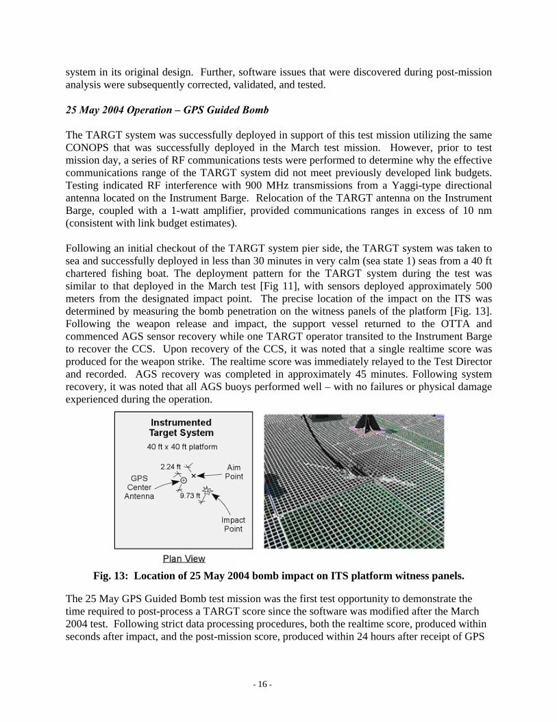
system in its original design. Further, software issues that were discovered during post-mission analysis were subsequently corrected, validated, and tested. 25 May 2004 Operation – GPS Guided Bomb The TARGT system was successfully deployed in support of this test mission utilizing the same CONOPS that was successfully deployed in the March test mission. However, prior to test mission day, a series of RF communications tests were performed to determine why the effective communications range of the TARGT system did not meet previously developed link budgets. Testing indicated RF interference with 900 MHz transmissions from a Yaggi-type directional antenna located on the Instrument Barge. Relocation of the TARGT antenna on the Instrument Barge, coupled with a 1-watt amplifier, provided communications ranges in excess of 10 nm (consistent with link budget estimates). Following an initial checkout of the TARGT system pier side, the TARGT system was taken to sea and successfully deployed in less than 30 minutes in very calm (sea state 1) seas from a 40 ft chartered fishing boat. The deployment pattern for the TARGT system during the test was similar to that deployed in the March test [Fig 11], with sensors deployed approximately 500 meters from the designated impact point. The precise location of the impact on the ITS was determined by measuring the bomb penetration on the witness panels of the platform [Fig. 13]. Following the weapon release and impact, the support vessel returned to the OTTA and commenced AGS sensor recovery while one TARGT operator transited to the Instrument Barge to recover the CCS. Upon recovery of the CCS, it was noted that a single realtime score was produced for the weapon strike. The realtime score was immediately relayed to the Test Director and recorded. AGS recovery was completed in approximately 45 minutes. Following system recovery, it was noted that all AGS buoys performed well – with no failures or physical damage experienced during the operation.
Fig. 13: Location of 25 May 2004 bomb impact on ITS platform witness panels.
The 25 May GPS Guided Bomb test mission was the first test opportunity to demonstrate the time required to post-process a TARGT score since the software was modified after the March 2004 test. Following strict data processing procedures, both the realtime score, produced within seconds after impact, and the post-mission score, produced within 24 hours after receipt of GPS
- 16 -
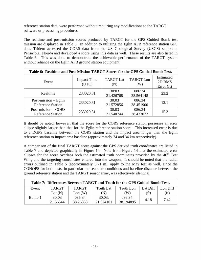
reference station data, were performed without requiring any modifications to the TARGT software or processing procedures. The realtime and post-mission scores produced by TARGT for the GPS Guided Bomb test mission are displayed in Table 6. In addition to utilizing the Eglin AFB reference station GPS data, Trident accessed the CORS data from the US Geological Survey (USGS) station at Pensacola, Florida and developed a score using this data as well. These results are also listed in Table 6. This was done to demonstrate the achievable performance of the TARGT system without reliance on the Eglin AFB ground station equipment.
Table 6: Realtime and Post-Mission TARGT Scores for the GPS Guided Bomb Test.
Event Impact Time (UTC)
TARGT Lat (N)
TARGT Lon (W)
Estimated 2D RMS Error (ft)
Realtime 233020.31 30:03 21.426768
086:34 38.564148 23.2
Post-mission – Eglin Reference Station 233020.31 30:03
21.572856 086:34
38.451900 12.1
Post-mission – CORS Reference Station 233020.31 30:03
21.540744 086:34
38.433072 15.3
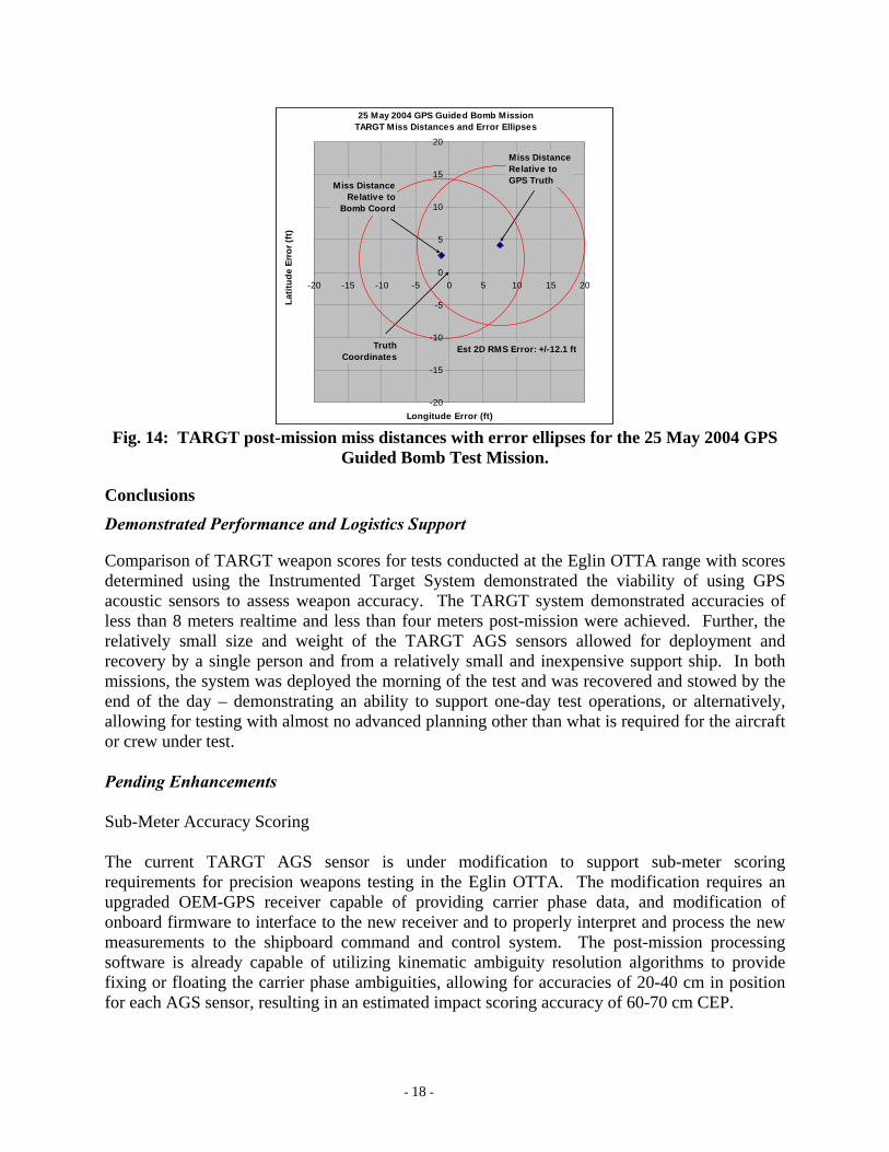
It should be noted, however, that the score for the CORS reference station possesses an error ellipse slightly larger than that for the Eglin reference station score. This increased error is due to a DGPS baseline between the CORS station and the impact area longer than the Eglin reference station to impact area baseline (approximately 74 and 34 km respectively). A comparison of the final TARGT score against the GPS derived truth coordinates are listed in Table 7 and depicted graphically in Figure 14. Note from Figure 14 that the estimated error ellipses for the score overlaps both the estimated truth coordinates provided by the 46th Test Wing and the targeting coordinates entered into the weapon. It should be noted that the radial errors outlined in Table 5 (approximately 3.71 m), apply to the May test as well, since the CONOPS for both tests, in particular the sea state conditions and baseline distance between the ground reference station and the TARGT sensor array, was effectively identical.
Table 7: Differences Between TARGT and Truth for the GPS Guided Bomb Test. Event TARGT
Lat (N) TARGT Lon (W)
Truth Lat (N)
Truth Lon (W)
Lat Diff (ft)
Lon Diff (ft)
Bomb 1 30:03 21.56544
086:34 38.26838
30.03: 21.524101
086:34: 38.194895 4.18 7.42
- 17 -
25 May 2004 GPS Guided Bomb Mission TARGT Miss Distances and Error Ellipses
-20
-15
-10
-5
0
5
10
15
20
-20 -15 -10 -5 0 5 10 15 20
Longitude Error (ft)
Latit
ude
Erro
r (ft
)
TruthCoordinates
Est 2D RMS Error: +/-12.1 ft
Miss DistanceRelative to
Bomb Coord
Miss DistanceRelative toGPS Truth
Fig. 14: TARGT post-mission miss distances with error ellipses for the 25 May 2004 GPS
Guided Bomb Test Mission.
Conclusions
Demonstrated Performance and Logistics Support Comparison of TARGT weapon scores for tests conducted at the Eglin OTTA range with scores determined using the Instrumented Target System demonstrated the viability of using GPS acoustic sensors to assess weapon accuracy. The TARGT system demonstrated accuracies of less than 8 meters realtime and less than four meters post-mission were achieved. Further, the relatively small size and weight of the TARGT AGS sensors allowed for deployment and recovery by a single person and from a relatively small and inexpensive support ship. In both missions, the system was deployed the morning of the test and was recovered and stowed by the end of the day – demonstrating an ability to support one-day test operations, or alternatively, allowing for testing with almost no advanced planning other than what is required for the aircraft or crew under test. Pending Enhancements Sub-Meter Accuracy Scoring The current TARGT AGS sensor is under modification to support sub-meter scoring requirements for precision weapons testing in the Eglin OTTA. The modification requires an upgraded OEM-GPS receiver capable of providing carrier phase data, and modification of onboard firmware to interface to the new receiver and to properly interpret and process the new measurements to the shipboard command and control system. The post-mission processing software is already capable of utilizing kinematic ambiguity resolution algorithms to provide fixing or floating the carrier phase ambiguities, allowing for accuracies of 20-40 cm in position for each AGS sensor, resulting in an estimated impact scoring accuracy of 60-70 cm CEP.
- 18 -
Munition Recovery The capability to recover the deployed munition can prove useful during weapons testing operations. The ability to determine the location of the weapon on the bottom of the ocean can be accomplished by utilizing an impact area in shallow water (less than 300 ft), and by supplementing each AGS buoy with a secondary hydrophone and acoustic recording channel. The concept under investigation includes locating a secondary hydrophone approximately 30 ft above the sea floor. The acoustic signal from the secondary weapon impact on the bottom would be recorded and extracted in post-mission to determine impact time. Estimated bottom localization accuracies of 10-15 ft CEP are expected; well within the search range for recovery divers. Mammal Detection and Range Clearance The possible presence of marine mammals in an offshore test range creates a potential situation where endangered species can be harmed. One method to mitigate this harm is to identify the presence of marine mammals by the sound they make [Au] and then use trilateration to determine their location [Ramaswamy]. Initial steps are being taken to modify the audio circuitry of TARGT to trigger on frequencies associated with marine mammals. An acoustic relay capability is also under development to allow the CCS operator to listen for mammal noises. TARGT listening and detection capabilities will provide test operators with the means of evaluating the range clearance of marine mammals. Transition to Aircraft Deployment The present TARGT sensor was designed to utilize electronics boards with low-cost components and to fit within a 4-inch diameter cylinder. In addition, the communication bandwidth requirements for the system are only 9600 bps. These features were designed into the system to allow for the option for repacking of the AGS sensor into a standard size-A sonobuoy to support aircraft deployment. A disposable TARGT sensor with a VHF class RF transceiver will allow for deployment and monitoring of the system by aircraft. Upon completion of testing, each unit would be commanded to scuttle – eliminating the need for sensor recovery. References Au, Whitlow W.L; Popper, Arthur N.; Fay, Richard R., “Hearing by Whales and Dolphins” Springer-Verlag, 2000 Cardoza, Miguel, et. al., “Autonomous Surface Watercraft”, US Patent 5119-09600, 11 February 2002 Eglin, “Final Programmatic Biological Assessment, Eglin Gulf Test and Training Range,” Eglin Air Force Base, Florida, November 2002 Garnier, R.; Beltri, E.; Marchand, Ph. and Diner, N., “Noise Signature Management of Fisheries Research Vessels: A European Study,” European Conference on Underwater Acoustics, Elsevier Applied Science, 1992, p 210-215
- 19 -
Hamilton, Michael J., et al; “Acoustic Energy Attenuation of 3DVSP Airgun Arrays Operating in Long Beach Harbor,” IEEE Oceans Conference Record, Vol. 1, 2003, p 76-80 Kayser, J.R., Cardoza, M.A., et.al., ”Weapon Scoring Results from a GPS Acoustic Weapon Test and Training System,” Institute of Navigation National Technical Meeting, San Diego, California, 24-26 January, 2005 Ramaswamy, B.; Potty, G.R.; Miller, J.H., “A marine mammal acoustic detection and localization algorithm using spectrogram image correlation”, IEEE Oceans Conference Record, Vol. 4, 2001, p 2354-2358 Saunders, J. and Cardoza, M., “Preliminary Results from a GPS-Based Portable Impact Location System,” Proceedings of The Institute of Navigation’s Satellite Division Meeting, ION GPS-95, Palm Springs, CA, Sept., 1995, p 12-15 Wenz, Gordon M., “Acoustic Ambient Noise in the Ocean: Spectra and Sources,” The Journal of the Acoustical Society of America, Vol. 34, No. 12, Dec. 1962, p 1936-1956
- 20 -