Embed Size (px)
Citation preview

DECC PPC (Combustion Plant) Offshore Emissions Monitoring Guidance
Page 1 of 52 Revision 2
September 2009
Offshore PPC (Combustion Plant) Emissions Monitoring Guide
Prepared for the DECC by AEA Technology and
PI Energy & Emissions Ltd
Rev Date Author/ Details Approved 2 Aug 2009 PI Energy & Emissions Update DECC 1 April 2007 Genesis Oil & Gas Update DECC 0 AEA Technology DECC

DECC PPC (Combustion Plant) Offshore Emissions Monitoring Guidance
Page 2 of 52 Revision 2
September 2009
CONTENTS Summary of Best Practice Considerations: 5
1 Introduction 9
1.1 APRIL 2007 REVISION – AEAT 9 1.2 APRIL 2009 REVISION – PI ENERGY & EMISSIONS 9
2 Emission Measurements Onshore 10
2.1 REASONS FOR ONSHORE MONITORING 10 2.2 ONSHORE MONITORING REQUIREMENTS 10 2.3 QUALITY ASSURANCE OF ONSHORE MONITORING 11
3 Fate of Pollutants Offshore 13
4 Monitoring Requirements Under Offshore IPPC Regulations 14
4.1 COMPONENTS OF OFFSHORE MONITORING 14 4.2 POLLUTANTS TO BE MONITORED 14 4.3 COMBUSTION EQUIPMENT TO BE MONITORED 15 4.4 MEASUREMENT TECHNIQUES & STANDARDS 15 4.5 OFFSHORE ISSUES AND CONSTRAINTS 15 4.6 SAMPLING & INITIAL BASELINE SURVEYS 15
5 Emission Measurement Techniques 16
5.1 OVERVIEW OF TECHNIQUES 16 5.2 PORTABILITY OF MONITORING EQUIPMENT 16 5.3 EXTRACTIVE MANUAL METHODS 17
5.3.1 General approach and limitations for use offshore 17 5.3.2 Standard methods 17
5.4 INSTRUMENTED TECHNIQUES 19 5.4.1 General approach and limitations 19 5.4.2 Standard methods 20 5.4.3 Nitrogen Oxides 21 5.4.4 Carbon monoxide 22 5.4.5 Oxygen 22 5.4.6 Sulphur dioxide 22 5.4.7 Unburnt Hydrocarbons 23
5.5 OTHER TECHNIQUES 24 5.5.1 Integrated samples for analysis 24 5.5.2 Predictive Emission Monitoring Systems 24 5.5.3 Fuel analysis 25
5.6 OTHER RELEVANT STANDARDS 25
6 Quality of Emission Measurements 26
6.1 ACCREDITATION AND MCERTS 26 6.2 MCERTS & PORTABLE MONITORING EQUIPMENT 26 6.3 SOURCE TESTING ASSOCIATION 27 6.4 MAIN QUALITY CONSIDERATIONS 27
DECC PPC (Combustion Plant) Offshore Emissions Monitoring Guidance
Page 3 of 52 Revision 2
September 2009
7 Main Issues in Offshore Measurements 30
8 Use of Emission Factors 32
8.1 DEFAULT EMISSION FACTORS 32 8.2 DEVELOPING EMISSION FACTORS 32
9 Sampling Facilities 33
10 Baseline Emission Survey 34
10.1 GENERAL REQUIREMENTS 34 10.2 REVIEW COMBUSTION PLANT 34 10.3 DEVELOP FACILITY TEST PROTOCOL 35 10.4 MEASUREMENTS 36 10.5 DATA STANDARDISATION AND REPORTING 36 10.6 REPORT 36

DECC PPC (Combustion Plant) Offshore Emissions Monitoring Guidance
Page 4 of 52 Revision 2
September 2009
Nomenclature Abbreviation or phrase Description BAT Best Available Techniques BREF BAT Reference BS British Standard CEMS Continuous Emission Monitoring System CEN European standards organisation CO Carbon monoxide DECC Department of Energy and Climate Change (regulatory
authority for offshore industry) EA Environment Agency (regulatory authority in England and
Wales) ELV Emission Limit Value EN European Standard DTI Dept. of Trade and Industry (regulatory authority for
offshore industry) {Now DECC} Defra Dept of Environment, Food and Rural Affairs EEMS Environmental Emissions Monitoring System FT-IR Fourier Transform infra red (analysis technique) GT Gas turbine IPPC Integrated Pollution Prevention and Control IR Infra-red (analysis technique) ISO International standards organisation LA-PPC Local Authority PPC LCPD Large Combustion Plant Directive LOD Limit of detection MCERTS Environmental Agency Measurement Certification Scheme NO Nitrogen monoxide (nitric oxide). NO2 Nitrogen dioxide, generally the minor component of the
total NOx emission NOx Nitrogen oxides, includes NO and NO2 nmVOC Non-methane volatile organic compound PC Personal computer PPC Pollution Prevention and Control PEMS Predictive Emission Monitoring System PTFE
Polytetrafluoroethylene (inert material for sample conditioning and transport)
QMS Quality Management System SEPA Scottish Environment Protection Agency Sira Sira Environmental operates the MCERTS scheme on behalf
of the Environment Agency SO2 Sulphur dioxide STA Source Testing Association STP Standard temperature and pressure, for standardisation of
emission concentrations in the UK this is 0ºC and 101.3 kPa.
UHC Unburnt hydrocarbons UKAS United Kingdom Accreditation Service UKOOA UK Offshore Operators Association (now Oil & Gas UK) USEPA United States Environmental Protection Agency VOC Volatile organic compound

DECC PPC (Combustion Plant) Offshore Emissions Monitoring Guidance
Page 5 of 52 Revision 2
September 2009
Summary of Best Practice Considerations:
DECC has commissioned a further update of the offshore PPC monitoring guidelines in order to provide clearer guidance to operators on what constitutes ‘Best Practice’ with respect to using combustion plant IPPC BAT Reference Documents (BREF), CEN / ISO techniques and procedures, and competent personnel, within the context of conducting quality monitoring surveys to comply with the conditions included in the PPC permit. The principle objective is to detail the minimum requirements for valid initial baseline measurements, and to outline how these can be achieved. The key considerations regarding Best Practice are as follows:
1. The quality of the initial baseline survey is important and will be a key factor in agreeing subsequent monitoring requirements with DECC at the time of permit review. It is in operators’ interests to aim for good measurement quality and good emissions characterisation for the main combustion equipment, if they wish to provide adequate justification for a reduced scope for subsequent monitoring; whether this is in terms of the frequency, the extent, the use of PEMS, or other substantiated proposals. The DECC emphasis in relation to periodic measurements is one of high quality / low frequency in preference to low quality / high frequency, as this will allow the objectives to be achieved in the optimal manner for all stakeholders.
2. The use of Standard CEN / ISO measurement techniques is considered best
practice and is recommended as part of a programme to ensure good quality results. By inference this incorporates the on-site use of calibration gases, in order to verify measurement data immediately before and after a test run, using competent personnel & suitable test procedures.
3. The use of direct instrumented stack measurement techniques (whereby a
flow of gas is extracted from the stack for immediate analysis using an approved detection principle) is recommended, in preference to the use of ‘classic’ wet chemical-based manual extractive methods, or integrated sample bag methods. In common with onshore regulatory guidance, and based on offshore experience to date, direct instrumented techniques are considered best practice for baseline surveys and the periodic monitoring of gaseous pollutants from combustion plant, and are suitable for use under offshore permit to work systems.
The key components in relation to undertaking quality measurements are; an agreed monitoring plan, a good (or characterised) sampling position, the application of a standard method, the use of competent test personnel, and a clear, detailed test report to demonstrate the traceability of the measurements.
4. A risk based approach can be used to identify the main emission sources that
warrant monitoring, and the minor sources that may either not require monitoring or could be monitored less frequently, or monitored using portable devices.
5. Appropriate attention should be given in the planning stages as to how data
relating to fuel flow, gas turbine load parameters, gas composition data, and stack velocity are to be measured and recorded in parallel with measurements of the stack emission concentrations. These parameters are important for the

DECC PPC (Combustion Plant) Offshore Emissions Monitoring Guidance
Page 6 of 52 Revision 2
September 2009
characterisation of emissions, and for the comparison with, or validation of, EEMS profiles and defaults. They will generate additional uncertainty which should be minimised to ensure good overall quality of the data.
6. Monitoring programmes should aim to characterise emissions profiles over a
range of representative operating conditions, and for relevant fuel types (i.e. gas and/or diesel).
7. The highest tier, which is more closely aligned with onshore PPC practice, is considered to be one that incorporates; • use of a suitable site specific protocol (refer to Section 10.3) • strategic assessment of monitoring and sampling requirements (to
EN 15259 or ISO 10396) • direct application of the CEN / ISO Standards detailed in Table 3 of these
guidelines, or a measurement procedure with demonstrated equivalence to those standards; the use of MCERTs certified analytical equipment; and, by inference, the use of on-site calibration gases
• involvement of MCERTs competent personnel; with, as a minimum, overall planning, review and on-site supervision by Level 2 Team Leader and on-site testing (as a minimum) by a Level 1 Technician
• use of QMS procedures undertaken by a UKAS 17025-accredited “test house”
• application of Source Testing Association (STA) minimum reporting requirements, including a record of any exceptions to standards resulting from site specific constraints
• detailed characterisation of all types of main combustion plant on the installation, across their load range and on applicable fuels; subject to any site specific constraints agreed with DECC as part of the monitoring programme (e.g. operational constraints that restrict current load range).
8. The lowest tier would incorporate the following elements;
• use of a suitable site specific protocol (refer to Section 10.3) • strategic assessment of monitoring and sampling requirements (to at least
ISO 10396) • application of CEN / ISO Standards, or a measurement procedure with
demonstrated equivalence to those standards, with use of calibration gases for pre- and post-test calibration
• involvement of MCERTs competent personnel; overall planning as a minimum by Level 2 Team Leader and on-site testing as a minimum by Level 1 Technician
• application of an accredited QMS and STA minimum reporting requirements, including a record of any exceptions resulting from site specific constraints
• characterisation of selected combustion plant on the installation.
DECC recognises that operational or logistics constraints may inevitably mean that best practice will be a continuum, ranging from the highest (ideal) tier to the lowest (acceptable) tier, rather than a single, clearly-defined protocol, and DECC will review exceptions to best practice on a case-by-case basis. For example, in extreme cases stack access restrictions or health and safety concerns might genuinely prevent the use of CEN / ISO Standards and lead to low-tier exceptions. At the other end of the continuum is the case where an Operator aims to meet the highest tier in all respects but logistically is only able to deploy the services of MCERTS Level 2 (Team Leader) for overall protocol planning, analysis, and reporting (onshore), with offshore on-site testing conducted by a competent MCERTS Level 1 technician reporting to the

DECC PPC (Combustion Plant) Offshore Emissions Monitoring Guidance
Page 7 of 52 Revision 2
September 2009
Level 2 team leader. This would normally constitute a minor exception to the highest tier.
9. DECC will expect operators to achieve the highest tier in most circumstances. This tier is considered necessary to meet the PPC permit condition requirements, and to provide a robust baseline to justify a less onerous tier or measurement frequency in future years, e.g. a frequency in line with the 3-year permit review process, or longer (providing that no operational or combustion equipment changes are made in the review period). Where an operator is able to demonstrate that only the lowest tier can be achieved (or is approached with minor exceptions), it may be necessary for monitor more frequently.
10. As a means of attaining the highest tier, the most straightforward way to
demonstrate that the core elements of the measurement technique and related procedures are included, and to ensure formal reporting of overall emission measurement and uncertainty, is to use analysis equipment with MCERTs type approval for the appropriate pollutants and ranges, operated on site by a MCERTs competent operative with the use of on-site calibration gases under UKAS accredited procedures.
11. If there is a requirement to demonstrate equivalence to CEN standards, then
CEN TS 14793 “Intra-laboratory validation procedure for an alternative method compared to a reference method” should be consulted prior to the documentation of detailed procedures by competent personnel, and the methodology and results should be detailed in the test report.
12. It is recognised that the offshore operational environment can be significantly
different to that found onshore, and that the onshore and offshore PPC objectives are different. DECC will therefore continue to take a pragmatic approach with respect to site-specific issues and constraints, as long as the operator makes all reasonable endeavours to achieve the highest tier in a fit for purpose manner. DECC will review exceptions to best practice on a case-by-case basis, and if there are genuine reasons for opting for the lowest tier, that approach will be approved.
13. The current EEMS-based approach to calculating combustion plant emissions
based on thermal input profiles and fixed emission factors is, in essence, a simple PEMS approach. It is acknowledged that there are more robust PEMS approaches available, but that these will generally rely on additional parameters such as online links to combustion plant signals (e.g. via DCS) and verification against baseline measurements. Demonstration that an operator is using a PEMS technique that offers improved fidelity compared to fixed EEMS profiles / factors, and has been verified by a highest tier monitoring survey, would be taken into consideration when determining the future monitoring frequency.
14. The data obtained from the initial baseline survey sampling will be used to;
• validate manufacturer/ supplier data used to derive emission factors. • check the annual emission loads detailed in the permit application, and/or
to amend the annual emission loads detailed in the permit conditions. • review and potentially amend default emission factors used for EEMS
returns. • determine subsequent monitoring requirements, taking account of the
quality of the baseline data, including overall uncertainty; repeatability of measurements; and the degree of consistency with existing good quality

DECC PPC (Combustion Plant) Offshore Emissions Monitoring Guidance
Page 8 of 52 Revision 2
September 2009
baseline data across similar combustion plant types when burning similar fuels.

DECC PPC (Combustion Plant) Offshore Emissions Monitoring Guidance
Page 9 of 52 Revision 2
September 2009
1 Introduction
1.1 APRIL 2007 REVISION – AEAT
DECC, The Department of Energy and Climate Change (formerly DTI / BERR) is the regulatory authority for IPPC Regulation for offshore combustion processes including gas turbines. Netcen, an operating division of AEA Technology plc, was instructed by Genesis Oil and Gas UK to revise the guidance relating to offshore emission monitoring in support of the offshore IPPC combustion processes. Netcen no longer undertakes emission monitoring directly but has extensive experience of emission monitoring in the UK and overseas. In addition, it has undertaken air emission surveys of combustion plant on North Sea oil and gas production facilities on behalf of several operators. The scope of this document covers the following areas:
(i) an outline of the relevant measurement methods that are commonly employed for onshore monitoring programmes;
(ii) the scope of measurements required under the Offshore Regulations; (iii) comment on the applicability of measurement Standards and techniques; (iv) the issues in offshore emission monitoring; (v) use and development of emission factors; (vi) reporting.
The main emissions to atmosphere considered by the Regulations are:
• Oxides of nitrogen (NOX) • Sulphur dioxide (SO2) • Carbon monoxide (CO) • Unburnt hydrocarbons (UHC)
There is no requirement to monitor offshore particulate emissions, and emissions from flares are outwith the scope of this document.
1.2 APRIL 2009 REVISION – PI ENERGY & EMISSIONS
In the two years since the April 2007 revision, PPC permits have been issued for all 80+ qualifying offshore installations. Many offshore operators have also submitted their monitoring programmes to DECC, in compliance with Condition 4 of their permits, which for most installations requires completion of an initial detailed baseline survey within the first three years of the permit (or sooner where specified). A number of baseline surveys have already been conducted and reported, but it is clear from discussions with operators that there are variations / uncertainties in the interpretation of the monitoring guidelines. DECC therefore commissioned PI Energy and Emissions Ltd (PIEE), a division of the Performance Improvements (PI) Group Ltd, to engage with representative stakeholders and to update the monitoring guidelines, in order to provide clearer guidance on what constitutes ‘Best Practice’ with respect to using BAT references and CEN / ISO techniques and procedures within the offshore context.
DECC PPC (Combustion Plant) Offshore Emissions Monitoring Guidance
Page 10 of 52 Revision 2
September 2009
2 Emission Measurements Onshore
2.1 REASONS FOR ONSHORE MONITORING
The main reasons that air emission measurements are undertaken at onshore combustion plant are to demonstrate or, check compliance with, the regulatory emission limits laid down in the process permit. Compliance demonstration is the responsibility of the operators and is carried out by them or their emission monitoring contractors. The scope and frequency of compliance monitoring is specified by the Regulatory Authority in the process permit. Check monitoring is carried out from time to time by the regulators or their appointed contractors. The scope of such check monitoring often matches the operator’s compliance monitoring programme. Other reasons for monitoring could include process characterisation and optimisation or, for new installations, plant commissioning and acceptance tests that may be undertaken. In addition, emission monitoring could be carried out to gather input data for modelling the predicted contribution to ground level concentrations from the combustion process. This activity is normally undertaken to check that workers and the general public are not likely to be exposed to pollutant concentrations which might exceed the associated exposure limit value, (or the appropriate fraction of the exposure limit value or air quality limit value). Emission controls are applied for a variety of reasons. One reason is because of health effects associated with pollutants (many of which have associated exposure limits). Other reasons include issues such as local amenity (for example due to dust deposition or plume colouration) and wider environmental damage (global warming, acidification). Much of the legislation regulating emissions in the UK has arisen from international protocols and agreements relating to environmental issues.
2.2 ONSHORE MONITORING REQUIREMENTS
Many operators of onshore combustion plant are required to operate continuous emission monitoring systems (CEMS) to comply with the monitoring requirements specified in their process permit. Use of CEMS is considered part of Best Available Techniques (BAT) for many types of process, and must be used for large combustion plant covered by the Large Combustion Plant Directive (LCPD - see below), but it is not mandatory for smaller plant. Most combustion plant is covered by a requirement to carry out periodic, short-term emissions monitoring for key pollutants; this may be in addition to the data being provided by a CEMS but is more often specified for existing plant where the installation of CEMS is not considered appropriate. Onshore, combustion plant is regulated under the Pollution Prevention and Control Regulations which were introduced under the Pollution Prevention and Control Act 1999 and build on the pollution control regime set up under Part I of the Environmental Protection Act 1990 (EPA 1990). The regulation falls within two main classifications:
1. IPPC Part A / Part A1 processes, (combustion plant at a designated installation where the net (aggregated) thermal input is greater than 50 MWth); and
2. LA-PPC Part B processes, (combustion plant at a designated installation where the net (aggregated) thermal input is between 20 and 50 MWth).

DECC PPC (Combustion Plant) Offshore Emissions Monitoring Guidance
Page 11 of 52 Revision 2
September 2009
The Scottish Environment Protection Agency (SEPA) is the regulatory authority for both Part A and Part B processes in Scotland. In England and Wales, Part A1 processes are regulated by the Environment Agency and Part B processes are regulated by Local Authorities. The LCPD also applies to newer onshore gas turbines with a capacity of more than 50 MWth. For onshore combustion plant, emission limits are applied for oxides of nitrogen (NOx) and carbon monoxide (CO). In addition, some permits specify an emission limit for particulate matter releases. Sulphur dioxide (SO2) emissions are normally controlled by limiting the sulphur content of the fuel. Part A processes can include combustion plant with a thermal input of less than 50 MWth or 20 MWth. If the total installed capacity of the combustion plant at the installation (effectively the site) is greater than the 50 MWth threshold, the draft sector guidance note published1 by the Environment Agency indicates that all new Part A combustion plant larger than 50 MWth are required to have continuous monitoring for NOx and CO. in accordance with the requirements of the LCPD. Guidance on Part B is published by Defra2, but this category is not relevant for the offshore sector. The Environment Agency & SEPA will consider the use of Predictive Emissions Monitoring Systems (PEMS) for continuous monitoring on a case-by-case basis, but only where supported by periodic verification measurements. Where CEMS is not specified in a process permit, the regulatory authority will usually require monitoring for defined species at a specified frequency. This may vary from a requirement to record daily observations of plume visibility, or another qualitative assessment, to more quantitative measurements at a specified frequency (for example quarterly or annual monitoring of NOX and CO for gas turbines).
2.3 QUALITY ASSURANCE OF ONSHORE MONITORING
The IPPC BAT Reference Documents (BREF) on the general principles of monitoring provides a hierarchy of measurement methods, with CEN Standards as the preferred choice. This is also consistent with the Environment Agency Technical Guidance Note M2 3 (adopted by other UK IPPC regulatory authorities). However, the BREF and EA guidance notes also require that monitoring is fit for purpose. The EA MCERTS performance standard provides criteria for the application of the International Standard EN ISO / IEC 17025 in the specific field of monitoring of emissions to air from stationary sources. The MCERTS scheme is intended to provide assurance to regulators and operators that emissions monitoring is fit for purpose with particular emphasis on the IPPC processes. It is largely to provide assurance that emissions data collected from a variety of sites, equipment, and conditions, is reliable relative to
1 Environment Agency Fuel and Power Sector IPPC Guidance note available at : http://www.sepa.org.uk/air/process_industry_regulation/pollution_prevention__control/uk_technical_guidance/s1_energy.aspx 2 Process guidance note (PG 1/4) available from Defra and update AQ24(04) available at : http://www.defra.gov.uk/environment/ppc/localauth/pubs/guidance/notes/pgnotes/ 3 Technical Guidance Note M2 ‘Monitoring of stack emissions to air’ is available at: http://www.environment-agency.gov.uk/business/regulation/31831.aspx

DECC PPC (Combustion Plant) Offshore Emissions Monitoring Guidance
Page 12 of 52 Revision 2
September 2009
emissions compliance limits (which onshore are generally concentration-based emission limit values – ELVs). The MCERTs scheme was originally applied to CEMS equipment to provide analyser type approvals, so that process operators and regulatory authorities could have confidence that CEMS would be fit for purpose. In 2002 MCERTs was extended to periodic test organisations undertaking regulatory and compliance monitoring, as an extension of ISO 17025 accreditation under UKAS. The MCERTs system is discussed further in Section 10 of these guidelines in relation to its potential to achieve a recognised high quality tier of baseline emissions measurements.

DECC PPC (Combustion Plant) Offshore Emissions Monitoring Guidance
Page 13 of 52 Revision 2
September 2009
3 Fate of Pollutants Offshore
Although the fate of pollutant discharges from onshore combustion processes can have implications for local air quality, the environmental and health impacts from offshore emissions are likely to be less significant. This is because facilities are usually located many miles from onshore locations, or each other, and contributions to onshore ground level concentrations (and the affect on the general public) will therefore not be significant. Whilst it is theoretically possible that emissions could impact other nearby offshore facilities, the contribution to ambient concentrations at those facilities will usually be very small and well within the appropriate exposure limit values for the pollutants of concern (NOx, SO2, CO and UHC species). Potential impacts at the facility where the combustion process is sited will be negligible in many cases; but there may be situations where pollutant emission rates are high and dispersion poor and, in those instances, the contribution to ambient concentrations on the source facility may be significant. However, this is extremely unlikely. Some pollutants may be subject to chemical reactions whereby another pollutant species is produced which may have a more significant or different affect on the environment. For example, oxides of nitrogen can undergo a photochemical reaction with unburnt hydrocarbons to produce ozone. This can cause damage to flora and fauna, but again the remote location of the offshore facilities will mean that this affect is not significant. In addition, carbon monoxide could react with hydroxyl radicals to yield carbon dioxide, thereby potentially increasing the contribution of this species to the "greenhouse" effect. However, CO is fairly stable, with a half-life of around a month, and consequently the contribution is likely to be very small. The estimated contribution of emissions from offshore combustion plant to UK totals4 for 2006 are summarised in Table 1.
Table 1: Contribution of offshore combustion plant emissions to UK total (2006)
Pollutant UK total emissions Mtonnes
Offshore contribution to UK total %
CO2 (as carbon) 152.5 2.7 NOX 1.5 3.3 SO2 0.7 0.17 CO 2.3 0.61 CH4 1.8 0.35 VOC 0.9 0.07 Note that the estimates in Table 1 relate to fuel use in production operations, and exclude emissions from flaring, drilling and non-combustion releases.
4 From National Atmospheric Emission Inventory, offshore contribution derived from operator data submitted through EEMS. Information on NAEI at : http://www.naei.org.uk/index.php

DECC PPC (Combustion Plant) Offshore Emissions Monitoring Guidance
Page 14 of 52 Revision 2
September 2009
4 Monitoring Requirements Under Offshore IPPC Regulations
This section provides an overview of Offshore PPC monitoring requirements. Further discussion is provided in subsequent sections of the guidance. The offshore regulations and guidance note5 require operators of permitted installations to report combustion emissions on an annual basis. At present, this is undertaken via the EEMS reporting system6. EEMS was updated in 2007, and operators have been reporting using the new format since the start of 2008. The EEMS system incorporates NOx emission profiles for selected combustion plant and default emission factors for other pollutants, which allow operators to estimate combustion emissions from running hours or other activity statistics such as fuel consumption. An operator can overwrite the default factors with more appropriate data if it is available. The last update to the EEMS NOx emissions profiles was carried out in 2005, using information gathered by UKOOA (now Oil & Gas UK).
4.1 COMPONENTS OF OFFSHORE MONITORING
Measurement of emissions is required in addition to the reporting requirements, and this has two components:
• Baseline monitoring; and
• Subsequent emission monitoring. The baseline monitoring is primarily required to provide verification or adjustment of the annual emission estimates in the permit application. The scope and frequency of any subsequent emissions monitoring (compliance monitoring or further baseline-type surveys) will be determined by DECC on a case-by-case basis, taking account of information included in the permit application and the results of the baseline survey. Clearly a detailed baseline survey of an appropriate quality could result in a reduced requirement for subsequent monitoring. It is therefore in the operators’ interests to aim for good measurement quality and good emissions characterisation if they wish to justify reducing the scope of subsequent monitoring.
4.2 POLLUTANTS TO BE MONITORED
Baseline monitoring aims to characterise the emissions from the combustion installations and includes measurement of NOX, SO2, CO and Unburnt Hydrocarbons (UHC). If possible UHC should be further characterised to determine the fractions of methane and non-methane volatile organic compound (nmVOC), although the measured fuel gas composition is more commonly used to split the UHC into methane and nmVOC. Any site specific obstacles to measuring UHC emissions should be detailed within Operator PPC monitoring programme or within the monitoring report.
5 Guidance Note on Offshore Combustion Installations (Prevention and Control of Pollution) Regulations 2001 (SI 2001 No 1091), December 2005, Edition 2, version 4 6 Information on EEMS is at http://appserv-p.learn-it.net/portal/page?_pageid=58,91618&_dad=portal&_schema=PORTAL

DECC PPC (Combustion Plant) Offshore Emissions Monitoring Guidance
Page 15 of 52 Revision 2
September 2009
4.3 COMBUSTION EQUIPMENT TO BE MONITORED
Emissions from the combustion installations are required to be characterised over a range of operating conditions ‘considered to be representative of the normal operation regime’. Where such condition may change over time this aspect should be assessed. A risk-based approach can be adopted to identify the main emission sources (electricity generation or gas compression turbines in continuous use with high thermal input) and those combustion plant which are of minor relevance to annual emissions (for example standby or emergency equipment with low use and low thermal input). This allows the operator to define a measurement programme that provides detailed coverage of the major combustion plant and an acceptable level of data for smaller combustion units. Development of a baseline monitoring programme is discussed further in Section 10, and Section 10.2 provides clarification on the selection of combustion equipment for baseline measurement.
4.4 MEASUREMENT TECHNIQUES & STANDARDS
For initial baseline surveys, the use of Standard CEN / ISO measurement techniques for the main pollutants is considered best practice, and is recommended as part of a programme designed to ensure good quality results. By inference this should incorporate the use of on-site calibration gases in order to verify measurement data before and after a test run, using competent personnel & suitable test procedures. Recommended CEN / ISO measurement techniques are discussed in Section 5, and associated quality control procedures in Section 6.
4.5 OFFSHORE ISSUES AND CONSTRAINTS
It is recognised that the offshore operational environment on the majority of the UKCS offshore installations covered by PPC can be significantly different from onshore PPC processes. This presents situation-specific issues and constraints which need to be considered as part of both planning and implementing the offshore monitoring. The main issues are discussed in Section 7. DECC will continue to take a pragmatic approach with respect to situation-specific issues and constraints, providing the operator makes all reasonable endeavours to follow best practices in a manner that is considered fit for purpose. DECC will review exceptions to the best practice on a case-by-case basis, taking account of situation-specific issues relating to the monitoring plan.
4.6 SAMPLING & INITIAL BASELINE SURVEYS
The overall objective of offshore baseline surveys is to improve the uncertainty of current and future estimates of the emission loads detailed in PPC applications and permits. Section 8 discusses the main areas where appropriate attention should be given to recording process data in parallel with the measurements of stack emissions. Section 9 highlights the main considerations regarding sampling, including the requirement for fit for purpose facilities to undertake baseline surveys of gaseous pollutant species. Section 10 discusses ‘Best Practice’ with respect to planning, conducting and reporting on the baseline surveys, and pulls together the recommendations from earlier sections of the guidelines.

DECC PPC (Combustion Plant) Offshore Emissions Monitoring Guidance
Page 16 of 52 Revision 2
September 2009
5 Emission Measurement Techniques
5.1 OVERVIEW OF TECHNIQUES
Measurement techniques can be classified under a number of headings. For example, they may be extractive methods, where a sample is removed from a duct for analysis. on a continuous or periodic (short-term) basis. Non-extractive methods analyse the flue gases within the duct, and include cross-duct measurement techniques (where the duct becomes a part of the measurement equipment) or in-situ measurement techniques (where sensors are placed within the duct – usually in a small filtered enclosure at the end of a probe), and are usually associated with continuous measurement systems. Manual or automated instrumented techniques can be employed for periodic measurements, but automated systems are required for continuous measurements. General guidance on emission sampling methods has been published by the Environment Agency7. There are several CEN, ISO and BS standards for emission monitoring (see Tables below). The DTI Clean Coal Technology programme has recently published a best practice bulletin and technology status report on automated emission monitoring for combustion processes, which provide useful background information on techniques8. A further source of emission monitoring data is the USEPA, which provides free access via the internet to its monitoring methods9. Contact details for relevant equipment suppliers are provided at Appendix A. In general, the UK regulatory authorities assign the following hierarchy to measurement Standards:
1. European Standard (EN) 2. International Standard (ISO) 3. National Standard (BS) 4. Other recognised method
There have been several recent and relevant European and ISO Standards produced for emission monitoring.
5.2 PORTABILITY OF MONITORING EQUIPMENT
Before discussing the available measurement techniques, it is appropriate to discuss the issue of portability, as experience has shown that this is a more important factor for offshore monitoring work than it is for onshore monitoring. Fully Portable - In the context of offshore surveys, this should be taken to mean a single piece of equipment that is hand transportable, battery driven and which is safe to transport by helicopter. For example, equipment that employs compressed gas cylinders or chemical solutions would not be fully portable. Some equipment classed as ‘portable’ onshore can only be viewed as ‘semi-portable’ in the offshore context. Semi-Portable - This should be taken to mean equipment that may be made up of several modules, each of which must be hand transportable. The system may require a 7 Environment Agency Monitoring Guidance notes M1 and M2, available at http://www.environment-agency.gov.uk/business/regulation/31831.aspx 8 DTI Technology Status Report 21 on emission monitoring technologies for combustion and gasification plant, available at http://www.berr.gov.uk/files/file20909.pdf 9 USEPA Methods can be found at http://www.epa.gov/ttn/emc/

DECC PPC (Combustion Plant) Offshore Emissions Monitoring Guidance
Page 17 of 52 Revision 2
September 2009
mains electricity supply, and may employ compressed gases (or chemical reagents) that would not be accepted for transport by helicopter. In the offshore context such equipment will typically require one or more temporary power sockets (110V x 16A) close to the test location. Transportable - This should be taken to mean equipment that may be made up of several modules, few, if any, of which are hand transportable. The equipment usually requires a mains electricity supply, and employs compressed gases (or chemical reagents) that would not be accepted for transport by helicopter. Onshore such systems are commonly used for periodic testing and are typically located in a mobile laboratory. Offshore, supply boat transportation and crane handling is often necessary to locate such equipment at a suitable test site on the installation and/or to relocate the equipment between test sites / modules. Fixed – This should be taken to mean equipment permanently installed on a duct and not intended for movement to other installations. The equipment invariably requires a mains electricity supply, and employs compressed gases for calibration and support. Onshore CEMS are typical of such fixed systems.
5.3 EXTRACTIVE MANUAL METHODS
5.3.1 General approach and limitations for use offshore The ‘classic’ manual wet chemical-based methods involve drawing an extracted sample of flue gas through glass or other inert collection vessels containing absorbent solutions. The target species is absorbed and is quantified by a suitable volume change, titration, ion selective electrode, colorimetric method or, more commonly by ion chromatography. The volume of gas sampled is measured by a gas meter or flow rate meter. The collected sample is often analysed some time later at a central laboratory facility. Extractive manual methods for organic compounds are available, but these usually involve capture of organic material on a substrate such as carbon that is usually present in a sorbent tube. Although manual methods are generally well established (see Table 2 below for Standards), there are problems associated with their use. The main difficulties with wet chemical techniques are that they require skilled operators and analysts to achieve acceptable repeatability and accuracy, and offshore production laboratory technicians are not typically trained in the specific analytical techniques required for exhaust pollutants. Also, the use of hazardous chemicals, albeit in small quantities, and glassware in the vicinity of a stack environment can be difficult. In most cases these systems should be considered as semi-portable. The main benefits are that, in hazardous areas or zones, an intrinsically safe sampling system can be deployed and the collected samples can often be sub-divided to provide an archive sample for repeat analysis if the data is in dispute. 5.3.2 Standard methods A summary of available Standards are provided in Table 2. The following paragraphs summarise and compare the main features for each pollutant.

DECC PPC (Combustion Plant) Offshore Emissions Monitoring Guidance
Page 18 of 52 Revision 2
September 2009
Table 2: Extractive manual method Standards
Reference Title Comment NOX BS:ISO 11564:1998 Stationary source emissions – Determination of
the mass concentration of nitrogen oxides - Naphthylethylenediamine photometric method.
Integrated method, photometric determination
USEPA Method 7d Determination of nitrogen oxide emissions from stationary sources (alkaline permanganate/ion chromatographic method).
Integrated method, ion chromatography determination
SO2 BS EN 14791:2005 Stationary source emissions. Determination of
mass concentration of sulphur dioxide. Reference method
Instrument method
ISO 11632: 1998
Stationary source emissions. Determination of mass concentration of sulfur dioxide. Ion chromatography method
Integrated method, ion chromatography determination
USEPA Method 6 Determination of sulfur dioxide emissions from stationary sources
Integrated method, titration determination
UHC BS EN 13649:2002 Stationary source emissions – Determination of
the mass concentration of individual gaseous organic compounds - Activated carbon and solvent desorption method
Sampling for determination of speciated organic compound determination
USEPA Method 18 Measurement of gaseous organic compound emissions by gas chromatography
Method for speciation of organic compounds
CO, O2 USEPA Method 3A Gas analysis for the determination of molecular
weight ORSAT method, also covers CO2 and high concentrations of CO
Nitrogen oxides: There are several wet chemical standard techniques in common use. The ISO Standard is not recommended (it involves sampling into an evacuated flask and it can be particularly difficult to obtain reliable data using this method). The US Environmental Protection Agency (USEPA) Method 7D involves passing a measured volume of flue gas through alkaline potassium permanganate solution. The absorbent solutions are then sealed and analysed for nitrate ion content using ion chromatography. Carbon monoxide: Manual wet chemical methods (for example ORSAT) have poor limits of detection and are generally only suitable for high CO levels in excess of 0.1% (1000 ppm). Therefore, for offshore gas turbines with typical CO levels at 10 – 200 ppm instrumented techniques are more appropriate. Oxygen: Wet chemical techniques include the ORSAT and Fyrite systems, which are both suitable for spot determinations. Such equipment gives oxygen concentrations on a wet basis whereas a dry measurement is usually required. However, the moisture content of the gas turbines should be easily calculated from the fuel analysis. Alternatively, moisture content can be measured using the extractive manual US EPA Method 4, where moisture is condensed or absorbed in an extractive sampling train and the collected mass of water determined by weighing. Although ORSAT is a current method in the USEPA suite of source emission analysis methods (Method 3A), it is no longer in common use in the UK. Sulphur dioxide: There are several wet chemical standard techniques in common use. For example, BS EN 14791:2005, and ISO 11632:1998. The methods all involve passing a measured volume of flue gas through hydrogen peroxide solution. The absorbed sulphur dioxide is oxidised to sulphate ion that is subsequently quantified by ion chromatography or barium perchlorate titration using thorin as an indicator. The BS EN
DECC PPC (Combustion Plant) Offshore Emissions Monitoring Guidance
Page 19 of 52 Revision 2
September 2009
14791:2005 Standard allows both methods of determination and has replaced BS 6069:4.1:1990 (the ISO 7934:1989 titration method).
Unburnt hydrocarbons: Manual chemical sampling methods can be used for determining some UHCs including VOCs. However, the main components of the combustion flue gases in this context are methane, ethane and other low molecular weight hydrocarbons, and these species are not particularly amenable to chemical absorption. Adsorption techniques (for example sorbent tubes with subsequent desorption or extraction and gas chromatography-based analysis) can be limited for the lighter hydrocarbons, but are commonly applied for higher molecular weight compounds. Monitoring for the speciated VOC associated with combustion normally involves the use of automated instrumental techniques to separate and quantify the VOC components in one or more integrated samples. The complexity of such techniques means that the analysis is not usually undertaken at the measurement site. Use of integrated samples without absorption or adsorption can be undertaken for UHC, where difficult sampling conditions apply, such as very wet flue gas conditions; where there is an explosion risk; where there is a fire risk; or where there are many vents to be sampled in difficult or cramped locations. In such cases, it is often advisable to collect an integrated sample in a plastic membrane bag (or stainless steel canister), perhaps diluted, and to transport them to a central location for instrumental analysis (see Section 5.4 and Section 5.5 below for more details).
5.4 INSTRUMENTED TECHNIQUES
5.4.1 General approach and limitations Automated instrumented techniques employing various detection principles are used for continuous or periodic emission measurements. Automated monitoring systems (AMS) include instruments routinely used for periodic testing, and permanently installed instruments to provide a continuous emission monitoring systems (CEMS). An AMS can be either extractive, cross stack or in-situ. However, the instrumented systems for periodic investigations are usually extractive. A number of Standards exist for instrumented analysis techniques (Table 3). Although instrumented methods are well established, there are problems associated with their use. The main difficulties with use offshore are three fold:
i) The Standards and best practice require use of calibration gases to verify performance of the equipment before and after use. The requirement for calibration gases means that measurement systems cannot be considered fully portable.
ii) Most AMS instruments have been developed for onshore fixed CEMS or periodic monitoring via onshore mobile laboratory.
iii) Most instrumented techniques used for periodic monitoring are not designed or certified to be used in hazardous environments.
These systems are usually semi-portable. Fully portable systems (effectively use of the instruments without calibration gases) are available for NOX, CO and Oxygen but these are unlikely to meet the quality requirements for baseline monitoring, and it may be necessary to demonstrate performance criteria equivalence, even when calibration gases are used.
DECC PPC (Combustion Plant) Offshore Emissions Monitoring Guidance
Page 20 of 52 Revision 2
September 2009
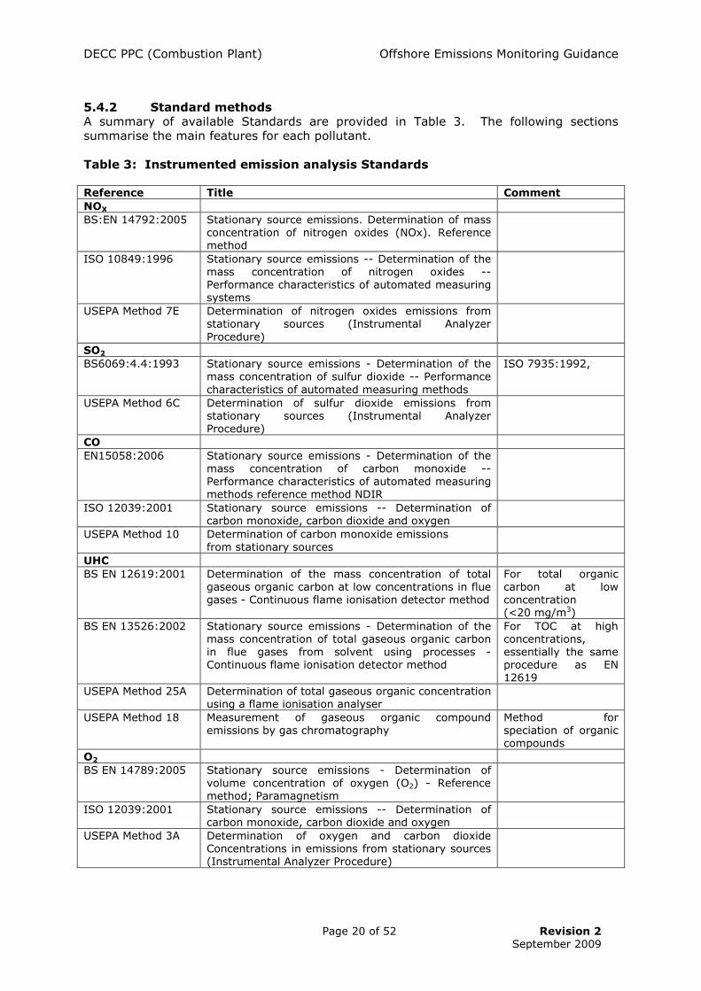
5.4.2 Standard methods A summary of available Standards are provided in Table 3. The following sections summarise the main features for each pollutant. Table 3: Instrumented emission analysis Standards
Reference Title Comment NOX BS:EN 14792:2005 Stationary source emissions. Determination of mass
concentration of nitrogen oxides (NOx). Reference method
ISO 10849:1996 Stationary source emissions -- Determination of the mass concentration of nitrogen oxides -- Performance characteristics of automated measuring systems
USEPA Method 7E Determination of nitrogen oxides emissions from stationary sources (Instrumental Analyzer Procedure)
SO2 BS6069:4.4:1993 Stationary source emissions - Determination of the
mass concentration of sulfur dioxide -- Performance characteristics of automated measuring methods
ISO 7935:1992,
USEPA Method 6C Determination of sulfur dioxide emissions from stationary sources (Instrumental Analyzer Procedure)
CO EN15058:2006 Stationary source emissions - Determination of the
mass concentration of carbon monoxide -- Performance characteristics of automated measuring methods reference method NDIR
ISO 12039:2001 Stationary source emissions -- Determination of carbon monoxide, carbon dioxide and oxygen
USEPA Method 10 Determination of carbon monoxide emissions from stationary sources
UHC BS EN 12619:2001 Determination of the mass concentration of total
gaseous organic carbon at low concentrations in flue gases - Continuous flame ionisation detector method
For total organic carbon at low concentration (<20 mg/m3)
BS EN 13526:2002 Stationary source emissions - Determination of the mass concentration of total gaseous organic carbon in flue gases from solvent using processes - Continuous flame ionisation detector method
For TOC at high concentrations, essentially the same procedure as EN 12619
USEPA Method 25A Determination of total gaseous organic concentration using a flame ionisation analyser
USEPA Method 18 Measurement of gaseous organic compound emissions by gas chromatography
Method for speciation of organic compounds
O2 BS EN 14789:2005 Stationary source emissions - Determination of
volume concentration of oxygen (O2) - Reference method; Paramagnetism
ISO 12039:2001 Stationary source emissions -- Determination of carbon monoxide, carbon dioxide and oxygen
USEPA Method 3A Determination of oxygen and carbon dioxide Concentrations in emissions from stationary sources (Instrumental Analyzer Procedure)

DECC PPC (Combustion Plant) Offshore Emissions Monitoring Guidance
Page 21 of 52 Revision 2
September 2009
5.4.3 Nitrogen Oxides BS EN 14792, ISO 10849 and USEPA Method 7E describe the sampling system and performance criteria for automated measurement of NOx emission concentrations. ISO 11042 and USEPA Method 20 (see Table 4) each specify a sampling procedure, performance specifications and the equipment to be used for determination of NOx emissions from gas turbines. These methods are not specified by UK regulatory authorities for compliance monitoring; therefore, in the UK they are only infrequently employed (e.g. for commissioning and acceptance tests). Chemiluminescence detection – This is the most established technique for instrumented determination of NOx emissions, although the use of other techniques are allowed by the ISO and USEPA standards as long as the performance criteria are satisfied. Analysers employing chemiluminescent detection are fairly complex and are not portable, but semi-portable units are now available. The majority of analysers are best suited to fixed CEMS use, as they can require rigorous sample conditioning to achieve reliable operation, but semi-portable units (including units with MCERTS product type approval) are used by emission monitoring contractors for high quality onshore compliance work, and are beginning to be used for similar work offshore as they offer a wide measurement range suitable for offshore combustion plant. Semi-portable multi-functional analysers, allowing more than one gaseous species to be determined by the same analyser, including chemiluminescence for NOx have also recently become available. It should be noted that NOx comprises nitrogen monoxide (NO) and nitrogen dioxide (NO2), but chemiluminescent analysers determine only NO. To determine total NOx a catalyst (converter) is used on a parallel analyser transport line to reduce the NO2 component to NO. Passage through the converter gives total NOx, whilst sequential measurements can give the relative proportions of NO and NO2. Infra red detection – This approach is commonly used for NOx determination but, although simpler and generally lighter than chemiluminescent analysers, the infra red analysers are generally only semi-portable. Most infra red systems require sample conditioning to remove moisture from the sample as this interferes with detection. The extractive type of infra red instruments have a poorer limit of detection than chemiluminescent units, but this would be unlikely to be an issue as gas turbines without NOx control have comparatively high emission concentrations. These systems are often used for high quality compliance CEMS or periodic monitoring work. As with the chemiluminescent unit, the infrared analyser measures NO only and total NOx is measured using a catalyst (converter) to reduce the NO2 fraction to NO. Some installed CEMS do not contain converters but instead assume that the NO2 component is a fixed fraction of the measured NO concentration. Consequently, they apply a factor to calculate the total NOx. The factors employed are often default values but can be confirmed periodically by measurement. The number of such CEMS used onshore is decreasing, as regulators consider measurement of total NOX to represent BAT. Semi-portable infrared analysers using Fourier Transform Infra Red (FTIR) detection are available. Some of these are very good for satisfying high quality compliance monitoring requirements, whether for continuous or periodic work. To ensure high quality results, all the above instrumented systems rely heavily on the use of standard gas mixtures for calibration. This normally is provided by traceable gas standards contained in cylinders. However, equipment is available with small calibration cells containing known amounts of the target species, and this can obviate the requirement for cylinders.

DECC PPC (Combustion Plant) Offshore Emissions Monitoring Guidance
Page 22 of 52 Revision 2
September 2009
Electrochemical cells - This is a comparatively recent analysis technique for NOx but there are now several manufacturers of such analysers. Many of the instruments are fully portable and most are multi-functional, allowing more than one gaseous species to be determined by the same analyser. However, use in conjunction with a measurement protocol based on Standards requires use of calibration gases to check performance criteria, which makes the technique semi-portable for offshore work. Many units offer an electrical calibration facility and claim not to require gas standards in routine use. This approach to calibration is not consistent with the Standards and should be treated with caution, particularly for baseline surveys. Chemical cell analysis systems have also been incorporated in installed CEMS applications for IPPC combustion processes, and some units have MCERTs and other type-approval. The main issue with the technique is that the chemical cells have a limited life, which can impact on performance. 5.4.4 Carbon monoxide ISO 12039 and USEPA Method 10 describe the sampling system and performance criteria for automated measurement of CO emission concentrations. The latest CEN Standard is EN 15058:2006. Instruments using infrared detection are well-established in both standalone and multi-functional units. In addition to their use in installed CEMS, there are semi-portable high quality infrared based CO analysers available for periodic use. Again, use of Standards with such equipment normally entails the use of cylinder gases to check calibration. However, some equipment incorporates calibration cell systems which may offer a means of avoiding the use of calibration gases for spot checks. Electrochemical cell detection is a comparatively recent analysis technique for CO and there are several manufacturers of fully portable emission analysers. The better units offer electrical calibration but again the Standards require use of calibration gases. As with NOx, the main issue with using chemical cell detection in installed CEMS or for periodic monitoring is that the cells have a limited life, and they also suffer from interference and the accuracy associated with measurements is generally poorer than with infra red-based CEMS. They are therefore not currently regarded as best practice and, if used for offshore baseline surveys, it will be necessary to demonstrate equivalence of the performance criteria relative to the Standards. 5.4.5 Oxygen EN 14789 and ISO 12039 describe sampling systems and performance specifications for on-line oxygen determinations. US EPA Method 3A also provides a methodology for the measurement of O2 using an instrumented technique. There are two main instrumented technologies for determining oxygen concentrations in flue gas. Most installed CEMS and boiler control systems employ either zirconia oxide probes (a form of chemical cell) or paramagnetic detection. Chemical cell and paramagnetic technologies are also well established in portable analysers for oxygen. 5.4.6 Sulphur dioxide There are several automated instrumental standards for monitoring SO2 from stationary sources and these include ISO 7935 and US EPA Method 6C.
ISO 7935:1992 provides performance standards for the monitoring method. The Standard does not prescribe any particular analytical technique, and indicates that there are several commonly employed detection systems and that these include: (i) absorption by infrared or ultra violet radiation; and (ii) fluorescence employing ultra violet radiation, interferometry and conductometry. The Standard only requires that the stated performance criteria are satisfied by the chosen system.

DECC PPC (Combustion Plant) Offshore Emissions Monitoring Guidance
Page 23 of 52 Revision 2
September 2009
US EPA Method 6C covers both performance specification and sampling procedures. Any infrared, ultra violet and fluorescence detection systems meeting the stated performance criteria can be used. All the above techniques would be expected to provide good sensitivity, accuracy and fast response characteristics. The various systems should all be considered as semi-portable, as they require a mains electricity supply and compressed gas calibration standards. Electrochemical cell detection is a comparatively recent analysis technique for SO2 and there are several manufacturers of fully portable battery driven emission analysers. The better units allow presentation of calibration gases to the analyser but such units should therefore be viewed as semi-portable for offshore use. As with NOx, the main issues associated with using chemical cell detection is that the cells have a limited life and can suffer from interference. 5.4.7 Unburnt Hydrocarbons A number of standard methods are available for the automated instrumented monitoring of UHC from combustion processes. These include EN 12619 and USEPA Method 25A, which use flame ionisation detection (FID) to provide a total organic carbon measurement (see below). In all cases a representative sample of flue gas is extracted, filtered and transported to the analysis instrument. A gas handling and transport system is employed which uses inert materials and maintains the gases above the dew point. The Standards also lay out procedures for calibration of the sampling and analysis system. Analytical detection techniques for UHC are summarised below. Flame Ionisation Detectors (FIDs) - For Methods 25 A and EN 12619, the use of a heated flame ionisation detector is specified for analysis. Such instruments are the widely-accepted technique for monitoring unburnt hydrocarbons from combustion sources. They normally require a mains electricity supply, compressed gas standards (typically propane) and fuel gases (hydrogen). Consequently, they can only be considered as semi-portable systems. Intrinsically safe FIDs for emission analysis are now available for use in hazardous areas (mostly for leak detection), but these still require the use of compressed gas cylinders.
Infrared detection – USEPA Method 25B allows the use of a non-dispersive infrared (NDIR) analyser for determination of VOC. These systems offer good sensitivity and a quick response. However, they are generally not fully portable, as they require a mains electricity supply and sample conditioning modules to remove moisture. They also normally require calibration gases, although there have been recent advances in systems with internal calibration cells. Analysers for VOCs are also available which use Fourier Transform Infra Red (FTIR) detection. These can deliver high quality source monitoring requirements, whether for continuous or periodic work, but again require a mains electricity supply and compressed gas cylinders for calibration. Consequently, they are, at best, semi-portable. Photo ionisation detection (PIDs) - These devices can also be employed to monitor VOCs from processes. They are also semi-portable, but less suited to detecting alkanes than FID and NDIR systems.

DECC PPC (Combustion Plant) Offshore Emissions Monitoring Guidance
Page 24 of 52 Revision 2
September 2009
5.5 OTHER TECHNIQUES
5.5.1 Integrated samples for analysis The use of sample bags or canisters offers an alternative to classical wet chemical sampling and direct instrumented measurements. This technique is particularly useful for sampling in explosion risk or fire hazard areas. An integrated flue gas sample is collected into a suitably inert sample container, and the contents analysed later at a safe location using suitable instrumentation. This approach is not encouraged by the UK onshore regulatory authorities, due to issues such as sample stability and losses. Sample transformation can be a significant issue, particularly for NOX measurement, as the NO component will oxidise to NO2 particularly if exposed to daylight and, if analysis is delayed, significant NOX errors can be introduced. However, several USEPA instrumented monitoring standards allow for bag sampling where direct measurement is not practical. Therefore, it is recognised that such an approach may be useful offshore, as intrinsically safe sampling equipment can then be deployed at the sampling location. 5.5.2 Predictive Emission Monitoring Systems A further technique for assessing NOx emissions is the use of predictive emission monitoring systems (PEMS). These systems do not measure emissions but use a computer model to predict emission concentrations based on process data (e.g. fuel flow, load, combustor temperature and ambient air temperature). Onshore and offshore experience shows that standard annular combustion (SAC) gas turbines burning clean stable fuel compositions exhibit emission profiles that lend themselves to PEMS techniques, providing good quality baseline emissions data and the necessary plant input signals are available to develop robust PEMS algorithms that can track turbine gas-path performance and unit condition. It is recognised that manufacturer’s data relating to emissions quality over time may be scarce, and in many cases such data must be treated with caution. This is a secondary reason why the measurement of emissions and characterisation of the unit profiles should be undertaken to appropriate quality standards. For example, if one gas turbine’s emissions can be characterised both before and after an axial air compressor wash then the degree to which the emission levels / profiles are affected by short to medium term degradation and the relationship with turbine parameters can be documented. The PEMS model is based on either measurements at the source or from generic emission information provided for the gas turbine. This approach is comparatively rare at present in the UK and the EA and SEPA onshore regulators require any operator using PEMS rather than CEMS for PPC monitoring, to periodically verify the PEMS using CEN / ISO Standard measurement methods (via MCERTS), as a means of demonstrating compliance with the conditions of the PPC permit (See Section 2.2). As NOx emission concentrations from gas turbines are relatively consistent, compared to those of boiler installations the use of a PEMS could provide a good approach to the documentation of reliable emission data for new gas turbines, and wider application may be feasible following good baseline surveys. (NB. EEMS is a simple offline PEMS, so a validated online PEMS could have a higher tier within the EEMS hierarchy than reporting using simple emission factors / profiles). Whilst it will always be necessary to verify the PEMS against measurement, particularly where the fuel gas differs from the fuel gas used to develop the algorithms used by the PEMS, good baseline data and the use of a robust PEMS may make it possible to increase the monitoring interval (less frequent monitoring) following discussions with DECC.

DECC PPC (Combustion Plant) Offshore Emissions Monitoring Guidance
Page 25 of 52 Revision 2
September 2009
5.5.3 Fuel analysis Sulphur dioxide emission factors can also be predicted from the sulphur content of the fuel. For oil fuels, the mass of SO2 emitted (tonnes of SO2 emitted / tonne of fuel burned) can be deduced by multiplying the percentage sulphur by 0.02. This assumes 100% conversion of sulphur to SO2. However, a small proportion of the sulphur may be oxidised to sulphur trioxide or inorganic sulphate and the multiplying factor could be slightly reduced. For gaseous fuels the emission factor for oxidation of hydrogen sulphide to sulphur dioxide (tonne of SO2 emitted / tonne of fuel burned) can be deduced by multiplying the percentage mass of hydrogen sulphide in the fuel gas by 0.0188. This assumes 100% conversion of H2S to SO2. Fuel analysis is also required to develop pollutant emission factors from the emission concentrations, and the results of the analyses can therefore be considered as a potential alternative to the use of direct stack measurement.
5.6 OTHER RELEVANT STANDARDS
In addition to the Standards listed in Table 2 and Table 3, Table 4 provides details of related EN and ISO emission monitoring Standards. EN 15259:2007 and ISO 10396:2007 should form the backbone of an emissions monitoring strategy, and DECC would expect to see evidence of their consideration within the baseline survey monitoring programme. EN 15259:2007 is already implemented in onshore UK as an integral part of the MCERTs scheme, so this provides a suitable basis for its consideration for offshore surveys. Table 4: Summary of other monitoring Standards
Reference
Title Comment
ISO 10396:2007 Stationary source emissions – Sampling for the automated determination of gas concentrations
Specification for sampling using automated systems, includes guidance on assessment of sampling plane
ISO 11042 (Parts 1&2) : 1996
Gas turbines. Exhaust gas emission. Measurement and evaluation
Gas turbine emission testing
USEPA Method 20 Determination of nitrogen oxides, sulfur dioxide, and oxygen emissions from stationary gas turbines
Gas turbine emission testing
ISO 10780:1994 Measurement of velocity and volume flow rate of gas streams in ducts
Velocity and flow rate by pitot tube.
BS EN 13284 Part 1:2002
Stationary source emissions - Determination of low range mass concentration of dust - Part 1: Manual gravimetric method
Particulate measurement (low concentrations)
BS EN 14790:2006 Stationary source emissions - Determination of water vapour in ducts
USEPA Method 4 Moisture determination EN14181:2004 Stationary source emissions – Quality
assurance of automated measuring systems
EN 15259:2007 Air Quality: Measurement of Stationary Source emissions – requirements for measurement sections and sites
Covers measurement objective, plan, and report. (Measurement Strategy)

DECC PPC (Combustion Plant) Offshore Emissions Monitoring Guidance
Page 26 of 52 Revision 2
September 2009
6 Quality of Emission Measurements
6.1 ACCREDITATION AND MCERTS
The UK emission monitoring industry has undergone significant developments since preparation of the background offshore monitoring document. Accreditation of the test organisation to EN 1702510 is commonplace, and is mandatory for organisations undertaking compliance and check monitoring of IPPC Part A1 processes in England & Wales. The Environment Agency Monitoring Certification Scheme (MCERTs) covers proficiency of individuals and organisations undertaking emission monitoring. Details of MCERTs can be found at: http://www.siraenvironmental.com/mcerts/ or http://www.mcerts.net . Guidance on emission monitoring including the minimum requirements for test organisations is available at: http://www.environment-agency.gov.uk/business/regulation/31847.aspx Accreditation of an organisation to EN 17025 and MCERTs can be checked through the UKAS website: http://www.ukas.org.uk/testing/singlesearch.asp. Search for ‘MCERTs’ and, when prompted, select Environment samples ‘stack emissions-sampling’. The entry provides a list of accredited organisations and the scope of accreditation of each organisation. The MCERTs scheme also covers type-approval certification of equipment used for emission monitoring such as CEMS and portable emission monitoring equipment. The MCERTs accreditation status of monitoring equipment, individuals and companies can be obtained from the scheme administrators (SIRA Environmental Ltd).
6.2 MCERTS & PORTABLE MONITORING EQUIPMENT
DECC strongly recommends that qualified personnel should carry out the offshore sampling, as it is extremely unlikely that the operator’s staff will have equivalent training and experience and the most significant cause of problems relating to sampling has been shown to be human error. Use of MCERTS competent personnel is therefore regarded as best practice for baseline survey measurements. The MCERTs specification for portable monitoring equipment was published in 2005 and revised in 2008 to better distinguish between two performance criteria 11. The MCERTs criteria for portable equipment for emission monitoring cover two types:
Type 1 - systems used for calibration of CEMS, where emissions are 50% or more of the permitted daily average limit or where regulations require monitoring to CEN/international Standards. These portable systems are designed to perform to the same high standards as required for CEMS. Used with appropriate test procedures and by competent personnel they will measure emissions to the best
10 BS EN ISO/IEC 17025:2005 General requirements for the competence of testing and calibration laboratories. 11 Available at http://publications.environment-agency.gov.uk/pdf/GEHO0305BKAM-e-e.pdf, with Sira certification at http://www.siraenvironmental.com/mcerts/product.aspx?page=263

DECC PPC (Combustion Plant) Offshore Emissions Monitoring Guidance
Page 27 of 52 Revision 2
September 2009
levels of overall uncertainty for deriving baseline characteristics / verifying compliance. These portable systems are a subset of the Sira CEMS listing. Type 2 - systems used for indicative monitoring, where emissions are likely to be below 50% of the emission limit or at installations with a smaller risk of significant environmental impact.
In essence, a Type 1 system will require calibration gases during use and should be considered as semi-portable for offshore work. Type 2 systems are fully portable for offshore work. The Type 1 systems would normally be most suitable for baseline surveys, whereas Type 2 systems could be suitable for baseline surveys but would need to be used with calibration gases, and performance criteria met in accordance with Section 6.4.
6.3 SOURCE TESTING ASSOCIATION
The Source Testing Association (STA) is an industry association representing emission testing organisations, process operators, monitoring equipment manufacturers and others. The STA produces guidance on reporting standards, test methods, safety and quality. Information on MCERTs and other useful guidance, including minimum standards of testing and reporting for STA members, is available from the website: http://www.s-t-a.org/Files%20Public%20Area/STA%20docs/M1054-99.pdf The Source Testing Association produces a useful annual guide to its membership organisations and the services they provide, including details of over 30 UK organisations accredited to ISO 10725 under the MCERTs scheme. A large number of these organisations operate mobile field laboratories for the purpose of periodic stack emissions testing. A significant number have the capability, resources and experience to meet the offshore PPC testing requirements using CEN / ISO Standards. A sub-set of these organisations will also already have experience of successful offshore testing to at least meet the minimum requirements outlined in these guidelines, and some are already working towards attaining a higher tier approach.
6.4 MAIN QUALITY CONSIDERATIONS
The key components to achieve quality measurements are; an agreed monitoring plan, a good (or characterised) sampling position, application of a Standard method, use of competent test personnel, and a clear, detailed test report to demonstrate the traceability of the measurements. Appropriate attention should be given in the planning stages to the measurement and recording of data relating to fuel flow, gas turbine load parameters, gas composition data, and stack velocity, in parallel with measurements of stack emissions. These parameters are important for characterisation of emissions and will generate additional elements of uncertainty that should be minimised to ensure good overall quality of data. Based on the information in this guidance, it is possible to identify:
• A highest (ideal) monitoring tier for conducting baseline surveys • A lowest (minimum) monitoring tier for conducting baseline surveys

DECC PPC (Combustion Plant) Offshore Emissions Monitoring Guidance
Page 28 of 52 Revision 2
September 2009
Highest Tier for baseline surveys The highest tier for conducting baseline surveys is one that is closely aligned with onshore PPC precedents, and incorporates:
• use of a suitable site specific protocol (refer to Section 10.3). • a strategic assessment of monitoring and sampling requirements (to EN
15259 / ISO 10396). • direct application of CEN / ISO Standards (see Table 3) and / or the use of
MCERTs certified analytical equipment - and by inference the use of on-site calibration gases.
• Involvement of MCERTs competent personnel; with, as a minimum, overall planning, review and on-site supervision by Level 2 Team Leader and on-site testing by Level 1 Technician.
• use of QMS procedures under a UKAS 17025-accredited test house. • application of STA minimum reporting requirements, including a record of
any exceptions to Standards resulting from site specific constraints. • detailed characterisation of all types of main combustion plant on the
installation, across their load range and on applicable fuels; subject to any site specific constraints agreed with DECC as part of the monitoring programme (e.g. operational constraints that restrict current load range).
Since many onshore test houses have limited familiarity / experience with offshore working environment and associated constraints, it is also recommended that the test team includes appropriate assistance from the operator or contractor personnel. Under most circumstances, DECC will expect operators to achieve the highest tier. This is considered necessary to meet PPC permit condition objectives, and to provide a robust baseline to justify a subsequent measurement frequency that is not onerous; i.e. one that is no more frequent than the 3-year permit review frequency (providing no operational or combustion equipment changes are made in the review period). However, DECC recognise that operational or logistics constraints may inevitably mean that best practice will be a continuum, ranging from the highest (ideal) tier to the lowest (acceptable) tier, rather than a single, clearly-defined protocol and DECC will review exceptions to best practice on a case-by-case basis. For example, in extreme cases stack access restrictions or health and safety concerns might genuinely prevent the use of CEN / ISO Standards and lead to low-tier exceptions. At the other end of the continuum is the case where an Operator aims to meet the highest tier in all respects but logistically is only able to deploy the services of MCERTS Level 2 (Team Leader) for overall protocol planning, analysis, and reporting (onshore), with offshore on-site testing conducted by competent MCERTS Level 1 technician reporting to the Level 2 team leader. This would normally constitute a minor exception to the highest tier. Where an operator is able to demonstrate that only the lowest tier can be achieved (or is approached with minor exceptions), it will probably be necessary to undertake measurements at more frequent intervals, as discussed and agreed with DECC. Lowest (Minimum) Tier for baseline surveys The lowest tier of acceptable baseline measurement is one that incorporates;
• use of a suitable site specific protocol (refer to Section 10.3) • a strategic assessment of monitoring and sampling requirements (to at
least ISO 10396)

DECC PPC (Combustion Plant) Offshore Emissions Monitoring Guidance
Page 29 of 52 Revision 2
September 2009
• application of CEN / ISO Standards, or a measurement procedure with demonstrated equivalence to those standards, with use of calibration gases on site for pre- and post- test calibration
• use of suitable analytical equipment by MCERTs competent personnel; with, as a minimum, overall planning by Level 2 Team Leader and on-site testing by Level 1 Technician.
• application of accredited QMS procedures and STA minimum reporting requirements, including a record of any exceptions to Standards or procedures resulting from site specific constraints.
• characterisation of selected combustion plant on the installation.
It is difficult to be specific as when the lowest tier would be acceptable. However one such occasion would be where an operator undertakes a highest tier on some of the equipment but other units are out of service (unplanned) and cannot be tested on same visit, The operator therefore plans to undertake a second visit using the lowest tier approach to spot check the untested units at their normal operating load. With regard to UKAS – 17025 and the equivalence to CEN standards, the UKAS guidelines indicate that accredited stack emissions testing organisations and personnel are expected to use CEN / ISO standard reference methods and compliant equipment as part of their work procedures. An organisation may use an alternative instrumental technique to that specified in the CEN / ISO standard reference methods, but the test party is then required to demonstrate that, not only are the equivalent performance criteria to the Standards being met, but also that the alternative technique works on the intended process application. This can be achieved in one of three ways:
• Firstly, by using a MCERTs certified piece of equipment as part of the UKAS procedure.
• Secondly by carrying out field tests under ISO 17025 accreditation, to compare the instrument against the CEN / ISO reference method.
• Thirdly by carrying out tests, using an appropriate test rig, under ISO 17025 accreditation, to compare the instrument against the reference method.
It is a UKAS and regulatory requirement that such field tests / rig tests should meet the requirements of CEN TS 14793 “Intra-laboratory validation procedure for an alternative method compared to a reference method”. Use of alternative methods such as NDIR for NOx, and Zirconia sensor for Oxygen are examples of valid techniques that have been demonstrated as alternative methods with appropriate test equipment. Where measurement techniques do not comply with either the Standard or an alternative method accreditation, such techniques are more appropriate for ball park spot checks, rather than quality baseline surveys, and should not be considered best practice. Whilst it is an important factor, it is not sufficient to state that calibration gases will be used as a means of addressing the Standards, as CEN TS 14793 requires the uncertainty and performance criteria of the complete end-to-end system to be field proven against a standard reference system.

DECC PPC (Combustion Plant) Offshore Emissions Monitoring Guidance
Page 30 of 52 Revision 2
September 2009
7 Main Issues in Offshore Measurements
The main issues encountered during offshore emission surveys are: • Logistics – This includes the transporting of personnel, equipment and calibration
gases to and between facilities. There are limited flights and limited space on flights; in addition there are safety issues concerned with transporting compressed gases or chemicals by helicopter. Following advice from the platform operators and shipping agents, calibration gases can be taken offshore for baseline measurements. Initial surveys of offshore emissions using fully portable equipment did not use calibration gases, because several platforms were visited and it was anticipated that the test programme would not allow sufficient time to transfer the gas cylinders between the platforms. However, following the issue of PPC permits, there have been a number of offshore tests conducted where calibration gases have been successfully used offshore; and their use is regarded as an essential element of best practice.
• Sampling facilities – The gas turbine exhaust ducts on offshore facilities generally
have limited provision for emission sampling. Although there are comparatively long flues, which should allow adequate mixing of flue gases, the most accessible locations for sampling are frequently at the turbine exhaust duct immediately downstream of the GT enclosure and this is not an ideal sampling location. The absence of insulation on some exhaust ducts can also prevent access at other locations due to high radiant temperatures. It is important to remember that only monitoring of gaseous species of pollutants is required under offshore PPC (and not particulates) – so the appropriate less onerous requirements of TGNM1 should be followed. As most offshore installations do not have existing sample ports, the retrofit of sampling facilities at a conveniently accessible location (often a compromise) will be a key factor during the early stages of planning a survey.
• Access – Individual gas turbines in the gas compression and electrical generation
modules are usually at different locations and at different levels on the platforms. Hand portable equipment may be moved comparatively easily to and between the various sampling locations. However, movement of heavier test equipment would be significantly more difficult. Crane access is not always possible near the sampling positions, and crane operations must be halted in medium to high winds. The selection of transportable equipment may therefore be suitable for some platform configurations, but not others, and in many cases semi-portable arrangements qill be the most appropriate compromise.
• Flameproof zones – Short-term measurements using fully-portable and semi-
portable equipment under appropriate permits and flammable and toxic gas personal monitors should not be an issue. Use of other semi-portable mains driven UHC emission monitoring equipment may be undertaken at a workshop location (i.e. sample collected in bags and returned to the workshop for analysis). The workshop should also provide a convenient location for storage and use of calibration gases. Following the issue of PPC permits, most operators appreciate that, to meet the CEN / ISO Standards, they need to conduct the necessary ‘Level 2’ risk assessments to allow the necessary equipment to be used under strict Permit to Work arrangements. This is an important element of the pre-planning.
• Equipment reliability - Older portable emission analysers may stop operating at low
ambient temperatures (this was a ‘feature’ of the design of these analysers, to avoid damage to the equipment from condensation of moisture present in the sample gas). Modern equipment incorporates more sophisticated sample drying systems, allowing

DECC PPC (Combustion Plant) Offshore Emissions Monitoring Guidance
Page 31 of 52 Revision 2
September 2009
operation at lower temperatures. Power supply issues due to frequency and voltage differences also should not be a problem.
• Communication – Communication routes between the test personnel, facility
personnel and the onshore facility and test house management can be difficult, and planning is needed to ensure communication is sufficient to quickly address any issues.
• Plant instrumentation – The data available to characterise the operation of
combustion equipment may be quite limited, particularly on older facilities and for smaller combustion units.
• Equipment warm-up time – Some analyser equipment may have long warm-up
times (e.g. up to 4 hours) and may not be suitable for expedient use unless it can be located in a non-hazardous zone and left on power overnight (between working shifts). In many instances, where equipment must be located and used in the process environment under suitable hot work / spark potential permit, it is more appropriate to make sure that the test team selects equipment that has a short warm-up time (e.g. 1 hour or less), providing this does not compromise the CEN / ISO Standards and procedures.
• Temporary utilities – Systems that can achieve full compliance with CEN / ISO
Standards, including many semi-portable systems, will require a temporary or permanent electricity supply (sockets) in the vicinity of the sampling location. Typically one or more 16A 110V supplies will be required, and this should be clearly identified at the planning stage and, if necessary, the facilities put in place in the run-up to scheduled testing.
It should be noted that a high level of co-operation from the platform personnel is essential when carrying out offshore emission monitoring work. Where possible, an operative from the facility should be assigned to liaise and assist with the measurement task. This approach allows issues that arise to be resolved quickly. This is particularly important where emissions are being characterised across operating load range, since a dedicated authorised operative is required to co-ordinate load changes to critical production plant (e.g. power generation / gas compressor turbines). The availability of combustion equipment for testing during or shortly after commissioning can be difficult. Operation of the facility is not stable and operators can be very reluctant to modify operating conditions to provide (for example) changes in load on individual combustion plant. This has implications for completing a baseline survey in a timely manner. This aspect should be discussed early on in the planning stages so as to minimise impact at time of testing. DECC will take a pragmatic view if there are genuine reasons why a particular item of combustion plant is not available for testing. The main barriers to the use of higher quality emission monitoring equipment for periodic monitoring are probably movement of the equipment around the facility; location of the equipment; and operation of the test and ancillary equipment in flameproof zones. A short reconnaissance survey of the installation is therefore recommended to provide input to the development of the site specific protocol and baseline survey test procedures, which should be undertaken well in advance of the scheduled test window.
DECC PPC (Combustion Plant) Offshore Emissions Monitoring Guidance
Page 32 of 52 Revision 2
September 2009
8 Use of Emission Factors
8.1 DEFAULT EMISSION FACTORS
Emission factors relate the release of a pollutant to an activity statistic, for example mass of pollutant per unit of fuel used, and are commonly applied to provide annual emission inventories (for example the EEMS database). Offshore emissions inventories have been estimated using pollutant emission factors and operating data from various sources. However, published emission factors, for example default emission factors published by the USEPA for uncontrolled gas turbines (that is machines without NOx control systems), are based on emission measurements from older, comparatively small gas turbines, and they tend to underestimate NOx emissions from modern uncontrolled gas turbines. The USEPA default factors also tend to overestimate CO and UHC emissions from modern gas turbines that have higher combustion efficiencies than the older machines. Emission factors are used to estimate annual emissions but there is a need for more reliable emissions information for current installed plant.
8.2 DEVELOPING EMISSION FACTORS
Emission factors can be developed from baseline survey emissions data, and these can then be used in preparing annual emission inventories (see Appendix B). The development of an emission factor for a pollutant requires knowledge of the pollutant emission concentration, the oxygen concentration of the emission and analysis of the fuel gas. It is therefore recommended that fuel samples are collected and analysed to allow calculation of emission factors. Appropriate attention should be given at the planning stages in relation to the measurement and reporting of fuel flow, gas turbine load parameters, gas composition data, and stack velocity, in parallel with the measurements of stack emissions. These parameters are important for characterisation of the emissions and will generate additional element of uncertainty, which should be minimised to ensure good overall quality of data. Since 2002 the fidelity of the EEMS database has been significantly improved by moving to turbine-specific emissions profiling for EPER / EPRTR and PPC reporting. Much, but not all, of the turbine-specific profiling developed for EEMS has been based on data collected using CEN / ISO standards and equipment. Where anomalies in the database have been noted these have generally been traced to the less stringent adherence to the Standards. Nevertheless, gaps remain in the database of offshore combustion plant, and it is in the interests of all stakeholders that consistent standards are used going forward to enhance the EEMS database and the reporting. This has been a critical consideration in the development of best practice guidelines for baseline testing.

DECC PPC (Combustion Plant) Offshore Emissions Monitoring Guidance
Page 33 of 52 Revision 2
September 2009
9 Sampling Facilities
ISO 10396, the Environment Agency Technical Guidance Note M1 (TGNM1) and other documents provide general guidance on choosing sampling locations and the provision of sampling facilities. The key requirements are for a sampling position as far away from flow disturbances (for example bends and dampers) and joining ducts as possible. It is recognised that, in the offshore context where ports often have to be retrofitted to existing stack infrastructure, the selected locations will often be a compromise position between the ‘ideal’ and ‘readily accessible’ locations. In this respect, it should be noted (as indicated in TGNM1) that the requirements for measuring emission concentrations of gaseous species of pollutants are much less onerous than the requirements for measuring particulates. Since particulate measurement is not required under offshore PPC, a fit-for-purpose interpretation of TGNM1 is therefore appropriate. It is recommended that, if in doubt, operators should seek guidance from their emissions monitoring consultant. Sampling ports are required to access the exhaust gases and, where practicable, should be located to allow a traverse of the ducts across two diameters (to assess mixing at the sampling position). If only gaseous concentration measurements are required, then a minimum 1 inch BSP or NPT socket and safe working access are all that are required. However, it should be noted that some test houses prefer a minimum 2 inch sockets to accommodate adequate tip pre-filters when undertaking testing for diesel fuel. For gas turbines without heat recovery, a flange connection is recommended (flanges appear to be less prone to seizing). To avoid discharge of hot gases at the sampling position, an isolating valve is recommended for exhaust ducts which are at higher than ambient pressure. These requirements should be discussed at the planning stage, as different operators have different requirements in relation to the provision of isolation valves under integrated safe systems of working, and requirements can therefore be very site specific. Safe working access and a work platform are required. Although the equipment used at the stack port may be hand-portable, it can include long sampling probes (up to 3m) that are difficult to manoeuvre if the sampling platform is too small. For this reason, adequate clearance must be provided around the port when considering the detailed design of any retrofit connections. Provision of additional larger sockets and platforms would be required for flow measurements or more elaborate emission measurements. However, this is not an offshore PPC requirement. Protection of equipment and personnel from radiant heat needs to be considered where exhaust ducts are not insulated. Access to a workshop or other work area is required to allow the recharging of batteries, the storage and use of calibration gas cylinders and the installation of the UHC analyser (if not deployed to the sampling position). Transportation of non-portable items (gases, semi-portable / transportable analysers) to an offshore installation will normally be via supply boat from the operator’s onshore supply base. Transportation will normally have to be arranged in appropriate offshore certified containerised cargo units.

DECC PPC (Combustion Plant) Offshore Emissions Monitoring Guidance
Page 34 of 52 Revision 2
September 2009
10 Baseline Emission Survey
10.1 GENERAL REQUIREMENTS
The operator needs to satisfy the Regulator that the baseline survey will characterise emissions from the facility’s combustion plant. This does not require that the operator should measure emissions from every combustion source on a facility. The most significant sources on a facility are likely to be gas turbines used for electricity generation or gas compression. The survey will require four main activities:
• A review of the combustion plant; • Develop a facility test protocol; • Undertake measurements; and • Produce a baseline survey emission report.
There will be interaction between the operator, the emission monitoring contractor and DECC to finalise the requirements.
10.2 REVIEW COMBUSTION PLANT
The contribution of the various combustion plant to the annual emissions should have been estimated as part of the permit application. Emission estimates may be based on vendor information or default emission factors, and this will provide a useful starting point to screen the plant which should be included in the baseline survey. Alternatively, the type, size, fuel (type and use) and anticipated or actual operating hours of the combustion plant can be used to determine the scope of measurements at combustion plant. The scope of the survey should aim to characterise the most significant sources including, where relevant, emissions when burning standby or alternative fuels. The measurements should determine, NOX, SO2, CO and UHC at a range of loads. As a minimum, these loads should be those considered typical of normal operation but, if possible, the entire operating range should be assessed for the major sources as this may provide information relevant for future operation of the facility. If a facility has multiple equipment of the same type and performing the same duty (e.g. power generation or gas compression) then it may be sufficient to characterise the emission profile for one machine over the normal and potential load range, i.e. not restricted to current operating loads, with measurements over a single load or a more limited range of loads for the “sister” units. If there are several units of the same type, but the units differ because some have been modified (for example uprated or derated), then a full range of measurements may be necessary for each unit to assess the differences in the emission profiles. Where the same type of units are used for different duties (for example electricity generation and gas compression) then one example for each duty should be characterised over the normal and potential load range, i.e. not restricted to current operating loads, with measurements over a single load or a more limited range of loads for the sister units.

DECC PPC (Combustion Plant) Offshore Emissions Monitoring Guidance
Page 35 of 52 Revision 2
September 2009
Where units are dual-fired or dual-fuelled (typically gas oil and gas), emissions should be characterised for both fuels. If machines can operate on a wide range of gas supplies then it may also be necessary to undertake baseline measurements on more than one gas supply.
10.3 DEVELOP FACILITY TEST PROTOCOL
A facility test plan or protocol should be developed which describes the work to be undertaken, the methods, equipment and, if applicable, the relevant Standards. The test protocol needs to convert the scope of the survey into a practical measurement programme reflecting issues such as access, safety requirements and the duration of the tests. The MCERTs site specific protocol and a Quality Plan (a requirement of EN17025) provide a framework to develop the facility test protocol. The MCERTs site-specific protocol model provides the following:
• the facility name and location • planned date of measurement • name(s) of sampling team and their roles, competencies and responsibilities • type of facility • facility description • identity of combustion plant to be tested • operational details of plant (fuel, duty, continuous, standby &c) • required test conditions (for example electrical load, fuel flow) • process data that need to be collected during measurements • expected emission concentrations • substances to be monitored • reference conditions for reporting emission concentrations • measurement method for each substance • internal test house technical procedures to implement method • uncertainty of the procedure • deviations from the procedure • equipment to be used • sampling duration and number of measurements/samples • calibration and zero gases to be used • measurement limit of detection and range • location of sampling planes for each combustion plant • description of sampling ports for each combustion plant • description of numbers of sampling ports and orientation • summary of compliance of sampling plane with test method • where chemical analysis is required – details of the analysis method, the
laboratory, the chain of custody requirements, the transit time, the storage conditions and the archive requirements
• procedure for recording of monitoring data • method for standardising data to reference conditions (and where appropriate
calculation of emission factors) • report format, author and person responsible for checking report • procedure for checking data quality • date report is due to be issued • details of on-site risk assessment • COSHH details (where appropriate) • equipment carriage details • facility safety requirements (induction, hazardous zones, ptw) • offshore safety requirements

DECC PPC (Combustion Plant) Offshore Emissions Monitoring Guidance
Page 36 of 52 Revision 2
September 2009
• other safety requirements (for example Method Statement)
10.4 MEASUREMENTS
For baseline measurements, the use of Standard methods is recommended as far as possible, with the use of calibration gases to check instrument response. Measurements should be carried out under steady operating conditions. Although gas turbines respond quickly to load changes and the emissions are generally very stable, it is nevertheless recommended that a minimum of 15 minutes should be allowed following a load change, and that the duration of the test period at the stabilised load should be at least 30 minutes. Semi-portable systems can be deployed offshore for baseline surveys. Fully portable systems can also be effectively deployed, but the use of certified calibration gases to check the response of the instrument on the facility (preferably before and after use) is considered best practice for baseline surveys. The use of calibration gases has an impact of the logistics of undertaking the survey, but is considered to be justified for a baseline survey. At present, the most portable combustion emission monitoring systems available are based on electrochemical cell detection (for NOX, SO2, CO and Oxygen) and flame ionisation detection (for UHC). Fully-portable detection systems tend to have a higher uncertainty than semi-portable, transportable or fixed equipment but the portable electrochemical cell devices are comparatively cheap (£5-15k) and are easy to use. To ensure reliable data the testing organisation needs robust quality assurance and control systems. For baseline testing this should include daily spot checks before and after use using calibration gases. The use of fully-portable systems without on-site calibration checks for baseline surveys is not recommended. However, such systems may have a role during screening surveys or for subsequent compliance monitoring. If, with agreement from DECC, operators are using fully portable equipment for baseline surveys the requirements of the lowest tier detailed in Section 6.4 must be met by the operator.
10.5 DATA STANDARDISATION AND REPORTING
Emission concentrations should be standardised to appropriate reference conditions (oxygen, moisture, temperature and pressure). Emission factors can be developed from the emission concentrations to allow calculation of annual emission estimates. Appendix B provides details of the standardisation and emission factor calculations.
10.6 REPORT
The STA has published minimum reporting requirements for members, which provides a reasonable basis for a test report12. The report shall be a complete account of the measurements and the development of the measurements into emission factors and annual emission estimates. The report should contain as a minimum (based on STA minimum reporting standards):
• objectives of the work
12 Available at : http://www.s-t-a.org/Files%20Public%20Area/STA%20docs/M1054-99.pdf

DECC PPC (Combustion Plant) Offshore Emissions Monitoring Guidance
Page 37 of 52 Revision 2
September 2009
• the methods employed • protocols used • deviations from methods used, including reasons and estimated impact on
uncertainty • the measurement equipment used • the persons who carried out the work • operating conditions of the combustion plant • details of duct gas conditions during test (temperature, oxygen should suffice for
combustion plant) • emission measurement results and uncertainty • supporting data (for example fuel flow during tests, annual fuel use) • fuel analysis • calculations • details of quality system
It should be noted that EN17025 and MCERTs also have minimum reporting standards, which are more detailed than the minimum outlined above.

DECC PPC (Combustion Plant)
Offshore Emissions Monitoring Guidance
Page 38 of 52 Revision 2 August 2009
Appendix A Supplier Contact Details
CONTENTS
Equipment used by AEA Technology during offshore emission surveys. Recent developments (since 2005) Table A1 Suppliers of portable emission monitoring instrumentation Table A2 Suppliers of hire equipment Table A3 Suppliers of continuous emission monitoring instrumentation Table A4 Portability of instrumented emission analysis systems Table A5 Uncertainty and price of instrumented analysis systems

ED44987 Offshore monitoring guidance Rev 2
Page 39 of 52 Netcen AEA Technology plc
Equipment used by AEA Technology during offshore surveys The measurements were undertaken using a mixture of owned and hired portable monitoring equipment. The principal monitoring equipment were Testo model 350 and 350xl portable flue gas emission analysers for NO, NO2 , SO2 , CO, O2 and temperature measurement. A semi-transportable Bernath model 3006 hydrocarbons emission analyser was used to measure UHC concentrations. Contact details for flue gas emission analyser suppliers and companies that hire such equipment are provided at Tables A1, A2 and A3. Sample was extracted from the duct through a stainless steel probe and passed to the analysers by a heated PTFE lined sample line. A Testo 339 sample conditioning unit was employed on occasions to cool the sample and remove moisture prior to transporting the sample to the analyser. The emission data were recorded at two minute intervals during the test periods. Generally two Testo analysers were deployed for the measurements; where calibration gases were not available, the second instrument was used to verify the data provided by the first unit at a selected machine. In baseline surveys, calibration gases were taken to the platforms, which allowed checking and setting of instrument response at the facility before and after measurements; in earlier surveys calibration gases were not taken offshore and, one analyser was used to check the data provided by the second analyser. The response of the analysers were checked with calibration gases before and after, shipping to the platforms. The measurements were undertaken using portable and semi-portable flue gas analysers, which had been prepared and used in accordance with the manufacturer’s instructions. Significant variation was noted for all the measured determinands when using the portable analysers without calibration gases. Limits of detection and resolutions for NO, NO2, SO2 and CO are nominally 1 part per million (ppm) however a more practical limit of detection is about 5ppm. The analysers exhibit a slow response to low concentrations of (in particular) SO2. AEA Technology considers that the uncertainty of the NOx measurements undertaken offshore using the Testo equipment without calibration gases was within 15%, however AEA Technology considers that the uncertainty of other determinands (CO and SO2) may have exceeded 25%. Other measurements undertaken offshore included ambient air temperature, humidity and pressure. However, such measurements are generally not required for routine emission monitoring. Tables A4 and A5 provide indicative ranges of uncertainty, price and applicability of technologies to fully-portable, semi-portable, transportable and fixed instrumented systems. Recent developments Whilst there are a significant number of analyser products that comply with CEN Standard reference techniques and / or have MCERTs product type-approval, many of these are only suitable for use in transportable systems. Offshore experience has shown that the deployment of transportable equipment for baseline survey testing offshore is only practicable in certain situations. Specifically where analyser equipment can be

ED44987 Offshore monitoring guidance Rev 2
Page 40 of 52 Netcen AEA Technology plc
located in a weatherproof non-hazardous area of the installation within reach of the stack sampling facilities, and left powered up as a normal laboratory device. Otherwise, long warm-up times (up to 4 hours), lack of portability between test locations, and associated logistics issues, may hamper their effective use and can prolong or compromise testing activity. It is recommended that this aspect along with all other practical issues should be assessed when developing the site-specific test protocol, as part of a site reconnaissance survey. Technology advances and product certification have meant that there are now a number of products of a portable nature which utilise the Standard CEN / ISO methods and / or have been certified to MCERTs product standard. Together suitable portable elements can be assembled into a semi-portable system and used in partnership with certified calibration gases to conduct quality baseline survey tests to the levels of uncertainty specified by the standards. These semi-portable systems are ideal for most offshore situations since they address the majority of practical concerns regarding the use of transportable equipment, without compromising on quality of measurement. They meet the required performance standards in a more cost-effective and robust manner, have quicker warm-up times (<1hour), are readily moved around the installation, can be maintained if they malfunction, and are in general less intrusive to normal site activity. Quantity of data can therefore be maximised without a detrimental effect on the quality of the data. Further details of instrumented analyser equipment type-approvals can be obtained from the equipment reference list on the Sira website. 13 By inference, best practice using the CEN / ISO standards for manual stack sampling implies the involvement of competent personnel. Therefore, the involvement of a UKAS accredited organisation that ideally follows STA practices should be considered Best Practice for the purpose of conducting the initial baseline surveys. This will generally mean specifying the services of an engineer / technician registered under the UK MCERTS scheme for personnel competency to be involved in the baseline survey. An MCERTS Level 2 Team Leader with appropriate technical endorsements should ideally be involved in the detailed planning stage and, at the least, a Level 1 Technician involved in the testing (stack measurement). Experience shows that, because offshore testing involves particular work procedures and logistical requirements, it is also advisable for the test team to include a rotating equipment (gas turbine) engineer with a knowledge of offshore gas turbine testing; to co-ordinate the overall test procedure and to ensure that all parallel process and control system parameters are recorded alongside with the stack emissions measurements. This engineer will usually be a member of the operator’s or a specialist contractor’s staff, and should have the authority to take overall supervisory responsibility for the test under the installation’s Permit-To-Work system. This implies a certain level of installation-specific awareness and training.
13 Sira MCERTS type approvals available at http://www.siraenvironmental.com/mcerts/
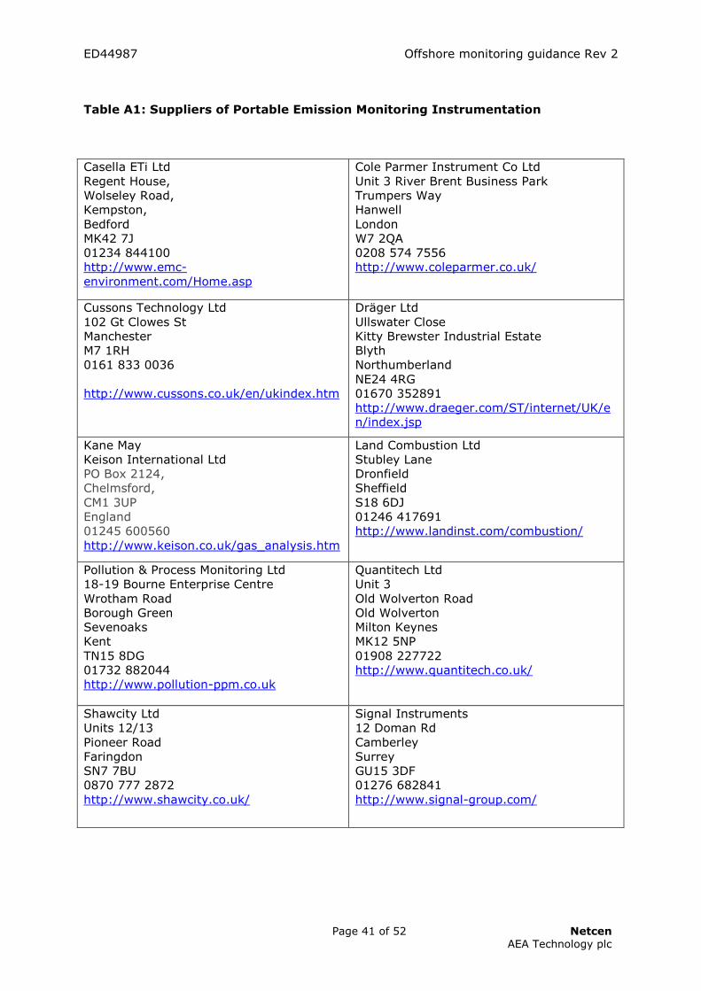
ED44987 Offshore monitoring guidance Rev 2
Page 41 of 52 Netcen AEA Technology plc
Table A1: Suppliers of Portable Emission Monitoring Instrumentation
Casella ETi Ltd Regent House, Wolseley Road, Kempston, Bedford MK42 7J 01234 844100 http://www.emc-environment.com/Home.asp
Cole Parmer Instrument Co Ltd Unit 3 River Brent Business Park Trumpers Way Hanwell London W7 2QA 0208 574 7556 http://www.coleparmer.co.uk/
Cussons Technology Ltd 102 Gt Clowes St Manchester M7 1RH 0161 833 0036 http://www.cussons.co.uk/en/ukindex.htm
Dräger Ltd Ullswater Close Kitty Brewster Industrial Estate Blyth Northumberland NE24 4RG 01670 352891 http://www.draeger.com/ST/internet/UK/en/index.jsp
Kane May Keison International Ltd PO Box 2124, Chelmsford, CM1 3UP England 01245 600560 http://www.keison.co.uk/gas_analysis.htm
Land Combustion Ltd Stubley Lane Dronfield Sheffield S18 6DJ 01246 417691 http://www.landinst.com/combustion/
Pollution & Process Monitoring Ltd 18-19 Bourne Enterprise Centre Wrotham Road Borough Green Sevenoaks Kent TN15 8DG 01732 882044 http://www.pollution-ppm.co.uk
Quantitech Ltd Unit 3 Old Wolverton Road Old Wolverton Milton Keynes MK12 5NP 01908 227722 http://www.quantitech.co.uk/
Shawcity Ltd Units 12/13 Pioneer Road Faringdon SN7 7BU 0870 777 2872 http://www.shawcity.co.uk/
Signal Instruments 12 Doman Rd Camberley Surrey GU15 3DF 01276 682841 http://www.signal-group.com/

ED44987 Offshore monitoring guidance Rev 2
Page 42 of 52 Netcen AEA Technology plc
Teledyne Analytical Instruments Ltd The Harlequin Centre Southall Lane Southall Middlesex UB2 5NH 0208 571 9596
Telegan Gas Detection (A division of Crowcon Detection Instruments Ltd.) 2 Blacklands Way Abingdon Business Park Abingdon Oxfordshire OX14 1DY 01235 557700 http://www.telegangas.co.uk/
Testo Ltd Newman lane Alton Hampshire GU34 2QJ 01420 544433 www.testo.co.uk
Note : This list is not exhaustive, and does not constitute an endorsement of the listed companies’ products or services. Table A2: Suppliers of Hire Equipment
AGL Airtesting Horizon House Baldock Industrial Estate London Road Baldock Hertfordshire SG7 6NG 01462 896818 www.aglairtesting.co.uk
Ashtead Technology Rentals Unit 3 Kirkton Avenue Pitmedden Road Industrial Estate Dyce Aberdeen AB21 0BF 01224 771888 http://www.ashtead-technology.com/
EIM (Northern) Ltd Unit 1 The Gate Centre Bredbury Parkway Bredbury Park Industrial Estate Stockport Cheshire SK6 2SN 0161 406 6500 http://www.eimnorthern.co.uk/
Quantitech Ltd Unit 3 Old Wolverton Road Old Wolverton Milton Keynes MK12 5NP 01908 227722 http://www.quantitech.co.uk/
Signal Instruments 12 Doman Rd Camberley Surrey GU15 3DF 01276 682841 http://www.signal-group.com/

ED44987 Offshore monitoring guidance Rev 2
Page 43 of 52 Netcen AEA Technology plc
Note : This list is not exhaustive, and does not constitute an endorsement of the listed companies’ products or services.
Table A3: Suppliers of Continuous Emission Monitoring Instrumentation
ABB Instrumentation Ltd Oldends Lane Stonehouse Gloucestershire GL10 3TA 01453 853374 www.abb.com
ABB Automation Products UK Sales Daresbury Park Daresbury Warrington Cheshire WA4 4BT Tel: 01952 670477
Casella ETi Ltd Regent house Wolseley road Kempston Bedford MK42 7JY 01234 844100 www.emc-environment.com
CBISS Ltd 11 Ark Royal Way Lairdside Technology Park Tranmere Birkenhead CH41 9HT 0151 666 8300 www.cbiss.co.uk
Codel International Ltd Station Building Station Road Bakewell Derbyshire DE45 1GE 01629 814351 www.codel.co.uk
Emerson Process Management. Heath Place, Bognor Regis West Sussex PO22 9SH England 01243 863 121 http://www.emersonprocess.com
Enotec UK Ltd PO Box 9026 Dumfries DG1 3YH 0870 350 0102 www.enotec.com
Enviro Technology Services Plc Kingfisher Business Park London Road Stroud Gloucestershire GL5 2BY UK 01453 733200 www.et.co.uk
Goyen Controls Europe Unit 3B Beechwood Chineham Business Park Basingstoke, Hampshire, RG24 8WA United Kingdom 01256 817 800 www.goyen.com.au
Horiba Instruments Ltd Kyoto close Moulton Park Northampton NN3 6FL 01604 542500 www.horiba.co.uk
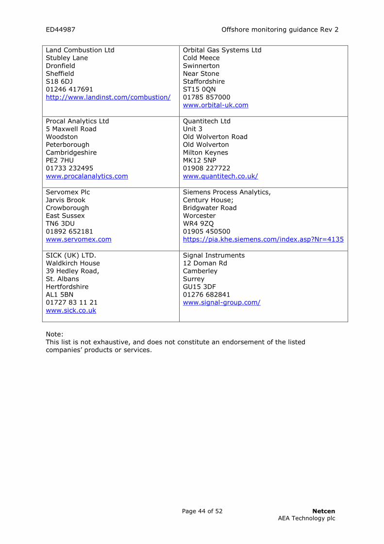
ED44987 Offshore monitoring guidance Rev 2
Page 44 of 52 Netcen AEA Technology plc
Land Combustion Ltd Stubley Lane Dronfield Sheffield S18 6DJ 01246 417691 http://www.landinst.com/combustion/
Orbital Gas Systems Ltd Cold Meece Swinnerton Near Stone Staffordshire ST15 0QN 01785 857000 www.orbital-uk.com
Procal Analytics Ltd 5 Maxwell Road Woodston Peterborough Cambridgeshire PE2 7HU 01733 232495 www.procalanalytics.com
Quantitech Ltd Unit 3 Old Wolverton Road Old Wolverton Milton Keynes MK12 5NP 01908 227722 www.quantitech.co.uk/
Servomex Plc Jarvis Brook Crowborough East Sussex TN6 3DU 01892 652181 www.servomex.com
Siemens Process Analytics, Century House; Bridgwater Road Worcester WR4 9ZQ 01905 450500 https://pia.khe.siemens.com/index.asp?Nr=4135
SICK (UK) LTD. Waldkirch House 39 Hedley Road, St. Albans Hertfordshire AL1 5BN 01727 83 11 21 www.sick.co.uk
Signal Instruments 12 Doman Rd Camberley Surrey GU15 3DF 01276 682841 www.signal-group.com/
Note: This list is not exhaustive, and does not constitute an endorsement of the listed companies’ products or services.

DECC PPC (Combustion Plant) Offshore Emissions Monitoring Guidance
Page 45 of 52 Revision 2 August 2009
Table A4: Portability of instrumented emission analysis systems Portability Techniques NO/NOx SO2 CO O2 VOC EC IR CL EC IR UV EC IR EC PM FID IR Fully b - - b - - b - b b - - Semi b b b b b b b b b b b b Transportable b b b b b b b b b b b b Fixed b b b b b b b b b b b b Notes: 1. Analytical techniques: EC = electrochemical cell, IR = Infra red systems, UV = ultraviolet systems, CL = Chemiluminescence, PM = Paramagnetic, FID = Flame ionisation detector. Table A5: Uncertainty and price of instrumented emission analysis systems Portability Price Uncertainty, % EC IR UV CL PM FID EC IR UV CL PM FID Fully L - - - M - 25/50 - - - 25 - Semi M M M M M M 10/25 10/25 10/25 10 10/25 10/25 Transportable M/H M/H M/H H M/H H 10/25 10/25 10/25 10 10 10/25 Fixed M/H M/H M/H H M/H H 10 10 10 10 10 10 Notes: 1. Analytical techniques: EC = electrochemical cell, IR = Infra red systems, UV = ultraviolet systems, CL = Chemiluminescence, PM = Paramagnetic, FID = Flame ionisation detector. 2. Prices : L= Low, M= Medium, H= High

DECC PPC (Combustion Plant)
Offshore Emissions Monitoring Guidance
Page 46 of 52 Revision 2 August 2009
Appendix B Data Calculations
CONTENTS
Standardisation of emission data Calculation of emission factors Emission factors for gaseous fuel Emission factors for oil fuel Annual emission

DECC PPC (Combustion Plant) Offshore Emissions Monitoring Guidance
Page 47 of 52 Revision 2 August 2009
Standardisation of emission data Measured emission concentrations are standardised to a mass concentration in dry flue gas at the relevant reference oxygen content and at 0°C, 101.3 kPa. The reference oxygen concentration is 3%, for boilers and other furnaces burning gaseous or liquid fuels or, 15% for gas turbines or diesel engines. The calculation is detailed below: [X]15% = [x]m . MW . (20.9-[ O2]ref)
22.4 (20.9-[O2]m) Where: [X]15% is the standardised mass concentration of the pollutant in mg m-3. [x]m is the measured concentration in ppm by volume for a dry flue gas. MW is the relative molecular mass of the pollutant (see note below). 22.4 is the volume occupied by 1 mole of an ideal gas at 0°C, 101.3 kPa. [O2]m is the measured O2 concentration on a dry basis. [O2]ref is the reference O2 concentration on a dry basis (3 or 15%) This calculation is appropriate where pollutant and O2 concentrations are measured on a dry basis. NOx emission concentrations and emission factors are defined in terms of NO2. Hence, the relative molecular mass used for NOx is 46. UHC emission concentrations and emission factors are usually defined in terms of carbon. Hence, the relative molecular mass used for UHC is 12 but this may be modified further for a FID measurement to account for different response factors due to choice of calibration gas. Calculation of emission factors An emission factor relates the release of a pollutant to a process activity. For combustion processes, emission factors are commonly described as the mass of pollutant released per unit of fuel burned. An emission factor can be calculated in several ways; the approach adopted uses the standardised pollutant emission concentrations and the fuel analysis. This approach avoids measurement of exhaust gas flow and fuel flows. Measurement of exhaust gas flow can have a high uncertainty and may not be practical at many industrial plants. Emission factors for gaseous fuel Gaseous fuel analysis data are for inerts (for example CO2 ,N2 ) and for hydrocarbons (for example CH4, C2H6). An example fuel analysis is provided in Table B1 below.

DECC PPC (Combustion Plant) Offshore Emissions Monitoring Guidance
Page 48 of 52 Revision 2 August 2009
Table B1: Example fuel analysis
Component Mole %
N2 1.38
CO2 0.27
CH4 97.65
C2H6 0.67
C3H8 0.02
nC4H10 0.00
iC4H10 0.01
nC5H12 0.00
iC5H12 0.00
C6+ 0.00
ppm
H2S 1 (max)
Notes:
The fuel analysis and combustion calculations are used to determine the stoichiometric air requirement and dry flue gas volume per cubic metre of fuel gas. The calculations assume an ideal gas. A dry flue gas volume was then calculated for an O2 concentration of 15%. Generally, the flue gas volumes generated from combustion of each fuel gas component were calculated in accordance with the following equations. CXHY + (X+(Y/4)O2 = X CO2 + (Y/2) H2O For combustion in air, each cubic metre of oxygen is associated with (79.1/20.9) cubic metres of nitrogen. C6+ Hydrocarbons were treated as hexane. The calculated dry flue gas volume at stoichiometric conditions (DFGVSC) can then be calculated (DFGV15) for the required oxygen content. For example at 15% oxygen: DFGV15 = DFGVSC . (20.9/(20.9-15)) For the example fuel analysis, the dry flue gas volume at 15% oxygen was calculated to be 30.0 m3 per m3 of fuel at 0°C, 101.3 kPa (note that fuel gas volumes are generally reported at 15°C). A pollutant emission factor (EF) can hence be calculated by multiplying the standardised pollutant concentration by the dry flue gas volume at the same reference oxygen content. For example at 15% oxygen: EF = [X]15% . DFGV15 Emission factors are reported in several ways and these are generally recalculated using physical or other properties of the fuel. For example, a thermal emission factor can be derived by dividing the emission factor calculated above by the calorific value of the gas. This is usually the net (inferior) CV but USEPA tends to use the gross (superior) CV. EFthermal = EF CV

DECC PPC (Combustion Plant) Offshore Emissions Monitoring Guidance
Page 49 of 52 Revision 2 August 2009
Where: EFthermal is the thermal emission factor expressed in units to suit the user (for example g GJ-1). CV is the calorific value in appropriate units or factors to suit the final units of the emission factor. Similarly, a mass emission factor can be derived using the fuel density: EFmass = EF
d Where: EFmass is the mass based emission factor, expressed in units to suit the user (for example g kg-1, tonne tonne-1). d is the density of the fuel gas incorporating appropriate units or factors to suit the final units of the emission factor. It should be noted that many gaseous fuel conditions are defined for a gas volume at a temperature of about 15°C. However, all concentrations and emission factors presented in this report have been prepared for a gas volume at 0°C. Emission factors for oil fuel Unlike gaseous fuels, oil fuel used offshore tends to be much more consistent. The US Environmental Protection Agency (USEPA) provides stoichiometric dry flue gas volume for fuel oil. The USEPA data can be found in USEPA Method 19 (US Code of Federal Regulations, Title 40 Part 60, Appendix A)14. The USEPA data is presented as the volume of dry flue gas at 20°C associated with the gross thermal input of the fuel. These USEPA conditions are not consistent with UK practice and consequently some manipulation of the data is required. Calculations assume an ideal gas. The gas oil properties assumed for the fuel used are detailed in Table B2. Table B2: Gas oil properties
Property Data Source
Sulphur content, % w/w 0.15 Maximum sulphur content Density, tonne m-3 0.857 DTI Energy statistics CV (gross), MJ kg-1 45.6 DTI Energy Statistics CV (Net), MJ kg-1 42.8 Gas oil data sheet USEPA FD factor, m
3 J-1 dry stoichiometric flue gas volume at 20°C, gross heat input
2.47 x 10⁻⁷ USEPA Method 19
CO2 emission factor, tonne tonne-1 3.14
National Atmospheric Emission Inventory
The USEPA dry flue gas volume at stoichiometric conditions was recalculated to provide the flue gas volume (DFGVref) for the required oxygen content (3 or 15%). For example at 15% oxygen: DFGV15 = FD . (273/293).(20.9/(20.9-15)). (45.6 x 10
6) The dry flue gas volume at 15% oxygen was calculated to be 37.2 m3 per kg of fuel.
14 Available at http://www.epa.gov/ttn/emc/methods/method19.html

DECC PPC (Combustion Plant) Offshore Emissions Monitoring Guidance
Page 50 of 52 Revision 2 August 2009
A pollutant emission factor (EF) can hence be calculated by multiplying the standardised pollutant concentration by the dry flue gas volume at the same reference oxygen content. For example at 15% oxygen: EF = [X]15% . DFGV15 Emission factors are reported in several ways and these are generally recalculated using physical or other properties of the fuel. For example, a thermal emission factor can be derived by dividing the emission factor calculated above by the calorific value of the gas. This is usually the net (inferior) CV but USEPA tends to use the gross (superior) CV. EFthermal = EF CV Where: EFthermal is the thermal emission factor expressed in units to suit the user (for example g GJ-1). CV is the calorific value in appropriate units or factors to suit the final units of the emission factor. Similarly, a volume emission factor can be derived using the fuel density: EFvol = EF . d Where: EFvol is the volume based emission factor, expressed in units to suit the user (for example g litre-1). d is the density of the fuel gas incorporating appropriate units or factors to suit the final units of the emission factor . Annual emissions These can be derived from the annual fuel consumption for each combustion device (or installation) and the pollutant emission factor derived for the typical load. Fuel consumption data may be available or can be calculated to reflect the actual or predicted installation ratings. For example for a combustion device typically running at 90% load. Qf = QI x (3600) x (0.9)/CV Where: Qf = Hourly Fuel flow (volume or mass basis) QI = Net rated thermal input of installation (MWth) CV = Inferior calorific value on volume or mass basis The annual emission of a component is given by : Annual emission = typical fuel flow x annual hours x emission factor For a field lifetime of 15 years and assuming the parameters will remain the same, the total emission of would be 15 times the annual emission.

DECC PPC (Combustion Plant) Offshore Emissions Monitoring Guidance
Page 51 of 52 Revision 2 August 2009
Example Calculation For a gas turbine producing 3 MW electricity, the following emission data were obtained: Table B3: Example emission data
Gas Turbine Generation
MW Measured O2
%, dry
Average concentrations, ppm by volume, dry
NOx CO UHC GT1 3 18.43 49.4 8.33 1.5
The standardised emission concentrations are given by the following equations: For NOx [NOx]15% = [49.4] . 46 . (20.9-15)
22.4 (20.9-[18.43]) = 242.7 mg m-3 (as NO2 )
For CO [CO]15% = [8.33] . 28 . (20.9-15)
22.4 (20.9-[18.43]) = 24.9 mg m-3 For UHC The measured values are expressed as propane (C3) equivalent concentrations. The standardised concentration is expressed as carbon and hence the molecular weight is 36 (12 x 3). [UHC]15% = [1.5] . (36) . (20.9-15)
22.4 (20.9-[18.43]) = 5.8 mg m-3 (as C) NOx emission factors The emission factors were calculated as described above using the example fuel analysis to derive the following fuel properties for a gas at 0°C, 101.3 kPa: Stoichiometric dry exhaust gas volume = 8.47 m3 per m3 fuel Dry exhaust volume at 15% O2 = 30.0 m3 per m3 fuel Inferior (NET) Calorific Value (for CV reference conditions of 15°C, 101.3 kPa but a gas volume at 0°C, 101.3 kPa ) = 35.5 MJ m-3 Gas density (at 0°C, 101.3 kPa ) = 0.73 kg m-3

DECC PPC (Combustion Plant) Offshore Emissions Monitoring Guidance
Page 52 of 52 Revision 2 August 2009
EF = [X]15% . DFGV15 = (242.7) . (30.0) . 10-3 = 7.28 g m-3 (g NO2 per m
3 fuel at 0°C, 101.3 kPa) EFthermal = EF CV = 7.28 . 103 35.5 = 205 g GJ-1 (g NO2 per GJ net thermal input) EFmass = EF
d = 7.28 . 10-3 0.73 = 0.0099 tonne tonne-1 (tonne NO2 per tonne fuel)