Embed Size (px)
Citation preview
OFFSHORE PIPELINE
REPAIR METHODS
AND COSTS DIAPIR AREA ALASKA (OCS LEASE SALE NO 87)
Addendum to OFFS HO TRANSPORTATION
I COSTS
JOB NO 226902 NOVEMBER 1984
RJ BROWN AND ASSOCIATES ZUG SINGAPORE
TABLE OF CONTENTS
CHAPTER 1 INTRODUCTION AND SUMMARY
CHAPTER 2
CHAPTER 3
CHAPTER 4
11 INTRODUCTION
12 SUMMARY
CONCLUSIONS AND RECOMMENDATIONS
2 1 GENERAL 22 REPAIR CONSIDERATIONS
23 PIPELINE REPAIR METHODS
24 REPAIR CASE STUDY
REPAIR CONSIDERATIONS
31 HAZARDS TO PIPELINES
32 TYPES OF REPAIR 33 REPAIR TECHNIQUES
331 Mechanical Sleeve Repair
332 Spool Piece Repair
34 TRENCH FILL-IN RATES
341 Summer Trench Fill-In
342 linter Trench Fill-In
343 Trench Fill-In Summary
PIPELINE REPAIR 41 REPAIR SITE ICE CONDITIONS 42 EXCAVATION AND TRENCH CLEARING
43 PIPELINE REPAIR
431 Pipeline Repair Spreads Consisting of Floating Vessels For Ice Conditions
A Through D
432 Pipeline Repair Spreads Consisting of Submarine Vessels
433 Comparison of Floating Vessel and Submarine Vessel Spread
Costs
434 Pipeline Repair in Ice Condition E
CHAPTER 5 REPAIR CASE STUDY
51 STUDY CASE DESCRIPTION
52 REPAIR SCHEDULE
53 COST ESTIMATE
CHAPTER l
INTRODUCTION AND SUMMARY
11 INTRODUCTION
The subject covered in this report is offshore pipeline
repair methods and costs in Diapir Area Alaska (OCS Lease
Sale 87) This report forms an addendum to the joint
industry study report titled Offshore Pipeline Transporshy
tation Feasibility and Costs Diapir Area Alaska prepared
by R J Brown and Associates (RJBA) in March 1984 under
job no 2269-01
The objectives of this study were to determine equipment
requirements and their costs to carry out offshore pipeline
repair in Diapir Area water depths 60 feet to 330 feet on
a year-round basis It was assumed that pipeline repair
work will be performed using conventional repair techniques
and tools These techniques include the repair of smal 1
dents and leaks by clamping a mechanical sleeve around the
damaged area to the repair of a large damage such as a
line break by replacing a section of pipeline with a spool
piece about 500 feet in length Pipeline repair work
involving the replacement of a larger length of pipeline
was considered new pipeline installation work This will
require the mobilization of an entire pipeline installation
spread and was discussed in the main study report
The subject of detecting a pipeline leak or a damage is not
discussed in this report It was assumed that a leak will
be detected and confirmed by instrumentation in the pipeshy
line system and that its approximate location will be
known The repair operation begins with a survey and
inspection task to determine the exact damage location and
the extent of damage
12 SUMMARY
The following paragraphs summarize the contents of each
chapter contained in this report
Conclusions and Recommendations
Chapter 2 summarizes the conclusions and recommendations
from each subsequent chapter
Repair Considerations
Repair considerations are discussed in chapter 3 These
considerations include a discussion on hazards to pipelines
in Diapir Area repair techniques and problems associated
with implementing the repair techniques in Diapir Area on a
year-round basis Trench fill-in due to natural sedishy
mentation and ice keel activity influence the repair
equipment requirements and costs Estimates of trench
fill-in due to sedimentation and ice keel activity in water
depths of 65 feet and 100 feet are provided
Pipeline Repair
Chapter 4 provides details of equipment requirements to
carry out pipeline repair work in Diapir Area Surface
vessel and submarine vessel repair spreads are defined for
Ice Condition A through D Additional Ice Conditions E
consisting of a grounded massive ice feature and Ice
Condition F consisting of a stable ice sheet are
discussed Equipment costs day rates and spread producshy
tivities are given
1-2
Repair Case Study
A case study of a repair scenario is provided in chapter 5
A repair schedule and a cost estimate are given for the
repair of a 36 inch oil trunk line in 100 feet water depth
The repair cost includes the following cost elements
leak location
survey and inspection
repair material
mobilization and demobilization costs of repair
spread
trench clearing and excavation costs
pipeline repair costs
logistic support costs and
pipeline pressure testing costs
1-3
CHAPTER 2
CONCLUSIONS AND RECOMMENDATIONS
21 GENERAL
This chapter contains the conclusions of the study sumshy
marized chapter by chapter Where applicable recommendashy
tions for additional studies or development effort are
presented
22 REPAIR CONSIDERATIONS
The major hazards Diapir Area pipelines will be exposed to
are ice keels and permafrost degredation Hazards of
corrosion instability and ship anchors are far less
significant in this area compared to other major pipeline
areas in the world
Regular inspection of the pipelines for signs of internal
and external deterioration can minimize unexpected pipeline
shutdown caused by leaks Such deterioration can be
repaired during ice-free periods The exception will be
the case of a leak caused by a vessel anchor or an ice
keel Since pipelines in Diapir Area will be trenched to
protect them from ice keels the chance of such damage
occurring is expected to be remote
Conventional pipeline repair techniques can be used in
Diapir Area However techniques that require bulky repair
tools are more difficult to implement in more severe Ice
Conditions Thus mechanical connector type repair is
easier to implement when compared with repair methods using
hyperbaric welding techniques
The transport of a spool piece to work site can be achieved
2-1
in a number of ways Both bottom tow and off-bottom tow
methods can be used without difficulty The off-bottom tow
method has the advantages of low tow vessel horsepower
requirements and ease of manipulation at repair site This
technique is well suited for under ice repair work
The soil fill-in to the pipeline trench has a significant
impact on repair effort This soil movement is caused by
natural sedimentation and soil movement due to ice keel
action on the sea floor The proportion of the trench
cross-section which must be excavated for damage inspection
and repair will increase as years go by In shallow water
depth with high bed load transport rates and in areas with
high rate of ice keel reworking of the sea bed the trench
may be fully filled-in and may require a major effort for
pipeline repair access excavation
23 PIPELINE REPAIR METHODS
Pipeline repair spreads will be exposed to the four operatshy
ing Ice Conditions defined in the main study report Two
additional Ice Conditions are defined for pipeline repair
purposes They are grounded massive ice features and
stable ice platforms
Trench clearing work for pipeline access must be carried
out using remotely operated diver operated dredge pumps
with hydraulic booms and cutterheads Such dredging units
are currently available Power requirements for a dredge
pump is estimated to be about 100 HP
Floating and submarine vessel based pipeline repair spreads
can be used in Diapir Area The floating vessel repair
spread wil 1 consist of a pipeline repair vessel supply
vessel and icebreaker vessels Submarine vessel repair
spread wil 1 consist of a submarine repair vesse 1 and a
2-2
submarine support vessel Autonomous work submarines are
currently under manufacture and a pipeline repair submarine
can be developed from present day technology A comparison
of repair costs shows that the submarine vessel repair
spread will cost less to operate in Ice Conditions C and D
A submarine vessel operating base is needed for year-round
pipeline repair work The submarine vessel base can be
located at a port designed for year-round operation or at
an offshore platform If the latter method is to be used
the design of arctic offshore platforms must incorporate
such facilities A preliminary design of such a facility
is recommended to determine its implications on platform
design and construction Furthermore a preliminary design
study of an arctic pipeline repair submarine is recommended
to develop design and performance specifications for such a
vessel
Ice Condition E a grounded massive ice feature offers the
most challenging repair situation Pipeline repair in this
situation will be slow and costly Grounded ice features
are commonly found in the transition zone water depth 50
to 75 feet during the winter months However they can be
present in shallower water as well as in deeper water
Bypass pipelines across the transition zone can reduce the
risk of total pipeline shut down in case of a line damage
in this area
24 REPAIR CASE STUDY
The study case consists of pipeline repair work on the
Scenario A 36 inch Oliktok point trunkline in 100 foot
water depth in Ice Condition C The pipeline was repaired
with a 300 foot long replacement spool piece using a
submarine pipeline repair spread The estimated repair
duration and cost were 13 weeks and $ 13 7 willion respecshy
tively
2-3
CHAPTER 3
REPAIR CONSIDERATIONS
31 HAZARDS TO ARCTIC PIPELINES
Arctic pipelines like their counterparts in other parts of
the world are subjected to a number of hazards In addishy
tion to the hazards such as ship anchors corrosion
hydrodynamic and soil instability arctic pipelines will be
exposed to the hazards of ice keel activity and permafrost
degradation A brief discussion of each of these hazards
as applied to arctic offshore pipelines is given below
Internal and External Corrosion
Arctic pipelines will be subjected to both internal and
external corrosion External corrosion of a pipeline is
mitigated by corrosion coating and cathodic protection
Regular inspection of the pipeline can be made to ensure
the integrity of the cathodic protection system over the
operating life of the pipeline Similarly pipeline inshy
ternal corrosion can be mitigated by use of proper
operating procedures and corrosion inhibitors Regular
internal inspection with inspection pigs can detect
internal corrosion problems and steps can be taken to
remedy the situation In arctic pipelines such inspection
tasks can lead to preventative maintenance work where any
defective parts of the pipeline system can be repaired
during ice-free periods whether such defects be found in
the corrosion coating the cathodic protection system the
pipe steel or wherever
Mechanical Damage
The risk of oechanical damage to pipelines caused by ship
anchors will be relatively low in the arctic waters
3-1
compared to other major pipeline areas of the world This
is because during most parts of the year there will be very
little surface traffic and also because arctic pipelines
will be trenched for protection from ice keels However
this hazard cannot be totally eliminated due to the possishy
ble presence of construction vessels
lvdrodynamic and Soil Instability
To properly designed and constructed pipelines these two
hazards will not pose a threat because of the moderate
hydrodynamic environment in the arctic and the relatively
stable sea floor soils in Diapir Area
Ice Keels
Ice keels constitute a major hazard to arctic pipelines
To reduce their exposure to this hazard arctic pipelines
are installed in deep trenches This subject was discussed
in detail in section 35 of the main study report
Permafrost Degradation
Offshore arctic pipelines may encounter areas of
permafrost Hot pipelines can cause the permafrost to melt
and in thaw unstable soils may lead to a loss of
foundation support which in turn leads to progressive
settlement and eventual pipeline failure in the form of a
line buckle or rupture Repair to pipe1ine damage caused
by this type of failure is complex not only must the pipe
be repaired it must also be provided with a firm
foundation to prevent any further settlement This type of
pipeline situation may be rectified by providing piled
supports to the repaired pipeline or by providing a thaw
stable soil foundation under the pipe
3-2
32 TYPES OF PIPELINE REPAIR
The emphasis of this study was to determine the equipment
required to carry out year-round pipeline repair work in
Diapir Area It was considered that conventional repair
techniques and tools will be used for the repair tasks
These techniques and tools consist of the following
Installation of a mechanical sleeve around the
pipeline to repair small damages such as gouges
dents and small leaks
Replacing a pipe section with a spool piece to
repair large dents buckles or line rupture The
spool piece can be a few feet long to a few hundred
feet long
If a very long section of pipe must be replaced that is a
section too long to transport by the methods discussed in
section 33 then an entire pipe-lay spread will have to be
mobilized to carry out the repair This case is considered
as new pipeline installation work and was covered in the
main study report This situation can arise when the
length of the section of the pipeline to be replaced
exceeds 1000 feet
33 REPAIR TECHNIQUES
To carry out each type of repair described in section 32 a
number of operational problems must be overcome These
problems and the appropriate solutions are described below
331 Mechanical Sleeve Repair
A typical split-sleeve clamp is shown on drawing No A-300
To install the sleeve clamp the following tasks must be
3-3
performed
Transport repair clamp accessories and personnel
to repair site
Access pipeline by clearing trench
Remove concrete coating corrosion coating and
clean pipe at repair location
Place clamp around repair pipe section and install
bolts
Seal the annulus between pipe and clamp
To carry out rapid repair work an inventory of repair
clamps suitable for the pipelines in operation must be
maintained It was assumed in this study that such an
inventory is maintained and that there is no lead time
required to procure the repair clamps
Methods and vessels required to transport the repair clamps
and personnel to repair site are addressed in section 43
Accessing the pipeline for repair will require dredging
work to be performed This work has to be performed with
divers assistance as it is necessary to protect the exist shy
ing pipe during this operation Dredging methods and
equipment are discussed in section 42
Soil fill-in will be present in the trench due to natural
sedimentation and soil movement due to ice keel activity on
the sea floor To plan the repair operation it is
necessary to have an estimate of the soil to be removed
from the trench In a real repair operation this estimate
will be prepared during the damage inspection survey For
the purpose of this report estimates of soil to be removed
are provided in section 34 for both natural sedimentation
and ice keel action
3-4
Weight coating and corrosion coating removal pipe cleaning
and clamp installation work will be carried out by divers
using conventional hand tools and power tools
For the purpose of this report it was assumed that the time
required to install the clamp after trench clearing is five
days in calm open water conditions
332 Spool Piece Repair
Spool piece repair of a pipeline can be carried out by a
number of methods They are
Surface tie-in repair
Hyperbaric welded repair using
Alignment frame
H-frames
H-frames and weld ball
Mechanical connector repair using
Swivels and non-misalignment connectors
Length compensator and misalignment connectors
A brief discussion of these methods and their applicability
to Diapir Area is given below A summary is provided in
Table 31
Surface Tie-In Repair
A typical surface tie-in repair operation is depicted on
drawing No A-301 In this method the repair section is
cut off and the pipe is lifted to the surface by the repair
vessel A spool piece section is welded to the pipe and
then it is lowered to the sea floor The maximum length of
pipe that can be cut out and repaired with this method is
limited to about 100 feet In Diapir Area this method can
be used only in Ice Condition A or open water conditions
3-5
Even in Ice Condition A a disadvantage is the amount of
dredging required to lower the welded section of the pipe
to the required depth of soil cover
Hyperbaric Welded Repair using Alignment Frame
A typical alignment frame is shovm on drawing No A-302
The alignment frame is used to align the ends of pipe for
welding This method will only be suitable for Ice Condishy
tion A mainly because of the difficulties in handling a
large frame from the work vessel in the presence of sea
ice
Hyperbaric Welded Repair using H-Frames
H-Frames smaller and lighter than an alignment frame can
be used to align the pipe ends Here the H-Frames are
positioned such that sufficient length of pipe can be
lifted off the sea floor to provide the flexibility
required to align the pipe ends This method can be used
in Diapir Area in all ice conditions However the
handling of the hyperbaric welding chamber with umbilical
lines may pose ice related operational problems A typical
Hyperbaric welding chamber is depicted in drawing No
A-303
Hyperbaric Welded Repair using H-Frames and Weld Ball
Drawing No A-304 shows a typical weld ball The introducshy
tion of the weld ball greatly reduces the accuracy of
alignment required to make the weld This method is also
suitable for arctic pipeline repair work because of the
reduced time required to complete the repair work
However the comments made in the previous section
regarding the hyperbaric welding chamber are valid for this
method
3-6
Mechanical Connector Repair using Swivels and Non-Misalign
ment Connectors
A typical spool piece installation is shown on drawing No
A-305 Use of swivels eliminates the need to achieve
precision alignment of pipe ends
Mechanical connectors must be secured to the ends of the
pipeline after cutting out the repair section The
non-misalignment col let type connector such as those
manufactured by Cameron Iron Works is not specifically
built for pipeline repair work Its use in this system
requires that both ends of the pipe are lifted to the
surface to weld on one connector half and attach the tie-in
base Thus this system can only be used in Diapir Area
under Ice Condition A
Mechanical Connector Repair with Length Compensation and
Misalignment Connectors
In this system the need for swivels is eliminated by using
misalignment ball connectors Length adjustment of the
spool piece is accomplished via a length compensator The
connectors are mechanically attached to the pipe ends
This system is well suited for Diapir Area in all Ice
Conditions
Pipeline Repair Tools
Mechanical connection devices are widely used in offshore
pipeline repair in place of hyperbaric welding Two basic
types of connection devices are available namely the
sleeve type which is used to attach pipe ends together
and interlocking types which consist of male and female
assemblies For repair both types are needed as the
appropriate connection assembly must first be attached to
3-7
the prepared pipe end
Eight representative connectors are briefly reviewed in
terms of advantages and disadvntages It is noted that
depending on market conditions and technological
advancements connectors available at the time of repair
may be significantly different from those described The
following connector devices are presently available
Cameron Iron Works Collet Connector
Comex Connector
Big Inch Marine Flexiforge
Daspit Brothers PermaLock and PermaKupl
Hughes Hydrotech Hydrocouple
Plidco Flange
Star Subsea Maintenance Ltd Starcouple
Gripper Inc Grip and Seal Couplings
These devices are depicted on drawing A-306 their relative
advantages and disadvantages are presented in Table 32
The connectors that accomodate axial misalignment
(Hydrotech Gripper Comex) all utilize a ball type
coupling as shown on drawing No A-307
A typical repair system utilizes a spool piece two
ball-type connectors and a gripping device at each end
The gripping sleeves which allow for length adjustment
are first slid over the bare pipe ends The spool piece is
then lowered into position Gripping devices and seals are
set and tested the connectors are set and tested and the
repair is completed Drawing No A-308 through A-310 show
pipeline repair operation with mechanical connectors based
on a technique used by Hughes Hydrotech Other
manufacturers such as Gripper Inc and Big Inch Marine
Systems (BIMS) embody similar arrangements Pipeline
repair systems offered by these three manufacturers are
3-8
summarized beloV tbe costs are for JtJST Class 900 systems
Hake Descr tion Cost $
12 75tt 0D 2lt OD 36 0D
Gripper Utilizes 2 ball-type 140000 360000 860000
connectors nnd a grip
a11d seal device a each
end Joint is made by
tightening collct grips
Big Inch Joint is made by forging a 50000 220000 570000
connection h~~ on to each
pipe e~d us a Secial
ma~drel che systeQ in-
eludes connectors to each
e~C and two ball-cype con-
necors For pipe 16 inch
and abo~e a lengch coo-
Hughes Two hy~ro ccunle connectors 95000 244000 520000
Hydro are used co 2ak2 connections
to the pipe enCs A spool
piece with two ball-tye
connectors is used for the
tie-in
The costs given above for 21 inch and 36 inch systems
include a length compensator
In this study it was assumed that spool piece reoair will
be carried out using mechanical [)all corrnectors -Vith a
length compensator Specific problems encountered with this
type of repair are discussed below together with their
respective solutions
To carry out a spool piece repair the following tasks must
be performed
fabricate spool piece
transport spool piece handling equipment tools
and personnel to job-site
excavate to expose damaged pipe section
cut pipe section and remove
install mechanical connectors to the pipe ends
maneuver repair spool piece into location and
align pipe ends with repair pipe
activate mechanical connectors and complete
connection
An inventory of spare pipe mechanical connectors swivels
and length compensators must be maintained to eliminate
waiting time for the procurement of these articles
The transportation of the spool piece to the repair site
can create a special problem Short lengths up to 100 feet
or so can be fabricated on the work vessel if a surface
vessel is used Longer lengths of pipe can be towed to the
repair site on bottom or off bottom The off bottom tow
method can be particularly attractive in the arctic during
the ice covered months of November to June A typical
spool piece prepared for off bottom tow is shown on drawing
No A-311 In this method the pipeline spool piece is
floated 6 to 10 feet off the sea floor with buoyancy tanks
and drag chain assemblies The drag chains are also used
to maintain the hydrodynamic stability required during the
tow operation The low currents near the sea floor in
Diapir Area during the ice covered months mean that the
3-10
drag chain required to maintain tow spool piece stability
is low The required chain weight to ensure hydrodynamic
stability of the tovJecl spool piece and the estimated to
loads are given below for towing during ice covered months
of November to June
ipe Nominal Chain Drag (2) Estimated (b)
Dia111e er Inch 100 ft Tow Load (lb100 ft)
L6 40 60
60 90
36 90 135
a Based on a winter design current velocity of 05
feetsec
b Based on a chain to sea floor resistance factor of
1 5
Thus the spool piece can be towed during the ice covered
months with a lightly powered vessel such as a work submashy
rine Up to 1000 feet long section can be towed with a
thrust of 1 000 lbs This method has another attraction
namely the relative ease of maneuvering the work piece
into loca tion This can be accomplished with diver
operated manual winches
The bottoo tormiddotJ method cart be used to transport trte pipe
spool piece to location in both summer and middotinter lIigh -
1-corsepo~middotJer icebreakers can be used to per~on ttLLS task
Table 613 in chapter 6 of the main study report presented
length of pipe segments that can be bottom towed by tow
vessels having pull capabilities of 150 300 and 500 tons
Pine lat1r1cbing in Vinter months bullJill a1sc pose special
3-ll
problems Pipe can be launched through a hole cut in the
ice It will be possible to drag the pipe on fast ice to a
water depth the tow vessel can reach and lower it through
a slot cut in the ice
The effort of trench clearing work will be considerably
greater for spool piece repair work This work will have
to be diver assisted Estimates of dredging volumes are
presented in section 34
Cutting pipe sections maneuvering the spool piece into loshy
cation and making end connections will be carried out by
conventional means with diver assistance
In this study it was assumed that the time for replacing
the spool piece once the trench has been cleared is 15 days
in calm ice-free water
34 TRENCH FILL-IN
It is expected that deep trenches will be required for
pipelines in the study area to afford protection from ice
scours These trenches will initially be open following
installation of the pipeline thus allowing easy access for
inspecting locating possible leaks and carrying out repair
operations As these trenches fill-in over the life of the
pipeline however the volume of sediment which must be
excavated to access the pipe can become quite large and
this would therefore be a major consideration in any repair
operation Natural trench fill-in will result from marine
sedimentation and ice keels gouging the seabed During the
brief arctic open water season waves and steady currents
can erode the trench sides and deposit sediment in its
bottom
Waves and currents in the lagoons behind the coastal
barrier island are relatively small but the water depths
are shallow Therefore small waves may be effective at
filling in pipeline trenches Areas seaward of the barrier
islands are subject to more substantial wave action over a
significant open water season duration Further offshore
the open water seasons are progressively shorter and there
are more numerous sea ice invasions This combined with
the limitation in the fetch length due to the proximity of
the permanent pack ice acts with the greater water depths
to reduce the rate of trench fill-in during the open water
season
During the ice covered season and to a 1 imi ted degree
during open water conditions ice keels can drag along the
bottom causing ice scour marks The plowing associated
with this ice scouring can push seabed sediment into the
pipeline trench There is little movement of the winter
fast-ice behind the barrier island or in shallow water and
ice gouging is expected to push only limited amounts of
soil into a trench in those areas Further offshore
however the depth and rate of occurence of ice gouges is
greater and the rate of trench fill-in due to seabed
reworking will be much more significant compared to the
sedimentation rate
The analysis methods utilized to evaluate trench fill-in
due to sedimentation and ice gouging are rigorous but
include several simplifying assumptions about the nature of
marine processes Additionally because of the limited
scope of work for the present study data on waves curshy
rents sea bottom conditions and ice gouging have only been
developed and synthesized at a reconnaissance level These
assumptions are deemed adequate for the purposes of this
study However it must be kept in mind that fill-in rates
herein determined are only first order estimates and are
limited to the sediment types seafloor conditions and
3-13
trench profiles assumed in the test case examples
341 Summer Trench Fill-In
Marine sedimentation in seafloor trenches can develop from
numerous natural processes These processes are normally
driven by ocean waves and currents and they are commonly
influenced by the local input of sediment as well as the
type of sediment on the sea floor The geometry of the
seafloor itself can also be important as depressions
especially sharper ones tend to preferentially collect
sediment
In general the marine sedimentation processes can be
divided into two classes One class results from a slow
uniform setting of fine suspended sediment onto the sea
bottom Although this process can be locally important it
is unlikely to be dominant in wide areas of the North
Alaska continental shelf because the bottom sediments are
primarily silts and fine sands Such silts and fine sands
tend to be transported and deposited by the second class of
marine sedimentation processes marine bedload processes
The processes resulting in the transport of marine bedload
sediment along with the resulting deposition and erosion
have only recently been quantified Even in the much
simpler river environment where bedload sediment is
transported by a nearly steady and uniform current the
science of predicting erosion and deposition patterns is
not well developed In the marine environment the proshy
cesses are greatly complicated by the unsteadiness of near
bottom fluid velocities resulting from the combined action
of waves and currents These processes are strongly
nonlinear and no complete analytic solution has been found
Modern methods for evaluating marine bedload transport
3-14
often rely on various semi-empirical relationships between
near bottom fluid stress and the instantaneous rate of
sediment transport and corrmanly form the basis of numerical
models One such model was originally developed by Madsen
and Grant (1976) for use in the engineering of a nuclear
power plant which was to be located off of the New Jersey
Coast (but which was never built) This model depended
upon laboratory work done by numerous people at the sedishy
mentation research laboratory of Berkley University as well
as parallel work at the Danish Hydraulics Laboratory most
notably by Jonsson (1966) A similar model has been used
by Niedoroda et al (1982) to compare computed fill-in
rates against those measured in Southwest Ocean Outfall
test pits located off the California Coast south of San
Francisco Results of this comparison were surprisingly
good A derivative of this model was selected for use in
the present project to estimate the rate of pipeline trench
fill-in during open water conditions
Environmental Data for Sedimentation Analysis
The environmental parameters affecting the transport of
sediment in the vicinity of the proposed pipeline trenches
include
wave height period and direction
steady current velocity and direction
duration and spatial extent of summer open
water
Each of these environmental conditions vary significantly
throughout the Diapir Lease Sale Area and available non-
propriety data are 1 imi ted A set of wave current and
open water season conditions which are representative for
the study area were selected for use in this analysis A
site approximately 25 miles north of Oliktok Point with 65
3- l 5
to 100 ft water depth was considered
The summer wave and current conditions in the Alaskan
Beaufort Sea result primarily from local wind conditions
Wind speed and direction data for September at Oliktok
(Climatic Atlas) were utilized along with the open water
fetch length rose to estimate the directional percent disshy
tribution of significant wave heights The total percentshy
age distribution for all directions corresponds to the
significant wave height data presented in Table 3-2 of the
main study report Wave periods for each significant wave
height were estimated from available data based on a
constant wave slope
The steady wind induced bottom current speed was approxshy
imated as 2 percent of the wind speed The direction of
the bottom current was established based on the surface
current heading in the same direction as the wind and the
bottom current being reflected off the Alaskan shoreline
The set of wave and steady current conditions analyzed
assume that the wave height and current speed are directly
related via the wind speed Similarly the wave and
current directions are directly related via the wind
direction
Computer Model
The computer model for marine bedload transport which was
used in this project is of a finite difference type The
seafloor was represented by an array of depth points (24
points by 24 points) which are in vector form so that the
seafloor was represented in three dimensions The bedload
transport and resulting patterns of erosion and deposition
in the seafloor trench were computed for each combination
of wave height wave period wave approach direction
bottom current speed and bot ton current direction
3-16
established in the preceding paragraphs
For each combination of the above parameters the computashy
tion of bedload transport proceeded in a fixed manner The
wave period was divided into sixteen sub-intervals A
vector sum of the instantaneous near bottom wave orbital
velocity and the mean bottom boundary layer velocity was
made This sum was used to evaluate a current friction
factor from a Moody relationship a wave friction factor
from a Jonsson-type relationship and a combined wave
current factor according to the algorithm first defined by
Jonsson (1966) The evaluation of the latter parameter
allows the determination of the instantaneous fluid stress
acting on the bottom sediments This fluid stress is
compared to the critical fluid stress necessary to entrain
(ie initiate movement of) bottom sediments using the
well known Shields criteria
If the computed Shields parameter exceeded the critical
Shields parameter then sediment transport during that one
sixteenth of the wave cycle was computed using an
Einstein-Brown relationship The marine bedload transport
which was computed during each or any of the sixteen
sub-intervals of the wave period were summed and normalized
to establish the time-average rate of bedload transport
This computation was made for each grid point of the depth
grid The time averaged bedload transport rates were
multiplied by a time step interval which was selected to be
proportional to the duration of the particular wave and
current conditions in the overall wave climatology
Patterns of erosion and deposition within the depth grid
were computed using a sediment continuity equation The
sediment transport was parameterized as a volume flux
Hence the porosity of the bottom sediment had to be
estimated in order to determine the appropriate patterns of
3-17
sedimentation and erosion
It must be stressed that the Shields relationship and the
Einstein-Brown equation are valid only where the force
which stabilizes bedload sediment against transport is
entirely gravitational This limits the application of
this computational routine to cohesionless sediments such
as sands and silts Strictly speaking even these types of
sediments may be stabilized to unknown degrees by the
presence of organic material such as mucus from infauna in
some continental shelf environments This has been regardshy
ed as a detail which can be appropriately overlooked during
this first order analysis
Trench Fill-In Test Cases
Two test cases were selected to illustrate the approximate
rate of pipeline trench fill-in on the relatively shallow
and silty continental shelf of North Alaska Case 1 was
located at a water depth of 65 feet and Case 2 was located
at a water depth of 100 feet In both cases the seafloor
was assumed to be composed of a homogeneous layer of
granular sediment with a grain size corresponding to the
boundary between coarse silt and fine sand The porosity
was assumed to be forty percent In both cases the
seafloor was taken to have a pipeline trench with sides
slopes of 1 vertical to 25 horizontal In the first case
where the water depth is 65 feet the bottom of the trench
is at a depth of 75 4 feet and has a 10 foot wide flat
area In the second case where the general seafloor is
taken to be at a depth of 100 feet the trench is 231
feet deep making the depth of its bottom at 123 4 feet
This trench is also assumed to have a narrow (10 foot) flat
area at its bottom The same wave and current climatology
has been applied to both test cases but were adjusted for
differences in water depths
3-18
The average duration of open water conditions for Case 1
(65 foot water depth) has been taken as 30 days per year
whereas the average open water duration at the 100 foot
water depth site has been taken as 15 days These average
durations were computed based on the median duration and
variability presented in the previous report Both average
durations are longer than the median durations
The results of applying the above described computer model
and oceanographic data to these test cases are shown in
Drawing Nos A-312 and A-313 Both cases are for a pipeshy
line trench oriented north-south
The estimated sedimentation in the pipeline trench for Case
1 is shown over a ten year period on Drawing No A-312
The general pattern of erosion and deposition in the
pipeline trench is similar during the first and second five
year intervals Erosion tends to dominate the eastern side
of the trench and deposition dominates the western side
This appears to be caused by an asymmetry in the direcshy
tional wave climatology Larger waves from the northeast
tend to dominate the annual climatology These waves are
associated with easterly winds which result in steady
bottom currents with westerly components The fill-in of
the pipeline trench does not agree with the simplistic
pattern of sediment collecting in the trench bottom
Instead the form of the trench actually migrates to the
east as it fills in
The increasing depth of sediment over the pipeline does not
follow a simple linear progression According to the
results obtained with the computer model the pipe is
covered with sediment on the order of 1 to 2J2 feet in
thickness over a period of five years depending on the
pipe diameter During the second five year interval the
sediment cover increases to a thickness on the order of 8
3-19
feet above the pipe If the same pattern continues to
develop the pipe will be buried to near the total pipeline
depth of over 15 ft within 15 years
It is also important to note that the pipe cannot be found
beneath the centerline of the trench as it undergoes the
effects of marine bedload transport The trench actually
migrates while the location of the buried pipe is fixed
Similar results have been experienced in the North Sea and
reported in non-proprietary studies
The results of estimating the fill-in rate during the open
water season for the second test case at a water depth of
100 ft are shown on Drawing No A-313 The effect of the
greater water depth and short open water season are immedishy
ately apparent when this drawing is compared to the previshy
ous one The bottom of the trench is covered by approxishy
mately 2 feet of sediment during the first 10 years This
increases to 3z feet of sediment during the second 10
years and 4lz feet during the final 10 years Thus in a 30
year period only approximately 412 feet of bedload sediment
collect on the bottom of the trench The results of the
change in shape and position of the pipeline trench are
similar in pattern in 100 feet water depth as they were at
65 feet The trench tends to migrate in an easterly direcshy
tion as it fills in
342 Winter Trench Fill-In
The Alaskan Beaufort Sea is typically covered by ice from
October to June and there is very little wave and current
activity which could cause fill-in of the pipeline trench
There is a potential however for ice keels to gouge the
seabed in water depth less than 200 feet If these gouges
intersect the pipeline trench they will push some sediment
in to the trench This reworking of the seabed primarily
3-20
occurs during the winter months but may also be associated
with a summer ice intrusion
Trench fill-in processes due to ice gouges which are
necessary to define the pipeline repair site excavation
requirements are shown on Drawing No A-314 There will be
a general fill-in of the trench by ice gouges which intershy
sect the trench but do not contact the pipeline This type
of previous ice gouge is depicted by Gouge A on the
drawing The volume of soil pushed into the trench by each
gouge is a function of factors including
ice gouge width depth and profile
trench depth width and angle with respect to ice
gouge and
previous trench fill-in due to sediment transport
and ice gouging
Obviously a shallow ice gouge will push only a sflall
amount of soil into the trench A deep gouge will largely
fill a portion of the trench equal to the gouge width plus
the gouge flank widths
If it is assumed that the annual percent of the trench
fill-in is equal to the percent of the seabed reworked each
year the trench fill-in can be characterized by the
following equation
1 - (1 - K) T
Where
GT = proportion of trench length filled in after T years
=proportion of seabed gouged after T years
3-21
K = Fraction of seabed gouged each year
= Summation of gouge widths
survey line length
T Time period in years
Measured valves for K range from approximately 0 01 to
0 02 The percentage of trench fill-in by ice gouging is
shown on Drawing No A-315 for K ranging from 001 to
005
If the pipeline is damaged by an ice keel contact the same
ice keel will push soil into the surrounding trench This
type of local fill-in at the repair site is represented by
Gouge B in Drawing No A-314 Locating the damaged pipe
section and making minor repairs will be simplified if the
site is left exposed in the bottom of the ice gouge If
the pipe is displaced by the ice keel contact or sustains
more than very local damage the pipeline may require
excavating over the full width of the impacting ice gouge
Required excavation volumes will vary as a function of the
following variables
trench depth width and side slope
required excavation length
extent of fill-in due to local ice gouge general
ice gouging and sedimentation
required degree of overdredging
343 Trench Fill-In Summary
The proposed pipeline trenches in less than 200 feet water
depth will experience significant fill-in due to both
sedimentation and ice gouge reworking of the seabed The
proportion of the trench cross-section which must be
excavated for damage inspection and repair will increase
3-22
over the life of the pipeline In shallow water depth with
high bedload transport rates and in areas with high rate of
ice keel reworking of the seabed the trench may be fully
filled in and require a major effort for pipeline repair
access excavation
3-23
TABLE 31 COMPARISON OF REPAIR METHODS
METHOD APPLICABLE ICE CONDITION REMARKS
Surface Tie-in AampF Sensitive to the
Repair presence of sea ice
Hyperbaric Weld using A Bulky equipment Best Alignment Frame used in open water
Hyperbaric Weld using B Hyperbaric chamber may H-Frames pose ice related
operational problems
Otherwise suitable
Hyperbaric Weld using B As above accurate alignment not required
H-Frames and Weld Ball
Mechanical connectors A Pipe ends must be with swivels and non lifted out of water
misalignment connectors to attach connectors
Mechanical connectors D Most expedient repair with misalignment-ball method for Diapir connectors and length Area compensator
CONHECTOR DESCRIPTION LIMITATIONS ADVANTAGES DISADVANTAGES
Cameron Collet connector with sleeve
Cemex Connector
Big lnch Marine Flexiforge
Daspit Brothers Permalok Pennamiddot kupl
Hughes Hydroshytech Hydro Couple
Plidco Flange
Starcouple
Gripper
Hydraulically actishyvated flange exploshysively welded sleeve
Worm screw activates slips and seals with misalignment connector
Cold forging of pipe into collar Used for flange attachment
Bolt Activated packing seals and slips
Hydraulically actishyvated packing seals and slips
Mechanical flange attrtchment with optional backwelding
Cryogenic shrink sleeve of titanium nickel alloy
Bolt activated slips and seals with misshyalignment connector
None
Diamtets less than 16 inch
None
Small diamter pipe only
None
Small diameter pipe
Diameters less than 2625 inch
None
Metallic gasket widespread use with no knovn leaks
Misalignment tolshyerance 15
Metal to metal seal misalignshyment capability available
Lo cost wideshyspread use
Allows plusmn 20 misalignment widespread use rapid installashytion
Cost
Hetal to metal seal
Widespread use with no known leaks Misalshyignment tolerance plusmn lSc
Explosive elding technique experishymental requires pre-installation of connector halves on pipe ends no misshyalign~ent capability
No usage history
No major disadshyvantage
Reliability depends on installation no misshyalignment capability
Elastomeric seals in sleeves Hay require maintenance
Temporary repair reliability depends on installation
No misalignment capashyability
No major disadshyvanage
PREPARATOfJ OF THE IR
10~ middot f I -~--~ BOLTING
middot f ( ~=J l t ==-=== I
~~Wt JOINT INDUSTRY STUDY
Ga RJBAbullL7 R J BROWN AND ASSOCIATES
PIPELll-IE
LOWERING THE
HINGED SPLITshy
SLEEVE OVER
THE LEAK
TO
SECURE ANO
SEAL THE LEAK
INSTALLATION PROCEDURE FOR
SPLIT- SLEEVE CLAMP
NONE JD A-300 0261084 226902
PPiLL~E
LIFT PlPELlNES UNT1L ENDS ARE OUT OF THE WATER
0
STEP I
STEP 2
AND WE_D
0
STEP3
t MOVE SARGE SlDEiYAYS ANO LOWER PPELINE TO BOTTOM RE1VOVE BUOYS AND DAVIT LINES
ORGlNAL FPE POSTCN
STEP 4 PLAN VEW
JOINT INDUSTRY STUDY SURFACE TIE-IN REPAIR
aa RJBA NONE 0261084 226902 A-301JDbullD R J BROWN AND ASSOCIATES
PPE END
HYPER BA RIC WELDING KABITA
PIPE END MANIPULATING CLAMP
PIPE END
WELDING HABIT AT JOINT INDUSTRY STUDY
AND ALIGNMENT FRAME
Gamp RJBA JD19L7 R J BROWN AND ASSOCIATES NONE 261084 226902 A-302 0
SEA
PIPE
TV MONITOR
SEAL
JOINT INDUSTRY STUDY HYPERBARIC WELDING CHAMBER
06 RJBA 0NONE JD 261084 226902 A-303bullD R J BROWN AND ASSOCIATES
PECE
PIPE
ENETATION SUTT CC1~ECTS SLEEpound
TO SPOOL PIEC~ (A20pound SUFftCE --iELO)
FlLLET NELDS AHE BCTrEEN MkCl-lNO FORGpoundIGS
LJTEGRL SEtLs PROTECT FILLET
WELDS
FlLL~T WELDS ARE BETWEEN MACHJJEC FORSNGS
fITEGRAL SEALS PROTECT FILLET Yt(LDS
WELDBALL DESIGNJOINT INDUSTRY STUDY
aa RJBA JD 261084 226902 A-304 0eD R J BROWN AND ASSOClATES NONE
FULL P-ElETRA710N 8UTT WELD CONNECTS SOCXET TO PIPELINE
SURFACE SUPPORT
STEP ONE LOWER TIEmiddotIN ASSEMBLY AND ACTUAshyTORS ONTO TIE-IN BASE
Ibull
l STEP Two ACTUATORS HYDRAULICALLY MAKE
CONNECTION OF COLLET CONNECTORS
l -~-middot
STEP THREE ACTUATORS ARE LIFTED TO SURFACE SWIVEL JOINTS ARE LAID ON SEA BOTTOM
STEP FOUR COLLET FINGERS ARE LOCKED ON MATING HUBS CONNECTION COMPLETED
SPOOLPIECE WITH SWIVELS AND JOINT INDUSTRY STUDY
NON-MISALIGNMENT CONNECTORS
fGililli RJBA 0NONE 261084 226902 A-305JD5L7 R J BROWN AND ASSOCIATES
CAYlR0i - Celle Ctcct IG NCH MAJltJiE -Fe1ifgrct
VICKERS - Eoloiyt Wedttq siv
OSPIT BR_OTHERS-Permc-loi It HUGHES - HYDROTECH-MARK V HydroCoupe
I - P1C fLG(
l ~coltgt(SSbullG l1 0
t-sirrc SCtw
-ft(ll(Vll( ~i~bullOC
0 -lJ1-ltT(IHlt 111ltC
0amp RJBAeL7 R J BROWN AND ASSOCIATES
JOINT INDUSTRY STUDY
PIPELINE CONNECTORS
226901 A-306 0
- -
2 3 4 3 4 5 9
1l bull
~~~~~~~~~~~~~~lfj _--fr1l ~~ ~middot i --------- )-shy
PIPELINE SLEEVE BALL CONNECTOR JOINT
THE HYDROCOUPLE HALVES ARE DRAVN TOGETHER AND LOCKED laquoND SEALED IN PLACE
SLEEVE CONNECTOR
I HYDRAULIC FLUID PORTS 6 LOCKING FINGERS
2 PACKING 7 ACTUATOR RING
3 THRUST COLLAR 8 SEAL
4 SLIP 9 BALL
5 SOCKET BODY 10 SETTING BOLTS
MECHANICAL REPAIR CONNECTORSJOINT INDUSTRY STUDY
G1illlt RJBA eL7 R J BROWN AND ASSOCIATES NONE JO 0261084 226902 A-307
z I
0 UJ _J
100
_J 80 u r IshyC) z ~ 60
r () z UJ 0 Ishy 40 u 0 UJ CJ lt( ishyz UJ ()
0 UJ 0
20
0 0 1 0 20 30 40
TIME AFTER TRENCH EXCAVATED (YEARS)
k= PROPORTION OF SEABED REWORKED BY ICE GOUGES EACH YEAR
JOINT INDUSTRY STUDY TRENCH FILL-IN BY ICE GOUGES
C79 RJBA bullD R J BROWN AND ASSOCIATES NONE JD 21184 226902 A-315 0
CHAPTER I
PIPELINE REPAIR METHODS
41 REPAIR SITE ICE CONDITIONS
Four Ice Conditions that may be encountered by pipeline
installation and trenching spreads in Diapir Area were
defined in section 3 3 of the main study report these
were
Ice Condition A less than 8 inches of first year
ice or less than 2 okta of ice coverage
Ice Condition B less than 3 feet of first year ice
or less than 7 okta of ice coverage
Ice Condition C 3 to 5 feet of ice with ridges and
less than 7 okta of ice coverage and
Ice Condition D greater than 6 feet of ice with
large ridges of 10 to 15 feet high including pack
ice
A pipeline repair spread operating year round may
encounter all four Ice Conditions defined above In
addition two more Ice Conditions Ice Condition E and F
may be encountered by this pipeline repair spread Deshy
scriptions of these two Ice Conditions are given below
Ice Condition E Grounded massive ice feature such
as a ridge an ice is land a rubble pile or a
floeberg with keel dug into the sea floor Ice
keel may or may not be directly on the pipeline
route Hov1ever movement of the ice feature may
pose a threat to the pipeline or to the repair
spread or to both
4-1
Ice Condition F Fast ice stationary and providing a
stable work platform
Pipeline repair work in Ice Condition E is considered as a
special case Pipeline repair methods and costs for working
from a stationary stable ice platform were discussed in a
previous AOGA study Therefore operating in this Ice
Condition is not addressed in this report Drawing No
A-400 shows the major winter ice zones Ice Condition F can
exist around a grounded ice feature and around the grounded
transition zone in winter months
42 EXCAVATION AND TRENCH CLEARING
Soil back-fill in the trench must be removed to access the
pipeline for repair The estimated volumes of soil that
must be removed for two types of pipeline repair operations
were given in section 34 of this report Removal of this
soil must be carried out while the pipeline is still inside
the trench This requires that the operation be performed
under careful control of the equipment operator to avoid
any further accidental damage to the pipeline
Both soft and hard soil material can be expected in the
trench Natural sedimentation will deposit soft material
in the trench whereas ice keel plowing will tend to deposit
hard soil materials Therefore the trench clearing
equipment must be able to handle both types of soil The
trench clearing work is best carried out using a remotely
operated or diver operated dredge pump
Remotely operated and diver operated dredge pumps with
hydraulic booms incorporating cutter heads are currently
available in the market These dredge pumps require a
considerable anount of energy to operate A typical dredge
is shmm on Drawing No A-403 It is a remotely operated 6
inch dredge manufactured by Aluvial Mining and Shaft
Sinking Company of UK This dredge has a hydraulic boom
capable of reaching 30 feet
This dredge absorbs 112 HP during operation and has a
maximum solid handling capability of 200 cubic yards per
hour This solid handling capability reflects ideal
operating conditions In practice when handling soft
sediments it may be possible to obtain a solid handling
rate close to the ideal rates However when hard soils
must be handled such as over-consolidated clays which
require solid cutting and chopping the solid handling
capacity will be greatly reduced For the purpose of this
study it was assumed that an average efficiency of 15 can
be achieved by this pump during trench clearing work where
a mixture of hard and soft soil sediments will be handled
giving an average production rate 30 cubic yards per hour
The hydraulic boom of this dredge pump can be fitted with a
vibrating clay cutting head for handling clayey materials
The dredge pump can be operated from a floating pipeline
repair vessel remotely or with diver assistance In the
case of a submarine pipeline repair vessel the pump can be
mounted inside the vessel with the hydraulic boom built as
an integral part of the submarine An arrangement of this
nature would allow the trench clearing operation to be
carried out under visual observations from the submarine
The 100 HP energy requirement can be easily met when tbe
pump is operated from a surface supported pipeline repair
vessel For an autonomous submarine vessel however this
energy requirement will dictate that the vessel power plant
be increased to meet the energy demand of the dredge pump
This item is further discussed in section 43
4-3
43 PIPELINE REPAIR
This section gives a description and costs of pipeline
repair spreads suitable for each Ice Condition defined
Two types of repair spreads are considered They are
floating vessel repair spreads
submarine vessel repair spreads
Table 4 1 gives a summary of minimum vessel requirements
for Ice Condition A through D for a pipeline repair spread
consisting of floating vessels Table 4 3 gives the same
for pipeline repair spreads consisting of submarine vesshy
sels Descriptions of the repair spreads are given below
431 Pipeline Repair Spreads Consisting of Floating Vessels For
Ice Conditions A Through D
Each pipeline repair spread will contain
a pipeline repair vessel complete with survey and
saturation diving equipment
a supply vessel and
icebreakers for anchor handling and ice management
A description and cost of pipeline repair vessel are given
below
Pipeline Repair Vessel
The pipe line repair vessel is the central unit of the
spread The vessel could have a ship-shaped hull or a
conical shaped hull In this study it was assumed that the
pipeline repair vessel will have a ice-strengthened
ship-shaped hull This assumption was based on the
following considerations
4-4
A ship-shaped vessel can be more easily maneuvered
in different Ice Conditions with less icebreaker
support compared to a conical vessel
Lower capital cost of a ship-shaped vessel
A conical vessel may show superior capability in maintainshy
ing position in a given Ice Condition with less icebreaker
support However for pipeline repair tasks the ability
to move the vessel in and out of the repair site under any
Ice Condition is considered to be more important
The floating ship-shaped pipeline repair vessel is similar
to the pipeline connection vessel discussed under tow
method in chapter 6 of the main study report
The arctic multi-function support vessel described in
section 5 5 of the main report can also be outfitted to
perform pipeline repair work
General specifications of a floating repair vessel suitable
for operating in water depths of 60 to 330 feet in Diapir
area are given below
General Specifications for a Floating Pipeline Repair
Vessel
Vessel Characteristics
Overall length approx 400 feet
Waterline length approx 340 feet
Beam approx 70 feet
Depth to main deck approx 30 feet
Draft (maximum) approx 22 feet
Draft (normal operating) approx 17 feet
Deadweight on normal operating draft approx 2000 ton
4-5
Deadweight on maximum draft approx 5200 ton
Deck Cranes and Winches
Two hydraulic service cranes having approximately 15 and
20 ton capacity at a reach of 50 feet
Spool piece handling davits over central moon pool each
approximately 120 ton capacity
One hydraulic deck handling winch of approximately 30
ton capacity
Machinery
Diesel electric power units
Operating Ice Conditions Ice Strengthening Class Propulshy
sion Power and Thruster Power (Bow and Stern Thrusters)
Operating Ice Strengthening Propulsion Bow and Stern Ice Condition Class Power Thruster Power
HP HP
A Non Ice-Strengthened 10000 3000 B 4 20000 6000 c 8 35000 12000 D 8 35000 12000
Mooring System
Four point mooring system with underwater fairleads
Dynamic positioning
Ice Load Mitigating System
Heeling tanks
De-icing System
Steam monitors
Deck Work Area
Totally enclosed heated deck work area approximately 200
feet x 60 feet with a load rating of 1 tonsq foot for
fabrication work
Fully equipped work-shop of approximately 1000 sq feet
area situated at main deck level for maintenance and
repair work
Diving System
Saturation diving complex rated to 500 foot depth with
12 divers
Diving bell provided with motion compensating main
cable and guide wires
Heated moonpool approximately 15 feet x 15 feet
for diving bell
Heated moonpool approximately 150 feet x 10 feet
for spool piece handling
Survey and Inspection Equipment
ROV complete with video cameras and recorders
Side scan sonar equipment
4-7
Precision echo sounder
The cost and lead time required to construct and equip this vessel are estimated to be $70 million and 35 years respectively The operating cost for a class 4 vessel is
estimated at $110 000 per day The operating cost for a class 8 vessel is estimated at $140 000 per day A surmnary of capital and operating costs are given in table 42
432 Pipeline Repair Spreads Consisting of Submarine Vessels
Each repair spread will contain an autonomous pipeline repair submarine and
an autonomous supply submarine
A description of each submarine vessel and general specishyfications are given below A summary is provided in table
43
Autonomous Pipeline Repair Submarine
Autonomous work submarines are currently being manufactured or under development for offshore operations such as subsea inspection diverless intervention diver lockout and rescue work One autonomous submarine now available is the
SEAHORSE II submarine manufactured by Bruker Heerestechnik
of Germany A general description of this vessel is given below
SEAHORSE II Basic Unit
Principal Characteristics
Length overall L18 feet Width 72 feet
4-8
Height over conning tower 141 feet
Height to deck level 92 feet
Hull diameter 72 feet
Weight in air sgt3 ton
Displacement submerged 1835 cu ft
Operational depth 650 feet
Can be increased to 1475 feet
Payload capacity (to 650 feet depth) 55 to 88 ton
Crew 4 to 6
Electric Propulsion System
Diesel engine output 154 HP
Electric MotorGenerator 108 HP
Hain propeller (hydraulic) output 108 HP
Main Propeller speed 320 rpm
Control thrusters number 4 Control thruster output 134 HP
Control thruster speed 500 rpm
Cruising speed (approximately) 5 knots Range surface 400 nm
Range subsea 100 nm
Battery capacity 400 v 1000 Ah
Life Support
Oxygen 3 x 18 cu ft at 200 bar
Life support endurance 1600 man hours
Air 10 x 18 cu ft at 200 bar
Standard Equipment
24 v 165 Ah
Gyro compass Pinger locator
Radar system Pinger release
Sonar system Television
4-9
Electronic log Search light
Echograph Flash light
Depth gauges Anchoring system
Surface radio Release buoy
Underwater conununication Navigation lights
The general arrangement of the SEAHORSE II submarine is
shown on drawing No A-401 It is claimed to be the first
custom tailored commercial autonomous submarine for undershy
water inspection and research work It can operate under
water with total independence for a period of about one
week The vessel can be provided with diver lockout option
with a diver lockout chamber accomodating up to six divers
located between the engine compartment and the central
section It is separated from the rest of the submarine by
means of two pressure-tight bulkheads In each bulkhead
there is a pressure-tight door to give a passageway from
the forward section to the engine compartment The lockout
chamber is operated in the following manner during travel
the divers are under normal atmospheric conditions Once
the area and depth is reached where the divers are to be
deployed the doors in the chamber bulkheads are closed and
the chamber is pressurized to ambient pressure Thereafter
the lockout hatches are opened and the divers can leave the
submarine within a very short time while special ballast
tanks are flooded adequately The hatches are closed again
by remote control from the pilots compartment By means
of a compressor installed in the engine room the lockout
chamber is depressurized again until atmospheric pressure
is reached
The lockout chamber can be used for decompression of
divers at least for diving up to about 160 feet
The cost of a SEAHORSE II submarine with diver lockout
feature is estimated to be $ 30 million An arctic
4-10
version of this unit is estimated to cost $ 50 million
The factor that limits the endurance of this submarine is
the capacity of the lead acid batteries that store electric
power In order to overcome this limitation Bruker
Meerestechnick is developing a self contained power source
consisting of a closed cycle diesel engine which can
operate under water using on board fuel and oxygen supply
It is estimated that the power plant will be available for
operation in about 3 years from now
The other systems that need development are the gas recovshy
ery system and diver heating system Development work is
under way currently on both these systems The diver
heating problem is expected to be solved when the
underwater power plant is available the heat rejected from
the engine being used for this purpose
Comex of Marseille France and Cnexo the French state
agency responsible for deep ocean technology are currently
constructing the SAGA I autonomous work submarine SAGA I
overcomes the limited power capacity of electricity storage
batteries by incorporating a solution developed for the
Swedish Navy SAGA I power plant consist of two 4 cylinshy
der United Stirlings 134 HP 4-275 engines a development
of the smaller 40 HP 4-95 system designed for diver lockout
submersibles The engine is based on the closed-cycle
Stirling principle and offers a compact total arrangement
for air-independent pouer supply
The unit is reported to have high efficiency good power to
weight ratio and low noise and vibration due to the fully
controlled pressurized fuel combustion arrangements This
arrangement is dubbed the combustion gas recirculation
system and provides the colbustion control of pure oxygen
under pressure Based on supp lying oxygen to the
I+ -11
externally-heated engine by means of a set of ejector
tubes with no moving parts this approach creates a back
flow of combustion gases inside the combustion chamber to
reduce their temperature to the 3632degF design level of a
standard engine heater
An advanced liquid oxygen storage system with superior
insulation is another important element of the package
The 4-275 engine for SAGA I project generates about 108 HP
in continuous operation and the integrated power moduleLOX
system provides more than 10000 kWh from 11 short tons of
oxygen
Measuring 4 ft x 24 x 25 ft each power unit weighs only
1250 lb develops 2400 rpm and has a combustion chamber
working pressure of 319 psi
This working pressure allows exhaust gas to be evacuated
directly at depths down to 656 ft one of the advantages of
the stirling concept compared to the diesel engine in
subsea applications Below this depth exhaust gas removal
is handled by a booster pump which consumes very little
power because of the high inlet pressure
The main characteristics of the SAGA I submarine are given
below
SAGA I
Principal Characteristics
Length overall 92 feet
Width 243 feet
Main height over conning tower 279 feet
Surface displacement 319 ton
4-12
Main draft 120 feet
Submerged displacement 600 ton
Operational depth 1968 feet
Diving operational depth 1476 feet
Power Generation
Main engines 2 x 4-cyl
United Stirling
134 HP 4-275
engines air
independent
fully conshy
trolled pure
oxygen presshy
surized comshy
bustion arshy
rangement
complete with
combustion gas
recirculation
Main engine power capacity 10000 kWh
Lead acid battery power capacity 820 kWh
Propulsion
Main propellers Two hydrostatic
transmissions
each 75 HP
Hydrostatic
transmissions
can be directly
powered by main
engines or by
back up elecshy
tric motor
4-13
Crew
Minimum crew 6
additional crew 1
Divers 6
Speed
Normal submerged 4 knots
Maximum submerged 6 knots
Surface 7 knots
Life Support
Atmospheric compartment 25 days
Tank Capacities
Buoyancy control tanks 440 cu ft
Payload adjustment tanks 107 cu ft
Water ballast 1764 cu ft
The manufacturing cost of SAGA I submarine is estimated to
be $170 million
SAGA I extends the duration of submarine vessel supported
underwater work activities to over one week The self
sufficiency of the submarine depends on its particular
application the distance between the base port and the
work site and the energy required to perform the repair
work For example when the round trip distance is 200
nautical miles and the operating depth is 450 feet self
sufficiency at the work site will be 7 days with energy
consumption for work equipment being 240 kWh day For a
round trip distance of 100 nautical miles and 7 days self
sufficiency at work site the energy consumption by work
4-14
equipment can be raised to 470 kWhday
In each case the complete power of the lead acid batteries
will be reserved as back-up or for emergency use
SAGA I is scheduled for sea trials in mid 1986 and is
expected to be operational in 1987
Though SAGA I provides a giant step in autonomous work
submarine technology it still does not satisfy entirely
the requirements for an autonomous submarine pipeline
repair vessel capable of operating year round in Diapir
Area The SAGA I with some modifications can be used in
Diapir Area as an inspection and survey submarine with
limited work capability Incorporating a dredge pump with
in the submarine would allow it to carry out trench clearshy
ing work and perform simple pipeline repair tasks such as
the installation of a split sleeve clamp However dependshy
ing on the extent of the trench clearing work required
more than one trip to the work site may be necessary
Arctic Pipeline Repair Submarine
A work submarine that is capable of carrying out pipeline
repair work throughout the ice covered periods in Diapir
Area must have the following requirements
Autonomous operating period 30 days
Life support (total crew) 60 days
Maximum height 15 feet
Cargo capacity for pipeline repair
equipment 10 tons
Dredge pump for trench cleaning 100 HP
Saturation diving system 12 divers
Depth capability 500 feet
4-15
In addition to the arctic repair submarine a supply
submarine will be required to supply fuel and materials for
the repair submarine and for other tasks such as inshy
spection survey and rescue work
A low overall height will be desirable to reduce the risk
of ice keel contact when operating in shallow water The
general specifications for an arctic pipeline repair
submarine are given below
General Specifications for an Arctic Pipeline Repair
Submarine
Main Characteristics
Overall length approx 120 feet
Width approx 25 feet
Main height approx 15 feet
Submerged displacement approx 800 ton
Operational depth approx 600 feet
Diving operational depth approx 500 feet
Cargo capacity approx 15 ton
Crew
Submarine operation 6
Survey and navigation 1
Diving support 6
Divers 12
Life Support
Atmospheric compartment 36000 man hrs
4-16
Speed
Normal submerged 4 knots
Maximum submerged 6 knots
Surface 7 knots
Propulsion
Closed cycle stirling engine closed cycle diesel engine
or nuclear powered
Thrust required for towing pipeline
spool pieces 1000 lb
Dredge pumps for trench clearing work 2 x 100 HP
Hydraulically controlled dredge head 1 x 50 ft reach
support arm
H-Frames for handling pipelines and 4 x 10 ton
spool pieces
Hydraulic power supply for ancillary 80 HP
equipment
An arctic pipeline repair submarine having the above
characteristics is estimated to cost $500 million The
development time required is estimated at 5 years This
submarine can be developed from extensions to existing
technology and no new technology will be required
Repair Submarine Spread Support Base
The submarine pipeline repair spread must be based at a
location affording easy access to the pipelines The
spread can be located at an arctic port designed for year
round operation or at a port designed for operation during
4-17
low ice conditions with the submarine launching and
recovery in winter months being carried out over
strengthened ice or at an offshore fixed platform with
suitable submarine support facility In this study it is
assumed that the pipeline repair submarine vessel spread
will be based at a port designed for year round operation
This assumption is based on the fact that year round
drilling and production activities will require logistic
support and such support will be provided by both sea and
air transportation methods The icebreaker vessels and
supply vessels required for these operations will require a
port designed for year round operation
The second choice for a submarine base is an offshore
platform The repair submarine base requires a space
approximately 150 feet by and 60 feet by 25 feet high
This space must be located below sea level with a
pressure-tight door and dewatering facilities built into
the chamber
Launching a repair submarine from strengthened ice is a
practicable concept However when the weights of the
lifting and transportation equipment required are conshy
sidered the cost of this operation may appear to be very
high compared to the other two methods
4 3 3 COHPARISON OF FLOATING VESSEL AND SUBMARINE VESSEL SPREAD
COSTS
The cost of pipeline repair spread will depend on the
service contract in existence between the operating company
and the contracting company In this study it is assumed
that the spread is contracted to perform the repair task
after the detection of the pipeline damage The total cost
of the pipeline repair spread is assumed to be made up of a
fixed mobilization and demobilization cost and a variable
time dependent cost Drawing No A-402 presents a cost
comparison of floating and submarine repair spreads To
derive this cost comparison it was assumed that pipeline
repair vessel supply vessel icebreaker vessels and
submarine vessels will be available in Diapir Area This
assumption was made because these vessels will be required
to support other Arctic offshore activities such as drill shy
ing platform installation and logistic functions The
estimated mobilization and demobilization costs and day
rates for the various spreads are as follows
Spread Description Ice Condition MobDemob Operating Day Rate
Cost $day (x 1000)
$ million
Surface Vessel A 1 5 70
Surface Vessel B 35 370
St1rface Vessel c 55 610
Surface Vessel D 65 705
Submarine Vessel ALL 40 130
To compare the repair costs it is necessary to incorporate
a productivity derating factor to account for the loss of
productivity due to sea ice The following productivity
derating factors were used in deriving the cost comparison
curves shown on drawing No A-402
Spread
Surface Vessel
Surface Vessel
Surface Vessel
Surface Vessel
Submarine Vessel
Ice Condition Productivity Derating
F
l 0 0 1 J
25
13
B
c D
CD
4-19
It must be noted that the submarine vessel assisting repair
will be subjected to the danger of encountering keels of
large ice masses It was assumed that ice movement monishy
toring operations will be carried out at regular intervals
434 Pipeline Repair in Ice Condition E
Pipeline repair in Ice Condition E presents the most
difficult task and the greatest threat to the pipe line
repair spread Two problems that must be overcome are
accessing the pipeline if the grounded ice feature is
located directly above it and the danger to the pipeline
repair spread should the ice feature move under ice presshy
sure wind shear or current loads
Grounded ice features are found under a number of differshy
ent circumstances The most common of these is the groundshy
ing of pressure ridges along the transition zone also
known as the shear zone Grounded ice conditions are
present every year in the tranzition zone water depth
ranges from 50 to 75 feet The pressure ridges after
grounding can be subjected to movements from the build up
of ice pressure behind them These pressure ridges will
vary widely in length Grounded ridges 25 miles and 10
miles long have been recorded though these may be extreme
sizes More typical grounded ridges are less than a mile
long to about 4 miles long
Large ice features such as floebergs and ice islands can
also get grounded during storms The storm surges allow
these features to float in to shallower waters where they
are stranded when the storm surges subside
In each case the pipeline repair situation under a grounded
ice feature becomes a unique problem
I+ - 2 0
Accessing Pipeline Repair Area
The major problem in all these cases is accessing the
pipeline The shape of the ice keel the location of the
pipeline repair point with respect to ice keel and the
depth of ice keel embedment into the sea floor will
determine the equipment and time requirements to access the
pipeline
Two methods can be used to achieve this objective They
are
tunnelling under ice features and
refloating the ice feature
Every year grounded ice features are present across the
transition zone Accessing a pipeline in this area in
winter using present day technology may turn out to be an
impossible task One method of overcoming this problem is
to install a bypass pipeline parallel to the main line
during the time of pipeline construction to allow a
secondary flow path
A discussion of each of these methods follows
Tunnelling
This method can be used in the case of large ice features
which show no movement The depth of embedment of the ice
keel into the sea floor must be determined and the repaired
pipeline must be lowered below this level to avoid further
ice keel contact with pipeline Tunnelling across the ice
keel can be accomplished using a high pressure water lance
operated by manned submarine or by ROV Currently similar
techniques are used in the Canadian east coast to secure
tow lines to icebergs Once the ice keel is tunnelled the
4-21
soil must be excavated and removed to expose the pipeline
and to lower it below the deepest ice keel penetration
This work can be carried out by a floating vessel moored to
the ice feature by a work submarine equipped with a dredge
pump or by working off the ice feature and using it as a
work platform Naturally these operations will be very
slow and therefore costly
Refloating The Ice Feature
This method can be applied to ice features with relatively
small volume The ice excavation work can be carried out
with explosives and mechanical equipment Stability of the
ice feature may pose a danger to the crew and equipment
Bypass Pipelines
A bypass pipeline can be installed during the construction
of the pipeline to provide two flow paths across the
transition zone The minimum distance between these bypass
lines must be greater than the largest grounded ice feature
and the maximum length of ice scour Valves must be inshy
stalled to isolate each section of pipeline in case of
damage By this means the need to access the pipeline for
immediate repair can be avoided Repair work can be
carried out when the grounded ice feature moves away from
the pipeline damage site under natural forces
4-22
CHAPTER 5
REPAIR CASE STUDY
51 STUDY CASE DESCRIPTION
The repair study case is the Scenario A 36 inch Oliktok
point oil trunkline given in the main study report The
location of the damage was assumed to be at mile post 683
in 100 feet water depth Pipeline route and bathymetry are
shown on drawing No 4-100 of the main study report
It was also assumed that the extent of damage requires a
section of pipe 300 feet long to be replaced with a spool
piece The Ice Condition present at the time of damage and
repair was assumed to be Ice Condition C
The submarine vessel pipeline repair spread was chosen to
illustrate the repair scenario This choice was based on
the consideration that this spread will be able to complete
the repair at a lower cost as was shown on drawing No
A-402
52 PIPELINE REPAIR SCHEDULE
The pipeline repair schedule is given on drawing no A-500
The scenario repair case begins after the detection and
confirmation of a line damage The pipeline repair work is
then made up of the following tasks
Inspect pipeline and locate damage
Survey damage location and estimate damage
severity
Evaluate collected data and prepare detailed repair
plan
Mobilize trench clearing spread transport and
clear trench
Assemble repair pipe and material
Fabricate repair pipe spool piece
Launch and tow pipeline spool piece to repair site
Cut and remove damaged pipeline section
Replace damaged section with new spool piece
Test repaired pipeline
Demobilize equipment
Leak location survey and inspection will be carried out
using a manned autonomous submarine and is assumed to take
7 days The data obtained from this survey is used to plan
the repair operation In order to expedite the repair work
the dredging and trench clearing work is started immediateshy
ly after the survey operation
The estimated volume of soil to be dredged from the trench
is 10000 cubic yards The estimated time to dredge this
material is 15 days at an average rate of 30 cubic yards
per hour under ice free conditions This time is increased
by a factor of 13 to 20 days to allow for work
interruptions due to ice keel movements A total of 28
days is allowed to include travel time
Meanwhile pipeline repair materials are assembled and a
spool piece is fabricated The repair submarine completes
the trench clearing operation and returns to base for
refueling and crew change The spool piece is next transshy
ported to the work site by the off bottom tow method and
pipeline repair work is car-ried out The estimated time
for this work is 16 days in calm open water conditions
The weighted time allowing for work interruptions is 28
days A total of 35 days are allowed to include the travel
time to and from the work site
On completion of the pipeline repair work the pipeline is
5-2
pressure tested and put back into operation
53 PIPELINE REPAIR COST
Pipeline repair cost is made up of the following composhy
nents
damage location and survey cost
material cost and spool piece fabrication cost
excavation and trench clearing cost
pipeline repair spread cost
logistic support cost and
pipeline testing cost
A discussion of each cost component and the pipeline repair
cost estimate are given below A summary is presented in
table 5 1
Damage Location and Survey Cost
The task will be carried out by an automonous inspection
submarine at a cost of $40000day The estimated time
period for this work is 7 days The cost of this operation
is estimated at $280 000 This vessel is also used to
provide logistic support to the repair submarine Mobishy
lization and demobilization costs are given separately
Material Cost and Spool Piece Fabrication Cost
Material requirements for the repair work are corrosion
and weight coated line pipe mechanical connectors
buoyancy tank and chain assemblies and rigging for tow out
The material cost for 300 feet long spool piece is estimatshy
ed at $750000
5-3
Repair Spread Mobilization and Demobilization Cost
A lump sum mobilization and demobilization cost is incurred
to allow for preparing the vessels for the operation the
transport of personnel and the procurement of consumables
The mobilization and demobilization of the repair vessel
spread consisting of the repair submarine and the support
submarine are estimated at $ 4000000
Excavation and Trenching Cost
The work will be carried out using a dredge pump (100 HP
capacity) mounted in the work submarine The day rate for
the submarine vessel spread was estimated at $130000 and
the duration of this activity at 28 days The cost of
this operation is $3640000
Pipeline Repair Spread Cost
The same spread used for excavation and trenching work will
carry out this work The estimated time to complete the
work is 35 days at a cost of $4550000
Logistic Support Cost
Cost of this item is included in the excavation and repair
spread cost
Pipeline Pressure Testing Cost
On completion of the repair work the repaired pipeline must
be pressure tested The cost of the pressure test includshy
ing material and personnel is estimated to be $500000
5-4
TABLE 51 PIPELINE REPAIR COST ESTIMATE
SUMMARY
Item Cost $ x 1000
Damage location and survey cost 280
Material and spool piece fabrication
cost 750
Repair spread mobilization and 4000
demobilization cost
Excavation and trenching day rate 3640 related cost
Pipeline repair day rate related cost 4550
Logistic support cost (inc above)
Pipeline pressure testing cost 500
Total Cost 13720
432 Pipeline Repair Spreads Consisting of Submarine Vessels
433 Comparison of Floating Vessel and Submarine Vessel Spread
Costs
434 Pipeline Repair in Ice Condition E
CHAPTER 5 REPAIR CASE STUDY
51 STUDY CASE DESCRIPTION
52 REPAIR SCHEDULE
53 COST ESTIMATE
CHAPTER l
INTRODUCTION AND SUMMARY
11 INTRODUCTION
The subject covered in this report is offshore pipeline
repair methods and costs in Diapir Area Alaska (OCS Lease
Sale 87) This report forms an addendum to the joint
industry study report titled Offshore Pipeline Transporshy
tation Feasibility and Costs Diapir Area Alaska prepared
by R J Brown and Associates (RJBA) in March 1984 under
job no 2269-01
The objectives of this study were to determine equipment
requirements and their costs to carry out offshore pipeline
repair in Diapir Area water depths 60 feet to 330 feet on
a year-round basis It was assumed that pipeline repair
work will be performed using conventional repair techniques
and tools These techniques include the repair of smal 1
dents and leaks by clamping a mechanical sleeve around the
damaged area to the repair of a large damage such as a
line break by replacing a section of pipeline with a spool
piece about 500 feet in length Pipeline repair work
involving the replacement of a larger length of pipeline
was considered new pipeline installation work This will
require the mobilization of an entire pipeline installation
spread and was discussed in the main study report
The subject of detecting a pipeline leak or a damage is not
discussed in this report It was assumed that a leak will
be detected and confirmed by instrumentation in the pipeshy
line system and that its approximate location will be
known The repair operation begins with a survey and
inspection task to determine the exact damage location and
the extent of damage
12 SUMMARY
The following paragraphs summarize the contents of each
chapter contained in this report
Conclusions and Recommendations
Chapter 2 summarizes the conclusions and recommendations
from each subsequent chapter
Repair Considerations
Repair considerations are discussed in chapter 3 These
considerations include a discussion on hazards to pipelines
in Diapir Area repair techniques and problems associated
with implementing the repair techniques in Diapir Area on a
year-round basis Trench fill-in due to natural sedishy
mentation and ice keel activity influence the repair
equipment requirements and costs Estimates of trench
fill-in due to sedimentation and ice keel activity in water
depths of 65 feet and 100 feet are provided
Pipeline Repair
Chapter 4 provides details of equipment requirements to
carry out pipeline repair work in Diapir Area Surface
vessel and submarine vessel repair spreads are defined for
Ice Condition A through D Additional Ice Conditions E
consisting of a grounded massive ice feature and Ice
Condition F consisting of a stable ice sheet are
discussed Equipment costs day rates and spread producshy
tivities are given
1-2
Repair Case Study
A case study of a repair scenario is provided in chapter 5
A repair schedule and a cost estimate are given for the
repair of a 36 inch oil trunk line in 100 feet water depth
The repair cost includes the following cost elements
leak location
survey and inspection
repair material
mobilization and demobilization costs of repair
spread
trench clearing and excavation costs
pipeline repair costs
logistic support costs and
pipeline pressure testing costs
1-3
CHAPTER 2
CONCLUSIONS AND RECOMMENDATIONS
21 GENERAL
This chapter contains the conclusions of the study sumshy
marized chapter by chapter Where applicable recommendashy
tions for additional studies or development effort are
presented
22 REPAIR CONSIDERATIONS
The major hazards Diapir Area pipelines will be exposed to
are ice keels and permafrost degredation Hazards of
corrosion instability and ship anchors are far less
significant in this area compared to other major pipeline
areas in the world
Regular inspection of the pipelines for signs of internal
and external deterioration can minimize unexpected pipeline
shutdown caused by leaks Such deterioration can be
repaired during ice-free periods The exception will be
the case of a leak caused by a vessel anchor or an ice
keel Since pipelines in Diapir Area will be trenched to
protect them from ice keels the chance of such damage
occurring is expected to be remote
Conventional pipeline repair techniques can be used in
Diapir Area However techniques that require bulky repair
tools are more difficult to implement in more severe Ice
Conditions Thus mechanical connector type repair is
easier to implement when compared with repair methods using
hyperbaric welding techniques
The transport of a spool piece to work site can be achieved
2-1
in a number of ways Both bottom tow and off-bottom tow
methods can be used without difficulty The off-bottom tow
method has the advantages of low tow vessel horsepower
requirements and ease of manipulation at repair site This
technique is well suited for under ice repair work
The soil fill-in to the pipeline trench has a significant
impact on repair effort This soil movement is caused by
natural sedimentation and soil movement due to ice keel
action on the sea floor The proportion of the trench
cross-section which must be excavated for damage inspection
and repair will increase as years go by In shallow water
depth with high bed load transport rates and in areas with
high rate of ice keel reworking of the sea bed the trench
may be fully filled-in and may require a major effort for
pipeline repair access excavation
23 PIPELINE REPAIR METHODS
Pipeline repair spreads will be exposed to the four operatshy
ing Ice Conditions defined in the main study report Two
additional Ice Conditions are defined for pipeline repair
purposes They are grounded massive ice features and
stable ice platforms
Trench clearing work for pipeline access must be carried
out using remotely operated diver operated dredge pumps
with hydraulic booms and cutterheads Such dredging units
are currently available Power requirements for a dredge
pump is estimated to be about 100 HP
Floating and submarine vessel based pipeline repair spreads
can be used in Diapir Area The floating vessel repair
spread wil 1 consist of a pipeline repair vessel supply
vessel and icebreaker vessels Submarine vessel repair
spread wil 1 consist of a submarine repair vesse 1 and a
2-2
submarine support vessel Autonomous work submarines are
currently under manufacture and a pipeline repair submarine
can be developed from present day technology A comparison
of repair costs shows that the submarine vessel repair
spread will cost less to operate in Ice Conditions C and D
A submarine vessel operating base is needed for year-round
pipeline repair work The submarine vessel base can be
located at a port designed for year-round operation or at
an offshore platform If the latter method is to be used
the design of arctic offshore platforms must incorporate
such facilities A preliminary design of such a facility
is recommended to determine its implications on platform
design and construction Furthermore a preliminary design
study of an arctic pipeline repair submarine is recommended
to develop design and performance specifications for such a
vessel
Ice Condition E a grounded massive ice feature offers the
most challenging repair situation Pipeline repair in this
situation will be slow and costly Grounded ice features
are commonly found in the transition zone water depth 50
to 75 feet during the winter months However they can be
present in shallower water as well as in deeper water
Bypass pipelines across the transition zone can reduce the
risk of total pipeline shut down in case of a line damage
in this area
24 REPAIR CASE STUDY
The study case consists of pipeline repair work on the
Scenario A 36 inch Oliktok point trunkline in 100 foot
water depth in Ice Condition C The pipeline was repaired
with a 300 foot long replacement spool piece using a
submarine pipeline repair spread The estimated repair
duration and cost were 13 weeks and $ 13 7 willion respecshy
tively
2-3
CHAPTER 3
REPAIR CONSIDERATIONS
31 HAZARDS TO ARCTIC PIPELINES
Arctic pipelines like their counterparts in other parts of
the world are subjected to a number of hazards In addishy
tion to the hazards such as ship anchors corrosion
hydrodynamic and soil instability arctic pipelines will be
exposed to the hazards of ice keel activity and permafrost
degradation A brief discussion of each of these hazards
as applied to arctic offshore pipelines is given below
Internal and External Corrosion
Arctic pipelines will be subjected to both internal and
external corrosion External corrosion of a pipeline is
mitigated by corrosion coating and cathodic protection
Regular inspection of the pipeline can be made to ensure
the integrity of the cathodic protection system over the
operating life of the pipeline Similarly pipeline inshy
ternal corrosion can be mitigated by use of proper
operating procedures and corrosion inhibitors Regular
internal inspection with inspection pigs can detect
internal corrosion problems and steps can be taken to
remedy the situation In arctic pipelines such inspection
tasks can lead to preventative maintenance work where any
defective parts of the pipeline system can be repaired
during ice-free periods whether such defects be found in
the corrosion coating the cathodic protection system the
pipe steel or wherever
Mechanical Damage
The risk of oechanical damage to pipelines caused by ship
anchors will be relatively low in the arctic waters
3-1
compared to other major pipeline areas of the world This
is because during most parts of the year there will be very
little surface traffic and also because arctic pipelines
will be trenched for protection from ice keels However
this hazard cannot be totally eliminated due to the possishy
ble presence of construction vessels
lvdrodynamic and Soil Instability
To properly designed and constructed pipelines these two
hazards will not pose a threat because of the moderate
hydrodynamic environment in the arctic and the relatively
stable sea floor soils in Diapir Area
Ice Keels
Ice keels constitute a major hazard to arctic pipelines
To reduce their exposure to this hazard arctic pipelines
are installed in deep trenches This subject was discussed
in detail in section 35 of the main study report
Permafrost Degradation
Offshore arctic pipelines may encounter areas of
permafrost Hot pipelines can cause the permafrost to melt
and in thaw unstable soils may lead to a loss of
foundation support which in turn leads to progressive
settlement and eventual pipeline failure in the form of a
line buckle or rupture Repair to pipe1ine damage caused
by this type of failure is complex not only must the pipe
be repaired it must also be provided with a firm
foundation to prevent any further settlement This type of
pipeline situation may be rectified by providing piled
supports to the repaired pipeline or by providing a thaw
stable soil foundation under the pipe
3-2
32 TYPES OF PIPELINE REPAIR
The emphasis of this study was to determine the equipment
required to carry out year-round pipeline repair work in
Diapir Area It was considered that conventional repair
techniques and tools will be used for the repair tasks
These techniques and tools consist of the following
Installation of a mechanical sleeve around the
pipeline to repair small damages such as gouges
dents and small leaks
Replacing a pipe section with a spool piece to
repair large dents buckles or line rupture The
spool piece can be a few feet long to a few hundred
feet long
If a very long section of pipe must be replaced that is a
section too long to transport by the methods discussed in
section 33 then an entire pipe-lay spread will have to be
mobilized to carry out the repair This case is considered
as new pipeline installation work and was covered in the
main study report This situation can arise when the
length of the section of the pipeline to be replaced
exceeds 1000 feet
33 REPAIR TECHNIQUES
To carry out each type of repair described in section 32 a
number of operational problems must be overcome These
problems and the appropriate solutions are described below
331 Mechanical Sleeve Repair
A typical split-sleeve clamp is shown on drawing No A-300
To install the sleeve clamp the following tasks must be
3-3
performed
Transport repair clamp accessories and personnel
to repair site
Access pipeline by clearing trench
Remove concrete coating corrosion coating and
clean pipe at repair location
Place clamp around repair pipe section and install
bolts
Seal the annulus between pipe and clamp
To carry out rapid repair work an inventory of repair
clamps suitable for the pipelines in operation must be
maintained It was assumed in this study that such an
inventory is maintained and that there is no lead time
required to procure the repair clamps
Methods and vessels required to transport the repair clamps
and personnel to repair site are addressed in section 43
Accessing the pipeline for repair will require dredging
work to be performed This work has to be performed with
divers assistance as it is necessary to protect the exist shy
ing pipe during this operation Dredging methods and
equipment are discussed in section 42
Soil fill-in will be present in the trench due to natural
sedimentation and soil movement due to ice keel activity on
the sea floor To plan the repair operation it is
necessary to have an estimate of the soil to be removed
from the trench In a real repair operation this estimate
will be prepared during the damage inspection survey For
the purpose of this report estimates of soil to be removed
are provided in section 34 for both natural sedimentation
and ice keel action
3-4
Weight coating and corrosion coating removal pipe cleaning
and clamp installation work will be carried out by divers
using conventional hand tools and power tools
For the purpose of this report it was assumed that the time
required to install the clamp after trench clearing is five
days in calm open water conditions
332 Spool Piece Repair
Spool piece repair of a pipeline can be carried out by a
number of methods They are
Surface tie-in repair
Hyperbaric welded repair using
Alignment frame
H-frames
H-frames and weld ball
Mechanical connector repair using
Swivels and non-misalignment connectors
Length compensator and misalignment connectors
A brief discussion of these methods and their applicability
to Diapir Area is given below A summary is provided in
Table 31
Surface Tie-In Repair
A typical surface tie-in repair operation is depicted on
drawing No A-301 In this method the repair section is
cut off and the pipe is lifted to the surface by the repair
vessel A spool piece section is welded to the pipe and
then it is lowered to the sea floor The maximum length of
pipe that can be cut out and repaired with this method is
limited to about 100 feet In Diapir Area this method can
be used only in Ice Condition A or open water conditions
3-5
Even in Ice Condition A a disadvantage is the amount of
dredging required to lower the welded section of the pipe
to the required depth of soil cover
Hyperbaric Welded Repair using Alignment Frame
A typical alignment frame is shovm on drawing No A-302
The alignment frame is used to align the ends of pipe for
welding This method will only be suitable for Ice Condishy
tion A mainly because of the difficulties in handling a
large frame from the work vessel in the presence of sea
ice
Hyperbaric Welded Repair using H-Frames
H-Frames smaller and lighter than an alignment frame can
be used to align the pipe ends Here the H-Frames are
positioned such that sufficient length of pipe can be
lifted off the sea floor to provide the flexibility
required to align the pipe ends This method can be used
in Diapir Area in all ice conditions However the
handling of the hyperbaric welding chamber with umbilical
lines may pose ice related operational problems A typical
Hyperbaric welding chamber is depicted in drawing No
A-303
Hyperbaric Welded Repair using H-Frames and Weld Ball
Drawing No A-304 shows a typical weld ball The introducshy
tion of the weld ball greatly reduces the accuracy of
alignment required to make the weld This method is also
suitable for arctic pipeline repair work because of the
reduced time required to complete the repair work
However the comments made in the previous section
regarding the hyperbaric welding chamber are valid for this
method
3-6
Mechanical Connector Repair using Swivels and Non-Misalign
ment Connectors
A typical spool piece installation is shown on drawing No
A-305 Use of swivels eliminates the need to achieve
precision alignment of pipe ends
Mechanical connectors must be secured to the ends of the
pipeline after cutting out the repair section The
non-misalignment col let type connector such as those
manufactured by Cameron Iron Works is not specifically
built for pipeline repair work Its use in this system
requires that both ends of the pipe are lifted to the
surface to weld on one connector half and attach the tie-in
base Thus this system can only be used in Diapir Area
under Ice Condition A
Mechanical Connector Repair with Length Compensation and
Misalignment Connectors
In this system the need for swivels is eliminated by using
misalignment ball connectors Length adjustment of the
spool piece is accomplished via a length compensator The
connectors are mechanically attached to the pipe ends
This system is well suited for Diapir Area in all Ice
Conditions
Pipeline Repair Tools
Mechanical connection devices are widely used in offshore
pipeline repair in place of hyperbaric welding Two basic
types of connection devices are available namely the
sleeve type which is used to attach pipe ends together
and interlocking types which consist of male and female
assemblies For repair both types are needed as the
appropriate connection assembly must first be attached to
3-7
the prepared pipe end
Eight representative connectors are briefly reviewed in
terms of advantages and disadvntages It is noted that
depending on market conditions and technological
advancements connectors available at the time of repair
may be significantly different from those described The
following connector devices are presently available
Cameron Iron Works Collet Connector
Comex Connector
Big Inch Marine Flexiforge
Daspit Brothers PermaLock and PermaKupl
Hughes Hydrotech Hydrocouple
Plidco Flange
Star Subsea Maintenance Ltd Starcouple
Gripper Inc Grip and Seal Couplings
These devices are depicted on drawing A-306 their relative
advantages and disadvantages are presented in Table 32
The connectors that accomodate axial misalignment
(Hydrotech Gripper Comex) all utilize a ball type
coupling as shown on drawing No A-307
A typical repair system utilizes a spool piece two
ball-type connectors and a gripping device at each end
The gripping sleeves which allow for length adjustment
are first slid over the bare pipe ends The spool piece is
then lowered into position Gripping devices and seals are
set and tested the connectors are set and tested and the
repair is completed Drawing No A-308 through A-310 show
pipeline repair operation with mechanical connectors based
on a technique used by Hughes Hydrotech Other
manufacturers such as Gripper Inc and Big Inch Marine
Systems (BIMS) embody similar arrangements Pipeline
repair systems offered by these three manufacturers are
3-8
summarized beloV tbe costs are for JtJST Class 900 systems
Hake Descr tion Cost $
12 75tt 0D 2lt OD 36 0D
Gripper Utilizes 2 ball-type 140000 360000 860000
connectors nnd a grip
a11d seal device a each
end Joint is made by
tightening collct grips
Big Inch Joint is made by forging a 50000 220000 570000
connection h~~ on to each
pipe e~d us a Secial
ma~drel che systeQ in-
eludes connectors to each
e~C and two ball-cype con-
necors For pipe 16 inch
and abo~e a lengch coo-
Hughes Two hy~ro ccunle connectors 95000 244000 520000
Hydro are used co 2ak2 connections
to the pipe enCs A spool
piece with two ball-tye
connectors is used for the
tie-in
The costs given above for 21 inch and 36 inch systems
include a length compensator
In this study it was assumed that spool piece reoair will
be carried out using mechanical [)all corrnectors -Vith a
length compensator Specific problems encountered with this
type of repair are discussed below together with their
respective solutions
To carry out a spool piece repair the following tasks must
be performed
fabricate spool piece
transport spool piece handling equipment tools
and personnel to job-site
excavate to expose damaged pipe section
cut pipe section and remove
install mechanical connectors to the pipe ends
maneuver repair spool piece into location and
align pipe ends with repair pipe
activate mechanical connectors and complete
connection
An inventory of spare pipe mechanical connectors swivels
and length compensators must be maintained to eliminate
waiting time for the procurement of these articles
The transportation of the spool piece to the repair site
can create a special problem Short lengths up to 100 feet
or so can be fabricated on the work vessel if a surface
vessel is used Longer lengths of pipe can be towed to the
repair site on bottom or off bottom The off bottom tow
method can be particularly attractive in the arctic during
the ice covered months of November to June A typical
spool piece prepared for off bottom tow is shown on drawing
No A-311 In this method the pipeline spool piece is
floated 6 to 10 feet off the sea floor with buoyancy tanks
and drag chain assemblies The drag chains are also used
to maintain the hydrodynamic stability required during the
tow operation The low currents near the sea floor in
Diapir Area during the ice covered months mean that the
3-10
drag chain required to maintain tow spool piece stability
is low The required chain weight to ensure hydrodynamic
stability of the tovJecl spool piece and the estimated to
loads are given below for towing during ice covered months
of November to June
ipe Nominal Chain Drag (2) Estimated (b)
Dia111e er Inch 100 ft Tow Load (lb100 ft)
L6 40 60
60 90
36 90 135
a Based on a winter design current velocity of 05
feetsec
b Based on a chain to sea floor resistance factor of
1 5
Thus the spool piece can be towed during the ice covered
months with a lightly powered vessel such as a work submashy
rine Up to 1000 feet long section can be towed with a
thrust of 1 000 lbs This method has another attraction
namely the relative ease of maneuvering the work piece
into loca tion This can be accomplished with diver
operated manual winches
The bottoo tormiddotJ method cart be used to transport trte pipe
spool piece to location in both summer and middotinter lIigh -
1-corsepo~middotJer icebreakers can be used to per~on ttLLS task
Table 613 in chapter 6 of the main study report presented
length of pipe segments that can be bottom towed by tow
vessels having pull capabilities of 150 300 and 500 tons
Pine lat1r1cbing in Vinter months bullJill a1sc pose special
3-ll
problems Pipe can be launched through a hole cut in the
ice It will be possible to drag the pipe on fast ice to a
water depth the tow vessel can reach and lower it through
a slot cut in the ice
The effort of trench clearing work will be considerably
greater for spool piece repair work This work will have
to be diver assisted Estimates of dredging volumes are
presented in section 34
Cutting pipe sections maneuvering the spool piece into loshy
cation and making end connections will be carried out by
conventional means with diver assistance
In this study it was assumed that the time for replacing
the spool piece once the trench has been cleared is 15 days
in calm ice-free water
34 TRENCH FILL-IN
It is expected that deep trenches will be required for
pipelines in the study area to afford protection from ice
scours These trenches will initially be open following
installation of the pipeline thus allowing easy access for
inspecting locating possible leaks and carrying out repair
operations As these trenches fill-in over the life of the
pipeline however the volume of sediment which must be
excavated to access the pipe can become quite large and
this would therefore be a major consideration in any repair
operation Natural trench fill-in will result from marine
sedimentation and ice keels gouging the seabed During the
brief arctic open water season waves and steady currents
can erode the trench sides and deposit sediment in its
bottom
Waves and currents in the lagoons behind the coastal
barrier island are relatively small but the water depths
are shallow Therefore small waves may be effective at
filling in pipeline trenches Areas seaward of the barrier
islands are subject to more substantial wave action over a
significant open water season duration Further offshore
the open water seasons are progressively shorter and there
are more numerous sea ice invasions This combined with
the limitation in the fetch length due to the proximity of
the permanent pack ice acts with the greater water depths
to reduce the rate of trench fill-in during the open water
season
During the ice covered season and to a 1 imi ted degree
during open water conditions ice keels can drag along the
bottom causing ice scour marks The plowing associated
with this ice scouring can push seabed sediment into the
pipeline trench There is little movement of the winter
fast-ice behind the barrier island or in shallow water and
ice gouging is expected to push only limited amounts of
soil into a trench in those areas Further offshore
however the depth and rate of occurence of ice gouges is
greater and the rate of trench fill-in due to seabed
reworking will be much more significant compared to the
sedimentation rate
The analysis methods utilized to evaluate trench fill-in
due to sedimentation and ice gouging are rigorous but
include several simplifying assumptions about the nature of
marine processes Additionally because of the limited
scope of work for the present study data on waves curshy
rents sea bottom conditions and ice gouging have only been
developed and synthesized at a reconnaissance level These
assumptions are deemed adequate for the purposes of this
study However it must be kept in mind that fill-in rates
herein determined are only first order estimates and are
limited to the sediment types seafloor conditions and
3-13
trench profiles assumed in the test case examples
341 Summer Trench Fill-In
Marine sedimentation in seafloor trenches can develop from
numerous natural processes These processes are normally
driven by ocean waves and currents and they are commonly
influenced by the local input of sediment as well as the
type of sediment on the sea floor The geometry of the
seafloor itself can also be important as depressions
especially sharper ones tend to preferentially collect
sediment
In general the marine sedimentation processes can be
divided into two classes One class results from a slow
uniform setting of fine suspended sediment onto the sea
bottom Although this process can be locally important it
is unlikely to be dominant in wide areas of the North
Alaska continental shelf because the bottom sediments are
primarily silts and fine sands Such silts and fine sands
tend to be transported and deposited by the second class of
marine sedimentation processes marine bedload processes
The processes resulting in the transport of marine bedload
sediment along with the resulting deposition and erosion
have only recently been quantified Even in the much
simpler river environment where bedload sediment is
transported by a nearly steady and uniform current the
science of predicting erosion and deposition patterns is
not well developed In the marine environment the proshy
cesses are greatly complicated by the unsteadiness of near
bottom fluid velocities resulting from the combined action
of waves and currents These processes are strongly
nonlinear and no complete analytic solution has been found
Modern methods for evaluating marine bedload transport
3-14
often rely on various semi-empirical relationships between
near bottom fluid stress and the instantaneous rate of
sediment transport and corrmanly form the basis of numerical
models One such model was originally developed by Madsen
and Grant (1976) for use in the engineering of a nuclear
power plant which was to be located off of the New Jersey
Coast (but which was never built) This model depended
upon laboratory work done by numerous people at the sedishy
mentation research laboratory of Berkley University as well
as parallel work at the Danish Hydraulics Laboratory most
notably by Jonsson (1966) A similar model has been used
by Niedoroda et al (1982) to compare computed fill-in
rates against those measured in Southwest Ocean Outfall
test pits located off the California Coast south of San
Francisco Results of this comparison were surprisingly
good A derivative of this model was selected for use in
the present project to estimate the rate of pipeline trench
fill-in during open water conditions
Environmental Data for Sedimentation Analysis
The environmental parameters affecting the transport of
sediment in the vicinity of the proposed pipeline trenches
include
wave height period and direction
steady current velocity and direction
duration and spatial extent of summer open
water
Each of these environmental conditions vary significantly
throughout the Diapir Lease Sale Area and available non-
propriety data are 1 imi ted A set of wave current and
open water season conditions which are representative for
the study area were selected for use in this analysis A
site approximately 25 miles north of Oliktok Point with 65
3- l 5
to 100 ft water depth was considered
The summer wave and current conditions in the Alaskan
Beaufort Sea result primarily from local wind conditions
Wind speed and direction data for September at Oliktok
(Climatic Atlas) were utilized along with the open water
fetch length rose to estimate the directional percent disshy
tribution of significant wave heights The total percentshy
age distribution for all directions corresponds to the
significant wave height data presented in Table 3-2 of the
main study report Wave periods for each significant wave
height were estimated from available data based on a
constant wave slope
The steady wind induced bottom current speed was approxshy
imated as 2 percent of the wind speed The direction of
the bottom current was established based on the surface
current heading in the same direction as the wind and the
bottom current being reflected off the Alaskan shoreline
The set of wave and steady current conditions analyzed
assume that the wave height and current speed are directly
related via the wind speed Similarly the wave and
current directions are directly related via the wind
direction
Computer Model
The computer model for marine bedload transport which was
used in this project is of a finite difference type The
seafloor was represented by an array of depth points (24
points by 24 points) which are in vector form so that the
seafloor was represented in three dimensions The bedload
transport and resulting patterns of erosion and deposition
in the seafloor trench were computed for each combination
of wave height wave period wave approach direction
bottom current speed and bot ton current direction
3-16
established in the preceding paragraphs
For each combination of the above parameters the computashy
tion of bedload transport proceeded in a fixed manner The
wave period was divided into sixteen sub-intervals A
vector sum of the instantaneous near bottom wave orbital
velocity and the mean bottom boundary layer velocity was
made This sum was used to evaluate a current friction
factor from a Moody relationship a wave friction factor
from a Jonsson-type relationship and a combined wave
current factor according to the algorithm first defined by
Jonsson (1966) The evaluation of the latter parameter
allows the determination of the instantaneous fluid stress
acting on the bottom sediments This fluid stress is
compared to the critical fluid stress necessary to entrain
(ie initiate movement of) bottom sediments using the
well known Shields criteria
If the computed Shields parameter exceeded the critical
Shields parameter then sediment transport during that one
sixteenth of the wave cycle was computed using an
Einstein-Brown relationship The marine bedload transport
which was computed during each or any of the sixteen
sub-intervals of the wave period were summed and normalized
to establish the time-average rate of bedload transport
This computation was made for each grid point of the depth
grid The time averaged bedload transport rates were
multiplied by a time step interval which was selected to be
proportional to the duration of the particular wave and
current conditions in the overall wave climatology
Patterns of erosion and deposition within the depth grid
were computed using a sediment continuity equation The
sediment transport was parameterized as a volume flux
Hence the porosity of the bottom sediment had to be
estimated in order to determine the appropriate patterns of
3-17
sedimentation and erosion
It must be stressed that the Shields relationship and the
Einstein-Brown equation are valid only where the force
which stabilizes bedload sediment against transport is
entirely gravitational This limits the application of
this computational routine to cohesionless sediments such
as sands and silts Strictly speaking even these types of
sediments may be stabilized to unknown degrees by the
presence of organic material such as mucus from infauna in
some continental shelf environments This has been regardshy
ed as a detail which can be appropriately overlooked during
this first order analysis
Trench Fill-In Test Cases
Two test cases were selected to illustrate the approximate
rate of pipeline trench fill-in on the relatively shallow
and silty continental shelf of North Alaska Case 1 was
located at a water depth of 65 feet and Case 2 was located
at a water depth of 100 feet In both cases the seafloor
was assumed to be composed of a homogeneous layer of
granular sediment with a grain size corresponding to the
boundary between coarse silt and fine sand The porosity
was assumed to be forty percent In both cases the
seafloor was taken to have a pipeline trench with sides
slopes of 1 vertical to 25 horizontal In the first case
where the water depth is 65 feet the bottom of the trench
is at a depth of 75 4 feet and has a 10 foot wide flat
area In the second case where the general seafloor is
taken to be at a depth of 100 feet the trench is 231
feet deep making the depth of its bottom at 123 4 feet
This trench is also assumed to have a narrow (10 foot) flat
area at its bottom The same wave and current climatology
has been applied to both test cases but were adjusted for
differences in water depths
3-18
The average duration of open water conditions for Case 1
(65 foot water depth) has been taken as 30 days per year
whereas the average open water duration at the 100 foot
water depth site has been taken as 15 days These average
durations were computed based on the median duration and
variability presented in the previous report Both average
durations are longer than the median durations
The results of applying the above described computer model
and oceanographic data to these test cases are shown in
Drawing Nos A-312 and A-313 Both cases are for a pipeshy
line trench oriented north-south
The estimated sedimentation in the pipeline trench for Case
1 is shown over a ten year period on Drawing No A-312
The general pattern of erosion and deposition in the
pipeline trench is similar during the first and second five
year intervals Erosion tends to dominate the eastern side
of the trench and deposition dominates the western side
This appears to be caused by an asymmetry in the direcshy
tional wave climatology Larger waves from the northeast
tend to dominate the annual climatology These waves are
associated with easterly winds which result in steady
bottom currents with westerly components The fill-in of
the pipeline trench does not agree with the simplistic
pattern of sediment collecting in the trench bottom
Instead the form of the trench actually migrates to the
east as it fills in
The increasing depth of sediment over the pipeline does not
follow a simple linear progression According to the
results obtained with the computer model the pipe is
covered with sediment on the order of 1 to 2J2 feet in
thickness over a period of five years depending on the
pipe diameter During the second five year interval the
sediment cover increases to a thickness on the order of 8
3-19
feet above the pipe If the same pattern continues to
develop the pipe will be buried to near the total pipeline
depth of over 15 ft within 15 years
It is also important to note that the pipe cannot be found
beneath the centerline of the trench as it undergoes the
effects of marine bedload transport The trench actually
migrates while the location of the buried pipe is fixed
Similar results have been experienced in the North Sea and
reported in non-proprietary studies
The results of estimating the fill-in rate during the open
water season for the second test case at a water depth of
100 ft are shown on Drawing No A-313 The effect of the
greater water depth and short open water season are immedishy
ately apparent when this drawing is compared to the previshy
ous one The bottom of the trench is covered by approxishy
mately 2 feet of sediment during the first 10 years This
increases to 3z feet of sediment during the second 10
years and 4lz feet during the final 10 years Thus in a 30
year period only approximately 412 feet of bedload sediment
collect on the bottom of the trench The results of the
change in shape and position of the pipeline trench are
similar in pattern in 100 feet water depth as they were at
65 feet The trench tends to migrate in an easterly direcshy
tion as it fills in
342 Winter Trench Fill-In
The Alaskan Beaufort Sea is typically covered by ice from
October to June and there is very little wave and current
activity which could cause fill-in of the pipeline trench
There is a potential however for ice keels to gouge the
seabed in water depth less than 200 feet If these gouges
intersect the pipeline trench they will push some sediment
in to the trench This reworking of the seabed primarily
3-20
occurs during the winter months but may also be associated
with a summer ice intrusion
Trench fill-in processes due to ice gouges which are
necessary to define the pipeline repair site excavation
requirements are shown on Drawing No A-314 There will be
a general fill-in of the trench by ice gouges which intershy
sect the trench but do not contact the pipeline This type
of previous ice gouge is depicted by Gouge A on the
drawing The volume of soil pushed into the trench by each
gouge is a function of factors including
ice gouge width depth and profile
trench depth width and angle with respect to ice
gouge and
previous trench fill-in due to sediment transport
and ice gouging
Obviously a shallow ice gouge will push only a sflall
amount of soil into the trench A deep gouge will largely
fill a portion of the trench equal to the gouge width plus
the gouge flank widths
If it is assumed that the annual percent of the trench
fill-in is equal to the percent of the seabed reworked each
year the trench fill-in can be characterized by the
following equation
1 - (1 - K) T
Where
GT = proportion of trench length filled in after T years
=proportion of seabed gouged after T years
3-21
K = Fraction of seabed gouged each year
= Summation of gouge widths
survey line length
T Time period in years
Measured valves for K range from approximately 0 01 to
0 02 The percentage of trench fill-in by ice gouging is
shown on Drawing No A-315 for K ranging from 001 to
005
If the pipeline is damaged by an ice keel contact the same
ice keel will push soil into the surrounding trench This
type of local fill-in at the repair site is represented by
Gouge B in Drawing No A-314 Locating the damaged pipe
section and making minor repairs will be simplified if the
site is left exposed in the bottom of the ice gouge If
the pipe is displaced by the ice keel contact or sustains
more than very local damage the pipeline may require
excavating over the full width of the impacting ice gouge
Required excavation volumes will vary as a function of the
following variables
trench depth width and side slope
required excavation length
extent of fill-in due to local ice gouge general
ice gouging and sedimentation
required degree of overdredging
343 Trench Fill-In Summary
The proposed pipeline trenches in less than 200 feet water
depth will experience significant fill-in due to both
sedimentation and ice gouge reworking of the seabed The
proportion of the trench cross-section which must be
excavated for damage inspection and repair will increase
3-22
over the life of the pipeline In shallow water depth with
high bedload transport rates and in areas with high rate of
ice keel reworking of the seabed the trench may be fully
filled in and require a major effort for pipeline repair
access excavation
3-23
TABLE 31 COMPARISON OF REPAIR METHODS
METHOD APPLICABLE ICE CONDITION REMARKS
Surface Tie-in AampF Sensitive to the
Repair presence of sea ice
Hyperbaric Weld using A Bulky equipment Best Alignment Frame used in open water
Hyperbaric Weld using B Hyperbaric chamber may H-Frames pose ice related
operational problems
Otherwise suitable
Hyperbaric Weld using B As above accurate alignment not required
H-Frames and Weld Ball
Mechanical connectors A Pipe ends must be with swivels and non lifted out of water
misalignment connectors to attach connectors
Mechanical connectors D Most expedient repair with misalignment-ball method for Diapir connectors and length Area compensator
CONHECTOR DESCRIPTION LIMITATIONS ADVANTAGES DISADVANTAGES
Cameron Collet connector with sleeve
Cemex Connector
Big lnch Marine Flexiforge
Daspit Brothers Permalok Pennamiddot kupl
Hughes Hydroshytech Hydro Couple
Plidco Flange
Starcouple
Gripper
Hydraulically actishyvated flange exploshysively welded sleeve
Worm screw activates slips and seals with misalignment connector
Cold forging of pipe into collar Used for flange attachment
Bolt Activated packing seals and slips
Hydraulically actishyvated packing seals and slips
Mechanical flange attrtchment with optional backwelding
Cryogenic shrink sleeve of titanium nickel alloy
Bolt activated slips and seals with misshyalignment connector
None
Diamtets less than 16 inch
None
Small diamter pipe only
None
Small diameter pipe
Diameters less than 2625 inch
None
Metallic gasket widespread use with no knovn leaks
Misalignment tolshyerance 15
Metal to metal seal misalignshyment capability available
Lo cost wideshyspread use
Allows plusmn 20 misalignment widespread use rapid installashytion
Cost
Hetal to metal seal
Widespread use with no known leaks Misalshyignment tolerance plusmn lSc
Explosive elding technique experishymental requires pre-installation of connector halves on pipe ends no misshyalign~ent capability
No usage history
No major disadshyvantage
Reliability depends on installation no misshyalignment capability
Elastomeric seals in sleeves Hay require maintenance
Temporary repair reliability depends on installation
No misalignment capashyability
No major disadshyvanage
PREPARATOfJ OF THE IR
10~ middot f I -~--~ BOLTING
middot f ( ~=J l t ==-=== I
~~Wt JOINT INDUSTRY STUDY
Ga RJBAbullL7 R J BROWN AND ASSOCIATES
PIPELll-IE
LOWERING THE
HINGED SPLITshy
SLEEVE OVER
THE LEAK
TO
SECURE ANO
SEAL THE LEAK
INSTALLATION PROCEDURE FOR
SPLIT- SLEEVE CLAMP
NONE JD A-300 0261084 226902
PPiLL~E
LIFT PlPELlNES UNT1L ENDS ARE OUT OF THE WATER
0
STEP I
STEP 2
AND WE_D
0
STEP3
t MOVE SARGE SlDEiYAYS ANO LOWER PPELINE TO BOTTOM RE1VOVE BUOYS AND DAVIT LINES
ORGlNAL FPE POSTCN
STEP 4 PLAN VEW
JOINT INDUSTRY STUDY SURFACE TIE-IN REPAIR
aa RJBA NONE 0261084 226902 A-301JDbullD R J BROWN AND ASSOCIATES
PPE END
HYPER BA RIC WELDING KABITA
PIPE END MANIPULATING CLAMP
PIPE END
WELDING HABIT AT JOINT INDUSTRY STUDY
AND ALIGNMENT FRAME
Gamp RJBA JD19L7 R J BROWN AND ASSOCIATES NONE 261084 226902 A-302 0
SEA
PIPE
TV MONITOR
SEAL
JOINT INDUSTRY STUDY HYPERBARIC WELDING CHAMBER
06 RJBA 0NONE JD 261084 226902 A-303bullD R J BROWN AND ASSOCIATES
PECE
PIPE
ENETATION SUTT CC1~ECTS SLEEpound
TO SPOOL PIEC~ (A20pound SUFftCE --iELO)
FlLLET NELDS AHE BCTrEEN MkCl-lNO FORGpoundIGS
LJTEGRL SEtLs PROTECT FILLET
WELDS
FlLL~T WELDS ARE BETWEEN MACHJJEC FORSNGS
fITEGRAL SEALS PROTECT FILLET Yt(LDS
WELDBALL DESIGNJOINT INDUSTRY STUDY
aa RJBA JD 261084 226902 A-304 0eD R J BROWN AND ASSOClATES NONE
FULL P-ElETRA710N 8UTT WELD CONNECTS SOCXET TO PIPELINE
SURFACE SUPPORT
STEP ONE LOWER TIEmiddotIN ASSEMBLY AND ACTUAshyTORS ONTO TIE-IN BASE
Ibull
l STEP Two ACTUATORS HYDRAULICALLY MAKE
CONNECTION OF COLLET CONNECTORS
l -~-middot
STEP THREE ACTUATORS ARE LIFTED TO SURFACE SWIVEL JOINTS ARE LAID ON SEA BOTTOM
STEP FOUR COLLET FINGERS ARE LOCKED ON MATING HUBS CONNECTION COMPLETED
SPOOLPIECE WITH SWIVELS AND JOINT INDUSTRY STUDY
NON-MISALIGNMENT CONNECTORS
fGililli RJBA 0NONE 261084 226902 A-305JD5L7 R J BROWN AND ASSOCIATES
CAYlR0i - Celle Ctcct IG NCH MAJltJiE -Fe1ifgrct
VICKERS - Eoloiyt Wedttq siv
OSPIT BR_OTHERS-Permc-loi It HUGHES - HYDROTECH-MARK V HydroCoupe
I - P1C fLG(
l ~coltgt(SSbullG l1 0
t-sirrc SCtw
-ft(ll(Vll( ~i~bullOC
0 -lJ1-ltT(IHlt 111ltC
0amp RJBAeL7 R J BROWN AND ASSOCIATES
JOINT INDUSTRY STUDY
PIPELINE CONNECTORS
226901 A-306 0
- -
2 3 4 3 4 5 9
1l bull
~~~~~~~~~~~~~~lfj _--fr1l ~~ ~middot i --------- )-shy
PIPELINE SLEEVE BALL CONNECTOR JOINT
THE HYDROCOUPLE HALVES ARE DRAVN TOGETHER AND LOCKED laquoND SEALED IN PLACE
SLEEVE CONNECTOR
I HYDRAULIC FLUID PORTS 6 LOCKING FINGERS
2 PACKING 7 ACTUATOR RING
3 THRUST COLLAR 8 SEAL
4 SLIP 9 BALL
5 SOCKET BODY 10 SETTING BOLTS
MECHANICAL REPAIR CONNECTORSJOINT INDUSTRY STUDY
G1illlt RJBA eL7 R J BROWN AND ASSOCIATES NONE JO 0261084 226902 A-307
z I
0 UJ _J
100
_J 80 u r IshyC) z ~ 60
r () z UJ 0 Ishy 40 u 0 UJ CJ lt( ishyz UJ ()
0 UJ 0
20
0 0 1 0 20 30 40
TIME AFTER TRENCH EXCAVATED (YEARS)
k= PROPORTION OF SEABED REWORKED BY ICE GOUGES EACH YEAR
JOINT INDUSTRY STUDY TRENCH FILL-IN BY ICE GOUGES
C79 RJBA bullD R J BROWN AND ASSOCIATES NONE JD 21184 226902 A-315 0
CHAPTER I
PIPELINE REPAIR METHODS
41 REPAIR SITE ICE CONDITIONS
Four Ice Conditions that may be encountered by pipeline
installation and trenching spreads in Diapir Area were
defined in section 3 3 of the main study report these
were
Ice Condition A less than 8 inches of first year
ice or less than 2 okta of ice coverage
Ice Condition B less than 3 feet of first year ice
or less than 7 okta of ice coverage
Ice Condition C 3 to 5 feet of ice with ridges and
less than 7 okta of ice coverage and
Ice Condition D greater than 6 feet of ice with
large ridges of 10 to 15 feet high including pack
ice
A pipeline repair spread operating year round may
encounter all four Ice Conditions defined above In
addition two more Ice Conditions Ice Condition E and F
may be encountered by this pipeline repair spread Deshy
scriptions of these two Ice Conditions are given below
Ice Condition E Grounded massive ice feature such
as a ridge an ice is land a rubble pile or a
floeberg with keel dug into the sea floor Ice
keel may or may not be directly on the pipeline
route Hov1ever movement of the ice feature may
pose a threat to the pipeline or to the repair
spread or to both
4-1
Ice Condition F Fast ice stationary and providing a
stable work platform
Pipeline repair work in Ice Condition E is considered as a
special case Pipeline repair methods and costs for working
from a stationary stable ice platform were discussed in a
previous AOGA study Therefore operating in this Ice
Condition is not addressed in this report Drawing No
A-400 shows the major winter ice zones Ice Condition F can
exist around a grounded ice feature and around the grounded
transition zone in winter months
42 EXCAVATION AND TRENCH CLEARING
Soil back-fill in the trench must be removed to access the
pipeline for repair The estimated volumes of soil that
must be removed for two types of pipeline repair operations
were given in section 34 of this report Removal of this
soil must be carried out while the pipeline is still inside
the trench This requires that the operation be performed
under careful control of the equipment operator to avoid
any further accidental damage to the pipeline
Both soft and hard soil material can be expected in the
trench Natural sedimentation will deposit soft material
in the trench whereas ice keel plowing will tend to deposit
hard soil materials Therefore the trench clearing
equipment must be able to handle both types of soil The
trench clearing work is best carried out using a remotely
operated or diver operated dredge pump
Remotely operated and diver operated dredge pumps with
hydraulic booms incorporating cutter heads are currently
available in the market These dredge pumps require a
considerable anount of energy to operate A typical dredge
is shmm on Drawing No A-403 It is a remotely operated 6
inch dredge manufactured by Aluvial Mining and Shaft
Sinking Company of UK This dredge has a hydraulic boom
capable of reaching 30 feet
This dredge absorbs 112 HP during operation and has a
maximum solid handling capability of 200 cubic yards per
hour This solid handling capability reflects ideal
operating conditions In practice when handling soft
sediments it may be possible to obtain a solid handling
rate close to the ideal rates However when hard soils
must be handled such as over-consolidated clays which
require solid cutting and chopping the solid handling
capacity will be greatly reduced For the purpose of this
study it was assumed that an average efficiency of 15 can
be achieved by this pump during trench clearing work where
a mixture of hard and soft soil sediments will be handled
giving an average production rate 30 cubic yards per hour
The hydraulic boom of this dredge pump can be fitted with a
vibrating clay cutting head for handling clayey materials
The dredge pump can be operated from a floating pipeline
repair vessel remotely or with diver assistance In the
case of a submarine pipeline repair vessel the pump can be
mounted inside the vessel with the hydraulic boom built as
an integral part of the submarine An arrangement of this
nature would allow the trench clearing operation to be
carried out under visual observations from the submarine
The 100 HP energy requirement can be easily met when tbe
pump is operated from a surface supported pipeline repair
vessel For an autonomous submarine vessel however this
energy requirement will dictate that the vessel power plant
be increased to meet the energy demand of the dredge pump
This item is further discussed in section 43
4-3
43 PIPELINE REPAIR
This section gives a description and costs of pipeline
repair spreads suitable for each Ice Condition defined
Two types of repair spreads are considered They are
floating vessel repair spreads
submarine vessel repair spreads
Table 4 1 gives a summary of minimum vessel requirements
for Ice Condition A through D for a pipeline repair spread
consisting of floating vessels Table 4 3 gives the same
for pipeline repair spreads consisting of submarine vesshy
sels Descriptions of the repair spreads are given below
431 Pipeline Repair Spreads Consisting of Floating Vessels For
Ice Conditions A Through D
Each pipeline repair spread will contain
a pipeline repair vessel complete with survey and
saturation diving equipment
a supply vessel and
icebreakers for anchor handling and ice management
A description and cost of pipeline repair vessel are given
below
Pipeline Repair Vessel
The pipe line repair vessel is the central unit of the
spread The vessel could have a ship-shaped hull or a
conical shaped hull In this study it was assumed that the
pipeline repair vessel will have a ice-strengthened
ship-shaped hull This assumption was based on the
following considerations
4-4
A ship-shaped vessel can be more easily maneuvered
in different Ice Conditions with less icebreaker
support compared to a conical vessel
Lower capital cost of a ship-shaped vessel
A conical vessel may show superior capability in maintainshy
ing position in a given Ice Condition with less icebreaker
support However for pipeline repair tasks the ability
to move the vessel in and out of the repair site under any
Ice Condition is considered to be more important
The floating ship-shaped pipeline repair vessel is similar
to the pipeline connection vessel discussed under tow
method in chapter 6 of the main study report
The arctic multi-function support vessel described in
section 5 5 of the main report can also be outfitted to
perform pipeline repair work
General specifications of a floating repair vessel suitable
for operating in water depths of 60 to 330 feet in Diapir
area are given below
General Specifications for a Floating Pipeline Repair
Vessel
Vessel Characteristics
Overall length approx 400 feet
Waterline length approx 340 feet
Beam approx 70 feet
Depth to main deck approx 30 feet
Draft (maximum) approx 22 feet
Draft (normal operating) approx 17 feet
Deadweight on normal operating draft approx 2000 ton
4-5
Deadweight on maximum draft approx 5200 ton
Deck Cranes and Winches
Two hydraulic service cranes having approximately 15 and
20 ton capacity at a reach of 50 feet
Spool piece handling davits over central moon pool each
approximately 120 ton capacity
One hydraulic deck handling winch of approximately 30
ton capacity
Machinery
Diesel electric power units
Operating Ice Conditions Ice Strengthening Class Propulshy
sion Power and Thruster Power (Bow and Stern Thrusters)
Operating Ice Strengthening Propulsion Bow and Stern Ice Condition Class Power Thruster Power
HP HP
A Non Ice-Strengthened 10000 3000 B 4 20000 6000 c 8 35000 12000 D 8 35000 12000
Mooring System
Four point mooring system with underwater fairleads
Dynamic positioning
Ice Load Mitigating System
Heeling tanks
De-icing System
Steam monitors
Deck Work Area
Totally enclosed heated deck work area approximately 200
feet x 60 feet with a load rating of 1 tonsq foot for
fabrication work
Fully equipped work-shop of approximately 1000 sq feet
area situated at main deck level for maintenance and
repair work
Diving System
Saturation diving complex rated to 500 foot depth with
12 divers
Diving bell provided with motion compensating main
cable and guide wires
Heated moonpool approximately 15 feet x 15 feet
for diving bell
Heated moonpool approximately 150 feet x 10 feet
for spool piece handling
Survey and Inspection Equipment
ROV complete with video cameras and recorders
Side scan sonar equipment
4-7
Precision echo sounder
The cost and lead time required to construct and equip this vessel are estimated to be $70 million and 35 years respectively The operating cost for a class 4 vessel is
estimated at $110 000 per day The operating cost for a class 8 vessel is estimated at $140 000 per day A surmnary of capital and operating costs are given in table 42
432 Pipeline Repair Spreads Consisting of Submarine Vessels
Each repair spread will contain an autonomous pipeline repair submarine and
an autonomous supply submarine
A description of each submarine vessel and general specishyfications are given below A summary is provided in table
43
Autonomous Pipeline Repair Submarine
Autonomous work submarines are currently being manufactured or under development for offshore operations such as subsea inspection diverless intervention diver lockout and rescue work One autonomous submarine now available is the
SEAHORSE II submarine manufactured by Bruker Heerestechnik
of Germany A general description of this vessel is given below
SEAHORSE II Basic Unit
Principal Characteristics
Length overall L18 feet Width 72 feet
4-8
Height over conning tower 141 feet
Height to deck level 92 feet
Hull diameter 72 feet
Weight in air sgt3 ton
Displacement submerged 1835 cu ft
Operational depth 650 feet
Can be increased to 1475 feet
Payload capacity (to 650 feet depth) 55 to 88 ton
Crew 4 to 6
Electric Propulsion System
Diesel engine output 154 HP
Electric MotorGenerator 108 HP
Hain propeller (hydraulic) output 108 HP
Main Propeller speed 320 rpm
Control thrusters number 4 Control thruster output 134 HP
Control thruster speed 500 rpm
Cruising speed (approximately) 5 knots Range surface 400 nm
Range subsea 100 nm
Battery capacity 400 v 1000 Ah
Life Support
Oxygen 3 x 18 cu ft at 200 bar
Life support endurance 1600 man hours
Air 10 x 18 cu ft at 200 bar
Standard Equipment
24 v 165 Ah
Gyro compass Pinger locator
Radar system Pinger release
Sonar system Television
4-9
Electronic log Search light
Echograph Flash light
Depth gauges Anchoring system
Surface radio Release buoy
Underwater conununication Navigation lights
The general arrangement of the SEAHORSE II submarine is
shown on drawing No A-401 It is claimed to be the first
custom tailored commercial autonomous submarine for undershy
water inspection and research work It can operate under
water with total independence for a period of about one
week The vessel can be provided with diver lockout option
with a diver lockout chamber accomodating up to six divers
located between the engine compartment and the central
section It is separated from the rest of the submarine by
means of two pressure-tight bulkheads In each bulkhead
there is a pressure-tight door to give a passageway from
the forward section to the engine compartment The lockout
chamber is operated in the following manner during travel
the divers are under normal atmospheric conditions Once
the area and depth is reached where the divers are to be
deployed the doors in the chamber bulkheads are closed and
the chamber is pressurized to ambient pressure Thereafter
the lockout hatches are opened and the divers can leave the
submarine within a very short time while special ballast
tanks are flooded adequately The hatches are closed again
by remote control from the pilots compartment By means
of a compressor installed in the engine room the lockout
chamber is depressurized again until atmospheric pressure
is reached
The lockout chamber can be used for decompression of
divers at least for diving up to about 160 feet
The cost of a SEAHORSE II submarine with diver lockout
feature is estimated to be $ 30 million An arctic
4-10
version of this unit is estimated to cost $ 50 million
The factor that limits the endurance of this submarine is
the capacity of the lead acid batteries that store electric
power In order to overcome this limitation Bruker
Meerestechnick is developing a self contained power source
consisting of a closed cycle diesel engine which can
operate under water using on board fuel and oxygen supply
It is estimated that the power plant will be available for
operation in about 3 years from now
The other systems that need development are the gas recovshy
ery system and diver heating system Development work is
under way currently on both these systems The diver
heating problem is expected to be solved when the
underwater power plant is available the heat rejected from
the engine being used for this purpose
Comex of Marseille France and Cnexo the French state
agency responsible for deep ocean technology are currently
constructing the SAGA I autonomous work submarine SAGA I
overcomes the limited power capacity of electricity storage
batteries by incorporating a solution developed for the
Swedish Navy SAGA I power plant consist of two 4 cylinshy
der United Stirlings 134 HP 4-275 engines a development
of the smaller 40 HP 4-95 system designed for diver lockout
submersibles The engine is based on the closed-cycle
Stirling principle and offers a compact total arrangement
for air-independent pouer supply
The unit is reported to have high efficiency good power to
weight ratio and low noise and vibration due to the fully
controlled pressurized fuel combustion arrangements This
arrangement is dubbed the combustion gas recirculation
system and provides the colbustion control of pure oxygen
under pressure Based on supp lying oxygen to the
I+ -11
externally-heated engine by means of a set of ejector
tubes with no moving parts this approach creates a back
flow of combustion gases inside the combustion chamber to
reduce their temperature to the 3632degF design level of a
standard engine heater
An advanced liquid oxygen storage system with superior
insulation is another important element of the package
The 4-275 engine for SAGA I project generates about 108 HP
in continuous operation and the integrated power moduleLOX
system provides more than 10000 kWh from 11 short tons of
oxygen
Measuring 4 ft x 24 x 25 ft each power unit weighs only
1250 lb develops 2400 rpm and has a combustion chamber
working pressure of 319 psi
This working pressure allows exhaust gas to be evacuated
directly at depths down to 656 ft one of the advantages of
the stirling concept compared to the diesel engine in
subsea applications Below this depth exhaust gas removal
is handled by a booster pump which consumes very little
power because of the high inlet pressure
The main characteristics of the SAGA I submarine are given
below
SAGA I
Principal Characteristics
Length overall 92 feet
Width 243 feet
Main height over conning tower 279 feet
Surface displacement 319 ton
4-12
Main draft 120 feet
Submerged displacement 600 ton
Operational depth 1968 feet
Diving operational depth 1476 feet
Power Generation
Main engines 2 x 4-cyl
United Stirling
134 HP 4-275
engines air
independent
fully conshy
trolled pure
oxygen presshy
surized comshy
bustion arshy
rangement
complete with
combustion gas
recirculation
Main engine power capacity 10000 kWh
Lead acid battery power capacity 820 kWh
Propulsion
Main propellers Two hydrostatic
transmissions
each 75 HP
Hydrostatic
transmissions
can be directly
powered by main
engines or by
back up elecshy
tric motor
4-13
Crew
Minimum crew 6
additional crew 1
Divers 6
Speed
Normal submerged 4 knots
Maximum submerged 6 knots
Surface 7 knots
Life Support
Atmospheric compartment 25 days
Tank Capacities
Buoyancy control tanks 440 cu ft
Payload adjustment tanks 107 cu ft
Water ballast 1764 cu ft
The manufacturing cost of SAGA I submarine is estimated to
be $170 million
SAGA I extends the duration of submarine vessel supported
underwater work activities to over one week The self
sufficiency of the submarine depends on its particular
application the distance between the base port and the
work site and the energy required to perform the repair
work For example when the round trip distance is 200
nautical miles and the operating depth is 450 feet self
sufficiency at the work site will be 7 days with energy
consumption for work equipment being 240 kWh day For a
round trip distance of 100 nautical miles and 7 days self
sufficiency at work site the energy consumption by work
4-14
equipment can be raised to 470 kWhday
In each case the complete power of the lead acid batteries
will be reserved as back-up or for emergency use
SAGA I is scheduled for sea trials in mid 1986 and is
expected to be operational in 1987
Though SAGA I provides a giant step in autonomous work
submarine technology it still does not satisfy entirely
the requirements for an autonomous submarine pipeline
repair vessel capable of operating year round in Diapir
Area The SAGA I with some modifications can be used in
Diapir Area as an inspection and survey submarine with
limited work capability Incorporating a dredge pump with
in the submarine would allow it to carry out trench clearshy
ing work and perform simple pipeline repair tasks such as
the installation of a split sleeve clamp However dependshy
ing on the extent of the trench clearing work required
more than one trip to the work site may be necessary
Arctic Pipeline Repair Submarine
A work submarine that is capable of carrying out pipeline
repair work throughout the ice covered periods in Diapir
Area must have the following requirements
Autonomous operating period 30 days
Life support (total crew) 60 days
Maximum height 15 feet
Cargo capacity for pipeline repair
equipment 10 tons
Dredge pump for trench cleaning 100 HP
Saturation diving system 12 divers
Depth capability 500 feet
4-15
In addition to the arctic repair submarine a supply
submarine will be required to supply fuel and materials for
the repair submarine and for other tasks such as inshy
spection survey and rescue work
A low overall height will be desirable to reduce the risk
of ice keel contact when operating in shallow water The
general specifications for an arctic pipeline repair
submarine are given below
General Specifications for an Arctic Pipeline Repair
Submarine
Main Characteristics
Overall length approx 120 feet
Width approx 25 feet
Main height approx 15 feet
Submerged displacement approx 800 ton
Operational depth approx 600 feet
Diving operational depth approx 500 feet
Cargo capacity approx 15 ton
Crew
Submarine operation 6
Survey and navigation 1
Diving support 6
Divers 12
Life Support
Atmospheric compartment 36000 man hrs
4-16
Speed
Normal submerged 4 knots
Maximum submerged 6 knots
Surface 7 knots
Propulsion
Closed cycle stirling engine closed cycle diesel engine
or nuclear powered
Thrust required for towing pipeline
spool pieces 1000 lb
Dredge pumps for trench clearing work 2 x 100 HP
Hydraulically controlled dredge head 1 x 50 ft reach
support arm
H-Frames for handling pipelines and 4 x 10 ton
spool pieces
Hydraulic power supply for ancillary 80 HP
equipment
An arctic pipeline repair submarine having the above
characteristics is estimated to cost $500 million The
development time required is estimated at 5 years This
submarine can be developed from extensions to existing
technology and no new technology will be required
Repair Submarine Spread Support Base
The submarine pipeline repair spread must be based at a
location affording easy access to the pipelines The
spread can be located at an arctic port designed for year
round operation or at a port designed for operation during
4-17
low ice conditions with the submarine launching and
recovery in winter months being carried out over
strengthened ice or at an offshore fixed platform with
suitable submarine support facility In this study it is
assumed that the pipeline repair submarine vessel spread
will be based at a port designed for year round operation
This assumption is based on the fact that year round
drilling and production activities will require logistic
support and such support will be provided by both sea and
air transportation methods The icebreaker vessels and
supply vessels required for these operations will require a
port designed for year round operation
The second choice for a submarine base is an offshore
platform The repair submarine base requires a space
approximately 150 feet by and 60 feet by 25 feet high
This space must be located below sea level with a
pressure-tight door and dewatering facilities built into
the chamber
Launching a repair submarine from strengthened ice is a
practicable concept However when the weights of the
lifting and transportation equipment required are conshy
sidered the cost of this operation may appear to be very
high compared to the other two methods
4 3 3 COHPARISON OF FLOATING VESSEL AND SUBMARINE VESSEL SPREAD
COSTS
The cost of pipeline repair spread will depend on the
service contract in existence between the operating company
and the contracting company In this study it is assumed
that the spread is contracted to perform the repair task
after the detection of the pipeline damage The total cost
of the pipeline repair spread is assumed to be made up of a
fixed mobilization and demobilization cost and a variable
time dependent cost Drawing No A-402 presents a cost
comparison of floating and submarine repair spreads To
derive this cost comparison it was assumed that pipeline
repair vessel supply vessel icebreaker vessels and
submarine vessels will be available in Diapir Area This
assumption was made because these vessels will be required
to support other Arctic offshore activities such as drill shy
ing platform installation and logistic functions The
estimated mobilization and demobilization costs and day
rates for the various spreads are as follows
Spread Description Ice Condition MobDemob Operating Day Rate
Cost $day (x 1000)
$ million
Surface Vessel A 1 5 70
Surface Vessel B 35 370
St1rface Vessel c 55 610
Surface Vessel D 65 705
Submarine Vessel ALL 40 130
To compare the repair costs it is necessary to incorporate
a productivity derating factor to account for the loss of
productivity due to sea ice The following productivity
derating factors were used in deriving the cost comparison
curves shown on drawing No A-402
Spread
Surface Vessel
Surface Vessel
Surface Vessel
Surface Vessel
Submarine Vessel
Ice Condition Productivity Derating
F
l 0 0 1 J
25
13
B
c D
CD
4-19
It must be noted that the submarine vessel assisting repair
will be subjected to the danger of encountering keels of
large ice masses It was assumed that ice movement monishy
toring operations will be carried out at regular intervals
434 Pipeline Repair in Ice Condition E
Pipeline repair in Ice Condition E presents the most
difficult task and the greatest threat to the pipe line
repair spread Two problems that must be overcome are
accessing the pipeline if the grounded ice feature is
located directly above it and the danger to the pipeline
repair spread should the ice feature move under ice presshy
sure wind shear or current loads
Grounded ice features are found under a number of differshy
ent circumstances The most common of these is the groundshy
ing of pressure ridges along the transition zone also
known as the shear zone Grounded ice conditions are
present every year in the tranzition zone water depth
ranges from 50 to 75 feet The pressure ridges after
grounding can be subjected to movements from the build up
of ice pressure behind them These pressure ridges will
vary widely in length Grounded ridges 25 miles and 10
miles long have been recorded though these may be extreme
sizes More typical grounded ridges are less than a mile
long to about 4 miles long
Large ice features such as floebergs and ice islands can
also get grounded during storms The storm surges allow
these features to float in to shallower waters where they
are stranded when the storm surges subside
In each case the pipeline repair situation under a grounded
ice feature becomes a unique problem
I+ - 2 0
Accessing Pipeline Repair Area
The major problem in all these cases is accessing the
pipeline The shape of the ice keel the location of the
pipeline repair point with respect to ice keel and the
depth of ice keel embedment into the sea floor will
determine the equipment and time requirements to access the
pipeline
Two methods can be used to achieve this objective They
are
tunnelling under ice features and
refloating the ice feature
Every year grounded ice features are present across the
transition zone Accessing a pipeline in this area in
winter using present day technology may turn out to be an
impossible task One method of overcoming this problem is
to install a bypass pipeline parallel to the main line
during the time of pipeline construction to allow a
secondary flow path
A discussion of each of these methods follows
Tunnelling
This method can be used in the case of large ice features
which show no movement The depth of embedment of the ice
keel into the sea floor must be determined and the repaired
pipeline must be lowered below this level to avoid further
ice keel contact with pipeline Tunnelling across the ice
keel can be accomplished using a high pressure water lance
operated by manned submarine or by ROV Currently similar
techniques are used in the Canadian east coast to secure
tow lines to icebergs Once the ice keel is tunnelled the
4-21
soil must be excavated and removed to expose the pipeline
and to lower it below the deepest ice keel penetration
This work can be carried out by a floating vessel moored to
the ice feature by a work submarine equipped with a dredge
pump or by working off the ice feature and using it as a
work platform Naturally these operations will be very
slow and therefore costly
Refloating The Ice Feature
This method can be applied to ice features with relatively
small volume The ice excavation work can be carried out
with explosives and mechanical equipment Stability of the
ice feature may pose a danger to the crew and equipment
Bypass Pipelines
A bypass pipeline can be installed during the construction
of the pipeline to provide two flow paths across the
transition zone The minimum distance between these bypass
lines must be greater than the largest grounded ice feature
and the maximum length of ice scour Valves must be inshy
stalled to isolate each section of pipeline in case of
damage By this means the need to access the pipeline for
immediate repair can be avoided Repair work can be
carried out when the grounded ice feature moves away from
the pipeline damage site under natural forces
4-22
CHAPTER 5
REPAIR CASE STUDY
51 STUDY CASE DESCRIPTION
The repair study case is the Scenario A 36 inch Oliktok
point oil trunkline given in the main study report The
location of the damage was assumed to be at mile post 683
in 100 feet water depth Pipeline route and bathymetry are
shown on drawing No 4-100 of the main study report
It was also assumed that the extent of damage requires a
section of pipe 300 feet long to be replaced with a spool
piece The Ice Condition present at the time of damage and
repair was assumed to be Ice Condition C
The submarine vessel pipeline repair spread was chosen to
illustrate the repair scenario This choice was based on
the consideration that this spread will be able to complete
the repair at a lower cost as was shown on drawing No
A-402
52 PIPELINE REPAIR SCHEDULE
The pipeline repair schedule is given on drawing no A-500
The scenario repair case begins after the detection and
confirmation of a line damage The pipeline repair work is
then made up of the following tasks
Inspect pipeline and locate damage
Survey damage location and estimate damage
severity
Evaluate collected data and prepare detailed repair
plan
Mobilize trench clearing spread transport and
clear trench
Assemble repair pipe and material
Fabricate repair pipe spool piece
Launch and tow pipeline spool piece to repair site
Cut and remove damaged pipeline section
Replace damaged section with new spool piece
Test repaired pipeline
Demobilize equipment
Leak location survey and inspection will be carried out
using a manned autonomous submarine and is assumed to take
7 days The data obtained from this survey is used to plan
the repair operation In order to expedite the repair work
the dredging and trench clearing work is started immediateshy
ly after the survey operation
The estimated volume of soil to be dredged from the trench
is 10000 cubic yards The estimated time to dredge this
material is 15 days at an average rate of 30 cubic yards
per hour under ice free conditions This time is increased
by a factor of 13 to 20 days to allow for work
interruptions due to ice keel movements A total of 28
days is allowed to include travel time
Meanwhile pipeline repair materials are assembled and a
spool piece is fabricated The repair submarine completes
the trench clearing operation and returns to base for
refueling and crew change The spool piece is next transshy
ported to the work site by the off bottom tow method and
pipeline repair work is car-ried out The estimated time
for this work is 16 days in calm open water conditions
The weighted time allowing for work interruptions is 28
days A total of 35 days are allowed to include the travel
time to and from the work site
On completion of the pipeline repair work the pipeline is
5-2
pressure tested and put back into operation
53 PIPELINE REPAIR COST
Pipeline repair cost is made up of the following composhy
nents
damage location and survey cost
material cost and spool piece fabrication cost
excavation and trench clearing cost
pipeline repair spread cost
logistic support cost and
pipeline testing cost
A discussion of each cost component and the pipeline repair
cost estimate are given below A summary is presented in
table 5 1
Damage Location and Survey Cost
The task will be carried out by an automonous inspection
submarine at a cost of $40000day The estimated time
period for this work is 7 days The cost of this operation
is estimated at $280 000 This vessel is also used to
provide logistic support to the repair submarine Mobishy
lization and demobilization costs are given separately
Material Cost and Spool Piece Fabrication Cost
Material requirements for the repair work are corrosion
and weight coated line pipe mechanical connectors
buoyancy tank and chain assemblies and rigging for tow out
The material cost for 300 feet long spool piece is estimatshy
ed at $750000
5-3
Repair Spread Mobilization and Demobilization Cost
A lump sum mobilization and demobilization cost is incurred
to allow for preparing the vessels for the operation the
transport of personnel and the procurement of consumables
The mobilization and demobilization of the repair vessel
spread consisting of the repair submarine and the support
submarine are estimated at $ 4000000
Excavation and Trenching Cost
The work will be carried out using a dredge pump (100 HP
capacity) mounted in the work submarine The day rate for
the submarine vessel spread was estimated at $130000 and
the duration of this activity at 28 days The cost of
this operation is $3640000
Pipeline Repair Spread Cost
The same spread used for excavation and trenching work will
carry out this work The estimated time to complete the
work is 35 days at a cost of $4550000
Logistic Support Cost
Cost of this item is included in the excavation and repair
spread cost
Pipeline Pressure Testing Cost
On completion of the repair work the repaired pipeline must
be pressure tested The cost of the pressure test includshy
ing material and personnel is estimated to be $500000
5-4
TABLE 51 PIPELINE REPAIR COST ESTIMATE
SUMMARY
Item Cost $ x 1000
Damage location and survey cost 280
Material and spool piece fabrication
cost 750
Repair spread mobilization and 4000
demobilization cost
Excavation and trenching day rate 3640 related cost
Pipeline repair day rate related cost 4550
Logistic support cost (inc above)
Pipeline pressure testing cost 500
Total Cost 13720
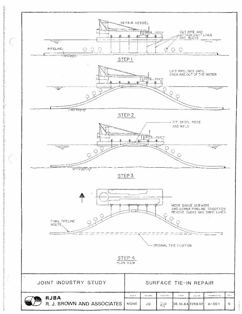
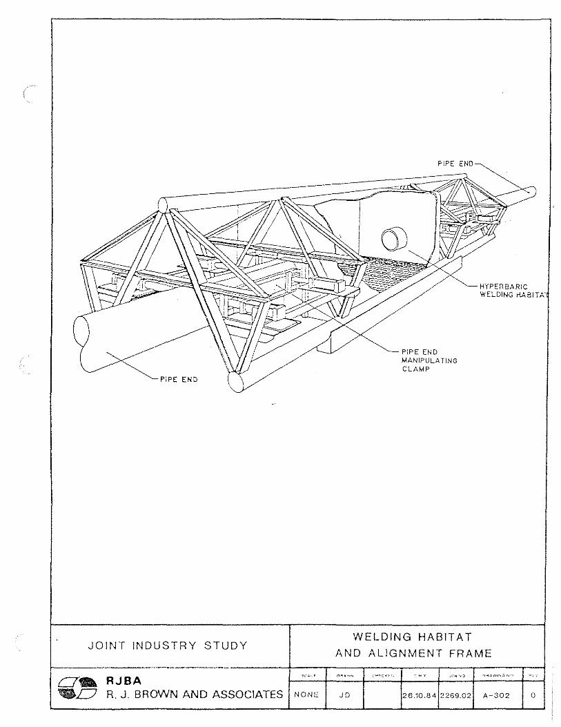
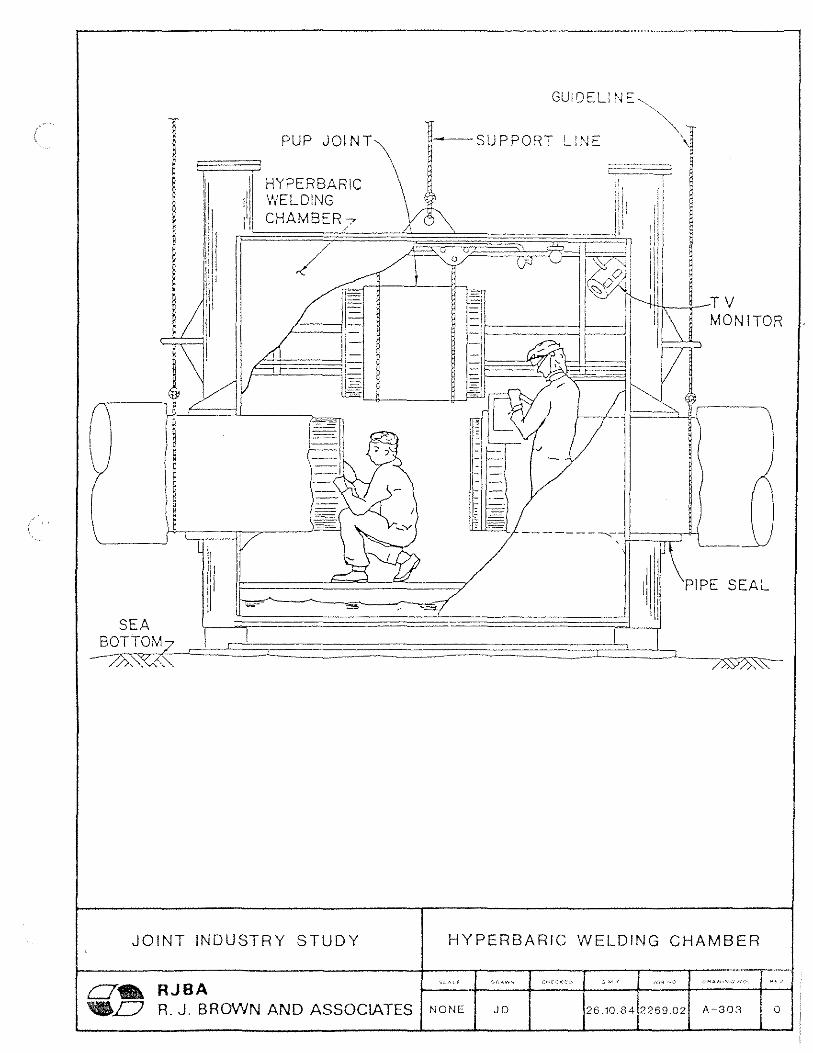
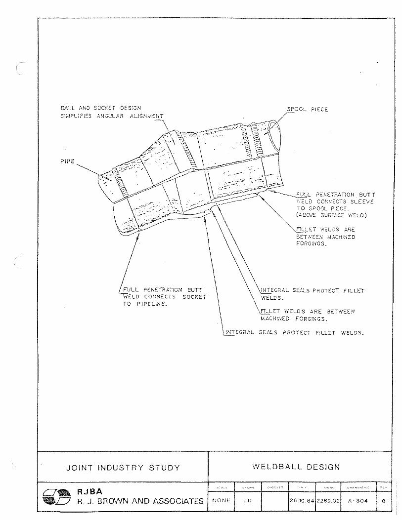
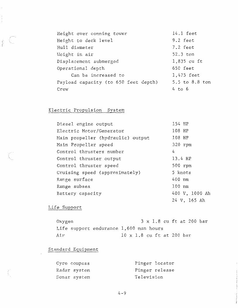
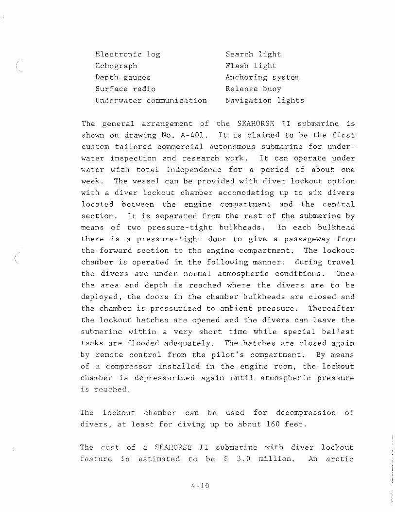
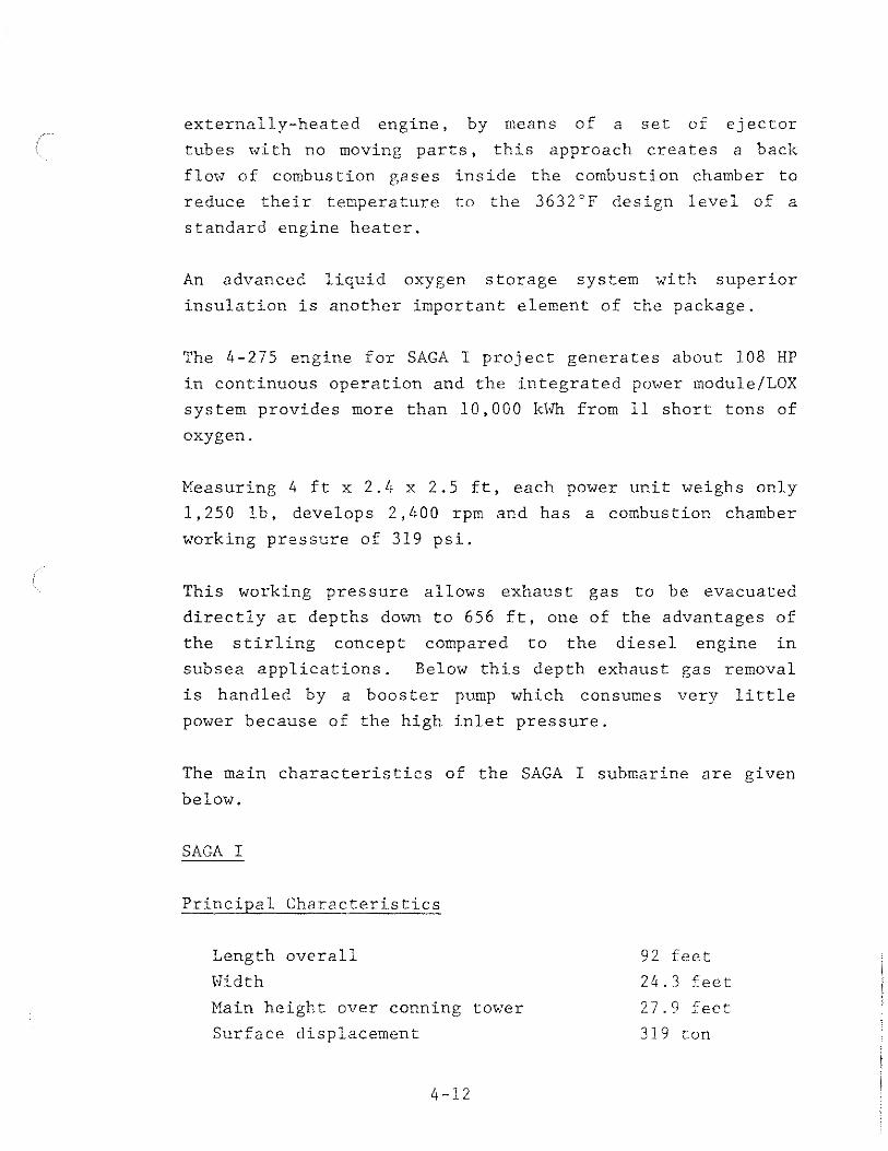
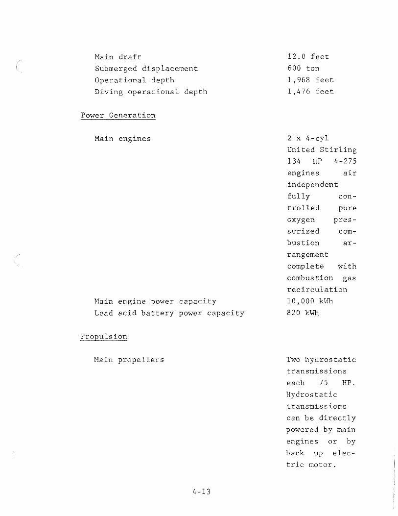
Crew
Minimum crew 6
additional crew 1
Divers 6
Speed
Normal submerged 4 knots
Maximum submerged 6 knots
Surface 7 knots
Life Support
Atmospheric compartment 25 days
Tank Capacities
Buoyancy control tanks 440 cu ft
Payload adjustment tanks 107 cu ft
Water ballast 1764 cu ft
The manufacturing cost of SAGA I submarine is estimated to
be $170 million
SAGA I extends the duration of submarine vessel supported
underwater work activities to over one week The self
sufficiency of the submarine depends on its particular
application the distance between the base port and the
work site and the energy required to perform the repair
work For example when the round trip distance is 200
nautical miles and the operating depth is 450 feet self
sufficiency at the work site will be 7 days with energy
consumption for work equipment being 240 kWh day For a
round trip distance of 100 nautical miles and 7 days self
sufficiency at work site the energy consumption by work
4-14
equipment can be raised to 470 kWhday
In each case the complete power of the lead acid batteries
will be reserved as back-up or for emergency use
SAGA I is scheduled for sea trials in mid 1986 and is
expected to be operational in 1987
Though SAGA I provides a giant step in autonomous work
submarine technology it still does not satisfy entirely
the requirements for an autonomous submarine pipeline
repair vessel capable of operating year round in Diapir
Area The SAGA I with some modifications can be used in
Diapir Area as an inspection and survey submarine with
limited work capability Incorporating a dredge pump with
in the submarine would allow it to carry out trench clearshy
ing work and perform simple pipeline repair tasks such as
the installation of a split sleeve clamp However dependshy
ing on the extent of the trench clearing work required
more than one trip to the work site may be necessary
Arctic Pipeline Repair Submarine
A work submarine that is capable of carrying out pipeline
repair work throughout the ice covered periods in Diapir
Area must have the following requirements
Autonomous operating period 30 days
Life support (total crew) 60 days
Maximum height 15 feet
Cargo capacity for pipeline repair
equipment 10 tons
Dredge pump for trench cleaning 100 HP
Saturation diving system 12 divers
Depth capability 500 feet
4-15
In addition to the arctic repair submarine a supply
submarine will be required to supply fuel and materials for
the repair submarine and for other tasks such as inshy
spection survey and rescue work
A low overall height will be desirable to reduce the risk
of ice keel contact when operating in shallow water The
general specifications for an arctic pipeline repair
submarine are given below
General Specifications for an Arctic Pipeline Repair
Submarine
Main Characteristics
Overall length approx 120 feet
Width approx 25 feet
Main height approx 15 feet
Submerged displacement approx 800 ton
Operational depth approx 600 feet
Diving operational depth approx 500 feet
Cargo capacity approx 15 ton
Crew
Submarine operation 6
Survey and navigation 1
Diving support 6
Divers 12
Life Support
Atmospheric compartment 36000 man hrs
4-16
Speed
Normal submerged 4 knots
Maximum submerged 6 knots
Surface 7 knots
Propulsion
Closed cycle stirling engine closed cycle diesel engine
or nuclear powered
Thrust required for towing pipeline
spool pieces 1000 lb
Dredge pumps for trench clearing work 2 x 100 HP
Hydraulically controlled dredge head 1 x 50 ft reach
support arm
H-Frames for handling pipelines and 4 x 10 ton
spool pieces
Hydraulic power supply for ancillary 80 HP
equipment
An arctic pipeline repair submarine having the above
characteristics is estimated to cost $500 million The
development time required is estimated at 5 years This
submarine can be developed from extensions to existing
technology and no new technology will be required
Repair Submarine Spread Support Base
The submarine pipeline repair spread must be based at a
location affording easy access to the pipelines The
spread can be located at an arctic port designed for year
round operation or at a port designed for operation during
4-17
low ice conditions with the submarine launching and
recovery in winter months being carried out over
strengthened ice or at an offshore fixed platform with
suitable submarine support facility In this study it is
assumed that the pipeline repair submarine vessel spread
will be based at a port designed for year round operation
This assumption is based on the fact that year round
drilling and production activities will require logistic
support and such support will be provided by both sea and
air transportation methods The icebreaker vessels and
supply vessels required for these operations will require a
port designed for year round operation
The second choice for a submarine base is an offshore
platform The repair submarine base requires a space
approximately 150 feet by and 60 feet by 25 feet high
This space must be located below sea level with a
pressure-tight door and dewatering facilities built into
the chamber
Launching a repair submarine from strengthened ice is a
practicable concept However when the weights of the
lifting and transportation equipment required are conshy
sidered the cost of this operation may appear to be very
high compared to the other two methods
4 3 3 COHPARISON OF FLOATING VESSEL AND SUBMARINE VESSEL SPREAD
COSTS
The cost of pipeline repair spread will depend on the
service contract in existence between the operating company
and the contracting company In this study it is assumed
that the spread is contracted to perform the repair task
after the detection of the pipeline damage The total cost
of the pipeline repair spread is assumed to be made up of a
fixed mobilization and demobilization cost and a variable
time dependent cost Drawing No A-402 presents a cost
comparison of floating and submarine repair spreads To
derive this cost comparison it was assumed that pipeline
repair vessel supply vessel icebreaker vessels and
submarine vessels will be available in Diapir Area This
assumption was made because these vessels will be required
to support other Arctic offshore activities such as drill shy
ing platform installation and logistic functions The
estimated mobilization and demobilization costs and day
rates for the various spreads are as follows
Spread Description Ice Condition MobDemob Operating Day Rate
Cost $day (x 1000)
$ million
Surface Vessel A 1 5 70
Surface Vessel B 35 370
St1rface Vessel c 55 610
Surface Vessel D 65 705
Submarine Vessel ALL 40 130
To compare the repair costs it is necessary to incorporate
a productivity derating factor to account for the loss of
productivity due to sea ice The following productivity
derating factors were used in deriving the cost comparison
curves shown on drawing No A-402
Spread
Surface Vessel
Surface Vessel
Surface Vessel
Surface Vessel
Submarine Vessel
Ice Condition Productivity Derating
F
l 0 0 1 J
25
13
B
c D
CD
4-19
It must be noted that the submarine vessel assisting repair
will be subjected to the danger of encountering keels of
large ice masses It was assumed that ice movement monishy
toring operations will be carried out at regular intervals
434 Pipeline Repair in Ice Condition E
Pipeline repair in Ice Condition E presents the most
difficult task and the greatest threat to the pipe line
repair spread Two problems that must be overcome are
accessing the pipeline if the grounded ice feature is
located directly above it and the danger to the pipeline
repair spread should the ice feature move under ice presshy
sure wind shear or current loads
Grounded ice features are found under a number of differshy
ent circumstances The most common of these is the groundshy
ing of pressure ridges along the transition zone also
known as the shear zone Grounded ice conditions are
present every year in the tranzition zone water depth
ranges from 50 to 75 feet The pressure ridges after
grounding can be subjected to movements from the build up
of ice pressure behind them These pressure ridges will
vary widely in length Grounded ridges 25 miles and 10
miles long have been recorded though these may be extreme
sizes More typical grounded ridges are less than a mile
long to about 4 miles long
Large ice features such as floebergs and ice islands can
also get grounded during storms The storm surges allow
these features to float in to shallower waters where they
are stranded when the storm surges subside
In each case the pipeline repair situation under a grounded
ice feature becomes a unique problem
I+ - 2 0
Accessing Pipeline Repair Area
The major problem in all these cases is accessing the
pipeline The shape of the ice keel the location of the
pipeline repair point with respect to ice keel and the
depth of ice keel embedment into the sea floor will
determine the equipment and time requirements to access the
pipeline
Two methods can be used to achieve this objective They
are
tunnelling under ice features and
refloating the ice feature
Every year grounded ice features are present across the
transition zone Accessing a pipeline in this area in
winter using present day technology may turn out to be an
impossible task One method of overcoming this problem is
to install a bypass pipeline parallel to the main line
during the time of pipeline construction to allow a
secondary flow path
A discussion of each of these methods follows
Tunnelling
This method can be used in the case of large ice features
which show no movement The depth of embedment of the ice
keel into the sea floor must be determined and the repaired
pipeline must be lowered below this level to avoid further
ice keel contact with pipeline Tunnelling across the ice
keel can be accomplished using a high pressure water lance
operated by manned submarine or by ROV Currently similar
techniques are used in the Canadian east coast to secure
tow lines to icebergs Once the ice keel is tunnelled the
4-21
soil must be excavated and removed to expose the pipeline
and to lower it below the deepest ice keel penetration
This work can be carried out by a floating vessel moored to
the ice feature by a work submarine equipped with a dredge
pump or by working off the ice feature and using it as a
work platform Naturally these operations will be very
slow and therefore costly
Refloating The Ice Feature
This method can be applied to ice features with relatively
small volume The ice excavation work can be carried out
with explosives and mechanical equipment Stability of the
ice feature may pose a danger to the crew and equipment
Bypass Pipelines
A bypass pipeline can be installed during the construction
of the pipeline to provide two flow paths across the
transition zone The minimum distance between these bypass
lines must be greater than the largest grounded ice feature
and the maximum length of ice scour Valves must be inshy
stalled to isolate each section of pipeline in case of
damage By this means the need to access the pipeline for
immediate repair can be avoided Repair work can be
carried out when the grounded ice feature moves away from
the pipeline damage site under natural forces
4-22
CHAPTER 5
REPAIR CASE STUDY
51 STUDY CASE DESCRIPTION
The repair study case is the Scenario A 36 inch Oliktok
point oil trunkline given in the main study report The
location of the damage was assumed to be at mile post 683
in 100 feet water depth Pipeline route and bathymetry are
shown on drawing No 4-100 of the main study report
It was also assumed that the extent of damage requires a
section of pipe 300 feet long to be replaced with a spool
piece The Ice Condition present at the time of damage and
repair was assumed to be Ice Condition C
The submarine vessel pipeline repair spread was chosen to
illustrate the repair scenario This choice was based on
the consideration that this spread will be able to complete
the repair at a lower cost as was shown on drawing No
A-402
52 PIPELINE REPAIR SCHEDULE
The pipeline repair schedule is given on drawing no A-500
The scenario repair case begins after the detection and
confirmation of a line damage The pipeline repair work is
then made up of the following tasks
Inspect pipeline and locate damage
Survey damage location and estimate damage
severity
Evaluate collected data and prepare detailed repair
plan
Mobilize trench clearing spread transport and
clear trench
Assemble repair pipe and material
Fabricate repair pipe spool piece
Launch and tow pipeline spool piece to repair site
Cut and remove damaged pipeline section
Replace damaged section with new spool piece
Test repaired pipeline
Demobilize equipment
Leak location survey and inspection will be carried out
using a manned autonomous submarine and is assumed to take
7 days The data obtained from this survey is used to plan
the repair operation In order to expedite the repair work
the dredging and trench clearing work is started immediateshy
ly after the survey operation
The estimated volume of soil to be dredged from the trench
is 10000 cubic yards The estimated time to dredge this
material is 15 days at an average rate of 30 cubic yards
per hour under ice free conditions This time is increased
by a factor of 13 to 20 days to allow for work
interruptions due to ice keel movements A total of 28
days is allowed to include travel time
Meanwhile pipeline repair materials are assembled and a
spool piece is fabricated The repair submarine completes
the trench clearing operation and returns to base for
refueling and crew change The spool piece is next transshy
ported to the work site by the off bottom tow method and
pipeline repair work is car-ried out The estimated time
for this work is 16 days in calm open water conditions
The weighted time allowing for work interruptions is 28
days A total of 35 days are allowed to include the travel
time to and from the work site
On completion of the pipeline repair work the pipeline is
5-2
pressure tested and put back into operation
53 PIPELINE REPAIR COST
Pipeline repair cost is made up of the following composhy
nents
damage location and survey cost
material cost and spool piece fabrication cost
excavation and trench clearing cost
pipeline repair spread cost
logistic support cost and
pipeline testing cost
A discussion of each cost component and the pipeline repair
cost estimate are given below A summary is presented in
table 5 1
Damage Location and Survey Cost
The task will be carried out by an automonous inspection
submarine at a cost of $40000day The estimated time
period for this work is 7 days The cost of this operation
is estimated at $280 000 This vessel is also used to
provide logistic support to the repair submarine Mobishy
lization and demobilization costs are given separately
Material Cost and Spool Piece Fabrication Cost
Material requirements for the repair work are corrosion
and weight coated line pipe mechanical connectors
buoyancy tank and chain assemblies and rigging for tow out
The material cost for 300 feet long spool piece is estimatshy
ed at $750000
5-3
Repair Spread Mobilization and Demobilization Cost
A lump sum mobilization and demobilization cost is incurred
to allow for preparing the vessels for the operation the
transport of personnel and the procurement of consumables
The mobilization and demobilization of the repair vessel
spread consisting of the repair submarine and the support
submarine are estimated at $ 4000000
Excavation and Trenching Cost
The work will be carried out using a dredge pump (100 HP
capacity) mounted in the work submarine The day rate for
the submarine vessel spread was estimated at $130000 and
the duration of this activity at 28 days The cost of
this operation is $3640000
Pipeline Repair Spread Cost
The same spread used for excavation and trenching work will
carry out this work The estimated time to complete the
work is 35 days at a cost of $4550000
Logistic Support Cost
Cost of this item is included in the excavation and repair
spread cost
Pipeline Pressure Testing Cost
On completion of the repair work the repaired pipeline must
be pressure tested The cost of the pressure test includshy
ing material and personnel is estimated to be $500000
5-4
TABLE 51 PIPELINE REPAIR COST ESTIMATE
SUMMARY
Item Cost $ x 1000
Damage location and survey cost 280
Material and spool piece fabrication
cost 750
Repair spread mobilization and 4000
demobilization cost
Excavation and trenching day rate 3640 related cost
Pipeline repair day rate related cost 4550
Logistic support cost (inc above)
Pipeline pressure testing cost 500
Total Cost 13720
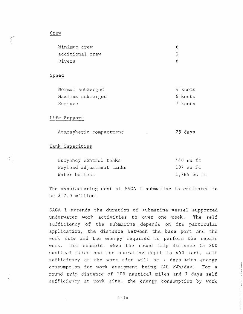
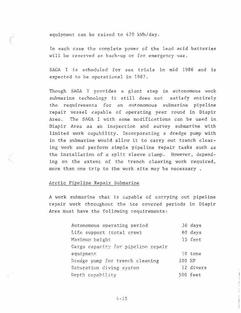
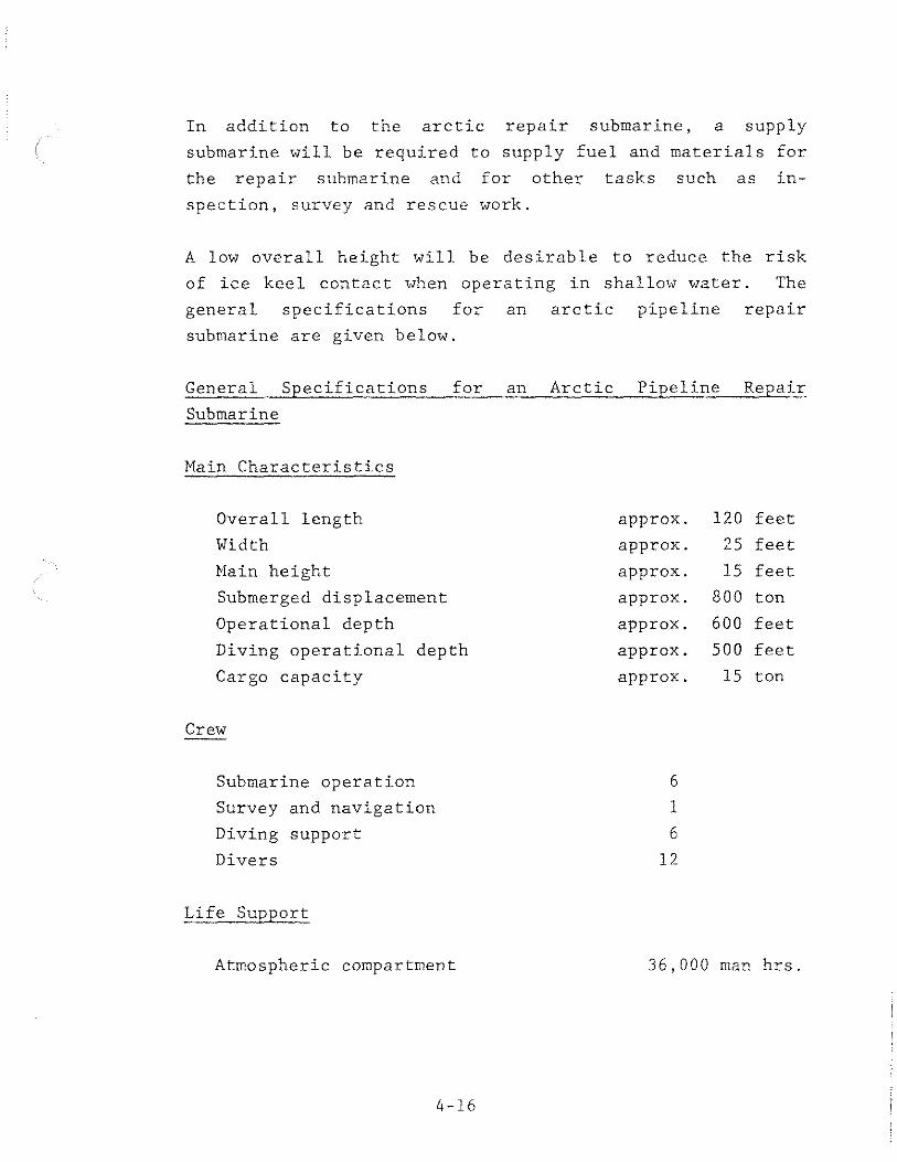
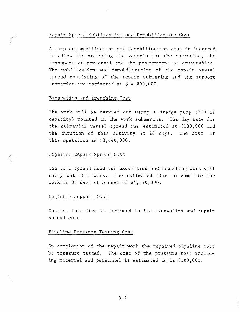