Embed Size (px)
Citation preview
GUIDE FOR BUILDING AND CLASSING
OFFSHORE LNG TERMINALS
APRIL 2004
American Bureau of Shipping Incorporated by Act of Legislature of the State of New York 1862
Copyright 2004 American Bureau of Shipping ABS Plaza 16855 Northchase Drive Houston, TX 77060 USA

This Page Intentionally Left Blank
ABS GUIDE FOR BUILDING AND CLASSING OFFSHORE LNG TERMINALS . 2004 iii
Foreword
This update to the Guide has been prepared to assist the industry with Classification of offshore Liquefied Natural Gas (LNG) terminals. This edition includes minor editorial changes, and introduces requirements and clarification to pending subsections of previous edition.
The Guide describes criteria to be used for offshore LNG terminals which are to be classed or certified by American Bureau of Shipping (ABS).
The present Guide addresses LNG terminals. ABS is willing to expand the criteria for handling other gaseous materials as the industry demand for same increases. ABS recognizes that industry participation is a vital factor due to the rapidly progressing use of offshore gas terminals. To understand and apply this new technology and its standards, it is imperative that ABS, the offshore and onshore community, regulatory agencies and the public at large have a common understanding of the terms and concepts involved, and an awareness of how these concepts are to be applied to ABS rulemaking. This continues to be the driving force for the Guide.

This Page Intentionally Left Blank
ABS GUIDE FOR BUILDING AND CLASSING OFFSHORE LNG TERMINALS . 2004 v
GUIDE FOR BUILDING AND CLASSING
OFFSHORE LNG TERMINALS
CONTENTS CHAPTER 1 General Requirements for All Offshore LNG Terminals.....1
Section 1 Scope and Conditions of Classification ....................3 CHAPTER 2 Requirements for Gravity-Based Offshore LNG
Terminals ..............................................................................17 Section 1 Classification of Gravity-Based Offshore LNG
Terminals ................................................................21 Section 2 Design of Gravity-Based Offshore LNG
Terminals ................................................................29 Section 3 Surveys During Construction, Installation and
Commissioning .......................................................65 Section 4 Surveys After Construction and Maintenance of
Class .......................................................................75 Section 5 Risk-based Surveys for Maintenance of Class.......85
CHAPTER 3 Requirements for Floating Offshore LNG Terminals........89
Section 1 Classification of Floating Offshore LNG Terminals ................................................................93
Section 2 Design of Floating Offshore LNG Terminals.........105 Section 3 Surveys During Construction, Installation and
Commissioning .....................................................125 Section 4 Surveys After Construction and Maintenance of
Class .....................................................................133 Section 5 Risk-based Surveys for Maintenance of Class.....149

This Page Intentionally Left Blank
ABS GUIDE FOR BUILDING AND CLASSING OFFSHORE LNG TERMINALS . 2004 1
C H A P T E R 1 General Requirements for All Offshore LNG Terminals
CONTENTS SECTION 1 Scope and Conditions of Classification ..............................3
1 Classification..........................................................................3 1.1 Process ............................................................................. 3 1.3 Certificates and Reports.................................................... 3 1.5 Representations as to Classification ................................. 4 1.7 Scope of Classification...................................................... 4
3 Suspension and Cancellation of Classification......................5 3.1 General ............................................................................. 5 3.3 Notice of Surveys .............................................................. 5 3.5 Special Notations .............................................................. 5 3.7 Suspension of Class ......................................................... 5 3.9 Lifting of Suspension......................................................... 6 3.11 Cancellation of Class ........................................................ 6
5 Purpose..................................................................................6 7 Classification Symbols and Notations....................................7
7.1 Class Notations ................................................................. 7 7.3 Geographical Limitations................................................... 7 7.5 Terminals Not Built Under Survey ..................................... 7
9 Rules for Classification ..........................................................7 9.1 Application of Rules .......................................................... 7 9.3 Scope of Class .................................................................. 8 9.5 Alternatives ....................................................................... 8 9.7 ABS Type Approval Program ............................................ 8 9.9 Novel Features................................................................ 11 9.11 Effective Date of Rule Change........................................ 11
11 Other Regulations ................................................................12 11.1 International and Other Regulations................................ 12 11.3 Governmental Regulations.............................................. 12
13 IACS Audit ...........................................................................12 15 Conditions for Survey After Construction.............................12
15.1 Damage, Failure and Repair ........................................... 12 15.3 Notification and Availability for Survey ............................ 13
17 Units .....................................................................................13 19 Fees .....................................................................................13
2 ABS GUIDE FOR BUILDING AND CLASSING OFFSHORE LNG TERMINALS . 2004
21 Disagreement.......................................................................14 21.1 Rules and Guides............................................................14 21.3 Surveyor ..........................................................................14
23 Limitation of Liability.............................................................14 25 Abbreviations and References.............................................14
25.1 Abbreviations...................................................................14 25.3 References ......................................................................15
ABS GUIDE FOR BUILDING AND CLASSING OFFSHORE LNG TERMINALS . 2004 3
C H A P T E R 1 General Requirements for All Offshore LNG Terminals
S E C T I O N 1 Scope and Conditions of Classification
1 Classification
1.1 Process The term classification, as used herein, indicates that an offshore Liquefied Natural Gas (LNG) terminal has been designed, constructed, installed and surveyed in compliance with the subject Guide, existing Rules and Guides or other acceptable standards. The continuance of classification is dependent on the fulfillment of requirements for surveys after construction.
The classification process consists of:
a) The development of Rules, Guides, standards and other criteria for the design, construction, installation and maintenance of offshore LNG terminals and their equipment;
b) The review of the design and survey during and after construction to verify compliance with such Rules, Guides, standards or other criteria;
c) The assignment and registration of class when such compliance has been verified, and;
d) The issuance of a renewable Classification certificate, with annual endorsements, valid for five years.
The Rules, Guides and standards are developed by the Bureau staff and passed upon by committees made up of naval architects, ocean and marine engineers, shipbuilders, engine builders, steel makers, process engineers and by other technical, operating and scientific personnel associated with the worldwide maritime industry. Theoretical research and development, established engineering disciplines, as well as satisfactory service experience are utilized in their development and promulgation. The Bureau and its committees can act only upon such theoretical and practical considerations in developing Rules and standards.
For Classification, all offshore LNG terminals are to comply with the requirements of this Guide and all applicable Rules.
1.3 Certificates and Reports Review of design documentation and surveys during and after construction are conducted by the Bureau to verify to itself and its committees that an item of material, equipment or machinery is in compliance with this Guide and to the satisfaction of the attending Surveyor. All reports and certificates are issued solely for the use of the Bureau, its committees, its clients and other authorized entities.
Chapter 1 General Requirements for All Offshore LNG Terminals Section 1 Scope and Conditions of Classification 1-1
4 ABS GUIDE FOR BUILDING AND CLASSING OFFSHORE LNG TERMINALS . 2004
The Bureau will release information from reports and certificates to the Coastal State to assist in rectification of deficiencies during port state control intervention. Such information includes text of conditions of classification, survey due dates and certificate expiration dates. The Owner will be advised of any request and/or release of information. The Bureau will release certain information to the terminal’s underwriters and P&I clubs for underwriting purposes. Such information includes text of overdue conditions of classification, survey due dates and certificate expiration dates. The Owners will be advised of any request and/or release of information. In the case of overdue conditions of classification, the Owners will be given the opportunity to verify the accuracy of the information prior to release. The Bureau may release terminal-specific information related to the classification and applicable statutory certification status. This information may be published on the Bureau web site or by other media and may include the terminal's classification, any operating restrictions noted in the Bureau’s Record, the names, dates and locations of all surveys performed by ABS, the expiration date of all certificates issued by ABS, survey due dates, the text of conditions of classification (also known as outstanding recommendations), transfers, suspensions, withdrawals, cancellations and reinstatements of class and other related information as may be required.
1.5 Representations as to Classification Classification is a representation by the Bureau as to the structural and mechanical fitness for a particular use or service, in accordance with its Rules, Guides and standards. The Rules and Guides of the American Bureau of Shipping are not meant as a substitute for the independent engineering judgment of professional designers, naval architects, marine engineers, owners, operators, masters and crew, nor as a substitute for the quality control procedures of ship and platform builders, engine builders, steel makers, suppliers, manufacturers and sellers of marine vessels, materials, system components, machinery or equipment. The Bureau, being a technical society, can only act through Surveyors or others who are believed by it to be skilled and competent. The Bureau represents solely to the offshore LNG terminal Owner or client of the Bureau that when assigning class, it will use due diligence in the development of Rules, Guides and standards, and in using normally applied testing standards, procedures and techniques as called for by the Rules, Guides, standards or other criteria of the Bureau for the purpose of assigning and maintaining class. Bureau further represents to the Owner or other client of the Bureau that its certificates and reports evidence compliance only with one or more of the Rules, Guides, standards or other criteria of the Bureau, in accordance with the terms of such certificate or report. Under no circumstances whatsoever are these representations to be deemed to relate to any third party. The user of this document is responsible for ensuring compliance with all applicable laws, regulations and other governmental directives and orders related to an offshore LNG terminal, its machinery and equipment, or their operation. Nothing contained in any Rule, Guide, standard, certificate or report issued by the Bureau shall be deemed to relieve any other entity of its duty or responsibility to comply with all applicable laws, including those related to the environment.
1.7 Scope of Classification Nothing contained in any certificate or report is to be deemed to relieve any designer, builder, owner, manufacturer, seller, supplier, repairer, operator, other entity or person of any warranty, express or implied. Any certificate or report evidences compliance only with one or more of the Rules, Guides, standards or other criteria of the American Bureau of Shipping, and is issued solely for the use of the Bureau, its committees, its clients or other authorized entities. Nothing contained in any certificate, report, plan or document review or approval is to be deemed to be in any way a representation or statement beyond those contained in 1-1/1.5 of this Guide. The validity, applicability and interpretation of any certificate, report, plan or document review or approval are governed by the Rules, Guides and standards of the American Bureau of Shipping, who shall remain the sole judge thereof. The Bureau is not responsible for the consequences arising from the use by other parties of the Rules, Guides, standards or other criteria of the American Bureau of Shipping without review, plan approval and survey by the Bureau.
Chapter 1 General Requirements for All Offshore LNG Terminals Section 1 Scope and Conditions of Classification 1-1
ABS GUIDE FOR BUILDING AND CLASSING OFFSHORE LNG TERMINALS . 2004 5
The term “approved” is to be interpreted to mean that the plans, reports or documents have been reviewed for compliance with one or more of the Rules, Guides, standards or other criteria acceptable to the Bureau.
This Guide is published with the understanding that responsibility for safe operation and shutting down process or cargo transfer operations when conditions exceed the safe operational and environmental limits specified in the offshore LNG terminal design basis does not rest upon the Committee.
3 Suspension and Cancellation of Classification
3.1 General The continuance of the Classification of the offshore LNG terminals is conditional upon the Guide requirements for periodical, damage and other surveys being duly carried out. The Committee reserves the right to reconsider, withhold, suspend or cancel the class of any offshore LNG terminal and its equipment for non-compliance with the Rules, for defects reported by the Surveyors which have not been rectified in accordance with their recommendations or for nonpayment of fees which are due on account of Classification, Statutory and Cargo Gear Surveys. Suspension or cancellation of class may take effect immediately or after a specified period of time.
3.3 Notice of Surveys It is the responsibility of the Owner to ensure that all surveys necessary for the maintenance of class are carried out at the proper time. The Bureau will give proper notice to an Owner of upcoming surveys. This may be done by means of a letter, a quarterly status report or other communication. The non-receipt of such notice, however, does not absolve the Owner from his responsibility to comply with survey requirements for maintenance of class.
3.5 Special Notations If the survey requirements related to maintenance of special notations are not carried out as required, the suspension or cancellation may be limited to those notations only.
3.7 Suspension of Class Class will be suspended and the Certificate of Classification will become invalid from the date of any use, operation or other application of any offshore LNG terminal and its equipment for which it has not been approved and which affects or may affect classification or the structural integrity, quality or fitness for a particular use or service.
Class will be suspended and the Certificate of Classification will become invalid in any of the following circumstances:
i) If recommendations issued by the Surveyor are not carried out by their due dates and no extension has been granted,
ii) If Continuous Survey items which are due or overdue at the time of Annual Survey are not completed and no extension has been granted,
iii) If the periodical surveys required for maintenance of class, other than Annual or Special Periodical Surveys, are not carried out by the due date and no Rule allowed extension has been granted, or
iv) If any damage, failure, deterioration or repair has not been completed as recommended.
Chapter 1 General Requirements for All Offshore LNG Terminals Section 1 Scope and Conditions of Classification 1-1
6 ABS GUIDE FOR BUILDING AND CLASSING OFFSHORE LNG TERMINALS . 2004
Class may be suspended, in which case the Certificate of Classification will become invalid, if proposed repairs as referred to in 1-1/15.1 of this Guide have not been submitted to the Bureau and agreed upon prior to commencement.
Class is automatically suspended and the Certificate of Classification is invalid in any of the following circumstances:
i) If the Annual Survey is not completed by the date which is three (3) months after the due date,
ii) If the Special Survey is not completed by the due date, unless the offshore LNG terminal is under attendance for completion prior to resuming operation. Under exceptional circumstances, consideration may be given for an extension of the Special Survey, provided the terminal is attended and the attending Surveyor so recommends. Such an extension shall not exceed three (3) months.
3.9 Lifting of Suspension Class will be reinstated after suspension for overdue surveys upon satisfactory completion of the overdue surveys. Such surveys will be credited as of the original due date.
Class will be reinstated after suspension for overdue recommendations upon satisfactory completion of the overdue recommendation.
Class will be reinstated after suspension for overdue Continuous Survey items upon satisfactory completion of the overdue items.
3.11 Cancellation of Class If the circumstances leading to suspension of class are not corrected within the time specified, the offshore LNG terminal’s class will be cancelled.
Class is cancelled immediately when a offshore LNG terminal and its equipment are operated without having completed recommendations which were required to be dealt with before the offshore LNG terminal is brought back into service.
When class has been suspended for a period of three (3) months due to overdue Annual, Special or other surveys required for maintenance of class; overdue Continuous Survey items; or overdue outstanding recommendations, class will be canceled. A longer suspension period may be granted for offshore LNG terminals and their equipment which are either laid up, awaiting disposition of a casualty or under attendance for reinstatement.
5 Purpose
An Offshore LNG Terminal provides LNG storage and receives and/or offloads LNG. There are two major variations of offshore LNG terminal: Load Terminals and Discharge Terminals, with various configurations of each.
A Load Terminal receives gas directly from one or more wells or from another offshore facility where it may or may not have been processed. The gas is liquefied in an onboard liquefaction facility and stored for offloading as LNG to a trading LNG carrier. Alternatively, a Load Terminal may receive LNG from a liquefaction plant via a pipeline.
A Discharge Terminal receives LNG from trading LNG carriers and stores it. In such terminals, the stored LNG is normally vaporized in a re-gasification facility and discharged ashore. However, offloading LNG in a lightering operation is also feasible.
Chapter 1 General Requirements for All Offshore LNG Terminals Section 1 Scope and Conditions of Classification 1-1
ABS GUIDE FOR BUILDING AND CLASSING OFFSHORE LNG TERMINALS . 2004 7
7 Classification Symbols and Notations
7.1 Class Notations Offshore LNG terminals that have been built, installed and commissioned to the satisfaction of the Surveyors to the Bureau to the full requirements of this Guide, where approved by the Committee for service for the specified design environmental conditions, will be classed and distinguished in the ABS Record by the symbol À A1, followed by the appropriate notation for the intended service listed below. Class notations were chosen to provide a clear description of the function of each configuration using the following symbols:
F Floating G Gravity Based L Liquefaction Facility O Transfer of LNG (Offloading/Loading) P Gas Processing Facility R Re-Gasification Facility S Storage Facility T Terminal without Processing Equipment
A complete description of applicable class notation is provided for gravity-based LNG terminals and floating LNG terminals in 2-1/1.1 and 3-1/1.1 of this Guide, respectively.
7.3 Geographical Limitations Offshore LNG terminals which have been built to the satisfaction of the Surveyors to the Bureau to special modified requirements for a limited service, where approved by the Committee for that particular service, will be classed and distinguished in the Record by suitable symbols or notations, but the symbols or notations will either be followed by or have included in them the appropriate service limitation.
7.5 Terminals Not Built Under Survey The symbol “À” (Maltese-Cross) signifies that the system was built, installed and commissioned to the satisfaction of the Bureau Surveyors. Offshore LNG terminals and their equipment that have not been built under survey to this Bureau, but which are submitted for Classification, will be subjected to special consideration. Where found satisfactory and thereafter approved by the Committee, they will be classed and distinguished in the Record by the notation described above, but the symbol “À” signifying survey during construction will be omitted.
9 Rules for Classification
9.1 Application of Rules This Guide contains provisions for the classification of offshore LNG terminals. This Guide is intended for use in conjunction with the ABS Rules for Building and Classing Steel Vessels (Steel Vessel Rules), the Rules for Building and Classing Mobile Offshore Drilling Units (MODU Rules), ABS Rules for Building and Classing Offshore Installations or other applicable ABS Rules and Guides.
Chapter 1 General Requirements for All Offshore LNG Terminals Section 1 Scope and Conditions of Classification 1-1
8 ABS GUIDE FOR BUILDING AND CLASSING OFFSHORE LNG TERMINALS . 2004
9.3 Scope of Class A description of the parts of an offshore LNG terminal included in the ABS classification is provided in 2-1/1 and 3-1/1 of this Guide for gravity-based terminals and floating terminals, respectively.
9.5 Alternatives The Committee is at all times ready to consider alternative arrangements and designs which can be shown, through either satisfactory service experience or a systematic analysis based on sound engineering principles, to meet the overall safety, serviceability and strength standards of the Rules and Guides. The Committee will consider special arrangements or design for details of offshore LNG terminals and their equipment which can be shown to comply with standards recognized in the country in which the offshore LNG terminal and its equipment are designed or built, provided these are not less effective.
Any departure from the requirements of this Guide may be considered by the Bureau on the basis of an additional risk assessment to that required per 2-2/3 or 3-2/3 of this Guide for gravity-based or floating structures, respectively, or at least a separate, clearly identified part of the risk assessment. In the case of such departures, classification is subject to the Bureau’s approval upon a demonstration of fitness for purpose in line with the principles of ABS Guides and Rules, as well as recognized and generally accepted good engineering practice. Risk acceptance criteria are to be developed in line with the principles of the ABS Rules and are subject to Bureau’s approval. The ABS Guidance Notes on Risk Assessment Application for the Marine and Offshore Oil and Gas Industries contain an overview of risk assessment techniques and additional information.
A risk approach justification of alternatives may be applicable either to the terminal as a whole or to individual systems, subsystems or components. As appropriate, account must be given to remote hazards outside of the bounds of the system under consideration. Such account must include incidents relating to remote hazards directly affecting or being influenced by the system under consideration. The Bureau will consider the application of risk-based techniques in the design of the terminal, verification surveys during construction and surveys for maintenance of class.
Portions of the terminal not included in the risk assessment are to comply with the applicable parts of the ABS Rules.
The following are the responsibility of the Owner/Operator:
i) Risk acceptance criteria.
ii) Hazard identification.
iii) Risk assessment.
iv) Risk management.
v) Compliance of the system under consideration with the applicable requirements of Flag and Coastal State.
9.7 ABS Type Approval Program
9.7.1 Type Approval Products that can be consistently manufactured to the same design and specification may be Type Approved under the ABS Type Approval Program. The ABS Type Approval Program is a voluntary option for the demonstration of compliance of a product with the Rules or other recognized standards. It may be applied at the request of the designer or manufacturer. The ABS Type Approval Program generally covers Product Type Approval (1-1/9.7.3), but is also applicable for a more expeditious procedure towards Unit-Certification, as specified in 1-1/9.7.2.
Chapter 1 General Requirements for All Offshore LNG Terminals Section 1 Scope and Conditions of Classification 1-1
ABS GUIDE FOR BUILDING AND CLASSING OFFSHORE LNG TERMINALS . 2004 9
9.7.2 Unit-Certification Unit-Certification is a review of individual materials, components, products and systems for compliance with ABS Rules, Guides or other recognized standards. This allows these items to be placed on a vessel, marine structure or system to become eligible for classification. Certification is a “one-time” review. The process is:
i) A technical evaluation of drawings or prototype tests of a material, component, product or system for compliance with the ABS Rules, Guides or other recognized standards,
ii) A survey during manufacture for compliance with the ABS Rules, Guides or other recognized standards and results of the technical evaluation,
iii) Alternatively, a certificate of type approval (see below) will expedite the requirements of i) and ii) above,
iv) Products found in compliance are issued “Individual Unit Certification”,
v) There is no requirement for subsequent reviews or surveys.
9.7.3 Product Type Approval Product Type Approval is a voluntary program used to prove eligibility for certification by demonstrating a product manufacturer’s conformance to a specific standard or specification. Manufacturers who can demonstrate the ability to produce consistent products in compliance with these standards are issued “Certificates of Type Approval” (see 1-1-A3/5.3.4 of the Steel Vessel Rules). The Certificate of Type Approval is neither an alternative to, nor an equivalent of, an Individual Unit Certificate. In order to remain valid, the Certificate of Type Approval requires routine audits of the manufacturer and continued compliance of the product with existing or new specifications.
9.7.4 Approval on Behalf of Administrations ABS has also been authorized and/or notified to type approve certain equipment on behalf of Administrations. The list of authorizations and notifications are maintained at each ABS Technical Office.
9.7.5 Applicable Uses of Type Approved Products When a product is at a stage suitable for testing and/or for use in a classed vessel, and unit certification is required, the manufacturer is to present the product to an attending Surveyor for witnessing of all required Rule testing. Unless specified in the Design Assessment, technical evaluation would not normally be required.
When a product is at a stage suitable for use in a classed vessel and unit certification is not required, the product may be installed, to the satisfaction of the attending Surveyor, without the need for technical evaluation.
9.7.6 Definitions Audit. A systematic and independent examination to determine whether quality activities and related results comply with planned arrangements and whether these arrangements are implemented effectively and are suitable to achieve the stated objectives.
General Audit. An audit that addresses the general operation of a site, and addresses applicable sections of the Quality and Environmental System Manual, quality and environmental system procedures, operating procedures and process instructions.
Surveillance Audit. An audit that addresses specific areas within the operation at a site, and addresses selected sections of the Quality and Environmental System Manual, quality and environmental system procedures, operating procedures and process instructions.
Chapter 1 General Requirements for All Offshore LNG Terminals Section 1 Scope and Conditions of Classification 1-1
10 ABS GUIDE FOR BUILDING AND CLASSING OFFSHORE LNG TERMINALS . 2004
Audit Checklist. A listing of specific items within a given area that are to be audited.
Audit Report/Checklist. A combination of audit report and associated checklist.
Component. Parts/members of a product or system formed from material.
Finding. A statement of fact supported by objective evidence about a process whose performance characteristics meet the definition of non-conformance or observation.
Material. Goods used that will require further forming or manufacturing before becoming a new component or product.
Non-conformance. Non-fulfillment of a specified requirement.
Observation. A detected weakness that, if not corrected, may result in the degradation of product or service quality or potential negative impact on the environment.
Product. Result of the manufacturing process.
Production Testing. This is the destructive and nondestructive testing of the materials and components used in the manufacture of a product and its final testing that is recorded in Unit Certification. The waiving of witnessed testing during production testing may only be allowed as defined in 1-1-A3/3 “Limitations” and 1-1-A3/5.5 “Product Quality Assessment Certification” of the Steel Vessel Rules.
Prototype Testing (also known as "Type Testing"). This is the destructive and nondestructive testing of the materials and components presented for evaluation of the original or first article product. If a Surveyor’s witness is required, this may not be waived under any section of this Guide, unless it is done by a recognized third party.
Recognized Third Party. Is a member of the International Association of Classification Societies, a Flag Administration, a Nationally Certified testing Laboratories and others who may be presented to the Bureau for special consideration.
9.7.7 The Terms and Conditions for Use of ABS Type Approved Product Logo When a product is eligible for a Certificate of Type Approval (1-1-A3/5.3.4 of the Steel Vessel Rules), the Type Approved Product Logo may also be used with the understanding that it is copyrighted and its use must be controlled, as follows:
i) Any advertisement or other use of the logo is to be presented to the Manager of ABS Programs for review prior to use
ii) The logo may only be used on correspondence, advertising and promotional material and must not be used except in connection with those goods or services described in the scope and conditions of the Product Design Assessment Certificate.
iii) The logo may be used only on those materials (i.e., Internet site, letterhead, marketing literature, advertising, invoice stock forms, packaging, etc.) relating to the particular facility and process/product lines included within the Product Type Approval Certificate.
iv) The logo may not, under any circumstances, be used directly on or closely associated with products in such a way as to imply that the products themselves are “Unit – certified” by ABS.
v) If used with other logos, ABS may ask that the manufacturer discontinue any use of other logos that are unacceptable to ABS and any form of statement that, in the opinion of ABS, might be misleading.
vi) Upon the termination of certification, for whatever reason, the manufacturer must undertake to immediately discontinue all use of the logo and to destroy all stocks of material on which it appears.
Chapter 1 General Requirements for All Offshore LNG Terminals Section 1 Scope and Conditions of Classification 1-1
ABS GUIDE FOR BUILDING AND CLASSING OFFSHORE LNG TERMINALS . 2004 11
vii) When advertising the product as ABS Type Approved, the manufacturer’s name, if different from the parent company, is to be used in conjunction with this logo. Any use should be specific to the process/product line covered and not represented as a blanket approval of the company.
viii) The logo may be scaled uniformly to any size necessary. The color of the logo shall be either black or blue (reflex blue or PMS 294 blue).
ix) A camera-ready sheet of these logos is available in .pdf format by e-mail from [email protected].
See the ABS Type Approved Product Logo, as follows:
See the ABS Type Approval Program in Appendix 1-1-A3 of the Steel Vessel Rules. The ABS Type Approval Program and the indicated references are available for download from the ABS website at: “http://www.eagle.org/rules/downloads.html”
9.9 Novel Features Offshore LNG terminals which contain novel features of design to which the provisions of this Guide are not directly applicable may be classed, when approved by the Committee, on the basis that this Guide, insofar as applicable, has been complied with and that special consideration has been given to the novel features based on the best information available at that time.
9.11 Effective Date of Rule Change
9.11.1 Effective Date This Guide and subsequent changes to this Guide are to become effective on the date specified by the Bureau. In general, the effective date is not less than six months from the date on which the Guide is published and released for its use. However, the Bureau may bring into force the Guide or individual changes before that date if necessary or appropriate.
9.11.2 Implementation of Rule Changes In general, until the effective date, plan approval for designs will follow prior practice, unless review under the latest Guide is specifically requested by the party signatory to the application for classification. If one or more systems are to be constructed from plans previously approved, no retroactive application of the subsequent Rule changes will be required, except as may be necessary or appropriate for all contemplated construction.
Chapter 1 General Requirements for All Offshore LNG Terminals Section 1 Scope and Conditions of Classification 1-1
12 ABS GUIDE FOR BUILDING AND CLASSING OFFSHORE LNG TERMINALS . 2004
11 Other Regulations
11.1 International and Other Regulations While this Guide covers the requirements for the classification of offshore LNG terminals and their equipment, the attention of Owners, designers and builders is directed to the regulations of international, governmental and other authorities dealing with those requirements in addition to or over and above the classification requirements. Where authorized by the Administration of a country signatory thereto and upon request of the Owners of a classed offshore LNG terminal or one intended to be classed, the Bureau will survey a terminal for compliance with the provision of International and Governmental Conventions and Codes, as applicable.
11.3 Governmental Regulations Where authorized by a government agency and upon request of the Owners of a new or existing offshore LNG terminal, the Bureau will survey and certify a classed offshore LNG terminal or one intended to be classed for compliance with particular regulations of that government on their behalf.
13 IACS Audit The International Association of Classification Societies (IACS) conducts audits of processes followed by all of its member societies to assess the degree of compliance with the IACS Quality System Certification Scheme requirements. For this purpose, auditors for IACS may accompany ABS personnel at any stage of the classification or statutory work, which may necessitate the auditors having access to the offshore LNG terminal and its equipment, or access to the premises of the builder or manufacturer. In such instances, prior authorization for the auditor’s access will be sought by the local ABS office.
15 Conditions for Survey After Construction
15.1 Damage, Failure and Repair
15.1.1 Examination and Repair Damage, failure, deterioration or repair to the offshore LNG terminal and its equipment which affects classification is to be submitted by the Owners or their representatives for examination by the Surveyor at the first opportunity. All repairs found necessary by the Surveyor are to be carried out to his satisfaction.
15.1.2 Repairs Where repairs to the offshore LNG terminal and its equipment which may affect classification are planned in advance to be carried out, a complete repair procedure, including the extent of the proposed repair and the need for Surveyor’s attendance, is to be submitted to and agreed upon by the Surveyor reasonably in advance. Failure to notify the Bureau in advance of the repairs may result in suspension of the offshore LNG terminal’s classification until such time as the repair is redone or evidence is submitted to satisfy the Surveyor that the repair was properly carried out. The above is not intended to include maintenance and overhaul to machinery and equipment, in accordance with recommended manufacturer’s procedures and established marine and offshore practice, which do not require Bureau approval. However, any repair as a result of such maintenance and overhauls which affects or may affect classification is to be noted in the offshore LNG terminal’s log and submitted to the Surveyors, as required by 1-1/15.1.1.
Chapter 1 General Requirements for All Offshore LNG Terminals Section 1 Scope and Conditions of Classification 1-1
ABS GUIDE FOR BUILDING AND CLASSING OFFSHORE LNG TERMINALS . 2004 13
15.1.3 Representation Nothing contained in this Section or in a rule or regulation of any government or other administration, or the issuance of any report or certificate pursuant to this Section or such a rule or regulation, is to be deemed to enlarge upon the representations expressed in 1-1/1.1 through 1-1/1.7 hereof, and the issuance and use of any such reports or certificates are to be governed in all respects by 1-1/1.1 through 1-1/1.7 hereof.
15.1.4 Temporary Installation, Maintenance, Modification, Repair or Replacements ABS is to be notified of the Owner’s intention to install temporary equipment or machinery that can affect the safety or intended functioning of the system. Depending on circumstances, ABS may require design review, surveys and individual certification of such equipment or machinery.
Where a major modification or replacement is made to the structure, equipment or machinery of the terminal, the Bureau is to be notified and the applicable requirements of this Guide are to be met.
15.3 Notification and Availability for Survey The Surveyors are to have access to classed offshore LNG terminals and their equipment at all reasonable times. For the purpose of Surveyor monitoring, monitoring Surveyors are also to have access to classed offshore LNG terminals and their equipment at all reasonable times. Such access may include attendance at the same time as the assigned Surveyor or during a subsequent visit without the assigned Surveyor. The Owners or their representatives are to notify the Surveyors for inspection on occasions when the units on which the offshore LNG terminals are installed are on dry dock or on a slipway.
The Surveyors are to undertake all surveys on classed offshore LNG terminals and their equipment upon request, with adequate notification, of the Owners or their representatives, and are to report thereon to the Committee. Should the Surveyors find occasion during any survey to recommend repairs or further examination, notification is to be given immediately to the Owners or their representatives so that appropriate action may be taken. The Surveyors are to avail themselves of every convenient opportunity for carrying out periodical surveys in conjunction with surveys of damages and repairs in order to avoid duplication of work.
17 Units
This Guide is written in three systems of units, viz., SI units, MKS units and US customary units. Each system is to be used independently of any other system.
Unless indicated otherwise, the format of presentation in this Guide of the three systems of units, is as follows:
SI units (MKS units, US customary units)
19 Fees
Fees in accordance with normal ABS practice will be charged for all services rendered by ABS. Expenses incurred by Bureau in connection with these services will be charged in addition to the fees. Fees and expenses will be billed to the party requesting that particular service.
Chapter 1 General Requirements for All Offshore LNG Terminals Section 1 Scope and Conditions of Classification 1-1
14 ABS GUIDE FOR BUILDING AND CLASSING OFFSHORE LNG TERMINALS . 2004
21 Disagreement
21.1 Rules and Guides Any disagreement regarding either the proper interpretation of Rules and Guides or translation of Rules and Guides from the English language edition is to be referred to the Bureau for resolution.
21.3 Surveyor In case of disagreement between the Owners or builders and the Surveyors regarding the material, workmanship, extent of repairs or application of the Rules and Guides relating to any system classed or proposed to be classed by the Bureau, an appeal may be made in writing to the Committee, who will order a special survey to be held. Should the opinion of the Surveyor be confirmed, expense of this special survey is to be paid by the party appealing.
23 Limitation of Liability The combined liability of the American Bureau of Shipping, its committees, officers, employees, agents or subcontractors for any loss, claim or damage arising from its negligent performance or nonperformance of any of its services or from breach of any implied or expressed warranty of workmanlike performance in connection with those services, or from any other reason, to any person, corporation, partnership, business entity, sovereign, country or nation, will be limited to the greater of a) $100,000 or b) an amount equal to ten times the sum actually paid for the services alleged to be deficient. The limitation of liability may be increased, up to an amount twenty-five times the sum paid for services, upon receipt of Client’s written request at or before the time of performance of services, and upon payment by Client of an additional fee of $10.00 for every $1,000.00 increase in the limitation.
25 Abbreviations and References
25.1 Abbreviations ABS American Bureau of Shipping ACI American Concrete Institute AISC American Institute of Steel Construction ANSI American National Standards Institute API American Petroleum Institute ASTM American Society for Testing and Materials ASME American Society of Mechanical Engineers AWS American Welding Society CSA Canadian Standards Association FIP Federation Internatioale de la Precontrainte IMO International Maritime Organization NACE National Association of Corrosion Engineers NFPA National Fire Protection Association PCI Prestressed Concrete Instititue SIGTTO Society of International Gas Tanker and Terminal Operators Ltd.
Chapter 1 General Requirements for All Offshore LNG Terminals Section 1 Scope and Conditions of Classification 1-1
ABS GUIDE FOR BUILDING AND CLASSING OFFSHORE LNG TERMINALS . 2004 15
25.3 References i) Steel Vessel Rules – ABS Rules for Building and Classing Steel Vessels
ii) MODU Rules – ABS Rules for Building and Classing Mobile Offshore Drilling Units
iii) M/W Rules – ABS Rules for Materials and Welding – Part 2
iv) Offshore Installations Rules – ABS Rules for Building and Classing Offshore Installations
v) SPM Rules – ABS Rules for Building and classing Single Point Moorings
vi) FPI Guide – ABS Guide for Building and Classing Floating Production Installations
vii) Facilities Guide – ABS Guide for Building and Classing Facilities on Offshore Installations
viii) LNGC Guide – ABS Guide for Building and Classing Membrane Tank LNG Vessels
ix) ABS Guide for Automatic or Remote Control and Monitoring for Machinery and Systems (other than Propulsion) on Offshore Installations
x) ABS Guide for the Fatigue Assessment of Offshore Structures
xi) ABS Guide for Nondestructive Inspection of Hull Welds
xii) ABS Guidance Notes on Risk Assessment Application for the Marine and Offshore Oil and Gas Industries
xiii) ABS Guide for Risk Evaluations for the Classification of Marine-Related Facilities
xiv) ABS Guidance Notes on Review and Approval of Novel Concepts
xv) ABS Guide for Surveys Using Risk Based Inspection for the Offshore Industry
xvi) ABS Guide for Surveys Based on Reliability-Centered Maintenance
xvii) ACI 213R Guide for Structural Lightweight Aggregate Concrete
xviii) ACI 301 Specifications for Structural Concrete
xix) ACI 311.4R Guide for Concrete Inspection Programs
xx) ACI 318 Building Code Requirements for Structural Concrete
xxi) ACI 357R-84 Guide for the Design and Construction of Fixed Offshore Concrete Structures
xxii) ACI 357.2R-88 State-of-the-Art Report on Barge-Like Concrete Structures
xxiii) AISC Manual of Steel Construction, ASD
xxiv) API RP 2A, RP 2T, RP 14C, RP 500, RP 521, 620, RP 2003
xxv) ASTM 330 Specification for Lightweight Aggregates for Structural Concrete
xxvi) CSA S474-94 Concrete Structures (Offshore Structures)
xxvii) NACE RP0176-94
xxviii) NFPA 59 A Standard for Production, Storage and Handling of Liquefied Natural Gas Note: The requirements of the IMO “International Code for the Construction and Equipment of Ships Carrying Liquefied Gases in Bulk” are incorporated within requirements of the ABS Steel Vessel Rules.
ABS is prepared to consider other appropriate alternative methods and recognized codes of practice.

This Page Intentionally Left Blank
ABS GUIDE FOR BUILDING AND CLASSING OFFSHORE LNG TERMINALS . 2004 17
C H A P T E R 2 Requirements for Gravity-Based Offshore LNG Terminals
CONTENTS SECTION 1 Classification of Gravity-Based Offshore LNG
Terminals ..............................................................................21 1 ABS Class Symbols and Notations......................................21
1.1 Class Notations ............................................................... 21 1.3 À AMCC and À AMCCU Notations................................. 22 1.5 Application of Class Notations......................................... 22
3 Plans and Data to be Submitted ..........................................23 3.1 Design Plans and Data for Structures ............................. 23 3.3 Design Plans for LNG Containment System, LNG and
GNG Handling Systems .................................................. 25 3.5 Design Plans for Process Facilities, Support and Safety
Systems .......................................................................... 26 3.7 Electrical Installations...................................................... 27 3.9 Instrumentation and Control Systems ............................. 27 3.11 Fire Protection and Personnel Safety.............................. 28 3.13 Installation Procedures.................................................... 28 3.15 Start-up and Commissioning Manual .............................. 28
TABLE 1 Terminal Configuration...............................................22
SECTION 2 Design of Gravity-Based Offshore LNG Terminals...........29
1 Environmental Loading and Design Basis...........................29 1.1 Environmental and Related Conditions ........................... 29 1.3 Design Basis ................................................................... 30
3 Risk Assessment .................................................................30 5 Structure – Gravity-Based Terminal ....................................31
5.1 General Design Requirements and Load Type Definitions ....................................................................... 31
5.3 Gravity Steel Terminals................................................... 35 5.5 Gravity Concrete Terminals ............................................ 39 5.7 Foundation Design .......................................................... 50
7 Containment Systems..........................................................54 7.1 Design Features.............................................................. 54 7.3 Design Loads .................................................................. 54 7.5 Steel Terminals ............................................................... 54
18 ABS GUIDE FOR BUILDING AND CLASSING OFFSHORE LNG TERMINALS . 2004
7.7 Concrete Terminals .........................................................54 7.9 Condensate Storage .......................................................55
9 Process Facilities .................................................................55 9.1 Process Safety Criterion..................................................55 9.3 Gas Processing ...............................................................57 9.5 Liquefaction .....................................................................57 9.7 Re-gasification.................................................................57 9.9 Import Systems ...............................................................58 9.11 Export Systems ...............................................................58 9.13 Risers and Flow Lines .....................................................58
11 Arrangements ......................................................................58 11.1 Referenced Rules, Guides and Documents ....................58 11.3 General Arrangement ......................................................58 11.5 Storage Tank Locations...................................................59 11.7 Bow or Stern Loading......................................................59 11.9 Location and Insulation of Accommodation Spaces
and Living Quarters .........................................................59
13 Hazardous Areas .................................................................59 15 Process Support and Service Systems ...............................60 17 Electrical Systems and Installations ....................................60 19 Instrumentation and Control Systems..................................61 21 Safety Systems ....................................................................61
21.1 General............................................................................61 21.3 Gas Detection Systems...................................................63 21.5 Fire Detection Systems ...................................................63 21.7 Fire Extinguishing and Water Spray (Deluge)
Systems...........................................................................63 21.9 Structural Fire Protection.................................................63 21.11 Personnel Protection and Life Saving Appliances ...........63 21.13 Means of Escape.............................................................64 21.15 Emergency Shutdown Systems.......................................64
TABLE 1 Allowable Tensile Stresses for Reinforcing Steel
and Prestressing Tendons to Control Cracking .........43 FIGURE 1 Idealized Stress-Strain Relation for Concrete in
Uniaxial Compression ................................................44 FIGURE 2 Idealized Stress-Strain Relation for Non-Prestressed
Steel in Uniaxial Tension ...........................................45 SECTION 3 Surveys During Construction, Installation and
Commissioning .................................................................... 65 1 General ................................................................................65 3 Construction Surveys...........................................................65
3.1 General............................................................................65 3.3 Survey at Vendor's Shop.................................................65 3.5 Structure Construction/Fabrication Surveys ....................65
ABS GUIDE FOR BUILDING AND CLASSING OFFSHORE LNG TERMINALS . 2004 19
3.7 LNG Containment and Handling Systems....................... 70 3.9 Process Systems ............................................................ 71 3.11 Piping .............................................................................. 71 3.13 Electrical ......................................................................... 71 3.15 Instrumentation ............................................................... 71 3.17 Mechanical ...................................................................... 71
5 Installation, Hook-up and Commissioning Surveys .............71 5.1 Installation Surveys ......................................................... 71 5.3 Commissioning Surveys.................................................. 72 5.5 Personnel Safety............................................................. 73
SECTION 4 Surveys After Construction and Maintenance of Class ...75
1 General ................................................................................75 3 Surveys ................................................................................75
3.1 Annual Survey................................................................. 75 3.3 Intermediate Survey ........................................................ 75 3.5 Special Periodical Survey ............................................... 75 3.7 Continuous Survey Program ........................................... 76 3.9 Survey Based on Preventative Maintenance
Techniques ..................................................................... 76 3.11 In-line Surveys and Timing of Surveys............................ 76 3.13 UWILD Surveys............................................................... 76 3.15 Boiler Surveys ................................................................. 76
5 Maintenance Records..........................................................77 5.1 Annual Survey................................................................. 77 5.3 Special Periodical Survey ............................................... 79 5.5 UWILD Survey ................................................................ 82 5.7 Boiler Survey................................................................... 82
7 Inspection Plan ....................................................................82 9 Modifications ........................................................................82 11 Damage and Repairs ...........................................................83 13 Certification on Behalf of Coastal and Flag States ..............83
SECTION 5 Risk-based Surveys for Maintenance of Class .................85
1 General ................................................................................85 1.1 Applicability ..................................................................... 85 1.3 Survey Periods................................................................ 85
3 Requirements for Risk-Based Survey..................................85 3.1 General ........................................................................... 85 3.3 Site-Specific Risk Assessment........................................ 86
5 Surveys ................................................................................86 5.1 General ........................................................................... 86 5.3 Initial Survey ................................................................... 86 5.5 Annual Survey................................................................. 87 5.7 Special Periodical Survey ............................................... 87
20 ABS GUIDE FOR BUILDING AND CLASSING OFFSHORE LNG TERMINALS . 2004
7 Modifications ........................................................................87 9 Damage and Repairs ...........................................................87 11 Certification on Behalf of Coastal and Flag States ..............87
ABS GUIDE FOR BUILDING AND CLASSING OFFSHORE LNG TERMINALS . 2004 21
C H A P T E R 2 Requirements for Gravity-Based Offshore LNG Terminals
S E C T I O N 1 Classification of Gravity-Based Offshore LNG Terminals
In addition to all of the requirements mentioned in Chapter 1 of this Guide, the following requirements are applicable to gravity-based offshore LNG terminals.
1 ABS Class Symbols and Notations
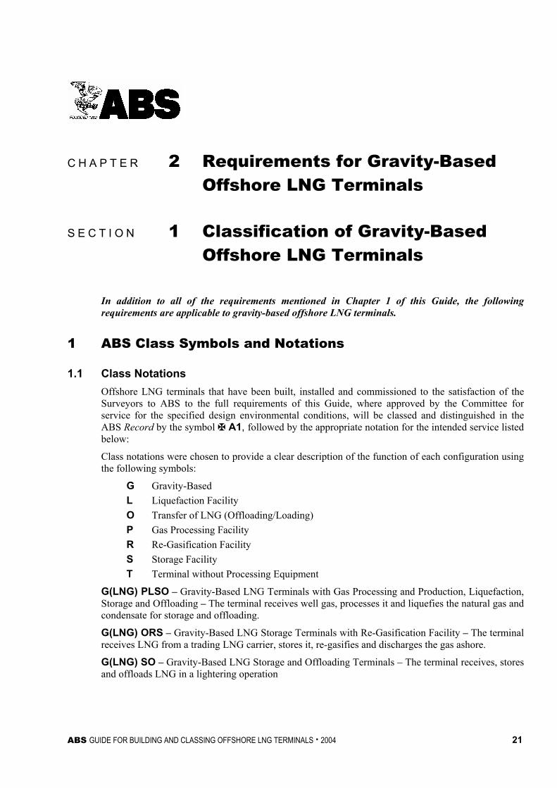
1.1 Class Notations Offshore LNG terminals that have been built, installed and commissioned to the satisfaction of the Surveyors to ABS to the full requirements of this Guide, where approved by the Committee for service for the specified design environmental conditions, will be classed and distinguished in the ABS Record by the symbol À A1, followed by the appropriate notation for the intended service listed below: Class notations were chosen to provide a clear description of the function of each configuration using the following symbols:
G Gravity-Based L Liquefaction Facility O Transfer of LNG (Offloading/Loading) P Gas Processing Facility R Re-Gasification Facility S Storage Facility T Terminal without Processing Equipment
G(LNG) PLSO – Gravity-Based LNG Terminals with Gas Processing and Production, Liquefaction, Storage and Offloading – The terminal receives well gas, processes it and liquefies the natural gas and condensate for storage and offloading.
G(LNG) ORS – Gravity-Based LNG Storage Terminals with Re-Gasification Facility – The terminal receives LNG from a trading LNG carrier, stores it, re-gasifies and discharges the gas ashore.
G(LNG) SO – Gravity-Based LNG Storage and Offloading Terminals – The terminal receives, stores and offloads LNG in a lightering operation
Chapter 2 Requirements for Gravity-Based Offshore LNG Terminals Section 1 Classification of Gravity-Based Offshore LNG Terminals 2-1
22 ABS GUIDE FOR BUILDING AND CLASSING OFFSHORE LNG TERMINALS . 2004
1.3 À AMCC and À AMCCU Notations Automatic or remote control and monitoring equipment/machinery that have been constructed and installed to the satisfaction of the Surveyors to this Bureau and to the full requirements of the ABS Guide for Automatic or Remote Control and Monitoring for Machinery and Systems (other than propulsion) on Offshore Installations, when found satisfactory after trial and approved by the Committee, will be classed and distinguished in the Record by the notation À AMCC. Where it is intended that the machinery be controlled and monitored from a remote control and monitoring center located outside the machinery space(s), a Class notation À AMCCU will be assigned. It should be noted that the above notations do not cover the instrumentation and control systems for any process systems.
1.5 Application of Class Notations The class notations described above cover the following components:
i) Gravity-based offshore LNG terminals including the terminal’s principal structure, equipment, machinery and all electrical systems under one of the notations in 2-1/1.1 above, subject to the requirements of this Guide.
ii) Foundations in accordance with the requirements of this Guide.
iii) Gas processing, production and liquefaction facilities according to the requirements of this Guide and the applicable sections of the Facilities Guide.
iv) LNG storage facilities (Containment Systems) in accordance with the requirements of this Guide and the applicable sections of Part 5 of the Steel Vessel Rules.
v) Inlet and outlet facilities in accordance with the requirements of this Guide.
vi) LNG and GNG (Gaseous Natural Gas/LNG vapor) handling systems in accordance with the requirements of this Guide and the applicable sections of Part 5 of the Steel Vessel Rules.
vii) Re-gasification facilities in accordance with the requirements of this Guide.
viii) Safety systems in accordance with the requirements of this Guide.
ix) Helicopter landing area in accordance with the requirements of this Guide and the applicable sections of the Steel Vessel Rules.
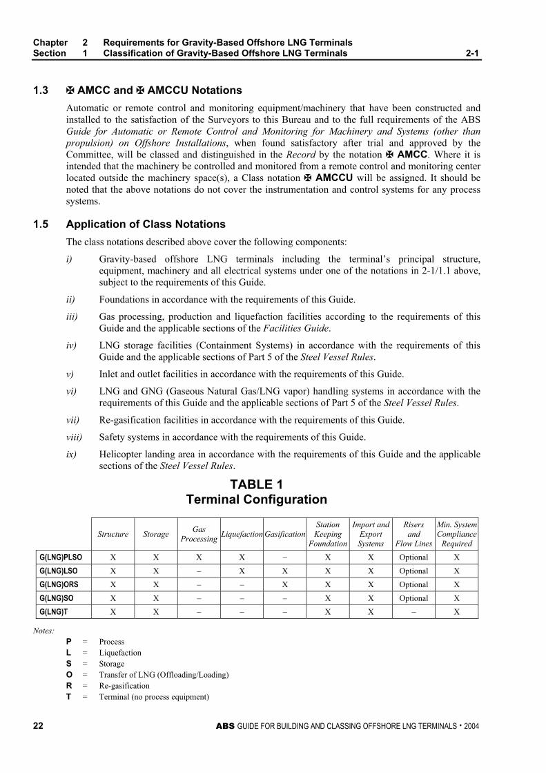
TABLE 1 Terminal Configuration
Structure Storage Gas Processing Liquefaction Gasification
Station Keeping
Foundation
Import and Export Systems
Risers and
Flow Lines
Min. SystemCompliance
Required
G(LNG)PLSO X X X X – X X Optional X
G(LNG)LSO X X – X X X X Optional X
G(LNG)ORS X X – – X X X Optional X
G(LNG)SO X X – – – X X Optional X
G(LNG)T X X – – – X X – X
Notes: P = Process L = Liquefaction S = Storage O = Transfer of LNG (Offloading/Loading) R = Re-gasification T = Terminal (no process equipment)
Chapter 2 Requirements for Gravity-Based Offshore LNG Terminals Section 1 Classification of Gravity-Based Offshore LNG Terminals 2-1
ABS GUIDE FOR BUILDING AND CLASSING OFFSHORE LNG TERMINALS . 2004 23
3 Plans and Data to be Submitted
Plans and data to be submitted for design review shall be submitted at least in triplicate; one copy for return to the submitter, one copy retained by ABS engineering office, and one copy for the use of the attending Surveyor. Full size prints of documents are preferred. If it is not feasible, all reduced prints must be clearly legible in all details. Proceeding paragraphs of this Subsection “Plans and Data to be Submitted” cover submittals for full variety of Class Notations. The actual extent of plans and data to be submitted depend upon the equipment, machinery and systems installed on the terminal and requested for Classification by the Owner.
3.1 Design Plans and Data for Structures Plans showing the scantlings, arrangements and details of the principal parts of the hull structure of each terminal to be built under survey are to be submitted and approved before the work of construction has commenced. These plans are to clearly indicate the scantlings, joint details and welding, or other methods of connection. In general, plans are to be submitted that include the following, where applicable:
• Arrangement plans, elevations and plan views clearly showing in sufficient detail the overall configuration, dimensions and layout of the structure, its facilities and foundation
• Layout plans indicating the locations of equipment and locations of the equipment loads and other design deck loads, fender loads, etc., which are imposed on the structure
• Structural plans indicating the complete structural arrangement, dimensions, member sizes, plating and framing, material properties and details of connections and attachments; for concrete structures, plans indicating general notes about materials and workmanship, arrangements and details of reinforcement, typical details of concrete cover, the location and detail of construction joints, waterstops, etc.
• Pile plans indicating arrangements, nominal sizes, thicknesses and penetration
• Welding details and procedures, and schedule of nondestructive testing
• Corrosion control systems
• Structural plans indicating the complete arrangements of structures, such as helidecks, crane pedestals, equipment foundations and manner of reinforcement, fendering, various houses and other structures which are not normally considered vital to the overall structural integrity of the offshore structure
• Various information in support of novel features utilized in the offshore structure design such as hydrostatic and stability curves, elements of any mooring system, etc.
3.1.1 Site Condition Reports The site condition reports are to be submitted. For details, refer to 1/1.11.1 of the Offshore Installation Rules. The principal purpose of these reports is to demonstrate that site conditions have been evaluated in establishing design criteria. Among the items to be discussed are:
i) Environmental conditions of waves, winds, currents, tides, water depth, air and sea temperature and ice
ii) Seabed topography, stability and pertinent geotechnical data
iii) Seismic conditions
Where appropriate, data established for a previous installation in the vicinity of the installation proposed for classification may be utilized if acceptable in the opinion of the Bureau.
Chapter 2 Requirements for Gravity-Based Offshore LNG Terminals Section 1 Classification of Gravity-Based Offshore LNG Terminals 2-1
24 ABS GUIDE FOR BUILDING AND CLASSING OFFSHORE LNG TERMINALS . 2004
3.1.2 Design Data and Calculations Information is to be submitted for the terminal that describes the methods of design and analysis which were employed to establish its design. The estimated design service life of a terminal is also to be stated. Where model testing is used as a basis for a design, the applicability of the test results will depend on the demonstration of the adequacy of the methods employed, including enumeration of possible sources of error, limits of applicability and methods of extrapolation to full-scale data. Preferably, procedures should be reviewed and agreed upon before model testing is done.
As required in subsequent Sections, calculations are to be submitted to demonstrate the sufficiency of the proposed design. Such calculations are to be presented in a logical and well-referenced fashion employing a consistent system of units. Where the calculations are in the form of computer analysis, the submittal is to provide input and output data with computer-generated plots for the structural model. A program description (not listings), user manuals and the results of program verification sample problems may be required to be submitted.
3.1.3 Plans or Specifications Plans or specifications depicting or describing the arrangements and details of the major items of the terminal are to be submitted for review or approval in a timely manner.
Documentation to facilitate the survey of concrete quality, as applicable to the Quality Control Plan (QCP) (see 2-3/3.5 for details), is to be submitted for approval.
Detailed procedural descriptions and design calculations covering all phases of the construction, transportation and installation of the gravity-based structure are to be submitted prior to the work being done.
Where deemed appropriate, and when requested by the Owner, a schedule for information submittal and plan approval can be jointly established by the Owner and the Bureau. This schedule, which the Bureau will adhere to as far as reasonably possible, is to reflect the construction schedule and the complexity of the terminal as it affects the time required for review of the submitted data.
3.1.4 Information Memorandum An information memorandum on the terminal is to be prepared and submitted to the Bureau. The Bureau will review the contents of the memorandum to establish consistency with other data submitted for the purpose of obtaining classification. The Bureau will not review the contents of the memorandum for their accuracy or the features described in the memorandum for their adequacy.
An information memorandum is to contain, as appropriate to the terminal, the following:
• Site plan indicating the general features at the site and the exact location of the terminal.
• Environmental design criteria, including the recurrence interval used to assess environmental phenomena (2-2/1.1).
• Plans showing the general arrangement of the terminal.
• Description of the safety and protective systems provided.
• The number of personnel to be normally stationed at the terminal.
• Listing of governmental authorities having cognizance over the terminal.
• Listing of any novel features.
• Brief description of any monitoring proposed for use on the terminal.
• Description of transportation and installation procedures.
Chapter 2 Requirements for Gravity-Based Offshore LNG Terminals Section 1 Classification of Gravity-Based Offshore LNG Terminals 2-1
ABS GUIDE FOR BUILDING AND CLASSING OFFSHORE LNG TERMINALS . 2004 25
3.3 Design Plans for LNG Containment System, LNG and GNG Handling Systems The following plans, calculations and information, as appropriate, are to be submitted in addition to those required by Section 1-1-7 of the Steel Vessel Rules:
• Full particulars of the intended cargo including maximum vapor pressure, minimum and maximum temperature, and loading and storage procedures.
• General arrangement plans of the terminal showing the position of the following:
i) Cargo containment system, cargo tanks, fuel oil, water ballast and other tanks and void spaces.
ii) Manholes and any other opening of the cargo tanks.
iii) Doors and other openings in cargo pump and compressor rooms and other gas-dangerous rooms.
iv) Ventilation ducts of cargo compressor rooms and other “gas-dangerous” spaces.
v) Door, air-locks, manholes, ducts and other openings for “non-gas-dangerous” spaces which are, however, adjacent to the cargo area.
vi) Cargo piping, both liquid and gaseous phases, located under and above deck.
vii) Vent piping and gas-freeing piping and protective devices such as flame screens, etc. fitted at the outlet end of the vents etc.
viii) Gas-dangerous spaces.
• Plans of the terminal structure in way of the cargo tanks, including the installation of attachments, accessories, internal reinforcements, saddles for support and tie-down devices.
• Plans of the structure of the cargo containment system, including the installation of attachments, supports and attachment of accessories. Detailed construction drawings together with design calculations for the pressure boundary, tank support arrangement and analysis for the load distribution. Anti collision, chocking arrangement and design calculations.
• Distribution of the grades and of the types of steel proposed for use in the structures of the terminal together with the calculation of the temperatures on all of the structures which can be affected by the low temperatures of the cargo.
• Results of direct calculations of the stresses in the cargo containment system.
• Specifications and plans of the insulation system and calculation of the heat balance.
• Thermal heat analysis determining the LNG boil-off rate from the storage tanks.
• Calculations to show the means provided for handling the boil-off gas from storage tanks without causing overpressurization in the tanks.
• Procedures and calculations of the cooling down, loading and unloading operations.
• Loading and unloading systems, venting systems and gas-freeing systems, as well as a schematic diagram of the remote controlled valve system.
• Details and installation of the safety valves and relevant calculations of their relieving capacity.
• Details and installation of the various monitoring and control systems, including the devices for measuring the level of the cargoes in the tanks and the temperatures in the containment system.
• Schematic diagram of the ventilation system indicating the vent pipe sizes and height of the openings above the main deck.
Chapter 2 Requirements for Gravity-Based Offshore LNG Terminals Section 1 Classification of Gravity-Based Offshore LNG Terminals 2-1
26 ABS GUIDE FOR BUILDING AND CLASSING OFFSHORE LNG TERMINALS . 2004
• Schematic diagram of the refrigeration system together with the calculations concerning the refrigerating capacity for a re-liquefaction plant, if provided.
• Details of the electrical equipment installed in the cargo area and of the electrical bonding of the cargo tanks and piping.
• Where fitted, plans and specifications relative to the use of the cargo as fuel for boilers and internal combustion engines (general installations; schematic diagram of the fuel-gas lines with the indication of all of the valves and safety devices; compressors of the fuel gas and relevant engines; fuel-gas heaters and pressure vessels; installation of the burners of the fuel-gas and of the fuel oil; electrical bonding systems).
• Details of testing procedures of cargo tanks and liquid and vapor systems.
• Diagram of inert-gas system or hold-space environmental-control system.
• Diagram of gas-detection system.
• Jettison arrangements, if provided.
• Details of all cargo and vapor handling equipment.
• Welding procedure for LNG storage tanks and LNG and GNG piping systems.
• Emergency shutdown arrangements.
• Construction details of cargo and booster pumps and compressors including material specification.
• Hazardous areas drawing showing access, openings, vent outlets.
• De-watering and ballast arrangement for the cargo area.
3.5 Design Plans for Process Facilities, Support and Safety Systems
3.5.1 Process and Re-Gasification Facilities • The process system description.
• Project specification and overall process concept evaluation.
• Process flow sheets.
• Heat and mass balance.
• Equipment layout drawings.
• Area classification and ventilation drawings.
• Piping and Instrument Diagrams (P&IDs).
• Safety Analysis Function Evaluation (SAFE) charts.
• Shut down and emergency shut down system (to include a hazard analysis and Failure Modes and Effects Analysis (FMEA) to identify critical components).
• Pressure relief and depressurization systems.
• Flare and vent systems.
• Spill containment, closed and open drain systems.
• Process equipment documentation including calculations showing suitability of all pressurized components in the system to withstand the maximum design pressure that a specific component is likely to encounter in service.
Chapter 2 Requirements for Gravity-Based Offshore LNG Terminals Section 1 Classification of Gravity-Based Offshore LNG Terminals 2-1
ABS GUIDE FOR BUILDING AND CLASSING OFFSHORE LNG TERMINALS . 2004 27
• Process piping systems.
• Packaged process units.
• The monitoring and control system for the entire system pressure regulation and gas dispersion system (to include calculations for sizing of the venting system and the relief valve) radiant heat analysis to demonstrate that the radiant heat intensity at any deck level or location where normal maintenance or operating activity could take place is not exceeding API RP 521 recommendations.
3.5.2 Process Support and Service Systems • Piping and Instrument Diagrams (P&IDs) for each system.
• Equipment documentation.
• Process support piping specifications.
• Specifications and data sheets for internal combustion engines and turbines
• Specifications and data sheets for cranes (Optional).
• Marine support systems as required by the ABS Rules applicable to the type of terminal.
3.7 Electrical Installations • Electrical one-line diagrams.
• Short-circuit current calculations.
• Coordination study.
• Specifications and data sheets for generators and motors.
• Specifications and data sheets for distribution transformers.
• Details of storage batteries.
• Details of emergency power source.
• Standard details of wiring cable and conduit installation practices.
• Switchboards and distribution panel.
• Panel board.
• Installations in classified areas.
3.9 Instrumentation and Control Systems • General arrangements.
• Data sheet.
• Schematic drawings – Electrical systems.
• Schematic drawings – Hydraulic and pneumatic systems.
• Programmable electronic systems.
Chapter 2 Requirements for Gravity-Based Offshore LNG Terminals Section 1 Classification of Gravity-Based Offshore LNG Terminals 2-1
28 ABS GUIDE FOR BUILDING AND CLASSING OFFSHORE LNG TERMINALS . 2004
3.11 Fire Protection and Personnel Safety • Firewater system.
• Water spray (Deluge) systems for any deckhouse, superstructure and manifold areas.
• Water spray (Deluge) systems for process equipment.
• Dry powder system for LNG storage tank area.
• Fixed fire extinguishing systems.
• Paint lockers and flammable material storerooms.
• Emergency control stations.
• Portable and semi-portable extinguishers.
• Fire and gas detection and alarm systems.
• Fire and gas cause and effect chart.
• Structural fire protection (which indicates classification of all bulkheads for quarters section, machinery spaces and processing facilities).
• Heating Ventilation and Air Conditioning (HVAC) plan [including Air Handling Unit (AHU)] location, duct layout, duct construction and bulkhead penetration details.
• Joiner detail arrangement and structural fire protection material certification.
• Guard rails.
• Escape routes (may be included on the fire control plan or separate plan).
• Lifesaving appliances and equipment plan (escape routes must be indicated).
• Insulation of hot surfaces.
• Fire and explosion hazard analysis.
• Due to the varying configurations of the project, some portions of these requirements may not be applicable.
3.13 Installation Procedures • Procedures for loading sections of the terminal structure, deck area, process modules decks and
topsides.
• Procedures for carrying out all installation work offshore including foundation preparation, platform installation and completion.
3.15 Start-up and Commissioning Manual • Provisions/procedures for start-up.
• Manual/procedures for commissioning trials.
ABS GUIDE FOR BUILDING AND CLASSING OFFSHORE LNG TERMINALS . 2004 29
C H A P T E R 2 Requirements for Gravity-Based Offshore LNG Terminals
S E C T I O N 2 Design of Gravity-Based Offshore LNG Terminals
1 Environmental Loading and Design Basis
1.1 Environmental and Related Conditions
1.1.1 General The minimum recurrence interval used to establish the magnitude of the Design Environmental Condition is 100 years, except where the use of a shorter recurrence interval produces higher magnitude load effects. As applicable, when a National Authority having jurisdiction over the LNG terminal specifies the use of a lower return period, this will be specially considered.
1.1.2 Environmental Conditions The LNG terminal is to be designed for the site-specific environmental conditions specified in Part 3 of the Offshore Installations Rules. In addition to the Design Environmental Conditions mentioned above, the designer is to specify any limiting Operating Environmental Conditions. These are sets of characteristic parameters for the environmental factors that need to be limited so that the safe performance of an operation or function is not compromised. Such operations may include, as appropriate, transportation and installation of the LNG terminal structure itself and for conditions after the LNG terminal structure’s installation (berthing and mooring of cargo and supply vessels, cargo transfer, personnel transfer, fuel oil transfer etc.). These sets of conditions are herein referred to as Operating Environmental Conditions.
1.1.3 Environmental Factors to be Considered In general, the design of the LNG terminal will require investigation of the following environmental factors, as appropriate to the type of terminal structure and the terminal’s installation site:
i) Waves
ii) Wind
iii) Currents
iv) Tides and storm surges
v) Air and sea temperatures
Chapter 2 Requirements for Gravity-Based Offshore LNG Terminals Section 2 Design of Gravity-Based Offshore LNG Terminals 2-2
30 ABS GUIDE FOR BUILDING AND CLASSING OFFSHORE LNG TERMINALS . 2004
vi) Ice and snow
vii) Marine growth
viii) Seismicity
ix) Sea ice
Other phenomena, such as tsunamis, submarine slides, seiche, abnormal composition of air and water, air humidity, salinity, ice drift, icebergs, ice scouring, etc. may require investigation depending upon the specific installation site.
The required investigation of seabed and soil conditions is described in Section 3/6 of the Offshore Installations Rules.
1.3 Design Basis The design of the unit and the facilities on the installation for gas processing, liquefaction, storage, re-gasification including importing of raw gas or LNG and exporting of processed gas or LNG is to be in accordance with the criteria defined in this Guide, including any additional prevention or mitigation safeguards identified in the risk assessment required in 2-2/3 of this Guide.
In addition to the requirements mentioned above, it is also the responsibility of the designer, owner and operator to comply with any additional requirements that may be imposed by the flag state or the coastal state or any other jurisdictions in the intended area of deployment and operation. This would include requirements for importing and exporting pipelines.
The complete basis for the design is to be stated in the operations manual and is to include the intended location, the envelope of environmental operating conditions and the storage capacities and throughputs of the production/re-gasification systems.
3 Risk Assessment A Risk Assessment shall be carried out to identify significant hazards and accident scenarios that may affect the installation or any part thereof, and to consider the benefit of existing or potential risk control options. The objective of the risk assessment is to identify areas of the design that may require the implementation of risk control measures to reduce identified risk(s) to an acceptable level. For this purpose, a systematic process is to be applied to identify situations where a combination or sequence of events could lead to undesirable consequences such as property damage, personnel safety and environmental damage. The risk assessment shall consider, as a minimum, the following events: i) Damage to the primary structure due to extreme weather, impact/collision, dropped objects,
helicopter collision, exposure to unsuitably cold temperatures, exposure to high radiant heat ii) Fire and explosion iii) Loss of primary liquid containment (for a duration to be determined based on an approved
contingency plan) iv) LNG leakage v) Release of flammable or toxic gas to the atmosphere or inside an enclosed space vi) Roll-over (thermodynamic instability due to LNG stratification) vii) Loss of ability to offload LNG or discharge gas ashore viii) Loss of any one critical component in the process system ix) Loss of electrical power
Chapter 2 Requirements for Gravity-Based Offshore LNG Terminals Section 2 Design of Gravity-Based Offshore LNG Terminals 2-2
ABS GUIDE FOR BUILDING AND CLASSING OFFSHORE LNG TERMINALS . 2004 31
The identified risk control options (prevention and mitigation measures) deemed necessary to be implemented should be considered part of the design basis of the terminal.
ABS recommends that early in the project a risk assessment plan be developed, documented and submitted to the Bureau for review prior to conducting the risk assessment. During review of the plan, an agreement will be reached on the extent of Bureau participation and/or monitoring of project-related risk studies. The Bureau’s participation in and/or monitoring of key tasks (e.g. Hazard Identification meetings) is necessary in order to establish a minimum level of confidence on the risk assessment results.
5 Structure – Gravity-Based Terminal
This Section defines the general design requirements and load type definitions of steel or concrete gravity-based offshore LNG terminals.
The ABS Offshore Installations Rules, directly and by reference to other standards, present the criteria deemed most applicable to the structural design of offshore LNG terminals. Major portions of the structural criteria from these ABS standards are excerpted and modified below to reflect envisioned LNG terminal service. This has been done for the convenience of users and to concisely present in this Guide the main structural design and construction features included in the scope of Classification and the criteria to be applied. Reference should be made to the aforementioned Offshore Installations Rules for additional background on the referenced criteria.
In the design criteria presented below, it is assumed that the structural elements and the seabed foundation soil that resist the specified loads will not be exposed directly to the LNG and its cryogenic temperature.
5.1 General Design Requirements and Load Type Definitions
5.1.1 Analytical Approaches 5.1.1(a) Format of Design Specifications. The design requirements of this Guide are generally specified in terms of a working stress (also called ‘allowable stress’) format for steel structures and an ultimate strength format for concrete structures. In addition, this Guide requires that consideration be given to satisfying the serviceability of structure relative to deflection, vibration and, in the case of concrete, cracking.
ABS will give special consideration to the use of alternative specification formats such as those based on probabilistic or semi-probabilistic limit state design concepts.
5.1.1(b) Loading Formats. Either a deterministic or spectral format may be employed to describe various load components. When a static approach is used, it is to be demonstrated, where relevant, that consideration has been given to the general effects of dynamic amplification. The influence of waves, other than the highest waves, is to be investigated for their potential to produce maximum peak stresses due to resonance with the structure.
When considering an earthquake in seismically active areas, a dynamic analysis is to be performed. A dynamic analysis is also to be considered to assess the effects of environmental or other types of loads where dynamic amplification is expected. When a fatigue analysis is performed, a long-term distribution of the stress range with proper consideration of dynamic effects is to be obtained for relevant loadings anticipated during the design life of the terminal [see 2-2/5.3.7 and 2-2/5.5.5(d)].
Chapter 2 Requirements for Gravity-Based Offshore LNG Terminals Section 2 Design of Gravity-Based Offshore LNG Terminals 2-2
32 ABS GUIDE FOR BUILDING AND CLASSING OFFSHORE LNG TERMINALS . 2004
5.1.1(c) Combinations of Loading Components. Loads imposed during and after installation are to be taken into account. In consideration of the various loads described in 2-2/5.1.4, loads to be considered for design are to be combined consistent with their probability of simultaneous occurrence. However, earthquake loadings may be applied without consideration of other environmental effects unless conditions at the site necessitate their inclusion. If site-specific directional data are not obtained, the direction of applied environmental loads is to be such as to produce the highest possible influence on the terminal.
Loading combinations corresponding to conditions after installation are to reflect both operating and design environmental loadings (2-2/1.1). Reference is to be made to 2-2/5.3, 2-2/5.5 and 2-2/5.7 regarding the minimum load combinations to be considered. The Operator is to specify the operating environmental conditions and the maximum tolerable environmental loads during installation.
5.1.2 Overall Design Considerations 5.1.2(a) Air Gap. An air gap of at least 1.5 m (5 ft) is to be provided between the maximum wave crest elevation and the lowest protuberance of the superstructure for which wave forces have not been included in the design. After accounting for the initial and expected long-term settlements of the structure due to consolidation (and possibly regional subsidence in a hydrocarbon or other reservoir area), the design wave crest elevation is to be superimposed on the still water level and consideration is to be given to wave run-up, tilting of the structure and, where appropriate, tsumanis.
5.1.2(b) Long-Term and Secondary Effects. Consideration is to be given to the following effects, as appropriate, to the planned structure:
i) Local vibration due to machinery, equipment and vortex shedding.
ii) Stress concentrations at critical joints, openings and any location where stress risers may occur due to discontinuities in stress flow (e.g., appurtenance attachments).
iii) Secondary stresses induced by large deflection (P-δ effects).
iv) Cumulative fatigue.
v) Corrosion.
vi) Abrasion due to ice.
vii) Freeze-thaw action on concrete and coatings.
viii) Differential settlement and rocking.
ix) Water migration into void and/or dry ballast areas
5.1.2(c) Reference Marking. For large or complex terminals, consideration should be given to installing permanent reference markings during construction to facilitate future surveys. Where employed, such markings may consist of weld beads, metal or plastic tags or other permanent markings. In the case of a concrete terminal, markings may be provided using suitable coatings or permanent lines molded into the concrete.
5.1.2(d) Zones of Exposure. Measures taken to mitigate the effects of corrosion are to be specified and described in terms of the following definitions for corrosion protection zones.
• Submerged Zone. That part of the installation below the splash zone.
• Splash Zone. The part of the installation containing the areas above and below the still water level which are regularly subjected to wetting due to wave action. Characteristically, the splash zone is not easily accessible for field painting, nor protected by cathodic protection.
• Atmospheric Zone. That part of the installation above the splash zone.
Chapter 2 Requirements for Gravity-Based Offshore LNG Terminals Section 2 Design of Gravity-Based Offshore LNG Terminals 2-2
ABS GUIDE FOR BUILDING AND CLASSING OFFSHORE LNG TERMINALS . 2004 33
Additionally, for terminals located in areas subject to floating or submerged ice, that portion of the structure which may reasonably be expected to come into contact with floating or submerged ice is to be designed with consideration for such contact.
5.1.2(e) Access for Inspection. In the design of the terminal, consideration should be given to providing access for inspection during construction and, to the extent practicable, for survey after construction.
5.1.3 General Design Considerations for Concrete or Steel Gravity Terminals 5.1.3(a) Positioning. The procedure for transporting and positioning the structure and the accuracy of measuring devices used during these procedures are to be documented.
5.1.3(b) Repeated Loadings. Effects of repeated loadings on soil properties, such as pore pressure, water content, shear strength and stress-strain behavior, are to be investigated.
5.1.3(c) Soil Reactions. Soil reactions against the base of the structure and possible differential settlements during and after installation are to be investigated. Consideration should be given to the occurrence of point loading caused by sea bottom irregularities. Suitable grouting between base slab and sea floor can be employed to reduce concentration of loads.
5.1.3(d) Terminal Operation. The expected loads and other demands that will be acting on the LNG Terminal as a result of the need to berth and moor vessels are to be considered in the design. These may include vessel breasting and mooring loads, the presence of fenders and the additional hydrodynamic and gravity loads that they bring, the need to support bollards and other mooring hardware, etc.
5.1.3(e) Maintenance. The strength and durability of construction materials is to be maintained. Where sulphate attack is anticipated, as from stored oil, adequate mitigation methods are to be employed.
5.1.3(f) Reinforcement Corrosion. Means to minimize reinforcing steel corrosion are to be considered and may include the use of high chromium and low carbon steel.
5.1.3(g) Instability. Instability of structural members due to submersion is to be considered, with due account for second-order effects produced by factors such as geometrical imperfections.
5.1.3(h) Horizontal Sliding. Where necessary, protection against horizontal sliding along the sea floor is to be provided by means of skirts, shear keys or equivalent means.
5.1.3(i) Dynamic Analysis. Where dynamic effects are significant to the structural design, dynamic analysis, including simulation of wave-structure response and soil-structure interaction, should be carried out.
5.1.3(j) Long Term Resistance. The long-term resistance to abrasion, cavitation, freeze-thaw durability and strength retention of the concrete is to be considered.
5.1.3(k) Negative Buoyancy. Provision is to be made to maintain either adequate negative buoyancy or the functional equivalent such as tension piles attached at all times to resist the uplift forces from submergence, waves, currents and overturning moments.
Chapter 2 Requirements for Gravity-Based Offshore LNG Terminals Section 2 Design of Gravity-Based Offshore LNG Terminals 2-2
34 ABS GUIDE FOR BUILDING AND CLASSING OFFSHORE LNG TERMINALS . 2004
5.1.4 Types of Loads Loads applied to an offshore terminal are, for purposes of this Guide, categorized as follows.
5.1.4(a) Dead Loads. Dead loads are loads that do not change during the mode of operation under consideration. Dead loads include the following:
i) Weight in air of the structure including, as appropriate, the weight of the principal structure (e.g., caissons, gravity foundation, piling), weight of the internal LNG containment structure, grout, module support frame, decks, modules, stiffeners, piping, helicopter deck, skirt, columns and any other fixed structural parts.
ii) Weight of permanent ballast and the weight of permanent machinery.
iii) External hydrostatic pressure and buoyancy calculated on the basis of the still-water level.
iv) Static earth pressure.
5.1.4(b) Live Loads. Live loads associated with the normal operation and uses of the structure are loads which may change during the mode of operation considered. Though environmental loads are live loads, they are categorized separately [see 2-2/5.1.4(d)]. Live loads acting after construction and installation include the following:
i) The weight of temporary equipment which can be removed
ii) The weight of crew and consumable supplies
iii) Fluids in the vessels and pipes during operation
iv) Fluids in the vessels and pipes during testing
v) The weight of fluids in storage and ballast tanks
vi) The forces exerted on the structure due to terminal operations, e.g., LNG cargo vessel berthing and mooring
vii) The forces exerted on the structure during the operation of cranes and vehicles
viii) The forces exerted on the structure by vessels moored to the structure or accidental impact consideration for a typical supply vessel that would normally service the installation
ix) The forces exerted on the structure by helicopters during take-off and landing or while parked on the structure
Where applicable, the dynamic effects on the structure of the listed items are to be taken into account. Where appropriate, some of the items of live load listed above may be adequately accounted for by designing decks, etc. to a maximum, uniform area load as specified by the Operator, or past practice for similar conditions.
Live loads occurring during transportation and installation are to be determined for each specific operation involved, and the dynamic effects of such loads are to be accounted for as necessary.
5.1.4(c) Deformation Loads. Deformation loads are loads due to deformations imposed on the structure. The deformation loads include those due to temperature variations (e.g., hot or cold hydrocarbon or process fluid storage) leading to thermal induced stress in the structure and, where necessary, loads due to soil displacements (e.g., differential settlement or lateral displacement) or due to deformations of adjacent structures. For concrete terminals, deformation loads due to prestress, creep, shrinkage and expansion are to be taken into account.
Chapter 2 Requirements for Gravity-Based Offshore LNG Terminals Section 2 Design of Gravity-Based Offshore LNG Terminals 2-2
ABS GUIDE FOR BUILDING AND CLASSING OFFSHORE LNG TERMINALS . 2004 35
5.1.4(d) Environmental Loads. Environmental loads are loads due to wind, waves, current, ice, snow, earthquake and other environmental phenomena. The characteristic parameters defining an environmental load are to be appropriate to the installation site and in accordance with the requirements of 2-2/1.1 of this Guide. Operating environmental loads are those loads derived from the parameters characterizing operating environmental conditions. Design environmental loads are those loads derived from the parameters characterizing the design environmental condition.
The combination and severity of design environmental loads are to be in accordance with 2-2/1.1 of this Guide.
Environmental loads are to be applied to the structure from directions producing the most unfavorable effects on the structure, unless site-specific studies provide evidence in support of a less stringent requirement. Directionality may be taken into account in applying the environmental criteria.
Earthquake loads and loads due to accidents or rare occurrence environmental phenomena need not be combined with other environmental loads, unless site-specific conditions indicate that such combinations are appropriate.
5.1.4(e) Other Loads. For deck mounted equipment – for use in the preliminary design of deck transverses and girders that are directly resisting the reaction forces and when the Bureau permits it in lieu of a more comprehensive method, the approach presented in Appendix 2, Section 7 of the FPI Guide may be used.
5.3 Gravity Steel Terminals
5.3.1 General 5.3.1(a) Materials. The requirements of this Paragraph are intended for terminals constructed of steel, manufactured and having properties as specified in Section 2/1 of the Offshore Installations Rules. Where it is intended to use steel or other materials having properties differing from those specified in Section 2/1 of the Offshore Installations Rules, their applicability will be considered subject to a review of the specifications for the alternative materials and the proposed methods of fabrication.
5.3.1(b) Corrosion Protection. Materials are to be protected from the effects of corrosion by the use of a corrosion protection system including the use of coatings. The system is to be effective from the time the terminal is initially placed on site. Where the sea environment contains unusual contaminants, any special corrosive effects of such contaminants are also to be considered. For the design of protection systems, reference is to be made to the National Association of Corrosion Engineers (NACE) publication RP 0176-94, or other appropriate references.
5.3.1(c) Steel-Concrete Hybrid Structures. The steel portions of a steel-concrete hybrid structure are to be designed in accordance with the requirements of 2-2/5.3 of this Guide, and the concrete portions are to be designed as specified in 2-2/5.5. Any effects of the hybrid structure interacting on itself in areas such as corrosion protection should be considered.
5.3.1(d) Steel-Concrete Composite Structures. Steel-Concrete composite structures are to be designed in accordance with 2-2/5.3 of this Guide and the AISC, “Allowable Stress Design”.
5.3.2 General Design Criteria Steel terminals are to be designed and analyzed for the loads to which they are likely to be exposed during construction, installation and in-service operations. To this end, the effects on the structure of a minimum set of loading conditions, as indicated in 2-2/5.3.3, are to be determined, and the resulting structural responses are not to exceed the safety and serviceability criteria given below.
Chapter 2 Requirements for Gravity-Based Offshore LNG Terminals Section 2 Design of Gravity-Based Offshore LNG Terminals 2-2
36 ABS GUIDE FOR BUILDING AND CLASSING OFFSHORE LNG TERMINALS . 2004
The use of design methods and associated safety and serviceability criteria other than those specifically covered in this Section is permitted where it can be demonstrated that the use of such alternative methods will result in a structure possessing a level of safety equivalent to or greater than that provided by the direct application of these requirements.
5.3.3 Loading Conditions Loadings that produce the most unfavorable effects on the terminal during and after construction and installation are to be considered. Loadings to be investigated for conditions after installation are to include at least those relating to both the realistic operating and design environmental conditions combined with other pertinent loads in the following manner.
Operating environmental loading combined with dead and maximum live loads appropriate to the function and operations of the terminal.
Design environmental loading combined with dead and live loads appropriate to the function and operations of the terminal during the design environmental condition.
For terminals located in seismically active areas, earthquake loads are to be combined with dead and live loads appropriate to the operation and function of the terminal which may be occurring at the onset of an earthquake.
5.3.4 Structural Analysis 5.3.4(a) The nature of loads and loading combinations as well as the local environmental conditions are to be taken into consideration in the selection of design methods. Methods of analysis and their associated assumptions are to be compatible with the overall design principles. Linear, elastic methods (working stress methods) can be employed in design and analysis, provided proper measures are taken to prevent general and local buckling failure, and the interaction between soil and structure is adequately treated. When assessing structural instability as a possible mode of failure, the effects of initial stresses and geometric imperfections are to be taken into account. Construction tolerances are to be consistent with those used in the structural stability assessment.
5.3.4(b) Dynamic effects are to be accounted for if the wave energy in the frequency range of the structural natural frequencies is of sufficient magnitude to produce significant (greater than 15% of the static loads) dynamic response in the structure. In assessing the need for dynamic analyses, information regarding the natural frequencies of the structure in its intended position is to be obtained. The determination of dynamic effects is to be accomplished either by computing the dynamic amplification effects in conjunction with a deterministic analysis or by a random dynamic analysis based on a probabilistic formulation. In either case, the analysis is to be accompanied by a statistical description and evaluation of the relevant input parameters.
5.3.5 Allowable Stress Approach When a design is based on a working stress method [2-2/5.1.1 and 2-2/5.3.4(a)], the safety criteria are to be expressed in terms of appropriate basic allowable stresses in accordance with requirements specified below.
5.3.5(a) Controlling Reference Standards
i) For stiffened and unstiffened flat plate or cylindrical shell structure, the allowable stresses are as specified in the API RP 2T with element strength as defined in the API Bulletins 2V or 2U for flat plate or cylindrical shell structure, respectively.
ii) For tubular elements and their connections (e.g., jacket type construction), the allowable stresses are as specified in the API RP 2A.
Chapter 2 Requirements for Gravity-Based Offshore LNG Terminals Section 2 Design of Gravity-Based Offshore LNG Terminals 2-2
ABS GUIDE FOR BUILDING AND CLASSING OFFSHORE LNG TERMINALS . 2004 37
iii) For structural members and loadings covered by Part 5 of the American Institute of Steel Construction (AISC) Manual of Steel Construction, ASD, with the exception of earthquake loadings (see 2-2/5.3.5(c) below), the basic allowable stresses of the members are to be obtained using the AISC Specification.
iv) Other applicable recognized industry standards
5.3.5(b) Where stresses in members/components described in 2-2/5.3.5(a) are shown to be due to forces imposed by the design environmental condition acting alone or in combination with dead and live loads, the basic allowable stresses cited in 2-2/5.3.5(a) may be increased by one-third, provided the resulting structural member sizes are not less than those required for the operating environment loading combined with dead and live loads without the one-third increase in allowable stresses.
5.3.5(c) When considering loading combinations which include earthquake loads (2-2/5.3.3) on individual members or on the overall structure, the allowable stress may be set equal to 1.7 times the basic allowable stress of the member.
5.3.5(d) The allowable stresses specified in 2-2/5.3.5(b) are to be regarded as the limits for stresses in all structural parts for the marine operations covered in Section 3/7 of the Offshore Installations Rules, except for lifting, where the one-third increase in the basic allowable stress is not permitted. The lifting analysis should adequately account for equipment and fabrication weight increase.
5.3.5(e) For any two- or three-dimensional stress field within the scope of the working stress formulation, the equivalent stress (e.g., the vonMises stress intensity) is to be limited by an appropriate allowable stress less than yield stress, with the exception of those stresses of a highly localized nature. In the latter case, local yielding of the structure may be accepted, provided it can be demonstrated that such yielding does not lead to progressive collapse of the overall structure and that the general structural stability is maintained. The allowable vonMises stress of the structure is to be 0.6 of the yield strength for the operational conditions. A one-third increase in the allowable stress (i.e., 0.8 of the yield strength) is allowed for the design conditions.
5.3.5(f) Whenever elastic instability, overall or local, may occur before the stresses reach their basic allowable levels, appropriate allowable buckling stresses govern.
5.3.5(g) Mooring between Terminal and Vessel. The local foundation structure and vessel structure are to be checked for the given mooring loads using an appropriate engineering method such as FEA. The operating mooring load is defined as the maximum load imposed on the mooring lines between the terminal and the maximum size vessel for the operating environmental condition and the terminal, unless a smaller vessel is apt to impose higher mooring loads under the influence of the operating wind, wave, current and tides. Data and calculations are to be submitted to establish the validity of this operating mooring load. Safety factors for the mooring lines between the terminal and vessel are to comply with 3/4.9 of the Rules for Single Point Moorings.
When a rigid mooring structure is used as the mooring structure between the terminal and vessel, the connecting structures are to comply with 3/5.5 of the Offshore Installations Rules.
5.3.6 Structural Response to Earthquake Loads Terminals located in seismically active areas are to be designed to possess adequate strength and stiffness to withstand the effects of a strength level earthquake, as well as sufficient ductility to remain stable during rare motions of greater severity associated with a ductility level earthquake. The sufficiency of the structural strength and ductility is to be demonstrated by strength and, as required, ductility analyses.
Chapter 2 Requirements for Gravity-Based Offshore LNG Terminals Section 2 Design of Gravity-Based Offshore LNG Terminals 2-2
38 ABS GUIDE FOR BUILDING AND CLASSING OFFSHORE LNG TERMINALS . 2004
For a strength level earthquake, the strength analysis is to demonstrate that the structure is adequately sized for strength and stiffness so as to maintain all nominal stresses within their yield or buckling limits.
In the ductility analysis, it is to be demonstrated that the structure has the capability of absorbing the energy associated with the ductility level earthquake without reaching a state of incremental collapse.
In all seismically active locations around the world, a seismic report should be submitted that presents the seismic design parameters in a manner consistent with the approach taken in the RP 2A for developing site-specific criteria.
5.3.7 Fatigue Assessment For structural components, members and joints where fatigue is a probable mode of failure, or for which past experience is insufficient to assure safety from possible cumulative fatigue damage, an assessment of fatigue life is to be carried out. Emphasis is to be given to the splash zone, areas that are difficult to inspect and repair once the terminal is in service, and areas susceptible to corrosion-accelerated fatigue.
For structural members and joints which require a detailed assessment of cumulative fatigue damage, the results of the assessment are to indicate a minimum expected fatigue life of a fatigue design factor (safety factor for fatigue design) times the design life of the terminal. The fatigue design factor is a factor that is applied to individual structural details which accounts for: uncertainties in the fatigue assessment process, the consequences of failure (i.e., criticality) and the relative difficulty of inspection and repair. Section 4, Table 1 of the Guide for the Fatigue Assessment of Offshore Structures provides specific information on the values of the fatigue design factor. For a terminal located on the outer continental shelf of the United States, an alternative version of Table 1 is presented in Appendix 3 of the same document.
A spectral fatigue analysis technique is recommended to calculate the fatigue life of the terminal. Other rational analysis methods are also acceptable if the forces and member stresses can be properly represented. The dynamic effects should be taken into consideration if they are significant to the structural response.
5.3.8 Stresses in Connections Connections of structural components and members are to be developed to ensure effective load transmission between joined elements to minimize stress concentration and (as applicable) to prevent excessive “punching” shear. Connection details are also to be designed to minimize undue constraints against overall ductile behavior and to minimize the effects of post-weld shrinkage. Undue concentration of welding is to be avoided.
The design of tubular joints may be in accordance with the API RP 2A.
5.3.9 Local Structure Structures that do not directly contribute to the overall strength of the gravity-based offshore terminal, i.e., their loss or damage would not impair the structural integrity of the offshore terminal, are considered to be local structure.
Local structures are to be adequate for the nature and magnitude of applied loads. Allowable stresses specified in 2-2/5.3.5 are to be used as stress limits, except for those structural parts whose primary function is to absorb energy, in which case, sufficient ductility is to be demonstrated.
Chapter 2 Requirements for Gravity-Based Offshore LNG Terminals Section 2 Design of Gravity-Based Offshore LNG Terminals 2-2
ABS GUIDE FOR BUILDING AND CLASSING OFFSHORE LNG TERMINALS . 2004 39
5.5 Gravity Concrete Terminals
5.5.1 General 5.5.1(a) Materials. Unless otherwise specified, the requirements of this Paragraph are intended for structures constructed of materials manufactured and having properties as specified in 2/1 of the Offshore Installation Rules. Where it is intended to use materials having properties differing from those specified in 2/1 of the Offshore Installation Rules, the use of such materials will be specially considered. Specifications for alternative materials, details of the proposed methods of manufacture and, where available, evidence of satisfactory previous performance are to be submitted for approval.
Structural lightweight concrete should conform to ACI 213R, “Guide for Structural Lightweight Aggregate Concrete”. Lightweight aggregates should conform to the requirements of ASTM C330, “Specification for Lightweight Aggregates for Structural Concrete”.
5.5.1(b) Durability. Materials, concrete mix proportions, construction procedures and quality control are to be chosen to produce satisfactory durability for structures located in a marine environment. Problems to be specifically addressed include chemical deterioration of concrete, corrosion of the reinforcement and hardware, abrasion of the concrete, freeze-thaw durability and fire hazards as they pertain to the zones of exposure defined in 3/3.5.5 of the Offshore Installation Rules.
Test mixes should be prepared and tested early in the design phase to ensure that proper values of strength, creep, alkali resistance, etc. will be achieved.
5.5.1(c) Concrete-Steel Hybrid Structures. The concrete portions of a hybrid structure are to be designed in accordance with the requirements of this Paragraph and the steel portions in accordance with the requirements of 3/4 of the Offshore Installation Rules. Any effects of the hybrid structure interacting on itself in areas such as corrosion protection should be considered.
5.5.2 Design Method 5.5.2(a) General. The requirements of this Paragraph relate to the ultimate strength method of design employing the Limit State Design [or Load and Resistance Factor Design (LRFD)] format.
5.5.2(b) Load Magnitude. The magnitude of a design load for a given type of loading k is obtained by multiplying the load, Fk, by the appropriate load factor, ck, i.e., design load = ckFk.
5.5.2(c) Design Strength. In the analysis of sections, the design strength of a given material is obtained by multiplying the material strength, fk, by the appropriate strength reduction factor, φ, i.e., design strength = φ fk. The strength reduction factor and material strength of concrete (fc′) and reinforcement steel (fy) are defined in 2-2/5.5.5(c) and 2-2/5.5.6(b), respectively.
5.5.3 Load Definition 5.5.3(a) Load Categories. The load categories referred to in this Paragraph, i.e., dead loads, live loads, deformation loads and environmental loads are defined in 2-2/5.1.4.
5.5.3(b) Combination Loads. Loads taken in combination for the Operating Environmental Conditions and the Design Environmental Condition are indicated in 2-2/5.5.5(b).
Chapter 2 Requirements for Gravity-Based Offshore LNG Terminals Section 2 Design of Gravity-Based Offshore LNG Terminals 2-2
40 ABS GUIDE FOR BUILDING AND CLASSING OFFSHORE LNG TERMINALS . 2004
5.5.3(c) Earthquake and Other Loads. Earthquake loads and loads due to environmental phenomena of rare occurrence need not be combined with other environmental loads unless site-specific conditions indicate that such combination is appropriate.
5.5.4 Design Reference Design considerations for concrete terminals not directly addressed in this Guide are to follow the requirements of the American Concrete Institute (ACI) 318 and ACI 357R, or equivalent.
5.5.5 Design Requirements 5.5.5(a) General. The strength of the LNG Terminal structure is to be such that adequate safety exists against failure of the structure or its components. Among the modes of possible failure to be considered are the following:
i) Loss of overall equilibrium.
ii) Failure of critical sections.
iii) Instability resulting from large deformations.
iv) Excessive plastic or creep deformation.
The serviceability of the structure is to be assessed. The following items are to be considered in relation to their potential influences on the serviceability of the structure:
i) Cracking and spalling.
ii) Deformations.
iii) Corrosion of reinforcement or deterioration of concrete.
iv) Vibrations.
v) Leakage.
5.5.5(b) Required Strength (Load Combinations). The required strength (U) of the structure and each member is to be equal to, or greater than, the maximum of the following.
U = 1.2(D + T) + 1.6Lmax + 1.3EO
U = 1.2(D + T) + 1.2Lmax + cEEmax
U = 0.9(D + T) + 0.9Lmin + cEEmax
in which cE assumes the following values:
cE = 1.3 for wave, current, wind or ice load
cE = 1.4 for earthquake loads
In the preceding equations, the symbols D, T and L represent dead load, deformation load and live load, respectively (see 2-2/5.5.3). The symbol EO represents operating environmental loads while Emax represents design environmental loads. The symbol Lmin represents minimum expected live loads, while Lmax represents maximum expected live loads. Each live load is to be established with respect to expected environmental conditions which may limit or preclude the existence of the live load.
For loads of type D, the load factor 1.2 is to be replaced by 1.0 if it leads to a more unfavorable load combination. For loads of type EO, the load factor 1.3 may be reduced if a more unfavorable load combination results. For strength evaluation, the effects of deformation load may be ignored, provided adequate ductility is demonstrated.
Chapter 2 Requirements for Gravity-Based Offshore LNG Terminals Section 2 Design of Gravity-Based Offshore LNG Terminals 2-2
ABS GUIDE FOR BUILDING AND CLASSING OFFSHORE LNG TERMINALS . 2004 41
While the critical design loadings will be identified from the load combinations given above, the other simultaneously occurring load combinations during construction and installation phases are to be considered if they can cause critical load effects.
5.5.5(c) Strength Reduction Factors. The strength of a member or a cross section is to be calculated in accordance with the provisions of 2-2/5.5.6 of this Guide and it is to be multiplied by the following strength reduction factor, φ:
i) For flexure without tension, φ = 0.90
ii) For axial compression or compression combined with flexure.
Reinforced members with spiral reinforcement, φ = 0.70
Other reinforced members (excluding slabs and shells), φ = 0.65
The values given above may be increased linearly to 0.90 as φPn decreases from 0.10fc′Ag or φPb, whichever is smaller, to zero.
fc′ = specified compression strength of concrete
Ag = gross area of section
Pn = axial design load in compression member
Pb = axial load capacity assuming simultaneous occurrence of the ultimate strain of concrete and yielding of tension steel
Slabs and shells, φ = 0.70
iii) For shear and torsion, φ = 0.75
iv) For bearing on concrete, φ = 0.65, except for post-tensioning anchorage bearing.
For bearing on concrete in post-tension anchorage, φ = 0.85.
Alternatively, the expected strength of concrete members can be determined by using idealized stress-strain curves and material factors (cM) given in ACI 357R. The material factors applied to the stress-strain curves limit the maximum stress to achieve the desired reliability similar to using the strength reduction factors given above. The strength reduction factors (φ) and the material factors (cM) are not to be used simultaneously.
5.5.5(d) Fatigue. The fatigue strength of the structure will be considered satisfactory if under the unfactored operating loads the following conditions are satisfied:
i) The stress range in reinforcing or prestressing steel does not exceed 138 MPa (20,000 psi), or where reinforcement is bent, welded or spliced, 69 MPa (10,000 psi).
ii) There is no membrane tensile stress in concrete and not more than 1.4 MPa (200 psi) flexural tensile stress in concrete.
iii) The stress range in compression in concrete does not exceed 0.50fc′ where fc′ is the specified compressive strength of concrete.
iv) Where maximum shear exceeds the allowable shear of the concrete alone, and where the cyclic range is more than half the maximum allowable shear in the concrete alone, all shear is taken by reinforcement. In determining the allowable shear of the concrete alone, the influence of permanent compressive stress may be taken into account.
v) In situations where fatigue stress ranges allow greater latitude than those under the serviceability requirements given in 2-2/Table 1, the latter condition shall assume precedence.
Chapter 2 Requirements for Gravity-Based Offshore LNG Terminals Section 2 Design of Gravity-Based Offshore LNG Terminals 2-2
42 ABS GUIDE FOR BUILDING AND CLASSING OFFSHORE LNG TERMINALS . 2004
vi) Bond stress does not exceed 50% of that permitted for static loads. If lap splices of reinforcement or pretensioning anchorage development are subjected to cyclic tensile stresses greater than 50% of the allowable static stress, the lap length or prestressing development length should be increased by 50%.
Where the above nominal values are exceeded, an in-depth fatigue analysis is to be performed. In such an analysis, the possible reduction of material strength is to be taken into account on the basis of appropriate data (S-N curves) corresponding to the 95th percentile of specimen survival. In this regard, consideration is to be given not only to the effects of fatigue induced by normal stresses, but also to fatigue effects due to shear and bond stresses under unfactored load combinations.
Particular attention is to be given to submerged areas subjected to the low-cycle, high-stress components of the loading history.
In prestressed members containing unbonded reinforcement, special attention should be given to the possibility of fatigue in the anchorages or couplers that may be subject to corrosive action.
Where an analysis of the fatigue life is performed, the expected fatigue life of the terminal is to be at least twice the design life. In order to estimate the cumulative fatigue damage under variable amplitude stresses, a recognized cumulative rule is to be used. Miner’s rule is an acceptable method for the cumulative fatigue damage analysis.
5.5.5(e) Serviceability Requirements
Serviceability. The serviceability of the structure is to be checked by the use of stress-strain diagrams (2-2/Figure 1 and 2-2/Figure 2) with strength reduction factor, φ = 1.0, and the unfactored load combination:
U = D + T + L + EO
Where L is the most unfavorable live load, and all other terms are as previously defined.
Using this method, the reinforcing stresses are to be limited in compliance with 2-2/Table 1. Additionally, for hollow structural cross sections, the maximum permissible membrane strain across the walls should not cause cracking under any combination of D, L, T and Emax using load factors taken as 1.0. For structures prestressed in one direction only, tensile stresses in reinforcement transverse to the prestressing steel shall be limited so that the strains at the plane of the prestressing steel do not exceed Dps/ES where Dps is as defined in 2-2/Table 1 and ES is the modulus of elasticity of reinforcement [see 2-2/5.5.6(b)].
Alternative criteria such as those which directly limit crack width will also be considered.
Liquid-Containing Structures. The following criteria are to be satisfied for liquid-containing structures to ensure adequate design against leakage:
• The reinforcing steel stresses are to be in accordance with 2-2/5.5.5(e) above
• The compression zone is to extend over 25% of the wall thickness, or 205 mm (8 in.), whichever is the lesser
• There is to be no membrane tensile stress unless other construction arrangements are made, such as the use of special barriers to prevent leakage
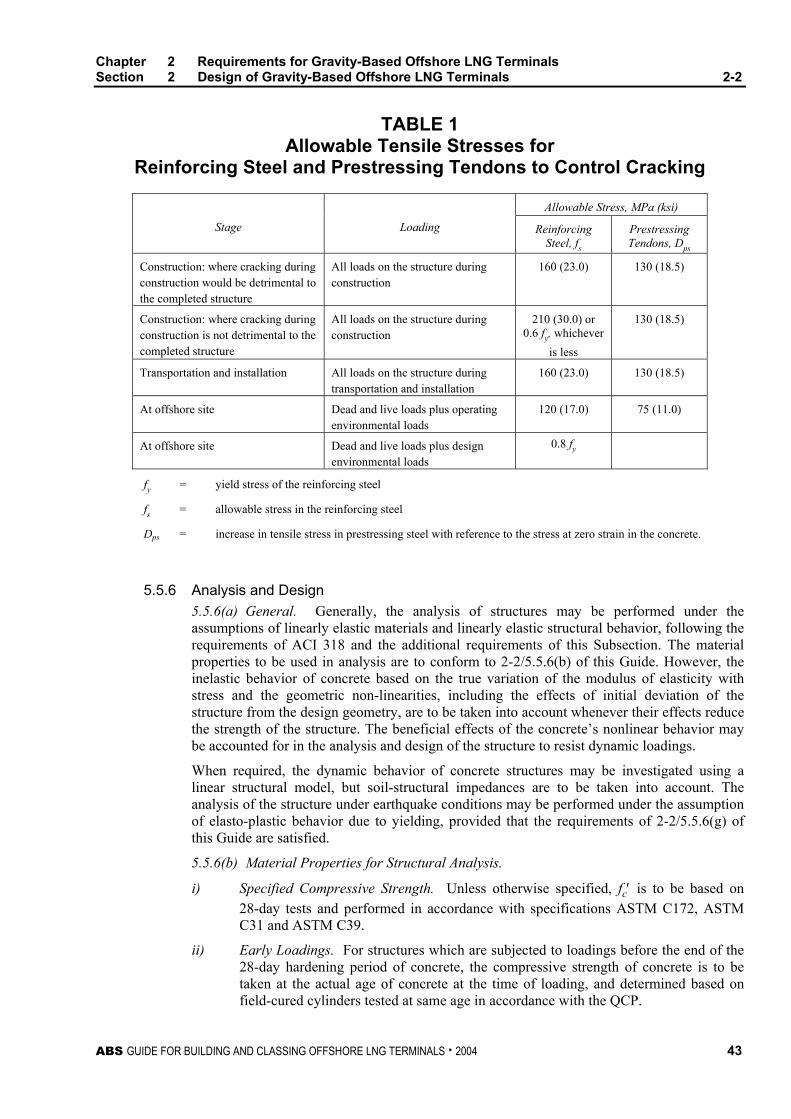
Chapter 2 Requirements for Gravity-Based Offshore LNG Terminals Section 2 Design of Gravity-Based Offshore LNG Terminals 2-2
ABS GUIDE FOR BUILDING AND CLASSING OFFSHORE LNG TERMINALS . 2004 43
TABLE 1 Allowable Tensile Stresses for
Reinforcing Steel and Prestressing Tendons to Control Cracking
Allowable Stress, MPa (ksi)
Stage Loading Reinforcing Steel, fs
Prestressing Tendons, Dps
Construction: where cracking during construction would be detrimental to the completed structure
All loads on the structure during construction
160 (23.0) 130 (18.5)
Construction: where cracking during construction is not detrimental to the completed structure
All loads on the structure during construction
210 (30.0) or 0.6 fy, whichever
is less
130 (18.5)
Transportation and installation All loads on the structure during transportation and installation
160 (23.0) 130 (18.5)
At offshore site Dead and live loads plus operating environmental loads
120 (17.0) 75 (11.0)
At offshore site Dead and live loads plus design environmental loads
0.8 fy
fy = yield stress of the reinforcing steel
fs = allowable stress in the reinforcing steel
Dps = increase in tensile stress in prestressing steel with reference to the stress at zero strain in the concrete.
5.5.6 Analysis and Design 5.5.6(a) General. Generally, the analysis of structures may be performed under the assumptions of linearly elastic materials and linearly elastic structural behavior, following the requirements of ACI 318 and the additional requirements of this Subsection. The material properties to be used in analysis are to conform to 2-2/5.5.6(b) of this Guide. However, the inelastic behavior of concrete based on the true variation of the modulus of elasticity with stress and the geometric non-linearities, including the effects of initial deviation of the structure from the design geometry, are to be taken into account whenever their effects reduce the strength of the structure. The beneficial effects of the concrete’s nonlinear behavior may be accounted for in the analysis and design of the structure to resist dynamic loadings.
When required, the dynamic behavior of concrete structures may be investigated using a linear structural model, but soil-structural impedances are to be taken into account. The analysis of the structure under earthquake conditions may be performed under the assumption of elasto-plastic behavior due to yielding, provided that the requirements of 2-2/5.5.6(g) of this Guide are satisfied.
5.5.6(b) Material Properties for Structural Analysis.
i) Specified Compressive Strength. Unless otherwise specified, fc′ is to be based on 28-day tests and performed in accordance with specifications ASTM C172, ASTM C31 and ASTM C39.
ii) Early Loadings. For structures which are subjected to loadings before the end of the 28-day hardening period of concrete, the compressive strength of concrete is to be taken at the actual age of concrete at the time of loading, and determined based on field-cured cylinders tested at same age in accordance with the QCP.
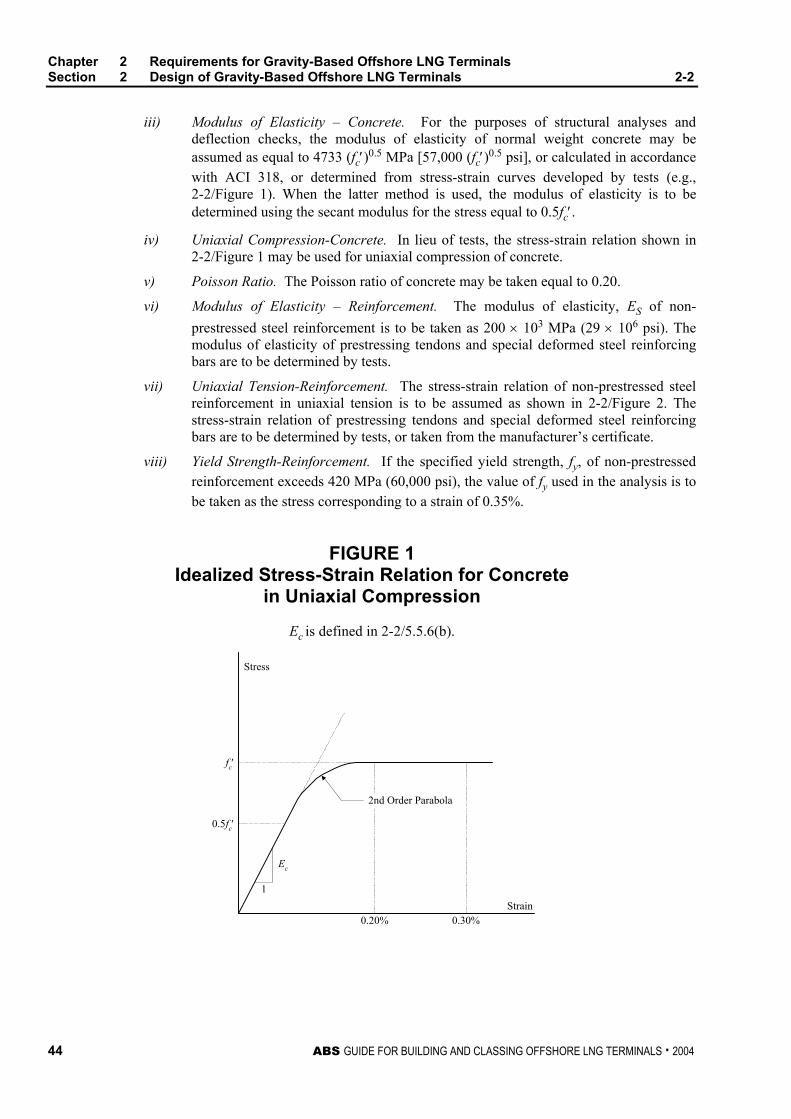
Chapter 2 Requirements for Gravity-Based Offshore LNG Terminals Section 2 Design of Gravity-Based Offshore LNG Terminals 2-2
44 ABS GUIDE FOR BUILDING AND CLASSING OFFSHORE LNG TERMINALS . 2004
iii) Modulus of Elasticity – Concrete. For the purposes of structural analyses and deflection checks, the modulus of elasticity of normal weight concrete may be assumed as equal to 4733 (fc′)0.5 MPa [57,000 (fc′)0.5 psi], or calculated in accordance with ACI 318, or determined from stress-strain curves developed by tests (e.g., 2-2/Figure 1). When the latter method is used, the modulus of elasticity is to be determined using the secant modulus for the stress equal to 0.5fc′.
iv) Uniaxial Compression-Concrete. In lieu of tests, the stress-strain relation shown in 2-2/Figure 1 may be used for uniaxial compression of concrete.
v) Poisson Ratio. The Poisson ratio of concrete may be taken equal to 0.20.
vi) Modulus of Elasticity – Reinforcement. The modulus of elasticity, ES of non-prestressed steel reinforcement is to be taken as 200 × 103 MPa (29 × 106 psi). The modulus of elasticity of prestressing tendons and special deformed steel reinforcing bars are to be determined by tests.
vii) Uniaxial Tension-Reinforcement. The stress-strain relation of non-prestressed steel reinforcement in uniaxial tension is to be assumed as shown in 2-2/Figure 2. The stress-strain relation of prestressing tendons and special deformed steel reinforcing bars are to be determined by tests, or taken from the manufacturer’s certificate.
viii) Yield Strength-Reinforcement. If the specified yield strength, fy, of non-prestressed reinforcement exceeds 420 MPa (60,000 psi), the value of fy used in the analysis is to be taken as the stress corresponding to a strain of 0.35%.
FIGURE 1 Idealized Stress-Strain Relation for Concrete
in Uniaxial Compression
Ec is defined in 2-2/5.5.6(b).
1
Ec
0.5fc′
fc′
0.20% 0.30%Strain
2nd Order Parabola
Stress
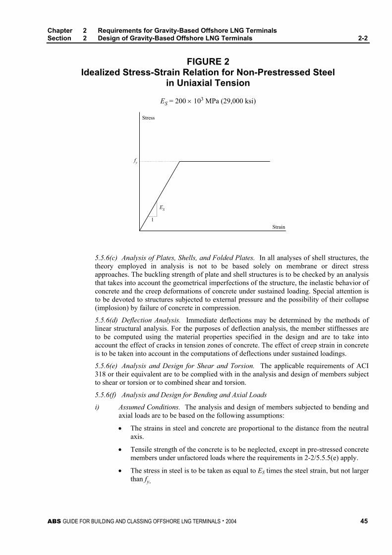
Chapter 2 Requirements for Gravity-Based Offshore LNG Terminals Section 2 Design of Gravity-Based Offshore LNG Terminals 2-2
ABS GUIDE FOR BUILDING AND CLASSING OFFSHORE LNG TERMINALS . 2004 45
FIGURE 2 Idealized Stress-Strain Relation for Non-Prestressed Steel
in Uniaxial Tension
ES = 200 × 103 MPa (29,000 ksi)
1
ES
Strain
Stress
fy
5.5.6(c) Analysis of Plates, Shells, and Folded Plates. In all analyses of shell structures, the theory employed in analysis is not to be based solely on membrane or direct stress approaches. The buckling strength of plate and shell structures is to be checked by an analysis that takes into account the geometrical imperfections of the structure, the inelastic behavior of concrete and the creep deformations of concrete under sustained loading. Special attention is to be devoted to structures subjected to external pressure and the possibility of their collapse (implosion) by failure of concrete in compression.
5.5.6(d) Deflection Analysis. Immediate deflections may be determined by the methods of linear structural analysis. For the purposes of deflection analysis, the member stiffnesses are to be computed using the material properties specified in the design and are to take into account the effect of cracks in tension zones of concrete. The effect of creep strain in concrete is to be taken into account in the computations of deflections under sustained loadings.
5.5.6(e) Analysis and Design for Shear and Torsion. The applicable requirements of ACI 318 or their equivalent are to be complied with in the analysis and design of members subject to shear or torsion or to combined shear and torsion.
5.5.6(f) Analysis and Design for Bending and Axial Loads
i) Assumed Conditions. The analysis and design of members subjected to bending and axial loads are to be based on the following assumptions:
• The strains in steel and concrete are proportional to the distance from the neutral axis.
• Tensile strength of the concrete is to be neglected, except in pre-stressed concrete members under unfactored loads where the requirements in 2-2/5.5.5(e) apply.
• The stress in steel is to be taken as equal to ES times the steel strain, but not larger than fy.
Chapter 2 Requirements for Gravity-Based Offshore LNG Terminals Section 2 Design of Gravity-Based Offshore LNG Terminals 2-2
46 ABS GUIDE FOR BUILDING AND CLASSING OFFSHORE LNG TERMINALS . 2004
• The stresses in the compression zone of concrete are to be assumed to vary with strain according to the curve given in 2-2/Figure 1 or any other substantiated rule acceptable to the Bureau. Rectangular distribution of compressive stresses in concrete specified by ACI 318 may be used.
• The maximum strain in concrete at the ultimate state is not to be larger than 0.30%.
ii) Failure. The members in bending are to be designed in such a way that yielding of steel occurs prior to compressive failure of concrete.
5.5.6(g) Seismic Analysis
i) Dynamic Analysis. For terminals to be located at sites known to be seismically active [see 2-2/5.5.6(h)], dynamic analysis is to be performed to determine the response of the terminal to design earthquake loading. The terminal is to be designed to withstand this loading without damage to the structural integrity. In addition, a ductility check is also to be performed to ensure that the structure has sufficient ductility to experience deflections more severe than those resulting from the design earthquake loading without the collapse of the structure or its foundation.
ii) Design Conditions. The dynamic analysis for earthquake loadings is to be performed taking into account:
• The interaction of all load bearing or load carrying components of the structure.
• The compliance of the soil and the dynamic soil-structure interaction.
• The dynamic effects of the ambient and contained fluids.
iii) Method of Analysis. The dynamic analysis for earthquake loadings may be performed by any recognized method such as determination of time histories of the response by direct integration of the equations of motion or the response spectra method.
iv) Ductility Check. In the ductility check, ground motions (e.g., spectral ordinates) at least twice those used for the design earthquake are to be assumed. If the ductility check is performed with the assumption of elasto-plastic behavior of the structure, the selected method of analysis is to be capable of taking into account the non-linearities of the structural model. The possibility of dynamic instability (dynamic buckling) of individual members and of the whole structure should be considered.
5.5.6(h) Seismic Design
i) Compressive Strains. Compressive strains in the concrete at critical sections (including plastic hinge locations) are to be limited to 0.3%, except when greater strain may be accommodated by confining steel.
ii) Flexural Bending or Load Reversals. For structural members or sections subjected to flexural bending or to load reversals where the percentage of tensile reinforcement exceeds 70% of the reinforcement at which yield stress in the steel is reached simultaneously with compression failure in the concrete, special confining reinforcement (e.g., T-headed bars) and/or compressive reinforcement are to be provided to prevent brittle failure in the compressive zone of concrete.
iii) Web Reinforcement. Web reinforcement (stirrups) of flexural members is to be designed for shear forces which develop at full plastic bending capacity of end sections. In addition,
• The diameter of rods used as stirrups is not to be less than 10 mm (#3 bar).
• Only closed stirrups (stirrup ties) are to be used. T-headed bars or other mechanically-headed bars may be used if their effectiveness has been verified.
Chapter 2 Requirements for Gravity-Based Offshore LNG Terminals Section 2 Design of Gravity-Based Offshore LNG Terminals 2-2
ABS GUIDE FOR BUILDING AND CLASSING OFFSHORE LNG TERMINALS . 2004 47
• The spacing of stirrups is not to exceed the lesser of d/2 or 16 bar diameters of compressive reinforcement where d is the distance from the extreme compression fiber to the centroid of tensile reinforcement. Tails of stirrups are to be anchored within a confined zone, i.e., turned inward.
iv) Splices. No splices are allowed within a distance d, defined above, from a plastic hinge. Lap splices are to be designed in accordance with ACI 318. Mechanical and welded splices are permitted. Mechanical splices are to be in compliance with ACI 349.
5.5.7 Design Details 5.5.7(a) Concrete Cover
i) General. The following minimum concrete cover for reinforcing bars is required:
• Atmospheric zone not subjected to salt spray: 50 mm (2 in.)
• Splash and atmospheric zones subjected to salt spray and exposed to soil: 65 mm (2.5 in.)
• Submerged zone: 50 mm (2 in.)
• Areas not exposed to weather or soil: 40 mm (1.5 in.)
• Cover of stirrups may be 13 mm (0.5 in.) less than covers listed above.
ii) Tendons and Ducts. The concrete cover of prestressing tendons and post-tensioning ducts is to be increased by at least 25 mm (1 in.) above the values listed herein.
iii) Sections Less Than 500 mm (20 in.) Thick. In sections less than 500 mm (20 in.) thick, the concrete cover of reinforcing bars and stirrups may be reduced below the values listed herein, however, the cover is not to be less than the following:
• 1.5 times the nominal aggregate size
• 1.5 times the maximum diameter of reinforcement, or 19 mm (0.75 in.)
• Tendons and post-tensioning duct covers are to have 12.5 mm (0.5 in.) added to the above.
5.5.7(b) Minimum Reinforcement. The minimum requirements of ACI 318 should be satisfied. In addition, for loadings during all phases of construction, transportation and operation (including design environmental loading) where tensile stresses occur on a face of the structure, the following minimum reinforcement is to be provided.
AS = (ft/fy)bde
where
AS = total cross-section area of reinforcement
ft = mean tensile strength of concrete
fy = yield stress of the reinforcing steel
b = width of structural element
de = effective tension zone, to be taken as 1.5c + 10db
c = cover of reinforcement
db = diameter of reinforcement bar
Chapter 2 Requirements for Gravity-Based Offshore LNG Terminals Section 2 Design of Gravity-Based Offshore LNG Terminals 2-2
48 ABS GUIDE FOR BUILDING AND CLASSING OFFSHORE LNG TERMINALS . 2004
de should be at least 0.2 times the depth of the section, but not greater than 0.5 (h – x), where x is the depth of the compression zone prior to cracking and h is the section thickness. At intersections between structural elements where transfer of shear forces is essential to the integrity of the structure, adequate transverse reinforcement is to be provided. 5.5.7(c) Reinforcement Details. Generally, lapped joints and mechanical splices should be avoided in structural members subjected to significant fatigue loading. Where lapped splices are used in members subject to fatigue, the development length of reinforcing bars is to be twice that required by ACI 318, and lapped bars are to be tied with tie wire. Where mechanical splices are used in members subject to fatigue, the coupled assembly of reinforcing bars and the mechanical coupler shall demonstrate adequate fatigue resistance by test.
Where lapped bars will be subject to tension during operation, through-slab confinement reinforcement is to be considered at the splices. Where longitudinal bars are subjected to tension during operation, special consideration should be given to number of reinforcement with splices at a single location.
Reinforcing steel is to comply with the chemical composition specifications of ACI 359 if welded splices are used.
For anchorage of shear and main reinforcement, mechanically-headed bars (T-headed bars) may be used if their effectiveness has been verified by static and dynamic testing. Shear reinforcement should be full length without splices. Entire close-up stirrups should be anchored by hooks or bends of at least 90° followed by a straight leg length of a minimum 12 bar diameters.
5.5.7(d) Post Tensioning Ducts. Ducting for post-tensioning ducts may be rigid steel or plastic (polyethylene or polystyrene). Steel tubing is to have a minimum wall thickness of 1 mm. Plastic tubing is to have a minimum wall thickness of 2 mm. Ducts may also be semi-rigid steel, spirally wrapped, of minimum thickness of 0.75 mm and are to be grout-tight. All splices in steel tubes and semi-rigid duct are to be sleeved and the joints sealed with heat-shrink tape. Joints in plastic duct are to be fused or sleeved and sealed. The inside diameter of ducts shall be at least 6 mm (0.25 in.) larger than the diameter of the post-tensioning tendon in order to facilitate grout injection. Flexible ducts are used only in special areas where the rigid or semi-rigid duct is impracticable, such as at sharp bends. A mandrel should be inserted into the ducts to prevent them from dislocation during concreting. 5.5.7(e) Post-Tensioning Anchorages and Couplers. Anchorages for unbonded tendons and couplers are to develop the specified ultimate capacity of the tendons without exceeding anticipated set. Anchorages for bonded tendons are to develop at least 90% of the specified ultimate capacity of the tendons, when tested in an unbonded condition without exceeding anticipated set. However, 100% of the specified ultimate capacity of the tendons is to be developed after the tendons are bonded in the member. Anchorage and end fittings are to be permanently protected against corrosion. Post-tensioning anchorages shall preferably be recessed in a pocket which is then filled with concrete. The fill should be mechanically tied to the structure by reinforcements as well as bonded by epoxy or polymer. Anchor fittings for unbonded tendons are to be capable of transferring to the concrete a load equal to the capacity of the tendon under both static and cyclic loading conditions. 5.5.7(f) Embeded Metals in Concrete. Consideration should be given to preventing corrosion of exposed faces of steel embedment. These embedments should be separated from the reinforcing steel. Effects of dimensional changes due to factors such as prestressing, and temperature changes which may result in fractures near embedments may require provisions to prevent deformation.
Chapter 2 Requirements for Gravity-Based Offshore LNG Terminals Section 2 Design of Gravity-Based Offshore LNG Terminals 2-2
ABS GUIDE FOR BUILDING AND CLASSING OFFSHORE LNG TERMINALS . 2004 49
5.5.8 Construction and Detailing 5.5.8(a) General. Construction methods and workmanship are to follow accepted practices as described in ACI 301, ACI 318, ACI 357 or other relevant standards. 5.5.8(b) Mixing, Placing and Curing of Concrete. Mixing of concrete is to conform to the requirements of ACI 318 and ASTM C94. In cold weather, concreting in air temperatures below 2°C (35°F) should be carried out only if special precautions are taken to protect the fresh concrete from damage by frost. The temperature of the concrete at the time of placing is to be at least 4°C (40°F) and the concrete is to be maintained at this or a higher temperature until it has reached a strength of at least 5 MPa (700 psi).
Protection and insulation are to be provided to the concrete, where necessary. The aggregates and water used in the mix are to be free from snow, ice and frost. The temperature of the fresh concrete may be raised by heating the mixing water or the aggregates or both. Cement should never be heated nor should it be allowed to come into contact with water at a temperature greater than 60°C (140°F).
During hot weather, proper attention is to be given to ingredients, production methods, handling, placing, protection and curing to prevent excessive concrete temperatures or water evaporation which will impair the required strength or serviceability of the member or structure. The temperature of concrete as placed is not to exceed 30°C (90°F) and the maximum temperature due to heat of hydration is not to exceed 65°C (145°F).
Special attention is to be paid to the curing of concrete in order to ensure maximum durability and to minimize cracking. Concrete should be cured with fresh water, whenever possible, to ensure that the concrete surface is kept wet during hardening. Care should be taken to avoid the rapid lowering of concrete temperatures (thermal shock) caused by applying cold water to hot concrete surfaces.
Sea water is not to be used for curing reinforced or prestressed concrete, although, if demanded by the construction program, “young” concrete may be submerged in sea water, provided it has gained sufficient strength to withstand physical damage. When there is doubt about the ability to keep concrete surfaces permanently wet for the whole of the curing period, a heavy-duty membrane curing compound should be used.
The rise of temperature in the concrete caused by the heat of hydration of the cement is to be controlled to prevent steep temperature stress gradients which could cause cracking of the concrete. Since the heat of hydration may cause significant expansion, members must be free to contract, so as not to induce excessive cracking. In general, when sections thicker than 610 mm (2 ft) are concreted, the temperature gradients between internal concrete and external ambient conditions are to be kept below 20°C (68°F).
Construction joints are to be made and located in such a way as not to impair the strength and crack resistance of the structure. Where a joint is to be made, the surface of the concrete is to be thoroughly cleaned and all laitance and standing water removed. Vertical joints are to be thoroughly wetted and coated with neat cement grout or equivalent enriched cement paste or epoxy coating immediately before placing of new concrete.
Whenever watertight construction joints are required, in addition to the above provisions, the heavy aggregate of the existing concrete is to be exposed and an epoxide-resin bonding compound is to be sprayed on just before concreting. In this case, the neat cement grout can be omitted.
Chapter 2 Requirements for Gravity-Based Offshore LNG Terminals Section 2 Design of Gravity-Based Offshore LNG Terminals 2-2
50 ABS GUIDE FOR BUILDING AND CLASSING OFFSHORE LNG TERMINALS . 2004
5.5.8(c) Reinforcement. The reinforcement is to be free from loose rust, grease, oil, deposits of salt or any other material likely to affect the durability or bond of the reinforcement. The specified cover to the reinforcement is to be maintained accurately. Special care is to be taken to correctly position and rigidly hold the reinforcement so as to prevent displacement during concreting.
5.5.8(d) Prestressing Tendons, Ducts and Grouting. Further guidance on prestressing steels, sheathing, grouts and procedures to be used when storing, making up, positioning, tensioning and grouting tendons will be found in the relevant sections of ACI 318, Prestressed Concrete Institute (PCI) publications, Federation Internationale de la Precontrainte (FIP) Recommended Practices and the specialist literature.
All steel for prestressing tendons is to be clean and free from grease, insoluble oil, deposits of salt or any other material likely to affect the durability or bond of the tendons.
During storage, prestressing tendons are to be kept clear of the ground and protected from weather, moisture from the ground, sea spray and mist. No welding, flame cutting or similar operations are to be carried out on or adjacent to prestressing tendons under any circumstances where the temperature of the tendons could be raised or weld splash could reach them.
Where protective wrappings or coatings are used on prestressing tendons, they are to be chemically neutral so as not to produce chemical or electrochemical corrosive attack on the tendons.
All ducts are to be watertight and all splices carefully taped to prevent the ingress of water, grout or concrete. During construction, the ends of ducts are to be capped and sealed to prevent the entry of sea water. Ducts may be protected from excessive rust by the use of chemically neutral protective agents such as vapor phase inhibitor powder.
Where ducts are to be grouted, all oil or similar material used for internal protection of the sheathing is to be removed before grouting. However, water-soluble oil used internally in the ducts or on the tendons may be left on, to be removed by the initial portion of the grout.
Air vents are to be provided at all crests in the duct profile. Threaded grout entries which permit the use of a screwed connector from the grout pump may be used with advantage.
For long vertical tendons, the grout mixes, admixtures and grouting procedures are to be checked to ensure that no water is trapped at the upper end of the tendon due to excessive bleeding or other causes. Suitable admixtures known to have no injurious effects on the metal or concrete may be used for grouting to increase workability and to reduce bleeding and shrinkage. Temperature of members must be maintained above 10°C (50°F) for at least 48 hours after grouting. General guidance on grouting will be found in the specialist literature. Holes left by unused ducts or by climbing rods of slipforms are to be grouted in the same manner as described above.
5.7 Foundation Design For the foundation design, a site investigation should be carried out in accordance with 3/6.3 of the Offshore Installations Rules. Soil data should be taken in the vicinity of, and preferably within, the terminal base area. For gravity-based terminals, the borings are to be taken to a minimum depth of the larger horizontal dimension or three times the smaller dimension of the base, whichever is greater. If piles are used, the depth of the boring should be in accordance with 3/6.3 of the Offshore Installation Rules.
Chapter 2 Requirements for Gravity-Based Offshore LNG Terminals Section 2 Design of Gravity-Based Offshore LNG Terminals 2-2
ABS GUIDE FOR BUILDING AND CLASSING OFFSHORE LNG TERMINALS . 2004 51
5.7.1 Foundation Design Requirements 5.7.1(a) General. The loadings used in the analysis of the safety of the foundation are to include those defined in 2-2/5.7.1(g) and those experienced by the foundation during installation. Foundation displacements are to be evaluated to the extent necessary to assure that they are within limits that do not impair the intended function and safety of the structure.
The soil and the structure are to be considered as an interactive system, and the results of analyses, as required in subsequent paragraphs, are to be evaluated from this point of view.
5.7.1(b) Cyclic Loading Effects. The influence of cyclic loading on soil properties is to be considered. For gravity-based terminals in particular, possible reduction of soil strength is to be investigated and employed in design. Where appropriate, the following conditions are to be considered:
i) Design storm during the initial consolidation phase.
ii) Short-term effects of the design storm.
iii) Long-term cumulative effects of several storms, including the design storm.
iv) Reduced soil strength characteristics resulting from these conditions are to be employed in design.
v) In seismically active zones, similar deteriorating effects due to repeated loadings are to be considered.
vi) Other possible effects resulting from cyclic loading, such as induced cyclic loading effects on soils from resonant breaking of impinging ice sheets, such as changes in load-deflection characteristics, effect of rocking inducing high pore pressures, liquefaction potential and slope stability are also to be considered, and these effects should be accounted for when they will affect the design.
5.7.1(c) Scour. Where scour is expected to occur, either effective protection is to be furnished soon after the installation of the terminal, or the depth and lateral extent of scouring, as evaluated in the site investigation program, is to be accounted for in design.
5.7.1(d) Deflections and Rotations. Tolerable limits of deflections and rotations are to be established based on the type and function of the LNG Terminal’s structure, and the effects of those movements on other structural elements that interact with the Terminal’s structure. Maximum allowable values of structural movements, as limited by these interactive considerations or overall structural stability, are to be considered in the design.
5.7.1(e) Soil Strength. The ultimate strength or stability of soil is to be determined using test results which are compatible with the method selected. In a total stress approach, the total shear strength of the soil obtained from simple tests is used. A total stress approach largely ignores changes in the soil’s pore water pressure under varying loads and the drainage conditions at the site. When an effective stress approach is used, effective soil strength parameters and pore water pressures are determined from tests that attempt to predict in-situ total stresses and pore pressures.
5.7.1(f) Dynamic and Impact Considerations. For dynamic and impact loading conditions, a realistic and compatible treatment is to be given to the interactive effects between the soil and structure. When analysis is required, it may be accomplished by lumped parameter, foundation impedance functions or by continuum approaches including the use of finite element methods. Such models are to include consideration of internal and radiational damping provided by the soil and the effects of soil layering.
Chapter 2 Requirements for Gravity-Based Offshore LNG Terminals Section 2 Design of Gravity-Based Offshore LNG Terminals 2-2
52 ABS GUIDE FOR BUILDING AND CLASSING OFFSHORE LNG TERMINALS . 2004
Studies of the dynamic response of the structure are to include, where applicable, consideration of the nonlinear and inelastic characteristics of the soil, the possibilities of deteriorating strength and increased or decreased damping due to cyclic soil loading and the added mass of soil subject to acceleration. Where applicable, the influence of nearby structures is to be included in the analysis.
5.7.1(g) Loading Conditions. Loading scenarios due to various installations and operating conditions shall be evaluated and conditions exerting the highest loadings on the foundation are to be taken into account. Post installation loadings to be checked are to include at least those relating to both the operating and design environmental conditions combined in the following manner:
i) Operating environmental loading combined with dead and maximum live loads appropriate to the function and operations of the structure.
ii) Design environmental loading combined with dead and live loads appropriate to the function and operations of the structure during the design environmental condition.
iii) Design environmental loading combined with dead load and minimum live loads appropriate to the function and operations of the structure during the design environmental conditions.
For areas with potential seismic activity, the foundation is to be designed for sufficient strength to sustain seismic loads. The designer should take measures to prevent frost heave such as by adding a heating system, and should also determine the risk of liquefaction of granular soil.
5.7.2 Gravity-based Terminal Foundations 5.7.2(a) General. The stability of the foundation with regard to bearing and sliding failure modes is to be investigated, employing the soil shear strengths determined in accordance with 3/6.3 of the Offshore Installations Rules (that concern the investigation of seabed soil conditions) and 2-2/5.7.1(b). The effects of adjacent structures and the variation of soil properties in the horizontal direction are to be considered, where relevant.
Where leveling of the site is not carried out or any other measures are not taken to reduce tilt, the predicted tilt of the overall structure is to be based on the average bottom slope of the sea floor and the tolerance of the elevation measuring device used in the site investigation program. Differential settlement is also to be calculated, and the tilting of the structure caused by this settlement is to be combined with the predicted structural tilt. Any increased loading effects caused by the tilting of the structure are to be considered in the foundation stability requirements of 2-2/5.7.2(b).
When an underpressure or overpressure is experienced by the sea floor under the structure, provision is to be made to prevent piping which could impair the integrity of the foundation. The influence of hydraulic and slope instability, if any, is to be determined for the structural loading cases ii) and iii) of 2-2/5.7.1(g).
Initial consolidation and secondary settlements, as well as permanent horizontal displacements, are to be calculated.
5.7.2(b) Stability. The bearing capacity and lateral resistance are to be calculated under the most unfavorable combination of loads. Possible long-term redistribution of bearing pressures under the base slab is to be considered in order to ensure that the maximum edge pressures are used in the design of the perimeter of the base.
The lateral resistance of the platform is to be investigated with respect to various potential shearing planes. Special consideration is to be given to any layers of soft soil.
Chapter 2 Requirements for Gravity-Based Offshore LNG Terminals Section 2 Design of Gravity-Based Offshore LNG Terminals 2-2
ABS GUIDE FOR BUILDING AND CLASSING OFFSHORE LNG TERMINALS . 2004 53
Calculations for overturning moment and vertical forces induced by the passage of a wave are to include the vertical pressure distribution across the top of the foundation and along the sea floor.
The capacity of the foundation to resist a deep-seated bearing failure is to be analyzed. In lieu of a more rigorous analysis where uniform soil conditions are present or where conservatively chosen soil properties are used to approximate a non-uniform soil condition, and where a trapezoidal distribution of soil pressure is a reasonable expectation, the capacity of the foundation to resist a deep-seated bearing failure can be calculated by standard bearing capacity formulas applicable to eccentrically loaded shallow foundations. Alternatively, slip-surface methods covering a range of kinematically feasible deep rupture surfaces can be employed in the bearing capacity calculations.
The maximum allowable shear strength of the soil is to be determined by dividing the ultimate shear strength of the soil by the minimum safety factors given below.
When the ultimate soil strength is determined by an effective stress method, the safety factor is to be applied to both the cohesive and frictional terms. If a total stress method is used, the safety factor is to be applied to the undrained shear strength. Any degradation due to cyclic effects is to be considered. The minimum safety factors to be obtained when employing a standard bearing capacity formulation and various trial sliding failure planes with the loading conditions of 2-2/5.7.1(g) are 2.0 for loading case i) and 1.5 for loading cases ii) and iii). The safety factors to be obtained when considering the Design Earthquake will be specially considered.
Where present, the additional effects of penetrating walls or skirts that transfer vertical and lateral loads to the soil are to be investigated as to their contribution to bearing capacity and lateral resistance.
5.7.2(c) Soil Reaction on the Structure. For conditions during and after installation, the reaction of the soil against all structural members seated on or penetrating into the sea floor is to be determined and accounted for in the design of these members. The distribution of soil reactions is to be based on the results of the site-investigation specified in 3/6.3 of the Offshore Installations Rules. Calculations of soil reactions are to account for any deviation from a plane surface, the load-deflection characteristics of the soil and the geometry of the base of the structure.
Where applicable, effects of local soil stiffening, nonhomogeneous soil properties, as well as the presence of boulders and other obstructions are to be accounted for in design. During installation, consideration is to be given to the possibility of local contact pressures due to irregular contact between the base and the sea floor. These pressures are additive to the hydrostatic pressure.
An analysis of the penetration resistance of structural elements projecting into the sea floor below the foundation structure is to be performed. The design of the ballasting system is to reflect uncertainties associated with achieving the required penetration of the structure. Since the achievement of the required penetration of the platform and its skirts is of critical importance, the highest expected values of soil strength are to be used in the calculation of penetration.
5.7.2(d) Pile Foundations. Pile foundations are to be capable of withstanding axial, bending and lateral forces at the same time. Analysis of the pile as a beam column on an elastic foundation is to be submitted to the Bureau for review. The analyses of different kinds of soil using representative soil resistance and deflection (p-y) curves are described in the Offshore Installations Rules and API RP2A, as applicable.
Chapter 2 Requirements for Gravity-Based Offshore LNG Terminals Section 2 Design of Gravity-Based Offshore LNG Terminals 2-2
54 ABS GUIDE FOR BUILDING AND CLASSING OFFSHORE LNG TERMINALS . 2004
7 Containment Systems
The LNG containment system is a mandatory part of ABS classification of the terminal’s structure. The LNG containment system is to be in accordance with the requirements of Section 5-8-4 of the Steel Vessel Rules or NFPA 59A.
Alternative arrangements for the LNG containment system such as the use of properly designed prestressed concrete structure as a secondary cryogenic barrier, application of membrane lining/barrier systems into concrete containment components, etc., may be given special consideration.
7.1 Design Features Unless considered otherwise, the design of the containment system should incorporate the following features to satisfy the intent of these Rules and Standard:
i) A secondary containment system such that if there is a failure in the primary system, the secondary system is to be capable of containing the leaked liquid contents for an agreed period of time consistent with the approved scenarios for the safe disposal of same.
ii) There is to be a minimum of two independent means of determining the liquid level in the LNG storage tanks.
iii) Means to fill the tank from various elevations within the tank to avoid stratification.
iv) Independent high and high-high level alarms.
v) At least one pressure gauge connected to the vapor space.
vi) Two independent overpressure protection devices.
vii) Devices for measuring the liquid temperature at the top, middle and bottom of tank.
viii) A gas detection system which will alarm high gas concentrations in the space between the primary and the secondary barrier.
7.3 Design Loads Tanks together with their supports and fixtures are to be designed with consideration of proper combinations of the following loads:
i) Internal Pressure.
ii) External Pressure.
iii) Seismic loads.
iv) Thermal loads.
v) Tank and cargo weight with the corresponding reactions in way of the supports.
vi) Insulation weight.
vii) Loads in way of towers and other attachments.
7.5 Steel Terminals In the case of gravity-based steel offshore LNG terminals, the requirements of Section 5-8-4 of the Steel Vessel Rules are considered applicable.
7.7 Concrete Terminals On gravity-based concrete offshore LNG terminals the outer containment system may be constructed of concrete in accordance with the requirements of Section 4.3 of NFPA 59A.
Chapter 2 Requirements for Gravity-Based Offshore LNG Terminals Section 2 Design of Gravity-Based Offshore LNG Terminals 2-2
ABS GUIDE FOR BUILDING AND CLASSING OFFSHORE LNG TERMINALS . 2004 55
7.9 Condensate Storage Condensate storage tanks integral with the terminal’s hull are to be in compliance with the requirements of Section 5-1-7 of the Steel Vessel Rules and 3-5/5.9 of the Facilities Guide.
Condensate storage in tanks adjacent to LNG storage tanks will be considered acceptable, provided it can be shown that loss of primary LNG containment would not cause an underpressure situation or the ingress of air into the condensate tank.
9 Process Facilities
Where process facilities are requested to be within the scope of Class, the facilities installed onboard the terminal for processing raw gas from the well(s) or bringing partially processed gas from another installation, LNG production or liquefaction or re-gasification system for converting LNG into vapor for shipment ashore, the entire installation including the import and export system are subject to requirements of this Guide.
For Classification purposes, it is to be ensured that whichever of the process systems are employed, the facilities are in place so that the entire operation can be carried out safely. Accordingly, in order to carry out an assessment of the system, the plans and calculations listed in 2-1/3.5 of this Guide are required to be submitted:
The Bureau may require additional information depending on the systems used and their configuration.
Where processing facilities are not within the scope of Class, requirements contained in this Guide relating to the safety of the terminal will be considered within the scope of Class. For example, the following systems will be subject to approval by the Bureau:
i) Interface to the Fire Extinguishing system
ii) Hazardous areas
iii) Gas disposal system (venting and relief)
9.1 Process Safety Criterion The design of the onboard process facilities described above is to include an overall evaluation of the proposed concept with a view toward reducing the likelihood of the occurrence of the undesirable events identified in 2-2/3 of this Guide.
ABS evaluation will include a systematic consideration of arrangements, layouts, process systems, process support systems, process controls and safety systems as well as a review of fitness for purpose of all safety critical equipment. The term “safety critical” is meant to include all equipment whose reliable performance is essential to maintaining a safe facility as well as equipment whose failure in and of itself could lead to an unsafe occurrence.
While the design of the terminal arrangements, safety systems and systems for handling LNG and LNG vapor on a terminal may rely primarily on the proven practices employed on LNG carriers, it must be recognized that on an LNG carrier, except during cargo loading and discharge operations, there is very little hydrocarbon outside of the containment system. Accordingly, additional provisions may be required depending on the process system installed on the terminal. This may include such items as an extension of the hazardous areas, the need for a gas dispersion analysis and the provision of a means to de-energize electrical systems in the event of a major release of high-pressure gas. Due to the varying quantity and means of handling and storage of the hydrocarbon refrigerants, it must also be recognized that the level of risk associated with natural gas liquefaction is dependant on the liquefaction process selected. Accordingly, wherever possible, the location of these systems should be on open deck.

Chapter 2 Requirements for Gravity-Based Offshore LNG Terminals Section 2 Design of Gravity-Based Offshore LNG Terminals 2-2
56 ABS GUIDE FOR BUILDING AND CLASSING OFFSHORE LNG TERMINALS . 2004
Similarly, while some LNG carriers are arranged for bow or stern loading and unloading in accordance with the provisions of 5-8-3/8 of the Steel Vessel Rules, it must be recognized that the existing requirements for LNG carriers do not envisage the increased risk of an LNG or LNG vapor release from the systems and equipment that may be employed in the import and export systems covered under 2-2/9.9 and 2-2/9.11 of this Guide. Accordingly, drip trays are to be provided as necessary and components such as cryogenic hoses and gas swivels that may be susceptible to leakage should be located on the open deck. Furthermore the means to provide reliable, adequate ventilation in any enclosed spaces containing portions of the gas transfer system and provisions for gas detection are to be considered and included in the overall risk analysis required in 2-2/3 of this Guide.
The safe disposal of flaring of hydrocarbon gas released due to an overpressure or other upset condition should be taken into consideration in the design of the system. However, the process systems are to be closed systems. Accordingly, continuous flaring is not an acceptable design premise.
The process safety overall criterion is that systems and equipment on an offshore LNG terminal be designed to minimize the risk of hazards to personnel, property and environment. Implementation of this criterion to gas processing, liquefaction or re-gasification facilities and the associated support facilities is intended to:
i) Prevent an abnormal condition from causing an upset condition.
ii) Prevent an upset condition from causing a release of hydrocarbons or cryogenic fluids.
iii) Safely collect and dispose of hydrocarbon or cryogenic fluids released.
iv) Prevent formation of explosive mixtures.
v) Prevent ignition of flammable liquids or gases and vapors released.
vi) Limit exposure of personnel to fire hazards.
9.1.1 System Requirements The design of process systems and process control systems described above, along with process support systems, depressurization and vent systems, flares and drain systems, is to comply with the requirements of Chapter 4, Section 3 of the Facilities Guide. In addition, systems that are in direct contact with LNG or LNG vapor are to be designed for compliance with the requirements of Part 5, Chapter 8 of the Steel Vessel Rules and the applicable requirements of NFPA 59 A Standard for the Production, Storage and Handling of Liquefied Natural Gas (LNG) 2001. Where there is a conflict between various referenced requirements, the Bureau is to be consulted for clarification.
The systems and equipment for ship-to-terminal LNG loading or LNG discharge such as special loading arms and/or cryogenic hose, hose cranes, primary emergency release couplings (PERCs), relative motion sensors, emergency shutdown systems and other special arrangements will be considered in each case based on the submitted design justification. The design justification is to include an envelope of limiting operational environments, including sea states, wind, current and visibility.
9.1.2 Component Requirements It is envisaged that a list of major components present on an LNG terminal includes but is not limited to: loading arms, cryogenic hoses, pig receivers, separators, knock-out drums, heat exchangers, packed columns, absorbers, plate fin type heat exchangers, spiral (spool) wound heat exchangers, tube and shell heat exchangers, pumps, and compressors with either gas turbine or electric drivers, direct and indirect heaters and vaporizers. These process system components and the associated piping systems that carry hydrocarbon liquids and vapors will be subject to Bureau review.
Chapter 2 Requirements for Gravity-Based Offshore LNG Terminals Section 2 Design of Gravity-Based Offshore LNG Terminals 2-2
ABS GUIDE FOR BUILDING AND CLASSING OFFSHORE LNG TERMINALS . 2004 57
The design, manufacture, testing, certification and installation of process components are to be in compliance with the requirements of 3-3/17 of the Facilities Guide. The selection of material of components subject to temperatures below -18°C (0°F) is to comply with the requirements of Section 5-8-6 of the Steel Vessel Rules. Conformance to standards or codes different from those listed therein will be considered, where applicable. Components not covered in the referenced ABS Guide will be considered on the basis of compliance with applicable acceptable industry standards and the manufacturer’s design justification and proof testing. Design justification based on stress analysis should comply with the requirements of the ASME Boiler and Pressure Vessel Code Section VIII Division 2.
9.3 Gas Processing For the purposes of this Guide, the gas processing facilities are considered to include all systems and components for the reception of raw gas from the well(s) or partially processed gas from another installation on the platform facilities for such processes such as acid gas removal, dehydration and mercury removal.
9.5 Liquefaction For the purpose of this Guide, the Liquefaction Facilities are considered to include all systems and components for pre-cooling, fractionation, main cryogenic refrigeration and storage. There are a number of proven proprietary liquefaction methodologies available. Whichever of these systems is used, details, as mentioned in 2-2/9.1, are to be submitted.
The subsystems and major items of equipment can vary significantly depending on which liquefaction methodology is employed. Accordingly, a description of the system and an operational philosophy adopted is to be submitted in order to evaluate the safety of the entire system.
However, the following is given as a reference to define the scope of classification:
i) It is envisaged that the pre-cooling may be done in a propane, nitrogen or mixed refrigerant heat exchanger with the associated refrigerant refrigeration cycle: compressor, condenser, coolers and accumulators. The pre-cooling heat exchanger may be of the spiral wound or plate fin type.
ii) It is envisaged that the fractionation includes subsystems or plants called de-ethanizers, de-propanizers and de-butanizers. Each plant is comprised of a vertical column type separator, pumps, heat exchangers and accumulators.
iii) The main cryogenic refrigeration is normally done in either a multi-stage spiral wound heat exchanger or in an assembly of plate fin type heat exchangers called a cold box. In most LNG liquefaction processes, a mixture of hydrocarbons is used as the primary refrigerant and these processes are called MR Processes. However, in the cascade system, propane, ethane, methane and ethylene are each used at consecutive stages of refrigeration. In the nitrogen system, nitrogen is used as the refrigerant in a compression and expansion process.
iv) The storage includes both LNG storage and storage of condensate produced from the liquefaction process.
9.7 Re-gasification For the purposes of this Guide, Re-gasification Facilities are considered to include all systems and components for removing LNG from the storage tanks, pressurizing, heating and vaporizing LNG and, in some cases, odorizing the LNG vapor and discharge ashore of vaporized gas through an off-loading system. If there are compressors in the discharge system, they would be considered part of the Re-gasification Facility.
Chapter 2 Requirements for Gravity-Based Offshore LNG Terminals Section 2 Design of Gravity-Based Offshore LNG Terminals 2-2
58 ABS GUIDE FOR BUILDING AND CLASSING OFFSHORE LNG TERMINALS . 2004
9.9 Import Systems For the purposes of this Guide, Import Systems on load terminals are considered to include the entire gas swivel on turret-moored units and the first onboard flange for units maintained on station through a spread mooring system, plus all onboard gas flow lines up to the gas processing facility.
In the case of discharge terminals, the Import Systems would include the liquid and vapor loading arms and the cryogenic hoses or the cargo manifold, depending on the LNG ship to terminal transfer configuration employed, plus all on deck valves and piping up to the liquid and vapor inlet flanges on the cargo tank domes.
9.11 Export Systems For the purpose of this Guide, Export Systems on load terminals are considered to include the cargo pumps, stripping pumps, high duty gas compressors, LNG vaporizers and all valves and piping in the liquid discharge and vapor return systems up to and including the cargo manifold, loading arms or cryogenic hoses, depending on the LNG-terminal-to-ship transfer configuration employed.
In the case of discharge terminals, the Export Systems would include the gas flow lines from the re-gasification facility up to and including the last onboard flange.
9.13 Risers and Flow Lines Rigid and flexible risers, connecting flow lines and submerged jumpers are not considered to be within the scope of classification of the terminal. However, at the Owner’s request, the Owner import or export risers starting from but not including the Pipe Line End Manifold (PLEM) may be included in the scope of classification, provided they are found to be in compliance with the requirements of Chapter 7 of the FPI Guide.
11 Arrangements
11.1 Referenced Rules, Guides and Documents Refer to 1-1/25 of this Guide.
11.3 General Arrangement Machinery and equipment are to be arranged in groups or areas in accordance with API RP14J. Equipment items that could become fuel sources in the event of a fire are to be separated from potential ignition sources by space separation, firewalls or protective walls.
Typical fuel sources may be as listed below:
i) Gas inlet departing flow lines xi) LNG manifolds or loading arms ii) Process and Hydrocarbon Refrigerant Piping xii) Separators and Scrubbers iii) Risers and Pipelines xiii) Coalescers iv) Vents xiv) Gas Compressors v) Pig Launchers and Receivers xv) Liquid Hydrocarbon Pumps vi) Drains xvi) Heat Exchangers vii) Portable Fuel Tanks xvii) Hydrocarbon Refrigerant Storage Tanks viii) Chemical Storage Tanks xviii) Gas Metering Equipment ix) Laboratory Gas Bottles xix) Oil Treaters (unfired vessels) x) Sample Pots xx) Swivels
Chapter 2 Requirements for Gravity-Based Offshore LNG Terminals Section 2 Design of Gravity-Based Offshore LNG Terminals 2-2
ABS GUIDE FOR BUILDING AND CLASSING OFFSHORE LNG TERMINALS . 2004 59
Typical ignition sources may be as listed below:
i) Fired Vessels x) Electrical Equipment ii) Combustion Engines & Gas Turbines xi) Waste Heat Recovery Equipment iii) Living Quarters xii) Mobile phones iv) Flares xiii) Lightning v) Welding Machines xiv) Spark Producing Hand Tools vi) Grinding Machines xv) Portable Computers vii) Cutting Machinery or Torches xvi) Cameras viii) Static Electricity xvii) Non-Intrinsically Safe Flashlights ix) Ships xviii) Helicopters
In case of a fire, the means of escape is to permit the safe evacuation of all occupants to a safe area, even when the structure they occupy can be considered lost in a conflagration. With safety spacing, protective firewalls and equipment groupings, a possible fire from a classified location is not to impede the safe exit of personnel from the danger source to the lifeboat embarkation zone or any place of refuge.
11.5 Storage Tank Locations The location of storage tanks with respect to the outer boundaries of the structure is to be consistent with the extent of damage assumed in 2-2/3i) of this Guide, unless it can be shown that other arrangements will be not less effective at protecting the storage tanks.
11.7 Bow or Stern Loading The requirements of 5-8-8/8 of the Steel Vessel Rules for bow or stern loading arrangements will be considered applicable to import or export systems that are routed in the vicinity of accommodations or other sources of vapor ignition.
11.9 Location and Insulation of Accommodation Spaces and Living Quarters Accommodation spaces or living quarters are to be located outside of hazardous areas and may not be located above or below LNG or condensate storage tanks or process areas. “H-60” ratings are required for the bulkheads of permanent living quarters, temporary living quarters and normally manned modules that face areas such as LNG storage areas, fired vessels (heaters), or the process vessels and other similar hazards. If such bulkhead is more than 33 m (100 ft) from this source, then this can be relaxed to an “H-0” rating. As is explained in Chapter 3, Section 8 of the Facilities Guide, “A-60” and “A” rated bulkheads, respectively, may be utilized, provided that a risk analysis or fire load analysis was satisfactorily reviewed by ABS, indicating that lower bulkhead fire ratings are acceptable.
13 Hazardous Areas
The delineation of hazardous areas or gas-dangerous spaces on an offshore LNG terminal is to be consistent with the following general guidelines. Where there is overlapping, in general, the higher (more conservative) delineation should be applied.
The delineation of gas-dangerous spaces in 5-8-1/3.17 of the Steel Vessel Rules and Chapter 7, Section 7.6 of NFPA 59A, as applicable, will be considered applicable to LNG storage and LNG and LNG vapor piping systems associated with LNG storage, loading and discharge.
The delineation of gas-dangerous spaces associated with process facilities is to be consistent with the requirements of 3-6/15 of the Facilities Guide, which is consistent with API RP 500 series.
Chapter 2 Requirements for Gravity-Based Offshore LNG Terminals Section 2 Design of Gravity-Based Offshore LNG Terminals 2-2
60 ABS GUIDE FOR BUILDING AND CLASSING OFFSHORE LNG TERMINALS . 2004
The delineation of hazardous areas associated with the below deck storage of condensate and other hydrocarbon liquids with a flash point of less than 60°C (140°F) is to be consistent with the requirements of 5-1-7/31.5 of the Steel Vessel Rules.
15 Process Support and Service Systems This Subsection presents criteria for the design and installation of process support and service systems on offshore LNG terminals. General arrangement of these systems is to comply with API RP 14J, or other applicable standards. Process support systems are utility and auxiliary systems that complement the process systems covered in 2-2/11 of this Guide. Process support systems include, but are not limited to, the following: i) Utility/Instrument Air System ii) Fuel/Instrument Gas System iii) Use of Produced Gas as Fuel iv) Purging System v) Inert Gas System vi) Nitrogen System vii) Fuel Oil System viii) Hydraulic System ix) Lubricating Oil System x) Chemical Injection System xi) Heating and Cooling System These systems are to be in compliance with the requirements of Chapter 4, Section 4 of the Facilities Guide and Part 5, Chapter 8 of the Steel Vessel Rules, as applicable. Depending on the type of structure, support systems and components may include, but are not limited to, the following: i) Boilers and Pressure Vessels ii) Turbines and Gears iii) Internal-Combustion Engines iv) Pumps and Piping Systems (i.e., Fuel Oil, Lube Oil, Fresh Water, De-watering, Inert Gas,
etc.) These systems are to be in compliance with the requirements of Chapter 4, Section 5 of the Facilities Guide and the applicable sections of the Steel Vessel Rules and the MODU Rules.
17 Electrical Systems and Installations Electrical systems used solely for the process facilities described in 2-2/11 of this Guide are to meet the requirements of Chapter 4, Section 6 of the Facilities Guide. Where electrical systems or equipment are used to supply services other than these process facilities, the equipment is to comply with the requirements of a recognized code for electrical installations acceptable to the Bureau. Electrical installations are to comply with the above referenced requirements and with API RP 14F. Consideration will be given to the use of other recognized national or international standards, such as IEC, provided they are no less effective and the entire system is designed to such standards. For installations classified by class and zone, the requirements of API RP 14FZ (when approved) may be used in lieu of API 14F.
Chapter 2 Requirements for Gravity-Based Offshore LNG Terminals Section 2 Design of Gravity-Based Offshore LNG Terminals 2-2
ABS GUIDE FOR BUILDING AND CLASSING OFFSHORE LNG TERMINALS . 2004 61
Where sections of API RP 14F are called out in the following text, the intent is solely to help identify relevant clauses. The designer is not relieved from full compliance with all of the recommended practices contained in API RP 14F. The references to IEC standards are intended solely as minimum requirements when standards other that API RP 14F are applied.
Where conflicts exist between various referenced standards, the Bureau is to be consulted to provide required clarification.
19 Instrumentation and Control Systems
The control and instrumentation systems are to provide an effective means for monitoring and controlling pressures, temperatures, flow rates, liquid levels and other process variables for the safe and continuous operation of the process and storage facilities. Where control over the electrical power generation and distribution is required for the operation of the facilities, then the control system should also be arranged to cover this. Control and instrumentation systems for process, process support, utility and electrical systems are to be suitable for the intended application. All control and safety shutdown systems are to be designed for safe operation of the equipment during start-up, shutdown and normal operational conditions.
Instrumentation and control systems serving the process facilities described in 2-2/11 of this Guide are to be in compliance with Chapter 4, Section 7 of the Facilities Guide, which is based on API RP 14C and other applicable standards.
Instrumentation and control systems serving the LNG storage and transfer of LNG and LNG vapor on and off the unit are to be in compliance with the requirements of Section 5-8-13 of the Steel Vessel Rules.
Where there is a conflict between overlapping referenced requirements, the Bureau is to be consulted for required clarification.
21 Safety Systems
21.1 General
21.1.1 Approach The safety systems referred to in this Subsection are intended to protect life, property and the environment and are applicable to the entire installation, including the loading and off-loading arrangements for gas, LNG and LNG vapor. The overall safety system should be comprised of subsystems providing two levels of protection: the primary system which is to provide protection against the risk of fire or explosion; and the secondary system which is intended to reduce the consequence of fire by affording protection to the people and the facility and reducing the risk of fire spread. The primary and secondary safety measures required consist of both active and passive systems as described in this Subsection. However, in all cases, the effectiveness of these systems should be established by conducting a fire and explosion hazard analysis.
Each space considered a fire risk, such as the process equipment, cargo deck area, spaces containing gas processing equipment such as compressors, heaters, etc. and machinery spaces containing any oil-fired unit or internal combustion machinery with an aggregate power of not less than 375 kW (500 hp), is to be fitted with an approved gas detection, fire detection and fire extinguishing system complying with the requirements of this Subsection.
Chapter 2 Requirements for Gravity-Based Offshore LNG Terminals Section 2 Design of Gravity-Based Offshore LNG Terminals 2-2
62 ABS GUIDE FOR BUILDING AND CLASSING OFFSHORE LNG TERMINALS . 2004
21.1.2 Governmental Authority In addition to the ABS Class requirements of this Subsection, depending on the flag of registry of the terminal or area of operation, the flag or coastal state may have additional requirements or regulations which may need to be complied with. Therefore, the appropriate governmental authorities should be consulted for each installation.
21.1.3 Primary Systems Many of the products being handled onboard an offshore LNG terminal are highly flammable, and therefore, examples of some of the measures that may be necessary to protect against fire or explosion risk are as follows:
i) Avoid the possibility of liquid or gas escaping in locations where there is a source of vapor ignition. A typical example of this will be to isolate the vent and relief valve outlets from storage tanks and process systems in relation to the air intakes and openings.
ii) Provide fixed gas detection systems comprised of two different types of elements which will activate an audible alarm at a manned control station to alert of a gas release before the gas can migrate to an unclassified area.
iii) A low temperature detection system in and around the LNG storage facility to sound an alarm at a normally manned station to alert in the event of a liquid or vapor leak.
iv) A multi-tiered Emergency Shutdown system capable of isolating an upset condition with local system or single train shutdowns before the condition requires a complete platform shutdown.
v) Maintain integrity of the containment boundary at all times to reduce the possibility of an uncontrolled discharge of LNG or LNG vapor. Where it is possible for LNG to leak in the event of a failure, such as at a joint, valve or similar connection, a spill tray immediately underneath these components should be provided.
vi) Maintain a positive separation between process areas, cargo storage, cargo handling area and areas containing source of vapor ignition. A typical example of this is electrically driven cargo or process compressors.
vii) Eliminate direct access from the space containing process equipment to spaces containing machinery such as electrical equipment, fired equipment or other similar equipment which may be considered an ignition source.
21.1.4 Secondary System The secondary systems are systems which are employed to prevent the spread of fire and may be categorized as follows:
i) Fire detection system.
ii) Fire extinguishing systems.
iii) Water deluge system.
iv) Personnel protection and life saving appliances.
v) Structural fire protection.
Chapter 2 Requirements for Gravity-Based Offshore LNG Terminals Section 2 Design of Gravity-Based Offshore LNG Terminals 2-2
ABS GUIDE FOR BUILDING AND CLASSING OFFSHORE LNG TERMINALS . 2004 63
21.3 Gas Detection Systems
21.3.1 The fixed gas detection system is to comply with requirements of Chapter 4, Section 8 of the Facilities Guide.
21.3.2 The requirements of NFPA 59A Chapter 9 will be considered to be applicable in the LNG processing areas. In such areas where there is a potential for gas concentrations to accumulate, the gas detection sensors should activate an audible and visual alarm at not more than 25% of the lower flammable limit of the gas or vapor being monitored.
21.3.3 The gas detection system is to be of an approved type and the installation arrangements such that loss of single detector(s) over a specific area will not render the entire system ineffective.
21.3.4 The gas detection system should be provided with an alternative source of power such that in the event of failure of the main power source the alternative power supply will commence automatically.
21.5 Fire Detection Systems The fire detection system protecting the LNG Storage and LNG and LNG vapor handling systems is to be in accordance with the requirements of Chapter 4, Section 8 of the Facilities Guide. The requirements of NFPA 59A Chapter 9 are also considered applicable.
21.7 Fire Extinguishing and Water Spray (Deluge) Systems NFPA 59A Chapter 9 is considered applicable to offshore LNG terminals, and as is required therein, the extent of fire protection required shall be determined by an evaluation based on sound fire protection engineering principles, analysis of local conditions, hazards within the facility and exposure to or from other sources of fire such as the attending vessels. Fire water systems, water spray systems, dry powder, foam and carbon dioxide systems are to be provided as required by Section 5-8-11 of the Steel Vessel Rules and Chapter 3, Section 8 and Chapter 4, Section 8 of the Facilities Guide for floating units and gravity-based units, respectively.
21.9 Structural Fire Protection The term “structural fire protection” refers to the passive method of providing fire protection to the spaces/compartments of the unit through the usage of fire divisions and the limitation of combustibles in the construction materials. Maintaining the adequacy of the fire division includes proper protection of penetrations in those divisions, which includes electrical, piping or ventilation system penetrations. The requirements of 4-8/9 of the Facilities Guide will be applied. In applying these requirements, the gas inlet and LNG vapor outlet system are to be treated as wellhead areas.
21.11 Personnel Protection and Life Saving Appliances Compliance with Chapter 4, Section 8 of the Facilities Guide is required. Personnel involved in emergency activities shall be equipped with the necessary protective clothing and equipment qualified in accordance with 5-8-11/6 of the Steel Vessel Rules and NFPA 600 Standard on Industrial Fire Brigades. Written practices and procedures shall be developed to protect personnel from identified hazards such as entry into confined or hazardous spaces.
Chapter 2 Requirements for Gravity-Based Offshore LNG Terminals Section 2 Design of Gravity-Based Offshore LNG Terminals 2-2
64 ABS GUIDE FOR BUILDING AND CLASSING OFFSHORE LNG TERMINALS . 2004
21.13 Means of Escape At least two means of escape are to be provided for all continuously manned areas and areas that are used on a regular working basis. The two means of escape must be through routes that minimize the possibility of having both routes blocked in an emergency situation. Escape routes are to have a minimum width of 0.71 m (28 in.). Dead-end corridors exceeding 7 m (23 ft) in length are not permitted. Dead-end corridors are defined as a pathway which (when used during an escape) has no exit.
Escape route paths are to be properly identified and provided with adequate lighting. An escape route plan is to be prominently displayed at various points in/of the facility. Alternatively, this information may be included in the Fire Control or Fire/Safety Plan.
21.15 Emergency Shutdown Systems
21.15.1 Process Emergency Shutdown (ESD) An emergency shutdown (ESD) system with manual stations is to be provided, in accordance with Appendix C of API RP14 and Section 9.2 of NFPA 59A, to shut down the flow of hydrocarbon gas on to the platform and to terminate all gas processing and liquefaction process on the facility.
In addition, for the LNG loading and discharge systems and the LNG storage systems, Emergency Shutdown Valves are to be provided along with means for control, in accordance with 5-8-5/6 of the Steel Vessel Rules.
The emergency shutdown system is to be automatically activated by:
i) The detection of an abnormal operating condition by pressure sensors in the inlet and outlet systems or in the process systems.
ii) The detection of fire on the terminal.
iii) The detection of combustible gas at a 60% level of the lower explosive limit.
iv) The detection of hydrogen sulfide (H2S) gas at a level of 50 ppm.
Emergency shutdown stations are to be provided for manual activation of the Process Safety Shutdown system for shutdown of all pumping and process systems. These manual activation stations are to be protected against accidental activation, and conveniently located at the primary evacuation points (i.e., boat landing, helicopter deck, etc.) and the emergency control stations.
For design guidance, the following additional locations may be considered appropriate for emergency shutdown stations:
i) Exit stairway at each deck level.
ii) Main exits of living quarters.
iii) Main exits of production (process) facility deck.
ABS GUIDE FOR BUILDING AND CLASSING OFFSHORE LNG TERMINALS . 2004 65
C H A P T E R 2 Requirements for Gravity-Based Offshore LNG Terminals
S E C T I O N 3 Surveys During Construction, Installation and Commissioning
1 General
This Section pertains to surveys and inspections during construction, installation and commissioning of a gravity-based offshore LNG terminal. The documentation requirements for review are given in 2-1/3 of this Guide. A general quality plan highlighting required surveys together with ABS hold points is to be determined by the builder and agreed upon by the attending Surveyor.
3 Construction Surveys
3.1 General During construction of equipment components for an offshore LNG terminal, the attending Surveyor is to have access to vendors’ facilities to witness construction and/or testing, as required by this Guide. The vendor is to contact the attending Surveyor to make necessary arrangements. If the attending Surveyor finds reason to recommend repairs or additional surveys, notice will be immediately given to the Owner or Owner’s Representative so that appropriate action may be taken. Coordination of the vendors’ certification program is carried out through ABS’ Vendor Coordinators.
3.3 Survey at Vendor's Shop Survey requirements for equipment components and packaged units at the vendor’s shop are summarized in relevant sections of applicable ABS Rules/Guides. Each vendor is required to have an effective quality system which is to be verified by the attending Surveyor.
3.5 Structure Construction/Fabrication Surveys A Quality Control Program (QCP) compatible with the type, size and intended service of the terminal is to be developed and submitted to this Bureau for approval. Required hold points on the QCP that is to form the basis for all future ABS surveys at the fabrication yard shall be agreed upon by the attending Surveyor. As a minimum, all of the items enumerated in the following applicable Subsections are to be covered by the QCP. ABS shall assure that all tests and inspections specified in the QCP are satisfactorily carried out by a competent person, and ABS surveys shall be considered to supplement and not replace inspections that should be carried out by the fabricator or operator.
The fabricator is to maintain a system of material traceability to the satisfaction of the attending Surveyor. Data as to place of origin and results of tests for materials shall be retained and are to be readily available to ABS upon request.
Chapter 2 Requirements for Gravity-Based Offshore LNG Terminals Section 3 Surveys During Construction, Installation and Commissioning 2-3
66 ABS GUIDE FOR BUILDING AND CLASSING OFFSHORE LNG TERMINALS . 2004
Where equipment and components are assembled in blocks or modules, the Surveyor is to inspect the fit-up, piping and electrical connections, and to witness the required tests on the completed assembly in guidance with QCP and in accordance with the approved plans and Rule/Guide requirements. The progress and suitability of structural fit-up and joining of constructed/fabricated blocks/modules are to be to the satisfaction of the attending Surveyor. All erection joints are to be subjected to visual examination, proven tight, and the extent of Non-Destructive Examination (NDE) carried out is to be to the satisfaction of the attending Surveyor.
3.5.1 Surveys on Steel Structures 3.5.1(a) Quality Control Program (QCP). The quality control program for the construction of a steel terminal is to include the following items, as appropriate:
• Material quality and traceability • Steel Forming • Welder qualification and records • Welding procedure specifications and qualifications • Weld inspection • Tolerances alignments and compartment testing • Corrosion control systems • Tightness and hydrostatic testing procedures • Nondestructive testing • Installation of main structure
The items which are to be considered for each of the topics, mentioned above are indicated in 2-3/3.5.1(b) through 2-3/3.5.1(j).
3.5.1(b) Material Quality and Traceability. The properties of the material are to be in accordance with Part 2, Section 1 of the Offshore Installation Rules. Manufacturer’s certificates are to be supplied with the material. Verification of the material’s quality is to be done by the Surveyor at the plant of manufacture, in accordance with ABS Rules for Materials and Welding – Part 2. Alternatively, material manufactured to recognized standards may be accepted in lieu of the above steel requirements provided the substitution of such materials is approved by the Bureau. Materials used are to be in accordance with those specified in the approved design and all materials required for classification purposes are to be tested in the presence of an ABS Surveyor. The Constructor is to maintain a material traceability system for all the primary and special application structures. 3.5.1(c) Steel Forming. When forming changes base plate properties beyond acceptable limits, appropriate heat treatments are to be carried out to reestablish required properties. Unless approved otherwise, the acceptable limits of the reestablished properties should meet the minimums specified for the original material before forming. The Bureau will survey formed members for their compliance with the forming dimensional tolerances required by the design. 3.5.1(d) Welder Qualification and Records. Welders who are to work on the structure are to be qualified in accordance with the welder qualification tests specified in a recognized code or, as applicable, ABS Rules for Materials and Welding – Part 2 to the satisfaction of the attending Surveyor. Certificates of qualification are to be prepared to record evidence of the qualification of each welder qualified by an approved standard/code, and such certificates are to be available for the use of the Surveyors. In the event that welders have been previously tested in accordance with the requirements of a recognized code and provided that the period of effectiveness of the previous testing has not lapsed, these welder qualification tests may be accepted.
Chapter 2 Requirements for Gravity-Based Offshore LNG Terminals Section 3 Surveys During Construction, Installation and Commissioning 2-3
ABS GUIDE FOR BUILDING AND CLASSING OFFSHORE LNG TERMINALS . 2004 67
3.5.1(e) Welding Procedure Specifications and Qualifications. Welding procedures are to be approved in accordance with ABS Rules for Materials and Welding – Part 2. Welding procedures conforming to the provisions of a recognized code may, at the Surveyor's discretion, be accepted. A written description of all procedures previously qualified may be employed in the structure’s construction provided it is included in the quality control program and made available to the Surveyors. When it is necessary to qualify a welding procedure, this is to be accomplished by employing the methods specified in the recognized code, and in the presence of the Surveyor.
3.5.1(f) Weld Inspection. As part of the overall quality control program, a detailed plan for the inspection and testing of welds is to be prepared and this plan is to include the applicable provisions of the Offshore Installation Rules.
3.5.1(g) Tolerances and Alignments. The overall structural tolerances, forming tolerances, and local alignment tolerances are to commensurate with those considered in developing the structural design. Inspections are to be carried out to ensure that the dimensional tolerance criteria are being met. Particular attention is to be paid to the out-of-roundness of members for which buckling is an anticipated mode of failure. Structural alignment and fit-up prior to welding shall be monitored to ensure consistent production of quality welds.
3.5.1(h) Corrosion Control Systems. The details of any corrosion control systems employed for the structure are to be submitted for re-view. Installation and testing of the corrosion control systems are to be carried out to the satisfaction of the attending Surveyor in accordance with the approved plans.
3.5.1(i) Tightness and Hydrostatic Testing Procedures. Compartments which are designed to be permanently watertight or to be maintained watertight during installation are to be tested by a procedure approved by the attending Surveyor. The testing is also to be witnessed by the attending Surveyor.
3.5.1(j) Nondestructive Testing. A system of nondestructive testing is to be included in the fabrication specification of the structures. The minimum extent of nondestructive testing shall be in accordance with the Offshore Installation Rules or recognized design Code. All nondestructive testing records are to be reviewed and approved by the attending Surveyor. Additional nondestructive testing may be requested by the attending Surveyor if the quality of fabrication is not in accordance with industry standards.
3.5.2 Surveys on Concrete Structures 3.5.2(a) Quality Control Program (QCP). For concrete structures, the QCP mentioned above is to cover the following items, as appropriate:
• Survey prior to concreting
• Survey during batching, mixing and placing concrete
• Survey of joints, prestressing and grouting
• Survey of form removal and concrete curing
• Survey of finished concrete
• Installation survey of main structure
• Tightness and Hydrostatic testing, as applicable (See 1/2.3.9 of the Offshore Installation Rules)
The items which are to be considered for each of the topics mentioned above are indicated in 2-3/3.5.2(b) through 2-3/3.5.2(h) of this Guide.
Chapter 2 Requirements for Gravity-Based Offshore LNG Terminals Section 3 Surveys During Construction, Installation and Commissioning 2-3
68 ABS GUIDE FOR BUILDING AND CLASSING OFFSHORE LNG TERMINALS . 2004
3.5.2(b) Surveys Prior to Concreting. Prior to their use in construction, the manufacturers of cement, reinforcing rods, prestressing tendons and appliances are to provide documentation of the pertinent physical properties. These data are to be made available to the attending Surveyor who will check conformity with the properties specified in the approved design.
As applicable, at the construction site, the Surveyor is to be satisfied that proper consideration is being given to: the support of the structure during construction; the storage of cement and prestressing tendons in weathertight areas; the storage of admixtures; adhesives and coating materials to manufacturer’s specifications; and the storage of aggregates to limit segregation, contamination by deleterious substances and moisture variations within the stock pile.
The quality, cleanliness, dimension and alignment of the forms and shores supporting the forms are to be to the satisfaction of the attending Surveyor. The measurements are to be within the allowable finished dimensional tolerances specified in the approved design.
Reinforcing steel, prestressing tendons, post-tensioning ducts, anchorages and any included steel are to be checked, as appropriate to the planned structure, for size, bending, spacing, location, firmness of installation, surface condition, vent locations, proper duct coupling and duct capping.
3.5.2(c) Surveys during Batching, Mixing and Placing Concrete. The production and placing of the concrete are to employ procedures which will provide a well mixed and well compacted concrete. Such procedures are also to limit segregation, loss of material, contamination and premature initial set during all operations.
Field-testing of aggregate gradation, cleanliness, moisture content and unit weight is to be performed by the constructor following standards and schedules specified in the QCP. The frequency of testing is to be determined taking into account the uniformity of the supply source, volume of concreting and variations of atmospheric conditions. Mix water is to be tested for purity following methods and schedules specified in the QCP.
Mix components of each batch of concrete are to be measured by a method specified in the quality control program. The designer is to specify the allowable variation of mix component proportions, and the constructor is to record the actual proportions of each batch.
Sampling and testing of concrete are to be carried out following the procedures specified in the QCP. As a minimum, the following concrete qualities are to be measured by the Constructor:
i) Consistency
ii) Workability
iii) Air content
iv) Unit Weight
v) Strength
To minimize macro and micro cracking due to heat of hydration during concreting and curing, the temperature rise and thermal gradients are to be monitored, controlled and recorded to the satisfaction of the attending Surveyor.
3.5.2(d) Survey of Joints. All construction joints are to be to the satisfaction of the attending Surveyor. Where required, leak testing of construction joints is to be carried out using procedures specified in the QCP. When deciding which joints are to be inspected, consideration is to be given to the hydrostatic head on the subject joint during normal operation, the consequence of a leak at the subject joint and the ease of repair once the platform is in service.
Chapter 2 Requirements for Gravity-Based Offshore LNG Terminals Section 3 Surveys During Construction, Installation and Commissioning 2-3
ABS GUIDE FOR BUILDING AND CLASSING OFFSHORE LNG TERMINALS . 2004 69
3.5.2(e) Surveys of Prestressing and Grouting. A schedule indicating the sequence and anticipated elongation and stress accompanying the tensioning of tendons is to be prepared. Any failures to achieve proper tensioning are to be immediately reported to the designer to obtain guidance as to needed remedial actions.
Pre- or post-tensioning loads are to be determined by measuring both tendon elongation and tendon stress. These measurements are to be compared, and should the variation of measurements exceed the specified amount, the cause of the variation is to be determined and any necessary corrective actions are to be accomplished.
The grout mix is to conform to that specified in the design. The constructor is to keep records of the mix proportions and ambient conditions during grout mixing. Tests for grout viscosity, expansion and bleeding, compressive strength and setting time are to be made by the constructor using methods and schedules specified in the QCP. Employed procedures are to ensure that ducts are completely filled.
Anchorages are to be inspected to ensure that they are located and sized as specified in the design. Anchorages are also to be inspected to assure that they will be provided with adequate cover to mitigate the effects of corrosion.
3.5.2(f) Surveys of Form Removal and Concrete Curing. The structure is to have sufficient strength to bear its own weight, construction loads and the anticipated environmental loads without undue deformations before forms and form supports are removed. The schedule of form removal is to be specified in the QCP, giving due account to the loads and the anticipated strength.
Curing procedures for use on the structure are to be specified in the QCP. When conditions at the construction site cause a deviation from these procedures, justification for these deviations is to be fully documented and included in the construction records.
Where the construction procedures require the submergence of recently placed concrete, special methods for protecting the concrete from the effects of salt water are to be specified in the QCP. Age of concrete at submergence in sea water is to be specified in the QCP (see also 3/5.11.2e of the Offshore Installation Rules). Unless otherwise noted, concrete should not be submerged until 28 days after placing. Any deviation from the QCP should be justified, fully documented and submitted to this Bureau for approval.
3.5.2(g) Survey of Finished Concrete. The surface of the hardened concrete is to be completely inspected for cracks, honeycombing, pop-outs, spalling and other surface imperfections. When such defects are found, their extent is to be reported to the Surveyor and to the designer for guidance on any necessary repairs.
The structure is to be examined using an appropriate NDE method such as calibrated rebound hammer or similar device. Refer to ACI “Guide for Concrete Inspection Programs” ACI 311.4R for guidance on additional requirements. Where the results of surface inspection, cylinder strength tests or nondestructive testing do not meet the design criteria, the designer is to be consulted regarding remedial actions which are to be taken.
The completed sections of the structure are to be checked for compliance with specified design tolerances for thickness, alignment, etc., and to the extent practicable, the location of reinforcing and prestressing steel and post-tensioning ducts. Variations from the tolerance limits are to be reported to the designer for evaluation and guidance as to any necessary remedial actions.
Chapter 2 Requirements for Gravity-Based Offshore LNG Terminals Section 3 Surveys During Construction, Installation and Commissioning 2-3
70 ABS GUIDE FOR BUILDING AND CLASSING OFFSHORE LNG TERMINALS . 2004
3.5.2(h) Records. Reference is to be made to 1/2.3.12 of the Offshore Installation Rules regarding the need to compile construction records. For a concrete structure, the construction records are to include, as applicable, all material certificates and test reports, tensioning and grouting records, concrete records including weight, moisture content and mix proportions, a listing of test methods and results, ambient conditions during the pours (temperature rise and thermal gradients), calibration data for test equipment, towing records, data on initial structural settlements and the inspector’s logs. These records are to be retained by the Operator.
3.7 LNG Containment and Handling Systems
3.7.1 LNG Storage Tank, LNG and GNG Piping System Fabrication All LNG storage tanks or storage systems and LNG and GNG piping systems are to be fabricated in accordance with approved plans to the satisfaction of the Surveyor and in compliance with the manufacturer’s approved quality assurance program and fabrication procedures. The ABS Surveyor will verify the use of ABS-certified materials for the tank shell and/or membranes, piping components and insulation systems. Welders, weld procedures, nondestructive examination procedures, equipment and personnel will all be qualified by the Surveyor who will monitor all phases of LNG tank construction and review fabrication reports and NDE records. The ABS Surveyor will attend and report on all pressure testing and tightness testing during the entire fabrication period.
3.7.2 LNG Systems Operations Manual The LNG systems operation/handling manual should be available onboard to all persons concerned, outlining necessary data for the safe storage and handling of LNG. Description contained in the manual is to include, but is not limited to the following:
i) Outline feature of LNG and GNG systems such as:
• Principal particulars.
• Properties and characteristics of the LNG (range of density and composition).
• Storage tanks, piping, LNG/GNG handling equipment.
• Control system and instrumentation.
ii) Safety systems such as:
• Fire protection, ventilation, fire detection, fire-fighting equipment.
• Personnel protection, safety precautions, equipment.
• Communications.
iii) Normal operating procedures or cargo handling guidance such as:
• Inerting, gasing, cooling down, loading, discharging, warming up, aeration.
iv) An envelope of limiting environmental conditions for carrying out safe operations.
v) Emergency operations such as:
• Cargo leakage or spillage.
• Jettisoning (if applicable).
• Accepting LNG from a disabled LNG carrier at a load terminal.
• Lightering at a discharge terminal that normally only discharges vapor.
Chapter 2 Requirements for Gravity-Based Offshore LNG Terminals Section 3 Surveys During Construction, Installation and Commissioning 2-3
ABS GUIDE FOR BUILDING AND CLASSING OFFSHORE LNG TERMINALS . 2004 71
3.9 Process Systems Process pressure vessels, refrigerant storage tanks, heat exchangers piping system components, compressors, pumps and other mechanical equipment and electrical and control systems and equipment that is part of a classed process system will be surveyed during fabrication, installation and testing to the same extent that LNG storage and handling systems are reviewed, in accordance with 2-3/3.7 above.
3.11 Piping All piping installation/testing is to be in accordance with Bureau-approved drawings and procedures. All welds are to be visually inspected and nondestructively tested, as required and to the satisfaction of the attending Surveyor. Upon completion of satisfactory installation, the piping system is to be proven tight by hydrostatic testing to the required pressure, but not less than its normal working pressure. Where sections of pipes are hydrostatically tested at the fabrication shops, an onboard test is to be conducted to confirm proper installation and tightness of the flanged and/or welded connections.
3.13 Electrical All electrical wiring, equipment and systems are to be installed/tested in accordance with Bureau-approved drawings and procedures. Proper support for all cables and suitable sealing of cable entries to equipment are to be verified. Upon completion of wire connections, the affected sections of the equipment and cabling are to be insulation-tested and proven in order. All grounding is also to be verified in order.
3.15 Instrumentation All instrumentation installation/testing is to be in accordance with Bureau-approved drawings and procedures. All supports are to be verified. Upon completion, all systems are to be functionally tested and proven in order.
3.17 Mechanical All mechanical equipment installation/testing is to be in accordance with Bureau-approved drawings and procedures, including the grounding of the equipment. Upon completion, all equipment is to be functionally tested and proven in order.
5 Installation, Hook-up and Commissioning Surveys
Surveys during installation are to be carried out in accordance with approved plans and procedures.
5.1 Installation Surveys The effects which may be induced in the structure during the marine operations required for the transportation and installation of the structure and equipment are to be accounted for. The emphasis of this Subsection is on the influence which these operations may have on the safety and integrity of the structure.
Upon completion of fabrication and when the structure is to be transported to site for installation, the installation procedures are to be to the satisfaction of the attending Surveyor. Procedures for the below-mentioned operations are to be submitted to the Bureau for review and approval. In order to verify that installation has been accomplished in a manner conforming to the approved plans or drawings covering these procedures, the attending Surveyor is to witness these operations, as applicable. The extent of the Surveyor’s attendance may vary depending on whether the terminal is steel or concrete.
Chapter 2 Requirements for Gravity-Based Offshore LNG Terminals Section 3 Surveys During Construction, Installation and Commissioning 2-3
72 ABS GUIDE FOR BUILDING AND CLASSING OFFSHORE LNG TERMINALS . 2004
For steel gravity-based terminals, installation surveys shall typically include:
• Load-out and tie-down for systems/components applicable or floating and towing operations for self-floating systems/components that are towed to site
• Launching, floating, lifting and/or upending for dry tow items or submergence operations for self-floating items
• Positioning at site and leveling, which may include penetration of internal skirt
• Installation of decks and modules
• Piling and grouting as applicable
• Welding and NDE
• Final field erection and leveling
• Pre-tensioning
For concrete gravity-based terminals, installation surveys shall typically include:
• Load-out and tie-down for systems/components applicable or floating and towing operations for self-floating systems/components that are towed to site
• Towing arrangements
• Positioning at site and leveling, which may include penetration of internal skirt
• Installation – topside and equipment
• Installation – gravity-based structure
• Touch-down procedure
• Skirt penetration
• Verticality of structure
• Pre-tensioning
Significant deviations from approved procedures may require re-submittal of supporting documentation to provide an assessment of the significance of the deviation and the remedial actions to be taken.
To ensure that overstressing of the structure during transportation has not occurred, the Bureau is to have access to towing records to ascertain if conditions during the towing operations exceeded those employed in the analyses required in Section 3/7 of the Offshore Installation Rules. Results are to be submitted to demonstrate compliance with the reviewed design analysis.
5.3 Commissioning Surveys The commissioning date will be the date on which a Surveyor issues the Interim Classification Certificate for the offshore LNG terminal. Commissioning of all Rule-required systems is to be verified by the attending ABS Surveyor. The commissioning is to be in accordance with the approved step-by-step commissioning procedures. The Surveyor is to be permitted access to critical/hold points to verify that the procedures are satisfactorily accomplished. The Surveyor is to observe the terminal operating under various capacities and conditions.
Approved LNG and GNG transfer operations including emergency procedures are to be verified to the extent deemed necessary by the attending Surveyor. The overall performance of the LNG containment system should be verified for compliance with the design parameters during the initial cool-down, loading and discharge operations. Records of all of these performances should be maintained and are to be made available to the Bureau.
Chapter 2 Requirements for Gravity-Based Offshore LNG Terminals Section 3 Surveys During Construction, Installation and Commissioning 2-3
ABS GUIDE FOR BUILDING AND CLASSING OFFSHORE LNG TERMINALS . 2004 73
Similarly, the safe and satisfactory performance of all process systems covered under the terminal’s classification will be verified by the Surveyor as part of the commissioning survey.
5.5 Personnel Safety Personnel safety precautions, which should include checks of operational readiness of all lifesaving, fire and gas detection and fire fighting equipment, ESD systems, unobstructed escape routes and establishment of communication procedures, are to be taken during commissioning and are required to be verified by the attending Surveyor. All such emergency procedures should be capable of dealing with any contingencies such as spillage, fire and other hazards.

This Page Intentionally Left Blank
ABS GUIDE FOR BUILDING AND CLASSING OFFSHORE LNG TERMINALS . 2004 75
C H A P T E R 2 Requirements for Gravity-Based Offshore LNG Terminals
S E C T I O N 4 Surveys After Construction and Maintenance of Class
1 General
This Section pertains to periodical surveys after construction for the maintenance of classification for gravity-based offshore LNG terminals.
3 Surveys
3.1 Annual Survey An Annual Survey is to be carried out within three (3) months before or after each annual anniversary date of the crediting of the previous Special Periodical Survey or original construction date.
For terminals on Continuous Survey, all Continuous Survey requirements for those parts (items) due are generally to be completed each year. The Annual Survey will not be credited and the Certificate of Classification will not be endorsed unless Continuous Survey items which are due or overdue at the time of the Annual Survey are either completed or granted an extension.
3.3 Intermediate Survey Intermediate Survey of gravity-based terminals is not required.
3.5 Special Periodical Survey A Special Periodical Survey is to be carried out within five (5) years of the initial Classification Survey, and at five-year intervals thereafter.
Special Periodical Survey may be commenced at the fourth Annual Survey and be continued with completion by the fifth anniversary date. Where the Special Periodical Survey is commenced prior to the fourth Annual Survey, the entire survey is to be completed within 15 months if such work is to be credited to the Special Periodical Survey.
A Special Periodical Survey will be credited as of the completion date of the survey but not later than five (5) years from date of build or from the date recorded for the previous Special Periodical Survey. If the Special Periodical Survey is completed within three (3) months prior to the due date, the Special Periodical Survey will be credited to agree with the effective due date.
Chapter 2 Requirements for Gravity-Based Offshore LNG Terminals Section 4 Surveys After Construction and Maintenance of Class 2-4
76 ABS GUIDE FOR BUILDING AND CLASSING OFFSHORE LNG TERMINALS . 2004
Special consideration may be given to Special Periodical Survey requirements in unusual cases. Consideration may be given for extensions of Rule-required Special Periodical Surveys under extreme circumstances.
3.7 Continuous Survey Program At request of the Owner, and upon approval of the proposed arrangements, a system of Continuous Surveys may be undertaken, whereby the Special Periodical Survey requirements are carried out in regular rotation to complete all of the requirements of the particular Special Periodical Survey within a five-year period. The proposed arrangements are to provide for survey of approximately 20% of the total number of survey items during each year of the five-year period. Reasonable alternate arrangements may be considered.
Each part (item) surveyed becomes due again for survey approximately five (5) years from the date of the survey and the due parts (items) are generally to be completed each year. For Continuous Surveys, a suitable notation will be entered in the Record and the date of the completion of the cycle published.
The Bureau may withdraw its approval for Continuous Survey if the Surveyor’s recommendations are not complied with.
3.9 Survey Based on Preventative Maintenance Techniques A properly conducted preventative maintenance/condition-monitoring plan may be credited as satisfying the requirements of Special Continuous Survey. This plan must be in accordance with Appendix 7-A-14, “Guide for Survey Based on Preventative Maintenance Techniques” of the Rules for Survey After Construction – Part 7.
3.11 In-line Surveys and Timing of Surveys All items required to undergo Special Periodical Surveys are to be carried out at the same time and interval in order that they are recorded with the same crediting date. In cases where damage has involved extensive repairs and examination, the survey thereon may, where approved by the Committee, be accepted as equivalent to Special Periodical Survey.
Surveys are to be completed within three (3) months of their due dates, unless extended by agreement with the Bureau. Surveys carried out within this three-month window period will be credited and due at the same anniversary date in subsequent cycle. When so desired by the Operator/Owner, any part of the terminal installation may be offered for survey prior to the three-month window and the survey will be credited as of the date it has been surveyed.
3.13 UWILD Surveys UWILD Surveys are to be carried out by competent diver(s) or other approved means once in any five-year period and in association with Special Periodical Survey, with an interval not exceeding five (5) years. Consideration may be given for extensions of the Under Water survey In Lieu of Drydocking (UWILD) due dates under special circumstances.
3.15 Boiler Surveys Waste-heat or fired auxiliary boilers intended for working pressures above 3.4 bar (3.5 kgf/cm2, 50 psi), are to be surveyed two times in any five-year period, with an interval not exceeding three (3) years between Boiler surveys. Consideration may be given for extensions of Rule-required Boiler Surveys. The extension may be granted by the Surveyor, provided a survey is carried out in accordance with 7-7-1/7 of the Rules for Survey After Construction – Part 7.
Chapter 2 Requirements for Gravity-Based Offshore LNG Terminals Section 4 Surveys After Construction and Maintenance of Class 2-4
ABS GUIDE FOR BUILDING AND CLASSING OFFSHORE LNG TERMINALS . 2004 77
5 Maintenance Records
Maintenance records are to be kept and made available for review by the attending Surveyor. The maintenance records will be reviewed to establish the scope and content of the required Annual and Special Periodical Surveys which are to be carried out by a Surveyor. During the service life of the unit, maintenance records are to be updated on a continuing basis. The operator is to inform the Bureau of any changes to the maintenance procedures and their frequencies as may be caused, for example, by changes or additions to the original equipment. The Surveyor may determine during his periodic survey if the changes are sufficient to warrant review by the ABS Engineering staff.
5.1 Annual Survey At each Annual Survey, in addition to a general review of the maintenance records and where applicable and required for Classification of the terminal, the Surveyor is to verify the effectiveness of the following items by visual examination and operational testing, as appropriate:
5.1.1 Hull Structure i) Visual examination of the terminal’s structure above water to be carried out as far as
accessible/possible while paying special attention to splash zones for possible damage or deterioration from corrosion.
ii) Any novel features incorporated in the design of the terminal in accordance with procedures agreed to by ABS during design review.
iii) Particular attention is to be given to significant modifications or repairs made as a result of findings at time of previous survey.
5.1.2 Equipment and Machinery i) Equipment/machinery with their associated pumps, piping, electrical installations are
to be generally examined as accessible.
ii) Machinery and boiler space(s), bilge pumping system including bilge wells and associated alarms are to be generally examined and bilge alarms to be tested.
iii) Boilers and pressure vessels and their external appurtenances including safety devices, foundations, controls, relieving gear, high pressure and escape steam piping, insulation and gauges are to be examined.
5.1.3 Electrical, Instrumentation and Control Systems i) Electrical installation, emergency sources of power, switch gears and other electrical
equipment. The operation of the emergency sources of electrical power and their automatic operation are to be confirmed as far as practicable.
ii) Precautions against electric shocks, fire and other hazards of electrical origin are to be generally examined.
iii) Electrical equipment installed in hazardous or gas dangerous spaces delineated in the ABS-approved plan are to be generally examined as accessible.
iv) Instrumentation and control equipment with their associated electrical cabling are to be generally examined.
Chapter 2 Requirements for Gravity-Based Offshore LNG Terminals Section 4 Surveys After Construction and Maintenance of Class 2-4
78 ABS GUIDE FOR BUILDING AND CLASSING OFFSHORE LNG TERMINALS . 2004
5.1.4 Containment Systems i) Survey of the containment system is to be carried out in line with the applicable
requirements of ABS’ Annual Survey for liquefied gas carriers. (Refer to 7-3-2/1.13.7 of the Rules for Survey After Construction – Part 7 for details)
ii) Inerting system installed in accordance with 5-8-9 of the Steel Vessel Rules is to be examined and tested in accordance with 7-6-2/3.1.1 of the Rules for Survey After Construction – Part 7.
5.1.5 Safety Systems i) General examination of the safety systems are to be carried out as far as practicable.
These systems include are but not limited to: gas detection, fire detection, fire extinguishing, structural fire protection and emergency shutdown systems.
ii) Personnel protection and life saving appliances, and means of escape are to be examined as far as practicable.
iii) Fire-extinguishing equipment required for classification purposes, as outlined in the Steel Vessel Rules, are to be examined, including examination and/or test of the following;
a. Fire main system including isolating valves and hydrants.
b. Fire/emergency fire pumps.
c. Fire hoses, nozzles, applicators and spanners.
d. Semi-portable and portable fire extinguishers.
e. Fire Control Plans, where required.
f. International Shore Connection.
g. Fixed fire-fighting system controls, piping, instructions and marking.
h. Remote controls for stopping fans/machinery and shutting off fuel supplies in machinery spaces.
i. Fireman’s outfits.
j. Closing arrangements of funnel annular spaces, skylights, doorways, tunnels, and machinery ventilation system.
iv) Access doors and ventilation systems serving the hazardous or gas-dangerous spaces, and associated alarms.
v) Where areas of the terminal are designated for helicopter operations and where fitted, the following are to be generally examined:
a. Access arrangements, ventilation, and electrical equipment.
b. Fuel storage and refueling system including tank, pumps, piping, valves, vent, sounding, overflow, spill containment and remote shutdowns.
5.1.6 Additional Requirements i) Where the terminal’s process and/or support system is classed with this Bureau, the
survey of the systems is to be carried out considering the extent of classification defined within the Class Notation assigned to the terminal, and in line with the applicable requirements of ABS’ Annual Survey for facilities on offshore installations. (Refer to Paragraph 5-2/7.1 of the Facilities Guide for details)
Chapter 2 Requirements for Gravity-Based Offshore LNG Terminals Section 4 Surveys After Construction and Maintenance of Class 2-4
ABS GUIDE FOR BUILDING AND CLASSING OFFSHORE LNG TERMINALS . 2004 79
ii) Where the terminal’s automatic and remote control and monitoring system is approved for AMCC or AMCCU Class Notation, the system is to be generally examined while the terminal’s service generators are in operation and control systems are energized. For further details, refer to Section 7-8-1 of the Rules for Survey After Construction – Part 7.
iii) Where the terminal’s import and export system is classed with this Bureau, the survey of the system is to be carried out in accordance with the requirements of Chapter 9, Section 18 of the FPI Guide.
iv) Where parts (items) of the terminal are approved for “Surveys based on Preventive Maintenance Techniques”, each such part due or overdue at the time of the Annual Survey is to be examined/tested as required by the Surveyor.
v) Where parts (items) of the terminal are approved for “Continuous Surveys”, each such part due or overdue at the time of this Annual Survey is to be examined/tested as required by the Surveyor.
vi) Where parts (items) of the terminal are approved for “Risk-Based Inspection” (RBI), each such part due or overdue at the time of this Annual Survey is to be examined/tested in accordance with the ABS approved RBI Plan.
Because of the varied nature and purposes of offshore LNG terminals, the above requirements are to be considered as the general scope of required surveys. Additional surveys defined in the ABS-approved “Inspection Plan” (See 2-4/7 of this Guide) are to be carried out to confirm the fitness of the terminal for satisfactory continuous operation.
5.3 Special Periodical Survey The Special Periodical Survey is to include all items listed under the Annual Survey with more comprehensive examination and testing of the terminal’s structure, machinery, equipment, fire protection/fighting/extinguishing systems, cargo containment and transfer systems. The Special Periodical Survey is to be carried out in conjunction with the fifth year UWILD Survey.
At each Special Periodical Survey, in addition to a general review of the maintenance records and where applicable and required for Classification of the terminal, the Surveyor is to verify the effectiveness of the following items by visual examination and operational testing, as appropriate:
5.3.1 Hull Structure i) Underwater inspection of selected areas of the terminal.
ii) Nondestructive Examination (NDE) is to be carried out on representative joints of the structure and if found necessary, structural supports of conductors and risers. The extent and method to be employed in the cleaning, inspection and NDE process are to be in accordance with an approved Inspection Plan.
iii) Corrosion protection system.
iv) Degree of scouring in way of terminal support structure, tilt and subsidence of the terminal are to be checked and witnessed by the attending Surveyor.
v) Hull thickness measurements (gaugings). The extent and method to be employed in gauging process is to be in accordance with an approved Inspection Plan.

Chapter 2 Requirements for Gravity-Based Offshore LNG Terminals Section 4 Surveys After Construction and Maintenance of Class 2-4
80 ABS GUIDE FOR BUILDING AND CLASSING OFFSHORE LNG TERMINALS . 2004
5.3.2 Equipment and Machinery i) All openings to the sea, including sanitary and other overboard discharges together
with the valves connected therewith, are to be examined internally and externally.
ii) The emergency fire pump nonreturn valve (if fitted) is to be examined internally and externally.
iii) Pumps and pumping arrangements, including valves, cocks, pipes, strainers and nonmetallic flexible expansion pieces in the main circulating system are to be examined.
iv) Operation of the bilge/dewatering system. Other systems are to be tested as considered necessary.
v) The foundations of main and auxiliary machinery are to be examined.
vi) Heat exchangers and other unfired pressure vessels with design pressures over 6.9 bar (7 kgf/cm2, 100 psi) are to be examined, opened out and pressure tested as deemed necessary, and associated relief valves proven operable. Evaporators that operate with a vacuum on the shell need not be opened, but may be accepted on basis of satisfactory external examination and operational test or review of operating records.
vii) Air compressors, air reservoirs and associated piping are to be examined. If air reservoirs cannot be examined internally, they are to be hydrostatically tested. All relief valves and safety devices are to be proven operable.
viii) Where provided, steam reciprocating engines are to be opened and examined including cylinders, pistons, valves, valve gear, crossheads, crankpins, main journals and thrust bearing.
ix) Where provided, main and auxiliary steam condensers are to be opened, examined and leak tested as deemed necessary by the Surveyor.
x) Where provided, main steam piping is to be examined. Where deemed necessary by the Surveyor, the thickness is to be ascertained by NDE. Alternatively, for installation operating at temperatures not exceeding 427°C (800°F), hydrostatic tests to 1.25 times the working pressure may be accepted.
xi) For operational testing of main and auxiliary machinery, see appropriate sections of the Rules for Survey After Construction – Part 7, as applicable.
xii) Where provided, auxiliary internal combustion engines are to be opened, examined and measured as applicable, in accordance with 7-6-2/3.1.2 of the Rules for Survey After Construction – Part 7.
Parts which have been examined within 15 months need not be examined again, except in special circumstances. Special consideration as to the requirements for Special Periodical Surveys may be given for main engines with bores 300 mm (11.8 inches) or under, provided the engine is maintained under a manufacturer’s scheduled maintenance program. The records of the program, including lubrication servicing, are to be made available to the Surveyor. Periodical overhauls, required by the manufacturer’s scheduled maintenance program, are to be witnessed by the Surveyor and will be accepted for completion of the cycle.
Chapter 2 Requirements for Gravity-Based Offshore LNG Terminals Section 4 Surveys After Construction and Maintenance of Class 2-4
ABS GUIDE FOR BUILDING AND CLASSING OFFSHORE LNG TERMINALS . 2004 81
5.3.3 Electrical, Instrumentation and Control Systems i) Fittings and connections on main switchboards and distribution panels.
ii) Electric cables, as far as practicable.
iii) Generators, including emergency generator, are to be run under load. Where the generators are arranged to operate in parallel, satisfactory load sharing and operation of the circuit breakers, including the reverse power trip, is to be demonstrated.
iv) The insulation resistance of the circuits is to be measured between conductors and between conductors and earth and these values compared with those previously measured.
v) Where electrical auxiliaries are used for vital purposes, the generators and motors are to be examined and their prime movers opened for examination. The insulation resistance of each generator and motor is to be measured with all circuits of different voltages above earth being tested separately and in accordance with 7-6-2/3.1.2 of the Rules for Survey After Construction – Part 7.
vi) On the occasion of major repairs, the coils repaired or renewed are to be subjected to a dielectric strain test, as specified under the applicable parts of 4-8-3/3.15 of the Steel Vessel Rules. In addition, the circuits containing the repairs or renewals and coils which have been disturbed during repairs are to be subjected to dielectric strain tests for one minute by application of a potential of 125% of the maximum operating voltage of the circuits to which it is applied. The DC fields of generators and motors are to be subjected for one minute to a test potential equal to 50% of the value specified under the applicable parts of 4-8-3/3.15 of the Steel Vessel Rules, and the whole apparatus operated under full-load conditions.
5.3.4 Containment Systems i) Survey of the containment system is to be carried out in line with the applicable
requirements of ABS’ Special Survey for liquefied gas carriers. (Refer to 7-3-2/5.11 of the Rules for Survey After Construction – Part 7 for details)
ii) The inerting system installed in accordance with 5-8-9 of the Steel Vessel Rules is to be examined and tested in accordance with 7-6-2/1.1.11 of the Rules for Survey After Construction – Part 7.
5.3.5 Additional Requirements i) Where the terminal’s process and/or support system is classed with this Bureau, the
survey of the system is to be carried out considering the extent of classification defined within the Class Notation assigned to the terminal, and in line with the applicable requirements of ABS’ Special Periodical Survey for facilities on offshore installations. (Refer to 5-2/7.3 of the Facilities Guide for details)
ii) Where the terminal’s automatic and remote control and monitoring system is approved for AMCC or AMCCU Class Notation, in addition to the applicable requirements of the Annual Survey [refer to 2-4/5.1.6ii) above], all mechanical, hydraulic and pneumatic control actuators and their power systems are to be examined and tested, insulation resistance readings are to be taken, automatic controls are to be tested, and the entire control system is to be subjected to a trial at reduced power to ascertain proper performance of the automatic functions, alarms and safety systems. For further details, refer to Section 7-8-2 of the Rules for Survey After Construction – Part 7.
iii) Where the terminal’s import and export system is classed with this Bureau, the survey of the system is to be carried out in accordance with the requirements of Chapter 9, Section 19 of the FPI Guide.
Chapter 2 Requirements for Gravity-Based Offshore LNG Terminals Section 4 Surveys After Construction and Maintenance of Class 2-4
82 ABS GUIDE FOR BUILDING AND CLASSING OFFSHORE LNG TERMINALS . 2004
Because of the varied nature and purposes of offshore LNG terminals, the above requirements are to be considered as the general scope of required surveys. Therefore, additional surveys defined in the ABS approved “Inspection Plan” (See 2-4/7 of this Guide) are to be carried out to confirm the fitness of the terminal for satisfactory continuous operation.
5.5 UWILD Survey The UWILD is to be carried out in accordance with documented procedures that have been submitted for review and approved by the Bureau in advance of the survey. The approved procedure is to be made available onboard the terminal for the Surveyor’s reference. The UWILD Survey is to include the following:
i) The UWILD procedure is to contain the following:
• Procedure for divers to identify the exact location at which they are conducting their inspection.
• Procedure for cleaning the marine growth for inspection purposes that is to include the extent and location of the underwater cleaning.
• Procedure and extent for measuring the cathodic potential readings in way of the structures.
• Procedure and extent for taking thickness gaugings of the structures and NDT of critical joints.
• Qualifications of all divers conducting the inspection, NDT and thickness gaugings.
• Type of underwater video and photography, including means of communication, monitoring and recording.
ii) All Special Periodical Survey items related to the underwater portion of the hull or structure, including the gauging requirements are to be dealt with during the underwater survey.
5.7 Boiler Survey Boiler surveys are to comply with the requirements stated in Section 7-7-1 of the Rules for Survey After Construction – Part 7.
7 Inspection Plan
The requirements of 2-4/5.1 and 2-4/5.3 above are intended to define the general scope of required surveys. Because of the varied nature and purposes of offshore terminals, it is not considered practicable to establish a firm schedule of requirements. The periodical surveys are to be carried out in accordance with the reviewed inspection plan to confirm the fitness of the terminal for continued operation. The Inspection Plan should cover all surveys for the design life of the terminal.
9 Modifications
When it is intended to carry out any modifications to the LNG containment systems, process systems, machinery, piping, equipment, etc., which may affect classification, the details of such modifications are to be submitted for review. If the Bureau determines that the modification will affect classification, the terminal to be modified will be subject to the review, testing and inspection requirements of this Guide.
Chapter 2 Requirements for Gravity-Based Offshore LNG Terminals Section 4 Surveys After Construction and Maintenance of Class 2-4
ABS GUIDE FOR BUILDING AND CLASSING OFFSHORE LNG TERMINALS . 2004 83
11 Damage and Repairs
11.1 If an offshore LNG terminal that has been classed suffers any damage to the terminal structure, LNG containment system, process systems, machinery, piping, equipment, etc., which may affect classification, the Bureau is to be notified and the damage examined by a Surveyor. Details of intended repairs are to be submitted for approval, and the work is to be carried out to the satisfaction of the attending Surveyor.
11.3 When a piece of machinery, piping or process equipment suffers a premature or unexpected failure, and is subsequently repaired or replaced without Surveyor attendance, details of the failure, including damaged parts, where practicable, are to be retained onboard for examination by the Surveyor during the next scheduled visit. Alternatively, the part or parts may be landed ashore for further examination and testing, as required.
11.5 If failures noted in 2-4/11.3 above are deemed to be a result of inadequate or inappropriate maintenance, the maintenance and inspection plan is to be amended and resubmitted for approval.
13 Certification on Behalf of Coastal and Flag States
When the Bureau is authorized to perform surveys on behalf of a governmental authority, and when requested by the Owner, items as specified by the governmental authority or Owner will be surveyed. Reports indicating the results of such surveys will be issued, accordingly. Where the periodicity and types of surveys on behalf of a governmental authority differ from those required by the applicable portions of this Section, the Flag State, Coastal State or other governmental authority’s requirements take precedence.

This Page Intentionally Left Blank
ABS GUIDE FOR BUILDING AND CLASSING OFFSHORE LNG TERMINALS . 2004 85
C H A P T E R 2 Requirements for Gravity-Based Offshore LNG Terminals
S E C T I O N 5 Risk-based Surveys for Maintenance of Class
1 General
The provisions of this Section contain survey requirements specific to the maintenance of classification for gravity-based offshore LNG terminals for which inspection plans have been developed using risk-based techniques as an equivalent alternative to prescriptive requirements, as defined in Chapter 2, Section 4 of this Guide.
1.1 Applicability While this Section provides risk-based survey requirements as an alternative for maintenance of Class, the Sections on the classification process contained in this Guide are still applicable. Where no specific references or guidance are given in this Section, the relevant requirements of conventional Rules/Guides remain valid.
1.3 Survey Periods Because of the diverse nature and purposes of offshore LNG terminals and the varied contents of inspection plans likely to be developed as part of an Owner’s risk-based approach to Classification, it is not considered practicable to establish a firm schedule of survey requirements in this Section for maintenance of Class.
3 Requirements for Risk-Based Survey
3.1 General Where the risk-based approach is to be adopted, the Owner’s proposed maintenance and inspection plans, including details of frequency and extent of activities, are to be submitted for review. Where these plans deviate from the conventional survey requirements described in this Guide, the risk assessment methodology is to specifically address these deviations, which are not to result in an unacceptable level of safety or integrity of the terminal. In addition to the maintenance and inspection plans noted above, the following documentation is to be submitted to the Bureau at least six months before the plan is to be put into effect. This documentation is to establish, at a minimum:
Chapter 2 Requirements for Gravity-Based Offshore LNG Terminals Section 5 Risk-based Surveys for Maintenance of Class 2-5
86 ABS GUIDE FOR BUILDING AND CLASSING OFFSHORE LNG TERMINALS . 2004
i) The basis and methodology employed in the risk-based techniques.
ii) The means by which the technique is used to establish maintenance plans.
iii) The means by which the technique is used to update and modify maintenance and inspection plans.
iv) The means by which the following items are to be controlled:
• Accident and Non-Conformity Reporting.
• Overdue Inspections/Surveys.
• Internal Audits and Management Reviews.
• Control, Storage and Retention of Documents and Data.
• Change Procedures for Bureau-approved plans.
3.3 Site-Specific Risk Assessment Where the risk-based approach is to be adopted on offshore LNG terminals, the risk assessment on which the inspection and maintenance plan is based is to be site-specific.
5 Surveys
5.1 General
5.1.1 Special Periodical Survey To credit a Special Periodical Survey based on risk-based inspection techniques, the terminal is to be subject to a continuous survey program, whereby the survey of all applicable items is to be carried out on a continuous basis over the five-year Special Survey cycle. If this program includes a preventative maintenance/condition monitoring plan, this plan is to be in accordance with Appendix 7-A-14, “Guide for Survey Based on Preventative Maintenance Techniques”, of the Rules for Survey After Construction – Part 7.
5.1.2 Inspection Plan The inspection plan detailing the timing and extent of activities will be reviewed to establish the scope and content of the Annual and Special Periodical Surveys which are required to be carried out by a Surveyor, who will also monitor the Owner’s in-house quality management system required by this Guide. During the service life of the terminal, maintenance and inspection records are to be updated on a continuing basis and are to be available for reference by the attending Surveyor. The operator is to inform the Bureau of any changes to the maintenance procedures and their frequencies, as may be caused, for example, by changes, additions or deletions to the original equipment.
5.3 Initial Survey An Initial Survey is to be carried out to confirm that systems and required plans have been properly implemented. The survey is to be carried out a minimum of three (3) months after the date of implementation of the approved plans, but no later than concurrently with the next due Annual Survey.
Chapter 2 Requirements for Gravity-Based Offshore LNG Terminals Section 5 Risk-based Surveys for Maintenance of Class 2-5
ABS GUIDE FOR BUILDING AND CLASSING OFFSHORE LNG TERMINALS . 2004 87
5.5 Annual Survey An Annual Survey is to be carried out by a Surveyor within three (3) months before or after each anniversary date of the initial/renewal Classification Survey. The survey is to be carried out in accordance with the approved risk-based inspection plan to confirm the fitness of the terminal for continued operation. Where the inspection plan specifically applies ABS Rules, the applicable items are to be complied with.
5.7 Special Periodical Survey A Special Periodical Survey of the facilities is to be carried out within five (5) years of the initial Classification Survey and at five-year intervals thereafter. The survey is to include all items in the approved risk-based inspection plan listed under the Annual Survey, confirmation of the completion of the continuous survey program, and where the inspection plan specifically applies ABS Rules, the applicable items are to be complied with.
7 Modifications
When modifications to the terminal that may affect classification are to be carried out after the issuance of the Classification Certificate, the details of such modifications are to be submitted for review. If the Bureau determines that the modification will affect classification, the terminal to be modified will be subject to the review, testing and inspection requirements of this Guide. All documentation requirements for review and the design documentation described in Chapter 2, Section 1 of this Guide is to be available to the attending Surveyor at the time of the modifications.
9 Damage and Repairs
The requirements stated in 2-4/11 of this Guide shall apply.
11 Certification on Behalf of Coastal and Flag States
Only when the Coastal and/or Flag States and/or other governmental authority accept and authorize the Bureau for Certification based on risk-based inspection techniques, the Bureau will carry out surveys as authorized. If the Coastal and/or Flag States and/or other governmental authority do not accept the risk-based approach, surveys will be carried in conventional, prescriptive manner.

This Page Intentionally Left Blank
ABS GUIDE FOR BUILDING AND CLASSING OFFSHORE LNG TERMINALS . 2004 89
C H A P T E R 3 Requirements for Floating Offshore LNG Terminals
CONTENTS SECTION 1 Classification of Floating Offshore LNG Terminals..........93
1 ABS Class Symbols and Notations......................................93 1.1 Class Notations ............................................................... 93 1.3 SafeHull .......................................................................... 94 1.5 Dynamic Loading Approach ............................................ 94 1.7 On-site Operation............................................................ 94 1.9 Longer Design Fatigue Life ............................................. 94 1.11 Spectral Fatigue Analysis................................................ 94 1.13 Additional Notations ........................................................ 95 1.15 À AMS Notation .............................................................. 95 1.17 À ACC and À ACCU Notations....................................... 95 1.19 À AMCC and À AMCCU Notations................................. 95 1.21 Temporary Mooring Equipment Symbol “Á” ................... 95 1.23 Application of Class Notations......................................... 96
3 Plans and Data to be Submitted ..........................................97 3.1 Design Plans and Data for Structures ............................. 97 3.3 Design Plans and Data for Position Mooring
Systems .......................................................................... 99 3.5 Design Plans for LNG Containment System, LNG
and GNG Handling Systems ........................................... 99 3.7 Design Plans for Process Facilities, Support and
Safety Systems ............................................................. 101 3.9 Electrical Installations.................................................... 102 3.11 Instrumentation and Control Systems ........................... 102 3.13 Fire Protection and Personnel Safety............................ 102 3.15 Installation Procedures.................................................. 103 3.17 Start-up and Commissioning Manual ............................ 103
TABLE 1 Terminal Configuration...............................................96
SECTION 2 Design of Floating Offshore LNG Terminals ...................105
1 Environmental Loading and Design Basis.........................105 1.1 Environmental and Related Conditions ......................... 105 1.3 Design Basis ................................................................. 106
3 Risk Assessment ...............................................................106
90 ABS GUIDE FOR BUILDING AND CLASSING OFFSHORE LNG TERMINALS . 2004
5 Structure – Floating Terminal ............................................107 5.1 Floating Steel Terminals................................................107 5.3 Floating Concrete Terminals .........................................112
7 Containment Systems........................................................112 7.1 Design Features ............................................................112 7.3 Design Loads ................................................................112 7.5 Steel Terminals .............................................................113 7.7 Concrete Terminals .......................................................113 7.9 Condensate Storage .....................................................113
9 Position Mooring ................................................................113 11 Process Facilities ...............................................................113
11.1 Process Safety Criterion................................................114 11.3 Gas Processing .............................................................115 11.5 Liquefaction ...................................................................115 11.7 Re-gasification...............................................................116 11.9 Import Systems .............................................................116 11.11 Export Systems .............................................................116 11.13 Risers and Flow Lines ...................................................117
13 Arrangements ....................................................................117 13.1 Referenced Rules, Guides and Documents ..................117 13.3 General Arrangement ....................................................117 13.5 Storage Tank Locations.................................................118 13.7 Bow or Stern Loading....................................................118 13.9 Location and Insulation of Accommodation Spaces
and Living Quarters .......................................................118
15 Hazardous Areas ...............................................................118 17 Process Support and Service Systems .............................118 19 Electrical Systems and Installations ..................................119 21 Instrumentation and Control Systems................................120 23 Safety Systems ..................................................................120
23.1 General..........................................................................120 23.3 Gas Detection Systems.................................................121 23.5 Fire Detection Systems .................................................122 23.7 Fire Extinguishing and Water Spray (Deluge)
Systems.........................................................................122 23.9 Structural Fire Protection...............................................122 23.11 Personnel Protection and Life Saving Appliances .........122 23.13 Means of Escape...........................................................122 23.15 Emergency Shutdown Systems.....................................123
SECTION 3 Surveys During Construction, Installation and
Commissioning .................................................................. 125 1 General ..............................................................................125 3 Construction Surveys.........................................................125
3.1 General..........................................................................125 3.3 Survey at Vendor's Shop...............................................125 3.5 Structure Fabrication/Erection .......................................125
ABS GUIDE FOR BUILDING AND CLASSING OFFSHORE LNG TERMINALS . 2004 91
3.7 LNG Containment and Handling Systems..................... 130 3.9 Process Systems .......................................................... 131 3.11 Piping ............................................................................ 131 3.13 Electrical ....................................................................... 131 3.15 Instrumentation ............................................................. 131 3.17 Mechanical .................................................................... 131
5 Installation, Hook-up and Commissioning Surveys ...........131 5.1 Installation Surveys ....................................................... 131 5.3 Commissioning Surveys................................................ 132 5.5 Personnel Safety........................................................... 132
SECTION 4 Surveys After Construction and Maintenance of
Class....................................................................................133 1 General ..............................................................................133 3 Surveys ..............................................................................133
3.1 Annual Survey............................................................... 133 3.3 Intermediate Survey ...................................................... 133 3.5 Special Periodical Survey ............................................. 133 3.7 Continuous Survey Program ......................................... 134 3.9 Survey Based on Preventative Maintenance
Techniques ................................................................... 134 3.11 In-line Surveys and Timing of Surveys.......................... 134 3.13 Drydocking Surveys ...................................................... 134 3.15 Boiler Surveys ............................................................... 135 3.17 Tailshaft/Tubeshaft Surveys.......................................... 135
5 Maintenance Records........................................................135 5.1 Annual Survey............................................................... 135 5.3 Intermediate Survey ...................................................... 138 5.5 Special Periodical Survey ............................................. 139 5.7 Drydocking Survey ........................................................ 145 5.9 Boiler Survey................................................................. 147 5.11 Tailshaft/Tubeshaft Survey ........................................... 147
7 Inspection Plan ..................................................................147 9 Modifications ......................................................................148 11 Damage and Repairs .........................................................148 13 Certification on Behalf of Coastal and Flag States ............148
SECTION 5 Risk-based Surveys for Maintenance of Class ...............149
1 General ..............................................................................149 1.1 Applicability ................................................................... 149 1.3 Survey Periods.............................................................. 149
3 Requirements for Risk-based Survey................................149 3.1 General ......................................................................... 149 3.3 Site-Specific Risk Assessment...................................... 150
92 ABS GUIDE FOR BUILDING AND CLASSING OFFSHORE LNG TERMINALS . 2004
5 Surveys ..............................................................................150 5.1 General..........................................................................150 5.3 Initial Survey..................................................................150 5.5 Annual Survey ...............................................................151 5.7 Special Periodical Survey..............................................151
7 Modifications ......................................................................151 9 Damage and Repairs .........................................................151 11 Certification on Behalf of Coastal and Flag States ............151
ABS GUIDE FOR BUILDING AND CLASSING OFFSHORE LNG TERMINALS . 2004 93
C H A P T E R 3 Requirements for Floating Offshore LNG Terminals
S E C T I O N 1 Classification of Floating Offshore LNG Terminals
In addition to all of the requirements mentioned in Chapter 1 of this Guide, the following requirements are applicable to floating offshore LNG terminals.
1 ABS Class Symbols and Notations
1.1 Class Notations Offshore LNG terminals that have been built, installed and commissioned to the satisfaction of the Surveyors to the Bureau to the full requirements of this Guide, where approved by the Committee for service for the specified design environmental conditions, will be classed and distinguished in the ABS Record by the symbol À A1, followed by the appropriate notation for the intended service listed below: Class notations were chosen to provide a clear description of the function of each configuration using the following symbols:
F Floating L Liquefaction Facility O Transfer of LNG (Offloading/Loading) P Gas Processing Facility R Re-Gasification Facility S Storage Facility T Terminal without Processing Equipment
F(LNG) PLSO – Floating LNG Terminals with Gas Processing and Production, Liquefaction, Storage and Offloading – The terminal receives well gas, processes it, liquefies the natural gas and condensate for storage and offloading.
F(LNG) ORS – Floating LNG Storage Terminals with Re-Gasification Facility – The terminal receives LNG from a trading LNG carrier, stores it, re-gasifies and discharges the gas ashore.
F(LNG) SO – Floating LNG Storage and Offloading Terminals – The terminal receives, stores and offloads LNG in a lightering operation.
Chapter 3 Requirements for Floating Offshore LNG Terminals Section 1 Classification of Floating Offshore LNG Terminals 3-1
94 ABS GUIDE FOR BUILDING AND CLASSING OFFSHORE LNG TERMINALS . 2004
1.3 SafeHull Floating terminals designed and built to the SafeHull criteria will be distinguished in the Record by the notation SH. The floating terminal steel hull structure designed and built to SafeHull criteria is only applicable and mandatory to floating terminals with a membrane-type containment system, whereby the dynamic loads generated by the liquid inside the tanks are directly transmitted to the hull structure and the size limitations are as described in 3-2/5.1.1 of this Guide. In addition, the design of the containment system is to be assessed and analyzed as per Part 5, Chapter 8 of the Steel Vessel Rules. For LNG terminals with containment system of independent Type-B tanks, refer to 3-2/5.1.1 of this Guide.
1.5 Dynamic Loading Approach SafeHull program cannot be applied to the floating terminal steel hull structure with a containment system of independent Type-B tanks. Therefore, to assess the adequacy of the hull structure, Dynamic Loading Approach (DLA) will be applied and is considered mandatory. Accordingly, terminals built to plans reviewed in accordance with an acceptable procedure and criteria for calculating and evaluating the behavior of hull structures under dynamic loading conditions, in addition to compliance with other requirements of the Rules and Guide, will be distinguished in the Record by the notation SH-DLA. In addition, the design of the containment system of independent Type-B tanks is to be assessed and analyzed in accordance with Part 5, Chapter 8 of the Steel Vessel Rules.
Where requested, the DLA and notation SH-DLA referred to above may also be applied to assess the adequacy of the floating steel structure of LNG Terminals with a membrane-type containment system referred to in 3-1/1.3 of this Guide. In such cases, the SH-DLA notation for membrane design is optional.
1.7 On-site Operation Terminals designed and built to the special modified requirements for on-site operation, where approved by the Committee for that particular service, will be identified in the Record by the added notation (S years) followed by the approved site of operation, thus SH (S100) Gulf of Mexico and/or SH-DLA (S100) Gulf of Mexico, where “100” signifies that the terminal is reviewed for 100 years design return period.
1.9 Longer Design Fatigue Life Terminals built to plans reviewed based on the SafeHull fatigue criteria for a design life longer than 20 years will be distinguished in the Record by the added notation FL (years), thus FL (30), where “30” signifies that the terminal is reviewed for 30 years design fatigue life. This notation is not available to Type B independent tank terminals for which spectral fatigue analysis is mandatory.
1.11 Spectral Fatigue Analysis Terminals built to plans reviewed based on spectral fatigue analysis in accordance with the ABS Guidance Notes on Spectral-Based Fatigue Analysis for Floating Production, Storage and Offloading (FPSO) Systems will be distinguished in the Record by the symbol SFA. If the design fatigue life is longer than 20 years, the design life will also be distinguished in the Record by the added notation (years), thus SFA (30), where “30” signifies that the terminal is reviewed for 30 years design fatigue life.
Chapter 3 Requirements for Floating Offshore LNG Terminals Section 1 Classification of Floating Offshore LNG Terminals 3-1
ABS GUIDE FOR BUILDING AND CLASSING OFFSHORE LNG TERMINALS . 2004 95
1.13 Additional Notations A floating terminal that has a propulsion system and a means of disengaging the vessel from its mooring and riser systems to allow the vessel to ride out severe weather or seek refuge under its own power for a specified design environmental condition will be classed with the appropriate class notation in 3-1/1.1 above and with the notations (Disconnectable), À AMS at the end. One example of such class designation is:
À A1, F(LNG) ORS (Disconnectable), À AMS In some cases, an Owner may elect to install a re-gasification facility on a new or existing trading LNG carrier so that the vessel may load and transport LNG and then re-gasify for direct discharge ashore. When such a facility is installed on an ABS-classed LNG carrier, the re-gasification facilities may be eligible for ABS certification which will be denoted with the additional notation (LNG) R – Re-gasification Facility, so that the class notation as it appears in the Record will be:
À A1 Liquefied Gas Carrier, (LNG) R
1.15 À AMS Notation Machinery and boilers for self-propulsion that have been constructed and installed to the satisfaction of the Surveyors to this Bureau to the full requirements of the Rules, when found satisfactory after trial and approved by the Committee, will be classed and distinguished in the Record by the notation À AMS.
1.17 À ACC and À ACCU Notations Equipment and machinery for monitoring the propulsion machinery space and for control and monitoring of the propulsion and auxiliary machinery from a continuously-manned centralized control station that have been constructed and installed to the satisfaction of the Surveyors to this Bureau and to the full requirements of the Steel Vessel Rules, when found satisfactory after trial and approved by the Committee, will be classed and distinguished in the Record by the notation À ACC. These provisions cover propulsion machinery during start-up, navigating and maneuvering, and do not cover operations in port or at mooring or anchorage. Where it is intended that the propulsion machinery space be periodically unattended and that propulsion machinery be controlled primarily from the navigation bridge, a Class notation À ACCU will be assigned.
1.19 À AMCC and À AMCCU Notations Automatic or remote control and monitoring equipment/machinery that have been constructed and installed to the satisfaction of the Surveyors to this Bureau and to the full requirements of the ABS Guide for Automatic or Remote Control and Monitoring for Machinery and Systems (other than propulsion) on Offshore Installations, when found satisfactory after trial and approved by the Committee, will be classed and distinguished in the Record by the notation À AMCC. Where it is intended that the machinery be controlled and monitored from a remote control and monitoring center located outside the machinery space(s), a Class notation À AMCCU will be assigned. It should be noted that the above notations do not cover the instrumentation and control systems for any process systems.
1.21 Temporary Mooring Equipment Symbol “Á” When requested by the Owner, the symbol Á may be placed after the symbols of classification in the Record, thus À A1 Á, which will signify that the equipment for temporary mooring is in compliance with 3-5-1/3 of the MODU Rules or Part 3, Chapter 5 of the Steel Vessel Rules.
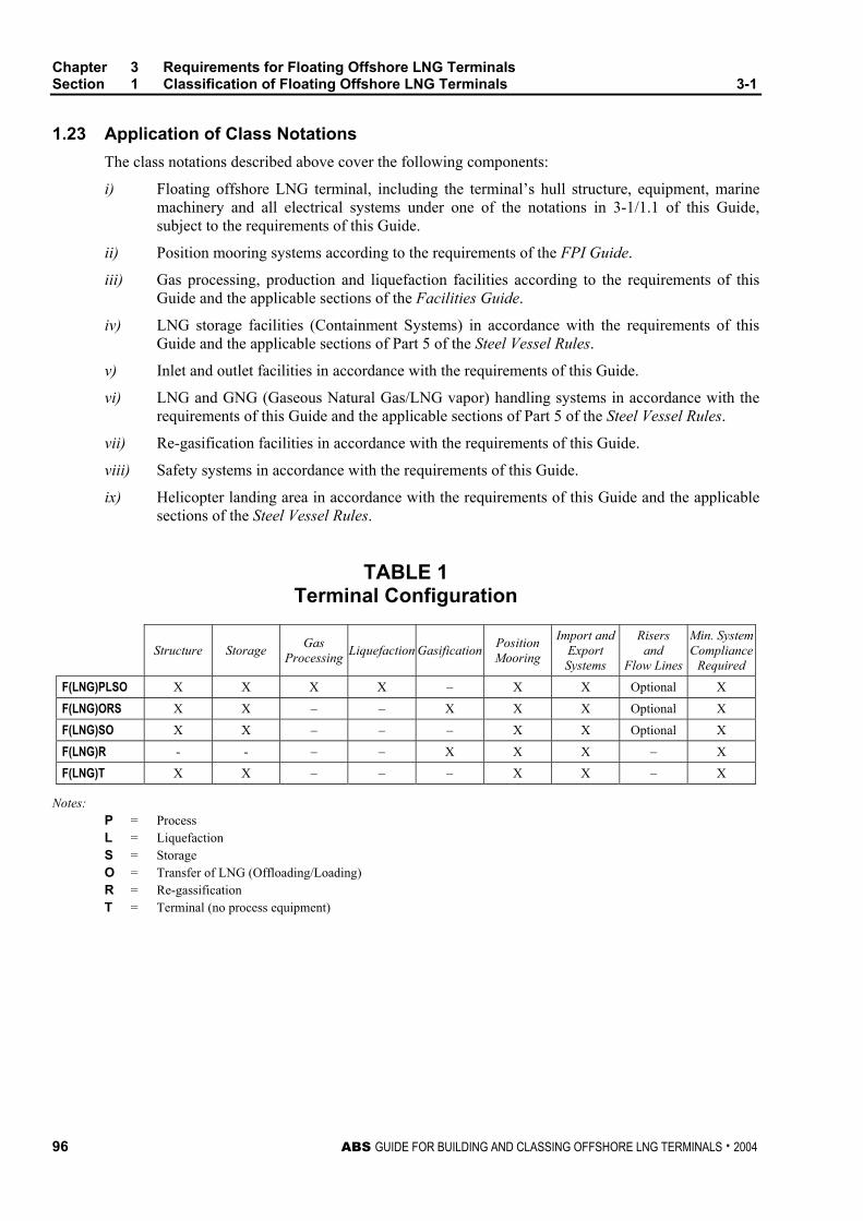
Chapter 3 Requirements for Floating Offshore LNG Terminals Section 1 Classification of Floating Offshore LNG Terminals 3-1
96 ABS GUIDE FOR BUILDING AND CLASSING OFFSHORE LNG TERMINALS . 2004
1.23 Application of Class Notations The class notations described above cover the following components:
i) Floating offshore LNG terminal, including the terminal’s hull structure, equipment, marine machinery and all electrical systems under one of the notations in 3-1/1.1 of this Guide, subject to the requirements of this Guide.
ii) Position mooring systems according to the requirements of the FPI Guide.
iii) Gas processing, production and liquefaction facilities according to the requirements of this Guide and the applicable sections of the Facilities Guide.
iv) LNG storage facilities (Containment Systems) in accordance with the requirements of this Guide and the applicable sections of Part 5 of the Steel Vessel Rules.
v) Inlet and outlet facilities in accordance with the requirements of this Guide.
vi) LNG and GNG (Gaseous Natural Gas/LNG vapor) handling systems in accordance with the requirements of this Guide and the applicable sections of Part 5 of the Steel Vessel Rules.
vii) Re-gasification facilities in accordance with the requirements of this Guide.
viii) Safety systems in accordance with the requirements of this Guide.
ix) Helicopter landing area in accordance with the requirements of this Guide and the applicable sections of the Steel Vessel Rules.
TABLE 1 Terminal Configuration
Structure Storage Gas Processing Liquefaction Gasification Position
Mooring
Import and Export Systems
Risers and
Flow Lines
Min. SystemCompliance
Required F(LNG)PLSO X X X X – X X Optional X
F(LNG)ORS X X – – X X X Optional X
F(LNG)SO X X – – – X X Optional X
F(LNG)R - - – – X X X – X
F(LNG)T X X – – – X X – X
Notes: P = Process L = Liquefaction S = Storage O = Transfer of LNG (Offloading/Loading) R = Re-gassification T = Terminal (no process equipment)
Chapter 3 Requirements for Floating Offshore LNG Terminals Section 1 Classification of Floating Offshore LNG Terminals 3-1
ABS GUIDE FOR BUILDING AND CLASSING OFFSHORE LNG TERMINALS . 2004 97
3 Plans and Data to be Submitted
Plans and data to be submitted for design review shall be submitted at least in triplicate; one copy for return to the submitter, one copy retained by ABS engineering office, and one copy for the use of the attending Surveyor. Full size prints of documents are preferred. If it is not feasible, all reduced prints must be clearly legible in all details. Proceeding paragraphs of this Subsection “Plans and Data to be Submitted” cover submittals for full variety of Class Notations. The actual extent of plans and data to be submitted depend upon the equipment, machinery and systems installed on the terminal and requested for Classification by the Owner.
3.1 Design Plans and Data for Structures Plans showing the scantlings, arrangements and details of the principal parts of the hull structure of each terminal to be built under survey are to be submitted and approved before the work of construction has commenced. These plans are to clearly indicate the scantlings, joint details and welding or other methods of connection. In general, plans are to be submitted that include the following, where applicable:
• General arrangement.
• Body plan, lines, offsets, curves of form, inboard and outboard profile.
• Wind heeling moment curves of equivalent data.
• An arrangement plan of watertight compartmentation.
• Diagrams showing the extents to which the watertight and weathertight integrity is intended to be maintained, the location, type, and disposition of watertight and weathertight closures.
• Capacity plan and tank sounding tables.
• Summary of distributions of weights (fixed, variable, ballast, etc.) for various conditions.
• Type, location and quantities of permanent ballast, if any.
• Loadings for all decks.
• Transverse section showing scantlings.
• Longitudinal sections showing scantlings.
• Decks, including helicopter deck.
• Framing, shell plating, watertight bulkheads and flats, structural bulkheads and flats, tank bulkheads and flats with location of overflows and air pipes.
• Pillars, girders, diagonals and struts.
• Stability columns, intermediate columns, hulls, pontoons, superstructure and deck houses.
• Arrangement and details of watertight doors and hatches.
• Foundations for anchoring equipment, industrial equipment, process and process support modules, etc., where attached to hull structure, superstructures or deckhouses.
• Mooring turrets and yoke arms, including mechanical details.
• Corrosion control arrangements.
• Methods and locations for nondestructive testing.
Chapter 3 Requirements for Floating Offshore LNG Terminals Section 1 Classification of Floating Offshore LNG Terminals 3-1
98 ABS GUIDE FOR BUILDING AND CLASSING OFFSHORE LNG TERMINALS . 2004
3.1.1 Site Condition Reports The site condition reports, comprised of the environmental and soil data, are to be submitted. For details, refer to Chapter 3, Section 4 of the FPI Guide. The principal purpose of these reports is to demonstrate that site conditions have been evaluated in establishing design criteria. Among the items to be discussed are:
i) Environmental conditions of waves, winds, currents, tides, water depth, air and sea temperature and ice
ii) Seabed topography, stability and pertinent geotechnical data
iii) Seismic conditions
Where appropriate, data established for a previous installation in the vicinity of the installation proposed for classification may be utilized if acceptable in the opinion of the Bureau.
3.1.2 Design Data and Calculations Information is to be submitted for the terminal which describes the methods of design, and analysis, which were employed to establish its design. The estimated design service life of a terminal is also to be stated. Where model testing is used as a basis for a design, the applicability of the test results will depend on the demonstration of the adequacy of the methods employed, including enumeration of possible sources of error, limits of applicability and methods of extrapolation to full-scale data. Preferably, procedures should be reviewed and agreed upon before model testing is done.
As required in subsequent sections, calculations are to be submitted to demonstrate the sufficiency of the proposed design. Such calculations are to be presented in a logical and well-referenced fashion employing a consistent system of units. Where the calculations are in the form of computer analysis, the submittal is to provide input and output data with computer generated plots for the structural model. A program description (not listings), user manuals and the results of program verification sample problems may be required to be submitted.
3.1.3 Plans and Specifications. Plans or specifications depicting or describing the arrangements and details of the major items of the terminal are to be submitted for review or approval in a timely manner.
Where deemed appropriate, and when requested by the Owner, a schedule for information submittal and plan approval can be jointly established by the Owner and the Bureau. This schedule, which the Bureau will adhere to as far as reasonably possible, is to reflect the construction schedule and the complexity of the terminal as it affects the time required for review of the submitted data.
3.1.4 Information Memorandum An information memorandum on the terminal is to be prepared and submitted to the Bureau. The Bureau will review the contents of the memorandum to establish consistency with other data submitted for the purpose of obtaining classification. The Bureau will not review the contents of the memorandum for their accuracy or the features described in the memorandum for their adequacy.
An information memorandum is to contain, as appropriate to the terminal, the following:
• Site plan indicating the general features at the site and the exact location of the terminal.
• Environmental design criteria, including the recurrence interval used to assess environmental phenomena (see 3-2/1.1).
• Plans showing the general arrangement of the terminal.
Chapter 3 Requirements for Floating Offshore LNG Terminals Section 1 Classification of Floating Offshore LNG Terminals 3-1
ABS GUIDE FOR BUILDING AND CLASSING OFFSHORE LNG TERMINALS . 2004 99
• Description of the safety and protective systems provided.
• The number of personnel to be normally stationed at the terminal.
• Listing of governmental authorities having cognizance over the terminal.
• Listing of any novel features.
• Brief description of any monitoring proposed for use on the terminal.
• Description of transportation and installation procedures.
3.3 Design Plans and Data for Position Mooring Systems The design documentation for the mooring system is to include the following, when applicable:
• Mooring arrangement or pattern.
• Details of winching equipment.
• Details of anchoring system.
• Details of mooring line segments.
• Connections at anchors and between mooring line segments.
• Details of in-line (spring) buoys.
• Details of buoy for Catenary Anchor Leg Mooring (CALM) system.
• Details of Single Anchor Leg Mooring (SALM) structures, if appropriate.
• Details of Turret System to show turret structure, swivel, turntable and disconnecting device.
• Details of yoke (hard or soft) connecting the vessel and CALM/SALM structure.
• Environmental Report.
• Mooring Analysis describing method of load calculations and analysis of dynamic system to determine the mooring line design loads.
• Model Test report when the design loads are based on model tests in a wave basin.
• Thruster specifications and calculations of a system with dynamic positioning system for thruster forces and power to counteract environmental forces (See Chapter 3, Sections 3 and 4 of the FPI Guide.).
3.5 Design Plans for LNG Containment System, LNG and GNG Handling Systems The following plans, calculations and information, as appropriate, are to be submitted in addition to those required by Section 1-1-7 of the Steel Vessel Rules:
• Full particulars of the intended cargo and its properties, including flashpoint, maximum vapor pressure, minimum and maximum temperature and loading and storage procedures.
• General arrangement plans of the terminal showing the position of the following:
i) LNG containment system, fuel oil, water ballast and other tanks and void spaces.
ii) Manholes and any other opening of the cargo tanks.
iii) Doors and other openings in cargo pump and compressor rooms and other gas-dangerous rooms.
iv) Ventilation ducts of cargo compressor rooms and other “gas-dangerous” spaces.
Chapter 3 Requirements for Floating Offshore LNG Terminals Section 1 Classification of Floating Offshore LNG Terminals 3-1
100 ABS GUIDE FOR BUILDING AND CLASSING OFFSHORE LNG TERMINALS . 2004
v) Door, air-locks, manholes, ducts and other openings for “non-gas-dangerous” spaces which are, however, adjacent to the cargo area, including rooms inside and under the forecastle deck.
vi) Cargo piping, both liquid and gaseous phases, located under and above deck.
vii) Vent piping and gas-freeing piping and protective devices such as flame screens, etc. fitted at the outlet end of the vents etc.
viii) Gas-dangerous spaces.
• Plans of the terminal structure in way of the cargo tanks, including the installation of attachments, accessories, internal reinforcements, saddles for support and tie-down devices.
• Plans of the structure of the cargo containment system, including the installation of attachments, supports and attachment of accessories. For independent pressure cargo tanks, the standard or Code adopted for the construction and design is to be identified. Detailed construction drawings together with design calculations for the pressure boundary, tank support arrangement and analysis for the load distribution. Anti-collision, chocking arrangement and design calculations.
• Distribution of the grades and of the types of steel proposed for the structures of the terminal together with the calculation of the temperatures on all of the structures which can be affected by the low temperatures of the cargo.
• Results of direct calculations of the stresses in the terminal structure and in the cargo containment system.
• A sloshing analysis to demonstrate that the LNG storage tanks, the containment system and the structure can withstand loads under conditions of partially filled tanks to any level consistent with the operations procedures. The description of analysis tools and supporting documents for the validation of the tools are to be provided.
• Specifications and plans of the insulation system and calculation of the heat balance.
• Thermal heat analysis determining the LNG boil-off rate from the storage tanks.
• Calculations to show the means provided for handling the boil-off gas from storage tanks without causing overpressurization in the tanks.
• Procedures and calculations of the cooling down, loading and unloading operations.
• Loading and unloading systems, venting systems and gas-freeing systems as well as a schematic diagram of the remote controlled valve system.
• Details and installation of the safety valves and relevant calculations of their relieving capacity.
• Details and installation of the various monitoring and control systems, including the devices for measuring the level of the cargoes in the tanks and the temperatures in the containment system.
• Schematic diagram of the ventilation system indicating the vent pipe sizes and height of the openings above the main deck.
• Schematic diagram of the refrigeration system together with the calculations concerning the refrigerating capacity for a re-liquefaction plant, if provided.
• Details of the electrical equipment installed in the cargo area and of the electrical bonding of the cargo tanks and piping.
• Where fitted, plans and specifications relevant to the use of the cargo as fuel for boilers and internal combustion engines (general installations; schematic diagram of the fuel-gas lines with the indication of all the valves and safety devices; compressors of the fuel gas and relevant engines; fuel-gas heaters and pressure vessels; installation of the burners of the fuel-gas and of the fuel oil; electrical bonding systems).
Chapter 3 Requirements for Floating Offshore LNG Terminals Section 1 Classification of Floating Offshore LNG Terminals 3-1
ABS GUIDE FOR BUILDING AND CLASSING OFFSHORE LNG TERMINALS . 2004 101
• Details of testing procedures of cargo tanks and liquid and vapor systems.
• Diagram of inert-gas system or hold-space environmental control system.
• Diagram of gas-detection system.
• Jettison arrangements, if provided.
• Details of all cargo and vapor handling equipment.
• Welding procedure for cargo tanks, LNG and GNG piping systems.
• Emergency shutdown arrangements.
• Construction details of cargo and booster pumps and compressors, including material specification.
• Hazardous areas drawing showing access, openings, vent outlets.
• Bilge and ballast arrangement for the cargo area.
• Emergency towing arrangement.
3.7 Design Plans for Process Facilities, Support and Safety Systems
3.7.1 Process and Re-Gasification Facilities • The process system description.
• Project specification and overall process concept evaluation.
• Process flow sheets.
• Heat and mass balance.
• Equipment layout drawings.
• Area classification and ventilation drawings.
• Piping and instrument diagrams (P&IDs).
• Safety analysis function evaluation (SAFE) charts.
• Shutdown and emergency shutdown system to include a hazard analysis and Failure Modes and Effects Analysis (FMEA) to identify critical components.
• Pressure relief and depressurization systems.
• Flare and vent systems.
• Spill containment, closed and open drain systems.
• Process equipment documentation, including calculation showing suitability of all pressurized components in the system to withstand the maximum design pressure that a specific component is likely to encounter in service.
• Process piping systems.
• Packaged process units.
• The monitoring and control system for the entire system pressure regulation and gas dispersion system (to include calculations for sizing of the venting system and the relief valve) radiant heat analysis to demonstrate that the radiant heat intensity at any deck level or location where normal maintenance or operating activity could take place is not exceeding API RP 521 recommendations.
Chapter 3 Requirements for Floating Offshore LNG Terminals Section 1 Classification of Floating Offshore LNG Terminals 3-1
102 ABS GUIDE FOR BUILDING AND CLASSING OFFSHORE LNG TERMINALS . 2004
3.7.2 Process Support and Service Systems • Piping and Instrument Diagrams (P&IDs) for each system.
• Equipment documentation.
• Process support piping specifications.
• Specification data sheets for internal combustion engines and turbines.
• Specification data sheets for cranes (Optional).
• Marine support systems, as required by the ABS Rules applicable to the type of terminals.
3.9 Electrical Installations • Electrical one-line diagrams.
• Short-circuit current calculations.
• Coordination study.
• Specifications and data sheets for generators and motors.
• Specifications and data sheets for distribution transformers.
• Details of storage batteries.
• Details of emergency power source.
• Standard details of wiring cable and conduit installation practices.
• Switchboards and distribution panel.
• Panel board.
• Installations in classified areas.
3.11 Instrumentation and Control Systems • General arrangements.
• Data sheet.
• Schematic drawings – electrical systems.
• Schematic drawings – hydraulic and pneumatic systems.
• Programmable electronic systems.
3.13 Fire Protection and Personnel Safety • Firewater system.
• Water spray (Deluge) systems for deckhouse, superstructure and manifold areas.
• Water spray (Deluge) systems for process equipment.
• Dry powder system for LNG storage tank area.
• Fixed fire extinguishing systems.
• Paint lockers and flammable material storerooms.
• Emergency control stations.
• Portable and semi-portable extinguishers.
Chapter 3 Requirements for Floating Offshore LNG Terminals Section 1 Classification of Floating Offshore LNG Terminals 3-1
ABS GUIDE FOR BUILDING AND CLASSING OFFSHORE LNG TERMINALS . 2004 103
• Fire and gas detection and alarm systems.
• Fire and gas cause and effect chart.
• Structural fire protection (which indicates classification of all bulkheads for quarters section, machinery spaces and processing facilities).
• Heating ventilation and air conditioning (HVAC) plan [including air handling unit (AHU)], location, duct layout, duct construction and bulkhead penetration details.
• Joiner detail arrangement and structural fire protection material certification.
• Guard rails.
• Escape routes (may be included on the fire control plan or separate plan).
• Lifesaving appliances and equipment plan (escape routes must be indicated).
• Insulation of hot surfaces.
• Fire and explosion hazard analysis.
• Due to the varying configurations of the project, some portions of these requirements may not be applicable.
3.15 Installation Procedures • Procedures for loading sections of the terminal structure, deck area, process modules decks and
topsides.
• Procedures for carrying out all installation work offshore including foundation preparation platform installation and completion.
3.17 Start-up and Commissioning Manual • Provisions/Procedures for start-up.
• Manual/Procedures for commissioning trials.

This Page Intentionally Left Blank
ABS GUIDE FOR BUILDING AND CLASSING OFFSHORE LNG TERMINALS . 2004 105
C H A P T E R 3 Requirements for Floating Offshore LNG Terminals
S E C T I O N 2 Design of Floating Offshore LNG Terminals
1 Environmental Loading and Design Basis
1.1 Environmental and Related Conditions
1.1.1 General The minimum recurrence interval used to establish the magnitude of the Design Environmental Condition is 100 years, except where the use of a shorter recurrence interval produces higher magnitude load effects. As applicable, when a National Authority having jurisdiction over the LNG Terminal specifies the use of a lower return period, this will be specially considered.
1.1.2 Environmental Conditions The LNG Terminal is to be designed for the site-specific environmental conditions specified in Chapter 3 of the FPI Guide or Part 3 of the Offshore Installations Rules. In addition to the Design Environmental Conditions mentioned above, the designer is to specify any limiting, Operating Environmental Conditions. These are sets of characteristic parameters for the environmental factors which need to be limited so that the safe performance of an operation or function is not compromised. Such operations may include, as appropriate, transportation and installation of the LNG Terminal structure itself and for conditions after the LNG terminal structure’s installation (berthing and mooring of cargo and supply vessels, cargo transfer, fuel oil transfer, personnel transfer, etc.). These sets of conditions are herein referred to as Operating Environmental Conditions.
1.1.3 Environmental Factors to be Considered In general, the design of the LNG terminal will require investigation of the following environmental factors, as appropriate to the type of terminal structure and the terminal’s installation site:
i) Waves
ii) Wind
iii) Currents
iv) Tides and storm surges
v) Air and sea temperatures
Chapter 3 Requirements for Floating Offshore LNG Terminals Section 2 Design of Floating Offshore LNG Terminals 3-2
106 ABS GUIDE FOR BUILDING AND CLASSING OFFSHORE LNG TERMINALS . 2004
vi) Ice and snow
vii) Marine growth
viii) Seismicity
ix) Sea ice
Other phenomena, such as tsunamis, submarine slides, seiche, abnormal composition of air and water, air humidity, salinity, ice drift, icebergs, ice scouring, etc. may require investigation depending upon the specific installation site.
The required investigation of seabed and soil conditions is described in Section 3/6 of the Offshore Installations Rules.
1.3 Design Basis The design of the unit and the facilities on the installation for gas processing, liquefaction, storage, re-gasification, including importing of raw gas or LNG and exporting of processed gas or LNG, is to be in accordance with the criteria defined in this Guide, including any additional prevention or mitigation safeguards identified in the risk assessment required in 3-2/3 of this Guide.
In addition to the requirements mentioned above, it is also the responsibility of the designer, Owner and operator to comply with any additional requirements that may be imposed by the flag state or the coastal state or any other jurisdictions in the intended area of deployment and operation. This would include requirements for importing and exporting pipelines.
The complete basis for the design is to be stated in the operations manual and is to include the intended location, the envelope of environmental operating conditions and the storage capacities and throughputs of the production/re-gasification systems.
3 Risk Assessment
A Risk Assessment shall be carried out to identify significant hazards and accident scenarios that may affect the installation or any part thereof, and consider the benefit of existing or potential risk control options.
The objective of the risk assessment is to identify areas of the design that may require the implementation of risk control measures to reduce identified risk(s) to an acceptable level. For this purpose, a systematic process is to be applied to identify situations where a combination or sequence of events could lead to undesirable consequences such as property damage, personnel safety and environmental damage at an acceptable frequency.
The risk assessment shall consider, as a minimum, the following events:
i) Damage to the primary structure due to extreme weather, impact/collision, dropped objects, helicopter collision, exposure to unsuitably cold temperatures, exposure to high radiant heat
ii) Fire and explosion
iii) Loss of primary liquid containment (for a duration to be determined based on an approved contingency plan)
iv) LNG leakage
v) Release of flammable or toxic gas to the atmosphere or inside an enclosed space
vi) Roll-Over (thermodynamic instability due to LNG stratification)
vii) Loss of stability
viii) Loss of any single component in the station keeping/mooring system
Chapter 3 Requirements for Floating Offshore LNG Terminals Section 2 Design of Floating Offshore LNG Terminals 3-2
ABS GUIDE FOR BUILDING AND CLASSING OFFSHORE LNG TERMINALS . 2004 107
ix) Loss of ability to offload LNG or discharge gas ashore
x) Loss of any one critical component in the process system
xi) Loss of electrical power
The identified risk control options (prevention and mitigation measures) deemed necessary to be implemented should be considered part of the design basis of the terminal.
ABS recommends that early in the project a risk assessment plan be developed, documented and submitted to the Bureau for review prior to conducting the risk assessment. During review of the plan, an agreement will be reached on the extent of Bureau participation and/or monitoring of project-related risk studies. The Bureau’s participation in and/or monitoring of key tasks (e.g., Hazard Identification meetings) is necessary in order to establish a minimum level of confidence on the risk assessment results.
5 Structure – Floating Terminal
The ABS Offshore Installations Rules and the FPI Guide, directly and by reference to other standards, present the criteria deemed most applicable to the structural design of Offshore LNG Terminals. Major portions of the structural criteria from these ABS standards are excerpted and modified below to reflect envisioned LNG Terminal service. This has been done for the convenience of users and to concisely present in this Guide the main structural design and construction features included in the scope of Classification and the criteria to be applied. Reference should be made to the mentioned Offshore Installations Rules and FPI Guide for additional background on the referenced criteria.
5.1 Floating Steel Terminals
5.1.1 General 5.1.1(a) Basic Principle. The design and construction of steel floating LNG and/or LNG vapor terminal structures are to be based on the applicable requirements in the Steel Vessel Rules or FPI Guide, with modifications to reflect the service of terminals positioned to a fixed site on a long term basis and cryogenic temperature of the cargo, as indicated in this Guide. 5.1.1(b) Referenced Rules and Guides. Refer to 1-1/25 of this Guide. 5.1.1(c) Proportion. This Guide is intended for ship-shaped terminals with a length not exceeding 500 m, a breadth not exceeding one-fifth of the length nor more than 2.5 times the depth. Terminals beyond these proportions and terminals other than ship-shaped will be specially considered. 5.1.1(d) Types of Tanks. In this Guide, the following types of tanks are considered: • Membrane tanks • Type B (IMO Gas Carrier Code) independent tanks • Other tanks (subject to special consideration 5.1.1(e) Access for Inspection. In the design of the terminal, consideration should be given to providing access for inspection during construction and, to the extent practicable, for survey after construction. 5.1.1(f) Steel-Concrete Hybrid Structures. The steel portions of a steel-concrete hybrid structure are to be designed in accordance with the requirements of 3-2/5.1 of this Guide, and the concrete portions are to be designed as specified in 3-2/5.3. Any effects of the hybrid structure interacting on itself in areas such as corrosion protection should be considered. 5.1.1(g) Steel-Concrete Composite Structures. Steel-concrete composite structures are to be designed in accordance with 3-2/5.1 of this Guide and the AISC, “Allowable Stress Design”.
Chapter 3 Requirements for Floating Offshore LNG Terminals Section 2 Design of Floating Offshore LNG Terminals 3-2
108 ABS GUIDE FOR BUILDING AND CLASSING OFFSHORE LNG TERMINALS . 2004
5.1.2 Materials and Welding 5.1.2(a) Material. This Guide is intended for terminals of welded construction using steels complying with the requirements of Chapter 1 of the M/W Rules and Section 5-8-6 of the Steel Vessel Rules. Use of materials other than those mentioned and the corresponding scantlings will be specially considered.
5.1.2(b) Selection of Material Grade. The selection of structural steel material grade for hull and tanks is to be in accordance with 3-1-2/3.1 and 5-8-4/9 of the Steel Vessel Rules. The M/W Rules is one of the “Recognized Standards” in 5-8-4/9.1 of the Steel Vessel Rules.
5.1.2(c) Welding. The welding is to be in accordance with Section 2-4-1 of the M/W Rules and 5-8-4/10 of Steel Vessel Rules.
5.1.3 Survival Capability and Location of Cargo Tanks Terminals are to comply with the survival capability and cargo tank location requirements in 5-8-2 of the Steel Vessel Rules.
5.1.4 Longitudinal Strength The longitudinal strength is to be based on Section 3-2-1 of the Steel Vessel Rules with modifications as indicated below for terminals classed with (S) notation.
5.1.4(a) Still-water Loads. Still-water bending moment and shear force calculations for all anticipated loading conditions during on-site and in-transit operation are to be submitted together with the distribution of light weights.
The influence of mooring equipment and riser weights over the still-water bending moments and shear forces is to be taken into consideration in these calculations.
5.1.4(b) Wave Induced Loads
i) Direct Calculation. Wave-induced bending moments and shear forces may be determined from Chapter 3, Section 3 of the FPI Guide for the on-site and transit conditions, respectively, subject to the minimum as specified below.
ii) Environmental Severity Factor (ESF) Approach. In lieu of direct calculation, wave-induced bending moments and shear forces in on-site condition may be calculated by the Environmental Severity Factor (ESF) approach, as described in Appendix 1 of the FPI Guide. This approach can be applied to modify the Steel Vessel Rules wave-induced hull girder bending moment and shear force formulas subject to the minimum, as specified in 3-2/7.1.4(b) and 3-2/7.1.4(c).
In either of the above cases, the minimum value of wave-induced bending moments (or shear forces) for use with scantling determination is not to be taken less than 50 percent of the value given in 3-2-1/3.5.1 (or 3-2-1/3.5.3) of the Steel Vessel Rules using Mws and Mwh (or Fwp and Fwn) for on-site operation, and not less than 85% for transit conditions.
5.1.4(c) Minimum Scantlings and Section Modulus
i) Minimum Scantlings for ESF Approach. In addition to the minimum wave loads, the scantlings (SM for bending moments and shell/bulkhead thickness for shear forces), as determined from ESF approach, are to be not less than 85% of the values calculated from 3-2-1/3.7.1(a) of the Steel Vessel Rules for SM and 3-2-1/3.9.2 and 3-2-1/3.9.4 of the Steel Vessel Rules for the thickness of side shell and longitudinal bulkhead using Mws and Mwh (or Fwp and Fwn).
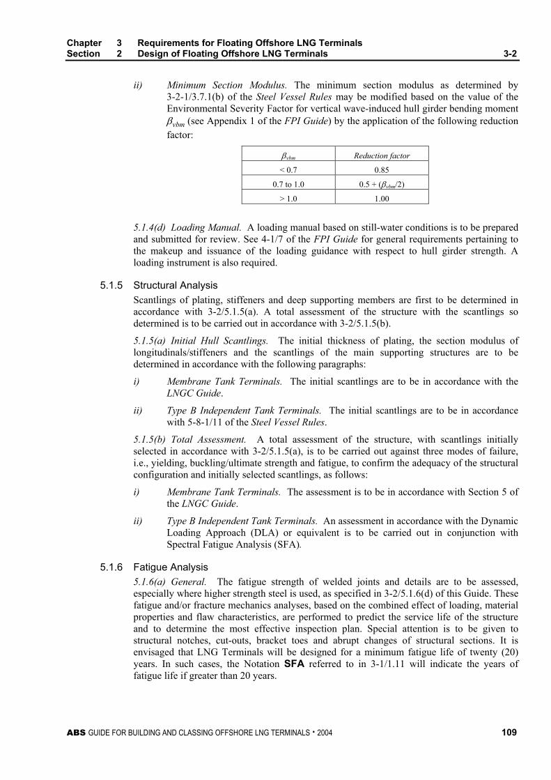
Chapter 3 Requirements for Floating Offshore LNG Terminals Section 2 Design of Floating Offshore LNG Terminals 3-2
ABS GUIDE FOR BUILDING AND CLASSING OFFSHORE LNG TERMINALS . 2004 109
ii) Minimum Section Modulus. The minimum section modulus as determined by 3-2-1/3.7.1(b) of the Steel Vessel Rules may be modified based on the value of the Environmental Severity Factor for vertical wave-induced hull girder bending moment βvbm (see Appendix 1 of the FPI Guide) by the application of the following reduction factor:
βvbm Reduction factor
< 0.7 0.85
0.7 to 1.0 0.5 + (βvbm/2)
> 1.0 1.00
5.1.4(d) Loading Manual. A loading manual based on still-water conditions is to be prepared and submitted for review. See 4-1/7 of the FPI Guide for general requirements pertaining to the makeup and issuance of the loading guidance with respect to hull girder strength. A loading instrument is also required.
5.1.5 Structural Analysis Scantlings of plating, stiffeners and deep supporting members are first to be determined in accordance with 3-2/5.1.5(a). A total assessment of the structure with the scantlings so determined is to be carried out in accordance with 3-2/5.1.5(b).
5.1.5(a) Initial Hull Scantlings. The initial thickness of plating, the section modulus of longitudinals/stiffeners and the scantlings of the main supporting structures are to be determined in accordance with the following paragraphs:
i) Membrane Tank Terminals. The initial scantlings are to be in accordance with the LNGC Guide.
ii) Type B Independent Tank Terminals. The initial scantlings are to be in accordance with 5-8-1/11 of the Steel Vessel Rules.
5.1.5(b) Total Assessment. A total assessment of the structure, with scantlings initially selected in accordance with 3-2/5.1.5(a), is to be carried out against three modes of failure, i.e., yielding, buckling/ultimate strength and fatigue, to confirm the adequacy of the structural configuration and initially selected scantlings, as follows:
i) Membrane Tank Terminals. The assessment is to be in accordance with Section 5 of the LNGC Guide.
ii) Type B Independent Tank Terminals. An assessment in accordance with the Dynamic Loading Approach (DLA) or equivalent is to be carried out in conjunction with Spectral Fatigue Analysis (SFA).
5.1.6 Fatigue Analysis 5.1.6(a) General. The fatigue strength of welded joints and details are to be assessed, especially where higher strength steel is used, as specified in 3-2/5.1.6(d) of this Guide. These fatigue and/or fracture mechanics analyses, based on the combined effect of loading, material properties and flaw characteristics, are performed to predict the service life of the structure and to determine the most effective inspection plan. Special attention is to be given to structural notches, cut-outs, bracket toes and abrupt changes of structural sections. It is envisaged that LNG Terminals will be designed for a minimum fatigue life of twenty (20) years. In such cases, the Notation SFA referred to in 3-1/1.11 will indicate the years of fatigue life if greater than 20 years.
Chapter 3 Requirements for Floating Offshore LNG Terminals Section 2 Design of Floating Offshore LNG Terminals 3-2
110 ABS GUIDE FOR BUILDING AND CLASSING OFFSHORE LNG TERMINALS . 2004
5.1.6(b) Design Fatigue Life. The minimum design fatigue life is the service life multiplied by the Fatigue Design Factor (FDF) for site-specific service terminals using the wave spectrum at that site. Impact on fatigue life as a result of tow from fabrication to installation site is to be included in the fatigue assessment.
Where a terminal is designed for a design fatigue life in excess of 20 years, the design life will appear in the Record as described in 3-1/1.9 and 3-1/1.11 of this Guide.
5.1.6(c) Fatigue Design Factor. FDF is a factor, equal or greater than one (1) that is applied to individual structural details and which accounts for: uncertainties in the fatigue assessment process, the consequences of failure (i.e., criticality), and the relative difficulty of inspection and repair. ABS Guide for the Fatigue Assessment of Offshore Structures provides specific information on the values of FDF.
5.1.6(d) Process of Fatigue Analysis
i) Membrane Tank Terminals. The fatigue analysis is to be in accordance with Paragraph 5/7 of the LNGC Guide. For site-specific environment, Appendix 2, Section 1 of the FPI Guide may also be referred to. In addition, a Spectral Fatigue Analysis may be carried out in accordance with the Spectral Fatigue Procedure for Ship-Shaped FPSOs.
ii) Type B Independent Tank Terminals. The fatigue analysis is to be a spectral fatigue analysis in accordance with the Spectral Fatigue Procedure for Ship-Shaped FPSOs.
5.1.7 Design Loads for Local Structures Note: For the purpose of 3-2/5.1.7, “Transit Condition” means that the terminal is either in: a) transit from/to
site with own propulsion or with propulsion assistance, or b) on site, but in a disconnectable mode with own propulsion. For the purpose of 3-2/5.1.7, “On-Site Condition” means that the terminal is not in “Transit Condition.”
5.1.7(a) Sloshing Loads. The natural periods of liquid motions and sloshing loads are to be determined and an assessment carried out of the strength of boundary structures of liquid tanks.
i) Transit Condition. For membrane tank terminals, the sloshing pressure heads given in Paragraph 3/11 of the LNGC Guide may be used for determining the scantlings. For Type B Independent Tank Terminals, another analytical method such as numerical simulation using three-dimensional flow analysis or model experiments is to be used. Such analytical method may also be used for membrane tank terminals as an alternative.
ii) On-site Condition. Sloshing loads are also to be determined for on-site service. Appendix 2, Section 2 of the FPI Guide may be referred to.
5.1.7(b) Forebody Strengthening. Impact loads on the forebody structure are to be determined for transit and on-site conditions. Unless one end is specifically designated as the bow, terminals are to be designed with each end as the bow.
i) Bottom Slamming
• Transit Condition. For terminals with heavy weather ballast draft forward equal to or less than 0.04L and greater than 0.025L, the bottom slamming pressures are to be calculated using Paragraph 3/13.3 of the LNGC Guide and the scantlings determined in accordance with Paragraph 6/7.1 of the LNGC Guide. Terminals with heavy weather ballast draft forward equal to or less than 0.025L will be subject to special consideration.
• On-site Condition. For the determination of loads in on site condition, refer to the Appendix 2, Section 6 of the FPI Guide.
Chapter 3 Requirements for Floating Offshore LNG Terminals Section 2 Design of Floating Offshore LNG Terminals 3-2
ABS GUIDE FOR BUILDING AND CLASSING OFFSHORE LNG TERMINALS . 2004 111
ii) Bowflare Slamming
• Transit Condition. For vessels having a bowflare shape parameter greater than 21 m in the forebody, bowflare slamming loads are to be calculated in accordance with Paragraph 3/13.5 of the LNGC Guide and the scantlings determined in accordance with Paragraph 6/7.3 of the LNGC Guide.
• On-site Condition. For the determination of loads in on-site condition, refer to Appendix 2, Section 5 of the FPI Guide.
iii) Bow Impact Loads
• Transit Condition. Where experimental data are not available or direct calculation is not carried out, nominal bow pressures above LWL from the forward end to the collision bulkhead may be obtained from Paragraph 3/13.1 of the LNGC Guide.
• On-site Condition. For the determination of loads in the on-site condition, refer to Appendix 2, Section 4 of the FPI Guide.
iv) Green Water
• Transit Condition. Where experimental data are not available or direct calculation is not carried out, nominal green water pressure on deck from FP to 0.30L aft, including the extension beyond the FP, may be obtained from 5-3-3/5.5.4(b) of the Steel Vessel Rules. Minimum deck scantlings may then be determined using 5-3-6/9 of the Steel Vessel Rules.
• On-site Condition. For the determination of loads in the on-site condition, refer to Appendix 2, Section 3 of the FPI Guide.
5.1.7(c) Loads from Mooring and Other Equipment
i) Position Mooring System. In the structural design of terminals, the interface between the position mooring system and the hull structure are to be considered. The criteria to be applied for these cases are presented in 4-2/15.1 of the FPI Guide.
ii) Equipment, Modules and Their Supports. The effect of loads from equipment, modules and their supports are also to be considered. The criteria are in 4-2/15.3 of the FPI Guide.
5.1.7(d) Terminal Operation. The expected loads and other demands that will be acting on the LNG Terminal as a result of the need to berth and moor vessels are to be considered in the design. These may include vessel breasting and mooring loads, the presence of fenders and the additional hydrodynamic and gravity loads that they bring, the need to support bollards and other mooring hardware, etc.
5.1.8 Superstructures, Deckhouses and Helicopter Decks 5.1.8(a) Superstructures and Deckhouses. The design of superstructures and deckhouses is to comply with the requirements of 3-2-11 of the Steel Vessel Rules. The structural arrangement of forecastle decks in 3-2-11/9 of the Steel Vessel Rules is to be satisfied, regardless of speed.
5.1.8(b) Helicopter Decks. The helicopter deck structures are to be in accordance with 3-2-11/11 of the Steel Vessel Rules.
5.1.8(c) Other Structures. For deck-mounted equipment – for use in the preliminary design of deck transverses and girders that are directly resisting the reaction forces and when ABS permits it in lieu of a more comprehensive method – the approach presented in Appendix 2, Section 7 of the FPI Guide may be used.
Chapter 3 Requirements for Floating Offshore LNG Terminals Section 2 Design of Floating Offshore LNG Terminals 3-2
112 ABS GUIDE FOR BUILDING AND CLASSING OFFSHORE LNG TERMINALS . 2004
5.1.9 Other Structures The design criteria for other hull structures where not addressed in this Guide or the referenced Rules and Guides are to conform to recognized practices acceptable to ABS.
5.3 Floating Concrete Terminals There are no structural design requirements developed at this time that are specifically applicable to floating concrete offshore LNG terminals.
7 Containment Systems The LNG containment system is a mandatory part of ABS classification of the terminal’s structure. The LNG containment system is to be in accordance with the requirements of Section 5-8-4 of the Steel Vessel Rules or NFPA 59A. Alternative arrangements for the LNG containment system, such as the use of a properly designed prestressed concrete structure as a secondary cryogenic barrier, application of membrane lining/barrier systems into concrete containment components, etc., may be given special consideration.
7.1 Design Features Unless considered otherwise, the design of the containment system should incorporate the following features to satisfy the intent of these Rules and Standard: i) A secondary containment system such that if there is a failure in the primary system, the
secondary system is to be capable of containing the leaked liquid contents for an agreed period of time consistent with the approved scenarios for the safe disposal of same.
ii) There is to be a minimum of two independent means of determining the liquid level in the LNG storage tanks.
iii) Means to fill the tank from various elevations within the tank to avoid stratification. iv) Independent high and high-high level alarms. v) At least one pressure gauge connected to the vapor space. vi) Two independent overpressure protection devices. vii) Devices for measuring the liquid temperature at the top, middle and bottom of tank. viii) A gas detection system which will alarm high gas concentrations in the space between the
primary and the secondary barrier.
7.3 Design Loads Tanks, together with their supports and fixtures, are to be designed with consideration of proper combinations of the following loads: i) Internal pressure. ii) External pressure. iii) Dynamic loads due to motion of the floating terminal. iv) Thermal loads. v) Sloshing loads. vi) Loads corresponding to hull deflections. vii) Tank and cargo weight with the corresponding reactions in way of the supports. viii) Insulation weight. ix) Loads in way of towers and other attachments.
Chapter 3 Requirements for Floating Offshore LNG Terminals Section 2 Design of Floating Offshore LNG Terminals 3-2
ABS GUIDE FOR BUILDING AND CLASSING OFFSHORE LNG TERMINALS . 2004 113
The sloshing loads are to consider any level of filling in each tank unless it can be shown that cargo can be shifted in a timely manner, and the level in the tanks can be maintained within the approved design limits.
The loads in way of supports are also to consider the unit inclined up to the worst angle of inclination resulting from flooding consistent with the unit’s agreed-to damage stability criteria up to an angle of 30 degrees.
7.5 Steel Terminals In the case of floating steel offshore LNG terminals, the requirements of 5-8-4 of the Steel Vessel Rules are considered applicable.
7.7 Concrete Terminals On floating concrete offshore LNG terminals constructed of prestressed concrete, the outer containment system may be constructed of concrete in accordance with the requirements of Section 4.3 of NFPA 59A.
7.9 Condensate Storage Condensate storage tanks integral with the terminal’s hull are to be in compliance with the requirements of 5-1-7 of the Steel Vessel Rules and 3-5/5.9 of the Facilities Guide.
Condensate storage in tanks adjacent to LNG storage tanks will be considered acceptable, provided it can be shown that loss of primary LNG containment would not cause an underpressure situation or the ingress of air into the condensate tank.
9 Position Mooring
Unless the terminal is classed with the notation (Disconnectable), À AMS, floating terminals are to be capable of remaining on station under the most adverse environmental conditions specified in 3-2/1 of this Guide through a position mooring system. The position mooring system may be comprised of a conventional anchor mooring system or Single Point Mooring (SPM) systems such as: Catenary Anchor Leg Mooring (CALM), Single Anchor Leg Mooring (SALM), Turret Mooring, etc. The design, fabrication, installation, deployment and testing is to be in compliance with the requirements of Chapter 5 of the FPI Guide.
11 Process Facilities
Where process facilities are requested to be within the scope of Class, the facilities installed onboard the terminal for processing raw gas from the well(s) or bringing partially processed gas from another installation, LNG production or liquefaction or re-gasification system for converting LNG into vapor for shipment ashore, the entire installation, including the import and export system, are subject to requirements of this Guide.
For Classification purposes, it is to be ensured that whichever of the process systems are employed, the facilities are in place so that the entire operation can be carried out safely. Accordingly, in order to carry out an assessment of the system, the plans and calculations listed in 3-1/3.7 of this Guide are required to be submitted.
The Bureau may require additional information depending on the systems used and their configuration.
Chapter 3 Requirements for Floating Offshore LNG Terminals Section 2 Design of Floating Offshore LNG Terminals 3-2
114 ABS GUIDE FOR BUILDING AND CLASSING OFFSHORE LNG TERMINALS . 2004
Where processing facilities are not within the scope of Class, requirements contained in this Guide relating to the safety of the terminal will be considered within the scope of Class. For example, the following systems will be subject to approval by the Bureau:
i) Interface to the Fire Extinguishing system
ii) Hazardous areas
iii) Gas disposal system (venting and relief)
11.1 Process Safety Criterion The design of the onboard process facilities described above is to include an overall evaluation of the proposed concept with a view toward reducing the likelihood of the occurrence of the undesirable events identified in 3-2/3 of this Guide.
The Bureau evaluation will include a systematic consideration of arrangements, layouts, process systems, process support systems, process controls and safety systems as well as a review of fitness for purpose of all safety critical equipment. The term “safety critical” is meant to include all equipment whose reliable performance is essential to maintaining a safe facility as well as equipment whose failure in and of itself could lead to an unsafe occurrence.
While the design of the terminal arrangements, safety systems and systems for handling LNG and LNG vapor on a terminal may rely primarily on the proven practices employed on LNG carriers, it must be recognized that on an LNG carrier, except during cargo loading and discharge operations, there is very little hydrocarbon outside of the containment system. Accordingly, additional provisions may be required depending on the process system installed on the terminal. This may include such items as an extension of the hazardous areas, the need for a gas dispersion analysis and the provision of a means to de-energize electrical systems in the event of a major release of high pressure gas.
Due to the varying quantity and means of handling and storage of the hydrocarbon refrigerants, it must also be recognized that the level of risk associated with natural gas liquefaction is dependant on the liquefaction process selected. Accordingly, wherever possible, the location of these systems should be on open deck.
Similarly, while some LNG carriers are arranged for bow or stern loading and unloading in accordance with the provisions of 5-8-3/8 of the Steel Vessel Rules, it must be recognized that the existing requirements for LNG carriers do not envisage the increased risk of an LNG or LNG vapor release from the systems and equipment that may be employed in the import and export systems covered under 3-2/11.9 and 3-2/11.11 of this Guide. Accordingly, drip trays are to be provided as necessary, and components such as cryogenic hoses and gas swivels that may be susceptible to leakage should be located on the open deck. Furthermore, the means to provide reliable, adequate ventilation in any enclosed spaces containing portions of the gas transfer system and provisions for gas detection are to be considered and included in the overall risk analysis required in 3-2/3 of this Guide.
The safe disposal of flaring of hydrocarbon gas released due to an overpressure or other upset condition should be taken into consideration in the design of the system. However, the process systems are to be closed systems. Accordingly, continuous flaring is not an acceptable design premise.
The process safety overall criterion is that systems and equipment on an offshore LNG terminal be designed to minimize the risk of hazards to personnel, property and environment. Implementation of this criterion to gas processing, liquefaction or re-gasification facilities and the associated support facilities is intended to:
i) Prevent an abnormal condition from causing an upset condition.
ii) Prevent an upset condition from causing a release of hydrocarbons or cryogenic fluids.
iii) Safely collect and dispose of hydrocarbon or cryogenic fluids released.
Chapter 3 Requirements for Floating Offshore LNG Terminals Section 2 Design of Floating Offshore LNG Terminals 3-2
ABS GUIDE FOR BUILDING AND CLASSING OFFSHORE LNG TERMINALS . 2004 115
iv) Prevent formation of explosive mixtures.
v) Prevent ignition of flammable liquids or gases and vapors released.
vi) Limit exposure of personnel to fire hazards.
11.1.1 System Requirements The design of process systems and process control systems described above, along with process support systems, depressurization and vent systems, flares and drain systems, is to comply with the requirements of Chapter 3, Section 3 of the Facilities Guide. In addition, systems that are in direct contact with LNG or LNG vapor are to be designed for compliance with the requirements of Part 5, Chapter 8 of the Steel Vessel Rules and the applicable requirements of NFPA 59, A Standard for the Production, Storage and Handling of Liquefied Natural Gas (LNG) 2001. Where there is a conflict between various referenced requirements, the Bureau is to be consulted for clarification.
The systems and equipment for ship-to-terminal LNG loading or LNG discharge such as special loading arms and/or cryogenic hose, hose cranes, primary emergency release couplings (PERCs), relative motion sensors, emergency shutdown systems and other special arrangements will be considered in each case based on the submitted design justification. The design justification is to include an envelope of limiting operational environments including sea states, wind, current and visibility.
11.1.2 Component Requirements It is envisaged that a list of major components present on an LNG terminal includes but is not limited to: loading arms, cryogenic hoses, pig receivers, separators, knock-out drums, heat exchangers, packed columns, absorbers, plate fin type heat exchangers, spiral (spool) wound heat exchangers, tube and shell heat exchangers, pumps and compressors with either gas turbine or electric drivers, direct and indirect heaters and vaporizers. These process system components and the associated piping systems that carry hydrocarbon liquids and vapors will be subject to Bureau review.
The design, manufacture, testing, certification and installation of process components are to be in compliance with the requirements of 3-3/17 of the Facilities Guide. The selection of material of components subject to temperatures below -18°C (0°F) is to comply with the requirements of Section 5-8-6 of the Steel Vessel Rules. Conformance to standards or codes different from those listed therein will be considered, where applicable. Components not covered in the referenced ABS Guide will be considered on the basis of compliance with applicable, acceptable industry standards and the manufacturer’s design justification and proof testing. Design justification based on stress analysis should comply with the requirements of the ASME Boiler and Pressure Vessel Code Section VIII Division 2.
11.3 Gas Processing For the purposes of this Guide, the gas processing facilities are considered to include all systems and components for the reception of raw gas from the well(s) or partially processed gas from another installation on the platform facilities for such processes as acid gas removal, dehydration and mercury removal.
11.5 Liquefaction For the purpose of this Guide, the Liquefaction Facilities are considered to include all systems and components for pre-cooling, fractionation, main cryogenic refrigeration and storage. There are a number of proven, proprietary liquefaction methodologies available, whichever of these systems is used, and details, as mentioned in 3-2/11.1, are to be submitted.
Chapter 3 Requirements for Floating Offshore LNG Terminals Section 2 Design of Floating Offshore LNG Terminals 3-2
116 ABS GUIDE FOR BUILDING AND CLASSING OFFSHORE LNG TERMINALS . 2004
The subsystems and major items of equipment can vary significantly depending on which liquefaction methodology is employed. Accordingly, a description of the system and an operational philosophy adopted is to be submitted in order to evaluate the safety of the entire system.
However, the following is given as a reference to define the scope of Classification:
i) It is envisaged that the pre-cooling may be done in a propane, nitrogen or mixed refrigerant heat exchanger with the associated refrigerant refrigeration cycle: compressor, condenser, coolers and accumulators. The pre-cooling heat exchanger may be of the spiral wound or plate fin type.
ii) It is envisaged that the fractionation includes subsystems or plants called de-ethanizers, de-propanizers and de-butanizers. Each plant is comprised of a vertical column type separator, pumps, heat exchangers and accumulators.
iii) The main cryogenic refrigeration is normally done in either a multi-stage spiral wound heat exchanger or in an assembly of plate fin type heat exchangers called a cold box. In most LNG liquefaction processes, a mixture of hydrocarbons is used as the primary refrigerant and these processes are called MR Processes. However, in the cascade system, propane, ethane, methane, and ethylene are each used at consecutive stages of refrigeration. In the nitrogen system, nitrogen is used as the refrigerant in a compression and expansion process.
iv) The storage includes both LNG storage and storage of condensate produced from the liquefaction process.
11.7 Re-gasification For the purposes of this Guide, Re-gasification Facilities are considered to include all systems and components for removing LNG from the storage tanks, pressurizing, heating and vaporizing LNG and in some cases odorizing the LNG vapor and discharge ashore of vaporized gas through an off-loading system. If there are compressors in the discharge system, they would be considered part of the Re-gasification Facility.
11.9 Import Systems For the purposes of this Guide, Import Systems on load terminals are considered to include the entire gas swivel on turret-moored units and the first onboard flange for units maintained on station through a spread mooring system, plus all onboard gas flow lines up to the gas processing facility.
In the case of discharge terminals, the Import Systems would include the liquid and vapor loading arms and the cryogenic hoses or the cargo manifold, depending on the LNG ship to terminal transfer configuration employed, plus all on deck valves and piping up to the liquid and vapor inlet flanges on the cargo tank domes.
11.11 Export Systems For the purpose of this Guide, Export Systems on load terminals are considered to include the cargo pumps, stripping pumps, high duty gas compressors, LNG vaporizers and all valves and piping in the liquid discharge and vapor return systems up to and including the cargo manifold, loading arms or cryogenic hoses, depending on the LNG terminal to ship transfer configuration employed.
In the case of discharge terminals, the Export Systems would include the gas flow lines from the re-gasification facility up to and including the entire gas swivel on turret moored units or the last onboard flange on units maintained on station through a spread mooring system.
Chapter 3 Requirements for Floating Offshore LNG Terminals Section 2 Design of Floating Offshore LNG Terminals 3-2
ABS GUIDE FOR BUILDING AND CLASSING OFFSHORE LNG TERMINALS . 2004 117
11.13 Risers and Flow Lines Rigid and flexible risers connecting flow lines and submerged jumpers are not considered to be within the scope of classification of the terminal. However, at the Owner’s request, the import or export risers starting from, but not including the Pipe Line End Manifold (PLEM), may be included in the scope of classification, provided they are found to be in compliance with the requirements of Chapter 7 of the FPI Guide.
13 Arrangements
13.1 Referenced Rules, Guides and Documents Refer to 1-1/25 of this Guide.
13.3 General Arrangement Machinery and equipment are to be arranged in groups or areas in accordance with API RP14J. Equipment items that could become fuel sources in the event of a fire are to be separated from potential ignition sources by space separation, firewalls or protective walls.
Typical fuel sources may be as listed below:
i) Gas inlet departing flow lines xi) LNG manifolds or loading arms ii) Process and Hydrocarbon Refrigerant Piping xii) Separators and Scrubbers iii) Risers and Pipelines xiii) Coalescers iv) Vents xiv) Gas Compressors v) Pig Launchers and Receivers xv) Liquid Hydrocarbon Pumps vi) Drains xvi) Heat Exchangers vii) Portable Fuel Tanks xvii) Hydrocarbon Refrigerant Storage Tanks viii) Chemical Storage Tanks xviii) Gas Metering Equipment ix) Laboratory Gas Bottles xix) Oil Treaters (unfired vessels) x) Sample Pots xx) Swivels
Typical ignition sources may be as listed below:
i) Fired Vessels x) Electrical Equipment ii) Combustion Engines & Gas Turbines xi) Waste Heat Recovery Equipment iii) Living Quarters xii) Mobile phones iv) Flares xiii) Lightning v) Welding Machines xiv) Spark Producing Hand Tools vi) Grinding Machines xv) Portable Computers vii) Cutting Machinery or Torches xvi) Cameras viii) Static Electricity xvii) Non-Intrinsically Safe Flashlights ix) Ships xviii) Helicopters
In case of a fire, the means of escape is to permit the safe evacuation of all occupants to a safe area, even when the structure they occupy can be considered lost in a conflagration. With safety spacing, protective firewalls and equipment groupings, a possible fire from a classified location is not to impede the safe exit of personnel from the danger source to the lifeboat embarkation zone or any place of refuge.
Chapter 3 Requirements for Floating Offshore LNG Terminals Section 2 Design of Floating Offshore LNG Terminals 3-2
118 ABS GUIDE FOR BUILDING AND CLASSING OFFSHORE LNG TERMINALS . 2004
13.5 Storage Tank Locations The location of storage tanks with respect to the outer boundaries of the structure is to be consistent with the extent of damage assumed in 2-2/3 and 2-2/5.1.3 of this Guide, unless it can be shown through relative motion studies or traffic studies that other arrangements will be not less effective at protecting the storage tanks.
13.7 Bow or Stern Loading The requirements of 5-8-8/8 of the Steel Vessel Rules for bow or stern loading arrangements will be considered applicable to import or export systems that run past accommodations or other sources of vapor ignition.
13.9 Location and Insulation of Accommodation Spaces and Living Quarters Accommodation spaces or living quarters are to be located outside of hazardous areas and may not be located above or below LNG or condensate storage tanks or process areas. “H-60” ratings are required for the bulkheads of permanent living quarters, temporary living quarters and normally manned modules that face areas such as LNG storage areas, fired vessels (heaters), or the process vessels and other similar hazards. If such bulkhead is more than 33 m (100 ft) from this source, then this can be relaxed to an “H-0” rating. As is explained in Chapter 3, Section 8 of the Facilities Guide, “A-60” and “A” rated bulkheads, respectively, may be utilized, provided that a risk or fire load analysis was done and reviewed by the Bureau, indicating that these bulkheads are acceptable.
15 Hazardous Areas
The delineation of hazardous areas or gas-dangerous spaces on an offshore LNG terminal is to be consistent with the following general guidelines. Where there is overlapping, in general, the higher (more conservative) delineation should be applied.
The delineation of gas-dangerous spaces in 5-8-1/3.17 of the Steel Vessel Rules and Chapter 7, Section 7.6 of NFPA 59A, as applicable, will be considered applicable to LNG storage and LNG and LNG vapor piping systems associated with LNG storage, loading and discharge.
The delineation of gas-dangerous spaces associated with process facilities is to be consistent with the requirements of 3-6/15 of the Facilities Guide, which are consistent with API RP 500 series.
The delineation of hazardous areas associated with the below deck storage of condensate and other hydrocarbon liquids with a flash point of less than 60°C is to be consistent with the requirements of 5-1-7/31.5 of the Steel Vessel Rules.
17 Process Support and Service Systems
This Subsection presents criteria for the design and installation of process support and service systems on offshore LNG terminals. General arrangement of these systems is to comply with API RP 14J, or other applicable standard. Process support systems are utility and auxiliary systems that complement the process systems covered in 3-2/11 of this Guide.
Process support systems include, but are not limited to, the following:
i) Utility/Instrument Air System.
ii) Fuel/Instrument Gas System.
iii) Use of Produced Gas as Fuel.
iv) Purging System.
Chapter 3 Requirements for Floating Offshore LNG Terminals Section 2 Design of Floating Offshore LNG Terminals 3-2
ABS GUIDE FOR BUILDING AND CLASSING OFFSHORE LNG TERMINALS . 2004 119
v) Inert Gas System.
vi) Nitrogen System.
vii) Fuel Oil System.
viii) Hydraulic System.
ix) Lubricating Oil System.
x) Chemical Injection System.
xi) Heating and Cooling System.
These systems are to be in compliance with the requirements of Chapter 3, Section 4 of the Facilities Guide and Part 5, Chapter 8 of the Steel Vessel Rules, as applicable.
Depending on the type of structure support systems and components may include, but are not limited to, the following:
• Boilers and Pressure Vessels.
• Turbines and Gears.
• Internal Combustion Engines.
• Pumps and Piping Systems (i.e., Fuel Oil, Lube Oil, Fresh Water, Bilge, Ballast, Control, Inert Gas, etc.).
• Components of the station keeping system.
These systems are to be in compliance with the requirements of Chapter 3, Section 5 of the Facilities Guide and the applicable sections of the Steel Vessel Rules and the MODU Rules.
19 Electrical Systems and Installations
Electrical systems used solely for the process facilities described in 2-2/13 of this Guide are to meet the requirements of Section 5-8-10 of the Steel Vessel Rules and Chapter 3, Section 6 of the Facilities Guide. Where electrical systems or equipment are used to supply services other than these process facilities, the equipment is also to comply with the requirements of a recognized code for electrical installations acceptable to the Bureau.
Electrical installations are to comply with the above-referenced requirements and with API RP 14F. Consideration will be given to the use of other recognized national or international standards such as IEC, provided they are no less effective and the entire system is designed to such standards. For installations classified by class and zone, the requirements of API RP 14FZ (when approved) may be used in lieu of API 14F.
Where sections of API RP 14F are called out in the following text, the intent is solely to help identify relevant clauses. The designer is not relieved from full compliance with all of the recommended practices contained in API RP 14F. The references to IEC standards are intended solely as minimum requirements when standards other that API RP 14F are applied.
Where conflicts exist between various referenced standards, the Bureau is to be consulted to provide required clarification.
Chapter 3 Requirements for Floating Offshore LNG Terminals Section 2 Design of Floating Offshore LNG Terminals 3-2
120 ABS GUIDE FOR BUILDING AND CLASSING OFFSHORE LNG TERMINALS . 2004
21 Instrumentation and Control Systems
The control and instrumentation systems are to provide an effective means for monitoring and controlling pressures, temperatures, flow rates, liquid levels and other process variables for the safe and continuous operation of the process and storage facilities. Where control over the electrical power generation and distribution is required for the operation of the facilities, then the control system should also be arranged to cover this. Control and instrumentation systems for process, process support, utility and electrical systems are to be suitable for the intended application. All control and safety shutdown systems are to be designed for safe operation of the equipment during start-up, shutdown and normal operational conditions.
Instrumentation and control systems serving the process facilities described in 3-2/11 of this Guide are to be in compliance with Chapter 3, Section 7 of the Facilities Guide which is based on API RP 14C and other applicable standards.
Instrumentation and control systems serving the LNG storage and transfer of LNG and LNG vapor on and off the unit are to be in compliance with the requirements of Section 5-8-13 of the Steel Vessel Rules.
Where there is a conflict between overlapping referenced requirements, the Bureau is to be consulted for required clarification.
23 Safety Systems
23.1 General
23.1.1 Approach The safety systems referred to in this Subsection are intended to protect life, property and the environment and are applicable to the entire installation, including the loading and off-loading arrangements for gas, LNG and LNG vapor. The overall safety system should be comprised of subsystems providing two levels of protection: the primary system, which is to provide protection against the risk of fire or explosion; and the secondary system, which is intended to reduce the consequence of fire by affording protection to the people and the facility and reducing the risk of fire spread. The primary and secondary safety measures required consist of both active and passive systems as described in this Subsection. However, in all cases, the effectiveness of these systems should be established by conducting a fire and explosion hazard analysis.
Each space considered a fire risk, such as the process equipment, cargo deck area, spaces containing gas processing equipment such as compressors, heaters, etc. and machinery spaces containing any oil fired unit or internal combustion machinery with an aggregate power of not less than 375 kW, is to be fitted with an approved gas detection, fire detection and fire extinguishing system complying with the requirements of this Subsection.
23.1.2 Governmental Authority In addition to the ABS Class requirements of this Subsection, depending on the flag registry of the terminal and the area of operation, the flag state and the coastal state may have additional requirements or regulations which may need to be complied with. Therefore, the appropriate governmental authorities should be consulted for each installation.
Chapter 3 Requirements for Floating Offshore LNG Terminals Section 2 Design of Floating Offshore LNG Terminals 3-2
ABS GUIDE FOR BUILDING AND CLASSING OFFSHORE LNG TERMINALS . 2004 121
23.1.3 Primary Systems Many of the products being handled onboard an offshore LNG terminal are highly flammable, and therefore, examples of some of the measures that may be necessary to protect against fire or explosion risk are as follows:
i) Avoid the possibility of liquid or gas escaping in locations where there is a source of vapor ignition. A typical example of this will be to isolate the vent and relief valve outlets from storage tanks and process systems in relation to the air intakes and openings.
ii) Provide fixed gas detection systems comprised of two different types of elements which will activate an audible alarm at a manned control station to alert of a gas release before the gas can migrate to an unclassified area.
iii) A low temperature detection system in and around the LNG storage facility to alarm at a normally manned station to alert in the event of a liquid or vapor leak.
iv) A multi-tiered Emergency Shutdown system capable of isolating an upset condition with local system or single train shutdowns before the condition requires a complete platform shutdown.
v) Maintain integrity of the containment boundary at all times to reduce the possibility of an uncontrolled discharge of LNG or LNG vapor. Where it is possible for LNG to leak in the event of a failure, such as at a joint, valve or similar connection, a spill tray immediately underneath these components should be provided.
vi) Maintain a positive separation between process areas, cargo storage, cargo handling area and areas containing sources of vapor ignition. A typical example of this is electrically driven cargo or process compressors.
vii) Eliminate direct access from the space containing process equipment to spaces containing machinery such as electrical equipment, fired equipment or other similar equipment which may be considered an ignition source.
23.1.4 Secondary Systems The secondary systems are systems that are employed to prevent the spread of fire may be categorized as follows:
i) Fire detection system.
ii) Fire extinguishing systems.
iii) Water deluge system.
iv) Personnel protection and life saving appliances.
v) Structural fire protection.
23.3 Gas Detection Systems
23.3.1 The fixed gas detection system is to comply with requirement of Section 5-8-13 of the Steel Vessel Rules and Chapter 3, Section 8 and of the Facilities Guide.
23.3.2 The requirements of NFPA 59A Chapter 9 will be considered to be applicable in the LNG processing areas. In such areas, where there is a potential for gas concentrations to accumulate, the gas detection sensors should activate an audible and visual alarm at not more than 25% of the lower flammable limit of the gas or vapor being monitored.
Chapter 3 Requirements for Floating Offshore LNG Terminals Section 2 Design of Floating Offshore LNG Terminals 3-2
122 ABS GUIDE FOR BUILDING AND CLASSING OFFSHORE LNG TERMINALS . 2004
23.3.3 The gas detection system is to be of an approved type and the installation arrangements such that loss of single detector(s) over a specific area will not render the entire system ineffective.
23.3.4 The gas detection system should be provided with an alternative source of power such that in the event of failure of the main power source, the alternative power supply will commence automatically.
23.5 Fire Detection Systems The fire detection system protecting the LNG Storage and LNG and LNG vapor handling systems is to be in accordance with the requirements of Section 5-8-11 of the Steel Vessel Rules and Chapter 3, Section 8 of the Facilities Guide, as applicable. The requirements of NFPA 59A Chapter 9 are also considered applicable.
23.7 Fire Extinguishing and Water Spray (Deluge) Systems NFPA 59A Chapter 9 is considered applicable to offshore LNG terminals, and as is required therein, the extent of fire protection required shall be determined by an evaluation based on sound fire protection engineering principles, analysis of local conditions, hazards within the facility and exposure to or from other sources of fire such as the attending vessels.
Fire water systems, water spray systems, dry powder, foam and carbon dioxide systems are to be provided, as required by Section 5-8-11 of the Steel Vessel Rules and Chapter 3, Section 8 of the Facilities Guide.
23.9 Structural Fire Protection The term “structural fire protection” refers to the passive method of providing fire protection to the spaces/compartments of the unit through the usage of fire divisions and the limitation of combustibles in the construction materials. Maintaining the adequacy of the fire division includes proper protection of penetrations in those divisions which includes electrical, piping or ventilation system penetrations.
The requirements of 3-8/9 of the Facilities Guide are to be complied with. In applying these requirements, the gas inlet and LNG vapor outlet system, including the swivel, are to be treated as wellhead areas.
23.11 Personnel Protection and Life Saving Appliances Compliance with 5-8-14 of the Steel Vessel Rules and Chapter 3, Section 8 of the Facilities Guide is required.
Personnel involved in emergency activities shall be equipped with the necessary protective clothing and equipment qualified in accordance with 5-8-11/6 of the Steel Vessel Rules and NFPA 600 Standard on Industrial Fire Brigades.
Written practices and procedures shall be developed to protect personnel from identified hazards such as entry into confined or hazardous spaces.
23.13 Means of Escape At least two means of escape are to be provided for all continuously manned areas and areas that are used on a regular working basis. The two means of escape must be through routes that minimize the possibility of having both routes blocked in an emergency situation. Escape routes are to have a minimum width of 0.71 m (28 in.). Dead-end corridors exceeding 7 m (23 ft.) in length are not permitted. Dead-end corridors are defined as a pathway which (when used during an escape) has no exit.

Chapter 3 Requirements for Floating Offshore LNG Terminals Section 2 Design of Floating Offshore LNG Terminals 3-2
ABS GUIDE FOR BUILDING AND CLASSING OFFSHORE LNG TERMINALS . 2004 123
Escape route paths are to be properly identified and provided with adequate lighting. An escape route plan is to be prominently displayed at various points in/of the facility. Alternatively, this information may be included in the Fire Control or Fire/Safety Plan.
23.15 Emergency Shutdown Systems
23.15.1 Process Emergency Shutdown (ESD) An emergency shutdown (ESD) system with manual stations is to be provided, in accordance with Appendix C of API RP14 and Section 9.2 of NFPA 59A, to shut down the flow of hydrocarbon gas on to the platform and to terminate all gas processing and liquefaction process on the facility.
In addition, for the LNG loading and discharge systems and the LNG storage systems, Emergency Shutdown Valves are to be provided along with means for control, in accordance with 5-8-5/6 of the Steel Vessel Rules.
The emergency shutdown system is to be automatically activated by:
i) The detection of an abnormal operating condition by pressure sensors in the inlet and outlet systems or in the process systems;
ii) The detection of fire on the terminal;
iii) The detection of combustible gas at a 60% level of the lower explosive limit;
iv) The detection of hydrogen sulfide (H2S) gas at a level of 50 ppm.
Emergency shutdown stations are to be provided for manual activation of the Process Safety Shutdown system for shutdown of all pumping and process systems. These manual activation stations are to be protected against accidental activation and are to be conveniently located at the primary evacuation points (i.e., boat landing, helicopter deck, etc.) and the emergency control stations.
For design guidance, the following additional locations may be considered appropriate for emergency shutdown stations:
i) Exit stairway at each deck level
ii) Main exits of living quarters
iii) Main exits of production (process) facility deck

This Page Intentionally Left Blank
ABS GUIDE FOR BUILDING AND CLASSING OFFSHORE LNG TERMINALS . 2004 125
C H A P T E R 3 Requirements for Floating Offshore LNG Terminals
S E C T I O N 3 Surveys During Construction, Installation and Commissioning
1 General
This Section pertains to surveys and inspections during construction, installation and commissioning of a floating offshore LNG terminal. The documentation requirements for review are given in 3-1/3 of this Guide. A general quality plan highlighting required surveys together with ABS hold points is to be determined by the builder and agreed upon by the attending Surveyor.
3 Construction Surveys
3.1 General During construction of equipment components for an offshore LNG terminal, the attending Surveyor is to have access to vendors’ facilities to witness construction and/or testing, as required by this Guide. The vendor is to contact the attending Surveyor to make necessary arrangements. If the attending Surveyor finds reason to recommend repairs or additional surveys, notice will be immediately given to the Owner or Owner’s Representative so that appropriate action may be taken. Coordination of the vendors’ certification program is carried out through ABS’ Vendor Coordinators.
3.3 Survey at Vendor's Shop Survey requirements for equipment components and packaged units at the vendor’s shop are summarized in relevant sections of applicable ABS Rules/Guides. Each vendor is required to have an effective quality system which is to be verified by the attending Surveyor.
3.5 Structure Fabrication/Erection A Quality Control Program (QCP) compatible with the type, size and intended service of the terminal is to be developed and submitted to this Bureau for approval. Required hold points on the QCP that is to form the basis for all future ABS surveys at the fabrication yard shall be agreed upon by the attending Surveyor. As a minimum, all of the items enumerated in the following applicable Subsections are to be covered by the QCP. ABS shall assure that all tests and inspections specified in the QCP are satisfactorily carried out by a competent person, and ABS surveys shall be considered to supplement and not replace inspections that should be carried out by the fabricator or operator.
The fabricator is to maintain a system of material traceability to the satisfaction of the attending Surveyor. Data as to place of origin and results of tests for materials shall be retained and are to be readily available to ABS upon request.
Chapter 3 Requirements for Floating Offshore LNG Terminals Section 3 Surveys During Construction, Installation and Commissioning 3-3
126 ABS GUIDE FOR BUILDING AND CLASSING OFFSHORE LNG TERMINALS . 2004
Where equipment and components are assembled in blocks or modules, the Surveyor is to inspect the fit-up, piping and electrical connections, and to witness the required tests on the completed assembly in guidance with the QCP and in accordance with the approved plans and Rule/Guide requirements. The progress and suitability of structural fit-up and joining of constructed/fabricated blocks/modules are to be to the satisfaction of the attending Surveyor. All erection joints are to be subjected to visual examination, proven tight, and the extent of Non-Destructive Examination (NDE) carried out is to be to the satisfaction of the attending Surveyor.
3.5.1 Surveys on Steel Structures 3.5.1(a) Quality Control Program. The quality control program for the construction of a steel terminal is to include the following items, as appropriate. • Material quality and traceability • Steel Forming • Welder qualification and records • Welding procedure specifications and qualifications • Weld inspection • Tolerances alignments and compartment testing • Corrosion control systems • Tightness and hydrostatic testing procedures • Nondestructive testing • Installation of main structure
The items which are to be considered for each of the topics, mentioned above are indicated in 2-3/3.5.1(b) through 2-3/3.5.1(j).
3.5.1(b) Material Quality and Traceability. The properties of the material are to be in accordance with the ABS Rules for Materials and Welding – Part 2. Manufacturer’s certificates are to be supplied with the material. Verification of the material’s quality is to be done by the Surveyor at the plant of manufacture, in accordance with ABS Rules for Materials and Welding – Part 2. Alternatively, material manufactured to recognized standards may be accepted in lieu of the above steel requirements provided the substitution of such materials is approved by the Bureau. Materials used are to be in accordance with those specified in the approved design and all materials required for classification purposes are to be tested in the presence of an ABS Surveyor. The Constructor is to maintain a material traceability system for all the primary and special application structures. 3.5.1(c) Steel Forming. When forming changes base plate properties beyond acceptable limits, appropriate heat treatments are to be carried out to reestablish required properties. Unless approved otherwise, the acceptable limits of the reestablished properties should meet the minimums specified for the original material before forming. The Bureau will survey formed members for their compliance with the forming dimensional tolerances required by the design. 3.5.1(d) Welder Qualification and Records. Welders who are to work on the structure are to be qualified in accordance with the welder qualification tests specified in a recognized code or, as applicable, ABS Rules for Materials and Welding – Part 2 to the satisfaction of the attending Surveyor. Certificates of qualification are to be prepared to record evidence of the qualification of each welder qualified by an approved standard/code, and such certificates are to be available for the use of the Surveyors. In the event that welders have been previously tested in accordance with the requirements of a recognized code and provided that the period of effectiveness of the previous testing has not lapsed, these welder qualification tests may be accepted.

Chapter 3 Requirements for Floating Offshore LNG Terminals Section 3 Surveys During Construction, Installation and Commissioning 3-3
ABS GUIDE FOR BUILDING AND CLASSING OFFSHORE LNG TERMINALS . 2004 127
3.5.1(e) Welding Procedure Specifications and Qualifications. Welding procedures are to be approved in accordance with ABS Rules for Materials and Welding – Part 2. Welding procedures conforming to the provisions of a recognized code may, at the Surveyor's discretion, be accepted. A written description of all procedures previously qualified may be employed in the structure’s construction provided it is included in the quality control program and made available to the Surveyors. When it is necessary to qualify a welding procedure, this is to be accomplished by employing the methods specified in the recognized code, and in the presence of the Surveyor.
3.5.1(f) Weld Inspection. As part of the overall quality control program, a detailed plan for the inspection and testing of welds is to be prepared and this plan is to include the applicable provisions of the Steel Vessel Rules.
3.5.1(g) Tolerances and Alignments. The overall structural tolerances, forming tolerances, and local alignment tolerances are to commensurate with those considered in developing the structural design. Inspections are to be carried out to ensure that the dimensional tolerance criteria are being met. Particular attention is to be paid to the out-of-roundness of members for which buckling is an anticipated mode of failure. Structural alignment and fit-up prior to welding shall be monitored to ensure consistent production of quality welds.
3.5.1(h) Corrosion Control Systems. The details of any corrosion control systems employed for the structure are to be submitted for re-view. Installation and testing of the corrosion control systems are to be carried out to the satisfaction of the attending Surveyor in accordance with the approved plans.
3.5.1(i) Tightness and Hydrostatic Testing Procedures. Compartments which are designed to be permanently watertight or to be maintained watertight during installation are to be tested by a procedure approved by the attending Surveyor. The testing is also to be witnessed by the attending Surveyor.
3.5.1(j) Nondestructive Testing. A system of nondestructive testing is to be included in the fabrication specification of the structures. The minimum extent of nondestructive testing shall be in accordance with the ABS Guide for Nondestructive Inspection of Hull Welds or recognized design Code. All nondestructive testing records are to be reviewed and approved by the attending Surveyor. Additional nondestructive testing may be requested by the attending Surveyor if the quality of fabrication is not in accordance with industry standards.
3.5.2 Surveys on Concrete Structures 3.5.2(a) Quality Control Program (QCP). For concrete structures, the QCP mentioned above is to cover the following items, as appropriate:
• Survey prior to concreting
• Survey during batching, mixing and placing concrete
• Survey of joints, prestressing and grouting
• Survey of form removal and concrete curing
• Survey of finished concrete
• Installation survey of main structure
• Tightness and Hydrostatic testing, as applicable (See 1/2.3.9 of the Offshore Installation Rules)
The items which are to be considered for each of the topics mentioned above are indicated in 3-3/3.5.2(b) through 3-3/3.5.2(h) of this Guide.
Chapter 3 Requirements for Floating Offshore LNG Terminals Section 3 Surveys During Construction, Installation and Commissioning 3-3
128 ABS GUIDE FOR BUILDING AND CLASSING OFFSHORE LNG TERMINALS . 2004
3.5.2(b) Surveys Prior to Concreting. Prior to their use in construction, the manufacturers of cement, reinforcing rods, prestressing tendons and appliances are to provide documentation of the pertinent physical properties. These data are to be made available to the attending Surveyor who will check conformity with the properties specified in the approved design.
As applicable, at the construction site, the Surveyor is to be satisfied that proper consideration is being given to: the support of the structure during construction; the storage of cement and prestressing tendons in weather-tight areas; the storage of admixtures, adhesives and coating materials to manufacturer's specifications; and the storage of aggregates to limit segregation, contamination by deleterious substances and moisture variations within the stock pile.
The quality, cleanliness, dimension and alignment of the forms and shores supporting the forms are to be to the satisfaction of the attending Surveyor. The measurements are to be within the allowable finished dimensional tolerances specified in the approved design.
Reinforcing steel, prestressing tendons, post-tensioning ducts, anchorages and any included steel are to be checked, as appropriate to the planned structure, for size, bending, spacing, location, firmness of installation, surface condition, vent locations, proper duct coupling and duct capping.
3.5.2(c) Surveys during Batching, Mixing and Placing Concrete. The production and placing of the concrete are to employ procedures which will provide a well-mixed and well-compacted concrete. Such procedures are also to limit segregation, loss of material, contamination and premature initial set during all operations.
Field-testing of aggregate gradation, cleanliness, moisture content and unit weight is to be performed by the constructor following standards and schedules specified in the QCP. The frequency of testing is to be determined taking into account the uniformity of the supply source, volume of concreting and variations of atmospheric conditions. Mix water is to be tested for purity following methods and schedules specified in the QCP.
Mix components of each batch of concrete are to be measured by a method specified in the quality control program. The designer is to specify the allowable variation of mix component proportions, and the constructor is to record the actual proportions of each batch.
Sampling and testing during the production of concrete is to be carried out following the procedures specified in the QCP. As a minimum, the following concrete qualities are to be measured by the Constructor.
• Consistency
• Workability
• Air content
• Unit Weight
• Strength
To minimize macro and micro cracking due to heat of hydration during concreting and curing, the temperature rise and thermal gradients are to be monitored, controlled and recorded to the satisfaction of the attending Surveyor.
3.5.2(d) Survey of Joints. All construction joints are to be to the satisfaction of the attending Surveyor. Where required, leak testing of construction joints is to be carried out using procedures specified in the QCP. When deciding which joints are to be inspected, consideration is to be given to the hydrostatic head on the subject joint during normal operation, the consequence of a leak at the subject joint and the ease of repair once the platform is in service.
Chapter 3 Requirements for Floating Offshore LNG Terminals Section 3 Surveys During Construction, Installation and Commissioning 3-3
ABS GUIDE FOR BUILDING AND CLASSING OFFSHORE LNG TERMINALS . 2004 129
3.5.2(e) Surveys of Prestressing and Grouting. A schedule indicating the sequence and anticipated elongation and stress accompanying the tensioning of tendons is to be prepared. Any failures to achieve proper tensioning are to be immediately reported to the designer to obtain guidance as to needed remedial actions.
Pre- or post-tensioning loads are to be determined by measuring both tendon elongation and tendon stress. These measurements are to be compared, and should the variation of measurements exceed the specified amount, the cause of the variation is to be determined and any necessary corrective actions are to be accomplished.
The grout mix is to conform to that specified in the design. The constructor is to keep records of the mix proportions and ambient conditions during grout mixing. Tests for grout viscosity, expansion and bleeding, compressive strength and setting time are to be made by the constructor using methods and schedules specified in the QCP. Employed procedures are to ensure that ducts are completely filled.
Anchorages are to be inspected to ensure that they are located and sized as specified in the design. Anchorages are also to be inspected to assure that they will be provided with adequate cover to mitigate the effects of corrosion.
3.5.2(f) Surveys of Form Removal and Concrete Curing. The structure is to have sufficient strength to bear its own weight, construction loads and the anticipated environmental loads without undue deformations before forms and form supports are removed. The schedule of form removal is to be specified in the QCP, giving due account to the loads and the anticipated strength.
Curing procedures for use on the structure are to be specified in the QCP. When conditions at the construction site cause a deviation from these procedures, justification for these deviations is to be fully documented and included in the construction records.
Where the construction procedures require the submergence of recently placed concrete, special methods for protecting the concrete from the effects of salt water are to be specified in the QCP. Age of concrete at submergence in sea water is to be specified in the QCP (see also 3/5.11.2e of the Offshore Installation Rules). Unless otherwise noted, concrete should not be submerged until 28 days after placing. Any deviation from the QCP should be justified, fully documented and submitted to this Bureau for approval.
3.5.2(g) Survey of Finished Concrete. The surface of the hardened concrete is to be completely inspected for cracks, honeycombing, pop-outs, spalling and other surface imperfections. When such defects are found, their extent is to be reported to the Surveyor and to the designer for guidance on any necessary repairs.
The structure is to be examined using an appropriate NDE method such as a calibrated rebound hammer or a similar nondestructive testing device. Refer to ACI “Guide for Concrete Inspection Programs” ACI 311.4R for guidance on additional requirements. Where the results of surface inspection, cylinder strength tests or nondestructive testing do not meet the design criteria, the designer is to be consulted regarding remedial actions which are to be taken.
The completed sections of the structure are to be checked for compliance with specified design tolerances for thickness, alignment, etc., and to the extent practicable, the location of reinforcing and prestressing steel and post-tensioning ducts. Variations from the tolerance limits are to be reported to the designer for evaluation and guidance as to any necessary remedial actions.
Chapter 3 Requirements for Floating Offshore LNG Terminals Section 3 Surveys During Construction, Installation and Commissioning 3-3
130 ABS GUIDE FOR BUILDING AND CLASSING OFFSHORE LNG TERMINALS . 2004
3.5.2(h) Records. Reference is to be made to 1/2.3.12 of the Offshore Installation Rules regarding the need to compile construction records. For a concrete structure, the construction records are to include, as applicable, all material certificates and test reports, tensioning and grouting records, concrete records including weight, moisture content and mix proportions, a listing of test methods and results, ambient conditions during the pours (temperature rise and thermal gradients), calibration data for test equipment, towing records, data on initial structural settlements and the inspector's logs. These records are to be retained by the Operator.
3.7 LNG Containment and Handling Systems
3.7.1 LNG Storage Tank, LNG and GNG Piping System Fabrication All LNG storage tanks or storage systems and LNG and GNG piping systems are to be fabricated in accordance with approved plans to the satisfaction of the Surveyor and in compliance with the manufacturer’s approved quality assurance program and fabrication procedures. The ABS Surveyor will verify the use of ABS-certified materials for the tank shell and or membranes, piping components and insulation systems. Welders, weld procedures, nondestructive examination procedures, equipment and personnel will all be qualified by the Surveyor who will monitor all phases of LNG tank construction and review fabrication reports and NDE records. The ABS Surveyor will attend and report on all pressure testing and tightness testing during the entire fabrication period.
3.7.2 LNG Systems Operations Manual The LNG systems operation/handling manual should be available onboard to all persons concerned, outlining necessary data for the safe storage and handling of LNG. Description contained in the manual is to include, but not be limited to the following:
i) Outline feature of LNG and GNG systems such as:
• Principal particulars.
• Properties and characteristics of the LNG (range of density and composition).
• Storage tanks, piping, LNG/GNG handling equipment.
• Control system and instrumentation.
ii) Safety systems such as:
• Fire protection, ventilation, fire detection, fire fighting equipment.
• Personnel protection, safety precautions, equipment.
• Communications.
iii) Normal operating procedures or cargo handling guidance such as:
• Inerting, gasing, cooling down, loading, discharging, warming up, aeration.
iv) An envelope of limiting environmental conditions for carrying out safe operations.
v) Emergency operations such as:
• Cargo leakage or spillage.
• Jettisoning (if applicable).
• Accepting LNG from a disabled LNG carrier at a load terminal.
• Lightering at a discharge terminal that normally only discharges vapor.
Chapter 3 Requirements for Floating Offshore LNG Terminals Section 3 Surveys During Construction, Installation and Commissioning 3-3
ABS GUIDE FOR BUILDING AND CLASSING OFFSHORE LNG TERMINALS . 2004 131
3.9 Process Systems Process pressure vessels, refrigerant storage tanks, heat exchanges piping system components, compressors, pumps and other mechanical equipment and electrical and control systems and equipment that is part of a classed process system will be surveyed during fabrication, installation and testing to the same extent that LNG storage and handling systems are reviewed in accordance with 3-3/3.7 above.
3.11 Piping All piping installation/testing is to be in accordance with Bureau-approved drawings and procedures. All welds are to be visually inspected and nondestructively tested, as required and to the satisfaction of the attending Surveyor. Upon completion of satisfactory installation, the piping system is to be proven tight by hydrostatic testing to the required pressure, but not less than its normal working pressure. Where sections of pipes are hydrostatically tested at the fabrication shops, an onboard test is to be conducted to confirm proper installation and tightness of the flanged and/or welded connections.
3.13 Electrical All electrical wiring, equipment and systems are to be installed/tested in accordance with Bureau-approved drawings and procedures. Proper support for all cables and suitable sealing of cable entries to equipment are to be verified. Upon completion of wire connections, the affected sections of the equipment and cabling are to be insulation-tested and proven in order. All grounding is also to be verified in order.
3.15 Instrumentation All instrumentation installation/testing is to be in accordance with Bureau-approved drawings and procedures. All supports are to be verified. Upon completion, all systems are to be functionally tested and proven in order.
3.17 Mechanical All mechanical equipment installation/testing is to be in accordance with Bureau-approved drawings and procedures, including the grounding of the equipment. Upon completion, all equipment is to be functionally tested and proven in order.
5 Installation, Hook-up and Commissioning Surveys
Surveys during installation are to be carried out in accordance with approved plans and procedures.
5.1 Installation Surveys For floating terminals, detailed requirements are contained in Chapter 8, Section 1 of the FPI Guide. In general, it is to include the following, where applicable:
• General description of the mooring system and floating terminal
• Pre-installation verification procedures for the sea-bed condition and contingency procedures
• Pile or anchor and mooring line installation procedures
• Tensioning and proof load testing procedures of the anchor piles or anchor-chain system
• Hook-up of the anchor chain system to the floating terminal
Chapter 3 Requirements for Floating Offshore LNG Terminals Section 3 Surveys During Construction, Installation and Commissioning 3-3
132 ABS GUIDE FOR BUILDING AND CLASSING OFFSHORE LNG TERMINALS . 2004
• For disconnectable mooring system, procedures for the disconnecting and connecting of the floating terminal’s mooring system
• Final field erection and leveling
• Pre-tensioning of mooring system
5.3 Commissioning Surveys The commissioning date will be the date on which a Surveyor issues the Interim Classification Certificate for the offshore LNG terminal. Commissioning of all Rule-required systems is to be verified by the attending ABS Surveyor. The commissioning is to be in accordance with the approved step-by-step commissioning procedures. The Surveyor is to be permitted access to critical/hold points to verify that the procedures are satisfactorily accomplished. The Surveyor is to observe the terminal operating under various capacities and conditions.
Approved LNG and GNG transfer operations including emergency procedures are to be verified to the extent deemed necessary by the attending Surveyor. The overall performance of the LNG containment system should be verified for compliance with the design parameters during the initial cool-down, loading and discharge operations. Records of all these performance should be maintained and are to be made available to the Bureau.
Similarly, the safe and satisfactory performance of all process systems covered under the terminal’s classification will be verified by the Surveyor as part of the commissioning survey.
5.5 Personnel Safety Personnel safety precautions which should include checks of operational readiness of all lifesaving, fire and gas detection and fire fighting equipment, ESD systems, unobstructed escape routes and establishment of communication procedures are to be taken during commissioning and are required to be verified by the attending Surveyor. All such emergency procedures should be capable of dealing with any contingencies such as spillage, fire and other hazards.
ABS GUIDE FOR BUILDING AND CLASSING OFFSHORE LNG TERMINALS . 2004 133
C H A P T E R 3 Requirements for Floating Offshore LNG Terminals
S E C T I O N 4 Surveys After Construction and Maintenance of Class
1 General
This Section pertains to periodical surveys after construction for the maintenance of classification for floating offshore LNG terminals.
3 Surveys
3.1 Annual Survey An Annual Survey of the terminal is to be carried out within three (3) months before or after each annual anniversary date of the crediting of the previous Special Periodical Survey or original construction date.
For terminals on Continuous Survey, all Continuous Survey requirements for those parts (items) due are generally to be completed each year. The Annual Survey will not be credited and the Certificate of Classification will not be endorsed unless Continuous Survey items which are due or overdue at the time of the Annual Survey are either completed or granted an extension.
3.3 Intermediate Survey An Intermediate Survey of the terminal is to be carried out either at or between the second and third Annual Survey after Special Periodical Survey No. 1 and subsequent Special Periodical Surveys.
3.5 Special Periodical Survey A Special Periodical Survey of the terminal is to be carried out within five (5) years of the initial Classification Survey, and at five-year intervals thereafter.
The Special Periodical Survey may be commenced at the fourth Annual Survey and be continued with completion by the fifth anniversary date. Where the Special Periodical Survey is commenced prior to the fourth Annual Survey, the entire survey is to be completed within 15 months if such work is to be credited to the Special Periodical Survey.
A Special Periodical Survey will be credited as of the completion date of the survey but not later than five years from date of build or from the date recorded for the previous Special Periodical Survey. If the Special Periodical Survey is completed within three (3) months prior to the due date, the Special Periodical Survey will be credited to agree with the effective due date.
Chapter 3 Requirements for Floating Offshore LNG Terminals Section 4 Surveys After Construction and Maintenance of Class 3-4
134 ABS GUIDE FOR BUILDING AND CLASSING OFFSHORE LNG TERMINALS . 2004
Special consideration may be given to Special Periodical Survey requirements in unusual cases. Consideration may be given for extensions of Rule-required Special Periodical Surveys under extreme circumstances.
3.7 Continuous Survey Program At request of the Owner, and upon approval of the proposed arrangements, a system of Continuous Surveys may be undertaken, whereby the Special Periodical Survey requirements are carried out in regular rotation to complete all of the requirements of the particular Special Periodical Survey within a five-year period. The proposed arrangements are to provide for survey of approximately 20% of the total number of survey items during each year of the five-year period. Reasonable alternate arrangements may be considered.
Each part (item) surveyed becomes due again for survey approximately five (5) years from the date of the survey and the due parts (items) are generally to be completed each year. For Continuous Surveys, a suitable notation will be entered in the Record and the date of the completion of the cycle published.
The Bureau may withdraw its approval for Continuous Survey if the Surveyor’s recommendations are not complied with.
3.9 Survey Based on Preventative Maintenance Techniques A properly conducted preventative-maintenance/condition-monitoring plan may be credited as satisfying the requirements of Special Continuous Survey. This plan must be in accordance with Appendix 7-A-14 “Guide for Survey Based on Preventative Maintenance Techniques” of the Rules for Survey After Construction – Part 7.
3.11 In-line Surveys and Timing of Surveys All items required to undergo Special Periodical Surveys are to be carried out at the same time and interval in order that they are recorded with the same crediting date. In cases where damage has involved extensive repairs and examination, the survey thereon may, where approved by the Committee, be accepted as equivalent to Special Periodical Survey.
Surveys are to be completed within three (3) months of their due dates, unless extended by agreement with the Bureau. Surveys carried out within this three-month window period will be credited and due at the same anniversary date in subsequent cycle. When so desired by the Operator/Owner, any part of the terminal installation may be offered for survey prior to the three-month window and the survey will be credited as of the date it has been surveyed.
3.13 Drydocking Surveys Drydocking Surveys or equivalent UWILDs are to be carried out twice in any five-year period, with an interval not exceeding three (3) years. Consideration may be given for extensions of drydocking or UWILD due dates under special circumstances. An underwater inspection by competent diver(s) may be required for such extensions.
Where the terminal is classed as non self-propelled or with the Notation (Disconnectable) À AMS, the Drydocking Survey is to comply with the requirements stated in 3-4/5.7 of this Guide. An approved UWILD may be considered equivalent to an out-of-water drydocking for terminals up to and including Special Periodical Survey No. 4 or twenty (20) years of age, whichever is reached earlier. For each drydocking or equivalent UWILD after Special Periodical Survey No. 4, requests to conduct a UWILD in accordance with previously approved plans are to be submitted for consideration well in advance of the proposed survey. For detailed requirements of the UWILD, refer to Chapter 9, Section 2 of the FPI Guide. Approvals to conduct the UWILD after Special Periodical Survey No. 4 are to be made available onboard for the Surveyor’s reference.
Chapter 3 Requirements for Floating Offshore LNG Terminals Section 4 Surveys After Construction and Maintenance of Class 3-4
ABS GUIDE FOR BUILDING AND CLASSING OFFSHORE LNG TERMINALS . 2004 135
Where the terminal’s self-propulsion system is classed with the notation À AMS, it would be treated similarly to a trading LNG carrier. For these terminals, the Drydocking Survey is to comply with the requirements stated in Section 7-4-1 of the Rules for Survey After Construction – Part 7 and UWILD will not be considered equivalent to an out-of-water Drydocking Survey when carried out concurrent with the Special Periodical Survey – Hull. For detailed requirements of the UWILD, refer to Appendix 7-A-1 of the Rules for Survey After Construction – Part 7.
3.15 Boiler Surveys Where provided, Boiler Surveys of main propulsion boilers are to be carried out at intervals defined in 7-2-1/17 of the Rules for Survey After Construction – Part 7.
Waste-heat or fired auxiliary boilers intended for working pressures above 3.4 bar (3.5 kgf/cm2, 50 psi), are to be surveyed two times in any five-year period, with an interval not exceeding three (3) years between Boiler Surveys.
Consideration may be given for extensions of Rule-required Boiler Surveys. The extension may be granted by the Surveyor, provided a survey is carried out in accordance with 7-7-1/7 of the Rules for Survey After Construction – Part 7.
3.17 Tailshaft/Tubeshaft Surveys A Tailshaft or Tubeshaft Survey of self-propelled terminals are to be carried out at intervals defined in 7-2-1/13 of the Rules for Survey After Construction – Part 7. However, due to low running hours, this interval may be extended. For details, refer to 3-4/5.5 of this Guide.
5 Maintenance Records
Maintenance records are to be kept and made available for review by the attending Surveyor. The maintenance records will be reviewed to establish the scope and content of the required Annual and Special Periodical Surveys which are to be carried out by a Surveyor. During the service life of the unit, maintenance records are to be updated on a continuing basis. The operator is to inform the Bureau of any changes to the maintenance procedures and their frequencies as may be caused, for example, by changes or additions to the original equipment. The Surveyor may determine during his periodic survey if the changes are sufficient to warrant review by the ABS Engineering staff.
5.1 Annual Survey At each Annual Survey, in addition to a general review of the maintenance records, the Surveyor is to verify the effectiveness of the following items by visual examination and operational testing, as appropriate:
5.1.1 Hull Structure for Ship- or Barge-type Terminals i) The weather decks, hull plating and its closing appliances together with watertight
penetrations are to be generally examined as far as practicable.
ii) Freeing ports, guard rails, lifelines, gangways and deck houses.
iii) Confirmation of loading guidance and stability data, as applicable. Loading instruments accepted for classification are to be confirmed in working order by use of the approved check conditions.
iv) Confirmation that no structural alterations have been made which would affect the calculation determining the position of the load lines. The Load Line marks are to be sighted, found plainly visible and recut and/or painted, as required.
Chapter 3 Requirements for Floating Offshore LNG Terminals Section 4 Surveys After Construction and Maintenance of Class 3-4
136 ABS GUIDE FOR BUILDING AND CLASSING OFFSHORE LNG TERMINALS . 2004
v) Arrangement of structural fire protection, operation of manual and/or automatic fire doors, if fitted, and the means for escape from the accommodations, machinery spaces and other spaces are satisfactory.
vi) Suspect areas of the hull are to be examined, including an overall and Close-up Survey of those suspect areas which were identified at previous Special Periodical or Intermediate Survey. For further details regarding survey of suspect areas and examination of salt-water spaces, refer to the 7-3-2/1.1.9 of the Rules for Survey After Construction – Part 7.
vii) Where areas of the terminal are designated for helicopter operations, the helicopter deck, deck supporting structure, deck surface, deck drainage and safety netting or equivalent are to be examined.
viii) Any novel features incorporated in the design of the terminal in accordance with procedures agreed to by ABS during design review.
ix) Particular attention is to be given to significant modifications or repairs made as a result of findings at time of previous survey.
5.1.2 Hull Structure for Other Type Terminals Annual Survey of hull for structures other than ship- or barge-type terminals are to be in accordance with an approved Inspection Plan defined in 3-4/7 of this Guide.
5.1.3 Equipment and Machinery i) Equipment/machinery with their associated pumps, piping, electrical installations are
to be generally examined as accessible.
ii) Machinery and boiler space(s), bilge pumping system including bilge wells and associated alarms are to be generally examined and bilge alarms to be tested.
iii) Boilers and pressure vessels and their external appurtenances including safety devices, foundations, controls, relieving gear, high pressure and escape steam piping, insulation and gauges are to be examined.
iv) Means to bring the machinery into operation (dead ship starting arrangement) as required by 4-8-2/3 of the Steel Vessel Rules.
v) Main propulsion gear-tooth contact is to be examined at the time of the first Annual Survey after vessel enters service, or after replacement gears have been placed in service. For further details, refer to 4-3-1/9.9 of the Steel Vessel Rules.
vi) Accessible parts of the steering arrangements together with an operational test of the main and auxiliary steering gear while the terminal is on-site.
vii) Testing of all means of communication between the steering control stations.
5.1.4 Electrical, Instrumentation and Control Systems i) Electrical installation, emergency sources of power, switchgears and other electrical
equipment. The operation of the emergency sources of electrical power and their automatic operation are to be confirmed as far as practicable.
ii) Precautions against electric shocks, fire and other hazards of electrical origin are to be generally examined.
iii) Electrical equipment installed in hazardous or gas dangerous spaces delineated in the ABS-approved plan are to be generally examined as accessible.
iv) Instrumentation and control equipment with their associated electrical cabling, are to be generally examined.
Chapter 3 Requirements for Floating Offshore LNG Terminals Section 4 Surveys After Construction and Maintenance of Class 3-4
ABS GUIDE FOR BUILDING AND CLASSING OFFSHORE LNG TERMINALS . 2004 137
5.1.5 Containment Systems i) Survey of the containment system is to be carried out in line with the applicable
requirements of ABS’ Annual Survey for liquefied gas carriers. (Refer to 7-3-2/1.13.7 of the Rules for Survey After Construction – Part 7 for details)
ii) Inerting system installed in accordance with Section 5-8-9 of the Steel Vessel Rules is to be examined and tested in accordance with 7-6-2/1.1.11 of the Rules for Survey After Construction – Part 7.
5.1.6 Safety Systems i) General examination of the safety systems is to be carried out as far as practicable.
These systems include but are not limited to: gas detection, fire detection, fire extinguishing, structural fire protection and emergency shutdown systems.
ii) Personnel protection and life saving appliances and means of escape are to be examined as far as practicable.
iii) Fire-extinguishing equipment as outlined in the Steel Vessel Rules, including examination and/or test of the following;
a. Fire main system including isolating valves and hydrants.
b. Fire/emergency fire pumps.
c. Fire hoses, nozzles, applicators and spanners.
d. Semi-portable and portable fire extinguishers.
e. Fire Control Plans, where required.
f. International Shore Connection.
g. Fixed fire-fighting system controls, piping, instructions and marking.
h. Remote controls for stopping fans/machinery and shutting off fuel supplies in machinery spaces.
i. Fireman’s outfits.
j. Closing arrangements of funnel annular spaces, skylights, doorways, tunnels, and machinery ventilation system.
iv) Access doors and ventilation systems serving the hazardous or gas dangerous spaces, and associated alarms.
v) Where areas of the terminal are designated for helicopter operations and where fitted, the following are to be generally examined:
a. Access arrangements, ventilation, and electrical equipment.
b. Fuel storage and refueling system including tank, pumps, piping, valves, vent, sounding, overflow, spill containment and remote shutdowns.
5.1.7 Mooring System The spread mooring system is to be generally examined so far as can be seen and placed in satisfactory condition as necessary. In addition, the following above-water items are to be examined, placed in satisfactory condition and reported upon, where applicable:
i) The anchor chain stopper structural arrangements are to be visually examined, including the structural foundations of all the stoppers or holders. Tensioning equipment is to be generally examined.
Chapter 3 Requirements for Floating Offshore LNG Terminals Section 4 Surveys After Construction and Maintenance of Class 3-4
138 ABS GUIDE FOR BUILDING AND CLASSING OFFSHORE LNG TERMINALS . 2004
ii) The anchor chain catenary angles are to be measured to ensure that the anchor chain tensions are within the design allowable tolerances. Where anchor cables are used, their tensions are to be verified to be within the allowable tensions.
iii) The anchor chains or anchor cables above the water are to be visually examined for wear and tear.
Annual Survey of mooring systems other than spread mooring design is to be specially agreed upon by the Bureau and to be in accordance with the requirements stated in Bureau approved Inspection Plan.
5.1.8 Additional Requirements i) Where the terminal’s process and/or support system is classed with the Bureau, the
survey of the systems is to be carried out considering the extent of classification defined within the Class Notation assigned to the terminal, and in line with the applicable requirements of ABS’ Annual Survey for Facilities on Offshore Installations. For details, refer to Subsection 5-2/7.1 of the Facilities Guide.
ii) Where the terminal’s automatic and remote control and monitoring system is approved for ACC, ACCU, AMCC or AMCCU Class Notation, the system is to be generally examined while the terminal’s service generators are in operation and control systems are energized. For further details, refer to the Steel Vessel Rules.
iii) Where the terminal’s import and export system is classed with the Bureau, the survey of the system is to be carried out in accordance with the requirements of Chapter 9, Section 18 of the FPI Guide.
iv) Where parts (items) of the terminal are approved for “Surveys based on Preventive Maintenance Techniques”, each such part due or overdue at the time of the Annual Survey is to be examined/tested as required by the Surveyor.
v) Where parts (items) of the terminal are approved for “Continuous Surveys”, each such part due or overdue at the time of this Annual Survey is to be examined/tested as required by the Surveyor.
vi) Where parts (items) of the terminal are approved for “Risk-Based Inspection” (RBI), each such part due or overdue at the time of this Annual Survey is to be examined/tested in accordance with the ABS approved RBI Plan.
vii) Maintenance Records, to establish the updated scope and content of the required surveys to be carried out by ABS Surveyors, are to be reviewed. Changes (if any) to the maintenance procedures and their frequency informed by the Operator/Owner are to be reviewed by the Surveyor or requested to be submitted to appropriate ABS technical office for review.
Because of the varied nature and purposes of offshore LNG terminals, the above requirements are to be considered as the general scope of required surveys. Additional surveys defined in the ABS approved “Inspection Plan” (See 3-4/7 of this Guide) are to be carried out to confirm the fitness of the terminal for satisfactory continuous operation.
5.3 Intermediate Survey In addition to the requirements of the Annual Survey, the Intermediate Survey is to include sufficient examination, tests and checks carried out by the Surveyors to satisfy themselves that the hull is found or placed in satisfactory condition and is fit for its intended purpose until the next Special Periodical Survey, subject to proper maintenance and operation and to periodic surveys being carried out at the due dates. The Intermediate Survey for ship- or barge-type terminals is to include the following:
Chapter 3 Requirements for Floating Offshore LNG Terminals Section 4 Surveys After Construction and Maintenance of Class 3-4
ABS GUIDE FOR BUILDING AND CLASSING OFFSHORE LNG TERMINALS . 2004 139
i) For terminals over five (5) years of age, an overall survey of a minimum of three (3) representative salt water ballast tanks selected by the Surveyor is to be carried out. Where POOR coating condition is found, where soft coating has been applied or where a protective coating has not been applied, the examination is to be extended to other ballast spaces of the same type.
ii) For vessels more than 10 years of age, an Overall Survey of all ballast spaces.
iii) If such examinations reveal no visible structural defects, the examination may be limited to a determination that the protective coating remains effective.
iv) In salt water ballast spaces other than double bottom tanks where POOR coating condition is found and Owners or their representatives elect not to restore the coating, where a soft coating has been applied or a protective coating has not been applied, the ballast tanks are to be internally examined at each subsequent Annual Survey with thickness measurements carried out as considered necessary.
v) In double bottom salt water ballast tanks where POOR coating condition is found and Owners or their representatives elect not to restore the coating, where a soft coating has been applied or a protective coating has not been applied, internal examination at each subsequent Annual Survey with thickness measurements carried out as considered necessary is required where substantial corrosion is documented.
vi) When extensive areas of wastage are found, thickness measurements are to be carried out and renewals made when wastage exceeds the allowable margin. Where reduced scantlings on the basis of effective corrosion control have been adopted, the results of any measurements are to be evaluated based on scantlings before reduction.
Intermediate Survey of hull for structures other than ship- or barge-type terminals are to be in accordance with an approved Inspection Plan defined in 3-4/7 of this Guide.
5.5 Special Periodical Survey The Special Periodical Survey is to include all items listed under the Annual Survey with more comprehensive examination and testing of the terminal’s structure, machinery, equipment, fire protection/fighting/extinguishing systems, cargo containment and transfer systems and mooring system. The Special Periodical Survey is to be carried out in conjunction with the associated UWILD Survey.
At each Special Periodical Survey for ship- or barge- type terminals, in addition to a general review of the maintenance records and where applicable and required for Classification of the terminal, the Surveyor is to verify the effectiveness of the following items by visual examination and operational testing, as appropriate:
5.5.1 Hull Structure i) A Drydocking Survey or equivalent UWILD is to be carried out in accordance with
3-4/5.7 of this Guide.
ii) All decks, watertight bulkheads, and internal and external surfaces of shell plating are to be examined. Plating in way of side shell or superstructure portlights is to be especially examined.
iii) An Overall Survey of all spaces; double bottom, deep, ballast, peak and cargo tanks; pumprooms, pipe tunnels, duct keels, machinery spaces, dry spaces, cofferdams and voids, bilges and drain wells, sounding, venting, pumping and drainage arrangements.
Chapter 3 Requirements for Floating Offshore LNG Terminals Section 4 Surveys After Construction and Maintenance of Class 3-4
140 ABS GUIDE FOR BUILDING AND CLASSING OFFSHORE LNG TERMINALS . 2004
This examination is to be supplemented by thickness measurement and testing, as deemed necessary, to ensure that the structural integrity remains effective. The examination is to be sufficient to discover substantial corrosion, significant deformation, fractures, damages or other structural deterioration.
iv) Engine room structure is to be examined. Particular attention is to be given to tank tops, shell plating in way of tank tops, brackets connecting side shell frames and tank tops, and engine room bulkheads in way of tank top and bilge wells.
Particular attention is to be given to the sea suction, seawater cooling pipes and overboard discharge valves and their connection to the side shell plating. Where extensive areas of wastage are found, thickness measurements are to be carried out, and renewals and/or repairs made when wastage exceeds allowable margins.
v) In salt water ballast spaces other than double bottom tanks where POOR coating condition is found and Owners or their representatives elect not to restore the coating, where soft coating has been applied or where a protective coating has not been applied, the ballast tanks, where fitted, are to be internally examined and thickness measurements carried out as deemed necessary by the Surveyor at each subsequent Annual Survey.
When such coating conditions are found in double bottom salt water ballast tanks, internal examinations at each subsequent Annual Survey is required where substantial corrosion is documented. When deemed necessary by the Surveyor or where extensive corrosion exists, thickness measurements are to be carried out.
vi) Internal examination requirements will be specially considered for lube oil tanks and for tanks used exclusively for permanent ballast which are fitted with an effective means of corrosion control.
Where double bottom and other tanks, except for the peak tanks, are used primarily for heavy fuel oil or exclusively for light oils, the internal examination may be waived, provided that upon a general external examination of the tanks, the Surveyor finds their condition to be satisfactory.
In addition to the general external examinations, the following internal examinations are to be carried out and found satisfactory as a condition of waiving the internal examination of the remaining fuel oil tanks.
• At Special Periodical Survey No. 3 – one forward fuel oil double bottom.
• At Special Periodical Survey No. 4 and 5 – one fuel oil double bottom forward, one in vicinity of amidships, and one aft.
• At Special Periodical Survey No. 6 and subsequent Special Periodical Surveys – one fuel oil double bottom in way of each cargo hold.
Independent oil tanks in machinery spaces are to be externally examined and, if deemed necessary, tested under a head of liquid.
vii) All tank protective devices, where fitted, are to be examined externally for proper assembly and installation, damage, deterioration or traces of carryover at the outlets.
All pressure-vacuum valves and pressure relief valves are to be opened out, pressure and vacuum valve discs checked for good contact with their respective seats and/or proved by testing.
viii) All airpipes are to be opened out and the condition of closing arrangements and flame screens, if fitted, verified.
Chapter 3 Requirements for Floating Offshore LNG Terminals Section 4 Surveys After Construction and Maintenance of Class 3-4
ABS GUIDE FOR BUILDING AND CLASSING OFFSHORE LNG TERMINALS . 2004 141
5.5.2 Hull Thickness Measurement Requirements i) Thickness measurements are to be carried out in accordance with the requirements
stated in the 7-3-2/5.1 of the Rules for Survey After Construction – Part 7 as applicable to LNG carriers over 90 meters (295 feet) and over in length. Minimum requirements for thickness measurements at Special Periodical Surveys are to be in accordance with the requirements stated in the 7-3-2/5.1.14 of Rules for Survey After Construction – Part 7 as applicable to LNG carriers over 90 meters (295 feet) and over in length.
The extent and method to be employed in the gauging process is to be in accordance with an approved Inspection Plan.
Thickness measurements taken during or after the fourth Annual Survey will be credited towards the Special Periodical Survey. Where extensive areas of wastage are found, the Surveyor may require further thickness measurements as deemed necessary. Renewals are to be made when wastage exceeds allowable margins.
Where substantial corrosion is found, additional thickness measurements are to be taken to confirm the extent of substantial corrosion.
Where reduced scantlings on the basis of effective corrosion control have been adopted, the results of any gaugings are to be evaluated based on the scantlings before reduction.
Transverse sections are to be chosen based upon cargo/ballast history, arrangement and condition of coatings. Thickness measurement locations are to be chosen from areas likely to be most exposed to corrosion effects, (i.e., typically in way of ballast tanks) or are revealed from deck plating thickness measurements.
The thickness measurement requirements in way of internals may be modified by the attending Surveyor if the corrosion prevention system remains in GOOD or FAIR condition.
The Surveyor may require further thickness measurements as deemed necessary.
ii) Where the terminal is classed with the notation (Disconnectable) À AMS or À AMS, the boundaries of double-bottom, deep, ballast, peak and other integral tanks are to be tested with a head of liquid. Where the terminal is classed as non self-propelled, such boundaries are to be subject to visual examination and only if suspect may be required to be tested with a head of liquid, subject to NDE or thickness gauging, as deemed necessary by the attending Surveyor.
The testing of double bottoms and other spaces not designed for the carriage of liquid may be omitted, provided that a satisfactory internal examination together with an examination of the tanktop is carried out. The Surveyor may require further tank testing as deemed necessary.
5.5.3 Equipment and Machinery i) All openings to the sea, including sanitary and other overboard discharges together
with the valves connected therewith, are to be examined internally and externally.
ii) The emergency fire pump nonreturn valve (if fitted) is to be examined internally and externally.
iii) Pumps and pumping arrangements, including valves, cocks, pipes, strainers and nonmetallic flexible expansion pieces in the main circulating system are to be examined.
Chapter 3 Requirements for Floating Offshore LNG Terminals Section 4 Surveys After Construction and Maintenance of Class 3-4
142 ABS GUIDE FOR BUILDING AND CLASSING OFFSHORE LNG TERMINALS . 2004
iv) Operation of the bilge/dewatering system. Other systems are to be tested as considered necessary.
v) The foundations of main and auxiliary machinery are to be examined.
vi) Heat exchangers and other unfired pressure vessels with design pressures over 6.9 bar (7 kgf/cm2, 100 psi) are to be examined, opened out and pressure tested as deemed necessary, and associated relief valves proven operable. Evaporators that operate with a vacuum on the shell need not be opened, but may be accepted on basis of satisfactory external examination and operational test or review of operating records.
vii) Air compressors, air reservoirs and associated piping are to be examined. If air reservoirs cannot be examined internally, they are to be hydrostatically tested. All relief valves and safety devices are to be proven operable.
viii) Where provided, examination of the steering machinery is to be carried out, including an operational test and checking of relief-valve settings. Further, a hydrostatic check of the steering system to the relief valve setting is to be conducted, using the installed power units.
ix) Where provided, reduction gearing is to be opened and examined as deemed necessary by the Surveyor in order to confirm the condition of the gears, pinions, shafts, bearings and lubrication system. Alternative means of ascertaining the condition of epicyclic gearing will be specially considered.
x) Where provided, steam reciprocating engines are to be opened and examined, including cylinders, pistons, valves, valve gear, crossheads, crankpins, main journals and thrust bearing.
xi) Where provided, main and auxiliary steam condensers are to be opened, examined and leak tested as deemed necessary by the Surveyor.
xii) Where provided, main steam piping is to be examined. Where deemed necessary by the Surveyor, the thickness is to be ascertained by NDE. Alternatively, for an installation operating at temperatures not exceeding 427°C (800°F), hydrostatic tests to 1.25 times the working pressure may be accepted.
xiii) For operational testing of main and auxiliary machinery, see appropriate sections of the Steel Vessel Rules, as applicable.
xiv) Where provided, main and auxiliary internal combustion engines are to be opened, examined and measured, as applicable, in accordance with 7-6-2/3.1.2 of the Rules for Survey After Construction – Part 7.
Parts which have been examined within fifteen months need not be examined again, except in special circumstances. Special consideration as to the requirements for Special Periodical Surveys may be given for main engines with bores 300 mm (11.8 inches) or under, provided the engine is maintained under a manufacture's scheduled maintenance program. The records of the program, including lubrication servicing, are to be made available to the Surveyor. Periodical overhauls, required by the manufacture's scheduled maintenance program, are to be witnessed by the Surveyor and will be accepted for completion of the cycle.
xv) Where provided, gas turbines are to be opened and maintained in accordance with manufacturer's recommendations as appropriate for the actual applicable operating conditions. Owners are to submit for approval maintenance schedules for each type of gas turbine in service specifying proposed intervals for combustion checks, hot-gas-path examinations and major examinations. Upon approval, the schedules will become part of the Special Periodical Survey – Machinery records.
Chapter 3 Requirements for Floating Offshore LNG Terminals Section 4 Surveys After Construction and Maintenance of Class 3-4
ABS GUIDE FOR BUILDING AND CLASSING OFFSHORE LNG TERMINALS . 2004 143
For units in continuous service, at least one hot-gas-path examination is to be scheduled each survey cycle and is to include an examination of turbine rotors, fixed blading, combustors, inlet casings (including demisters and filters), exhaust casing including regenerator, air control valves and protective apparatus. Other parts and associated equipment as may be deemed necessary by the attending Surveyor are to be opened up for examination. Opening of compressor sections is to be scheduled in conjunction with major examinations, provided that examination of the blades visible from the inlet plenum during the hot-gas-path examination reveals no evidence of defects. The required examinations of auxiliary gas turbine units, at least once each cycle, are to be based on manufacturer’s recommendations, as appropriate for the actual operating hours and conditions, together with an operation test including protective apparatus. Where units are arranged such that the unit is removed from the terminal and dismantled at another facility, the internal examination may be carried out at the facility. The reinstallation is to be carried out to the satisfaction of the Surveyor.
5.5.4 Electrical, Instrumentation and Control Systems i) Fittings and connections on main switchboards and distribution panels.
ii) Electric cables, as far as practicable.
iii) Generators, including emergency generator, are to be run under load. Where the generators are arranged to operate in parallel, satisfactory load sharing and operation of the circuit breakers, including the reverse power trip, is to be demonstrated.
iv) The insulation resistance of the circuits is to be measured between conductors and between conductors and earth and these values compared with those previously measured.
v) Where electrical auxiliaries are used for vital purposes, the generators and motors are to be examined and their prime movers opened for examination. The insulation resistance of each generator and motor is to be measured with all circuits of different voltages above earth being tested separately and in accordance with 7-6-2/3.1.2 of the Rules for Survey After Construction – Part 7.
vi) On the occasion of major repairs, the coils repaired or renewed are to be subjected to a dielectric strain test, as specified under the applicable parts of 4-8-3/3.15 of the Steel Vessel Rules. In addition, the circuits containing the repairs or renewals and coils which have been disturbed during repairs are to be subjected to dielectric strain tests for one minute by application of a potential of 125% of the maximum operating voltage of the circuits to which it is applied. The DC fields of generators and motors are to be subjected for one minute to a test potential equal to 50% of the value specified under the applicable parts of 4-8-3/3.15 of the Steel Vessel Rules, and the whole apparatus operated under full-load conditions.
5.5.5 Containment Systems i) Survey of the containment system is to be carried out in line with the applicable
requirements of ABS’ Special Survey for liquefied gas carriers. For details, refer to 7-3-2/5.11 of the Rules for Survey After Construction – Part 7.
ii) The inerting system installed in accordance with 5-8-9 of the Steel Vessel Rules is to be examined and tested in accordance with 7-6-2/3.1.1 of the Rules for Survey After Construction – Part 7.
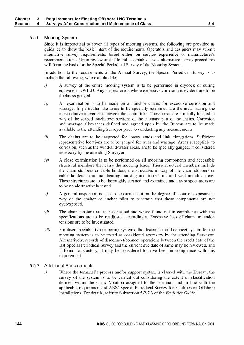
Chapter 3 Requirements for Floating Offshore LNG Terminals Section 4 Surveys After Construction and Maintenance of Class 3-4
144 ABS GUIDE FOR BUILDING AND CLASSING OFFSHORE LNG TERMINALS . 2004
5.5.6 Mooring System Since it is impractical to cover all types of mooring systems, the following are provided as guidance to show the basic intent of the requirements. Operators and designers may submit alternative survey requirements, based either on service experience or manufacturer's recommendations. Upon review and if found acceptable, these alternative survey procedures will form the basis for the Special Periodical Survey of the Mooring System.
In addition to the requirements of the Annual Survey, the Special Periodical Survey is to include the following, where applicable:
i) A survey of the entire mooring system is to be performed in drydock or during equivalent UWILD. Any suspect areas where excessive corrosion is evident are to be thickness gauged.
ii) An examination is to be made on all anchor chains for excessive corrosion and wastage. In particular, the areas to be specially examined are the areas having the most relative movement between the chain links. These areas are normally located in way of the seabed touchdown sections of the catenary part of the chains. Corrosion and wastage allowances defined and agreed upon by the Bureau are to be made available to the attending Surveyor prior to conducting any measurements.
iii) The chains are to be inspected for looses studs and link elongations. Sufficient representative locations are to be gauged for wear and wastage. Areas susceptible to corrosion, such as the wind-and-water areas, are to be specially gauged, if considered necessary by the attending Surveyor.
iv) A close examination is to be performed on all mooring components and accessible structural members that carry the mooring loads. These structural members include the chain stoppers or cable holders, the structures in way of the chain stoppers or cable holders, structural bearing housing and turret/structural well annulus areas. These structures are to be thoroughly cleaned and examined and any suspect areas are to be nondestructively tested.
v) A general inspection is also to be carried out on the degree of scour or exposure in way of the anchor or anchor piles to ascertain that these components are not overexposed.
vi) The chain tensions are to be checked and where found not in compliance with the specifications are to be readjusted accordingly. Excessive loss of chain or tendon tensions are to be investigated.
vii) For disconnectable type mooring systems, the disconnect and connect system for the mooring system is to be tested as considered necessary by the attending Surveyor. Alternatively, records of disconnect/connect operations between the credit date of the last Special Periodical Survey and the current due date of same may be reviewed, and if found satisfactory, it may be considered to have been in compliance with this requirement.
5.5.7 Additional Requirements i) Where the terminal’s process and/or support system is classed with the Bureau, the
survey of the system is to be carried out considering the extent of classification defined within the Class Notation assigned to the terminal, and in line with the applicable requirements of ABS’ Special Periodical Survey for Facilities on Offshore Installations. For details, refer to Subsection 5-2/7.3 of the Facilities Guide.
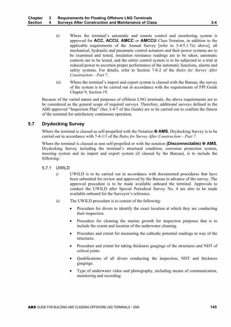
Chapter 3 Requirements for Floating Offshore LNG Terminals Section 4 Surveys After Construction and Maintenance of Class 3-4
ABS GUIDE FOR BUILDING AND CLASSING OFFSHORE LNG TERMINALS . 2004 145
ii) Where the terminal’s automatic and remote control and monitoring system is approved for ACC, ACCU, AMCC or AMCCU Class Notation, in addition to the applicable requirements of the Annual Survey [refer to 3-4/5.1.7ii) above], all mechanical, hydraulic and pneumatic control actuators and their power systems are to be examined and tested, insulation resistance readings are to be taken, automatic controls are to be tested, and the entire control system is to be subjected to a trial at reduced power to ascertain proper performance of the automatic functions, alarms and safety systems. For details, refer to Section 7-8-2 of the Rules for Survey After Construction – Part 7.
iii) Where the terminal’s import and export system is classed with the Bureau, the survey of the system is to be carried out in accordance with the requirements of FPI Guide Chapter 9, Section 19.
Because of the varied nature and purposes of offshore LNG terminals, the above requirements are to be considered as the general scope of required surveys. Therefore, additional surveys defined in the ABS approved “Inspection Plan” (See 3-4/7 of this Guide) are to be carried out to confirm the fitness of the terminal for satisfactory continuous operation.
5.7 Drydocking Survey Where the terminal is classed as self-propelled with the Notation À AMS, Drydocking Survey is to be carried out in accordance with 7-4-1/1 of the Rules for Survey After Construction – Part 7.
Where the terminal is classed as non self-propelled or with the notation (Disconnectable) À AMS, Drydocking Survey including the terminal’s structural condition, corrosion protection system, mooring system and its import and export system (if classed by the Bureau), is to include the following:
5.7.1 UWILD i) UWILD is to be carried out in accordance with documented procedures that have
been submitted for review and approved by the Bureau in advance of the survey. The approved procedure is to be made available onboard the terminal. Approvals to conduct the UWILD after Special Periodical Survey No. 4 are also to be made available onboard for the Surveyor’s reference.
ii) The UWILD procedure is to consist of the following:
• Procedure for divers to identify the exact location at which they are conducting their inspection.
• Procedure for cleaning the marine growth for inspection purposes that is to include the extent and location of the underwater cleaning.
• Procedure and extent for measuring the cathodic potential readings in way of the structures.
• Procedure and extent for taking thickness gaugings of the structures and NDT of critical joints.
• Qualifications of all divers conducting the inspection, NDT and thickness gaugings.
• Type of underwater video and photography, including means of communication, monitoring and recording.
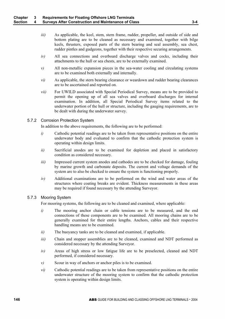
Chapter 3 Requirements for Floating Offshore LNG Terminals Section 4 Surveys After Construction and Maintenance of Class 3-4
146 ABS GUIDE FOR BUILDING AND CLASSING OFFSHORE LNG TERMINALS . 2004
iii) As applicable, the keel, stem, stern frame, rudder, propeller, and outside of side and bottom plating are to be cleaned as necessary and examined, together with bilge keels, thrusters, exposed parts of the stern bearing and seal assembly, sea chest, rudder pintles and gudgeons, together with their respective securing arrangements.
iv) All sea connections and overboard discharge valves and cocks, including their attachments to the hull or sea chests, are to be externally examined.
v) All non-metallic expansion pieces in the sea-water cooling and circulating systems are to be examined both externally and internally.
vi) As applicable, the stern bearing clearance or weardown and rudder bearing clearances are to be ascertained and reported on.
vii) For UWILD associated with Special Periodical Survey, means are to be provided to permit the opening up of all sea valves and overboard discharges for internal examination. In addition, all Special Periodical Survey items related to the underwater portion of the hull or structure, including the gauging requirements, are to be dealt with during the underwater survey.
5.7.2 Corrosion Protection System In addition to the above requirements, the following are to be performed:
i) Cathodic potential readings are to be taken from representative positions on the entire underwater body and evaluated to confirm that the cathodic protection system is operating within design limits.
ii) Sacrificial anodes are to be examined for depletion and placed in satisfactory condition as considered necessary.
iii) Impressed current system anodes and cathodes are to be checked for damage, fouling by marine growth and carbonate deposits. The current and voltage demands of the system are to also be checked to ensure the system is functioning properly.
iv) Additional examinations are to be performed on the wind and water areas of the structures where coating breaks are evident. Thickness measurements in these areas may be required if found necessary by the attending Surveyor.
5.7.3 Mooring System For mooring systems, the following are to be cleaned and examined, where applicable:
i) The mooring anchor chain or cable tensions are to be measured, and the end connections of these components are to be examined. All mooring chains are to be generally examined for their entire lengths. Anchors, cables and their respective handling means are to be examined.
ii) The buoyancy tanks are to be cleaned and examined, if applicable.
iii) Chain and stopper assemblies are to be cleaned, examined and NDT performed as considered necessary by the attending Surveyor.
iv) Areas of high stress or low fatigue life are to be preselected, cleaned and NDT performed, if considered necessary.
v) Scour in way of anchors or anchor piles is to be examined.
vi) Cathodic potential readings are to be taken from representative positions on the entire underwater structure of the mooring system to confirm that the cathodic protection system is operating within design limits.

Chapter 3 Requirements for Floating Offshore LNG Terminals Section 4 Surveys After Construction and Maintenance of Class 3-4
ABS GUIDE FOR BUILDING AND CLASSING OFFSHORE LNG TERMINALS . 2004 147
vii) Highly stressed, high wear and tear areas of the mooring chain are to be closely examined and nondestructively tested, if found necessary by the attending Surveyor. These include areas in way of the stoppers and sea bed touchdown areas.
5.7.4 Import and Export System Where the terminal’s import and export system is classed with the Bureau, the following items are to be cleaned and examined, where applicable:
i) The entire riser system.
ii) The arch support buoyancy tanks, their structures and the clamping devices.
iii) The flexible riser, including all end flanges and bolting arrangements, and spreader bars, if applicable.
iv) The entire export flexible system is to be examined for damage due to chafing and fatigue fractures.
v) Hoses designed and manufactured based on OCIMF standards are to be tested in accordance with the OCIMF Guide for the Handling, Storage, Inspection and Testing of Hoses in the Field.
vi) All navigation aids are to be examined and functionally tested
5.9 Boiler Survey Boiler Survey is to comply with the requirements stated in Section 7-7-1 of the Rules for Survey After Construction – Part 7.
5.11 Tailshaft/Tubeshaft Survey Where the terminal is classed with the notation (Disconnectable) À AMS, the Tailshaft or Tubeshaft Survey is to comply with the applicable requirements stated in Sections 7-5-1 and 7-5-2 of the Rules for Survey After Construction – Part 7. However, due to low running hours, this interval may be extended based on the following being carried out, as applicable, to the satisfaction of the attending Surveyor: i) Diver’s external examination of stern bearing and outboard seal area, including weardown
check as far as is possible. ii) Examination of the shaft area (inboard seals) in propulsion room(s). iii) Confirmation of lubricating oil records (satisfactory oil loss rate, no evidence of unacceptable
contamination). iv) Shaft seal elements are to be examined/replaced in accordance with seal manufacturer’s
recommendations.
7 Inspection Plan
The requirements of 3-4/5.1 through 3-4/5.11 above are intended to define the general scope of required surveys. Because of the varied nature and purposes of offshore terminals, it is not considered practicable to establish a firm schedule of requirements. The periodical surveys are to be carried out in accordance with the reviewed inspection plan to confirm the fitness of the terminal for continued operation. The Inspection Plan should cover all surveys for the design life of the terminal.
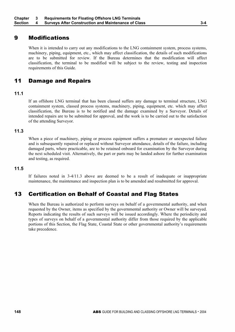
Chapter 3 Requirements for Floating Offshore LNG Terminals Section 4 Surveys After Construction and Maintenance of Class 3-4
148 ABS GUIDE FOR BUILDING AND CLASSING OFFSHORE LNG TERMINALS . 2004
9 Modifications
When it is intended to carry out any modifications to the LNG containment system, process systems, machinery, piping, equipment, etc., which may affect classification, the details of such modifications are to be submitted for review. If the Bureau determines that the modification will affect classification, the terminal to be modified will be subject to the review, testing and inspection requirements of this Guide.
11 Damage and Repairs
11.1 If an offshore LNG terminal that has been classed suffers any damage to terminal structure, LNG containment system, classed process systems, machinery, piping, equipment, etc. which may affect classification, the Bureau is to be notified and the damage examined by a Surveyor. Details of intended repairs are to be submitted for approval, and the work is to be carried out to the satisfaction of the attending Surveyor.
11.3 When a piece of machinery, piping or process equipment suffers a premature or unexpected failure and is subsequently repaired or replaced without Surveyor attendance, details of the failure, including damaged parts, where practicable, are to be retained onboard for examination by the Surveyor during the next scheduled visit. Alternatively, the part or parts may be landed ashore for further examination and testing, as required.
11.5 If failures noted in 3-4/11.3 above are deemed to be a result of inadequate or inappropriate maintenance, the maintenance and inspection plan is to be amended and resubmitted for approval.
13 Certification on Behalf of Coastal and Flag States
When the Bureau is authorized to perform surveys on behalf of a governmental authority, and when requested by the Owner, items as specified by the governmental authority or Owner will be surveyed. Reports indicating the results of such surveys will be issued accordingly. Where the periodicity and types of surveys on behalf of a governmental authority differ from those required by the applicable portions of this Section, the Flag State, Coastal State or other governmental authority’s requirements take precedence.
ABS GUIDE FOR BUILDING AND CLASSING OFFSHORE LNG TERMINALS . 2004 149
C H A P T E R 3 Requirements for Floating Offshore LNG Terminals
S E C T I O N 5 Risk-based Surveys for Maintenance of Class
1 General
The provisions of this Section contain survey requirements specific to the maintenance of classification for floating offshore LNG terminals for which inspection plans have been developed using risk-based techniques as an equivalent alternative to prescriptive requirements as defined in Chapter 3, Section 4 of this Guide.
1.1 Applicability While this Section provides risk-based survey requirements as an alternative for maintenance of Class, the Sections on the classification process contained in this Guide are still applicable. Where no specific references or guidance are given in this Section, the relevant requirements of conventional Rules/Guides remain valid.
1.3 Survey Periods Because of the diverse nature and purposes of offshore terminals and the varied contents of inspection plans likely to be developed as part of an Owner’s risk-based approach to Classification, it is not considered practicable to establish a firm schedule of survey requirements in this section for maintenance of Class.
3 Requirements for Risk-based Survey
3.1 General Where the risk-based approach is to be adopted, the Owner’s proposed maintenance and inspection plans, including details of frequency and extent of activities, are to be submitted for review. Where these plans deviate from the conventional survey requirements described in this Guide, the risk assessment methodology is to specifically address these deviations which are not to result in an unacceptable level of safety or integrity of the terminal. In addition to the maintenance and inspection plans noted above, the following documentation is to be submitted to the Bureau at least six (6) months before the plan is to be put into effect. This documentation is to establish, at a minimum:
Chapter 3 Requirements for Floating Offshore LNG Terminals Section 5 Risk-based Surveys for Maintenance of Class 3-5
150 ABS GUIDE FOR BUILDING AND CLASSING OFFSHORE LNG TERMINALS . 2004
i) The basis and methodology employed in the risk-based techniques.
ii) The means by which the technique is used to establish maintenance plans.
iii) The means by which the technique is used to update and modify maintenance and inspection plans.
iv) The means by which the following items are to be controlled:
• Accident and Non-Conformity Reporting.
• Overdue Inspections/Surveys.
• Internal Audits and Management Reviews.
• Control, Storage and Retention of Documents and Data.
• Change Procedures for Bureau approved plans.
3.3 Site-Specific Risk Assessment Where the risk-based approach is to be adopted on offshore LNG terminals, the risk assessment on which the inspection and maintenance plan is based is to be site-specific. If the terminal is to be relocated, the risk assessment is to be reviewed by the Owner and resubmitted to the Bureau for approval.
5 Surveys
5.1 General
5.1.1 Special Periodical Survey To credit a Special Periodical Survey based on risk-based inspection techniques, the terminal is to be subject to a Continuous Survey program, whereby the survey of all applicable items is to be carried out on a continuous basis over the five-year Special Periodical Survey cycle. If this program includes a preventative-maintenance/condition-monitoring plan, this plan is to be in accordance with Appendix 7-A-14, “Guide for Survey Based on Preventative Maintenance Techniques”, of the Rules for Survey After Construction – Part 7.
5.1.2 Inspection Plan The inspection plan detailing the timing and extent of activities will be reviewed to establish the scope and content of the Annual and Special Periodical Surveys which are required to be carried out by a Surveyor who will also monitor the Owner’s in-house quality management system required by this Guide. During the service life of the terminal, maintenance and inspection records are to be updated on a continuing basis and be available for reference by the attending Surveyor. The operator is to inform the Bureau of any changes to the maintenance procedures and their frequencies as may be caused, for example, by changes, additions or deletions to the original equipment.
5.3 Initial Survey An Initial Survey is to be carried out to confirm that systems and required plans have been properly implemented. The survey is to be carried out a minimum of three (3) months after the date of implementation of the approved plans, but no later than concurrently with the next due Annual Survey.
Chapter 3 Requirements for Floating Offshore LNG Terminals Section 5 Risk-based Surveys for Maintenance of Class 3-5
ABS GUIDE FOR BUILDING AND CLASSING OFFSHORE LNG TERMINALS . 2004 151
5.5 Annual Survey An Annual Survey is to be carried out by a Surveyor within three (3) months before or after each anniversary date of the initial/renewal Classification Survey. The survey is to be carried out in accordance with the approved risk-based inspection plan to confirm the fitness of the terminal for continued operation. Where the inspection plan specifically applies ABS Rules, the applicable items are to be complied with.
5.7 Special Periodical Survey A Special Periodical Survey of the facilities is to be carried out within five (5) years of the initial Classification Survey and at five-year intervals thereafter. The survey is to include all items in the approved risk-based inspection plan listed under the Annual Survey, confirmation of the completion of the Continuous Survey program, and where the inspection plan specifically applies ABS Rules, the applicable items are to be complied with.
7 Modifications
When modifications to the terminal that may affect classification are to be carried out after the issuance of Classification Certificate, the details of such modifications are to be submitted for review. If the Bureau determines that the modification will affect classification, the terminal to be modified will be subject to the review, testing and inspection requirements of this Guide. All documentation requirements for review and the design documentation described in Section 3-2 of this Guide is to be available to the attending Surveyor at the time of the modifications.
9 Damage and Repairs
The requirements stated in 3-4/11 of this Guide shall apply.
11 Certification on Behalf of Coastal and Flag States
Only when the Coastal and/or Flag States and/or other governmental authority accept and authorize the Bureau for Certification based on risk-based inspection techniques, the Bureau will carry out surveys, as authorized. If the Coastal and/or Flag States and/or other governmental authority do not accept a risk-based approach, surveys will be carried in a conventional, prescriptive manner.

This Page Intentionally Left Blank