Embed Size (px)
Citation preview
as
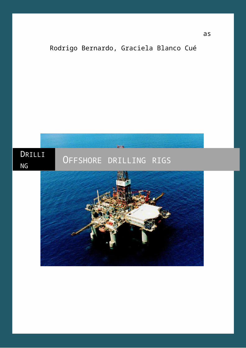
Drilling Offshore drilling rigs
Table of contents:1. Introduction2. What is offshore drilling?3. History4. Types of offshore drilling rigs
4.1. Fixed platfoms4.2. Compliant towers4.3. Semi-submersible platform4.4. Jack-up drilling rigs4.5. Drillships4.6. Floating production systems4.7. Tension-leg platform4.8. Gravity-based structure4.9. Spar platforms4.10. Condeep platforms4.11. Normally unmanned installations (NUI)4.12. Conductor support systems
5. Maintenance and supply6. Crew7. Drawbacks8. The future of offshore drilling9. Glosary
Introduction
Offshore drilling refers to a mechanical process where a wellbore is drilled through the seabed. It is typically carried out in order to explore for and subsequently extract petroleum which lies in rock formations beneath the seabed. Most commonly, the term is used to describe drilling activities on the continental shelf, though the term can also be applied to drilling in lakes, inshore waters and inland seas.
Offshore drilling presents environmental challenges, both from the produced hydrocarbons and the materials used during the drilling operation. Controversies include the ongoing US offshore drilling debate.
There are many different types of facilities from which offshore drilling operations take place. These include bottom founded drilling rigs (jackup barges and swamp barges), combined drilling and production facilities either bottom founded or floating platforms, and deepwater mobile offshore drilling units (MODU) including semi-submersibles and drillships. These are capable of operating in water depths up to 3,000 metres (9,800 ft). In shallower waters the mobile units are anchored to the seabed, however in deeper water (more than 1,500 metres (4,900 ft) the semisubmersibles or drillships are maintained at the required drilling location using dynamic positioning.
What is offshore drilling?Offshore drilling refers to a mechanical process where a wellbore is drilled through the seabed. It is typically carried out in order to explore for and subsequently extract petroleum which lies in rock formations beneath the seabed. Most commonly, the term is used to describe drilling activities on the continental shelf, though the term can also be applied to drilling in lakes, inshore waters and inland seas.
Offshore drilling presents environmental challenges, both from the produced hydrocarbons and the materials used during the drilling operation. Controversies include the ongoing US offshore drilling debate.
There are many different types of facilities from which offshore drilling operations take place. These include bottom founded drilling rigs (jackup barges and swamp barges), combined drilling and production facilities either bottom founded or floating platforms, and deepwater mobile offshore drilling units (MODU) including semi-submersibles and drillships. These are capable of operating in water depths up to 3,000 metres (9,800 ft). In shallower waters the mobile units are anchored to the seabed, however in deeper water (more than 1,500 metres (4,900 ft) the semisubmersibles or drillships are maintained at the required drilling location using dynamic positioning.
HistoryAround 1891, the first submerged oil wells were drilled from platforms built on piles in the fresh waters of the Grand Lake St. Marys (a.k.a. Mercer County Reservoir) in Ohio. The wells were developed by small local companies such as Bryson, Riley Oil, German-American and Banker's Oil.
Around 1896, the first submerged oil wells in salt water were drilled in the portion of the Summerland field extending under the Santa Barbara Channel in California. The wells were drilled from piers extending from land out into the channel.
Other notable early submerged drilling activities occurred on the Canadian side of Lake Erie in the 1900s and Caddo Lake in Louisiana in the 1910s. Shortly thereafter wells were drilled in tidal zones along the Texas and Louisiana gulf coast. The Goose Creek Oil Field near Baytown, Texas is one such example. In the 1920s drilling activities occurred from concrete platforms in Venezuela's Lake Maracaibo.
One of the oldest subsea wells is the Bibi Eibat well, which came on stream in 1923 in Azerbaijan. The well was located on an artificial island in a shallow portion of the Caspian Sea. In the early 1930s, the Texas Co., later Texaco (now Chevron) developed the first mobile steel barges for drilling in the brackish coastal areas of the Gulf of Mexico.
In 1937, Pure Oil (now Chevron) and its partner Superior Oil (now ExxonMobil) used a fixed platform to develop a field 1 mile (1.6 km) offshore of Calcasieu Parish, Louisiana in 14 feet (4.3 m) of water.
In 1946, Magnolia Petroleum (now ExxonMobil) drilled at a site 18 miles (29 km) off the coast, erecting a platform in 18 feet (5.5 m) of water off St. Mary Parish, Louisiana.
In early 1947, Superior Oil erected a drilling and production platform in 20 feet (6.1 m) of water some 18 miles (29 km) off Vermilion Parish, La. But it was Kerr-McGee Oil Industries (now Anadarko Petroleum), as operator for partners Phillips Petroleum (ConocoPhillips) and Stanolind Oil & Gas (BP) that completed its historic Ship Shoal Block 32 well in October 1947, months before Superior actually drilled a discovery from their Vermilion platform farther offshore. In any case, that made Kerr-McGee's well the first oil discovery drilled out of sight of land.
When offshore drilling moved into deeper waters of up to 30 metres (98 ft), fixed platform rigs were built, until demands for drilling equipment was needed in the 100 feet (30 m) to 120 metres (390 ft) depth of the Gulf of Mexico, the first jack-up rigs began appearing from specialized offshore drilling contractors such as forerunners of ENSCO International.
The first semi-submersible resulted from an unexpected observation in 1961. Blue Water Drilling Company owned and operated the four-column submersible Blue Water Rig No.1 in the Gulf of Mexico for Shell Oil Company. As the pontoons were not sufficiently buoyant to support the weight of the rig and its consumables, it was towed between locations at a draught mid-way between the top of the pontoons and the underside of the deck. It was
noticed that the motions at this draught were very small, and Blue Water Drilling and Shell jointly decided to try operating the rig in the floating mode. The concept of an anchored, stable floating deep-sea platform had been designed and tested back in the 1920s by Edward Robert Armstrong for the purpose of operating aircraft with an invention known as the 'seadrome'. The first purpose-built drilling semi-submersible Ocean Driller was launched in 1963. Since then, many semi-submersibles have been purpose-designed for the drilling industry mobile offshore fleet.
The first offshore drillship was the CUSS 1 developed for the Mohole project to drill into the Earth's crust.
As of June, 2010, there were over 620 mobile offshore drilling rigs (Jackups, semisubs, drillships, barges) available for service in the competitive rig fleet.
One of the world's deepest hubs is currently the Perdido in the Gulf of Mexico, floating in 2,438 meters of water. It is operated by Royal Dutch Shell and was built at a cost of $3 billion. The deepest operational platform is the Petrobras America Cascade FPSO in the Walker Ridge 249 field in 2,600 meters of water.
Types
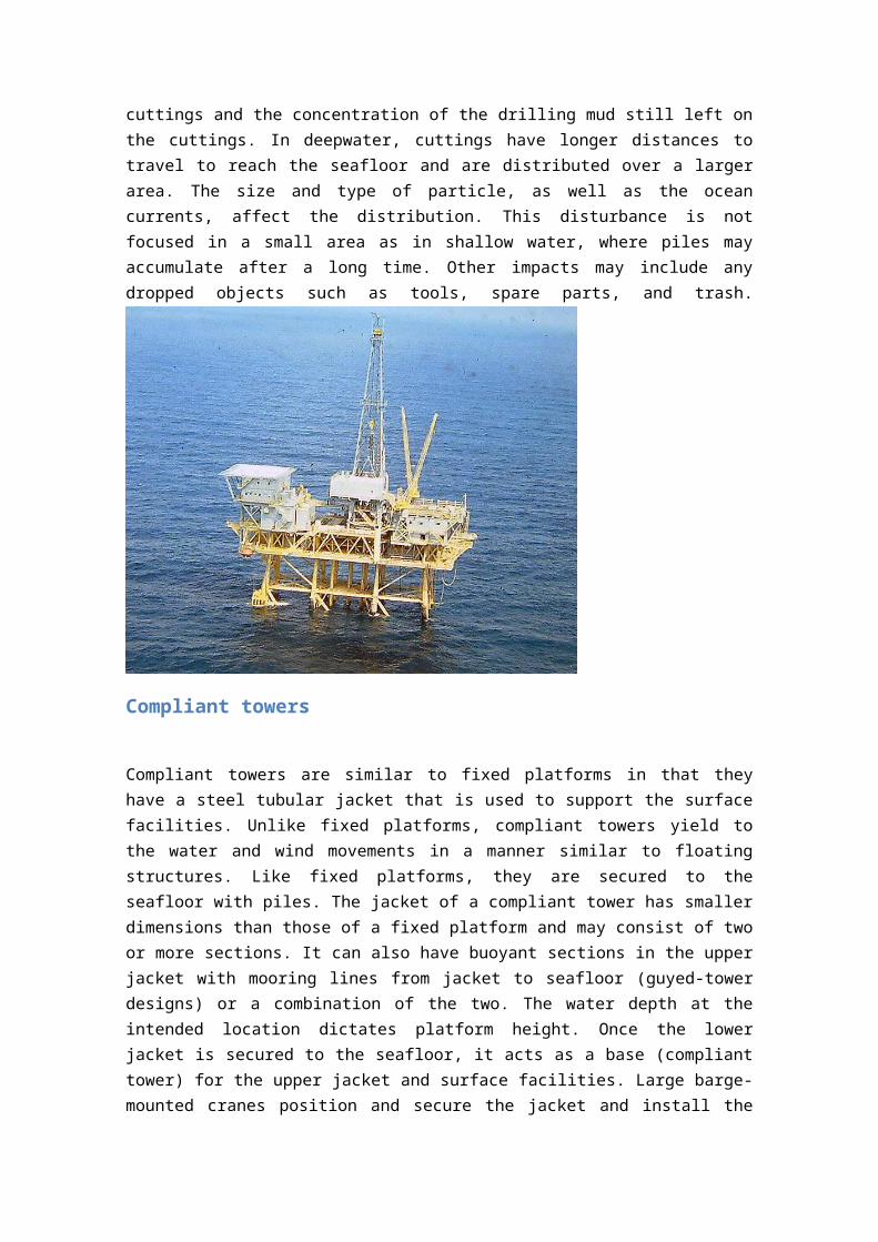
Fixed platforms
A fixed platform consists of a welded tubular steel jacket, deck, and surface facility. The jacket and deck make up the foundation for the surface facilities. Piles driven into the seafloor secure the jacket. The water depth at the intended location dictates the height of the platform. Once the jacket is secured and the deck is installed, additional modules are added for drilling, production, and crew operations. Large, barge-mounted cranes position and secure the jacket prior to the installation of the topsides modules. Economic considerations limit development of fixed (rigid) platforms to water depths no greater than 1,500 ft.
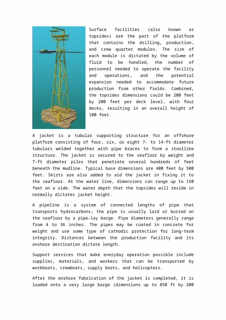
Surface facilities (also known as topsides) are the part of the platform that contains the drilling, production, and crew quarter modules. The size of each module is dictated by the volume of fluid to be handled, the number of personnel needed to operate the facility and operations, and the potential expansion needed to accommodate future production from other fields. Combined, the topsides dimensions could be 200 feet by 200 feet per deck level, with four decks, resulting in an overall height of 100 feet.
A jacket is a tubular supporting structure for an offshore platform consisting of four, six, or eight 7- to 14-ft diameter tubulars welded together with pipe braces to form a stoollike structure. The jacket is secured to the seafloor by weight and 7-ft diameter piles that penetrate several hundreds of feet beneath the mudline. Typical base dimensions are 400 feet by 500 feet. Skirts are also added to aid the jacket in fixing it to the seafloor. At the water line, dimensions can range up to 150 feet on a side. The water depth that the topsides will reside in normally dictates jacket height.
A pipeline is a system of connected lengths of pipe that transports hydrocarbons; the pipe is usually laid or buried on the seafloor by a pipe-lay barge. Pipe diameters generally range from 4 to 36 inches. The pipes may be coated in concrete for weight and use some type of cathodic protection for long-term integrity. Distances between the production facility and its onshore destination dictate length.
Support services that make everyday operation possible include supplies, materials, and workers that can be transported by workboats, crewboats, supply boats, and helicopters.
After the onshore fabrication of the jacket is completed, it is loaded onto a very large barge (dimensions up to 850 ft by 200 ft by 50 ft) that will transport the jacket to its location. The towing of the jacket may involve the use of several tugs (up to 52,000 hp combined) over hundreds of miles, the distance determined by where the jacket is fabricated and where the intended site is located. In some designs, there is a jacket base section that may be in place before the actual jacket is installed. The placement of the jacket base section prior to the jacket could provide better support during installation. Once the jacket arrives on location, it is launched, up-ended, and lowered into position with two or more tugs. With a beacon system or with a remotely operated vehicle (ROV) assist, the jacket is placed in position on the seafloor. The beacon system consists of homing devices laid on the seafloor around the area of the jacket's intended site; the beacons allow computer-aided control and monitoring of the installation process. Then a pile and hammer-handling barge is brought in to drive the piles into the seafloor, through guides in the legs. A second method of pile driving is the use of an underwater hammer with ROV alignment. Once this work is completed, the jacket is secure on location and the surface facilities can be installed.
The surface facilities are fabricated onshore and towed out on one or more crane barges. Once on location, the crane barge(s) is moored in whatever fashion needed and installation begins. Mooring can be done by different methods such as lines to the seafloor only or a combination of lines to the jacket and the seafloor. A crane on the barge(s) transfers the modules as a whole or separately from the barge(s) to the deck where workers complete the final connections.
A pipeline is connected to the jacket via a jumper at its base. A pipe-laying barge or ship installs the pipeline over the distance needed to connect the platform to shore or another facility. For deepwater applications, these vessels may be dynamically positioned and do not require any mooring system.
The nature of a component as well as the weather dictates the extent and duration of the maintenance performed on a platform. Either divers in shallow water or an ROV in deeper
water would inspect the jacket or anything inside its boundary to determine the extent of maintenance required. A crane barge would attempt any retrieval or replacement. The crew can maintain any surface facility component, such as the drilling, production and crew quarters module, and repair it with parts brought in by workboats. If major repairs or replacements are needed, a crane barge transfers large materials or complete modules.
The pipelines are monitored for pressure changes in the lines and through ROV inspection by video. If leaks are detected, repairs are begun. Clamps can be used to minimize lost fluids until a new line is laid and put on line. Pigs are pumped through sections of the pipe to clean out the inner walls, clearing them of any paraffin or hydrate coating. (Pigs are wipers that can be several feet long and whose cross-section equals the inner diameter of the pipeline.)
With platforms, seafloor footprints are limited to the dimensions of the base of the jacket and the mooring systems of crane barges and workboats. These dimensions are stated earlier in this chapter. The mooring systems of the crane barges and workboats may vary, but they commonly use the jacket structure and the seafloor for anchoring.
During normal operations of the surface facility, air emissions occur from the separation, compression, and cogeneration components, and from other sources. Emissions can occur during the installation and maintenance of any of the components. The prime movers for the drilling operations and the operational components for the living quarters also add to the air emissions. Stored chemical may spill or ignite, adding to the emissions.
Water discharges from the surface facility can occur from many sources during normal operations. Discharges may also occur during the installation and maintenance of any component. Any of the many liquid chemicals used in everyday operations have the potential of being spilled. These include but are not limited to any glycol or methanol used in chemical injection, dispersant agents used in oil-spill response, produced waters, mud residues from the rock cuttings, and cleaning agents.
From drilling operations, the cuttings account for most of the discharges. The water depth dictates the distribution of the cuttings and the concentration of the drilling mud still left on the cuttings. In deepwater, cuttings have longer distances to travel to reach the seafloor and are distributed over a larger area. The size and type of particle, as well as the ocean currents, affect the distribution. This disturbance is not focused in a small area as in shallow water, where piles may accumulate after a long time. Other impacts may include any dropped objects
such as tools, spare parts, and trash.
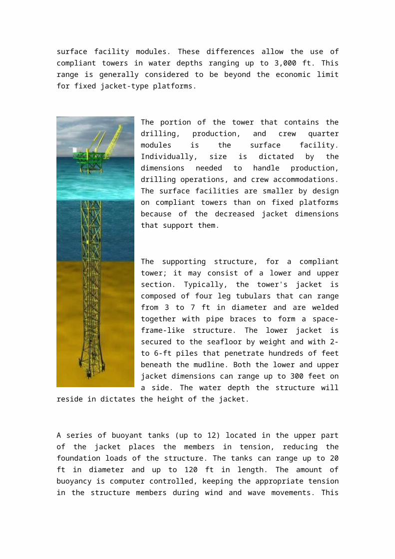
Compliant towers
Compliant towers are similar to fixed platforms in that they have a steel tubular jacket that is used to support the surface facilities. Unlike fixed platforms, compliant towers yield to the water and wind movements in a manner similar to floating structures. Like fixed platforms,
they are secured to the seafloor with piles. The jacket of a compliant tower has smaller dimensions than those of a fixed platform and may consist of two or more sections. It can also have buoyant sections in the upper jacket with mooring lines from jacket to seafloor (guyed-tower designs) or a combination of the two. The water depth at the intended location dictates platform height. Once the lower jacket is secured to the seafloor, it acts as a base (compliant tower) for the upper jacket and surface facilities. Large barge-mounted cranes position and secure the jacket and install the surface facility modules. These differences allow the use of compliant towers in water depths ranging up to 3,000 ft. This range is generally considered to be beyond the economic limit for fixed jacket-type platforms.
The portion of the tower that contains the drilling, production, and crew quarter modules is the surface facility. Individually, size is dictated by the dimensions needed to handle production, drilling operations, and crew accommodations. The surface
facilities are smaller by design on compliant towers than on fixed platforms because of the decreased jacket dimensions that support them.
The supporting structure, for a compliant tower; it may consist of a lower and upper section. Typically, the tower's jacket is composed of four leg tubulars that can range from 3 to 7 ft in diameter and are welded together with pipe braces to form a space-frame-like structure. The lower jacket is secured to the seafloor by weight and with 2- to 6-ft piles that penetrate hundreds of feet beneath the mudline. Both the lower and upper jacket dimensions can range up to 300 feet on a side. The water depth the structure will reside in dictates the height of the jacket.
A series of buoyant tanks (up to 12) located in the upper part of the jacket places the members in tension, reducing the foundation loads of the structure. The tanks can range up to 20 ft in diameter and up to 120 ft in length. The amount of buoyancy is computer controlled, keeping the appropriate tension in the structure members during wind and wave movements. This buoyant system can also be incorporated into some member designs, minimizing the size and placement of the tanks.
For compliant towers in general, mooring is only used in the guyed-tower design. For guyed-towers, several mooring lines (up to 20 lines measuring 5 ½-inch dia.) are attached to the jacket close to the waterline and are spread out evenly around it (up to 4,000 ft of line). Clump weights (120 ft x 8 ft, up to 200 tons) may be attached to each mooring line and move as the tower moves with the wind and wave forces. To control the tower motions better, the lines are kept in tension during the swaying motions. The portion of the lines past the clump weights are anchored into the seafloor with piles (as many as 20, each 72-inch dia., 115-ft long, penetrating 130 ft, and weighing up to 60 tons).
A system of connected lengths of pipe that transports hydrocarbons. A pipe-lay barge usually lays or buries them on the seafloor. Pipe diameters generally range up to 36 inches. They may be coated in concrete or use some type of cathodic protection for long-term integrity. Distances between the production facility and its onshore destination dictate pipeline length.
Support Services that make everyday operations possible include supplies, materials, and workers, which can be transported by workboats, crewboats, supply boats, and helicopters.
During the onshore fabrication of the jacket, the mooring system for the guyed-tower is installed. A specially designed, dynamically positioned crane barge that consists of a 100-foot crane, guyline winch module, anchor pile module, and clump weight module can be used to install the compliant tower. The installation procedure starts with the anchor piles, then the chains, then the clump weights, and finally the remaining mooring lines that attach to the jacket as needed. Until the jacket is installed, anchor buoys hold the remaining lines in position.
After onshore fabrication, the jacket is towed in one or two pieces out to the site on a specially designed barge. The process is similar to how it is done for fixed platforms, such as Shell's Cognac or Bullwinkle project. For normal compliant towers, the upper and lower jacket can be joined at sea or vertically joined at the site. For the guyed-tower design, the jacket is in one piece and does not need joining. The jacket can be launched from the rear or side of the barge. For compliant towers, up to 10,000 hp per jacket section (upper and lower) may be needed. A series of tugs with a combined horsepower of up to 25,000 hp can be used to tow guyed-towers. The design of the compliant tower and whether the jacket is in one or two pieces dictate the number of tugs needed. One or two dynamically positioned crane barges (up to 2,000 tons) are used to install the jacket as a whole (guyed-towers) or join them vertically onsite or at sea.
After the jacket is installed, a deck barge brings the surface facilities out from shore to the site and installs them either module by module or as a complete unit. The crane barge can be moored to the jacket or to the seafloor with up to 12 lines. The twelve-point layout is most commonly utilized.
A dynamically positioned pipe-laying ship installs the pipeline or pipeline bundle. Since the dynamic-positioned system eliminates the need for anchors, the ship can operate in and around compliant towers having mooring systems without interfering with the guylines or mooring of the crane barges. The complete installation process can take up to eight months before any additional drilling or production can start. Maintenance of compliant towers is completed in a method similar to that of a fixed platform. Considerations in the guyed-tower design for the mooring system must be addressed when any maintenance vessels are moved. The installed component and the weather conditions dictate the extent and duration of the maintenance needed. A remotely operated vehicle (ROV) would do any anticipated maintenance of the jacket and would inspect anything within the boundary of the jacket (buoyancy tanks, risers etc.) and the mooring system (in guyedtower design). A crane barge would complete any retrieval or replacement.
The crew can maintain any surface facility component such as the drilling, production, and crew quarters modules and repair them with parts brought in by workboats. If major repairs or replacements are needed, a crane barge would transfer the needed large materials or complete modules.
Monitoring of the pipelines is accomplished by ROV inspection and watching for signs of pressure drops or increased fluid volumes. If leaks are detected, clamps can be used to minimize lost fluids until a new line is laid and put on line. Pigs are pumped through sections of the pipe to clean out the inner walls, clearing them of any paraffin or hydrate coating. (Pigs are wipers that are normally a few feet long and whose cross-section equals the inner diameter of the pipeline.)
In compliant towers, the seafloor footprint is the base-structure dimension mooring system of the tower (if guyed-tower design) and the mooring systems of crane barges and workboats. Base dimensions can range up to 300 feet on a side. The mooring systems of the crane barges
and workboats may vary, but they commonly use the jacket structure and the seafloor for anchoring.
Operations are similar to those of fixed platforms but differ mainly in size and quantity. During normal operations of the surface facility, air emissions from the separation, compression, and cogeneration components apply. The prime movers for the drilling operations and the operational components for the living quarters also add to the air emissions. Stored chemicals may spill or ignite, adding to the emissions.
Water discharges from the surface facility can occur from many sources during normal operations. Discharges may also occur during the installation and maintenance of any component. Any of the many liquid chemicals used in everyday operations have the potential of being spilled. These include but are not limited to any glycol or methanol used in chemical injection, dispersant agents used in oil-spill response, produced waters, mud residue from the rock cuttings, and cleaning agents.
From the drilling operations, the cuttings account for most of the depositing. The distribution of the cuttings and the concentration of the drilling mud still left on the cuttings are dictated by the water depth and current. In deepwater, cuttings have longer distances to travel to reach the seafloor and create larger arrays of disturbance. These cuttings are not focused in a small area as in shallow water, where piles of cuttings may accumulate over a long time. Other impacts may include any dropped objects such as tools, spare parts, and trash.
Semi-submersible platform
A semi-submersible (semisubmerged ship) is a specialised marine vessel used in a number of specific offshore roles such as offshore drilling rigs, safety vessels, oil production platforms, and heavy lift cranes. They are designed with good stability and seakeeping characteristics. Other terms include semisubmersible, semi-sub, or simply semi.
Offshore drilling in water depth greater than around 520 meters requires that operations be carried out from a floating vessel, as fixed structures are not practical. Initially in the early 1950s monohull ships were used like CUSS I, but these were found to have significant heave, pitch and yaw motions in large waves, and the industry needed more stable drilling platforms.
A semi-submersible obtains its buoyancy from ballasted, watertight pontoons located below the ocean surface and wave action. The operating deck can be located high above the sea level
due to the good stability of the design, and therefore the operating deck is kept well away from the waves. Structural columns connect the pontoons and operating deck.[1]
With its hull structure submerged at a deep draft, the semi-submersible is less affected by wave loadings than a normal ship. With a small water-plane area, however, the semi-submersible is sensitive to load changes, and therefore must be carefully trimmed to maintain stability. Unlike a submarine or submersible, during normal operations, a semi-submersible vessel is never entirely underwater.
A semi-submersible vessel is able to transform from a deep to a shallow draft by deballasting (removing ballast water from the hull), and thereby become a surface vessel. The heavy lift vessels use this capability to submerge the majority of their structure, locate beneath another floating vessel, and then deballast to pick up the other vessel as a cargo
Jack-up drilling rigs
A jack-up rig or a self-elevating unit is a type of mobile platform that consists of a buoyant hull fitted with a number of movable legs, capable of raising its hull over the surface of the sea. The buoyant hull enables transportation of the unit and all attached machinery to a desired location. Once on location the hull is raised to the required elevation above the sea surface on its legs supported by the sea bed. The legs of such units may be designed to penetrate the sea bed, may be fitted with enlarged sections or footings, or may be attached to a bottom mat. Generally Jackup rigs are not self propelled and rely on tugs or heavy lift ships for transportation. To see more details regarding Design, construction and installation of such platforms refer to:[2]
Jack up platforms are used as exploratory drilling platforms and offshore and wind farm service platforms. Jackup platforms have been the most popular and numerous of various mobile types in existence. The total number of Jackup 'Drilling' rigs alone in operation number about 540 by the end of 2013. The first one was designed by R. G. LeTourneau for Zapata Oil, owned by George H. W. Bush, who later became the 41st president of the United States.
Jack-up rigs are so named because they are self-elevating with three or four movable legs that can be extended (“jacked”) above or below the hull. Jack-ups are towed to the site with the hull, which is actually a water-tight barge that floats on the water’s surface, lowered to the water level, and the legs extended above the hull. When the rig reaches the work site, the
crew jacks the legs downward through the water and into the sea floor (or onto the sea floor with mat supported jack-ups). This anchors the rig and holds the hull well above the waves.
A jackup is a floating barge fitted with long support legs that can be raised or lowered. The jackup is maneuvered (self-propelled or by towing) into location with its legs up and the hull floating on the water. Upon arrival at the work location, the legs are jacked down onto the seafloor. Then "preloading" takes place, where the weight of the barge and additional ballast water are used to drive the legs securely into the seabottom so they will not penetrate further while operations are carried out. After preloading, the jacking system is used to raise the entire barge above the water to a predetermined height or "air gap", so that wave, tidal and current loading acts only on the relatively slender legs and not on the barge hull.
Modern jacking systems use a rack and pinion gear arrangement where the pinion gears are driven by hydraulic or electric motors and the rack is affixed to the legs.
Jackup rigs can only be placed in relatively shallow waters, generally less than 400 feet (120 m) of water. However, a specialized class of jackup rigs known as premium or ultra-premium jackups are known to have operational capability in water depths ranging from 500 to 625 feet.
Drillships
A drillship is a merchant vessel designed for use in exploratory offshore drilling of new oil and gas wells or for scientific drilling purposes. In most recent years the vessels are use in deepwater and ultra-deepwater applications, equipped with the latest and most advanced dynamic positioning systems.
The first drillship was the CUSS I, designed by Robert F. Bauer of Global Marine in 1955. The CUSS I had drilled in 400 feet deep waters by 1957.[1] Robert F. Bauer became the first president of the Global Marine in 1958.[1]
In 1961 Global Marine started a new drillship era. They ordered several self-propelled drillships each with a rated centerline drilling of 20,000 foot-wells in water depths of 600 feet. The first was named CUSS (Glomar) II, a 5,500-deadweight-ton vessel. Costing around $4.5 million. Built by a Gulf Coast shipyard. The vessel was almost twice the size of the CUSS I, and became the world’s first drillship built as new construction which set sail in 1962.[1]
In 1962 The Offshore Company elected to build a new type of drillship, larger than that of the Glomar class. This new drillships would feature a first ever anchor mooring array based on a unique turret system. The vessel was named Discoverer I. The Discoverer I had no main propulsion engines, meaning they needed to be towed out to the drill site.
The drillship can be used as a platform to carry out well maintenance or completion work such as casing and tubing installation, subsea tree installations and well capping. Drillships are often built to the design specification to meet the requirements set by the oil production company and/or investors.
From the first drillship CUSS I to the Deepwater Asgard the fleet size has been growing ever since. In 2013 the worldwide fleet of drillships tops 80 ships, more than double its size in 2009. Drillships are not only growing in size but also in capability with new technology assisting operations from academic research to ice-breaker class drilling vessels. U.S. President Barack Obama's decision in late March 2010 to expand U.S. domestic exploratory drilling seems likely to increase further developments of drillship technology.
Drillships are just one way to perform various types of drilling. This function can also be performed by semi-submersibles, jackups, barges, or platform rigs.
Drillships have the functional ability of semi-submersible drilling rigs and also have a few unique features that separate them from all others. First being the ship-shaped design. A drillship has greater mobility and can move quickly under its own propulsion from drill site to drill site in contrast to semi-submersibles and jackup barges and platforms. Drillships have the ability to save time sailing between oilfields worldwide. A drillship takes 20 days to move from the Gulf of Mexico to the Offshore Angola. Whereas, a semi-submersible drilling unit must be towed and takes 70 days. Drillship construction cost is much higher than that of a semi-submersible. But although mobility comes at a high price, the drillship owners can charge higher day rates and get the benefit of lower idle times between assignments.
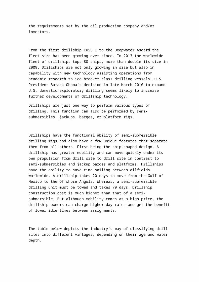
The table below depicts the industry’s way of classifying drill sites into different vintages, depending on their age and water depth.
Drillship Launch Date Water Depth (ft.)
CUSS I 1961 350
Discoverer 534 1975 7,000
Enterprise 1999 10,000
Inspiration 2009 12,000
The drilling operations are very detailed and in depth. A simple way to understand what a drillship is to do in order to drill, a marine riser is lowered from the drillship to the seabed with a blowout preventer (BOP) at the bottom that connects to the wellhead. The BOP is used to quickly disconnect the riser from the wellhead in times of emergency or in any needed situation. Underneath the derrick is a moonpool, an opening through the hill covered by the rig floor. Some of the modern drillships have larger derricks that allow dual activity operations, for example simultaneous drilling and casing handling.
Transocean, Pride International, Seadrill, Noble Corporation, Atwood Oceanics and Pacific Drilling are a few of the companies that own and operate drillships globally.
Floating production systems
A floating production, storage and offloading (FPSO) unit is a floating vessel used by the offshore oil and gas industry for the processing of hydrocarbons and for storage of oil. An FPSO vessel is designed to receive hydrocarbons produced from nearby platforms or subsea template, process them, and store oil until it can be offloaded onto a tanker or, less frequently, transported through a pipeline. FPSOs are preferred in frontier offshore regions as they are easy to install, and do not require a local pipeline infrastructure to export oil. FPSOs can be a conversion of an oil tanker or can be a vessel built specially for the application. A vessel used only to store oil (without processing it) is referred to as a floating storage and offloading vessel (FSO). There are also under construction (as at 2013) floating liquefied natural gas (FLNG) vessels, which will extract and liquefy natural gas on board.
Oil has been produced from offshore locations since the late 1940s. Originally, all oil platforms sat on the seabed, but as exploration moved to deeper waters and more distant locations in the 1970s, floating production systems came to be used.
The first oil FPSO was the Shell Castellon, built in Spain in 1977. Today, over 200 vessels are deployed worldwide as oil FPSOs.
In addition to the significant growth of this market sector, we are witnessing today the progressive extension of the significant knowledge base of building and operating these floating facilities to provide solutions for other segments of the oil and gas industry.
As an example, the Sanha LPG FPSO, which operates offshore Angola, is the first such vessel with complete onboard liquefied petroleum gas processing and export facilities. It can store up to 135,000 cubic meters of LPG while awaiting export tankers for offloading.
Another very promising expansion is the progressive development of the floating LNG (FLNG) market. An LNG FPSO works under the same principles an oil FPSO works under, taking the well stream and separating out the natural gas (primarily methane and ethane) and producing LNG, which is stored and offloaded.
As a very significant and momentous event, on May 20, 2011, Royal Dutch Shell announced the planned development of a floating liquefied natural gas facility (FLNG), which will be situated 200 km off the coast of Western Australia and is due for completion in around 2017. When it is finished, this will be the largest floating offshore facility. It will measure around 488m long and 74m wide, and when fully ballasted will weigh 600,000 tonnes. It will have a total storage capacity of 436,000 cubic metres of LNG, plus LPG condensate.
On June 2012, Petronas signed the engineering, procurement, construction, installation and commissioning contract for the project with the Technip and DSME consortium. The unit is destined for the Kanowit gas field off Sarawak, Malaysia. It is expected to be the World's First Floating Liquefaction Unit in operation when completed in 2015.
At the opposite (discharge and regasification) end of the LNG chain, the first ever conversion of an LNG carrier (Golar LNG owned Moss type LNG carrier) into an LNG floating storage and regasification unit was carried out in 2007 by Keppel shipyard in Singapore.
Oil produced from offshore production platforms can be transported to the mainland either by pipeline or by tanker. When a tanker is chosen to transport the oil, it is necessary to accumulate oil in some form of storage tank such that the oil tanker is not continuously occupied during oil production, and is only needed once sufficient oil has been produced to fill the tanker.
Floating production, storage and offloading vessels are particularly effective in remote or deepwater locations where seabed pipelines are not cost effective. FPSOs eliminate the need to lay expensive long-distance pipelines from the processing facility to an onshore terminal. This can provide an economically attractive solution for smaller oil fields which can be exhausted in a few years and do not justify the expense of installing a pipeline. Furthermore, once the field is depleted, the FPSO can be moved to a new location.[citation needed]
A floating storage and offloading unit (FSO) is essentially a simplified FPSO without the capability for oil or gas processing. Most FSOs are converted single hull supertankers. An example is Knock Nevis, ex Seawise Giant, for many years the world's largest ship, which has been converted to an FSO for use offshore. The vessel was sold to Indian ship breakers, and renamed Mont for her final journey in December 2009. After clearing Indian customs, she was sailed to, and intentionally beached at Alang, Gujarat, India for demolition.
At the other end of the LNG logistics chain, where the natural gas is brought back to ambient temperature and pressure, specially modified ships may also be used as floating storage and regasification units (FSRUs). A LNG floating storage and regasification unit receives liquefied natural gas (LNG) from offloading LNG carriers, and the onboard regasification system provides natural gas exported to shore through risers and pipelines.
The FPSO operating in the deepest waters is the FPSO BW Pioneer, built and operated by BW Offshore on behalf of Petrobras Americas INC. The FPSO is moored at a depth of 2,600 m in Block 249 Walker Ridge in the US Gulf of Mexico and is rated for 100,000 bbl/d (16,000 m3/d). The EPCI contract was awarded in October 2007, and production started in early 2012. The FPSO conversion was carried out at Keppel Shipyard Tuas in Singapore, while the topsides were fabricated in modules at various international vendor locations. The FPSO has a disconnectable turret (APL). The vessel can disconnect in advance of hurricanes and reconnect with minimal down time.[citation needed] A contract for an FPSO to operate in even deeper waters (2,900 m) for Shell's Stones field in the US Gulf of Mexico was awarded to SBM Offshore in July 2013.[9]
One of the world's largest FPSO is the Kizomba A, with a storage capacity of 2.2 million barrels (350,000 m3). Built at a cost of over US$800 million by Hyundai Heavy Industries in Ulsan, Korea, it is operated by Esso Exploration Angola (ExxonMobil). Located in 1200 meters (3,940 ft) of water at Deepwater block 200 statute miles (320 km) offshore in the Atlantic Ocean from Angola, Central Africa, it weighs 81,000 tonnes and is 285 meters long, 63 meters wide, and 32 meters high (935 ft by 207 ft (63 m) by 105 ft).[10]
The first FSO in the Gulf of Mexico, The FSO Ta'Kuntah, has been in operation since August 1998. The FSO, owned and operated by MODEC, is under a service agreement with PEMEX Exploration and Production. The FSO Ta'Kuntah was installed as part of the Cantarell Field Development. The field is located in the Bay of Campeche, offshore Mexico's Yucatán peninsula. The FSO Ta'Kuntah is a converted ULCC tanker with a SOFEC external turret mooring system, two flexible risers connected in a lazy-S configuration between the turret and a pipeline end manifold (PLEM) on the seabed, and a unique offloading system. The FSO is designed to handle 800,000 bbl/d (130,000 m3/d) with no allowance for downtime.
The Skarv FPSO, developed and engineered by Aker Solutions for BP Norge, will be the most advanced and largest FPSO deployed in the Norwegian Sea, offshore Mid Norway. Skarv is a gas condensate and oil field development. The development will tie in five sub-sea templates, and the FPSO has capacity to include several smaller wells nearby in the future. The process plant on the vessel can handle about 19,000,000 cubic metres per day (670,000,000 cu ft/d) of gas and 13,500 cubic metres per day (480,000 cu ft/d) of oil. An 80 km gas export pipe will tie in to Åsgard transport system. Aker Solutions (formerly Aker Kvaerner) developed the front-end design for the new floating production facility as well as the overall system design for the field and preparation for procurement and project management of the total field development. The hull is an Aker Solutions proprietary "Tentechtm975" design. BP also selected Aker Solutions to perform the detail engineering, procurement and construction management assistance (EPcma) for the Skarv field development. The EPcma contract covers detail engineering and procurement work for the FPSO topsides as well as construction management assistance to BP including hull and topside facilities. The production start for the field is scheduled for August 2011. BP awarded the contract for fabrication of the Skarv FPSO hull to Samsung Heavy Industries in South Korea and the Turret contract to SBM. The FPSO has a length of 292m, breadth of 50.6m and is 29m deep and accommodate 100 people in single cabins. The hull will be delivered in January 2010
Tension-leg platform
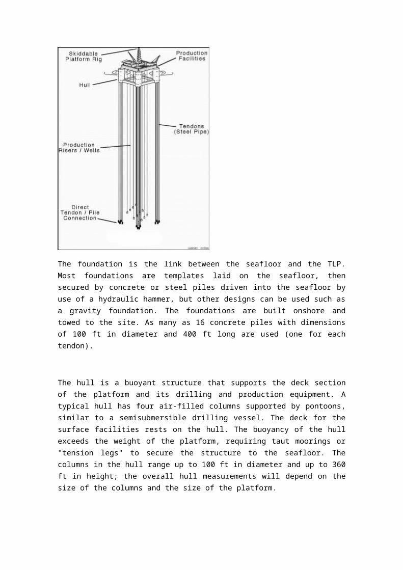
A Tension Leg Platform (TLP) is a buoyant platform held in place by a mooring system. The TLP's are similar to conventional fixed platforms except that the platform is maintained on location through the use of moorings held in tension by the buoyancy of the hull. The mooring system is a set of tension legs or tendons attached to the platform and connected to a template or foundation on the seafloor. The template is held in place by piles driven into the seafloor. This method dampens the vertical motions of the platform, but allows for horizontal movements. The topside facilities (processing facilities, pipelines, and surface trees) of the TLP and most of the daily operations are the same as for a conventional platform.
The foundation is the link between the seafloor and the TLP. Most foundations are templates laid on the seafloor, then secured by concrete or steel piles driven into the seafloor by use of a hydraulic hammer, but other designs can be used such as a gravity foundation. The foundations are built onshore and towed to the site. As many as 16 concrete piles with dimensions of 100 ft in diameter and 400 ft long are used (one for each tendon).
The hull is a buoyant structure that supports the deck section of the platform and its drilling and production equipment. A typical hull has four air-filled columns supported by pontoons, similar to a semisubmersible drilling vessel. The deck for the surface facilities rests on the hull. The buoyancy of the hull exceeds the weight of the platform, requiring taut moorings or "tension legs" to secure the structure to the seafloor. The columns in the hull range up to 100 ft in diameter and up to 360 ft in height; the overall hull measurements will depend on the size of the columns and the size of the platform.
Modules are units that make up the surface facilities on the deck section of the platform. Early in TLP development, industry discovered that it is cost effective to build the surface facility in separate units (modules), assemble them at shallow inshore location, and then tow them to the site. The modules that are part of a typical TLP include the wellbay, power, process, quarters, and drilling; they are secured to the deck, which is attached to the hull. The typical surface facility will be 65,000 sq ft. The living quarters house up to 100 people, depending on the type and scope of activity being performed. Process capacity ranges up to 150,000 BPD oil and 400 MMscfd gas. A typical drilling rig located on a larger TLP would have a 1.5 million-pound pull derrick, a 2,000-hp top-drive derrick, and three 2,200-hp pumps.
A template provides a frame on the seafloor in which to insert either conductors or piles. Not all TLP's use templates; if used, they are typically the first equipment installed at the site. There are several types of templates that may be used in conjunction with a TLP to support drilling, foundation integrity, or the integration of the two. Drilling templates provide a guide for locating and drilling wells; they may also be a base for the tie-in of flowlines from satellite wells or for export pipelines and their risers. Foundation templates may be one single piece or separate pieces for each corner. The foundation piles are driven through the foundation template. An integrated template is a single piece that contains all drilling support, anchors the tendons, and locates and guides the foundation piles. Separate templates allow each part to be installed individually. They also use smaller pieces that weigh less and are easier to install. The drilling template can be installed and drilling can begin while the foundation template is being designed and built.
Tension Legs (tendons) are tubulars that secure the hull to the foundation; this is the mooring system for the TLP. Tendons are typically steel tubes with dimensions of 2-3 ft in diameter with up to 3 inches of wall thickness, the length depending on water depth. A typical TLP would be installed with as many as 16 tendons.
Gravity-based structure
A gravity-based structure (GBS) is a support structure held in place by gravity. A common application for a GBS is an offshore oil platform. These structures are often constructed in fjords since their protected area and sufficient depth are very desirable for construction. A GBS intended for use as an offshore oil platform is constructed of steel reinforced concrete, often with tanks or cells which can be used to control the buoyancy of the finished GBS. When completed, a GBS is towed to its intended location and sunk. Prior to deployment, a study of the seabed will have been done in order to ensure it can withstand the vertical load exerted on it by that structure.
Gravity-based structures are also used for offshore wind power plants. By the end of 2010, 14 of the world's offshore wind farms were supported by gravity-based structures. The GBS are suited for water depths greater than 20 m. The deepest registered offshore wind farm with gravity-based structures is Thornton Bank 1, Belgium, with a depth up to 27.5 m. As offshore wind power plants are growing in size and moving towards deeper waters, the GBS is considered competitive in comparison with other support structures.
Spar platforms
A spar (Surface Piercing Articulated Reservoir)[citation needed] is a type of floating oil platform typically used in very deep waters, and is named for logs used as buoys in shipping that are moored in place vertically. Spar production platforms have been developed as an alternative to conventional platforms.
A spar platform consists of a large-diameter, single vertical cylinder supporting a deck. The cylinder is weighted at the bottom by a chamber filled with a material that is denser than water to lower the center of gravity of the platform and provide stability. Spars are anchored to the seabed by way of a spread mooring system with either a chain-wire-chain or chain-polyester-chain composition.
There are three primary types of spars; the classic spar, truss spar, and cell spar. The classic spar consists of the cylindrical hull noted above, with the heavy ballast at the bottom of the cylinder.
A truss spar has a shorter cylindrical "hard tank" than a classic spar and has a truss structure connected to the bottom of hard tank. At the bottom of the truss structure, there is a relatively small, square shaped "soft tank" that houses the heavy ballasting material. The majority of spars are of this type.
A cell spar has a large central cylinder surrounded by smaller cylinders of alternating lengths. At the bottom of the longer cylinders is the soft tank housing the heavy ballasting material, similar to a truss spar. There is currently only one cell spar in operation.
The Brent Spar, a platform designed for storage and offloading of crude oil products was installed in the Brent Field in June of 1976. The attempted deep sea disposal of the platform in the 1990s created a huge backlash by Greenpeace. The Spar was eventually dismantled and pieces were used as a foundation for a quay in Norway.
The first spar designed for oil and gas production was the Neptune spar, located in the Gulf of Mexico and was installed in September 1996 by Kerr McGee (now Anadarko).
The world's deepest production platform is Perdido, a truss spar in the Gulf of Mexico, with a mean water depth of 2,438 meters. It is operated by Royal Dutch Shell and was built at a cost of $3 billion
Normally unmanned installations (NUI)
A Normally Unmanned Installation (NUI) is a type of automated offshore Oil/Gas platform designed to be primarily operated remotely, without the constant presence of personnel.
These generally were characterized by their small size, often consisting of just a well bay with a helipad on top. They are often a compromise of providing the convenience of surface wellheads, which are easier to build and maintain, while avoiding the high operating costs of a full production platform.
They are generally only used in shallower water, where constructing many small NUIs is a relatively easy and cheap option as compared to the cost of using subsea wells.
This can be seen in the Southern North Sea where large numbers of wells are on smaller NUIs, compared with the more northern areas of the continental shelf where fewer larger platforms and subsea sites are the norm.
NUIs are commonly serviced from a nearby larger platform, e.g., Mungo serviced from Marnock. These installations will include an emergency shelter with essential food and water in order to provide a safe refuge in the event that weather or other considerations prevent a visiting crew from returning to base. Regular visits may be made for routine maintenance and for smaller well work such as wireline operations. Anything larger requires a drilling rig to be brought in, but this is still an advantage over subsea wells, which require a drilling rig or light intervention vessel for any well intervention.
In recent times NUI has become a phase within the decommissioning of previously manned offshore installations. Platforms would generally be positively isolated from hydrocarbons and flushed clean to suit environmental issues. Platforms would then only be visited infrequently for integrity checks and maintenance of temporary equipment left for power requirements and safety functionality. The platform would then remain in this phase until further decommissioning activities are carried out to remove the topsides in modules or piece small, then remove the jacket.
Conductor support systems
On offshore oil platforms, conductor support systems, also known as conductor supported systems or satellite platforms, are small unmanned installations consisting of little more than a well bay, and a small process plant. They are designed to operate in conjunction with a static production platform which is connected to the platform by flow lines and/or by Umbilical cable.
Traditionally, these jacket-type structures have been installed and used in shallow to medium water depths of up to 40 – 60 meters. The conductor supported system use its inherited strength of the well conductors to support both the wells and the topside structure.
The conductor supported system is particularly suited to areas with more benign environmental conditions. The well conductors act as both piles and conductors. These are drilled and installed using a drilling jackup rig using conventional drilling / lifting techniques.
Maintenance and supply
A typical oil production platform is self-sufficient in energy and water needs, housing electrical generation, water desalinators and all of the equipment necessary to process oil and gas such that it can be either delivered directly onshore by pipeline or to a floating platform or tanker loading facility, or both. Elements in the oil/gas production process include wellhead,production manifold, production separator, glycol process to dry gas, gas compressors, water injection pumps, oil/gas export metering and main oil line pumps.
Larger platforms assisted by smaller ESVs (emergency support vessels) like the British Iolair that are summoned when something has gone wrong, e.g. when asearch and rescue operation is required. During normal operations, PSVs (platform supply vessels) keep the platforms provisioned and supplied, and AHTS vesselscan also supply them, as well as tow them to location and serve as standby rescue and firefighting vessels.
Crew
Essential personnelNot all of the following personnel are present on every platform. On smaller platforms, one worker can perform a number of different jobs. The following also are not names officially recognized in the industry:
OIM (offshore installation manager) who is the ultimate authority during his/her shift and makes the essential decisions regarding the operation of the platform;
Operations team leader (OTL); Offshore operations engineer (OOE) who is the senior technical authority on the
platform; PSTL or operations coordinator for managing crew changes; Dynamic positioning operator, navigation, ship or vessel maneuvering (MODU), station
keeping, fire and gas systems operations in the event of incident; automation systems specialist, to configure, maintain and troubleshoot the process
control systems (DCS), process safety systems, emergency support systems and vessel management systems;
Second mate to meet manning requirements of flag state, operates fast rescue craft, cargo operations, fire team leader;
Third mate to meet manning requirements of flag state, operate fast rescue craft, cargo operations, fire team leader;
Ballast control operator to operate fire and gas systems; Crane operators to operate the cranes for lifting cargo around the platform and
between boats; Scaffolders to rig up scaffolding for when it is required for workers to work at height; Coxswains to maintain the lifeboats and manning them if necessary; Control room operators, especially FPSO or production platforms; Catering crew, including people tasked with performing essential functions such as
cooking, laundry and cleaning the accommodation; Production techs to run the production plant; Helicopter pilot(s) living on some platforms that have a helicopter based offshore and
transporting workers to other platforms or to shore on crew changes; Maintenance technicians (instrument, electrical or mechanical).
Incidental personnelDrill crew will be on board if the installation is performing drilling operations. A drill crew will normally comprise:
Toolpusher Driller Roughnecks Roustabouts Company man Mud engineer Derrickhand Geologist Welders and Welder Helpers Well services crew will be on board for well work. The crew will normally comprise: Well services supervisor Wireline or coiled tubing operators Pump operator Pump hanger and Ranger
Drawbacks
RisksThe nature of their operation — extraction of volatile substances sometimes under extreme pressure in a hostile environment — means risk; accidents and tragedies occur regularly. The U.S. Minerals Management Service reported 69 offshore deaths, 1,349 injuries, and 858 fires and explosions on offshore rigs in the Gulf of Mexico from 2001 to 2010. In July 1988, 167 people died when Occidental Petroleum's Piper Alpha offshore production platform, on the Piper field in the UK sector of the North Sea, exploded after a gas leak. The resulting investigation conducted by Lord Cullen and publicized in the first Cullen Report was highly critical of a number of areas, including, but not limited to, management within the company, the design of the structure, and the Permit to Work System. The report was commissioned in 1988, and was delivered November 1990. The accident greatly accelerated the practice of providing living accommodations on separate platforms, away from those used for extraction.
However, this was in itself a hazardous environment. In March 1980, the 'flotel' (floating hotel) platform Alexander L. Kielland capsized in a storm in the North Sea with the loss of 123 lives.
In 2001, Petrobras 36 in Brazil exploded and sank five days later, killing 11 people.
Given the number of grievances and conspiracy theories that involve the oil business, and the importance of gas/oil platforms to the economy, platforms in the United States are believed to be potential terrorist targets. Agencies and military units responsible for maritime counter-terrorism in the US (Coast Guard, Navy SEALs, Marine Recon) often train for platform raids.
On April 21, 2010, the Deepwater Horizon platform, 52 miles off-shore of Venice, Louisiana, (property of Transocean and leased to BP) exploded, killing 11 people, and sank two days later. The resulting undersea gusher, conservatively estimated to exceed 20 million US gallons (76,000 m3) as of early June, 2010, became the worst oil spill in US history, eclipsing the Exxon Valdez oil spill.
Ecological effectsIn British waters, the cost of removing all platform rig structures entirely was estimated in 1995 at £1.5 billion, and the cost of removing all structures including pipelines—called a "clean sea" approach—at £3 billion.[citation needed]
Aquatic organisms invariably attach themselves to the undersea portions of oil platforms, turning them into artificial reefs. In the Gulf of Mexico and offshore California, the sea around oil platforms are popular destinations for sports and commercial fishermen, because of the greater numbers of fish near the platforms. The United States and Brunei have active Rigs-to-Reefs programs, in which former oil platforms are left in the sea, either in place or towed to new locations, as permanent artificial reefs. In the US Gulf of Mexico, as of September 2012, 420 former oil platforms, about 10 percent of decommissioned platforms, have been converted to permanent reefs.[17]
On the US Pacific coast, marine Biologist Milton Love has proposed that oil platforms off California be retained as artificial reefs, instead of being dismantled (at great cost), because he has found them to be havens for many of the species of fish which are otherwise declining in the region, in the course of 11 years of research.[18] Love is funded mainly by government agencies, but also in small part by the California Artificial Reef Enhancement Program. Divers have been used to assess the fish populations surrounding the platforms.
The future of offshore drillingThe consensus is that the offshore drilling business will continue to grow, with emphasis on technical breakthroughs to reduce drilling costs. The industry has demonstrated that it can drill in water depths up to and more than 10,000 ft., and can operate in the most severe environments, but all at a very high cost that can run into hundreds of thousands of dollars per day. Ultra deepwater wells costing more than $50 million are common, and some wells have cost more than $100 million. It is very difficult to justify wells that cost this much given the risks involved in drilling the unknown. The challenge to the offshore industry is to drill safely and economically, which means “technology of economics,” with safety, environment, security, and personnel health all playing a large role.
Glossary
DrillingDrilling is a cutting process that uses a drill bit to cut or enlarge a hole of circular cross-section in solid materials. The drill bit is a rotary cutting tool, often multipoint. The bit is pressed against the workpiece and rotated at rates from hundreds to thousands of revolutions per minute. This forces the cutting edge against the workpiece, cutting off chips (swarf) from the hole as it is drilled.
http://en.wikipedia.org/wiki/Drilling
Drilling rigA drilling rig is a machine which creates holes in the ground. Drilling rigs can be massive structures housing equipment used to drill water wells, oil wells, or natural gas extraction wells, or they can be small enough to be moved manually by one person and are called augers. They sample sub-surface mineral deposits, test rock, soil and groundwater physical properties, and also can be used to install sub-surface fabrications, such as underground utilities, instrumentation, tunnels or wells.
http://en.wikipedia.org/wiki/Drilling_rig
DrillshipeA drillship is a maritime vessel that has been fitted with drilling apparatus. It is most often used for exploratory offshore drilling of new oil or gas wells in deep water or for scientific drilling.
http://en.wikipedia.org/wiki/Drillship
HydrocarbonIn organic chemistry, a hydrocarbon is an organic compound consisting entirely of hydrogen and carbon. Hydrocarbons from which one hydrogen atom has been removed are functional
groups, called hydrocarbyls. Aromatic hydrocarbons (arenes), alkanes, alkenes, cycloalkanes and alkyne-based compounds are different types of hydrocarbons.
The majority of hydrocarbons found on earth naturally occur in crude oil, where decomposed organic matter provides an abundance of carbon and hydrogen which, when bonded, can catenate to form seemingly limitless chains.
http://en.wikipedia.org/wiki/Hydrocarbon