Embed Size (px)
Citation preview
5150 Fairview Street
Burlington, ON L7L 6B7
T: (905) 331-6555 F: (905) 331-6562 www.airongroup.ca
Offices for Health Department277 Victoria StreetToronto, Ontario
P:\_
AIR
ON
HV
AC
AN
D C
ON
TRO
L LT
D\P
RO
JEC
TS\8
168
- 277
VIC
TOR
IA\S
UB
MIT
TALS
\DE
SIG
N D
WG
S\8
168
- 277
VIC
TOR
IA S
TRE
ET.
RE
V6.
VS
D
Rev. 1 of x
PROJECT
1234
Date
56
07/02/1308/28/1309/12/1310/08/1310/29/1311/12/13
Modified By
UB
UBUB
UBUB
UB
DescriptionSubmittals
Added One Unit Heater in Penthouse
Approved By
DC Voltage McQuay Heat Pumps Wiring Details Pg20
Make-up Air Unit intake temp sensor changed to Outdoor sensorVdc McQuay Heat Pumps with Two Temp Sensors Wiring DetailsVdc Voltage McQuay Heat Pumps Wiring Details
UB
UB
UB
UB
UB
UB
Approved ByDZ, MH
Page No.
Drawing Title:
Job No.Project Manager
Designer
8168
Uka Berisha
System:Building:
BASOffices
1 OF 32
Offices for Health Department
277 Victoria Street
Submittal Data: July 02, 2013
Covering: Building Automation System
Engineer: TMP Consulting Engineers
285 Yorkland Blvd
Willowdale, ON, M2J 1S5
Tel: 416-499-8000
Fax: 416-499-7446
Contractor: City of Toronto
Cover sheet
Addendum No. 2 for RFQ No. 4305-16-5026- Page 2 of 33
5150 Fairview Street
Burlington, ON L7L 6B7
T: (905) 331-6555 F: (905) 331-6562 www.airongroup.ca
Offices for Health Department277 Victoria StreetToronto, Ontario
P:\_
AIR
ON
HV
AC
AN
D C
ON
TRO
L LT
D\P
RO
JEC
TS\8
168
- 277
VIC
TOR
IA\S
UB
MIT
TALS
\DE
SIG
N D
WG
S\8
168
- 277
VIC
TOR
IA S
TRE
ET.
RE
V6.
VS
D
Rev. 2 of x
PROJECT
1234
Date
56
07/02/1308/28/1309/12/1310/08/1310/29/1311/12/13
Modified By
UB
UBUB
UBUB
UB
DescriptionSubmittals
Added One Unit Heater in Penthouse
Approved By
DC Voltage McQuay Heat Pumps Wiring Details Pg20
Make-up Air Unit intake temp sensor changed to Outdoor sensorVdc McQuay Heat Pumps with Two Temp Sensors Wiring DetailsVdc Voltage McQuay Heat Pumps Wiring Details
UB
UB
UB
UB
UB
UB
Approved ByDZ, MH
Page No.
Drawing Title:
Job No.Project Manager
Designer
8168
Uka Berisha
System:Building:
BASOffices
2 OF 32
Index
Index
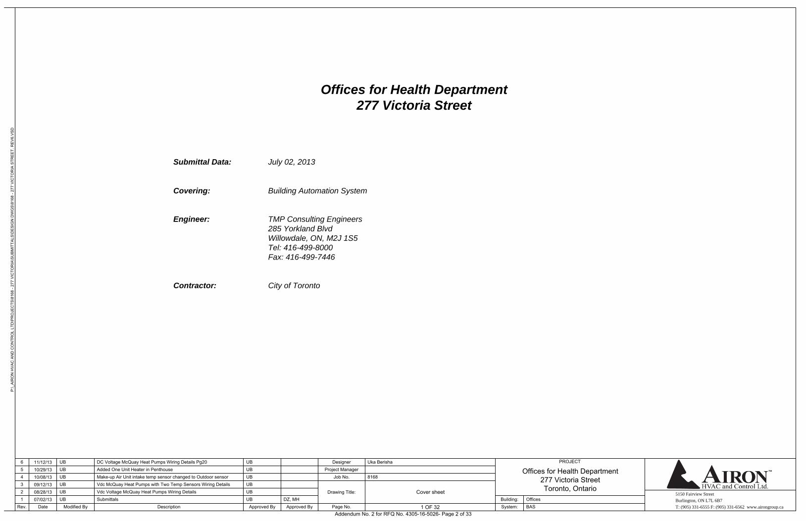
Cover Page
2Index
3General point description
4Controls legend
5Wiring installation instructions
6System architectural layout
7System architectural layout
9Heat pump loop
10Domestic Hot Water
11Exhaust Fans (Penthouse)
13Make-up Air Unit
14Exhaust Fans (First Floor)
15Heat Pumps (Typical for Carrier heat pumps)
16Heat Pumps (Typical for McQuay heat pumps)
17Heat Pumps and floor CO2 Sensor (Typical of Two for Carrier heat pumps)
18Heat Pumps with Two Temp Sensors (Typical of Zero for Carrier heat pumps)
19Heat Pumps with Two Temp Sensors (Typical of Zero for McQuay heat pumps)
21Heat Pump Schedule First Floor
22Heat Pump Schedule Second Floor
23Heat Pump Schedule Third Floor
24Heat Pump Schedule Fourth Floor
25Heat Pump Schedule Fifth Floor
26Heat Pump Schedule Sixth Floor
27Heat Pump Schedule Seventh Floor
28Heat Pump Schedule Eighth Floor
29Heat Pump Schedule Ninth Floor
30Heat Pump Schedule Tenth and Eleventh Floor
31Sequence of operation
32Sequence of operation
8Controllers MAC Addresses
12Unit Heater (Penthouse)
20Heat Pump with DC control board
Addendum No. 2 for RFQ No. 4305-16-5026- Page 3 of 33
5150 Fairview Street
Burlington, ON L7L 6B7
T: (905) 331-6555 F: (905) 331-6562 www.airongroup.ca
Offices for Health Department277 Victoria StreetToronto, Ontario
P:\_
AIR
ON
HV
AC
AN
D C
ON
TRO
L LT
D\P
RO
JEC
TS\8
168
- 277
VIC
TOR
IA\S
UB
MIT
TALS
\DE
SIG
N D
WG
S\8
168
- 277
VIC
TOR
IA S
TRE
ET.
RE
V6.
VS
D
Rev. 3 of x
PROJECT
1234
Date
56
07/02/1308/28/1309/12/1310/08/1310/29/1311/12/13
Modified By
UB
UBUB
UBUB
UB
DescriptionSubmittals
Added One Unit Heater in Penthouse
Approved By
DC Voltage McQuay Heat Pumps Wiring Details Pg20
Make-up Air Unit intake temp sensor changed to Outdoor sensorVdc McQuay Heat Pumps with Two Temp Sensors Wiring DetailsVdc Voltage McQuay Heat Pumps Wiring Details
UB
UB
UB
UB
UB
UB
Approved ByDZ, MH
Page No.
Drawing Title:
Job No.Project Manager
Designer
8168
Uka Berisha
System:Building:
BASOffices
3 OF 32
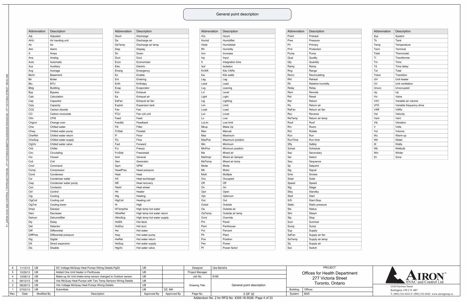
General point description
General point description
AnaAutoAuxAvg
AbbreviationAdjAHUAirAlmA
BsmtBlrBtuBldgBypCalc
AnalogAutomaticAuxiliaryAverage
DescriptionAdjustedAir handing unitAirAlarmAmps
BasementBoilerBTUBuildingBypassCalculation
CapCptyCO2COCfmChgovrChwChwpChwRetChwSupClgVlvChlrCircCloCoilCmdCompCond
Chilled water pumpChilled water returnChilled water supplyChilled water valveChillerCirculatingClosedCoilCommandCompressorCondenser
CapacitorCapacityCarbon dioxideCarbon monoxideCFMChange overChilled water
CwCwpConCtrlClgClgCoilClgTwrDmprDecrDehumDlyDetDiffDiffPresDig
DamperDecreaseDehumidifierDelayDetectorDifferentialDifferential pressureDigital
Condenser waterCondenser water pumpContactorControlCoolingCooling coilCooling tower
DXDis
Direct expansionDisable
Disch DischargeDaDaTemp
Discharge airDischarge air temp
EmergEnEntEnth
DispDnDuctEconElec
EvapExhEaEaFanExptnkFan
EmergencyEnableEnteringEnthalpy
DisplayDownDuctEconomizerElectric
EvaporatorExhaustExhaust airExhaust air fanExpansion tankFan
FCUFeedFeedbkFiltFirStatFlFloFwdFrzFrzStatGnrlGenGpmHeadPresHeatHXHRHtwhl
ForwardFreezeFreezestatGeneralGeneratorGPMHead pressureHeatHeat exchangerHeat recoveryHeat wheel
Fan coil unitFeedFeedbackFilterFirestatFloorFlow
HtrHtgHtgCoilHiHiTempHwHthwRetHthwSupHotDkHotDucHwHwpHwRetHwSupHtgVlv
Hot deckHot ductHot waterHot water pumpHot water returnHot water supplyHot water valve
HeaterHeatingHeating coilHighHigh temp hot waterHigh temp hot water returnHigh temp hot water supply
Abbreviation DescriptionHrs HoursHumidHstatRh
HumidifierHumidistatHumidity
IncrInp
IncreaseInput
LeadLvgLvlLight
ItIsolKVARKwLag
LtgLimLoadLocLoLoLim
LeadLeavingLevelLight
Integration timeIsolationKilo VARsKilo wattsLag
LightingLimitLoadLocalLowLow limit
MkupManMaxMaxPosMinMinPosMaMaDmprMaTempModeMtrMultiOccOffOnOpnOptOut
Mixed air damperMixed air tempModeMotorMultipleOccupiedOffOnOpenOptimumOut
Make UpManualMaximumMaximum positionMinimumMinimum positionMixed air
OutsdOaOaTempOvrdPnlPentPctPltPosPwrPf
PlantPositionPowerPower factor
OutsideOutside airOutside air tempOverridePanelPenthousePercent
Abbreviation DescriptionPrehtPresPriProt
PreheatPressurePrimaryProtection
PumpQualQty
PumpQualityQuantity
RampRng
RampRange
Abbreviation Description
RstRetRaRaFan
RecrcRhtRhRelayRem
RevRaTempRoofRmRotRun
ResetReturnReturn airReturn air fan
RecirculatingReheatRelative humidityRelayRemote
ReverseReturn air tempRoofRoomRotateRun
RunTimeSftySchedSecSelSeqSpSigSmkSolarSpeedStgStbyStartS/SStaticStsStm
SignalSmokeSolarSpeedStageStandbyStartStart-StopStatic pressureStatusSteam
Run timeSafetyScheduleSecondarySelectSequenceSetpoint
StpSumSumpSupSaFanSaTempSaSwi Switch
StopSummerSumpSupplySupply air fanSupply air tempSupply air
SysTkTempTermTstatTrTm
SystemTankTemperatureTerminalThermostatTransformerTime
TdTotTrans
Time delayTotalTransition
UHUV
Unit heaterUnit ventilation
Abbreviation Description
VARVelVentVib
UnoccUpVlvVAVVFD
VVolWuWtrWWb
VARsVelocityVentVibration
UnoccupiedUpValveVariable air volumeVariable frequency drive
VoltsVolumeWarm-upWaterWattsWetbulb
WinZn
WinterZone
Addendum No. 2 for RFQ No. 4305-16-5026- Page 4 of 33
5150 Fairview Street
Burlington, ON L7L 6B7
T: (905) 331-6555 F: (905) 331-6562 www.airongroup.ca
Offices for Health Department277 Victoria StreetToronto, Ontario
P:\_
AIR
ON
HV
AC
AN
D C
ON
TRO
L LT
D\P
RO
JEC
TS\8
168
- 277
VIC
TOR
IA\S
UB
MIT
TALS
\DE
SIG
N D
WG
S\8
168
- 277
VIC
TOR
IA S
TRE
ET.
RE
V6.
VS
D
Rev. 4 of x
PROJECT
1234
Date
56
07/02/1308/28/1309/12/1310/08/1310/29/1311/12/13
Modified By
UB
UBUB
UBUB
UB
DescriptionSubmittals
Added One Unit Heater in Penthouse
Approved By
DC Voltage McQuay Heat Pumps Wiring Details Pg20
Make-up Air Unit intake temp sensor changed to Outdoor sensorVdc McQuay Heat Pumps with Two Temp Sensors Wiring DetailsVdc Voltage McQuay Heat Pumps Wiring Details
UB
UB
UB
UB
UB
UB
Approved ByDZ, MH
Page No.
Drawing Title:
Job No.Project Manager
Designer
8168
Uka Berisha
System:Building:
BASOffices
4 OF 32
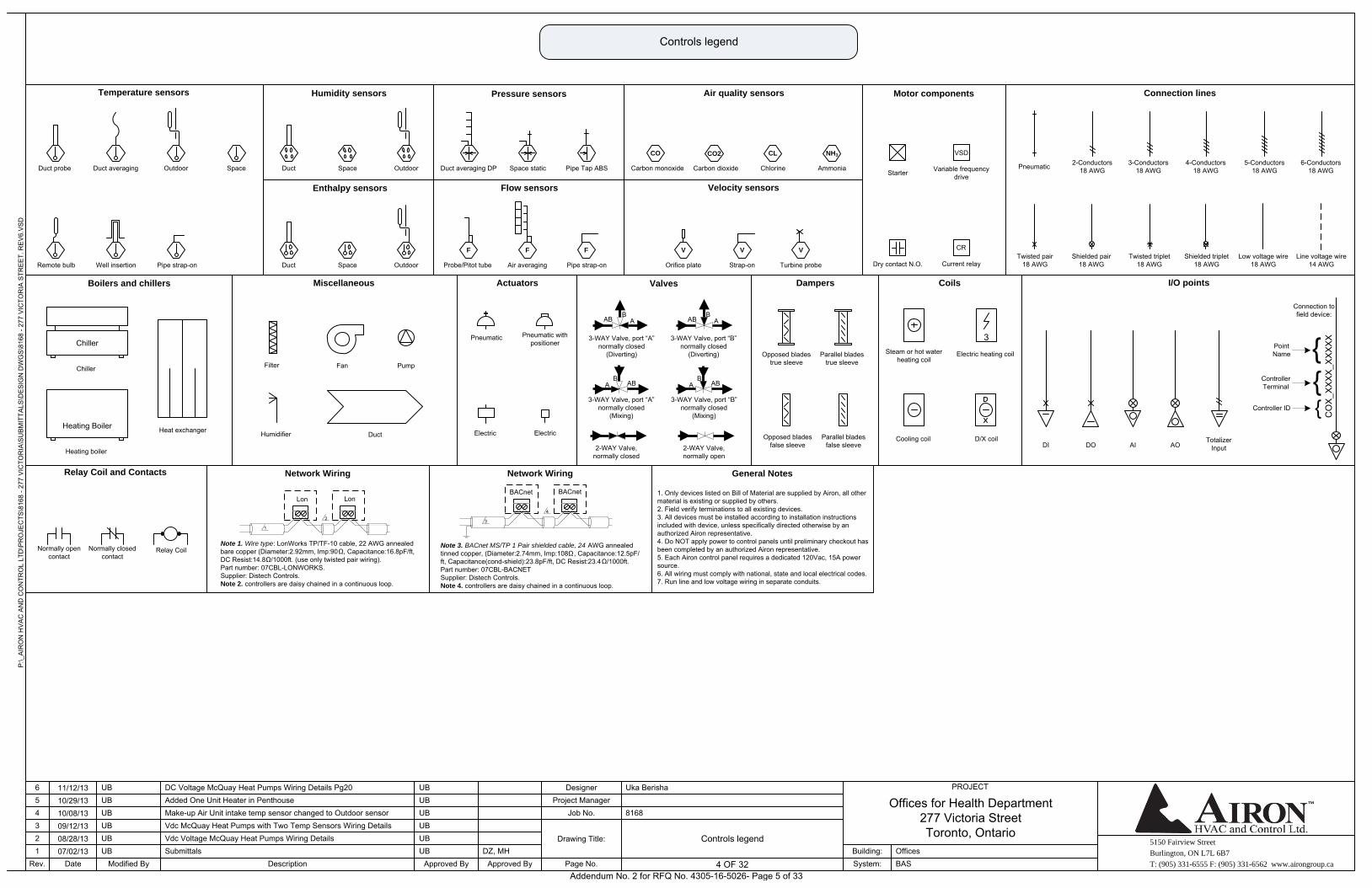
Controls legend
Controls legend
Temperature sensors
Duct probe Duct averaging Outdoor
Well insertion Pipe strap-onRemote bulb
Space
Humidity sensors
Duct Space Outdoor
Enthalpy sensors
Duct Space Outdoor
Flow sensors
Probe/Pitot tube
F F
Air averaging
F
Pipe strap-on
Pressure sensors
Pipe Tap ABSDuct averaging DP Space static
CO
Air quality sensors
Carbon monoxide
CO2
Carbon dioxide Chlorine
XCL XNH3
Ammonia
V
Orifice plate
V
Strap-on
V
Turbine probe
Velocity sensors
VSD
Starter Variable frequency drive
Motor components
CR
Dry contact N.O. Current relay
Pneumatic 2-Conductors18 AWG
3-Conductors18 AWG
4-Conductors18 AWG
5-Conductors18 AWG
6-Conductors18 AWG
Twisted pair18 AWG
Shielded pair18 AWG
Twisted triplet18 AWG
Shielded triplet18 AWG
Connection lines
Low voltage wire18 AWG
Line voltage wire14 AWG
Valves
3-WAY Valve, port “A”
normally closed (Mixing)
3-WAY Valve, port “B”
normally closed (Mixing)
2-WAY Valve, normally closed
2-WAY Valve, normally open
3-WAY Valve, port “A”
normally closed(Diverting)
3-WAY Valve, port “B”
normally closed(Diverting)
AB AB
AB AB
ABAB
ABAB
Pneumatic Pneumatic with positioner
Electric
Actuators
Electric
Opposed blades true sleeve
Parallel blades true sleeve
Opposed blades false sleeve
Parallel blades false sleeve
Dampers Coils
3Steam or hot water
heating coilElectric heating coil
Cooling coil D/X coil
I/O points
DI DO AI AOTotalizer
Input
Connection to field device:
Controller ID Point
Name
CO
X_X
XX
X_X
XX
XX
Controller Terminal
Humidifier
Fan Pump
Duct
Miscellaneous
Filter
Heating Boiler
Heating boiler
Heat exchanger
Boilers and chillers
Chiller
Chiller
Network Wiring
Note 3. BACnet MS/TP 1 Pair shielded cable, 24 AWG annealed tinned copper, (Diameter:2.74mm, Imp:108Ω , Capacitance:12.5pF/ft, Capacitance(cond-shield):23.8pF/ft, DC Resist:23.4Ω/1000ft.Part number: 07CBL-BACNETSupplier: Distech Controls.Note 4. controllers are daisy chained in a continuous loop.
3
4
BACnet BACnet
Network Wiring
Note 1. Wire type: LonWorks TP/TF-10 cable, 22 AWG annealed bare copper (Diameter:2.92mm, Imp:90Ω, Capacitance:16.8pF/ft, DC Resist:14.8Ω/1000ft. (use only twisted pair wiring).Part number: 07CBL-LONWORKS.Supplier: Distech Controls.Note 2. controllers are daisy chained in a continuous loop.
1
2
Lon Lon
Relay Coil and Contacts
Normally open contact
Normally closed contact
Relay Coil
General Notes
1. Only devices listed on Bill of Material are supplied by Airon, all other material is existing or supplied by others.2. Field verify terminations to all existing devices.3. All devices must be installed according to installation instructions included with device, unless specifically directed otherwise by an authorized Airon representative.4. Do NOT apply power to control panels until preliminary checkout has been completed by an authorized Airon representative.5. Each Airon control panel requires a dedicated 120Vac, 15A power source.6. All wiring must comply with national, state and local electrical codes.7. Run line and low voltage wiring in separate conduits.
Addendum No. 2 for RFQ No. 4305-16-5026- Page 5 of 33
5150 Fairview Street
Burlington, ON L7L 6B7
T: (905) 331-6555 F: (905) 331-6562 www.airongroup.ca
Offices for Health Department277 Victoria StreetToronto, Ontario
P:\_
AIR
ON
HV
AC
AN
D C
ON
TRO
L LT
D\P
RO
JEC
TS\8
168
- 277
VIC
TOR
IA\S
UB
MIT
TALS
\DE
SIG
N D
WG
S\8
168
- 277
VIC
TOR
IA S
TRE
ET.
RE
V6.
VS
D
Rev. 5 of x
PROJECT
1234
Date
56
07/02/1308/28/1309/12/1310/08/1310/29/1311/12/13
Modified By
UB
UBUB
UBUB
UB
DescriptionSubmittals
Added One Unit Heater in Penthouse
Approved By
DC Voltage McQuay Heat Pumps Wiring Details Pg20
Make-up Air Unit intake temp sensor changed to Outdoor sensorVdc McQuay Heat Pumps with Two Temp Sensors Wiring DetailsVdc Voltage McQuay Heat Pumps Wiring Details
UB
UB
UB
UB
UB
UB
Approved ByDZ, MH
Page No.
Drawing Title:
Job No.Project Manager
Designer
8168
Uka Berisha
System:Building:
BASOffices
5 OF 32
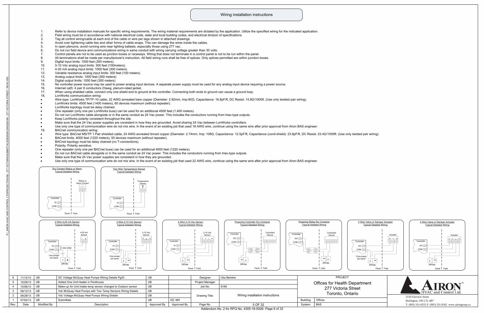
Wiring installation instructions
Wiring installation instructions
1. Refer to device installation manuals for specific wiring requirements. The wiring material requirements are dictated by the application. Utilize the specified wiring for the indicated application.2. Field wiring must be in accordance with national electrical code, state and local building codes, and electrical division of specifications.3. Tag all control wiring/cable at each end of the cable or wire per tags shown in attached drawings.4. Avoid over tightening cable ties and other forms of cable wraps. This can damage the wires inside the cables.5. In open plenums, avoid running wire near lighting ballasts, especially those using 277 vac.6. Do not run field device and communications wiring in same conduit with wiring carrying voltage greater than 30 volts.7. Control panels are not to be used as junction boxes or raceways. Wiring that does not terminate in a control panel is not to be run within the panel.8. All terminations shall be made per manufacturer's instruction. All field wiring runs shall be free of splices. Only splices permitted are within junction boxes. 9. Digital input limits: 1000 feet (300 meters).10. 0-10 Vdc analog input limits: 300 feet (100meters).11. 4-20 mA analog input limits: 1000 feet (300 meters).12. Variable resistance analog input limits: 300 feet (100 meters).13. Analog output limits: 1000 feet (300 meters)14. Digital output limits: 1000 feet (300 meters)15. No controller power source may be used to power analog input devices. A separate power supply must be used for any analog input device requiring a power source.16. Internet cat5: 4 pair 8 conductors 23awg, plenum-rated jacket.17. When using shielded cable, connect only one shield end to ground at the controller. Connecting both ends to ground can cause a ground loop.18. LonWorks communication wiring: Wire type: LonWorks TP/TF-10 cable, 22 AWG annealed bare copper (Diameter: 2.92mm, Imp:90Ω, Capacitance: 16.8pF/ft, DC Resist: 14.8Ω/1000ft. (Use only twisted pair wiring). LonWorks limits: 4500 feet (1400 meters), 60 devices maximum (without repeater). LonWorks topology must be daisy chained. One repeater (only one per LonWorks buss) can be used for an additional 4500 feet (1,400 meters). Do not run LonWorks cable alongside or in the same conduit as 24 Vac power. This includes the conductors running from triac-type outputs. Keep LonWorks polarity consistent throughout the site. Make sure that the 24 Vac power supplies are consistent in how they are grounded. Avoid sharing 24 Vac between LonWorks controllers. Use only one type of communication wire do not mix wire. In the event of an existing job that used 18 AWG wire, continue using the same wire after prior approval from Airon BAS engineer.19. BACnet communication wiring: Wire type: BACnet MS/TP 1 Pair shielded cable, 24 AWG annealed tinned copper (Diameter: 2.74mm, Imp: 108Ω, Capacitance: 12.5pF/ft, Capacitance (cond-shield): 23.8pF/ft, DC Resist: 23.4Ω /1000ft. (Use only twisted pair wiring). BACnet limits: 4000 feet (1220 meters), 50 devices maximum (without repeater). BACnet topology must be daisy chained (no T-connections). Polarity: Polarity sensitive. One repeater (only one per BACnet buss) can be used for an additional 4000 feet (1220 meters). Do not run BACnet cable alongside or in the same conduit as 24 Vac power. This includes the conductors running from triac-type outputs. Make sure that the 24 Vac power supplies are consistent in how they are grounded. Use only one type of communication wire do not mix wire. In the event of an existing job that used 22 AWG wire, continue using the same wire after prior approval from Airon BAS engineer.
COM
DI
FieldPanel
Status or Alarm Contact
Dry Contact Status or AlarmTypical Detailed Wiring
Controller
COM
AI
FieldPanel
Temperature Sensor
Two Wire Temperature SensorTypical Detailed Wiring
T
Controller
COM
AI
FieldPanel
4-20 mA Sensor
2 Wire 4-20 mA SensorTypical Detailed Wiring
+-
+-24Vdc
500 OHM
One jumper per panel
Controller
COM
AI
FieldPanel
2-10 Vdc Sensor
4 Wire 2-10 Vdc SensorTypical Detailed Wiring
-+ T ~
T ~24Vac
Controller COM
DO
FieldPanel
Controlled Device
Powering Controller Dry ContactsTypical Detailed Wiring
T~24Vac
Controller
COM
DO
FieldPanel
Controlled Device
Powering Relay Dry ContactsTypical Detailed Wiring
T~24Vac
Controller
COM
AO
FieldPanel
Actuator
4 Wire Valve or Damper ActuatorTypical Detailed Wiring
-+ T ~
T ~24Vac
Controller
COM
AI
FieldPanel
2-10 Vdc Sensor
3 Wire 2-10 Vdc SensorTypical Detailed Wiring
T
Y
One jumper per panel
~
T ~24Vac
Controller
COM
AO
FieldPanel
Actuator
3 Wire Valve or Damper ActuatorTypical Detailed Wiring
-
+
One jumper per panel
~
T ~24Vac
Controller
Addendum No. 2 for RFQ No. 4305-16-5026- Page 6 of 33
5150 Fairview Street
Burlington, ON L7L 6B7
T: (905) 331-6555 F: (905) 331-6562 www.airongroup.ca
Offices for Health Department277 Victoria StreetToronto, Ontario
P:\_
AIR
ON
HV
AC
AN
D C
ON
TRO
L LT
D\P
RO
JEC
TS\8
168
- 277
VIC
TOR
IA\S
UB
MIT
TALS
\DE
SIG
N D
WG
S\8
168
- 277
VIC
TOR
IA S
TRE
ET.
RE
V6.
VS
D
Rev. 6 of x
PROJECT
1234
Date
56
07/02/1308/28/1309/12/1310/08/1310/29/1311/12/13
Modified By
UB
UBUB
UBUB
UB
DescriptionSubmittals
Added One Unit Heater in Penthouse
Approved By
DC Voltage McQuay Heat Pumps Wiring Details Pg20
Make-up Air Unit intake temp sensor changed to Outdoor sensorVdc McQuay Heat Pumps with Two Temp Sensors Wiring DetailsVdc Voltage McQuay Heat Pumps Wiring Details
UB
UB
UB
UB
UB
UB
Approved ByDZ, MH
Page No.
Drawing Title:
Job No.Project Manager
Designer
8168
Uka Berisha
System:Building:
BASOffices
6 OF 32
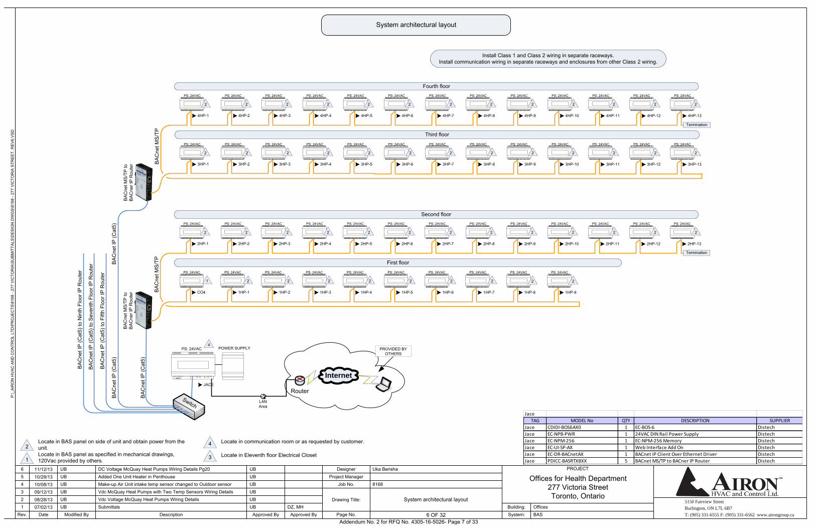
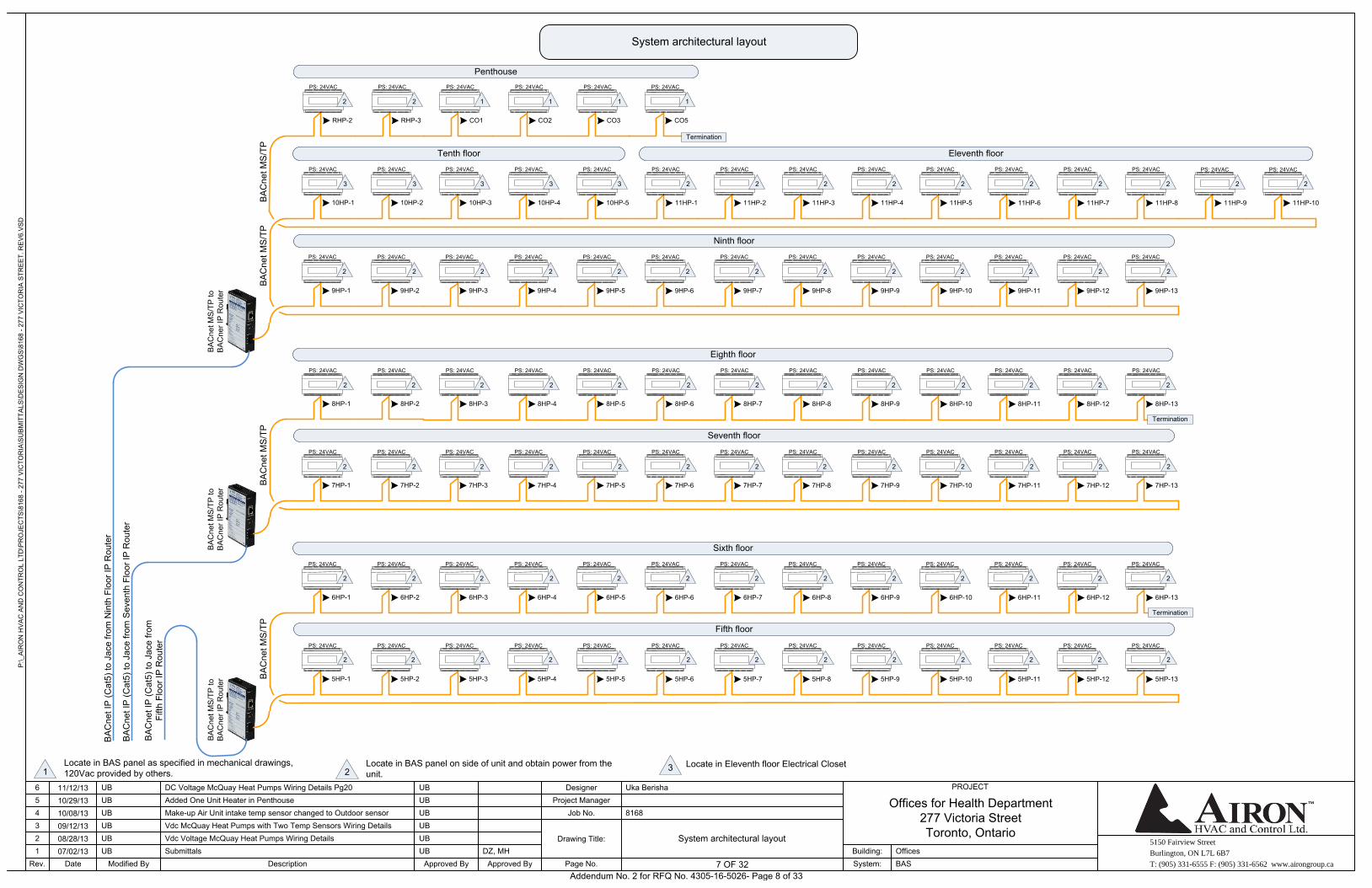
System architectural layout
Locate in BAS panel on side of unit and obtain power from the unit.2Locate in BAS panel as specified in mechanical drawings, 120Vac provided by others.1
Locate in communication room or as requested by customer.4
JACE
PS: 24VAC POWER SUPPLY
LAN Area
Internet
Router
PROVIDED BY OTHERS
BA
Cne
t IP
(Cat
5)
PS: 24VAC
BA
Cne
t MS
/TP
First floor
CO4 1HP-1 1HP-2 1HP-3 1HP-4 1HP-5 1HP-6 1HP-7 1HP-8 1HP-9
2HP-1 2HP-2 2HP-3 2HP-4 2HP-5 2HP-6 2HP-7 2HP-8 2HP-9 2HP-10 2HP-11 2HP-12 2HP-13
Termination
Second floor
Switch
BA
Cne
t MS
/TP
to
BA
Cne
r IP
Rou
ter
BA
Cne
t MS
/TP
Third floor
3HP-1 3HP-2 3HP-3 3HP-4 3HP-5 3HP-6 3HP-7 3HP-8 3HP-9 3HP-10 3HP-11 3HP-12 3HP-13
4HP-1 4HP-2 4HP-3 4HP-4 4HP-5 4HP-6 4HP-7 4HP-8 4HP-9 4HP-10 4HP-11 4HP-12 4HP-13
Termination
Fourth floor
BA
Cne
t MS
/TP
to
BA
Cne
r IP
Rou
ter
System architectural layout
PS: 24VAC PS: 24VAC PS: 24VAC PS: 24VAC PS: 24VAC PS: 24VAC PS: 24VAC PS: 24VAC PS: 24VAC
PS: 24VAC PS: 24VAC PS: 24VAC PS: 24VAC PS: 24VAC PS: 24VAC PS: 24VAC PS: 24VAC PS: 24VAC PS: 24VAC PS: 24VAC PS: 24VAC PS: 24VAC
PS: 24VAC PS: 24VAC PS: 24VAC PS: 24VAC PS: 24VAC PS: 24VAC PS: 24VAC PS: 24VAC PS: 24VAC PS: 24VAC PS: 24VAC PS: 24VAC PS: 24VAC
PS: 24VAC PS: 24VAC PS: 24VAC PS: 24VAC PS: 24VAC PS: 24VAC PS: 24VAC PS: 24VAC PS: 24VAC PS: 24VAC PS: 24VAC PS: 24VAC PS: 24VAC
BA
Cne
t IP
(Cat
5)
BA
Cne
t IP
(Cat
5) to
Fift
h Fl
oor I
P R
oute
r
BA
Cne
t IP
(Cat
5)
BA
Cne
t IP
(Cat
5) to
Sev
enth
Flo
or IP
Rou
ter
BA
Cne
t IP
(Cat
5) to
Nin
th F
loor
IP R
oute
r
Locate in Eleventh floor Electrical Closet3
4
1 2 2 2 2 2 2 2 2 2
2 2222222222 22
2 2 2 2 2 2 2 2 2 2 2 2 2
2222222222222
Jace
TAG MODEL No QTY DESCRIPTION SUPPLIER
Jace CDIDI-BOS6AX0 1 EC-BOS-6 Distech
Jace EC-NPB-PWR 1 24VAC DIN Rail Power Supply Distech
Jace EC-NPM-256 1 EC-NPM-256 Memory Distech
Jace EC-UI-SP-AX 1 Web Interface Add On Distech
Jace EC-DR-BACnetAX 1 BACnet IP Client Over Ethernet Driver Distech
Jace PDICC-BASRTXBXX 5 BACnet MS/TP to BACner IP Router Distech
Install Class 1 and Class 2 wiring in separate raceways.Install communication wiring in separate raceways and enclosures from other Class 2 wiring.
Addendum No. 2 for RFQ No. 4305-16-5026- Page 7 of 33
5150 Fairview Street
Burlington, ON L7L 6B7
T: (905) 331-6555 F: (905) 331-6562 www.airongroup.ca
Offices for Health Department277 Victoria StreetToronto, Ontario
P:\_
AIR
ON
HV
AC
AN
D C
ON
TRO
L LT
D\P
RO
JEC
TS\8
168
- 277
VIC
TOR
IA\S
UB
MIT
TALS
\DE
SIG
N D
WG
S\8
168
- 277
VIC
TOR
IA S
TRE
ET.
RE
V6.
VS
D
Rev. 7 of x
PROJECT
1234
Date
56
07/02/1308/28/1309/12/1310/08/1310/29/1311/12/13
Modified By
UB
UBUB
UBUB
UB
DescriptionSubmittals
Added One Unit Heater in Penthouse
Approved By
DC Voltage McQuay Heat Pumps Wiring Details Pg20
Make-up Air Unit intake temp sensor changed to Outdoor sensorVdc McQuay Heat Pumps with Two Temp Sensors Wiring DetailsVdc Voltage McQuay Heat Pumps Wiring Details
UB
UB
UB
UB
UB
UB
Approved ByDZ, MH
Page No.
Drawing Title:
Job No.Project Manager
Designer
8168
Uka Berisha
System:Building:
BASOffices
7 OF 32
System architectural layout
BA
Cne
t MS
/TP
BA
Cne
t MS
/TP
Ninth floor
9HP-1 9HP-2 9HP-3 9HP-4 9HP-5 9HP-6 9HP-7 9HP-8 9HP-9 9HP-10 9HP-11 9HP-12 9HP-13
10HP-1 10HP-2 10HP-3 10HP-4 10HP-5 11HP-1 11HP-2 11HP-3 11HP-4 11HP-5 11HP-6 11HP-7 11HP-8
RHP-2 RHP-3 CO1 CO2 CO3
Tenth floor
Penthouse
BA
Cne
t MS
/TP
to
BA
Cne
r IP
Rou
ter
BA
Cne
t MS
/TP
Seventh floor
7HP-1 7HP-2 7HP-3 7HP-4 7HP-5 7HP-6 7HP-7 7HP-8 7HP-9 7HP-10 7HP-11 7HP-12 7HP-13
8HP-1 8HP-2 8HP-3 8HP-4 8HP-5 8HP-6 8HP-7 8HP-8 8HP-9 8HP-10 8HP-11 8HP-12 8HP-13
Termination
Eighth floor
BA
Cne
t MS
/TP
to
BA
Cne
r IP
Rou
ter
BA
Cne
t MS
/TP
Fifth floor
5HP-1 5HP-2 5HP-3 5HP-4 5HP-5 5HP-6 5HP-7 5HP-8 5HP-9 5HP-10 5HP-11 5HP-12 5HP-13
6HP-1 6HP-2 6HP-3 6HP-4 6HP-5 6HP-6 6HP-7 6HP-8 6HP-9 6HP-10 6HP-11 6HP-12 6HP-13
Termination
Sixth floor
BA
Cne
t MS
/TP
to
BA
Cne
r IP
Rou
ter
11HP-9 11HP-10
Eleventh floor
PS: 24VAC PS: 24VAC PS: 24VAC PS: 24VAC PS: 24VAC PS: 24VAC PS: 24VAC PS: 24VAC PS: 24VAC PS: 24VAC PS: 24VAC PS: 24VAC PS: 24VAC
PS: 24VAC PS: 24VAC PS: 24VAC PS: 24VAC PS: 24VAC PS: 24VAC PS: 24VAC PS: 24VAC PS: 24VAC PS: 24VAC PS: 24VAC PS: 24VAC PS: 24VAC
PS: 24VAC PS: 24VAC PS: 24VAC PS: 24VAC PS: 24VAC PS: 24VAC PS: 24VAC PS: 24VAC PS: 24VAC PS: 24VAC PS: 24VAC PS: 24VAC PS: 24VAC
PS: 24VAC PS: 24VAC PS: 24VAC PS: 24VAC PS: 24VAC PS: 24VAC PS: 24VAC PS: 24VAC PS: 24VAC PS: 24VAC PS: 24VAC PS: 24VAC PS: 24VAC
PS: 24VAC PS: 24VAC PS: 24VAC PS: 24VAC PS: 24VAC PS: 24VAC PS: 24VAC PS: 24VAC PS: 24VAC PS: 24VAC PS: 24VAC PS: 24VAC PS: 24VAC
PS: 24VAC PS: 24VAC PS: 24VAC PS: 24VAC PS: 24VAC PS: 24VAC PS: 24VAC PS: 24VAC PS: 24VAC PS: 24VAC PS: 24VAC PS: 24VAC PS: 24VAC
PS: 24VAC PS: 24VAC PS: 24VAC PS: 24VAC PS: 24VAC
PS: 24VAC PS: 24VAC
System architectural layout
BA
Cne
t IP
(Cat
5) to
Jac
e fro
m
Fifth
Flo
or IP
Rou
ter
BA
Cne
t IP
(Cat
5) to
Jac
e fro
m S
even
th F
loor
IP R
oute
r
BA
Cne
t IP
(Cat
5) to
Jac
e fro
m N
inth
Flo
or IP
Rou
ter
Locate in BAS panel on side of unit and obtain power from the unit.2
Locate in BAS panel as specified in mechanical drawings, 120Vac provided by others.1
Locate in Eleventh floor Electrical Closet3
2 2 2 2 2 2 2 2 2 2 2 2 2
2222222222222
2 2 2 2 2 2 2 2 2 2 2 2 2
2222222222222
2 2 2 2 2 2 2 2 2 2 2 2 2
2 2 2222222233333
2 2 1 1 1
CO5
PS: 24VAC
1
Termination
Addendum No. 2 for RFQ No. 4305-16-5026- Page 8 of 33
5150 Fairview Street
Burlington, ON L7L 6B7
T: (905) 331-6555 F: (905) 331-6562 www.airongroup.ca
Offices for Health Department277 Victoria StreetToronto, Ontario
P:\_
AIR
ON
HV
AC
AN
D C
ON
TRO
L LT
D\P
RO
JEC
TS\8
168
- 277
VIC
TOR
IA\S
UB
MIT
TALS
\DE
SIG
N D
WG
S\8
168
- 277
VIC
TOR
IA S
TRE
ET.
RE
V6.
VS
D
Rev. 8 of x
PROJECT
1234
Date
56
07/02/1308/28/1309/12/1310/08/1310/29/1311/12/13
Modified By
UB
UBUB
UBUB
UB
DescriptionSubmittals
Added One Unit Heater in Penthouse
Approved By
DC Voltage McQuay Heat Pumps Wiring Details Pg20
Make-up Air Unit intake temp sensor changed to Outdoor sensorVdc McQuay Heat Pumps with Two Temp Sensors Wiring DetailsVdc Voltage McQuay Heat Pumps Wiring Details
UB
UB
UB
UB
UB
UB
Approved ByDZ, MH
Page No.
Drawing Title:
Job No.Project Manager
Designer
8168
Uka Berisha
System:Building:
BASOffices
8 OF 32
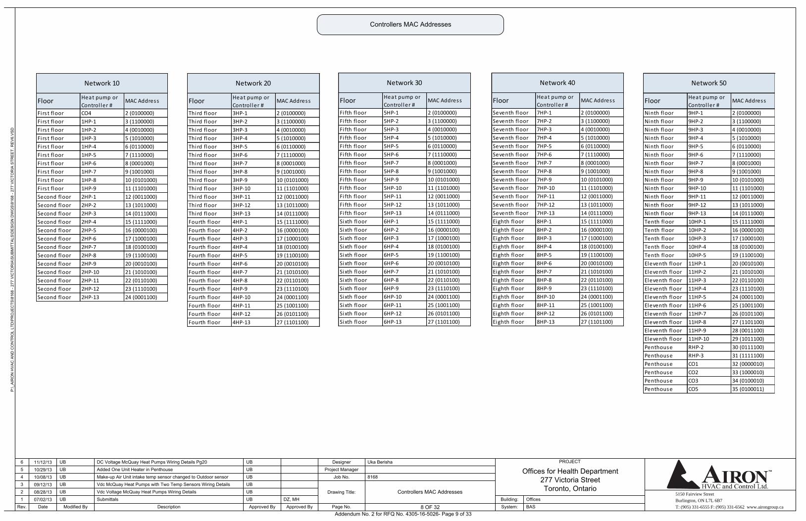
Controllers MAC Addresses
Controllers MAC Addresses
Ninth floor 9HP-1 2 (0100000)
Ninth floor 9HP-2 3 (1100000)
Ninth floor 9HP-3 4 (0010000)
Ninth floor 9HP-4 5 (1010000)
Ninth floor 9HP-5 6 (0110000)
Ninth floor 9HP-6 7 (1110000)
Ninth floor 9HP-7 8 (0001000)
Ninth floor 9HP-8 9 (1001000)
Ninth floor 9HP-9 10 (0101000)
Ninth floor 9HP-10 11 (1101000)
Ninth floor 9HP-11 12 (0011000)
Ninth floor 9HP-12 13 (1011000)
Ninth floor 9HP-13 14 (0111000)
Tenth floor 10HP-1 15 (1111000)
Tenth floor 10HP-2 16 (0000100)
Tenth floor 10HP-3 17 (1000100)
Tenth floor 10HP-4 18 (0100100)
Tenth floor 10HP-5 19 (1100100)
Eleventh floor 11HP-1 20 (0010100)
Eleventh floor 11HP-2 21 (1010100)
Eleventh floor 11HP-3 22 (0110100)
Eleventh floor 11HP-4 23 (1110100)
Eleventh floor 11HP-5 24 (0001100)
Eleventh floor 11HP-6 25 (1001100)
Eleventh floor 11HP-7 26 (0101100)
Eleventh floor 11HP-8 27 (1101100)
Eleventh floor 11HP-9 28 (0011100)
Eleventh floor 11HP-10 29 (1011100)
Penthouse RHP-2 30 (0111100)
Penthouse RHP-3 31 (1111100)
Penthouse CO1 32 (0000010)
Penthouse CO2 33 (1000010)
Penthouse CO3 34 (0100010)
Penthouse CO5 35 (0100011)
Network 50
MAC AddressFloorHeat pump or
Control ler #
Seventh floor 7HP-1 2 (0100000)
Seventh floor 7HP-2 3 (1100000)
Seventh floor 7HP-3 4 (0010000)
Seventh floor 7HP-4 5 (1010000)
Seventh floor 7HP-5 6 (0110000)
Seventh floor 7HP-6 7 (1110000)
Seventh floor 7HP-7 8 (0001000)
Seventh floor 7HP-8 9 (1001000)
Seventh floor 7HP-9 10 (0101000)
Seventh floor 7HP-10 11 (1101000)
Seventh floor 7HP-11 12 (0011000)
Seventh floor 7HP-12 13 (1011000)
Seventh floor 7HP-13 14 (0111000)
Eighth floor 8HP-1 15 (1111000)
Eighth floor 8HP-2 16 (0000100)
Eighth floor 8HP-3 17 (1000100)
Eighth floor 8HP-4 18 (0100100)
Eighth floor 8HP-5 19 (1100100)
Eighth floor 8HP-6 20 (0010100)
Eighth floor 8HP-7 21 (1010100)
Eighth floor 8HP-8 22 (0110100)
Eighth floor 8HP-9 23 (1110100)
Eighth floor 8HP-10 24 (0001100)
Eighth floor 8HP-11 25 (1001100)
Eighth floor 8HP-12 26 (0101100)
Eighth floor 8HP-13 27 (1101100)
Network 40
MAC AddressFloorHeat pump or
Control ler #
Fi fth floor 5HP-1 2 (0100000)
Fi fth floor 5HP-2 3 (1100000)
Fi fth floor 5HP-3 4 (0010000)
Fi fth floor 5HP-4 5 (1010000)
Fi fth floor 5HP-5 6 (0110000)
Fi fth floor 5HP-6 7 (1110000)
Fi fth floor 5HP-7 8 (0001000)
Fi fth floor 5HP-8 9 (1001000)
Fi fth floor 5HP-9 10 (0101000)
Fi fth floor 5HP-10 11 (1101000)
Fi fth floor 5HP-11 12 (0011000)
Fi fth floor 5HP-12 13 (1011000)
Fi fth floor 5HP-13 14 (0111000)
Sixth floor 6HP-1 15 (1111000)
Sixth floor 6HP-2 16 (0000100)
Sixth floor 6HP-3 17 (1000100)
Sixth floor 6HP-4 18 (0100100)
Sixth floor 6HP-5 19 (1100100)
Sixth floor 6HP-6 20 (0010100)
Sixth floor 6HP-7 21 (1010100)
Sixth floor 6HP-8 22 (0110100)
Sixth floor 6HP-9 23 (1110100)
Sixth floor 6HP-10 24 (0001100)
Sixth floor 6HP-11 25 (1001100)
Sixth floor 6HP-12 26 (0101100)
Sixth floor 6HP-13 27 (1101100)
Network 30
MAC AddressFloorHeat pump or
Control ler #
Third floor 3HP-1 2 (0100000)
Third floor 3HP-2 3 (1100000)
Third floor 3HP-3 4 (0010000)
Third floor 3HP-4 5 (1010000)
Third floor 3HP-5 6 (0110000)
Third floor 3HP-6 7 (1110000)
Third floor 3HP-7 8 (0001000)
Third floor 3HP-8 9 (1001000)
Third floor 3HP-9 10 (0101000)
Third floor 3HP-10 11 (1101000)
Third floor 3HP-11 12 (0011000)
Third floor 3HP-12 13 (1011000)
Third floor 3HP-13 14 (0111000)
Fourth floor 4HP-1 15 (1111000)
Fourth floor 4HP-2 16 (0000100)
Fourth floor 4HP-3 17 (1000100)
Fourth floor 4HP-4 18 (0100100)
Fourth floor 4HP-5 19 (1100100)
Fourth floor 4HP-6 20 (0010100)
Fourth floor 4HP-7 21 (1010100)
Fourth floor 4HP-8 22 (0110100)
Fourth floor 4HP-9 23 (1110100)
Fourth floor 4HP-10 24 (0001100)
Fourth floor 4HP-11 25 (1001100)
Fourth floor 4HP-12 26 (0101100)
Fourth floor 4HP-13 27 (1101100)
Network 20
FloorHeat pump or
Control ler #MAC Address
Firs t floor CO4 2 (0100000)
Fi rs t floor 1HP-1 3 (1100000)
Fi rs t floor 1HP-2 4 (0010000)
Fi rs t floor 1HP-3 5 (1010000)
Fi rs t floor 1HP-4 6 (0110000)
Fi rs t floor 1HP-5 7 (1110000)
Fi rs t floor 1HP-6 8 (0001000)
Fi rs t floor 1HP-7 9 (1001000)
Fi rs t floor 1HP-8 10 (0101000)
Fi rs t floor 1HP-9 11 (1101000)
Second floor 2HP-1 12 (0011000)
Second floor 2HP-2 13 (1011000)
Second floor 2HP-3 14 (0111000)
Second floor 2HP-4 15 (1111000)
Second floor 2HP-5 16 (0000100)
Second floor 2HP-6 17 (1000100)
Second floor 2HP-7 18 (0100100)
Second floor 2HP-8 19 (1100100)
Second floor 2HP-9 20 (0010100)
Second floor 2HP-10 21 (1010100)
Second floor 2HP-11 22 (0110100)
Second floor 2HP-12 23 (1110100)
Second floor 2HP-13 24 (0001100)
Network 10
FloorHeat pump or
Control ler #MAC Address
Addendum No. 2 for RFQ No. 4305-16-5026- Page 9 of 33
5150 Fairview Street
Burlington, ON L7L 6B7
T: (905) 331-6555 F: (905) 331-6562 www.airongroup.ca
Offices for Health Department277 Victoria StreetToronto, Ontario
P:\_
AIR
ON
HV
AC
AN
D C
ON
TRO
L LT
D\P
RO
JEC
TS\8
168
- 277
VIC
TOR
IA\S
UB
MIT
TALS
\DE
SIG
N D
WG
S\8
168
- 277
VIC
TOR
IA S
TRE
ET.
RE
V6.
VS
D
Rev. 9 of x
PROJECT
1234
Date
56
07/02/1308/28/1309/12/1310/08/1310/29/1311/12/13
Modified By
UB
UBUB
UBUB
UB
DescriptionSubmittals
Added One Unit Heater in Penthouse
Approved By
DC Voltage McQuay Heat Pumps Wiring Details Pg20
Make-up Air Unit intake temp sensor changed to Outdoor sensorVdc McQuay Heat Pumps with Two Temp Sensors Wiring DetailsVdc Voltage McQuay Heat Pumps Wiring Details
UB
UB
UB
UB
UB
UB
Approved ByDZ, MH
Page No.
Drawing Title:
Job No.Project Manager
Designer
8168
Uka Berisha
System:Building:
BASOffices
9 OF 32
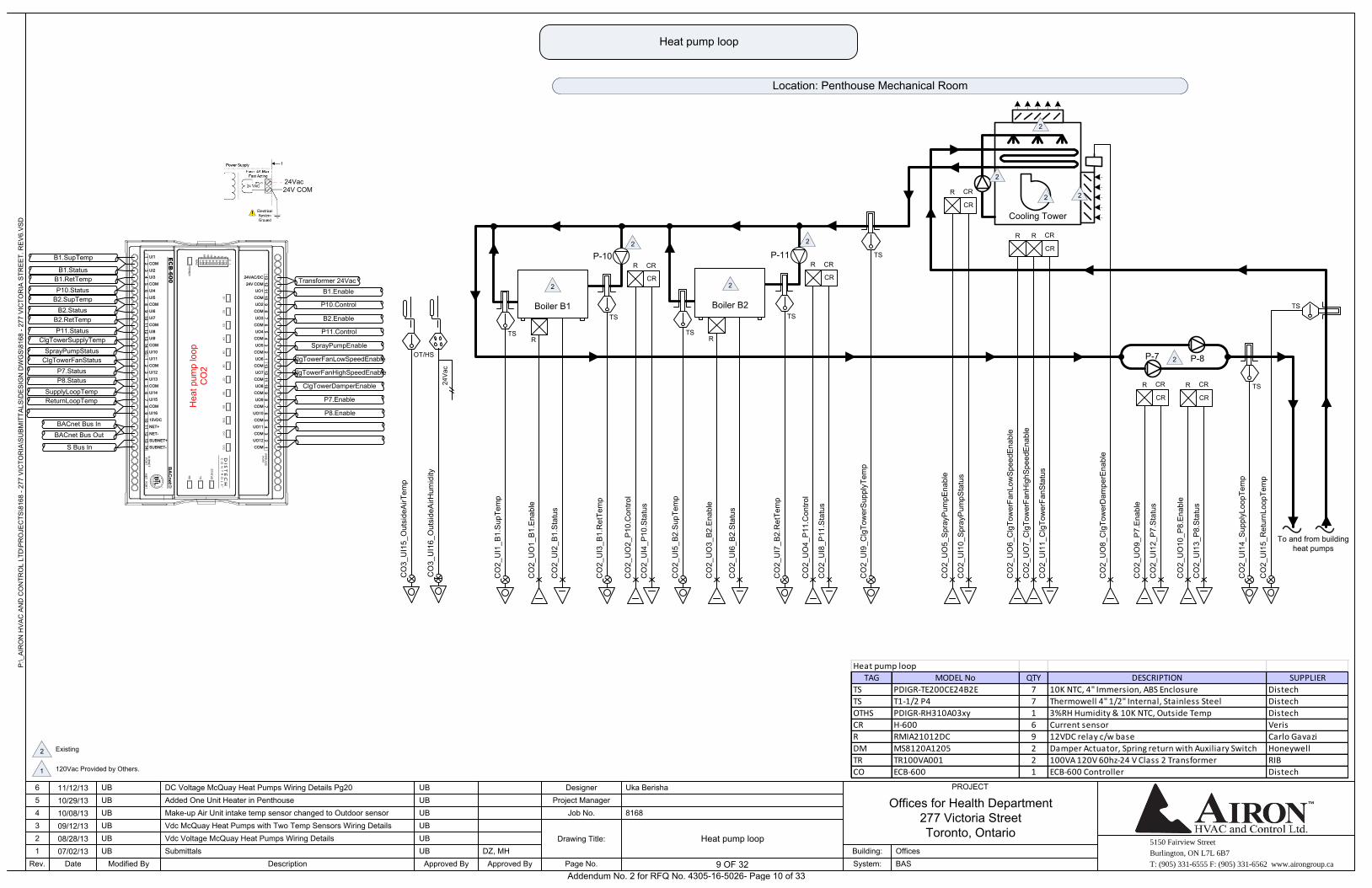
Heat pump loop
Heat pump loop
TS
TS
CO
2_U
I14_
Sup
plyL
oopT
emp
CO
2_U
I15_
Ret
urnL
oopT
emp
To and from building heat pumps
Boiler B2
P-11
TS
TS
R
CO
2_U
O3_
B2.
Ena
ble
CO
2_U
I6_B
2.S
tatu
s
CO
2_U
I5_B
2.S
upTe
mp
CO
2_U
I7_B
2.R
etTe
mp
CR
R CR
CO
2_U
O4_
P11
.Con
trol
CO
2_U
I8_P
11.S
tatu
s
Boiler B1
P-10
TS
TS
R
CO
2_U
O1_
B1.
Ena
ble
CO
2_U
I2_B
1.S
tatu
s
CO
2_U
I1_B
1.S
upTe
mp
CO
2_U
I3_B
1.R
etTe
mp
CR
R CR
CO
2_U
O2_
P10
.Con
trol
CO
2_U
I4_P
10.S
tatu
s
Location: Penthouse Mechanical Room
CO
2_U
O8_
Clg
Tow
erD
ampe
rEna
ble
P-7 P-8
CRR CR
CO
2_U
O9_
P7.
Ena
ble
CO
2_U
I12_
P7.
Sta
tus
CRR CR
CO
2_U
O10
_P8.
Ena
ble
CO
2_U
I13_
P8.
Sta
tus
Cooling Tower
CRR CR
CO
2_U
O5_
Spr
ayP
umpE
nabl
e
CO
2_U
I10_
Spr
ayP
umpS
tatu
s
CRR CR
CO
2_U
O7_
Clg
Tow
erFa
nHig
hSpe
edE
nabl
e
CO
2_U
I11_
Clg
Tow
erFa
nSta
tus
R
CO
2_U
O6_
Clg
Tow
erFa
nLow
Spe
edE
nabl
e
TS
CO
2_U
I9_C
lgTo
wer
Sup
plyT
emp
OT/HS
CO
3_U
I15_
Out
side
AirT
emp
CO
3_U
I16_
Out
side
AirH
umid
ity
24V
ac
Transformer 24Vac
Hea
t pum
p lo
opC
O2
B1.SupTemp
B1.RetTemp
B1.Status
B2.SupTemp
P10.Status
B2.RetTemp
B2.Status
ClgTowerSupplyTemp
P11.Status
ClgTowerFanStatus
SprayPumpStatus
P8.Status
P7.Status
ReturnLoopTemp
SupplyLoopTemp
B1.Enable
B2.Enable
P10.Control
P11.Control
ClgTowerFanLowSpeedEnable
SprayPumpEnable
ClgTowerFanHighSpeedEnable
P7.Enable
ClgTowerDamperEnable
P8.Enable
ECB-600
78
91
01
11
21
324VAC/DC
24V COM
12
34
56
78
91
01
11
21
31
23
45
6
UO1
UO2
COM
COM
UO3
UO4
COM
COM
UO5
UO6
COM
COM
UO7
UO8
COM
COM
UO9
UO10
COM
COM
UO11
UO12
COM
COM
76
54
32
1
UI1
COM
13
12
11
10
98
54
32
11
51
41
11
09
87
6
UI2
COM
UI4
UI3
UI5
UI6
UI7
COM
COM
UI9
COM
UI8
UI10
COM
UI12
UI11
UI13
UI14
UI15
COM
COM
15VDC
NET+
UI16
13
12
14
SUBNET+
SUBNET-
NET- BACnet Bus In
BACnet Bus Out
S Bus In
Existing 2
120Vac Provided by Others.1
2
2 2
2
2
2
22
2
Heat pump loop
TAG MODEL No QTY DESCRIPTION SUPPLIER
TS PDIGR-TE200CE24B2E 7 10K NTC, 4" Immersion, ABS Enclosure Distech
TS T1-1/2 P4 7 Thermowell 4" 1/2" Internal, Stainless Steel Distech
OTHS PDIGR-RH310A03xy 1 3%RH Humidity & 10K NTC, Outside Temp Distech
CR H-600 6 Current sensor Veris
R RMIA21012DC 9 12VDC relay c/w base Carlo Gavazi
DM MS8120A1205 2 Damper Actuator, Spring return with Auxiliary Switch Honeywell
TR TR100VA001 2 100VA 120V 60hz-24 V Class 2 Transformer RIB
CO ECB-600 1 ECB-600 Controller Distech
24Vac24V COM
Addendum No. 2 for RFQ No. 4305-16-5026- Page 10 of 33
5150 Fairview Street
Burlington, ON L7L 6B7
T: (905) 331-6555 F: (905) 331-6562 www.airongroup.ca
Offices for Health Department277 Victoria StreetToronto, Ontario
P:\_
AIR
ON
HV
AC
AN
D C
ON
TRO
L LT
D\P
RO
JEC
TS\8
168
- 277
VIC
TOR
IA\S
UB
MIT
TALS
\DE
SIG
N D
WG
S\8
168
- 277
VIC
TOR
IA S
TRE
ET.
RE
V6.
VS
D
Rev. 10 of x
PROJECT
1234
Date
56
07/02/1308/28/1309/12/1310/08/1310/29/1311/12/13
Modified By
UB
UBUB
UBUB
UB
DescriptionSubmittals
Added One Unit Heater in Penthouse
Approved By
DC Voltage McQuay Heat Pumps Wiring Details Pg20
Make-up Air Unit intake temp sensor changed to Outdoor sensorVdc McQuay Heat Pumps with Two Temp Sensors Wiring DetailsVdc Voltage McQuay Heat Pumps Wiring Details
UB
UB
UB
UB
UB
UB
Approved ByDZ, MH
Page No.
Drawing Title:
Job No.Project Manager
Designer
8168
Uka Berisha
System:Building:
BASOffices
10 OF 32
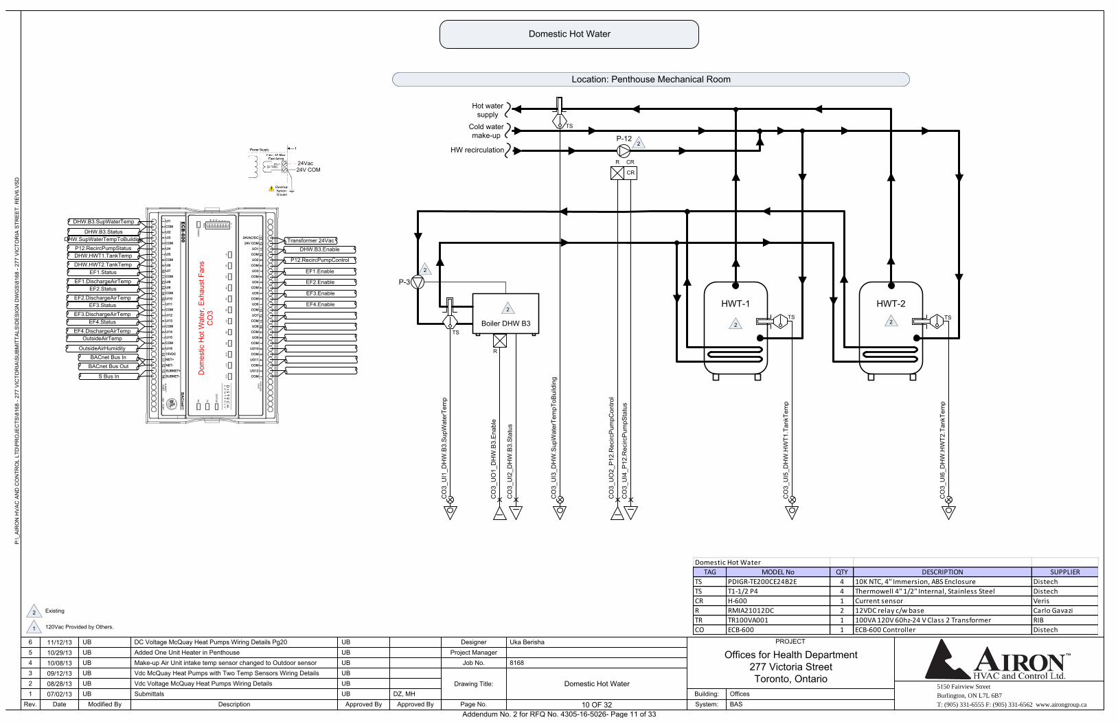
Domestic Hot Water
Domestic Hot Water
Boiler DHW B3
P-3
HWT-1 HWT-2
Hot water supply
Cold water make-up
R
CO
3_U
O1_
DH
W.B
3.E
nabl
e
CO
3_U
I2_D
HW
.B3.
Sta
tus
CO
3_U
I5_D
HW
.HW
T1.T
ankT
emp
CO
3_U
I6_D
HW
.HW
T2.T
ankT
emp
CR
R CR
CO
3_U
O2_
P12
.Rec
ircP
umpC
ontro
l
CO
3_U
I4_P
12.R
ecirc
Pum
pSta
tus
Location: Penthouse Mechanical Room
TSTS
P-12HW recirculation
CO
3_U
I3_D
HW
.Sup
Wat
erTe
mpT
oBui
ldin
g
TS
CO
3_U
I1_D
HW
.B3.
Sup
Wat
erTe
mp
TS
Transformer 24Vac
Dom
estic
Hot
Wat
er, E
xhau
st F
ans
CO
3
DHW.B3.SupWaterTemp
DHW.SupWaterTempToBuilding
DHW.B3.Status
DHW.HWT1.TankTemp
P12.RecircPumpStatus
EF1.Status
DHW.HWT2.TankTemp
EF2.Status
EF1.DischargeAirTemp
EF3.Status
EF2.DischargeAirTemp
EF4.Status
EF3.DischargeAirTemp
OutsideAirTemp
EF4.DischargeAirTemp
OutsideAirHumidity
DHW.B3.Enable
EF1.Enable
P12.RecircPumpControl
EF2.Enable
EF4.Enable
EF3.Enable
ECB-600
78
91
01
11
21
324VAC/DC
24V COM
12
34
56
78
91
01
11
21
31
23
45
6
UO1
UO2
COM
COM
UO3
UO4
COM
COM
UO5
UO6
COM
COM
UO7
UO8
COM
COM
UO9
UO10
COM
COM
UO11
UO12
COM
COM
76
54
32
1
UI1
COM
13
12
11
10
98
54
32
11
51
41
11
09
87
6
UI2
COM
UI4
UI3
UI5
UI6
UI7
COM
COM
UI9
COM
UI8
UI10
COM
UI12
UI11
UI13
UI14
UI15
COM
COM
15VDC
NET+
UI16
13
12
14
SUBNET+
SUBNET-
NET- BACnet Bus In
BACnet Bus Out
S Bus In
Existing 2
120Vac Provided by Others.1
2
2
2
2 2
Domestic Hot Water
TAG MODEL No QTY DESCRIPTION SUPPLIER
TS PDIGR-TE200CE24B2E 4 10K NTC, 4" Immersion, ABS Enclosure Distech
TS T1-1/2 P4 4 Thermowell 4" 1/2" Internal, Stainless Steel Distech
CR H-600 1 Current sensor Veris
R RMIA21012DC 2 12VDC relay c/w base Carlo Gavazi
TR TR100VA001 1 100VA 120V 60hz-24 V Class 2 Transformer RIB
CO ECB-600 1 ECB-600 Controller Distech
24Vac24V COM
Addendum No. 2 for RFQ No. 4305-16-5026- Page 11 of 33
5150 Fairview Street
Burlington, ON L7L 6B7
T: (905) 331-6555 F: (905) 331-6562 www.airongroup.ca
Offices for Health Department277 Victoria StreetToronto, Ontario
P:\_
AIR
ON
HV
AC
AN
D C
ON
TRO
L LT
D\P
RO
JEC
TS\8
168
- 277
VIC
TOR
IA\S
UB
MIT
TALS
\DE
SIG
N D
WG
S\8
168
- 277
VIC
TOR
IA S
TRE
ET.
RE
V6.
VS
D
Rev. 11 of x
PROJECT
1234
Date
56
07/02/1308/28/1309/12/1310/08/1310/29/1311/12/13
Modified By
UB
UBUB
UBUB
UB
DescriptionSubmittals
Added One Unit Heater in Penthouse
Approved By
DC Voltage McQuay Heat Pumps Wiring Details Pg20
Make-up Air Unit intake temp sensor changed to Outdoor sensorVdc McQuay Heat Pumps with Two Temp Sensors Wiring DetailsVdc Voltage McQuay Heat Pumps Wiring Details
UB
UB
UB
UB
UB
UB
Approved ByDZ, MH
Page No.
Drawing Title:
Job No.Project Manager
Designer
8168
Uka Berisha
System:Building:
BASOffices
11 OF 32
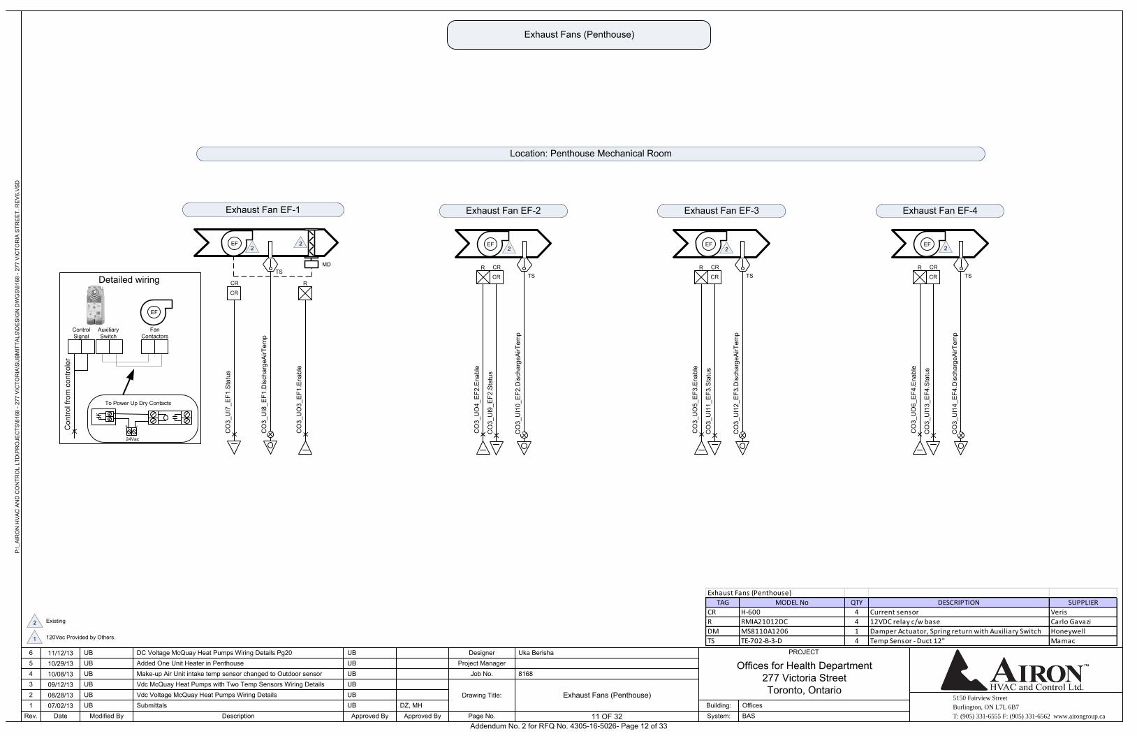
Exhaust Fans (Penthouse)
Exhaust Fans (Penthouse)
EF
MD
CR CR R
CO
3_U
O3_
EF1
.Ena
ble
CO
3_U
I7_E
F1.S
tatu
s
Exhaust Fan EF-1
EF
CR CRR
CO
3_U
O4_
EF2
.Ena
ble
CO
3_U
I9_E
F2.S
tatu
s
Exhaust Fan EF-2
TSC
O3_
UI8
_EF1
.Dis
char
geA
irTem
p
TS
CO
3_U
I10_
EF2
.Dis
char
geA
irTem
p
EF
CR CRR
CO
3_U
O5_
EF3
.Ena
ble
CO
3_U
I11_
EF3
.Sta
tus
Exhaust Fan EF-3
TS
CO
3_U
I12_
EF3
.Dis
char
geA
irTem
p
EF
CR CRR
CO
3_U
O6_
EF4
.Ena
ble
CO
3_U
I13_
EF4
.Sta
tus
Exhaust Fan EF-4
TS
CO
3_U
I14_
EF4
.Dis
char
geA
irTem
p
Location: Penthouse Mechanical Room
Existing 2
120Vac Provided by Others.1
22
2 2 2
Exhaust Fans (Penthouse)
TAG MODEL No QTY DESCRIPTION SUPPLIER
CR H-600 4 Current sensor Veris
R RMIA21012DC 4 12VDC relay c/w base Carlo Gavazi
DM MS8110A1206 1 Damper Actuator, Spring return with Auxiliary Switch Honeywell
TS TE-702-B-3-D 4 Temp Sensor - Duct 12" Mamac
EF
Con
trol f
rom
con
trole
r
Control Signal
Auxiliary Switch
Fan Contactors
Detailed wiring
To Power Up Dry Contacts
24Vac
+ -
Addendum No. 2 for RFQ No. 4305-16-5026- Page 12 of 33
5150 Fairview Street
Burlington, ON L7L 6B7
T: (905) 331-6555 F: (905) 331-6562 www.airongroup.ca
Offices for Health Department277 Victoria StreetToronto, Ontario
P:\_
AIR
ON
HV
AC
AN
D C
ON
TRO
L LT
D\P
RO
JEC
TS\8
168
- 277
VIC
TOR
IA\S
UB
MIT
TALS
\DE
SIG
N D
WG
S\8
168
- 277
VIC
TOR
IA S
TRE
ET.
RE
V6.
VS
D
Rev. 12 of x
PROJECT
1234
Date
56
07/02/1308/28/1309/12/1310/08/1310/29/1311/12/13
Modified By
UB
UBUB
UBUB
UB
DescriptionSubmittals
Added One Unit Heater in Penthouse
Approved By
DC Voltage McQuay Heat Pumps Wiring Details Pg20
Make-up Air Unit intake temp sensor changed to Outdoor sensorVdc McQuay Heat Pumps with Two Temp Sensors Wiring DetailsVdc Voltage McQuay Heat Pumps Wiring Details
UB
UB
UB
UB
UB
UB
Approved ByDZ, MH
Page No.
Drawing Title:
Job No.Project Manager
Designer
8168
Uka Berisha
System:Building:
BASOffices
12 OF 32
CR
R CR
RTS
CO
5_U
I2_U
H.R
oom
Tem
pSen
CO
5_D
O1_
UH
.Ena
ble/
Dis
able
CO
5_U
I1_U
H.S
tatu
s
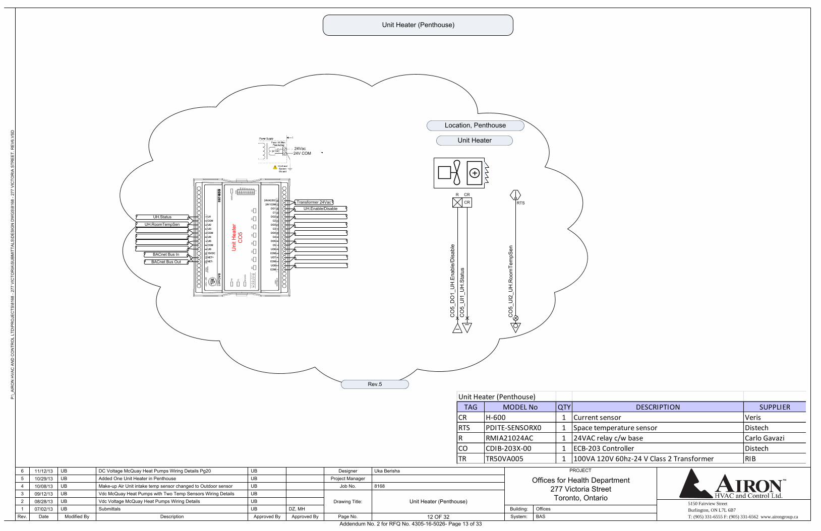
Unit Heater
Location, Penthouse
Rev.5
Unit Heater (Penthouse)
Unit Heater (Penthouse)
Unit Heater (Penthouse)
TAG MODEL No QTY DESCRIPTION SUPPLIER
CR H-600 1 Current sensor Veris
RTS PDITE-SENSORX0 1 Space temperature sensor Distech
R RMIA21024AC 1 24VAC relay c/w base Carlo Gavazi
CO CDIB-203X-00 1 ECB-203 Controller Distech
TR TR50VA005 1 100VA 120V 60hz-24 V Class 2 Transformer RIB
12
13
14
15
16
17
1824VAC/DC
24V COM
67
89
10
11
12
34
5
DO1
DO2
C2
C1
DO3
DO4
C4
C3
DO5
UO6
COM
C5
UO7
UO8
COM
COM
76
54
32
1
UI1
COM
12
11
10
98
UI2
COM
UI4
UI3
UI5
UI6
15VDC
COM
NET+
NET-
Uni
t Hea
ter
CO
5
Transformer 24Vac
UH.Status
UH.RoomTempSen
UH.Enable/Disable
BACnet Bus In
BACnet Bus Out
24Vac24V COM
Addendum No. 2 for RFQ No. 4305-16-5026- Page 13 of 33
5150 Fairview Street
Burlington, ON L7L 6B7
T: (905) 331-6555 F: (905) 331-6562 www.airongroup.ca
Offices for Health Department277 Victoria StreetToronto, Ontario
P:\_
AIR
ON
HV
AC
AN
D C
ON
TRO
L LT
D\P
RO
JEC
TS\8
168
- 277
VIC
TOR
IA\S
UB
MIT
TALS
\DE
SIG
N D
WG
S\8
168
- 277
VIC
TOR
IA S
TRE
ET.
RE
V6.
VS
D
Rev. 13 of x
PROJECT
1234
Date
56
07/02/1308/28/1309/12/1310/08/1310/29/1311/12/13
Modified By
UB
UBUB
UBUB
UB
DescriptionSubmittals
Added One Unit Heater in Penthouse
Approved By
DC Voltage McQuay Heat Pumps Wiring Details Pg20
Make-up Air Unit intake temp sensor changed to Outdoor sensorVdc McQuay Heat Pumps with Two Temp Sensors Wiring DetailsVdc Voltage McQuay Heat Pumps Wiring Details
UB
UB
UB
UB
UB
UB
Approved ByDZ, MH
Page No.
Drawing Title:
Job No.Project Manager
Designer
8168
Uka Berisha
System:Building:
BASOffices
13 OF 32
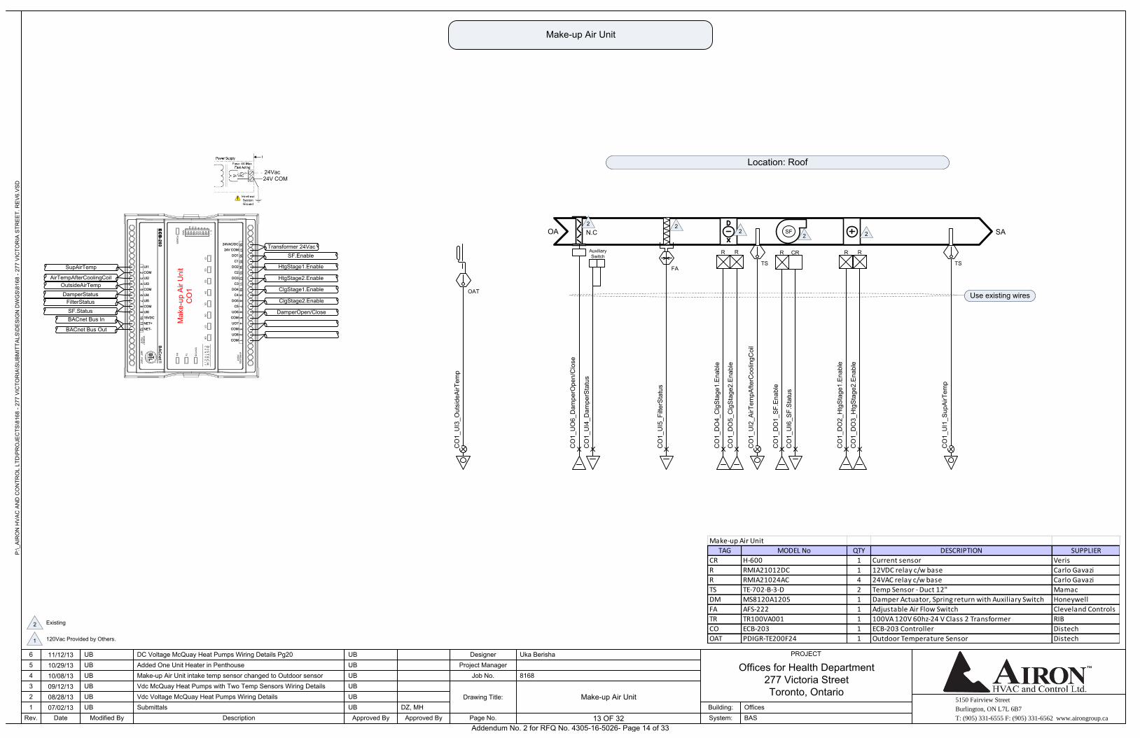
Make-up Air Unit
Make-up Air Unit
OA
TS
CO
1_U
I1_S
upA
irTem
p
SASF
FA
CO
1_U
I5_F
ilter
Sta
tus
Auxiliary Switch
CO
1_U
I4_D
ampe
rSta
tus
CO
1_U
O6_
Dam
perO
pen/
Clo
se
N.C
CO
1_D
O1_
SF.
Ena
ble
CO
1_U
I6_S
F.S
tatu
s
CRR
RR
RR
CO
1_D
O3_
Htg
Sta
ge2.
Ena
ble
CO
1_D
O2_
Htg
Sta
ge1.
Ena
ble
CO
1_D
O4_
Clg
Sta
ge1.
Ena
ble
CO
1_D
O5_
Clg
Sta
ge2.
Ena
ble
Location: Roof
TS
CO
1_U
I2_A
irTem
pAfte
rCoo
lingC
oil
12
13
14
15
16
17
1824VAC/DC
24V COM
67
89
10
11
12
34
5
DO1
DO2
C2
C1
DO3
DO4
C4
C3
DO5
UO6
COM
C5
UO7
UO8
COM
COM
76
54
32
1
UI1
COM
12
11
10
98
UI2
COM
UI4
UI3
UI5
UI6
15VDC
COM
NET+
NET-
Mak
e-up
Air
Uni
tC
O1
Transformer 24Vac
SupAirTemp
OutsideAirTemp
AirTempAfterCoolingCoil
FilterStatus
DamperStatus
SF.Status
SF.Enable
HtgStage2.Enable
HtgStage1.Enable
ClgStage1.Enable
DamperOpen/Close
ClgStage2.Enable
BACnet Bus In
BACnet Bus Out
Use existing wires
Existing 2
120Vac Provided by Others.1
2
2
222
Make-up Air Unit
TAG MODEL No QTY DESCRIPTION SUPPLIER
CR H-600 1 Current sensor Veris
R RMIA21012DC 1 12VDC relay c/w base Carlo Gavazi
R RMIA21024AC 4 24VAC relay c/w base Carlo Gavazi
TS TE-702-B-3-D 2 Temp Sensor - Duct 12" Mamac
DM MS8120A1205 1 Damper Actuator, Spring return with Auxiliary Switch Honeywell
FA AFS-222 1 Adjustable Air Flow Switch Cleveland Controls
TR TR100VA001 1 100VA 120V 60hz-24 V Class 2 Transformer RIB
CO ECB-203 1 ECB-203 Controller Distech
OAT PDIGR-TE200F24 1 Outdoor Temperature Sensor Distech
24Vac24V COM
OAT
CO
1_U
I3_O
utsi
deA
irTem
p
Addendum No. 2 for RFQ No. 4305-16-5026- Page 14 of 33
5150 Fairview Street
Burlington, ON L7L 6B7
T: (905) 331-6555 F: (905) 331-6562 www.airongroup.ca
Offices for Health Department277 Victoria StreetToronto, Ontario
P:\_
AIR
ON
HV
AC
AN
D C
ON
TRO
L LT
D\P
RO
JEC
TS\8
168
- 277
VIC
TOR
IA\S
UB
MIT
TALS
\DE
SIG
N D
WG
S\8
168
- 277
VIC
TOR
IA S
TRE
ET.
RE
V6.
VS
D
Rev. 14 of x
PROJECT
1234
Date
56
07/02/1308/28/1309/12/1310/08/1310/29/1311/12/13
Modified By
UB
UBUB
UBUB
UB
DescriptionSubmittals
Added One Unit Heater in Penthouse
Approved By
DC Voltage McQuay Heat Pumps Wiring Details Pg20
Make-up Air Unit intake temp sensor changed to Outdoor sensorVdc McQuay Heat Pumps with Two Temp Sensors Wiring DetailsVdc Voltage McQuay Heat Pumps Wiring Details
UB
UB
UB
UB
UB
UB
Approved ByDZ, MH
Page No.
Drawing Title:
Job No.Project Manager
Designer
8168
Uka Berisha
System:Building:
BASOffices
14 OF 32
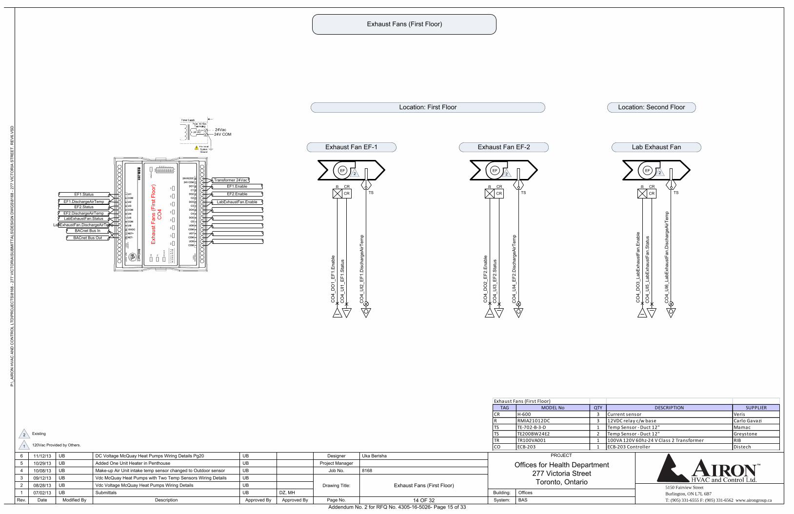
Exhaust Fans (First Floor)
Exhaust Fans (First Floor)
EF
CR CRR
CO
4_D
O1_
EF1
.Ena
ble
CO
4_U
I1_E
F1.S
tatu
s
Exhaust Fan EF-1
TS
CO
4_U
I2_E
F1.D
isch
arge
AirT
emp
EF
CR CRR
CO
4_D
O2_
EF2
.Ena
ble
CO
4_U
I3_E
F2.S
tatu
s
Exhaust Fan EF-2
TS
CO
4_U
I4_E
F2.D
isch
arge
AirT
emp
EF
CR CRR
CO
4_D
O3_
LabE
xhau
stFa
n.E
nabl
e
CO
4_U
I5_L
abE
xhau
stFa
n.S
tatu
s
Lab Exhaust Fan
TS
CO
4_U
I6_L
abE
xhau
stFa
n.D
isch
arge
AirT
emp
Location: First Floor Location: Second Floor
12
13
14
15
16
17
1824VAC/DC
24V COM
67
89
10
11
12
34
5
DO1
DO2
C2
C1
DO3
DO4
C4
C3
DO5
UO6
COM
C5
UO7
UO8
COM
COM
76
54
32
1
UI1
COM
12
11
10
98
UI2
COM
UI4
UI3
UI5
UI6
15VDC
COM
NET+
NET-
Exh
aust
Fan
s (F
irst F
loor
)C
O4
Transformer 24Vac
EF1.Status
EF2.Status
EF1.DischargeAirTemp
LabExhaustFan.Status
EF2.DischargeAirTemp
LabExhaustFan.DischargeAirTemp
EF1.Enable
LabExhaustFan.Enable
EF2.Enable
BACnet Bus In
BACnet Bus Out
Existing 2
120Vac Provided by Others.1
2 2 2
Exhaust Fans (First Floor)
TAG MODEL No QTY DESCRIPTION SUPPLIER
CR H-600 3 Current sensor Veris
R RMIA21012DC 3 12VDC relay c/w base Carlo Gavazi
TS TE-702-B-3-D 1 Temp Sensor - Duct 12" Mamac
TS TE200BW24E2 2 Temp Sensor - Duct 12" Greystone
TR TR100VA001 1 100VA 120V 60hz-24 V Class 2 Transformer RIB
CO ECB-203 1 ECB-203 Controller Distech
24Vac24V COM
Addendum No. 2 for RFQ No. 4305-16-5026- Page 15 of 33
5150 Fairview Street
Burlington, ON L7L 6B7
T: (905) 331-6555 F: (905) 331-6562 www.airongroup.ca
Offices for Health Department277 Victoria StreetToronto, Ontario
P:\_
AIR
ON
HV
AC
AN
D C
ON
TRO
L LT
D\P
RO
JEC
TS\8
168
- 277
VIC
TOR
IA\S
UB
MIT
TALS
\DE
SIG
N D
WG
S\8
168
- 277
VIC
TOR
IA S
TRE
ET.
RE
V6.
VS
D
Rev. 15 of x
PROJECT
1234
Date
56
07/02/1308/28/1309/12/1310/08/1310/29/1311/12/13
Modified By
UB
UBUB
UBUB
UB
DescriptionSubmittals
Added One Unit Heater in Penthouse
Approved By
DC Voltage McQuay Heat Pumps Wiring Details Pg20
Make-up Air Unit intake temp sensor changed to Outdoor sensorVdc McQuay Heat Pumps with Two Temp Sensors Wiring DetailsVdc Voltage McQuay Heat Pumps Wiring Details
UB
UB
UB
UB
UB
UB
Approved ByDZ, MH
Page No.
Drawing Title:
Job No.Project Manager
Designer
8168
Uka Berisha
System:Building:
BASOffices
15 OF 32
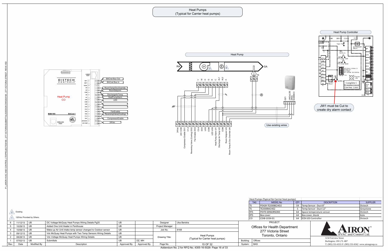
Heat Pumps (Typical for Carrier heat pumps)
Heat Pumps (Typical for Carrier heat pumps)
RA SA
TS
Heat Pump
Y W O G R
SF
C AL1
AL2
A
Hea
t Pum
p A
larm
UI1
LED
UO
6
CO
M
UO
5
DO
4
C3-
4
Fan
Ena
ble
DO
3
Rev
ersi
ng V
alve
(Coo
ling)
DO
2
C1-
2
Com
pres
sor E
nabl
e D
O1
Roo
m T
emp
& O
cc O
verr
ide
UI4
Roo
m S
etpo
int U
I3
CO
M
Dis
char
ge A
ir Te
mp
UI2
TEM
PC
OM
MO
N
SE
TPO
INT
LED
Heat Pump Controller
JW1 must be Cut to create dry alarm contact
Use existing wires
ECB-103
34
56
12
56
12
31
21
21
23
4
NET+
15VDC
NET-
UI4
COM
UI2
UI3
UI1
COM
UO5
UO6
DO4
DO3
DO2
C3-4
C1-2
24VAC/DC
24V COM
DO1
SUBNET
PORT
WIRELESS
PORT
BACnet Bus In
BACnet Bus Out
RoomTemp/OccOverride
DischargeAirTemp
RoomSetpoint
HeatPumpAlarm
LED
ReversingValve(Cooling)
FanEnable
CompressorEnable
24Vac
Heat PumpCO
Existing 2
120Vac Provided by Others.1
2 2
Heat Pumps (Typical for Carrier heat pumps)
TAG MODEL No QTY DESCRIPTION SUPPLIER
TS PDIGR-TE200BE24D2 59 Temp Sensor - Duct 8" Distech
TS TE200BW24E2 5 Temp Sensor - Duct 12" Greystone
RTS PDITE-SENSORSOX0 64 Space temperature sensor Distech
RTS Box cover 64 Box cover, blank Kele
CO CDIB-103X-01 64 ECB-103 Controller Distech
24V
CO
M
24V
ac
Addendum No. 2 for RFQ No. 4305-16-5026- Page 16 of 33
5150 Fairview Street
Burlington, ON L7L 6B7
T: (905) 331-6555 F: (905) 331-6562 www.airongroup.ca
Offices for Health Department277 Victoria StreetToronto, Ontario
P:\_
AIR
ON
HV
AC
AN
D C
ON
TRO
L LT
D\P
RO
JEC
TS\8
168
- 277
VIC
TOR
IA\S
UB
MIT
TALS
\DE
SIG
N D
WG
S\8
168
- 277
VIC
TOR
IA S
TRE
ET.
RE
V6.
VS
D
Rev. 16 of x
PROJECT
1234
Date
56
07/02/1308/28/1309/12/1310/08/1310/29/1311/12/13
Modified By
UB
UBUB
UBUB
UB
DescriptionSubmittals
Added One Unit Heater in Penthouse
Approved By
DC Voltage McQuay Heat Pumps Wiring Details Pg20
Make-up Air Unit intake temp sensor changed to Outdoor sensorVdc McQuay Heat Pumps with Two Temp Sensors Wiring DetailsVdc Voltage McQuay Heat Pumps Wiring Details
UB
UB
UB
UB
UB
UB
Approved ByDZ, MH
Page No.
Drawing Title:
Job No.Project Manager
Designer
8168
Uka Berisha
System:Building:
BASOffices
16 OF 32
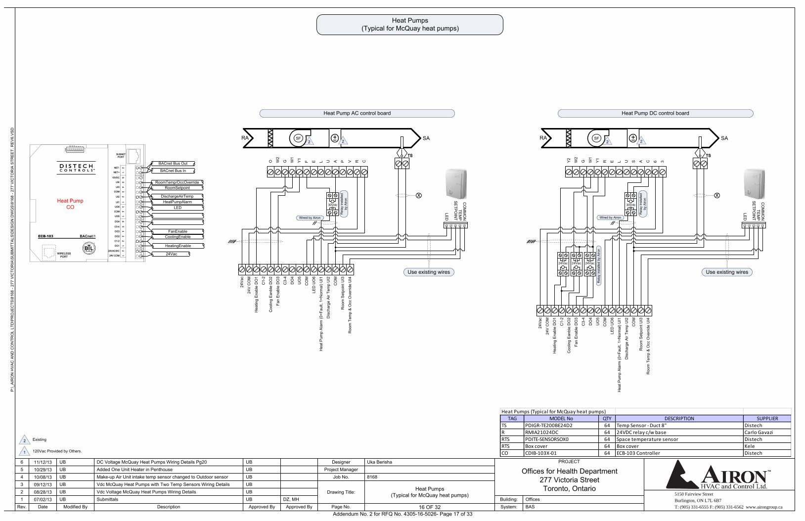
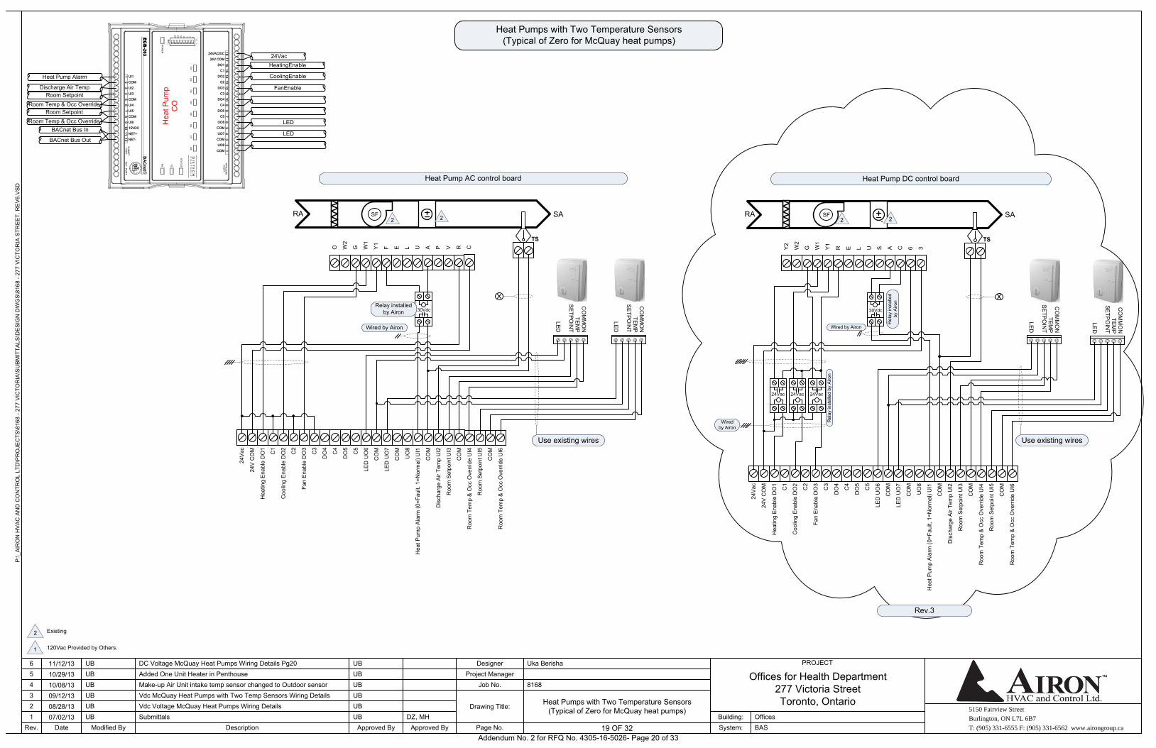
Heat Pumps (Typical for McQuay heat pumps)
Heat Pumps (Typical for McQuay heat pumps)
RA SA
TS
Heat Pump AC control board
SF
TS
O W2
G W1
Y1 F E L U
Hea
t Pum
p A
larm
(0=F
ault,
1=N
orm
al) U
I1
LED
UO
6
CO
M
UO
5
DO
4
C3-
4
Fan
Ena
ble
DO
3
Coo
ling
Ean
ble
DO
2
C1-
2
Hea
ting
Ena
ble
DO
1
Roo
m T
emp
& O
cc O
verr
ide
UI4
Roo
m S
etpo
int U
I3
CO
M
Dis
char
ge A
ir Te
mp
UI2
TEM
PC
OM
MO
N
SE
TPO
INT
LED
Use existing wires
A P V R C
30Vdc
Wired by Airon
Rel
ay in
stal
led
by A
iron
ECB-103
34
56
12
56
12
31
21
21
23
4
NET+
15VDC
NET-
UI4
COM
UI2
UI3
UI1
COM
UO5
UO6
DO4
DO3
DO2
C3-4
C1-2
24VAC/DC
24V COM
DO1
SUBNET
PORT
WIRELESS
PORT
BACnet Bus In
BACnet Bus Out
RoomTemp/OccOverride
DischargeAirTemp
RoomSetpoint
HeatPumpAlarm
LED
CoolingEnable
FanEnable
HeatingEnable
24Vac
Heat PumpCO
Existing 2
120Vac Provided by Others.1
2 2
Heat Pumps (Typical for McQuay heat pumps)
TAG MODEL No QTY DESCRIPTION SUPPLIER
TS PDIGR-TE200BE24D2 64 Temp Sensor - Duct 8" Distech
R RMIA21024DC 64 24VDC relay c/w base Carlo Gavazi
RTS PDITE-SENSORSOX0 64 Space temperature sensor Distech
RTS Box cover 64 Box cover Kele
CO CDIB-103X-01 64 ECB-103 Controller Distech
24V
CO
M
24V
ac
RA SA
TS
Heat Pump DC control board
SF
TS
Y2
W2
G W1
Y1 R E L U
Hea
t Pum
p A
larm
(0=F
ault,
1=N
orm
al) U
I1
LED
UO
6
CO
M
UO
5
DO
4
C3-
4
Fan
Ena
ble
DO
3
Coo
ling
Ean
ble
DO
2
C1-
2
Hea
ting
Ena
ble
DO
1
Roo
m T
emp
& O
cc O
verr
ide
UI4
Roo
m S
etpo
int U
I3
CO
M
Dis
char
ge A
ir Te
mp
UI2
TEM
PC
OM
MO
N
SE
TPO
INT
LED
Use existing wires
S A C 6 3
30Vdc
Wired by Airon
Rel
ay in
stal
led
by A
iron
2 2
24V
CO
M
24V
ac
24Vac 24Vac 24Vac
Rel
ay in
stal
led
by A
iron
Addendum No. 2 for RFQ No. 4305-16-5026- Page 17 of 33
5150 Fairview Street
Burlington, ON L7L 6B7
T: (905) 331-6555 F: (905) 331-6562 www.airongroup.ca
Offices for Health Department277 Victoria StreetToronto, Ontario
P:\_
AIR
ON
HV
AC
AN
D C
ON
TRO
L LT
D\P
RO
JEC
TS\8
168
- 277
VIC
TOR
IA\S
UB
MIT
TALS
\DE
SIG
N D
WG
S\8
168
- 277
VIC
TOR
IA S
TRE
ET.
RE
V6.
VS
D
Rev. 17 of x
PROJECT
1234
Date
56
07/02/1308/28/1309/12/1310/08/1310/29/1311/12/13
Modified By
UB
UBUB
UBUB
UB
DescriptionSubmittals
Added One Unit Heater in Penthouse
Approved By
DC Voltage McQuay Heat Pumps Wiring Details Pg20
Make-up Air Unit intake temp sensor changed to Outdoor sensorVdc McQuay Heat Pumps with Two Temp Sensors Wiring DetailsVdc Voltage McQuay Heat Pumps Wiring Details
UB
UB
UB
UB
UB
UB
Approved ByDZ, MH
Page No.
Drawing Title:
Job No.Project Manager
Designer
8168
Uka Berisha
System:Building:
BASOffices
17 OF 32
CO
M
Roo
m S
etpo
int U
I3
Dis
char
ge A
ir Te
mp
UI2
CO
M
Hea
t Pum
p A
larm
UI1
Fan
Ena
ble
DO
3
C2
Rev
ersi
ng V
alve
(Coo
ling)
DO
2
C1
Com
pres
sor E
nabl
e D
O1
UI6
CO
M
Floo
rCO
2.S
enso
r UI5
Roo
m T
emp
& O
cc O
verr
ide
UI4C5
DO
5
C4
DO
4
C3
UO
8
CO
M
UO
7
CO
M
LED
UO
6
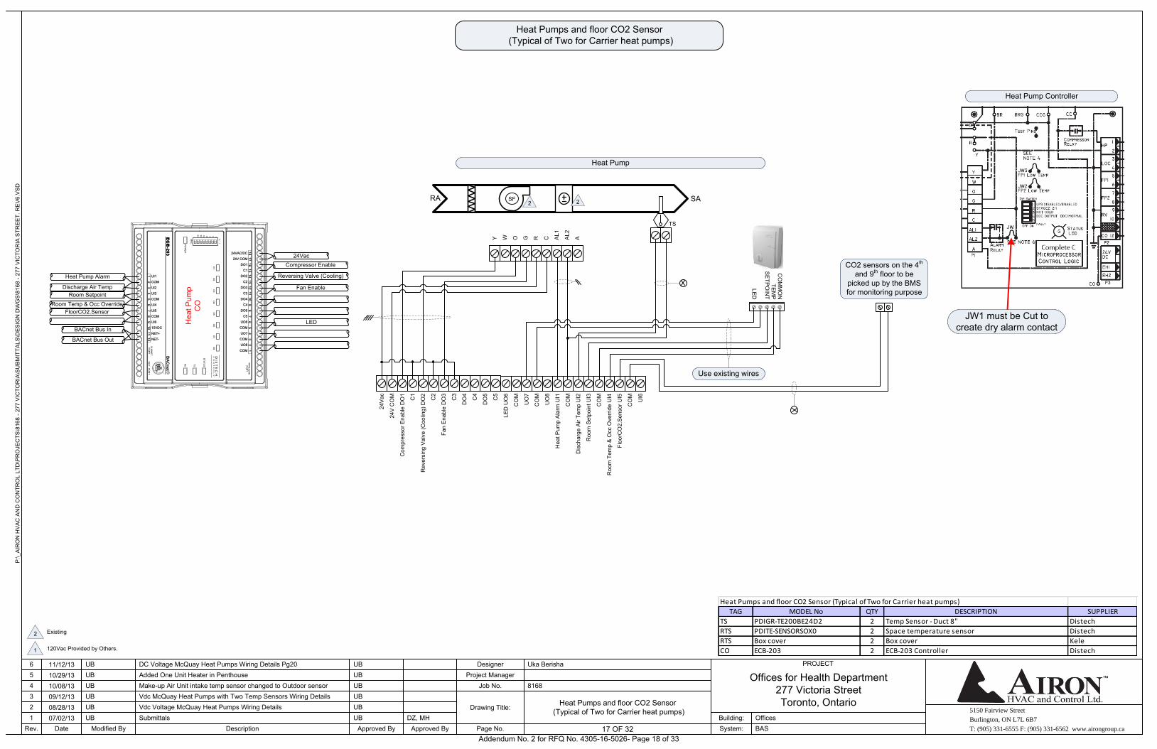
Heat Pumps and floor CO2 Sensor (Typical of Two for Carrier heat pumps)
Heat Pumps and floor CO2 Sensor (Typical of Two for Carrier heat pumps)
RA SA
TS
Heat Pump
Y W O G R
SF
C AL1
AL2
A
TEM
PC
OM
MO
N
SE
TPO
INT
LED
Heat Pump Controller
JW1 must be Cut to create dry alarm contact
Use existing wires
12
13
14
15
16
17
1824VAC/DC
24V COM
67
89
10
11
12
34
5
DO1
DO2
C2
C1
DO3
DO4
C4
C3
DO5
UO6
COM
C5
UO7
UO8
COM
COM
76
54
32
1
UI1
COM
12
11
10
98
UI2
COM
UI4
UI3
UI5
UI6
15VDC
COM
NET+
NET-
Hea
t Pum
pC
O
24Vac
Heat Pump Alarm
Room Setpoint
Discharge Air Temp
FloorCO2.Sensor
Room Temp & Occ Override
Compressor Enable
Fan Enable
Reversing Valve (Cooling)
LED
BACnet Bus In
BACnet Bus Out
CO2 sensors on the 4th and 9th floor to be
picked up by the BMS for monitoring purpose
Existing 2
120Vac Provided by Others.1
2 2
Heat Pumps and floor CO2 Sensor (Typical of Two for Carrier heat pumps)
TAG MODEL No QTY DESCRIPTION SUPPLIER
TS PDIGR-TE200BE24D2 2 Temp Sensor - Duct 8" Distech
RTS PDITE-SENSORSOX0 2 Space temperature sensor Distech
RTS Box cover 2 Box cover Kele
CO ECB-203 2 ECB-203 Controller Distech
24V
CO
M
24V
ac
Addendum No. 2 for RFQ No. 4305-16-5026- Page 18 of 33
5150 Fairview Street
Burlington, ON L7L 6B7
T: (905) 331-6555 F: (905) 331-6562 www.airongroup.ca
Offices for Health Department277 Victoria StreetToronto, Ontario
P:\_
AIR
ON
HV
AC
AN
D C
ON
TRO
L LT
D\P
RO
JEC
TS\8
168
- 277
VIC
TOR
IA\S
UB
MIT
TALS
\DE
SIG
N D
WG
S\8
168
- 277
VIC
TOR
IA S
TRE
ET.
RE
V6.
VS
D
Rev. 18 of x
PROJECT
1234
Date
56
07/02/1308/28/1309/12/1310/08/1310/29/1311/12/13
Modified By
UB
UBUB
UBUB
UB
DescriptionSubmittals
Added One Unit Heater in Penthouse
Approved By
DC Voltage McQuay Heat Pumps Wiring Details Pg20
Make-up Air Unit intake temp sensor changed to Outdoor sensorVdc McQuay Heat Pumps with Two Temp Sensors Wiring DetailsVdc Voltage McQuay Heat Pumps Wiring Details
UB
UB
UB
UB
UB
UB
Approved ByDZ, MH
Page No.
Drawing Title:
Job No.Project Manager
Designer
8168
Uka Berisha
System:Building:
BASOffices
18 OF 32
CO
M
Roo
m S
etpo
int U
I3
Dis
char
ge A
ir Te
mp
UI2
CO
M
Hea
t Pum
p A
larm
UI1
Fan
Ena
ble
DO
3
C2
Rev
ersi
ng V
alve
(Coo
ling)
DO
2
C1
Com
pres
sor E
nabl
e D
O1
Roo
m T
emp
& O
cc O
verr
ide
UI6
CO
M
Roo
m S
etpo
int U
I5
Roo
m T
emp
& O
cc O
verr
ide
UI4C5
DO
5
C4
DO
4
C3
UO
8
CO
M
LED
UO
7
CO
M
LED
UO
6
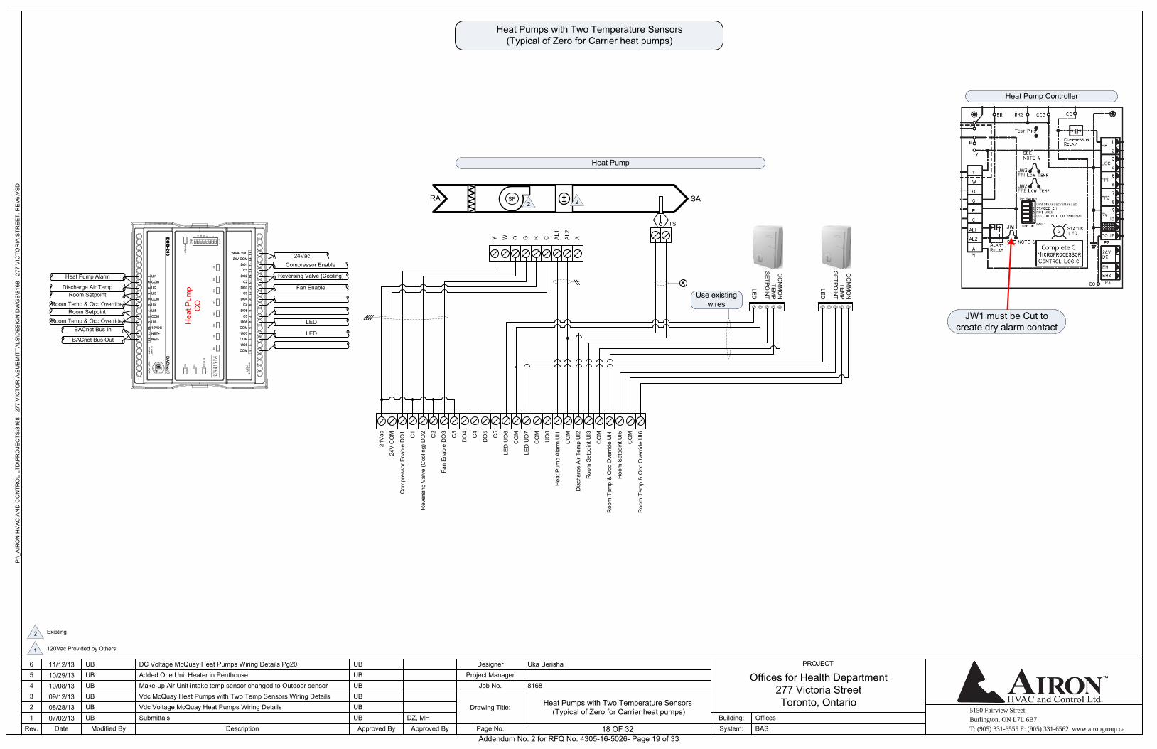
Heat Pumps with Two Temperature Sensors (Typical of Zero for Carrier heat pumps)
Heat Pumps with Two Temperature Sensors (Typical of Zero for Carrier heat pumps)
RA SA
TS
Heat Pump
Y W O G R
SF
C AL1
AL2
A
TEM
PC
OM
MO
N
SE
TPO
INT
LED
Heat Pump Controller
JW1 must be Cut to create dry alarm contact
Use existing wires
12
13
14
15
16
17
1824VAC/DC
24V COM
67
89
10
11
12
34
5
DO1
DO2
C2
C1
DO3
DO4
C4
C3
DO5
UO6
COM
C5
UO7
UO8
COM
COM
76
54
32
1
UI1
COM
12
11
10
98
UI2
COM
UI4
UI3
UI5
UI6
15VDC
COM
NET+
NET-
Hea
t Pum
pC
O
24Vac
Heat Pump Alarm
Room Setpoint
Discharge Air Temp
Room Setpoint
Room Temp & Occ Override
Room Temp & Occ Override
Compressor Enable
Fan Enable
Reversing Valve (Cooling)
LED
LED
BACnet Bus In
BACnet Bus Out
TEM
PC
OM
MO
N
SE
TPO
INT
LED
Existing 2
120Vac Provided by Others.1
2 2
24V
CO
M
24V
ac
Addendum No. 2 for RFQ No. 4305-16-5026- Page 19 of 33
5150 Fairview Street
Burlington, ON L7L 6B7
T: (905) 331-6555 F: (905) 331-6562 www.airongroup.ca
Offices for Health Department277 Victoria StreetToronto, Ontario
P:\_
AIR
ON
HV
AC
AN
D C
ON
TRO
L LT
D\P
RO
JEC
TS\8
168
- 277
VIC
TOR
IA\S
UB
MIT
TALS
\DE
SIG
N D
WG
S\8
168
- 277
VIC
TOR
IA S
TRE
ET.
RE
V6.
VS
D
Rev. 19 of x
PROJECT
1234
Date
56
07/02/1308/28/1309/12/1310/08/1310/29/1311/12/13
Modified By
UB
UBUB
UBUB
UB
DescriptionSubmittals
Added One Unit Heater in Penthouse
Approved By
DC Voltage McQuay Heat Pumps Wiring Details Pg20
Make-up Air Unit intake temp sensor changed to Outdoor sensorVdc McQuay Heat Pumps with Two Temp Sensors Wiring DetailsVdc Voltage McQuay Heat Pumps Wiring Details
UB
UB
UB
UB
UB
UB
Approved ByDZ, MH
Page No.
Drawing Title:
Job No.Project Manager
Designer
8168
Uka Berisha
System:Building:
BASOffices
19 OF 32
CO
M
Roo
m S
etpo
int U
I3
Dis
char
ge A
ir Te
mp
UI2
CO
M
Hea
t Pum
p A
larm
(0=F
ault,
1=N
orm
al) U
I1
Fan
Ena
ble
DO
3
C2
Coo
ling
Ena
ble
DO
2
C1
Hea
ting
Ena
ble
DO
1
Roo
m T
emp
& O
cc O
verr
ide
UI6
CO
M
Roo
m S
etpo
int U
I5
Roo
m T
emp
& O
cc O
verr
ide
UI4C5
DO
5
C4
DO
4
C3
UO
8
CO
M
LED
UO
7
CO
M
LED
UO
6
Heat Pumps with Two Temperature Sensors (Typical of Zero for McQuay heat pumps)
Heat Pumps with Two Temperature Sensors (Typical of Zero for McQuay heat pumps)
RA SA
TS
Heat Pump AC control board
SF
TS
O W2
G W1
Y1 F E L U
TEM
PC
OM
MO
N
SE
TPO
INT
LED
A P V R C
30Vdc
Wired by Airon
Relay installed by Airon
12
13
14
15
16
17
1824VAC/DC
24V COM
67
89
10
11
12
34
5
DO1
DO2
C2
C1
DO3
DO4
C4
C3
DO5
UO6
COM
C5
UO7
UO8
COM
COM
76
54
32
1
UI1
COM
12
11
10
98
UI2
COM
UI4
UI3
UI5
UI6
15VDC
COM
NET+
NET-
Hea
t Pum
pC
O
24Vac
Heat Pump Alarm
Room Setpoint
Discharge Air Temp
Room Setpoint
Room Temp & Occ Override
Room Temp & Occ Override
HeatingEnable
FanEnable
CoolingEnable
LED
LED
BACnet Bus In
BACnet Bus Out
TEM
PC
OM
MO
N
SE
TPO
INT
LED
Existing 2
120Vac Provided by Others.1
2 2
24V
CO
M
24V
ac
RA SA
TS
Heat Pump DC control board
SF
TS
Y2
W2
G W1
Y1 R E L U
TEM
PC
OM
MO
N
SE
TPO
INT
LED
Use existing wires
S A C 6 3
30Vdc
Wired by Airon
Rel
ay in
stal
led
by A
iron
2 2
24Vac 24Vac 24Vac
Wired by Airon
Rel
ay in
stal
led
by A
iron
CO
M
Roo
m S
etpo
int U
I3
Dis
char
ge A
ir Te
mp
UI2
CO
M
Hea
t Pum
p A
larm
(0=F
ault,
1=N
orm
al) U
I1
Fan
Ena
ble
DO
3
C2
Coo
ling
Ena
ble
DO
2
C1
Hea
ting
Ena
ble
DO
1
Roo
m T
emp
& O
cc O
verr
ide
UI6
CO
M
Roo
m S
etpo
int U
I5
Roo
m T
emp
& O
cc O
verr
ide
UI4C5
DO
5
C4
DO
4
C3
UO
8
CO
M
LED
UO
7
CO
M
LED
UO
6
24V
CO
M
24V
ac
TEM
PC
OM
MO
N
SE
TPO
INT
LED
Use existing wires
Rev.3
Addendum No. 2 for RFQ No. 4305-16-5026- Page 20 of 33
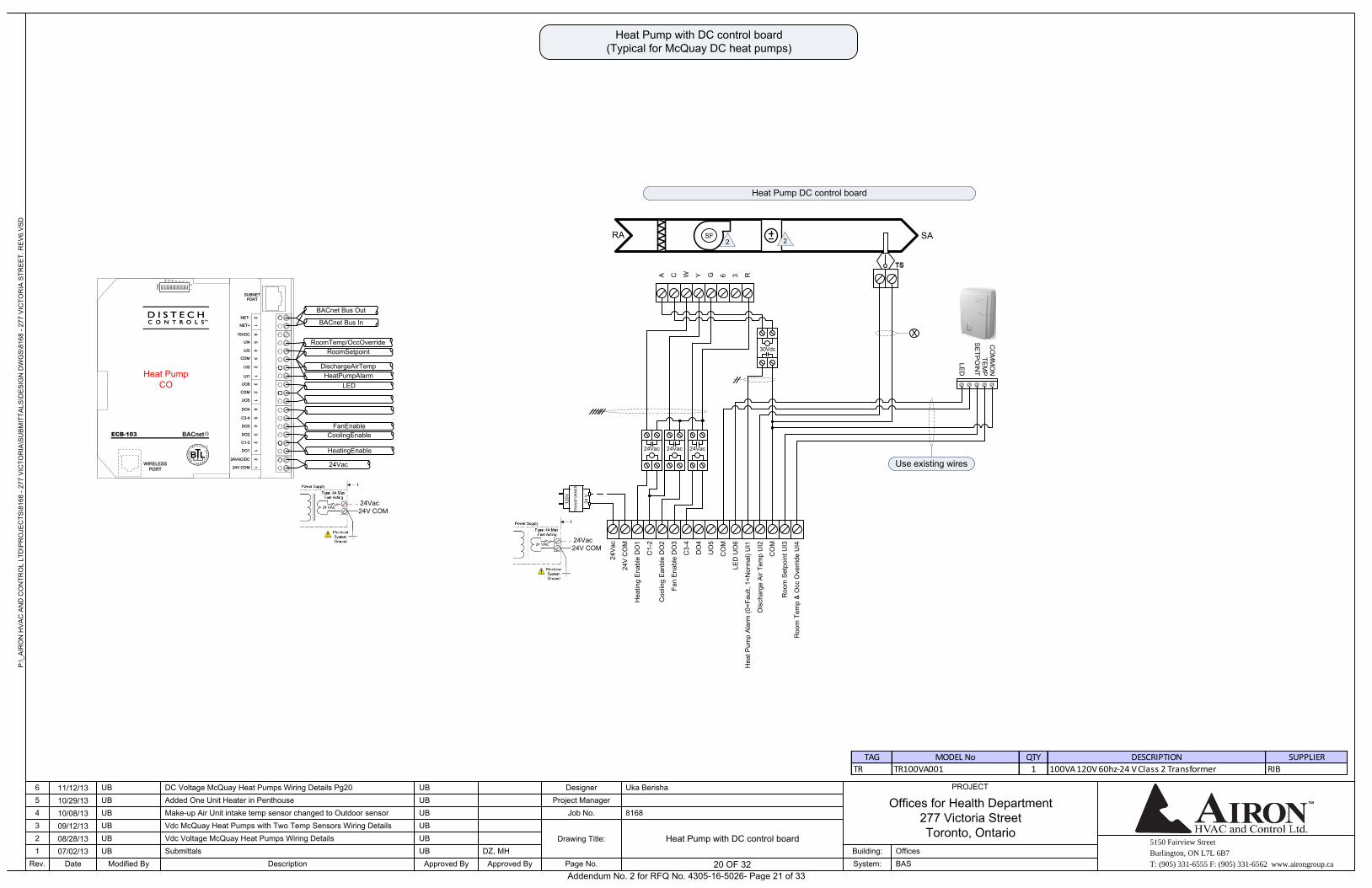
5150 Fairview Street
Burlington, ON L7L 6B7
T: (905) 331-6555 F: (905) 331-6562 www.airongroup.ca
Offices for Health Department277 Victoria StreetToronto, Ontario
P:\_
AIR
ON
HV
AC
AN
D C
ON
TRO
L LT
D\P
RO
JEC
TS\8
168
- 277
VIC
TOR
IA\S
UB
MIT
TALS
\DE
SIG
N D
WG
S\8
168
- 277
VIC
TOR
IA S
TRE
ET.
RE
V6.
VS
D
Rev. 20 of x
PROJECT
1234
Date
56
07/02/1308/28/1309/12/1310/08/1310/29/1311/12/13
Modified By
UB
UBUB
UBUB
UB
DescriptionSubmittals
Added One Unit Heater in Penthouse
Approved By
DC Voltage McQuay Heat Pumps Wiring Details Pg20
Make-up Air Unit intake temp sensor changed to Outdoor sensorVdc McQuay Heat Pumps with Two Temp Sensors Wiring DetailsVdc Voltage McQuay Heat Pumps Wiring Details
UB
UB
UB
UB
UB
UB
Approved ByDZ, MH
Page No.
Drawing Title:
Job No.Project Manager
Designer
8168
Uka Berisha
System:Building:
BASOffices
20 OF 32
Heat Pump with DC control board
Heat Pump with DC control board (Typical for McQuay DC heat pumps)
RA SA
TS
Heat Pump DC control board
SF
TS
A C W Y G 6 3 RH
eat P
ump
Ala
rm (0
=Fau
lt, 1
=Nor
mal
) UI1
LED
UO
6
CO
M
UO
5
DO
4
C3-
4
Fan
Ena
ble
DO
3
Coo
ling
Ean
ble
DO
2
C1-
2
Hea
ting
Ena
ble
DO
1
Roo
m T
emp
& O
cc O
verr
ide
UI4
Roo
m S
etpo
int U
I3
CO
M
Dis
char
ge A
ir Te
mp
UI2
TEM
PC
OM
MO
N
SE
TPO
INT
LED
Use existing wires
30Vdc
2 2
24V
CO
M
24V
ac
24Vac 24Vac 24Vac
TRA
NS
FOR
ME
R
24 V
120V
24Vac24V COM
ECB-103
34
56
12
56
12
31
21
21
23
4
NET+
15VDC
NET-
UI4
COM
UI2
UI3
UI1
COM
UO5
UO6
DO4
DO3
DO2
C3-4
C1-2
24VAC/DC
24V COM
DO1
SUBNET
PORT
WIRELESS
PORT
BACnet Bus In
BACnet Bus Out
RoomTemp/OccOverride
DischargeAirTemp
RoomSetpoint
HeatPumpAlarm
LED
CoolingEnable
FanEnable
HeatingEnable
24Vac
Heat PumpCO
24Vac24V COM
TAG MODEL No QTY DESCRIPTION SUPPLIER
TR TR100VA001 1 100VA 120V 60hz-24 V Class 2 Transformer RIB
Addendum No. 2 for RFQ No. 4305-16-5026- Page 21 of 33
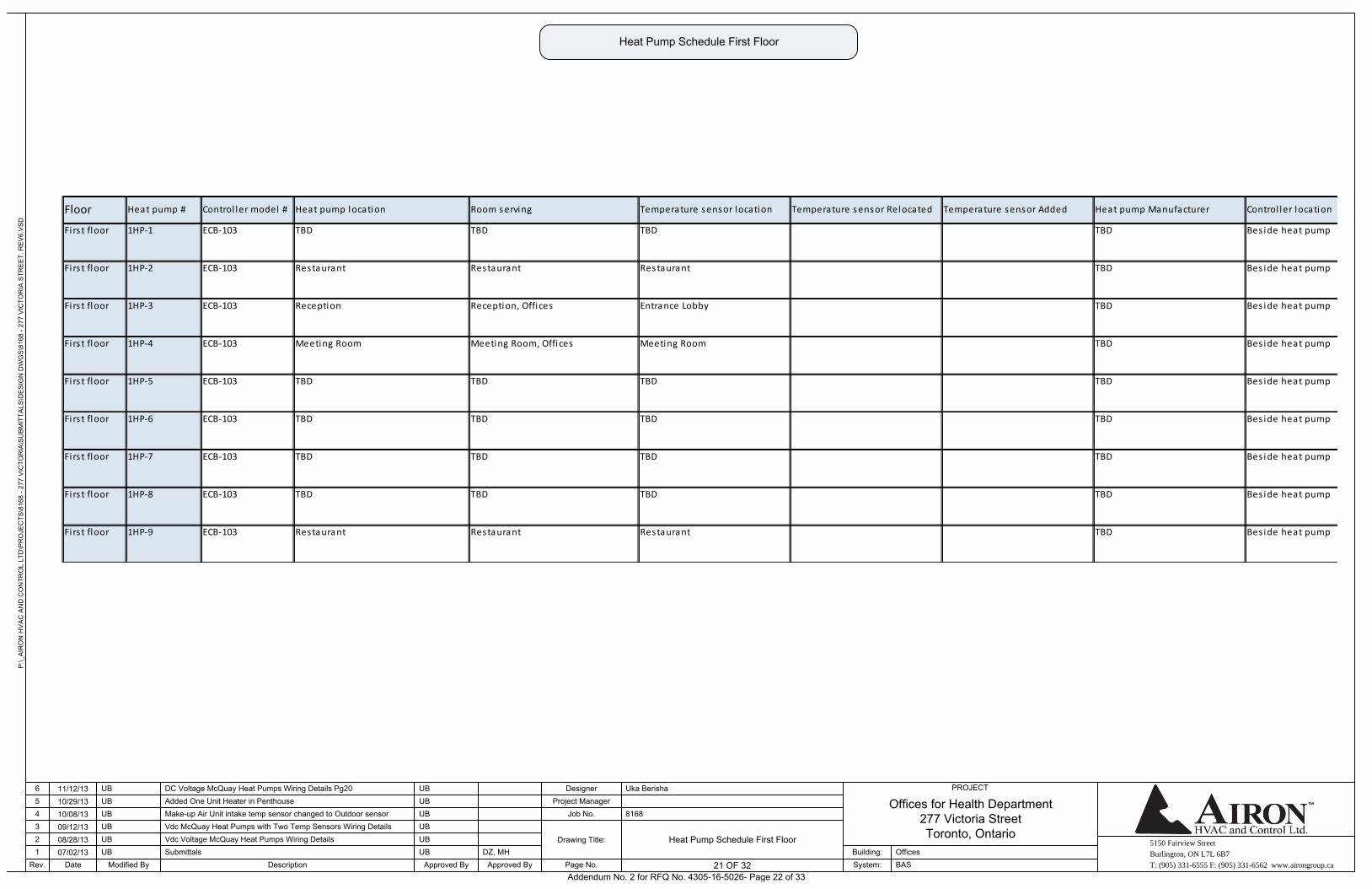
5150 Fairview Street
Burlington, ON L7L 6B7
T: (905) 331-6555 F: (905) 331-6562 www.airongroup.ca
Offices for Health Department277 Victoria StreetToronto, Ontario
P:\_
AIR
ON
HV
AC
AN
D C
ON
TRO
L LT
D\P
RO
JEC
TS\8
168
- 277
VIC
TOR
IA\S
UB
MIT
TALS
\DE
SIG
N D
WG
S\8
168
- 277
VIC
TOR
IA S
TRE
ET.
RE
V6.
VS
D
Rev. 21 of x
PROJECT
1234
Date
56
07/02/1308/28/1309/12/1310/08/1310/29/1311/12/13
Modified By
UB
UBUB
UBUB
UB
DescriptionSubmittals
Added One Unit Heater in Penthouse
Approved By
DC Voltage McQuay Heat Pumps Wiring Details Pg20
Make-up Air Unit intake temp sensor changed to Outdoor sensorVdc McQuay Heat Pumps with Two Temp Sensors Wiring DetailsVdc Voltage McQuay Heat Pumps Wiring Details
UB
UB
UB
UB
UB
UB
Approved ByDZ, MH
Page No.
Drawing Title:
Job No.Project Manager
Designer
8168
Uka Berisha
System:Building:
BASOffices
21 OF 32
Heat Pump Schedule First Floor
Heat Pump Schedule First Floor
TBD
Firs t floor 1HP-3 ECB-103 Reception Reception, Offices Entrance Lobby
TBD TBD
Firs t floor 1HP-2 ECB-103 Restaurant Restaurant Restaurant
Firs t floor 1HP-1 ECB-103 TBD TBD
TBD
TBD
Firs t floor 1HP-7 ECB-103 TBD TBD TBD
Firs t floor 1HP-6 ECB-103 TBD TBD TBD
TBD
Firs t floor 1HP-5 ECB-103 TBD TBD TBD TBD
Firs t floor 1HP-4 ECB-103 Meeting Room Meeting Room, Offices Meeting Room
TBD
Firs t floor 1HP-9 ECB-103 Restaurant Restaurant Restaurant TBD
TBD
Firs t floor 1HP-8 ECB-103 TBD TBD TBD
Bes ide heat pump
Bes ide heat pump
Bes ide heat pump
Bes ide heat pump
Bes ide heat pump
Bes ide heat pump
Bes ide heat pump
Bes ide heat pump
Bes ide heat pump
Floor Heat pump # Control ler model # Heat pump location Room serving Temperature sensor Relocated Temperature sensor Added Heat pump Manufacturer Control ler locationTemperature sensor location
Addendum No. 2 for RFQ No. 4305-16-5026- Page 22 of 33
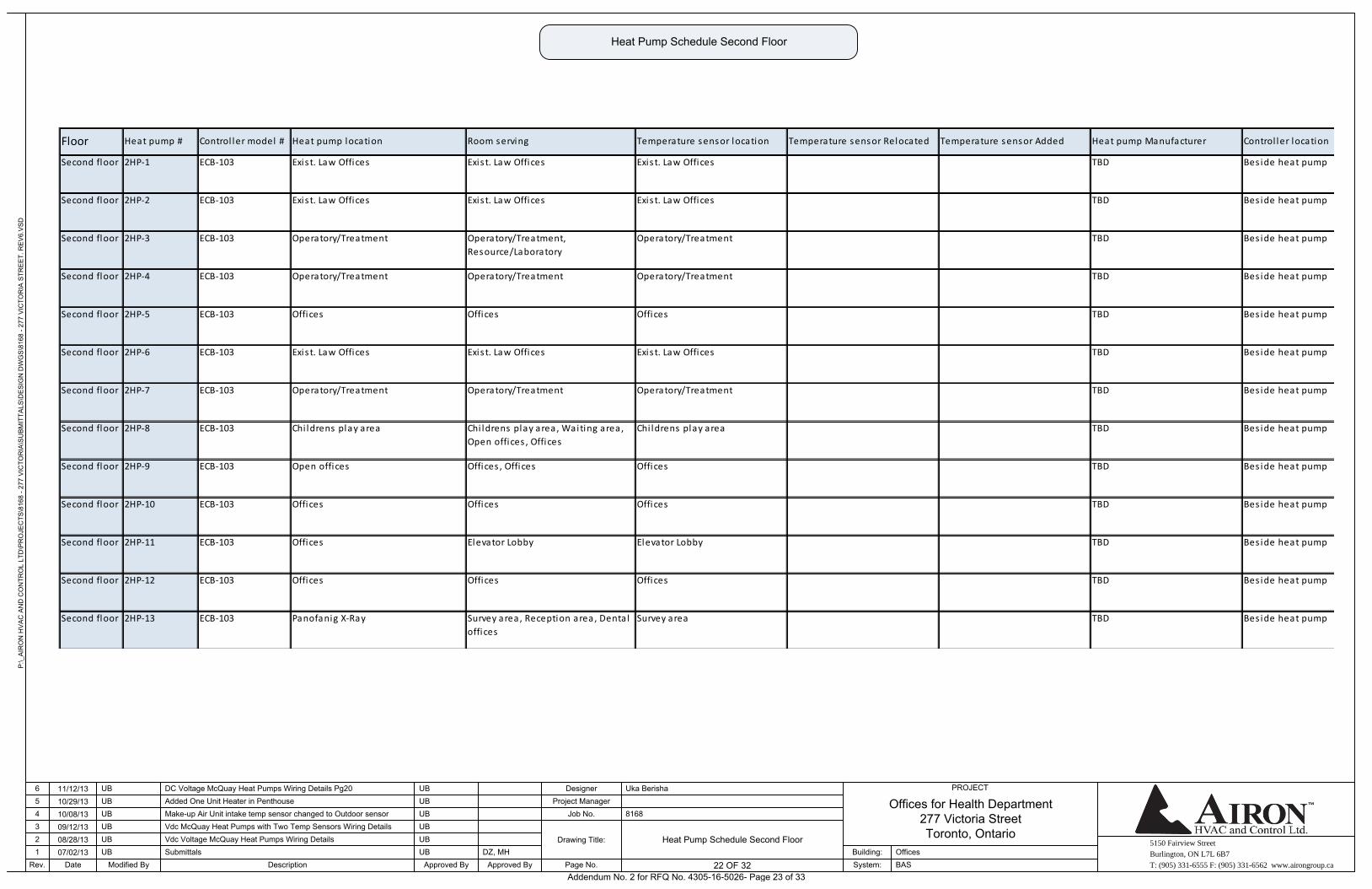
5150 Fairview Street
Burlington, ON L7L 6B7
T: (905) 331-6555 F: (905) 331-6562 www.airongroup.ca
Offices for Health Department277 Victoria StreetToronto, Ontario
P:\_
AIR
ON
HV
AC
AN
D C
ON
TRO
L LT
D\P
RO
JEC
TS\8
168
- 277
VIC
TOR
IA\S
UB
MIT
TALS
\DE
SIG
N D
WG
S\8
168
- 277
VIC
TOR
IA S
TRE
ET.
RE
V6.
VS
D
Rev. 22 of x
PROJECT
1234
Date
56
07/02/1308/28/1309/12/1310/08/1310/29/1311/12/13
Modified By
UB
UBUB
UBUB
UB
DescriptionSubmittals
Added One Unit Heater in Penthouse
Approved By
DC Voltage McQuay Heat Pumps Wiring Details Pg20
Make-up Air Unit intake temp sensor changed to Outdoor sensorVdc McQuay Heat Pumps with Two Temp Sensors Wiring DetailsVdc Voltage McQuay Heat Pumps Wiring Details
UB
UB
UB
UB
UB
UB
Approved ByDZ, MH
Page No.
Drawing Title:
Job No.Project Manager
Designer
8168
Uka Berisha
System:Building:
BASOffices
22 OF 32
Heat Pump Schedule Second Floor
Heat Pump Schedule Second Floor
Bes ide heat pump
Bes ide heat pump
Bes ide heat pump
Bes ide heat pump
Bes ide heat pump
Bes ide heat pump
Bes ide heat pump
Bes ide heat pump
Bes ide heat pump
Bes ide heat pump
Bes ide heat pump
Bes ide heat pump
Bes ide heat pump
TBDSecond floor 2HP-13 ECB-103 Panofanig X-Ray Survey area, Reception area, Dental
offices
Survey area
TBD
Second floor 2HP-12 ECB-103 Offices Offices Offices TBD
TBD
Second floor 2HP-11 ECB-103 Offices Elevator Lobby Elevator Lobby
TBD
Second floor 2HP-10 ECB-103 Offices Offices Offices
Second floor 2HP-9 ECB-103 Open offices Offices , Offices Offices
TBD
Second floor 2HP-8 ECB-103 Chi ldrens play area Chi ldrens play area, Waiting area,
Open offices , Offices
Chi ldrens play area TBD
TBD
Second floor 2HP-7 ECB-103 Operatory/Treatment Operatory/Treatment Operatory/Treatment
Second floor 2HP-6 ECB-103 Exis t. Law Offices Exis t. Law Offices Exis t. Law Offices
Heat pump Manufacturer
Second floor 2HP-5 ECB-103 Offices Offices Offices
TBD
Second floor 2HP-4 ECB-103 Operatory/Treatment Operatory/Treatment Operatory/Treatment TBD
TBD
Second floor 2HP-2 ECB-103 Exis t. Law Offices Exis t. Law Offices Exis t. Law Offices
Second floor 2HP-1 ECB-103 Exis t. Law Offices Exis t. Law Offices Exis t. Law Offices
Control ler location
TBD
Second floor 2HP-3 ECB-103 Operatory/Treatment Operatory/Treatment,
Resource/Laboratory
Operatory/Treatment
TBD
Floor Heat pump # Control ler model # Heat pump location Room serving Temperature sensor location Temperature sensor Relocated Temperature sensor Added
Addendum No. 2 for RFQ No. 4305-16-5026- Page 23 of 33
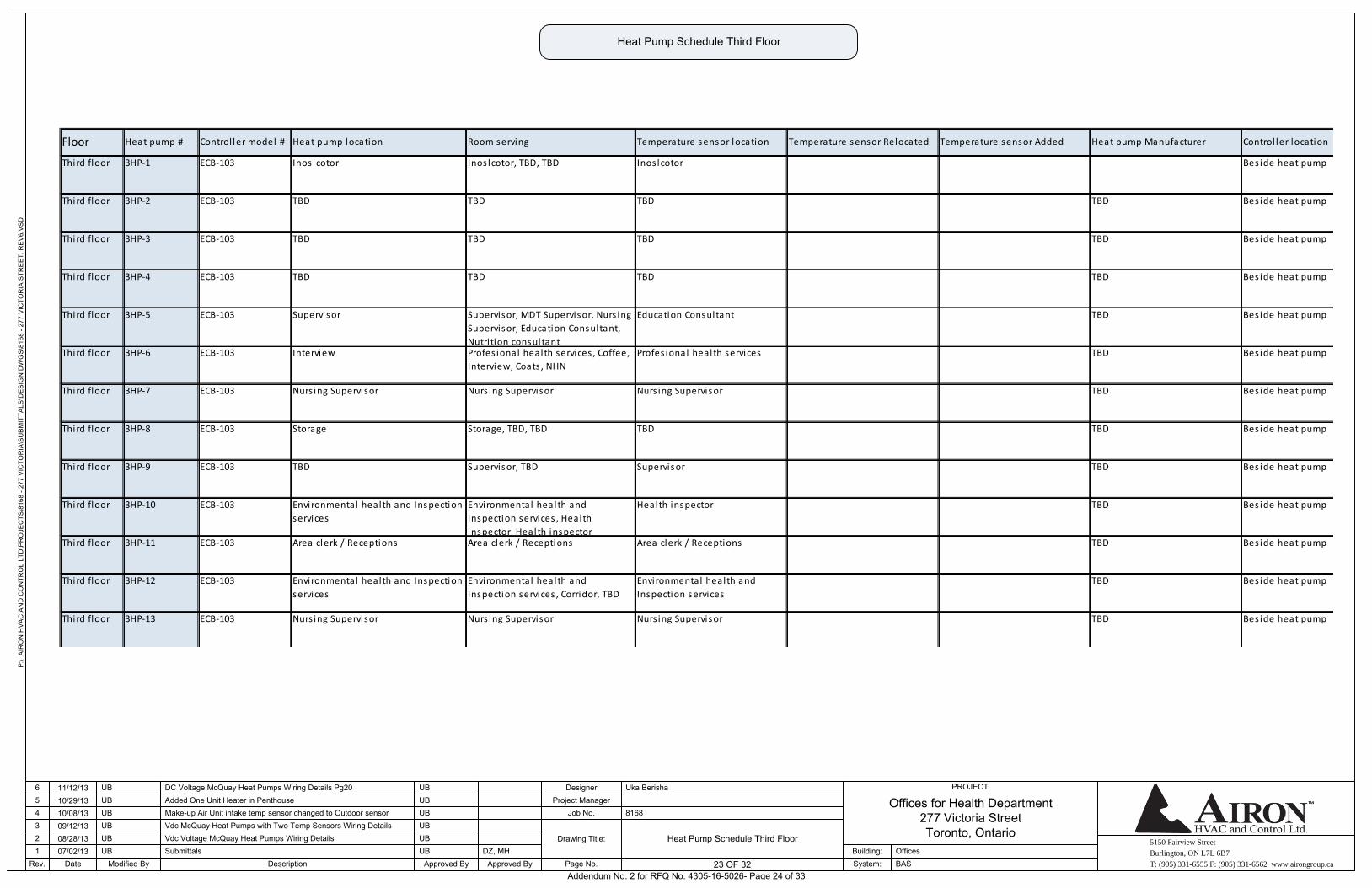
5150 Fairview Street
Burlington, ON L7L 6B7
T: (905) 331-6555 F: (905) 331-6562 www.airongroup.ca
Offices for Health Department277 Victoria StreetToronto, Ontario
P:\_
AIR
ON
HV
AC
AN
D C
ON
TRO
L LT
D\P
RO
JEC
TS\8
168
- 277
VIC
TOR
IA\S
UB
MIT
TALS
\DE
SIG
N D
WG
S\8
168
- 277
VIC
TOR
IA S
TRE
ET.
RE
V6.
VS
D
Rev. 23 of x
PROJECT
1234
Date
56
07/02/1308/28/1309/12/1310/08/1310/29/1311/12/13
Modified By
UB
UBUB
UBUB
UB
DescriptionSubmittals
Added One Unit Heater in Penthouse
Approved By
DC Voltage McQuay Heat Pumps Wiring Details Pg20
Make-up Air Unit intake temp sensor changed to Outdoor sensorVdc McQuay Heat Pumps with Two Temp Sensors Wiring DetailsVdc Voltage McQuay Heat Pumps Wiring Details
UB
UB
UB
UB
UB
UB
Approved ByDZ, MH
Page No.
Drawing Title:
Job No.Project Manager
Designer
8168
Uka Berisha
System:Building:
BASOffices
23 OF 32
Heat Pump Schedule Third Floor
Heat Pump Schedule Third Floor
Floor Heat pump # Control ler model # Heat pump location Room serving Temperature sensor location Temperature sensor Relocated Temperature sensor Added Heat pump Manufacturer Control ler location
Third floor 3HP-1 ECB-103 Inos lcotor Inos lcotor, TBD, TBD Inos lcotor
TBD
Third floor 3HP-3 ECB-103 TBD TBD TBD TBD
Third floor 3HP-2 ECB-103 TBD TBD TBD
TBD
Third floor 3HP-6 ECB-103 Interview Profes ional health services , Coffee,
Interview, Coats , NHN
Profes ional health services
TBD
Third floor 3HP-5 ECB-103 Supervisor Supervisor, MDT Supervisor, Nurs ing
Supervisor, Education Consultant,
Nutri tion consultant
Education Consultant
Third floor 3HP-4 ECB-103 TBD TBD TBD
TBD
Third floor 3HP-9 ECB-103 TBD Supervisor, TBD Supervisor
Third floor 3HP-8 ECB-103 Storage Storage, TBD, TBD TBD
TBD
Third floor 3HP-7 ECB-103 Nurs ing Supervisor Nurs ing Supervisor Nurs ing Supervisor TBD
TBD
Third floor 3HP-11 ECB-103 Area clerk / Receptions Area clerk / Receptions Area clerk / Receptions TBD
TBD
Third floor 3HP-10 ECB-103 Environmental health and Inspection
services
Environmental health and
Inspection services , Health
inspector, Health inspector
Health inspector
TBD
Third floor 3HP-13 ECB-103 Nurs ing Supervisor Nurs ing Supervisor Nurs ing Supervisor
Third floor 3HP-12 ECB-103 Environmental health and Inspection
services
Environmental health and
Inspection services , Corridor, TBD
Environmental health and
Inspection services
TBD
Bes ide heat pump
Bes ide heat pump
Bes ide heat pump
Bes ide heat pump
Bes ide heat pump
Bes ide heat pump
Bes ide heat pump
Bes ide heat pump
Bes ide heat pump
Bes ide heat pump
Bes ide heat pump
Bes ide heat pump
Bes ide heat pump
Addendum No. 2 for RFQ No. 4305-16-5026- Page 24 of 33
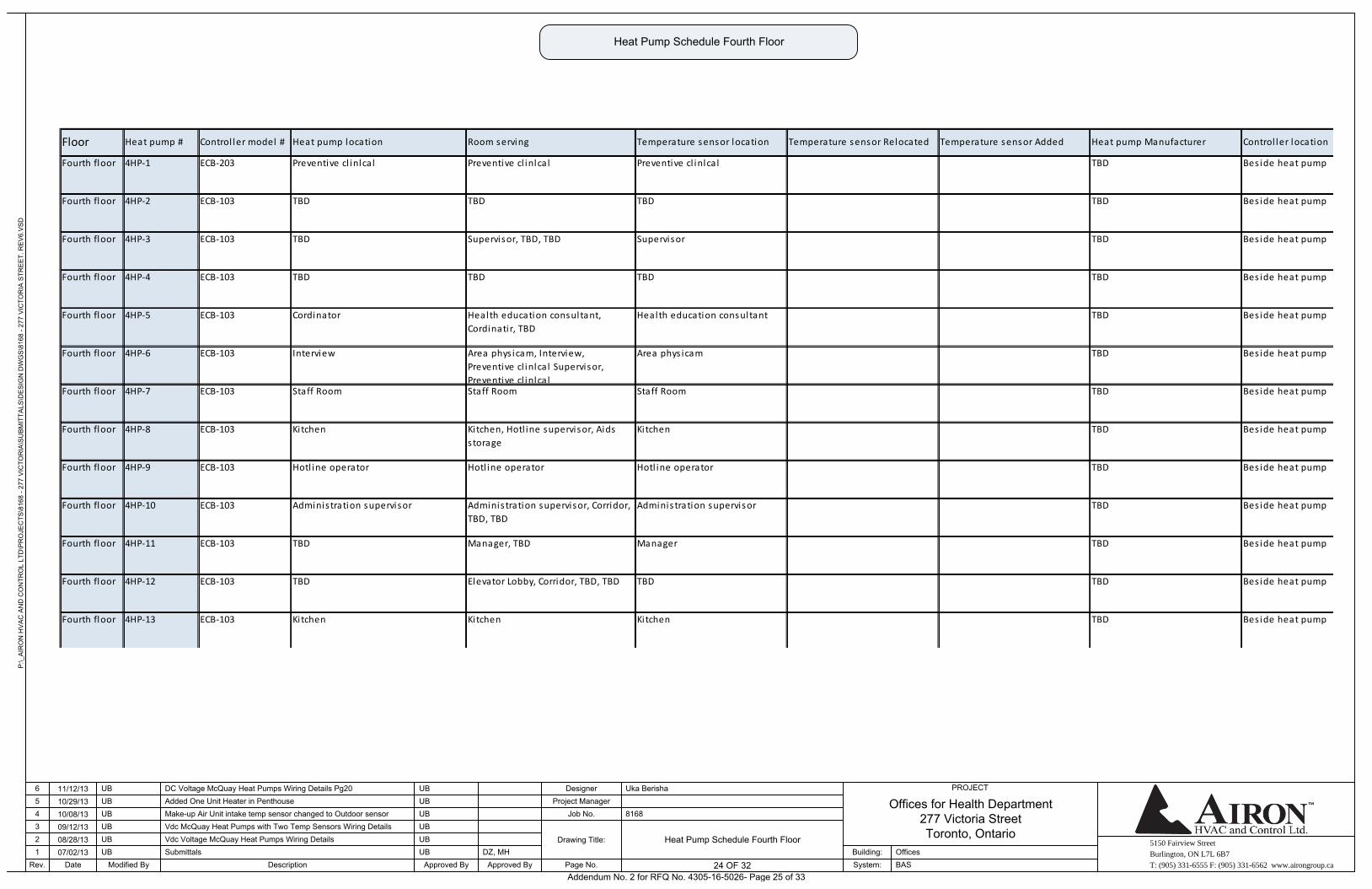
5150 Fairview Street
Burlington, ON L7L 6B7
T: (905) 331-6555 F: (905) 331-6562 www.airongroup.ca
Offices for Health Department277 Victoria StreetToronto, Ontario
P:\_
AIR
ON
HV
AC
AN
D C
ON
TRO
L LT
D\P
RO
JEC
TS\8
168
- 277
VIC
TOR
IA\S
UB
MIT
TALS
\DE
SIG
N D
WG
S\8
168
- 277
VIC
TOR
IA S
TRE
ET.
RE
V6.
VS
D
Rev. 24 of x
PROJECT
1234
Date
56
07/02/1308/28/1309/12/1310/08/1310/29/1311/12/13
Modified By
UB
UBUB
UBUB
UB
DescriptionSubmittals
Added One Unit Heater in Penthouse
Approved By
DC Voltage McQuay Heat Pumps Wiring Details Pg20
Make-up Air Unit intake temp sensor changed to Outdoor sensorVdc McQuay Heat Pumps with Two Temp Sensors Wiring DetailsVdc Voltage McQuay Heat Pumps Wiring Details
UB
UB
UB
UB
UB
UB
Approved ByDZ, MH
Page No.
Drawing Title:
Job No.Project Manager
Designer
8168
Uka Berisha
System:Building:
BASOffices
24 OF 32
Heat Pump Schedule Fourth Floor
Heat Pump Schedule Fourth Floor
Temperature sensor Relocated Temperature sensor Added Heat pump Manufacturer Control ler location
TBD
Fourth floor 4HP-4 ECB-103
Floor Heat pump # Control ler model # Heat pump location Room serving Temperature sensor location
Fourth floor 4HP-3 ECB-103 TBD Supervisor, TBD, TBD Supervisor
TBD
Fourth floor 4HP-2 ECB-103 TBD TBD TBD TBD
Fourth floor 4HP-1 ECB-203 Preventive cl inlcal Preventive cl inlcal Preventive cl inlcal
TBD
Fourth floor 4HP-6 ECB-103 Interview Area phys icam, Interview,
Preventive cl inlcal Supervisor,
Preventive cl inlcal
Area phys icam TBD
TBD
Fourth floor 4HP-5 ECB-103 Cordinator Health education consultant,
Cordinatir, TBD
Health education consultant
TBD TBD TBD
TBD
Fourth floor 4HP-9 ECB-103 Hotl ine operator Hotl ine operator Hotl ine operator
TBD
Fourth floor 4HP-8 ECB-103 Kitchen Kitchen, Hotl ine supervisor, Aids
s torage
Kitchen
Fourth floor 4HP-7 ECB-103 Staff Room Staff Room Staff Room
TBD
Fourth floor 4HP-12 ECB-103 TBD Elevator Lobby, Corridor, TBD, TBD TBD
Fourth floor 4HP-11 ECB-103 TBD Manager, TBD Manager
TBD
Fourth floor 4HP-10 ECB-103 Administration supervisor Administration supervisor, Corridor,
TBD, TBD
Administration supervisor TBD
TBD
TBD
Fourth floor 4HP-13 ECB-103 Kitchen Kitchen Kitchen
Bes ide heat pump
Bes ide heat pump
Bes ide heat pump
Bes ide heat pump
Bes ide heat pump
Bes ide heat pump
Bes ide heat pump
Bes ide heat pump
Bes ide heat pump
Bes ide heat pump
Bes ide heat pump
Bes ide heat pump
Bes ide heat pump
Addendum No. 2 for RFQ No. 4305-16-5026- Page 25 of 33
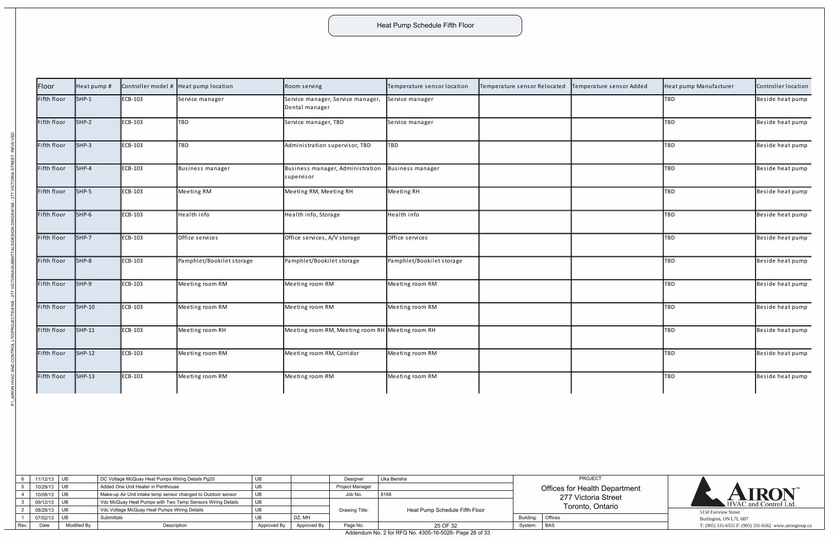
5150 Fairview Street
Burlington, ON L7L 6B7
T: (905) 331-6555 F: (905) 331-6562 www.airongroup.ca
Offices for Health Department277 Victoria StreetToronto, Ontario
P:\_
AIR
ON
HV
AC
AN
D C
ON
TRO
L LT
D\P
RO
JEC
TS\8
168
- 277
VIC
TOR
IA\S
UB
MIT
TALS
\DE
SIG
N D
WG
S\8
168
- 277
VIC
TOR
IA S
TRE
ET.
RE
V6.
VS
D
Rev. 25 of x
PROJECT
1234
Date
56
07/02/1308/28/1309/12/1310/08/1310/29/1311/12/13
Modified By
UB
UBUB
UBUB
UB
DescriptionSubmittals
Added One Unit Heater in Penthouse
Approved By
DC Voltage McQuay Heat Pumps Wiring Details Pg20
Make-up Air Unit intake temp sensor changed to Outdoor sensorVdc McQuay Heat Pumps with Two Temp Sensors Wiring DetailsVdc Voltage McQuay Heat Pumps Wiring Details
UB
UB
UB
UB
UB
UB
Approved ByDZ, MH
Page No.
Drawing Title:
Job No.Project Manager
Designer
8168
Uka Berisha
System:Building:
BASOffices
25 OF 32
Heat Pump Schedule Fifth Floor
Heat Pump Schedule Fifth Floor
Floor Heat pump # Control ler model # Heat pump location Room serving Temperature sensor location Temperature sensor Relocated Temperature sensor Added Heat pump Manufacturer Control ler location
Fi fth floor 5HP-1 ECB-103 Service manager Service manager, Service manager,
Dental manager
Service manager TBD
TBD
Fifth floor 5HP-4 ECB-103 Bus iness manager Bus iness manager, Administration
supervisor
Bus iness manager
TBD
Fifth floor 5HP-3 ECB-103 TBD Administration supervisor, TBD TBD
Fifth floor 5HP-2 ECB-103 TBD Service manager, TBD Service manager
TBD
Fifth floor 5HP-7 ECB-103 Office services Office services , A/V storage Office services
Fi fth floor 5HP-6 ECB-103 Health info Health info, Storage Health info
TBD
Fifth floor 5HP-5 ECB-103 Meeting RM Meeting RM, Meeting RH Meeting RH TBD
TBD
Fifth floor 5HP-9 ECB-103 Meeting room RM Meeting room RM Meeting room RM TBD
TBD
Fifth floor 5HP-8 ECB-103 Pamphlet/Booki let s torage Pamphlet/Booki let s torage Pamphlet/Booki let s torage
TBD
Fifth floor 5HP-12 ECB-103 Meeting room RM Meeting room RM, Corridor Meeting room RM
TBD
Fifth floor 5HP-11 ECB-103 Meeting room RH Meeting room RM, Meeting room RH Meeting room RH
Fifth floor 5HP-10 ECB-103 Meeting room RM Meeting room RM Meeting room RM
TBD
Fifth floor 5HP-13 ECB-103 Meeting room RM Meeting room RM Meeting room RM TBD
Bes ide heat pump
Bes ide heat pump
Bes ide heat pump
Bes ide heat pump
Bes ide heat pump
Bes ide heat pump
Bes ide heat pump
Bes ide heat pump
Bes ide heat pump
Bes ide heat pump
Bes ide heat pump
Bes ide heat pump
Bes ide heat pump
Addendum No. 2 for RFQ No. 4305-16-5026- Page 26 of 33
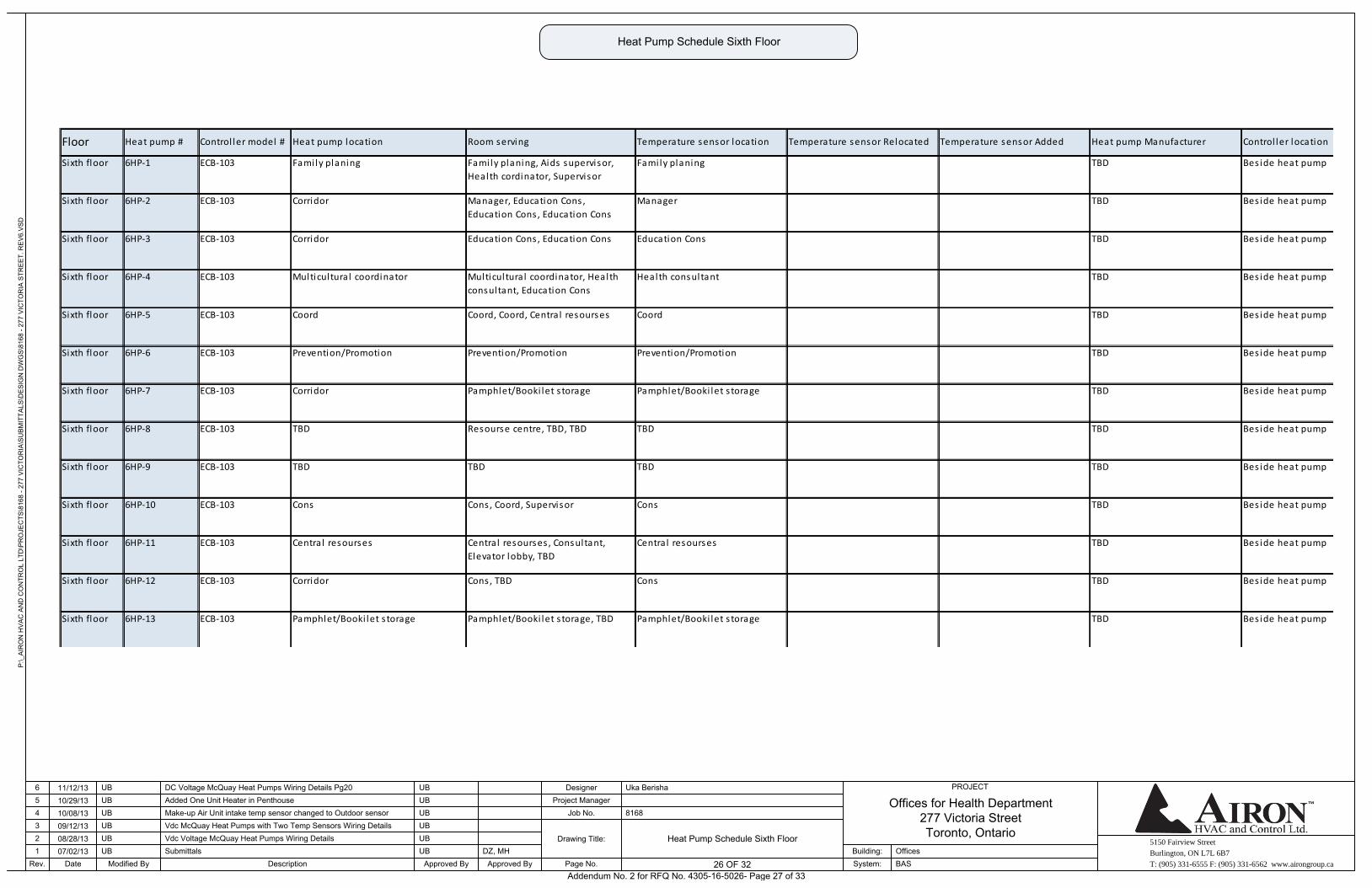
5150 Fairview Street
Burlington, ON L7L 6B7
T: (905) 331-6555 F: (905) 331-6562 www.airongroup.ca
Offices for Health Department277 Victoria StreetToronto, Ontario
P:\_
AIR
ON
HV
AC
AN
D C
ON
TRO
L LT
D\P
RO
JEC
TS\8
168
- 277
VIC
TOR
IA\S
UB
MIT
TALS
\DE
SIG
N D
WG
S\8
168
- 277
VIC
TOR
IA S
TRE
ET.
RE
V6.
VS
D
Rev. 26 of x
PROJECT
1234
Date
56
07/02/1308/28/1309/12/1310/08/1310/29/1311/12/13
Modified By
UB
UBUB
UBUB
UB
DescriptionSubmittals
Added One Unit Heater in Penthouse
Approved By
DC Voltage McQuay Heat Pumps Wiring Details Pg20
Make-up Air Unit intake temp sensor changed to Outdoor sensorVdc McQuay Heat Pumps with Two Temp Sensors Wiring DetailsVdc Voltage McQuay Heat Pumps Wiring Details
UB
UB
UB
UB
UB
UB
Approved ByDZ, MH
Page No.
Drawing Title:
Job No.Project Manager
Designer
8168
Uka Berisha
System:Building:
BASOffices
26 OF 32
Heat Pump Schedule Sixth Floor
Heat Pump Schedule Sixth Floor
Bes ide heat pump
Bes ide heat pump
Bes ide heat pump
Bes ide heat pump
Bes ide heat pump
Bes ide heat pump
Bes ide heat pump
Bes ide heat pump
Bes ide heat pump
Bes ide heat pump
Bes ide heat pump
Bes ide heat pump
Bes ide heat pump
TBDSixth floor 6HP-13 ECB-103 Pamphlet/Booki let s torage Pamphlet/Booki let s torage, TBD Pamphlet/Booki let s torage
TBD
Sixth floor 6HP-12 ECB-103 Corridor Cons, TBD Cons TBD
TBD
Sixth floor 6HP-11 ECB-103 Central resourses Central resourses , Consultant,
Elevator lobby, TBD
Central resourses
TBD
Sixth floor 6HP-10 ECB-103 Cons Cons, Coord, Supervisor Cons
Sixth floor 6HP-9 ECB-103 TBD TBD TBD
TBD
Sixth floor 6HP-8 ECB-103 TBD Resourse centre, TBD, TBD TBD TBD
TBD
Sixth floor 6HP-7 ECB-103 Corridor Pamphlet/Booki let s torage Pamphlet/Booki let s torage
TBD
Sixth floor 6HP-6 ECB-103 Prevention/Promotion Prevention/Promotion Prevention/Promotion
Sixth floor 6HP-5 ECB-103 Coord Coord, Coord, Central resourses Coord
TBD
Sixth floor 6HP-4 ECB-103 Multicultural coordinator Multicultural coordinator, Health
consultant, Education Cons
Health consultant TBD
TBD
Sixth floor 6HP-3 ECB-103 Corridor Education Cons , Education Cons Education Cons
TBD
Sixth floor 6HP-2 ECB-103 Corridor Manager, Education Cons ,
Education Cons , Education Cons
Manager
Sixth floor 6HP-1 ECB-103 Family planing Family planing, Aids supervisor,
Health cordinator, Supervisor
Family planing
Floor Heat pump # Control ler model # Heat pump location Room serving Temperature sensor location Temperature sensor Relocated Temperature sensor Added Heat pump Manufacturer Control ler location
Addendum No. 2 for RFQ No. 4305-16-5026- Page 27 of 33

5150 Fairview Street
Burlington, ON L7L 6B7
T: (905) 331-6555 F: (905) 331-6562 www.airongroup.ca
Offices for Health Department277 Victoria StreetToronto, Ontario
P:\_
AIR
ON
HV
AC
AN
D C
ON
TRO
L LT
D\P
RO
JEC
TS\8
168
- 277
VIC
TOR
IA\S
UB
MIT
TALS
\DE
SIG
N D
WG
S\8
168
- 277
VIC
TOR
IA S
TRE
ET.
RE
V6.
VS
D
Rev. 27 of x
PROJECT
1234
Date
56
07/02/1308/28/1309/12/1310/08/1310/29/1311/12/13
Modified By
UB
UBUB
UBUB
UB
DescriptionSubmittals
Added One Unit Heater in Penthouse
Approved By
DC Voltage McQuay Heat Pumps Wiring Details Pg20
Make-up Air Unit intake temp sensor changed to Outdoor sensorVdc McQuay Heat Pumps with Two Temp Sensors Wiring DetailsVdc Voltage McQuay Heat Pumps Wiring Details
UB
UB
UB
UB
UB
UB
Approved ByDZ, MH
Page No.
Drawing Title:
Job No.Project Manager
Designer
8168
Uka Berisha
System:Building:
BASOffices
27 OF 32
Heat Pump Schedule Seventh Floor
Heat Pump Schedule Seventh Floor
Temperature sensor Relocated Temperature sensor Added Heat pump Manufacturer Control ler location
TBD
Seventh
floor
7HP-2 ECB-103 TBD TBD TBD
Seventh
floor
7HP-1 ECB-103 TBD TBD TBD
Floor Heat pump # Control ler model # Heat pump location Room serving Temperature sensor location
TBD
Seventh
floor
7HP-5 ECB-103 TBD TBD TBD
Seventh
floor
7HP-4 ECB-103 TBD TBD TBD
TBD
Seventh
floor
7HP-3 ECB-103 TBD TBD TBD TBD
TBD
Seventh
floor
7HP-7 ECB-103 TBD TBD TBD TBD
TBD
Seventh
floor
7HP-6 ECB-103 TBD TBD TBD
TBD
Seventh
floor
7HP-10 ECB-103 TBD TBD TBD
TBD
Seventh
floor
7HP-9 ECB-103 TBD TBD TBD
Seventh
floor
7HP-8 ECB-103 TBD TBD TBD
TBD
Seventh
floor
7HP-13 ECB-103 TBD TBD TBD
Seventh
floor
7HP-12 ECB-103 TBD TBD TBD
TBD
Seventh
floor
7HP-11 ECB-103 TBD TBD TBD TBD
TBD
Bes ide heat pump
Bes ide heat pump
Bes ide heat pump
Bes ide heat pump
Bes ide heat pump
Bes ide heat pump
Bes ide heat pump
Bes ide heat pump
Bes ide heat pump
Bes ide heat pump
Bes ide heat pump
Bes ide heat pump
Bes ide heat pump
Addendum No. 2 for RFQ No. 4305-16-5026- Page 28 of 33
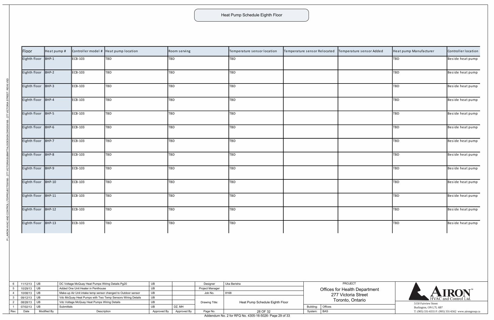
5150 Fairview Street
Burlington, ON L7L 6B7
T: (905) 331-6555 F: (905) 331-6562 www.airongroup.ca
Offices for Health Department277 Victoria StreetToronto, Ontario
P:\_
AIR
ON
HV
AC
AN
D C
ON
TRO
L LT
D\P
RO
JEC
TS\8
168
- 277
VIC
TOR
IA\S
UB
MIT
TALS
\DE
SIG
N D
WG
S\8
168
- 277
VIC
TOR
IA S
TRE
ET.
RE
V6.
VS
D
Rev. 28 of x
PROJECT
1234
Date
56
07/02/1308/28/1309/12/1310/08/1310/29/1311/12/13
Modified By
UB
UBUB
UBUB
UB
DescriptionSubmittals
Added One Unit Heater in Penthouse
Approved By
DC Voltage McQuay Heat Pumps Wiring Details Pg20
Make-up Air Unit intake temp sensor changed to Outdoor sensorVdc McQuay Heat Pumps with Two Temp Sensors Wiring DetailsVdc Voltage McQuay Heat Pumps Wiring Details
UB
UB
UB
UB
UB
UB
Approved ByDZ, MH
Page No.
Drawing Title:
Job No.Project Manager
Designer
8168
Uka Berisha
System:Building:
BASOffices
28 OF 32
Heat Pump Schedule Eighth Floor
Heat Pump Schedule Eighth Floor
Bes ide heat pump
Bes ide heat pump
Bes ide heat pump
Bes ide heat pump
Bes ide heat pump
Bes ide heat pump
Bes ide heat pump
Bes ide heat pump
Bes ide heat pump
Bes ide heat pump
Bes ide heat pump
Bes ide heat pump
Bes ide heat pump
TBD
TBD
TBD
TBD
TBDEighth floor 8HP-13 ECB-103 TBD TBD TBD
TBD
Eighth floor 8HP-12 ECB-103 TBD TBD TBD
Eighth floor 8HP-11 ECB-103 TBD TBD TBD
Eighth floor 8HP-10 ECB-103 TBD TBD TBD TBD
TBD
Eighth floor 8HP-9 ECB-103 TBD TBD TBD
TBD
Eighth floor 8HP-8 ECB-103 TBD TBD TBD
Eighth floor 8HP-7 ECB-103 TBD TBD TBD
TBD
Eighth floor 8HP-6 ECB-103 TBD TBD TBD TBD
Eighth floor 8HP-5 ECB-103 TBD TBD TBD
TBD
Eighth floor 8HP-4 ECB-103 TBD TBD TBD
Eighth floor 8HP-3 ECB-103 TBD TBD TBD
Eighth floor 8HP-2 ECB-103 TBD TBD TBD TBD
Eighth floor 8HP-1 ECB-103 TBD TBD TBD
Floor Heat pump # Control ler model # Heat pump location Room serving Temperature sensor location Temperature sensor Relocated Temperature sensor Added Heat pump Manufacturer Control ler location
Addendum No. 2 for RFQ No. 4305-16-5026- Page 29 of 33
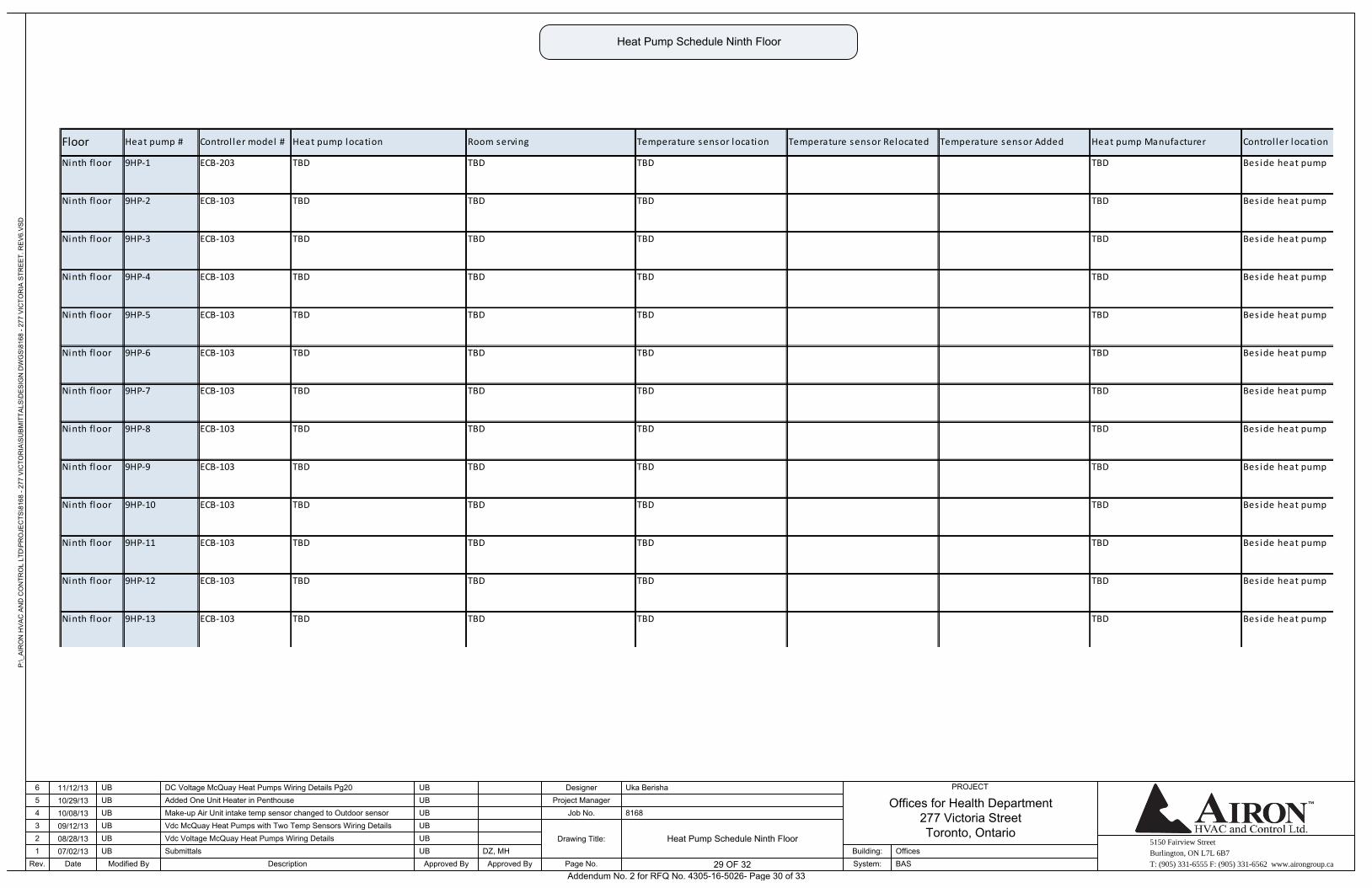
5150 Fairview Street
Burlington, ON L7L 6B7
T: (905) 331-6555 F: (905) 331-6562 www.airongroup.ca
Offices for Health Department277 Victoria StreetToronto, Ontario
P:\_
AIR
ON
HV
AC
AN
D C
ON
TRO
L LT
D\P
RO
JEC
TS\8
168
- 277
VIC
TOR
IA\S
UB
MIT
TALS
\DE
SIG
N D
WG
S\8
168
- 277
VIC
TOR
IA S
TRE
ET.
RE
V6.
VS
D
Rev. 29 of x
PROJECT
1234
Date
56
07/02/1308/28/1309/12/1310/08/1310/29/1311/12/13
Modified By
UB
UBUB
UBUB
UB
DescriptionSubmittals
Added One Unit Heater in Penthouse
Approved By
DC Voltage McQuay Heat Pumps Wiring Details Pg20
Make-up Air Unit intake temp sensor changed to Outdoor sensorVdc McQuay Heat Pumps with Two Temp Sensors Wiring DetailsVdc Voltage McQuay Heat Pumps Wiring Details
UB
UB
UB
UB
UB
UB
Approved ByDZ, MH
Page No.
Drawing Title:
Job No.Project Manager
Designer
8168
Uka Berisha
System:Building:
BASOffices
29 OF 32
Heat Pump Schedule Ninth Floor
Heat Pump Schedule Ninth Floor
Bes ide heat pump
Bes ide heat pump
Bes ide heat pump
Bes ide heat pump
Bes ide heat pump
Bes ide heat pump
Bes ide heat pump
Bes ide heat pump
Bes ide heat pump
Bes ide heat pump
Bes ide heat pump
Bes ide heat pump
Bes ide heat pump
TBD
TBD
TBD
Ninth floor 9HP-13 ECB-103 TBD TBD TBD TBD
TBD
Ninth floor 9HP-12 ECB-103 TBD TBD TBD
TBD
Ninth floor 9HP-11 ECB-103 TBD TBD TBD
Ninth floor 9HP-10 ECB-103 TBD TBD TBD
TBD
Ninth floor 9HP-9 ECB-103 TBD TBD TBD TBD
Ninth floor 9HP-8 ECB-103 TBD TBD TBD
TBD
Ninth floor 9HP-7 ECB-103 TBD TBD TBD
Ninth floor 9HP-6 ECB-103 TBD TBD TBD
Ninth floor 9HP-5 ECB-103 TBD TBD TBD TBD
TBD
Ninth floor 9HP-4 ECB-103 TBD TBD TBD
TBD
Ninth floor 9HP-3 ECB-103 TBD TBD TBD
Ninth floor 9HP-2 ECB-103 TBD TBD TBD
Ninth floor 9HP-1 ECB-203 TBD TBD TBD TBD
Heat pump Manufacturer Control ler locationFloor Heat pump # Control ler model # Heat pump location Room serving Temperature sensor location Temperature sensor Relocated Temperature sensor Added
Addendum No. 2 for RFQ No. 4305-16-5026- Page 30 of 33
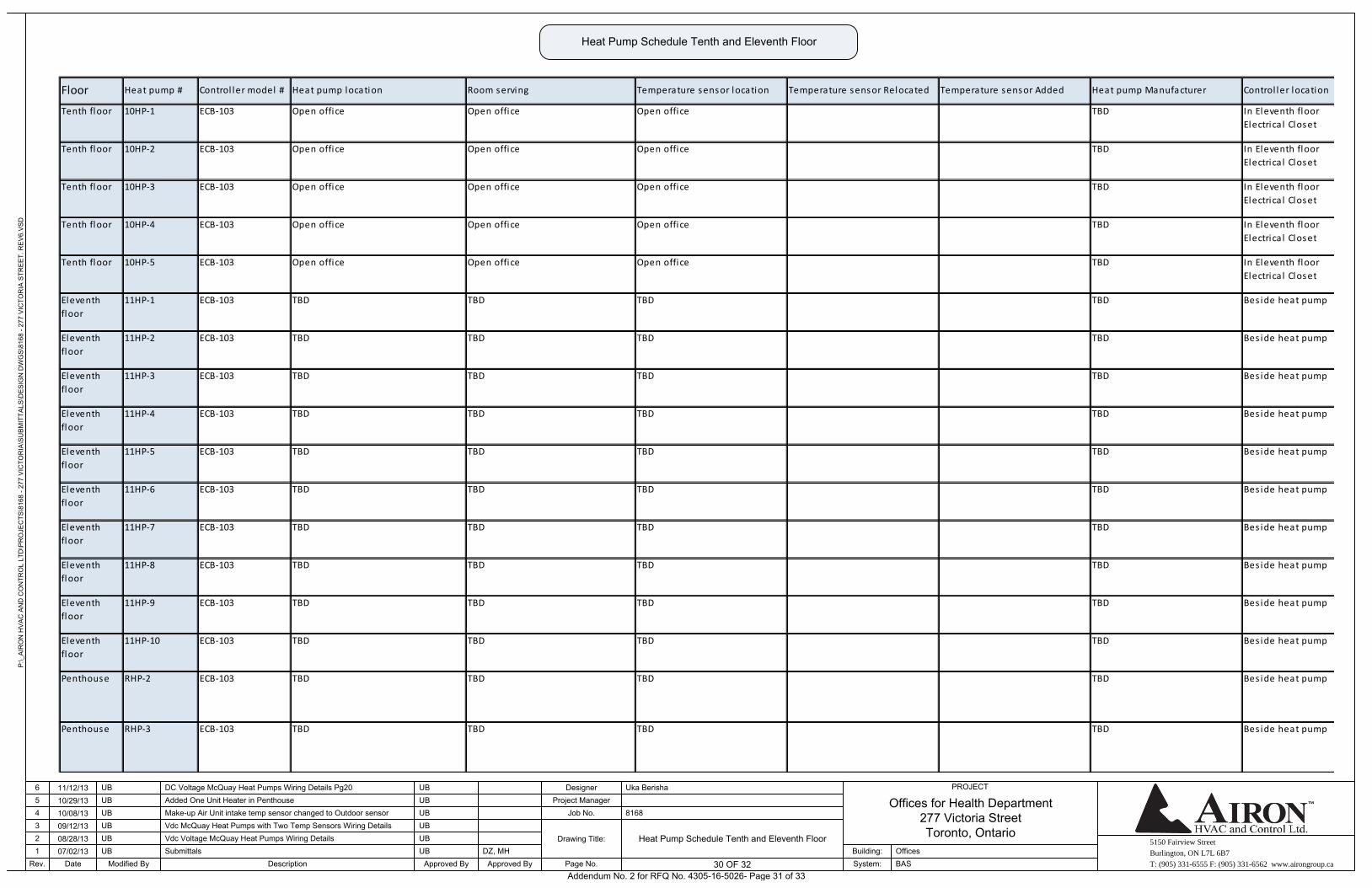
5150 Fairview Street
Burlington, ON L7L 6B7
T: (905) 331-6555 F: (905) 331-6562 www.airongroup.ca
Offices for Health Department277 Victoria StreetToronto, Ontario
P:\_
AIR
ON
HV
AC
AN
D C
ON
TRO
L LT
D\P
RO
JEC
TS\8
168
- 277
VIC
TOR
IA\S
UB
MIT
TALS
\DE
SIG
N D
WG
S\8
168
- 277
VIC
TOR
IA S
TRE
ET.
RE
V6.
VS
D
Rev. 30 of x
PROJECT
1234
Date
56
07/02/1308/28/1309/12/1310/08/1310/29/1311/12/13
Modified By
UB
UBUB
UBUB
UB
DescriptionSubmittals
Added One Unit Heater in Penthouse
Approved By
DC Voltage McQuay Heat Pumps Wiring Details Pg20
Make-up Air Unit intake temp sensor changed to Outdoor sensorVdc McQuay Heat Pumps with Two Temp Sensors Wiring DetailsVdc Voltage McQuay Heat Pumps Wiring Details
UB
UB
UB
UB
UB
UB
Approved ByDZ, MH
Page No.
Drawing Title:
Job No.Project Manager
Designer
8168
Uka Berisha
System:Building:
BASOffices
30 OF 32
Heat Pump Schedule Tenth and Eleventh Floor
Heat Pump Schedule Tenth and Eleventh Floor
Bes ide heat pump
Penthouse RHP-3 ECB-103 TBD TBD TBD TBD Bes ide heat pump
Penthouse RHP-2 ECB-103 TBD TBD TBD TBD
Floor Heat pump # Control ler model # Heat pump location Room serving Temperature sensor location Temperature sensor Relocated Temperature sensor Added Heat pump Manufacturer Control ler location
TBD
Tenth floor 10HP-2 ECB-103 Open office Open office Open office
Tenth floor 10HP-1 ECB-103 Open office Open office Open office
TBD
Eleventh
floor
11HP-1 ECB-103 TBD TBD TBD
Tenth floor 10HP-5 ECB-103 Open office Open office Open office
TBD
Tenth floor 10HP-4 ECB-103 Open office Open office Open office TBD
Tenth floor 10HP-3 ECB-103 Open office Open office Open office
Eleventh
floor
11HP-3 ECB-103 TBD TBD TBD TBD
TBD
Eleventh
floor
11HP-2 ECB-103 TBD TBD TBD
TBD
Eleventh
floor
11HP-5 ECB-103 TBD TBD TBD
Eleventh
floor
11HP-4 ECB-103 TBD TBD TBD
TBD
Eleventh
floor
11HP-9 ECB-103 TBD TBD TBD
Eleventh
floor
11HP-8 ECB-103 TBD TBD TBD
TBD
Eleventh
floor
11HP-7 ECB-103 TBD TBD TBD TBD
Eleventh
floor
11HP-6 ECB-103 TBD TBD TBD
TBD
TBD
TBD
TBD
In Eleventh floor
Electrica l Closet
In Eleventh floor
Electrica l Closet
In Eleventh floor
Electrica l Closet
In Eleventh floor
Electrica l Closet
Eleventh
floor
11HP-10 ECB-103 TBD TBD TBD TBD Bes ide heat pump
Bes ide heat pump
Bes ide heat pump
Bes ide heat pump
Bes ide heat pump
In Eleventh floor
Electrica l Closet
Bes ide heat pump
Bes ide heat pump
Bes ide heat pump
Bes ide heat pump
Bes ide heat pump
Addendum No. 2 for RFQ No. 4305-16-5026- Page 31 of 33
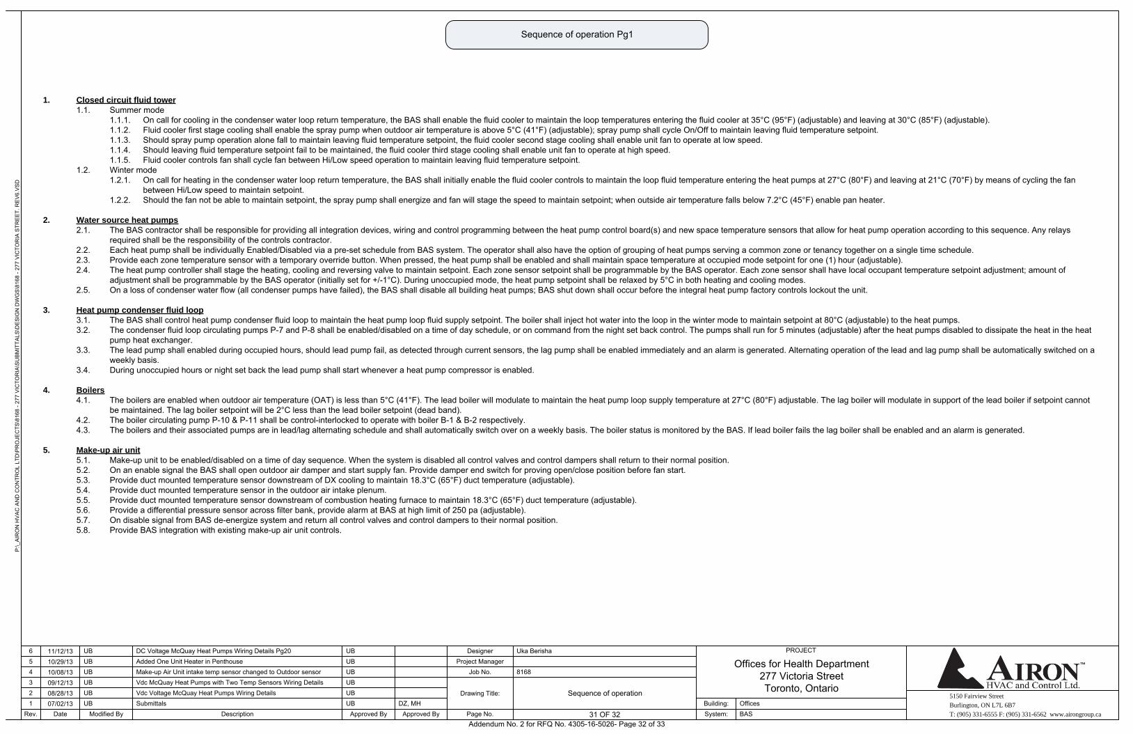
5150 Fairview Street
Burlington, ON L7L 6B7
T: (905) 331-6555 F: (905) 331-6562 www.airongroup.ca
Offices for Health Department277 Victoria StreetToronto, Ontario
P:\_
AIR
ON
HV
AC
AN
D C
ON
TRO
L LT
D\P
RO
JEC
TS\8
168
- 277
VIC
TOR
IA\S
UB
MIT
TALS
\DE
SIG
N D
WG
S\8
168
- 277
VIC
TOR
IA S
TRE
ET.
RE
V6.
VS
D
Rev. 31 of x
PROJECT
1234
Date
56
07/02/1308/28/1309/12/1310/08/1310/29/1311/12/13
Modified By
UB
UBUB
UBUB
UB
DescriptionSubmittals
Added One Unit Heater in Penthouse
Approved By
DC Voltage McQuay Heat Pumps Wiring Details Pg20
Make-up Air Unit intake temp sensor changed to Outdoor sensorVdc McQuay Heat Pumps with Two Temp Sensors Wiring DetailsVdc Voltage McQuay Heat Pumps Wiring Details
UB
UB
UB
UB
UB
UB
Approved ByDZ, MH
Page No.
Drawing Title:
Job No.Project Manager
Designer
8168
Uka Berisha
System:Building:
BASOffices
31 OF 32
Sequence of operation
Sequence of operation Pg1
1. Closed circuit fluid tower
1.1. Summer mode1.1.1. On call for cooling in the condenser water loop return temperature, the BAS shall enable the fluid cooler to maintain the loop temperatures entering the fluid cooler at 35°C (95°F) (adjustable) and leaving at 30°C (85°F) (adjustable).1.1.2. Fluid cooler first stage cooling shall enable the spray pump when outdoor air temperature is above 5°C (41°F) (adjustable); spray pump shall cycle On/Off to maintain leaving fluid temperature setpoint.1.1.3. Should spray pump operation alone fall to maintain leaving fluid temperature setpoint, the fluid cooler second stage cooling shall enable unit fan to operate at low speed.1.1.4. Should leaving fluid temperature setpoint fail to be maintained, the fluid cooler third stage cooling shall enable unit fan to operate at high speed.1.1.5. Fluid cooler controls fan shall cycle fan between Hi/Low speed operation to maintain leaving fluid temperature setpoint.
1.2. Winter mode1.2.1. On call for heating in the condenser water loop return temperature, the BAS shall initially enable the fluid cooler controls to maintain the loop fluid temperature entering the heat pumps at 27°C (80°F) and leaving at 21°C (70°F) by means of cycling the fan
between Hi/Low speed to maintain setpoint.1.2.2. Should the fan not be able to maintain setpoint, the spray pump shall energize and fan will stage the speed to maintain setpoint; when outside air temperature falls below 7.2°C (45°F) enable pan heater.
2. Water source heat pumps
2.1. The BAS contractor shall be responsible for providing all integration devices, wiring and control programming between the heat pump control board(s) and new space temperature sensors that allow for heat pump operation according to this sequence. Any relays required shall be the responsibility of the controls contractor.
2.2. Each heat pump shall be individually Enabled/Disabled via a pre-set schedule from BAS system. The operator shall also have the option of grouping of heat pumps serving a common zone or tenancy together on a single time schedule.2.3. Provide each zone temperature sensor with a temporary override button. When pressed, the heat pump shall be enabled and shall maintain space temperature at occupied mode setpoint for one (1) hour (adjustable).2.4. The heat pump controller shall stage the heating, cooling and reversing valve to maintain setpoint. Each zone sensor setpoint shall be programmable by the BAS operator. Each zone sensor shall have local occupant temperature setpoint adjustment; amount of
adjustment shall be programmable by the BAS operator (initially set for +/-1°C). During unoccupied mode, the heat pump setpoint shall be relaxed by 5°C in both heating and cooling modes.2.5. On a loss of condenser water flow (all condenser pumps have failed), the BAS shall disable all building heat pumps; BAS shut down shall occur before the integral heat pump factory controls lockout the unit.
3. Heat pump condenser fluid loop
3.1. The BAS shall control heat pump condenser fluid loop to maintain the heat pump loop fluid supply setpoint. The boiler shall inject hot water into the loop in the winter mode to maintain setpoint at 80°C (adjustable) to the heat pumps.3.2. The condenser fluid loop circulating pumps P-7 and P-8 shall be enabled/disabled on a time of day schedule, or on command from the night set back control. The pumps shall run for 5 minutes (adjustable) after the heat pumps disabled to dissipate the heat in the heat
pump heat exchanger.3.3. The lead pump shall enabled during occupied hours, should lead pump fail, as detected through current sensors, the lag pump shall be enabled immediately and an alarm is generated. Alternating operation of the lead and lag pump shall be automatically switched on a
weekly basis.3.4. During unoccupied hours or night set back the lead pump shall start whenever a heat pump compressor is enabled.
4. Boilers
4.1. The boilers are enabled when outdoor air temperature (OAT) is less than 5°C (41°F). The lead boiler will modulate to maintain the heat pump loop supply temperature at 27°C (80°F) adjustable. The lag boiler will modulate in support of the lead boiler if setpoint cannot be maintained. The lag boiler setpoint will be 2°C less than the lead boiler setpoint (dead band).
4.2. The boiler circulating pump P-10 & P-11 shall be control-interlocked to operate with boiler B-1 & B-2 respectively.4.3. The boilers and their associated pumps are in lead/lag alternating schedule and shall automatically switch over on a weekly basis. The boiler status is monitored by the BAS. If lead boiler fails the lag boiler shall be enabled and an alarm is generated.
5. Make-up air unit
5.1. Make-up unit to be enabled/disabled on a time of day sequence. When the system is disabled all control valves and control dampers shall return to their normal position.5.2. On an enable signal the BAS shall open outdoor air damper and start supply fan. Provide damper end switch for proving open/close position before fan start.5.3. Provide duct mounted temperature sensor downstream of DX cooling to maintain 18.3°C (65°F) duct temperature (adjustable).5.4. Provide duct mounted temperature sensor in the outdoor air intake plenum.5.5. Provide duct mounted temperature sensor downstream of combustion heating furnace to maintain 18.3°C (65°F) duct temperature (adjustable).5.6. Provide a differential pressure sensor across filter bank, provide alarm at BAS at high limit of 250 pa (adjustable).5.7. On disable signal from BAS de-energize system and return all control valves and control dampers to their normal position.5.8. Provide BAS integration with existing make-up air unit controls.
Addendum No. 2 for RFQ No. 4305-16-5026- Page 32 of 33
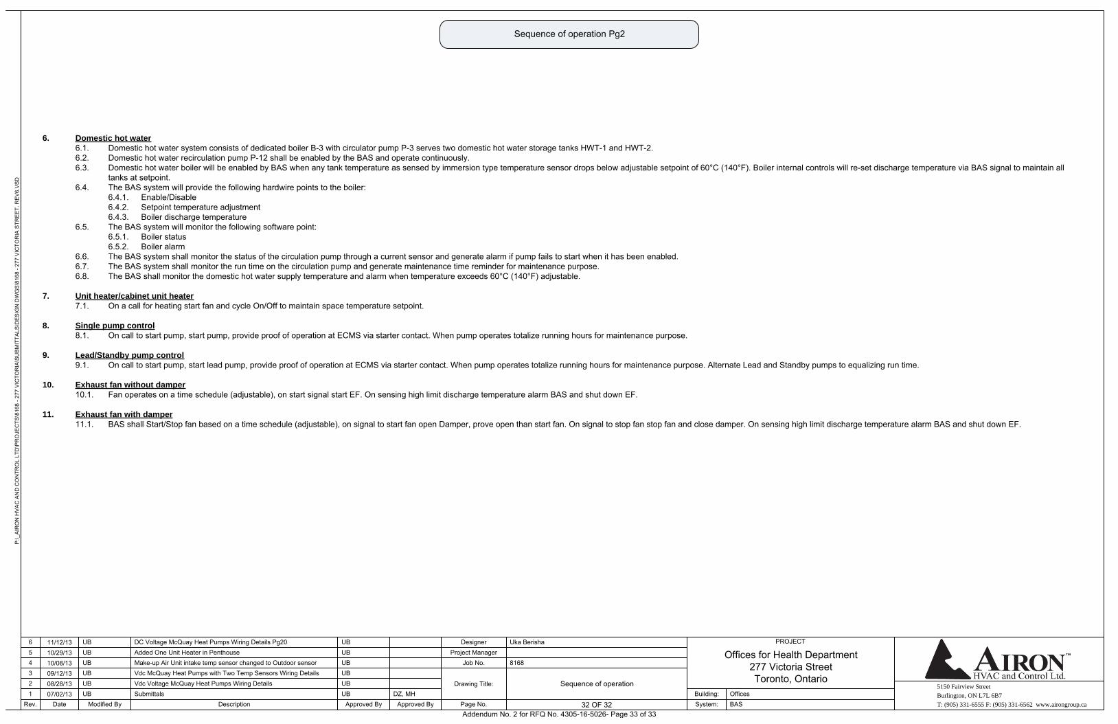
5150 Fairview Street
Burlington, ON L7L 6B7
T: (905) 331-6555 F: (905) 331-6562 www.airongroup.ca
Offices for Health Department277 Victoria StreetToronto, Ontario
P:\_
AIR
ON
HV
AC
AN
D C
ON
TRO
L LT
D\P
RO
JEC
TS\8
168
- 277
VIC
TOR
IA\S
UB
MIT
TALS
\DE
SIG
N D
WG
S\8
168
- 277
VIC
TOR
IA S
TRE
ET.
RE
V6.
VS
D
Rev. 32 of x
PROJECT
1234
Date
56
07/02/1308/28/1309/12/1310/08/1310/29/1311/12/13
Modified By
UB
UBUB
UBUB
UB
DescriptionSubmittals
Added One Unit Heater in Penthouse
Approved By
DC Voltage McQuay Heat Pumps Wiring Details Pg20
Make-up Air Unit intake temp sensor changed to Outdoor sensorVdc McQuay Heat Pumps with Two Temp Sensors Wiring DetailsVdc Voltage McQuay Heat Pumps Wiring Details
UB
UB
UB
UB
UB
UB
Approved ByDZ, MH
Page No.
Drawing Title:
Job No.Project Manager
Designer
8168
Uka Berisha
System:Building:
BASOffices
32 OF 32
Sequence of operation
Sequence of operation Pg2
6. Domestic hot water
6.1. Domestic hot water system consists of dedicated boiler B-3 with circulator pump P-3 serves two domestic hot water storage tanks HWT-1 and HWT-2.6.2. Domestic hot water recirculation pump P-12 shall be enabled by the BAS and operate continuously.6.3. Domestic hot water boiler will be enabled by BAS when any tank temperature as sensed by immersion type temperature sensor drops below adjustable setpoint of 60°C (140°F). Boiler internal controls will re-set discharge temperature via BAS signal to maintain all
tanks at setpoint.6.4. The BAS system will provide the following hardwire points to the boiler:
6.4.1. Enable/Disable6.4.2. Setpoint temperature adjustment6.4.3. Boiler discharge temperature
6.5. The BAS system will monitor the following software point:6.5.1. Boiler status6.5.2. Boiler alarm
6.6. The BAS system shall monitor the status of the circulation pump through a current sensor and generate alarm if pump fails to start when it has been enabled.6.7. The BAS system shall monitor the run time on the circulation pump and generate maintenance time reminder for maintenance purpose.6.8. The BAS shall monitor the domestic hot water supply temperature and alarm when temperature exceeds 60°C (140°F) adjustable.
7. Unit heater/cabinet unit heater
7.1. On a call for heating start fan and cycle On/Off to maintain space temperature setpoint.
8. Single pump control
8.1. On call to start pump, start pump, provide proof of operation at ECMS via starter contact. When pump operates totalize running hours for maintenance purpose.
9. Lead/Standby pump control
9.1. On call to start pump, start lead pump, provide proof of operation at ECMS via starter contact. When pump operates totalize running hours for maintenance purpose. Alternate Lead and Standby pumps to equalizing run time.
10. Exhaust fan without damper
10.1. Fan operates on a time schedule (adjustable), on start signal start EF. On sensing high limit discharge temperature alarm BAS and shut down EF.
11. Exhaust fan with damper
11.1. BAS shall Start/Stop fan based on a time schedule (adjustable), on signal to start fan open Damper, prove open than start fan. On signal to stop fan stop fan and close damper. On sensing high limit discharge temperature alarm BAS and shut down EF.
Addendum No. 2 for RFQ No. 4305-16-5026- Page 33 of 33


![[Product Monograph Template - Standard]€¦ · L7L 5H4 . Date of Revision: February 25, 2016 : Submission Control No: 188223 . BICL-CCDS No. 0260-01](https://img.pdfslide.us/doc/110x75/5f535355ea3dfc23d5557466/product-monograph-template-standard-l7l-5h4-date-of-revision-february-25.jpg)