Embed Size (px)
Citation preview
OSM OFFICE OF SURFACE MINING
RECLAMATION AND ENFORCEMENT
TECHNICAL REPORT/1994
INVESTIGATION OF DAMAGE TO STRUCTURES
IN THE McCUTCHANVILLE-DA YLIGHT
AREA OF SOUTHWESTERN INDIANA
Volume 3 of 3
Part VII: Experimental and Analytical Studies of the . Vibration Response of Residential Structures Due to Surface Mine Blasting.
Part VIII: Dynamic Soil Property Testing and Analysis of Soil Properties, Daylight and McCutchanville, Indiana.
Part IX: Environmental Conditions Related to Geology, Soils, and Precipitation, McCutchan ville and Daylight, Vanderburgh County, Indiana.
U.S. Department of the Interior
;\""~~T OF%
"' 0 :;;j ;:o
US Department of Interior Office of Surface Mining
i Reclamation and Enforcement I Kenneth K. Eltschlager
Mining/Explosives Engineer 3 Parkway Center
Pittsburgh, PA 15220
Phone 412.937.2169 Fax 412.937.3012 [email protected]
d~.~ ~ - ~"" 'JR Office of Surface Mining Reclamation and Enforcement ~~ ~~
O,.c·suRrAC~
OSM OFFICE OF SURFACE MINING
RECLAMATION AND ENFORCEMENT
TECHNICAL REPORT/1994
INVESTIGATION OF DAMAGE TO STRUCTURES
IN THE McCUTCHANVILLE-DA YLIGHT
AREA OF SOUTHWESTERN INDIANA
Volume 2 of 3
Part II: Geologic and Unconsolidated Materials in the McCutchanville-Daylight Area.
Part III: Blast Design Effects on Ground Vibrations in McCutchanville and Daylight,
Indiana from Blasting at the AMAX, Ayrshire Mine.
Part IV: Vibration Environment and Damage Characterization for Houses in
McCutchanville and Daylight, Indiana.
Part V: Racking Response of Large Structures from Air blast, A Case Study.
Part VI: Investigation of Building Damage in the McCutchanville-Daylight, Indiana Area.
1 US Department of Interior Office of Surface Mining
' Reclamation and Enforcement
U.S. Department of the Interior ' ',,,,,,,,,,,,,,,,,, '"
Office of Surface Mining Reclamation and Enforcement
Kenneth K. Eltschlager Mining/Explosives Engineer
3 Parkway Center Pittsburgh, PA 15220
Phone 412.937.2169 Fax 412.937.3012
Part VIII
Dynamic Soil Propezty Testing and Analysis of Soil Properties, Daylight and McCutchanville, Indiana.

DYNAMIC SOIL PROPERTY TESTING AND ANALYSIS OF SOIL PROPERTIES
DAYLIGHT and McCUTCHANVILLE, INDIANA
by
PAUL F. HADALA
and
RICHARD W. PETERSON
JANUARY 1993
(Revised November 1993)
Conducted by:
Geotechnical Laboratory U.S. Army Engineer Waterways Experiment Station
Vicksburg, MS
Sponsored by:
Office of Surface Mining, U.S. Department of the Interior

Revisions made in November 1993 include only pagination, pen and ink typographical corrections on pages 53 and 65, and the addition of-Appendix B which was prepared in response to a telephone request for clarifications and additions by the sponsor in October 1993. A Table of Contents was also added.
TABLE OF CONTENTS
CHAPTER 1, INTRODUCTION, OBJECTIVES, AND SCOPE 1
CHAPTER 2, DYNAMIC SOIL PROPERTY TESTINGS . 3
Memorandum for Record dated 30 Dec 92, subject: · Laboratory 4 Soil Testing - Interagency Agreement No. EF68-IA91-13796, "Field and Laboratory Evaluation of Potential Causative Factors of Structural Damages in Daylight/McCutchanville, IN"
CHAPTER 3, STATIC SETTLEMENT ANALYSES . 51
Memorandum for Record dated 30 Dec 92, subject: Settlement 52 and Bearing Capacity Calculations Based on Soil Property Data Collected in the Daylight and McCutchanville Areas
CHAPTER 4, EARTH PRESSURE ANALYSIS AND MISCELLANEOUS OBSERVATIONS 63
Memorandum for Record dated 9 Jan 93, subject: Addendum to 64 11 May 91 Memorandum for Record and Lateral Earth Pressure Analyses for OSM Study
APPENDIX A, TRIP REPORT ON RECONNAISSANCE VISIT TO DAYLIGHT/ .80 MCCUTCHANVILLE PREPARED BEFORE THIS INVESTIGATION BEGAN UNDER SEPARATE OSM FUNDING
Memorandum for Record dated 11 Mar 91, subject: Inspection . 81 of Building Damage Near Daylight and McCutchanville, indiana, and Examination of Related Documents
APPENDIX B, ADDENDUM OF 30 OCT 93 ................. 10~-
-i-

CHAPTER 1
Introduction
1. As part of a larger investigation of blasting related vibrations in Daylight and McCutchanville, Indiana, carried out by the Structures Laboratory (SL), U.S. Army Engineer Waterways Experiment Station (WES), the Geotechnical Laboratory (GL) of WES conducted supporting tests and analyses. The work was carried out for the Office of Surface Mining (OSM), Department of the Interior, under Interagency Agreement No. EF68-IA91-13796 during the period October 1991 to December 1992, and is related to concurrent tests and studies carried out by OSM and by the U.S. Bureau of Mines and the U.S. Geological Survey for OSM. The OSM technical monitor for this study was Mr. Peter Michael.
Objectives
2. The objectives of the GL studies were:
a. To determine if undisturbed unsaturated soil samples from the Daylight/McCutchanville area could collapse under many cycles of low amplitude vibration.
b. To determine if soil samples from the Daylight/McCutchanville area would experience an increase in pore pressure or loss of shear strength as a result of cyclic loading.
c. To perform a static settlement analysis for a typical residential building foundation in the area. (Results of this analysis were given to SL for evaluation of the potential of the predicted settlement magnitudes to cause structural damage.)
d. To perform a static earth pressure analysis for a typical residential basement wall. (Results of the analysis were also given to SL for evaluation of their potential for structural damage.)
3. Chapter 2 of this report is a Memorandum for Record addressing objectives 2.a. and 2.b. It was furnished to OSM in draft form on 17 Aug 92 and finalized on 30 Dec 92 based on review comments. Chapter 3 is a Memorandum for Record addressing objective 2.c. It was furnished to OSM in draft form on 18 Sep 92 and was finalized on 30 Dec 92 based on review comments. Chapter 4 is a Memorandum for Record addressing objective 2.d. It was furnished to OSM in draft form on 14 Jan 93 and finalized on 19 Jan 93 based on review comments.
4. Appendix A is a trip report written by the senior author on 11 Mar 91 as a result of a reconnaissance visit made on 20-21 Feb 91 to observe a number of damaged buildings in the Daylight/McCutchanville area before the start of the present study. It serves to document information available to the authors at the beginning of this study. Because it is referenced extensively in some of the chapters and is not generally available, it has been included as an appendix. At the request of the OSM technical monitor, the senior author revisited the hypothesis, conclusions, and judgments in this trip report in light of the additional information obtained during the course of the present study. Chapter 4 of the main report also contains an addendum to Appendix A based on this additional information and identifies potential causal mechanisms for building damage not considered at the beginning of the study.
5. This document serves only to collect and preserve the above mentioned memoranda under a single cover and place the documents in proper context with respect to one another and the project objectives.
-2-
CHAPTER 2
DYNAMIC SOIL PROPERTY TESTINGS
-3-
,_
L
REPLY TO ATTENTION OF
CEWES-GV-A
MEMORANDUM FOR RECORD
DEPARTMENT OF THE ARMY WATERWAYS EXPERIMENT STATION, CORPS OF ENGINEERS
39011 HALLS FERRY ROAD VICKSBURG, MISSISSIPPI 39180·61119
30 Dec 92
SUBJECT: Laboratory Soil Testing - Interagency Agreement No. EF68-IA91-13796, "Field and Laboratory Evaluation of Potential Causative Factors of Structural Damages in Daylight/McCutchanville, IN"
Introduction
1. Reference the section entitled "Statement of Work Laboratory Soil Testing" of the subject Interagency Agreement (encl 1). The question addressed in this study is: "Is there a potential for collapse of the structure of unsaturated soils or for pore-pressure rise in saturated soils in the study area due to ground vibration?" (quoted from page 2 of the Interagency Agreement). The laboratory soils investigation to answer these questions was conducted by the staff of the Geotechnical Laboratory (GL), U.S. Army Engineer Waterways Experiment Station (WES) and is summarized in this memorandum.
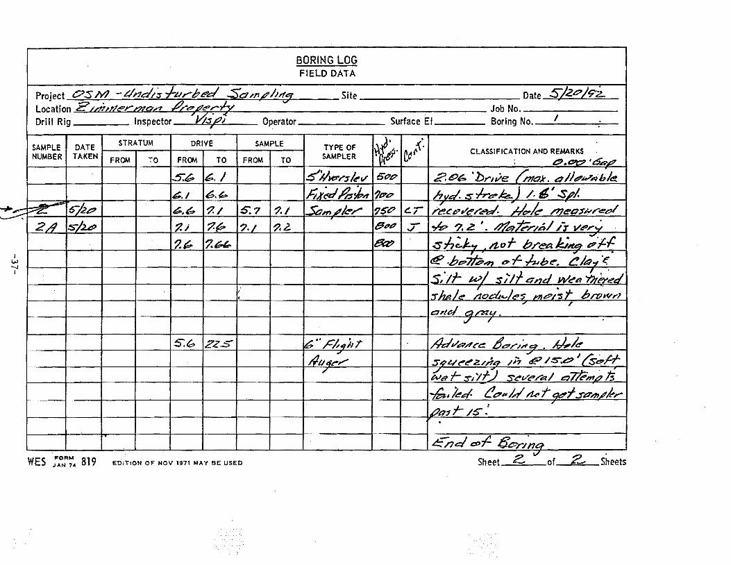
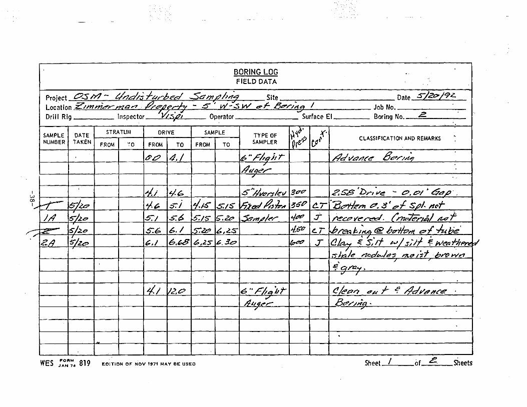
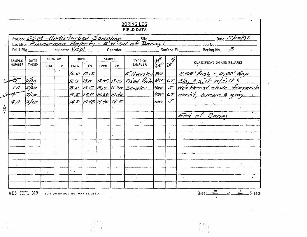
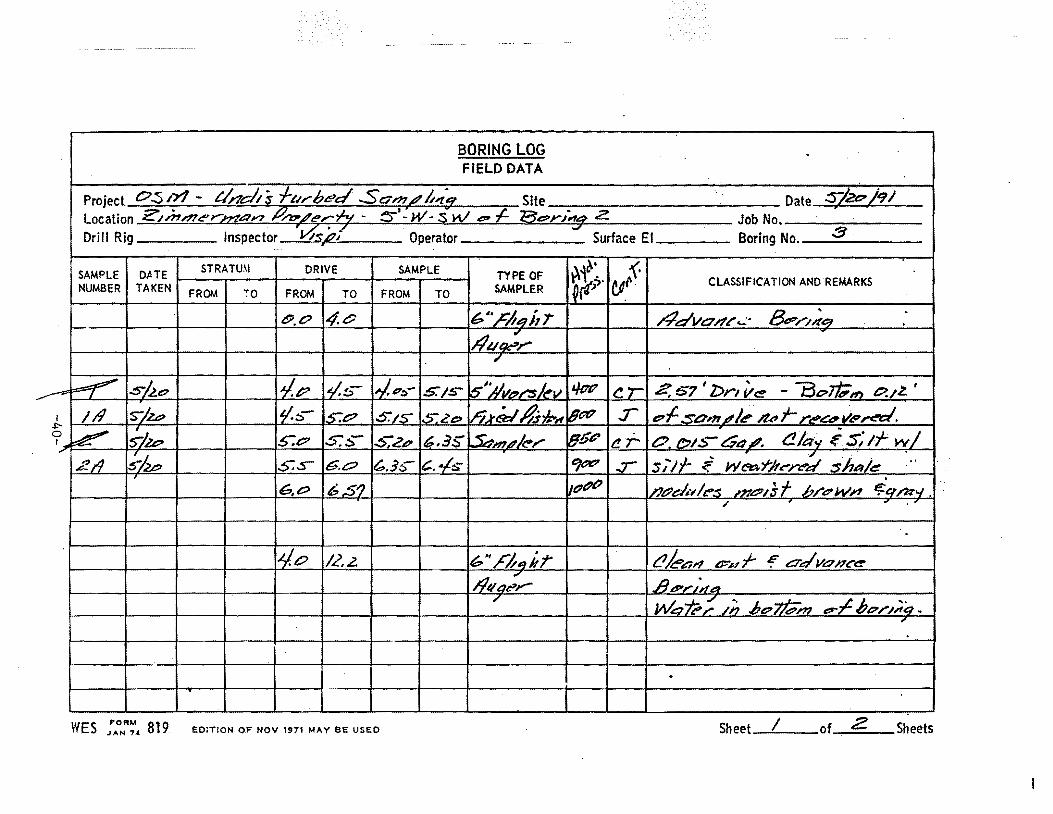
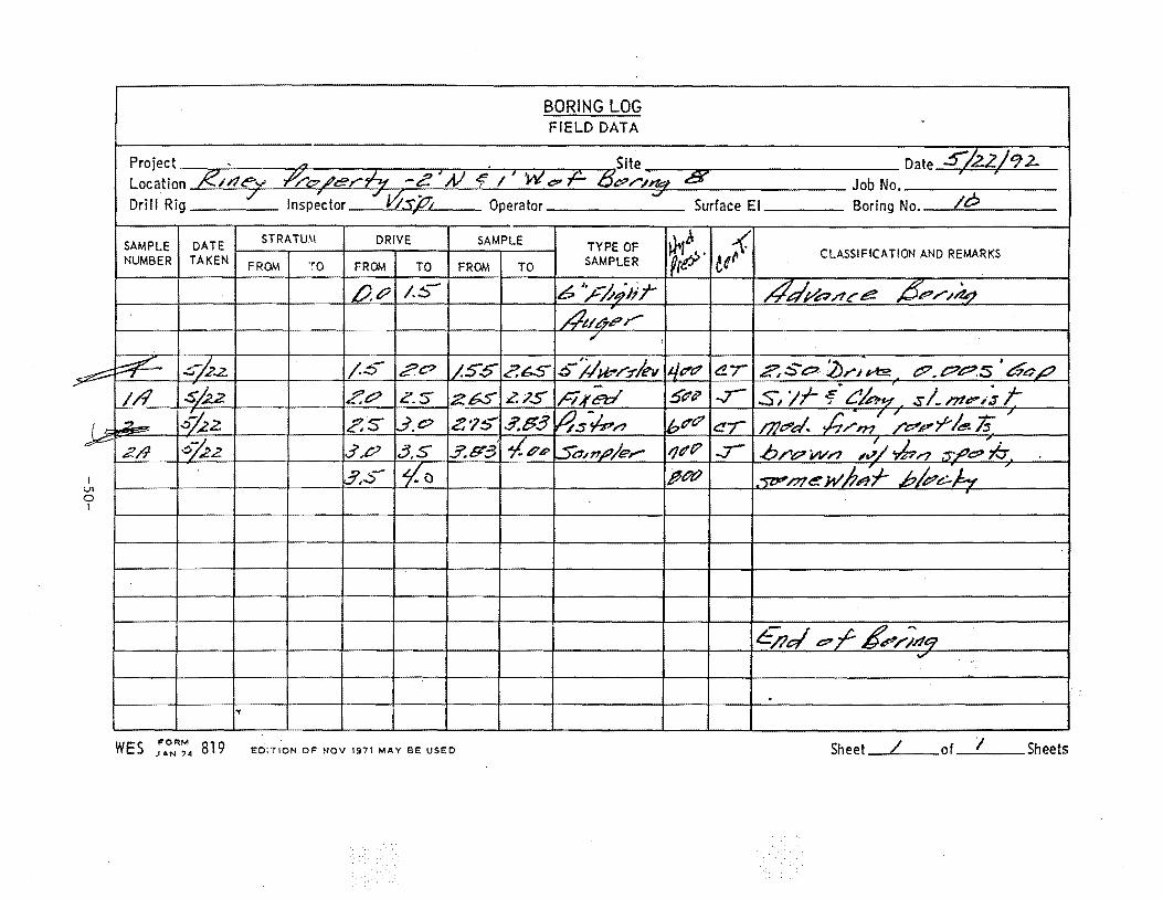
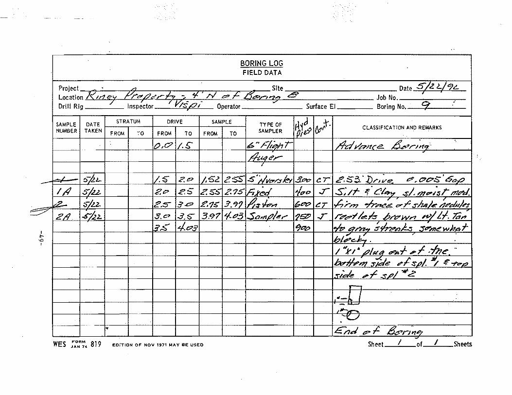
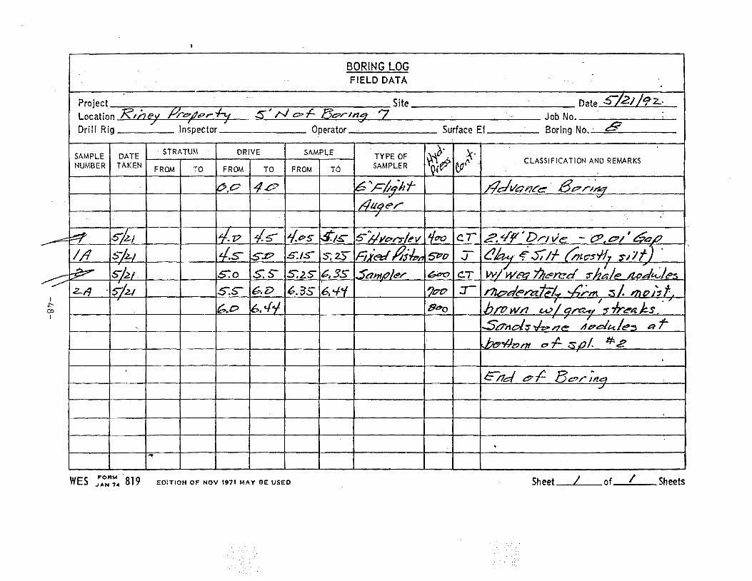
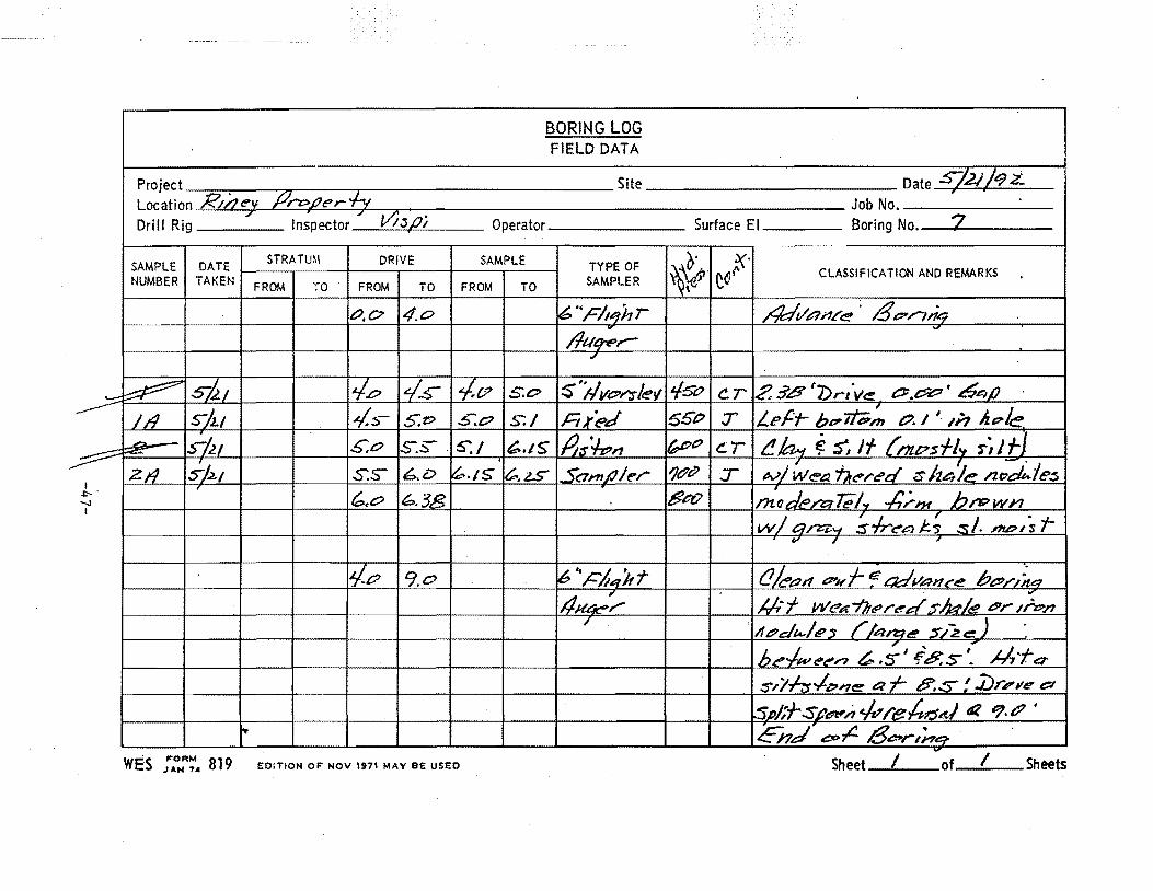
2. On 24 May 92, 26 cardboard tube samples and 27 jar samples were delivered to the GL Soils Humid Room for storage until the laboratory testing was conducted. The information recorded on the boring logs was compared with the data written on the identification tags for the samples. No inconsistencies were found (see encl 2 for a copy of the boring logs). The samples were taken by an OSM contractor with a 5-in. diameter fixed piston sampler supplied by WES under the personal technical supervision of Mr. Mark Vispi of GL.
Laboratory Testing Program
3. Preliminary Test. On 26 May 92, one back-pressure saturated, consolidated, undrained triaxial compression test with pore pressure measurements was initiated. The test (number OSM-UDl-1-4.8) was conducted as a preliminary test to determine whether the soil tended to expand or contract
ROUTING: 1. CEWES-GV-Z (Dr. Marcuson) 2. 3. CEWES-GV-Z (Mrs. Staer-file)
HYDRAULICS LABORATORY
GEOTECHNICAL LABORATORY
STRUCTURES LABORATORY
ENVIRONMENTAL l.ABORATORY
-4-
COASTAL ENGINEERING RESEARCH CENTER
INFORMATION TECHNOLOGY LABOR A TORY
CEWES-GV-A SUBJECT: Laboratory Soil Testing - Interagency Agreement No. EF68-IA91-13796, "Field and Laboratory Evaluation of Potential Causative Factors of Structural Damages in DaylightjMcCutchanville, IN"
in shear and to gain an understanding of the time required for consolidation. Procedures and equipment used for this test were similar to those described in EM 1110-2-19061 and ASTM Test Method D 47672 • The results of this test are summarized in Table 1, "Summary of Triaxial Compression Test Results."
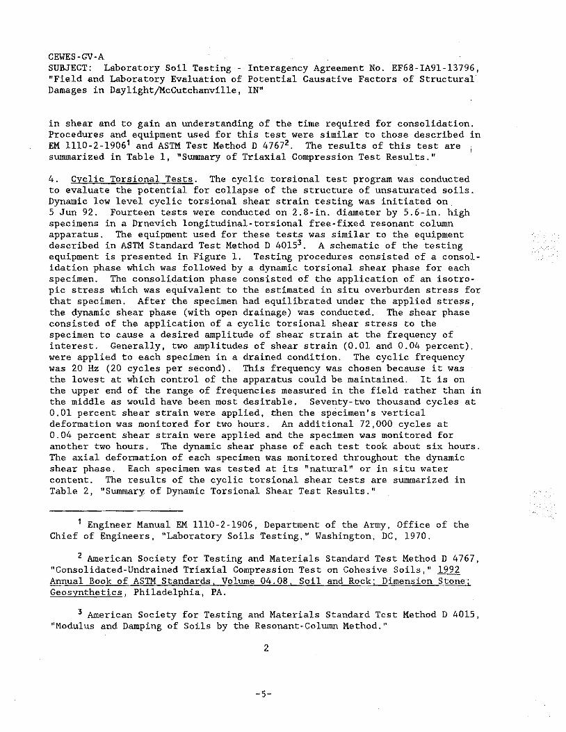
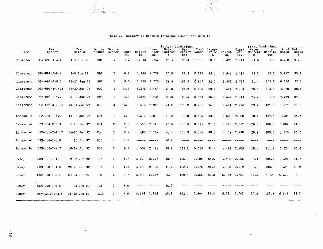
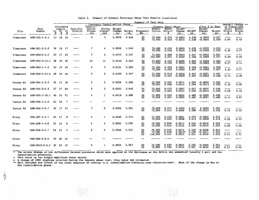
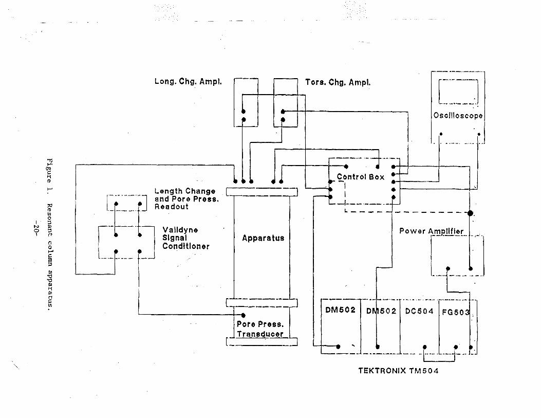
4. Cyclic Torsional Tests. The cyclic torsional test program was conducted to evaluate the potential for collapse of the structure of unsaturated soils. Dynamic low level cyclic torsional shear strain testing was initiated on 5 Jun 92. Fourteen tests were conducted on 2.8-in. diameter by 5.6-in. high specimens in a Drnevich longitudinal-torsional free-fixed resonant column apparatus. The equipment used for these tests was similar to the equipment described in ASTM Standard Test Method D 40153 . A schematic of the testing equipment is presented in Figure 1. Testing procedures consisted of a consoiidation phase which was followed by a dynamic torsional shear phase for each specimen. The consolidation phase consisted of the application of an isotropic stress which was equivalent to the estimated in situ overburden stress for that specimen. After the specimen had equilibrated under the applied stre~s, the dynamic shear phase (with open drainage) was conducted. The shear phase consisted of the application of a cyclic torsional shear stress to the specimen to cause a desired amplitude of shear strain at the frequency of interest. Generally, two amplitudes of shear strain (0.01 and 0.04 percent). were applied to each specimen in a drained condition. The cyclic frequency was 20Hz (20 cycles per second). This frequency was chosen because it was the lowest at which control of the apparatus could be maintained. It is on the upper end of the range of frequencies measured in the field rather than in the middle as would have been most desirable. Seventy-two thousand cycles at 0.01 percent shear strain were applied, then the specimen's vertical deformation was monitored for two hours. An additional 72,000 cycles at 0.04 percent shear strain were applied and the specimen was monitored for another two hours. The dynamic shear phase of each test took about six hours. The axial deformation of each specimen was monitored throughout the dynamic shear phase. Each specimen was tested at its "natural" or in situ water content. The results of the cyclic torsional shear tests are summarized in Table 2, "Summary; of Dynamic Torsional Shear Test Results."
1 Engineer Manual EM 1110-2-1906, Department of the Army, Office of the Chief of Engineers, "Laboratory Soils Testing," Washington, DC, 1970.
2 American Society for Testing and Materials Standard Test Method D 4767, "Consolidated-Undrained Triaxial Compression Test on Cohesive Soils," 1992 Annual Book of ASTM Standards, Volume 04.08, Soil and Rock; Dimension Stone; Geosynthetics, Philadelphia, PA.
3 American Society for Testing and Materials Standard Test Method D 4015, "Modulus and Damping of Soils by the Resonant-Column Method."
2
-5-
CEWES-GV-A SUBJECT: Laboratory Soil Testing - Interagency Agreement No. EF68-IA91-13796, "Field and Laboratory Evaluation of Potential Causative Factors of Structural Damages in Daylight/McCutchanville, IN"
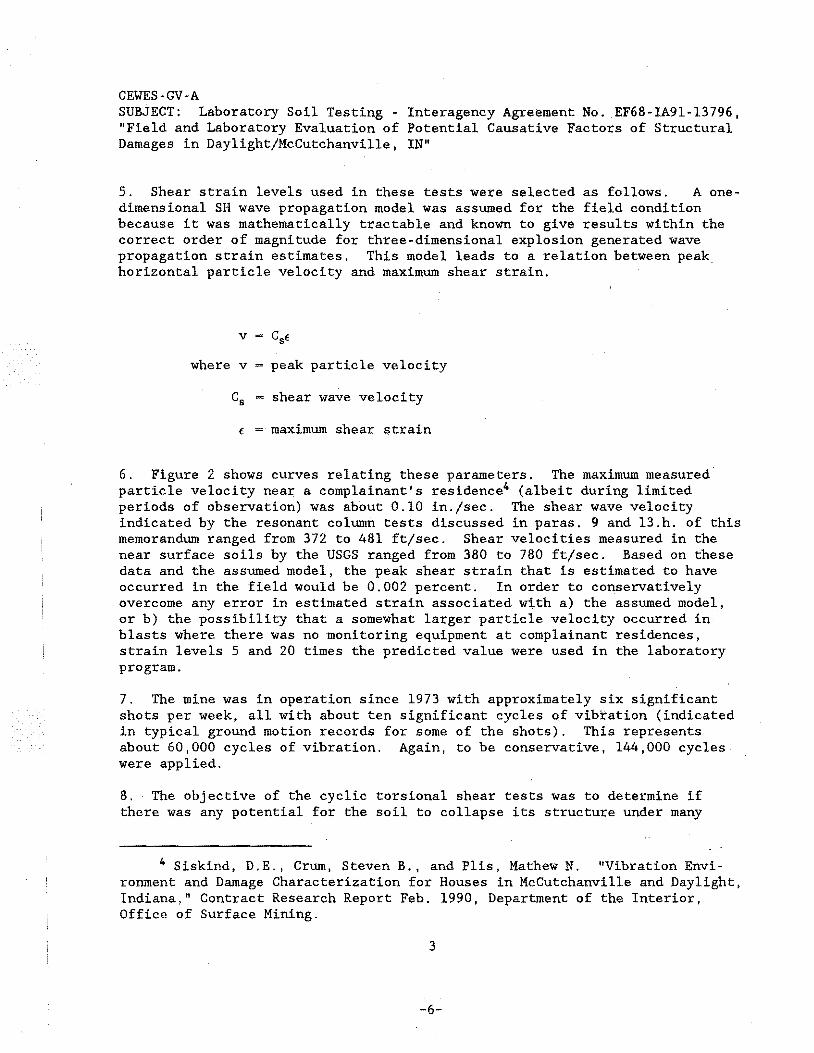
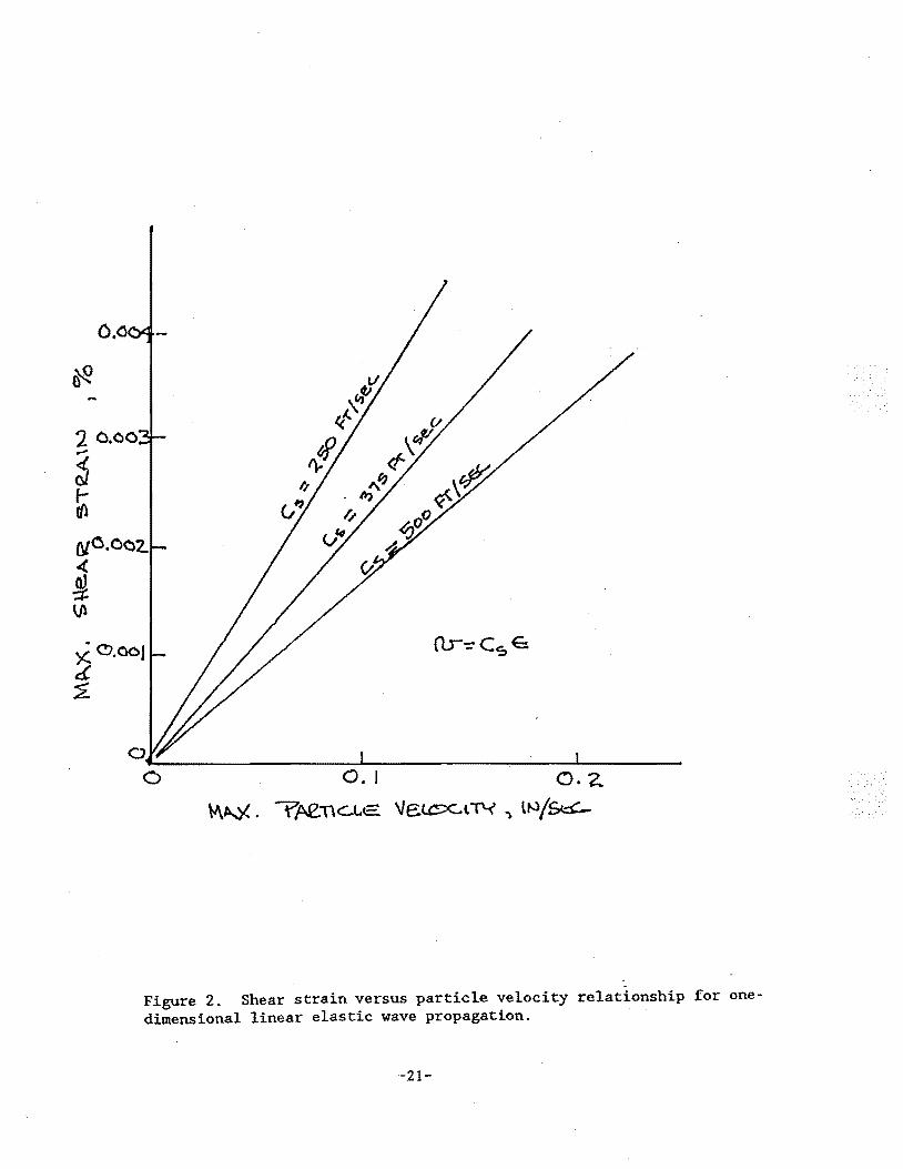
5. Shear strain levels used in these tests were selected as follows. A onedimensional SH wave propagation model was assumed for the field condition because it was mathematically tractable and known to give results within the correct order of magnitude for three-dimensional explosion generated wave propagation strain estimates. This model leads to a relation between peak. horizontal particle velocity and maximum shear strain.
v
where v peak particle velocity
shear wave velocity
E maximum shear strain
6. Figure 2 shows curves relating these parameters. The maximum measured particle velocity near a complainant's residence4 (albeit during limited periods of observation) was about 0.10 in./sec. The shear wave velocity indicated by the resonant column tests discussed in paras. 9 and 13.h. of this memorandum ranged from 372 to 481 ftjsec. Shear velocities measured in the near surface soils by the USGS ranged from 380 to 780 ft/sec. Based on these data and the assumed model, the peak shear strain that is estimated to have occurred in the field would be 0.002 percent. In order to conservatively overcome any error in estimated strain associated with a) the assumed model, or b) the possibility that a somewhat larger particle velocity occurred in blasts where there was no monitoring equipment at complainant residences, strain levels 5 and 20 times the predicted value were used in the laboratory program.
7. The mine was in operation since 1973 with approximately six significant shots per week, all with about ten significant cycles of vibration (indicated in typical ground motion records for some of the shots). This represents about 60,000 cycles of vibration. Again, to be conservative, 144,000 cycles were applied.
8. The objective of the cyclic torsional shear tests was to determine if there was any potential for the soil to collapse its structure under many
4 Siskind, D.E., Crum, Steven B., and Plis, Mathew N. "Vibration Environment and Damage Characterization for Houses in McCutchanville and Daylight, Indiana," Contract Research Report Feb. 1990, Department of the Interior, Office of Surface Mining.
3
-6-
CEWES-GV-A SUBJECT: Laboratory Soil Testing - Interagency Agreement No. EF68-IA91-13796, "Field and Laboratory Evaluation of Potential Causative Factors of Structural Damages in Daylight/McCutchanville, IN"
cycles of strain at or above those experienced in the field. Collapse potential was measured by monitoring the vertical deformation of the 5.6-in. high confined specimens as cyclic torsional loading was applied. Irt terms of maximum strain amplitude and total number of cycles,· the environll1ent created in the laboratory was more severe than that which occurred irt the field in the Daylight and McCutchanville areas. Note also that the strain amplitudes and number of cycles are both larger than that specified in the Interagency Agreement (Section IV: B .1. f. ) ( encl 1) . This change was made when it was found in preliminary testing that the smaller amplitudes and durations gave responses at or below our capability to measure vertical and torsional displacement (0.0001 in.) in the laboratory environment.
9. Resonant Column Tests. Two of the specimens subjected to the cyclic torsional shear tests described in paragraph 4 were tested as resonant column tests at the conclusion of the dynamic torsional shear test. This was done in order to obtain information on the shear wave velocity of the soils to supplement the USGS field data. Use of the shear wave velocity data to compute strain levels to be expected was discussed in para. 6. The testing methods, equipment, and procedures were similar to the methodology described in ASTM Standard Test Method D 40155. The results of the resonant column tests are summarized in Table 3, "Summary of Resonant Column Test Results."
10. Monotonic and Cyclic Triaxial Compression Tests. This group of tests was conducted for the purpose of determining whether there was any loss of shear strength of near surface soils due to cyclic loading and if there was any potential for pore pressure generation by cyclic loading. Beginning 7 Jul 92, triaxial compression tests (numbers OSM-UDl 2.6.1-1, OSM-UDl-2~6.1-2, OSM-UD2-4-13.5-l, and OSM-UD-2-4-13.5-2) were conducted on four specimens tested at their natural water contents (i.e., unsaturated. See para. 13.d). Two of the specimens were consolidated and sheared monotonically (with drainage open) using equipment and procedures similar to those described in Engineer Manual EM 1110-2-1906 and ASTM Standard Test Method D 4767. The procedures used during the shear phase for the other two specimens were modified as follow,s. Following the consolidation phase, 20 cycles (at 1 Hz) of axial dynam:i,c deviator stress were applied (with drainage open) using the stress controlled loading mode. When the cyclic loading was completed, each specimen was subjected to strain controlled monotonic loading with drainage open until failure (5 percent axial strain) occurred; During the dynamic loading phas~, the extension and compression loads applied to the specimens were sufficiently large to ensure that a reversal of the major principal stresses occurred. Cyclic reversal of principal stress has been shown to generate pore pressure in some soils. The zero to peak amplitudes of the
5 "American Society for Testing Materials Standard Test Method D 4015, "Modulus and Damping of Soils by the Resonant-ColumnMethod."
4
-,-7-
CEWES-GV-A SUBJECT: Laboratory Soil Testing - Interagency Agreement No. EF68-IA91-13796, "Field and Laboratory Evaluation of Potential Causative Factors of Structural Damages in Daylight/McCutchanville, IN"
cyclic deviator stress were approximately 2 psi (this is 4 percent to 7 percent of the deviator stresses at failure under static load). The resulting zero to peak cyclic axial strains were from 0.001 to 0.02 percent and are respectively within and significantly above the range expected based on the calculations in para. 6. The results of these tests are summarized in Table 1, "Summary of Triaxial Compression Test Results."
11. A back pressure saturated, consolidated, undrained triaxial compression. test (number OSM-UD2-l-4.8-l) similar in most respects to the one described in para. 3, and whose data are discussed in para. 13.e., was conducted 19-24 Aug 92 on a specimen from the Zimmermann property obtained at the same nominal depth as the earlier test. The test was different from the earlier test because an undrained cyclic loading phase was inserted following the consolidation phase (in which the specimen was isotopically consolidated to 5 psi) and before the undrained shear phase of the test. The specimen was subjected to 20 cycles of a 1 Hz cyclic deviator stress of -2 psi about the isotropic consolidation stress of 5 psi during this phase. Results of the test are reported in Table 1.
12. Miscellaneous Tests. Selected index tests were also conducted on each specimen. Atterberg limits were determined for all specimens. A specific gravity test was conducted on the specimen which was used for the back pressure saturated triaxial test (number OSM-UDl-1-4.8). It was believed that one test was sufficient to index this property because the materials which were encountered during the investigation were similar and the range of specific gravities for most soils is fairly limited. The procedures and equipment which were used for the Atterberg Limits tests and the specific gravity test were described in Engineer Manual EM 1110-2-1906. Similar procedures and equipment are also described by ASTM Standard Test Methods D 4318, "Liquid Limit, Plastic Limit, and Plasticity Index of Soils", and D 854, "Specific Gravity of Soils", respectively. The results of the tests for each specimen are summarized in Tables 1 and 2.
13. Test Results and Observations. Pertinent observations based on the data obtained during the investigation are summarized below:
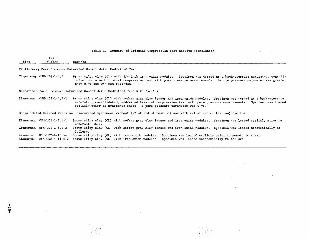
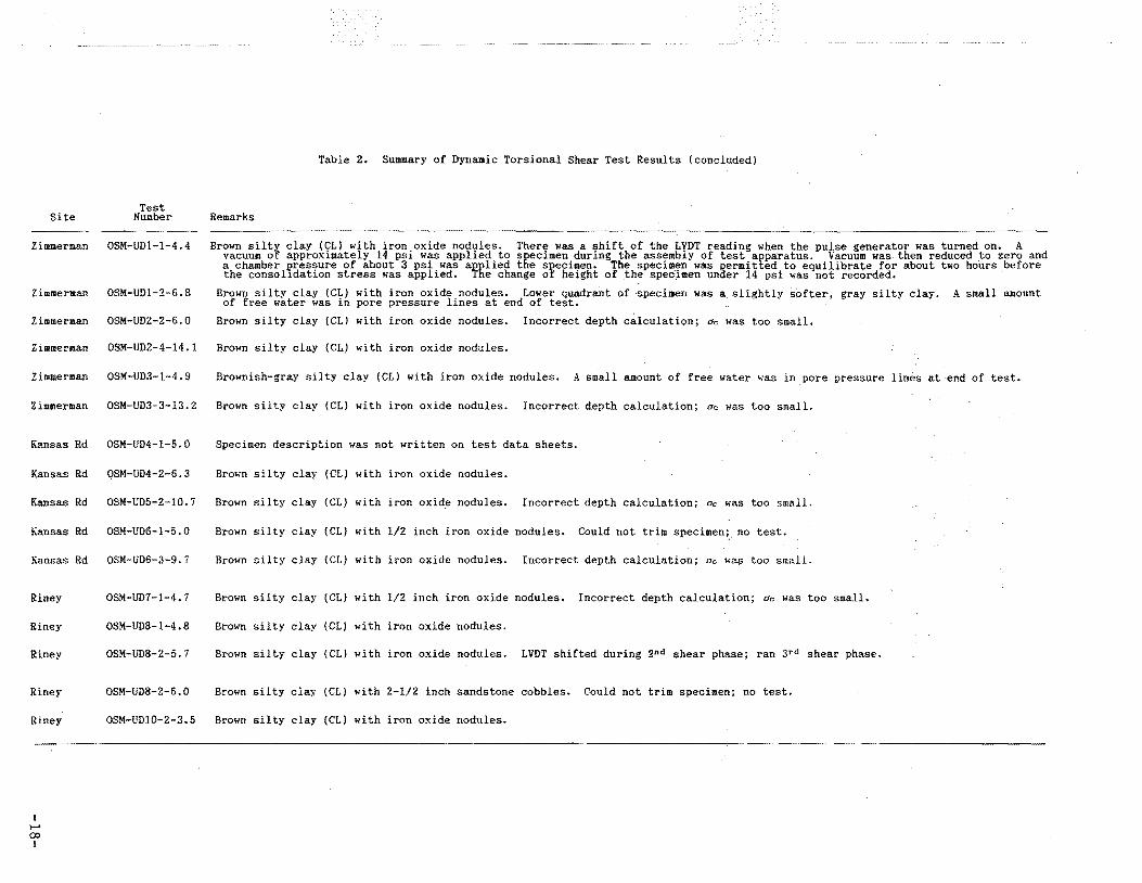
a. Most specimens were a mottled brown to gray silty clay with iron oxide nodules. The size of the iron oxide nodules varied from very small to. about 1/4 in. diameter.
b. The results of the Atterberg limits tests indicated the soil was a low plasticity clay (CL). The liquid limits ranged from 45 percent to 22 percent and the plasticity indexes ranged from 25 percent to 7 percent.
c. The specific gravity of the one specimen tested was 2.73.
5
-8-
CEWES-GV-A SUBJECT: Laboratory Soil Testing - Interagency Agreement No. EF68-IA91-1379~,
"Field and Laboratory Evaluation of Potential Causative Factors of Structural Damages in Daylight/McCutchanville, IN"
d. The test specimens were dense to very dense. Void ratios ranged from 0.79 to 0.52. The initial degrees of saturation of the specimens ranged from 80 percent to 98 percent, although the degrees of saturation for most of the specimens ranged from 85 percent to 95 percent. The question quoted in para. 1 implies that some fully saturated samples would be encountered in the undisturbed sampling program. As indicated by Tables 1 and 2, no saturated samples were encountered in the samples taken which ranged in depth from 4 ft to 14 ft.
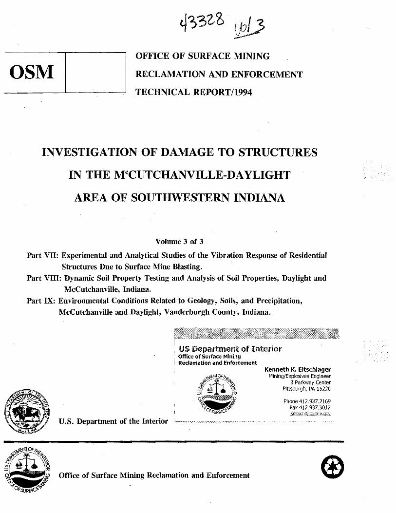
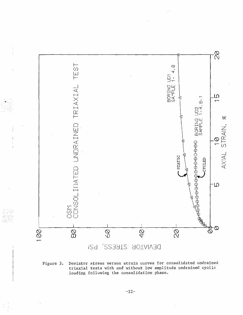
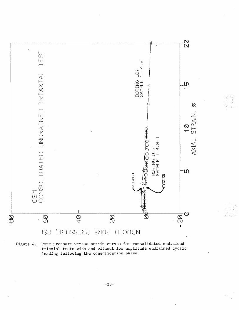
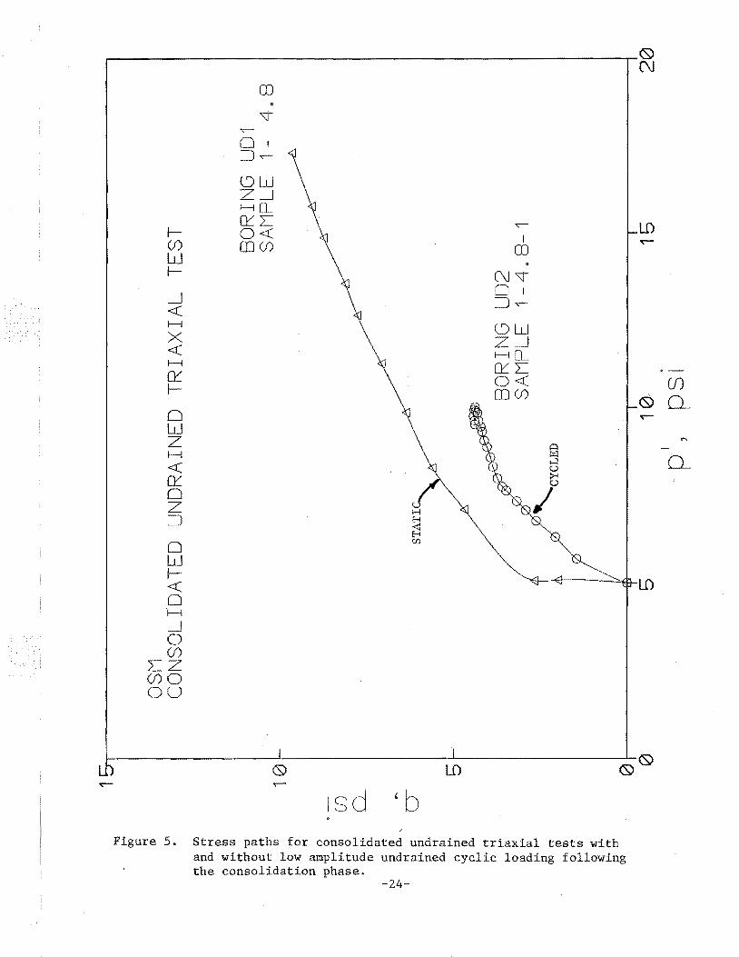
e. The results of the back-pressure saturated, consolidated, undrained triaxial compression test ,with pore pressure measurements indicated that the artificially saturated specimen was dense and strong. Based upon the stress path data, failure occurred at an axial strain of 5 percent to 6 percent. The effective angle of internal friction was 30 degrees and the cohesion intercept was about 2 psi. An effective angle of internal friction of 30 degrees for a clay soil is fairly large. Skempton's A-pore pressure parameter was about -0.8. This value indicated that the specimen tended to dilate strongly during shear and inferred that the specimen was highly overconsolidated. It also infers that the hypothesis that positive pore pressure development and strength reduction due to cyclic loading is unlikely. The test results are summarized as a deviator stress versus axial strain relationship in Figure 3, as an induced pore pressure versus axial strain relationship in Figure 4, and as a shear stress versus normal stress relationship in Figure 5.
f. The back pressure saturated, consolidated, cyclic, and monotonic loading undrained triaxial compression test which was a companion to that discussed in para. 13.e. did not result in any residual pore pressure mobili~ zation at the ends of the specimen after cyclic loading. However, there was a small pore pressure oscillation of -0.4 psi during the cycling of the deviator stress. The specimen tried to dilate during the subsequent monotonic loading; Skempton's A-pore pressure parameter during monotonic shear was about -0.1. The maximum deviator stress during shear was 8.4 psi versus 12.8 psi in the uncycled specimen. However, the initial and post consolidation void ratios of the cyclically loa'ded specimen were substantially higher than those of its companion specimen. This void ratio difference fully accounts for the strength differences. Test results are plotted in Figures 3, 4, and 5 for comparison with the non-cycled companion test.
g. The results of the dynamic torsional shear tests indicated there was little tendency for axial deformation to occur during shear. Typically the axial strains which were caused by torsional loading were less than 0.02 percent. After the shear phase was completed, most specimens rebounded to the height of the specimen prior to the shear test. This behavior may be described as viscoelastic, as compared to the plastic behavior which occurred during the consolidation phase for each test specimen.
6
-9-
CEWES-GV-A SUBJECT: Laboratory Soil Testing - Interagency Agreement No. EF68-IA91-13796, "Field and Laboratory Evaluation of Potential Causative Factors of Structural Damages in Daylight/McCutchanville, IN"
h. Two specimens were tested as resonant column tests after the dynamic shear tests (see paras. 6 and 9) were completed. Shear strains ranged from less than 0.001 percent to about 0.02 percent. The corresponding maximum shear moduli were of the order of 5000 psi, but decreased to about 3000 psi at larger shear strains. Material damping increased from 3 percent at smaller shear strains to about 7 percent at larger shear strains (see Table 3).
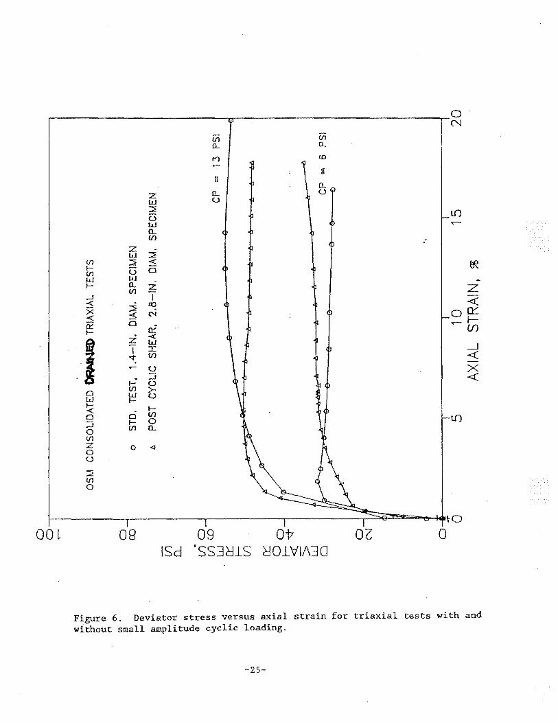
i. The results of the consolidated drained triaxial compression tests on specimens tested at their natural water contents (i.e. unsaturated) indicated that the application of 20 cycles of dynamic axial loading did not affect the consolidated drained strength of the specimens significantly. The test results were expressed as deviator stress versus axial strain relationships in Figure 6. For the specimens from a depth of 6.1 ft, the deviator stress at failure for the specimen which was loaded cyclicly prior to monotonic shear was 31 psi, while the deviator stress for the specimen subjected only to monotonic shear was 30 psi. For specimens from a depth of 13.5 ft, the deviator stresses at failure were about 50 psi. The test data were compared at an axial strain of 5 percent. This value of strain corresponded to the axial strain at which the back pressure saturated triaxial compression test specimen failed. The shear strengths were also compared at axial strains of about 15 percent. For the specimens from a depth of 6.1 ft, the deviator stress for the specimen loaded cyclicly prior to monotonic shear was about 34 psi, while the deviator stress for the specimen subjected to only monotonic shear was about 28 psi. For the specimens from a depth of 13.5 ft, the deviator stress for the specimen which was loaded cyclicly prior to monotonic shear was about 49 psi while the deviator stress for the specimen which was subjected to only monotonic shear was about 55 psi. The differences noted are not large enough to cause foundation instability and are explainable by the small differences in initial water content and void ratios between companion specimens.
Analysis and Conclusions (underlined)
14. Based upon the analysis of the data obtained from the laboratory tests, no anomalies were identified. The responses of the specimens to the loading conditions were anticipated. The material was a dense to very dense silty clay. It exhibited a fairly large angle of internal friction. Under the specified loading conditions, -the specimens subjected to smaller shear strains responded "visco-elastically" whereas the specimens subjected to larger shear strains deformed "plastically." The latter group of specimens tended to dilate during shear. The laboratory data inferred that the soil would perform adequately as a foundation material for lightly loaded structures.
15. Under the sustained oscillating shear strain environment created in the torsional shear tests, the six in. high specimens changed in height by an amount ranging from 5 to 15 ten-thousandths of an inch. This is a vertical
7
-10-
CEWES-GV-A SUBJECT: Laboratory Soil Testing - Interagency Agreement No. EF68-IA91-13796, "Field and Laboratory Evaluation of Potential Causative Factors of Structural Damages in Daylight/McCutchanville, IN"
strain of 0.025 percent or less. Even if such strain occurred uniformly over a 100-ft deep soil column, only 0.3 in. of surface displacement would result. Differential displacement between two surface points would be less. Conventional residential structures would not be damaged by these conditions. The torsional shear tests conducted on samples from three different si'tes offered no evidence to suggest the existence of any kind of collapse mechanism or creep mechanism caused or triggered by sustained low level vibration. The specimens essentially behaved visco-elastically in the tests conducted. This eliminates soil structure collapse or creep due to sustained vibration from the list of possible causal mechanisms for the observed building distress.
16. The comparison of the consolidated drained cyctic and non-cyclic triaxial tests showed no strength loss due to cycling of the deviator stress, at 4 percent to 7 percent of the peak strength. These tests were on unsaturated specimens and, because of this, shed no light on the question of whether positive pore pressure would have been mobilized by cycling a saturated undrained specimen. The consolidated undrained static test was performed on an artificially saturated specimen. It indicated negative pore pressure in shear at large shear strains. Negative pore pressures increase rather than degrade strength. One consolidated undrained test (with cyclic loading) was also performed on an artificially saturated specimen. It showed:
a. No induced pore pressure at the ends of the specimen after cyclic loading.
b. A tendency to dilate during shear as inferred by the negative pore pressure response during undrained shear.
c. A shear strength consistent with the shear strength of the uncycled test when the initial, naturally occurring void ratio differences between the specimens are considered.
The fact that all specimens from depths of 14.0 ft or less for which degrees of saturation in situ were determined were less than 98 percent, and most were less than 95 percent, and all of the trends exhibited in the triaxial testing program indicate that positive pore pressures induced by cyclic undrained loading are just not possible in the in situ condition at depths sufficiently shallow so as to impact the bearing capacity of residential building foundations.
17. At the outset of this study, it was judged that the two hypothesized causal mechanisms (pore pressure rise or collapse under cyclic loading) to be evaluated in the laboratory dynamic soil testing programs were unlikely. Nevertheless since it was possible to conduct definitive laboratory testing which would eliminate the need for judgment, it was decided .to proceed.
8
-11-
CEWES-GV-A SUBJECT: Laboratory Soil Testing - Interagency Agreement No. EF68-IA9l-l3796, "Field and Laboratory Evaluation of Potential Causative Factors of Structural Damages in Daylight/McCutchanville, IN"
The testing program confirmed that these hypothesized causal mechanisms were not physically possible in the soils tested.
18. If you have questions regarding the laboratory test results or the interpretation of the data, please call Dr. Richard W. Peterson at 60l-634-3737.or Dr. Paul F. Hadala at 601-634-3475.
11 Encls
CF:
~A.~~~-~ RICHARD W. PETERSON Research Civil Engineer Geotechnical Laboratory
Mr. Peter Michael, Office of Surface Mining Mr. Vince Chiarito, CEWES-SS-A
9
-12-
PAUL F. HADALA Assistant Director Geotechnical Laboratory
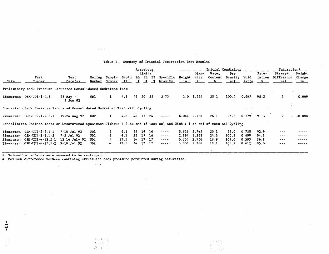
Table 1. Summary of Triaxial Compression Test Results
Atterberg Initial Conditions Limits Diam· Water Dry
Test Test Boring Sample Depth LL PL PI Specific Height eter Content Density Void Site Number Date(s)_ Number ~ ...!L_ _! _! _! Gravitx ...:....in..... ...:!It,_ ' J2Cf Ratio
Preliminary Back Pressure Saturated Consolidated Undrained Test
Zimmerman OSM·UDl·l-4.8 28 May - UDl 1 4.8 45 20 25 2.73 3.0 1.374 25.1 100.4 0.697 8 -Jun 92
Comparison Back Pressure Saturated Consolidated Undrained Test with Cycling
Zimmerman OSM·UDZ-1-4.8-1 19-24 Aug 92 UD2 1 4.8 42 18 24 6.044 2.788 26.1 95.8 0.779
Consolidated-Drained Tests on Unsaturated Specimens Without (-2 at end of test no) and With (·1 at end of test no) Cycling
Zimmerman OSM-UDl-2-6.1-1 7-10 Jul 92 UDl 2 6.1 35 19 16 ..... -- 5.616 Zimmerman OSM-UDl-2-6.1-2 7-8 Jul 92 UDl 2 6.1 35 19 16 -..... - 2.994 Zimmerman OSM·UD2-4-13.5-l 13-16 July 92 UD2 4 13.5 34 17 17 .... - .. 6.203 Zimmerman OSM-UD2-4-13 5-2 9-10 Jul 92 UD2 4 13.5 34 17 17 -- ..... 3.006
* Volumetric strains were assumed to be isotropic. # Maximum difference between confining stress and back pressure permitted during saturation.
I .... \.A)
I
2.745 25.1 98.0 0. 738 1.368 24.3 100.3 0.699 2.766 18.9 107.0 0.593 1.366 19.1 10.5. 7 0.612
Saturatj.on* Satu- ·Stress# ·Height ration Difference Change _J__ J2Si ~
98.2 3 0.009
91.3 2 -0.008
92.9 94.9 86.9 85.0
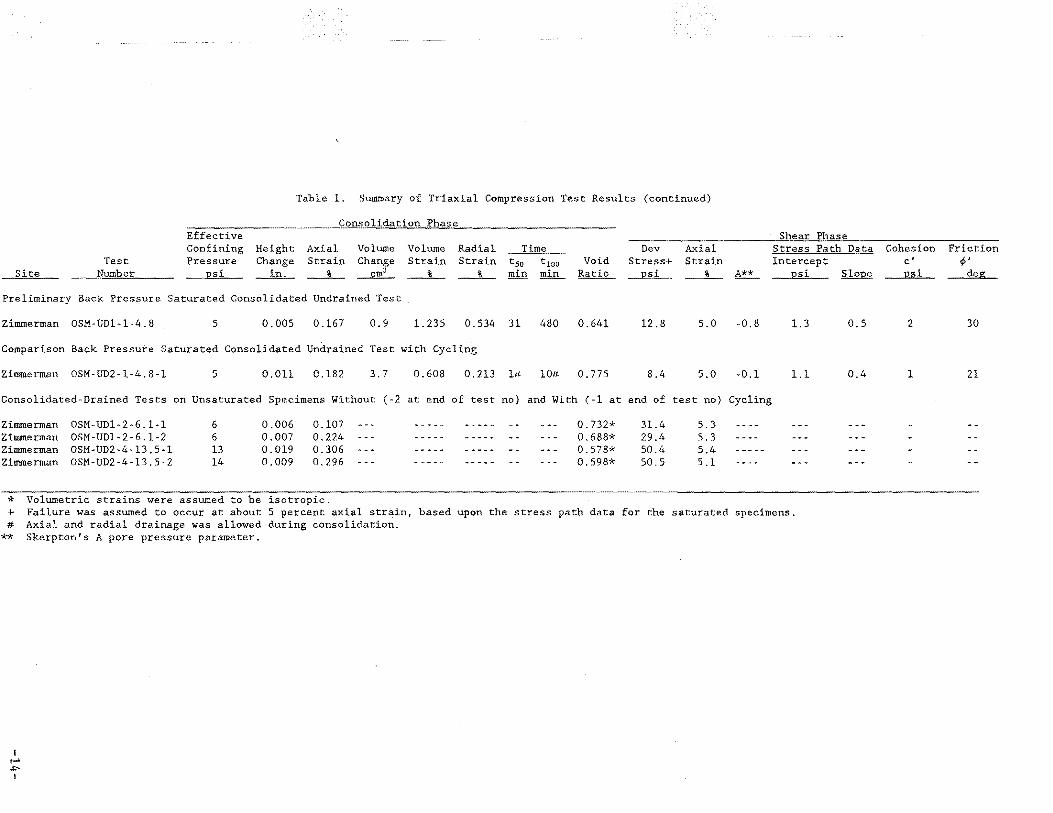
Table 1. Summary of Triaxial Compression Test Results (continued)
Consolidation Phase Effective Confining Height Axial Volume Volume Radial Time Dev Axial
Test Pressure Change Strain Change Strain Strain t5o tlOO Void Stress+ Strain Site Number psi_ _1n_,_ __ %_ ---f.!!L __% _ __ %_ min min Ratio ]2Si __%_ A**
Preliminary Back Pressure Saturated Consolidated Undrained Test
Zimmerman OSM~UDl~l-4.8 5 0.005 0.167 0.9 1. 235 0.534 31 480 0.641 12.8 5.0 -0.8
Comparison Back Pressure Saturated Consolidated Undrained Test with Cycling
Zimmerman OSM~UD2-l-4.8-l 5 0.011 0.182 3.7 0.608 0.213 l# 10# 0.775 8.4 5.0 -0.1
Consolidated~Drained Tests on Unsaturated Specimens Without (-2 at end of test no) and With (-1 at end of test no) Cycling
Zimmerman Zimmerman Zimmerman Zimmerman
OSM-UDl-2-6.1~1
OSM-UDl-2-6.1-2 OSM~UD2-4-13.5-l
OSM-UD2-4-13.5-2
6 6 13 14
0.006 0.007 0.019 0.009
0.107 0.224 0.306 0.296
* Volumetric strains were assumed to be isotropic.
0.732* 0.688* 0.578* 0.598*
31.4 29.4 50.4 50.5
5.3 5.3 5.4 5.1
Shear Phase Stress Path Data Intercept
JlSi SloJle
1.3 0.5
1.1 0.4
+ Failure was assumed to occur at about 5 percent axial strain, based upon the stress path data for the saturated specimens. # Axia:'. and radial drainage was allowed during consolidation.
** Skerpton's A pore pressure parameter.
I 1-' .1::-1
Cohesion Friction c' ¢' PSi deg
2 30
1 21
I ...... 1.11 I
Site Test
Number
Table 1. Summary of Triaxial Compression Test Results (concluded)
Remarks
Preliminary Back Pressure Saturated Consolidated Undrained Test
Zimmerman OSM-UDl-1-4.8 Brown silty clay (CL) with 1/4 inch iron oxide nodules. Specimen was tested as a back-pressure saturated, consolidated, undrained triaxial compression test with pore pressure measurements. B-pore pressure parameter was greater than 0.95 but was not recorded.
Comparison Back Pressure Saturated Consolidated Undrained Test with Cycling
Zimmerman OSM-UD2-l-4.8-l Brown silty clay (CL) with softer gray clay lenses and iron oxide nodules. Specimen was tested as a back-pressure saturated, consolidated, undrained triaxial compression test with pore pressure measurements. Specimen was loaded cyclicly prior to monotonic shear. B-pore pressure parameter was 0.95.
Consolidated-Drained Tests on Unsaturated Specimens Without (-2 at end of test no) and With {-1 at end of test no) Cycling
Zimmerman OSM-UDl-2-6.1-1 Brown silty clay (CL) with softer gray clay lenses and iron oxide nodules. Specimen was loaded cyclicly prior to monotonic shear.
Zimmerman OSM-UDl-2-6.1-2 Brown silty clay (CL) with softer gray clay lenses and iron oxide nodules. Specimen was loaded monotonically to failure.
Zimmerman OSM-UD2-4-13.5-l Brown silty clay (CL) with iron oxide nodules. Specimen was loaded cyclicly prior to monotonic shear. Zimmerman OSM-UD2-4-13.5-2 Brown silty clay ( CL) with iron oxide nodules. Specimen was loaded monotonically to failure.
I 1-' 0' I
Site
Zimmerman
Test Number
OSM-UD1-1-4.4
Test Date(sl
4-5 Jun 92
Zimmerman OSM-UD1-2-6.8 8-9 Jun 92
Zimmerman OSM-UD2-2-6.0 26-27 Jun 92
Zimmerman OSM-UD2-4-14.1 29-30 Jun 92
Zimmerman OSM-UD3-1-4.9 9-10 Jun 92
Zimmerman OSM-UD3-3-13.2 10-11 Jun 92
Kansas Rd OSM-UD4-1-5.0 12-13 Jun 92
Kansas Rd OSM-UD4-2-6.3 17-18 Jun 92
Kansas Rd OSM-UD5-2-10.7 15-16 Jun 92
Kansas Rd OSM-UD6-1-5.0 16 Jun 92
Kansas Rd OSM-UD6-3-9.7 16-17 Jun 92
Riney OSM-UD7-1-4.7 19-20 Jun 92
Riney OSM-UD8-1-4.8 22-23 Jun 92
Riney OSM-UD8-2-5.7 23-24 Jun 92
Riney OSM-UD8-2-6.0 23 Jun 92
Riney OSM-UD10-2-3.5 25-26 Jun 92
Boring Number
UD1
UD1
UD2
UD2
UD3
UD3
UD4
UD4
UD5
UDS
UD6
UD7
UD8
UD8
UD8
UD10
Table 2. Summary of Dynamic Torsional Shear Test Results
Initial Conditions Final Conditions S"atur-Sample Dram= - Water Dr~ Void
Number Depth Height eter Content Dens1ty Ratio J.:h_ __in_,_ ~ __ %__ ~
ation Height __ %_ __in_,_
D1am- Water -- Dry Void eter Content Dens1ty Ratio
_ill,_ __ %__ ~
Saturation
_% _
4.4 5.543 2.752 25.5 96.4 0.769 90.5 5.491 2.741 24.6 98.1 0.738 91.0
2 6.8 5.549 2.739 25.5 98.5 0.730 95.4 5.546 2.729 25.0 99.3 0.717 95.4
2 6.0 5.555 2.770 21.9 103.5 0.647 92.2 5.555 2.756 21.4 104.5 0.630 92.8
4 14.1 5.578 2.768 20.8 104.2 0.636 89.5 5.574 2.764 20.5 104.6 0.630 89.1
4.9 5.522 2.735 26.8 92.5 0.844 86.6 5.442 2.714 25.4 95.3 0.789 87.8
3 13.2 5.513 2.806 24:2 100.2 0.701 94.3 5.474 2. 796 23.2 101.6 0.677 93.7
1 5.0 5.512 2.810 18.2 106.8 0.596 83.2 5.502 2.800 18.1 107.5 0.585 84.2
2 _6.3 5.553 2.842 20.6 105.6 0.615 91.6 5.548 2.837 20.3 106.0 0.607 91.1
2 10.7 5.488 2.792 20·4 108.3 0.574 96.8 5.482 2.790 20.2 108.6 0.570 96.6
5.0 20.2
3 9. 7 5.502 2.798 18.2 112.2 0.519 95.7 5.494 2.805 18.0 111.8 0.524 93.6
1 4.7 5.578 2.772 18.8 106.2 0.605 85.0 5.566 2.766 18.4 106.9 0.594 84.7
4.8 5.538 2.820 17.2 108.2 0.576 81.3 5.538 2.819 16.9 108.2 0.575 80.2
2 5.7 5.538 2.757 16.8 109.6 0.555 82.8 5.532 2.754 16.5 110.0 0.549 82.1
2 6.0 18.0
2. 3.5 5.566 2. 775 20.6 102.4 0.664 84.4 5.551 2.763 20.3 103.5 0.646 85.7
I ...... ..... I
Table 2. Summary of Dynamic Torsional Shear Test Results (continued)
Summary of T~at Data
Site Test
Number
Atterberg Limits
LL PL PI _!__!__!
Zimmerman OSM-UD1-1-4.4 43 19 24
Zimmerman OSM-UD1-2-6.8 36 19 17
Zimmerman OSM-UD2-2-6.0 33 17 16
Zimmerman OSM-UD2-4-14.1 38 18 20
Zimmerman OSM-UD3-1-4.9 43 19 24
Zimmerman OSM-UD3-3-13.2 38 18 20
Kansas Rd OSM-UD4-1-5.0 32 14 18
Kansas Rd OSM-UD4-2-6.3 37 17 20
Kansas Rd OSM-UD5-2-10.7 40 19 21
Kansas Rd OSM-UD6-l-5.0 25 18 7
Kansas Rd OSM-UD6-3-9.7 34 17 17
Riney OSM-UD7-1-4.7 25 17 8
Riney OSM-UD8-1-4.8 22 14 8
Riney OSM-UD8-2-5.'i 24 15 9
Riney OSM-UD8-2-6.0 30 16 14
Riney OSM-UDl0-2-3.5 30 18 12
Specific Gravity
ISotrop1c Consohdat10n Pnase Consoh-dation Stress Height Stre~s Chan~e· Ch~nge He~ght
IDil- _l;llil_ ~ ~
5 2 0.0070 5.536
1 4 0.0092 5.540
7 4 0.0076 5.547
14 11 0.0149 5.563
6 3 0.0131 5.509
6 3 o.o16o 5;497
5 2 0.0056 5.506
6 3 0.0053 5.548
4 1 0.0018 5.486
3 0 0.0006 5.501
4 1 0.0040 5.574
5 2 0.0085 5.530
6 3 0.0048 5.533
4 1 0.0033 5.563
Frequency Hz.
20 20
20 20
20 20
20 20
20 20
20 20
20 20
20 20
20 20
20 20
20 20
20 20
20 20 20
20 20
Dynamic Shear Phase Number Shear He1ght Cycles Strain• Change Height
After 2 hr Rest He1ght Change Height ~~
OVerall Change ** of Dimensions Axial Radial
Strain Strain _% __ ~ ~ % %
72,000 0.010 -0.0002 5.536 -0.0003 5.537 72,000 0.033 -0.0016 5.538 -0.0005 5.539 0.94
72,000 0.010 0.0005 5.539 -0.0002 5.539 72,000 0.040 0.0010 5.538 -0.0006 5.539 . 0.05
72 000 102:ooo
12,goo 72, 00
0.009 0.041
8:8!8
0.0003 0.0010
0.0008 0.0014
5.547 5.546
5.562 5.562
-0.0003 -0.0009
-g.ooo8 - .0008
5.547 5.547
5.563 5.563
o.oo
0.07
72,000 0.009 0.0004 5.508 -0.0001 5.508 72,000 0.039 0.0020 5.507 -0.0005 5.507 1.45
72,000 0.010 0.0003 5.497 -0.0001 5.497 72,000 0.042 -0.0009 5.497 -0.0003 5.498 0.71
72,000 0.010 0.0011 5.505 -0.0005 5.506 72,000 0.042 0.0014 5.504 -0.0013 5.506 0.18
72,000 0.010 0.0007 5.547 -0.0007 5.548 72,000 0.042 0.0013 5.546 -0.0012 5.548 0.09
72,000 0.010 0.0002 5.486 -0.0005 5.486 72,000 0.043 0.0003 5.485 -0.0011 5.486 0.11
72,000 0.011 0.0003 5.501 0.0002 5.501 72,000 0.041 0.0006 5.500 -0.0015 5.502 0.15
72,000 0.010 0.0001 5.574 -0.0002 5.574 72,000 0.040 0.0008 5.573 -0.0008 5.574 0.22
72,000 72,000
72,000 72,000
144,000
0.009 0.042
0.010 0.040 0.041
0.0013 0.0016
0.0012 0.0012& 0. 0013
5.528 -0.0010 5.528 -0.0015
5.532 -0.0008 5.532 -0.0011 5.531 -0.0010
5.529 5.529
5.533 5.533 5.532
0.00
0.11
72,000 0.010 0.0004 5.562 -0.0004 5.563 72,000 0.040 0.0012 5.561 -0.0010 5.562 0.12
0.40
0.37
0.50
0.14
0.77
0.36
0.36
0.18
0.07
0.25
0.22
0.04
0.11
0.43
* The stress change l~th~ difference between pressures which were applied to the specimens as the device was assembled (usually 3 psi). and the consolidation pressures.
+ This value is the single amplitude shear strain. & A change of LVDT r~adings occurred during the dynamic shear test; this value was estimated. ** This includes the effect of the total sequence of testing (i.e. consolidation-vibration-rest-vibration-rest). Most of the Change is due to
the consolidation phase.
Site
Zimmerman
Zimmerman
Zimmerman
Zimmerman
Zimmerman
Zimmerman
Kansas Rd
Kansas Rd
Kansas Rd
Kansas Rd
Kansas Rd
Riney
Riney
Riney
Riney
Riney
I ...... co I
Test Number
OSM-UD1-1-4.4
OSM-UDl-2-6.8
OSM-UD2-2-6.0
OSM-UD2-4-14.1
OSM-UD3-1-4.9
OSM-UD3-3-13.2
OSM-UD4-l-5.0
QSM-UD4-2-6.3
OSM-UD5-2-10.7
OSM-UD6-1-5.0
OSM-UD6-3-9.7
OSM-UD7-1-4.7
OSM-UDS-1-4.8
OSM-UDS-2-5.7
OSM-UDS-2-6.0
OSM-UDl0-2-3.5
Table 2. Summary of Dynamic Torsional Shear Test Results (concluded)
Remarks
Brown silty clay (CL) with iron oxide nodules. There was a shift of the LVDT reading when the pulse generator was turned on. A vacuum of approximately 14 psi was applied to specimen during the assembly of test apparatus. Vacuum was then reduced to zero and a chamber pressure of about 3 psi was applied the specimen. The specimen was permitted to equilibrate for about two ho.urs before the consolldation stress was applied. The change of height of the spec'imen under 14 psi was not recorded. ·
Brown silty clay (C~) with iron oxide.nodules. Lower quadrant of specimen was a slightly softer, gray silty clay. A small amount of free water was 1n pore pressure l1nes at end of test.
Brown silty clay (CL) with iron oxide nodules. Incorrect depth calculation; ac was too small.
Brown silty clay (CL) with iron oxide nodules.
Brownish-gray silty clay (CL) with iron oxide nodules. A small amount of free water was in pore pressure lines at end of test.
Brown silty clay (CL) with iron oxide nodules. Incorrect depth calculation; ac was too small.
Specimen description was not written on test data sheets.
Brown silty clay (CL) with iron oxide nodules.
Brown silty clay (CL) with iron oxide nodules. Incorrect depth calculation; ac was too small.
Brown silty clay (CL) with 1/2 inch iron oxide nodules. Could not trim specimen;_ no test.
Brown silty clay (CL) with iron oxide nodules. Incorrect depth calculation; ac was too small.
Brown silty clay (CL} with 1/2 inch iron oxide nodules. Incorrect depth calculation; ac was too small.
Brown silty clay {CL) with iron oxide nodules.
Brown silty clay {CL) with iron oxide nodules. LVDT shifted during 2nd shear phase; ran 3rd shear phase.
Brown silty clay {CL) with 2-1/2 inch sandstone cobbles. Could not trim specimen; no test.
Brown silty clay (CL) with iron oxide nodules.
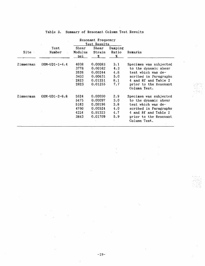
Table 3. Summary of Resonant Column Test Results
Resonant Frequency Test Results
Test Shear Shear Damping Site Number Modulus Strain Ratio Remarks
psi %
Zimmerman OSM-UDl-1-4.4 403S O.OOOS3 3.1 Specimen was subjected 377S 0.00162 4.3 to the dynamic shear 3526 0.00244 4.S test which was de-3403 0.00631 5.0 scribed in Paragraphs 2S23 0.01251 S.1 4 and Sf and Table 2 2S23 0.01255 7.7 prior to the Resonant
Column Test.
Zimmerman OSM-UD1-2-6.S 5624 0.00050 2.9 Specimen was subjected 5475 0.00097 3.0 to the dynamic shear 51S3 0.00196 3.S test which was de-4760 0.00524 4.0 scribed in Paragraphs 4224 0.01323 4.7 4 and Sf and Table 2 3S43 0.01709 5.9 prior to the Resonant
Column Test.
-19-
"
"Tj 1-'·
~ H CD
t-'
:;o CD tn 0
I ::; N Ill 0 ::;
, ("t
(') 0 t-'
~ ~ 'tl Ill H Ill g tn .
Long. Chg. Amp!.
\"- -- ----·- Length Chan L_t •] Rand Pore Pre~~. [
---.1 eadout
I Valid~
l. Signal
-~·----l·_t ___ r- I Conditioner I Apparatus
(
[: Tran$d:U£.!.L
Tors. Chg. Ampl.
Control Box -, I
--1---------~,. ___ _
[-···----] ............. ___ . Oscilloscope
• •
Pow•r rl?.!!fl!L:-·
i
l_ --.. -~ - -- ··- -- - -·
----··--· ._,_ .. __ ,.,_ ........ ,,. -···. -····· .,.... ... _______ ..,_,..
DM502 I OM502 I OCS04 I FGSO
- -- -r---· _L_ ___ r- -· L
TEKTRONIX TM504
c.o
2 o.oo
~ ~ otO.ooz. .(
~ 'ft
i (!),OOJ
d. :z.
0 0~------------~0~--------~~--~-------
. I O.Z,.
Figure 2. Shear strain versus particle velocity relationship for onedimensional linear elastic wave propagation.
-21-
. '"t~
0 0 ...--
0 '(\]
1- CD (/) . w "'t"
01 :J~
l')W Z_j HQ_
H 0:::2::: LO X 0~
ffi(l) I .;--<( m H N"-'t
G:: 01 :J...-
l')W ~
0 z_j HQ_
w O::::L z 0~ ffi(f) <(
H 0cr: <( I-G::
.;--({)
0 z :J
0 w <( ,..., LO L: H _j 0 (/)
L:Z (/)Q ou
0 0 0 0 00 m ~ T C\J
ISd 'SS3~1S ~OlVI/\30
Figure 3. Deviator stress versus strain curves for consolidated undrained triaxial tests with and without low amplitude undrained cyclic loading following the consolidation phase.
-22-
_j
<(
X <(
(/) w 1--
I-I
X <( I-I
(S) N
m . "¢
01 ::::J~
DW Z_j f-i(L ~L: 0<( Q)(/)
ISd '3dnSS3tld 3d0d 03JnO~II
I m
C\1"¢ 01 ::::J~
(S) N
lf) ....-
Figure 4. Pore pressure versus strain curves for consolidated undrained triaxial tests with and without low amplitude undrained cyclic loading following the consolidation phase.
-23-
f:R
_j <(
X <(
QJ
~ ~
01 ~..,--
DW Z_j HD_
G::::L ..,--1- O<C I (f) [D(f) QJ w 1- N~
_j CJ I ~..,--
<( H DW X _j <( H H G::::L fr: O<C 1- CD (f)
0 w z H <( fr: 0
H
~ E-1
0 Cf.l
w 1-<( 0 H _j 0 (f)
L ({)0 ou
LO
!Sd 'b Figure 5. Stress paths for consolidated undrained triaxial tests with
and without low amplitude undrained cyclic loading following the consolidation phase.
-24-
('S) N
LO ~
(f)
('S) o_ ~
o_
LO
OOL
0 N
(f) (/)
0.. 0..
n (!)
II II
0..
z 0.. 0 w 0 :::::E 1.[) 0 w ....-0.. (/) .·
z w :L (f) 2 -< tR 1-- 0 0 (/)
w w . 1-- 0.. z (/)
-' I -< :::::E
00 <{
>< -< ('I on:::: -< ~ 0 ..-1--1-- ~ (/)
i z -< w I :::r: __j
"¢ (/) <{
0 X :J <{
1-- 0 0
(f) >-w 0 w 1--1---< 1--0 0 (/)
-' 1-- 0 1.[)
0 (/) a.
(f)
z 0
0 <l
0
2 (f)
0
0
08 09 Oil OZ 0 !Sd 'SSJt:llS t:!OlVIAJO
Figure 6. Deviator stress versus axial strain for triaxial tests with and without small amplitude cyclic loading.
-25-
C" nil
Mr. Chiarito U.S. Army WES Attn: EWES-SS-R
OFFICE OF SURFACE MINING Reclamation and Enforcement
Eastern Support Center T~n P~rkw~y ~nter Pittsburgh; PA 15220
AUG 2 2 1991
3909 Halls Ferry Road ·, Vicksburg, MS 39180-6199
·-- .
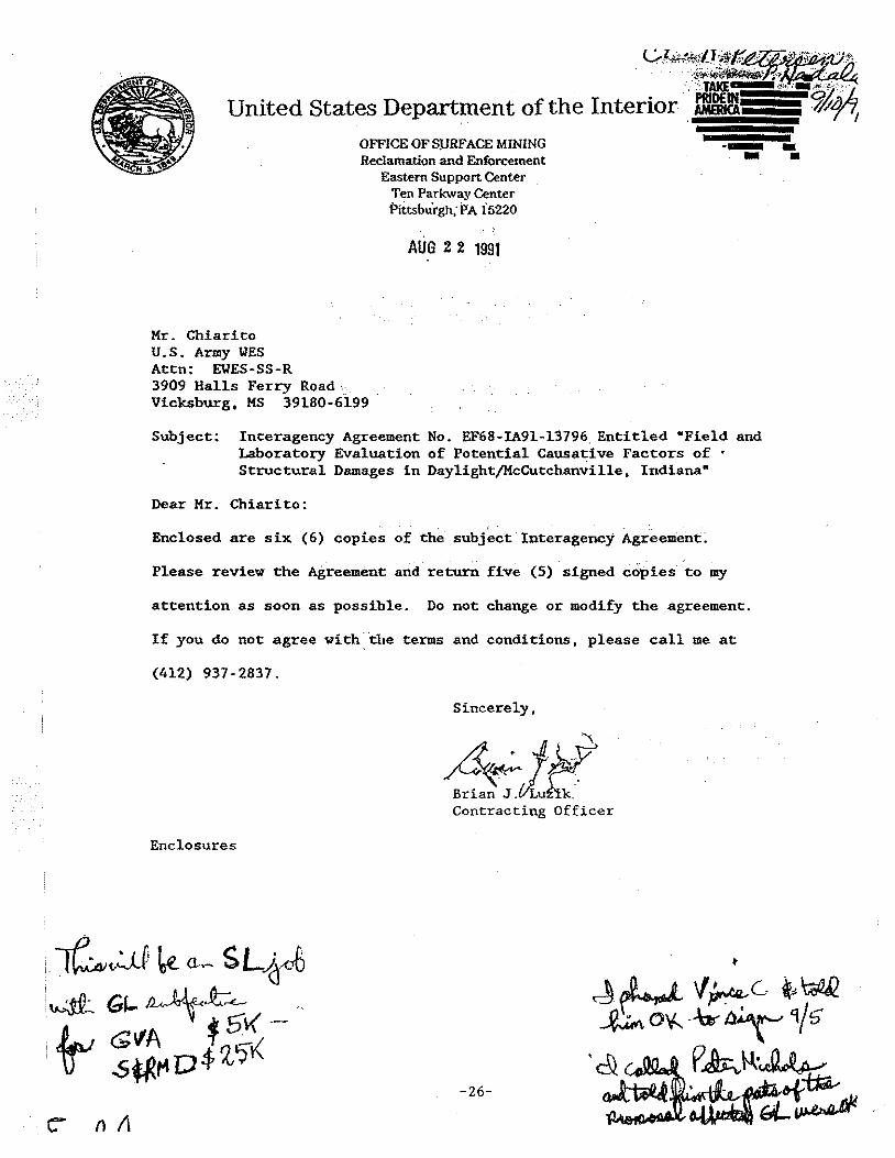
Subject: Interagency Agreement No. EF68~IA91-13796. Entitled wField and Laboratory Evaluation of Potential Causative Factors of • Structural Damages in DaylightjMcCutchanville, Indiana"
Dear Mr. Chiarito:
Enclosed are six (6) copies ofthe subject Interagency Agreement~
Please review the Agreement and return five (5) signed cdpies to my
attention as soon as possible. Do not change or modify the agreement.
If you do not agree with:·the terms and conditions, please call me at
(412) 937-2837.
Sincerely,
4. ~ .J1 . '\
~~~~ Contracting Officer
Enclosures
-26-
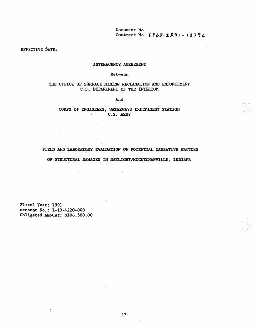
Document No. Contract No. f F b8· ;r; A 'II - I 3 7 ~ t.
EFFECTIVE. DATE:
INTERAGENCY AGREEMENT
Between
THE OFFICE OF SURFACE MINING RECLAMATION AND ENFORCEMENT U.S. DEPARTMENT OF THE INTERIOR
And
CORPS OF ENGINEERS, YATERYAYS EXPERIMEN'.f STATION U.S. ARMY
FIELD AND l.ABORATOR;Y EVAWATION OF .,TENTIAL CAUSATIVE .FACTORS
OF . STRUCTURAL DAMAGES IN DAYLIGHT/MCCUTCHANVILLE, INDIANA
Fiscal Year: 1991 Account No.: 1-13-4220-000 Obligated Amount: $106,500.00
-27-
Document No. Contract No.
INTERAGENct·AGRE'EMENT
Between
THE OFFICE OF SURFACE MINING RECLAMATION AND ENFORCEMENT
And
CORPS OF ENGINEERS , WATERWAYS EXPERIMENT STATION
I . OBJECTIVE
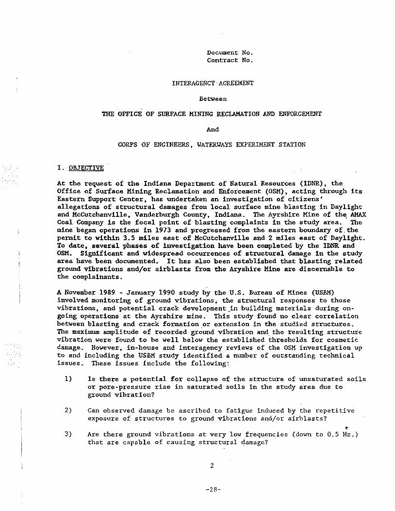
At the request of the Indiana Department of Natural Resources (IDNR), the Office of Surface Mining Reclamation and Enforcement (OSM), acting through its Eastern Support Center, has undertaken an investigation of citizens' allegations of structural damages from local surface mine blasting in Daylight and HcCutchanville, Vanderburgh County, Indiana. The Ayrshire Mine of th~ AMAX Coal Company is the focal point of blasting complaints in the study area. The mine began operations in 1973 and progressed from the eastern boundary of, the permit to within 3.5 miles east of HcCutchanville and 2 miles east of Daylight. To date, several phases of investigation have been completed by the IDNR and OSH. Significant and widespread occurrences of structural damage in the study area have been documented. It has also been established that blasting related ground vibrations and/or airblasts from the Aryshire Mine are discernable to the complainants.
A November 1989 - January 1990 study by the U.S. Bureau of Mines (USBM) involved monitoring of ground vibrations, the structural responses to those vibrations, and potential crack development_in building materials during ongoing operations at the Ayrshire mine. This study found no clear correlation between blasting and crack formation or extension in the studied structures. The maximum amplitude of recorded gr~und vibration and the resulting structure vibration were found to be well below the established thresholds for cosmetic damage. However, in-house and interagency reviews of the OSM investigation up to and including the USBM study identified a number of outstanding technical issues. These issues include the following:
1) Is there a potential for collapse of the structure of unsaturated soils or pore-pressure rise in saturated soils in the study area due to ground vibration?
2) Can observed damage be ascribed to fatigue induced by the repetitive exposure of structures to ground vibrations and/or airblasts?
~
3) Are there ground vibrations at very low frequencies (down to 0.5 Hz.) that are capable of causing structural damage?
2
-28-
4) Are there comparable damages in a remote area (unaffected by blasting) with simil~r geology, soils, and topography?
5) ·Do airblasts produce adverse structural response in the study area? .· . -.
6) Certain types of structural damages, observed by some investigators, appear to have been caused by lateral forces. If so, what are the relati~e contributions of blast-induced ground vibrationsjairblasts, earthquakes, and wind to this force?
7) 'Do alternative mechanisms (inadequate foundations, ·slopejsoil movement) contribute to the observed damages?
8) To what degree do geology, soil, and topography influence ground wave propagation, site response amplification, and the amplitude, frequency, and duration of waves?
9) To what extent does blast design (both conventional and cast blasting) alter the effects of blast vibrations in the study area?
II. BACKGROUND
The work to be performed under this is Agreement will be an integral part of an interagency study aimed at resolving the above issues. Other agencies participating in this study are the U.S. Bureau of tfines (USBM) and the U.S. Geological Survey (USGS) • The tasks to be performed specifically by the Corps of Engineers, Yaterways Experiment Station (YES) are designed to address Issues 1, 2, 3, 5, 6, and 7. Technical support to this Agreement will be provided by the IDNR and OSM.
Authority to enter into this Interagency Agreement is contained in the Surface Mining Control and Reclamation Act of 1977 (P.L. 95-87) and the Economy Act (P.L. 97-258).
III. TERMS OF AGREEMENT
This Agreement may be amended by mutual consent of both parties in writing. The period of performance of this Agreem~nt shall be for one year from date of acceptance. It shall continue in force unless modified by mutual consent or terminated by either party by written notice to the other party at least 30 days prior to the termination date. Due to the nature of field and analysis tasks being undertaken and the required schedule for completion, it is acknowledged that the Agreement will span portions of FY 1991 and FY 1992.
IV. STATEMENT OF WORK
A. OSM agrees to:
1. Provide personnel for the purpose of coordinating site selection and
3
-29-
other field activities affecting structure analyses; and ground vibration, airblast and structure response monitoring.
2. Obtain all.rights.~f.entry and all otqer ~overoment cl~~rances for p'roperty access. . . . :·... .. . .. . . . . . . ..
3. Provide geophysical and shallo~ drilling and undi~turbed sampling services, through a contractor or government agency, for purposes of collect~ng soil samples from sites in Daylight, McCutchanville and a "remote" area (unaffected by blasting). Exact sampling procedures and
· locations and depths w~ll be selec~ed by OSM in consultation with the principal investigator. · ·
4. Provide soil samples to WES for transport to the Waterways Experiment Station in Vicksburg, Mississippi for cyclic load testing.
5. Reimburse WES for personnel, equipment, materials, travel, per diem and other expenses incurred in performing tasks under this-~ -up to the amount of $167,075.
B. The WES agrees to:
1. Perform testing and modeling services in the field and lab as. per the following Scope of Work:
IN-FIEID MONITORING AND STRUCTURAL D~CS ANALYSES
a. Select one structure in the study area for load failure analyses. Select one st~cture in the study area for monitoring ground vibrations, airblasts and s~ructural response.
Conduct engineering analyses on selected structure to (l) estimate vertical.wall l9ads on .. f~~_E~~§.~·J(2')aetermine probabll!-....., G L
.:..._extent;__~! .. ~l!1l~-~i.9Jl ... S~t~~ement from estf.rila~ed static wall loads · and-\3) determine differential settlements required to cause · cl«i._ yield line c_ racking in unreinforced basement floor slabs. qv~· . ~
c. Conduct lateral load analyses for unreinforced basement walls in selected structure as follows: i(l) Develop realistic bounding
. values for lateral earth. pressures on basement walls, to include '---P-t;ol?_ab..!e.._values for confined swell pressures in expansive clays;·
(2) estimate vertical loads on the walls; (3) estimate structural strength of the w~lls; and (4) estimate onset of cracking in the walls, using values for lateral earth pressures, vertical wall loads and wall strength.
d. Monitor free·field and near-structure ground vibrations; airblas~ distributions on mine-facing side of structure; and structural response during surface mine blasting_activity and other so~rces of cyclic loading~ Monitor ground vibrations in the range of 0.5 to 60 Hz. Also conduct a modal test to identify overall and. component dynamic properties of structure. Use data to determine
4
-30-
energy levels of very low frequency vibrations; and interrelationships between exterior dynamic loadings and structural response.
e. Perform multi-degree-of-freedom and fatigue analyses using a structural model (one-story a~d. two-story) based on information obtained under Task Lei. Estimate minimum stress ·1evels that could caUse cracking · and/9r othel- damage based· on various scenarios pertaining to dynamic. loading .• parameters. material prestrain levels and fatigu~. Determine whethe~ relationship exists between common crack patterns :i.n the Study area and cyclic loading.
LABORATORY SOIL TESTING
f. -·i'-est:· a·oil .. sampi'es .. for.coitSoTidat:i.on under induced·::cyclic loading · \. as follows: Apply cyclic loading tests ,to 12 sa.mPles obtained I from D~ylight, KcCutchanville and the i!'~ote area by OSM. \ .Between 12 and 24 tests shall be conducted usb1g a Drnevich t:; 1 resonant column loading device. Each tested sample shall be ~ drained and subjected to 30,000 cyclic loadings in a frequency
l range of 4 to 20 ·Hz. All 12 samples s~ll initially be tested at· J- two separate shear strain levels,· the largest of which shall be ! based on the highest observed peak particle velocity measured in I the study area. Furthe+ testing at 1/10 the original shear . strain level shall be performed o'nl.y 'if consolidation is detected
in the initial result~. . ... /
g. ·'
If~~~iidation occurs ·in· te~ting under Task l.f., evaluate potential damaging effects of soil consolid.S.tion beneath structural foundations. ·The evaluation shall be based on av~ilable site-specific soil data as \..ell as the test results.
:::::-~---·-··--' -· . -· .. h. f-·Cobduct two pilot undrained cyelic triaxial tests and two
' . . . i '
\ companion static. undrained. triaxial . tests.· to failure on saturated specimens from the study area. Use a vertical strain level equal to twice the maximum shear strain level used under Task l.f. Assess whether significant strength degradation occurs as a result of low level cyclic loading. If significant strength degradation is determined, .recommend fur~et testing not funded under· this IA.
i. !' If significant strength degradation is determined under Task ~ l.h., develop a chart showing effect of degradation on slope
stability.
2. Attend meetings with other interagency .team members from USGS, USBM,
,, . i
OSM and IDNR. Present preliminaryrfindings, recommend project $6 modi~ications where. app:opriat: ~no ideritify suppor:jcoordination ~ /r requ~rements for remain1ng act~v1ties .. Theexact t1me and place· of the f::...J
me~tings shall be agreed U:pon by all project participants. · .,.;:>{
s
-31-
I
; ····· ... OJ
the.\~ results 1/Gt.._
. 3. i Following compl.etion of all ·field work and analysis, meet. with interagency team to develop an interagency draft report on the of the investigation.
4. Perform services ac~~~ding to the following schedule:
,a. Mobilize necessary personnel and equipment to the study area for field operations upon selection of study sites.
b. ~~-A~tend an interagency team meeting for evaluation of project progress and consideration of possible project modifications
! ~1L~tgl}._ty __ (~.0).-~l.~E~F-.~ys of this Agreement's effective , date. · · ·· ·· ···· ·• \.....- ... ..;
c. Complete field monitoring and all other data-gathering activities within one hundred and five (105} calendar days of this Agreement's effective date.
d.
e.
J Complete all data analyses within one hundred and eighty (180) [ calendar days of this Agreement's effective date.
~ttend (with written YES draft report in hand} an•interagency 1 team meeting to develop composite draft final report following i performance of 4.d, but within two hundred and twenty (220) J calendar days of this Agreement's effective date.
f ' I i
-.....!
f. Complete the review of the interagency team composite draft final report following the performance of 4.e, but within two hundred and thirty (230) calendar days of this Agreement's effective date.
V. KEY OFFICIALS
project officers shall be:
Peter Micha~l (COTR) Office of Surface Mining Reclamation and Enforcement Eastern Support Center Ten Parkway Center Pittsburgh, PA 15220 412-937-2867
Vincent P. Chiarito U.S. Army Engineer WES Attn: CEWES-SS-R 3909 Halls Ferry Road Vicksburg, MS 39180-6199 601-634-2714
~>G •
SL 1 .. . I
iThe principal investigators for WES will be Vincent Chiarito and
1
Dr. Paul Hadala. !
6
-32-
VI. FUNDING
OSM will fund this Agreement by obligations under its Regulatory and .. Technology Activity usi.ng a combinati-on of FY l99l·and FY 1992 funds.
FY 1991 funds in the amount of $106,500 will be obligated with the execution of this agreement and will remain available to the WES until expended~ ~e remaining $60,575 will be obligated from FY 1992 funds on or after October 1, 1991.
VII. fAYMENT
VIII.
Monthly payment will be made by OSM upon receipt of a properly executed Standard.Form 1081 and the required monthly report. The form shall be submitted to:
OFFICE OF SURFACE MINING RECLAMATION AND ENFORCEMENT Eastern Support Center Ten Parkway Center · Pittsburgh, PA 15220 ATTN: Management Services Branch
DELIVERABLES
The fol;low:!.ng it.ems are deliverables under this Agreement:
a. Three copies of monthly letter reports outlining monthly activities, problems encountered, and budget status. are to be submitted to the OSM project officer by the 7th of ~he following month.
b. One hard copy and 5 1/4 inch diskettes of the agency's draft report for incorporation into~he interagency team report. The report diskettes are to be on software compatible with "Word Perfect" version 5.0.
c. One set of 5 1/4 inch diskettes containing all databases of field data and analyses. The applicable software for operation must be identified for each database.
d. The following deliverables are to be completed prior to OSM's acceptance of work performed under this Agreement:
i. Submission and acceptance of the interagency team's composite report;
ii. Submission of a copy of all field data gathered during the investigation including photography, data logs/record~. and laboratory test results; and
iii. Participation of the principal investigator in an
7
-33-
IX. EVALUATIONS
interagency briefing of OSM management staff following submission of the final team report to OSM.
OSM reserves the right to make programmatic evaluations of the work carried out by the YES under this Agreement, including field or laboratory site visits. Any such visits will be made with the prior knowledge of the YES project officer. Appropriate and mutually agreeable overview procedures will be established by the YES and OSM project officers to adjudicate review results in the case of YES·OSM disagreement.
X. PUBLIC INFORMATION
All information obtained under the terms of this Agreement is public property.
Copies of all scientific publications of the results of research under this Agreement and any press releases prepared by YES regarding this
·Agreement and/or any subagreements will be forwarded for review to the cognizant Project Officer prior to public release or presentation: In all such cases, credit for joint support to YES and OSM shall be acknowledged in all printable material. In the case of failure to agree as to the interpretation of results, either party'may publish data after due notice and submission of the proposed manuscript to the other. In such instances, the party publishing the data will duly credit the cooperation of the other party, but will assume responsibility for any statements on which there is a difference of opinion. To prevent disclosure of information requested to be kept confidential by third parties and prohibited from disclosure by Federal law and to protect potential patent and invention rights, Project Officers shall seek advice of their respective General Counsel's office as appropriate. Provisions of this Agreement cannot supersede public disclosure requirements of the Freedom of Information Act.
XI. MISCELLANEOUS
During the performance of this Agreement, the participants agree to abide by the terms of Executive Order ll246 on non-discrimination and will not discriminate against ant person because of race, color, religion, sex, or national origin. The participants will take affirmative action to ensure that applicants are employed without regard to their race, color, religion, sex, or national origin.
No member or delegate to Congress, or resident Commissioner, shall be admitted to any share or part of this Agreement, or to any benefit~that may arise therefrom,· but this provision shall not be construed to extend to this agreement it made with a corporation or its general welfare.
8
-34-
Signed this __ day of ____ , 1991.
UNITED STATES DEPARTMENT OF THE INTERIOR OFFICE OF SUREACE MI~ING RECLAMATION AND ENFORCEMENT
By: -------------------------------------------------------------------Title: __________________________________________ _
Accepted th:l,s __ day of ______ , 1991.
UNITED STATES ARMY, CORPS OF ENGINEERS 'W'ATERYAYS EXPERIMENT STATION
By: __________________________________________ ~---
Title~---------------------------------------------
9
-35-
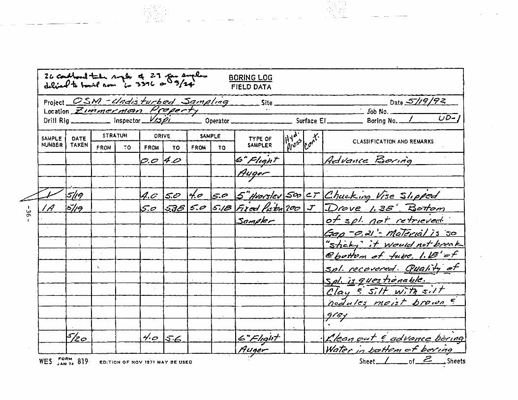
-2L.~-\;.L... ~ C\ ~, t..,..,~, BORING LOG ~-b. ~ "'- """ ~ ~.,(.. ..,.. .,,"+ FIELD DATA
Project 0 .S N7 - L'/4a?s l-~rr6ed ..:Sc,n,e_l~,.;~ Site Date ..:S/19 /9 4 Location Z.Nn!:!t.l!!"Y"t.Z!.c::l,, Pfo/e-,t-y ' .. · Job No • Drill Rig Inspector 0;Jj:?i ' Operator Surface El Boring No. I . LJ{) .. ,
STRATUM DRIVE SAMPLE e.· K· SAMPLE DATE TYPE OF '}icP el CLASSIFICATION AND REMARKS NUMBER TAKEN FROM ;o FROM TO FROM TO SAMPLER
o.o 4.0 6 "'rlu/h t- //d VC:Ut£'~ Be:-,..-,,"q Auo:,.....
/ . ~ ~ :5'b9 4.0 S:c> ~e? s;.e:> s'#y~.l)'/.ev Sct> t!.T Ci/;uc..k,~ J.tse sl,~.;t~~e/ - h J'~ /l.sb, Vre:>ve
., / • .3 8 i' -at>·'Tfc>n? I 1/1 t>/i'? S:o ~-:78 5:&? ~'"':/8 7t?o ..:r
\..V 0'\
1.S.t:lm//e.,.- o.;:. :s..tJI. /JC?i# /~ </r,~;ed- · I
l/"2-...., - t:::'. ~~ '- m a "-t;;y,t:i I ; -s ·;:;·o ·
''s-1-z;;.k,.y.. ,· f Wc:7utd ,.1?.;-b/'t:"l'\ J:.._
t(g bd'tk,.., d.,c ..,4.t/:;?t:!l'. /. /6!1 1 c ,c
l ••• :SZ?I· /"t:U"e?Vt:!',..-tl!"'d· t:'J)Qtt;/.".,4. CP~ ~
_,AI. 'is_ 9 Q~ .lz.t?nnblt!'. ~- .... --r- 't» '1-t!/ac.1 ~ S,/ W.r .:s.J no;;/ u lt!'s nt&? ,; r .e:u~p • .,;n 'f.
/
t!J/<1!?-/ ~~ / .
~ko .,.;.0 .::> :b ~ .. /=hqi,'f' , c/ea,.., pu·l- "!.' .t:"/dJ-'bJ~~~ b&'rl'n&~-, )#,~,.. /~ .ht:?H.i?n'f c-;t: be-'//hCJ
... /91.144,...
WES ::NR':,. 819 EDiTION OF NOV .1971 MAY BE USEO Sheet I of Z Sheets
BORING LOG FIELD DATA
Project t:?S M - 4naltj ..J-u,-bC'd Sa ,:fl,.t?IJ1ff!. Site Date .S:LZt? Jr;:Z_ Location P /dtt:t?eJ""'l2Z.(Zd. k..,. '£ff_r.J.7 Job No. Drill Rig Inspector 'i:s'p; Operator Surface El Boring No. I
7 .
SAMPLE DATE STRATUM DRIVE SAMPLE TYPE OF J· e~"·{ ~~ 9' CLASSIFICATION AND REMARKS NUMBER TAKEN FROM ·~o FROM TO FROM TO SAMPLER 'Vc& t:!' -e::::t::? • 6-ns:?
5.6 6./ SQ~t"'l"',./t!'v 5t?l? 2.&>6 'bru/e f.mox. e;/J,,._,~R.bl<!!. ~.I 6.~ hJ'~ jb;t,, ?D"P hvel. :s .Jre?k.) /. ~, .S;/.
ohP 6.6 ?./ 5:7 ?.I ...St:;, ~ /t!'r '/SP t!r ·' ~ ~k meosl~r.:!!!e:>/ ~ f-'..c;.... I /?!!.C e'? ,/ 11" /4 •
2/1 ~-j.2.t:? ?.I '7-F ?.J ?..a 6ft?P - ~ ?. z. '. /Jtn#r;nl ir V't",.~ J
?.6 7.~ l!lt:l? .;:s.J,;_)!.~ Aof bJ""eA k.;dq ;1-.;: d!? ·bD"i;:e,., c- -1-- -kbt!'# e In"$·~ . I
.>J -..!
s,';r w/ s, .. Jf 4,-,d VJ/e!'a ~;;e-eL I
; , . . . :rItA/ e /toe.-6,_/ e'S l'lt.t::'PS f brtJw"'
c ,, d a /'2:!l '' •
, , o./ ,
!::>-.~ zz.s ~··,c_t,j,r htl ,/pd r~ .de:-r ,~;,. C? • A),. It:!' ., ., '6,'# 1'1114/:*r' St9'L!It!'t!'Zrdq ;;"7 d!!? /S~ S~
/ t_,/9 f- S1 'IT) S~V't='ra/ eidlf'Ht,d E ~,J~et- ~&?liM M-r c:Jd'f SP41~k,.-b'n71- /S .
I ,
. ei?d et:'-1- Sor;"ncr i
WES ::NR~ .. 819 EDiTION OF NOV 1971 MAY BE USED Sheet Z of Z Sheets
BORING LOG . FIELD DATA
Project OS /Y'J- .c/nd/:1 f&r·.6ed S.am.r;?/J,;:eJ Site Date S}2r:>/9L Location E'nnnie"'r n-24,-, ~.t?dt!'~ - 5 ' W -"'..:s W ,;:.. .Be?r/;(&J I Job No.
'0;s't7~ Operator ......
Boring No. e. Drill Rig Inspector ,- Surface El
STRATUM DRIVE SAMPLE ,<)-· :(· SAMPLE DATE TYPE OF ~~ p c/· CLASSIFICATION AND REMARKS ~
NUMBER TAKEN FROM ·~o FROM TO FROM TO SAMPLER ·q(e: d',c? 4./ 6''..Cht:~J,r 8&?/',1/t~
. .4e/ Vdrtt" eo
#u~:~~r-"" ..
I
I~ I ~b 6_ .. /lvol"!t/~v 31:?'1!7 .?.SB 'br, ~1!: - 0. t:?l • 6erp ·. I (.,..)
co -r- lsi .eo- l.c/.6 . . ,;.,.s- /i;ts:/~~A 5517 ·~, &?# .:1' e::-1 Sp/. IIC'f-t_.... S:l S:IS er
)/I S.J.le:? S:l s:~ .S:/5' ~.2.? ,.::::;:, , ; /<"r '-/¢ :r ~CPY't:"~· ~ntu7er,~/ /UI'f ..... ~ !S/2.o .S:6 6.1 S:a:> 6,2-S 4,~0 t!...T kb~$J.1~@ 6t?#z:>r~t erl-lztbe. . "
Zt9 !;-JZ&> 6.~ &.,zs 6.w ~c:'%7 .T C!.~ i ~·,t ~ls~'ll ~ w~,t.h~~ 6./ / , .
<S_)K:l/e ,zcd~e-s m.~~;t brtPw.l"1 '
/
Sf CI~..Y. .., F
¢.1 ~.c?.&, 6 "l='ht:ti,r f!_kpn d,u r "f /Je/rdHt'"l!!!' /JL/f/;:_ B&?r/.do ·
"" ,
. - - - -- -- -····- -
WES ::NR~. 819 EO:TION OF NOV 1971 MAY BE USEO Sheet I of ~. Sheets
BORING LOG FIELD DATA
Project O.S '?" -t'/...7ms -/-url;ed ..Sa,,r',/utp Site Date Sko-jqz · Location i?/md/e'!?l'Pa P/i,::?,fr'.:;-fy - .S W ·..sw CI!'.P. "8CJ>r'"'7 I Job No. _______ _
Drill Rig Inspector Visj:zi Operator Surface El Boring No.--=z.~---=---
SAMPLE I DATE NUMBER TAKEN
STRATUM
FROM I TO
DRIVE . ,.. SAMPLE I I ~- I {t FROM I TO FROM I TO ;Av:;L~~ ~[#)· Cd'\ 'I · CLASSIFICATION AND REMARKS
/2.c7l/2..rS""I I l5'#wr-slevl~ I I e,s-# '/dst .. 17,~ 1 ~1!1~
~~~ ~~ 4/1 s_h,c;-
~/.&? /~2" I ,yeo 9S"~ (! r , 1¢,&/ 114.$ P/.fp 17'. $'"' /1?1?1> ;J
I . • ~ 1 I I . I E;;d c:> j:. 8¥Pnn'9 .....
~
1---+---r---+---+---t---+-____;-+---+------t---lr---J---
WES ;AoNR~~ 819 Eor'rtON OF NOV. 1971 MAY BE usEO Sheet ~ of 2... Sheets
BORING LOG -FIELD DATA
Project O,Sirl- t'/;?d.ts f~c~,..6t!!d Samt!/.t;t;: Site ..
Date .:si.zo. /91 Location ;e,..n..n<!"~~"'"nt4n R/b"1f':"9' - s-·: .w- s w · ~ f- a~r.~1? z. •
Job No. Boring No. 3 Drill Rig Inspector 1s.;2.i Operator Surface El
STRATU~I DRIVE SAMPLE ~,. :{-SAMPLE Dft.TE TYPE OF ~~})s· ur- CLASSIFICATION AND REMARKS NUMBER TAKEN FROM :o FROM TO FROM TO SAMPLER
t!?.O 4.c:: 6~'F/14hT A1dvadi""o;;;:· /3.?//~&; .
f-
i#tt~r-~
"""" ~ .s/.G.o /._p :¢. ... -.::> ,!.I?:>- s:;s- ~<#v"';:5'/~v ¥t?P Cl 2'. 57 I 1:>r'J Ve - "BO'r/;I'J? &>./~ 1
111 s-j~ I¥.!) 157&" .:5:/S 1..>-~0' r;~t!tl /1;-b, p .r pf. so,, Lilt!' .114 f- rt!'~ .//!',d. )
~ s-;1!1? S:C? .s::::.- .s:z~ 6.3S' :5'4,#/<!"/" tf51? 0 I!:? I.:!>-64 .I? • C!/a'l i:s:lr w/ t!T"' , , k;:: • .fs s; .. ;f- ~ Wt!t;;'t"}t~r;.d shal~ .&?/1 $j2,o s:s- G.c::> t;,]:;- f:Ja? .:r ..
6,0 6t51_ Jf?t?t' l.17t?d·llt"'..s /nt?l3 f o/'e?Wt!'? IF~m"' .1
/ ~ • , i
i
J ' '1o 6"/tqb~ t! /ec,, a:'# f- "! ad vo Ut:'(!>
.
12.2. /1//a:r- .B_p,... ,I:, el
~
W.t:?i?:/;, .bt?Jt?m er~bl?l"'".l;,'q~ · , .
. i
. -- __ .....___····-····- -····---····- - - -- -····- -····-· -·····-····- -····-····----·····- ····- ····-····-· ····-·-- -
WES :,..oNA':_. 819 EOrTIOI-{ OF NOV 1971 MAY BE USED Sheet I of Z Sheets
BORING LOG I
FIELD DATA .
Project - ~ • Site Date 5/2.2/9 2 ~ ,
Location /?;fie..; 'FC? /erfy--z '),) "f I' '¥'1 e;t' I!- lJ&?/"/!r!J 8' Job No. Drill Rig / lnsp;ctor -J/is):Ji Operator Surface El Boring No. /0
SAMPLE DATE STRATU.\\ DRIVE SAMPLE TYPE OF W1;. 1' CLASSIFICATION AND REMARKS NUMBER TAKEN FROM ·:o FROM TO FROM TO SAMPLER fp M" i/.1? /.S' 6 ;:,c~,p;; j- #drPAre 4~r/~
..4tt?J~r ,;
'
~ .:::-/c.z 15 ,Zt7 l/.5"$'" ?,6$ .s)/w/'::rkv lt/t?t? C!./ z ::.:>...;.P £;,-J pf::'e t:P. t:::?~S I t5a-~ ~
-, - s, '/1- 'f·ck~ s/_m,;".rr lA' .:S'/.2.2 Zt::' z.s :Z65 2.?.5 ,c; ,r ct::l" 5~t' ..r 0 L;>. c:> .?.$3 l0's~..-? ben?' .;;, /7 h /
~ ? .0 '22 ?.5" £:7S' <:!/ m~e~. r-'" ft"-"'R" Y'. ~ Ji
_;~2 3,17 ~(?&> .Ja,n,J?/e,.- /}ti'P ..::r ~yip ". .;?/} 3.S 3.t9'3 .b/'.?Wr1 ~~ rJ ;s,?-'e? .,f:y
k?,~- ,to #(/{J' .~meWJ;;I- .6k;_;.., ~ . )
£/?vi e? r §',r;oq .....
. ,.
--- -- '--
WES :AONFI.~ 819 EO;TION OF NOV 1971 MAY BE USEO Sheet__L or_l_ Sheets
BORING LOG FIELD DATA
Project • h · Site Date S /.!. L/ t:Jc.. Location R,r/9 re;.L?e...-9 ~- ": rl ~ ;t-' ~,-,~ 8 Job No.
, Drill Rig Inspector -v;S,PI Operator Surface El Boring No. ~
SAMPLE DATE STRATUM DRIVE SAMPLE TYPE OF ~~~ 611· CLASSIFICATION AND REMARKS NUMBER TAKEN FROM ·~o FROM TO FROM TO SAMPLER
6"~~hT /1-d YPJtce ~rJ:to/·. ·. o~o /.~
.4t.J..?e,- "' /
~ :;,-/21- I/. ;S" ,Zt.? ;.s.c. zss .s·HIIC"/'.3'h .!lt?o Cl' .t?.:sa. ]),..J;,e.. P',. C"t:?S' 't!lia;J? -1/1 ~7U. Zc> es zss Z.?5 ll=il'~d l(}'D ...r s; /r ~ · ct~ .s/. Q;l?l~/ di~Pei.
kz.. S/1.2 R.s- g.o R.7C 3.?2_ A~cJr;.n Gt:Jt:> ~T .;;;-,., *.flt."~ ;,..,c .:rhaJe 4-e'~),.r' ~ 2/1 4""'/z2. 9.c> .3.6"" 3.97 9-P3 Sa,,,JfJ/4,.... I?~ ..r r,-1!?-;k,l:::s- .LJ/i?wr? .~v/ Lf. 7;;,'
l.?£ .t/o,g 9oo.o I..Jz,. --- ;~r-~nk :ft!"'m~ wkerf-I
lbl~~. "' """ '-0 . I
I "K'1• ~INa t:PA.f ,;I ,-/J,e .. .f:lc,-;f/., 1?1 :r 1::/e e? / s AJ/. ~ ~ -n,...c:;
."il"de. , .;:. s .PI .,.,. 2
r-r .. _ ~ I - ....__.. . ""'"'w' .'U
.. £1'7d &P ,4 ~r,-;_,P/ WES : ... ONR~. 819 EOi'TION OF NOV 1971 MAY BE USED Sheet __ / of __ / Sheets
BORING LOG FIELD DATA
Project Site Date .s-/2.1 19 2...·
Location R,;,o/- Ht:?f'P,.. fy ~; N e.>.;:.. /5t:?rl~{) · 7 Job No. .
Drill Rig Inspector Operator Surface E1 Boring No.- 8
SAMPLE DATE STRATUM DRIVE SAMPLE TYPE OF ~· {· ~i . CLASSIFICATION AND REMARKS NUMBER TAKEN FROM ·;o FROM TO FROM TO SAMPLER 'Qce"' eJJ"'
~.0 4C ip"/=/;ihf- /:Jdvan~~ 8P.rl',;q ,4uQ;r ""
;'
..,.:;=- 4 s-kt liv /.5'" .t/.e>S" 4:t.s: S_UYt:>J"'!r/~ v li"t) c.T £,4f£'D.rJale - cP cP/ 't:$aL1
l/1 !>-;.l.../ l4.s- isP S.t.s- :.>-: zS IAi~ fli.!z,,-. 5'?0 :r t!~ .f' S:lf ~tr;s'lf., s,lf) · .....-:: ~ S"b.! S:o s.s- S.2.S 6,3S 5al1f.t?le/" ~ <!T w/~M th~n?d ~h::IP .ttod~/e:;
2../J ·S?u s:s- G.z:> 6.3S 6, --1-i l?c7t7 :r rlk::?d~i""a:#/.., -.h;./11 :sf. rJ) p J ~f. G~o 16..4~ /!lbo lh •f I . 1/!J w/1 _ (A.;' a,-r;-.....rl' ·:rlri!'i!!i. J:..s I
Sond~ .Jz,.',;,... ]Pdule~ aT kYiz:,, c 1- :s LJ /. #,e
c:-11d 67 t- Be:-/"' ;lt4 -.7
. .,
--~ ... - --····- --··- ...____ --~-1..-.
WES ; ... oNA~ .. 819 e:omoN oF NOV 1971 MAY ee: use:o Sheet__L ot__!_ Sheets
BORING LOG FIELD DATA
i
Project Site Date .s-J21 ze; .i:.. Location R.~hev J/re>.JJer-/:;J.
~I
Job No. Drill Rig.
7 ln;pector vlJpi Operator Surface El Boring No. 2
SAMPLE DATE STRATUM DRIVE SAMPLE TYPE OF o·. ?(·
'\~-e11" c~"' CLASSIFICATION AND REMARKS I
NUMBER TAKEN FROM ·:o FROM TO FROM TO SAMPLER !
t.?,O 4.o ~ ··;:;,lf!h r Advan/e · IS t:?/ldq
!9tt~r- - I
"
"--"::: ~ s/2, l~.o 1-/.s- ~(P S.o S 'II Vt::'r:rle!f J/5'17 e.r ,?, 38 1"Dr/ve. o.e::P • 6e'Jp
J/9 s-Ju -¥.:;,- S.r> S:t:? ~-.I A ..red 5St:> :r Lef:t- bP"71"";, P. 1 ' /h /zt?le S"'il./ S:o s:s-. S:/ ~.IS f1s~, (:PI? t!T L!la'"~ ~~If (mvsfl'~ :-;11-J
::::::-- s/.2., ~./S :Sam/.ller , . ' -.
Z/9 s.s- 6,D t;.,z.> '}(PIP :r N/ W<!'a tJ,f!",..t!'d :s lt41e /ZC?ck../1?$ I ,
n:.cdE>rz::~T;i/¥ ,.h;.;u hrr>wn .t- .
'·C> 6:..38 $t:tJ ........ I
w I t:J rz:z....., :s ~r~~ ):. ; .::s I. AlP I; t-v / ,
1-~ 9.o ~ "Fhqkt Okal"' t::l'uf-e advAJ1ce b~r.l~&~ .du~'r
. .,.
J./;f We~~t7lttPr-~d s/Jao/(!! Pr ,re:..n /
· llt?dt..JtP:s {/arJ:le :si2..e J b. •-.h. , I ' ,- ~ t t!" wet!' r~ t::. • '5 -f 8. S . ' . er
::s/11-;;r.,L.r:>i?e: a r 9.s! j),.-,."e &¥
5J)/:1-SJJ6t'Ack/'e/,1:f~tl at t!J.t?'
"' End eo.;:. ;8&¥",~q -
WES ::NR~ .. 819 EDiTION OF NOV 1971 MAY BE USED Sheet I of___!_ Sheets
BORING LOG FIELD DATA
. ..
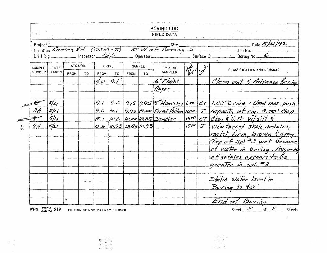
· Project -.. - Site Date S/.GJ /92-· Location J::;:;.,nsa-;:s. Rei. {os IY1- s-2 /0' W e:;-f- 8t?r.1n.~ 5
-e'< ~ '. .. Job No.
Drill Rig Inspector 1/;..:;s-d,·· Operator Surface Ei Boring No. · ¢.? . '
SAMPLE rATE STRATUM DRIVE SAMPLE TYPE OF o.· ~· ~"il C<Sr- CLASSIFICATION AND REMARKS
NUMBER TAKEN FROM ·:-o FROM TO FROM TO SAMPLER [~{ .
i~/C? to/./. 6 ;,Fit4h'T C!/enn &""Nf "f' -4-dr&"Jnce: &.r,~..:te; w~c:']',...-
,
~ .s/2.! J!').f 9.£:. 9:1~- 9.9S ls-H'vo-,..,.l~v b&~?? c:r /.~.fll 'DrJ,/e - d:JC>d nuJ.,t /Jtl' h .319 S/l.! 9.6 to./ C) . .t)S" /(?,CO iJ::ik ed /1s~n /ZPt? :r l!d # AC; t; Cl' 1- /' ~~. t:9 .. C?&> I t$4 L7 A- s/.lJ l:saHt/) 1~,.- ~ ·7 ~ f .
I /0.1 /t?.p /P,Pb ~B~ J4~ t:.T t!/a .. , e s; rt- w s;·-; ~ .....::;;....
I 1-A S/z..t Vtl.6 liP. 93 1!11'.85 /0.'73 J!>t:tP :r wla ihe!""C'"d shnle nodules .. .1::--0'
bmw,., .f. 4J""a"-~' I I rnot1t .;;;-m
~ f! ':zt f b.,/ . I I /&?/J 01' SrJI :..3 W(!' '<!"Cd~;$~
pf Wa-kol'" ,;; bu,-;,.,t:f • ke;u~Ac
t? ,C Jtud~le'~ ~LJ~t?4~ c/-o k 7
IG?~~"t;.,- ,;., :•,·L?!. a: 3 I
, ....
ls~lic wa#r level ;11 I
Rt::P /" j,u:. i !1 4.. tp I
I . .... £/?de::>-/- l3orJner -- ········- -~···-·-·····- . -
WES : ... ONR~-4 819 EDiTION OF NOV 1971 MAY BE USEO Sheet Z of~ siieets
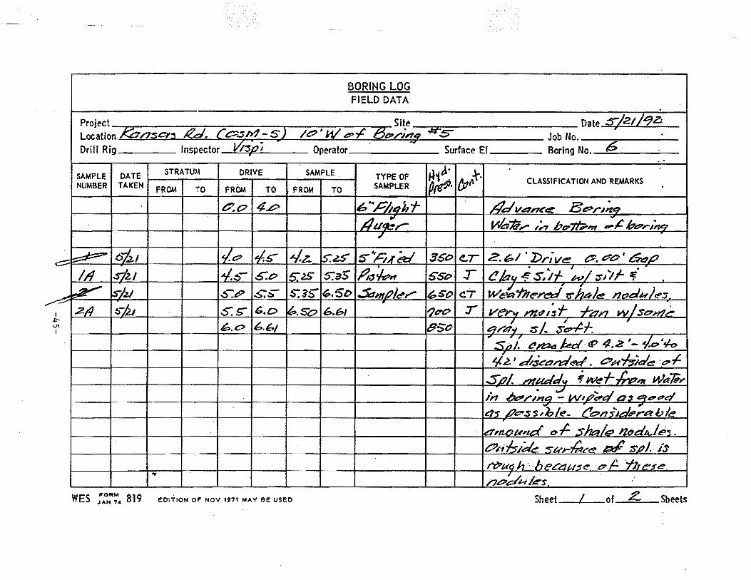
BORING LOG FIELD DATA
Project . Site Date o/21/qa Location. ,k:P/7~~~ Rd. l o.sh?- S l 1&:1' W ~~ 8~>,.,-,'9. ~s ;
Job No. Drill Rig Inspector v~pi ... .,
6 Operator Surface El Boring No. . .
STRATUM DRIVE SAMPLE tl c.· tp,.Jr. SAMPLE DATE TYPE OF
~ CLASSIFICATION AND REMARKS NUMBER TAKEN FROM ;o FROM TO FROM TO SAMPLER ~ f .
t::'.c:> 4P h•h/t1J1'f /?d v.a-n<'e Be>r.~:.Zq /lu~,- ~;@:,.... ;~ bu7'f;;.Jn ~~ bi!?rJ"n.q
/
~ o'i2.1 II.~ 1.,.<~ 4-z. ls:'~ S"h,tS:/ 3St:> e.r 2. 61 'I>ri' ve C::.P'L>' 64P .,_
1/1 l.sizJ 14.~- .S:o 1£ 2S' s:as ,q.,~, S"Se> :r /3/oc,.i~if 'w!~/l/- 1i _., ~ ~2/ ~--&> .:5::~ S:3~ G-.51> .:JdmPid'Y"' h. SO C.T W~Yh~~ "trhe1Je J1ddu)~s -- 2/4 ~.S'o T ver.., rlt.ff,;f -1-tdn wlsL?n?~ I. !;>7J.I S:t> b,O 6.61 I?D"O
-"" 6.6J e://'~ :s 1.. ...ft:?-t.f.
., IJl 6.0 650 I
.. 5;,z ~~ kc/·tP 4.2 ,_ ,;e>·¥-o ~2. 1 ~:i~on::lf!:'t::l. Ou-/:rlde ·.eo.f.
SLJI. ,.,uJJu f' wef-/;,, Wet];,.. .. ;:;J .. d ln bt?/~na - W1J?"e.. 03 e:ttiJIIOerq
4-r ,1/e:-~-s;bl~- t!~n5id";.a-ble d,ILI?Und' o.f:. sJJa/.- 12bdA./~,. t:!JI'i.;;.ld~ ~ur-kt~~ IJ:1tfr SJJI. IS
~uah . hect::~u-st!' 17;.:.. ·t;u'!'5~. .., I~ .
/?tt:>e t-i 1/!r.$. WES ::NR~• 819 EO;TION OF NOV 1971 MAY BE USEO Sheet L-of Z Sheets
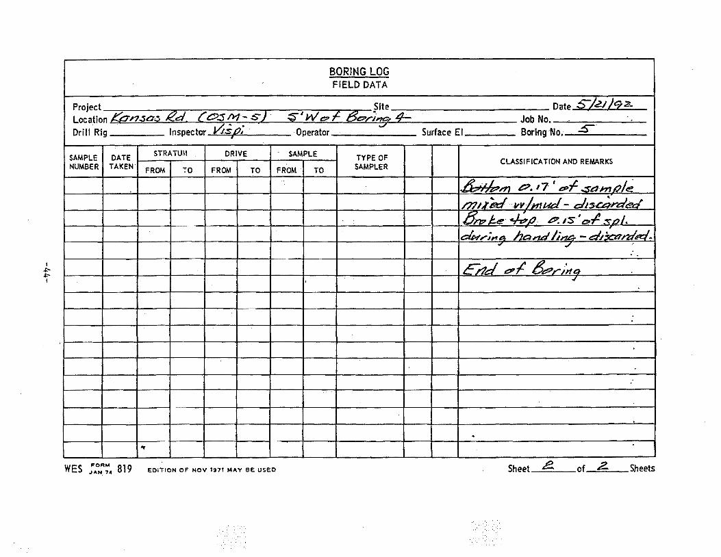
I .!::'.!::'-I
I
Project Location Kan.sa;J. Rd. {' O:S M- S 2 · Drill Rig Inspector 0spi
'I
SAMPLE DATE STRATUM DRIVE
NUMBER TAKEN FROM ;a FROM TO
.. WES ::NR~4 819 EOlTION OF NOV t97t MAY BE USED
BORING LOG FIELD DATA
Site S'' We?~ /3e?r)'!51= 4-
Operator
SAMPLE TYPE OF
FROM TO SAMPLER
..
.
Date ~/e.; Jq 2,.
Job No. I Surface El Boring No. · S
CLASSIFICATION AND REMARKS
~rn 1!".17 'ePf·..:sa-nu.J!~ m1.red vvlntud- c:h:u:;;,reJecl .tf/7? /:..e c;;/J ~iS 't>,l :::o/. I
du,-i~A hal'td /;~ - dticwrd'IR/ . ., ,./ ' .. i
crJd e:PI 6e?r-/na ..;
.
. i
-~···········-·-
Sheet &. of 2. Sheets
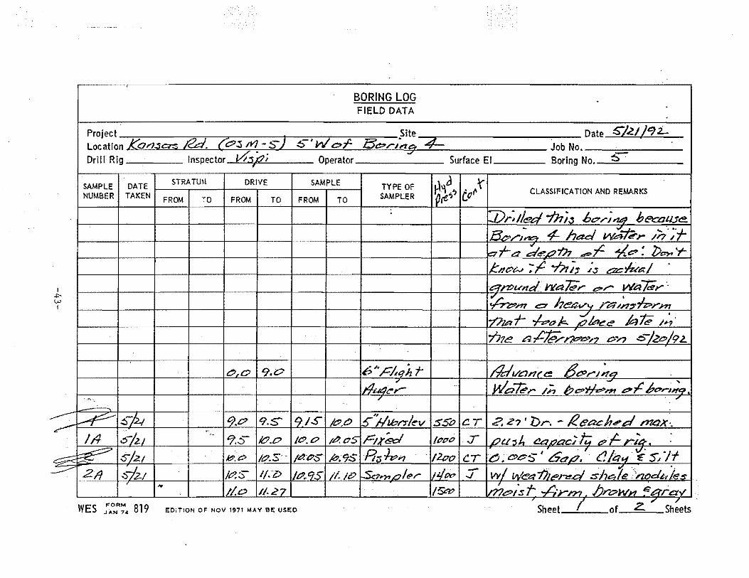
I ~ (.).)
I
BORING LOG FIELD DATA
Project • .Site Date S'l£1 )CJ:L Location KarJ.sc:rs Rd. &.:s ~-s) .5 W' c:f- Be:-rJTZ9 4= Job No.-----=----Drill Rig Inspector vf:s,t?i Operator Surface El Boring No._~=-----
SAMPLE I DATE DRIVE SAMPLE TYPE OF ~~~'ltc~l CLASSIFICATION AND REMARKS NUMBER TAKEN ;o FROM TO FROM TO SAMPLER
-n>w#d wakr- &",.... wa#Y ·. ~m" <:=:~ heav r;::::; ;~ .,tp,..../41 777a f- -/-Pd A iCJ ke? ble /J-~. 7'716! ~.,ct&/-,;;;.,.7 on .e:.-}ec/9£.
~-
(;:> «?. Z? ' Dr. - R eacJt., d max:. '· '7.S /t?PO
Jt::>.C>
..,
WES ;AoNR~4 819 EDiTION OF NOV 1971 MAY BE USED
..
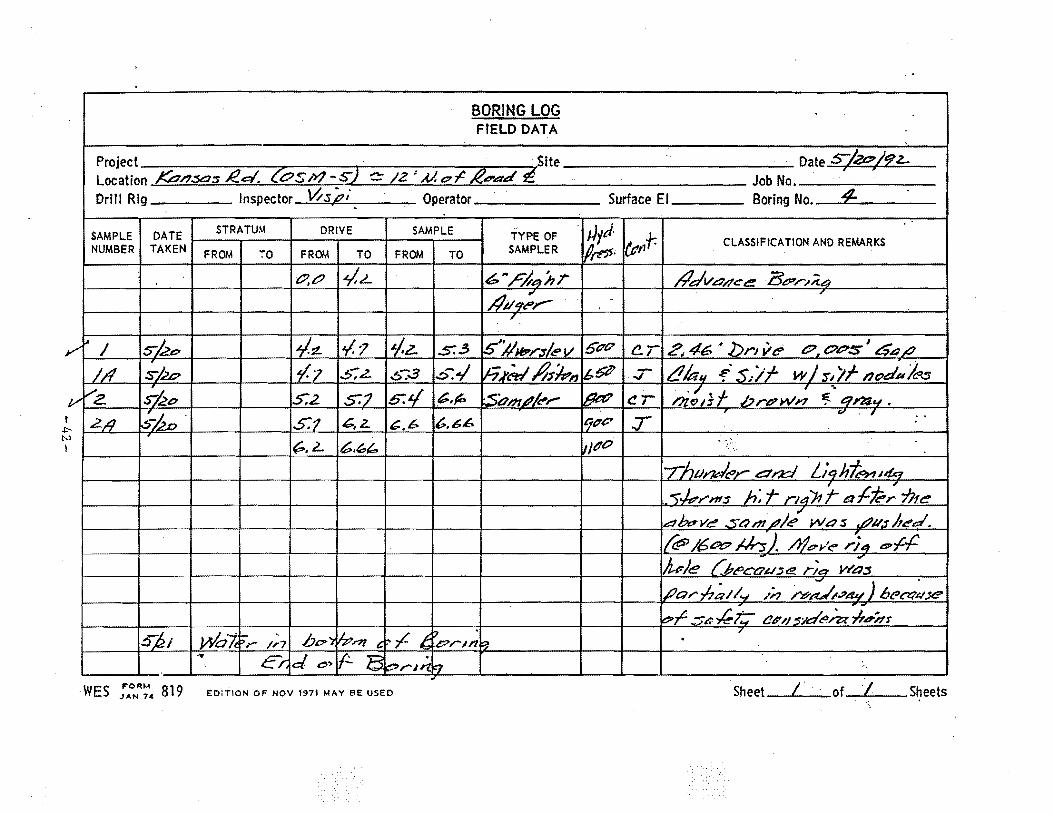
BORING LOG FIELD DATA
Project · · tite Date S/2DL~Z-~ ,
Location KPnsa:s .IZ.cl. COSIY'J-s-2 c: /2 'Al.t?~ £lt!fl'ad- Job No. Drill Rig Inspector l-'l.s,£i Operator Surface El Boring No • 4-. .
SAMPLE DATE STRATUM DRIVE SAMPLE TYPE OF · u1J. {l:tlf: CLASSIFICATION AND REMARKS
NUMBER TAKEN FROM ;o FROM TO FROM TO SAMPLER 1/td· ·~t:? -/,L 6 ",&,14),r #d'v&"n~e BJ?,-.,;;.4
/lu9;r-' ·-· "
·, ,
... "' I Skc ~-~ ¥.7 1-z. .S:!J '5i1H?r;s/e v 51717 er 2,46 · .bnve I t?, C7.?S t!S.t: P
1/1 S/2.1:? l-7 5,2. .s:s s....j h)'~ /1;-;t,, ~6"Z' .:r /Jia" f.S;//- w/s/JI-nodPb .......... z l~c S:2 S:7 b-:4 6.p :Si:lm4!/c'r ~
,/ I ""
t!l ni.o1i f .brPW~-'1 ~ t:/1"1:/.y.
2/l ~~- S:1 tG., z.. 6.66 'f17P .T v , . '
6.6 . N
~.2- 6.u IJPl' ..
'-rfwi"Jtt-l&r- am Liqh~~4q .-r~rnt:S h>r rl4'11 t- l!l'I:J'k-; ilf~
" e~J?e,vt:! som~/t!? was .L?usl!~d. {t!i> /6Pf7 J4hj /i/or'~ ~4 e-~.f: /u:)e f.Pi!>cau:;e. r;a- W;..:s ,(Ja;-/7;11~ /;, ~~.?4.¥) 6eet1~.11!? ~e>~ ~-sc -k-1::" t:!l? ,, ~:1d~ar *ddt"
s;&ti Wah - .. bo>) )p.r?f t: ~ ,c t,
17 • , ">r /,.7 'lpruz ~
. .. Er. d c> l- E ~rJI1 F7 ., '--' -····--·-···---~~--
· WES ;..,0N"'~4 819 Eo:TION oF Nov 1971 MAY BE usEo Sheet [ · · .·of I Sheets
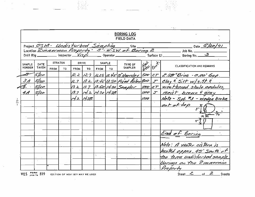
BORING LOG -FIELD DATA
Project osn:t- L/nd/'s ft/rb~ Sd-mf/Aiz Site Date .:::>"-/2~ /9/ Location .2/.m.l"?/er.l?7an /?/ZJ".,£-t?:t;. - -5" ,_ w-s w e>;C- Bo,....IHgt. z Job No. Drill Rig Inspector YLsoi Operator Surface El Boring No. d
y-
SAMPLE DATE STRATU.\1 DRIVE SAMPLE TYPE OF ~· ~·
NUMBER TAKEN SAMPLER ~~ ea(\ CLASSIFICATION AND REMARKS FROM -~o FROM TO FROM TO 01
b=a-- S"ke:- /2, 2. 12.? 14~5 1/3:.¥-:> silveor.r/e 1/ s~ cr "a . , ~ tt?. .:::>";!!? ,...., Ye - o • .e=:'tP -a.;t:J .
3/9 s/2o 1/2. "1 /3. 2._ 113. .;:,- 1:1. S".e> n./t=J::~//s;t,/1 Be-o ..r t:!lav ~ 's,~tf- w/~,if .f. ~- S/.,2.e:> 113. 2.. /3.7 [13.-!:.&- li-si.1P ~ .... A.~/" /t:'t7b er w~l-lt~~ s/~le /?e?du/~.:; 4/1 S/.2e> t42.. v.t/.1-t> i.t/.7.9
, /J1 0' I; j- h /"Z? W fl i- &I~ 14
7
!3.7 //e?O .:r /~2.. 1f.7e /2..1?1?
., .,/
J.lt::,f?- SLJI· #J - W~.el4e bh?ke. ·
t?&-t f- C? ~ ._j.,p .0 A"~ S"J ({! )., .,' ~~"'l~·
' 't''t f) J--J ..
E~ &? ,C 8~,..,;,~
. lltbk .' /1 Wafrr t!/S ~r/'1 /s lk-#.e~ ~#.#I'DX 45' s~.un :.e"-r +7?1~ ~,;e ///1~;-hlr-.Perl s-onu;/e
~~,-/~0$ ~n 7'77e r;m/?!t='rh14/'} " !?ro~r~
WES ;AoNR~"' 819 Eri;TION OF NOV 1971 MAY BE USED Sheet -<- of~ Sheets
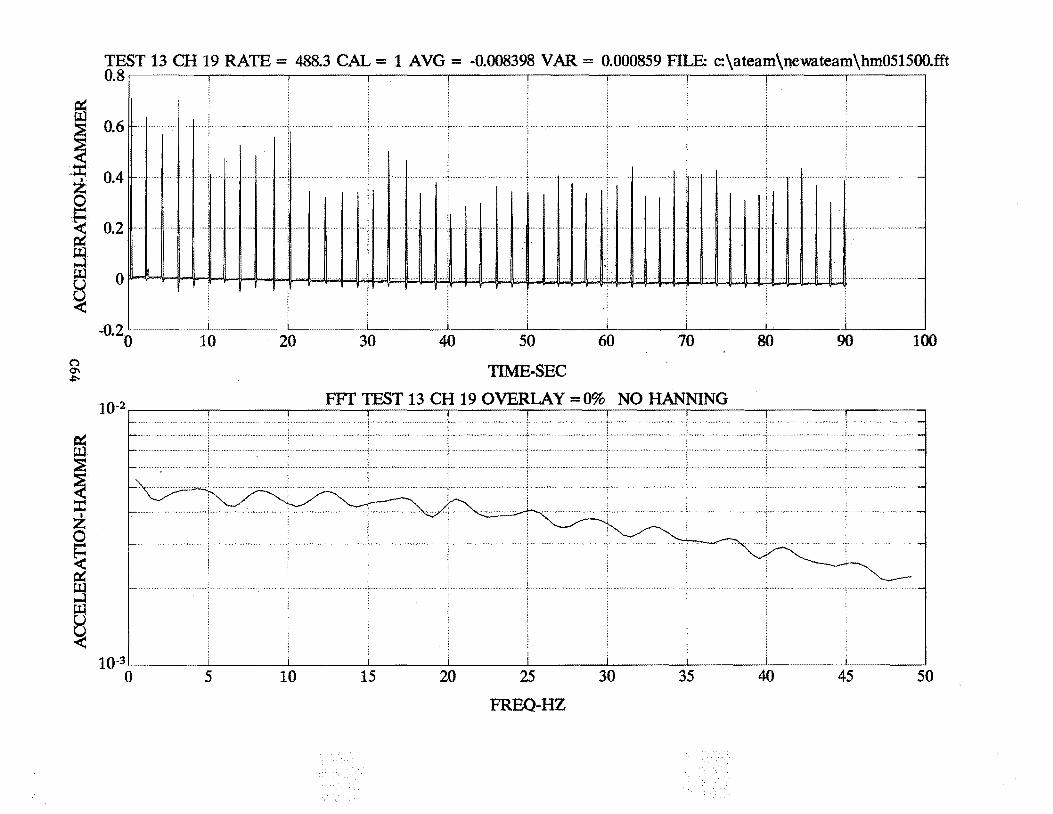
TEST 13 CH 19 RATE= 488.3 CAL= 1 AVG = -0.008398 VAR = 0.000859 FILE: c:\ateam\newateam\hm051500.fft us~----~------~----~------~----~------~----~------~------~----~
0.6 fl- + fi3
I :::z:: 0.4 z Q ·~·· 0.2 ~
·++·I '1·1
···t······ft·····ll······+··+·+ I +·· 'l·······l·
. ······";······ " ······· ...................... ~ ... .
······-
········I· ;.l .. l ...... j •... ! ...... f .... , ... l·t···l ·I I +· I• I l·l·l+·H I·+ ·I 1·1 +··t· · ·· -1
:5 e ~
0 .............. -
-02 . 0 10 20 (") a-.ll'-
10-2
ffi ~ X z ~ < ~
~ ~ ~
10-3 0 5 10
30 40 50
TIME-SEC
_[_
60 70
FFf TEST 13 CH 19 OVERLAY =0% NO HANNING
15 20 25
FREQ-HZ
30 35
_j_
80 90 100
40 45 50
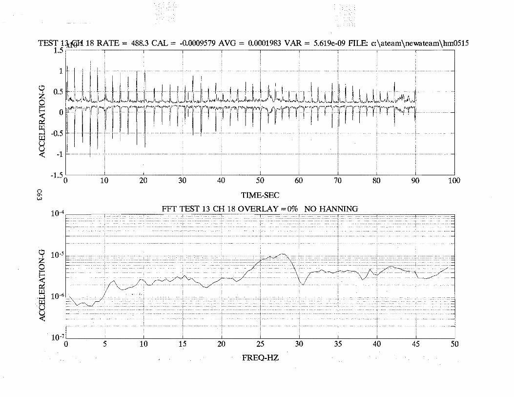
TEST 1~H 18 RATE= 488.3 CAL= -0.0009579 AVG = 0.0001983 VAR = 5.619e-09 FILE: c:\ateam\newateam\hm0515 1.5
1
0 0.5 z Q ~ 0 r::t:: lJ.l ....l -0.5 lJ.l u ~ -1
-1.50 10 n 0'\ w
10-4
~ 10-5
z 0 -·~ r::t:: r.a ·~ 10-6
.. f::j .·u ~
10-7
0 5
20
10
30 40 50
TIME-SEC
60 70
FFT TEST 13 CH 18 OVERLAY =0% NO HANNING
15 20 25 30 35
FREQ•HZ
80 90 100
40 45 50
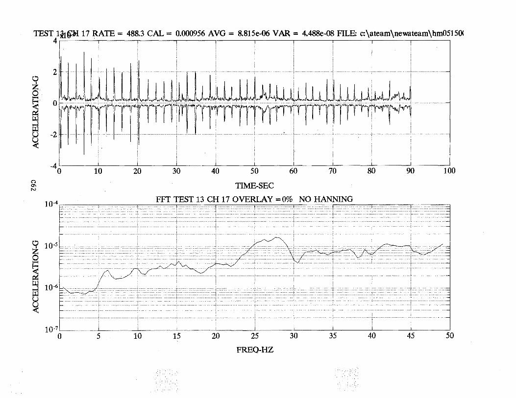
TEST 1iJ.~ 17 RATE= 488.3 CAL= 0.000956 AVG = 8.815e-06 V AR = 4.488e-08 FILE: c:\ateam\newateam\hm0515()( 4 . .
C!:l
~·~ E= <:. ~
::3 Ul
~ -<(
n 0'\ N
0 z 0
~ ~
::3 ~ ~
2
0
-2
-4o 10 20 30 40 50 60 70 80 90 100
10-7 0 5 10
TIME-SEC
FFT TEST 13 CH 17 OVERLAY =0% NO HANNING
15 20 25 30 35
FREQ-HZ
40 45 50
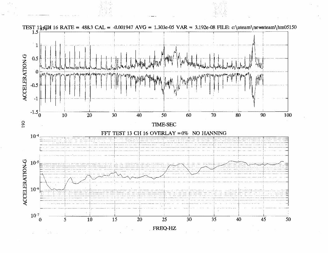
TEST 1il_((}H 16 RATE= 488.3 CAL= -0.001947 AVG = 1.303e-05 V AR = 3.192e-08 FILE: c:\ateam\newateam\hm05150 1.5~----~------~----~------~----~------~------~----~------~-----.
1
0 0.5 I z 0 E=: <: 0
ffi ...:! -0.5 ~ ~
n 0'\ 1-'
0 I z
0 -~ ~
~ !:ll u u ~
-1
-1.50
10-7
0
i
10
5
20
10
30 40 50
TIME-SEC
60 70
FFT TEST 13 CH 16 OVERLAY = 0% NO HANNING
15 20 25
FREQ-HZ
30 35
80 90 100
40 45 50
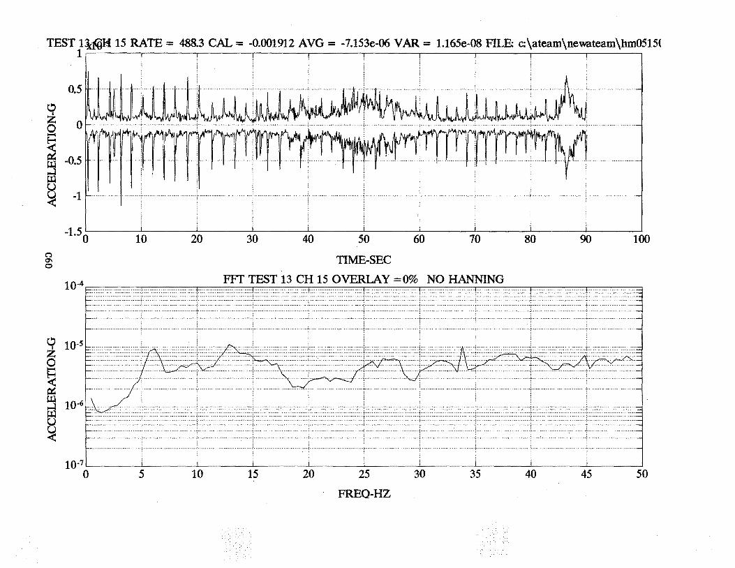
TEST 1~ 15 RATE= 488.3 CAL= -0.001912 AVG = -7.153e-06 VAR = 1.165e-08 FILE: c:\ateam\newateam\hm0515( 1 . . . . . . . .
0.5
" z Q 0
~ r:t:: llJ -0.5
0 ~ -1
-1.5 0 10
C'l 0\ 0
10-4
C!l 10-S z I······················
0
~ r:t::
20 30 40 50
TIME-SEC
60 70
FFT TEST 13 CH 15 OVERLAY =0% NO HANNING
80 90 100
~ ~ ~ 10-'o~-++±+~E 5 10 15 20 25
FREQ-HZ
30 35 40 45 50
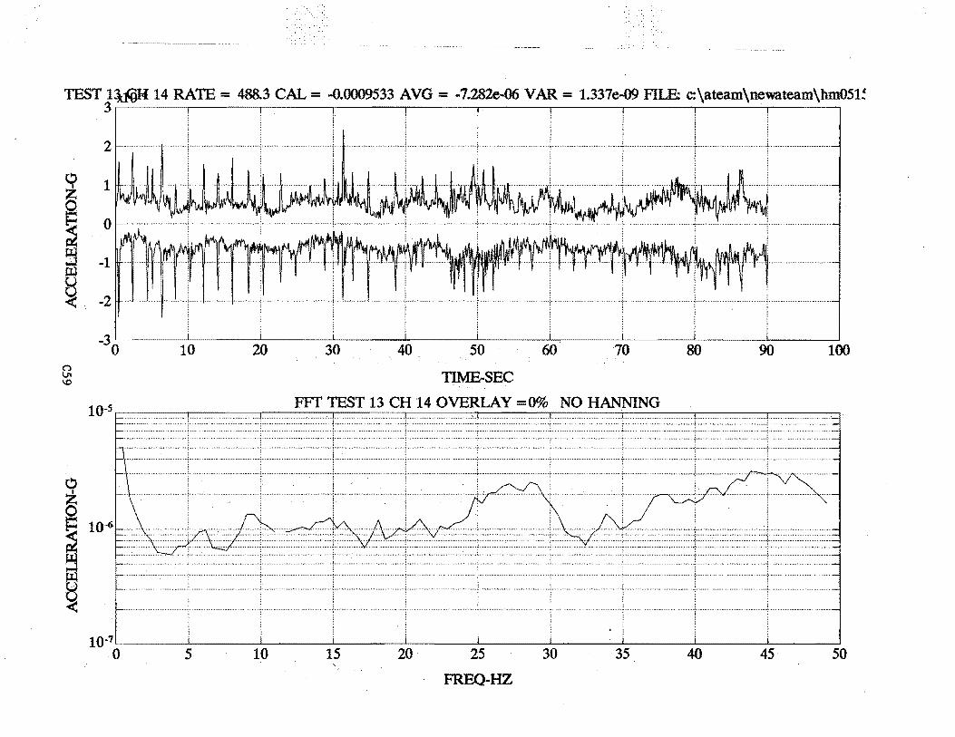
TEST 1iiijM 14 RATE= 488.3 CAL= ·0.0009533 AVO= -7.282e-06 VAR = 1.337e-09 FILE: c:\ateam\newateam\hm051~ 3~----~----~------~----~----~------~----~------~----~----~
2
0 1 I
~ ~ 0
ffi -1 es ~. -2
n VI \0
0 z 0 E=! ~ ·el Ill u
-30
10"5
l' ..... i ......................................... ; .......................... ""'·+· ........................ ; ................ ..
10 20 30 40 50 60 70 80 90 100
TIME-SEC
FFT TEST 13 CH 14 OVERLAY =0% NO HANNING
~
10-~-----:~----~-----t~---:tc.----:&----~k--=~~-====l~==-=~==-== 5 20 25 30 45 35 40 10 15 50 '
FREQ-HZ
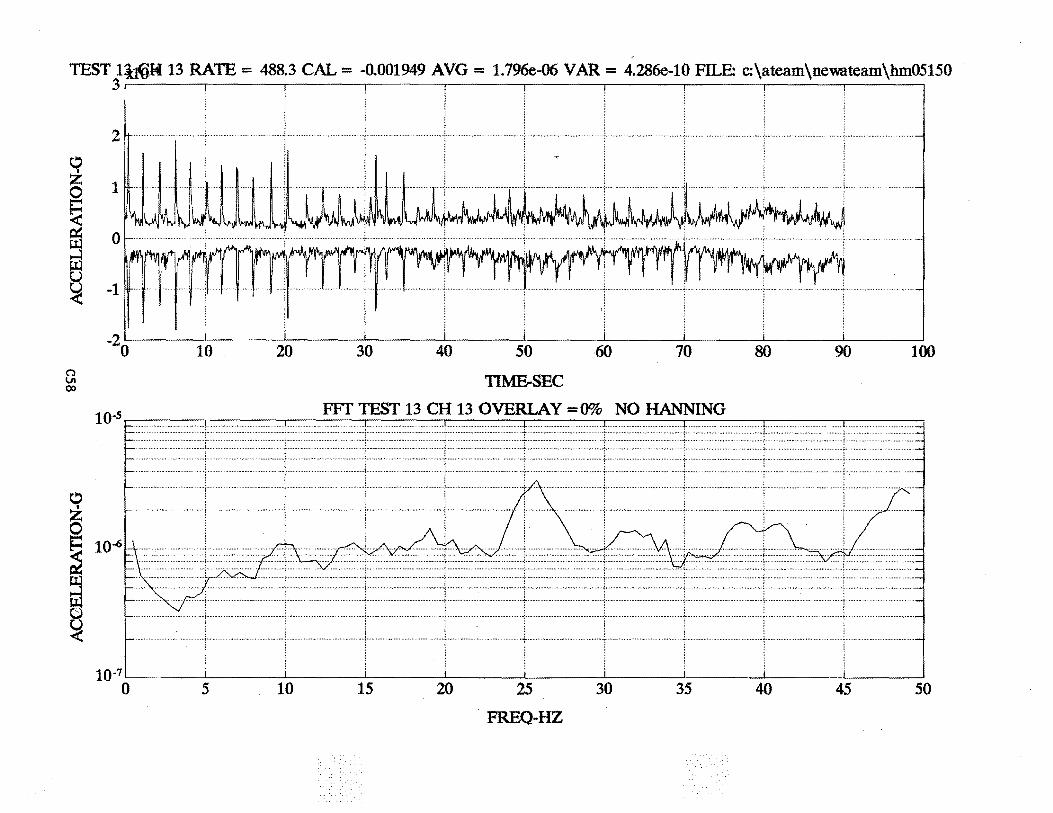
TEST liJ.ijH 13 RATE= 488.3 CAL= -0.001949 AVG = 1.796e-06 V AR = 4.286e-10 FILE: c:\ateam\newateam\hm05150 3~----~----~------~----~----~------~----~----~------~----~
10 20 30 40 50
TIME-SEC
60 70
FFT TEST 13 CH 13 OVERLAY =0% NO HANNING
........... . ..... " ...... ···-:·"'. .. ..... ~., .......... ; ............... "........... ..: .... , ........................... , . ··?··"·"''"'" ...... ..., ... , ... f ........ , ... ,., ...
80 90 100
........... -
Q ..... . z 1- ... ······ 0 v\ ~ I ········
;::; 10 .. ::\: ' , ~ ........... ~ ". A"' I \ /'\............. ~"-~ Tc·~ Ill. '-·' .. : ~ ·~·" • -····· .. . =· . . ..< ~ .. \. 1 .~ .. ~!. ...... ,t.\ .. . ~ ' ./ .... .. ..
(;;) I v .,.... ' I ~ i 1 u i
... .l
10•7
0 5 10 15 20 25 30 35 40 45 50
. FREQ-HZ
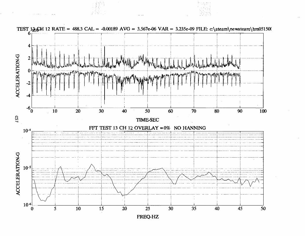
TEST 1:it~H 12 RATE= 488.3 CAL= -0.00189 AVG = 3.567e-06 VAR = 3.235e-09 FILE: c:\ateam\newateam\hm0515()( 6
0
~ ~ ~
~ u ~
C':l V1 .......
0 z 0
~
4
2
0
-2
-4
-60 10 20 30 40 50
TIME-SEC
60 70
104 FFr TEST 13 CH 12 OVERLAY =0% NO HANNING
r-·
80 90 100
........ t...... . .......................... ~ ....................................... _
~ < ...... L
10~'·····------~----~----~----~----~----~----~------~--~ 0 5 10 15 20 25 30 35 40 45 50
FREQ-HZ
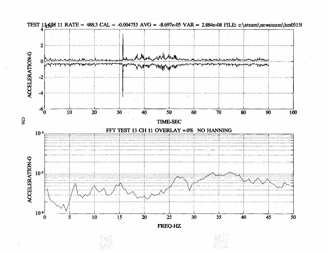
TEST 1~ 11 RATE = 488.3 CAL= -0.004753 AVG = -8.697e-05 V AR = 2884e-08 F1LE: c:\ateam\newateam\hm0515( 4
2
·li>
(") IJI 0\
z 0 ~· ~ -2
~ ~ -4 ~
0 z 0
-60 10 20 30 40 50
TIME-SEC
60 70
FFT TEST 13 CH 11 OVERLAY =0% NO HANNING
80 90 100
E::; 10 -S r- "' ..,.,.....,., < r-············ ..... ······ --1 - ......... ,.......... • ..... \............... .-- ' /\ / .l ~ \. 7 \ ' ~ r-· . . /1 '\ I i' '-.. ."-:. toJ r- .. , l \ f\ /\ I '-- / \1 '--' r.tl !\··················· ~ r-· I \ ....... J 'V' \ / ~ ... _.lY..
< lO~r~l ~ ... . \r--~ I i
0 5 10 15 20 25 30 35 40 45 50
FREQ-HZ
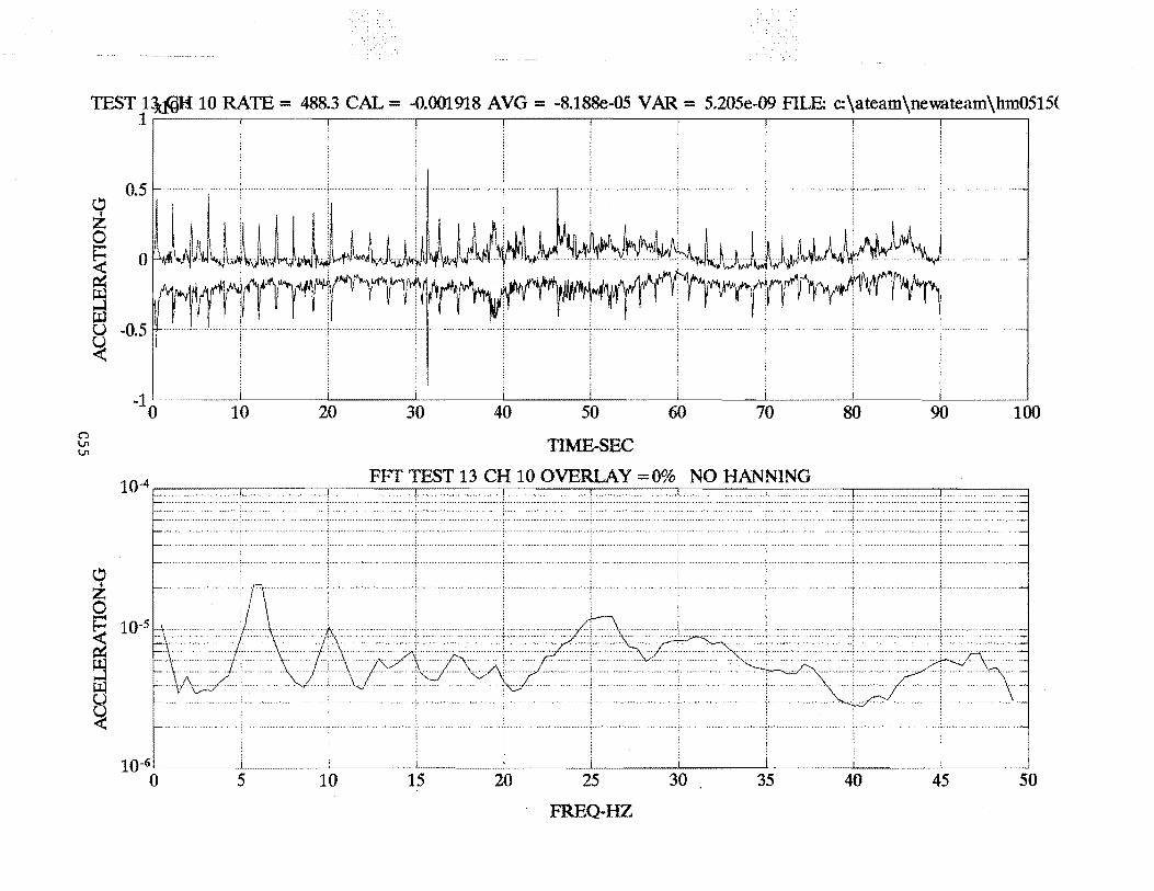
C'l Vt Vt
TEST 1~ 10 RATE= 488.3 CAL= -0.001918 AVG = -8.188e-05 VAR = 5.205e..09 FILE: c:\ateam\newateam\hm0515( 1~----~----~------~----~------~----~------~----~------~-----.
~ z 0
0.5
~ 0 f-IlA'! '-.JW < ffi ~ u -0.5 ~
-10 10 20 30 40 50
TIME-SEC
60 70
10_4 FFf TEST 13 CH 10 OVERLAY =0% NO HANNING
~ z 0 P. 10-5 H········ ...
i t3 <t:
10-6 5 0 10 15 20 25 30 35
FREQ-HZ
80 90 100
40 45 50
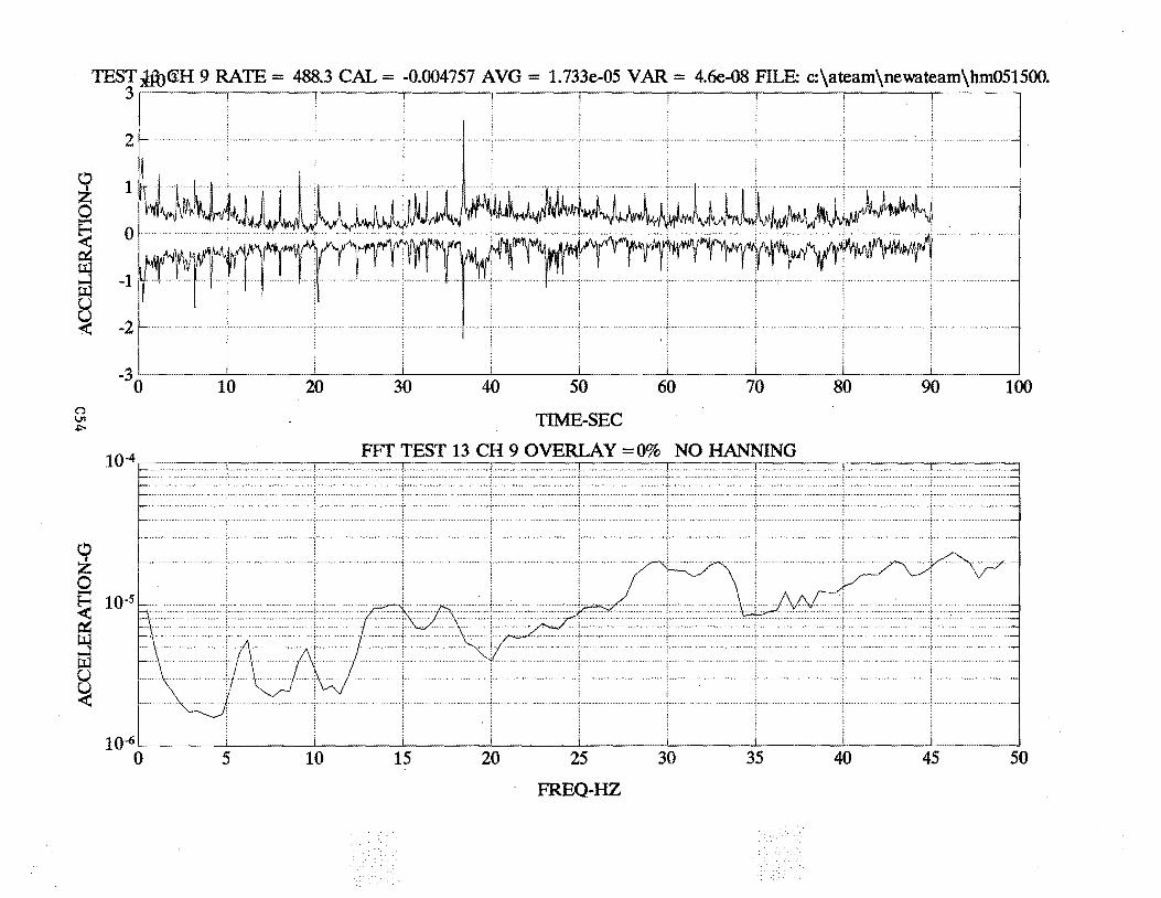
TEST ~G;H 9 RATE= 488.3 CAL= -0.004757 AVG = 1.733e-05 VAR = 4.6e-08 FILE: c:\ateam\newateam\hm051500. 3 .
\!:) z 0
~ ~
::s IJ.l u ~
(') VI ~
0 z g ~
~ ~
2
1
0
-1
-2
-3 0 10 20 30 40 50 60 70 80 90 100
TIME-SEC
FFf TEST 13 CH 9 OVERLAY =0% NO HANNING
10-6L_~=t=+4~t-~--+s~~--;ts-~ 0 5 20 35 50 40 45 10 15 25 30
FREQ-HZ
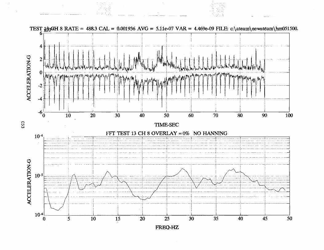
n V'l w
TEST ift)QH 8 RATE= 488.3 CAL= 0.001936 AVG;::: 5.11e-07 V AR = 4.469e-09 FILE: c:\ateam\newateam\hm051500. 6
0 I z
0
~ ~ u ~
~ ~ ::l B ~
4
2
0
-2
-4
-6 0 10 20 30 40 50 60 70 80 90 100
TIME-SEC
FFf TEST 13 CH 8 OVERLAY =0% NO HANNING
10~~----~----~------~----~----~------~-----L----~~----J-----~ 0 5 10 15 20 25 30 35 40 45 50
FREQ-HZ
APPENDIX D
2-D Static Analyses of Floor Slab and Basement Wall
Dl
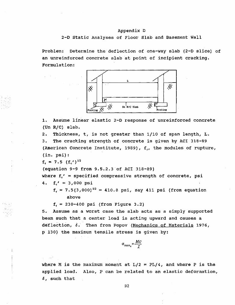
Appendix D 2-0 Static Analyses of Floor Slab and Basement Wall
Problem: Determine the deflection of one-way slab (2-D slice) of an unreinforced concrete slab at point of incipient cracking.
Formulation:
/// // / L /
/% /% ·oci ...
~~o;'" I/% rooting~
OnJR/C Slab * ~~ I ~OOtlJl9
1. Assume linear elastic 2-0 response of unreinforced concrete
(Un R/C) slab. 2. Thickness, t, is not greater than 1/10 of span length, L. 3. The cracking strength of concrete is given by ACI 318-89 (American Concrete Institute, 1989), fr, the modules of rupture,
(in. psi):
fr = 7 • 5 ( fc 1 ) 112
(equation 9-9 from 9.5.2.3 of ACI 318-89) where fe' = specified compressive strength of concrete, psi
4. ~' = 3,000 psi fr = 7.5(3,000) 112 = 410.8 psi, say 411 psi (from equation
above
fr = 230-400 psi (from Figure 3. 2) 5. Assume as a worst case the slap acts as a simply supported
beam such that a center load is acting upward and causes a defledtion, &. Then from Popov (Mechanics of Materials 1976 1
p 130) the maximum tensile stress is given by:
Me crmaxe=z
where M is the maximum moment at L/2 = PL/4, and where P is the
applied load. Also, P can be related to an elastic deformation,
&, such that
D2
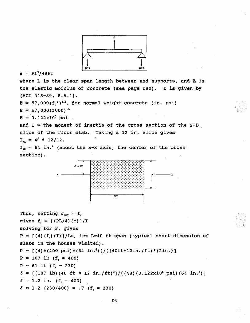
o = PL3/48EI
E !
Pl2
p
t b !
P/2
where L is the clear span length between end supports, and E is the elastic modulus of concrete (see page 580). E is given by (ACI 318-89, 8.5.1). E = 57,000 (fc') 112 , for normal weight concrete (in. psi) E = 57,000(3000) 112
E = 3 .122x106 psi and I = the moment of inertia of the cross section of the 2-0 slice of the floor slab. Taking a 12 in. slice gives
Ixx = 43 * 12/12. Ixx = 64 in. 4 (about the x-x axis, the center of the cross
section).
Thus, setting Omax = fr
gives fr = [ (PL/4) (c)] /I solving for P, gives
12"
P = [(4) (fr) (I)]/Lc, let L=40 ft span (typical short dimension of
slabs in the houses visited).
P = ((4)*(400 psi)*(64 in. 4)]/[(40ft*12in.jft)*(2in.)]
P = 107 lb (fr = 400)
P = 61 lb ( f r = 2 3 0) o = [(107 lb) (40ft* 12 in.jft) 3]/[(48) (3.122x10⁶ psi) (64 in. 4)]
o = 1.2 in. (fr = 400) 0 = 1.2 (230/400) = .7 (~ = 230)
D3
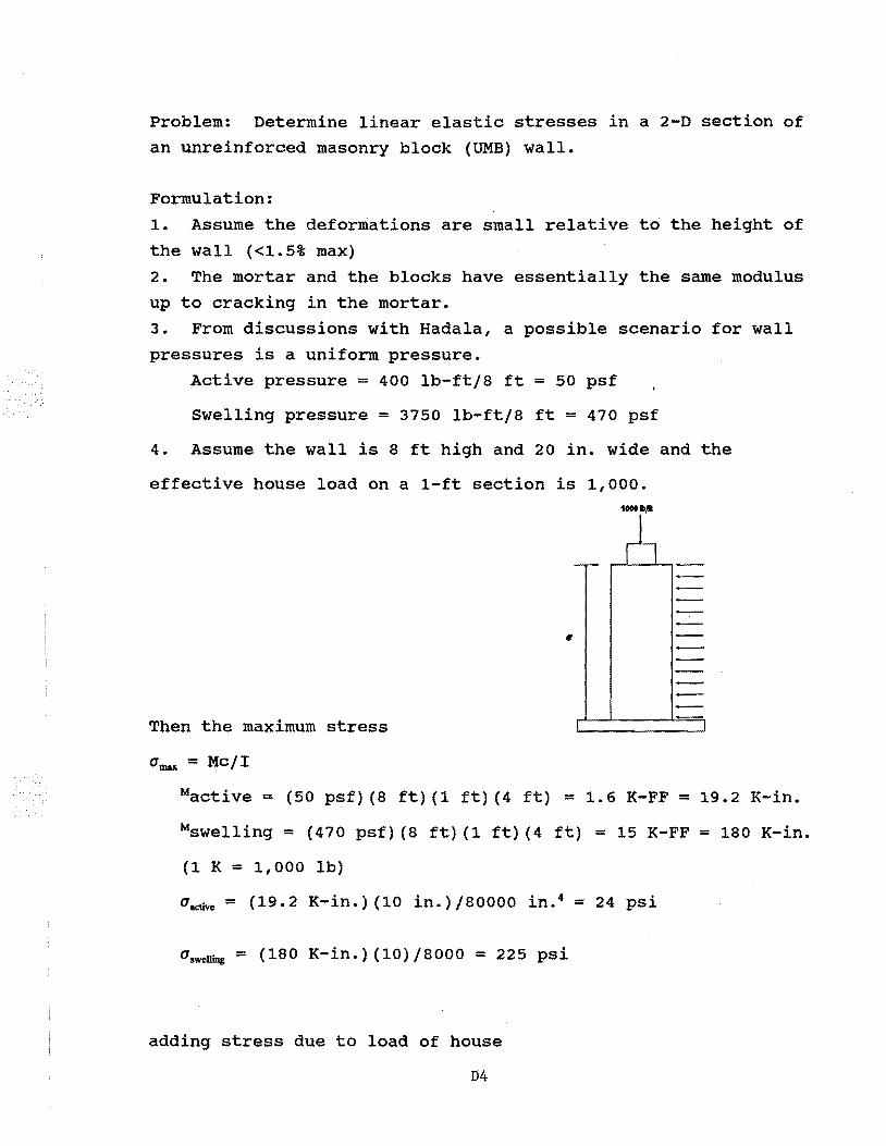
Problem: Determine linear elastic stresses in a 2-D section of an unreinforced masonry block (UMB) wall.
Formulation:
1. Assume the deformations are small relative to the height of
the wall (<1.5% max) 2. The mortar and the blocks have essentially the same modulus
up to cracking in the mortar. 3. From discussions with Hadala, a possible scenario for wall pressures is a uniform pressure.
Active pressure = 400 lb-ft/8 ft = 50 psf
Swelling pressure = 3750 lb-ft/8 ft = 470 psf
4. Assume the wall is 8 ft high and 20 in. wide and the
effective house load on a 1-ft section is 1,000 •
•
Then the maximum stress
O'max = Mc/I
Mactive = (50 psf) (8 ft) (1 ft) (4 ft) = 1.6 K-FF = 19.2 K-in.
Mswelling = (470 psf) (8 ft) (1 ft) (4 ft) = 15 K-FF = 180 K-in.
(1 K = 1,000 lb)
O'active = (19.2 K-in.) (10 in.)/80000 in. 4 = 24 psi
O'swelling = (180 K-in.) (10) /8000 = 225 psi
adding stress due to load of house
04
a8 = 1,000/[(20) (12)] = 4.2 psi
Maximum tension is
a.ctivo = 24-4.2 = 19.8 psi
a~~ = 225-4.2 = 220 psi
DS
Appendix E
Fatigue Damage to Homes in Daylight and McCutchanville, Indiana
El
Department of Civil Engineering o College of Engineering
West Virginia University Office of the Chairman
H E H 0 R A· N D 0 H
TO: Dr. Robert Hall, CEWES-SS-A
FROM: Dr. Sam
DATE:
SUBJECT: Fatigue Damage to Homes in Daylight and McCUtchanville, Indiana Potentially Related to Surface Mine Blasting.
I have reviewed the references listed in enclosure 1 to assess the probability that the subject homes were damaged by blast induced vibrations cumulatively, e.g. by material fatigue (resulting in material failure) from repetitive blast vibration events.
Siskind, et. al. in Referenc~ 11 indicates that 5 to 10 injsec {ips) peak particle velocity (ppv) blast vibrations is the minimum ppv required to crack concrete walks, driveways and foundations, and to cause major superstructure cracks. The highest ppv recorded in the Reference 11 study is 0.1 ips. However, Hadala indicates in Reference 1 that values of about 5 times this number could have occurred in the vicinity of Daylight and maximum values of 0.2 ips could have occurred near McCutchanville. Thus, the maximum predicted values of ppv are at least an order of magnitude lower than the minimum ppv to cause major damage. At this low level of vibration, I do not believe the major damage observed, e.g. cracking of basement floors and driveways, can be attributed to material fatigue failure. In any case, those structural elements that are loaded in compression, such as basement walls, will not fail in fatigue. The possibility that these small amplitude repeated ground vibrations may result in co:q.solidation of the foundation soil leading to differential settlement and major structural damage is being investigated by Dr. Paul hadala, u.s. Army Waterways Experiment station.
Threshold damage is defined as superficial hairline cracks in plaster that can be seen. The U.S. Bureau of Mines Report RI 8896 dated 1984 (Reference 5) documents a study of repeated blast vibration on a wood frame home. On page 55 they indicate wallboard joint cracking after 56,000 cycles at a ppv of 0.5 ips. They go on to say that this corresponds to 2 blasts per day at 5 cycles per blast at a ppv of o.s ips for 28 years. Note that 0.5 ips was the
P.Q. Box 6101 o Morgantown, WV 26506--6101
E2
maximum predicted ppv by hadala in Reference 1. Ralston, Director of Indiana Department of Natural Resources (INDR), in his memorandum. dated May 10, 1991, indicated the ppv recorded in McCUtchanville by INDR was about 0.03 ips in 1987 and was still 0.03 ips in 1991. Thus, it seems that the average ppv is at least an order of magnitude less than o.s ips. Dowding (Reference 6, Figure 11.6, page 161) indicates that 88 percent of gypsum panels will not crack before 100,000 cycles at so percent of their static strength. He goes on to say that similar tests conducted on plasterboard confirmed this trend. Appendix A in Reference 5 list failure strains for gypsum wallboard in bending as varying between about 900 and about 4700 p. in/in. Figure 25 ·in Reference 5 relates maximum ground vibration to wallboard strain, and indicates the maximum strain at a ppv of o. 5 ips is less than 100 p. in/ in. Again, this is at least an order of magnitude less than the level required to cause fatigue damage.
All of the data I reviewed indicates that the maximum ppv recorded at the subject homes was not greater than o.s ips, and the average ppv was at least an order of magnitude less. Therefore, it is very unlikely that cosmetic damage was caused by fatigue failure from repeated blast produced ground vibrations. In conclusion, it is my opinion that damage observed in the subject homes is not the result of material fatigue failure trom repetitive blast vibration events.
E3
REFERENCES
1. Hadala, P.F. "Inspection of Building Damage Near Daylight and McCutchanville, Indiana, and Examination of Related Documents." Memorandum For Record, CEWES-GV-Z (70-1x), Vicksburg, MS, 11 Mar 91.
2. Chiarito, V .P. "Trip Report: Meeting and Field Study on Residential Structural Damages Potentially Related to Surface Mine Blasting In Vanderburgh, County, 19-21 Feb 1991, Observation and Recommendations." USAEWES-SS-R, Vicksburg, MS, March 1991.
3. Siskind, D.E., Stagg, M.S., Kopp, J.W. and Dowding, C.H. "Structure Response and Damage Produced by Ground Vibration from Surface Mine Blasting. " R.I. 8 507, U.S. Bureau of Mines, 1980.
4. Siskind, D.E., Stachura, V.J., Stagg, M.S., and Kopp, J.W. "Structure Response and Damage Produced by Airblast From Surface Mining." R.I. 8485, U.s.Bureau of Mines, 1980.
5. Stagg, M.S., Siskind, D.E., Stevens, M.G., and Dowding, C.H. "Effects of Repeated Blasting on a Wood-Frame House." R.I. 8896, u.s. Bureau of Mines, 1984.
6. Dowding, C.H. "Blast Vibration Monitorinq and Control." Prentice Hall, Inc., Englewood Cliffs, NJ, 1985.
7. Wiss, J.F. and Nichols, H.R. "A Study of Damage to a
8.
Residential Structure From Blast Vibrations." American Society of Civil Engineers, New York, NY, 1974.
Bhattacharya, S., Baker, Investigation Report." Westmont, IL, 10 Feb 86.
C.H., and Huck, P.J. "Richey Engineers International, Inc.,
9. Woods, R.D. "Transmission of Blast Induced Seismic Waves ·in Vicinity of McCutchanville, Indiana." Undated.
10. Woods, R.D. Letter to David Pope, dated 3 Oct 1990, regarding Amax coal, McCutchanville, and Daylight, Indiana.
11. Siskind, D.E., Crum, s.v., and Plis, M.No "Vibration Environment and Damage Characterization for Houses in McCutchanville and Daylight, Indiana," Contract Research Report, Interagency Agreement EC68-IA9-13259, u.s. Department of the Interior, Bureau of Mines, Twin Cities Research Center, 1990.
12. Siskind, D.E., crum, s.v., Otterness, R.E., and Kopp, J.W. "Comparative Study of Blasting Vibrations from indiana Surface Coal Mines." R.I. 9226, u.s. Bureau of Mines, 1989.
E4
Enclosure 1
13. Ralston, P.R., Director, Indiana Department of Natural Resources, Letter to Mr. Carl Close, Office of surface Mining, Pittsburgh, PA, May 10, 1991.
E5
CHAPTER 3
STATIC SETTLEMENT ANALYSES
-51-
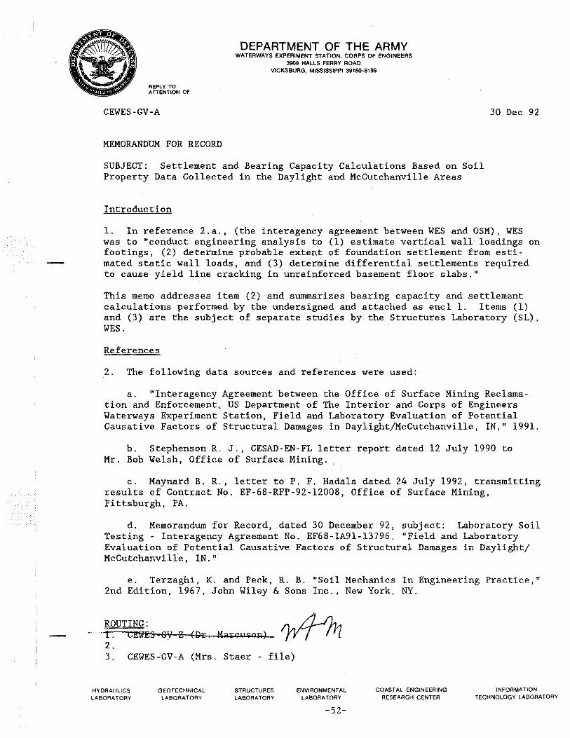
REPLY TO ATTENTION OF
CEWES~GV-A
MEMORANDUM FOR RECORD
DEPARTMENT OF THE ARMY WATERWAYS EXPERIMENT STATION, CORPS OF ENGINEERS
3909 HALLS FERRY ROAD VICKSBURG, MISSISSIPPI 39180-6199
30 Dec 92
SUBJECT: Settlement and Bearing Capacity Calculations Based on Soil Property Data Collected in the Daylight and McCutchanville Areas
Introduction
1. In reference 2.a., (the interagency agreement between WES and OSM), WES was to "conduct engineering analysis to (1) estimate vertical wall loadings on footings, (2) determine probable extent of foundation settlement from estimated static wall loads, and (3) determine differential settlements required to cause yield line cracking in unreinforced basement floor slabs."
This memo addresses item (2) and summarizes bearing capacity and settlement calculations performed by the undersigned and attached as encl 1. Items (1) and (3) are the subject of separate studies by the Structures Laboratory (SL), WES.
References
2. The following data sources and references were used:
a. "Interagency Agreement between the Office of Surface Mining Reclamation and Enforcement, US Department of The Interior and Corps of Engineers Waterways Experiment Station, Field and Laboratory Evaluation of Potential Causative Factors of Structural Damages in Daylight/McCutchanville, IN," 1991.
b. Stephenson R. J., CESAD-EN-FL letter report dated 12 July 1990 to Mr. Bob Welsh, Office of Surface Mining.
c. Maynard B. R., letter toP. F. Hadala dated 24 July 1992, transmitting results of Contract No. EF-68-RFP-92-12008, Office of Surface Mining, Pittsburgh, PA.
d. Memorandum for Record, dated 30 December 92, subject: Laboratory Soil Testing - Interagency Agreement No. EF68-IA91-13796, "Field and Laboratory Evaluation of Potential Causative Factors of Structural Damages in Daylight/ McCutchanville, IN."
e. Terzaghi, K. and Peck, R. B. "Soil Mechanics In Engineering Practice," 2nd Edition, 1967, John Wiley & Sons Inc., New York, NY.
ROUTING: - ---r. CEWES 9\7 Z (J;)r. Marcw~on)
2. 3. CEWES-GV-A (Mrs. Staer - file)
HYDRAULICS LABORATORY
GEOTECHNICAL LABORATORY
STRUCTURES LABORATORY
ENVIRONMENTAL LABORATORY
-52-
COASTAL ENGINEERING RESEARCH CENTER
INFORMATION TECHNOLOGY LABORATORY
CEWES-GV-A 30 Dec 92 SUBJECT: Settlement and Bearing Capacity Calculations Based on Soil Property Data Collected in the Daylight and McCutchanville Areas.
f. US Army Corps of Engineers, "Engineering and Design, Settlement Analysis," EM 1110-1-1904, 30 September 1990, Washington, DC.
g. Siskind, D. E., Crum, S. V., and Pels, M. N. "Vibration Environment and Damage Characterization For Houses in McCutchanville at Daylight, Indiana," Contract Research Report February 1990, Department of the Interior, Office of Surface Mining.
Base Case
3. Mr. Vince Chiarito of SL provided the vertical wall loading base case based on calculated structure dead loads for l~tory residential buildings. The base case was given to the undersign~ a 2100 lb/lineal ft load on a strip footing 20 inches wide, 4 ft below original ground. The bearing pressure is 1260 lb/ft2 which is not considered a high bearing pressure. I assumed a square foundation excavation 4 ft below original ground containing a 50 x 50 ft basement whose walls are supported on the strip footing described above.
Soil Property Data
4. References b. and c. contain soil index property data from numerous borings in the Daylight and McCutchanville area. Reference d. contains shear wave velocity data from the area and cites additional USBR shear wave velocity data from the area. Reference b. contains the results of 14 consolidation tests on undisturbed sample from 4.0 to 15.0 ft in depth from several borings in the area. Eleven of these tests are on non-swelling CL soils and three are on swelling CH or CL-CH soils. All the tests indicate that the soils are preconsolidated; that is, each has been subjected to a vertical stress for a long period of time larger than the current overburden stress. Possible causes of this are desiccation of clays or erosion of overburden over a long period of time: Pre-consolidation pressures do not exceed 4 kips/sq ft. Existing overburden pressures at the consolidation specimen locations are less than or equal to 1.5 kips/sq ft. For erosion to be the cause, erosion of 30 ft of material would be required over geologic time. Pre-consolidation by glacial ice is ruled out because of the low pre-consolidation pressure and geologic literature which indicates this area is outside the limits of continental glaciation. Preconsolidation by desiccation during the deposition process or by interaction with a root structure (as can occur in a fragiapan) are the most likely causes. The low initial void ratios noted in reference d., and which can also be seen in reference b., are consistent with pre-consolidation. The consolidation test data are summarized on page 2 of the enclosure.
2
-53-
CEWES-GV-A 30 Dec 92 SUBJECT: Settlement and Bearing Capacity Calculations Based on Soil Property Data Collected in the Daylight and McCutchanville Areas.
Because pre-consolidation pressures are substantially more than the bearing pressure, one should not expect large settlements.
Bearing Capacity
5. The bearing capacity of a 20 in. wide strip ~ooting was calculated under the very conservative assumption that it was a surface strip footing (instead of being 4 ft deep) using equation 33.6 of reference e. (unconsolidatedundrained (Q) triaxial test and unconfined compression (UC) test shear strength data from reference b., standard penetration test blow count data from reference c., and blow count versus strength correlations from page 347 of reference e. A factor of safety of 3.0 (conventional practice) was chosen. The allowable bearing capacity exceeds the estimated 2100 lb/lineal foot loading even when using strength values exceeded by 90 percent of the test data. See page 1 of the enclosure for the details of the analysis. Bearing capacity failure is therefore not a reasonable scenario for the footing size and load in the base case and the soils encountered in the subsurface investigations.
Settlement
6. There are several parts to the process of estimating settlements. They are: (1) analysis of soil data to determine pre-consolidation pressure (Pc), compression index (Cc) and rebound compression index (CR) (see page 2 of enclosure), (2) calculation of vertical stress increments as a function of depth under the middle of a footing and at a basement corner due to excavation of the basement and the addition of the wall loading (see pages 3 and 4 of the enclosure), (3) calculation of immediate settlement under the footing load (see page 5 of the enclosure) and (4) calculation of long term settlement under the footing (page 6 of the enclosure).
7. Soil Data. The void ratios, pre-consolidated pressures, and compressibility data are consistent with index property, blow count, and strength data. The sites where samples were obtained are pre-consolidated at least down to depths of 15 ft. As will be seen later, the footings produce a negligible change in stress in the soil below 11 ft. It is therefore appropriate to use a rebound index CR for settlement calculations. Measured values of CR range from 0.01 to 0.03 and a value of 0.02 was chosen for use in the analysis.
8. Vertical Stress versus Depth". The Boussinesq solution, (reference f., page C-6) was used to calculate vertical stress increments in a linear elastic medium under a corner and the mid point of a 2100 lb/ft loaded strip footing around the perimeter of a 50 ft square excavation 4 ft deep due to the combination of the excavation (a decrease in stress) and the loaded strip footing
3
-54-
CEWES-GV-A SUBJECT: Settlement and Bearing Capacity Calculations Based on Soil Property Data Collected in the Daylight and McCutchanville Areas.
30 Dec 92
(an increase in stress). Two plots on page 4 of the enclosure show the results. As shown in the plots, there is a net increase in stress in the top 7 ft below the footing. This means that only shallow depth soil properties have any practical influence on settlements. It should be noted that the maximum stresses in these plots are less than the measured pre-consolidation pressures.
9. Immediate Settlement. A theoretical solution based on the theory of elasticity for the elastic settlement under a uniform, infinitely long strip loading on a linear elastic half-space given in reference f. was used to calculate immediate settlement. Young's modulus was calculated by assuming that Poisson's Ratio (v) was equal to 0.5 and using shear wave velocity data from reference d. to calculate shear modulus. The calculated settlement was 0.03 in.
10. Time Dependent Settlement. The time dependent settlement calculations are given on page 6 of the enclosure. They are based upon the rebound compression index (because maximum stress increment is less than preconsolidation pressure), a void ratio of 0.6, and the stress versus depth plots on page 4 of the enclosure. Maximum time dependent settlements of 0.18 and 0.11 in. were calculated for the centerline and corner respectively.
11. Total Settlement, Differential Settlement and Field Observations. The calculated total settlements for the corner was 0.14 in. and for the centerline was 0.21 in. The differential settlement calculated was 0.07 in. (about l/16 in.). Differential settlements were reported for seven houses in the study area in reference g. and are substantially larger (greater than l-in.) than calculated here and indicated that the downhill .side of the buildings had settled relative to the uphill side. Differential settlements larger than those calculated could be explained by elastic and consolidation settlement processes only if (l) the soil profile was nonuniform (one side of the building was founded on or close to rock and the other over at least 20 ft of soil) and CR was substantially larger than measured or (2) the pre-consolidation pressures reported are wrong. There is no evidence to suggest either of these possibilities and there is a strong internal consistency among the soils data which contradicts both possibilities.
12. Summary. Differential settlements of 1.1 to 4.9 in. were measured at seven houses in the subject area. These settlements far exceed that calcu lated based on the soil property data, theory of elasticity and theory of consolidation for a typical foundation geometry and loading (ie. 0.07 in.).
4
-55-
CEWES-GV-A 30 Dec 92 SUBJECT: Settlement and Bearing Capacity Calculations Based on Soil Property Data Collected in the Daylight and McCutchanville Areas.
Reasonable excursions from the typical case could not account for the difference. Most of the differential settlement observed at these buildings is due to some other cause.
Encl
c2~~~ PAUL F. HADALA Assistant Director Geotechnical Laboratory
5
-56-
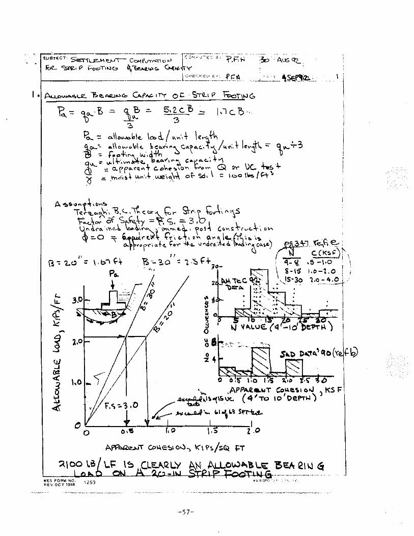
s~~~~~~~~~u,f ~~:~·:z:r:;:~j~~.; 3 .· "f.F.i-i i3z:> A~ ctL ·.
1----------·--· l Cr< E.C KEu::..:~_.f_E~. --~ __ ..;_..:'_~_: __ ~S:E..~!2.J. .....
-
0 0 •$' '•0 1•1$ ~•0 ·~ /)
'""' APPA.ll.&t~~T Co~e.\1 ~,J 3 t<S F Jk.~t.I1."(\S.Uc._ ( 41 TO 10
1 Oefi'TW)
~ u ~ · .... f. I-\ 1.~ Sf1'-1t.i,.
~----_.~~--~~----~----~' \.~ z ,0
57-
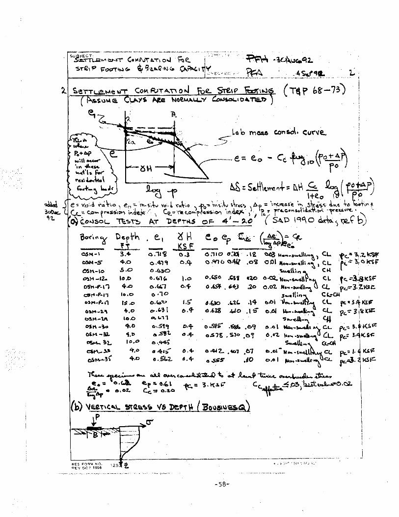
~---· ----------·--------------·- ·---· .......... --........ . s.uJ~\Sfu;at-A !:NT C::o~o~P..,\ A."'"\ o.J ~e. i · .vv · '' • ~ ·~~..Xa"t2.
s,.-e, 'P ~001'\NGo ~ '3'!-r..Q'N c. Q..?N.,, ~'(·~-:-~_:~---~ ... ---~ .. --.:~~5~-~~ ... __
Pe+o.p 1M~" ac.c.w" '•n 4..c,..
""""'" ~
( Tt\ f> £,g-73J
LQ b rneu, c.ons.o\. Cu\"ve..
.~5" .. -----e= e.o - c~ h,o(faf~ry
~:.:~~~, ~ ~ = s .. H\~,... .+ • M\ .S.. .Q.,. ( f" !A:?) f lte.o 7d ~~.
e-=- 'la'•d .,:..~ \-·,o ' eD-::.. ·,'1\. ,·.tv Vc:t'• ~ 'fc:.t•O y..Po.,. \Yio;,·.\~ ''t~";. ) Ar, = \rl(,:tt.o.s'e ·."'. s\v .i'!._<>. ~ ... f. +~ ~ot'IVI t C..c=· (J::I ... f"•SSIOI'\ '"a~ ·' \ C~t,. '('e e..Ol'o<of~·~··cn II'\~ f" I' rrc.c.• ... ,u\111A-\t.o..., ~e.~uf'(. \
o} (.ot.lsoL. 1'1:.:~ Th A.T "0 ~ Pi'"'.S oF- 4 1- ,_ ~ 1
( Sl\. o I Gli:\ 0 ~ ) r-'L ~ b)
o.w·,_.~ o;trh ._: ~~~~ e." eP _ -~- ~~.;.~ O.SM•' 3.4- o.11~ 0.1 O:llc.? o;ld· .\2 ~ ............. l\\ .. ~ 1 CJ... fc."'~.'Z.~ O»t•S 4.0 o.4-,, o.q. a."tlo Q.l\(l .olir oOI .... _ .... .,\h .. ~) C.L. ·rc.-='3tC~-F' OSt\•lO .;.o 0 .Q.~O ~l\\,... ~ Clot ·
(ll'.r.""' -12. IO.D 0.(:.1'- t.o o.C.So ~if 12.0 O·cQ.. M-..·~f.l\~ .. "1 CL f(",...:-3~1dF Ofti•f'·l, +.o o.loi., o."f- o .&:if • ~+J :zo o.O'Z. tt .... .,.ol\\~ ~ CJ.. ·f".::;-].Z,Ksl:. cort·'·n 1o.o o ·1o , .... 111.,"l.. · CL:04 , o,.,..., .. ,, rs.o o.c..--u IS 1.4Jo .L.'l.C.. .\4 o.ol \l .... s-..&tt'1 C.L fe-"31-Ks" 6111'4~2.'\ +.o e>-·'~ l o.'f- (Lt.ZS .c.Jo ,\.;; o.OI u-• ._1:-:-"). <:.L p,-: lj'i'~Sil: C:>SI"' .. '\1\ 10.0 ell. ... , ~ .... dJt .. "\ c.u . : OSt\ .~o q..o o·.S'lcr D·'f- o..si~ .~ .o9 o .. 6\ Mo.~"-''~ c.r... p,-=- s. · KS.~ bS.M -sz. -J.t> G .sit. o ·+ o.S1t; • Sl<> ,01 6 .•1. )Ia .. -s-.t6"\ CL pc.= 3 CliSM-.. ?.1.,. I O,D o .. tt4~ S........\\l .. ~c:;c_..cfi c:$t"\-~ lt,o e••> o.+ o.IUZ,. ,4b1 ,bi c..o&-w .... s~\ C(.. pc:= J. tUIZ
(6~5\' 4-..o • ._!)C..2. '. + o .sss- .10 o.o l .,......,....Jlt"' <::t. r:-4· I<SV:::.
"'(......""tee: .,-.. oA.ll ~Co,&~~-~-:.:t .l......f~ ~a:.-., _ .a!•-= o.c.a. e.r:.o.,\ ~= 3.t-c£a7' Cc....tJ..:b.~.O'-)'~:u.Et~o.O"Z.. -.::aAr • e.oz.. Ce -::t o.'l.o -w-· - .
(b) 'JUT'C'\.. ~o.a.~~ '16 l)e.,T·~ { 'Bous~.-.&) ( ~ .
S'
j
-58-
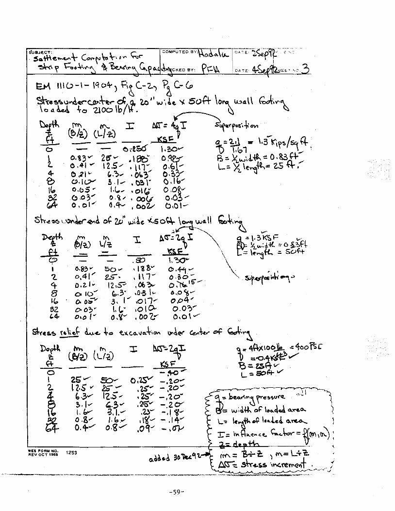
'Do~ ~ t'r'\ ::t: ~~ t: lei~ lL/-2) ~ - - ~~ 0 '--~
' 25' ........ S::)v o.W -.to ..... 2.. lZ·S v 2S'- ?$ ... - 'ZO""
~ 1-z.S', • •
~·~""" 2S"' '2. ... ' -. 0 ~.1....- '-·3" .2CC"' -. 2. c::Y l.v -3.1.- .23- -.I <if~
a. o.g ..... /.b ..... ,,~ ..... - ."14~ 0.+ ........ o.g........- ,Oct"' - \ (f}.-1
----·----"~--~· --· ·----------~ -59-
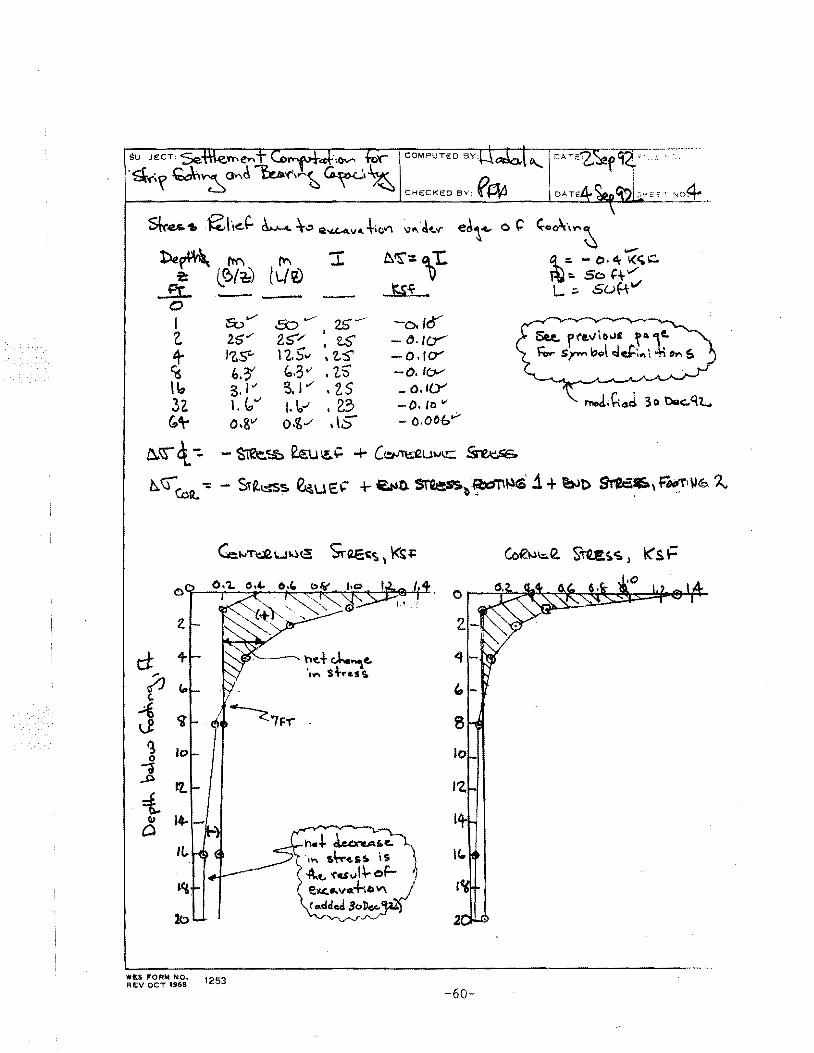
i
OAT / :J·~?;;:E.., ~o4
~~ fW'I (Y\ ::r: t: (~/~ lLI~
..£I:_ ---- ---0 I eo.....-- a:>.....---- 2£-- -o.lo " 2:5"" 2.:5"'/ : 2..5' - (), lif j- I~S'... I 'l. Sv , 2.:5' - o .f cY' ~ 6. ?"' "·3 v' I 1. s - o. I(>-'
I~ g. I"' :,, J"' • 2. S - o.t(Y' 32. 1. V" (, !,..1 , 2.3 -0. to v
{;'\'" o.811 o.~,.,.. , \5" - o.ooe.v
1)..\S" c\.-:. -~~ e.~ 1!,.;': + C~Ut.IIC ~
b..~ <Dt.-: - Sit~s. ~uE~ + E.;.lD. St'Qass.b:~~(S· .i +b-ib ~' f'~~\1~ 2..
t± ;; (.
.{ Lf ~ 0
J .. :t ~
D
WE$ FORM NO, REV OCT 1968
ne+cJ...""'le. ·,~ s+.-ui.
8
lo
I'Z.
1+ I C..
1253
-60-
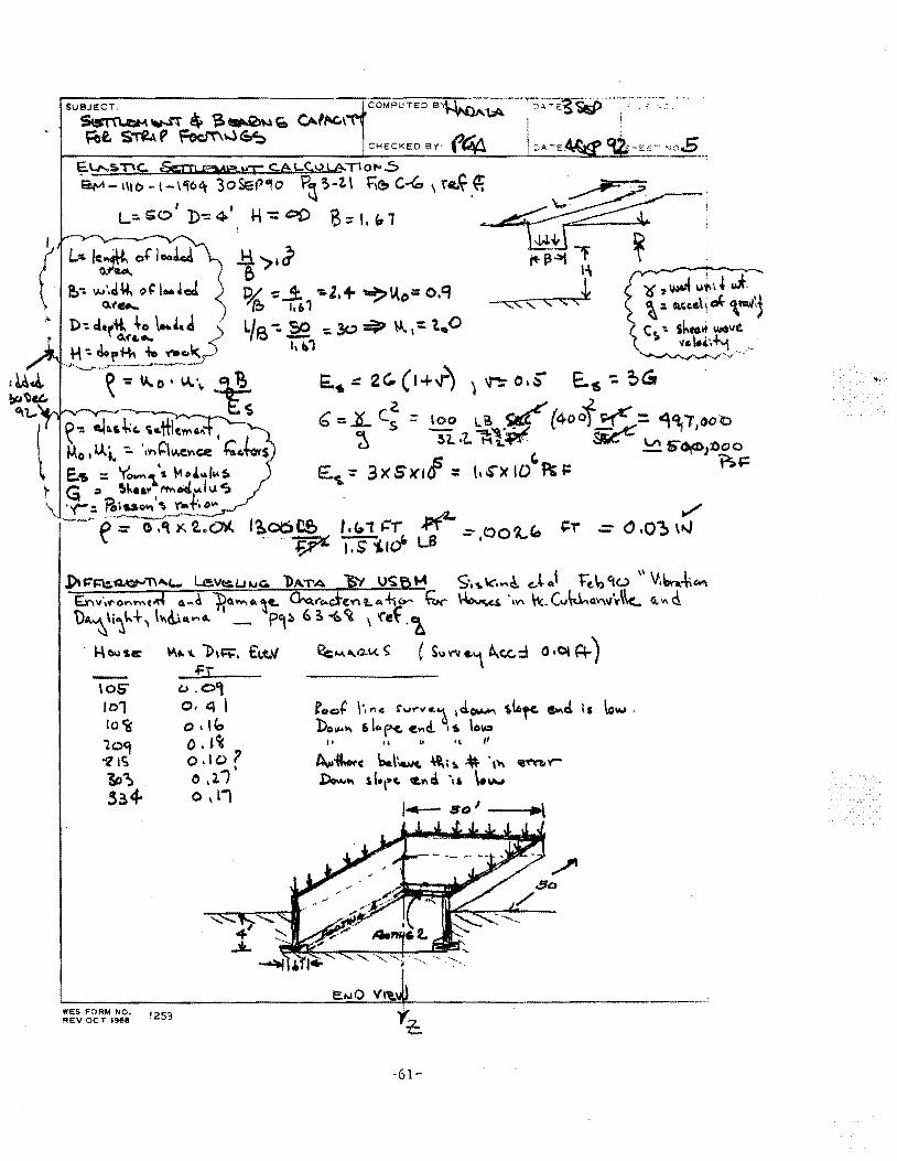
SUBJECT.
~ v..rr ~ 'a-.Q>.~o.i • CAfltG\
~-~-~--~---~-'--~----~-~----------~-cH_e:_cK_e:_o_s_Y:_~~~~~--~~~L-~~-~0~ ~lJ...s:nc. &:m,e,,W3·KC cA q:.o LA T1 o,.. ..S ~-1\lo-t-\liC>~ '3oSI:P"'o P~~-2.\ fie. C~, '<'e.~.~
I I L:::.e;o D-=4- H-=00 '8::-l,w1
j)u::.-~=~:;Q..~· .. T\A.C... le.VtcLH.IG. bATA );y U'S;f>t-4 9,,.\<:' .... ~ C.~ A' t:"e_\,<1.u ,, v.~Co'\ t:r,..,·, ... on•"M:;{ o. .. d '}tQ~o.~c. ~l"c.ci-cV'Ii.A-+i<r- ~ ~i \V\ ~(v~avw'"\\c.. (t.,Q. \)..,~\i~t..+, \~~...... _ p,~ 6! -b ~ \ '<'ef ·~
· 14cwse:: ~ .. 'I."}>,~. €1.t.l/ ~MII..G..t.<.~ ( S~o~'f'Vc.\ ~c.c:.::\ O·OlA--) .c:r
lOS' lo1 lo <is '209 1? lc; lt;~
5~4
WE$ FORM NO. REV OCT 1968 1253
t.J. 0, o. ~ l
0 "" 0. t C( o.lo? • 0,2-1 0 \ l1
roe>+ \', "'C r..,..-,._1 1 d.~ 'rllofc. ct.¥~cl is \o""" . Do~"' ail"rc- ~ ... d.. 11. \oW)
ft H f\ fl
A,.,~ \:-\·~ "'' \ ~ ·," .Dow"' st.1 .. c. c.l"'c:i \• \."""
,..,.._ tiD I ----1111>1
-61-
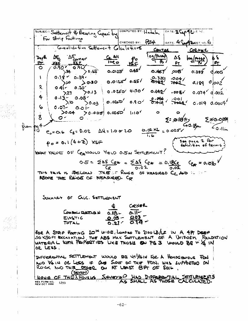
I·.
o ,o \ t.::.-' o .s.S' I
./ .oos /
<3,1~ d ooz ,/ ! / '
0.014 q ·002.. I
~ ' o, ol~ a.aoo4
~'"T ';N.,.OE 0\=" ~ ... \AlOUL.O 'fi\!H .. O O•S1tJ ~(,J!.I"te.J.JT?
0·5-::. '2hi -c;g .. = z)., Ce• ::::. O,l~e Ce.- = OtOl:, I (R O•O'l.. ~
1W'"!I. 'ltaL.u\. \<;,. t-'k(..c::,u.,) . :N-Et' : ... f.' (2N-~Ge. 0~ \t\IIIA\I>Le.O Cc_ /Jti,Jf> i- · • ·
~ ~s; ~CJ4' 01=. \'4~. CR'
C:O.,..-.ou QA"D4 w E~"TtC. Tc:trA.L...
foe. A STt.J1P ~1wG Z.O'"' U~&Oe,.\..oAou To lloo~/1..# \"-1 A "\'Pr t>ceY' oo ~,::-r 8rlte.el'..v f\.Tt o-..) TWe- ~S J/\~~ ~&..e."e~ ~ A \)J\1=-0t"" r:au~..~Ut\TION M~-r&""' l... ~PM 'PeoP5G.T'~ W'<.ll ~"'~~. ~ ?& :s ~o""-o ce "'. ~ l~ o~ LE~~. i
'PI~~~-nN.. se::t'T\R;t-~\\1-JT WOV\.0 BG. ~ ')E:. Ul roe,. #t.. \\ot\OC:~•o"'~ l1:».S ~o 'V.,.. '"" ot.. Ltss. •~=- ~ Stol.:" ~ 1\\1;1" ~~. '-""~ .suPAien;o e»J R.oc.NC,. ~~o ~\5. e1L. 0.,.. ft.\t' \..~St ePt- (% Sou.. I
e;lt:>
-62-·
CHAPTER 4
EARTH PRESSURE ANALYSES AND MISCELLANEOUS OBSERVATIONS
-63-
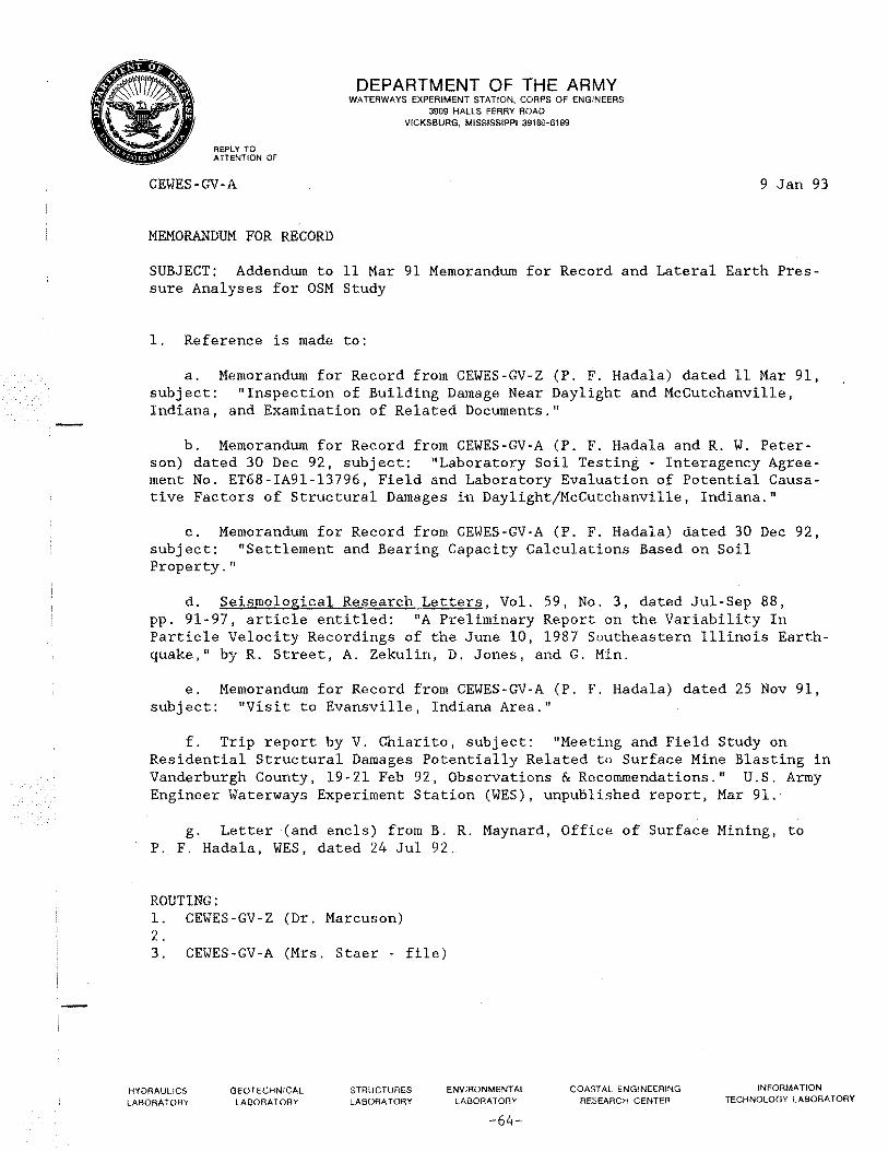
,-
REPLY TO ATTENTION OF
CEWES-GV-A
MEMORANDUM FOR RECORD
DEPARTMENT OF THE ARMY WATERWAYS EXPERIMENT STATION, CORPS OF ENGINEERS
3909 HALLS FERRY ROAD VICKSBURG, MISSISSIPPI 39180-6199
9 Jan 93
SUBJECT: Addendum to 11 Mar 91 Memorandum for Record and Lateral Earth Pressure Analyses for OSM Study
1. Reference is made to:
a. Memorandum for Record from CEWES-GV-Z (P. F. Hadala) dated 11 Mar 91, subject: "Inspection of Building Damage Near Daylight and McCutchanville, Indiana, and Examination of Related Documents."
b. Memorandum for Record from CEWES-GV-A (P. F. Hadala and R. W. Peterson) dated 30 Dec 92, subject: "Laboratory Soil Testing - Interagency Agreement No. ET68-IA91-13796, Field and Laboratory Evaluation of Potential Causative Factors of Structural Damages in Daylight/McCutchanville, Indiana."
c. Memorandum for Record from CEWES-GV-A (P. F. Hadala) dated 30 Dec 92, subject: "Settlement and Bearing Capacity Calculations Based on Soil Property."
d. Seismological Research Letters, Vol. 59, No. 3, dated Jul-Sep 88, pp. 91-97, article entitled: "A Preliminary Report on the Variability In Particle Velocity Recordings of the June 10, 1987 Southeastern Illinois Earthquake," by R. Street, A. Zekulin, D. Jones, and G. Min.
e. Memorandum for Record from CEWES-GV-A (P. F. Hadala) dated 25 Nov 91, subject: "Visit to Evansville, Indiana Area."
f. Trip report by V. Chiarito, subject: "Meeting and Field Study on Residential Structural Damages Potentially Related to Surface Mine Blasting in Vanderburgh County, 19-21 Feb 92, Observations & Recommendations." U.S. Army Engineer Waterways Experiment Station (WES), unpublished report, Mar 91.
g. Letter (and encls) from B. R. Maynard, Office of Surface Mining, to P. F. Hadala, WES, dated 24 Jul 92.
ROUTING: 1. CEWES-GV-Z (Dr. Marcuson) 2. 3. CEWES-GV-A (Mrs. Staer - file)
HYDRAULICS LABORATORY
GEOTECHNICAL LABORATORY
STRUCTURES LABORATORY
ENVIRONMENTAL LABORATORY
-64-
COASTAL ENGINEERING RESEARCH CENTER
INFORMATION TECHNOLOGY LABORATORY
CEWES-GV-A 9 Jan 93 SUBJECT: Addendum to 11 Mar 91 Memorandum for Record and Lateral Earth Pressure Analyses for OSM Study
h. Book entitled, "Soil Mechanics In Engineering Practice," by K. Terzaghi and R. B. Peck, second edition, 1967, John Wiley Publishers, New York.
i. Letter (and encls) from C. H. Dowding, Northwestern University to P. F. Hadala WES dated 30 Mar 1992.
Addendum
2. Since reference l.a. was written, I have bbtained additional information that bears on judgments and opinions given therein.
a. A WES conducted laboratory study sponsored by OSM and reported in reference l.b. eliminated the possibility of blasting vibration induced collapse or pore pressure mobilization as a cause of building settlement of instability in the Daylight and McCutchanville areas.
b. AWES conducted analytical study using existing laboratory consolidation test data for the Daylight and McCutchanville areas reported in reference l.c. proved that elastic and consolidation foundation settlements under typical residential building loads were not sufficient to damage the buildings and were much smaller than settlements measured at six area buildings by the USBM.
c. Since I wrote reference l.a., I have learned that the area has been subjected to ground vibration due to earthquake shaking. Enclosure 1, furnished to me by IDNR, is a measurement of earthquake induced vibration in the area. Reference l.d. describes data from an earthquake that occurred in 1987 which produced peak particle velocities of 0.20, 0.22, ~5, and 0.44 inches/ sec at instruments located in Daylight, IN. Also, ModifLed Mercalli Intensity V1 damage has been reported in at least one modern earthquake at Evansville (personal communication with Dr. Ted Algermisson of the US Geological Survey).
d. During a visit to the area on 15 Oct 91, I observed the construction of two concrete block basements in progress (reference l.e.). The block was unfilled and unreinforced. Short dowels had been grouted into the top course of blocks at intervals of about 10 ft which were to be connected to the sill of the wood frame. Since these dowels extended only into the top course, any
1 "V. Felt by nearly everyone; many awakened. Some dishes, windows and other fragile items broken; a few instances of cracked plaster, unstable objects overturned. Disturbance of trees, poles, and other tall objects sometimes noticed. Pendulum clocks may stop."
2
-65-
CEWES-GV-A 9 Jan 93 SUBJECT: Addendum to 11 Mar 91 Memorandum for Record and Lateral Earth Pressure Analyses for OSM Study
horizontal expansion or contraction of the superstructure due to temperature changes would be transmitted to the top course of block and, if large enough, could be a cause of the continuous horizontal cracks I observed in the mortar just below the top course of block in many of the structures (see para. 8 of reference l.a.). The possibility of this type of construction detail did not occur to me when writing reference l.a. It, coupled with sufficient thermal expansion, could be an alternate explanation for the horizontal cracking.
e. Since I did not consider the possibility of earthquake induced ground motions' as a source for horizontal loading, and the combined effects of thermal changes and the structural details to cause horizontal cracking, the statement when I wrote reference l.a.: "there are some types of cosmetic damage present at some buildings that are clearly associated with horizontal loading or movement and this author could find no source for such movement or loading other than blasting" is no longer appropriate. I would delete it in the light of better knowledge since I now can identify two possible other sources for movements for consistent with the characteristics of damage that I could not account for in Mar 91.
f. The list of hypotheses in paragraph 5 of reference l.a. should be amended to add" ( i) earthquake induced ground motion, (j) thermal cyclic changes, and (k) frost action." Item (k) has not been discussed before (see reference i). Where the foundation is above the frost line as in the case of an exposed basement such as at the McCutchan residence, there is some risk of frost or frost heave induced damage to the structure.
Earth Pressures
3. In paragraphs 9-16 of reference 1. a. , Atterberg limit, X- ray diffraction and consolidation test data on soil samples from the Daylight/McCutchanville area were extensively discussed. These data indicated that some, but certainly not all, of the soils encountered in the top 10 ft were capable of swelling upon the addition of water. Swelling pressures of 0.6, 0.6, 2.1, and 2.5 tonsjsq ft were measured in four of the fourteen consolidation tests conducted. No swelling occurred in the other ten. Atterberg limit data indi cated that expansive clay was present in 6 of 21 borings. In reference l.a., I stated that "I could find no pattern ... to explain why expansive clays are present in some borings and not in others in the area." In reference l.a., I also noted that "there is an imperfect correlation ... of bowed basement walls with expansive soil. However, the Effinger residence, which has the most seriously bowed-in basement wall, does not correlate."
4. In light of the concern over expansive clay, Interagency Agreement No. EF68-IA91-13796 between WES and OSM (Section B.l.C.(l)) calls on WES to: "(1) develop realistic bounding values for lateral earth pressures on basement
3
-66-
CEWES-GV-A 9 Jan 93 SUBJECT: Addendum to 11 Mar 91 Memorandum for Record and Lateral Earth Pressure Analyses for OSM Study
walls, to include probably values for confined swell pressures in expansive clays ... " This section of this memorandum deals with this subject but will not repeat material already included in reference l.a.
5. As part of the recent multi-agency field investigation at Daylight/ McCutchanville, OSM contracted with commercial firms for (a) additional borings in the vicinity of certain complainant and companion non-complainant residences, and (b) for Atterberg Limits on selected samples from those borings. A total of 85 samples from 21 borings were tested to determine Atterberg Limits and/or gradation (see reference I.g.). A total of 12 samples from the additional borings had Atterberg Limits that would classify them as being of medium of high swelling potential as shown in encl 2. It is interesting to compare encl 2 to encl 2 of reference l.a., a like plot of the earlier data (which has been reproduced here as encl 3 for the reader's convenience). The only obvious difference is that a greater percent of the test results fall below the A line. The gradation curves from the recent contractor performed tests suggest a sand size content that is unusually large for what the geologists are describing as highly weathered shales. It may be that the shale fragments were not processed correctly before conducting Atterberg limits test in some cases and the presence of expansive clay is underestimated by these data.
6. On 13-16 Oct 92 a meeting was held at the Indiana Geological Survey (IGS) in Bloomington, Indiana. Those present are identified in encl 4. The purpose of the meeting was to review all the soil property and geophysical data collected in the vicinity of complainant and companion houses and obtain advice of IGS staff on interpretation of all the data but especially the natural gamma logs. Judgments on the soil profile and the presence of expansive clays considering all the available data are given in encl 4. Enclosure 5 compares older Atterberg limit data, new Atterberg limit data, the interpretation from encl 3 and the presence or absence of bowed-in walls. The correlation between bowed-in walls and expansive clay at depths shallower than the bottom of the wall is not good. Everywhere there are bowed-in walls and soil data available there is expansive clay present but it is generally too deep in the profile to produce severe wall loads.
7. Earth pressure calculations for several cases are presented along with all underlying assumptions in encl 6. Lateral loads per unit length on basement walls embedded 5 ft in soil were estimated as follows:
4
-67-
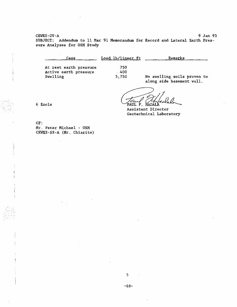
CEWES·GV·A 9 Jan 93 SUBJECT: Addendum to 11 Mar 91 Memorandum for Record and Lateral Earth Pres· sure Analyses for OSM Study
Case
At rest earth pressure Active earth pressure Swelling
6 Encls
CF: Mr. Peter Michael - OSM CEWES-SS-A (Mr. Chiarito)
Load lb/linear ft
750 400
3,750
Remarks
No swelling soils proven to along side basement wall.
Assistant Director Geotechnical Laboratory
5
-68-
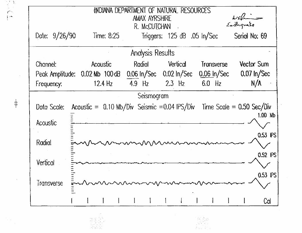
' '· I
r~~
~ .. ·-~
I 0\ \0 I
Date: 9/26/90
~DlANA DEP.ARTMENT OF NAlURftL RESOURCES PMAA. AYRSHIRE R. McCUTCHAN .
Time: 8:25 Triggers: 125 dB .05 In/Sec
Analysis Results
lv' ~tz. .. .:::£---~lv.,.\..q
Serial No: 69
Channel: Acoustic Radial Vertical T ronsverse Vector Sum 0.071n/Sec Peak Amplitude: 0.02 Mb 100d8 0.06 In/Sec · 0.021n/Sec 0.061n/Sec
Frequency: 12.4 Hz 4.9 Hz 2.3 Hz 6.0 Hz N/A ·
Seismogram
Data Scale: Acoustic = 0.10 Mb/Div Seismic =0.041PS/Div lime Scale = 0.50 Sec/Oiv = 1.00 Mb
Acoustic = Ay 0.53 PS
Radial ~ J\v - 0.52 IPS
Vertical ·-Av Transverse ~~PS
Cal
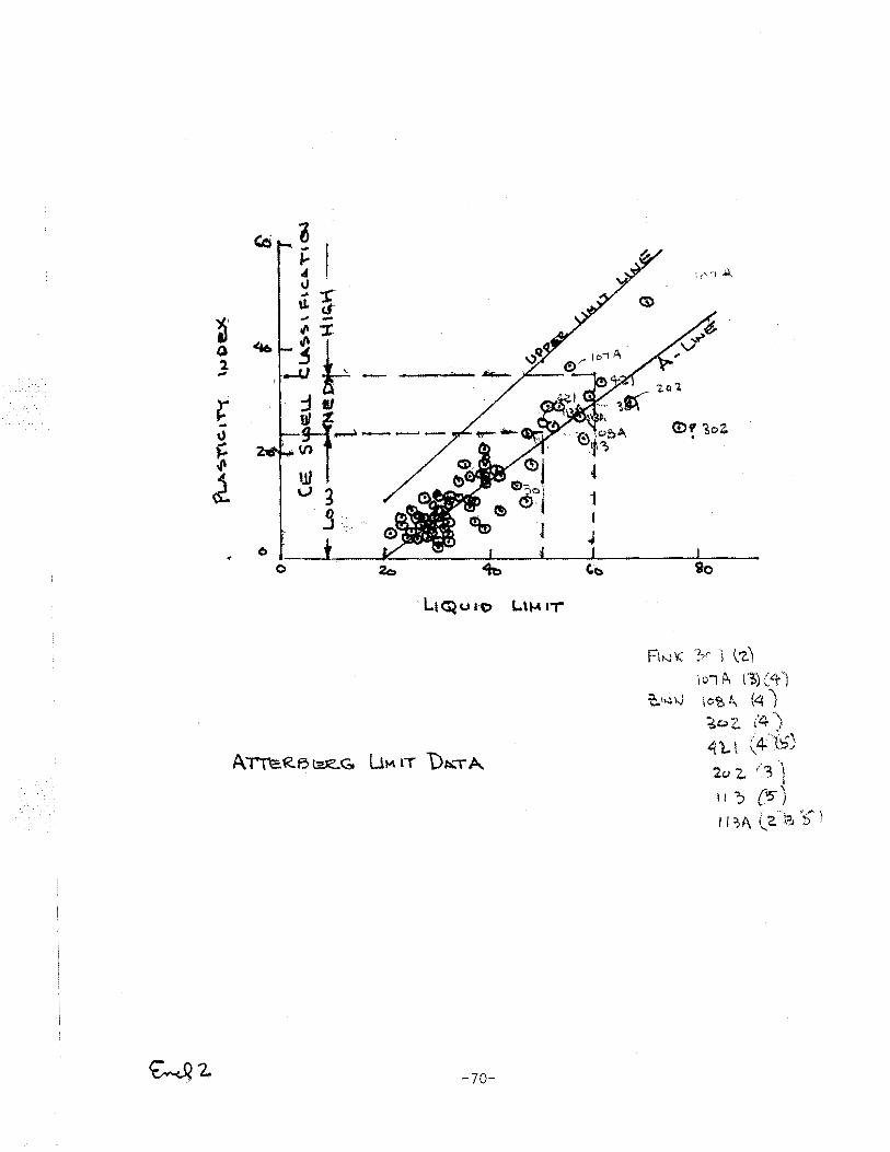
Ctl ~ ... I J..
4
~:c tJ. d"
~· ... -g~ 0 ,_
,;
l: ~~ - :1~~--\)
~ ~ \.) 3
.s . ··. '>.
0
0 ~
LI~Ul·O L.\ ... IT
FI~>-J '( '?-/: i l 'Z.l \Oi ~ (1,) (.:r')
t-.,t~ 0 I o"6 A, (4 ) - '!1. \ ~c;;.z. ( . ) '1 'L l (4.\'6')
Arn=.RB~.ze.G u~ lT t>~-rA '""' z. /3 )
I I ., {15'" J ( '''•, '<j ·"' -,
I I ?A \}· I",., !l '
-70-
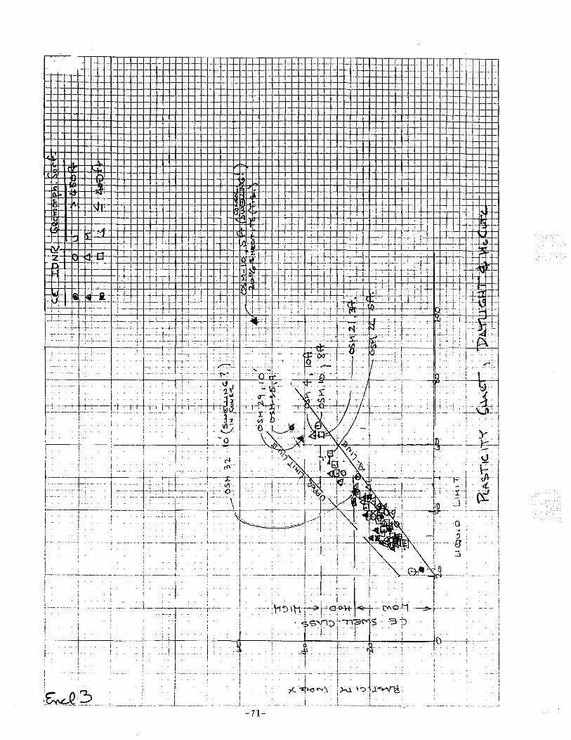
.. ) __ .
' ... J
-71-
'-----, I
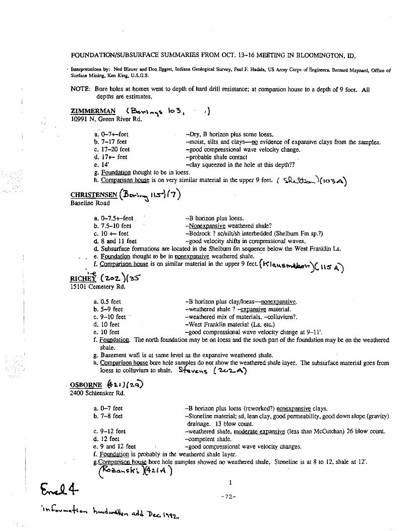
FOUNDATION/SUBSURFACE SUMMARIES FROM OCT. 13-16 MEETING IN BLOOMINGTON, ID.
· lnlerpretations by: Ned Bleuer and Don Eggen, Indiana Geological Survey, Paul F. Hadala, US Army Corps of Engineers, Bernard Maynard. Office of Surface Mining, Ken King, U.S.G.S.
NOTE: Bore holes at homes went to depth of hard drill resistance; at companion house to a depth of9 foot. All depths are estimates.
ZIMMERMAN (Be,~,, ... ,,. lo !t 1 '}
10991 N. Green River Rd.
a. 0-7+-feet -Dry, B horizon plus some loess. b. 7-17 feet -moist, silts and clays-oo evidence of expansive clays from the samples. c. 17-20 feet -good compressional wave velocity change. d. 17+- feet -probable shale contact e. 14' -clay squeezed in the hole at this depth?? g. Foundation thought to be in loess. h. Comparison house is on very similar material in the upper 9 feet. ( ~ l(lo~A)
CHRISTENSEN (!~··~ llS"} ( 7) Baseline Road
a. 0-7.5+-feet. -B horizon plus loess. b. 7.5-10 feet -Nonexpansive weathered shale? c. 10 +- feet -Bedrock ? sc/silt/sh interbedded (Shelburn Fm sp. ?) d. 8 and 11 feet -good velocity shifts in compressional waves. d. Subsurface formations are located in the Shelburn fm sequence below the West Franklin Ls.
. . e. Foundation thought to be in nonexpansive weathered shale. . f. Comparison house is on similar material in the upper 9 feet. ( k' lq.u,~~..., j( H 5' A. J
RICHEf ( 'Z.02. )( ?>'5' 15101 Cemetery Rd.
a. 0.5 feet -B horizon plus clay/loess-nonexpansive. b. 5-9 feet -weathered shale ? -expansive material. c. 9-10 feet · · -weathered mix of materials, -colluvium?. d. 10 feet -West Franklin material (Ls, etc.) e. 10 feet -good compressional wave velocity change at 9-11'. f. Foundation.
shale. The north foundation may be on loess and the south part of the foundation may be on the weathered
g. Basement wall is at same level as the expansive weathered shale. h. Comparison house bore hole samples do not show the weathered shale layer. The subsurface material goes from
loess to colluvium to shale. S-ht.vc."'s ( '2.c..".LA)
OSBORNE if.,_ J) ( '2.cV 2400 Schlensker Rd.
a. 0-7 feet -B horizon plus loess (reworked?) nonexpansive clays. b. 7-8 feet -Stoneline material; sd,lean clay, good permeability, good down slope (gravity)
drainage. 13 blow count. c. 9-12 feet -weathered shale, moderate expansive (less than McCutchan) 26 blow count. d. 12 feet -competent shale. e. 9 and 12 feet -good compressional wave velocity changes. f. Foundation is probably in the weathered shale layer. g.Comparison house bore hole samples showed no weathered shale, Stoneline is at 8 to 12, shale at 12'. f>a.a .... >k'- X42.t A)
1
-72-
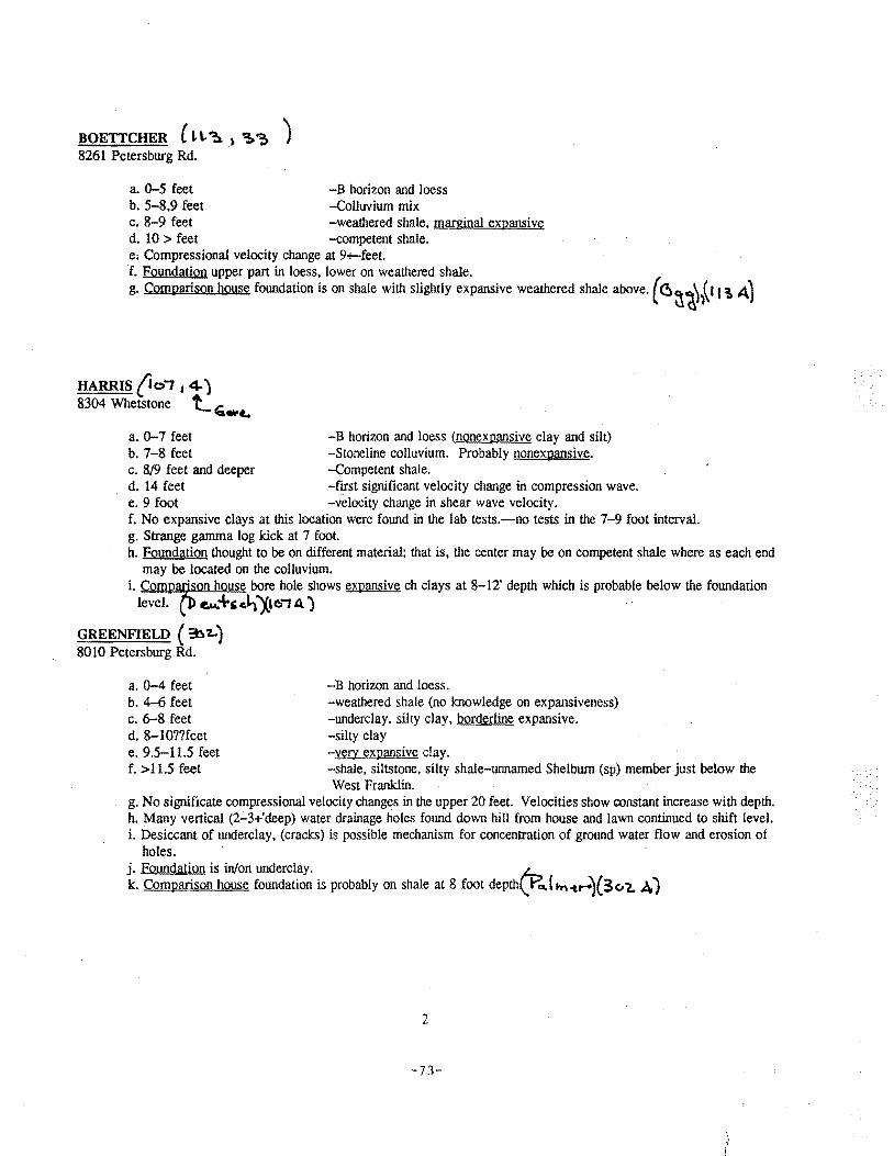
BOETTCHER ( t \.1a. ~ ~ ~ ) 8261 Petersburg Rd.
a. 0-5 feet -B horizon and loess b. 5-8,9 feet -Colluvium mix c. 8-9 feet -weathered shale, marginal expansive d. 10 > feet -competent shale. e, Compressional velocity change at 9+-feet. f. Foundation upper part in loess, lower on weathered shale. g. Comparison house foundation is on shale with slightly expansive weathered shale above. { (!)~ih\11 \A)
HARRIS (i ol 1 4) 8304 Whetstone ~ If"' ......
a. 0-7 feet -B horizon and loess (nonexpansive clay and silt) b. 7-8 feet -Stoneline colluvium. Probably nonexpansive. c. 8/9 feet and deeper -Competent shale. d. 14 feet -frrst significant velocity change in compression wave. e. 9 foot -velocity change in shear wave velocity. f. No expansive clays at this location were found in the lab tests.-no tests in the 7-9foot interval. g. Strange gamma log kick at 7 foot. h. Foundation thought to be on different material; that is, the center may be on competent shale where as each end
may be located on the colluvium. i. Comparison house bore hole shows expansive ch clays at 8-12' depth which is probable below the foundation
leveL ~ ~+s~I·\Xae.; A) · · .
GREENFIELD ( :b'Z...) 8010 Petersburg Rd.
a. 0-4 feet b. 4-6 feet c. 6-8 feet d. 8-lO??feet e. 9.5-11.5 feet f. > 11.5 feet
-B horizon and loess. -weathered shale (no knowledge on expansiveness) -underclay, silty clay, borderline expansive. -silty clay -very expansive clay. -shale, siltstone, silty shale-unnamed Shelburn (sp) member just below the West Franklin.
g. No significate compressional velocily changes in the upper 20 feet. Velocities show constant increase with depth. h. Many vertical (2-3+'deep) water drainage holes found down hill from house and lawn continued to shift level. i. Desiccant of underclay, (cracks) is possible mechanism for concentration of ground water flow and erosion of
holes. · j. Foundation is in/on underclay. fr::, k. Comparison house foundation is probably on shale at 8 foot depth\.r"'ltn-c,.....)(3c/2. A)
2
-73-
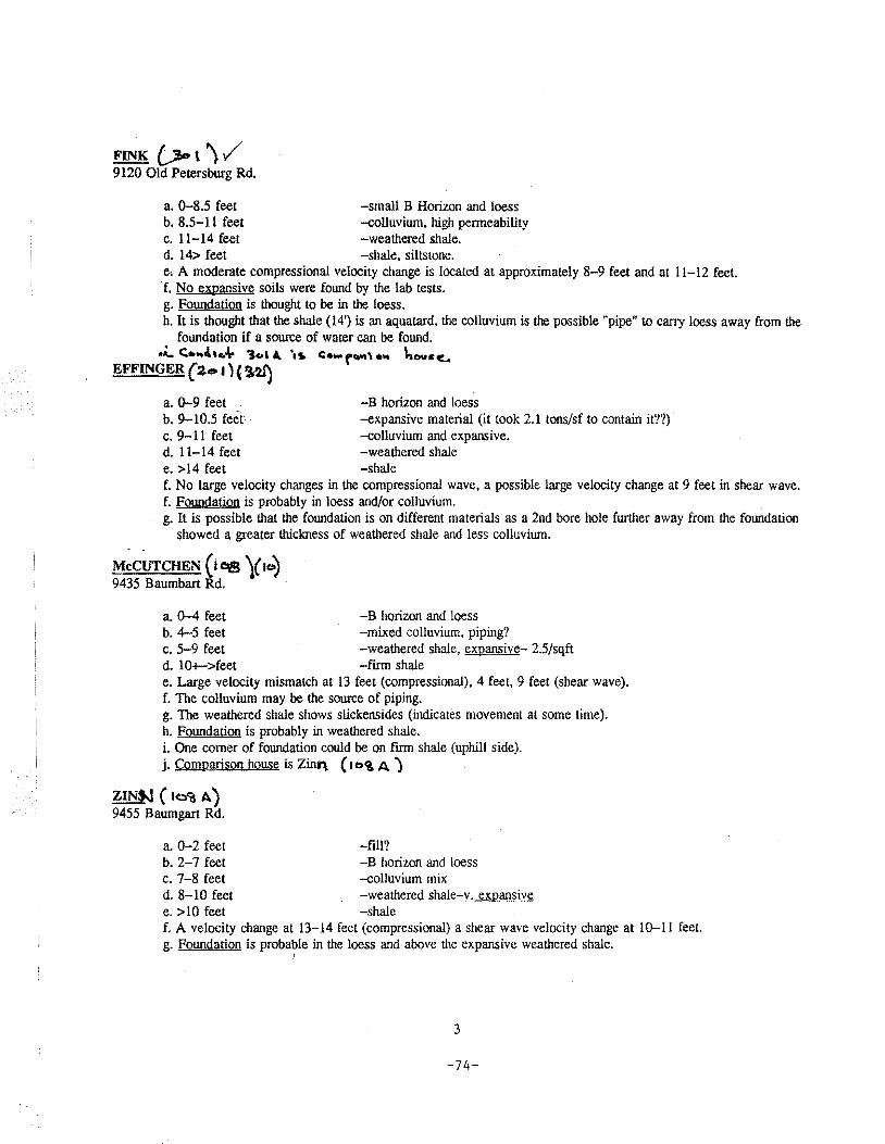
FINK . {.;Jo \ l ../ 9120 Old Petersburg Rd.
a. 0-8.5 feet -small B Horizon and loess b. 8.5-11 feet -colluvium, high permeability c. ll-14 feet -weathered shale. d. 14> feet -shale, siltstone. e, A moderate compressional velocity change is located at approximately 8-9 feet and at 11-12 feet.
. f. No expansive soils were found by the lab tests. g. Foundation is thought to be in the loess. h. It is thought that the shale (14') is an aquatard, the colluvium is the possible "pipe" to carry loess away from the
foundation if a source of water can be found . .,.t, c;.., .. .Ltc.4 'Jc.l A. 'at. C•w f~"t • ._ het~~sc..,
EFFINGER (2.o 1) ( '3s2I)
a. 0-9 feet -B horizon and loess b. 9-10.5 feet' -expansive material (it took 2.1 tons/sf to contain it??) c. 9-11 feet -colluvium and expansive. d. 11-14 feet -weathered shale e. >14 feet -shale f. No large velocity changes in the compressional wave, a possible large velocity change at 9 feet in shear wave. f. Foundation is probably in loess and/or colluvium. g. It is possible that the foundation is on different materials as a 2nd bore hole further away from the foundation
showed a greater thickness of weathered shale and less colluvium.
McCUTCHEN ( i eta )( 1o) 9435 Baumbart Rd.
a. 0-4 feet -B horizon and loess b. 4-5 feet -mixed colluvium, piping? c. 5-9 feet -weathered shale, expansive- 2.5/sqft d. 10+->feet -firm shale e. Large velocity mismatch at 13 feet (compressional). 4 feet, 9 feet (shear wave). f. The colluvium may be the source of piping. g. The weathered shale shows slickensides (indicates movement at some time). h. Foundation is probably in weathered shale. i. One comer of foundation could be on flllll shale (uphill side). j. Comparison house is Zinl\ ( 1 C)'& A )
ZINSJ ( lo<;s A) 9455 Baumgart Rd.
a. 0-2 feet -fill? b. 2-7 feet -B horizon and loess c. 7-8 feet -colluvium mix d. 8-10 feet -weathered shale-v. expansive e. > 10 feet -shale f. A velocity change at 13-14 feet (compressional) a shear wave velocity change at 10-11 feet. g. Foundation is probable in the loess and above the expansive weathered shale.
;
3
-74-
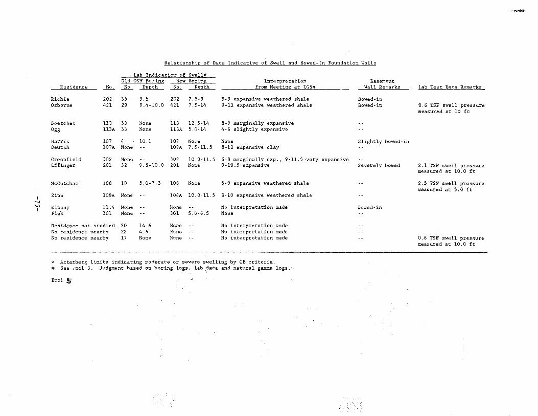
-~
Relationship of Data Indicative of Swell and Bowed-In Foundation Walls
Lab Indication of Swell* Old OSM Boring; New Boring Interpretation Basement
Residence -.lliL:. .Ji2..:.. Depth No. DePth from Me~ting at IGS# Wall Remarks Lab Test Data Remarks
Richie 202 35 9.5 202 7.5-9 5-9 expansive weathered shale Bowed-in Osborne 421 29 9.4-10.0 421 7.5-14 9-12 expansive weathered shale Bowed-in 0.6 TSF swell pressure
measured at 10 ft
Boetcher 113 33 None 113 12.5-14 8-9 marginally expansive Ogg 113A 33 None 113A 5.0-14 4-6 slightly expansive
Harris 107 4 10.1 107 None None Slightly bowed-in Deutch 107A None .. 107A 7.5-11.5 8-12 expansive clay
Greenfield 302 None . - 302 10.0-11.5 6-8 marginally exp., 9-11.5 very expansive Effinger 201 32 9.5-10.0 201 None 9-10.5 expansive Severely bowed 2.1 TSF swell pressure
measured at 10.0 ft
McCutchan 108 10 5.0-7.3 108 None 5-9 expansive weathered shale -- 2.5 TSF swell pressure measured at 5.0 ft
I Zinn 108A None -- 108A 10.0-11.5 8-10 expansive weathered shale
....., V1 Kinney 11.4 None -- None No interpretation made Bowed-in I
Fink 301 None -- 301 5.0-6 5 None
Residence not studied 20 14.6 None -. No interpretation made No residence nearby 22 4.6 None - - No interpretation made No residence nearby 17 None None -- No interpretation made -- 0.6 TSF swell pressure
measured at 10.0 ft
* Atterberg limits indicating moderate or severe swelling by CE criteria. # See .mel 3. Judgment based on boring logs, lab ,data and natural gamma logs.·
Encl 5
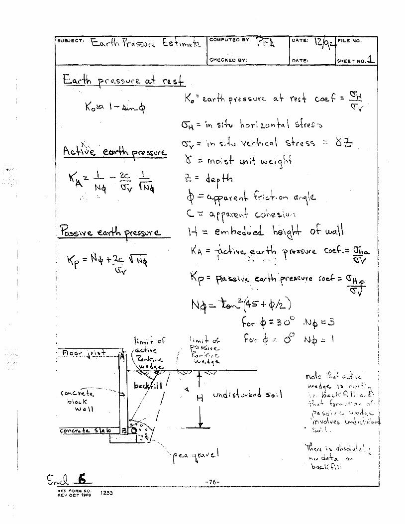
~ r ~ \'1 ~ + ~c -r ~~ ~\{
~-·-- ~. ~~--
(0\"\C.'t~\~
bloc. I< Wcl\l
'.Hi$ I"ORM NO. ~I!V OCT 1966 1253
·,
COMPUTED BY: OATE: \Z..jq_1.. FILE NO.
CHE.CKEO BY: OATE: SHEET NO.:::l
I I \ t 'x""}_ cs-v = \ .... ~ i -1-v Yt.'f' ;-,e. a ~i--re c;.s -· u 't:;
Y - . I ./ · I l (.J - rY) 01 S r \)"'I 't 1/V {. I ~ )''q
r: = 4Q.r1-h ~ = Cl...ffO.'< .c?.V\~ f'(';c.t• O"rl CfM\\<t.
r - ! ~ ~ .._ - o..rro...~ .. ,,. c...or-.e-;.,v .. ~~
\-\ -= em ~~JJel he\~\+ o~ VJa.\\ K A. = +'"'h ... c- ea.""+h \ re:s$ur~ co~'-.= §o.. ' . •, ) '/ ' :~ ~ v
'T(? = ~o.~S.s.\v~. e.A.I""" ~rrer.~u.'e
'f'Cl s;.;,:111 ~ K.a I'"' ·r\~ ·,,' e.!' W(..!'\~ >-r
~ H UY\d i $~vvbe! So·.\
j_ . ·, l'.) e..o. ~\ ro . .; eJ
.tv~ :::3
N:?.::: I
....J:) , f I l I \IA<.H. , -.. a'OSd. u. ~ ~, . •
' . ... ..... c.> tl<l -\· #. ·? ,.,,
bQ.,c...\'( (:\ \<.
-76-------··-~----~--------------------------------
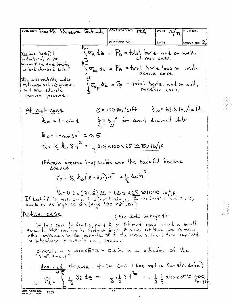
SUBJECT: l:O.t
~u\..-L bat<k~~ \ l \" at..,..\' e.• \ · m s\.c-. "Y"'> ,, .. (•'h (;!. "\) (tYI ~ de~,·J~ ~o \JV'I!\~\v ,. \ce ~ CSo '\ •
i~ w.l \ ~l"o.~o\.t~ IJ..'fl~t.'(" ,..._+-, l"n,.{Q. a.c:Jw4,; ~~<e~~<"<'. o. VI ~ OV('f" .• t•~;, '"· o:\ Q,
~S'S.\ 'I <II.. f'~"l& Uov't'o(. •
At f~&-\- Co.6 ~
~0 = l-~~
9!o-=- l-~t,ob -:. 0,~
OA TE: \ ~1., FIL.E NO.
CHECKED BY: OATE: SHEET NO.
Po-::.~ ~0 ~\i'Z..-:.. *O•'SV..IOO'l<-2-S ~lSo\b/\f.
Yo:. Od. S ( 31, G} 2.5 + ~'2.. "5 ~J.S_ :::q 000 \~ /\ f T.fba.f.kL\\ ·,~ ~~.~"'\i c.o.-p•\•~'·.t~(r'"·~· \~,(~\ .... ·, ... Z- ,·.,';.·~·'·'~~.\ c ..... :,,;-\ '~<o """"" 111 P<- o.!;. ~··<~ \-- a,..:·, o. ~ ( 1~'\'\(. I 'Od Y'e."-f }~\·"'! .
~ . \,; .
: ~c.~·,'le.. C,O.ltt.
&, 'rri.il ,. •·•
r /L.•rJ..·· (' ~.~~
~ = :,o c= o ( Se.~ '<'e ~ o..
ld. 'ls H '- · = :, z \ . l ~~~o "'';..:) ... ~ 4-co i ; \'o~ 1\ .
·~------------~~--------------------------------------------------~ WE$ !fORM NO, 1253 -77-AEV OCT 1~15tl
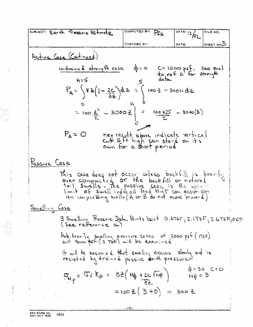
COMPUTED BY: DATe:: riAL FILE NO.
CHECKED BY: DATE: SHEET NO:::,
fC\ ~\~o.(l- ~~)h -,S\ 0
~ - I oo .:l..
'2-
"" i)
_ ?>000 -t.\ "' loo ~ - Oo co('S}
<)~
\'ve .~ r_:.~ •J \ t o.. bovt. ·\ Y)J·, c. eft~ c.~ .. i¥ b r+ h\ ~,h ~0..>""1 t~{·C\ !\ i OWV\ tor 0.. Shart r E:.\"''1 ad
It\";. C.O.~(l.. d.o~L~ .~o+ 0C.( 1,)\' IJV'.\~~6 bo.c.Y-C\\ \\. ~eo.,v.\.,:\
0\J t..'f' C.t.? ~"r;p ~~. \ c.!.\ Q'(' 1-R ((.. bo..c..k ~; \ ~ ()r n al,l V'<:t \ '-l
':>.o·, ~ Swf..\\~ 1 1l'ie., f"'-Si\v~ ~~£.~ .. ~·?.. -\t-:. vy'•··? .·
\\MI\-. of S'W<l'~h \)'\t;I..YC·e..d \oa.d. \{,"t1 CJl'>-\ ~C.(.\)V\ 0~ C\ V) V.'A y\-e. \6.,1£\~ lNG. \\ «> (A C\ B do Y\ot \11)0VQ. \WI ().13.>-"")
, ?_w ~.!.~~-.. ~~~f: 3 S~<t. \\\~"'"' 1?-"s~l)re. ))o.~ ~._ .... -\._ ~Is t 0 · (;>\SV) 'Z., \\'&F)(.. b T~ 'J:i 1D CP \ Se.-e.. 'f"e..~~'('""'"''-C.. o.... ') .
1:\~·,+'('a.•f,',)\ S..U...t..\\1"\ ,~'(';:S<.v~ <:,t),'i.~~ 0~ ?.._QO<;> fS~ (\1St) O.Y\c{ ~00<.1 \,S'(: ( G. ~) IN',\\ ~c_ E.;<.o_\'V\ ·,I"<'.- J. ,
\t v.,;.\l ~ G.i.'i.V'A, ~. &. ~~A s~~ \\\,,\ OCLI.N!;. s\oi,\.A~ a ... d \~ '('t ~·,'f.-t -t 4 'tl~ J. 'f" a.. • ...., 4 ~ fll. ~~ \'<!;.. -'\el. r··H\ fre & r. ut (!....~
1St:-( ~ ~ ac:.. V"'f) Vt.
=-too-2:.( 3+o)
~='3o c.:::o N~.:: 3
3oo t..
~--------------------------~7B- ------··---------\liES I"OfiM llQ, Rt!: \1 OCT 1~68 1253
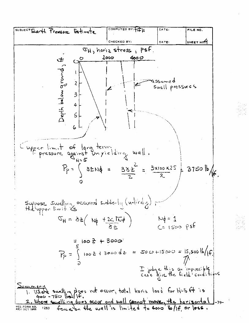
COMPUTED BY: \4
CHECKED BY:
d:: /"I
-o ~ :)
e 2 rro ~ 3 0 -• ......0. 4
,.,~:
~ 5 " Cl
0
= 'DO t t- oOC>e>' 5 ' ) 100 c -t scoo d 2:- :::=
()
• sp"ftpvi~ ~~\~ ~0~, ' ~e.C;) - '160 \~f \.(:'
DATE:::
DA. TE:
\
\ \
FII.E NO.
SHEET N~
~+ ~ 1 (.::. 1 s·o<;'l ~ ~J
·-.-~~~·~W~.~~~~~~~~~~~~~~~~~~~~~~~~~~~~-79-m~s t'ORM NO, IU!:V OC'l' 1~61)
APPENDIX A
TRIP REPORT ON RECONNAISSANCE VISIT TO DAYLIGHT/MCCUTCHANVILLE
PREPARED BEFORE THIS INVESTIGATION BEGAN UNDER SEPARATE OSM FUNDING
(This memorandum is included because it is referenced extensively in some chapters of this report
and is not generally available)
-80-
CEWES-GV-Z (70-lx) 11 Mar 91
MEMORANDUM FOR RECORD
SUBJECT: Inspection of Building Damage Near Daylight and McCutchanville, Indiana, and Examination of Related Documents
1. Introduction. The undersigned, along with Mr. Vince Chiarito of the Structures Laboratory, WES, and respresentatives of the Office of Surface Mining (OSM), the Bureau of Mines (USBM), and the U.S. Geological Survey (USGS) visited 13 residences and two churches to the west of the Ayrshire Mine on 20 and 21 Feb 91 to observe damage to the buildings and to talk with the residents. I also reviewed all of the documents listed in encl 1. This memorandum will later refer to Reference numbers in this enclosure.
2. The OSM funded WES for this participation in the inspection team and the preparation of this memorandum under an Interagency Agreement dated 13 Jan 91. Approximately 100 property owners in the Daylight and McCutchanville areas have claimed that blasting by the mine has caused damage to their.buildings, yet the distances between the buildings and the blasts and the charge weights involved in the blasts are within levels that, in prior U.S. blasting experience and literature of which this writer is aware, have not caused co~metic or structural damage to buildings. Is this evidence of some heretofor~ unnoticed phenomena related to blasting or is the damage due to other causes?
3. The objective of my participation was to determine if the information available was sufficient to answer the above question and to render judgments as to possible causes of the damage.
4. Some key facts not in dispute. Damage complaints have been reported by only a small fraction of the building owners {about 7%). The damage is real in every case reported. The nature of the damage varies from cosmetic to structural. The vibration of the houses in response to ground shock and/or airblast is felt by and is audible to the area residents. Airblast itself is generally not audible. The mine opened in 1973. There have been a very large number of blasts over the years. Onset of significant complaints (November 1988) lags by a few months the change by the mine owner to cast blasting in March 1988. Cast blasting uses powder factors between 1- and l-l/2 lbsfcu yd whereas the previously used method had typical powder factors of 3/4 lbs/cu yd. There are typically 3 shots/day every 3 days. Total charge ranges from 100,000 to 400,000 lbs and charges pet delay range from 250 to 4,200 lbs. The March 1989 shortest distances from the highwall to Daylight and McCutchanville were, respectively, 9,500 ft. and 18,000 ft. The mine high wall has moved closer to these communities in the past few years, but will never reach them (under present local law) because surface mining is not permitted in Vanderburg County.
5. Hypotheses. Some hypotheses presented by various people in an attempt to explain the damage at various locations are:
-81-
a. Ground vibration of unusually high levels and/or unusually low frequencies caused by amplification due to topographic features and/or soil profile characteristics.
b. Airblast of unusually high levels due to unfavorable cloud cover, thermal gradients, wind directions, and/or topographic features.
c. Airport jet noise or sonic booms~
d. The presence of expansive clay minerals and cyclic moisture charges in the foundation soils is causing damage.
e. Liquefaction or pore pressure buildup under cyclic loading.
f. Subsurface erosion of soils near foundations due to lack of filters around underdrain.
g. Basement andjor footing construction practices which result in inherent weaknesses under static loads are responsible.
h. Combinations of some of the above.
6. Enclosure 2 is a portion of the Daylight and Evansville North USGS quadrangle maps showing the locations of the buildings visited, approximate boring locations, the mine and other relevant information. Enclosure 3 is a summary of notes prepared on the buildings visited.
7. Enclosure 3 is summarized in Enclosure 4. The most heavily damaged structures had significant differential settlement. Four of 13 structures with basements had bowed- in: walls.. The majority of the residences visited had surface water drainage arid/or undrain inadequacies, some of which could be clearly linked to differential settlement patterns. This will be discussed in a later section. Expansive soil was present at 3 of the 15 structures and was not in evidence at 7 of 15. There is an imperfect correlation, in Enclosure 4, of bowed basement walls with expansive soil. However, the Effinger residence, which had the most seriously bowed-in basement wall, does not correlate.
8. The majority (8 of 15) of the buildings visited had pervasive fine horizontal cracks at or above ground line andjor other evidence of distress caused by an above or below ground horizontal loading. The closest building, St. John's, does not fall in this group, but all of the other buildings visited east of North Green River Road do (St. John's does not have a basement as the others do).
9. Expansive Soils. References 1 and 2 respectively contain Indiana Department of Natural Resources (IDNR) and Corps of Engineers (CE) water content, Atterberg Limits, shrinkage limits, gradation, Unified. Soil Classification System classification data for more than 100 specimens collected from the study area which can all be used to infer swell potential using criteria given in Reference 5. Reference 2 also contains a few sets of consolidation test results that unequivocably determine the degree of swell potential. References 1 and 3 contain the results of X- ray diffraction analyses by others to determine the nature of the clay minerals present.
-82-
Some minerals, particularly smectite and morillonite, have extremely great swell potential if brought in contact with water.
10. The area has no past history of expansive clay soils. Enclosure 5 from Reference 4 and Figure 2-1 of Reference 5 both show no areas of expansive soil in the project area. Discussions and descriptions of the soil in Vanderburgh and Warrick Counties, contained in References 6 and 7 respectively also give no hint of the presence of expansive clays. Neither does Reference 8, a report on the bedrock in the area. Yet, as we will see, they are present.
11. The first piece of relevant data, a sample from the surface near house #108 (McCutchan) reported in Reference 9, was found to have 68% of its minus 2 pm fraction (25%) comprised of smectite and mixed layer smectite-illite minerals.
12. X-ray diffraction results by IDNR in Reference 1 are not consistent with those of the CE on samples from the same boring and depth range. IDNR indicates mixed layer clays, ranging from 24% to 61% of the minus 2 pm fraction and no smectite. CE reports one sample with 53% smectite, none with mixed layer minerals, and seven with vermiculite, a less expansive mineral but still one of concern.
13. In Enclosure 6, I organized all the soil laboratory data from References 1 and 2. Samples indicated by a dark dot • are clearly expansive by CE criteria and by the method of VanDer Merve (see Reference 5). All of the samples which are classifiable as expansive based on engineering properties and index properties have at least 10% by total weight of dry material of expansive clay mineral. However, many samples with more than 20% vermiculite clay mineral are clearly not expansive in flooded consolidation tests, and many samples with more than 20% of mixed-layer minerals do not have Atterberg limits suggestive of expansion. This inconsistency led me to relay heaviest on that which is easiest to measure and interpret in the laboratory and that which has the best empirical tie to past experience with expansive soils; i.e. the gradation, limits, water contents, and consolidation tests. I tended to discount X-ray diffraction results when they were inconsistent with the above. Enclosure 7 shows the Atterberg limits data from 3 ft or greater in depth plotted on a plasticity chart. Encl9sure 8 shows PI vs % < 2 pm for the same data. Enclosure 7 shows six of the Atterberg limits classify the samples as medium swell potential and six classify as high out of a total of over 60 specimens. Twenty percent of the samples have some swell potential and three have marginal swell potential. Enclosure 8 indicated 13 samples with a high or very high swell potential by VanDer Merve's criteria. As indicated in the example in Enclosure 8, "very high" would produce a heave of 1. 2 in. while "medium" would produce 0.3 in. heave.in soil profiles like those seen at those few sites near Evansville where expansive clays were found.
14. I could find no pattern based on topography or geomorphology (Reference 10) to explain why expansive clays are present in some borings and not in others in this area. In general, the expansive clay, if present, was 3 ft thick or less and between 4 ft and 14 ft in depth. It was sometimes found just above weathered rock and sometimes in the middle of the soil column. All I can say with certainty is that in 6 of the 21 borings that had laboratory soil test specimens tested for limits and gradation, there was expansive clay
-83-
present, and in the others, there was not. Also where there were CE and lDNR soils lab data at approximately the same depth in the same boring, the two tended to agree.
15. About 28% of the borings had expansive clays present in a depth range where seasonal moisture changes could cause foundation movement. Enclosure 4 categorizes houses near certain borings as having expansive clay based on the data in Enclosure 6. Three of the four with bowed-in walls had expansive clay present. The borings were sometimes more than 100 ft from the house in question and the categorizations should be viewed with caution for this reason. Consolidation tests suggest swell pressures of 0.6 to 2.5 tons/sq ft at the 5- to 10-ft depth range in flooded consolidation tests. These loads would be sufficient to deform inward and severely crack unreinforced, unfilled concrete block basement walls of the types used in the houses visited. Still,the Effinger house which had severe wall damage does not have expansive clay in a boring made in the general area. I would like to see an undisturbed sample boring 5 ft from the north wall of the house with flooded consolidation tests on the samples obtained to determine whether there is a swelling soil near the house. Based on the information I have, I cannot say definitely one way or the other what caused the basement damage at the Effinger residence.
16. In addition to expansive soil, one must have a change in subsurface moisture to cause shrink swell phenomena. Enclosure 9 shows considerable variation in precipitation with seasonal and multi-year dry and wet spells. In the summer of 1988, a three-year low ended. Additionally, poor surface drainage control and partially plugged underdrains existed at some houses creating a situation where expansion could have been maximized coincidently with the start of cast blasting and heavy complaints. I conclude that expansive soil has contributed to the foundation damage at a few of the houses, but by no means the majority. To say definitively which ones were affected and which were not would take a major separate geotechnical investigation at each residence.
17. Jet Noise and Sonic Booms. The property owners had not reported any sonic booms in the area or any damage due to aircraft noise. Four of the houses visited were fairly close to the Evansville Airport, but jet traffic there is light. The only indications of concern are found in Reference 9 which points out that a few of the complaints come from buildup "within 0.3 miles of the most active runway." The runway used for commercial passenger aircraft does not have a flight path over any of the houses we visited and is 3/4 mile from the nearest house visited. The references notes "upon working in some of the houses that aircraft operations caused structural rattling that could be both felt and heard." While aircraft noise is present, there is no mention of sonic booms anywhere in the record made available to me, and I feel that this subject should be dismissed from further consideration. Reference 9 notes that aircraft noise did not trigger instruments mounted in basements but that wall vibrations of less than 0.035 in/sec. were recorded at above ground wall and corner locations. These are insignificant levels and I recommend that aircraft noise be dismissed from further consideration. There simply is not any evidence that leads one to believe that a cause and effect relationship exists.
-84-
18. Subsurface (Internal) Erosion. The predominantly CL soils found in the area are moderately erodable and the underdrainage systems around the outside of the strip footings supporting the residences should be built as filters. Discussion with two homeowners and one builder who built his own home indicated that the common practice is to place 2 ft of pea gravel (or larger stone) around and over a perforated drain along the outside of the footing, cover this with a few inches of straw, and then backfill the area between the basement (or crawlplace) wall and the natural undisturbed soil with dumped material from the excavation.
19. To accomplish filtration, a layer of fine sand or a geotextile between the gravel and natural or backfill soil is required and apparently no one uses them in residential construction in this area. Examination of three underdrain outlet pipes at ·different residences indicated some degree of internal erosion. CL soils partically or totally filled the outlet. This material could be eroding from under the footings and, if it did erode, it would cause differential settlement. This is almost certainly what happened in the case of the garage floor at the Fink residence.
20. Liquefaction or Pore Pressure Rise. The soils at this site are not saturated. Initial saturation.values reported in CE lab tests range from 56% to 98% with most below 90%. These soils will not liquefy when shaken severely. The Atterberg limits indicate that most of the soils present are also too plastic to be concerned with this issue. A key word literature search and the author's personal knowledge of the literature turned up no blasting or explosive testing experiences where such had occurred at vibration levels and scaled distances comparable to the Daylight-McCutchanville areas. Russian literature describes densification of wet loess with explosives, and U.S. literature describes densification of wet soils, but scaled distances involved are three orders of magnitude smaller than those present here. The question of pore pressure rise can be safely dismissed in my opinion.
21. Settlement Under Repeated Low Level Vibration. Noticeable vibration is occurring. In January 1988, there were 59 separate blasting events at the mine. In that year, there were over 500 events. Each event produces 10 to 20 cycles of motion (as shown by waveforms in Reference 9) in the frequency range from a few Hz to a few tens of Hz. This is 5,000 to 10,000 cycles per year, or perhaps 30,000 or more cycles in the period of interest. Vibration amplitudes are small, usually a few hundredths of an inchjsec based on Reference 9. What happens to this predominantly CL partially saturated soil with a void ratio in the 0.37 to 0.78 range when subjected to many cycles of low amplitude strain in a drained condition? I could find no data in the literature to answer that question and recommend that some drained long duration, torsion or axial vibration tests be run on arained, undisturbed samples from the site and that the sample be monitored for volume change. I also could not find any case reported in the literature where repeated vibration at the levels that appear to be occurring here caused differential settlements, so I have no reason to expect this to be a problem. However, I can't completely discount the possibility, hence I recommend a few tests.
22. Surveys of Damage or Complaints. We were briefed on one survey by OSM personnel which included only reviewes of 107 complaint cases. Of these, 6 had no damage, 62 had cosmetic damage, 32 had an intermediate level of damage, and 7 were seriously damaged. The number of complaints correlated temporaly
-RS-
with the total charge weight used. The only other clear trend is that no two story homes were rated as "severely damaged" (the Harris horne is two story; see my notes. Apparently the rating team did no"t call this severe).
23. Reference 9 describes a crack monitoring program conducted between 1 Nov 1989 and 3 Jan 1990. Forty-five cracks spread out over six residences were examined 38 times for crack widening and/or elongation during the period. Only one crack extension occurred and width changes noted were less than ± 0.1 mrn. The latter was thought to be normal thermal cycling. Several rather large blasts occurred during this period with a total of 59 blast events. OSM displacement gages in the study houses also showed no changes. This is strong evidence that blasting as practiced at the time of the Reference 9 study was not causing damage in these six residences.
24. Reference 18 describes a survey conducted in 1977 of selected homeowners out to six miles from the mine when the high wall was far to the east of its present position. Complaints of damage decrease in number and severity with distance. Beyond a distance of about five miles (within the glacial lake), the trend of the least severe damage category reversed and actually increased with distance.
25. Airblast. The author feels others in the review group have a better basis for judgment in this area. Windows were not broken out. The Christiansen home has windows with diagonal cracks, but this might have been caused by differential settlement. Glass begins to break at 140 db, so we can be confident that this level has not occurred. The airblast data in Reference 9 covers a short period of time and does not include all possible meterological conditions which aggravate airblast or the largest events that have occurred. The highest levels recorded in that reference was 121 db. OSM criteria uses 134 db as a safety limit. There is no guarantee that airblast larger than measured has not occurred in the Daylight and McCutchanville areas. Reference 9 contains data which indicates that the structures which were instrumented in the November 1989 to January 1990 time period responded more to ground vibrations than to airblast.
26. Ground Vibration. Enclosure 10 is a summary of particle velocity attenuation curves or data bands from several sources for studies near the Ayrshire and Blanford Mines taken from References 9, 14, and 15. The scaled
ranges of interest exceed 8000 ft/ .{7000 = 95 ftjlb 1/2. While the highest particle, velocity recorded in the Reference 9 study was 0.1 in.jsec, enclosure 10 suggests that values'of about 5 times this number could have occurred at the minimum scaled range of interest in the northwest direction from the mine in the vicinity of Daylight and values of 0.2 in.jsec could have occurred near McCuthanville. These are clearly large enough motions to account for the perceptions of motion reported by the residents. However, they are less than those at which damage is expected at frequencies of vibration of 3 Hz or more. This is below the frequency range reported in Reference 9.
27. The waveforms on pages 26 and 27 of Reference 9 suggest that most of the structural response is the result of ground motion rather than airblast. These waveforms do indicate that the predominant frequencies are 4 Hz or higher.
-86-
28. I would like to see 5% damped pseudo-velocity spectra calculated for the actual radial and transverse wave forms obtained from the Reference 9 study (assuming original analog or digital time histories still exist) to see if lower frequencies than those which appear from visual examination of the waveforms can be found. I would also like to see ground motion data obtained with instruments with a 1/4 or 1/2 Hz lower limit of fidelity to see if there are any lower frequency components being missed.
29. Site Amplification. The topographic conditions at McCutchanville and the soft lakebed deposits do lend themselves to the amplification of ground motion as suggested in References 22 and 23. However, when the topographic and soil profile cross sections are plotted at common horizontal and vertical scales, the slopes appear rather mild and the amount of amplification to be expected is rather minor. This author has never encountered measured amplifications of 50 (as indicated in Reference 22) in experience with seismic ground motion amplification, and I don't know of a theoretical basis for values that large either. Five, rather than 50, might be a more reasonable upper bound. Regardless, the measurements made in Reference 9 and summarized in Enclosure 10 have already built into them whatever amplification factor nature gives the sites, so that issue is not really germaine to the question of how much motion occurred. What is germain and cannot be answered with the available data is the question: Were the source functions (the charges and delays) used before the period of USBM monitoring sufficiently different to produce higher amplitudes or lower frequencies of ground vibration?
30. Summary:
a. Expansive clay does exist at some locations where damage has been reported but does not exist at others.
b. There is imperfect correlation of expansive clay and bowed-in basement walls exists. Some of the damage seen is likely due to shrink-swell of expansive clays due to varying moisture conditions. The Effinger home is an apparent exception. Soils data should be collected nearer to the house if possible.
c. No credible evidence exists to support liquefaction, pore pressure rise, sonic booms, or jet noise as contributing to observed damage.
d. Some construction practices observed (unreinforced footings, unreinforced and unfilled concrete block basement walls, lack of filters around underdrain) and/or poor surface drainage control practice could aggravate or cause vertical differential settlement damage unrelated to blasting.
e. Although recorded levels of ground motion and airblast are smaller than established safety criteria, there are some types of cosmetic damage present at some buildings that are clearly associated with horizontal loading or horizontal movement, and this author can find no source for such movement or loading other than the blasting. There is no systemic pattern of these cases with distance or topography.
-87-
f. Unless there are lower frequency components present in the data from the Reference 9 study than those apparent on pages 26 and 27, the amplitudes recorded during that study should not have caused damage. Yet as indicated in e. above, there .. is damage likely due to vibration. It is possible that this damage occurred prior to November 1989 when other shot arrangements, delay combinations, and charge sizes were used.
g. If digital records exist of the ground motion data reported in Reference 9, 5% damped pseudo-velocity response spectra should be calculated from them t.o provide a better picture of their frequency content.
h. Measurements of broader band frequency response (i.e. 1/4 to 200Hz), ground motion, airblast and structural movement in a 250,000 to 300,000 lb range total charge weight event at sites in the Daylight and in the McCutchanville communities are desirable to see whether there are any very low frequency components present that we are not seeing with the instrumentation used thus far.
i. We do not have data on the effects of long direction, very low amplitude sustained vibration on settlement of cohesive soils. A limited laboratory test program is recommended and will be proposed to OSM in a separate document. ·
j. Site amplification due to topographic effects and/or soft top layers is occurring at these sites, but its effects are already included in the Reference 9 measurements.
k. Since it is expected that there will be a continued effort to understand the wave propagation characteristics of this site, it is recommended that field cross-hole S-wave velocity measurements be made in the overburden soil and in the bedrock.
1. The bottom line of my profession judgment (and it is only a judgment!) is that blasting was responsible for some of the lighter damage seen in the Daylight and McCutchanville areas but that most of the damage that could be called major was due to swelling soil conditions, inadequate drainage, lack of filters, and/or unconservative foundation c ruction practices.
,/ I ':: ;:;~J ?" ./_;_1~1&-/ ,,· ' i
PAUL F. HADALA, PhD, PE Assistant Chief Geotechnical Laboratory
-88-
REFERENCES
1. Anonymous. Handout, 20 Feb 91, Set of Boring Logs labeled, "Appendix U.G., Soil Descriptions, Gamma-Ray Logs and Data Plots for OSM 1-25, 37-37," Indiana Dept. of Natural Resources.
2. Stephens, R.J. CESAD-EN-FL letter report to Mr. Bob Welsh, OSM, Pittsburgh, PA, dated 12 Jul 90.
3, Stevenson, P.J. CESAD-EN-FL letter report to Mr. Bob Welsh, OSM, Pittsburgh, PA, dated 20 Jul 90. X-ray diffraction analysis.
4. McKeen, R.G. DOT/FAA/RD/81/25.
"Design of Airport Pavements for Expansive Soils," Jun 1981, Final Report, U.S. Dept. of Transportation.
5. Anonymous. "Foundations in Expansive Soils." Technical Manual TM 5-818-7, Sep 1983, Headquarters Dept of the Army, Washington, D.C.
6. Kelly, L.A. "Soil Survey of Vanderburgh County, Indiana." USDA Soil Conservation Service, 1976.
7. Shively, J. L. "Soil Survey of Warrick County, Indiana." USDA Soil Conservation Service, 1979.
8. Gray, H.H. "The Mississippian and Pennsylvanian (Carboniferous) Systems in the United States- Indiana." U.S. Geological Survey Prof. Paper 1110-K, 1979.
9. Siskind, D.E., Crum, Steven V., and Plis, Matthew, N. "Vibration Environment and Damage Characterization for Houses in McCutchanville and Daylight, Indiana." Contract Research Report, Feb 1990, Office of Surface Mining, Dept. of Interior.
10. Hester, N.C, Bleuer, N.K. Eggert, D.E., Hasenmueller, N.R., Arnold, J.E., Chitwood, T.W., Riddle, S.L., Frushour, S.S., Fitch, J.R. Jr., and Johnson, C.R. "Geologic Framework and Physical Properties of Bedrock and Lacustrine Deposits In and Around McCutchanville, Indiana." 1989-90 Mid-Year Report, Part I. Indiana Department of Natural Resources.
11. Anonymous. "Ayrshire Mine Blasting Summary, Jan 1988 through Jan 1990." A handout provided by OSMon 20 Feb 91.
12. Kopp, J.W. "Initiation Timing Influence on Ground Virbation and Airblast." U.S. Bureau of Mines Information Circular #9135. 1987.
13. Anonymous. "Map Showing Thickness Contours of Unconsolidated Materials." Undated handout provided by Office of Surface !-fining on 20 Feb 1991.
14. Siskind, D.E. and Stachura, V.J. "Vibrations from Blasting Over Aband0ned Underground Mines," pp. 60-72. U.S. Bureau of Mines, IC 9135. 1987.
Encl l
-89-
15. Siskind, D.E., Crum, S.V., Otterness, R.E., and Kopp, J.W. Study of Blasting Vibrations from Indiana Surface Coal Mines." U.S. Bureau of Miens. 1989.
"Comparative R.I. 9226 ..
16. Siskind, D.E., Crum, S. V., Otterness, R.E., andKopp, J.W. "Investi~ gation of Blasting Vibrations Above Abandoned Underground Coal Mines." 1 Sep 1987. PB 90-153131, Twin Cities Mining Research Center, U.S. Bureau of Mines.
17. Siskind, D.E. "Assessment of Blasting Vibrations from Surface .Mine Blasting in Peabody's Universal Mine, Blanford, IN." 31 May 1990. PB 90-225665, Twin Cities Mining Research Center, U.S. Bureau of Mines.
18. Barnes, Jack. "The Effects of Strip Mine Blasting on Residential Structures, Ayrshire Mine, Warrick and Vanderburgh Counties, Indiana." Proceedings of The Indiana Academy of Sciences, pp 311~320. 1978.
19. Siskind, D.E., Stagg, M.S., Kopp, J.W. and Dowding, C.H. ·~Structure
Response and Damage Produced by Ground Vibration from Surface Mine Blasting."· R.I. 8507, U.S. Bureau of Mines. 1980.
20. Siskind, D.E. and Crum, S.V. "Delay Timing and Geological Influence on Low Frequency Vibrations from Blasting at Nine Indiana Surface Coal Mines." International Journal of Surface Mining and Reclamation, Vol. 4, pp 57-67. 1990.
21. Siskind, D.E. "Low Frequency Vibrations from Surface Mine Blasting Over Abandoned Underground Mines." Proceedings, International Congress on Rock mechanics, Vol. 1, Montreal, Canada. 1987.
22. Woods, R.D. "Transmission of Blast Induced Seismic Waves in Vicinity of· Mccutchanville, Indiana." Undated.
23. Woods, R.D. Letter to David Pope, dated 3 Oct 1990, regarding Amax Coal, McCutchanville, and Daylight, Indiana.
24. Litvinov, I.M. "Construction of Blasting Works for Deep Compaction of Slump~Prone Loess Soils in a Built Up Area." Soil Mechanics and FoundatioQ Engineering, Volume?, No. 3. May-June l9b9.
25. Siskind, D.E., Stachura, V.J., and Nutting, M.J. "Low-Frequency Vibrations Produced by Surface Mine. Blasting Over Abandoned Underground Mines." R.I. 9078, U.S. Bureau of Mines. 1987
26. Krutov, V.I., Kagar, V.K., and Shadchinev, B.E. "Compaction of Soils Prone to Slump-Type Settlement by Restricted Wetting and Deep Blasting." Soil Mechanics and Foundation Engineering, Vol. 25, No. 3. May-June 1988.
27. Konovalov, P.A. et al. Saturated Loess Soil in the Engineering, Vol. 23, ~o. 4.
"Construction of Artificial Bases on WaterTadzhik SSR." Soil Mechanics and Foundation
July-August 1986.
-90-
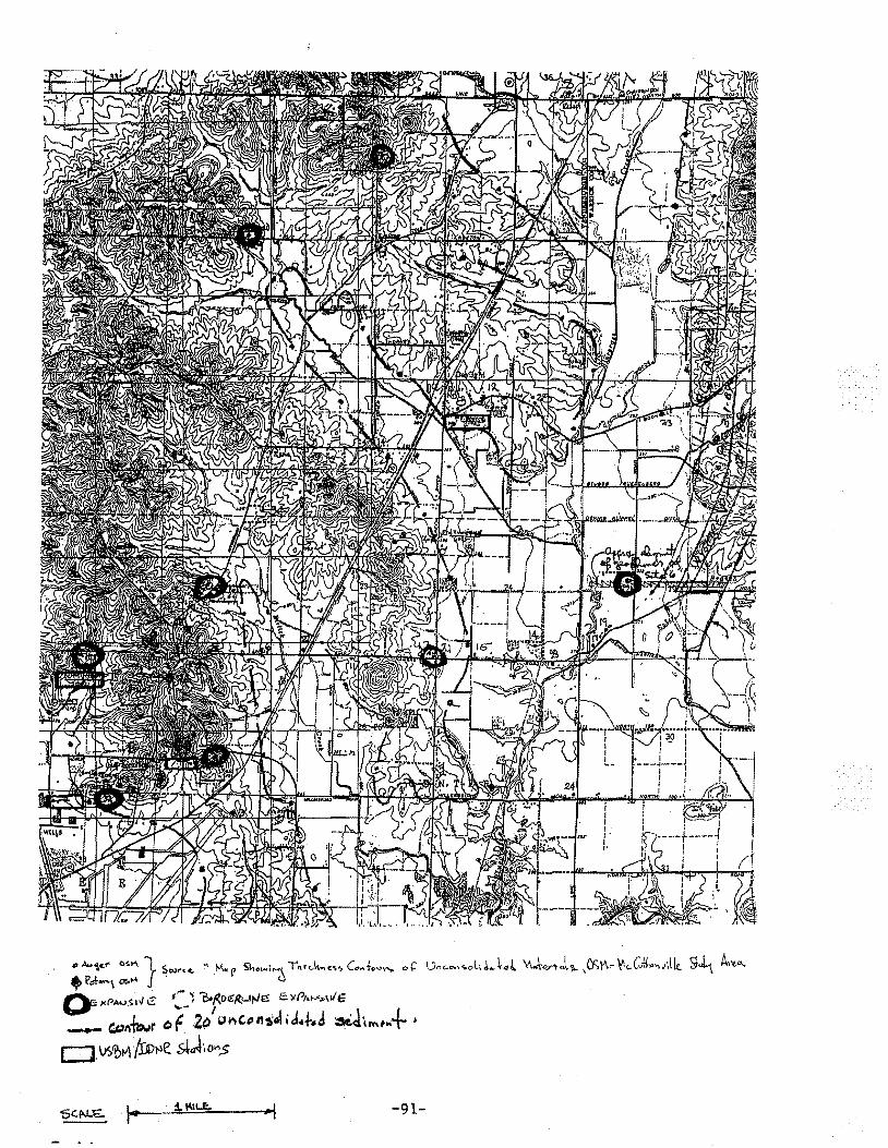
-91-
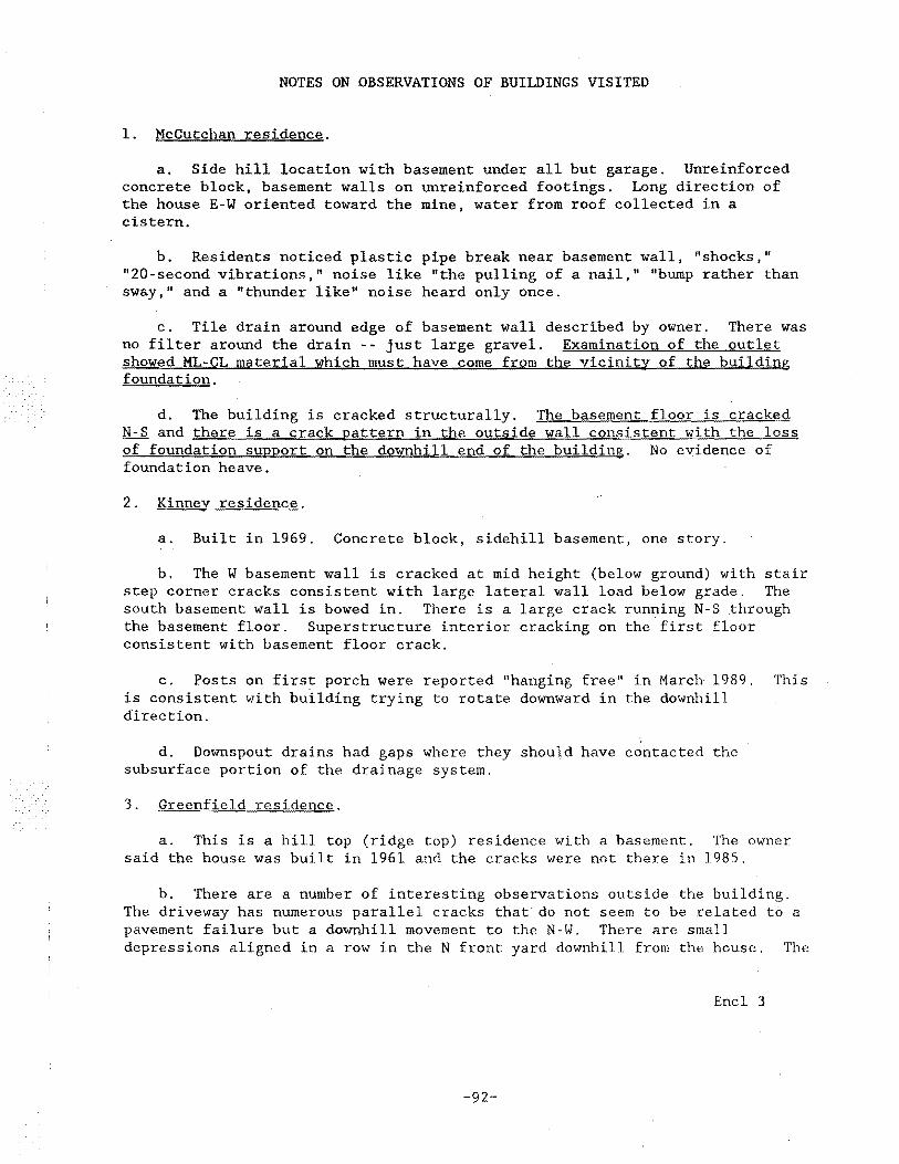
NOTES ON OBSERVATIONS OF BUILDINGS VISITED
1. McCutchan residence.
a. Side hill location with basement under all but garage. Unreinforced concrete block, basement walls on unreinforced footings. Long direction of the house E-W oriented toward the mine, water from roof collected in a cistern.
b. Residents noticed plastic pipe break near basement wall, "shocks," "20-second vibrations," noise like "the pulling of a nail," "bump rather than sway," and a "thunder like" noise heard only once.
c. Tile drain around edge of basement wall described by owner. There was no filter around the drain -- just large gravel. Examination of the outlet showed ML-CL material which must have come from the vicinity of the building foundation.
d. The building is cracked structurally. The basement floor is cracked N-S and there is a crack pattern in the outside wall consistent with the loss of foundation support on the downhill end of the building. No evidence of foundation heave.
2. Kinney residence.
a. Built in 1969. Concrete block, sidehill basement, one story.
b. The W basement wall is cracked at mid height (below ground) with stair step corner cracks consistent with large lateral wall load below grade. The south basement wall is bowed in. There is a large crack running N-S through the basement floor. Superstructure interior cracking on the first floor consistent with basement floor crack.
c. Posts on first porch were reported "hanging free" in March 1989. This is consistent with building trying to rotate downward in the downhill direction.
d. Downspout drains had gaps where they should have contacted the subsurface portion of the drainage system.
3. Greenfield residence.
a. This is a hill top (ridge top) residence with a basement. The owner said the house was built in 1961 and the cracks were not there in 1985.
b. There are a number of interesting observations outside the building. The driveway has numerous parallel cracks that do not seem to be related to a pavement failure but a downhill movement to the N-W. There are small depressions aligned in a row in the N front yard downhill from the house. The
Encl 3
-92-
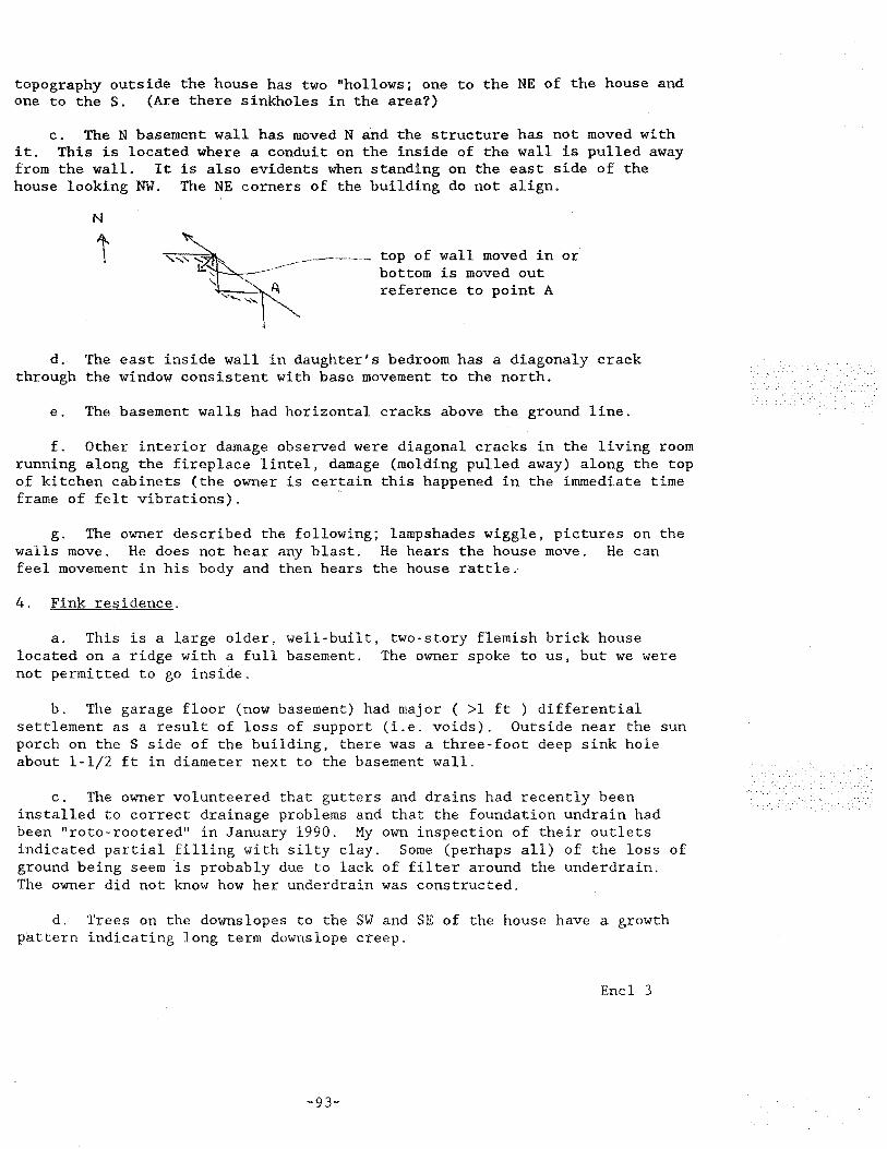
topography outside the house has two "hollows; one to the NE of the house and one to the S. (Are there sinkholes in the area?)
c. The N basement wall has moved N and the structure has not moved with it. This is located where a conduit on the inside of the wall is pulled away from the wall. It is also evidents when standing on the east side of the house looking NW. The NE corners of the building do not align.
N
top of wall moved in or bottom is moved out reference to point A
d. The east inside wall in daughter's bedroom has a diagonaly crack through the window consistent with base movement to the north.
e. The basement walls had horizontal cracks above the ground line.
f. Other interior damage observed were diagonal cracks in the living room running along the fireplace lintel, damage (molding pulled away) along the top of kitchen cabinets (the owner is certain this happened in the immediate time frame of felt vibrations).
g. The owner described the following; lampshades wiggle, pictures on the walls move. He does not hear any blast. He hears the house move. He can feel movement in his body and then hears the house rattle.
4. Fink residence.
a. This is a large older, well-built, two-story flemish brick house located on a ridge with a full basement. The owner spoke to us, but we were not permitted to go inside.
b. The garage floor (now basement) had major ( >1 ft ) differential settlement as a result of loss of support (i.e. voids). Outside near the sun porch on the S side of the building, there was a three-foot deep sink hole about 1-1/2 ft in diameter next to the basement wall.
c. The owner volunteered that gutters and drains had recently been installed to correct drainage problems and that the foundation undrain had been "roto-rootered" in January 1990. My own inspection of their outlets indicated partial filling with silty clay. Some (perhaps all) of the loss of ground being seem is probably due to lack of filter around the underdrain. The owner did not know how her underdrain was constructed.
d. Trees on the downslopes to the SW and SE of the house have a growth pattern indicating long term downslope creep.
Encl 3
-93-
e. The owner said her basement was wet and muddy.
f. The outside walls were diagonally cracked near several windows.
5. St John's Roman Catholic Church.
a. This is a new church. This is the closest building to the mine we visited. It is constructed on grade.
b. The building vibrated about 11:15 a.m. production blast occurred at about that time I noise but a perceptable sensation of movement. irritating.
while we were in it (a later learned). There was n< It was not personally
c. The staff described some problems with windows and copper roof leaki in the church proper, but these had been corrected. No connection with blasting could be established.
d. The west outside block wall behind the altar had vertical cracks anc there was a floor crack perpendicular to the outside wall nearby. There was 1/4 in. differential movement across the crack.
e. We daily mass in the new
observed chapel. chapel.
cracked stained glass and a symmetrically cut frame in t
This glass was removed from the old church and installed
f. On the north and south sides of the long east wing, there were vertical cracks about 6 ft apart in the outside wall. There was a diagonal crack above the kitchen exterior door.
g. This is one of the least damaged of the buildings visited.
6. Christianson residence.
a. This is the northern-most home visited and is almost as close to the northern edge of the mine as St. John's is to the center. This property is either in or on the edge of the glacial age lake deposit, The terrain to th east is flat.
b. The house is a wood frame, permastone veneer, two-story structure wi a basement (that was dug after the house was built), and is one of the more severe structurally damaged homes visited.
c. Observations on the outside of the building indicated diagonal crack: on the east side under windows. There was a vertical crack in the chimney 01
the west side.
d. In the interior, there were several cracks over the living room and master bedroom archway doors. The door to the glassed in porch and the porcr windows were all sticking. Porch window glass was cracked.
e. There were cracks in basement walls. (Field notes did not contain further elaboration.)
-94-
f. The barn had unusual distress. A roof support beam was town away from one of the wooden interior columns.
7. Zimmerman residence.
a. This is one of the closer residences and is also on the edge of the glacial lake. It is a brick veneer one-story residence with a basement. The house is 16-1/2 years old.
b. Exterior observations included six horizontal cracks in the chimney, vertical cracks over the garage door. Settlement of the front porch, settlement of backfill of basement excavation in rear side of house. Downspouts were separated from the below ground drains.
c. There was a diagonal stair-step crack in the west basement block wall and basement floor cracks (without noticeable differential settlement). There were continuous horizontal cracks in the basement walls above ground level and I could find no possible explanation for this except external horizontal loading applied from above or below.
e. The owners' record of "nail pop"occurrence was interesting:
Date Cumulative Number
Jan 89 280 Aug 89 397 Sep 89 569 What kind of nails were Jun 90 597 used to install sheetrock Mar 90 636 was unknown Feb 91 959
f. The owner described observations of chandeliers rattling and feeling a sense of movement in the basement floor as a result of mine blasts.
8. Bohrer residence.
a. This is a wood frame, brick veneer house. There were interior horizontal cracks near the back door and diagonal cracks near windows. There was a large diagonal exterior crack near a S side window and one near the garage door.
b. There was a horizontal crack above ground level on the S side of the basement. The sewer drain cracked at the junction of the cast iron pipe and the tile and others were cracked where the sewer drain exited the basement. This was one of the instrumented houses.
9. Boettcher (Campbell) residence.
a. This is an old L-shaped wood frame, brick veneer residence with a basement under part of the building and a crawl space under the rest. The building is on a side of a hill. The foundation walls are on a series of separate stepped footings which are not tied together.
-95-
b. The front exterior of the building had two large diagonal cracks, 01
in the NE corner that was aasociated with differential settlement of that corner of the building, and one that may have been caused by a tree root. (Large tree close to building in a location where there was no basement.) There were also diagonal cracks on the rear side of the building over the crawl space.
c. The basement floor was badly cracked. It was either center heave 01
edge drop. Based on the wall conditions, I am of the opinion it was edge drop. There were vertical and diagonal basement wall cracks. Exterior drainage of the building was recently repaired. I did not find any underdr< exits. I do not think this basement damage is vibration related. It is vertical rather than horizontal loading caused.
10. Effinger residence.
a. This is a one-story brick veneer home with a concrete block basement built by the owner in 1979. This residence is on the top of a ridge, relatively close to the airport and due west of the mine.
b. The owners described their feelings as "the house trembled" and "slamming from underneath." They did not feel any swaying movement of their bodies.
c. Outside the house I observed that the patio on the north side was tilted toward the house. I inspected the underdrain outlets. There was plenty of fall, but both outlets were partially full of ML-CL soil. The own. said the drains were set on the footers, covered with 2 ft of pea gravel, a few inches of straw, and then dumped fill from the excavation. This does no satisfy filter criteria. The foundation excavation was only about 2 ft oustide the basement wall and was nearly vertical. It was dry during construction. The owner had a good set of construction photos.
d. The owner said the house was down 2 inches at the southwest corner (l had run levels) and he is sure that was not the way it was built.
e. There were horizontal cracks over the right (west) of the back door, also diagonal cracks on the NW corner. Horizontal and vertical cracks were under the windows on the N side.
f. There were four cracks in the R/C front port deck.
g. The N and E basement walls had heavy, open en-echelon diagonal and horizontal cracks.
h. The north basement wall was bowed in. The basement walls are about 9 ft high.
i. There was cracking in the SW corner of the basement room floor.
j. The owner saic the basement floor in the NW corner became wet and muddy during rainstorms.
-96-
Harris residence.
a. This is a large two-story, wood frame, stone veneer building built in )3. It is oriented with 'the lag direction N-S and is on teh side of a ige. The owner moved in April 1988 and "felt vibrations fromthe start." ~whole house slammed, sometimes "from below" and sometimes "from above."
b. The owner observed basement wall damage for the first time shortly ter a felt event of November 16, 1988. The fall of 1988 was described by s. Harris as "hideous" and she said that sporadic large events occurred rough July 1990.
c. Local damage around the top of pipe columns in the basement indicate rizontal movement.
d. One basement block wall was slightly bowed in.
e. Large vertical cracks on both sides of the house, said to have been iginally present in basement, were claimed to have been widened by recent ents.
f. Overall basement crack patterns suggest a N~s~N or vice versa vement.
g. The sun porch showed signs of outward and downward movement.
h. On the first floor, there were diagonal or vertical cracks around most 1ors and windows.
i. The severity of damage in the basement was greater than the first .oor which was greater than the second.
J. An air conditioner drain pipe break in the attic over the one-story 1rt of the building was consistent with the N-S movement observed elsewhere.
k. This house leaves me with the impression that most of what I observed iS not the result of differential settlement or heaving. The pattern of image was very consistent with overall racking of the house by horizontal )ading.
~. Bluegrass Methodist Church.
a. This is a two-story brick church with attached Sunday school classroom ~ilding built in 1964-65. These were the tallest concrete block walls Jserved in our tour.
b. The most prominent feature in the church sanctuary was a long, orizontal crack about 3-4 ft above floor level in both sides which was said o have occurred three years ago.
c. Chandeliers on long chains in the church were said to r~ttle followed y swaying.
-97-
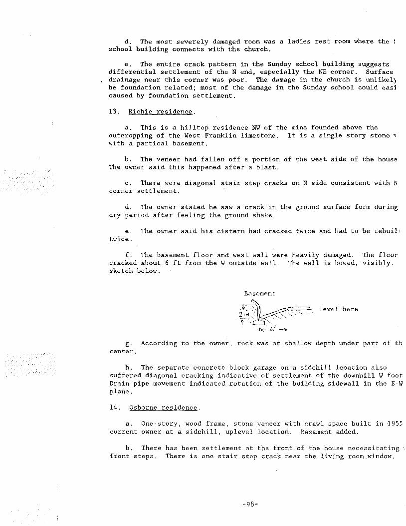
d. The most severely damaged room was a ladies rest room where the school building connects with the church.
e. The entire crack pattern in the Sunday school building suggests differential settlement of theN end, especially the NE corner. Surface drainage near this corner was poor. The damage in the church is unlikel) be foundation related; most of the damage in the Sunday school could easi caused by foundation settlement.
13. Richie residence.
a. This is a hilltop residence NW of the mine founded above the outcropping of the West Franklin limestone. It is a single story stone ' with a partical basement.
b. The veneer had fallen off a portion of the west side of the house The owner said this happened after a blast.
c. There were diagonal stair step cracks on N side consistent with N corner settlement.
d. The owner stated he saw a crack in the ground surface form during dry period after feeling the ground shake.
e. The owner said his cistern had cracked twice and had to be rebuil1 twice.
f. The basement floor and west wall were heavily damaged. The floor cracked about 6 ft from theW outside wall. The wall is bowed, visibly. sketch below.
Basement
g. According to the owner, rock was at shallow depth under part of th center.
h. The separate concrete block garage on a sidehill lcoation also suffered diagonal cracking indicative of settlement of the downhill W foot Drain pipe movement indicated rotation of the building sidewall in the E-W plane.
14. Osborne residence.
a. One-story, wood frame, stone veneer with crawl space built in 1955 current owner at a sidehill, uplevel location. Basement added.
b. There has been settlement at the front of the house necessitating front steps. There is one stair step crack near the living room window.
-98-
c. On the rear (uphill) side of the house, there were several cracks, one 11hich was wide.
d. There were stair step cracks on the east side of the house.
e. There were E-W ceiling cracks in front and back bedrooms.
f. There was a long horizontal crack at ground level in the basement 1.
g. The basement wall on the front side of the house was bowed in.
h. A separate concrete block garage had back wall stair step cracks bably due to differential settlement caused or aggravated by septic tank :fall. The ground was very wet.
Norton residence.
a. This is a one-story brick veneer and siding clad wood frame residence :h a basement.
b. The owner has lived in the residence since 1967. The house is older.
c. The carport floor has settled next to the house. There was a broken 1stic waterpipe under the carport that had to be repaired.
d. In the basement there was one floor crack in a large unjointed floor. ~re was a horizontal crack at ground level in the basement that was tensive on the east side.
e. The garage had cracked floor slabs (it was a large pour with no nstruction joints). There was differential settlement in one corner that s attributable to poor drainage.
-99-
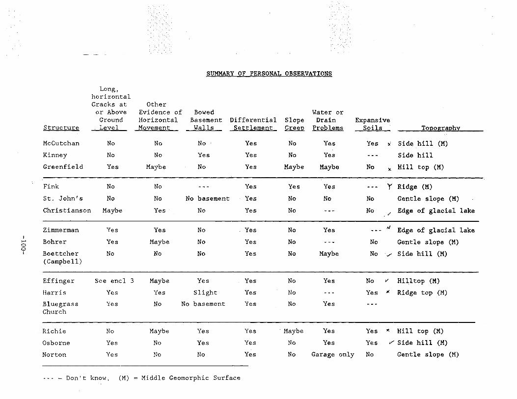
SUMMARY OF PERSONAL OBSERVATIONS
Long, horizontal Cracks at Other or Above Evidence of Bowed Water or
Ground Horizontal Basement Differential Slope Drain Expansive Structure Level Movement Walls Settlement Creep Problems Soils Topo£.raPhv
McCutchan No No No Yes No Yes Yes )( Side hill (M)
Kinney No No Yes Yes No Yes --- Side hill
Greenfield Yes Maybe No Yes Maybe Maybe No l<. Hill top (M)
Fink No No --- Yes Yes Yes --- Y Ridge (M)
St. John's No No No basement Yes No No No Gentle slope (M)
Christianson Maybe Yes· No Yes No --- No Edge of glacial lake v -
Zimmerman Yes Yes No Yes No Yes #J Edge of glacial lake ---I ,_. Bohrer Yes Maybe No Yes No --- No Gentle slope (M)
0 0 I Boettcher No No No Yes No Maybe No .,/ Side hill (M)
(Campbell)
Effinger See encl 3 Maybe Yes Yes No Yes No v Hilltop (M)
Harris Yes Yes Slight Yes No --- Yes 1( Ridge top (M)
Bluegrass Yes No No basement Yes No Yes Church
Richie No Maybe Yes Yes ·Maybe Yes Yes l( Hill top (M)
Osborne Yes No Yes Yes No Yes Yes v Side hill (M)
Norton Yes No No Yes No Garage only No Gentle slope (M)
Don't know, (M) = Middle Geomorphic Surface
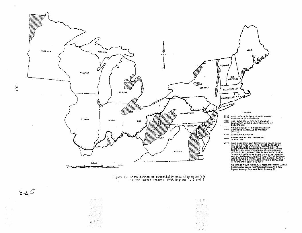
I ,..... 0 ,..... 1
I
~ ' .
"---..
~;/
,. -1 I .,....... / I ( L ', ---- '\ --~
:~--------~ )\
(' v---lll!NQj)
~ -N-
~ WISCONSIN
UiOIAHA
SCALE
100 0 100 .:1'00 Ml
~~~----··· ····-· ·-·· ·--------~~
Figure 2. Distribution of potential in the United States:
~~
-~~F ~ MEWYQRX
exoansive materials Re~ions 1, 3 and 5
B1lllll ~
D ..__.... .....
~ HIGH: HIGHt. Y EXPANSIVE: ANO/OR HIGH FREQUENCY OF OCCURENCE
t..OW; GENEAAL.L. Y OF L.OW E XPANStvE CHAAACT.ER AHO/OR I..OW FREQUENCY OF OCCURRENCE
NON EXPANSIVE: THE OCCURRENCE OF EXPANSIVE MATERIAL.$ EXTREME:L.Y" LtMITEO
CATEGORY 90UNOAAY
SOUTHERN LIMIT OF CONTINENTAL. Gt..ACIAT!ON
NOTE: FOUR CATEGORIES OF EXPANSIVENESS ARS SHOWN ON THE OISTRISIJTION ...... PS. THESE CATEGORIES ARE GENEAAt..lZ£0 ANO ~UAL.ITATIVE ANO AAI! SASEO UPON TH£ PAESENCS: OF t.tONTMORil. .. I..ONITE ANO THE AEt..ATIV~ FREQUENCY OF OCCUARENC! OF ARGII..l..ACEOUS MATERIAL. IN THE AREA. MAJOR CATEGORIZATIONS ARE aASEO UPON STRATIGRAPHY ANO PliYSIOGRAPHY. OESCRIPTIONS OF THE PREOO~ INANT GE01..0GtC FO~ATIONS ARE GtV5.N IN TASL.£ 1. THE BASJS FOR THE CATEGORIZATION tS E:XPl..AIN£0 IN PARAGAAP?i 22 OF THE TEXT.
M.!p tollfilet! by D. M. Palrick, H. K. Woods, and Ftet!erick l. Smtih, Engiftetriftg Geolog, and Roc1c Meclt3nics Division, U. S. At my Enginet Waterways E'IJI!filll!!nt station, Vicllsbulg. Ms.
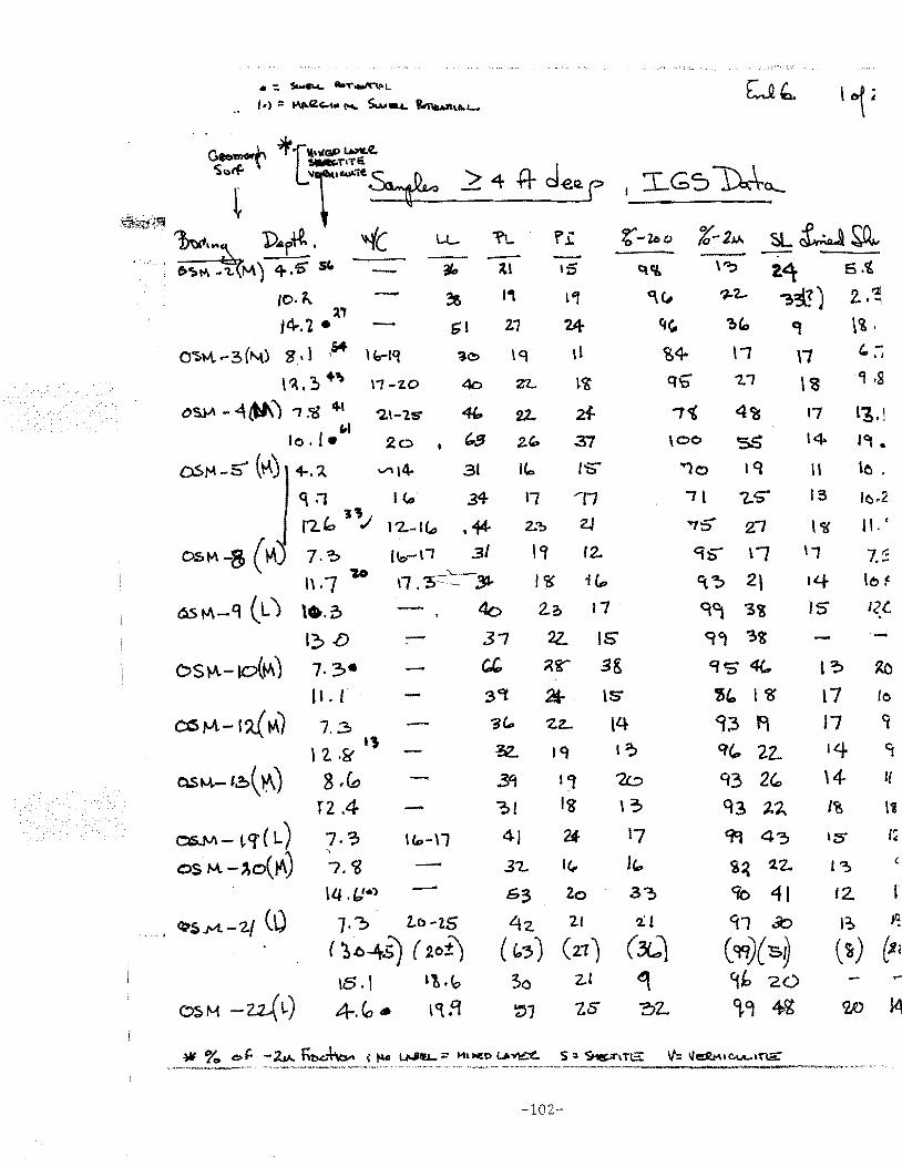
• :. s-.w~ ilooT~L
.• I•>:: ~IZ<:..tto 1'4 S.....~ f~ut..L-
. .Gee"'*~ ~r'l•'lfGP l..to:I'Lt. \' .... TITE.
s ... tf:. "T'-"tU""' > 4 n d ~~ L ~- rr •r ~;\7.~{.:'1
... · ·.· 1--~ D.r+!.. ..(( u.. 'I'L · r,;: ... • t!IS"" -1.. M) 4,5" SC. ~ ~~ 1;'5
10· ~ ~ I, L'l . ~,
14-.l • G I 2.1 '24-
0~M.-3(~) 8' 1 ,M l b-lq '3e> \q \1
\ ~. ~ ..... \7-7.0 4o Zl... ~<6
C)S,)..\ - 4 (tl\ ') 1 ,cg 4 ' "2.\-ls- 4{:. 22. 24-
"' lo. I• 2o • €:,5 2.'- 37
O.S1'4 -5' (~) / +."' """14- 31 l(a
q :1 I <.:. 34 11 'li I"") " 'I'.,; I 4 1 '2..-IC.., • 44- 2.~ ZJ
ostv' -8 ( ~) 7.? r~o-n 31 I~ r2. l\.7 ~o \1 .~'- 31- I~ i(p
~fv\-q (L) \•.o 4o 2.2> t7
~~ .{) - 37 2Z. IS
DS~-10(~) 7. 3• C.C. ~i"" 3&
~M.-!~M)
QSt--\.- ~~( ~)
os..M- vr( L) OS M. - /.o(~)
• ~$.M. -2/ (\)
ILL scr 24-7.3
\ 2 ·a-" I 'S
8 .(o
T2 .4 7.? I c.,- \1 ~
7.~
lll. ft/•1 G3 Zo
1· :, Z..b -25 4z. 21
( "b~-Ari) ( 20±) ( c,-,) (zr) \6 .j L'! •\?
\S
\4 I~
1/.::J \3
17
I c...
3~
'iL
(.L) ~
2"\ 6.~
"!~!) 2. ~ .... 'l \~.
\00
"'1o
71
'7$" 21
9'S" l/
~~ 2l q~ 3~
9~ 3t CJS 4(.
'!C, lCS'
~;3 f\
q"' 22.. '13 2G. q3 ')..')..
~ 4'3
%~ 2.Z.
<to 41 ~1 a:> (Cfl)(slj
\1 ' ,-;
\CS 'l ,g
17 L6.! 14 l<lj •
ll \o .
IS lo.2
l~ 11. (
\1 7.'3. ILf- to~
JS 12(.
·-l? ~
l7 to
17 <t
14 Cf
\4- l{
I~ 1'8
IS' I(
·~ 12.
I~ ~
(~) ~(
4.Co. ~~fl
3o ~~
2J
lS ?::lL
'1h 20
9.9 4<6 w ~
-102-
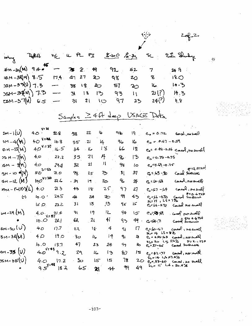
, ( ...
~?-f!.,.. ... ..., ,~ ....
"'/
~~ l)~Q. 'N/c... I.L fL P.I %-2-PD ~:b SL %~~ -
46"' .:6~ -'lt1(M) 9" A--. - ~ 2' .. 4q 9'2... ::i2- 7 24f1 ~M -~M\ Y> ·S" f1.dr 41 2.1 a:;, ~~ 2.0 ~ ~~.o
~~-~~\))1.~ ~'6 \~ 2cJ S7 ?a u .. te ·? ::>~-~~) /.'? ~ 1?:. I? q:, I \ 2.1 l?J It,.~
~tJ\ - !> "~t\-1) "' . s - ?\ 2l \o 0...'1 2:, 24{7) II.~
5et-el< <; ?.4~ J.ca.e l)S ~(_~ }:>~~~ \
~- \lU) 'I'='~
4.0. 12,.g ~8 '2.2 '" O.b lq e...,.= (!) ,j'2,. -.So>\ '...., s...e.\\
>M-~\o\) +D 'l=V. l.!f-.<6 ~5"' 2.1 14 q(o lf.o e., ""' t~.,, -r>.S'\
>:>K-- M) 4-.0" .:::li' 1(, •• 5" ~4 1(, I~ b'- I~ e..::. D·~-I).St:, ~ ~~ "' I .
)~ M -1(\1\) 4-.o 2:C.2 35 2l 14 9p j;, ec. =-(!).'"til -t>.1'S
)~ !'-\ - c('V\ J 4.o 2~4 32. 2) 11 9<'6 Co e.,=o "-\-o .1""' I ~=~; "'f ... ~.STSP.
~-~"\~ so 7J.O ~ 1..5" ~ ~l 37 C"o-:. • C..3 -.?t:> ~~~
>Sf"\ -t.t (M Lt?O v ::3& 2.2. L • 3<t 1"1 2o <k. ~ ~ ;r.c.t>-:'-\ ~.(r\.a'~
:t:>~- F-\1!•)/ L) 4-. o 21.~ +? Ill 2-s-' <il 2.7 ec-::.!=-1 -J.t ~~~~ .P=i!:> ·"nF t·) lo .o · 21-.5' 44- 2A 7o 'R 4-~ <i"0 ='J. -6:Tb ~ SU.o!\.1-\...C.
13 )3 I:>' St.:/11 ~ L ~ "' l ._,o
lsp Z3.2. 31 '16' e'v:.C.C..-6=12 c.-w.Q Pl.c:r ~
;.P-t - 'Z.C\ L ~ '\ 4,0. '2.1 .4- ':\\ L" I'L Cf4 \'S e c.:.-,':!--;b'\ -~ [I'C'~ IJ:57
4-l c.,..uQ 1'-"= 6 ·'-TS.t • tb.O U./ ~ 2L 't'? ~· e..~.c£-;'11 SA>C!!/.INCA
~M-~tv} 4o n.7 2.:~ I g. 4 "11 r7 e.,;-,f.J.,-r_i ~I o-.tl~
~1-1-~~) 4D l<l ,0 l1 ::!oi..P 14 LS::.'ilt,:, · · ·
3o l<., 'll I~ ca. ::1' e.sts-.r..-, ~, rur~ '5~ ~u l.S 11.'1.% . ?:: '1." TS~
Jo.O J 3:1 47 2.3. 2.4- 'i"J io e .. "'.l7'-4s" ~ s.~e~
~~M- '3!S (v) 1/:4; l:, Is ~~MAY~. 4.o 1.~ Z'\ u ... &7 eo:::f?..-;11
:1.> ""- ~ s't v) 4.o ~ ls- IS 18 '2.0 'Sl. ... t+ 4.r. ~7.+7dt
\'1.2 e ..... sz-,o C..Jtooi I jhO ~t . 'I ~41 St...• tl' L.S :. 2c,,s-:.t,
" q.s IS·~ f.::.5 ~\ 4+ ~ 49
-103-
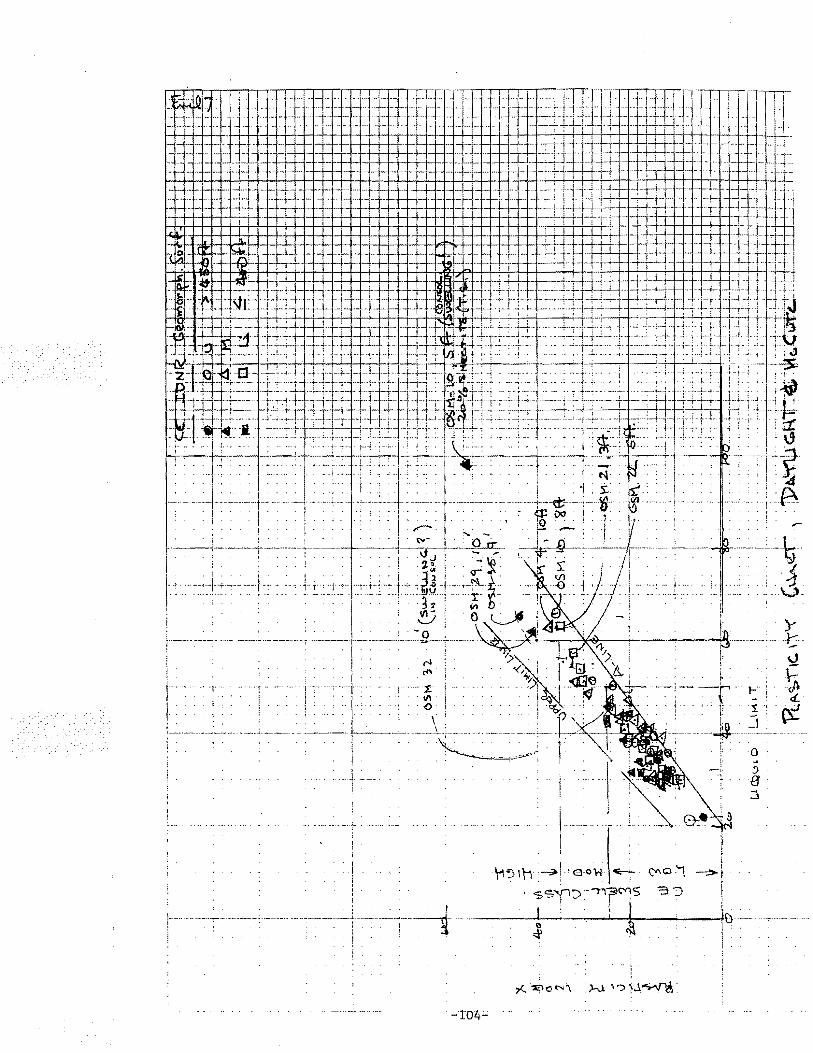
·~~~~ .! •• -__ J,. - -- - :~ l# fi L=fi 1 ·. .. . ·· I'JI __ l#l __ ~ __ • . . + --:-7 1- -- -- - . - - l . . :=- -. J.~L =r- :_H-i-++++++++++++-l-+-1 -,--f--+- .. ±±±tii:~ +- . -- .. .
+- L .i±±:lJ:±.f::- -~ ~~~ ::_t+: ··j·t -- ' · - r- - ·tt-
. . I . 1 !
. ! !
i .
l !
\1~1\1·-:ll>l •e:oH .,.___ ~Q-\
. -s'i7"(1:> ·-n-r~s '3;) f
-~':-----' ·~:-.--J..i--Jl':--.....__--f,\)-:'"~-.--,--------J. . : . . ~. . i
i .
_;T04-
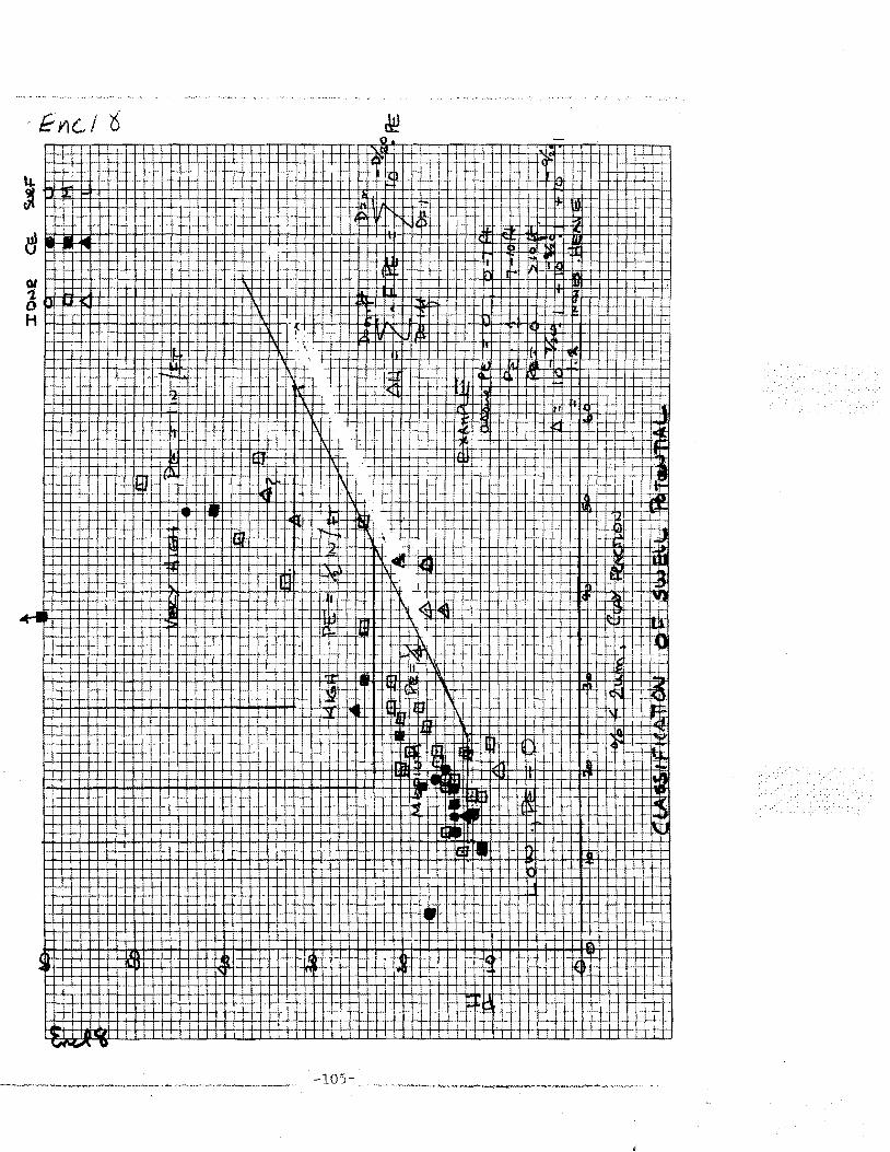
-lOS
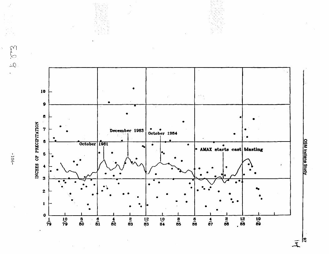
)'(I f ,'<:.Y
.:-C)
I ...... 0 o-1
10
9
8
z 0 7 e f.:: es s u
•
• •
•
•
•
3 I • • December 198 ·October 1984
•
• • • •
• • • • t!
ll.. 5 !k..
.. ••
• AM'AX starts eastl blastin«
0
:1 ... • • •
• •
~ • • • . ,.
e I I •
31\ \•L • . . -...., . .. . • • • • • • • • • ••• • • • 2 1- • • • • • • • ,. . . . . . . .
• • 1-
• • • • • •• 1 • • • • • • • • 0 1 I I I I I L •
. 1 10 8 8 ... 2 12 10 8 6 ~ ~ M M ~ ~ ~ M ~ M ~ ~ ~
.. • •
..4..
0 (I)
3: g: ii' ::J Dl
Yl a.
~
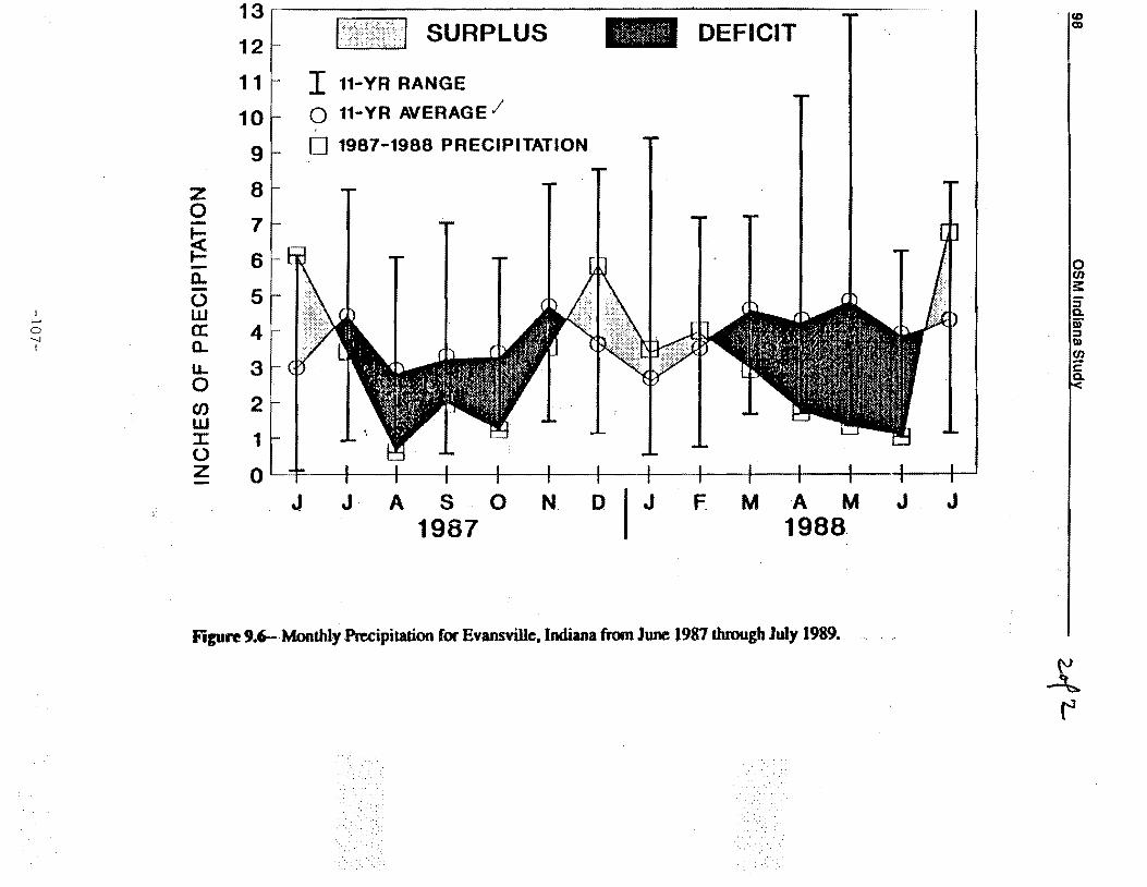
I ,..... 0 --.1 I
13
12
11
10
9
z 8 0 - 7 ~ ~ 6 -0. - 5 (.) w a: 4 0. u.. 3 0 Cl) 2 w ::r: 1 (.) z 0
J
SURPLUS
I 11-YR RANGE
0 11-YR AVERAGE/ ' 0 1987-1988 PRECIPITATION
J A S 0 1987
N D I J
DEFICIT
F M A M 1988
Figuft 9.6- Monthly Precipitation for Evansville, Indiana from June 1987 through July 1989.
J J
'CD Ql
0 CJ)
~ 5' a. iii' ::J I» CJ) -c a.
{'J
~ ('1
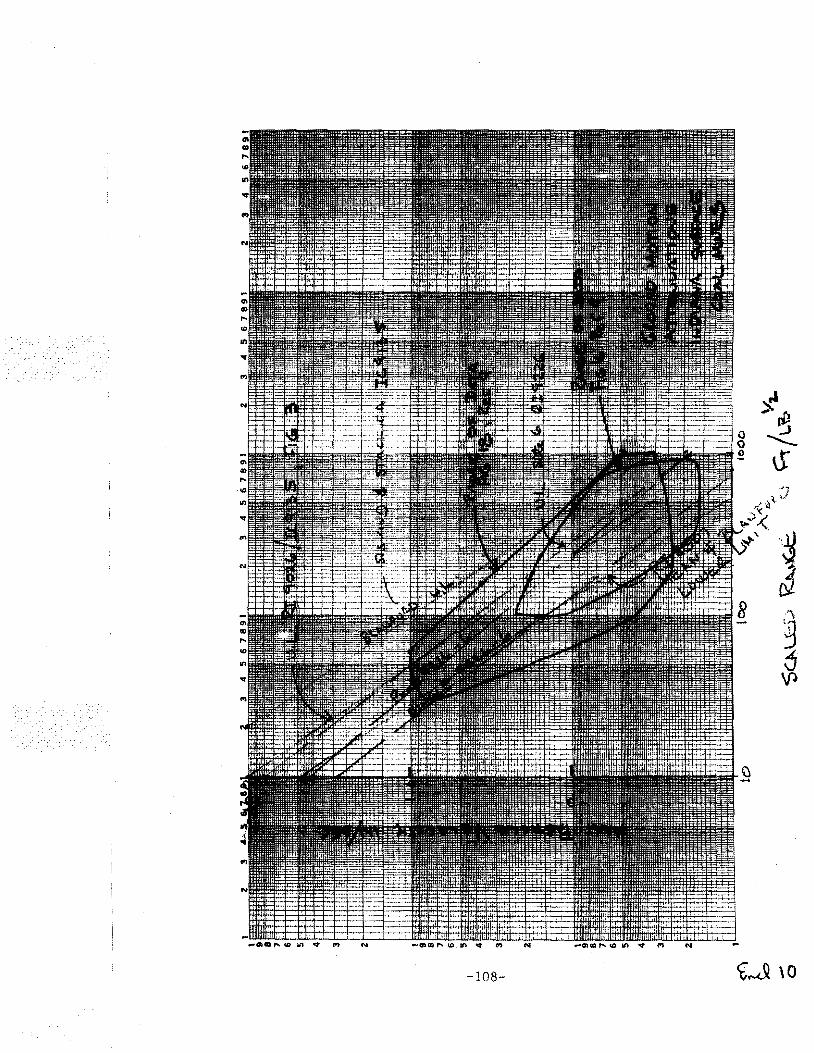
-108-
APPENDIX B
ADDENDUM OF 30 OCT 93 TELEPHONE REQUEST
FROM SPONSOR
-109-
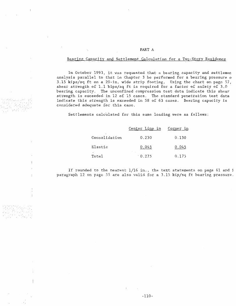
PART A
Bearing Capacity and Settlement Calculation for a Two-Story Residence
In October 1993, it was requested that a bearing capacity and settlemen analysis parallel to that in Chapter 3 be performed for a bearing pressure o 3.15 kips/sq ft on a 20-in. wide strip footing. Using the chart on page 57, shear strength of 1.1 kips/sq ft is required for a factor of safety of 3.0 bearing capacity. The unconfined compression test data indicate this shear strength is exceeded in 12 of 15 cases. The standard penetration test data indicate this strength is exceeded in 58 of 63 cases. Bearing capacity is considered adequate for this case.
Settlements calculated for this same loading were as follows:
Center Line in
Consolidation 0.230 0.130
Elastic
Total . 0. 275 0.175
If rounded to the nearest 1/16 in. , the text statements on page 61 and j
paragraph 12 on page 55 are also valid for a 3.15 kipjsq ft bearing pressure.
110-
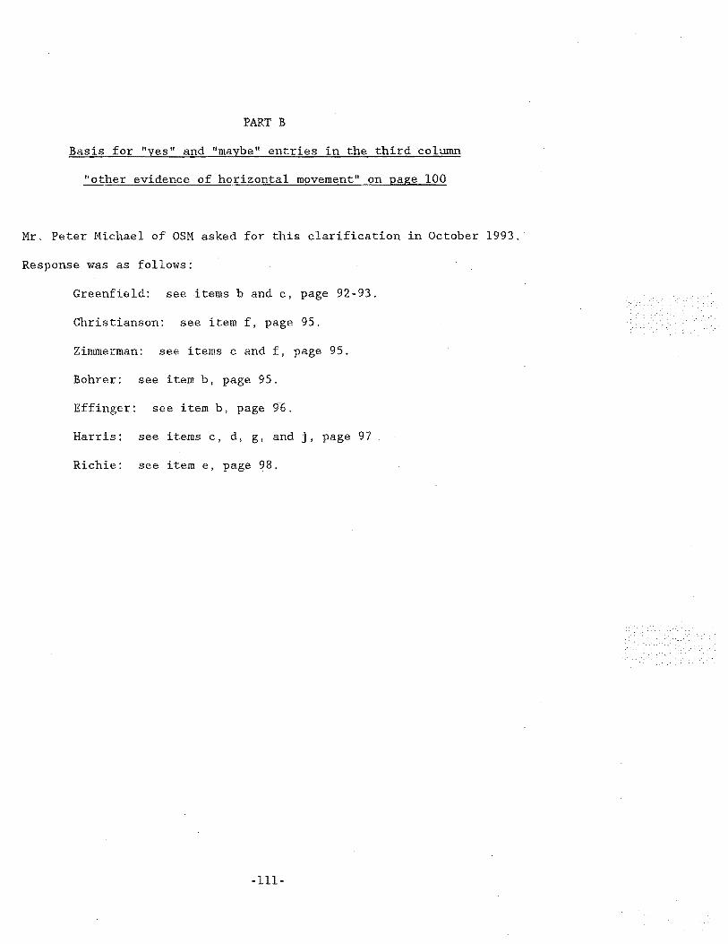
PART B
Basis for "yes" and "maybe" entries in the third column
"other evidence of horizontal movement" on page 100
Mr. Peter Michael of OSM asked for this clarification in October 1993. ·
Response was as follows:
Greenfield: see items b and c, page 92-93.
Christianson: see item f, page 95.
ZimmeTman: see items c and f, page 95.
Bohrer: see item b, page 95.
Effinger: see item b, page 96.
Harris: see items c, d, g, and j, page 97
Richie: see item e, page 98.
-111-