Embed Size (px)
Citation preview
Office of Bridges and Structures
Bridge Inspection Manual Issue Date: January 1, 2014
Developed By:
PROJECT NO. TR-646 SPONSORED BY THE IOWA HIGHWAY RESEARCH BOARD
DISCLAIMER
THE BRIDGE INSPECTION MANUAL IS PUBLISHED SOLELY TO PROVIDE
INFORMATION AND GUIDANCE TO BRIDGE INSPECTORS WHEN INSPECTING
BRIDGES IN THE STATE OF IOWA. THIS MANUAL IS ISSUED TO SECURE, SO FAR AS
POSSIBLE, UNIFORMITY OF PRACTICE AND PROCEDURE IN COMPLIANCE WITH THE
NATIONAL BRIDGE INSPECTION STANDARDS. THIS MANUAL IS NOT PURPORTED TO
BE A COMPLETE GUIDE IN ALL AREAS OF BRIDGE INSPECTION AND IS NOT A
SUBSTITUTE FOR ENGINEERING JUDGMENT.
Bridge Inspection Manual Table of Contents
i January 2014
TABLE OF CONTENTS
CHAPTER 1 REGULATIONS, ADMINISTRATION, AND POLICIES ....................................................................... 1-1
1.1 Purpose of Manual ......................................................................................................................... 1-1 1.2 Definitions, Abbreviations and Acronyms, and Terminology .......................................................... 1-1
1.2.1 Definitions ........................................................................................................................ 1-1 1.2.2 Abbreviations and Acronyms............................................................................................ 1-2 1.2.3 Bridge Terminology Figures ............................................................................................. 1-3
1.3 History and Requirements of National Bridge Inspection Standards ............................................ 1-21 1.3.1 History and Background of NBIS .................................................................................... 1-21 1.3.2 Bridge Inspection Organization ...................................................................................... 1-22 1.3.3 Required Qualifications of Bridge Inspection Personnel ................................................ 1-22 1.3.4 Bridge Inventory Requirements ...................................................................................... 1-23
1.4 Types of Inspections and Their Frequencies ................................................................................ 1-24 1.4.1 Initial Inspections ............................................................................................................ 1-24 1.4.2 Routine Inspections ........................................................................................................ 1-24 1.4.3 In-depth Inspections ....................................................................................................... 1-25
1.5 Iowa DOT Inspection Program Policies ........................................................................................ 1-29 1.5.1 Safety ............................................................................................................................. 1-29 1.5.2 Media Relations ............................................................................................................. 1-31
1.6 Statewide Inspection Program Policies ........................................................................................ 1-31 1.6.1 Timelines for Completion of Inspections and Reports .................................................... 1-31 1.6.2 Standardized Bridge Orientation and Labeling Conventions .......................................... 1-31 1.6.3 Critical Findings/Emergency Response ......................................................................... 1-32 1.6.4 Inspection Intervals for Non-regulated Structures .......................................................... 1-32 1.6.5 Temporary Structures .................................................................................................... 1-33 1.6.6 Temporary Supports ...................................................................................................... 1-34
CHAPTER 2 CONDITION EVALUATION OF BRIDGES FOR IOWA DOT PERSONNEL ....................................... 2-1
2.1 Inspection Planning ........................................................................................................................ 2-1 2.1.1 Reviewing Past Inspection Reports, SIIMS Data, Existing Bridge Plans, and Bridge Repair
Plans ................................................................................................................................ 2-1 2.1.2 Determining Required Inspection Documentation and Preparing Needed Sketches ....... 2-1 2.1.3 Arranging for Access and Other Inspection Equipment.................................................... 2-1 2.1.4 Arranging for Advanced Bridge Washing ......................................................................... 2-2 2.1.5 Executing Any Required Agency Notifications and Permits ............................................. 2-2 2.1.6 Adjusting Work Schedules ............................................................................................... 2-2
2.2 Condition Evaluation of National Bridge Inventory (NBI) Items ...................................................... 2-3 2.2.1 Appraisal Evaluations ....................................................................................................... 2-3 2.2.2 General Condition Rating Codes ...................................................................................... 2-5
2.3 Evaluation of National Bridge Elements ......................................................................................... 2-8 2.4 General Inspection Procedures ...................................................................................................... 2-9
2.4.1 Deck Inspection ................................................................................................................ 2-9 2.4.2 Superstructure Inspection .............................................................................................. 2-20 2.4.3 Substructure Inspection ................................................................................................. 2-32 2.4.4 Channel Inspection ........................................................................................................ 2-35 2.4.5 Culvert Inspection .......................................................................................................... 2-37
2.5 SIIMS Documentation ................................................................................................................... 2-39 2.5.1 About SIIMS ................................................................................................................... 2-39
Bridge Inspection Manual Table of Contents
ii January 2014
2.5.2 Manager Module Menu in SIIMS .................................................................................... 2-40 2.5.3 Collector (Inspector) Module Menu in SIIMS .................................................................. 2-40 2.5.4 Creating Inspection Reports ........................................................................................... 2-40 2.5.5 Bridge Descriptions in SIIMS.......................................................................................... 2-40 2.5.6 NBI Calculations ............................................................................................................. 2-41 2.5.7 Photographs, Sketches, Plans, Documents, and Files................................................... 2-41 2.5.8 Critical Findings .............................................................................................................. 2-45 2.5.9 Load Rating Documentation ........................................................................................... 2-46 2.5.10 Supplemental Inspection Information ............................................................................. 2-47 2.5.11 Maintenance, Repair, and Replacement ........................................................................ 2-47 2.5.12 Inspection Report ........................................................................................................... 2-52 2.5.13 Inspection Information .................................................................................................... 2-54
2.6 SI&A Data ..................................................................................................................................... 2-54 2.7 Under Records ............................................................................................................................. 2-55
CHAPTER 3 QUALITY ASSURANCE/QUALITY CONTROL (QA/QC) FOR IOWA DOT PERSONNEL ................. 3-1
3.1 Scope of Iowa DOT Bridge Inspection Quality assurance/Quality Control Program ...................... 3-1 3.2 NBIS Definition of Terms ................................................................................................................ 3-1
3.2.1 Quality Control ................................................................................................................. 3-1 3.2.2 Quality Assurance ............................................................................................................ 3-1
3.3 Role of SIIMS ................................................................................................................................. 3-1 3.4 Quality Control ................................................................................................................................ 3-2
3.4.1 Inspection Scheduling ...................................................................................................... 3-2 3.4.2 Data Collection ................................................................................................................. 3-2 3.4.3 Inspection Report Approval .............................................................................................. 3-2 3.4.4 Training ............................................................................................................................ 3-4
3.5 Quality Assurance .......................................................................................................................... 3-4 3.5.1 Team Selection ................................................................................................................ 3-5 3.5.2 Bridge Selection ............................................................................................................... 3-5 3.5.3 Quality Assurance Inspections ......................................................................................... 3-5 3.5.4 Tolerance Thresholds ...................................................................................................... 3-5 3.5.5 Scoring ............................................................................................................................. 3-6 3.5.6 Close-out Meeting .......................................................................................................... 3-10
CHAPTER 4 CONDITION EVALUATION OF BRIDGES FOR LOCAL PUBLIC AGENCIES .................................. 4-1
4.1 Inspection Planning ........................................................................................................................ 4-1 4.1.1 Reviewing Past Inspection Reports, SIIMS Data, Existing Bridge Plans, and Bridge Repair
Plans ................................................................................................................................ 4-1 4.1.2 Determining Required Inspection Documentation and Preparing Needed Sketches ....... 4-1 4.1.3 Arranging for Access and Other Inspection Equipment.................................................... 4-1 4.1.4 Arranging for Advanced Bridge Washing ......................................................................... 4-2 4.1.5 Executing Any Required Agency Notifications and Permits ............................................. 4-2 4.1.6 Adjusting Work Schedules ............................................................................................... 4-2
4.2 Condition Evaluation of National Bridge Inventory (NBI) Items ...................................................... 4-3 4.2.1 Appraisal Evaluations ....................................................................................................... 4-3 4.2.2 General Condition Rating Codes ...................................................................................... 4-5
4.3 SIIMS .............................................................................................................................................. 4-8 4.3.1 About SIIMS ..................................................................................................................... 4-8 4.3.2 Manager Module Menu in SIIMS ...................................................................................... 4-8 4.3.3 Collector (Inspector) Module Menu in SIIMS .................................................................... 4-9 4.3.4 Bridge File ........................................................................................................................ 4-9
Bridge Inspection Manual Table of Contents
iii January 2014
4.4 Field Data Items IN SIIMS .............................................................................................................. 4-9 4.4.1 Deck Inspection ................................................................................................................ 4-9 4.4.2 Superstructure Inspection .............................................................................................. 4-12 4.4.3 Substructure Inspection ................................................................................................. 4-19 4.4.4 Culvert Inspection .......................................................................................................... 4-23 4.4.5 Channel and Channel Protection ................................................................................... 4-25 4.4.6 Bridge Data .................................................................................................................... 4-28
4.5 Additional SIIMS Documentation .................................................................................................. 4-29 4.6 Reporting of Special Items ........................................................................................................... 4-31
4.6.1 Fatigue-Prone Details .................................................................................................... 4-31 4.6.2 Fracture Critical Elements .............................................................................................. 4-32
4.7 Maintenance, Repair, and Replacement (MR&R) ........................................................................ 4-33 4.7.1 Recommendations ......................................................................................................... 4-33 4.7.2 Cost Estimates ............................................................................................................... 4-36
CHAPTER 5 QUALITY ASSURANCE/QUALITY CONTROL (QA/QC) FOR LOCAL PUBLIC AGENCIES ............ 5-1
5.1 Scope of Local Public AgencyQuality Assurance/Quality Control Program .................................... 5-1 5.2 NBIS Definition of Terms ................................................................................................................ 5-1
5.2.1 Quality Control ................................................................................................................. 5-1 5.2.2 Quality Assurance ............................................................................................................ 5-1
5.3 Role of SIIMS ................................................................................................................................. 5-1 5.4 Quality Control ................................................................................................................................ 5-2
5.4.1 Inspection Scheduling ...................................................................................................... 5-2 5.4.2 LPA Compliance .............................................................................................................. 5-2 5.4.3 Data Collection ................................................................................................................. 5-3 5.4.4 Inspection Report Approval .............................................................................................. 5-3 5.4.5 Training ............................................................................................................................ 5-3
5.5 Quality Assurance .......................................................................................................................... 5-3 5.5.1 Review of LPA Bridge Records ........................................................................................ 5-4 5.5.2 LPA Team Leader Reviews.............................................................................................. 5-4 5.5.3 Load Rating Engineer Reviews ........................................................................................ 5-5
List of Tables
Table 1.2.2. Abbreviations and Acronyms ................................................................................................................ 1-2 Table 2.2.1.1. Appraisal Values for Waterway Adequacy ......................................................................................... 2-3 Table 2.2.1.3. Appraisal Values for Traffic Safety Features ...................................................................................... 2-5 Table 2.2.2. Grouping of Descriptive Conditions ....................................................................................................... 2-6 Table 2.2.2.1. General Condition Ratings for Deck, Superstructure, and Substructure ............................................ 2-6 Table 2.2.2.2. General Condition Ratings for Channel and Channel Protection ....................................................... 2-7 Table 2.2.2.3. General Condition Ratings for Culvert ................................................................................................ 2-7 Table 2.5.11.2. Maintenance Recommendation Codes .......................................................................................... 2-48 Table 4.2.1.1. Appraisal Values for Waterway Adequacy ......................................................................................... 4-3 Table 4.2.1.3. Appraisal Values for Traffic Safety Features ...................................................................................... 4-5 Table 4.2.2. Grouping of Descriptive Conditions ....................................................................................................... 4-6 Table 4.2.2.1. General Condition Ratings for Deck, Superstructure, and Substructure ............................................ 4-6 Table 4.2.2.2. General Condition Ratings for Channel and Channel Protection ....................................................... 4-7 Table 4.2.2.3. General Condition Ratings for Culvert ................................................................................................ 4-7 Table 4.7.1.1. Maintenance Recommendation Codes ............................................................................................ 4-34
Bridge Inspection Manual Table of Contents
iv January 2014
List of Figures
Figure 1.2.3.1. Timber Stringer Bridge Components ................................................................................................. 1-4 Figure 1.2.3.2. Reinforced Concrete Slab Bridge Components ................................................................................ 1-5 Figure 1.2.3.3. Reinforced Concrete Beam Bridge Components .............................................................................. 1-6 Figure 1.2.3.4. Prestressed Concrete Beam Bridge Components ............................................................................ 1-7 Figure 1.2.3.5. Prestressed Concrete Quad Tee Beam Bridge Components ........................................................... 1-8 Figure 1.2.3.6. Precast Concrete Box Beam Bridge Components ............................................................................ 1-9 Figure 1.2.3.7. Precast Concrete Panel Beam Bridge Components ....................................................................... 1-10 Figure 1.2.3.8. Precast Concrete Channel Beam Bridge Components ................................................................... 1-11 Figure 1.2.3.9. Steel Rolled Beam or Welded Steel Plate Girder Bridge Components ........................................... 1-12 Figure 1.2.3.10. Steel Girder and Floorbeam Bridge Components ......................................................................... 1-13 Figure 1.2.3.11. Steel Truss Bridge Components ................................................................................................... 1-14 Figure 1.2.3.12. Steel Tied Arch Bridge Components ............................................................................................. 1-15 Figure 1.2.3.13. Steel True Arch Bridge Components ............................................................................................ 1-16 Figure 1.2.3.14. Concrete Spandrel Arch Bridge Components ............................................................................... 1-17 Figure 1.2.3.15. Suspension Bridge Components ................................................................................................... 1-18 Figure 1.2.3.16. Cable Stayed Bridge Components ................................................................................................ 1-19 Figure 1.2.3.17. Culvert Components ...................................................................................................................... 1-20 Figure 2.4.1.2. Sample Bridge Quantity Table ......................................................................................................... 2-10 Figure 2.4.1.6.1-1. Joint Opening Sketch ................................................................................................................. 2-12 Figure 2.4.1.6.1-2. Sliding Steel Joint Retrofit .......................................................................................................... 2-13 Figure 2.4.1.6.2. EF Joint Pavement Marking .......................................................................................................... 2-14 Figure 2.4.1.9.3 (continued). Non-Cantilevered and Cantilevered Curbs................................................................. 2-18 Figure 2.4.2.4. Weathering Steel Patina Rating ....................................................................................................... 2-22 Figure 2.4.2.4.3.1. Pin and Hanger Hinge ................................................................................................................ 2-26 Figure 2.4.2.4.3.2. Rotational Hinge Connection ..................................................................................................... 2-26 Figure 2.4.2.6-1. Steel Fixed Bolster and Steel Rocker Bearings ............................................................................ 2-28 Figure 2.4.2.6-2. Steel Sliding Plate Bearings.......................................................................................................... 2-28 Figure 2.4.2.6-3. Pintle Plate & Pintle Plate with Elastomeric Pad Bearings............................................................ 2-28 Figure 2.4.2.6-4. Disc Bearings ................................................................................................................................ 2-29 Figure 2.4.2.6-5. Pot Bearings ................................................................................................................................. 2-29 Figure 2.5.7.2. Common Photo Caption Key Words ................................................................................................ 2-44 Figure 3.5.5.4-1. Supporting Document Review Scoring Guide ................................................................................. 3-8 Figure 3.5.5.4-2 Summary Score for Quality Assurance Review ............................................................................... 3-9 Figure 4.4.2.1-1. Steel Fixed Bolster and Steel Rocker Bearings ............................................................................ 4-13 Figure 4.4.2.1-2. Steel Sliding Plate Bearings.......................................................................................................... 4-13 Figure 4.4.2.1-3. Pintle Plate & Pintle Plate with Elastomeric Pad Bearings............................................................ 4-14 Figure 4.4.2.1-4. Disc Bearings ................................................................................................................................ 4-14 Figure 4.4.2.1-5. Pot Bearings ................................................................................................................................. 4-14

Bridge Inspection Manual Table of Contents
v January 2014
List of Reference Documents
AASHTO Manual for Bridge Evaluation, 2nd Edition, 2011 Interims AASHTO Guide Manual for Bridge Element Inspection, 1st Edition, 2011 NBE Manual, Iowa DOT, 2014 Iowa DOT Instructional Memorandum 2.120 Iowa DOT Instructional Memorandum 6.102
Bridge Inspection Manual Chapter 1 – Regulations, Administration, and Policies
1-1 January 2014
CHAPTER 1
REGULATIONS, ADMINISTRATION, AND POLICIES
1.1 PURPOSE OF MANUAL
The purpose of this manual is to organize, document, and combine Iowa Department of Transportation
(Iowa DOT) policies and procedures for bridge inspection practices and post-inspection recommendations
so Iowa DOT personnel, local agencies, and consultants will have a readily available resource for their
use. Previously, bridge inspection policies and procedures were documented by various means, making it
difficult to provide consistent answers to questions regarding bridge inspection topics. This manual is
intended to ensure uniformity and document best practices for inspection of Iowa’s bridges, especially as
experienced inspection personnel retire.
1.2 DEFINITIONS, ABBREVIATIONS AND ACRONYMS, AND TERMINOLOGY
1.2.1 Definitions
The following terms in this manual are used as defined below:
Bridge – A structure, including supports, erected over a depression or an obstruction such as a
body of water, a highway, or a railway; having a track or passageway for carrying traffic or other
moving loads; and having an opening measured along the centerline of the roadway of more than
20 feet between undercopings of abutments or spring lines of arches or extreme ends of openings
for multiple boxes. It may also contain multiple pipes, where the clear distance between openings
is less than half of the smaller contiguous opening.
Bridge Management (previously Pontis) – A software program developed to assist in managing
highway bridges and other structures.
Critical Finding – A structural or safety-related deficiency for a bridge requiring immediate
follow-up inspection or action.
Fatigue – The tendency of a member to fail at a stress level below yield stress when subjected to
cyclical loadings.
Fracture Critical Member – A steel member in tension or with a tension element, whose failure
would be expected to cause a partial or full collapse of the bridge.
Glulam – Glue laminated timber, which is an engineered wood product consisting of individual
laminations of wood, usually 2 inches or less in thickness, bonded together.
Gusset Plate - A rectangular or triangular steel plate connecting members of a truss together.
HEC-18 – Hydraulic Engineering Circular No. 18 (HEC-18), which presents the state of
knowledge and practice for the design, evaluation, and inspection of bridges for scour.
Histoplasmosis – A disease contracted from contact with microscopic fungi borne from
decomposing biological fluids such as bird droppings.
Load Rating – The process of determining the live load capacity of a structure based on analysis
of its current condition.
Program Manager – The individual in charge of the bridge inspection program, who has been
assigned or delegated the duties and responsibilities for bridge inspection, reporting, and
inventory. The Program Manager provides overall leadership and is available to inspection Team
Leaders to provide guidance.
Bridge Inspection Manual Chapter 1 – Regulations, Administration, and Policies
1-2 January 2014
Quality Assurance – Planned and systematic activities implemented within a quality system and
demonstrated as needed to provide adequate confidence that deliverables will satisfactorily fulfill
quality requirements.
Quality Control – Efforts within a quality system encompassing operational techniques and
activities used to verify an established level of quality has been achieved.
Scour – Removal of material from a streambed or embankment as a result of excessive action of
stream flow.
Scour Critical Bridge – A bridge with a foundation element determined to be unstable for the
observed or evaluated scour condition.
Scour Plan of Action – A written procedure developed by the bridge owner or delegated Program
Manager outlining the foundation scour monitoring plan to be followed for a specific bridge
during flood events.
Structurally Deficient Bridge – A bridge in which significant load-carrying elements are found to
be in poor condition due to deterioration, or a bridge in which the adequacy of the waterway
opening provided by the bridge is determined to be extremely insufficient to the point of causing
intolerable traffic interruptions.
Team Leader – An individual in charge of an inspection team responsible for planning, preparing,
and performing field inspection of the bridge.
Thalweg – The line defining the lowest points or maximum depth along the length of a river bed
or valley.
Triaxial Constraint – A 3-dimensional stress state reducing the ductility of a material. Under
triaxial constraint, steel is unable to deform, and brittle fracture can occur under service
conditions where ductile behavior is normally expected.
1.2.2 Abbreviations and Acronyms
The abbreviations and acronyms used in this manual are defined in Table 1.2.2.
Table 1.2.2. Abbreviations and Acronyms
Abbreviation Term
AASHTO American Association of State Highway and Transportation Officials
ANSI American National Standards Institute
ASTM American Society for Testing and Materials
BME Bridge Management Element
BMI Unit The Bridge Maintenance and Inspection Unit of the Iowa Department of Transportation
BrM Bridge Management software
CFR Code of Federal Regulations
CMP Corrugated Metal Plate
CoRe Commonly Recognized
FCM Fracture Critical Member
FHWA Federal Highway Administration
HEC-18 Hydraulic Engineering Circular No. 18
HMA Hot-Mix Asphalt
I.M. 2.120 Iowa Department of Transportation Instructional Memorandum 2.120
IOM Independent Oversight Model
Bridge Inspection Manual Chapter 1 – Regulations, Administration, and Policies
1-3 January 2014
Abbreviation Term
Iowa DOT Iowa Department of Transportation
LPA Local Public Agency
MR&R Maintenance, Repair and Replacement
NBE National Bridge Element
NBI National Bridge Inventory
NBIS National Bridge Inspection Standards
NDT Non-destructive Testing
NHS National Highway System
OBS Iowa DOT Office of Bridges and Structures
OSHA Occupational Safety and Health Administration
POA Plan of Action
PPCB Pretensioned/Prestressed Concrete Beam
PPE Personal Protective Equipment
PPRJ Pavement Pressure Relief Joint
QA Quality Assurance
QC Quality Control
RMS Records Management System
SI&A Structure Inventory and Appraisal
SIIMS Structure Inventory and Inspection Management System
UBIV Underbridge Inspection Vehicle
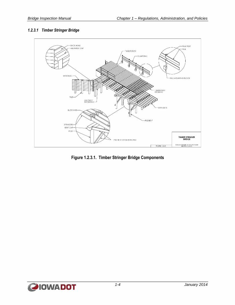
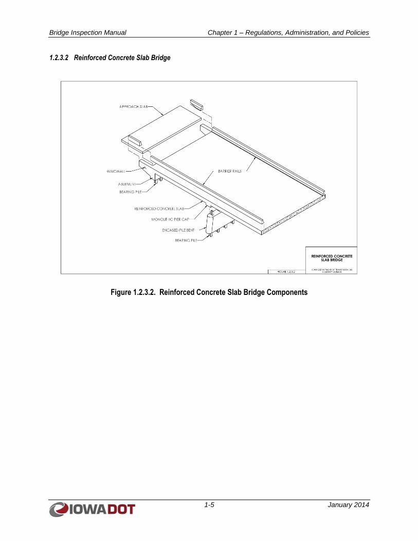
1.2.3 Bridge Terminology Figures
Figures 1.2.3.1 through 1.2.3.17 are provided to standardize the terminology and labeling of bridge
components to be used in bridge inspection reports. The bridges portrayed represent the majority of
bridge types used throughout the State of Iowa (State), both on the State and U.S. highway system and on
the local roads system.
Bridge Inspection Manual Chapter 1 – Regulations, Administration, and Policies
1-4 January 2014
1.2.3.1 Timber Stringer Bridge
Figure 1.2.3.1. Timber Stringer Bridge Components
Bridge Inspection Manual Chapter 1 – Regulations, Administration, and Policies
1-5 January 2014
1.2.3.2 Reinforced Concrete Slab Bridge
Figure 1.2.3.2. Reinforced Concrete Slab Bridge Components
Bridge Inspection Manual Chapter 1 – Regulations, Administration, and Policies
1-6 January 2014
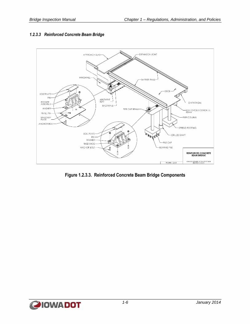
1.2.3.3 Reinforced Concrete Beam Bridge
Figure 1.2.3.3. Reinforced Concrete Beam Bridge Components
Bridge Inspection Manual Chapter 1 – Regulations, Administration, and Policies
1-7 January 2014
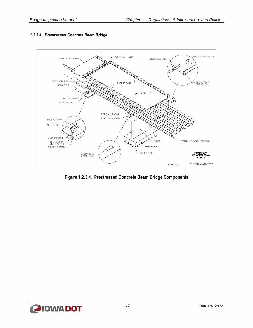
1.2.3.4 Prestressed Concrete Beam Bridge
Figure 1.2.3.4. Prestressed Concrete Beam Bridge Components
Bridge Inspection Manual Chapter 1 – Regulations, Administration, and Policies
1-8 January 2014
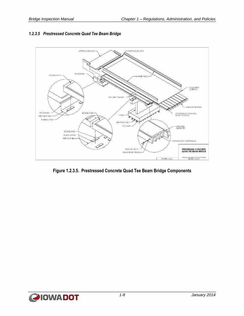
1.2.3.5 Prestressed Concrete Quad Tee Beam Bridge
Figure 1.2.3.5. Prestressed Concrete Quad Tee Beam Bridge Components

Bridge Inspection Manual Chapter 1 – Regulations, Administration, and Policies
1-9 January 2014
1.2.3.6 Precast Concrete Box Beam Bridge
Figure 1.2.3.6. Precast Concrete Box Beam Bridge Components
Bridge Inspection Manual Chapter 1 – Regulations, Administration, and Policies
1-10 January 2014
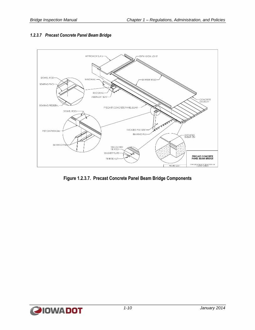
1.2.3.7 Precast Concrete Panel Beam Bridge
Figure 1.2.3.7. Precast Concrete Panel Beam Bridge Components
Bridge Inspection Manual Chapter 1 – Regulations, Administration, and Policies
1-11 January 2014
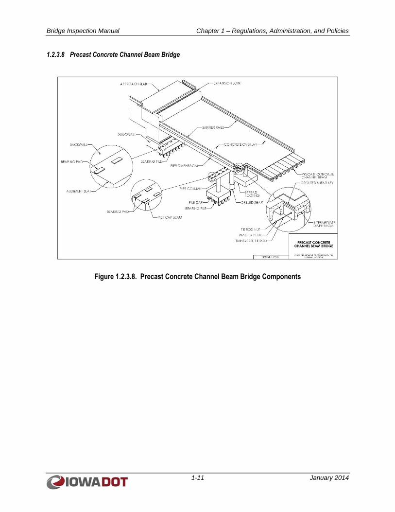
1.2.3.8 Precast Concrete Channel Beam Bridge
Figure 1.2.3.8. Precast Concrete Channel Beam Bridge Components
Bridge Inspection Manual Chapter 1 – Regulations, Administration, and Policies
1-12 January 2014
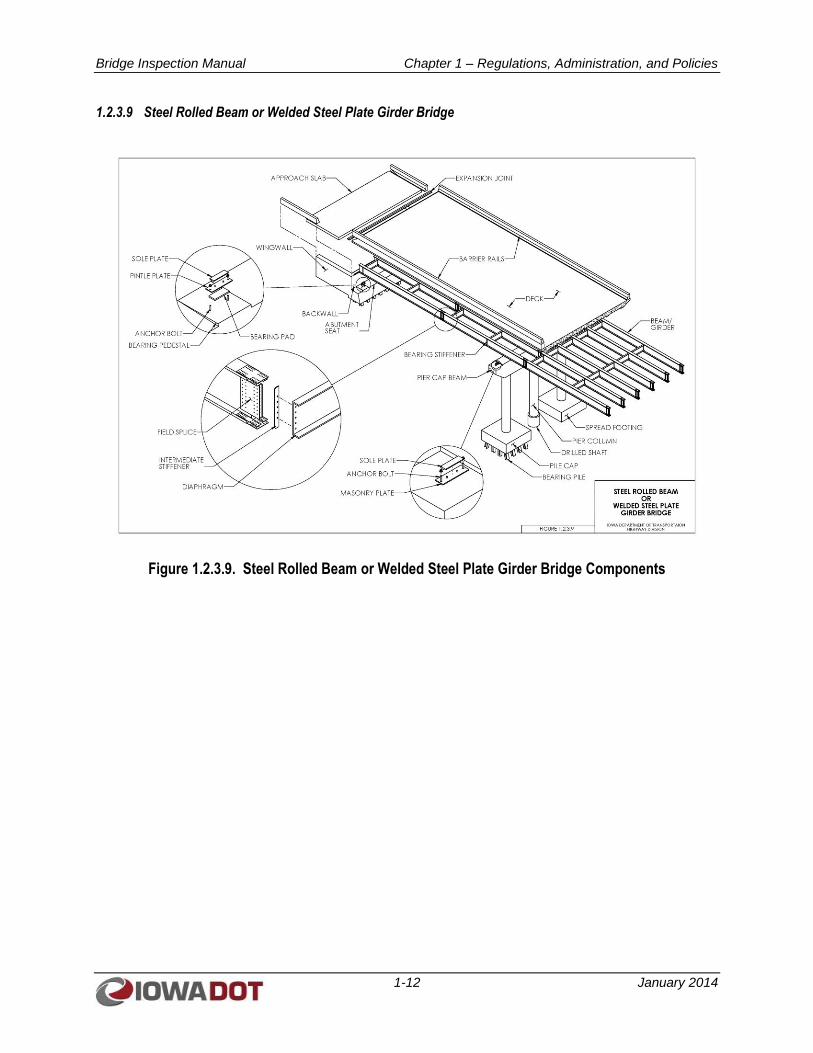
1.2.3.9 Steel Rolled Beam or Welded Steel Plate Girder Bridge
Figure 1.2.3.9. Steel Rolled Beam or Welded Steel Plate Girder Bridge Components
Bridge Inspection Manual Chapter 1 – Regulations, Administration, and Policies
1-13 January 2014
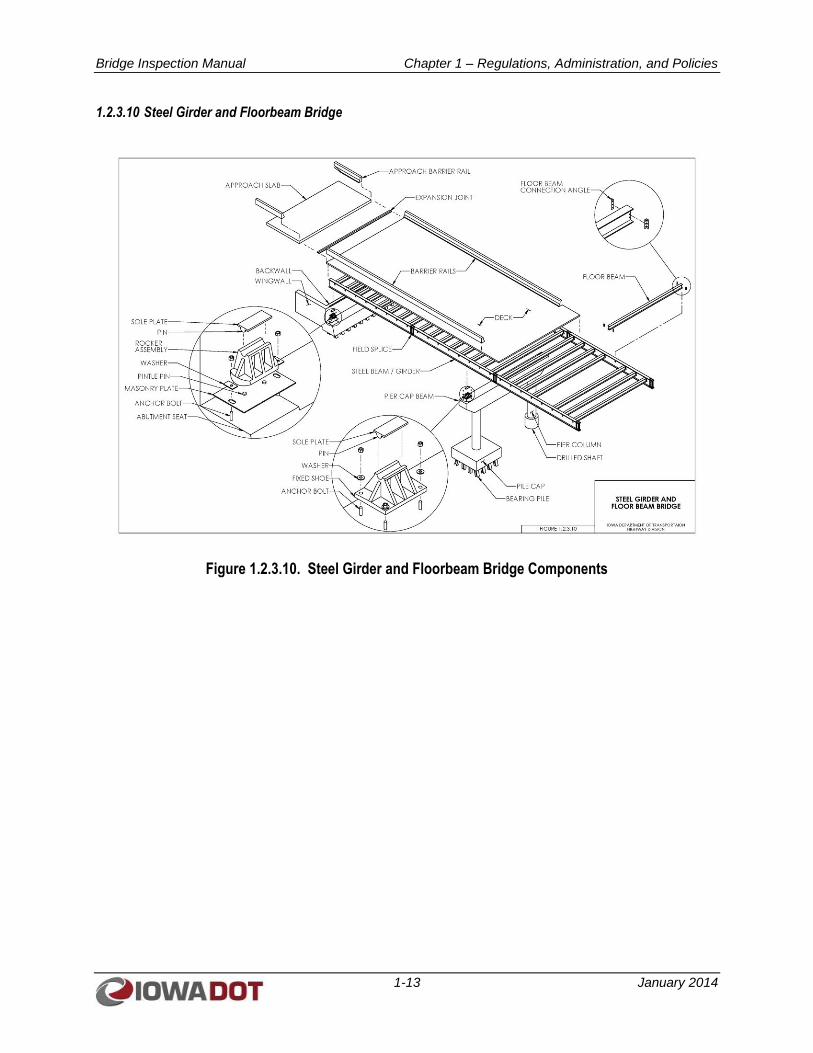
1.2.3.10 Steel Girder and Floorbeam Bridge
Figure 1.2.3.10. Steel Girder and Floorbeam Bridge Components
Bridge Inspection Manual Chapter 1 – Regulations, Administration, and Policies
1-14 January 2014
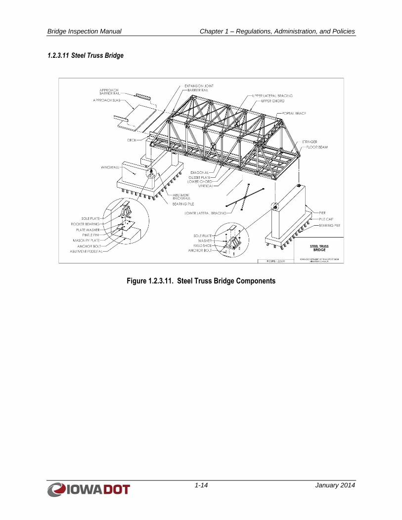
1.2.3.11 Steel Truss Bridge
Figure 1.2.3.11. Steel Truss Bridge Components
Bridge Inspection Manual Chapter 1 – Regulations, Administration, and Policies
1-15 January 2014
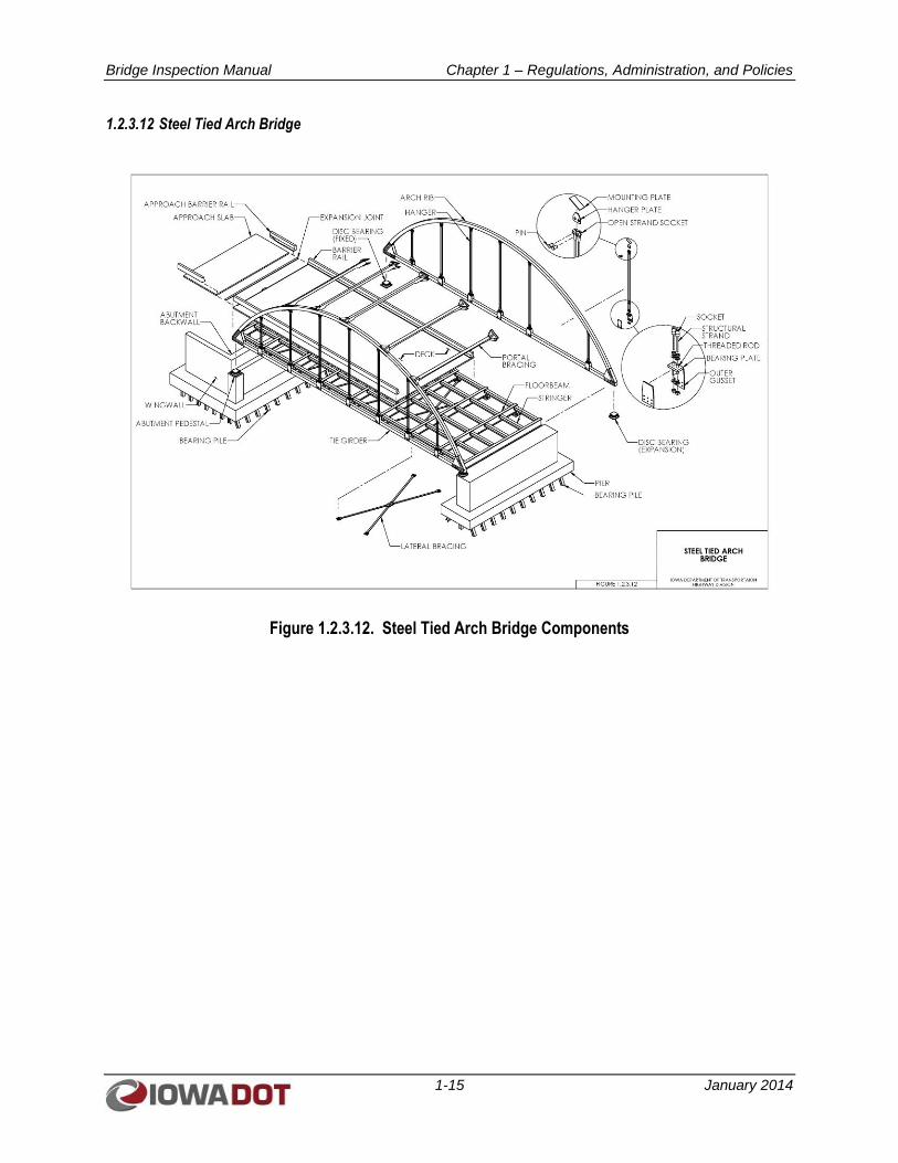
1.2.3.12 Steel Tied Arch Bridge
Figure 1.2.3.12. Steel Tied Arch Bridge Components
Bridge Inspection Manual Chapter 1 – Regulations, Administration, and Policies
1-16 January 2014
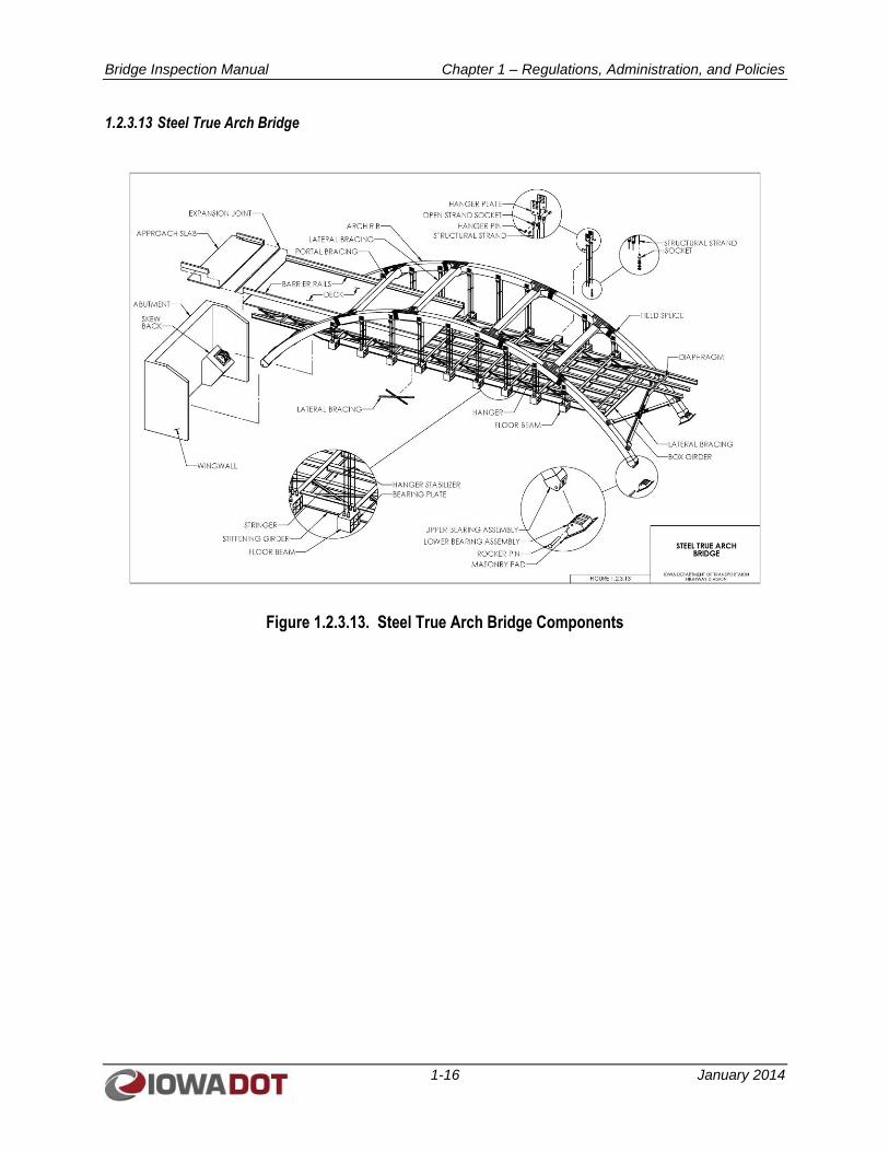
1.2.3.13 Steel True Arch Bridge
Figure 1.2.3.13. Steel True Arch Bridge Components
Bridge Inspection Manual Chapter 1 – Regulations, Administration, and Policies
1-17 January 2014
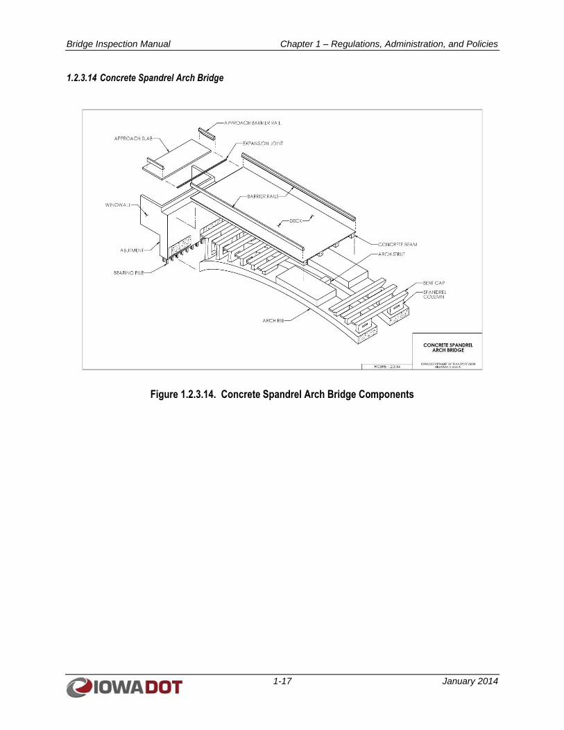
1.2.3.14 Concrete Spandrel Arch Bridge
Figure 1.2.3.14. Concrete Spandrel Arch Bridge Components
Bridge Inspection Manual Chapter 1 – Regulations, Administration, and Policies
1-18 January 2014
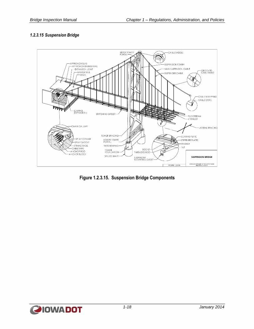
1.2.3.15 Suspension Bridge
Figure 1.2.3.15. Suspension Bridge Components
Bridge Inspection Manual Chapter 1 – Regulations, Administration, and Policies
1-19 January 2014
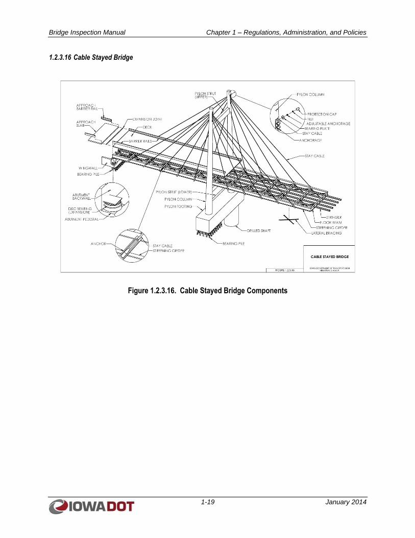
1.2.3.16 Cable Stayed Bridge
Figure 1.2.3.16. Cable Stayed Bridge Components
Bridge Inspection Manual Chapter 1 – Regulations, Administration, and Policies
1-20 January 2014
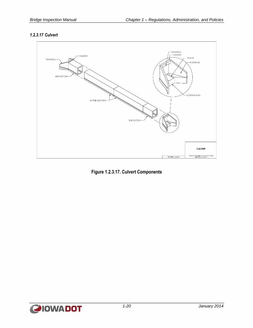
1.2.3.17 Culvert
Figure 1.2.3.17. Culvert Components
Bridge Inspection Manual Chapter 1 – Regulations, Administration, and Policies
1-21 January 2014
1.3 HISTORY AND REQUIREMENTS OF NATIONAL BRIDGE INSPECTION STANDARDS
1.3.1 History and Background of NBIS
With the mobility introduced to society during the automobile age and the increased development of the
current road system in the U.S., the demands on our nation’s bridges have evolved throughout the 20th and
21st centuries. With these increasing demands, the responsibility to maintain our nation’s bridges for the
public’s safety has taken on new importance. As bridges have aged and deteriorated, a number of
significant bridge failures became the impetus for developing the current National Bridge Inspection
Standards (NBIS) governing how the nation’s bridges are inspected, load rated, and maintained. The first
significant bridge failure leading to the current NBIS requirements was the December 15, 1967, collapse
of the Silver Bridge on Route 35 between Point Pleasant, West Virginia, and Gallipolis, Ohio. In this
most devastating bridge collapse in U.S. history in terms of loss of life, 46 people died as a result of an
eyebar failure in this eyebar-chain suspension bridge. As a result of the collapse, President Lyndon
Johnson called for an investigation, which resulted in the 1968 passing of the Federal Highway Act by
Congress, U.S. Code Title 23, Section 151 setting forth the requirement to establish the NBIS.
In the 1968 Act, responsibility for establishing the NBIS was delegated to the Federal Highway
Administration (FHWA). In 1970, the American Association of State Highway and Transportation
Officials (AASHTO) Manual for Maintenance Inspection of Bridges and the FHWA Bridge Inspector’s
Training Manual were developed. After publishing the proposed NBIS in the Federal Register and
allowing comments from individual states, FHWA published the initial NBIS in 1971.
The NBIS required all public bridges on the Federal-aid highway system to have a Structure Inventory
and Appraisal (SI&A) conducted by 1972 and the data reported to FHWA. In 1978, the NBIS was
extended to include all public bridges regardless of whether they were on the Federal-aid highway system.
Important aspects of the NBIS were the following:
1. All states were required to perform periodic inspections of bridges greater than 20 feet in span
length on at least a biennial basis.
2. Data collection was standardized and reported to FHWA.
3. Qualifications for inspection personnel were defined.
4. Training programs were developed and implemented.
5. The Bridge Replacement Program was established to provide funding for bridge replacement on
the system.
Over the years, the inspection standards have been updated, often as the result of lessons learned from
additional bridge failures. In June 1983, a suspended span of the Mianus River Bridge in Connecticut
collapsed, killing three people. The cause of the collapse was traced to the failure of one of the four
fracture critical pin and hanger assemblies that supported the suspended span. This collapse focused
attention on fracture critical bridges and established national inspection guidelines, additional inspector
training, and new fatigue research for these types of structures. FHWA added a new supplement to the
Bridge Inspector’s Training Manual 70 in 1986: Inspection of Fracture Critical Bridge Members. Fracture
Critical Members were defined in the supplement as “Steel tension members whose failure would be
expected to result in collapse of the span or bridge.”
National attention turned to underwater inspections with the collapse of New York’s I-90 bridge over the
Schoharie Creek in 1987, which resulted in 10 deaths. With heavy run-off due to snowmelt and 5.9 inches
Bridge Inspection Manual Chapter 1 – Regulations, Administration, and Policies
1-22 January 2014
of rainfall, the bearing soils beneath one of the piers were weakened due to scour. Pier No. 3 collapsed,
causing the progressive collapse of Spans 3 and 4.
With over 86 percent of the bridges in the national registry spanning waterways and subject to potential
scour, FHWA issued a technical advisory guide in 1988, “Scour at Bridges.” In October 1988, the NBIS
was modified based on suggestions made in the 1987 Surface Transportation and Uniform Relocation
Assistance Act. The national underwater inspection frequency interval was set at a maximum of
60 months, and scour-critical bridge inspections were initiated.
Most recently in 2007, the collapse of the I-35W bridge over the Mississippi River in Minneapolis,
Minnesota has again heightened awareness of NBIS requirements and has focused attention on the
inspection and load rating of gusset plates for truss bridges and on potential overload conditions during
construction and repair activities. The conclusions drawn from the collapse of the I-35W bridge, which
killed 13 people and injured 145, has resulted in new emphasis on gusset plate inspection, has led to the
development of FHWA guidelines for the load rating of gusset plates, and has led to increased scrutiny of
conditions and loadings that could be imposed during bridge construction or rehabilitation operations.
1.3.2 Bridge Inspection Organization
With the revisions to the NBIS that became effective in January 2005, state transportation departments
were made responsible for inspecting or causing to inspect all highway bridges located on public roads
fully or partially within the state’s boundaries, with the exception of bridges owned by Federal agencies.
Federal agencies must, in turn, inspect or cause to inspect all highway bridges located on public roads
fully or partially within the respective agency’s responsibility or jurisdiction.
To execute the duties set forth above, each state transportation department or Federal agency must include
a bridge inspection organization responsible for the following:
Statewide or Federal agency-wide bridge inspection policies and procedures, quality assurance
and quality control, and preparation and maintenance of a bridge inventory.
Bridge inspection reports, load ratings, and other requirements of the NBIS.
The NBIS does allow the delegation of the above duties, as is often the case with individual counties or
municipalities performing their own inspections. Iowa has delegated inspection duties to local agencies
that have bridges under their jurisdiction through Iowa Code section 314.18. However, the delegation of
the duties does not relieve the state transportation departments or the Federal agencies of any
responsibilities under the NBIS. A further requirement is that the state transportation departments or
Federal agency bridge inspection organizations have a Program Manager, who meets specific required
qualifications, to oversee the program.
1.3.3 Required Qualifications of Bridge Inspection Personnel
The Program Manager is the individual in charge of the inspection program for a particular state or
Federal agency who has been assigned or delegated the duties and responsibilities for bridge inspection,
reporting, and inventory. The Program Manager provides overall leadership for the program and is
available to the Team Leaders to provide guidance. The requirements of a Program Manager are both of
the following:
Be a registered professional engineer or have 10 years of bridge inspection experience.
Have successfully completed an FHWA-approved comprehensive bridge inspection training
course.
Bridge Inspection Manual Chapter 1 – Regulations, Administration, and Policies
1-23 January 2014
A Team Leader is the individual in charge of an inspection team who is responsible for planning,
preparing for, and performing a bridge inspection. In accordance with the NBIS, the Team Leader must
be at the bridge site at all times during an inspection. An individual may qualify to be a bridge inspection
Team Leader in one of the following five ways:
Have the same qualifications as for a Program Manager, or
Have 5 years of bridge inspection experience and have successfully completed an FHWA-
approved comprehensive bridge inspection training course, or
Be certified as a Level III or IV Bridge Safety Inspector under the National Society of
Professional Engineer’s program for National Certification in Engineering Technologies and have
completed an FHWA-approved comprehensive bridge inspection training course, or
Have all of the following:
o A bachelor’s degree in engineering from a college or university accredited by or determined
as substantially equivalent by the Accreditation Board for Engineering and Technology
o Successfully passed a National Council of Examiners for Engineering and Surveying
Fundamentals of Engineering examination
o Two years of bridge inspection experience
o Successfully completed an FHWA-approved comprehensive bridge inspection training
course, or
Have all of the following:
o A associate’s degree in engineering from a college or university accredited by or determined
as substantially equivalent by the Accreditation Board for Engineering and Technology
o Four years of bridge inspection experience
o Successfully completed an FHWA-approved comprehensive bridge inspection training course
The NBIS requires periodic bridge inspection refresher training for Program Managers and Team Leaders
as part of QC and QA. The Iowa DOT has defined periodic as being every five years. Therefore, all
bridge inspection personnel are required to complete the Bridge Inspection Refresher Training course
every five years following the completion of the Safety Inspection of In-service Bridges Training Course.
The individual charged with overall responsibility for load rating bridges must be a registered
professional engineer.
An underwater bridge inspection diver must successfully complete an FHWA-approved comprehensive
bridge inspection training course or other FHWA-approved underwater diver bridge inspection training
course.
1.3.4 Bridge Inventory Requirements
Each state or Federal bridge inspection agency must prepare and maintain an inventory of all bridges
subject to the NBIS within its jurisdiction. Iowa DOT utilizes the Structure Inventory and Inspection
Management System (SIIMS) to maintain its bridge inventory.
Certain National Bridge Inventory (NBI) data must be collected and retained by the state or Federal
agency for compilation by FHWA. The data must be reported using FHWA-established procedures as
outlined in the “Recording and Coding Guide for Structure Inventory and Appraisal of the Nation’s
Bridges.” The SI&A sheet displays most of the NBI data required by FHWA.
Bridge Inspection Manual Chapter 1 – Regulations, Administration, and Policies
1-24 January 2014
1.4 TYPES OF INSPECTIONS AND THEIR FREQUENCIES
1.4.1 Initial Inspections
An Initial Inspection is the first inspection of a bridge, which becomes a part of the bridge inventory.
However, the elements of an Initial Inspection may also apply when there has been a change in the
configuration of the bridge due to widening, lengthening, rehabilitation, the addition of supplemental
bents, or if there has been a change in the bridge ownership.
The Initial Inspection is a fully documented investigation performed by persons meeting the NBIS
qualifications for inspection personnel, and the inspection must be accompanied by an analytical
determination of load capacity. The purpose of the inspection is two-fold: 1) To provide all NBI data
required by Federal regulations and all other relevant information normally collected by Iowa DOT; and
2) To determine the baseline structural condition and to identify and list any existing problems or
locations on the structure that may have potential problems. During the Initial Inspection, the inspector
shall note any fracture critical members or details aided by a prior review of the plans. Assessments are
also made of other conditions that might warrant special attention. An Initial Inspection for a newly
constructed or newly rehabilitated bridge shall include all the requirements of an In-depth Inspection.
1.4.2 Routine Inspections
Routine Inspections are regularly scheduled inspections consisting of observations, measurements, or
both needed to determine the physical and functional condition of a bridge, to identify any changes from
the “Initial” or previously recorded conditions, and to ensure the structure continues to satisfy present
service requirements.
The Routine Inspection must fully satisfy the NBIS requirements with respect to maximum inspection
frequency, the updating of NBI data, and the qualifications of the inspection personnel. These inspections
are generally conducted from the deck, from ground or water levels or both, and from permanent work
platforms or walkways, if present. Inspections of underwater portions of the substructure are limited to
observations during low-flow periods, probing for signs of undermining, or both. Special equipment such
as an Underbridge Inspection Vehicle (UBIV), rigging, or staging may be necessary for a Routine
Inspection in circumstances where it provides for the only practical means of access to areas of the
structure being monitored.
The areas of the structure to be closely monitored are those determined by previous inspections, load
rating calculations, or both to be critical to load-carrying capacity. If additional close-up, hands-on
inspection of other areas is found necessary during the inspection, an In-depth Inspection of those areas
should also be performed in accordance with Section 1.4.3.
The results of a Routine Inspection should be fully documented with appropriate photographs and written
notes that include any recommendations for maintenance and repair and for scheduling follow-up
In-depth or Special Inspections, if necessary. The Load Rating Evaluation Form shall be completed after
a Routine Inspection to determine if re-evaluation of the load ratings is necessary.
For Routine Inspections, bridges shall be inspected at intervals not to exceed 24 months. The NBIS does
recognize that age, traffic considerations, and known deficiencies may require establishing criteria to
perform Routine Inspections at less than 24 months, and it is left to the individual state or Federal bridge
inspection agencies to determine the criteria. The inspection interval for Routine Inspections may be
increased from 24 months to a maximum of 48 months only with written FHWA approval if past
inspection findings and analysis justify an increased inspection interval.
Bridge Inspection Manual Chapter 1 – Regulations, Administration, and Policies
1-25 January 2014
1.4.3 In-depth Inspections
An In-depth Inspection is a close-up, hands-on inspection of one or more members above or below the
water level to identify any deficiencies not readily detectable using Routine Inspection procedures. This
type of inspection can be scheduled independently of a Routine Inspection, though generally at longer
intervals, or it may be a follow-up to a Damage or Initial Inspection. Traffic control and special
equipment such as a UBIV, staging, and work boats should be provided to obtain access if needed.
Personnel with special skills such as divers, rope access inspectors, and riggers may be required. When
appropriate or necessary to fully ascertain the existence of or the extent of any deficiencies,
nondestructive field tests or other material tests may need to be performed.
An In-depth Inspection may also include a load rating to assess the residual capacity of the member or
members, depending on the extent of the deterioration or damage. Nondestructive load testing may be
included to assist in determining a bridge’s safe load carrying capacity.
In-depth Inspections are used to document all bridge elements in a more detailed manner due to
conditions that are less than optimal. The definition of In-depth Inspection for Iowa is slightly different
than what is described in the NBIS. Instead of using an In-depth Inspection for specific elements of a
bridge and overlapping Routine with In-depth inspections, Iowa has chosen to define an entire inspection
as either Routine or In-depth. Criteria have been established to differentiate Routine from In-depth
inspections.
An In-depth Inspection requires all data fields relevant to the bridge in the Deck, Superstructure,
Substructure, and Channel tabs be filled out or updated for the current conditions found. Descriptive
inspection notes for the relevant data fields entered are recommended.
The following criteria shall be used to determine if a bridge should have an In-depth Inspection:
For all fracture critical bridges, inspect every 24 months.
For fatigue vulnerable bridges, inspect at 24-month or 72-month intervals depending on crack
history. If crack history indicates that two or fewer locations have had fatigue cracks develop and
these cracks have been arrested, an In-depth Inspection is required every 72 months.
For structurally deficient bridges, inspect every 24 months.
For all bridges with two or more condition ratings of 5 or less, inspect every 24 months.
For all culverts with condition ratings of 5 or less, inspect every 24 months.
For bridges with one condition rating of 5 or less, inspection can be an In-depth Inspection if the
inspector determines it to be necessary.
Most of the bridges in Iowa are relatively small, and differentiating which elements require an In-depth
Inspection and which can have a Routine Inspection is difficult to track. Therefore, when the In-depth
criteria are met, all elements of a bridge should receive an In-depth Inspection and documentation. The
activities, procedures, and findings should be completely and carefully documented.
1.4.3.1 Fracture Critical Member Inspections
A Fracture Critical Member (FCM) Inspection consists of a hands-on inspection of FCMs or FCM
components including visual and other nondestructive evaluation. An FCM Inspection includes
identification of FCMs and a plan for inspecting such members and defining the inspection procedures to
be used. The frequency of inspection shall be in accordance with the NBIS.
Bridge Inspection Manual Chapter 1 – Regulations, Administration, and Policies
1-26 January 2014
A very detailed, close visual inspection is the primary method of detecting cracks. This may require
critical areas be specially cleaned prior to inspection and additional lighting or magnification be used.
Photographs should be taken and sketches should be made of the conditions found, and on-site
comparison of photographs and sketches should take place at follow-up inspections. Where fracture
toughness of the steel is not documented, tests may be necessary to determine the threat of brittle fracture
at low temperatures.
FCMs shall be inspected at intervals not to exceed 24 months. The NBIS does recognize that age, traffic
considerations, and known deficiencies may require establishment of criteria to perform FCM Inspections
at less than 24 months, and it is left to the individual state or Federal bridge inspection agencies to
determine the criteria. The frequency of inspection for FCMs should be reduced to a maximum of
12 months when:
1. Fatigue cracks have been found at previous inspections.
2. The alignment of FCMs or sub-elements has measurably changed from the as-built condition.
3. Deterioration in tension areas of the FCM has caused the superstructure to be at a condition rating
of 4 or less.
FCMs can be inspected at a frequency less than 24 months by using an FCM Inspection (NBI Item 92A)
or a Special Inspection (NBI Item 92C) at a reduced frequency.
Team Leaders who perform field inspections of Fracture Critical bridges shall complete the Fracture
Critical Inspection Techniques for Steel Bridges training course.
1.4.3.2 Underwater Inspections
Underwater Inspections are used to inspect structural members that cannot be inspected visually or by
wading during the Routine Inspection. These inspections are performed by a certified diver at intervals
meeting the NBIS requirements, and they often require inspection by tactile probing methods.
Occurrences that could result in a decision to perform Underwater Inspections at intervals less than those
required by NBIS are known instances of structural damage; scour and erosion due to water movement;
streambed load; ice loading; navigation traffic collision; deleterious effects of water movement; and
effects of drift or elements in the water.
Typically underwater structural elements shall be inspected at intervals not to exceed 60 months. The
NBIS does recognize that construction materials, environment, age, scour characteristics, condition rating
from past inspections, and known deficiencies may require establishing criteria to perform inspection of
underwater structural elements at less than 60 months, and it is left to the individual state or Federal
bridge inspection agencies to determine the criteria. The inspection interval for underwater structural
elements may be increased from 60 months to a maximum of 72 months only with written FHWA
approval, if past inspection findings and analysis justify an increased inspection interval.
1.4.3.3 Special Inspections
A Special Inspection is an inspection scheduled at the discretion of the bridge owner or the responsible
agency. It is used to monitor a particular known member condition or suspected deficiency and it must be
performed by a qualified Team Leader familiar with the bridge and available to accommodate the
assigned frequency of investigation. The individual performing the Special Inspection should be carefully
instructed regarding the nature of the known deficiency and its functional relationship to satisfactory
bridge performance. In this instance, guidelines and procedures on what to observe or measure must be
provided, and a timely process to interpret the field results should be in place.
Bridge Inspection Manual Chapter 1 – Regulations, Administration, and Policies
1-27 January 2014
The determination of an appropriate Special Inspection frequency should consider the severity of the
known deficiency. Special Inspections usually are not sufficiently comprehensive to meet NBIS
requirements for biennial inspections. Special Inspection dates and frequency are documented by using
NBI items 92C and 93C.
A Special Inspection should be scheduled when:
1. Deterioration is progressing at a rate that warrants inspection more frequently than 24 months.
2. Channel degradation or channel movement is progressing at a rate that warrants inspection more
frequently than 24 months.
3. Temporary supports are in place.
4. Fatigue cracks have been found in a redundant steel structure. Special Inspections can be stopped
when repair has been performed to mitigate the cracks.
5. Fatigue cracks have been found in a FCM. Special Inspections should continue even after cracks
have been mitigated. Only after the potential for any future fatigue cracks has been eliminated can
Special Inspections be stopped on a fracture critical bridge.
6. Collision damage has severely affected the load capacity of the bridge and repairs cannot be done
within a reasonable time period. Once repairs have been made, the Special Inspections can be
stopped.
7. Section loss has severely affected the load capacity of the bridge. Once repairs or rehabilitation
work have been completed, the Special Inspections can be stopped.
1.4.3.3.1 Intermediate Fatigue Inspections
For bridges that are considered fracture critical and have fatigue-prone details, an Intermediate Fatigue
Inspection may be scheduled as a type of Special Inspection. The purpose of an Intermediate Fatigue
Inspection is to monitor fatigue-prone details. Another reason for this type of inspection would be to
observe and monitor fatigue crack retrofits performed to determine if they have successfully arrested
potential propagation of fatigue cracks.
Good practice procedures for Intermediate Fatigue Inspections include marking and dating locations
where fatigue cracks are present. To accurately determine the ends of fatigue cracks, nondestructive test
methods may need to be incorporated to supplement visual investigation. These nondestructive methods
may typically include dye penetrant or magnetic particle testing methods.
1.4.3.4 Other Inspections
At the discretion of the bridge owner, other types of inspections may be used to monitor the performance
of bridges or specific bridge components. Other Inspection dates and frequencies are documented by
using the non-NBI fields for the inspection type called “Other.” “Other” inspections are not tracked by
the FHWA for frequency compliance.
1.4.3.4.1 Damage Inspections
A Damage Inspection is an unscheduled inspection used to assess structural damage as the result of
unforeseen environmental factors or human actions. Such inspections may be warranted due to events
such as an unexpected overload of the bridge; a vehicle-bridge collision; a bridge being struck by an over-
height vehicle; a reported deficiency by the public or maintenance personnel; or flood-induced damage
from floating flood debris, bridge buoyancy conditions, wash-out of a bridge approach, or scour
damage/bridge settlement.
Bridge Inspection Manual Chapter 1 – Regulations, Administration, and Policies
1-28 January 2014
A Damage Inspection may require an on-site assessment of whether a bridge can remain in service;
therefore, consultation with a registered professional engineer may be warranted. In addition to
determining whether the bridge can remain in service, the Damage Inspection should assess whether the
damage to the bridge presents a risk to other facilities below or adjacent to the damaged components.
Appropriate equipment should be available and personnel notified in case partial or full closure of the
bridge is necessary and detour routes are required. If the bridge is closed immediately as a precautionary
measure, the Damage Inspection should be followed by a structural analysis to determine the bridge’s safe
load carrying capacity.
1.4.3.4.2 Pin or Pin and Hanger Inspections
Pin or Pin and Hanger Inspections are one type of inspection that could be required for steel bridges with
pinned elements. This might include steel truss bridges pinned at their joints; steel arch bridges pinned at
their supports or at their crown; and steel girder, steel stringer, or steel truss bridges with spans suspended
by pin and hanger systems. This type of inspection requires specialized equipment and often special
access methods to allow for testing of the pin members by nondestructive ultrasonic testing methods. For
typical ultrasonic test procedures, a transmitter and a receiver are attached to one end of a pin member.
The transmitter transforms the energy of an electrical voltage into an ultrasonic wave, and the ultrasonic
wave travels through the material at a velocity dependent upon the material’s properties. The ultrasonic
wave travels through the material until the test specimen boundary reflects the signal, and then the
reflected signal travels back through the material to a receiver. The receiver converts the mechanical
energy back to electrical energy, which is then amplified. The amplified signal, or echo, is displayed on
the instrument screen, and if the member contains a discontinuity (that is, a defect), the discontinuity
appears as a reflected defect echo on the screen.
Some pin and hanger members are considered FCMs. If the pin and hangers are considered FCMs, a
hands-on, visual inspection of all elements of the connection is required as part of a regularly scheduled
FCM Inspection. However, because the ultrasonic pin testing usually requires specialized access, such as
a manlift or UBIV, to place personnel and the test equipment close to the pin, it also allows for ready
access to perform supplementary hands-on inspection of the assembly.
Pin and hanger connections not considered FCMs can be inspected with ultrasonic testing methods at a
60-month frequency. This type of inspection should be tracked by designating it as an “Other” Inspection.
1.4.3.4.3 Scour Inspections
Scour Inspections are used to assess an existing bridge’s vulnerability to scour and stream instability. In
addition, Scour Inspections allow for documentation of scour changes since the previous inspection. The
visual inspection should document the existing condition of the bridge, including, but not limited to, pier
and abutment type; foundation depth (based on existing plans or physical probing in the field);
substructure location and alignment relative to the stream; scour depth at abutments and piers; bridge
skew; condition or absence of scour countermeasures; stream aggradation or degradation; upstream and
downstream channel stability; potential or presence of debris; lateral movement of stream; and bed and
bank soil material. The visual inspection should include photo documentation of the bridge deck,
roadway profile, abutment walls, piers, and upstream/downstream channel configurations, as a minimum.
The information obtained from the visual inspection can be used to evaluate the scour potential from a
flood event of a known return frequency through the use of analytical tools. Hydraulic models and
equations in the HEC-18 computer program are commonly used for the analysis. These results, in
conjunction with the field inspection and a structural analysis, can then be used to assess existing or
potential scour and, if necessary, establish a formal Plan of Action for management of the scour potential
of the structure to protect public safety.
Bridge Inspection Manual Chapter 1 – Regulations, Administration, and Policies
1-29 January 2014
1.4.3.4.4 Posting Sign Adequacy Inspections
A Posting Sign Adequacy Inspection would typically consist of an inspection to determine if posting
signs are being maintained or, in the case of a closed bridge, to determine if barricades are being
maintained in place and public access is restricted. This type of inspection could also be used to spot
check a posted bridge to determine if overweight vehicles are complying with posting restrictions.
1.5 IOWA DOT INSPECTION PROGRAM POLICIES
1.5.1 Safety
By its nature, bridge inspection includes inherent dangers. Inspection staff are often working from
elevated heights and often over water; they are working in and around active traffic; they are often
working in challenging weather conditions; in working around the abutments of bridges, they are often
working along steep, slippery slopes where footing can be difficult; and they must constantly focus on
gathering the pertinent information required for a bridge inspection while also keeping their own safety
and the safety of their coworkers and the traveling public in mind. Each bridge inspector should
remember he or she is responsible for his or her own personal safety as well as the safety of others
impacted by his or her work. To that end, some policies and common sense procedures are needed to
protect staff from the dangers of bridge inspection, to help them recognize hazards, implement controls,
and to give them the ability to select, use, and maintain tools and equipment in their work to minimize
and, if possible, eliminate accidents, injuries, and near misses.
Generally, causes of accidents can be traced to two root causes: human error and equipment failure.
Human errors can, in turn, be broken down into a number of factors, which may include improper
attitude, horseplay, personal limitations, physical impairments, boredom, thoughtlessness, and taking
shortcuts. Therefore, bridge inspectors must practice good work habits to minimize dangers they may
encounter on the job. Inspectors first and foremost must practice common sense when performing bridge
inspection activities. For example, it is Iowa DOT’s policy that inspectors shall be tied-off 100 percent of
the time when working in the basket of a manlift or UBIV or when using assisted climbing techniques to
access bridge elements for inspection. Failure to maintain this 100 percent tied-off policy will
unnecessarily expose the inspector to fall hazards that could otherwise be avoided. When working
outside the basket of a manlift or UBIV, the inspector should be tied-off to a fixed object rather than the
basket, in case the manlift or UBIV should move.
Environmental factors can also be a source of injury. Stinging insects, spiders, snakes, and nesting
animals can startle or surprise a bridge inspector causing injury or sudden unexpected movements that
could result in a fall. The presence of poison ivy, poison oak, and electric cattle fences can cause on-the-
job injury or, at best, discomfort. In some cases, bridge configurations constituting confined spaces could
have limited access entrances, poor oxygen content, or toxic gases.
With the physical demands of bridge inspection activities, proper work habits and mental attitude are
important. Inspectors also need to be well rested and alert for their job assignments, maintain good
physical health, and shall not be under the influence of drugs or alcohol on the job. Even over-the-
counter medications can cause impairments that can affect balance or cause drowsiness and should be
used with caution. Good work practices also include common sense activities such as keeping a clean,
uncluttered work environment and using tools and equipment properly and for only their intended use.
Inspectors who are controlling the basket of a manlift or UBIV should be trained in the operation of that
particular type of equipment so movement of the basket is performed smoothly without sudden
movements that could surprise a coworker in the basket. Training in the operation of the particular access
equipment will also minimize the potential for damaging the equipment or members of the bridge being
inspected.
Bridge Inspection Manual Chapter 1 – Regulations, Administration, and Policies
1-30 January 2014
The Occupational Safety and Health Administration (OSHA) applies different regulations depending on
the nature of the work activity. The General Industry standards (OSHA CFR 1910) apply to activities
like bridge maintenance or inspection, surveying, or wetland assessments. The Construction standards
(OSHA CFR 1926) apply to new work on bridges, roadways, or other structures. Work, including bridge
inspections, will be considered to be a maintenance activity when it meets the following criteria: It is
work done for the purposes of making or keeping a structure, fixture or foundation (substrates) in proper
condition in a routine, scheduled, or anticipated fashion – work that is done to keep a structure in its
existing state, preventing failure or decline. Inspections related to the monitoring of work performed by a
construction contractor will be considered construction activity.
Inspection personnel should receive awareness training for safety hazards they may encounter on the job.
This safety training may include knowledge of proper procedures when working around active traffic, fall
protection training, awareness training for confined spaces, ladder safety training, training for working on
railroad property, and training for work over water. When working over water, particularly if the
inspector is not tied-off, a personal floatation device or a safety boat with a life ring and two-way
communication should be employed.
The inspection Team Leader’s responsibilities include supervising job procedures and ensuring safe
practices are being followed. The Team Leader not only needs to set a good example for the inspection
staff but also should enforce safety policies and institute corrective actions when these policies are not
followed. It is good practice that the Team Leader performs a safety briefing on the first day of
inspection for a bridge or on subsequent days when work conditions or personnel working on the bridge
might change. Topics to be discussed at the safety briefing might include individual worker assignments;
use of the “buddy” system; any special considerations for the particular bridge being inspected, including
potential electrical hazards from power facilities on the bridge or from overhead power lines; safety
procedures for work over water, other roadways, or railroads; weather conditions; the types of traffic
control that will be used; methods of bridge access that will be used, such as ladders, manlifts, UBIVs,
waders, and assisted climbing; safe working zones; location and phone number of nearest first responders
or medical services; and communication protocol, including two-way radios and cell phones with cell
phone numbers for all staff on the job and for the local District office.
Inspection personnel shall use appropriate protective clothing and Personal Protective Equipment (PPE) when
performing bridge inspection activities. Clothing worn should be properly sized (neither too loose nor too
tight) and appropriate for the weather conditions. Leather work boots with traction lug soles should be worn,
and safety shoes or boots with toe-impact protection meeting the requirements of ASTM F 2413 or ANSI 241
are required to be worn in work areas where personnel may be carrying or handling materials such as parts or
heavy tools that could be dropped and where objects might fall onto or equipment could run over the feet.
Work gloves should be worn to protect against sharp edges and excessively hot or cold steel. A tool belt or
pouch may be worn to provide ready access to frequently used tools, but the tools also need to be secured to
prevent them from falling on passing vehicular traffic. Additional PPE shall include an ANSI 107, Class 2 or
3 High Visibility Safety Vest (Class 3 is rated for traffic speeds above 50 mph). If working at night outside
the cab of a vehicle, high visibility pants and head gear are also required. Hard hats, shall meet the
requirements of ANSI Z89.1. Safety goggles or safety glasses with side shields should be worn whenever
chipping concrete or hammering on bridge members, and ear protection should be worn if working around
loud pneumatic or power equipment. A dust mask or properly fitted respirator should be worn when working
in particularly dusty conditions or in the presence of bird droppings to prevent contracting Histoplasmosis, a
disease contracted from contact with microscopic fungi borne from decomposing biological fluids such as
bird droppings. Finally, when walking or working on an unprotected surface 6 feet or more from the ground
or a lower level, or when working from the basket of a manlift or UBIV or using assisted climbing techniques,
the inspector shall wear a properly adjusted full-body harness, shock absorbing lanyard with double locking
Bridge Inspection Manual Chapter 1 – Regulations, Administration, and Policies
1-31 January 2014
snap hooks, and a cross-arm strap with a D-ring (if needed). The harness shall meet the requirements of
ANSI A10.14, ANSI/ASSE Z359, or the latest version of 29 CFR 1910.66,1926.104 or 1926.502.
1.5.2 Media Relations
Elements of the Iowa DOT Bridge Inspection Program and individual bridge records available in SIIMS may
be subject to open public records laws. For example, data is annually made available to FHWA and the
public regarding the number and locations of structurally deficient bridges within the State. However, if
approached by a member of the press about the condition of a specific bridge or bridges, inspectors shall defer
comment and refer the individual to the Iowa DOT Office of Public Affairs.
1.6 STATEWIDE INSPECTION PROGRAM POLICIES
1.6.1 Timelines for Completion of Inspections and Reports
For Routine, In-depth, FCM, Underwater, and Special Inspections, SI&A data shall be entered into SIIMS
within 90 days of the date of the inspection completion.
For existing bridge modifications that alter previously recorded data and for new bridges, the SI&A data
shall be entered into the State or Federal agency inventory within 90 days after the completion of work for
State or federal agency bridges and within 180 days after the completion of work for all other bridges.
For changes in load restrictions or closure status, the SI&A data shall be entered into SIIMS within
90 days after the change in status of the structure.
1.6.2 Standardized Bridge Orientation and Labeling Conventions
To promote uniformity in reporting inspection data, all bridge components shall be labeled using the
following numbering convention consistent with the progression of mileposts on the State highway
system:
For bridges on a roadway with a north/south designation, bridge substructure components shall be
numbered in increasing order starting at the south end of the bridge, relative to the direction
designation, and progressing toward the north. Thus, the south abutment would be referred to as
the “near” abutment and the north abutment would be referred to as the “far” abutment.
Likewise, interior supports would be numbered Pier No. 1 at the southernmost interior support
and would increase in number proceeding to the north. Span numbers would also increase in
number from south to north. Floorbeams and diaphragms are numbered from the near end to far
end of each span. The first floorbeam or diaphragm over an abutment or pier will be designated as
#0. The numbering continues consecutively thru the span to the next substructure unit where the
numbering begins again at #0. Truss panel points would similarly increase from south to north
from near end to far end of a span. Thus the truss panel point at the south support would be L0
for a lower chord panel point (or U0 for an upper chord panel point) and panel point L1 (or U1)
for a first interior panel point. Beam or stringer lines would be numbered increasing from left to
right, with Beam Line No. 1 at the westernmost beam and increasing in number to the
easternmost beam. Likewise, pile numbers for exposed piles at abutments or pile bents would be
numbered in increasing order from left to right (west to east).
For bridges on a roadway with an east/west designation, bridge substructure components shall be
numbered in increasing order starting at the west end of the bridge, relative to the direction
designation, and progressing toward the east. Thus, the west abutment would be referred to as the
“near” abutment and the east abutment would be referred to as the “far” abutment. Likewise,
interior supports would be numbered Pier No. 1 at the westernmost interior support and would
increase in number proceeding to the east. Span numbers would also increase in number from
Bridge Inspection Manual Chapter 1 – Regulations, Administration, and Policies
1-32 January 2014
west to east. Floorbeams and diaphragms are numbered from the near end to far end of each
span. The first floorbeam or diaphragm over an abutment or pier will be designated as #0. The
numbering continues consecutively thru the span to the next substructure unit where the
numbering begins again at #0. Truss panel points would similarly increase from west to east
from near end to far end of a span. Thus the truss panel point at the west support would be L0 for
a lower chord panel point (or U0 for an upper chord panel point) and panel point L1 (or U1) for a
first interior panel point. Beam or stringer lines would be numbered increasing from left to right,
with Beam Line No. 1 at the northernmost beam and increasing in number to the southernmost
beam. Likewise, pile numbers for exposed piles at abutments or pile bents would be numbered in
increasing order from left to right (north to south).
1.6.3 Critical Findings/Emergency Response
Critical structural and safety related deficiencies found during the field inspection or as a result of a
structural analysis of the bridge should be immediately brought to the attention of the bridge owner or
responsible agency by the Program Manager or Team Leader if a safety hazard is present. This process
alerts the bridge owner so that1) timely action is taken to ensure the safety of the traveling public,
2) damage or deterioration can be repaired in a proper and timely manner, and 3) the damage and repairs
are documented in the bridge file. The process also aids in identifying problem areas that affect other
bridges with similar details so follow-up inspections can be performed if needed.
A standard Critical Findings Report form has been incorporated into SIIMS. Conditions requiring a
Critical Findings Report shall include, but are not limited to, the following:
A partial or complete collapse of a bridge
A structural or other defect posing a definite and immediate public safety hazard
A condition rating of 2 or less for any of the following NBI items:
o NBI Item 58, Deck
o NBI Item 59, Superstructure
o NBI Item 60, Substructure
o NBI Item 61, Channel and Channel Protection
o NBI Item 62, Culvert
o NBI Item 113, Scour Critical
In cases where it is determined the bridge could be used safely at a lower posted load limit, the bridge
may remain open if it is immediately posted at the reduced limit. At the discretion of a bridge owner,
other conditions, not specified in this manual, may be designated that would require preparation of a
Critical Finding Report.
1.6.4 Inspection Intervals for Non-regulated Structures
1.6.4.1 Pedestrian Bridges
The NBIS does not define the required interval for inspection of non-vehicular bridges, such as pedestrian
bridges. The owner should develop a protocol for the inspection interval for pedestrian bridges.
1.6.4.2 Culverts
The definition of a bridge, provided in Section 1.2.1 of this manual, addresses single cell box culverts
with spans greater than 20 feet and multiple cell culverts with an aggregate length between extreme ends
Bridge Inspection Manual Chapter 1 – Regulations, Administration, and Policies
1-33 January 2014
of openings that is greater than 20 feet. Therefore, a box culvert meeting the criteria under the definition
for a bridge shall fall under the required inspection intervals defined in the NBIS.
For box culverts that do not fall within the NBIS criteria for the definition of a bridge, the owner shall
develop a protocol for the required inspection interval.
1.6.4.3 Privately Owned Structures Privately owned structures not open to public use are not governed by NBIS regulations. A bridge on a
public highway where the bridge is privately owned is not subject to the NBIS; therefore, FHWA has no
legal authority to require private bridge owners to inspect or maintain their bridges. However, FHWA
strongly encourages private bridge owners to follow the NBIS as a standard for inspecting their structures
or to reroute the public road when a privately owned bridge carries a public road. The bridge owner
should have a Program Manager who is assigned the above responsibilities, or the bridge owner may
retain a consultant to perform the duties of Program Manager.
1.6.5 Temporary Structures
Any replacement structure, which is expected to remain in place without further project activity, other
than maintenance, for a significant period of time, shall not be considered temporary. Under such
conditions, that structure, regardless of its type, shall be considered the minimum adequate to remain in
place. The structure must be added to the NBI and evaluated accordingly.
If a structure has been taken out of service due to condition, collapse, or removal, and a temporary
structure or low water crossing has been installed, the NBI data for the original structure should have the
following coding:
1. Item 41 = E – Open, temporary structure in place to carry legal loads while original structure is
closed and awaiting replacement or rehabilitation.
2. Item 58 = 0 – Out of service.
3. Item 59 = 0 – Out of service.
4. Item 60 = 0 – Out of service.
5. If applicable, Item 62 = 0 – Out of service.
6. Item 64 = 0 – Temporary structure.
7. Item 66 = 0 – Temporary structure.
8. Item 103 = T – Temporary structure(s) or conditions exist.
There are NBI items that are to be coded according to the temporary structure’s conditions. The items
that are to be coded are as follows:
1. Item 10 – Inventory Route, Minimum Vertical Clearance.
2. Item 47 – Inventory Route, Total Horizontal Clearance.
3. Item 53 – Minimum Vertical Clearance over Bridge Roadway.
4. Item 54 – Minimum Vertical Underclearance.
5. Item 55 – Minimum Lateral Underclearance on the Right.
6. Item 56 – Minimum Lateral Underclearance on the Left.
7. Item 70 – Bridge Posting.
Bridge Inspection Manual Chapter 1 – Regulations, Administration, and Policies
1-34 January 2014
The original structure must be removed from the NBI if no work has been done to replace it within five
years of the time the bridge was closed. If, after the original structure is removed from the NBI, the
temporary structure qualifies as a bridge, it must be added to the NBI and evaluated accordingly.
1.6.6 Temporary Supports
A structure that has temporary supports is to be evaluated as if no temporary supports are in place. Most
NBI items shall be determined as if the temporary supports are not in place. Condition ratings and load
ratings shall not take into account the effect of the temporary supports. The NBI items shall be coded
considering the temporary supports in place are as follows:
1. Item 41 = D – Open, would be posted or closed except for temporary shoring, etc., to allow for
unrestricted traffic.
2. Item 103 = T – Temporary structure(s) or conditions exist.
If the temporary supports are to remain in place more than five years, the supports are no longer
considered temporary and the structure shall be evaluated accordingly.
Chapter 2 – Condition Evaluation of Bridges Bridge Inspection Manual for Iowa DOT Personnel
2-1 January 2014
CHAPTER 2
CONDITION EVALUATION OF BRIDGES
FOR IOWA DOT PERSONNEL
2.1 INSPECTION PLANNING
2.1.1 Reviewing Past Inspection Reports, SIIMS Data, Existing Bridge Plans, and Bridge Repair Plans
The first step in preparing for any bridge inspection for bridges on the Iowa DOT State or U.S highway
system is to gather information regarding the existing bridge so the inspector is educated with regard to
the configuration and type of bridge as well as its documented history. This is important so the number of
inspection personnel and type of equipment and tools, including non-destructive testing equipment,
needed to perform the inspection can be determined. If as-built plans and/or plans of any repairs or
rehabilitation projects are available, they should be reviewed to help the inspector gain an understanding
of the bridge configuration and structure type as well as allow the inspector to plan ahead for the access
constraints that might affect how the bridge will be inspected. Typically, if existing plans are available,
they would be included as part of the bridge’s record within the SIIMS database. Another helpful
resource is any available shop drawings produced by the contractor or the contractor’s fabricators at the
time the bridge was originally built or rehabilitated.
In addition to existing plans and shop drawings, the bridge record within SIIMS should also contain past
inspection reports for the bridge. Reviewing these past reports not only helps the inspector identify
problem areas of the bridge previously documented, but they may also document the progression of
damage or deterioration over the course of multiple inspections, thus allowing the inspector to identify
trends or problem areas worsening over time. The inspection reports should also include past
photographs and field sketches documenting the condition of the bridge.
2.1.2 Determining Required Inspection Documentation and Preparing Needed Sketches
In reviewing the available information for the bridge, the inspector will begin to develop an understanding
of the bridge. In preparation for the upcoming bridge inspection, it may be necessary to prepare sketches
or tables in advance to be used for documenting current conditions so to be more efficient in the field and
to more clearly record crucial inspection findings. For example, prior to going out into the field for the
bridge inspection, a table may be prepared to record bearing and expansion joint movement data, or
sketches may be prepared for use in recording crack locations and sizes for the underside surface of the
bridge deck or for individual piers or abutments.
2.1.3 Arranging for Access and Other Inspection Equipment
A critical component of any bridge inspection preparation is determining how the bridge components will
be accessed during the inspection. In addition, depending on the nature of the bridge components, such as
whether the bridge includes fracture critical components requiring arms-length access, the access
requirements may require more rigorous planning.
Depending on the size of the bridge and its height above ground level, inspection access could be as
simple as ground-level observations. More often than not, ladders, a UBIV, a manlift, or even rope access
techniques may be necessary to properly access key bridge components. However, developing an access
plan requires careful consideration of the components to be inspected; the topography and features
Chapter 2 – Condition Evaluation of Bridges Bridge Inspection Manual for Iowa DOT Personnel
2-2 January 2014
crossed by the bridge that might limit access options; whether traffic interruptions can be tolerated; any
load restrictions on the bridge; the geometry of the bridge and its sidewalks, bridge rails, and fencing; and
a review of whether certain access methods may provide a cost advantage by saving time and labor even
at the expense of the equipment costs or rental.
If it is determined that a manlift or UBIV is required to access the bridge components for inspection,
advance planning is required to either schedule the equipment, if State owned, or to determine availability
and rent the equipment from an outside source. A variety of UBIV options are available that allow the
vehicle reach and the number of rotating turrets to be tailored to the specific constraints of the bridge to
be inspected. This may be especially critical for truss bridges, where the ability to maneuver the boom of
a UBIV through and between truss members may be dependent on the configuration of the UBIV.
2.1.4 Arranging for Advanced Bridge Washing
It is important that bridge components are free of debris, animal nesting materials, and bird droppings to
allow the most efficient use of the inspection team’s time in the field. Therefore, coordinating with
Iowa DOT district maintenance personnel in advance of the bridge inspection is important to ensure
required bridge cleaning activities are completed before the inspection team arrives at the bridge site.
Inspections scheduled during winter months may not allow advanced bridge washing due to freezing
conditions. Additionally, some environmental regulations may limit periods when active nests of
migratory birds, such as swallows, may be removed.
2.1.5 Executing Any Required Agency Notifications and Permits
Many bridges on the State or U.S. highway system cross facilities requiring advance notification or
permits with other agencies. Bridges over navigable waterways such as the Mississippi and Missouri
rivers will require advance notice to the U.S. Coast Guard so barge operators can be advised of the
inspection activities, especially if the inspection will require the mechanical arms of a UBIV to be
extended below the superstructure of a bridge where it could conflict with barge traffic.
Similarly, bridges over railroads will require notification of the railroads so a UBIV does not conflict with
active train traffic. In addition, the use of a railroad flagger will be required to control train movement
during bridge inspection activities. If railroad right-of-way must be crossed or used to provide bridge
access, the bridge inspector must have a railroad flagger present, and a right-of-access permit may need to
be obtained. The railroad must be notified far enough in advance to allow them time to schedule a flagger
for the inspection and to obtain the access permit.
If there are any critical utilities mounted on the bridge or crossing the bridge that could cause safety
concerns (for example, an overhead high voltage line that needs to be de-energized to avoid conflict with
the mechanical arm of a UBIV), advance coordination with the utility may be needed.
2.1.6 Adjusting Work Schedules
As practicable, but still maintaining NBIS compliance with required inspection frequencies, bridge
inspections should be performed when weather conditions will have minimal impact on workflow. If
possible, inspections for bridges over rivers and streams should periodically be scheduled during low-
flow months to allow the best view of components above the waterline. For the most effective
inspections, periods of extreme temperature or high winds should be avoided.
The Team Leader should also use his or her best judgment to determine if inspection activities should be
suspended due to changing weather conditions. For example, potential exposure to lightning, particularly
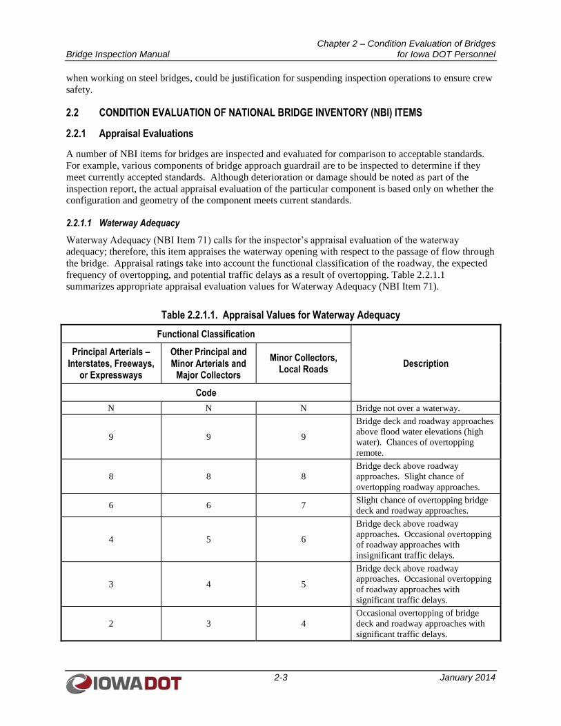
Chapter 2 – Condition Evaluation of Bridges Bridge Inspection Manual for Iowa DOT Personnel
2-3 January 2014
when working on steel bridges, could be justification for suspending inspection operations to ensure crew
safety.
2.2 CONDITION EVALUATION OF NATIONAL BRIDGE INVENTORY (NBI) ITEMS
2.2.1 Appraisal Evaluations
A number of NBI items for bridges are inspected and evaluated for comparison to acceptable standards.
For example, various components of bridge approach guardrail are to be inspected to determine if they
meet currently accepted standards. Although deterioration or damage should be noted as part of the
inspection report, the actual appraisal evaluation of the particular component is based only on whether the
configuration and geometry of the component meets current standards.
2.2.1.1 Waterway Adequacy
Waterway Adequacy (NBI Item 71) calls for the inspector’s appraisal evaluation of the waterway
adequacy; therefore, this item appraises the waterway opening with respect to the passage of flow through
the bridge. Appraisal ratings take into account the functional classification of the roadway, the expected
frequency of overtopping, and potential traffic delays as a result of overtopping. Table 2.2.1.1
summarizes appropriate appraisal evaluation values for Waterway Adequacy (NBI Item 71).
Table 2.2.1.1. Appraisal Values for Waterway Adequacy
Functional Classification
Description Principal Arterials –
Interstates, Freeways, or Expressways
Other Principal and Minor Arterials and
Major Collectors
Minor Collectors, Local Roads
Code
N N N Bridge not over a waterway.
9 9 9
Bridge deck and roadway approaches
above flood water elevations (high
water). Chances of overtopping
remote.
8 8 8
Bridge deck above roadway
approaches. Slight chance of
overtopping roadway approaches.
6 6 7 Slight chance of overtopping bridge
deck and roadway approaches.
4 5 6
Bridge deck above roadway
approaches. Occasional overtopping
of roadway approaches with
insignificant traffic delays.
3 4 5
Bridge deck above roadway
approaches. Occasional overtopping
of roadway approaches with
significant traffic delays.
2 3 4
Occasional overtopping of bridge
deck and roadway approaches with
significant traffic delays.
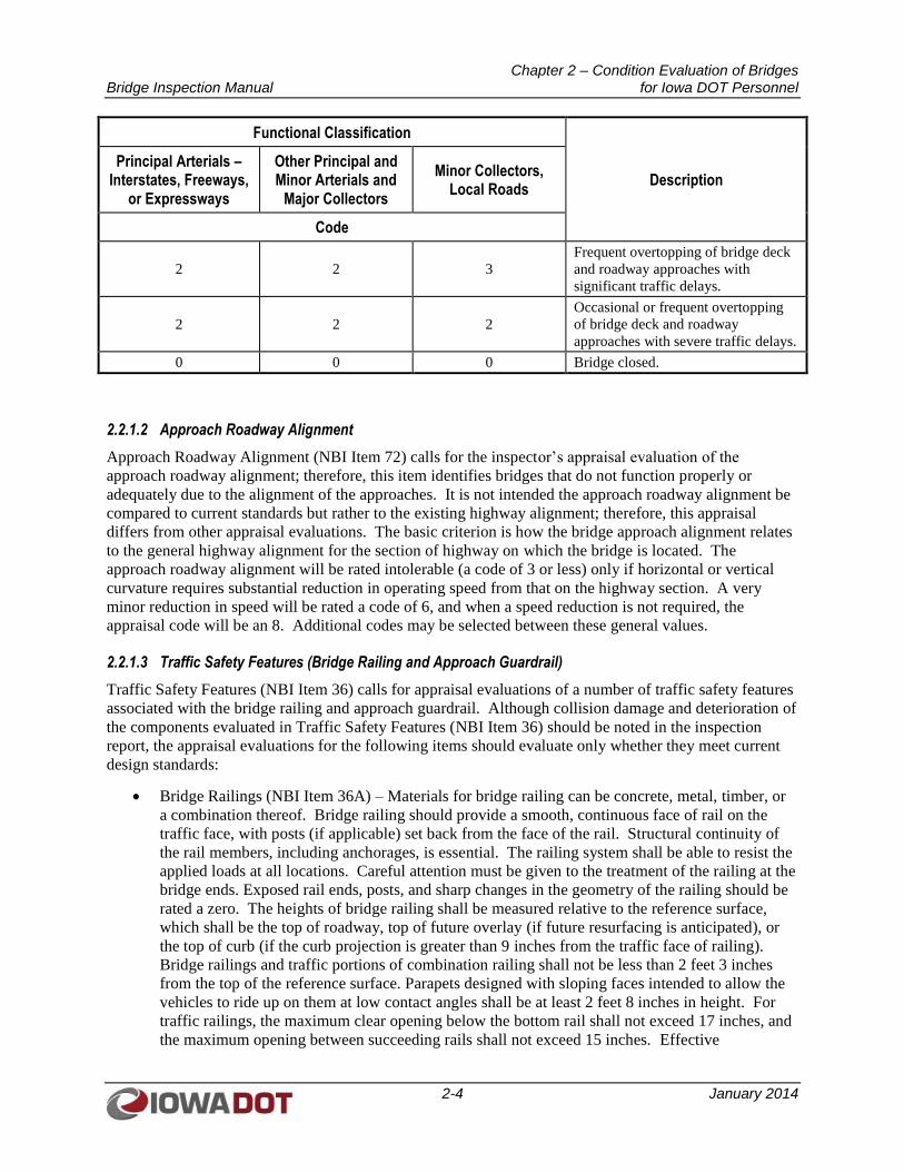
Chapter 2 – Condition Evaluation of Bridges Bridge Inspection Manual for Iowa DOT Personnel
2-4 January 2014
Functional Classification
Description Principal Arterials –
Interstates, Freeways, or Expressways
Other Principal and Minor Arterials and
Major Collectors
Minor Collectors, Local Roads
Code
2 2 3
Frequent overtopping of bridge deck
and roadway approaches with
significant traffic delays.
2 2 2
Occasional or frequent overtopping
of bridge deck and roadway
approaches with severe traffic delays.
0 0 0 Bridge closed.
2.2.1.2 Approach Roadway Alignment
Approach Roadway Alignment (NBI Item 72) calls for the inspector’s appraisal evaluation of the
approach roadway alignment; therefore, this item identifies bridges that do not function properly or
adequately due to the alignment of the approaches. It is not intended the approach roadway alignment be
compared to current standards but rather to the existing highway alignment; therefore, this appraisal
differs from other appraisal evaluations. The basic criterion is how the bridge approach alignment relates
to the general highway alignment for the section of highway on which the bridge is located. The
approach roadway alignment will be rated intolerable (a code of 3 or less) only if horizontal or vertical
curvature requires substantial reduction in operating speed from that on the highway section. A very
minor reduction in speed will be rated a code of 6, and when a speed reduction is not required, the
appraisal code will be an 8. Additional codes may be selected between these general values.
2.2.1.3 Traffic Safety Features (Bridge Railing and Approach Guardrail)
Traffic Safety Features (NBI Item 36) calls for appraisal evaluations of a number of traffic safety features
associated with the bridge railing and approach guardrail. Although collision damage and deterioration of
the components evaluated in Traffic Safety Features (NBI Item 36) should be noted in the inspection
report, the appraisal evaluations for the following items should evaluate only whether they meet current
design standards:
Bridge Railings (NBI Item 36A) – Materials for bridge railing can be concrete, metal, timber, or
a combination thereof. Bridge railing should provide a smooth, continuous face of rail on the
traffic face, with posts (if applicable) set back from the face of the rail. Structural continuity of
the rail members, including anchorages, is essential. The railing system shall be able to resist the
applied loads at all locations. Careful attention must be given to the treatment of the railing at the
bridge ends. Exposed rail ends, posts, and sharp changes in the geometry of the railing should be
rated a zero. The heights of bridge railing shall be measured relative to the reference surface,
which shall be the top of roadway, top of future overlay (if future resurfacing is anticipated), or
the top of curb (if the curb projection is greater than 9 inches from the traffic face of railing).
Bridge railings and traffic portions of combination railing shall not be less than 2 feet 3 inches
from the top of the reference surface. Parapets designed with sloping faces intended to allow the
vehicles to ride up on them at low contact angles shall be at least 2 feet 8 inches in height. For
traffic railings, the maximum clear opening below the bottom rail shall not exceed 17 inches, and
the maximum opening between succeeding rails shall not exceed 15 inches. Effective
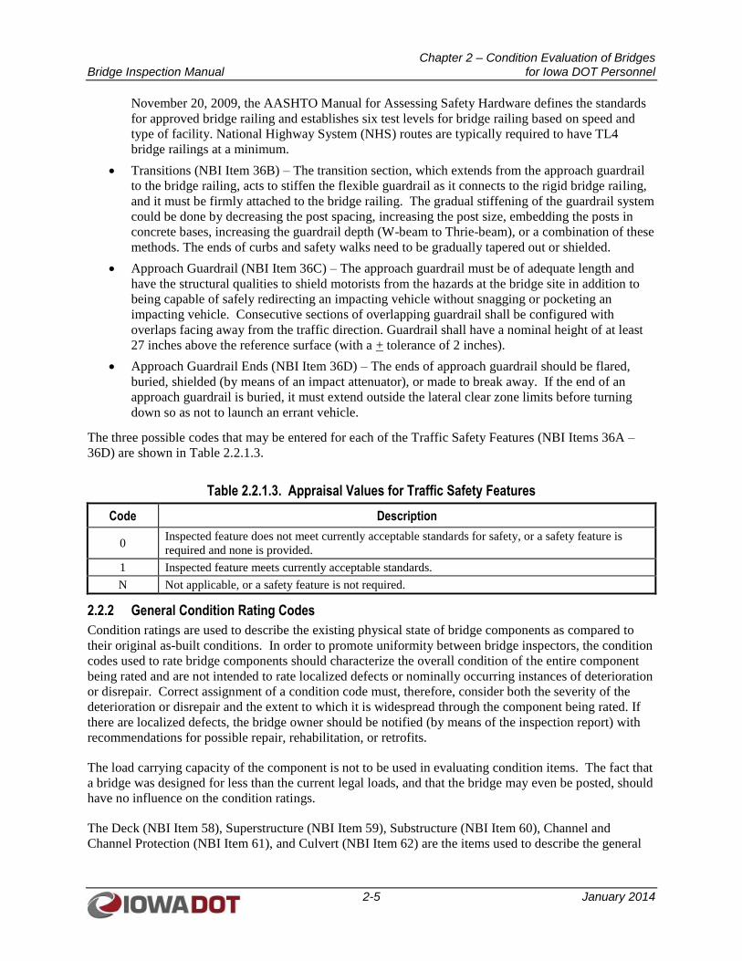
Chapter 2 – Condition Evaluation of Bridges Bridge Inspection Manual for Iowa DOT Personnel
2-5 January 2014
November 20, 2009, the AASHTO Manual for Assessing Safety Hardware defines the standards
for approved bridge railing and establishes six test levels for bridge railing based on speed and
type of facility. National Highway System (NHS) routes are typically required to have TL4
bridge railings at a minimum.
Transitions (NBI Item 36B) – The transition section, which extends from the approach guardrail
to the bridge railing, acts to stiffen the flexible guardrail as it connects to the rigid bridge railing,
and it must be firmly attached to the bridge railing. The gradual stiffening of the guardrail system
could be done by decreasing the post spacing, increasing the post size, embedding the posts in
concrete bases, increasing the guardrail depth (W-beam to Thrie-beam), or a combination of these
methods. The ends of curbs and safety walks need to be gradually tapered out or shielded.
Approach Guardrail (NBI Item 36C) – The approach guardrail must be of adequate length and
have the structural qualities to shield motorists from the hazards at the bridge site in addition to
being capable of safely redirecting an impacting vehicle without snagging or pocketing an
impacting vehicle. Consecutive sections of overlapping guardrail shall be configured with
overlaps facing away from the traffic direction. Guardrail shall have a nominal height of at least
27 inches above the reference surface (with a + tolerance of 2 inches).
Approach Guardrail Ends (NBI Item 36D) – The ends of approach guardrail should be flared,
buried, shielded (by means of an impact attenuator), or made to break away. If the end of an
approach guardrail is buried, it must extend outside the lateral clear zone limits before turning
down so as not to launch an errant vehicle.
The three possible codes that may be entered for each of the Traffic Safety Features (NBI Items 36A –
36D) are shown in Table 2.2.1.3.
Table 2.2.1.3. Appraisal Values for Traffic Safety Features
Code Description
0 Inspected feature does not meet currently acceptable standards for safety, or a safety feature is
required and none is provided.
1 Inspected feature meets currently acceptable standards.
N Not applicable, or a safety feature is not required.
2.2.2 General Condition Rating Codes
Condition ratings are used to describe the existing physical state of bridge components as compared to
their original as-built conditions. In order to promote uniformity between bridge inspectors, the condition
codes used to rate bridge components should characterize the overall condition of the entire component
being rated and are not intended to rate localized defects or nominally occurring instances of deterioration
or disrepair. Correct assignment of a condition code must, therefore, consider both the severity of the
deterioration or disrepair and the extent to which it is widespread through the component being rated. If
there are localized defects, the bridge owner should be notified (by means of the inspection report) with
recommendations for possible repair, rehabilitation, or retrofits.
The load carrying capacity of the component is not to be used in evaluating condition items. The fact that
a bridge was designed for less than the current legal loads, and that the bridge may even be posted, should
have no influence on the condition ratings.
The Deck (NBI Item 58), Superstructure (NBI Item 59), Substructure (NBI Item 60), Channel and
Channel Protection (NBI Item 61), and Culvert (NBI Item 62) are the items used to describe the general
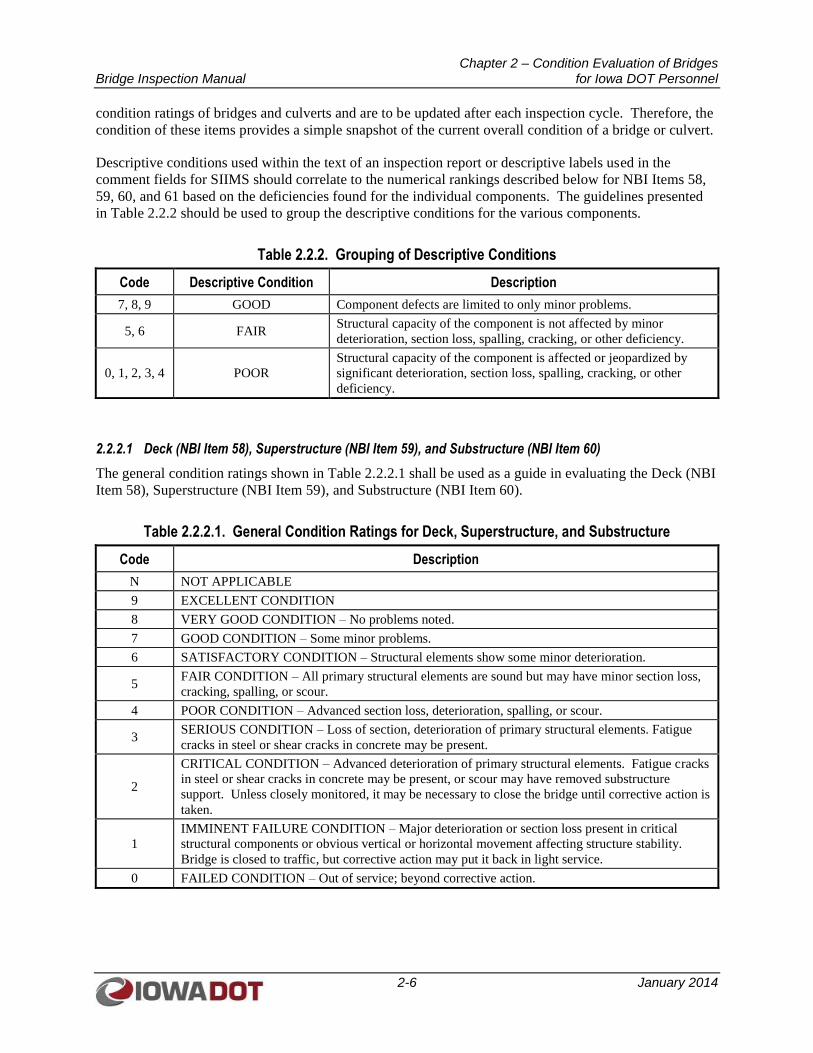
Chapter 2 – Condition Evaluation of Bridges Bridge Inspection Manual for Iowa DOT Personnel
2-6 January 2014
condition ratings of bridges and culverts and are to be updated after each inspection cycle. Therefore, the
condition of these items provides a simple snapshot of the current overall condition of a bridge or culvert.
Descriptive conditions used within the text of an inspection report or descriptive labels used in the
comment fields for SIIMS should correlate to the numerical rankings described below for NBI Items 58,
59, 60, and 61 based on the deficiencies found for the individual components. The guidelines presented
in Table 2.2.2 should be used to group the descriptive conditions for the various components.
Table 2.2.2. Grouping of Descriptive Conditions
Code Descriptive Condition Description
7, 8, 9 GOOD Component defects are limited to only minor problems.
5, 6 FAIR Structural capacity of the component is not affected by minor
deterioration, section loss, spalling, cracking, or other deficiency.
0, 1, 2, 3, 4 POOR
Structural capacity of the component is affected or jeopardized by
significant deterioration, section loss, spalling, cracking, or other
deficiency.
2.2.2.1 Deck (NBI Item 58), Superstructure (NBI Item 59), and Substructure (NBI Item 60)
The general condition ratings shown in Table 2.2.2.1 shall be used as a guide in evaluating the Deck (NBI
Item 58), Superstructure (NBI Item 59), and Substructure (NBI Item 60).
Table 2.2.2.1. General Condition Ratings for Deck, Superstructure, and Substructure
Code Description
N NOT APPLICABLE
9 EXCELLENT CONDITION
8 VERY GOOD CONDITION – No problems noted.
7 GOOD CONDITION – Some minor problems.
6 SATISFACTORY CONDITION – Structural elements show some minor deterioration.
5 FAIR CONDITION – All primary structural elements are sound but may have minor section loss,
cracking, spalling, or scour.
4 POOR CONDITION – Advanced section loss, deterioration, spalling, or scour.
3 SERIOUS CONDITION – Loss of section, deterioration of primary structural elements. Fatigue
cracks in steel or shear cracks in concrete may be present.
2
CRITICAL CONDITION – Advanced deterioration of primary structural elements. Fatigue cracks
in steel or shear cracks in concrete may be present, or scour may have removed substructure
support. Unless closely monitored, it may be necessary to close the bridge until corrective action is
taken.
1
IMMINENT FAILURE CONDITION – Major deterioration or section loss present in critical
structural components or obvious vertical or horizontal movement affecting structure stability.
Bridge is closed to traffic, but corrective action may put it back in light service.
0 FAILED CONDITION – Out of service; beyond corrective action.

Chapter 2 – Condition Evaluation of Bridges Bridge Inspection Manual for Iowa DOT Personnel
2-7 January 2014
2.2.2.2 Channel and Channel Protection (NBI Item 61)
The general condition ratings shown in Table 2.2.2.2 shall be used as a guide in evaluating Channel and
Channel Protection (NBI Item 61).
Table 2.2.2.2. General Condition Ratings for Channel and Channel Protection
Code Description
N Not applicable. Use when bridge is not over a waterway (channel).
9 There are no noticeable or noteworthy deficiencies that affect the condition of the channel.
8 Banks are protected or well vegetated. River control devices such as spur dikes and embankment
protection are not required or are in a stable condition.
7 Bank protection is in need of minor repairs. River control devices and embankment protection
have a little minor damage. Banks and/or channel have minor amounts of drift.
6
Bank is beginning to slump. River control devices and embankment protection have widespread
minor damage. There is minor streambed movement evident. Debris is restricting the channel
slightly.
5 Bank protection is being eroded. River control devices and/or embankment have major damage.
Trees and brush restrict the channel.
4 Bank and embankment protection is severely undermined. River control devices have severe
damage. Large deposits of debris are in the channel.
3
Bank protection has failed. River control devices have been destroyed. Streambed aggradation,
degradation, or lateral movement has changed the channel to now threaten the bridge and/or
approach roadway.
2 The channel has changed to the extent the bridge is near a state of collapse.
1 Bridge is closed because of channel failure. Corrective action may put it back in light service.
0 Bridge is closed because of channel failure. Replacement is necessary.
2.2.2.3 Culvert (NBI Item 62)
The general condition ratings shown in Table 2.2.2.3 shall be used as a guide in evaluating a Culvert (NBI
Item 62).
Table 2.2.2.3. General Condition Ratings for Culvert
Code Description
N Not applicable. Used if structure is not a culvert.
9 No deficiencies.
8 No noticeable or noteworthy deficiencies that affect the condition of the culvert. Insignificant
scrape marks caused by drift.
7
Shrinkage cracks, light scaling, and insignificant spalling that does not expose reinforcing steel.
Insignificant damage caused by drift with no misalignment and not requiring corrective action.
Some minor scouring has occurred near curtain walls, wingwalls, or pipes. Metal culverts have a
smooth symmetrical curvature with superficial corrosion and no pitting.
6
Deterioration or initial disintegration, minor chloride contamination, cracking with some leaching,
or spalls on concrete or masonry walls and slabs. Local minor scouring at curtain walls,
wingwalls, or pipes. Metal culverts have a smooth curvature, non-symmetrical shape, significant
corrosion, or moderate pitting.
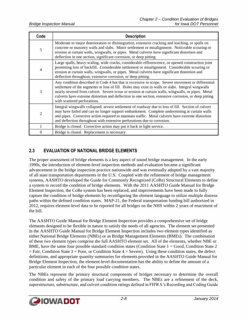
Chapter 2 – Condition Evaluation of Bridges Bridge Inspection Manual for Iowa DOT Personnel
2-8 January 2014
Code Description
5
Moderate to major deterioration or disintegration, extensive cracking and leaching, or spalls on
concrete or masonry walls and slabs. Minor settlement or misalignment. Noticeable scouring or
erosion at curtain walls, wingwalls, or pipes. Metal culverts have significant distortion and
deflection in one section, significant corrosion, or deep pitting.
4
Large spalls, heavy scaling, wide cracks, considerable efflorescence, or opened construction joint
permitting loss of backfill. Considerable settlement or misalignment. Considerable scouring or
erosion at curtain walls, wingwalls, or pipes. Metal culverts have significant distortion and
deflection throughout, extensive corrosion, or deep pitting.
3
Any condition described in Code 4 but that is excessive in scope. Severe movement or differential
settlement of the segments or loss of fill. Holes may exist in walls or slabs. Integral wingwalls
nearly severed from culvert. Severe scour or erosion at curtain walls, wingwalls, or pipes. Metal
culverts have extreme distortion and deflection in one section, extensive corrosion, or deep pitting
with scattered perforations.
2
Integral wingwalls collapsed; severe settlement of roadway due to loss of fill. Section of culvert
may have failed and can no longer support embankment. Complete undermining at curtain walls
and pipes. Corrective action required to maintain traffic. Metal culverts have extreme distortion
and deflection throughout with extensive perforations due to corrosion.
1 Bridge is closed. Corrective action may put it back in light service.
0 Bridge is closed. Replacement is necessary.
2.3 EVALUATION OF NATIONAL BRIDGE ELEMENTS
The proper assessment of bridge elements is a key aspect of sound bridge management. In the early
1990s, the introduction of element-level inspection methods and evaluation became a significant
advancement in the bridge inspection practice nationwide and was eventually adopted by a vast majority
of all state transportation departments in the U.S. Coupled with the refinement of bridge management
systems, AASHTO developed the Guide for Commonly Recognized (CoRe) Structural Elements to define
a system to record the condition of bridge elements. With the 2011 AASHTO Guide Manual for Bridge
Element Inspection, the CoRe system has been replaced, and improvements have been made to fully
capture the condition of bridge elements by reconfiguring the element language to utilize multiple distress
paths within the defined condition states. MAP-21, the Federal transportation funding bill authorized in
2012, requires element-level data to be reported for all bridges on the NHS within 2 years of enactment of
the bill.
The AASHTO Guide Manual for Bridge Element Inspection provides a comprehensive set of bridge
elements designed to be flexible in nature to satisfy the needs of all agencies. The element set presented
in the AASHTO Guide Manual for Bridge Element Inspection includes two element types identified as
either National Bridge Elements (NBEs) or as Bridge Management Elements (BMEs). The combination
of these two element types comprise the full AASHTO element set. All of the elements, whether NBE or
BME, have the same four possible standard condition states (Condition State 1 = Good, Condition State 2
= Fair, Condition State 3 = Poor, or Condition State 4 = Severe). Using these condition states, the defect
definitions, and appropriate quantity summaries for elements provided in the AASHTO Guide Manual for
Bridge Element Inspection, the element-level documentation has the ability to define the amount of a
particular element in each of the four possible condition states.
The NBEs represent the primary structural components of bridges necessary to determine the overall
condition and safety of the primary load carrying members. The NBEs are a refinement of the deck,
superstructure, substructure, and culvert condition ratings defined in FHWA’s Recording and Coding Guide
Chapter 2 – Condition Evaluation of Bridges Bridge Inspection Manual for Iowa DOT Personnel
2-9 January 2014
for the Structure Inventory and Appraisal of the Nation’s Bridges. Additional elements included in this
section are bridge rail and bearings. The NBEs are designed to remain consistent from agency to agency in
order to facilitate the capture of bridge element condition at the national level. Descriptions of the NBE can
be found in the NBE Manual prepared by OBS.
2.4 GENERAL INSPECTION PROCEDURES
2.4.1 Deck Inspection
2.4.1.1 Concrete Decks
Concrete decks should be inspected for cracking, spalling, potholes, efflorescence, leaching,
delamination, exposed reinforcing steel, and full or partial depth failures. Narrow cracks (1/16 inch and
wider) in the top and bottom surfaces should be shown on sketches. The path of a crack and its location
should be sketched to scale as is practical. Photographs of individual cracks are generally not needed, but
if included, they should include a scale or a common item like a pencil for reference.
Hollow areas should be sketched to scale and dimensioned as is practical. Photographs of hollow areas
are generally not needed for the report. The method of sounding used (that is, random hammer tap, chain
drag, or rotary percussion sounding) should be documented. Spalling, scaling, and patches should be
sketched to scale as is practical. Sketches need to be drawn to scale so Bridge Element quantities can be
tabulated, checked, and reproduced by another inspector. If an inspector reports a deck is 40 percent
hollow, then another inspector should be able to look at the inspector’s sketch and calculate a similar
quantity of hollow area.
If the concrete deck consists of partial- or full-depth pretensioned panels, it should also be inspected for
failures at the pretension and post-tension anchor zones, failures of grout-fill joints between panels, and
failures of bearing edges along supporting beams.
Inspection teams must prepare a cross section sketch and measure bridge rail heights for all bridges. The
team’s sketch must be an accurate cross section showing the number of beams (not applicable for slab
bridge); the values recorded for NBI Item 50, Curb or Sidewalk Width, NBI Item 51, Bridge Roadway
Width Curb-to-Curb, and NBI Item 52, Deck Width Out-to-Out; the bridge rail heights; any overlays;
overlay material; and dates of any changes, such as overlays, widening, or retrofit rails.
Curb and barrier rail conditions should be photographed; sketches are generally not needed for curb and
barrier rail deterioration. The overall condition of bridge railings should be examined, including the
alignment and the height of the rails. Sighting down the line of a bridge rail can be a quick way to
identify obvious problems and may also highlight other structural problems, such as substructure
settlement. The height of the bridge rail, especially for bridge decks that have been overlaid, should be
checked to determine if it meets current design standards. Any damage due to traffic impact should be
noted as well as any rotation of the bridge rail. Broken steel or timber railing elements should be noted as
well as structural defects that may affect the intended function of the bridge rail, which is to redirect
errant vehicles. For precast concrete bridge rails, any apparent anchorage failures or separation from the
bridge deck should be noted.
2.4.1.2 Decks with Concrete Overlays
Iowa DOT uses two types of overlay material:
Low Slump concrete (Class O PCC)
High Performance Concrete (Class HPC-O PCC)
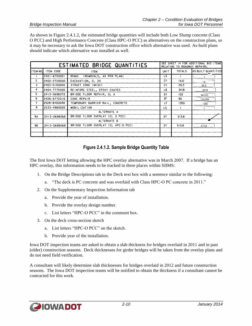
Chapter 2 – Condition Evaluation of Bridges Bridge Inspection Manual for Iowa DOT Personnel
2-10 January 2014
As shown in Figure 2.4.1.2, the estimated bridge quantities will include both Low Slump concrete (Class
O PCC) and High Performance Concrete (Class HPC-O PCC) as alternatives on the construction plans, so
it may be necessary to ask the Iowa DOT construction office which alternative was used. As-built plans
should indicate which alternative was installed as well.
Figure 2.4.1.2. Sample Bridge Quantity Table
The first Iowa DOT letting allowing the HPC overlay alternative was in March 2007. If a bridge has an
HPC overlay, this information needs to be tracked in three places within SIIMS:
1. On the Bridge Descriptions tab in the Deck text box with a sentence similar to the following:
a. “The deck is PC concrete and was overlaid with Class HPC-O PC concrete in 2011.”
2. On the Supplementary Inspection Information tab
a. Provide the year of installation.
b. Provide the overlay design number.
c. List letters “HPC-O PCC” in the comment box.
3. On the deck cross-section sketch
a. List letters “HPC-O PCC” on the sketch.
b. Provide year of the installation.
Iowa DOT inspection teams are asked to obtain a slab thickness for bridges overlaid in 2011 and in past
(older) construction seasons. Deck thicknesses for girder bridges will be taken from the overlay plans and
do not need field verification.
A consultant will likely determine slab thicknesses for bridges overlaid in 2012 and future construction
seasons. The Iowa DOT inspection teams will be notified to obtain the thickness if a consultant cannot be
contracted for this work.
Chapter 2 – Condition Evaluation of Bridges Bridge Inspection Manual for Iowa DOT Personnel
2-11 January 2014
2.4.1.3 Sounding Concrete Decks A sounding is performed by use of one of several methods. Chain drag, hammer tapping, or steel
rod/pipe tapping are the three typical methods used to sound a deck for delaminations (hollow areas).
These methods can be used separately or together to gather the data needed to make a determination of
the area of the deck that is delaminated. When using a hammer or steel rod/pipe, taps should be
approximately 2 feet apart and should cover the entire area of the deck. The chain drag will generally be
used in a sweeping motion with passes that are approximately 2 feet apart and cover the entire deck area.
Areas around deck cracks 1/16 inch or wider should be given closer attention due to the higher probability
of a delaminated area developing. Discolored areas of the deck should also be sounded more vigorously.
When a delaminated area is found, the extents of the delamination should be documented on a sketch.
The total area of delamination on a deck should be calculated and included in the inspection notes.
2.4.1.3.1 Sounding Concrete Decks with Concrete Overlays
The following criteria shall be used to determine whether a concrete bridge deck with a concrete overlay
requires sounding:
1. A deck with a new overlay does not require sounding until the overlay is 10 years old unless
extensive cracking or significant spalling occurs, thus indicating a problem with the overlay.
2. The frequency of sounding, after the initial sounding, will be based on the findings of the initial
sounding. Office of Bridges and Structures (OBS) engineering staff will determine the
recommended frequency.
3. A deck that has been epoxy injected or had patching by contract shall be sounded on the third
inspection after this work was completed. The frequency of future soundings will be determined
by OBS engineering staff.
4. If a deck has become hollow over 40 percent of the deck area, no future soundings are required. If
the deck is epoxy injected, patched by contract, or re-overlaid, sounding should begin again on
the third inspection after this work is completed.
Spalling, scaling, and patching of the overlay should be documented with sketches and photographs at all
inspections. Photographs of typical or the most severe deterioration are recommended.
2.4.1.3.2 Sounding Concrete Decks without Overlays
Concrete decks without an overlay shall initially be sounded when the deck is 20 years old. A sounding
may be required sooner if evidence of extensive cracking is found or spalling is occurring. After the initial
sounding, OBS engineering staff will determine the frequency of future soundings. Spalling, scaling, and
patching should be documented at all inspections with sketches. Photographs of typical or the most severe
deterioration are recommended.
2.4.1.4 Steel Decks
Steel grid decks should be inspected for corrosion, broken welds, broken or damaged bearing bars or
cross bars, and section loss. Concrete-filled steel grid decks should be checked for spalling or scaling of
the concrete infill, water ponding, corrosion of steel grid members, and leakage on the underside of the
deck. Corrugated metal decks should be checked for evidence of rust-through and open cracks in the
wearing surface. Orthotropic steel decks also need to be checked for evidence of rust-through; cracks in
the steel plate, web elements, or welded connections; and debonding of the overlay.
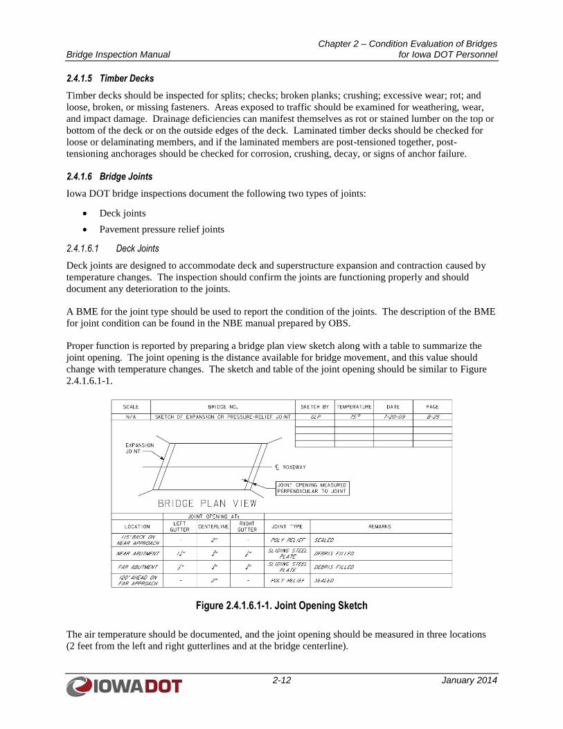
Chapter 2 – Condition Evaluation of Bridges Bridge Inspection Manual for Iowa DOT Personnel
2-12 January 2014
2.4.1.5 Timber Decks
Timber decks should be inspected for splits; checks; broken planks; crushing; excessive wear; rot; and
loose, broken, or missing fasteners. Areas exposed to traffic should be examined for weathering, wear,
and impact damage. Drainage deficiencies can manifest themselves as rot or stained lumber on the top or
bottom of the deck or on the outside edges of the deck. Laminated timber decks should be checked for
loose or delaminating members, and if the laminated members are post-tensioned together, post-
tensioning anchorages should be checked for corrosion, crushing, decay, or signs of anchor failure.
2.4.1.6 Bridge Joints
Iowa DOT bridge inspections document the following two types of joints:
Deck joints
Pavement pressure relief joints
2.4.1.6.1 Deck Joints
Deck joints are designed to accommodate deck and superstructure expansion and contraction caused by
temperature changes. The inspection should confirm the joints are functioning properly and should
document any deterioration to the joints.
A BME for the joint type should be used to report the condition of the joints. The description of the BME
for joint condition can be found in the NBE manual prepared by OBS.
Proper function is reported by preparing a bridge plan view sketch along with a table to summarize the
joint opening. The joint opening is the distance available for bridge movement, and this value should
change with temperature changes. The sketch and table of the joint opening should be similar to Figure
2.4.1.6.1-1.
Figure 2.4.1.6.1-1. Joint Opening Sketch
The air temperature should be documented, and the joint opening should be measured in three locations
(2 feet from the left and right gutterlines and at the bridge centerline).
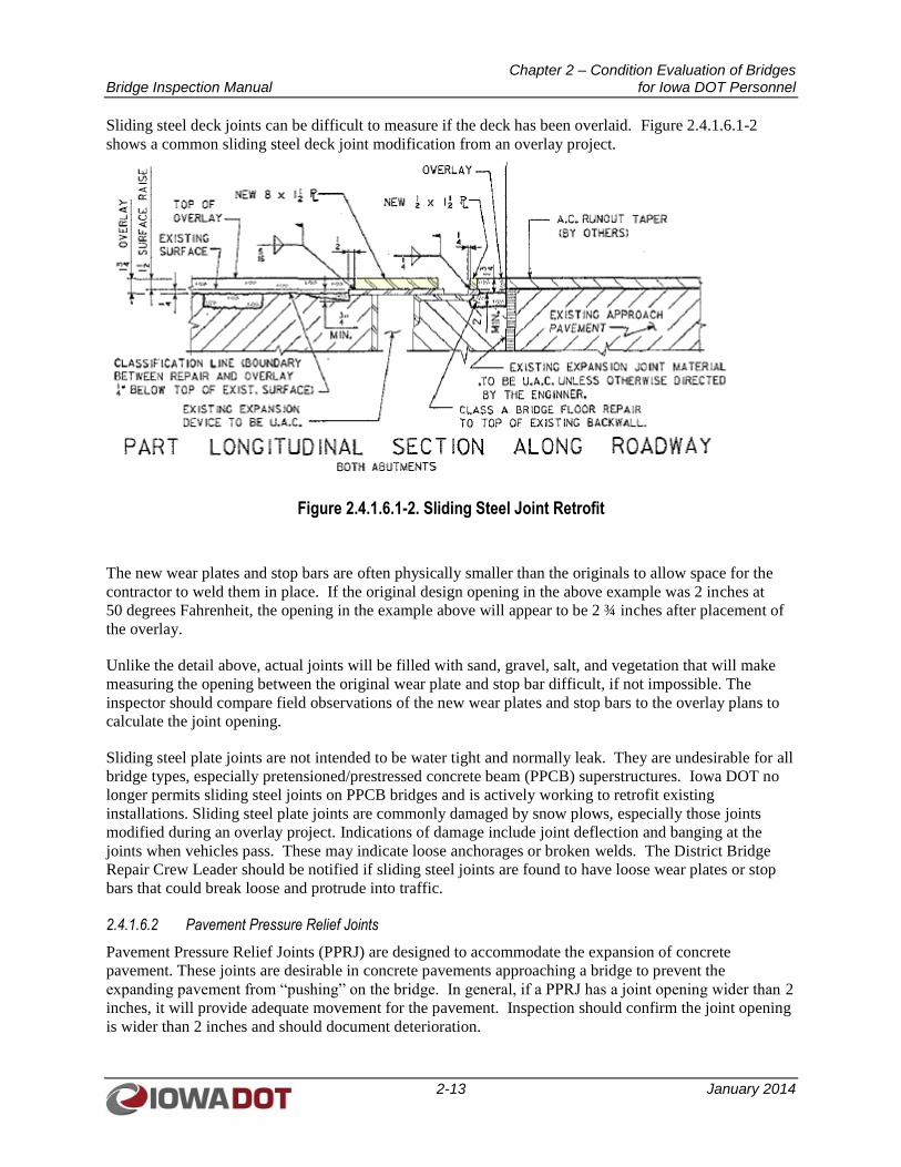
Chapter 2 – Condition Evaluation of Bridges Bridge Inspection Manual for Iowa DOT Personnel
2-13 January 2014
Sliding steel deck joints can be difficult to measure if the deck has been overlaid. Figure 2.4.1.6.1-2
shows a common sliding steel deck joint modification from an overlay project.
Figure 2.4.1.6.1-2. Sliding Steel Joint Retrofit
The new wear plates and stop bars are often physically smaller than the originals to allow space for the
contractor to weld them in place. If the original design opening in the above example was 2 inches at
50 degrees Fahrenheit, the opening in the example above will appear to be 2 ¾ inches after placement of
the overlay.
Unlike the detail above, actual joints will be filled with sand, gravel, salt, and vegetation that will make
measuring the opening between the original wear plate and stop bar difficult, if not impossible. The
inspector should compare field observations of the new wear plates and stop bars to the overlay plans to
calculate the joint opening.
Sliding steel plate joints are not intended to be water tight and normally leak. They are undesirable for all
bridge types, especially pretensioned/prestressed concrete beam (PPCB) superstructures. Iowa DOT no
longer permits sliding steel joints on PPCB bridges and is actively working to retrofit existing
installations. Sliding steel plate joints are commonly damaged by snow plows, especially those joints
modified during an overlay project. Indications of damage include joint deflection and banging at the
joints when vehicles pass. These may indicate loose anchorages or broken welds. The District Bridge
Repair Crew Leader should be notified if sliding steel joints are found to have loose wear plates or stop
bars that could break loose and protrude into traffic.
2.4.1.6.2 Pavement Pressure Relief Joints
Pavement Pressure Relief Joints (PPRJ) are designed to accommodate the expansion of concrete
pavement. These joints are desirable in concrete pavements approaching a bridge to prevent the
expanding pavement from “pushing” on the bridge. In general, if a PPRJ has a joint opening wider than 2
inches, it will provide adequate movement for the pavement. Inspection should confirm the joint opening
is wider than 2 inches and should document deterioration.
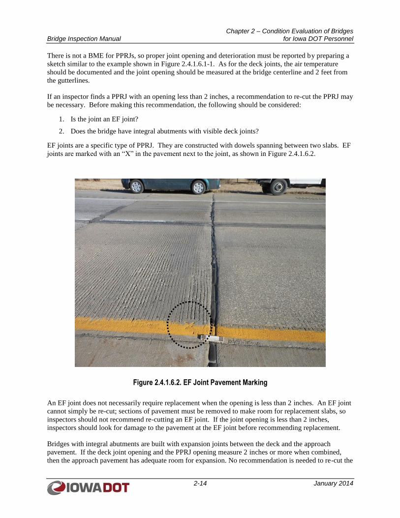
Chapter 2 – Condition Evaluation of Bridges Bridge Inspection Manual for Iowa DOT Personnel
2-14 January 2014
There is not a BME for PPRJs, so proper joint opening and deterioration must be reported by preparing a
sketch similar to the example shown in Figure 2.4.1.6.1-1. As for the deck joints, the air temperature
should be documented and the joint opening should be measured at the bridge centerline and 2 feet from
the gutterlines.
If an inspector finds a PPRJ with an opening less than 2 inches, a recommendation to re-cut the PPRJ may
be necessary. Before making this recommendation, the following should be considered:
1. Is the joint an EF joint?
2. Does the bridge have integral abutments with visible deck joints?
EF joints are a specific type of PPRJ. They are constructed with dowels spanning between two slabs. EF
joints are marked with an “X” in the pavement next to the joint, as shown in Figure 2.4.1.6.2.
Figure 2.4.1.6.2. EF Joint Pavement Marking
An EF joint does not necessarily require replacement when the opening is less than 2 inches. An EF joint
cannot simply be re-cut; sections of pavement must be removed to make room for replacement slabs, so
inspectors should not recommend re-cutting an EF joint. If the joint opening is less than 2 inches,
inspectors should look for damage to the pavement at the EF joint before recommending replacement.
Bridges with integral abutments are built with expansion joints between the deck and the approach
pavement. If the deck joint opening and the PPRJ opening measure 2 inches or more when combined,
then the approach pavement has adequate room for expansion. No recommendation is needed to re-cut the
Chapter 2 – Condition Evaluation of Bridges Bridge Inspection Manual for Iowa DOT Personnel
2-15 January 2014
PPRJ in this situation. However, if the deck joint at an integral abutment has been filled with hot-mix
asphalt (HMA) during an HMA overlay of the approach, then the joint is no longer considered an
expansion joint, and the PPRJ alone must measure 2 inches or more to have adequate room for expansion.
PPRJs are generally located 60 to 75 feet from the ends of a deck. If there is not a PPRJ within 100 feet
of the end of a deck and evidence of a PPRJ is not visible when standing 100 feet from the end of a deck,
a recommendation to re-cut the PPRJ may be necessary.
When PPRJs are visible, their distance from the deck must be recorded because it is common for PPRJs to
be covered when a roadway is overlaid with an asphalt leveling course. If a PPRJ is covered with HMA
and is no longer visible, the joint is still considered adequate if the joint opening was previously wider
than 2 inches. Inspectors should report when the joint was covered in the joint sketch and should monitor
the location for raveling asphalt.
A PPRJ that does not extend through the shoulder is considered adequate. This situation should be noted
in the joint sketch, but it is not a condition that needs to be addressed.
2.4.1.7 Coding NBI Item 58 (Deck Condition Rating)
The overall condition of a bridge deck should be coded as shown in Table 2.2.2.1 for NBI Item 58, Deck.
For culverts or other structures without a deck, such as a corrugated metal structural plate arch bridge,
code N (not applicable) should be used for NBI Item 58. Decks integral with the superstructure, such as
for a cast-in-place box girder bridge or a concrete T-beam bridge, shall be rated for the deck only, and the
superstructure condition of the integral deck-type bridge should not influence the deck rating.
The condition of supplemental wearing surfaces, joints or expansion devices, curbs, sidewalks, parapets,
railings, and drainage scuppers should not be considered in the overall deck evaluation. However, their
condition should be noted in the inspection report.
An NBI rating of 5 or less requires a comment on the reasons for this condition rating. A condition rating
of 5 begins to affect the Sufficiency Rating negatively.
2.4.1.8 National Bridge Elements
The description of the NBE for deck condition can be found in the NBE manual prepared by OBS.
The NBE should include comments and inspection notes under each element as necessary. Comments
and inspection notes should be included when there is a portion of the element in condition state 3 or 4.
2.4.1.9 Additional SIIMS Deck Data
The Deck section in SIIMS has several items that are not part of the NBI or NBE data. These items are to
be updated as necessary at each Routine or In-depth Inspection.
2.4.1.9.1 Deck Drains
The deck drain type is to be chosen from the drop-down menu in SIIMS. The drop-down options include
the following types of deck drains:
Unextended
Empties into Pipe
Steel Extension
Chapter 2 – Condition Evaluation of Bridges Bridge Inspection Manual for Iowa DOT Personnel
2-16 January 2014
Plastic Extension
Miscellaneous
None
The condition of the deck drain should be determined as Good, Fair, or Poor. If no drain extension exists,
N/A should be selected from the condition drop-down menu. If a drain is in poor condition, a comment
should be included that describes why it is considered to be in poor condition.
2.4.1.9.2 Curb Type – Left and Right
The type of curb on the bridge deck should be chosen from the drop-down menu in SIIMS for the left and
right curbs. The drop-down options include the following types of curb:
<9”
> 9”
Sidewalk
Sidewalk with Traffic Division
Curb with Retrofit Rail
Miscellaneous
None
The condition of the curb should be determined as Good, Fair, or Poor. If the curb type is “None”, N/A
should be selected from the condition drop-down menu. If a curb is in poor condition, a comment should
be included describing why it is considered to be in poor condition.
2.4.1.9.3 Cantilevered Curb
A cantilevered curb refers to a curb that overhangs the edge of the deck. The concern with this type of
curb is corrosion of the tension reinforcing along the gutter line. Figure 2.4.1.9.3 shows sample sketches
of non-cantilevered and cantilevered curbs. A barrier rail on a thin concrete deck that is supported by
steel channels or steel cantilevers is not considered a cantilevered curb.
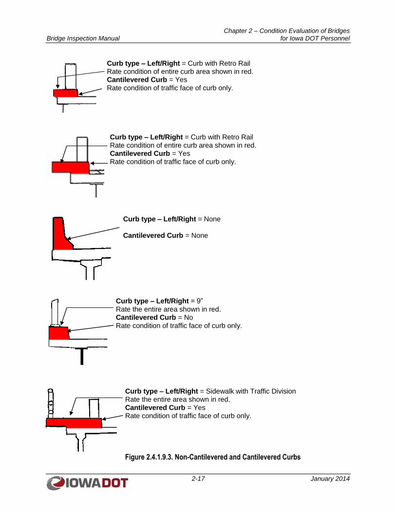
Chapter 2 – Condition Evaluation of Bridges Bridge Inspection Manual for Iowa DOT Personnel
2-17 January 2014
Curb type – Left/Right = Curb with Retro Rail Rate condition of entire curb area shown in red. Cantilevered Curb = Yes Rate condition of traffic face of curb only.
Curb type – Left/Right = Curb with Retro Rail Rate condition of entire curb area shown in red. Cantilevered Curb = Yes Rate condition of traffic face of curb only.
Curb type – Left/Right = None Cantilevered Curb = None
Curb type – Left/Right = 9” Rate the entire area shown in red. Cantilevered Curb = No Rate condition of traffic face of curb only.
Curb type – Left/Right = Sidewalk with Traffic Division Rate the entire area shown in red. Cantilevered Curb = Yes Rate condition of traffic face of curb only.
Figure 2.4.1.9.3. Non-Cantilevered and Cantilevered Curbs
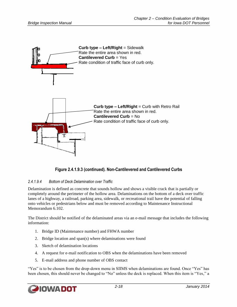
Chapter 2 – Condition Evaluation of Bridges Bridge Inspection Manual for Iowa DOT Personnel
2-18 January 2014
Curb type – Left/Right = Sidewalk Rate the entire area shown in red. Cantilevered Curb = Yes Rate condition of traffic face of curb only.
Curb type – Left/Right = Curb with Retro Rail Rate the entire area shown in red. Cantilevered Curb = No Rate condition of traffic face of curb only.
Figure 2.4.1.9.3 (continued). Non-Cantilevered and Cantilevered Curbs
2.4.1.9.4 Bottom of Deck Delamination over Traffic
Delamination is defined as concrete that sounds hollow and shows a visible crack that is partially or
completely around the perimeter of the hollow area. Delaminations on the bottom of a deck over traffic
lanes of a highway, a railroad, parking area, sidewalk, or recreational trail have the potential of falling
onto vehicles or pedestrians below and must be removed according to Maintenance Instructional
Memorandum 6.102.
The District should be notified of the delaminated areas via an e-mail message that includes the following
information:
1. Bridge ID (Maintenance number) and FHWA number
2. Bridge location and span(s) where delaminations were found
3. Sketch of delamination locations
4. A request for e-mail notification to OBS when the delaminations have been removed
5. E-mail address and phone number of OBS contact
“Yes” is to be chosen from the drop-down menu in SIIMS when delaminations are found. Once “Yes” has
been chosen, this should never be changed to “No” unless the deck is replaced. When this item is “Yes,” a
Chapter 2 – Condition Evaluation of Bridges Bridge Inspection Manual for Iowa DOT Personnel
2-19 January 2014
note should be made in the comment field after each inspection saying whether or not more loose
concrete was found.
2.4.1.9.5 Left and Right Bridge Rail
The left and right bridge rail type is included in the SIIMS data for a national research project. These
items should be updated only if the barrier rail type changes. The types available in the drop-down menu
are:
1. Metal Tube Bridge Rail
2. Safety Shape Concrete Barrier (F-shape/Jersey)
3. Timber Bridge Rail
4. Thrie Beam Bridge Rail
5. W-Beam Bridge Rail
2.4.1.9.6 Left and Right Guardrail
The guardrail installations should be inspected using the following guidelines:
1. Approach guardrails should be inspected to the limits of the end terminal. In some installations,
the approach guardrails continue for long distances past the bridge structures. In these instances,
the inspectors must use their judgment to determine where to stop the guardrail inspection. If
over half of the guardrail’s length extends past the pressure relief joint, the inspection can end at
the pressure relief joint.
2. Guardrails surrounding piers and along the toe of berms must be inspected if they are physically
attached to the substructure. Any deterioration found should be photographed and described
using the appropriate substructure Bridge Element.
3. Guardrails surrounding piers and along the toe of berms not attached to the substructure should
be given a visual inspection as occasioned during your normal movements around the structure to
accomplish your inspection. Collision damage that has damaged the rail or posts should be
photographed and described using the appropriate substructure Bridge Element.
4. Include a note on the deck tab if the approach guardrails could not be inspected due to snow cover
or high traffic volumes.
5. The inspection does not require digging down around posts to search for rot.
The guardrail descriptions should be completed by the inspection team. The August 2010 Guardrail
Identification Manual should be used to identify the end, rail, and transition types.
Guardrails over culverts should be inspected, but descriptions and ratings do not need to be entered on the
Deck tab, which is not used for culverts. Any deterioration found should be documented and described
using the appropriate culvert Bridge Element.
If the deterioration or damage appears to have been addressed or marked by the District, a
recommendation is not necessary. For example, if impact barrels or traffic cones have been placed along
a damaged rail, a recommendation is not needed.
A condition should be selected from the drop-down menus for each element of the guardrail. If the
condition is designated as “Poor,” a description of the reasons for the poor condition should be entered in
the comment field.
Chapter 2 – Condition Evaluation of Bridges Bridge Inspection Manual for Iowa DOT Personnel
2-20 January 2014
2.4.1.9.7 Approach Pavement
The three main types of approach surfacing are as follows:
1. Concrete – Full-depth concrete, even when there is an HMA overlay
2. Asphalt – Full-depth HMA with no concrete substrate
3. Gravel – Full-depth granular material
In SIIMS, the inspector should indicate which approach surfacing is present or if some other surfacing is
present. A comment describing the approach should be included.
2.4.2 Superstructure Inspection
Superstructure members should be inspected for signs of distress, which may include horizontal or
vertical displacement of components affecting structural stability, cracking, deterioration, section loss,
collision damage, or overload damage.
A discussion of how member components should be numbered and identified for the inspection report is
provided in Section 1.6.2 of this manual.
2.4.2.1 Concrete Slab
A concrete slab bridge does not contain beams or girders. The deck is the superstructure. Concrete slab
bridges contain larger reinforcing bars than a standard deck. Continuous slabs have large reinforcing bars
over the piers near the top of the deck. Transverse cracking over a pier should be documented because of
the increased potential for corrosion of the main reinforcing steel in this area.
Concrete deterioration near the abutments should be documented whether it is occurring on the top or
bottom of the deck. Severe deterioration in this area can affect the shear capacity of the concrete slab.
Repairs to this area due to deterioration are difficult. Temporary support of the deck may be required in
some cases.
Photographs and sketches of deterioration in high stress areas are required.
2.4.2.2 Reinforced Concrete Beams
A reinforced concrete beam bridge is a cast-in-place concrete structure. The beams are placed
monolithically with the deck in most cases. The deck may contain more reinforcing than a conventional
deck on a girder bridge. Deterioration of the deck can have a greater impact on the load capacity of this
type of bridge than a typical girder bridge.
Cracking of the deck or girders in high stress areas shall be documented with sketches. Signs of rust
staining should also be included in the inspection documentation with photographs and written
descriptions.
Girder deterioration shall be sketched and photographed at bearing areas.
2.4.2.3 Prestressed Concrete Beams
Prestressed concrete beam bridges are typically I-beam, bulb tee beam, channel beam, double tee beam,
or box beam structures. In all of these types of bridges, stressed strands or bars induce compressive forces
into the concrete to give the beam increased load carrying capacity. This load carrying capacity can be
compromised by concrete deterioration around these strands or bars. The most common area for concrete
Chapter 2 – Condition Evaluation of Bridges Bridge Inspection Manual for Iowa DOT Personnel
2-21 January 2014
deterioration or spalling is at the ends of the beams where salt-laden water can leak onto the beam ends
through open or leaking deck joints and contaminate the concrete, thus causing corrosion to begin in the
strand or bar. Prestressed steel is more susceptible to corrosion and will corrode faster than mild steel
reinforcing.
The second most common reason for loss of prestress capacity is due to impact loads by over-height
vehicles. Impacts can cause spalling around the strand or bars so the compressive force applied to the
concrete is lost in the impacted area. If a strand or bar is severed because of impact, this also causes a loss
in prestress force.
Cracking in the high stress areas of prestressed beams shall be documented with sketches in the inspection
report. The number and location of strands or bars exposed due to deterioration or impact damage are to
be included in the inspection report. Photographs of deterioration or damage are required.
2.4.2.4 Steel Beams and Girders
Steel beam or girder bridges are made up of two or more beam lines of I-shaped members. Inspection of
steel superstructure elements should include checking steel members for paint failure, corrosion, section
loss, evidence of fatigue or fracture, evidence of overload, collision damage, connection damage, and
possible damage from excessive heat. Inspection procedures typically include visual methods to find
defects as well as physical methods such as hammer sounding, cleaning to remove rust scale, and
measuring remaining steel thickness. Visual and physical inspection procedures should focus on high
stress zones, areas exposed to drainage run-off, areas exposed to traffic, previous repair locations,
previously noted defects, and fatigue-prone or fracture-prone details.
Properly performing paint coatings should be free of chalking, pitting, rust, or generalized rust staining.
The overall paint condition should be assessed based on the condition of the majority of the surface, not
just localized areas of rusting.
For weathering steel members, the typical oxide colors that can be expected for properly performing
weathering steel include a yellow-orange color for new steel or a purple-brown color for members in
service for many years. Weathering steel members exhibiting a black or yellow color could indicate a
failed condition of the protective oxide and may show small flakes (approximately ¼ inch in diameter) or
laminar sheets of loose oxide film. When inspectors are checking for section loss due to corrosion, the
member should be scraped to remove rust scale and the member thickness should be measured to
determine the section remaining. The overall condition of the weathering steel should be rated according
to the scale shown in Figure 2.4.2.4.
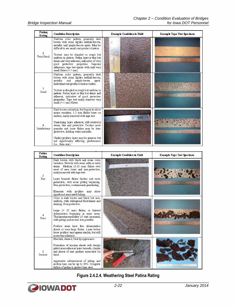
Chapter 2 – Condition Evaluation of Bridges Bridge Inspection Manual for Iowa DOT Personnel
2-22 January 2014
Figure 2.4.2.4. Weathering Steel Patina Rating
Chapter 2 – Condition Evaluation of Bridges Bridge Inspection Manual for Iowa DOT Personnel
2-23 January 2014
The weathering steel patina rating should be documented in the NBEs for the steel girders. Any tape test
strips should be photographed and included in the documentation of the inspection.
Bolted or riveted connections should be inspected for loose or missing bolts or rivets, section loss to the
bolt or rivet heads, and corrosion of the connecting parts. Pack rust can build up between the connection
plate and the girder element, which can cause bending in the connection plate and unanticipated tensile
stress in the bolts or rivets.
Instances of overload to a steel structure will usually be manifested in high stress zones. Therefore, if
overload is suspected, particular attention should be paid to bearing areas where the load would be
transferred from superstructure to substructure; high shear zones adjacent to member supports and points
of concentrated loads; and high moment regions, including the middle third of a span for positive moment
and the end fourths at intermediate supports for negative moment in continuous spans.
Areas of collision damage should be carefully inspected for signs of fracture or member cracking;
distortion due to collision should be documented and quantified in the inspection report. If cracks or
gouges in the steel members have occurred due to collision damage, dye penetrant or magnetic particle
testing may be required to accurately determine the extent of the defect.
2.4.2.4.1 Fatigue-Prone Details
Fatigue-prone details include, but are not limited to, the following:
Welded cover plates, particularly the end terminations
Web gap area at diaphragm stiffeners when out-of-plane bending is possible
Welded gusset plate connections to girder webs, flanges or truss members
Weld terminations of longitudinal stiffeners
Coped areas in a floorbeam or cross beam
Tack welds in tension areas
Intersecting welds
Fatigue is the tendency of a member to fail at a stress level below yield stress when subjected to cyclical
loadings. Fatigue-prone details require additional attention. If fatigue cracks or fractures are noted, non-
destructive testing methods, such as dye penetrant testing or magnetic particle testing, may be required to
determine the extents of cracks in steel members. Ultrasonic methods are typically used to test pin
members for defects. Thickness gauges (D-Meters) or calipers can be used to determine the thickness of
steel remaining for a particular member.
Triaxial constraint is a 3-dimensional stress state that reduces the ductility of a material. Under triaxial
constraint, steel is unable to deform, and brittle fracture can occur under service conditions where ductile
behavior is normally expected. Due to the nature of these unique conditions, the chance for member
failure is greater for these conditions and they warrant added emphasis during inspection. Finally, the
ability of inspectors to recognize conditions of triaxial constraint is important to guard against brittle
failure.
AASHTO prioritizes fatigue details into categories from A (least critical) to E’ (most critical). The
inspector shall be familiar with the various fatigue categories and be able to classify the categories
encountered in the field to determine the seriousness of the detail. Fatigue-prone details should be
Chapter 2 – Condition Evaluation of Bridges Bridge Inspection Manual for Iowa DOT Personnel
2-24 January 2014
identified and noted in the inspection report so that details can be monitored for cracks in subsequent
inspections.
2.4.2.4.2 Fracture Critical Members
FCMs are steel members in tension or with a tension element, whose failure would be expected to cause a
partial or full collapse of the bridge. The NBIS requires FCMs to be inspected at “arms length.”
Floorbeams are primary superstructure members that transmit loads from the deck to the main girders or
trusses. Floorbeams are generally considerably smaller than the main girders and are oriented
perpendicular to traffic. There may be direct contact with the bottom of the deck or they may support
longitudinal stringers, parallel to the main girders or truss. Stringers may be continuous or simply
supported at the floorbeams. Steel floorbeams are considered fracture critical when:
1. The connections to main girders are considered flexible or hinged;
2. There are no stringers;
3. The stringers are configured as simple spans; or
4. The stringers are continuous and the floorbeam spacing is greater than 14 feet.
2.4.2.4.2.1. FCM Pre-inspection Preparation
Prior to inspecting a bridge with known FCMs, the following procedures should be used in preparation
for the inspection:
1. Review the FCM locations as identified in the bridge file.
2. Identify all fatigue-prone details requiring a hands-on inspection.
3. Determine what documentation will be needed as part of this inspection.
4. Determine the workflow needed and access requirements for inspecting the FCMs in the most
efficient manner.
5. Discuss the workflow with all the members of the inspection team so they understand their roll in
the inspection. It is recommended the workflow be documented and kept in the bridge file.
6. Assess the equipment needs to perform this inspection. This will include lighting adequate to
identify small defects. It is recommended to keep a list of the equipment needed for the inspection
in the bridge file.
7. Make arrangements to have the superstructure washed if debris, bird nests, or bird droppings
inhibit proper inspection of important areas.
8. Make arrangements to have the necessary access equipment available for the inspection.
9. Verify who shall be notified if a potentially serious condition is found.
2.4.2.4.2.2. Requirements During FCM Inspection
During an FCM inspection, the following procedures should be used:
1. Perform a hands-on inspection to visually inspect the FCMs for deterioration, defects, damage,
and cracks. Perform a hands-on inspection of all fatigue-prone details. A hands-on inspection is
defined as the inspector being able to touch all surfaces of the tension carrying regions of FCMs.
Chapter 2 – Condition Evaluation of Bridges Bridge Inspection Manual for Iowa DOT Personnel
2-25 January 2014
2. Clean suspect locations for better visual assessment, and use appropriate non-destructive testing
methods to verify potential crack locations and member thickness in deteriorated areas.
3. Photograph and sketch locations where deficiencies are found. Include appropriate dimensions
and perspectives on all sketches. Close-up photographs should be taken before and after any
cleaning, paint removal, or testing. Include a photograph of the general location so others can
understand exactly where close-up photographs were taken.
4. Confirm by using a checklist or other appropriate means that all FCMs were inspected.
5. If a serious defect is found, notify the appropriate personnel immediately to determine what
actions are necessary.
2.4.2.4.3 Hinges
A hinge in a steel girder is a location where bending moments are not transferred because of a pin and
hanger connection or a rotational connection system. A joint will be present in the deck at a hinge
location. Hinges require careful inspection because of the complexity of the connection and the high
stresses present.
2.4.2.4.3.1. Pin and Hanger Connections
A typical pin and hanger hinge configuration is shown in Figure 2.4.2.4.3.1. Pin and hanger connections
may be considered FCMs. Because of the complexities of the connection and the high stresses present,
pin and hanger assemblies should receive a close-up inspection as part of a scheduled Routine or Fracture
Critical inspection. Hanger links should be checked for out-of-plane bending. Retaining nuts should be
checked for cracks and to confirm retaining nuts are tight. Pins should be visually inspected for signs of
corrosion. Pin/pin and hanger connections should be examined for evidence of movement of the hanger
links off the ends of the pin, fracture of hanger links, misalignment or bowing of the hanger links (often
from pack rust), bleeding rust stains, wear on the pins, or pin fractures. Because hinges are located at deck
joints, leaking joints can promote corrosion in the hinge components. Thus, the assemblies can become
bound due to corrosion of components, which can cause unanticipated tensile stress on the pins or
bending stress on the hanger links. Often web plates at pin and hanger connections are stiffened and
reinforced with web doubler plates to provide additional bearing area for pins. Doubler plates should be
checked for pack rust that could apply an outward force to hanger plates and retaining nuts.
Pins for pin and hanger assemblies shall be ultrasonic tested on a 60- to 72-month frequency.
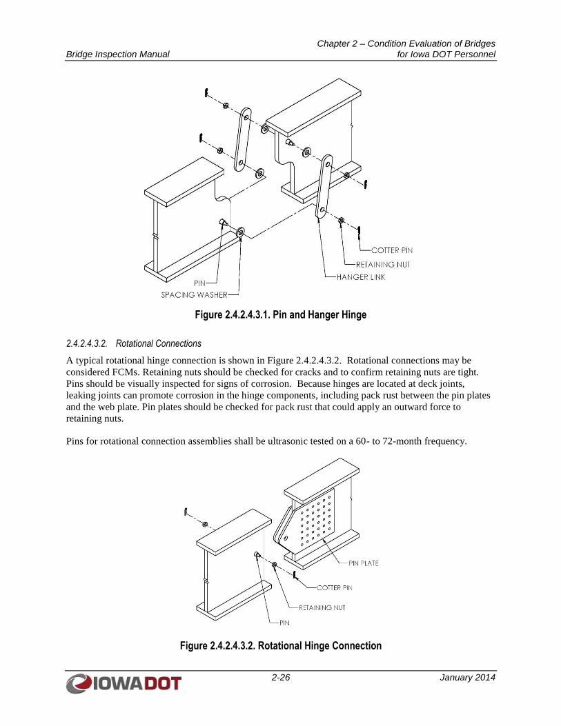
Chapter 2 – Condition Evaluation of Bridges Bridge Inspection Manual for Iowa DOT Personnel
2-26 January 2014
Figure 2.4.2.4.3.1. Pin and Hanger Hinge
2.4.2.4.3.2. Rotational Connections
A typical rotational hinge connection is shown in Figure 2.4.2.4.3.2. Rotational connections may be
considered FCMs. Retaining nuts should be checked for cracks and to confirm retaining nuts are tight.
Pins should be visually inspected for signs of corrosion. Because hinges are located at deck joints,
leaking joints can promote corrosion in the hinge components, including pack rust between the pin plates
and the web plate. Pin plates should be checked for pack rust that could apply an outward force to
retaining nuts.
Pins for rotational connection assemblies shall be ultrasonic tested on a 60- to 72-month frequency.
Figure 2.4.2.4.3.2. Rotational Hinge Connection
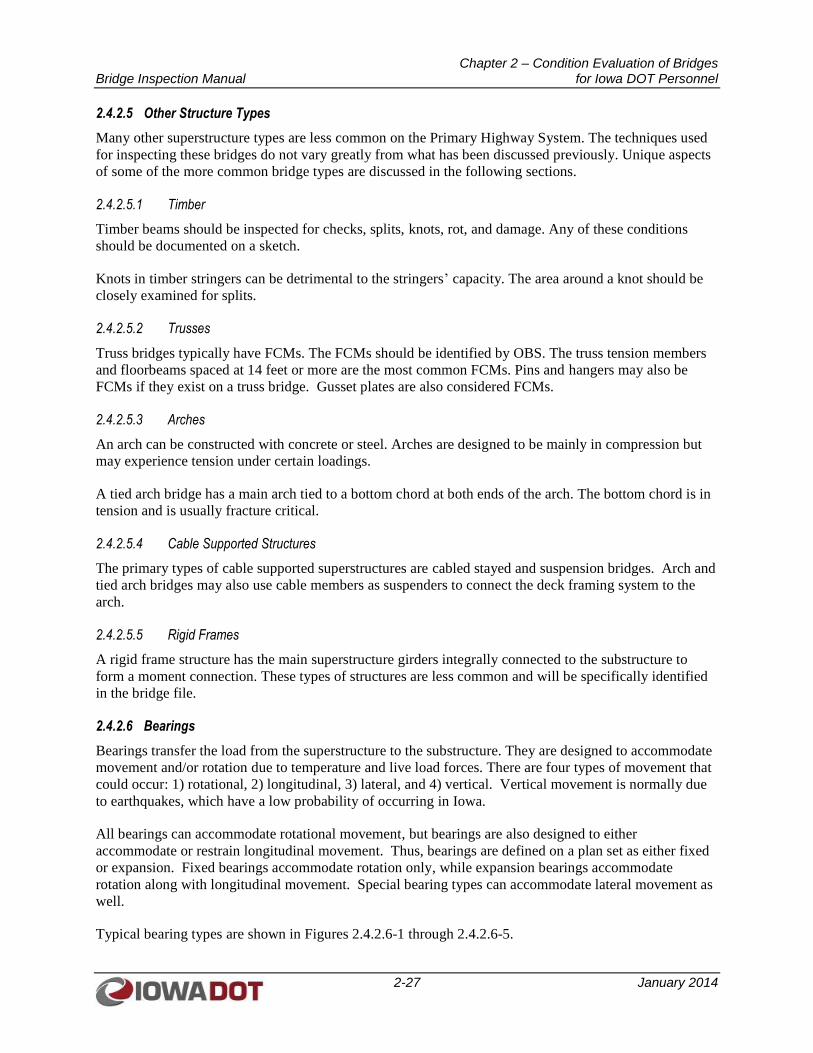
Chapter 2 – Condition Evaluation of Bridges Bridge Inspection Manual for Iowa DOT Personnel
2-27 January 2014
2.4.2.5 Other Structure Types
Many other superstructure types are less common on the Primary Highway System. The techniques used
for inspecting these bridges do not vary greatly from what has been discussed previously. Unique aspects
of some of the more common bridge types are discussed in the following sections.
2.4.2.5.1 Timber
Timber beams should be inspected for checks, splits, knots, rot, and damage. Any of these conditions
should be documented on a sketch.
Knots in timber stringers can be detrimental to the stringers’ capacity. The area around a knot should be
closely examined for splits.
2.4.2.5.2 Trusses
Truss bridges typically have FCMs. The FCMs should be identified by OBS. The truss tension members
and floorbeams spaced at 14 feet or more are the most common FCMs. Pins and hangers may also be
FCMs if they exist on a truss bridge. Gusset plates are also considered FCMs.
2.4.2.5.3 Arches
An arch can be constructed with concrete or steel. Arches are designed to be mainly in compression but
may experience tension under certain loadings.
A tied arch bridge has a main arch tied to a bottom chord at both ends of the arch. The bottom chord is in
tension and is usually fracture critical.
2.4.2.5.4 Cable Supported Structures
The primary types of cable supported superstructures are cabled stayed and suspension bridges. Arch and
tied arch bridges may also use cable members as suspenders to connect the deck framing system to the
arch.
2.4.2.5.5 Rigid Frames
A rigid frame structure has the main superstructure girders integrally connected to the substructure to
form a moment connection. These types of structures are less common and will be specifically identified
in the bridge file.
2.4.2.6 Bearings
Bearings transfer the load from the superstructure to the substructure. They are designed to accommodate
movement and/or rotation due to temperature and live load forces. There are four types of movement that
could occur: 1) rotational, 2) longitudinal, 3) lateral, and 4) vertical. Vertical movement is normally due
to earthquakes, which have a low probability of occurring in Iowa.
All bearings can accommodate rotational movement, but bearings are also designed to either
accommodate or restrain longitudinal movement. Thus, bearings are defined on a plan set as either fixed
or expansion. Fixed bearings accommodate rotation only, while expansion bearings accommodate
rotation along with longitudinal movement. Special bearing types can accommodate lateral movement as
well.
Typical bearing types are shown in Figures 2.4.2.6-1 through 2.4.2.6-5.
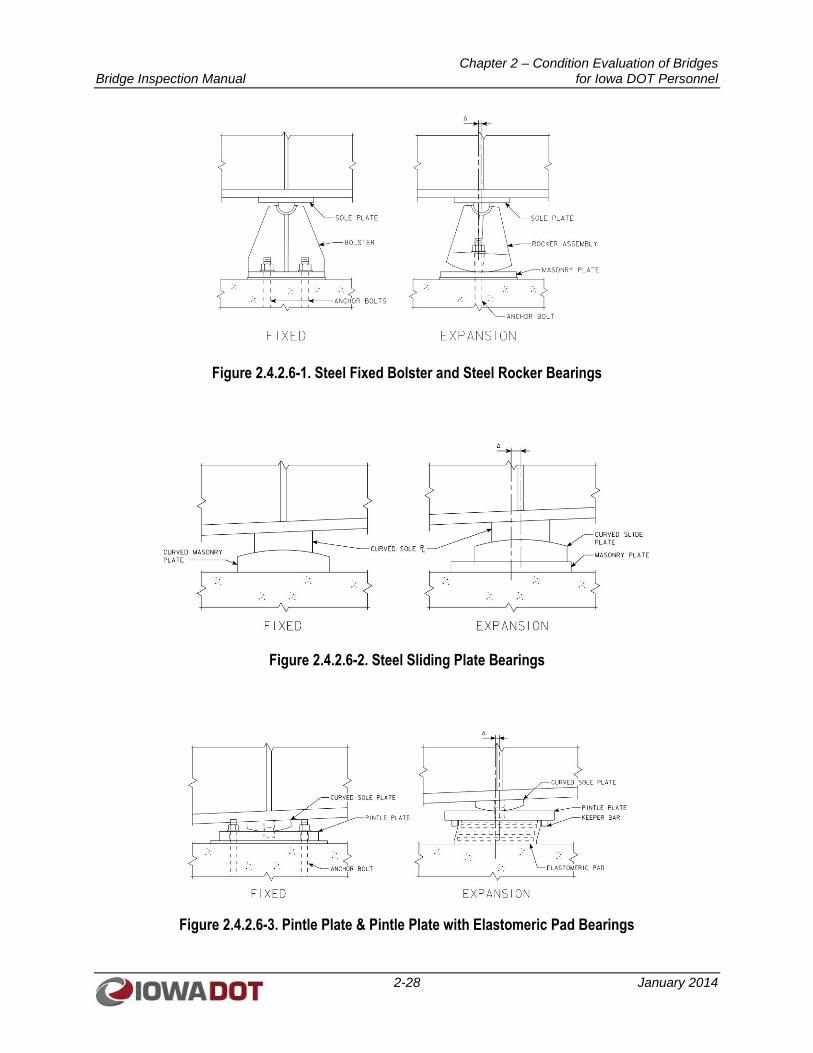
Chapter 2 – Condition Evaluation of Bridges Bridge Inspection Manual for Iowa DOT Personnel
2-28 January 2014
Figure 2.4.2.6-1. Steel Fixed Bolster and Steel Rocker Bearings
Figure 2.4.2.6-2. Steel Sliding Plate Bearings
Figure 2.4.2.6-3. Pintle Plate & Pintle Plate with Elastomeric Pad Bearings
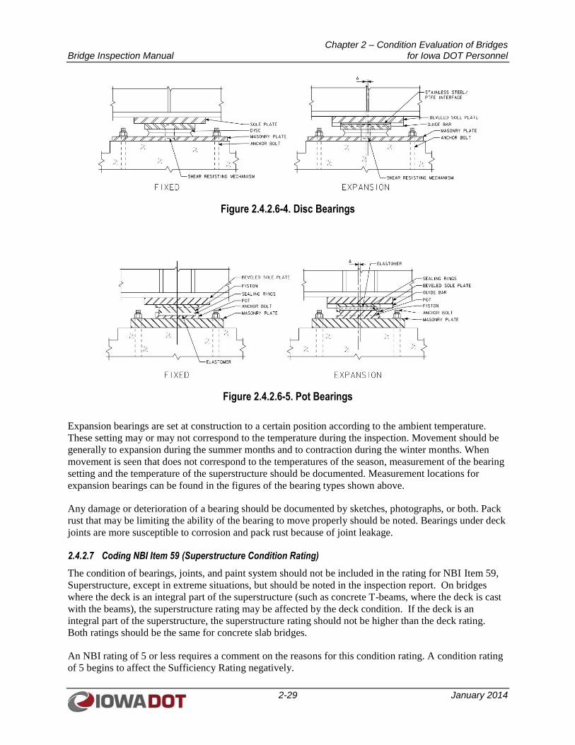
Chapter 2 – Condition Evaluation of Bridges Bridge Inspection Manual for Iowa DOT Personnel
2-29 January 2014
Figure 2.4.2.6-4. Disc Bearings
Figure 2.4.2.6-5. Pot Bearings
Expansion bearings are set at construction to a certain position according to the ambient temperature.
These setting may or may not correspond to the temperature during the inspection. Movement should be
generally to expansion during the summer months and to contraction during the winter months. When
movement is seen that does not correspond to the temperatures of the season, measurement of the bearing
setting and the temperature of the superstructure should be documented. Measurement locations for
expansion bearings can be found in the figures of the bearing types shown above.
Any damage or deterioration of a bearing should be documented by sketches, photographs, or both. Pack
rust that may be limiting the ability of the bearing to move properly should be noted. Bearings under deck
joints are more susceptible to corrosion and pack rust because of joint leakage.
2.4.2.7 Coding NBI Item 59 (Superstructure Condition Rating)
The condition of bearings, joints, and paint system should not be included in the rating for NBI Item 59,
Superstructure, except in extreme situations, but should be noted in the inspection report. On bridges
where the deck is an integral part of the superstructure (such as concrete T-beams, where the deck is cast
with the beams), the superstructure rating may be affected by the deck condition. If the deck is an
integral part of the superstructure, the superstructure rating should not be higher than the deck rating.
Both ratings should be the same for concrete slab bridges.
An NBI rating of 5 or less requires a comment on the reasons for this condition rating. A condition rating
of 5 begins to affect the Sufficiency Rating negatively.
Chapter 2 – Condition Evaluation of Bridges Bridge Inspection Manual for Iowa DOT Personnel
2-30 January 2014
2.4.2.8 National Bridge Elements
The description of the NBE for superstructures can be found in the NBE manual prepared by OBS.
The NBE should include comments and inspection notes under each element as necessary. Comments and
inspection notes should be included when there is a portion of the element in condition state 3 or 4.
2.4.2.9 Additional SIIMS Superstructure Data
The Superstructure section in SIIMS has several items not part of the NBI or NBE data. These items
should be updated as necessary at each Routine or In-depth Inspection.
2.4.2.9.1 Additional Structure Detail Fields
Some bridges have unique features not captured within the standard structure type codes of the NBI. A
field called “Additional Structure Details” has been created within SIIMS to document some of these
special features. A drop-down menu of items is used to allow selection of a special feature if one exists.
The drop-down menu includes:
1. Welded I Girder with Diaphragms (more than 2 girders) – Bridges with standard diaphragms
between girder lines
2. Two-girder Welded I Girder with Stringers – Standard two-girder bridges with stringers and
floorbeams
3. Two-girder Welded I Girder with Floorbeams – A two-girder bridge with floorbeams and no
stringers
4. Welded I Girder with Floorbeams (more than 2 girders) – Multiple girders with floorbeams
supporting the deck
5. Pony Truss – To specifically identify this type of truss bridge
6. Arch Deck with No Fill – A concrete arch structure with no fill material between the arch and the
deck
7. Other – Any unique feature that would make the bridge necessary to include in a query
2.4.2.9.1.1. Beams/Girders
The Beams/Girders section in SIIMS will be eliminated once the new NBEs are implemented. The beam
end deterioration can be documented by using the environments for beam and girder elements.
2.4.2.9.1.2. Diaphragms
The Diaphragms section in SIIMS is for documenting the type of diaphragms found on a bridge. A drop-
down menu in SIIMS lists the choices of diaphragms to select from for end diaphragms and intermediate
diaphragms. The choices are:
1. Concrete – Solid concrete reinforced with mild steel
2. Rolled Steel – A single rolled steel member, usually an I shape or channel shape
3. Steel Angles – Multiple steel angles usually in an X-frame or K-frame configuration
4. Miscellaneous – Any type not fitting the three other categories
5. None – No diaphragms present
Chapter 2 – Condition Evaluation of Bridges Bridge Inspection Manual for Iowa DOT Personnel
2-31 January 2014
2.4.2.9.1.3. Fracture Critical/Fatigue Prone /Fatigue Retrofit
The Fracture Critical/Fatigue Prone /Fatigue Retrofit section in SIIMS is for documenting whether a
bridge has FCMs, Fatigue Vulnerable details, or if there has been a retrofit of a Fatigue Vulnerable detail.
A “Yes” or “No” should be chosen from the drop-down menu for each of the three items. If “Yes” is
chosen for any one of these features, the type of feature found on the bridge should be checked in the
corresponding list. More than one item can be checked in any one list.
2.4.2.9.1.4. Fatigue Inspection History
A Fatigue Inspection is an inspection of the fatigue prone details of a steel member. This inspection is
done during a Routine or In-depth Inspection.
A Fracture Critical bridge, with fatigue prone details, may require an Intermediate Fatigue Inspection at
an interval between a Routine or In-depth Inspection. An Intermediate Fatigue Inspection is required
when a Fracture Critical bridge has or has had fatigue cracks.
The Fatigue Inspection History section in SIIMS is for documenting the date of the last Fatigue
Inspection and the date of the next Fatigue Inspection. Fatigue Inspections are scheduled on a 24- or
72-month basis. A bridge can be on a 72-month Fatigue Inspection frequency if there have never been
more than two locations found with fatigue cracks, these fatigue cracks have been arrested, and the bridge
is not Fracture Critical. When more than two locations have had fatigue cracks verified, the bridge’s
fatigue-prone details must be inspected every 24 months. If the 72-month frequency is allowed, the check
box designated as “Six Year Cycle” should be checked.
The number of locations with fatigue cracks shall be documented by entering the number of locations
with the following:
1. Previous confirmed cracks – total number of locations with cracks found during previous
inspections
2. New confirmed cracks – new cracks found during the current inspection
3. Cracks extended beyond holes – old cracks with ¾-inch-diameter crack arrest holes that did not
stop the crack from extending past the hole
4. Confirmed cracks – the total number of crack locations currently found on the bridge regardless if
they have had ¾-inch diameter arresting holes drilled or large hole retrofits
If all of the cracks have been arrested with ¾-inch diameter holes or larger hole retrofits, “Yes” should be
selected from the drop-down for the question “Have holes been drilled at all cracks?”. Otherwise, “No”
should be selected.
2.4.2.9.1.5. Pin and Hanger Inspections
To identify whether a Pin and Hanger assembly exists on the bridge, “Yes” or “No” should be selected
from the drop-down menu. If there are Pin and Hanger assemblies on the bridge, the date of the last
ultrasonic inspection and the date of the next ultrasonic inspection should be entered.
An ultrasonic inspection will be performed at a 60- to 72-month frequency. This inspection will be
documented as an “Other” inspection type.
Chapter 2 – Condition Evaluation of Bridges Bridge Inspection Manual for Iowa DOT Personnel
2-32 January 2014
2.4.3 Substructure Inspection
Substructure members should be inspected for deterioration, as described below, due to specific material
characteristics, as well as for signs of foundation settlement, rotation (tipping), lateral movement,
overstress due to poorly functioning bridge bearings, scour, and undermining damage. During inspection
for scour and undermining, areas surrounding the footings should be probed to find areas of loose backfill
or areas where scour action has removed streambed material from around the footings. Footings not
located in areas influenced by stream flow may also experience undermining from bridge drainage
outletting near substructure foundations. High stress zones of substructure members should be examined
for localized failure at bearing pedestals and high shear and flexural zones.
2.4.3.1 Abutments
Abutments are located at the ends of the bridge and support the superstructure at the transition between
bridge and pavement. Abutments can be supported by spread footings or piles. An abutment may be
integral, semi-integral, or stub type.
Spalling, scaling, and cracking in the abutment seat and backwall concrete should be noted and sketched.
Undermining of the abutment should be noted and sketched. Undermining extending under the abutment
to the point where the approach fill may be washing out from under the abutment is significant.
Investigation of a possible void under the approach pavement is necessary. A void should be reported to
OBS immediately to determine if it affects the safety of the roadway. The District may need to be
contacted in severe cases.
If undermining has exposed steel piles, the piles should be examined for section loss as is practical.
Section loss at the interface between the pile and footing is the most common place for this to occur.
2.4.3.1.1 Integral Abutments
An integral abutment is connected to the superstructure in a way that makes the abutment flex with the
expansion and contraction of the superstructure. This flexing will often displace soil and create a trough
in front of the footing and a void under the approach pavement at the paving notch. These conditions are
not detrimental to the structure. The void under the approach should be monitored to make sure it does
not grow too large due to water erosion.
2.4.3.1.2 Semi-Integral Abutments
A semi-integral abutment can be a retrofit or an original design. Leaching of subsurface drainage from the
approach fill occurring between the footing and the backwall may be present, which may indicate a non-
functioning sub-drain.
2.4.3.1.3 Stub Abutments
The backwall should be examined for signs of crushing or cracking from deck pressure against the
backwall. The joint opening should be measured between the deck and backwall on the underside of the
joint. The joint opening on top of the backwall may not be comparable to the gap between the deck and
backwall underneath the joint.
The bridge seat should be examined for spalling, scaling, and hollow areas. Spalling or scaling that has
caused bearing loss must be measured and sketched.
Chapter 2 – Condition Evaluation of Bridges Bridge Inspection Manual for Iowa DOT Personnel
2-33 January 2014
2.4.3.2 Piers
There are many types of piers. They can be concrete, steel, or a combination of both. Steel pier caps can
be fracture critical.
Piers should be examined for signs of atypical movement. Settlement of pier footings can cause tipping of
the pier. Any unusual movement should be documented with a sketch and vertical alignment
measurements.
2.4.3.2.1 Concrete Piers
Spalling, scaling, cracking, and hollow areas of concrete should be documented with sketches and written
descriptions of significant deterioration. Cracking in high stress areas should be documented.
Flood debris against a pier should be documented. Flood debris can cause scour, which may lead to
undermining of the pier footing.
2.4.3.2.2 Steel Bents
Steel bents should be checked for impact damage from flood debris. In addition, steel bent components
and steel piles should be checked for fatigue cracking, pack rust, and section loss due to corrosion.
Connections between primary vertical members and secondary bracing members should be checked for
cracked welds, loose connections, or section loss at gusset plate connections.
2.4.3.2.3 Integral Steel Pier Caps
Integral steel pier caps should be checked for signs of overstress at high shear or flexural zones. For
FCMs, an “arms length” inspection of all components and connections should be conducted.
2.4.3.3 Underwater Inspection of Substructures
Pier elements below the waterline are to be inspected by means of wading or probing at periods of low
water.
Underwater Inspections are required when the low water depth is never below 2 feet. When the low
water level is between 2 feet and 6 feet, Underwater Inspections are to be performed at a 48-month
frequency, and NBI Items 92B and 93B, Underwater Inspection, must be filled in. Additional
Underwater Inspection requirements include the following:
1. If the water depth at low water is not less than 6 feet, divers are required to perform the inspection
of underwater portions of the substructure. The Underwater Inspection by divers should be coded
as “Yes.”
2. When the water depth is between 2 feet and 6 feet, wading and probing are used to inspect the
portions of the substructure underwater. It is at the inspector’s discretion whether a boat is used if
the water level and current are too dangerous for wading.
3. The streambed should be documented during Underwater Inspections to the extent practical.
2.4.3.4 Coding NBI Item 60 (Substructure Condition Rating)
All substructure elements should be inspected for visible signs of distress including evidence of cracking,
section loss, settlement, misalignment, scour, collision damage, and corrosion. The rating given by NBI
Item 113, Scour Critical Bridges, may have a significant effect on NBI Item 60, Substructure, if scour has
substantially affected the overall condition of the substructure. When NBI Item 113, Scour Critical
Chapter 2 – Condition Evaluation of Bridges Bridge Inspection Manual for Iowa DOT Personnel
2-34 January 2014
Bridges, is coded 2 or less on the SI&A form, NBI Item 60, Substructure, shall be coded 2 or less in
accordance with Hydraulic Engineering Circular 18 (HEC-18), Section 10.3.2, Bridge Inspection,
FHWA’s Recording and Coding Guide for the Structure Inventory and Appraisal of the Nation’s Bridges.
The substructure condition rating shall be made independent of the deck and superstructure. This item
describes the physical condition of piers, abutments, piles, fenders, footings, or other components.
Integral-abutment wingwalls up to the first construction or expansion joint shall be included in the
evaluation. For non-integral superstructure and substructure units, the substructure shall be considered as
the portion below the bearings. For structures where the substructure and superstructure are integral, the
substructure shall be considered as the portion below the superstructure.
An NBI rating of 5 or less requires a comment on the reasons for this condition rating. A condition rating
of 5 begins to affect the Sufficiency Rating negatively.
2.4.3.5 National Bridge Elements
The description of the NBE for substructures can be found in the NBE manual prepared by OBS.
The NBE should include comments and inspection notes under each element as necessary. Comments
and inspection notes should be included when there is a portion of the element in condition state 3 or 4.
2.4.3.6 SIIMS Pier Data
The Pier section in SIIMS is used to document the foundation type and the pier structure. The condition
of individual piers is more easily documented by using this section. Bridges with more than two piers are
difficult to document when multiple issues are found. Describing multiple issues for many piers in the
NBE can be confusing. In this section, written documentation of the conditions found for each pier during
the inspection can be included.
The number of piers should be selected from the drop-down menu. When the number of piers is chosen,
areas will appear for each of the piers identified.
2.4.3.6.1 Foundation Type
The foundation description should be identified for each pier by using the most relevant type listed in the
drop-down menu.
When the foundation is not visible, the foundation condition should be coded as unknown from the drop-
down menu. When the foundation is visible, it should be rated as Good, Fair, or Poor. If a Poor condition
is found, a description of the condition should be entered in the comment field.
Comments on the overall condition of the foundation should be entered when an individual foundation
has deterioration not common among all the foundations of the bridge.
2.4.3.6.2 Pier Type
The pier description should be identified for each pier by using the most relevant type listed in the drop-
down menu.
The pier condition should be coded as Good, Fair, or Poor. If a Poor condition is found, a description of
the condition should be entered in the comment field.
Chapter 2 – Condition Evaluation of Bridges Bridge Inspection Manual for Iowa DOT Personnel
2-35 January 2014
Comments on the overall condition of the pier should be entered when an individual pier has deterioration
not common among all the piers of the bridge.
2.4.3.7 Additional SIIMS Substructure Data
The Substructure section in SIIMS has several items not part of the NBI or NBE data. These items are to
be updated as necessary at each Routine or In-depth Inspection.
2.4.3.7.1 Foundation
The foundation types for the near and far abutments should be identified by using the most relevant type
from the drop-down menu under the Description heading.
If the foundation elements are not visible, the condition should be coded as unknown. When the
foundation elements are visible, the condition should be coded as Good, Fair, or Poor. If a Poor condition
is found, a description of the condition should be entered in the comment field.
2.4.3.7.2 Berm Protection
The berm types for the near and far abutments should be identified by using the most relevant type from
the drop-down menu under the Description heading.
The condition should be evaluated as Good, Fair, or Poor. If a Poor condition is found, a description of
the condition should be entered in the comment field.
2.4.4 Channel Inspection
Channels should be inspected for the physical condition associated with the flow of water through the
bridge, such as stream stability, and the condition of the channel, riprap, slope protection, or stream
control devices, including spur dikes. The inspector should be particularly concerned with visible signs
of excessive water velocity, which may affect undermining of slope protection, erosion of banks, and
realignment of the stream, which, in turn, may result in immediate or potential problems. Accumulation
of drift and debris on the superstructure and substructure should be noted in the inspection report but shall
not be included in the condition rating.
2.4.4.1 Coding NBI Item 61 (Channel Condition Rating)
The rating for NBI Item 61, Channel/Channel Protection, should reflect the general condition of the
channel in relation to the following:
1. Bank vegetation – Vegetation protects the banks from erosion by normal water flow.
2. River control devices – Devices include spur dikes, jetties, retards, and other control systems.
3. Debris in channel restricting flow – Debris could cause scour to occur around substructure
elements.
4. Trees and brush restricting the channel – Trees and brush could cause a restriction accelerating
the flow and the potential for stream degradation or scour.
5. Degradation or aggradation of the streambed – Streambed elevations significantly different than
the as-built condition may cause unexpected problems during high water events.
6. Channel movement away from the as-built condition – Channel movement may encroach on the
substructure or approach pavement, causing undermining and potential failure of the bridge or
roadway.
Chapter 2 – Condition Evaluation of Bridges Bridge Inspection Manual for Iowa DOT Personnel
2-36 January 2014
An NBI rating of 5 or less requires a comment on the reasons for this condition rating. A condition rating
of 5 begins to affect the Sufficiency Rating negatively.
2.4.4.2 National Bridge Elements
The description of the NBE for Channel condition can be found in the NBE manual prepared by OBS.
The NBE should include comments and inspection notes under each element as necessary. Comments
and inspection notes should be included when there is a portion of the element in condition state 3 or 4.
2.4.4.3 Additional SIIMS Channel Data
The Channel section in SIIMS has several items not part of the NBI or NBE data. These items should be
updated as necessary at each Routine or In-depth Inspection.
2.4.4.3.1 Bank Protection
The type of bank protection present upstream and downstream, if any (spur dike, jetty, retard, other, or
none), should be described.
The conditions of the protection devices should be described as follows:
1. Good – functioning and no damage to device
2. Fair – functioning but minor damage to device
3. Poor – not functioning properly due to damage to device
4. N/A - no bank protection device
2.4.4.3.2 Revetment
The type of revetment present, if any (riprap, concrete, other, or none), should be described.
The conditions of the revetment should be described as follows:
1. Good – functioning and no damage
2. Fair – functioning but minor damage
3. Poor – not functioning properly due to damage
4. Blank – no revetment present
2.4.4.3.3 NBI Item 113, Scour Critical Bridges
NBI Item 113 and the Scour Critical Classification are to be entered by the Hydraulic engineers only. If
scour is found at the inspection, the inspection shall be routed to the hydraulic engineers for review before
the report is finalized.
2.4.4.4 Underwater Inspection
Complete the following information for bridges that cross a waterway feature:
1. The “Underwater Inspection by Divers” should be coded as “Yes” when the low water depth is 6
feet or more. Enter “No” if divers are not required.
2. The streambed should be documented during Underwater Inspections to the extent practical. The
“Streambed” should be coded “Yes” when it can be documented during the Underwater
Chapter 2 – Condition Evaluation of Bridges Bridge Inspection Manual for Iowa DOT Personnel
2-37 January 2014
Inspection. Enter “No” when the streambed cannot be documented during the Underwater
Inspection.
3. The number of piers that require Underwater Inspection should be documented. Only piers in
low water above 2 feet in depth are to be included. Enter “0” when there are no piers requiring
Underwater Inspection.
2.4.4.5 Waterway Characteristics
The waterway characteristics document the elevations of the following:
High water
Current water
Low water
Pile tip
Scour hole
Plan streambed
Other information that should be documented includes the reference point of the elevation used and the length
of the pile according to plan or pile log information.
2.4.4.6 Channel Cross Section
A channel cross section on the upstream side of the bridge is required to be a part of the bridge record. A
standard Channel Cross Section form has been incorporated into SIIMS. Each bridge structure is required
to have data points at the top of bank, toe of bank, thalweg, and each substructure unit. The Channel
Cross Sections are updated in SIIMS every 4 years for natural waterways and every 10 years for drainage
ditches controlled by a drainage district, unless conditions at the bridge warrant more frequent
monitoring.
Although the Channel Cross Section is required in SIIMS, hand-drawn channel sketches may be uploaded
to the report, or the standard Channel Cross Section form in SIIMS may be used to auto-generate a
channel cross section sketch.
2.4.5 Culvert Inspection
A culvert with an opening greater than 20 feet as measured along the center of the roadway is considered
a bridge-sized structure and is subject to NBIS requirements. Similarly, a grouping of culverts with a
length greater than 20 feet as measured along the roadway centerline, and where the clear distance
between openings is less than half the smaller contiguous opening, is considered a bridge-sized structure.
Culverts should be inspected for their overall condition, any approach roadway and embankment
settlement, the condition of their end treatments (headwalls, parapets, and wingwalls), and the condition
of their appurtenance structures (such as aprons, weirs, and energy dissipaters). The inside of a culvert
should be inspected for any damage or deterioration. Weep holes should be checked to determine if they
are functioning or if they are plugged. Joints should be checked for deterioration or spalls.
2.4.5.1 Concrete Headwalls
For concrete headwalls, the following items should be reviewed at each inspection:
1. Wall condition – wall tipping, cracking, and concrete scaling
2. Apron condition – concrete scaling, settlement, and cracking
Chapter 2 – Condition Evaluation of Bridges Bridge Inspection Manual for Iowa DOT Personnel
2-38 January 2014
3. Curtain wall – stream bottom elevation, piping of water under or around the curtain wall, and
riprap present
2.4.5.2 Concrete Barrels
For concrete barrels, the following items should be reviewed at each inspection:
1. Wall condition – cracking, spalling, scaling, joint openings, and bulging
2. Slab condition – cracking, spalling, scaling, joint openings, and leaching
3. Floor condition – sediment depth, spalling, scaling, settlement, and heaving
2.4.5.3 Metal Culverts
For metal culverts, the following items should be reviewed at each inspection:
1. Corrosion – section loss
2. Erosion – potential piping around the culvert
3. Distortion – unusual defections or alignment
4. Connections – loose or missing bolts
2.4.5.4 Concrete Arches
For concrete arches, the following items should be reviewed at each inspection:
1. Footings – scour, cracking, spalling, and pile exposure
2. Arches – spalling, scaling, exposed reinforcing, conditions at the springline
3. Wingwalls – wall tipping, cracking, and concrete scaling
4. Fill – signs of settlement, sink holes, and pavement settlement
2.4.5.5 Fill Depth
The fill depth must be measured for all culvert types. This information is needed for dead load
calculations used for the load rating. A sketch of the cross section of the culvert with the elevations of the
fill at the parapets, roadway shoulders, and centerline of roadway should be made. The maximum fill
depth should be documented on the sketch if it is different from the recommended elevation locations
described.
2.4.5.6 Coding NBI Item 62 (Culvert Condition Rating)
The rating for NBI Item 62, Culvert, should evaluate the alignment, settlement, joints, structural
condition, scour, and other elements associated with culverts. The rating code is intended to be an overall
condition evaluation of the culvert. Integral wingwalls to the first construction or expansion joint shall be
included in the evaluation.
An NBI rating of 5 or less requires a comment on the reasons for this condition rating. A condition rating
of 5 begins to affect the Sufficiency Rating negatively.
2.4.5.7 National Bridge Elements
The description of the NBE for culverts can be found in the NBE manual prepared by OBS.
Chapter 2 – Condition Evaluation of Bridges Bridge Inspection Manual for Iowa DOT Personnel
2-39 January 2014
The NBE should include comments and inspection notes under each element as necessary. Comments
and inspection notes should be included when there is a portion of the element in condition state 3 or 4.
2.4.5.8 Additional SIIMS Culvert Data
The Culvert section in SIIMS has items not part of the NBE or NBI data. These items should be updated
as necessary at each Routine or In-depth Inspection.
2.4.5.8.1 Fill
There is a check box that must be checked when no fill is present over the top of the culvert. This
identifies culverts for which the top of the slab is the driving surface of the roadway.
2.4.5.8.2 Revetment
The type of revetment present, if any (riprap, concrete, other, or none), should be described.
The overall condition of the revetment should be described as follows:
1. Good – functioning and no damage
2. Fair – functioning but minor damage
3. Poor – not functioning properly due to damage
4. Blank – no revetment present
If the condition is considered poor, a description of the condition should be entered into the comment
field.
2.5 SIIMS DOCUMENTATION
2.5.1 About SIIMS
The Structure Inventory and Inspection Management System (SIIMS) is the single-source location for
entering and reviewing condition information for all Iowa bridges, both State owned and locally owned.
In order to use SIIMS and other applications hosted on State web servers, a user must first obtain a State
of Iowa Enterprise A & A account I.D. and password. In addition, a user must be registered in SIIMS by
completing a form for a Bridge Owner, Bridge Inspector, Bridge Load Rating Engineer, or Bridge Data
Entry Personnel. Individuals who do not qualify for any of these levels of access must complete a form
for Bridge Information. The various permission levels control the level of access provided within the
system.
SIIMS has the ability to track all keystrokes made within the system based on the user. In this way, the
software can determine the source of any information changed or edited within the system. For this
reason, it is important a user does not share his/her user I.D. or password with anyone else.
The architecture of the SIIMS software includes several modules. There are two modules that will be
used by most users: a Manager module and a Collector (or Inspector) module. The Manager module or
Collector module are accessed through the main menu items listed at the top of the screen after initial log
in. Access to items under the Manager or Collector modules is controlled by user permissions at the log
in.
Chapter 2 – Condition Evaluation of Bridges Bridge Inspection Manual for Iowa DOT Personnel
2-40 January 2014
2.5.2 Manager Module Menu in SIIMS
The Manager module menu is geared toward Program Managers for bridge inspection programs at either
the State or local level. Access to the Manager module menu is limited based on permissions granted.
For example, the Program Manager for a local agency may be granted permission to access bridge
inspection data only for bridges under his/her jurisdiction. Functions within the Manager module menu
include queries to search for data and mapping options (for example, to display all bridges within a
particular county). Through the menu, the user also has the ability to provide system reports used to
support funding decisions for a local agency’s bridge program.
2.5.3 Collector (Inspector) Module Menu in SIIMS
The Collector module menu allows an inspector to filter and view the bridge inspection report status,
workflows and upcoming inspections. Access to the Collector module menu is limited based on
permissions granted. For example, an inspector for a local agency will only be granted permission to
access bridge inspection information for bridges under the jurisdiction of the given local agency. The
Collector module menu allows inspectors to organize and view the bridges they are tasked with
inspecting.
2.5.4 Creating Inspection Reports
New reports can be created and pending reports can be viewed or edited based on the status of the report.
To create a new report, the inspector must navigate to the specific bridge needing inspection and click the
Create Report button. When a user is creating a new report, historical information from the bridge file,
such as the bridge plans, will automatically be associated to the bridge from information in the Central
Database. In addition, when creating a report, the user must specify the report type (for example, Iowa
Full State, Iowa Full County, Load Rating Report, or Iowa Other). Once the report type is chosen, the
Inspection type can be selected from the list shown.
2.5.5 Bridge Descriptions in SIIMS
The Bridge Descriptions tab in SIIMS provides written descriptions of what an inspector should expect to see
when arriving at a bridge. As such, the descriptions should be of the configuration of the bridge, not the
condition of the bridge. The descriptions should include rough dates of when the bridge and bridge
components were built, retrofitted, or repaired. If the date of a change to a bridge or bridge component is
unknown, the description should indicate when the change was first recorded, such as: “Retrofitted
rectangular concrete bridge rails were installed sometime prior to the 1991 inspection.”
2.5.5.1 General Guidelines for Written Descriptions
In general, describe permanent and long-term features of the bridge, such as overlays, retrofitted barrier
rails, beam replacements, paint, abutment backwall rebuilds, paving notch rebuilds, riprap installations,
and articulated block mat installations. When describing a change, retrofit, or addition, include the year
when the new feature was first included.
Conversely, do not list Design Numbers or FHWA Bridge Numbers in the descriptions. The descriptions are
not intended to describe maintenance features, such as Portland cement patches to the deck or epoxy injection
of the deck. In addition, they would not describe deterioration such as spalls or impact damage.
2.5.5.2 Descriptive Information Required for Sub-sections
2.5.5.2.1 Bridge Description Describe the bridge size (length and width), the superstructure type, and the bridge location. The location
information should describe the feature the bridge is crossing over, such as “…carrying Westbound I-80 over
Mud Creek 1.5 miles west of US-65.”
Chapter 2 – Condition Evaluation of Bridges Bridge Inspection Manual for Iowa DOT Personnel
2-41 January 2014
2.5.5.2.2 Waterway Indicate the skew of the waterway in relation to the bridge and the direction of the skew (right-hand back or
left-hand back). Describe the upstream channel characteristics related to the stream path.
2.5.5.2.3 Roadway Under Bridge List the name of the route under the bridge. List the span(s) the route passes through as it goes under the
bridge.
2.5.5.2.4 Substructure Describe the type of abutments for the bridge. Describe the number of piers and the type(s) of piers.
Describe which piers use fixed and which piers use expansion bearings.
2.5.5.2.5 Superstructure Indicate the number of spans in the bridge. Describe the type of girder used. Describe any special features of
the superstructure, such as fatigue vulnerability and list the details of the special features.
2.5.5.2.6 Culvert Indicate the number of barrels for the culvert, and the height and width of each barrel. Indicate the skew of
the culvert relative to the roadway and the direction of the skew (right-hand back or left-hand back). Describe
the type of headwalls used (straight or flared).
2.5.5.2.7 Roadway The description of the bridge roadway refers to the bridge deck. Describe the roadway material type. Include
the type and year of installation of the overlay, if one exists.
2.5.5.2.8 Approaches Describe the type of pavement used on the bridge approaches. If an overlay exists on the approach
roadway, describe the type of overlay and the year it was installed. Describe any maintenance performed
on the approach pavement.
2.5.6 NBI Calculations
Calculated fields, the Sufficiency Rating, and the classification for Structural/Functional Deficiency are
recalculated and updated in SIIMS during entry of inspection data for a new inspection. The logic for the
calculated appraisal ratings and the Sufficiency Rating can be reviewed in the NBI Calcs section in
SIIMS. It is recommended that these ratings be recalculated by choosing “Recalculate NBI Ratings” in
the NBI Calcs section of SIIMS before finalizing an inspection.
The data fields that are calculated in the NBI Calcs section in SIIMS are:
1. NBI Item 67, Structural Evaluation
2. NBI Item 68, Deck Geometry
3. NBI Item 69, Underclearances
4. Sufficiency Rating
5. Classification – Structurally Deficient or Functionally Obsolete
2.5.7 Photographs, Sketches, Plans, Documents, and Files
Photographs, sketches, plans, documents and files are attached under the Report Info - Pictures section in
SIIMS. Almost any file type can be added to a bridge file. The type of document will determine whether
the document should be attached with an inspection report or as part of the Bridge File. If a document
relates to only a specific inspection, such as photographs and sketches, it should be attached to the “In
Chapter 2 – Condition Evaluation of Bridges Bridge Inspection Manual for Iowa DOT Personnel
2-42 January 2014
Progress” inspection report. When a document relates to the bridge, such as design plans or a scour plan
of action, the document should be attached in the “Files” area on the Asset Details page.
Files attached as part of an inspection report must be attached before the inspection report is finalized. If a
document or file is not attached before the inspection report is finalized, the report must be unapproved to
attach the files and then reapproved.
Files can be attached in the Asset Details page at any time, whether an inspection is in progress or not.
The description field for each document should include specific information about the subject of the
document so anyone looking at the Bridge File will know what each document contains without having to
open each document.
2.5.7.1 Required Photographs
For Routine Inspections, the following photographs are required:
1. Bridges
a. Approaches, with and against the route direction
b. Profile view
c. Upstream and downstream views, when over water
d. Both abutments (overall)
e. Typical pier, including one of each type if there are multiple types
f. Bottom of the deck overall to show girder type and configuration
g. Top of deck overall
h. All deck joints
i. Guardrail overall
j. Any condition that may warrant repair
2. Culverts
a. Both inlet and outlet profiles
b. Roadway above
c. Upstream and downstream views
d. Any condition that may warrant repair
In-depth Inspections should include all the required photographs for a Routine Inspection as well as
photographs relating to the field notes on deteriorated or unique conditions. In addition, photographs of
the posting signs should be included in the report. Structures with a condition rating coding of 4 or less
for Deck (NBI Item 58), Superstructure (NBI Item 59), Substructure (NBI Item 60), Channel and Channel
Protection (NBI Item 61), or Culvert (NBI Item 62) are required to have photographs of the deficiency,
although it is good practice to photographically document any significant deficiency.
2.5.7.2 Photograph Annotation Convention
The description field for each photograph should include specific words so that photos of unique
circumstances can be found in future queries. These key words do not have to be used in any specific

Chapter 2 – Condition Evaluation of Bridges Bridge Inspection Manual for Iowa DOT Personnel
2-43 January 2014
order or consecutively. A query will look for any combination of these words in a description. Common
key words that may be used to find photographs of a particular issue are shown in Figure 2.5.7.2.
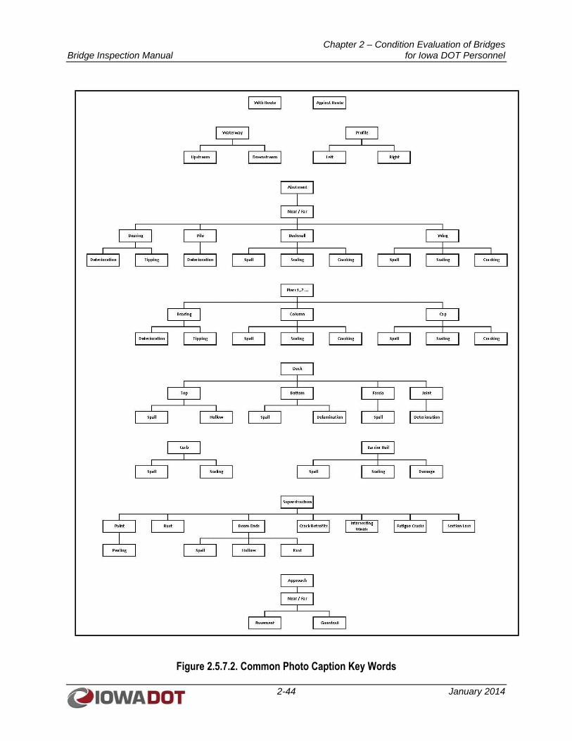
Chapter 2 – Condition Evaluation of Bridges Bridge Inspection Manual for Iowa DOT Personnel
2-44 January 2014
Figure 2.5.7.2. Common Photo Caption Key Words
Chapter 2 – Condition Evaluation of Bridges Bridge Inspection Manual for Iowa DOT Personnel
2-45 January 2014
2.5.7.3 Sketches
Sketches should be scanned into a single .pdf file before attaching them to an inspection report. If there is
a large number of sketches to attach for a given bridge, the sketches can be grouped in logical pieces and
attached as independent groups of sketches. When several groups of sketches are to be attached to an
inspection report, each .pdf file should include a description identifying the type of sketches that are in
each group. Logical groupings are:
Profile
Substructure
Superstructure
Deck
2.5.7.4 Plans
The original design plans as well as any repair or rehabilitation plans are to be attached to a bridge file in
the Manager’s module. Each plan set should be in a single file. If a bridge was built with staged
construction, each stage can be attached individually. Each plan set should include a description of the
details of the plans. The description should include the general work type and whether the plans are the
“As-Built” set.
2.5.7.5 Other Documents
Any other documents relating to an inspection or the bridge in general can be attached under the
following groupings:
1. Files – General documents: correspondence, material test reports, load test reports, etc.
2. Map – An aerial map
3. Load Ratings – Load Rating calculations
4. Scour – Scour calculations, Plans-of-Action, flood data, etc.
5. Fracture Critical Details – Documentation of the elements that are Fracture Critical as required by
the NBIS
6. Channel Sections – Channel sketches showing changes in channel profile
7. Audio – Any audio or video recordings
2.5.8 Critical Findings
Reporting of Critical Findings is required under the NBIS. Critical Findings are structural or safety
related deficiencies requiring immediate follow-up inspection or action. Typically, a Critical Finding
requires bridge closure or lane closure. A form has been set up for documenting the finding and the
follow-up actions. This form can be completed as part of a Routine or In-depth Inspection or as part of a
separate Damage Inspection. The form should be completed as soon as possible from the time of the
finding.
A complete description of the Critical Finding and the immediate action taken should be included in Part I
of the form. Once the situation has been assessed, Part II of the form should be completed. Part II should
include the proposed resolution of the Critical Finding and the time frame anticipated for completion.
The procedures to be used when issuing a Critical Findings Report are as follows:
Chapter 2 – Condition Evaluation of Bridges Bridge Inspection Manual for Iowa DOT Personnel
2-46 January 2014
1. The individual discovering the critical finding shall:
a. Immediately report the finding to the Office of Bridges and Structures, who will notify
maintenance personnel to close or restrict traffic on the bridge.
b. Complete Part I of the Critical Findings Report within 48 hours of the finding.
2. The Office of Bridges and Structures shall:
a. Take action to ensure the safety of the travelling public.
b. Complete Part II of the Critical Findings Report within 5 days of the finding.
3. Before a closed bridge may be reopened to traffic, the following must be completed:
a. A Professional Engineer, Licensed in the State of Iowa, shall approve any structural
repairs.
b. The bridge shall be load rated.
c. The bridge shall be inspected by a Team Leader.
2.5.9 Load Rating Documentation
2.5.9.1 Load Rating Evaluation Form
The Load Rating Evaluation Form must be completed for every inspection. This form will determine if
the existing load rating needs to be re-evaluated to determine if it is still valid or if a new load rating is
needed. The name of the individual who completes the Load Rating Evaluation Form and the date he/she
completes it must be entered at the top of the form.
All the questions on the form default to “No.” If any one of the questions is changed to “Yes,” a re-
evaluation of the load rating or potentially a new load rating calculation will be required. After the
evaluation form is completed, the Program Manager will make the request to have the load ratings re-
evaluated or re-calculated based on the criteria on the Load Rating Evaluation Form.
2.5.9.2 Load Rating Bridge Report
The load rating must be completed by a Professional Engineer licensed in the State of Iowa. As noted
above, the need for a load rating re-evaluation or a new load rating calculation is determined by filling out
the Load Rating Evaluation Form.
If the load rating is re-evaluated and there is no reason found to update the load rating, the following
fields on the Load Rating Bridge Report Tab need to be updated:
1. Report By: – indicates who performed the review
2. Date: – indicates the date the review was completed
3. Comment: – indicates the review did not require re-rating of the bridge
If the load rating is re-calculated and the ratings have changed, the entire Load Rating Bridge Report Tab
must be updated. The Load Rating Bridge Report Tab can be generated by an unlicensed engineer, but a
licensed engineer must put his/her name and license number at the bottom of the form. It is
recommended the new calculations be attached to the inspection report before it is finalized. If the ratings
are not completed before the inspection is finalized, a Load Rating Bridge Report should be created to
update the ratings and attach the calculations.
Chapter 2 – Condition Evaluation of Bridges Bridge Inspection Manual for Iowa DOT Personnel
2-47 January 2014
2.5.10 Supplemental Inspection Information
The NBIS requires information on inspection equipment needs and maintenance history be maintained for
all bridges. The Supplemental Inspection Information section in SIIMS provides a means to document
this information. This section includes:
1. Special equipment requirements for inspection
2. Traffic control needs during inspection
3. Time requirements for inspection
4. Construction work history (design number, repair type, and year completed)
2.5.11 Maintenance, Repair, and Replacement
The Maintenance, Repair, and Replacement (MR&R) section in SIIMS is used to make recommendations
for repair, rehabilitation, and replacement. The maintenance recommendations include all maintenance
needs found during an inspection. These recommendations automatically transmit to the Records
Management System (RMS) for the District bridge repair crews to manage. When a recommendation has
been completed, deferred, submitted for contract work, or programmed, this information is transmitted
back to SIIMS.
2.5.11.1 Maintenance Recommendations
When a recommendation is made, one of four check boxes must be checked to identify the type of
recommendation. The four options are:
1. Corrective – The District must make the repair within 12 months or make provisions to have the
work done by contract.
2. Preventive – Maintenance will prevent future deterioration. Deterioration is not causing a
structural or safety issue at this time.
3. Monitor – The District must monitor the condition at an interval set by OBS or the District as
appropriate.
4. From RMS – This recommendation was made by the bridge repair crew and transmitted to SIIMS
from the RMS system.
A default type will be checked after the recommendation code is selected from the drop-down menu. This
does not mean this is the only option for the recommendation. Some recommendation codes will display
the Corrective and Preventive box checked. In this case, the severity of the condition should be used to
determine which type of recommendation should be made. One of the boxes should be unchecked before
the report is finalized.
Recommendations made during an inspection but not yet completed will come forward at future
inspections. If a past recommendation has not been completed and is still necessary, the recommendation
should be left as it is. A duplicate recommendation is not appropriate. If additional deterioration is found
and the recommendation needs to change to a different code, then the recommendation status should be
changed to “Cancelled” and a new recommendation added.
Recommendations previously completed serve as maintenance history. The NBIS requires a maintenance
history be maintained for all bridges. In the past, the maintenance completed by District personnel was
not tracked.
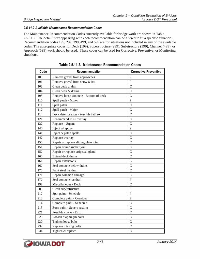
Chapter 2 – Condition Evaluation of Bridges Bridge Inspection Manual for Iowa DOT Personnel
2-48 January 2014
2.5.11.2 Available Maintenance Recommendation Codes
The Maintenance Recommendation Codes currently available for bridge work are shown in Table
2.5.11.2. The default text appearing with each recommendation can be altered to fit a specific situation.
Recommendation codes 199, 299, 399, 499, and 599 are for situations not included in any of the available
codes. The appropriate codes for Deck (199), Superstructure (299), Substructure (399), Channel (499), or
Approach (599) work should be used. These codes can be used for Corrective, Preventive, or Monitoring
situations.
Table 2.5.11.2. Maintenance Recommendation Codes
Code Recommendation Corrective/Preventive
100 Remove gravel from approaches P
101 Remove gravel from snow & ice P
103 Clean deck drains C
104 Clean deck & drains C
105 Remove loose concrete - Bottom of deck C
110 Spall patch - Minor P
111 Spall patch C
112 Spall patch - Major C
114 Deck deterioration - Possible failure C
121 Recommend PCC overlay C
132 Replace - Urgent C
140 Inject w/ epoxy P
141 Inject & patch spalls C
142 Replace overlay C
150 Repair or replace sliding plate joint C
151 Repair crumb rubber joint C
152 Repair or replace strip seal gland C
160 Extend deck drains C
161 Repair extensions C
162 Seal concrete below drains C
170 Paint steel handrail C
171 Repair collision damage C
172 Seal concrete handrail P
199 Miscellaneous - Deck C
200 Clean superstructure P
212 Spot paint - Schedule P
213 Complete paint - Consider P
214 Complete paint - Schedule C
215 Zone paint - Severe rusting C
221 Possible cracks - Drill C
223 Loosen diaphragm bolts C
230 Tighten loose bolts C
232 Replace missing bolts C
234 Tighten & replace C
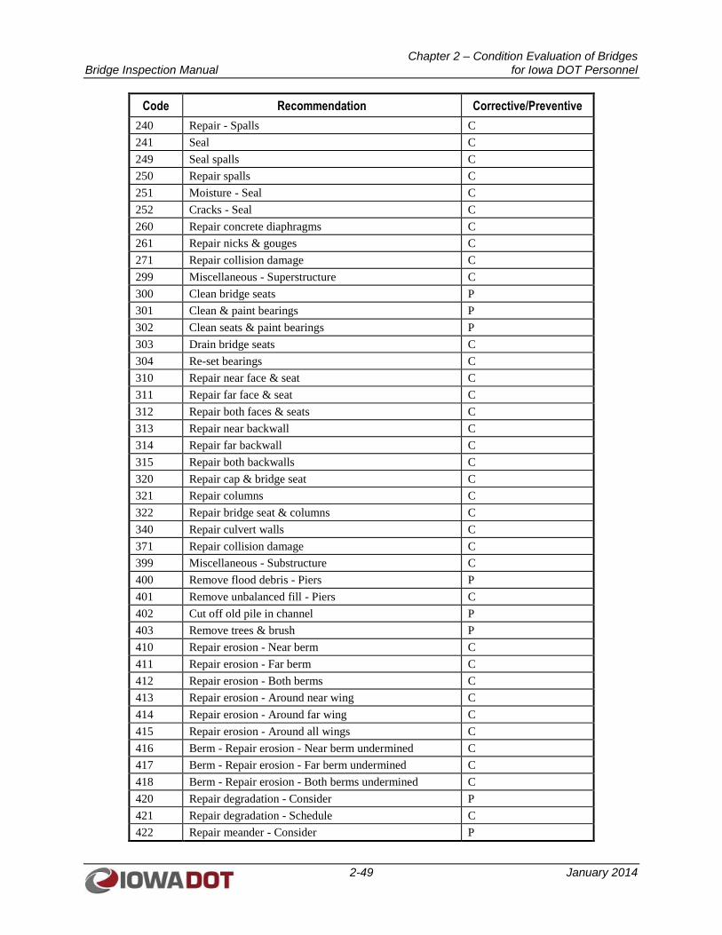
Chapter 2 – Condition Evaluation of Bridges Bridge Inspection Manual for Iowa DOT Personnel
2-49 January 2014
Code Recommendation Corrective/Preventive
240 Repair - Spalls C
241 Seal C
249 Seal spalls C
250 Repair spalls C
251 Moisture - Seal C
252 Cracks - Seal C
260 Repair concrete diaphragms C
261 Repair nicks & gouges C
271 Repair collision damage C
299 Miscellaneous - Superstructure C
300 Clean bridge seats P
301 Clean & paint bearings P
302 Clean seats & paint bearings P
303 Drain bridge seats C
304 Re-set bearings C
310 Repair near face & seat C
311 Repair far face & seat C
312 Repair both faces & seats C
313 Repair near backwall C
314 Repair far backwall C
315 Repair both backwalls C
320 Repair cap & bridge seat C
321 Repair columns C
322 Repair bridge seat & columns C
340 Repair culvert walls C
371 Repair collision damage C
399 Miscellaneous - Substructure C
400 Remove flood debris - Piers P
401 Remove unbalanced fill - Piers C
402 Cut off old pile in channel P
403 Remove trees & brush P
410 Repair erosion - Near berm C
411 Repair erosion - Far berm C
412 Repair erosion - Both berms C
413 Repair erosion - Around near wing C
414 Repair erosion - Around far wing C
415 Repair erosion - Around all wings C
416 Berm - Repair erosion - Near berm undermined C
417 Berm - Repair erosion - Far berm undermined C
418 Berm - Repair erosion - Both berms undermined C
420 Repair degradation - Consider P
421 Repair degradation - Schedule C
422 Repair meander - Consider P
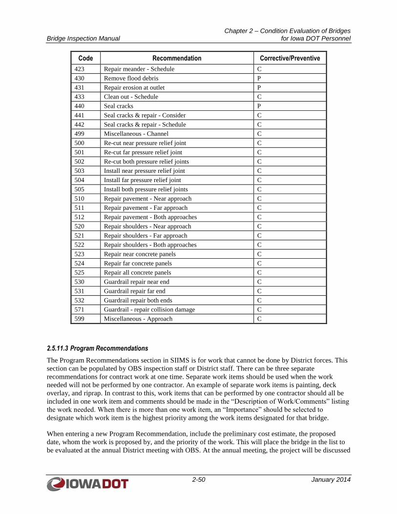
Chapter 2 – Condition Evaluation of Bridges Bridge Inspection Manual for Iowa DOT Personnel
2-50 January 2014
Code Recommendation Corrective/Preventive
423 Repair meander - Schedule C
430 Remove flood debris P
431 Repair erosion at outlet P
433 Clean out - Schedule C
440 Seal cracks P
441 Seal cracks & repair - Consider C
442 Seal cracks & repair - Schedule C
499 Miscellaneous - Channel C
500 Re-cut near pressure relief joint C
501 Re-cut far pressure relief joint C
502 Re-cut both pressure relief joints C
503 Install near pressure relief joint C
504 Install far pressure relief joint C
505 Install both pressure relief joints C
510 Repair pavement - Near approach C
511 Repair pavement - Far approach C
512 Repair pavement - Both approaches C
520 Repair shoulders - Near approach C
521 Repair shoulders - Far approach C
522 Repair shoulders - Both approaches C
523 Repair near concrete panels C
524 Repair far concrete panels C
525 Repair all concrete panels C
530 Guardrail repair near end C
531 Guardrail repair far end C
532 Guardrail repair both ends C
571 Guardrail - repair collision damage C
599 Miscellaneous - Approach C
2.5.11.3 Program Recommendations
The Program Recommendations section in SIIMS is for work that cannot be done by District forces. This
section can be populated by OBS inspection staff or District staff. There can be three separate
recommendations for contract work at one time. Separate work items should be used when the work
needed will not be performed by one contractor. An example of separate work items is painting, deck
overlay, and riprap. In contrast to this, work items that can be performed by one contractor should all be
included in one work item and comments should be made in the “Description of Work/Comments” listing
the work needed. When there is more than one work item, an “Importance” should be selected to
designate which work item is the highest priority among the work items designated for that bridge.
When entering a new Program Recommendation, include the preliminary cost estimate, the proposed
date, whom the work is proposed by, and the priority of the work. This will place the bridge in the list to
be evaluated at the annual District meeting with OBS. At the annual meeting, the project will be discussed
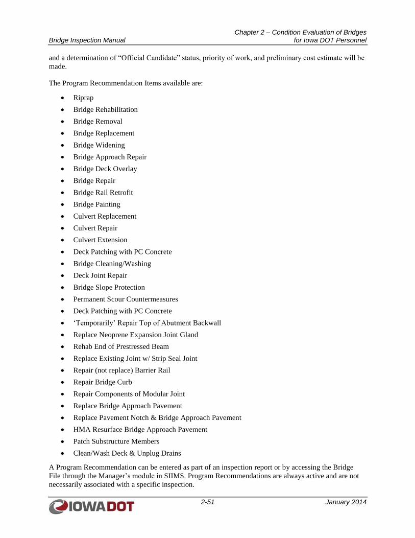
Chapter 2 – Condition Evaluation of Bridges Bridge Inspection Manual for Iowa DOT Personnel
2-51 January 2014
and a determination of “Official Candidate” status, priority of work, and preliminary cost estimate will be
made.
The Program Recommendation Items available are:
Riprap
Bridge Rehabilitation
Bridge Removal
Bridge Replacement
Bridge Widening
Bridge Approach Repair
Bridge Deck Overlay
Bridge Repair
Bridge Rail Retrofit
Bridge Painting
Culvert Replacement
Culvert Repair
Culvert Extension
Deck Patching with PC Concrete
Bridge Cleaning/Washing
Deck Joint Repair
Bridge Slope Protection
Permanent Scour Countermeasures
Deck Patching with PC Concrete
‘Temporarily’ Repair Top of Abutment Backwall
Replace Neoprene Expansion Joint Gland
Rehab End of Prestressed Beam
Replace Existing Joint w/ Strip Seal Joint
Repair (not replace) Barrier Rail
Repair Bridge Curb
Repair Components of Modular Joint
Replace Bridge Approach Pavement
Replace Pavement Notch & Bridge Approach Pavement
HMA Resurface Bridge Approach Pavement
Patch Substructure Members
Clean/Wash Deck & Unplug Drains
A Program Recommendation can be entered as part of an inspection report or by accessing the Bridge
File through the Manager’s module in SIIMS. Program Recommendations are always active and are not
necessarily associated with a specific inspection.
Chapter 2 – Condition Evaluation of Bridges Bridge Inspection Manual for Iowa DOT Personnel
2-52 January 2014
The “Need for Project Statement” is for the use of OBS. This statement will be used in the concept and is
requested when the concept is being written. The “Need for Project Statement” should include specific
information about the bridge, Structurally Deficient or Functionally Obsolete status, and reasons for
needing the project.
Once a Project has been let to contract, the status of the proposed work item should be changed to
“Completed.” The Assistant District Engineer should update the status after letting. The status can be
updated to “Completed,” “Programmed,” “Cancelled,” or “Deferred” at any time.
2.5.12 Inspection Report
An inspection report is made up of several sections from the inspection input areas. Each inspection
report should include all of the appropriate areas to create a final report. Not all sections need to be
included in a given report, but may be needed for future inspections or as additional information after the
inspection report is finalized. If a section is removed from the “Report Sections” screen, the section
removed cannot be viewed or printed after the report is finalized. Sections that may be used in future
reports should not be removed but can have the “Print” check box left blank. By leaving the “Print” check
box blank, this section will not be included in the final report, but can be viewed and printed individually.
Sections of the inspection report that can be removed are areas that will never apply to the given bridge. If
a structure is a culvert, the Deck, Superstructure, and Substructure sections will never be used and can be
removed. The Culvert section can be removed from a structure that has a Deck, Superstructure, and
Substructure. The Channel section can be removed when the bridge is over another roadway. The Pier
section can be removed for a culvert or a single-span structure.
When an In-depth or Routine Inspection is performed, the sections outlined in Sections 2.5.12.2 and
2.5.12.3 of this manual should always be included in the report.
2.5.12.1 Error Check
The Error Check section should be reviewed before an inspection report is submitted for review and
before it is finalized. The Error Check section will display the items in SIIMS that do not meet current QC
or formatting guidelines. Each error must be corrected before the inspection report can be finalized. Some
errors may be corrected automatically when the NBI calculations are manually recalculated.
Some common errors are:
Field(s) left blank in the Load Rating Evaluation Form
Comment field left blank when a condition rating is 5 or less
SI&A data not completed
2.5.12.2 Typical Bridge Inspection Report Sections
A typical bridge inspection report should consist of the sections indicated below in the following order:
1. Cover
2. Table of Contents
3. Bridge Description
4. SI&A
5. Maintenance Recommendations (if recommendations exist)
Chapter 2 – Condition Evaluation of Bridges Bridge Inspection Manual for Iowa DOT Personnel
2-53 January 2014
6. Program Recommendations (if recommendations exist)
7. BrM
8. Deck
9. Superstructure
10. Substructure
11. Piers (if piers are present)
12. Channel (if channel is present)
13. Pictures
14. Sketches
15. Load Rating
16. Map
2.5.12.3 Typical Culvert Inspection Report Sections
A typical culvert inspection report should consist of the sections indicated below in the following order:
1. Cover
2. Table of Contents
3. Bridge Description
4. SI&A
5. Maintenance Recommendations (if recommendations exist)
6. Program Recommendations (if recommendations exist)
7. BrM
8. Culvert
9. Channel
10. Pictures
11. Sketches
12. Load Rating
13. Map
2.5.12.4 “Print” Check Box
The “Print” check box should be checked for all the required sections of an inspection report. Several of
the additional sections, not required for a typical inspection report, should not be deleted from the report
listing. The “Print” check box should be left unchecked so these sections do not appear in the final
inspection report, but are available to view or print at a later date. These sections include:
Channel Section
Critical Finding
Load Rating Evaluation
Supplementary Inspection Information
Chapter 2 – Condition Evaluation of Bridges Bridge Inspection Manual for Iowa DOT Personnel
2-54 January 2014
Special/Other Inspection (NBI)
Special/Other Inspection (Non-NBI)
Under Records
The final inspection report does not require printing or saving. The report can be viewed, printed, or e-
mailed any time after the report is finalized. For all sections included in the final report, the box under the
columns “Include in Table of Contents” and “Show Page Number” should be checked.
Documents created outside of SIIMS can be added to an inspection report. If a document that is not one of
the standard documents in SIIMS would be a valuable item to include in a report, it can be added from the
Report Sections window.
2.5.13 Inspection Information
The Inspection Information section in SIIMS includes information related to what, when, and how an
inspection was completed. The date of the inspection(s) type performed is updated in this section. The
inspection frequency can be updated as needed for any of the inspection types. The primary inspector’s
name and anyone who assisted in the inspection are to be listed in the appropriate fields.
If an inspection was performed later than the required frequency due to unforeseen or unusual
circumstances, an explanation of the “Unusual Circumstances” for exceeding the inspection frequency is
required in the field provided. This will inform FHWA as to why an inspection could not be completed as
scheduled. The month the inspection was originally required to be performed must remain the same for
the following inspection. Therefore, the frequency for the next inspection should be adjusted to place the
inspection back in the original month. For example, if a bridge was scheduled for inspection in March and
could not be inspected until April, the frequency should be changed to 23 months to put the next
inspection back to a March due date.
A general comments field is provided in this section for inspectors to provide information to the Program
Manager or other inspectors about special issues related to the given bridge. This information is not
included in any report section and is for internal use only.
2.6 SI&A DATA
The Structure Inventory and Appraisal (SI&A) is a compilation of NBI data submitted annually to
FHWA. The SI&A does not contain all fields submitted to FHWA, and the SI&A format is not a standard
form required by FHWA. Each state is able to format the form in any way it chooses. Iowa DOT’s format
was developed to provide as much information as possible in an organized way on a single sheet.
The SI&A form in SIIMS contains information pulled from other SIIMS forms or external databases as
well as data that must be entered directly on the SI&A form. Most of this information must be entered
within 90 days of the bridge being opened to traffic. The fields on the SI&A form are defined as shown in
FHWA’s Recording and Coding Guide for the Structure Inventory and Appraisal of the Nation’s Bridges.
For bridges on the State and federal highway system, if errors are found in fields on the SI&A form that
are not editable by the bridge inspector, OBS should be contacted to have the errors corrected.
Chapter 2 – Condition Evaluation of Bridges Bridge Inspection Manual for Iowa DOT Personnel
2-55 January 2014
2.7 UNDER RECORDS
The Under Records section in SIIMS pertains to a bridge crossing a roadway. The inventory route for the
under record is the route under the bridge. The following four fields can be edited by the bridge
inspector:
1. Item 19, Bypass Detour Length – This is the detour length if the route under the bridge were to be
closed.
2. Item 47, Inventory Route Total Horizontal Clearance – This is the widest available clearance
under the bridge on the inventory route of the under record.
3. Item 101, Parallel Structure Design – This item will be coded as “N – No parallel structure,” in
most cases. If there are two bridges carrying the inventory route under a bridge, then this item
should be coded “L – Left” or “R - Right.” In this case, there would be separate under records for
each direction of the inventory route.
4. Item 102, Direction of Traffic – This item will be coded as “2-2-way traffic” in most cases. A
bridge crossing a one-way ramp would be coded as “1-1-way traffic.”
A bridge will have multiple under records if more than one signed route goes under the bridge. Each route
should have a separate under record. All four items listed above will have to be populated for each
inventory route passing under the bridge.
Bridge Inspection Manual Chapter 3 –QA/QC for Iowa DOT Personnel
3-1 January 2014
CHAPTER 3
QUALITY ASSURANCE/QUALITY CONTROL (QA/QC) FOR
IOWA DOT PERSONNEL
3.1 SCOPE OF IOWA DOT BRIDGE INSPECTION QUALITY ASSURANCE/QUALITY CONTROL PROGRAM
The Iowa segment of the NBI is more than 25,000 bridges. Iowa DOT owns, inspects, and maintains
more than 4,000 of these bridges in compliance with the NBIS.
More than 21,000 of the bridges in the Iowa NBI are owned, inspected, and maintained by counties,
cities, and other public agencies. County and city bridge owners are referred to as Local Public Agencies
(LPAs). Iowa Code 314.18 requires LPAs to be responsible for the safety inspection and evaluation of all
highway bridges under their jurisdiction that are located on public roads in accordance with the NBIS.
Iowa DOT published Instructional Memorandum (I.M.) 2.120 to assist LPAs in complying with the
NBIS.
Private bridge owners are not subject to the NBIS and do not fall under Iowa DOT oversight. They are
encouraged but not required to perform inspections that comply with the NBIS.
3.2 NBIS DEFINITION OF TERMS
The NBIS definitions of Quality Control and Quality Assurance are provided in the following sections.
3.2.1 Quality Control
Quality Control is defined as procedures intended to maintain the quality of a bridge inspection and load
rating at or above a specified level.
3.2.2 Quality Assurance
Quality Assurance is defined as the use of sampling and other measures to assure the adequacy of quality
control procedures in order to verify or measure the quality level of the entire bridge inspection and load
rating program.
3.3 ROLE OF SIIMS
Iowa DOT implemented SIIMS in May 2010. SIIMS is a software package used to update the bridge
records of Iowa’s portion of the NBI. The user interface is a password-protected website allowing
Iowa DOT and LPA bridge inspectors to manage inspections and document findings in a standardized
reporting format.
SIIMS is the foundation of the Iowa DOT quality control program. The software presents standard
collection screens for data entry, schedules inspections, and performs integrity checks at each stage of the
approval process. These quality control measures are in place to obtain consistent inspection data from
multiple inspectors, which is necessary if proper resource planning is to occur across the State.
Bridge Inspection Manual Chapter 3 –QA/QC for Iowa DOT Personnel
3-2 January 2014
3.4 QUALITY CONTROL
3.4.1 Inspection Scheduling
Inspection dates and inspection frequencies are entered in SIIMS for all NBI structures. Multiple
inspection types, such as Fracture Critical or Underwater Inspections, may be entered and scheduled for
separate dates, years, and frequencies.
SIIMS can forecast upcoming inspections and provide maps of bridge locations.
When the date of an inspection passes without the creation of an inspection report, SIIMS will
automatically notify the bridge owner and Program Manager via e-mail if a report is not created by the
time the inspection is 1 month, 3 months, and 6 months past due.
If an inspection report was created but remains unapproved, SIIMS will automatically notify the bridge
owner and Program Manager via e-mail when the inspection report is 3 months and 6 months past the
inspection date.
If an inspection report is not created or the report remains unapproved 6 months after the inspection date,
SIIMS will automatically notify the bridge owner and Program Manager via e-mail and request an
aggressive, short-term plan to correct this deficiency.
3.4.2 Data Collection
When an inspection report is created in SIIMS, a series of web pages are populated with the NBI
information available for the structure. SIIMS promotes consistent NBI data collection by standardizing
the data entry based on the following:
1. The inspector reviews each NBI entry and updates the data to reflect his/her inspection findings.
2. Each report includes a Load Rating Evaluation Form the inspector must complete before SIIMS
will allow the inspection report to be approved.
Each report has an Error Check page to alert the inspector to entries missing or varying from an expected
format.
3.4.3 Inspection Report Approval
The last step in the data entry process for an inspection report is requesting approval. When an inspector
submits a report for approval, the error check software in SIIMS will review the report fields. If data
entry errors are found, such as Item 92A (Fracture Critical Details) is coded “Yes” but no Fracture
Critical Inspection date is entered, an Error Check page will appear, and the report will not be approved
until the errors are resolved.
When the error check software finds entries that do not match the data stored in the SIIMS database, the
inspector will be asked if the new data should overwrite the existing data or if the existing data should
remain. The inspector must choose whether to use the report values or central database values before
SIIMS will allow the report to be approved. Some data may be uneditable because it is data maintained
by the Iowa DOT. If the data is uneditable and appears to be incorrect or in question, contact the Office
of Research and Analytics to correct or clarify the data discrepancy.
Iowa DOT inspectors submit each report to the Quality Control team for content review and approval. A
member of the Quality Control team reads each report to check the following:
Bridge Inspection Manual Chapter 3 –QA/QC for Iowa DOT Personnel
3-3 January 2014
1. The fields used for data entry are appropriate for the type of structure being inspected.
2. The written descriptions convey mental images of field conditions consistent with the
photographs and sketches of deterioration.
3. The descriptions, photographs, and sketches provide sufficient information for a person not able
to physically visit the bridge to make judgments about maintenance activities or structural repairs.
If the member of the Quality Control team finds the report fails these checks, the Quality Control team
member may either make the necessary corrections or return the report to the inspector for completion. If
the Quality Control team member decides the report is complete, he/she must then decide to take one of
three actions based on the findings in the report:
1. Approve the report without making maintenance recommendations
2. Approve the report with maintenance recommendations
3. Forward the report for further review to:
a. Engineering review
b. Scour review
c. Load Rating review
The following criteria should be used to determine when to forward the inspection report to Engineering
Review:
1. A condition rating decreased to a 4 or below.
2. An NBE has a combined total of more than 10% in condition state 3 and/or 4.
3. A BME has a combined total of more than 15% in condition state 3 and/or 4
4. Any issue the Quality Control team finds questionable.
The following criteria should be used to determine when to forward the inspection report to Preliminary
Bridge Design for Scour Review:
1. The structure is a scour susceptible bridge.
2. Scour is found during the current inspection.
3. Severe channel movement is present that is threatening a bridge substructure element.
4. Any condition the Quality Control team finds questionable.
The following criteria should be used to determine when to forward the inspection report to Load Rating
review:
1. There is collision damage to beams since the last inspection with:
a. exposed strand(s) in prestressed beams;
b. gouges, tears, or bends in steel beams; or
c. unrepaired previous collision damage.
2. There is more than 1/16 inch new section loss in steel beams and any additional section loss at an
old area.
3. There is new or additional bearing area loss.
Bridge Inspection Manual Chapter 3 –QA/QC for Iowa DOT Personnel
3-4 January 2014
4. There is a new deck, new deck overlay, new barrier rails, or bridge widening since the last
inspection.
5. There are damaged sign trusses attached to bridges (attachments with exposed anchor bolts,
cracks in truss members, truss members with significant section loss).
6. Strengthening of load carrying members has been performed since the last inspection.
7. There are special, posted, or detour bridges.
8. There are wood piling problems (hollow or rotten areas, major splits).
9. The structure is a new bridge.
10. There is movement of substructure units.
11. There is significant concrete deterioration of prestressed beam ends, pier caps and columns, if not
previously reported.
12. There is post tensioning of prestressed concrete beam bridges.
13. There is post tensioned retrofit of steel and concrete bridges.
Engineer review or Load Rating review includes reviewing the entire inspection and making
recommendations for repair. Recommendations for program work, when needed, should also be
completed during an engineer’s review. When the review is complete, the engineer will approve the final
report.
A Scour review will only review the need for repair of the waterway. When the Scour review is complete,
the report will be sent back to the Quality Control team for finalization or further engineer review.
3.4.4 Training
The NBIS requires periodic bridge inspection refresher training for Program Managers and Team Leaders
in Part 650.313(g). Iowa DOT has defined periodic as being every 5 years. All State and LPA bridge
inspection personnel are required to complete the Bridge Inspection Refresher Training Course every
5 years following the completion of the Safety Inspection of In-Service Bridges Training Course.
The SIIMS system contains an individual’s qualifications as a team leader. When an individual’s
refresher training or professional license is within 6 months of expiring, a notice will appear each time the
user logs into SIIMS. This notice will show the date(s) of expiration.
3.5 QUALITY ASSURANCE
The terms quality control and quality assurance are not interchangeable. The NBIS defines quality
control as a tool and quality assurance as an evaluation of that tool. SIIMS has built-in quality controls
guiding inspectors through data collection and standardize data entry in order to obtain consistent
inspection data from multiple inspectors.
Quality assurance is a review of the inspection data to provide the following:
1. An evaluation of how well the quality control tools in SIIMS are delivering consistent inspection
data
2. Identification of where the data are not consistent so the quality control tools can be corrected or
modified
Bridge Inspection Manual Chapter 3 –QA/QC for Iowa DOT Personnel
3-5 January 2014
Iowa DOT employs six inspection teams to perform NBI inspections complying with the NBIS. The
supervisor of the inspection teams performs a formal quality assurance review of two teams annually
using the criteria described in the following sections.
3.5.1 Team Selection
Two inspection teams are reviewed annually. The six teams are selected in the following 3-year cycle:
Year 1 = Teams 1 and 4
Year 2 = Teams 2 and 5
Year 3 = Teams 3 and 6
3.5.2 Bridge Selection
Four bridges assigned to a team are selected for review, but the bridges should not be selected at random.
The bridges should be scheduled for inspection during the calendar year of the review. The age and
sufficiency rating should be considered to avoid selecting bridges that are too new to have notable
deterioration. The type (SI&A item 43) of the four structures selected must include the following:
1. 402, Steel Continuous Multi-Beam
2. 502, Prestressed Concrete Multi-Beam
3. 201, Concrete Continuous Slab
4. 219, Concrete Continuous Culvert
The size and complexity of the structures should be similar to a number of other bridges of the same type
the team inspects.
3.5.3 Quality Assurance Inspections
The supervisor will inspect the selected bridges using an Independent Oversight Model (IOM), which is a
quality assurance review generating a bridge inspection independent and without the knowledge of the
team under review. The supervisor should review previous inspection reports and plans, prepare
sketches, take digital photographs, rate NBI items, complete Bridge Element condition states, and
describe deterioration as if he/she were performing the biennial NBI inspection.
3.5.4 Tolerance Thresholds
The supervisor will compare the IOM inspections to the NBI inspection reports the team submits and
prepare a summary of any differences between the reports. Specifically, the supervisor should look for
consistency in NBI ratings, Bridge Element condition states, sketches, and photographs using the
following thresholds established to define if data are in-tolerance or out-of-tolerance:
NBI Tolerances:
1. NBI condition/appraisal ratings are within +/- 1 of the IOM ratings.
2. Subjective NBI lengths (field measurements that may be difficult to exactly duplicate, such as
vertical clearances) are within +/- 0.2 feet or +/- 3 inches.
3. Non-subjective NBI lengths (obtained from bridge plans that should not vary, such as the longest
span) are within +/- 0.1 feet or +/- 2 inches.
Bridge Inspection Manual Chapter 3 –QA/QC for Iowa DOT Personnel
3-6 January 2014
4. Non-subjective NBI quantities (obtained from bridge plans that should not vary, such as the
number of spans) are within +/- 0 quantity.
5. Non-subjective NBI descriptive codes (obtained from bridge plans that should not vary, such the
type of wearing surface) are within +/- 0.
AASHTO Bridge Elements:
1. Each Bridge Element included in the inspection team’s NBI report that does not apply to the
bridge should be counted as out-of-tolerance.
2. Each failure to include a Bridge Element in the inspection team’s NBI report that does apply to
the bridge should be counted as out-of-tolerance.
Condition States for AASHTO Bridge Elements:
1. Bridge Elements where condition state quantities are reported in feet: +/- 10 feet
2. Bridge Elements where condition state quantities are reported in square feet: +/- 25 square feet
3. Bridge Elements where condition state quantities are reported in each: +/- 1
3.5.5 Scoring
Each report will receive a score of up to 100 points. The report score is the sum of points awarded in the
following four categories:
1. Condition/Appraisal Ratings = 25 points
2. SI&A Data Items = 25 points
3. AASHTO Bridge Elements = 25 points
4. Supporting Documentation = 25 points
3.5.5.1 Condition/Appraisal Ratings
The supervisor will compare the inspection team’s NBI ratings for SI&A items 58 – 62 and 72 to the IOM
inspection. The six items will be counted as either in-tolerance or out-of-tolerance. A score will be
calculated as follows:
N = number of out-of-tolerance items
Score = (1 - N / 6) * 25 pts.
3.5.5.2 SI&A Data Items
The supervisor will compare the inspection team’s values for SI&A items 10, 27, 28, 32 – 36, 41 – 56,
and 106 – 108 to the IOM inspection. The 37 values for these items will be counted as either in-tolerance
or out-of-tolerance. A score will be calculated as follows:
N = number of out-of-tolerance items
Score = (1 - N / 37) * 25 pts.
3.5.5.3 AASHTO Bridge Elements
The supervisor will count the number of Bridge Elements that are either in-tolerance or out-of-tolerance.
A score will be calculated as follows:
N = number of out-of-tolerance elements
Bridge Inspection Manual Chapter 3 –QA/QC for Iowa DOT Personnel
3-7 January 2014
T = total number of elements in the IOM inspection
Score = (1 - N / T) * 25 pts.
3.5.5.4 Supporting Documentation
The supervisor will score the inspection team’s photographs; photo descriptions; sketches; Bridge
Element text descriptions; and proper use of grammar, capitalization, and sentence structure. Each
criterion is worth up to 5 points. An overall score for Supporting Documentation will be calculated by
summing the scores for the five aforementioned criteria. Each criterion score shall be based on the
following model:
5 = Excellent documentation
4
3 = Minimum acceptable effort
2
1 = Completely unacceptable effort
Points 4 and 2 are to be used where the documentation is judged to fall between the 5, 3, and 1 point
scores.
The example provided in Figure 3.5.5.4-1 is intended to provide a scoring guide for Supporting
Documentation, but the reviewer must use judgment to decide if the inspection team’s documentation
more closely aligns with the excellent or unacceptable end of the rating scale.
Figure 3.5.5.4-2 is a summary scoring sheet for the entire Quality Assurance Review.
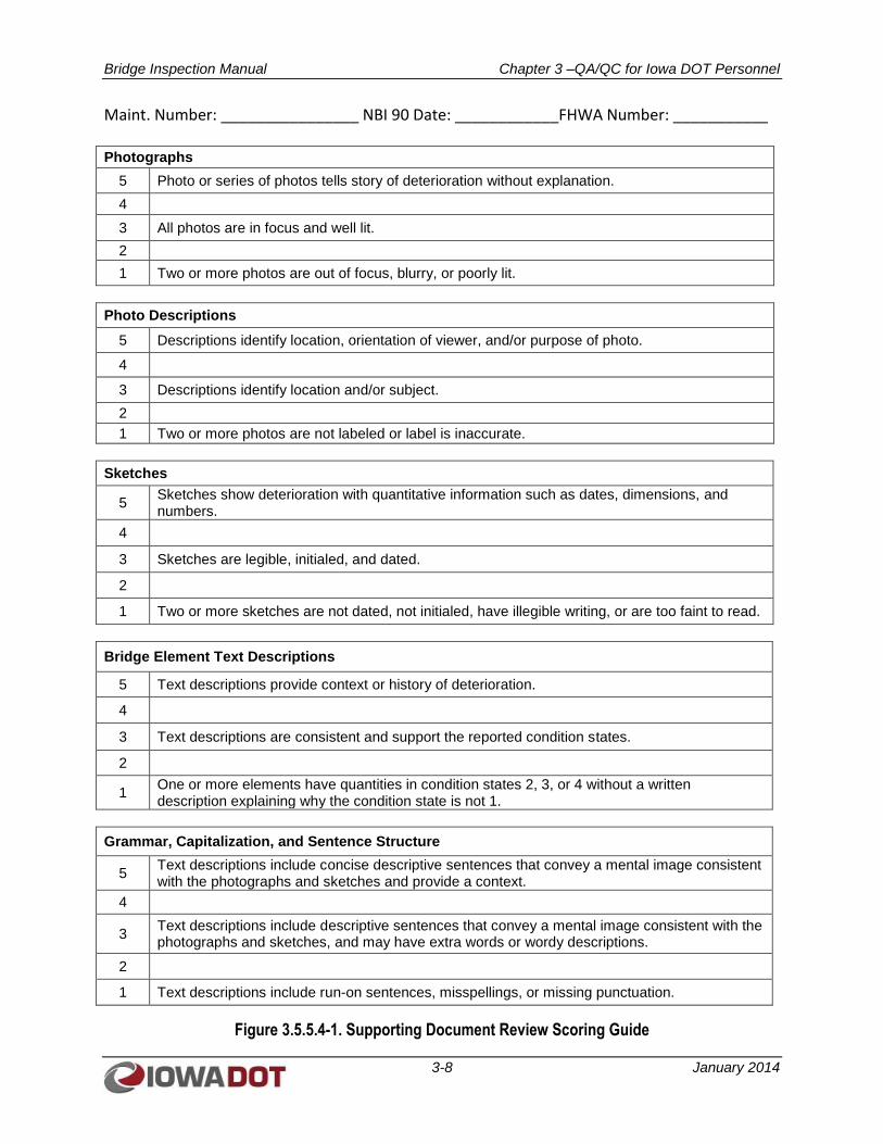
Bridge Inspection Manual Chapter 3 –QA/QC for Iowa DOT Personnel
3-8 January 2014
Maint. Number: ________________ NBI 90 Date: ____________FHWA Number: ___________ Photographs
5 Photo or series of photos tells story of deterioration without explanation.
4
3 All photos are in focus and well lit.
2
1 Two or more photos are out of focus, blurry, or poorly lit.
Photo Descriptions
5 Descriptions identify location, orientation of viewer, and/or purpose of photo.
4
3 Descriptions identify location and/or subject.
2
1 Two or more photos are not labeled or label is inaccurate.
Sketches
5 Sketches show deterioration with quantitative information such as dates, dimensions, and numbers.
4
3 Sketches are legible, initialed, and dated.
2
1 Two or more sketches are not dated, not initialed, have illegible writing, or are too faint to read.
Bridge Element Text Descriptions
5 Text descriptions provide context or history of deterioration.
4
3 Text descriptions are consistent and support the reported condition states.
2
1 One or more elements have quantities in condition states 2, 3, or 4 without a written description explaining why the condition state is not 1.
Grammar, Capitalization, and Sentence Structure
5 Text descriptions include concise descriptive sentences that convey a mental image consistent with the photographs and sketches and provide a context.
4
3 Text descriptions include descriptive sentences that convey a mental image consistent with the photographs and sketches, and may have extra words or wordy descriptions.
2
1 Text descriptions include run-on sentences, misspellings, or missing punctuation.
Figure 3.5.5.4-1. Supporting Document Review Scoring Guide
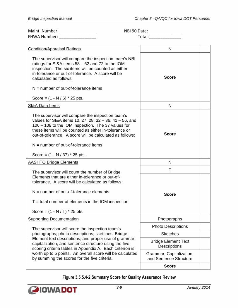
Bridge Inspection Manual Chapter 3 –QA/QC for Iowa DOT Personnel
3-9 January 2014
Maint. Number: ________________ NBI 90 Date: ______________ FHWA Number: ________________ Total:______________
Condition/Appraisal Ratings The supervisor will compare the inspection team’s NBI ratings for SI&A items 58 – 62 and 72 to the IOM inspection. The six items will be counted as either in-tolerance or out-of-tolerance. A score will be calculated as follows: N = number of out-of-tolerance items Score = (1 - N / 6) * 25 pts.
N
Score
SI&A Data Items The supervisor will compare the inspection team’s values for SI&A items 10, 27, 28, 32 – 36, 41 – 56, and 106 – 108 to the IOM inspection. The 37 values for these items will be counted as either in-tolerance or out-of-tolerance. A score will be calculated as follows: N = number of out-of-tolerance items Score = (1 - N / 37) * 25 pts.
N
Score
AASHTO Bridge Elements The supervisor will count the number of Bridge Elements that are either in-tolerance or out-of-tolerance. A score will be calculated as follows: N = number of out-of-tolerance elements T = total number of elements in the IOM inspection Score = (1 - N / T) * 25 pts.
N
T
Score
Supporting Documentation The supervisor will score the inspection team’s photographs; photo descriptions; sketches; Bridge Element text descriptions; and proper use of grammar, capitalization, and sentence structure using the five scoring criteria tables in Appendix A. Each criterion is worth up to 5 points. An overall score will be calculated by summing the scores for the five criteria.
Photographs
Photo Descriptions
Sketches
Bridge Element Text Descriptions
Grammar, Capitalization, and Sentence Structure
Score
Figure 3.5.5.4-2 Summary Score for Quality Assurance Review
Bridge Inspection Manual Chapter 3 –QA/QC for Iowa DOT Personnel
3-10 January 2014
3.5.6 Close-out Meeting
The supervisor will schedule a meeting with the inspection teams to review the findings from the IOM
inspections and the scores of the team inspections. The meeting should be a constructive discussion to
identify gaps in training, training topics that should be repeated or emphasized, expectations that should
be revised or clarified, and possible changes to SIIMS.
Chapter 4 – Condition Evaluation of Bridges Bridge Inspection Manual for Local Public Agencies
4-1 January 2014
CHAPTER 4
CONDITION EVALUATION OF BRIDGES
FOR LOCAL PUBLIC AGENCIES
Refer to Iowa DOT I.M. 2.120 for guidelines and procedures for LPAs to assist them in complying with
the NBIS.
4.1 INSPECTION PLANNING
4.1.1 Reviewing Past Inspection Reports, SIIMS Data, Existing Bridge Plans, and Bridge Repair Plans
The first step in preparing for any bridge inspection is to gather information regarding the existing bridge
so the inspector is educated with regard to the configuration and type of bridge as well as its documented
history. This is important so the number of inspection personnel and type of equipment and tools,
including non-destructive testing equipment, needed to perform the inspection can be determined. If as-
built plans and/or plans of any repairs or rehabilitation projects are available, they should be reviewed to
help the inspector gain an understanding of the bridge configuration and structure type as well as to allow
the inspector to plan ahead for the access constraints that might affect how the bridge will be inspected.
Typically, if existing plans are available, they would be included as part of the bridge’s record within the
SIIMS database. Another helpful resource is any available shop drawings produced by the contractor or
the contractor’s fabricators at the time the bridge was originally built or rehabilitated.
In addition to existing plans and shop drawings, the bridge record within SIIMS should also contain past
inspection reports for the bridge. Reviewing these past reports not only helps the inspector identify
problem areas of the bridge previously documented, but they may also document the progression of
damage or deterioration over the course of multiple inspections, thus allowing the inspector to identify
trends or problem areas worsening over time. The inspection reports should also include past
photographs and field sketches documenting the condition of the bridge.
4.1.2 Determining Required Inspection Documentation and Preparing Needed Sketches
In reviewing the available information for the bridge, the inspector will begin to develop an understanding
of the bridge. In preparation for the upcoming bridge inspection, it may be necessary to prepare sketches
or tables in advance to be used for documenting current conditions to be more efficient in the field and to
more clearly record crucial inspection findings. For example, prior to going into the field for the bridge
inspection, a table may be prepared to record bearing and expansion joint movement data, or sketches
may be prepared for use in recording crack locations and sizes for the underside surface of the bridge
deck or for individual piers or abutments.
4.1.3 Arranging for Access and Other Inspection Equipment
A critical component of any bridge inspection preparation is determining how the bridge components will
be accessed during the inspection. In addition, depending on the nature of the bridge components, such as
whether the bridge includes fracture critical components requiring arms-length access, the access
requirements may require more rigorous planning.
Depending on the size of the bridge and its height above ground level, inspection access could be as
simple as ground-level observations. More often than not, ladders, a UBIV, a manlift, or even rope access
Chapter 4 – Condition Evaluation of Bridges Bridge Inspection Manual for Local Public Agencies
4-2 January 2014
techniques may be necessary to properly access key bridge components. However, developing an access
plan requires careful consideration of the components to be inspected; the topography and features
crossed by the bridge that might limit access options; any load restrictions on the bridge; the geometry of
the bridge and its sidewalks, bridge rails, and fencing; and a review of whether certain access methods
may provide a cost advantage by saving time and labor even at the expense of the equipment costs or
rental.
If it is determined that a manlift or UBIV is required to access the bridge components for inspection,
advance planning is required to either schedule the equipment, if owned by the LPA, or to determine
availability and rent the equipment from an outside source. A variety of UBIV options are available that
allow the vehicle reach and the number of rotating turrets to be tailored to the specific constraints of the
bridge to be inspected. This may be especially critical for truss bridges, where the ability to maneuver the
boom of a UBIV through and between truss members may be dependent on the configuration of the
UBIV.
4.1.4 Arranging for Advanced Bridge Washing
It is important that bridge components are free of debris, animal nesting materials, and bird droppings to
allow the most efficient use of the inspection team’s time in the field. Therefore, coordinating with LPA
bridge maintenance personnel in advance of the bridge inspection is important to ensure required bridge
cleaning activities are completed before the inspection team arrives at the bridge site. Inspections
scheduled during winter months may not allow advanced bridge washing due to freezing conditions.
Additionally, some environmental regulations may limit periods when active nests of migratory birds,
such as swallows, may be removed.
4.1.5 Executing Any Required Agency Notifications and Permits
Many bridges cross facilities requiring advance notification or permits with other agencies. Bridges over
navigable waterways such as the Mississippi and Missouri rivers will require advance notice to the U.S.
Coast Guard so barge operators can be advised of the inspection activities, especially if the inspection will
require the mechanical arms of a UBIV to be extended below the superstructure of a bridge where it could
conflict with barge traffic.
Similarly, bridges over railroads will require notification of the railroads so a UBIV does not conflict with
active train traffic. In addition, the use of a railroad flagger will be required to control train movement
during bridge inspection activities. If railroad right-of-way must be crossed or used to provide bridge
access, the bridge inspector must have a railroad flagger present, and a right-of-access permit may need to
be obtained. The railroad must be notified far enough in advance to allow them time to schedule a flagger
for the inspection and to obtain the access permit.
If there are any critical utilities mounted on the bridge or crossing the bridge that could cause safety
concerns (for example, an overhead high voltage line that needs to be de-energized to avoid conflict with
the mechanical arm of a UBIV), advance coordination with the utility may be needed.
4.1.6 Adjusting Work Schedules
As practicable, but still maintaining NBIS compliance with required inspection frequencies, bridge
inspections should be performed when weather conditions will have minimal impact on workflow. If
possible, inspections for bridges over rivers and streams should be periodically scheduled during low-
flow months to allow the best view of components above the waterline. For the most effective
inspections, periods of extreme temperature or high winds should be avoided.
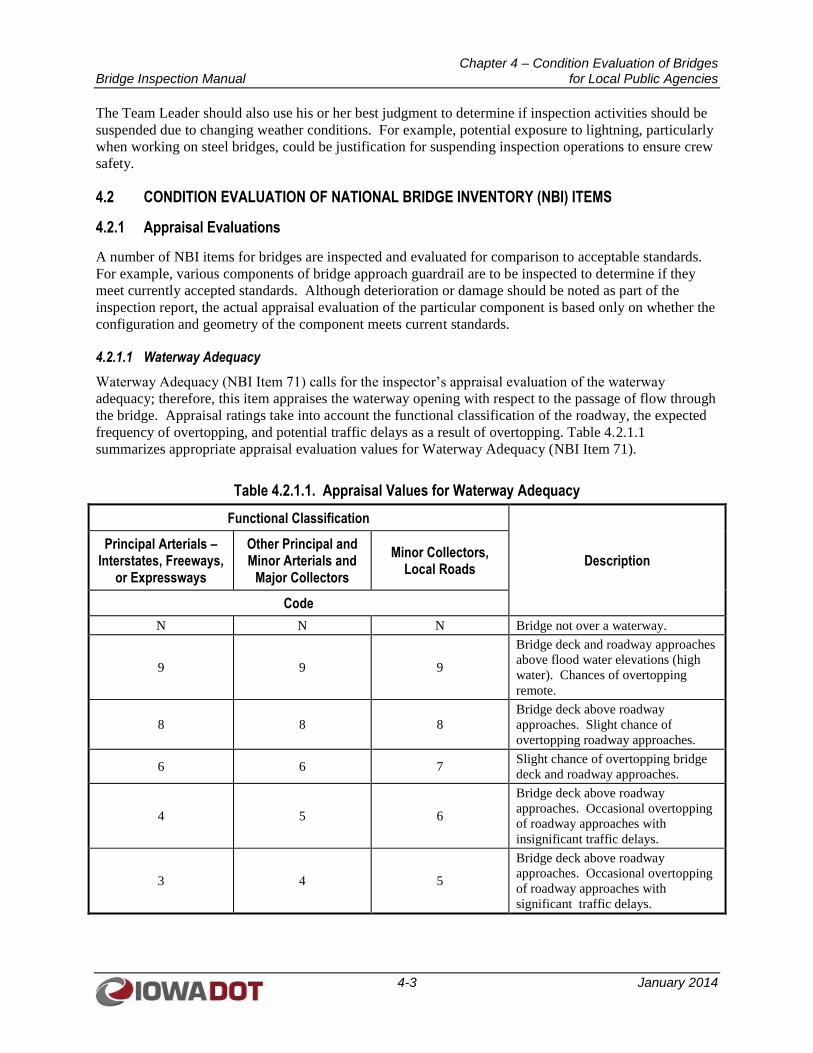
Chapter 4 – Condition Evaluation of Bridges Bridge Inspection Manual for Local Public Agencies
4-3 January 2014
The Team Leader should also use his or her best judgment to determine if inspection activities should be
suspended due to changing weather conditions. For example, potential exposure to lightning, particularly
when working on steel bridges, could be justification for suspending inspection operations to ensure crew
safety.
4.2 CONDITION EVALUATION OF NATIONAL BRIDGE INVENTORY (NBI) ITEMS
4.2.1 Appraisal Evaluations
A number of NBI items for bridges are inspected and evaluated for comparison to acceptable standards.
For example, various components of bridge approach guardrail are to be inspected to determine if they
meet currently accepted standards. Although deterioration or damage should be noted as part of the
inspection report, the actual appraisal evaluation of the particular component is based only on whether the
configuration and geometry of the component meets current standards.
4.2.1.1 Waterway Adequacy
Waterway Adequacy (NBI Item 71) calls for the inspector’s appraisal evaluation of the waterway
adequacy; therefore, this item appraises the waterway opening with respect to the passage of flow through
the bridge. Appraisal ratings take into account the functional classification of the roadway, the expected
frequency of overtopping, and potential traffic delays as a result of overtopping. Table 4.2.1.1
summarizes appropriate appraisal evaluation values for Waterway Adequacy (NBI Item 71).
Table 4.2.1.1. Appraisal Values for Waterway Adequacy
Functional Classification
Description Principal Arterials –
Interstates, Freeways, or Expressways
Other Principal and Minor Arterials and
Major Collectors
Minor Collectors, Local Roads
Code
N N N Bridge not over a waterway.
9 9 9
Bridge deck and roadway approaches
above flood water elevations (high
water). Chances of overtopping
remote.
8 8 8
Bridge deck above roadway
approaches. Slight chance of
overtopping roadway approaches.
6 6 7 Slight chance of overtopping bridge
deck and roadway approaches.
4 5 6
Bridge deck above roadway
approaches. Occasional overtopping
of roadway approaches with
insignificant traffic delays.
3 4 5
Bridge deck above roadway
approaches. Occasional overtopping
of roadway approaches with
significant traffic delays.
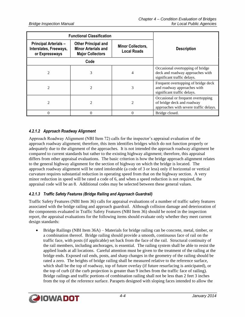
Chapter 4 – Condition Evaluation of Bridges Bridge Inspection Manual for Local Public Agencies
4-4 January 2014
Functional Classification
Description Principal Arterials –
Interstates, Freeways, or Expressways
Other Principal and Minor Arterials and
Major Collectors
Minor Collectors, Local Roads
Code
2 3 4
Occasional overtopping of bridge
deck and roadway approaches with
significant traffic delays.
2 2 3
Frequent overtopping of bridge deck
and roadway approaches with
significant traffic delays.
2 2 2
Occasional or frequent overtopping
of bridge deck and roadway
approaches with severe traffic delays.
0 0 0 Bridge closed.
4.2.1.2 Approach Roadway Alignment
Approach Roadway Alignment (NBI Item 72) calls for the inspector’s appraisal evaluation of the
approach roadway alignment; therefore, this item identifies bridges which do not function properly or
adequately due to the alignment of the approaches. It is not intended the approach roadway alignment be
compared to current standards but rather to the existing highway alignment; therefore, this appraisal
differs from other appraisal evaluations. The basic criterion is how the bridge approach alignment relates
to the general highway alignment for the section of highway on which the bridge is located. The
approach roadway alignment will be rated intolerable (a code of 3 or less) only if horizontal or vertical
curvature requires substantial reduction in operating speed from that on the highway section. A very
minor reduction in speed will be rated a code of 6, and when a speed reduction is not required, the
appraisal code will be an 8. Additional codes may be selected between these general values.
4.2.1.3 Traffic Safety Features (Bridge Railing and Approach Guardrail)
Traffic Safety Features (NBI Item 36) calls for appraisal evaluations of a number of traffic safety features
associated with the bridge railing and approach guardrail. Although collision damage and deterioration of
the components evaluated in Traffic Safety Features (NBI Item 36) should be noted in the inspection
report, the appraisal evaluations for the following items should evaluate only whether they meet current
design standards:
Bridge Railings (NBI Item 36A) – Materials for bridge railing can be concrete, metal, timber, or
a combination thereof. Bridge railing should provide a smooth, continuous face of rail on the
traffic face, with posts (if applicable) set back from the face of the rail. Structural continuity of
the rail members, including anchorages, is essential. The railing system shall be able to resist the
applied loads at all locations. Careful attention must be given to the treatment of the railing at the
bridge ends. Exposed rail ends, posts, and sharp changes in the geometry of the railing should be
rated a zero. The heights of bridge railing shall be measured relative to the reference surface,
which shall be the top of roadway, top of future overlay (if future resurfacing is anticipated), or
the top of curb (if the curb projection is greater than 9 inches from the traffic face of railing).
Bridge railings and traffic portions of combination railing shall not be less than 2 feet 3 inches
from the top of the reference surface. Parapets designed with sloping faces intended to allow the
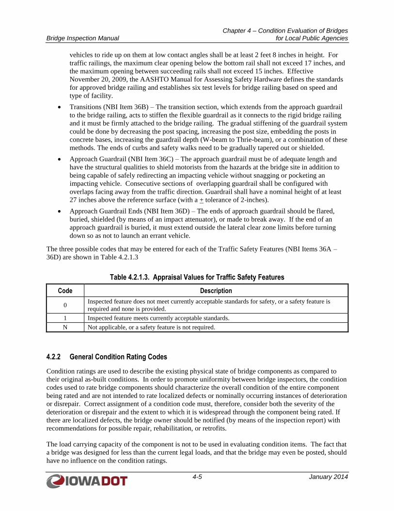
Chapter 4 – Condition Evaluation of Bridges Bridge Inspection Manual for Local Public Agencies
4-5 January 2014
vehicles to ride up on them at low contact angles shall be at least 2 feet 8 inches in height. For
traffic railings, the maximum clear opening below the bottom rail shall not exceed 17 inches, and
the maximum opening between succeeding rails shall not exceed 15 inches. Effective
November 20, 2009, the AASHTO Manual for Assessing Safety Hardware defines the standards
for approved bridge railing and establishes six test levels for bridge railing based on speed and
type of facility.
Transitions (NBI Item 36B) – The transition section, which extends from the approach guardrail
to the bridge railing, acts to stiffen the flexible guardrail as it connects to the rigid bridge railing
and it must be firmly attached to the bridge railing. The gradual stiffening of the guardrail system
could be done by decreasing the post spacing, increasing the post size, embedding the posts in
concrete bases, increasing the guardrail depth (W-beam to Thrie-beam), or a combination of these
methods. The ends of curbs and safety walks need to be gradually tapered out or shielded.
Approach Guardrail (NBI Item 36C) – The approach guardrail must be of adequate length and
have the structural qualities to shield motorists from the hazards at the bridge site in addition to
being capable of safely redirecting an impacting vehicle without snagging or pocketing an
impacting vehicle. Consecutive sections of overlapping guardrail shall be configured with
overlaps facing away from the traffic direction. Guardrail shall have a nominal height of at least
27 inches above the reference surface (with a + tolerance of 2-inches).
Approach Guardrail Ends (NBI Item 36D) – The ends of approach guardrail should be flared,
buried, shielded (by means of an impact attenuator), or made to break away. If the end of an
approach guardrail is buried, it must extend outside the lateral clear zone limits before turning
down so as not to launch an errant vehicle.
The three possible codes that may be entered for each of the Traffic Safety Features (NBI Items 36A –
36D) are shown in Table 4.2.1.3
Table 4.2.1.3. Appraisal Values for Traffic Safety Features
Code Description
0 Inspected feature does not meet currently acceptable standards for safety, or a safety feature is
required and none is provided.
1 Inspected feature meets currently acceptable standards.
N Not applicable, or a safety feature is not required.
4.2.2 General Condition Rating Codes
Condition ratings are used to describe the existing physical state of bridge components as compared to
their original as-built conditions. In order to promote uniformity between bridge inspectors, the condition
codes used to rate bridge components should characterize the overall condition of the entire component
being rated and are not intended to rate localized defects or nominally occurring instances of deterioration
or disrepair. Correct assignment of a condition code must, therefore, consider both the severity of the
deterioration or disrepair and the extent to which it is widespread through the component being rated. If
there are localized defects, the bridge owner should be notified (by means of the inspection report) with
recommendations for possible repair, rehabilitation, or retrofits.
The load carrying capacity of the component is not to be used in evaluating condition items. The fact that
a bridge was designed for less than the current legal loads, and that the bridge may even be posted, should
have no influence on the condition ratings.
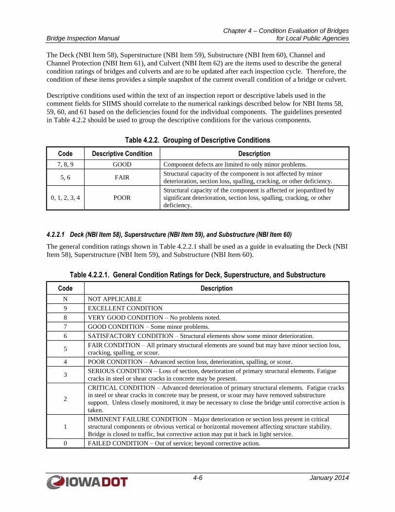
Chapter 4 – Condition Evaluation of Bridges Bridge Inspection Manual for Local Public Agencies
4-6 January 2014
The Deck (NBI Item 58), Superstructure (NBI Item 59), Substructure (NBI Item 60), Channel and
Channel Protection (NBI Item 61), and Culvert (NBI Item 62) are the items used to describe the general
condition ratings of bridges and culverts and are to be updated after each inspection cycle. Therefore, the
condition of these items provides a simple snapshot of the current overall condition of a bridge or culvert.
Descriptive conditions used within the text of an inspection report or descriptive labels used in the
comment fields for SIIMS should correlate to the numerical rankings described below for NBI Items 58,
59, 60, and 61 based on the deficiencies found for the individual components. The guidelines presented
in Table 4.2.2 should be used to group the descriptive conditions for the various components.
Table 4.2.2. Grouping of Descriptive Conditions
Code Descriptive Condition Description
7, 8, 9 GOOD Component defects are limited to only minor problems.
5, 6 FAIR Structural capacity of the component is not affected by minor
deterioration, section loss, spalling, cracking, or other deficiency.
0, 1, 2, 3, 4 POOR
Structural capacity of the component is affected or jeopardized by
significant deterioration, section loss, spalling, cracking, or other
deficiency.
4.2.2.1 Deck (NBI Item 58), Superstructure (NBI Item 59), and Substructure (NBI Item 60)
The general condition ratings shown in Table 4.2.2.1 shall be used as a guide in evaluating the Deck (NBI
Item 58), Superstructure (NBI Item 59), and Substructure (NBI Item 60).
Table 4.2.2.1. General Condition Ratings for Deck, Superstructure, and Substructure
Code Description
N NOT APPLICABLE
9 EXCELLENT CONDITION
8 VERY GOOD CONDITION – No problems noted.
7 GOOD CONDITION – Some minor problems.
6 SATISFACTORY CONDITION – Structural elements show some minor deterioration.
5 FAIR CONDITION – All primary structural elements are sound but may have minor section loss,
cracking, spalling, or scour.
4 POOR CONDITION – Advanced section loss, deterioration, spalling, or scour.
3 SERIOUS CONDITION – Loss of section, deterioration of primary structural elements. Fatigue
cracks in steel or shear cracks in concrete may be present.
2
CRITICAL CONDITION – Advanced deterioration of primary structural elements. Fatigue cracks
in steel or shear cracks in concrete may be present, or scour may have removed substructure
support. Unless closely monitored, it may be necessary to close the bridge until corrective action is
taken.
1
IMMINENT FAILURE CONDITION – Major deterioration or section loss present in critical
structural components or obvious vertical or horizontal movement affecting structure stability.
Bridge is closed to traffic, but corrective action may put it back in light service.
0 FAILED CONDITION – Out of service; beyond corrective action.
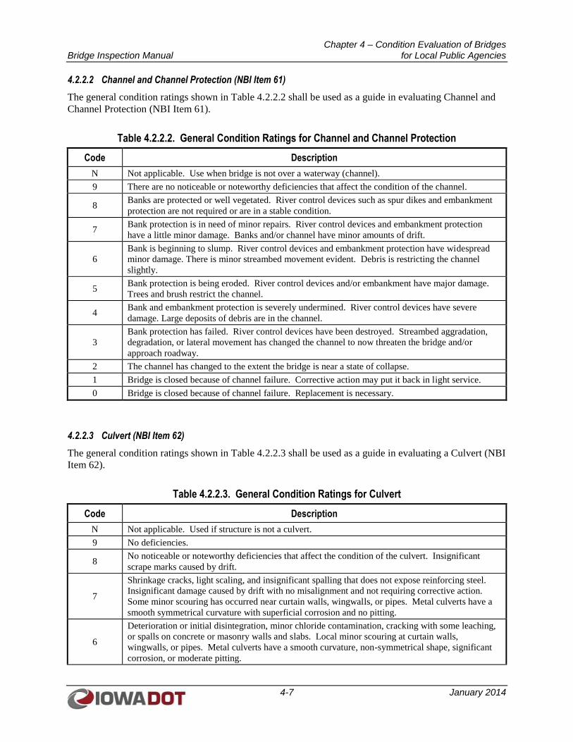
Chapter 4 – Condition Evaluation of Bridges Bridge Inspection Manual for Local Public Agencies
4-7 January 2014
4.2.2.2 Channel and Channel Protection (NBI Item 61)
The general condition ratings shown in Table 4.2.2.2 shall be used as a guide in evaluating Channel and
Channel Protection (NBI Item 61).
Table 4.2.2.2. General Condition Ratings for Channel and Channel Protection
Code Description
N Not applicable. Use when bridge is not over a waterway (channel).
9 There are no noticeable or noteworthy deficiencies that affect the condition of the channel.
8 Banks are protected or well vegetated. River control devices such as spur dikes and embankment
protection are not required or are in a stable condition.
7 Bank protection is in need of minor repairs. River control devices and embankment protection
have a little minor damage. Banks and/or channel have minor amounts of drift.
6
Bank is beginning to slump. River control devices and embankment protection have widespread
minor damage. There is minor streambed movement evident. Debris is restricting the channel
slightly.
5 Bank protection is being eroded. River control devices and/or embankment have major damage.
Trees and brush restrict the channel.
4 Bank and embankment protection is severely undermined. River control devices have severe
damage. Large deposits of debris are in the channel.
3
Bank protection has failed. River control devices have been destroyed. Streambed aggradation,
degradation, or lateral movement has changed the channel to now threaten the bridge and/or
approach roadway.
2 The channel has changed to the extent the bridge is near a state of collapse.
1 Bridge is closed because of channel failure. Corrective action may put it back in light service.
0 Bridge is closed because of channel failure. Replacement is necessary.
4.2.2.3 Culvert (NBI Item 62)
The general condition ratings shown in Table 4.2.2.3 shall be used as a guide in evaluating a Culvert (NBI
Item 62).
Table 4.2.2.3. General Condition Ratings for Culvert
Code Description
N Not applicable. Used if structure is not a culvert.
9 No deficiencies.
8 No noticeable or noteworthy deficiencies that affect the condition of the culvert. Insignificant
scrape marks caused by drift.
7
Shrinkage cracks, light scaling, and insignificant spalling that does not expose reinforcing steel.
Insignificant damage caused by drift with no misalignment and not requiring corrective action.
Some minor scouring has occurred near curtain walls, wingwalls, or pipes. Metal culverts have a
smooth symmetrical curvature with superficial corrosion and no pitting.
6
Deterioration or initial disintegration, minor chloride contamination, cracking with some leaching,
or spalls on concrete or masonry walls and slabs. Local minor scouring at curtain walls,
wingwalls, or pipes. Metal culverts have a smooth curvature, non-symmetrical shape, significant
corrosion, or moderate pitting.
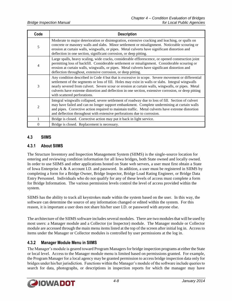
Chapter 4 – Condition Evaluation of Bridges Bridge Inspection Manual for Local Public Agencies
4-8 January 2014
Code Description
5
Moderate to major deterioration or disintegration, extensive cracking and leaching, or spalls on
concrete or masonry walls and slabs. Minor settlement or misalignment. Noticeable scouring or
erosion at curtain walls, wingwalls, or pipes. Metal culverts have significant distortion and
deflection in one section, significant corrosion, or deep pitting.
4
Large spalls, heavy scaling, wide cracks, considerable efflorescence, or opened construction joint
permitting loss of backfill. Considerable settlement or misalignment. Considerable scouring or
erosion at curtain walls, wingwalls, or pipes. Metal culverts have significant distortion and
deflection throughout, extensive corrosion, or deep pitting.
3
Any condition described in Code 4 but that is excessive in scope. Severe movement or differential
settlement of the segments or loss of fill. Holes may exist in walls or slabs. Integral wingwalls
nearly severed from culvert. Severe scour or erosion at curtain walls, wingwalls, or pipes. Metal
culverts have extreme distortion and deflection in one section, extensive corrosion, or deep pitting
with scattered perforations.
2
Integral wingwalls collapsed, severe settlement of roadway due to loss of fill. Section of culvert
may have failed and can no longer support embankment. Complete undermining at curtain walls
and pipes. Corrective action required to maintain traffic. Metal culverts have extreme distortion
and deflection throughout with extensive perforations due to corrosion.
1 Bridge is closed. Corrective action may put it back in light service.
0 Bridge is closed. Replacement is necessary.
4.3 SIIMS
4.3.1 About SIIMS
The Structure Inventory and Inspection Management System (SIIMS) is the single-source location for
entering and reviewing condition information for all Iowa bridges, both State owned and locally owned.
In order to use SIIMS and other applications hosted on State web servers, a user must first obtain a State
of Iowa Enterprise A & A account I.D. and password. In addition, a user must be registered in SIIMS by
completing a form for a Bridge Owner, Bridge Inspector, Bridge Load Rating Engineer, or Bridge Data
Entry Personnel. Individuals who do not qualify for any of these levels of access must complete a form
for Bridge Information. The various permission levels control the level of access provided within the
system.
SIIMS has the ability to track all keystrokes made within the system based on the user. In this way, the
software can determine the source of any information changed or edited within the system. For this
reason, it is important a user does not share his/her user I.D. or password with anyone else.
The architecture of the SIIMS software includes several modules. There are two modules that will be used by
most users: a Manager module and a Collector (or Inspector) module. The Manager module or Collector
module are accessed through the main menu items listed at the top of the screen after initial log in. Access to
items under the Manager or Collector modules is controlled by user permissions at the log in.
4.3.2 Manager Module Menu in SIIMS
The Manager’s module is geared toward Program Managers for bridge inspection programs at either the State
or local level. Access to the Manager module menu is limited based on permissions granted. For example,
the Program Manager for a local agency may be granted permission to access bridge inspection data only for
bridges under his/her jurisdiction. Functions within the Manager’s module of the software include queries to
search for data, photographs, or descriptions in inspection reports for which the manager may have
Chapter 4 – Condition Evaluation of Bridges Bridge Inspection Manual for Local Public Agencies
4-9 January 2014
permission. It also includes mapping options (for example, to display all bridges within a particular county),
and it has the ability to provide system reports used to support funding decisions for a local agency’s bridge
program.
4.3.3 Collector (Inspector) Module Menu in SIIMS
The Collector module menu allows an inspector to filter and view the bridge inspection report status,
workflows and upcoming inspections. Access to the Collector module menu is limited based on permissions
granted. For example, an inspector for a local agency will only be granted permission to access bridge
inspection information for bridges under the jurisdiction of the given local agency. The Collector module
menu allows inspectors to organize and view the bridges they are tasked with inspecting.
4.3.4 Bridge File
Bridge owners are required to maintain a complete, accurate, and current record of each bridge under their
jurisdiction, either electronically or hard copy, in accordance with the AASHTO Manual for Bridge
Evaluation. The components of a complete bridge record are listed in the AASHTO Manual for Bridge
Evaluation. Many of the items listed will be included in SIIMS for each bridge. Bridge owners are
encouraged to include electronic copies of as many of these items in SIIMS as practicable. See I.M. 2.120
for details on required items for a Bridge File.
4.4 FIELD DATA ITEMS IN SIIMS
For LPA bridges not located on the NHS, element-level reporting of condition states for bridge
components is not required by the NBIS. As a result, LPAs should evaluate the various field data using a
condition evaluation scale similar to the values shown in Table 4.2.2.1 for Deck, Superstructure, and
Substructure components; Table 4.2.2.2 for Channel and Channel Protection components; or
Table 4.2.2.3 for Culvert components.
4.4.1 Deck Inspection
Concrete decks should be inspected for cracking, spalling, potholes, efflorescence, leaching,
delamination, exposed reinforcing steel, and full or partial depth failures. If the concrete deck consists of
partial- or full-depth pretensioned panels, it should also be inspected for failures at the pretension and
post-tension anchor zones, failures of grout-fill joints between panels, and failures of bearing edges along
supporting beams.
Steel grid decks should be inspected for corrosion, broken welds, broken or damaged bearing bars or
cross bars, and section loss.
Timber decks should be inspected for splits; checks; broken planks; crushing; excessive wear; rot; and
loose, broken, or missing fasteners.
The overall condition rating of the Deck (NBI Item 58) shall be coded as shown in Table 4.2.2.1. For
culverts or other structures without a deck, such as a corrugated metal structural plate arch bridge, code N
(not applicable) should be used for NBI Item 58. Decks integral with the superstructure, such as for a
cast-in-place box girder bridge or a concrete T-beam bridge, shall be rated for the deck only, and the
superstructure condition of the integral deck-type bridge should not influence the deck rating. Deck field
notes are to be maintained in the remarks field of the items described below or in the General Comments
field.
Chapter 4 – Condition Evaluation of Bridges Bridge Inspection Manual for Local Public Agencies
4-10 January 2014
4.4.1.1 Wearing Surface
Wearing surfaces for protecting bridge decks may include flexible materials such as asphaltic concrete,
semi-rigid materials such as an epoxy concrete overlay, or rigid materials such as a low slump concrete
overlay. The wearing surface should be inspected for spalls, delaminations, patched areas, potholes,
cracks, and overall effectiveness. A condition rating (0 – 9) should be assigned on the Field Data
Collection Form in SIIMS to describe the overall condition of the wearing surface; the condition should
be coded “N” if there is no wearing surface.
4.4.1.2 Deck – Structural Condition
The structural condition of concrete decks should be inspected for cracking, spalling, potholes, Rust
staining, efflorescence, leaching, delamination, exposed reinforcing steel, and full or partial depth
failures. Evidence of deterioration to reinforcing steel should be examined closely to determine its extent.
The extent of spalling and delamination can be determined by hammer sounding, chain dragging, or
rotary percussion sounding. Hollow sounding areas should be mapped and recorded. Any rutting or wear
that may result in reduced skid resistance should be noted. The underside of the deck should be examined
for indications of efflorescence or water passing through cracks. Any loose concrete that could fall on
vehicles or pedestrians should be removed.
A condition rating (0 – 9) should be assigned on the Field Data Collection Form in SIIMS to describe the
overall structural condition of the deck.
4.4.1.3 Curbs
Concrete curb sections, including concrete barrier rails, should be examined for cracking, spalling,
delamination, impact damage, overall condition, and alignment. Cracking in the face of curbs or barrier
rails could result from shrinkage cracking, reflective cracking at barrier rail vertical reinforcing, or
structural cracking. Any exposed or corroding reinforcing steel should be documented. Precast concrete
parapet or barrier rail elements should be checked for evidence of active water leakage between the
parapet and deck causing corrosion and potential failure of anchorages.
Timber wheel guards, including riser blocks, should be checked for splits, checks, and decay. In addition,
wheel guards should be checked to determine if they are bolted securely in place.
A condition rating (0 – 9) should be assigned on the Field Data Collection Form in SIIMS to describe the
overall condition of the curbs; the condition should be coded “N” if there are no curbs.
4.4.1.4 Median
Raised concrete medians often are non-structural toppings to the bridge deck but may show signs of
deterioration, such as cracking, scaling, spalling or impact damage from snow plows. Raised medians
that are structural deck elements intended to support vehicle loads should be evaluated for their load
carrying capabilities. A condition rating (0 – 9) should be assigned on the Field Data Collection Form in
SIIMS to describe the overall condition of the median; the condition should be coded “N” if there is no
median.
4.4.1.5 Sidewalks
Concrete sidewalks should be examined for cracking, scaling, spalling, potholes, or delamination.
Sidewalks should be evaluated for compliance with requirements of the Americans with Disabilities Act
with respect to accessibility compliance and safety items such as tripping hazards, potential for ponding
of water or ice, and condition of walking surface. A condition rating (0 – 9) should be assigned on the
Chapter 4 – Condition Evaluation of Bridges Bridge Inspection Manual for Local Public Agencies
4-11 January 2014
Field Data Collection Form in SIIMS to describe the overall condition of the sidewalks; the condition
should be coded “N” if there are no sidewalks.
4.4.1.6 Railings
Bridge railings should be evaluated for their condition and for their adequacy of geometry and structural
capacity. The face of railing exposed to traffic shall be smooth and continuous. The inspector should be
familiar with the railing requirements of the bridge owner. Metal railings should be inspected for
corrosion damage, loose or broken components, and impact damage. Connections should be inspected for
loose or missing bolts or rivets and for broken welds. A condition rating (0 – 9) should be assigned on
the Field Data Collection Form in SIIMS to describe the overall condition of the railings; the condition
should be coded “N” if there are no railings.
4.4.1.7 Paint
For painted railing components, the coating should be examined for chalking, fading, or peeling. The
condition of the paint coating should be documented. A condition rating (0 – 9) should be assigned on
the Field Data Collection Form in SIIMS to describe the overall condition of the paint coating; the
condition should be coded “N” if there is no paint coating on the rails.
4.4.1.8 Drains
The inspector should determine if drains are functioning properly, ideally under wet weather conditions.
Any clogged drain scuppers, missing drain grates, or water ponding should be noted. Drains and
downspout piping connections should be examined to confirm connections are intact and water is being
properly discharged away from the structure. Any corrosion or holes in downspout piping should be
noted. In addition, any erosion or undermining at drain outfalls should be noted. A condition rating (0 –
9) should be assigned on the Field Data Collection Form in SIIMS to describe the overall condition of the
drains; the condition should be coded “N” if there are no drains.
4.4.1.9 Utility Connections
Utility connections and supports should be examined for proper function under expansion and
contraction. Any discontinuities in conduit, exposed wiring, or missing junction box covers should be
noted. The inspector should be aware of the type of utilities present on a bridge and the nature of the
hazards present during inspection.
Utilities are frequently retrofitted on bridges, and the nature of the retrofit should be inspected for the
presence of improper welding techniques or welds to tension members, which may create fatigue-
sensitive conditions. Any utility deficiencies should be reported promptly since the bridge inspector may
be the first person to report a utility failure and the utility owner may not be aware of a problem. A
condition rating (0 – 9) should be assigned on the Field Data Collection Form in SIIMS to describe the
overall condition of the utility connections; the condition should be coded “N” if there are no utilities.
4.4.1.10 Joint Leakage
The inspector should note drainage leaking through open joints, cracks, or spalls in the curbs, parapets, or
other elements where leakage is not intended. A condition rating (0 – 9) should be assigned on the Field
Data Collection Form in SIIMS to describe the degree of joint leakage; the condition should be coded “N”
if this item does not apply.
Chapter 4 – Condition Evaluation of Bridges Bridge Inspection Manual for Local Public Agencies
4-12 January 2014
4.4.1.11 Expansion Joints and Devices
It is good practice to measure and record joint openings between identifiable locations so the opening
width can be checked during future inspections to establish a record of joint movement over time. The
ambient temperature and the time of day for the measurement should be documented. The inspector
should look for proper joint alignment, the condition of any joint glands or seals (if present), and evidence
of spalls in the slab edges adjacent to joint armoring. In addition, the inspector should listen for audible
sounds of joint damage under traffic loading. Joints should be inspected from the bridge deck and from
below to determine the condition of joint supports and to detect leakage. Where drainage troughs are
provided under open joints, the inspector should check for build-up of debris in troughs that could prevent
proper drainage or impede joint movement.
Sealed joints such as strip seals should be inspected for debris in the neoprene glands, tears, and
separation of the gland from the steel extrusions. For bolt-down reinforced elastomeric joints, the
inspector should check for missing anchor bolt covers, broken anchor bolts, separation of joint elements,
and audible sound of loose panels under traffic. The undersides of modular joints should be inspected for
evidence of weld cracking between support bars and joint extrusions, as well as for equal movement gaps
between adjacent extrusions.
A condition rating (0 – 9) should be assigned on the Field Data Collection Form in SIIMS to describe the
overall condition of the expansion joints and devices; the condition should be coded “N” if there are no
expansion joints or devices.
4.4.2 Superstructure Inspection
Superstructure members should be inspected for signs of distress, which may include horizontal or
vertical displacement of components affecting structure stability, excessive deflection, cracking,
deterioration, section loss, collision damage, or overload damage.
An overall condition rating of the Superstructure (NBI Item 59) shall be provided as shown in
Table 4.2.2.1. Code “N” should be used for all culverts. On bridges where the deck is an integral part of
the superstructure (such as concrete T-beams, where the deck is cast with the beams), the superstructure
rating may be affected by the deck condition. If the deck is an integral part of the superstructure, the
superstructure rating should not be higher than the deck rating. Both ratings should be the same for
concrete slab bridges.
The condition of bearings, joints, and paint system should not be included in superstructure condition
rating except in extreme situations, but should be noted in the remarks. FCMs should receive careful
attention since their failure could lead to collapse of a span or the bridge.
Superstructure field notes are to be maintained in the remarks field of the items described below or in the
General Comments field.
4.4.2.1 Bearing Devices
Bridge bearings transmit the superstructure loads to the substructure elements and allow for rotation at
fixed bearings, and rotation and movement at expansion bearings. Steel components of bearings should
be checked for corrosion that would limit or restrain intended movements. Elastomeric bearings should
be checked for abnormal flattening or shear deformation, bulging, or splitting. High load/multi-rotation
bearings, such as pot bearings and disc bearings, should also be checked for proper seating of components
with respect to each other; weld cracks; and wear, binding, and deterioration of guide bars. In addition,
bearings should be checked for proper alignment and orientation for the ambient temperature, loose or
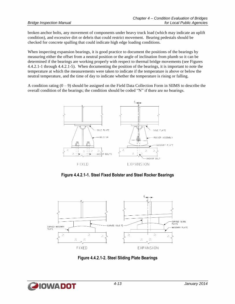
Chapter 4 – Condition Evaluation of Bridges Bridge Inspection Manual for Local Public Agencies
4-13 January 2014
broken anchor bolts, any movement of components under heavy truck load (which may indicate an uplift
condition), and excessive dirt or debris that could restrict movement. Bearing pedestals should be
checked for concrete spalling that could indicate high edge loading conditions.
When inspecting expansion bearings, it is good practice to document the positions of the bearings by
measuring either the offset from a neutral position or the angle of inclination from plumb so it can be
determined if the bearings are working properly with respect to thermal bridge movements (see Figures
4.4.2.1-1 through 4.4.2.1-5). When documenting the position of the bearings, it is important to note the
temperature at which the measurements were taken to indicate if the temperature is above or below the
neutral temperature, and the time of day to indicate whether the temperature is rising or falling.
A condition rating (0 – 9) should be assigned on the Field Data Collection Form in SIIMS to describe the
overall condition of the bearings; the condition should be coded “N” if there are no bearings.
Figure 4.4.2.1-1. Steel Fixed Bolster and Steel Rocker Bearings
Figure 4.4.2.1-2. Steel Sliding Plate Bearings
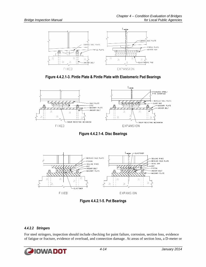
Chapter 4 – Condition Evaluation of Bridges Bridge Inspection Manual for Local Public Agencies
4-14 January 2014
Figure 4.4.2.1-3. Pintle Plate & Pintle Plate with Elastomeric Pad Bearings
Figure 4.4.2.1-4. Disc Bearings
Figure 4.4.2.1-5. Pot Bearings
4.4.2.2 Stringers
For steel stringers, inspection should include checking for paint failure, corrosion, section loss, evidence
of fatigue or fracture, evidence of overload, and connection damage. At areas of section loss, a D-meter or
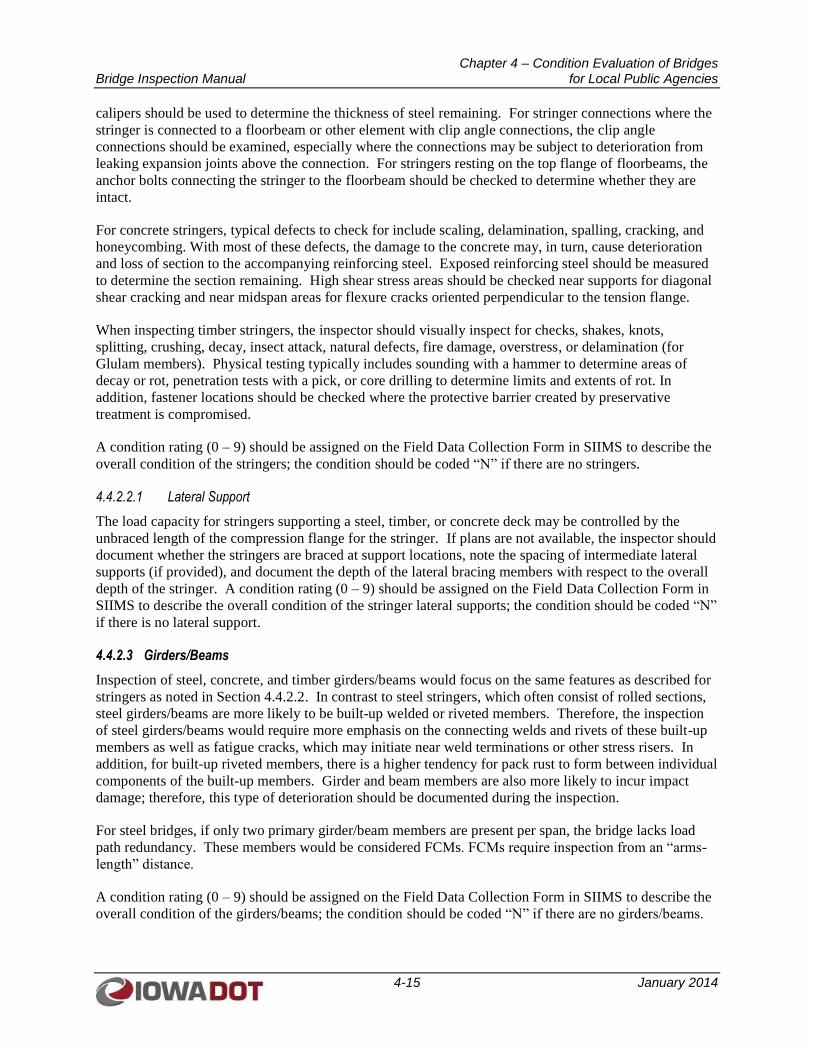
Chapter 4 – Condition Evaluation of Bridges Bridge Inspection Manual for Local Public Agencies
4-15 January 2014
calipers should be used to determine the thickness of steel remaining. For stringer connections where the
stringer is connected to a floorbeam or other element with clip angle connections, the clip angle
connections should be examined, especially where the connections may be subject to deterioration from
leaking expansion joints above the connection. For stringers resting on the top flange of floorbeams, the
anchor bolts connecting the stringer to the floorbeam should be checked to determine whether they are
intact.
For concrete stringers, typical defects to check for include scaling, delamination, spalling, cracking, and
honeycombing. With most of these defects, the damage to the concrete may, in turn, cause deterioration
and loss of section to the accompanying reinforcing steel. Exposed reinforcing steel should be measured
to determine the section remaining. High shear stress areas should be checked near supports for diagonal
shear cracking and near midspan areas for flexure cracks oriented perpendicular to the tension flange.
When inspecting timber stringers, the inspector should visually inspect for checks, shakes, knots,
splitting, crushing, decay, insect attack, natural defects, fire damage, overstress, or delamination (for
Glulam members). Physical testing typically includes sounding with a hammer to determine areas of
decay or rot, penetration tests with a pick, or core drilling to determine limits and extents of rot. In
addition, fastener locations should be checked where the protective barrier created by preservative
treatment is compromised.
A condition rating (0 – 9) should be assigned on the Field Data Collection Form in SIIMS to describe the
overall condition of the stringers; the condition should be coded “N” if there are no stringers.
4.4.2.2.1 Lateral Support
The load capacity for stringers supporting a steel, timber, or concrete deck may be controlled by the
unbraced length of the compression flange for the stringer. If plans are not available, the inspector should
document whether the stringers are braced at support locations, note the spacing of intermediate lateral
supports (if provided), and document the depth of the lateral bracing members with respect to the overall
depth of the stringer. A condition rating (0 – 9) should be assigned on the Field Data Collection Form in
SIIMS to describe the overall condition of the stringer lateral supports; the condition should be coded “N”
if there is no lateral support.
4.4.2.3 Girders/Beams
Inspection of steel, concrete, and timber girders/beams would focus on the same features as described for
stringers as noted in Section 4.4.2.2. In contrast to steel stringers, which often consist of rolled sections,
steel girders/beams are more likely to be built-up welded or riveted members. Therefore, the inspection
of steel girders/beams would require more emphasis on the connecting welds and rivets of these built-up
members as well as fatigue cracks, which may initiate near weld terminations or other stress risers. In
addition, for built-up riveted members, there is a higher tendency for pack rust to form between individual
components of the built-up members. Girder and beam members are also more likely to incur impact
damage; therefore, this type of deterioration should be documented during the inspection.
For steel bridges, if only two primary girder/beam members are present per span, the bridge lacks load
path redundancy. These members would be considered FCMs. FCMs require inspection from an “arms-
length” distance.
A condition rating (0 – 9) should be assigned on the Field Data Collection Form in SIIMS to describe the
overall condition of the girders/beams; the condition should be coded “N” if there are no girders/beams.
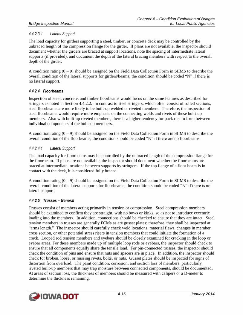
Chapter 4 – Condition Evaluation of Bridges Bridge Inspection Manual for Local Public Agencies
4-16 January 2014
4.4.2.3.1 Lateral Support
The load capacity for girders supporting a steel, timber, or concrete deck may be controlled by the
unbraced length of the compression flange for the girder. If plans are not available, the inspector should
document whether the girders are braced at support locations, note the spacing of intermediate lateral
supports (if provided), and document the depth of the lateral bracing members with respect to the overall
depth of the girder.
A condition rating (0 – 9) should be assigned on the Field Data Collection Form in SIIMS to describe the
overall condition of the lateral supports for girders/beams; the condition should be coded “N” if there is
no lateral support.
4.4.2.4 Floorbeams
Inspection of steel, concrete, and timber floorbeams would focus on the same features as described for
stringers as noted in Section 4.4.2.2. In contrast to steel stringers, which often consist of rolled sections,
steel floorbeams are more likely to be built-up welded or riveted members. Therefore, the inspection of
steel floorbeams would require more emphasis on the connecting welds and rivets of these built-up
members. Also with built-up riveted members, there is a higher tendency for pack rust to form between
individual components of the built-up members.
A condition rating (0 – 9) should be assigned on the Field Data Collection Form in SIIMS to describe the
overall condition of the floorbeams; the condition should be coded “N” if there are no floorbeams.
4.4.2.4.1 Lateral Support
The load capacity for floorbeams may be controlled by the unbraced length of the compression flange for
the floorbeam. If plans are not available, the inspector should document whether the floorbeams are
braced at intermediate locations between supports by stringers. If the top flange of a floor beam is in
contact with the deck, it is considered fully braced.
A condition rating (0 – 9) should be assigned on the Field Data Collection Form in SIIMS to describe the
overall condition of the lateral supports for floorbeams; the condition should be coded “N” if there is no
lateral support.
4.4.2.5 Trusses – General
Trusses consist of members acting primarily in tension or compression. Steel compression members
should be examined to confirm they are straight, with no bows or kinks, so as not to introduce eccentric
loading into the members. In addition, connections should be checked to ensure that they are intact. Steel
tension members in trusses are generally FCMs as are gusset plates; therefore, they shall be inspected at
“arms length.” The inspector should carefully check weld locations, material flaws, changes in member
cross section, or other potential stress risers in tension members that could initiate the formation of a
crack. Looped rod tension members and eyebars should be closely examined for cracking in the loop or
eyebar areas. For these members made up of multiple loop rods or eyebars, the inspector should check to
ensure that all components equally share the tensile load. For pin-connected trusses, the inspector should
check the condition of pins and ensure that nuts and spacers are in place. In addition, the inspector should
check for broken, loose, or missing rivets, bolts, or nuts. Gusset plates should be inspected for signs of
distortion from overload. The paint condition, corrosion, and section loss of members, particularly
riveted built-up members that may trap moisture between connected components, should be documented.
At areas of section loss, the thickness of members should be measured with calipers or a D-meter to
determine the thickness remaining.
Chapter 4 – Condition Evaluation of Bridges Bridge Inspection Manual for Local Public Agencies
4-17 January 2014
For timber trusses, timber members should be inspected for checks, splits, cracks, insect damage, and
decay. The inspector should carefully check joints for decay where there are contact surfaces where
moisture can be trapped or enter around holes for bolts or truss rods. The inspector should check for
evidence of crushing at ends of compression members. At end panel joints, where the timber members
may come in contact with the ground or trap dirt and debris, the inspector should check for decay and rot.
In addition, the inspector should check connections for loose, broken, or missing bolts or nuts. For
covered bridges, roofs and sides should be investigated to ensure they are protecting structural members
from the elements. Any fire hazards, which need to be corrected to safeguard the structure, should be
reported.
A condition rating (0 – 9) should be assigned on the Field Data Collection Form in SIIMS to describe the
overall condition of the truss; the condition should be coded “N” if this field does not apply.
4.4.2.5.1 Portals
Portal bracing members between lines of trusses are usually the members with the most restrictive vertical
clearance. These members should be checked for impact damage. A condition rating (0 – 9) should be
assigned on the Field Data Collection Form in SIIMS to describe the overall condition of the portal
members; the condition should be coded “N” if there are no portals.
4.4.2.5.2 Bracing
All upper and lower bracing members should be checked for damage and to observe if they are properly
adjusted and functioning correctly; lateral and sway bracing should be observed under live load to
confirm proper function. Connection gusset plates for lateral and sway bracing members may easily trap
the nesting material of birds or other debris, thus retaining moisture and promoting corrosion and section
loss. The condition of connections and any section loss of rivets, bolts, gusset plates or structural
members should be documented. Connection plates of lateral bracing and sway bracing should be
checked for fatigue cracking due to wind or live load induced vibration. A condition rating (0 – 9) should
be assigned on the Field Data Collection Form in SIIMS to describe the overall condition of the truss
bracing; the condition should be coded “N” if there is no truss bracing.
4.4.2.6 Paint
The paint coating of steel members should be inspected for chalking, peeling, and overall effectiveness.
Generally, chalking is the first indication that the paint system is beginning to fail. A condition rating
(0 – 9) should be assigned on the Field Data Collection Form in SIIMS to describe the overall condition
of the paint; the condition should be coded “N” if there are no painted members.
4.4.2.7 Rivets or Bolts
Rivets and bolts should be examined to document loose, broken, or missing rivets, bolts, or nuts. In
heavily corroded areas, the loss of rivet or bolt heads due to corrosion should be documented. A condition
rating (0 – 9) should be assigned on the Field Data Collection Form in SIIMS to describe the overall
condition of rivets and bolts; the condition should be coded “N” if there are no rivets or bolts.
4.4.2.8 Welds – Cracks
Particularly in tensile zones of members or for members fully in tension, welds should be examined for
cracks or poor workmanship. Tack welds, temporary fit-up welds, and field welds in tension members
should be carefully examined. The inspector should check for instances of intersecting welds in tensile
zones, which could provide stress risers. Weld cracks found in tension zones may require nondestructive
testing methods, such as dye penetrant testing or magnetic particle testing, to determine the termination
Chapter 4 – Condition Evaluation of Bridges Bridge Inspection Manual for Local Public Agencies
4-18 January 2014
point of the crack. A condition rating (0 – 9) should be assigned on the Field Data Collection Form in
SIIMS to describe the overall condition of welds; the condition should be coded “N” if there are no welds.
4.4.2.9 Steel Corrosion
Corroded steel members may require removal of rust build-up by hammering or scraping to determine
extents of section loss. The inspector should document if rust corrosion is surface corrosion only, rust
with section loss, or pack rust. In addition, the inspector should document the locations of defects and the
extent of rust, and should measure the remaining steel thickness. A condition rating (0 – 9) should be
assigned on the Field Data Collection Form in SIIMS to describe the overall severity of steel corrosion;
the condition should be coded “N” if this data field does not apply.
4.4.2.10 Timber Decay
Inspection for timber decay should include physical testing, typically by hammer sounding or penetration
tests with a pick or core drill, to determine extents of sound timber cross section remaining. A condition
rating (0 – 9) should be assigned on the Field Data Collection Form in SIIMS to describe the overall
severity and extent of timber decay; the condition should be coded “N” if this data field does not apply.
4.4.2.11 Concrete Cracking
Documentation of concrete cracking should include a description of the crack location, width of crack,
and length of crack. Feeler gauges or wallet-sized transparent cards with various crack width comparison
gauges are available for estimating crack widths. The inspector should note the location and nature of the
crack, such as whether the crack is a diagonal crack radiating upward toward midspan from a support
location (shear crack) or if it is a crack beginning at and oriented perpendicular to the tension side of the
member near midspan (positive moment flexure crack). A condition rating (0 – 9) should be assigned on
the Field Data Collection Form in SIIMS to describe the overall severity and extent of the concrete
cracking; the condition should be coded “N” if this data field does not apply.
4.4.2.12 Collision Damage
All vehicular collision damage or flood debris impact to superstructure members should be noted. In
addition, the extents of damage, particularly deterioration that could affect the public safety or the load
carrying capacity of the bridge, should be documented. This might include severed prestressing strands
of concrete beams, torn bottom flanges of steel beans, or torn elements of truss members. Documentation
should be supplemented with nondestructive testing, if required, to determine the remaining usable
section properties of damaged members. A condition rating (0 – 9) should be assigned on the Field Data
Collection Form in SIIMS to describe the overall severity and degree of collision damage; the condition
should be coded “N” if this data field does not apply.
4.4.2.13 Deflection Under Load
Excessive superstructure deflection under load could indicate failure of a critical member. The inspector
should sight along barrier rails of the bridge or check bridge expansion joints to observe for unusual
deflection of the bridge superstructure or possible substructure settlement. In addition, the inspector
should watch for localized deflection of members, which could indicate a connection failure. A condition
rating (0 – 9) should be assigned on the Field Data Collection Form in SIIMS to describe the overall
extent of deflection under load.
4.4.2.14 Alignment of Members
The inspector should watch for misalignment of members that could be caused by an overload condition
or localized failure. Gusset plates should be checked for distortion or misalignment. A condition rating
Chapter 4 – Condition Evaluation of Bridges Bridge Inspection Manual for Local Public Agencies
4-19 January 2014
(0 – 9) should be assigned on the Field Data Collection Form in SIIMS to describe the overall condition
of member alignment.
4.4.2.15 Vibration Under Load
Although all bridges will tend to vibrate to some degree, the inspector should take note of excessive
vibrations under load. In addition, the inspector should listen for audible rattles or banging of members
that could be indicative of damaged or loose members, such as lateral bracing, expansion joints, or
bearings not in full contact with structural members. A condition rating (0 – 9) should be assigned on the
Field Data Collection Form in SIIMS to describe the overall extent of vibration under load.
4.4.3 Substructure Inspection
All substructure elements should be inspected for visible signs of distress, including evidence of cracking,
section loss, settlement, misalignment, scour, collision damage, overload conditions, and corrosion.
Integral abutment wingwalls to the first construction or expansion joint shall be included in the evaluation
for abutments. For non-integral superstructure and substructure units, the substructure shall be considered
the portion below the bearings. For structures where the substructure and superstructure are integral, the
substructure shall be considered as the portion below the superstructure.
An overall condition rating of the Substructure (NBI Item 60) shall be provided as shown in Table
4.2.2.1. Code “N” should be used for all culverts. The substructure condition rating should be made
independent of the condition ratings for the deck and superstructure.
For scour critical bridges, the scour conditions may substantially affect the overall condition of the
substructure. When NBI Item 113, Scour Critical Bridges, is coded 2 or less, the Substructure rating (NBI
item 60) must be coded with the same value as NBI Item 113.
Substructure field notes are to be maintained in the remarks field of the items described below or in the
General Comments field.
4.4.3.1 Abutments
4.4.3.1.1 Caps
The horizontal surfaces on the tops of the beam seats are particularly vulnerable to deterioration due to
the road debris and chloride-laden runoff that may be deposited on the cap from open or failed expansion
joints. For concrete abutments, cracking, spalling, and corrosion of reinforcing steel in the concrete cap
should be documented. Areas around bridge bearings should be checked for spalls or cracks from the
concentrated bearing loads. For timber abutment caps, the inspector should look for rot and decay of the
timber cap in addition to any splits, checks, or shakes. A condition rating (0 – 9) should be assigned on
the Field Data Collection Form in SIIMS to describe the overall condition of the abutment caps; the
condition should be coded “N” if there are no caps.
4.4.3.1.2 Wings
The inspector should check for lateral movement of the wingwalls (rotation, bulging, sliding, or shifting)
as well as settlement. Such movements may cause cracking in concrete wingwalls, broken timber
wingwall planks, buckled steel sheet pile, or distress at the interface with the abutment cap and backwall.
Wingwall movement or settlement may also be caused by stream scour. Ends of wingwalls should be
checked for erosion damage, which may allow for roadway runoff to be trapped behind the wingwalls and
create saturated soil conditions increasing the soil loads on wingwalls. A condition rating (0 – 9) should
Chapter 4 – Condition Evaluation of Bridges Bridge Inspection Manual for Local Public Agencies
4-20 January 2014
be assigned on the Field Data Collection Form in SIIMS to describe the overall condition of the abutment
wings; the condition should be coded “N” if there are no wings.
4.4.3.1.3 Backwall
The backwall should be examined for signs of crushing or cracking from deck pressure against the
backwall. The inspector should also check abutment backwalls for rotation or bulging from unbalanced
earth loads. For concrete backwalls, the inspector should look for cracks, spalling, or efflorescence stains.
In addition, the tops of concrete backwalls should be examined for scaling and concrete deterioration
from chloride-laden bridge runoff and mechanical action of approach slab rotation. For timber plank
backwalls, the inspector should look for broken or split planks, and for steel sheet pile backwalls, the
inspector should look for buckled sheet piles. A condition rating (0 – 9) should be assigned on the Field
Data Collection Form in SIIMS to describe the overall condition of the abutment backwalls; the condition
should be coded “N” if there are no backwalls.
4.4.3.1.4 Footing
Abutment footings should be investigated for evidence of scour or undercutting. The inspector should
document if the ground line has been scoured or eroded below the bottoms of the footings. The areas
around spread footings should be probed for scour holes, and footings should be observed for signs of
settlement. Cracks or spalling in concrete footings should be documented. A condition rating (0 – 9)
should be assigned on the Field Data Collection Form in SIIMS to describe the overall condition of the
abutment footings; the condition should be coded “N” if there are no footings or the footings are not
visible.
4.4.3.1.5 Piles
The inspector should document if piles are exposed below the bottom of the abutment footing. Piles
should be checked for damage from flood debris. The inspector should document the vertical alignment
of piles if excessive unbalanced soil load at abutment or scour has caused the abutment to rotate or slide.
For steel piles showing signs of corrosion loss, the thickness of pile flanges and web should be measured
to determine the thickness of steel remaining. Timber piles should be sounded with a hammer and probe
as necessary to detect and measure for rot or decay, especially in zones alternately wet and dry. Cracks or
spalls in concrete piles should be noted. A condition rating (0 – 9) should be assigned on the Field Data
Collection Form in SIIMS to describe the overall condition of the abutment piles; the condition should be
coded “N” if there are no piles or the piles are not visible.
4.4.3.1.6 Erosion
Particularly for bridges on dirt or gravel roads in which no approach slabs are provided, the approach
roadway adjacent to the bridge backwall and wingwalls should be examined for erosion holes or signs of
settlement that may indicate loss of soil behind the abutment. Ends and exposed faces of wingwalls
should be checked for erosion where bridge or side ditch runoff could cause erosion problems around the
abutment. Abutments should be examined for distress due to stream erosion. The inspector should check
for erosion near abutments where deck drains outlet onto the bridge berms. The condition of scour and
erosion countermeasures such as channel armoring or riprap adjacent to the abutment or wingwalls should
be documented. A condition rating (0 – 9) should be assigned on the Field Data Collection Form in
SIIMS to describe the overall condition with respect to abutment erosion.
4.4.3.1.7 Settlement
Footing settlement from scour or undercutting is discussed in Section 4.4.3.1.4, above. The inspector
should check for localized settlement of abutment due to erosion from roadway side ditches or outlets
Chapter 4 – Condition Evaluation of Bridges Bridge Inspection Manual for Local Public Agencies
4-21 January 2014
from bridge scuppers. Settlement, particularly for abutments on spread footings, could also be caused by
overload conditions. A condition rating (0 – 9) should be assigned on the Field Data Collection Form in
SIIMS to describe the overall condition with respect to abutment settlement; the condition should be
coded “N” if there is no settlement noted.
4.4.3.2 Piles or Bents
4.4.3.2.1 Caps
For piers located under bridge expansion joints, pier caps are particularly vulnerable to deterioration due
to the road debris and chloride-laden runoff that may be deposited on the cap from open or failed
expansion joints. For concrete pier caps, cracking, spalling, and corrosion of reinforcing steel should be
documented. Areas around bridge bearings should be checked for spalls or cracks from the concentrated
bearing loads. For timber pier caps, the inspector should look for crushing at beam bearing areas, rot,
decay of the timber cap, and any splits, checks, or shakes. Steel bent caps should be checked for
corrosion loss. A condition rating (0 – 9) should be assigned on the Field Data Collection Form in SIIMS
to describe the overall condition of the pier caps; the condition should be coded “N” if there are no caps.
4.4.3.2.2 Columns
Pier columns should be checked for lateral movement or tilt that could be caused by unbalanced soil loads
or locked-up bearing devices. The inspector should document cracks, spalls, and corrosion of reinforcing
steel for concrete pier columns, especially columns under bridge expansion joints, columns exposed to
bridge scupper outlets or columns exposed to salt spray from adjacent roadways. For steel columns, the
inspector should document any corrosion and measure for section loss as required. A condition rating (0
– 9) should be assigned on the Field Data Collection Form in SIIMS to describe the overall condition of
the pier columns; the condition should be coded “N” if there are no piers.
4.4.3.2.3 Footings
If pier footings are exposed, concrete footings should be checked for cracks, spalls, or corrosion of
reinforcing steel. Footings should be checked for signs of settlement. Exposed pier footings could also
be indicative of unexpected scour or erosion. A condition rating (0 – 9) should be assigned on the Field
Data Collection Form in SIIMS to describe the overall condition of the pier footings; the condition should
be coded “N” if there are no footings or the footings are not visible.
4.4.3.2.4 Piles
The inspector should document if piles are exposed below the bottom of the pier footing. For pile bents,
piles should be checked for damage from flood debris or deterioration at the waterline. The inspector
should document the vertical alignment of pile bents if unbalanced soil load at pier or scour has caused
the pier to rotate or tilt. For steel piles showing signs of corrosion loss, the thickness of pile flanges and
web should be measured to determine the thickness of steel remaining. Timber piles should be sounded
with a hammer and probe as necessary to detect and measure for rot or decay, especially in zones
alternately wet and dry. Cracks or spalls in concrete piles should be noted. A condition rating (0 – 9)
should be assigned on the Field Data Collection Form in SIIMS to describe the overall condition of the
pier piles; the condition should be coded “N” if there are no piles or the piles are not visible.
4.4.3.2.5 Scour
For piers located in water, evaluation for effects of scour may need to be performed by means of an
Underwater Inspection. Underwater Inspection should probe and use tactile methods to determine extents
of scour holes adjacent to the pier footing. Underwater Inspection should also check for the scour effects
on concrete footings by noting any loss of cement paste or spalls discovered below the water line.
Chapter 4 – Condition Evaluation of Bridges Bridge Inspection Manual for Local Public Agencies
4-22 January 2014
For piers exposed to scour only during high water events, inspections should be scheduled during low
flow events, if possible, to document the condition of scour countermeasures or any scour effects on the
pier.
A condition rating (0 – 9) should be assigned on the Field Data Collection Form in SIIMS to describe the
overall condition of scour at the piers; the condition should be coded “N” if this field does not apply.
4.4.3.2.6 Settlement
The inspector should sight along bridge rails to detect any settlement at pier locations. For suspected
settlement conditions, the suspected pier should be further investigated to determine the cause and extents
of settlement. For suspected settlement, the inspector should consider mounting a survey target on the top
of the pier to allow monitoring of the pier settlement over time. A condition rating (0 – 9) should be
assigned on the Field Data Collection Form in SIIMS to describe the overall condition with respect to pier
settlement.
4.4.3.3 Concrete Cracking
Documentation of concrete cracking for substructure members should include a description of the crack
location, width of crack, and length of crack. Feeler gauges or wallet-sized transparent cards with various
crack width comparison gauges are available for estimating crack widths. For abutment or pier caps, the
inspector should note the location and nature of the crack, such as whether the crack is a diagonal crack
radiating upward toward midspan from a support or column location (shear crack) or if it is a crack
beginning at and extending perpendicular to the tension side of the cap near midspan (positive moment
flexure crack). A condition rating (0 – 9) should be assigned on the Field Data Collection Form in SIIMS
to describe the overall severity with respect to concrete cracking; the condition should be coded “N” if
this data field does not apply.
4.4.3.4 Steel Corrosion
Corroded steel members may require removal of rust build-up by hammering or scraping to determine
extents of section loss. The inspector should document if rust corrosion is surface corrosion only, rust
with section loss, or pack rust. In addition, the inspector should document the location of defects and the
extent of rust, and should measure the remaining steel thickness. A condition rating (0 – 9) should be
assigned on the Field Data Collection Form in SIIMS to describe the overall severity of steel corrosion;
the condition should be coded “N” if this data field does not apply.
4.4.3.5 Timber Decay
Inspection for timber decay should include physical testing, typically by hammer sounding or penetration
tests with a pick or core drill, to determine extents of sound timber cross section remaining. A condition
rating (0 – 9) should be assigned on the Field Data Collection Form in SIIMS to describe the overall
severity with respect to timber decay; the condition should be coded “N” if this data field does not apply.
4.4.3.6 Debris on Seats
Particularly under open or leaking bridge joints, road debris may build up on abutment and pier beam
seats and cap beams. Build-up of pigeon nesting material or excrement can also obscure the clear view of
cap elements and hinder inspection procedures. All such types of debris have a tendency to hold moisture
and promote concrete deterioration, corrosion of steel, and decay of timber members. Prior to initiating
inspection operations, bridge cleaning efforts should be initiated by maintenance crews to allow for the
most efficient use of the inspector’s time and allow for a thorough inspection. A condition rating (0 – 9)
Chapter 4 – Condition Evaluation of Bridges Bridge Inspection Manual for Local Public Agencies
4-23 January 2014
should be assigned on the Field Data Collection Form in SIIMS to describe the overall severity with
respect to debris on the seats; the condition should be coded “N” if this data field does not apply.
4.4.3.7 Paint
The paint coating of steel substructure members should be inspected for chalking, peeling, and overall
effectiveness. Generally chalking is the first indication that the paint system is beginning to fail. A
condition rating (0 – 9) should be assigned on the Field Data Collection Form in SIIMS to describe the
overall condition of the paint coating; the condition should be coded “N” if there are no painted members.
4.4.3.8 Collision Damage
Bridge substructure members located adjacent to active roadways may encounter collision damage from
an errant vehicle. Damaged members should be thoroughly checked, and impact damage such as concrete
spalls or cracks and bent or cracked steel members should be documented. Immediate action should be
taken if public safety is in question or if there is a question regarding substructure stability. A condition
rating (0 – 9) should be assigned on the Field Data Collection Form in SIIMS to describe the overall
severity of the collision damage; the condition should be coded “N” if there is no collision damage.
4.4.4 Culvert Inspection
A culvert with an opening greater than 20 feet as measured along the center of the roadway is considered
a bridge-sized structure and is subject to NBIS requirements. Similarly, a grouping of culverts with a
length greater than 20 feet as measured along the roadway centerline, and where the clear distance
between openings is less than half the smaller contiguous opening, is considered a bridge-sized structure.
Culverts should be inspected for their overall condition, any approach roadway and embankment
settlement, the condition of their end treatments (headwalls, parapets, and wingwalls), and the condition
of their appurtenance structures (such as aprons, weirs, and energy dissipaters). The inside of a culvert
should be inspected for any damage or deterioration. Weep holes should be checked to determine if they
are functioning or if they are plugged. Joints should be checked for deterioration or spalls.
An overall condition rating of the Culvert (NBI Item 62) shall be provided as shown in Table 4.2.2.3.
Culverts should be evaluated with respect to their alignment, settlement, joints, structural condition,
scour, and other elements associated with culverts. The rating code is intended to be an overall condition
evaluation of the culvert. Integral wingwalls to the first construction or expansion joint shall be included
in the evaluation.
Culvert field notes are to be maintained in the remarks field of the items described below or in the
General Comments field.
4.4.4.1 Barrel
The inspector should sight along the length of the culvert barrel to look for signs of settlement. The
roadway embankment should also be viewed for signs of settlement, erosion or settlement of side slopes,
pavement cracking, or pavement patching indicative of embankment settlement. Joints within the culvert
should be checked for differential movement, infiltration of water, or exfiltration into the surrounding
supporting soils. The inspector should check for loss of filler material or sealers at joints.
4.4.4.1.1 Concrete
For concrete box culverts, sidewalls, the top slab, and the base slab should be inspected for abrasion,
cracking, or spalling of concrete surfaces, as well as for honeycombing of concrete and exposed
Chapter 4 – Condition Evaluation of Bridges Bridge Inspection Manual for Local Public Agencies
4-24 January 2014
reinforcing steel. Deteriorated areas should be sounded to determine the extents of delamination. A
condition rating (0 – 9) should be assigned on the Field Data Collection Form in SIIMS to describe the
overall condition of the culvert concrete; the condition should be coded “N” if the culvert has no concrete
elements.
For concrete arch culverts, the arch area near the spring line should be inspected for abrasion, cracking, or
spalling, as well as honeycombing of concrete and exposed reinforcing steel.
4.4.4.1.2 Steel
For steel culverts, any flattening of the top or sides of the metal elements or any shape distortions from
the original as-built conditions should be noted. The inspector should check the base of Corrugated Metal
Plate (CMP) structures for differential settlement or undermining. In addition, the inspector should check
along the length of the CMP for misalignment of plate elements, leakage at seams and dents, or local
defects. Finally, the inspector should check for cracks and distortions, especially at bolt locations. A
condition rating (0 – 9) should be assigned on the Field Data Collection Form in SIIMS to describe the
overall condition of the steel components; the condition should be coded “N” if there are no steel
components.
4.4.4.1.3 Timber
Timber culverts should be inspected for checks, splits, shakes, fungus decay, rot, deflection, and loose
fasteners. Gaps between adjoining members that are leaking fill material should be noted. A condition
rating (0 – 9) should be assigned on the Field Data Collection Form in SIIMS to describe the overall
condition of timber components; the condition should be coded “N” if there are no timber components.
4.4.4.2 Headwall
Headwalls may be constructed with concrete, steel, or timber. Inspect for the typical deterioration
damage of the material type used.
At concrete headwalls, the inspector should check for indications of movement, rotation or settlement of
wingwalls, and separation or rotation of wingwalls from the main barrel.
For metal structures that do not have concrete headwalls, the inspector should check for any upward
displacement at the inlet. For inlet or outlet ends mitered into the embankment slope, the inspector should
check for evidence of edges folding inward.
For timber headwalls, the inspector should look for checks, splits, shakes, fungus decay, rot, deflection
and loose fasteners. Gaps between adjoining members that are leaking fill material should be noted.
A condition rating (0 – 9) should be assigned on the Field Data Collection Form in SIIMS to describe the
overall condition of the headwalls; the condition should be coded “N” if there are no headwalls.
4.4.4.3 Cut-off Wall
The downstream cut-off wall should be checked for potential scour behind the wall in the upstream
direction. The depth and limits of scour near the cutoff wall should be determined by probing with a rod.
The inspector should watch for signs of piping along the outside face of the culvert walls or below the
base slab. A condition rating (0 – 9) should be assigned on the Field Data Collection Form in SIIMS to
describe the overall condition of the cut-off walls; the condition should be coded “N” if there are no cut-
off walls or they are not visible.
Chapter 4 – Condition Evaluation of Bridges Bridge Inspection Manual for Local Public Agencies
4-25 January 2014
4.4.4.4 Adequacy
The inspection should include an evaluation of whether the size of the culvert adequately addresses the
hydraulic demand. The inspector should look for high water marks as well as whether there are signs
piping occurring along the outside of the culvert walls. In addition, the inspector should look for signs of
erosion at the inlet end of the culvert or overtopping of the culvert. A condition rating (0 – 9) should be
assigned on the Field Data Collection Form in SIIMS to describe the overall culvert hydraulic adequacy.
4.4.4.5 Debris
The inspector should check for accumulation of debris, particularly at the inlet end of the culvert, which
could block the entrance. In addition, the inspector should check for silting in of the culvert barrel. The
inspector should note whether brush, trees, or debris are interfering with proper flow through the culvert.
A condition rating (0 – 9) should be assigned on the Field Data Collection Form in SIIMS to describe the
overall severity of debris accumulation.
4.4.5 Channel and Channel Protection
When examining the channel and channel protection, inspectors should observe the adequacy of the
waterway opening under the structure or approaching culvert inlet to determine if the waterway is
unobstructed and affords free flow of water. Obstructions such as debris or growth may contribute to
scour and may be a potential fire hazard to the structure. Sand and gravel bars deposited in the channel
may direct stream flow in such a manner as to cause harmful scour at piers or abutments. In addition, the
inspector should be particularly concerned with visible signs of excessive water velocity, which may
affect undermining of slope protection, erosion of banks, and realignment of the stream, which, in turn,
may result in immediate or potential problems.
The surrounding area should also be observed to determine if the bridge and approaches are causing
problems, such as flooding due to inadequate openings of the structure or skew of the piers or abutments,
or if erosion of banks or levees is resulting from improper protection.
An overall condition rating of the Channel and Channel Protection (NBI Item 61) shall be provided as
shown in Table 4.2.2.2. This condition rating should take into account stream bank stability, stream bank
protection systems, river control devices, streambed movement, and whether there is debris in the channel
that could affect the hydraulic opening. Accumulation of drift and debris on the superstructure,
substructure, or culvert inlet should be noted in the inspection report but shall not be included in the
condition rating.
Channel and Channel Protection field notes are to be maintained in the remarks field of the items
described below or in the General Comments field.
4.4.5.1 Channel Scour
Scour can generally be categorized into three types. General scour involves channel bed degradation
along a considerable distance of the channel and would typically occur whether or not the bridge structure
was present. Contraction scour is the lowering of the streambed under the structure resulting from the
acceleration of the stream flow due to a reduced waterway opening at the bridge. Local scour is the
lowering of the streambed adjacent to an obstruction in the streambed, such as a pier foundation.
The inspector should check for timber debris in the channel or added vegetation that could contribute to
contraction scour. In addition, ice jams, excessive riprap, sedimentation, an excessive number of piers in
the channel, and inadequate bridge length can all contribute to contraction scour. Probing around pier and

Chapter 4 – Condition Evaluation of Bridges Bridge Inspection Manual for Local Public Agencies
4-26 January 2014
abutment locations should be employed to determine the depth and extents of scour holes. In addition,
although scour holes could silt back in, probing would indicate the difference in compaction of natural
soils and soils deposited following scour activities.
A condition rating (0 – 9) should be assigned on the Field Data Channel Collection Form in SIIMS to
describe the overall severity of the channel scour.
4.4.5.2 Embankment Erosion
Lateral stream migration is the relocation of the stream channel over time due to lateral scour of the
embankments. The inspector should note the angle of attack of the natural stream with respect to the
bridge opening, which may be a contributing source of embankment erosion. In addition, the inspector
should note bank sloughing and undercutting by the stream action. Left unchecked, early stages of lateral
stream migration can lead to channel misalignment, where the stream flow now impacts one of the bridge
abutments or flows under a bridge at a skew angle incompatible with the span opening(s). A condition
rating (0 – 9) should be assigned on the Field Data Channel Collection Form in SIIMS to describe the
overall severity of embankment erosion.
4.4.5.3 Drift
Drift and debris accumulations against the upstream side of piers partially blocking the hydraulic opening
should be recorded. Debris build-up can cause unintended contraction scour or local scour. In addition,
drift build-up can present a fire hazard to the bridge. A condition rating (0 – 9) should be assigned on the
Field Data Channel Collection Form in SIIMS to describe the overall severity of the drift build-up with
respect to its potential to create a scour or a fire hazard.
4.4.5.4 Vegetation
Excessive vegetation or tree growth along a channel’s banks can also lead to contraction scour. In
contrast, grass and other light vegetation along stream banks can promote bank stability and help prevent
sloughing. A condition rating (0 – 9) should be assigned on the Field Data Channel Collection Form in
SIIMS to describe the overall bank stability with respect to vegetation growth.
4.4.5.5 Channel Change
As noted in Section 4.4.5.2, as stream embankments scour over time, lateral stream migration can occur.
Overtopping of stream meanders during flood events could also cause stream cutting and a channel
change. Channel cross sections should be reviewed over subsequent inspection cycles to identify
appropriate countermeasures that may be needed to promote stability of the bridge opening. A condition
rating (0 – 9) should be assigned on the Field Data Channel Collection Form in SIIMS to describe the
overall channel stability with respect to channel change.
4.4.5.6 Fender System
Fender systems or dolphins are used to protect bridge substructures from unintended impact by floating
debris or maneuvering vessels. Fenders are typically a protective unit or cover around a pier or the face
of an abutment and are frequently attached to the substructure. Dolphins are generally a stand-alone unit
placed upstream or downstream from a pier.
Piles should be inspected for fenders or dolphins in a manner similar to inspection of bridge substructure
components. Steel frame members, cables, and connections should be inspected for corrosion, impact
damage, and abrasion from vessel or debris impact. Timber piles and fender components should be
inspected for decay, insect damage, marine organisms, impact, and structural damage; connections and
Chapter 4 – Condition Evaluation of Bridges Bridge Inspection Manual for Local Public Agencies
4-27 January 2014
cables should be checked for corrosion. Concrete components should be checked for spalling, cracking,
corrosion of reinforcing steel, and damage or abrasion from debris or vessel impact. Auxiliary
components such as rubber rub rails should be checked for damage and connection damage. Any
hydraulic components should be checked to ensure that they are working correctly. In addition,
navigation lighting and beacons should be checked for broken or missing lenses, proper light function,
and damage to connections, wiring, and conduit.
A condition rating (0 – 9) should be assigned on the Field Data Channel Collection Form in SIIMS to
describe the overall condition of the fender systems; the condition should be coded “N” if there are no
fenders or dolphins.
4.4.5.7 Spur Dikes and Jetties
Spur dikes and jetties are river control structures designed to modify the flow of the river to help control
lateral streambed movement. Spur dikes are often placed on the outside of a river bend to protect the
stream bank by slowing velocities and inducing sediment deposition. The overall effectiveness of spur
dikes and jetties should be evaluated from the standpoint of whether they are functioning as intended to
protect the bridge. A condition rating (0 – 9) should be assigned on the Field Data Channel Collection
Form in SIIMS to describe the overall condition of the spur dikes and jetties; the condition should be
coded “N” if there are no spur dikes or jetties.
4.4.5.8 Riprap
Riprap and other armoring types of countermeasures are not intended to alter the stream’s flow
significantly but are designed to reduce the hydraulic stresses from design flood events. Riprap is often
used to protect piers and abutments from contraction or local scour. The inspector should evaluate riprap
for proper placement and whether it is functioning as intended to protect the stream banks. A condition
rating (0 – 9) should be assigned on the Field Data Channel Collection Form in SIIMS to describe the
overall effectiveness of the riprap; the condition should be coded “N” if there is no riprap.
4.4.5.9 Adequacy of Opening
The inspector should check the adequacy of the overall waterway opening. Specifically, the inspector
should check for high water marks and should look for signs of contraction scour, lateral stream
migration, or embankment sloughing that may indicate whether the opening size is inadequate. A
condition rating (0 - 9) should be assigned on the Field Data Channel Collection Form in SIIMS to
describe the overall adequacy of the hydraulic opening.
4.4.5.10 Scour Critical Bridge A scour analysis shall be made by a hydraulic/geotechnical/structural engineer according to FHWA scour
analysis guidelines. NBI Item 113 shall be coded according to the findings of the scour analysis or scour
conditions observed at the bridge site. When Item 113 is coded 2 or less, the Substructure Condition Rating
(Item 60) must be coded to match Item 113.
A bridge that is found to be Scour Critical must have a Plan of Action (POA) developed. The POA includes a
specific plan for monitoring, inspecting, or closing a Scour Critical bridge during or after a flood event. A
POA is required when NBI Item 113 is coded 0, 1, 2 or 3. A field in SIIMS identifying that a POA has or has
not been implemented must be filled in with a “Yes” or “No.” The analysis method must also be documented
in SIIMS. Check boxes for Level A, B, or C analyses are provided in SIIMS to identify the type of analysis
performed. One or more analysis types may be checked. The analysis documentation and POA must be
uploaded into SIIMS.
Chapter 4 – Condition Evaluation of Bridges Bridge Inspection Manual for Local Public Agencies
4-28 January 2014
4.4.5.11 Unknown Foundations A bridge with an unknown foundation must be analyzed for potential risk of failure during a flood event.
There are two levels of analysis that can be performed. Check boxes for Level A and B analyses are provided
in SIIMS to identify the type of analysis performed. Both check boxes may be checked when the Level A
assessment identifies risk level as Moderate or High. The risk level shall also be entered in SIIMS. In SIIMS,
it must be documented that a POA has or has not been implemented. Enter “Yes” or “No” in the
corresponding field identifying whether a POA has been implemented. The analysis documentation and a
POA must be uploaded into SIIMS.
4.4.6 Bridge Data
4.4.6.1 Load Posting Table
If the bridge is load restricted, the inspector should verify whether the posted limits in the field match the
recommended limits. The actual tonnage shown on the signs in the field are to be entered in the table.
Remarks should be made to clarify the load limits or explain any discrepancies.
4.4.6.2 Signing
The inspector should verify that other required regulatory signs are properly posted at the correct height,
are not obstructed by vegetation, and are clear and legible. These signs may include reduced speed limit
signs, restricted vertical clearance signs, narrow bridge signs, bridge closure signs, and lateral delineators.
A rating of Good, Fair, or Poor should be used to document the legibility and visibility of the signs. For
applicable signs at the bridge site, comments on the legibility and visibility of the signs should be made
on the Field Data Collection Form in SIIMS.
4.4.6.3 Approaches
4.4.6.3.1 Concrete Approaches The inspector should check the approach pavement condition for cracking, settlement, unevenness, or
roughness. Joints between approach pavement and abutment should be examined to verify they do not leak
and provide adequate movement for bridge thermal expansion. The inspector should check that roadway
approach drainage does not pond on shoulders and does not erode approach fills or areas at ends of wingwalls.
In addition, the inspector should verify approach roadway drainage is directed away from the bridge. A
condition rating (0 – 9) should be assigned on the Field Data Collection Form in SIIMS to describe the overall
condition of the approach slabs; the condition should be coded “N” if there are no approach slabs.
4.4.6.3.2 Relief Joints The inspector should check pavement relief joints in the bridge approaches for proper function to determine if
they are properly accommodating thermal movement. The inspector should check for road debris or other
factors that might inhibit movement at pressure relief joints. A condition rating (0 – 9) should be assigned on
the Field Data Collection Form in SIIMS to describe the overall condition of pressure relief joints; the
condition should be coded “N” if there are no pressure relief joints.
4.4.6.3.3 Guardrail
Guardrail and all guardrail components, including transition sections at bridge rail and guardrail end
treatments, should be checked for conformance to current standards. The inspector should check
guardrail installation height and the condition of guardrail for impact damage, cracks, rust, and secure
connections. Posts should be firmly embedded in the ground, and laterally displaced posts should be
reported. Wood posts should be checked for rot or insect damage. If impact attenuator devices are used,
the inspector should check for evidence of damage due to impact and that energy absorbing components
have not ruptured; the inspector should also check that cable anchorages are secure and undamaged. A
Chapter 4 – Condition Evaluation of Bridges Bridge Inspection Manual for Local Public Agencies
4-29 January 2014
condition rating (0 – 9) should be assigned on the Field Data Collection Form in SIIMS to describe the
overall condition of the approach guardrail; the condition should be coded “N” if there is no approach
guardrail. In addition, NBI Items 36A through 36D must be coded as shown in Table 4.3.1.3 to document
whether the bridge rail, guardrail transitions, approach guardrail, and guardrail end treatments meet
currently accepted standards.
4.4.6.3.4 Embankment
The approach embankment should be checked for steepness, signs of excessive erosion, settlement, and
undermining of pavement, shoulders, or guardrail. A condition rating (0 – 9) should be assigned on the
Field Data Collection Form in SIIMS to describe the overall condition of approach roadway
embankments.
4.5 ADDITIONAL SIIMS DOCUMENTATION
4.5.1.1 Photographs, Sketches, Plans, Documents, and Files
Photographs, sketches, plans, documents and files are attached under the Report Info - Pictures section in
SIIMS. Almost any file type can be added to a bridge file. The type of document will determine whether
the document should be attached with an inspection report or as part of the Bridge File. If a document
relates to only a specific inspection, such as photographs and sketches, it should be attached to the
inspection report. When a document relates to the bridge, such as design plans or a scour plan of action,
the document should be attached in the “Files” area on the Asset Details page.
Files attached as part of an inspection report must be attached before the inspection report is finalized. If a
document or file is not attached before the inspection report is finalized, the report must be unapproved to
attach the files and then reapproved.
Files can be attached in the “Files” area on the Asset Details page at any time, whether an inspection is in
progress or not. The description field for each document should include specific information about the
subject of the document so anyone looking at the Bridge File will know what each document contains
without having to open each document.
4.5.1.2 Load Rating Evaluation Form
The Load Rating Evaluation Form must be completed for every inspection. This form will determine if
the existing load rating needs to be re-evaluated to determine if it is still valid or if new load rating is
needed. The name of the individual who completes the Load Rating Evaluation Form and the date he/she
completes it must be entered at the top of the form.
If any one of the questions is changed from the default to “Yes,” a re-evaluation of the load rating or
potentially a new load rating calculation will be required. After the evaluation form is completed, the
Program Manager will make the request to have the load ratings re-evaluated or re-calculated based on the
criteria on the Load Rating Evaluation Form.
4.5.1.3 Load Rating Report
The load rating must be completed by a Professional Engineer licensed in the State of Iowa. As noted
above, the need for a load rating re-evaluation or a new load rating calculation is determined by filling out
the Load Rating Evaluation Form.
If the load rating is re-evaluated and there is no reason found to update the load rating, the following
fields on the Load Rating Bridge Report Tab need to be updated:
Chapter 4 – Condition Evaluation of Bridges Bridge Inspection Manual for Local Public Agencies
4-30 January 2014
1. Report By: – indicates who performed the review
2. Date: – indicates the date the review was completed
3. Comment: – indicates the review did not require re-rating of the bridge
If the load rating is re-calculated and the ratings have changed, the entire Load Rating Bridge Report Tab
must be updated. The Load Rating Bridge Report Tab can be generated by an unlicensed engineer, but a
licensed engineer must put his/her name and license number at the bottom of the form. It is recommended the
new calculations be attached to the inspection report before it is finalized. If the ratings are not completed
before the inspection is finalized, a Load Rating Bridge Report should be created to update the ratings and
attach the calculations.
4.5.1.4 Critical Findings
The purpose of the Critical Findings Report in SIIMS is to ensure serious bridge damage or defects are
reported, that the necessary notifications are made to the bridge owner by the Program Manager or Team
Leader, and proper and timely action is taken to ensure the safety of the travelling public. This process
alerts the bridge owner so damage or deterioration can be repaired in a proper and timely manner and
ensures damage and repairs are documented.
The procedures to be used for LPAs when issuing a Critical Findings Report are as follows:
1. The individual discovering the critical finding shall:
a. Immediately report the finding to the responsible local official, who may notify law enforcement
or maintenance personnel to close the bridge.
b. Complete Part I of the Critical Findings Report within 48 hours of the finding.
2. The responsible local official shall:
a. Take action to ensure the safety of the traveling public.
b. Complete Part II of the Critical Findings Report within 5 days of the finding.
3. Before a closed bridge may be reopened to traffic, the following must be completed:
a. A Professional Engineer, licensed in the State of Iowa, shall approve any structural repairs.
b. The bridge shall be load rated.
c. The bridge shall be inspected by a Team Leader.
4.5.1.5 Channel Section
A channel cross section on the upstream side of the bridge is required to be a part of the bridge record. A
standard Channel Cross Section form has been incorporated into SIIMS. Each bridge structure is required
to have a data point at the top of bank, toe of bank, thalweg, and each substructure unit. The Channel
Cross Sections are to be updated in SIIMS every 4 years for natural waterways and every10 years for
drainage ditches controlled by a drainage district unless conditions at the bridge warrant more frequent
monitoring.
The Channel Cross Section is required in SIIMS. Hand-drawn channel sketches may be uploaded to the report
or the standard Channel Cross Section form in SIIMS may be used to auto-generate a channel cross section
sketch.
4.5.1.6 NBI Calculations
Calculated fields, the Sufficiency Rating, and the classification for Structural/Functional Deficiency are
recalculated and updated in SIIMS during entry of inspection data for a new inspection. The logic for the
Chapter 4 – Condition Evaluation of Bridges Bridge Inspection Manual for Local Public Agencies
4-31 January 2014
calculated appraisal ratings and the Sufficiency Rating can be reviewed in the NBI Calcs section in
SIIMS. It is recommended that these ratings be recalculated by choosing “Recalculate NBI Ratings” in
the NBI Calcs section of SIIMS before finalizing an inspection.
The data fields that are calculated in the NBI Calcs section in SIIMS are:
1. NBI Item 67, Structural Evaluation
2. NBI Item 68, Deck Geometry
3. NBI Item 69, Underclearances
4. Sufficiency Rating
5. Classification – Structurally Deficient or Functionally Obsolete
4.5.1.7 Supplemental Inspection Information
The NBIS requires information on inspection equipment needs and maintenance history be maintained for
all bridges. The Supplemental Inspection Information section in SIIMS provides a means to document
this information. This section includes:
1. Special equipment requirements for inspection
2. Traffic control needs during inspection
3. Time requirements for inspection
4. Fracture Criticality and fatigue vulnerability
4.6 REPORTING OF SPECIAL ITEMS
4.6.1 Fatigue-Prone Details
Fatigue-prone details consist of, but are not limited to, the following:
Welded cover plates, particularly the end terminations
Web gap area at diaphragm stiffeners when out-of-plane bending is possible
Welded gusset plate connections to girder webs, flanges or truss members
Weld terminations of longitudinal stiffeners
Coped areas in a floorbeam or cross beam
Tack welds in tension areas
Intersecting welds
Fatigue is the tendency of a member to fail at a stress level below yield stress when subjected to cyclical
loadings. Fatigue-prone details require additional attention. If fatigue cracks or fractures are noted, non-
destructive testing methods, such as dye penetrant testing or magnetic particle testing, may be required to
determine the extents of cracks in steel members. Ultrasonic methods are typically used to test pin
members for defects. Thickness gauges (D-Meters) or calipers can be used to determine the thickness of
steel remaining for a particular member.
Triaxial constraint is a 3-dimensional stress state that reduces the ductility of a material. Under triaxial
constraint, steel is unable to deform, and brittle fracture can occur under service conditions where ductile
Chapter 4 – Condition Evaluation of Bridges Bridge Inspection Manual for Local Public Agencies
4-32 January 2014
behavior is normally expected. Due to the nature of these unique conditions, the chance for member
failure is greater for these conditions and they warrant added emphasis during inspection. Finally, the
ability of inspectors to recognize conditions of triaxial constraint is important to guard against brittle
failure.
AASHTO prioritizes fatigue details into categories from A (least critical) to E’ (most critical). The
inspector shall be familiar with the various fatigue categories and be able to classify the categories
encountered in the field to determine the seriousness of the detail. Fatigue-prone details should be
identified and noted in the inspection report so that the details can be monitored for cracks in subsequent
inspections.
4.6.2 Fracture Critical Elements
FCMs are steel members in tension or with a tension element, whose failure would be expected to cause a
partial or full collapse of the bridge. The NBIS requires FCMs to be inspected at “arms length.”
Steel floorbeams are considered fracture critical when:
1. The connections to main girders are considered flexible or hinged;
2. There are no stringers;
3. The stringers are configured as simple spans; or
4. The stringers are continuous and the floorbeam spacing is greater than 14 feet.
4.6.2.1 FCM Pre-inspection Preparation
Prior to inspecting a bridge with known FCMs, the following procedures should be used in preparation
for the inspection:
1. Review the FCM locations as identified in the bridge file.
2. Identify all fatigue-prone details requiring a hands-on inspection.
3. Determine what documentation will be needed as part of this inspection.
4. Determine the workflow needed and access requirements for inspecting the FCMs in the most
efficient manner.
5. Discuss the workflow with all the members of the inspection team so they understand their roll in
the inspection. It is recommended the workflow be documented and kept in the bridge file.
6. Assess the equipment needs to perform this inspection. This will include lighting adequate to
identify small defects. It is recommended to keep a list of the equipment needed for the inspection
in the bridge file.
7. Make arrangements to have the superstructure washed if debris, bird nests, or bird droppings
inhibit proper inspection of important areas.
8. Make arrangements to have the necessary access equipment available for the inspection.
9. Verify who shall be notified if a potentially serious condition is found.
Chapter 4 – Condition Evaluation of Bridges Bridge Inspection Manual for Local Public Agencies
4-33 January 2014
4.6.2.2 Requirements During FCM Inspection
During an FCM inspection, the following procedures should be used:
1. Perform a hands-on inspection to visually inspect the FCMs for deterioration, defects, damage,
and cracks. Perform a hands-on inspection of all fatigue-prone details. A hands-on inspection is
defined as the inspector being able to touch all surfaces of the tension carrying regions of FCMs.
2. Clean suspect locations for better visual assessment, and use appropriate non-destructive testing
methods to verify potential crack locations and member thickness in deteriorated areas.
3. Photograph and sketch locations where deficiencies are found. Include appropriate dimensions
and perspectives on all sketches. Close-up photographs should be taken before and after any
cleaning, paint removal, or testing. Include a photograph of the general location so others can
understand exactly where close-up photographs were taken.
4. The Fracture Critical Member Locations and Conditions form (Attachment K or L in I.M. 2.120)
is required to be completed for each fracture critical bridge.
5. If a serious defect is found, notify the appropriate personnel immediately to determine what
actions are necessary.
4.7 MAINTENANCE, REPAIR, AND REPLACEMENT (MR&R)
4.7.1 Recommendations
The Maintenance, Repair and Replacement (MR&R) section of SIIMS is used to make recommendations
for repair, rehabilitation and replacement. Defects not repaired could affect the functionality of the
bridge, its load carrying capacity, or the safety of the public. In addition, if repairs are not made, the
defect could lead to added deficiencies that could be avoided through proactive repair. The inspector
shall make recommendations for repair and shall include recommended time frames for completing the
repairs (for example, within 1 month, during the next bridge maintenance cycle, or prior to the next
routine inspection) in order to convey the urgency of repairing the defect and to aid the bridge owner in
prioritizing the repair. The bridge owner will need to evaluate the recommendations for repair and
evaluate the suggested time frames with respect to the costs of the repairs and the available funding in the
bridge repair program. Repair recommendations may require a follow-on In-depth Inspection of the
defects to support the development of repair plans and a cost estimate.
When a recommendation is made, one of three check boxes must be checked to identify the type of
recommendation. The three options are:
1. Corrective – Defects that should be repaired as soon as practicable because the condition of the
bridge is affected.
2. Preventive – Maintenance will prevent future deterioration. Deterioration is not causing a
structural or safety issue at this time.
3. Monitor – The Local Agency must monitor the condition at an appropriate interval.
A default type will be checked after the recommendation code is selected from the drop-down menu. This
does not mean this is the only option for the recommendation. Some recommendation codes will display
the Corrective and Preventive box checked. In this case, the severity of the condition should be used to
determine which type of recommendation should be made. One of the boxes should be unchecked before
the report is finalized.
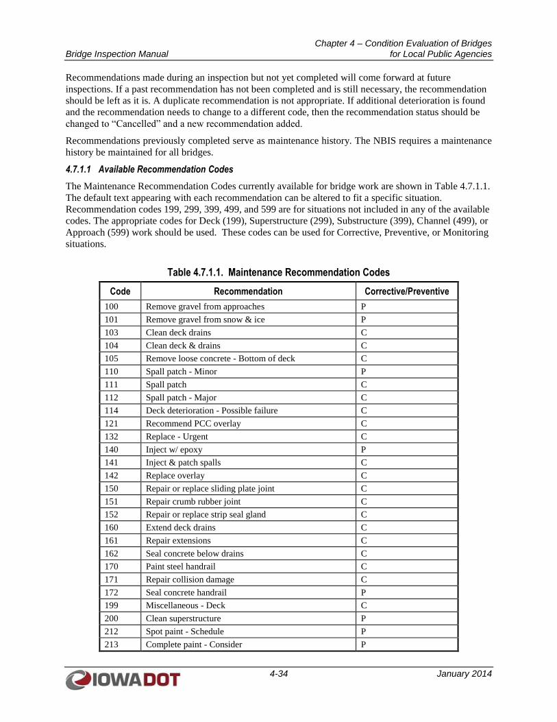
Chapter 4 – Condition Evaluation of Bridges Bridge Inspection Manual for Local Public Agencies
4-34 January 2014
Recommendations made during an inspection but not yet completed will come forward at future
inspections. If a past recommendation has not been completed and is still necessary, the recommendation
should be left as it is. A duplicate recommendation is not appropriate. If additional deterioration is found
and the recommendation needs to change to a different code, then the recommendation status should be
changed to “Cancelled” and a new recommendation added.
Recommendations previously completed serve as maintenance history. The NBIS requires a maintenance
history be maintained for all bridges.
4.7.1.1 Available Recommendation Codes
The Maintenance Recommendation Codes currently available for bridge work are shown in Table 4.7.1.1.
The default text appearing with each recommendation can be altered to fit a specific situation.
Recommendation codes 199, 299, 399, 499, and 599 are for situations not included in any of the available
codes. The appropriate codes for Deck (199), Superstructure (299), Substructure (399), Channel (499), or
Approach (599) work should be used. These codes can be used for Corrective, Preventive, or Monitoring
situations.
Table 4.7.1.1. Maintenance Recommendation Codes
Code Recommendation Corrective/Preventive
100 Remove gravel from approaches P
101 Remove gravel from snow & ice P
103 Clean deck drains C
104 Clean deck & drains C
105 Remove loose concrete - Bottom of deck C
110 Spall patch - Minor P
111 Spall patch C
112 Spall patch - Major C
114 Deck deterioration - Possible failure C
121 Recommend PCC overlay C
132 Replace - Urgent C
140 Inject w/ epoxy P
141 Inject & patch spalls C
142 Replace overlay C
150 Repair or replace sliding plate joint C
151 Repair crumb rubber joint C
152 Repair or replace strip seal gland C
160 Extend deck drains C
161 Repair extensions C
162 Seal concrete below drains C
170 Paint steel handrail C
171 Repair collision damage C
172 Seal concrete handrail P
199 Miscellaneous - Deck C
200 Clean superstructure P
212 Spot paint - Schedule P
213 Complete paint - Consider P
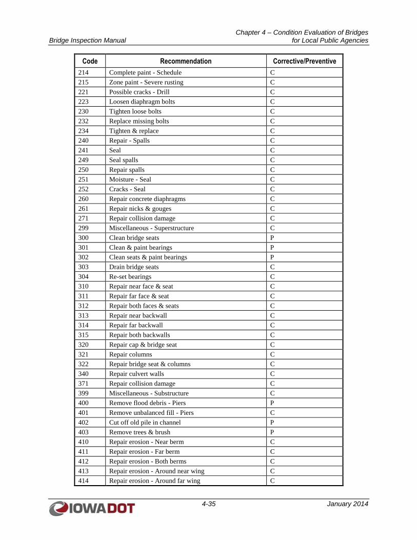
Chapter 4 – Condition Evaluation of Bridges Bridge Inspection Manual for Local Public Agencies
4-35 January 2014
Code Recommendation Corrective/Preventive
214 Complete paint - Schedule C
215 Zone paint - Severe rusting C
221 Possible cracks - Drill C
223 Loosen diaphragm bolts C
230 Tighten loose bolts C
232 Replace missing bolts C
234 Tighten & replace C
240 Repair - Spalls C
241 Seal C
249 Seal spalls C
250 Repair spalls C
251 Moisture - Seal C
252 Cracks - Seal C
260 Repair concrete diaphragms C
261 Repair nicks & gouges C
271 Repair collision damage C
299 Miscellaneous - Superstructure C
300 Clean bridge seats P
301 Clean & paint bearings P
302 Clean seats & paint bearings P
303 Drain bridge seats C
304 Re-set bearings C
310 Repair near face & seat C
311 Repair far face & seat C
312 Repair both faces & seats C
313 Repair near backwall C
314 Repair far backwall C
315 Repair both backwalls C
320 Repair cap & bridge seat C
321 Repair columns C
322 Repair bridge seat & columns C
340 Repair culvert walls C
371 Repair collision damage C
399 Miscellaneous - Substructure C
400 Remove flood debris - Piers P
401 Remove unbalanced fill - Piers C
402 Cut off old pile in channel P
403 Remove trees & brush P
410 Repair erosion - Near berm C
411 Repair erosion - Far berm C
412 Repair erosion - Both berms C
413 Repair erosion - Around near wing C
414 Repair erosion - Around far wing C
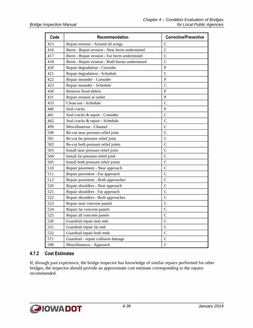
Chapter 4 – Condition Evaluation of Bridges Bridge Inspection Manual for Local Public Agencies
4-36 January 2014
Code Recommendation Corrective/Preventive
415 Repair erosion - Around all wings C
416 Berm - Repair erosion - Near berm undermined C
417 Berm - Repair erosion - Far berm undermined C
418 Berm - Repair erosion - Both berms undermined C
420 Repair degradation - Consider P
421 Repair degradation - Schedule C
422 Repair meander - Consider P
423 Repair meander - Schedule C
430 Remove flood debris P
431 Repair erosion at outlet P
433 Clean out - Schedule C
440 Seal cracks P
441 Seal cracks & repair - Consider C
442 Seal cracks & repair - Schedule C
499 Miscellaneous - Channel C
500 Re-cut near pressure relief joint C
501 Re-cut far pressure relief joint C
502 Re-cut both pressure relief joints C
503 Install near pressure relief joint C
504 Install far pressure relief joint C
505 Install both pressure relief joints C
510 Repair pavement - Near approach C
511 Repair pavement - Far approach C
512 Repair pavement - Both approaches C
520 Repair shoulders - Near approach C
521 Repair shoulders - Far approach C
522 Repair shoulders - Both approaches C
523 Repair near concrete panels C
524 Repair far concrete panels C
525 Repair all concrete panels C
530 Guardrail repair near end C
531 Guardrail repair far end C
532 Guardrail repair both ends C
571 Guardrail - repair collision damage C
599 Miscellaneous - Approach C
4.7.2 Cost Estimates
If, through past experience, the bridge inspector has knowledge of similar repairs performed for other
bridges, the inspector should provide an approximate cost estimate corresponding to the repairs
recommended.
Chapter 5 –QA/QC Bridge Inspection Manual for Local Public Agencies
5-1 January 2014
CHAPTER 5
QUALITY ASSURANCE/QUALITY CONTROL (QA/QC) FOR
LOCAL PUBLIC AGENCIES
5.1 SCOPE OF LOCAL PUBLIC AGENCYQUALITY ASSURANCE/QUALITY CONTROL PROGRAM
Of the more than 25,000 bridges in Iowa that are in the NBI, approximately 21,000 of the bridges are
owned, inspected, and maintained by counties, cities, and other public agencies. County and city bridge
owners are referred to as Local Public Agencies (LPAs). Iowa Code 314.18 requires LPAs to be
responsible for the safety inspection and evaluation of all highway bridges under their jurisdiction that are
located on public roads, in accordance with the NBIS. Iowa DOT published I.M. 2.120 to assist LPAs in
complying with the NBIS.
Private bridge owners are not subject to the NBIS and do not fall under Iowa DOT oversight. They are
encouraged but not required to perform inspections that comply with the NBIS.
5.2 NBIS DEFINITION OF TERMS
The NBIS definitions of Quality Control and Quality Assurance are provided in the following sections.
5.2.1 Quality Control
Quality Control is defined as procedures intended to maintain the quality of a bridge inspection and load
rating at or above a specified level.
5.2.2 Quality Assurance
Quality Assurance is defined as the use of sampling and other measures to assure the adequacy of quality
control procedures in order to verify or measure the quality level of the entire bridge inspection and load
rating program.
5.3 ROLE OF SIIMS
Iowa DOT implemented SIIMS in May 2010. SIIMS is a software package used to update the bridge
records of Iowa’s portion of the NBI. The user interface is a password-protected website allowing
Iowa DOT and LPA bridge inspectors to manage inspections and document findings in a standardized
reporting format.
SIIMS is the foundation of the Iowa DOT quality control program. The software presents standard
collection screens for data entry, schedules inspections, and performs integrity checks at each stage of the
approval process. These quality control measures are in place to obtain consistent inspection data from
multiple inspectors, which is necessary if proper resource planning is to occur across the State.
Chapter 5 –QA/QC Bridge Inspection Manual for Local Public Agencies
5-2 January 2014
5.4 QUALITY CONTROL
5.4.1 Inspection Scheduling
Inspection dates and inspection frequencies are entered in SIIMS for all NBI structures. Multiple
inspection types, such as Fracture Critical or Underwater Inspections, may be entered and scheduled for
separate dates, years, and frequencies.
SIIMS can forecast upcoming inspections and provide maps of bridge locations.
When the date of an inspection passes without the creation of an inspection report, SIIMS will
automatically notify the bridge owner and Program Manager via e-mail if a report is not created by the
time the inspection is 1 month, 3 months, and 6 months past due.
If an inspection report was created but remains unapproved, SIIMS will automatically notify the bridge
owner and Program Manager via e-mail when the inspection report is 3 months and 6 months past the
inspection date.
If an inspection report is not created or the report remains unapproved 6 months after the inspection date,
SIIMS will automatically notify the bridge owner and Program Manager via e-mail and request an
aggressive, short-term plan to correct this deficiency.
5.4.2 LPA Compliance
For LPAs with NBIS compliance issues, the LPA will be directed to complete one of the following
actions:
1. Complete all the actions necessary to resolve the compliance deficiencies.
2. Submit an aggressive, short-term plan to correct the deficiencies for FHWA approval.
Iowa DOT will issue two notifications to the LPA. First, Iowa DOT will issue a 60-day notification to the
LPA that failure to correct the NBIS errors will result in the LPA being assessed as non-compliant with
the NBIS. At the end of the 60 days, Iowa DOT will issue a 30-day second advanced notification
recommending that FHWA not approve future Federal-aid projects for the noted LPA.
For LPAs that have not corrected the NBIS deficiencies or have not carried out a short term plan to
correct the NBIS deficiencies within 90 days from the date of the first notification, Iowa DOT will notify
FHWA of the recommended local governmental entities that should have their Federal-aid project
funding suspended.
For those LPAs that submit a short-term plan, Iowa DOT shall review the plan to ensure the LPA
necessarily corrected deficiencies in a reasonable time frame and, if it does, Iowa DOT will recommend
its approval to FHWA. Additionally, Iowa DOT shall evaluate the progress made by the LPA to complete
the short-term corrective plan in accordance with the approved timeline. Iowa DOT shall notify FHWA
when the LPA has failed to make sufficient progress or failed to complete its short-term plan by the
approved timelines. Additionally, in the case of failure to make sufficient progress or complete its short-
term plan by the approved timelines, Iowa DOT shall issue a 30-day advanced notification recommending
that FHWA not approve future Federal-aid projects for the noted LPA.
Chapter 5 –QA/QC Bridge Inspection Manual for Local Public Agencies
5-3 January 2014
5.4.3 Data Collection
When an inspection report is created in SIIMS, a series of web pages are populated with the NBI
information available for the structure. SIIMS promotes consistent NBI data collection by standardizing
the data entry based on the following:
1. The inspector reviews each NBI entry and updates the data to reflect his/her inspection findings.
2. Each report includes a Load Rating Evaluation Form the inspector must complete before SIIMS will
allow the inspection report to be approved.
Each report has an Error Check page alerting the inspector to entries that are missing or varying from an
expected format.
5.4.4 Inspection Report Approval
The last step in the data entry process for an inspection report is requesting approval. When an inspector
submits a report for approval, the error check software in SIIMS will review the report fields. If data
entry errors are found, such as Item 92A (Fracture Critical Details) is coded “Yes” but no Fracture
Critical inspection date is entered, an Error Check page will appear, and the report will not be approved
until the errors are resolved.
When the error check software finds entries that do not match the data stored in the SIIMS database, the
inspector will be asked if the new data should overwrite the existing data or if the existing data should
remain. The inspector must choose whether to use the report values or central database values before
SIIMS will allow the report to be approved. Some data may be uneditable because it is data maintained
by the Iowa DOT. If the data is uneditable and appears to be incorrect or in question, contact the Office of
Research and Analytics to correct or clarify the data discrepancy.
LPA inspectors perform their own quality control review of the report content. SIIMS is programmed to
check for data entry errors, but decisions about maintenance activities or structural repairs are made by
the LPA inspector or Program Manager.
5.4.5 Training
The NBIS requires periodic bridge inspection refresher training for Program Managers and Team Leaders
in Part 650.313(g). Iowa DOT has defined periodic as being every 5 years. All State and LPA bridge
inspection personnel are required to complete the Bridge Inspection Refresher Training Course every
5 years following the completion of the Safety Inspection of In-Service Bridges Training Course.
The SIIMS system contains an individual’s qualifications as a team leader. When an individual’s
refresher training or professional license is within 6 months of expiring, a notice will appear each time the
user logs into SIIMS. This notice will show the date(s) of expiration.
5.5 QUALITY ASSURANCE
The terms quality control and quality assurance are not interchangeable. The NBIS defines quality
control as a tool and quality assurance as an evaluation of that tool. SIIMS has built-in quality controls
that guide inspectors through data collection and standardize data entry in order to obtain consistent
inspection data from multiple inspectors.
Quality assurance is a review of the inspection data to provide the following:
Chapter 5 –QA/QC Bridge Inspection Manual for Local Public Agencies
5-4 January 2014
1. An evaluation of how well the quality control tools in SIIMS are delivering consistent inspection
data
2. Identification of where the data are not consistent so the quality control tools can be corrected or
modified
5.5.1 Review of LPA Bridge Records
Iowa DOT I.M. 2.120 states the Iowa DOT shall annually review a random sample of LPA bridge records
to determine if they contain the following minimum (as applicable) items:
1. Bridge Plans
2. Repair Plans
3. Photographs
4. Scour Evaluation Data
5. Channel Cross Section
6. Local Agency Field Data Collection Form
7. Structure Inventory and Appraisal (SI&A) Forms
8. Load Rating Calculations
9. Load Rating Evaluation Form
10. Critical Findings
11. Critical Features List
12. Special Inspection Equipment List
5.5.2 LPA Team Leader Reviews
The LPA Program Manager (the individual in charge of the LPA inspection program) is required to
conduct a Team Leader review every 4 years. The review includes the following:
1. An independent party review by a Professional Engineer licensed in the State of Iowa and
qualified as a Team Leader.
2. A field review of inspection data for 10 bridges inspected during the past 12 months. The bridges
selected shall include, but are not limited to, the following:
a. Predominant bridge types inspected
b. Bridges with lower sufficiency ratings
c. Bridges with Deck (NBI Item 58), Superstructure (NBI Item 59), Substructure (NBI Item 60),
Culvert (NBI Item 62), or Posting (NBI Item 70) rated 4 or less (if applicable to the bridges
inspected by the Team Leader)
3. The Reviewer accompanies the Team Leader under review during the inspection of 2 of the 10
selected bridges.
4. A Quality Assurance Field Review Worksheet completed for each bridge inspected. The Quality
Assurance Field Review Worksheet is available in IM 2.120.
5. Verification of the information provided by an individual to obtain access to SIIMS as a Team
Leader.
Chapter 5 –QA/QC Bridge Inspection Manual for Local Public Agencies
5-5 January 2014
6. Documentation that the Team Leader has completed the Bridge Inspector Refresher Training
Course and, if needed, Fracture Critical Inspection Techniques for Steel Bridges Training Course.
The findings of the Team Leader reviews are reported to the Iowa DOT. If there are negative findings
regarding the Team Leader, the report shall include corrective recommendations, or actions taken, to resolve
those findings.
5.5.3 Load Rating Engineer Reviews
Load Rating Engineer reviews will be conducted by the Office of Bridges and Structures utilizing SIIMS in
conjunction with on-site field reviews as part of the Iowa DOT’s annual oversight of the LPA’s program.