Embed Size (px)
Citation preview

Office for Nuclear RegulationAn agency of HSE
PROTECTIVE MARKING IF APPLICABLE
Generic Design Assessment – New Civil Reactor Build
Step 4 Fault Studies – Containment and Severe Accident Assessment of the
Westinghouse AP1000® Reactor
Assessment Report: ONR-GDA-AR-11-004B Revision 0
23 November 2011
.

PROTECTIVE MARKING IF APPLICABLE
Report ONR-GDA-AR-11-004bOffice for Nuclear Regulation An agency of HSE
Revision 0
Page (i)
COPYRIGHT
© Crown copyright 2011 First published December 2011 You may reuse this information (excluding logos) free of charge in any format or medium, under the terms of the Open Government Licence. To view the licence visit www.nationalarchives.gov.uk/doc/open-government-licence/, write to the Information Policy Team, The National Archives, Kew, London TW9 4DU, or email [email protected].
Some images and illustrations may not be owned by the Crown so cannot be reproduced without permission of the copyright owner. Enquiries should be sent to [email protected].
Unless otherwise stated, all corporate names, logos, and Registered® and Trademark™ products mentioned in this Web site belong to one or more of the respective Companies or their respective licensors. They may not be used or reproduced in any manner without the prior written agreement of the owner(s).
For published documents, the electronic copy on the ONR website remains the most current publicly available version and copying or printing renders this document uncontrolled.

PROTECTIVE MARKING IF APPLICABLE
Report ONR-GDA-AR-11-004bOffice for Nuclear Regulation An agency of HSE
Revision 0
Page (ii)
PREFACE
The Office for Nuclear Regulation (ONR) was created on 1st April 2011 as an Agency of the Health and Safety Executive (HSE). It was formed from HSE's Nuclear Directorate (ND) and has the same role. Any references in this document to the Nuclear Directorate (ND) or the Nuclear Installations Inspectorate (NII) should be taken as references to ONR.
The assessments supporting this report, undertaken as part of our Generic Design Assessment (GDA) process, and the submissions made by Westinghouse relating to the AP1000® reactor design, were established prior to the events at Fukushima, Japan. Therefore, this report makes no reference to Fukushima in any of its findings or conclusions. However, ONR has raised a GDA Issue which requires Westinghouse to demonstrate how they will be taking account of the lessons learnt from the events at Fukushima, including those lessons and recommendations that are identified in the ONR Chief Inspector’s interim and final reports. The details of this GDA Issue can be found on the Joint Regulators’ new build website www.hse.gov.uk/newreactors and in ONR’s Step 4 Cross-cutting Topics Assessment of the AP1000® reactor.
PROTECTIVE MARKING IF APPLICABLE
Report ONR-GDA-AR-11-004bOffice for Nuclear Regulation An agency of HSE
Revision 0
Page (iii)
EXECUTIVE SUMMARY
This report presents the findings of the Fault Studies assessment of the Design Basis Containment Thermal Hydraulics Response and Severe Accident of the AP1000 reactor undertaken as part of Step 4 of the Health and Safety Executive’s (HSE) Generic Design Assessment (GDA). The assessment has been carried out on the Pre-construction Safety Report (PCSR) and supporting documentation submitted by Westinghouse during Step 4.
Only limited work was performed in the area of Design Basis Containment Thermal Hydraulics and Severe Accidents during Generic Design Assessment Steps 2 and 3. The scope of the Step 4 assessment was therefore to review the safety case of the AP1000 reactor in these technical areas and by examining the evidence, supporting arguments and claims made by Westinghouse, to make a judgement on the adequacy of the PCSR and supporting documentation.
It is seldom possible, or necessary, to assess a safety case in its entirety, therefore sampling is used to limit the areas scrutinised, and to improve the overall efficiency of the assessment process. Sampling is done in a focused, targeted and structured manner with a view to revealing any topic-specific, or generic, weaknesses in the safety case. The areas identified for sampling in Step 4 were set-out in advance in an assessment plan based upon the findings of the Step 3 report.
My assessment has focussed on:
thermal hydraulics challenges to the containment during design basis accident conditions;
operation of the Passive Containment Cooling System (PCS) during normal operation and fault conditions;
strategy for severe accident progression management;
key features of the design to mitigate against the consequence of a severe accident, such as In-Vessel Retention (IVR) of the molten material and debris within the RPV lower head;
challenges to the containment hydrogen control and management system; and
aspects of validation of the computer codes employed to support the claims within the safety submissions.
It is implicit in the judgements made in the transient analysis, specifically in relation to those faults which subject the containment to thermal and pressure loads, that the containment remains intact when those loads are within the design basis. It is necessary to check, therefore, that the safety case adequately demonstrates that accidents claimed to be within the design basis do not subject the containment to loads which might cause its failure. It is also necessary to ensure that the codes used in the analysis do reasonably predict the loads on the containment when subjected to these Design Basis Accident (DBA) conditions. It should be noted that the structural behaviour of the containment in response to these predicted loads is reviewed within the Structural Integrity assessment area and is reported separately.
A severe accident commences when failures in the emergency core cooling functions results in a failure to maintain the core in a coolable geometry and, importantly, the core geometry becomes unstable. In order to achieve the expected consequence targets, the AP1000 includes severe accident mitigation measures that are novel compared to existing Pressurised Water Reactors (PWR). I have examined the key features of the design, and the intended approach to control the core melt progression and the retention of molten core debris within the Reactor Pressure Vessel (RPV) lower head.
The AP1000 is designed to prevent the failure of RPV lower head, and hence retain the resulting molten material within this volume. This concept is referred to as In-Vessel Retention (IVR), and is achieved by cooling the RPV through introduction of cooling water into the reactor cavity cooling annulus from the In-containment Refuelling Water Storage Tank (IRWST) when the core outlet

PROTECTIVE MARKING IF APPLICABLE
Report ONR-GDA-AR-11-004bOffice for Nuclear Regulation An agency of HSE
Revision 0
Page (iv)
temperature is observed to exceed 650°C. The coolability limit for the success of IVR is determined by Critical Heat Flux (CHF) on the external vessel surface. The assessment of this strategy has received particular attention within GDA and is reported in Section 4 of this report.
The summary of my assessment is given in this report with highlights below:
Westinghouse safety submissions claim that the AP1000 plant containment design can withstand the various thermal hydraulics challenges in DBA conditions and that the proposed hydrogen control system minimises the challenges to containment integrity during a severe accident.
Westinghouse has recently advised HSE of a change in the design of the hydrogen igniters which will require qualification testing before active commissioning.
I have commissioned an independent confirmatory analysis to examine the claims for the maximum pressure and temperature within the containment environment during DBAs. I have also examined the effectiveness of the PCS during normal operations, and performance of the water cooling of the containment during the accident conditions. The results of my assessment and the confirmatory analyses have largely supported the claims made within the safety submissions, except for the uncertainty relating to the percentage of condensate formation, collection and return to the IRWST during DBAs. This concern is also the subject of a GDA Issue raised by Fault Studies for the loss of coolant accident faults where there are differing requirements on the water inventory within the IRWST.
Westinghouse claims that the core damage frequency for the AP1000 reactor is lower than in the current generation of operating PWRs. Nevertheless, the AP1000 reactor design employs the In-vessel Retention concept to mitigate the consequences of a severe accident and avoid a potential challenge to the containment integrity. I have commissioned independent confirmatory analyses for a number of representative scenarios and although there remains significant uncertainty, such as melt configuration during the relocation, I am satisfied that it confirms the likely success of IVR where Westinghouse has claimed a successful outcome.
During the Step 4 assessment of the AP1000 reactor, I have made a number of observations relating to the shortfalls of evidence and in the supporting arguments in the areas of DBA containment thermal hydraulics, severe accidents and hydrogen management techniques. Westinghouse has responded through the technical discussions and provision of additional information from its computational analysis. This was performed in support of the justification for the claims presented in the safety submission. I expect the revised PCSR will capture the improvements in these areas.
In a number of areas, international research is continuing to further improve the understanding of the core melt, its relocation behaviour and its composition characteristics within the lower head together with Molten Core Concrete Interaction (MCCI). The research is linked to international initiatives to improve the code predictive capabilities in an effort to reduce the uncertainties associated with modelling, and capturing the complex phenomena associated with severe accidents. Westinghouse has been active in performing research and development in support of areas relevant to AP1000. I commend Westinghouse for this work and encourage it to sustain its involvement in order to support any future design evolutions. I would also encourage any prospective licensees to get involved in these initiatives to enhance their understanding of the implication of this research on the conservative assumptions employed within the fault analysis supporting the site specific safety case.
It has been agreed with Westinghouse that it is more appropriate to assess the proposed Technical Specifications, Emergency Operating Procedures (EOP) and the Severe Accident Management Guidelines (SAMGs) and the site-specific radiological consequence assessments during the site

PROTECTIVE MARKING IF APPLICABLE
Report ONR-GDA-AR-11-004bOffice for Nuclear Regulation An agency of HSE
Revision 0
Page (v)
licensing process. Hence, these items are considered outside the scope of the GDA process and have not been included in my assessment.
Although HSE’s Nuclear Directorate (ND) will need to assess the additional information that becomes available as the GDA Design Reference is supplemented with additional details on a site by site basis, my judgement is that:
From my assessment and the results provided by the confirmatory analysis, I have concluded that an acceptable safety case has been made for the design features of the AP1000 reactor. However, HSE’s ND will need to assess the additional information that becomes available as the GDA Design Reference is supplemented with detailed information becoming available for the Site Specific PCSR, and on future submissions on a site by site basis.
There are some areas where HSE’s ND will require additional information to underpin my conclusions and these are identified as Assessment Findings and will be carried forward as normal regulatory business. These are discussed within the report and listed in Annex 1.
Overall, based on the sample undertaken in accordance with HSE’s ND procedures, I am broadly satisfied that the claims, arguments and evidence presented within the PCSR and supporting documentation submitted as part of the GDA process, presents an adequate safety case for the generic AP1000 reactor design. I consider that from a containment thermal hydraulics and severe accident point of view, the AP1000 reactor is suitable for construction in the UK, subject to assessment of additional information that becomes available as the GDA Design Reference is supplemented with additional details on a site-by-site basis.

PROTECTIVE MARKING IF APPLICABLE
Report ONR-GDA-AR-11-004bOffice for Nuclear Regulation An agency of HSE
Revision 0
Page (vi)
LIST OF ABBREVIATIONS
AC Alternating Current
ADS Automatic Depressurisation System
AICC Adiabatic Isochoric Complete Combustion
ALARP As Low As Reasonably Practicable
ACRS Advisory Committee on Reactor Safeguards (US NRC)
BDBA Beyond Design Basis Accidents
BMS (Nuclear Directorate) Business Management System
BSL Basic Safety level (in SAPs)
BSO Basic Safety Objective (in SAPs)
CAMP Code and Maintenance Programme
CA Modules CA (Civil A) Modules are the prefabricated structural modules used for the in containment structures and within the Auxiliary Building. These comprise steel/concrete composite or steel only modules used for walls and floors.
CDF Core Damage Frequency
CET Core Exit Temperature
CFD Computational Fluid Dynamics
CHF Critical Heat Flux
CMT Core Make-up Tank
CRDM Control Rod Drive Mechanism
CSARP Cooperative Severe Accident Research Programme
CSNI Committee the Safety of Nuclear Installations
CSS In-containment Spray System
CV Containment Vessel
DAS Diverse Actuation System
DBA Design Basis Accident
DC Direct Current
DDT Deflagration to Detonation Transition
DECC Department of Energy and Climate Change
DfT Department for Transport
DVI Direct Vessel Injection
ECCS Emergency Core Cooling System
EDCD European Design Control Document
EOP Emergency Operating Procedures

PROTECTIVE MARKING IF APPLICABLE
Report ONR-GDA-AR-11-004bOffice for Nuclear Regulation An agency of HSE
Revision 0
Page (vii)
LIST OF ABBREVIATIONS
FCI Fuel Coolant Interaction
FPS Fire Protection System
GDA Generic Design Assessment
HGCS Hydrogen Gas Control System
HSE The Health and Safety Executive
IAEA The International Atomic Energy Agency
INEEL Idaho National Engineering and Environmental Laboratory
IRWST In-containment Refuelling Water Storage Tank
ISP International Standard Problem
IVR In-Vessel Retention
LBLOCA Large Break Loss of Coolant Accident
LOCA Loss of Coolant Accident
LP Lumped Parameter
MAAP Modular Accident Analysis Programme
MCCI Molten Core Concrete Interaction
MCR Main Control Room
MDEP Multinational Design Evaluation Programme
MSLB Main Steam Line Break
NCB Non Classified Building
ND The (HSE) Nuclear Directorate
ONR Office for Nuclear Regulation (formerly the Nuclear Directorate of HSE)
OJEU Official Journal of the European Union
PAR Passive Autocatalytic Recombiner
PCCWST Passive Containment Cooling Water Storage Tank
PCS Passive Containment Cooling System
PCSR Pre-construction Safety Report
PMS Protection and Monitoring System
PRA Probabilistic Risk Assessment
PRHR Passive Residual Heat Removal
PSA Probabilistic Safety Analysis
PXS Passive Core Cooling Systems
RCS Reactor Coolant System
RGP Relevant Good Practice
RI Regulatory Issue

PROTECTIVE MARKING IF APPLICABLE
Report ONR-GDA-AR-11-004bOffice for Nuclear Regulation An agency of HSE
Revision 0
Page (viii)
LIST OF ABBREVIATIONS
RIA Regulatory Issue Action
RO Regulatory Observation
ROA Regulatory Observation Action
ROAAM Risk Oriented Accident Analysis Methodology
RPV Reactor Pressure Vessel
SAMG Severe Accident Management Guidelines
SAP Safety Assessment Principles
SBO Station Black-out
SFAIRP So Far As Is Reasonably Practicable
SFP Spent Fuel Pool
SG Steam Generator
SGTR Steam Generator Tube Rupture
SSC System, Structure and Component
SSER Safety, Security and Environmental Report
TAG (Nuclear Directorate) Technical Assessment Guide
TQ Technical Query
TSC Technical Support Contractor
US NRC Nuclear Regulatory Commission (United States of America)
VLS Containment Hydrogen Control System
WENRA The Western European Nuclear Regulators’ Association

PROTECTIVE MARKING IF APPLICABLE
Report ONR-GDA-AR-11-004bOffice for Nuclear Regulation An agency of HSE
Revision 0
Page (ix)
TABLE OF CONTENTS
1 INTRODUCTION...................................................................................................................... 1
2 NUCLEAR DIRECTORATE’S ASSESSMENT STRATEGY FOR FAULT STUDIES - CONTAINMENT AND SEVERE ACCIDENT ........................................................................... 3 2.1 Assessment Plan ............................................................................................................ 3 2.2 Standards and Criteria .................................................................................................... 4 2.3 Assessment Scope ......................................................................................................... 7
2.3.1 Findings from GDA Step 3............................................................................................. 7 2.3.2 Use of Technical Support Contractors........................................................................... 8 2.3.3 Cross-cutting Topics ...................................................................................................... 9 2.3.4 Integration with other Assessment Topics..................................................................... 9 2.3.5 Out of Scope Items ...................................................................................................... 10 2.3.6 PCSR Status................................................................................................................ 10
3 WESTINGHOUSE’S SAFETY CASE..................................................................................... 12
4 GDA STEP 4 NUCLEAR DIRECTORATE ASSESSMENT FOR FAULT STUDIES - CONTAINMENT AND SEVERE ACCIDENT ......................................................................... 15 4.1 Containment Thermal Hydraulics.................................................................................. 15
4.1.1 Background and Introduction....................................................................................... 15 4.1.2 Containment Response in Anticipated Events and Design-Basis Faults .................... 16 4.1.3 Passive Residual Heat Removal (PRHR) System ...................................................... 17 4.1.4 Passive Containment External Cooling System .......................................................... 20 4.1.5 Contaminent Isolation and Bypass .............................................................................. 25 4.1.6 Containment Activity Management.............................................................................. 26 4.1.7 Containment Response in Accident Conditions .......................................................... 28 4.1.8 WGOTHIC Computer Code Assessment .................................................................... 30
4.2 Effectiveness of the Measures to Depressurise Reactor Coolant System.................... 32 4.2.1 Core Outlet Temperatures........................................................................................... 32 4.2.2 Automatic Depressurisation System (ADS)................................................................. 34
4.3 Severe Accident Management...................................................................................... 35 4.3.1 In-vessel Melt Retention Strategy................................................................................ 36 4.3.2 Steam Explosion Risk.................................................................................................. 38 4.3.3 Hydrogen Management ............................................................................................... 40 4.3.4 Vent in Accident Conditions......................................................................................... 44 4.3.5 Spent Fuel Pool Facility ............................................................................................... 45 4.3.6 Severe Accident Analysis Codes................................................................................. 46
4.4 Confirmatory Analyses.................................................................................................. 49 4.4.1 PCS Performance - Detailed Modelling of the Flow in the Containment Annulus....... 49 4.4.2 Containment Performance in Design Basis Faults...................................................... 50 4.4.3 Severe Accident Progression ...................................................................................... 52
4.5 Overseas Regulatory Interface ..................................................................................... 55
PROTECTIVE MARKING IF APPLICABLE
Office for Nuclear Regulation An agency of HSE
Report ONR-GDA-AR-11-004bRevision 0
Page (x)
5 CONCLUSIONS..................................................................................................................... 56 5.1 Key Findings from the Step 4 Assessment ................................................................... 57 5.2 GDA Issues................................................................................................................... 57
6 REFERENCES....................................................................................................................... 58
Tables
Table 1: Relevant Safety Assessment Principles for Fault Studies - Containment and Severe Accident Considered During Step 4
Annexes
Annex 1: Assessment Findings to be Addressed During the Forward Programme as Normal Regulatory Business – Fault Studies - Containment and Severe Accident – AP1000
Annex 2: GDA Issues – Fault Studies – Containment and Severe Accident – AP1000
Figures
Figure 1: Schematic of the Water Inlet Arrangement for the RPV External Cooling
Figure 2: Schematic of the Passive Residual Heat removal System External Cooling

PROTECTIVE MARKING IF APPLICABLE
Report ONR-GDA-AR-11-004bOffice for Nuclear Regulation An agency of HSE
Revision 0
Page 1
1 INTRODUCTION
1 My report presents the findings of the GDA Step 4 Fault Studies - Containment Thermal Hydraulics Response and Severe Accident assessment of the AP1000 reactor Pre-Construction Safety Report (PCSR) (Ref. 12) and supporting documentation provided by Westinghouse under the Health and Safety Executive's (HSE) Generic Design Assessment (GDA) process. I assessed the PCSR and its supporting evidentiary information derived from the Master Submission List (MSL) (Ref. 14). My approach was to assess the principal submission, i.e. the PCSR, and then undertake an assessment of the relevant documentation sourced from the Master Submission List on a sampling basis in accordance with the requirements of HSE Nuclear Directorate’s (ND) Business Management System (BMS) procedure AST/001 (Ref. 2). I used the Safety Assessment Principles (SAP) (Ref. 4) as the basis for my assessment. Ultimately, the goal of assessment is to reach an independent and informed judgment on the adequacy of a nuclear safety case.
2 During the assessment a number of Technical Queries (TQ) and Regulatory Observations (RO) were issued and the responses made by Westinghouse assessed. Where relevant, detailed design information from specific projects for this reactor type has been assessed to build confidence and assist in forming a view as to whether the design intent proposed within the GDA process can be realised.
3 A number of items, such as technical specifications and Severe Accident Management Guidelines (SAMG), have been agreed with Westinghouse to be outside the scope of the GDA process and hence have not been included in this assessment.
4 The AP1000 design includes a large containment building such that active measures are not required to limit the containment pressure and temperature immediately following an accident. The UK AP1000 safety submissions claim that the plant containment design can withstand the various thermal hydraulics challenges in Design Basis Accident (DBA) conditions. These provisions are assessed in Section 4.1.
5 The containment also houses the hydrogen management and control system to minimise the challenges to containment integrity during design basis accidents and in severe accident conditions. Successful containment is dependent on the effective performance of the Passive Containment Cooling System (PCS) and effective mixing of fluids within the containment volume. The effectiveness of this approach is assessed in Section 4.1.
6 There are many aspects of the design that rely on the effective operation of passive safety features which have largely been developed through early work on the AP600 and its supporting test activities/facilities. These include the use of a large volume of water within the In-containment Refuelling Water Storage Tank (IRWST) as a heat sink and heat rejection from this to the containment shell. The implications for this on containment response are considered in Section 4.1.
7 In order to achieve the international consequence targets, the AP1000 has dedicated severe accident mitigation measures that are ‘novel’ to existing PWRs. These features include the employment of major sources of water supplies injected into the core, and the provision of the Automatic Depressurisation System (ADS) of the reactor coolant system at various stages of the fault progression. The operation of this system is reviewed in Section 4.1.
8 The In-vessel Retention (IVR) designed to control the movement of core debris into the RPV lower head where it is retained is discussed in Section 4.3. The hydrogen control and management scheme, to mitigate against hydrogen explosion, positioned within the containment is also discussed in Section 4.3.

PROTECTIVE MARKING IF APPLICABLE
Report ONR-GDA-AR-11-004bOffice for Nuclear Regulation An agency of HSE
Revision 0
Page 2
9 The severe accident commences when both the normal and emergency core cooling systems have failed. The outcome of this is a failure to maintain the core in a coolable geometry and, importantly, the core geometry becomes unstable. The course and speed of the core melt and all subsequent phases depends on the type of scenario occurring, the rate of core uncovery, the decay heat levels, the heat generation from zircaloy™ / steam exothermic reaction, and the plant responses to failure during the intended controlled movement of debris from the core region to the RPV bottom head where it remains for the majority of accident scenarios.
10 There are major technical challenges associated with justifying the effectiveness of the AP1000 passive systems because of the complex thermal hydraulics and structural interactions with debris in the head, wall ablation and external passive cooling with CHF limitations. These challenges require a clear understanding of the complex phenomena of debris progression during severe accident. Modelling the physical processes challenges the capabilities of the computer codes employed to analyse severe accidents, largely because of the large uncertainties associated with the representation of the phenomena involved, and the acknowledged difficulties of certain types of codes, such as Lumped Parameter (LP) codes, to capture the behaviour of the plant during transient conditions. I have recognised that Westinghouse has been active in performing research and development in support of the mitigation measures. I have examined the information that has been used to underpin the key design features of the plant and have made comments on these, where appropriate.
11 The steam explosion phenomenon as a result of melt relocation for in-vessel and ex-vessel conditions is discussed in Section 4.3.
12 There are complex phenomena associated with the thermal hydraulics and chemistry associated with the melt progression and final stabilisation in the bottom head during accident transients. Hence, large uncertainties are associated with predicting all aspects of the bottom head behaviour using the currently available computer codes. I therefore commissioned a set of independent confirmatory analyses to gain an independent view of the level of uncertainties, details of which are presented in Section 4.4.
13 The strategy used for my assessment within GDA Step 4 is outlined in the following Sections together with the standards against which the safety case has been judged.

PROTECTIVE MARKING IF APPLICABLE
Report ONR-GDA-AR-11-004bOffice for Nuclear Regulation An agency of HSE
Revision 0
Page 3
2 NUCLEAR DIRECTORATE’S ASSESSMENT STRATEGY FOR FAULT STUDIES - CONTAINMENT AND SEVERE ACCIDENT
14 Only very limited work was performed in the area of Design Basis Containment Thermal Hydraulics and Severe Accident during GDA Steps 2 and 3. The scope of the GDA Step 4 assessment was therefore to review the safety case of the AP1000 plant in these technical areas by examining the arguments and evidence supporting the claims made by Westinghouse. The main outcome of this work is to make a judgement on the adequacy of the PCSR and its supporting documentation. My assessment strategy for GDA Step 4 was set out in an assessment plan that identified the intended scope of my assessment and the standards and criteria that would be applied. This is summarised in the next section.
2.1 Assessment Plan
15 My plan for assessment of the Containment Thermal Hydraulics Response and Severe Accident topic area in GDA Step 4 is set out in Ref. 1.
16 The technical assessment in the Fault Studies - Containment Thermal Hydraulics Response and Severe Accident topic area only commenced part way through the GDA Step 3 process. For this reason, the scope of the assessment only included certain aspects of the severe accident analysis at that stage. I have therefore included those areas that would have been reviewed in GDA Step 3. Topics for further consideration were identified as the:
thermal hydraulic analysis of a sample of individual fault sequences analysed in support of the Probabilistic Safety Analysis (PSA) success criteria;
evidence to support the claims of in-vessel melt retention and consequences of failure of the pressure vessel;
justification of the validity of the computer models used for the analysis;
adequacy of the primary depressurisation system;
measures to mitigate hydrogen risk;
primary containment cooling system; and
use of containment spray.
17 Particular focus was placed on the evidence required to support the claimed values for safety limits presented as design criteria in the safety case. My assessment focused on the following topics:
thermal hydraulics challenges to the containment during design basis accident conditions;
strategy for severe accident progression management;
key features of the design which mitigate against the consequence of a severe accident;
performance of the containment hydrogen control and management system;
adequacy of the evidence supporting the claims and arguments assessed within GDA Step 3; and
validation and use of the computer codes employed in relation to containment thermal hydraulics and severe accident to support the claims within the safety submissions.
PROTECTIVE MARKING IF APPLICABLE
Report ONR-GDA-AR-11-004bOffice for Nuclear Regulation An agency of HSE
Revision 0
Page 4
18 In selected cases, I have commissioned independent confirmatory analyses from Technical Support Contractors (TSC).
19 The specific issues relating to IVR and the adequacy of the hydrogen management and control system to minimise the challenges to containment integrity during a severe accident have also been included within the assessment at GDA Step 4. My assessment has also covered the suitability of the devices designed to mitigate the accident consequences in conjunction with the chemistry area discipline.
2.2 Standards and Criteria
20 The standards and criteria that are used to judge the AP1000 design are defined in the 2006 HSE SAPs for Nuclear Facilities (Ref. 4). These principles require a robust demonstration of the design against conservative design assumptions for postulated faults considered within the design basis. The bulk of the assessment principles provide guidance for the assessment of these faults.
21 In the case of very low frequency events which potentially lead to a severe accident, a different set of requirements apply. These requirements are designed to require a demonstration that measures have been taken to mitigate the risk associated with the faults to a level that is As Low As Reasonably Practicable (ALARP). In these cases, the assessment is focused on confirming that appropriate mitigation measures have been identified and that the cost of further safety measures would be disproportionate to the potential reductions of risk.
22 The following principles taken from Ref. 4 are considered relevant to the assessment of the containment thermal hydraulics response and severe accidents have been used:
EKP.1: Engineering principles: key principles – Inherent safety The underpinning safety aim for any nuclear facility should be an inherently safe design, consistent with the operational purposes of the facility.
EKP.2: Engineering principles: key principles – Fault tolerance
The sensitivity of the facility to potential faults should be minimised. EKP.3: Engineering principles: key principles – Defence-in-depth
A nuclear facility should be so designed and operated that defence-in-depth against potentially significant faults or failures are achieved by the provision of several levels of protection.
ECS.4: Engineering principles: safety classification and standards – Codes and
standards For structures, systems and components that are important to safety, for which there are no appropriate established codes or standards, an approach derived from existing codes or standards for similar equipment, in applications with similar safety significance, may be applied.
ECS.5: Engineering principles: safety classification and standards – Use of
experience, tests or analysis In the absence of applicable or relevant codes and standards, the results of experience, tests, analysis, or a combination thereof, should be applied to demonstrate that the item will perform its safety function(s) to a level commensurate with its classification.
PROTECTIVE MARKING IF APPLICABLE
Report ONR-GDA-AR-11-004bOffice for Nuclear Regulation An agency of HSE
Revision 0
Page 5
EDR.4: Engineering principles: design for reliability – Single failure criterion
During any normally permissible state of plant availability no single random failure, assumed to occur anywhere within the systems provided to secure a safety function, should prevent the performance of that safety function.
ERL.1: Engineering principles: reliability of claims – Form of claims
The reliability claimed for any structure, system or component important to safety should take into account its novelty, the experience relevant to its proposed environment, and the uncertainties in operating and fault conditions, physical data and design methods.
ESS.12: Engineering principles: safety systems – Prevention of service
infringement Adequate provisions should be made to prevent the infringement of any service requirement of a safety system, its sub-systems and components.
FA.1: Fault analysis: general – Design basis analysis, PSA and severe accident
analysis Fault analysis should be carried out comprising design basis analysis, suitable and sufficient PSA, and suitable and sufficient severe accident analysis.
FA.2: Fault analysis: general – Identification of initiation faults
Fault analysis should identify all initiating faults having the potential to lead to any person receiving a significant dose of radiation, or to a significant quantity of radioactive material escaping from its designated place of residence or confinement.
FA.3: Fault analysis: general – Fault sequences
Fault sequences should be developed from the initiating faults and their potential consequences analysed.
FA.4: Fault analysis: general – Fault tolerance
DBA should be carried out to provide a robust demonstration of the fault tolerance of the engineering design and the effectiveness of the safety measures.
FA.9: Fault analysis: general – Further use of DBA
DBA should provide an input into the safety classification and the engineering requirements for systems, structures and components performing a safety function; the limits and conditions for safe operation; and the identification of requirements for operator actions.
FA.15: Fault analysis: severe accident analysis – Fault sequences
Fault sequences beyond the design basis that have the potential to lead to a severe accident should be analysed.
FA.16: Fault analysis: severe accident analysis – Uses of severe accident
analysis The severe accident analysis should be used in the consideration of further risk-reducing measures.

PROTECTIVE MARKING IF APPLICABLE
Report ONR-GDA-AR-11-004bOffice for Nuclear Regulation An agency of HSE
Revision 0
Page 6
FA.17: Fault analysis: assurance of validity of data and models – Theoretical models Theoretical models should adequately represent the facility and site.
FA.18: Fault analysis: assurance of validity of data and models – Calculation
models Calculational methods used for the analyses should adequately represent the physical and chemical processes taking place.
FA.19: Fault analysis: assurance of validity of data and models – Use of data
The data used in the analysis of safety-related aspects of plant performance should be shown to be valid for the circumstances by reference to established physical data, experiment or other appropriate means.
FA.20: Fault analysis: assurance of validity of data and models – Computer
models Computer models and datasets used in support of the analysis should be developed, maintained and applied in accordance with appropriate quality assurance procedures.
SC.4: The regulatory assessment of safety cases – Safety case characteristics In addition, Paragraph 93 of SC.4: requires demonstration that ALARP has been achieved for new facilities, modifications or periodic safety reviews, the safety case should:
i) identify and document all the options considered;
ii) provide evidence of the criteria used in decision making or option selection; and
iii) support comparison of costs and benefits where quantified claims of gross disproportion have been made.
The above principles are listed in Table 1.
23 The safety principles listed above are UK specific, but HSE’s ND also expects that the means of mitigation of the consequences of a severe accident shall also comply with the safety objective number O3, relative to accidents with core melt, of the WENRA Statement on safety objectives for New Nuclear Power Plants (Ref. 8).
24 In terms of containment and severe accident, the AP1000 design intent was based on the interactions that had already occurred between Westinghouse and staff of the United States Nuclear Regulatory Commission (US NRC) and its Advisory Committee on Reactor Safeguards (ACRS) and also on the French and German Utility Technical Guidelines for future PWR plant (Ref. 23). These Guidelines demand significant improvements in consideration and management of severe accidents at the design stage. These guidelines include:
A reduced target for Core Damage Frequency (CDF).
The requirement that accidents causing early large release of radiation to the public be “practically eliminated”, implying that sufficient design and operation provisions
The possibility of certain conditions occurring is considered to have been practically eliminated if it is physically impossible for the conditions to occur or if the conditions can be considered with a high degree of confidence to be extremely unlikely to arise (from IAEA NSG1.10 – Ref. 18).

PROTECTIVE MARKING IF APPLICABLE
Report ONR-GDA-AR-11-004bOffice for Nuclear Regulation An agency of HSE
Revision 0
Page 7
are incorporated to meet regulatory expectations of a level of integrity where formal justification of the consequences of failing would not normally be required. Ref. 57 provides the definition and expectation of the conditions that meet the criteria for practically eliminated.
25 These expectations have been addressed by Westinghouse.
2.3 Assessment Scope
26 For the purposes of GDA, the assessment has concentrated on examining the containment thermal hydraulics response in accident conditions and the performance of the systems designed to provide mitigation against the consequences of a severe accident. The specific topics sampled have been based on the findings of the GDA Step 3 Assessment.
27 I have therefore included the examination of the molten debris control features known as the “IVR” and the Hydrogen Gas Control System (HGCS) in my assessment. The success of these systems in the accident management of the plant is conditional on operator action and successful primary circuit depressurisation.
2.3.1 Findings from GDA Step 3
28 The GDA Step 3 report identified a number of specific issues which needed addressing by Westinghouse in sufficient time to be assessed in GDA Step 4:
Computer codes employed in severe accidents against validity of assurance SAPs FA.17 to FA. 22.
Sampling of severe accident sequences based on outputs from PSA.
Review of ADS engineering aspects and operator actuation plus optioneering employed.
Consider further Westinghouse information on chemistry aspects of core melt and impact of assumptions on in vessel retention CHF.
Consider steam explosions for in-vessel location and ex-vessel conditions likely to impact on the containment integrity.
Consider hydrogen mitigation scheme combustion, shock wave and detonation effects.
Discuss US NRC views on Passive Containment Cooling System (PCS).
29 The following further items were identified for consideration in GDA Step 4:
The basis of the analysis and the validation of the codes used to determine the hydrogen transport and distribution within the containment environment, and consideration of the common-mode failure of the Igniters and Passive Autocatalytic Recombiners (PAR) distributed within the containment.
Examination of the effects of uncertainties in the transient progression of the molten debris from the core region to its arrival within the RPV Bottom Head.
The need for passive and diverse means of venting the containment during fault conditions.
30 In each of these areas, Westinghouse has made substantial progress within GDA Step 4 and the detailed findings of my assessment are discussed in Section 4 of this report.

PROTECTIVE MARKING IF APPLICABLE
Report ONR-GDA-AR-11-004bOffice for Nuclear Regulation An agency of HSE
Revision 0
Page 8
2.3.2 Use of Technical Support Contractors
31 Technical Support Contractors have been used in a number of areas:
The development of an independent computer model of the AP1000 primary circuit, the various mitigation measures and containment systems including detailed reactor core, the cooling circuit and the features relevant to the IVR concept to examine all aspects of the transient core melt and the subsequent containment challenges during the severe accident.
Confirmatory analysis using an independently developed lumped parameter computer code to examine the AP1000 containment thermal hydraulics performance in selected bounding scenarios within the design basis accidents conditions.
The development of an independent computer model of the AP1000 PCS, including the containment shell, air inlet tubes, air baffle plates and the features of the outlet chimney to examine the overall system performance in normal operating conditions.
A review of the computer codes employed, including International Standard Problem (ISP) verification studies performed to provide knowledge and insights on containment hydrogen mixing phenomena.
A review of the containment design against relevant international good practice.
The topic of steam explosion phenomena relating to In-Vessel and Ex-Vessel explosions has also been examined in a brief review.
32 The contractor review supported by the confirmatory analysis of the severe accident progression simulating the core melt and degradation, relocation and core melt stabilisation within the lower head was performed to provide independent verification and confirmation of the claims made within the PCSR and its supporting documents. This work is reported in Ref. 46 and has provided additional assurance of the timing and severity of key events, consequences of a severe accident and the success of the IVR design feature. The result of this independent confirmatory analyses work is further described in Section 4.4.
33 I commissioned a programme of confirmatory analyses to examine the containment thermal hydraulics performance in design basis accident conditions. This analysis covered two bounding cases which are reported in Refs. 38 and 39. This work was performed to examine the margins to the maximum pressures and temperatures in the containment environment. The mass and energy release into the containment from the Reactor Coolant System (RCS) was provided by Westinghouse and the results from the confirmatory analysis using the input data were consistent with those of Westinghouse. The analyses also covered the sensitivity of the results to the PCS performance. More details are provided in Section 4.4.
34 The flow structure and the stability of the buoyancy driven airflow that influences the overall performance of the AP1000 PCS was examined using Computational Fluid Dynamics (CFD) analysis code. This work is reported in Ref. 47 and has provided the flow patterns around the containment shell for normal operating conditions for a variety of external conditions, especially the effect of wind on PCS operation. The CFD calculations were also supported by independent modelling using the transient analysis code TRACE. More details are provided in Section 4.4.
35 The reviews covering the analysis of chemistry and chemical reactions during a severe accident and the status of the composition of debris (Refs. 48 and 49) within the lower
PROTECTIVE MARKING IF APPLICABLE
Report ONR-GDA-AR-11-004bOffice for Nuclear Regulation An agency of HSE
Revision 0
Page 9
head have been managed together with my chemistry colleagues, the results of which are reported in (Ref. 36).
36 Similarly, the chemical behaviour and the performance of the igniters and Passive Autocatalytic Recombiners (PAR) within the environment likely to exist within the containment as a result of a severe accident, has been jointly managed with my chemistry colleagues and is reported in Ref. 24. This reference provides some independent confirmation of the claims made.
37 I also commissioned a short review of the international research to examine and consider the relevance of the current knowledge to the areas of the AP1000 design where the risk of steam explosion may exist.
2.3.3 Cross-cutting Topics
38 The following Cross-cutting Topics have been considered within this report:
39 The core fuel melt including all core materials and their interactions and behavioural characteristics during severe accident has required collaboration. My colleagues in the chemistry topic assessed the chemistry of molten material and chemical reactions during the transient, and I have assessed the issues relating to thermal hydraulics and complex heat transfer processes within and from the melt progression and stabilisation.
40 The operation of the hydrogen management system, known as the Containment Hydrogen Control System (VLS), particularly the performance of PARs and H2 igniters is also an issue for both chemistry and containment.
2.3.4 Integration with other Assessment Topics
41 I have collaborated with my chemistry colleagues in the chemistry area on a number of topics.
42 The performance of H2 igniters and PARs is affected by dust, contaminants, and fission products that may be present in accident conditions. The impact of these on performance of the igniters appear to be a short delay in the start-up characteristics which I consider will not adversely affect the overall containment’s performance during accident conditions.
43 The adequacy of the performance of the hydrogen mitigation measures is necessary to ensure that hydrogen concentration within the containment will not exceed the maximum concentration limits imposed for the containment. This is influenced by the total amount of hydrogen generated during the transient and the rate of generation. My assessment has required collaboration with the chemistry topic area. The performance of the H2 igniters will significantly influence the hydrogen transport and distribution within the containment together with the design features within the containment volume. The issues relating to the assessment of hydrogen transport within the containment have been covered and further discussed in Section 4.3.
44 The assessment of core melt behaviour in severe accidents has also required collaboration with my chemistry colleagues. This is discussed in Section 4.3.
45 The interaction with other assessment disciplines such as fault studies and PSA has been routine - the three assessment areas have been very closely integrated, with contact on a daily basis. My particular concern has been to ensure that the assumptions on DBA and BDBA scenarios made in fault studies are considered, and appropriately

PROTECTIVE MARKING IF APPLICABLE
Report ONR-GDA-AR-11-004bOffice for Nuclear Regulation An agency of HSE
Revision 0
Page 10
assessed for their impact on containment thermal hydraulics and severe accident demands.
46 In performing the confirmatory analyses to examine the plant’s performance in severe accident conditions, close collaboration was developed with the PSA team to ensure that the bounding cases were included in the analyses matrix. The selection of these scenarios was informed by the insights of the PSA discipline and the supporting TSC modelling expertise to provide confidence in Westinghouse’s submissions.
47 The design of the fuel pond has been the subject of extensive discussions in a number of assessment areas. In particular, it is the subject of a GDA issue in the fault study area. I have therefore limited my assessment of this area and the reader is directed to the Fault Studies Assessment Step 4 report (Ref. 37) for details of the assessment of this subject.
2.3.5 Out of Scope Items
48 It has been agreed with Westinghouse that it is more appropriate to assess the proposed Technical Specifications, Emergency Operating Procedures (EOP) and the Severe Accident Management Guidelines (SAMG) and the site-specific radiological consequence assessments during the site licensing process. Hence, these items are outside the scope of the GDA process and have not been included in my assessment. But these are noted to be critical to the successful management of a severe accident.
2.3.6 PCSR Status
49 In December 2009 Westinghouse submitted a revised version of the PCSR, UKP-GW-GL-732 Revision 2 at Ref.12, which was found to be overly reliant on the European Design Control Document (EDCD) (Ref. 42). This safety submission did not contain sufficient claims, arguments and evidence to substantiate the AP1000 design and demonstrate that the risks were controlled to be as low as reasonably practicable.
50 During my GDA Step 4 assessment of the AP1000 reactor, I have made a number of observations relating to the shortfalls of evidence and in the supporting arguments in this assessment topic area, and have consequently raised Technical Queries (TQ) and Regulatory Observations (RO) which relate to the containment thermal hydraulics performance, IVR and hydrogen management system. Westinghouse has responded to these, and through technical discussions and provision of additional information in support of the justification for the claims presented in the safety submission, I have been able to carry out my assessment. However, the overall shortfall in justification of the safety claims has led to the need for Westinghouse to produce a replacement PCSR. Westinghouse has therefore been developing a revised PCSR throughout GDA Step 4 to take account of comments, and responses to ROs, TQs. I expect the revised PCSR will capture the improvements in the areas relevant to this report.
51 In December 2010 a draft version of the consolidated PCSR was issued to HSE’s ND, UKP-GW-GL-793 Revision A (Ref. 13). There was little opportunity to comment on this version of the PCSR at the time. On 30 March 2011 Westinghouse submitted their final consolidated PCSR, UKP-GW-GL-793 Revision 0 but this was not assessed as part of GDA Step 4.
52 In summary, Westinghouse has an ongoing work stream to incorporate the responses to the TQs and ROs in all assessment topic areas to make up for the shortfalls in the December 2009 PCSR. A replacement PCSR was issued at the end of March 2011, which was not assessed and will require assessment to confirm it is fit for purpose. I note that the related cross-cutting GDA Issue GI-AP1000-CC-02 has been raised as part of

PROTECTIVE MARKING IF APPLICABLE
Report ONR-GDA-AR-11-004bOffice for Nuclear Regulation An agency of HSE
Revision 0
Page 11
the Cross-Cutting Assessment Report at Ref. 26, requesting Westinghouse to submit a final consolidated safety case to support the GDA Design Reference including the PCSR. I have therefore not raised an Assessment Finding relating to this topic and look to the satisfactory resolution of the extant cross cutting GDA Issue.

PROTECTIVE MARKING IF APPLICABLE
Report ONR-GDA-AR-11-004bOffice for Nuclear Regulation An agency of HSE
Revision 0
Page 12
3 WESTINGHOUSE’S SAFETY CASE
53 The safety case for the containment system provides the substantiation to demonstrate that adequate containment of radioactive material is maintained in design basis and other events. An overview is given in the Pre-construction Safety Case (PCSR).
54 Chapter 23 describes the containment and ventilation aspects of the plant and presents evidence that the engineering provision meets the safety requirements of normal operation, fault and hazard conditions.
55 Chapter 10, presents a summary of the Probabilistic Safety Assessment (PSA) for the AP1000, its links to Design Basis Accident (DBA) analysis and the approach to risk reduction in accordance with the ALARP principle.
56 The design is founded on adherence to the principles of delivering the following safety functions without the need for Alternating Current (AC) power:
Shutting down the nuclear reaction.
Removing decay heat by natural mechanisms such as natural circulation, conduction, convection, evaporation, and condensation.
Maintaining the reactor coolant water inventory.
Containment isolation.
Maintaining other safety functions such as spent fuel pool cooling, Main Control Room (MCR) habitability and severe accident mitigation.
57 These passive systems provide a means of controlling reactivity and removing decay heat for the first 72 hours in design basis accident scenarios. The following systems are key components:
58 The Passive Residual Heat Removal (PRHR) system uses a heat exchanger in the In-containment Refuelling Water Storage Tank (IRWST) to remove heat from the primary circuit by natural circulation and therefore delay primary system pressure relief demands.
59 The IRWST has two functions; decay heat removal via the passive residual heat removal system, and the provision of water inventory as an injection source into the RCS in the event of a LOCA. The inlet to the heat exchanger housed within the IRWST is connected to one of the two hot legs while the outlet is connected to the outlet plenum on one of the two steam generators. In the event of loss of RCS heat removal from Steam Generators (SG), the IRWST will absorb heat from the heat exchanger while primary system coolant circulates through the heat exchanger by natural circulation. After a few hours of operation in transient plant mode, the IRWST will begin to boil. Steam generated from IRWST boiling is released into the containment and will begin to condense on the containment walls. The condensate will then be directed by a safety-grade guttering system attached to the containment liner back to the IRWST to continue the cycle of events.
60 The Passive Containment Cooling System (PCS) uses water flowing under gravity and natural circulation of air to cool the outside of the Containment Vessel (CV) to remove the heat energy released inside the CV following an accident. The liquid film on the outside of the steel vessel is formed by applying water from the Passive Containment Cooling Water Storage Tank (PCCWST) positioned above the containment dome. Heat is transferred to the CV directly from energy released via any leak location, the IRWST water and from the containment generally by condensation on the inside of the CV. The condensate then runs back to the IRWST.
PROTECTIVE MARKING IF APPLICABLE
Report ONR-GDA-AR-11-004bOffice for Nuclear Regulation An agency of HSE
Revision 0
Page 13
61 Evaporation of the falling liquid film is enhanced by buoyancy-driven flows of moist air in an annular space between the outside of the steel containment shell wall and the inside of a baffle suspended from the shield building wall. Air inlets are provided at the top of the shield building. The design is such that the containment pressure remains below the design limit for more than 24 hours without operator action. Although the PCCWST is expected to initially hold water inventory for a period of 72 hours after the accident.
62 The operation of these passive systems has been verified using Lumped Parameter (LP) thermal-hydraulics computer codes, which in turn are validated against real systems tests and extensive rig testing. Computer simulations using these codes have enabled Westinghouse to claim that for the AP1000 design these innovative passive features substantially enhance its nuclear safety capability.
63 The number of containment penetrations has been reduced by half compared to PWRs in operation currently and the containment isolation valves have been replaced by types that are less likely to leak than those used on previous PWRs.
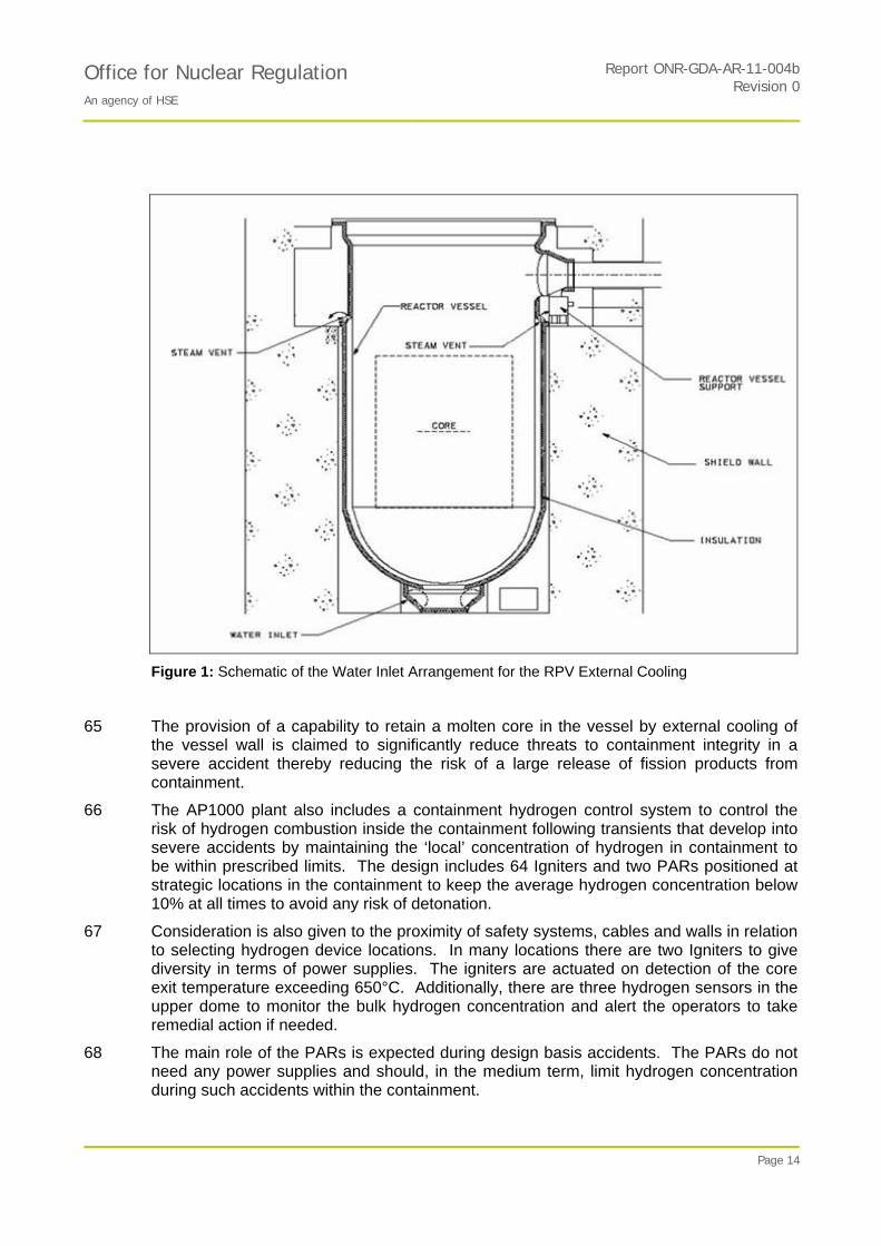
64 The Automatic Depressurisation System (ADS) included in the AP1000 design depressurises the primary circuit to allow for safety injection and to permit in-vessel melt retention in the event of a severe accident. The ADS can also be initiated by the operator on detection of core exit temperature at 650°C. In addition, the plant’s external reactor vessel bottom head cooling, essential to the success of IVR, is achieved by direct flooding of the cavity with water from the IRWST. The flooding of the cavity is expected to be initiated by the operator on detection of core exit temperature of 650°C. The schematic arrangement of the IRWST water inlet to cool the external surfaces of the RPV is shown in Figure 1.
PROTECTIVE MARKING IF APPLICABLE
Report ONR-GDA-AR-11-004bOffice for Nuclear Regulation An agency of HSE
Revision 0
Page 14
Figure 1: Schematic of the Water Inlet Arrangement for the RPV External Cooling
65 The provision of a capability to retain a molten core in the vessel by external cooling of the vessel wall is claimed to significantly reduce threats to containment integrity in a severe accident thereby reducing the risk of a large release of fission products from containment.
66 The AP1000 plant also includes a containment hydrogen control system to control the risk of hydrogen combustion inside the containment following transients that develop into severe accidents by maintaining the ‘local’ concentration of hydrogen in containment to be within prescribed limits. The design includes 64 Igniters and two PARs positioned at strategic locations in the containment to keep the average hydrogen concentration below 10% at all times to avoid any risk of detonation.
67 Consideration is also given to the proximity of safety systems, cables and walls in relation to selecting hydrogen device locations. In many locations there are two Igniters to give diversity in terms of power supplies. The igniters are actuated on detection of the core exit temperature exceeding 650°C. Additionally, there are three hydrogen sensors in the upper dome to monitor the bulk hydrogen concentration and alert the operators to take remedial action if needed.
68 The main role of the PARs is expected during design basis accidents. The PARs do not need any power supplies and should, in the medium term, limit hydrogen concentration during such accidents within the containment.

PROTECTIVE MARKING IF APPLICABLE
Report ONR-GDA-AR-11-004bOffice for Nuclear Regulation An agency of HSE
Revision 0
Page 15
4 GDA STEP 4 NUCLEAR DIRECTORATE ASSESSMENT FOR FAULT STUDIES - CONTAINMENT AND SEVERE ACCIDENT
69 My assessment of the AP1000 design within the GDA Step 4 process, has concentrated on examining the containment thermal hydraulics response in accident conditions and the performance of the systems designed to provide mitigation against the consequences of a severe accident. Whilst there are overlaps between the claims and substantiation provided for all equipment and safety features that are utilised to mitigate against the consequences of accidents presented within the PCSR and its supporting documents, I have reported the findings of my assessment under three main headings:
Containment Thermal Hydraulics Response.
Effectiveness of the Measures to Depressurise Reactor Coolant System.
Severe Accidents with failure to Restore Cooling covering hydrogen generation, control and management within the containment.
70 My report therefore includes the assessment findings for the containment thermal hydraulics performance and severe accident.
71 I have also assessed a number of other topics that are closely related to the topic areas covered above. These are also included within this Section of the report.
4.1 Containment Thermal Hydraulics
4.1.1 Background and Introduction
72 The containment environment is enveloped by the Containment Vessel (CV), which is a free standing cylindrical steel vessel with elliptical upper and lower heads. The vessel is 39.6m in diameter, 65.6m in height and is generally 44mm in thickness. It is designed to resist mainly internal pressure but also a much smaller external pressure.
73 The containment vessel houses the reactor pressure vessel, the steam generators, the reactor coolant system and other related systems during normal operations and provides a high degree of leak tightness.
74 The containment vessel is surrounded by the Shield Building structure with a primary function of providing radiation shielding and protecting the CV from external hazards. It also forms an integral part of the passive cooling system by providing an air gap around the CV for natural air circulation. It supports the passive containment cooling system water storage tank above the CV, which is used for cooling during fault events. The air circulation around the CV is provided by air inlets at the eaves of the Shield Building through which air is drawn into the gap or annulus between the Shield Building and the CV. The air is then directed by baffles along the outer surface of the CV, which cools it, and rises up through the air diffuser in the centre of the roof.
75 The annulus between the Shield Building and the CV is permanently open to the environment via the air inlets, although screens are provided to stop debris or animals from entering. The air baffles are hung within the upper annulus. The middle annulus area contains the majority of containment penetrations and radioactive piping. Drains are provided to the floor of the upper annulus to direct any runoff water out of the Shield Building.
76 There are two structures suspended from the conical roof. Firstly, a suspended slab directly beneath the air discharge stack called the shield plate which prevents radiation shine upwards from the CV. Screens are provided to prevent ingress of debris and birds and rainwater is collected by the plate and drained away. Secondly, there is the tank

PROTECTIVE MARKING IF APPLICABLE
Report ONR-GDA-AR-11-004bOffice for Nuclear Regulation An agency of HSE
Revision 0
Page 16
valve room which is suspended under the south east side of the roof. Both of these floors and the PCS tank are accessed by an ‘external’ staircase and lift. A door opening from the top of the stairs is formed through the SC wall of the Shield Building.
77 The containment is required to protect the public from any accident state that involves release of radioactivity from the fuel in accordance with the appropriate HSE SAPs. These events are claimed to be very low probability occurrences, but the containment must be a leak-tight barrier against these releases. In order to perform these functional requirements the containment has to be able to accommodate the thermal and pressure demands arising from Design Basis Accidents (DBA) and Beyond Design Basis Accidents (BDBA).
78 It is a requirement that the fault transient analysis demonstrates that when subject to limiting thermal and pressure loads, that the containment remains intact. It is necessary to check, that the safety case adequately demonstrates accidents claimed to be within the design basis do not subject the containment to loads which might cause its failure, and to ensure that the codes used in the analyses do reasonably predict the load demands on the containment when subjected to these DBA conditions. I assessed the predictive codes used to support the safety justification against the requirements identified in the appropriate HSE SAPs.
79 My assessment addressed those DBA accidents and internal challenges to containment on pressure and temperature limits, penetration seal leakage rates, and adequacy of the containment cooling systems. I examined the passive heat transfer to the containment wall as it is a significant heat transfer route that will influence the pressure and temperature demands. My assessment included the condensation heat transfer phenomena on walls, structures and components within the containment and other phenomena such as thermal capacity effects that are required to be analysed to make containment performance predictions.
80 The containment building and cooling systems also facilitate the operation of the hydrogen mitigation scheme. Some 64 operator initiated igniters and two PARs are potentially available to control the build-up of hydrogen both locally and globally. It is the passive heat removal systems within the containment that help promote the hydrogen mixing through buoyancy and condensation effects.
81 The full scope of the AP1000 containment thermal hydraulics response includes the containment environment, the containment isolation system, and the hydrogen control and management system. The containment has also to be able to withstand a number of internal hazards such as fire, and external hazards such as seismic events, flooding and aircraft impact. It should be noted that the structural behaviour of the containment in response to these predicted loads is reviewed within the civil structural assessment area and is reported separately (Ref. 40).
4.1.2 Containment Response in Anticipated Events and Design-Basis Faults
82 In normal operation post-reactor-trip, steam generators provide cooling until the active residual heat removal systems can be commissioned and steam generators isolated. This places few demands on the functioning of the containment systems. However, Westinghouse formally claims a diverse passive system in Design Basis Fault analysis which does make claims on containment systems.
83 In the event of loss of normal post-trip cooling, the Passive Residual Heat Removal System is claimed as an alternative to the steam generators. This system extracts heat from the primary circuit by natural circulation and deposits it in the water of the In-
PROTECTIVE MARKING IF APPLICABLE
Report ONR-GDA-AR-11-004bOffice for Nuclear Regulation An agency of HSE
Revision 0
Page 17
containment Refuelling Water Storage Tank. This is a substantial volume of water, but in the absence of active cooling, it will eventually boil and release steam into containment, resulting in a containment pressure transient. The pressure is limited by condensation on the walls of the containment and the heat is ultimately removed by water and air flowing over the external face of the containment shell. Condensate on the inner shell surface is recirculated by a series of gutters on the containment walls leading back to the IRWST.
84 In the event of a loss-of-coolant accident, the primary circuit is depressurised by the Automatic Depressurisation System (ADS). Initially, this is achieved by venting through spargers directly into the IRWST water. This reduces the amount of high energy steam entering containment early in the transient. However, the system is designed to allow water to enter the primary circuit by gravity from the IRWST and sufficient depressurisation requires an additional vent path direct to containment. Again condensate is recirculated to the IRWST via the gutters on the shell of the containment.
85 The principal design basis faults used to determine the containment design pressure are the Large-Break Loss-of-Coolant Accident (LBLOCA) and the Main Steam-line Break (MSLB). These faults are assessed for fuel integrity in the Design Basis Fault Assessment (Ref. 37). Assessment of the containment response is detailed below, together with consideration of the systems claimed to mitigate these faults. Finally, my assessment of the WGOTHIC computer code is described.
4.1.3 Passive Residual Heat Removal (PRHR) System
86 The passive Heat removal system can operate either via the heat exchanger in the IRWST with a pressurised primary circuit, or by gravity drain into the vessel in the case of full depressurisation.
87 The passive residual heat removal heat exchanger is located in the IRWST at an elevation above the reactor core. The inlet to the heat exchanger is connected to one of the two hot legs while the outlet is connected to the outlet plenum on one of the two steam generators. The inlet is open to the RCS pressure, and the outlet pipe is normally closed by two isolation valves in parallel to assure that the system is protected against a single active failure. During normal operation, the water in the heat exchanger tubes is in thermal equilibrium with the IRWST. When a safety injection signal is generated following an accident, the isolation valves are opened and natural circulation is established in the heat exchanger. To ensure that the system operates at natural circulation flow rates, the reactor coolant pumps are tripped on a safety injection Safeguard signal.
88 The Heat Exchanger consists of inlet and outlet channel heads connected together by vertical C-shaped tubes. The tubes are inside the IRWST more than 1m below the IRWST water surface.
89 The PRHR heat exchanger is designed to remove sufficient decay heat in fault conditions to limit claims on pressuriser safety valves and hence to reduce the likelihood of a containment pressure transient.
90 In the event of a Loss-of-Coolant Accident (LOCA), where inventory drops too low to sustain flows through the PRHR heat exchanger, depressurisation is provided using a four-stage automatic depressurisation system. This permits a relatively slow, controlled RCS pressure reduction.
91 The ADS is designed to lower the pressure of the RCS so that the accumulators and later the IRWST can inject cold borated water into the reactor core. The ADS consists of twenty valves divided into four depressurisation stages. These stages connect to the
PROTECTIVE MARKING IF APPLICABLE
Report ONR-GDA-AR-11-004bOffice for Nuclear Regulation An agency of HSE
Revision 0
Page 18
RCS at three locations. The ADS first, second and third stage valves are connected to the nozzles on top of the pressuriser. Each stage consists of two trains of valves. The first stage is triggered by a low Core Make-up Tank (CMT) liquid level. The CMTs provide gravity injected borated water to the core at the RCS pressure, prior to the accumulator injection. ADS Stages 2 and 3 open shortly after the first stage on timers. The flashing coolant that is discharged out of ADS Stage 1, 2 and 3 valves is directed to the IRWST by means of spargers.
92 The fourth-stage valves are connected by two redundant paths to each reactor coolant loop hot leg (i.e. 4 valves in total). The ADS Stage 4 system is operated by explosive squib-valves, discharging directly to the containment atmosphere.
93 The IRWST is a large pool filled with borated water within the containment building. One of its (safety) functions is to provide low-pressure injection for the RCS. The IRWST has two injection lines connected to the Direct Vessel Injection (DVI) lines. These flow paths are normally isolated by two squib valves in parallel. When the primary pressure drops below the head pressure of the water in the IRWST, the flow path is established through the DVI line into the reactor vessel downcomer. The IRWST water is sufficient to flood the lower containment compartments to a level above the reactor vessel head and below the outlet of the ADS Stage 4 lines.
Westinghouse Case
94 The normal residual heat removal system will be a Class 2 system. It provides cooling for the in-containment refuelling water storage tank during operation of the passive residual heat removal heat exchanger. The system is manually initiated by the operator.
95 The normal residual heat removal system limits the in-containment refuelling water storage tank water temperature to less than boiling temperature during extended operation of the passive residual heat removal system.
96 If the PRHR heat exchanger is in sustained operation without class 2 systems in operation, heat is removed from the IRWST coolant water directly through the containment shell as well as by evaporation.
97 The vapour is released into the containment, where it is condensed on the containment vessel wall and returned to the IRWST by utilising the network of gutters that lead to the IRWST. If the condensate is successfully returned to the IRWST, the source of water supply to the Passive Core Cooling (PXS) system is maintained, allowing the cooling process of the primary system to continue for a significant period of time.
98 In the event of loss-of-coolant accidents, primary circuit depressurisation prevents the PRHR functioning as designed and the primary system is automatically depressurised fully to allow gravity feed into the primary circuit from the IRWST.
99 The pipework and valves required to operate the system meet Class 1 requirements and sufficient redundancy and diversity is provided to meet the system reliability claimed.
Assessment
100 The AP1000 containment passive recirculation performance is an essential part of its response to the LOCA and intact circuit faults where the normal active means of protection are not available. The AP1000 design relies on the ability to recirculate condensate to the IRWST and back into the primary coolant system by natural circulation.

PROTECTIVE MARKING IF APPLICABLE
Report ONR-GDA-AR-11-004bOffice for Nuclear Regulation An agency of HSE
Revision 0
Page 19
101 The system is designed to operate without the use of active equipment such as pumps and AC power sources. The PXS depends on reliable passive components and processes such as gravity injection and expansion of compressed gases in accumulators. The PXS requires a one-time alignment of valves upon actuation of the specific components.
102 The system is claimed to provide protection against certain design-basis faults as well as severe accidents. Its inherent simplicity and the lack of power requirements are strengths of the design. However, it is necessary to provide a comprehensive demonstration that the system will meet its safety function including the requirements to be robust against single random failures (SAP EDR.4) and any failures consequential on the fault (SAP FA.6). Furthermore I have assessed the system against the requirements of SAP ERL.1 taking account of its novelty.
103 Assessment of the external cooling of the containment shell via the PCS operation is reported in Section 4.1.3. The functioning of the internal systems is considered below. Spurious operation of the system during power operation is considered in the Design Basis Fault topic area (Ref. 37).
104 The design of the PXS, while novel, builds on previous concepts. The AP600 design was the first nuclear power plant with exclusively passive safety systems certified in the United States. The certification was based on comprehensive integral system and separate effects testing conducted by Westinghouse and the U.S. Department of Energy at the SPES test facility in Italy and at the APEX test facility at Oregon State University.
105 The U.S. Nuclear Regulatory Commission conducted confirmatory tests at the ROSA-AP600 test facility in Japan and the OSU/APEX Facility. This experimentally-based approach to qualification is considered good practice given the novelty of the design. The issue of scaling has been adequately addressed.
106 To support my assessment, I commissioned a review of this feature of the design by my contractors. They identified some useful confirmatory analysis which is discussed in Sections 4.4 below.
107 In addition, the potential issue of interaction between Sparger heads in the IRWST was identified as requiring further consideration.
108 In faults where depressurisation of the primary circuit is required, the ADS1-3 flow is directed into the IRWST via two spargers. The condensation of the steam in the sub-cooled liquid may result in significant mechanical loads on the structure of the IRWST and on the PRHR heat exchanger inside the IRWST. This has been examined by depressurisation tests at the VAPORE facility and no significant effects have been observed. However, this facility used only one sparger.
109 Consequently, a review of possible interaction of steam injection via two spargers and their effect on chugging is required. Westinghouse has responded to technical queries on this topic advising that the issue has been addressed, but the response is not adequately detailed. This has been raised as an Assessment Finding in the Design Basis Fault Topic area (Ref. 37) and needs to be addressed post GDA.
4.1.3.1 IRWST Inventory Control
110 Fundamental to the operation of the RCS passive cooling system is that the inventory of the IRWST is controlled to be within the safety case assumptions. I note that the level is monitored remotely and it is intended that this part of surveillances is defined in Technical

PROTECTIVE MARKING IF APPLICABLE
Report ONR-GDA-AR-11-004bOffice for Nuclear Regulation An agency of HSE
Revision 0
Page 20
Specifications. I also note that the design of the monitoring instrumentation has been subject to enhancement.
111 In addition, in a severe accident the external reactor vessel bottom head cooling is achieved by direct flooding of the cavity with water from the IRWST. This operation is initiated by the operator on detection of core exit temperature at 650°C. The initiation of cavity flooding is essential to a successful IVR in severe accident conditions.
112 On initiation in a severe accident, the IRWST water inventory is drained into the reactor cavity via two lines, each with a Squib valve and a normally open isolation valve in series located upstream of the Squib valve.
113 In view of the importance of this to the safety claims, it will be necessary to review the justification of these arrangements to ensure that all reasonably practical measures have been taken.
114 I have therefore raised two Assessment Findings requesting the licensee to provide justification of the arrangements to monitor the conditions in the IRWST, and justification that the spurious actuation of the IRWST valves is ALARP. This justification would need to cover the adequacy of the power supply to these valves in fault conditions.
Assessment Findings
AF-AP1000-CSA-01: The licensee shall, prior to start of site nuclear island safety-related concrete, provide a justification for the arrangements to monitor the conditions in the IRWST.
AF-AP1000-CSA-02: The licensee shall, prior to start of site nuclear island safety-related concrete, provide an ALARP justification of the measures proposed to limit the spurious actuation of the IRWST valves.
4.1.4 Passive Containment External Cooling System
115 The Passive Containment Cooling System (PCS) is a passive safety system which provides heat removal from the containment shell to the environment via natural circulation of air and water flow from the Passive Containment Cooling Water Storage Tank (PCCWST) by the force of gravity. It serves as the means of transferring heat to the ultimate heat sink for events resulting in a significant increase in containment pressure and temperature.
116 The AP1000 is unique amongst current reactors in operation in using condensation of steam on the internal surface of the containment shell as a medium for transferring heat to the buoyancy driven airflow over the outer surfaces of the containment shell before its is discharge to the atmosphere as the ultimate heat sink. The Passive Cooling System is designed to be passive and autonomous and not only protect the containment building integrity, but also provide a means of decay heat rejection in a number of design basis faults. This system is augmented by more routine heat removal systems, but the safety case does not claim that these systems are required and the PCS is relied upon as the primary safety-grade system.
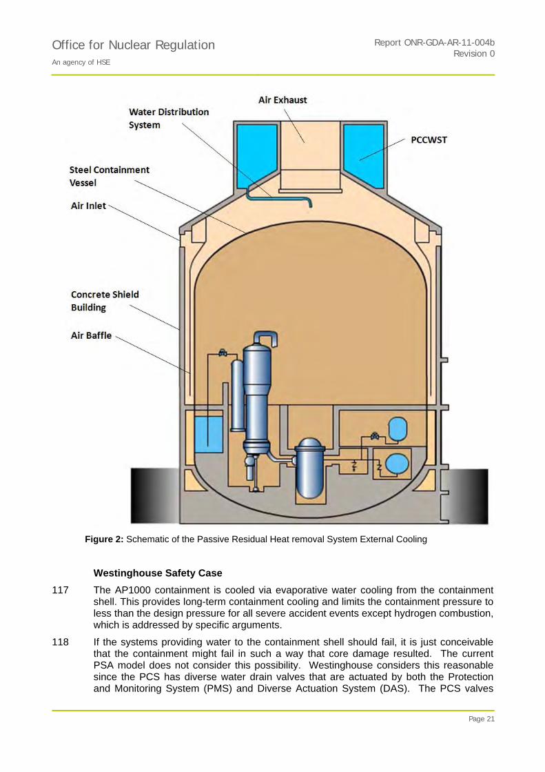
PROTECTIVE MARKING IF APPLICABLE
Report ONR-GDA-AR-11-004bOffice for Nuclear Regulation An agency of HSE
Revision 0
Page 21
Figure 2: Schematic of the Passive Residual Heat removal System External Cooling
Westinghouse Safety Case
117 The AP1000 containment is cooled via evaporative water cooling from the containment shell. This provides long-term containment cooling and limits the containment pressure to less than the design pressure for all severe accident events except hydrogen combustion, which is addressed by specific arguments.
118 If the systems providing water to the containment shell should fail, it is just conceivable that the containment might fail in such a way that core damage resulted. The current PSA model does not consider this possibility. Westinghouse considers this reasonable since the PCS has diverse water drain valves that are actuated by both the Protection and Monitoring System (PMS) and Diverse Actuation System (DAS). The PCS valves

PROTECTIVE MARKING IF APPLICABLE
Report ONR-GDA-AR-11-004bOffice for Nuclear Regulation An agency of HSE
Revision 0
Page 22
are designed to fail open upon loss of power. In addition, the operators would have at least 24 hours to secure other water supplies if all of the PCS valves fail before a significant risk of containment failure.
119 The PCS limits releases of radioactivity (post accident) by reducing the pressure differential between the containment atmosphere and the external environment, thereby diminishing the driving force for leakage of fission products from the containment to the atmosphere should the containment not be completely leak tight.
120 The water from PCCWST is released onto the top of the containment via a redundant, diverse system of valves and lines, including a line that can be connected to an outside water source such as a fire truck for longer term cooling. In the unlikely event that water cannot be supplied to the top of the containment shell for an extended period of time, air-only cooling by air flowing through the PCS annulus provides significant cooling to the containment. Under favourable environmental conditions, the containment could be expected to reach an equilibrium pressure that will not challenge containment integrity. However, under nominal-to-conservative environmental conditions, containment integrity by air-only cooling cannot be assured. Even in this case, it is predicted that containment integrity is most likely to be maintained for more than 24 hours after accident initiation.
121 A significant amount of time is available for operator action to secure alternative sources of water from one of several supplies. In the very unlikely situation that a water supply is not provided and the pressure rise threatens the containment integrity, venting the containment is directed by the severe accident management guidance to mitigate uncontrolled releases of fission products.
122 The AP1000 can be vented on an ad-hoc basis from a number of containment penetrations. Once venting is concluded, the increased steam concentration in the containment improves the natural convective cooling to the containment shell is such that no further venting is anticipated.
Assessment
123 The heat removal from the containment atmosphere, through the steel vessel, into the cooling water and air flow over the external surface of the vessel, is a fundamental aspect of the AP1000 response to accidents and therefore I chose to sample the following issues:
the adequacy of the system for supplying water to the external surface of the containment shell;
the consequences of interruption of water supply to the external surface;
the effect of damage to the containment shell on the system function; and
the suitability of the modelling of the physical phenomena used to justify the design.
4.1.4.1 External Water Supply to the PCS
124 Westinghouse has improved the reliability of the PCS system by increasing the redundancy of the pipe work feeding water from the tank on the containment roof. Westinghouse provided further detail in response to my technical queries, (TQ-AP1000-1024, Ref. 9).
125 The proposed system is suitably classified and includes redundant pipe work, which meets the requirement of SAP ERD.4 to consider the possibility of single failures of equipment. However, the Westinghouse response did not adequately reflect the UK

PROTECTIVE MARKING IF APPLICABLE
Report ONR-GDA-AR-11-004bOffice for Nuclear Regulation An agency of HSE
Revision 0
Page 23
requirements for resistance to passive failures. Nevertheless, I judge that the system is in principle suitably capable. It will be necessary to ensure that the control of plant availability, within station Technical Specifications, is sufficient to meet UK requirements. I have therefore raised Assessment Finding AF-AP1000-CSA-03 requiring that the operational strategy be suitably justified.
126 The actuation of the system includes redundant valves and the normally-closed valves are designed to spring open on loss of electrical supplies. This meets the requirements of SAP ESS.12 - that the system is a fail-safe design.
127 There is protection against blockage of the pipework by a system of screens and the pipes are protected against icing by trace heating, but the information provided was not sufficiently detailed to assess these features.
128 Westinghouse claims that the reactor protection includes provisions that allow the operators to trip the reactor on low water temperature in the PCCWST. I question whether tripping the reactor and placing demands on post-trip cooling is the optimum strategy under such conditions. I have therefore raised Assessment Finding AF-AP1000-CSA-04 requiring a review of this strategy.
129 Arrangements have been added to facilitate replenishment of the water source by diverse means; including using water supplied by fire tender.
130 To adequately wet and cool the containment shell outer surface, the water is delivered to a distribution bucket above the centre of the containment dome, which subsequently delivers the water to the containment surface. A weir-type water distribution system on the dome surface distributes the water to effectively wet the dome and vertical sides of the containment shell.
131 The containment shell is coated with a corrosion-resistant surface treatment that enhances the ability of the surface to become wetted and water film formation.
132 The water distribution has been demonstrated by a series of tests on a scaled facility and this has informed assumptions on the fraction of the external surface cooled by water that is reported at Ref. 17. This fraction appears to be pessimistically represented in Westinghouse’s supporting analysis.
133 Westinghouse plans to carry out periodic testing of this feature on the plant.
4.1.4.2 Consequences of Interrupted Water Supply
134 Westinghouse has assessed the consequences of interruption of the water supply both in the short and the long term. Based on insights from the PSA model, it has increased the redundancy and diversity of this system.
135 The current assumption in the PSA is that air-only cooling is successful in preventing early containment failure. Assuming that air-only cooling always leads to containment failure results in increasing the PSA core damage frequency by about a third. It is therefore important to establish either that the claims made for the water cooling system can be substantiated, or that the consequences of its failure are benign. I chose to examine the consequences of failure on the basis that this is readily amenable to analysis.
136 The containment response to this event has been analysed using the WGOTHIC code and the treatment is relatively simple. Assessment of the validation of the code against the requirements of SAPs is given in Section 4.1.8 below.
PROTECTIVE MARKING IF APPLICABLE
Report ONR-GDA-AR-11-004bOffice for Nuclear Regulation An agency of HSE
Revision 0
Page 24
137 I have required this analysis to be repeated by my technical support contractors using the COCOSYS code. This code uses a slightly more sophisticated model of condensation on the inside of the containment dome. Assessment was carried out for the bounding faults of the large LOCA and the main steam line break, which are reported at Ref. 38 and Ref. 39 respectively.
138 The analysis of the main steam line break showed that containment integrity can be maintained for the fault examined. This is discussed in more detail in Section 4.1.8 below.
139 The LOCA was a more severe test and the consequences of losing external water are less clear and there is some risk to containment if action is not taken, although analysis indicates that this is small. See Section 4.1.7 below.
140 The conclusion is that the containment design limit would be breached, but the chances of it failing are relatively small. I note that confirmatory analysis, reported in Section 4.4.1, has indicated that the effect of wind on cooling of the containment shell could be a significant benefit and this has been neglected in the analysis.
141 If the PCS water fails to actuate and the water flow cannot be restored, the operator can vent the containment as instructed by the severe accident management guidelines to prevent containment failure. The operator probably has more than a day to do this. Equally, the option exists to supply water from a fire tender.
142 Overall, I judge that the design of the containment external cooling appears adequate in response to the unlikely event of loss of external water supplies.
4.1.4.3 Effect of Damage to the Containment Shell
143 Hazards caused by events external to the plant are assessed in Ref. 40. However, I have considered the consequences of failure of the normal means of containment heat removal from the external surface of the containment shell. Should the air baffle plates be disrupted, so that the air flow passage is partially or severely blocked, the heat sink in the short term becomes the concrete outer shell of the containment building by thermal radiation and natural convection.
144 The design of the containment outer shell is such that the air inlet openings are at high level and therefore substantial blockage of these is considered unlikely. However, provided that water is supplied to the containment shell with a reasonable coverage, analysis indicates that cooling is likely to remain effective.
4.1.4.4 Adequacy of Physical Modelling
145 The justification of the functioning of the system is based on a combination of thermal hydraulic experiments on scale models and empirical data correlated and employed in relatively simple models (Ref. 16). I have reviewed these models and I identified the need to consider further the heat transfer under conditions where the effects of natural (buoyancy induced) and forced (wind pressure driven) convection could interfere with each other – possibly creating adverse flow conditions. These conditions are termed mixed convection and can under certain conditions, result in heat transfer levels lower than predicted by standard correlations.
146 I commissioned detailed modelling of the geometry of the containment annulus flow passage using Computational Fluid Dynamics (CFD). The model employed finite-volume meshes in three dimensions. The studies are reported in Ref. 47. These studies confirmed that it is pessimistic to assume that there is no wind impinging on the

PROTECTIVE MARKING IF APPLICABLE
Report ONR-GDA-AR-11-004bOffice for Nuclear Regulation An agency of HSE
Revision 0
Page 25
containment structure. Furthermore even relatively small amounts of wind substantially enhance the heat removal from the containment structure.
147 There were no conditions identified which could adversely affect the heat transfer and the flow is considered relatively well behaved. I have therefore concluded that under most atmospheric conditions, the assessment of the capability of the system to remove the decay heat will have been substantially underestimated.
Assessment Findings
AF-AP1000-CSA-03: The licensee shall, prior to start of site nuclear island safety-related concrete, provide further justification for operation of the PCS addressing:
the adequacy of provisions against blockage of the water supply pipework for all reasonably foreseeable conditions; and
the arrangements to determine the minimum plant availability in Technical Specifications.
AF-AP1000-CSA-04: The licensee shall, prior to start of site nuclear island safety-related concrete, provide an ALARP justification of the measures proposed in the event of detecting low temperatures in the PCS leading to a degraded capability of this system.
4.1.5 Contaminent Isolation and Bypass
148 The isolation of containment in the event of a fault is important to providing a functional barrier to fission product release to the environment. This is true in the case of Design-basis faults as well as severe accidents. Accordingly, this system should respect the Engineering Key principles in the SAPs. The system components must be appropriately classified and as far as reasonably practical, be insensitive to faults and inherently safe by design.
Westinghouse Case
149 Containment Isolation Valves maintain the integrity of the containment in the event of a loss-of-coolant accident, thus minimising the release of radioactive material from the containment.
150 The Containment Isolation Valves are of a spring return design such that no external power source is required to close them. This passive approach offers a high degree of inherent safety and high reliability.
151 Automatic containment isolation valves are powered by Class 1E DC power. Air-operated valves fail in the closed position upon loss of a support system, such as instrument air or electric power.
152 A diverse method of initiating closure is provided for those containment isolation valves associated with penetrations representing the highest potential for containment bypass.
153 Administrative procedures are designed to ensure that testing and maintenance does not result in configurations of valves that could defeat containment isolation.
154 Containment penetrations with leak tight barriers, both inboard and outboard, are designed to limit pressure excursion between the barriers due to heat up of fluid between the barriers.

PROTECTIVE MARKING IF APPLICABLE
Report ONR-GDA-AR-11-004bOffice for Nuclear Regulation An agency of HSE
Revision 0
Page 26
155 The actuators for power-operated isolation valves inside the containment are located above the maximum containment water level. The actuators are designed for flooded operation or are not required to function following containment isolation. The actuators are also designed and qualified to minimise spurious opening in a flooded condition.
156 The AP1000 design does not depend on active systems to remove airborne particulates or elemental iodine from the containment atmosphere following a postulated loss of coolant accident with core melt. Naturally occurring passive removal processes associated with condensation on the containment shell provide significant removal capability such that airborne elemental iodine is reduced to very low levels within a few hours and the airborne particulates are reduced to extremely low levels within 12 hours.
157 The likelihood of containment bypass resulting from a primary-to-secondary leak is also reduced by measures to isolate the steam generators and the direction of secondary relief of steam into containment.
Assessment
158 The assessment of the mechanical design of the system is outside the scope of this assessment topic and can be found in Mechanical Engineering GDA Step 4 Assessment Report (Ref. 41).
159 The adoption of passive systems has substantially reduced the number of penetrations in the containment vessel and the adoption of a steel design potentially simplifies provision of robust penetrations.
160 The measures taken to ensure the function of this system appear reasonable and compare favourably against existing plant. This in part contributes to the low probability of off-site release claimed for the AP1000.
4.1.6 Containment Activity Management
161 In accidents of sufficient severity to result in fuel damage, there is a risk that volatile fission products and active particulate will be released from the RCS into the containment building. In the AP1000, various design features are available to limit the inventory of mobile fission products within the containment building potentially at risk of release to the environment.
162 This is partly achieved by circulation of air in containment and condensation on the containment walls that is enhanced by the PCS cooling water on the external containment shell. As the vapour condenses, it assists in transporting airborne contamination towards the liquid film on the containment walls. As the condensate flows down into the IRWST, it transports the contamination to a region where its chemical state can be appropriately adjusted to ensure immobilisation, hence providing a principal means of controlling fission product within the containment.
163 The magnitude of the circulation and condensation effects in the AP1000 design is a unique feature of the design and has led Westinghouse to claim that containment spray is not required to control fission products. However, the design does include an in-containment spray system that may be used.
164 The assessment of the measures to control fission products within containment is reported within the Reactor Chemistry assessment area (Ref. 36). A number of mechanisms are postulated in circulation and condensation:
sedimentation (where particulate settles under gravity);

PROTECTIVE MARKING IF APPLICABLE
Report ONR-GDA-AR-11-004bOffice for Nuclear Regulation An agency of HSE
Revision 0
Page 27
diffusiophoresis where particles are swept to a surface by the mass flux set up in a condensing vapour boundary layer;
thermophoresis where particles drift toward a surface by Brownian Motion under the influence of a temperature gradient; and
turbulent diffusion and turbulent agglomeration.
165 The physical models employed are plausible and are informed from relevant experimental data from both separate effect and integral tests. The analysis is based on conservative particulate sizes taken from the related supporting work that has been performed for US NRC, which is further discussed in the Reactor Chemistry Assessment Report, Ref. 36.
166 I judge that the thermohydraulic arguments made for effective activity removal from the containment atmosphere are reasonable.
167 The AP1000 containment design, as part of the Fire Protection System (FPS), includes an In-containment Spray System (CSS) which can be used during a severe accident. The CSS provides mitigation against airborne release to the environment, albeit with a limited duration and effectiveness in accident conditions.
168 In addition to controlling the airborne release of fission products, the successful initiation of the CSS spray system may be a benefit in controlling the temperature and pressure within the internal environment of the containment for up to 3 hours by condensing the steam present within the containment. The operation of this system in fault conditions needs to take account of complex interactions between expectations of the SAMGs, human factors, the accident transient and the implementation of the containment spray system.
169 Given the complexity of the arguments and the potential safety benefit that the system initiation could offer, I consider that the mode of spray system operation and the role of the operator should be reviewed within the Emergency Operation Procedures (EOP) and the SAMGs as part of the licensing activities.
170 The topic of fission product control within the containment due to an accident is further covered within the Reactor Chemistry Assessment Report (Ref. 36) which has resulted in GDA Issue GI-AP1000-RC-01 requiring Westinghouse to provide further evidence that the source term for severe accident release has been appropriately applied for the AP1000 design. There is also a related Assessment Finding (AF-AP1000-RC-66) requesting a licensee to review the SAMGs for the provision of spray water for fission product control and consider whether any improvements to the containment spray system design or performance would be reasonably practicable.
171 Given the review of the SAMGs has been excluded within the GDA Step 4 assessment, I have raised the following Assessment Finding requesting a full justification of the operational strategy of the in-containment spray system.
Assessment Finding
AF-AP1000-CSA-05: The licensee shall, prior to active commissioning – fuel load, identify the operational requirements of the containment spray system during fault conditions. The justification is expected to clarify the expectations of the system within the Emergency Operating Procedures (EOP) and implementation of the Severe Accident Management Guidelines (SAMG) for the AP1000.

PROTECTIVE MARKING IF APPLICABLE
Report ONR-GDA-AR-11-004bOffice for Nuclear Regulation An agency of HSE
Revision 0
Page 28
4.1.7 Containment Response in Accident Conditions
4.1.7.1 Containment Response in LOCA Fault
172 The containment of AP1000 is the ultimate barrier against the release of radioactive materials into the environment. Therefore, the integrity of the containment system in accident conditions is maintained mainly by suppressing the pressure and temperature of the containment atmosphere below design limits in both Design Basis Accidents and accidents involving serious core damage and its debris confinement.
173 In the event of a loss of coolant accident, the escape of high pressure coolant from the primary circuit threatens to damage the fuel and the hot steam entering the containment potentially threatens containment integrity. This fault requires assessment for its containment response to demonstrate that multiple barriers to fission product release are not defeated.
174 In the smaller LOCA, sensors detect the reduction in primary circuit level and depressurise the plant initially through the ADS valves and spargers into the cold water in the IRWST. The core make-up tanks then introduce cold water to the primary circuit. The overall result is that the rate at which energy is released into containment is limited and therefore I have limited my assessment of containment response to consideration of the Large-Break LOCA.
175 In the AP1000 design, the Large-Break LOCA is analysed as a Design Basis fault and therefore the requirements of SAPs FA.3 to FA.19, relating to such faults, need to be respected.
Westinghouse Case
176 The large-break LOCA (LBLOCA) event is defined in the AP1000 design PSA (Section 2 Ref. 59) as all RCS ruptures with break sizes sufficient to produce a depressurisation of the RCS that allows gravity injection from the IRWST. The break size corresponding to this category is a 0.2286m equivalent diameter or larger break, up to the size of a double-ended break of a cold or hot leg.
177 The LBLOCA analysis for the AP1000 design has shown that significant quantity of water and steam is discharged into the containment. In this fault scenario the CMTs are assumed to drain during the transient to maximise the mass and energy released into the containment.
178 A large break LOCA results in a large energy input into the containment. The mass and energy releases inside the containment cause a dramatic increase in temperature and pressure. The passive containment cooling system limits the peak pressure and temperature to less than the allowable values by condensing steam on the inside wall of the steel containment shell. The containment fan coolers and spray system may also be available to the operators to condense steam and remove heat. (Ref. 59)
179 The containment analysis employs the Westinghouse-GOTHIC (WGOTHIC) computer code, which is a computer programme for modelling transient multiphase flow in a containment.
180 To model the passive cooling features of the AP1000, several assumptions are made in creating the plant data input decks. The external cooling water does not completely wet the containment shell, therefore both wet and dry sections of the shell are modelled in the WGOTHIC analyses. The analyses use conservative coverage fractions to determine evaporative cooling.

PROTECTIVE MARKING IF APPLICABLE
Report ONR-GDA-AR-11-004bOffice for Nuclear Regulation An agency of HSE
Revision 0
Page 29
181 For the LOCA events, two double-ended guillotine reactor coolant system pipe breaks are analysed. The breaks are postulated to occur in either a hot or a cold leg of the reactor coolant system.
182 The containment system is designed to survive intact for all break sizes, up to and including the double-ended severance of a reactor coolant pipe.
183 The single failure postulated for the containment pressure/temperature calculations is the failure of one of the valves controlling the cooling water flow for the PCS. Failure of one of these valves would lead to cooling water flow being delivered to the containment vessel through two of three delivery headers.
184 For the Design Basis analysis, no claim is placed on systems that are not Class 1.
185 Analysis demonstrates that containment pressure and temperature limits are not exceeded.
Assessment
186 Assessment of the WGOTHIC modelling of LOCA is presented in Section 4.1.8 below. I regard this as an extrapolation of experimental studies carried out on facilities scaled to represent the AP1000. I recognise that some of the features of the modelling are designed to introduce a degree of conservatism. However, I felt that it was necessary to commission independent calculations of the containment response to increase confidence in the extrapolation from AP600 to AP1000 and to examine the sensitivity to a number of uncertainties. This was done using the COCOSYS computer code, reported at Ref. 39.
187 The COCOSYS model was intended to be essentially best estimate and as a result, the pressures predicted were lower than those of WGOTHIC, although the important aspects of the transient were consistently represented. The analysis confirmed the conclusion that the containment pressure is unlikely to exceed its design value. Details are provided in Section 4.4.2 below.
188 Sensitivity to the loss of containment external water cooling was examined. Analysis of this fault for still-air conditions resulted in containment pressures in excess of the design value. However, if the predicted value is examined in the context of the containment fragility curve taken from Ref. 27, the analysis does not indicate that containment failure is very likely. This rises as ambient conditions become more extreme, but remains modest for conditions normally encountered within the UK. More details on this aspect are given in Section 4.1.4.2 above.
189 Overall I have concluded that Westinghouse have demonstrated a reasonable case that the design is robust against this fault.
4.1.7.2 Containment Response in Main Steam Line Break Fault
190 Fracture of the Main Steam Line (MSLB) within containment is a low probability fault sequence because of the high integrity of the pipework, but since it has the potential to release large amounts of steam into the containment building it represents a significant challenge to the containment integrity and therefore a possible means by which the containment shell design pressure might be exceeded. Consequentially this fault is traditionally analysed as part of the work to establish the design-basis of the containment. This requires that SAPs FA.3 to FA.19, relating to such faults, be respected.

PROTECTIVE MARKING IF APPLICABLE
Report ONR-GDA-AR-11-004bOffice for Nuclear Regulation An agency of HSE
Revision 0
Page 30
Westinghouse Case
191 Gross failure of the main steam line is analysed within the design basis. The fault is protectable without core damage and does not result in over pressurisation of the containment. This analysis is presented in Chapter 15 of Ref. 42.
192 The Passive Containment Cooling System limits and reduces the containment temperature and pressure following main steam line break accident inside the containment by removing thermal energy from the containment atmosphere through the shell and out to the ambient air. This analysis is presented in Section 6.2.2 of Ref. 42.
193 Pipe restraints and jet barriers are provided where appropriate to mitigate consequential damage to the main control room and essential control and instrumentation.
Assessment
194 The peak pressure in this fault is reached relatively quickly and is reduced as the affected steam generator dries out and post reactor trip, the primary circuit is cooled by alternative means.
195 There is not sufficient time for external water cooling of the containment shell to have a significant impact on the short-term transient. However, the containment response is such that the peak pressure remains below the containment design pressure.
196 I commissioned independent calculations of the containment response using the COCOSYS computer code (Ref. 38). The COCOSYS predictions were qualitatively similar, but predicted lower containment pressures as would be expected for a best estimate code.
197 The containment atmosphere was predicted to reach local peak temperatures in excess of the design temperature for a short time. This is not expected to affect structures within the containment due to the presence of films of water. However, this could have some impact on equipment qualification. Further details are provided in Section 4.4.2 below.
198 Sensitivity studies considered the effect of disruption to cooling external to the containment shell and found that heat loss to the concrete structure of the containment shell is sufficient for containment integrity to be preserved.
199 I conclude that Westinghouse has demonstrated its claims that the containment is robust against steam release from the secondary systems.
Assessment Finding
AF-AP1000-CSA-06: The licensee shall, prior to start of site nuclear island safety-related concrete, review containment equipment qualification to demonstrate that it remains valid in view of the results of fault studies.
4.1.8 WGOTHIC Computer Code Assessment
200 The Safety Assessment Principles FA.17 to FA.19 require that the computer modelling adequately represents the plant and that the modelling be shown to be appropriate by comparison with experiment or other means.

PROTECTIVE MARKING IF APPLICABLE
Report ONR-GDA-AR-11-004bOffice for Nuclear Regulation An agency of HSE
Revision 0
Page 31
Westinghouse Case
201 Validation of the WGOTHIC computer code is documented in Ref. 16 and its application to AP1000 is documented in Ref. 17.
202 The computer program is designed for modelling multiphase flow in a containment transient analysis. It solves the conservation equations in integral form for mass, energy, and momentum for multi-component flow in a sequence of finite volumes; each representing a region of the containment.
203 After the blowdown phase of a large LOCA, Westinghouse conservatively neglects the effect of droplets entrained out of the break on the vapour temperature by turning off this physical process in the model.
Assessment
204 The WGOTHIC predecessor, GOTHIC, is widely used by the US nuclear industry and derives originally from the COBRA subchannel code. As part of the containment design process, the applicant prepared a table systematically ranking the phenomena that need to be addressed to examine the performance of passive containment. This was reviewed by the NRC and I have chosen not to assess it in detail.
205 The WGOTHIC modelling represents heat transfer to and from surfaces by a combination of natural and forced convection using experimentally derived functions of appropriate non-dimensional groups (Reynolds Number, Grashof Number etc.). However, remote from any jets, the process of turbulent diffusion driven by buoyancy forces dominates the heat and mass transfer. This results in a relatively simple model. The correlations employed appear to be reasonable and are supported by a substantial bulk of relevant experimental data.
206 The correlations employed are thought to slightly over predict heat transfer from horizontal surfaces and under predict the heat transfer from inclined surfaces with an overall slight conservatism in modelling containment heat loss. There is a slight trend to under predict heat transfer at higher heat fluxes, but this is within the uncertainty of the data presented.
207 The WGOTHIC code can be used to model the spatial distribution of flow and temperature in some detail and sensitivity studies on nodalization have been performed. The final nodalization is quite crude, and the transport of momentum is neglected so it can not be expected to represent the flow distribution within containment with high fidelity, but analysis suggests that it is adequate and introduces some conservatism into the analysis of containment pressure.
208 The correlations for heat transfer to the inner surface of the containment shell were factored to ensure that experimental data was conservatively represented and the effects of developing boundary layers were conservatively neglected.
209 The modelling of droplets entrained into the containment cavity during a LOCA represents the heat transfer assuming droplets of a specified size. This modelling is satisfactory during the early stages of blowdown, but cannot be relied upon later and therefore the heat transfer from the droplets is turned off at a defined point in the transient. This has been demonstrated to be conservative.
210 The approach to validating the model of containment shell flow and heat transfer has been based on integral experiments. These consist both of wind tunnel tests and integral tests in the PCS Large-Scale Tests facility; a 1/8-linear-scale version of the AP600 containment vessel.

PROTECTIVE MARKING IF APPLICABLE
Report ONR-GDA-AR-11-004bOffice for Nuclear Regulation An agency of HSE
Revision 0
Page 32
211 The wind tunnel tests were conducted at various scales depending on whether local or global data were required. Due consideration of scaling effects is evident.
212 The testing in the Large-Scale Tests facility included release of helium as an analogue to hydrogen.
213 The experiments were performed for the AP600 design. However, the important features of the PCS design are unchanged for AP1000 and therefore the analysis is considered to be applicable to the AP1000.
214 Conclusions from the tests were that, provided the external surface of the containment shell is wetted, the inner surface heat transfer was generally limiting. Within the containment, the mixing was good with no indications of stratification.
215 Much of this testing was closely supervised by the US NRC, who endorsed the competence of staff and the conduct of the tests.
216 One area of uncertainty is the fraction of the external shell that is wetted by the water film. I believe that Westinghouse have used appropriately conservative modelling. However, as part of the AP1000 periodic in-service testing programme measurements will be performed to demonstrate that the area coverage fractions are maintained over the life of the plant. This data should be reviewed when it becomes available to confirm the design assumptions, see Assessment Finding AF-AP1000-CSA-07.
217 The code documentation is extensive and detailed and is generally satisfactory. However, no ranges of applicability are listed for correlations and models used in the correlations and models. However, the ranges needed for analysis of a LOCA and an MSLB in the AP1000 passive containment are not very different from the conditions against which GOTHIC has been validated. I do not consider this a significant issue in the short term, but Westinghouse should consider rectifying this on their next release of the documentation.
218 The independent calculations performed with COCOSYS on a similar resolution predicted significantly lower containment pressures (Ref. 38). The difference is particularly significant for the LOCA cases, but is also large compared with the effect of much of the uncertainty examined in sensitivity studies.
219 Overall I conclude that Westinghouse has used WGOTHIC to represent the containment response observed in integral tests and I judge that this is appropriate to represent the plant performance.
Assessment Finding
AF-AP1000-CSA-07: The licensee shall, prior to active commissioning – fuel load, confirm by reviewing in-service testing data that the assumptions on the PCS wetting of the containment shell are valid for the UK design of the AP1000.
4.2 Effectiveness of the Measures to Depressurise Reactor Coolant System
4.2.1 Core Outlet Temperatures
220 The operator may depressurise the RCS at various stages during the fault conditions, but not whilst at power. However, depressurisation by ADS Stage 4 is anticipated to be activated when the Core Exit Temperature (CET) reaches 650°C (1202°F). The core outlet temperature is also proposed to be used for the subsequent initiation of severe accident management procedures associated with control of debris within the RPV and containment performance. This includes initiation of in-containment refuelling water

PROTECTIVE MARKING IF APPLICABLE
Report ONR-GDA-AR-11-004bOffice for Nuclear Regulation An agency of HSE
Revision 0
Page 33
storage tank injection into the reactor cooling annulus and containment hydrogen igniters actuation. The objective of this is to ensure that the primary system is depressurised prior to relocation for molten corium to the vessel lower head, limiting the potential for a consequential failure of the vessel.
Assessment
221 The effectiveness of the measurement of CET in accident management was reviewed by the Committee for the Safety of Nuclear Installations (CSNI) Working Group which concluded (Ref. 50) that a combination of a selection of core outlet temperature readings and other instrumentation indications, such as reactor vessel water level, should be used to define the initiation of the different accident management procedures. Ref. 50 indicates that various test results suggest the thermocouple responses significantly lagged behind the cladding temperatures. This brings into question the effectiveness of this measure as a way of preventing core melt, but since this is not the objective in the AP1000 strategy, I consider that this delay does not significantly impact the time available to act and prevent a high-pressure vessel failure.
222 It may be reasonably practicable to consider initiating depressurisation earlier using alternative indications such as core water levels as a means of preventing core damage earlier in the event.
223 I recognise that the core outlet temperature measurement is supported by redundancy and diversity of other instrumentation effectively measuring the CETs via, for example, hot leg thermocouples which appears to be in line with the historical relevant good practice. However, I consider that in the light of the experimental data provided by Ref. 50 and the expert opinion, it is necessary to raise an Assessment Finding regarding the accuracy of the measured coolant temperatures in such conditions, AF-AP1000-CSA-08.
224 The thermocouples measuring core exit temperatures are routed via the RPV head. The routing of such instrumentation that is used to inform accident management procedure are potentially at risk from fault scenarios, such as excessive corrosion around the nozzles housing the Control Rod Drive Mechanism (CRDM). The loss of coolant from such locations could lead to a direct steam impingement onto these instrumentation lines during accident conditions, and is likely to impact the inspection requirements and qualification of the instrumentation that are routed/supported by the RPV head. The corrosion experience at Davis-Besse plant reinforces the importance of protecting such instrumentation lines routed via the RPV head.
225 I recognise that occurrence of fault conditions needing such instrumentations is a low probability event, and the lessons learnt following the Davis-Besse plant incurring CRDM corrosion will be considered within the maintenance requirements of the AP1000 plant. I do however consider that the protection of such instrumentation routing is necessary in the case of design-basis faults as well as severe accidents. Accordingly this system should respect the engineering principles in the SAPs.
226 In summary, in fault conditions where the operator action is highly dependant on measurements such as CET output, other instrumentation such as the hot leg temperature measurement and other reactor temperature and water level indicators are available to the operator and should be considered as part of an holistic approach. I have therefore raised the concern relating to the availability of such instrumentation informing any pending operator action in the following Assessment Findings.

PROTECTIVE MARKING IF APPLICABLE
Report ONR-GDA-AR-11-004bOffice for Nuclear Regulation An agency of HSE
Revision 0
Page 34
Assessment Findings
227 There are a number of observations made with regards to the operational requirements for instrumentation indicating the onset of a severe accident, given the significance of the instrumentation shortfall identified in Ref. 50:
AF-AP1000-CSA-08: The licensee shall, prior to active commissioning – cold operations, demonstrate that the measurement systems indicating core conditions used to initiate the accident management procedures, such as, core exit temperature have been qualified for the potential environment likely to exist in severe accident conditions. This demonstration should give consideration to common cause failure.
AF-AP1000-CSA-09: The licensee shall, prior to active commissioning – cold operations, provide evidence that the relevant in-service inspection procedures are in place to monitor degradation through ageing of the in-vessel thermocouples over long operational periods and throughout the plant’s life-time.
4.2.2 Automatic Depressurisation System (ADS)
228 In the event of a LOCA, the primary circuit is depressurised by a series of ADS valves. Initially, this is achieved by venting through spargers directly into the IRWST water, which reduces the amount of high energy steam entering containment early in the transient.
229 The ADS is designed to lower the pressure of the RCS so that the accumulators and later the IRWST can inject cold borated water into the reactor core. The ADS consists of twenty valves divided into four depressurisation stages. These stages connect to the RCS at three locations. The ADS first, second and third stage valves are connected to the nozzles on top of the pressuriser that are independent of the pressuriser safety relief valves.
230 Each stage consists of two trains of valves. The first stage opens on CMT liquid level. ADS Stages 2 and 3 open shortly after the first stage on timers. The flashing coolant that is discharged out of ADS Stage 1, 2 and 3 valves is directed to the IRWST by means of spargers.
231 The valves are intended to discharge a mixture of water and steam at high flow rates to rapidly depressurise the RCS. An important characteristic of the AP1000 design is that the ADS, in conjunction with the PXS, potentially provides an automated bleed and feed capability for fault scenarios such as loss of feedwater and loss of PRHR capability. Manual bleed and feed with the operator manually using DAS system to open the ADS valves to promote depressurisation is also an option. Westinghouse state that the ADS will be actuated depressurising the RCS automatically or by operator action after 30 minutes.
232 In addition to functional requirements claimed in design-basis faults for the sequenced opening of the ADS valves, the RCS depressurisation can also be achieved through initiation of ADS Stage 4 valve, which is anticipated to be activated when the CET reaches 650°C. The stage four ADS valves are connected by two redundant paths to each reactor coolant loop hot leg (i.e. 4 valves in total). The ADS Stage 4 system is operated by explosive squib-valves, discharging directly into the containment atmosphere.
233 The passive design safety approach of the AP1000 is to depressurise the RCS if the flow from the break is greater than the make-up capacity of the CVS. The inadvertent opening of the ADS valves, however, deliberately introduces a large break on the hot leg

PROTECTIVE MARKING IF APPLICABLE
Report ONR-GDA-AR-11-004bOffice for Nuclear Regulation An agency of HSE
Revision 0
Page 35
equivalent in size to a LBLOCA allowing the RCS pressure to fall to a sufficiently low value to allow the introduction of borated water from the IRWST safety injection line into the reactor, relying only on a gravity driven pressure head.
234 During the course of the GDA Step 4 assessment, HSE’s ND raised concerns about the possibility of the protection and monitoring system spuriously actuating the ADS system. The Regulatory Observation, RO-AP1000-82, required that Westinghouse identify any additional measures to reduce the frequency of this event.
235 The topic of the ADS valves operation and a concern relating to adequacy of the safety case covering spurious actuation of these valves is further covered in the Fault Studies and Control and Instrumentation GDA Step 4 Reports (Ref. 37 and Ref. 25). This has resulted in GDA Issue GI-AP1000-CI-04, requiring Westinghouse to formally introduce the change to the PMS design to introduce the interlock/blocker on the ADS valves via the design change process.
236 Whilst I acknowledge that dual capability of automated and operator initiated actuation of the ADS valves is most likely to offer operational flexibility, I do however have concerns relating to spurious actuation of the ADS valves. Since the extant GDA Issue (GI-AP1000-CI-04) covers this area, I am not raising an Assessment Finding relating to this concern. I would therefore look to a satisfactory resolution of the GDA Issue that requires Westinghouse to reduce the ADS spurious initiating frequency to satisfy my concerns.
4.3 Severe Accident Management
237 The severe accident generally evolves from a loss of core cooling capability leading to fuel degradation, and core melt that may eventually lead to fuel relocation and/or the potential for release of radionuclides in excess of design basis limits. The measures in place to mitigate the consequences are limited in most existing plants, but HSE’s Safety Assessment Principles require that reasonably practical measures are taken to limit the consequences of such events.
238 The AP1000 severe accident supporting documentation has been examined in order to demonstrate compliance with HSE’s requirements. These include numerical targets for risk and a requirement to demonstrate that risks from planned operation of the reactor are as low as reasonably practicable. This requires consideration of measures that may be taken to reduce the overall risk beyond those required to meet the plant’s deterministic Design Basis Assessment.
239 The design alternatives considered include not only Level 1 measures to reduce core damage frequency, but also the severe accident mitigation design alternatives aimed at reducing the size and frequency of releases following core damage.
240 The analyses and the associated PSA also serve the requirement to demonstrate the well-balanced nature of the reactor design, with no particular accident attracting a disproportionate share of the overall risk.
241 Internationally various strategies are proposed to mitigate the risk of radiological release following core melt. These fall into two categories:
242 In the case of reactors with thermal power typically less than 3600 MWt, In-vessel melt retention by external flooding is favoured, while for power reactors with higher thermal power, the design of a melt spreading device is favoured. HSE’s ND does not favour any particular approach and recognises that the uncertainty in severe accident phenomena possibly makes either approach valid.

PROTECTIVE MARKING IF APPLICABLE
Report ONR-GDA-AR-11-004bOffice for Nuclear Regulation An agency of HSE
Revision 0
Page 36
243 The approach taken by Westinghouse is to retain the molten core in vessel. Assessment of the evidence presented to support this strategy is presented below.
4.3.1 In-vessel Melt Retention Strategy
244 The design of the AP1000 severe accident mitigation measures is based on reliably depressurising the primary circuit to enable safety injection, or failing this, in-vessel melt retention by external cooling of the vessel.
245 This strategy is designed to avoid the possibility of high-pressure jets of molten fuel, which could overheat the containment and to reduce the likelihood and severity of steam explosions and hydrogen burns.
246 This strategy follows a consensus that depressurisation is a primary response to a severe accident, but contrasts with the approach of maintaining the reactor pit dry and providing a spreading area.
Westinghouse Case
247 In-vessel Retention (IVR) of core debris by external reactor vessel cooling is discussed in detail in Chapter 39 of Ref. 27. With the reactor vessel intact and debris retained in the lower head, phenomena such as Molten Core-Concrete Interaction (MCCI) and ex-vessel steam explosion, which could occur as a result of core debris relocation to the reactor cavity (schematically shown in Figure 1), are prevented.
248 The AP1000 reactor vessel insulation and containment geometry promote in-vessel retention. Engineered design features of the AP1000 containment system flood the reactor cavity during accidents and thereby submerge the reactor vessel in water. Coolant released through the break during a LOCA event is directed to the reactor cavity.
249 The PXS as well as other plant structural features enable the removal of sufficient heat from the external surface of the RV to limit wall thinning and prevent the vessel wall from reaching temperatures at which the RV could fail. IVR is described in detail in Chapter 39 of the AP1000 Probabilistic Safety Analysis (Ref. 27).
250 The primary benefit of IVR is that ex-vessel severe accident phenomena associated with relocation of core debris to the containment are physically prevented and hence the risk of containment failure averted.
251 Thus, retention of the core within the RV significantly reduces the potential for large fission product releases to the environment following postulated core damage accidents (Ref. 27, Appendix 19B).
Assessment
252 The phenomena associated with in-vessel melt retention have been the subject of considerable amounts of study and debate. The issues are described in some detail in Ref. 44. The complexity of the phenomena mean that computer modelling is of only limited fidelity, but is used to extrapolate from experiments that inevitably have only been carried out on a limited scale.
253 In addition, I have considered the potential effect of entrained debris on the effectiveness of the external vessel flow. The system is simple and the openings are large, so there is not an apparent vulnerability. However, I have not found sufficient information to demonstrate that the system is robust. This will be further examined as part of the
PROTECTIVE MARKING IF APPLICABLE
Report ONR-GDA-AR-11-004bOffice for Nuclear Regulation An agency of HSE
Revision 0
Page 37
response to Assessment Finding AF-AP1000-RC-67, raised in the Reactor Chemistry topic area Assessment report (Ref. 36). The response to this Assessment Finding is expected to cover the effectiveness of cooling capability due to the presence of debris within the reactor pit.
254 Experiments fall into two categories; firstly those used to characterise the behaviour of the molten material and secondly those used to determine the heat transfer from the vessel to the surrounding water. Westinghouse have presented evidence that provided nucleate boiling can be maintained on the outer surface of the pressure vessel and that there is no significant internal pressure, then a sufficient part of the vessel wall will remain cool enough to retain the molten material.
255 Experiments to establish the critical heat flux above which nucleate boiling would cease, have been carried out at full scale (Ref. 43). I have obtained expert review of this information by my TSC and I am satisfied that these experiments give an acceptable representation of the conditions that must be avoided.
256 The condition of the melt is less certain. French research has suggested that it may be possible for the molten material to form into metallic and oxidic layers and an overlying metallic layer may have good thermal contact with the vessel (Ref. 58). If this were to occur, it would concentrate the heat flux in a limited region of the vessel and would limit the decay heat that could be removed. Some experiments have demonstrated this phenomenon and others have failed to reproduce it.
257 Accordingly I raised the Regulatory Observation RO-AP1000-068 at Ref. 10, requiring Westinghouse to consider the implications of segregation of the melt into various liquid layers.
258 Westinghouse were able to demonstrate that taking a bounding set of assumptions on the composition of the melt, a molten pool in the vessel lower plenum would be retained for the majority of fault sequences and those for which this was not demonstrated were not risk significant.
259 In view of the uncertainties associated with this topic, I commissioned my contractors to conduct an independent set of calculations using the MELCOR computer model which is presented at Ref. 46.
260 MELCOR predicted slower lateral progression of the melt and resulted in both significantly more melting of structural steel work before the melt reached the lower plenum and significantly more superheat in the melt. This was found to be at least in part due to the material properties used in MELCOR and when consistent properties were adopted, calculations were similar.
261 The MELCOR results suggested that superheat of the melt prior to relocation might challenge the integrity of the vessel immediately on relocation, but since a higher fraction of steel work was predicted to melt, the peak heat fluxes from an established melt pool were less sensitive to melt segregation than suggested by Westinghouse and therefore more likely to be contained.
262 In my assessment and review of the confirmatory analysis, I have noted that representation of the exact location of the lower core support plate in the lower head of the reactor pressure vessel and the volume of the lower head geometry is limited by MELCOR due to the input restriction which is further discussed at Ref. 46. The issue of very high temperatures on initial relocation reported at Ref. 46 is against the conventional wisdom, and merits further study, but this has not been possible on a timescale relevant to GDA Step 4.

PROTECTIVE MARKING IF APPLICABLE
Report ONR-GDA-AR-11-004bOffice for Nuclear Regulation An agency of HSE
Revision 0
Page 38
263 Based on the calculations performed to date, I believe that in-vessel melt retention is likely to be successful in the majority of cases, but I recognise that the outcome for individual fault sequences is uncertain and I expect this to be a topic of debate for many years to come. Nevertheless, the provision of this means of mitigation for severe accidents is likely to be an improvement over existing designs of PWR and therefore is a welcome feature of the design and a step forward, even if the magnitude of improvement cannot be fully quantified at this stage.
264 I do however note that SAP FA.15 identifies that where severe accident uncertainties are judged to have a significant effect on the assessed risk, research aimed at confirming the modelling assumptions should be performed.
Assessment Finding
AF-AP1000-CSA-10: The licensee shall, prior to start of site nuclear island safety-related concrete, demonstrate by performing sensitivity analysis the effect of uncertainty in parameters influencing the material melting characteristics of the UK design of the AP1000.
4.3.2 Steam Explosion Risk
265 A steam explosion may occur as a result of molten metal or oxide core debris mixing with water and interacting thermally. Steam is created at a very high rate, producing a sonic pressure front and dynamic loading on local structures. The risk of steam explosion in AP1000 was examined by Westinghouse and reported in Chapter 34.2.2.1 of the AP1000 PRA (Ref. 27).
Westinghouse Case
266 Steam explosions are postulated to occur inside the reactor vessel when debris relocates from the core region into the lower plenum and in the reactor cavity if the vessel fails and debris is ejected from it into water in the reactor cavity.
267 In-vessel steam explosions are argued to be benign and ex-vessel events are considered sufficiently low frequency to be of concern.
4.3.2.1 In-Vessel Fuel-Coolant Interaction (FCI)
268 In-vessel steam explosions were studied extensively for a geometry similar to that of AP1000. An uncertainty analysis concluded that lower head vessel failure from in-vessel steam explosion is physically unreasonable with very large margin to failure.
269 Current analysis using MAAP has shown that the molten debris relocation from the upper core region to the lower plenum is expected to occur as a result of a sidewall failure of the core shroud and core barrel. Downward relocation through the lower core support plate is considered to be a less likely relocation mode due to the large heat sink below the active fuel.
270 The sidewall failure allows a limited mass of molten debris to relocate initially to the lower plenum. The likelihood for vessel failure and subsequent containment failure due to in-vessel steam explosion is so small as to be negligible.

PROTECTIVE MARKING IF APPLICABLE
Report ONR-GDA-AR-11-004bOffice for Nuclear Regulation An agency of HSE
Revision 0
Page 39
271 The results of the in-vessel steam explosion analysis indicate that an in-vessel fuel coolant interaction cannot generate sufficient energy, in a short time scale, to produce a missile that could fail the AP1000 containment.
4.3.2.2 Ex-Vessel Fuel-Coolant Interaction
272 The first level of defence for ex-vessel steam explosion is the in-vessel retention of the molten core debris. If molten debris does not relocate from the vessel to the containment, there are no conditions for ex-vessel steam explosion. In the event that the reactor cavity is not flooded and the vessel fails, the PSA containment event tree assumes that the containment fails in the early time frame. However, analysis has been reported of the likely effect of molten core material entering the reactor vessel pit. This concluded that if a steam explosion was triggered, it would be unlikely to threaten the containment structure (Ref. 28).
Assessment
273 The potential for containment failure from in-vessel FCI was addressed for AP600 by the US department of Energy using Risk Oriented Accident Analysis Methodology (ROAAM). Failure was judged to be physically unreasonable by a large margin. This analysis and conclusion has been extended to the AP1000 on the basis that the geometry is essentially the same.
274 US NRC has assessed the possibility of in-vessel steam explosions resulting in vessel failure, both directly and by the action of induced missiles. It has considered the analysis presented by Westinghouse and has concluded that the modelling assumptions used by Westinghouse are conservative, that the code employed is supported by a suitable body of evidence and hence that the risk of vessel failure by this mode is very low.
275 US NRC accepted the applicant’s conclusion that, given the AP600 geometry (relatively flat radial power profile, high aspect ratio, and relatively thick core plate), the melt release would occur following a sideways growth of the crust surrounding the melt pool, breach of the reflector and the core barrel. However, US NRC also acknowledged that although the downward melt relocation is less likely (because of the potential for the coolability of the blockage in the lower core region), the high level of uncertainty associated with crust failure and the limited qualitative arguments provided by Westinghouse meant that it was not possible to completely eliminate the downward scenario from further consideration.
276 I believe that this is consistent with a general view in the CSNI experts group and therefore I consider Westinghouse’s arguments are credible for in-vessel steam explosion.
277 In the case of ex-vessel steam explosions, Westinghouse make no formal claim in the PSA for successful containment, but have carried out analysis and demonstrated containment integrity for AP600. It has been argued that in the case of AP1000, the likely severity of an explosion would be less due to the more favourable geometry of the vessel pit.
278 US NRC commissioned independent calculations (Ref. 45) and while acknowledging the uncertainty in such calculations confirmed the conclusions of the Westinghouse analysis.
279 I conclude that the risk from steam explosions in AP1000 is at least in line with current best practice.

PROTECTIVE MARKING IF APPLICABLE
Report ONR-GDA-AR-11-004bOffice for Nuclear Regulation An agency of HSE
Revision 0
Page 40
4.3.3 Hydrogen Management
280 Measures are taken to mitigate the effects of hydrogen because hydrogen combustion can have an adverse effect on containment pressure and temperature. In extreme cases, it can also lead to a shock wave that can cause damage to containment structures.
Westinghouse Case
281 The AP1000 strategy for combustible gas control is described in the PCSR (Ref. 12, Section 6.5.2). The system designed to limit hydrogen concentration in fault conditions is known as the Containment Hydrogen Control System (VLS). This is detailed in Ref. 35 and consists of three main elements:
Passive Autocatalytic Recombiners (PAR) credited for DBA events;
hydrogen igniters for severe accident events; and
containment dome hydrogen sensors.
282 Westinghouse make the following claims:
no containment failure from hydrogen if the hydrogen igniters are operational;
the probability of containment failure due to diffusion flame is very small; and
no containment failure is predicted from deflagration.
283 Hydrogen is generated during a severe accident from the reaction of steam with fuel cladding or other metals. Only in-vessel hydrogen generation is considered, since vessel failure and ex-vessel debris relocation is assumed to fail containment. Four scenarios are considered in the severe accident analysis:
local high temperatures due to standing diffusion flames;
local hydrogen explosion;
global hydrogen combustion; and
global hydrogen explosion.
284 The last two phenomena can only occur later in the accident when the hydrogen is mixed throughout the containment and these are prevented by measures to limit global hydrogen concentrations.
285 Diffusion flames may be formed when high-concentration hydrogen plumes encounter oxygen and burn as a standing flame. Controlled ignition is provided by the hydrogen igniters placed at key locations within containment.
286 Locations where diffusion flames may occur are examined for potential failure of the containment due to creep of the containment shell at high temperature.
287 The pipework comprising Stage 4 of the automatic depressurisation system is routed to the main containment space. This prevents significant hydrogen releases to the in-containment refuelling water storage tank and Passive Core Cooling System (PXS) compartments, which are relatively small volumes and include sensitive equipment. ADS 4 vents to the loop compartments where hydrogen can burn without threatening containment integrity.
288 If ADS Stage 4 fails, the design of the IRWST vents prevents diffusion flames near the containment walls. Vents from the passive injection system compartments and chemical

PROTECTIVE MARKING IF APPLICABLE
Report ONR-GDA-AR-11-004bOffice for Nuclear Regulation An agency of HSE
Revision 0
Page 41
volume and control system compartment are located away from the containment shell in order to mitigate the threat from hydrogen diffusion flames.
289 Containment failure from a directly-initiated detonation wave is not considered to be a credible event for the AP1000 containment because there are no ignition sources of sufficient energy to directly initiate a detonation in the AP1000 containment (Ref.12).
290 Deflagration to Detonation Transition (DDT) is considered to be the only likely mechanism to produce a shock wave. This occurs when a flame accelerates through unburned material until it achieves sonic velocity. The possibility of DDT has been analysed and discounted for all risk-significant severe accidents (Ref. 31).
291 The likelihood of DDT in the AP1000 containment is evaluated locally in confined compartments during in-vessel hydrogen generation and globally once hydrogen is mixed in the containment. DDT can only occur if the right combination of gas mixture and geometric configuration exist. The hydrogen concentration necessary to form a detonable mixture depends on the size of the enclosure in which the flame is assumed to accelerate. The concentration requirements for DDT in different regions of the AP1000 containment are extrapolated from experimental data using scaling arguments based on the detonation cell width.
292 In the PSA, DDT is assumed to result in containment failure.
Assessment
293 The assessment of the chemical aspects of hydrogen control is reported in Ref. 36. The risk from hydrogen in design-basis faults is limited principally by providing sufficient core cooling to limit the fuel temperatures and hence the magnitude of the hydrogen source. The effects of design-basis faults are therefore less severe than those of severe accidents even allowing for the possibility of additional random failures within safety systems intended to respond to design-basis faults. I have therefore focused my assessment mainly on the provision of measures to mitigate severe accidents. I expect that reasonably practical measures are taken to ensure containment integrity.
4.3.3.1 Design Basis Events
294 The design-basis source term in AP1000 is reported in Ref. 30. A value of 5% of the total zirconium is assumed to oxidise, with a hydrogen release of around 40 kg. This hydrogen is assumed to be released instantaneously and the containment hydrogen mitigation systems are demonstrated to be effective.
295 This is conservative compared to fuel safety limits in fault studies which enforce a constraint of 1% of clad reacted. The analysis demonstrates that the AP1000 containment design is robust against these levels of release. I am therefore satisfied that the AP1000 design can meet the requirements of Design Basis faults.
296 I note that the chemistry topical area has required a more realistic assessment of the parameters used within the analysis.
4.3.3.2 Severe Accident Events
297 For an accident to be considered “severe” significant fuel damage will have occurred, much beyond that seen in DBA events and eventually the core components, including the fuel, may melt. The oxidation in this context can occur either by the interaction between fuel cladding and steam or possibly by fuel debris with water.

PROTECTIVE MARKING IF APPLICABLE
Report ONR-GDA-AR-11-004bOffice for Nuclear Regulation An agency of HSE
Revision 0
Page 42
298 Westinghouse claim that the VLS functions to limit the hydrogen concentration to less than 10% by volume inside containment following a severe accident event. The base assumption is that 100% of the fuel cladding reacts with water. This is evidently conservative.
299 The main requirements for the in-vessel hydrogen analyses are to provide the sources of hydrogen, generation rates and release locations and associated steam flows for the assessment of the performance of the hydrogen management systems. A total of 25 accident scenarios are analysed for the Probabilistic Risk Assessment (PRA). These cases account for variations on the release rates, release locations and system availabilities.
300 The principal scenarios examined include failure of gravity injection or recirculation, various LOCA states, vessel failure and variations in timings. Together these scenarios, and the variation of cases within them, cover the principal parameters which will affect the hydrogen generation rate and release location.
301 The fault sequences include cases with early and late re-flooding of the core, varying degrees of depressurisation and various release locations within containment.
302 The analysis demonstrates the importance of the AP1000 automatic depressurisation system to the design of the VLS, particularly the igniter locations, as the ADS-4 valves vent from the hot legs to the containment and provide a path of least resistance to release hydrogen as it is generated in the RCS.
303 The analysis indicates that the PARs alone have insufficient capacity to prevent the global hydrogen concentration in the containment from exceeding the lower flammability limit of 4% volume in a severe accident. The safety case thus takes credit for operation of the hydrogen igniters located within the containment. The initiation of the igniters can be achieved using AC or DC power. I have therefore raised the following Assessment Finding requiring that a licensee should consider the possibility of reducing the plant vulnerability to loss of DC power in this context.
304 The most penalising case presented in the PRA analysis is for a LBLOCA with accumulator failure (accident class 3BR).
Assessment Finding
AF-AP1000-CSA-11: The licensee shall, prior to start of site nuclear island safety-related concrete, complete a review to determine whether it is reasonably practicable to reduce the vulnerability of the hydrogen management measures to loss of DC power supplies.
4.3.3.3 Modelling of Hydrogen
305 In AP1000 the severe accident sources of hydrogen are calculated using the Modular Accident Analysis Programme (MAAP4). The use of MAAP4 is further discussed in Section 4.6. of the Reactor Chemistry assessment report (Ref. 36). Westinghouse considers two sources of hydrogen during the in-vessel phase; zirconium and steel oxidation. For hydrogen production, the MAAP4 models have been benchmarked against relevant experimental tests and the predicted hydrogen production should be similar to that obtained with other codes.
306 Until fuel melts, the oxidation is determined by the fuel temperatures and the supply of water/steam. Where fuel geometry is maintained, the analysis methods are adequately

PROTECTIVE MARKING IF APPLICABLE
Report ONR-GDA-AR-11-004bOffice for Nuclear Regulation An agency of HSE
Revision 0
Page 43
qualified. Much greater uncertainties exist in the later stages of the MAAP4 predictions. During melt relocation to the lower head the amount of hydrogen generated is limited by the surface area of the melt, which is subject to uncertainty on the fragmentation that will occur.
307 During those scenarios which feature late reflooding of fuel debris, the AP1000 analysis predicts a modest increase in the hydrogen generation. This is another area of uncertainty, with the mass and rates directly linked to the state of the core at the time of reflooding. By choosing a ‘high’ clad collapse temperature Westinghouse maximises the time with an ordered core structure, thus maximising the hydrogen produced during any reflood.
308 Overall the approach of basing the VLS design on the hydrogen generated by 100% cladding reaction is considered a reasonable methodology for demonstrating the suitability of the hydrogen control systems in AP1000. For the AP1000 design, the rate and location of release are important determining parameters. The release rates predicted by MAAP4 can be considered conservative.
4.3.3.4 Combustion Modelling
309 Westinghouse uses the MAAP4 code to model hydrogen behaviour in the containment, including its combustion, as described in the AP1000 PRA report (Ref. 27, Section 41) and in Ref. 19. MAAP4 includes combustible gas burning models that examine the flammability, burn completeness and burning rates within each lumped parameter control volume in the containment. Hydrogen combustion is considered as diffusion flames when the igniters are operating.
310 The assessment of loads from a hydrogen burn (deflagration) is performed using the Adiabatic Isochoric Complete Combustion (AICC) approach. This assumes that all available hydrogen burns, irrespective of the local concentration in containment and that none of the heat is dissipated to containment structures. This is pessimistic for slow flames and involves only mass balances in its treatment of the burn chemistry.
311 Accelerating flame fronts in DDT can give higher transient pressures than those predicted by AICC. The probability of DDT is assessed, based upon the MAAP4 analysis, using the methodology developed by Sherman-Berman (Ref. 33). Essentially, this method classifies the likelihood of DDT as a function of compartment geometry and conditions, based on experimental data. The parameter used to define susceptibility to DDT is the “detonation cell width”; the larger this value, the less likely DDT. The modelling used is relatively simplistic and while it is likely to be acceptable as a discriminator if large margins are demonstrated, it does not fully represent the complexities such as turbulence, which can occur in practice. I note that the adequacy of this modelling has been assessed by my colleagues in the Reactor Chemistry assessment area which has resulted in the Assessment Finding AF-AP1000-RC-64. I do therefore expect that this concern will be satisfactorily addressed in response to this finding.
312 The analysis for AP1000 is presented in Ref. 34 and 32. The sequences selected are based upon the level 1 PRA model for at-power and shutdown events assuming that all offsite power and standby diesel generators fail. The top 50 events for each state were determined and grouped into 7 and 5 representative cases respectively for at-power and shutdown. The more susceptible locations in AP1000 include the CMT room, valve vault and CVS room. Detonation cell widths for the IRWST, PXS room, PXS and SG compartment are typically many orders of magnitude greater than the criteria, with only one case producing a value lower than this in the IRWST, but this still results in a low probability of DDT according to the methodology employed.

PROTECTIVE MARKING IF APPLICABLE
Report ONR-GDA-AR-11-004bOffice for Nuclear Regulation An agency of HSE
Revision 0
Page 44
313 Based upon the evidence presented during GDA, the main conclusions I draw for the assessment of hydrogen mitigation in accidents in AP1000 are:
Westinghouse has justified the design of the AP1000 hydrogen control system, taking account of the appropriate factors, including the source term, the provision of protection systems for design basis and severe accidents, consideration of a range of accident scenarios and resulting hydrogen levels, location in relation to hydrogen releases and containment mixing behaviour and analysis of combustion hazards.
The overall approach, using a mixture of PARs and Igniters for design basis and severe accident events respectively, in addition to other features such as a manual containment vent and dedicated hydrogen sensors offer a suitable degree of confidence in the overall system design. The approach taken to calculate the system performance is conservative, using large source terms with significant margin over that expected in actual events.
The modelling of the production and mixing of combustible gases in the containment is reasonable, using validated computer codes.
The analysis of DDT and fast flames uses a simple methodology based on experimental data which I judge to be adequate.
314 Overall with the igniters operational, the MAAP4 code predicts that hydrogen concentration is controlled and no global deflagration or DDT occurs. I judge that the case presented in the PRA report is conservative due to the rapid generation rate, pessimistic cladding oxidation and the primary-circuit break location assumed for the faults.
315 I judge that the claims, arguments and evidence as presented in this area are reasonable and believe that Westinghouse have made an adequate case to support GDA.
4.3.4 Vent in Accident Conditions
316 The AP1000 includes a filtered route for purging the containment in the event of high containment activity values being detected. This system is normally isolated as part of containment isolation for Design Basis faults and is not classified as a safety system. However, Westinghouse claims the ability to vent the containment, if necessary, in a severe accident. This is expected to offer a defence-in-depth measure intended to control containment pressure.
317 The containment air filtration system can be manually connected to the on-site diesel generators if there is a loss of AC power. This route is designed as a means to remove airborne activity in a post-accident clean up campaign, although it is not clear whether the system would be hardened sufficiently for use as an emergency purge route.
318 Overall, I expect that the AP1000 should identify a design which reduces risks in this area as far as reasonably practicable. In order to confirm that a suitably-hardened purge route is available, I have raised an Assessment Finding requiring more detail.
Assessment Finding
AF-AP1000-CSA-12: The licensee shall, prior to construction – nuclear island safety-related concrete, provide the details of the design of the containment venting system for use in the event of containment pressurisation in a severe accident to prevent uncontrolled radiological releases from the primary containment.

PROTECTIVE MARKING IF APPLICABLE
Report ONR-GDA-AR-11-004bOffice for Nuclear Regulation An agency of HSE
Revision 0
Page 45
4.3.5 Spent Fuel Pool Facility
Assessment
319 The design basis safety case for the Spent Fuel Pool (SFP) has been considered in Ref. 37. During GDA Step 4 there was ongoing discussion between HSE’s ND Fault Studies discipline and Westinghouse, as Westinghouse responded to the requirements of RO-AP1000-54. Westinghouse’s response to this regulatory observation culminated in a new design basis safety case being provided to HSE’s ND at the end of GDA Step 4. This safety case makes a number of new claims and identifies some modifications to the design, including the provision of filtration to blow out panels designed to open to atmosphere in certain fault scenarios.
320 As a result of the new design safety case only being received at the end of GDA Step 4, GDA Issue GI-AP1000-FS-01 has been raised in Ref. 37. This requires Westinghouse to review the claims made in the safety case on relevant sections of PCSR and discuss the implications with the relevant HSE’s ND topic leads as appropriate. It also requires Westinghouse to complete the proposed design changes and provide the details to HSE’s ND.
321 Furthermore, I note from the Civil Engineering and External Hazards Assessment Report (Ref. 40) that since the pool structures are of “CA Modules”, it is HSE ND’s expectation that two levels of containment should be provided for the water within the SFP, each with a leak detection and retention system. This is covered by GDA Issue GI-AP1000-CE-04 which requires Westinghouse to carry out an engineering study in order to select appropriate improvements in accordance with the ALARP principles.
322 Given interactions with the other topic areas and the late submission of a design basis safety case for the SFP, I chose not to review this facility in my assessment. I do however, look to the satisfactory resolution of these GDA Issues and their implications for this topic area. In particular, as part of the response to GI-AP1000-FS-01, I am expecting Westinghouse to identify whether there are any implications in the new design basis safety case for the management of severe accidents. For example, the severe accident capabilities of the new modifications identified.
323 Despite not being an area for specific focus in the severe accident topic area in GDA Step 4, I have raised an Assessment Finding. HSE’s SAPs require supporting analysis for conditions that are beyond design basis to be examined and presented with the safety submissions. Recognising that significant quantities of nuclear fuel will be present, this beyond design basis examination should include the SFP. Potential scenarios should be identified, the possible consequences discussed, and any claimed mitigation identified. Although in Ref. 60 Westinghouse provides an overview of the PRA evaluation of the AP1000 spent fuel pool, it is not currently clear if there are any additional fault sequences to those already identified for design basis scenarios, and which, if any, of the design basis and defence-in-depth safety systems and features would be claimed to mitigate any severe accident events.
324 I have therefore raised the following Assessment Finding requiring the future licensee to identify severe accident fault scenarios for the SFP, identify what claims on the performance of systems and operators are required in a SFP severe accident scenario, and demonstrate the adequacy of any claimed systems and actions.
325 It should be noted that the spent fuel pool PRA (Ref. 60) is not integrated with the reactor PRA and therefore contributions to the overall site risk from the spent fuel pool are not accounted for. It should also be noted that the spent fuel pool PRA was not assessed in Step 4 as part of Ref. 55.
PROTECTIVE MARKING IF APPLICABLE
Report ONR-GDA-AR-11-004bOffice for Nuclear Regulation An agency of HSE
Revision 0
Page 46
Assessment Finding
AF-AP1000-CSA-13: The licensee shall, prior to start of site nuclear island safety-related concrete, identify severe accident fault scenarios for the SFP, set out the claims on the performance of systems and operations that are required in such accidents, and demonstrate the adequacy of any claimed systems and actions.
4.3.6 Severe Accident Analysis Codes
326 Westinghouse use the MAAP4 code to predict the general progress of a severe accident, supplemented with WGOTHIC for analysis of containment response.
327 WGOTHIC is assessed in Section 4.1.8 above. The assessment of MAAP is presented below.
4.3.6.1 Use of the MAAP4 Code to Model Degraded Cores
Westinghouse Case
328 Version 4.04 of the Modular Accident Analysis Programme (MAAP) code is used to evaluate severe accident scenarios. Details of the code models and validation and its application to AP1000 is discussed in Ref. 19 which has identified Assessment Finding AF-AP1000-RC-64, requesting a validation document demonstrating the applicability of the code to AP1000.
329 Uncertainty studies have been used to show, with a high degree of confidence, that the AP1000 containment will accommodate the effects of a severe accident in a range of scenarios. For at least the first 24 hours after the onset of core damage. Such evaluations demonstrate the robustness of the containment design.
Assessment
330 The MAAP code was used by Westinghouse to model entire accident sequences from their initiating faults through successive protection failures to increasingly unlikely scenarios including extensive core damage. However, Westinghouse did not use MAAP itself to analyse the success criterion for IVR, which were beyond its capabilities. This was modelled using a steady state model of natural circulation in the melt pool and heat transfer through the vessel wall. This is discussed further in Section 4.3.1.
331 The purpose of the code is to determine the progress of the melt progression in a severe accident so that the magnitude of potential off-site radiological releases and the rate at which hydrogen is released to the containment can be determined. The chemistry and transport of fission products has been assessed in the Reactor Chemistry topic area.
332 The code is generally not used for Design Basis analysis and is not intended to represent the phenomena in such faults to the same degree of fidelity as, for example, WCOBRA/TRAC. However, I have examined its performance against the requirements of SAPs FA.17 to FA.19 which require that the models provide a satisfactory representation of the plant and processes and that suitable validation evidence is available.
333 Fuel degradation occurs when core liquid inventories drop to such a level that the fuel is no longer wet or cooled. The damage then progresses through the stages of:

PROTECTIVE MARKING IF APPLICABLE
Report ONR-GDA-AR-11-004bOffice for Nuclear Regulation An agency of HSE
Revision 0
Page 47
fuel distortion;
cladding oxidation;
cladding and fuel melting; and
relocation of fuel melt to the vessel lower plenum.
334 These processes are increasingly uncertain as the accident progresses, but have been validated against the result of substantial research programmes over many years.
Fuel Distortion
335 In the event of fuel uncovery, the operator is expected to depressurise the primary circuit if this has not already occurred during the fault. Consequentially, fuel can be expected to balloon and fail releasing any inventory in the pellet-cladding gap and reducing the space available for coolant flow in parts of the reactor core.
Cladding Oxidation
336 The reaction between zirconium and steam is the most significant source of hydrogen gas. At the early part of the transient, this reaction also generates a lot of heat. MAAP4 models this reaction and the reaction of steam with steel which produces less hydrogen and heat. Hydrogen is produced rapidly while the fuel is melting, but the production rate slows down as the melt collects and the metallic surface area decreases.
337 The production of hydrogen, vaporisation of nuclear material with low melting point and the radiological release source term in severe accidents is assessed in Section 4.6.3 of the Reactor Chemistry Assessment Report
338 Westinghouse calculates this behaviour in line with the generally recommended practice for severe accidents. The method used within MAAP4 to determine the balance of thermal energy (decay heat, vaporisation and heats of reaction between phases) has been the subject of TQ-AP1000-1050 and TQ-AP1000-1051 (Ref. 9). Overall, the partitioning of decay power between the corium phases present and the containment is reasonably well established, so the decay heat predicted by MAAP4 is about as accurate as should be expected. However, the analysis of IVR for ND (Ref. 29) concluded that IVR was quite sensitive to the percentage heat lost to vaporisation. For instance, if the percentage heat lost by vaporisation was only 18%, IVR would not be as successful in roughly one out of ten scenarios.
Fuel Melting and Relocation
339 Many of the physical and chemical properties of the materials used by the MAAP4 code to model the core are based on algorithms in MATPRO, the properties system developed by Idaho National Engineering and Environmental Laboratory (INEEL) for the RELAP5 and SCDAP severe accident codes (Ref. 51). When MATPRO was developed, there were data for (U, Zr, O) mixtures and melts up to 2273K, as could be used in detailed models for fuel, but no data for mixtures of these three elements with iron. TQ-AP1000-1055 (Ref. 9) was raised to clarify the approach used in MAAP4 to its modelling of these effects.
340 Because there are many different substances in the reactor, melting may pass through phases of softening, mixtures of liquids plus solids then separation into one or more liquid

PROTECTIVE MARKING IF APPLICABLE
Report ONR-GDA-AR-11-004bOffice for Nuclear Regulation An agency of HSE
Revision 0
Page 48
layers. The approach taken in MAAP4 is to use interpolation to derive properties for four-component (U, Zr, Fe, O) and higher-order mixtures. No attempt at detailed chemical modelling is made because a) the validation data did not exist when it was written and b) computing restrictions on complex properties modelling. This leads to inconsistencies in parameters such as component thermal capacities and simplifications such as solid and liquid mixtures having the same compositions. Nevertheless, the MATPRO models can model key features of the U-Zr-O system including the eutectic and extended mutual solubilities at higher temperature. However, it appears that this may not be the criterion used to initiate slumping and relocation of the core in MAAP4, see below.
341 As the fuel melts, thermal conductivity decreases and convection takes over as viscosity decreases. The thermal conductivity of uranium dioxide was incorrect in MATPRO and any deficiencies in MATPRO data have not been corrected in MAAP4. In TQ-AP1000-1055 (Ref. 9), I asked Westinghouse how significant the thermal conductivity of the melt would be in analysing accidents. Westinghouse presented calculations showing that thermal conductivity had only a small effect on the timings of events and the dominating factor appears to be the heat capacity. Unlike MATPRO, MAAP4 does include the latent heat of fusion explicitly, and mass and energy are conserved in MAAP4, (Ref. 52). This gives better agreement with experiments than achieved by MATPRO.
342 For modelling heat transfer within the molten pool, MAAP4 relies on the Nusselt correlation which overestimates heat transfer in the molten pool at low superheat, the Rayleigh correlation would be better, (Refs. 52 and 53). MAAP4 does use the Jahn Reineke correlation, which is a Rayleigh number correlation, for the heat transfer from the molten oxide to the crust.
343 Once a severe accident is assumed to start, MAAP4 generally predicts times for the core to transfer to the lower head greater than one hour. For a small number of transients, including the total loss of feedwater, relocation of the melt may not occur for more than a day. Once the core reaches the lower head, any remaining water boils off in 30 minutes.
344 My review of the MAAP4 analysis identified a significant detail that has not been fully resolved within GDA. This concerns the MAAP4 modelling of the temperature at which core slumping and relocation is initiated. In MAAP4 analysis fuel melting starts at 3,100°K; the melting point of pure UO2 and relocation of the corium occurs promptly, with only a fraction of the fuel mass melted. In MELCOR calculations melting starts at 2,800°K, which is more reasonable, but rather implausibly, fuel relocation is associated with significant UO2 melt superheat.
345 In general, the modelling of melt chemistry in the MAAP4 code is as detailed as in MELCOR (Ref. 46) and the difference in the temperature at which relocation begins reflects genuine uncertainty in this parameter. The results of the VERCORS test programme (Ref. 1101) suggest a fuel collapse temperature nearer 2,300°K, even lower than MELCOR. Neither MELCOR nor MAAP4 claims to predict this key parameter, which is simply an assumption in both codes. This topic has been the subject of further discussion in the Reactor Chemistry topic assessment (Ref. 36) which has identified this as an area for further work leading to Assessment Finding AF-AP1000-RC-68 requiring an examination of the effect of sensitivity to this parameter on the likelihood of in-vessel retention.
346 I used my TSC to examine this sensitivity using the MELCOR code, and I have concluded that, while this has a significant effect on the progression of the transient, it is not sufficient to invalidate the conclusion that in-vessel melt retention will generally be successful. In arriving at this conclusion, I have noted that similar to modelling restriction
PROTECTIVE MARKING IF APPLICABLE
Report ONR-GDA-AR-11-004bOffice for Nuclear Regulation An agency of HSE
Revision 0
Page 49
for the lower core support plate, MELCOR is unable to capture the exact configuration of the RPV lower head geometry. More details are found in Section 4.4.
347 I do also note that MAAP4 does not model layering or focussing of the melt. In order to analyse the focussing phenomenon, Westinghouse used a steady-state model, starting from the equilibrated slurry predicted by MAAP4. This is considered reasonable. However my judgement is that the possibility of transient effects should be given appropriate consideration. This has been done to some extent in the analysis that I commissioned.
348 Overall, the Chemistry Topic Assessment concludes that the chemical approximations used by MAAP4 are generally as good as can be found in other codes available today. I do however note that the Reactor Chemistry topic assessment has raised Assessment Finding AF-AP1000-RC-R25 requiring a validation statement for the applicability of MAAP4 to AP1000. This is expected to cover the assumptions employed for AP1000 for the whole of the analysis beyond design basis. I am not therefore raising an additional assessment finding and look to satisfactory resolution of the issued raised by this Assessment Finding.
4.4 Confirmatory Analyses
4.4.1 PCS Performance - Detailed Modelling of the Flow in the Containment Annulus
349 Detailed CFD analysis of the containment annulus was commissioned to test Westinghouse claims. Westinghouse claims that with an imposed wind, the pressure driven flow in the PCS completely dominates the natural convection flow. This claim has been made in a number of the wind tunnel test reports and has allowed Westinghouse to carry out the tests without the need to model the heat release from the PCS, which would have substantially increased the complexity of the wind tunnel tests. Furthermore, it has claimed that operation of the PCS is aided by wind so that the most conservative case can be assumed to be with no wind.
350 The independent analysis had the following objectives:
To examine the flow structure and the stability of the buoyancy driven airflow in the PCS and to look for flow patterns that degrade its effectiveness at removing heat from the containment shell.
To determine the influence of wind on PCS operation.
351 The claim that with wind, forced convection dominates the naturally ventilated flow appears to be correct. The complex flow structure predicted has very little effect on the overall heat transfer from the containment shell, which is well behaved.
352 Results for the case of an imposed wind support the claim that wind assists cooling by natural ventilation. The peak flow velocities calculated for relatively low wind speeds are significantly greater than those seen with only natural convection driven flow in the PCS. This higher flow increases the heat loss from the containment shell by convection, leading to lower temperatures.
353 The proposed design of the baffle plate has corrugations on the outer surface and an end fixing to hold each plate in place. This detail has the potential to alter the flow structure locally, and therefore the heat transfer from the surface of the baffle plate. CFD calculations modelling the baffle corrugations in detail indicate that these have a weak effect on the overall heat transfer from the containment shell and simplified models remain applicable.
PROTECTIVE MARKING IF APPLICABLE
Report ONR-GDA-AR-11-004bOffice for Nuclear Regulation An agency of HSE
Revision 0
Page 50
4.4.2 Containment Performance in Design Basis Faults
354 To assess the validity of the claims made within the safety submissions, I commissioned GRS to perform a set of confirmatory analyses to examine the thermal hydraulics performance of the AP1000 containment for the two bounding scenarios likely to challenge the containment pressure and temperature limits in design basis accidents. These bounding scenarios have been identified as the double-ended cold leg guillotine break and the main steam line break.
355 These cases are further described in the following sections.
4.4.2.1 Double-Ended Cold Leg Guillotine Break
356 Confirmatory calculations for the Large Loss of Coolant Accident were performed using COCOSYS and the results are reported in Ref. 39. The analysis is focussed on maximum pressure and temperature in the containment.
357 The nodalization used was broadly based on that employed in the Westinghouse WGOTHIC calculation. This enabled the relevant region to be selected for the mass and energy release from the break location into the containment atmosphere. The PCS system was also modelled using the performance data derived by experiments as a basis.
358 A Double-Ended Cold-leg Guillotine Break of the main coolant pipework was identified as a bounding case and a short evaluation of the AP1000 Phenomena Identification and Ranking procedure was followed to identify the main uncertainties for study. The natural-draft air cooling of the containment shell and its cooling by means of the water from the PCS storage tank were considered of high importance and examined in a series of sensitivity studies.
359 Except for the initial phase during blowdown, the pressures in the containment compartments are essentially uniform. Up to 50s, the pressure behaviour of WGOTHIC and COCOSYS agree closely. After 50s, the trend of the COCOSYS pressure curve is similar to that of WGOTHIC, although the COCOSYS pressure maximum is lower than in WGOTHIC and it appears somewhat earlier. The differences can be explained by different physical models and modelling assumptions.
360 The main contribution comes from the differences in the simulation of the heat structures. In WGOTHIC, the energy transfer for many of the heated structures is switched off after the blow-down flow terminates. Furthermore the heat transfer to the containment shell is reduced by a multiplier on both inner and outer side and only free convection is considered on inside shell surfaces. This approach neglects the effect of local flows.
361 As with the steam-line break, Section 4.4.2.2, the set of conservative assumptions used in the WGOTHIC study lead to a higher calculated maximum pressure in the containment than the results of the corresponding COCOSYS calculations (indicating a significant margin to the design pressure).
362 Sensitivity studies show that a partial degradation of the external water cooling of the containment shell is tolerable without threatening the containment design pressure, but a total loss of cooling water results in this value being exceeded by a small amount under conditions of no external wind and maximum ambient temperature. This does not mean that failure of the containment is likely, but indicates that failure cannot be discounted under these extreme conditions. This confirms that the provision of a functioning external cooling system is an important part of the defence-in-depth provided in the design.

PROTECTIVE MARKING IF APPLICABLE
Report ONR-GDA-AR-11-004bOffice for Nuclear Regulation An agency of HSE
Revision 0
Page 51
363 Analysis suggests that provided the external water cooling is maintained, the annulus cooling is not particularly sensitive to blockages in the annulus. This helps build confidence that the function of the system is resistant to potential damage to the structure.
4.4.2.2 Main Steam Line Break
364 Confirmatory calculations for the Main Steam Line Break were performed using the GRS containment code COCOSYS. The results are reported in Ref. 38.
365 The nodalization used was similar to that employed in the Westinghouse WGOTHIC calculation. The PCS system was also modelled based on performance data derived from experiments.
366 Two Main Steam Line Break scenarios at different levels of station power were investigated:
the base case at 30 % power; and
a sensitivity case at 101 % power.
367 Additionally, sensitivity studies were performed for input and model parameters.
368 The base case was intended to analyse the consequences of a steam-line break occurring with relatively high secondary-side pressure and inventory compared to normal operation.
369 The peak containment pressure was reached after a few hundred seconds and was limited by the inventory of the steam generators. The timing of the predicted pressure peak was in close agreement with Westinghouse’s predictions. The activation of the system for water cooling of the external surface of the containment shell occurred shortly before this and therefore had only a limited impact on the maximum pressure achieved within the containment.
370 The pressures in the annulus between the containment vessel and shield building stay constant at about 100 kPa throughout the fault, indicating that the annulus chimney discharge capacity is sufficient to release the steam generated by evaporating PCS cooling water.
371 The differences in the predicted containment pressures between WGOTHIC and COCOSYS are thought to be due to the conservative modelling assumptions made by Westinghouse for the heat transfer between the containment environment and the shell external cooling flow.
372 The approach Westinghouse uses with WGOTHIC includes a set of conservative assumptions and hence the Westinghouse analysis resulted in higher calculated maximum pressures in the containment compared to COCOSYS, but still below the design pressure.
373 The maximum gas temperatures in the containment dome are predicted to exceed the design values, for a short period, but containment surface temperatures were not affected due to the heat losses. However, there is a need to review the assumptions used for equipment qualification in the context of these predictions. This is covered by Assessment Finding AF-AP1000-CSA-06.
374 Overall the results of the confirmatory studies for the maximum containment pressure and temperatures are in good agreement with Westinghouse’s predictions and the differences observed are understandable.

PROTECTIVE MARKING IF APPLICABLE
Report ONR-GDA-AR-11-004bOffice for Nuclear Regulation An agency of HSE
Revision 0
Page 52
4.4.3 Severe Accident Progression
4.4.3.1 Background
375 A major focus of the AP1000 severe accident design is aimed at retaining molten core materials within the vessel by means of ex-vessel cooling with water. To examine the claims made within the AP1000 for the performance of the severe accident mitigation features, I commissioned Sandia National Laboratories (SNL) to perform a set of confirmatory analyses. SNL has used MELCOR severe accident analysis code to examine the performance of AP1000 in a severe accident for a number of bounding scenarios.
376 These analyses were to demonstrate severe accident management strategies inherent in the reactor plant’s design. Two key aspects of the AP1000 design are the long-term retention and stabilisation of the core melt within the RPV lower head, and the management and control of hydrogen produced in a severe accident. The containment’s integrity must be assured from these predicted demands that challenge it, such as hydrogen combustion and steam pressurisation.
4.4.3.2 Confirmatory Analyses
377 Sandia has performed its confirmatory analyses using the independently developed MELCOR severe accident analysis code in order to evaluate selected severe accident scenarios relevant to the AP1000 safety case. In order for the in-vessel retention accident management strategy to be successful, it is necessary that the reactor system be completely depressurised with a high degree of reliability. This is accomplished through the four stage automatic depressurisation system described earlier.
378 MELCOR is a fully integrated, “engineering-level” computer code that models the progression of severe accidents in PWRs. MELCOR is under ongoing development as an advanced plant risk assessment tool at Sandia National Laboratories for the US NRC. A broad spectrum of severe accident phenomena in PWRs is treated in MELCOR in a unified framework. These include thermal-hydraulic response in the reactor coolant system, reactor cavity, containment, and confinement buildings; core heat up, degradation, and relocation; core-concrete attack; hydrogen production, transport, and combustion; fission product release and transport behaviour.
379 In development of MELCOR SNL continues to receive significant developmental support from the US NRC, and through the CSARP International research cooperative. In recent years, MELCOR development activities have focused on implementing best-knowledge modelling of core melt progression processes within the core region, the lower vessel head and core catchers. These developments are based on the body of research around Phebus, MASCA and other international research programmes including improved modelling of fission product speciation, release and transport based on Phebus and Vercors testing programmes. A MELCOR validation document exists (Ref. 54).
380 A principal focus of the confirmatory analyses was on the verification of the IVR concept under the conditions stated by Westinghouse as being required for successful IVR, namely successful RCS depressurisation and successful flooding of the reactor cavity. Other confirmatory studies performed were aimed at verifying selected analyses described in the AP1000 Probabilistic Safety Analysis both with respect to source term and IVR.
381 The MELCOR model of AP1000 was originally developed by Sandia for the AP600 design and was updated for the AP1000 more recently by ERI for the USNRC during AP1000 design certification activities. The most recent version of this model was

PROTECTIVE MARKING IF APPLICABLE
Report ONR-GDA-AR-11-004bOffice for Nuclear Regulation An agency of HSE
Revision 0
Page 53
upgraded by Sandia for the latest MELCOR code, version 1.8.6, in support of the generic design assessment for the UK version of AP1000. In the current version of the UK AP1000 model, the core is represented by 5 radial rings and 12 axial levels. The flow solution represents the region as a network of 1D pipes.
382 The core plate is represented with 1 axial level and the lower plenum with 5 axial levels to accommodate the requirements of the new molten pool models available in MELCOR version 1.8.6. The lower head wall is segmented into 12 angular segments and 24 nodes through the wall thickness in order to resolve the angular dependence of the heat flux over the lower head to the cavity water and the thermal gradients through the vessel wall thickness. Twenty-four through wall nodes are used to accurately represent the residual mechanical strength in the outer most cooled vessel wall nodes under high heat flux conditions.
383 The RCS model included the reactor pressure vessel, steam generators, ECCS components, CMT’s, pressuriser and the ADS system. The containment model uses 12 control volumes to model the containment compartmentalisation including open volumes, the cavity and the IRWST. Containment shell, passive core cooling systems, passive containment cooling systems and the PCS external flooding systems are also represented. Finally, an expanded control logic package was implemented in the latest AP1000 model to allow extended flexibility in modelling a wide variety of accident sequences including Station Blackouts (SBO), LOCAs and Steam Generator Tube Rupture (SGTR) accidents.
384 Hydraulic nodalization allowed modelling of 2-D in-vessel natural circulation provided that the inertia is negligible and that special hot leg nodalization captures important counter current natural circulation phenomena.
385 An initial matrix of confirmatory analyses was based on sequences from the AP1000 PSA and included SGTR, hot leg LOCAs, spurious ADS actuation, and SBO accidents. An additional set of benchmark calculations were performed to confirm thermal-hydraulic consistency between SNL MELCOR models and Westinghouse’s models. The benchmark analyses were successful in demonstrating similar depressurisation rates, core water levels, core re-flooding rates and overall accident progression.
386 Concerning IVR success, the MELCOR analyses showed some variability with many cases confirming IVR whilst other cases did not. The trend with MELCOR analyses occasionally showed IVR failure whenever the in-core degradation phase was protracted by the specific thermal-hydraulic conditions for that case. These cases were characterised by the relocation of somewhat larger masses of superheated molten corium that produced high transient heat loads to the lower head wall that temporarily exceeded the critical heat flux on the vessel wall exterior.
387 These particular analyses did not conform to expectations in the qualitative behaviour of the melt. Based on analysis of the TMI accident, the expectation is that the first relocation of molten material will refreeze above the core support plate and that some melt segregation will occur, with a metal layer formed at the top that transports heat radially, causing failure of the core barrel and melt relocation from the downcomer. This process was not replicated in MELCOR and the issue was not successfully resolved within GDA.
388 The MELCOR calculations simulates the entire accident transient in an integrated analysis that predicts the time varying heat loads to the lower vessel head beginning on the first arrival of material. This is in contrast to the WEC analyses that evaluate IVR based on a steady state analysis of fully developed natural circulation of stratified ceramic

PROTECTIVE MARKING IF APPLICABLE
Report ONR-GDA-AR-11-004bOffice for Nuclear Regulation An agency of HSE
Revision 0
Page 54
and metallic molten pools. It is recognised that the MAAP4 calculations also provides the heat flux to the vessel.
389 The MELCOR model has also been updated with the latest information from Westinghouse that has been provided during the period of confirmatory analysis. The focus for selecting the analyses were aimed at demonstrating IVR, principally centred on spurious ADS-4 accidents with varying functioning of other safety trains. The analysis matrix is given in Ref. 46.
390 The test matrix demonstrated that the MELCOR analyses were able to confirm the corresponding MAAP analyses in terms of system depressurisation rates, core water levels, core reflooding rate (from IRWST injection) and overall accident progression. Having gained very good overall thermal hydraulic comparisons, some MELCOR analyses continued to produce instances of high transient heat loads to the lower head vessel wall that exceeded the critical value.
391 In general MELCOR analyses confirmed IVR, however, there were instances of high transient heat loads to the reactor vessel lower head that exceeded the critical heat flux. One-of-three benchmark analyses and four-of-twelve confirmatory analyses exhibited this feature. It has been determined that the high initial transient heat flux is due to core melt superheat and MELCOR’s estimation of the Rayleigh Number based heat transfer coefficient.
392 This modelling treatment is currently under review by the MELCOR development team and is likely to be determined conservative. The melt superheat is observed in the MELCOR analyses and not the WEC analyses because of MELCOR’s core phase diagram treatment. In view of this finding and in an attempt to replicate the benchmark WEC analyses, the MELCOR UO2 melting temperature was reset to the pure material melting temperature of 3113K and the calculations repeated. Using this assumption, all benchmark cases resulted in only partially molten core materials transferring to the lower head with all benchmark cases producing lower head heat fluxes well below the critical value, implying successful IVR.
393 In addition, in the process of requesting additional data from Westinghouse to perform these confirmatory analyses, HSE became aware of information that requires updating in the PSA documentation supporting the PCSR. It is expected that Westinghouse will address the need to update any data presented in these documents in response to various Assessment Findings raised within the GDA Step 4 PSA Assessment Reports at Ref. 55. I would therefore look to a satisfactory resolution of these Assessment Findings to remove the inconsistencies within the PCSR supporting documentations.
394 The conclusions from these analyses include:
In contradiction with current understanding and lessons learned from the TMI event, MELCOR predicts fully molten material transferred to lower plenum with a few hundred degrees (K) of superheat.
MELCOR’s molten pool models presume a relatively large melt/wall heat transfer coefficient that initially can produce heat fluxes exceeding the critical value.
The MELCOR heat transfer coefficient in this case may be conservatively overestimated and may be overestimating the transient heat loads to the wall.
Raising the assumed liquidus temperature of the core melt to WEC analyses values results in lower superheat in the lower plenum materials and the MELCOR-predicted heat loads to the vessel wall remain below the critical heat flux, mainly because heat transfer is not enhanced by convection processes.

PROTECTIVE MARKING IF APPLICABLE
Report ONR-GDA-AR-11-004bOffice for Nuclear Regulation An agency of HSE
Revision 0
Page 55
Using material properties used in the WEC analyses, the MELCOR models for lower head heat fluxes remain below the critical values. It can be noted that MELCOR predicts sufficient metallic pool masses in the lower head that the focusing effect usually associated with failure of IVR is not realised.
395 In summary, MELCOR confirms IVR when using Westinghouse’s material property values, employed within MAAP4, for ceramic material liquidus temperature. Using best estimate phase diagram information, MELCOR predicts that the largest heat loads to the vessel wall are transient in nature and associated with the initial relocation events to the lower head. This modelling treatment is currently under review by the MELCOR development team and is likely to be viewed as conservative.
4.5 Overseas Regulatory Interface
396 HSE’s Strategy for working with overseas regulators is set out in (Ref. 56) and (Ref. 57). In accordance with this strategy, HSE collaborates with overseas regulators, both bilaterally and multinationally. In particular, HSE’s ND collaborates through the work of the International Atomic Energy Agency (IAEA) and the OECD Nuclear Energy Agency (OECD-NEA) representing the UK in the Multinational Design Evaluation Programme (MDEP). The latter is a multinational initiative undertaken by national safety authorities to develop innovative approaches to leverage the resources and knowledge of the national regulatory authorities tasked with the review of new reactor power plant designs. This helps to promote consistent nuclear safety assessment standards among different countries. There have been no MDEP meetings for the AP1000 in the severe accident topic area.
397 In the thermal hydraulics and severe accident area, a meeting has been held with the US NRC to keep it informed of the fault analysis aspects of the AP1000 GDA. Following on from these discussions, the US NRC has provided access to the input data decks for the MELCOR computer codes for the purposes of performing confirmatory analysis using TSCs. US NRC has also provided HSE’s ND with reports summarising the results and findings of their experimental campaigns investigating AP1000 / AP600 passive systems.
398 HSE’s ND is a member of the following OECD nuclear safety research projects:
The ROSA-2 large scale test facility aimed a supporting research of severe accident phenomena such as loop circuit thermal stratification and counter current flow.
The PKL-2 programme looking to provide code validation information on boron dilution and mid-loop operation during refuelling.
399 HSE’s ND is also a member of the Code and Maintenance Programme (CAMP) and the Cooperative Severe Accident Research Programme (CSARP) which are aimed at sharing and supporting US NRC code development activities. Both TRACE and MELCOR come under these programmes.

PROTECTIVE MARKING IF APPLICABLE
Report ONR-GDA-AR-11-004bOffice for Nuclear Regulation An agency of HSE
Revision 0
Page 56
5 CONCLUSIONS
400 This report presents the findings of the GDA Step 4 Fault Studies – Containment Thermal Hydraulics Response and Severe Accident assessment of the Westinghouse AP1000 reactor.
401 I have examined the safety case provided in the PCSR for assessment during GDA Step 4, but found most of the safety case arguments in the European Design Control Document and supporting references and in responses to technical queries and regulatory observations. I anticipate that the supporting information, particularly those in response to the regulatory observations will be incorporated into a revised PCSR and the document will need to be reviewed when it is issued, as identified by the Cross-cutting GDA Issue GI-AP1000-CC-02 requesting Westinghouse to submit a final consolidated safety case to support the GDA Design Reference including the PCSR.
402 The design of the containment is a significant development from that of existing similar PWR plant and has reduced reliance on external systems to ensure containment integrity. Instead the plant relies on a number of passive systems of novel design.
403 Suitable experiments have been conducted to qualify these passive systems and based on the information provided and the work carried out by my contractors, I am broadly satisfied that they can meet the design requirements.
404 The analysis of containment response to design-basis faults is carried out using codes similar to those used for existing plant and the analysis is generally considered suitable.
405 The design of the passive PCS allows for buoyancy driven airflow that influences the overall performance of the AP1000 during normal operations and fault conditions. The independently developed CFD model of the containment and the PCS showed stable air flow patterns around the containment shell for a variety of external conditions.
406 In the event of a severe accident, the AP1000 is designed both to automatically depressurise the primary circuit and then to drain water into the primary circuit, reflooding the vessel. The flooding of the reactor cavity by draining the water in the IRWST requires manual initiation, although in some accident scenarios the cavity can be partially flooded through the accident progression. This is intended to cool the core by natural circulation or, failing that to retain any core melt within the vessel. This strategy is likely to result in lower plant risk than for existing PWRs, but I recognise that the analysis justifying in-vessel melt retention remains uncertain and further work is required to address this uncertainty. There are however, international research initiatives to resolve some of the issues discussed in this report and I would encourage prospective licensees involvement in these initiatives to enhance their understanding of the implication of these research programmes on the assumptions employed within the fault analysis supporting the site specific safety case.
407 The AP1000 containment incorporates a number of hydrogen igniters designed to limit and control the extent of hydrogen concentration. The operation of these depends on operator action to charge the units on detection of core exit temperature set point. These measures are taken to address the hydrogen generated in a severe accident, but in the case of criteria for hydrogen flame propagation, some further justification of the use of the design criteria is required and the reliance of AC and DC power to control hydrogen in the event of a severe accident needs to be reviewed.
408 Some further detail is required on the effectiveness of the measures taken to harden various flow passages against the consequences of a severe accident and to preserve the function of instrumentation.

PROTECTIVE MARKING IF APPLICABLE
Report ONR-GDA-AR-11-004bOffice for Nuclear Regulation An agency of HSE
Revision 0
Page 57
409 The operation of the plant in these events will be considered in more detail when a licensee has developed their appropriate operational documentation.
410 To conclude, I am broadly satisfied with the claims, arguments and evidence laid down within the PCSR and supporting documentation for the Fault Studies – Containment and Severe Accident. I consider that from a Fault Studies – Containment and Severe Accident view point, the Westinghouse AP1000 design is suitable for construction in the UK. However, this conclusion is subject to satisfactory progression and assessment of additional information that becomes available as the GDA Design Reference is supplemented with additional details on a site-by-site basis.
5.1 Key Findings from the Step 4 Assessment
411 I conclude that the Assessment Findings listed in Annex 1 should be programmed during the forward programme of the AP1000 reactor as normal regulatory business.
5.2 GDA Issues
412 I have not raised any GDA Issues in this assessment topic area.
PROTECTIVE MARKING IF APPLICABLE
Report ONR-GDA-AR-11-004bOffice for Nuclear Regulation An agency of HSE
Revision 0
Page 58
6 REFERENCES
1 GDA Step 4 Fault Studies Assessment Plan for the Westinghouse AP1000. HSE-ND Assessment Plan AR 09/048. April 2010. TRIM Ref. 2009/455978.
2 ND BMS. Assessment Process. AST/001 Issue 4. HSE. April 2010. www.hse.gov.uk/foi/internalops/nsd/assessment/ast001.htm.
3 ND BMS. Technical Reports. AST/003 Issue 3. HSE. November 2009. www.hse.gov.uk/foi/internalops/nsd/assessment/ast003.htm.
4 Safety Assessment Principles for Nuclear Facilities. 2006 Edition Revision 1. HSE. January 2008. www.hse.gov.uk/nuclear/saps/saps2006.pdf.
5 Nuclear power station generic design assessment – guidance to requesting parties. Version 3. HSE. August 2008. www.hse.gov.uk/newreactors/guidance.htm.
6 Step 3 Fault Studies Assessment of the Westinghouse AP1000. HSE-ND Assessment Report AR 09/018, November 2009, TRIM Ref. 2009/335824.
7 ND BMS. Transient Analysis for DBAs in Nuclear Reactors. T/AST/034 Issue 1. HSE. November 1999. www.hse.gov.uk/nuclear/operational/tech_asst_guides/tast034.pdf.
8 Western European Nuclear Regulators’ Association. Reactor Harmonization Group. WENRA Reactor Reference Safety Levels. WENRA. January 2008. www.wenra.org.
9 Westinghouse AP1000 - Schedule of Technical Queries Raised during Step 4. HSE-ND. TRIM Ref. 2010/600721.
10 Westinghouse AP1000 - Schedule of Regulatory Observations Raised during Step 4. HSE-ND. TRIM Ref. 2010/600724.
11 Westinghouse AP1000 - Schedule of Regulatory Issues Raised during Step 4. HSE-ND. TRIM Ref. 2010/600725.
12 AP1000 Pre-construction Safety Report. UKP-GW-GL-732, Revision 2, Westinghouse Electric Company LLC, December 2009. TRIM Ref. 2011/23759.
13 AP1000 Pre-construction Safety Report. UKP-GW-GL-793, Revision A. Westinghouse Electric Company LLC. December 2010. TRIM Ref. 2011/23783.
14 AP1000 Master Submission List. UKP-GW-GLX-001 Revision 0. Westinghouse Electric Company LLC. April 2011. TRIM Ref. 2011/246930.
15 Nuclear Safety Criteria for the Design of Stationary PWR plants. ANSI N18.2. American National Standards Institute. August 1973.
16 WGOTHIC Code Description and Validation, WCAP-14382. Westinghouse Electric Company LLC. May 1996, TRIM Ref. 2011/93241.
17 WGOTHIC Application to AP600 and AP1000. WCAP-15846 Revision 1. Westinghouse Electric Company LLC . March 2004, TRIM Ref. 2011/94376.
18 Design of Reactor Containment Systems for Nuclear Power Plants, IAEA Safety Standards Series No. NS-G-1.10, IAEA 2004.
19 AP1000 Severe Accident Source Term to the Environment Calculation Analysis with MAAP4.04. APP-PRA-GSC-206 Revision 1. 25 August 2010. Westinghouse Electric Company LLC. TRIM Ref. 2011/81566.
20 Technical Review of AP 1000 Passive Core and Containment Cooling Systems, GRS-V-HSE WP05/5a-01, February 2011, TRIM Ref. 2011/201334.

PROTECTIVE MARKING IF APPLICABLE
Report ONR-GDA-AR-11-004bOffice for Nuclear Regulation An agency of HSE
Revision 0
Page 59
21 Theofanous T G, Liu C, Additon S, Angelini S, Kymäläinen O, Salmassi T, In-Vessel Coolability and Retention of a Core Melt, DOE/ID-10460, Vol. 2, October 1996.
22 Analysis of In-Vessel Retention and Ex-Vessel Fuel Coolant Interaction for AP1000, NUREG/CR-6849.
23 Technical Guidelines for the Design and Construction of the Next Generation of Nuclear Power Plants with Pressurised Water Reactors. Adopted during the GPR/German experts plenary meetings held on October 19th and 26th 2000.
24 GDA Reactor Chemistry Support – AP1000 Hydrogen Control Review. SERCO/TCS/ND1760/R002, Issue 1, SERCO. April 2011, TRIM Ref. 2011/273202.
25 Step 4 Control and Instrumentation Assessment of the Westinghouse AP1000® Reactor. ONR Assessment Report ONR-GDA-AR-11-006, Revision 0. TRIM Ref. 2010/581525.
26 Step 4 Cross-cutting Topic Assessment of the Westinghouse AP1000® Reactor. ONR Assessment Report ONR-GDA-AR-11-016, Revision 0. TRIM Ref. 2010/581515.
27 UK AP1000 Probabilistic Risk Assessment. UKP-GW-GL-022, Revision 0. Westinghouse Electric Company LLC. May 2007. TRIM Ref. 2011/81984.
28 Theofanous T G, Scobel J H, Oh S J. In-Vessel Retention Technology Development and Use for Advanced PWR Designs in the USA and Korea. UCSB contract 2002-022-K(I). 15 January 2004.
29 AP1000 In-Vessel Retention of Molten Core Debris (IVR): The Impact of Lower Plenum Debris Bed Chemistry and Mixing Uncertainties on Reactor Vessel Integrity during a Core Melt. EPS-PRA-GSC-306 Revision 0. Westinghouse Electric Company LLC. August 2010. TRIM Ref. 2011/81844.
30 AP1000 Containment Hydrogen Generation for DBAs. APP-VLS-M3C-003 Revision 1. Westinghouse Electric Company LLC. February 2011. TRIM Ref. 2011/107388.
31 Not used.
32 AP1000 Revised MAAP Parameter File and Hydrogen Mixing/Combustion Analysis. APP-SSAR-GSC-117 Westinghouse Electric Company LLC. August 2010. TRIM Ref. 2011/107390.
33 The Possibility of Local Detonations During Degraded-Core Accidents in the Bellefonte Nuclear Power Plant. NUREG/CR-4803. SAND86-1180. Sandia National Laboratories. January 1987.
34 AP1000 Hydrogen Mixing and Combustion Analysis. APP-PRA-GSC-241. Westinghouse Electric Company LLC. August 2010. TRIM Ref. 2011/81568.
35 Containment Hydrogen Control System - System Specification Document. APP-VLS-M3-001. Westinghouse Electric Company LLC. May 2009. TRIM Ref. 2011/107389.
36 Step 4 Reactor Chemistry Assessment of the Westinghouse AP1000® Reactor. ONR Assessment Report ONR-GDA-AR-11-008, Revision 0. TRIM Ref. 2010/581523.
37 Step 4 Fault Studies – Design Basis Faults Assessment of the Westinghouse AP1000®
Reactor. ONR Assessment Report ONR-GDA-AR-11-004a, Revision 0. TRIM Ref. 2010/581406.
38 Performance of MSLB Analysis for the Passive Containment Cooling System – AP1000, GRS-V- HSE-WP20a-02, February 2011, TRIM Ref. 2011/109598.

PROTECTIVE MARKING IF APPLICABLE
Report ONR-GDA-AR-11-004bOffice for Nuclear Regulation An agency of HSE
Revision 0
Page 60
39 Performance of a LOCA Analysis for the Passive Containment Cooling System - AP1000, GRS-V-HSE-WP20-02, February 2011, TRIM Ref. 2011/72714.
40 Step 4 Civil Engineering and External Hazards Assessment of the Westinghouse AP1000® Reactor. ONR Assessment Report ONR-GDA-AR-11-002, Revision 0. TRIM Ref. 2010/581528.
41 Step 4 Mechanical Engineering Assessment of the Westinghouse AP1000® Reactor. ONR Assessment Report ONR-GDA-AR-11-010, Revision 0. TRIM Ref. 2010/581521.
42 AP1000 European Design Control Document. EPS-GW-GL-700 Revision 0. Westinghouse Electric Company LLC. TRIM Ref. 2011/384093.
43 Limits of Coolability in the AP1000-Related ULPU-2400 Configuration V Facility. Centre for Risk Studies and Safety. University of California. Santa Barbara CRSS-03/06. June 30. 2003.
44 Analysis of In-Vessel Retention and Ex-Vessel Fuel Coolant Interaction for AP1000. ERI/NRC 03-202. US NRC. January 2004. TRIM Ref. 2011/376932.
45 Lower Head Integrity Under In-Vessel Steam Explosion Loads. U.S. Nuclear Regulatory Commission. DOE/ID-10541. June 1996. TRIM Refs 2011/376940 and 2011/376962.
46 MELCOR Analysis of AP-1000 In-Vessel Retention. Sandia Letter Report ND2289. May 2011. TRIM Ref. 2011/556693.
47 Computational Fluid Dynamics Analysis of the AP1000 Passive Containment Cooling System (PCS), 16454/TR/0001, Issue 1, March 2011, TRIM Ref. 2011/404699.
48 GDA Reactor Chemistry Support – Hydrogen Control Good Practice Review. SERCO/TCS/ND1760/R001, Issue 1, September 2010, TRIM Ref. 2011/89720.
49 GDA Reactor Chemistry Support – AP1000 Hydrogen Control Review. SERCO/TCS/ND1760/R002, Issue 1, April 2011, TRIM Ref. 2011/273202.
50 Core Exit Temperature (CET) Effectiveness in Accident Management of Nuclear Power Reactor – Nuclear Safety. NEA/CSNI/R(2010)9. OECD. October 2010.
51 Siefken L J, Coryell E W, Harvego E A, Hohorst J K. SCDAP/RELAP5/MOD 3.3 Code Manual: MATPRO - Library of Materials Properties. NUREG/CR-6150 v4r2 USNRC, 2001.
52 Mignanelli M, Turland B, Dickinson S. Generic Design Assessment: Severe Accident Chemistry Part 2: AP1000. NNL/SPR03860/06/10/41 Issue 1. February 2011. TRIM Ref. 2011/116830.
53 Theofanous T G. Natural Convection for In-Vessel Retention at Prototypic Rayleigh Numbers. Nuclear Engineering and Design v200 pp1-9. 2000.
54 MELCOR Computer Code Manuals, Version 1.8.5. NUREG/CR-6119, Vol. 3, Rev. 0. SAND2001-0929P. Demonstration Problems. May 2001.
55 Step 4 Probabilistic Safety Analysis Assessment of the Westinghouse AP1000® Reactor. ONR Assessment Report ONR-GDA-AR-11-003, Revision 0. TRIM Ref. 2010/581527.
56 New Nuclear Power Stations – Safety assessment in an international context. Version 3. HSE. March 2009. www.hse.gov.uk/newreactors/ng05.pdf.
57 UK Generic Design Acceptance – Strategy for working with overseas regulators. HSE. March 2009. www.hse.gov.uk/newreactors.ngn04.pdf.

PROTECTIVE MARKING IF APPLICABLE
Office for Nuclear Regulation An agency of HSE
Report ONR-GDA-AR-11-004bRevision 0
Page 61
58 Seiler J P. Theoretical Analysis for a Corium Pool with a Miscibility Gap. Nuclear Technology. v41, pp 233 – 243. 2003.
59 AP1000 European Design Control Document. EPS-GW-GL-700 Revision 1. Westinghouse Electric Company LLC. 2009. TRIM Ref. 2011/81804.
60 AP1000 PRA Spent Fuel Pool Evaluation. UKP-GW-GL-743 Rev. 1. Westinghouse Electric Company LLC. TRIM Ref. 2011/93194.

PROTECTIVE MARKING IF APPLICABLE
Office for Nuclear Regulation Report ONR-GDA-AR-11-004b
An agency of HSE Revision 0
Page 62
Table 1
Relevant Safety Assessment Principles for Fault Studies - Containment and Severe Accident Considered During Step 4
SAP No. SAP Title Description
EKP.1 Engineering principles: key principles – Inherent safety
The underpinning safety aim for any nuclear facility should be an inherently safe design, consistent with the operational purposes of the facility.
EKP.2 Engineering principles: key principles – Fault tolerance The sensitivity of the facility to potential faults should be minimised.
EKP.3 Engineering principles: key principles – Defence in depth
A nuclear facility should be so designed and operated that defence in depth against potentially significant faults or failures is achieved by the provision of several levels of protection.
ECS.4 ECS.4: Engineering principles: safety classification and standards – Codes and standards
For structures, systems and components that are important to safety, for which there are no appropriate established codes or standards, an approach derived from existing codes or standards for similar equipment, in applications with similar safety significance, may be applied.
ECS.5 Engineering principles: safety classification and standards – Use of experience, tests or analysis
In the absence of applicable or relevant codes and standards, the results of experience, tests, analysis, or a combination thereof, should be applied to demonstrate that the item will perform its safety function(s) to a level commensurate with its classification.
EDR.4 Engineering principles: design for reliability – Single failure criterion
During any normally permissible state of plant availability no single random failure, assumed to occur anywhere within the systems provided to secure a safety function, should prevent the performance of that safety function.
FA.1 Fault analysis: general – Design basis analysis, PSA and severe accident analysis
Fault analysis should be carried out comprising design basis analysis, suitable and sufficient PSA, and suitable and sufficient severe accident analysis.
FA.2 Fault analysis: general – Identification of initiation faults
Fault analysis should identify all initiating faults having the potential to lead to any person receiving a significant dose of radiation, or to a significant quantity of radioactive material escaping from its designated place of residence or confinement.

PROTECTIVE MARKING IF APPLICABLE
Office for Nuclear Regulation Report ONR-GDA-AR-11-004b
An agency of HSE Revision 0
Page 63
Table 1
Relevant Safety Assessment Principles for Fault Studies - Containment and Severe Accident Considered During Step 4
SAP No. SAP Title Description
FA.3 Fault analysis: general – Fault sequences
Fault sequences should be developed from the initiating faults and their potential consequences analysed.
FA.4 Fault analysis: general – Fault tolerance
DBA should be carried out to provide a robust demonstration of the fault tolerance of the engineering design and the effectiveness of the safety measures.
FA.9 Fault analysis: general – Further use of DBA
DBA should provide an input into the safety classification and the engineering requirements for systems, structures and components performing a safety function; the limits and conditions for safe operation; and the identification of requirements for operator actions.
FA.15 Fault analysis: severe accident analysis – Fault sequences
Fault sequences beyond the design basis that have the potential to lead to a severe accident should be analysed.
FA.16 Fault analysis: severe accident analysis – Uses of severe accident analysis
The severe accident analysis should be used in the consideration of further risk-reducing measures.
FA.17 Fault analysis: assurance of validity of data and models – Theoretical models
Theoretical models should adequately represent the facility and site.
FA.18 Fault analysis: assurance of validity of data and models – Calculation models
Calculational methods used for the analyses should adequately represent the physical and chemical processes taking place.
FA.19 Fault analysis: assurance of validity of data and models – Use of data
The data used in the analysis of safety-related aspects of plant performance should be shown to be valid for the circumstances by reference to established physical data, experiment or other appropriate means.
FA.20 Fault analysis: assurance of validity of data and models – Computer models
Computer models and datasets used in support of the analysis should be developed, maintained and applied in accordance with appropriate quality assurance procedures.

PROTECTIVE MARKING IF APPLICABLE
Office for Nuclear Regulation An agency of HSE
Report ONR-GDA-AR-11-004bRevision 0
Page 64
Table 1
Relevant Safety Assessment Principles for Fault Studies - Containment and Severe Accident Considered During Step 4
SAP No. SAP Title Description
SC.4 The regulatory assessment of safety cases – Safety case characteristics
In addition, Paragraph 93 of SC.4: requires demonstration that ALARP has been achieved for new facilities, modifications or periodic safety reviews, the safety case should: i) identify and document all the options considered, ii) provide evidence of the criteria used in decision making or option selection,
and iii) support comparison of costs and benefits where quantified claims of gross
disproportion have been made.

PROTECTIVE MARKING IF APPLICABLE
Office for Nuclear Regulation Report ONR-GDA-AR-11-004b
An agency of HSE Revision 0
Annex 1
Page 65
Assessment Findings to be Addressed During the Forward Programme as Normal Regulatory Business
Fault Studies – Containment and Severe Accident – AP1000
Finding No. Assessment Finding MILESTONE
(by which this item should be addressed)
AF-AP1000-CSA-01 The licensee shall provide justification for the arrangements to monitor the conditions in the IRWST.
Prior to start of site Nuclear island safety-related concrete
AF-AP1000-CSA-02 The licensee shall provide an ALARP justification of the measures proposed to limit the spurious actuation of the IRWST valves.
Prior to start of site Nuclear island safety-related concrete
AF-AP1000-CSA-03 The licensee shall provide further justification for operation of the PCS addressing: the adequacy of provisions against blockage of the water supply pipework for all
reasonably foreseeable conditions; and the arrangements to determine the minimum plant availability in Technical
Specifications.
Prior to start of site Nuclear island safety-related concrete
AF-AP1000- CSA-04 The licensee shall provide an ALARP justification of the measures proposed in the event of detecting low temperatures in the PCS leading to a degraded capability of this system.
Prior to start of site Nuclear island safety-related concrete
AF-AP1000- CSA-05 The licensee shall identify the operational requirements of the containment spray system during fault conditions. The justification is expected to clarify the expectations of the system within the Emergency Operating Procedures (EOP) and implementation of the Severe Accident Management Guidelines (SAMG) for the AP1000.
Prior to active commissioning – fuel load
AF-AP1000- CSA-06 The licensee shall, review containment equipment qualification to demonstrate that it remains valid in view of the results of fault studies.
Prior to start of site Nuclear island safety-related concrete
AF-AP1000- CSA-07 The licensee shall confirm by reviewing in-service testing data that the assumptions on the PCS wetting of the containment shell are valid for the UK design of the AP1000.
Prior to active commissioning – fuel load
AF-AP1000- CSA-08 The licensee shall demonstrate that the measurement systems indicating core conditions used to initiate the accident management procedures, such as, core exit temperature have been qualified for the potential environment likely to exist in severe accident conditions. This demonstration should give consideration to common cause failure.
Prior to active commissioning – cold operations
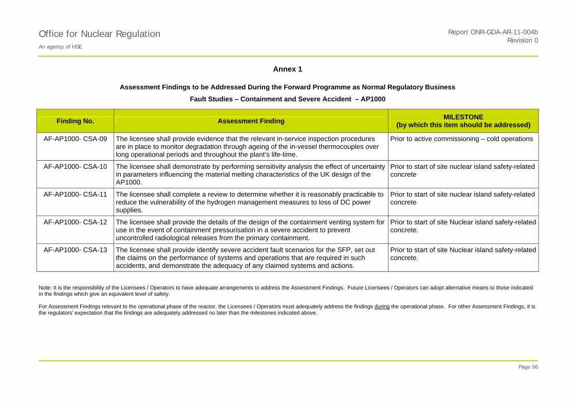
PROTECTIVE MARKING IF APPLICABLE
Office for Nuclear Regulation An agency of HSE
Report ONR-GDA-AR-11-004bRevision 0
Annex 1
Page 66
Assessment Findings to be Addressed During the Forward Programme as Normal Regulatory Business
Fault Studies – Containment and Severe Accident – AP1000
Finding No. Assessment Finding MILESTONE
(by which this item should be addressed)
AF-AP1000- CSA-09 The licensee shall provide evidence that the relevant in-service inspection procedures are in place to monitor degradation through ageing of the in-vessel thermocouples over long operational periods and throughout the plant’s life-time.
Prior to active commissioning – cold operations
AF-AP1000- CSA-10 The licensee shall demonstrate by performing sensitivity analysis the effect of uncertainty in parameters influencing the material melting characteristics of the UK design of the AP1000.
Prior to start of site nuclear island safety-related concrete
AF-AP1000- CSA-11 The licensee shall complete a review to determine whether it is reasonably practicable to reduce the vulnerability of the hydrogen management measures to loss of DC power supplies.
Prior to start of site nuclear island safety-related concrete
AF-AP1000- CSA-12 The licensee shall provide the details of the design of the containment venting system for use in the event of containment pressurisation in a severe accident to prevent uncontrolled radiological releases from the primary containment.
Prior to start of site Nuclear island safety-related concrete.
AF-AP1000- CSA-13 The licensee shall provide identify severe accident fault scenarios for the SFP, set out the claims on the performance of systems and operations that are required in such accidents, and demonstrate the adequacy of any claimed systems and actions.
Prior to start of site Nuclear island safety-related concrete.
Note: It is the responsibility of the Licensees / Operators to have adequate arrangements to address the Assessment Findings. Future Licensees / Operators can adopt alternative means to those indicated in the findings which give an equivalent level of safety. For Assessment Findings relevant to the operational phase of the reactor, the Licensees / Operators must adequately address the findings during the operational phase. For other Assessment Findings, it is the regulators' expectation that the findings are adequately addressed no later than the milestones indicated above.

PROTECTIVE MARKING IF APPLICABLE
Report ONR-GDA-AR-11-004bOffice for Nuclear Regulation An agency of HSE
Revision 0
Annex 2
Page 67
GDA Issues - Fault Studies – Containment and Severe Accident – AP1000
There are no GDA Issues for this topic area.