Embed Size (px)
Citation preview
InspectionOf
SN 0525LP-608-7500
Shore FacilitiesNAVFAC MO-322
Volume IMarch 1993
SNDL DISTRIBUTION
(25 Copies each):
FKA1C COMNAVFACENGCOM
(10 Copies each):
FA46 PWCLANTFB54 PWCPAC
HQ U.S. AIR FORCEEngineering And Services CenterTyndall AFB, FL 32403
(2 Copies each):
E3AFA6FA7FA10FA18FA24FA47FB7FB10FB13FB21FB28FB30FB36FB45FB58FC3FC5FC7FC14FC17FD4FF1FF3FF6FF32FF38FF42FG2FG3FJA4
LABONRNASLANTNAVSTALANTSUBASELANTNAVPHIBASEIANTCOMNAVBASELANTHOSPLANTNASPACNAVSTAPACSUBASEPACNAVPHIBASEPACCOMNAVBASEPACNAVSHIPREPFACNAVFACPACTRIREFFACPACHOSPPACCOMNAVACTEURNAVSUPACTEURNAVSTAEURNASEURNAVALHOSPOCEANCENCOMNAVDIST Washington, DCNAVSTACNONAVOBSYFLDSUPPACTUSNANAVPGSCOLNAVCOMMSTACOMMUNICATIONUNITNAVAL HOME
FKA8F5 SUBASEFKM9 NSC
FKN1 EFDs
FKP7 NAVSHIPYDsFT104 PWCCNET
U.S. ARMYOffice Chief of EngineersWashington, D.C. 20314 (DAEN-MPO)
FKM12 NAVPETOFFFKM13 SPCCFKM15 ASOFKN2 CBCsFKN3 OICCsFKN7 NEESAFKN10 NAVSUPPFACFKN11 NAVCIVENGRLABFKP1B WPNSTAsFKP1J NAVORDSTAsFKP16 NAVSSESFKQ6A NAVAIRDEVCENFKQ6G NUSCFKR1A NASFKR1B NAVAVNDEPOTFKR3A NAVAIRENGCENFKR5 NAVAVIONICCENFR3 NASRFSFORFR4 NAFFT6 NASCNETFT9 NAVAVMUSEUMFT13 NATTCFT28 NETCFT31 NTCFT37 NAVSCOLCECOFFFT38 NAVSUBTRACENPACFT39 NAVTECHTRACENFT55 NAVSCSCOLFT108 NAVALHOSPV3 COMCABV4 MCAFV5 MCASV16 CG MCBV23 CG MCLB
Additional Copies may be obtained from:Naval Publications and Forms Center5801 Tabor AvenuePhiladelphia, PA 19120
FOREWORD
A major problem facing Facility Managers is the physical condition of the shoreestablishment. Advancing deterioration frequently threatens operational readiness. Intimes of declining resources there is a tendency to condone breakdown maintenanceversus planned maintenance and to reduce or curtail Facility inspections. This results inpoorly defined and understated maintenance and repair resource requirements andcondition. Facility Managers are always in a position of justifying resource needs todecision makers. At higher levels, programs are evaluated not only on need, but onmission readiness impact while recognizing available resources cannot fully fund allprograms. Documentation of real property condition and its effect on operationalreadiness is critical in justifying budget requests. Facility condition is determined byaccurate facility inspection. It is both the cornerstone of a sound Facility ManagementSystem and the bedrock on which it is built. Without good facility conditioninformation and a common sense approach to Facilities Management it is difficult toexercise good stewardship over assigned assets and supporting resources.
This manual contains policy and criteria for inspection and condition assessmentof shore facilities and preventive maintenance of equipment. It provides guidance toimplement and maintain an inspection/assessment system. Comprehensive inspectionby technically qualified personnel is the key to helping protect Real Propertyinvestment. An effective facilities management program avoids over/undermaintenance. It fosters timely corrective action before advancing deterioration causesmajor repairs, or impacts mission.
Application of maintenance standards will effectively and efficiently protectpersonnel and property at a cost commensurate with facility functional requirements.Use of this guidance will assure economical maintenance and maximum reliability offacilities and equipment. Additional information or suggestions to improve thispublication are invited and should be submitted through appropriate channels to theNaval Facilities Engineering Command (Attention: Code 163), 200 Stovall Street,Alexandria, VA 22332-2300. This publication supersedes NAVFAC MO-322 Vol I ofJuly 1977.
This publication has been reviewed in accordance with the Secretary of the NavyInstruction 5600.16A and is certified as an official publication of the Naval FacilitiesEngineering Command.
E. R. HAMMCAPTAIN, CEC, U.S. NavyAssistant Commander forPublic Works Centers and Departments
i

ABSTRACT
This publication establishes the Continuous Inspection Program for Real Propertyfacilities and equipment. Practices and procedures are recommended to ensure facilityand equipment safety, reliability and readiness at optimum cost.
The contents of this manual contain definitions and recommended standards forthe Shore Facilities Inspection/Assessment System; inspection frequency and times, pro-cedures and types; suggested guidelines for records and reports; procedures for condi-tion assessments; discussions of the Annual Inspection Summary and facilitymaintenance planning.
iii

CHANGE CONTROL SHEET
Document all changes, page replacements, and pen and ink alterations posted in this manual.
AMENDMENT AMENDMENT POST DATE POSTED BYNUMBER DATE (LAST NAME)
v

Table of Contents
1. INTRODUCTION 1-1
1.1
1.2
1.3
1.4
1.5
PURPOSE . . . . . . . . . . . . . . . . . . . . . . . . . . . . . . . . . . . . 1-1
OBJECTIVE . . . . . . . . . . . . . . . . . . . . . . . . . . . . . . . . . . . 1-1
DISCUSSION . . . . . . . . . . . . . . . . . . . . . . . . . . . . . . . . . . 1-1
SCOPE . . . . . . . . . . . . . . . . . . . . . . . . . . . . . . . . . . . . . . . 1-1
1.4.1 Volume 1-Inspection/Assessment System . . . . . . . . . . . . . . . 1-2
1.4.2 Volume 2-Control Inspection Checklist . . . . . . . . . . . . . . . . 1-2
1.4.3 Volume 3-Instructor’s Manual for Control Inspector Training. . . . . . . . . . . . . . . . . . . . . . . . . . . . . . . . . . . 1-2
RESPONSIBILITIES . . . . . . . . . . . . . . . . . . . . . . . . . . . . . . 1-2
1.5.1 Activity Responsibility . . . . . . . . . . . . . . . . . . . . . . . . . 1-2
1.5.1.1 Facilities Management Program . . . . . . . . . . . . . . . . 1-2
1.5.1.2 Facility and Equipment Inventories . . . . . . . . . . . . . . 1-3
1.5.1.3 Safety . . . . . . . . . . . . . . . . . . . . . . . . . . . . . . . 1-4
1.5.1.4 Organization . . . . . . . . . . . . . . . . . . . . . . . . . . . 1-4
1.5.1.5 Control Inspector’s Duties . . . . . . . . . . . . . . . . . . . 1-4
1.5.1.6 PMI Inspector Duties . . . . . . . . . . . . . . . . . . . . . . 1-5
1.5.1.7 Supervisor’s Duties . . . . . . . . . . . . . . . . . . . . . . . 1-5
1.5.1.8 Operator Inspection . . . . . . . . . . . . . . . . . . . . . . . 1-5
1.5.1.9 Management’s Appraisal Responsibility . . . . . . . . . . . 1-5
1.5.1.10 Shore Base Readiness Report (BASEREP) . . . . . . . . . 1-6
1.5.2 Claimant Responsibilities . . . . . . . . . . . . . . . . . . . . . . . . 1-6
1.5.3 Naval Facilities Engineering Command (NAVFACENGCOM)Responsibilities . . . . . . . . . . . . . . . . . . . . . . . . . . . . . 1-8
2. SYSTEM DESCRIPTION 2-1
2.1 PURPOSE . . . . . . . . . . . . . . . . . . . . . . . . . . . . . . . . . . . . 2-1
2.2 INVENTORIES . . . . . . . . . . . . . . . . . . . . . . . . . . . . . . . . . 2-1
2.2.1 Real Property Inventory . . . . . . . . . . . . . . . . . . . . . . . . 2-1
vii
2.2.1.1 Utility Systems Inventories . . . . . . . . . . . . . . . . . . . 2-1
2.2.2 Systems Inventory . . . . . . . . . . . . . . . . . . . . . . . . . . . . 2-2
2.2.3 Preventive Maintenance Inspection (PMI) Inventory . . . . . . . . 2-2
2.2.4 Replacement Items Inventory . . . . . . . . . . . . . . . . . . . . . 2-2
2.2.5 Real Property Baseline Inventory . . . . . . . . . . . . . . . . . . . 2-3
2.3 INSPECTION TYPES . . . . . . . . . . . . . . . . . . . . . . . . . . . . . . 2-3
2.3.1 Control Inspection (CI) . . . . . . . . . . . . . . . . . . . . . . . . . 2-3
2.3.1.1 Specialized Inspection . . . . . . . . . . . . . . . . . . . . . 2-3
2.3.1.2 Engineering Investigation . . . . . . . . . . . . . . . . . . . 2-4
2.3.2 Preventive Maintenance Inspection (PMI) . . . . . . . . . . . . . . 2-4
2.3.3 Operator Inspection . . . . . . . . . . . . . . . . . . . . . . . . . . . 2-4
2.3.4 Certification Inspections . . . . . . . . . . . . . . . . . . . . . . . . 2-4
2.4 STANDARDS AND TECHNICAL ASSISTANCE . . . . . . . . . . . . .2-5
2.4.1 Inspection Guides . . . . . . . . . . . . . . . . . . . . . . . . . . . . 2-5
2.4.1.1 Control Inspection Checkpoints . . . . . . . . . . . . . . . . 2-5
2.4.1.2 PMI Checkpoints . . . . . . . . . . . . . . . . . . . . . . . . 2-5
2.4.2 Maintenance Standards . . . . . . . . . . . . . . . . . . . . . . . . . 2-5
2.4.2.1 Level of Maintenance Classification (LMC) Codes . . . . . 2-5
2.4.2.2 Condition Evaluation Standards . . . . . . . . . . . . . . . . 2-6
2.4.2.3 Regulatory Standards and Safety Codes . . . . . . . . . . . 2-7
2.4.3 Technical Sources . . . . . . . . . . . . . . . . . . . . . . . . . . . . 2-7
2.4.3.1 Manuals and New Technology . . . . . . . . . . . . . . . . . 2-7
2.4.3.2 Technical Assistance . . . . . . . . . . . . . . . . . . . . . . 2-7
2.4.3.3 Engineered Performance Standards (EPS) . . . . . . . . . . 2-7
2.5 FORMS AND RECORDS . . . . . . . . . . . . . . . . . . . . . . . . . . 2-10
2.6 RELATED PROGRAMS AND AGREEMENTS . . . . . . . . . . . . 2-10
2.6.1 Maintenance Service Agreements (MSA) . . . . . . . . . . . . . 2-10
2.6.2 Intra/Inter-Services Support Agreements (ISSA) . . . . . . . . . 2-11
2.6.3 Engineering Evaluation (EE) of Existing Assets . . . . . . . . . . 2-11
2.6.4 Family Housing Programs . . . . . . . . . . . . . . . . . . . . . . . 2-11
viii
3. CONTROL INSPECTION PROCEDURES 3-1
3.1
3.2
3.3
3.4
3.5
3.6
PURPOSE . . . . . . . . . . . . . . . . . . . . . . . . . . . . . . . . . . . . 3-1
OBJECTIVES . . . . . . . . . . . . . . . . . . . . . . . . . . . . . . . . . .3-1
INSPECTOR QUALIFICATIONS . . . . . . . . . . . . . . . . . . . . . .3-2
SCHEDULING CONTROL INSPECTIONS . . . . . . . . . . . . . . . .3-2
3.4.1 Frequencies . . . . . . . . . . . . . . . . . . . . . . . . . . . . . . . . 3-2
3.4.2 Scheduling Considerations . . . . . . . . . . . . . . . . . . . . . . . 3-2
3.4.3 Control Inspection Times . . . . . . . . . . . . . . . . . . . . . . . . 3-3
PREPARING TO INSPECT . . . . . . . . . . . . . . . . . . . . . . . . . . 3-4
ADDITIONAL DUTIES OF MECHANICAL AND ELECTRICALINSPECTORS . . . . . . . . . . . . . . . . . . . . . . . . . . . . . . . . . .3-5
3.7 CORRECTING NON-DEFERRABLE (CRITICAL) ANDDEFERRABLE DEFICIENCIES . . . . . . . . . . . . . . . . . . . . . . .3-5
3.8 CONTRACTOR ASSISTANCE . . . . . . . . . . . . . . . . . . . . . . . .3-5
4. CONTROL INSPECTION REPORTS AND RECORDS 4-1
4.1 REPORT DESCRIPTIONS . . . . . . . . . . . . . . . . . . . . . . . . . .4-1
4.1.1 Facility Inspection Checklist . . . . . . . . . . . . . . . . . . . . . . 4-1
4.1.2 Facility Condition Summary Report Sheet . . . . . . . . . . . . . . 4-1
4.1.3 Facility Condition Report Detailed Deficiency List . . . . . . . . . 4-1
4.2 REPORT PREPARATION . . . . . . . . . . . . . . . . . . . . . . . . . .4-5
4.2.1 Preparation of “Detailed Deficiency List” . . . . . . . . . . . . . . . 4-6
4.2.1.1 Report Accuracy . . . . . . . . . . . . . . . . . . . . . . . . . 4-6
4.2.2 Work Packaging . . . . . . . . . . . . . . . . . . . . . . . . . . . . . 4-7
4.2.3 Inspection Report Numbering . . . . . . . . . . . . . . . . . . . . . 4-7
4.2.4 Deficiency Cost Estimates . . . . . . . . . . . . . . . . . . . . . . . 4-8
4.2.5 Special Projects Program . . . . . . . . . . . . . . . . . . . . . . . . 4-8
4.2.6 Inspection Report Use . . . . . . . . . . . . . . . . . . . . . . . . . 4-8
4.3 TYPES OF RECORDS . . . . . . . . . . . . . . . . . . . . . . . . . . . . . 4-9
4.3.1 Facility History Files . . . . . . . . . . . . . . . . . . . . . . . . . . 4-9
4.3.1.1 Warranty Program . . . . . . . . . . . . . . . . . . . . . . . . 4-9
ix
4.3.2 Cyclic Maintenance Planning Files . . . . . . . . . . . . . . . . . 4-14
4.3.3 Completed Job Order Files . . . . . . . . . . . . . . . . . . . . . . 4-14
4.3.4 Completed E/S Work Files . . . . . . . . . . . . . . . . . . . . . . 4-14
4.4 MANAGEMENT REVIEW AND APPRAISAL . . . . . . . . . . . . . 4-15
4.5 FACILITY MAINTENANCE PLANNING . . . . . . . . . . . . . . . . 4-15
5. PREVENTIVE MAINTENANCE INSPECTION/SERVICE (PMI)PROCEDURES 5-1
5.1 OBJECTIVE . . . . . . . . . . . . . . . . . . . . . . . . . . . . . . . . . . . 5-1
5.1.1 Discussion . . . . . . . . . . . . . . . . . . . . . . . . . . . . . . . . . 5-1
5.1.2 Management Prerequisite . . . . . . . . . . . . . . . . . . . . . . . . 5-2
5.2 PMI INSPECTOR QUALIFICATIONS . . . . . . . . . . . . . . . . . . . 5-2
5.3 ESTABLISHING A PMI PROGRAM . . . . . . . . . . . . . . . . . . . . 5-2
5.3.1 PMI Inventory . . . . . . . . . . . . . . . . . . . . . . . . . . . . . . 5-2
5.3.2 PMI Contractor Assistance . . . . . . . . . . . . . . . . . . . . . . . 5-2
5.3.3 PMI Guides and Frequency . . . . . . . . . . . . . . . . . . . . . . . 5-3
5.3.4 Inspection Record . . . . . . . . . . . . . . . . . . . . . . . . . . . . 5-5
5.4 SCHEDULING INSPECTIONS . . . . . . . . . . . . . . . . . . . . . . . . 5-5
5.4.1 PMI Frequencies . . . . . . . . . . . . . . . . . . . . . . . . . . . . . 5-5
5.4.2 PMI Times . . . . . . . . . . . . . . . . . . . . . . . . . . . . . . . . 5-5
5.4.3 PMI Scheduling Considerations . . . . . . . . . . . . . . . . . . . . 5-6
5.5 HANDLING MAJOR DEFICIENCIES . . . . . . . . . . . . . . . . . . . 5-6
5.6 SUPPORT REQUIREMENTS . . . . . . . . . . . . . . . . . . . . . . . . 5-6
5.7 PROGRAM ANALYSIS . . . . . . . . . . . . . . . . . . . . . . . . . . . . 5-6
6. OPERATOR INSPECTION PROCEDURES 6-1
6.1 OBJECTIVE . . . . . . . . . . . . . . . . . . . . . . . . . . . . . . . . . . . 6-1
6.2 RESPONSIBILITY . . . . . . . . . . . . . . . . . . . . . . . . . . . . . . . 6-1
6.3 QUALIFICATIONS . . . . . . . . . . . . . . . . . . . . . . . . . . . . . . . 6-1
6.4 SCHEDULING INSPECTIONS . . . . . . . . . . . . . . . . . . . . . . . . 6-1
6.5 PERFORMING OPERATOR INSPECTIONS . . . . . . . . . . . . . . . 6-1
X
7. ANNUAL INSPECTION SUMMARY (AIS) 7-1
7.1 PURPOSE . . . . . . . . . . . . . . . . . . . . . . . . . . . . . . . . . . . . 7-1
7.2 OBJECTIVE . . . . . . . . . . . . . . . . . . . . . . . . . . . . . . . . . . . 7-1
7.3 AIS FUNDING RELATIONSHIP . . . . . . . . . . . . . . . . . . . . . . 7-1
7.4 PREPARATION OF THE AIS . . . . . . . . . . . . . . . . . . . . . . . . 7-2
7.4.1 Type “B” Annual Inspection Summary . . . . . . . . . . . . . . . . . 7-3
7.4.2 Type “C” Annual Inspection Summary . . . . . . . . . . . . . . . . . 7-9
8. THE BASE ENGINEERING SUPPORT, TECHNICAL (BEST)SYSTEM 8-1
8.1 OBJECTIVE . . . . . . . . . . . . . . . . . . . . . . . . . . . . . . . . . . . 8-1
8.2 DISCUSSION . . . . . . . . . . . . . . . . . . . . . . . . . . . . . . . . . . 8-1
8.3 THE SFI MODULE . . . . . . . . . . . . . . . . . . . . . . . . . . . . . . . 8-1
8.3.1 Inventory . . . . . . . . . . . . . . . . . . . . . . . . . . . . . . . . . 8-1
8.3.2 Inspection Frequencies And Standard Hours . . . . . . . . . . . . 8-2
8.3.2.1 CI Frequencies and Standard Hours . . . . . . . . . . . . . 8-2
8.3.2.2 PMI Frequencies and Standard Hours . . . . . . . . . . . . 8-2
References Reference- 1
APPENDIX A
APPENDIX B
APPENDIX CAPPENDIX DAPPENDIX EAPPENDIX F
APPENDIX G
Sample Guides For Developing Utility SystemsPseudofacility NumbersMinimum Recommended Frequencies forControl InspectionControl Inspection TimesFacility Inspection ChecklistWork PackagingMaintenance Planning (Maintenance ActionPlan-MAP)Long Range Maintenance Planning (LRMP)
A-1
B-1C-1D-1E-1
F-1G-1
Index Index- 1
xi
Figure No. Title Page
1-14-14-24-34-44-54-65-15-27-17-27-3
Shore Base Readiness Report (BASEREP)Facility Inspection ChecklistFacility Condition Summary ReportFacility Condition Report Detailed Deficiency ListFacility Condition Report - Coded Floor PlanControl Inspection Report FlowHistorical Record Built-up RoofPM Inspection Record CardPMI Inventory and Tracking RecordForm for Type “B” AISForm for Type “B AISType “C” Annual Inspection Summary FormSummary-1Type “C” Annual Inspection Summary FormSummary-2Example of Completed Form Summary-1Example of Completed Form Summary-2
TABLES
1-74-24-34-44-54-104-115-35-47-47-5
7-4
7-57-6
7-10
7-117-147-15
Table No. Title Page
2-12-2
Level of Maintenance Classification (LMC) Codes 2-6Selected Listing of Maintenance & Operations Manuals 2-8
FIGURES
xii
CHAPTER 1. INTRODUCTION
1.1 PURPOSE. This manual is a guide for personnelwho operate, inspect, test, certify, assess the conditionof, and maintain shore facilities and equipment. Itprovides criteria, standards and procedures for develop-ment and implementation of a comprehensive Inspec-tion/Assessment System.
1.2 OBJECTIVE. The objectives are to:(1) systematically identify deficiencies,(2) recommend action that will correct
deficiencies and/or impede advancing deterioration,and
(3) maintain facilities and systems at a levelconsistent with mission.
1.3 DISCUSSION. Facility acquisition costs are minuscule in comparison to life cyclemaintenance costs associated with facility ownership. While design and construction arechallenging and rewarding from the aspect of satisfying a real facility need, there is littleglamour for the facility manager who must make the difficult daily funding decisionsthat keep the same facilities operational. There is little awareness of cost of ownershipand various maintenance strategies which need to be coupled to establish and achievefacility life extension goals. Knowledge of facility condition is critical to an effectivefacility manager and this knowledge can only be attained by facility inspection. A dedi-cated inspection effort is vital to properly identify Real Property maintenance andrepair deficiencies which will potentially impact mission or degrade plant investment.This manual outlines methods to identify and quantify deficiencies and their mission im-pact. Inspection by-products are: (1) an accurate assessment of facility condition andthe potential impact on readiness by Investment Category/Base Readiness MissionCategory (BASEREP) and (2) identification of resource needs for budget planning pur-poses. Chief of Naval Operations (CNO) requires each major claimant to provide afacility condition assessment (BASEREP), OPNAVINST 3501.167 (series) and AnnualInspection Summary (AIS), OPNAV 11010.34 (series) annually. Overall Navy assess-ments are then prepared by OPNAV which portray the long-term impact of resource al-location decisions. Assessments and resource allocation decisions are adjusted annuallyfor a six-year projection (Future Years Defense Plan - FYDP).
1.4 SCOPE. This is the first of three volumes which describes investigations andevaluations needed to effectively manage facilities and equipment (excluding transporta-tion) for which Public Works is responsible. These volumes contain no instant magicalsolution to Facility Management and condition problems. They do, however, provide a
1-1
logical systematic approach providing Facility Managers with information needed tomake sound decisions based on economics and mission support.
1.4.1 Volume l-Inspection/Assessment System. Chapter 1 assigns respon-sibilities for the maintenance of shore facilities. Chapter 2 describes the Inspection/As-sessment system. The remaining chapters (3 through 8) provide detailed inspectionguidance.
1.4.2 Volume 2-Control Inspection Checklist. This volume provides inspectionchecklists for use by technical Control Inspectors.
1.4.3 Volume 3-Instructor’s Manual for Control Inspector Training Course.This volume provides a training plan for conducting an Inspector Training course toteach Control Inspectors how to assess, evaluate and document facility deficiencies.
1.5 RESPONSIBILITIES. OPNAV Instructions 11010.23 (series) and 11000.16 (series)contain CNO’s management concepts for Real Property Maintenance Activities(RPMA). These instructions convey CNO policy for facility inspections and conditionassessments and assign organizational responsibilities. Embedded in this policy andguidance is an attempt to achieve a state of equilibrium between the functional value offacilities to mission and the financial resources available to support the shore estab-lishment.
1.5.1 Activity Responsibility. Commanders, Commanding Officers and Officers-in-Charge of Shore Activities having plant account custody of land or facilities (Class Iand II Real Property) respectively are responsible to the CNO through their majorclaimant for prudent planning and plant maintenance. This includes identifying andreporting resource requirements, material condition, safety, environmental and ap-pearance deficiencies as well as efficient and effective utilization of assigned assets in-cluding funds. Without explicit well defined, well organized knowledge of facilitycondition, it is impossible to successfully plan, fund and execute a Facility ManagementStrategy.
1.5.1.1 Facilities Management Program. The Commanding Officer isresponsible for establishing and maintaining an effective facilities management programsuch as that specified in NAVFAC MO-321, “Facilities Management” (for Public WorksDepartments). Performance Standards shall be incorporated into work planning and es-timating procedures and variance analyses shall be performed. The cornerstone of asound facilities management system is a good facilities inspection program. Activitiesserved by a Public Works Center (PWC) or Department (PWD) of another activity areresponsible for all functions except execution of work. They are still responsible for ac-cepting the work performed by others.
1-2
The Facilities Management Program includes as a minimum:
l Conducting a continuous, comprehensive inspection of RealProperty Assets to identify and quantify condition. Maintenanceand Repair work generated from continuous inspection shallconstitute a minimum of 65% of the nonrecurring workprogrammed for accomplishment. The Continuous InspectionProgram is comprised of 3 types of inspection: Control, PreventiveMaintenance and Operator. These are discussed in this volume.
l Training personnel to conduct accurate inspections using approvedguidance.
l Establishing and maintaining a Preventive Maintenance Inspection(PMI) program for dynamic equipment.
l Establishing and conducting an Operator Inspection program forequipment and facilities requiring a full time operator.
l Initiating proper and responsive action to correct deficiencies.
l Preparing and submitting an AIS and required assessments tohigher authority which accurately reflects facility condition.
l Preparing, maintaining and using maintenance plans developedfrom a budget based on requirements identified via acomprehensive Continuous Inspection Program.
l Ensuring that Minor Construction/Alteration work, includingplanning and design, does not interfere with or consume resourcesneeded to plan, estimate or accomplish Maintenance and Repairwork. OPNAV Instruction 11000.16 states that expenditures forMinor Construction and Alteration (less Equipment Installation)shall not normally exceed 10% of the total claimant expendituresfor Maintenance of Real Property (MRP) without prior approval ofCNO (OP-44).
l Reducing the level of maintenance on facilities to be demolished,renovated, replaced or not fully utilized. Maintenance standards,including safety, shall be appropriate to use.
l Making inspectors aware of environmental and energy/utilitiesconservation program goals and instructing them to documentdeficiencies accordingly.
1.5.1.2 Facility and Equipment Inventories. Accurate inventories arecritical. Essential Class I and II property inventory, including items of dynamic equip-ment, must be accurately maintained. A facilities manager must know which assets re-quire maintenance, their location, amount of maintenance needed and relativeimportance of the asset to mission.
1-3
1.5.1.3 Safety. Equipment such as safety glasses, shoes, hard hats,gloves, respirators, and belts shall be provided to inspectors as required. Guidance shallbe given concerning protective equipment requirements, maintenance and use of equip-ment, and safety precautions to be observed. Inspections of electric and steam distribu-tion systems, elevators, etc. may require a helper to minimize danger. Inspectors shallobserve safety precautions and be familiar with safety instructions. Safety Inspectorsand Industrial Hygienists should augment the Control Inspection effort and maintain adialogue to determine the proper course of corrective action, etc. If these personnel areunavailable, required services should be purchased from other sources (PWC, contract,etc.)
1.5.1.4 Organization. NAVFAC P-318, “Organization and Functionsfor Public Works Departments,” recommends a Work Generation Branch in the FacilityManagement Engineering Division (FMED). Responsibilities include scheduling andperforming facility inspections, preparing inspection reports, and planning and estimat-ing functions.
1.5.1.5 Control Inspector’s Duties. Control Inspectors shall:
l Carefully review facility files for reported problems, historicaltrends and status of planned work prior to a field inspection.
l Be familiar with current space utilization assignments, warranties,inter/intra service support and/or lease agreements.
l Consult with facility occupants regarding known problems prior toinspection.
l Conduct thorough inspections and produce an accurate report withreliable data. Incomplete examinations should be reported.Corrective actions shall be recommended based on personalobservation and/or tests or engineering investigations by qualifiedpersonnel.
l Recommend other tests or investigations if required.
l Attempt to determine and report the true cause of a problem ratherthan reporting cosmetic deficiencies.
l Be alert to deficiencies affecting entire systems. Recommendrepair by replacement of the system rather than piecemeal,temporary solutions to problems when practical. Indicate whenSpecial Projects should be developed.
l Appraise the effectiveness and quality of repairs to previouslyreported problems. Report inferior quality work or ineffectivefixes. Note failure to perform specified work.
1-4
l Evaluate Preventive Maintenance and Operator InspectionProgram effectiveness . Recommend changes when needed.
l Prepare cost estimates, by craft, to correct deficiencies.
l Classify deficiencies as Deferrable or Critical (OPNAV Instruction11010.34 provides guidance.)
l Report changes in space usage.
1.5.1.6 PMI Inspector Duties. Maintenance and Utilities shop person-nel are responsible for conducting PMI of dynamic equipment in accordance withspecifications provided by the FMED. The FMED is responsible for PMI Program ad-ministration. The Maintenance Division and Utilities Division personnel should assistthe FME Division in developing inventories, identifying checkpoints, assigning inspec-tion frequencies, planning, scheduling, and appraising PMI effectiveness. Once the Pro-gram has been defined, it is the FMED responsibility to issue work authorizations forPMI accomplishment and monitor PMI execution.
1.5.1.7 Supervisor’s Duties. The Work Generation Branch Supervisormust assure that each Control Inspector is properly instructed and trained. The Super-visor should review each incoming Customer Work Request to ensure the work is notduplicated on an Inspection Report. If so, the customer should be notified of workstatus and the Work Request returned. An effectively administered Control InspectionProgram will substantially reduce Customer Work Requests for Maintenance andRepair. The Work Generation Branch Supervisor shall conduct random inspections toassure quality. Major unexplained discrepancies between previous and current Inspec-tion Reports are to be resolved with inspectors, including site visits, to evaluate problemareas and ensure the inspector is adequately trained. The FMED Director should ran-domly review Inspection Reports for completeness, accuracy and validity of reporteddeficiencies and recommended corrective actions. The Shop Supervisor responsible forexecuting operator inspection or PMI Work is responsible for training workers, main-taining work quality, promptly reporting out-of-scope PMI deficiencies and suggestionsfor over/under maintenance.
1.5.1.8 Operator Inspection. Operator Inspection is conducted by theperson assigned to operate the equipment or system. It includes examination, lubrica-tion and minor adjustments. Standard Operating Procedures (SOPS) shall be developedand posted on the equipment or facilities, or written in a watch log. During the watch,the operator should note what was done and indicate if major repair or overhaul isneeded. Work beyond operator’s capability or authority should be reported to the su-pervisor. Breakdowns should be reported immediately.
1.5.1.9 Management’s Appraisal Responsibility. Management shallmonitor the “health” of the operation. Indicators exist for continuing appraisal. For ex-
1-5
ample, if the percentage of Specific Maintenance and Repair Work generated fromContinuous Inspection is less than 65%, the Inspection Program may be ineffective orinspection generated work is not being programmed for accomplishment. Note thelevel of Emergency work. An increase in Emergency work and a decrease in PMI workmay indicate dynamic equipment inspections are not being worked as planned or PMIspecifications and frequency may need adjustment. It may also indicate that an item ofequipment needs to be replaced versus continual repair. Management indicators andtargets are included in the “Management Guide, Maintenance Subsystem, Base En-gineering Support, Technical (BEST)” and NAVFAC MO-321 Chapters 10 and 11.These will assist in measuring and monitoring overall program effectiveness. Manualdata collection for appraisal is tedious, but simplified with automation.
1.5.1.10 Shore Base Readiness Report (BASEREP). OPNAV Instruc-tion 3501.167 (series) establishes procedures for assessing the readiness of Navy shoreactivities. Readiness data helps justify resources for shore establishment. TheBASEREP (Figure 1-1) is an operator’s assessment of base readiness. Commanding Of-ficers evaluate readiness of assets (personnel, facilities, and equipment) by MissionCategory. Rating factors are used to assess readiness capability by mission area. Theseare:
l C1 - Asset has fully met all demands in the Mission Categorythroughout the reporting period;
l C2 - Asset has substantially met all demands of the MissionCategory throughout the reporting period with only minor difficulty;
l C3 - Asset has only marginally met demands of the MissionCategory throughout the reporting period, but with major difficulty;
l C4 - Asset has not met vital demands of the Mission Category.
BASEREP ratings for “Condition” of facilities must be supported by Facility InspectionReports. Inspection Reports also provide repair solutions required by CNO forBASEREP ratings of C3 and/or C4.
1.5.2 Claimant Responsibilities. A synopsis of Claimant RPMA responsibilitiesoutlined in OPNAV Instruction 11000.16 follows:
n Issue guidance and instructions for administration and management ofassigned land and facilities.
n Maintain a qualified staff to administer land and facilities matters. UtilizeNaval Facilities Engineering Command (NAVFACENGCOM) technicalassistance.
n Provide training for personnel whose decisions affect land and facilities orthe resources to acquire, maintain or dispose of them.
1-6
CHAPTER 2. SYSTEM DESCRIPTION
2.1 PURPOSE. This chapter describes an Inspec-tion/Assessment System designed to determinefacility and equipment condition and proper correc-tive measures to obtain maximum utilization andreadiness at minimum cost. It discusses the con-tinuous inspection program, types of inspections, in-ventories, standards and inter-relationship ofinspection programs. The procedures provide sys-tematic methods for identifying and reporting main-tenance and repair work on a continuous basis andarrangement of data for management decisionsbased on priority.
2.2 INVENTORIES. Inventory data is basic to effective maintenance planning. Inven-tories should be verified and updated during inspections.
2.2.1 Real Property Inventory. Real Property Inventory for Class I and ClassII property owners is contained in NAVFAC Manual P-164, “Detailed Inventory ofNaval Shore Facilities.” It is the basic reference for Control Inspection. Facility usageshould be reviewed during inspection and the activity Facility Planner notified of chan-ges. Real Property Inventories are the responsibility of activity Facility Planners. Chan-ges to property record cards shall be reported to the geographic EFD’s/EFA’s FacilitiesPlanning and Real Estate Department. The EFD/EFA will make revisions to the NavyFacilities Assets Data Base (NFADB) which will be reflected in revised NAVFAC P-164 publications.
2.2.1.1 Utility Systems Inventories. Utility systems and componentsare difficult to identify because facility numbers are not usually assigned. Pseudo facilitynumbers may be assigned. Utility pseudo facility numbers should be composed of atleast two factors: (1) utility service code and (2) descriptive type service. Appendix Aprovides a pseudo facility numbering guide. Inventories of systems and components arethe basis for developing preventive maintenance inspection and service of equipment.Inventories should be sorted so frequency of inspection, priority data, replacement infor-mation, etc. can readily be determined.
Listings should indicate systems or components that, if disabled, would:
l Disrupt essential mission-related operations.
l Endanger life and/or property.
2-1
• Impair quality of life.
• Cause environmental problems.
• Require a long lead-time for replacement.
2.2.2 Systems Inventory. A systems inventory shows all vents, pipes, anodes,rectifiers, valves, inspection access, motors, traps, filters, and other components for asingle system. Within each system a separate sublist may indicate components requiringpreventive maintenance and those that are repaired by replacement. Each system re-quires inspection and is the responsibility of both Control Inspectors and PreventiveMaintenance Inspectors depending on the type inspection performed.
2.2.3 Preventive Maintenance Inspection (PMI) Inventory. A PMI inventory isa listing of items of dynamic equipment requiring periodic lubrication, adjustmentand/or inspection. PMI of equipment with an assigned operator is generally part of theoperator’s SOPS, especially if failure would have serious consequences. If the operatordoes not have time or training to perform the work, it should be included in the PMIprogram. PM Inspection is particularly applicable to unattended:
Water supply, treatment, and distribution systems.
Sewage collection and treatment systems.
Fuel storage and handling facilities.
Compressed air and industrial gas generating and distribution systems.
Electric generating and distribution systems.
Appurtenants to cathodic protection equipment systems.
Heating, ventilating, refrigeration, air conditioning equipment andsystems.
Bakery, food preparation and service, and dish washing equipment.
Weight-handling equipment.
Public Works shop equipment.
2.2.4 Replacement Items Inventory. Small items such as fractional horsepowermotors, water coolers, self-lubricating fans, window unit air conditioners, automaticdoor closers and other sealed units do not normally require preventive maintenance un-less critical to a mission essential operation. These items are replaced when they breakdown. Control Inspection of systems and user complaints (numerous E/S calls) alsoidentify the need to replace items. An inventory of such items, with replacement dates,including stock or availability data should be maintained.
2-2
2.2.5 Real Property Baseline Inventory. The Baseline Inventory expands uponthe Real Property Inventory and gives detailed information on components or sub-com-ponents. It is used to identify unique/special inspection, certification, or maintenancerequirements for use in Facilities Support Contracts or work scheduling. It should con-tain such items as the number and kind of piles supporting a pier, the total number ofrailway ties in the system and number in the replacement program. Square feet of roof-ing by type and facility, length of a distribution system section according to size and typeof pipe (including cathodic protection and rectifiers), and other detailed informationshould also be included.
2.3 INSPECTION TYPES. The Continuous Inspection Program is comprised of threetypes of inspection: (1) Operator, (2) Preventive Maintenance, and (3) Control. Ef-fective planning and execution of these inspections ensures a comprehensive examina-tion of all facilities and equipment.
2.3.1 Control Inspection (CI). Control Inspection is a scheduled structural,mechanical and electrical examination of facilities conducted throughout the year todetermine physical condition. CI is the cornerstone of the Continuous Inspection Pro-gram. Other types of inspections such as command, safety inspections and user inspec-tions can supplement and support Control Inspections. It is advantageous to encourageinformal reports from Master-at-Arms, building “monitors,” and facility occupants.Booklets or written instructions on the care and operation of components of a facilityfor occupant use are also helpful. Feedback from the users’ perspective enables PublicWorks to monitor the “health” of a facility between scheduled inspections. Supplemen-tal inspection input should be reviewed prior to the scheduled CI and appropriate infor-mation included in the CI Report. Control Inspection is the primary source of workgeneration. It should produce the majority of shop and contract maintenance and repairworkload. AIS and budget base data is a natural by-product of effective CI.
2.3.1.1 Specialized Inspection. Specialized Inspections are investiga-tions, tests or observations that require special skill or equipment. Specialized inspec-tions include: Waterfront, Electrical Systems, Automated Control Systems, Elevators,Fleet Moorings, Roofing, Surfaced Areas/Airfield Pavements, Coatings/CompositeMaterials, Mechanical Systems, Underground Utilities, Petroleum Fuel Facilities,Trackage, Bridges/Trestles, Underground Structures, Corrosion Control/CathodicProtection, Pest Management Programs, Antenna Towers. Inspections in general areperformed by EFDs/EFAs on a reimbursable basis. Certain EFDsEFAs are tasked toprovide specialized expertise and act as the “lead” in specific technical areas. The objec-tives of this are to:
l Develop and maintain recognized experts in specific areas.
l Concentrate on technical provisions and standards.
2-3
l Support activities, other EFDs/EFAs and NAVFACENGCOM inhighly technical matters.
Specialized Inspections are part of Control Inspection for areas where special expertiseis required, but unavailable. These inspections are normally conducted on facilities andequipment which impact safety or mission. They provide feeder information to the Con-trol Inspector and indicate if detailed engineering investigations and designs are re-quired.
2.3.1.2 Engineering Investigation. Engineering Investigations are onetime highly technical studies requested by Control Inspectors based on a need. Theymay be conducted to determine the cause of a defect, extent of damage, ability of afacility to function, safety limitations, or condition of the facility or component. In addi-tion, they may provide background information to supplement or support otherprograms and studies. A dialogue should be established between Engineering andFMED to review previous, current and proposed studies and other pertinent informa-tion.
2.3.2 Preventive Maintenance Inspection (PMI). PMI consists of examination,lubrication, minor adjustments and/or minor repair of dynamic equipment to which aspecific operator is not assigned. The Work Generation Branch of the FMED deter-mines what to inspect and the job specifications. The Shore Facilities Inspection (SFI)Module of Public Works Management Automation/Base Engineering Support, Techni-cal (PWMA/BEST) will be helpful in facilitating the implementation and administrationof a PMI Program. (See Chapter 8 for more information on PWMA/BEST.)
2.3.3 Operator Inspection. This includes examination, lubrication, and minoradjustments of equipment and systems for which the PWD is responsible and to whichan operator is assigned. Safety and maintenance checks shall be included in StandardOperating Procedures (SOPS) and shall be conducted as listed in activity regulationsand manufacturers’ literature. Continuous observations shall be made when equipmentis operating.
2.3.4 Certification Inspections. The intent of Certification Inspections is to en-sure functional reliability and safety and to prevent property damage or personal injury.Certification of certain type facilities, components or sub-components is recommendedand is sometimes mandatory. Elevators, Graving Drydocks, Crane and Railroad Track-age, Boilers and Unfired Pressure Vessels, Hyperbaric Facilities require certification.Information regarding certification requirements of these areas is in respective NAV-FAC Maintenance and Operations (MO) Manuals or instructions. The Certificationprogram is designed to identify and classify defects according to hazard or
2-4
risk. When prescribed limits are exceeded, the facility or component shall be placedout of service until repaired.
2.4 STANDARDS AND TECHNICAL ASSISTANCE. Technical information sources,standards, criteria and checklists for inspections are defined as follows:
2.4.1 Inspection Guides. Checklists, inspection points and other references in-clude:
2.4.1.1 Control Inspection Checkpoints. MO-322, Volume 2 containsinspection checklists for Buildings, Mechanical/Electrical, Utility Plants and Distribu-tion Systems and Miscellaneous Equipment, Structures and Systems. NAVFAC MOmanuals covering maintenance, operations and inspection for a specific type facility arealso available.
2.4.1.2 PMI Checkpoints. PMI checkpoints may be obtained frommanufacturer’s manuals, facility/equipment history files and NAVFAC MO manuals.Manufacturer’s manuals for similar equipment may also be useful. Many new facilitiesmay have Operation and Maintenance Support Information (OMSI) manuals of essen-tial facility and equipment data. OMSI manuals may be a part of the constructioncontractor’s delivery requirements. Warranty data is also included.
2.4.2 Maintenance Standards. The description of condition of plant andproperty must measurably relate to maintenance standards. Application of standardspermit decisions on maintenance necessity, extent and frequency of maintenance, andeffectiveness of the results of prior maintenance efforts. Application of standards per-mit comparison between conditions observed and the standard. The level of main-tenance must be related to the Facilities Requirements Plan and the applicable Level ofMaintenance Classification Code (Section 2.4.2.1.). For example, a warehouse in excessof requirement, or scheduled for removal within five years should not be maintained atthe same level as one to be retained twenty-five years.
2.4.2.1 Level of Maintenance Classification (LMC) Codes. Allfacilities may not contribute equally to mission. Relating facility maintenance to mis-sion, can result in more maintenance to facilities that are the most vital to mission. Thiscan be don,: by assigning levels of maintenance classification (LMC) codes. The LMCcode is not a priority system for work. Work on a Class C facility may be needed aheadof a Class A facility for safety reasons or protection of property. Parts of a single facilitycan also have different LMCs.
For example, some sections of roads or railroads serving an ammunition depot may bemore vital to mission than other sections. Multi-classification may be justified for somefacilities; however, it should be minimized. LMC codes for each facility should appear
2-5
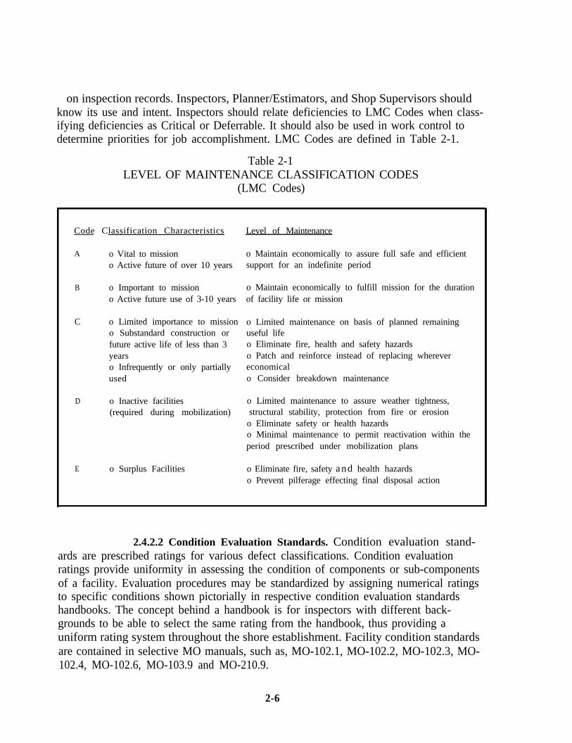
on inspection records. Inspectors, Planner/Estimators, and Shop Supervisors shouldknow its use and intent. Inspectors should relate deficiencies to LMC Codes when class-ifying deficiencies as Critical or Deferrable. It should also be used in work control todetermine priorities for job accomplishment. LMC Codes are defined in Table 2-1.
Table 2-1LEVEL OF MAINTENANCE CLASSIFICATION CODES
(LMC Codes)
Code Classification Characteristics Level of Maintenance
A o Vital to mission o Maintain economically to assure full safe and efficiento Active future of over 10 years support for an indefinite period
B o Important to mission o Maintain economically to fulfill mission for the durationo Active future use of 3-10 years of facility life or mission
C o Limited importance to mission o Limited maintenance on basis of planned remainingo Substandard construction or useful lifefuture active life of less than 3 o Eliminate fire, health and safety hazardsyears o Patch and reinforce instead of replacing wherevero Infrequently or only partially economicalused o Consider breakdown maintenance
D o Inactive facilities o Limited maintenance to assure weather tightness,(required during mobilization) structural stability, protection from fire or erosion
o Eliminate safety or health hazardso Minimal maintenance to permit reactivation within theperiod prescribed under mobilization plans
E o Surplus Facilities o Eliminate fire, safety and health hazardso Prevent pilferage effecting final disposal action
2.4.2.2 Condition Evaluation Standards. Condition evaluation stand-ards are prescribed ratings for various defect classifications. Condition evaluationratings provide uniformity in assessing the condition of components or sub-componentsof a facility. Evaluation procedures may be standardized by assigning numerical ratingsto specific conditions shown pictorially in respective condition evaluation standardshandbooks. The concept behind a handbook is for inspectors with different back-grounds to be able to select the same rating from the handbook, thus providing auniform rating system throughout the shore establishment. Facility condition standardsare contained in selective MO manuals, such as, MO-102.1, MO-102.2, MO-102.3, MO-102.4, MO-102.6, MO-103.9 and MO-210.9.
2-6
2.4.2.3 Regulatory Standards and Safety Codes. Inspectors andFacility Managers should be familiar with these standards and know how they apply.These include:
n National Building Codes:
• Corrosion
l Electrical
l Elevator
l Plumbing
l FRA Track Safety Standards
l OSHA Requirements
n Design Criteria (Applicable to repair):
l Design Manuals, NAVFAC DM Series and MIL-HDBKs
l Industrial or Association Standards
l Standard Engineering Texts and References
l Military Standards
l Type Specifications
n Environmental Regulations
2.4.3 Technical Sources. Sources of information include:
2.4.3.1 Manuals and New Technology. Inspectors should actively seekand be familiar with NAVFAC MO Manuals, especially in their craft areas, and with ap-plicable technical manuals, NCEL Tech Data Bulletins, inspection guides, andmanufacturer’s instructions. A complete list of NAVFAC Manuals and Publications isincluded in NAVFAC P-349, “NAVFAC Documentation Index.” Table 2-2 contains anexcerpt listing of manuals with which Control Inspectors need to be familiar. Indepthguidance for such topics as corrosion control, surfaced areas and roofing are a few ex-amples.
2.4.3.2 Technical Assistance. Inspectors should seek advice and assis-tance when needed or in doubt. Assistance is available from their supervisor, or En-gineering Field Division/Engineering Field Activity (EFD/EFA), Public Works Centersand NCEL via the EFD/EFA.
2.4.3.3 Engineered Performance Standards (EPS). Industrial stand-ards are rigidly defined for the exact performance of work throughout the productionprocess where the work place is constant and method of work performance is carefullyprepared. In maintenance, however, the same task may be performed at different times
2-7
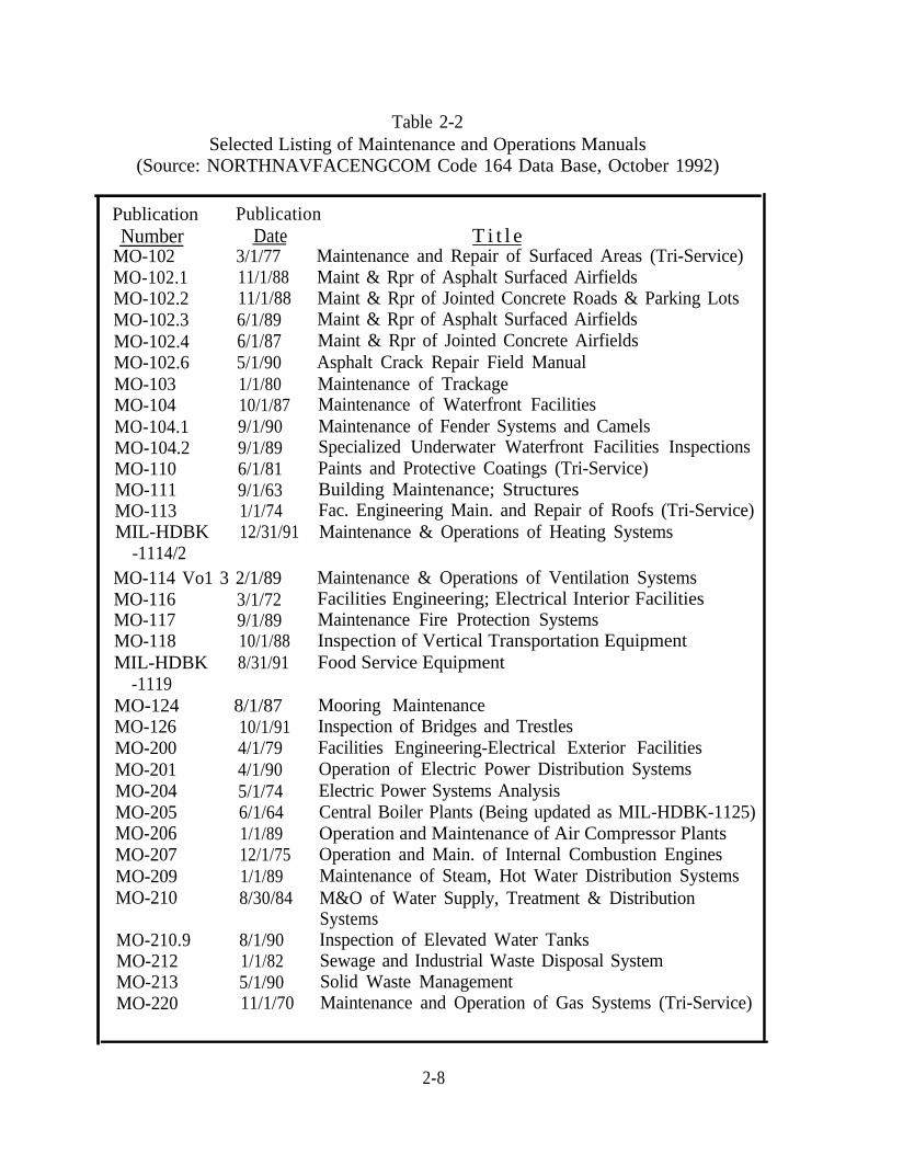
Table 2-2Selected Listing of Maintenance and Operations Manuals
(Source: NORTHNAVFACENGCOM Code 164 Data Base, October 1992)
Publication PublicationNumber Date T i t l e
MO-102 3/1/77 Maintenance and Repair of Surfaced Areas (Tri-Service)MO-102.1 11/1/88 Maint & Rpr of Asphalt Surfaced AirfieldsMO-102.2 11/1/88 Maint & Rpr of Jointed Concrete Roads & Parking LotsMO-102.3 6/1/89 Maint & Rpr of Asphalt Surfaced AirfieldsMO-102.4 6/1/87 Maint & Rpr of Jointed Concrete AirfieldsMO-102.6 5/1/90 Asphalt Crack Repair Field ManualMO-103 1/1/80 Maintenance of TrackageMO-104 10/1/87 Maintenance of Waterfront FacilitiesMO-104.1 9/1/90 Maintenance of Fender Systems and CamelsMO-104.2 9/1/89 Specialized Underwater Waterfront Facilities InspectionsMO-110 6/1/81 Paints and Protective Coatings (Tri-Service)MO-111 9/1/63 Building Maintenance; StructuresMO-113 1/1/74 Fac. Engineering Main. and Repair of Roofs (Tri-Service)MIL-HDBK 12/31/91 Maintenance & Operations of Heating Systems
-1114/2MO-114 Vo1 3 2/1/89 Maintenance & Operations of Ventilation SystemsMO-116 3/1/72 Facilities Engineering; Electrical Interior FacilitiesMO-117 9/1/89 Maintenance Fire Protection SystemsMO-118 10/1/88 Inspection of Vertical Transportation EquipmentMIL-HDBK 8/31/91 Food Service Equipment
-1119MO-124 8/1/87 Mooring MaintenanceMO-126 10/1/91 Inspection of Bridges and TrestlesMO-200 4/1/79 Facilities Engineering-Electrical Exterior FacilitiesMO-201 4/1/90 Operation of Electric Power Distribution SystemsMO-204 5/1/74 Electric Power Systems AnalysisMO-205 6/1/64 Central Boiler Plants (Being updated as MIL-HDBK-1125)MO-206 1/1/89 Operation and Maintenance of Air Compressor PlantsMO-207 12/1/75 Operation and Main. of Internal Combustion EnginesMO-209 1/1/89 Maintenance of Steam, Hot Water Distribution SystemsMO-210 8/30/84 M&O of Water Supply, Treatment & Distribution
SystemsMO-210.9 8/1/90 Inspection of Elevated Water TanksMO-212 1/1/82 Sewage and Industrial Waste Disposal SystemMO-213 5/1/90 Solid Waste ManagementMO-220 11/1/70 Maintenance and Operation of Gas Systems (Tri-Service)
2-8
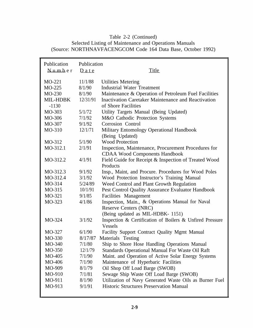
Table 2-2 (Continued)Selected Listing of Maintenance and Operations Manuals
(Source: NORTHNAVFACENGCOM Code 164 Data Base, October 1992)
Publication PublicationN u m b e r D a t e Title
MO-221 11/1/88 Utilities MeteringMO-225 8/1/90 Industrial Water TreatmentMO-230 8/1/90 Maintenance & Operation of Petroleum Fuel FacilitiesMIL-HDBK 12/31/91 Inactivation Caretaker Maintenance and Reactivation
-1130 of Shore FacilitiesMO-303 5/1/72 Utility Targets Manual (Being Updated)MO-306 7/1/92 M&O Cathodic Protection SystemsMO-307 9/1/92 Corrosion ControlMO-310 12/1/71 Military Entomology Operational Handbook
(Being Updated)MO-312 5/1/90 Wood ProtectionMO-312.1 2/1/91 Inspection, Maintenance, Procurement Procedures for
CDAA Wood Components HandbookMO-312.2 4/1/91 Field Guide for Receipt & Inspection of Treated Wood
ProductsMO-312.3 9/1/92 Insp., Maint, and Procure. Procedures for Wood PolesMO-312.4 3/1/92 Wood Protection Instructor’s Training ManualMO-314 5/24/89 Weed Control and Plant Growth RegulationMO-315 10/1/91 Pest Control Quality Assurance Evaluator HandbookMO-321 9/1/85 Facilities ManagementMO-323 4/1/86 Inspection, Main., & Operations Manual for Naval
Reserve Centers (NRC)
MO-324 3/1/92(Being updated as MIL-HDBK- 1151)Inspection & Certification of Boilers & Unfired PressureVessels
MO-327MO-330MO-340MO-350MO-405MO-406MO-909MO-910MO-911MO-913
6/1/90 Facility Support Contract Quality Mgmt Manual8/17/87 Materials Testing7/1/80 Ship to Shore Hose Handling Operations Manual12/1/79 Standards Operational Manual For Waste Oil Raft7/1/90 Maint. and Operation of Active Solar Energy Systems7/1/90 Maintenance of Hyperbaric Facilities8/1/79 Oil Shop Off Load Barge (SWOB)7/1/81 Sewage Ship Waste Off Load Barge (SWOB)8/1/90 Utilization of Navy Generated Waste Oils as Burner Fuel9/1/91 Historic Structures Preservation Manual
2-9
to obtain identical results, but rarely is the method of work performance identical in allrespects. Work sites, tools, materials and methods may vary between two performancesof the task. Engineered Performance Standards are developed by observing main-tenance personnel at work and by measuring their work through the application of ap-proved Industrial Engineering techniques. This provides the Planner and Estimator andshops with estimating standards that truly represent the specific type of work (main-tenance) to be done. Time standards for many maintenance and repair tasks are avail-able in the NAVFAC P-700 Manual (series), “Engineered Performance Standards.”These standards are also incorporated in the Facilities Engineering Job Estimating(FEJE) module of BEST. Application of EPS is facilitated by use of the BEST Auto-mation Tool.
2.5 FORMS AND RECORDS. Only forms needed to effectively manage the ShoreFacilities Inspection/Assessment System should be used. Records must permit ap-praisal of the planning and execution of the inspection effort; preparation of requiredreports; identification of future funding requirements; and maintenance of accurate his-torical data. Specific reports, forms and records are discussed in Chapter 4, Control In-spection Reports and Records and Chapter 5, Preventive MaintenanceInspection/Service (PMI) Procedures.
2.6 RELATED PROGRAMS AND AGREEMENTS. Specific agreements and programsare an important part of the Inspection/Assessment System. They are:
2.6.1 Maintenance Service Agreements (MSA). Formal agreements for recur-ring services on specific equipment and facilities. The scope of work must be defined ina written specification and the work quality and quantity specified in a contractual-likeagreement between the customer and Public Works. MSA’s are used primarily byPWC’s. MSA’s should be reviewed, renegotiated and updated annually. Basic elementsof the agreement are:
n Level of Maintenance. The level to which equipment or facilities are tobe maintained.
n Unplanned Corrective Maintenance. Provisions for a breakdown ormalfunction requiring unscheduled service.
n Planned Corrective Maintenance or PMI. A scheduled shutdown ofequipment for planned maintenance or cyclic checks, adjustments, andservice to keep equipment at a prescribed level of operating performance.
n Planner/Estimator Inspection. Provisions for on-site evaluation of workto finalize the job plan and estimate.
n Quality Assurance Evaluation (QAE). Ongoing evaluation of work (byshop supervision, and/or full-time Quality Control Technicians) to assessquality and quantity of work performed.
2-10
2.6.2 Intra/Inter-Services Support Agreements (ISSA). Formal Agreements toprovide support in a contractual-like manner by or between DOD components oranother federal agency/department. Intra denotes agreements between Navy com-ponents, Inter denotes external Navy sources. The content of ISSAs should address thesame basic elements as MSA, as a minimum.
2.6.3 Engineering Evaluation (EE) of Existing Assets. Engineering Evaluationis part of the Shore Facilities Planning System (SFPS) and is described in the “ShoreFacilities Planning Manual”, NAVFACINST 11010.44 (series). SFPS planners rely oninformation provided by on-site inspections, Control Inspection Reports, AIS, engineer-ing investigations, and other technical studies. To assure high quality Shore FacilitiesPlanning documentation, Planner/Estimators and/or Control Inspectors should be as-signed to assist EFD planners in on-site, visual inspections. Control Inspector back-grounds and experience provide invaluable assistance to planners by:
Identifying undocumented facility use/users.
Defining user and host-tenant relationships.
Indicating adequacy of facilities for current use.
Determining siting adequacy for current use based on safety criteria.
Evaluating suitability of facilities for other uses.
Assessing facility condition (functional and physical) and citing majordeficiencies.
2.6.4 Family Housing Programs. Family Housing inspections include:
Maintenance and Repair Inspection Program (MARIP). Its purpose is toidentify family housing maintenance and repair deficiencies. Programresponsibility lies with the EFD’s Housing Division. Direction isestablished in NAVFACINST 11101.94 (series).
Occupancy Inspection Program (OIP). The program includes four vitalinspections: make-ready, check-in, pre-termination, and termination.They identify Command and occupant responsibilities, determinecondition of quarters, initiate good occupant relations, orient and instructthe occupant on equipment operation, and ensure occupants understand
2-11
procedures for obtaining Emergency/Service. This program is discussedin the Navy Family Housing Manual, NAVFAC P-930.
2-12
CHAPTER 3. CONTROL INSPECTION PROCEDURES
3.1 PURPOSE. The purpose of ControlInspection is to conduct a complete visualinspection of all facility components, itemsand systems to determine physical condi-tion. The inspector shall address the needfor repair, replacement versus repair ofselected items, or replacement in total.The Inspector’s Report is the single mostimportant document in the process and isthe inspectors “only” product. The inspec-tor is the direct link between the facility’shealth and the funding process. The In-spection Report must answer:
n What is wrong (description& scope)?
n Where is the problem(location)?
How big is the problem(quantity)?
n How to correct the problem (solution)?
n How much does it cost to fix ($)?
n Who should fix it (craft/contract)?
When should it be fixed (priority)?
3.2 OBJECTIVES. Control Inspection is a scheduled facility inspection designed to:
n Provide a thorough examination of each facility and its components andmake uniform assessment of condition.
Appraise the adequacy of Operator and Preventive MaintenanceInspections.
n Assure adequate, consistent levels of maintenance by detecting over orunder maintenance.
n Minimize system breakdowns and repair costs.
n Regulate the input of work for PW shops or contract.
n Provide AIS/BASEREP reporting data.
3-1
n Identify facility maintenance and repair resource requirements andprovide a basis for developing a meaningful, executable resource plan.
3.3 INSPECTOR QUALIFICATIONS. Inspectors should have a technical trade back-ground in electrical, mechanical or structural disciplines. Formal education in theory isdesirable. They should have the ability to write clear, concise, detailed descriptivereports of facility condition. They need to be experienced in maintenance and repairoperations and skilled in inspection techniques, planning and estimating, maintenancestandards, safety, health and building codes. It is usually cost effective for inspectors atsmall activities to possess a craftsman rate in one discipline with experience and/orknowledge of the others. Working knowledge may be obtained from on-site training,EFD/EFA or PWC training, correspondence courses, or instruction from schools or in-dustrial facilities. A basic understanding of micro computers and the ability to becomeproficient in their use is recommended. Training and experience requirements are con-tained in Office of Personnel Management Standards. Basic Control Inspection Pro-gram Training can be attained by completing two-phased training offered byEFDs/EFAs: Phase 1 (Control Inspector Training) and NTTC-160 Correspondencecourse (Phase II) available from NAVFAC Code 161,8530 La Mesa Boulevard, LaMesa, CA 92041. Control Inspection can be performed by engineers, Inspection Branchor contractor personnel.
3.4 SCHEDULING CONTROL INSPECTIONS. Control Inspection workload shouldbe balanced with available capability and scheduled annually. This provides the most ef-fective method of identifying and processing deficiencies. Facility inspection schedulingdocumentation should be administered and maintained by the Work GenerationBranch. Where PWMA/BEST is installed, the Shore Facilities Inspection (SFI)module can perform this function (see Chapter 8).
3.4.1 Frequencies. Recommended Control Inspection frequencies are con-tained in Appendix B. Available resources may not permit inspecting at this frequency;however, the frequencies in Appendix B have been established by CNO as a baseline forconsistent reporting purposes and as a desirable Navy goal. Activity Inspection frequen-cies must, however, be based on available resources, facility mission, experience and en-gineering judgment.
3.4.2 Scheduling Considerations. When developing inspection schedules, cer-tain variables to consider are:
n Activity resources available for Control Inspection.
n Time for each discipline to inspect a facility (See Section 3.4.3).
n Team size. When possible, Inspection teams should be formed. Teamsoffer complementary experience and training, provide safety backup andmaximize transportation utilization. This permits technical discussions
3-2
for problem resolution and insures the presence of another person duringthe inspection of attics, crawl spaces, roofs and fire escapes. Facilitiesrequiring only a single discipline can be used to smooth resource “peaks”and “valleys” in the scheduling process.
n Climatic conditions (rainy season, severe winters, dry season, stormseason, and tides) impact planned scheduling. Extra inspections may benecessary after storms.
n Special requirements such as special equipment, tools, security clearance,etc.
n Inadequate Inspection Resources. If all facilities cannot be inspected atthe CNO recommended frequency (Appendix B), an alternative plan isneeded. One alternative is to use the LMC as the basis for scheduling bygrouping facilities into 3 categories: Group 1 containing LMC “A”, Group2 containing LMC “B”, and Group 3 containing LMC “C”, “D” and “E”, i.e.,mission essential, mission support and non-mission related. Dependingon resources available, inspect all Group 1, 1/2 of Group 2 and 1/3 of theGroup 3 facilities each year. Note - AIS facility inspection status muststill be reported based on CNO baseline standards (Appendix B) and notalternative frequencies.
n Overtime.
Utilizing an A&E contractor or PWC to inspect all or selected facilities.
n Augmenting the Inspection force with qualified shop personnel on atemporary basis.
A key to successful scheduling execution is to send a memo to the Facility occupant ad-vising of the scheduled inspection and requesting their input prior to the actual visit.The memo may contain space for feedback of their problems and experiences foranalysis beforehand.
3.4.3 Control Inspection Times. Inspection time is the amount of time normallyrequired to examine the facility with appropriate tools or equipment. Appendix Cprovides inspection time guides to help prepare initial schedules. Time must be addedto make sketches, report writing, cost estimating, travel and delay time. It is importantto give inspectors adequate time to make careful inspections. Intangible factors thatmay affect inspection time allocation are: inspector undergoing on-the-job training,scope of deficiencies, age of facility, type of construction, and site conditions. Initial in-spections will generally require more time because the size and scope of deficienciesfound are usually greater. Recording actual inspection time is critical to the success offuture schedule development. Time spent on inspection preparation, on-site inspection,travel and report writing should be recorded separately. After a series of inspections
3-3
has been made, better time values are available for adjusting schedules. Activities usingPWMA/BEST may use the SFI module to generate and refine inspection times.
3.5 PREPARING TO INSPECT Prior to on-site inspection the inspector shouldanalyze work control files including E/S files to determine if major deficiencies exist orare developing. The status of work planned or in progress should be considered and ad-dressed in the Inspection Report. Work on the current shop load plan should be in-cluded on the Inspection Report and noted that Job Order “X” will correct a specificdeficiency. New deficiencies with a significant impact on currently planned orauthorized work should be noted on the Inspection Report and brought tomanagement’s attention. This allows management to modify job orders thus reducingor preventing costly delays during work accomplishment. Jobs on the Shop Load Planshould be modified to include correction of appropriate newly discovered deficiencies,if prudent. Review of E/S work can reveal potential problems or highlight intermittent,cyclic or seasonal occurrences. Additional items that should be included on the inspec-tion planning and preparation checklist are to:
n Be familiar with Activity’s Master Plan for Facility use and generaldevelopment.
n Obtain facility floor plans.
n Obtain listings, status and appropriate documentation for major alterationand maintenance projects.
n Determine craft codes and labor rates.
n Determine maintenance cycles with respect to painting schedules,long-range maintenance plans, etc.
n Obtain a list of pertinent contracts and warranties.
n Obtain lists of building tenants and maintenance persons.
Establish Facility priority (LMC).
n Arrange security clearance for the inspection.
n Determine special safety precautions that must be observed:radioactivity, asbestos, confined spaces air sampling, hard hat/safetyglasses/safety shoe requirements, weak roof areas, inspector physicalexams, etc.
n Resolve any interference with other inspections or audits scheduled foraccomplishment: energy audit, asbestos, roofs, security or fire protection.
n Determine special tool and test equipment requirements, and define thedepth of diagnostics intended during the conduct of the inspection.
n Notify the building manager/user of the planned inspection and requestpreliminary user feedback of known trouble areas.
3-4
3.6 ADDITIONAL DUTIES OF MECHANICAL AND ELECTRICAL INSPECTORS.Mechanical and Electrical Control Inspectors must monitor PMI program effectivenessand recommend changes where needed. To do this, they must be familiar with thescope and frequencies of Preventive Maintenance Inspections. Inspectors should alsobe involved in review of PMI feedback reports and E/S analysis. There is seldom needfor structural PMI.
3.7 CORRECTING NON-DEFERRABLE (CRITICAL) AND DEFERRABLEDEFICIENCIES. A deficiency is considered to be Critical if: (1) it must be correctedwithin 12 months and (2) it will impact mission, affects quality of life or has safety or en-vironmental hazard potential. Deficiencies not meeting these two (2) criteria (time andtype) are Deferrable. A critical deficiency that has existed for more than four (4) years isto be classified as deferrable. Processing and programming deficiencies for correction isa Work Generation Branch function within the FME Division. This requires FMEDivision Management to ensure that:
n The deficiency scope and year of correction be defined.
n The deficiency be included in a maintenance action plan. If it is SpecialProject scope, it should be submitted to the major claimant forprogramming or in the case of NIF activities, approved for inclusion inthe NIF overhead budget for recapture.
NOTE: Activities utilizing the PWMA/BEST Work Input Control (WIC) module cantrack deficiencies from inception to Facility history files.
3.8 CONTRACTOR ASSISTANCE. An activity may determine that contractor assis-tance is required for Control Inspections. They can examine facilities/systems to deter-mine physical condition and provide reports identifying deficiencies and estimatedcosts. In addition, they can develop Step I Special Project documentation for deficien-cies exceeding the Commanding Officer’s funding authority. Input of deficiency data(as job packages) into the activity’s ADP system can also be made part of thecontractor’s responsibility.
Assistance in obtaining contractor support is available by submitting an Engineering Ser-vices Request (ESR) to the EFD/EFA, The EFD/EFA will prepare an Engineering Ser-vices contract for award to a qualified A-E firm. Pre-negotiation and on-site "kickoff"meetings with EFD/EFA, activity, and contractor personnel is an essential step. Theyensure all parties understand contract requirements and quality of expected products.To help ensure a successful product, activity involvement throughout the contract is es-sential. Initially, the activity should provide the contractor with facilities and locationmaps, units of measure, Facility History Files, drawings, and Service Call history. Theactivity should randomly conduct comparison inspections to ensure “product satisfac-tion.” Specification packages are available from NAVFAC EFDs/EFAs to assure a
3-5
quality product is received and the contract is properly administered.
There are advantages and disadvantages to contractor inspections. Advantages include:
n Obtaining a one-time comprehensive inspection to supplement in-houseeffort.
n A more liberal approach and identification of long-range Special Projectscope repairs.
n Obtaining an outsider’s view of facility conditions and incorporation ofrepair by replacement philosophy vice the potential for a “scrape, patchand paint” approach.
Disadvantages include:
n Lengthy contract processing time.
n Assigning work tasks to administer and monitor the contract.
n Dependency on contractor inspections for AIS data.
n Abandoning the Control Inspection Program as a means to generate workon a continuous basis for shop/contract accomplishment.
n Loss of corporate facility knowledge and familiarity.
n Public Works/Customer relationships may suffer as a result of lessfrequent interface.
The volume of one-time inspection data is often overwhelming causingthe product to not be properly used.
n Delegation of responsibility for classifying deficiencies as Critical orDeferrable to the contractor.
n The expense of contractor assistance is normally three to five timesin-house cost.
n Difficulty of monitoring thoroughness of crawl space and attic inspections.
An alternative to total contract inspection is contract inspection of selected facilitieswith remaining inspections done in-house. This enables the activity to select mission es-sential and/or facilities which are difficult to inspect for contract inspection thus ensur-ing comprehensive coverage overall. Examples might be: infra-red inspection ofelectrical panels; infra-red roof inspection by aircraft.
Contract inspection should be viewed as an alternative only if there is insufficient in-house inspection personnel or expertise is limited in certain areas.
3-6
CHAPTER 4. CONTROL INSPECTION REPORTS AND RECORDS
4.1 REPORT DESCRIPTIONS. The Control Inspec-tion Report Package consists of: A “Facility Condi-tion Summary Report” and a “Facility ConditionReport Detailed Deficiency List.” The Report pack-age enables Inspectors to systematically reportdeficiencies, urgency, and provide preliminary laborhour and material estimates by trade. The Reportidentifies “packages of work” that can be planned, es-timated, and programmed into a work control systemas a single undertaking. It can also be used to pro-vide budget-oriented resource requirements data andis the basis for the Annual Inspection Summary (AIS)and BASEREP assessment. Priorities assigned by In-spectors highlight urgent items requiring immediatecorrection differentiating from long-range requirements for maintenance planning pur-poses. A “Facility Inspection Checklist” may also be added to the Report package toreflect facility components examined and not examined during the Inspection. Figures4-1, 4-2 and 4-3 portray the CI Report package documents and format.
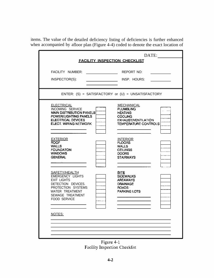
4.1.1 Facility Inspection Checklist. The cover sheet of the completed Inspec-tion Report package may be a “Facility Inspection Checklist,” Appendix D. It tellsmanagement at a glance what facility components were inspected (structurally, electri-cally, mechanically) and if it received a roof inspection. It lists items to be inspected. Itsuse ensures all major items in a facility are considered by the Inspector and provides asummary of what was inspected. Figure 4-1 portrays a typical checklist.
4.1.2 Facility Condition Summary Report Sheet. The “Facility Condition Sum-mary Report,” Figure 4-2, provides a summary of labor hours and cost by craft andmaterial or contract necessary to restore the facility to an acceptable condition.Management can quickly view craft areas involved for workload programming and costof restoration for budget and operating plan purposes.
4.1.3 Facility Condition Report Detailed Deficiency List. The “Facility Condi-tion Report Detailed Deficiency List,” Figure 4-3, provides information necessary forday-to-day management, i.e., what is wrong, cost of correction and urgency. Manage-ment should immediately evaluate each item checked “Immediate” or in the “One-Year”columns and plan or initiate corrective action. Deficiencies remaining unfunded on 30September comprise the activity’s Critical Maintenance and Repair backlog on the AIS.Deficiencies checked in the “Two Years and Beyond” column provide a relative degreeof urgency and are included on the AIS backlog as Deferrable Maintenance and Repair
4-1
items. The value of the detailed deficiency listing of deficiencies is further enhancedwhen accompanied by afloor plan (Figure 4-4) coded to denote the exact location of
DATE:FACILITY INSPECTION CHECKLIST
FACILITY NUMBER:
INSPECTOR(S):
REPORT NO:
INSP. HOURS:
ENTER: (S) = SATISFACTORY or (U) = UNSATISFACTORY
ELECTRICAL MECHANICALINCOMING SERVICE
EXTERIOR INTERIOR
SAFETY/HEALTHEMERGENCY LIGHTSEXIT LIGHTSDETECTION DEVICES.PROTECTION SYSTEMSWATER TREATMENTSEWAGE TREATMENTFOOD SERVICE
NOTES:
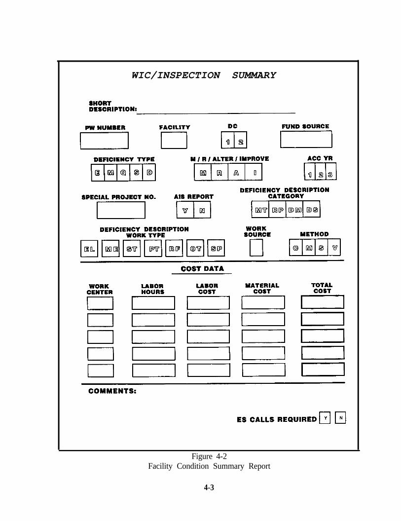
WIC/INSPECTION SUMMARY
Figure 4-2Facility Condition Summary Report
4-3
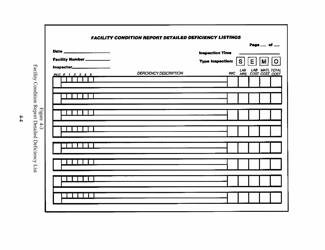
Figure 4-3Facility C
ondition Report D
etailed Deficiency L
ist
4-4
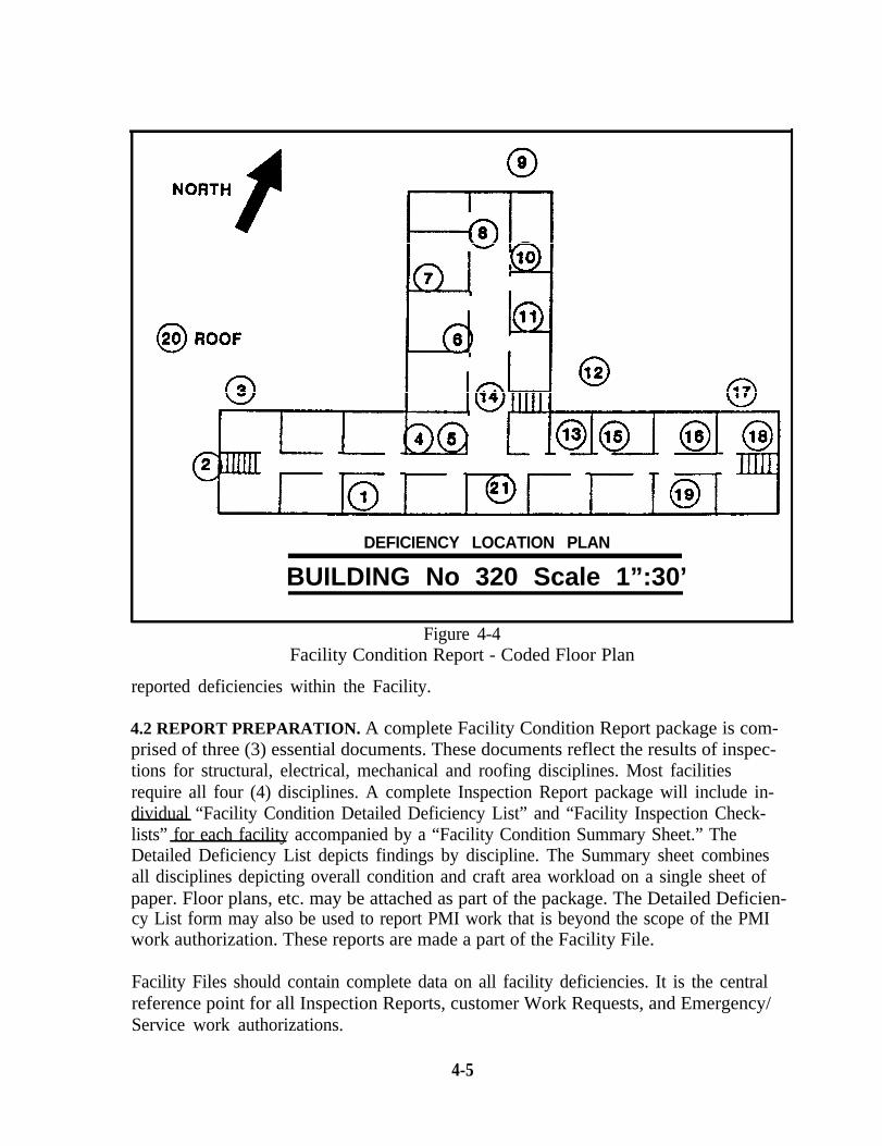
DEFICIENCY LOCATION PLAN
BUILDING No 320 Scale 1”:30’
Figure 4-4Facility Condition Report - Coded Floor Plan
reported deficiencies within the Facility.
4.2 REPORT PREPARATION. A complete Facility Condition Report package is com-prised of three (3) essential documents. These documents reflect the results of inspec-tions for structural, electrical, mechanical and roofing disciplines. Most facilitiesrequire all four (4) disciplines. A complete Inspection Report package will include in-dividual “Facility Condition Detailed Deficiency List” and “Facility Inspection Check-lists” for each facility accompanied by a “Facility Condition Summary Sheet.” TheDetailed Deficiency List depicts findings by discipline. The Summary sheet combinesall disciplines depicting overall condition and craft area workload on a single sheet ofpaper. Floor plans, etc. may be attached as part of the package. The Detailed Deficien-cy List form may also be used to report PMI work that is beyond the scope of the PMIwork authorization. These reports are made a part of the Facility File.
Facility Files should contain complete data on all facility deficiencies. It is the centralreference point for all Inspection Reports, customer Work Requests, and Emergency/Service work authorizations.
4-5
4.2.1 Preparation of “Detailed Deficiency List”. The Inspection Report is thekey to the Shore Facilities Inspection/Assessment System. Incomplete, inaccuratereports result in confusion, extra paper work, avoidable cost, and may endanger life andproperty. Inspectors should be instructed in inspection report preparation. Inspectorsshould describe deficiencies on the “Detailed Deficiency List” (Figure 4-3). Attempt torecord the true cause of a problem. A separate sketch may describe work more clearlyand be attached as a supplement. Inspectors should concisely describe each deficiencyand recommend corrective action. Inspectors shall designate each deficiency as Defer-rable or Critical using guidelines in OPNAVINST 11010.34. They should prepare apreliminary cost estimate (labor and material or contract costs) to correct each deficien-cy (see paragraph 4.2.4). Although Control Inspectors generally do not make adjust-ments to equipment, it is permissible at small activities if Inspectors are qualified andauthorized. The report should contain enough detail to enable a job order to be writtenwithout revisiting the job site. Inspectors should ask these questions before releasingthe report: (1) Could a final estimate for labor and material costs be made from mydescription? (2) Is there enough information for FMED personnel to make intelligentdecisions concerning priorities and funding? (3) Could the deficiency be corrected fromthe information on my report? The report form is designed for deficiencies of SpecificWork scope; however, Emergency/Service and Minor Work deficiencies can also berecorded and processed. Inspection reports will reflect three types of findings:
New finds. Original, first time deficiencies not previously documented.
n Known deficiencies. A known problem that has not been corrected.The cost estimate and scope of work may require revision because ofdeterioration (or partial correction of the problem).
No deficiency finds. This should be recorded and kept on file.
4.2.1.1 Report Accuracy. Thorough reporting is important. Inspectorssometimes ask: “Why keep reporting the same deficiencies? They never get corrected.”There will never be resources to correct everything so deficiencies will continue to exist.In fact, they will get worse due to deterioration and Deferrable deficiencies will, even-tually, become Critical. Thorough reporting is essential, especially during austere times,because:
l Scope and cost requirements must be updated. This is needed inthe budget process. It provides justification for the current level offunding and is the only hope for increasing funding.
l Routine updating and comparative analysis permits an accurateannual facility condition assessment. This is also a factorconsidered in higher level resource decisions.
l Complete reporting enables management to intelligently prioritizeall work, giving consideration to deficiencies which migrate fromDeferrable to Critical.
4-6
l It provides information for a continuing review of workload withrespect to in-house/contract decisions.
l Updating of scope and costs for Special Projects helps the claimantreevaluate project priorities.
As a minimum, each deficiency reported should:
l Reflect a correction action verb - repair, replace, prepare, etc.
l Define the problem - leaking valve, broken switch plate.
l Location - exact - Bldg. E, Room 307, South wall.
l Quantify costs - + 25% accuracy for budget and planning purposes.
l Be noted on a floor plan - shops must be able to easily locate.
4.2.2 Work Packaging. Work identified by inspection is used for AIS, budget,contract and shop loading decisions. It can fill these roles best, however, when it can beviewed in the way it will eventually be authorized for accomplishment. Work packagingis a technique that “packages” deficiencies together the way it makes sense to do the job.This should be done by the inspector at the time of report preparation. The inspectorshould ask which deficiencies should logically be worked together as a single undertak-ing and then group those items on the Inspection Report. The letters A, B, C, etc. onthe left side of the Inspection Report can denote items that can be worked together.Note the blocks on Figure 4-3. The package should then be assigned a Work Request(P.W.) number and entered in the Work Control Program or Work Input Control(WIC) module. A breakdown by Work Center should be shown in the Work CenterSummary Section of WIC. Summarization into packages can reduce the number ofentries in a manual or automated system by 40-60 percent. This technique is illustratedin Appendix E. This appendix also provides a sample input for a Public Works Manage-ment Automation (PWMA), BEST, WIC Module data entry.
4.2.3 Inspection Report Numbering. Each Detailed Deficiency List or Workpackage should be numbered. The number should be shown on all Job Orders correct-ing a deficiency. One system consisting of four components which can be used for In-spection Report Numbering is:
Bldg. No. Month Year(last digit)
Discipline(M,E,S,R)
Example: Bldg. 320; Mechanical Inspection for the facility conducted in Aprilof 1992.
4-7
Detailed Deficiency List number: 320-4-2-MSummary Sheet and Checklist number: 320-4-2
4.2.4 Deficiency Cost Estimates. Inspectors will prepare only preliminary costestimates. NAVFAC P-716, “Unit Price Standards” (UPS), MEANS, RichardsonDodge, etc. are recommended as useful tools. Estimates should show labor andmaterial by craft regardless of whether the work will be done in-house or by contract.Final estimates with material take offs may be generated for deficiencies designated ascritical only if they will be funded and worked within 12 months. Inspectors should notrecommend the method of work accomplishment, e.g., PWD or contract forces (unlessobvious). Costs may be adjusted if a decision to contract is made. Cost data must beprovided for all deficiencies. If information is incorrect or missing, reports generatedfrom deficiency data will not be accurate.
4.2.5 Special Projects Program. Special projects are work which is beyond theCommanding Officer’s approval authority. OPNAVINST 11010.20 series providesguidance. Control Inspectors should be the primary source of input for the SpecialProjects Program. If a Special Project requirement is identified, inspectors should:
Prepare a scoping estimate (see paragraph 4.2.4).
n Annotate the item as a potential Special Project to alert management.
n Forward the Inspection Report to Engineering/Planning via the FMEDfor evaluation and preparation of project documentation.
It is critical that Engineering personnel perform an on-site validation of the SpecialProjects technical requirement, scope, cost and ensure inclusion of all major relatedwork required for that facility. This validation process prevents overloading shops withproject scope work, permits economies of construction and causes minimum disruptionto facility occupants. Phased projects should be considered if the total cost is too highfor funding in a single year or if operational constraints prohibit single year funding.Total project requirement (scope) should be identified to the claimant with phasedwork accomplished by several contracts. Activities should take full advantage ofclaimant funding to correct major deficiencies that would deplete activity resources. Toenable proper claimant programming, Special Projects should be prepared and sub-mitted throughout the year as inspections are completed and requirements identified.
4.2.6 Inspection Report Use. The inspection and subsequent report are a wasteof resources if management fails to use the product to effectively manage facilities. Thenumber of ways the product can be used is limited only by the imagination and initiativeof management. In addition to the routine uses as a shop/contract loading, budget andAIS tool there are other “spin-offs” of data that can assist the manager in decisionmaking. A few examples are craft summaries (staffing); backlog reduction plans;
4-8
Facility Condition Index by facility, cost account or investment category; priority listingby facility, customer, etc; type deficiency (roofing/paint) listing; condition assessment byfacility age; etc. The FMED Director, or designee, shall review, coordinate and processall Inspection Reports. If funding is not available, deficiencies should be placed in back-log as a valid critical or deferrable requirement. If it is more important than a plannedand funded job, it should be processed and the less important item relegated to backlogstatus. A Control Inspection Report flow is shown in Figure 4-5.
4.3 TYPES OF RECORDS. An effective inspection records system, whether manualor automated, consists of:
4.3.1 Facility History Files. A current Inspection Report should be on file foreach facility. The Facility History Files should include copies of work in process andcompleted work. Accurate facility history is critical to the decision making process in-volving economics of repair, repair versus replacement, effectiveness of maintenancemethods, techniques, etc. Figure 4-6 shows an example of Historical Records for built-up and asphalt-shingled roofs. Other examples may be found in literature from tradegroups or other NAVFAC MO Manuals. Accurate Historical Records are also the bestmeans of gathering data to arrive at a meaningful evaluation of completed jobs to deter-mine methods of improvement or cost reduction on future jobs. These records shouldbe used to:
Determine product effectiveness under varying environments or ondifferent surfaces.
n Compare different products under similar conditions.
n Compare different equipment for product application.
n Determine labor efficiency under varying conditions.
n Judge better (or lower) quality products on planned jobs.
n Better determine frequency of application of a product.
The proper use of Historical Records replaces guesswork with purposeful direction andplanning. Goals can be established realistically and with confidence based on recordedexperience. The ultimate result is a refined maintenance program which provides aneconomical and efficient means of prolonging facility life and protecting investments.
4.3.1.1 Warranty Program. This program is vital to a cost conscious or-ganization, especially one under a Station Operations and Maintenance Contract. It iseasy to have work covered by warranty erroneously accomplished by another means.This is minimized if warranties are recorded and work monitored and tracked to avoidin-house accomplishment. The success of this program is directly related to feedbackfrom Contract Surveillance personnel (for a contract operation). It also helps manage-
4-9
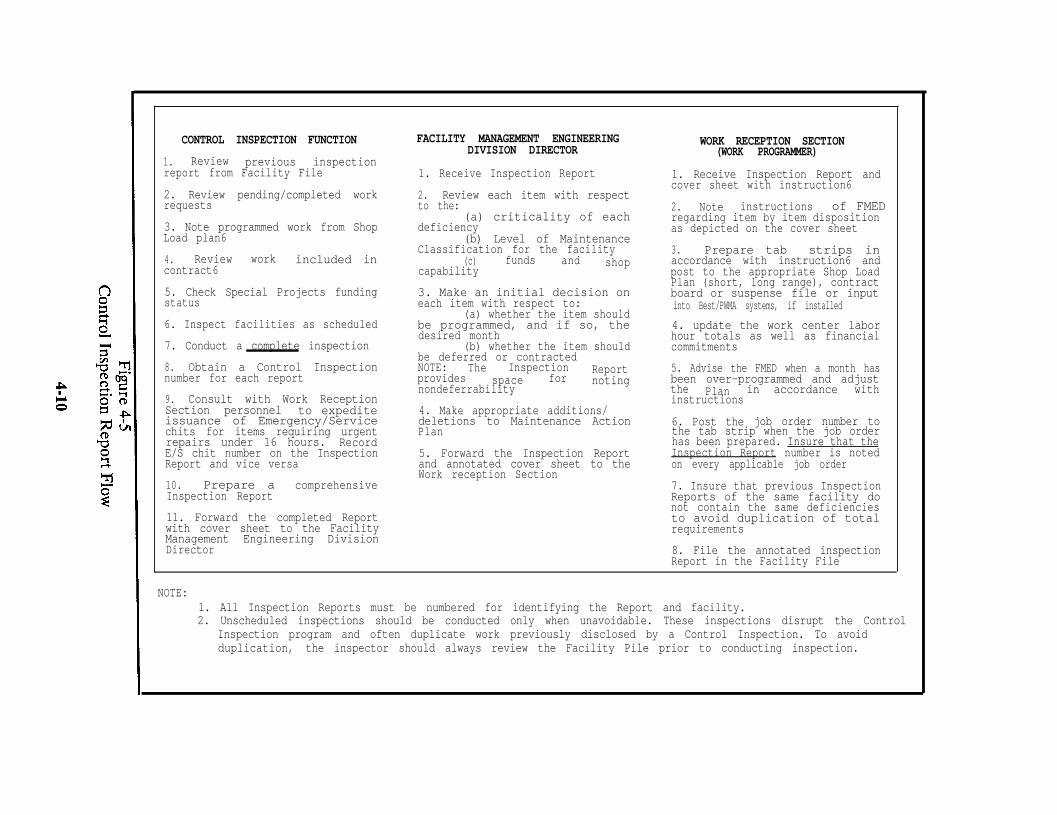
CONTROL INSPECTION FUNCTION
1. Review previous inspectionreport from Facility File
2. Review pending/completed workrequests
3. Note programmed work from ShopLoad plan6
4. Review work included incontract6
5. Check Special Projects fundingstatus
6. Inspect facilities as scheduled
7. Conduct a complete inspection
8. Obtain a Control Inspectionnumber for each report
9. Consult with Work ReceptionSection personnel to expediteissuance of Emergency/Servicechits for items requiring urgentrepairs under 16 hours. RecordE/S chit number on the InspectionReport and vice versa
10. Prepare aInspection Report
comprehensive
11. Forward the completed Reportwith cover sheet to the FacilityManagement Engineering DivisionDirector
FACILITY MANAGEMENT ENGINEERINGDIVISION DIRECTOR
1. Receive Inspection Report
2. Review each item with respectto the:
(a) criticality of eachdeficiency
(b) Level of MaintenanceClassification for the facility
(c) funds andcapability
shop
3. Make an initial decision oneach item with respect to:
(a) whether the item shouldbe programmed, and if so, thedesired month
(b) whether the item shouldbe deferred or contractedNOTE: The Inspectionprovides
Reportspace for
nondeferrabilitynoting
4. Make appropriate additions/deletions to Maintenance ActionPlan
5. Forward the Inspection Reportand annotated cover sheet to theWork reception Section
WORK RECEPTION SECTION(WORK PROGRAMMER)
1. Receive Inspection Report andcover sheet with instruction6
2. Note instructions of FMEDregarding item by item dispositionas depicted on the cover sheet
3. Prepare tab strips inaccordance with instruction6 andpost to the appropriate Shop LoadPlan (short, long range), contractboard or suspense file or inputinto Best/PWMA systems, if installed
4. update the work center laborhour totals as well as financialcommitments
5. Advise the FMED when a month hasbeen over-programmed and adjustthe Plan in accordance withinstructions
6. Post the job order number tothe tab strip when the job orderhas been prepared. Insure that theInspection Report number is notedon every applicable job order
7. Insure that previous InspectionReports of the same facility donot contain the same deficienciesto avoid duplication of totalrequirements
8. File the annotated inspectionReport in the Facility File
NOTE:1. All Inspection Reports must be numbered for identifying the Report and facility.2. Unscheduled inspections should be conducted only when unavoidable. These inspections disrupt the Control
Inspection program and often duplicate work previously disclosed by a Control Inspection. To avoidduplication, the inspector should always review the Facility Pile prior to conducting inspection.
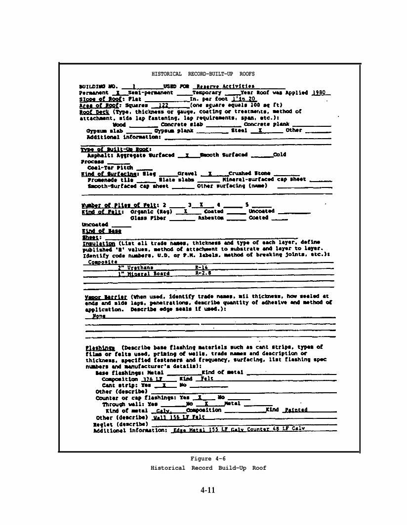
HISTORICAL RECORD-BUILT-UP ROOFS
Figure 4-6
Historical Record Build-Up Roof
4-11
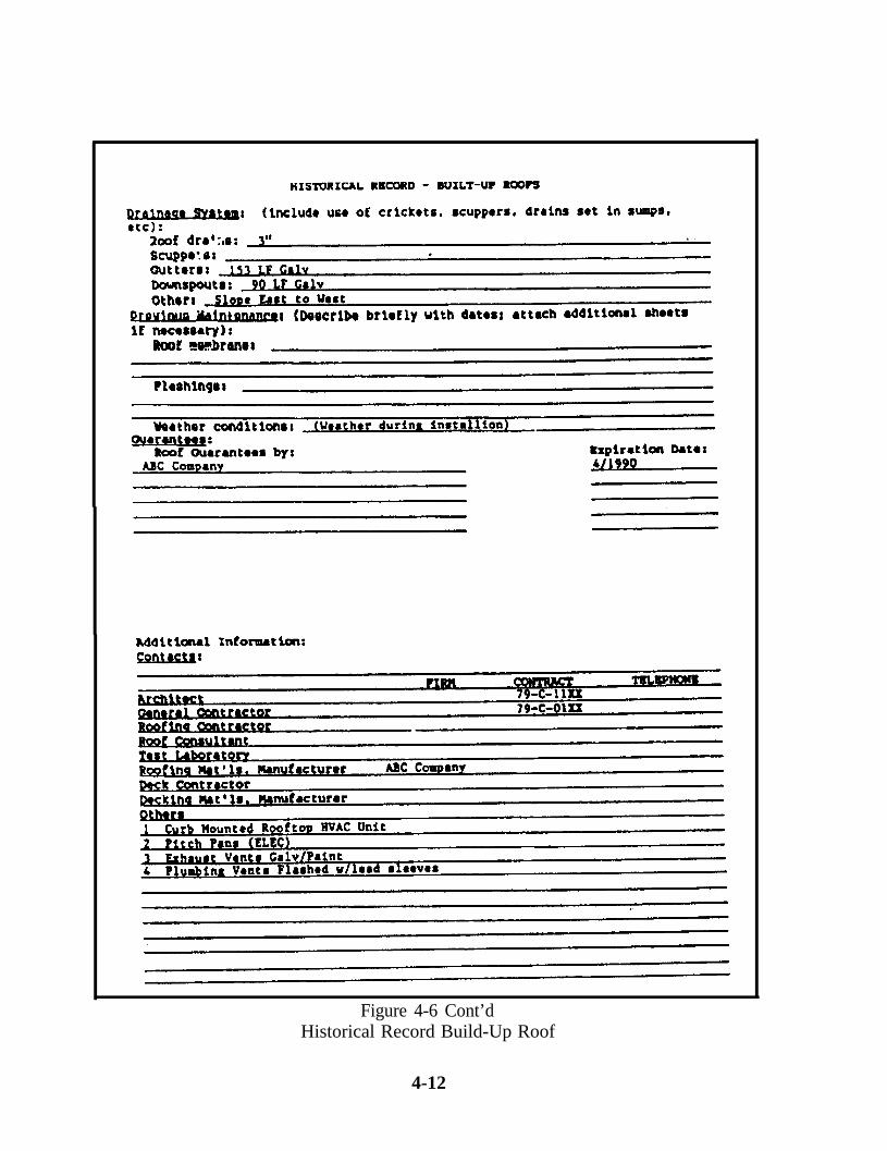
Figure 4-6 Cont’dHistorical Record Build-Up Roof
4-12
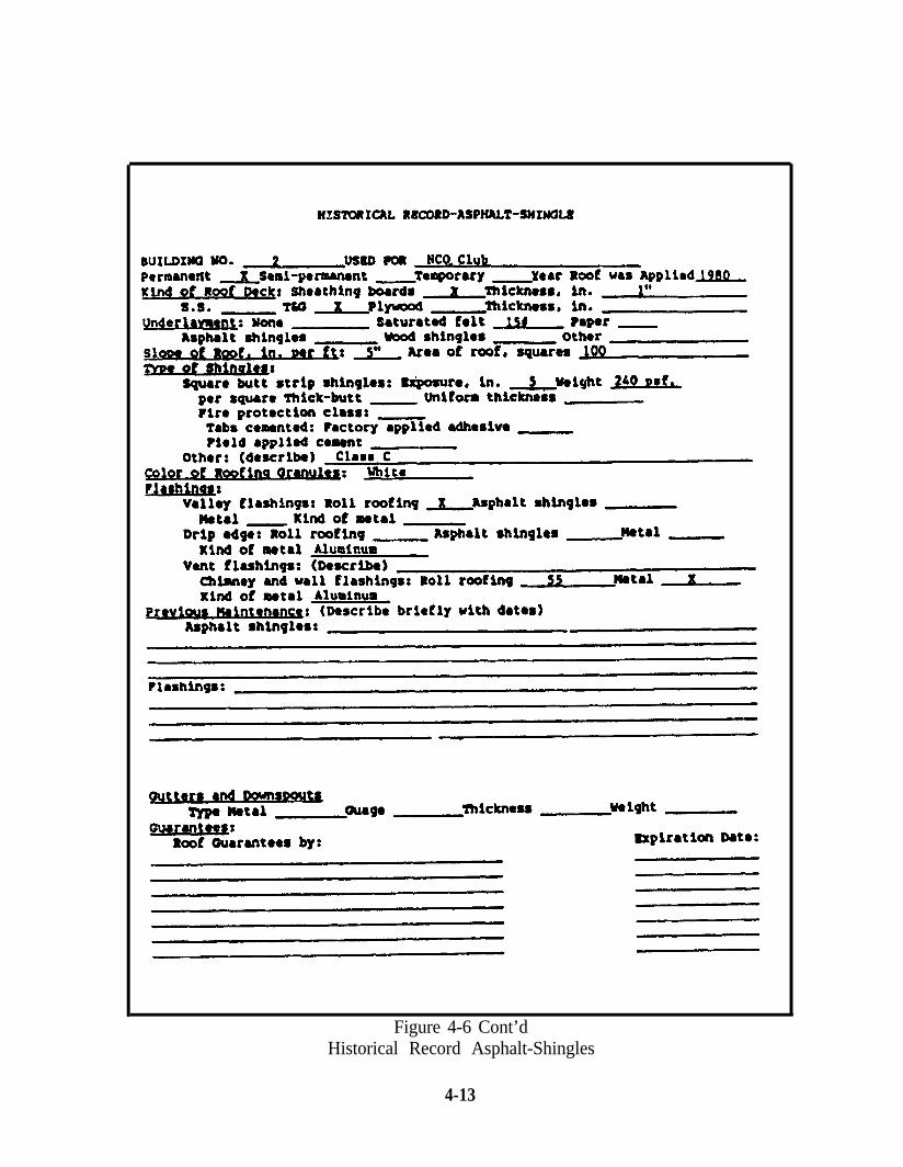
Figure 4-6 Cont’dHistorical Record Asphalt-Shingles
4-13
ment to establish life cycle data for replacement equipment and predict future replace-ment. Automation is recommended to track warranty information.
4.3.2 Cyclic Maintenance Planning Files. Programmed Maintenance in theareas of roofing, painting, flooring, overhauls, is recommended. As an illustration, a fiveyear cycle for exterior painting would mean that 1/5th of the total exterior area should bepainted each year. Individual structures are identified as they require painting and areprioritized on the applicable Maintenance Action Plan (see paragraph 4.5).
4.3.3 Completed Job Order Files. Completed Work Authorizations are filed intwo ways: (1) in sequence of issue by number by year of issue in the Completed JobOrder File, and (2) in sequence of issue by facility or Property Record Card Number inthe Facility File.
4.3.4 Completed E/S Work Files. Completed E/S work authorizations are alsofiled in two ways: (1) in sequence by number by year of issue and (2) in sequence byfacility or Property Record Card Number. Files should be purged at least annually afteranalysis and extraction of data to assist in decisions made concerning equipment/facilitycomponent replacement, vandalism problems, etc. Automated E/S operations can bepurged to history for longer term retention. Extracts of annual E/S effort by type workby Facility is recommended for inclusion in the Facility File.
4-14
4.4 MANAGEMENT REVIEW AND APPRAISAL, See Chapter 1 Paragraph 1.5.1.9 fordiscussion of Facilities Management Program appraisal responsibilities. With respect tothe Control Inspection process, the FMED should be concerned with whether inspec-tions are conducted as planned; if inspections are thorough and accurate; if recommen-dations are technically sound; and if cost estimates are accurate within acceptable limits.The FMED should conduct random follow-up inspections to verify effectiveness. Costeffectiveness can be compared to the actual cost of correcting comparable items.
4.5 FACILITY MAINTENANCE PLANNING. Congressional interest in the use ofMaintenance of Real Property (MRP) funds, especially the portion used to reduce main-tenance and repair backlog reported on the AIS, established the need to develop aMaintenance Action Plan (MAP) comprised of AIS items to be accomplished withMaintenance and Repair (M&R) funds. The MAP is the activity’s plan for spendingMRP funds available for Minor and Specific work (LCC 06 and 07). This generally ap-proximates 30% + 5% of M&R funding available. NAVFAC MO-321 providesclarification of Labor Class Codes. The MAP is a list of individual line items selectedfrom the latest AIS (Code 1 deficiencies) which are the most critical, mission essentialdeficiencies. It should be prepared concurrent with the NAVCOMPT Budget and pro-vide a firm spending plan for the Current Year portion of the Budget. Executionagainst the MAP must be continuously tracked to be effective. Some major claimantsrequire submission of the MAP as part of the Navy Comptroller Budget package.Claimants may establish varying target amounts for MAP development, e.g. 75% ofMinor and Specific “resource availability” as a MAP target. Procedural guidelines fordeveloping a MAP are contained in Appendix F. Maintenance planning uses the resultsof the inspection program for multi-year programming. It also relies on accurate facilityand equipment historical records. A longer plating horizon (normally five years) per-mits more efficient resource allocation and contract execution. This usually is moreeconomical and permits better prioritization of deficiencies adversely affecting missionand readiness. If a five-year plan is desired, an estimated “Plan-Year” should be as-signed to Deferrable deficiencies to enable programming in the appropriate year. Out-year planning must consider anticipated funding. The Detailed Deficiency ListInspection Report format is ideal for indicating “Plan-Year” at the time of deficiencyidentification. Public Works Centers have established a Long Range Maintenance Plan-ning (LRMP) Program which is a service available on a reimbursable basis. Training ofactivity personnel and installation of the LRMP Program is also available from theCenters.
More details, including inspection times, are in Appendix G or obtained by contactingthe nearest Public Works Center. LRMP provides the activity with systematic, in-depthdocumentation of maintenance and repair requirements forecasted over a multi-yearplanning cycle. This information is used to formulate funding strategies and to allocateresource dollars to critical mission needs and to predict future facility requirements.
4-15
CHAPTER 5. PREVENTIVE MAINTENANCE INSPECTION/SERVICE(PMI) PROCEDURES
5.1 OBJECTIVE. The primary objective ofPMI is to ensure the continued reliability ofdynamic equipment. PMI is a systematic ap-proach to protect vital operating equipmentfrom premature breakdown or replacement.A second objective is to assure efficient opera-tion by providing systematic examination ofequipment and systems and correcting minordeficiencies before they expand into majoritems for repair or replacement.
51.1 Discussion. PMI consists of examination, lubrication, minor adjustment,and minor repair. It is concerned primarily with items that, if disabled, would interferewith essential operations, endanger life and/or property, or involve high cost or longlead time for replacement. A viable and effective PMI program will assist in providingthe command with the tools to avoid breakdown maintenance situations and is a cost ef-fective vehicle for “protective maintenance.” PMI alerts management to upcomingmaintenance deficiencies in time for systematic planning and scheduling of repair work.This philosophy is in contrast to “breakdown maintenance” where the majority of repairsare done on an “emergency” basis. The system is used to schedule periodic inspectionsand servicing, monitor equipment repairs including labor and materials, and maintain in-ventory data including spare parts numbers, spare parts stocked, and set-up require-ments where necessary. Some advantages of an effective PM program are:
Reduced equipment downtime.
n More effective maintenance scheduling.
n Reduced emergency maintenance costs.
n Longer equipment life and better capital expenditure decisions.
Reduced inventory shortages and overstocks.
Cost savings from PMI will not be immediate. Maintenance costs may rise initially, lar-gely because previously hidden deficiencies will be uncovered. After the program is inoperation for one or two years cost savings will result from reduced E/S work and ef-ficiencies gained through planned and scheduled maintenance versus fire drill break-down maintenance. PMI is highly repetitive work that can be planned, estimated andscheduled. Therefore, it should be issued as an estimated Standing Job Order, LaborClass Code (LCC) 03 and charged to the appropriate PMI Cost Account Number(CAN).
5-1
5.1.2 Management Prerequisite. If a PMI program is to function properly, fullmanagement support is essential. Many programs of this nature falter shortly after avigorous beginning. Management must assign priority to this program to ensure itsdevelopment, implementation, and continued accomplishment, with dynamic follow-upto ensure acceptable performance.
5.2 PMI INSPECTOR QUALIFICATIONS. PM Inspectors should hold a craftsman ratein their respective trades. They should be able to execute written instructions containedin the work authorization containing checkpoints and frequency of work to be per-formed. They should be able to detect abnormal equipment conditions and communi-cate needs in clear, concise, details to supervision and FMED via PM feedback reports.
5.3 ESTABLISHING A PMI PROGRAM. The following guidelines are needed to estab-lish a PMI Program.
5.3.1 PMI Inventory. An inventory of all dynamic equipment needs to bedeveloped. Formal record keeping, either manual or automated, is essential. When es-tablishing the inventory, facilities and systems should be subdivided based on theirrelationship to mission, i.e., direct mission, indirect mission and non-mission related.Identify each piece of critical equipment and its components. Research these to deter-mine the number of different procedures involved with each component that must bescheduled and performed and at what frequency. Once the number of components andprocedures has been determined, inspection guides, checkpoints and frequencies will beneeded for each procedure. A sample PMI record card for a manual system is shown inFigure 5-1. Equipment History Files should be set up for each piece of equipment.These files should contain manufacturers’ literature, parts lists, drawings, etc., as well ascompleted PM cards. When establishing a PMI Program, it is important to involveMaintenance and Utilities Division personnel. Their corporate knowledge is critical indeveloping inventories, establishing checkpoints, and assigning priorities. Themechanic is the most important person in determining the job to be done as well as themost effective and efficient way to get it done. A PMI Inventory Record sheet, Figure5-2 provides an example of procedures, decision points and necessary implementationactions.
Equipment of marginal mission importance should be excluded from the program.Overstatement of requirements can cause loss of interest by shop personnel if they seework authorized that is not critical to activity needs. The inventory should contain aspare parts catalog frequently needed by the mechanics.
5.3.2 PMI Contractor Assistance. Contractor assistance may be obtained to es-tablish inventories and perform other functions to establish a PMI Program. Commer-cial firms can conduct inventories, label equipment, establish checkpoints andinspection guides, determine frequencies and generate PMI schedules. The activity
5-2
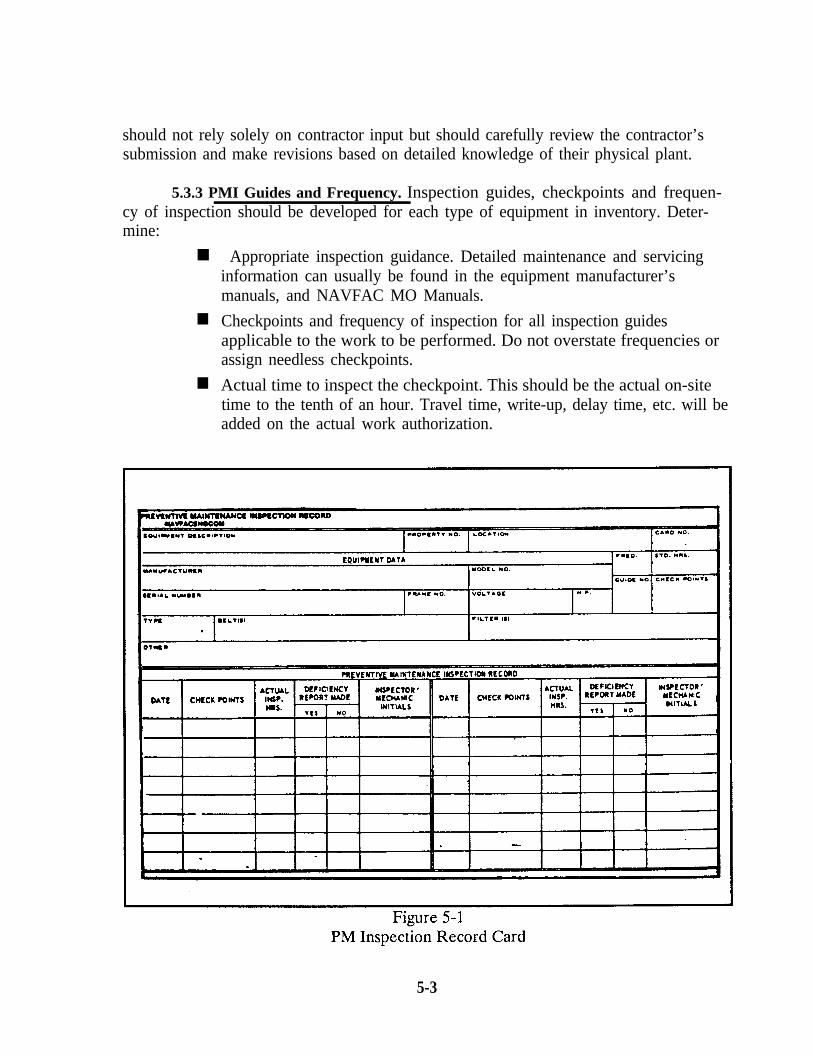
should not rely solely on contractor input but should carefully review the contractor’ssubmission and make revisions based on detailed knowledge of their physical plant.
5.3.3 PMI Guides and Frequency. Inspection guides, checkpoints and frequen-cy of inspection should be developed for each type of equipment in inventory. Deter-mine:
n Appropriate inspection guidance. Detailed maintenance and servicinginformation can usually be found in the equipment manufacturer’smanuals, and NAVFAC MO Manuals.
n Checkpoints and frequency of inspection for all inspection guidesapplicable to the work to be performed. Do not overstate frequencies orassign needless checkpoints.
n Actual time to inspect the checkpoint. This should be the actual on-sitetime to the tenth of an hour. Travel time, write-up, delay time, etc. will beadded on the actual work authorization.
5-3
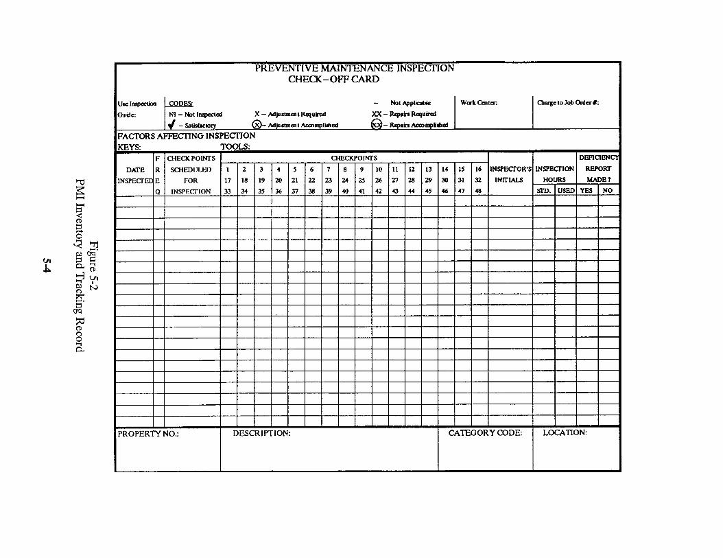
5.3.4 Inspection Record. A PMI Record Card should be developed for eachitem of inventory. Include data in subparagraph 5.3.3 as well as:
n Item identification including property number, nomenclature, make,model, and other pertinent information.
n Location - Building number, floor, room number, etc.
The PMI Record Card should be used during inspection and updated to reflect:
n Checkpoint inspected.
Description of deficiencies corrected or reported. If the equipment ispart of a building system, copies should be placed in the Facility File.
n Actual time spent on-site (tenths of an hour). After several PMIs of theitem of equipment, the actual times should be averaged and compared tothe estimate, differences reconciled and estimates revised. This givesmore accurate data for planning and scheduling shop workload.
n Date of Inspection.
n Inspector’s Initials - Inspectors should be rotated so different views onequipment and component condition may be obtained.
5.4 SCHEDULING INSPECTIONS. A 52 week schedule for each shop should bedeveloped, spreading the work equally if possible. Work scheduling should considerlocation, type, frequency, and shop.
5.4.1 PMI Frequencies. Initial PMI frequencies should be based onmanufacturers’ guidelines. Experience and analysis of actual maintenance records willindicate the need to revise frequencies.
5.4.2 PMI Times. Time allowed to perform each PMI should be based on timeneeded to perform specific checklist items plus time for travel, delay, site access, etc.Time allowed should permit the inspector to complete service with tools, parts, andmaterials available in a hand-carried preplanned Inspection/Service kit. When cir-cumstances require more than one hour per piece of equipment and the inspector doesnot have to return to the shop for additional tools, parts or materials, the effort shouldbe completed. An Emergency/Service Work Authorization should be issued to accountfor time expended and the Inspection Record noted accordingly. NAVFAC P-717.0“Preventive/Recurring Maintenance Handbook” contains Inspection/Service time stand-ards for some items of dynamic equipment.
5.4.3 PMI Scheduling Considerations. It is not usually economical for all itemsto receive PMI. Annual operation and maintenance costs for these items should bemonitored and required services analyzed. Perhaps some services could be performedas cyclic maintenance on Specific Job Orders issued at predetermined intervals, thus
5-5
eliminating need for PMI. Certain types of low cost, non-mission equipment such asfractional horsepower motors, window unit air conditioners (except for filter changes),water coolers, household refrigerators with sealed units, and automatic door closers maybe replaced or repaired at time of breakdown more economically than under the PMIProgram. Replacement items which are part of “vital” operating equipment should bestocked, or readily available at breakdown. Self Help programs, particularly in FamilyHousing and barracks, should be used to the fullest extent for PMI type work. It is im-perative, however, that Public Works coordinate all work. The decision to PM onepiece of equipment does not mean all like items require PMI. Environmental condi-tions, equipment age and usage vary between common equipment at the same activityand among activities. Proper scheduling permits orderly and efficient accomplishmentof PMI. Similar equipment in the same general area of the base should be scheduled forPM consecutively. A single master schedule can be used if all PMI is performed by oneWork Center. If more than one Work Center performs PMI, it is advantageous toprepare a schedule for each Work Center, to permit labor requirements leveling.
5.5 HANDLING MAJOR DEFICIENCIES. Equipment breakdowns discovered duringPMI should be reported immediately to the supervisor or Work Reception Desk. Workbeyond the scope of the PMI work authorization (usually major repairs and overhauls)should be recorded on a Control Inspection Report (Detailed Deficiency List) and for-warded to the Work Generation Branch via the Inspector’s Supervisor (and UtilitiesDivision if utilities equipment). The craftsman should include a priority, i.e., immedi-ate, one year, etc. for correction of major deficiencies.
5.6 SUPPORT REQUIREMENTS. When management commits to establishing a PMIProgram they must also commit resources to install and operate the Program. InitialPMI planning and estimating (P&E) requires approximately 12 P&E hours for eachpiece of major equipment of which 4 hours is for writing work orders and preparing thePMI schedule. Maintaining the PMI function requires approximately 1 P&E hour per150 shop hours of PMI work authorized (or contract equivalent). This is needed to up-date work authorizations annually. In addition, a minimum of 160 hours are needed toreview PMI program effectiveness, 1 hour per 50 items of PMI inventory to update in-ventory and adjust PMI requirements, and 1 hour per 50 PMI Reports to reviewReports and coordinate actions needed to correct reported deficiencies.
5.7 PROGRAM ANALYSIS. Analysis of the PMI Program should be conducted routine-ly and especially prior to renewing work authorization. The analysis must question:
n Is all key equipment covered under PMI and is the level of serviceeffective?
n Can the PMI frequency be reduced without impact?
n How does equipment replacement cost compare to annual PMI cost?
5-6
n Is PMI justified based on economics, mission, or both?
Would it be more cost-efficient to not inspect and repair or replace whenfailure occurs?
5-7
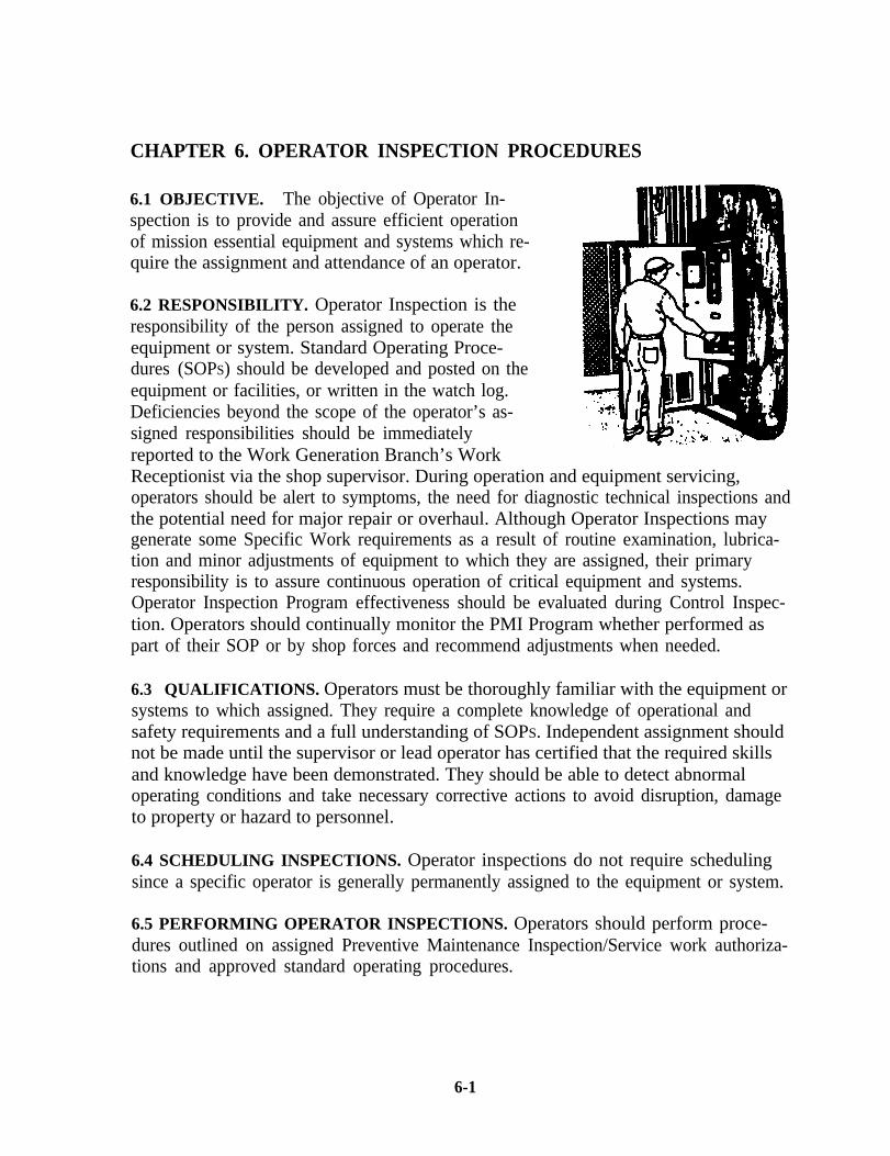
CHAPTER 6. OPERATOR INSPECTION PROCEDURES
6.1 OBJECTIVE. The objective of Operator In-spection is to provide and assure efficient operationof mission essential equipment and systems which re-quire the assignment and attendance of an operator.
6.2 RESPONSIBILITY. Operator Inspection is theresponsibility of the person assigned to operate theequipment or system. Standard Operating Proce-dures (SOPS) should be developed and posted on theequipment or facilities, or written in the watch log.Deficiencies beyond the scope of the operator’s as-signed responsibilities should be immediatelyreported to the Work Generation Branch’s WorkReceptionist via the shop supervisor. During operation and equipment servicing,operators should be alert to symptoms, the need for diagnostic technical inspections andthe potential need for major repair or overhaul. Although Operator Inspections maygenerate some Specific Work requirements as a result of routine examination, lubrica-tion and minor adjustments of equipment to which they are assigned, their primaryresponsibility is to assure continuous operation of critical equipment and systems.Operator Inspection Program effectiveness should be evaluated during Control Inspec-tion. Operators should continually monitor the PMI Program whether performed aspart of their SOP or by shop forces and recommend adjustments when needed.
6.3 QUALIFICATIONS. Operators must be thoroughly familiar with the equipment orsystems to which assigned. They require a complete knowledge of operational andsafety requirements and a full understanding of SOPS. Independent assignment shouldnot be made until the supervisor or lead operator has certified that the required skillsand knowledge have been demonstrated. They should be able to detect abnormaloperating conditions and take necessary corrective actions to avoid disruption, damageto property or hazard to personnel.
6.4 SCHEDULING INSPECTIONS. Operator inspections do not require schedulingsince a specific operator is generally permanently assigned to the equipment or system.
6.5 PERFORMING OPERATOR INSPECTIONS. Operators should perform proce-dures outlined on assigned Preventive Maintenance Inspection/Service work authoriza-tions and approved standard operating procedures.
6-1
CHAPTER 7. ANNUAL INSPECTION SUMMARY (AIS)
7.1 PURPOSE. The purpose of the Annual Inspection Summary (AIS) is to report thecondition of Navy owned and operated real property, including temporary in-grants notout-leased or declared surplus.
7.2 OBJECTIVE. The objective of the AIS is to provide an annual assessment offacility condition and report the impact of condition on mission readiness. A secondaryobjective is to provide a means for the command chain to present unfunded facility con-dition problems to higher authority for programming consideration. Although the AISis not a request for funds, it provides solid supporting justification for additional resour-ces to correct facility problems. The AIS also provides:
n An assessment of the overall facility inspection program and inspectioncoverage.
n An assessment of individual facility condition.
n A budget-oriented report of facility resource requirements.
n The data needed to develop an executable Maintenance Action Plan(MAP) within resource constraints.
Data needed to make an assessment of Base Readiness (BASEREP).
7.3 AIS FUNDING RELATIONSHIP. High interest in the deteriorating condition ofNavy Real Property and severe reductions in facility repair funds prompted the Chief ofNaval Operations (CNO), to institute procedures to identify, report and analyze facilitydeficiencies. These procedures:
n Emphasize inspection of facilities with direct bearing on activity readiness.
n Emphasize inspection of facilities with high economic impact onoperations.
n Identify facility condition deficiencies by Investment Category.
n Prioritize facility problems as critical or deferrable.
n Require major claimants to review and verify AIS Reports.
Synchronize facility condition reporting with the budget requestprogramming cycle.
n Include Real Property Maintenance Activities (RPMA) programrequirements as an agenda item for the Military Construction ReviewBoard (MCRB) and require major claimants to defend their RPMAprogram before the MCRB based on AIS data.
7-1
n Permit CNO to view the MCON and RPMA Program as relatedrequirements by Investment Category addressing both current and futureneeds jointly.
Use the AIS and BASEREP as tools to help CNO formulateprogramming guidelines and define the direction of MCON and RPMAthrough the Future Years Defense Plan (FYDP).
7.4 PREPARATION OF THE AIS. There are three (3) different types of Annual Inspec-tion Summaries depending on the types of property involved. Preparation instructionsas well as reporting formats differ with each type. Specific guidance for preparation andreporting is contained in instructions promulgated by the commands involved. Only theType “A” report is required by CNO. The three (3) types are:
TYPE “A”. Navy owned and operated property, including facilities operated bycontractor for research and development, not out-leased or declared surplus.OPNAVINST 11010.34 (series) contains forms and instructions for annual preparation.The majority of Navy activities are in this category and therefore subject toOPNAVINST 11010.34 series reporting requirements.
TYPE “B”. Navy property, except industrial facilities, out-leased, declared surplus,or sold with a recapture provision. Para. 7.4.1 provides information for preparation ofType “B” AIS Reports.
TYPE “C”. Industrial facilities not Navy operated. Reporting instructions forapplicable activities will be issued by the requesting command. Para. 7.4.2 provides in-formation for preparation of Type “C” AIS Reports.
7-2
7.4.1 Type “B” Annual Inspection Summary
1. TYPE OF PROPERTY. Type “B” Annual Inspection Summary (Figures 7-1 and 7-2)shall be used to report conditions for the following types of property:
a. Naval Property, not including Industrial Facilities, which is outleased, or outper-mitted, to others.
b. Naval Property, not including Industrial Facilities, which has been declaredexcess or surplus and is pending lease, transfer or sale, and for which the Navy is respon-sible for protection, maintenance and repair until such time that this responsibility istransferred to the disposal agency. Also included is property of activities which havebeen disestablished and which are not covered under reports for other types of property.
c. Naval Property, not including Industrial Facilities, which has been sold ortransferred with a provision for recapture in event of a national emergency.
2. INSPECTION.
a. Category of Inspection. The data for preparing a Type “B” Annual InspectionSummary are usually obtained from a one-time comprehensive inspection, as opposedto regular inspections.
b. Inspection Party. It is desirable that the inspector be accompanied by arepresentative of the lessee, or owner, so the lessee or owner will be more conversantwith the deficiencies listed.
c. Inspector’s Recommendations. The Inspector’s Recommendations, as shown inthe summary, shall be in consonance with facilities categorization code levels for Navalinstallations; the terms of the lease, permit, or sales contract; and the Condition Reportfor Leased Property, if one was prepared.
d. Facilities Categorization Codes. In general, the facilities categorization codesfor outleased Naval property shall be the same as those for Naval installations in an ac-tive status. The lease, permit or sales contract will specify the lessee’s, permittees’ orowners’ responsibility for maintenance and may modify the required amount of main-tenance. Copies of such documents should be reviewed prior to each inspection. Whena Condition Report for Leased Property has been made the maintenance required ofthe lessee cannot be more than that required to return the property to the conditionshown in the report, unless the lease specifically states otherwise.
7-3
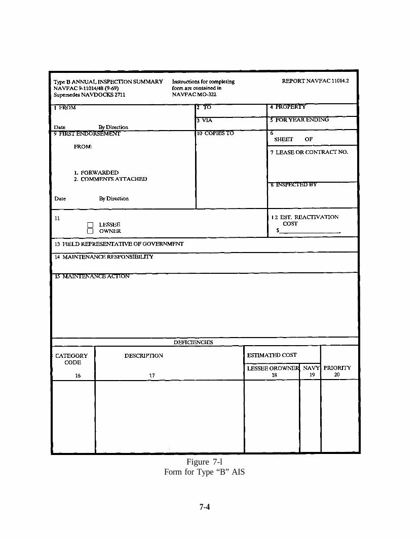
Figure 7-lForm for Type “B” AIS
7-4
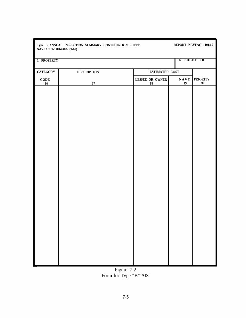
Type B ANNUAL INSPECTION SUMMARY CONTINUATION SHEET REPORT NAVFAC 11014-2NAVFAC 9-11014/48A (9-69)
1. PROPERTY
CATEGORY
CODE16
DESCRIPTION
17
6 SHEET Of
ESTIMATED COST
LESSEE OR OWNER NAVY PRIORITY18 19 20
Figure 7-2Form for Type “B” AIS
7-5
e. Inspection Scheduling. Inspections shall be scheduled no later than 12 monthsafter the previous inspection.
3. WHEN TO SUBMIT. Submit upon request of the cognizant Major Claimant, or itsfield representative.
a. Who. For Naval property, not including Industrial Facilities, which is outleasedor outpermitted to others, the Type “B” Annual Inspection Summary shall be preparedand forwarded to the Major Claimant as follows:
(1) For the above described property which is located on an active Navalactivity having a Public Works Department, the Public Works Officer shall prepare andforward the Type “B” Annual Inspection Summary to the Major Claimant, via the EFD.
(2) For property in the custody of the Naval Facilities EngineeringCommand, the summary shall be prepared and forwarded to the NAVFACENGCOMby the EFD. For property not in the custody of the NAVFACENGCOM, and for prop-erty which has been sold or transferred with a provision for recapture the summary shallbe prepared and forwarded by the EFD to the requesting Major Claimant and activitywith one copy to the Commander, Naval Facilities Engineering Command.
4. COMPOSITION. The Type “B” Annual Inspection Summary shall be prepared onForm NAVFAC 9-11014/48 (9-69), Type “B” Annual Inspection Summary, and FormNAVFAC 9-11014/48A (9-69), Type “B” Annual Inspection Summary ContinuationSheet. No forwarding letter is required. Report symbol NAVFAC 11014-2 applies.
a. Information Source. This type of summary shall show all deficiencies, exceptthose of a housekeeping nature (for example, items costing less than $1,000 to correct),together with estimated correction costs. When correction action on any deficiency hasbeen initiated, but not completed, notation shall be made to that effect. The propertysubject to inclusion in the Type “B” Annual Inspection Summary includes not only thatclassified by Category Codes, but also shop cranes and hoists and Public Works shopequipment for maintenance and production facilities.
5. INSTRUCTIONS FOR COMPLETING FORMS NAVFAC 9-11014/48 (9-69) AND11014/48A (9-69), TYPE “B” ANNUAL INSPECTION SUMMARY AND TYPE “B” AN-NUAL INSPECTION SUMMARY CONTINUATION SHEET.
a. Action-Activity. The submitting activity shall provide appropriate entries inBlocks 1 through 5, 8 and 9, and Columns 10 through 13. (If the summary is prepared bythe EFD, this action will be completed by the EFD.)
7-6
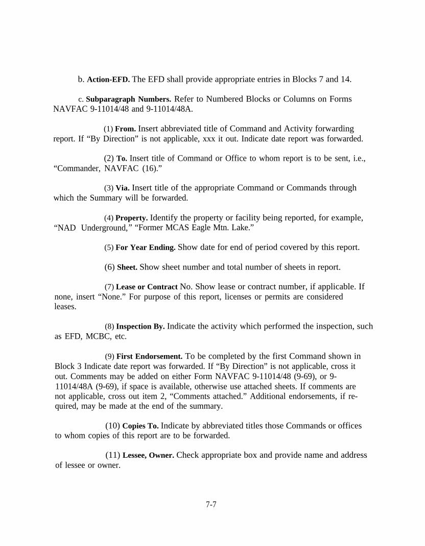
b. Action-EFD. The EFD shall provide appropriate entries in Blocks 7 and 14.
c. Subparagraph Numbers. Refer to Numbered Blocks or Columns on FormsNAVFAC 9-11014/48 and 9-11014/48A.
(1) From. Insert abbreviated title of Command and Activity forwardingreport. If “By Direction” is not applicable, xxx it out. Indicate date report was forwarded.
(2) To. Insert title of Command or Office to whom report is to be sent, i.e.,“Commander, NAVFAC (16).”
(3) Via. Insert title of the appropriate Command or Commands throughwhich the Summary will be forwarded.
(4) Property. Identify the property or facility being reported, for example,“NAD Underground,” “Former MCAS Eagle Mtn. Lake.”
(5) For Year Ending. Show date for end of period covered by this report.
(6) Sheet. Show sheet number and total number of sheets in report.
(7) Lease or Contract No. Show lease or contract number, if applicable. Ifnone, insert “None.” For purpose of this report, licenses or permits are consideredleases.
(8) Inspection By. Indicate the activity which performed the inspection, suchas EFD, MCBC, etc.
(9) First Endorsement. To be completed by the first Command shown inBlock 3 Indicate date report was forwarded. If “By Direction” is not applicable, cross itout. Comments may be added on either Form NAVFAC 9-11014/48 (9-69), or 9-11014/48A (9-69), if space is available, otherwise use attached sheets. If comments arenot applicable, cross out item 2, “Comments attached.” Additional endorsements, if re-quired, may be made at the end of the summary.
(10) Copies To. Indicate by abbreviated titles those Commands or officesto whom copies of this report are to be forwarded.
(11) Lessee, Owner. Check appropriate box and provide name and addressof lessee or owner.
7-7
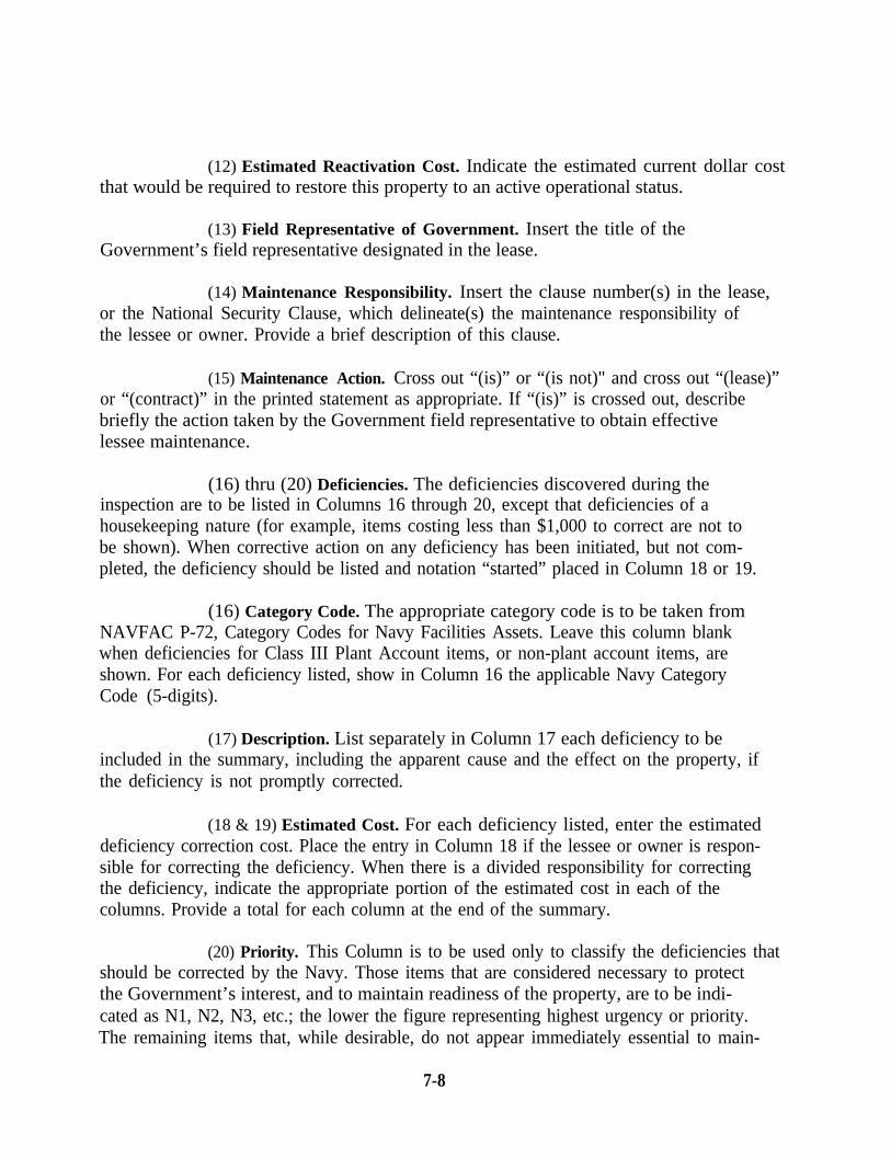
(12) Estimated Reactivation Cost. Indicate the estimated current dollar costthat would be required to restore this property to an active operational status.
(13) Field Representative of Government. Insert the title of theGovernment’s field representative designated in the lease.
(14) Maintenance Responsibility. Insert the clause number(s) in the lease,or the National Security Clause, which delineate(s) the maintenance responsibility ofthe lessee or owner. Provide a brief description of this clause.
(15) Maintenance Action. Cross out “(is)” or “(is not)" and cross out “(lease)”or “(contract)” in the printed statement as appropriate. If “(is)” is crossed out, describebriefly the action taken by the Government field representative to obtain effectivelessee maintenance.
(16) thru (20) Deficiencies. The deficiencies discovered during theinspection are to be listed in Columns 16 through 20, except that deficiencies of ahousekeeping nature (for example, items costing less than $1,000 to correct are not tobe shown). When corrective action on any deficiency has been initiated, but not com-pleted, the deficiency should be listed and notation “started” placed in Column 18 or 19.
(16) Category Code. The appropriate category code is to be taken fromNAVFAC P-72, Category Codes for Navy Facilities Assets. Leave this column blankwhen deficiencies for Class III Plant Account items, or non-plant account items, areshown. For each deficiency listed, show in Column 16 the applicable Navy CategoryCode (5-digits).
(17) Description. List separately in Column 17 each deficiency to beincluded in the summary, including the apparent cause and the effect on the property, ifthe deficiency is not promptly corrected.
(18 & 19) Estimated Cost. For each deficiency listed, enter the estimateddeficiency correction cost. Place the entry in Column 18 if the lessee or owner is respon-sible for correcting the deficiency. When there is a divided responsibility for correctingthe deficiency, indicate the appropriate portion of the estimated cost in each of thecolumns. Provide a total for each column at the end of the summary.
(20) Priority. This Column is to be used only to classify the deficiencies thatshould be corrected by the Navy. Those items that are considered necessary to protectthe Government’s interest, and to maintain readiness of the property, are to be indi-cated as N1, N2, N3, etc.; the lower the figure representing highest urgency or priority.The remaining items that, while desirable, do not appear immediately essential to main-
7-8
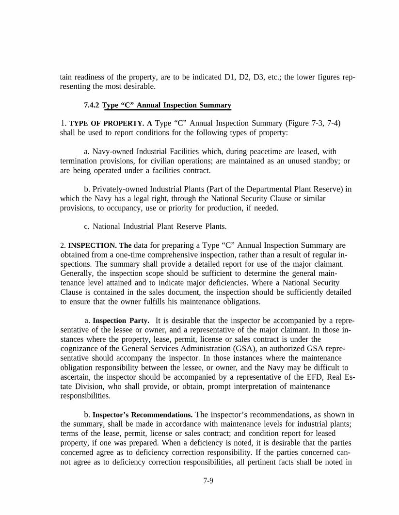
tain readiness of the property, are to be indicated D1, D2, D3, etc.; the lower figures rep-resenting the most desirable.
7.4.2 Type “C” Annual Inspection Summary
1. TYPE OF PROPERTY. A Type “C” Annual Inspection Summary (Figure 7-3, 7-4)shall be used to report conditions for the following types of property:
a. Navy-owned Industrial Facilities which, during peacetime are leased, withtermination provisions, for civilian operations; are maintained as an unused standby; orare being operated under a facilities contract.
b. Privately-owned Industrial Plants (Part of the Departmental Plant Reserve) inwhich the Navy has a legal right, through the National Security Clause or similarprovisions, to occupancy, use or priority for production, if needed.
c. National Industrial Plant Reserve Plants.
2. INSPECTION. The data for preparing a Type “C” Annual Inspection Summary areobtained from a one-time comprehensive inspection, rather than a result of regular in-spections. The summary shall provide a detailed report for use of the major claimant.Generally, the inspection scope should be sufficient to determine the general main-tenance level attained and to indicate major deficiencies. Where a National SecurityClause is contained in the sales document, the inspection should be sufficiently detailedto ensure that the owner fulfills his maintenance obligations.
a. Inspection Party. It is desirable that the inspector be accompanied by a repre-sentative of the lessee or owner, and a representative of the major claimant. In those in-stances where the property, lease, permit, license or sales contract is under thecognizance of the General Services Administration (GSA), an authorized GSA repre-sentative should accompany the inspector. In those instances where the maintenanceobligation responsibility between the lessee, or owner, and the Navy may be difficult toascertain, the inspector should be accompanied by a representative of the EFD, Real Es-tate Division, who shall provide, or obtain, prompt interpretation of maintenanceresponsibilities.
b. Inspector’s Recommendations. The inspector’s recommendations, as shown inthe summary, shall be made in accordance with maintenance levels for industrial plants;terms of the lease, permit, license or sales contract; and condition report for leasedproperty, if one was prepared. When a deficiency is noted, it is desirable that the partiesconcerned agree as to deficiency correction responsibility. If the parties concerned can-not agree as to deficiency correction responsibilities, all pertinent facts shall be noted in
7-9

Figure 7-3Type “C” Annual Inspection Summary Form
Summary- 1
7-10
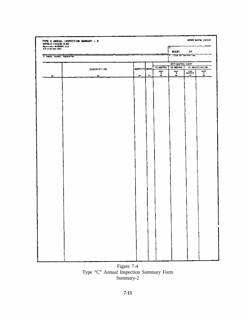
Figure 7-4Type “C” Annual Inspection Summary Form
Summary-2
7-11
the summary in order that appropriate action may be taken at Departmental level. Inthe case of deficiencies at plants of the National Industrial Plant Reserve, it is mostdesirable that the EFD representative, and the authorized GSA field representative,agree on interpretation of the lease or sales contract, and the estimated deficiency coststhat are the responsibility of the lessee or purchaser. In the case of plants that have beensold, the inspector’s judgment must reflect the owner’s responsibility contingent uponhis use of the facility and seriousness of the deficiency. One-time comprehensive inspec-tions providing rehabilitation estimates need not be made each year, provided sig-nificant changes have not occurred since the previous report.
c. Maintenance Levels. Maintenance levels for industrial plants are provided by theresponsible major claimant. The lease, permit, license or sales contract, or the NationalSecurity Clause of such document, will specify lessees’, permittees’ or owners’ respon-sibility for maintenance; and may modify the maintenance level required. Where copiesof applicable leases, permits, licenses, or sales contracts are not available in the EFD,they should be reviewed at the office of the major claimant’s field representative priorto each inspection. Where a Condition Report for Leased Property has been made, themaintenance required of the lessee cannot be more than that required to return theproperty to the condition shown in the report, unless the lease specifically states other-wise.
d. Inspection Scheduling. Industrial Plant inspections shall be scheduled by theEFD so summaries will reach the major claimant prior to 1 December of each year.
3. WHEN TO SUBMIT. Submit annually, at no later than 12-month intervals. Submitupon request of the cognizant major claimant, or its field representative, for all otherproperty. When a cognizant major claimant, or its field representative, has previously re-quested that a property inspection be made, and the request is not limited to a one-timecomprehensive inspection, the EFD shall submit summaries at no later than 12-monthintervals. Summaries shall be forwarded to reach the cognizant major claimant prior to1 December each year.
4. WHO. The summary shall be prepared by the geographical EFD in which the proper-ty is located. Following will be their responsibilities:
(1) Establishing inspection dates,
(2) Facilities inspection to determine their physical condition,
(3) Providing technical recommendations for deficiencies correction,
(4) Providing cost estimates for deficiencies correction, and
7-12
(5) Preparing the Type "C" Annual Inspection Summary.
5. DISTRIBUTION. Semi-annual summaries are made only at the request of the cog-nizant Major Claimant. Copies of the report will be submitted to the Major Claimantonly.
6. COMPOSITION. The Type "C" Annual Inspection Summary shall be prepared onForm NAVFAC 9-11014/49 (9-69) Type "C" Annual Inspection Summary-1 and FormNAVFAC 9-11014/50 (9-69) Type "C" Annual Inspection Summary-2. Figure 7-5 andFigure 7-6 are sample completed forms of a Type "C" Annual Inspection Summary.
a. Information Source. This type of summary shall include all deficiencies, exceptthose of a housekeeping nature (for example, items costing less than $1,000 to correct),together with an estimated correction cost. When corrective action on any deficiencyhas been initiated, but not completed, notation shall be made to that effect. The proper-ty subject to inclusion in the Type "C" Annual Inspection Summary also includes the fol-lowing:
(1) Public works shop equipment for maintenance and production facilities.
(2) Fire extinguisher systems.
(3) Locomotives, railroad rolling stock, materials-handling equipment andweight-handling equipment.
(4) Production equipment only if requested by the cognizant major claimantor its field representative.
b. Instructions for Completing Forms NAVFAC 9-11014/49 (9-69) Type “C’Annual Inspection Summary-l and NAVFAC 9-11014/50 (6-69) Type “C” Annual Inspec-tion Summary-2. Subparagraph numbers, following, refer to numbered Blocks orColumns on Forms NAVFAC 9-11014/49 and 9-11014/50:
(1) From. Insert abbreviated title of Command and Activity forwardingreport. Signature of Commander/Commanding Officer, EFD, or other person au-thorized to forward report. If “By Direction” is not applicable, cross it out. Indicate datereport was forwarded.
(2) To. Insert title of Command or Office to whom report is to be sent.
(3) Date of Inspection. Show date inspection was completed.
7-13
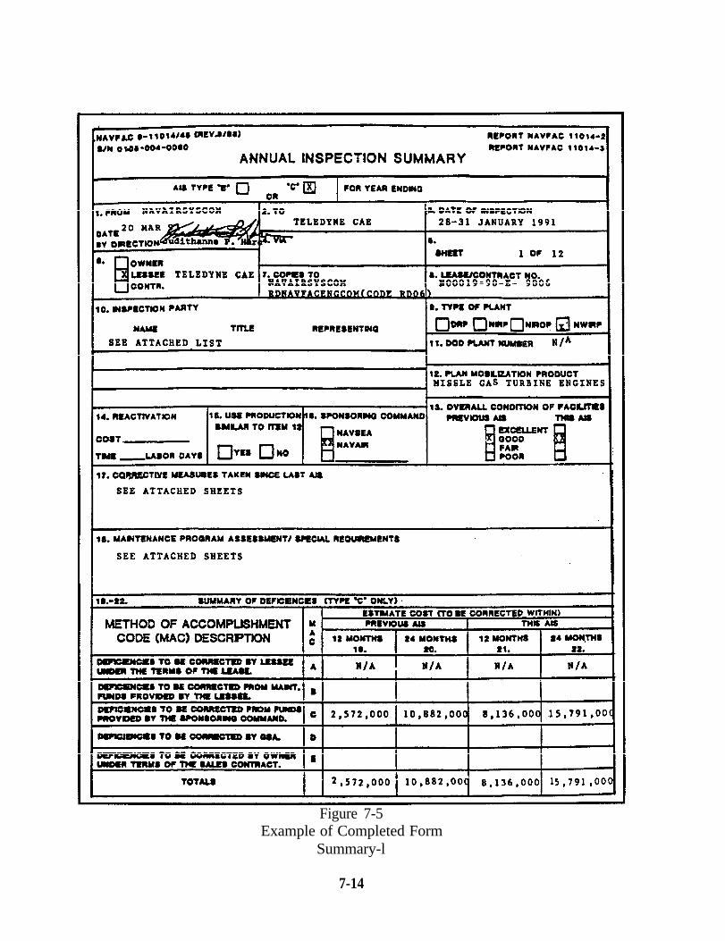
Figure 7-5Example of Completed Form
Summary-l
7-14
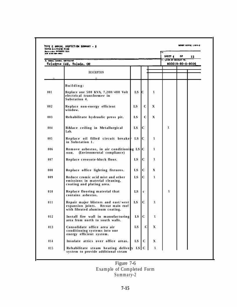
DESCRIPTION
21 22
Building:
001 Replace one 500 KVA, 7,200/480 Volt LS C Xelectrical transformer inSubstation 4.
002 Replace non-energy efficient LS C Xwindow.
003
004
Rehabilitate hydraulic press pit.
R&lace ceiling in MetallurgicalLab.
LS C X
LS C X
005 Replace oil filled circuit breaker LS C Xin Substation 1.
006
007
Remove asbestos, in air conditioning LS C Xroom. (Environmental compliance)
Replace creosote-block floor. LS C X
008 Replace office lighting fixtures. LS C X
009 Reduce cromic acid mist and other LS C Xemissions in material cleaning,coating and plating area.
010 Replace flooring material thatcontains asbestos.
LS c X
011 Repair major blisters and east/west LS C Xexpansion joints. Recoat main roofwith fibrated aluminum coating.
012 Install fire wall in manufacturing LS C Xarea from north to south walls.
013 Consolidate office area air LS C Xconditioning systems into oneenergy efficient system.
014
015
Insulate attics over office areas. LS C X
Rehabilitate steam heating delivery LS C Xsystem to provide additional steam
Figure 7-6Example of Completed Form
Summary-2
7-15
(4) Copies To. Indicate by abbreviated titles those Commands, or Officesto whom copies of this report are to be forwarded.
(5) Sheet. Show sheet number and total number of sheets in report.
(6) Owner, Lessee or Contractor. Check appropriate box and provide nameand address of owner, lessee or contractor.
(7) Lease or Contract No. Show lease or contract number, if applicable.If none, insert “None.” For purpose of this report, licenses and permits are consideredleases.
(8) Type of Plant. Check appropriate box.
(9) Inspection Party. List members of inspection party by name, title andthe organization they represent.
(10) DOD Plant Number. If this property has been assigned a DOD plantnumber, show that number. If none, insert “None.”
(11) Planned Mobilization Product. Indicate the product planned forproduction in this plant when mobilization occurs.
(12) Overall Condition of Facilities. Check the appropriate box for thisreport and also check the appropriate box for the condition reported in the previousreport.
(13) Reactivation. Show the estimated dollar cost and mandays necessaryto place the facilities, not including production equipment, in the proper condition toproduce the planned mobilization product. These entries should be the same as the sumtotal of Columns 27 and 28. If these estimates for reactivation have been repeated fromthe previous reports, notation shall be made to that effect.
(14) Use. If the plant is being used for its intended purpose, that is, theproduction of a product similar to the planned mobilization product, place a check markin the YES box. If not, place a check mark in the NO box.
(15) Sponsoring Command. Check the appropriate box. If necessary, insertthe brief title of the major claimant.
(16) Corrective Measures Taken Since Last Report. Provide a briefstatement as to corrective measures taken and maintenance accomplished since the pre-vious inspection. Discrepancies from the requirements of the lease or sales contract
7-16
shall be noted with an indication as to the cause of these discrepancies and the measurestaken to correct them, including recommendations to higher authority. If necessary, con-tinue on blank sheets.
(17 thru (20) Summary of Deficiencies. This part provides a summary ofestimated deficiency costs discovered during the inspection, classified by the method foraccomplishing the deficiencies correction. Data for Columns 19 and 20 are taken fromColumns 25 and 26, classified by the mark in Column 24. Data for Columns 17 and 18shall be taken from Columns 19 and 20 of the previous report.
(21) thru (28) Deficiencies. The deficiencies discovered during theinspection are to be listed in Columns 21 through 28, except that deficiencies of ahousekeeping nature (for example, items costing less than $1,000 to correct) are not tobe shown. When corrective action on any deficiency has been initiated, but not com-pleted, the deficiency should be listed and a notation “Started” placed in Column 25 or26. Deficiencies corrected before the inspection is completed should not be listed. Datais required for three classifications of deficiencies: (a) those requiring corrective actionwithin the ensuing twelve months, (b) those requiring corrective action within the ensu-ing twenty-four months, and (c) those requiring corrective action only when the proper-ty is reactivated for mobilization production.
(22) Description. List separately each deficiency to be included in thesummary, including the apparent cause and effect on the property if the deficiency is notpromptly corrected.
(23) Quantity. For each deficiency listed in Column 22, indicate whereappropriate, the quantity involved in correcting the deficiency. For example for paving,1000 SY; for concrete work, 20 CY; for pipe replacement, 1275 LF.
(24) Mark. Each deficiency which should be corrected within the ensuing12 or 24 month period shall be identified to indicate correction responsibility. The markto be applied shall be determined by the Major Claimant’s field representative as fol-lows:
(a) For those deficiencies in outleased Departmental Reserve Plants,or outleased plants of the National Industrial Plant Reserve, in the custody of GSA, thatshould normally be corrected by the lessee at his own expense under the terms of thelease.
(b) For those deficiencies in outleased Departmental Reserve Plantsthat should be corrected from maintenance funds provided by the lessee in lieu of cashrental under the terms of the lease, and as directed by government representative for
7-17
the lease.
(c) For those deficiencies in outleased Departmental Reserve Plantsthat should be corrected from funds provided by the cognizant primary supportauthority.
(d) For those deficiencies in outleased plants of the NationalIndustrial Plant Reserve, in the custody of GSA, that should be corrected by GSA withits appropriated funds. Indicate whether the deficiency is serious enough to recommendthat GSA request an appropriation for correction in its next budget submission.
(e) For those deficiencies in Departmental Plants, or plants of theNational Industrial Plant Reserve, which have been sold; that should be corrected bythe purchaser (owner) under the terms of the sales contract.
(25) and (26) Estimated Cost. Provide a cost estimate for each deficiencycorrection listed in Column 22. If the deficiency should be corrected in the ensuing 12months, list the cost estimate in Column 25. If the deficiency should be corrected within13 to 24 months, list the cost estimate in Column 26.
(27) and (28) Estimated Cost at Reactivation. This covers the rehabilitationrequired to reactivate the plant, not including production equipment, for planned peakproduction, and includes the number of mandays required, Column 27. The dollar fig-ure, Column 28, for reactivation rehabilitation is in addition to the cost for deficienciescorrection within the 12 month and 24 month periods.
7-18
CHAPTER 8. THE BASE ENGINEERING SUPPORT, TECHNICAL(BEST) SYSTEM
8.1 OBJECTIVE. The objective of BEST is to provide Public Works personnel with asimple, flexible, interactive ADP system to track workload that is easy to operate.
8.2 DISCUSSION. BEST is a “tool” that automates the Navy’s facilities managementsystem. It consists of standard user-friendly software and features independent function-al modules. There are separate equipment suites for maintenance, housing andtransportation functional areas. The Maintenance/Utilities subsystem consists of fivemodules:
n Emergency Service (E/S)
n Shore Facilities Inspection (SFI)
Work Input Control (WIC)
n Facilities Engineering Job Estimating (FEJE)
n Utilities (UT)
Central processing unit and storage device sizes and the number of work stations andprinters will vary among activities. The modular system is flexible and versatile enoughto accommodate most Public Works Department needs. A microcomputer version isavailable as well as the Honeywell mini version. Other functions are automated orbeing developed to complement the BEST system as part of a Public Works Manage-ment Automation (PWMA) micro initiative. BEST is a large portion of the PWMA pie.More detailed information concerning BEST and the five Maintenance/Utilitiesmodules can be found in the “Management Guide, Maintenance/Utilities Subsystem,Base Engineering Support, Technical” and the user’s manuals for the individualmodules.
8.3 THE SFI MODULE. The SFI Module automates the Shore Facility Inspection/As-sessment System. The SFI Module automates the normal clerical functions and schedul-ing operations associated with management of both the Control Inspection (CI)program for facilities and the Preventive Maintenance Inspection (PMI) programs fordynamic equipment. The SFI module contains two (2) sub-modules, CI and PMI.
8.3.1 Inventory. An effective use of the SFI Module is an accurate facilities anddynamic equipment inventory. This is essential for CI and PMI programs whethermanaged through the SFI Module or manually. It includes such items as facility numberand name, priority, inspection frequency, map grid, and zone. PMI equipment inven-tories include equipment name, number and inventory code. After initial data inputand start-up, a procedure for inventory update must be established to maintain accurateinventories. The FME Division is the focal point for gathering changes to data elements
8-1
and input of revisions into the system.
8.3.2 Inspection Frequencies And Standard Hours. CI and PMI require dif-ferent methods of putting in inspection frequencies and standard hours.
8.3.2.1 CI Frequencies and Standard Hours. Frequencies and hoursare entered directly into the CI sub-module. Type inspection, frequency, and standardhours are entered for each facility. Each inspection-can then be scheduled. After thefinal schedule is approved, the system generates inspection work orders. Upon comple-tion, actual labor hours expended can be matched to the schedule for performancereports and unaccomplished inspections.
8.3.2.2 PMI Frequencies and Standard Hours. Frequencies and hoursare estimated in the FEJE Module. A job order for a particular type of equipment iswritten, one phase per frequency. Appropriate checkpoints and pertinent equipmentare attached. The job order is then sent from FEJE to SFI, ready for each phase to bescheduled.
8.3.3 Scheduling. The SFI module allows the user to decide which week of thefiscal year each inspection should take place and when the phases should be scheduled.In this manner total hours per quarter, month, or week can be obtained. This reporthelps the scheduler develop the Work Plan Summary for the Shop Load Plan in theWIC module.
8.3.4 Management Reports On Facility/Equipment Condition. The System canbe queried at any time and management reports generated. This flexibility provides aneffective tool to the PW manager to ascer-tain the current condition of any facility orpiece of equipment. Overall, this leads tobetter work scheduling, project selection,and maintenance. A detailed description ofmanagement reports and indicators can befound in the BEST “Management Guide.”
8-2
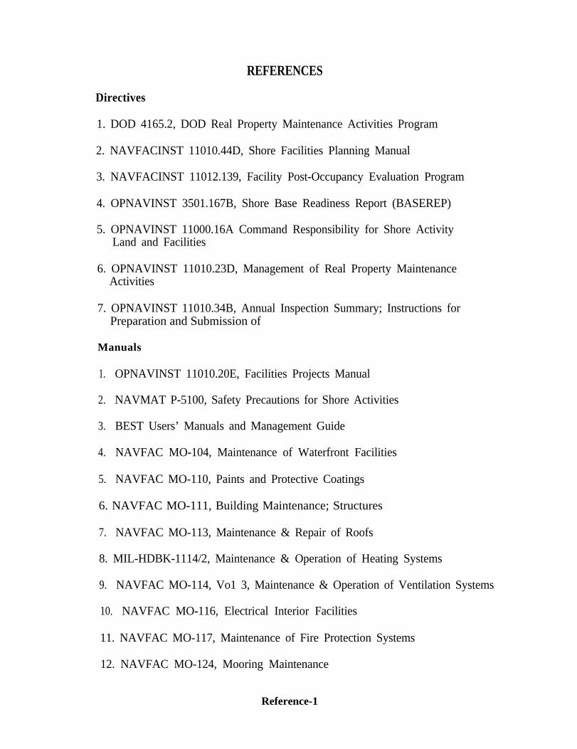
Directives
REFERENCES
1. DOD 4165.2, DOD Real Property Maintenance Activities Program
2. NAVFACINST 11010.44D, Shore Facilities Planning Manual
3. NAVFACINST 11012.139, Facility Post-Occupancy Evaluation Program
4. OPNAVINST 3501.167B, Shore Base Readiness Report (BASEREP)
5. OPNAVINST 11000.16A Command Responsibility for Shore ActivityLand and Facilities
6. OPNAVINST 11010.23D, Management of Real Property MaintenanceActivities
7. OPNAVINST 11010.34B, Annual Inspection Summary; Instructions forPreparation and Submission of
Manuals
1. OPNAVINST 11010.20E, Facilities Projects Manual
2. NAVMAT P-5100, Safety Precautions for Shore Activities
3. BEST Users’ Manuals and Management Guide
4. NAVFAC MO-104, Maintenance of Waterfront Facilities
5. NAVFAC MO-110, Paints and Protective Coatings
6. NAVFAC MO-111, Building Maintenance; Structures
7. NAVFAC MO-113, Maintenance & Repair of Roofs
8. MIL-HDBK-1114/2, Maintenance & Operation of Heating Systems
9. NAVFAC MO-114, Vo1 3, Maintenance & Operation of Ventilation Systems
10. NAVFAC MO-116, Electrical Interior Facilities
11. NAVFAC MO-117, Maintenance of Fire Protection Systems
12. NAVFAC MO-124, Mooring Maintenance
Reference-1
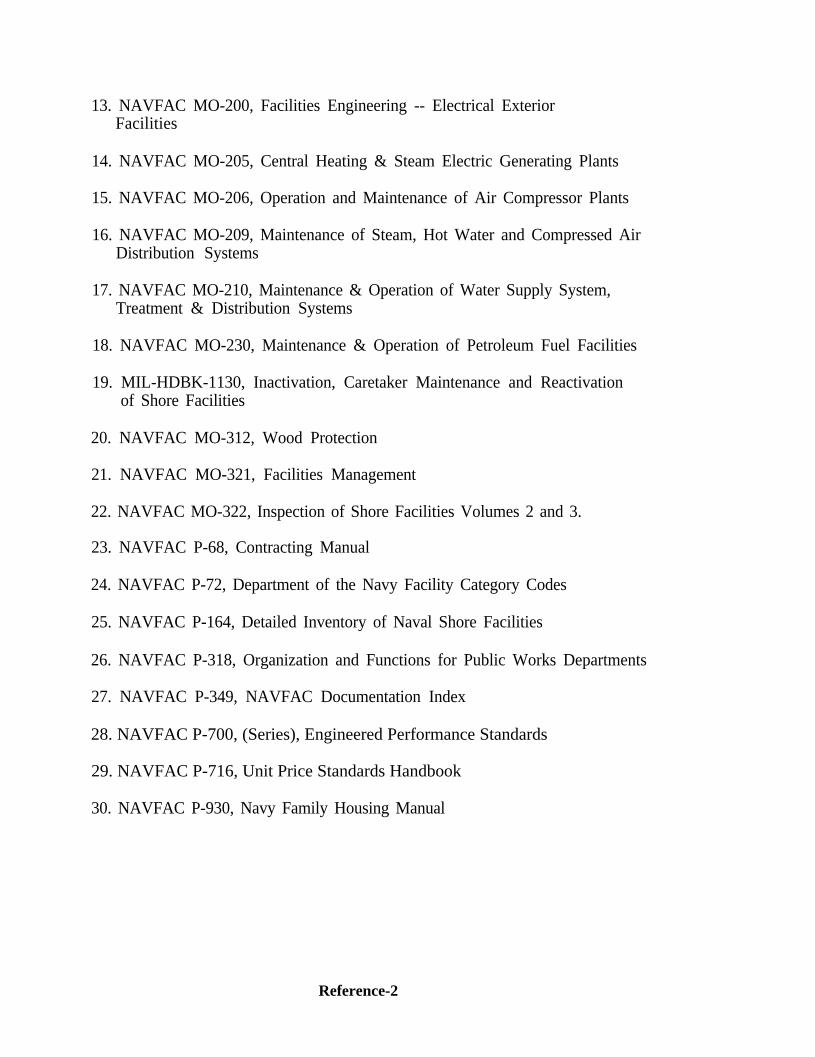
13. NAVFAC MO-200, Facilities Engineering -- Electrical ExteriorFacilities
14. NAVFAC MO-205, Central Heating & Steam Electric Generating Plants
15. NAVFAC MO-206, Operation and Maintenance of Air Compressor Plants
16. NAVFAC MO-209, Maintenance of Steam, Hot Water and Compressed AirDistribution Systems
17. NAVFAC MO-210, Maintenance & Operation of Water Supply System,Treatment & Distribution Systems
18. NAVFAC MO-230, Maintenance & Operation of Petroleum Fuel Facilities
19. MIL-HDBK-1130, Inactivation, Caretaker Maintenance and Reactivationof Shore Facilities
20. NAVFAC MO-312, Wood Protection
21. NAVFAC MO-321, Facilities Management
22. NAVFAC MO-322, Inspection of Shore Facilities Volumes 2 and 3.
23. NAVFAC P-68, Contracting Manual
24. NAVFAC P-72, Department of the Navy Facility Category Codes
25. NAVFAC P-164, Detailed Inventory of Naval Shore Facilities
26. NAVFAC P-318, Organization and Functions for Public Works Departments
27. NAVFAC P-349, NAVFAC Documentation Index
28. NAVFAC P-700, (Series), Engineered Performance Standards
29. NAVFAC P-716, Unit Price Standards Handbook
30. NAVFAC P-930, Navy Family Housing Manual
Reference-2
APPENDIX ASample Guides For Developing Utility
Systems Pseudofacility Numbers
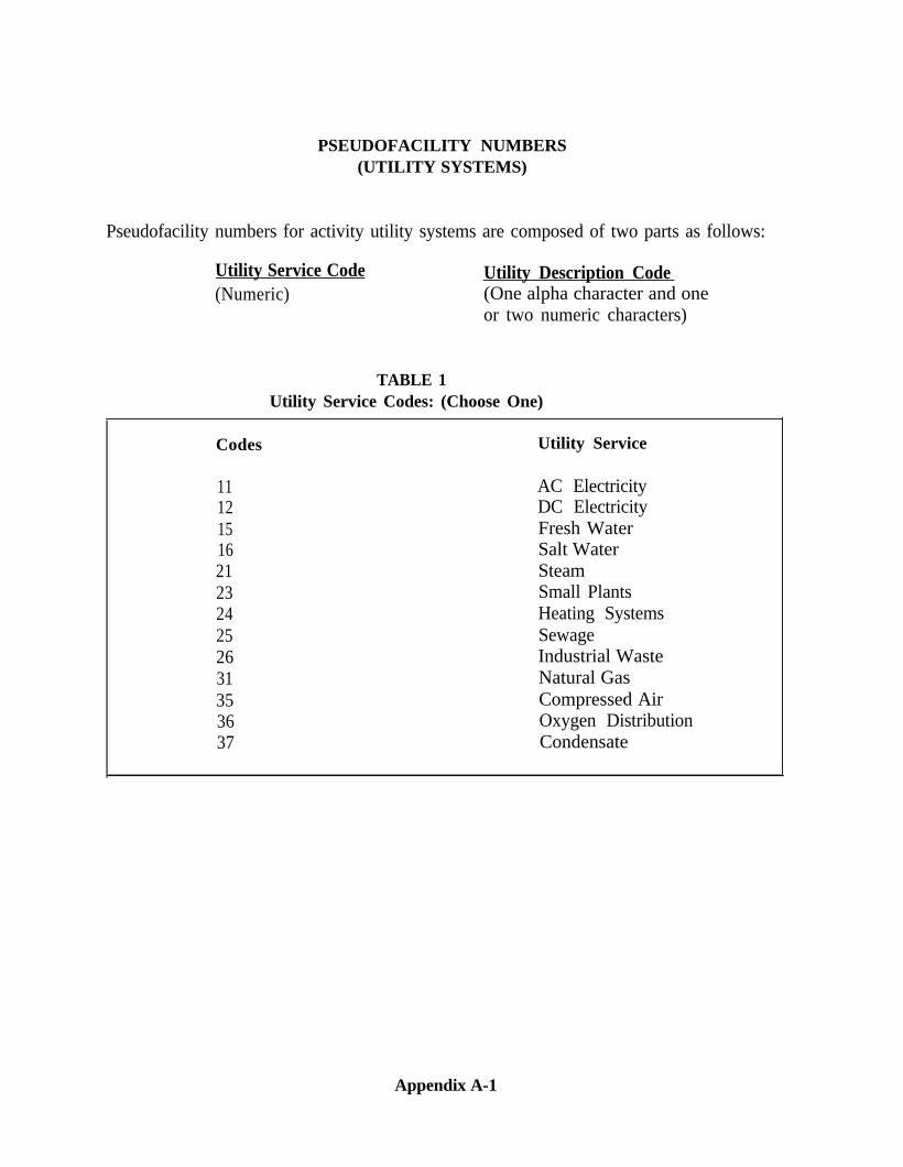
PSEUDOFACILITY NUMBERS(UTILITY SYSTEMS)
Pseudofacility numbers for activity utility systems are composed of two parts as follows:
(Numeric)Utility Service Code Utility Description Code
(One alpha character and oneor two numeric characters)
TABLE 1Utility Service Codes: (Choose One)
Codes Utility Service
11 AC Electricity12 DC Electricity15 Fresh Water16 Salt Water21 Steam23 Small Plants24 Heating Systems25 Sewage26 Industrial Waste31 Natural Gas35 Compressed Air36 Oxygen Distribution37 Condensate
Appendix A-1
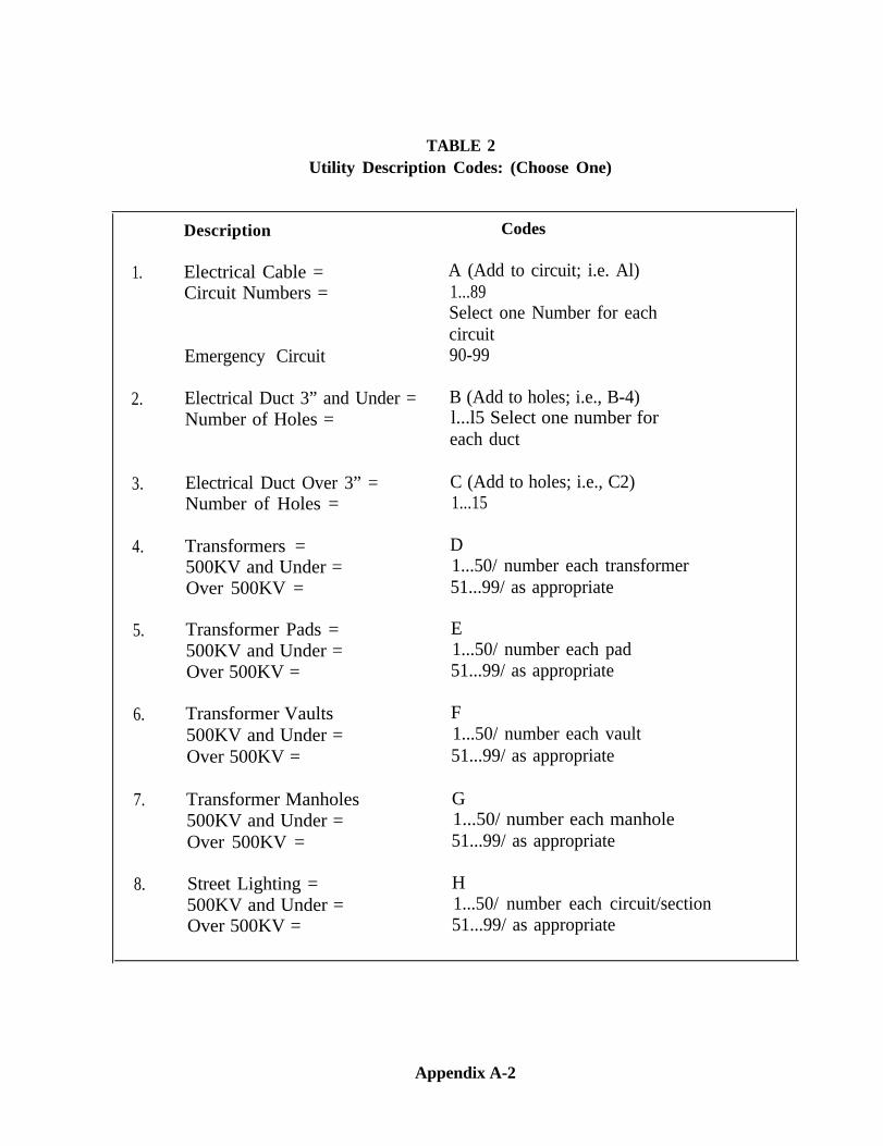
TABLE 2Utility Description Codes: (Choose One)
1.
2.
3.
4.
5.
6.
7.
8.
Description
Electrical Cable =Circuit Numbers =
Emergency Circuit
Electrical Duct 3” and Under =Number of Holes =
Electrical Duct Over 3” =Number of Holes =
Transformers =500KV and Under =Over 500KV =
Transformer Pads =500KV and Under =Over 500KV =
Transformer Vaults500KV and Under =Over 500KV =
Transformer Manholes500KV and Under =Over 500KV =
Street Lighting =500KV and Under =Over 500KV =
Codes
A (Add to circuit; i.e. Al)1...89Select one Number for eachcircuit90-99
B (Add to holes; i.e., B-4)l...l5 Select one number foreach duct
C (Add to holes; i.e., C2)1...15
D1...50/ number each transformer51...99/ as appropriate
E1...50/ number each pad51...99/ as appropriate
F1...50/ number each vault51...99/ as appropriate
G1...50/ number each manhole51...99/ as appropriate
H1...50/ number each circuit/section51...99/ as appropriate
Appendix A-2
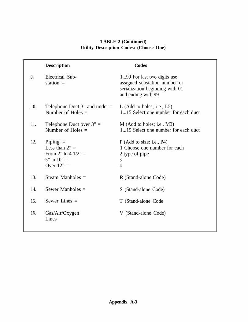
TABLE 2 (Continued)Utility Description Codes: (Choose One)
9.
10.
11.
12.
13.
14.
15.
16.
Description Codes
Electrical Sub-station =
1...99 For last two digits useassigned substation number orserialization beginning with 01and ending with 99
Telephone Duct 3” and under = L (Add to holes; i e., L5)Number of Holes = 1...15 Select one number for each duct
Telephone Duct over 3” = M (Add to holes; i.e., M3)Number of Holes = 1...15 Select one number for each duct
Piping = P (Add to size: i.e., P4)Less than 2” = 1 Choose one number for eachFrom 2” to 4 1/2” = 2 type of pipe5” to 10” = 3Over 12” = 4
Steam Manholes = R (Stand-alone Code)
Sewer Manholes = S (Stand-alone Code)
Sewer Lines = T (Stand-alone Code
Gas/Air/OxygenLines
V (Stand-alone Code)
Appendix A-3
APPENDIX BMinimum Recommended Frequencies
forControl Inspection
Use of minimum Control Inspection frequencies is not mandatory. They will howeverbe the basis for AIS Reporting to insure Navy-wide consistency in inspection coveragedetermination. They are also provided as a reasonable basis for Control Inspectionscheduling. Activities may wish to accelerate frequencies based on special mission re-quirements.
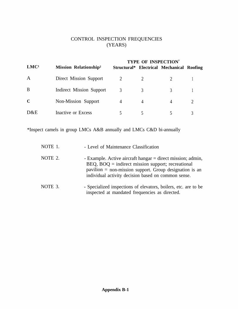
CONTROL INSPECTION FREQUENCIES(YEARS)
LMC¹ Mission Relationship²TYPE OF INSPECTION3
Structural* Electrical Mechanical Roofing
A Direct Mission Support 2 2 2 1
B Indirect Mission Support 3 3 3 1
C Non-Mission Support 4 4 4 2
D&E Inactive or Excess 5 5 5 3
*Inspect camels in group LMCs A&B annually and LMCs C&D bi-annually
NOTE 1. - Level of Maintenance Classification
NOTE 2. - Example. Active aircraft hangar = direct mission; admin,BEQ, BOQ = indirect mission support; recreationalpavilion = non-mission support. Group designation is anindividual activity decision based on common sense.
NOTE 3. - Specialized inspections of elevators, boilers, etc. are to beinspected at mandated frequencies as directed.
Appendix B-1
APPENDIX CControl Inspection Times
These tables include times for physical inspection only. Initial data collection andanalysis, travel, cost estimating and report writing are add-ons to times reflected. Thetables are provided as a guide for preparing initial inspection schedules. During inspec-tion performance, inspectors should record actual times for use in revising schedules.
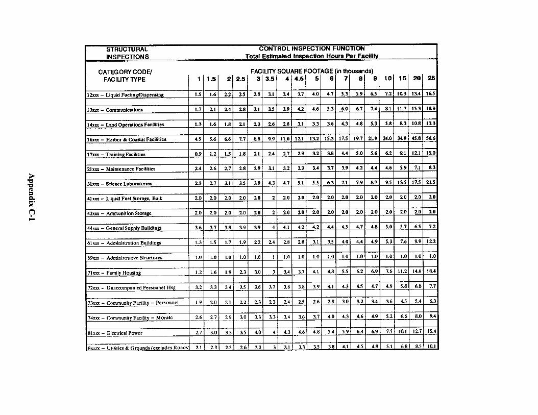
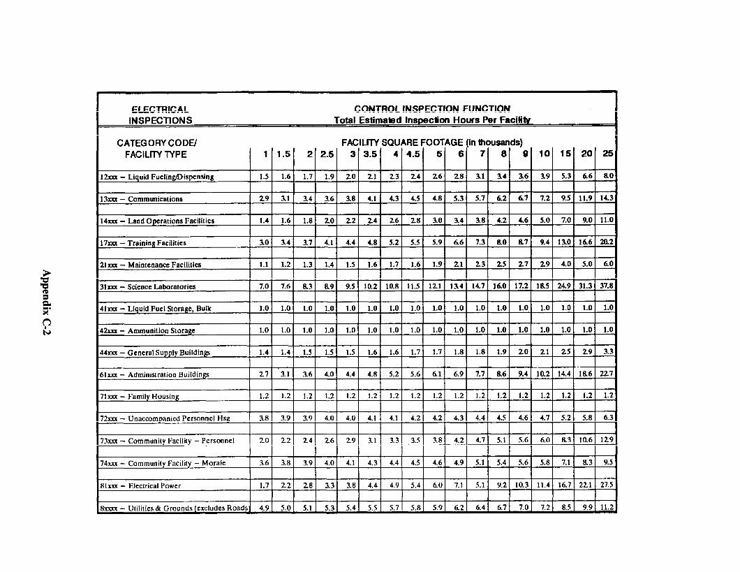
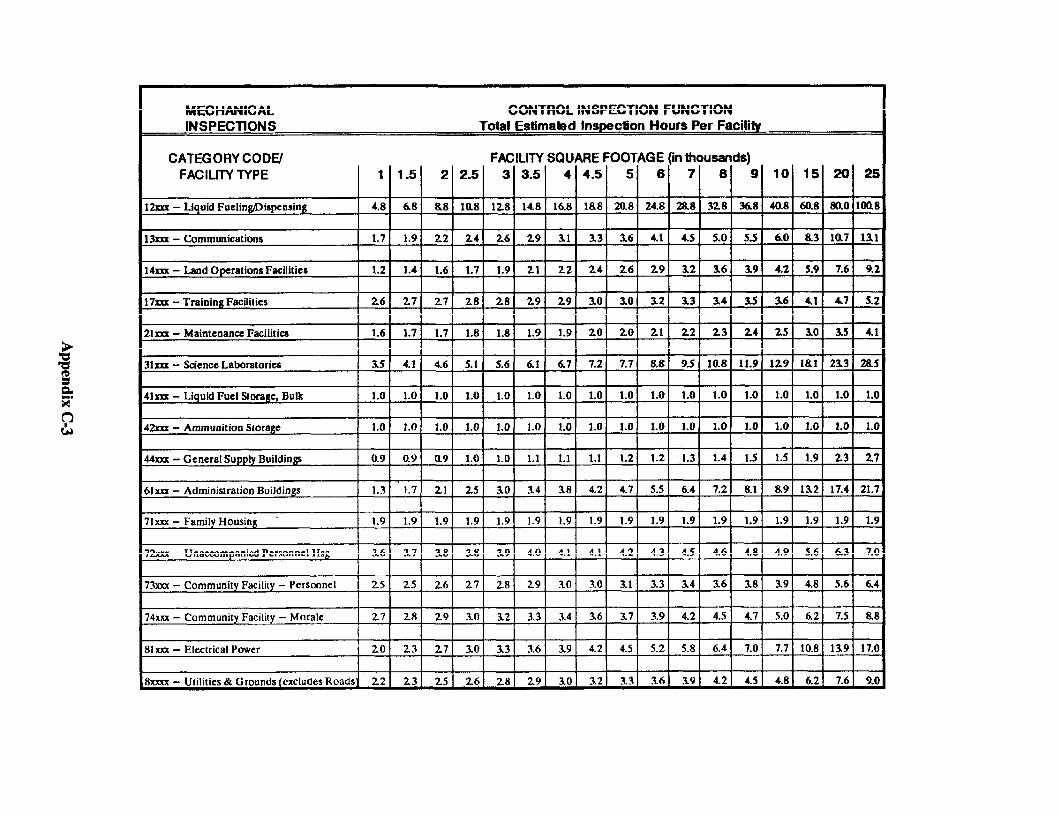
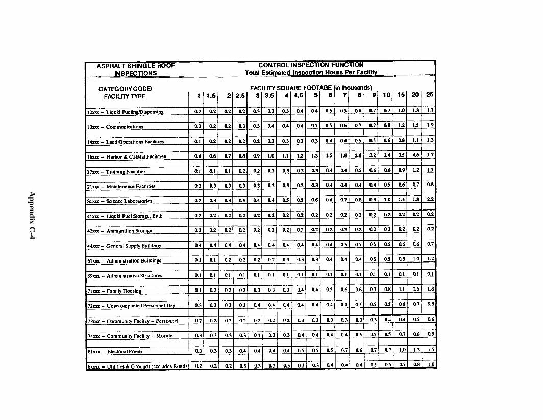
Appendix C
-4
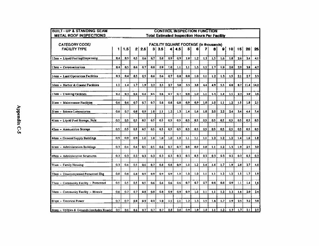
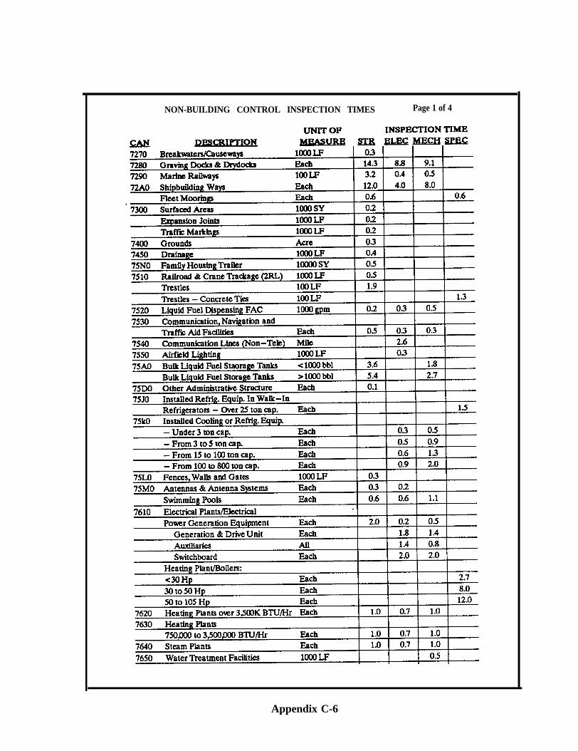
Appendix C-6
NON-BUILDING CONTROL INSPECTION TIMES Page 1 of 4
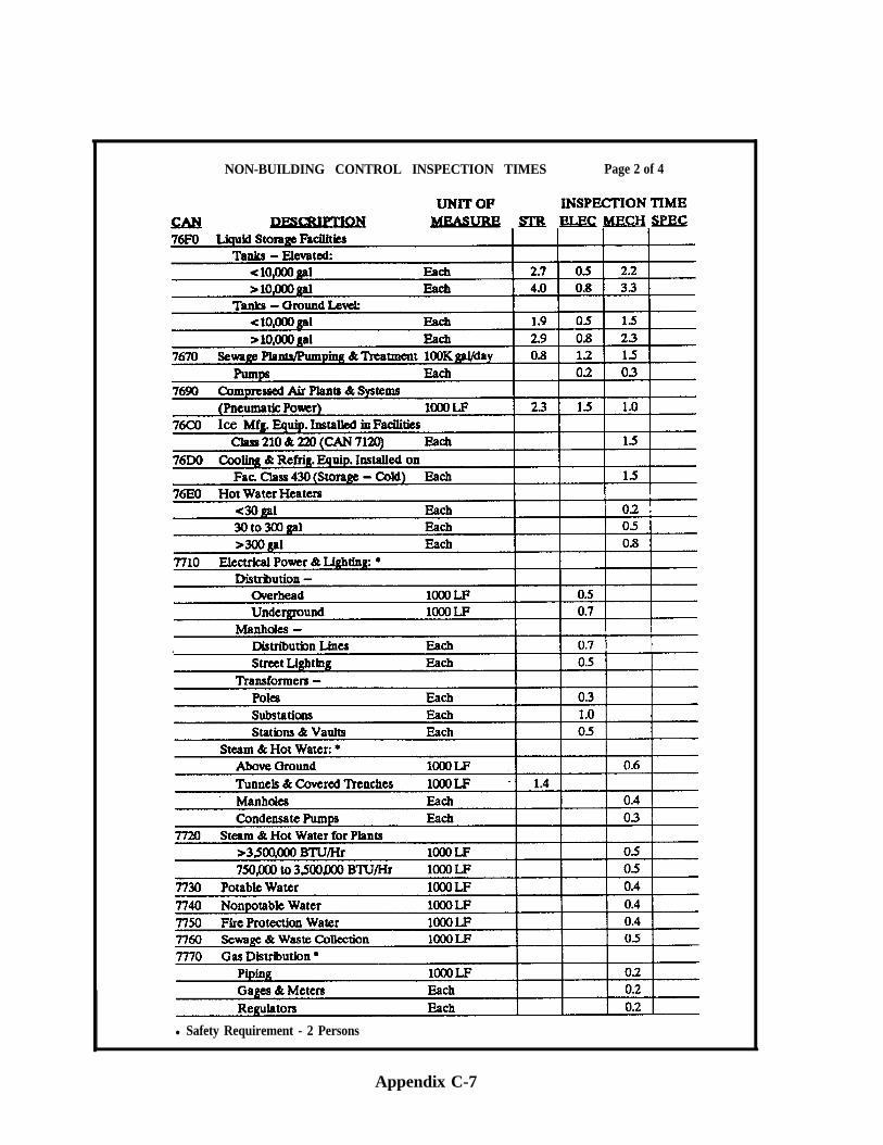
NON-BUILDING CONTROL INSPECTION TIMES Page 2 of 4
l Safety Requirement - 2 Persons
Appendix C-7
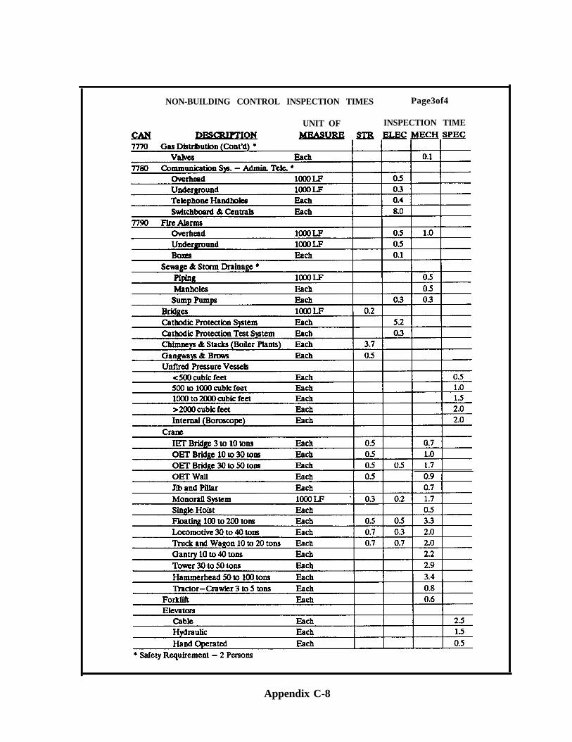
NON-BUILDING CONTROL INSPECTION TIMES Page3of4
UNIT OF INSPECTION TIME
Appendix C-8
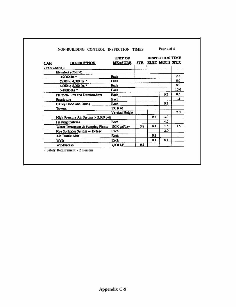
NON-BUILDING CONTROL INSPECTION TIMES Page 4 of 4
l Safety Requirement - 2 Persons
Appendix C-9
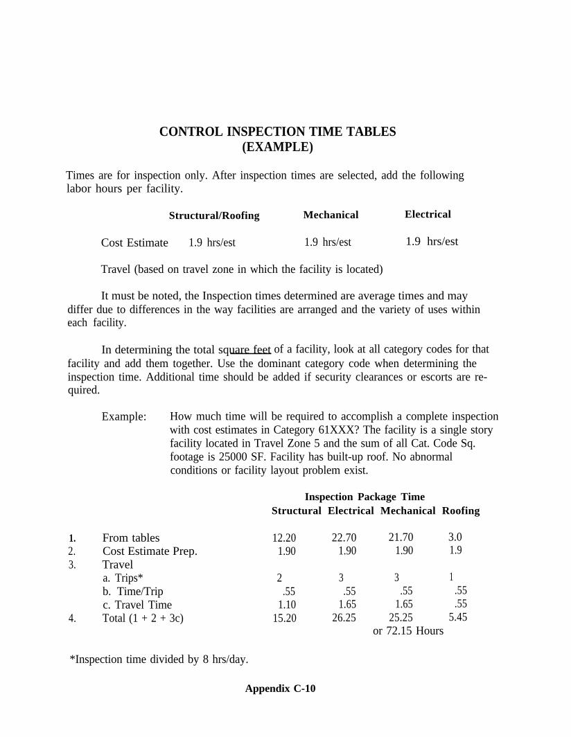
CONTROL INSPECTION TIME TABLES(EXAMPLE)
Times are for inspection only. After inspection times are selected, add the followinglabor hours per facility.
Structural/Roofing Mechanical
Cost Estimate 1.9 hrs/est 1.9 hrs/est
Travel (based on travel zone in which the facility is located)
Electrical
1.9 hrs/est
It must be noted, the Inspection times determined are average times and maydiffer due to differences in the way facilities are arranged and the variety of uses withineach facility.
In determining the total square feet of a facility, look at all category codes for thatfacility and add them together. Use the dominant category code when determining theinspection time. Additional time should be added if security clearances or escorts are re-quired.
Example: How much time will be required to accomplish a complete inspectionwith cost estimates in Category 61XXX? The facility is a single storyfacility located in Travel Zone 5 and the sum of all Cat. Code Sq.footage is 25000 SF. Facility has built-up roof. No abnormalconditions or facility layout problem exist.
Inspection Package TimeStructural Electrical Mechanical Roofing
1.2.3.
4.
From tablesCost Estimate Prep.Travela. Trips*b. Time/Tripc. Travel TimeTotal (1 + 2 + 3c)
12.201.90
2.55
1.1015.20
*Inspection time divided by 8 hrs/day.
Appendix C-10
22.70 21.70 3.01.90 1.90 1.9
3 3 1.55 .55 .55
1.65 1.65 .5526.25 25.25 5.45
or 72.15 Hours
APPENDIX DFacility Inspection Checklist
This form is used as a cover sheet for the completed Inspection Report package. It tellsmanagement at a glance what facility components were inspected. It lists items to be in-spected.
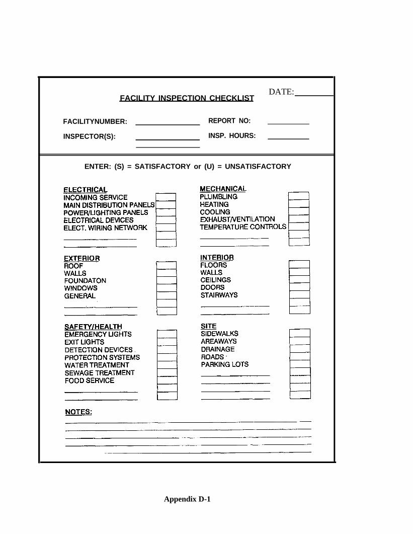
FACILITY INSPECTION CHECKLISTDATE:
FACILITYNUMBER: REPORT NO:
INSPECTOR(S): INSP. HOURS:
ENTER: (S) = SATISFACTORY or (U) = UNSATISFACTORY
Appendix D-1
APPENDIX E
WORK PACKAGING
Work identified by inspection is used for AIS, budget, contract and shop loadingdecisions. This Appendix is one technique for “packaging” deficiencies together the wayit makes sense to do the job.
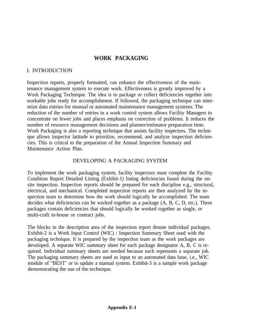
WORK PACKAGING
I. INTRODUCTION
Inspection reports, properly formatted, can enhance the effectiveness of the main-tenance management system to execute work. Effectiveness is greatly improved by aWork Packaging Technique. The idea is to package or collect deficiencies together intoworkable jobs ready for accomplishment. If followed, the packaging technique can mini-mize data entries for manual or automated maintenance management systems. Thereduction of the number of entries in a work control system allows Facility Managers toconcentrate on fewer jobs and places emphasis on correction of problems. It reduces thenumber of resource management decisions and planner/estimator preparation time.Work Packaging is also a reporting technique that assists facility inspectors. The techni-que allows inspector latitude to prioritize, recommend, and analyze inspection deficien-cies. This is critical to the preparation of the Annual Inspection Summary andMaintenance Action Plan.
DEVELOPING A PACKAGING SYSTEM
To implement the work packaging system, facility inspectors must complete the FacilityCondition Report Detailed Listing (Exhibit-1) listing deficiencies found during the on-site inspection. Inspection reports should be prepared for each discipline e.g., structural,electrical, and mechanical. Completed inspection reports are then analyzed by the in-spection team to determine how the work should logically be accomplished. The teamdecides what deficiencies can be worked together as a package (A, B, C, D, etc.). Thesepackages contain deficiencies that should logically be worked together as single, ormulti-craft in-house or contract jobs.
The blocks in the description area of the inspection report denote individual packages.Exhibit-2 is a Work Input Control (WIC) / Inspection Summary Sheet used with thepackaging technique. It is prepared by the inspection team as the work packages aredeveloped. A separate WIC summary sheet for each package designator A, B, C is re-quired. Individual summary sheets are needed because each represents a separate job.The packaging summary sheets are used as input to an automated data base, i.e., WICmodule of “BEST’ or to update a manual system. Exhibit-3 is a sample work packagedemonstrating the use of the technique.
Appendix E-1
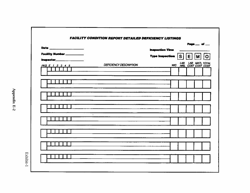
Exhibit-1
Appendix E
-2
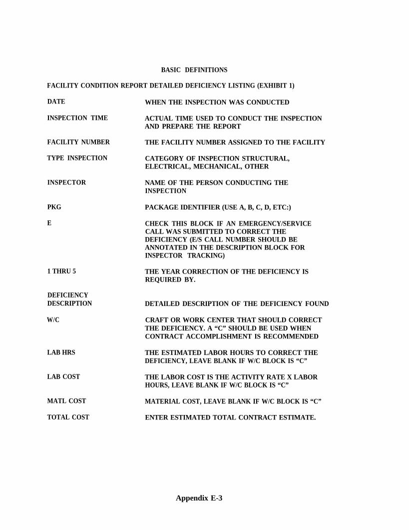
BASIC DEFINITIONS
FACILITY CONDITION REPORT DETAILED DEFICIENCY LISTING (EXHIBIT 1)
DATE WHEN THE INSPECTION WAS CONDUCTED
INSPECTION TIME ACTUAL TIME USED TO CONDUCT THE INSPECTIONAND PREPARE THE REPORT
FACILITY NUMBER THE FACILITY NUMBER ASSIGNED TO THE FACILITY
TYPE INSPECTION CATEGORY OF INSPECTION STRUCTURAL,ELECTRICAL, MECHANICAL, OTHER
INSPECTOR NAME OF THE PERSON CONDUCTING THEINSPECTION
PKG PACKAGE IDENTIFIER (USE A, B, C, D, ETC:)
E CHECK THIS BLOCK IF AN EMERGENCY/SERVICECALL WAS SUBMITTED TO CORRECT THEDEFICIENCY (E/S CALL NUMBER SHOULD BEANNOTATED IN THE DESCRIPTION BLOCK FORINSPECTOR TRACKING)
1 THRU 5
DEFICIENCYDESCRIPTION
W/C
LAB HRS
LAB COST
MATL COST MATERIAL COST, LEAVE BLANK IF W/C BLOCK IS “C”
TOTAL COST ENTER ESTIMATED TOTAL CONTRACT ESTIMATE.
THE YEAR CORRECTION OF THE DEFICIENCY ISREQUIRED BY.
DETAILED DESCRIPTION OF THE DEFICIENCY FOUND
CRAFT OR WORK CENTER THAT SHOULD CORRECTTHE DEFICIENCY. A “C” SHOULD BE USED WHENCONTRACT ACCOMPLISHMENT IS RECOMMENDED
THE ESTIMATED LABOR HOURS TO CORRECT THEDEFICIENCY, LEAVE BLANK IF W/C BLOCK IS “C”
THE LABOR COST IS THE ACTIVITY RATE X LABORHOURS, LEAVE BLANK IF W/C BLOCK IS “C”
Appendix E-3
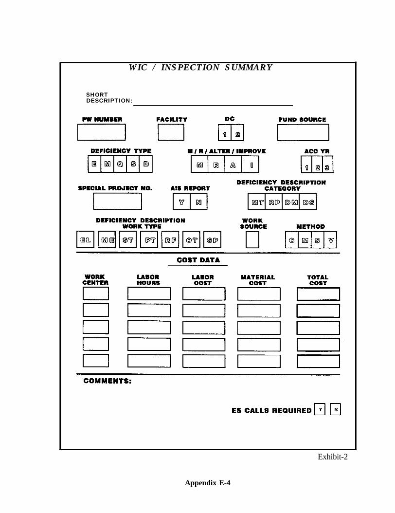
WIC / INSPECTION SUMMARY
SHORTDESCRIPTION:
Exhibit-2
Appendix E-4
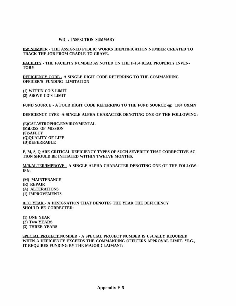
WIC / INSPECTION SUMMARY
PW NUMBER - THE ASSIGNED PUBLIC WORKS IDENTIFICATION NUMBER CREATED TOTRACK THE JOB FROM CRADLE TO GRAVE.
FACILITY - THE FACILITY NUMBER AS NOTED ON THE P-164 REAL PROPERTY INVEN-TORY
DEFICIENCY CODE - A SINGLE DIGIT CODE REFERRING TO THE COMMANDINGOFFICER’S FUNDING LIMITATION
(1) WITHIN CO’S LIMIT(2) ABOVE CO’S LIMIT
FUND SOURCE - A FOUR DIGIT CODE REFERRING TO THE FUND SOURCE eg: 1804 O&MN
DEFICIENCY TYPE- A SINGLE ALPHA CHARACTER DENOTING ONE OF THE FOLLOWING:
(E)CATASTROPHIC/ENVIRONMENTAL(M)LOSS OF MISSION(S)SAFETY(Q)QUALITY OF LIFE(D)DEFERRABLE
E, M, S, Q ARE CRITICAL DEFICIENCY TYPES OF SUCH SEVERITY THAT CORRECTIVE AC-TION SHOULD BE INITIATED WITHIN TWELVE MONTHS.
M/R/ALTER/IMPROVE - A SINGLE ALPHA CHARACTER DENOTING ONE OF THE FOLLOW-ING:
(M) MAINTENANCE(R) REPAIR(A) ALTERATIONS(1) IMPROVEMENTS
ACC YEAR - A DESIGNATION THAT DENOTES THE YEAR THE DEFICIENCYSHOULD BE CORRECTED:
(1) ONE YEAR(2) Two YEARS(3) THREE YEARS
SPECIAL PROJECT NUMBER - A SPECIAL PROJECT NUMBER IS USUALLY REQUIREDWHEN A DEFICIENCY EXCEEDS THE COMMANDING OFFICERS APPROVAL LIMIT. *E.G.,IT REQUIRES FUNDING BY THE MAJOR CLAIMANT:
Appendix E-5
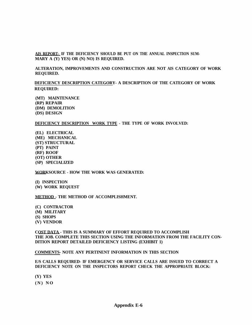
AIS REPORT- IF THE DEFICIENCY SHOULD BE PUT ON THE ANNUAL INSPECTION SUM-MARY A (Y) YES) OR (N) NO) IS REQUIRED.
ALTERATION, IMPROVEMENTS AND CONSTRUCTION ARE NOT AIS CATEGORY OF WORKREQUIRED.
DEFICIENCY DESCRIPTION CATEGORY- A DESCRIPTION OF THE CATEGORY OF WORKREQUIRED:
(MT) MAINTENANCE(RP) REPAIR(DM) DEMOLITION(DS) DESIGN
DEFICIENCY DESCRIPTION WORK TYPE - THE TYPE OF WORK INVOLVED:
(EL) ELECTRICAL(ME) MECHANICAL(ST) STRUCTURAL(PT) PAINT(RF) ROOF(OT) OTHER(SP) SPECIALIZED
WORKSOURCE - HOW THE WORK WAS GENERATED:
(I) INSPECTION(W) WORK REQUEST
METHOD - THE METHOD OF ACCOMPLISHMENT.
(C) CONTRACTOR(M) MILITARY(S) SHOPS(V) VENDOR
COST DATA - THIS IS A SUMMARY OF EFFORT REQUIRED TO ACCOMPLISHTHE JOB. COMPLETE THIS SECTION USING THE INFORMATION FROM THE FACILITY CON-DITION REPORT DETAILED DEFICIENCY LISTING (EXHIBIT 1)
COMMENTS- NOTE ANY PERTINENT INFORMATION IN THIS SECTION
E/S CALLS REQUIRED- IF EMERGENCY OR SERVICE CALLS ARE ISSUED TO CORRECT ADEFICIENCY NOTE ON THE INSPECTORS REPORT CHECK THE APPROPRIATE BLOCK:
(Y) YES
( N ) N O
Appendix E-6
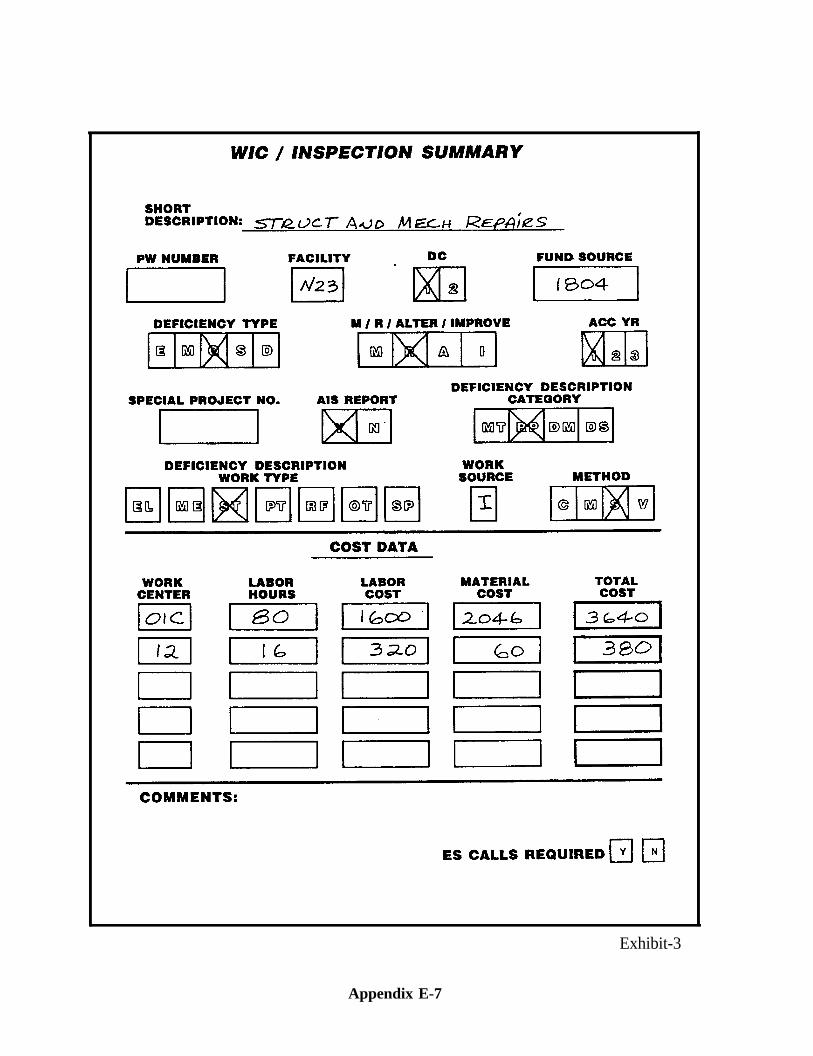
Exhibit-3
Appendix E-7
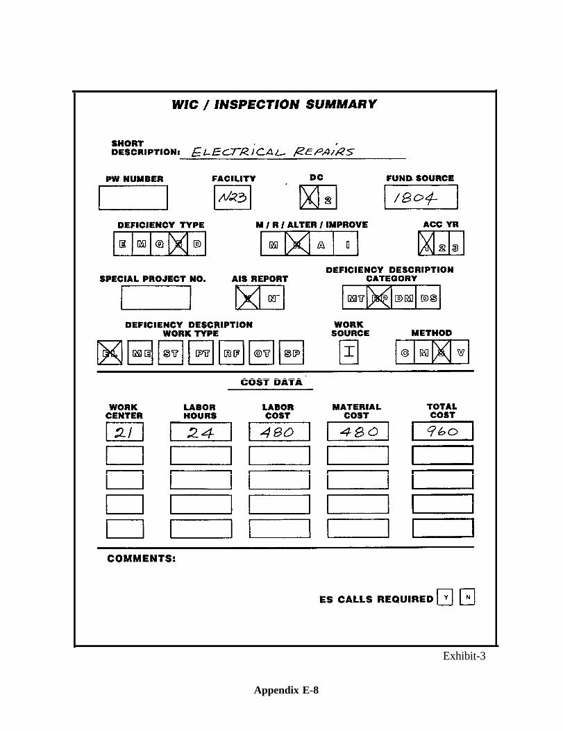
Exhibit-3
Appendix E-8
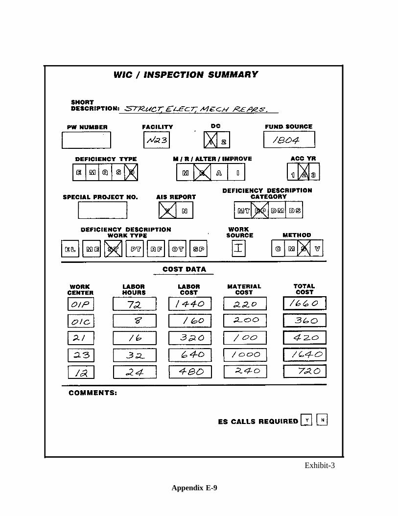
Exhibit-3
Appendix E-9
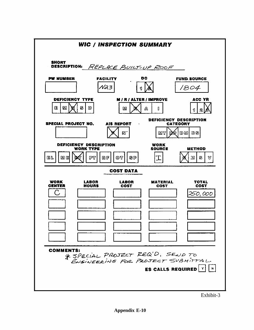
Exhibit-3
Appendix E-10
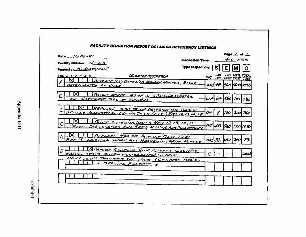
Exhibit-3
Appendix E
-11
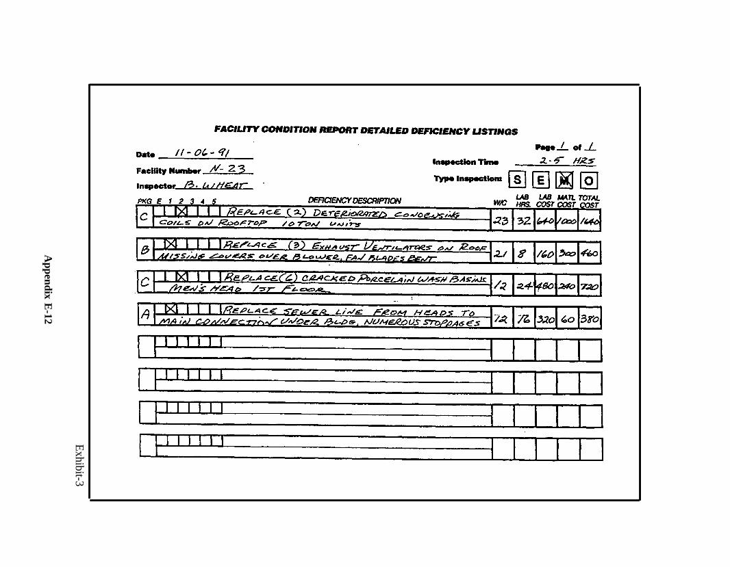
Exhibit-3
Appendix E
-12
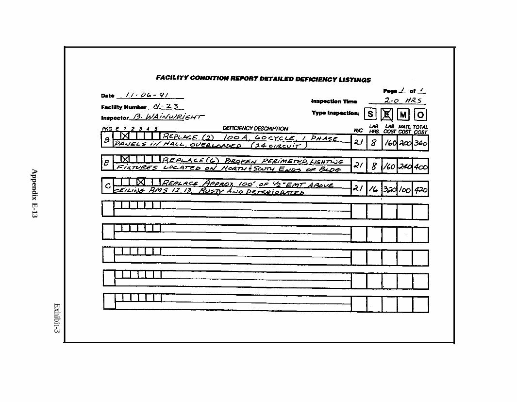
Exhibit-3
Appendix E
-13
APPENDIX F
MAINTENANCE PLANNING(MAINTENANCE ACTION PLAN - MAP)
The Maintenance Action Plan (MAP) is a list of high priority Minor and Specific typework that is to be accomplished, either in-house or by contract.
MAINTENANCE PLANNING(MAINTENANCE ACTION PLAN - MAP)
I. INTRODUCTION
The Maintenance Action Plan (MAP) is a list of high priority Minor and Specific typework that is to be accomplished, either in-house or by contract within resources avail-able. It is a resources execution tool that should be prepared in the spring (NAV-COMPT/APPORTIONMENT) for the following fiscal year (FY). The MAP is part ofthe overall MAP Maintenance Plan that includes a plan to accomplish specific highpriority items of maintenance and repair (M & R) work. The MAP is comprised of in-dividual critical maintenance and repair (CMAR) items selected from a current updateof the Annual Inspection Summary (AIS). CMAR items have the highest priority andshould be selected from Investment Categories (IC) of greatest importance to the MajorClaimant and the activity. Detailed guidance for preparation of the AIS can be found inthe OPNAV Instruction 11010.34 series.
II. DETERMINING MINOR AND SPECIFIC RESOURCES
The first step in M&R budgeting and planning is to identify FA/M1 budget “require-ment.” This consists of determining the amount of valid resource needs for recurringwork such as Emergency/Service (E/S), Standing Job Orders (SJO), repetitive contracts,Maintenance Shop and Facilities Management Engineering Division (FMED) overheadsupport and non-recurring work such as Minor and Specific Jobs generated from AISDeficiency Code (DC) - one (1) items. Part “A” of Exhibit-1 contains a format for M&R“requirements” identification.
Once determined, the next step is to carefully reduce “requirements” to what you mustlive with in terms of actual funds available, i.e., the assigned FA/M1 dollar control.Generally, fixed items such as E/S, SJOs, and overhead support can’t be reduced belowa certain acceptable level. Flexibility nearly always must come from the amount of avail-able funds that can be realistically allotted to Minor and Specific work, i.e., DC-1CMAR deficiencies. Note - The AIS contains deferrable DC-1 M&R deficiencies(DMAR) which are also part of “requirements” subject to funding consideration, i.e.,they compete for available funds, but from a position of weakness, i.e., they’re not criti-cal. Funds remaining “after” funding fixed items is the starting point for the MAP and itsdevelopment. Part “B” of Exhibit-1 contains a format for Op-plan development and finaldetermination of that portion of Ml funds available for specific M&R items.
Appendix F-1
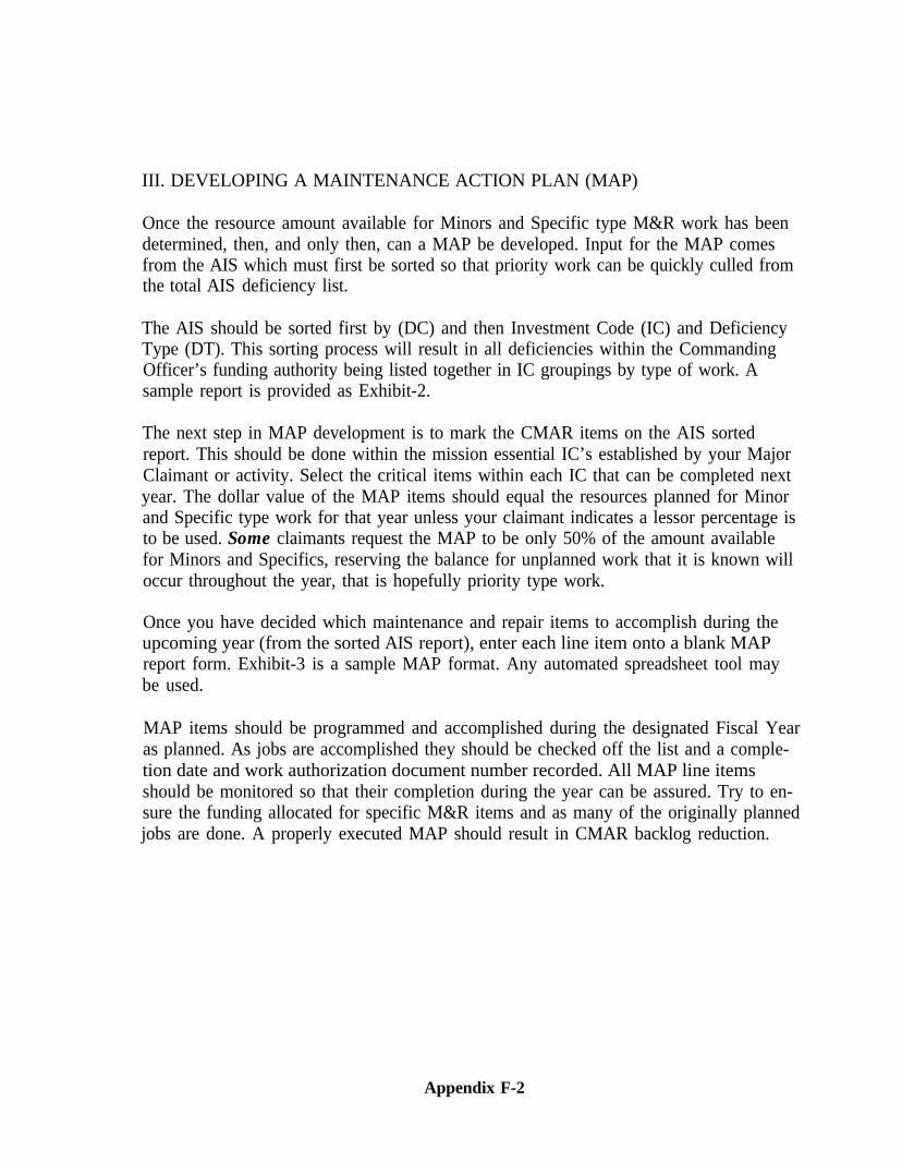
III. DEVELOPING A MAINTENANCE ACTION PLAN (MAP)
Once the resource amount available for Minors and Specific type M&R work has beendetermined, then, and only then, can a MAP be developed. Input for the MAP comesfrom the AIS which must first be sorted so that priority work can be quickly culled fromthe total AIS deficiency list.
The AIS should be sorted first by (DC) and then Investment Code (IC) and DeficiencyType (DT). This sorting process will result in all deficiencies within the CommandingOfficer’s funding authority being listed together in IC groupings by type of work. Asample report is provided as Exhibit-2.
The next step in MAP development is to mark the CMAR items on the AIS sortedreport. This should be done within the mission essential IC’s established by your MajorClaimant or activity. Select the critical items within each IC that can be completed nextyear. The dollar value of the MAP items should equal the resources planned for Minorand Specific type work for that year unless your claimant indicates a lessor percentage isto be used. Some claimants request the MAP to be only 50% of the amount availablefor Minors and Specifics, reserving the balance for unplanned work that it is known willoccur throughout the year, that is hopefully priority type work.
Once you have decided which maintenance and repair items to accomplish during theupcoming year (from the sorted AIS report), enter each line item onto a blank MAPreport form. Exhibit-3 is a sample MAP format. Any automated spreadsheet tool maybe used.
MAP items should be programmed and accomplished during the designated Fiscal Yearas planned. As jobs are accomplished they should be checked off the list and a comple-tion date and work authorization document number recorded. All MAP line itemsshould be monitored so that their completion during the year can be assured. Try to en-sure the funding allocated for specific M&R items and as many of the originally plannedjobs are done. A properly executed MAP should result in CMAR backlog reduction.
Appendix F-2
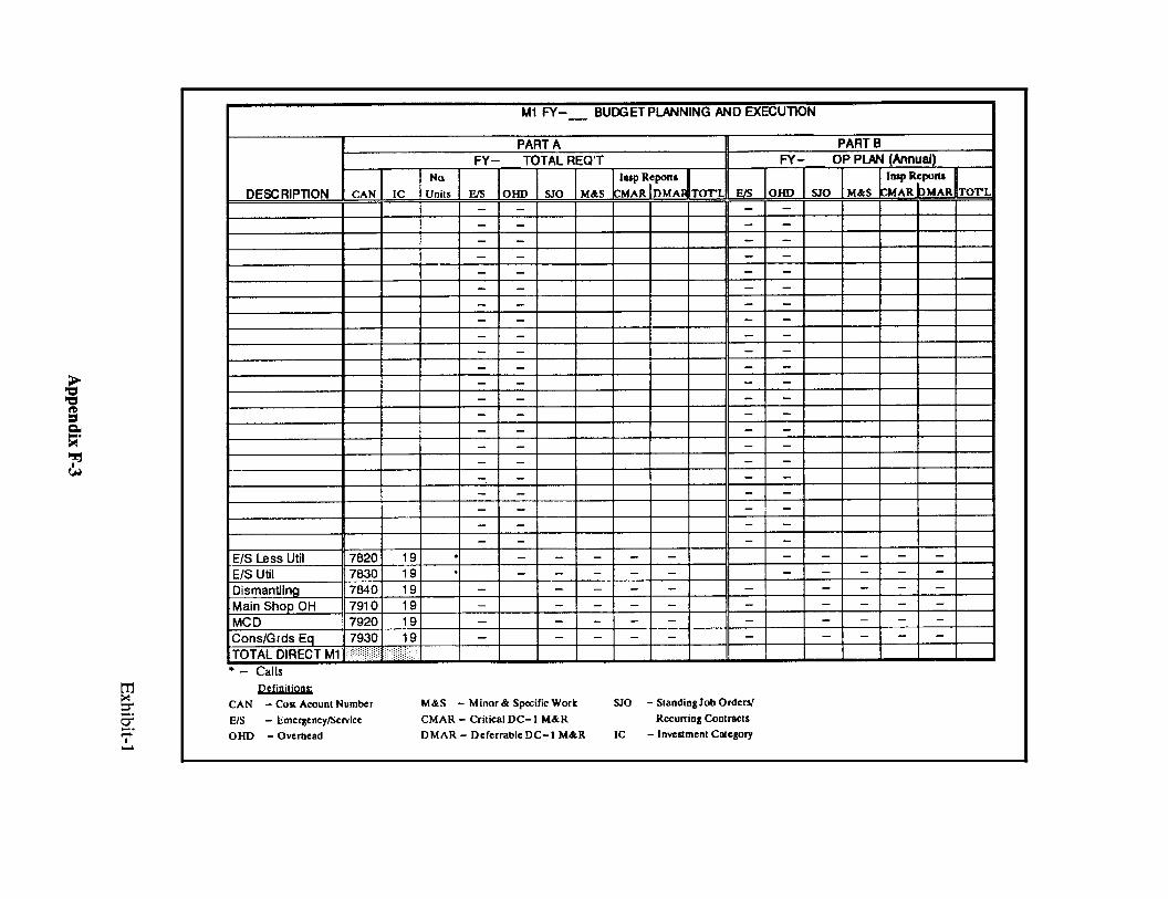
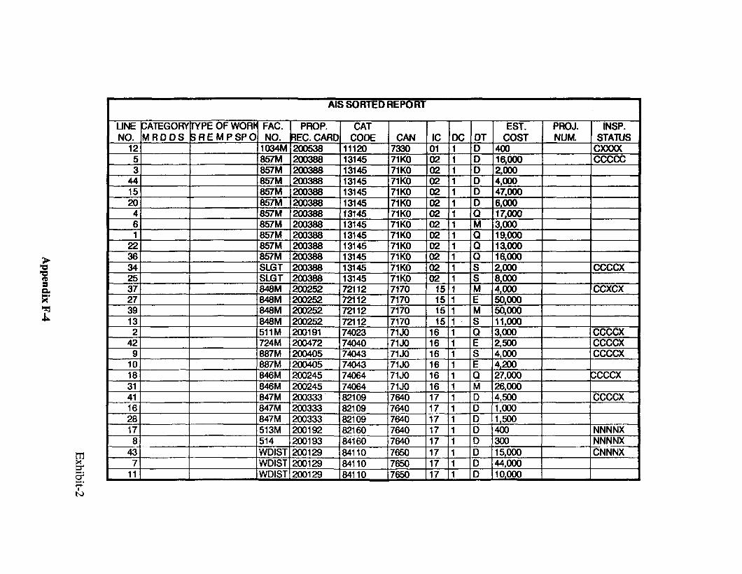
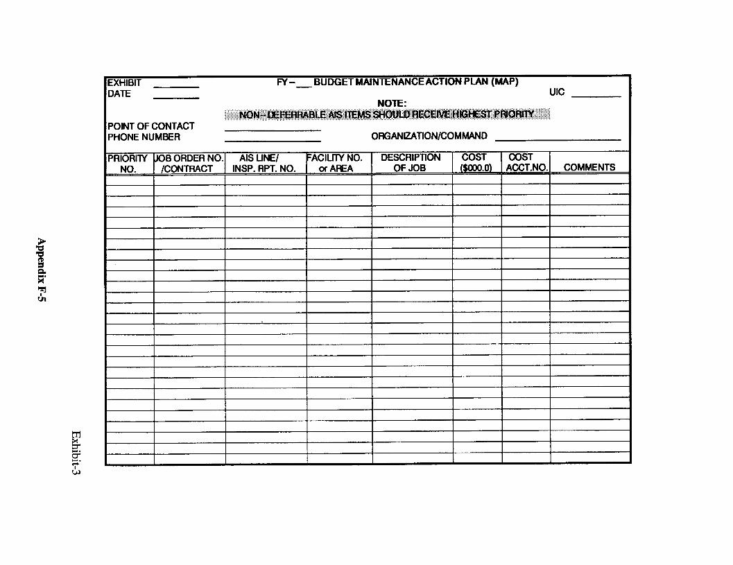
APPENDIX G
LONG RANGE MAINTENANCE PLANNING
(LRMP)
LONG RANGE MAINTENANCE PLANNING
I. INTRODUCTION
Long Range Maintenance Planning (LRMP) is a management system based on com-prehensive facility inspections and accurate cost estimates. The control inspection sys-tem provides the framework for the development of the Long Range MaintenancePlanning system. Both provide guidelines for systematic, in-depth documentation ofmaintenance and repair requirements forecasted over a multi-year planning cycle. TheLRMP system of inspection not only provides for in-depth inspection but inventory offacility components and installed equipment. It also provides additional emphasis on re-search, summarization and analysis.
Inventory of plant and equipment is the basic foundation block of the maintenancemanagement system. Control inspection does not emphasize the inventory phase andlisting of building systems and components as LRMP does. The inventory data collectedin the performance of LRMP inspections provides planning engineers with a listing offacility systems and components such as numbers of doors, windows, light fixtures, etc.The initial collection of this inventory is labor intensive.
Activities that utilize Control Inspection or Long Range Maintenance Planning inspec-tions are in a better position to formulate funding strategies and to allocate resource dol-lars. The KEY is to inspect, plan, and respond to the critical mission needs and futurefacility requirements.
II. OBJECTIVES
A. Document unfunded deficiencies and project system failures
B. Project budget and ceiling requirements
C. Produce an Annual Inspection Summary based on valid comprehensiveinspections, and a Budget plan addressing those deficiencies
D. Provide a dedicated inspection workforce
III. LRMP PROCESS
The LRMP process includes, but is not limited to, the following components:
Appendix G-1
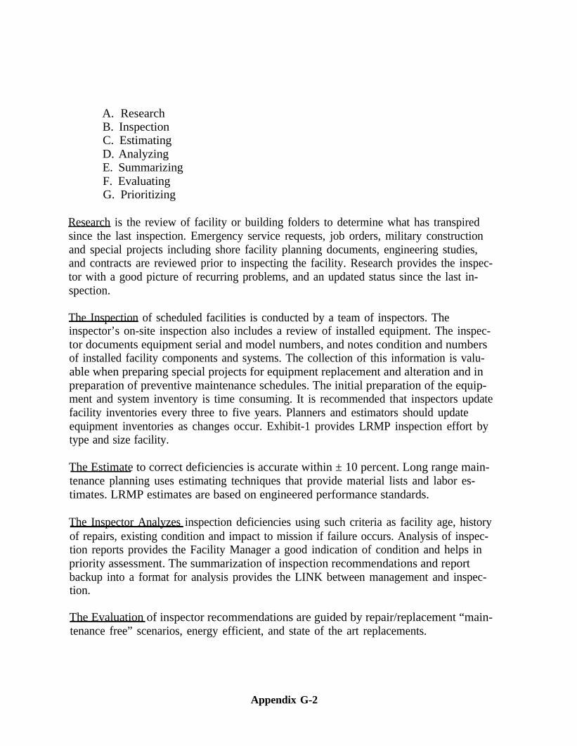
A. ResearchB. InspectionC. EstimatingD. AnalyzingE. SummarizingF. EvaluatingG. Prioritizing
Research is the review of facility or building folders to determine what has transpiredsince the last inspection. Emergency service requests, job orders, military constructionand special projects including shore facility planning documents, engineering studies,and contracts are reviewed prior to inspecting the facility. Research provides the inspec-tor with a good picture of recurring problems, and an updated status since the last in-spection.
The Inspection of scheduled facilities is conducted by a team of inspectors. Theinspector’s on-site inspection also includes a review of installed equipment. The inspec-tor documents equipment serial and model numbers, and notes condition and numbersof installed facility components and systems. The collection of this information is valu-able when preparing special projects for equipment replacement and alteration and inpreparation of preventive maintenance schedules. The initial preparation of the equip-ment and system inventory is time consuming. It is recommended that inspectors updatefacility inventories every three to five years. Planners and estimators should updateequipment inventories as changes occur. Exhibit-1 provides LRMP inspection effort bytype and size facility.
The Estimate to correct deficiencies is accurate within ± 10 percent. Long range main-tenance planning uses estimating techniques that provide material lists and labor es-timates. LRMP estimates are based on engineered performance standards.
The Inspector Analyzes inspection deficiencies using such criteria as facility age, historyof repairs, existing condition and impact to mission if failure occurs. Analysis of inspec-tion reports provides the Facility Manager a good indication of condition and helps inpriority assessment. The summarization of inspection recommendations and reportbackup into a format for analysis provides the LINK between management and inspec-tion.
The Evaluation of inspector recommendations are guided by repair/replacement “main-tenance free” scenarios, energy efficient, and state of the art replacements.
Appendix G-2
Priority or year of accomplishment recommendations are made by the inspector usingcriteria compatible with published AIS guidance, i.e., OPNAV Instruction 11010.34B.Priorities assigned are:
1st year Critical Deficiencies
Deficiencies that need to be accomplished in one year and will result in at least one ofthe following: loss of mission, catastrophic environmental, quality of life, or safety.
2nd and 3rd year Deferrable Deficiencies
Deficiencies which do not display signs of imminent system failure, but rapid deteriora-tion is evident with the system nearing the end of its life expectancy.
4th and 5th year Deferrable Deficiencies
Deficiencies which display some deterioration. The system is functional but nearing itslife expectancy within five years. Fourth and fifth year deficiencies should be re-evaluated prior to funding consideration (at least every 3 to 5 years).
IV. SYSTEM COMPARISON
A comparison of Control Inspection and Long Range Maintenance Planning is difficultbecause each system has it’s own unique advantages. Exhibit-2, Control Inspection/LongRange Maintenance Planning Comparative Analysis, outlines significant components ofeach system.
V. LRMP INSTALLATION
For additional information, assistance, or installation of the Long Range MaintenancePlanning system contact the nearest Public Works Center, NAVFAC Code 161, or En-gineering Field Division/Engineering Field Activity (EFD/EFA).
Appendix G-3
LONG RANGE MAINTENANCE PLANNING (LRMP)INSPECTION
TIMES
These tables include times for Physical Inspection and Report Writing. Initial Data Col-lection and Analyses, Travel and Cost Estimating are add-ons to times reflected. Thetables are provided as a guide for preparing initial inspection schedules. During inspec-tion performance, inspectors should record actual times for use in revising schedules.
Exhibit- 1
Appendix G-4
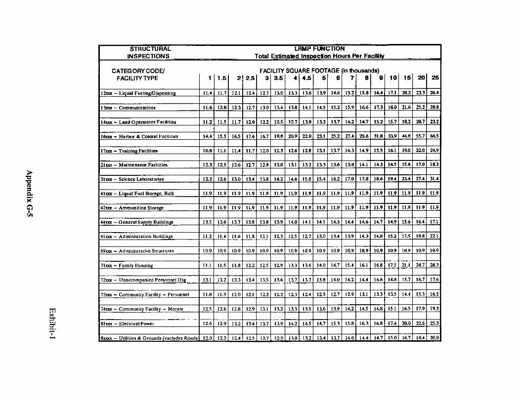
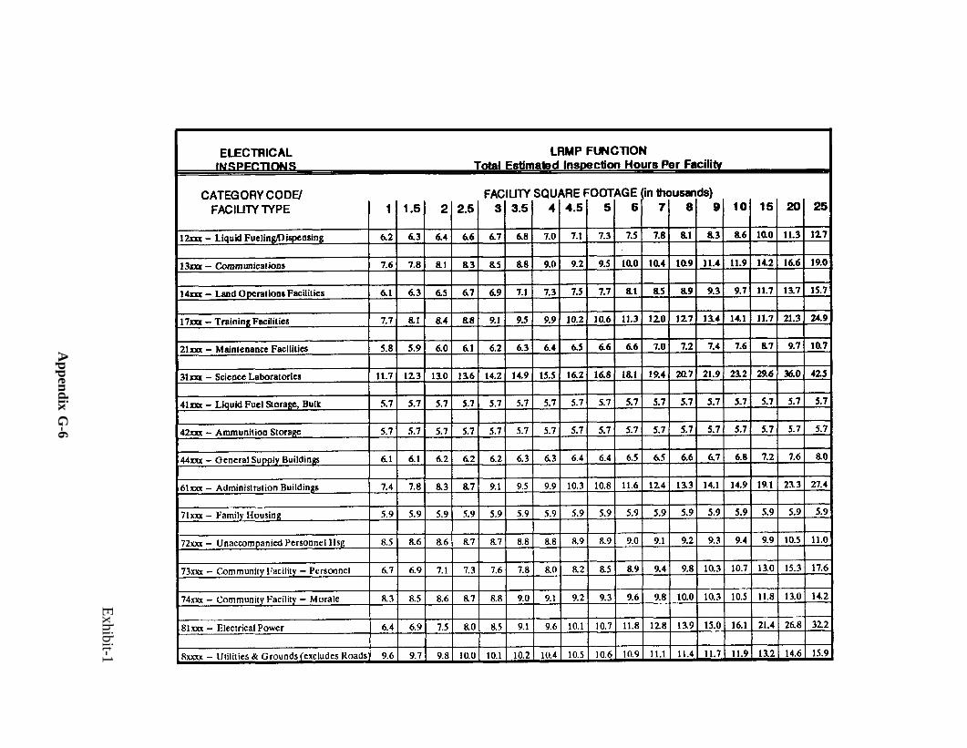
Exhibit-1
Appendix G
-6
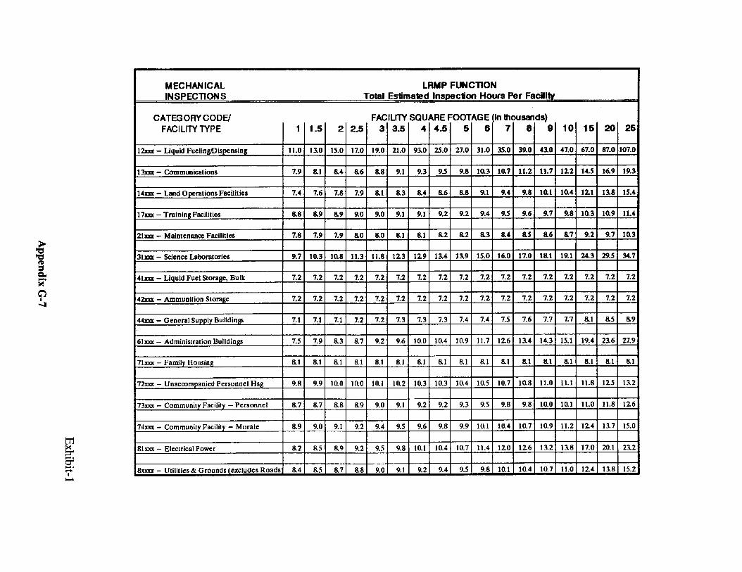
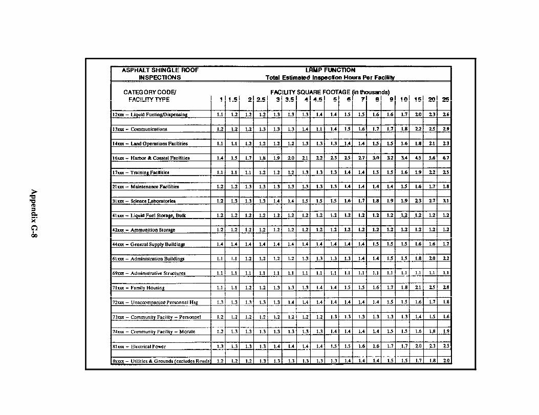
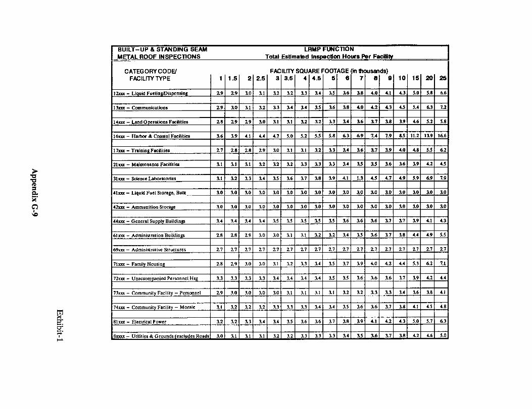
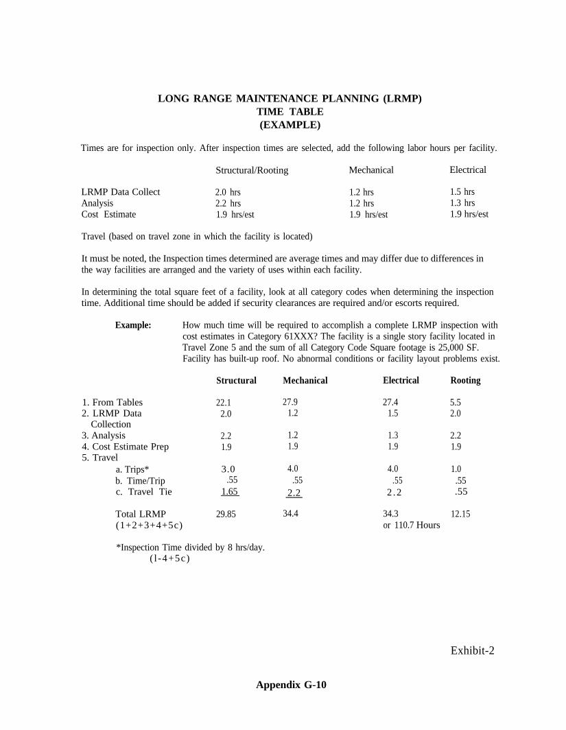
LONG RANGE MAINTENANCE PLANNING (LRMP)TIME TABLE(EXAMPLE)
Times are for inspection only. After inspection times are selected, add the following labor hours per facility.
Structural/Rooting
LRMP Data Collect 2.0 hrsAnalysis 2.2 hrsCost Estimate 1.9 hrs/est
Travel (based on travel zone in which the facility is located)
Mechanical Electrical
1.2 hrs 1.5 hrs1.2 hrs 1.3 hrs1.9 hrs/est 1.9 hrs/est
It must be noted, the Inspection times determined are average times and may differ due to differences inthe way facilities are arranged and the variety of uses within each facility.
In determining the total square feet of a facility, look at all category codes when determining the inspectiontime. Additional time should be added if security clearances are required and/or escorts required.
Example: How much time will be required to accomplish a complete LRMP inspection withcost estimates in Category 61XXX? The facility is a single story facility located inTravel Zone 5 and the sum of all Category Code Square footage is 25,000 SF.Facility has built-up roof. No abnormal conditions or facility layout problems exist.
1. From Tables2. LRMP Data
Collection3. Analysis4. Cost Estimate Prep5. Travel
a. Trips*b. Time/Tripc. Travel Tie
Structural
22.12.0
2.21.9
3.0.55
1.65
Total LRMP 29.85(1+2+3+4+5c)
*Inspection Time divided by 8 hrs/day.( l -4+5c)
Mechanical
27.91.2
1.21.9
4.0.55
2.2
Electrical
27.41.5
1.31.9
4.0.55
2 .2
Rooting
5.52.0
2.21.9
1.0.55.55
34.4 34.3 12.15or 110.7 Hours
Exhibit-2
Appendix G-10
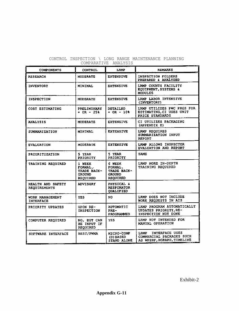
CONTROL INSPECTION \ LONG RANGE MAINTENANCE PLANNINGCOMPARATIVE ANALYSIS
Exhibit-2
Appendix G-11
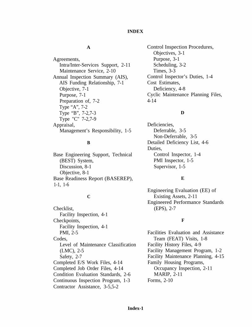
A
Agreements,Intra/Inter-Services Support, 2-11Maintenance Service, 2-10
Annual Inspection Summary (AIS),AIS Funding Relationship, 7-1Objective, 7-1Purpose, 7-1Preparation of, 7-2Type “A”, 7-2Type “B”, 7-2,7-3Type "C" 7-2,7-9
Appraisal,Management’s Responsibility, 1-5
B
Base Engineering Support, Technical(BEST) System,Discussion, 8-1Objective, 8-1
Base Readiness Report (BASEREP),1-1, 1-6
C
Checklist,Facility Inspection, 4-1
Checkpoints,Facility Inspection, 4-1PMI, 2-5
Codes,Level of Maintenance Classification(LMC), 2-5Safety, 2-7
Completed E/S Work Files, 4-14Completed Job Order Files, 4-14Condition Evaluation Standards, 2-6Continuous Inspection Program, 1-3Contractor Assistance, 3-5,5-2
INDEX
Control Inspection Procedures,Objectives, 3-1Purpose, 3-1Scheduling, 3-2Times, 3-3
Control Inspector’s Duties, 1-4Cost Estimates,
Deficiency, 4-8Cyclic Maintenance Planning Files,4-14
D
Deficiencies,Deferrable, 3-5Non-Deferrable, 3-5
Detailed Deficiency List, 4-6Duties,
Control Inspector, 1-4PMI Inspector, 1-5Supervisor, 1-5
E
Engineering Evaluation (EE) ofExisting Assets, 2-11
Engineered Performance Standards(EPS), 2-7
F
Facilities Evaluation and AssistanceTeam (FEAT) Visits, 1-8
Facility History Files, 4-9Facility Management Program, 1-2Facility Maintenance Planning, 4-15Family Housing Programs,
Occupancy Inspection, 2-11MARIP, 2-11
Forms, 2-10
Index-1
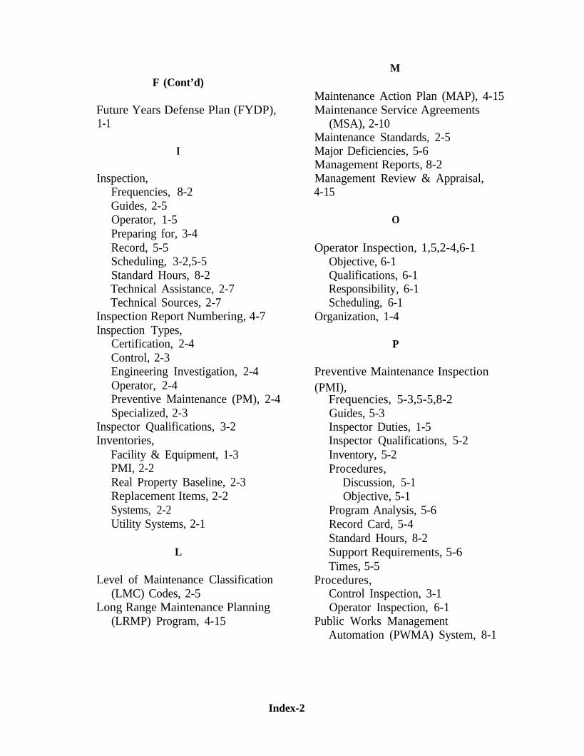
F (Cont’d)
Future Years Defense Plan (FYDP),1-1
I
Inspection,Frequencies, 8-2Guides, 2-5Operator, 1-5Preparing for, 3-4Record, 5-5Scheduling, 3-2,5-5Standard Hours, 8-2Technical Assistance, 2-7Technical Sources, 2-7
Inspection Report Numbering, 4-7Inspection Types,
Certification, 2-4Control, 2-3Engineering Investigation, 2-4Operator, 2-4Preventive Maintenance (PM), 2-4Specialized, 2-3
Inspector Qualifications, 3-2Inventories,
Facility & Equipment, 1-3PMI, 2-2Real Property Baseline, 2-3Replacement Items, 2-2Systems, 2-2Utility Systems, 2-1
L
Level of Maintenance Classification(LMC) Codes, 2-5
Long Range Maintenance Planning(LRMP) Program, 4-15
M
Maintenance Action Plan (MAP), 4-15Maintenance Service Agreements
(MSA), 2-10Maintenance Standards, 2-5Major Deficiencies, 5-6Management Reports, 8-2Management Review & Appraisal,4-15
O
Operator Inspection, 1,5,2-4,6-1Objective, 6-1Qualifications, 6-1Responsibility, 6-1Scheduling, 6-1
Organization, 1-4
P
Preventive Maintenance Inspection(PMI),
Frequencies, 5-3,5-5,8-2Guides, 5-3Inspector Duties, 1-5Inspector Qualifications, 5-2Inventory, 5-2Procedures,
Discussion, 5-1Objective, 5-1
Program Analysis, 5-6Record Card, 5-4Standard Hours, 8-2Support Requirements, 5-6Times, 5-5
Procedures,Control Inspection, 3-1Operator Inspection, 6-1
Public Works ManagementAutomation (PWMA) System, 8-1
Index-2
Q
Qualifications,Inspector, 3-2
R
Rating Factors, 1-6Readiness Report,
Shore Base, 1-6Real Property Inventory, 2-1Records, 2-10Regulatory Standards, 2-7Related Programs and Agreements,2-10Responsibilities,
Activity, 1-2Claimant, 1-6NAVFACENGCOM, 1-8
Report Accuracy, 4-6Report Descriptions, 4-1Report Preparation, 4-5Reports,
Facility Condition Summary, 4-1Facility Condition DetailedDeficiency, 4-1Management, 8-2
S
Safety, 1-4Safety Codes, 2-7Scheduling Inspections, 3-2Shore Base Readiness Report
(BASEREP), 1-6Shore Facilities Inspection System
Description, 2-1Discussion, 1-1Objective, 1-1Purpose, 1-1Scope, 1-1
Shore Facilities Inspection (SFI)Module,Discussion, 8-1
Inspection Frequencies, 8-2Inventory, 8-1Management Reports, 8-2Objective, 8-1Scheduling, 8-2Standard Hours, 8-2
Special Projects Program, 4-8Standards,
Condition Evaluation, 2-6Regulatory, 2-7
T
Times,Control Inspection, 3-3LRMP, 4-15PMI, 5-5
Training,Control Inspection Course, 1-2, 1-8
U
Utility Systems Inventories, 2-1
W
Warranty Program, 4-9Work Packaging, 4-7
Index-3