Embed Size (px)
Citation preview
ASME B31.9-1996 Edition Revision of ASMElANSl B31 .!-1988
BUllDlNG SERVICES
ASME CODE FOR PRESSURE PIPING, B31 AN AMERICAN NATIONAL STANDARD
The American Society of Mechanical Engineers
COPYRIGHT American Society of Mechanical EngineersLicensed by Information Handling ServicesCOPYRIGHT American Society of Mechanical EngineersLicensed by Information Handling Services

STD-ASIE B31-7-ENGL 179b W 0759b70 0580379 247
The American Society of Mechanical Engineers
A N A M E R I C A N N A T I O N A L S T A N D A R D
ASME CODE FOR PRESSURE PlPlN6, B31 AN AMERICAN NATIONAL STANDARD
ASME B31.8-1896 Edition Revision of ASMUANSI B31.9-1988
COPYRIGHT American Society of Mechanical EngineersLicensed by Information Handling ServicesCOPYRIGHT American Society of Mechanical EngineersLicensed by Information Handling Services
Date of Issuance: April 18, 1997
The 1996 Edition of this Code is being issued with an automatic update service that includes Addenda, Interpretations, and Cases. The next Edition is scheduled for publication in 1999.
The use of Addenda allows revisions made in response to public review comments or committee actions to be published on a regular basis; revisions published in Addenda will become effective 6 months after the Date of Issuance of the Addenda.
ASME issues written replies to inquiries concerning interpretations of technical aspects of the Code. The Interpretations are not part of the Code or the Addenda and are published in a separate supplement.
Periodically certain actions of the ASME B31 Committee will be published as Cases. While these Cases do not constitute formal revisions of the Code, they may be used in specifications, or otherwise, as representing considered opinions of the Committee. The Cases are not part of the Code or the Addenda and are published in a separate supplement.
ASME is the registered trademark of The American Society of Mechanical Engineers.
This code or standard was developed under procedures accredited as meeting the criteria for American National Standards. The Consensus Committee that approved the code or standard was balanced to assure that individuals from competent and concerned interests have had an opportunity to participate. The proposed code or standard was made available for public review and comment which provides an opportunity for additional public input from industry, academia, regulatory agencies, and the public-at-large.
ASME does not "approve," "rate," or "endorse" any item, construction, proprietary device, or activity.
ASME does not take any position with respect to the validity of any patent rights asserted in connection with any items mentioned in this document, and does not undertake to insure anyone utilizing a standard against liability for infringement of any applicable Letters Patent, nor assume any such liability. Users of a code or standard are expressly advised that determination of the validity of any such patent rights, and the risk of infringement of such rights, is entirely their own responsibility.
Participation by federal agency representative(s) or person(s) affiliated with industry is not to be interpreted as government or industry endorsement of this code or standard.
ASME accepts responsibilityfor onlythose interpretations issued in accordance with governing ASME procedures and policies which preclude the issuance of interpretations by individual volunteers.
No part of this document may be reproduced in any form, in an electronic retrieval system or otherwise,
without the prior written permission of the publisher.
The American Society of Mechanical Engineers 345 E. 47th Street, New York, NY 10017
Copyright O 1997 by THE AMERICAN SOCIETY OF MECHANICAL ENGINEERS
All Rights Reserved Printed in U.S.A.
COPYRIGHT American Society of Mechanical EngineersLicensed by Information Handling ServicesCOPYRIGHT American Society of Mechanical EngineersLicensed by Information Handling Services
FOREWORD
The need for a national code for pressure piping became increasingly evident from 1915 to 1925. The American Standards Association initiated the B31 Proj- ect in March 1926 to meet that need. The American Society of Mechanical Engineers proposed the work and has served as sponsor since its inception.
The first edition was published in 1935 as the Ameri- can Tentative Standard Code for Pressure Piping. To keep the Code abreast of developments in design, welding, and of new standards and specifications, as well as of developments in service conditions, new or supplementary editions were issued as follows:
B31. Piping
B31. B31. B31.
Piping
1-1942. American Standard Code for Pressure
I a-1944, Supplement 1 lb- 1947, Supplement 2 1-195 I . American Standard Code for Pressure
B31.la-1953, Supplement 1 to B31.1-1951 B3 1 . I - 1955, American Standard Code for Pressure
Piping In 1955, a decision was made to develop and publish
separate Code Sections for various industries. The cur- rent Sections are:
B31.1, Power Piping B3 I .3, Process Piping B3 1.4, Pipeline Transportation Systems for Liquid
Hydrocarbons and Other Liquids B3 I S , Refrigeration Piping
B31.8, Gas Transmission and Distribution Piping
B3 1.9, Building Services Piping B3 l. 1 1, Slurry Transportation Piping Systems In 1969, the American Standards Association, re-
named the United States of America Standards Institute, became the American National Standards Institute (ANSI), and the B31 Sectional Committee became the B31 Standards Committee. In 1978, The American Society of Mechanical Engineers was granted accredita- tion by ANSI to organize the B31 Committee as the ASME Code for Pressure Piping, with Code Sections designated as ANSYASME B31.
Need for a separate Building Services Section of the Code for Pressure Piping was recognized for several years. This new Code Section, ASME B31.9 Building Services Piping, first issued in 1982, was developed to f i l l that need.
The Code has intentionally been written on a conser- vative basis in order to avoid the necessity for complex design, fabrication, and inspection criteria. For this reason, application of this Code is expected to be simple and straightforward.
Following approval by the B31 Main Committee and the ASME Board on Pressure Technology Codes and Standards, and after public review, this Code Section was approved by the American National Standards Institute on August 26, 1996.
Systems
... I I 1
COPYRIGHT American Society of Mechanical EngineersLicensed by Information Handling ServicesCOPYRIGHT American Society of Mechanical EngineersLicensed by Information Handling Services

ASME CODE FOR PRESSURE PIPING, B31
OFFICERS
L. E. Hayden, Jr.. Chair D. R. Frikken, Vice Chair J. Yarmush, Secretary
COMMITTEE PERSONNEL
P. A. Bourquin, Pleasantville, New York J. D. Byers, Mobil Research & Development, Princeton, New Jersey L. F. Clynch, CONOCO, Ponca City, Oklahoma D. M. Fischer, Sargent & Lundy, Naperville, Illinois P. D. Flenner, Consumers Power Co., Covert, Michigan D. R. Frikken, Monsanto Co., St. Louis, Missouri P. H. Gardner, Wilmington, Delaware R. W. Haupt, Pressure Piping Engineering Associates, Inc., Foster City, California L. E. Hayden, Jr., Victaulic Company of America, Easton, Pennsylvania R. R. Hoffmann, Federal Energy Regulatory Commission, Washington, District of
B. P. Holbrook, Riley Stoker Corp., Worcester, Massachusetts G. A. Jolly, Henry Vogt Machine Co., Louisville, Kentucky K. Kaye. Ministry of Municipal Affairs, Vancouver, British Columbia, Canada W. B. McGehee, Houston, Texas E. Michalopoulos, Hartford Steam Boiler Inspection and Insurance Co., Hartford,
A. P. Povilonis, ABB Combustion Engineering, Inc., Windsor, Connecticut W. V. Richards, William V. Richards, Inc., Lincolnshire, Illinois G. W. Spohn, 111, Colejon Spohn Corp., Cleveland, Ohio L. G. Vetter, Sargent & Lundy Engineers, Chicago, Illinois R. B. West, State of Iowa, Des Moines, Iowa
Columbia
Connecticut
B31.9 BUILDING SERVICES PIPING SECTION COMMITTEE
P. A. Bourquin, Chair, Pleasantville, New York F. R. Lyons, Secretary, ASME, New York, New York D. D. Christian, Victaulic Co., Easton, Pennsylvania A. Cohen, Copper Development Association, Inc., New York, New York R. D. Gilligan, C. G. Bostwick Co., Inc., Woburn, Massachusetts H. J. Post, Wayne, Pennsylvania P. S. Rampone, Hart Design Group, Greenville, Rhode Island W. J. Sperko, Sperko Engineering Services, Inc., Greensboro, North Carolina H. E. Wetzell, Jr., Smith & Oby Co., Cleveland, Ohio
B31.3 SUBGROUP ON ACTIVITIES
B. L. Agee, Eastman Chemical Co., Kingsport, Tennessee L. J. Balasundararn, Raytheon Engineers and Constructors, Inc., Cambridge,
B. C. Bassett, Phillips Petroleum Co., Bartlesville, Oklahoma R. K. Broyles, Pathway Bellows, Inc., Oak Ridge, Tennessee D. D. Christian, Victaulic Co., Easton, Pennsylvania
Massachusetts
COPYRIGHT American Society of Mechanical EngineersLicensed by Information Handling ServicesCOPYRIGHT American Society of Mechanical EngineersLicensed by Information Handling Services
S. Costa, Newark, Delaware J. A. D'Avanzo, E. I. du Pont de Nemours 81 Co.., Inc., Wilmington, Delaware D. R. Edwards, Phillips Petroleum Co., Bartlesville, Oklahoma O. R. Greulich, NASA Ames Center, Moffett Field, California R. Grichuk, Fluor Daniel, Houston, Texas D. 6. Kadakia, T. D. Williamson, Inc., Tulsa, Oklahoma C. Nath, E. 1. du Pont de Nemours & Co., Inc., Wilmington, Delaware H. E. Svetlik, Phillips Petroleum Co., Richardson, Texas Q. N. Truong, Houston, Texas L. J. Weibeler, Air Products & Chemicals, Inc., Allentown, Pennsylvania
B31 EXECUTIVE COMMITTEE
L. E. Hayden, Jr., Chair, Victaulic Company of America, Easton, Pennsylvania D. R. Frikken, Vice Chair, Monsanto Co., St. Louis, Missouri J. Yarmush, Secretary, ASME, New York, New York P. D. Flenner, Consumers Power Co., Covert, Michigan L. G. Vetter, Sargent & Lundy Engineers, Chicago, Illinois
B31 MATERIALS, FABRICATION, AND EXAMINATION TECHNICAL COMMITTEE
P. D. Flenner, Chair, Consumers Power Co., Covert, Michigan J. Yarmush, Secretary, ASME, New York, New York J. A. Cox, Colonial Pipeline Co., Atlanta, Georgia P. C. DuPernell, Lancaster, New York D. G. Hopkins, E. 1. duPont de Nemours 81 Co., Wilmington, Delaware A. D. Nance, A. D. Nance Associates, Inc., Evans, Georgia D. W. Rahoi, CCM 2000, Rockaway, New Jersey R. 1. Seals, Berkeley, California R. J. Silvia, Process Engineers and Constructors, Inc., Warwick, Rhode Island W. J. Sperko, Sperko Engineering Services, Inc., Greensboro, North Carolina E. F. Summers, Jr., Babcox & Wilcox Construction, Inc., Copley, Ohio
B31 MECHANICAL DESIGN TECHNICAL COMMllTEE
R. W. Haupt, Chair, Pressure Piping Engineering Associates, Inc., Foster City, California J. Yarmush. Secretary, ASME, New York, New York C. Becht IV, Becht Engineering Co., Liberty Corner, New Jersey J. P. keen, AEA O'Donnell, Pittsburgh, Pennsylvania J. A. Graziano, Tennessee Valley Authority, Chattanooga, Tennessee J. D. Hart, SSD Engineering Consultants, Walnut Creek, California 6. P. Holbrook, Riley Stoker Corp., Worcester, Massachusetts W. J. Koves, UOP. Inc., Des Plaines, Illinois P. L. Lin, Wisconsin Public Service Corp., Kewaunee, Wisconsin G. Mayers, Naval Surface Warfare Center, Annapolis, Maryland T. Q. McCawley, Charlotte, North Carolina E. Michalopoulos, Hartford Steam Boiler Inspection and Insurance Co., Hartford,
J. C. Minichiello, Vectra, Naperville, Illinois A. D. Nance, A. D. Nance Associates, Inc., Evans, Georgia A. W. Paulin, Coade Engineering Services, Houston, Texas P. S. Rampone, Hart Design Group, Greenville, Rhode Island R. A. Robleto, Brown and Root, Inc., Houston, Texas E. C. Rodabaugh, Dublin, Ohio M. J. Rosenfeld, Kiefner & Associates, Inc., Worthington, Ohio R. A. Schmidt, Ladish Co., Russellville, Arkansas
Connecticut
vi
COPYRIGHT American Society of Mechanical EngineersLicensed by Information Handling ServicesCOPYRIGHT American Society of Mechanical EngineersLicensed by Information Handling Services
Q. N. Truong, M. W. Kellogg Co., Houston, Texas E. A. Wais, Wais and Associates, Inc., Norcross, Georgia G. E. Woods, Raytheon, Houston, Texas
B31 CONFERENCE GROUP
T. A. Bell, Pipeline Safety Engineer, Utilities Engineer, Olympia, Washington M. L. Brunton, KPO, Topeka, Kansas G. Bynog, Texas Department of Labor and Standards, Austin, Texas R. Coomes, Department of Housing/Boiler Section, Frankfort, Kentucky A. W. Diamond, Department of Labour & Manpower, Saint Johns, Newfoundland,
M. P. Fitzpatrick. Department of Labour & Human Resources, Fredericton, New
J. W. Greenawalt, Jr., Oklahoma Department of Labor, Oklahoma City, Oklahoma H. D. Hanrath, Ministry ConsumerKomm. Rel., Toronto, Ontario, Canada C. J. Harvey, Alabama Public Service Commission, Montgomery, Alabama D. T. Jagger, Boiler Division, State of Ohio, Columbus, Ohio M. Kotb, Regie du Batiment du Quebec, Montreal, Quebec, Canada K. T. Lau, Alberta Boiler and Pressure Vessel Safety, Edmonton, Alberta, Canada R. G. Marini, New Hampshire Public Utilities Commission, Concord, New Hampshire 1. W. Mault, Manitoba Department of Labour, Winnipeg, Manitoba, Canada A. W. Meiring, Department of Fire Prevention and Building Safety, Indianapolis, Indiana J. W. Morvant, State of Louisiana, Baton Rouge, Louisiana R. F. Mullaney, Boiler and Pressure Vessel Safety Branch, Vancouver, British Columbia,
W. A. Owen, North Dakota Public Service Commission, Bismarck, North Dakota W. M. Picardo, Department of Consumer and Regulatory Affairs, Washington, District of
P. Sher, Department of Public Utility Control, New Britain, Connecticut H. E. Shutt, Illinois Commerce Commission, Springfield, Illinois M. E. Skarda, Department of Labour, Little Rock, Arkansas R. L. Smith, University of South Carolina, Columbia, South Carolina E. L. Sparrow, Board of Public Utilities, Newark, New Jersey D. A. Starr, Department of Labor, Lincoln, Nebraska D. Stursma, Iowa State Department of Commerce, Des Moines, Iowa R. P. Sullivan, National Board of Boiler and Pressure Vessel Inspectors, Columbus, Ohio J. E. Troppman, Division of Labor/Boiler Inspection, Denver, Colorado R. W. Vindich, Department of Labor and Industry, Harrisburg, Pennsylvania C. H. Walters, National Board, Cornelius, Oregon W. A. West, Department of Labour, Charlottetown, Prince Edward Island, Canada T. F. Wickham, Department of Labor, Providence, Rhode Island
Canada
Brunswick, Canada
Canada
Columbia
B31 NATIONAL INTEREST REVIEW GROUP
American Boiler Manufacturers Association - R. J. Fletcher American Institute of Chemical Engineers - W. C. Carnell American Pipe Fitting Association - H. Thielsch American Society of Heating, Refrigeration and Air Conditioning Engineers - H. R.
Chemical Manufacturers Association - D. R. Frikken Compressed Gas Association - M. F. Melchioris Copper Development Association - A. Cohen Ductile Iron Pipe Research Association -T. F. Stroud Edison Electric Institute - R. L. Williams International District Heating Association - G. Von Bargen Manufacturers Standardization Society of the Valve and Fittings Industry - R. A.
Kornblum
Schmidt
COPYRIGHT American Society of Mechanical EngineersLicensed by Information Handling ServicesCOPYRIGHT American Society of Mechanical EngineersLicensed by Information Handling Services
Mechanical Contractors Association of America -Jack Hansmann National Association of Plumbing-Heating-Cooling Contractors - R. E. White National Association of Regulatory Utility Commissioners - D. W. Snyder National Fire Protection Association - T. C. Lemoff National Fluid Power Association - H. G. Anderson Pipe Fabrication Institute - L. Katz Slurry Transport Association - P. E. Snoek Society of Ohio Safety Engineers -J. M. Holleran Valve Manufacturers Association - R. A. Handschumacher
v111 ...
COPYRIGHT American Society of Mechanical EngineersLicensed by Information Handling ServicesCOPYRIGHT American Society of Mechanical EngineersLicensed by Information Handling Services

ASME B31.9-1996 Summary of Changes
The following Summary of Changes lists the major revisions to the 1988 Edition. Revisions, other than those identified as editorial and Errata, become effective 6 months after the Date of Issuance of this Edition.
Page location Change ... III Foreword Updated
V Personnel Updated
X i Contents Updated
xvii
1 4
8
9
10
11
12
13
14
14
15
16
17
Introduction
900.1
(1) Ninth para. revised (2) Tenth and eleventh paras. added
Revised in its entirety
Fig. 900.1.2 B Legend revised
900.2
900.3
901.2.3
(1 brittle failure and definition added (2) combustible liquid and definition added (3) flammable liquid and definition added
(1) d6 corrected by Errata to dg (2) SF and definition added
Revised
902.3.1 (c) Revised
Table 902.4.3 (1 ) First entry deleted (2) Last entry added
904.1 .I(b) Revised
Fig. 904.2.2 Revised
904.3.3(b) Last sentence revised
904.4.1 (1) Formula (5) revised (2) S and definition added
Table 904.3.3 Added
Fig. 904.3.3A
Fig. 904.3.36
904.5.3
Revised in i ts entirety
Revised in i ts entirety
(1 1 First and last sentences revised (2) Formula ( 6 ) revised
ix
COPYRIGHT American Society of Mechanical EngineersLicensed by Information Handling ServicesCOPYRIGHT American Society of Mechanical EngineersLicensed by Information Handling Services

STD*ASflE B33-7-ENGL L77b 0757b70 0 5 8 0 3 8 7 315
905.2.2
905.2.3
Redesignated as 905.2.4 and new 905.2.2
added
Added
905.2.5 Added
18 906.3 Last sentence added
22, 23
24
25
26
29
34
38
40
41
47
49
50
52
57
61
65
67
Table 919.3.1
921.1.3
Fig. 921.1.3C
Fig. 921.1.3D
922.3
Table 926.1
Table 926.2
927.4.6(c)
Fig. 927.4.3C
927.5.1
936.1 .I
937.4.1
937.5.1
Table A-1
Table A-2
Appendix C
D-1
Appendix E
Revised
Revised
Revised in its entirety
Revised in its entirety
Added
Revised
Revised
Revised
Callout corrected by Errata
Revised
Added
Revised
Revised
Revised
Revised in its entirety
Revised
Last para. added
Added
69 Index Updated
NOTE:
The Interpretat ions to ASME B31.9 issued be tween Oc tober 26, 1983, and January 1 O, '1 997, follow the last page of this Edition. Interpretat ions Nos. 1 a n d 2 were i nc luded w i th t he upda te se rv i ce to the 1988 Edi t ion and are be ing repr in ted here. The update serv ice to the 1996 Edi t ion begins w i t h Interpretat ions No. 3. The Interpretat ions are not par t of ASME 831.9.
x
COPYRIGHT American Society of Mechanical EngineersLicensed by Information Handling ServicesCOPYRIGHT American Society of Mechanical EngineersLicensed by Information Handling Services
CONTENTS
... Foreword . . . . . . . . . . . . . . . . . . . . . . . . . . . . . . . . . . . . . . . . . . . . . . . . . . . . . . . . . . . . . . . . . . . . . . . . . . . . . . . . . I I I
Personnel . . . . . . . . . . . . . . . . . . . . . . . . . . . . . . . . . . . . . . . . . . . . . . . . . . . . . . . . . . . . . . . . . . . . . . . . . . . . . . . . . v
ASME B31.9-1996 Summary of Changes . . . . . . . . . . . . . . . . . . . . . . . . . . . . . . . . . . . . . . . . . . . . . . . . . . . . ix Introduction . . . . . . . . . . . . . . . . . . . . . . . . . . . . . . . . . . . . . . . . . . . . . . . . . . . . . . . . . . . . . . . . . . . . . . . . . . . . . . . xvii
Chapter I Scope and Definitions
900 General . . . . . . . . . . . . . . . . . . . . . . . . . . . . . . . . . . . . . . . . . . . . . . . . . . . . . . . . . . . . . . . . . . . . . i 900.1 Scope . . . . . . . . . . . . . . . . . . . . . . . . . . . . . . . . . . . . . . . . . . . . . . . . . . . . . . . . . . . . . . . . . . . . . . . i 900.2 Definitions . . . . . . . . . . . . . . . . . . . . . . . . . . . . . . . . . . . . . . . . . . . . . . . . . . . . . . . . . . . . . . . . . . 3 900.3 Nomenclature . . . . . . . . . . . . . . . . . . . . . . . . . . . . . . . . . . . . . . . . . . . . . . . . . . . . . . . . . . . . . . 7
Figure 900.1.2B Code Jurisdictional Limits for Piping - Drum Type Boilers . . . . . . . . . . . . . . , . . . 2
Chapter II Design
Part I 90 1 901.1 90 1.2 901.3 90 I . 4 901.5 90 1.7 902 902.1 902.2 902.3 902.4
Fart 2 903 904 904.1 904.2 904.3 904.4 904.5 904.6 904.7
Conditions and Criteria . . . . . . . . . . . . . . . . . . . . . . . . . . . . . . . . . . . . . . . . . . . . . . . . . . . . Design Conditions . . . . . . . . . . . . . . . . . . . . . . . . . . . . . . . . . . . . . . . . . . . . . . . . . . . . . . . . . . . General . . . . . . . . . . . . . . . . . . . . . . . . . . . . . . . . . . . . . . . . . . . . . . . . . . . . . . . . . . . . . . . . . . . . . Pressure . . . . . . . . . . . . . . . . . . . . . . . . . . . . . . . . . . . . . . . . . . . . . . . . . . . . . . . . . . . . . . . . . . . . Temperature . . . . . . . . . . . . . . . . . . . . . . . . . . . . . . . . . . . . . . . . . . . . . . . . . . . . . . . . . . . . . . . . . Ambient Influences . . . . . . . . . . . . . . . . . . . . . . . . . . . . . . . . . . . . . . . . . . . . . . . . . . . . . . . . . . Dynamic Effects . . . . . . . . . . . . . . . . . . . . . . . . . . . . . . . . . . . . . . . . . . . . . . . . . . . . . . . . . . . . . Thermal Expansion and Contraction Loads . . . . . . . . . . . . . . . . . . . . . . . . . . . . . . . . . . . . Design Criteria . . . . . . . . . . . . . . . . . . . . . . . . . . . . . . . . . . . . . . . . . . . . . . . . . . . . . . . . . . . . . . General . . . . . . . . . . . . . . . . . . . . . . . . . . . . . . . . . . . . . . . . . . . . . . . . . . . . . . . . . . . . . . . . . . . . .
Allowable Stresses and Other Stress Limits . . . . . . . . . . . . . . . . . . . . . . . . . . . . . . . . . . . Allowances . . . . . . . . . . . . . . . . . . . . . . . . . . . . . . . . . . . . . . . . . . . . . . . . . . . . . . . . . . . . . . . . . .
Pressure-Temperature Design Criteria for Piping Components . . . . . . . . . . . . . . . . . .
9 9 9 9 9 9 9 9 9 9
IO 10 I I
Pressure Design of Piping Components . . . . . . . . . . . . . . . . . . . . . . . . . . . . . . . . . . . . . 12
Pressure Design of Components . . . . . . . . . . . . . . . . . . . . . . . . . . . . . . . . . . . . . . . . . . . . . . 12 Straight Pipe . . . . . . . . . . . . . . . . . . . . . . . . . . . . . . . . . . . . . . . . . . . . . . . . . . . . . . . . . . . . . . . . 12 Curved and Mitered Segments of Pipe . . . . . . . . . . . . . . . . . . . . . . . . . . . . . . . . . . . . . . . . 12 Branch Connections . . . . . . . . . . . . . . . . . . . . . . . . . . . . . . . . . . . . . . . . . . . . . . . . . . . . . . . . . 13 Closures . . . . . . . . . . . . . . . . . . . . . . . . . . . . . . . . . . . . . . . . . . . . . . . . . . . . . . . . . . . . . . . . . . . . 14 Pressure Design of Flanges and Blanks . . . . . . . . . . . . . . . . . . . . . . . . . . . . . . . . . . . . . . . 14 Reducers . . . . . . . . . . . . . . . . . . . . . . . . . . . . . . . . . . . . . . . . . . . . . . . . . . . . . . . . . . . . . . . . . . . . 17
Criteria for Press’ure Design of Piping Components . . . . . . . . . . . . . . . . . . . . . . . . . . . . 12
Pressure Design of Other Pressure Containing Components . . . . . . . . . . . . . . . . . . . . 17
Part 3 Selection and Limitation of Components . . . . . . . . . . . . . . . . . . . . . . . . . . . . . . . . . . . . 17 905 Pipe . . . . . . . . . . . . . . . . . . . . . . . . . . . . . . . . . . . . . . . . . . . . . . . . . . . . . . . . . . . . . . . . . . . . . . . . 17 905.1 General . . . . . . . . . . . . . . . . . . . . . . . . . . . . . . . . . . . . . . . . . . . . . . . . . . . . . . . . . . . . . . . . . . . . . 17 905.2 Specific Limitations . . . . . . . . . . . . . . . . . . . . . . . . . . . . . . . . . . . . . . . . . . . . . . . . . . . . . . . . . . 17
xi
COPYRIGHT American Society of Mechanical EngineersLicensed by Information Handling ServicesCOPYRIGHT American Society of Mechanical EngineersLicensed by Information Handling Services

906 906.1 906.2 906.3 907 907.1 907.2 908 908.1 908.3 908.4 908.5
Part 4 910 91 1 911.1 91 1.2 912 913 913.1 914 914.1 9 14.2 915 916 916.1 9 16.2 917 917.1 917.2 917.3
Part 5 919 919.1 919.2 9 19.3 9 19.4 919.8 919.9 919.10 920 920 . I 920.2 92 1 921.1 92 I . 2 92 I . 3 92 I . 4 92 I . 5 92 I . 6
Fitting. Bends. and Intersections .............................................. 18
Limitations on Fittings ....................................................... 18
..................................................................... Fittings 18 Bends and Miter Joints ....................................................... 18
Valves 18 General 18 Marking 18
General 18 18
Gaskets 18 Bolting 18
...................................................................... ..................................................................... ....................................................................
Flanges. Blanks. Gaskets. and Bolting ........................................ 18 .....................................................................
Flange Facings .............................................................. ..................................................................... ......................................................................
Selection and Limitation of Joints .......................................... 18 Piping Joints ................................................................
Metallic Pipe ................................................................ Nonmetallic Pipe ............................................................ 19 Flanged Joints ............................................................... Mechanical and Proprietary Joints ............................................ 19 Limitations on Mechanical and Proprietary Joints .............................. 19
Acceptable Types ............................................................ 19 Limitations on Threaded Joints ............................................... 19 Flared. Flareless. and Compression Joints ..................................... 19 Bell and Spigot Joints ....................................................... 20 Caulked or Leaded Joints .................................................... 20 Push-Type Elastomer Gasket ................................................. 20 Brazed and Soldered Joints .................................................. 20
18 Welded Joints 19
19
19
...............................................................
............................................................. Threaded Joints 19
..................................................................... ................................................................
General 20 Brazed Joints 20 Soldered Joints 20 ..............................................................
Expansion. Flexibility. and Support ......................................... 20 Expansion and Flexibility .................................................... 20
Properties for Analysis ....................................................... 20 Analysis. Metallic Piping .................................................... 21
..................................................................... ....................................................................
General 20 Concepts 20
.................................................................. .................................................................
...................................................................
Movements 21 Cold Spring 22 Reactions 22
General 23 Test Loads 24
General 24 Fixtures 27 Structural Attachments 27
Loads on Pipe Supporting Elements .......................................... 23
Design of Pipe Supporting Elements .......................................... 24
..................................................................... ..................................................................
.....................................................................
..................................................................... .......................................................
Supplemental Steel .......................................................... 28 Attachments to Concrete ..................................................... 28 Supporting Structures ........................................................ 28
COPYRIGHT American Society of Mechanical EngineersLicensed by Information Handling ServicesCOPYRIGHT American Society of Mechanical EngineersLicensed by Information Handling Services

Part 6 Systems .................................................................... 922 Design Requirements Pertaining to Specific Piping Systems .................... 922 . I Pressure Reducing Systems .................................................. 922.2 Steam Trap Piping .......................................................... 922.3 Fuel Oil Piping ............................................................. Figures 904.2.2 904.3.3A
904.3.3B
921.1.3C 921.1.3D
Tables 902.4.3 904.2.1A 904.3.3 917.3
919.3.1 92 1.2.2A
Nomenclature for Miter Joints ................................................ 90 deg . Branch Intersections Not Requiting Added Reinforcement - Standard
Wall Pipe ................................................................ 45 deg . Branch Intersections Not Requiring Added Reinforcement - Standard
Wall Pipe ................................................................ Support Spans for Standard Wall Steel Pipe .................................. Support Spans for Copper and Thermoplastic Pipe ............................
Joint Factors E .............................................................. Pipe Thickness for Bends .................................................... Header and Branch Materials for Standard Wall Pipe .......................... Rated Internal Working Pressures of Joints Made With Copper Water
Moduli of Elasticity and Thermal Expansion Coefficients ...................... Capacities of Threaded ASTM A 36 Steel Rods ..............................
Tube and Solder Joint Fittings. psig ........................................
Chapter III Materials
923 Materials . General Requirements ........................................... 923.1 Materials and Specifications .................................................. 923.2 Limitations on Specific Metals ............................................... 923.3 Limitations on Specific Nonmetals ............................................ 923.4 Coatings and Linings ......................................................... 923.5 Deterioration in Service ......................................................
Chapter IV Component Requirements and Standard Practices
926 Dimensions and Ratings of Components ...................................... 926.1 Standard Piping Components ................................................. 926.2 Standard Practices ........................................................... 926.3 Nonstandard Piping Components .............................................. 926.4 Abbreviations ...............................................................
Tables
926.2 Standard Practices ........................................................... 926 . I Component Standards and Specifications ......................................
Chapter V Fabrication. Assembly. and Erection
927 Welded Fabrication of Metals ................................................ 927.1 General ..................................................................... 927.2 Materials . . . . . . . . . . . . . . . . . . . . . . . . . . . . . . . . . . . . . . . . . . . . . . . . . . . . . . . . . . . . . . . . . . . . 927.3 Preparation .................................................................. 927.4 Rules for Welding ...........................................................
28 28 28 29 29
13
15
16 25 26
11 12 14
21 22 27
31 31 31 31 32 32
33 33 33 33 33
34 38
39 39 39 39 39
... X l l l
COPYRIGHT American Society of Mechanical EngineersLicensed by Information Handling ServicesCOPYRIGHT American Society of Mechanical EngineersLicensed by Information Handling Services

927.5 927.6 928 928 . I 928.2 929 929 . I 930 930.1 93 I 934 934.1 934.2 934.3 935 935.1 935.2 935.3 935.4 935.5 935.6 935.7 935.8 935.9 935.10 935.1 1 935.12 935.13
Figures 927.4.3A 927.4.3B 927.4.3C
927.4.5A 927.4.5B 927.4.6A 927.4.6B
Qualification ................................................................
Bell and Spigot Joints ....................................................... 46 Threaded Piping ............................................................. 46 Flare Joints ................................................................. 46 Fermle Bite Joints ........................................................... 46 Compression Joints .......................................................... 46 Other Mechanical and Proprietary Joints ...................................... 46 Borosilicate Glass Piping .................................................... 46 Equipment Connections ...................................................... 46 Cold Spring ................................................................. 46 Valve Installation ............................................................ 46 Repair of Defective Work ................................................... 46
Bolting Procedure ........................................................... 45
Fillet Weld Size ............................................................. 40 Minimum Welds for Double-Welded Slip-on and Socket-Welding Flanges . . . . . . 41 Minimum Welding Dimensions for Socket-Welding Components Other Than
Flanges ................................................................... 41 Acceptable Welds for Flat Heads ............................................. 42 Unacceptable Welds for Flat Heads .......................................... 42 Typical Weld Branch Connections ............................................ 43 Typical Weld Details ........................................................ 43
Chapter VI Inspection. Examination. and Testing
936 936 . I 936.2 936.3 936.4 936.5 936.6 937 937.1 937.2 937.3
Inspection and Examination .................................................. 47 General ..................................................................... 47
Responsibility for Examination ............................................... 47 Methods of Examination ..................................................... 47 Type and Extent of Required Examination .................................... 47 Acceptance Criteria .......................................................... 47 Leak Testing ................................................................ 48 General ..................................................................... 48 Preparation for Testing ...................................................... 48 Hydrostatic Testing .......................................................... 49
Required Inspection .......................................................... 47
xiv
COPYRIGHT American Society of Mechanical EngineersLicensed by Information Handling ServicesCOPYRIGHT American Society of Mechanical EngineersLicensed by Information Handling Services

937.4 Pneumatic Testing . . . . . . . . . . . . . . . . . . . . . . . . . . . . . . . . . . . . . . . . . . . . . . . . . . . . . . . . . . . 49 937.5 Initial Service Leak Test . . . . . . . . . . . . . . . . . . . . . . . . . . . . . . . . . . . . . . . . . . . . . . . . . . . . . 50
Appendices Appendix A Table A-1, Allowable Stresses . . . . . . . . . . . . . . . . . . . . . . . . . . . . . . . . . . . . . . . . . . . . . . . 52
Temperature Limits for Thermoplastic Pipe ................................. 57
Made From Reinforced Thermosetting Resins . . . . . . . . . . . . . . . . . . . . . . . . . . . . . . . 58
Resin Pipe . . . . . . . . . . . . . . . . . . . . . . . . . . . . . . . . . . . . . . . . . . . . . . . . . . . . . . . . . . . . . . . . 58 Appendix B Table B.1. Allowable Pressures for Nonmetallic. Nonplastic Pressure
Piping . . . . . . . . . . . . . . . . . . . . . . . . . . . . . . . . . . . . . . . . . . . . . . . . . . . . . . . . . . . . . . . . . . . . 59 Appendix C Reference Standards . . . . . . . . . . . . . . . . . . . . . . . . . . . . . . . . . . . . . . . . . . . . . . . . . . . . . . . . . 61 Appendix D Preparation of Technical Inquiries . . . . . . . . . . . . . . . . . . . . . . . . . . . . . . . . . . . . . . . . . . . . 65 Appendix E Nonmandatory Quality System Program . . . . . . . . . . . . . . . . . . . . . . . . . . . . . . . . . . . . . . . 67
Table A-2. Hydrostatic Design Stresses (HDS) and Recommended
Table A-3. Design Stress Values for Contact Molded (Hand-Lay-Up) Pipe
Table A.4. Hydrostatic Design Basis Stress for Machine-Made Thermosetting
Index . . . . . . . . . . . . . . . . . . . . . . . . . . . . . . . . . . . . . . . . . . . . . . . . . . . . . . . . . . . . . . . . . . . . . . . . . . . . . . . . . . . . 69
xv
COPYRIGHT American Society of Mechanical EngineersLicensed by Information Handling ServicesCOPYRIGHT American Society of Mechanical EngineersLicensed by Information Handling Services

INTRODUCTION
The ASME B31 Code for Pressure Piping consists of a number of individually published Sections, each an American National Standard. Hereafter, in this Intro- duction and in the text of this Code Section B3 1.9, where the word Code is used without specific identification, it means this Code Section.
The Code sets forth engineering requirements deemed necessary for safe design and construction of pressure piping. While safety is the basic consideration, this factor alone will not necessarily govern the final specifi- cations for any piping system. The designer is cautioned that the Code is not a design handbook; it does not do away with the need for the designer or for competent engineering judgment.
To the greatest possible extent, Code requirements for design are stated in terms of basic design principles and formulas. These are supplemented as necessary with specific requirements to assure uniform application of principles and to guide selection and application of piping elements. The Code prohibits designs and prac- tices known to be unsafe and contains warnings where caution, but not prohibition, is warranted.
This Code Section includes: (a) references to acceptable material specifications
and component standards, including dimensional re- quirements and pressure-temperature ratings;
(b) requirements for design of components and as- semblies, including pipe supports;
(c) requirements and data for evaluation and limita- tion of stresses, reactions, and movements associated with pressure, temperature changes, and other forces;
(d) guidance and limitations on the selection and application of materials, components, and joining methods;
(e) requirements for the fabrication, assembly, and erection of piping; and
cf) requirements for examination, inspection, and testing of piping.
It is intended that this Edition of Code Section B31.9 and any subsequent addenda not be retroactive. Unless agreement is specifically made between contracting parties to use another issue, or the regulatory body having jurisdiction imposes the use of another issue,
the latest edition and addenda issued at least 6 months prior to the original contract date for the first phase of activity covering a piping system or systems shall be the governing document for all design, materials, fabrication, erection, examination, and testing for the piping until the completion of the work and initial operation.
Users of this Code are cautioned against making use of revisions without assurance that they are acceptable to the proper authorities in the jurisdiction where the piping is to be installed.
Code users will note that clauses in the Code are not necessarily numbered consecutively. Such disconti- nuities result from following a common outline, insofar as practicable, for all Code Sections. In this way, corresponding material is correspondingly numbered in most Code Sections, thus facilitating reference by those who have occasion to use more than one Section.
The Code is under the direction of ASME Committee B3 1, Code for Pressure Piping, which is organized and operates under ASME procedures that have been accredited by the American National Standards Institute. The Committee is a continuing one and keeps all Code Sections current with new developments in materials, construction, and industrial practice. Addenda may be issued periodically. New editions are published at inter- vals of 3 to 5 years.
It is the owner’s responsibility to select the Code Section that most nearly applies to a proposed piping installation. Different Code Sections may apply to differ- ent parts of an installation. Factors to be considered by the owner include: limitations of the Code Section, jurisdictional requirements, and the applicability of other codes and standards. All applicable requirements of the selected Code Section shall be met, and the owner should impose additional requirements supplementing those of the Code in order to assure safe piping for the proposed installation.
Rules for each Code Section have been developed considering the need for application specific require- ments for the pressure piping involved. Applications considered for each Code Section include:
(a) B31.1 Power Piping - piping typically found
xvii
COPYRIGHT American Society of Mechanical EngineersLicensed by Information Handling ServicesCOPYRIGHT American Society of Mechanical EngineersLicensed by Information Handling Services

in electric power generating stations, industrial and institutional plants, geothermal heating systems, and central and district heating and cooling systems;
(b) B31.3 Process Piping - piping typically found in petroleum refineries; chemical, textile, paper, semi- conductor, and cryogenic plants; and related processing plants and terminals;
(c) B31.4 Liquid Transportation Piping - piping for transporting predominantly liquid products between plants and terminals and within terminals, and for pumping, regulating, and metering stations;
(d) B31.5 Refrigeration Piping - piping for refriger- ants and secondary coolants;
(e) B31.8 Gas Transportation and Distribution Pip- ing - piping for transporting predominantly gas prod- ucts between sources and terminals, including compres- sor, regulating, and metering stations; and gas gathering pipelines;
(f) B31.9 Building Services Piping - piping for industrial, institutional, commercial, and public build- ings, and multi-unit residences, which does not require the range of sizes, pressures, and temperatures covered in B31.1; and
(g) B31.11 Slurry Transportation Piping - piping for transporting aqueous slumes between plants and terminals, and within terminals and pumping and regu- lating stations.
Certain piping within a facility may be subject to other codes and standards, including but not limited to:
(a ) ASME Boiler and Pressure Vessel Code, Section III - nuclear power piping;
( b ) ANSI 2223.1 National Fuel Gas Code - fuel gas piping from the point of delivery to the connections of each gas utilization device;
( c ) NFPA Fire Protection Standards - fire protec- tion systems using water and other materials such as carbon dioxide, halon, foam, dry chemicals, and wet chemicals;
(d} NFPA 99 Health Care Facilities - medical and laboratory gas systems; and
( e ) NFPA 8503 Standard for Pulverized Fuel Sys- tems. Building and Plumbing Codes.
The Committee has established an orderly procedure to consider requests for interpretation and revision of Code requirements. To receive consideration, inquiries must be in writing and must give full particulars (see Appendix D, Preparation of Technical Inquiries). The approved reply to an inquiry will be sent directly to the inquirer. In addition, the question and reply will be published as part of an Interpretation Supplement issued to the applicable Code Section.
A Case is the prescribed form of reply to an inquiry when study indicates that the Code wording needs clarification or when the reply modifies existing require- ments of the Code or grants permission to use new materials or alternative constructions. Proposed Cases are published in Mechanical Engineering for public review. In addition, the Case will be published as part of a Case Supplement issued to the applicable Code Section.
A Case is normally issued for,a limited period, after which it may be renewed, incorporated in the Code, or allowed to expire if there is no indication of further need for the requirements covered by the Case. How- ever, the provisions of a Case may be used after its expiration or withdrawal, provided the Case was effec- tive on the original contract date or was adopted before completion of the work, and the contracting parties agree to its use.
Materials are listed in the Stress Tables only when sufficient usage in piping within the scope of the Code has been shown. Materials may be covered by a Case. Requests for listing shall include evidence of satisfactory usage and specific data to permit establishment of allowable stresses, maximum and minimum temperature limits, and other restrictions. (To develop usage and gain experience, unlisted materials may be used in accordance with para. 923.1.2.)
Requests for interpretation and suggestions for revi- sion should be addressed to the Secretary, ASME B31 Committee, 345 East 47th Street, New York, NY 10017.
xviii
COPYRIGHT American Society of Mechanical EngineersLicensed by Information Handling ServicesCOPYRIGHT American Society of Mechanical EngineersLicensed by Information Handling Services

STD-ASME 831*7-ENGL 277b m 0757b70 0580375 472 m
ASME B31.9-1996 Edition
CHAPTER I SCOPE AND
900 GENERAL
This Building Services Piping Code is a Section of The American Society of Mechanical Engineers Code for Pressure Piping, B31. This Section, herein called the Code, is published as a separate document for convenience.
Standards and specifications incorporated by reference in this Code are shown in Table 926.1, Appendix A, and elsewhere. It is not considered practical to refer to a dated edition of each standard or specification where referenced. Instead, the dated edition references are included in Appendix C.
The user is cautioned that the local building code must be observed and adhered to when its requirements are more stringent than those of this Code.
Components of piping systems shall conform to the specifications and standards listed in this Code. Piping elements neither specifically approved nor specifically prohibited by this Code may be used provided they are qualified for use as set forth in applicable chapters of this Code.
Engineering requirements of this Code, while consid- ered necessary and adequate for safe design, generally employ a simplified approach. An engineer capable of applying a more rigorous aflalysis shall have the latitude to do so. He must be able to demonstrate the validity of his approach.
900.1 Scope
900.1.1 Coverage and Application. This Code Sec- tion has rules for the piping in industrial, institutional, commercial, and public buildings, and multi-unit resi- dences, which does not require the range of sizes, pressures, and temperatures covered in B3 I . l . This Code prescribes requirements for the design, materials, fabrication, installation, inspection, examination, and testing of piping systems for building services. It in- cludes piping systems in the building or within the property limits.
DEFINITIONS
900-900.1.2
900.1.2 Services and Limits (a) Services. This Code applies to the following
building services, except as excluded in para. 900.1.3: (1) water for heating and cooling ( 2 ) condensing water (3) steam or other condensate (4) other nontoxic liquids (5) steam (6) vacuum (7) compressed air (8) other nontoxic, nonflammable gases (9) combustible liquids including fuel oil
(b) Boiler External Piping. The scope of this Code includes boiler external piping within the following limits:
(I) for steam boilers, 15 psig max. ( 2 ) for water heating units, 160 psig max. and
250°F max. Boiler external piping above these pressure or temper-
ature limits is within the scope of ASME B3 1.1. Boiler external piping is the piping connected to the boiler and extending to the points identified in Fig. 900.1.2B.
(c ) Material and Size Limits. Piping systems of the following materials are within the scope of this Code, through the indicated maximum size (and wall thickness if noted):
( I ) carbon steel: NPS 30 and 0.500 in. wall ( 2 ) stainless steel: NPS 12 and 0.500 in. wall (3) aluminum: NPS 12 (4 ) brass and copper: NPS 12 (12.125 in. O.D.
(5) thermoplastics: NPS 14 (6) ductile iron: NPS 18 (7) reinforced thermosetting resin: 14 in.
for copper tubing)
Other materials may be used as noted in Chapter III. (d) Pressure Limits. Piping systems with working
pressures not in excess of the following limits are within the scope of this Code:
(1) steam and condensate: 150 psig (2) liquids: 350 psig (3) vacuum: 1 atm external pressure (4) compressed air and gas: 150 psig
I
COPYRIGHT American Society of Mechanical EngineersLicensed by Information Handling ServicesCOPYRIGHT American Society of Mechanical EngineersLicensed by Information Handling Services

Fig. 900.1.28 ASME B31.9-1996 Edition
Vents and instrumentation
1 I
Single installation
Multiple installatic
Common header A. :-Ta Saturated drain -" -
Contr," A"
" Inlet header
B F" Vents and
instrumentation 1 I
Single installation
Multiple installation
Saturated drain -
- - Soot blowers Single installation
1-f Soot blowers
Two or more
a common source Water drum Regulating valve
single and multiple installations
ADMINISTRATIVE JURISDICTION AND TECHNICAL RESPONSIBILITY
Boiler Proper - The ASME Boiler and Pressure Vessel Code (ASME BPV Code) has total administrative juris- diction and technical responsibility. Refer to ASME BPV Code, Section 1 , Preamble, fourth paragraph. - Boiler External Piping and Joint (BEP). See para. 900.1.2(b) for 831.9 Scope.
- - Nonboiler External Piping and Joint (NBEP)
FIG. 900.1.2B CODE JURISDICTIONAL LIMITS FOR PIPING - DRUM TYPE BOILERS
2
COPYRIGHT American Society of Mechanical EngineersLicensed by Information Handling ServicesCOPYRIGHT American Society of Mechanical EngineersLicensed by Information Handling Services
ASME B31.9-1996 Edition
(e ) Temperature Limits. Piping systems with working temperatures not in excess of the following limits-are within the scope of this Code:
(1 ) steam and condensate: 366°F (2) other gases and vapors: 200°F (3) other nonflammable liquids: 250°F
The minimum temperature for all services is 0°F.
900.1.3 Exclusions. This Code does not apply to economizers, heaters, pumps, tanks, heat exchangers, and equipment covered by the ASME Boiler and Pres- sure Vessel (BPV) Code.
900.2 Definitions
adhesive bond: a union of materials by means of an adhesive
anchor: a structural attachment device or mechanism that prevents the movement of pipe due to thermal expansion, expansion joint thrust, and.other loads
arc welding: a group of welding processes that pro- duce coalescence of metals by heating them with an arc, with or without the use of filler metal
assembly: the joining together of two or more piping components
automatic weIding: welding with equipment that per- forms the welding operation without constant observa- tion and adjustment of controls by a welding operator. The equipment may or may not perform the loading and unloading of the work.
backing: material placed at the root of a weld joint to support molten weld mztal
backing ring: backing in the form of a ring
ball or swivel joint: a joint that permits pipe motion by means of rotation
base metal (material): the metal (material) to be welded, brazed, soldered, or cut
boiler external piping (BEP): See para. 900.1.2(b).
branch connection: the attachment of the end of a branch pipe to the run of a main pipe, with Òr without the use of a fitting. Figure 927.4.6 shows typical branch connections which do not use fittings.
braze welding: a joining process that produces coales- cence of metals by using a filler metal whose liquidus is above 800°F and below the solidus of the base metals. Unlike brazing, the filler metal is not distributed in the joint by capillary attraction.
900.1.2-900.2
brazing: a joining process that produces coalescence of metals by heating to a suitable temperature and by using a filler metal whose liquidus is above 800°F and below the solidus of the base metals. The filler metal is distributed by capillary attraction between closely fitted joint surfaces.
brine: a liquid used for the transmission of heat without change of state in cooling systems, which is nonflammable or has a flash point above 150°F as determined by the method of ASTM D 93
brittle failure: a pipe failure mode that exhibits no material .deformation visible to the naked eye, Le., stretching, elongation, or necking down, in the area of the break
butt joint: a joint between two members aligned ap- proximately in the same plane
chilled water: water used as a brine at a supply temperature below 60°F
coalescence: the growing together or growth into one body of materials being welded, brazed, or soldered
combustible liquid: a liquid having a flash point at or above 100°F
consumable insert: backing in the form of filler metal which is melted into the root of the weld and fused with the base metals
contractor: the entity responsible for fabrication and installation of piping and associated equipment
crack: a fracture-type imperfection characterized by a sharp tip and high ratio of length and depth to opening displacement
defect: an imperfection which by nature or accumu- lated effect renders a part of the piping unable to meet minimum applicable acceptance standards or specifica- tions. A defect is cause for rejection.
deposited metal: filler metal. that has been added during a welding operation
design pressure: the pressure, equal to or greater than the highest working pressure, used to determine the minimum permissible wall thickness or component rat- ing. See para. 901.2.
design temperature: the temperature equal to or higher than the highest working temperature, used in determin- ing the required wall thickness or component rating. See para. 901.3.
3
COPYRIGHT American Society of Mechanical EngineersLicensed by Information Handling ServicesCOPYRIGHT American Society of Mechanical EngineersLicensed by Information Handling Services

900.2
design thickness: the sum of the minimum thicknesses required by the design conditions and corrosion, me- chanical, and other allowances
engineer: the engineer as agent of the owner is the party responsible for design of piping systems to meet operating and safety standards
engineering design: the detailed design for a piping installation, developed from the building systems re- quirements and conforming to Code requirements, in- cluding necessary drawings and specifications
equipment connection: an integral part of equipment such as boilers, pressure vessels, heat exchangers, pumps, etc., designed for attachment of piping
erection: the complete installation of a piping system, including field fabrication and assembly
examination: any of a number of quality control opera- tions that use visual or other methods to reveal imperfec- tions (indications) and to evaluate their significance
examiner: a person employed by the piping manufac- turer, fabricator, or erector who is competent to perform examinations
expansion joint: a component installed in a piping system for the purpose of absorbing dimensional changes, such as those caused by thermal expansion or contraction
fabrication: bending, forming, cutting, machining, and joining of piping components into integral subassemblies ready for erection. Fabrication may be performed in the shop or in the field.
face of weld: the exposed surface of a weld on the side from which the welding was done
jìller metal (material): metal (material) to be added in welding, brazing, braze welding, or soldering
jìllet weld: a weld of approximately triangular cross section joining two surfaces approximately at right angles
flammable liquid: a liquid having a closed cup flash point below 100°F
@x: material used to dissolve, to prevent accumulation of, or to facilitate removal of oxides and other undesir- able substances during welding, brazing, or soldering
jux-cored arc welding (FCAW): an arc welding pro- cess that employs a continuous tubular filler metal (consumable) electrode having a core of flux for
ASME B31.9-1996 Edition
shielding. Added shielding may or may not be obtained from an externally supplied gas or gas mixture.
full jìllet weld: a fillet weld whose size is equal to the thickness of the thinner member joined. See size of weld.
fusion: the melting together of filler and base material, or of base material only, that results in coalescence
gas metal arc welding (GMAW): an arc welding pro- cess that employs a continuous solid filler metal (con- sumable) electrode. Shielding is obtained entirely from an externally supplied gas or gas mixture. (Some meth- ods of this process have been called MIG or CO;? welding.)
gas pocket: See porosity, the preferred term.
gas tungsten arc welding (GTAW): an arc welding process that employs a tungsten (nonconsumable) elec- trode. Shielding is obtained from a gas or gas mixture. Pressure may or may not be used and filler metal may or may not be used. (This process has sometimes been called TIG welding.)
gas welding: See oxyfuel gas welding.
groove weld: a weld made in the groove between two members
heat affected zone (HAZ): that portion of the base metal which has not been melted, but whose mechanical properties or microstructure have been altered by the heat of welding, brazing, soldering, forming, or cutting
header: See main.
heat fusion: a joining process in which melted surfaces of plastic pipe and fittings are engaged and held together under moderate pressure until cool
impe~ection: an abnormality or indication found dur- ing examination or inspection which is not necessarily a cause for rejection. See also defect.
inert gas: a gas that does not combine with or affect the base material or filler material
inert gas metal arc welding: See gas metal arc weld- ing, the preferred term.
inspection: any operation performed to assure the owner that the materials, components, fabrication, and installation are in accordance with the engineering design. Inspection may include review of certifications, welding procedure and welder qualifications, records of examinations and testing, and any examination that may be required by the engineering design.
4
COPYRIGHT American Society of Mechanical EngineersLicensed by Information Handling ServicesCOPYRIGHT American Society of Mechanical EngineersLicensed by Information Handling Services

STD-ASME BIL-S-ENGL L79b m 0757b70 0580397 O37 m
ASME 831.9-1996 Edition
inspector: the owner, or a person representing the owner (not employed by the manufacturer, fabricator, or erector when different from the owner) who performs an inspection
joinr design: the joint geometry together with the required dimensions
joint penetration: the minimum depth a groove weld extends from its face into a joint, exclusive of reinforce- ment. Joint penetration may include root penetration. See root penetration.
liquidus: the lowest temperature at which a metal or alloy is completely liquid
main: as used in this Code, a section of pipe to which a branch or branches are connected
manual welding: welding wherein the entire welding operation is performed and controlled by hand
maximum allowable stress: the maximum stress value that may be used in the design formulas for a given material and design temperature. Stress values tabulated in Appendix A are for stress in tension.
may: As used in this Code, may denotes permission or indifference; it is neither a requirement nor a recom- mendation.
mechanical joint: a pipe joint in which mechanical strength is developed by threaded, grooved, rolled, compressed, flared, or flanged pipe ends, with gasketed, caulked, or machined and mated surfaces for leak resistance
melting range: the temperature range between solidus and liquidus of a metal
miter joint: two or more straight sections of pipe joined (in pairs) on a line bisecting the angle of junction so as to produce a change in direction
nominal: a dimension of a product as given in a standard or specification, prior to consideration of toler- ances; also, a designated size or rating, not necessarily an actual measurement
nominal thickness: the thickness given in the product specification to which manufacturing tolerances are applied
NPS: nominal pipe size
oxidizing flame: an oxyfuel gas flame having an oxi- dizing effect due to excess oxygen
900.2
oxyacerylene welding (OAW): a gas welding process in which coalescence is produced by heating with a gas flame or flames obtained from the combustion of acetylene with oxygen, with or without the application of pressure and with or without the use of filler metal
oxyfuel gas welding (OFW): a group of welding pro- cesses in which coalescence is produced by heating with a flame or flames obtained from the combustion of fuel gas with oxygen, with or without the application of pressure, and with or without the use of filler metal
oxygen cutting (OC): a group of cutting processes used to sever or remove metals by means of the reaction of oxygen with the base metal at elevated temperatures. In the case of oxidation-resistant metals the reaction is facilitated by use of a chemical flux or metal powder.
pass: a single progression of a welding or surfacing operation along a joint, weld deposit, or substrate. The result of a pass is a weld bead, layer, or spray deposit.
peel test: a destructive method of examination that mechanically separates a lap joint by peeling
peening: the mechanical working of metals using im- pact blows
pipe alignment guide: a restraint in the form of a sleeve or frame that permits the pipeline to move freely only along the axis of the pipe. See restraint.
pipe-supporting elements: These include: (a ) fixtures: elements that transfer the load from
the pipe or structural attachment to the support structure or equipment; and
(b) structural attachments: brackets, clips, lugs, or other elements welded, bolted, or clamped to the pipe. Support structures such as stanchions, towers, building frames, and foundations, and equipment such as vessels, exchangers, and pumps, are not considered pipe-support- ing elements.
porosity: cavity-type imperfections formed by gas en- trapment during solidification of weld metal
postheating, also called postweld heat treatment (PWHT): the application of heat to an assembly after a welding, brazing, soldering, cutting, or forming oper- ation
preheating ( P H ) : the application of heat to the base metal immediately before welding, brazing, soldering, cutting, or forming
5
COPYRIGHT American Society of Mechanical EngineersLicensed by Information Handling ServicesCOPYRIGHT American Society of Mechanical EngineersLicensed by Information Handling Services

900.2
procedure: the detailed elements (with prescribed val- ues or range of values) of a process or method used to produce a specific result
procedure qualification: the demonstration that welds or other work produced by a specified procedure can meet prescribed standards
purge gas: the replacement of air within a piping system with an inert gas; may be required by the welding procedure specification prior to making a gas tungsten arc weld
qual$cation: See preferred terms, procedure qualifi- cation and welder performance qualification.
recommend: has the same effect as should
reducingjame: an oxyfuel gas flame having a reduced effect due to excess fuel gas
reinforcement: In branch connections, reinforcement is material around a branch opening that serves to strengthen it. The material is either integral in the branch components or added in the form of weld metal, a pad, a saddle, or a sleeve. In welding, reinforcement is weld metal in excess of the specified weld size.
restraint: a structural attachment, device, or mecha- nism that limits movement of the pipe in one or more directions. See pipe alignment guide.
reverse polarity: the arrangement of direct current arc welding leads with the work as the negative pole and the electrode as the positive pole of the welding arc; a synonym for direct current electrode positive
root opening: the separation between members to be joined at the root of the joint
root penetration: the depth that a weld extends into the root of a joint measured on the center line of the root cross section
root reinforcement: weld reinforcement at the side other than that from which welding was done
ASME B31.9-1% Edition
semiautomatic arc welding: arc welding with equip- ment that controls only the filler metal feed. The advance of the welding is manually controlled.
shall: used to indicate that a provision or prohibition in this Code is required, ¡.e., mandatory
shielded metal arc welding (SMAW): an arc welding process in which coalescence is produced by heating with an electric arc between a covered metal electrode and the work. Shielding is obtained from decomposition of the electrode coveting. Pressure is not used and filler metal is obtained from the electrode.
should: used to indicate that a provision of this Code is not required, but represents good practice
single-welded butt joint: a butt joint welded from one side only
size of weld (a) groove weld: the joint penetration (depth of
bevel plus root penetration when Specified). The size of a groove weld and its effective throat are the same.
(b) jìllet weld: for an equal leg fillet weld, the leg length of the largest isosceles right triangle which can be inscribed within the fillet weld cross section. For an unequal leg fillet weld, the leg lengths of the largest right triangle which can be inscribed within the fillet weld cross section.
NOTE: When one member makes an angle with the other member greater than 105 deg., the leg length (size) is of less signiticance than the effective throat, which is the controlling factor in the strength of the weld.
slag inclusion: nonmetallic solid material trapped in the weld metal or between the weld metal and base metal
solder: a filler metal used in soldering which has a liquidus not exceeding 800°F
soldering: a group of joining processes that produces coalescence of metals by heating them to a suitable temperature and by using a filler metal having a liquidus not exceeding 800°F and below the solidus of the base metals
root surface: the Of a on the solidus: the highest temperature at which a metal or side other than that from which welding was done alloy is completely solid
run: See main. solvent cement: a solvent adhesive that dissolves or softens the surface being bonded so that the assembly
seal weld: a fillet weld used on a pipe joint primarily becomes essentially a single fused to obtain fluid tightness as opposed to mechanical
"
strength; usually used in conjunction with a threaded solvent cementing: joining plastic parts by use of the joint appropriate solvent cement
6
COPYRIGHT American Society of Mechanical EngineersLicensed by Information Handling ServicesCOPYRIGHT American Society of Mechanical EngineersLicensed by Information Handling Services
ASME B31.9-1996 Edition
spacer strip: a metal strip or bar prepared for a groove weld, and inserted in the root of a joint to serve .as a backing and to maintain root opening during welding; it can also bridge an exceptionally wide gap due to poor fit-up
spatter: in arc and gas welding, the metal particles expelled during welding that do not form part of the weld
straight polarity: the arrangement of direct current arc welding leads in which the work is the positive pole and the electrode is the negative pole of the welding arc; a synonym for direct current electrode negative
stringer bead: a type of weld bead made without appreciable weaving motion. See also weave bead.
submerged arc welding (SA W): an arc welding process that produces coalescence of metals by heating them with an arc or arcs drawn between a bare metal electrode or electrodes and the base metals. The arc is shielded by a blanket of granular fusible material. Pressure is not used and filler metal is obtained from the electrode and sometimes from a supplementary welding rod.
supplemental steel: structural members that frame be- tween existing building framing steel members and are significantly smaller in size than the existing steel
tuck weld: a weld made to hold parts in proper alignment until final welds are made
thermoplastic: a plastic that is capable of being repeat- edly softened by heating and hardened by cooling, and whose change upon heating is substantially physical
thermosetting resin: a plastic that, when cured by heat or chemical means, changes into a substantially infusible, insoluble product
throat of a fzllet weld (a) theoretical: the perpendicular distance from the
beginning of the root of the joint to the hypotenuse of the largest right triangle that can be inscribed within the fillet weld cross section
( b ) actual: the shortest distance from the root of a fillet weld to its face
thrust block: a type of anchor consisting of a concrete block bearing against earth, usually used on an under- ground pipeline
toe of weld: the junction between the face of a weld and the base metal
tungsten electrode: a nonconsumable electrode used in arc welding, consisting of a tungsten wire
900.2-900.3
undercut: a groove melted into the base metal adjacent to the toe or root of a weld, and left unfilled by weld metal
weave bead: a type of weld bead made with transverse oscillation
welding: a process in which a localized coalescence of metal is produced by heating to a suitable tempera- ture, with or without pressure and with or without the use of filler metal. The filler metal has a melting point approximately the same as the base metals.
welder: one who is capable of performing a manual or semiautomatic welding operation
welder cert8cation: the action of determining, veri- fying, or attesting in writing that a welder is qualified to produce welds which can meet prescribed standards
Welder Pe$ormance Qualification: demonstration of a welder’s ability to produce welds in a manner de- scribed in a welding procedure specification that meets prescribed standards
welding operator: one who operates a welding ma- chine or automatic welding equipment
welding procedure: the detailed methods and practices, including all joint welding procedures, involved in making a welded joint
Welding Procedure Qualz3carion: demonstration that welds made in a manner described in the Welding Procedure Specification will meet prescribed standards. The Procedure Qualification Record (PQR) describes the materials, methods, and results of the test.
Welding Procedure Specification (WPS): the written form of the welding procedure for making a specified kind of a welded joint using specified base and filler metals
wetting: the condition in which a liquid filler metal or flux forms a zero angle of contact on a solid base metal surface
900.3 Nomenclature
Symbols used in this Code are listed here with definitions. Upper and lower case English letters precede Greek letter symbols.
a = weld size (attachment weld, back of slip-on or socket welding flange), in.
A = thickness allowance for corrosion (see para. 902.4. I), for mechanical joint preparation (see
7
COPYRIGHT American Society of Mechanical EngineersLicensed by Information Handling ServicesCOPYRIGHT American Society of Mechanical EngineersLicensed by Information Handling Services

9003
para. 902.4.2), or for mechanical strength (see para. 902.4.4), in.
b = weld size (attachment weld, face of slip-on flange), in.
B = intemal area, greatest of pipe or expansion joint bellows, in.*
C = head or closure factor, dimensionless d = inside pipe diameter (D - 2T), for use in
closure and branch connection reinforcement calculations, in.
dg = inside diameter of gasket on raised or flat (plain) face flanges; or gasket pitch diameter for ring joint and fully retained gasketed flanges, in.
D = outside pipe diameter, as measured or per dimensional standard, in.
D, = diameter equal to nominal pipe size, in. e = coefficient of thermal expansion, inAn."F E = longitudinal or spiral welded joint efficiency
factor, dimensionless (Table 902.4.3)
f = stress range reduction factor for cyclic condi-
F = casting quality factor, dimensionless h = thread depth in ASME B 1.20.1, in.
h, = gasket moment arm, in. I = moment of inertia, in.''
ksi = kips (1000 lb) per sq in. L = developed length of pipe axis between an-
Ls = length of pipe between supports or guides, ft N = number of stress or thermal cycles, dimen-
P = internal design pressure, psig Q = force to overcome spring rate or friction
of expansion joint and guides, pounds-force (lb/ft)
E,,, = modulus of elasticity, psi (Table 919.3.1)
tions, dimensionless
chors, ft
sionless
r = radius of gyration, in. r2 = mean radius of pipe, based on nominal dimen-
R = anchor or support reaction, Ib/ft sions, in.
R , = effective radius of miter joint; the shortest distance from the pipe center line to the
ASME B31.9-19% Edition
intersection of planes of adjacent miter joints, in.
S = basic allowable stress value prior to applying joint factor E, psi
S, = allowable stress range, psi [see para. 902.3.2(c)]
S, = basic material allowable stress prior to applying joint factor E, at minimum (cold) normal temperature, psi
S, = computed expansion stress range, psi SF = maximum allowable stress in material due to
internal pressure considering casting quality factor at design temperature
S,, = basic material allowable stress prior to applying joint factor E, at maximum (hot) normal temperature, psi
S, = longitudinal compressive stress, psi SLp = longitudinal stress due to pressure, psi SE = maximum allowable stress in material due to
internal pressure, considering joint efficiency factor E at design temperature, psi
t, = minimum required thickness of flat head, closure, or blank, in.
t,,, = minimum required wall thickness, in. (see para. 904. l . 1)
r , = weld throat size, in. T = measured or minimum specification wall
thickness, exclusive of corrosion allowance, in.
T,, = nominal pipe thickness, in. U = distance between anchors, measured in a
straight line, ft v = Poisson's ratio, dimensionless
W = total bolt load, lb/ft W, = weight of pipe and insulation less fluid, Ib/ft W, = weight of pipe, insulation, and fluid, Ib/ft Y = resultant thermal movement to be absorbed
Z = section modulus, in. (Y = lesser angle between axis of branch and axis
of main, deg.
by piping system, in. 3
AT = temperature difference, "F 8 = angle of miter cut (one-half the change in
direction at a miter joint), deg.
8
COPYRIGHT American Society of Mechanical EngineersLicensed by Information Handling ServicesCOPYRIGHT American Society of Mechanical EngineersLicensed by Information Handling Services

ASME B31.9-1996 Edition
CHAPTER II RESIGN
PART 1 CONDITIONS AND CRITERIA
901 DESIGN CONDITIONS
901.1 General
These design conditions define the pressures, tempera- tures, and other conditions applicable to the design of building services piping. Such systems shall be designed for the most severe conditions of coincident pressure, temperature, and loading anticipated under any condi- tions of normal operation, including startup and shut- down. The most severe condition shall be that which results in the greatest required wall thickness and the highest component rating.
901.2 Pressure
Pressures referred to in this Code are expressed in pounds-force per square inch gage (psig), unless other- wise stated.
901.2.1 Internal Design Pressure. The internal de- sign pressure, including the effects of static head, shall not be less than the maximum sustained fluid operating pressure within the piping system. Consideration should be given to possible pressure surges. Pump shutoff pressures shall be considered.
901.2.2 External Design Pressure. Piping subject to external pressure shall be designed for the maximum differential pressure anticipated in normal operation.
901.2.3 Required Containment or Relief. Provision shall be made to safely contain or relieve excessive pressure to which the piping may be subjected. Piping not protected by a pressure-relieving device, or that can be isolated from a pressure-relieving device, shall be designed for at least the highest pressure that can be developed.
901-902.1
901.3 Temperature
Temperatures referred to in this Code are the tempera- tures of piping materials expressed in degrees Fahren- heit, unless otherwise stated. The piping shall be de- signed for a temperature representing the maximum condition expected.
The temperature of the piping materials is considered to be the same as that of the fluid in the piping.
901.4 Ambient Influences
901.4.1 Cooling, Effects on Pressure. Where the cooling of a fluid may reduce the pressure in the piping to below atmospheric, the piping shall be designed to withstand the external pressure, or provision shall be made to break the vacuum.
901.4.2 Fluid Expansion Effects. Where the expan- sion of a fluid may increase the pressure, the piping system shall be designed to withstand the increased pressure, or provision shall be made to relieve the excess pressure.
901.5 Dynamic Effects
Piping shall be designed, arranged, and supported with due consideration of vibration, hydraulic shock, wind, and earthquake.
901.7 Thermal Expansion and Contraction Loads
When a piping system is prevented from free thermal expansion and contraction as a result of anchors and restraints, thrusts and moments are set up which must be taken into account as set forth in paras. 902 and 919.
902 DESIGN CRITERIA
902.1 General
The provisions of para. 902 pertain to ratings, stress values, allowable stress criteria, design allowances, and mínimum design values, and formulate the permissible variations in these factors when used in design of piping.
COPYRIGHT American Society of Mechanical EngineersLicensed by Information Handling ServicesCOPYRIGHT American Society of Mechanical EngineersLicensed by Information Handling Services
902.2-9023.1
902.2 Pressure-Temperature Design Criteria for Piping Components
902.2.1 Components Having Specific Ratings (a ) For Listed Components. Pressure-temperature
ratings have been established for certain piping compo- nents and are contained in some of the standards listed in Table 926.1. These ratings are accepted for use in accordance with this Code.
(b) For Components Not Listed. If it is necessary to use components which do not conform to standards listed in Table 926.1, they shall be qualified for pressure design in accordance with the requirements of para. 904. In addition, they shall be used within the ratings and other service limitations given by the manufacturer.
902.2.2 Components Not Having Specific Ratings. Components conforming to some of the standards listed in Table 926.1 are specified as having ratings equal to those of seamless pipe of corresponding material and wall thickness. For the purposes of this Code, these components shall be used as follows.
( a ) Butt welding fittings shall be specified to a wall thickness at least as great as that of the pipe to which they are to be connected.
( b ) Forged steel or alloy threaded and butt welding fittings shall be specified in the nominal pressure class at least as great as that listed for the wall thickness of pipe to which they are to be connected.
902.2.3 Ratings, Normal Design Conditions. A pip- ing system shall be considered safe for operation if the maximum pressure which may act on any part or component of the system does not exceed the maximum pressure allowed by this Code, at the design temperature for that component; or does not exceed the rated pressure at design temperature for that component in the applicable standard listed in Table 926.1.
902.2.5 Ratings at Transitions. Where piping sys- tems operating at different design conditions are con- nected, a division valve shall be provided, which shall be designed for the higher pressure-temperature condition.
902.3 Allowable Stresses and Other Stress Limits
902.3.1 Allowable Stress Values (a) General. The allowable stresses to be used for
design calculations shall conform to those in Appendix A, unless modified by other requirements of this, Code.
For pipe and tube that do not contain longitudinal or spiral joints, Appendix A shows the basic allowabIe stress S.
ASME B31.9-1996 Edition
For pipe and tube that contain longitudinal or spiral joints, Appendix A shows the product of the basic allowable stress S and the longitudinal or spiral joint factor E. SE is then the allowable stress. For such materials, divide the value shown in the table by the joint factor E to obtain the basic allowable stress S for Code computations in which the joint factor need not be considered.
Allowable stresses for materials not listed in Appen- dix A shall be as listed in ASME B3 1.1 or shall be determined using the bases in (b) through (f) below, as applicable.
( b ) For Cast Iron. Basic allowable stress values at temperature for cast iron (except as covered in para. 904.1.2) shall not exceed the lower of the following:
(1) one-tenth of specified minimum yield strength at room temperature;
(2) one-tenth of tensile strength at temperature.' ( c ) For Malleable and Ductile Iron. Basic allowable
stress values at temperature for malleable and ductile iron shall not exceed the lower of the following:
( I ) one-fifth of specified minimum tensile strength at room temperature;
(2) one-fifth of tensile strength at temperature.' (d) Other Metals. Basic allowable stress values for
materials other than bolting materials, cast iron, and malleable iron shall not exceed the lowest of the following:
( 1 ) one-fourth of specified m i n i m u m tensile strength at room temperature;
(2) one-fourth of tensile strength at temperature;' (3) two-thirds of specified minimum yield strength
(4 ) two-thirds of yield strength at temperature.' ( e ) Thermoplastics. The basic allowable stress for
pressure design only of thermoplastic materials shall be one-half the hydrostatic design basis at the design temperature, as determined from test data obtained in accordance with ASTM D 1598 or analyzed in accord- ance with ASTM D 2837.
cfl Reinforced Thermoset Resins. The basic allow- able stress for pressure design only of reinforced thermo- setting resin materials shall be one-half the hydrostatic design basis at the design temperature, as determined from test data obtained in accordance with ASTM D 1598, or analyzed in accordance with Procedure B of ASTM D 2992. Data obtained by the method of ASTM
at room temperature;
' The remile (or yield) strength at temperature is derived by multiplying the average expected tensile (or yield) strength at temperature by the ratio of the specified minimum tensile (or yield) strength at room temperature to the average expected tensile (or yield) strength at room temperature.
10
COPYRIGHT American Society of Mechanical EngineersLicensed by Information Handling ServicesCOPYRIGHT American Society of Mechanical EngineersLicensed by Information Handling Services
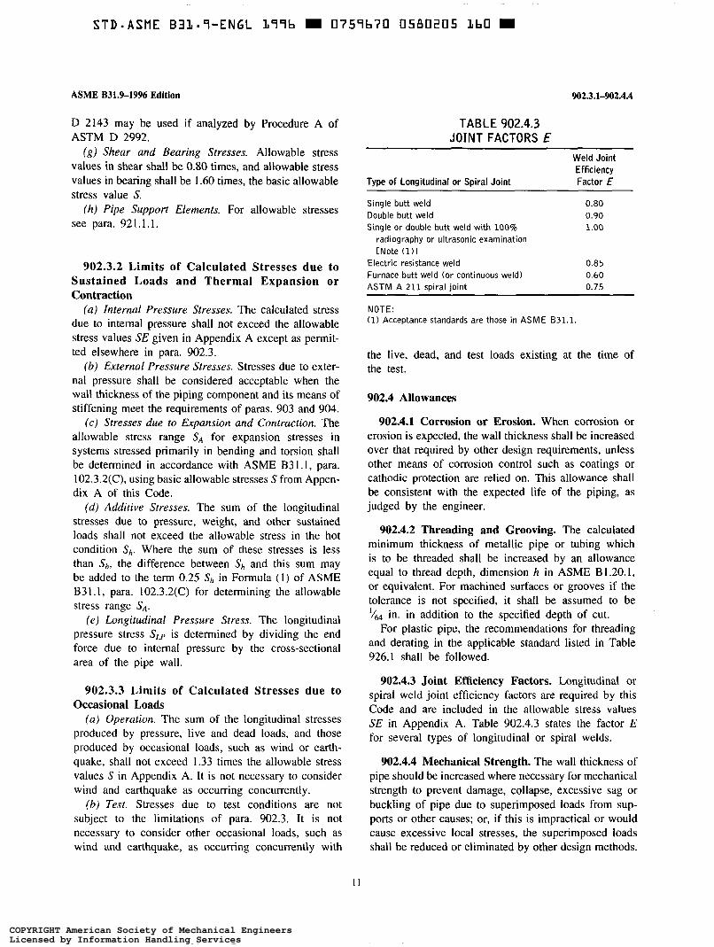
ASME B31.9-1996 Edition
D 2143 may be used if analyzed by Procedure A of ASTM D 2992.
(g) Shear and Bearing Stresses. Allowable stress values in shear shall be 0.80 times, and allowable stress values in bearing shall be 1.60 times, the basic allowable stress value S.
(h) Pipe Support Elements. For allowable stresses see para. 921.1.1.
902.3.2 Limits of Calculated Stresses due to Sustained Loads and Thermal Expansion or Contraction
(a) Internal Pressure Stresses. The calculated stress due to internal pressure shall not exceed the allowable stress values SE given in Appendix A except as permit- ted elsewhere in para. 902.3.
(b) External Pressure Stresses. Stresses due to exter- nal pressure shall be considered acceptable when the wall thickness of the piping component and its means of stiffening meet the requirements of paras. 903 and 904.
( c ) Stresses due to Expansion and Contraction. The allowable stress range SA for expansion stresses in systems stressed primarily in bending and torsion shall be determined in accordance with ASME B3 1.1, para. 102.3.2(C), using basic allowable stresses S from Appen- dix A of this Code.
( d ) Additive Stresses. The sum of the longitudinal stresses due to pressure, weight, and other sustained loads shall not exceed the allowable stress in the hot condition s h . Where the sum of these stresses is less than S,, the difference between S, and this sum may be added to the term 0.25 s h in Formula (1) of ASME B31 .l, para. 102.3.2(C) for determining the allowable stress range S,.
( e ) Longitudinal Pressure Stress. The longitudinal pressure stress S,, is determined by dividing the end force due to internal pressure by the cross-sectional area of the pipe wall.
902.3.3 Limits of Calculated Stresses due to Occasional Loads
( a ) Operation. The sum of the longitudinal stresses produced by pressure, live and dead loads, and those produced by occasional loads, such as wind or earth- quake, shall not exceed 1.33 times the allowable stress values S in Appendix A. It is not necessary to consider wind and earthquake as occurring concurrently.
(b) Test. Stresses due to test conditions are not subject to the limitations of para. 902.3. It is not necessary to consider other occasional loads, such as wind and earthquake, as occurring concurrently with
I I
902.3.1-902.4.4
TABLE 902.4.3 JOINT FACTORS E
Weld Joint Efficiency
Type of Longitudinal or Spiral Joint Factor E
Single butt weld 0.80 Double butt weld 0.90 Single or double butt weld with 100% 1.00
radiography or ultrasonic examination [Note (1) l
Electric resistance weld 0.85 Furnace butt weld (or continuous weld) 0.60 ASTM A 211 spiral joint 0.75
NOTE: (1) Acceptance standards are those in ASME 631.1.
the live, dead, and test loads existing at the time of the test.
902.4 Allowances
902.4.1 Corrosion or Erosion. When corrosion or erosion is expected, the wall thickness shall be increased over that required by other design requirements, unless other means of corrosion control such as coatings or cathodic protection are relied on. This allowance shall be consistent with the expected life of the piping, as judged by the engineer.
902.4.2 Threading and Grooving. The calculated minimum thickness of metallic pipe or tubing which is to be threaded shall be increased by an allowance equal to thread depth, dimension h in ASME B 1.20.1, or equivalent. For machined surfaces or grooves if the tolerance is not specified, it shall be assumed to be 1/64 in. in addition to the specified depth of cut.
For plastic pipe, the recommendations for threading and derating in the applicable standard listed in Table 926.1 shall be followed.
902.4.3 Joint Efficiency Factors. Longitudinal or spiral weld joint efficiency factors are required by this Code and are included in the allowable stress values SE in Appendix A. Table 902.4.3 states the factor E for several types of longitudinal or spiral welds.
902.4.4 Mechanical Strength. The wall thickness of pipe should be increased where necessary for mechanical strength to prevent damage, collapse, excessive sag or buckling of pipe due to superimposed loads from sup- ports or other causes; or, if this is impractical or would cause excessive local stresses, the superimposed loads shall be reduced or eliminated by other design methods.
COPYRIGHT American Society of Mechanical EngineersLicensed by Information Handling ServicesCOPYRIGHT American Society of Mechanical EngineersLicensed by Information Handling Services

90s904.2.2
PART 2 PRESSURE DESIGN OF
COMPONENTS PIPING
903 CRITERIA FOR PRESSURE DESIGN OF PIPING COMPONENTS
Components manufactured in accordance with the specifications and standards listed in Table 926.1 or in Appendix A shall be considered suitable for use at the pressure-temperature ratings or allowable stresses in accordance with para. 902.2. Components not manu- factured in accordance with those specifications and standards shall be used only in accordance with para. 902.2.2.
The rules in para. 904 usually are for the pressure design of components not covered in para. 902.2, but may be used for a more rigorous or special design of components covered in para. 902.2. The designs shall be checked for adequacy of mechanical strength under applicable loadings stated in para. 901.
904 PRESSURE DESIGN OF COMPONENTS
904.1 Straight Pipe
904.1.1 Straight Pipe Under Internal Pressure (u) Steel, Alloy, und Nonferrous Pipe. The minimum
wall thickness of pipe wall, including allowances, shall not be less than that determined by Formula (1).
P D 2SE
r,,, ="+A
Design pressure shall not exceed that determined by Formula (2).
P = 2SE (t,,, - A)
D (2)
The engineer may, at his option, use the values of r,,, and P determined by the applicable formulas in ASME B31.1.
( I ) If pipe is ordered by its nominal wall thickness, the manufacturing tolerances on wall thickness must be taken into account. After the minimum wall thickness r,,, is determined, this minimum thickness shall be increased to provide the manufacturing tolerance al- lowed in the applicable pipe specification. The next heavier commercial wall thickness shall then be selected.
ASME B31.%19% Edition
TABLE 904.2.1A PIPE THICKNESS FOR BENDS
Radius of Bends, Minimum Thickness Pipe Diameters, Dn Recommended Prior to
[Note (1)l Bending
6 or greater 1.06tm 5 1.08tm 4 1.14tm 3 1.24tm
NOTE: (1) Interpolation is permissible for a radius other than those listed.
(2) When computing the design pressure for a pipe of a definite minimum wall thickness fm the value of pressure obtained by Formula (2) may be rounded to the next higher 10 psi.
(b) Ductile Iron Pipe. The thickness of ductile iron pipe shall be determined from one of the following:
( 1 ) ANSVAWA C150/A21.50 or C151/ A21.51; (2) ANSI A21.14 or A21.52; (3) Federal Specification W - P - 4 2 l .
The tabulated thicknesses in these standards include allowances for foundry tolerances and water hammer.
(c) Straight Nonmetallic Pipe. The maximum pres- sure ratings for plastic and other nonmetallic pipe shall be as given in the applicable standards listed in Table 926. l .
904.1.2 Straight Metallic Pipe Under External Pressure. In determining wall thickness and stiffening requirements for straight pipe under external pressure, the procedures outlined in UG-28 of Section VIII, Division 1 of the ASME BPV Code shall be followed.
904.2 Curved and Mitered Segments of Pipe
904.2.1 Pipe Bends (u) Thickness of Bends. The minimum wall thickness
t, at any point in a completed pipe bend shall not be less than that required by para. 904. l. l. Table 904.2.1A may be used as a guide in specifying wall thickness for ordering pipe to be bent.
(b) Flattening of Bends. Flattening of a bend, as measured by the difference of maximum and minimum diameters, shall not exceed 8% of the average measured outside diameter of the pipe before bending.
Greater flattening may be permitted or less flattening may be required if specified by the engineering design.
904.2.2 Miter Joints. Thickness determined in ac- cordance with para. 904. l. 1 does not allow for disconti- nuity stresses at the joint between mitered segments
12
COPYRIGHT American Society of Mechanical EngineersLicensed by Information Handling ServicesCOPYRIGHT American Society of Mechanical EngineersLicensed by Information Handling Services
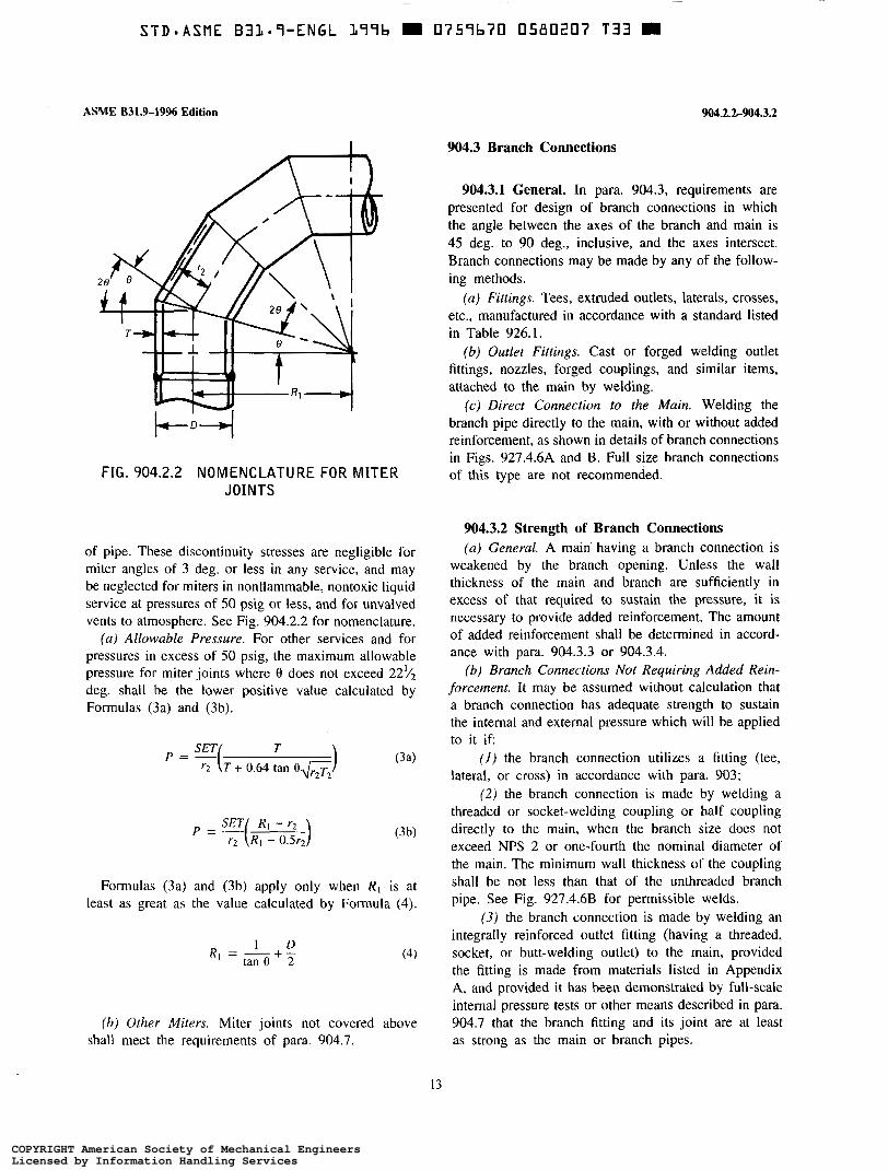
STDOASME BILaS-ENGL L77b m 0757b70 0580207 T33 m
ASME 831.9-1996 Edition 904.2.2-904.3.2
904.3 Branch Connections
904.3.1 General. In para. 904.3, requirements are presented for design of branch connections in which the angle between the axes of the branch and main is 45 deg. to 90 deg., inclusive, and the axes intersect. Branch connections may be made by any of the follow- ing methods.
(u) Fittings. Tees, extruded outlets, laterals, crosses, etc., manufactured in accordance with a standard listed in Table 926.1.
(b) Outlet Fittings. Cast or forged welding outlet fittings, nozzles, forged couplings, and similar items, attached to the main by welding.
(c) Direct Connection to the Main. Welding the branch pipe directly to the main, with or without added reinforcement, as shown in details of branch connections in Figs. 927.4.6A and B. Full size branch connections
FIG. 904.2.2 NOMENCLATURE FOR MITER of this type are not recommended. JOINTS
of pipe. These discontinuity stresses are negligible for miter angles of 3 deg. or less in any service, and may be neglected for miters in nonflammable, nontoxic liquid service at pressures of 50 psig or less, and for unvalved vents to atmosphere. See Fig. 904.2.2 for nomenclature.
( a ) Allowable Pressure. For other services and for pressures in excess of 50 psig, the maximum allowable pressure for miter joints where 0 does not exceed 22v2 deg. shall be the lower positive value calculated by Formulas (3a) and (3b).
P = -(R SET RI - ) r2 I - O.Sr2
Formulas (3a) and (3b) apply only when R, is at least as great as the value calculated by Formula (4).
I D tan O + T RI = -
(b) Other Miters. Miter joints not covered above shall meet the requirements of para. 904.7.
904.3.2 Strength of Branch Connections (u) General. A main having a branch connection is
weakened by the branch opening. Unless the wall thickness of the main and branch are sufficiently in excess of that required to sustain the pressure, it is necessary to provide added reinforcement. The amount of added reinforcement shall be determined in accord- ance with para. 904.3.3 or 904.3.4.
(6) Branch Connections Not Requiring Added Rein- forcement. It may be assumed without calculation that a branch connection has adequate strength to sustain the internal and external pressure which will be applied to it i f
( I ) the branch connection utilizes a fitting (tee, lateral, or cross) in accordance with para. 903;
( 2 ) the branch connection is made by welding a threaded or socket-welding coupling or half coupling directly to the main, when the branch size does not exceed NPS 2 or one-fourth the nominal diameter of the main. The minimum wall thickness of the coupling shall be not less than that of the unthreaded branch pipe. See Fig. 927.4.6B for permissible welds.
(3) the branch connection is made by welding an integrally reinforced outlet fitting (having a threaded, socket, or butt-welding outlet) to the main, provided the fitting is made from materials listed in Appendix A, and provided it has been demonstrated by full-scale internal pressure tests or other means described in para. 904.7 that the branch fitting and its joint are at least as strong as the main or branch pipes.
13
COPYRIGHT American Society of Mechanical EngineersLicensed by Information Handling ServicesCOPYRIGHT American Society of Mechanical EngineersLicensed by Information Handling Services
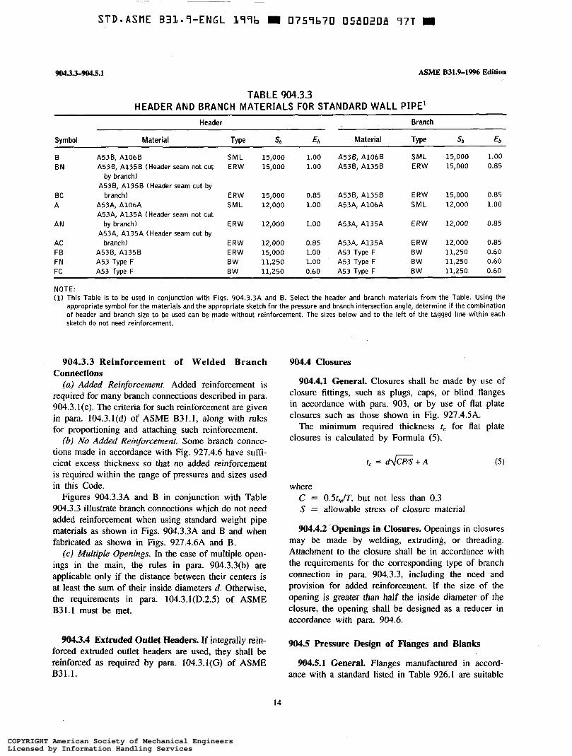
9043.3-w.5.1 ASME B31.9-19% Edition
TABLE 904.3.3 HEADER AND BRANCH MATERIALS FOR STANDARD WALL PIPE’
~ ~~~ ~ ~ ~~~ ~
Header Branch
Symbol Material Type s h Eh Material Type S b Eb
B A538, A1066 SML 15,000 1.00 A53B, A106B SML 15,000 1.00 BN A53B, A135B (Header seam not cut ERW 15,000 1.00 A536, A1356 ERW 15,000 0.85
by branch) A536, A135B (Header seam cut by
BC branch) ERW 15,000 0.85 A538, A135B ERW 15,000 0.85 A A53A, A106A SML 12,000 1.00 A53A, A106A SML 12,000 . 1.00
A53A, A135A (Header seam not cut
A53A, A135A (Header seam cut by AN by branch) ERW 12,000 1.00 A53A, A135A ERW 12,000 0.85
AC branch) ERW 12,000 0.85 A53A, A135A ERW 12,000 0.85 FB A536, A1356 ERW 15,000 1.00 A53 Type F BW 11,250 0.60 FN A53 Type F BW 11,250 1.00 ’ A53 Type F BW 11,250 0.60 FC A53 Type F BW 11,250 0.60 A53 Type F BW 11,250 0.60
NOTE: (1) This Table is t o be used in conjunction with Figs. 904.3.3A and B. Select the header and branch materials from the Table. Using the
appropriate symbol for the materials and the appropriate sketch for the pressure and branch intersection angle, determine if the combination of header and branch size to be used can be made without reinforcement. The sizes below and t o the left of the tagged line within each sketch do not need reinforcement.
904.3.3 Reinforcement of Welded Branch Connections
(a) Added Reinforcement. Added reinforcement is required for many branch connections described in para. 904.3.1(c). The criteria for such reinforcement are given in para. 104.3.l(d) of ASME B31.1, along with rules for proportioning and attaching such reinforcement.
(b) No Added Reinforcement. Some branch connec- tions made in accordance with Fig. 927.4.6 have suffi- cient excess thickness so that no added reinforcement is required within the range of pressures and sizes used in this Code.
Figures 904.3.3A and B in conjunction with Table 904.3.3 illustrate branch connections which do not need added reinforcement when using standard weight pipe materials as shown in Figs. 904.3.3A and B and when fabricated as shown in Figs. 927.4.6A and B.
(c) Multiple Openings. In the case of multiple open- ings in the main, the rules in para. 904.3.3(b) are applicable only if the distance between their centers is at least the sum of their inside diameters d. Otherwise, the requirements in para. 104.3.1(D.2.5) of ASME B31.1 must be met.
904.3.4 Extruded Outlet Headers. If integrally rein- forced extruded outlet headers are used, they shall be reinforced as required by para. 104.3.1(G) of ASME B31.1.
904.4 Closures
904.4.1 General. Closures shall be made by use of closure fittings, such as plugs, caps, or blind flanges in accordance with para. 903, or by use of flat plate closures such as those shown in Fig. 927.4.5A.
The minimum required thickness tc for flat plate closures is calculated by Formula (5).
tc = d e + A (5)
where C = OSt,,/T, but not less than 0.3 S = allowable stress of closure material
904.4.2 ‘Openings in Closures. Openings in closures may be made by welding, extruding, or threading. Attachment to the closure shall be in accordance with the requirements for the corresponding type of branch connection in para. 904.3.3, including the need and provision for added reinforcement. If the size of the opening is greater than half the inside diameter of the closure, the opening shall be designed as a reducer in accordance with para. 904.6.
904.5 Pressure Design of Flanges and Blanks
904.5.1 General. Flanges manufactured in accord- ance with a standard listed in Table 926.1 are suitable
14
COPYRIGHT American Society of Mechanical EngineersLicensed by Information Handling ServicesCOPYRIGHT American Society of Mechanical EngineersLicensed by Information Handling Services

STDDASME BIL=S-ENGL L99b m 0759b70 0580209 BOb m
ASME B31.9-1996 Edition
32
28
24
2 2 20 $
16 o
12
8
4
2 2 4 8 12 16 20 24 28 32
Header Size, NPS
(a) 90 deg., 100 psig
2 4 6 8 10 12 14 16 18
Header Size, NPS
(c) 90 deg., 300 psig
Fig. 904.3.3A
24
20
16 z aì ._
r 12 li)
C
E m
8
4
- 2 4- 6 8 10 12 14 16 18 20
Header Size, NPS
(b) 90 deg.. 200 psig
2 4 6 8 10 12 14 16
Header Size, NPS
(d) 90 deg., 350 p i g
GENERAL NOTES: (a) See Table 904.3.3 for instructions on the use of this figure. (b) A 12.5% mill tolerance and a ’& in. corrosion allowance have been used in the calculations for this figure. (c) The pipe size limit for this Code is NPS 30. The sketches end at that size, but allowable unreinforced branches may ex-
(d l A53 Type F, butt weld pipe, is l imited to NPS 4 as it is not available above that size. (e) This figure is based on the rules of 631.1.
tend to larger sizes for some materials and pressures.
FIG. 904.3.3A 90 deg. BRANCH INTERSECTIONS NOT REQUIRING ADDED REINFORCEMENT - STANDARD WALL PIPE
15
COPYRIGHT American Society of Mechanical EngineersLicensed by Information Handling ServicesCOPYRIGHT American Society of Mechanical EngineersLicensed by Information Handling Services

Fig. 90433B
~~
STD*ASME B31-7-ENGL 377b 0757b70 0580230 526 m
28
24
L 20 z
E 16 al
c o
: 12
8
4
2 2 4 8 12 16 20 24 28 32
Header Size, NPS
ASME B31.9-1996 Edition
18
16
14
v) Q 12 z
10 6
E 8 c
m E
6
4
2 2 4 6 8 10 12 14 16 13 20 22 24
Header Size. NPS
(a) 45 deg., 100 psig
2 4 6 8 10 12 14 16 Header Size, NPS
( c ) 45 deg.. 300 psiy
(bl 45 deg., 200 p i g
2 4 6 8 10 12
Header Size, NPS
(d) 45 deg., 350 psig
GENERAL NOTES: (a) See Table 904.3.3 for instructions on the use of this figure. (b) A 12.5% mill tolerance and a ’& in. corrosion allowance have been used in the calculations for this figure. (c) The pipe size limit for this Code is NPS 30. Tbe sketches end at that size, but allowable unreinforced branches may ex-
(d) A53 Type F, butt weld pipe, is limited to NPS 4 as it is not available above that size. (e) This figure is based on the rules of 831.1.
tend to larger sizes for some materials and pressures.
FIG. 904.3.38 45 deg. BRANCH INTERSECTIONS NOT REQUIRING ADDED REINFORCEMENT -STANDARD WALL PIPE
16
COPYRIGHT American Society of Mechanical EngineersLicensed by Information Handling ServicesCOPYRIGHT American Society of Mechanical EngineersLicensed by Information Handling Services
ASME B31.9-1996 Edition
for use in accordance with para. 903. Other flanges shall be designed in accordance with Appendix [I, Section VIII, Division I of the ASME BPV Code.
904.5.2 Blind Flanges. Blind flanges manufactured in accordance with a standard listed in Table 926.1 are suitable for use in accordance with para. 903. Other blind flanges shall be designed in accordance with UG- 34 of Section VIII, Division 1 of the ASME BPV Code.
904.5.3 Blanks. The minimum required thickness of a permanent blank installed between two flanges shall be calculated by Formula (6).
t,. = d,,J3P/lss + A (6)
S = allowable stress of blank material. Use SF if material is a casting.
Blanks used only for testing with an incompressible fluid shall be calculated in accordance with Formula (6), except that P shall be the test pressure and S may be taken as 0.95 times the specified minimum yield strength of the blank material.
904.6 Reducers
904.6.1 General. Reducers manufactured in accord- ance with a standard listed in Table 926.1 are suitable for use with pipe of the same nominal thickness.
904.6.2 Segmented Reducers. The minimum wall thickness of segmented (orange peel) reducers fabricated with longitudinal welds shall be determined in accord- ance with para. 904.1.2, using a weld joint efficiency factor of 0.6. The slope of the reducing section shall not be at an angle greater than 30 deg. to the axis of the pipe.
904.7 Pressure Design of Other Pressure Containing Components
904.7.1 Listed Components. Other pressure con- taining components manufactured in accordance with a standard listed in Table 926.1 are suitable for use in accordance with para. 903.
904.7.2 Unlisted Components. Pressure containing components made of listed materials but not made in accordance with a specification or standard listed in Table 926.1 or Appendix A shall be substantiated by at least one of the following:
904.5.1-905.2.5
(a) engineering calculations; (b) experimental stress analysis such as described in
Appendix 6 in Section VIU, Division 2 of the ASME BPV Code;
(c ) proof test in accordance with UG-101 in Section VIII, Division 1 of the ASME BPV Code.
If differences in size and proportion are small, compo- nents may be designed by interpolation between similar configurations which have been proven by one of the procedures described above, or that conform to a listed standard.
PART 3 SELECTION AND LIMITATION OF
COMPONENTS
905 PIPE
905.1 General
905.1.1 Listed Pipe. Pipe manufactured in accord- ance with a specification or standard listed in Table 926.1 or Appendix A, as qualified by the Notes, may be used in accordance with its ratings or allowable stresses, within other limitations in para. 905, and within the limitations on joints in Chapter II, Part 4 and on materials in Chapter III.
905.2 Specific Limitations
905.2.1 Cast Iron Pipe. Cast iron pipe shall not be used above ground in oil or other flammable liquid service, nor in compressed gas service.
905.2.2 Steel Pipe. Furnace butt weld steel pipe shall not be used for flammable or combustible liquids.
905.2.3 Copper Alloy Pipe and Tube. Copper pipe and tube shall not be used for flammable or combustible liquids except as permitted in para. 922.3.1(c).
905.2.4 Nonmetallic Pipe. Unlisted reinforced ther- mosetting resin pipe shall not be used.
905.2.5 Thermoplastics Pipe. See para. 923.3.2 for limitations on thermoplastics.
17
COPYRIGHT American Society of Mechanical EngineersLicensed by Information Handling ServicesCOPYRIGHT American Society of Mechanical EngineersLicensed by Information Handling Services
906-9 10
906 FITTINGS, BENDS, AND INTERSECTIONS
906.1 Fittings
906.1.1 Listed Fittings. Fittings manufactured in accordance with a specification or standard listed in Table 926.1 or Appendix A may be used in accordance with their ratings or allowable stresses, within other limitations in para. 906, and within the limitations on joints in Chapter II, Part 4 and on materials in Chapter III.
906.2 Bends and Miter Joints
See para. 904.2.2(a) for service limitations on re- stricted miter joints.
906.3 Limitations on Fittings
Cast iron fittings shall not be used in flammable liquid or gas service. See para. 923.3.2 for limitations on thermoplastics.
907 VALVES
907.1 General
907.1.1 Listed Valves. Valves manufactured in ac- cordance with a standard listed in Table 926.1 may be used in accordance with their ratings, within other limitations in para. 907, and within the limitations on joints in Chapter II, Part 4 and on materials in Chapter III.
907.1.2 Unlisted Valves. Valves not manufactured in accordance with a listed standard shall be used only within the manufacturer’s recommendations as to service and ratings, and within the limitations on comparable listed valves, considering composition, mechanical prop- erties, dimensions, method of manufacture, and quality control. Otherwise, the valves shall be qualified in accordance with para. 904.7.2.
907.2 Marking
Each valve shall bear markings in accordance with MSS SP-25, including the manufacturer’s name or trademark, the material of construction, and symbols to indicate the service conditions for which the manufac- turer rates the valve. Other markings shall be included if required by the applicable standard.
ASME B31.%1996 Edition
908 FLANGES, BLANKS, GASKETS, AND BOLTING
908.1 General
908.1.1 Listed Components. Flanges, blanks, gas- kets, and bolting manufactured in accordance with a standard listed in Table 926.1 may be used in accordance with their ratings, within manufacturers’ recommenda- tions, within other limitations in para. 908, and within the limitations on joints in Chapter II, Part 4 and on materials in Chapter III.
908.3 Flange Facings
Flange facings shall be in accordance with the stan- dards listed in Table 926.1, or as provided in MSS SP-6. When bolting raised-face steel flanges to flat- face cast iron flanges, bolting torque should be limited to prevent cracking the cast iron flange; otherwise, steel flanges should be furnished with a flat-face and full- face gaskets shall be used.
908.4 Gaskets
Material, thickness, and type of gasket shall be selected to suit the fluid to be handled and the design pressure and temperature.
908.5 Bolting
Bolts, nuts, and washers shall conform to applicable standards listed in Table 926.1.
PART 4 SELECTION AND LIMITATION OF
JOINTS
910 PIPING JOINTS
The type of joint used shall be suitable for the design conditions and the fluid handled, and shall be selected with consideration of joint tightness and mechanical strength.
18
COPYRIGHT American Society of Mechanical EngineersLicensed by Information Handling ServicesCOPYRIGHT American Society of Mechanical EngineersLicensed by Information Handling Services

STD*ASME B31.7-ENGL b77b D 0757b70 0580213 237 m
ASME B31.9-2996 Edition
911 WELDED JOINTS
911.1 Metallic Pipe
Welded joints shall only be used for materials for which welding procedures, welders, and welding ma- chine operators have been qualified as required in Chapter V.
911.1.1 Butt and Miter Welds. Butt and miter joint welds shall be made in accordance with para. 927.4.2, and shall be full penetration welds. (Backing rings are not recommended.)
911.1.2 Socket Welding. Socket welds shall be made in accordance with para. 9 11. I .3. In addition, dimensions of socket type joints shall conform to those in standards listed in Table 926.1.
911.1.3 Fillet Welds. Fillet welds in properly de- signed connections shall be made in accordance with para. 927.4.3.
911.1.4 Seal Welds. Seal welds are intended only to provide leak tightness for threaded joints and are not considered to add strength to the joint.
911.2 Nonmetallic Pipe
911.2.1 Thermoplastic Welding. Welds in thermo- plastic materials shall conform to the requirements in para. 934. I .3.
911.2.2 Thermoplastic Socket Welding. Dimen- sions of socket-type joints shall conform to those in standards for fittings listed in Table 926.1.
912 FLANGED JOINTS
Flanged joints shall meet the requirements in para. 908.
913 MECHANICAL AND PROPRIETARY JOINTS
Grooved, extruded, expanded, rolled, O-ring, clamp, gland-type, and other mechanical or proprietary joints may be used where experience or tests in accordance with para. 904.7 have demonstrated that the joint is safe for the operating conditions and the fluids being transported, and where adequate provision is made to prevent separation of the joint. All such joints shall be used within the manufacturer’s limitations on pressure-
911-915
temperature ratings and other recommendations for in- stallation and use.
913.1 Limitations on Mechanical and Proprietary Joints
Joints dependent on friction characteristics or resil- iency of combustible or low melting point materials for mechanical continuity or leak tightness shall not be used for flammable fluids or gases inside buildings.
914 THREADED JOINTS
Threaded joints may be used within the limitations on fittings in para. 906, limitations on materials in Chapter III, and other limitations herein.
914.1 Acceptable Types
Threads on pipe and fittings shall be tapered pipe threads in accordance with ASME B 1.20.1 or other applicable standards listed in Table 926.1, except that threads in wrought steel couplings NPS 2 and smaller may be straight pipe threads. Threads other than tapered pipe threads may be used where tightness of the joint depends on a seal weld or seating surface other than the threads, and where experience or test has demon- strated that such threads are suitable.
914.2 Limitations on Threaded Joints
(u) Threaded joints shall not be used where severe erosion, crevice corrosion, shock, or vibration are ex- pected to occur.
(6) Metallic pipe with a wall thickness less than that of standard wall in ASME B36.10M shall not be threaded, regardless of service.
(c) Plastic pipe with wall thickness less than that of Schedule 80 shall not be threaded.
(d) Polyethylene pipe and polybutylene pipe shall not be threaded.
915 FLARED, FLARELESS, AND COMPRESSION JOINTS
Flared, flareless, and compression type tubing fittings and joints may be used within the limitations of applica- ble standards listed in Table 926. I , on materials in Chapter III, and other limitations herein.
Fittings and joints shall be compatible with the tubing with which they are used, and shall be used within the manufacturer’s pressure-temperature ratings. Vibration
19
COPYRIGHT American Society of Mechanical EngineersLicensed by Information Handling ServicesCOPYRIGHT American Society of Mechanical EngineersLicensed by Information Handling Services
915-919.3.1
and thermal cycling shall be considered in each appli- cation.
916 BELL AND SPIGOT JOINTS
916.1 Caulked or Leaded Joints
Bell and spigot joints, caulked with lead and packing material, may be used only for water service up to 100"F, where adequate provision is made to prevent separation of the joints. See ANSVAWWA C600 for joints in cast iron pressure piping.
916.2 Push-Type Elastomer Gasket
Push-type joints with elastomer gaskets may be used where experience or tests have demonstrated that the joint is safe for the operating conditions and the fluid being transported, and where adequate provision is made to prevent separation of the joints.
917 BRAZED AND SOLDERED JOINTS
917.1 General
Brazed and soldered socket-type joints shall be made in accordance with para. 928 and with brazing or soldering filler metals which are compatible with the base material and with the pressure, temperature, and other service conditions.
917.2 Brazed Joints
Socket-type brazed joints may be used within the limitations on materials in Chapter III.
9173 Soldered Joints
917.3.1 General. Soldered socket-type joints may be used within the pressure-temperature limitations in Ta- ble 917.3. Soldered joints other than socket-type shall not be used.
917.3.2 Limitations. Soldered joints shall not be used for flammable or toxic gases or liquids. They shall not be used for compressed air or other gases in tubing over 4.125 in. O.D. unless the maximum pressure is limited to 20 psig.
ASME B31.9-1996 Edition
PART 5 EXPANSION, FLEXIBILITY, AND
SUPPORT
919 EXPANSION AND FLEXIBILITY
919.1 General
In addition to design requirements for pressure, weight, and other loadings, piping systems subject to thermal expansion or contraction, or to similar move- ments imposed by other sources shall be designed to prevent:
(u) failure of piping or supports from overstress or fatigue;
(6) leakage of joints; (c ) detrimental stresses or distortion in connected
equipment (pumps, turbines, valves, etc.) resulting from excessive thrusts and moments.
919.2 Concepts
919.2.1 General. The treatment of flexib' analysis in this Code covers only the simplest applications. For piping systems not compatible with this simplified approach, the user is directed to Chapter 11, Part 5 of ASME B3 I . 1. The concepts, methods, and requirements therein are acceptable under this Code.
919.2.2 Means of Providing Flexibility. Flexibility may be increased by one or more of the following means:
(u) adding elbows, bends, or loops where feasible; (b) installing expansion joints, properly guided and
(c) installing rotary joints, properly guided and re- restrained;
strained.
919.2.3 Flexibility in Nonmetallic Piping. Particular care must be taken in selecting the methods given in para. 919.2.2 when laying out nonmetallic piping sys- tems, because they are difficult or impossible to analyze, have very limited capacity for overstress, are subject to brittle failure, and may have high coefficients of thermal expansion and nonlinear stress-strain character- istics.
919.3 Properties for Analysis
919.3.1 Coefficients of Thermal Expansion. Table 919.3.1 contains data on thermal expansion characteris-
20
COPYRIGHT American Society of Mechanical EngineersLicensed by Information Handling ServicesCOPYRIGHT American Society of Mechanical EngineersLicensed by Information Handling Services

STD=ASME B33.7-ENGL 177b m 0 7 5 7 b 7 0 0 5 8 0 2 3 5 OOT H
ASME B31.9-1996 Edition 919.3.1-919.8
TABLE 917.3 RATED INTERNAL WORI<ING PRESSURES OF JOINTS MADE WITH COPPER WATER TUBE AND
SOLDER JOINT FITTINGS, psigl
Types K, L, M Copper Water Tube in Nominal Sizes, in.
Liquids and Gases [Note (213 Service
Solder or Brazing Alloy Temperature, 5-8 10-12 Saturated Steam and Used in Joints “F, Max. 1/4-1 1V4-2 2l/,-4 [Note (2)l [Note (2)l Condensate, All Sizes
50-50 Tin-Lead ASTM B 32 Gr 50A 100 200 175 150 135 100
150 150 125 1 O0 90 70 200 [Note (1)l 100 90 75 70 50 . . . 250 [Note (1)l 85 75 50 45 40 15
. . .
. . .
95-5 Tin-Antimony ASTM B 32 Gr 95TA 100 500 400 300 270 150
150 400 350 275 250 150 200 CNote (1)l 300 250 200 180 140 250 CNote (1)l 200 175 150 135 110 15
. . .
. . .
. . .
Brazing Alloys 200 [Note (1)l [Note (3) l [Note (311 [Note ( 3 ) l [Note (311 [Note (311 250 [Note (1)l 300 210 170 150 150 15 350 [Note (1)l 270 190 150 150 150 120
...
NOTES: (1) See paras. 900.1.2(d) and (e) for pressure and temperature limits under this Code. (2) See limitations in para. 917.3.2. ( 3 ) Rated pressure for temperatures up to 200°F is that of the tube being joined.
tics of many of the metallic and nonmetallic materials used in this Code.
919.4 Analysis, Metallic Piping
919.4.1 Requirements for Analysis (a ) SimpliJied Analysis. No formal analysis is re-
quired for systems which meet one of the following criteria.
( I ) The system duplicates a successfully operating installation or replaces a system with a satisfactory service record.
(2) The system is of ductile material (e.g., there are no cast iron fittings); the segment being analyzed has no more than two anchors and no intermediate restraints; i t has no more than two pipe sizes, differing by one standard size; the least nominal wall thickness is no less than 75% of the greatest; and thermal expansion in the segment satisfies Formula (9):
D,Y/(L - U)* = 0.03 or Less (9)
where D, = the nominal size of the larger pipe in the
segment
NOTE: There is no assurance that Formula (9) is always accurate or conservative, especially for nearly straight sawtooth segments or for unequal leg U-bends where UU is more than 2.5. There is no assurance that end reactions will be. acceptably low.
(3) The system is laid out with a conservative margin of inherent flexibility, or employs joining meth- ods, expansion devices, or a combination of joining method and expansion devices in accordance with appli- cable manufacturers’ instructions.
(b) Other Methods of Analysis. Piping systems which do not meet the criteria of (a) above shall be analyzed by suitable approximate or conservative methods as outlined in ASME B3l. 1, paras. 119.7.1(C) and (D), and as directed elsewhere in para. 119 of ASME B31.1.
919.8 Movements
Movements caused by thermal expansion or contrac- tion and other similar loadings shall be determined for consideration of obstructions and design of supports.
21
COPYRIGHT American Society of Mechanical EngineersLicensed by Information Handling ServicesCOPYRIGHT American Society of Mechanical EngineersLicensed by Information Handling Services

919.9-919.10 ASME B31.9-19% Edition
TABLE 919.3.1 MODULI OF ELASTICITY AND THERMAL EXPANSION COEFFICIENTS
~ ~ ~~ ~~~~~~~~~
. Linear Thermal Expansion, in./lOO ft, Modulus of Coefficient [Note (1)l Between 70°F and Indicated Temperature, "F Elasticity, of Thermal Expansion,
Material psi x 10" idin., O F X lo4 O 25 ' 50 70 100 125
Carbon steel
Austenitic stainless steel
Aluminum
Gray cast iron
Ductile Iron
Copper C12200 (99.9Cu)
Copper CA 23000 (red brass) (8501)
ABS 1210 1316 2112
CPVC 4120
PVC 1120 1220 2110 2120
PB 2110
PE 2306 3306 3406
PP 1110 1208 2105
RTRP
27.5
29.0
10.0
13.0
...
17.0
17.0
0.25 0.34
0.42
0.42 0.41 0.34
. . .
0.09 0.13 0.15
. . .
Consult manufacturer
6.33
9.27
12.69
5.76
5.97
9.50
10.40
55.0 40.0 40.0
35.0
30.0 35.0 50.0 30.0
72.0
80.0 70.0 60.0
48.0 43.0 40.0
-0.49
-0.72
-0.97
-0.49
-0.46
-0.80
-0.87
. . .
. . .
. . .
* . . ... ... ... ...
. . .
. . .
. . .
. . .
f . .
...
...
-0.32
-0.46
-0.63
-0.32
-0.30
-0.51
-0.56
. . .
. . .
. . .
. . .
...
...
...
...
. . .
. . .
. . .
. . .
. . .
...
...
-0.14 O
-0.21 o
-0.28 O
-0.14 O
-0.14 O
-0.23 O
-0.25 O
-1.32 O -0.96 O -0.96 O
-0.84 O
-0.72 O -0.84 O -1.20 o -0.72 O
-1.73 O
-1.92 O -1.68 O -1.44 O
-1.15 O -1.03 O -0.96 O
0.23
0.34
0.46
0.21
0.21
0.34
0.37
1.98 1.44 1.44
1.26
1.08 1.26 1.80 1.08
2.59
2.88 2.52 2.16
1.73 1.55 1.44
0.42
0.62
0.85
0.38
0.39
0.63
0.69
. . .
. . .
. . .
2.31
. . .
. . .
...
...
4.75
. . .
. . .
. . .
. . .
. . . f . .
NOTE: (1) Average of the mean values over the temperature range for which data are shown.
919.9 Cold Spring
Cold spring is the intentional displacement of piping during assembly. When applied, it is normally to com- pensate for one-half of the total expected pipe movemenb due to expansion. Possible benefits of cold spring include:
(u) reduced likelihood of overstrain during initial operation;
(b) reduced deviation from as-installed hanger posi- tions; and
(c) reduction of maximum end reactions. No credit for cold spring is permitted in stress range
calculations.
919.10 Reactions
Terminal reactions and resulting moments shall be taken into consideration where supporting structure or connected equipment is likely to be affected by such loadings. Determination of these loads may require analysis as specified in para. 919.4.1(b).
22
COPYRIGHT American Society of Mechanical EngineersLicensed by Information Handling ServicesCOPYRIGHT American Society of Mechanical EngineersLicensed by Information Handling Services

STDmASME B 3 L * 9 - E N G L L77b H 0757b70 0580217 782 m
ASME B31.9-1996 Edition 920-920.1.1
TABLE 919.3.1 MODULI OF ELASTICITY AND THERMAL EXPANSION COEFFICIENTS
Linear Thermal Expansion, in./100 ft, Between 70°F and Indicated Temperature, "F
150 175 200 225 250 275 300 325 350 375 Material
0.61
0.90
1.23
0.55
0.57
0.91
1.00
. . .
. . .
. . .
3.36
. . .
. . .
. . .
. . .
6.91
. . . * . . . . .
. . .
. . .
. . .
0.80 0.99 1.21 1.40 1.61 1.82 2.04 2.26 2.48
1.18 1.46 1.75 2.03 2.32 2.61 2.90 3.20 3.50
1.62 2.00 2.41 2.83 3.24 3.67 4.09 4.52 4.95
0.73 0.90 1.00 1.27 1.45 1.64 1.83 2.03 2.22
0.76 0.94 1.13 1.33 1.53 1.72 1.93 2.13 2.36
1.20 1.48 1.77 2.05 2.34 2.62 2.91 3.19
1.31 1.62 1.93 2.25 2.56 2.87 3.18 3.49 . . .
. . . . . . . . . ... ... . . . . . . ... . . .
. . . . . . . . . . . . . . . . . . . . . . . . . . .
. . . . . . . . . ... . . . . . . . . . . . . . . .
4.41 . . . . . . . .. . . . . . . . . . . . .
. . . . . . . . . . . . . . . . . . . . . ... , , .
. . . . . . . . . . . . . . . . . . . . . . . . . . .
. . . . . . . . . . . . . . . . . . . . . ... . . .
. . . . . . . . . . . . . . . . . . . . . ... . . .
9.07 . . . . . . . . . . . . . . .
. . . . . . . . . . . . . . . . . . . .. . . . . . .
. . . . . . . . . . . . . . . . . . . .. . . . . . .
. . . . . . . . . ... ... . . . . . . ... . . .
. . . . . . . . . . . . . . . . . . . . . ... . . .
. . . . . . . . . . . . . . . . . . . . . . . . . . .
. . . . . . . . . . . . . . . . . . . . . . . . . . .
Carbon steel
Austenitic stainless steel
Aluminum
Gray cast iron
Ductile iron
Copper C12200 (99.9Cu)
Copper CA 23000 (red brass) (85Cu)
A B S 1210 1316 2112
CPVC 4120
PVC 1120 1220 2110 2120
PB 2110
PE 2306 3306 3406
PP 1110 1208 2105
RTRP
920 LOADS ON PIPE SUPPORTING ELEMENTS
920.1 General
Supports, as used in this Code, include rigid hangers (that support the line from above without springs), spring hangers, supports that bear the load from below, and guides and anchors that limit pipe movement as well as support loads.
920.1.1 Loads on Supports. The loads to be consid- ered in design of supports are:
(u) dead weight of pipe, fittings, valves, insulation, inline equipment, hanger system, and other pipelines (if supported from the line under consideration);
(b) live weight of contents; (c) weight of test fluid (see para. 920.2); (d) occasional loads, such as ice, wind, and earth-
quake.
23
COPYRIGHT American Society of Mechanical EngineersLicensed by Information Handling ServicesCOPYRIGHT American Society of Mechanical EngineersLicensed by Information Handling Services

920.1.1-921.1.3
Weight of test fluid and occasional loads need not be considered concurrently.
920.1.2 Loads on Restraints (a) General. In addition to the loads described in
para. 920.1 .I, anchors, guides, and other restraints shall be designed to bear loads resulting from thermal expan- sion and contraction and from other movements of the piping, such as those caused by internal pressure.
(b) Expansion Joint Loads. Use of expansion joints usually increases reactions at anchors. For corrugated and slip joints, in the absence of manufacturer's data, anchor reaction may be calculated as the sum of:
(1 ) operating pressure times area corresponding to the maximum inside diameter of the joint corrugations;
(2 ) the force required to cause full rated deflection of the joint; and
(3) frictional forces at guides and supports. If the expansion joint is at an elbow or bend, the
vector forces due to fluid change in direction must also be included.
920.1.3 Other Loads. Loads from other design con- ditions described in para. 901 shall be considered in design of both supports and 'restraints. Loads due to shock and vibration should preferably be minimized by the use of suitable dampeners or properly placed supports and restraints.
920.2 Test Loads
920.2.1 Test Loads on Rigid Supports. Rigid sup- ports shall be capable of bearing the total load under test conditions as well as those of normal operation, unless additional supports are provided during testing.
920.2.2 Test Loads on Spring Hangers. Load condi- tions for calculated operation of spring hangers should not take test loads into account. The hanger assembly, however, shall be capable of supporting the test load unless additional supports are provided during testing.
921 DESIGN OF PIPE SUPPORTING ELEMENTS
921.1 General
Pipe supporting elements shall be designed to carry the sum of all concurrently acting loads described in para. 920. Unless designed to anchor or restrain line movements by withstanding the resultant forces and moments, they shall permit free movement of the piping resulting from thermal expansion or other causes.
ASME B31.9-19% Edition
In addition, supports shall be so located and spaced as to protect the supported piping from excessive stress and distortion.
921.1.1 Materials and Stresses. Except as permitted herein, materials for pipe supporting elements shall be listed in Appendix A. Allowable stresses for pipe supporting elements shall be one-fifth of the minimum tensile strength shown in Appendix A. For carbon steel of unknown specification, the allowable stress shall not exceed 9500 psi. . ( a ) Threaded Parts. The maximum safe loads shall
be calculated on the root area of the threads of threaded parts.
(b) Allowable Overstress. An increase in allowable stress is permitted up to 80% of specified minimum yield strength during hydrostatic testing, not to exceed 24,000 psi for carbon steel of unknown specification.
(c) Selection of Material. Hanger and support materi- als shall be compatible with the characteristics of the piping materials, so that neither shall adversely affect the other.
921.1.2 Hanger Adjustments. Hangers supporting piping NPS 2v2 and larger shall be designed to permit adjustment after erection while supporting the load. Threaded parts for adjustment shall be in accordance with ASME B1.l.
Turnbuckles and adjusting nuts shall have full thread engagement. Threaded adjustments shall be provided with suitable locking devices.
921.1.3 Support Spacing ( a ) Piping Stresses. Stresses in the piping due to
support spacing shall not exceed the basic allowable stress S when computed on the basis of a support span twice as great as the actual span.
(b) Allowable Deflection. The allowable deflection of the pipe between supports shall not exceed the smaller of 0.25 in. or 15% of the outside diameter of the pipe, based on the weight of the pipe, service fluid (S.G. I l.O), and insulation.
(c) Spacing, Steel Pipe. Figure 921 .I .3C shows the maximum recommended support spacing for standard weight Grade A, Grade B, and Schedule I O pipe.
( d ) Spacing, Other Materials. The maximum recom- mended support spacing for copper and plastic pipe is shown in Fig. 921.1.3D.
(e) Limitations on Charts. The spans i n Figs. 921.1.3C and D are based on limitations in para. 921.1.3(a) and (b) and are not applicable where there are concentrated loads, Le., valves, special fittings, etc. Spans and deflections are based .on the simple beam
24
COPYRIGHT American Society of Mechanical EngineersLicensed by Information Handling ServicesCOPYRIGHT American Society of Mechanical EngineersLicensed by Information Handling Services

50
45
40
25
2G
15
10 5
0.5
1 2
3 5
a 12
16
20
24
30
Pipe
Si
ze,
NPS
5 0.
5 1
2 3
5 a
12
1~
20
24
30
Pipe
Si
ze.
NPS
(a1
Basic
Al
lowa
ble
Stre
ss
= 12
,000
ps
i Gr
ade
A
GEN
ERAL
NO
TES:
[b)
Basic
Al
lowa
ble
Stre
ss
= 15
,000
ps
i Gr
ade
8
GEN
ERAL
NO
TES:
(a)
For
Grad
e A
pipe
th
read
ed
to
NPS
2 an
d we
lded
ab
ove
NPS
2.
(a)
For
Grad
e B
pipe
tl~
reac
lcd
to
NPS
2 an
d we
lded
ab
ove
NPS
2.
ibl
Use
for
groo
ved
pipe
. {b
) Us
e 12
,000
ps
i ch
art
for
groo
ved
]oilr
ts.
60
45
40
35
50
psig
.z C
150
psig
5
30
kg
25
20
15
II I
I I
I I
I IY
Yl
I I
I I
l/l
I I
I (
1 In
tern
al
[pre
ssur
e 1
FIG
. 92
1.1.
3C
SUPP
OR
T SP
ANS
FOR
STA
ND
ARD
W
ALL
STEE
L PI
PE
50
psig
150
psig
250
psig
COPYRIGHT American Society of Mechanical EngineersLicensed by Information Handling ServicesCOPYRIGHT American Society of Mechanical EngineersLicensed by Information Handling Services

30
25
20
c f 15
r2
10 5 0
- - - - 4
2 3
: I’
Wat
er
of
ti L
0.5
1.5
2 2.
5 4
6 8
10
12
Nom
inal
Tu
be
Size
Pi
pe
Size
, NP
S
(a)
Draw
n Te
mpe
r-AST
M
888.
Ty
pe
L. C
oppe
r Tu
be
(b)
Ther
mop
last
ic Pi
pe
14
12
IO
.z c m
8 cn
c
6
- - - - - a I / - - - - + P / ,’ 1
- - - - 4 4 /
f / / 7 - - -
GEN
ERAL
NO
TES:
(a
) Ba
sed
on
pipe
at
73°
F wi
th
wale
r an
d in
sula
tion.
Cl
oser
sp
acing
re
quirc
!d
at
high
er
tem
pera
ture
s. (b
J Us
e sl~
~clds
on
al
l ha
nger
s to
av
oid
poin
t lo
adin
g of
pi
pe.
FIG
. 92
1.1.
3D
SUPP
ORT
SP
ANS
FOR
COPP
ER A
ND T
HERM
OPL
ASTI
C PI
PE
I /
COPYRIGHT American Society of Mechanical EngineersLicensed by Information Handling ServicesCOPYRIGHT American Society of Mechanical EngineersLicensed by Information Handling Services
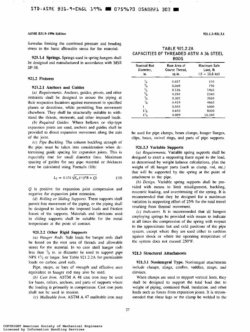
STD-ASME B33.S-ENGL 37Sb m 0757b70 0580223 303 m
ASME B31.9-1996 Edition
formulas limiting the combined pressure and bending stress to the basic allowable stress for the material.
921.1.4 Springs. Springs used in spring hangers shall be designed and manufactured in accordance with MSS SP-58.
921.2 Fixtures
921.2.1 Anchors and Guides (a ) Requirements. Anchors, guides, pivots, and other
restraints shall be designed to secure the piping at their respective locations against movement in specified planes or directions, while permitting free movement elsewhere. They shall be structurally suitable to with- stand the thrusts, moments, and other imposed loads.
(b) Required Guides. Where bellows or slip-type expansion joints are used, anchors and guides shall be provided to direct expansion movement along the axis of the joint.
(c) Pipe Buckling. The column buckling strength of the pipe must be taken into consideration when de- termining guide spacing for expansion joints. This is especially true for small diameter lines. Maximum spacing of guides for any pipe material or thickness may be calculated using Formula (IO):
Ls = 0 . 1 3 1 4 m ) (10)
Q is positive for expansion joint compression and negative for expansion joint extension.
(d ) Rolling or Sliding Supports. These supports shall permit free movement of the piping, or the piping shall be designed to include the imposed loads and friction forces of the supports. Materials and lubricants used in sliding supports shall be suitable for the metal temperature at the point of contact.
921.2.2 Other Rigid Supports (a) Hanger Rods. Safe loads for hanger rods shall
be based on the root area of threads and allowable stress for the material. In no case shall hanger rods less than "/8 in. in diameter be used to support pipe NPS 1 '/2 or larger. See Table 92 1.2.2A for permissible loads on carbon steel rods.
Pipe, straps, or bars of strength and effective area equivalent to hanger rod may also be used.
(b ) Cast Iron. ASTM A 48 cast iron may be used for bases, rollers, anchors, and parts of supports where the loading is primarily in compression. Cast iron parts shall not be used in tension.
(c) Malleable Iron. ASTM A 47 malleable iron may
27
921.1.3-9213.1
TABLE 921.2.2A CAPACITIES OF THREADED ASTM A 36 STEEL
RODS Nominal Rod Root Area of Maximum Safe
Diameter, Coarse Thread, Load, lb in. sq in. (S = 11.6 ksi)
94 0.027 310 3/8 0.068 790 5; 0.126 1460 '18 0.202 2340
'/8 0.419 4860 0.302 3500
1 0.552 6400 1 0.693 8000 1 0.889 10,300
be used for pipe clamps, beam clamps, hanger flanges, clips, bases, swivel rings, and parts of pipe supports.
921.2.3 Variable Supports (a ) Requirements. Variable spring supports shall be
designed to exert a supporting force equal to the load, as determined by weight balance calculations, plus the weight of all hanger parts (such as clamp, rod, etc.) that will be supported by the spring at the point of attachment to the pipe.
(b) Design. Variable spring supports shall be pro- vided with means to limit misalignment, buckling, eccentric loading, and overstressing of the spring. It is recommended that they be designed for a maximum variation in supporting effort of 25% for the total travel resulting from thermal movement.
(c) Indicators. It is recommended that all hangers employing springs be provided with means to indicate at all times the compression of the spring with respect to the approximate hot and cold positions of the pipe system, except where they are used either to cushion against shock or where the operating temperature of the system does not exceed 250°F.
921.3 Structural Attachments
921.3.1 Nonintegral Type. Nonintegral attachments include clamps, slings, cradles, saddles, straps, and clevises.
When clamps are used to support vertical lines, they shall be designed to support the total load due to weight of piping, contained fluid, insulation, and other loads such as forces from expansion joints. It is recom- mended that shear lugs or the clamp be welded to the
COPYRIGHT American Society of Mechanical EngineersLicensed by Information Handling ServicesCOPYRIGHT American Society of Mechanical EngineersLicensed by Information Handling Services

STD-ASME B3L-S-ENGL L99b m 0757b70 0580222 2 4 T D
921.3.1-922.1.2
pipe to prevent slippage, following the requirements of para. 921.3.2.
921.3.2 Integral Type. Integral attachments include ears, shoes, lugs, cylindrical attachments, rings, and skirts fabricated so as to be an integral part of the piping. When welded to the pipe, materials and procedure shall be compatible with the piping and strength shall be adequate for all expected loadings. If piping and support materials differ in allowable stress, the lower shall govern design.
Integral attachments shall be used in conjunction with restraints or braces where multiaxial loadings are imposed. Design shall consider all imposed weight and thermal loadings, and shall minimize localized stresses induced in the piping by the attachment.
921.4 Supplemental Steel
Where it is required to frame structural members between existing steel members, such supplementary steel shall be designed using the allowable stress speci- fied in para. 921.1.1.
921.5 Attachments to Concrete
921.5.1 Maximum Loads on Attachments. Loads on anchors, cast-in-place inserts, and other attachments to concrete shall not exceed one-fifth of the ultimate strength of the attachment as determined by manufactur- er’s tests in concrete of compressive strength not greater than that in which the attachment will be used, but at least 2500 psi.
If the compressive strength of the concrete is un- known, it shall be assumed to be 2500 psi and the manufacturer’s rated load for the fastener shall be reduced in the ratio of 2500 psi to the strength used in the tests to determine the rating.
In the absence of manufacturer’s ratings, the attach- ment may be tested for ultimate strength in accordance with ASTM E 488.
921.5.2 Expansion Studs and Anchors. Mechani- cally attached concrete or masonry anchors shall extend into the concrete at least the minimum distance recom- mended by the manufacturer; use a length at least 41/2 times the fastener diameter in the absence of such recommendation.
If multiple anchors are required to hold a load, they must be spaced at least eight diameters on center to realize the full design capacity of each anchor.
ASME B31.9-19% Edition
921.5.3 Concrete Inserts. Placing of inserts shall be in accordance with the manufacturer’s recommenda- tions.
921.5.4 Explosive Actuated Fasteners. Explosive actuated fasteners shall not be used where a group of fasteners is necessary to support the total load.
921.5.5 Split Pin Compression Anchors. Split pin compression anchors shall be used only for shear loads.
921.6 Supporting Structures
The engineer shall assure himself that the supporting structure has adequate strength to sustain all loads imposed by the piping.
PART 6 SYSTEMS
922 DESIGN REQUIREMENTS PERTAINING TO SPECIFIC PIPING SYSTEMS
922.1 Pressure Reducing Systems
922.1.1 General. Where pressure reducing valves are used, a relief device or safety valve shall be provided on the low pressure side of the system. Otherwise, the piping and equipment on the low side of the system shall be designed to withstand the upstream design pressure. The relief or safety devices shall be located adjoining or as close as practicable to the reducing valve. The combined relieving capacity provided shall be such that the design pressure of the low pressure system will not be exceeded if the reducing valve fails to open.
922.1.2 Alternative Systems. In steam systems where the use of relief valves as described in para. 922. l . 1 is not feasible (e.g., because there is no accept- able discharge location for the vent piping), alternative designs may be substituted for the relief devices. In either case, it is recommended that alarms be provided which will reliably warn the operator of failure of any pressure reducing valve.
(a ) Tandem Steam Pressure Reducing Valves. Two or more steam pressure reducing valves may be installed in series, each set at or below the safe working pressure
28
COPYRIGHT American Society of Mechanical EngineersLicensed by Information Handling ServicesCOPYRIGHT American Society of Mechanical EngineersLicensed by Information Handling Services
ASME 831.9-1996 Edition
of the equipment served. In this case, no relief device is required.
Each pressure reducing valve shall have the capability of closing off against full line pressure, and of control- ling the reduced pressure at or below the design pressure of the low pressure system, in the event that the other valve fails to open.
(b) Trip Stop Values. A trip stop steam valve set to close at or below the design pressure of the low pressure system may be used in place of a second reducing valve or a relief valve.
922.1.3 Bypass Valves. Hand controlled bypass valves having a capacity no greater than the reducing valve may be installed around pressure reducing valves if the downstream piping is protected by relief valves as required in para. 922.1.1, or if the design pressure of the downstream piping system and equipment is at least as high as the upstream pressure.
922.1.4 Design of Valves and Relief Devices. Pres- sure reducing and bypass valves, and relief devices, shall be designed for inlet pressure and temperature conditions.
922.2 Steam Trap Piping
922.2.1 Drip Lines. Drip lines from steam headers, mains, separators, heaters, or other equipment that operate at differing pressures shall not be connected to discharge through the same trap.
922.2.2 Discharge Piping. Trap discharge piping shall be designed for the same pressure and temperature
922.1.2-922.3.3
as the inlet piping unless the discharge is vented to atmosphere, or is operated under low pressure and has no stop valves.
922.3 Fuel Oil Piping
922.3.1 Pipe Material (a) Pipe in buildings shall be steel pipe of a material
listed in Table 926.1 except as permitted in 922.3.1 (b). Type F furnace butt welded pipe shall not be used where concealed, i.e., in walls, chases, shafts, or above ceilings. Spiral welded pipe shall not be used.
(b) Type L copper tubing may be used in buildings if protected from exposure to fire.
(c) Underground piping may be steel, Type K copper tubing, aluminum, ductile iron, thermoplastic, or rein- forced thermoplastic resin piping. Buried pipe and fittings shall be protected against corrosion.
922.3.2 Joints (a) Threaded, welded, brazed, or flared joints shall
be used within buildings. A pipe thread compound suitable for oil shall be used on threaded joints. Joints relying on friction or a combustible material shall not be used. Brazing or flare fittings shall be wrought. Flanged or grooved joints may be used with a gasket material meeting the requirements of API 607 or another standard acceptable to the owner.
(b) For underground piping, friction type joints and grooved joints may also be used.
922.3.3 Valves. At the point of entry of underground piping to the building, an accessible steel or ductile iron valve shall be installed to control the flow of oil.
29
COPYRIGHT American Society of Mechanical EngineersLicensed by Information Handling ServicesCOPYRIGHT American Society of Mechanical EngineersLicensed by Information Handling Services

STD-ASME B31-9-ENGL L99b H 0759b70 0580224 OL2 M
ASME B31.%1996 Edition
CHAPTER III MATERIALS
923 MATERIALS - GENERAL REQUIREMENTS
Chapter III states limitations for materials, based on their inherent properties. Their use in piping is also subject to requirements and limitations in other parts of this Code.
923.1 Materials and Specifications
923.1.1 Listed or Published Specifications. Any material used in pressure containing piping components shall conform to a specification listed in Appendix A, or to a published specification in accordance with para. 923.1.2.
923.1.2 Materials Not Listed. Allowable stresses for materials not shown in Appendix A, but which are shown in ASME B3 1.1, may be taken from Appendix A of ASME B31.1.
A material not listed in this Code nor in ASME B31.1, but which conforms to a published specification covering composition, physical and mechanical proper- ties, method and process of manufacture, heat treatment (if applicable), and quality control, may be used if it otherwise meets the requirements of this Code. Allow- able stresses for such materials shall be determined in accordance with the applicable basis in para. 902.3.1, or a more conservative basis. Particular attention should be given to properties which may tend to affect weldabil- ity or ductility adversely.
923.1.3 Used Materials. Used pipe and other compo- nents of known specifications may be employed pro- vided they have been thoroughly cleaned and visually inspected (and tested if applicable) to determine that they are in good condition, meet the applicable dimensional requirements, and do not contain defects which could impair strength or tightness or which are not acceptable under this Code.
923.1.4 Limitations on Unknown Materials. Steel of unknown specification shall be used only for struc- tural supports and restraints.
923-9U3.2
923.2 Limitations on Specific Metals
923.2.1 Cast Iron. The low ductility of cast iron should be considered and its use should be avoided where shock loading may occur.
923.2.2 Ductile Iron. Ductile (nodular) cast iron components having dimensions conforming to ASME B16.3, ASME B16.4, or to ASME B16.5 may be used in accordance with the manufacturer’s pressure- temperature ratings. Welding shall not be used as a method of joining ductile iron components.
923.2.3 Copper and Copper Alloys. Consideration should be given to the melting point of copper in flammable fluid service.
923.2.4 Aluminum and Aluminum Alloys. Consid- eration should be given to the melting point of aluminum in flammable fluid service. When assembling threaded joints in aluminum alloys, a suitable thread compound shall be used to prevent seizing. Pipe in the annealed temper should not be threaded.
923.3 Limitations on Specific Nonmetals
923.3.1 General. Nonmetallic pressure containing components, such as glass, ceramics, plastics, or rubber, may be used within the limitations of para. 923.1.2 and within manufacturers’ limitations on pressure-tem- perature ratings and application. Consideration shall be given to the suitability of the material for the service conditions and the fluid to be handled, its flammability, resistance to shock, its dimensional stability, and proper support and protection from damage.
923.3.2 Thermoplastics. Thermoplastics shall not be used for toxic fluids or for oxygen. They shall not be used for flammable liquids or flammable gases above ground. If thermoplastics are used for compressed air or other compressed gases, special precautions must be observed. The stored energy and specific failure mechanism of the pipe need to be considered. Materials such as PVC, CPVC, and PVDF, which exhibit brittle
31
COPYRIGHT American Society of Mechanical EngineersLicensed by Information Handling ServicesCOPYRIGHT American Society of Mechanical EngineersLicensed by Information Handling Services

.~
STD=ASME BIL*S-ENGL L77b m 0759b70 0580225 T57 m
923.3.2-923.5
failure as defined in ASTM F 41 2, shall not be used for compressed air or gas service.
Consideration shall be given to the brittleness and flammability of thermoplastics and to their loss of strength under only slight increases in temperature. In selecting thermoplastics, note that design properties are subject to considerable variation from one type and grade to another.
923.3.3 Reinforced Thermosetting Resin. In select- ing reinforced thermosetting resin (RTR) piping, note that design properties are subject to considerable varia- tion from one type and grade to another. Consideration
ASME 831.9-1996 Edition
shall be given to the flammability of RTR piping and its susceptibility to brittle failure.
923.4 Coatings and Linings
External coatings or internal linings may be used on pipe or components that conform to the requirements of this Code, but such coatings or linings shall not be considered as adding strength.
923.5 Deterioration in Service
It is the responsibility of the engineer to select materials which will resist deterioration in service, or to make allowances for such deterioration in accordance with para. 902.4.1.
32
COPYRIGHT American Society of Mechanical EngineersLicensed by Information Handling ServicesCOPYRIGHT American Society of Mechanical EngineersLicensed by Information Handling Services

ASME B31.9-1996 Edition
CHAPTER IV
926-926.4
COMPONENT REQUIREMENTS AND STANDARD PRACTICES
926 DIMENSIONS AND RATINGS OF COMPONENTS
926.1 Standard Piping Components
926.4 Abbreviations
Abbreviations used in Tables 926.1 and 926.2 signify the following:
Standard piping components shall conform to one Abbreviation Term of the standards or specifications listed in Table 926.1. General Those listed in ASME B3 1.1 may also be used. BW butt-welding
CI cast iron
926.1.1 Boiler External Piping. Materials used in DI
boiler external piping shall be ASME SA or SB specifi- MI
cations corresponding to the ASTM specifications listed SS sw
in Table 926.1. HT LT TS
926.2 Standard Practices Thd
The standards listed in Table 926.2 should be used for design and installation where applicable under this Code.
926.3 Nonstandard Piping Components
When nonstandard piping components are used, pres- sure design shall be in accordance with para. 904. Adherence to the dimensional principles in American National Standards referenced in Table 926.1 is recom- mended to the greatest practicable extent.
ABS CPVC PB PE PP PVC RTP RTR SDR PR
ductile iron malleable iron stainless steel socket-welding high temperature low temperature tensile strength threaded
Plastics acrylonitrile-butadiene-styrene chlorinated polyvinyl chloride polybutylene polyethylene polypropylene Polyvinyl chloride reinforced thermosetting plastic reinforced thermosetting resin standard dimension ratio pressure rating
33
COPYRIGHT American Society of Mechanical EngineersLicensed by Information Handling ServicesCOPYRIGHT American Society of Mechanical EngineersLicensed by Information Handling Services
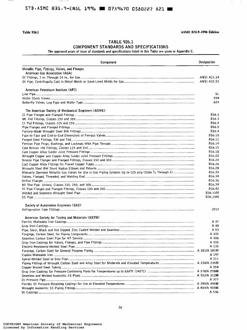
Table 926.1 ASME B31.9-19% Edition
TABLE 926.1 COMPONENT STANDARDS AND SPECIFICATIONS
The approved years of issue of standards and specifications listed in this Table are given in Appendix C.
Component Designation
ANSI A21.14 ANSI A21.52
51 594 609
816.1 816.3 816.4 816.5 816.9
816.10 616.11 816.14 816.15 816.18 816.22 616.24 616.26 816.28 816.33 816.34 616.36 816.39 616.42
B36.10M B36.19M
J513
A 47 A 48 A 53
A 105 A 106 A 126 A 135
A 181lA 181M A 197 A 211
A 234lA 234M A 254
A 278lA 278M A 312lA 312M
A 377 A 395lA 395M A 403/A 403M
A 536
34
COPYRIGHT American Society of Mechanical EngineersLicensed by Information Handling ServicesCOPYRIGHT American Society of Mechanical EngineersLicensed by Information Handling Services

ASME B31.9-1996 Edition
TABLE 926.1 (CONT’D) COMPONENT STANDARDS AND SPECIFICATIONS
The approved years of issue of standards and specifications listed in this Table are given in Appendix C.
Table 926.1
Component Designation
A 539 B 2618 26M
B 42 B 43 B 6 1 B 62
B b81B b8M B 75lB 75M B aa/B aaM
B 13518 135M B 2101B 210M B 241lB 241M B 2471B 247M B 251/B 251M
B 280 B 283 B 302 B 361 B 547
CllOlA21.10 C151lA21.51
C207 C208 C500 C606
FS WW-P-421
5p-42
S P-43 S P-45 S P-51 5p-67 5p-70
5p-71
S P-72 S P-78
SW Reducer Inserts .............................................................................................................................................................. S P-79 Bronze Gate, Angle, and Check Valves .................................................................................................................................. S P-80 Carbon Steel Pipe Unions - SW and Thd ............................................................................................................................ Steel Valves - SW and Thd Ends ......................................................................................................................................... C I Globe and Angle Valves, Flanged and Thd Ends ............................................................................................................... 5p-85
Diaphragm Type Valves ........................................................................................................................................................ 5p-88
S P-83 S P-84
(Table continues on next page and Note fallows Table)
35
COPYRIGHT American Society of Mechanical EngineersLicensed by Information Handling ServicesCOPYRIGHT American Society of Mechanical EngineersLicensed by Information Handling Services

Table 926.1 ASME B31.9-1996 Edition
TABLE 926.1 (CONT’D) COMPONENT STANDARDS AND SPECIFICATIONS
The approved years of issue of standards and specifications listed in this Table are given in Appendix C.
Component Designation
C 3611C 361M c 582
D 1527 D 1785 D 2104 D 2239 D 2241 D 2282 D 2310 D 2447 D 2464 D 2466 D 2467 D 2468 D 2513 D 2517 D 2609 D 2662 D 2666 D 2672 B 2683 D 2737 D 2846 D 2996 D 2997 D 3000 D 3035 D 3261 D 3287 D 3309 D 3517 D 3754 D 3840
F 437 F 438 F 439 F 441 F 442
C300 C301 C302 C900
(Table continues on next page and Note follows Table)
36
COPYRIGHT American Society of Mechanical EngineersLicensed by Information Handling ServicesCOPYRIGHT American Society of Mechanical EngineersLicensed by Information Handling Services
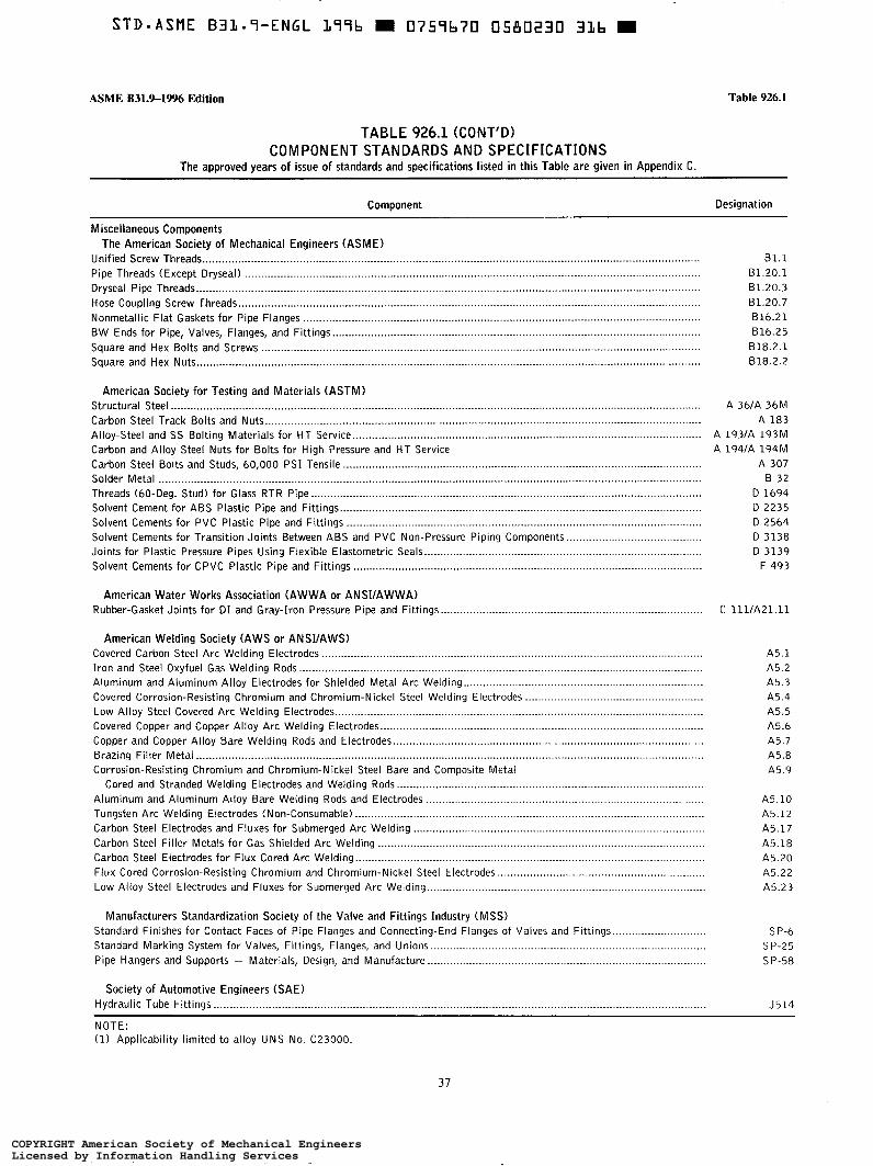
STD-ASME B31.7-ENGL 177b 0757b70 0580230 3Lb m
ASME B31.9-1996 Edition Table 926.1
TABLE 926.1 (CONT’D) COMPONENT STANDARDS AND SPECIFICATIONS
The approved years of issue of standards and specifications listed in this Table are given in Appendix C.
Component Designation
81.1 81.20.1 B1.20.3 B1.20.7 616.21 816.25
818.2.1 818.2.2
A 361A 36M A 183
A 193/A 193M A 194lA 194M
A 307 B 32
D 1694 D 2235 D 2564 D 3138 D 3139
F 493
C 1111A21.11
A5.1 A5.2 A5.3 A5.4 A5.5 A5.6 A5.7 A5.8 A5.9
A5.10 A5.12 A5.17 A5.18 A5.20 A5.22 A5.23
S P-6 S P-25 S P-58
J514
NOTE: (1) Applicability limited to alloy UNS No. C23000.
37
COPYRIGHT American Society of Mechanical EngineersLicensed by Information Handling ServicesCOPYRIGHT American Society of Mechanical EngineersLicensed by Information Handling Services

Table 926.2 ASME B31.9-1996 Edition
TABLE 926.2 STANDARD PRACTICES
The approved years of issue of standards and specifications listed in this Table are given in Appendix C .
Component Designation
American Petroleum Institute (API or ANSUAPI) Fire Test for Soft-Seated Quarter-Turn Valves. Fourth Edition .............................................................................................
American Society for Testing and Materials (ASTM) Test Methods for Flash Point by Pensky-Martens Closed Tester ............................................................................................ Test Method for Time-to-Failure of Plastic Pipe Under Constant Internal Pressure ............................................................... Test Method for Cyclic Pressure Strength of RTP Pipe ......................................................................................................... Practice for Heat Joining of Polyolefin Pipe and Fittings ..................................................................................................... Practice for Underground Installation of Thermoplastic Pressure Piping ............................................................................... Method for Obtaining Hydrostatic Design Basis for Thermoplastic Pipe Materials ................................................................. Practice for Making Solvent-Cemented Joints With PVC Pipe and Fittings ........................................................................... Method for Obtaining Hydrostatic Design Basis for RTR Pipe and Fittings ........................................................................... Practice for Flaring Polyolefin Pipe and Tubing ................................................................................................................... Test Method for Strength of Anchors in Concrete and Masonary Elements ............................................................................ Practice for Safe Handling of Solvent Cements Used for Joining Thermoplastic Pipe and Fittings ........................................ Definition of Terms Relating to Plastic Piping Systems .........................................................................................................
American Water Works Association (AWWA or ANSIIAWWA) Thickness Design of DI Pipe ................................................................................................................................................. Installation of DI Water Mains and Other Appurtenances ......................................................................................................
Copper Development Association (CDA) Copper Tube Handbook .........................................................................................................................................................
Manufacturers Standardization Society of the Valve and Fittings Industry (MSS) Pipe Hangers and Supports - Selection and Application ...................................................................................................... Pipe Hangers and Supports - Fabrication and Installation Practices ................................................................................... Guidelines on Terminology for Pipe Hangers and Supports ....................................................................................................
Std 607-1993
D 9 3 'D 1598 D 2143 D 2657 D 2774 D 2837 D 2855 D 2992 D 3140
E488 F402 F412
C150/A21.50 C600
. .
5p-69 5p-89 5p-90
38
COPYRIGHT American Society of Mechanical EngineersLicensed by Information Handling ServicesCOPYRIGHT American Society of Mechanical EngineersLicensed by Information Handling Services

ASME B31.%1996 Edition
FABRICATION,
927-927.4.4
CHAPTER V ASSEMBLY, AND ERECTION
927 WELDED FABRICATION OF METALS
927.1 General
Welding shall be performed in accordance with the qualification requirements of para. 927.5. Limitations on imperfections and acceptance standards are as stated in Chapter VI or in the engineering design.
927.2 Materials
927.2.1 Filler Metal. Filler metal, including consum- able welding inserts, shall conform to the requirements of Section II, Part C of the ASME BPV Code or AWS AS series specifications for filler metals. A filler metal not conforming to the above may be used with the owner’s approval.
927.2.2 Backing Rings. Backing rings are not re- quired but when used shall be of a material compatible with the base metal and shall fit the inside diameter of the pipe. Backing rings may be tacked to the inside of the pipe and shall be fused into the root of the weld.
927.3 Preparation
927.3.1 Butt and Miter Welds (a) End Preparation. End preparation for butt and
miter joint welds shall be as shown in the welding procedure specification. The basic bevel angles shown in ASME B16.25 may be used. Oxygen or arc cutting is acceptable only if the cut is reasonably smooth and true. Discoloration which may remain on the flame- cut surface is not considered to be detrimental oxidation.
(b) Cleaning. Weld areas and surfaces shall be clean and free from paint, oil, rust, scale, or any other material detrimental to the weld or base metal before welding begins and shall be kept clean during welding. All slag shall be cleaned from flame-cut surfaces.
(c) Internal Alignment. The prepared ends of piping components to be joined shall be aligned as accurately as is practicable within commercial tolerances on diameter, wall thickness, and out-of-roundness. Alignment shall be preserved during welding.
(d) Spacing. The root opening of the joint shall be as given in the welding procedure.
927.3.2 Fillet Welds. If fillet welding is used in joining piping components, applicable requirements of para. 927.3.1 shall be met in preparing the parts for welding.
927.4 Rules for Welding
927.4.1 General ( a ) Protection of Work. No welding shall be done
if there is impingement of rain, snow, sleet, or high wind on the weld area, or if the weld area is frosted or wet.
(b) Preheat. Preheating shall be as required by the Welding Procedure Specification.
927.4.2 Butt and Miter Welds (a ) Tuck Welds. If used, tack welds shall be made
by a qualified welder or shall be removed. Tack welds which have cracked shall be removed. Tack welds shall be made with filler metal which is compatible with the first pass filler metal, and shall be fused with the first pass.
(b) External Alignment. If the external surfaces of the two components are not aligned, the weld shall be tapered between the surfaces.
927.4.3 Fillet and Socket Welds (a) Welding. The applicable provisions of para.
927.4.2(a) shall be followed. (b) Contour. Fillet and socket welds may vary from
convex to concave. The size of a fillet weld is deter- mined as shown in Fig. 927.4.3A.
( c ) Details. Minimum fillet welds for slip-on flanges and socket welding components are shown in Figs. 927.4.3B and C.
927.4.4 Seal Welds. If seal welding of threaded joints is performed, the surfaces shall be cleaned and all exposed threads shall be covered by the seal weld. Seal welding shall be done by qualified welders.
39
COPYRIGHT American Society of Mechanical EngineersLicensed by Information Handling ServicesCOPYRIGHT American Society of Mechanical EngineersLicensed by Information Handling Services
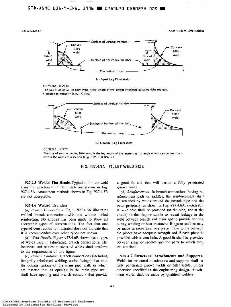
927.4.5-927.4.1 ASME B31.9-1996 Edition
Surface of vertical member
Surface of horizontal member
Theoretical throat
(a) Equal Leg Fillet Weld
GENERAL NOTE: The size of an equal leg fillet weld is the length of the largest inscribed isosceles right triangle. (Theoretical throat = 0.707 X size. 1
Surface of vertical member
Surface of horizontal member
I i Theoretical throat
(b) Unequal Leg Fillet Weld
GENERAL NOTE. The size of an unequal leg fillet weld is the leg length of the largest right triangle which can be inscribed within the weld cross section fe. 9.. 1/2 in. X 3i4 in.)
FIG. 927.4.3A FILLET WELD SIZE
927.4.5 Welded Flat Heads. Typical minimum weld sizes for attachment of fiat heads are shown in Fig. 927.4.5A. Attachment methods shown in Fig. 927.4.5B are not acceptable.
927.4.6 Welded Branches (a) Branch Connections. Figure 927.4.6A illustrates
welded branch connections with and without added reinforcing. No attempt has been made to show all acceptable types of constructions. The fact that one type of construction is illustrated does not indicate that it is recommended over other types not shown.
(b) Weld Details. Figure 927.4.6B shows basic types of welds used in fabricating branch connections. The locations and minimum sizes of welds shall conform to the requirements of this figure.
( c ) Branch Contours. Branch connections (including integrally reinforced welding outlet fittings) that abut the outside surface of the main pipe wall, or which are inserted into an opening in the main pipe wall, shall have opening and branch contours that provide
a good fit and that will permit a fully penetrated groove weld.
(d) Reinforcement. In branch connections having re- inforcement pads or saddles, the reinforcement shall be attached by welds around the branch pipe and the outer periphery, as shown in Fig. 927.4.6A, sketch (b). A vent hole shall be provided (at the side, not at the crotch) in the ring or saddle to reveal leakage in the weld between branch and main and to provide venting during welding or heat treatment. Rings or saddles may be made in more than one piece if the joints between the pieces have adequate strength and if each piece is provided with a vent hole. A good fit shall be provided between rings or saddles and the parts to which they are attached.
927.4.7 Structural Attachments and Supports. Welds for structural attachments and supports shall be fully penetrated groove welds or fillet welds, unless otherwise specified in the engineering design. Attach- ment welds shall be made by qualified welders.
40
COPYRIGHT American Society of Mechanical EngineersLicensed by Information Handling ServicesCOPYRIGHT American Society of Mechanical EngineersLicensed by Information Handling Services

ASME B31.9-1996 Edition
(a) Front and Back Weld
927.4.8-927.5.3
(b) Face and Back Weld
' in. approximate before welding
(c ) Socket Welding Flange
a = the lesser of 1 .I T, or the thickness of the hub, but not less than 1/8 in 6 = the lesser of T, or 1/4 in.
FIG. 927.4.3B MINIMUM WELDS FOR DOUBLE-WELDED SLIP-ON AND SOCKET-WELDING FLANGES
927.4.8 Weld Defect Repairs. Defects in welds shall
made in accordance with the procedure used for the original welds, or by another welding method only if it is to a qualified procedure, recognizing that the cavity to be repaired may differ in contour and dimensions from the original joint.
927.5 Qualification
Tn be removed to sound metal. Repair welds are to be
927.5.1 General. A Welding Procedure Specification shall be prepared and the procedure shall be qualified before any welding is done. Qualification of the proce- dures to be used and of the performance of welders and welding operators shall be in accordance with the ASME BPV Code, Section IX.
a = the greater of 1.1 T, or 1/8 in. 927.5.2 Welding Responsibility. Each employer is
responsible for all welding done by his employees.
FIG. 927.4.3C MINIMUM WELDING 927.5.3 Qualification Responsibility DIMENSIONS FOR SOCI<ET-WELDING (u) Procedures. Each employer is responsible for
COMPONENTS OTHER THAN FLANGES qualifying any welding procedure that he intends to
41
COPYRIGHT American Society of Mechanical EngineersLicensed by Information Handling ServicesCOPYRIGHT American Society of Mechanical EngineersLicensed by Information Handling Services

927.53-921.6
T min.
ASME B31.9-19% Edition
Greater of: 2 X required pipe thickness, or 1.25 X actual pipe thickness, but need not exceed required min. thickness of 4 5 deg. min.
45 deg. min.
Pipe may project beyond weld. Closure may be beveled (45 deg. max.) beyond weld.
FIG. 927.4.54, ACCEPTABLE WELDS FOR FLAT HEADS
Incomplete penetration
FIG. 927.4.5B UNACCEPTABLE WELDS FOR FLAT HEADS
use. To avoid duplication of effort, welding procedures qualified by a technically competent group or agency may be used, provided all of the following conditions are met.
( I ) The group or agency qualifying the procedure shall have met all of the procedure qualification require- ments of this Code.
(2) The employer shall accept responsibility for the procedure thus qualified.
(3) The employer has qualified at least one welder or welding operator using the procedure thus qualified.
(4) The employer shall assume responsibility for the procedure qualification work done for him by signing the records required in para. 927.6.
(b) Welders and Welding Operators. Each employer shall be responsible for qualifying the welders and welding operators employed by him. To avoid duplica- tion of effort, he may accept a welder or welding operator qualification made by a previous employer or a technically competent group or agency (subject to approval of the owner or his agent) on piping using
the same or equivalent procedure wherein the essential variables are within the limits of the ASME BPV Code, Section IX. An employer accepting such a qualification shall obtain a copy of the performance qualification test record showing by whom the welder or welding operator was qualified, the date of qualification, and a history of the welder or welding operator showing continued performance to maintain the qualification. The employer shall then prepare and sign the record required in para. 927.6, accepting responsibility for the ability of the welder or welding operator.
927.6 Qualification Records
The employer shall maintain records, certified by him and available to the owner or his agent, of the procedures used and the welders or welding operators he employs, showing the date and results of procedure and performance qualifications.
42
COPYRIGHT American Society of Mechanical EngineersLicensed by Information Handling ServicesCOPYRIGHT American Society of Mechanical EngineersLicensed by Information Handling Services

ASME B31.9-1% Edition Figs. 927.4.6A, 927.4.6B
+"+--L --- """"
hole
-
(a) Without Added Reinforcement (b) With Added Reinforcement
(cl Angular Branch Without Added Reinforcement
FIG. 927.4.6A TYPICAL WELD BRANCH CONNECTIONS
1/16 in. to 118 i n . + b -
in.
Main
1/16 in. to 118 in.
Inserted Branch Set-on Branch
6 = the lesser of T, (branch) or 1/4 in,
FIG. 927.4.6B TYPICAL WELD DETAILS
43
COPYRIGHT American Society of Mechanical EngineersLicensed by Information Handling ServicesCOPYRIGHT American Society of Mechanical EngineersLicensed by Information Handling Services

~
STD-ASME B3119-ENGL 179b m O759670 0580237 770 m
928-934.1.2
928 BRAZING AND SOLDERING OF METALS
928.1 Brazing
928.1.1 Brazing Materials ( a ) Filler Metal. The brazing filler metal shall con-
form to an applicable AWS classification. (b) Flux. When required, fluxes shall be compatible
with the materials brazed and with the filler metal used. Flux residue should be removed when joints are completed.
928.1.2 Preparation and Technique. The technique for brazing in the Copper Tube Handbook of the Copper Development Association shall be followed.
928.1.3 Brazing Qualification. Brazing procedure and performance qualification are not required. If quali- fication is specified in the engineering design, the requirements in the ASME BPV Code, Section IX are acceptable.
928.2 Soldering
928.2.1 Materials ( a ) Filler Metal. Filler metal shall conform to the
applicable ASTM specification. Solder shall melt and flow freely within the specified temperature range.
(b) Flux. Flux should be used to prevent oxidation during soldering and to promote surface wettability.
928.2.2 Preparation and Technique. The technique for soldering in the Copper Tube Handbook of the Copper Development Association shall be followed.
929 BENDING
929.1 General
Pipe may be bent to any radius by any hot or cold method that results in a bend surface free of cracks and substantially free of buckles. Such bends shall meet the design requirements of para. 904.2.1. This shall not prohibit the use of creased or corrugated bends if specified in the engineering design.
930 FORMING
930.1 General
Piping components may be formed (by swaging, lapping, or upsetting of pipe ends, by extrusion of necks, etc.) by any suitable hot or cold method that
ASME 831.94996 Edition
results in formed surfaces that conform to specified dimensions and which are uniform and free of cracks and tears.
931 HEAT TREATMENT
The materials and material thicknesses permitted under this Code do not require heat treatment. If the engineering design specifies heat treatment after weld- ing, these requirements shall be made part of the Welding Procedure Specification.
934 FABRICATION OF NONMETALS
934.1 Joining Thermoplastic Piping
934.1.1 Materials. Adhesives, cements, and sealers used to join piping components shall be compatible with the materials being joined and shall conform to applicable ASTM specifications. Joining materials which have deteriorated by exposure to air, which are beyond the shelf life recommended by the manufacturer, or which will not spread smoothly shall not be used.
934.1.2 Solvent Cemented Joints (a ) Preparation. PVC and CPVC surfaces to be
solvent cemented shall be cleaned. Cleaning for ABS shall conform to ASTM D 2235. Cuts shall be free of burrs. Circumferential cuts shall be as square as those obtained by use of a saw with miter box. A slight interference fit between pipe and fitting socket is preferred, and diametral clearance between pipe and entrance of socket shall not exceed 0.04 in. This fit shall be checked before solvent cementing.
(b) Procedure. Solvent cemented joints shall be made in accordance with ASTM D 2855. Solvent cements for thermoplastics shall conform to the following speci- fications:
Material ASTM Specification
PVC D 2564 CPVC D 2846 ABS D 2235
Application of cement to both surfaces and assembly of the surfaces shall produce a continuous bond and a smàll fillet of cement at the outside of the joint. For branch connections not using a tee, a full reinforcement saddle with integral branch socket shall be cemented to the main pipe over its entire contact surface. In addition, the saddle shall be further secured to the main pipe by wrapping glass fiber tape saturated with epoxy resin around the saddle and the circumference
44
COPYRIGHT American Society of Mechanical EngineersLicensed by Information Handling ServicesCOPYRIGHT American Society of Mechanical EngineersLicensed by Information Handling Services

ASME B31.9-1996 Edition
of the pipe. Solvent cement shall be handled as recom- mended in ASTM F 402.
934.1.3 Heat Fusion Joints (a) Preparation. Surfaces to be heat fused together
shall be cleaned free of foreign material and surface film. Cuts shall be free from burrs, and circumferential cuts shall be as square as those obtained by use of a saw with miter box. Fixtures shall be used to align pipe and fitting when the joint is made.
(b) Technique. Heat fusion joints for polyethylene, polypropylene, and other thermoplastics commonly joined by heat fusion shall be made in accordance with procedures in ASTM D 2657, Techniques I - Socket Fusion or II - Butt Fusion, and as recommended by the manufacturer. Uniform heating of both surfaces and their assembly shall produce a continuous homogeneous bond between them and a small fillet of fused material at the outside of the joint. Branches shall be made only by use of molded fittings.
934.1.4 Flared Joints and Elastomeric Sealed Joints
(a ) Flared Joints. Flared joints shall be made in accordance with ASTM D 3140.
(b) Elastomeric Sealed Joints. Elastomeric sealed joints shall be made in accordance with ASTM D 3 139.
934.2 Reinforced Thermosetting Resin Piping Joints
934.2.1 Materials. The provisions of para. 934.1.1 shall also apply to reinforced thermosetting resin pipe.
934.2.2 Preparation. Cutting of pipe shall be done without chipping or cracking it, particularly the inner surface of centrifugally cast pipe. Pipe shall be preheated if necessary to comply with the above requirement. Cuts shall be free from burrs, and circumferential cuts shall be as square as those obtained by use of a saw with miter box. For branch connections, holes in the main pipe shall be made with a hole saw. Mold release agent and other material which would interfere with adhesion shall be sanded or otherwise removed from surfaces to be cemented.
934.2.3 Chemical Setting Adhesive Joints. Chemi- cal setting adhesive joints shall be made in accordance with the manufacturer’s recommendations. Application of adhesive to the surfaces and their assembly shall produce a continuous bond between them.
For branch connections, a full reinforcement saddle having an integral short length of branch pipe shall be
934.1.2-935.2.4
used. The branch shall project enough to complete a nozzle or to join to the branch pipe. The cut edges of the hole in the main pipe shall be sealed with cement at the time the saddle is cemented to the main pipe.
934.2.4 Hand Lay-Up Joints. Application of plies of reinforcement saturated with catalyzed resin to the surfaces to be joined shall produce a continuous structure with them. Cuts shall be sealed to protect the reinforce- ment from the contents of the pipe. Thickness of the laid-up portion shall be at least equal to the pipe thickness.
934.3 Repair of Defective Work
Defective material, joints, and other workmanship in nonmetallic piping that fails to meet the requirements of para. 936 and of the engineering design shall be repaired by an acceptable method or shall be replaced. Repair of defects in plastic piping by use of a patching saddle is an acceptable method.
935 ASSEMBLY
935.1 General
The assembly of piping components, either in a shop or as field erection, shall be done so that the completely erected piping conforms to the requirements of this Code and of the engineering design.
935.2 Bolting Procedure
935.2.1 Alignment. Flanged joints shall be fitted up so that the gasket contact faces, prior to bolting, bear uniformly on the gasket, and then shall be made up with relatively uniform bolt stress.
935.2.2 Gasket Loading. In bolting gasketed flanged joints, the gasket shall be uniformly compressed in accordance with the design principles applicable to the type of gasket used.
935.2.3 Steel-to-Iron Flanged Joints. When bolting raised-face steel flanges to flat-face cast iron flanges, care shall be used to prevent flanges.
935.2.4 Bolt Engagement. be fully engaged.
damage to the cast iron
All bolts and nuts shall
45
COPYRIGHT American Society of Mechanical EngineersLicensed by Information Handling ServicesCOPYRIGHT American Society of Mechanical EngineersLicensed by Information Handling Services

935.3-935.13
935.3 Bell and Spigot Joints
935.3.1 Caulked Joints. Caulked bell and spigot joints shall be assembled using oakum and poured lead or other joint compounds suitable for the service. Assembly of cast iron bell and spigot pressure piping shall meet the requirements of ANWAWWA (2600.
935.3.2 Elastomeric Joints. Bell and spigot joints using elastomeric gaskets shall be assembled in accord- ance with the manufacturer’s recommendations.
935.4 Threaded Piping
935.4.1 Threading. Dimensions of threaded joints shall conform to the applicable standard listed in Table 926.1. Threads shall be clean and free of breaks and tears.
935.4.2 Joint Compound. Any compound or lubri- cant used in threaded joints shall be suitable for the service conditions, and shall not react unfavorably with either the service fluid or the piping materials.
935.4.3 Seal Welded Joints. Threaded joints which are to be seal welded shall be assembled without thread compound.
935.4.4 Backing Off. Backing off of threaded joints to facilitate alignment of the pipe is not permitted.
935.4.5 Threaded Plastic Pipe. Strap wrenches or other full circumference wrenches shall be used to tighten threaded joints. Tools and other devices used to hold or apply forces shall not leave the surface scored or deeply scratched. For RTR piping, threads shall be coated with sufficient catalyzed resin to cover the threads and completely fill the clearance between pipe and fitting.
ASME 8319-1996 Edition
935.7 Compression Joints
Ends of tubing shall be cut square and deburred. No scratches, breaks, or mars are permitted on the outside of the tube at the fitting.
935.8 Other Mechanical and Proprietary Joints
Grooved, expanded, rolled, O-ring, clamp, gland, and other joints permitted by para. 913 shall be assembled in accordance with the manufacturer’s instructions.
935.9 Borosilicate Glass Piping
Glass-to-glass connections shall be made with clamp compression type couplings. Closure pieces should pref- erably be furnished to exact dimension. If necessary, pipe may be field cut and beaded according to manufac- turer’s instructions. Beaded-to-plain end connections may be made with couplings specially designed for this purpose. Alignment and support for all glass piping shall be verified and adjusted in accordance with manu- facturer’s instructions before joints are tightened.
935.10 Equipment Connections
When connections are made to equipment or strain- sensitive piping components, care should be taken to avoid misalignment which can introduce undesirable end reactions.
935.11 Cold Spring
Before assembling joints to be cold sprung, supports, guides, and anchors shall be examined to verify that they will not interfere with desired movement or cause undesired movements. The gap or overlap prior to final assembly ,shall be checked and corrected if necessary to conform to that shown on the drawing.
935.12 Valve Installation
935.5 Flare Joints Installation of valves with the stem below the hori- zontal is not recommended.
Ends of tubing shall be cut square and deburred. No scratches, breaks, cracks, or other mars at the 935.13 ~~~~i~ of Defective Work sealing surface of the flare shall be permitted.
Joints that leak during test shall be tightened within
935.6 Ferrule Bite Joints limits of procedures or manufacturer’s instructions. Do not attempt to tighten leaking joints with pneumatic
Ends of tubing shall be cut square and deburred. test pressure on ;he system. Joints which cannot be No scratches, breaks, or other mars on the outside safely tightened shall be replaced. Assemblies rejected surface of the tubing at the fitting shall be permitted. during examination shall be repaired and reassembled In tightening the nut, only sufficient torque shall be or replaced. Replace any glass piping component that used to “bite” lightly and uniformly into the tube. is chipped or scratched.
46
COPYRIGHT American Society of Mechanical EngineersLicensed by Information Handling ServicesCOPYRIGHT American Society of Mechanical EngineersLicensed by Information Handling Services

ASME B31.9-1996 Edition
INSPECTION,
936936.6.1
CHAPTER VI EXAMINATION, AND TESTING
936 INSPECTION AND EXAMINATION
936.1 General
Inspection applies to quality assurance functions per- formed by the owner, or for the owner by persons other than the manufacturer, fabricator, or erector. Ex- amination applies to quality control functions performed by personnel employed by the manufacturer, fabricator, or erector of the piping.
936.1.1 Quality System Program. A quality system program is not required by this Code. If a system is required by the engineering design, the program in Appendix E or a similar program acceptable to the owner may be used.
936.2 Required Inspection
Prior to initial operation, it is the owner’s responsibil- ity to verify that all required examination and testing have been completed and to inspect the piping, or have it inspected, to the extent necessary to satisfy himself that it conforms to all applicable requirements of this Code and the engineering design.
936.2.1 Access to the Work. The owner and his representatives shall have access to any place where work concerned with the piping is being performed. This includes manufacture, fabrication, assembly, erection, examination, and testing of the piping.
936.2.2 Rights of Owner. The owner and his repre- sentatives shall have the right to audit any examinations, to inspect the piping using examination methods speci- fied in the engineering design, and to review all certifi- cations and records.
936.3 Responsibility for Examination
Inspection does not relieve the manufacturer, fabrica- tor, or erector of responsibility for performing all required examinations and preparing suitable records for the owner’s use.
936.4 Methods of Examination
The methods described herein shall be performed by competent personnel.
936.4.1 Visual Examination. Visual examination is observation of the portions of materials, components, joints, supports, and other piping elements that are or can be exposed to view before, during, or after manufacture, fabrication; assembly, or erection. This examination includes verification of, Code and engineering design requirements for materials and components, dimensions, joint preparation, alignment, joining practices, supports, assembly, and erection.
936.5 Type and Extent of Required Examination
Unless otherwise specified in the engineering design, the type of examination shall be visual examination in accordance with the method in para. 936.4.1.
If the degree of examination and inspection or the basis for rejection is to be more rigorous than required by this Code, it shall be a matter of prior agreement between the fabricator or installer and the purchaser.
936.6 Acceptance Criteria
Imperfections or indications revealed by examination shall be evaluated in accordance with the following criteria. They are acceptable unless they exceed the specified limitations. Those that exceed the stated limits are defects, and the work shall be repaired or replaced in accordance with the appropriate requirements in Chapter V. Acceptance criteria in para. 936.6 not detectable by visual examination are included to indicate a minimum quality level acceptable under this Code.
936.6.1 Girth Welds and Groove Welds. Limita-
(a) Cracks. None permitted. (b) Luck of Fusion. The length of unfused areas
shall not be more than 20% of the circumference of the pipe, or of the total length of the weld, and no more than 11/2 in. in any 6 in. of weld.
(c) Incomplete Penetration. The total joint penetra-
tions on imperfections are as follows.
47
COPYRIGHT American Society of Mechanical EngineersLicensed by Information Handling ServicesCOPYRIGHT American Society of Mechanical EngineersLicensed by Information Handling Services

936.6.1-937.2.1
tion shall not be less than the thickness of the thinner of the components being joined, except that incomplete root penetration is acceptable if it does not exceed the lesser of 1/32 in. or 20% of the required thickness, and its extent is not more than I 1/2 in. in any 6 in. of weld.
( d ) Undercut and Reinforcement. Undercut shall not exceed the lesser of 1/32 in. or 12'/,% of wall thickness. Thickness of weld reinforcement shall not exceed in.
( e ) Concave Root. Concavity of the root surface shall not reduce the total thickness of the joint, including reinforcement, to less than the thickness of the thinner of the components being joined.
v) Excess Root Penetration. The excess shall not exceed the lesser of '/8 in. or 5% of the inside diameter of the pipe. (g) Weld Surfaces. There shall be no overlaps or
abrupt ridges and valleys.
936.6.2 Fillet Welds. Limitations on imperfections in fillet, socket, and seal welds are the same as in para. 936.6.1 for cracks, lack of fusion, undercut, and weld surfaces.
936.6.3 Brazed and Soldered Joints. Limitations on imperfections in brazed and soldered joints are as follows.
(a) Penetration of filler metal inside the pipe shall not exceed 100% of the wall thickness.
(b) There shall be no visible unfilled joint space. ( c ) There shall be no visible evidence of excessive
overheating.
936.6.4 Threaded Joints. Limitations on imperfec- tions for ASME B 1.20. I threaded pipe joints are as follows.
(u) No more than six and no less than two threads shall be visible after makeup of the joint.
(6) There shall be no severe chipping or tearing of visible threads.
936.6.5 Caulked and Leaded Joints. Limitations on imperfections in caulked and leaded joints are as follows.
(a ) The finished joint shall be within in. of the rim of the bell.
(b) In the finished joint, the spigot shall be centered in the b e l l within 1/8 in.
( c ) The joint shall be made in a continuous pour.
936.6.6 Flanged Joints. Limitations on imperfections in flanged joints are as follows.
(a) When observed during assembly, the flange faces shall be parallel within I deg., and the force required
ASME B31.9-19% Edition
to align pipe axes shall not exceed 10 lb/ft per in. of NPS.
(b) Bolts and nuts shall be fully engaged.
936.6.7 Flared, Flareless, and Compression Joints. Limitations on imperfections in flared, flareless, and compression joints are as follows.
(a ) There shall be no cracks in flare or tube end. (6) Tube ends shall be cut square (visual). (c) Tube ends shall be free of distortion or grooves
( d ) Negligible force shall be required to align ends.
936.6.8 Mechanical and Proprietary Joints. Imper- fections in mechanical and proprietary joints shall be within the limitations established by the manufacturer.
936.6.9 Solvent-Cemented, Adhesive, and Heat- Fusion Joints. Limitations on imperfections in solvent- cemented, adhesive and heat-fusion joints are as follows.
(a ) Internal protrusion shall not exceed 50% of wall thickness for solvent-cemented and 25% for adhesive and heat-fusion joints.
(b) There shall be no visible unfilled or unbonded areas.
that would hinder assembly or sealing.
936.6.10 Hand Lay-Up Joints. Limitations on im- perfections in hand lay-up joints are as follows.
(u) There shall be no visible evidence of lack of bonding.
(b) The length of the laid-up joint shall be at least the lesser of 4 in. or the nominal diameter of the pipe.
( c ) The thickness of the laid-up joint shall be at least equal to the wall thickness of the thinner pipe.
937 LEAK TESTING
937.1 General
Prior to initial operation, each piping system shall be tested for leakage. Hydrostatic testing in accordance with para. 937.3 shall be employed if possible. Pneu- matic testing may be used in lieu of hydrostatic testing only in accordance with the limitations in para. 937.4. Initial service testing may be used within the limitations of para. 937.5.
937.2 Preparation for Testing
937.2.1 Exposure of Joints. All joints including welds shall be left uninsulated and exposed for examina- tion during the test.
48
COPYRIGHT American Society of Mechanical EngineersLicensed by Information Handling ServicesCOPYRIGHT American Society of Mechanical EngineersLicensed by Information Handling Services
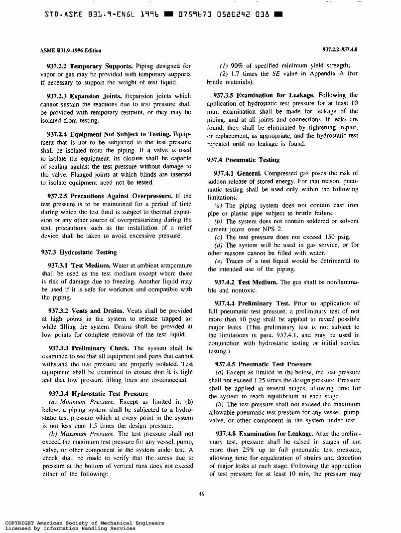
ASME B31.9-1996 Edition
937.2.2 Temporary Supports. Piping designed for vapor or gas may be provided with temporary supports if necessary to support the weight of test liquid.
937.2.3 Expansion Joints. Expansion joints which cannot sustain the reactions due to test pressure shall be provided with temporary restraint, or they may be isolated from testing.
937.2.4 Equipment Not Subject to Testing. Equip- ment that is not to be subjected to the test pressure shall be isolated from the piping. If a valve is used to isolate the equipment, its closure shall be capable of sealing against the test pressure without damage to the valve. Flanged joints at which blinds are inserted to isolate equipment need not be tested.
937.2.5 Precautions Against Overpressure. If the test pressure is to be maintained for a period of time during which the test Auid is subject to thermal expan- sion or any other source of overpressurizing during the test, precautions such as the installation of a relief device shall be taken to avoid excessive pressure.
937.3 Hydrostatic Testing
937.3.1 Test Medium. Water at ambient temperature shall be used as the test medium except where there is risk of damage due to freezing. Another liquid may be used if it is safe for workmen and compatible with the piping.
937.3.2 Vents and Drains. Vents shall be provided at high points in the system to release trapped air while filling the system. Drains shall be provided at low points for complete removal of the test liquid.
937.3.3 Preliminary Check. The system shall be examined to see that all equipment and parts that cannot withstand the test pressure are properly isolated. Test equipment shall be examined to ensure that it is tight and that low pressure filling lines are disconnected.
937.3.4 Hydrostatic Test Pressure (a) Minimum Pressure. Except as limited in (b)
below, a piping system shall be subjected to a hydro- static test pressure which at every point in the system is not less than 1.5 times the design pressure.
(b) Maximum Pressure. The test pressure shall not exceed the maximum test pressure for any vessel, pump, valve, or other component in the system under test. A check shall be made to verify that the stress due to pressure at the bottom of vertical runs does not exceed either of the following:
937.2.2-937.4.8
(I) 90% of specified minimum yield strength; (2) 1.7 times the SE value in Appendix A (for
brittle materials).
937.3.5 Examination for Leakage. Following the application of hydrostatic test pressure for at least 10 min, examination shall be made for leakage of the piping, and at all joints and connections. I f leaks are found, they shall be eliminated by tightening, repair, or replacement, as appropriate, and the hydrostatic test repeated until no leakage is found.
937.4 Pneumatic Testing
937.4.1 General. Compressed gas poses the risk of sudden release of stored energy. For that reason, pneu- matic testing shall be used only within the following limitations.
(a) The piping system does not contain cast iron pipe or plastic pipe subject to brittle failure.
(b) The system does not contain soldered or solvent cement joints over NPS 2.
(c ) The test pressure does not exceed 150 psig. (d) The system will be used in gas service, or for
(e) Traces of a test liquid would be detrimental to other reasons cannot be filled with water.
the intended use of the piping.
937.4.2 Test Medium. The gas shall be nonflamma- ble and nontoxic.
937.4.4 Preliminary Test. Prior to application of full pneumatic test pressure, a preliminary test of not more than I O psig shall be applied to reveal possible major leaks. (This preliminary test is not subject to the limitations in para. 937.4. I , and may be used in conjunction with hydrostatic testing or initial service testing.)
937.4.5 Pneumatic Test Pressure (u) Except as limited in (b) below, the test pressure
shall not exceed 1.25 times the design pressure. Pressure shall be applied in several stages, allowing time for the system to reach equilibrium at each stage.
(b) The test pressure shall not exceed the maximum allowable pneumatic test pressure for any vessel, pump, valve, or other component in the system under test.
937.4.8 Examination for Leakage. After the prelim- inary test, pressure shall be raised in stages of not more than 25% up to full pneumatic test pressure, allowing time for equalization of strains and detection of major leaks at each stage. Following the application of test pressure for at least IO min, the pressure may
49
COPYRIGHT American Society of Mechanical EngineersLicensed by Information Handling ServicesCOPYRIGHT American Society of Mechanical EngineersLicensed by Information Handling Services
STD*ASME B31.7-ENGL 179b 0757b70 0580293 T79
937.4.8-937.5.2
be reduced to design pressure and examination shall be made for leakage of the piping. Leaks may be detected by soap bubble, halogen gas, scented gas, test gage monitoring, ultrasonic, or other suitable means. If leaks are found, pressure shall be vented, appropriate repair or replacement shall be made, and the pneumatic test repeated until no leakage is found.
937.5 Initial Service Leak Test
937.5.1 General. For gases and steam and condensate service not over 15 psig, and for nontoxic, noncombusti-
ASME B31.9-1996 Edition
ble, nonflammable liquids at pressures not over 100 psig and temperatuies not over 200"F, it is permissible to conduct the system testing with the service fluid as outlined in para. 937.5.2.
937.5.2 Service Testing. A preliminary test with air at low pressure (para. 937.4.4) may be used. In any event, the piping system shall be brought up to operating pressure gradually with visual examination at a pressure between one-half and two-thirds of design pressure. A final examination shall be made at operating pressure. If the piping system is free of leaks, it will have met the requirements of para. 937.1.
50
COPYRIGHT American Society of Mechanical EngineersLicensed by Information Handling ServicesCOPYRIGHT American Society of Mechanical EngineersLicensed by Information Handling Services

ASME B31.9-1996 Edition Appendix A
APPENDIX A
Table A-I begins on next page.
51
COPYRIGHT American Society of Mechanical EngineersLicensed by Information Handling ServicesCOPYRIGHT American Society of Mechanical EngineersLicensed by Information Handling Services

Mate
rial
Spec
. No
.
TABL
E A-
l AL
LOW
ABLE
ST
RES
SES
Max.
Allow
able
Stres
s Va
lue
in Te
nsion
SE
, St
reng
ths
ksi,
for
Met
al
Tem
pera
ture
, OF
, No
t Ex
ceed
ing
Min.
M
in.
Type
or
Facto
r Te
nsile
, Yi
eld,
0 to
Grad
e Cl
ass
P-No
. No
tes
Eor
F ks
i ks
i 10
0 15
0 20
0 25
0 30
0 35
0 40
6
Carb
on
Stee
l Se
amles
s Pi
pe
and
Tube
is
. . Bu
tt W
elded
Pi
pe
and
Tube
.
. . .
. Elec
tric
Resis
tance
W
elded
Pi
pe
and
Tube
. *
. .
. ,
. . .
. . Sp
iral
Weld
ed
Pipe
an
d Tu
be
ASTM
A
53
A S
ASTM
A
53
B S
ASTM
A
106
A .
*
ASTM
A
106
B .
. .
API
5L
A .
API
5L
B
ASTM
A
53
API
5L
ASTM
A
53
ASTM
A
53
ASTM
A
135
ASTM
A
135
API
5L
API
5L
API
5L
ASTM
A
211
ASTM
A
211
ASTM
A
211
F
A25
. .
A E
B E
A .
.
B . .
.
A25
, * .
A .
. .
B .
. .
A570
-30
. A5
70-3
3 .
. .
A570
-40
. .
1 1 1 1 1 1 1 1 1 1 1 1 1 1 1 1 1 1
. . .
1.00
48.0
. . .
1.00
60.0
. .
1.00
48
.0 .
. 1.
00
60.0
(1)
1.00
48.0
(1)
1.00
60
.0
(2)
0.60
45.0
25.0
6.8
6.8
6.8
6.8
6.8
6.8
6.8
(1)
0.60
45.0
25.0
6.7
6.7
6.7
6.7
6.7
6.7
6.7
. . .
0.85
48.0
. . .
0.85
60.0
. . .
0.85
48.0
. . .
0.85
60.0
(1)
0.85
45.0
(1)
0.85
48.0
(1)
0.85
60.0
(3)
0.75
(3)
0.75
(3)
0.75
49.0
52.0
55.0
30.0
12.0
12.0
12.0
12.0
12.0
12.0
12.0
35.0
15.0
15.0
15.0
15.0
15.0
15.0
15.0
30
.0 12
.0 12
.0 12
.0 12
.0 12
.0 12
.0 12
.0 35
.0 15
.0 15
.0 15
.0 15
.0 15
.0 15
.0 15
.0
30.0
12.0
12.0
12.0
12.0
12.0
12.0
12.0
35.0
15.0
15.0
15.0
15.0
15.0
15.0
15.0
30.0
10.2
10.2
10.2
10.2
10.2
10.2
10.2
35.0
12.8
12.8
12.8
12.8
12.8
12.8
12.8
30.0
10.2
10.2
10.2
10.2
10.2
10.2
10.2
35.0
12.8
12.8
12.8
12.8
12.8
12.8
12.8
%
25.0
9.5
9.5
9.5
9.5
9.5
9.5
9.5
E
30.0
10.2
10.2
10.2
10.2
10.2
10.2
10.2
35.0
12.8
12.8
12.8
12.8
12.8
12.8
12.8
F P : 30
.0 9.2
8.4
9.2
. .
. ..,
. . .
. .
33.0
9.8
9.9
9.8
s! .a.
. .
. . .
.
s 40
.0 10
.3 9.4
10
.3 . .
. . .
. . .
. B
COPYRIGHT American Society of Mechanical EngineersLicensed by Information Handling ServicesCOPYRIGHT American Society of Mechanical EngineersLicensed by Information Handling Services

Forg
ings
and
Fitti
ngs
. . .
. . .
. Stru
ctura
ls (1
2)
. . Bo
lts,
Nuts,
an
d St
uds
. .
. Du
ctile
Iro
n Pi
pe
. . Fi
tting
s an
d Co
uplin
gs
. , Stai
nles
s St
eel
Seam
less
Pi
pe
and
Tube
18Cr
-8Ni
18
Cr-8
Ni
18Cr
-8Ni
E 18
Cr-8
Ni
16Cr
-12N
i-2M
o 16
Cr-1
2Ni-2
Mo
16Cr
-12N
i-2M
o lb
Cr-1
2Ni-2
Mo
18Cr
-13N
i-3M
o 18
Cr-1
3Ni-3
Mo
ASTM
A
105
ASTM
A
181
ASTM
A
181
ASTM
A
234
ASTM
A
234
. .
. . .
60
. . .
70
. . .
W
PB
. . .
WPC
..~
ASTM
A3
6 .
1
ASTM
A
307
ASTM
A
377
B .
. .
. . .
.
. .
.
ASTM
A
395
ASTM
A
536
60-4
9-18
.
. .
65-4
5-12
,.. . .
.
ASTM
A
312
s304
00
. . .
8 AS
TM
A 31
2 53
0400
. .
. 8
ASTM
A
312
s304
03
. . .
8 AS
TM
A 31
2 s3
0403
. .
. 8
ASTM
A
312
5316
00
. . .
8 AS
TM
A 31
2 53
1600
. .
8
ASTM
A
312
S316
03
. . .
8 AS
TM
A 31
2 53
1603
.
8 AS
TM
A 31
2 s3
1700
. .
. 8
ASTM
A
312
s317
00
8
. . .
. .
. . .
. . .
. .
(l)(3)
. . .
(l)(ll)
, . .
. .
(10)
(1)
(l)(lO
) . .
(10
) (1)
(l)(
lO)
(1)
(l)(lO
)
. 70
.0 36
.0 17
.5 17
.5 17
.5 17
.5 17
.5 17
.5 .
. 60
.0 30
.0 15
.0 15
.0 15
.0 15
.0 15
.0 15
.0 .
. 70
.0 36
.0 17
.5 17
.5 17
.5 17
.5 17
.5 17
.5 1.0
0 60
.0 35
.0 15
.0 15
.0 15
.0 15
.0 15
.0 15
.0 1.0
0 70
.0 40
.0 17
.5 17
.5 17
.5 17
.5 17
.5 17
.5
. . .
58
.0 36
.0 12
.6 12
.6 12
.6 .2.
6 12
.6 12
.6
. .
55.0
. . .
7.0
7.0
7.0
7.0
7.0
7.0
. . .
. . .
. . .
. . .
.
0.80
60.0
40.0
9.6
9.6
. . .
. .
0.80
65.0
45.0
10.4
10.4
. . .
. .
1.00
75.0
30.0
1.00
75.0
30.0
1.00
70.0
25.0
1.00
70.0
25.0
1.00
75.0
30.0
1.00
75.0
30.0
1.00
70.0
25.0
1.00
70.0
25.0
1.00
75.0
30.0
1.00
75.0
30.0
16.0
. 16
.0 .
13.3
13.3
16.0
. 16
.0 13
.3 .
13.3
. 16
.0 .
16.0
.
13.3
. 15
.1 . .
11
.4 . .
13
.3 . .
13
.8 16
.0 .
. 11
.3 . .
13
.3 . .
13
.8 . .
16
.0 . .
12.0
. . .
14.1
. . .
10.2
. .
13.0
. .
12.4
. . .
15.6
. . .
10.1
. . .
13.3
. . .
12.4
. . .
15.6
. .
17.5
% 15
.0 5
17.5
E 15
.0 .-
17.5
1 s
12.6
E C :
7.0
. . . . .
. .
.
11.0
13.8 9.3
12
.5 11
.4 15
.4 9.2
13.2
11.4
15.4
(Tab
le co
ntinu
es
on n
ext
page
an
d No
tes
follo
w Ta
ble)
COPYRIGHT American Society of Mechanical EngineersLicensed by Information Handling ServicesCOPYRIGHT American Society of Mechanical EngineersLicensed by Information Handling Services
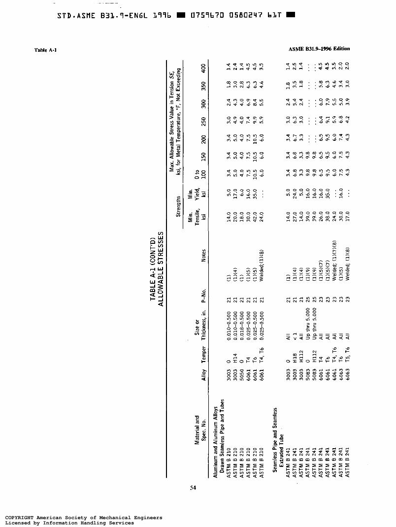
TABL
E A-
l (C
ONT
’D)
ALLO
WAB
LE
STR
ESSE
S
WI P
Mate
rial
and
Size
or
Spec
. No
. Al
loy
Temp
er
Thick
ness
, in.
P-
No.
Notes
Max.
Allow
able
Stres
s. Va
lue
in Te
nsion
SE
, St
reng
ths
ksi,
for
Meta
l Te
mper
ature
, “F
, No
t Ex
ceed
ing
Min.
Mi
n.
Tens
ile,
Yield
, 0
to ks
i ks
i 10
0 15
0 20
0 25
0 30
0 35
0 40
0
Alum
inum
and
Alum
inum
Alloy
s Dr
awn
Seam
less
Pipe
an
d Tu
bes
ASTM
6
210
ASTM
6
210
ASTM
6
210
ASTM
6
210
ASTM
B
210
ASTM
I3
210
Seam
less
Pipe
an
d Se
amles
s Ex
trude
d Tu
be
ASTM
6
241
ASTM
B
241
ASTM
B
241
ASTM
B
241
ASTM
B
241
ASTM
B
241
ASTM
B
241
ASTM
B
241
ASTM
B
241
ASTM
B
241
3003
0
0.01
0-0.
500
21
(1)
14.0
5.
0 3.
4 3.
4 3.
4 3.
0 2.
4 1.
8 1.
4 30
03
H14
0.01
0-0.
500
21
(l)(4
) 20
.0
17.0
5.
0 5.
0 5.
0 4.
9 4.
3 3.
0 2.
4 50
50
0 0.
018-
0.50
0 21
(1
) 18
.0
6.0
4.0
4.0
4.0
4.0
4.0
2.8
1.4
6061
T4
0.
025-
0.50
0 21
(l)
(5)
30.0
16
.0
7.5
7.5
7.5
7.4
6.9
6.3
4.5
6061
T6
0.
025-
0.50
0 21
(l)
(5)
42.0
35
.0
10.5
10
.5
10.5
9.
9 8.
4 6.
3 4.
5
6061
T4
,T6
0.02
5-0.
500
21
Weld
ed;(i)
(8)
24.0
.
. .
6.0
6.0
6.0
5.9
5.5
4.6
3.5
3003
0
All
21
(1)
14.0
5.
0 3.
4
3003
H1
8 -c
l 21
(l)
(4)
27.0
24
.0
6.8
3003
H1
12
All
21
(l)(4
) 14
.0
5.0
3.3
5083
0
Up t
hru
5.00
0 25
(l)
(9)
39.0
16
.0
9.8
5083
H1
12
Up t
hru
5.00
0 25
(l)
(9)
39.0
16
.0
9.8
6061
T4
Al
l 23
(l)
(5)(7
) 26
.0
16.0
6.
5 60
61
T6
All
23
(l)(5
)(7)
38.0
35
.0
9.5
6061
74
,T6
All
23
Weld
ed;
(l)(7)(
8) 24
.0
. .
. 6.
0
6063
T6
Al
l 23
(l)(
5) 30
.0
16.0
7.
5 60
63
T5,
Tb
All
23
Weld
ed;
(l)(8)
17.0
1.
. 4.
3
3.4
3.4
3.0
2.4
1.8
6.8
6.7
6.3
5.4
3.5
3.3
3.3
3.0
2.4
1.8
9.8
. .
. .
. .
. .
. .
9.8
. .
. .
. .
. .
. ,..
6.5
6.5
6.4
6.0
5.8
9.5
9.5
9.1
7.9
6.3
6.0
6.0
5.9
5.5
4.6
7.5
7.4
6.8
5.0
3.4
1.4
2.5 1.4
. .
.
. . .
4.
5 4.
5 3.5
2.0
4.3
4.3
4.2
3.9
3.0
2.0
COPYRIGHT American Society of Mechanical EngineersLicensed by Information Handling ServicesCOPYRIGHT American Society of Mechanical EngineersLicensed by Information Handling Services

TABL
E A-
l (C
ONT
’D)
%
ALLO
WAB
LE
STR
ESSE
S 5 E
Mate
rial
Max.
Allow
able
Stres
s Va
lue
in Te
nsion
SE
, .-
Stre
ngths
ks
i, for
Me
tal
Temp
eratu
re,
“F,
Not
Exce
eding
P G x
Min.
Mi
n.
Tens
ile,
Yield
, 0
to 6 E
Spec
. No
. Al
loy
No.
Cond
ition
P-No
. No
tes
ksi
ksi
100
150
200
250
300
350
400
t
Copp
er
and
Copp
er
Alloy
s Se
amles
s Pi
pe
and
Tube
Co
pper
Pi
pe
Size
ra
nge
NPS
1/8-Z
inc
l Co
pper
Pi
pe
Size
ra
nge
NPS
1/8-2
inc
l Co
pper
Pi
pe
Size
ra
nge
NPS
2l/e-
12
incl
Red
Bras
s Pi
pe
Copp
er
Tube
Co
pper
Tu
be
Copp
er
Tube
Co
pper
Tu
be
Copp
er
Tube
Co
pper
Tu
be
Bras
s Tu
be
Copp
er
Tube
Co
pper
Pi
pe,
Thre
adles
s
ASTM
B
42
ASTM
B
42
ASTM
B
42
ASTM
0
43
ASTM
B
68
ASTM
B
75
ASTM
B
75
ASTM
B
75
ASTM
B
88
ASTM
B
88
ASTM
B
335
ASTM
B
280
ASTM
B
302
102,
122
Anne
aled
102,
122
Hard
dr
awn
102,
122
Light
dr
awn
230
Anne
aled
102,
122
Anne
aled
102,
122
Anne
aled
102,
122
Light
dr
awn
102,
122
Hard
dr
awn
102,
122
Anne
aled
102,
122
Draw
n 23
0 An
neale
d 10
2, 12
2 An
neale
d 10
2, 12
2 Dr
awn
31
31
31
32
. 31
31
31
. . .
. . .
32 .
. . .
30.0
9.0
(6)
45.0
40.0
(6)
36.0
30.0
. 40
.0 12
.0 (1)
30
.0 9.0
. .
. 30
.0 9.0
(6)
36
.0 30
.0 (6)
45
.0 40
.0 (1)
30
.0 9.0
(l)(
6) 36
.0 30
.0 . .
. 40
.0 12
.0 (1)
30
.0 9.0
(1)
36
.0 30
.0
6.0
5.1
4.8
4.8
4.7
4.0
3.0
11.3
11.3
11.3
11.3
11.0
10.3
4.3
9.0
9.0
9.0
9.0
8.7
8.5
8.2
8.0
8.0
8.0
8.0
8.0
7.0
5.0
6.0
6.0
5.9
5.8
5.0
3.8
2.5
6.0
5.1
4.8
4.8
4.7
4.0
3.0
9.0
9.0
9.0
9.0
8.7
8.5
8.2
11.3
11.3
11.3
11.3
11.0
10.3
4.3
6.0
5.1
4.8
4.8
4.7
4.0
3.0
9.0
9.0
9.0
9.0
8.7
8.5
8.2
8.0
8.0
8.0
8.0
8.0
7.0
5.0
6.0
5.1
4.8
4.8
4.7
4.0
3.0
9.0
9.0
9.0
9.0
8.7
8.5
8.2
(Not
es
follo
w on
ne
xt pa
ge)
COPYRIGHT American Society of Mechanical EngineersLicensed by Information Handling ServicesCOPYRIGHT American Society of Mechanical EngineersLicensed by Information Handling Services

TABL
E A-
l (C
ONT
’D)
GENE
RAL
NOTE
S:
(a)
See
para
. 90
2.3
for
discu
ssion
of
allow
able
stres
s va
lues.
(b)
The
tabu
lated
sp
ecific
ation
s ar
e AS
TM,
exce
pt as
note
d. Fo
r bo
iler
exter
nal
piping
, the
co
rresp
ondin
g AS
M
E sp
ecific
ation
s sh
all
be u
sed.
See
Secti
on
II of
the
ASM
E BP
V Co
de.
tc)
The
stres
s va
lues
may
be i
nter
polat
ed
to de
term
ine
allow
able
stres
ses
for
inter
media
te
tempe
ratur
es.
(d)
The
P-Nu
mber
s ind
icate
d in
this
Appe
ndix
are
ident
ical
to tho
se
adop
ted
in Se
ction
IX
of
the
ASM
E BP
V Co
de.
(e)
All
stres
s va
lues
are
show
n in
units
of
thous
ands
of
poun
ds-fo
rce
per
squa
re
in.
(ksi).
Multip
ly by
10
00
to ob
tain
value
s in
psi.
tf) Ma
terial
s lis
ted
in Ta
ble
926.
1 for
wh
ich
allow
able
stres
s va
lues
are
not
tabu
lated
in
Appe
ndix
A ma
y be
use
d at
allow
able
stres
ses
foun
d in
ASM
E 83
1.1
or in
Secti
on
I or
Secti
on
VIII,
Di
vision
1
of the
AS
ME
BPV
Code
. Ho
weve
r, the
tem
pera
ture
limits
in
this
Code
sh
all
apply
.
NOTE
S:
(1)
This
mate
rial
is no
t ac
cepta
ble
for
boile
r ex
terna
l pip
ing.
See
Fig.
900.1
.28.
(2)
ASTM
A
53
Type
F
pipe
shall
no
t be
use
d for
fla
mmab
le or
toxic
fluids
. (3)
Th
ese
stres
s va
lues
includ
e a
quali
ty fac
tor
of 0.9
2 for
str
uctur
al ma
teria
l us
ed
in fab
ricati
ng
press
ure
cont
aining
co
mpon
ents.
Ma
terial
s us
ed
in su
pport
s sh
all
have
an
all
owab
le str
ess
value
in
tensio
n of
one-
fifth
the
spec
ified
minim
um
tensil
e str
ength
. (4)
Th
e str
ess
value
s giv
en
for
this
mate
rial
are
not
appli
cable
wh
en
eithe
r we
lding
or
therm
al cu
tting
is em
ploye
d; in
such
ca
ses,
use
the
value
for
0
tempe
r. (5)
Th
e str
ess
value
s for
thi
s ma
teria
l ar
e no
t ap
plica
ble
when
eit
her
weldi
ng
or the
rmal
cuttin
g is
emplo
yed;
in su
ch
case
s, us
e the
va
lues
for
the
welde
d co
nditio
n. (6)
W
here
braz
ed
cons
tructi
on
is em
ploye
d, str
ess
value
s for
the
an
neale
d co
nditio
n sh
all
be u
sed.
(7)
For
stres
s-reli
eved
tem
pers
(T35
1, T3
510,
T351
1, T4
51,
T451
0, T4
511,
T651
, T6
510,
T651
1),
stres
s va
lues
for
mate
rial
in the
ba
sic
tempe
r sh
all
be u
sed.
(8)
Stre
ngth
of re
duce
d-se
ction
ten
sile
spec
imen
is
requ
ired
to qu
ality
weldi
ng
proc
edur
e. Se
e the
AS
ME
BPV
Code
, Se
ction
IX
, QW
-150.
(9)
The
supp
lier
of ma
teria
l sh
all
be c
onsu
lted
as t
o the
ab
ility
of the
all
oy
to wi
thstan
d str
ess
corro
sion
crack
ing
unde
r de
sign
cond
itions
an
d co
mbina
tions
of
stres
s an
d co
rrosiv
e en
viron
ments
. (10
) Du
e to
the
relat
ively
low
yield
stren
gth
of the
se
mater
ials,
these
hig
her
stres
s va
lues
were
es
tablis
hed
for
use
at tem
pera
tures
wh
ere
the
shor
t-tim
e ten
sile
prop
ertie
s go
vern
, in
orde
r to
perm
it the
us
e of
these
all
oys
wher
e sli
ghtly
gr
eater
de
forma
tion
is ac
cepta
ble.
The
stres
s va
lues
in thi
s ra
nge
exce
ed
62’/,%
bu
t do
not
exce
ed
90%
of
the
yield
stren
gth
at tem
pera
ture.
Use
of the
se
stres
ses
may
resu
lt in
dimen
siona
l ch
ange
s du
e to
perm
anen
t str
ain.
Thes
e str
ess
value
s ar
e no
t re
comm
ende
d for
the
fla
nges
of
gask
eted
joints
or
other
ap
plica
tions
wh
ere
sligh
t am
ounts
of
distor
tion
can
caus
e lea
kage
or
malfu
nctio
n.
(11)
The
spec
ificati
on
prov
ides
wall
thick
ness
es
appr
opria
te to
the
vario
us
diame
ters
and
comb
inatio
ns
of pre
ssure
an
d lay
ing
cond
ition.
See
ANSI
lAW
WA
C150
/A
21.50
, Ma
nual
for
the
Thick
ness
De
sign
of Du
ctile
Iron
Pipe
. (12
) Ma
terial
s su
ch
as
pipe
listed
els
ewhe
re
in Ap
pend
ix A
may
be u
sed
as s
tructu
ral
mate
rial
in ac
corda
nce
with
pa
ra.
921.
COPYRIGHT American Society of Mechanical EngineersLicensed by Information Handling ServicesCOPYRIGHT American Society of Mechanical EngineersLicensed by Information Handling Services

ASME 8319-1996 Edition
TABLE A-2 HYDROSTATIC DESIGN STRESSES (HDS) AND RECOMMENDED
TEMPERATURE LIMITS FOR THERMOPLASTIC PIPE Recommended Temperature
Limits [Notes (l), (2)l Hydrostatic Design Stress at
73°F ASTM Minimum, Maximum, [Note (3)1, 100°F, 180°F,
Spec. No. Material "F "F ksi ksi ksi
D 1527 D 2282 D 2513
D 2846 F 441 } F 442
D 2513 D 2662 D 2666 D 3000 D 3309 t D 2104 D 2239 D 2447 D 2513 D 2737 D 3035
...
D 1785 D 2241 D 2513 D 2672
ABS1210 -30 180 1.0 0.8 ... ABS1316 -30 180 1.6 1.25 ... ABS2112 -30 180 1.25 1.0 ...
CPVC4120 O 210 2.0 1.6 0.5
P62110 O
PE2306 PE3306 PE3406 PE3408
{ PP
PVCllZO PVC1220 PVCZllO PVC2120
-30 -30 -30 -30
30
210 1.0 0.8 0.5
140 160 180 180
210
150 150 130 150
0.63 0.63 0.63 0.80
...
2.0 2.0 1 .o 2.0
0.4 ... 0.5 ... 0.5 ... 0.5 ...
... ...
1.6 ... 1.6 ... 0.8 ... 1.6 ...
NOTES: (1) These recommended limits are for low pressure applications with water and other fluids that do not
significantly affect the properties of the thermoplastic. The upper temperature limits are reduced at higher pressures, depending on the combination of fluid and expected service life. Lower temperature limits are affected more by the environment, safeguarding, and installation conditions than by strength.
(2) These recommended limits apply only to materials listed. Manufacturers should be consulted for temperature limits on specific types and kinds of materials not listed.
(3) Use these hydrostatic design stress ( H D S ) values at all lower temperatures.
Table A-2
57
COPYRIGHT American Society of Mechanical EngineersLicensed by Information Handling ServicesCOPYRIGHT American Society of Mechanical EngineersLicensed by Information Handling Services

Tables A-3, A-4 ASME 631.9-19% Edition
TABLE A-3 DESIGN STESS VALUES FOR CONTACT MOLDED (HAND-LAY-UP) PIPE
MADE FROM REINFORCED THERMOSETTING RESINS Material Stress Values
Spec. No. Resin Reinforcing Thickness, in. [Note (M, psi
ASTM C 582 Polyester Glass fiber '/B - 916 900 '14 1200 5/1 6 1350 b '/B 1500
NOTE: (1) Stress values apply in the range -2OOF to 18OoF.
TABLE A-4 HYDROSTATIC DESIGN BASIS STRESS FOR MACHINE-MADE
THERMOSETTING RESIN PIPE Hoop Stress, psi -
Hydrostatic Design Basis Material [Note U)], 73°F
ASTM Spec. Designation No. and Number Cyclic Static
Type Grade Class (ASTM 2310) [Note (2)l [Note (3)l
D 2517 filament wound
D 2996 filament wound
D 2997 centrifugally cast
Glass-fiber reinforced epoxy resin, gas pressure pipe
G I ass-fi ber reinforced epoxy resin
No liner RTRP-1lAD 5000 . . . ¡ RTRW-11AW . . . 16,000
I No liner RTRP-11AD 5000 1 RTRP-11AW . . . . . .
16,000 Epoxy resin
liner, reinforced
RTRP-11FE 6300 ¡ RTRP-1lFD 5000 . . . . . .
Glass-fiber reinforced polyester resin
Polyestel- resin I reinfot L.su
iner r r n r l
Glass-fiber reinforced polyester resin
i RTRP-12EC 4000 RTRP-12ED 5000 RTRP-12EU
. . .
. . . . . . 12,500
RTRP-12AD 5000 . . .
{ RTRP-12AU 12,500 ...
I Polvester resin liner RTRP-22BT . . . 10,000 reinforced RTRP-22BU ... 12,500
Epoxy resin RTRP-21CT ... 10,000 liner, { RTRP-21CU ... 12,500 nonreinforced
NOTES: (1) Service (design) factor must be applied to these values to obtain a hydrostatic design stress. (2) When using the cyclic design basis, the service factor shall not exceed 1.0. (3) When using the static design basis, the Service factor shall not exceed 0.5.
58
COPYRIGHT American Society of Mechanical EngineersLicensed by Information Handling ServicesCOPYRIGHT American Society of Mechanical EngineersLicensed by Information Handling Services
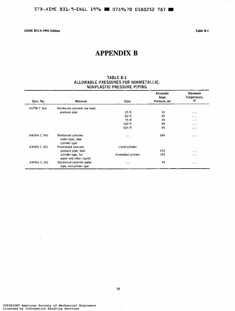
S T D - A S M E B 3 1 - 7 - E N G L L97b m 0759b70 0580252 T87 m
ASME B31.9-1996 Edition
APPENDIX B
TABLE B-1 ALLOWABLE PRESSURES FOR NONMETALLIC,
NONPLASTIC PRESSURE PIPING
Table B-1
Spec. No. Material
Allowable Maximum Gage Temperature,
Class Pressure, psi O F
ASTM C 361 Reinforced concrete low head pressure pipe 25 ft
50 ft 75 f t
100 ft 125 f t
10 20 30 40 50
. . .
. . .
. . .
. . .
. . . AWWA C 300 Reinforced concrete . . . 260 ...
water pipe, steel cylinder type
pressure pipe, steel cylinder type, for
AWWA C 301 Prestressed concrete Lined cylinder
Embedded cylinder 250 350
water and other liquids
pipe, noncylinder type AWWA C 302 Reinforced concrete water . . . 45 ...
59
COPYRIGHT American Society of Mechanical EngineersLicensed by Information Handling ServicesCOPYRIGHT American Society of Mechanical EngineersLicensed by Information Handling Services
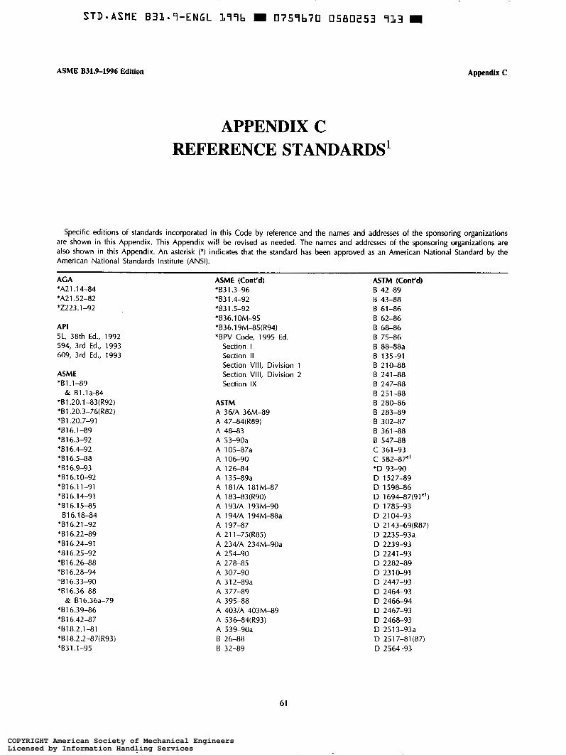
ASME B31.9-1996 Edition
APPENDIX C REFERENCE STANDARDS'
Appendix C
Specific editions of standards incorporated in this Code by reference and the names and addresses of the sponsoring organizations are shown in this Appendix. This Appendix will be revised as needed. The names and addresses of the sponsoring organizations are also shown in this Appendix. An asterisk (*) indicates that the standard has been approved as an American National Standard by the American National Standards Institute (ANSI).
AGA *A2 1 . 1 4-84 *A21.52-82 *Z223.1-92
API 5L, 38th Ed., 1992 594, 3rd Ed., 1993 609, 3rd Ed., 1993
ASME *B1 .l-89
& Bl.la-84 *B1.20.1-83(R92) *B1.20.3-76(R82) *B1.20.7-91 *B16.1-89 *B1 6.3-92 *B1 6.4-92 *B1 6.5-88 *B1 6.9-93 'B16.10-92 *B16.11-91 'B16.14-91 *B1 6.1 5-85 B1 6.1 8-84
'616.21-92 *B16.22-89 *B16.24-91 *B1 6.25-92 '816.26-88 *B1 6.28-94 *B1 6.33-90 *B1 6.36-88
& B1 6.36a-79 *B1 6.39-86 *B1 6.42-87 *B18.2.1-81 *B18.2.2-87(R93) *B31.1-95
ASME (Cont'd) '831.3-96 'B31.4-92 'B31.5-92 *B36.1 OM-95 *B36.19M-85(R94) *BPV Code, 1995 Ed.
Section I Section II Section VIII, Division 1 Section VIII, Division 2 Section IX
ASTM A 36lA 36M-89 A 47-84(R89)
A 53-90a A 105-87a
A 48-83
A 106-90 A 126-84 A 135-89a A 181/A 181M-87 A 183-83(R90) A 193lA 193M-90 A 194lA 194M-88a A 197-87 A 2 1 1 -75(R85) A 234lA 234M-90a
A 278-85
A 312-89a
A 254-90
A 307-90
A 377-89 A 395-88 A 403/A 403M-89 A 536-84(R93) A 539-90a B 26-88 B 32-89
ASTM (Cont'd) B 42-89 B 43-88 B 61-86 B 62-86 B 68-86
B 88-88a
B 210-88 B 241-88
B 75-86
B 135-91
B 247-88 B 251-88 B 280-86 B 283-89 B 302-87 B 361-88 B 547-88 C 361-93 C 582-87'' *D 93-90 D 1527-89 D 1598-86 D 1694-87(91") D 1785-93 D 2 104-93 D 2 143-69(R87) D 2235-93a D 2239-93 D 2241-93 D 2282-89 D 2310-91 D 2447-93 D 2464-93 D 2466-94 D 2467-93 D 2468-93 D 2513-93a D 251 7-81 (87) D 2564-93
61
COPYRIGHT American Society of Mechanical EngineersLicensed by Information Handling ServicesCOPYRIGHT American Society of Mechanical EngineersLicensed by Information Handling Services
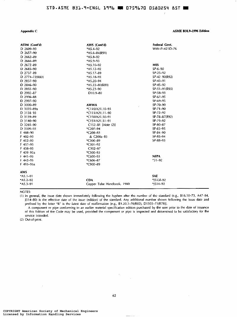
Appendix C ASME B31.9-1996 Edition
ASTM (Cont'd) D 2609-93 D 2657-90 D 2662-89 D 2666-89 D 2672-89 D 2683-90 D 2737-89 D 2774-72(R83) D 2837-90 D 2846-90 D 2855-90 D 2992-87 D 2996-88 D 2997-90 D 3000-89 D 3035-89a D 3 138-93 D 3 139-89 D 3 140-90 D 3261-90 D 3309-93 E 488-90 F 402-93 F 412-93 F 437-93
F 439-93a F 438-93
F 441-93 F 442-93 F 493-93a
AWS *A5.1-91 *A5.2-92 *A5.3-91
AWS (Cont'd) *A5.4-92 *A5.6-84(R91) *A5.8-92 *A5.9-93 *A5.10-92 *A5.12-92 *AS. 1 7-89 *A5.18-93 *A5.20-94 *A5.22-80(R89) *A5.23-90 Dl 0.9-80
AWWA *CllO/A21.10-93 *C111/A21.11-90 *Cl 50/A21 .50-91 *C151/A21.51-91 C152-81 [Note (2)1
*C207-94 *C208-83
& C208a-83 *C300-89 *C301-92 C302-87
*C500-93 *C600-93 *C606-87 *C900-89
Federal Covt. W - P 4 2 1 D-76
MSS SP-6-90 SP-25-92 SP-42-90(R92) SP-43-91 SP-45-92 SP-51-91(R95) SP-58-93 SP-67-95 SP-69-95 SP-70-90 SP-71-90 SP-72-92 SP-78-87(R92) SP-79-92 SP-80-87 SP-83-95 SP-84-90 SP-85-94 SP-88-93
NFPA *3 1-92
SAE CDA *J51 3f-92 Copper Tube Handbook, 1980 *J51 4-92
NOTES: (1) In general, the issue date shown immediately following the hyphen after the number of the standard (e.g., B16.10-73, A47-84,
J514-80) is the effective date of the issue (edition) of the standard. Any additional number shown following the issue date and prefixed by the letter "R" is the latest date of reaffirmation [e.g., 81.20.3-76(R82), D1503-73(R78)].
A component or pipe conforming to an earlier material specification edition purchased by the user prior to the date of issuance of this Edition of the Code may be used, provided the component or pipe is inspected and determined, to be satisfactory for the service intended.
(2) Out-of-print.
62
COPYRIGHT American Society of Mechanical EngineersLicensed by Information Handling ServicesCOPYRIGHT American Society of Mechanical EngineersLicensed by Information Handling Services

STD*ASME B31-9-ENGL 297b m 0757b70 0560255 77b m
ASME B31.%1996 Edition
Specifications and standards of the following organizations appear in this Appendix:
AGA
API
ASME
ASTM
AWS
American Gas Association 1515 Wilson Blvd., Arlington, Virginia 22209 703 841 -8558
American Petroleum Institute Publications and Distribution Section 1220 L Street, N.W., Washington, D.C. 20005 202 682-8375
The American Society of Mechanical Engineers Order Department 22 Law Drive, P.O. Box 2300, Fairfield, New Jersey 07007-2300 201 882-1 167
American Society for Testing and Materials 100 Barr Harbor Drive West Conshohocken, PA 19428-2959 610 832-9500
American Welding Society 550 N.W. LeJeune Road, P.O. Box 351040, Miami, Florida 33135 305 443-9353
AWWA
. . .
CDA
MSS
NFPA
SAE
Appendix C
American Water Works Association 6666 W. Quincy Avenue, Denver, Colorado 80235 303 794-771 1
Federal Specifications: Superintendent of Docu- ments United States Government Printing Office Washington, D.C. 20402 202 783-3238
Copper Development Association, Inc. 260 Madison Avenue, 16th fi. New York, New York 10016-2401 212 251-7200
Manufacturers Standardization Society of the Valve and Fittings Industry 127 Park Street, N.E., Vienna, Virginia 22180 703 281 -661 3
National Fire Protection Association Batterymarch Park, Quincy, Massachusetts 02269 61 7 770-7000
Society of Automotive Engineers 400 Commonwealth Drive, Warrendale, Penn- sylvania 15096 412 776-4841
63
COPYRIGHT American Society of Mechanical EngineersLicensed by Information Handling ServicesCOPYRIGHT American Society of Mechanical EngineersLicensed by Information Handling Services

ASME B31.9-1996 Edition
APPENDIX D PREPARATION OF TECHNICAL
D-1 INTRODUCTION
The ASME B31 Committee, Code for Pressure Pip- ing, will consider written requests for interpretations and revisions of the Code rules, and develop new rules if dictated by technological development. The committee’s activities in this regard are limited strictly to interpretations of the rules or to the consideration of revisions to the present rules on the basis of new data or technology. As a matter of published policy, ASME does not approve, certify, rate, or endorse any item, construction, proprietary device, or activity, and, accordingly, inquiries requiring such consideration will be returned. Moreover, ASME does not act as a consul- tant on specific engineering problems or on the general application or understanding of the Code rules. If, based on the inquiry information submitted, it is the opinion of the Committee that the inquirer should seek professional assistance, the inquiry will be returned with the recom- mendation that such assistance be obtained.
Inquiries that do not provide the information needed for the Committee’s full understanding will be returned.
The Introduction to this Code states, “It is the owner’s responsibility to select the Code Section that most nearly applies to a proposed piping installation.” The Committee will not respond to inquiries requesting assignment of a Code Section to a piping installation.
D-2 REQUIREMENTS
Inquiries shall be limited strictly to interpretations of the rules or to the consideration of revisions to the present rules on the basis of new data or technology. Inquiries shall meet the following requirements: (a) Scope. Involve a single rule or closely related
D-1-D-3
INQUIRIES
rules in the scope of the Code. An inquiry letter concerning unrelated subjects will be returned.
(b) Background. State the purpose of the inquiry, which would be either to obtain an interpretation of Code rules, or to propose consideration of a revision to the present rules. Provide concisely the information needed for the Committee’s understanding of the in- quiry, being sure to include reference to the applicable Code Section, Edition, Addenda, paragraphs, figures, and tables. If sketches are provided, they shall be limited to the scope of the inquiry.
( c ) Inquiry Structure ( I ) Proposed Question(s). The inquiry shall be
stated in a condensed and precise question format, omitting superfluous background information, and, where appropriate, composed in such a way that “yes” or ‘ho” (perhaps with provisos) would be an acceptable reply. The inquiry statement should be technically and editorially correct.
(2) Proposed Reply(ies). Provide a proposed reply stating what it .is believed that the Code requires.
If in the inquirer’s opinion a revision to the Code is needed, recommended wording shall be provided in addition to information justifying the change.
D-3 SUBMITTAL
Inquiries should be submitted in typewritten form; however, legible handwritten inquiries will be consid- ered. They shall include the name and mailing address of the inquirer, and be mailed to the following address:
Secretary ASME B31 Committee 345 East 47th Street New York, NY 10017
65
COPYRIGHT American Society of Mechanical EngineersLicensed by Information Handling ServicesCOPYRIGHT American Society of Mechanical EngineersLicensed by Information Handling Services
STD*ASME B3Lm7-ENGL L77b m 0757b70 0580257 5b7 m
ASME B31.9-1996 Edition
APPENDIX E
Appendix E
NONMANDATORY QUALITY SYSTEM PROGRAM (See para. 936. I . I .)
Organizations performing Design, Fabrication, As- sembly, Erection, Inspection, Examination, Testing, In- stallation, Operation, and Maintenance for B31.9 piping systems shall have a written Quality System in accord- ance with applicable I S 0 9000 Series documents. Regis- tration or certification of the Quality System shall be by agreement 'between contracting parties invblved.
Reference IS0 9000 Documents (a) I S 0 9000-1:1994. Quality Management and Qual-
ity Assurance Standards - Part l: Guidelines for Selection and Use
(b) I S 0 9000-2: 1993. Quality Management and Quality Assurance Standards - Part 2: Generic Guide-
lines for the Application of IS0 9001, IS0 9002, and IS0 9003
(c) I S 0 9000-3:1991. Quality Management and Qual- ity Assurance Standards - Part 3: Guidelines for the Application of IS0 9 0 0 1 to the Development, Supply, and Maintenance of Software
(d) I S 0 9001:1994. Quality Systems - Model for Quality Assurance in Design, Development, Production, Installation, and Servicing
(e ) I S 0 9002:1994. Quality Systems - Model for Quality Assurance in Production and Servicing
@J I S 0 9003:1994. Quality Systems - Model for Quality Assurance in Final Inspection and Test
67
COPYRIGHT American Society of Mechanical EngineersLicensed by Information Handling ServicesCOPYRIGHT American Society of Mechanical EngineersLicensed by Information Handling Services

~~ .
S T D * A S M E B3L.S-ENGL L77b m 0759b70 0580258 q T 5
ASME 631.9-1996 Edition
INDEX
abbreviations ................................. .92 6.3 acceptance standards .......................... .92 7.1 access to the work .......................... .936. 2.1 acetone .................................. 934.1.2(a) adhesive bond ........................ .900.2, 934.1.1 alarms ..................................... .922. 1.2 alignment, bolting .......................... .935. 2.1 allowances ............................. 902.4, 902.1 aluminum pipe ................ Fig . 921.1.3D, 923.2.4 ambient influences ............................ .90 1.4 anchor., . . . . . . . . . . . 900.2, 901.7, 920.1, 921.2, 935.11 annealed temper ............................ .923. 2.4 assembly .............................. 900.2, 935.1 automatic welding ............ 900.2; see also welding axes ....................................... .904. 3.1
backing ...................................... .90 0.2 backing off ................................ .935. 4.4
ball joint .................................... .90 0.2 bars, hanger .............................. 921.2.2(a) base material ........................... 900.2, 9 17.1 base metal ........................... .900.2. 927.2.2 bead. stringer ................................ .go0 .2 bead. weave ................................. .90 0.2 bellows .............................. .900.3, 921.2.1 bending ....................................... 929 bending and torsion ......................... .902. 3.2 bends ............................... .906.2. 9 19.2.2 bevel angles ................... 904.5.1, 904.5.3, 908 blanks ......................... 904.5.1, 904.5.3, 908 boiler external piping ......... .900 . I .2. Fig . 900.1.2B,
926 . 1 . 1 bolting engagement ......................... .935. 2.4
materials ................................ .902. 3.1 procedure .................................. .93 5.2 torque ..................................... .90 8.3
backing ring ................. .900.2, 91 1.1.1, 927.2.2
borosilicate glass piping ....................... .93 5.9 branch connection
definition .................................. .900 .2 general .................................... .904 .3 full size ............................. .Fig. 904.3.3 nonmetallic .............................. .934. 1.2 welded ................................ Fig . 904.3
Index
branch intersection ..................... .Fig. 904.3.3 branch opening ............................. .904. 3.2 branch pipe ................ .904.3.1, 927.4.6, 934.2.3 braze welding ................ 900.2; see also welding brazing qualification ........................ .928. 1.3 brine ........................................ .900 .2 brittle failure ................. .900.2, 9 19.2.2, 923.3.2 buckling .................................... 92 1.2.1 building services piping def ................. .900. 1.2 butt fusion ................. 934.1.3; see also welding butt joint ............................ .900.2, 927.3.1 butt weld .................... .902.2.2. Table 902.4.3,
911.1.1, 926.3, 927.3.1
capacity .................... 9 19.2.3, Table 92 1.2.2A caps ....................................... .904. 4.1 cast ..................................... 904.3.1(b) cast iron ................. 902.3.l(b) and (d), 904.1.2,
923.2.1, 923.2.2, 926.3 cathodic protection ......................... ,902.4.1 cellulose-acetate-butyrate ............. .926.3. 934.1.2;
see also plastic pipe cements ................................... .934. 1.1 centrifugally cast pipe ....................... .934. 2.2 ceramics ................................... .923. 3.1 certifications ............................... .936. 2.2 chemical setting adhesive joints .............. 934.2.3;
see also joint chilled water ................................. .90 0.2
926.3, 934.1.2(a) and (b); see also plastic piping
chlorinated poly (vinyl chloride) ......... Table 926.1,
clamp-type joint ................................ 913 clamps .......................... 92 1.2.2(c), 92 1.3.1 cleaning ...................... .927.3.1(b), 934.1.2(a) clevises ..................................... 92 1.3.1 closures ................................... .904. 4.1 coalescence .................................. .90 0.2 coatings ........................... .902.4.1, 923.3.2 Code computations ....................... 902.3.1(a) cold spring ............................ 919.9, 935.1 1 column buckling strength .................. 921.2.1(c) combustible liquid ................. .900 . 1.2(a), 900.2 commercial wall thickness ................... ,904.1.2
69
COPYRIGHT American Society of Mechanical EngineersLicensed by Information Handling ServicesCOPYRIGHT American Society of Mechanical EngineersLicensed by Information Handling Services

Index
components ........ .902.2.1(b). 902.2.2, 902.2.3, 903. 926.1, Table 926.1
compressed gas ................. .900.1.2(d). 905.2.1, 917.3.2, 923.3.2
concrete ........................... .921.5.1. 921.5.2 conical section ............................. .904. 6.1 consumable insert ........................... ..900 .2 continuous weld ........................... .see weld contour ............................ .924.4.8. 927.4.3 contractor .................................... .900 .2 cooling .............................. .900.2. 901.4.1 copper pipe ............ 905.2.3, Fig . 921.1.3, 923.2.3,
Table 926.1, 928.1.2 corrosion allowance ............ .902.4.1. Fig . 904.3.3
control .................................. .902. 4.1 crack ........................................ .90 0.2 cradles .................................... .921. 3.1 crevice corrosion ............................. .91 4.2 crosses .................................. 904.3.l(a) cylindrical attachments ....................... 92 1.3.2
dampeners ................................. .920. 1.3 dead weight ................................ .920. 1.1 defect ....................................... .90 0.2 definitions ................................... .90 0.2 deflection ........................ 92 1 . 1.2(b), 92 1 . 1.3 deposited metal .............................. .90 0.2 derating ................................... .900. 2.4 design
hydrostatic ...................... 902.3.1(e) and (f) joint ...................................... .900 .2 minimum requirements for ....... pressure ........................ special ........................
design conditions ................. design criteria .................... design methods ................... design philosophy ................ design pressure ........ .900.2, 901.1 design requirements ...............
.......... 900.1.1
........ .903. 904
............. 903
..... 901. 902.2.4
........ .902. 903
......... .902. 4.5
......... .904. 7.2 . 904.1.2(a), 926.2
........... .91 9.1 design temperature ............. 900.2, 901.1, 902.2.3 design thickness .............................. .900 .2 deterioration in service ........................ .92 3.5 detrimental material ...................... 927.3.1 (b) diameter ................................ .904. 2.1(b) dimensional standard ......................... .900 .3 direct connection ......................... 904.3.l(c) division valve .............................. .902. 2.4 drains ..................................... .937. 3.2 drip lines .................................. .922. 2.1 ductile iron pipe .............. .904.1.2, 923.2.2, 926.3
ASME B31.9-1996 Edition
dynamic effects .............................. .90 1.5
ears ....................................... .921. 3.2
elbows ........................ .919.2.2, Table 926.1 electric resistance weld ................. Table 902.4.3 end force ................................ 902.3.2(e) end preparation ........................... 927.3.1 (a) engineer .............. .900.2. 904.1.2(a), 92 1.6, 923.5 engineering calculations ..................... .904. 7.2 engineering design ................. 900.2, 904.2.1(b),
927.1, 928.1.3, 929.1, 934.3, 935.1, 936.2
erection ...................... .900.2, 921 . 1.2, 935.1, 936.2.1, 936.4.1
erosion .................... .91 4.2. see also corrosion examination ...................... 900.2, 935.13, 936 examiner .................................... .900 .2 exclusions ................................. .900. 1.3 expansion .............................. 919, 921.5.1
920.1.2(b), 921.2.1(b) expected life ............................... .902. 4.1 explosive actuated fasteners .................. 92 1 5.4 extended outlets ............................ .904. 3.1
extruded outlets .......................... 904.3.l(a)
earthquake loads ................... .902.3.3, 920 . 1 . 1
equipment connections ................ .900.2. 935.10
expansion joint .................. 900.2, 913, 919.2.2,
external alignment ........................ 927.4.2(b)
fabrication ........................ .900.2, 927, 936.3
field erection ................................. .93 5.1 filler metal ................... .900.2, 927.2.1, 928 . 1 . 1
butt welding ........... 902.2.2, 926.3, Table 926.1 closure .................................. .904. 4.1 forged steel or alloy threaded .............. .902. 2.2 outlet ................................. 904.3.2(b)
fixtures ............................ 92 1.2, 934.1.3(a)
flammable liquid ........ 900.2, 905.2.1, 906.3, 913.1, 917.3.2, 923.3.2
flange facing ................................. .90 8.3
Table 926.1, 927.4.3(c) flat heads ...................... .927.4.5, Fig . 927.4.5 flexibility ...................................... 919 fluid, expansion effects ..................... .901. 4.2 fluid, incompressible ........................ .904. 5.3 flux .............................. .900.2, 928.1.1(b) forged couplings ......................... 904.3.l(b)
fatigue ....................................... 9 19.1
fittings ............... .904.3.1(a), 906.1, Table 926.1
flammable gas .............................. .917. 3.2
flanges ...................... .904.5. 908, 921.2.2(c),
70
COPYRIGHT American Society of Mechanical EngineersLicensed by Information Handling ServicesCOPYRIGHT American Society of Mechanical EngineersLicensed by Information Handling Services

ASME 831.9-1996 Edition Index
forming ....................................... 930 flared. flareless. and compression .............. 9 15. formulas ................................. 904.2.2(a) 934.1.4(a), 935.7, 936.6.7 foundry tolerances .......................... .904. 1.2 hand lay-up ....................... 934.2.4, 936.10 frictional forces .................. 920.1.2, 92 1.2.1(d) heat fusion .............................. .934. 1.3 fusion ............................... .900.2. 936.6.1 limitations ............... .90 5.1 .l, 906.1.1, 907.1.1
mechanical ..................... .900.2. 9 13, 935.8
gas pocket ................................... .900 .2 gases ........................................ .91 3.1 gasket .................................. .908, 9 16.2 gasket loading .............................. .935. 2.2
gland-type joint ................................ 913 glass ................................ .923.3.1, 935.9 glass-to-glass connections ..................... .93 5.9 grooved joint ................................... 913 grooving allowance .................... .see threading guides ........................ 920.1, 921.2.1, 935.11
gasket moment arm ........................... .900 .3
hangers .............................. .920.1. 92 1.2.2 heat affected zone ............................ .900 .2 heat fusion ................................... .90 0.2 heat treatment ............... .923.1.2. 927.4.6(d), 93 1 hydraulic shock ............................... 901.5 hydrostatic design stresses ............... Appendix A hydrostatic testing ........... 921 . 1. l(b). 937.1, 937.3,
937.4.4
imperfection .................... .900.2. 927.1, 936.6 indicators ................................ 92 1.2.3(c) inert gas ..................................... .900 .2 initial operation ................. .919.6, 936.2, 937.1 inquiries ............................... Appendix D inlet temperature ........................... .922. 1.4 inspection .............................. .900.2. 936 inspector .............................. 900.2, 936.2 insulation. ......................... .920. l . I . 921.3.1 intentional displacement ....................... .91 9.6 internal alignment ........................ 927.3.1(~) internal pressure tests ....................... .904. 3.2 interpolation . . . . . . . . . . . . . . . . . . Table 904.2.1, 904.7.2 iron supports ................................ 92 I . 2.2
joints bell and spigot. ....................... .916. 935.3 brazed and soldered . . . . . . . . . . . . . .917. Table 917.3 caulked or leaded .................. ,916.1, 935.3.1 compression ............................... .93 5.7 copper .............................. .Table 9 17.3 corrugated ............................. 920.1.2(b) flanged .............................. 912,935.2.1
piping ....................................... 910 proprietary ........................... 913.1, 935.8 push-type ................................... 9 16.2 rotary., ................................. .919. 2.2 slip ................................... 920.1.2(b)
solvent-cemented ......................... .934. 1.2 steel-to-iron .............................. .935. 2.3 swivel ........................... 900.2, 921.2.2(c) threaded ....... 91 1.1.4, 914, 923.2.4, 927.4.4, 935.4 welded .......................... 9 11, Appendix A
joint compound ............................ .935. 4.2 joint deflection ........................... 920.1.2(b) joint factor ........... 900.3, 902.3.1(a), Table 902.4.3 joint penetration ...................... .900.2. 936.6.1
socket-type ............................... 911 . 1.2
lapping ...................................... .93 0.1 laterals .................................. 904.3.l(a) leak testing .................................... 937 limits
pressure ................................. .900. 1.2 temperature ............................ 900.1.2(b)
linings ....................................... .92 3.4 liquidus ..................................... .90 0.2 live weight .................................. .920. 1.1 loads .............. 902.3.2, 920.1, 921.2.1(a), 923.2.1 loops ....................................... 9 19.2.2 lubricant ................................... .935. 4.2
machined surfaces .......................... .902. 4.2 main .................................. 900.2,904.3 main pipe wall ........................... 927.4.6(c) malleable iron ................. 902.3.1 (c). 92 1.2.2(c),
Table 926.1, 926.3 manufacturer ................................. .93 6.3 manufacturer’s recommendations ............. ,907.1.2 manufacturing tolerance ................... 904.1.2(a) marking ..................................... .90 7.2 materials ............... ,902.3.1 (d). 905 . 1 . 1, 907 . 1 . 1,
9 19.4.1, 922.3.1, 923. 934.1.1 may ......................................... .90 0.2 mechanical strength . . . . . . . . . . . . . . . . .902.4.4. 903. 910 melting range ........................ .900.2. 923.2.3 metal temperature ........................ 92 1.2.l(d) methylethyl ketone ......................... .934. 1.2
71
COPYRIGHT American Society of Mechanical EngineersLicensed by Information Handling ServicesCOPYRIGHT American Society of Mechanical EngineersLicensed by Information Handling Services

Index
minimum .thickness ......................... .W. 4.1 misalignment ..................... 921.2.3(b), 935.1.0 miter angles ................................ .904. 2.2 miter joint ............. 900.2, 904.2.2, 906.2, 927.3.1 moduli of elasticity .................... Table 919.3.1 moment of inertia ............................ .900 .3 moments ....................... .901.7. 919.6, 921.1 movements ................................... 9 19.8 multiaxial loading ......... P ................ .921. 3.2 multiple openings ........................ 904.3.3(c)
nomenclature ..................... 900.3, Fig . 904.2.2 nominal ..................................... .900 .2 nominal thickness ............................ .900 .2 nonflammable. nontoxic liquid service ........ .904. 2.2 nonmetals. fabrication of NPS ................... 934 nozzles .................................. 904.3.1 (b) nuts ......................................... .90 8.5
operation ........................ 902.3.3(a), 920.2.2 operation conditions ............................ 9 13
O-ring joint .................................... 913 overpressure ............................... .937. 2.5
owner, rights of ............................ .936. 2.2 oxidizing flame .............................. .900 .2
“orange peel“ reducer ......... see reducer. segmented
overstress ............... 919.1, 921.1.1(b), 921.2.3(b)
oxygen cutting ............ .900.2, 923.3.2, 927.3.1 (a)
P.Numbers ............................. Appendix A pads ..................................... 927.4.6( d) pass ......................................... .900 .2 peel test ..................................... .90 0.2 peening ...................................... .900 .2 permanent blank ........................... see blank Pipe
asbestos-cement .............. .905.2.2, Table 926.1
limitations on ................................ 905 metallic .............. 902.4.2, 911.1, 914.2, 919.4,
Table 926.1 nonmetallic ...... 904.1.2(c), 905.2.4, 911.2, 919.2.3
914.2, 905.2.2, 921.1.3(d), Fig . 92 1 . I .3D, 934.1
supporting elements ................... 900.2, 920, 921.1, Appendix A
threaded ................................. .935. 4.1 pipe alignment guide .................. .900.2, 902.3.1 pipe bends ................................. .904. 2.1
discharge ................................ .922. 2.2
plastic ........................... 902.4.2, 904.1.2,
ASME B31.9-1996 Edition
pivots ................................... 921.2.1(a) plugs ...................................... .904. 4.1 pneumatic testing ...................... .937.1, 937.4 Poisson’s ratio ............................... .900 .3 polybuthylene .......................... 914.2, 926.1 polyethylene ................. 9 14.2, 926 . I , 934 . I . 3(b) polypropylene ..................... .92 6. I , 934.1.3(b) PVC ................................ .926.1. 934.1.2 porosity ..................................... .900 .2 postheating .................................. .900 .2 preheating ................ .900.2, 927.4.1(b), 934.2.2 pressure containing components ............... .904.7.
pressure design ....................... .902.3.1. 926.2 pressure reducing system ...................... .92 2.1 pressure-temperature .................... 902.2, 903,
pressure surges .............................. 90 1.2.1 pressures .......... .901.2.1. 902.3.2, 904.1.2, 922.1.1 procedure ................... .900.2. 904 . I .2, 904.2.2,
proof test .................................. .904. 7.2 proportioning .............................. .904. 3.3 purge gas .................................... .900 .2
923.1.1, Appendix A
913. 915. 923.2.2, Table 926.1
92 1.3.2, 934.1.2(b)
qualification records .......................... .92 7.6 quality control ............... .907.1.2. 923.1.2, 936 . I quality system program ......... .93 6. I . 1. Appendix E
RTR ......................... .923.3.3. Table 926 . I . 926.3, 934.2
radiography ........................... Table 902.4.3 radius of gyration ............................ .90 0.3 ratings ....................... .902.1. 902.2.3, 907 . 1 . 1 recommend .................................. .90 0.2 reducer, segmented ......................... .904. 6.2 reducing flame ............................... .90 0.2 reference standards ..................... .Appendix C reinforcement ............. .900.2. 904.3.3, 927.4.6(d) repair of defective work ............... .934.3. 935 . 13 reserved curve section ...................... .904. 6. 1 restraint ....................... 900.2, 90 1 9 2 0 .7. . 1 . 2 resultant thermal movement ................... .900 .3 rings ....................................... 92 1.3.2 root area ................................. 921 . 1 . 1 (a) root opening ...................... .900.2. 927.3. 1 (d) root penetration ...................... .900.2, 936.6. 1 root reinforcement ............................ .900 .2 root surface ........................... .900.2. 936.6. 1 rubber ..................................... .923. 3. 1 run ................................. .900.2,93 7.4(b)
72
COPYRIGHT American Society of Mechanical EngineersLicensed by Information Handling ServicesCOPYRIGHT American Society of Mechanical EngineersLicensed by Information Handling Services

S T D * A S f l E B3L.S-ENGL L7Sb m 0759b70 05802b2 72b m
ASME B31.9-1996 Edition Index
saddles .................. 921.3.1, 927.6.4(d), 934.2.3 symbols ..................................... .900 .3 safety valve ................................ .922. 1.1 saw-tooth segments ....................... 919.4.1(a)
sealers ..................................... .934. 1.1 seating surface ............................... .91 4.1 service conditions ...... 907.2, 917.1, 923.3.1, 934.4.2 service limitations ........................ 902.2.1(b) service record ............................ 919.4.1(a) service testing ................ .937.1. 937.4.4, 937.5.2 shall ........................................ .900 .2 shear lugs .................................. 92 1.3.1 shock ..................... 914.2, 920.1.3, 921.2.3(c) shoes ....................................... 92 1.3.2 shop erection ................................. .93 5.1 should ........................................ 900.2 simplified analysis ........................ 919.4.1(a) skirts ....................................... 92 1.3.2 slag inclusion ................................ .90 0.2 slings ...................................... 92 1.3.1 socket fusion ............................. 934.1.3(b) solder ................ ,900.2, Table 917.3, 928.2.1(a) soldering ....................... .900.2. 917.1, 928.2 solidus ....................................... 900.2 solvent cement . . . . . . . . . . . . . . . . . . . 900.2, Table 926.1 spacer strip .................................. .90 0.2
scope ........................................ .900 .1 tapered pipe threads ........................... 9 14.1 tees ..................................... 904.3.1 (a) temporary supports ......................... .937. 2.2 tensile strength ............ .902.3.l(b). 921.1.1, 926.3 terminal reactions ............................ .91 9.5 test conditions .................... 902.3.3(b), 904.5.3 test loads .................................... .92 0.2 testing .............................. .see leak testing
thermal expansion and contraction ...... .901.7, 919.1, Table 919.3.1, 920.1.1, 921.2.3
thermoplastic ...................... .900.2. 902.3.1(e), 91 1.2.1, 923.3.2; 905.2.5,
see also plastic pipe thermosetting resin ................ .900.1.2(c). 900.2,
923.3.2, 926.1, 926.3 threading .......... 902.4.2, 921.1.1(a), 926.3, 935.4.1 thrust .................................... 921.2.1(a) thrust block ............................ 900.2, 901.7 tolerance ........................ 902.4.2, 927.3.1 (c) toxic .............................. .917.3.2.923. 3.2 tungsten electrode ............................ .900 .2 turnbuckles ................................ .921. 1.2
thermal cycling ............................ .914, 915
spacing .......................... 92 1 . 1.3, 927.3.l(d) spatter ....................................... .90 0.2 u-bends .................................. 919.4.1(a) specific ratings ............................. .902. 2.1 ultimate strength ........................... .921. 5.1 specifications and standards . . . . . . . . . . . . . 903, 923.1.1 ultrasonic examination ................. Table 902.4.3 specified depth of cut ....................... .902. 4.2 undercut ............................... 900.2, 936.1 springs .......................... 921.1.4, 921.2.3(c) stainless steel ...................... 900.1.2(c), 926.3 standard dimension ratio ...................... .92 6.3 standard practices ................ 926.2, Table 926.2 steel rods. threaded .................... Table 921.2.2 stem service ....................... .904.1.2. 922.1.2 stiffening requirements ............ 902.3.2(b), 904.1.2 straight pipe thread ........................... .91 4.1 strap wrench ............................... .935. 4.5 straps ........................... 921.2.2(a), 921.3.1 stress analysis .............................. .904. 7.2 stress limits .................................. .90 2.3 stress-strain ........................ .919.2.2, 919.2.3 stresses ...................... 900.2, 902.3.2, 904.2.2,
906.1.1, 921.1.1, 923.1.2, Appendix A
structural attachments . . . . . . . . . . . 900.2, 921.3, 927.4.7 supplemental steel ...................... 900.2, 921.4 support . . . . . . . . . . . . . . . . . . 900.3, 919, 920.1, 921.l(b),
Fig . 921.1.3C. 926, 935.1 1 swaging ...................................... 930.1
valve installation ............................ 935.12 valves ........................ .907. 920.1.1, 921 . 1 . l.
922.1.2, Table 926.1 vector forces ............................... .920. 1.2 vents .................... 904.2.2, 927.4.6(d), 937.3.2 vibration .......................... .901.5. 914.2, 915 visual examination .................... .935.2. 936.4.1
wall thickness ..................... 900.3, 902.3.2(b), 904.2.1, Table 904.2.1A
washers ..................................... .90 8.5 water hammer .............................. .904. 1.2 weight balance calculations ................ 921.2.3(a) weld
defect, repairs of ......................... .927. 4.8 fillet ............... 900.2, 911.1.3, 927.3.2, 936.6.2 groove .................... .900.2. 927.4.6,927.4.7 longitudinal ........................ .900.3. 904.6.2 miter ..................... 911.1.1, 927.3.1, 927.4.2
73
COPYRIGHT American Society of Mechanical EngineersLicensed by Information Handling ServicesCOPYRIGHT American Society of Mechanical EngineersLicensed by Information Handling Services
Index ASME B31.%1996 Edition
seal.. . . . . . . . . . .900.2, 911.1.4, 914.1, 935.4.3 and 4 weld details.. . . . . . . . . . . . . . . . .927.4.6(b), Fig. 927.4.6 weld joint efficiency factor. . . . . . . . . . .902.4.3, 904.6.2 weldability. . . . . . . . . . . . . . . . . . . . . . . . . .923.1.2, 928.2.1 welder.. . . . . . . . . . . . . . . . . . . . . . . . . . . . . . . . 900.2, 91 l . 1 welder certification . . . . . . . . . . . . . . . . . . . . . . . . . . . .900.2 welder performance qualification. :. . . . . .900.2, 927.4.2 welding . . . . . . . . . . . . . . . . . . . . . . . 900.2, Table 902.4.3,
904.3.1, 911.2, 926.3, 927.4.2 welding dimensions. . . . . . . . . . . . . . . . . . . . . .Fig. 927.4.3
welding operator . . . . . . . . . . . . . . . 900.2, 9 1 l . I , 927.5. I welding procedure. . . . . . . . . . . . . . . . . . . . . .900.2, 9 I 1. I ,
927.5.1, 927.5.3(a), 93 1 wetting.. . . . . . . . . . . . . . . . . . . . . . . . . . . . . . . . . . . . . .900.2 working pressure . . . . , . . . . . . . . . . . . 900. i .2(d), 922. I .2 working temperature. . . . . . . . . . . . . . . . . . . . . . 900.1.2(e)
yield strength . . . . . . . . . .902.3.1 (b), 904.5.3, 92 i . 1. I (b)
74
COPYRIGHT American Society of Mechanical EngineersLicensed by Information Handling ServicesCOPYRIGHT American Society of Mechanical EngineersLicensed by Information Handling Services