Embed Size (px)
Citation preview
12.2
Ontario Physics 11 SB0-17-650433-8
FN
CO
Pass
Approved
Not Approved
C12-F009ab-OP11USB
Allan Moon
2nd pass
N
S
N
S
N
S
N
S
N
S
N
S
N
S
N
S
N
S
N
S
N
S
N
S
N
S
N
S
N
S
N
S
N
S
N
S
N
S
N
S
Oersted’s DiscoveryIs there a link between electricity and magnetism? Charged particles behave in a similar way to magnetic poles. Like charges (positive and positive or negative and negative) repel each other and unlike charges (positive and negative) attract each other. In 1819, Danish physicist Hans Christian Oersted was the fi rst scientist to successfully connect electricity and magnetism. We have since found out that the electromagnetic force is one of the four fundamental forces of nature.
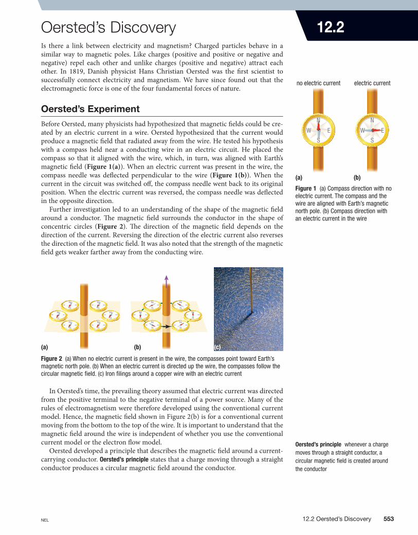
Oersted’s ExperimentBefore Oersted, many physicists had hypothesized that magnetic fi elds could be cre-ated by an electric current in a wire. Oersted hypothesized that the current would produce a magnetic fi eld that radiated away from the wire. He tested his hypothesis with a compass held near a conducting wire in an electric circuit. He placed the compass so that it aligned with the wire, which, in turn, was aligned with Earth’s magnetic fi eld (Figure 1(a)). When an electric current was present in the wire, the compass needle was defl ected perpendicular to the wire (Figure 1(b)). When the current in the circuit was switched off , the compass needle went back to its original position. When the electric current was reversed, the compass needle was defl ected in the opposite direction.
Further investigation led to an understanding of the shape of the magnetic fi eld around a conductor. Th e magnetic fi eld surrounds the conductor in the shape of concentric circles (Figure 2). Th e direction of the magnetic fi eld depends on the direction of the current. Reversing the direction of the electric current also reverses the direction of the magnetic fi eld. It was also noted that the strength of the magnetic fi eld gets weaker farther away from the conducting wire.
Oersted’s principle whenever a charge moves through a straight conductor, a circular magnetic fi eld is created around the conductor
In Oersted’s time, the prevailing theory assumed that electric current was directed from the positive terminal to the negative terminal of a power source. Many of the rules of electromagnetism were therefore developed using the conventional current model. Hence, the magnetic fi eld shown in Figure 2(b) is for a conventional current moving from the bottom to the top of the wire. It is important to understand that the magnetic fi eld around the wire is independent of whether you use the conventional current model or the electron fl ow model.
Oersted developed a principle that describes the magnetic fi eld around a current-carrying conductor. Oersted’s principle states that a charge moving through a straight conductor produces a circular magnetic fi eld around the conductor.
Figure 1 (a) Compass direction with no electric current. The compass and the wire are aligned with Earth’s magnetic north pole. (b) Compass direction with an electric current in the wire
(a) (b)
Figure 2 (a) When no electric current is present in the wire, the compasses point toward Earth’s magnetic north pole. (b) When an electric current is directed up the wire, the compasses follow the circular magnetic fi eld. (c) Iron fi lings around a copper wire with an electric current
(c)
N
S
EW
NNNN
SSS
N
S
EW
NNN
EEEWW
no electric current electric current
Ontario Physics 11 SB0-17-650433-8
FN
CO
Pass
Approved
Not Approved
C12-F008ab-OP11USB
Allan Moon
3rd pass
(b)(a)
NEL 12.2 oersted’s Discovery 553
7381a_Phy_Ch12_pp546-585.indd 553 1/6/11 1:38:57 PM

Applying Oersted’s PrincipleA learning tool was developed to help determine the direction of the magnetic fi eld around a straight current-carrying conductor. Th e right-hand rule for a straight conductor states that if a straight conductor is held in your right hand with your right thumb pointing in the direction of the conventional current, your curled fi ngers will point in the direction of the magnetic fi eld lines surrounding the con-ductor (Figure 3).
conventional current versus Electron FlowYou may wonder why conventional current is used when science has demonstrated that the electron fl ow model is accurate for conducting wires in circuits. Physicists have chosen to use conventional current because you would expect charge to fl ow from where there is an excess of charge to where there is a defi cit of charge. Recall from Section 11.4 that Benjamin Franklin chose positive to represent excess charge. As a result, conventional current models the fl ow of charges from positive to nega-tive. With conventional current, you use your right hand to determine the direction of the magnetic fi eld.
If you want to use the electron fl ow model instead, then you must use your left hand. Imagine a corresponding left -hand rule for a straight conductor. It is similar, except your left thumb follows the direction of electron fl ow. Th e fi ngers of your left hand still curl in the direction of the magnetic fi eld lines. Th e direction of the mag-netic fi eld is the same whether you use the right-hand rule or the left -hand rule. Try using the left -hand rule as shown in Figure 4 to confi rm this.
representing currents and Magnetic FieldsTh ere are many diff erent ways to represent a wire with a conventional current present in it. You can draw the wire in a three-dimensional way, as in Figure 3 and Figure 4. You can also draw the wire as a cross-section. To keep the drawing simple, the current can go into the page or out of the page. To represent a conventional cur-rent going into the page we use an X (Figure 5(a)), and to represent a conventional current coming out of the page we use a dot (Figure 5(b)). Th is model is based on
Magnetic Field DirectionRegardless of whether you use the conventional current direction or the electron fl ow direction to determine which way the current travels, the magnetic fi eld around a current-carrying wire is the same.
LEArNINg tIP
right-hand rule for a straight conductor if you hold a straight conductor in your right hand with your right thumb pointing in the direction of the conventional current, your curled fi ngers will point in the direction of the magnetic fi eld lines
Figure 4 The left-hand rule for electron fl ow in a straight wire, showing the direction of the magnetic fi eld lines. Notice that the direction of the magnetic fi eld lines is the same in Figure 3 and Figure 4.
conductor
magneticfield lines
electronflow
direction of magneticfield lines
lefthand
Ontario Physics 11 SB0-17-650433-8
FN
CO
Pass
Approved
Not Approved
C12-F011-OP11USB
Allan Moon
3rd pass
Figure 3 The right-hand rule for a straight conductor
electriccurrent
conductor
magneticfield lines
direction ofconvectional current
direction of magneticfield lines
righthand
Ontario Physics 11 SB0-17-650433-8
FN
CO
Pass
Approved
Not Approved
C12-F010-OP11USB
Allan Moon
3rd pass
554 Chapter 12 • Electromagnetism NEL
7381a_Phy_Ch12_pp546-585.indd 554 1/6/11 1:39:00 PM

an arrow. Imagine an arrow travelling away from you—you would see the tail in the shape of an X. If the arrow were travelling toward you, you would see the point of the arrow in the shape of a dot. Note how the concentric circles representing the magnetic fi eld are farther apart as you move away from the wire in Figure 5. Th e greater spacing represents the weaker strength of the magnetic fi eld as you move away from the wire.
Another method for showing the direction of the magnetic fi eld is to use a com-pass. If you place the compass on top of the wire, the wire will be obscured by the compass. If you place the compass below the wire, the wire will obscure the compass (Figure 6).
Using the right-hand rule, your thumb points to the right. Imagine grabbing the wire; use your pencil as a substitute. Notice that your fi ngers are pointing down if they are in front of the pencil and up if they are behind the pencil.
Implications of Oersted’s DiscoveryOersted’s discovery forever changed the world, leading to new kinds of technologies, such as motors and generators. He demonstrated that we could use electricity to produce magnetism. Controlling magnetism means that we can turn it on and off and change its strength by increasing or decreasing the current. We can also control the direction of the magnetic fi eld by changing the direction of the electric current.
Figure 5 (a) The X represents current in a conductor moving into the page, and the blue concentric circles show the direction of the magnetic fi eld. (b) The dot represents current in a conductor moving out of the page, and the blue concentric circles show the direction of the magnetic fi eld.
current into page
(a)
current into page
C12-F012a-OP11USB
CrowleArt Group
Deborah Crowle
1st pass
Ontario Physics 11 U
0176504338
FN
CO
Pass
Approved
Not Approved
current out of page
(b)
current out of page
C12-F012b-OP11USB
CrowleArt Group
Deborah Crowle
1st pass
Ontario Physics 11 U
0176504338
FN
CO
Pass
Approved
Not Approved
(a) (b)
Figure 6 (a) The compass is on top of the wire with the magnetic fi eld pointing downward. (b) The compass is underneath the wire with the magnetic fi eld pointing upward.
(a) (b)
N
S
EW
NNNN
SSS
conventional current
N
S
EW
conventional currentconventional current
NNN
SSS
NNNN
SS
C12-F013-OP11USB
CrowleArt Group
Deborah Crowle
2nd pass
Ontario Physics 11 U
0176504338
FN
CO
Pass
Approved
Not Approved
NEL 12.2 oersted’s Discovery 555
7381a_Phy_Ch12_pp546-585.indd 555 1/6/11 1:39:01 PM
• Hans Christian Oersted discovered that an electric current in a conductor produces a magnetic fi eld around the conductor.
• Oersted’s principle states that a charge moving through a straight conductor produces a circular magnetic fi eld around the conductor.
• Th e right-hand rule for a straight conductor states that if a straight conductor is held in your right hand with your right thumb pointing in the direction of the conventional current, your curled fi ngers will point in the direction of the magnetic fi eld lines.
• Oersted’s discovery can be used to produce magnetic fi elds with properties that can be controlled.
12.2 Questions
1. Copy each diagram in Figure 7 into your notebook and draw the magnetic fi eld. K/U C
2. Copy each diagram in Figure 8 into your notebook and label the direction of the conventional current. K/U C
3. A student draws a diagram showing what the magnetic fi eld around a current-carrying conductor looks like. The student draws concentric circles that are equally spaced around the conductor. Explain why the student’s diagram is inaccurate. T/I
4. Explain how the diagram in Figure 9 would change if you were to use the left-hand rule or the right-hand rule. K/U C
5. You are driving east in your car. Your car is equipped with a magnetic compass display in your rear-view mirror. You happen to drive underneath an electric wire that is labelled high current. You notice that your compass immediately displays north. In which direction is the conventional current fl owing in the wire? T/I
6. You use a current-carrying straight conductor to produce a magnetic fi eld. Which three properties of the magnetic fi eld can you control? K/U
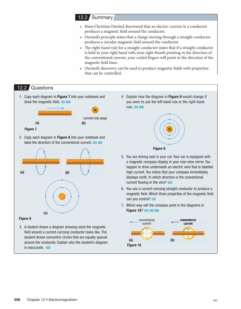
7. Which way will the compass point in the diagrams in Figure 10? K/U T/I C
12.2 Summary
C05-F017-OP11USB
CrowleArt Group
Deborah Crowle
3rd pass
Ontario Physics 11 U
0176504338
FN
CO
Pass
Approved
Not Approved
N
S
EW
NNN
conventionalcurrent
N
S
EW
conventionalcurrent
conventional
SSS
NNNNNN
conventionalcurrent
(a) (b)
C12-F014a-OP11USB
CrowleArt Group
Deborah Crowle
2nd pass
Ontario Physics 11 U
0176504338
FN
CO
Pass
Approved
Not Approved
Figure 7
(a) (b)current into page
C12-F014b-OP11USB
CrowleArt Group
Deborah Crowle
2nd pass
Ontario Physics 11 U
0176504338
FN
CO
Pass
Approved
Not Approved
Figure 8
C12-F015a-OP11USB
CrowleArt Group
Deborah Crowle
2nd pass
Ontario Physics 11 U
0176504338
FN
CO
Pass
Approved
Not Approved
(a)
C12-F015b-OP11USB
CrowleArt Group
Deborah Crowle
2nd pass
Ontario Physics 11 U
0176504338
FN
CO
Pass
Approved
Not Approved
(b)
C12-F015c-OP11USB
CrowleArt Group
Deborah Crowle
1st pass
Ontario Physics 11 U
0176504338
FN
CO
Pass
Approved
Not Approved
(c)
Figure 9
C12-F016-OP11USB
CrowleArt Group
Deborah Crowle
3rd pass
Ontario Physics 11 U
0176504338
FN
CO
Pass
Approved
Not Approved
Figure 10
556 Chapter 12 • Electromagnetism NEL
7381a_Phy_Ch12_pp546-585.indd 556 1/19/11 1:50:15 PM