Embed Size (px)
Citation preview
Odyssey®
3WattD I O D E L A S E R
Owners Manual
P A R T N E R I N G I N E S T H E T I C D I G I T A L D E N T I S T R Y S M
Table of ContentsSection 1 - Introduction . . . . . . . . . . . . . . . . . . . . . . . . . . .1
Section 2 -Specifications2.0 Laser Specifications . . . . . . . . . . . . . . . . . . . . . . . .22.1 Delivery System Specifications . . . . . . . . . . . . . . . .2 2.2 Warranty . . . . . . . . . . . . . . . . . . . . . . . . . . . . . . . . .22.3 Parts List . . . . . . . . . . . . . . . . . . . . . . . . . . . . . . . . .2
Section 3 – Laser Assembly Instructions 3.0 Removing the Laser from the Packaging . . . . . . . .33.0.1 Instructions on Unpacking & Dealer Assistance .33.0.2 Shipping Container Information . . . . . . . . . . . . .33.0.3 Contents of the Shipping Container . . . . . . . . . .33.1 Assembling the Laser . . . . . . . . . . . . . . . . . . . . . .33.1.1 Power Cord Installation . . . . . . . . . . . . . . . . . . . .33.1.2 Power/Fan Switch - Check . . . . . . . . . . . . . . . . . .33.1.3 Laser Key Switch – Check . . . . . . . . . . . . . . . . . .33.1.4 Remove Interlock . . . . . . . . . . . . . . . . . . . . . . . . .33.1.5 Foot Pedal Installation . . . . . . . . . . . . . . . . . . . . .33.1.6 Emergency Shutdown Switch . . . . . . . . . . . . . . .33.1.7 Installing the Disposable Fiber Cassette . . . . . . . .43.1.8 Summary: Laser Assembly Procedure . . . . . . . . .4
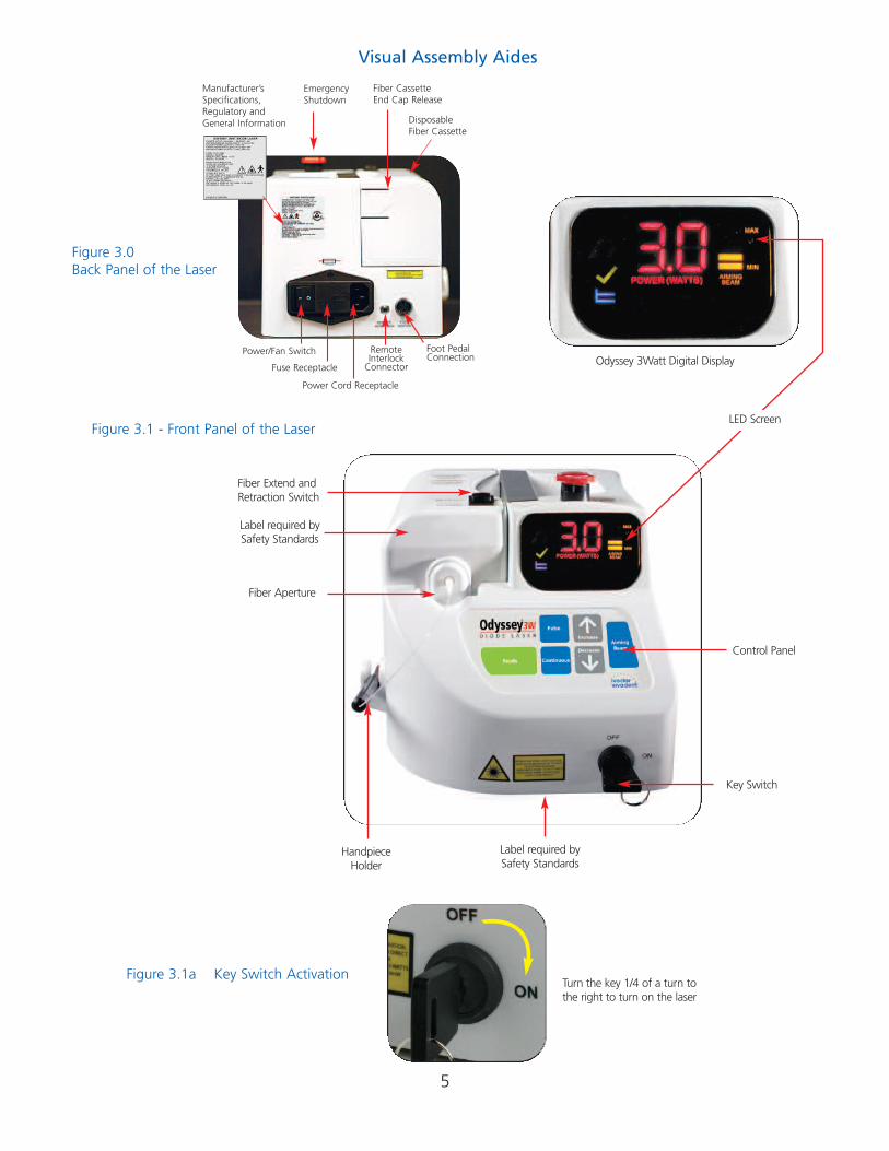
Visual Assembly AidesFigure 3.0 Back Panel of the Laser . . . . . . . . . . . . . . . .5Figure 3.1 Front Panel of the Laser . . . . . . . . . . . . . . . .5Figure 3.1a Key Switch Activation . . . . . . . . . . . . . . . .5Figure 3.2 Laser Control Pad . . . . . . . . . . . . . . . . . . . . .6Figure 3.2a Laser Display Indicators . . . . . . . . . . . . . . .6Figure 3.5 Emergency Shutdown Button - Activating . .6Figure 3.6 Emergency Shutdown Button - Releasing . .6Figure 3.7 Top View - Emergency Shutdown
Button and Fiber Retraction Switch . . . . . . .7Figure 3.7a Rocker Switch Activation . . . . . . . . . . . . . . . .7Figure 3.8 Laser Aperture and Cassette Power
Receiver Location on the Chassis . . . . . . . . .7Figure 3.9 Disposable Fiber Cassette Base
with a 15 Pin Power Coupler . . . . . . . . . . . .8Figure 3.10 Removable End Cap on the Fiber Cassette . .8Figure 3.11 Disposable Fiber Cassette without
an End Cap . . . . . . . . . . . . . . . . . . . . . . . .8Figure 3.12 Proximal End of the Fiber
as it Exits the Cassette . . . . . . . . . . . . . . . .8Figure 3.13 Locking Hub . . . . . . . . . . . . . . . . . . . . . . . .8Figure 3.14 Alignment Slot . . . . . . . . . . . . . . . . . . . . . .83.2 Facility Requirements . . . . . . . . . . . . . . . . . . . . . . .93.2.1 Power Requirements . . . . . . . . . . . . . . . . . . . . . .93.2.2 Heating and Ventilation . . . . . . . . . . . . . . . . . . . .93.2.3 Lighting . . . . . . . . . . . . . . . . . . . . . . . . . . . . . . . .93.2.4 Combustible Chemicals and Gases . . . . . . . . . . .93.2.5 High Speed Vacuum Systems . . . . . . . . . . . . . . .93.2.6 Access and Visual . . . . . . . . . . . . . . . . . . . . . . . .9
Section 4 - Safety Considerations4.0 Food and Drug Administration . . . . . . . . . . . . . . . .94.1 Statutory Licensure . . . . . . . . . . . . . . . . . . . . . . . . .94.2 OSHA and its Provisions . . . . . . . . . . . . . . . . . . . . .94.3 Laser Safety Program . . . . . . . . . . . . . . . . . . . . . . .94.4 Continuing Education . . . . . . . . . . . . . . . . . . . . . .124.5 In-office Safety Issues . . . . . . . . . . . . . . . . . . . . . .124.5.1 Lighting . . . . . . . . . . . . . . . . . . . . . . . . . . . . . . .124.5.2 Safety Eyewear . . . . . . . . . . . . . . . . . . . . . . . . .124.5.3 Test Firing the Laser . . . . . . . . . . . . . . . . . . . . . .134.5.4 Power Changes with Fiber Changes . . . . . . . . .134.5.5 Fiber Preparations . . . . . . . . . . . . . . . . . . . . . . .134.5.6 Danger – Laser in Use Signage . . . . . . . . . . . . .134.5.7 Sharps Disposal . . . . . . . . . . . . . . . . . . . . . . . . .134.5.8 Plume Evacuation . . . . . . . . . . . . . . . . . . . . . . .134.5.9 Key Switch and Mode Selection . . . . . . . . . . . .134.5.10 Safety Education . . . . . . . . . . . . . . . . . . . . . . .134.5.11 Laser Security . . . . . . . . . . . . . . . . . . . . . . . . . .134.5.12 Emergency Shutdown Options . . . . . . . . . . . .134.5.13 Hard Tissue Procedures . . . . . . . . . . . . . . . . . .134.6 ANSI Standards . . . . . . . . . . . . . . . . . . . . . . . . . . .13
Section 5 – Operating the Laser5.0 Standby and Ready Status . . . . . . . . . . . . . . . . . .135.1 Continuous Wave Mode . . . . . . . . . . . . . . . . . . .145.2 Pulsed Energy Mode . . . . . . . . . . . . . . . . . . . . . . .145.3 Tissue Responses to Laser Energy . . . . . . . . . . . . .14Figure 5.1 Poor Cleave on the Fiber . . . . . . . . . . . . . .145.4 Fiber and Handpiece Care . . . . . . . . . . . . . . . . . .145.5 Warning (Fiber Cassette Care) . . . . . . . . . . . . . . .155.6 System Procedures . . . . . . . . . . . . . . . . . . . . . . . .155.6.1 Selecting the Treatment Center . . . . . . . . . . . . .155.6.2 Checking Foot Pedal Installation . . . . . . . . . . . .155.6.3 Checking the Disposable Fiber
Cassette Installation . . . . . . . . . . . . . . . . . . . . .155.6.4 Checking Fiber Preparation . . . . . . . . . . . . . . . .155.6.5 Checking the Emergency
Shutdown Button - Release Instructions . . . . . .155.6.6 Checking the Key Activation and
Control Panel Display . . . . . . . . . . . . . . . . . . . .155.6.7 Setting Parameters . . . . . . . . . . . . . . . . . . . . . .155.6.8 Setting Power . . . . . . . . . . . . . . . . . . . . . . . . . .155.6.9 Setting Aiming Beam – Parameters . . . . . . . . .155.6.10 Avoiding Use of a Defective Fiber Tip (Shards) 155.6.11 Aiming Beam Activation . . . . . . . . . . . . . . . . .155.6.12 Test Firing the Laser Before
Beginning Procedures . . . . . . . . . . . . . . . . . . .155.6.13 Using Quick/Short Strokes with the Fiber Tip .155.6.14 Cleaning the Fiber Tip During a Procedure . . .155.6.15 Preventive Measure –
Placing the Laser in Standby . . . . . . . . . . . . . .165.6.16 Cleave Used Fiber Tip and Discard . . . . . . . . .165.6.17 Preventive Measure -
Cleaning the Fiber Before Retracting It. . . . . .16
5.6.18 Preventive Measure – Turning the Key Off Between Procedures . . . .16
5.6.19 Recording Power, Mode and Time Parameters in the Patients Chart. . . . . . . . . . .16
5.6.20 Self Diagnostic and Monitoring . . . . . . . . . . . .16
Section 6.0 Systems Components: Preparation, Care and Maintenance
6.0 Disposable Fiber Cassette . . . . . . . . . . . . . . . . . . .166.0.1 Replacing the Fiber Cassette . . . . . . . . . . . . . . .166.1 Fiber Preparation . . . . . . . . . . . . . . . . . . . . . . . . . .166.1.1 Jacket . . . . . . . . . . . . . . . . . . . . . . . . . . . . . . . . .176.1.2 Cladding . . . . . . . . . . . . . . . . . . . . . . . . . . . . . .176.1.3 Quartz/Silica Fiber . . . . . . . . . . . . . . . . . . . . . . .176.1.4 Stripping the Fiber . . . . . . . . . . . . . . . . . . . . . . .176.1.5 Cleaving the Fiber . . . . . . . . . . . . . . . . . . . . . . .176.1.6 Initiating the Fiber . . . . . . . . . . . . . . . . . . . . . . .186.1.7 Fiber Disinfection . . . . . . . . . . . . . . . . . . . . . . . .186.2.0 Maintenance . . . . . . . . . . . . . . . . . . . . . . . . . . .186.2.1 Laser Chassis Disinfection . . . . . . . . . . . . . . . . .186.2.2 Calibration . . . . . . . . . . . . . . . . . . . . . . . . . . . . .186.3.0 Handpiece Preparation . . . . . . . . . . . . . . . . . . .196.3.1 Preparation for Autoclaving . . . . . . . . . . . . . . . .196.3.2 Components of the Handpiece . . . . . . . . . . . . .196.3.3 Providing Adequate Fiber to
Cleave, Strip and Initiate . . . . . . . . . . . . . . . . . .196.3.4 Disposable Tips . . . . . . . . . . . . . . . . . . . . . . . . .196.3.5 Using the Stripper . . . . . . . . . . . . . . . . . . . . . . .196.3.6 Mounting the Disposable Tip . . . . . . . . . . . . . .19
Section 7.0 Labels, Signs, Warnings and Information7.1 Federal Compliance . . . . . . . . . . . . . . . . . . . . . . .197.2 Danger – Laser in Use Signage . . . . . . . . . . . . . . .207.3 Laser Classification – Aiming Beam . . . . . . . . . . .207.4 Laser Classification – Treatment Laser . . . . . . . . .207.5 Caution – Changes Not Approved . . . . . . . . . . . .207.6 Caution – Avoid Skin and Eye Contact . . . . . . . .207.7 Caution – No User Serviceable Parts
Within the Chassis . . . . . . . . . . . . . . . . . . . . . . . .207.8 Caution – Sale or Use of a Laser
by Other than a Physician or Dentist . . . . . . . . . .207.9 WARNING – Do Not Use Eyewear for
Other than the 810 nm Wavelength . . . . . . . . .207.10 Manufacturer’s General Information . . . . . . . . .207.11 Nominal Ocular Hazard Distance . . . . . . . . . . . .20
Section 8.0 Servicing8.1 Warranty Card . . . . . . . . . . . . . . . . . . . . . . . . . . .218.2 Repairs / Customer Service Address . . . . . . . . . . .21
Section 9.0 Glossary of Laser Terminology . . . . . . . . . . . .21
Section 10.0 Selected References on Laser Dentistry . . . .22
Section 11.0 Troubleshooting . . . . . . . . . . . . . . . . . . . . . .23
1
Section 1 - Introduction
As dentists strive to create the perfect smile, they are oftencompromised by the technology they use in their practice.Respected leaders from the dental profession and dentalequipment manufacturers have sought to identify the mostpractical and least invasive technology available to deliverrestorative and preventive care. Today, thanks to continuingefforts by these industry leaders, we have seen the introduction of many new devices that have advanced thedentist’s ability to perform at the highest standards. TheOdyssey 3Watt DIODE LASER from Ivoclar Vivadent, Inc. represents the latest solid state diode laser technology available for soft tissue modification and preventative care.Now featuring wireless power control.
Unlike solid state lasers that utilize a man-made rod of elements such as yttrium, aluminum, and garnet, doped with a rare earth compound like Erbium, the diode has components that have become known for their durability,dependability and longevity. We are, of course, referring tosemi-conductor crystal technology like that found in televisions, DVD players, telephones and many more of thosehousehold products that we have learned to rely on each day.
The major components of the Odyssey 3Watt are semi-conductor “chips” made from Aluminum, Gallium andArsenide, together commonly referred to as AlGaAs. They areactivated or “pumped” by passing an electrical currentthrough the diode to produce an elliptical shaped display ofmonochromatic light that can be focused into a very smallpoint and placed into the delivery fiber. The wave length produced by the diode is approximately 810 nanometers (nm)and produces invisible non-ionizing thermal radiation thatdoes not create changes in cellular DNA. The diode is aircooled and highly efficient when used correctly. For safety,the diode features several ways to stop energy flow if theoperator wishes to deactivate the laser. The safety systemincludes a choice of an emergency shutoff switch, a key, apower switch, a power cord or an electrical plug. Any ofthese items can be used to shut down the laser.
The design and technology used in the Odyssey 3Watt allowsthe dentist or hygienist* to transport the laser between different operatories. It has a lightweight and durable chassisthat is designed to use 110 – 120 V electricity found in most dental offices.
Training is recommended and opportunities for such areavailable through such outlets as Ivoclar Vivadent, Inc., pleasevisit our web site for training dates and locations atwww.getodysseylaser.com, the Academy of Laser Dentistry,dental schools and many dental continuums. You should alsoask your authorized dealer representative for the names of den-tists in your area who have a laser and who could help you in amentoring capacity. There are many applications for using thislaser system and you will be amazed of the results and wonderhow you ever practiced dentistry without the Odyssey 3Watt.
Laser safety is paramount in importance and each officeshould quickly develop and implement a laser safety programand appoint a “laser safety officer” to be responsible for thelaser. Their duties include management of the laser and allaccessories as well as training office personnel in all aspects oflaser safety. More duties are outlined in Section 4, subsection4.4 of this manual.
* In States / Provinces where the Dental Practice Act allows hygienists to utilize a laser.
Remember: Always test fire the laser outside the mouth before using it on apatient. The doctor or hygienist, thepatient and any staff member present inthe operatory should be wearing the appropriate safety eyewear whenever thelaser is being operated. Strict adherence toprotocols for safe laser use is essential.
2
Section 2 – Specifications
2.0 Laser Specifications Weight 5.5 lbs
Dimension in inches (H X W X L) 5.5” x 6.25” x 8.75”
Laser Classification (Per 60825)Laser Diode Class 4 Laser Device
WavelengthLaser 810 nm ±20 nm Aiming Beam 630 nm – 660 nm ±15 nm
Beam Divergence 9 degrees ± 1 degree
Power Range 100 mw to 3 Watts
Hertz Rate in Pulsed Mode - fixed 1.0 Hz
Pulse Duration - fixed 0.5 seconds
Duty Cyclepulsed mode 50%continuous wave 100%
Aiming Beam (3 mW ) Yes
Audible Notification Yes
Visual Notification Yes
Power Requirements 110 - 120 VAC @ 60 Hertz220 - 240 VAC @ 50 Hertz
Amperage 1.5 Amps @ 110-115 V AC 0.75 Amps @ 210-230 V AC
2.1 Delivery System Specifications2.1.1 Quartz silica fiber
1 cassette – approximately 20’ each (6 meters)
Fiber Diameter 400 microns
Autoclavable No
Retractable fiber deliverycassette (non-autoclavable) 1
2.2.2 Handpiece - Autoclavable 22.2.3 Tips for the Handpiece
Autoclavable and disposable 50 per box2.2.4 Laser Aperture -ST Adapter Type Yes
2.2 Warranty (See also Section 8)
Laser 1 year Parts and LaborFiber and Cassette 90 days Parts and Labor
2.3 Parts List Part Identification number
Fiber Stripper Tool 579031
Fiber Cleaver 579032
Protective Glasses Solid Sides 598558
Protective Glasses Plain Sides 598559
Protective Glasses Window Sides 598560
400 Micron Fiber Cartridge System 579036
Package of (20) Handpiece Tips - 60 degree angle 603502
Handpiece 579038
Handpiece Fiber Lock (inside of handpiece) 595477
Power Cord 579041
Odyssey 3Watt Owner’s Manual 603505
Odyssey 3Watt Clinical Guide 603499
Laser Safety Sign 603504
3
Section 3 - Laser Assembly Instructions
3.0 Removing the Laser from the Packaging3.0.1 - Instructions on Unpacking & Dealer Assistance:Your local authorized Ivoclar Vivadent dealer can provide a representative to assist you when you are ready toremove the laser from its shipping container. You mayremove it yourself if you wish to get a head start on the set-up, but please do not attempt to unpack the laser andinstall the various components without reading this sectionfirst. If you are unsure about any aspect of the assembly, callyour authorized dealer representative for assistance.
3.0.2 - Shipping Container Information: Though highly unlikely, you may need to return the laser for service or repairand the shipping container you received with your laser hasbeen especially designed to transport the laser.
3.0.3. - Contents of Shipping Container: The contents of theshipping container should include the following:
(1) Odyssey 3Watt Laser Unit with 400 Micron Fiber Cartridge System
(1) Fiber Stripper Tool (1) Fiber Cleaver(1) Protective Glasses - Window Sides Style(1) Protective Glasses - Solid Sides Style (1) Protective Glasses - Plain Style(2) Packages of (20) Handpiece Tips - 60 degree angle(2) Handpiece (autoclavable)(1) Laser Key (1) Foot Pedal(1) Power Cord(1) Odyssey 3Watt Owner’s Manual(1) Odyssey 3Watt Clinical Guide(1) Laser Safety Sign(1) Warranty Information
Please check all items sent with your laser to insure that all components are accounted for.
3.1 Assembling the LaserEach of the following items should be inspected, inserted intothe appropriate receptacle, and when applicable, lockedusing the locking hub.
3.1.1 Power Cord Installation: Remove the power cord fromthe Odyssey 3Watt package and plug the power cord into theappropriate receptacle on the back of the laser. See Figure 3.0on page 5. To prevent power surges due to electrical stormsor spikes in line voltage, you should use a power strip with acircuit breaker or unplug the laser when you are not present.
Plug the power cord into a 110 Volt AC outlet rated at 60Hz.
3.1.2 Power/Fan Switch: The power/fan switch for the laserand fan is the first item you turn on each day. The switch islocated on the rear panel of the laser near the lower righthand corner. See Figure 3.0 on page 5.
3.1.3 Laser Key Switch: The laser key switch is the major cir-cuit breaker for your laser. It will be the second item you turnon when activating the laser each day. Place the laser key intothe key receptacle located near the lower right corner on thefront of the laser. See Figure 3.1 and Figure 3.1a on page 5.Check the key switch by turning the key clockwise approxi-mately 1/4 of a turn. This is the (ON) operating position forthe key. The fan will start when the power/fan switch is onand the key is turned. Prior to leaving the office, the laser safe-ty officer should check to see that the key switch has beenturned off and the key removed and stored in a safe place.
3.1.4 Odyssey 3Watt Remote Interlock: The Odyssey 3WattLaser is equipped with a Remote Interlock Jack. The RemoteInterlock Jack is provided so that a clinician may install thelaser in a dedicated laser treatment room such that the laserwill be interlocked with the entrance door of the room. Insuch an interlocked installation, the laser would shut offanytime the door is opened, hypothetically, to protect the person’s eyes who is entering the room. It is recognized thatsuch installment is not facilitated nor required in many operatories or clinics. To that end, the Remote Interlock isavailable to any practitioner that requires it. The RemoteInterlock Jack is located and clearly labeled on the rear of thelaser. The miniphono jack is wired in the normally closed position; meaning that no further action is required to operate the laser without the interlock loop. If the interlockloop is desired you may purchase the loop from a local elec-tronics store. You need only inform the local electronics storethat you require a mini (1/8”) mono-phono jack wired into anormally closed momentary switch and select the switchdesign that best suits your needs. To install the loop, install theswitch on the door and simply plug the mini phono jack intothe Remote Interlock Jack on the rear of the laser.
3.1.5 Foot Pedal Installation Procedure: Locate the footswitch receptacle on the back of the laser and insert the proximal end of the foot switch cord into the marked receptacle on the back of the laser. Then check to see if it issecurely locked.
3.1.6 Emergency Shutdown Switch: Before you can activatethe laser, you must first check to see if the emergency shut-down switch has been depressed prior to shipment andlocked in the off position. The switch is the red button located on the top of the laser. Release the switch by grasp-ing it between your thumb and index finger, and gentlydepress it as you turn the button 1/4 turn clockwise. You willfeel it “click” or release and the spring loaded button will pop
back up. (See Figure 3.5 and Figure 3.6 on page 6). The display on the control panel should now be lighted. If the cartridge lock plate is not fully engaged, this will prevent thedisplay from lighting up. If you find that the display is still notoperational, check all attachments, keys and switches to seethat they are securely installed and that you have an activewall plug for electricity. (See Troubleshooting Section pg. 22).
If the laser can not be activated, please contact your authorized distributor who can help you to get a replacement.If the control panel does light up when you release the shutdown switch, you should test the switch again by depressingit to turn the laser off. If the shutdown switch is locked down,the laser will not turn on.
3.1.7 Installing the Disposable Fiber Cassette: When itcomes time to install a new cassette, carefully remove thefiber cassette from the packing. Remove the end cap fromthe old cassette and remove the cassette (do not dispose ofthe end cap). To install the new cassette, locate the end of thenew fiber. Avoid placing your finger on the proximal endof the new fiber. See Figure 3.12 on page 8. Human oils onthe fiber can burn and diminish the effective transmission ofradiant energy once the fiber is installed. While opening thedoor on the laser aperture with one hand, insert the proximalend of the new fiber into the laser aperture. See Figure 3.13on page 8. Be careful to align the slot on the fiber end withlocking hub of the aperture. See Figure 3.14 on page 8. Onceinserted, turn the fiber locking hub to the right (clockwise) tolock the fiber securely into the ST connection . Once the fiberis connected, align the dove tail of the cassette with the dovetail receiver on the chassis wall. See Figure 3.8 on page 7. Thiswill help assure that the power coupler (a serial port) on theunderside of the fiber cassette will be aligned with the receiver on the laser chassis. Slowly press the cassette intoplace. See Figures 3.8, 3.9 & 3.11 on pages 7 - 8. Onceconnected, replace the end cap to secure the fiber cassette.The laser will not operate until the end cap is firmly latched inplace. Turn the key switch and power/fan switch to the “on”position. Test your power connection by advancing the fiber,using the rocker switch on the top of the cassette. Depressthe switch at its most anterior point to see if it moves the fiberforward.
Next, select a low power to check transmission of energy (1Watt – 1.5 Watt). Put on the safety eyewear to protect youreyes. Place the laser in ready mode and depress the footpedal to activate the laser while holding the fiberapproximately 2-4 mm away from a piece of paper with printing on it. Aim at the printing, the paper will begin to burnin 1-2 seconds. See section 6.1.6. on page 15. You should beable to see the aiming beam on the paper and the fiber tipshould produce enough heat to let you know it is installedproperly and the fiber is sound. You do not want to use an
initiated fiber for this check because the energy wouldstop at the tip.
3.1.8 Summary: Laser Assembly Instructions:
1. Attach the laser’s power cord and place the plug into the wall receptacle.
2. Attach the foot pedal.3. Attach remote interlock, if desired (not required).4. Check the emergency shutdown switch to see that is
has been released.5. Install the fiber cassette and attach the fiber to the
ST connector and lock the locking hub. 6. Place the key into the key switch receptacle (see Figure
3.1a on page 5) and turn the key to the right.The control console should light up.
7. The light on the console indicating the operating statusshould be in the standby mode.
NOTE: When the power cord is plugged in, the fan/power motor switched on, the wireless foot pedalreceiver attached and the emergency shutdownreleased, the key will turn the laser on.
4
5
Figure 3.1 - Front Panel of the Laser
Figure 3.1a Key Switch Activation
Odyssey 3Watt Digital Display
LED Screen
Control Panel
Fiber Extend andRetraction Switch
Key Switch
HandpieceHolder
Turn the key 1/4 of a turn tothe right to turn on the laser
Fiber Aperture
Label required bySafety Standards
Label required bySafety Standards
Figure 3.0 Back Panel of the Laser
Manufacturer’sSpecifications,Regulatory andGeneral Information Disposable
Fiber Cassette
Foot Pedal Connection
Power/Fan Switch
EmergencyShutdown
Fiber CassetteEnd Cap Release
Power Cord Receptacle
RemoteInterlock
ConnectorFuse Receptacle
Visual Assembly Aides
6
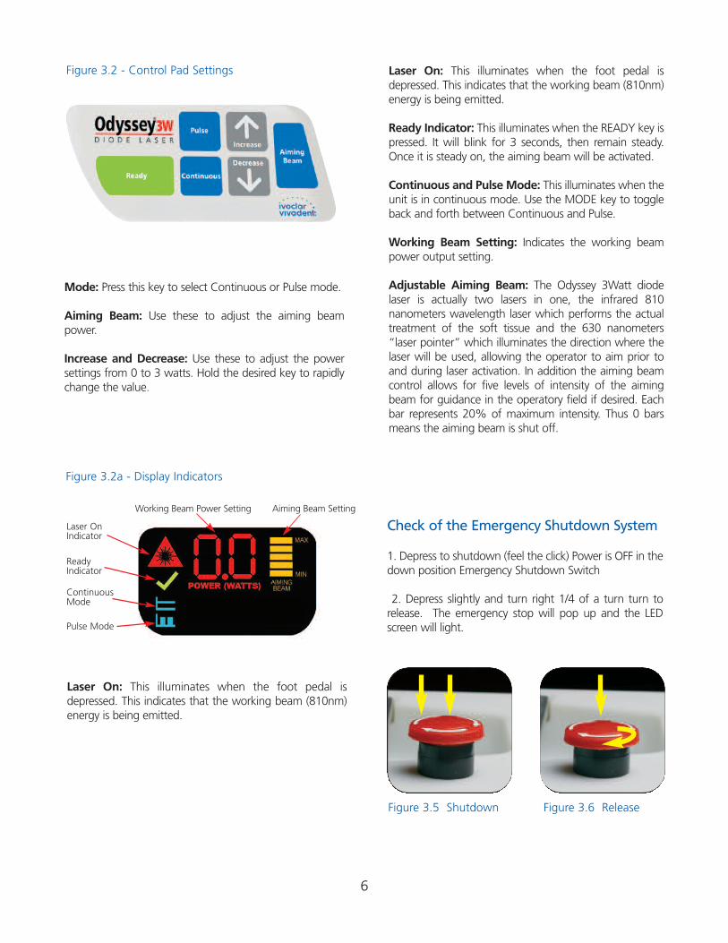
Figure 3.2 - Control Pad Settings
Mode: Press this key to select Continuous or Pulse mode.
Aiming Beam: Use these to adjust the aiming beampower.
Increase and Decrease: Use these to adjust the power settings from 0 to 3 watts. Hold the desired key to rapidlychange the value.
Laser On: This illuminates when the foot pedal isdepressed. This indicates that the working beam (810nm)energy is being emitted.
Figure 3.2a - Display Indicators
Laser On: This illuminates when the foot pedal isdepressed. This indicates that the working beam (810nm)energy is being emitted.
Ready Indicator: This illuminates when the READY key ispressed. It will blink for 3 seconds, then remain steady.Once it is steady on, the aiming beam will be activated.
Continuous and Pulse Mode: This illuminates when theunit is in continuous mode. Use the MODE key to toggleback and forth between Continuous and Pulse.
Working Beam Setting: Indicates the working beampower output setting.
Adjustable Aiming Beam: The Odyssey 3Watt diodelaser is actually two lasers in one, the infrared 810nanometers wavelength laser which performs the actualtreatment of the soft tissue and the 630 nanometers“laser pointer” which illuminates the direction where thelaser will be used, allowing the operator to aim prior toand during laser activation. In addition the aiming beamcontrol allows for five levels of intensity of the aimingbeam for guidance in the operatory field if desired. Eachbar represents 20% of maximum intensity. Thus 0 barsmeans the aiming beam is shut off.
Laser On Indicator
Working Beam Power Setting Aiming Beam Setting
Ready Indicator
Continuous Mode
Pulse Mode
Check of the Emergency Shutdown System
1. Depress to shutdown (feel the click) Power is OFF in thedown position Emergency Shutdown Switch
2. Depress slightly and turn right 1/4 of a turn turn torelease. The emergency stop will pop up and the LEDscreen will light.
Figure 3.5 Shutdown Figure 3.6 Release
7
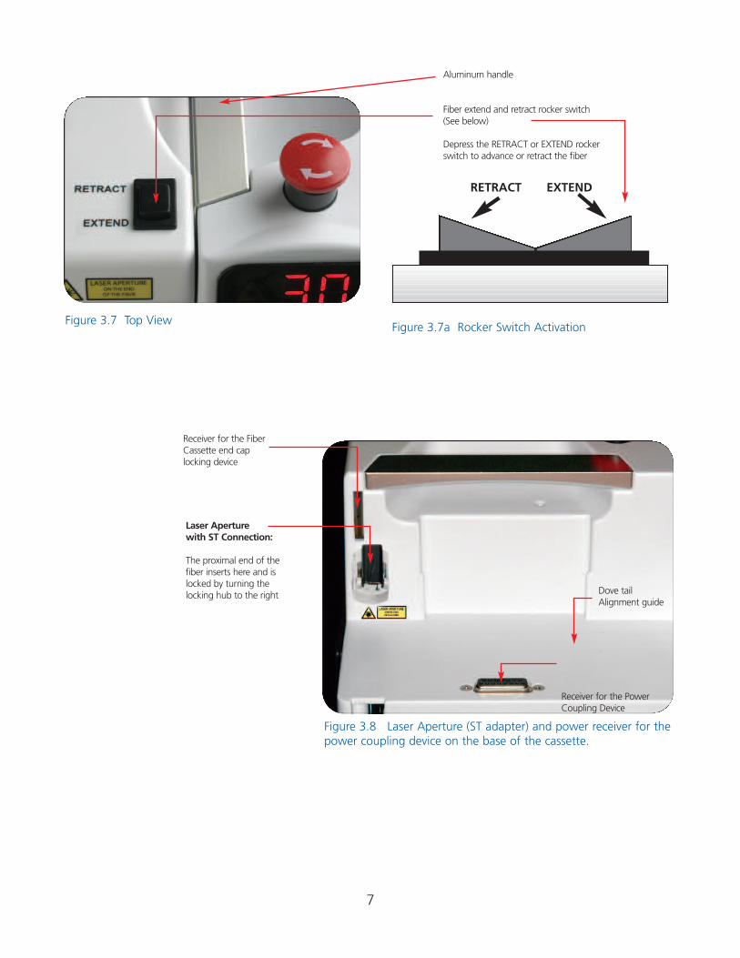
Figure 3.7 Top ViewFigure 3.7a Rocker Switch Activation
RETRACT EXTEND
Aluminum handle
Fiber extend and retract rocker switch(See below)
Depress the RETRACT or EXTEND rockerswitch to advance or retract the fiber
Laser Aperturewith ST Connection:
The proximal end of thefiber inserts here and islocked by turning thelocking hub to the right
Receiver for the FiberCassette end caplocking device
Figure 3.8 Laser Aperture (ST adapter) and power receiver for thepower coupling device on the base of the cassette.
Receiver for the PowerCoupling Device
Dove tail Alignment guide
8
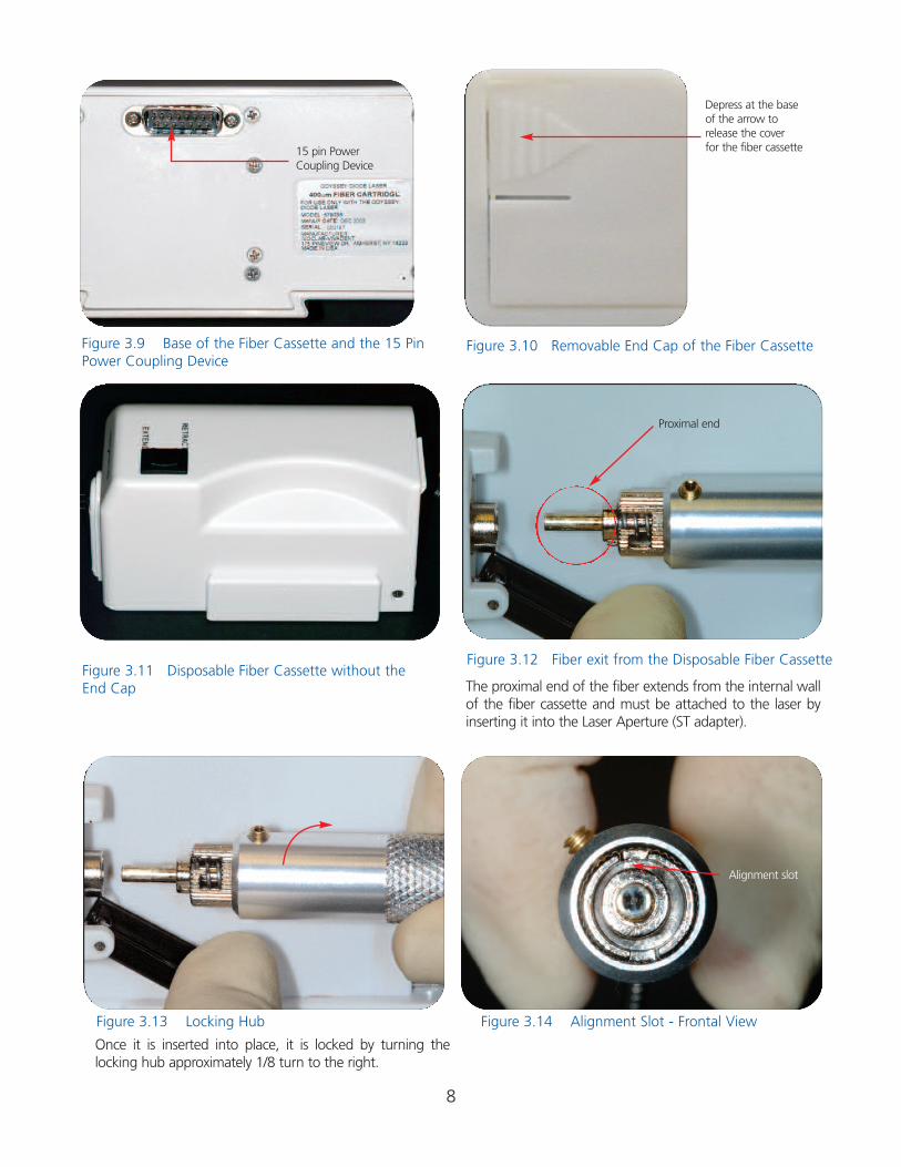
Depress at the base of the arrow to release the cover for the fiber cassette
Figure 3.9 Base of the Fiber Cassette and the 15 PinPower Coupling Device
Figure 3.10 Removable End Cap of the Fiber Cassette
Figure 3.13 Locking Hub Figure 3.14 Alignment Slot - Frontal View
Figure 3.11 Disposable Fiber Cassette without theEnd Cap
15 pin PowerCoupling Device
The proximal end of the fiber extends from the internal wallof the fiber cassette and must be attached to the laser byinserting it into the Laser Aperture (ST adapter).
Once it is inserted into place, it is locked by turning the locking hub approximately 1/8 turn to the right.
Figure 3.12 Fiber exit from the Disposable Fiber Cassette
Alignment slot
Proximal end
9
3.2 Evaluating the Facility and EnvironmentalConsiderations (United States)In order to insure the safe use of the laser in your facility,please check to make sure that the proposed location hasthe following:
3.2.1 Power Requirements:110 -120 V AC ±10 % at 60 Hz3 AmpsFrequency range 45 - 63 Hz9 volt Lithium battery
3.2.2 Heating and Ventilation:The room where the laser is used should have good cooling and heating system so that the laser can be operated within the optimum range of 20º - 30ºC (68º - 86º F).Avoid storing or transporting the laser in temperatures below 0º Celsius (32º F).
3.2.3 Lighting:Overhead lighting and or dental unit light should provideenough illumination to allow good operator vision when acti-vating the laser intra-orally.
3.2.4 Combustible Chemicals and Gases:All gases that are combustible or support combustion and areused in the operatory area where the laser is in use must beturned off during the procedure. Cleaning supplies or otherflammable chemical compounds should be stored in an areaaway from the surgical site in order to avoid possible combustion.
3.2.5 High Speed Vacuum Systems:Plume evacuation is a priority when vaporizing tissues. TheClinician or operator, and their chair-side assistants shouldkeep themselves and the patient safe by using a high volumevacuum system and high filtration masks that are suitable forvirus and bacterial control.
3.2.6 Access and Visual:Access to the treatment area should allow the dental team torestrict entry while the laser is in use. There should be a LaserIn Use Safety Sign placed in a designated area adjacent tothe entry into the treatment area. See Figure 7.1 on page 15.
NOTE: This equipment has been tested and found to complywith the limits for a Class A digital device, pursuant to Part 15of the FCC Rules. These limits are designed to provide rea-sonable protection against harmful interference when theequipment is operated in a commercial environment. Thisequipment generates, uses, and can radiate radio frequencyenergy and, if not installed and used in accordance with theinstruction manual, may cause harmful interference to radiocommunications. (Operation of this equipment in a residentialarea is likely to cause harmful interference in which case theuser will be required to correct the interference at his own expense).
4. Safety ConsiderationsThe safe use of the Odyssey 3Watt is the responsibilityof the entire dental team including the doctor, the lasersafety officer appointed from the dental office team.Protocols for the safe use of lasers have been developedby a combination of medical and dental professionalsworking in concert with educators at the universitylevel, scientists and laser manufacturers. Dental professionals have had to develop protocols and guidelines for using the laser on oral soft tissues. Soundjudgment and the concern for patient safety should bethe basis of all laser care. The following entities haveinfluence over laser use.
4.1 Statutory LicensureUsually, states or provinces do not have a specific licensurerequirement for use of a laser by a dentist. Most states requirea hygienists to attend licensure training that includes both alecture and hands-on training. Prior to using the laser, thehygiene applicants are required to pass a proficiency test for certification. These courses are usually taught by members ofthe Academy of Laser Dentistry who possess instructor credentials. Some US States and Canadian Provinces haveimplemented specific rules governing the use of lasers. Youshould check your State or Province’s website to determineapplicability of any requirements to your office.
4.2 OSHA and its ProvisionsWorker safety is the responsibility of the employer and is regulated by OSHA (Occupational Safety and HealthAdministration), a division of the U.S. Department of Labor.OSHA has issued no specific standard for safe use of lasers butrecognizes ANSI standard Z136.1 as a source for analyzingsafety with respect to medical lasers. For more informationsee OSHA Technical Manual (TED 1-0.15A) Section III, Chapter6, 1999. Ivoclar Vivadent Inc. recommends implementation ofa Laser Safety Program for the safety of your patients andoffice staff in connection with the use of the Odyssey 3WattDiode Laser.
4.3 Laser Safety ProgramWe recommend implementation of a Laser Safety Programappropriate for your dental office. The plan may include thefollowing:• Delegation of authority and responsibility for supervision
and control of the laser to a designated Laser Safety Officer;• Minimum Training requirements for users of the laser• Laser security against unauthorized use of the laser• Standard operating procedures to regulate the work envi-
ronment in order to protect the patient and office staff fromlaser hazards.
The safe use of a laser is the responsibility of the Laser SafetyOfficer (LSO) who can be a full or part-time employee, or thelaser operator. It is their responsibility to train the staff, main-
10
tain records concerning training and the laser’s performance,perform safety checks and prepare the laser for use on a dailybasis. The LSO must keep records of any incidents that relateto the failure of the laser or any adverse effects related to lasertherapy and report such incidents as prescribed by law. Thelaser safety officer assures that a medical follow-up has beensought or has occurred following any adverse incident duringtreatment. The LSO is responsible for the training of all officepersonnel who are involved with the laser preparation anduse. Daily checks of the facility and equipment are also theLSO’s responsibility. The LSO should test fire the laser each day prior to beginning each treatment procedure. For more information on the contents of a Laser Safety Plan, you canreview ANSI Standard Z136.3 for Safe User of Lasers in HealthCare Facilities or TR IEC 60825-8 Guidelines for the Safe Useof Medical Laser Equipment.
4.4 Continuing EducationThe laser safety officer should insure that the operator andstaff attend laser courses taught by qualified laser educators.Ongoing reviews of laser safety procedures should be a partof normal office routine.
4.5 In-office Safety Issues
4.5.1 Lighting: Always use the Odyssey 3Watt in a well lighted and ventilated area. Make certain that chemicals orgases capable of supporting or causing combustion are notpresent when using the laser. Use high volume vacuum toremove the laser “plume” and provide a high filtration masksfor all people present in the treatment area during lasing.
4.5.2 Safety Eyewear: While using the Odyssey 3Watt laser,doctors, auxiliary staff, patients, and anyone attending themin the operatory must wear the appropriate safety eyewearthat has been designed for use with the 810 nm wavelength.Never point the laser tip directly at the face, eyes or skin ofanyone while emitting energy. The aiming beam is also capable of causing eye damage
4.5.3 Test Firing the Laser: Always test-fire the Odyssey 3Wattprior to using it intra-orally. Using a power of 1 Watt continuous wave or less, place the laser in the ready mode.Then, activate the laser for 1-2 seconds while aiming the fiberonto a 2X2 gauze sponge wetted with water. Do not usealcohol or any other combustible material to wet the 2X2sponge as it may ignite.
4.5.4 Power Changes With Fiber Changes: Switching to asmaller diameter fiber will increase the density of the powerat the fiber tip. As a result, you may need to adjust yourpower downward. Increasing the power may be requiredwhen switching to a larger diameter fiber. In order to achievethe same rate of work after changing fiber diameters, remember this: a smaller diameter fiber will require less powerand conversely, a larger diameter will require more power.
4.5.5 Fiber Preparations: After cleaving and stripping the fiber,photo-initiation of the fiber tip will allow the operator toremove tissue more rapidly when contact procedures are indicated. Gingival debris on the tip will retain the heat and itshould be removed. The tip will also begin to blacken anddeteriorate as it retains the heated debris and can break if notremoved by cleaving it. Clean the tip often using a 2 X 2gauze sponge moistened with water. Do not use combustible liquids to moisten the 2 X 2.
4.5.6 Danger - Laser In Use Signage: Each operatory wherethe Odyssey 3Watt is used should have a “laser in use” signplaced at the operatory entrance when a procedure is inprogress. This signage will help to eliminate eye damagecaused by inadvertent exposure to laser energy. See Figure 7.1on page 17.
4.5.7 Sharps Disposal and Sponge Removal: Remove cleavedfiber remnants and place them into a sharps container for disposal. All sponges used for cleanup of lasers and fibersshould be disposed of in a bag for contaminated soft products.
4.5.8 Plume Evacuation: Use high volume evacuation suctionduring procedures to remove laser smoke or ‘plume’ debris.Use masks suitable for viral filtration. Caution - laser plumemay contain viable tissue particulates.
4.5.9 Key Switch and Mode Selection: When the key switchis in the ON position (turn to the right), the laser has beenenabled and can be activated while in the READY status.When not in use, insure that the key has been turned off orthat the laser is placed in the STANDBY status.
4.5.10 Safety Education: Provide comprehensive safety procedure training for all office personnel and include thestaff in all outside laser courses when possible. Be certain thatall members of the dental team understand how the laserworks and can advise patients as to their safety and advantages over conventional procedures.4.5.11 Laser Security: To prevent the unauthorized use of thelaser while not in use, the key should be removed from theunit and maintained by the Laser Safety Officer.
4.5.12 Emergency Shutdown Options: Any of these mechanisms can be used to shut down the emission of laserenergy in a real or perceived emergency.
1. Depress the emergency shutdown button2. Foot Pedal – remove your foot to stop lasing3. Key – turn off the key4. Switch the Power/Fan to the off position (O)5. Power Cord – unplug from the wall outlet
4.5.13 Hard Tissue Procedures: The Odyssey 3Watt diode isnot an appropriate laser for hard tissue procedures. The diodelaser is attracted to melanin, hemoglobin and to some extentto water and oxygenated hemoglobin. Avoid prolonged
11
exposure of the energy when working in and around the cervical areas of the tooth. Due to the thin layer of enamel inthis area, the laser’s energy may be absorbed by the hemoglobin in the pulp and pulpal hyperemia may occur.Extended exposure to laser energy could lead to pain and possible pulpal necrosis.
4.5.14 State/Provincial Certifications: Check your state orprovincial government website to determine if there are anylaws pertaining to the use of lasers. Some governmentsrequire a separate certification, inspection and fees in order touse a laser of this type.
4.6 American National Standards Institute(ANSI) - Safety StandardsANSI is a non-governmental, non-profit agency that hasestablished guidelines and safety standards for the use oflasers and other electro-optics. The provisions of ANSI Z 136.3outlines standards for lasers used in dentistry and the assessment of laser risks. ANSI also establishes guidelines forsafety eyewear and classifies all lasers based on their potentialfor damage to eyes or tissue.
5. Operating the LaserThe Odyssey 3Watt will deliver energy in either a continuouswave (CW) mode or in a pulsed mode which are called temporal emission modes (time related modes). Selecting theappropriate mode is a factor of controlling target tissue temperatures and the efficiency of energy delivered. The pulseduration (.05 seconds) and the number of pulses per second (1)have been fixed by the manufacturer using a 50 % duty cycle andyou will therefore need only to change the power and mode.
5.0 Standby and Ready StatusOnce you have turned on the power /fan switch on the backof the laser and the key switch on the front, you will see thelaser LED screen light up. The status of the laser will be inStandby which is a non-active status. The laser will not emitenergy while in Standby, even if you depress the foot pedal.On the left of the control panel you will see the ready button.See Figure 3.2. Press this key to place the unit into the readystatus. When this key is pressed whatever settings are displayed on the unit will be saved into the unit’s memory forthe program setting shown. The settings saved into the threeprogrammable modes will be retained even if the laser isturned off. Any adjustments to the manual settings after thelaser is in the ready status will not be saved to memory. Thelaser will now be ready to emit energy as you depress the footpedal.5.1 Continuous Wave (CW) ModeIn setting up the laser while in the CW mode, you will deliverthe amount of power in one second that you have set the laserfor. i.e., set the laser for 2 Watts CW and while in the readymode, the laser will deliver 2 Watts per second as long as youhave the foot pedal depressed. The CW mode is generally thefastest way to ablate tissues but heat can build up and cause
collateral damage to the target and adjacent tissues. Cool thetissues being lased by using periodic blast of air from a triplexsyringe and high speed suction. You may use water to cool inareas where there is prolonged exposure to the laser’s beam.Avoid using the air syringe when you have an opening in softtissue adjacent to or within the surgery site. An air embolismmay occur as a result of air captured within the tissue duringthe cooling process.
5.2 Pulsed Energy ModePulsing the laser energy will allow some cooling of the tissue in between emissions of energy. The “duty cycle” is the percentage of the time in each second that the laser is emitting energy. The pulses per second, the duty cycle and theenergy intensity per pulse will determine your average power.In the pulsed mode, the Odyssey 3Watt is programmed to deliver 1.0 pulse per second with each pulse lasting for 0.5 seconds.The duty cycle is set for 50% so you will have 1 energy pulsewith 1 period of rest with no energy between each pulse.
If the laser is producing energy at 1 time per second for 0.5seconds per pulse, you will be producing energy for a total of0.5 seconds. The result will be an average power per secondthat will be 50% of what you have set the laser for. Therefore,when using pulsed energy, you will have to adjust your powerupward in order to achieve the same rate of work as the samepower set in CW. 2 Watts of Pulsed energy will be the sameaverage power output as 1 Watt CW.
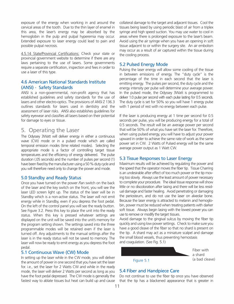
5.3 Tissue Responses to Laser EnergyMaximum results will be achieved by regulating the power andthe speed that the operator moves the fiber tip. Tissue Charringis an undesirable after effect of too much power or the tip mov-ing too slowly. Always use the least amount of power necessaryto complete your procedure. The ideal tissue response will showlittle or no discoloration after lasing and there will be less resid-ual damage and faster healing. Avoid penetrating or damagingthe periosteum, and do not use the laser on alveolar bone.Because the laser energy is attracted to melanin and hemoglo-bin, power must be reduced when treating patients with darkersoft tissue. Always begin lasing with the lowest power you canuse to remove or modify the target tissues.Avoid damage to the gingival sulcus by moving the fiber tipquickly and using low power settings. Check to make sure youhave a good cleave of the fiber so that no shard is present onthe tip. A shard may act as a miniature scalpel and damagethe small blood vessels, thus preventing hemostasis and coagulation. (See Fig. 5.1)
Figure 5.1
5.4 Fiber and Handpiece CareDo not continue to use the fiber tip once you have observedthat the tip has a blackened appearance that is greater in
Fiber witha shard(a bad cleave)
length than 2-4 mm from the previous cleave spot. See (Figure6.1) The protein debris of gingival tissue accumulates on thetip during surgery and retains extreme heat that can causerapid tip deterioration and subsequent breakage. This is especially important when using the laser for periodontalpocket debridement. During surgery, clean the tip often usinga 2 X 2 sponge moistened with water. Do not use alcohol orother combustible liquids to moisten the 2 X 2 gauze spongeand do not use the sponge while the tip is hot. Always use acold disinfectant solution like BIREX to wipe off the fiber jacket before retracting the fiber. The fiber can be advancedor retracted by using the “rocker switch” on the top of thefiber cassette.
The fiber cassette is a removable assembly with a plug-incapability that provides power for the internal retractiondevice. This cassette is disposable after all fiber has beenused. This cassette is not autoclavable.
“In vitro studies performed at the University at Buffalo validate thatthe infection control measures indicated by Ivoclar Vivadent can prevent the transmission of oral microorganisms between sites in apatient's mouth and between patients.”
Dr. Violet L. HaraszthyAssistant Professor of Restorative Dentistry
Dr. Joseph J. Zambon Professor of Periodontics and Endodontics University at Buffalo, School of Dental Medicine
Be advised about the potential hazards when inserting, steeplybending or improperly securing the fiberoptics to the chassis.Radiation exposure may occur in these instances which could beharmful to yourself, your staff and your patient. Special careshould be taken not to break or snap the fiber.
As the Aiming Beam passes down the same delivery system asthe Working Beam, it provides a good method of checking forintegrity of the delivery system. If the aiming beam spot is notpresent at the distal end of the delivery system, its intensity isreduced or it looks diffused, this is a possible indication of a damaged or not properly working delivery system.
The handpiece should be autoclaved after each patient and anew disposable tip applied. Recommended autoclave cycle is132˚C at 27 psi for 15 min. Be sure to remove the fiber lock-ing clasp and disposable tip prior to autoclaving as these partswill melt in the autoclave.
5.5 WARNING- !!!! DO NOT PLACE THE FIBER AND FIBERCASSETTE IN THE AUTOCLAVE TO STERILIZE THE SYSTEM.USE COLD DISINFECTING SOLUTIONS TO WIPE DOWN THEFIBER AND THE EXTERIOR OF THE LASER FIBER CASSETTE.
5.6 Systems Procedures5.6.1 Treatment Area Requirements: The laser should beplaced in an area with good ventilation and lighting. The electrical service required is a 110 Volt AC outlet - 60 Hz. Thearea where the laser is placed should be free of standingwater. Combustible gases or those that support combustionshould be turned off and all flammable materials or chemicalsstored in the area should be removed.
5.6.3 Fiber Cassette: Before using the laser, check the fibercassette to see that it is firmly seated. Depress the extend/retract rocker switch on the cassette to see that it is functioning properly. After Checking the Fiber Cassette Power,extend some fiber from the cassette.
5.6.4 Fiber Preparation: You will want to have approximately3 feet (1 meter) of fiber available to strip the fiber, cleave thefiber, initiate the fiber and disinfect the fiber (See Section 6.1).When the fiber is prepared, the handpiece and tip should beattached (See Section 6.3). Once prepared place the handpieceinto the holder on the side of the laser. See Figures 3.7 and3.7a on page 7. The rocker switch for fiber cassette operationshould not be depressed during laser operation.
5.6.5 Emergency Shutdown Button: Check the EmergencyShutdown Button to see that it has not been depressed. If it has,release it by depressing it slightly as you turn it 1/4 turn to the right.
5.6.6 Key Switch: Turn the Key Switch on the front of the laser to the“on” position by turning it approximately 1/4 turn to the right (clockwise).The control panel should light up and show the laser is in Standby Mode.
5.6.7 Setting Parameters: Review your power and moderequirements and then depress the mode button to selecteither Continuous (CW) or pulsed mode. The mode you haveselected will be displayed just below the LED screen and willbe designated by a small light in the corner of either the pulseor CW panel display. See Figure 3.2a on page 6.
5.6.8 Select Your Power by pressing the up or down arrowuntil you have reached the desired Wattage. Beginning witha low of 0.1 Watts, the power increases in increments of 100mW up to a maximum of 3 Watts (CW ). By holding the upor down arrow, you can have an un-interrupted increase untilyou reach your desired power.
5.6.9 Aiming Beam: The aiming beam can be turned on andoff by pressing the aiming beam button on the laser controlpanel. Press this button to progressively increase the aimingbeam intensity from 0 (off) to full intensity. Press the key oncemore to cycle back to 0. Each bar represents approximately20% of the aiming beam output. Note: that adjusting the intensity of the aiming beam,has no effect on the output power of the primary laser.
5.6.10 Examine the Fiber Tip to insure that you have notcreated a fiber tip shard during the cleaving process. Theshard can act like a miniature scalpel and cause damage whilediffusing the light beam and lowering the laser’s power. SeeSection 6.1 for fiber preparation.
12
13
5.6.11 Depress the Ready Button and the aiming beamshould light after 2 seconds. Review your power and moderequirements and then depress the mode button to selecteither CW or pulsed mode.
5.6.12 Test Fire the Laser outside the mouth by activating thelaser into a 2 X 2 gauze sponge that has been wetted withwater to prevent combustion. Do not use flammable liquidsto wet the sponge.
5.6.13 Depress the Foot Pedal and make short quick strokesat the lowest power that you can to remove the target tissueswhile lightly contacting it.
5.6.14 Remove Your Foot from the foot pedal and use a clean2 X 2 gauze sponge wetted with water to remove debris fromthe fiber tip. Do not use flammable liquids to wet the sponge.
5.6.15 Place the Laser in Standby Mode until you are ready tostart another procedure.
5.6.16 Cleave used fiber tip and discard in suitable biowastedisposal.
5.6.17 Wipe the Outside of the Fiber using a disinfectant orsterilization solution and then retract the fiber by depressingthe back of the rocker switch. Do not retract the distal end ofthe fiber into the cassette.
5.6.18 Turn the Key Off if you are not going to be startinganother procedure.
5.6.19 Record the Powers and total lasing times used for eachprocedure in the patient’s chart. Example:
Patient Name: Mary Jones Procedure: Gingivectomy # 6 and # 7 #6 Lasing time 90 seconds @ 2.0 Watts CW air cooled #7 Lasing time 60 seconds @ 1.5 Watts CW air / water spray
5.6.20 Odyssey 3Watt Self Diagnostic and Monitoring: Whenthe Odyssey 3Watt Laser’s microprocessor detects an issuewith performance it will immediately notify you by way of an audible beep. There are two different ways in which theOdyssey 3Watt will alert you to any issues:
1. Continuous audible beep when foot pedal is engaged.If you are operating the Odyssey 3Watt with the foot pedalengaged and the Odyssey 3Watt emits a constant audiblebeep and stops the beep when you release the foot pedal, themicroprocessor has determined that the laser power outputhas fallen below the set level. In this event the Odyssey 3WattLaser should be turned off and allowed to sit for 5 minutesthen turned on again. If the Odyssey 3Watt then performswithout beeping, the microprocessor has been able to makeoperational adjustments to the laser and the unit will performits functions. If, however, upon restart the unit continues tobeep when the foot pedal is engaged, the microprocessorwas unable to adjust the unit enough and the unit will needto be sent in for adjustment. (8.2 Repairs & Returns to IvoclarVivadent, Inc.)
2. Continuous audible beep when the unit is turned on. If you are operating the Odyssey 3Watt and it emits a con-stant audible beep whether or not the foot pedal is engaged,the microprocessor has determined that the laser has eitherlow power or a general fault has occurred. In this event theOdyssey 3Watt Laser should be turned off allowed to sit for 5minutes and turned on again. If the Odyssey 3Watt then performs without beeping the microprocessor has been ableto make operational adjustments to the laser and the unit willperform its functions. If, however, upon restart the unit continues to beep, the microprocessor was unable to adjustthe unit enough and the unit will need to be sent in for adjustment. (8.2 Repairs & Returns to Ivoclar Vivadent, Inc.)
6. System Components:Preparations, Care and MaintenanceThe fiber optic element of a laser is responsible for carryingthe light from the diode array to the tissue being treated. Thedental laser fibers are usually made of quartz, sapphire, silicaor a combination of those elements. Quartz/silica is the mostpopular product used in diode lasers.
Be advised about the potential hazards when inserting, steeplybending or improperly securing the fiberoptics to the chassis.Radiation exposure may occur in these instances which could beharmful to yourself, your staff and your patient. Special careshould be taken not to break or snap the fiber.
As the Aiming Beam passes down the same delivery system asthe Working Beam, it provides a good method of checking forintegrity of the delivery system. If the aiming beam spot is notpresent at the distal end of the delivery system, its intensity is reduced or it looks diffused, this is a possible indication of adamaged or not properly working delivery system.
6.0 Disposable Fiber CassetteThe fiber cassette is a removable assembly with a plug-incapability that provides power for the internal retractiondevice. This cassette is disposable after all fiber has beenused. This cassette is not autoclavable.
“The retractable fiber also provides an opportunity to use a variationof the “single use disposable” concept infection control. Each timethe laser fiber is prepared for use, the previously used terminal endis cleaved and discarded. The newly exposed, never used, portion of the fiber is then inserted into a sterilized handle and disposable tip. In my opinion the Odyssey® Laser complies with CDC recommendations, and OSHA expectations for critical (Spaulding classification) items used in dentistry.”Terrence J. Thines, D.D.S., M.S.Chair-Infection Control Committee Department of Oral Dionastic SciencesSchool of Dental MedicineState University of New York at Buffalo
14
6.0.1 Replacing the Fiber Cassette: A black mark on the fiberindicates 6’ of fiber remaining on the cassette. At this point,a new fiber cassette should be ordered. When the cassette isempty, it should be released from the laser aperture and gently removed. Slowly lift the cassette up using the dove tail as a guide. The fiber cartridge can be thrown away. Note: Retain the end cap, do not discard the end cap.Review the installation procedure again on page 5.
6.1 Fiber PreparationThe fiber cassette contains approximately 20’ (6 meters +) andis wound onto a spool. The fiber itself has three components:
• Jacket• Cladding• 400 micron quartz/silica fiber
6.1.1 Jacket: This is the protective cover for the fiber systemand usually is made of a synthetic material that is clear orwhite in color. There can be other colors used but there areno standardized color systems to denote the diameter of thefiber or its use.
6.1.2 Cladding: This is the material on the outside of thequartz/silica fiber that is used to block the lateral escape of laserenergy as it traverses the fiber. During stripping, you may“nick” the cladding and you will likely see the red aiming beamlight as it escape the site of the damage. This is not a danger ifall people in the area have the appropriate safety eyewear.
6.1.3 Quartz/Silica Fiber: The fiber is fairly flexible but can bebroken if bent into a small circle or bent at an angle of 90degrees. The cladding will burn as protein from the gingivaaccumulates on the fiber and will deteriorate the tip. It canfracture if not cleaved once the blackened area has reached3-4 mm. Stop lasing and wipe off the tip regularly as youwork to avoid accumulation of protein debris. Use water ona 2X2 gauze sponge to clean the tip. Do not use flammablematerials like alcohol products when cleaning a hot tip.Dispose of all small fiber remnants after you have cleaved thefiber. They should be kept in a small box with a lid until theycan be properly disposed of in the “sharps” container.
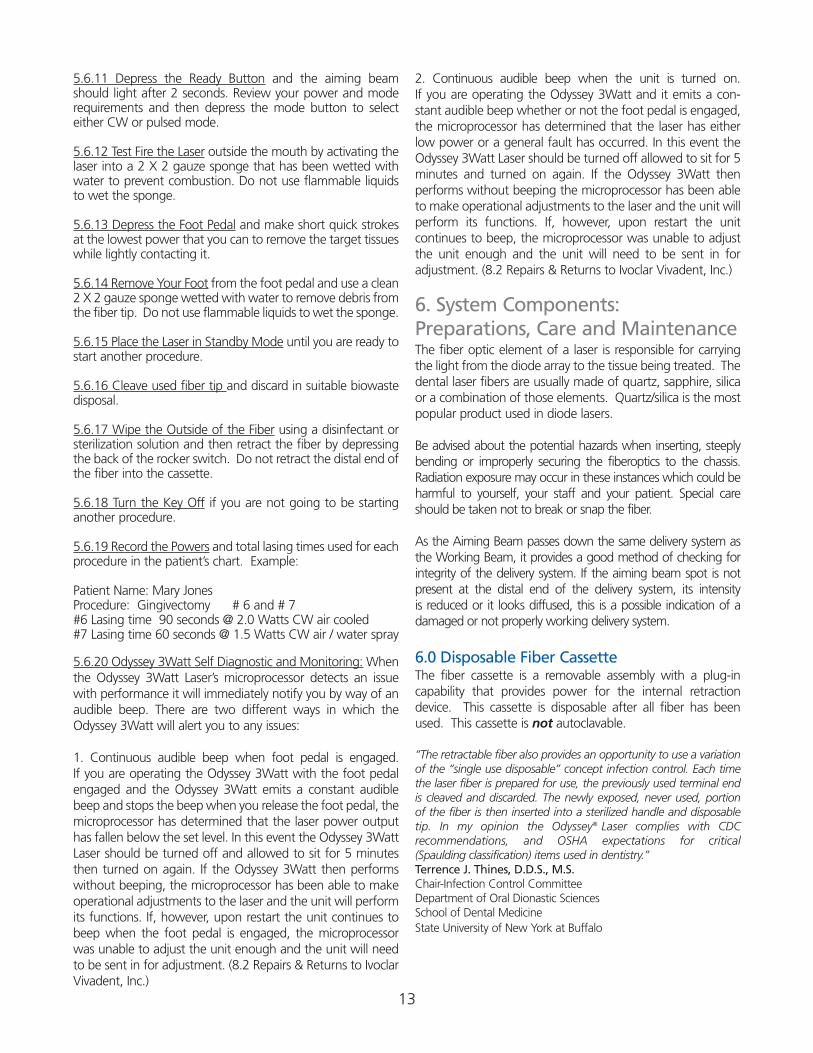
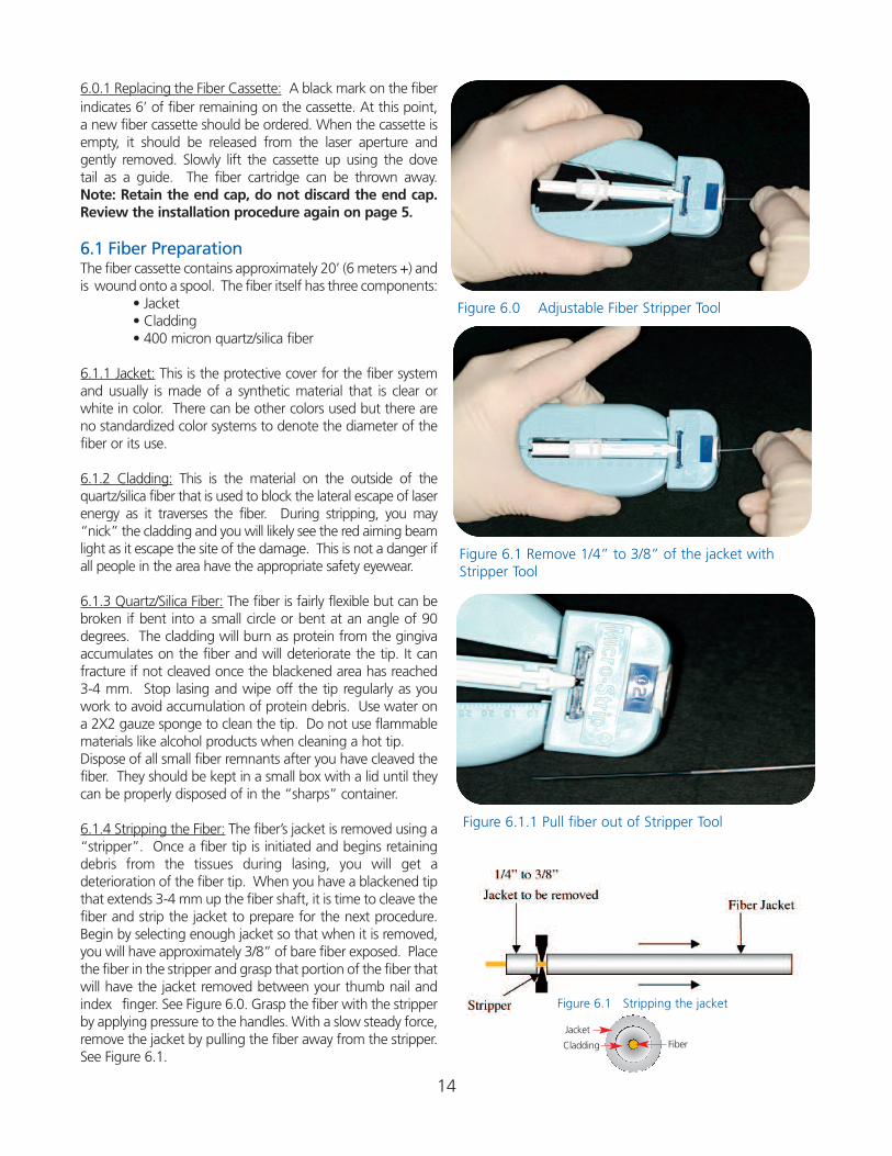
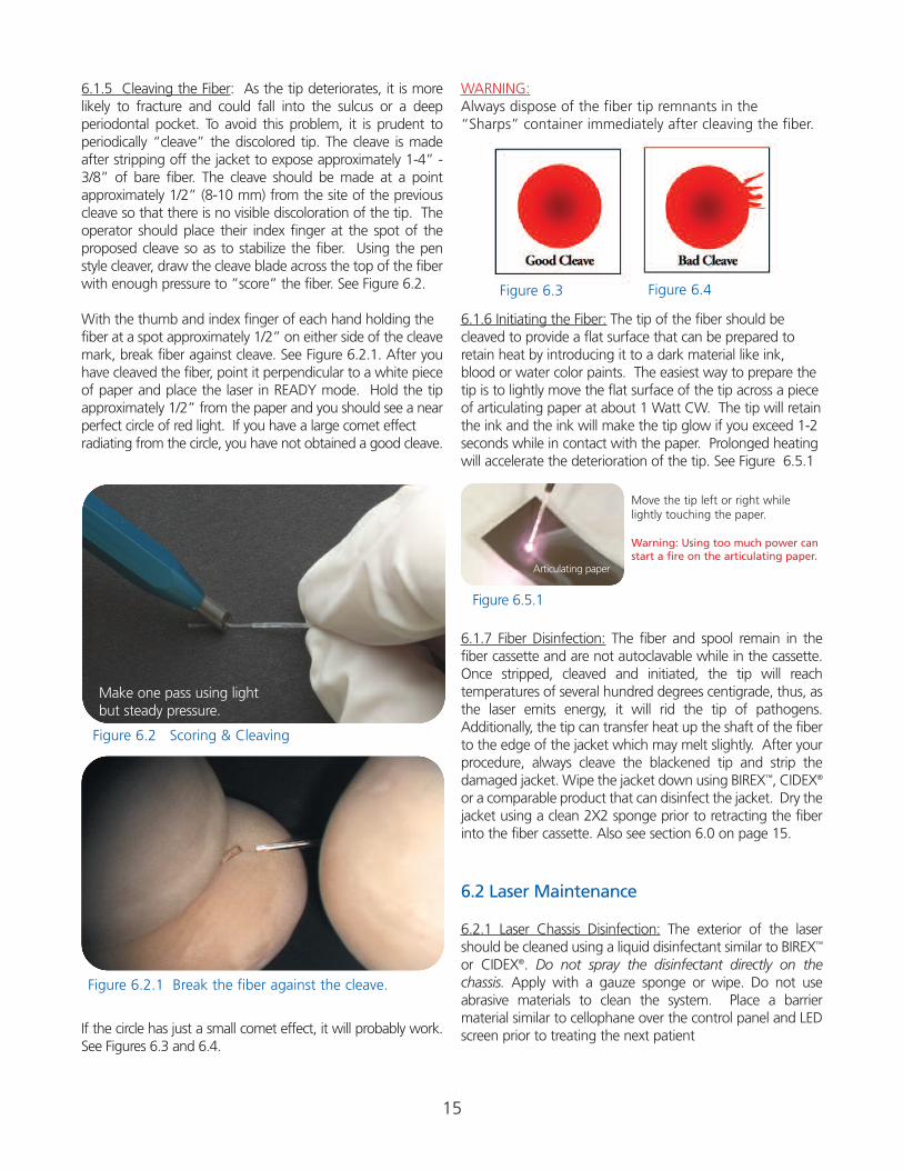
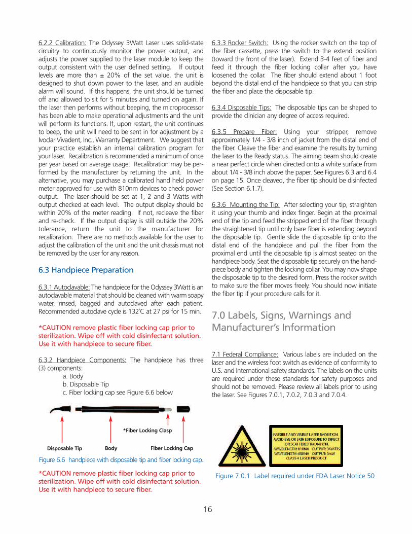
6.1.4 Stripping the Fiber: The fiber’s jacket is removed using a“stripper”. Once a fiber tip is initiated and begins retainingdebris from the tissues during lasing, you will get a deterioration of the fiber tip. When you have a blackened tipthat extends 3-4 mm up the fiber shaft, it is time to cleave thefiber and strip the jacket to prepare for the next procedure.Begin by selecting enough jacket so that when it is removed,you will have approximately 3/8” of bare fiber exposed. Placethe fiber in the stripper and grasp that portion of the fiber thatwill have the jacket removed between your thumb nail andindex finger. See Figure 6.0. Grasp the fiber with the stripperby applying pressure to the handles. With a slow steady force,remove the jacket by pulling the fiber away from the stripper.See Figure 6.1.
Figure 6.1 Remove 1/4” to 3/8” of the jacket withStripper Tool
Figure 6.1.1 Pull fiber out of Stripper Tool
Figure 6.0 Adjustable Fiber Stripper Tool
Figure 6.1 Stripping the jacket
Cladding
Jacket
Fiber
15
6.1.5 Cleaving the Fiber: As the tip deteriorates, it is morelikely to fracture and could fall into the sulcus or a deep periodontal pocket. To avoid this problem, it is prudent toperiodically “cleave” the discolored tip. The cleave is madeafter stripping off the jacket to expose approximately 1-4” -3/8” of bare fiber. The cleave should be made at a point approximately 1/2” (8-10 mm) from the site of the previouscleave so that there is no visible discoloration of the tip. Theoperator should place their index finger at the spot of the proposed cleave so as to stabilize the fiber. Using the penstyle cleaver, draw the cleave blade across the top of the fiber with enough pressure to ”score” the fiber. See Figure 6.2.
With the thumb and index finger of each hand holding the fiber at a spot approximately 1/2” on either side of the cleavemark, break fiber against cleave. See Figure 6.2.1. After youhave cleaved the fiber, point it perpendicular to a white pieceof paper and place the laser in READY mode. Hold the tipapproximately 1/2” from the paper and you should see a nearperfect circle of red light. If you have a large comet effect radiating from the circle, you have not obtained a good cleave.
If the circle has just a small comet effect, it will probably work.See Figures 6.3 and 6.4.
WARNING:Always dispose of the fiber tip remnants in the“Sharps” container immediately after cleaving the fiber.
6.1.6 Initiating the Fiber: The tip of the fiber should becleaved to provide a flat surface that can be prepared toretain heat by introducing it to a dark material like ink,blood or water color paints. The easiest way to prepare thetip is to lightly move the flat surface of the tip across a pieceof articulating paper at about 1 Watt CW. The tip will retainthe ink and the ink will make the tip glow if you exceed 1-2 seconds while in contact with the paper. Prolonged heatingwill accelerate the deterioration of the tip. See Figure 6.5.1
6.1.7 Fiber Disinfection: The fiber and spool remain in thefiber cassette and are not autoclavable while in the cassette.Once stripped, cleaved and initiated, the tip will reach temperatures of several hundred degrees centigrade, thus, asthe laser emits energy, it will rid the tip of pathogens.Additionally, the tip can transfer heat up the shaft of the fiberto the edge of the jacket which may melt slightly. After yourprocedure, always cleave the blackened tip and strip the damaged jacket. Wipe the jacket down using BIREX™, CIDEX®
or a comparable product that can disinfect the jacket. Dry thejacket using a clean 2X2 sponge prior to retracting the fiberinto the fiber cassette. Also see section 6.0 on page 15.
6.2 Laser Maintenance
6.2.1 Laser Chassis Disinfection: The exterior of the lasershould be cleaned using a liquid disinfectant similar to BIREX™
or CIDEX®. Do not spray the disinfectant directly on the chassis. Apply with a gauze sponge or wipe. Do not use abrasive materials to clean the system. Place a barrier material similar to cellophane over the control panel and LEDscreen prior to treating the next patient
Figure 6.3 Figure 6.4
Move the tip left or right whilelightly touching the paper.
Warning: Using too much power canstart a fire on the articulating paper.
Figure 6.5.1
Articulating paper
Figure 6.2.1 Break the fiber against the cleave.
Make one pass using light but steady pressure.
Figure 6.2 Scoring & Cleaving
16
6.2.2 Calibration: The Odyssey 3Watt Laser uses solid-state circuitry to continuously monitor the power output, andadjusts the power supplied to the laser module to keep theoutput consistent with the user defined setting. If output levels are more than ± 20% of the set value, the unit isdesigned to shut down power to the laser, and an audiblealarm will sound. If this happens, the unit should be turnedoff and allowed to sit for 5 minutes and turned on again. Ifthe laser then performs without beeping, the microprocessorhas been able to make operational adjustments and the unitwill perform its functions. If, upon restart, the unit continuesto beep, the unit will need to be sent in for adjustment by aIvoclar Vivadent, Inc., Warranty Department. We suggest thatyour practice establish an internal calibration program foryour laser. Recalibration is recommended a minimum of onceper year based on average usage. Recalibration may be per-formed by the manufacturer by returning the unit. In thealternative, you may purchase a calibrated hand held powermeter approved for use with 810nm devices to check poweroutput. The laser should be set at 1, 2 and 3 Watts with output checked at each level. The output display should bewithin 20% of the meter reading. If not, recleave the fiberand re-check. If the output display is still outside the 20% tolerance, return the unit to the manufacturer for recalibration. There are no methods available for the user toadjust the calibration of the unit and the unit chassis must notbe removed by the user for any reason.
6.3 Handpiece Preparation
6.3.1 Autoclavable: The handpiece for the Odyssey 3Watt is anautoclavable material that should be cleaned with warm soapywater, rinsed, bagged and autoclaved after each patient.Recommended autoclave cycle is 132˚C at 27 psi for 15 min.
*CAUTION remove plastic fiber locking cap prior tosterilization. Wipe off with cold disinfectant solution.Use it with handpiece to secure fiber.
6.3.2 Handpiece Components: The handpiece has three (3) components:
a. Bodyb. Disposable Tipc. Fiber locking cap see Figure 6.6 below
*CAUTION remove plastic fiber locking cap prior tosterilization. Wipe off with cold disinfectant solution.Use it with handpiece to secure fiber.
6.3.3 Rocker Switch: Using the rocker switch on the top ofthe fiber cassette, press the switch to the extend position(toward the front of the laser). Extend 3-4 feet of fiber andfeed it through the fiber locking collar after you have loosened the collar. The fiber should extend about 1 footbeyond the distal end of the handpiece so that you can stripthe fiber and place the disposable tip.
6.3.4 Disposable Tips: The disposable tips can be shaped toprovide the clinician any degree of access required.
6.3.5 Prepare Fiber: Using your stripper, remove approximately 1/4 - 3/8 inch of jacket from the distal end ofthe fiber. Cleave the fiber and examine the results by turningthe laser to the Ready status. The aiming beam should createa near perfect circle when directed onto a white surface fromabout 1/4 - 3/8 inch above the paper. See Figures 6.3 and 6.4on page 15. Once cleaved, the fiber tip should be disinfected(See Section 6.1.7).
6.3.6 Mounting the Tip: After selecting your tip, straightenit using your thumb and index finger. Begin at the proximalend of the tip and feed the stripped end of the fiber throughthe straightened tip until only bare fiber is extending beyondthe disposable tip. Gentle slide the disposable tip onto thedistal end of the handpiece and pull the fiber from the proximal end until the disposable tip is almost seated on thehandpiece body. Seat the disposable tip securely on the hand-piece body and tighten the locking collar. You may now shapethe disposable tip to the desired form. Press the rocker switchto make sure the fiber moves freely. You should now initiatethe fiber tip if your procedure calls for it.
7.0 Labels, Signs, Warnings andManufacturer’s Information
7.1 Federal Compliance: Various labels are included on thelaser and the wireless foot switch as evidence of conformity toU.S. and International safety standards. The labels on the unitsare required under these standards for safety purposes andshould not be removed. Please review all labels prior to usingthe laser. See Figures 7.0.1, 7.0.2, 7.0.3 and 7.0.4.
Disposable Tip Body Fiber Locking Cap
*Fiber Locking Clasp
Figure 6.6 handpiece with disposable tip and fiber locking cap.
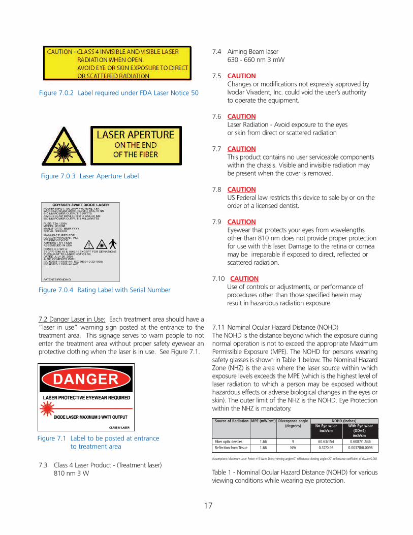
Figure 7.0.1 Label required under FDA Laser Notice 50
Source of Radiation MPE (mW/cm2) Divergence angle NOHD (inches)(degrees) No Eye wear With Eye wear
inch/cm (OD=4)inch/cm
Fiber optic devices 1.66 9 60.63/154 0.6087/1.546
Reflection from Tissue 1.66 N/A 0.37/0.96 0.00378/0.0096
Figure 7.0.2 Label required under FDA Laser Notice 50
Figure 7.1 Label to be posted at entrance to treatment area
Figure 7.0.3 Laser Aperture Label
Figure 7.0.4 Rating Label with Serial Number
7.2 Danger Laser in Use: Each treatment area should have a“laser in use” warning sign posted at the entrance to thetreatment area. This signage serves to warn people to notenter the treatment area without proper safety eyewear anprotective clothing when the laser is in use. See Figure 7.1.
7.3 Class 4 Laser Product - (Treatment laser)810 nm 3 W
7.4 Aiming Beam laser630 - 660 nm 3 mW
7.5 CAUTIONChanges or modifications not expressly approved byIvoclar Vivadent, Inc. could void the user’s authority to operate the equipment.
7.6 CAUTIONLaser Radiation - Avoid exposure to the eyes or skin from direct or scattered radiation
7.7 CAUTIONThis product contains no user serviceable components within the chassis. Visible and invisible radiation may be present when the cover is removed.
7.8 CAUTIONUS Federal law restricts this device to sale by or on theorder of a licensed dentist.
7.9 CAUTIONEyewear that protects your eyes from wavelengths other than 810 nm does not provide proper protection for use with this laser. Damage to the retina or cornea may be irreparable if exposed to direct, reflected or scattered radiation.
7.10 CAUTIONUse of controls or adjustments, or performance of procedures other than those specified herein mayresult in hazardous radiation exposure.
7.11 Nominal Ocular Hazard Distance (NOHD)The NOHD is the distance beyond which the exposure duringnormal operation is not to exceed the appropriate MaximumPermissible Exposure (MPE). The NOHD for persons wearingsafety glasses is shown in Table 1 below. The Nominal HazardZone (NHZ) is the area where the laser source within whichexposure levels exceeds the MPE (which is the highest level oflaser radiation to which a person may be exposed withouthazardous effects or adverse biological changes in the eyes orskin). The outer limit of the NHZ is the NOHD. Eye Protectionwithin the NHZ is mandatory.
Assumptions: Maximum Laser Power = 5 Watts Direct viewing angle=0˚, reflectance viewing angle=20˚, reflectance coefficient of tissue=0.001
Table 1 - Nominal Ocular Hazard Distance (NOHD) for variousviewing conditions while wearing eye protection.
17
18
8.0 Servicing
8.1 Warranty PolicyThe Odyssey 3Watt Diode Laser is warranted against defectivematerials and workmanship for a period of one (1) year fromthe date of purchase, and will be repaired or replaced, at ourdiscretion, if returned prepaid to our factory. This warrantydoes not cover damage to the Odyssey 3Watt Diode Laserunit or components caused by accident, misuse, or being tampered with. This warranty does not include labor,postage, or delivery charges. This warranty does not apply tothe external finish of the console, handpiece, fiber, powercord, foot pedal. Ivoclar Vivadent reserves the right to makechanges in design or to modify such previously manufacturedproducts. Your Odyssey 3Watt Diode Laser warranty does notbecome effective unless the registration card is sent to usonline or in the mail within ten (10) days of the purchase, withall invoice and serial number information completely filled in.
8.2 Repairs & Returns to Ivoclar Vivadent, Inc.Should the laser fail to operate correctly and your local dealerrepresentative is unable to assist you, please call IvoclarVivadent Customer Service at (800) 533-6825 in the U.S. orat (800) 263-8162 in Canada to obtain a Return GoodsAuthorization (RGA) number for shipping purposes. Pleaseinsure that the RGA number is clearly marked on the box usedto return the laser. Please clearly state the reasons for return.Send returns to:
CAUTION! Do not attempt to removethe cover from the laser chassis for thepurpose of repairing the laser. SeriousInjury from an electrical shock or laser radiation could occur. Removing the coveron the laser chassis will void the warranty.
CAUTION! Use of controls or adjustmentsor performance of procedures other thanthose specified herein may result in hazardous radiation exposure.
9.0: Glossary of Laser Terminology
Activate - The action that prepares the laser to emit energy.
Active Medium - The core material of a laser that is responsiblefor producing a source of electromagnetic energy when activatedby a power supply. They can be a gas, liquid dye, semi-conductorchip or a man made rod of Yttrium, Aluminum Garnet, Scandiumor Gallium, or some combination of those elements.
Amplitude - The height of an electromagnetic wave as measuredfrom the top of one wave to the lowest point on the next wave.
Articulating arm - A device used to deliver radiant energy from aCO2 or Erbium laser using a series of mirrors located within a jointed arm.
Atom - The smallest particle of an element. It can exist alone or incombination with other atoms.
Biopsy - A tissue sample removed from an area of questionablehealth. Used for examination and diagnosis of a disease.
Cleave - An act of scoring an optical fiber so that it separates intotwo pieces
Coherent - A property of electromagnetic waves in which everywave is of the same wave length and is in phase with the otheridentical waves.
Collagen - The fibrous protein that is prevalent in bone, tendons,cartilage, and connective tissue.
Collimated - A characteristic of laser wave lengths where theytravel in a parallel bundle and are slow to deviate.
Continuous Wave - A temporal mode where radiant laser energyis emitted constantly for one second without interruption. Alsoknown as (CW).
Electromagnetic components of Energy - Radiation consistingof electromagnetic waves where the vertical of the wave is theelectrical phase and the lateral component is a magnetic phase.Laser light is electromagnetic energy.
Electromagnetic Waves - Time varying electric and magneticfields propagating through space. They vary in their wave lengthsand frequency.
Electromagnetic Spectrum - A combination of all electromag-netic radiation arranged by wave length and frequency. Light aswe know it is from the visible portion of the spectrum.
Exposure - Introducing a tissue to laser energy as measured by theintensity of the power, the frequency and time.
Frequency - The number of complete oscillations per second of anelectromagnetic wave.
In the United StatesIvoclar Vivadent, IncAttn: Warranty Department 4628 West Sky Hawk DriveWest Jordan, UT 84084
In CanadaIvoclar Vivadent, IncAttn: Warranty Department 2785 Skymark Ave., Unit 1Mississauga, ON L4W 4Y3
19
Joule - A unit of energy. Expressed as milliJoules when used indental lasers operating in the pulsed mode.1000 MilliJoules persecond equal 1 Watt.
Laser - An acronym for Light Amplification by Stimulated Emissionof Radiation. Lasers are devices that utilize standard electricity froma wall outlet to stimulate an active medium which will produceelectromagnetic energy that is collimated, coherent and monochromatic.
Micron - One millionth of a meter. It can also be stated as 10-6
meter.
Mode - A stable condition of oscillation in a laser. Lasers can operate is one or more modes.
Molecule - The smallest particle of a substance that retains theproperty of that substance. It is composed of one or more atoms.
Nanometer - A billionth of a meter and can also be expressed as10-9. Nanometers and microns are the primary measures of a wavelength used in dental lasers.
Photon - A quantum (unit) of radiant energy. A particle of light.
Power (output power) - Expressed as Watts where1 Joule persecond equals 1 Watt.
Power Density - A measure of exposure of the power in Wattsdelivered per square millimeter or square centimeter.
Pulsed - A temporal emission of laser energy that is distributedamong periods where the laser is actively emitting (on) and periodsof no emission (off). The time period when the laser is not emit-ting energy (off) is referred to as period of thermal relaxation and isdesigned to allow the tissue to cool between bursts of energy.
Quantum - The smallest unit of measure for radiant (light) energy.
Radiant energy - The vertical component of electromagneticwaves as they travel through space. It is measured in Joules ormilliJoules.
Spontaneous Emission - As an electron accumulates incidentenergy, it is elevated to a higher energy orbit where it will becomeunstable and most emit a photon.
Stimulated Emission - An external source of energy from apower supply stimulates the unstable electron to return to a morestable energy level by emitting an additional photon.
Velocity - The rate of speed of an electromagnetic wave as it trav-els through space
Watt - The measure of power is Watts. As used in lasers,1 Joule per second is equal to 1 Watt.
10.0 Selected Referenceson Laser Dentistry
Leo Meserindino, D.D.S. and Robert Pick, D.D.S., Lasers inDentistry, 1995 by Quintessence Books
Jeffrey G. Manni, Dental Applications of Advanced Lasers.JGM Associates, Burlington MA Contact at (781) 272-6692
The Institute for Advanced Dental Technologies, Southfield, MI:“ Lasers Dentistry: Clinical Training Seminars” copyright in 1966
D.J.Coluzzi, “ An overview of laser wave lengths used indentistry”. Chapter in The Dental Clinics of North American:Convissar, Robert A. editor, “Lasers and Light Amplificationin Dentistry”, W.B. Saunders Company, 44(4): 753-765,October 2000
Andreas Moritz, et.al. “Treatment of periodontal pocketswith a diode laser”. Lasers in Surgery and Medicine, volume22, pages 302- 311. 1998
M. Kreisler, et.al., “Effects of Diode Laser Irradiation on theSurvival Rate of Gingival Fibroblast Cell Cultures”, LasersSurg Med, vol 28(5): 445-450, 2001
P. Spencer et.al. “Change of temperature in subjacent boneduring soft tissue laser ablation”, Journal of Periodontology,volume 69 (11) 1998
Nora Raffetto and Terri Gutierrez, “Lasers in periodontaltherapy, a five year retrospective”, California Dental HygieneAssociation Journal, volume 16 (2) pages 17-20 RedondoBeach, CA 2001
American National Standard Institute Standard Z136.3. Safeuse of Lasers in Health Care Facilities.
20
11.0 Troubleshooting
Problem: Laser has no response.
Corrective Action: Check that the power cord is securelyplugged into back of the laser unit. See page 5.
Corrective Action: Check that the power switch on the backpanel is turned to the on (O) position. See page 5.
Corrective Action: Check that the Emergency button is inthe up position. If not, turn the button 1/4 turn to the rightto release the button. See page 6.
Corrective Action: Check the fiber cartridge and verify thatit is properly engaged. See pages 7 - 8.
Problem: Laser has power but no LED display.
Corrective Action: Check to see that the Fiber Cassette End Cap of the fiber cassette is securely engaged.See page 7 - 8.
Problem: Laser has power but no output.
Corrective Action: Check that the foot pedal is installed correctly. See page 5.
Corrective Action: Remove the fiber cartridge and check if the fiber connector is attached. See page 7 - 8.
Problem: Measured power output on a powermeter is different from the LED display.
Corrective Action: Make sure the power meter is calibratedfor use with 810 nm wavelength devices. See page 16.
Corrective Action: Review the fiber tip for a good cleave.See page 15.
Problem: Fiber does not move from the cartridge.
Corrective Action: Make sure the fiber cartridge is seatedproperly. See page 7 - 8.
Problem: Audible beep on Laser will not stopwhen laser is on.
Corrective Action: Turn laser off for 5 minutes. Turn laserback on. If beep stops, the unit was able to make opera-tional adjustments and the laser should perform its function.If the beep continues, the laser must be sent in for adjust-ment. (8.2 Repairs & Returns to Ivoclar Vivadent, Inc.)See page 18.
Problem: Audible beep on Laser will not stopwhen foot pedal is depressed.
Corrective Action: Turn laser off for 5 minutes. Turn laserback on. If beep stops, the unit was able to make opera-tional adjustments and the laser should perform its function.If the beep continues, the laser must be sent in for adjust-ment. (8.2 Repairs & Returns to Ivoclar Vivadent, Inc.)See page 18.
Learn more about Odyssey®3Watt at www.GetOdysseyLaser.com
Call us toll free at 1-800-533-6825 in the U.S., www.ivoclarvivadent.us ©2006 Ivoclar Vivadent, Inc. Odyssey 3Watt is a registered trademark of Ivoclar Vivadent, Inc. 603505 10/06
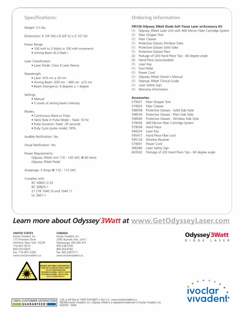
Specifications:
Weight: 5.5 lbs.
Dimensions: 6 1/4”(W) x 8 3/4”(L) x 5 1/2”(H)
Power Range:• 100 mW to 3 Watts in 100 mW increments• Aiming Beam (0.3 Watt )
Laser Classification:• Laser Diode: Class 4 Laser Device
Wavelength:• Laser: 810 nm ± 20 nm • Aiming Beam: 630 nm – 660 nm ±15 nm• Beam Divergence: 9 degrees ± 1 degree
Settings:• Manual• 5 Levels of aiming beam intensity
Modes:• Continuous Wave or Pulse• Hertz Rate in Pulse Mode – fixed: 10 Hz• Pulse Duration: fixed: .05 seconds• Duty Cycle (pulse mode): 50%
Audible Notification: Yes
Visual Notification: Yes
Power Requirements: Odyssey 3Watt Unit 110 - 120 VAC @ 60 HertzOdyssey 3Watt Pedal
Amperage: 3 Amps @ 110 - 115 VAC
Complies with:IEC 60601-2-22IEC 60825-121 CFR 1040.10 and 1040.11UL 2601-1
Ordering Information
595126 Odyssey 3Watt Diode Soft Tissue Laser w/Accessory Kit(1) Odyssey 3Watt Laser Unit with 400 Micron Fiber Cartridge System(1) Fiber Stripper Tool(1) Fiber Cleaver(1) Protective Glasses Window Sides(1) Protective Glasses Solid Sides(1) Protective Glasses Plain(2) Package of (20) Hand Piece Tips - 60 degree angle(2) Hand Piece (autoclavable)(1) Laser Key(1) Foot Pedal(1) Power Cord(1) Odyssey 3Watt Owner's Manual(1) Odyssey 3Watt Clinical Guide(1) Laser Safety Sign(1) Warranty Information
Accessories:579031 Fiber Stripper Tool579032 Fiber Cleaver598558 Protective Glasses - Solid Side Style598559 Protective Glasses - Plain Side Style598560 Protective Glasses - Window Side Style579036 400 Micron Fiber Cartridge System579038 Hand Piece594224 Laser Key595477 Hand Piece Fiber Lock595124 Wireless Receiver579041 Power Cord580280 Laser Safety Sign603502 Package of (20) Hand Piece Tips - 60 degree angle
UNITED STATESIvoclar Vivadent, Inc.175 Pineview DriveAmherst, New York 14228716-691-0010800-533-6825Fax: 716-691-2285www.ivoclarvivadent.us
CANADAIvoclar Vivadent, Inc.2785 Skymark Ave., Unit 1Mississauga, ON L4W 4Y3905-238-5700800-263-8182Fax: 905-238-5711www.ivoclarvivadent.ca
100% CUSTOMER SATISFACTION G U A R A N T E E D !
Odyssey®
3WattD I O D E L A S E R


![An Introduction to the Odyssey - New Providence School ... · An Introduction to the . Odyssey [End of Section] The . Odyssey . ... The Structure of the . Odyssey. The story begins](https://img.pdfslide.us/doc/110x75/5e7fbc824d346753aa429b99/an-introduction-to-the-odyssey-new-providence-school-an-introduction-to-the.jpg)