Embed Size (px)
Citation preview
2
www.odu-connectors.com
A PERFECT ALLIANCE.
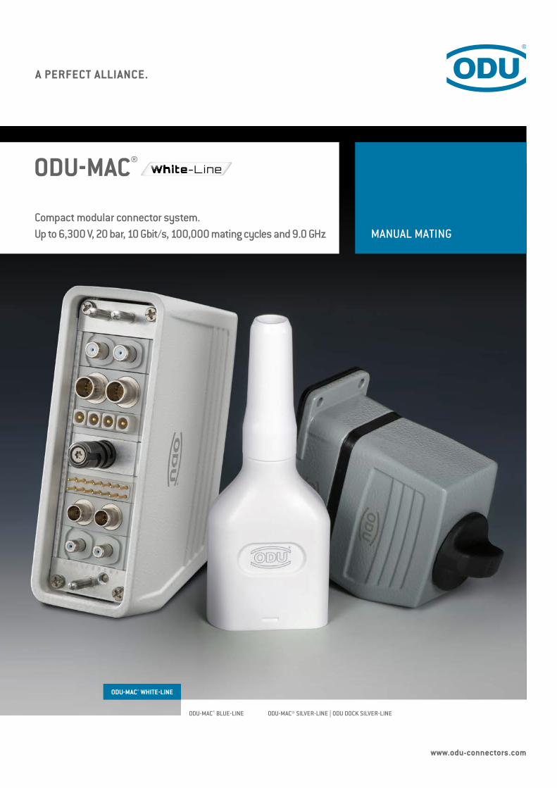
MANUAL MATINGCompact modular connector system.Up to 6,300 V, 20 bar, 10 Gbit/s, 100,000 mating cycles and 9.0 GHz
ODU-MAC®
ODU-MAC® WHITE-LINE
ODU-MAC® BLUE-LINE ODU-MAC® SILVER-LINE | ODU DOCK SILVER-LINE
3
ODU-MAC®
Non-magnetic ODU-MAC® ZERO
FEATURES
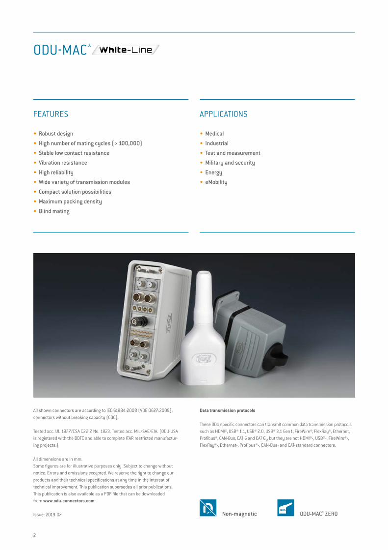
• Robust design
• High number of mating cycles (> 100,000)
• Stable low contact resistance
• Vibration resistance
• High reliability
• Wide variety of transmission modules
• Compact solution possibilities
• Maximum packing density
• Blind mating
APPLICATIONS
• Medical
• Industrial
• Test and measurement
• Military and security
• Energy
• eMobility
All shown connectors are according to IEC 61984:2008 (VDE 0627:2009); connectors without breaking capacity (COC).
Tested acc. UL 1977/CSA C22.2 No. 1823. Tested acc. MIL/SAE/EIA. (ODU-USA is registered with the DDTC and able to complete ITAR restricted manufactur-ing projects.)
All dimensions are in mm.Some figures are for illustrative purposes only. Subject to change without notice. Errors and omissions excepted. We reserve the right to change our products and their technical specifications at any time in the interest of technical improvement. This publication supersedes all prior publications. This publication is also available as a PDF file that can be downloaded from www.odu-connectors.com.
Issue: 2019-07
Data transmission protocols
These ODU specific connectors can transmit common data transmission protocols such as HDMI®, USB® 1.1, USB® 2.0, USB® 3.1 Gen1, FireWire®, FlexRay®, Ethernet, Profibus®, CAN-Bus, CAT 5 and CAT 6
A, but they are not HDMI®-, USB®-, FireWire®-,
FlexRay®-, Ethernet-, Profibus®-, CAN-Bus- and CAT-standard connectors.
2
3
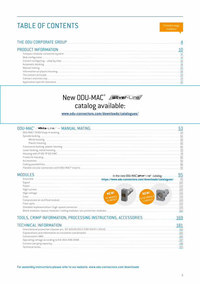
THE ODU CORPORATE GROUP 4
PRODUCT INFORMATION 10 Compact modular connector system 12 Web configurator 14 Correct configuring – step by step 16 Automatic docking 18 Manual mating 20 Information on plastic housing 28 The contact principle 30 Contact retention clip 34 Application specific solutions 36
ODU-MAC® – AUTOMATIC DOCKING. 39 Requirements on the complete system 40 ODU-MAC® S (Standard) 42 ODU-MAC® L (Large) 43 ODU-MAC® M+ (Mini) 44 ODU-MAC® P+ (Power) 45 PE transmission, grounding kit 46 ODU-MAC® T (Transverse) 48 ODU-MAC® QCH (Quick Change Head) 49 Strain relief housing 50
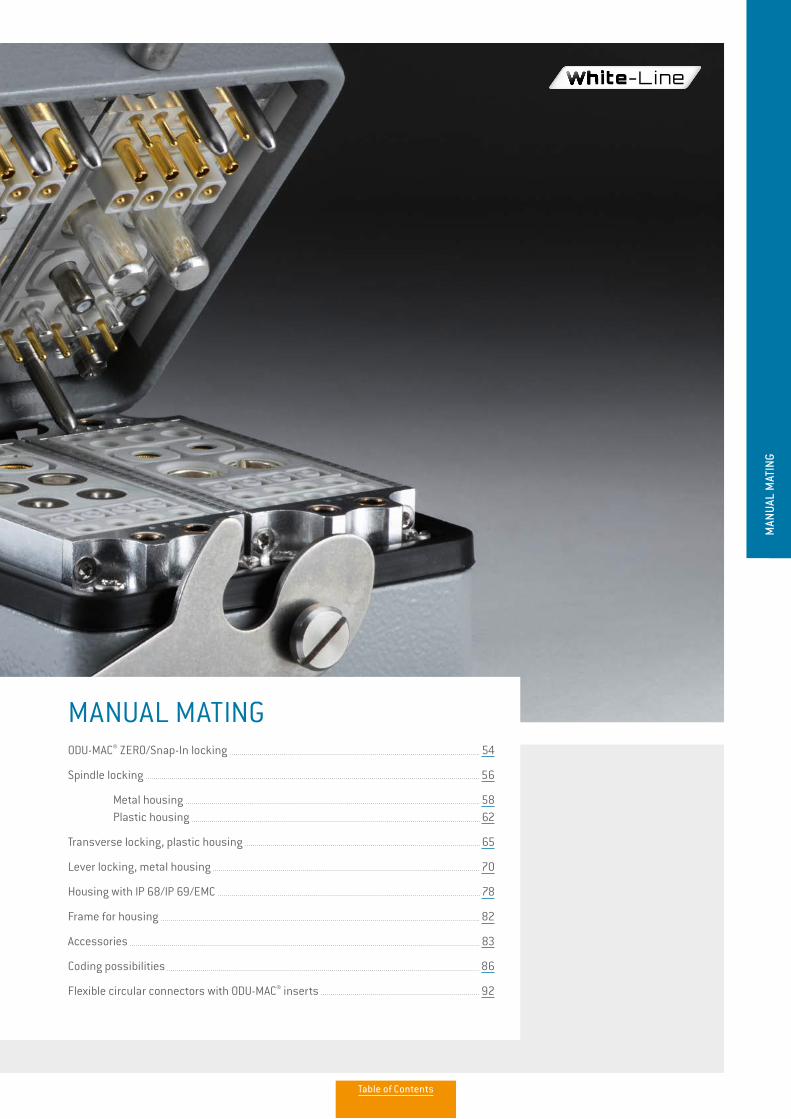
ODU-MAC® – MANUAL MATING. 53 ODU-MAC® ZERO/Snap-In locking 54 Spindle locking 56 Metal housing 58 Plastic housing 62 Transverse locking, plastic housing 65 Lever locking, metal housing 70 Housing with IP 68 / IP 69/ EMC 78 Frame for housing 82 Accessories 83 Coding possibilities 86 Flexible circular connectors with ODU-MAC® inserts 92
MODULES 95 Overview 96 Signal 102 Power 112 High current 120 High voltage 126 Coax 130 Compressed air and fluid module 140 Fiber optic 150 Shielded implementation / high-speed connector 156 Blank modules / spacer modules / coding modules / pin protection modules 164
TOOLS, CRIMP INFORMATION, PROCESSING INSTRUCTIONS, ACCESSORIES 169
TECHNICAL INFORMATION 181 International protection classes acc. IEC 60529:2013 (VDE 0470-1:2014) 182 Explanations and information on insulation coordination 183 Conversions / AWG 186 Operating voltage according to EIA-364-20D:2008 187 Current-carrying capacity 188 Technical terms 193
For assembly instructions please refer to our website: www.odu-connectors.com/downloads
TABLE OF CONTENTS
New ODU-MAC® Silver-Linecatalog available:
www.odu-connectors.com/downloads/catalogues/
NEW!PE-MODULE
1 CONTACT
NEW!
FLUID-MODULE
1 CONTACT
In the new ODU-MAC® catalog:https://www.odu-connectors.com/downloads/catalogues/
Clickable page numbers
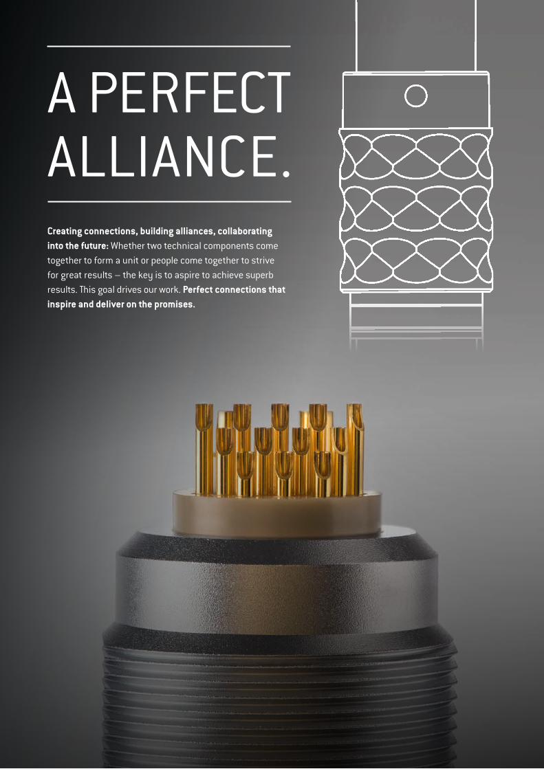
A PERFECT ALLIANCE.Creating connections, building alliances, collaborating into the future: Whether two technical components come together to form a unit or people come together to strive for great results – the key is to aspire to achieve superb results. This goal drives our work. Perfect connections that inspire and deliver on the promises.
WORLDWIDE
CUSTOMER PROXIMITY„
ODU Scandinavia AB
ODU Denmark ApS
ODU Mexico Manufacturing S.R.L. de C.V.
ODU GmbH & Co. KGHeadquartersODU-USA, Inc.
ODU North American Logistics
ODU Romania Manufacturing S.R.L.
ODU Italia S.R.L.
ODU France SARL
ODU-UK Ltd.
ODU (Shanghai) International Trading Co., Ltd.
ODU (Shanghai) Connectors Manufacturing Co.Ltd
ODU Korea Inc.
ODU Japan K.K.
ODU GROUP OVERVIEW
• More than 75 years of experience in connector technology
• A turnover of € 200 million
• Over 2,300 employees worldwide
• Sales subsidiaries in China, Denmark, France, Germany, Italy, Japan, Korea, Sweden, UK and the US as well as 5 production and logistics sites
• All technologies under one roof: Design and development, machine tool and special machine construction, injection, stamping, turning, surface technology, assembly and cable assembly
As of February 2019
CERTIFICATES & APPROVALS
• ISO 9001
• IATF 16949
• ISO 13485
• ISO 14001
• ISO 50001
• Wide range of UL, CSA, VG and VDE approvals
• UL Wiring Harnesses certified
For a complete list of our certifications and approvals, please visit our website.
2019-08_ImageSection_C_EN.indd 1-2 05.08.2019 12:39:04
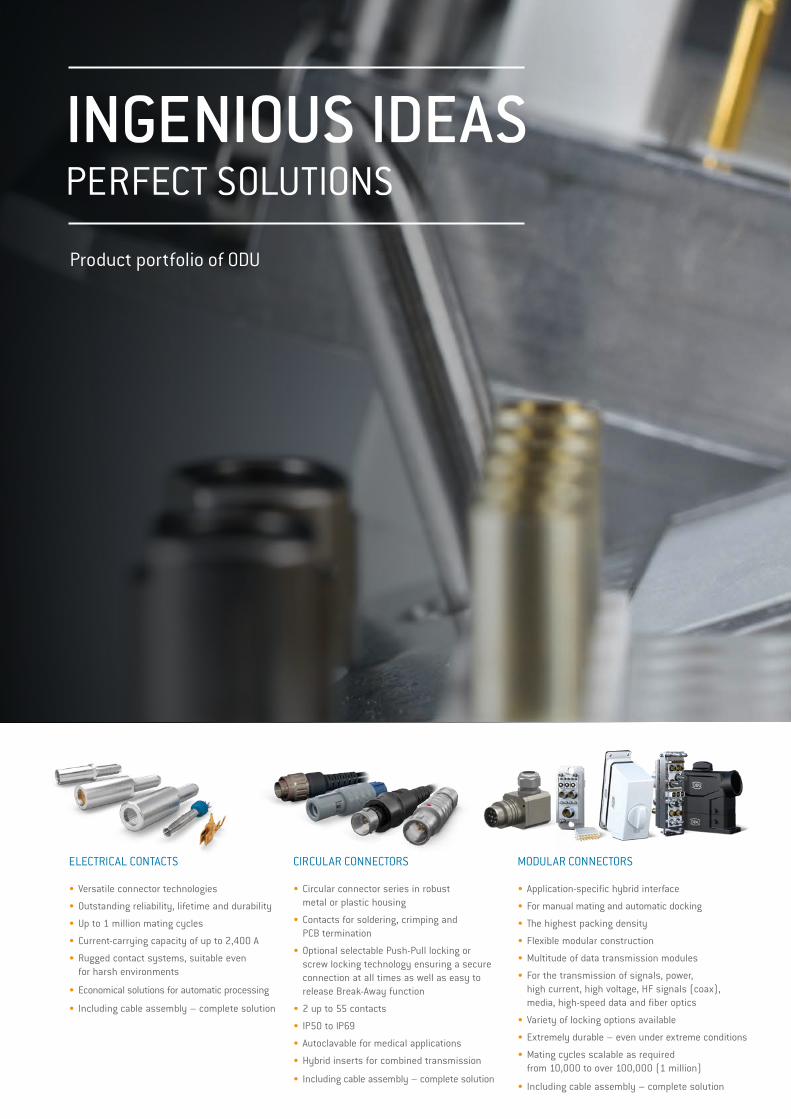
INGENIOUS IDEASPERFECT SOLUTIONS
Product portfolio of ODU
FOR A WIDE RANGE OF APPLICATIONS
VERSATILE
CONNECTORSOLUTIONS
„
• Contacts, connectors and cable assemblies for the highest technical requirements as well as special applications
• First-class implementation expertise
• High level of vertical manufacturing – all competences and key technologies under one roof
• Expert advice based on mutual partnership
• Short development and production paths
APPLICATION AND CUSTOMER-SPECIFIC SOLUTIONS
• Complete systems from a single source based on years of expertise
• State-of-the-art production facilities with 100 % end testing
• Cleanroom production
• Overmolding in silicone, hot-melt and high-pressure procedures
• Customer-specific labeling
• Prototype, small series and high volume production
• Rapid prototyping
CABLE ASSEMBLY
• Circular connector series in robust metal or plastic housing
• Contacts for soldering, crimping and PCB termination
• Optional selectable Push-Pull locking or screw locking technology ensuring a secure connection at all times as well as easy to release Break-Away function
• 2 up to 55 contacts
• IP50 to IP69
• Autoclavable for medical applications
• Hybrid inserts for combined transmission
• Including cable assembly – complete solution
CIRCULAR CONNECTORS
• Application-specific hybrid interface
• For manual mating and automatic docking
• The highest packing density
• Flexible modular construction
• Multitude of data transmission modules
• For the transmission of signals, power, high current, high voltage, HF signals (coax), media, high-speed data and fiber optics
• Variety of locking options available
• Extremely durable – even under extreme conditions
• Mating cycles scalable as required from 10,000 to over 100,000 (1 million)
• Including cable assembly – complete solution
MODULAR CONNECTORS
• Versatile connector technologies
• Outstanding reliability, lifetime and durability
• Up to 1 million mating cycles
• Current-carrying capacity of up to 2,400 A
• Rugged contact systems, suitable even for harsh environments
• Economical solutions for automatic processing
• Including cable assembly – complete solution
ELECTRICAL CONTACTS HEAVY DUTY CONNECTORS
PRINTED CIRCUIT BOARDS CONNECTORS
• Extremely durable even under extreme / harsh environments
• High vibration resistance
• Up to 400 A (higher currents upon request)
• Maximum flexibility in application designs
• High resilience and outstanding quality
• Including cable assembly – complete solution
2019-08_ImageSection_C_EN.indd 3-4 05.08.2019 12:39:27
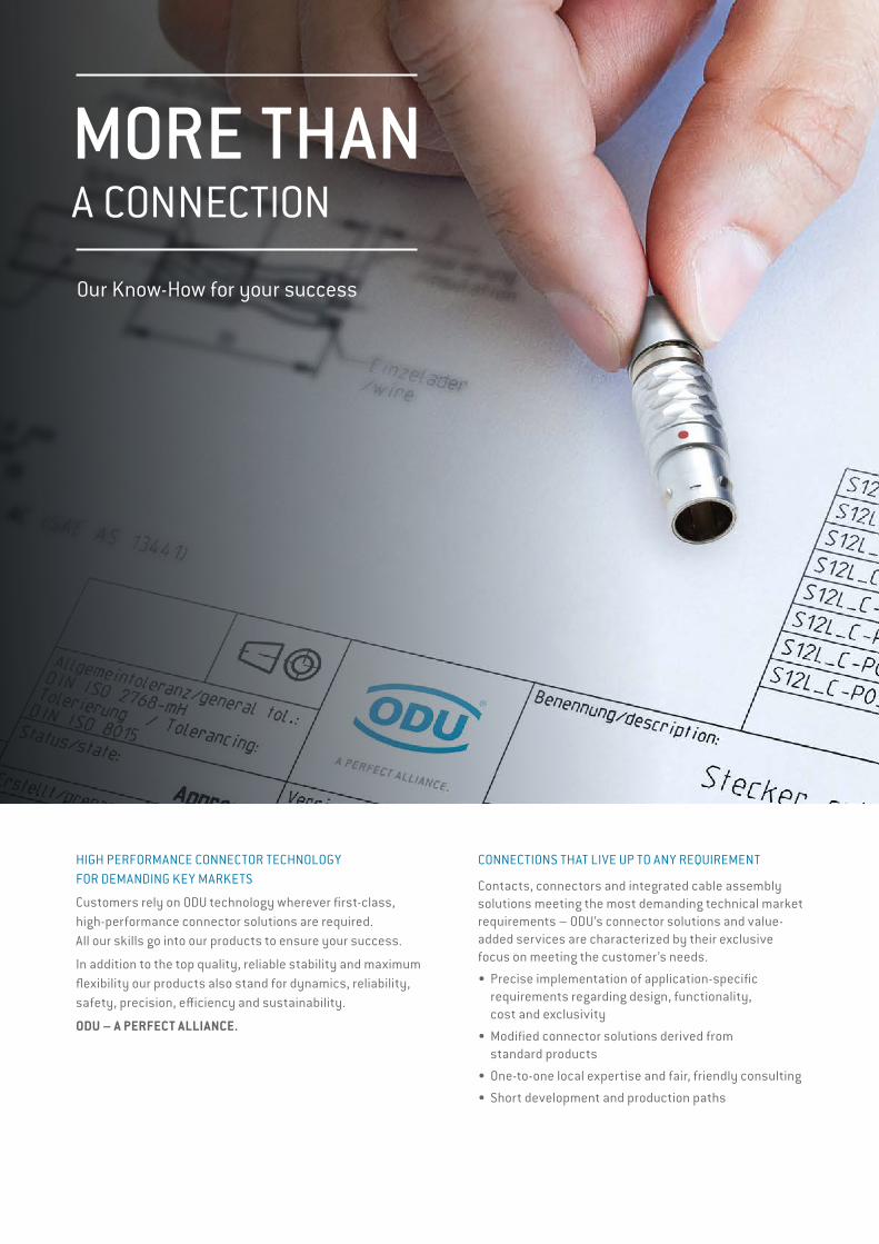
MORE THANA CONNECTION
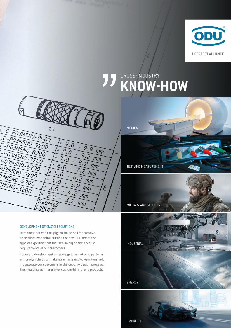
Our Know-How for your success CROSS-INDUSTRY
KNOW-HOW„
MEDICAL
INDUSTRIAL
ENERGY
MILITARY AND SECURITY
EMOBILITY
DEVELOPMENT OF CUSTOM SOLUTIONS
Demands that can’t be pigeon-holed call for creative specialists who think outside the box. ODU offers the type of expertise that focuses solely on the specific requirements of our customers.
For every development order we get, we not only perform a thorough check to make sure it’s feasible, we intensively incorporate our customers in the ongoing design process. This guarantees impressive, custom-fit final end products.
CONNECTIONS THAT LIVE UP TO ANY REQUIREMENT
Contacts, connectors and integrated cable assembly solutions meeting the most demanding technical market requirements – ODU’s connector solutions and value- added services are characterized by their exclusive focus on meeting the customer’s needs.
• Precise implementation of application-specific requirements regarding design, functionality, cost and exclusivity
• Modified connector solutions derived from standard products
• One-to-one local expertise and fair, friendly consulting
• Short development and production paths
HIGH PERFORMANCE CONNECTOR TECHNOLOGY FOR DEMANDING KEY MARKETS
Customers rely on ODU technology wherever first-class, high-performance connector solutions are required. All our skills go into our products to ensure your success.
In addition to the top quality, reliable stability and maximum flexibility our products also stand for dynamics, reliability, safety, precision, efficiency and sustainability.
ODU – A PERFECT ALLIANCE.
TEST AND MEASUREMENT
2019-08_ImageSection_C_EN.indd 5-6 05.08.2019 12:39:41
MORE THANA CONNECTION
Our Know-How for your success CROSS-INDUSTRY
KNOW-HOW„
MEDICAL
INDUSTRIAL
ENERGY
MILITARY AND SECURITY
EMOBILITY
DEVELOPMENT OF CUSTOM SOLUTIONS
Demands that can’t be pigeon-holed call for creative specialists who think outside the box. ODU offers the type of expertise that focuses solely on the specific requirements of our customers.
For every development order we get, we not only perform a thorough check to make sure it’s feasible, we intensively incorporate our customers in the ongoing design process. This guarantees impressive, custom-fit final end products.
CONNECTIONS THAT LIVE UP TO ANY REQUIREMENT
Contacts, connectors and integrated cable assembly solutions meeting the most demanding technical market requirements – ODU’s connector solutions and value- added services are characterized by their exclusive focus on meeting the customer’s needs.
• Precise implementation of application-specific requirements regarding design, functionality, cost and exclusivity
• Modified connector solutions derived from standard products
• One-to-one local expertise and fair, friendly consulting
• Short development and production paths
HIGH PERFORMANCE CONNECTOR TECHNOLOGY FOR DEMANDING KEY MARKETS
Customers rely on ODU technology wherever first-class, high-performance connector solutions are required. All our skills go into our products to ensure your success.
In addition to the top quality, reliable stability and maximum flexibility our products also stand for dynamics, reliability, safety, precision, efficiency and sustainability.
ODU – A PERFECT ALLIANCE.
TEST AND MEASUREMENT
2019-08_ImageSection_C_EN.indd 5-6 05.08.2019 12:39:41
ODU-MAC®ODU-MAC®
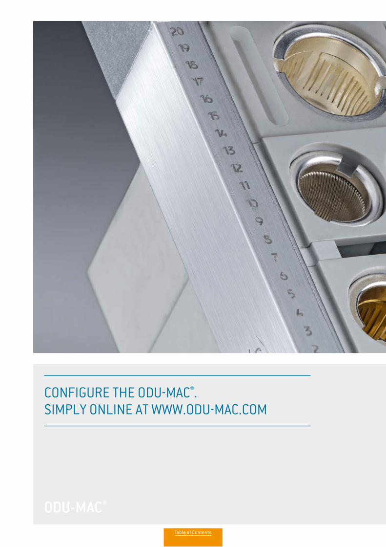
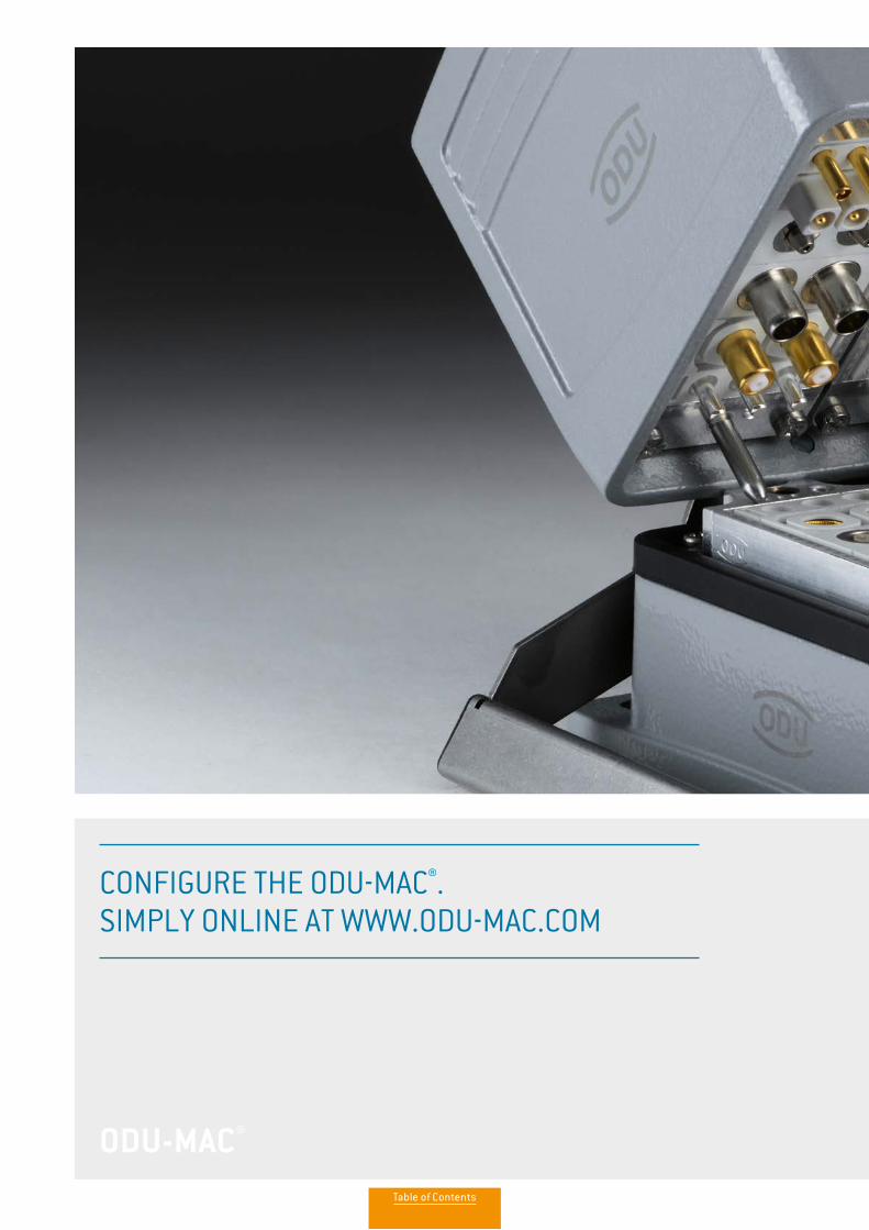
CONFIGURE THE ODU-MAC®. SIMPLY ONLINE AT WWW.ODU-MAC.COM
Table of Contents
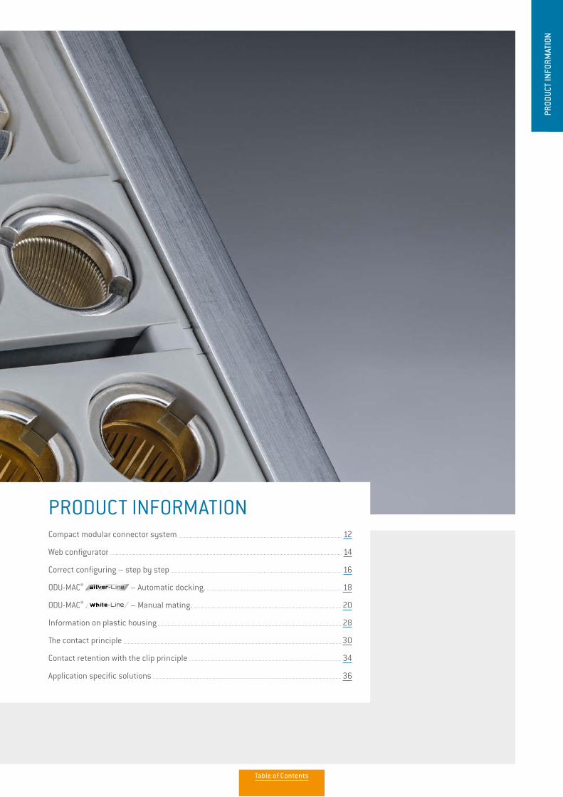
PRODUCT INFORMATIONCompact modular connector system 12
Web configurator 14
Correct configuring – step by step 16
ODU-MAC® – Automatic docking. 18
ODU-MAC® – Manual mating. 20
Information on plastic housing 28
The contact principle 30
Contact retention with the clip principle 34
Application specific solutions 36
PROD
UCT
INFO
RMAT
ION
Table of Contents

12
PRODUCT INFORMATION
THE ODU-MAC LEAVES NOTHING TO BE DESIRED:
• 100,000 mating cycles and more
• Versions in the docking frame for automatic docking
• Versions in rugged housing suitable for use in harsh environments
• Easy locking of the housing with Snap-In, spindle or lever
• Many different module options available
• Extremely compact due to the high contact density
MANUAL MATING.
AUTOMATIC DOCKING.
Our new performance class offers a true alternative – request our ODU-MAC Blue-Line catalog to find out more.
ODU-MAC ZERO
ADDITIONAL INFORMATION PROVIDED IN VIDEOS WWW.YOUTUBE.COM/ODUSTECKVERBINDER
ODU-MAC® – A MODULAR ALL-ROUNDER FOR THE MOST VARIED APPLICATIONS
THE SMART SOLUTION FOR CUTOMIZED CONNECTIONS
The ODU-MAC's flexible, modular design enables multiple connection types to be combined within single contacts. Whether signal, power, high current, high voltage, coax, high-speed data transmission, fiber optic and other media such as air or fluid – all types can be selected from the module and integrated into the individual connector solution. The connection options are just as versatile.
Many options are available for a variety of applications in industry or medical technology. For example, automated docking systems can use our stable aluminium frames, or a manual connection can be made with our robust housing design.
The result is an effective, compact and attractive complete connection that cannot be beaten in terms of functionality. Confusion due to an excessive number of connections is a thing of the past – an ODU-MAC customized to meet your requirements is todays's solution.
ODU-MAC is available in two basic versions: a flexible and adjustable alu-minium frame for automatic docking or in the housing for manual mating. Find out more about custom configurations on the following pages.
ODU-MAC®
New ODU-MAC® Silver-Linecatalog available:
www.odu-connectors.com/downloads/catalogues/
Table of Contents
13
PRODUCT INFORMATION
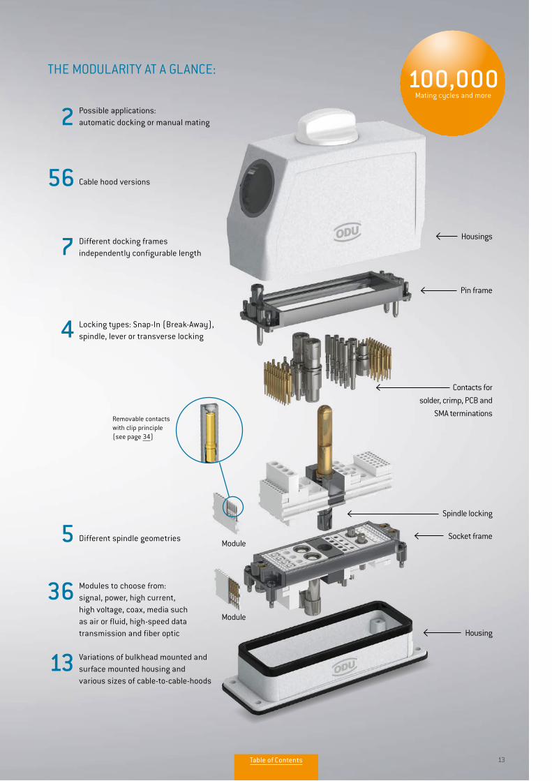
100,000Mating cycles and more
Possible applications:automatic docking or manual mating
Cable hood versions
Different docking frames independently configurable length
Locking types: Snap-In (Break-Away),spindle, lever or transverse locking
Different spindle geometries
Modules to choose from: signal, power, high current, high voltage, coax, media such as air or fluid, high-speed data transmission and fiber optic
Variations of bulkhead mounted and surface mounted housing and various sizes of cable-to-cable-hoods
5
36
Removable contacts with clip principle (see page 34)
THE MODULARITY AT A GLANCE:
Module
Module
Housings
Housing
Pin frame
Contacts for
solder, crimp, PCB and
SMA terminations
Spindle locking
Socket frame
56
7
4
13
2
13
New ODU-MAC® Silver-Linecatalog available:
www.odu-connectors.com/downloads/catalogues/
Table of Contents

14
PRODUCT INFORMATION
1
2
ODU-MAC® WEB CONFIGURATORIndividual configuration of your ODU-MAC® connection.
1. ACCESS: THROUGH WWW.ODU-CONNECTORS.COM
Entry via www.odu-connectors.com provides you with a great deal of product information and many application examples prior to configuration of your ODU-MAC.
Access to the configurator via the product category Modular Connectors.
With ODU-MAC web configurator it’s possible to configure your connection simply according to your requirements. The config-urator guides you through the different choices step by step and offers many continuative information. There are two ways to access the ODU-MAC web configurator:
www.odu-connectors.com
www.odu-connectors.com
Table of Contents

15
PRODUCT INFORMATION
www.odu-mac.com
PRODUCT VIDEOS ON FUNCTIONALITY
2. ACCESS: DIRECTLY THROUGH WWW.ODU-MAC.COM
www.odu-mac.com takes you directly to the configuration spacer, allowing you to start assembling your ODU-MAC immediately.
Videos explaining the functions of automatic docking and manual mating can be found under
Explanation on the welcome page of the configurator at www.odu-mac.com.
New ODU-MAC®
catalog available:www.odu-connectors.com/downloads/catalogues/
Table of Contents

16
PRODUCT INFORMATION
AUTOMATIC DOCKING.ODU-MAC®
INDIVIDUAL REQUIREMENTS – INDIVIDUAL CONFIGURATION
With ODU-MAC, we offer a modular connector system configured to your requirements. This means that you always receive the appropriate hybrid connection.
SELECT & REQUEST OFFERS
You will receive a drawing and a detailed offer within one working day of submitting your request. When placing an order you will receive the complete article number for connections preassembled by ODU (contacts supplied as accompanying loose items). We ask you to enquire directly about customized versions not covered by the standard.
Depending upon your requirements, you can choose 6 different frame types as a base for automatic docking.
Choose from 34 different modules for transferring signal, power, high current, high voltage, coax, high-speed data transmission, fiber optic and other media such as air or fluid and assemble your ODU-MAC individually.
1ST STEP: FRAME SELECTION
2ND STEP: MODULE SELECTION
Frames
ODU-MAC® S (Standard) ODU-MAC® T (Transverse)
ODU-MAC® L (Large) ODU-MAC® P+ (Power)
ODU-MAC® M+ (Mini)ODU-MAC® QCH (quick change head) (connector saver)
Modules
Signal Compressed air and fluid model
Power Fiber optic
High currentShielded implementation / high-speed connector
High voltageBlank modules / spacer modules / coding modules / pin protection module
Coax
For information to the configuration of your connector please refer to our website: www.odu-mac.com
How to configure your ODU-MAC®.
YOUR WAY TO AN INDIVIDUAL CONNECTION
New ODU-MAC®Silver-Linecatalog available:
www.odu-connectors.com/downloads/catalogues/
Table of Contents
17
PRODUCT INFORMATION
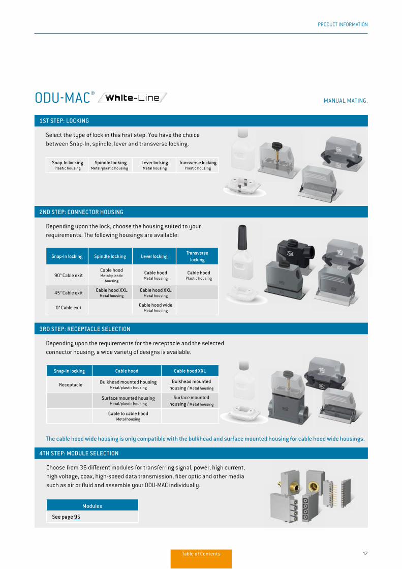
The cable hood wide housing is only compatible with the bulkhead and surface mounted housing for cable hood wide housings.
Snap-In locking Cable hood Cable hood XXL
Receptacle Bulkhead mounted housingMetal/plastic housing
Bulkhead mounted housing / Metal housing
Surface mounted housingMetal/plastic housing
Surface mounted housing / Metal housing
Cable to cable hoodMetal housing
Modules
See page 95
MANUAL MATING.ODU-MAC®
1ST STEP: LOCKING
4TH STEP: MODULE SELECTION
2ND STEP: CONNECTOR HOUSING
3RD STEP: RECEPTACLE SELECTION
Select the type of lock in this first step. You have the choice between Snap-In, spindle, lever and transverse locking.
Choose from 36 different modules for transferring signal, power, high current, high voltage, coax, high-speed data transmission, fiber optic and other media such as air or fluid and assemble your ODU-MAC individually.
Depending upon the lock, choose the housing suited to your requirements. The following housings are available:
Depending upon the requirements for the receptacle and the selected connector housing, a wide variety of designs is available.
Snap-In lockingPlastic housing
Spindle lockingMetal/plastic housing
Lever lockingMetal housing
Transverse lockingPlastic housing
Snap-In locking Spindle locking Lever lockingTransverse
locking
90° Cable exitCable hood Metal/plastic
housing
Cable hood Metal housing
Cable hood Plastic housing
45° Cable exit Cable hood XXLMetal housing
Cable hood XXLMetal housing
0° Cable exit Cable hood wideMetal housing
Table of Contents

18
AUTOMATIC DOCKING.
ODU-MAC in the docking frame is used only for automatic docking. Choose from a variety of different frames, adjust the length individually and assemble the frame with the modules you need for your requirements. With ODU-MAC you can always find the perfect solution. And should your requirements for a connection go beyond the standard solutions, we also offer customized special solutions.
ODU-MAC is configured for 3 to 60 grid units (more upon request), meaning that up to 600 contacts can be installed when the 10 contacts module with a module width of 2.54 mm (1 unit) is used. Versions for limited space (ODU-MAC M+ (Mini)), increased requirements for floating support (ODU-MAC L (Large)) and increased mechanical load (ODU-MAC P+ (Power)) are also available.
Overview of docking frames.
ODU-MAC® S (STANDARD) P. 42Standard solution for docking tasks. Tolerance compensation: +/– 0.6 mm.
1 2 3 4 5 6 7 8 9 10 11 12 13 14 15 16 17 18 19 20 21 22 23 24 61 62 63 64 65 66 67 68 69 70 71 72 73 74 75 76 787 78
FURTHER INFORMATION FROM PAGE 39.
ODU-MAC®
The length of the frames can be ordered individually depending upon the number of modules.
> 60 UNITS ON REQUEST3–60 UNITS STANDARD
ODU-MAC® L (LARGE) P. 43Frame with higher tolerance compensation and reinforced guiding bushes, as well as extended guiding pins.Tolerance compensation: +/– 1.2 mm.
New ODU-MAC® Silver-Linecatalog available:
www.odu-connectors.com/downloads/catalogues/
Table of Contents

19
ODU-MAC® M+ (MINI) P. 44Compact size with the smallest space requirement Tolerance compensation: +/– 0.6 mm.
ODU-MAC® T (TRANSVERSE) P. 48Transverse frames for installation in customized housing solutions or where low clearance heights make this necessary.
ODU-MAC® P+ (POWER) P. 45The frame for the highest requirements thanks to reinforced frame design. Tolerance compensation: +/– 2.5 mm.
ODU-MAC® QCH (QUICK CHANGE HEAD) P. 49Docking frames for the highest requirements with regard to mating cycles (connector saver) with the lowest maintenance time and expense thanks to easy exchange of the replacement parts. Tolerance compensation: +/– 0.6 mm.
New ODU-MAC® Silver-Linecatalog available:
www.odu-connectors.com/downloads/catalogues/
Table of Contents
20
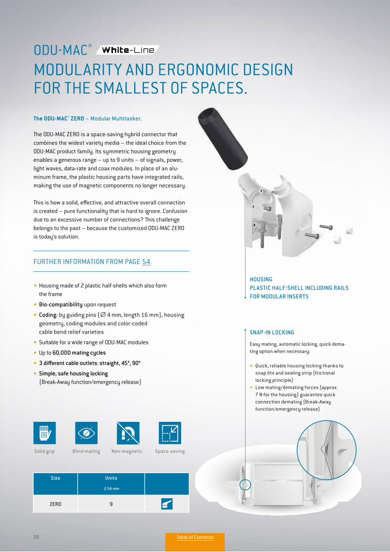
FURTHER INFORMATION FROM PAGE 54.
• Housing made of 2 plastic half-shells which also form the frame
• Bio-compatibility upon request
• Coding: by guiding pins (∅ 4 mm, length 16 mm), housing geometry, coding modules and color-coded cable bend relief varieties
• Suitable for a wide range of ODU-MAC modules
• Up to 60,000 mating cycles
• 3 different cable outlets: straight, 45°, 90°
• Simple, safe housing locking (Break-Away function/emergency release)
The ODU-MAC ZERO is a space-saving hybrid connector that combines the widest variety media – the ideal choice from the ODU-MAC product family. Its symmetric housing geometry enables a generous range – up to 9 units – of signals, power, light waves, data-rate and coax modules. In place of an alu-minum frame, the plastic housing parts have integrated rails, making the use of magnetic components no longer necessary.
This is how a solid, effective, and attractive overall connection is created – pure functionality that is hard to ignore. Confusion due to an excessive number of connections? This challenge belongs to the past – because the customized ODU-MAC ZERO is today’s solution.
The ODU-MAC® ZERO – Modular Multitasker.
MODULARITY AND ERGONOMIC DESIGN FOR THE SMALLEST OF SPACES.
ODU-MAC®
Size Units
2.54 mm
ZERO 9
HOUSING PLASTIC HALF-SHELL INCLUDING RAILS FOR MODULAR INSERTS
SNAP-IN LOCKING
Easy mating, automatic locking, quick dema-ting option when necessary:
• Quick, reliable housing locking thanks to snap fits and sealing strip (frictional locking principle)• Low mating/demating forces (approx. 7 N for the housing) guarantee quick connection demating (Break-Away function/emergency release)
Blind matingSolid grip Non-magnetic Space-saving
Table of Contents
21
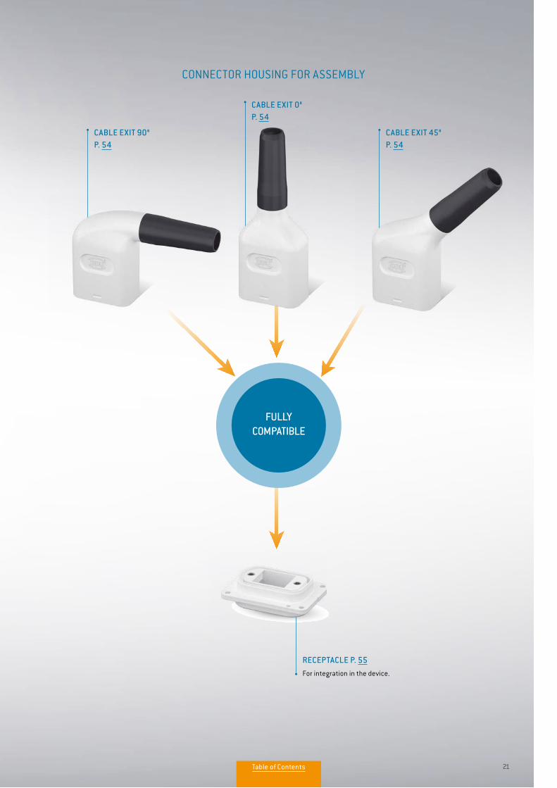
FULLY COMPATIBLE
CABLE EXIT 90° P. 54
CONNECTOR HOUSING FOR ASSEMBLY
RECEPTACLE P. 55For integration in the device.
CABLE EXIT 0° P. 54
CABLE EXIT 45° P. 54
Table of Contents
22
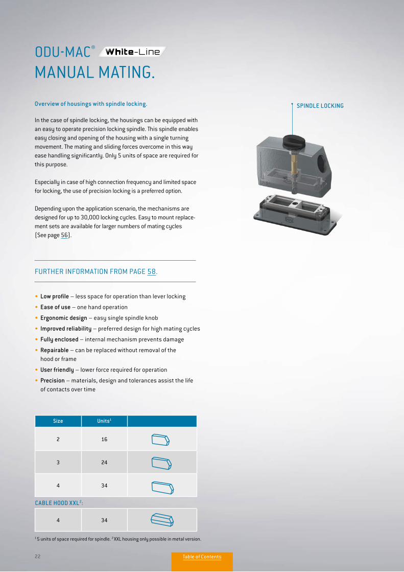
SPINDLE LOCKING
1 5 units of space required for spindle. 2 XXL housing only possible in metal version.
In the case of spindle locking, the housings can be equipped with an easy to operate precision locking spindle. This spindle enables easy closing and opening of the housing with a single turning movement. The mating and sliding forces overcome in this way ease handling significantly. Only 5 units of space are required for this purpose.
Especially in case of high connection frequency and limited space for locking, the use of precision locking is a preferred option.
Depending upon the application scenario, the mechanisms are designed for up to 30,000 locking cycles. Easy to mount replace-ment sets are available for larger numbers of mating cycles (See page 56).
Overview of housings with spindle locking.
Size Units1
2 16
3 24
4 34
CABLE HOOD XXL2:
4 34
FURTHER INFORMATION FROM PAGE 58.
• Low profile – less space for operation than lever locking
• Ease of use – one hand operation
• Ergonomic design – easy single spindle knob
• Improved reliability – preferred design for high mating cycles
• Fully enclosed – internal mechanism prevents damage
• Repairable – can be replaced without removal of the hood or frame
• User friendly – lower force required for operation
• Precision – materials, design and tolerances assist the life of contacts over time
MANUAL MATING.ODU-MAC®
Table of Contents
23
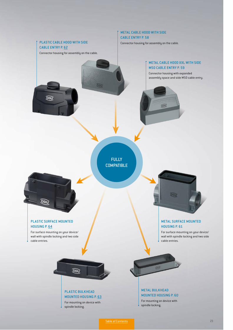
PLASTIC SURFACE MOUNTED HOUSING P. 64For surface mounting on your device/wall with spindle locking and two side cable entries.
PLASTIC CABLE HOOD WITH SIDE CABLE ENTRY P. 62Connector housing for assembly on the cable.
PLASTIC BULKHEAD MOUNTED HOUSING P. 63For mounting on device with spindle locking.
METAL BULKHEAD MOUNTED HOUSING P. 60For mounting on device with spindle locking.
METAL CABLE HOOD WITH SIDE CABLE ENTRY P. 58Connector housing for assembly on the cable.
METAL CABLE HOOD XXL WITH SIDE M50 CABLE ENTRY P. 59Connector housing with expanded assembly space and side M50 cable entry.
METAL SURFACE MOUNTED HOUSING P. 61For surface mounting on your device/wall with spindle locking and two side cable entries.
FULLY COMPATIBLE
Table of Contents
24
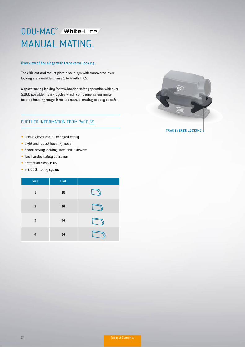
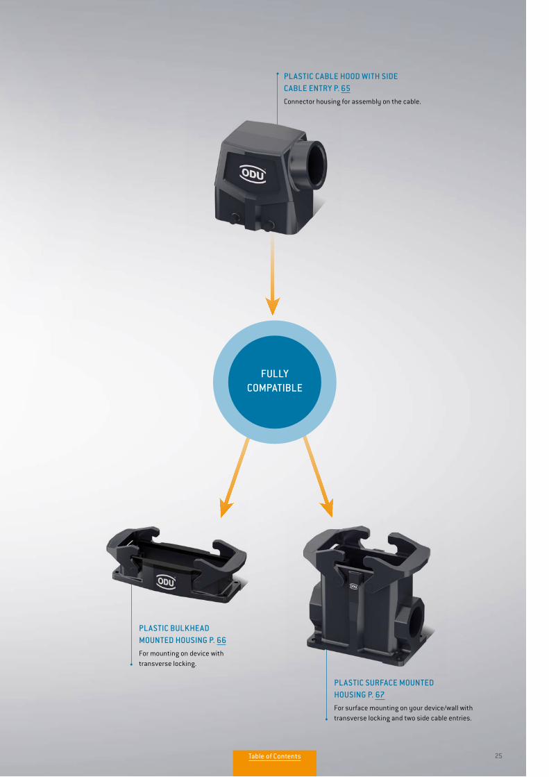
The efficient and robust plastic housings with transverse leverlocking are available in size 1 to 4 with IP 65.
A space saving locking for tow-handed safety operation with over 5,000 possible mating cycles which complements our multi- faceted housing range. It makes manual mating as easy as safe.
MANUAL MATING.ODU-MAC®
TRANSVERSE LOCKING
FURTHER INFORMATION FROM PAGE 65.
Size Unit
1 10
2 16
3 24
4 34
• Locking lever can be changed easily
• Light and robust housing model
• Space-saving locking, stackable sidewise
• Two-handed safety operation
• Protection class IP 65
• > 5,000 mating cycles
Overview of housings with transverse locking.
Table of Contents
25
PLASTIC CABLE HOOD WITH SIDE CABLE ENTRY P. 65Connector housing for assembly on the cable.
FULLY COMPATIBLE
PLASTIC SURFACE MOUNTED HOUSING P. 67For surface mounting on your device/wall with transverse locking and two side cable entries.
PLASTIC BULKHEAD MOUNTED HOUSING P. 66For mounting on device with transverse locking.
Table of Contents
26
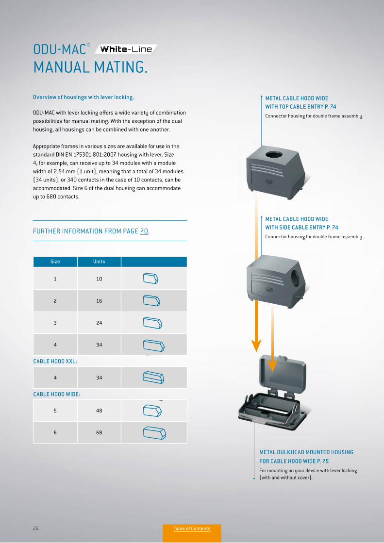
ODU-MAC with lever locking offers a wide variety of combination possibilities for manual mating. With the exception of the dual housing, all housings can be combined with one another.
Appropriate frames in various sizes are available for use in the standard DIN EN 175301-801:2007 housing with lever. Size 4, for example, can receive up to 34 modules with a module width of 2.54 mm (1 unit), meaning that a total of 34 modules (34 units), or 340 contacts in the case of 10 contacts, can be accommodated. Size 6 of the dual housing can accommodate up to 680 contacts.
Overview of housings with lever locking.
MANUAL MATING.ODU-MAC®
Size Units
1 10
2 16
3 24
4 34
CABLE HOOD XXL:
4 34
CABLE HOOD WIDE:
5 48
6 68
FURTHER INFORMATION FROM PAGE 70.
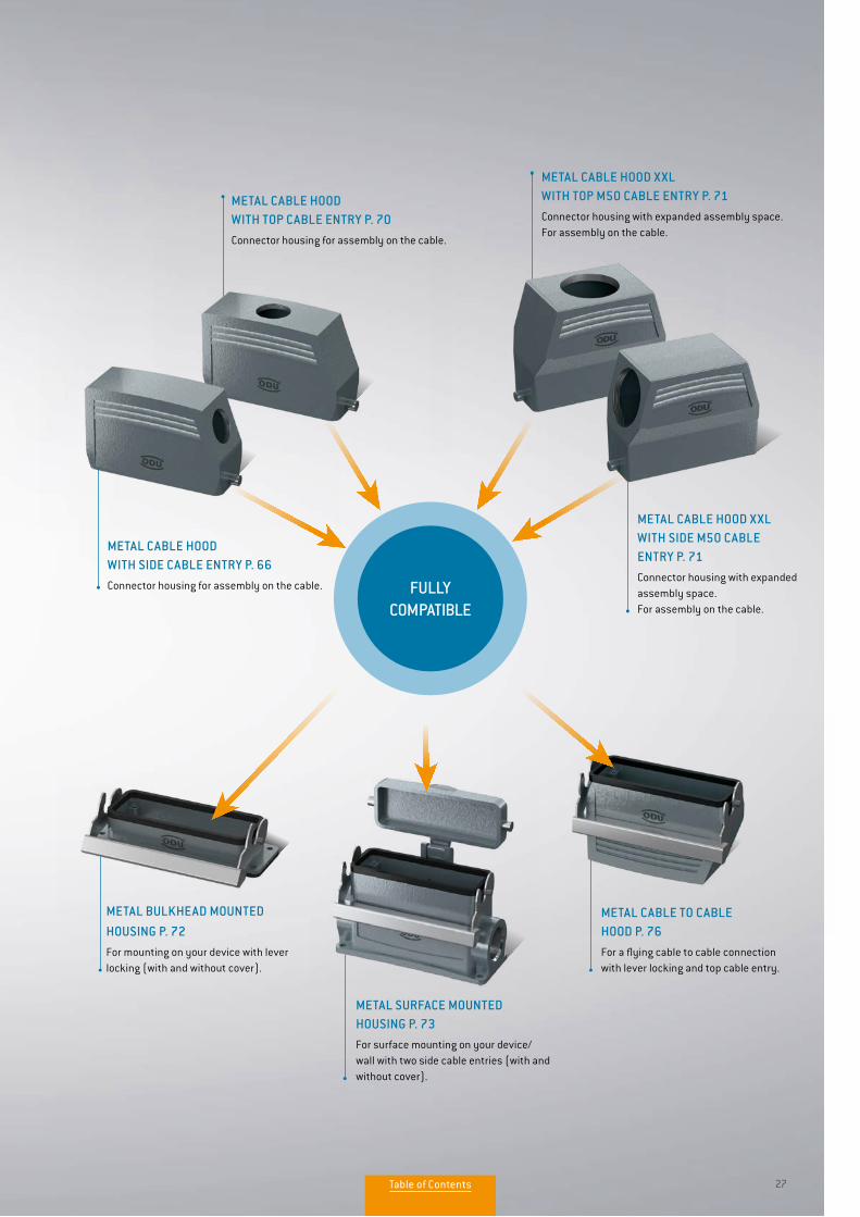
METAL CABLE HOOD WIDE WITH TOP CABLE ENTRY P. 74Connector housing for double frame assembly.
METAL CABLE HOOD WIDE WITH SIDE CABLE ENTRY P. 74Connector housing for double frame assembly.
METAL BULKHEAD MOUNTED HOUSING FOR CABLE HOOD WIDE P. 75For mounting on your device with lever locking (with and without cover).
Table of Contents
27
METAL CABLE TO CABLE HOOD P. 76For a flying cable to cable connection with lever locking and top cable entry.
METAL CABLE HOOD WITH SIDE CABLE ENTRY P. 66Connector housing for assembly on the cable.
METAL CABLE HOOD WITH TOP CABLE ENTRY P. 70Connector housing for assembly on the cable.
METAL CABLE HOOD XXL WITH TOP M50 CABLE ENTRY P. 71Connector housing with expanded assembly space. For assembly on the cable.
METAL BULKHEAD MOUNTED HOUSING P. 72
For mounting on your device with lever locking (with and without cover).
METAL SURFACE MOUNTED HOUSING P. 73For surface mounting on your device/wall with two side cable entries (with and without cover).
METAL CABLE HOOD XXL WITH SIDE M50 CABLE ENTRY P. 71Connector housing with expanded assembly space. For assembly on the cable.
FULLY COMPATIBLE
Table of Contents
28
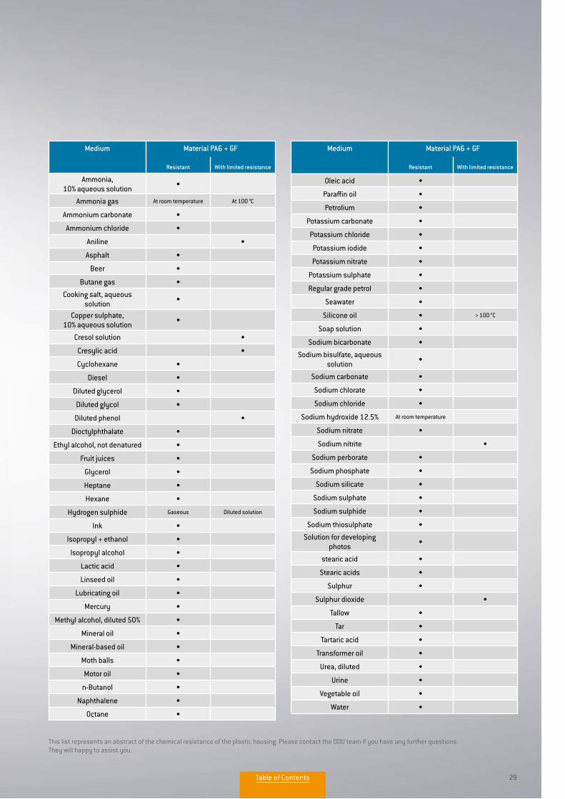
INFORMATION ON PLASTIC HOUSING
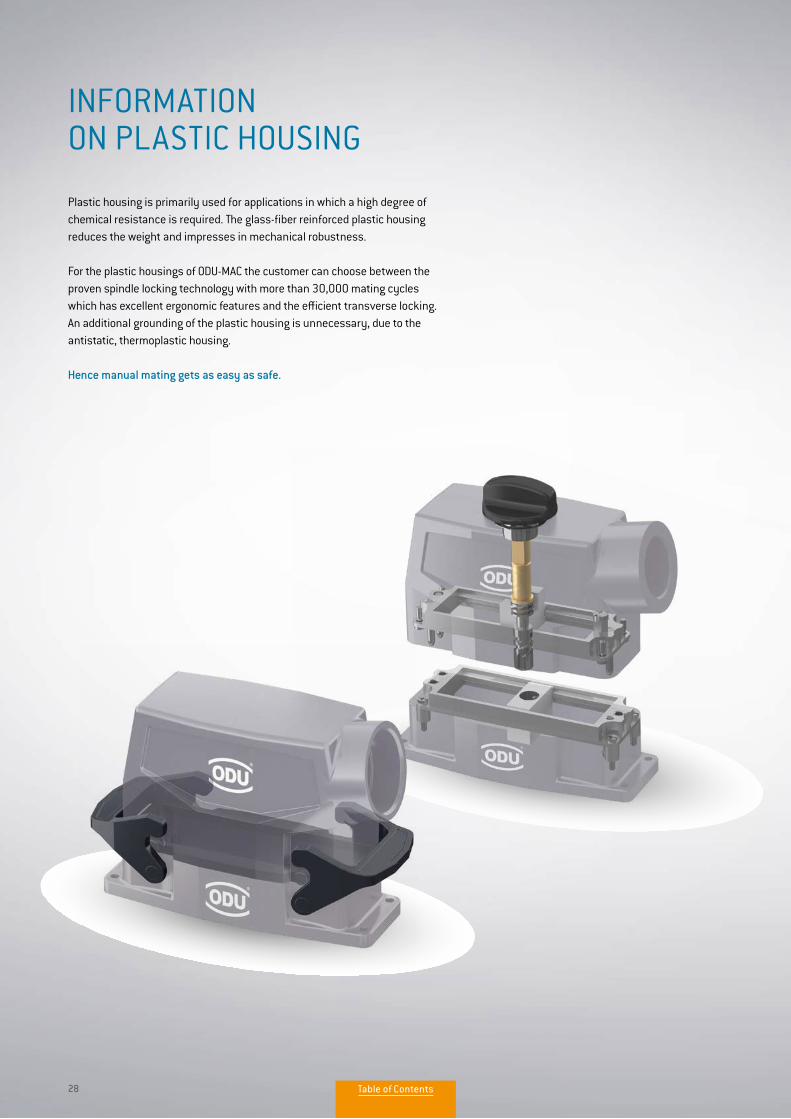
Plastic housing is primarily used for applications in which a high degree ofchemical resistance is required. The glass-fiber reinforced plastic housing reduces the weight and impresses in mechanical robustness.
For the plastic housings of ODU-MAC the customer can choose between the proven spindle locking technology with more than 30,000 mating cycles which has excellent ergonomic features and the efficient transverse locking. An additional grounding of the plastic housing is unnecessary, due to the antistatic, thermoplastic housing.
Hence manual mating gets as easy as safe.
Table of Contents
29
This list represents an abstract of the chemical resistance of the plastic housing. Please contact the ODU team if you have any further questions. They will happy to assist you.
Medium Material PA6 + GF
Resistant With limited resistance
Ammonia,10% aqueous solution •
Ammonia gas At room temperature At 100 °C
Ammonium carbonate •
Ammonium chloride •
Aniline •
Asphalt •
Beer •
Butane gas •
Cooking salt, aqueous solution •
Copper sulphate, 10% aqueous solution •
Cresol solution •
Cresylic acid •
Cyclohexane •
Diesel •
Diluted glycerol •
Diluted glycol •
Diluted phenol •
Dioctylphthalate •
Ethyl alcohol, not denatured •
Fruit juices •
Glycerol •
Heptane •
Hexane •
Hydrogen sulphide Gaseous Diluted solution
Ink •
Isopropyl + ethanol •
Isopropyl alcohol •
Lactic acid •
Linseed oil •
Lubricating oil •
Mercury •
Methyl alcohol, diluted 50% •
Mineral oil •
Mineral-based oil •
Moth balls •
Motor oil •
n-Butanol •
Naphthalene •
Octane •
Oleic acid •
Paraffin oil •
Petrolium •
Potassium carbonate •
Potassium chloride •
Potassium iodide •
Potassium nitrate •
Potassium sulphate •
Regular grade petrol •
Seawater •
Silicone oil • > 100 °C
Soap solution •
Sodium bicarbonate •
Sodium bisulfate, aqueous solution •
Sodium carbonate •
Sodium chlorate •
Sodium chloride •
Sodium hydroxide 12.5% At room temperature
Sodium nitrate •
Sodium nitrite •
Sodium perborate •
Sodium phosphate •
Sodium silicate •
Sodium sulphate •
Sodium sulphide •
Sodium thiosulphate •
Solution for developing photos •
stearic acid •
Stearic acids •
Sulphur •
Sulphur dioxide •
Tallow •
Tar •
Tartaric acid •
Transformer oil •
Urea, diluted •
Urine •
Vegetable oil •
Water •
Medium Material PA6 + GF
Resistant With limited resistance
Table of Contents
30
PRODUCT INFORMATION
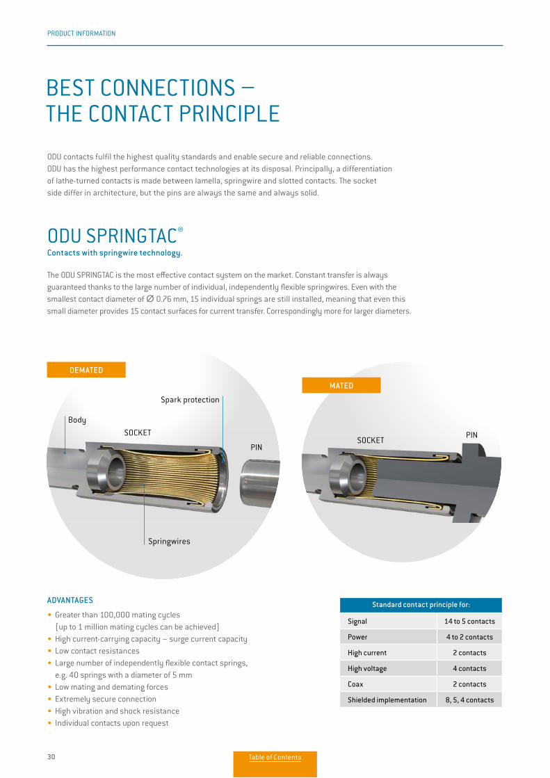
ODU SPRINGTAC® Contacts with springwire technology.
The ODU SPRINGTAC is the most effective contact system on the market. Constant transfer is always guaranteed thanks to the large number of individual, independently flexible springwires. Even with the smallest contact diameter of ∅∅ 0.76 mm, 15 individual springs are still installed, meaning that even this small diameter provides 15 contact surfaces for current transfer. Correspondingly more for larger diameters.
ADVANTAGES
• Greater than 100,000 mating cycles (up to 1 million mating cycles can be achieved)• High current-carrying capacity – surge current capacity• Low contact resistances• Large number of independently flexible contact springs, e.g. 40 springs with a diameter of 5 mm• Low mating and demating forces• Extremely secure connection• High vibration and shock resistance• Individual contacts upon request
BEST CONNECTIONS – THE CONTACT PRINCIPLE
ODU contacts fulfil the highest quality standards and enable secure and reliable connections. ODU has the highest performance contact technologies at its disposal. Principally, a differentiation of lathe-turned contacts is made between lamella, springwire and slotted contacts. The socket side differ in architecture, but the pins are always the same and always solid.
Standard contact principle for:
Signal 14 to 5 contacts
Power 4 to 2 contacts
High current 2 contacts
High voltage 4 contacts
Coax 2 contacts
Shielded implementation 8, 5, 4 contacts
SOCKETSOCKET
PINPIN
DEMATED
MATED
Springwires
Body
Spark protection
Table of Contents
31
PRODUCT INFORMATION
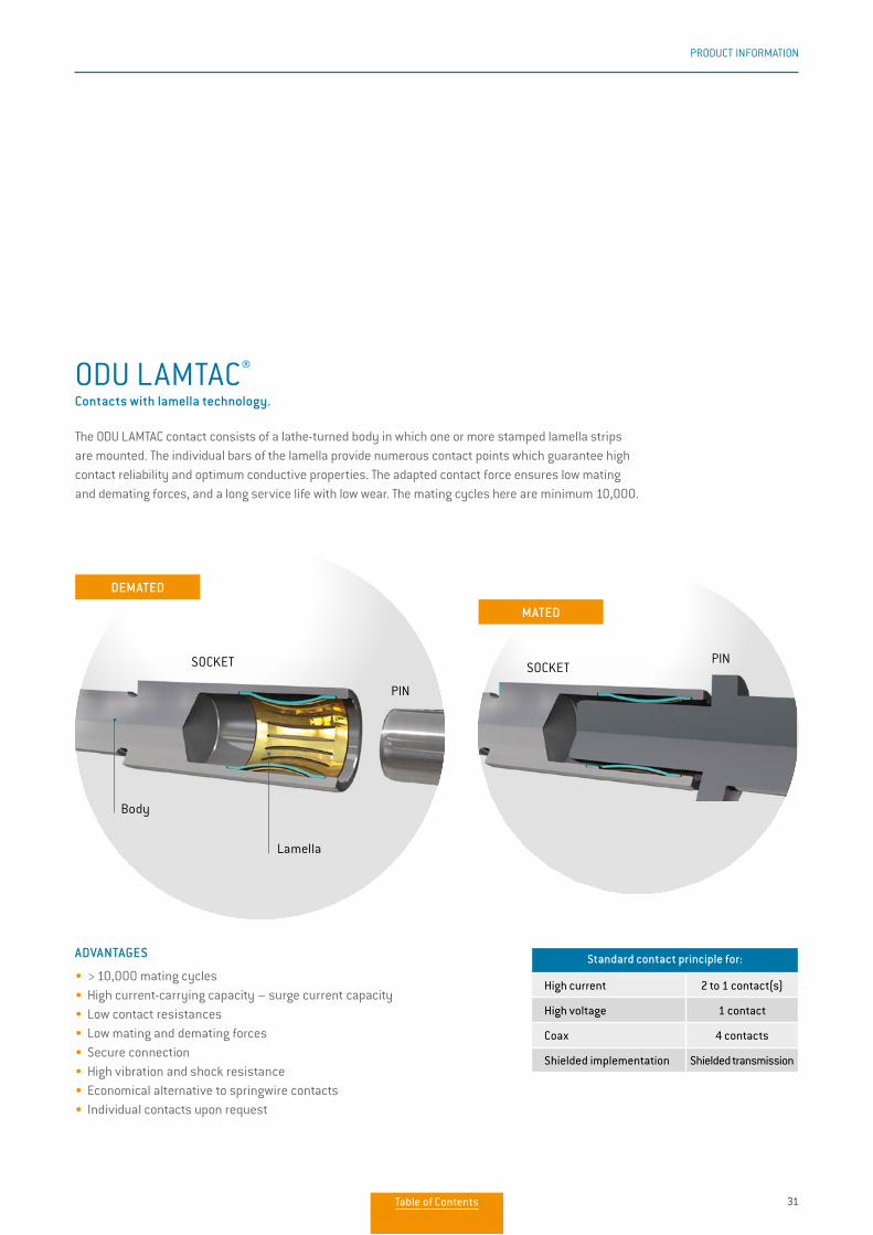
ODU LAMTAC® Contacts with lamella technology.
The ODU LAMTAC contact consists of a lathe-turned body in which one or more stamped lamella strips are mounted. The individual bars of the lamella provide numerous contact points which guarantee high contact reliability and optimum conductive properties. The adapted contact force ensures low mating and demating forces, and a long service life with low wear. The mating cycles here are minimum 10,000.
ADVANTAGES
• > 10,000 mating cycles• High current-carrying capacity – surge current capacity• Low contact resistances• Low mating and demating forces• Secure connection • High vibration and shock resistance• Economical alternative to springwire contacts• Individual contacts upon request
Standard contact principle for:
High current 2 to 1 contact(s)
High voltage 1 contact
Coax 4 contacts
Shielded implementation Shielded transmission
SOCKET SOCKET
PIN
PIN
Lamella
DEMATED
MATED
Body
Table of Contents
32
PRODUCT INFORMATION
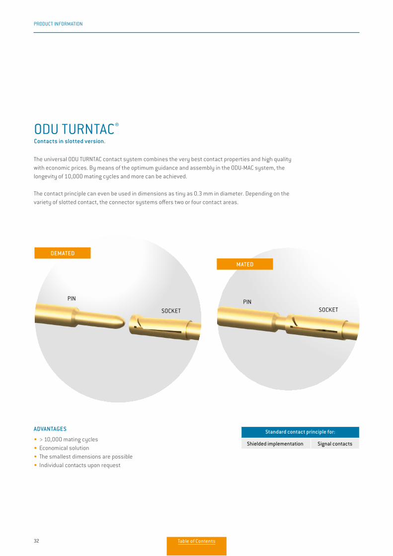
ODU TURNTAC®
Contacts in slotted version.
The universal ODU TURNTAC contact system combines the very best contact properties and high quality with economic prices. By means of the optimum guidance and assembly in the ODU-MAC system, the longevity of 10,000 mating cycles and more can be achieved.
The contact principle can even be used in dimensions as tiny as 0.3 mm in diameter. Depending on thevariety of slotted contact, the connector systems offers two or four contact areas.
ADVANTAGES
• > 10,000 mating cycles• Economical solution• The smallest dimensions are possible• Individual contacts upon request
Standard contact principle for:
Shielded implementation Signal contacts
SOCKET SOCKET
PIN PIN
DEMATED
MATED
Table of Contents
33
PRODUCT INFORMATION
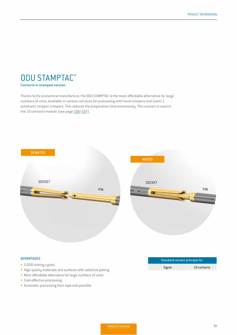
ODU STAMPTAC®
Contacts in stamped version.
Thanks to its economical manufacture, the ODU STAMPTAC is the most affordable alternative for large numbers of units. Available in various coil sizes for processing with hand crimpers and (semi-) automatic stripper crimpers. This reduces the preparation time enormously. This contact is used in the 10 contacts module (see page 106/107).
ADVANTAGES
• 5,000 mating cycles • High quality materials and surfaces with selective plating• Most affordable alternative for large numbers of units• Cost-effective processing• Automatic processing from tape reel possible
Standard contact principle for:
Signal 10 contacts
SOCKETSOCKET
PINPIN
DEMATED
MATED
Table of Contents
34
PRODUCT INFORMATION
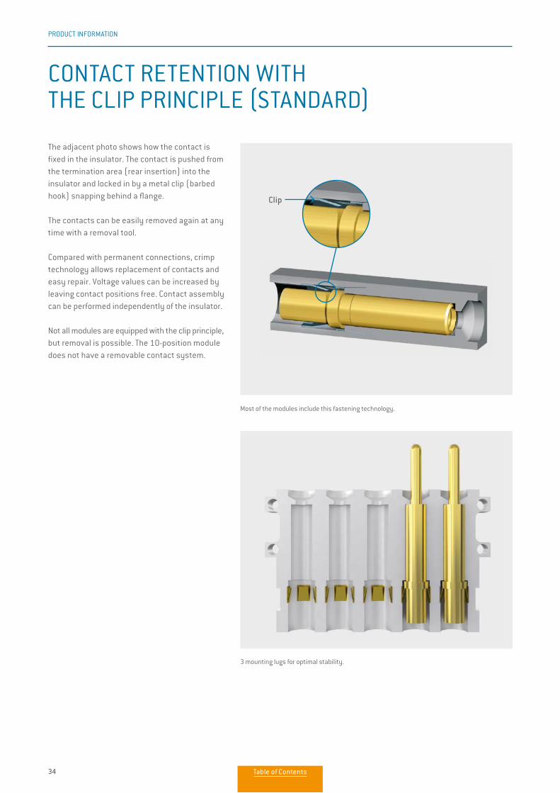
CONTACT RETENTION WITH THE CLIP PRINCIPLE (STANDARD)
The adjacent photo shows how the contact is fixed in the insulator. The contact is pushed from the termination area (rear insertion) into the insulator and locked in by a metal clip (barbed hook) snapping behind a flange.
The contacts can be easily removed again at any time with a removal tool.
Compared with permanent connections, crimp technology allows replacement of contacts and easy repair. Voltage values can be increased by leaving contact positions free. Contact assembly can be performed independently of the insulator.
Not all modules are equipped with the clip principle, but removal is possible. The 10-position module does not have a removable contact system.
Most of the modules include this fastening technology.
3 mounting lugs for optimal stability.
Clip
Table of Contents

35
PRODUCT INFORMATION
FOR YOUR NOTES
Table of Contents

36
APPLICATION SPECIFIC SOLUTIONS
Problem solvers who think outside the box are required when standard solutions find their limits. ODU offers you just this kind of expert: the ones who focus on your specific requirements. For every development order we get, we not only perform a thorough review study, we intensively involve our customers in the ongoing design process. This guarantees an impres-sive, custom-fit final result. Our standard connectors are frequently the base for custom modifications.
FOR INDUSTRIAL
FOR MEDICAL
MONOBLOC INSULATOR
Customers install this insulator block, equipped with standard ODU-MAC contacts, into its own custom housing.
COMPLETE DOCKING UNIT
Three ODU-MAC rows incl. spindle locking are mounted in a special stainless steel frame.
Advantages• Special floating support with tolerance compensation +/– 3 mmNew ODU-MAC® Silver-Line
catalog available:www.odu-connectors.com/downloads/catalogues/
Table of Contents
37
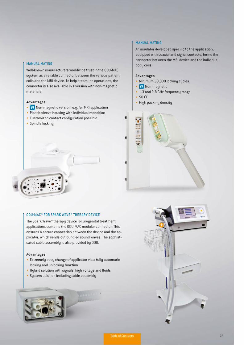
MANUAL MATING
An insulator developed specific to the application, equipped with coaxial and signal contacts, forms the connector between the MRI device and the individual body coils.
Advantages• Minimum 50,000 locking cycles • Non-magnetic• 1.3 and 2.8 GHz frequency range• 50 Ω• High packing density
MANUAL MATING
Well-known manufacturers worldwide trust in the ODU-MAC system as a reliable connector between the various patient coils and the MRI device. To help steamline operations, the connector is also available in a version with non-magnetic materials.
Advantages• Non-magnetic version, e.g. for MRI application • Plastic sleeve housing with individual monobloc • Customized contact configuration possible• Spindle locking
ODU-MAC® FOR SPARK WAVE® THERAPY DEVICE
The Spark Wave® therapy device for urogenital treatment applications contains the ODU-MAC modular connector. This ensures a secure connection between the device and the ap-plicator, which sends out bundled sound waves. The sophisti-cated cable assembly is also provided by ODU.
Advantages• Extremely easy change of applicator via a fully automatic locking and unlocking function• Hybrid solution with signals, high voltage and fluids • System solution including cable assembly
Table of Contents

ODU-MAC®ODU-MAC®
CONFIGURE THE ODU-MAC®. SIMPLY ONLINE AT WWW.ODU-MAC.COM
New ODU-MAC® Silver-Linecatalog available:
www.odu-connectors.com/downloads/catalogues/
Table of Contents

AUTOMATIC DOCKINGRequirements on the complete system 40
ODU-MAC® S (Standard) 42
ODU-MAC® L (Large) 43
ODU-MAC® M+ (Mini) 44
ODU-MAC® P+ (Power) 45
PE transmission, grounding kit 46
ODU-MAC® T (Transverse) 48
ODU-MAC® QCH (Quick Change Head) 49
Strain relief housing 50
AUTO
MAT
IC D
OCKI
NG
New ODU-MAC® Silver-Linecatalog available:
www.odu-connectors.com/downloads/catalogues/
Table of Contents

40
DOCKING FRAME
SYSTEM REQUIREMENTS AND TOLERANCES
High mating cycles and perfect transfer rates – in order to ensure these for automatic docking over the long term, the docking system must be a design consideration (e.g. center-ing systems).
Clean and smooth docking is secured by special guiding pins that are designed for the forces which guide the connector. Please note the mechanical requirements behind the design.
The maximum permissible gap between socket and pin pieces is 0.5 mm as a standard. Extension with long contact pins is possible.
MAXIMUM PERMISSIBLE OFFSET + STANDARD GAP MEASURE IN MATED CONDITION (RADIAL PLAY)
MAXIMUM PERMISSIBLE ANGLE DEVIATION WHEN MATING
2° 4°
OUR TEAM IS HAPPY TO ANSWER ANY ENQUIRIES YOU MAY HAVE.
Frame Tolerance
Z
S +/– 0.6 mm
L +/– 1.2 mm
M+ +/– 0.6 mm
Frame Tolerance
Z
T On request
P+ +/– 2.5 mm
QCH +/– 0.6 mm
Z
Gap measure max. 0–0.5 mm
Z
Gap measure max. 0–0.5 mm
New ODU-MAC® Silver-Linecatalog available:
www.odu-connectors.com/downloads/catalogues/
Table of Contents

41
DOCKING FRAME
AUTO
MAT
IC D
OCKI
NG
The values for the connected condition (pin S in B) result from the axial play of the centering sockets.
1
2
3
4
5
6
B
S
Strain relief for cables/braids must be provided by the customer. Draw your attention to our strain relief housing page 50.
1
2
3
45
6
NOTE: AUTOMATIC DOCKING SYSTEMS• The pin piece of the ODU-MAC S is to be fixed with the accompanying centering sockets and has mounted floating• The guiding system of the ODU-MAC requires additional guiding hardware for the system • The maximum permissible gap between socket and pin pieces is 0.5 mm as standard. Extension with long contact pins is possible.• An alignment system (e.g. guide rails, etc.) is necessary to achieve high mating cycles. The max. permissible alignment error is, for example, with the ODU-MAC S frame, less than +/– 0.6 mm radial• Strain relief for the cables/braids must be provided by the customer or use our strain relief housing see page 50.
FAILURE TO OBSERVE THESE SPECIFICATIONS MAY RESULT IN DAMAGE.
EXAMPLE OF AN S FRAME SYSTEM
ODU-MAC® socket piece (fixed) (screwed tight without play to wall B)
Fastening screw
Tolerance compensation in the example of an S frame: Axial play: 0.2 mm Radial play: +/– 0.6 mm
Pins for self-centering of ODU-MAC®
ODU-MAC® pin piece (floating) (with play via centering socket; screwed tight to wall S)
Pin for guiding walls B and S (customer performance)
New ODU-MAC® Silver-Linecatalog available:
www.odu-connectors.com/downloads/catalogues/
Table of Contents

42
DOCKING FRAME
ODU-MAC® S (STANDARD)
Description Part number Dim. A Note
Pin frame 611.020.0––.600.00010
Socket frame 610.020.0––.600.000
Pin frame 611.021.0––.600.00012.5
Socket frame 610.020.0––.600.000
Pin frame 611.025.0––.600.00021 Model for spindle locking
Socket frame 610.020.0––.600.000
Pin frame 611.050.0––.600.00010 With labelling
Socket frame 610.050.0––.600.000
Standard solutions for docking applications.
L = Number of units × 2.54
–– = Here please register number of desired units (03 to 60, above 61 on request)
TECHNICAL DATA
• Tolerance compensation: Axial play: 0.2 mm Radial play: +/– 0.6 mm• Pin piece floating supported • Minimum 100,000 mating cycles
Non-magnetic version available upon request.
SOCKET FRAME WITH GUIDING HOLE PIN FRAME WITH GUIDING PIN PANEL CUT-OUT
37
L +
30L
+ 17 L
10 10 3732+3
M4
A
L +
17L
+ 10
.5+0
.2
max. R4New ODU-MAC® Silver-Line
catalog available:www.odu-connectors.com/downloads/catalogues/
Table of Contents

43
DOCKING FRAME
AUTO
MAT
IC D
OCKI
NG
ODU-MAC® L (LARGE)
Description Part number
Pin frame 611.009.0––.600.000
Socket frame 610.009.0––.600.000
Frame with higher tolerance compensation and reinforced guiding bushes as well as extended guiding pins.
L = Number of units × 2.54
–– = Here please register number of desired units (03 to 60, above 61 on request)
TECHNICAL DATA
• Tolerance compensation: Axial play: 0.4 mm Radial play: +/– 1.2 mm• Double-sided floating supported • Minimum 100,000 mating cycles
Non-magnetic version available upon request.
SOCKET FRAME WITH GUIDING BUSHES PIN FRAME WITH GUIDING PIN PANEL CUT-OUT
UNMATED MATED
37 max. R4 M4
10 10 37 32+3
4.3
L +
46L
+ 34 L
18
L +
34L
+ 22
4.3201838
8
201838
8
New ODU-MAC® Silver-Linecatalog available:
www.odu-connectors.com/downloads/catalogues/
Table of Contents

44
DOCKING FRAME
ODU-MAC® M+ (MINI)
Compact design with minimal space requirements and optional PE transmission.
Description Part number
Pin frame 611.716.0––.600.000
Socket frame 610.716.0––.600.000
L = Number of units × 2.54
–– = Here please register number of desired units (03 to 60, above 61 on request)
TECHNICAL DATA
• Tolerance compensation: Axial play: 0.4 mm Radial play: +/– 0.6 mm • Double-sided floating supported • Minimum 100,000 mating cycles• Optional PE transmission see page 46
L
10
M3
M3
M4
M4
77
10
7 10max. R2 M3
max. R2
71010
Blechkontakt
Kontaktscheibe
Anziehdrehmoment: 1.2Nm ± 0.2Nm
Blechkontakt
Kontaktscheibe
Anziehdrehmoment: 1.2Nm ± 0.2Nm
1012.5
1037
inclusive fastening screw M3
inclusive fastening screw M3
optional PEoptional PE
1037
L +
6
L +
1 L
+ 6
L +
14
ca. L
+ 2
2
L L +
6 L
+ 14
ca
. L +
22
3.8 L
+ 13
+0.5
0
32+3 0
32+3 0
NOT COMPATIBLE WITH ODU-MAC M FRAME.
SOCKET FRAME WITH GUIDING HOLE PANEL CUT-OUT
PANEL CUT-OUTPIN FRAME WITH GUIDING PIN
Non-magnetic version available upon request.
L
10
M3
M3
M4
M4
77
10
7 10max. R2 M3
max. R2
71010
Blechkontakt
Kontaktscheibe
Anziehdrehmoment: 1.2Nm ± 0.2Nm
Blechkontakt
Kontaktscheibe
Anziehdrehmoment: 1.2Nm ± 0.2Nm
1012.5
1037
inclusive fastening screw M3
inclusive fastening screw M3
optional PEoptional PE
1037
L +
6
L +
1 L
+ 6
L +
14
ca. L
+ 2
2
L L +
6 L
+ 14
ca
. L +
22
3.8 L
+ 13
+0.5
0
32+3 0
32+3 0
New ODU-MAC® Silver-Linecatalog available:
www.odu-connectors.com/downloads/catalogues/
Table of Contents

45
DOCKING FRAME
AUTO
MAT
IC D
OCKI
NG
ODU-MAC® P+ (POWER)
Description Part number
Pin frame 611.730.0 ––.600.000
Socket frame 610.730.0 ––.600.000
The frame for highest requirements by a reinforced frame design. High tolerance compensation +/– 2.5 mm.
L = Number of units × 2.54
–– = Here please register number of desired units (05 to 60 in steps of 5, above 61 on request)
TECHNICAL DATA
• Tolerance compensation: Axial play: 1 mm Radial play: +/– 2.5 mm• Double-sided floating supported• Advisable for modules
with contact diameter > 5 mm and frame length > 40 units (depending on configuration)
• Contact diameter > 8 mm: this frame has to be used• Minimum 100,000 mating cycles• Optional PE transmission see page 47
optional PE
L L
+ 48
.6
L +
68
L L
+ 48
.6
L +
68
L +
30
L +
48.6
42
M5
M5
6.3 6.3
ca. 12 ca. 1215 1525 42
7.8
2,41
M6max. R5
34+3 0
KontaktscheibeAnziehdrehmoment: 2.2Nm ± 0.3Nm
KontaktscheibeAnziehdrehmoment: 4.2Nm ± 0.5Nm
Anziehdrehmoment: 1.5Nm ± 0.2Nm
Anziehdrehmoment: 3.0Nm ± 0.3Nm
AMit Loctite 243 sichern
ODU-MAC P+ FRAME WITHOUT OPTIONAL PE TRANSMISSION BACKWARDS COMPATIBLE WITH ODU-MAC P FRAME.
SOCKET FRAME WITH GUIDING BUSHES PIN FRAME WITH GUIDING PIN PANEL CUT-OUT
Non-magnetic version available upon request.
New ODU-MAC® Silver-Linecatalog available:
www.odu-connectors.com/downloads/catalogues/
Table of Contents

46
DOCKING FRAME
PE TRANSMISSION FOR ODU-MAC M+(MINI)
Part number Connection threads
190.270.001.000.000 M4
TECHNICAL DATA
• Tolerance compensation: Axial play: 0.4 mm Radial play: +/– 0.6 mm• Minimum 100,000 mating cycles• Double-sided version• Surface: nickel-plated
TECHNICAL DATA
• Tolerance compensation: Axial play: 0.4 mm Radial play: +/– 0.6 mm• Minimum 100,000 mating cycles• Double-sided version• Surface: nickel-plated
Part number Connection threads
190.270.002.000.000 M4
GROUNDING KIT FOR M+ SOCKET FRAME
GROUNDING KIT FOR M+ PIN FRAME
CONTACT RESISTANCE COMPLIANT WITH < 0.1 Ω NORM.
Non-magnetic version available upon request.
Non-magnetic version available upon request.
GROUNDING KIT MOUNTED
GROUNDING KIT MOUNTED
Max. 6 mm2 lug connection for PE transmission.
Max. 6 mm2 lug connection for PE transmission.
New ODU-MAC® Silver-Linecatalog available:
www.odu-connectors.com/downloads/catalogues/
Table of Contents

47
DOCKING FRAME
AUTO
MAT
IC D
OCKI
NG
PE TRANSMISSION FOR ODU-MAC P+ (POWER)
Part number Connection threads
174.100.100.201.100 M5
TECHNICAL DATA
• Tolerance compensation: Axial play: 1 mm Radial play: +/– 2.5 mm• Minimum 100,000 mating cycles• Double-sided version• Surface: Ag
TECHNICAL DATA
• Tolerance compensation: Axial play: 1 mm Radial play: +/– 2.5 mm• Minimum 100,000 mating cycles• Double-sided version• Surface: Ag
Max. 10 mm2 lug connection for PE transmission.
Part number Connection threads
180.100.000.301.100 M5
Max. 10 mm2 lug connection for PE transmission.
GROUNDING KIT FOR P+ SOCKET FRAME
GROUNDING KIT FOR P+ PIN FRAME
CONTACT RESISTANCE COMPLIANT WITH < 0.1 Ω NORM.
Non-magnetic version available upon request.
Non-magnetic version available upon request.
GROUNDING KIT MOUNTED
GROUNDING KIT MOUNTED
New ODU-MAC® Silver-Linecatalog available:
www.odu-connectors.com/downloads/catalogues/
Table of Contents

48
DOCKING FRAME
PANEL CUT-OUT
L+9L
40 6923
L+16L+5.5 10 10
12.5
40 6923
L+16L+5.5
L+9L
max. R2
max. R2
67.52540
L+1L+9
max. R2
max. R267
.52540
L+1L+9
SOCKET FRAME WITH GUIDING HOLE PIN FRAME WITH GUIDING PIN
L+9L
40 6923
L+16L+5.5 10 10
12.540 6923
L+16L+5.5
L+9L
max. R2
max. R2
67.52540
L+1L+9
max. R2
max. R2
67.52540
L+1L+9
L+9L
40 6923
L+16L+5.5 10 10
12.5
40 6923
L+16L+5.5
L+9L
max. R2
max. R2
67.52540
L+1L+9
max. R2
max. R2
67.52540
L+1L+9
Part number
Pin frame
Part number
Socket frame
Dim. L
mm
Units
611.055.029.303.600 610.055.029.103.600 7.62 3 × 2
611.055.029.304.600 610.055.029.104.600 10.16 4 × 2
611.055.029.305.600 610.055.029.105.600 12.7 5 × 2
611.055.029.306.600 610.055.029.106.600 15.24 6 × 2
611.055.029.307.600 610.055.029.107.600 17.78 7 × 2
611.055.029.308.600 610.055.029.108.600 20.32 8 × 2
611.055.029.309.600 610.055.029.109.600 22.86 9 × 2
611.055.029.310.600 610.055.029.110.600 25.4 10 × 2
Transverse frame, for when a low installation height is required.
ODU-MAC® T (TRANSVERSE)
Standard non-magnetic.
TECHNICAL DATA
• Installation even in housing solution
These models are available on request. Technical specifications have to be clarified in detail.
New ODU-MAC® Silver-Linecatalog available:
www.odu-connectors.com/downloads/catalogues/
Table of Contents

49
DOCKING FRAME
AUTO
MAT
IC D
OCKI
NG
1 2 3 4
MOUNTING WALL BACK MOUNTING WALL CENTRAL – FOR WALL THICKNESS 10 mm
Mou
ntin
g w
all
Mou
ntin
g w
all
1 2
Mou
ntin
g w
all
3 4
Mou
ntin
g w
all
ODU-MAC® QCH (QUICK CHANGE HEAD)
Description Part number
Part 1: Base part incl. distance piece 610.026.0 ––.600.000
Part 2: Socket frame – interchange part 610.020.0 ––.600.000
Part 3: Pin frame – interchange part 611.021.0 ––.600.000
Part 4: Base part incl. distance piece 610.026.0 ––.600.000
Distance piece as a spare part 610.026.201.304.000
Description Part number
Part 1: Base part 610.027.0 –– .600.000
Part 2: Socket frame – interchange part 610.020.0––.600.000
Part 3: Pin frame – interchange part 611.021.0––.600.000
Part 4: Base part 611.027.0––.600.000
Frames for the highest cycle requirements (connector saver) and with a low maintenance downtime, due replaceable parts.
1 2 3 4
The quick change head (connector saver) consists of 4 frames. Pin and socket frames are disconnected or connected when disconnecting or connecting between the second and third frame.
Pieces 1 and 2 or 3 and 4 always remain together.
In the event of damage or wear to the contacts, both replacement parts 2 and 3 are disconnected from pieces 1 and 4 and can be quickly and easily replaced with the new replacement parts without time spent on assembly. The connection is ready to use again within a matter of seconds.
FRAMES FOR THE QUICK CHANGE HEAD SYSTEM
The standard ODU-MAC S docking frames can be used for the connector saver. ODU-MAC L and P+ docking frames upon request. (M+ frame is not possible).
MODULES AND CONTACTS FOR THE QUICK CHANGE HEAD SYSTEM
All modules with depths not exceeding 19 mm can be used in the con-nector saver system. PCB contacts are installed in pieces 2 and 3. All socket contacts (crimp and PCB termination) suitable for pieces 2 and 3 can be used in pieces 1 and 4.
TECHNICAL DATA
• Tolerance compensation: Axial play: 0.2 mm Radial play: +/– 0.6 mm• Pin piece floating supported• Unlimited number of mating cycles (min. 100,000 mating cycles) • Replacement of the interchange parts without assembly effort
These models are available on request. Technical specifications have to be clarified in detail.
Non-magnetic version available upon request.
New ODU-MAC® Silver-Linecatalog available:
www.odu-connectors.com/downloads/catalogues/
Table of Contents

50
DOCKING FRAME
ODU-MAC® SILVER-LINE STRAIN RELIEF HOUSING
The accessories for docking solutions.
TECHNICAL DATA
• Material: aluminium• Operating temperature: −40 °C to +125 °C• Protection class1 can be adjusted individually• Cable clamps, see page 83• Locknut for cable clamp see page 84
CHARACTERISTICS
• Resistant and compact• Protection of the termination area• Individual strain-relief variations, cable entries as well as grounding connections• Suitable for all ODU-MAC docking frames• 6 standard lengths, compatible with all ODU-MAC docking frame varieties (further lengths available on request) • Optional fixing of the PCBs and components in the protected interior• ODU logo included as a standard; customer logo can also be delivered upon request
APPLICATION EXAMPLE
Graphic shows optional cable glamp, it is not automatically in the scope of delivery included. Additional M32 cable clamps can be placed
by the customer.
1 A higher protection class is possible for additional sealing of the housing.
1.559
70
52
41
72
(4)L+11 46
10.5
L
40.5
59
70
5272
Optionally without logo mounting wall of the customer
Graphic shows optional cable glamp, it is not automatically in the scope of delivery included.
New ODU-MAC® Silver-Linecatalog available:
www.odu-connectors.com/downloads/catalogues/
Table of Contents

51
DOCKING FRAME
AUTO
MAT
IC D
OCKI
NG
1.559
70
52
41
72
(4)L+11 46
10.5
L
40.5
59
70
5272
Optionally without logo mounting wall of the customer
Part number2 × cover without hole
Part number1 × cover with /1 × cover
without hole
Part number2 × cover with hole
Units
2.54 mm
Dim. L
mm
616.010.100.600.000 616.010.114.600.000 616.010.144.600.000 10 97
616.020.100.600.000 616.020.114.600.000 616.020.144.600.000 20 123
616.030.100.600.000 616.030.114.600.000 616.030.144.600.000 30 149
616.040.100.600.000 616.040.114.600.000 616.040.144.600.000 40 174
616.050.100.600.000 616.050.114.600.000 616.050.144.600.000 50 199
616.060.100.600.000 616.060.114.600.000 616.060.144.600.000 60 224
For mounting on an existing mounting wall of the customer.
The set comprises a housing profile including 2 covers and corresponding fastening screws for assembly of the included cover. Fastening material for an existing mounting wall of the customer is not included in the scope of delivery.
COVER WITH HOLE COVER WITHOUT HOLE HOUSING SET INCLUDING COVER
New ODU-MAC® Silver-Linecatalog available:
www.odu-connectors.com/downloads/catalogues/
Table of Contents
ODU-MAC®ODU-MAC®
CONFIGURE THE ODU-MAC®. SIMPLY ONLINE AT WWW.ODU-MAC.COM
ODU-MAC®
CONFIGURE THE ODU-MAC®. SIMPLY ONLINE AT WWW.ODU-MAC.COM
Table of Contents
ODU-MAC® ZERO/Snap-In locking 54
Spindle locking 56
Metal housing 58 Plastic housing 62
Transverse locking, plastic housing 65
Lever locking, metal housing 70
Housing with IP 68/IP 69/EMC 78
Frame for housing 82
Accessories 83
Coding possibilities 86
Flexible circular connectors with ODU-MAC® inserts 92
MANUAL MATING
MAN
UAL
MAT
ING
Table of Contents
54
HOUSING
87
52.6 52.6 52.6
76.4
89.5 87
52.6 52.6 52.6
76.4
89.5
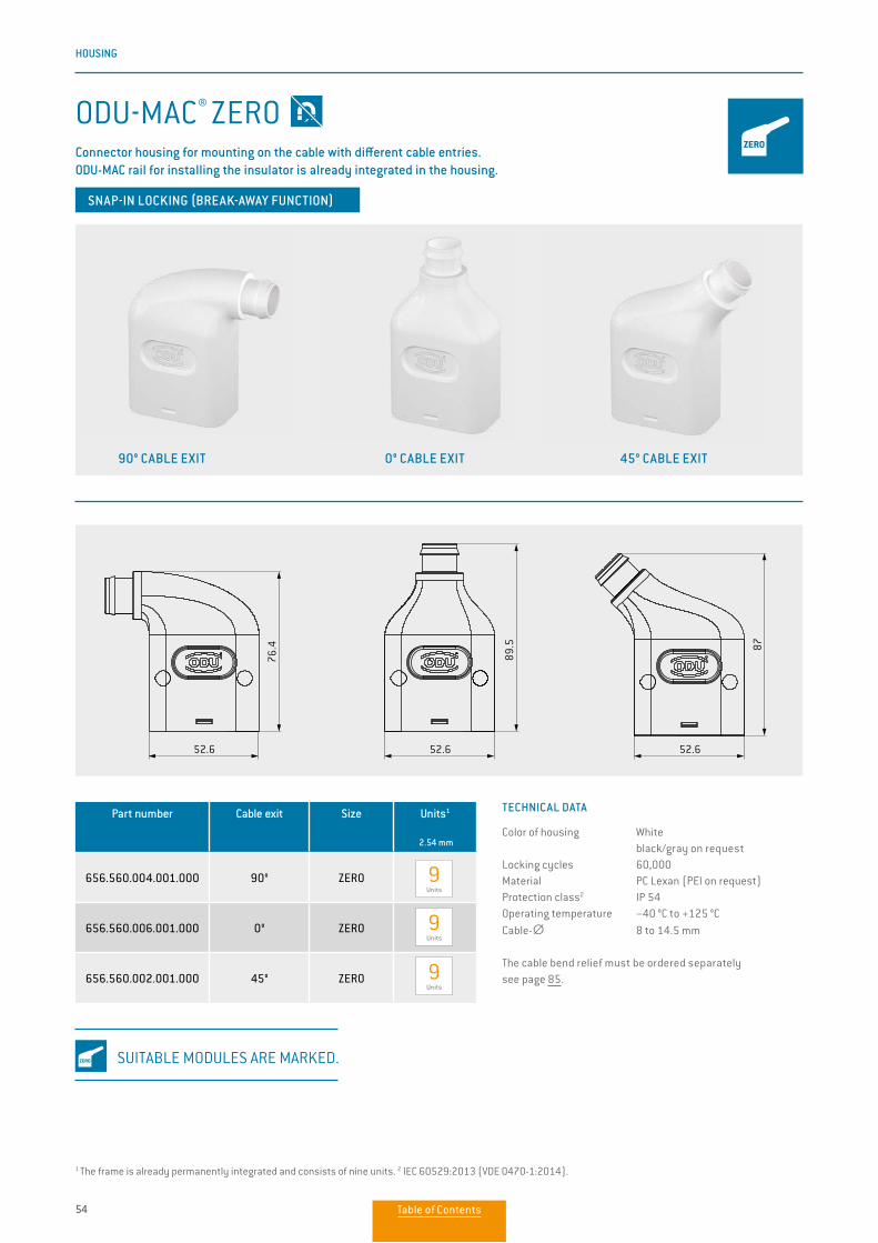
ODU-MAC® ZEROConnector housing for mounting on the cable with different cable entries.ODU-MAC rail for installing the insulator is already integrated in the housing.
SNAP-IN LOCKING (BREAK-AWAY FUNCTION)
TECHNICAL DATA
Color of housing White black/gray on request Locking cycles 60,000Material PC Lexan (PEI on request)Protection class2 IP 54Operating temperature −40 °C to +125 °CCable-∅ 8 to 14.5 mm
The cable bend relief must be ordered separately see page 85.
1 The frame is already permanently integrated and consists of nine units. 2 IEC 60529:2013 (VDE 0470-1:2014).
90° CABLE EXIT 0° CABLE EXIT 45° CABLE EXIT
Part number Cable exit Size Units1
2.54 mm
656.560.004.001.000 90° ZERO
656.560.006.001.000 0° ZERO
656.560.002.001.000 45° ZERO
9 Units
9 Units
9 Units
SUITABLE MODULES ARE MARKED.
Table of Contents
55
HOUSING
MAN
UAL
MAT
ING
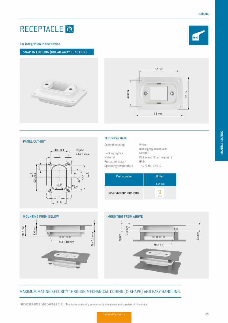
Part number Units2
2.54 mm
656.560.001.001.000 9 Units
RECEPTACLE
For integration in the device.
SNAP-IN LOCKING (BREAK-AWAY FUNCTION)
MOUNTING FROM BELOW MOUNTING FROM ABOVE
178°
ellipse33.6 × 26.2
2) Nur bei Einbaulage A
AA
13.1
1547
57.2
40 ± 0.1
33.6
R9.8
62 ±
0.1
TECHNICAL DATA
Color of housing White black/gray on request Locking cycles 60,000Material PC Lexan (PEI on request)Protection class1 IP 54Operating temperature −40 °C to +125 °C
1 IEC 60529:2013 (VDE 0470-1:2014). 2 The frame is already permanently integrated and consists of nine units.
MAXIMUM MATING SECURITY THROUGH MECHANICAL CODING (D-SHAPE) AND EASY HANDLING.
62 mm
72 mm
40 m
m
50 m
m
20.7
mm
M4 × 10 mmM4 (4 ×)
2.4
mm
2.4
mm
9 ±
0.1
mm
13 m
m
9 m
m
PANEL CUT-OUT
Table of Contents
56
HOUSING
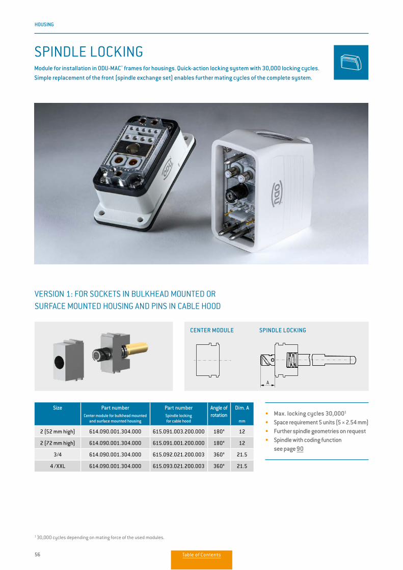
SPINDLE LOCKINGModule for installation in ODU-MAC® frames for housings. Quick-action locking system with 30,000 locking cycles. Simple replacement of the front (spindle exchange set) enables further mating cycles of the complete system.
Size Part numberCenter module for bulkhead mounted
and surface mounted housing
Part numberSpindle lockingfor cable hood
Angle of rotation
Dim. A
mm
2 (52 mm high) 614.090.001.304.000 615.091.003.200.000 180° 12
2 (72 mm high) 614.090.001.304.000 615.091.001.200.000 180° 12
3/4 614.090.001.304.000 615.092.021.200.003 360° 21.5
4 /XXL 614.090.001.304.000 615.093.021.200.003 360° 21.5
1 30,000 cycles depending on mating force of the used modules.
VERSION 1: FOR SOCKETS IN BULKHEAD MOUNTED OR SURFACE MOUNTED HOUSING AND PINS IN CABLE HOOD
A A
• Max. locking cycles 30,0001
• Space requirement 5 units (5 × 2.54 mm)• Further spindle geometries on request• Spindle with coding function
see page 90
CENTER MODULE SPINDLE LOCKING
Table of Contents
57
HOUSING
MAN
UAL
MAT
ING
1 30,000 cycles depending on mating force of the used modules.
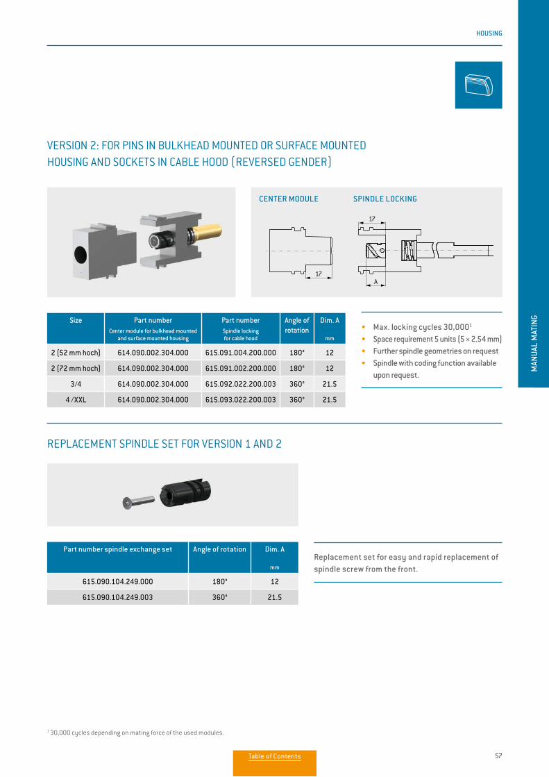
VERSION 2: FOR PINS IN BULKHEAD MOUNTED OR SURFACE MOUNTED HOUSING AND SOCKETS IN CABLE HOOD (REVERSED GENDER)
A17
17
A17
17
• Max. locking cycles 30,0001
• Space requirement 5 units (5 × 2.54 mm)• Further spindle geometries on request• Spindle with coding function available
upon request.
Size Part numberCenter module for bulkhead mounted
and surface mounted housing
Part numberSpindle lockingfor cable hood
Angle of rotation
Dim. A
mm
2 (52 mm hoch) 614.090.002.304.000 615.091.004.200.000 180° 12
2 (72 mm hoch) 614.090.002.304.000 615.091.002.200.000 180° 12
3/4 614.090.002.304.000 615.092.022.200.003 360° 21.5
4 /XXL 614.090.002.304.000 615.093.022.200.003 360° 21.5
Part number spindle exchange set Angle of rotation Dim. A
mm
615.090.104.249.000 180° 12
615.090.104.249.003 360° 21.5
REPLACEMENT SPINDLE SET FOR VERSION 1 AND 2
CENTER MODULE SPINDLE LOCKING
Replacement set for easy and rapid replacement of spindle screw from the front.
Table of Contents
58
HOUSING
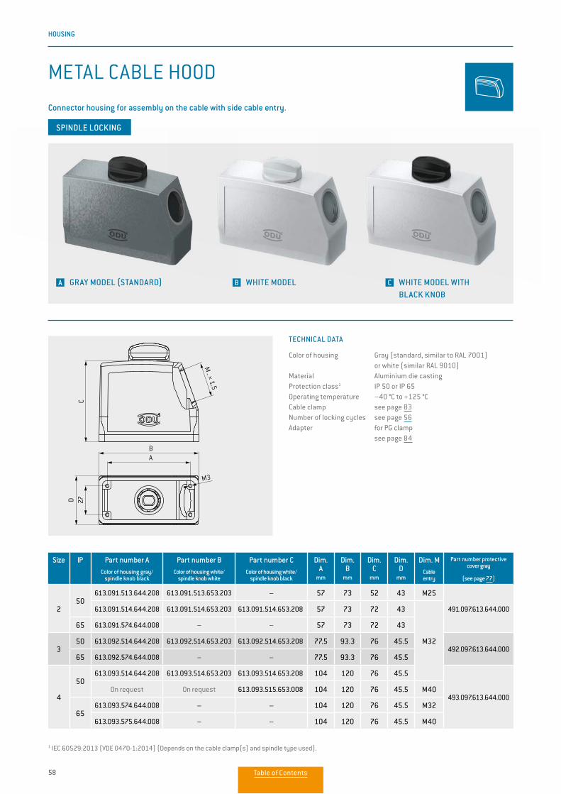
METAL CABLE HOOD
Connector housing for assembly on the cable with side cable entry.
TECHNICAL DATA
Color of housing Gray (standard, similar to RAL 7001) or white (similar RAL 9010)Material Aluminium die castingProtection class1 IP 50 or IP 65Operating temperature –40 °C to +125 °CCable clamp see page 83Number of locking cycles see page 56Adapter for PG clamp see page 84
1 IEC 60529:2013 (VDE 0470-1:2014) (Depends on the cable clamp(s) and spindle type used).
A GRAY MODEL (STANDARD) B WHITE MODEL C WHITE MODEL WITH BLACK KNOB
AB
D 27C
M _ × 1.5
M3
AB
D 27C
M _ × 1.5
M3
SPINDLE LOCKING
Size IP Part number AColor of housing gray/
spindle knob black
Part number B Color of housing white/
spindle knob white
Part number C Color of housing white/
spindle knob black
Dim. A
mm
Dim. B
mm
Dim. C
mm
Dim. D
mm
Dim. M
Cable entry
Part number protective cover gray
(see page 77)
250
613.091.513.644.208 613.091.513.653.203 – 57 73 52 43 M25
491.097.613.644.000613.091.514.644.208 613.091.514.653.203 613.091.514.653.208 57 73 72 43
M32
65 613.091.574.644.008 – – 57 73 72 43
350 613.092.514.644.208 613.092.514.653.203 613.092.514.653.208 77.5 93.3 76 45.5
492.097.613.644.00065 613.092.574.644.008 – – 77.5 93.3 76 45.5
4
50613.093.514.644.208 613.093.514.653.203 613.093.514.653.208 104 120 76 45.5
493.097.613.644.000On request On request 613.093.515.653.008 104 120 76 45.5 M40
65613.093.574.644.008 – – 104 120 76 45.5 M32
613.093.575.644.008 – – 104 120 76 45.5 M40
Table of Contents
59
HOUSING
MAN
UAL
MAT
ING
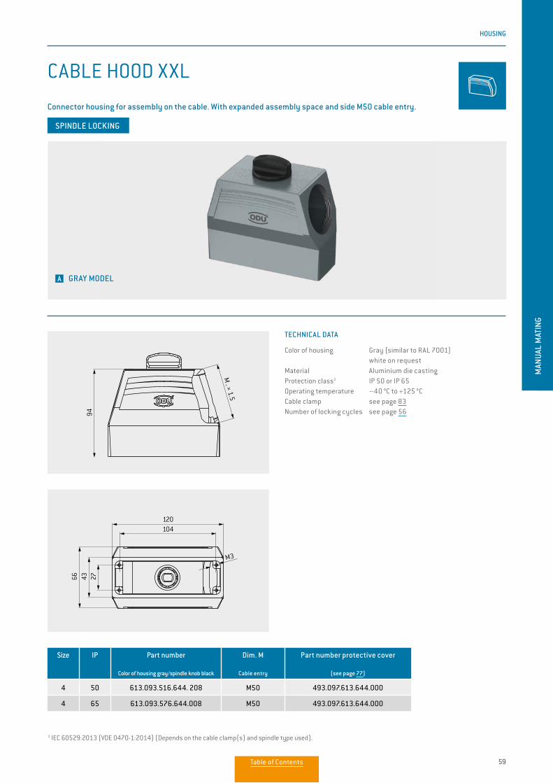
CABLE HOOD XXL
Connector housing for assembly on the cable. With expanded assembly space and side M50 cable entry.
TECHNICAL DATA
Color of housing Gray (similar to RAL 7001) white on requestMaterial Aluminium die castingProtection class1 IP 50 or IP 65Operating temperature –40 °C to +125 °CCable clamp see page 83Number of locking cycles see page 56
1 IEC 60529:2013 (VDE 0470-1:2014) (Depends on the cable clamp(s) and spindle type used).
A GRAY MODEL
94
104120
274366
M3
M _ × 1.5
94
104120
274366
M3
M _ × 1.5
SPINDLE LOCKING
Size IP Part number
Color of housing gray/spindle knob black
Dim. M
Cable entry
Part number protective cover
(see page 77)
4 50 613.093.516.644. 208 M50 493.097.613.644.000
4 65 613.093.576.644.008 M50 493.097.613.644.000
Table of Contents
60
HOUSING
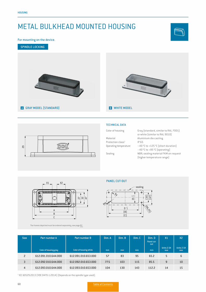
TECHNICAL DATA
Color of housing Gray (standard, similar to RAL 7001) or white (similar to RAL 9010)Material Aluminium die castingProtection class1 IP 65Operating temperature –40 °C to +125 °C (short duration)
–40 °C to +85 °C (operating)Sealing NBR; sealing material FKM on request
(higher temperature range)
SPINDLE LOCKING
Size Part number A
Color of housing gray
Part number B
Color of housing white
Dim. A
mm
Dim. B
mm
Dim. C
mm
Dim. DPanel cut-
out
mm
X1
Units 2.54
mm
X2
Units 2.54
mm
2 612.091.010.644.000 612.091.010.653.000 57 83 95 65.2 5 6
3 612.092.010.644.000 612.092.010.653.000 77.5 103 115 85.5 9 10
4 612.093.010.644.000 612.093.010.653.000 104 130 143 112.2 14 15
1 IEC 60529:2013 (VDE 0470-1:2014) (Depends on the spindle type used).
The frames depicted must be ordered separately, see page 82.
E29
27 32 47
ABC
M3
17
ca.25
5.3
4.5
(47)
(C)
(R6,25)
sealing
R4
(B)
(32)
M4
35+1 0
D +1 0
For mounting on the device.
METAL BULKHEAD MOUNTED HOUSING
A GRAY MODEL (STANDARD) B WHITE MODEL
PANEL CUT-OUT
29
B
M 32 × 1,5 (M
25)A
R4
47
M4
R6,25
X1 X2
27
CBA
4732
sealing
CB
+1 0
35+1 0
Table of Contents
61
HOUSING
MAN
UAL
MAT
ING
1 IEC 60529:2013 (VDE 0470-1:2014) (Depends on the cable clamp(s) and spindle type used).
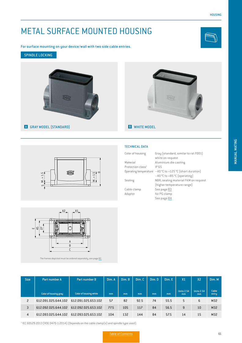
METAL SURFACE MOUNTED HOUSING
For surface mounting on your device/wall with two side cable entries.
TECHNICAL DATA
Color of housing Gray (standard, similar to ral 7001) white on requestMaterial Aluminium die castingProtection class1 IP 65Operating temperature −40 °C to +125 °C (short duration) −40 °C to +85 °C (operating)Sealing NBR; sealing material FKM on request (higher temperature range)Cable clamp See page 83Adapter for PG clamp See page 84
SPINDLE LOCKING
A GRAY MODEL (STANDARD) B WHITE MODEL
Size Part number A
Color of housing gray
Part number B
Color of housing white
Dim. A
mm
Dim. B
mm
Dim. C
mm
Dim. D
mm
Dim. E
mm
X1
Units 2.54
mm
X2
Units 2.54
mm
Dim. M
Cable entry
2 612.091.025.644.102 612.091.025.653.102 57 82 92.5 74 55.5 5 6 M32
3 612.092.025.644.102 612.092.025.653.102 77.5 105 117 84 56.5 9 10 M32
4 612.093.025.644.102 612.093.025.653.102 104 132 144 84 57.5 14 15 M32
The frames depicted must be ordered separately, see page 82.
27
120
D
5M
_ × 1
.5
M _ ×
1.5
X2 X1
BC
E 45 27
A
27
120
D
5M
_ × 1
.5
M _ ×
1.5
X2 X1
BC
E 45 27
A
Table of Contents
62
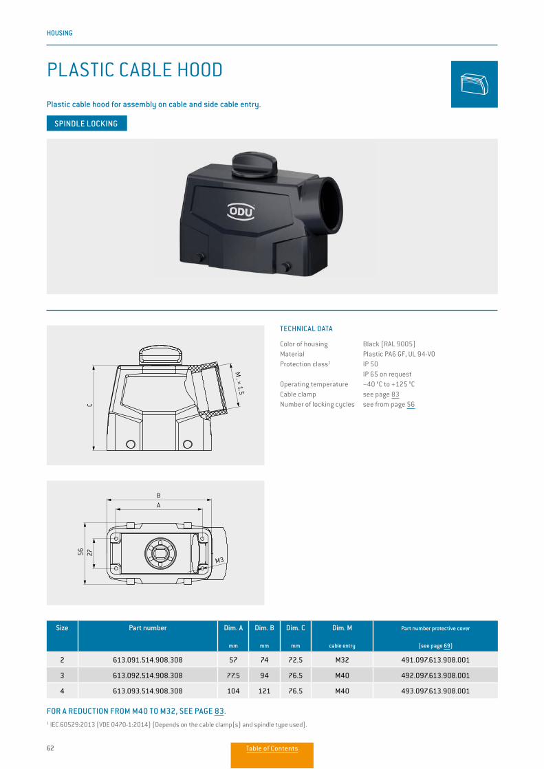
HOUSING
TECHNICAL DATA
Color of housing Black (RAL 9005)Material Plastic PA6 GF, UL 94-V0Protection class1 IP 50
IP 65 on requestOperating temperature −40 °C to +125 °CCable clamp see page 83Number of locking cycles see from page 56
FOR A REDUCTION FROM M40 TO M32, SEE PAGE 83.
Size Part number Dim. A
mm
Dim. B
mm
Dim. C
mm
Dim. M
cable entry
Part number protective cover
(see page 69)
2 613.091.514.908.308 57 74 72.5 M32 491.097.613.908.001
3 613.092.514.908.308 77.5 94 76.5 M40 492.097.613.908.001
4 613.093.514.908.308 104 121 76.5 M40 493.097.613.908.001
SPINDLE LOCKING
1 IEC 60529:2013 (VDE 0470-1:2014) (Depends on the cable clamp(s) and spindle type used).
PLASTIC CABLE HOOD
Plastic cable hood for assembly on cable and side cable entry.
M _ × 1.5
AB
C 27
56
M3
M _ × 1.5
AB
C 27
56
M3
Table of Contents
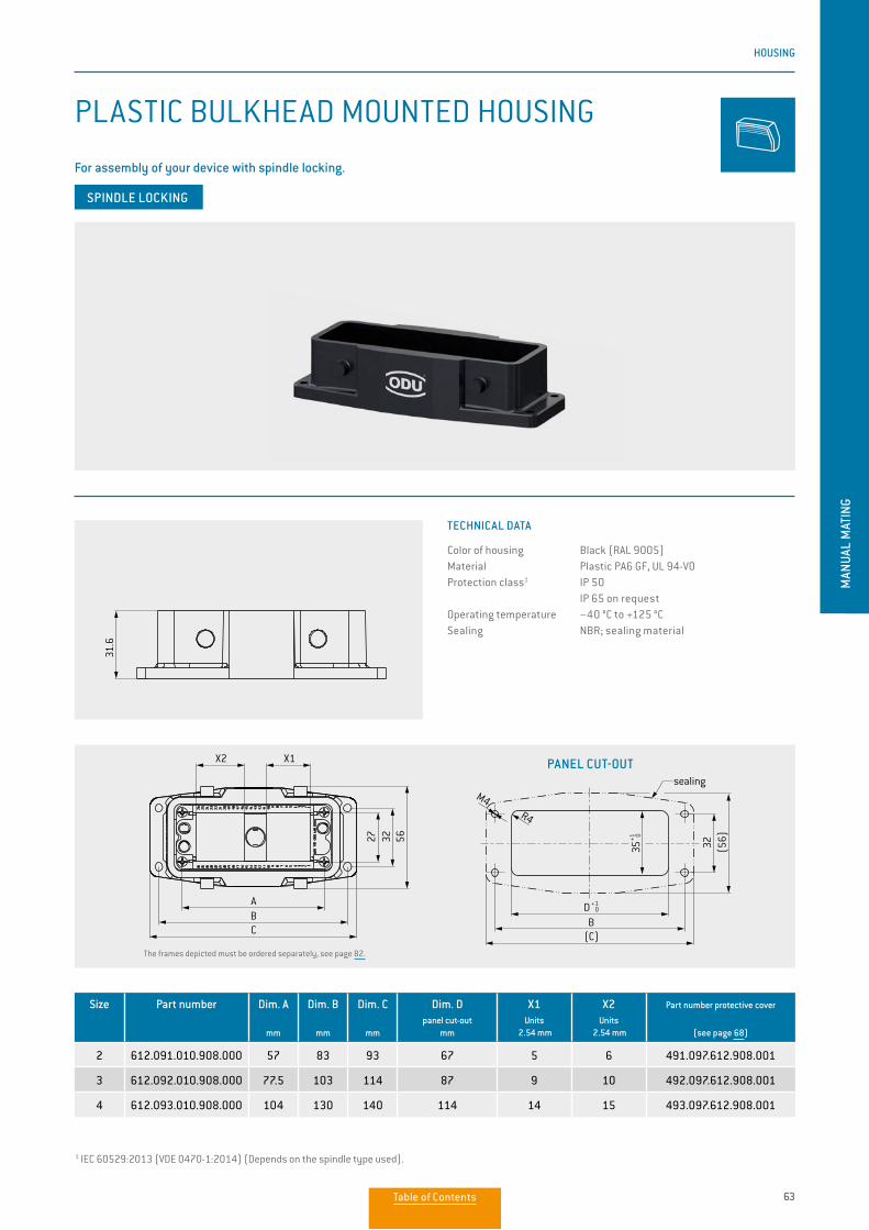
63
HOUSING
MAN
UAL
MAT
ING
TECHNICAL DATA
Color of housing Black (RAL 9005)Material Plastic PA6 GF, UL 94-V0Protection class1 IP 50
IP 65 on requestOperating temperature −40 °C to +125 °CSealing NBR; sealing material
Size Part number Dim. A
mm
Dim. B
mm
Dim. C
mm
Dim. Dpanel cut-out
mm
X1Units
2.54 mm
X2Units
2.54 mm
Part number protective cover
(see page 68)
2 612.091.010.908.000 57 83 93 67 5 6 491.097.612.908.001
3 612.092.010.908.000 77.5 103 114 87 9 10 492.097.612.908.001
4 612.093.010.908.000 104 130 140 114 14 15 493.097.612.908.001
SPINDLE LOCKING
1 IEC 60529:2013 (VDE 0470-1:2014) (Depends on the spindle type used).
PLASTIC BULKHEAD MOUNTED HOUSING
For assembly of your device with spindle locking.
PANEL CUT-OUT
The frames depicted must be ordered separately, see page 82.
X2
ABC
27
32
56
X1
31.6
sealing
X2 X1
563227(5
6)32
CBA
(C)B
35+1 0
D +1 0
M4R4
M3
(4×)
sealing
X2 X1
563227(5
6)32
CBA
(C)B
35+1 0
D +1 0
M4R4
M3
(4×)
Table of Contents
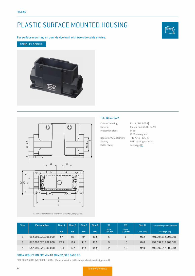
64
HOUSING
SPINDLE LOCKING
Size Part number Dim. A
mm
Dim. B
mm
Dim. C
mm
Dim. D
mm
X1Units
2.54 mm
X2Units
2.54 mm
Dim. M
Cable entry
Part number protective cover
(see page 68)
2 612.091.020.908.000 57 82 94 81.5 5 6 M32 491.097.612.908.001
3 612.092.020.908.000 77.5 105 117 81.5 9 10 M40 492.097.612.908.001
4 612.093.020.908.000 104 132 144 81.5 14 15 M40 493.097.612.908.001
PLASTIC SURFACE MOUNTED HOUSING
For surface mounting on your device/wall with two side cable entries.
TECHNICAL DATA
Color of housing Black (RAL 9005)Material Plastic PA6 GF, UL 94-V0Protection class1 IP 50
IP 65 on requestOperating temperature −40 °C to +125 °CSealing NBR; sealing materialCable clamp see page 83
D
5274557
ABC
M_ ×
1.5
X2 X1
M_ ×
1.5
The frames depicted must be ordered separately, see page 82.
1 IEC 60529:2013 (VDE 0470-1:2014) (Depends on the cable clamp(s) and spindle type used).
FOR A REDUCTION FROM M40 TO M32, SEE PAGE 83.
Table of Contents
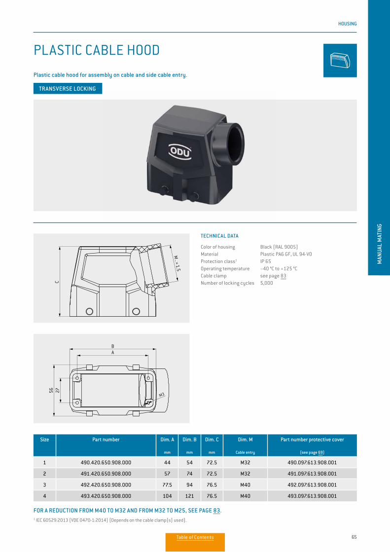
65
HOUSING
MAN
UAL
MAT
ING
FOR A REDUCTION FROM M40 TO M32 AND FROM M32 TO M25, SEE PAGE 83.
Size Part number Dim. A
mm
Dim. B
mm
Dim. C
mm
Dim. M
Cable entry
Part number protective cover
(see page 69)
1 490.420.650.908.000 44 54 72.5 M32 490.097.613.908.001
2 491.420.650.908.000 57 74 72.5 M32 491.097.613.908.001
3 492.420.650.908.000 77.5 94 76.5 M40 492.097.613.908.001
4 493.420.650.908.000 104 121 76.5 M40 493.097.613.908.001
PLASTIC CABLE HOOD
Plastic cable hood for assembly on cable and side cable entry.
TRANSVERSE LOCKING
TECHNICAL DATA
Color of housing Black (RAL 9005)Material Plastic PA6 GF, UL 94-V0Protection class1 IP 65Operating temperature −40 °C to +125 °CCable clamp see page 83Number of locking cycles 5,000
1 IEC 60529:2013 (VDE 0470-1:2014) (Depends on the cable clamp(s) used).
C
A
M3
M _ ×
1.5
B
56 27C
A
M3
M _ ×
1.5
B
56 27
Table of Contents
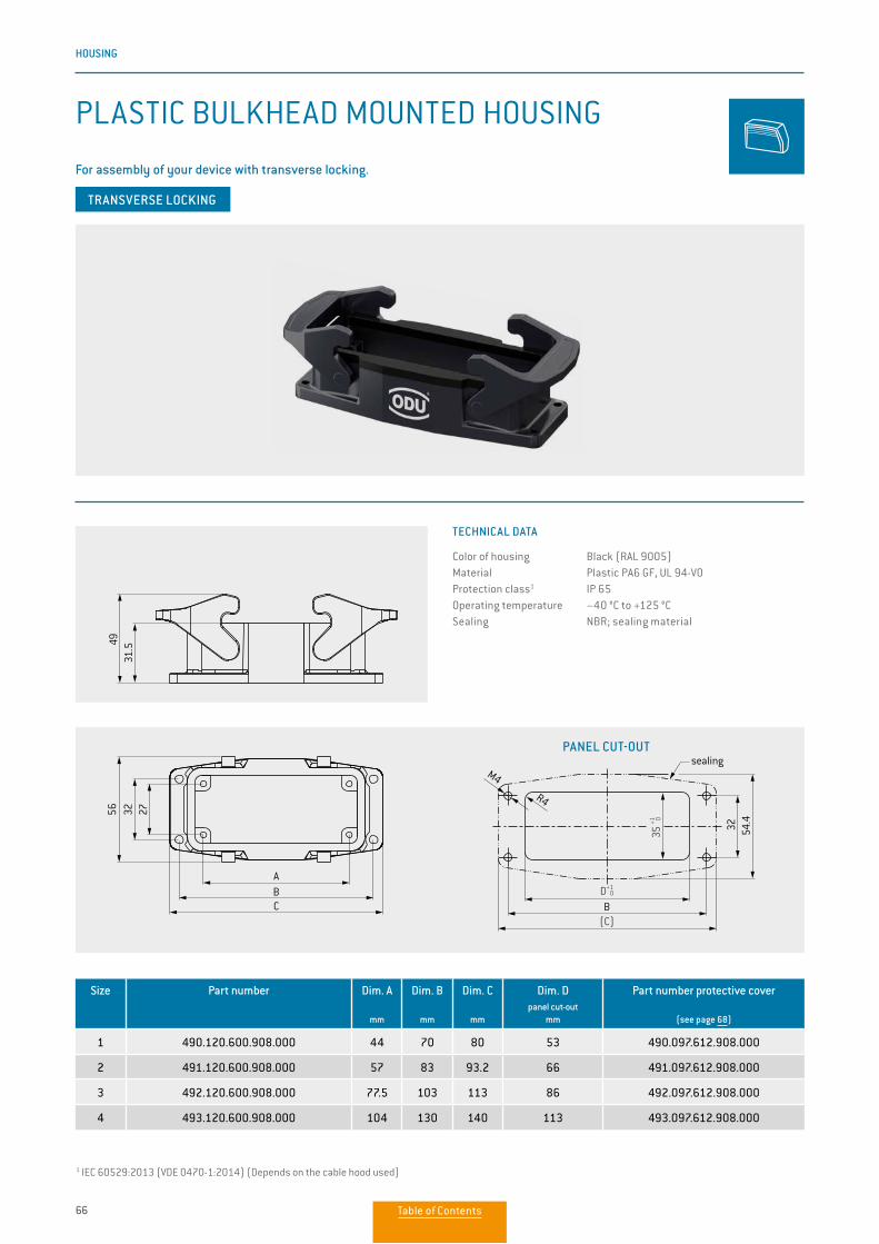
66
HOUSING
PANEL CUT-OUT
Size Part number Dim. A
mm
Dim. B
mm
Dim. C
mm
Dim. Dpanel cut-out
mm
Part number protective cover
(see page 68)
1 490.120.600.908.000 44 70 80 53 490.097.612.908.000
2 491.120.600.908.000 57 83 93.2 66 491.097.612.908.000
3 492.120.600.908.000 77.5 103 113 86 492.097.612.908.000
4 493.120.600.908.000 104 130 140 113 493.097.612.908.000
PLASTIC BULKHEAD MOUNTED HOUSING
For assembly of your device with transverse locking.
TECHNICAL DATA
Color of housing Black (RAL 9005)Material Plastic PA6 GF, UL 94-V0Protection class1 IP 65 Operating temperature −40 °C to +125 °CSealing NBR; sealing material
1 IEC 60529:2013 (VDE 0470-1:2014) (Depends on the cable hood used)
27
A
4931
.5
BC
3256 27
A
4931
.5
BC
3256
32 54.4
M4
R4
B
sealing
(C)
D+1 0
35+1 0
TRANSVERSE LOCKING
Table of Contents
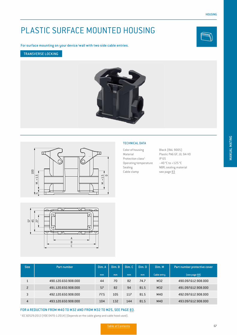
67
HOUSING
MAN
UAL
MAT
ING
TRANSVERSE LOCKING
PLASTIC SURFACE MOUNTED HOUSING
For surface mounting on your device/wall with two side cable entries.
Size Part number Dim. A
mm
Dim. B
mm
Dim. C
mm
Dim. D
mm
Dim. M
Cable entry
Part number protective cover
(see page 68)
1 490.120.650.908.000 44 70 82 74.7 M32 490.097.612.908.000
2 491.120.650.908.000 57 82 94 81.5 M32 491.097.612.908.000
3 492.120.650.908.000 77.5 105 117 81.5 M40 492.097.612.908.000
4 493.120.650.908.000 104 132 144 81.5 M40 493.097.612.908.000
100
57 45 27
ABC
D
5M
_ ×1.
5
M _ ×
1.5
100
57 45 27
ABC
D
5M
_ ×1.
5
M _ ×
1.5
TECHNICAL DATA
Color of housing Black (RAL 9005)Material Plastic PA6 GF, UL 94-V0Protection class1 IP 65Operating temperature −40 °C to +125 °CSealing NBR; sealing materialCable clamp see page 83
FOR A REDUCTION FROM M40 TO M32 AND FROM M32 TO M25, SEE PAGE 83.1 IEC 60529:2013 (VDE 0470-1:2014) (Depends on the cable glamp and cable hood used).
Table of Contents
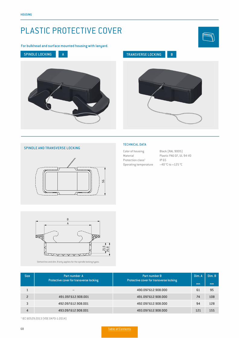
68
HOUSING
PLASTIC PROTECTIVE COVER
For bulkhead and surface mounted housing with lanyard.
TECHNICAL DATA
Color of housing Black (RAL 9005)Material Plastic PA6 GF, UL 94-V0Protection class1 IP 65 Operating temperature −40 °C to +125 °C
1 IEC 60529:2013 (VDE 0470-1:2014)
TRANSVERSE LOCKING
Size Part number AProtective cover for transverse locking
Part number BProtective cover for transverse locking
Dim. A
mm
Dim. B
mm
1 – 490.097.612.908.000 61 95
2 491.097.612.908.001 491.097.612.908.000 74 108
3 492.097.612.908.001 492.097.612.908.000 94 128
4 493.097.612.908.001 493.097.612.908.000 121 155
BA
21.6
5626
.8
BA
21.6
5626
.8
BA
SPINDLE AND TRANSVERSE LOCKING
Dotted line and dim. B only applies for the spindle locking types.
SPINDLE LOCKING
Table of Contents
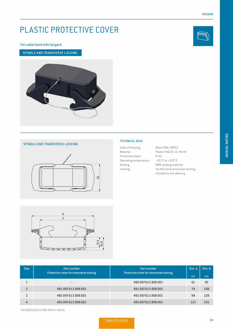
69
HOUSING
MAN
UAL
MAT
ING
TECHNICAL DATA
Color of housing Black (RAL 9005)Material Plastic PA6 GF, UL 94-V0Protection class1 IP 65 Operating temperature −40 °C to +125 °CSealing NBR; sealing materialLocking via the transverse lever locking included in the delivery
PLASTIC PROTECTIVE COVER
For cable hood with lanyard.
1 IEC 60529:2013 (VDE 0470-1:2014)
SPINDLE AND TRANSVERSE LOCKING
Size Part number Protective cover for transverse locking
Part number Protective cover for transverse locking
Dim. A
mm
Dim. B
mm
1 – 490.097.613.908.001 61 95
2 491.097.613.908.001 491.097.613.908.001 74 108
3 492.097.613.908.001 492.097.613.908.001 94 128
4 493.097.613.908.001 493.097.613.908.001 121 155
BA
21.6
5626
.8
BA
21.6
5626
.8
SPINDLE AND TRANSVERSE LOCKING
Table of Contents
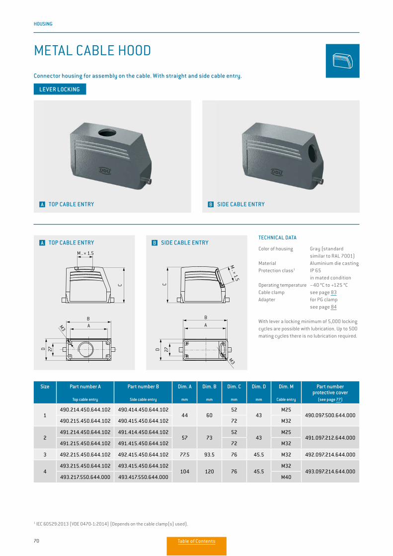
70
HOUSING
Size Part number A
Top cable entry
Part number B
Side cable entry
Dim. A
mm
Dim. B
mm
Dim. C
mm
Dim. D
mm
Dim. M
Cable entry
Part number protective cover
(see page 77)
1490.214.450.644.102 490.414.450.644.102
44 6052
43M25
490.097.500.644.000490.215.450.644.102 490.415.450.644.102 72 M32
2491.214.450.644.102 491.414.450.644.102
57 7352
43M25
491.097.212.644.000491.215.450.644.102 491.415.450.644.102 72 M32
3 492.215.450.644.102 492.415.450.644.102 77.5 93.5 76 45.5 M32 492.097.214.644.000
4493.215.450.644.102 493.415.450.644.102
104 120 76 45.5M32
493.097.214.644.000493.217.550.644.000 493.417.550.644.000 M40
LEVER LOCKING
1 IEC 60529:2013 (VDE 0470-1:2014) (Depends on the cable clamp(s) used).
A TOP CABLE ENTRY B SIDE CABLE ENTRY
METAL CABLE HOOD
Connector housing for assembly on the cable. With straight and side cable entry.
A TOP CABLE ENTRY B SIDE CABLE ENTRY
M _ × 1.5
AB
M3
C
27D
M _ × 1.5
A
B
M3C
27D
TECHNICAL DATA
Color of housing Gray (standard similar to RAL 7001)Material Aluminium die castingProtection class1 IP 65
in mated conditionOperating temperature −40 °C to +125 °C Cable clamp see page 83Adapter for PG clamp see page 84
With lever a locking minimum of 5,000 locking cycles are possible with lubrication. Up to 500 mating cycles there is no lubrication required.
Table of Contents
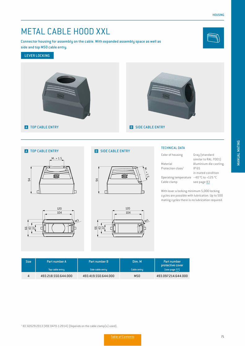
71
HOUSING
MAN
UAL
MAT
ING
Size Part number A
Top cable entry
Part number B
Side cable entry
Dim. M
Cable entry
Part number protective cover
(see page 77)
4 493.218.550.644.000 493.419.550.644.000 M50 493.097.214.644.000
LEVER LOCKING
1 IEC 60529:2013 (VDE 0470-1:2014) (Depends on the cable clamp(s) used).
A TOP CABLE ENTRY B SIDE CABLE ENTRY
METAL CABLE HOOD XXLConnector housing for assembly on the cable. With expanded assembly space as well as side and top M50 cable entry.
B SIDE CABLE ENTRY
120104
M3
2794
4366
M _ × 1.5
M3
M3
27
27
944366
120
120
104
M _ × 1.5
M3
M3
27
27
944366
120
120
104
M _ × 1.5
120104
M3
2794
4366M
_ × 1.5
A TOP CABLE ENTRYTECHNICAL DATA
Color of housing Gray (standard similar to RAL 7001)Material Aluminium die castingProtection class1 IP 65
in mated conditionOperating temperature −40 °C to +125 °C Cable clamp see page 83
With lever a locking minimum 5,000 locking cycles are possible with lubrication. Up to 500 mating cycles there is no lubrication required.
Table of Contents
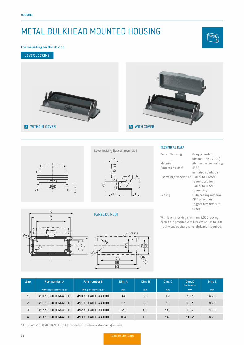
72
HOUSING
Size Part number A
Without protective cover
Part number B
With protective cover
Dim. A
mm
Dim. B
mm
Dim. C
mm
Dim. DPanel cut-out
mm
Dim. E
mm
1 490.130.400.644.000 490.131.400.644.000 44 70 82 52.2 ≈ 22
2 491.130.400.644.000 491.131.400.644.000 57 83 95 65.2 ≈ 27
3 492.130.400.644.000 492.131.400.644.000 77.5 103 115 85.5 ≈ 28
4 493.130.400.644.000 493.131.400.644.000 104 130 143 112.2 ≈ 28
Lever locking (just an example)
PANEL CUT-OUT
A WITHOUT COVER B WITH COVER
METAL BULKHEAD MOUNTED HOUSING
For mounting on the device.
E
29
27 32 47
ABC
M3
17
ca.25
5.3
4.5
(47)
(C)
(R6,25)
R4
(B)
(32)
M4
sealing
35+1 0
D +1 0
E
29
27 32 47
ABC
M3
17
ca.25
5.3
4.5
(47)
(C)
(R6,25)
R4
(B)
(32)
M4
sealing
35+1 0
D +1 0
E
29
27 32 47
ABC
M3
17
ca.25
5.3
4.5
(47)
(C)
(R6,25)
R4
(B)
(32)
M4
sealing
35+1 0
D +1 0
E
29
27 32 47
ABC
M3
17
ca.25
5.3
4.5
(47)
(C)
(R6,25)
R4
(B)
(32)
M4
sealing
35+1 0
D +1 0
TECHNICAL DATA
Color of housing Gray (standard similar to RAL 7001)Material Aluminium die castingProtection class1 IP 65
in mated conditionOperating temperature −40 °C to +125 °C
(short duration) −40 °C to +85°C (operating)Sealing NBR; sealing material
FKM on request (higher temperature range)
With lever a locking minimum 5,000 locking cycles are possible with lubrication. Up to 500 mating cycles there is no lubrication required.
1 IEC 60529:2013 (VDE 0470-1:2014) (Depends on the hood cable clamp(s) used).
LEVER LOCKING
Table of Contents
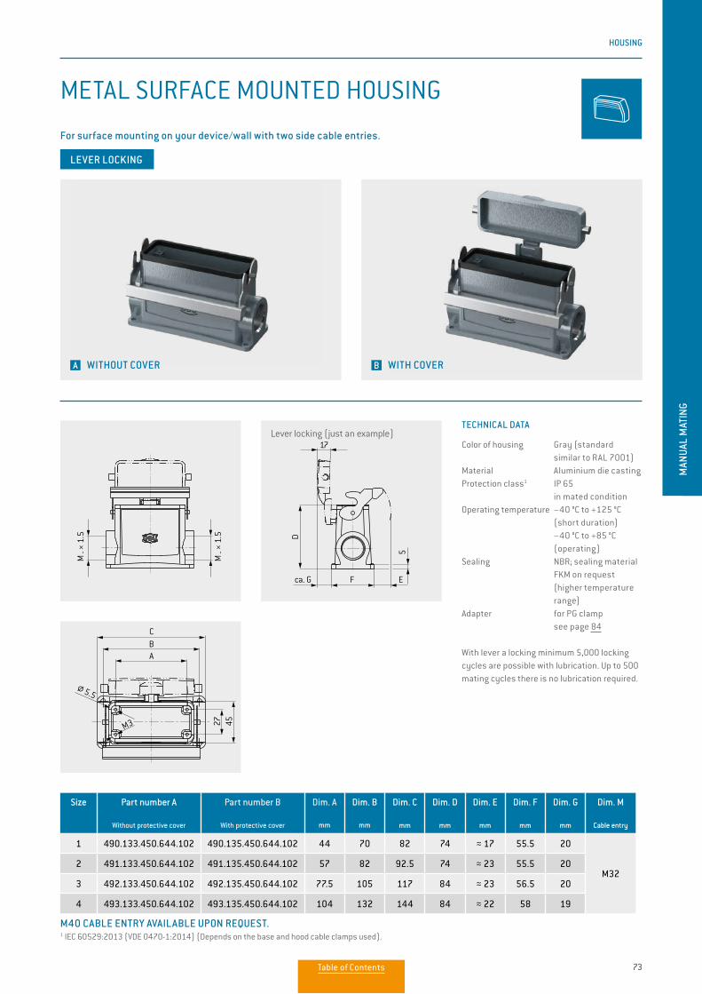
73
HOUSING
MAN
UAL
MAT
ING
Size Part number A
Without protective cover
Part number B
With protective cover
Dim. A
mm
Dim. B
mm
Dim. C
mm
Dim. D
mm
Dim. E
mm
Dim. F
mm
Dim. G
mm
Dim. M
Cable entry
1 490.133.450.644.102 490.135.450.644.102 44 70 82 74 ≈ 17 55.5 20
M322 491.133.450.644.102 491.135.450.644.102 57 82 92.5 74 ≈ 23 55.5 20
3 492.133.450.644.102 492.135.450.644.102 77.5 105 117 84 ≈ 23 56.5 20
4 493.133.450.644.102 493.135.450.644.102 104 132 144 84 ≈ 22 58 19
A WITHOUT COVER B WITH COVER
METAL SURFACE MOUNTED HOUSING
For surface mounting on your device/wall with two side cable entries.
Lever locking (just an example)
5.5
D
F
M _ ×
1.5
M _ ×
1.5
CBA
27 45
E
17
ca. G
M3
5
5.5
D
F
M _ ×
1.5
M _ ×
1.5
CBA
27 45
E
17
ca. G
M3
5
5.5
D
F
M _ ×
1.5
M _ ×
1.5
CBA
27 45
E
17
ca. G
M3
5
TECHNICAL DATA
Color of housing Gray (standard similar to RAL 7001)Material Aluminium die castingProtection class1 IP 65
in mated conditionOperating temperature −40 °C to +125 °C (short duration) −40 °C to +85 °C (operating)Sealing NBR; sealing material
FKM on request (higher temperature range)
Adapter for PG clamp see page 84
With lever a locking minimum 5,000 locking cycles are possible with lubrication. Up to 500 mating cycles there is no lubrication required.
1 IEC 60529:2013 (VDE 0470-1:2014) (Depends on the base and hood cable clamps used).M40 CABLE ENTRY AVAILABLE UPON REQUEST.
LEVER LOCKING
Table of Contents
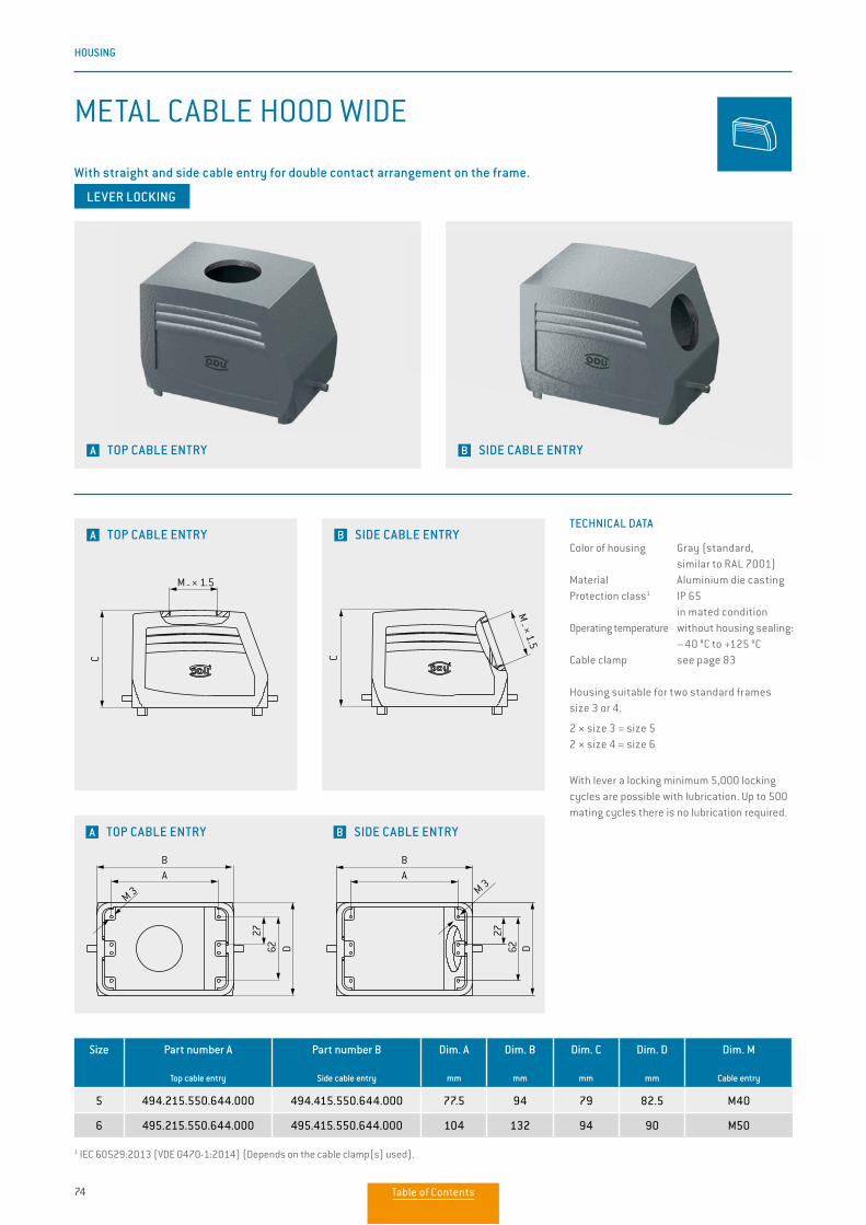
74
HOUSING
Size Part number A
Top cable entry
Part number B
Side cable entry
Dim. A
mm
Dim. B
mm
Dim. C
mm
Dim. D
mm
Dim. M
Cable entry
5 494.215.550.644.000 494.415.550.644.000 77.5 94 79 82.5 M40
6 495.215.550.644.000 495.415.550.644.000 104 132 94 90 M50
1 IEC 60529:2013 (VDE 0470-1:2014) (Depends on the cable clamp(s) used).
A TOP CABLE ENTRY B SIDE CABLE ENTRY
METAL CABLE HOOD WIDE
With straight and side cable entry for double contact arrangement on the frame.
A TOP CABLE ENTRY B SIDE CABLE ENTRY
A TOP CABLE ENTRY B SIDE CABLE ENTRY
TECHNICAL DATA
Color of housing Gray (standard, similar to RAL 7001)Material Aluminium die castingProtection class1 IP 65
in mated conditionOperating temperature without housing sealing:
–40 °C to +125 °CCable clamp see page 83
Housing suitable for two standard frames size 3 or 4.
2 × size 3 = size 52 × size 4 = size 6
With lever a locking minimum 5,000 locking cycles are possible with lubrication. Up to 500 mating cycles there is no lubrication required.
CC
M 3 M 3
M _ × 1.5
M _ × 1.5
BA
2762 D
BA
2762 D
CC
M 3 M 3
M _ × 1.5
M _ × 1.5
BA
2762 D
BA
2762 D
CC
M 3 M 3
M _ × 1.5
M _ × 1.5
BA
2762 D
BA
2762 D
LEVER LOCKING
Table of Contents
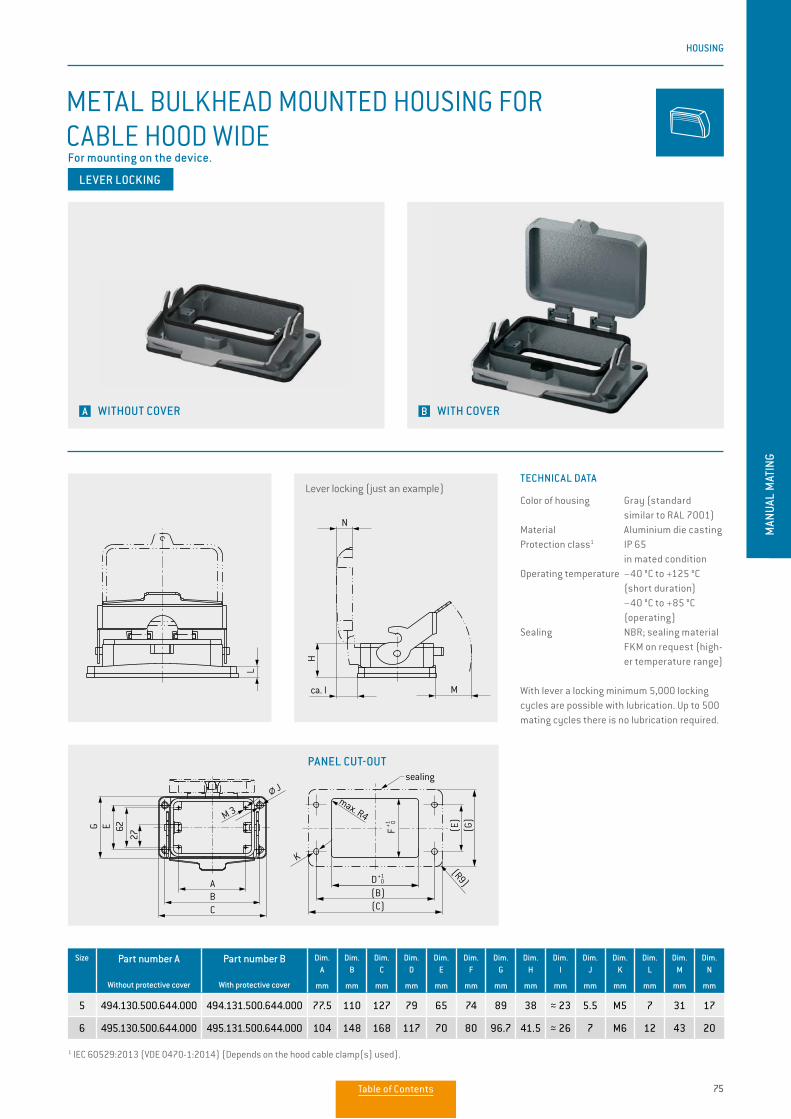
75
HOUSING
MAN
UAL
MAT
ING
Size Part number A
Without protective cover
Part number B
With protective cover
Dim. A
mm
Dim. B
mm
Dim. C
mm
Dim. D
mm
Dim. E
mm
Dim. F
mm
Dim. G
mm
Dim. H
mm
Dim. I
mm
Dim. J
mm
Dim. K
mm
Dim. L
mm
Dim. M
mm
Dim. N
mm
5 494.130.500.644.000 494.131.500.644.000 77.5 110 127 79 65 74 89 38 ≈ 23 5.5 M5 7 31 17
6 495.130.500.644.000 495.131.500.644.000 104 148 168 117 70 80 96.7 41.5 ≈ 26 7 M6 12 43 20
1 IEC 60529:2013 (VDE 0470-1:2014) (Depends on the hood cable clamp(s) used).
A WITHOUT COVER B WITH COVER
METAL BULKHEAD MOUNTED HOUSING FOR CABLE HOOD WIDEFor mounting on the device.
PANEL CUT-OUT
TECHNICAL DATA
Color of housing Gray (standard similar to RAL 7001)Material Aluminium die castingProtection class1 IP 65
in mated conditionOperating temperature −40 °C to +125 °C
(short duration) −40 °C to +85 °C (operating)Sealing NBR; sealing material
FKM on request (high-er temperature range)
With lever a locking minimum 5,000 locking cycles are possible with lubrication. Up to 500 mating cycles there is no lubrication required.
Lever locking (just an example)
2762E
ABC
G
M 3
M 3N
L
M
A
Gr. 5: M 40 x 1,5Gr. 6: M 50 x 1,5
B
62 D
C
27
Montageausschnitt
ca. I
H
J
(C)
(G)
(R9)
(E)
(B)
max. R4
K
sealing
D+1 0
F+1 0
2762E
ABC
G
M 3
M 3N
L
M
A
Gr. 5: M 40 x 1,5Gr. 6: M 50 x 1,5
B
62 D
C
27
Montageausschnitt
ca. I
H
J
(C)
(G)
(R9)
(E)
(B)
max. R4
K
sealing
D+1 0
F+1 0
2762E
ABC
G
M 3
M 3N
L
M
A
Gr. 5: M 40 x 1,5Gr. 6: M 50 x 1,5
B
62 D
C
27
Montageausschnitt
ca. I
H
J
(C)
(G)
(R9)
(E)
(B)
max. R4
K
sealing
D+1 0
F+1 0
2762E
ABC
G
M 3
M 3N
L
M
A
Gr. 5: M 40 x 1,5Gr. 6: M 50 x 1,5
B
62 D
C
27
Montageausschnitt
ca. I
H
J
(C)
(G)
(R9)
(E)
(B)
max. R4
K
sealing
D+1 0
F+1 0
LEVER LOCKING
Table of Contents
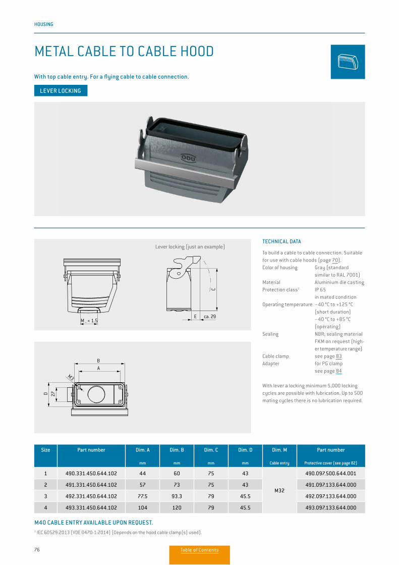
76
HOUSING
TECHNICAL DATA
To build a cable to cable connection. Suitable for use with cable hoods (page 70).Color of housing Gray (standard similar to RAL 7001)Material Aluminium die castingProtection class1 IP 65
in mated conditionOperating temperature −40 °C to +125 °C
(short duration) −40 °C to +85 °C (operating)Sealing NBR; sealing material
FKM on request (high-er temperature range)
Cable clamp see page 83Adapter for PG clamp see page 84
With lever a locking minimum 5,000 locking cycles are possible with lubrication. Up to 500 mating cycles there is no lubrication required.
Size Part number Dim. A
mm
Dim. B
mm
Dim. C
mm
Dim. D
mm
Dim. M
Cable entry
Part number
Protective cover (see page 82)
1 490.331.450.644.102 44 60 75 43
M32
490.097.500.644.001
2 491.331.450.644.102 57 73 75 43 491.097.133.644.000
3 492.331.450.644.102 77.5 93.3 79 45.5 492.097.133.644.000
4 493.331.450.644.102 104 120 79 45.5 493.097.133.644.000
METAL CABLE TO CABLE HOOD
Lever locking (just an example)
AM _ × 1.5 ca. 29E
AB
DC 27
M3
43
AM _ × 1.5 ca. 29E
AB
DC 27
M3
43
AM _ × 1.5 ca. 29E
AB
DC 27
M3
43
1 IEC 60529:2013 (VDE 0470-1:2014) (Depends on the hood cable clamp(s) used).
M40 CABLE ENTRY AVAILABLE UPON REQUEST.
LEVER LOCKING
With top cable entry. For a flying cable to cable connection.
Table of Contents
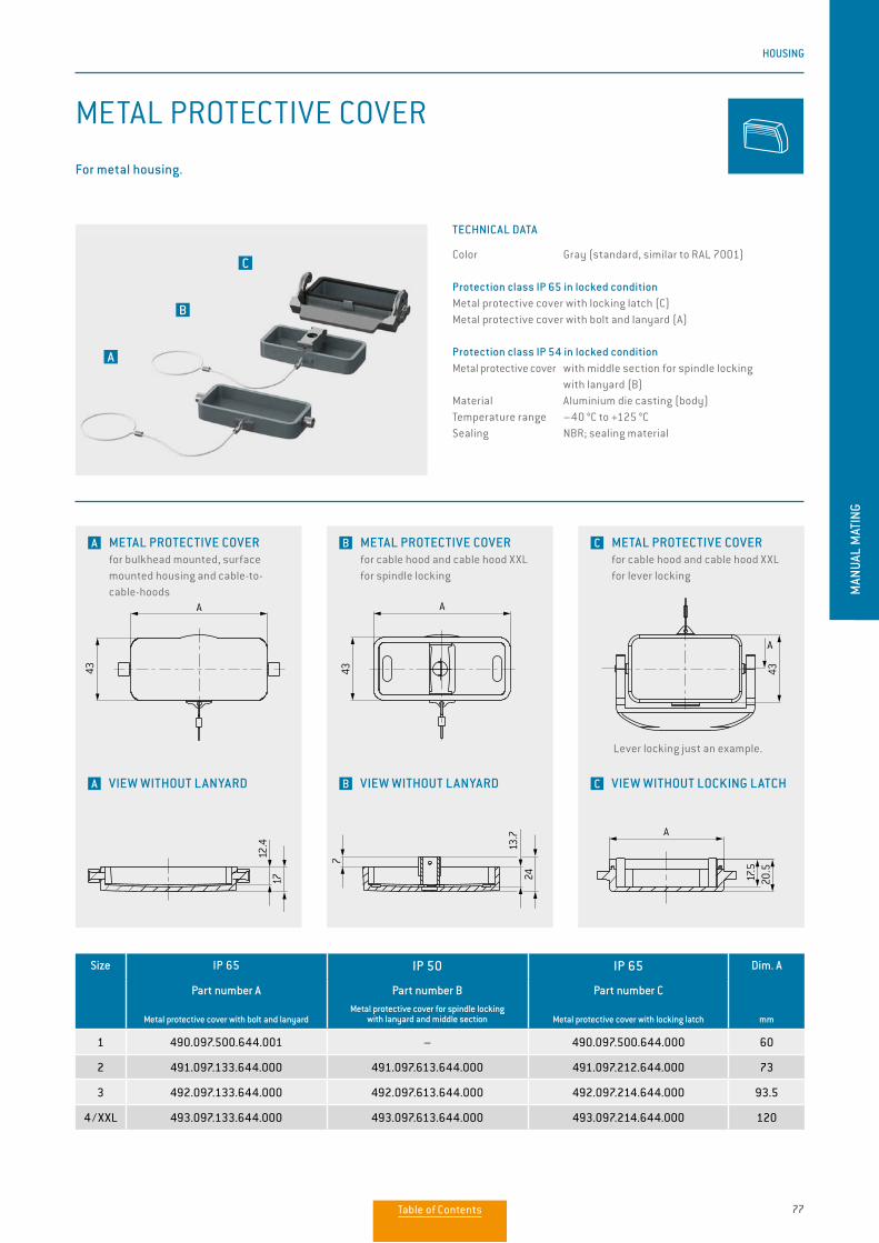
77
HOUSING
MAN
UAL
MAT
ING
Size IP 65 IP 50 IP 65 Dim. A
mm
Part number A
Metal protective cover with bolt and lanyard
Part number B Metal protective cover for spindle locking
with lanyard and middle section
Part number C
Metal protective cover with locking latch
1 490.097.500.644.001 – 490.097.500.644.000 60
2 491.097.133.644.000 491.097.613.644.000 491.097.212.644.000 73
3 492.097.133.644.000 492.097.613.644.000 492.097.214.644.000 93.5
4 / XXL 493.097.133.644.000 493.097.613.644.000 493.097.214.644.000 120
METAL PROTECTIVE COVER
TECHNICAL DATA
Color Gray (standard, similar to RAL 7001)
Protection class IP 65 in locked conditionMetal protective cover with locking latch (C)Metal protective cover with bolt and lanyard (A)
Protection class IP 54 in locked conditionMetal protective cover with middle section for spindle locking with lanyard (B) Material Aluminium die casting (body)Temperature range –40 °C to +125 °CSealing NBR; sealing material
For metal housing.
B
A
C
A METAL PROTECTIVE COVER for bulkhead mounted, surface mounted housing and cable-to-cable-hoods
B METAL PROTECTIVE COVER for cable hood and cable hood XXL for spindle locking
C METAL PROTECTIVE COVER for cable hood and cable hood XXL for lever locking
Lever locking just an example.
A
43
13.7
24
A
43
1712
.4
7
24.7
26
B
45.6
B
45.6
A
17.5
43A
A-A
20.5
A
43
13.7
24
A
43
1712
.4
7
24.7
26
B
45.6
B
45.6
A
17.5
43
A
A-A
20.5
A
43
13.7
24
A
43
1712
.4
7
24.7
26
B
45.6
B
45.6
A
17.5
43
A
A-A
20.5
A
43
13.7
24
A
43
1712
.4
7
24.7
26
B
45.6
B
45.6
A
17.5
43
A
A-A
20.5
A
43
13.7
24
A
43
1712
.4
7
24.7
26
B
45.6
B
45.6
A
17.5
43
A
A-A20
.5
A
43
13.7
24
A
43
1712
.4
7
24.7
26
B
45.6
B
45.6
A17
.543
A
A-A
20.5
A VIEW WITHOUT LANYARD B VIEW WITHOUT LANYARD C VIEW WITHOUT LOCKING LATCH
Table of Contents
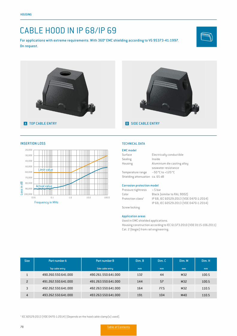
78
HOUSING
INSERTION LOSS
0.01 0.1 1.0 10.0 100.0
20,000
30,000
40,000
50,000
60,000
70,000
80,000
90,000
100,000
Frequency in MHz
Loss
in d
B
Limit value
Actual value
TECHNICAL DATA
EMC modelSurface Electrically conductibleSealing InsideHousing Aluminium die casting alloy seawater resistanceTemperature range –50 °C to +120 °CShielding attenuation ca. 65 dB
Corrosion protection modelPressure tightness > 5 barColor Black (similar to RAL 9002)Protection class1 IP 68, IEC 60529:2013 (VDE 0470-1:2014) IP 69, IEC 60529:2013 (VDE 0470-1:2014)Screw locking
Application areasUsed in EMC shielded applications. Housing construction according to IEC 61373:2010 (VDE 0115-106:2011) Cat. 2 (bogie) from rail engineering.
Size Part number A
Top cable entry
Part number B
Side cable entry
Dim. B
mm
Dim. C
mm
Dim. M
mm
Dim. H
mm
1 490.260.550.641.000 490.261.550.641.000 132 44 M32 100.5
2 491.262.550.641.000 491.263.550.641.000 144 57 M32 100.5
3 492.262.550.641.000 492.263.550.641.000 164 77.5 M32 110.5
4 493.262.550.641.000 493.263.550.641.000 191 104 M40 110.5
1 IEC 60529:2013 (VDE 0470-1:2014) (Depends on the hood cable clamp(s) used).
CABLE HOOD IN IP 68/IP 69For applications with extreme requirements. With 360° EMC shielding according to VG 95373-41:1997. On request.
A TOP CABLE ENTRY B SIDE CABLE ENTRY
Table of Contents
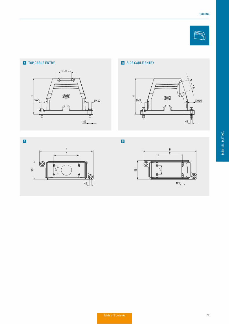
79
HOUSING
MAN
UAL
MAT
ING
A TOP CABLE ENTRY
A
B SIDE CABLE ENTRY
B
M6
SW10SW5
H
BC
27 2758
M6
M _ × 1.5
M _ × 1.5
H
BC
58
M3
M6
SW10SW5
M6
SW10SW5
H
BC
27 2758
M6
M _ × 1.5
M _ × 1.5
H
BC
58
M3
M6
SW10SW5
M6
SW10SW5
H
BC
27 2758
M6
M _ × 1.5
M _ × 1.5
HBC
58
M3
M6
SW10SW5
Table of Contents
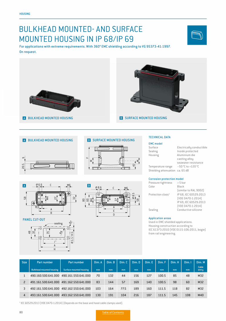
80
HOUSING
Size Part number
Bulkhead mounted housing
Part number
Surface mounted housing
Dim. A
mm
Dim. B
mm
Dim. C
mm
Dim. D
mm
Dim. E
mm
Dim. F
mm
Dim. H
mm
Dim. I
mm
Dim. MCable entry
1 490.160.500.641.000 490.161.550.641.000 70 132 44 156 127 100.5 85 48 M32
2 491.161.500.641.000 491.162.550.641.000 83 144 57 169 140 100.5 98 60 M32
3 492.161.500.641.000 492.162.550.641.000 103 164 77.5 189 160 111.5 118 82 M32
4 493.161.500.641.000 493.162.550.641.000 130 191 104 216 187 111.5 145 108 M40
1 IEC 60529:2013 (VDE 0470-1:2014) (Depends on the base and hood cable clamps used).
TECHNICAL DATA
EMC modelSurface Electrically conductibleSealing Inside protected Housing Aluminium die casting alloy seawater resistanceTemperature range –50 °C to +120 °CShielding attenuation ca. 65 dB
Corrosion protection modelPressure tightness > 5 barColor Black (similar to RAL 9002)Protection class1 IP 68, IEC 60529:2013 (VDE 0470-1:2014) IP 69, IEC 60529:2013 (VDE 0470-1:2014)Sealing Conductive silicone
Application areasUsed in EMC shielded applications. Housing construction according to IEC 61373:2010 (VDE 0115-106:2011, bogie) from rail engineering.
BULKHEAD MOUNTED- AND SURFACE MOUNTED HOUSING IN IP 68/IP 69For applications with extreme requirements. With 360° EMC shielding according to VG 95373-41:1997. On request.
A BULKHEAD MOUNTED HOUSING B SURFACE MOUNTED HOUSING
A B
PANEL CUT-OUT
A BULKHEAD MOUNTED HOUSING B SURFACE MOUNTED HOUSING
G
GSW 10SW 5
H
M6
FM M
42
58
8.5
27M3
60 M4
80
2758
AED
8.6 CB
BA
M3
M4
58
20.5
9
M3
C
M6
6.6 C M6
3227
G
G
SW 10SW 5
H
M6
FM M
42
58
8.5
27M3
60 M4
80
2758
AED
8.6 CB
BA
M3
M4
58
20.5
9
M3
C
M6
6.6 C M6
3227
G
G
SW 10SW 5
H
M6
FM M
42
58
8.5
27M3
60 M4
80
2758
AED
8.6 CB
BA
M3
M4
58
20.5
9
M3
C
M6
6.6 C M6
3227
G
G
SW 10SW 5
H
M6
FM M
42
58
8.5
27M3
60 M4
80
2758
AED
8.6 CB
BA
M3
M4
58
20.5
9
M3
C
M6
6.6 C M6
3227
sealing
3248
HAI+1
35+1
R7
R4
6.5/
M 6
Table of Contents
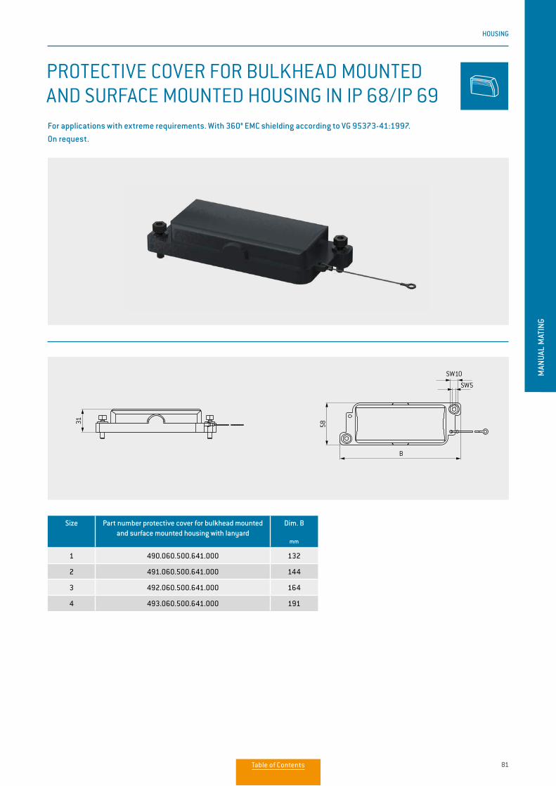
81
HOUSING
MAN
UAL
MAT
ING
PROTECTIVE COVER FOR BULKHEAD MOUNTED AND SURFACE MOUNTED HOUSING IN IP 68/IP 69For applications with extreme requirements. With 360° EMC shielding according to VG 95373-41:1997. On request.
Size Part number protective cover for bulkhead mounted and surface mounted housing with lanyard
Dim. B
mm
1 490.060.500.641.000 132
2 491.060.500.641.000 144
3 492.060.500.641.000 164
4 493.060.500.641.000 191
27 120
SW10
SchutzdeckelMontageausschnitt - Anbaugehäuse
SW5
B
I+10
35+1
0
32
M 6
3158
R4
A
27 120
SW10
SchutzdeckelMontageausschnitt - Anbaugehäuse
SW5
B
I+10
35+1
0
32
M 6
3158
R4
A
Table of Contents
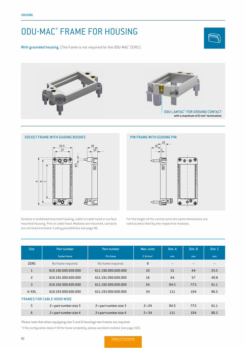
82
HOUSING
ODU-MAC® FRAME FOR HOUSING
Sockets in bulkhead mounted housing, cable to cable hood or surface mounted housing. Pins in cable hood. Modules are mounted, contacts are not fixed enclosed. Coding possibilities see page 86.
For the height of the contact pins the same dimensions are valid as described by the respective modules.
Size Part number
Socket frame
Part number
Pin frame
Max. units
2.54 mm1
Dim. A
mm
Dim. B
mm
Dim. C
mm
ZERO No frame required. No frame required. 9 – – –
1 610.190.000.600.000 611.190.000.600.000 10 51 44 25.5
2 610.191.000.600.000 611.191.000.600.000 16 64 57 40.8
3 610.192.000.600.000 611.192.000.600.000 24 84.5 77.5 61.1
4 / XXL 610.193.000.600.000 611.193.000.600.000 34 111 104 86.5
5 2 × part number size 3 2 × part number size 3 2 × 24 84.5 77.5 61.1
6 2 × part number size 4 2 x part number size 4 2 × 34 111 104 86.5
1 If the configuration doesn’t fill the frame completely, please use blank modules (see page 164).
FRAMES FOR CABLE HOOD WIDE
SOCKET FRAME WITH GUIDING BUSHES PIN FRAME WITH GUIDING PIN
Please note that when equipping size 5 and 6 housings two frames are required.
M3
Anziehdrehmoment 1,25Nmlocking torque
Anziehdrehmoment 0,8Nmlocking torque
34.5
A C
27
B
1810
10
216
M3
Anziehdrehmoment 1,25Nmlocking torque
Anziehdrehmoment 0,8Nmlocking torque
34.5
A C
27
B
1810
10
216
With grounded housing. (The frame is not required for the ODU-MAC® ZERO.)
ODU LAMTAC® FOR GROUND CONTACT with a maximum of 6 mm2 termination
Table of Contents
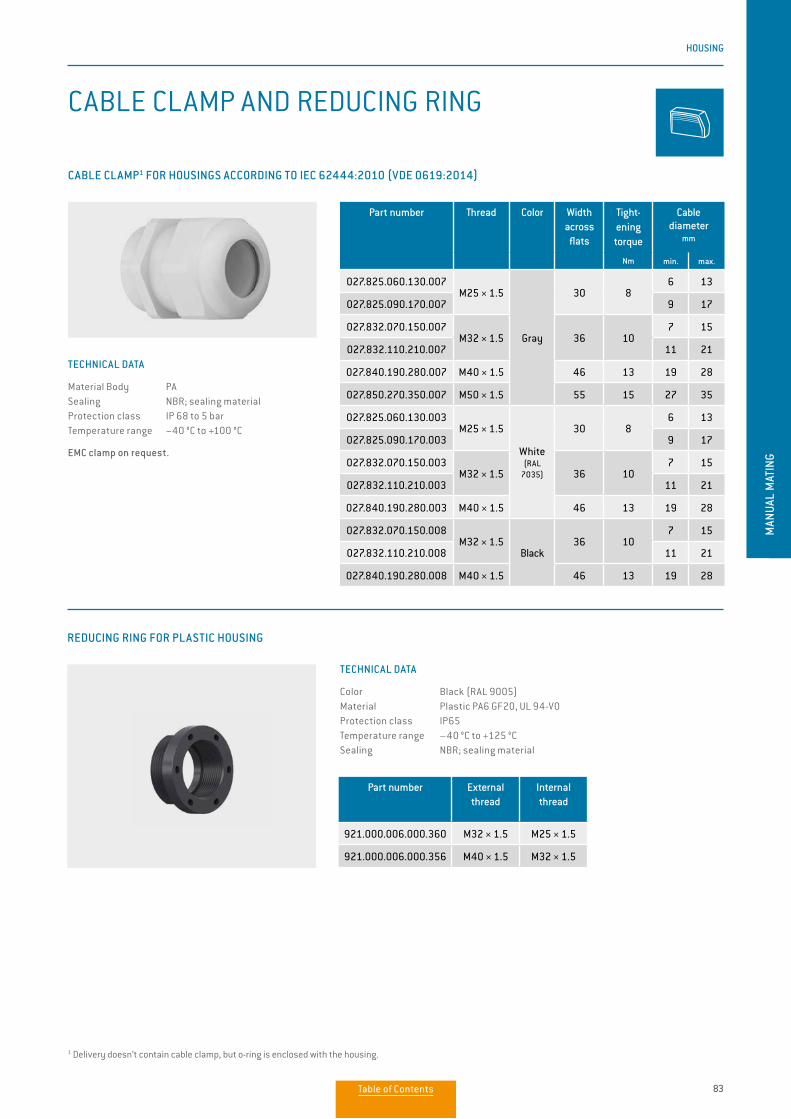
83
HOUSING
MAN
UAL
MAT
ING
REDUCING RING FOR PLASTIC HOUSING
Part number External thread
Internal thread
921.000.006.000.360 M32 × 1.5 M25 × 1.5
921.000.006.000.356 M40 × 1.5 M32 × 1.5
CABLE CLAMP AND REDUCING RING
1 Delivery doesn’t contain cable clamp, but o-ring is enclosed with the housing.
TECHNICAL DATA
Material Body PA Sealing NBR; sealing material Protection class IP 68 to 5 barTemperature range −40 °C to +100 °C
EMC clamp on request.
Part number Thread Color Width across
flats
Tight-ening torque
Nm
Cable diameter
mm
min. max.
027.825.060.130.007M25 × 1.5
Gray
30 86 13
027.825.090.170.007 9 17
027.832.070.150.007M32 × 1.5 36 10
7 15
027.832.110.210.007 11 21
027.840.190.280.007 M40 × 1.5 46 13 19 28
027.850.270.350.007 M50 × 1.5 55 15 27 35
027.825.060.130.003M25 × 1.5
White(RAL
7035)
30 86 13
027.825.090.170.003 9 17
027.832.070.150.003M32 × 1.5 36 10
7 15
027.832.110.210.003 11 21
027.840.190.280.003 M40 × 1.5 46 13 19 28
027.832.070.150.008M32 × 1.5
Black36 10
7 15
027.832.110.210.008 11 21
027.840.190.280.008 M40 × 1.5 46 13 19 28
CABLE CLAMP1 FOR HOUSINGS ACCORDING TO IEC 62444:2010 (VDE 0619:2014)
TECHNICAL DATA
Color Black (RAL 9005)Material Plastic PA6 GF20, UL 94-V0Protection class IP65Temperature range –40 °C to +125 °CSealing NBR; sealing material
Table of Contents
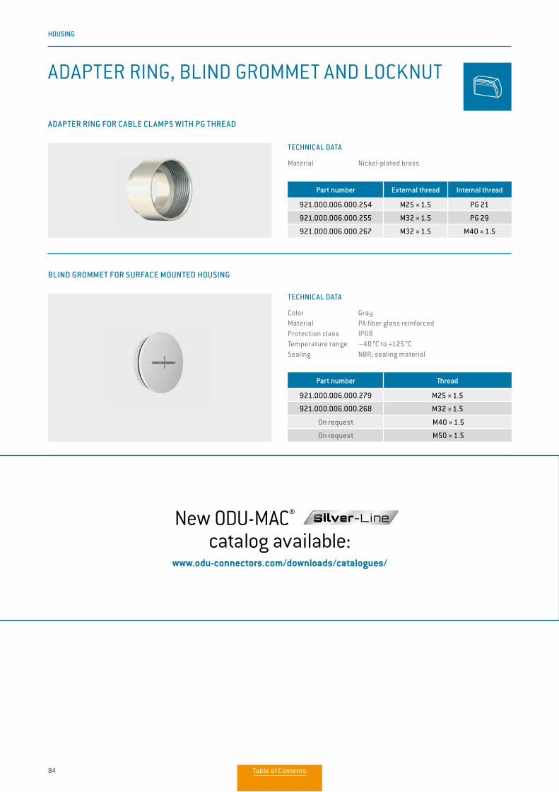
84
HOUSING
ADAPTER RING, BLIND GROMMET AND LOCKNUT
BLIND GROMMET FOR SURFACE MOUNTED HOUSING
LOCKNUT FOR CABLE CLAMP
For fixing the cable clamp in the ODU-MAC strain relief housing .
ADAPTER RING FOR CABLE CLAMPS WITH PG THREAD
Part number Thread
921.000.006.000.279 M25 × 1.5
921.000.006.000.268 M32 × 1.5
On request M40 × 1.5
On request M50 × 1.5
Part number Thread
931.000.003.000.112 M32 × 1.5
931.000.003.000.113 M40 × 1.5
Part number External thread Internal thread
921.000.006.000.254 M25 × 1.5 PG 21
921.000.006.000.255 M32 × 1.5 PG 29
921.000.006.000.267 M32 × 1.5 M40 × 1.5
TECHNICAL DATA
Material Nickel-plated brass
TECHNICAL DATA
Color GrayMaterial PA fiber glass reinforcedProtection class IP68Temperature range –40 °C to +125 °CSealing NBR; sealing material
TECHNICAL DATA
Material Nickel-plated brassNew ODU-MAC® Silver-Linecatalog available:
www.odu-connectors.com/downloads/catalogues/
Table of Contents
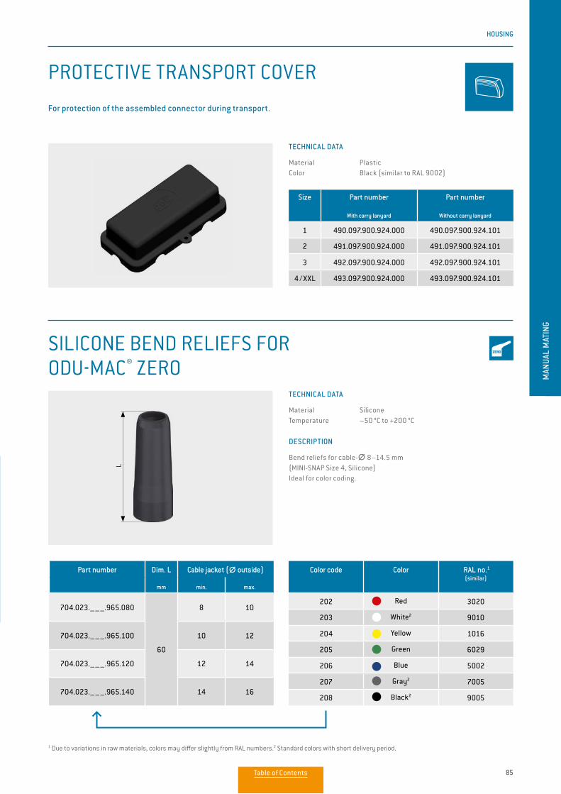
85
HOUSING
MAN
UAL
MAT
ING
PROTECTIVE TRANSPORT COVER
SILICONE BEND RELIEFS FOR ODU-MAC® ZERO
Size Part number
With carry lanyard
Part number
Without carry lanyard
1 490.097.900.924.000 490.097.900.924.101
2 491.097.900.924.000 491.097.900.924.101
3 492.097.900.924.000 492.097.900.924.101
4 / XXL 493.097.900.924.000 493.097.900.924.101
TECHNICAL DATA
Material PlasticColor Black (similar to RAL 9002)
TECHNICAL DATA
Material SiliconeTemperature –50 °C to +200 °C
DESCRIPTION
Bend reliefs for cable-∅∅ 8–14.5 mm (MINI-SNAP Size 4, Silicone)Ideal for color coding.
For protection of the assembled connector during transport.
Part number Dim. L
mm
Cable jacket (∅∅ outside)
min. max.
704.023.–––.965.080
60
8 10
704.023.–––.965.100 10 12
704.023.–––.965.120 12 14
704.023.–––.965.140 14 16
1 Due to variations in raw materials, colors may differ slightly from RAL numbers.2 Standard colors with short delivery period.
L
Color code Color RAL no.1
(similar)
202 Red 3020
203 White2 9010
204 Yellow 1016
205 Green 6029
206 Blue 5002
207 Gray2 7005
208 Black2 9005
Table of Contents
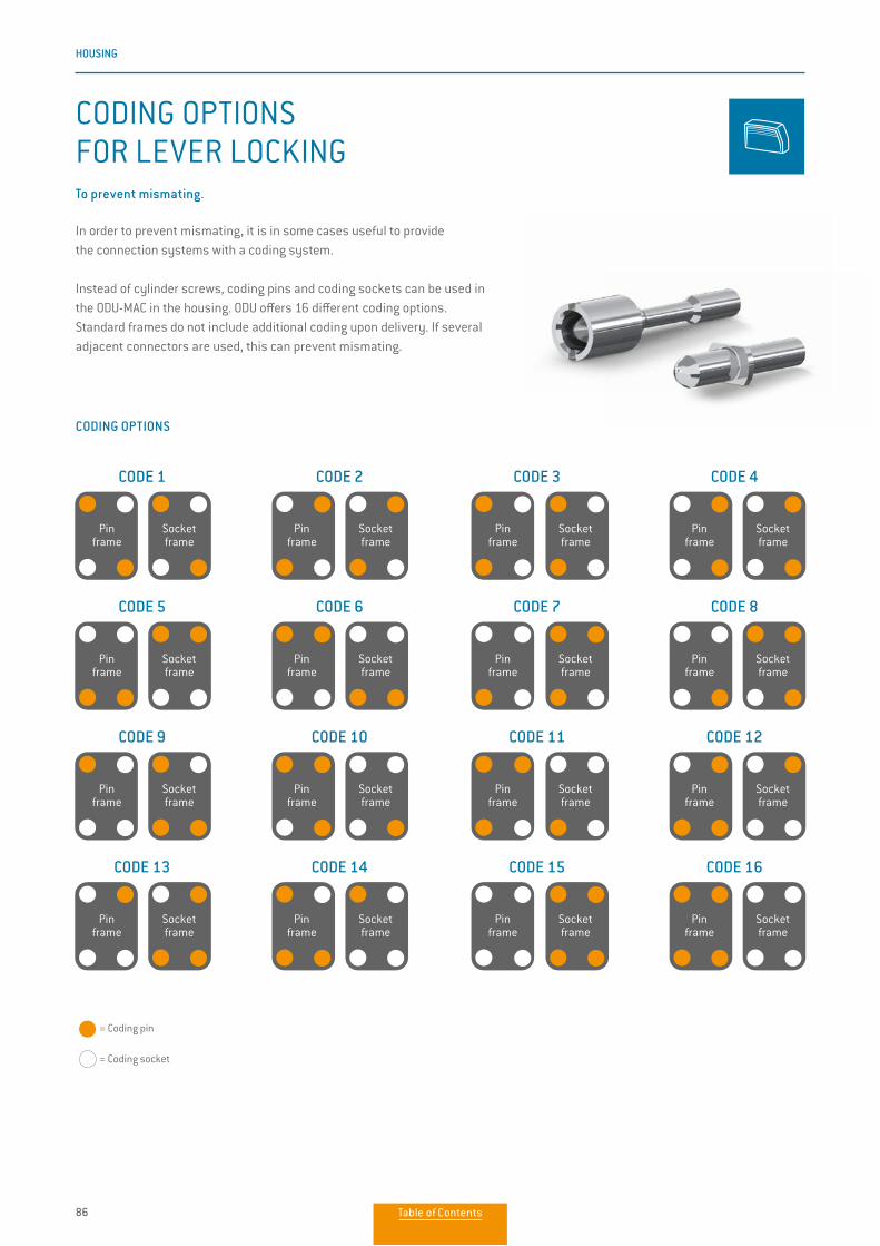
86
HOUSING
In order to prevent mismating, it is in some cases useful to provide the connection systems with a coding system.
Instead of cylinder screws, coding pins and coding sockets can be used in the ODU-MAC in the housing. ODU offers 16 different coding options.Standard frames do not include additional coding upon delivery. If several adjacent connectors are used, this can prevent mismating.
To prevent mismating.
CODING OPTIONS
CODE 1 CODE 2 CODE 3 CODE 4
CODE 9 CODE 10 CODE 11 CODE 12
CODE 5 CODE 6 CODE 7 CODE 8
CODE 13 CODE 14 CODE 15 CODE 16
= Coding pin = Coding socket
Pin frame
Socket frame
Pin frame
Socket frame
Pin frame
Socket frame
Pin frame
Socket frame
Pin frame
Socket frame
Pin frame
Socket frame
Pin frame
Socket frame
Pin frame
Socket frame
Pin frame
Socket frame
Pin frame
Socket frame
Pin frame
Socket frame
Pin frame
Socket frame
Pin frame
Socket frame
Pin frame
Socket frame
Pin frame
Socket frame
Pin frame
Socket frame
CODING OPTIONS FOR LEVER LOCKING
Table of Contents
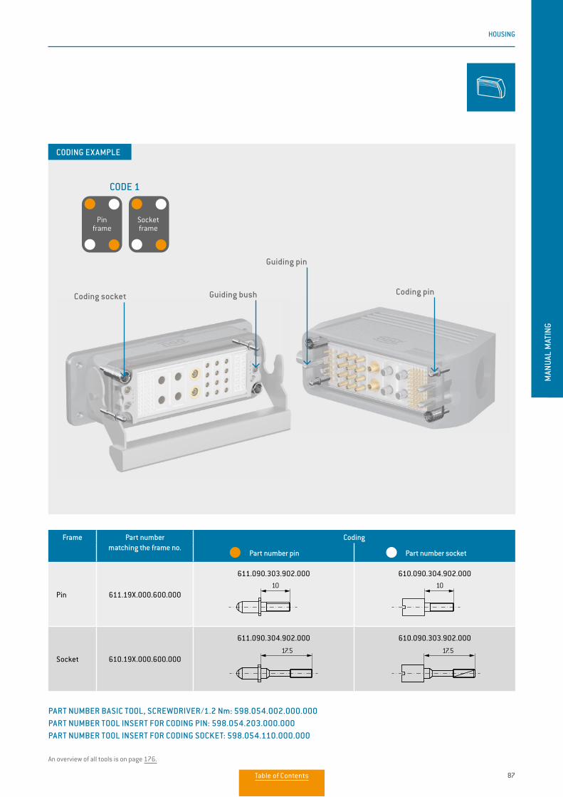
87
HOUSING
MAN
UAL
MAT
ING
Frame Part number matching the frame no.
Coding
Part number pin Part number socket
Pin 611.19X.000.600.000
611.090.303.902.000 610.090.304.902.000
Socket 610.19X.000.600.000
611.090.304.902.000 610.090.303.902.000
10
17.5
10
17.5
PART NUMBER BASIC TOOL, SCREWDRIVER/1.2 Nm: 598.054.002.000.000 PART NUMBER TOOL INSERT FOR CODING PIN: 598.054.203.000.000PART NUMBER TOOL INSERT FOR CODING SOCKET: 598.054.110.000.000
An overview of all tools is on page 176.
CODE 1
Pin frame
Socket frame
CODING EXAMPLE
Guiding pin
Coding pinCoding socket Guiding bush
Table of Contents
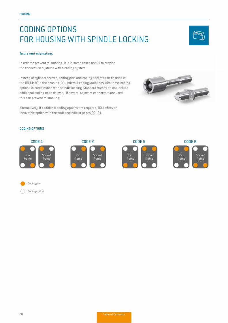
88
HOUSING
CODING OPTIONS FOR HOUSING WITH SPINDLE LOCKING
In order to prevent mismating, it is in some cases useful to provide the connection systems with a coding system.
Instead of cylinder screws, coding pins and coding sockets can be used in the ODU-MAC in the housing. ODU offers 4 coding variations with these coding options in combination with spindle locking. Standard frames do not include additional coding upon delivery. If several adjacent connectors are used, this can prevent mismating.
Alternatively, if additional coding options are required, ODU offers an innovative option with the coded spindle of pages 90–91.
To prevent mismating.
CODING OPTIONS
CODE 1 CODE 2 CODE 5 CODE 6
= Coding pin = Coding socket
Pin frame
Socket frame
Pin frame
Socket frame
Pin frame
Socket frame
Pin frame
Socket frame
Table of Contents
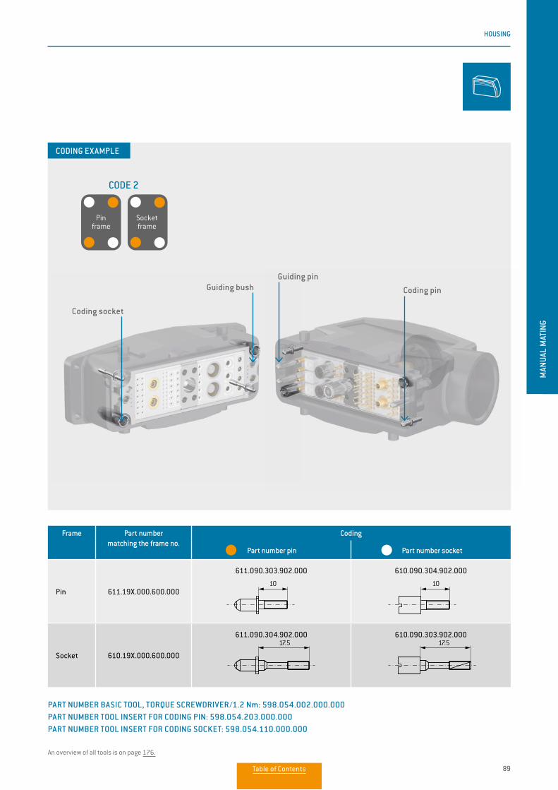
89
HOUSING
MAN
UAL
MAT
ING
CODE 2
Frame Part number matching the frame no.
Coding
Part number pin Part number socket
Pin 611.19X.000.600.000
611.090.303.902.000 610.090.304.902.000
Socket 610.19X.000.600.000
611.090.304.902.000 610.090.303.902.000
10 10
17.5 17.5
PART NUMBER BASIC TOOL, TORQUE SCREWDRIVER/1.2 Nm: 598.054.002.000.000 PART NUMBER TOOL INSERT FOR CODING PIN: 598.054.203.000.000PART NUMBER TOOL INSERT FOR CODING SOCKET: 598.054.110.000.000
An overview of all tools is on page 176.
Pin frame
Socket frame
CODING EXAMPLE
Guiding pin
Coding pin
Coding socket
Guiding bush
Table of Contents
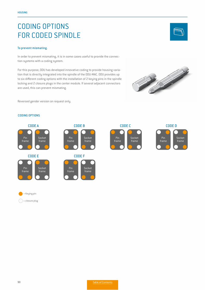
90
HOUSING
CODING OPTIONSFOR CODED SPINDLE
In order to prevent mismating, it is in some cases useful to provide the connec-tion systems with a coding system.
For this purpose, ODU has developed innovative coding to provide housing varia-tion that is directly integrated into the spindle of the ODU-MAC. ODU provides up to six different coding options with the installation of 2 keying pins in the spindle locking and 2 closure plugs in the center module. If several adjacent connectors are used, this can prevent mismating.
Reversed gender version on request only.
To prevent mismating.
CODING OPTIONS
CODE A CODE B CODE C CODE D
CODE E CODE F
Pin frame
Socket frame
Pin frame
Socket frame
Pin frame
Socket frame
Pin frame
Socket frame
Pin frame
Socket frame
Pin frame
Socket frame
= Keying pin = closure plug
Table of Contents
91
HOUSING
MAN
UAL
MAT
ING
ONLY IF A REPLACEMENT IS REQUIRED2
Part number keying pin
Part number closure plug
615.090.107.902.000 614.090.107.902.000
Size WITH CODING 1 Angle of rotationPart number
Center module for bulkhead mounted, surface mounted housing and
cable-to-cable-hoods
Part number Spindle locking for
cable hoods
2 (52 mm high) 614.090.001.304.010 615.091.003.200.010 180°
2 (72 mm high) 614.090.001.304.010 615.091.001.200.010 180°
3/4 614.090.001.304.010 615.092.021.200.013 360°
XXL 614.090.001.304.010 615.093.021.200.013 360°
An overview of all tools is on page 176.
2 They are included in the standard scope of delivery.
TORQUE SCREWDRIVER/0.9 Nm FOR LEFT-HAND THREADPART NUMBER BIT SLOT FOR THE ASSEMBLY OF THE SPINDLE CODING: 598.054.109.000.000
CODE B
CODING EXAMPLE
Pin frame
Socket frame
Closure plug Keying pin
Guiding pinGuiding bush
1 Keying pins and closure plugs are included as loose parts.
Table of Contents

92
HOUSING
FLEXIBLE CIRCULAR CONNECTORS WITH ODU-MAC® MODULES
Modular circular connectors from the existing portfolio can be easily configured with the flexible ODU-MAC inserts. The flexible insulators (half shells) are compatible with the housings of the series 209 and ODU DOCK and can be easily installed in them. The result is a modular circular connector with a very robust housing.
The flexible use provides space for ODU-MAC modules with 8 units. Thanks to the divided insulator, installation of ODU-MAC modules is possible without a large expenditure of time. The modules are easily inserted into the insulator. Following the completed contact arrangement, the two halves are clipped together and integrated into the respective housing.
Due to the combination of two proven ODU products you can arrange the inserts individually:
• Combination of ODU DOCK housings with integrated modules from the ODU-MAC program • Space for 8 units (1 unit = 2.54 mm) • Material insulator: PBT
Suitable for rugged housing from series 209 and housing ODU DOCK.
NOTE
• Please use only protruding contacts from ∅∅ 1.02 mm• Assembly instruction available on our website• Delivery times according to series 209 and ODU DOCK
Description Part number
Insulator socket
Part number
Insulator pin
Insulator half-shells 209.610.000.000.000 209.611.000.000.000
New ODU-MAC® Silver-Linecatalog available:
www.odu-connectors.com/downloads/catalogues/
Table of Contents

93
HOUSING
MAN
UAL
MAT
INGODU-MAC®
IN HEAVY DUTY CONNECTOR SERIES 209
ODU-MAC® IN ODU DOCK
APPLICATION EXAMPLES
New ODU-MAC® Silver-Linecatalog available:
www.odu-connectors.com/downloads/catalogues/
Table of Contents
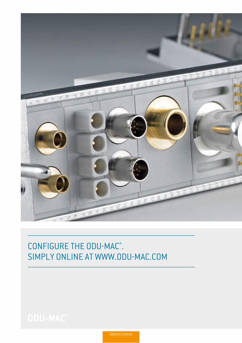
ODU-MAC®ODU-MAC®
CONFIGURE THE ODU-MAC®. SIMPLY ONLINE AT WWW.ODU-MAC.COM
Table of Contents
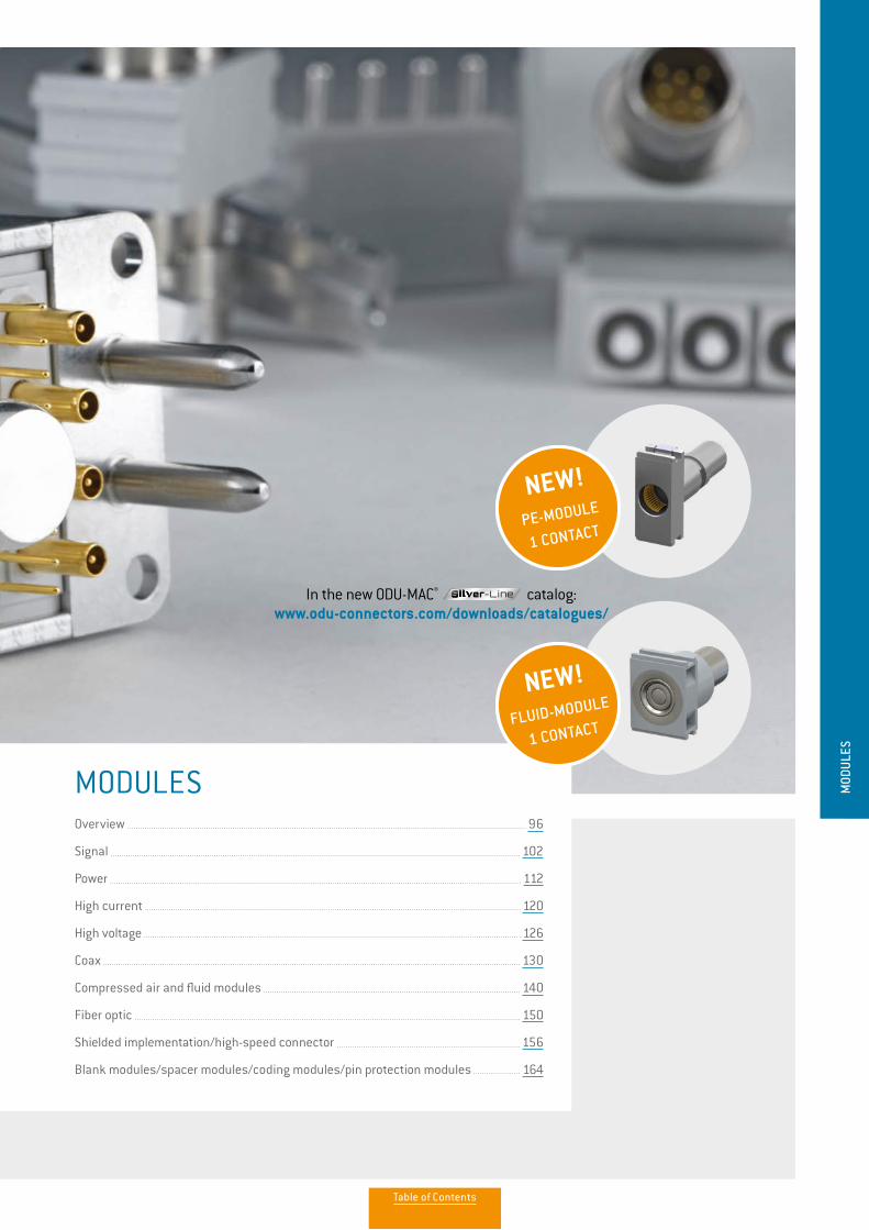
MODULESOverview 96
Signal 102
Power 112
High current 120
High voltage 126
Coax 130
Compressed air and fluid modules 140
Fiber optic 150
Shielded implementation/high-speed connector 156
Blank modules/spacer modules/coding modules/pin protection modules 164
MOD
ULES
NEW!PE-MODULE
1 CONTACT
In the new ODU-MAC® catalog:www.odu-connectors.com/downloads/catalogues/
NEW!FLUID-MODULE
1 CONTACT
Table of Contents
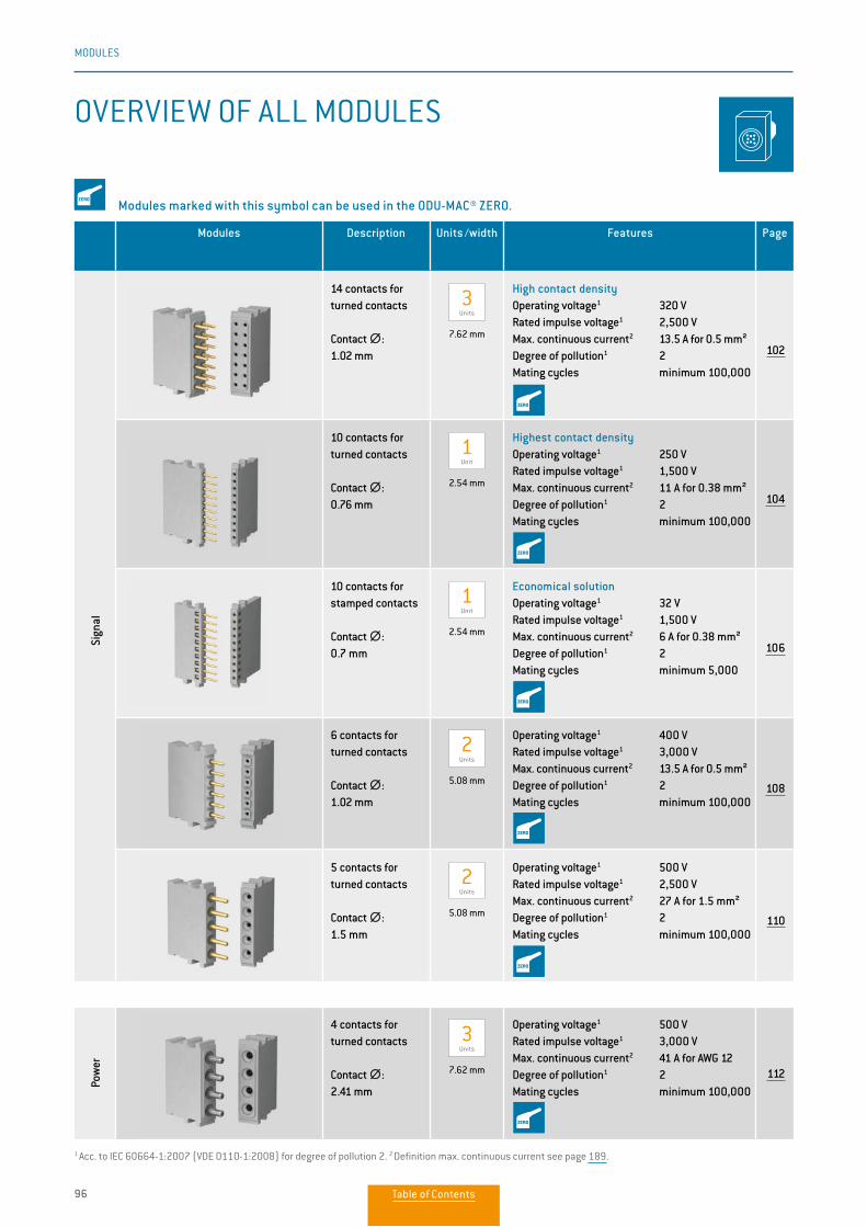
96
MODULES
Modules Description Units /width Features Page
Sign
al
14 contacts for turned contacts
Contact ∅∅: 1.02 mm
3 Units
7.62 mm
High contact densityOperating voltage1 320 VRated impulse voltage1 2,500 VMax. continuous current2 13.5 A for 0.5 mm²Degree of pollution1 2Mating cycles minimum 100,000
102
10 contacts for turned contacts
Contact ∅∅: 0.76 mm
1 Unit
2.54 mm
Highest contact densityOperating voltage1 250 VRated impulse voltage1 1,500 VMax. continuous current2 11 A for 0.38 mm²Degree of pollution1 2 Mating cycles minimum 100,000
104
10 contacts for stamped contacts
Contact ∅∅: 0.7 mm
1 Unit
2.54 mm
Economical solution Operating voltage1 32 VRated impulse voltage1 1,500 VMax. continuous current2 6 A for 0.38 mm²Degree of pollution1 2Mating cycles minimum 5,000
106
6 contacts for turned contacts
Contact ∅∅: 1.02 mm
2 Units
5.08 mm
Operating voltage1 400 VRated impulse voltage1 3,000 VMax. continuous current2 13.5 A for 0.5 mm²Degree of pollution1 2Mating cycles minimum 100,000
108
5 contacts for turned contacts
Contact ∅∅: 1.5 mm
2 Units
5.08 mm
Operating voltage1 500 VRated impulse voltage1 2,500 VMax. continuous current2 27 A for 1.5 mm²Degree of pollution1 2Mating cycles minimum 100,000
110
Pow
er
4 contacts for turned contacts
Contact ∅∅: 2.41 mm
3 Units
7.62 mm
Operating voltage1 500 VRated impulse voltage1 3,000 VMax. continuous current2 41 A for AWG 12Degree of pollution1 2Mating cycles minimum 100,000
112
1 Acc. to IEC 60664-1:2007 (VDE 0110-1:2008) for degree of pollution 2. 2 Definition max. continuous current see page 189.
OVERVIEW OF ALL MODULES
Modules marked with this symbol can be used in the ODU-MAC® ZERO.
Table of Contents
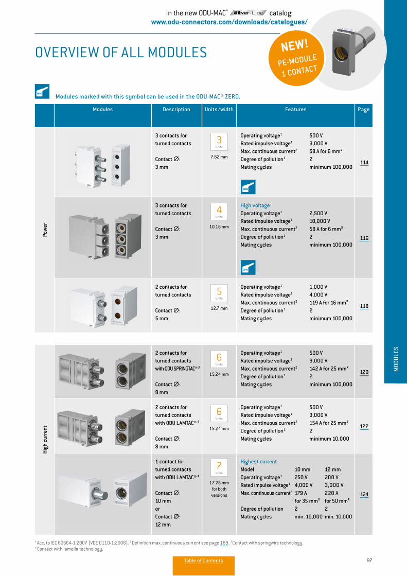
97
MODULES
MOD
ULES
Modules Description Units /width Features Page
Pow
er
3 contacts for turned contacts
Contact ∅∅: 3 mm
3 Units
7.62 mm
Operating voltage1 500 VRated impulse voltage1 3,000 VMax. continuous current2 58 A for 6 mm²Degree of pollution1 2Mating cycles minimum 100,000
114
3 contacts for turned contacts
Contact ∅∅: 3 mm
4Units
10.16 mm
High voltage Operating voltage1 2,500 VRated impulse voltage1 10,000 VMax. continuous current2 58 A for 6 mm²Degree of pollution1 2Mating cycles minimum 100,000
116
2 contacts for turned contacts
Contact ∅∅: 5 mm
5 Units
12.7 mm
Operating voltage1 1,000 VRated impulse voltage1 4,000 VMax. continuous current2 119 A for 16 mm²Degree of pollution1 2Mating cycles minimum 100,000
118
High
cur
rent
2 contacts for turned contactswith ODU SPRINGTAC® 3
Contact ∅∅: 8 mm
6 Units
15.24 mm
Operating voltage1 500 VRated impulse voltage1 3,000 VMax. continuous current2 142 A for 25 mm²Degree of pollution1 2Mating cycles minimum 100,000
120
2 contacts for turned contactswith ODU LAMTAC® 4
Contact ∅∅: 8 mm
6 Units
15.24 mm
Operating voltage1 500 VRated impulse voltage1 3,000 VMax. continuous current2 154 A for 25 mm²Degree of pollution1 2Mating cycles minimum 10,000
122
1 contact forturned contactswith ODU LAMTAC® 4
Contact ∅∅: 10 mm orContact ∅∅: 12 mm
7 Units
17.78 mmfor both versions
Highest currentModel 10 mm 12 mm Operating voltage1 250 V 200 VRated impulse voltage1 4,000 V 3,000 VMax. continuous current2 179 A 220 A for 35 mm² for 50 mm²Degree of pollution 2 2Mating cycles min. 10,000 min. 10,000
124
1 Acc. to IEC 60664-1:2007 (VDE 0110-1:2008). 2 Definition max. continuous current see page 189. 3 Contact with springwire technology. 4 Contact with lamella technology.
OVERVIEW OF ALL MODULES
Modules marked with this symbol can be used in the ODU-MAC® ZERO.
NEW!PE-MODULE
1 CONTACT
In the new ODU-MAC® catalog:www.odu-connectors.com/downloads/catalogues/
Table of Contents
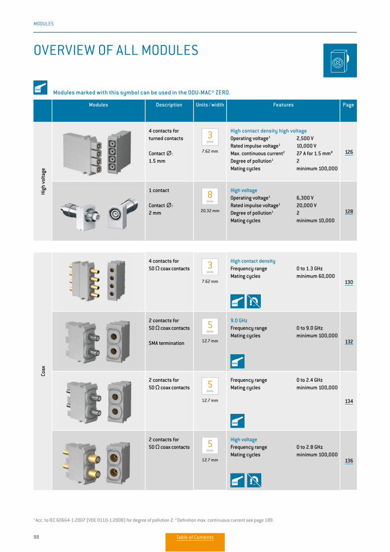
98
MODULES
Modules Description Units / width Features Page
High
vol
tage
4 contacts for turned contacts
Contact ∅∅: 1.5 mm
3 Units
7.62 mm
High contact density high voltageOperating voltage1 2,500 VRated impulse voltage1 10,000 VMax. continuous current2 27 A for 1.5 mm²Degree of pollution1 2Mating cycles minimum 100,000
126
1 contact
Contact ∅∅: 2 mm
8 Units
20.32 mm
High voltageOperating voltage1 6,300 VRated impulse voltage1 20,000 VDegree of pollution1 2Mating cycles minimum 10,000
128
Coax
4 contacts for 50 Ω coax contacts 3
Units
7.62 mm
High contact densityFrequency range 0 to 1.3 GHzMating cycles minimum 60,000
130
2 contacts for 50 Ω coax contacts
SMA termination
5 Units
12.7 mm
9.0 GHzFrequency range 0 to 9.0 GHzMating cycles minimum 100,000
132
2 contacts for 50 Ω coax contacts 5
Units 12.7 mm
Frequency range 0 to 2.4 GHzMating cycles minimum 100,000
134
2 contacts for 50 Ω coax contacts 5
Units 12.7 mm
High voltage Frequency range 0 to 2.8 GHzMating cycles minimum 100,000
136
Modules marked with this symbol can be used in the ODU-MAC® ZERO.
OVERVIEW OF ALL MODULES
1 Acc. to IEC 60664-1:2007 (VDE 0110-1:2008) for degree of pollution 2. 2 Definition max. continuous current see page 189.
Table of Contents
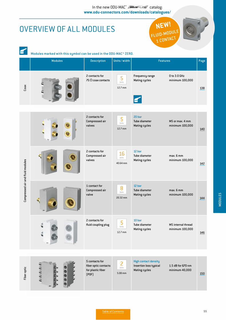
99
MODULES
MOD
ULES
Modules Description Units / width Features Page
Coax
2 contacts for 75 Ω coax contacts 5
Units 12.7 mm
Frequency range 0 to 3.0 GHzMating cycles minimum 100,000
138
Com
pres
sed
air a
nd fl
uid
mod
ules
2 contacts forCompressed air valves
5 Units
12.7 mm
20 barTube diameter M5 or max. 4 mmMating cycles minimum 100,000
140
2 contacts forCompressed air valves
16 Units
40.64 mm
12 barTube diameter max. 6 mmMating cycles minimum 100,000
142
1 contact forCompressed air valve
8 Units
20.32 mm
12 barTube diameter max. 6 mmMating cycles minimum 100,000
144
2 contacts forfluid coupling plug 5
Units 12.7 mm
10 barTube diameter M5 internal thread Mating cycles minimum 100,000
146
Fibe
r opt
ic
5 contacts for fiber optic contacts for plastic fiber (POF)
2 Units
5.08 mm
High contact density Insertion loss typical 1.5 dB for 670 nmMating cycles minimum 40,000
150
Modules marked with this symbol can be used in the ODU-MAC® ZERO.
OVERVIEW OF ALL MODULES NEW!
FLUID-MODULE
1 CONTACT
In the new ODU-MAC® catalog:www.odu-connectors.com/downloads/catalogues/
Table of Contents
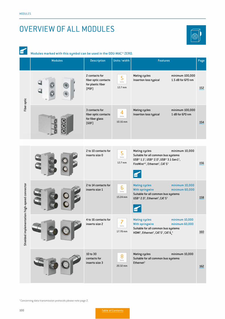
100
MODULES
Modules Description Units / width Features Page
Fibe
r opt
ic
2 contacts for fiber optic contacts for plastic fiber(POF)
5 Units
12.7 mm
Mating cycles minimum 100,000 Insertion loss typical 1.5 dB for 670 nm
152
3 contacts for fiber optic contacts for fiber glass (GOF)
4Units
10.16 mm
Mating cycles minimum 100,000Insertion loss typical 1 dB for 670 nm
154
Shie
lded
impl
emen
tatio
n/hi
gh-s
peed
con
nect
or
2 to 10 contacts for inserts size 0 5
Units 12.7 mm
Mating cycles minimum 10,000 Suitable for all common bus systemsUSB® 1.11, USB® 2.01, USB® 3.1 Gen11,
FireWire®1, Ethernet1, CAT 51 156
2 to 14 contacts for inserts size 1 6
Units 15.24 mm
Mating cycles minimum 10,000With springwire minimum 60,000Suitable for all common bus systemsUSB® 2.01, Ethernet1, CAT 51 158
4 to 16 contacts for inserts size 2 7
Units 17.78 mm
Mating cycles minimum 10,000With springwire minimum 60,000 Suitable for all common bus systemsHDMI1, Ethernet1, CAT 51, CAT 6
A1 160
10 to 30 contacts for inserts size 3
8 Units
20.32 mm
Mating cycles minimum 10,000Suitable for all common bus systemsEthernet1
162
Modules marked with this symbol can be used in the ODU-MAC® ZERO.
OVERVIEW OF ALL MODULES
1 Concerning data transmission protocols please note page 2.
Table of Contents
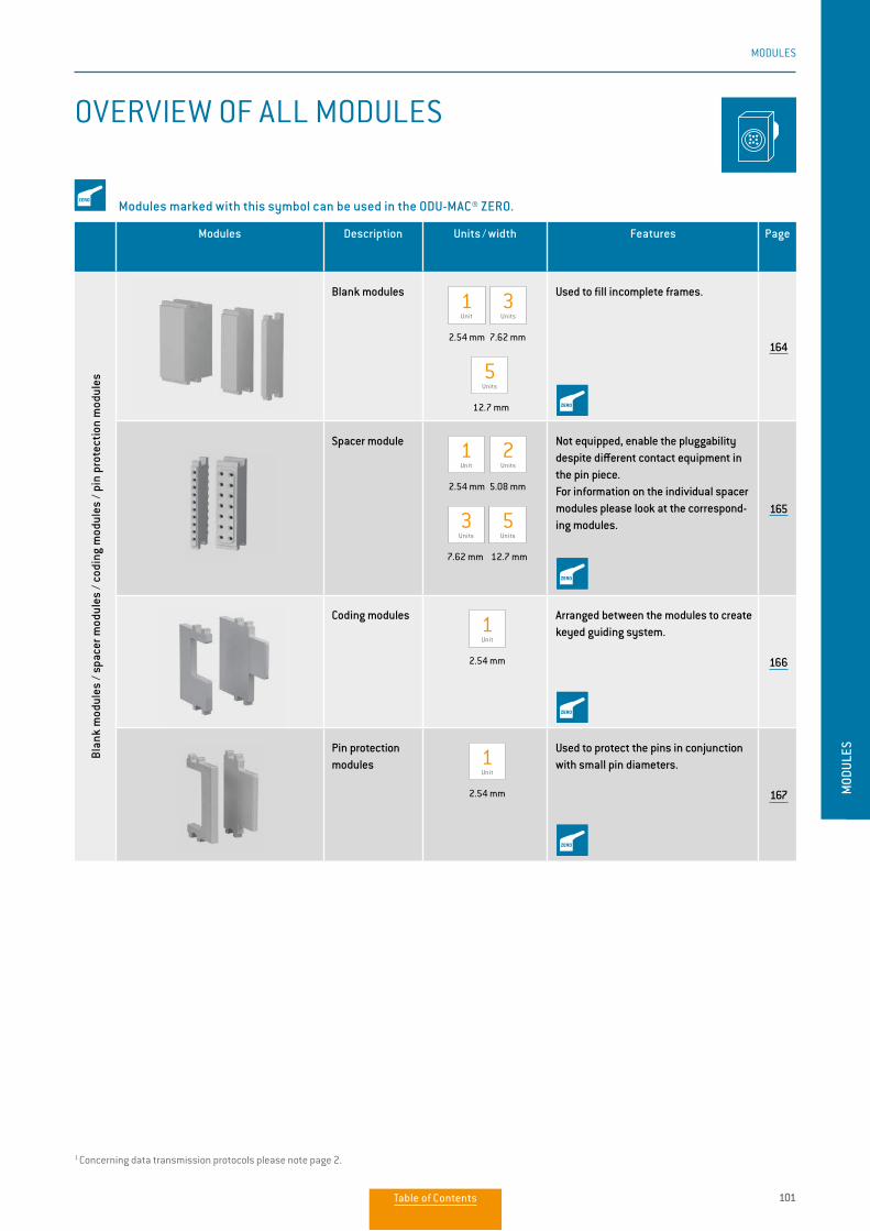
101
MODULES
MOD
ULES
Modules Description Units / width Features Page
Blan
k m
odul
es /
spac
er m
odul
es /
codi
ng m
odul
es /
pin
prot
ectio
n m
odul
es
Blank modules 1 Unit
3 Units
2.54 mm 7.62 mm
5
Units 12.7 mm
Used to fill incomplete frames.
164
Spacer module 1 Unit
2 Units
2.54 mm 5.08 mm
3 Units
5 Units
7.62 mm 12.7 mm
Not equipped, enable the pluggability despite different contact equipment in the pin piece. For information on the individual spacer modules please look at the correspond-ing modules.
165
Coding modules 1 Unit
2.54 mm
Arranged between the modules to create keyed guiding system.
166
Pin protection modules 1
Unit
2.54 mm
Used to protect the pins in conjunction with small pin diameters.
167
Modules marked with this symbol can be used in the ODU-MAC® ZERO.
OVERVIEW OF ALL MODULES
1 Concerning data transmission protocols please note page 2.
Table of Contents
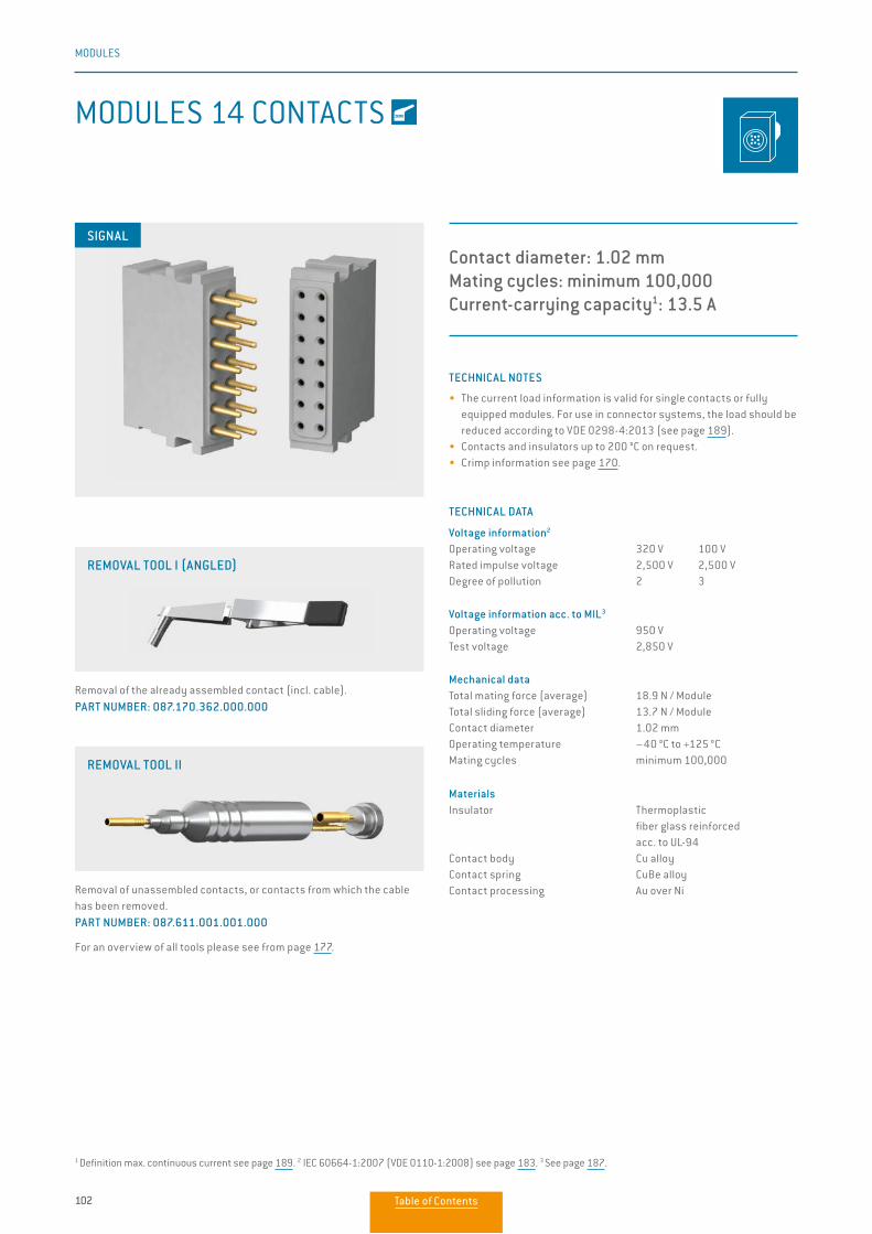
102
MODULES
MODULES 14 CONTACTS
Contact diameter: 1.02 mmMating cycles: minimum 100,000Current-carrying capacity1: 13.5 A
TECHNICAL NOTES
• The current load information is valid for single contacts or fully equipped modules. For use in connector systems, the load should be reduced according to VDE 0298-4:2013 (see page 189).
• Contacts and insulators up to 200 °C on request.• Crimp information see page 170.
TECHNICAL DATA
Voltage information2
Operating voltage 320 V 100 VRated impulse voltage 2,500 V 2,500 VDegree of pollution 2 3
Voltage information acc. to MIL3
Operating voltage 950 VTest voltage 2,850 V
Mechanical dataTotal mating force (average) 18.9 N / ModuleTotal sliding force (average) 13.7 N / ModuleContact diameter 1.02 mmOperating temperature –40 °C to +125 °CMating cycles minimum 100,000
MaterialsInsulator Thermoplastic fiber glass reinforced acc. to UL-94Contact body Cu alloyContact spring CuBe alloyContact processing Au over Ni
Removal of the already assembled contact (incl. cable). PART NUMBER: 087.170.362.000.000
REMOVAL TOOL I (ANGLED)
SIGNAL
1 Definition max. continuous current see page 189. 2 IEC 60664-1:2007 (VDE 0110-1:2008) see page 183. 3 See page 187.
Removal of unassembled contacts, or contacts from which the cable has been removed. PART NUMBER: 087.611.001.001.000
For an overview of all tools please see from page 177.
REMOVAL TOOL II
Table of Contents
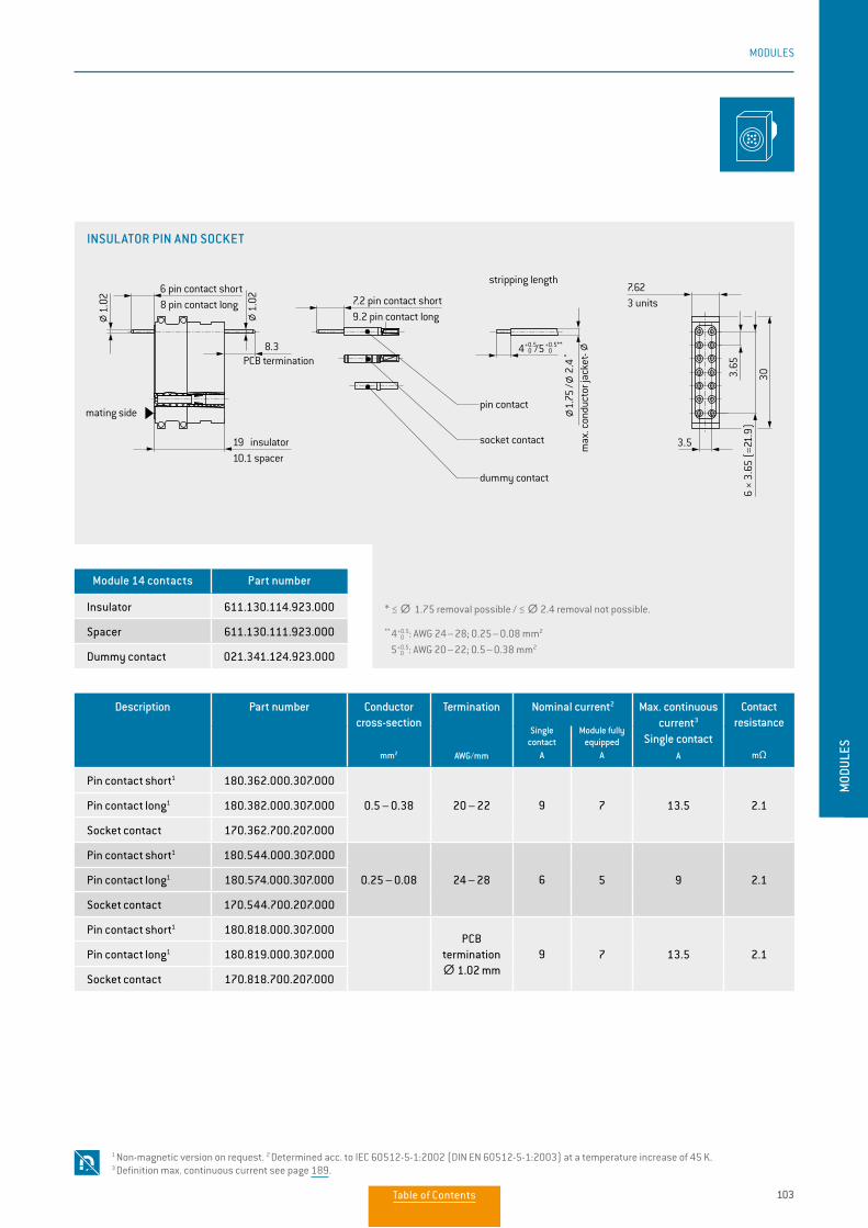
103
MODULES
MOD
ULES
* ≤ ∅∅ 1.75 removal possible / ≤ ∅∅ 2.4 removal not possible.
** 4 0+0.5: AWG 24 – 28; 0.25 – 0.08 mm2
5 0+0.5: AWG 20 – 22; 0.5 – 0.38 mm2
Description Part number Conductor cross-section
mm2
Termination
AWG/mm
Nominal current2 Max. continuous current3
Single contactA
Contact resistance
mΩ
Single contact
A
Module fully equipped
A
Pin contact short1 180.362.000.307.000
0.5 – 0.38 20 – 22 9 7 13.5 2.1Pin contact long1 180.382.000.307.000
Socket contact 170.362.700.207.000
Pin contact short1 180.544.000.307.000
0.25 – 0.08 24 – 28 6 5 9 2.1Pin contact long1 180.574.000.307.000
Socket contact 170.544.700.207.000
Pin contact short1 180.818.000.307.000PCB
termination ∅∅ 1.02 mm
9 7 13.5 2.1Pin contact long1 180.819.000.307.000
Socket contact 170.818.700.207.000
1 Non-magnetic version on request. 2 Determined acc. to IEC 60512-5-1:2002 (DIN EN 60512-5-1:2003) at a temperature increase of 45 K. 3 Definition max. continuous current see page 189.
Module 14 contacts Part number
Insulator 611.130.114.923.000
Spacer 611.130.111.923.000
Dummy contact 021.341.124.923.000
INSULATOR PIN AND SOCKET
6 pin contact short8 pin contact long
PCB termination
19 insulator10.1 spacer
7.2 pin contact short
stripping length
max
. con
duct
or ja
cket
-
pin contact
socket contact
dummy contact
3 units
8.3
303.65
6 ×
3.65
(=2
1.9)
3.5
1.02
1.02
7.62
9.2 pin contact long
1.
75 /
2.4
*
4+0.5 0 /5+0.5**
0
mating side
Table of Contents
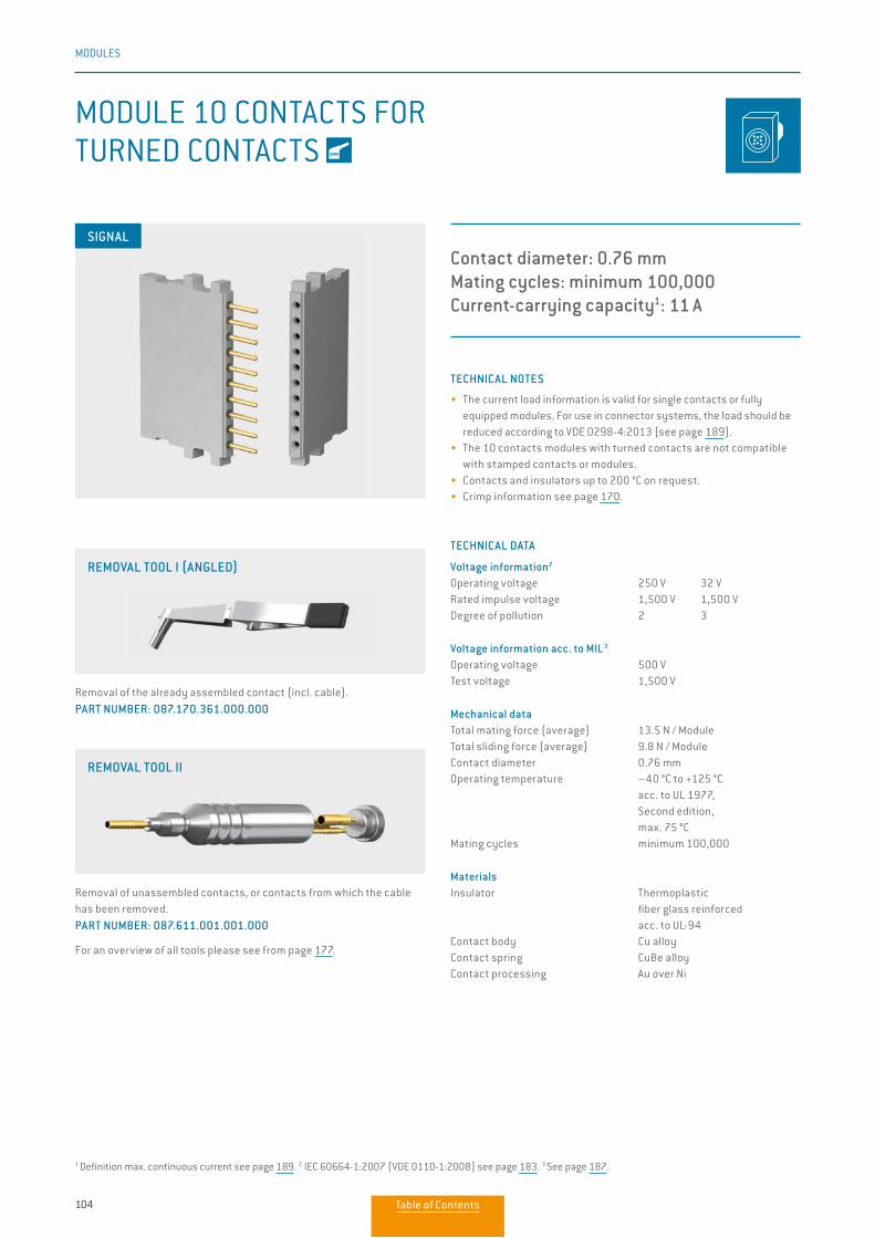
104
MODULES
MODULE 10 CONTACTS FOR TURNED CONTACTS
Contact diameter: 0.76 mmMating cycles: minimum 100,000Current-carrying capacity1: 11 A
TECHNICAL NOTES
• The current load information is valid for single contacts or fully equipped modules. For use in connector systems, the load should be reduced according to VDE 0298-4:2013 (see page 189).
• The 10 contacts modules with turned contacts are not compatible with stamped contacts or modules.
• Contacts and insulators up to 200 °C on request.• Crimp information see page 170.
TECHNICAL DATA
Voltage information2
Operating voltage 250 V 32 VRated impulse voltage 1,500 V 1,500 VDegree of pollution 2 3
Voltage information acc. to MIL3
Operating voltage 500 VTest voltage 1,500 V
Mechanical dataTotal mating force (average) 13.5 N / ModuleTotal sliding force (average) 9.8 N / ModuleContact diameter 0.76 mmOperating temperature –40 °C to +125 °C acc. to UL 1977, Second edition, max. 75 °CMating cycles minimum 100,000
MaterialsInsulator Thermoplastic fiber glass reinforced acc. to UL-94Contact body Cu alloyContact spring CuBe alloyContact processing Au over Ni
SIGNAL
Removal of the already assembled contact (incl. cable). PART NUMBER: 087.170.361.000.000
REMOVAL TOOL I (ANGLED)
1 Definition max. continuous current see page 189. 2 IEC 60664-1:2007 (VDE 0110-1:2008) see page 183. 3 See page 187.
Removal of unassembled contacts, or contacts from which the cable has been removed. PART NUMBER: 087.611.001.001.000
For an overview of all tools please see from page 177.
REMOVAL TOOL II
Table of Contents
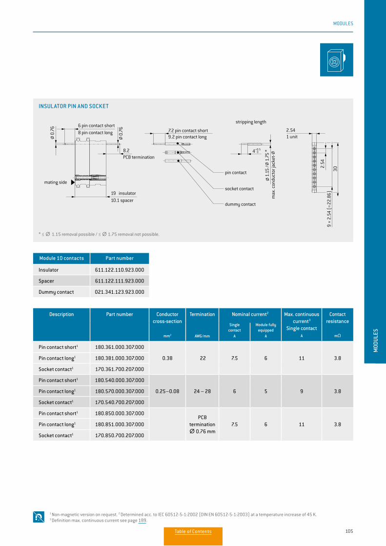
105
MODULES
MOD
ULES
Description Part number Conductor cross-section
mm2
Termination
AWG/mm
Nominal current2 Max. continuous current3
Single contactA
Contact resistance
mΩ
Single contact
A
Module fully equipped
A
Pin contact short1 180.361.000.307.000
0.38 22 7.5 6 11 3.8Pin contact long1 180.381.000.307.000
Socket contact1 170.361.700.207.000
Pin contact short1 180.540.000.307.000
0.25–0.08 24 – 28 6 5 9 3.8Pin contact long1 180.570.000.307.000
Socket contact1 170.540.700.207.000
Pin contact short1 180.850.000.307.000PCB
termination ∅∅ 0.76 mm
7.5 6 11 3.8Pin contact long1 180.851.000.307.000
Socket contact1 170.850.700.207.000
Module 10 contacts Part number
Insulator 611.122.110.923.000
Spacer 611.122.111.923.000
Dummy contact 021.341.123.923.000
INSULATOR PIN AND SOCKET
* ≤ ∅∅ 1.15 removal possible / ≤ ∅∅ 1.75 removal not possible.
1 Non-magnetic version on request. 2 Determined acc. to IEC 60512-5-1:2002 (DIN EN 60512-5-1:2003) at a temperature increase of 45 K. 3 Definition max. continuous current see page 189.
1 unit
max
. con
duct
or ja
cket
-
stripping length
7.2 pin contact short6 pin contact short8 pin contact long
PCB termination
mating side
19 insulator10.1 spacer
pin contact
socket contact
dummy contact
30
2.54
8.2
2.54
9.2 pin contact long
9 ×
2.54
(=
22.8
6)
4+0.5 0
1.15
/ 1.
75 *
0.76
0.76
9
2,52Steckseite
Table of Contents
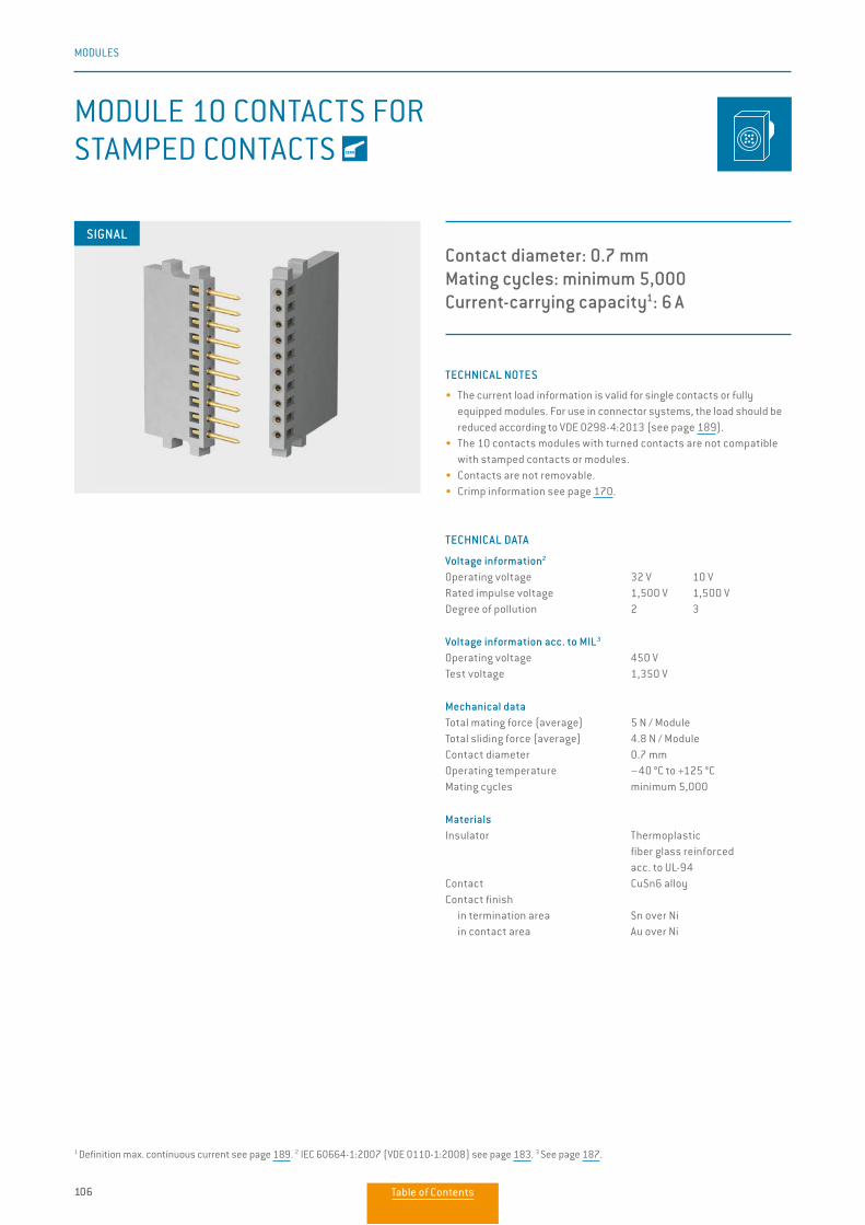
106
MODULES
MODULE 10 CONTACTS FOR STAMPED CONTACTS
Contact diameter: 0.7 mmMating cycles: minimum 5,000Current-carrying capacity1: 6 A
TECHNICAL NOTES
• The current load information is valid for single contacts or fully equipped modules. For use in connector systems, the load should be reduced according to VDE 0298-4:2013 (see page 189).
• The 10 contacts modules with turned contacts are not compatible with stamped contacts or modules.
• Contacts are not removable.• Crimp information see page 170.
TECHNICAL DATA
Voltage information2
Operating voltage 32 V 10 VRated impulse voltage 1,500 V 1,500 VDegree of pollution 2 3
Voltage information acc. to MIL3
Operating voltage 450 VTest voltage 1,350 V
Mechanical dataTotal mating force (average) 5 N / ModuleTotal sliding force (average) 4.8 N / ModuleContact diameter 0.7 mmOperating temperature –40 °C to +125 °CMating cycles minimum 5,000
MaterialsInsulator Thermoplastic fiber glass reinforced acc. to UL-94Contact CuSn6 alloyContact finish in termination area Sn over Ni in contact area Au over Ni
SIGNAL
1 Definition max. continuous current see page 189. 2 IEC 60664-1:2007 (VDE 0110-1:2008) see page 183. 3 See page 187.
Table of Contents
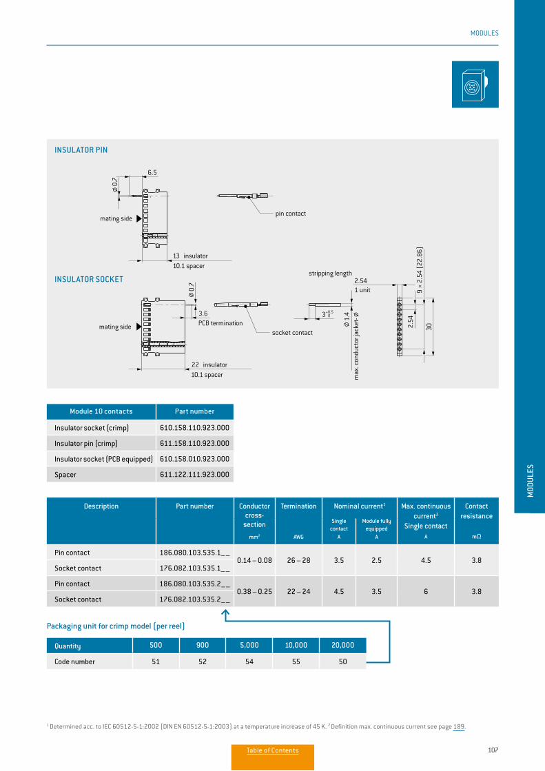
107
MODULES
MOD
ULES
1 Determined acc. to IEC 60512-5-1:2002 (DIN EN 60512-5-1:2003) at a temperature increase of 45 K. 2 Definition max. continuous current see page 189.
Description Part number Conductor cross-
section
mm2
Termination
AWG
Nominal current1 Max. continuous current2
Single contact
A
Contact resistance
mΩ
Single contact
A
Module fully equipped
A
Pin contact 186.080.103.535.1––0.14 – 0.08 26 – 28 3.5 2.5 4.5 3.8
Socket contact 176.082.103.535.1––
Pin contact 186.080.103.535.2––0.38 – 0.25 22 – 24 4.5 3.5 6 3.8
Socket contact 176.082.103.535.2––
Packaging unit for crimp model (per reel)
Quantity 500 900 5,000 10,000 20,000
Code number 51 52 54 55 50
Module 10 contacts Part number
Insulator socket (crimp) 610.158.110.923.000
Insulator pin (crimp) 611.158.110.923.000
Insulator socket (PCB equipped) 610.158.010.923.000
Spacer 611.122.111.923.000
INSULATOR SOCKET
INSULATOR PIN
3.6
6.5302.
549
× 2.
54 (
22.8
6)
2.54
PCB termination
13 insulator10.1 spacer
22 insulator10.1 spacer
1 unit
mating side
insulator socket
insulator pin
socket contact
pin contactmating side
max
. con
duct
or ja
cket
-
0.7
1.4
0.7
stripping length
3+0.5 0
3.6
6.5
302.54
9 ×
2.54
(22
.86)
2.54
PCB termination
13 insulator10.1 spacer
22 insulator10.1 spacer
1 unit
mating side
insulator socket
insulator pin
socket contact
pin contactmating side
max
. con
duct
or ja
cket
-
0.7
1.4
0.7
stripping length
3+0.5 0
Table of Contents
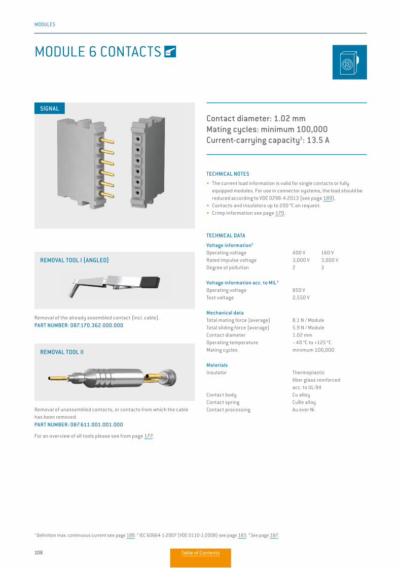
108
MODULES
MODULE 6 CONTACTS
Contact diameter: 1.02 mmMating cycles: minimum 100,000Current-carrying capacity1: 13.5 A
TECHNICAL NOTES
• The current load information is valid for single contacts or fully equipped modules. For use in connector systems, the load should be reduced according to VDE 0298-4:2013 (see page 189).
• Contacts and insulators up to 200 °C on request.• Crimp information see page 170.
TECHNICAL DATA
Voltage information2
Operating voltage 400 V 160 VRated impulse voltage 3,000 V 3,000 VDegree of pollution 2 3
Voltage information acc. to MIL3
Operating voltage 850 VTest voltage 2,550 V
Mechanical dataTotal mating force (average) 8.1 N / ModuleTotal sliding force (average) 5.9 N / ModuleContact diameter 1.02 mmOperating temperature –40 °C to +125 °CMating cycles minimum 100,000
MaterialsInsulator Thermoplastic fiber glass reinforced acc. to UL-94Contact body Cu alloyContact spring CuBe alloyContact processing Au over Ni
SIGNAL
Removal of the already assembled contact (incl. cable). PART NUMBER: 087.170.362.000.000
REMOVAL TOOL I (ANGLED)
Removal of unassembled contacts, or contacts from which the cable has been removed. PART NUMBER: 087.611.001.001.000
For an overview of all tools please see from page 177.
REMOVAL TOOL II
1 Definition max. continuous current see page 189. 2 IEC 60664-1:2007 (VDE 0110-1:2008) see page 183. 3 See page 187.
Table of Contents
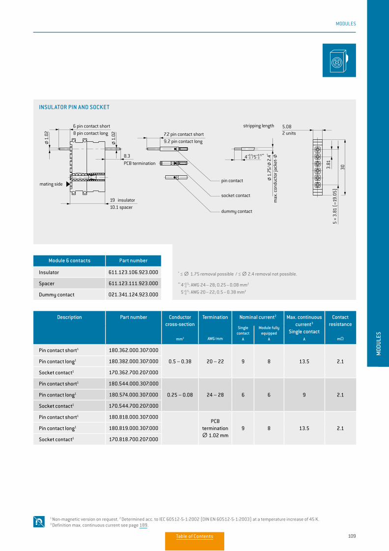
109
MODULES
MOD
ULES
Description Part number Conductor cross-section
mm2
Termination
AWG/mm
Nominal current2 Max. continuous current3
Single contact
A
Contact resistance
mΩ
Single contact
A
Module fully equipped
A
Pin contact short1 180.362.000.307.000
0.5 – 0.38 20 – 22 9 8 13.5 2.1Pin contact long1 180.382.000.307.000
Socket contact1 170.362.700.207.000
Pin contact short1 180.544.000.307.000
0.25 – 0.08 24 – 28 6 6 9 2.1Pin contact long1 180.574.000.307.000
Socket contact1 170.544.700.207.000
Pin contact short1 180.818.000.307.000PCB
termination ∅∅ 1.02 mm
9 8 13.5 2.1Pin contact long1 180.819.000.307.000
Socket contact1 170.818.700.207.000
Module 6 contacts Part number
Insulator 611.123.106.923.000
Spacer 611.123.111.923.000
Dummy contact 021.341.124.923.000
* ≤ ∅∅ 1.75 removal possible / ≤ ∅∅ 2.4 removal not possible.
** 4 0+0.5: AWG 24 – 28; 0.25 – 0.08 mm2
5 0+0.5: AWG 20 – 22; 0.5 – 0.38 mm2
1 Non-magnetic version on request. 2 Determined acc. to IEC 60512-5-1:2002 (DIN EN 60512-5-1:2003) at a temperature increase of 45 K. 3 Definition max. continuous current see page 189.
INSULATOR PIN AND SOCKET
4+0.5 0 /5+0.5**
0
5.08
303.81
5 ×
3.81
(=1
9.05
)
8.3
2 units
max
. con
duct
or ja
cket
-
7.2 pin contact short9.2 pin contact long
6 pin contact short8 pin contact long
19 insulator10.1 spacer
stripping length
mating sidepin contact
socket contact
dummy contact
1.75
/2.
4*
1.02
1.02
PCB termination4+0.5
0 /5+0.5** 0
5.08
303.81
5 ×
3.81
(=1
9.05
)
8.3
2 units
max
. con
duct
or ja
cket
-
7.2 pin contact short9.2 pin contact long
6 pin contact short8 pin contact long
19 insulator10.1 spacer
stripping length
mating sidepin contact
socket contact
dummy contact
1.75
/2.
4*
1.02
1.02
PCB termination
Table of Contents
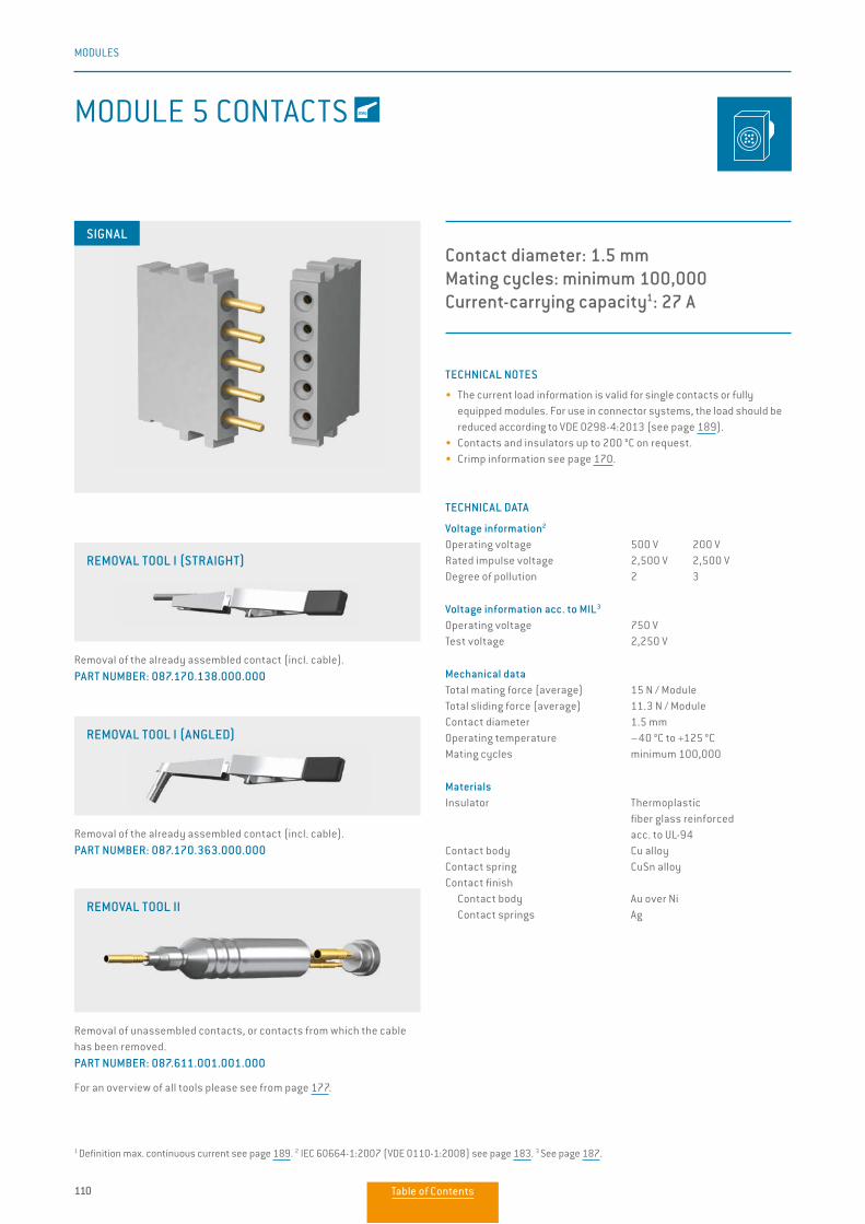
110
MODULES
MODULE 5 CONTACTS
Contact diameter: 1.5 mmMating cycles: minimum 100,000Current-carrying capacity1: 27 A
TECHNICAL NOTES
• The current load information is valid for single contacts or fully equipped modules. For use in connector systems, the load should be reduced according to VDE 0298-4:2013 (see page 189).
• Contacts and insulators up to 200 °C on request.• Crimp information see page 170.
TECHNICAL DATA
Voltage information2
Operating voltage 500 V 200 VRated impulse voltage 2,500 V 2,500 VDegree of pollution 2 3
Voltage information acc. to MIL3
Operating voltage 750 VTest voltage 2,250 V
Mechanical dataTotal mating force (average) 15 N / ModuleTotal sliding force (average) 11.3 N / ModuleContact diameter 1.5 mmOperating temperature –40 °C to +125 °CMating cycles minimum 100,000
MaterialsInsulator Thermoplastic fiber glass reinforced acc. to UL-94Contact body Cu alloyContact spring CuSn alloy Contact finish Contact body Au over Ni Contact springs Ag
SIGNAL
Removal of the already assembled contact (incl. cable). PART NUMBER: 087.170.138.000.000
Removal of the already assembled contact (incl. cable). PART NUMBER: 087.170.363.000.000
Removal of unassembled contacts, or contacts from which the cable has been removed. PART NUMBER: 087.611.001.001.000
For an overview of all tools please see from page 177.
REMOVAL TOOL I (STRAIGHT)
REMOVAL TOOL I (ANGLED)
REMOVAL TOOL II
1 Definition max. continuous current see page 189. 2 IEC 60664-1:2007 (VDE 0110-1:2008) see page 183. 3 See page 187.
Table of Contents
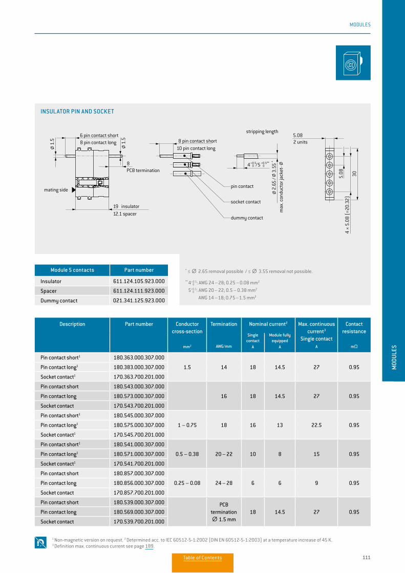
111
MODULES
MOD
ULES
Description Part number Conductor cross-section
mm2
Termination
AWG/mm
Nominal current2 Max. continuous current3
Single contact
A
Contact resistance
mΩ
Single contact
A
Module fully equipped
A
Pin contact short1 180.363.000.307.000
1.5 14 18 14.5 27 0.95Pin contact long1 180.383.000.307.000
Socket contact1 170.363.700.201.000
Pin contact short 180.543.000.307.000
16 18 14.5 27 0.95Pin contact long 180.573.000.307.000
Socket contact 170.543.700.201.000
Pin contact short1 180.545.000.307.000
1 – 0.75 18 16 13 22.5 0.95Pin contact long1 180.575.000.307.000
Socket contact1 170.545.700.201.000
Pin contact short1 180.541.000.307.000
0.5 – 0.38 20 – 22 10 8 15 0.95Pin contact long1 180.571.000.307.000
Socket contact1 170.541.700.201.000
Pin contact short 180.857.000.307.000
0.25 – 0.08 24 – 28 6 6 9 0.95Pin contact long 180.856.000.307.000
Socket contact 170.857.700.201.000
Pin contact short 180.539.000.307.000 PCB termination ∅∅ 1.5 mm
18 14.5 27 0.95Pin contact long 180.569.000.307.000
Socket contact 170.539.700.201.000
Module 5 contacts Part number
Insulator 611.124.105.923.000
Spacer 611.124.111.923.000
Dummy contact 021.341.125.923.000
* ≤ ∅∅ 2.65 removal possible / ≤ ∅∅ 3.55 removal not possible.
** 4 0+0.5: AWG 24 – 28; 0.25 – 0.08 mm2
5 0+0.5: AWG 20 – 22; 0.5 – 0.38 mm2
AWG 14 – 18; 0.75 – 1.5 mm2
1 Non-magnetic version on request. 2 Determined acc. to IEC 60512-5-1:2002 (DIN EN 60512-5-1:2003) at a temperature increase of 45 K. 3 Definition max. continuous current see page 189.
INSULATOR PIN AND SOCKET
2 units
max
. con
duct
or ja
cket
-
stripping length
pin contact
socket contact
dummy contact
8 pin contact short10 pin contact long
6 pin contact short8 pin contact long
PCB termination
19 insulator12.1 spacer
mating side
5.08
4 ×
5.08
(=2
0.32
)30
5.08
8
3.55
*
1.5
1.5
2.65
/
/5 +0.5** 04+0.5
0
2 units
max
. con
duct
or ja
cket
-
stripping length
pin contact
socket contact
dummy contact
8 pin contact short10 pin contact long
6 pin contact short8 pin contact long
PCB termination
19 insulator12.1 spacer
mating side
5.08
4 ×
5.08
(=2
0.32
)30
5.08
8
3.55
*
1.5
1.5
2.65
/
/5 +0.5** 04+0.5
0
Table of Contents
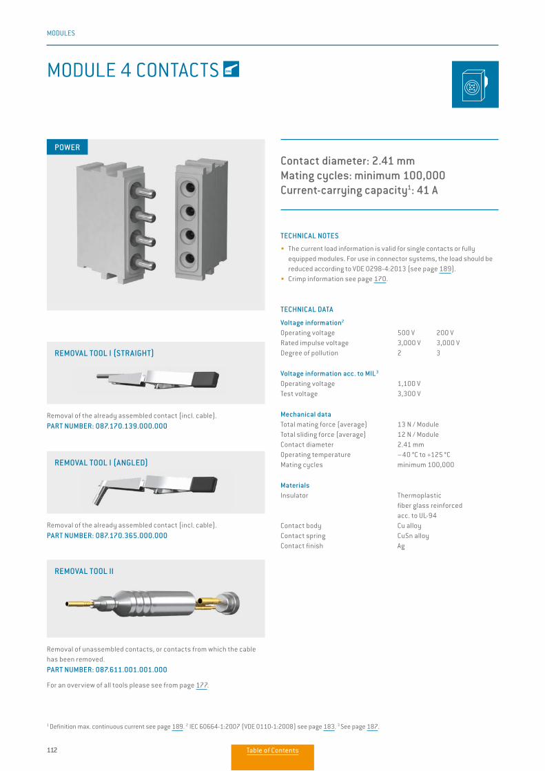
112
MODULES
MODULE 4 CONTACTS
Contact diameter: 2.41 mmMating cycles: minimum 100,000Current-carrying capacity1: 41 A
TECHNICAL NOTES
• The current load information is valid for single contacts or fully equipped modules. For use in connector systems, the load should be reduced according to VDE 0298-4:2013 (see page 189).
• Crimp information see page 170.
TECHNICAL DATA
Voltage information2
Operating voltage 500 V 200 VRated impulse voltage 3,000 V 3,000 VDegree of pollution 2 3
Voltage information acc. to MIL3
Operating voltage 1,100 VTest voltage 3,300 V
Mechanical dataTotal mating force (average) 13 N / ModuleTotal sliding force (average) 12 N / ModuleContact diameter 2.41 mmOperating temperature –40 °C to +125 °CMating cycles minimum 100,000
MaterialsInsulator Thermoplastic fiber glass reinforced acc. to UL-94Contact body Cu alloyContact spring CuSn alloyContact finish Ag
POWER
Removal of the already assembled contact (incl. cable). PART NUMBER: 087.170.139.000.000
Removal of the already assembled contact (incl. cable). PART NUMBER: 087.170.365.000.000
Removal of unassembled contacts, or contacts from which the cable has been removed. PART NUMBER: 087.611.001.001.000
For an overview of all tools please see from page 177.
REMOVAL TOOL I (ANGLED)
REMOVAL TOOL II
REMOVAL TOOL I (STRAIGHT)
1 Definition max. continuous current see page 189. 2 IEC 60664-1:2007 (VDE 0110-1:2008) see page 183. 3 See page 187.
Table of Contents
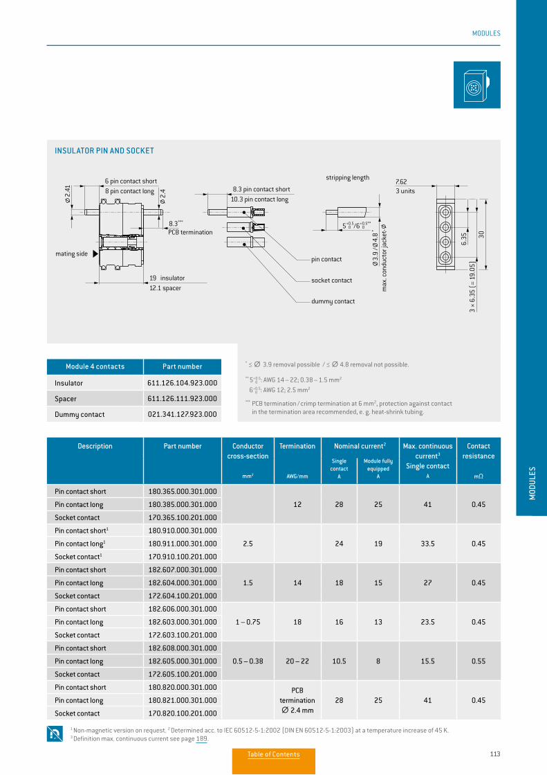
113
MODULES
MOD
ULES
* ≤ ∅∅ 3.9 removal possible / ≤ ∅∅ 4.8 removal not possible.
** 5 0+0.5: AWG 14 – 22; 0.38 – 1.5 mm2
6 0+0.5: AWG 12; 2.5 mm2
*** PCB termination / crimp termination at 6 mm2, protection against contact in the termination area recommended, e. g. heat-shrink tubing.
Description Part number Conductor cross-section
mm2
Termination
AWG/mm
Nominal current2 Max. continuous current3
Single contact
A
Contact resistance
mΩ
Single contact
A
Module fully equipped
A
Pin contact short 180.365.000.301.000
12 28 25 41 0.45Pin contact long 180.385.000.301.000
Socket contact 170.365.100.201.000
Pin contact short1 180.910.000.301.000
2.5 24 19 33.5 0.45Pin contact long1 180.911.000.301.000
Socket contact1 170.910.100.201.000
Pin contact short 182.607.000.301.000
1.5 14 18 15 27 0.45Pin contact long 182.604.000.301.000
Socket contact 172.604.100.201.000
Pin contact short 182.606.000.301.000
1 – 0.75 18 16 13 23.5 0.45Pin contact long 182.603.000.301.000
Socket contact 172.603.100.201.000
Pin contact short 182.608.000.301.000
0.5 – 0.38 20 – 22 10.5 8 15.5 0.55Pin contact long 182.605.000.301.000
Socket contact 172.605.100.201.000
Pin contact short 180.820.000.301.000 PCB termination ∅∅ 2.4 mm
28 25 41 0.45Pin contact long 180.821.000.301.000
Socket contact 170.820.100.201.000
Module 4 contacts Part number
Insulator 611.126.104.923.000
Spacer 611.126.111.923.000
Dummy contact 021.341.127.923.000
1 Non-magnetic version on request. 2 Determined acc. to IEC 60512-5-1:2002 (DIN EN 60512-5-1:2003) at a temperature increase of 45 K. 3 Definition max. continuous current see page 189.
INSULATOR PIN AND SOCKET
3 units
max
. con
duct
or ja
cket
-
stripping length
PCB termination
mating sidepin contact
socket contact
dummy contact
6 pin contact short8 pin contact long
19 insulator12.1 spacer
8.3 pin contact short10.3 pin contact long
8.3***
30
6.35
3 ×
6.35
(=
19.0
5)
7.62
4.8
*
3.9
/
5+0.5 0 /6+0.5**
0
2.42.41
Table of Contents
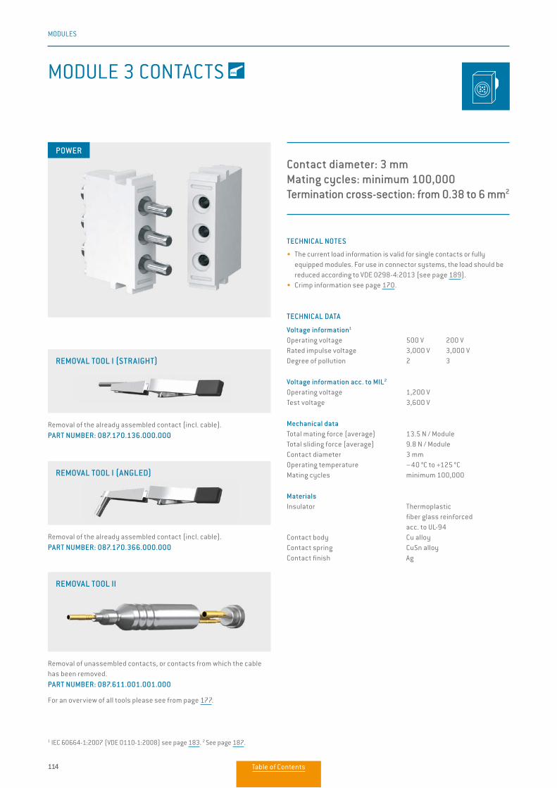
114
MODULES
MODULE 3 CONTACTS
Contact diameter: 3 mmMating cycles: minimum 100,000Termination cross-section: from 0.38 to 6 mm2
TECHNICAL NOTES
• The current load information is valid for single contacts or fully equipped modules. For use in connector systems, the load should be reduced according to VDE 0298-4:2013 (see page 189).
• Crimp information see page 170.
TECHNICAL DATA
Voltage information1
Operating voltage 500 V 200 VRated impulse voltage 3,000 V 3,000 VDegree of pollution 2 3
Voltage information acc. to MIL2
Operating voltage 1,200 VTest voltage 3,600 V
Mechanical dataTotal mating force (average) 13.5 N / ModuleTotal sliding force (average) 9.8 N / ModuleContact diameter 3 mmOperating temperature –40 °C to +125 °CMating cycles minimum 100,000
MaterialsInsulator Thermoplastic fiber glass reinforced acc. to UL-94Contact body Cu alloyContact spring CuSn alloyContact finish Ag
POWER
Removal of the already assembled contact (incl. cable). PART NUMBER: 087.170.136.000.000
Removal of the already assembled contact (incl. cable). PART NUMBER: 087.170.366.000.000
Removal of unassembled contacts, or contacts from which the cable has been removed. PART NUMBER: 087.611.001.001.000
For an overview of all tools please see from page 177.
REMOVAL TOOL I (ANGLED)
REMOVAL TOOL II
1 IEC 60664-1:2007 (VDE 0110-1:2008) see page 183. 2 See page 187.
REMOVAL TOOL I (STRAIGHT)
Table of Contents
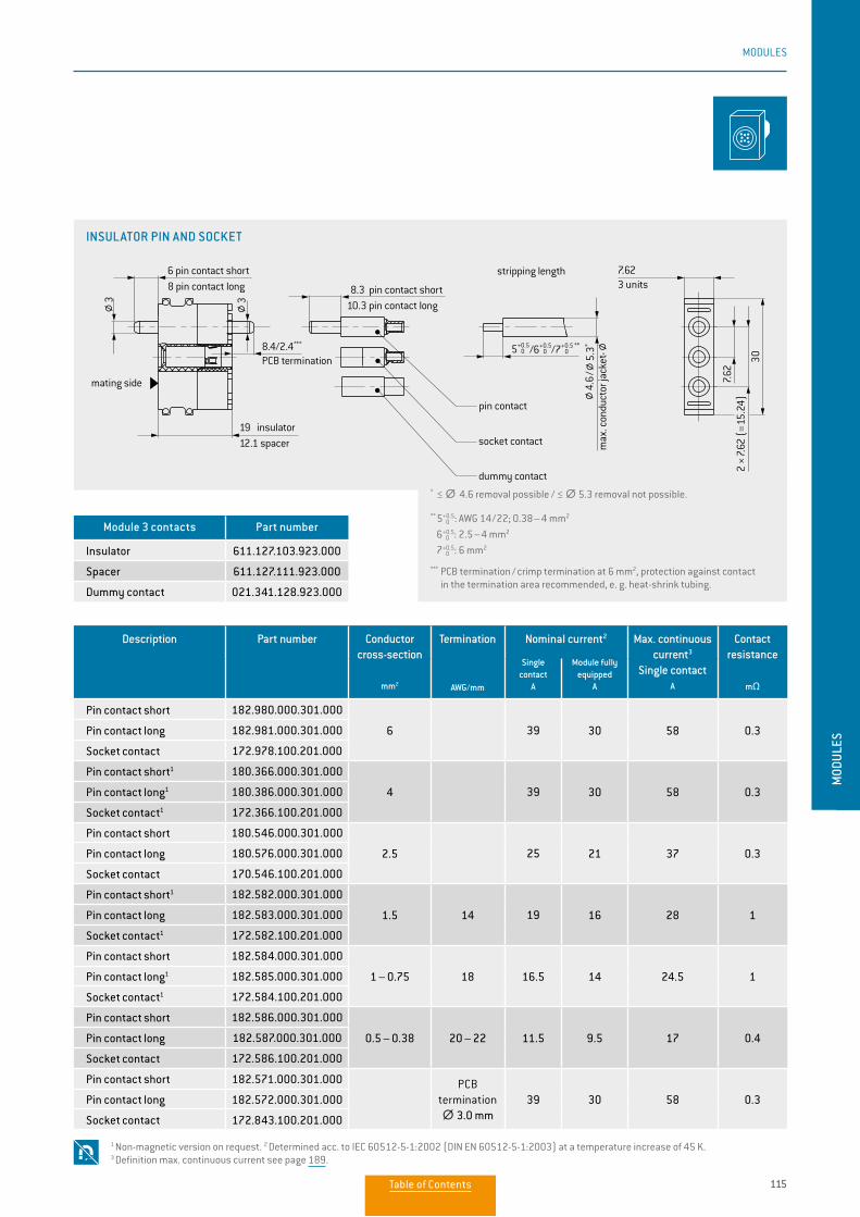
115
MODULES
MOD
ULES
Description Part number Conductor cross-section
mm2
Termination
AWG/mm
Nominal current2 Max. continuous current3
Single contact
A
Contact resistance
mΩ
Single contact
A
Module fully equipped
A
Pin contact short 182.980.000.301.000
6 39 30 58 0.3Pin contact long 182.981.000.301.000
Socket contact 172.978.100.201.000
Pin contact short1 180.366.000.301.000
4 39 30 58 0.3Pin contact long1 180.386.000.301.000
Socket contact1 172.366.100.201.000
Pin contact short 180.546.000.301.000
2.5 25 21 37 0.3Pin contact long 180.576.000.301.000
Socket contact 170.546.100.201.000
Pin contact short1 182.582.000.301.000
1.5 14 19 16 28 1Pin contact long 182.583.000.301.000
Socket contact1 172.582.100.201.000
Pin contact short 182.584.000.301.000
1 – 0.75 18 16.5 14 24.5 1Pin contact long1 182.585.000.301.000
Socket contact1 172.584.100.201.000
Pin contact short 182.586.000.301.000
0.5 – 0.38 20 – 22 11.5 9.5 17 0.4Pin contact long 182.587.000.301.000
Socket contact 172.586.100.201.000
Pin contact short 182.571.000.301.000 PCB termination∅∅ 3.0 mm
39 30 58 0.3Pin contact long 182.572.000.301.000
Socket contact 172.843.100.201.000
Module 3 contacts Part number
Insulator 611.127.103.923.000
Spacer 611.127.111.923.000
Dummy contact 021.341.128.923.000
* ≤ ∅∅ 4.6 removal possible / ≤ ∅∅ 5.3 removal not possible.
** 5 0+0.5: AWG 14 / 22; 0.38 – 4 mm2
6 0+0.5: 2.5 – 4 mm2
7 0+0.5: 6 mm2
*** PCB termination / crimp termination at 6 mm2, protection against contact in the termination area recommended, e. g. heat-shrink tubing.
1 Non-magnetic version on request. 2 Determined acc. to IEC 60512-5-1:2002 (DIN EN 60512-5-1:2003) at a temperature increase of 45 K. 3 Definition max. continuous current see page 189.
INSULATOR PIN AND SOCKET
5+0.5 0 /6+0.5
0 /7+0.5 ** 0
30
7.62
2 ×
7.62
(=
15.2
4)
7.62
PCB termination
6 pin contact short8 pin contact long
max
. con
duct
or ja
cket
-
stripping length
pin contact
socket contact
dummy contact
mating side
19 insulator12.1 spacer
8.3 pin contact short10.3 pin contact long
3 units
4.6
/5.
3*
33
8.4/2.4***
Table of Contents
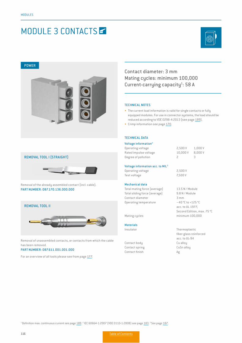
116
MODULES
MODULE 3 CONTACTS
Contact diameter: 3 mmMating cycles: minimum 100,000Current-carrying capacity1: 58 A
TECHNICAL NOTES
• The current load information is valid for single contacts or fully equipped modules. For use in connector systems, the load should be reduced according to VDE 0298-4:2013 (see page 189).
• Crimp information see page 170.
TECHNICAL DATA
Voltage information2
Operating voltage 2,500 V 1,000 VRated impulse voltage 10,000 V 8,000 VDegree of pollution 2 3
Voltage information acc. to MIL3
Operating voltage 2,500 VTest voltage 7,500 V
Mechanical dataTotal mating force (average) 13.5 N / ModuleTotal sliding force (average) 9.8 N / ModuleContact diameter 3 mmOperating temperature –40 °C to +125 °C acc. to UL 1977, Second Edition, max. 75 °CMating cycles minimum 100,000
MaterialsInsulator Thermoplastic fiber glass reinforced acc. to UL-94Contact body Cu alloyContact spring CuSn alloyContact finish Ag
POWER
Removal of unassembled contacts, or contacts from which the cable has been removed. PART NUMBER: 087.611.001.001.000
For an overview of all tools please see from page 177.
REMOVAL TOOL II
Removal of the already assembled contact (incl. cable). PART NUMBER: 087.170.136.000.000
REMOVAL TOOL I (STRAIGHT)
1 Definition max. continuous current see page 189. 2 IEC 60664-1:2007 (VDE 0110-1:2008) see page 183. 3 See page 187.
Table of Contents
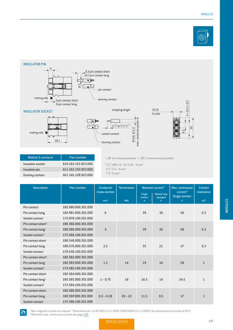
117
MODULES
MOD
ULES
* ≤ ∅∅ 4.6 removal possible / ≤ ∅∅ 5.3 removal not possible.
** 5 0+0.5: AWG 14 – 22; 0.38 – 4 mm2
6 0+0.5: 2.5 – 4 mm2
7 0+0.5: 6 mm2
Description Part number Conductor cross-section
mm2
Termination
AWG
Nominal current2 Max. continuous current3
Single contact
A
Contact resistance
mΩ
Single contact
A
Module fully equipped
A
Pin contact 182.980.000.301.000
6 39 30 58 0.3Pin contact long 182.981.000.301.000
Socket contact 172.978.100.201.000
Pin contact short1 180.366.000.301.000
4 39 30 58 0.3Pin contact long1 180.386.000.301.000
Socket contact1 172.366.100.201.000
Pin contact short 180.546.000.301.000
2.5 25 21 37 0.3Pin contact long 180.576.000.301.000
Socket contact 170.546.100.201.000
Pin contact short1 182.582.000.301.000
1.5 14 19 16 28 1Pin contact long 182.583.000.301.000
Socket contact1 172.582.100.201.000
Pin contact short 182.584.000.301.000
1 – 0.75 18 16.5 14 24.5 1Pin contact long1 182.585.000.301.000
Socket contact1 172.584.100.201.000
Pin contact short 182.586.000.301.000
0.5 – 0.38 20 – 22 11.5 9.5 17 1Pin contact long 182.587.000.301.000
Socket contact 172.586.100.201.000
Module 3 contacts Part number
Insulator socket 610.162.103.923.000
Insulator pin 611.162.103.923.000
Dummy contact 021.341.128.923.000
1 Non-magnetic version on request. 2 Determined acc. to IEC 60512-5-1:2002 (DIN EN 60512-5-1:2003) at a temperature increase of 45 K. 3 Definition max. continuous current see page 189.
INSULATOR PIN
INSULATOR SOCKET
dummy contact
30
8.5
2 ×
8.5
(=17
)
5+0.5 0 /6+0.5
0 /7+0.5 ** 0
10.16
6
28.1
8.3 pin contact short10.3 pin contact long
6 pin contact short8 pin contact long
4 unitsstripping length
insulator socket
insulator pin
pin contact
socket contact
dummy contactmating side
mating side
max
. con
duct
or ja
cket
-4.
6/5.
3*
3
Table of Contents
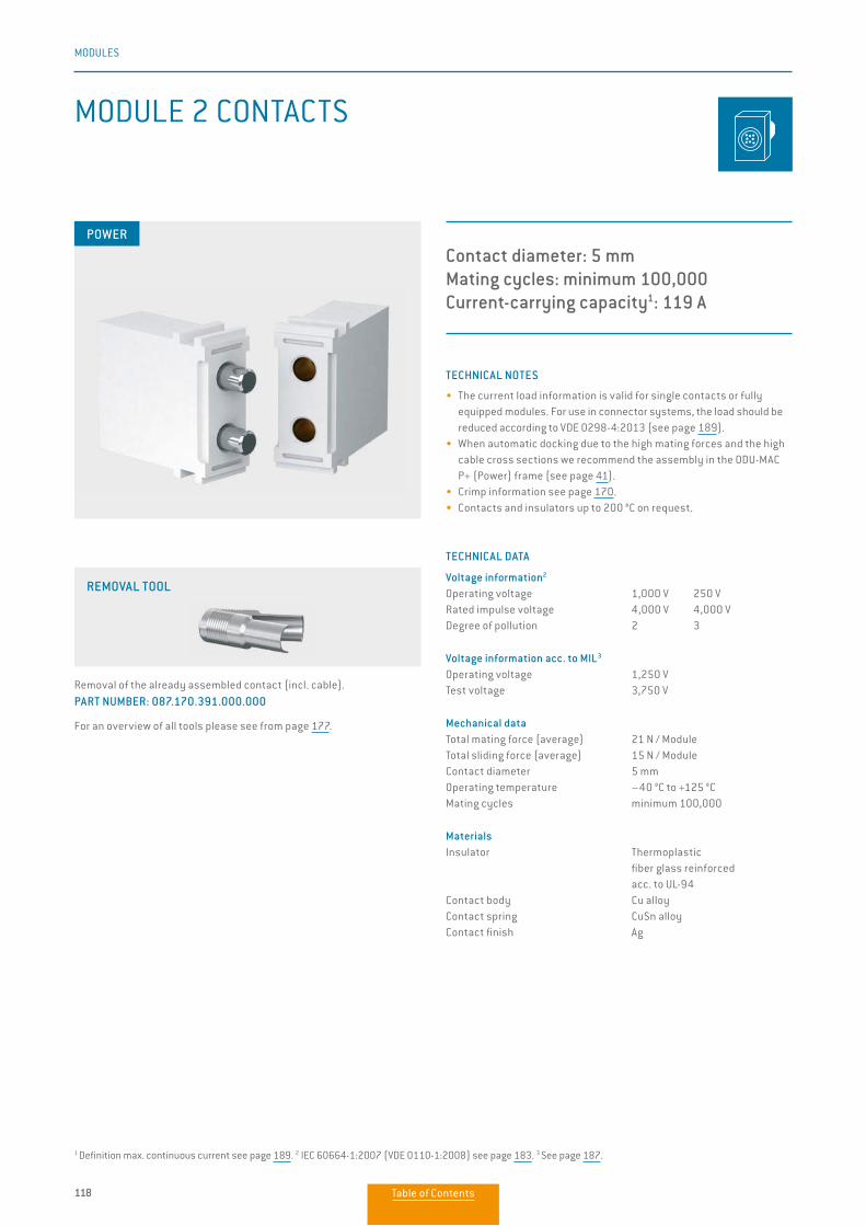
118
MODULES
MODULE 2 CONTACTS
Contact diameter: 5 mmMating cycles: minimum 100,000Current-carrying capacity1: 119 A
TECHNICAL NOTES
• The current load information is valid for single contacts or fully equipped modules. For use in connector systems, the load should be reduced according to VDE 0298-4:2013 (see page 189).
• When automatic docking due to the high mating forces and the high cable cross sections we recommend the assembly in the ODU-MAC P+ (Power) frame (see page 41).
• Crimp information see page 170.• Contacts and insulators up to 200 °C on request.
TECHNICAL DATA
Voltage information2
Operating voltage 1,000 V 250 VRated impulse voltage 4,000 V 4,000 VDegree of pollution 2 3
Voltage information acc. to MIL3
Operating voltage 1,250 VTest voltage 3,750 V
Mechanical dataTotal mating force (average) 21 N / ModuleTotal sliding force (average) 15 N / ModuleContact diameter 5 mmOperating temperature –40 °C to +125 °CMating cycles minimum 100,000
MaterialsInsulator Thermoplastic fiber glass reinforced acc. to UL-94Contact body Cu alloyContact spring CuSn alloyContact finish Ag
POWER
Removal of the already assembled contact (incl. cable). PART NUMBER: 087.170.391.000.000
For an overview of all tools please see from page 177.
REMOVAL TOOL
1 Definition max. continuous current see page 189. 2 IEC 60664-1:2007 (VDE 0110-1:2008) see page 183. 3 See page 187.
Table of Contents
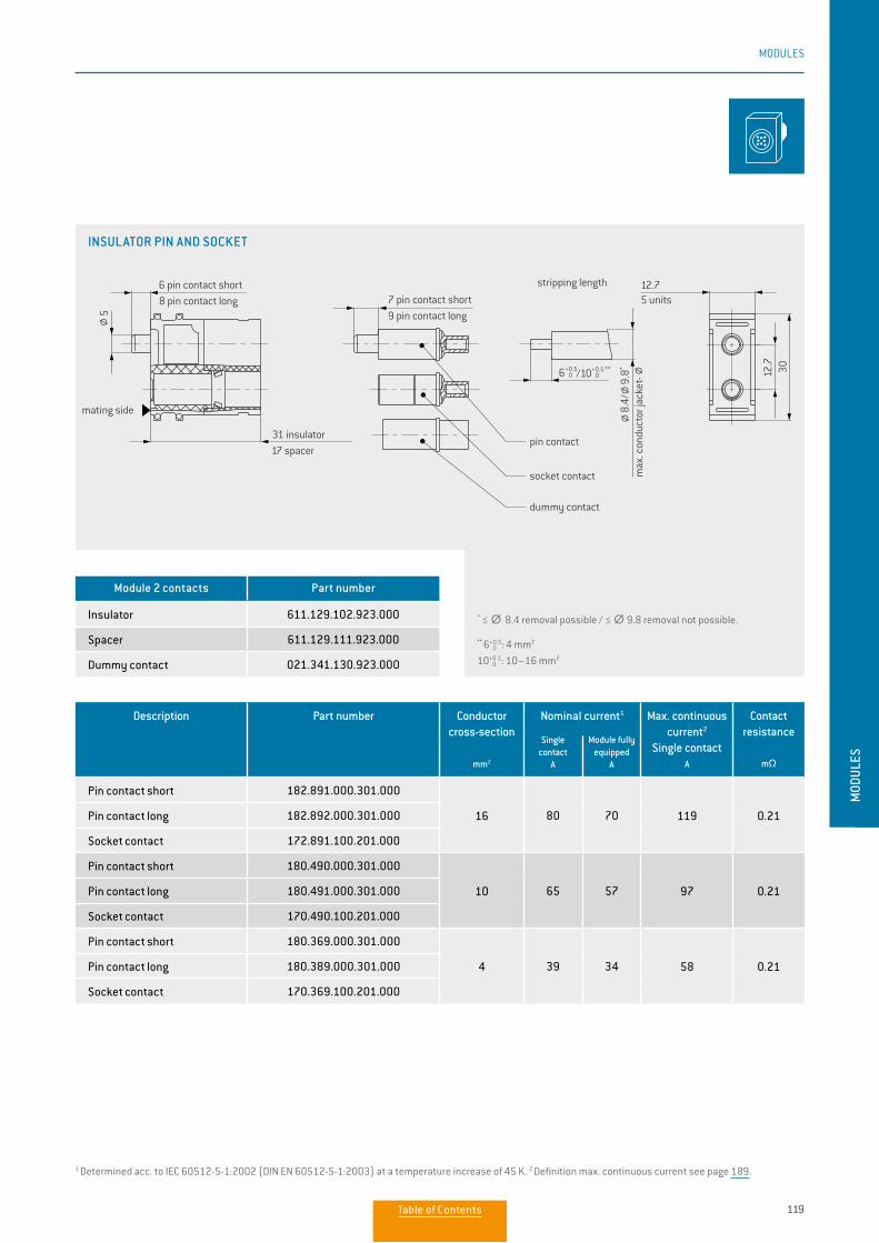
119
MODULES
MOD
ULES
Description Part number Conductor cross-section
mm2
Nominal current1 Max. continuous current2
Single contact
A
Contact resistance
mΩ
Single contact
A
Module fully equipped
A
Pin contact short 182.891.000.301.000
16 80 70 119 0.21Pin contact long 182.892.000.301.000
Socket contact 172.891.100.201.000
Pin contact short 180.490.000.301.000
10 65 57 97 0.21Pin contact long 180.491.000.301.000
Socket contact 170.490.100.201.000
Pin contact short 180.369.000.301.000
4 39 34 58 0.21Pin contact long 180.389.000.301.000
Socket contact 170.369.100.201.000
Module 2 contacts Part number
Insulator 611.129.102.923.000
Spacer 611.129.111.923.000
Dummy contact 021.341.130.923.000
* ≤ ∅∅ 8.4 removal possible / ≤ ∅∅ 9.8 removal not possible.
** 6 0+0.5: 4 mm2
10 0+0.5: 10–16 mm2
1 Determined acc. to IEC 60512-5-1:2002 (DIN EN 60512-5-1:2003) at a temperature increase of 45 K. 2 Definition max. continuous current see page 189.
INSULATOR PIN AND SOCKET
6+0.5 0 /10+0.5 **
0
3012.7
12.76 pin contact short8 pin contact long
stripping length
pin contact
socket contact
dummy contact
mating side
31 insulator17 spacer
7 pin contact short9 pin contact long
5 units
max
. con
duct
or ja
cket
-
5
8.4/
9.8*
6+0.5 0 /10+0.5 **
0
3012.7
12.76 pin contact short8 pin contact long
stripping length
pin contact
socket contact
dummy contact
mating side
31 insulator17 spacer
7 pin contact short9 pin contact long
5 units
max
. con
duct
or ja
cket
-
5
8.4/
9.8*
Table of Contents
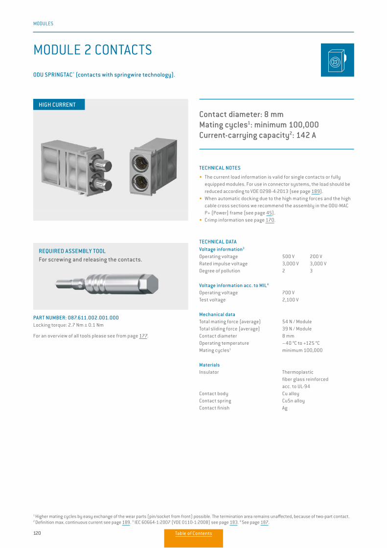
120
MODULES
MODULE 2 CONTACTS
Contact diameter: 8 mmMating cycles1: minimum 100,000Current-carrying capacity2: 142 A
ODU SPRINGTAC® (contacts with springwire technology).
TECHNICAL NOTES
• The current load information is valid for single contacts or fully equipped modules. For use in connector systems, the load should be reduced according to VDE 0298-4:2013 (see page 189).
• When automatic docking due to the high mating forces and the high cable cross sections we recommend the assembly in the ODU-MAC P+ (Power) frame (see page 45).
• Crimp information see page 170.
TECHNICAL DATAVoltage information3
Operating voltage 500 V 200 VRated impulse voltage 3,000 V 3,000 VDegree of pollution 2 3
Voltage information acc. to MIL4
Operating voltage 700 VTest voltage 2,100 V
Mechanical dataTotal mating force (average) 54 N / ModuleTotal sliding force (average) 39 N / ModuleContact diameter 8 mmOperating temperature –40 °C to +125 °CMating cycles1 minimum 100,000
MaterialsInsulator Thermoplastic fiber glass reinforced acc. to UL-94Contact body Cu alloyContact spring CuSn alloyContact finish Ag
HIGH CURRENT
REQUIRED ASSEMBLY TOOL For screwing and releasing the contacts.
PART NUMBER: 087.611.002.001.000Locking torque: 2.7 Nm ± 0.1 Nm
For an overview of all tools please see from page 177.
1 Higher mating cycles by easy exchange of the wear parts (pin/socket from front) possible. The termination area remains unaffected, because of two-part contact. 2 Definition max. continuous current see page 189. 3 IEC 60664-1:2007 (VDE 0110-1:2008) see page 183. 4 See page 187.
Table of Contents
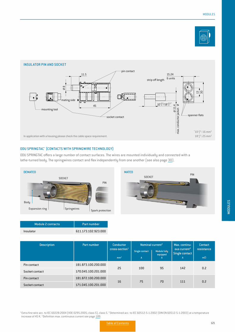
121
MODULES
MOD
ULES
ODU SPRINGTAC® (CONTACTS WITH SPRINGWIRE TECHNOLOGY)
ODU SPRINGTAC offers a large number of contact surfaces. The wires are mounted individually and connected with a lathe-turned body. The springwires contact and flex independently from one another (see also page 30).
SOCKETPIN
SOCKET
PIN
Spark protection
Body
Expansion ring
Description Part number Conductor cross-section1
mm2
Nominal current2 Max. continu-ous current3
Single contact
A
Contact resistance
mΩ
Single contact
A
Module fully equipped
A
Pin contact 181.873.100.200.00025 100 95 142 0.2
Socket contact 170.045.100.201.000
Pin contact 181.872.100.200.00016 75 70 111 0.2
Socket contact 171.045.100.201.000
Module 2 contacts Part number
Insulator 611.173.102.923.000
In application with a housing please check the cable space requirement.
*10 0+0.5 : 16 mm2
18 0+0.5: 25 mm2
Springwires
1 Extra fine wire acc. to IEC 60228:2004 (VDE 0295:2005; class 5), class 5. 2 Determined acc. to IEC 60512-5-1:2002 (DIN EN 60512-5-1:2003) at a temperature increase of 45 K. 3 Definition max. continuous current see page 189.
INSULATOR PIN AND SOCKET
45
15.2411.5
3013
6 units
max
. con
duct
or ja
cket
-
strip o length
mounting tool
pin contact
socket contactspanner flats
mounting tool complete (view "X")wrench size 21
for commercial 6-edge insert
8
11.4
mating side
10+0.5 0 /18+0.5 *
0
MATEDDEMATED
Table of Contents
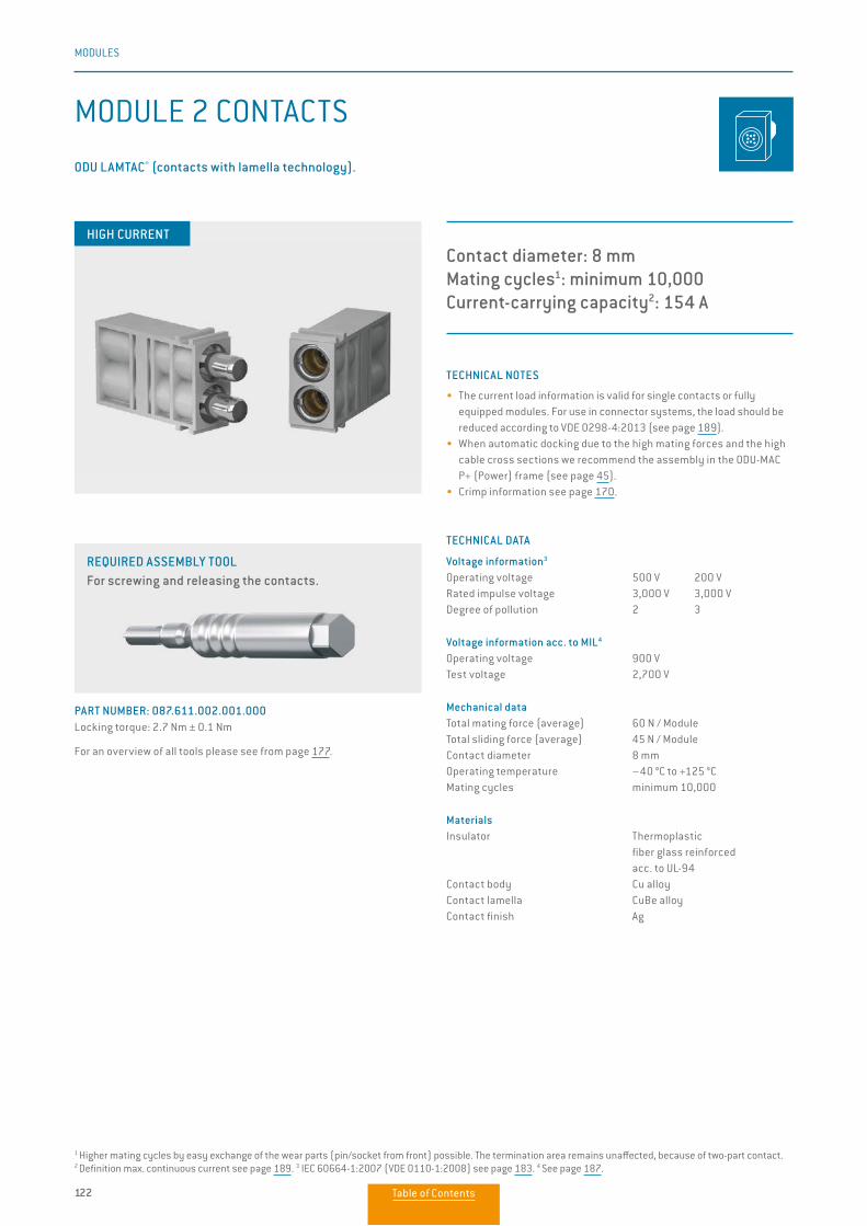
122
MODULES
MODULE 2 CONTACTS
Contact diameter: 8 mmMating cycles1: minimum 10,000Current-carrying capacity2: 154 A
TECHNICAL NOTES
• The current load information is valid for single contacts or fully equipped modules. For use in connector systems, the load should be reduced according to VDE 0298-4:2013 (see page 189).
• When automatic docking due to the high mating forces and the high cable cross sections we recommend the assembly in the ODU-MAC P+ (Power) frame (see page 45).
• Crimp information see page 170.
TECHNICAL DATA
Voltage information3
Operating voltage 500 V 200 VRated impulse voltage 3,000 V 3,000 VDegree of pollution 2 3
Voltage information acc. to MIL4
Operating voltage 900 VTest voltage 2,700 V
Mechanical dataTotal mating force (average) 60 N / ModuleTotal sliding force (average) 45 N / ModuleContact diameter 8 mmOperating temperature –40 °C to +125 °CMating cycles minimum 10,000
MaterialsInsulator Thermoplastic fiber glass reinforced acc. to UL-94Contact body Cu alloyContact lamella CuBe alloyContact finish Ag
ODU LAMTAC® (contacts with lamella technology).
REQUIRED ASSEMBLY TOOL For screwing and releasing the contacts.
PART NUMBER: 087.611.002.001.000Locking torque: 2.7 Nm ± 0.1 Nm
For an overview of all tools please see from page 177.
1 Higher mating cycles by easy exchange of the wear parts (pin/socket from front) possible. The termination area remains unaffected, because of two-part contact. 2 Definition max. continuous current see page 189. 3 IEC 60664-1:2007 (VDE 0110-1:2008) see page 183. 4 See page 187.
HIGH CURRENT
Table of Contents
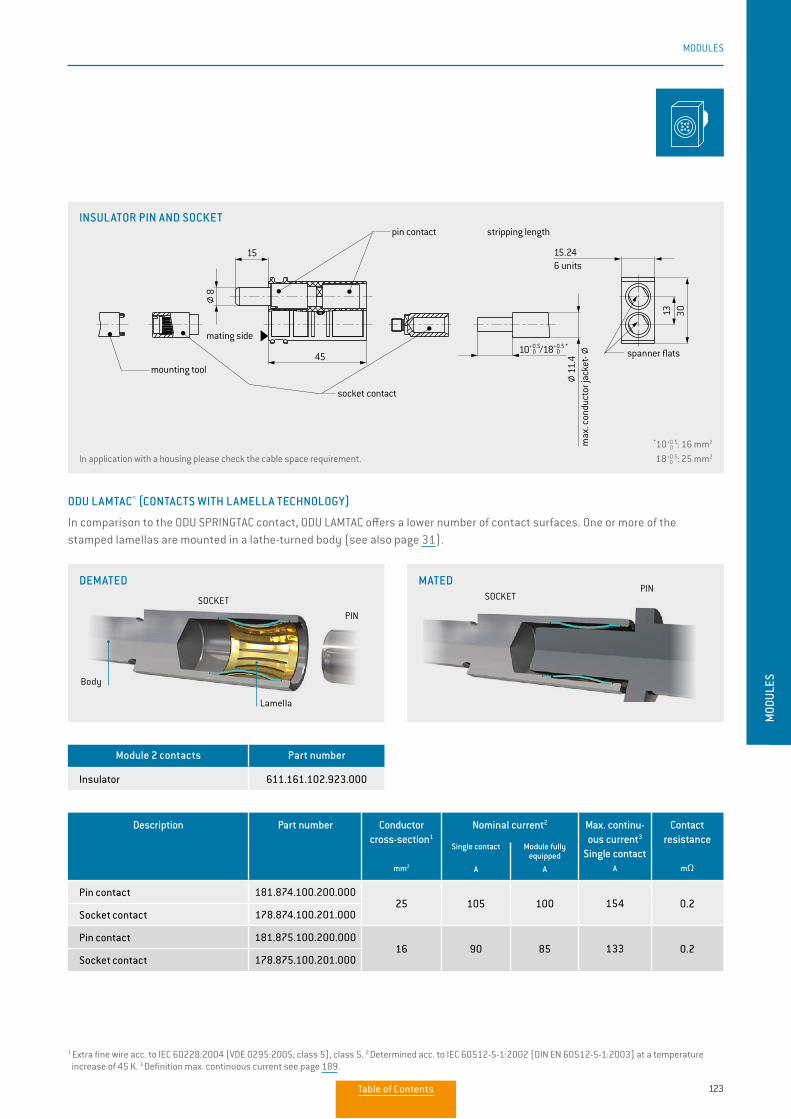
123
MODULES
MOD
ULES
Description Part number Conductor cross-section1
mm2
Nominal current2 Max. continu-ous current3
Single contact
A
Contact resistance
mΩ
Single contact
A
Module fully equipped
A
Pin contact 181.874.100.200.00025 105 100 154 0.2
Socket contact 178.874.100.201.000
Pin contact 181.875.100.200.00016 90 85 133 0.2
Socket contact 178.875.100.201.000
ODU LAMTAC® (CONTACTS WITH LAMELLA TECHNOLOGY)
In comparison to the ODU SPRINGTAC contact, ODU LAMTAC offers a lower number of contact surfaces. One or more of the stamped lamellas are mounted in a lathe-turned body (see also page 31).
Module 2 contacts Part number
Insulator 611.161.102.923.000
In application with a housing please check the cable space requirement.
*10 0+0.5 : 16 mm2
18 0+0.5: 25 mm2
SOCKETPIN
SOCKET
PIN
Body
Lamella
MATEDDEMATED
1 Extra fine wire acc. to IEC 60228:2004 (VDE 0295:2005; class 5), class 5. 2 Determined acc. to IEC 60512-5-1:2002 (DIN EN 60512-5-1:2003) at a temperature increase of 45 K. 3 Definition max. continuous current see page 189.
INSULATOR PIN AND SOCKET
45
15.2415
3013
X
10+0.5 0 /18+0.5 *
0
11.4
8
6 units
stripping length
mounting tool
pin contact
mating side
socket contact
spanner flats
mounting tool complete (view "X")
wrench size 21for commercial 6-edge insert
max
. con
duct
or ja
cket
-
Table of Contents
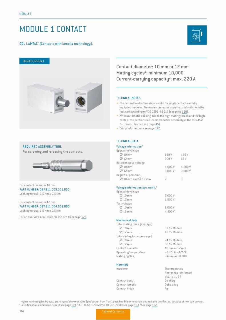
124
MODULES
Contact diameter: 10 mm or 12 mmMating cycles1: minimum 10,000 Current-carrying capacity2: max. 220 A
TECHNICAL NOTES
• The current load information is valid for single contacts or fully equipped modules. For use in connector systems, the load should be reduced according to VDE 0298-4:2013 (see page 189).
• When automatic docking due to the high mating forces and the high cable cross sections we recommend the assembly in the ODU-MAC P+ (Power) frame (see page 45).
• Crimp information see page 170.
TECHNICAL DATA
Voltage information3
Operating voltage ∅∅ 10 mm 250 V 160 V ∅∅ 12 mm 200 V 63 VRated impulse voltage ∅∅ 10 mm 4,000 V 4,000 V ∅∅ 12 mm 3,000 V 3,000 V Degree of pollution ∅∅ 10 mm and ∅∅ 12 mm 2 3 Voltage information acc. to MIL4
Operating voltage ∅∅ 10 mm 2,000 V ∅∅ 12 mm 1,500 V Test voltage ∅∅ 10 mm 6,000 V ∅∅ 12 mm 4,500 V
Mechanical dataTotal mating force (average) ∅∅ 10 mm 33 N / Module ∅∅ 12 mm 45 N / ModuleTotal sliding force (average) ∅∅ 10 mm 24 N / Module ∅∅ 12 mm 30 N / ModuleContact diameter 10 mm or 12 mmOperating temperature –40 °C to +125 °CMating cycles minimum 10,000
MaterialsInsulator Thermoplastic fiber glass reinforced acc. to UL-94Contact body Cu alloyContact lamella CuBe alloyContact finish Ag
MODULE 1 CONTACT
ODU LAMTAC® (Contacts with lamella technology).
HIGH CURRENT
REQUIRED ASSEMBLY TOOL For screwing and releasing the contacts.
For contact diameter 10 mm. PART NUMBER: 087.611.003.001.000Locking torque: 3.5 Nm ± 0.5 Nm
For contact diameter 12 mm. PART NUMBER: 087.611.004.001.000Locking torque: 3.5 Nm ± 0.5 Nm
For an overview of all tools please see from page 177.
1 Higher mating cycles by easy exchange of the wear parts (pin/socket from front) possible. The termination area remains unaffected, because of two-part contact. 2 Definition max. continuous current see page 189. 3 IEC 60664-1:2007 (VDE 0110-1:2008) see page 183. 4 See page 187.
Table of Contents
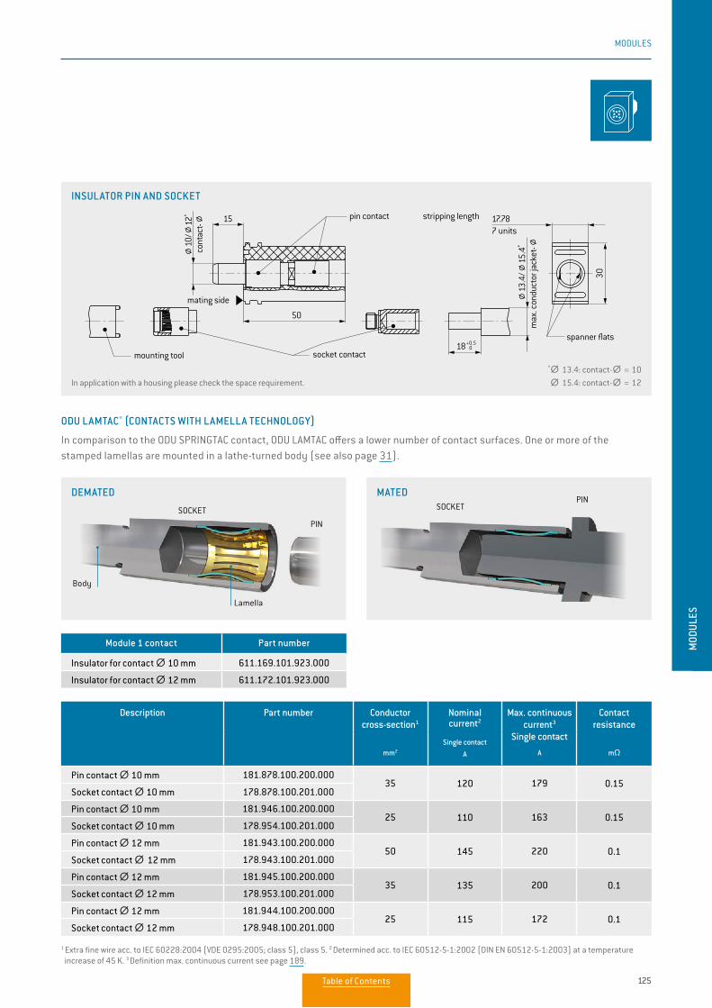
125
MODULES
MOD
ULES
SOCKETPIN
SOCKET
PIN
Body
Lamella
MATEDDEMATED
Description Part number Conductor cross-section1
mm2
Nominal current2
Max. continuous current3
Single contact
A
Contact resistance
mΩSingle contact
A
Pin contact ∅∅ 10 mm 181.878.100.200.00035 120 179 0.15
Socket contact ∅∅ 10 mm 178.878.100.201.000
Pin contact ∅∅ 10 mm 181.946.100.200.00025 110 163 0.15
Socket contact ∅∅ 10 mm 178.954.100.201.000
Pin contact ∅∅ 12 mm 181.943.100.200.00050 145 220 0.1
Socket contact ∅∅ 12 mm 178.943.100.201.000
Pin contact ∅∅ 12 mm 181.945.100.200.00035 135 200 0.1
Socket contact ∅∅ 12 mm 178.953.100.201.000
Pin contact ∅∅ 12 mm 181.944.100.200.00025 115 172 0.1
Socket contact ∅∅ 12 mm 178.948.100.201.000
ODU LAMTAC® (CONTACTS WITH LAMELLA TECHNOLOGY)
In comparison to the ODU SPRINGTAC contact, ODU LAMTAC offers a lower number of contact surfaces. One or more of the stamped lamellas are mounted in a lathe-turned body (see also page 31).
INSULATOR PIN AND SOCKET
Module 1 contact Part number
Insulator for contact ∅∅ 10 mm 611.169.101.923.000
Insulator for contact ∅∅ 12 mm 611.172.101.923.000
In application with a housing please check the space requirement.
*∅∅ 13.4: contact-∅ ∅ = 10 ∅∅ 15.4: contact-∅ ∅ = 12
1 Extra fine wire acc. to IEC 60228:2004 (VDE 0295:2005; class 5), class 5. 2 Determined acc. to IEC 60512-5-1:2002 (DIN EN 60512-5-1:2003) at a temperature increase of 45 K. 3 Definition max. continuous current see page 189.
50
17.78
30
15
18+0.5 0
10/
12*
13.4
/15
.4*
7 units
mounting tool complete (view "X")
wrench size 21for commercial 6-edge insert
mounting tool
pin contact stripping length
mating side
socket contact
spanner flats
cont
act-
max
. con
duct
or ja
cket
-
Table of Contents
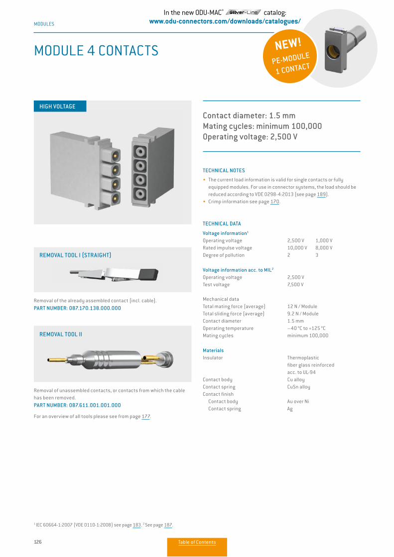
126
MODULES
TECHNICAL NOTES
• The current load information is valid for single contacts or fully equipped modules. For use in connector systems, the load should be reduced according to VDE 0298-4:2013 (see page 189).
• Crimp information see page 170.
TECHNICAL DATA
Voltage information1
Operating voltage 2,500 V 1,000 VRated impulse voltage 10,000 V 8,000 VDegree of pollution 2 3
Voltage information acc. to MIL2
Operating voltage 2,500 VTest voltage 7,500 V
Mechanical dataTotal mating force (average) 12 N / ModuleTotal sliding force (average) 9.2 N / ModuleContact diameter 1.5 mmOperating temperature –40 °C to +125 °CMating cycles minimum 100,000
MaterialsInsulator Thermoplastic fiber glass reinforced acc. to UL-94Contact body Cu alloyContact spring CuSn alloyContact finish Contact body Au over Ni Contact spring Ag
MODULE 4 CONTACTS
Contact diameter: 1.5 mmMating cycles: minimum 100,000Operating voltage: 2,500 V
HIGH VOLTAGE
Removal of the already assembled contact (incl. cable). PART NUMBER: 087.170.138.000.000
Removal of unassembled contacts, or contacts from which the cable has been removed. PART NUMBER: 087.611.001.001.000
For an overview of all tools please see from page 177.
REMOVAL TOOL I (STRAIGHT)
REMOVAL TOOL II
1 IEC 60664-1:2007 (VDE 0110-1:2008) see page 183. 2 See page 187.
NEW!PE-MODULE
1 CONTACT
In the new ODU-MAC® catalog:www.odu-connectors.com/downloads/catalogues/
Table of Contents
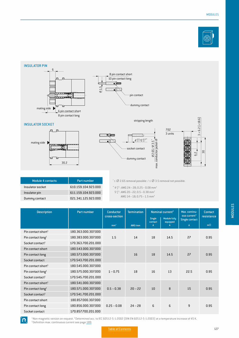
127
MODULES
MOD
ULES
* ≤ ∅∅ 2.65 removal possible / ≤ ∅∅ 3.5 removal not possible.
** 4 0+0.5 : AWG 24 – 28; 0.25 – 0.08 mm2
5 0+0.5
: AWG 20 – 22; 0.5 – 0.38 mm2
AWG 14 – 18; 0.75 – 1.5 mm2
Description Part number Conductor cross-section
mm2
Termination
AWG/mm
Nominal current2 Max. continu-ous current3
Single contact
A
Contact resistance
mΩ
Single contact
A
Module fully equipped
A
Pin contact short1 180.363.000.307.000
1.5 14 18 14.5 27 0.95Pin contact long1 180.383.000.307.000
Socket contact1 170.363.700.201.000
Pin contact short 180.543.000.307.000
16 18 14.5 27 0.95Pin contact long 180.573.000.307.000
Socket contact 170.543.700.201.000
Pin contact short1 180.545.000.307.000
1 – 0.75 18 16 13 22.5 0.95Pin contact long1 180.575.000.307.000
Socket contact1 170.545.700.201.000
Pin contact short1 180.541.000.307.000
0.5 – 0.38 20 – 22 10 8 15 0.95Pin contact long1 180.571.000.307.000
Socket contact1 170.541.700.201.000
Pin contact short 180.857.000.307.000
0.25 – 0.08 24 – 28 6 6 9 0.95Pin contact long 180.856.000.307.000
Socket contact 170.857.700.201.000
Module 4 contacts Part number
Insulator socket 610.159.104.923.000
Insulator pin 611.159.104.923.000
Dummy contact 021.341.125.923.000
1 Non-magnetic version on request. 2 Determined acc. to IEC 60512-5-1:2002 (DIN EN 60512-5-1:2003) at a temperature increase of 45 K. 3 Definition max. continuous current see page 189.
INSULATOR PIN
INSULATOR SOCKET
3 units
stripping length
max
. con
duct
or ja
cket
-
socket contact
dummy contact
mating side
insulator socket
insulator pin
mating side6 pin contact short8 pin contact long
pin contact
dummy contact
10 pin contact long 8 pin contact short
30.2
6
7.62
6.2
3 ×
6.2
(=18
.6)
30
1.5
4+0.5 0 /5+0.5**
0
2.65
/ 3.
5 *
13Steckseite
9
Table of Contents
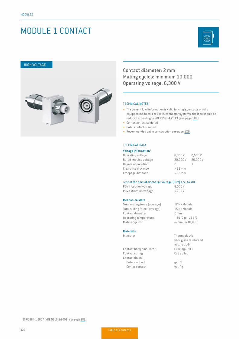
128
MODULES
TECHNICAL NOTES
• The current load information is valid for single contacts or fully equipped modules. For use in connector systems, the load should be reduced according to VDE 0298-4:2013 (see page 189).
• Center contact soldered.• Outer contact crimped.• Recommended cable construction see page 129.
TECHNICAL DATA
Voltage information1
Operating voltage 6,300 V 2,500 VRated impulse voltage 20,000 V 20,000 V Degree of pollution 2 3Clearance distance > 32 mmCreepage distance > 32 mm Test of the partial discharge voltage (PDV) acc. to VDEPDV inception voltage 6.000 VPDV extinction voltage 5.700 V
Mechanical dataTotal mating force (average) 17 N / ModuleTotal sliding force (average) 15 N / ModuleContact diameter 2 mmOperating temperature –40 °C to +125 °CMating cycles minimum 10,000
MaterialsInsulator Thermoplastic fiber glass reinforced acc. to UL-94Contact body / insulator Cu alloy / PTFEContact spring CuBe alloyContact finish Outer contact gal. Ni Center contact gal. Ag
MODULE 1 CONTACT
Contact diameter: 2 mmMating cycles: minimum 10,000Operating voltage: 6,300 V
HIGH VOLTAGE
1 IEC 60664-1:2007 (VDE 0110-1:2008) see page 183.
Table of Contents
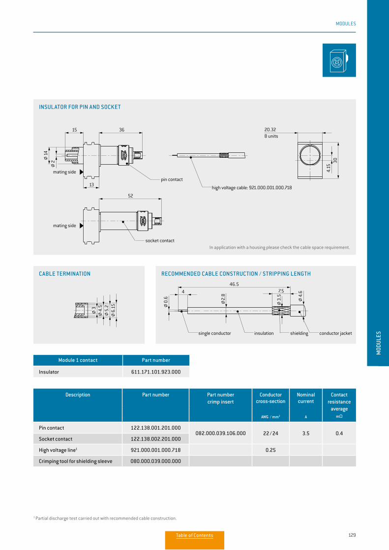
129
MODULES
MOD
ULES
Description Part number Part numbercrimp insert
Conductor cross-section
Nominal current
Contact resistance
average mΩAWG / mm2 A
Pin contact 122.138.001.201.000082.000.039.106.000 22 / 24 3.5 0.4
Socket contact 122.138.002.201.000
High voltage line1 921.000.001.000.718 0.25
Crimping tool for shielding sleeve 080.000.039.000.000
Module 1 contact Part number
Insulator 611.171.101.923.000
In application with a housing please check the cable space requirement.
1 Partial discharge test carried out with recommended cable construction.
INSULATOR FOR PIN AND SOCKET
CABLE TERMINATION RECOMMENDED CABLE CONSTRUCTION / STRIPPING LENGTH
30
20.32
13
15 36
4.15
4
46.5
52
7.5
8 units
mating side
mating side
pin contact
high voltage cable: 921.000.001.000.718
recommended cable construction / strip o lengths
single conductor insulation shielding conductor jacket
socket contact
3 4.5
0.6 2.
8
3.5 4.
6
5.2
6.15
142
30
20.32
13
15 36
4.15
4
46.5
52
7.5
8 units
mating side
mating side
pin contact
high voltage cable: 921.000.001.000.718
recommended cable construction / strip o lengths
single conductor insulation shielding conductor jacket
socket contact
3 4.5
0.6 2.
8
3.5 4.
6
5.2
6.15
142
30
20.32
13
15 36
4.15
4
46.5
52
7.5
8 units
mating side
mating side
pin contact
high voltage cable: 921.000.001.000.718
recommended cable construction / strip o lengths
single conductor insulation shielding conductor jacket
socket contact
3 4.5
0.6 2.
8
3.5 4.
6
5.2
6.15
142
Table of Contents
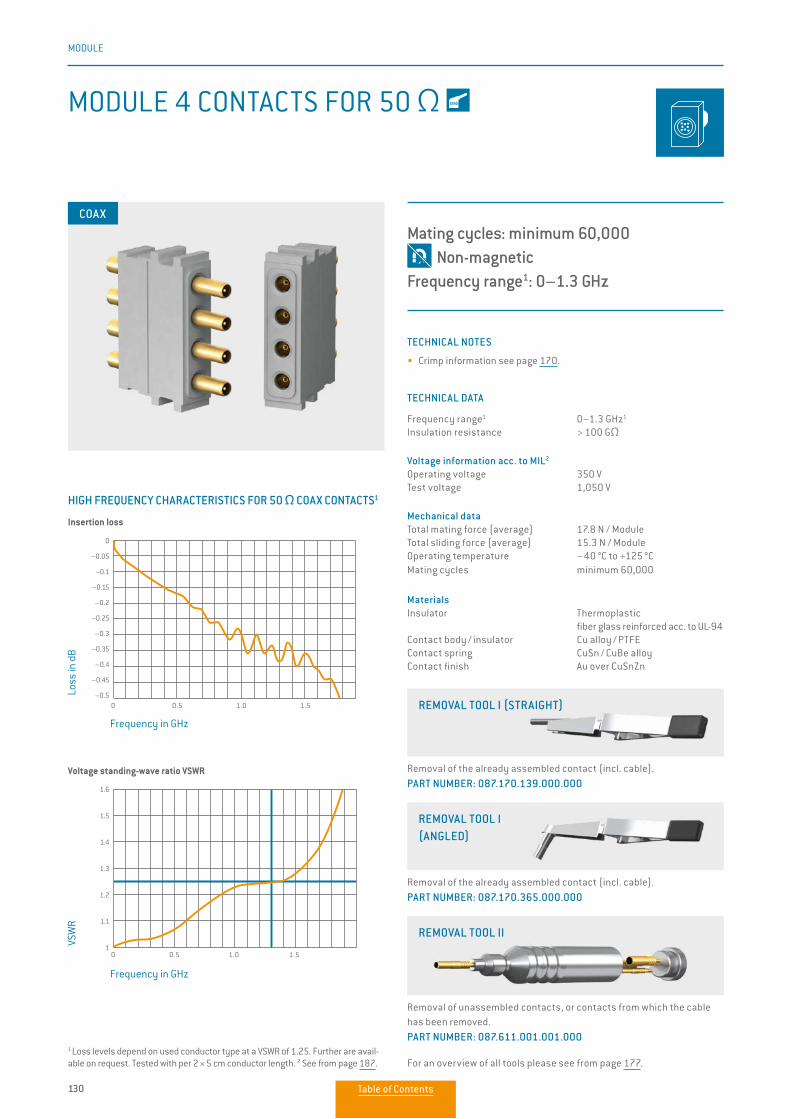
130
MODULE
MODULE 4 CONTACTS FOR 50 Ω
TECHNICAL NOTES
• Crimp information see page 170.
TECHNICAL DATA
Frequency range1 0–1.3 GHz1 Insulation resistance > 100 GΩ
Voltage information acc. to MIL2 Operating voltage 350 V Test voltage 1,050 V
Mechanical data Total mating force (average) 17.8 N / Module Total sliding force (average) 15.3 N / Module Operating temperature –40 °C to +125 °C Mating cycles minimum 60,000
MaterialsInsulator Thermoplastic fiber glass reinforced acc. to UL-94Contact body / insulator Cu alloy / PTFEContact spring CuSn / CuBe alloyContact finish Au over CuSnZn
COAX
Mating cycles: minimum 60,000 Non-magneticFrequency range1: 0–1.3 GHz
HIGH FREQUENCY CHARACTERISTICS FOR 50 Ω COAX CONTACTS1
Voltage standing-wave ratio VSWR
0 0.5 1.0 1.5
Frequency in GHz
Loss
in d
B
Frequency in GHz
VSW
R
1 Loss levels depend on used conductor type at a VSWR of 1.25. Further are avail-able on request. Tested with per 2 × 5 cm conductor length. 2 See from page 187.
Insertion loss
0 0.5 1.0 1.5
1.6
1.5
1.4
1.3
1.2
1.1
1
0
–0.05
–0.1
–0.15
–0.2
–0.25
–0.3
–0.35
–0.4
–0.45
–0.5
Removal of the already assembled contact (incl. cable). PART NUMBER: 087.170.139.000.000
REMOVAL TOOL I (STRAIGHT)
Removal of the already assembled contact (incl. cable). PART NUMBER: 087.170.365.000.000
REMOVAL TOOL I (ANGLED)
Removal of unassembled contacts, or contacts from which the cable has been removed. PART NUMBER: 087.611.001.001.000
For an overview of all tools please see from page 177.
REMOVAL TOOL II
Table of Contents
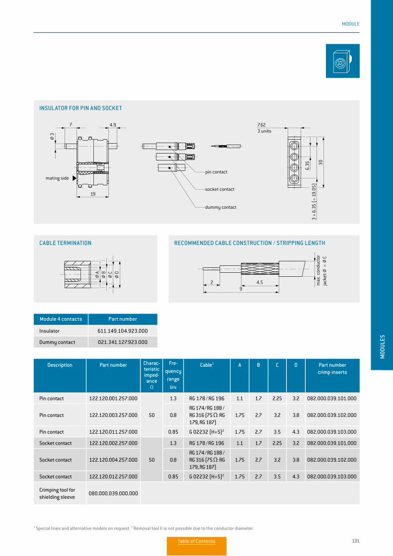
MOD
ULES
131
MODULE
Module 4 contacts Part number
Insulator 611.149.104.923.000
Dummy contact 021.341.127.923.000
Description Part number Charac-teristic imped-
anceΩ
Fre-quency range
GHz
Cable1 A B C D Part number crimp inserts
Pin contact 122.120.001.257.000
50
1.3 RG 178 / RG 196 1.1 1.7 2.25 3.2 082.000.039.101.000
Pin contact 122.120.003.257.000 0.8RG 174 / RG 188 / RG 316 (75 Ω: RG 179, RG 187)
1.75 2.7 3.2 3.8 082.000.039.102.000
Pin contact 122.120.011.257.000 0.85 G 02232 (H+S)2 1.75 2.7 3.5 4.3 082.000.039.103.000
Socket contact 122.120.002.257.000
50
1.3 RG 178 / RG 196 1.1 1.7 2.25 3.2 082.000.039.101.000
Socket contact 122.120.004.257.000 0.8RG 174 / RG 188 / RG 316 (75 Ω: RG 179, RG 187)
1.75 2.7 3.2 3.8 082.000.039.102.000
Socket contact 122.120.012.257.000 0.85 G 02232 (H+S)2 1.75 2.7 3.5 4.3 082.000.039.103.000
Crimping tool for shielding sleeve
080.000.039.000.000
1 Special lines and alternative models on request. 2 Removal tool II is not possible due to the conductor diameter.
INSULATOR FOR PIN AND SOCKET
CABLE TERMINATION RECOMMENDED CABLE CONSTRUCTION / STRIPPING LENGTH
7
19
4.9
30
6.35
7.62
2 4.59
3 ×
6.35
(=
19.0
5)
3 units
mating sidepin contact
socket contact
dummy contact
strip o lengths
3
B C DA
max
. con
duct
or
jack
et-
=
C
7
19
4.9
30
6.35
7.62
2 4.59
3 ×
6.35
(=
19.0
5)
3 units
mating sidepin contact
socket contact
dummy contact
strip o lengths
3
B C DA
max
. con
duct
or
jack
et-
=
C
7
19
4.9
30
6.35
7.62
2 4.59
3 ×
6.35
(=
19.0
5)
3 units
mating sidepin contact
socket contact
dummy contact
strip o lengths
3
B C DA
max
. con
duct
or
jack
et-
=
C
7
19
4.9
30
6.35
7.62
2 4.59
3 ×
6.35
(=
19.0
5)
3 units
mating sidepin contact
socket contact
dummy contact
strip o lengths
3
B C DA
max
. con
duct
or
jack
et-
=
C
Table of Contents
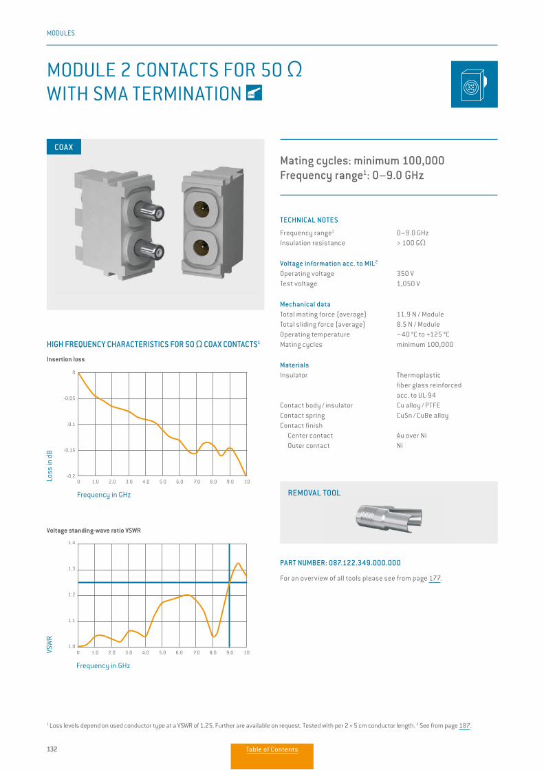
132
MODULES
MODULE 2 CONTACTS FOR 50 Ω WITH SMA TERMINATION
TECHNICAL NOTES
Frequency range1 0–9.0 GHzInsulation resistance > 100 GΩ
Voltage information acc. to MIL2
Operating voltage 350 VTest voltage 1,050 V
Mechanical dataTotal mating force (average) 11.9 N / ModuleTotal sliding force (average) 8.5 N / ModuleOperating temperature –40 °C to +125 °CMating cycles minimum 100,000
MaterialsInsulator Thermoplastic fiber glass reinforced acc. to UL-94Contact body / insulator Cu alloy / PTFEContact spring CuSn / CuBe alloyContact finish Center contact Au over Ni Outer contact Ni
Mating cycles: minimum 100,000Frequency range1: 0–9.0 GHz
COAX
0 1.0 2.0 3.0 4.0 5.0 6.0 7.0 8.0 9.0 10
1.4
1.3
1.2
1.1
1.0
0 1.0 2.0 3.0 4.0 5.0 6.0 7.0 8.0 9.0 10
0
-0.05
-0.1
-0.15
-0.2
1 Loss levels depend on used conductor type at a VSWR of 1.25. Further are avail able on request. Tested with per 2 × 5 cm conductor length. 2 See from page 187.
HIGH FREQUENCY CHARACTERISTICS FOR 50 Ω COAX CONTACTS1
Insertion loss
Voltage standing-wave ratio VSWR
Frequency in GHz
Loss
in d
B
Frequency in GHz
VSW
R
REMOVAL TOOL
PART NUMBER: 087.122.349.000.000
For an overview of all tools please see from page 177.
Table of Contents
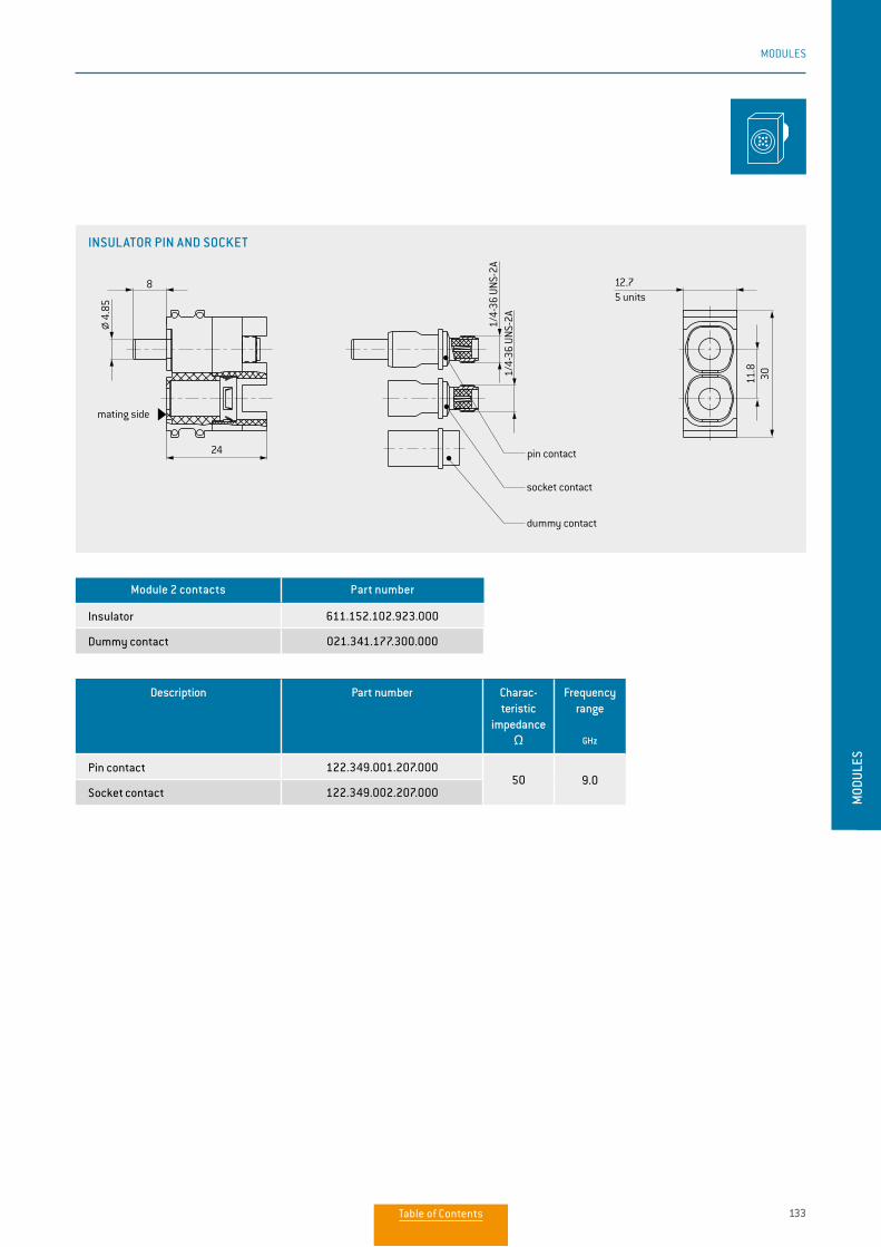
133
MODULES
MOD
ULES
Description Part number Charac-teristic
impedance Ω
Frequency range
GHz
Pin contact 122.349.001.207.00050 9.0
Socket contact 122.349.002.207.000
Module 2 contacts Part number
Insulator 611.152.102.923.000
Dummy contact 021.341.177.300.000
INSULATOR PIN AND SOCKET
8
24
1/4-
36 U
NS-2
A1/
4-36
UNS
-2A
11.8
30
12.7
4.85
5 units
mating side
pin contact
socket contact
dummy contact
Table of Contents
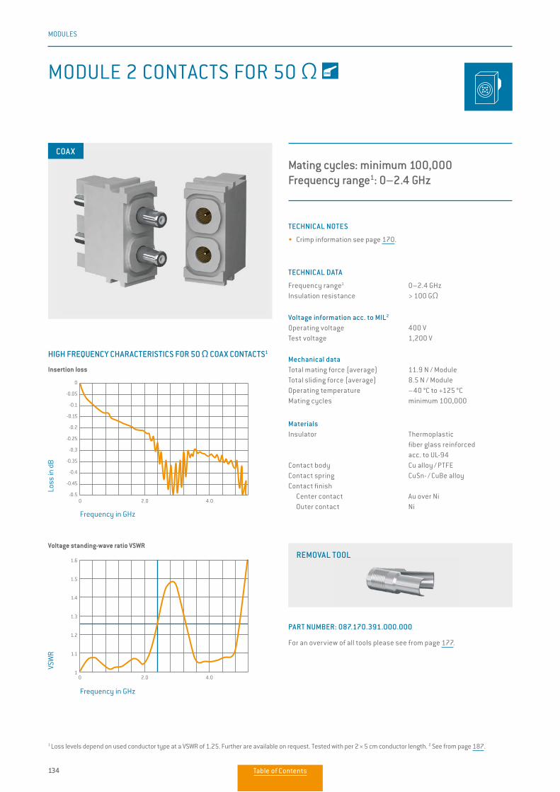
134
MODULES
MODULE 2 CONTACTS FOR 50 Ω
TECHNICAL NOTES
• Crimp information see page 170.
TECHNICAL DATA
Frequency range1 0–2.4 GHzInsulation resistance > 100 GΩ
Voltage information acc. to MIL2
Operating voltage 400 VTest voltage 1,200 V
Mechanical dataTotal mating force (average) 11.9 N / ModuleTotal sliding force (average) 8.5 N / ModuleOperating temperature –40 °C to +125 °CMating cycles minimum 100,000
MaterialsInsulator Thermoplastic fiber glass reinforced acc. to UL-94Contact body Cu alloy / PTFEContact spring CuSn- / CuBe alloyContact finish Center contact Au over Ni Outer contact Ni
Mating cycles: minimum 100,000Frequency range1: 0–2.4 GHz
COAX
0 2.0 4.0
0
-0.05
-0.1
-0.15
-0.2
-0.25
-0.3
-0.35
-0.4
-0.45
-0.5
HIGH FREQUENCY CHARACTERISTICS FOR 50 Ω COAX CONTACTS1
Frequency in GHz
Loss
in d
B
Frequency in GHz
VSW
R
1 Loss levels depend on used conductor type at a VSWR of 1.25. Further are avail able on request. Tested with per 2 × 5 cm conductor length. 2 See from page 187.
Insertion loss
Voltage standing-wave ratio VSWR
0 2.0 4.0
1.6
1.5
1.4
1.3
1.2
1.1
1
REMOVAL TOOL
PART NUMBER: 087.170.391.000.000
For an overview of all tools please see from page 177.
Table of Contents
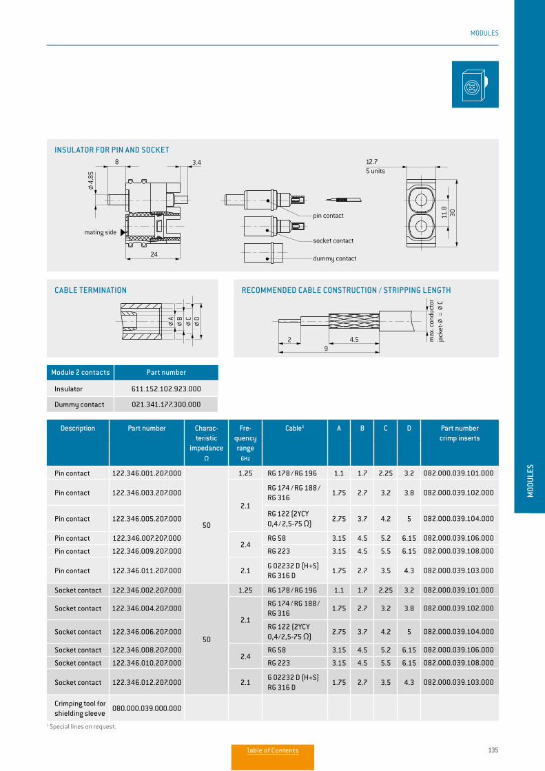
135
MODULES
MOD
ULES
1 Special lines on request.
Description Part number Charac-teristic
impedanceΩ
Fre-quency range
GHz
Cable1 A B C D Part number crimp inserts
Pin contact 122.346.001.207.000
50
1.25 RG 178 / RG 196 1.1 1.7 2.25 3.2 082.000.039.101.000
Pin contact 122.346.003.207.000
2.1
RG 174 / RG 188 /RG 316
1.75 2.7 3.2 3.8 082.000.039.102.000
Pin contact 122.346.005.207.000RG 122 (2YCY 0,4 / 2,5-75 Ω)
2.75 3.7 4.2 5 082.000.039.104.000
Pin contact 122.346.007.207.0002.4
RG 58 3.15 4.5 5.2 6.15 082.000.039.106.000
Pin contact 122.346.009.207.000 RG 223 3.15 4.5 5.5 6.15 082.000.039.108.000
Pin contact 122.346.011.207.000 2.1G 02232 D (H+S)RG 316 D
1.75 2.7 3.5 4.3 082.000.039.103.000
Socket contact 122.346.002.207.000
50
1.25 RG 178 / RG 196 1.1 1.7 2.25 3.2 082.000.039.101.000
Socket contact 122.346.004.207.000
2.1
RG 174 / RG 188 / RG 316
1.75 2.7 3.2 3.8 082.000.039.102.000
Socket contact 122.346.006.207.000RG 122 (2YCY 0,4/2,5-75 Ω)
2.75 3.7 4.2 5 082.000.039.104.000
Socket contact 122.346.008.207.0002.4
RG 58 3.15 4.5 5.2 6.15 082.000.039.106.000
Socket contact 122.346.010.207.000 RG 223 3.15 4.5 5.5 6.15 082.000.039.108.000
Socket contact 122.346.012.207.000 2.1G 02232 D (H+S)RG 316 D
1.75 2.7 3.5 4.3 082.000.039.103.000
Crimping tool for shielding sleeve
080.000.039.000.000
Module 2 contacts Part number
Insulator 611.152.102.923.000
Dummy contact 021.341.177.300.000
INSULATOR FOR PIN AND SOCKET8
24
3.4 12.7
11.8
30
2 4.59
5 units
mating side
pin contact
socket contact
dummy contact
strip o lengths
max
. con
duct
orja
cket
- =
C
4.85
DCBA
CABLE TERMINATION RECOMMENDED CABLE CONSTRUCTION / STRIPPING LENGTH
8
24
3.4 12.7
11.8
30
2 4.59
5 units
mating side
pin contact
socket contact
dummy contact
strip o lengths
max
. con
duct
orja
cket
- =
C
4.85
DCBA
8
24
3.4 12.7
11.8
30
2 4.59
5 units
mating side
pin contact
socket contact
dummy contact
strip o lengths
max
. con
duct
orja
cket
- =
C
4.85
DCBA
Table of Contents
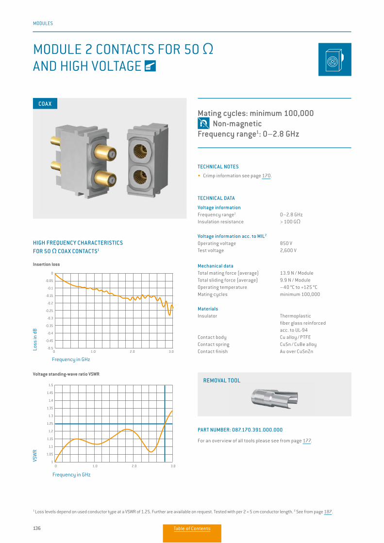
136
MODULES
MODULE 2 CONTACTS FOR 50 Ω AND HIGH VOLTAGE
TECHNICAL NOTES
• Crimp information see page 170.
TECHNICAL DATA
Voltage informationFrequency range1 0–2.8 GHzInsulation resistance > 100 GΩ
Voltage information acc. to MIL2
Operating voltage 850 VTest voltage 2,600 V
Mechanical dataTotal mating force (average) 13.9 N / ModuleTotal sliding force (average) 9.9 N / ModuleOperating temperature –40 °C to +125 °CMating cycles minimum 100,000
MaterialsInsulator Thermoplastic fiber glass reinforced acc. to UL-94Contact body Cu alloy / PTFEContact spring CuSn / CuBe alloyContact finish Au over CuSnZn
Mating cycles: minimum 100,000 Non-magneticFrequency range1: 0–2.8 GHz
COAX
Frequency in GHz
HIGH FREQUENCY CHARACTERISTICS FOR 50 Ω COAX CONTACTS1
Loss
in d
B
1 Loss levels depend on used conductor type at a VSWR of 1.25. Further are avail able on request. Tested with per 2 × 5 cm conductor length. 2 See from page 187.
0 1.0 2.0 3.0
Frequency in GHz
VSW
R
0 1.0 2.0 3.0
Insertion loss
Voltage standing-wave ratio VSWR
0
-0.05
-0.1
-0.15
-0.2
-0.25
-0.3
-0.35
-0.4
-0.45
-0.5
1.5
1.45
1.4
1.35
1.3
1.25
1.2
1.15
1.1
1.05
1
REMOVAL TOOL
PART NUMBER: 087.170.391.000.000
For an overview of all tools please see from page 177.
Table of Contents
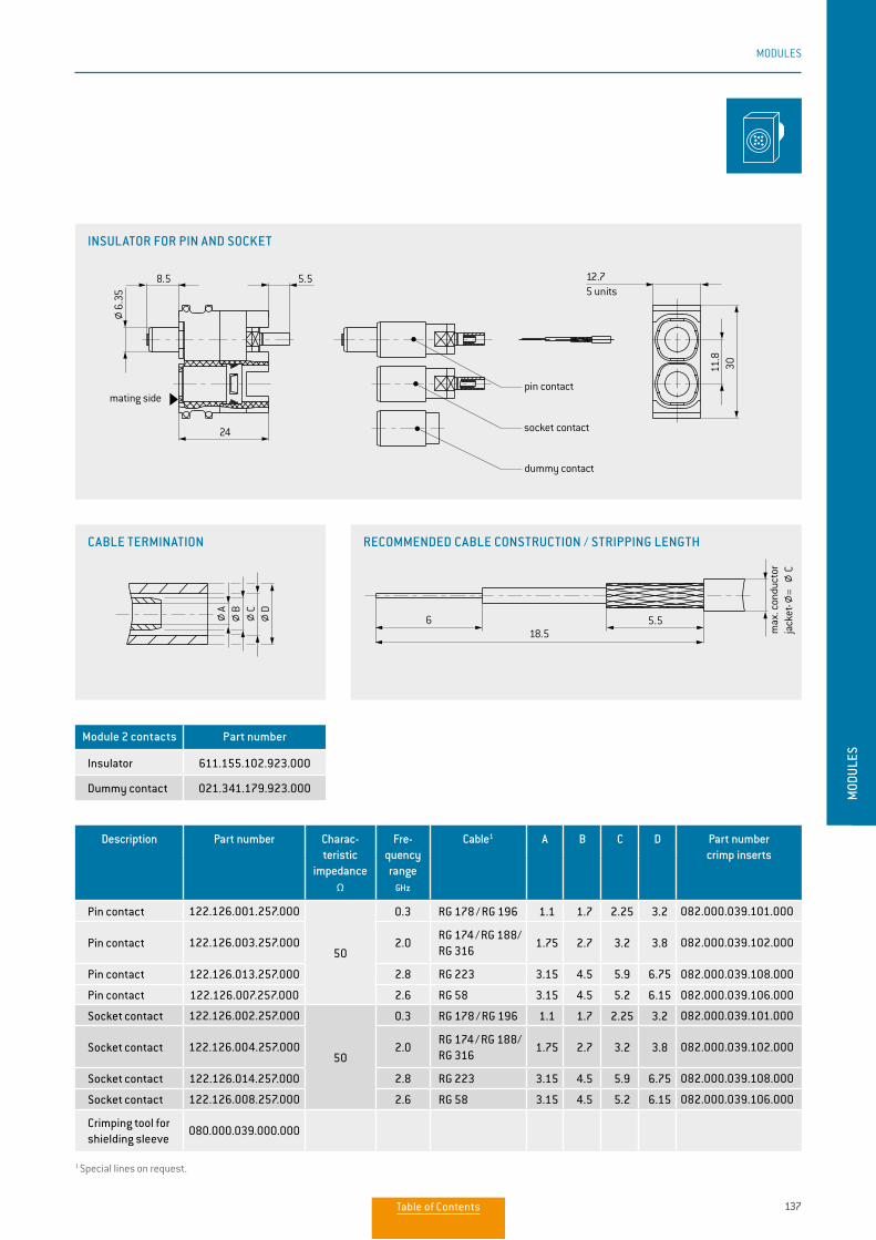
137
MODULES
MOD
ULES
Description Part number Charac-teristic
impedanceΩ
Fre-quency range
GHz
Cable1 A B C D Part number crimp inserts
Pin contact 122.126.001.257.000
50
0.3 RG 178 / RG 196 1.1 1.7 2.25 3.2 082.000.039.101.000
Pin contact 122.126.003.257.000 2.0RG 174 / RG 188/ RG 316
1.75 2.7 3.2 3.8 082.000.039.102.000
Pin contact 122.126.013.257.000 2.8 RG 223 3.15 4.5 5.9 6.75 082.000.039.108.000
Pin contact 122.126.007.257.000 2.6 RG 58 3.15 4.5 5.2 6.15 082.000.039.106.000
Socket contact 122.126.002.257.000
50
0.3 RG 178 / RG 196 1.1 1.7 2.25 3.2 082.000.039.101.000
Socket contact 122.126.004.257.000 2.0RG 174 / RG 188/ RG 316
1.75 2.7 3.2 3.8 082.000.039.102.000
Socket contact 122.126.014.257.000 2.8 RG 223 3.15 4.5 5.9 6.75 082.000.039.108.000
Socket contact 122.126.008.257.000 2.6 RG 58 3.15 4.5 5.2 6.15 082.000.039.106.000
Crimping tool for shielding sleeve
080.000.039.000.000
Module 2 contacts Part number
Insulator 611.155.102.923.000
Dummy contact 021.341.179.923.000
1 Special lines on request.
INSULATOR FOR PIN AND SOCKET
CABLE TERMINATION RECOMMENDED CABLE CONSTRUCTION / STRIPPING LENGTH
6 5.518.5
11.8
30
12.78.5 5.5
24
5 units
mating sidepin contact
socket contact
dummy contact
stripping length
max
. con
duct
or
jack
et-
=
C
6.35
DCBA
6 5.518.5
11.8
30
12.78.5 5.5
24
5 units
mating sidepin contact
socket contact
dummy contact
stripping length
max
. con
duct
or
jack
et-
=
C
6.35
DCBA
6 5.518.5
11.8
30
12.78.5 5.5
24
5 units
mating sidepin contact
socket contact
dummy contact
stripping length
max
. con
duct
or
jack
et-
=
C
6.35
DCBA
Table of Contents
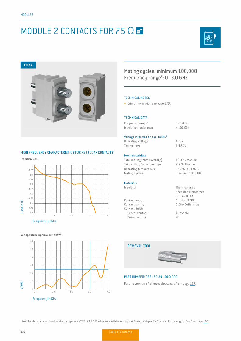
138
MODULES
TECHNICAL NOTES
• Crimp information see page 170.
TECHNICAL DATA
Frequency range1 0–3.0 GHzInsulation resistance > 100 GΩ
Voltage information acc. to MIL2
Operating voltage 475 VTest voltage 1,425 V
Mechanical dataTotal mating force (average) 13.3 N / ModuleTotal sliding force (average) 9.5 N / ModuleOperating temperature –40 °C to +125 °CMating cycles minimum 100,000
MaterialsInsulator Thermoplastic fiber glass reinforced acc. to UL-94Contact body Cu alloy/PTFEContact spring CuSn / CuBe alloyContact finish Center contact Au over Ni Outer contact Ni
MODULE 2 CONTACTS FOR 75 Ω
Mating cycles: minimum 100,000Frequency range1: 0–3.0 GHz
COAX
0 1.0 2.0 3.0 4.0
0
-0.05
-0.1
-0.15
-0.2
-0.25
-0.3
-0.35
-0.4
-0.45
-0.5
HIGH FREQUENCY CHARACTERISTICS FOR 75 Ω COAX CONTACTS1
Frequency in GHz
Loss
in d
B
Frequency in GHz
VSW
R
1 Loss levels depend on used conductor type at a VSWR of 1.25. Further are avail able on request. Tested with per 2 × 5 cm conductor length. 2 See from page 187.
Insertion loss
Voltage standing-wave ratio VSWR
0 1.0 2.0 3.0 4.0
1.6
1.5
1.4
1.3
1.2
1.1
1
REMOVAL TOOL
PART NUMBER: 087.170.391.000.000
For an overview of all tools please see from page 177.
Table of Contents
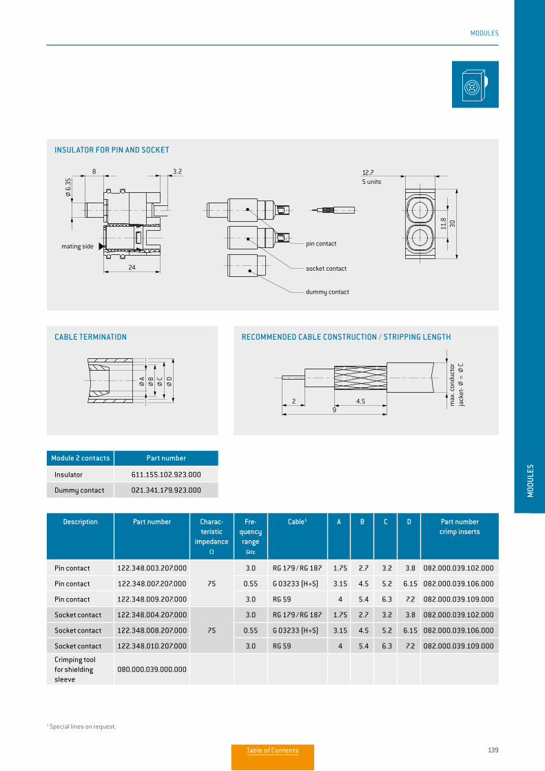
139
MODULES
MOD
ULES
Module 2 contacts Part number
Insulator 611.155.102.923.000
Dummy contact 021.341.179.923.000
Description Part number Charac-teristic
impedanceΩ
Fre-quency range
GHz
Cable1 A B C D Part number crimp inserts
Pin contact 122.348.003.207.000
75
3.0 RG 179 / RG 187 1.75 2.7 3.2 3.8 082.000.039.102.000
Pin contact 122.348.007.207.000 0.55 G 03233 (H+S) 3.15 4.5 5.2 6.15 082.000.039.106.000
Pin contact 122.348.009.207.000 3.0 RG 59 4 5.4 6.3 7.2 082.000.039.109.000
Socket contact 122.348.004.207.000
75
3.0 RG 179 / RG 187 1.75 2.7 3.2 3.8 082.000.039.102.000
Socket contact 122.348.008.207.000 0.55 G 03233 (H+S) 3.15 4.5 5.2 6.15 082.000.039.106.000
Socket contact 122.348.010.207.000 3.0 RG 59 4 5.4 6.3 7.2 082.000.039.109.000
Crimping tool for shielding sleeve
080.000.039.000.000
1 Special lines on request.
INSULATOR FOR PIN AND SOCKET
CABLE TERMINATION RECOMMENDED CABLE CONSTRUCTION / STRIPPING LENGTH
2 4.59
11.8
30
12.78
24
3.2
max
. con
duct
or
jack
et-
5 units
pin contact
socket contact
dummy contact
mating side
6.35
=
C
DCBA
2 4.59
11.8
30
12.78
24
3.2
max
. con
duct
or
jack
et-
5 units
pin contact
socket contact
dummy contact
mating side
6.35
=
C
DCBA
2 4.59
11.8
30
12.78
24
3.2
max
. con
duct
or
jack
et-
5 units
pin contact
socket contact
dummy contact
mating side
6.35
=
C
DCBA
Table of Contents
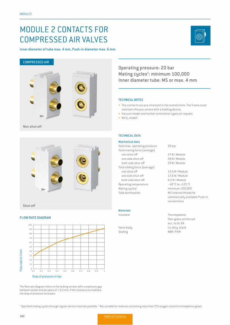
140
MODULES
TECHNICAL NOTES
• The contacts are pre-stressed in the mated state. The frame must maintain this pre-stress with a holding device.
• Vacuum model and further termination types on request.• No O
2 model2.
TECHNICAL DATA
Mechanical dataValid max. operating pressure 20 barTotal mating force (average) non shut-off 27 N / Module one side shut-off 28 N / Module both side shut-off 29 N / ModuleTotal sliding force (average) non shut-off 12.6 N / Module one side shut-off 12.6 N / Module both side shut-off 9.2 N / ModuleOperating temperature –40 °C to +125 °CMating cycles1 minimum 100,000Tube termination M5 internal thread for commercially available Push-in connections
MaterialsInsulator Thermoplastic fiber glass reinforced acc. to UL-94Valve body Cu alloy, blankSealing NBR / FKM
MODULE 2 CONTACTS FOR COMPRESSED AIR VALVES
Operating pressure: 20 barMating cycles1: minimum 100,000 Inner diameter tube: M5 or max. 4 mm
Non shut-off
Shut-off
Inner diameter of tube max. 4 mm, Push-in diameter max. 6 mm.
1 Specified mating cycles through regular service intervals possible. 2 Not suitable for mixtures containing more than 25% oxygen content and explosive gases.
FLOW RATE DIAGRAM
The flow rate diagram refers to the locking version with a maximum gap between socket and pin piece of ≤ 0.5 mm. If the clearance is modified, the drop of pressure increases.
Drop of pressure in bar
Flow
rate
in l/
min
0.1 0.2 0.3 0.4 0.5 0.6 0.7 0.8 0.9 1
100
90
80
70
60
50
40
30
20
10
0
COMPRESSED AIR
Table of Contents
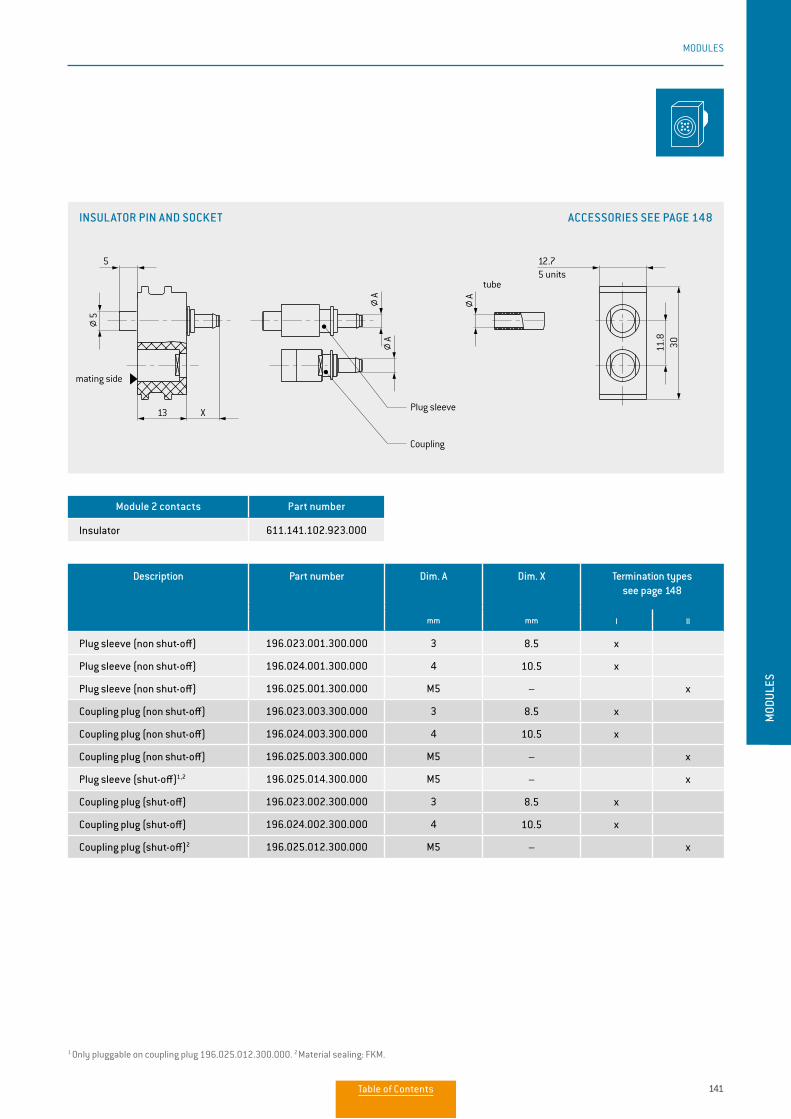
141
MODULES
MOD
ULES
Description Part number Dim. A
mm
Dim. X
mm
Termination types see page 148
I II
Plug sleeve (non shut-off) 196.023.001.300.000 3 8.5 x
Plug sleeve (non shut-off) 196.024.001.300.000 4 10.5 x
Plug sleeve (non shut-off) 196.025.001.300.000 M5 – x
Coupling plug (non shut-off) 196.023.003.300.000 3 8.5 x
Coupling plug (non shut-off) 196.024.003.300.000 4 10.5 x
Coupling plug (non shut-off) 196.025.003.300.000 M5 – x
Plug sleeve (shut-off)1,2 196.025.014.300.000 M5 – x
Coupling plug (shut-off) 196.023.002.300.000 3 8.5 x
Coupling plug (shut-off) 196.024.002.300.000 4 10.5 x
Coupling plug (shut-off)2 196.025.012.300.000 M5 – x
Module 2 contacts Part number
Insulator 611.141.102.923.000
1 Only pluggable on coupling plug 196.025.012.300.000. 2 Material sealing: FKM.
INSULATOR PIN AND SOCKET ACCESSORIES SEE PAGE 148
9 30
40.64
18.64
5.5
X13
12.7
3011.8
13
5
X
5.5
13 X
20.32
304.
5
16 units5 units
mating side
Plug sleeve
Coupling
tube
insulator pin
insulator socket
mating side
Plug sleeve
Coupling
tube
8 units
mating side Plug sleeve
Coupling
tube
99
AAA
AAA
5
AA A
Table of Contents
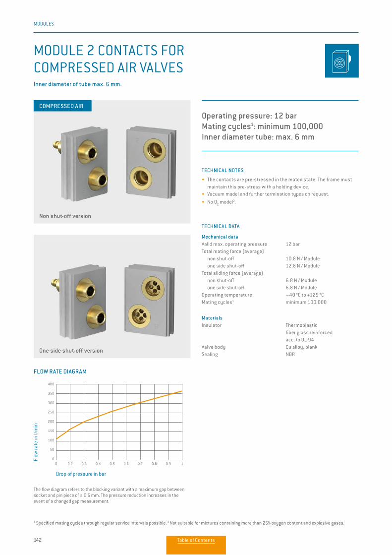
142
MODULES
TECHNICAL NOTES
• The contacts are pre-stressed in the mated state. The frame must maintain this pre-stress with a holding device.
• Vacuum model and further termination types on request.
• No O2 model2.
TECHNICAL DATA
Mechanical dataValid max. operating pressure 12 barTotal mating force (average) non shut-off 10.8 N / Module one side shut-off 12.8 N / ModuleTotal sliding force (average) non shut-off 6.8 N / Module one side shut-off 6.8 N / ModuleOperating temperature –40 °C to +125 °CMating cycles1 minimum 100,000
MaterialsInsulator Thermoplastic fiber glass reinforced acc. to UL-94Valve body Cu alloy, blankSealing NBR
MODULE 2 CONTACTS FOR COMPRESSED AIR VALVES
Operating pressure: 12 barMating cycles1: minimum 100,000Inner diameter tube: max. 6 mm
Inner diameter of tube max. 6 mm.
COMPRESSED AIR
Non shut-off version
One side shut-off version
1 Specified mating cycles through regular service intervals possible. 2 Not suitable for mixtures containing more than 25% oxygen content and explosive gases.
The flow diagram refers to the blocking variant with a maximum gap between socket and pin piece of ≤ 0.5 mm. The pressure reduction increases in the event of a changed gap measurement.
FLOW RATE DIAGRAM
Drop of pressure in bar
Flow
rate
in l/
min
0 0.2 0.3 0.4 0.5 0.6 0.7 0.8 0.9 1
400
350
300
250
200
150
100
50
0
Table of Contents
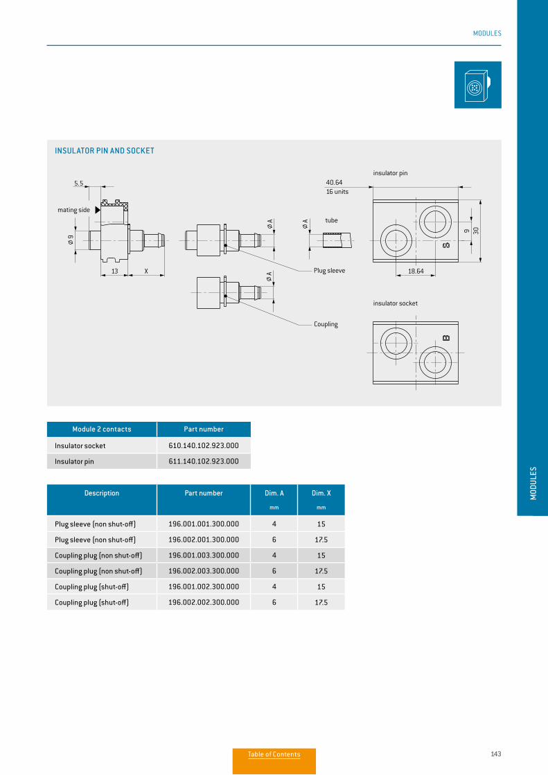
143
MODULES
MOD
ULES
Description Part number Dim. A
mm
Dim. X
mm
Plug sleeve (non shut-off) 196.001.001.300.000 4 15
Plug sleeve (non shut-off) 196.002.001.300.000 6 17.5
Coupling plug (non shut-off) 196.001.003.300.000 4 15
Coupling plug (non shut-off) 196.002.003.300.000 6 17.5
Coupling plug (shut-off) 196.001.002.300.000 4 15
Coupling plug (shut-off) 196.002.002.300.000 6 17.5
Module 2 contacts Part number
Insulator socket 610.140.102.923.000
Insulator pin 611.140.102.923.000
INSULATOR PIN AND SOCKET
9 30
40.64
18.64
5.5
X13
12.7
3011.8
13
5
X
5.5
13 X
20.32
304.
5
16 units5 units
mating side
Plug sleeve
Coupling
tube
insulator pin
insulator socket
mating side
Plug sleeve
Coupling
tube
8 units
mating side Plug sleeve
Coupling
tube
99
AAA
AAA
5
AA A
Table of Contents
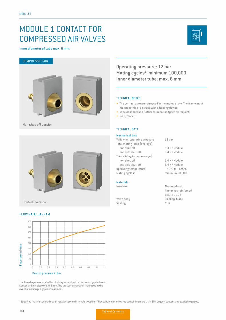
144
MODULES
TECHNICAL NOTES
• The contacts are pre-stressed in the mated state. The frame must maintain this pre-stress with a holding device.
• Vacuum model and further termination types on request.• No O
2 model2.
TECHNICAL DATA
Mechanical dataValid max. operating pressure 12 barTotal mating force (average) non shut-off 5.4 N / Module one side shut-off 6.4 N / ModuleTotal sliding force (average) non shut-off 3.4 N / Module one side shut-off 3.4 N / ModuleOperating temperature –40 °C to +125 °CMating cycles1 minimum 100,000
MaterialsInsulator Thermoplastic fiber glass reinforced acc. to UL-94Valve body Cu alloy, blankSealing NBR
MODULE 1 CONTACT FOR COMPRESSED AIR VALVES
Operating pressure: 12 barMating cycles1: minimum 100,000Inner diameter tube: max. 6 mm
Inner diameter of tube max. 6 mm.
Non shut-off version
Shut-off version
1 Specified mating cycles through regular service intervals possible. 2 Not suitable for mixtures containing more than 25% oxygen content and explosive gases.
The flow diagram refers to the blocking variant with a maximum gap between socket and pin piece of ≤ 0.5 mm. The pressure reduction increases in the event of a changed gap measurement.
FLOW RATE DIAGRAM
Drop of pressure in bar
Flow
rate
in l/
min
0 0.2 0.3 0.4 0.5 0.6 0.7 0.8 0.9 1
400
350
300
250
200
150
100
50
0
COMPRESSED AIR
Table of Contents
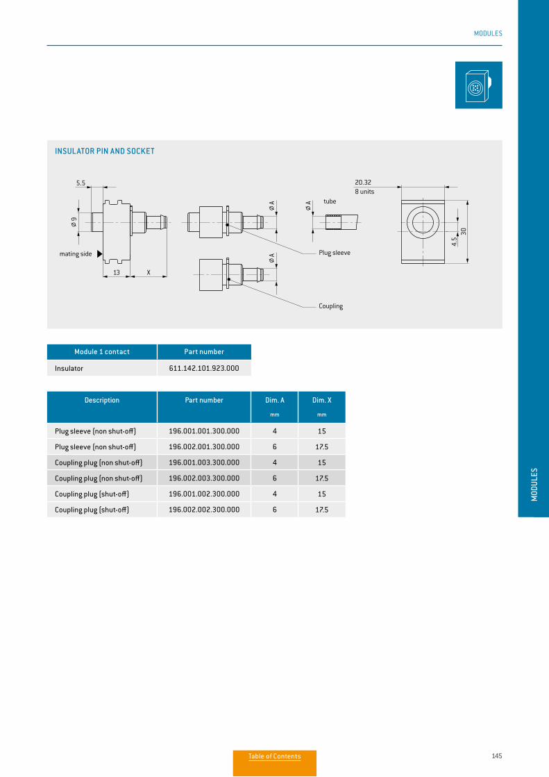
145
MODULES
MOD
ULES
Description Part number Dim. A
mm
Dim. X
mm
Plug sleeve (non shut-off) 196.001.001.300.000 4 15
Plug sleeve (non shut-off) 196.002.001.300.000 6 17.5
Coupling plug (non shut-off) 196.001.003.300.000 4 15
Coupling plug (non shut-off) 196.002.003.300.000 6 17.5
Coupling plug (shut-off) 196.001.002.300.000 4 15
Coupling plug (shut-off) 196.002.002.300.000 6 17.5
Module 1 contact Part number
Insulator 611.142.101.923.000
INSULATOR PIN AND SOCKET
9 30
40.64
18.64
5.5
X13
12.7
3011.8
13
5
X
5.5
13 X
20.32
304.
5
16 units5 units
mating side
Plug sleeve
Coupling
tube
insulator pin
insulator socket
mating side
Plug sleeve
Coupling
tube
8 units
mating side Plug sleeve
Coupling
tube
99
AAA
AAA
5
AA A
Table of Contents
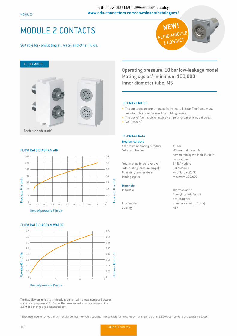
146
MODULES
TECHNICAL NOTES
• The contacts are pre-stressed in the mated state. The frame must maintain this pre-stress with a holding device.
• The use of flammable or explosive liquids or gases is not allowed.• No O
2 model2.
TECHNICAL DATA
Mechanical dataValid max. operating pressure 10 barTube termination M5 internal thread for commercially available Push-in connectionsTotal mating force (average) 64 N / ModuleTotal sliding force (average) 0 N / ModuleOperating temperature –40 °C to +125 °CMating cycles1 minimum 100,000
MaterialsInsulator Thermoplastic fiber glass reinforced acc. to UL-94Fluid model Stainless steel (1.4305)Sealing NBR
Operating pressure: 10 bar low-leakage modelMating cycles1: minimum 100,000Inner diameter tube: M5
Suitable for conducting air, water and other fluids.
MODULE 2 CONTACTS
FLUID MODEL
Both side shut-off
The flow diagram refers to the blocking variant with a maximum gap between socket and pin piece of ≤ 0.5 mm. The pressure reduction increases in the event of a changed gap measurement.
1 Specified mating cycles through regular service intervals possible. 2 Not suitable for mixtures containing more than 25% oxygen content and explosive gases.
FLOW RATE DIAGRAM AIR
Drop of pressure P in bar
Flow
rate
Q in
l/m
in
Flow
rate
Q in
m3 /h
0 0.2 0.3 0.4 0.5 0.6 0.7 0.8 0.9 1 1.2
140
120
100
80
60
40
20
0
8.4
7.2
6.0
4.8
3.6
2.4
1.2
0
FLOW RATE DIAGRAM WATER
Drop of pressure P in bar
Flow
rate
Q in
l/m
in
Flow
rate
Q in
m3 /h
0 1 2 3 4 5 6
4.0
3.5
3.0
2.5
2.0
1.5
1.0
0.5
0
0.24
0.21
0.18
0.15
0.12
0.09
0.06
0.03
0
NEW!
FLUID-MODULE
1 CONTACT
In the new ODU-MAC® catalog:www.odu-connectors.com/downloads/catalogues/
Table of Contents
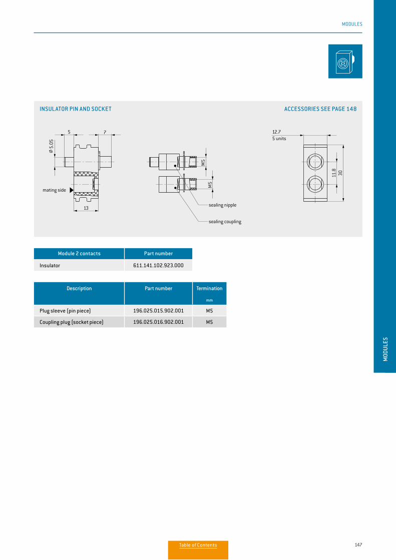
147
MODULES
MOD
ULES
Description Part number Termination
mm
Plug sleeve (pin piece) 196.025.015.902.001 M5
Coupling plug (socket piece) 196.025.016.902.001 M5
Module 2 contacts Part number
Insulator 611.141.102.923.000
INSULATOR PIN AND SOCKET ACCESSORIES SEE PAGE 148
5 7
M5
M5
12.7
3011.8
13
5 units
sealing nipple
sealing coupling
mating side
5.05
Table of Contents
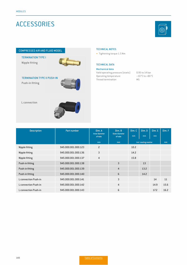
148
MODULES
ACCESSORIES
TECHNICAL NOTES
• Tightening torque 1.5 Nm
TECHNICAL DATA
Mechanical dataValid operating pressure (static) 0.95 to 14 barOperating temperature –10 °C to +80 °CThread termination M5
Nipple fitting
Push-in fitting
L connection
TERMINATION TYPE I
TERMINATION TYPE II PUSH-IN
COMPRESSED AIR AND FLUID MODEL
Description Part number Dim. AInner diameter
of tube
mm
Dim. BOuter diameter
of tube
mm
Dim. C
mm
Dim. D
mm
Dim. E
mm
Dim. F
mmincl. sealing washer
Nipple fitting 945.000.001.000.123 2 10.2
Nipple fitting 945.000.001.000.136 3 14.2
Nipple fitting 945.000.001.000.137 4 15.8
Push-in fitting 945.000.001.000.138 3 13
Push-in fitting 945.000.001.000.139 4 13.2
Push-in fitting 945.000.001.000.140 6 14.2
L connection Push-in 945.000.001.000.141 3 14 11
L connection Push-in 945.000.001.000.142 4 14.9 15.6
L connection Push-in 945.000.001.000.143 6 17.2 16.2
Table of Contents
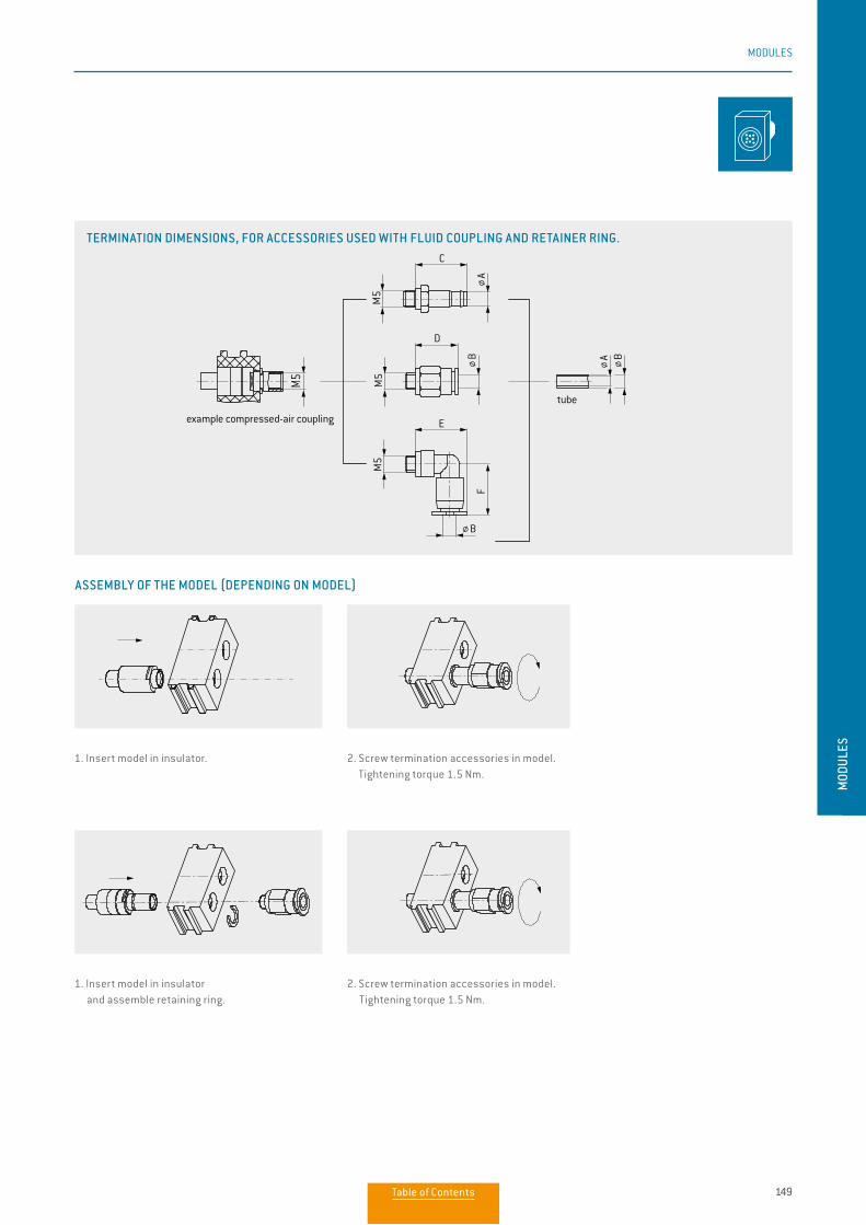
149
MODULES
MOD
ULES
TERMINATION DIMENSIONS, FOR ACCESSORIES USED WITH FLUID COUPLING AND RETAINER RING.
Isoierkörperinsulator
Druckluftkupplungcompressed air valve
Verschraubungfitting
Isolierkörperinsulator
Druckluftkupplungcompressed air valve
Verschraubungfitting
tube
example compressed-air coupling
tube
B
B
BA
A
M5
M5
M5
C
E
F
M5
D
B
B
BA
A
M5
M5
M5
X
C
E
F
M5
D
1. Insert model in insulator. 2. Screw termination accessories in model. Tightening torque 1.5 Nm.
ASSEMBLY OF THE MODEL (DEPENDING ON MODEL)
1. Insert model in insulator and assemble retaining ring.
2. Screw termination accessories in model. Tightening torque 1.5 Nm.
Isoierkörperinsulator
Druckluftkupplungcompressed air valve
Verschraubungfitting
Isolierkörperinsulator
Druckluftkupplungcompressed air valve
Verschraubungfitting
tube
example compressed-air coupling
tube
B
B
BA
A
M5
M5
M5
C
E
F
M5
D
B
B
BA
A
M5
M5
M5
X
C
E
F
M5
D
Isoierkörperinsulator
Druckluftkupplungcompressed air valve
Verschraubungfitting
Isolierkörperinsulator
Druckluftkupplungcompressed air valve
Verschraubungfitting
tube
example compressed-air coupling
tube
B
B
BA
A
M5
M5
M5
C
E
F
M5
D
B
B
BA
A
M5
M5
M5
X
C
E
F
M5
D
Isoierkörperinsulator
Druckluftkupplungcompressed air valve
Verschraubungfitting
Isolierkörperinsulator
Druckluftkupplungcompressed air valve
Verschraubungfitting
tube
example compressed-air coupling
tube
B
B
BA
A
M5
M5
M5
C
E
F
M5
D
B
B
BA
A
M5
M5
M5
X
C
E
F
M5
D
Table of Contents
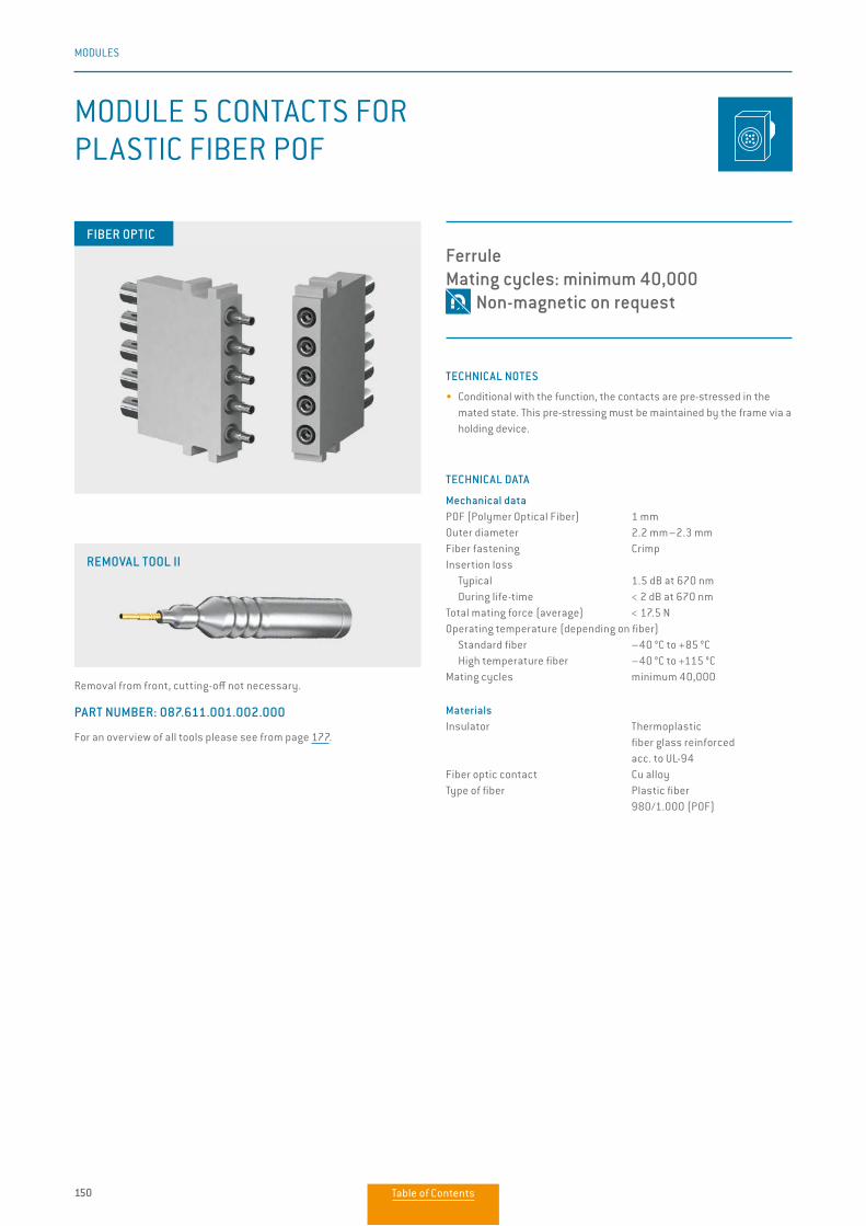
150
MODULES
TECHNICAL NOTES
• Conditional with the function, the contacts are pre-stressed in the mated state. This pre-stressing must be maintained by the frame via a holding device.
TECHNICAL DATA
Mechanical dataPOF (Polymer Optical Fiber) 1 mmOuter diameter 2.2 mm–2.3 mmFiber fastening CrimpInsertion loss Typical 1.5 dB at 670 nm During life-time < 2 dB at 670 nmTotal mating force (average) < 17.5 NOperating temperature (depending on fiber) Standard fiber –40 °C to +85 °C High temperature fiber –40 °C to +115 °CMating cycles minimum 40,000
MaterialsInsulator Thermoplastic fiber glass reinforced acc. to UL-94Fiber optic contact Cu alloyType of fiber Plastic fiber 980/1.000 (POF)
MODULE 5 CONTACTS FOR PLASTIC FIBER POF
FerruleMating cycles: minimum 40,000 Non-magnetic on request
Removal from front, cutting-off not necessary.
PART NUMBER: 087.611.001.002.000
For an overview of all tools please see from page 177.
REMOVAL TOOL II
FIBER OPTIC
Table of Contents
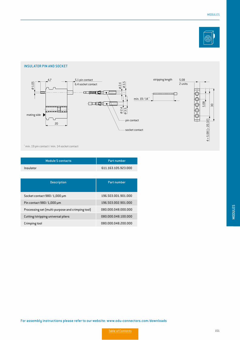
151
MODULES
MOD
ULES
Module 5 contacts Part number
Insulator 611.163.105.923.000
Description Part number
Socket contact 980 / 1,000 µm 196.503.001.901.000
Pin contact 980 / 1,000 µm 196.503.002.901.000
Processing set (multi-purpose and crimping tool) 080.000.048.000.000
Cutting/stripping universal pliers 080.000.048.100.000
Crimping tool 080.000.048.200.000
* min. 19 pin contact / min. 14 socket contact
For assembly instructions please refer to our website: www.odu-connectors.com/downloads
INSULATOR PIN AND SOCKET
4.7
20
min. 19 / 14 *
5.08
305.08
4 ×
5.08
(=
20.3
2)
* min. 19 / min. 14
5.1 pin contact6.4 socket contact 2 units
pin contact / socket contact
mating side
pin contact
socket contact
stripping length
2.4 3.5
2.4
3.5
1.05
4.7
20
min. 19 / 14 *
5.08
305.08
4 ×
5.08
(=
20.3
2)
* min. 19 / min. 14
5.1 pin contact6.4 socket contact 2 units
pin contact / socket contact
mating side
pin contact
socket contact
stripping length
2.4 3.5
2.4
3.5
1.05
Table of Contents
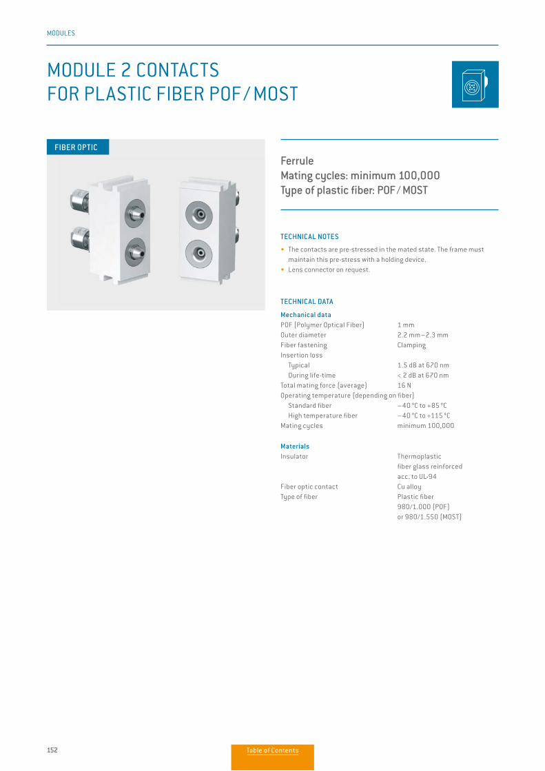
152
MODULES
TECHNICAL NOTES
• The contacts are pre-stressed in the mated state. The frame must maintain this pre-stress with a holding device.
• Lens connector on request.
TECHNICAL DATA
Mechanical dataPOF (Polymer Optical Fiber) 1 mmOuter diameter 2.2 mm–2.3 mmFiber fastening ClampingInsertion loss Typical 1.5 dB at 670 nm During life-time < 2 dB at 670 nmTotal mating force (average) 16 NOperating temperature (depending on fiber) Standard fiber –40 °C to +85 °C High temperature fiber –40 °C to +115 °CMating cycles minimum 100,000
MaterialsInsulator Thermoplastic fiber glass reinforced acc. to UL-94Fiber optic contact Cu alloyType of fiber Plastic fiber 980/1.000 (POF) or 980/1.550 (MOST)
MODULE 2 CONTACTS FOR PLASTIC FIBER POF / MOST
FerruleMating cycles: minimum 100,000Type of plastic fiber: POF / MOST
FIBER OPTIC
Table of Contents
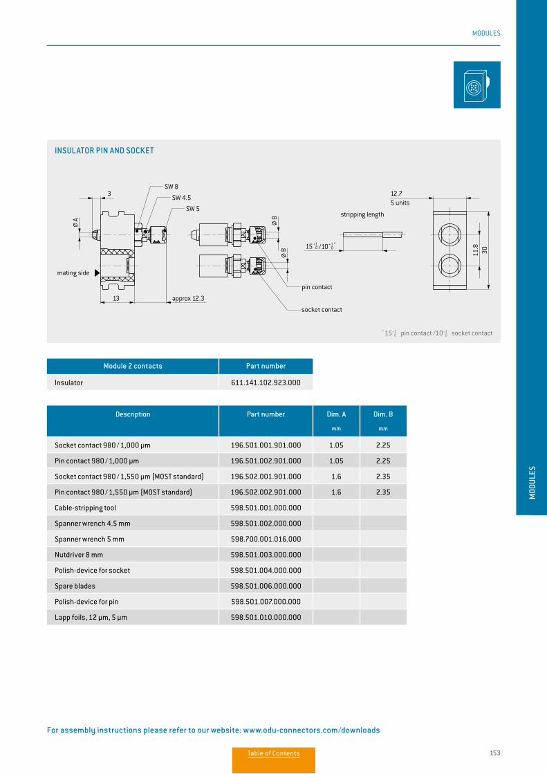
153
MODULES
MOD
ULES
For assembly instructions please refer to our website: www.odu-connectors.com/downloads
INSULATOR PIN AND SOCKET
* 15 0+1 pin contact /10 0
+1 socket contact
15+1 0 /10+1 *
0
11.8
30
12.7
13
BB
3
SW 5
SW 4.5
SW 8
5 units
approx 12.3
mating side
pin contact
socket contact
stripping length
A
Module 2 contacts Part number
Insulator 611.141.102.923.000
Description Part number Dim. A
mm
Dim. B
mm
Socket contact 980 / 1,000 µm 196.501.001.901.000 1.05 2.25
Pin contact 980 / 1,000 µm 196.501.002.901.000 1.05 2.25
Socket contact 980 / 1,550 µm (MOST standard) 196.502.001.901.000 1.6 2.35
Pin contact 980 / 1,550 µm (MOST standard) 196.502.002.901.000 1.6 2.35
Cable-stripping tool 598.501.001.000.000
Spanner wrench 4.5 mm 598.501.002.000.000
Spanner wrench 5 mm 598.700.001.016.000
Nutdriver 8 mm 598.501.003.000.000
Polish-device for socket 598.501.004.000.000
Spare blades 598.501.006.000.000
Polish-device for pin 598.501.007.000.000
Lapp foils, 12 µm, 5 µm 598.501.010.000.000
Table of Contents
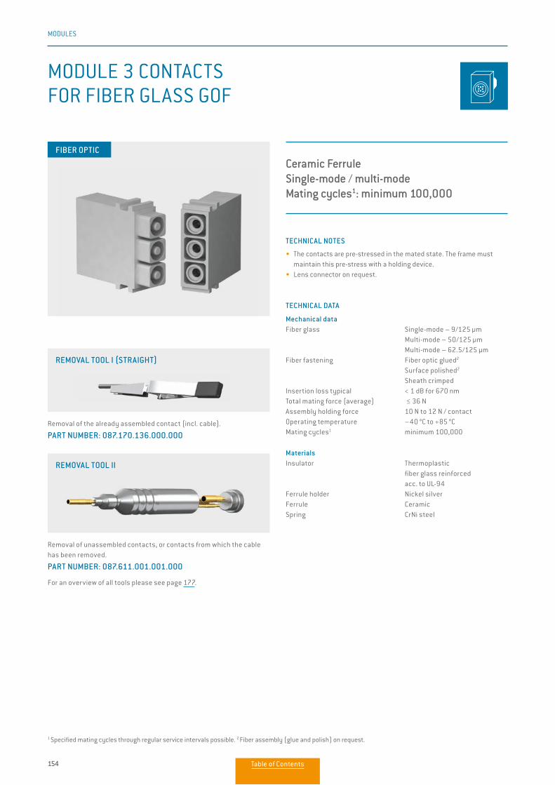
154
MODULES
TECHNICAL NOTES
• The contacts are pre-stressed in the mated state. The frame must maintain this pre-stress with a holding device.
• Lens connector on request.
TECHNICAL DATA
Mechanical dataFiber glass Single-mode – 9/125 μm Multi-mode – 50/125 μm Multi-mode – 62.5/125 μmFiber fastening Fiber optic glued2
Surface polished2
Sheath crimpedInsertion loss typical < 1 dB for 670 nmTotal mating force (average) ≤ 36 NAssembly holding force 10 N to 12 N / contactOperating temperature –40 °C to +85 °CMating cycles1 minimum 100,000
MaterialsInsulator Thermoplastic fiber glass reinforced acc. to UL-94Ferrule holder Nickel silverFerrule CeramicSpring CrNi steel
Ceramic Ferrule Single-mode / multi-modeMating cycles1: minimum 100,000
MODULE 3 CONTACTSFOR FIBER GLASS GOF
Removal of the already assembled contact (incl. cable).
PART NUMBER: 087.170.136.000.000
REMOVAL TOOL I (STRAIGHT)
Removal of unassembled contacts, or contacts from which the cable has been removed.
PART NUMBER: 087.611.001.001.000
For an overview of all tools please see page 177.
REMOVAL TOOL II
FIBER OPTIC
1 Specified mating cycles through regular service intervals possible. 2 Fiber assembly (glue and polish) on request.
Table of Contents
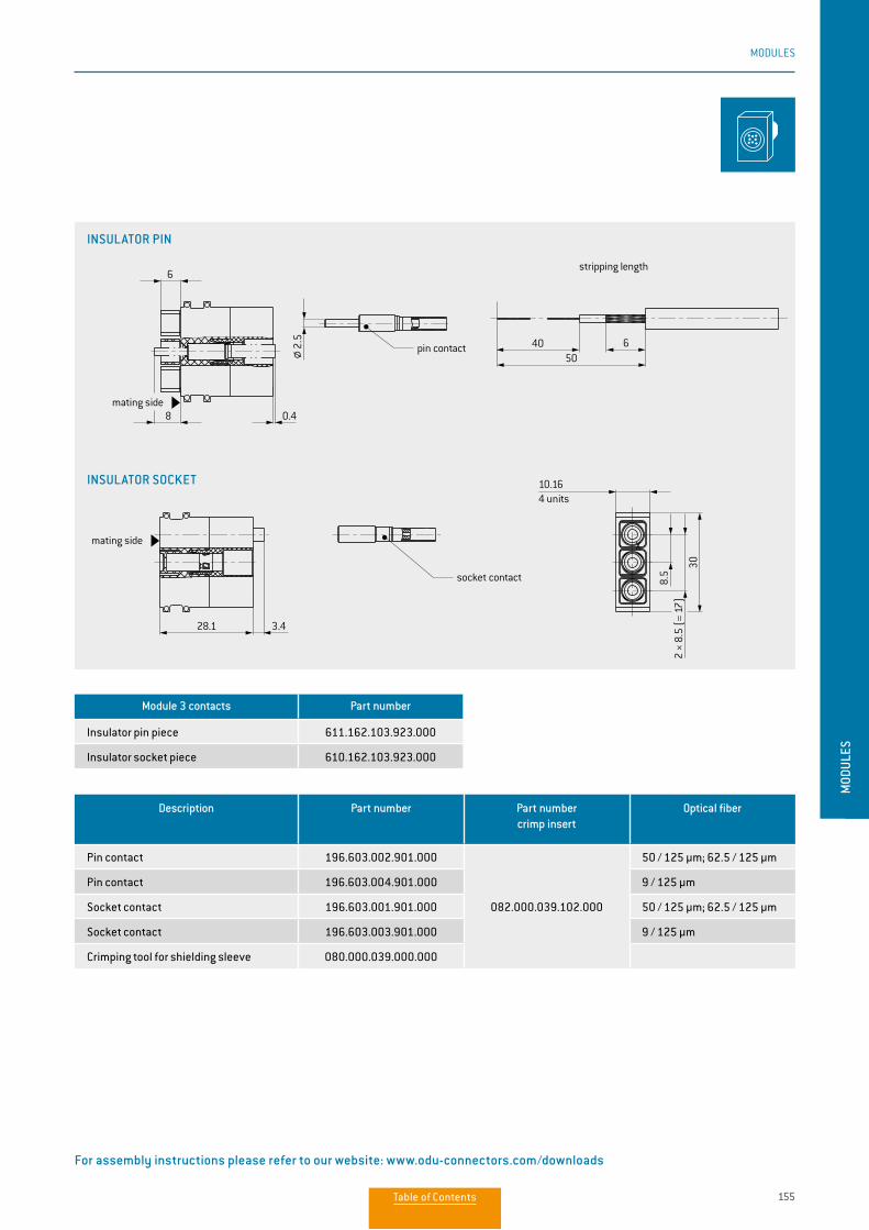
155
MODULES
MOD
ULES
INSULATOR SOCKET
INSULATOR PIN
X
8
6
0.4
28.1 3.4
10.16
30
8.5
2 ×
8.5
(= 1
7)
4050
6
4 units
insulator socket
mating side
mating side
socket contact
pin contact
stripping lengthinsulator pin
2.5
X
8
6
0.4
28.1 3.4
10.16
30
8.5
2 ×
8.5
(= 1
7)
4050
6
4 units
insulator socket
mating side
mating side
socket contact
pin contact
stripping lengthinsulator pin
2.5
Description Part number Part numbercrimp insert
Optical fiber
Pin contact 196.603.002.901.000
082.000.039.102.000
50 / 125 µm; 62.5 / 125 µm
Pin contact 196.603.004.901.000 9 / 125 µm
Socket contact 196.603.001.901.000 50 / 125 µm; 62.5 / 125 µm
Socket contact 196.603.003.901.000 9 / 125 µm
Crimping tool for shielding sleeve 080.000.039.000.000
Module 3 contacts Part number
Insulator pin piece 611.162.103.923.000
Insulator socket piece 610.162.103.923.000
For assembly instructions please refer to our website: www.odu-connectors.com/downloads
Table of Contents
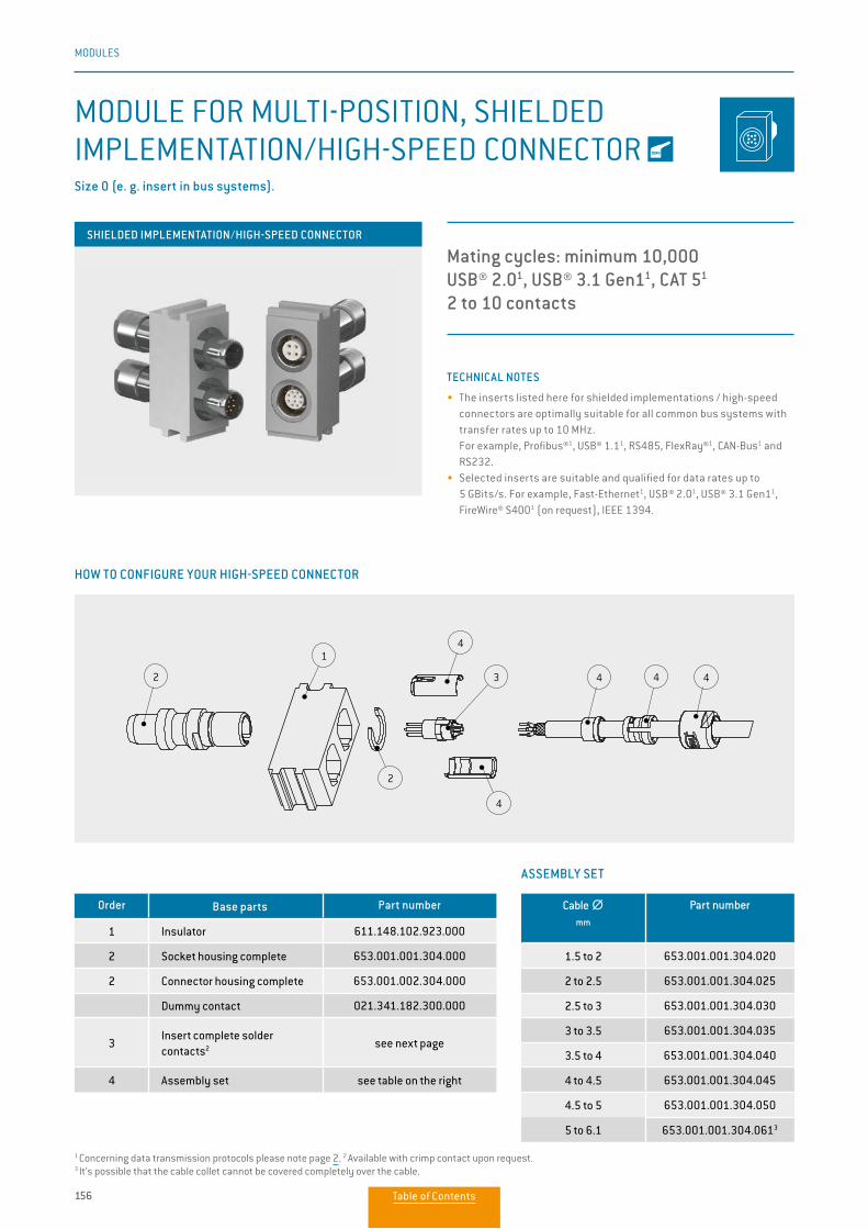
156
MODULES
TECHNICAL NOTES
• The inserts listed here for shielded implementations / high-speed connectors are optimally suitable for all common bus systems with transfer rates up to 10 MHz.
For example, Profibus®1, USB® 1.11, RS485, FlexRay®1, CAN-Bus1 and RS232.
• Selected inserts are suitable and qualified for data rates up to 5 GBits/s. For example, Fast-Ethernet1, USB® 2.01, USB® 3.1 Gen11, FireWire® S4001 (on request), IEEE 1394.
ASSEMBLY SET
Order Base parts Part number
1 Insulator 611.148.102.923.000
2 Socket housing complete 653.001.001.304.000
2 Connector housing complete 653.001.002.304.000
Dummy contact 021.341.182.300.000
3Insert complete solder contacts2 see next page
4 Assembly set see table on the right
Cable ∅∅mm
Part number
1.5 to 2 653.001.001.304.020
2 to 2.5 653.001.001.304.025
2.5 to 3 653.001.001.304.030
3 to 3.5 653.001.001.304.035
3.5 to 4 653.001.001.304.040
4 to 4.5 653.001.001.304.045
4.5 to 5 653.001.001.304.050
5 to 6.1 653.001.001.304.0613
MODULE FOR MULTI-POSITION, SHIELDED IMPLEMENTATION/HIGH-SPEED CONNECTOR Size 0 (e. g. insert in bus systems).
Mating cycles: minimum 10,000USB® 2.01, USB® 3.1 Gen11, CAT 51
2 to 10 contacts
2-pol. 3-pol. 4-pol. CAT 52, USB® 2.02
5-pol. 6-pol. 7-pol.
Polbilder:
contact layout
9-pol. 10-pol.USB® 3.1 Gen12
2
1
2
4
4
3 4 4 4
12,75 Einheiten
11,8
30
2/92,5
7/16
13
8 ca. 15
ca. 22
4,8
Abisolierlängen1
Stift
Buchse
Steckseite
Leitermantel
Schirm
Isolierung
Einzelader
SW 7
7 8,9
HOW TO CONFIGURE YOUR HIGH-SPEED CONNECTOR
SHIELDED IMPLEMENTATION/HIGH-SPEED CONNECTOR
1 Concerning data transmission protocols please note page 2. 2 Available with crimp contact upon request.3 It’s possible that the cable collet cannot be covered completely over the cable.
Table of Contents
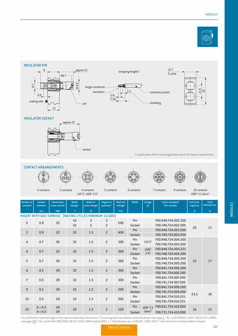
157
MODULES
MOD
ULES
Number of contacts
Contact diameter
mm
Termination cross-section
AWG
Rated voltage3
V
Rated im-pulse voltage3
kV
Degree of pollution3
Nominal voltage4
V AC
Model Catego-ry5
Insert complete6 Part number
Total mat-ing force
N
Total sliding force
N
2 0.9 2210 2 3
500Pin 700.849.724.002.200
20 1532 2 2 Socket 700.749.724.002.200
3 0.9 22 32 1.5 2 400Pin 700.849.724.003.200
Socket 700.749.724.003.200
4 0.7 26 32 1.5 2 300Pin
CAT 52700.848.724.004.200
22 17
Socket 700.748.724.004.200
4 0.7 22 32 1.5 2 300Pin USB®
2.02
700.848.724.404.221Socket 700.748.724.404.200
5 0.7 26 32 1.5 2 366Pin 700.848.724.005.200
Socket 700.748.724.005.200
6 0.5 28 32 1.5 2 300Pin 700.841.724.006.200
Socket 700.741.724.006.200
7 0.5 28 32 1.5 2 300Pin 700.841.724.007.200
Socket 700.741.724.007.200
9 0.5 28 10 1.2 2 200Pin 700.841.724.009.200
23.5 18Socket 700.741.724.009.200
10 0.5 28 10 1.2 2 200Pin 700.841.724.010.221
Socket 700.741.724.010.221
106 × 0.3 4 × 0.5
2824
10 1.2 2 100Pin USB® 3.1
Gen12
700.831.724.410.D0016 12
Socket 700.731.724.410.D00
INSERT WITH ODU TURNTAC® (MATING CYCLES MINIMUM 10,000)
1 You will find the required lengths in the relevant assembly instructions. 2 Concerning data transmission protocols please note page 2. 3 Acc. to IEC 60664-1:2007 (VDE 0110-1:2008), see page 183. 4 Acc. to EIA-364-20D:2008, SAE AS 13441:2004 method 3001.1. 5 Classification acc. to ISO/IEC 11801:2017. 6 Several inserts in crimp model on request.
In application with a housing please check the space requirement.
INSULATOR PIN
INSULATOR SOCKET
2 contacts 3 contacts 4 contactsCAT 52, USB® 2.02
5 contacts 6 contacts 7 contacts
Polbilder:
contact layout
9 contacts 10 contactsUSB® 3.1 Gen12
2
1
2
4
4
3 4 4 4
12.7
11.8
302.5
13
8
4.8
SW 75 units
approx 15
approx 22
stripping lengths1
pin
socket
mating side
conductor jacket
shielding
insulation
single conductor
7 8.9
2/97/16
CONTACT ARRANGEMENTS
2 contacts 3 contacts 4 contactsCAT 52, USB® 2.02
5 contacts 6 contacts 7 contacts
Polbilder:
contact layout
9 contacts 10 contactsUSB® 3.1 Gen12
2
1
2
4
4
3 4 4 4
12.7
11.8
302.5
13
8
4.8
SW 75 units
approx 15
approx 22
stripping lengths1
pin
socket
mating side
conductor jacket
shielding
insulation
single conductor
7 8.9
2/97/16
Table of Contents
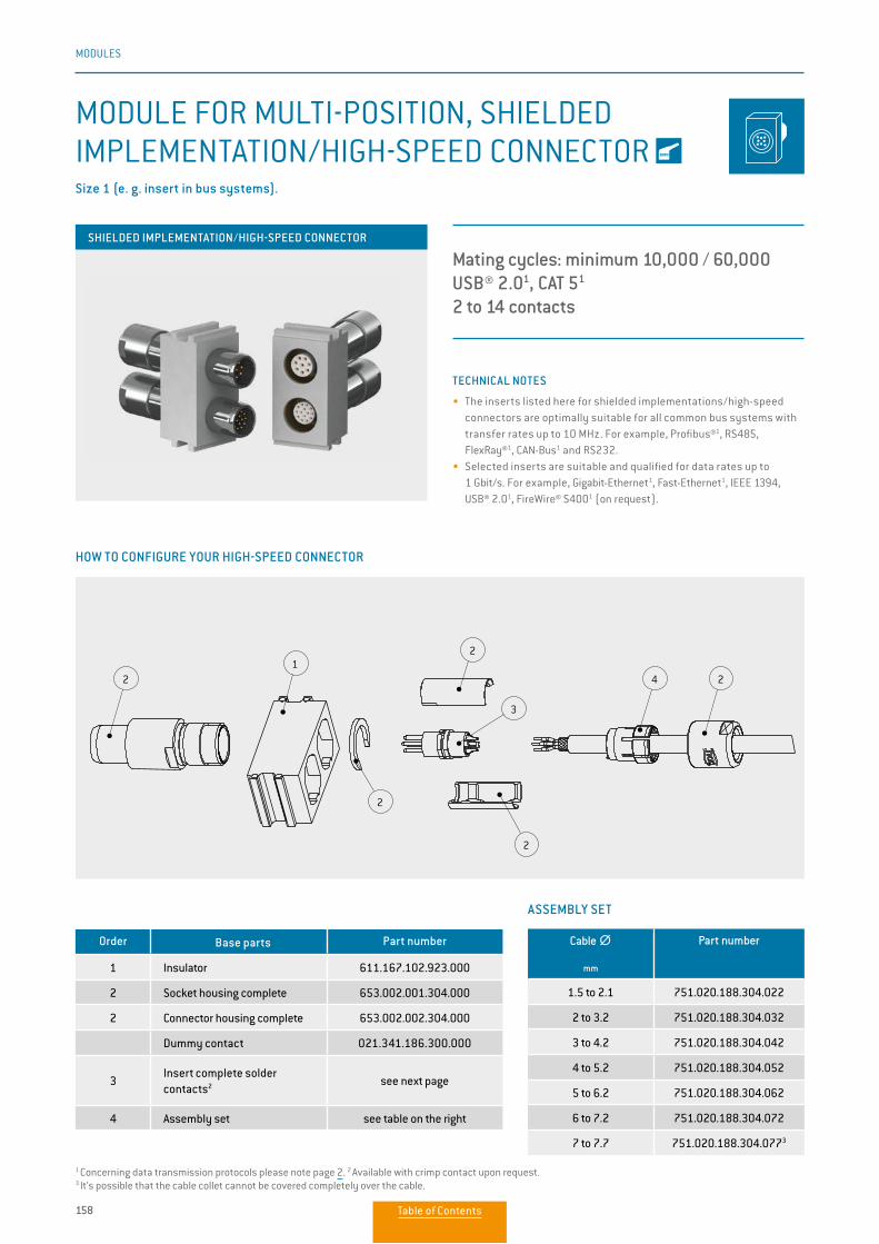
158
MODULES
TECHNICAL NOTES
• The inserts listed here for shielded implementations/high-speed connectors are optimally suitable for all common bus systems with transfer rates up to 10 MHz. For example, Profibus®1, RS485, FlexRay®1, CAN-Bus1 and RS232.• Selected inserts are suitable and qualified for data rates up to
1 Gbit/s. For example, Gigabit-Ethernet1, Fast-Ethernet1, IEEE 1394, USB® 2.01, FireWire® S4001 (on request).
ASSEMBLY SET
Order Base parts Part number
1 Insulator 611.167.102.923.000
2 Socket housing complete 653.002.001.304.000
2 Connector housing complete 653.002.002.304.000
Dummy contact 021.341.186.300.000
3Insert complete solder contacts2 see next page
4 Assembly set see table on the right
MODULE FOR MULTI-POSITION, SHIELDED IMPLEMENTATION/HIGH-SPEED CONNECTOR Size 1 (e. g. insert in bus systems).
Polbilder:
contact layout
2 contacts 3 contacts 4 contactsCAT 5
5 contacts 6 contacts 7 contacts 8 contacts 14 contacts10 contacts8 contactsCAT 5
21
2
2
2
3
4 2
10.99
13
9.5 ca. 18
ca. 29
2.52.5
10
15.246 units
3012.8
5.4
stripping lengths
pin
socket
mating side
conductor jacket
shielding
insulation
single conductor
SW 10
HOW TO CONFIGURE YOUR HIGH-SPEED CONNECTOR
Cable ∅∅
mm
Part number
1.5 to 2.1 751.020.188.304.022
2 to 3.2 751.020.188.304.032
3 to 4.2 751.020.188.304.042
4 to 5.2 751.020.188.304.052
5 to 6.2 751.020.188.304.062
6 to 7.2 751.020.188.304.072
7 to 7.7 751.020.188.304.0773
Mating cycles: minimum 10,000 / 60,000USB® 2.01, CAT 51
2 to 14 contacts
SHIELDED IMPLEMENTATION/HIGH-SPEED CONNECTOR
1 Concerning data transmission protocols please note page 2. 2 Available with crimp contact upon request. 3 It’s possible that the cable collet cannot be covered completely over the cable.
Table of Contents
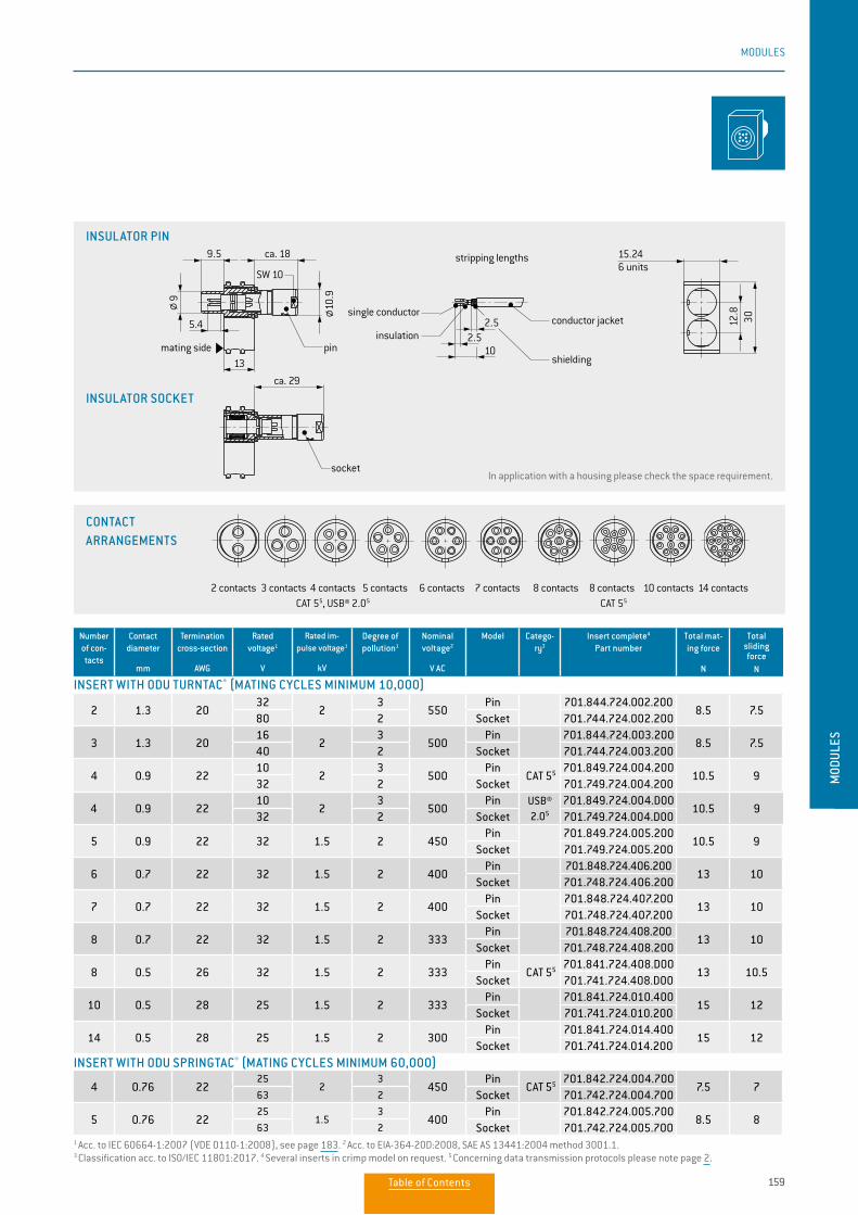
159
MODULES
MOD
ULES
Number of con-tacts
Contact diameter
mm
Termination cross-section
AWG
Rated voltage1
V
Rated im-pulse voltage1
kV
Degree of pollution1
Nominal voltage2
V AC
Model Catego-ry3
Insert complete4 Part number
Total mat-ing force
N
Total sliding force
N
2 1.3 2032
23
550Pin 701.844.724.002.200
8.5 7.580 2 Socket 701.744.724.002.200
3 1.3 2016
23
500Pin 701.844.724.003.200
8.5 7.540 2 Socket 701.744.724.003.200
4 0.9 2210
23
500Pin
CAT 55 701.849.724.004.20010.5 9
32 2 Socket 701.749.724.004.200
4 0.9 2210
23
500Pin USB®
2.05
701.849.724.004.D0010.5 9
32 2 Socket 701.749.724.004.D00
5 0.9 22 32 1.5 2 450Pin 701.849.724.005.200
10.5 9Socket 701.749.724.005.200
6 0.7 22 32 1.5 2 400Pin 701.848.724.406.200
13 10Socket 701.748.724.406.200
7 0.7 22 32 1.5 2 400Pin 701.848.724.407.200
13 10Socket 701.748.724.407.200
8 0.7 22 32 1.5 2 333Pin 701.848.724.408.200
13 10Socket 701.748.724.408.200
8 0.5 26 32 1.5 2 333Pin
CAT 55 701.841.724.408.D0013 10.5
Socket 701.741.724.408.D00
10 0.5 28 25 1.5 2 333Pin 701.841.724.010.400
15 12Socket 701.741.724.010.200
14 0.5 28 25 1.5 2 300Pin 701.841.724.014.400
15 12Socket 701.741.724.014.200
4 0.76 2225
23
450Pin
CAT 55 701.842.724.004.7007.5 7
63 2 Socket 701.742.724.004.700
5 0.76 2225
1.53
400Pin 701.842.724.005.700
8.5 863 2 Socket 701.742.724.005.700
INSERT WITH ODU TURNTAC® (MATING CYCLES MINIMUM 10,000)
INSERT WITH ODU SPRINGTAC® (MATING CYCLES MINIMUM 60,000)
1 Acc. to IEC 60664-1:2007 (VDE 0110-1:2008), see page 183. 2 Acc. to EIA-364-20D:2008, SAE AS 13441:2004 method 3001.1. 3 Classification acc. to ISO/IEC 11801:2017. 4 Several inserts in crimp model on request. 5 Concerning data transmission protocols please note page 2.
2 contacts 3 contacts 4 contactsCAT 55, USB® 2.05
5 contacts 6 contacts 7 contacts 8 contacts 14 contacts10 contacts8 contactsCAT 55
Polbilder:
contact layout
2 contacts 3 contacts 4 contactsCAT 5
5 contacts 6 contacts 7 contacts 8 contacts 14 contacts10 contacts8 contactsCAT 5
21
2
2
2
3
4 2
10.99
13
9.5 ca. 18
ca. 29
2.52.5
10
15.246 units
3012.8
5.4
stripping lengths
pin
socket
mating side
conductor jacket
shielding
insulation
single conductor
SW 10
CONTACT ARRANGEMENTS
In application with a housing please check the space requirement.
INSULATOR PIN
INSULATOR SOCKET
Table of Contents
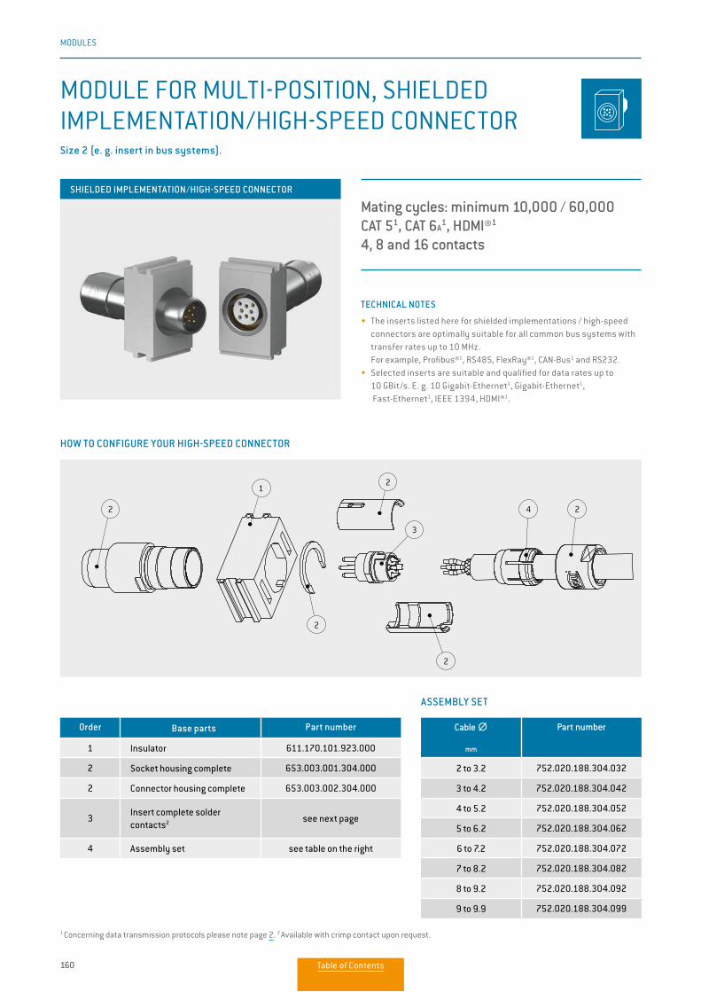
160
MODULES
Polbilder:
contact layout
4 contactsCAT 55
8 contactsCAT 55
CAT 6A
5
16 contactsHDMI®5
2
1
3
2
2
2
24
13.9
12
17.787 units
30
2.52
1113
9.5 ca. 23
ca. 35
6.5
stripping lengths
socket
mating side
conductor jacket
shielding
insulationsingle conductor
SW 12
pin
TECHNICAL NOTES
• The inserts listed here for shielded implementations / high-speed connectors are optimally suitable for all common bus systems with transfer rates up to 10 MHz.
For example, Profibus®1, RS485, FlexRay®1, CAN-Bus1 and RS232.• Selected inserts are suitable and qualified for data rates up to
10 GBit/s. E. g. 10 Gigabit-Ethernet1, Gigabit-Ethernet1, Fast-Ethernet1, IEEE 1394, HDMI®1.
MODULE FOR MULTI-POSITION, SHIELDED IMPLEMENTATION/HIGH-SPEED CONNECTORSize 2 (e. g. insert in bus systems).
Mating cycles: minimum 10,000 / 60,000CAT 51, CAT 6A
1, HDMI®1
4, 8 and 16 contacts
HOW TO CONFIGURE YOUR HIGH-SPEED CONNECTOR
ASSEMBLY SET
Order Base parts Part number
1 Insulator 611.170.101.923.000
2 Socket housing complete 653.003.001.304.000
2 Connector housing complete 653.003.002.304.000
3Insert complete solder contacts2 see next page
4 Assembly set see table on the right
Cable ∅∅
mm
Part number
2 to 3.2 752.020.188.304.032
3 to 4.2 752.020.188.304.042
4 to 5.2 752.020.188.304.052
5 to 6.2 752.020.188.304.062
6 to 7.2 752.020.188.304.072
7 to 8.2 752.020.188.304.082
8 to 9.2 752.020.188.304.092
9 to 9.9 752.020.188.304.099
SHIELDED IMPLEMENTATION/HIGH-SPEED CONNECTOR
1 Concerning data transmission protocols please note page 2. 2 Available with crimp contact upon request.
Table of Contents
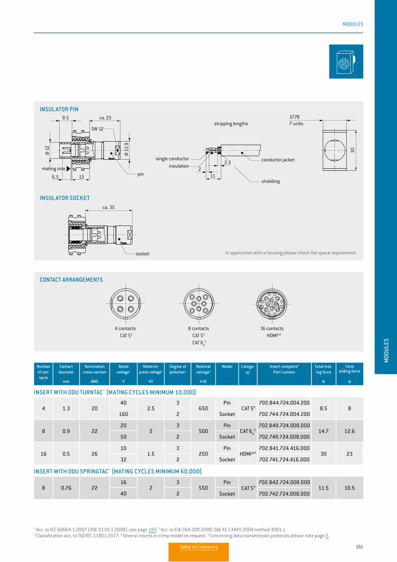
161
MODULES
MOD
ULES
Number of con-tacts
Contact diameter
mm
Termination cross-section
AWG
Rated voltage1
V
Rated im-pulse voltage1
kV
Degree of pollution1
Nominal voltage2
V AC
Model Catego-ry3
Insert complete4 Part number
Total mat-ing force
N
Total sliding force
N
4 1.3 2040
2.53
650Pin
CAT 55702.844.724.004.200
8.5 8160 2 Socket 702.744.724.004.200
8 0.9 2220
23
500Pin
CAT 6A
5702.849.724.008.D00
14.7 12.650 2 Socket 702.749.724.008.D00
16 0.5 2610
1.53
250Pin
HDMI®5702.841.724.416.D00
30 2332 2 Socket 702.741.724.416.D00
8 0.76 2216
23
550Pin
CAT 55702.842.724.008.D00
11.5 10.540 2 Socket 702.742.724.008.D00
INSERT WITH ODU TURNTAC® (MATING CYCLES MINIMUM 10,000)
INSERT WITH ODU SPRINGTAC® (MATING CYCLES MINIMUM 60,000)
CONTACT ARRANGEMENTS
Polbilder:
contact layout
4 contactsCAT 55
8 contactsCAT 55
CAT 6A
5
16 contactsHDMI®5
2
1
3
2
2
2
24
13.9
12
17.787 units
30
2.52
1113
9.5 ca. 23
ca. 35
6.5
stripping lengths
socket
mating side
conductor jacket
shielding
insulationsingle conductor
SW 12
pin
Polbilder:
contact layout
4 contactsCAT 55
8 contactsCAT 55
CAT 6A
5
16 contactsHDMI®5
2
1
3
2
2
2
24
13.9
12
17.787 units
30
2.52
1113
9.5 ca. 23
ca. 35
6.5
stripping lengths
socket
mating side
conductor jacket
shielding
insulationsingle conductor
SW 12
pin
1 Acc. to IEC 60664-1:2007 (VDE 0110-1:2008), see page 183. 2 Acc. to EIA-364-20D:2008, SAE AS 13441:2004 method 3001.1. 3 Classification acc. to ISO/IEC 11801:2017. 4 Several inserts in crimp model on request. 5 Concerning data transmission protocols please note page 2.
Polbilder:
contact layout
4 contactsCAT 55
8 contactsCAT 55
CAT 6A
5
16 contactsHDMI®5
2
1
3
2
2
2
24
13.9
12
17.787 units
30
2.52
1113
9.5 ca. 23
ca. 35
6.5
stripping lengths
socket
mating side
conductor jacket
shielding
insulationsingle conductor
SW 12
pin
In application with a housing please check the space requirement.
INSULATOR PIN
INSULATOR SOCKET
Table of Contents
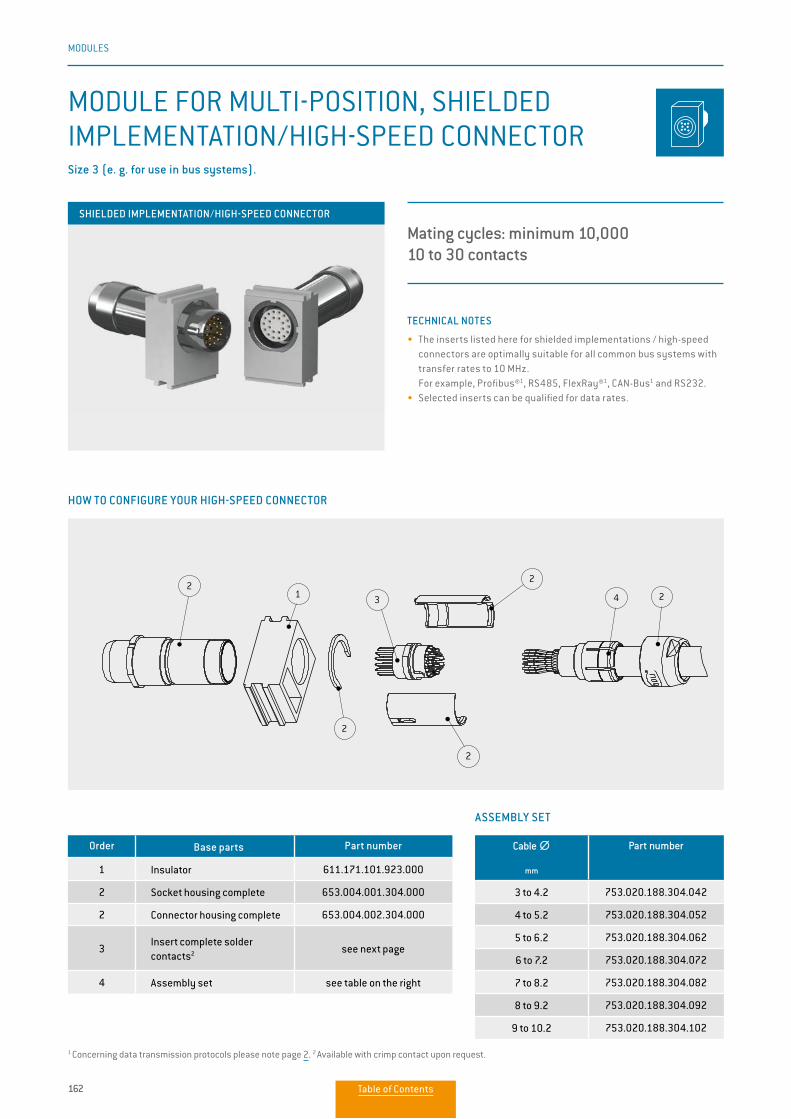
162
MODULES
TECHNICAL NOTES
• The inserts listed here for shielded implementations / high-speed connectors are optimally suitable for all common bus systems with transfer rates to 10 MHz.
For example, Profibus®1, RS485, FlexRay®1, CAN-Bus1 and RS232.• Selected inserts can be qualified for data rates.
ASSEMBLY SET
Order Base parts Part number
1 Insulator 611.171.101.923.000
2 Socket housing complete 653.004.001.304.000
2 Connector housing complete 653.004.002.304.000
3Insert complete solder contacts2 see next page
4 Assembly set see table on the right
MODULE FOR MULTI-POSITION, SHIELDED IMPLEMENTATION/HIGH-SPEED CONNECTORSize 3 (e. g. for use in bus systems).
Mating cycles: minimum 10,00010 to 30 contacts
21
2
3
2
2
24
Polbilder:
contact layout
22-pol.18-pol. 30-pol.10-pol.
16,514
13
2,52
ca. 46
6,5
13
ca. 309,5
4,15
30
20,328 Einheiten
Abisolierlängen
Stift
Buchse
Steckseite
Leitermantel
SchirmIsolierung
Einzelader
SW 14
HOW TO CONFIGURE YOUR HIGH-SPEED CONNECTOR
Cable ∅∅
mm
Part number
3 to 4.2 753.020.188.304.042
4 to 5.2 753.020.188.304.052
5 to 6.2 753.020.188.304.062
6 to 7.2 753.020.188.304.072
7 to 8.2 753.020.188.304.082
8 to 9.2 753.020.188.304.092
9 to 10.2 753.020.188.304.102
SHIELDED IMPLEMENTATION/HIGH-SPEED CONNECTOR
1 Concerning data transmission protocols please note page 2. 2 Available with crimp contact upon request.
Table of Contents
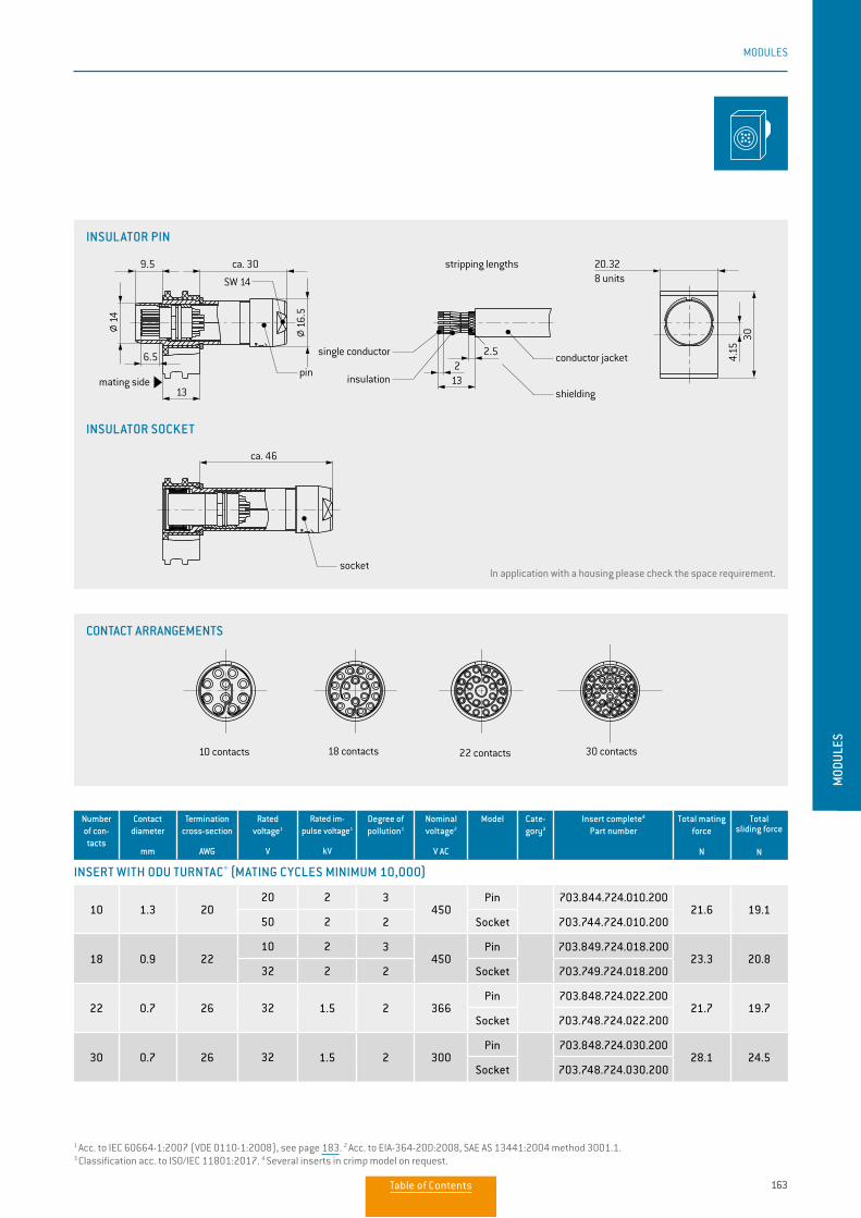
163
MODULES
MOD
ULES
Number of con-tacts
Contact diameter
mm
Termination cross-section
AWG
Rated voltage1
V
Rated im-pulse voltage1
kV
Degree of pollution1
Nominal voltage2
V AC
Model Cate-gory3
Insert complete4 Part number
Total mating force
N
Total sliding force
N
10 1.3 2020 2 3
450Pin 703.844.724.010.200
21.6 19.150 2 2 Socket 703.744.724.010.200
18 0.9 2210 2 3
450Pin 703.849.724.018.200
23.3 20.832 2 2 Socket 703.749.724.018.200
22 0.7 26 32 1.5 2 366Pin 703.848.724.022.200
21.7 19.7Socket 703.748.724.022.200
30 0.7 26 32 1.5 2 300Pin 703.848.724.030.200
28.1 24.5Socket 703.748.724.030.200
INSERT WITH ODU TURNTAC® (MATING CYCLES MINIMUM 10,000)
21
2
3
2
2
24
Polbilder:
contact layout
22 contacts18 contacts 30 contacts10 contacts
16.514
13
2.52
ca. 46
6.5
13
ca. 309.5
4.15
30
20.328 units
stripping lengths
pin
socket
mating side
conductor jacket
shieldinginsulation
single conductor
SW 14
21
2
3
2
2
24
Polbilder:
contact layout
22 contacts18 contacts 30 contacts10 contacts
16.514
13
2.52
ca. 46
6.5
13
ca. 309.5
4.15
30
20.328 units
stripping lengths
pin
socket
mating side
conductor jacket
shieldinginsulation
single conductor
SW 14
1 Acc. to IEC 60664-1:2007 (VDE 0110-1:2008), see page 183. 2 Acc. to EIA-364-20D:2008, SAE AS 13441:2004 method 3001.1. 3 Classification acc. to ISO/IEC 11801:2017. 4 Several inserts in crimp model on request.
21
2
3
2
2
24
Polbilder:
contact layout
22 contacts18 contacts 30 contacts10 contacts
16.514
13
2.52
ca. 46
6.5
13
ca. 309.5
4.15
30
20.328 units
stripping lengths
pin
socket
mating side
conductor jacket
shieldinginsulation
single conductor
SW 14
CONTACT ARRANGEMENTS
INSULATOR PIN
INSULATOR SOCKET
In application with a housing please check the space requirement.
Table of Contents
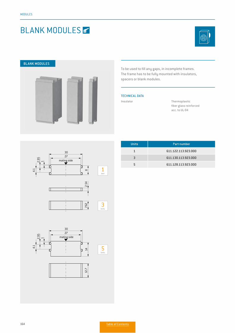
164
MODULES
Units Part number
1 611.122.113.923.000
3 611.130.113.923.000
5 611.128.113.923.000
BLANK MODULES
BLANK MODULES
TECHNICAL DATA
Insulator Thermoplastic fiber glass reinforced acc. to UL-94
To be used to fill any gaps, in incomplete frames. The frame has to be fully mounted with insulators, spacers or blank modules.
1 Unit
3 Units
5 Units
mating side2730
2.95
4.1 8
2.54
7.62
12.7
1
mating side2730
2.95
4.1
1
14
Table of Contents
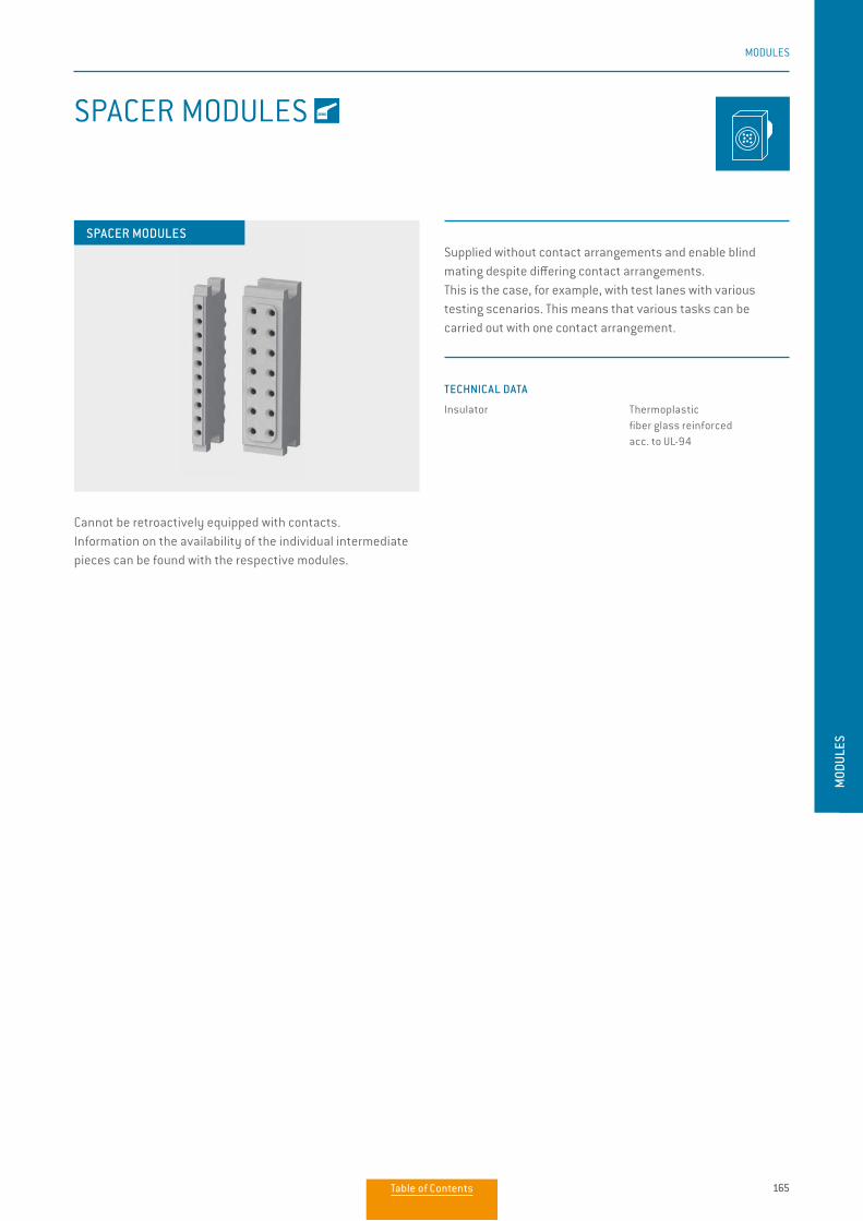
165
MODULES
MOD
ULES
SPACER MODULES
SPACER MODULES
Cannot be retroactively equipped with contacts. Information on the availability of the individual intermediate pieces can be found with the respective modules.
TECHNICAL DATA
Insulator Thermoplastic fiber glass reinforced acc. to UL-94
Supplied without contact arrangements and enable blind mating despite differing contact arrangements. This is the case, for example, with test lanes with various testing scenarios. This means that various tasks can be carried out with one contact arrangement.
Table of Contents
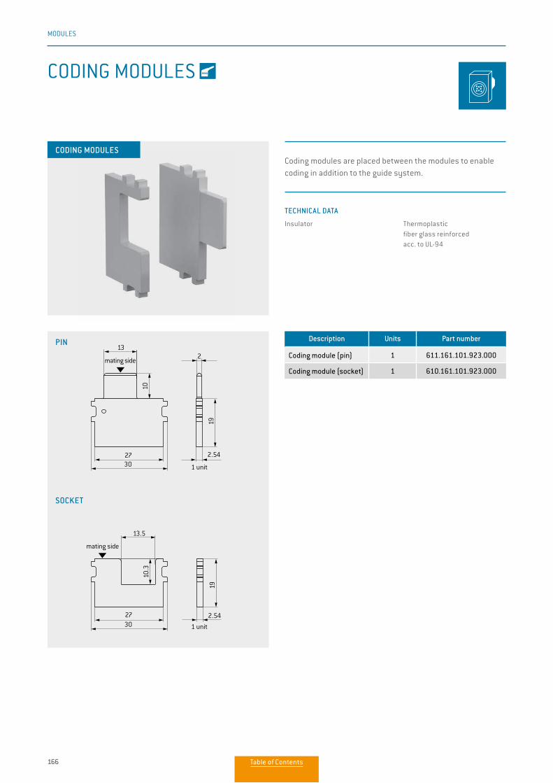
166
MODULES
CODING MODULES
CODING MODULES
Description Units Part number
Coding module (pin) 1 611.161.101.923.000
Coding module (socket) 1 610.161.101.923.000
PIN
SOCKET
1 unit
2.54
1 unit
2.5427
3,5
13.5
30
27
3,5
2
19
10
19
10.3
13
30
mating side
mating side
1 unit
2.54
1 unit
2.5427
3,5
13.5
30
27
3,5
2
19
10
19
10.3
13
30
mating side
mating side
Coding modules are placed between the modules to enable coding in addition to the guide system.
TECHNICAL DATA
Insulator Thermoplastic fiber glass reinforced acc. to UL-94
Table of Contents
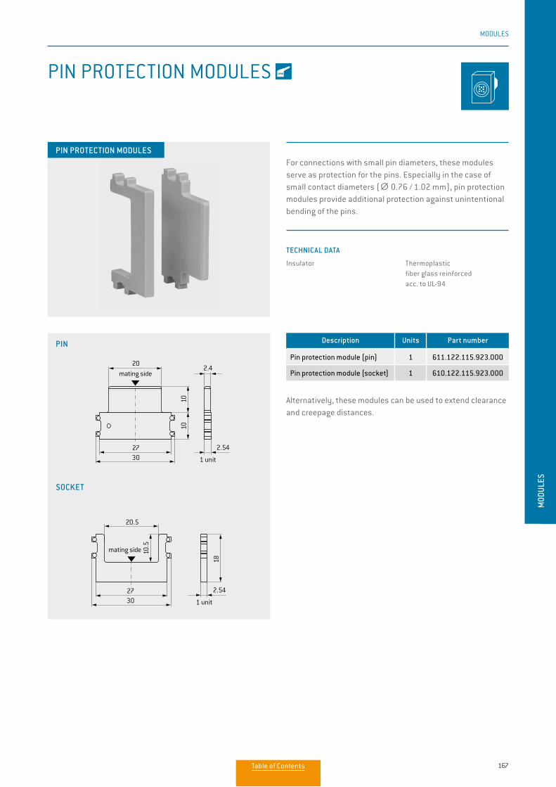
167
MODULES
MOD
ULES
PIN PROTECTION MODULES
Alternatively, these modules can be used to extend clearance and creepage distances.
Description Units Part number
Pin protection module (pin) 1 611.122.115.923.000
Pin protection module (socket) 1 610.122.115.923.000
TECHNICAL DATA
Insulator Thermoplastic fiber glass reinforced acc. to UL-94
For connections with small pin diameters, these modules serve as protection for the pins. Especially in the case of small contact diameters (∅∅ 0.76 / 1.02 mm), pin protection modules provide additional protection against unintentional bending of the pins.
PIN PROTECTION MODULES
PIN
SOCKET
20
20.5
1010
18
10.5
3027
3027
2.4
1 unit
2.54
1 unit
2.54
mating side
mating side
20
20.5
1010
18
10.5
3027
3027
2.4
1 unit
2.54
1 unit
2.54
mating side
mating side
Table of Contents
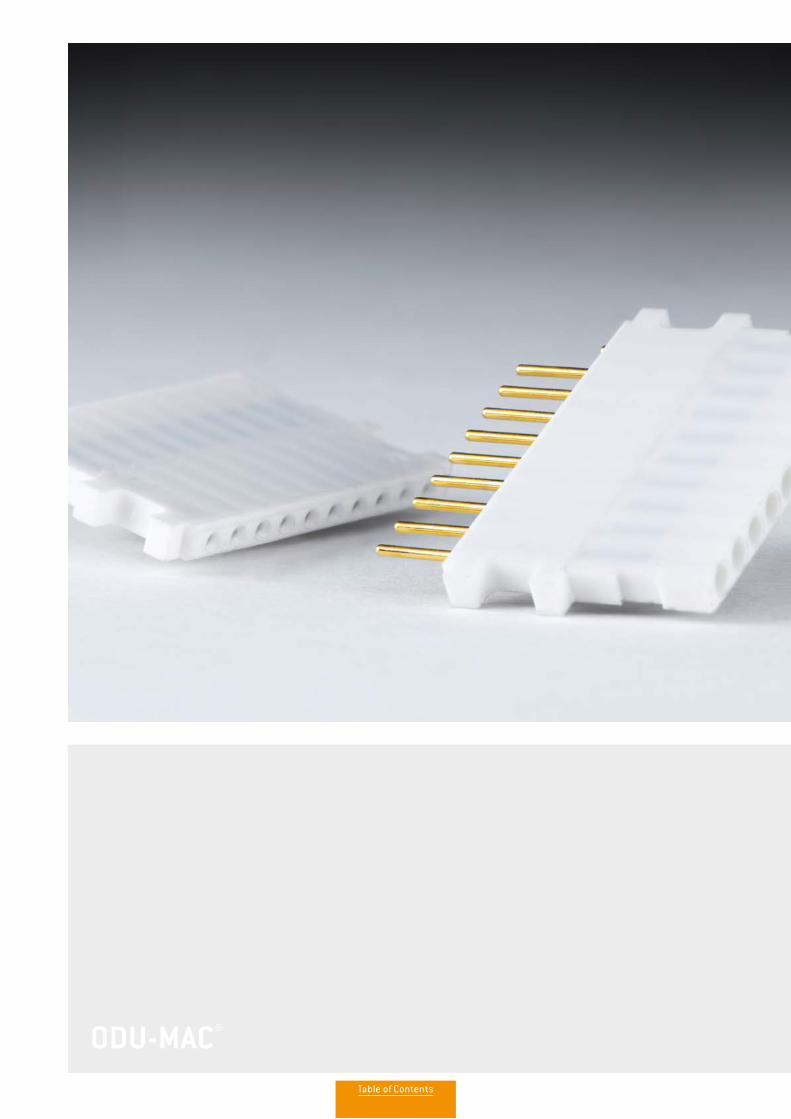
ODU-MAC®ODU-MAC®
Table of Contents
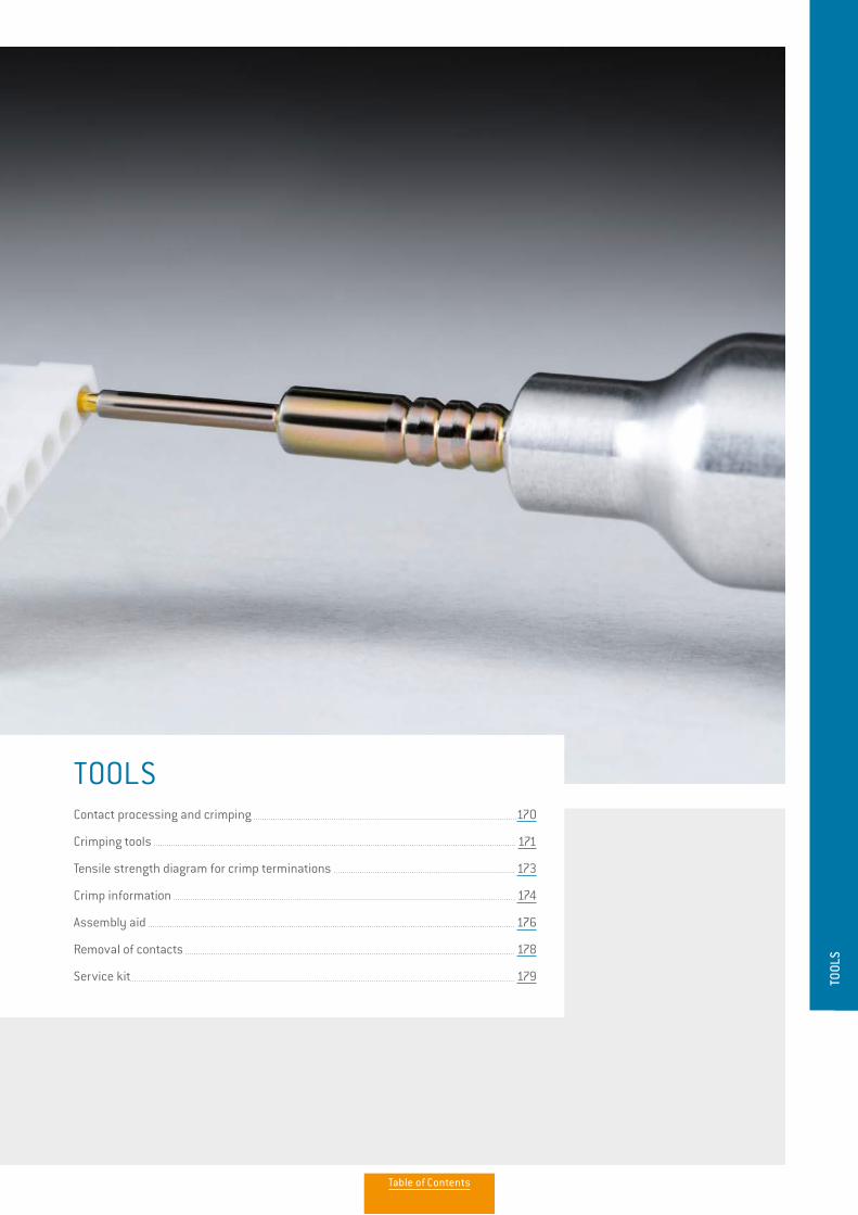
TOOLSContact processing and crimping 170
Crimping tools 171
Tensile strength diagram for crimp terminations 173
Crimp information 174
Assembly aid 176
Removal of contacts 178
Service kit 179 TOOL
S
Table of Contents
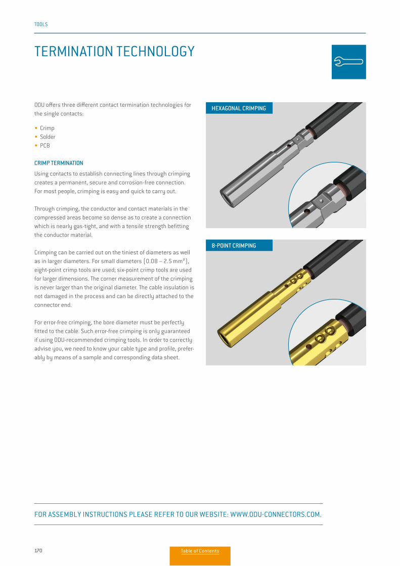
170
TOOLS
TERMINATION TECHNOLOGY
ODU offers three different contact termination technologies for the single contacts:
• Crimp• Solder• PCB
CRIMP TERMINATION
Using contacts to establish connecting lines through crimping creates a permanent, secure and corrosion-free connection. For most people, crimping is easy and quick to carry out.
Through crimping, the conductor and contact materials in the compressed areas become so dense as to create a connection which is nearly gas-tight, and with a tensile strength befitting the conductor material.
Crimping can be carried out on the tiniest of diameters as well as in larger diameters. For small diameters (0.08 – 2.5 mm²), eight-point crimp tools are used; six-point crimp tools are used for larger dimensions. The corner measurement of the crimping is never larger than the original diameter. The cable insulation is not damaged in the process and can be directly attached to the connector end.
For error-free crimping, the bore diameter must be perfectly fitted to the cable. Such error-free crimping is only guaranteed if using ODU-recommended crimping tools. In order to correctly advise you, we need to know your cable type and profile, prefer-ably by means of a sample and corresponding data sheet.
HEXAGONAL CRIMPING
8-POINT CRIMPING
FOR ASSEMBLY INSTRUCTIONS PLEASE REFER TO OUR WEBSITE: WWW.ODU-CONNECTORS.COM.
Table of Contents

171
TOOLS
TOOL
S
For further crimp information please refer to the table on page 174.
CRIMPING TOOLS
8-POINT CRIMPING TOOL FOR CONDUCTOR CONNECTIONS FROM 0.08 TO 1 mm²
8-POINT CRIMPING TOOL FOR CONDUCTOR CONNECTIONS FROM 1.5 TO 6 mm²
HEXAGONAL CRIMPING TOOL FOR CROSS-SECTIONS (AWG 12), 4 TO 6.0 mm²
MECHANICAL HEXAGONAL HAND CRIMPING TOOL FROM 10 TO 50 mm²
With user-friendly digital display.PART NUMBER: 080.000.051.000.000
POSITIONER FOR CONTACT DIAMETER FROM 0.76 TO 3 mm PART NUMBER: 080.000.051.101.000Has to be ordered separately.
With user-friendly digital display.PART NUMBER: 080.000.057.000.000
POSITIONER FOR CONTACT DIAMETER FROM 1.5 TO 3 mmPART NUMBER: 080.000.057.101.000 Has to be ordered separately.
With blocking system.PART NUMBER: 080.000.062.000.000
PART NUMBER: 080.000.064.000.000High pressing force with low manual force through precision mechanics. Folding head facilitates processing of unwieldy connector forms and changing of crimp inserts. CRIMPING JAWS FOR CONTACT DIAMETER FROM 5 TO 12 mm SEE PAGE 175Has to be ordered separately.
Table of Contents

172
TOOLS
CRIMPING TOOLS
For further crimp information please refer to the table on page 174.
HEXAGONAL CRIMPING TOOL FOR COAX CONTACTS
HAND CRIMPING TOOL FOR SINGLE CRIMP CONTACTS (STAMPED CONTACTS)
HAND CRIMPERS WITH ROLL FOR SPOOL GOODS (STAMPED CONTACTS)
With blocking system.PART NUMBER PLIER: 080.000.039.000.000
CRIMPING JAWS PLEASE SEE PAGE 174Has to be ordered separately.
PART NUMBER: 080.000.041.000.000Contacts are supplied on the reel and are automatically isolated. The feed occurs by hand operation.
• Suitable for coil size: 115 mm. Therefore 500/900 contacts can be processed.
• Processing with automatic stripper crimper possible, further information on request.
PART NUMBER: 080.000.040.000.000 Single contacts are positioned manually in the pliers and get crimped.
Table of Contents
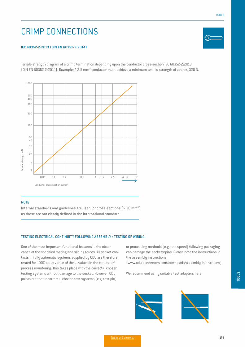
173
TOOLS
TOOL
S
CRIMP CONNECTIONS
Tensile strength diagram of a crimp termination depending upon the conductor cross-section IEC 60352-2:2013 (DIN EN 60352-2:2014). Example: A 2.5 mm² conductor must achieve a minimum tensile strength of approx. 320 N.
Conductor cross-section in mm2
Tens
ile s
tren
gth
in N
0.05 0.1 0.2 0.5 1 1.5 2.5 4 6 10
5
10
20
30
4050
100
200
300
400500
1,000
IEC 60352-2:2013 (DIN EN 60352-2:2014).
One of the most important functional features is the obser-vance of the specified mating and sliding forces. All socket con-tacts in fully automatic systems supplied by ODU are therefore tested for 100% observance of these values in the context of process monitoring. This takes place with the correctly chosen testing systems without damage to the socket. However, ODU points out that incorrectly chosen test systems (e.g. test pin)
or processing methods (e.g. test speed) following packaging can damage the sockets/pins. Please note the instructions in the assembly instructions (www.odu-connectors.com/downloads/assembly-instructions).
We recommend using suitable test adapters here.
NOTE Internal standards and guidelines are used for cross-sections (> 10 mm²),
as these are not clearly defined in the international standard.
TESTING ELECTRICAL CONTINUITY FOLLOWING ASSEMBLY / TESTING OF WIRING:
Table of Contents
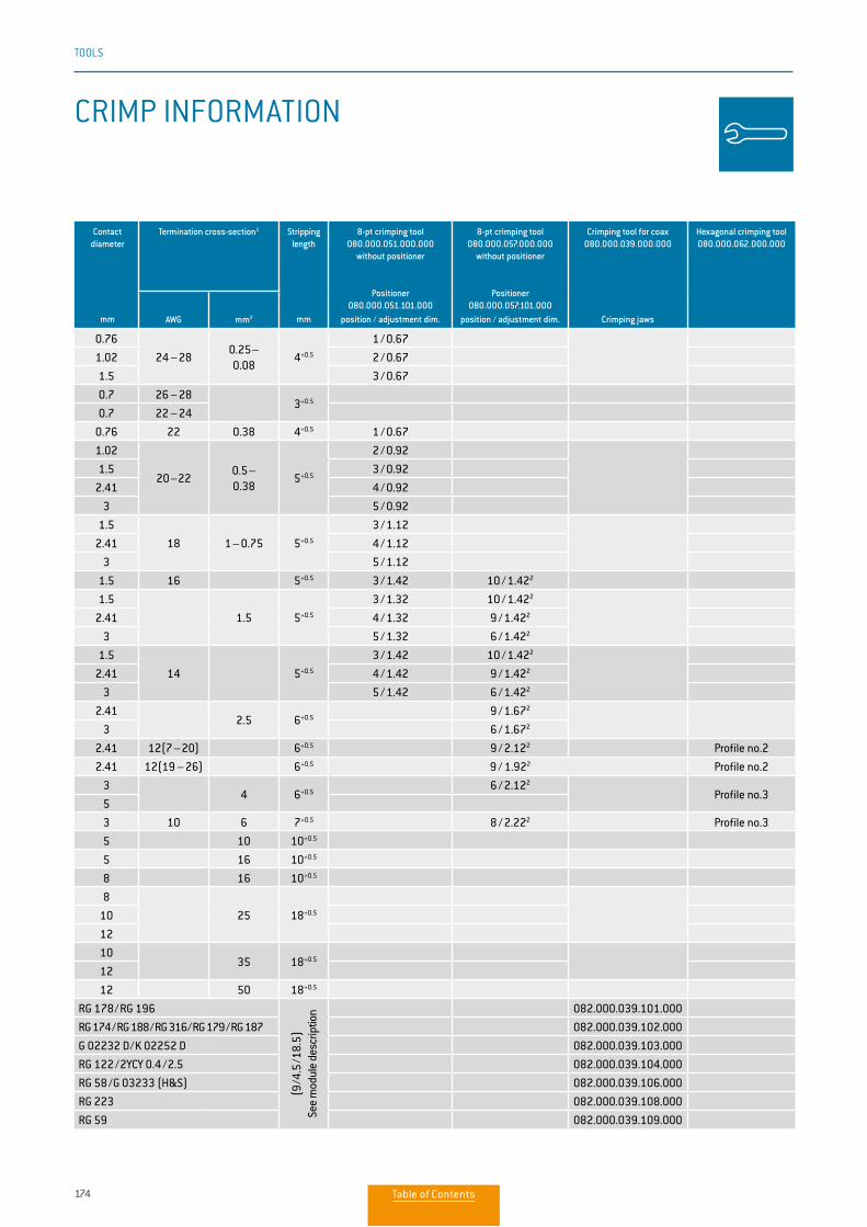
174
TOOLS
Contact diameter
mm
Termination cross-section1 Stripping length
mm
8-pt crimping tool080.000.051.000.000
without positioner
Positioner080.000.051.101.000
position / adjustment dim.
8-pt crimping tool080.000.057.000.000
without positioner
Positioner080.000.057.101.000
position / adjustment dim.
Crimping tool for coax080.000.039.000.000
Crimping jaws
Hexagonal crimping tool080.000.062.000.000
AWG mm2
0.76
24 – 280.25– 0.08
4+0.5
1 / 0.67
1.02 2 / 0.67
1.5 3 / 0.67
0.7 26 – 283+0.5
0.7 22 – 24
0.76 22 0.38 4+0.5 1 / 0.67
1.02
20 – 220.5– 0.38
5+0.5
2 / 0.92
1.5 3 / 0.92
2.41 4 / 0.92
3 5 / 0.92
1.5
18 1 – 0.75 5+0.5
3 / 1.12
2.41 4 / 1.12
3 5 / 1.12
1.5 16 5+0.5 3 / 1.42 10 / 1.422
1.5
1.5 5+0.5
3 / 1.32 10 / 1.422
2.41 4 / 1.32 9 / 1.422
3 5 / 1.32 6 / 1.422
1.5
14 5+0.5
3 / 1.42 10 / 1.422
2.41 4 / 1.42 9 / 1.422
3 5 / 1.42 6 / 1.422
2.412.5 6+0.5
9 / 1.672
3 6 / 1.672
2.41 12(7 – 20) 6+0.5 9 / 2.122 Profile no.2
2.41 12(19 – 26) 6+0.5 9 / 1.922 Profile no.2
34 6+0.5
6 / 2.122
Profile no.35
3 10 6 7+0.5 8 / 2.222 Profile no.3
5 10 10+0.5
5 16 10+0.5
8 16 10+0.5
8
25 18+0.510
12
1035 18+0.5
12
12 50 18+0.5
RG 178 / RG 196
(9 / 4
.5 /1
8.5)
See
mod
ule
desc
riptio
n 082.000.039.101.000
RG 174 / RG 188 / RG 316 / RG 179 / RG 187 082.000.039.102.000
G 02232 D / K 02252 D 082.000.039.103.000
RG 122 / 2YCY 0.4 / 2.5 082.000.039.104.000
RG 58 / G 03233 (H&S) 082.000.039.106.000
RG 223 082.000.039.108.000
RG 59 082.000.039.109.000
CRIMP INFORMATION
Table of Contents
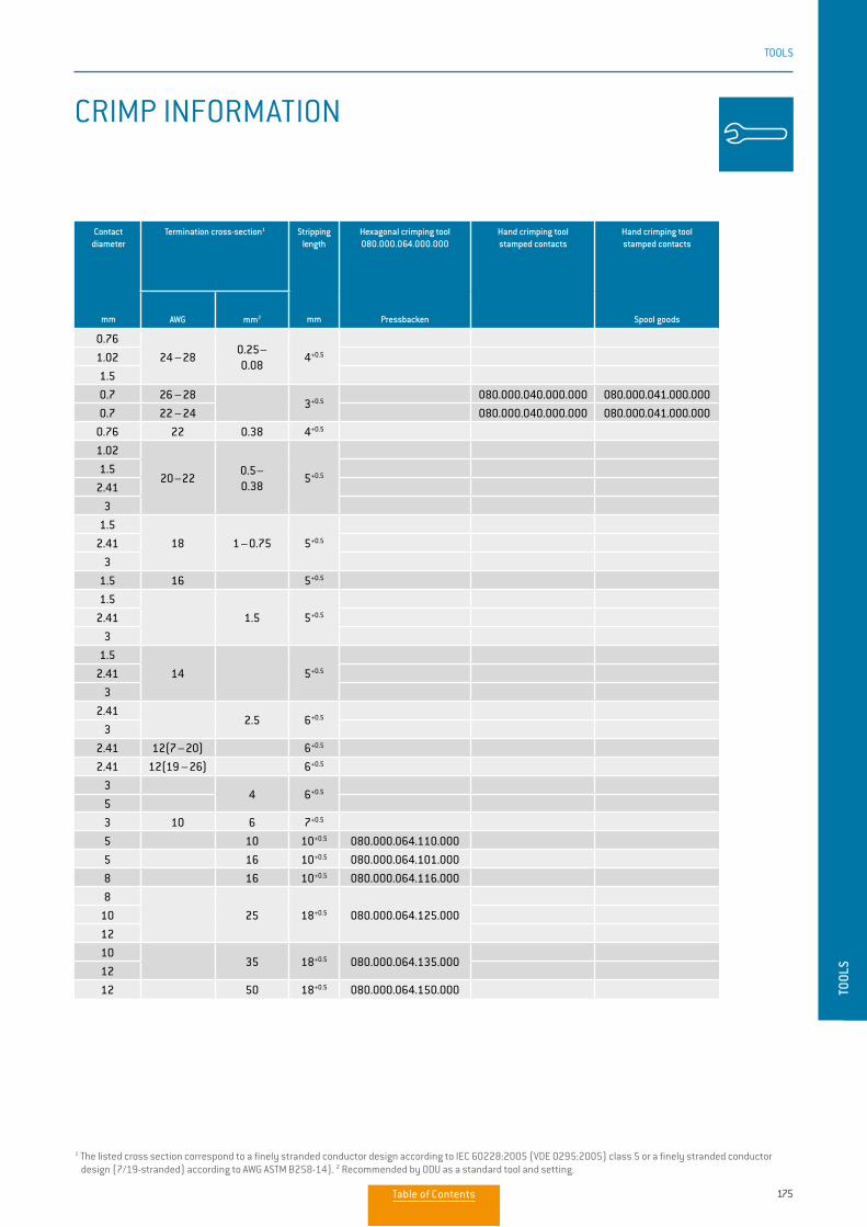
175
TOOLS
TOOL
S
Contact diameter
mm
Termination cross-section1 Stripping length
mm
Hexagonal crimping tool 080.000.064.000.000
Pressbacken
Hand crimping tool stamped contacts
Hand crimping tool stamped contacts
Spool goodsAWG mm2
0.76
24 – 280.25–0.08
4+0.51.02
1.5
0.7 26 – 283+0.5
080.000.040.000.000 080.000.041.000.000
0.7 22 – 24 080.000.040.000.000 080.000.041.000.000
0.76 22 0.38 4+0.5
1.02
20 – 220.5–0.38
5+0.51.5
2.41
3
1.5
18 1 – 0.75 5+0.52.41
3
1.5 16 5+0.5
1.5
1.5 5+0.52.41
3
1.5
14 5+0.52.41
3
2.412.5 6+0.5
3
2.41 12(7 – 20) 6+0.5
2.41 12(19 – 26) 6+0.5
34 6+0.5
5
3 10 6 7+0.5
5 10 10+0.5 080.000.064.110.000
5 16 10+0.5 080.000.064.101.000
8 16 10+0.5 080.000.064.116.000
8
25 18+0.5 080.000.064.125.00010
12
1035 18+0.5 080.000.064.135.000
12
12 50 18+0.5 080.000.064.150.000
CRIMP INFORMATION
1 The listed cross section correspond to a finely stranded conductor design according to IEC 60228:2005 (VDE 0295:2005) class 5 or a finely stranded conductor design (7/19-stranded) according to AWG ASTM B258-14). 2 Recommended by ODU as a standard tool and setting.
Table of Contents
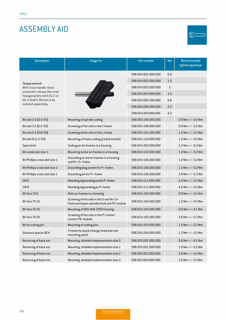
176
TOOLS
Description Usage for Part number Nm Recommended tightening torque
Torque wrenchWith cross handle. fixed. automatic release (for inner hexagonal bits with C6.3- or E6.3-shaft). Bit has to be ordered separately.
598.054.001.000.000 0.9
598.054.002.000.000 1.2
598.054.003.000.000 3
598.054.004.000.000 1.5
598.054.005.000.000 0.6
598.054.006.000.000 2.2
598.054.007.000.000 4.2
Bit slot 2.5 (0.4/70) Mounting of spindle coding 598.054.109.000.000 0.9 Nm +/– 0.2 Nm
Bit slot 3.5 (0.5/50) Screwing of the rails in the T frame 598.054.108.000.000 0.9 Nm +/– 0.2 Nm
Bit slot 5.5 (0.8/50) Screwing of the rails in the L frame 598.054.101.000.000 1.2 Nm +/– 0.2 Nm
Bit slot 8 (1.2/50) Mounting of frame coding (coded socket) 598.054.110.000.000 1.2 Nm +/– 0.2 Nm
Special bit Coding pin for frames in a housing 598.054.203.000.000 1.2 Nm +/– 0.2 Nm
Bit combi slot size 1 Mounting screw on frames in a housing 598.054.102.000.000 1.2 Nm +/– 0.2 Nm
Bit Phillips cross slot size 1Grounding screw on frames in a housing and M+/S+ frame
598.054.106.000.000 1.2 Nm +/– 0.2 Nm
Bit Phillips cross slot size 1 Grounding plug socket for P+ frame 598.054.106.000.000 1.5 Nm +/– 0.2 Nm
Bit Phillips cross slot size 1 Grounding pin for P+ frame 598.054.106.000.000 3.0 Nm +/– 0.3 Nm
SW 8 Mounting of grounding socket P+ frame 598.054.111.000.000 2.2 Nm +/– 0.3 Nm
SW 8 Mounting of grounding pin P+ frame 598.054.111.000.000 4.2 Nm +/– 0.5 Nm
Bit Torx TX 8 Rails on frames in a housing 598.054.103.000.000 0.9 Nm +/– 0.2 Nm
Bit Torx TX 10Screwing of the rails in the S and M+/S+ frame and spare spindle knob and PE-module
598.054.104.000.000 1.2 Nm +/– 0.2 Nm
Bit Torx TX 10 Mounting of ODU-MAC ZERO housing 598.054.104.000.000 0.6 Nm +/− 0.1 Nm
Bit Torx TX 20Screwing of the rails in the P+ frame/ contact PE-module
598.054.105.000.000 3.0 Nm +/– 0.3 Nm
Bit for coding pin Mounting of coding pins 598.054.203.000.000 1.2 Nm +/– 0.2 Nm
Distance spacer/QCHS frame for quick-change head and rear mounting panel
598.054.204.000.000 1.2 Nm +/– 0.2 Nm
Receiving of back nut Mounting, shielded implementation size 0 598.055.002.000.000 0.6 Nm +/– 0.1 Nm
Receiving of back nut Mounting, shielded implementation size 1 598.055.001.000.000 1.0 Nm +/– 0.2 Nm
Receiving of back nut Mounting, shielded implementation size 2 598.055.003.000.000 2.0 Nm +/– 0.2 Nm
Receiving of back nut Mounting, shielded implementation size 3 598.055.004.000.000 3.5 Nm +/– 0.3 Nm
ASSEMBLY AID
Table of Contents
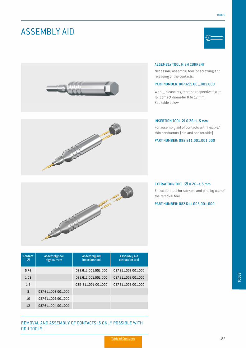
177
TOOLS
TOOL
S
Contact ∅∅
Assembly tool high current
Assembly aid insertion tool
Assembly aid extraction tool
0.76 085.611.001.001.000 087.611.005.001.000
1.02 085.611.001.001.000 087.611.005.001.000
1.5 085 .611.001.001.000 087.611.005.001.000
8 087.611.002.001.000
10 087.611.003.001.000
12 087.611.004.001.000
ASSEMBLY AID
INSERTION TOOL ∅∅ 0.76–1.5 mm
For assembly aid of contacts with flexible/thin conductors (pin and socket side).
PART NUMBER: 085.611.001.001.000
ASSEMBLY TOOL HIGH CURRENT
Necessary assembly tool for screwing and releasing of the contacts.
PART NUMBER: 087.611.00–.001.000
With – please register the respective figure for contact diameter 8 to 12 mm. See table below.
EXTRACTION TOOL ∅∅ 0.76–1.5 mm
Extraction tool for sockets and pins by use of the removal tool.
PART NUMBER: 087.611.005.001.000
REMOVAL AND ASSEMBLY OF CONTACTS IS ONLY POSSIBLE WITH ODU TOOLS.
Table of Contents
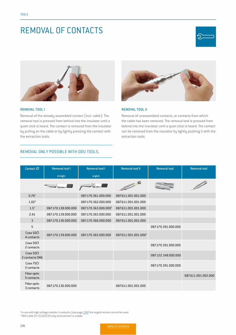
178
TOOLS
1 In use with high voltage module, 4 contacts, (see page 126) the angled version cannot be used. 2 With cable (H+S) G02232 only removal tool I is usable.
REMOVAL OF CONTACTS
Contact ∅∅ Removal tool I
straight
Removal tool I
angled
Removal tool II Removal tool Removal tool
0.762 087.170.361.000.000 087.611.001.001.000
1.022 087.170.362.000.000 087.611.001.001.000
1.52 087.170.138.000.000 087.170.363.000.0001 087.611.001.001.000
2.41 087.170.139.000.000 087.170.365.000.000 087.611.001.001.000
3 087.170.136.000.000 087.170.366.000.000 087.611.001.001.000
5 087.170.391.000.000
Coax 50Ω4 contacts
087.170.139.000.000 087.170.365.000.000 087.611.001.001.0002
Coax 50Ω2 contacts
087.170.391.000.000
Coax 50Ω2 contacts SMA
087.122.349.000.000
Coax 75Ω2 contacts
087.170.391.000.000
Fiber optic5 contacts
087.611.001.002.000
Fiber optic3 contacts
087.170.136.000.000 087.611.001.001.000
REMOVAL TOOL I
Removal of the already assembled contact (incl. cable): The removal tool is pressed from behind into the insulator until a quiet click is heard. The contact is removed from the insulator by pulling on the cable or by lightly pressing the contact with the extraction tools.
REMOVAL TOOL II
Removal of unassembled contacts, or contacts from which the cable has been removed. The removal tool is pressed from behind into the insulator until a quiet click is heard. The contact can be removed from the insulator by lightly pushing it with the extraction tools.
REMOVAL ONLY POSSIBLE WITH ODU TOOLS.
Table of Contents
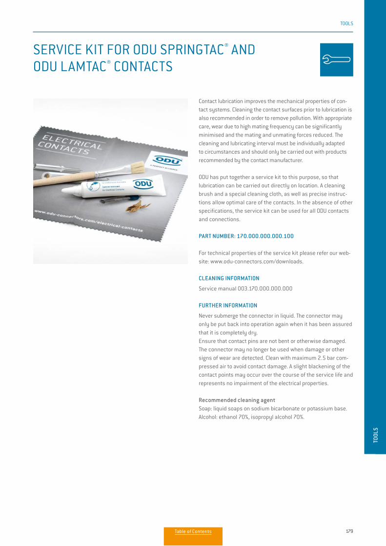
179
TOOLS
TOOL
S
Contact lubrication improves the mechanical properties of con-tact systems. Cleaning the contact surfaces prior to lubrication is also recommended in order to remove pollution. With appropriate care, wear due to high mating frequency can be significantly minimised and the mating and unmating forces reduced. The cleaning and lubricating interval must be individually adapted to circumstances and should only be carried out with products recommended by the contact manufacturer.
ODU has put together a service kit to this purpose, so that lubrication can be carried out directly on location. A cleaning brush and a special cleaning cloth, as well as precise instruc-tions allow optimal care of the contacts. In the absence of other specifications, the service kit can be used for all ODU contacts and connections.
PART NUMBER: 170.000.000.000.100
For technical properties of the service kit please refer our web-site: www.odu-connectors.com/downloads.
CLEANING INFORMATION
Service manual 003.170.000.000.000
FURTHER INFORMATION
Never submerge the connector in liquid. The connector may only be put back into operation again when it has been assured that it is completely dry. Ensure that contact pins are not bent or otherwise damaged. The connector may no longer be used when damage or other signs of wear are detected. Clean with maximum 2.5 bar com-pressed air to avoid contact damage. A slight blackening of the contact points may occur over the course of the service life and represents no impairment of the electrical properties.
Recommended cleaning agentSoap: liquid soaps on sodium bicarbonate or potassium base.Alcohol: ethanol 70%, isopropyl alcohol 70%.
SERVICE KIT FOR ODU SPRINGTAC® AND ODU LAMTAC® CONTACTS
Table of Contents
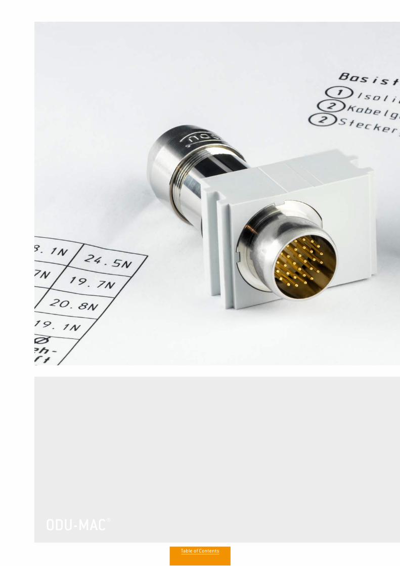
ODU-MAC®
Table of Contents
TECH
NICA
L IN
FORM
ATIO
N
TECHNICAL INFORMATIONInternational protection classes acc. IEC 60529:2013 (VDE 0470-1:2014) 182
Explanations and information according to VDE 184
Conversions / AWG 186
Operating voltage according to EIA-364-20D:2008 187
Current-carrying capacity 188
Technical terms 193
TECHNICAL INFORMATIONInternational protection classes acc. IEC 60529:2013 (VDE 0470-1:2014) 190
Explanations and details of safety requirements, tests, and voltage data 191
Voltage data acc. to “MIL” 194
Conversions/AWG (American Wire Gauge) 195
Base for current-carrying capacity 196
Current load 197
Current-carrying capacity diagrams 198
Line current load 201
Technical terms 202
TECH
NICA
L IN
FORM
ATIO
N
182
183
186
187
188
189
190
192
193
Table of Contents
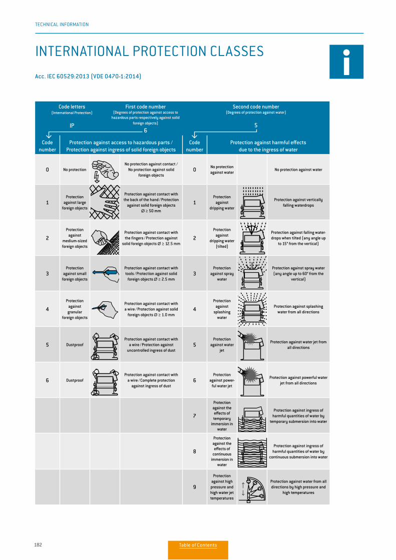
182
TECHNICAL INFORMATION
Code letters(International Protection)
IP
First code number(Degrees of protection against access to
hazardous parts respectively against solid foreign objects)
6
Second code number(Degrees of protection against water)
5
Code number
Protection against access to hazardous parts / Protection against ingress of solid foreign objects
Code number
Protection against harmful effects due to the ingress of water
0 No protectionNo protection against contact /
No protection against solid foreign objects
0 No protection against water
No protection against water
1Protection
against large foreign objects
Protection against contact with the back of the hand / Protection
against solid foreign objects ∅∅ ≥ 50 mm
1Protection
against dripping water
Protection against vertically falling waterdrops
2
Protection against
medium-sized foreign objects
Protection against contact with the fingers / Protection against solid foreign objects ∅∅ ≥ 12.5
mm
2
Protection against
dripping water (tilted)
Protection against falling water-drops when tilted (any angle up
to 15° from the vertical)
3Protection
against small foreign objects
Protection against contact with tools / Protection against solid
foreign objects ∅∅ ≥ 2.5 mm3
Protection against spray
water
Protection against spray water (any angle up to 60° from the
vertical)
4
Protection against granular
foreign objects
Protection against contact with a wire / Protection against solid
foreign objects ∅∅ ≥ 1.0 mm4
Protection against
splashing water
Protection against splashing water from all directions
5 DustproofProtection against contact with
a wire / Protection against uncontrolled ingress of dust
5Protection
against water jet
Protection against water jet from all directions
6 DustproofProtection against contact with
a wire / Complete protection against ingress of dust
6Protection
against power-ful water jet
Protection against powerful water jet from all directions
7
Protection against the effects of temporary
immersion in water
Protection against ingress of harmful quantities of water by
temporary submersion into water
8
Protection against the effects of
continuous immersion in
water
Protection against ingress of harmful quantities of water by
continuous submersion into water
9
Protection against high pressure and high water jet temperatures
Protection against water from all directions by high pressure and
high temperatures
INTERNATIONAL PROTECTION CLASSES
Acc. IEC 60529:2013 (VDE 0470-1:2014).
190
TECHNICAL INFORMATION
INTERNATIONAL PROTECTION CLASSES
Acc. IEC 60529:2013 (VDE 0470-1:2014)
Code letters(International Protection)
IP
First code number(Degrees of protection against access to
hazardous parts respectively against solid foreign objects)
6
Second code number(Degrees of protection against water)
5
Code number
Protection against access to hazardous parts / Protection against ingress of solid foreign objects
Code number
Protection against harmful effects due to the ingress of water
0 No protectionNo protection against contact /
No protection against solid foreign objects
0 No protection against water
No protection against water
1Protection
against large foreign objects
Protection against contact with the back of the hand / Protection
against solid foreign objects ∅ ≥ 50 mm
1Protection
against dripping water
Protection against vertically falling waterdrops
2
Protection against
medium-sized foreign objects
Protection against contact with the fingers / Protection against
solid foreign objects ∅ ≥ 12.5 mm2
Protection against
dripping water (tilted)
Protection against falling water-drops when tilted (any angle up
to 15° from the vertical)
3Protection
against small foreign objects
Protection against contact with tools / Protection against solid
foreign objects ∅ ≥ 2.5 mm3
Protection against spray
water
Protection against spray water (any angle up to 60° from the
vertical)
4
Protection against granular
foreign objects
Protection against contact with a wire / Protection against solid
foreign objects ∅ ≥ 1.0 mm4
Protection against
splashing water
Protection against splashing water from all directions
5 DustproofProtection against contact with
a wire / Protection against uncontrolled ingress of dust
5Protection
against water jet
Protection against water jet from all directions
6 DustproofProtection against contact with
a wire / Complete protection against ingress of dust
6Protection
against power-ful water jet
Protection against powerful water jet from all directions
7
Protection against the effects of temporary
immersion in water
Protection against ingress of harmful quantities of water by
temporary submersion into water
8
Protection against the effects of
continuous immersion in
water
Protection against ingress of harmful quantities of water by
continuous submersion into water
9
Protection against high pressure and high water jet temperatures
Protection against water from all directions by high pressure and
high temperatures
Table of Contents
183
TECHNICAL INFORMATION
TECH
NICA
L IN
FORM
ATIO
N
EXPLANATIONS AND INFORMATION ON INSULATION COORDINATION
APPLICABLE STANDARDS
IEC 60664-1:2007 (VDE 0110-1:2008) and IEC 61984:2008 (VDE 0627:2009), original (IEC 60664-1:2007 VDE 0110-1:2008) and IEC 61984:2008 (VDE 0627:2009) remains definitive for all of the technical information named).
GENERAL
The selection of a connector cannot only take functionality, number of contacts, current or voltage parameters into ac-count. In fact, consideration of the place of use and the installa-tion conditions prevailing there is indispensable.Depending upon the installation and ambient conditions, the connector can be used in accordance with the standards in a variety of voltage and current ranges. All of the voltage data listed in this catalog refers to the use of insulators in the ODU-MAC solid frame for housings or in the ODU-MAC docking frame.All of the connectors shown here involve connectors without contact rating (COC) in accordance with IEC 61984:2008 (VDE 0627:2009).
The most important influence variables and the electrical parameters harmonised with these will be explained in more detail in the following. Our technicians would be happy to assist you with any further questions. The following texts and tables are excerpts from the indicated standards.
OVERVOLTAGE CATEGORY
The necessary rated surge voltage is defined through the overvoltage category according to table F.1 together with the nominal voltage used. Depending upon the installation location, the respective overvoltage category is selected according to the criteria listed below for operating media that is fed directly from the low voltage mains.
Overvoltage category IOperating media for connection to circuits in which measures for limiting the transient overvoltages to an appropriately low value have been taken. For example, connectors for the voltage supply of computer hardware permanently connected to a power supply with electronic overvoltage limitation.
Overvoltage category IIOperating media fed by the fixed installation that consume energy. For example, household devices, portable tools and similar devices.
Overvoltage category III(= standard, when no special overvoltage category is indicated) Operating media in permanent installations and cases for which special requirements for reliability and availability of the operating media exist. For example, switches in permanent installations and operating media for industrial use with perma-nent connection to the permanent installation.
Overvoltage category IVOperating media for use at the termination point of the instal-lation. For example, electricity meters and primary overcurrent protection devices.
IEC 60664-1:2007 (VDE 0110-1:2008): TABLE F.1 – RATED SURGE VOLTAGE FOR OPERATING MEDIA FED DIRECTLY FROM THE LOW VOLTAGE MAINS.
Nominal voltage of the power supply system (net-work) acc. to IEC 60038:2009 (VDE 0175-1:2012)
Voltage conductor to neutral conductor
derived from nominal voltages a.c. or d.c. up to and including
V
Rated impulse voltageOvervoltage category
Three-phase-system V
Single-phase-system
V IV
IIV
IIIV
IVV
50 330 500 800 1,500
100 500 800 1,500 2,500
120 to 240 160 800 1,500 2,500 4,000
230 / 400 277 / 480 300 1,500 2,500 4,000 5,000
400 / 692 600 2,500 4,000 6,000 8,000
1,000 1,000 4,000 6,000 8,000 12,000
191
TECHNICAL INFORMATION
GENERAL
All the technical information listed in this catalog and the data sheets has been determined by drawing on various standards. Soweit nicht anders angegeben, wurde die Norm Unless otherwise stated, standard IEC 61984:2008 (VDE 0627:2009) “Connectors – Safety requirements and tests” has been usedto dimension and determine the values provided.
This international standard applies to connectors (with rated voltages of 50 V to 1,000 V alternating and direct, and rated currents of up to 125 A per contact) which either have no typespecification or which have a type specification whose safetyrequirements refer to this standard. The standard can be used as a guide for connectors with rated voltages up to 50 V. In cases such as this, IEC 60664-1:2007 must be consulted when dimensioning the clearance and creepage distances. This standard can also serve as a guide for connectors with rated currents higher than 125 A per pole.
All the connectors shown here are connectors without brea-king capacity (COC) according to IEC 61984:2008 (VDE 0627:2009).
All of the voltage data listed in this catalog refers to the use of insulators, which have been installed according to assembly regulations in the ODU MAC® frame for housings or in theODU-MAC® docking frame. Customer-specific attachments, which could reduce the clearance and creepage distances, have not been taken into account here.
The clearance and creepage distances are determined on the bases specified in IEC 60664-1:2007 (VDE 0110-1:2008).
The most important influence variables and the electrical para-meters harmonized with these will be explained in more detail in the following. We would be happy to assist you with any further questions. The texts and tables given here are excerpts from the indicated standards. As a rule, product committees lay down application-specific safety requirements for various fields of use; these requirements also regulate the insulation coordination and inspection of connectors.
In such cases, the “product standards” take precedence and must be observed instead of the “basic safety standards”
stated here. However, since this catalog and the technical data sheets cannot take all product standards into consideration,we have restricted ourselves to the following standard in terms of voltage data:
IEC 60664-1:2007 (VDE 0110-1:2008) “INSULATION COORDINATION FOR EQUIPMENT WITHIN LOW-VOLTAGE SYSTEMS”
This is what is known as a basic safety standard, which regula-tes the minimum requirements for dimensioning clearance and creepage distances, as well as their inspection. The standard applies to equipment used up to an altitude of 2,000 m above sea level and with a rated alternating voltage of up to 1,000 Vand a nominal frequency of up to 30 kHz or a rated direct voltage of up to 1,500 V. It applies in those cases where corresponding product standards do not define any values for clearance and creepage distances, nor lay down any require-ments for solid insulation, or where no product standards are even available.
The permissible overvoltage and the rated voltage may be sig-nificantly influenced by the use of blank modules and varying positioning of the contacts in the insulators.
The following general specifications have been defined for dimensioning:
• Isolation between electrical circuits (functional insulation between the contacts) or between an electrical circuit and local ground (contact with grounded frame) has been dimensioned as basic insulation. If “double insulation” or “reinforced insulation” is required, the voltage data provided may no longer apply; insulating clearances may need to be extended.
• Overvoltage category III is used, along with the TT and TN system types, to dimension the rated impulse voltage.
• Condition A is always used for the inhomogeneous field when dimensioning the clearance distances used.• The inspections prescribed for solid insulation and for clea-
rance distances (if necessary) are conducted as alternating voltage inspections according to Table F.5.
• The clearance and creepage distances are determined on the bases specified in this standard.
ERLÄUTERUNGEN UND ANGABEN ZU SICHERHEITSANFORDERUNGEN, PRÜFUNGEN UND SPANNUNGSANGABEN
TECH
NICA
L IN
FORM
ATIO
N
Table of Contents
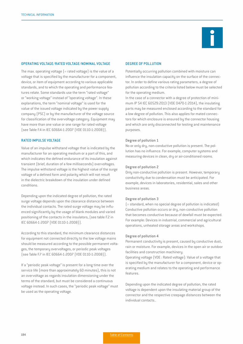
184
TECHNICAL INFORMATION
DEGREE OF POLLUTION
Potentially occurring pollution combined with moisture can influence the insulation capacity on the surface of the connec-tor. In order to define various rating parameters, a degree of pollution according to the criteria listed below must be selected for the operating medium.In the case of a connector with a degree of protection of mini-mum IP 54 IEC 60529:2013 (VDE 0470-1:2014), the insulating parts may be measured enclosed according to the standard for a low degree of pollution. This also applies for mated connec-tors for which enclosure is ensured by the connector housing and which are only disconnected for testing and maintenance purposes.
Degree of pollution 1No or only dry, non-conductive pollution is present. The pol-lution has no influence. For example, computer systems and measuring devices in clean, dry or air-conditioned rooms.
Degree of pollution 2Only non-conductive pollution is present. However, temporary conductivity due to condensation must be anticipated. For example, devices in laboratories, residential, sales and other business areas.
Degree of pollution 3(= standard, when no special degree of pollution is indicated) Conductive pollution occurs or dry, non-conductive pollution that becomes conductive because of dewfall must be expected. For example: Devices in industrial, commercial and agricultural operations, unheated storage areas and workshops.
Degree of pollution 4Permanent conductivity is present, caused by conductive dust, rain or moisture. For example, devices in the open air or outdoor facilities and construction machinery. Operating voltage (VDE : Rated voltage): Value of a voltage that is specified by the manufacturer for a component, device or op-erating medium and relates to the operating and performance features.
Depending upon the indicated degree of pollution, the rated voltage is dependent upon the insulating material group of the connector and the respective creepage distances between the individual contacts. The rated voltage may be significantly influenced by the use of blank modules and varying position-ing of the contacts in the insulator. Operating media may have more than one value or one range for rated voltage (see table F.4 in IEC 60664-1:2007 (VDE 0110-1:2008)).
NOMINAL VOLTAGE
A suitably rounded voltage value indicated by the manufacturer for the designation or identification of an operating medium. In these explanations, the term nominal voltage is used for the value of the issued voltage indicated by the power supply company (PSC) or by the manufacturer of the voltage source for classification of the overvoltage category.
RATED IMPULSE VOLTAGE
Value of an impulse withstand voltage that is indicated by the manufacturer for an operating medium or a part of this, and which indicates the defined endurance of its insulation against transient (brief, duration of a few milliseconds) overvoltages. The impulse withstand voltage is the highest value of the surge voltage of a defined form and polarity which will not result in the dielectric breakdown of the insulation under defined conditions.Depending upon the indicated degree of pollution, the rated surge voltage depends upon the clearance distance between the individual contacts. The rated surge voltage may be influ-enced significantly by the usage of blank modules and varied positioning of the contacts in the insulators, (see table F.2 in IEC 60664-1:2007 (VDE 0110-1:2008)). In the most recent edition of IEC 60664-1:2007 (VDE 0110-1:2008), the minimum clearance distances for operating media not connected directly to the low voltage mains should be measured according to the possible permanent voltages, the temporary overvoltages or periodic peak voltages (see table F.7 in IEC 60664-1:2007 (VDE 0110-1:2008)).
EXPLANATIONS AND INFORMATION ACCORDING TO VDE
192
TECHNICAL INFORMATION
OPERATING VOLTAGE/RATED VOLTAGE/NOMINAL VOLTAGE
The max. operating voltage (= rated voltage) is the value of a voltage that is specified by the manufacturer for a component, device, or item of equipment according to various applicable standards, and to which the operating and performance fea-tures relate. Some standards use the term “rated voltage”or “working voltage” instead of “operating voltage”. In these explanations, the term “nominal voltage” is used for thevalue of the issued voltage indicated by the power supply company (PSC) or by the manufacturer of the voltage sourcefor classification of the overvoltage category. Equipment may have more than one value or one range for rated voltage(see Table F.4 in IEC 60664-1:2007 (VDE 0110-1:2008)).
RATED IMPULSE VOLTAGE
Value of an impulse withstand voltage that is indicated by the manufacturer for an operating medium or a part of this, and which indicates the defined endurance of its insulation against transient (brief, duration of a few milliseconds) overvoltages. The impulse withstand voltage is the highest value of the surge voltage of a defined form and polarity which will not result in the dielectric breakdown of the insulation under defined conditions.
Depending upon the indicated degree of pollution, the rated surge voltage depends upon the clearance distance between the individual contacts. The rated surge voltage may be influ-enced significantly by the usage of blank modules and varied positioning of the contacts in the insulators, (see table F.2 in IEC 60664-1:2007 (VDE 0110-1:2008)).
According to this standard, the minimum clearance distances for equipment not connected directly to the low voltage mains should be measured according to the possible permanent volta-ges, the temporary overvoltages, or periodic peak voltages(see Table F.7 in IEC 60664-1:2007 (VDE 0110-1:2008)).
If a “periodic peak voltage” is present for a long time over the service life (more than approximately 60 minutes), this is not an overvoltage as regards insulation dimensioning under theterms of the standard, but must be considered a continuous voltage instead. In such cases, the “periodic peak voltage” must be used as the operating voltage.
DEGREE OF POLLUTION
Potentially occurring pollution combined with moisture can influence the insulation capacity on the surface of the connec-tor. In order to define various rating parameters, a degree of pollution according to the criteria listed below must be selected for the operating medium.In the case of a connector with a degree of protection of mini-mum IP 54 IEC 60529:2013 (VDE 0470-1:2014), the insulating parts may be measured enclosed according to the standard for a low degree of pollution. This also applies for mated connec-tors for which enclosure is ensured by the connector housing and which are only disconnected for testing and maintenance purposes.
Degree of pollution 1No or only dry, non-conductive pollution is present. The pol-lution has no influence. For example, computer systems and measuring devices in clean, dry or air-conditioned rooms.
Degree of pollution 2Only non-conductive pollution is present. However, temporary conductivity due to condensation must be anticipated. For example, devices in laboratories, residential, sales and other business areas.
Degree of pollution 3(= standard, when no special degree of pollution is indicated) Conductive pollution occurs or dry, non-conductive pollution that becomes conductive because of dewfall must be expected. For example: Devices in industrial, commercial and agricultural operations, unheated storage areas and workshops.
Degree of pollution 4Permanent conductivity is present, caused by conductive dust, rain or moisture. For example, devices in the open air or outdoor facilities and construction machinery. Operating voltage (VDE : Rated voltage): Value of a voltage that is specified by the manufacturer for a component, device or op-erating medium and relates to the operating and performance features.
Depending upon the indicated degree of pollution, the rated voltage is dependent upon the insulating material group of the connector and the respective creepage distances between the individual contacts..
Table of Contents
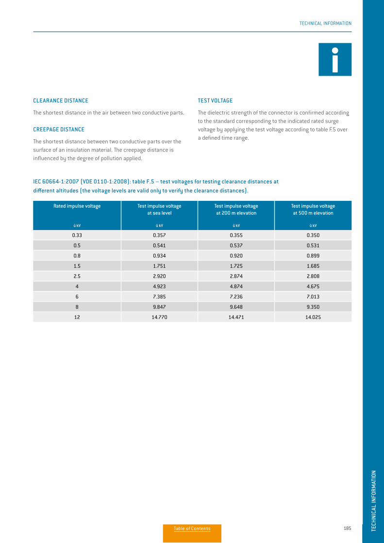
185
TECHNICAL INFORMATION
TECH
NICA
L IN
FORM
ATIO
N
IMPULSE TEST VOLTAGE / POWER FREQUENCY TEST VOLTAGE
Highest value of the surge voltage of a defined form and polar-ity that will not result in a dielectric breakdown or flashover of the insulation under defined conditions.
CLEARANCE DISTANCE
The shortest distance in the air between two conductive parts.
CREEPAGE DISTANCE
The shortest distance between two conductive parts over the surface of an insulation material. The creepage distance is influenced by the degree of pollution applied.
TEST VOLTAGE
The dielectric strength of the connector is confirmed according to the standard corresponding to the indicated rated surge voltage by applying the test voltage according to table F.5 over a defined time range.
IEC 60664-1:2007 (VDE 0110-1:2008): table F.5 – test voltages for testing clearance distances at different altitudes (the voltage levels are valid only to verify the clearance distances).
Rated impulse voltage
û kV
Test impulse voltageat sea level
û kV
Test impulse voltageat 200 m elevation
û kV
Test impulse voltageat 500 m elevation
û kV
0.33 0.357 0.355 0.350
0.5 0.541 0.537 0.531
0.8 0.934 0.920 0.899
1.5 1.751 1.725 1.685
2.5 2.920 2.874 2.808
4 4.923 4.874 4.675
6 7.385 7.236 7.013
8 9.847 9.648 9.350
12 14.770 14.471 14.025
193
TECHNICAL INFORMATION
CLEARANCE DISTANCE
The shortest distance in the air between two conductive parts.
CREEPAGE DISTANCE
The shortest distance between two conductive parts over the surface of an insulation material. The creepage distance is influenced by the degree of pollution applied.
TEST VOLTAGE
The dielectric strength of the connector is confirmed according to the standard corresponding to the indicated rated surge voltage by applying the test voltage according to table F.5 over a defined time range.
IEC 60664-1:2007 (VDE 0110-1:2008): table F.5 – test voltages for testing clearance distances at different altitudes (the voltage levels are valid only to verify the clearance distances).
Rated impulse voltage
û kV
Test impulse voltageat sea level
û kV
Test impulse voltageat 200 m elevation
û kV
Test impulse voltageat 500 m elevation
û kV
0.33 0.357 0.355 0.350
0.5 0.541 0.537 0.531
0.8 0.934 0.920 0.899
1.5 1.751 1.725 1.685
2.5 2.920 2.874 2.808
4 4.923 4.874 4.675
6 7.385 7.236 7.013
8 9.847 9.648 9.350
12 14.770 14.471 14.025
TECH
NICA
L IN
FORM
ATIO
N
Table of Contents
186
TECHNICAL INFORMATION
Circular wire
AWG Diameter Cross- section
mm2
Weight
kg/km
Max. resis tance
Ω/kmInch mm
4/0 [259/21] 0.6010 15.300 107.0 997.00 0.17
3/0 [259/22] 0.5360 13.600 85.0 793.00 0.22
2/0 [259/23] 0.4770 12.100 67.4 628.00 0.27
1/0 [259/24] 0.4240 10.800 53.5 497.00 0.34
1 [259/25] 0.3780 9.600 42.2 395.00 0.43
2 [259/26] 0.3350 8.500 33.6 312.00 0.55
4 [133/25] 0.2660 6.800 21.1 195.00 0.87
6 [133/27] 0.2100 5.300 13.3 122.00 1.38
8 [133/29] 0.1670 4.200 8.37 76.80 2.18
10 [1] 0.1019 2.590 5.26 46.77 3.45
10 [37/26] 0.1150 2.921 4.74 42.10 4.13
12 [1] 0.0808 2.050 3.31 29.41 5.45
12 [19/25] 0.0930 2.362 3.08 27.36 5.94
12 [37/28] 0.0910 2.311 2.97 26.45 6.36
14 [1] 0.0641 1.630 2.08 18.51 8.79
14 [19/27] 0.0730 1.854 1.94 17.23 9.94
16 [1] 0.0508 1.290 1.31 11.625 13.94
16 [19/29] 0.0590 1.499 1.23 10.928 15.70
18 [1] 0.0403 1.020 0.823 7.316 22.18
20 [1] 0.0320 0.813 0.519 4.613 35.10
20 [7/28] 0.0390 0.991 0.563 5.003 34.10
20 [19/32] 0.0420 1.067 0.616 5.473 32.00
22 [1] 0.0253 0.643 0.324 2.883 57.70
22 [19/34] 0.0330 0.838 0.382 3.395 51.80
24 [1] 0.0201 0.511 0.205 1.820 91.20
24 [7/32] 0.0250 0.635 0.227 2.016 86.00
24 [19/36] 0.0270 0.686 0.241 2.145 83.30
26 [1] 0.0159 0.404 0.128 1.139 147.00
26 [7/34] 0.0200 0.508 0.141 1.251 140.00
26 [19/38] 0.0220 0.559 0.154 1.370 131.00
28 [1] 0.0126 0.320 0.0804 0.715 231.00
28 [7/36] 0.0160 0.406 0.0889 0.790 224.00
28 [19/40] 0.0170 0.432 0.0925 0.823 207.00
30 [1] 0.0100 0.254 0.0507 0.450 374.00
30 [7/38] 0.0130 0.330 0.0568 0.505 354.00
32 [1] 0.0080 0.203 0.0324 0.288 561.00
32 [7/40] 0.0110 0.279 0.0341 0.303 597.10
34 [1] 0.0063 0.160 0.0201 0.179 951.00
34 [7/42] 0.0070 0.180 0.0222 0.197 1,491.00
36 [1] 0.0050 0.127 0.0127 0.1126 1,519.00
36 [7/44] 0.0060 0.150 0.0142 0.1263 1,322.00 Source: ASTM
The American Wire Gauge (AWG) is based on the principle that the cross-section of the wire chang-es by 26% from one gauge number to the next. The AWG numbers decrease as the wire diameter increases, while the AWG numbers increase as the wire diameter decreases. This only applies to solid wire.
However, stranded wire is predominately used in practice. This has the advantage of a longer service life under bending and vibration as well as greater flexibility in comparison with solid wire.
Stranded wires are made of multiple, smaller- gauge wires (higher AWG number). The stranded wire then receives the AWG numbers of a solid wire with the next closest cross-section to that of the stranded wire. In this case, the cross-section of the stranded wire refers to the sum of the cop-per cross-sections of the individual wires.
Accordingly, strands with the same AWG number but different numbers of wires differ in cross- section. For instance, an AWG 20 strand of 7 AWG 28 wires has a cross-section of 0.563 mm², while an AWG 20 strand of 19 AWG 32 wires has a cross- section of 0.616 mm².
CONVERSIONS/AWG (AMERICAN WIRE GAUGE)
194
TECHNICAL INFORMATION
The withstanding voltage values stated in this catalog were determined according to the method described in EIA-364-20F:2019 “Withstanding Voltage – Test Procedure for Electrical connectors, Sockets and Coaxial Con-tacts”. The inserts were tested while mated, and the test voltage was applied to the pin insert.
75% of the calculated dielectric withstanding voltage is used as the test voltage for further calculations. The operating voltage is 1/3 of this value.
This standard refers to IEC 60512-4-1:2003 “Connectors for electronic equipment – Tests and measurements –Part 4-1: Voltage stress tests – Test 4a:Voltage proof”.
If there are any deviations, the derating factors are to be factored in according to the applicable standards.All tests were conducted at the prescribed indoor climate and apply up to an altitude of 2,000 m.
Test voltage: Dielectric withstanding voltage × 0.75Operating voltage: Dielectric withstanding voltage × 0.75 × 0.33
EIA-364-20F:2019 „Withstanding Voltage – Test Procedure for Electrical connectors, Sockets and Coaxial Contacts“
VOLTAGE DATA ACC. TO “MIL”
Table of Contents
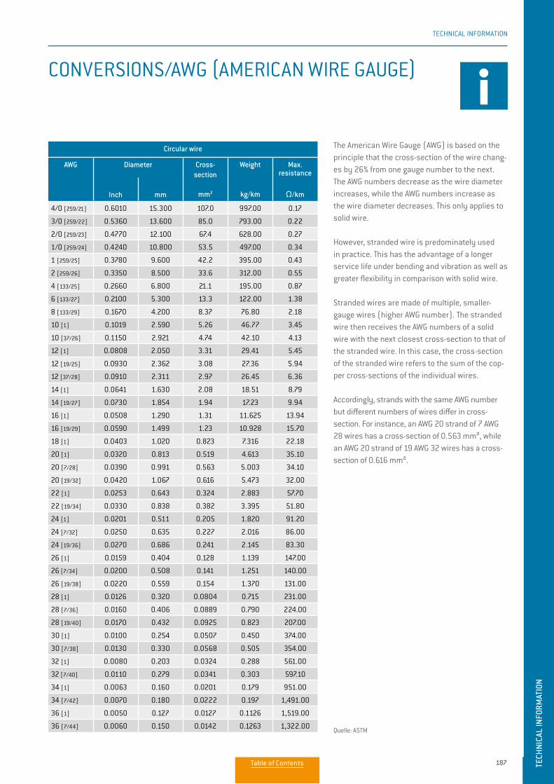
187
TECHNICAL INFORMATION
TECH
NICA
L IN
FORM
ATIO
N
The values specified in the catalog correspond to SAE AS 13441:2004 method 3001.1. The table values were deter-mined according to EIA 364-20D:2008. The inserts were tested while mated, and the test current was applied to the pin insert.
75% of the dielectric withstanding voltage is used for the further calculation. The operating voltage is 1/3 of this value.
All tests were conducted at normal indoor climate and apply up to an altitude of 2,000 m. If there are any deviations, the derating factors are to be factored in according to the applicable standards.
ATTENTION:With certain applications, the safety requirements for electrical devices are very strict in terms of operating voltage. In such cases, the operating voltage is defined according to the clearance and creepage distances between parts which could be touched.
When selecting such a connector, please contact us and let us know the safety standard which the product must meet.
Test voltage: Dielectric withstanding voltage × 0.75Operating voltage: Dielectric withstanding voltage × 0.75 × 0.33
OPERATING VOLTAGE
EIA-364-20D:2008 (SAE AS 13441:2004 method 3001.1).
195
TECHNICAL INFORMATION
Circular wire
AWG Diameter Cross- section
mm2
Weight
kg/km
Max. resis tance
Ω/kmInch mm
4/0 [259/21] 0.6010 15.300 107.0 997.00 0.17
3/0 [259/22] 0.5360 13.600 85.0 793.00 0.22
2/0 [259/23] 0.4770 12.100 67.4 628.00 0.27
1/0 [259/24] 0.4240 10.800 53.5 497.00 0.34
1 [259/25] 0.3780 9.600 42.2 395.00 0.43
2 [259/26] 0.3350 8.500 33.6 312.00 0.55
4 [133/25] 0.2660 6.800 21.1 195.00 0.87
6 [133/27] 0.2100 5.300 13.3 122.00 1.38
8 [133/29] 0.1670 4.200 8.37 76.80 2.18
10 [1] 0.1019 2.590 5.26 46.77 3.45
10 [37/26] 0.1150 2.921 4.74 42.10 4.13
12 [1] 0.0808 2.050 3.31 29.41 5.45
12 [19/25] 0.0930 2.362 3.08 27.36 5.94
12 [37/28] 0.0910 2.311 2.97 26.45 6.36
14 [1] 0.0641 1.630 2.08 18.51 8.79
14 [19/27] 0.0730 1.854 1.94 17.23 9.94
16 [1] 0.0508 1.290 1.31 11.625 13.94
16 [19/29] 0.0590 1.499 1.23 10.928 15.70
18 [1] 0.0403 1.020 0.823 7.316 22.18
20 [1] 0.0320 0.813 0.519 4.613 35.10
20 [7/28] 0.0390 0.991 0.563 5.003 34.10
20 [19/32] 0.0420 1.067 0.616 5.473 32.00
22 [1] 0.0253 0.643 0.324 2.883 57.70
22 [19/34] 0.0330 0.838 0.382 3.395 51.80
24 [1] 0.0201 0.511 0.205 1.820 91.20
24 [7/32] 0.0250 0.635 0.227 2.016 86.00
24 [19/36] 0.0270 0.686 0.241 2.145 83.30
26 [1] 0.0159 0.404 0.128 1.139 147.00
26 [7/34] 0.0200 0.508 0.141 1.251 140.00
26 [19/38] 0.0220 0.559 0.154 1.370 131.00
28 [1] 0.0126 0.320 0.0804 0.715 231.00
28 [7/36] 0.0160 0.406 0.0889 0.790 224.00
28 [19/40] 0.0170 0.432 0.0925 0.823 207.00
30 [1] 0.0100 0.254 0.0507 0.450 374.00
30 [7/38] 0.0130 0.330 0.0568 0.505 354.00
32 [1] 0.0080 0.203 0.0324 0.288 561.00
32 [7/40] 0.0110 0.279 0.0341 0.303 597.10
34 [1] 0.0063 0.160 0.0201 0.179 951.00
34 [7/42] 0.0070 0.180 0.0222 0.197 1,491.00
36 [1] 0.0050 0.127 0.0127 0.1126 1,519.00
36 [7/44] 0.0060 0.150 0.0142 0.1263 1,322.00 Quelle: ASTM
The American Wire Gauge (AWG) is based on the principle that the cross-section of the wire chang-es by 26% from one gauge number to the next. The AWG numbers decrease as the wire diameter increases, while the AWG numbers increase as the wire diameter decreases. This only applies to solid wire.
However, stranded wire is predominately used in practice. This has the advantage of a longer service life under bending and vibration as well as greater flexibility in comparison with solid wire.
Stranded wires are made of multiple, smaller- gauge wires (higher AWG number). The stranded wire then receives the AWG numbers of a solid wire with the next closest cross-section to that of the stranded wire. In this case, the cross-section of the stranded wire refers to the sum of the cop-per cross-sections of the individual wires.
Accordingly, strands with the same AWG number but different numbers of wires differ in cross- section. For instance, an AWG 20 strand of 7 AWG 28 wires has a cross-section of 0.563 mm², while an AWG 20 strand of 19 AWG 32 wires has a cross- section of 0.616 mm².
CONVERSIONS/AWG (AMERICAN WIRE GAUGE)
TECH
NICA
L IN
FORM
ATIO
N
Table of Contents
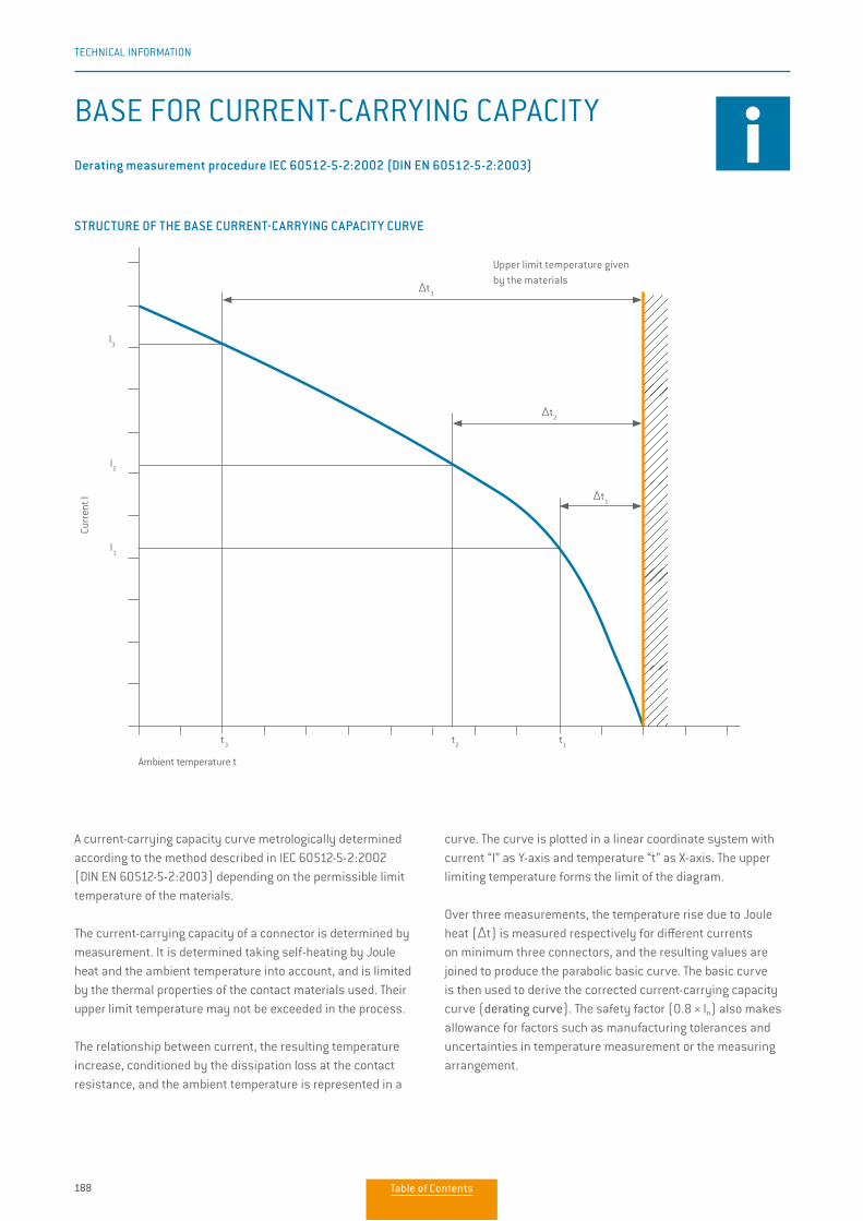
188
TECHNICAL INFORMATION
BASE FOR CURRENT-CARRYING CAPACITY
A current-carrying capacity curve metrologically determined according to the method described in IEC 60512-5-2:2002 (DIN EN 60512-5-2:2003) depending on the permissible limit temperature of the materials.
The current-carrying capacity of a connector is determined by measurement. It is determined taking self-heating by Joule heat and the ambient temperature into account, and is limited by the thermal properties of the contact materials used. Their upper limit temperature may not be exceeded in the process.
The relationship between current, the resulting temperature increase, conditioned by the dissipation loss at the contact resistance, and the ambient temperature is represented in a
curve. The curve is plotted in a linear coordinate system with current “I” as Y-axis and temperature “t” as X-axis. The upper limiting temperature forms the limit of the diagram.
Over three measurements, the temperature rise due to Joule heat (∆t) is measured respectively for different currents on minimum three connectors, and the resulting values are joined to produce the parabolic basic curve. The basic curve is then used to derive the corrected current-carrying capacity curve (derating curve). The safety factor (0.8 × ln) also makes allowance for factors such as manufacturing tolerances and uncertainties in temperature measurement or the measuring arrangement.
Derating measurement procedure IEC 60512-5-2:2002 (DIN EN 60512-5-2:2003).
Ambient temperature t
Curr
ent I
I3
I2
I1
t3
t2
t1
∆t1
∆t2
∆t3
STRUCTURE OF THE BASE CURRENT-CARRYING CAPACITY CURVE
Upper limit temperature givenby the materials
196
TECHNICAL INFORMATION
BASE FOR CURRENT-CARRYING CAPACITY
I3
I2
I1
t3
t2
t1
∆t1
∆t2
∆t3
A current-carrying capacity curve metrologically determined according to the method described in IEC 60512-5-2:2002 (DIN EN 60512-5-2:2003) depending on the permissible limit temperature of the materials.
The current-carrying capacity of a connector is determined by measurement. It is determined taking self-heating by Joule heat and the ambient temperature into account, and is limited by the thermal properties of the contact materials used. Their upper limit temperature may not be exceeded in the process.
The relationship between current, the resulting temperature increase, conditioned by the dissipation loss at the contact resistance, and the ambient temperature is represented in a
curve. The curve is plotted in a linear coordinate system with current “I” as Y-axis and temperature “t” as X-axis. The upper limiting temperature forms the limit of the diagram.
Over three measurements, the temperature rise due to Joule heat (∆t) is measured respectively for different currents on minimum three connectors, and the resulting values are joined to produce the parabolic basic curve. The basic curve is then used to derive the corrected current-carrying capacity curve (derating curve). The safety factor (0.8 × ln) also makes allowance for factors such as manufacturing tolerances and uncertainties in temperature measurement or the measuring arrangement.
Derating measurement procedure IEC 60512-5-2:2002 (DIN EN 60512-5-2:2003)
Ambient temperature t
Curr
ent I
STRUCTURE OF THE BASE CURRENT-CARRYING CAPACITY CURVE
Upper limit temperature givenby the materials
Table of Contents
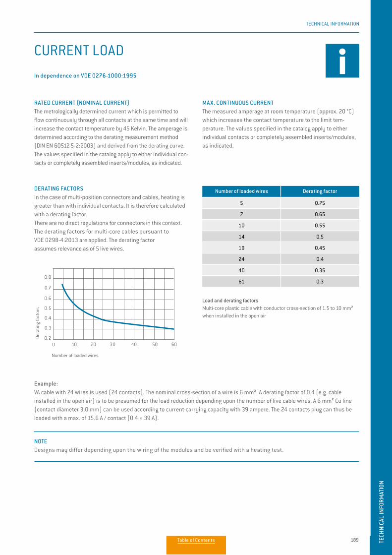
189
TECHNICAL INFORMATION
TECH
NICA
L IN
FORM
ATIO
N
CURRENT LOAD
DERATING FACTORSIn the case of multi-position connectors and cables, heating is greater than with individual contacts. It is therefore calculated with a derating factor. There are no direct regulations for connectors in this context. The derating factors for multi-core cables pursuant to VDE 0298-4:2013 are applied. The derating factor assumes relevance as of 5 live wires.
Example: VA cable with 24 wires is used (24 contacts). The nominal cross-section of a wire is 6 mm². A derating factor of 0.4 (e.g. cable installed in the open air) is to be presumed for the load reduction depending upon the number of live cable wires. A 6 mm² Cu line (contact diameter 3.0 mm) can be used according to current-carrying capacity with 39 ampere. The 24 contacts plug can thus be loaded with a max. of 15.6 A / contact (0.4 × 39 A).
(In dependence on VDE 0276-1000:1995).
Number of loaded wires Derating factor
5 0.75
7 0.65
10 0.55
14 0.5
19 0.45
24 0.4
40 0.35
61 0.3
Load and derating factorsMulti-core plastic cable with conductor cross-section of 1.5 to 10 mm² when installed in the open air.
Number of loaded wires
Dera
ting
fact
ors
0 10
0.8
0.7
0.6
0.5
0.4
0.3
0.23020 40 50 60
RATED CURRENT (NOMINAL CURRENT)The metrologically determined current which is permitted to flow continuously through all contacts at the same time and will increase the contact temperature by 45 Kelvin. The amperage is determined according to the derating measurement method (DIN EN 60512-5-2:2003) and derived from the derating curve. The values specified in the catalog apply to either individual con-tacts or completely assembled inserts/modules, as indicated.
MAX. CONTINUOUS CURRENTThe measured amperage at room temperature (approx. 20 °C) which increases the contact temperature to the limit tem-perature. The values specified in the catalog apply to either individual contacts or completely assembled inserts/modules, as indicated.
NOTE Designs may differ depending upon the wiring of the modules and be verified with a heating test.
197
TECHNICAL INFORMATION
CURRENT LOAD
DERATING FACTORSIn the case of multi-position connectors and cables, heating is greater than with individual contacts. It is therefore calculated with a derating factor. There are no direct regulations for connectors in this context. The derating factors for multi-core cables pursuant to VDE 0298-4:2013 are applied. The derating factor assumes relevance as of 5 live wires.
Example: VA cable with 24 wires is used (24 contacts). The nominal cross-section of a wire is 6 mm². A derating factor of 0.4 (e.g. cable installed in the open air) is to be presumed for the load reduction depending upon the number of live cable wires. A 6 mm² Cu line (contact diameter 3.0 mm) can be used according to current-carrying capacity with 39 ampere. The 24 contacts plug can thus be loaded with a max. of 15.6 A / contact (0.4 × 39 A).
In dependence on VDE 0276-1000:1995
Number of loaded wires Derating factor
5 0.75
7 0.65
10 0.55
14 0.5
19 0.45
24 0.4
40 0.35
61 0.3
Load and derating factorsMulti-core plastic cable with conductor cross-section of 1.5 to 10 mm² when installed in the open air
Number of loaded wires
Dera
ting
fact
ors
0 10
0.8
0.7
0.6
0.5
0.4
0.3
0.23020 40 50 60
RATED CURRENT (NOMINAL CURRENT)The metrologically determined current which is permitted to flow continuously through all contacts at the same time and will increase the contact temperature by 45 Kelvin. The amperage is determined according to the derating measurement method (DIN EN 60512-5-2:2003) and derived from the derating curve. The values specified in the catalog apply to either individual con-tacts or completely assembled inserts/modules, as indicated.
MAX. CONTINUOUS CURRENTThe measured amperage at room temperature (approx. 20 °C) which increases the contact temperature to the limit tem-perature. The values specified in the catalog apply to either individual contacts or completely assembled inserts/modules, as indicated.
NOTE Designs may differ depending upon the wiring of the modules and be verified with a heating test.
TECH
NICA
L IN
FORM
ATIO
N
Table of Contents
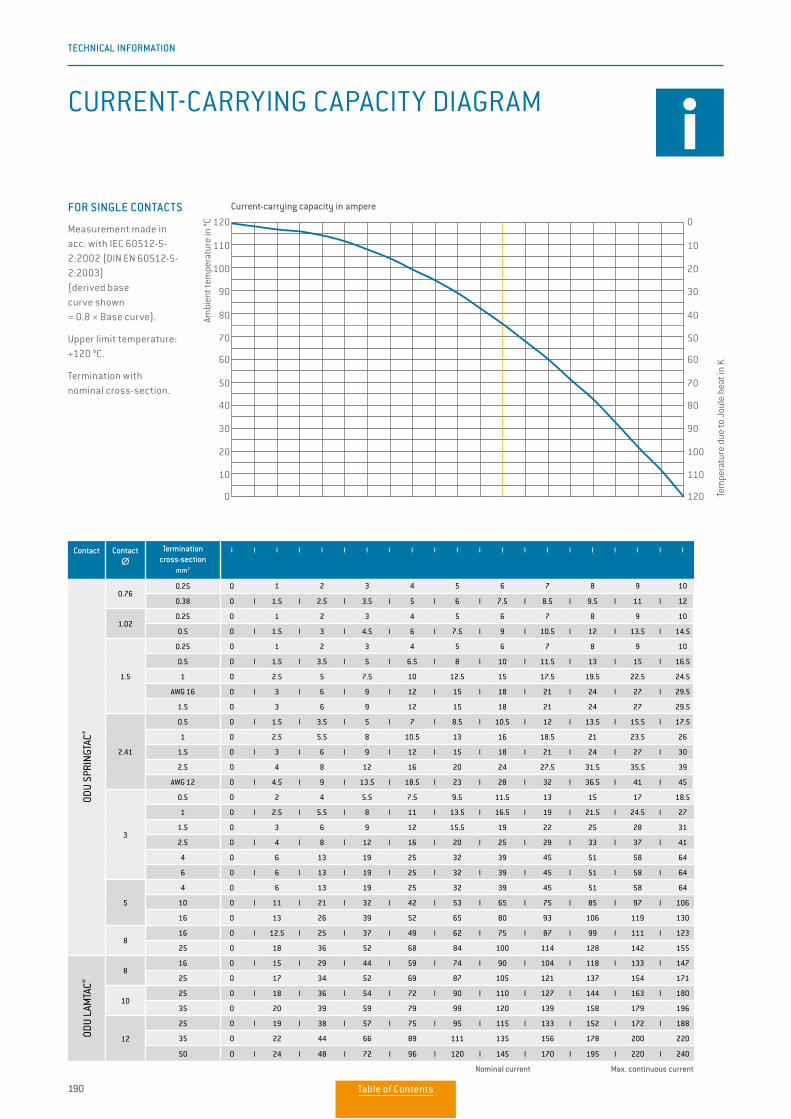
190
TECHNICAL INFORMATION
Contact Contact ∅∅
Termination cross-section
mm2
I I I I I I I I I I I I I I I I I I I I I
ODU
SPRI
NGTA
C®
0.760.25 0 1 2 3 4 5 6 7 8 9 10
0.38 0 I 1.5 I 2.5 I 3.5 I 5 I 6 I 7.5 I 8.5 I 9.5 I 11 I 12
1.020.25 0 1 2 3 4 5 6 7 8 9 10
0.5 0 I 1.5 I 3 I 4.5 I 6 I 7.5 I 9 I 10.5 I 12 I 13.5 I 14.5
1.5
0.25 0 1 2 3 4 5 6 7 8 9 10
0.5 0 I 1.5 I 3.5 I 5 I 6.5 I 8 I 10 I 11.5 I 13 I 15 I 16.5
1 0 2.5 5 7.5 10 12.5 15 17.5 19.5 22.5 24.5
AWG 16 0 I 3 I 6 I 9 I 12 I 15 I 18 I 21 I 24 I 27 I 29.5
1.5 0 3 6 9 12 15 18 21 24 27 29.5
2.41
0.5 0 I 1.5 I 3.5 I 5 I 7 I 8.5 I 10.5 I 12 I 13.5 I 15.5 I 17.5
1 0 2.5 5.5 8 10.5 13 16 18.5 21 23.5 26
1.5 0 I 3 I 6 I 9 I 12 I 15 I 18 I 21 I 24 I 27 I 30
2.5 0 4 8 12 16 20 24 27.5 31.5 35.5 39
AWG 12 0 I 4.5 I 9 I 13.5 I 18.5 I 23 I 28 I 32 I 36.5 I 41 I 45
3
0.5 0 2 4 5.5 7.5 9.5 11.5 13 15 17 18.5
1 0 I 2.5 I 5.5 I 8 I 11 I 13.5 I 16.5 I 19 I 21.5 I 24.5 I 27
1.5 0 3 6 9 12 15.5 19 22 25 28 31
2.5 0 I 4 I 8 I 12 I 16 I 20 I 25 I 29 I 33 I 37 I 41
4 0 6 13 19 25 32 39 45 51 58 64
6 0 I 6 I 13 I 19 I 25 I 32 I 39 I 45 I 51 I 58 I 64
5
4 0 6 13 19 25 32 39 45 51 58 64
10 0 I 11 I 21 I 32 I 42 I 53 I 65 I 75 I 85 I 97 I 106
16 0 13 26 39 52 65 80 93 106 119 130
816 0 I 12.5 I 25 I 37 I 49 I 62 I 75 I 87 I 99 I 111 I 123
25 0 18 36 52 68 84 100 114 128 142 155
ODU
LAM
TAC®
816 0 I 15 I 29 I 44 I 59 I 74 I 90 I 104 I 118 I 133 I 147
25 0 17 34 52 69 87 105 121 137 154 171
1025 0 I 18 I 36 I 54 I 72 I 90 I 110 I 127 I 144 I 163 I 180
35 0 20 39 59 79 99 120 139 158 179 196
12
25 0 I 19 I 38 I 57 I 75 I 95 I 115 I 133 I 152 I 172 I 188
35 0 22 44 66 89 111 135 156 178 200 220
50 0 I 24 I 48 I 72 I 96 I 120 I 145 I 170 I 195 I 220 I 240
Nominal current Max. continuous current
Measurement made in acc. with IEC 60512-5-2:2002 (DIN EN 60512-5-2:2003) (derived basecurve shown = 0.8 × Base curve).
Upper limit temperature: +120 °C.
Termination with nominal cross-section.
FOR SINGLE CONTACTS Current-carrying capacity in ampere
Tem
pera
ture
due
to J
oule
hea
t in
K
Ambi
ent t
empe
ratu
re in
°C
120
110
100
90
80
70
60
50
40
30
20
10
0
0
10
20
30
40
50
60
70
80
90
100
110
120
Strombelastbarkeit MAC Einzelkontakt S.124
Strombelastbarkeit MAC Modul S.125
CURRENT-CARRYING CAPACITY DIAGRAM
Table of Contents
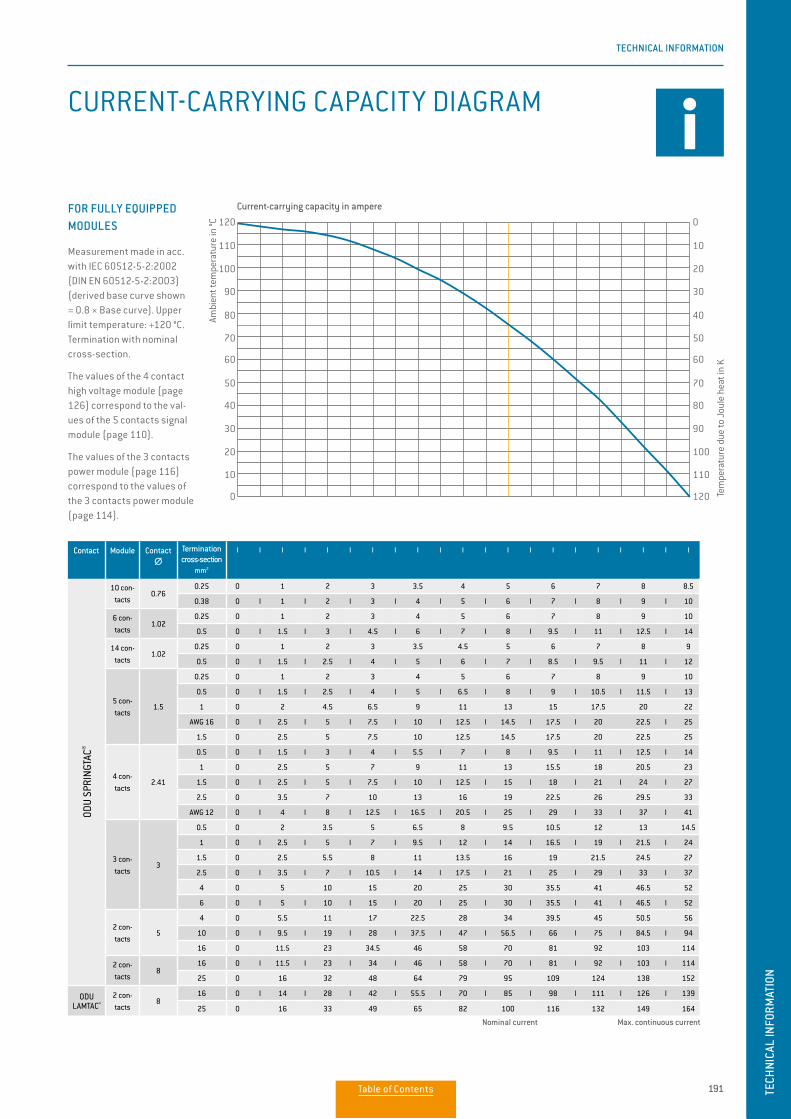
191
TECHNICAL INFORMATION
TECH
NICA
L IN
FORM
ATIO
N
Contact Module Contact ∅∅
Termination cross-section
mm2
I I I I I I I I I I I I I I I I I I I I I
ODU
SPRI
NGTA
C®
10 con-tacts
0.760.25 0 1 2 3 3.5 4 5 6 7 8 8.5
0.38 0 I 1 I 2 I 3 I 4 I 5 I 6 I 7 I 8 I 9 I 10
6 con-tacts
1.020.25 0 1 2 3 4 5 6 7 8 9 10
0.5 0 I 1.5 I 3 I 4.5 I 6 I 7 I 8 I 9.5 I 11 I 12.5 I 14
14 con-tacts
1.020.25 0 1 2 3 3.5 4.5 5 6 7 8 9
0.5 0 I 1.5 I 2.5 I 4 I 5 I 6 I 7 I 8.5 I 9.5 I 11 I 12
5 con-tacts
1.5
0.25 0 1 2 3 4 5 6 7 8 9 10
0.5 0 I 1.5 I 2.5 I 4 I 5 I 6.5 I 8 I 9 I 10.5 I 11.5 I 13
1 0 2 4.5 6.5 9 11 13 15 17.5 20 22
AWG 16 0 I 2.5 I 5 I 7.5 I 10 I 12.5 I 14.5 I 17.5 I 20 22.5 I 25
1.5 0 2.5 5 7.5 10 12.5 14.5 17.5 20 22.5 25
4 con-tacts
2.41
0.5 0 I 1.5 I 3 I 4 I 5.5 I 7 I 8 I 9.5 I 11 I 12.5 I 14
1 0 2.5 5 7 9 11 13 15.5 18 20.5 23
1.5 0 I 2.5 I 5 I 7.5 I 10 I 12.5 I 15 I 18 I 21 I 24 I 27
2.5 0 3.5 7 10 13 16 19 22.5 26 29.5 33
AWG 12 0 I 4 I 8 I 12.5 I 16.5 I 20.5 I 25 I 29 I 33 I 37 I 41
3 con-tacts
3
0.5 0 2 3.5 5 6.5 8 9.5 10.5 12 13 14.5
1 0 I 2.5 I 5 I 7 I 9.5 I 12 I 14 I 16.5 I 19 I 21.5 I 24
1.5 0 2.5 5.5 8 11 13.5 16 19 21.5 24.5 27
2.5 0 I 3.5 I 7 I 10.5 I 14 I 17.5 I 21 I 25 I 29 I 33 I 37
4 0 5 10 15 20 25 30 35.5 41 46.5 52
6 0 I 5 I 10 I 15 I 20 I 25 I 30 I 35.5 I 41 I 46.5 I 52
2 con-tacts
5
4 0 5.5 11 17 22.5 28 34 39.5 45 50.5 56
10 0 I 9.5 I 19 I 28 I 37.5 I 47 I 56.5 I 66 I 75 I 84.5 I 94
16 0 11.5 23 34.5 46 58 70 81 92 103 114
2 con-tacts
816 0 I 11.5 I 23 I 34 I 46 I 58 I 70 I 81 I 92 I 103 I 114
25 0 16 32 48 64 79 95 109 124 138 152
ODU LAMTAC®
2 con-tacts
816 0 I 14 I 28 I 42 I 55.5 I 70 I 85 I 98 I 111 I 126 I 139
25 0 16 33 49 65 82 100 116 132 149 164
Nominal current Max. continuous current
Measurement made in acc. with IEC 60512-5-2:2002 (DIN EN 60512-5-2:2003)(derived base curve shown = 0.8 × Base curve). Upper limit temperature: +120 °C. Termination with nominal cross-section.
The values of the 4 contact high voltage module (page 126) correspond to the val-ues of the 5 contacts signal module (page 110).
The values of the 3 contacts power module (page 116) correspond to the values of the 3 contacts power module (page 114).
FOR FULLY EQUIPPED MODULES
Current-carrying capacity in ampere
Tem
pera
ture
due
to J
oule
hea
t in
K
Ambi
ent t
empe
ratu
re in
°C
120
110
100
90
80
70
60
50
40
30
20
10
0
0
10
20
30
40
50
60
70
80
90
100
110
120
CURRENT-CARRYING CAPACITY DIAGRAM
Strombelastbarkeit MAC Einzelkontakt S.124
Strombelastbarkeit MAC Modul S.125Table of Contents
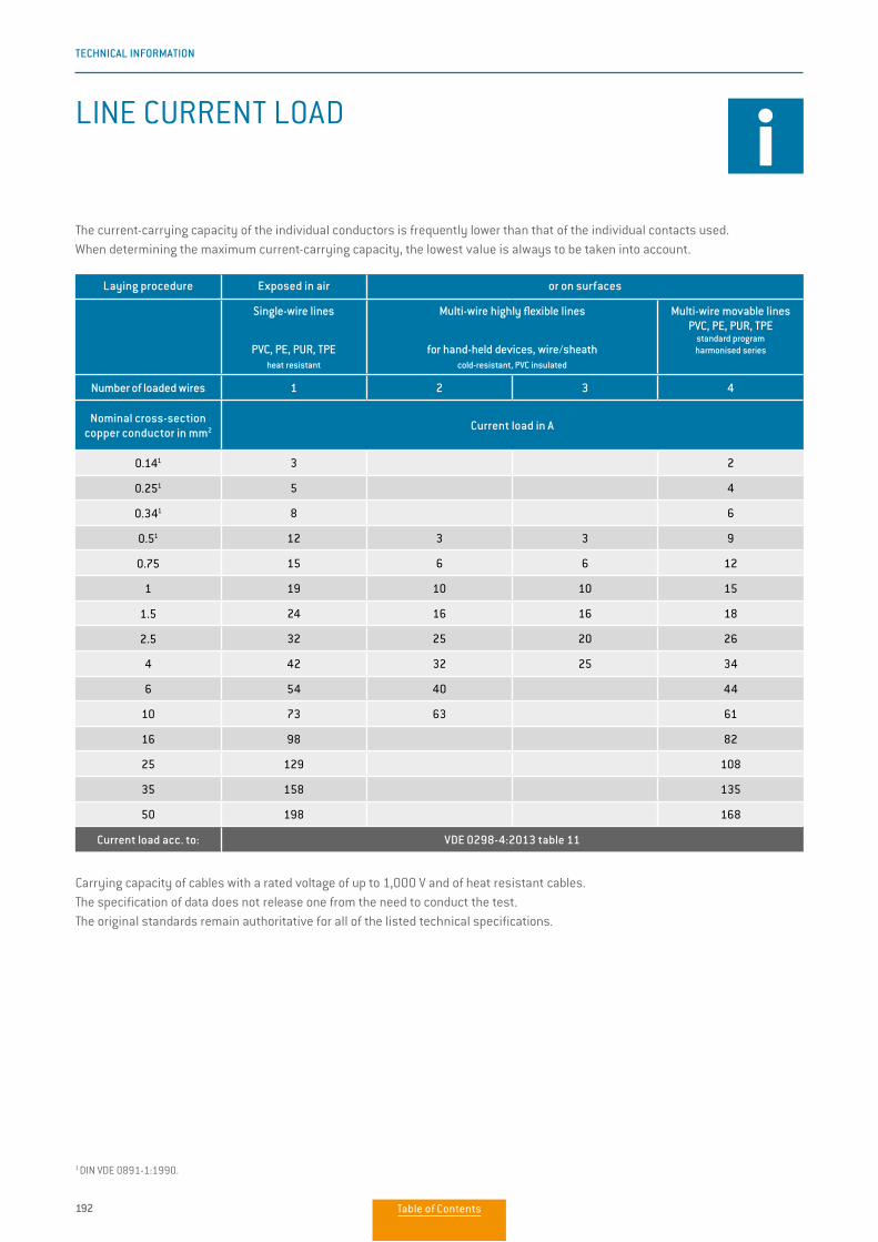
192
TECHNICAL INFORMATION
LINE CURRENT LOAD
Laying procedure Exposed in air or on surfaces
Single-wire lines
PVC, PE, PUR, TPE heat resistant
Multi-wire highly flexible lines
for hand-held devices, wire/sheath cold-resistant, PVC insulated
Multi-wire movable linesPVC, PE, PUR, TPE
standard program harmonised series
Number of loaded wires 1 2 3 4
Nominal cross-section copper conductor in mm2 Current load in A
0.141 3 2
0.251 5 4
0.341 8 6
0.51 12 3 3 9
0.75 15 6 6 12
1 19 10 10 15
1.5 24 16 16 18
2.5 32 25 20 26
4 42 32 25 34
6 54 40 44
10 73 63 61
16 98 82
25 129 108
35 158 135
50 198 168
Current load acc. to: VDE 0298-4:2013 table 11
Carrying capacity of cables with a rated voltage of up to 1,000 V and of heat resistant cables.The specification of data does not release one from the need to conduct the test. The original standards remain authoritative for all of the listed technical specifications.
The current-carrying capacity of the individual conductors is frequently lower than that of the individual contacts used. When determining the maximum current-carrying capacity, the lowest value is always to be taken into account.
1 DIN VDE 0891-1:1990.
Table of Contents
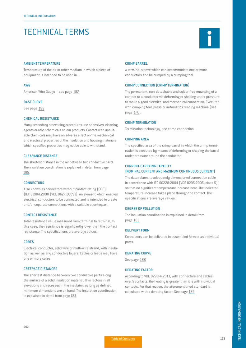
193
TECHNICAL INFORMATION
TECH
NICA
L IN
FORM
ATIO
N
FACHAUSDRÜCKE
ADER
Elektrischer Leiter, massiver Draht oder mehrdrähtige Litze, mit seiner Isolierung einschließlich etwa vorhandener Leit-schichten. Kabel oder Leitungen können eine oder mehrere Adern haben.
ANSCHLUSSQUERSCHNITT
Die angegebenen Querschnitte entsprechen einem„feindrähtigen“ Leiteraufbau nach IEC 60228:2004 (VDE 0295:2005; Class 5) oder einem „feindrähtigen“ Leiteraufbau (7/19-„drähtig“) gemäß AWG (ASTM B258-14).
ANSCHLUSSTECHNIKEN
Verfahren zum Anschluss der Leitungen an die elektro- mechanischen Bauelemente, zum Beispiel lötfreie Verbindun-gen nach IEC 60352 (DIN EN 60352): Crimp-, Schraubverbin-dung etc. oder Lötverbindung (siehe ab Seite 34).
AWG
American Wire Gauge (amerikanische Norm für Drahtquerschnitte) siehe Seite <?>.
BASISKURVE IEC 60512-5-2:2002 (DIN EN 60512-5-2:2003)
Siehe Seite 188.
BEMESSUNGSSTROM (NENNSTROM)
Siehe ab Seite 189.
BEMESSUNGSSPANNUNG
Lt. Norm IEC 60512-5-2:2002 (DIN EN 60512-5-2:2003) „Wert einer Spannung, der vom Hersteller für ein Bauteil, Gerät oder Betriebsmittel angegeben wird und auf den sich die Be-triebs- und Leistungsmerkmale beziehen“.
BETRIEBSTEMPERATUR BEI ODU-MAC®
Siehe obere Grenztemperatur (siehe Seite 194). Einzelne Module können von den hier angegebenen Tempera-turwerten abweichen, hier finden Sie die technischen Daten auf den entsprechenden Seiten.
CHEMIKALIENBESTÄNDIGKEIT
Bei einer Vielzahl von Weiterverarbeitungsprozessen werden Kleber, Reinigungsmittel oder andere Chemikalien an unseren Produkten verwendet. Beim Kontakt mit ungeeigneten Chemi-kalien können die mechanischen und elektrischen Eigenschaf-ten der Isolier- und Gehäusewerkstoffe negativ beeinflusst
werden und damit spezifizierte Eigenschaften nicht mehr stand- halten. Bitte beachten Sie unsere Verarbeitungsvorschläge und technischen Hinweise in diesem Katalog. Informationen zu unseren Kunststoffgehäusen finden Sie auf Seite 28.
CRIMPBEREICH
Der spezifizierte Bereich der Crimphülse, in dem die Crimp-verbindung durch Druckverformung oder Druckumformung der Hülse um den Leiter herum ausgeführt ist.
CRIMPHÜLSE
Eine Anschlusshülse, die einen oder mehrere Leiter aufnehmen kann und durch Anwendung eines Crimpwerkzeuges gecrimpt werden kann.
CRIMPANSCHLUSS
Anschlusstechnik, siehe Crimpverbindung.
CRIMPVERBINDUNG (CRIMPANSCHLUSS)
Die dauerhafte, nicht lösbare und lötfreie Befestigung eines Kontakts an einem Leiter durch Umformung der Crimphülse um den Leiter herum, so dass eine gute elektrische und mechani-sche Verbindung geschaffen wird. Ausführung mit Crimpzange, Presse oder automatischer Crimpmaschine (siehe Seite 171).
DERATING-KURVE
Siehe Seite 188.
DERATING-MESSVERFAHREN IEC 60512-5-2:2002 (DIN EN 60512-5-2:2003)
Siehe Seite 188.
DICHTIGKEIT IEC 60529:2013 (VDE 0470-1:2014)
Siehe Schutzarten Seite 182.
DRAHT
Drähte (massive Leiter) können mit einer Isolierhülse, einer elektrischen Abschirmung geliefert werden. Kabel oder Leiter können aus einem oder mehreren Drähten bestehen.
DURCHGANGSWIDERSTAND Gesamtwiderstandswert, gemessen von Anschluss zu Anschluss. Der Kontaktwiderstand ist dabei deutlich niedriger als der Durchgangswiderstand. Bei den Angaben handelt es sich um Mittelwerte.
202
TECHNICAL INFORMATION
TECHNICAL TERMS
AMBIENT TEMPERATURE
Temperature of the air or other medium in which a piece of equipment is intended to be used in.
AWG
American Wire Gauge – see page 195
BASE CURVE
See page 196
CHEMICAL RESISTANCE
Many secondary processing procedures use adhesives, cleaning agents or other chemicals on our products. Contact with unsuit-able chemicals may have an adverse effect on the mechanical and electrical properties of the insulation and housing materials which specified properties may not be able to withstand.
CLEARANCE DISTANCE
The shortest distance in the air between two conductive parts. The insulation coordination is explained in detail from page 191.
CONNECTORS
Also known as connectors without contact rating (COC): (IEC 61984:2008 (VDE 0627:2009)). An element which enables electrical conductors to be connected and is intended to create and/or separate connections with a suitable counterpart.
CONTACT RESISTANCE
Total resistance value measured from terminal to terminal. In this case, the resistance is significantly lower than the contact resistance. The specifications are average values.
CORES
Electrical conductor, solid wire or multi-wire strand, with insula-tion as well as any conductive layers. Cables or leads may have one or more cores.
CREEPAGE DISTANCES
The shortest distance between two conductive parts along the surface of a solid insulation material. This factors in all elevations and recesses in the insulator, as long as defined minimum dimensions are on hand. The insulation coordination is explained in detail from page 191.
CRIMP BARREL
A terminal sleeve which can accommodate one or more conductors and be crimped by a crimping tool.
CRIMP CONNECTION (CRIMP TERMINATION)
The permanent, non-detachable and solder-free mounting of a contact to a conductor via deforming or shaping under pressure to make a good electrical and mechanical connection. Executed with crimping tool, press or automatic crimping machine (see page 175).
CRIMP TERMINATION
Termination technology, see crimp connection.
CRIMPING AREA
The specified area of the crimp barrel in which the crimp termi-nation is executed by means of deforming or shaping the barrel under pressure around the conductor.
CURRENT-CARRYING CAPACITY (NOMINAL CURRENT AND MAXIMUM CONTINUOUS CURRENT)
The data relates to adequately dimensioned connection cable in accordance with IEC 60228:2004 (VDE 0295:2005; class 5), so that no significant temperature increase here. The indicated temperature increase takes place through the contact. The specifications are average values.
DEGREE OF POLLUTION
The insulation coordination is explained in detail from page 191.
DELIVERY FORM
Connectors can be delivered in assembled form or as individual parts.
DERATING CURVE
See page 196
DERATING FACTOR
According to VDE 0298-4:2013, with connectors and cables over 5 contacts, the heating is greater than it is with individual contacts. For that reason, the aforementioned standard is calculated with a derating factor. See page 197
187
188
189
188
170
185
183
183
Table of Contents
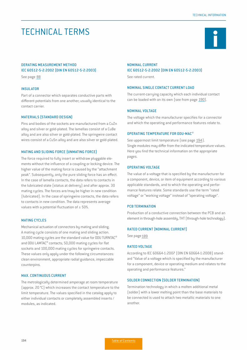
194
TECHNICAL INFORMATION
203
TECHNICAL INFORMATION
TECHNICAL TERMS
DERATING MEASUREMENT METHOD IEC 60512-5-2:2002 (DIN EN 60512-5-2:2003)
See page 196
INSULATOR
Part of a connector which separates conductive parts with different potentials from one another; usually identical to the contact carrier.
MATERIALS (STANDARD DESIGN)
Pins and bodies of the sockets are manufactured from a CuZn alloy and silver or gold-plated. The lamellas consist of a CuBe alloy and are also silver or gold-plated. The springwire contact wires consist of a CuSn alloy and are also silver or gold-plated.
MATING AND SLIDING FORCE (UNMATING FORCE)
The force required to fully insert or withdraw pluggable ele-ments without the influence of a coupling or locking device. The higher value of the mating force is caused by the “attachment peak”. Subsequently, only the pure sliding force has an effect. In the case of lamella contacts, the data refers to contacts in the lubricated state (status at delivery) and after approx. 30 mating cycles. The forces are/may be higher in new condition (lubricated). In the case of springwire contacts, the data refers to contacts in new condition. The data represents average values with a potential fluctuation of ± 50%.
MATING CYCLES
Mechanical actuation of connectors by mating and sliding. A mating cycle consists of one mating and sliding action. 10,000 mating cycles are the standard value for ODU TURNTAC®
and ODU LAMTAC® contacts; 50,000 mating cycles for flat sockets and 100,000 mating cycles for springwire contacts. These values only apply under the following circumstances: clean environment, appropriate radial guidance, impeccable counterpins.
MAX. CONTINUOUS CURRENT
The metrologically determined amperage at room temperature (approx. 20 °C) which increases the contact temperature to the limit temperature. The values specified in the catalog apply to either individual contacts or completely assembled inserts / modules, as indicated.
NOMINAL CURRENT IEC 60512-5-2:2002 (DIN EN 60512-5-2:2003)
See rated current.
NOMINAL SINGLE CONTACT CURRENT LOAD
The current-carrying capacity which each individual contact can be loaded with on its own (see from page 196).
NOMINAL VOLTAGE
The voltage which the manufacturer specifies for a connector and which the operating and performance features relate to.
OPERATING TEMPERATURE FOR ODU-MAC®
See uppermost limit temperature (see page 204). Single modules may differ from the indicated temperature values. Here you find the technical information on the appropriate pages.
OPERATING VOLTAGE
The value of a voltage that is specified by the manufacturer for a component, device, or item of equipment according to various applicable standards, and to which the operating and perfor-mance features relate. Some standards use the term “ratedvoltage” or “working voltage” instead of “operating voltage”.
PCB TERMINATION
Production of a conductive connection between the PCB and an element in through-hole assembly, THT (through-hole technology).
RATED CURRENT (NOMINAL CURRENT)
See page 197
RATED VOLTAGE
According to IEC 60664-1:2007 (DIN EN 60664-1:2008) stand-ard “Value of a voltage which is specified by the manufacturer for a component, device or operating medium and relates to the operating and performance features.”
SOLDER CONNECTION (SOLDER TERMINATION)
Termination technology in which a molten additional metal (solder) with a lower melting point than the base materials to be connected is used to attach two metallic materials to one another.
TECH
NICA
L IN
FORM
ATIO
N
189
190
88
194
Table of Contents
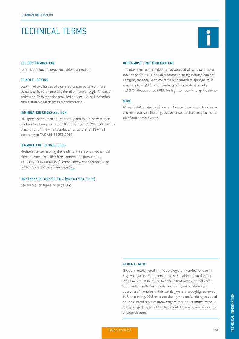
195
TECHNICAL INFORMATION
TECH
NICA
L IN
FORM
ATIO
N
204
TECHNICAL INFORMATION
TECHNICAL TERMS
SOLDER TERMINATION
Termination technology, see solder connection.
SPINDLE LOCKING
Locking of two halves of a connector pair by one or more screws, which are generally fluted or have a toggle for easier activation. To extend the provided service life, re-lubrication with a suitable lubricant is recommended.
TERMINATION CROSS-SECTION
The specified cross-sections correspond to a “fine-wire” con-ductor structure pursuant to IEC 60228:2004 (VDE 0295:2005; Class 5) or a “fine-wire” conductor structure (7/19 wire) according to AWG ASTM B258:2018.
TERMINATION TECHNOLOGIES
Methods for connecting the leads to the electro-mechanical element, such as solder-free connections pursuant to IEC 60352 (DIN EN 60352): crimp, screw connection etc. or soldering connection (see page 174).
TIGHTNESS IEC 60529:2013 (VDE 0470-1:2014)
See protection types on page 190
GENERAL NOTE
The connectors listed in this catalog are intended for use in high voltage and frequency ranges. Suitable precautionary measures must be taken to ensure that people do not come into contact with live conductors during installation and operation. All entries in this catalog were thoroughly reviewed before printing. ODU reserves the right to make changes based on the current state of knowledge without prior notice without being obliged to provide replacement deliveries or refinements of older designs.
UPPERMOST LIMIT TEMPERATURE
The maximum permissible temperature at which a connectormay be operated. It includes contact heating through current-carrying capacity. With contacts with standard springwire, it amounts to +120 °C, with contacts with standard lamella +150 °C. Please consult ODU for high-temperature applications.
WIRE
Wires (solid conductors) are available with an insulator sleeve and/or electrical shielding. Cables or conductors may be made up of one or more wires.
182
170
Table of Contents
196
www.odu-connectors.com
Simply scan the QR code to download the entire publication.
ODU GROUP WORLDWIDE
ODU GmbH & Co. KGPregelstraße 11, 84453 Mühldorf a. Inn, GermanyPhone: +49 8631 6156-0, Fax: +49 8631 6156-49, E-mail: [email protected]
HEADQUARTERS
SALES LOCATIONS
ODU (Shanghai) International Trading Co., Ltd.Phone: +86 21 58347828-0E-mail: [email protected]
ODU Denmark ApSPhone: +45 2233 5335E-mail: [email protected]
ODU France SARLPhone: +33 1 3935-4690 E-mail: [email protected]
ODU Italia S.R.L.Phone: +39 331 8708847E-mail: [email protected]
ODU Japan K.K.Phone: +81 3 6441 3210E-mail: [email protected]
ODU Korea Inc.Phone: +82 2 6964 7181E-mail: [email protected]
ODU Romania Manufacturing S.R.L.Phone: +40 269 704638E-mail: [email protected]
ODU Scandinavia ABPhone: +46 176 18262 E-mail: [email protected]
ODU-UK Ltd.Phone: +44 330 002 0640E-mail: [email protected]
ODU-USA, Inc.Phone: +1 805 484-0540 E-mail: [email protected]
Further information and specialized representatives can be found at: www.odu-connectors.com/contact
PRODUCTION AND LOGISTICS SITES
Germany Otto Dunkel GmbHChina ODU (Shanghai) Connectors Manufacturing Co.Ltd Mexico ODU Mexico Manufacturing S.R.L. de C.V. Romania ODU Romania Manufacturing S.R.L.USA ODU North American Logistics All dimensions are in mm. Some fi gures are
for illustrative purposes only. Subject to change without notice. Errors and omissions excepted. We reserve the right to change our products and their technical specifi cations at any time in the interest of technical improvement. This publication supersedes all prior publications. This publication is also available as a PDF fi le that can be downloaded from www.odu-connectors.com OD
U-M
AC W
HITE
-LIN
E / B
/ 07
19 /
EN