Embed Size (px)
Citation preview
ODROID-HC1 and ODROID-MC1: Aordable High-Performance AndCloud Computing At Home September 1, 2017
The ODROID-HC1 is a single board computer (SBC) which is an aordable solution for anetwork attached storage (NAS) server, and the ODROID-MC1 is a simple solution for
those who need an aordable and powerful personal cluster.
My ODROID-C2 Docker Swarm: Part 1 – Swarm Mode Features September 1, 2017
Docker Swarm mode provides cluster management and service orchestrationcapabilities including service discovery and service scaling, among other things, usingoverlay networks and an in-built load balancer respectively.
ODROID-XU4 Mainline U-Boot September 1, 2017
Hardkernel is working on a new version of U-Boot for the ODROID-XU4, with many newfeatures and improvements.
ODROID Wall Display: Using An LCD Monitor And An ODROID ToShow Helpful Information September 1, 2017
A wall monitor is an eective method of passively delivering a constant stream ofinformation. Rather than purchasing a digital picture frame that is not only expensive,
but is also small with limited functionality, why not use a computer monitor or TV screen with an ODROID todisplay photos, weather
Linux Gaming: Fanboy Part 2 – I am a Sega Fanboy! September 1, 2017
In the 1980s and 1990s, Nintendo and Sega fought to dominate the console market.While both had similar products, there were still some major dierences. If youcompare their earlier products, the Nintendo Entertainment System (NES) and Sega
Master System (SMS), and Game Boy/Game Boy Color (GB/GBC) and Game Gear
Home Assistant: Customization and Automations September 1, 2017
Advanced topics related to Home Assistant (HA) using in-depth steps, allowing you tomaximize the use of Home Assistant, and also help with experimentation.
Digole Serial Displays: Driving Digole’s Serial Display in UART, I2C,and SPI Modes with an ODROID-C1+ September 1, 2017
Digole.com oers several intelligent serial displays that are controlled through acomplete set of high-level proprietary commands. These commands make drawing
complex graphics and displaying images and video much easier, oering a oer a layer of abstraction thatmakes it easy to port their displays to a number of dierent

Meet An ODROIDian: Ted Jack-Philippe Nivan (@TedJack) September 1, 2017
Meet An ODROIDian is a monthly column where you can learn more about the peoplewho enjoy using Hardkernel products.

ODROID-HC1 and ODROID-MC1: Aordable High-PerformanceAnd Cloud Computing At Home September 1, 2017 By Rob Roy ODROID-HC1
Many people have been using the ODROID-XU4 forserver, NAS, cluster, mining and build-farmapplications, thanks to its high computingperformance and connectivities. They kept requestingeasier and cheaper solutions for scalability with astripped-down version of XU4, so Hardkernel hasintroduced a new product that is intended to be usedfor building an aordable and powerful Home Cloudserver, called the ODROID-HC1, which is now availablefor USD$49 at http://bit.ly/2wjNToV.
ODROID-HC1
The ODROID-HC1 is a single board computer (SBC)which is an aordable solution for a network attachedstorage (NAS) server. This home cloud servercentralizes data and enables users to share andstream multimedia les to phones, tablets and otherdevices on a network, which is ideal for a single useron many devices, for sharing les between family
members, and for developers or a group. You cantailor the ODROID-HC1 to your specic needs, andthere is plenty of software available with minimalconguration. The storage of the server can becustomized by using a large capacity hard drive orSSD. Depending on your needs, the frame is made tobe stackable. The engineered metal frame body isdesigned to store a 2.5 inch HDD/SSD while oeringexcellent heat dissipation.

The ODROID-HC1 is an elegant, aordable solution tohome cloud computing
The integrated SATA interface will give you the bestperformance
The ODROID-HC1 is an amazing stackable board forbuilding your personal cluster
The ODROID-HC1 is based on the very powerfulODROID-XU4 platform, and can run Samba, FTP, NFS,SSH, NGINX, Apache, SQL, Docker, WordPress and
other server software smoothly using full Linuxdistributions like Ubuntu, Debian, Arch and OMV.Available and ready-to-go operating system (OS)distributions are on the Hardkernel Wiki athttp://bit.ly/2wjNsuI. Any OS that runs on the XU4 isfully compatible with the HC1. We guarantee theproduction of ODROID-HC1 to the middle of 2020, butexpect to continue production long after.
Key features
Samsung Exynos5422 Cortex-A15 2Ghz and Cortex-A7Octa core CPUs
2Gbyte LPDDR3 RAM PoP stacked
SATA port for 2.5inch HDD/SSD storage
Gigabit Ethernet port
USB 2.0 Host
UHS-1 capable micro-SD card slot for boot media
Size : approximately 147 x 85 x 29 mm (includingaluminum cooling frame)
Linux server OS images based on modern Kernel 4.9LTS
Since bad USB cables and faulty USB-to-SATA bridgechipsets make users struggling due tophysical/electrical tolerance issues as well as drivercompatibility issues, the ODROID-HC1 has a built-inSATA connector on the PCB with a fully tested SATAbridge controller. To lower the cost, the board sizewas minimized due to the cost of the 10-layers PCB,which resulted in the removal of some features suchas the HDMI output, eMMC connector, USB 3.0 hub,power button, and slide switch.
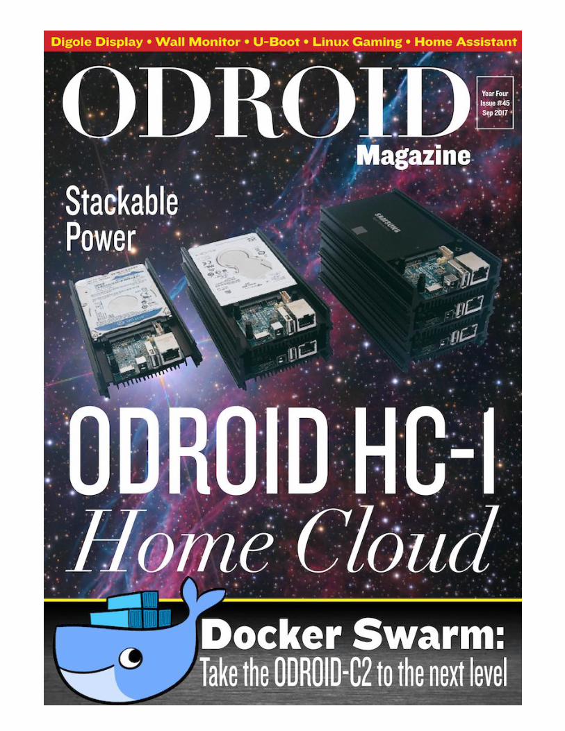
Any type of 2.5-inch SATA HDD/SSD storage may beinstalled, including 7mm, 9.5mm, 12mm and 15mmthick units. The Seagate Barracuda 2TB/5TB HDDs,Samsung 500GB HDD and 256GB SSD, Western Digital500GB and 1TB HDD, HGST 1TB HDD and otherstorages were fully tested with UAS and S.M.A.R.T.functions.
The ODROID-HC1 supports many dierent types of harddrives
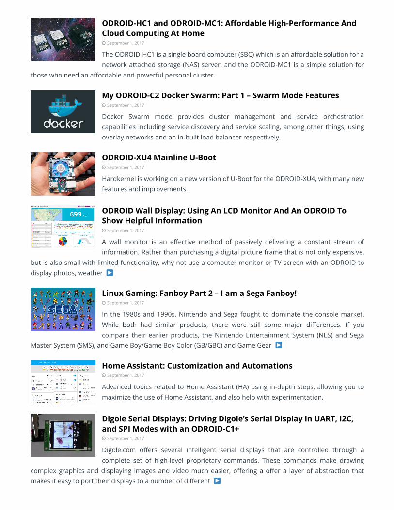
Your distributed server can be modular, compact, andstylish
For further details and a demonstration of theODROID-HC1 functionality, please watch the video athttps://youtu.be/t-L99pUANaA.
ODROID-MC1
The ODROID-MC1, which stands for My Cluster, is asimple solution for those who need an aordable andpowerful personal cluster. It is similar to the ODROID-HC1, but excludes the SATA interface and adds a largecooling fan for heavy computing loads. It isanticipated to be available in September 2017 forUSD$200.
Hardkernel spent several days building this big clustercomputer using 200 ODROID-MC1 units with 1600 CPUcores and 400GB RAM
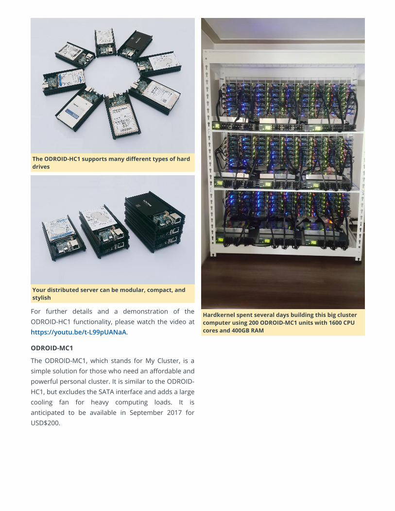
A stack of 4 ODROID-MC1 units, creating a cluster with32 CPU cores and 8GB RAM.
Cooling 4 ODROIDs with a single fan is a great cost-saving feature
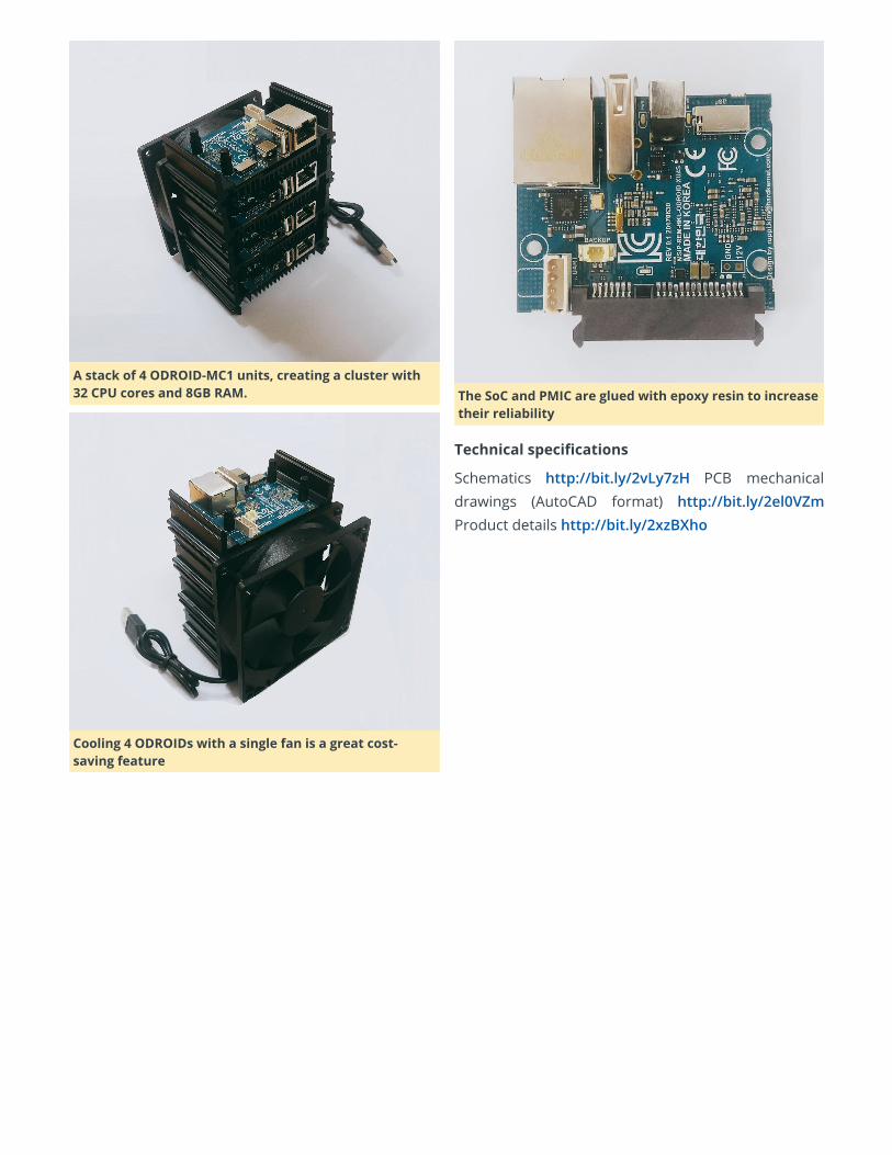
The SoC and PMIC are glued with epoxy resin to increasetheir reliability
Technical specications
Schematics http://bit.ly/2vLy7zH PCB mechanicaldrawings (AutoCAD format) http://bit.ly/2el0VZmProduct details http://bit.ly/2xzBXho
My ODROID-C2 Docker Swarm: Part 1 – Swarm Mode Features September 1, 2017 By Andy Yuen Docker, Linux, ODROID-C2
Docker introduced swarm mode in version 1.12.x toenable the deployment of containers on multipledocker hosts. Swarm mode provides clustermanagement and service orchestration capabilitiesincluding service discovery and service scaling, amongother things, using overlay networks and an in-builtload balancer respectively. These are mandatoryfeatures for the enterprise as there is a limit to thenumber of containers one can deploy on a singledocker host. For a high level architectural descriptionof swarm mode, please read my previous articlepublished in the November 2016 issue of ODROIDMagazine at http://bit.ly/2wiTVXM.
Several months ago, I was experimenting withDocker’s swarm mode on my ve board ODROID-C2cluster. I was able to start multiple Docker containerson multiple docker hosts but neither overlay network,routing mesh, nor load balancing were working inswarm mode. I tried using dierent versions of docker(1.12.x and 1.13.x) compiled on my ODROID-C2 to no
avail. I also tried running Kubernetes on my ODROID-C2 cluster. Again the networking part of Kubernetesdid not work. I suspected that the kernel was missingcertain modules needed for Docker and Kubernetesnetworking. Due to this, I stopped myexperimentation until now. What rekindled mypassion to get Docker swarm mode working wasseeing my hardware not being used: an ODROID VU7multi-touch screen and a VuShell for VU7.
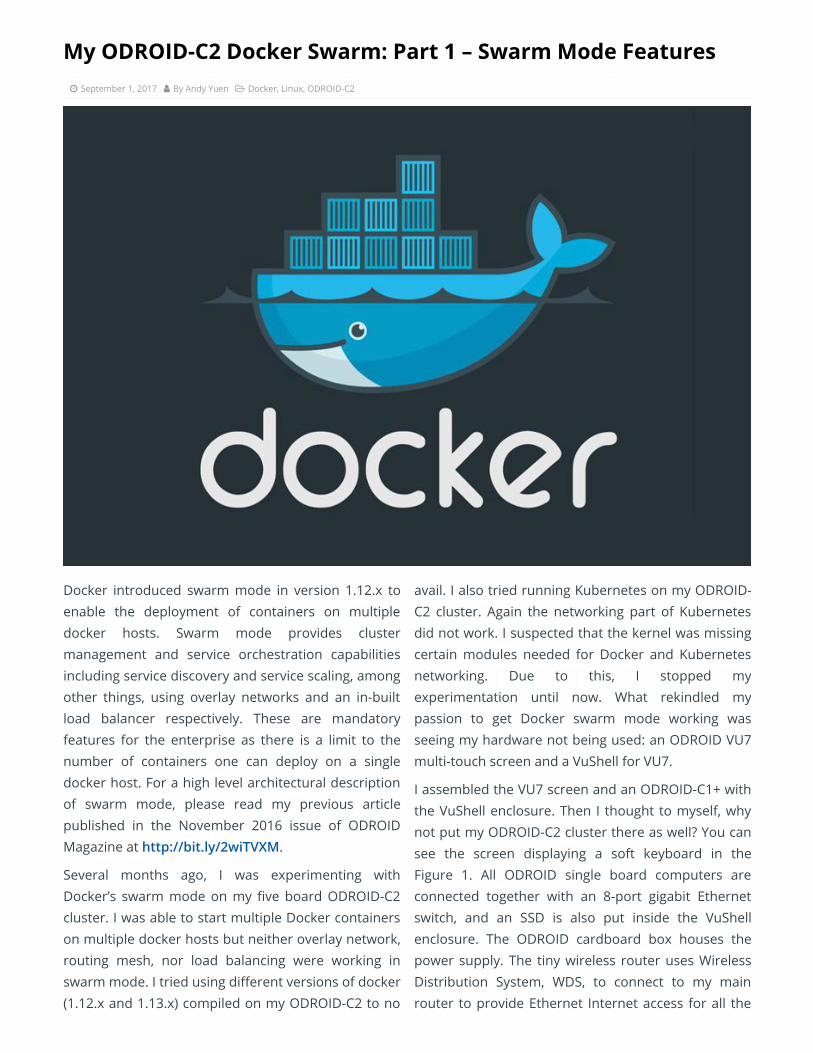
I assembled the VU7 screen and an ODROID-C1+ withthe VuShell enclosure. Then I thought to myself, whynot put my ODROID-C2 cluster there as well? You cansee the screen displaying a soft keyboard in theFigure 1. All ODROID single board computers areconnected together with an 8-port gigabit Ethernetswitch, and an SSD is also put inside the VuShellenclosure. The ODROID cardboard box houses thepower supply. The tiny wireless router uses WirelessDistribution System, WDS, to connect to my mainrouter to provide Ethernet Internet access for all the
ODROIDs housed in the VuShell, because they don’thave built-in WiFi.
Figure 1 – A Docker swam cluster using the ODROID-VUshell as a case
Hardkernel’s Ubuntu 16.04 OS
I had the suspicion that the cause for Docker’s swarmmode not working in previous attempts was due tosome missing or incompatible kernel modules in theOS. So, I decided to switch to another OS. I noticedthat Hardkernel recently released Ubuntu 16.04 (v2.3)for the ODROID-C2 so I gave it a try. The earlierversion of Hardkernel’s Ubuntu OS that I tried monthsearlier was unstable, but the current release workedwithout any issues. I was happy and told myself thatthis time it might work!
To make things easier, I installed and congured thefollowing packages:
parallel-ssh on the docker manager to allow me toissue commands once from the docker manager to beexecuted on all nodes
nfs-kernel-server on the manager and nfs-common onall nodes
curl on the manager for testing
dnsutils on all nodes
I also generated SSH keys for the “odroid” and “root”users on all members of the cluster, so that they canSSH into each other without a password.
Docker Swarm Mode Reboot
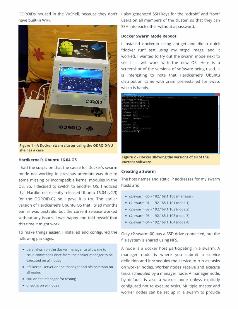
I installed docker.io using apt-get and did a quick“docker run” test using my httpd image, and itworked. I wanted to try out the swarm mode next tosee if it will work with the new OS. Here is ascreenshot of the versions of software being used. Itis interesting to note that Hardkernel’s Ubuntudistribution came with zram pre-installed for swap,which is handy.
Figure 2 – Docker showing the versions of all of thecurrent software
Creating a Swarm
The host names and static IP addresses for my swarmhosts are:
c2-swarm-00 – 192.168.1.100 (manager)
c2-swarm-01 – 192.168.1.101 (node 1)
c2-swarm-02 – 192.168.1.102 (node 2)
c2-swarm-03 – 192.168.1.103 (node 3)
c2-swarm-04 – 192.168.1.104 (node 4)
Only c2-swarm-00 has a SSD drive connected, but thele system is shared using NFS.
A node is a docker host participating in a swarm. Amanager node is where you submit a servicedenition and it schedules the service to run as taskson worker nodes. Worker nodes receive and executetasks scheduled by a manager node. A manager node,by default, is also a worker node unless explicitlycongured not to execute tasks. Multiple master andworker nodes can be set up in a swarm to provide
High Availability (HA). To bring up swarm mode, issuethe following command on the manager:
$ docker swarm init advertiseaddr
192.168.1.100
which returns:
swarm initialized: current mode
(8jw6y313hmt3vfa1me1dinro) is now a manager
To add a worker to this swarm, run the followingcommand on each node:
$ docker swarm join token SWMTKN1
2gvqzfx48uw8zcokwl5033iwdel2rl9n96lc0wj1qso7lr
ztubaokk5xcm5v7c4usmeswsgg1k
192.168.1.100:2377
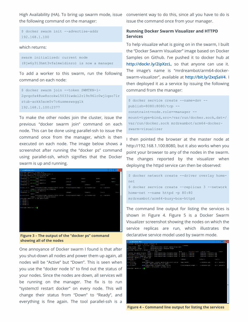
To make the other nodes join the cluster, issue theprevious “docker swarm join” command on eachnode. This can be done using parallel-ssh to issue thecommand once from the manager, which is thenexecuted on each node. The image below shows ascreenshot after running the “docker ps” commandusing parallel-ssh, which signies that the Dockerswarm is up and running.
Figure 3 – The output of the “docker ps” commandshowing all of the nodes
One annoyance of Docker swarm I found is that afteryou shut-down all nodes and power them up again, allnodes will be “Active” but “Down”. This is seen whenyou use the “docker node ls” to nd out the status ofyour nodes. Since the nodes are down, all services willbe running on the manager. The x is to run“systemctl restart docker” on every node. This willchange their status from “Down” to “Ready”, andeverything is ne again. The tool parallel-ssh is a
convenient way to do this, since all you have to do isissue the command once from your manager.
Running Docker Swarm Visualizer and HTTPDServices
To help visualize what is going on in the swarm, I builtthe “Docker Swarm Visualizer” image based on DockerSamples on Github. I’ve pushed it to docker hub athttp://dockr.ly/2ipXzcL, so that anyone can use it.The image’s name is “mrdreambot/arm64-docker-swarm-visualizer”, available at http://bit.ly/2xqSaV4. Ithen deployed it as a service by issuing the followingcommand from the manager:
$ docker service create name=dsv
publish=8080:8080/tcp
constraint=node.role==manager
mount=type=bind,src=/var/run/docker.sock,dst=/
var/run/docker.sock mrdreambot/arm64docker
swarmvisualizer
I then pointed the browser at the master node athttp://192.168.1.100:8080, but it also works when youpoint your browser to any of the nodes in the swarm.The changes reported by the visualizer whendeploying the httpd service can then be observed:
$ docker network create driver overlay home
net
$ docker service create replicas 3 network
homenet name httpd p 80:80
mrdreambot/arm64busyboxhttpd
The command line output for listing the services isshown in Figure 4. Figure 5 is a Docker SwarmVisualizer screenshot showing the nodes on which theservice replicas are run, which illustrates thedeclarative service model used by swarm mode.
Figure 4 – Command line output for listing the services

Figure 5 – Docker Swarm Visualizer
Routing Mesh, Load Balancing and Self-healing
The routing mesh in the swarm allows a request toreach a service even when the service is not runningon the node where the request has been received.This means that although the httpd service is runningon c2-swarm-00, c2-swarm-03 and c2-swarm-04, onecan point the browser at any one of the 5 nodes andstill get a response with the ODROID-Docker image.This was the behaviour that I observed.
Figure 6 – Load balancing example using 10.255.0.9
In addition to providing a routing mesh, the swarmalso performs load balancing. To test the loadbalancing feature, I connected to the managermultiple time using my browser, at the httpd serviceusing the address http://192.168.1.100/cgi-bin/lbtest.Notice that the hostnames (container Id) and IPaddresses are dierent in the two screenshots.
Figure 7 – Load balancing example using 10.255.0.10
The tests were repeated using the curl command:
$ curl http://192.168.1.100/cgibin/lbtest
Here is a screenshot of the curl commands outputwhich conrmed, again, that each request has beendirected to a dierent node:
Figure 8 – Load balancing across nodes
As for a demo on self-healing, I shut down c2-swarm-04, and you can see from the visualizer as well as thecommand line that another httpd container was spunup on c2-swarm-02 to replace the one on c2-swarm-04. This is because when we started the service, wespecied “replica=3”. This means the Docker swarmwill maintain the desired number of replicas, here it is3. This is called desired state reconciliation.
Figure 9 – Service recovery
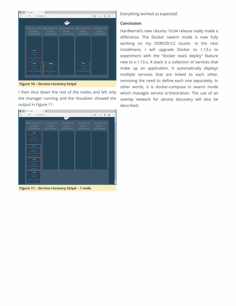
Figure 10 – Service recovery httpd
I then shut down the rest of the nodes and left onlythe manager running and the Visualizer showed theoutput in Figure 11.
Figure 11 – Service recovery httpd – 1 node
Everything worked as expected!
Conclusion
Hardkernel’s new Ubuntu 16.04 release really made adierence. The Docker swarm mode is now fullyworking on my ODROID-C2 cluster. In the nextinstallment, I will upgrade Docker to 1.13.x toexperiment with the “docker stack deploy” featurenew to v.1.13.x. A stack is a collection of services thatmake up an application. It automatically deploysmultiple services that are linked to each other,removing the need to dene each one separately. Inother words, it is docker-compose in swarm modewhich manages service orchestration. The use of anoverlay network for service discovery will also bedescribed.
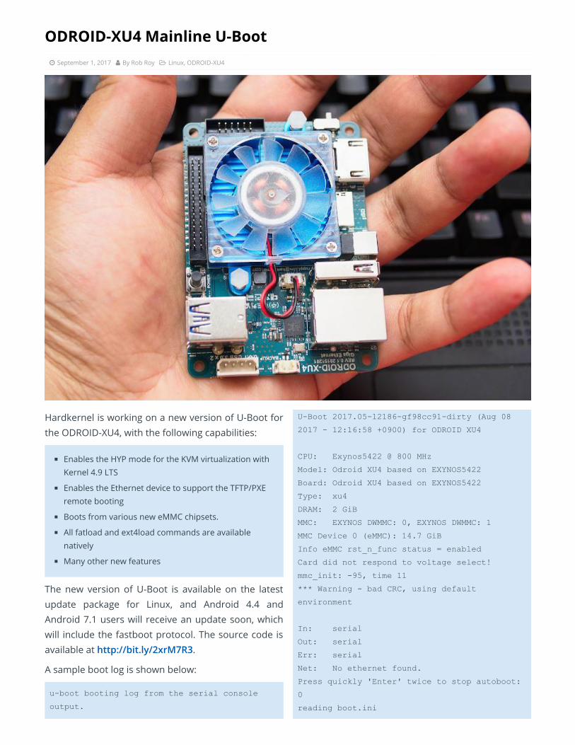
ODROID-XU4 Mainline U-Boot September 1, 2017 By Rob Roy Linux, ODROID-XU4
Hardkernel is working on a new version of U-Boot forthe ODROID-XU4, with the following capabilities:
Enables the HYP mode for the KVM virtualization withKernel 4.9 LTS
Enables the Ethernet device to support the TFTP/PXEremote booting
Boots from various new eMMC chipsets.
All fatload and ext4load commands are availablenatively
Many other new features
The new version of U-Boot is available on the latestupdate package for Linux, and Android 4.4 andAndroid 7.1 users will receive an update soon, whichwill include the fastboot protocol. The source code isavailable at http://bit.ly/2xrM7R3.
A sample boot log is shown below:
uboot booting log from the serial console
output.
UBoot 2017.0512186gf98cc91dirty (Aug 08
2017 12:16:58 +0900) for ODROID XU4
CPU: Exynos5422 @ 800 MHz
Model: Odroid XU4 based on EXYNOS5422
Board: Odroid XU4 based on EXYNOS5422
Type: xu4
DRAM: 2 GiB
MMC: EXYNOS DWMMC: 0, EXYNOS DWMMC: 1
MMC Device 0 (eMMC): 14.7 GiB
Info eMMC rst_n_func status = enabled
Card did not respond to voltage select!
mmc_init: 95, time 11
*** Warning bad CRC, using default
environment
In: serial
Out: serial
Err: serial
Net: No ethernet found.
Press quickly 'Enter' twice to stop autoboot:
0
reading boot.ini
9088 bytes read in 4 ms (2.2 MiB/s)
cfgload: applying boot.ini...
cfgload: setenv initrd_high "0xffffffff"
cfgload: setenv fdt_high "0xffffffff"
cfgload: setenv macaddr "00:1e:06:61:7a:39"
cfgload: setenv vout "hdmi"
cfgload: setenv cecenable "false" # false or
true
cfgload: setenv disable_vu7 "false" # false
cfgload: setenv governor "performance"
cfgload: setenv ddr_freq 825
cfgload: setenv external_watchdog "false"
cfgload: setenv external_watchdog_debounce "3"
cfgload: setenv HPD "true"
cfgload: setenv bootrootfs "console=tty1
console=ttySAC2,115200n8 root=UUID=e139ce78
984140fe882396a304a09859 rootwait ro
fsck.repair=yes net.ifnames=0"
cfgload: fatload mmc 0:1 0x40008000 zImage
reading zImage
4793144 bytes read in 135 ms (33.9 MiB/s)
cfgload: fatload mmc 0:1 0x42000000 uInitrd
reading uInitrd
5327028 bytes read in 143 ms (35.5 MiB/s)
cfgload: if test "$board_name" = "xu4"; then
fatload mmc 0:1 0x44000000 exynos5422
odroidxu4.dtb; setenv fdtloaded "true"; fi
reading exynos5422odroidxu4.dtb
61570 bytes read in 9 ms (6.5 MiB/s)
cfgload: if test "$board_name" = "xu3"; then
fatload mmc 0:1 0x44000000 exynos5422
odroidxu3.dtb; setenv fdtloaded "true"; fi
cfgload: if test "$board_name" = "xu3l";
then fatload mmc 0:1 0x44000000 exynos5422
odroidxu3lite.dtb; setenv fdtloaded "true";
fi
cfgload: if test "$fdtloaded" != "true";
then fatload mmc 0:1 0x44000000 exynos5422
odroidxu4.dtb; fi
cfgload: fdt addr 0x44000000
cfgload: setenv hdmi_phy_control "HPD=$HPD
vout=$vout"
cfgload: if test "$cecenable" = "false";
then fdt rm /cec@101B0000; fi
cfgload: if test "$disable_vu7" = "false";
then setenv hid_quirks
"usbhid.quirks=0x0eef:0x0005:0x0004"; fi
cfgload: if test "$external_watchdog" =
"true"; then setenv external_watchdog
"external_watchdog=$external_watchdog
external_watchdog_debounce=$external_watchdog
_debounce"; fi
cfgload: setenv bootargs "$bootrootfs
$videoconfig $hdmi_phy_control
$hid_quirks smsc95xx.macaddr=$macaddr
$external_watchdog governor=$governor"
cfgload: bootz 0x40008000 0x42000000
0x44000000
Kernel image @ 0x40008000 [ 0x000000
0x492338 ]
## Loading init Ramdisk from Legacy Image at
42000000 ...
Image Name: uInitrd
Image Type: ARM Linux RAMDisk Image
(uncompressed)
Data Size: 5326964 Bytes = 5.1 MiB
Load Address: 00000000
Entry Point: 00000000
Verifying Checksum ... OK
## Flattened Device Tree blob at 44000000
Booting using the fdt blob at 0x44000000
Using Device Tree in place at 44000000, end
44012081
Starting kernel ...
For comments, questions and suggestions, pleasevisit the original post at http://bit.ly/2wNfnVu.
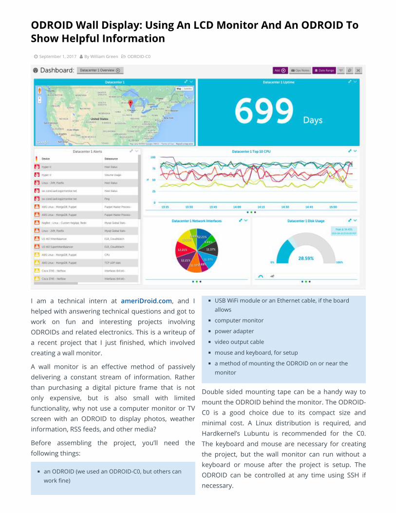
ODROID Wall Display: Using An LCD Monitor And An ODROID ToShow Helpful Information September 1, 2017 By William Green ODROID-C0
I am a technical intern at ameriDroid.com, and Ihelped with answering technical questions and got towork on fun and interesting projects involvingODROIDs and related electronics. This is a writeup ofa recent project that I just nished, which involvedcreating a wall monitor.
A wall monitor is an eective method of passivelydelivering a constant stream of information. Ratherthan purchasing a digital picture frame that is notonly expensive, but is also small with limitedfunctionality, why not use a computer monitor or TVscreen with an ODROID to display photos, weatherinformation, RSS feeds, and other media?
Before assembling the project, you’ll need thefollowing things:
an ODROID (we used an ODROID-C0, but others canwork ne)
USB WiFi module or an Ethernet cable, if the boardallows
computer monitor
power adapter
video output cable
mouse and keyboard, for setup
a method of mounting the ODROID on or near themonitor
Double sided mounting tape can be a handy way tomount the ODROID behind the monitor. The ODROID-C0 is a good choice due to its compact size andminimal cost. A Linux distribution is required, andHardkernel’s Lubuntu is recommended for the C0.The keyboard and mouse are necessary for creatingthe project, but the wall monitor can run without akeyboard or mouse after the project is setup. TheODROID can be controlled at any time using SSH ifnecessary.
After the required materials have been collected,follow the steps below to assemble the monitor. SinceODROIDs, like most other single board computers,lack a BIOS interface, it instead uses a special lewhere various settings, such as screen resolution, arestored. To allow the ODROID to output a signal to themonitor, rst nd out the monitor’s screen resolution.Edit the boot.ini le on the boot partition of yourmedia by uncommenting the matching monitorspecication resolution. Power on the ODROID andconnect to an available wireless network. Then, runthe software updater using the following command:
$ sudo apt update
After restarting the ODROID, the next step is to installthe required software. Navigate to the terminal andinstall the unclutter program:
$ sudo apt install unclutter
Unclutter will hide the cursor when not in use.DAKboard is a website that will provide the monitorwith its content. Navigate to dakboard.com, registeran account, and customize the page with RSS feeds,photos, weather, and other information. Under
DAKboard Options, Account Settings, there is aprivate URL, which you should copy. Open theterminal again and type the following:
$ sudo vi
~/.config/xlsession/Lubuntu/autostart
Press the o key and type “refox –url”, then paste yourDAKboard private URL. In vi, you can paste by clickingthe left and right mouse buttons at the same time.Press the escape key, then type “:wq”. Open Firefoxand navigate to https://mzl.la/2wpotqS in order toinstall the R-kiosk extension for Firefox. After theextension is installed, disconnect the power from theODROID. Mount the ODROID near the monitor, andposition and organize the power and video cables.Power on the ODROID and verify that everything isworking properly before mounting the monitor to thewall.
The ODROID should now display the information thatyou congured in DAKboard. Log in to DAKboard onanother computer to edit the page at any time. Thepage should now provide live information forweather, photos, and RSS feeds.

Linux Gaming: Fanboy Part 2 – I am a Sega Fanboy! September 1, 2017 By Tobias Schaaf Gaming, Linux
In last month’s issue, I talked about how I am notparticularly a Nintendo fanboy. By denition, thismust mean I’m a Sega fanboy, right? I mean, that’s thetypical assumption: you’re either a Nintendo or a Segafanboy. Since I already said I’m not Nintendo, thatmust mean I’m Sega, right? I guess that’s right, butlet’s take a deeper look into it.
Sega Hardware
In the 1980s and 1990s, Nintendo and Sega fought todominate the console market. While both had similarproducts, there were still some major dierences. Ifyou compare their earlier products, the NintendoEntertainment System (NES) and Sega Master System(SMS), and Game Boy/Game Boy Color (GB/GBC) andGame Gear (GG), it always seemed like Sega was inthe lead when it came to technology. The SMS had afaster processor, more RAM, more colors, and coulddisplay more of those colors at the same time. Overall
it seemed to be the more powerful machine. Still, ifyou compare sales, the NES outshone the SMS.
When I was still in school, a friend of mine owned anSMS. He often brought it to school so we could playafter classes until our parents picked us up. Backthen, we mostly played Alex Kidd in Miracle World,which was built into the system. This also meant ifyou bought a SMS you already got your rst gamewith it and didn’t needed to buy one.
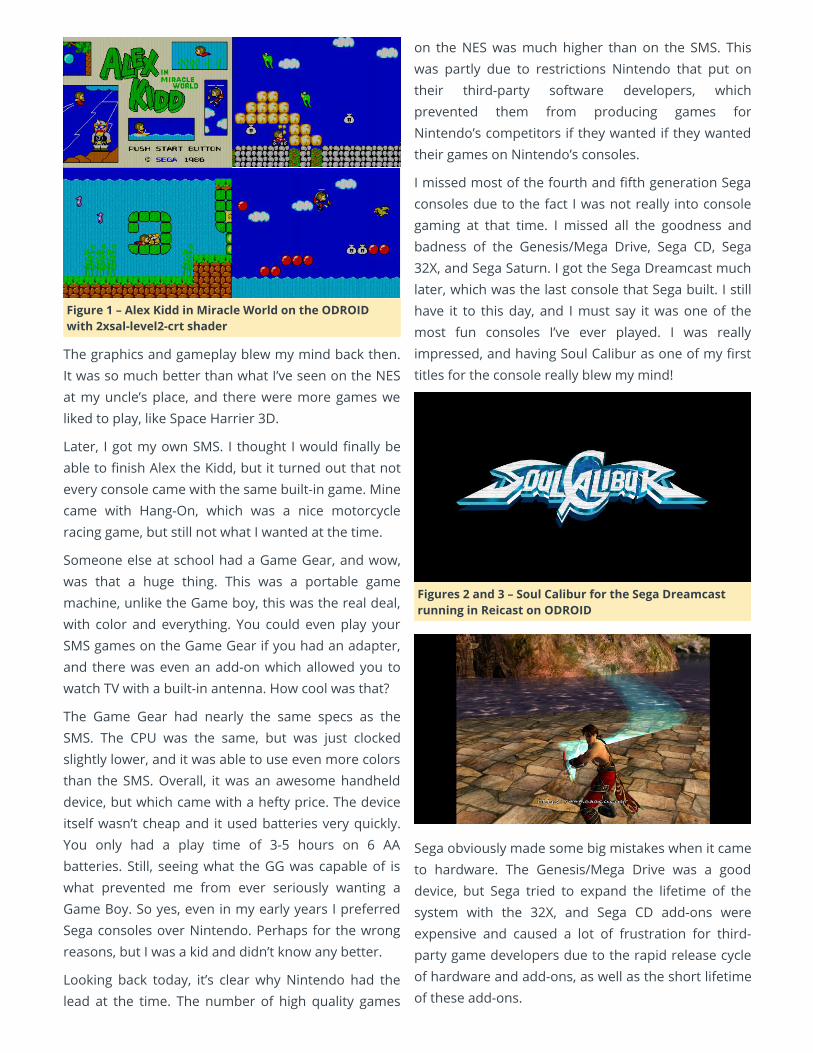
Figure 1 – Alex Kidd in Miracle World on the ODROIDwith 2xsal-level2-crt shader
The graphics and gameplay blew my mind back then.It was so much better than what I’ve seen on the NESat my uncle’s place, and there were more games weliked to play, like Space Harrier 3D.
Later, I got my own SMS. I thought I would nally beable to nish Alex the Kidd, but it turned out that notevery console came with the same built-in game. Minecame with Hang-On, which was a nice motorcycleracing game, but still not what I wanted at the time.
Someone else at school had a Game Gear, and wow,was that a huge thing. This was a portable gamemachine, unlike the Game boy, this was the real deal,with color and everything. You could even play yourSMS games on the Game Gear if you had an adapter,and there was even an add-on which allowed you towatch TV with a built-in antenna. How cool was that?
The Game Gear had nearly the same specs as theSMS. The CPU was the same, but was just clockedslightly lower, and it was able to use even more colorsthan the SMS. Overall, it was an awesome handhelddevice, but which came with a hefty price. The deviceitself wasn’t cheap and it used batteries very quickly.You only had a play time of 3-5 hours on 6 AAbatteries. Still, seeing what the GG was capable of iswhat prevented me from ever seriously wanting aGame Boy. So yes, even in my early years I preferredSega consoles over Nintendo. Perhaps for the wrongreasons, but I was a kid and didn’t know any better.
Looking back today, it’s clear why Nintendo had thelead at the time. The number of high quality games
on the NES was much higher than on the SMS. Thiswas partly due to restrictions Nintendo that put ontheir third-party software developers, whichprevented them from producing games forNintendo’s competitors if they wanted if they wantedtheir games on Nintendo’s consoles.
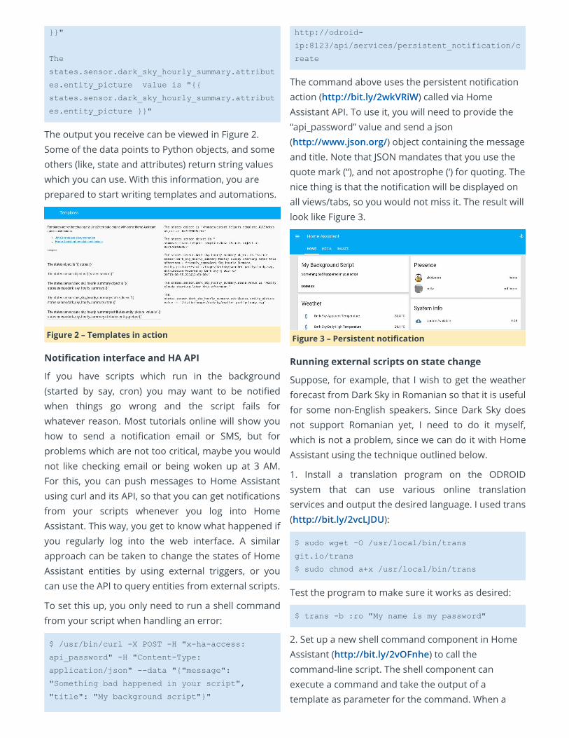
I missed most of the fourth and fth generation Segaconsoles due to the fact I was not really into consolegaming at that time. I missed all the goodness andbadness of the Genesis/Mega Drive, Sega CD, Sega32X, and Sega Saturn. I got the Sega Dreamcast muchlater, which was the last console that Sega built. I stillhave it to this day, and I must say it was one of themost fun consoles I’ve ever played. I was reallyimpressed, and having Soul Calibur as one of my rsttitles for the console really blew my mind!
Figures 2 and 3 – Soul Calibur for the Sega Dreamcastrunning in Reicast on ODROID
Sega obviously made some big mistakes when it cameto hardware. The Genesis/Mega Drive was a gooddevice, but Sega tried to expand the lifetime of thesystem with the 32X, and Sega CD add-ons wereexpensive and caused a lot of frustration for third-party game developers due to the rapid release cycleof hardware and add-ons, as well as the short lifetimeof these add-ons.

Because of this, Sega developed nearly all of thegames for the Dreamcast on their own. Sega may nothave been the best hardware developer at the time,but they knew how to make good games. They stillmake games today, and have even developed gamesfor their former rival Nintendo and their consoles.
Sega Emulation on ODROID
Since Sega stopped producing hardware after theSega Dreamcast, it is probably safe to say that all ofSega’s consoles run on ODROID, although some mayrun better than others. For example, the Sega 32X,which is an addon for the Sega Genesis, was dicultto emulate at rst, but thanks to the dynamicrecompiler on the PicoDrive emulator we can nowplay these games, even on the ODROID-C1.
With Reicast, the Sega Dreamcast got a speedyemulator that allows users to play many, but not all,of the Sega Dreamcast games on ODROID. Even theSega Saturn, which is known to have a verycomplicated architecture, runs at the very least on theXU3 and XU4 at a decent speed, with many workingtitles.
Thanks to emulation, I found a lot of new games forthe Sega Genesis/Mega Drive and other Sega systemsto enjoy. Animaniacs, Beyond Oasis, Comix Zone,Donald in Maui Mallard, or Monster World IV are justa few of the Sega Genesis games I enjoy. With KeioFlying Squadron, Lunar: The Silver Star, Popful Mail,and especially Snatcher, Sega CD has in its librarysome really awesome games. I like the fact that manygames for the Sega CD are still cartoon- or anime-based and, as such, often have cartoon or anime cut-scene videos which, along with some great musictracks, greatly enhance the experience. Maybe theSega CD was not a commercial success, but it hadsome nice games which I enjoy playing to this day.
Although only really playable on the ODROID-XU3/XU4, the Sega Saturn has some great games,including The Legend of Oasis, Elevator ActionReturns, Keio Flying Squadron 2, or Radiant Silvergun.Personally, I think it was a failure as a 3D console.Games like Radiant Silvergun or Wipeout show prettywell that 3D was not one of the Sega Saturn’s
strengths. You can see a lot of dithering, and theoverall 3D quality is much worse than on a Playstationor an N64. However, the 2D capabilities were rathergood. This could have been a great 2D 32-bit consolegame with lots of video cut-scenes and improved 2Dgraphics, rather than trying to push “pseudo 3D” onthe console. Some games obviously went this route,but many tried too hard to be 3D console games.
Of course, I still love Dreamcast emulation onODROID. Crazy Taxi 2, Dead or Alive 2, Evolution 1 and2, Giga Wing 1 and 2, Grandia II, Ikaruga, Incoming,Kidou Senshi Gundam – Renpou vs. Zeon DX,Phantasy Star Online Ver. 2, Power Stone 2, Rez, Skiesof Arcadia, Sonic Adventure 2, Soul Calibur, Star WarsEpisode I:Racer, Virtual Tennis 2, and Zero Gunner 2.There are so many awesome games with excellent 3Dgraphics that I really can’t get enough of it. Next to thePSP, I nd it’s the console with the second mostimpressive graphics on the ODROID.
Final Thoughts
So am I a Sega fanboy? I guess I am, due to my goodexperiences with Sega, rst as a child with the MasterSystem and Game Gear (compared to the NES andGame Boy), and later through the impressiveDreamcast, which I still love to this day and of which Ihave the most fond memories. Today, we can pick thebest games for every Sega console. It may not be asmany as for Nintendo, but that’s ne with me. Icontinue to enjoy Sega consoles.
Still, I realize that the gaming libraries of Sega oeredless Triple A series compared to the Nintendoconsoles, especially when it came to great series suchas Super Mario Bros., Pokémon, Zelda, Earthbound, F-Zero, Metroid, and Dragon Quest. However, Sega hadhis shining stars as well, with Sonic the Hedgehog,Phantasy Star, Golden Axe, Outrun, Virtual Fighter,and Wonderboy.
Sega might not have been the most successfulconsole company, but it created some very impressiveconsoles for its time, even if some may have been ill-fated. Sega also provided numerous games for arcadesystems, and they continue to produce great gamestoday.

Home Assistant: Customization and Automations September 1, 2017 By Adrian Popa Linux, Tinkering, Tutorial
In the July 2017 issue of ODROID Magazine, Iintroduced you to Home Assistant(http://bit.ly/2hlOPOE), which is an open-sourcehome automation platform. Based on the exampleslisted in that article, this article will discuss advancedtopics related to Home Assistant (HA) using in-depthsteps. This will allow you to maximize the use of HA,and also help with experimentation.
Working with HA Developer Tools
When accessed, the HA webui looks similar to the oneshown in Figure 1a. In the previous article, Imentioned the Developer Tools inside HA. You canaccess them by going to the left panel (bottom) in theweb interface and hovering over the buttons.
Figure 1a – Webui
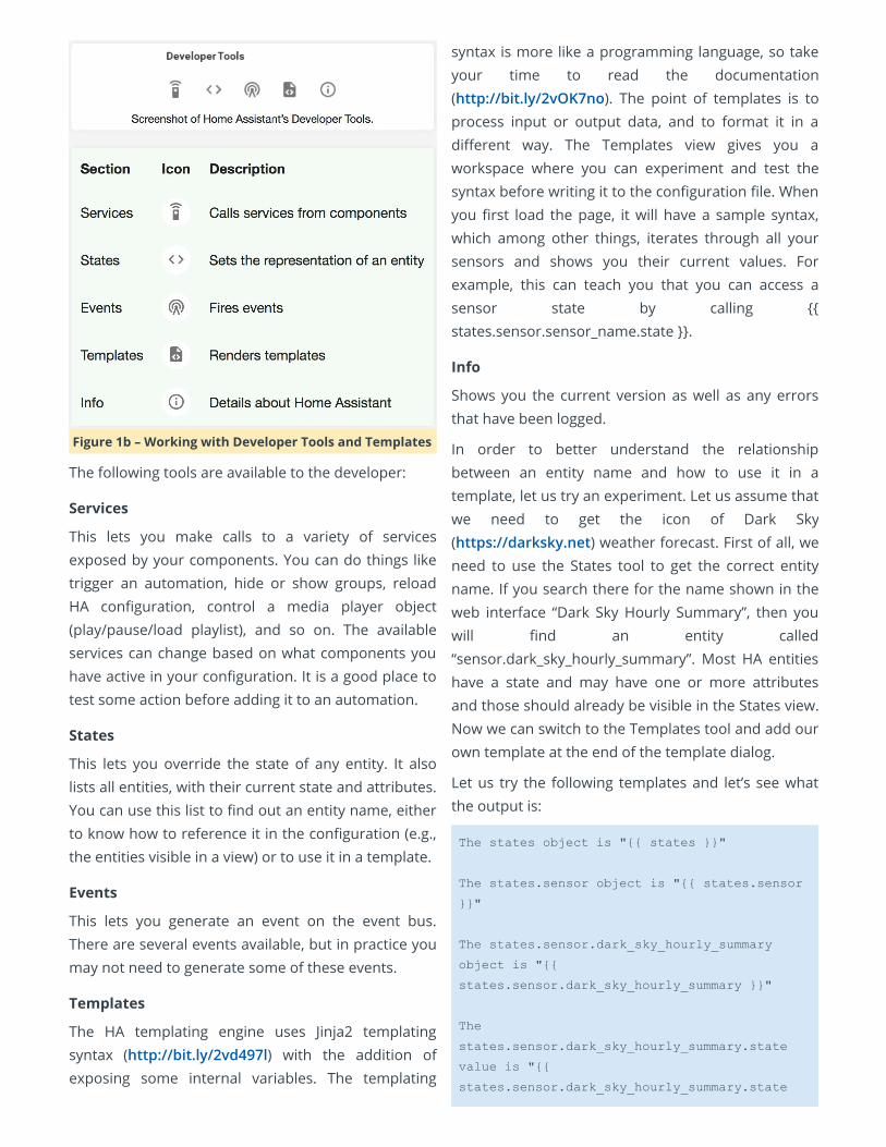
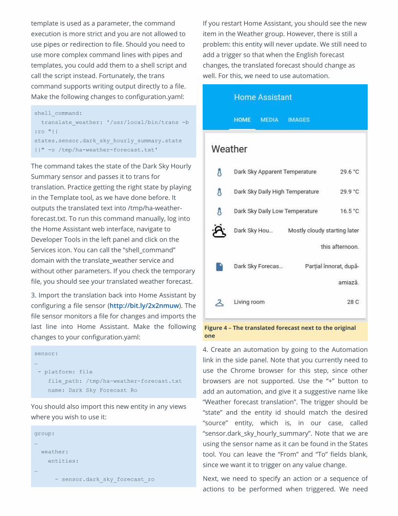
Figure 1b – Working with Developer Tools and Templates
The following tools are available to the developer:
Services
This lets you make calls to a variety of servicesexposed by your components. You can do things liketrigger an automation, hide or show groups, reloadHA conguration, control a media player object(play/pause/load playlist), and so on. The availableservices can change based on what components youhave active in your conguration. It is a good place totest some action before adding it to an automation.
States
This lets you override the state of any entity. It alsolists all entities, with their current state and attributes.You can use this list to nd out an entity name, eitherto know how to reference it in the conguration (e.g.,the entities visible in a view) or to use it in a template.
Events
This lets you generate an event on the event bus.There are several events available, but in practice youmay not need to generate some of these events.
Templates
The HA templating engine uses Jinja2 templatingsyntax (http://bit.ly/2vd497l) with the addition ofexposing some internal variables. The templating
syntax is more like a programming language, so takeyour time to read the documentation(http://bit.ly/2vOK7no). The point of templates is toprocess input or output data, and to format it in adierent way. The Templates view gives you aworkspace where you can experiment and test thesyntax before writing it to the conguration le. Whenyou rst load the page, it will have a sample syntax,which among other things, iterates through all yoursensors and shows you their current values. Forexample, this can teach you that you can access asensor state by calling states.sensor.sensor_name.state .
Info
Shows you the current version as well as any errorsthat have been logged.
In order to better understand the relationshipbetween an entity name and how to use it in atemplate, let us try an experiment. Let us assume thatwe need to get the icon of Dark Sky(https://darksky.net) weather forecast. First of all, weneed to use the States tool to get the correct entityname. If you search there for the name shown in theweb interface “Dark Sky Hourly Summary”, then youwill nd an entity called“sensor.dark_sky_hourly_summary”. Most HA entitieshave a state and may have one or more attributesand those should already be visible in the States view.Now we can switch to the Templates tool and add ourown template at the end of the template dialog.
Let us try the following templates and let’s see whatthe output is:
The states object is " states "
The states.sensor object is " states.sensor
"
The states.sensor.dark_sky_hourly_summary
object is "
states.sensor.dark_sky_hourly_summary "
The
states.sensor.dark_sky_hourly_summary.state
value is "
states.sensor.dark_sky_hourly_summary.state
"
The
states.sensor.dark_sky_hourly_summary.attribut
es.entity_picture value is "
states.sensor.dark_sky_hourly_summary.attribut
es.entity_picture "
The output you receive can be viewed in Figure 2.Some of the data points to Python objects, and someothers (like, state and attributes) return string valueswhich you can use. With this information, you areprepared to start writing templates and automations.
Figure 2 – Templates in action
Notication interface and HA API
If you have scripts which run in the background(started by say, cron) you may want to be notiedwhen things go wrong and the script fails forwhatever reason. Most tutorials online will show youhow to send a notication email or SMS, but forproblems which are not too critical, maybe you wouldnot like checking email or being woken up at 3 AM.For this, you can push messages to Home Assistantusing curl and its API, so that you can get noticationsfrom your scripts whenever you log into HomeAssistant. This way, you get to know what happened ifyou regularly log into the web interface. A similarapproach can be taken to change the states of HomeAssistant entities by using external triggers, or youcan use the API to query entities from external scripts.
To set this up, you only need to run a shell commandfrom your script when handling an error:
$ /usr/bin/curl X POST H "xhaaccess:
api_password" H "ContentType:
application/json" data ""message":
"Something bad happened in your script",
"title": "My background script""
http://odroid
ip:8123/api/services/persistent_notification/c
reate
The command above uses the persistent noticationaction (http://bit.ly/2wkVRiW) called via HomeAssistant API. To use it, you will need to provide the“api_password” value and send a json(http://www.json.org/) object containing the messageand title. Note that JSON mandates that you use thequote mark (“), and not apostrophe (‘) for quoting. Thenice thing is that the notication will be displayed onall views/tabs, so you would not miss it. The result willlook like Figure 3.
Figure 3 – Persistent notication
Running external scripts on state change
Suppose, for example, that I wish to get the weatherforecast from Dark Sky in Romanian so that it is usefulfor some non-English speakers. Since Dark Sky doesnot support Romanian yet, I need to do it myself,which is not a problem, since we can do it with HomeAssistant using the technique outlined below.
1. Install a translation program on the ODROIDsystem that can use various online translationservices and output the desired language. I used trans(http://bit.ly/2vcLJDU):
$ sudo wget O /usr/local/bin/trans
git.io/trans
$ sudo chmod a+x /usr/local/bin/trans
Test the program to make sure it works as desired:
$ trans b :ro "My name is my password"
2. Set up a new shell command component in HomeAssistant (http://bit.ly/2vOFnhe) to call thecommand-line script. The shell component canexecute a command and take the output of atemplate as parameter for the command. When a
template is used as a parameter, the commandexecution is more strict and you are not allowed touse pipes or redirection to le. Should you need touse more complex command lines with pipes andtemplates, you could add them to a shell script andcall the script instead. Fortunately, the transcommand supports writing output directly to a le.Make the following changes to conguration.yaml:
shell_command:
translate_weather: '/usr/local/bin/trans b
:ro "
states.sensor.dark_sky_hourly_summary.state
" o /tmp/haweatherforecast.txt'
The command takes the state of the Dark Sky HourlySummary sensor and passes it to trans fortranslation. Practice getting the right state by playingin the Template tool, as we have done before. Itoutputs the translated text into /tmp/ha-weather-forecast.txt. To run this command manually, log intothe Home Assistant web interface, navigate toDeveloper Tools in the left panel and click on theServices icon. You can call the “shell_command”domain with the translate_weather service andwithout other parameters. If you check the temporaryle, you should see your translated weather forecast.
3. Import the translation back into Home Assistant byconguring a le sensor (http://bit.ly/2x2nmuw). Thele sensor monitors a le for changes and imports thelast line into Home Assistant. Make the followingchanges to your conguration.yaml:
sensor:
…
platform: file
file_path: /tmp/haweatherforecast.txt
name: Dark Sky Forecast Ro
You should also import this new entity in any viewswhere you wish to use it:
group:
…
weather:
entities:
…
sensor.dark_sky_forecast_ro
If you restart Home Assistant, you should see the newitem in the Weather group. However, there is still aproblem: this entity will never update. We still need toadd a trigger so that when the English forecastchanges, the translated forecast should change aswell. For this, we need to use automation.
Figure 4 – The translated forecast next to the originalone
4. Create an automation by going to the Automationlink in the side panel. Note that you currently need touse the Chrome browser for this step, since otherbrowsers are not supported. Use the “+” button toadd an automation, and give it a suggestive name like“Weather forecast translation”. The trigger should be“state” and the entity id should match the desired“source” entity, which is, in our case, called“sensor.dark_sky_hourly_summary”. Note that we areusing the sensor name as it can be found in the Statestool. You can leave the “From” and “To” elds blank,since we want it to trigger on any value change.
Next, we need to specify an action or a sequence ofactions to be performed when triggered. We need
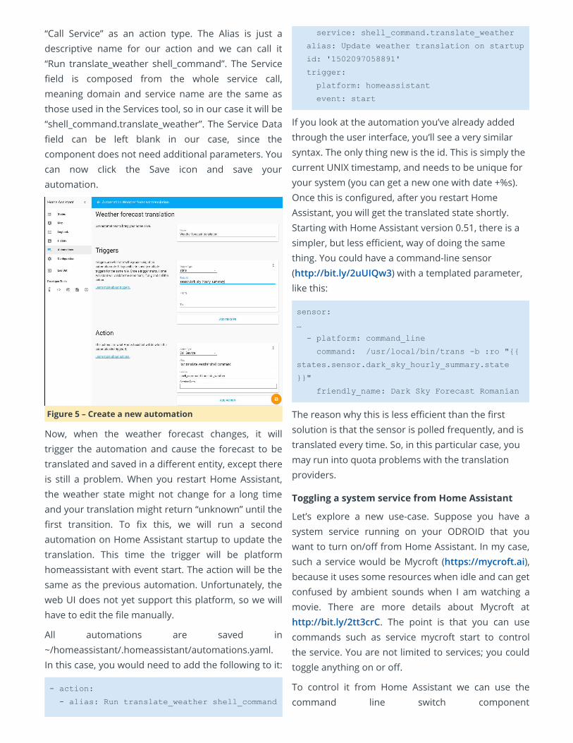
“Call Service” as an action type. The Alias is just adescriptive name for our action and we can call it“Run translate_weather shell_command”. The Serviceeld is composed from the whole service call,meaning domain and service name are the same asthose used in the Services tool, so in our case it will be“shell_command.translate_weather”. The Service Dataeld can be left blank in our case, since thecomponent does not need additional parameters. Youcan now click the Save icon and save yourautomation.
Figure 5 – Create a new automation
Now, when the weather forecast changes, it willtrigger the automation and cause the forecast to betranslated and saved in a dierent entity, except thereis still a problem. When you restart Home Assistant,the weather state might not change for a long timeand your translation might return “unknown” until therst transition. To x this, we will run a secondautomation on Home Assistant startup to update thetranslation. This time the trigger will be platformhomeassistant with event start. The action will be thesame as the previous automation. Unfortunately, theweb UI does not yet support this platform, so we willhave to edit the le manually.
All automations are saved in~/homeassistant/.homeassistant/automations.yaml.In this case, you would need to add the following to it:
action:
alias: Run translate_weather shell_command
service: shell_command.translate_weather
alias: Update weather translation on startup
id: '1502097058891'
trigger:
platform: homeassistant
event: start
If you look at the automation you’ve already addedthrough the user interface, you’ll see a very similarsyntax. The only thing new is the id. This is simply thecurrent UNIX timestamp, and needs to be unique foryour system (you can get a new one with date +%s).Once this is congured, after you restart HomeAssistant, you will get the translated state shortly.Starting with Home Assistant version 0.51, there is asimpler, but less ecient, way of doing the samething. You could have a command-line sensor(http://bit.ly/2uUIQw3) with a templated parameter,like this:
sensor:
…
platform: command_line
command: /usr/local/bin/trans b :ro "
states.sensor.dark_sky_hourly_summary.state
"
friendly_name: Dark Sky Forecast Romanian
The reason why this is less ecient than the rstsolution is that the sensor is polled frequently, and istranslated every time. So, in this particular case, youmay run into quota problems with the translationproviders.
Toggling a system service from Home Assistant
Let’s explore a new use-case. Suppose you have asystem service running on your ODROID that youwant to turn on/o from Home Assistant. In my case,such a service would be Mycroft (https://mycroft.ai),because it uses some resources when idle and can getconfused by ambient sounds when I am watching amovie. There are more details about Mycroft athttp://bit.ly/2tt3crC. The point is that you can usecommands such as service mycroft start to controlthe service. You are not limited to services; you couldtoggle anything on or o.
To control it from Home Assistant we can use thecommand line switch component
(http://bit.ly/2wdVGW5). Add the following to yourconguration.yaml:
switch:
platform: command_line
switches:
mycroft:
command_on: sudo /usr/sbin/service
mycroft start
command_off: sudo /usr/sbin/service
mycroft stop
command_state: /usr/sbin/service
mycroft status >/dev/null 2>&1
friendly_name: "Mycroft status"
You can also add it to a separate view:
group:
…
switches:
name: Switches
view: yes
entities:
switch.mycroft
There is one more thing you need to add for this towork. The sudo command will ask for a password bydefault, so we need to tell sudo that the userhomeassistant can run the service command as rootwithout a password. We can do this by running sudovisudo and adding the following line at the end of thele:
homeassistant ALL=NOPASSWD: /usr/sbin/service
Let us expand this example a little. Suppose you wantto be able to toggle a service running on a dierentdevice. The most secure way to do this would bethrough ssh. In order to do this, we will need to setupkeys for ssh, so that homeassistant user can runcommands through ssh without being prompted for apassword (note that for security’s sake you will needto protect your keys). You will need to run thefollowing steps with the homeassistant user:
1. Create a new ssh key for homeassistant with nopassword:
$ sudo su s /bin/bash homeassistant
$ cd ~homeassistant
$ sshkeygen t rsa
Accept the default values (key stored in/home/homeassistant/.ssh/id_rsa, and nopassphrase). You can use this key to control manydevices (including using it to login on routers forpresence detection), so there is no need to createmultiple keys.
2. Copy the key to the remote system. Make sure thatyou input the correct password for the account youare connecting as (I am using root on the remotedevice):
$ sshcopyid root@otherdeviceip
3. Test the connection manually:
$ ssh root@otherdeviceip hostname
You should receive one line with the other device’shostname, without being prompted for a password. Ifyou get this, it means it is working. If not, you can ndan awesome troubleshooting guide athttp://bit.ly/2vTQYdA.
4. Congure it in Home Assistant by adding a newswitch entry in conguration.yaml:
switch:
platform: command_line
switches:
…
mycroft_kitchen:
command_on: ssh root@kitchen
/usr/sbin/service mycroft start
command_off: ssh root@kitchen
/usr/sbin/service mycroft stop
friendly_name: "Mycroft Kitchen
status"
If you do not want the constant polling from HomeAssistant for the state, you can omit the“command_state” line and in this case Home Assistantwill assume it is o and will keep track only of thechanges you make in the user interface. Also, theinterface will change from a slider to two icons toactivate/deactivate.

Figure 6 – Switches for system processes
Toggling a switch based on media playback orpresence information
Now that we can manually turn Mycroft on/o (or anyswitch for that matter), let us make things interesting.I would like to have Mycroft running when I am athome (my phone is connected to the router anddetected by the presence detection we haveimplemented in the previous article) and Kodi is notplaying. However, that can be ambiguous. So, let usdene what we really want:
User transitions from “not_home” to “home” and Kodiis idle => turn on Mycroft
User transitions from “home” to “not_home” => turn oMycroft
User is “home” and Kodi transitions from anything toplaying => turn o Mycroft
User is “home” and Kodi transitions from anything toidle => turn on Mycroft
For this, we will create a few automations. What isdierent from the previous automations will be theuse of conditions (http://bit.ly/2x2FDYz). Triggersindicate when an action should happen, whileconditions are used as lters and say if that actionshould happen.
So, let us take the rst step. My user is tracked by thedevice called “nutty”. Since the web interface does notsupport conditions (note: conditions are onlysupported starting with version 0.51), we will have todo it manually, in the cong le automations.yaml:
action:
alias: Turn on Mycroft
service: switch.turn_on
entity_id:
switch.mycroft
alias: Turn on Mycroft when Nutty arrives
home and Kodi is idle
id: '1502097058892'
trigger:
platform: state
entity_id: device_tracker.nutty
to: 'home'
condition:
condition: and
conditions:
condition: state
entity_id:
'media_player.kodi_livingroom'
state: 'idle'
The automation is triggered and evaluated each timethe entity “device_tracker.nutty” changes state. Whenit is triggered, the condition is evaluated as well and if“media_player.kodi_livingroom” is idle at that time,then the action is executed and the switch is turnedon. I could have also tested that Mycroft is o, butturning on an already-on switch has no negative sideeects.
If that is dicult to follow, here is the pseudo-code:
onStateChange(device_tracker.nutty):
if states.device_tracker.nutty.state ==
'home':
if
states.media_player.kodi_livingroom.state ==
'idle':
switch.turn_on(switch.mycroft)
The o automation looks similar, but is simpler sinceit does not have an extra condition:
action:
alias: Turn off Mycroft
service: switch.turn_off
entity_id:
switch.mycroft
alias: Turn off Mycroft when Nutty leaves
home
id: '1502097058893'
trigger:
platform: state
entity_id: device_tracker.nutty
to: 'not_home'
The last two automations should be triggered by Kodistate changes and use conditions to test if the user ishome or not.
action:
alias: Turn off Mycroft
service: switch.turn_off
entity_id:
switch.mycroft
alias: Turn off Mycroft when Kodi is playing
and Nutty is home
id: '1502097058894'
trigger:
platform: state
entity_id: media_player.kodi_livingroom
to: 'playing'
condition:
condition: and
conditions:
condition: state
entity_id: 'device_tracker.nutty'
state: 'home'
And the last one should be:
action:
alias: Turn on Mycroft
service: switch.turn_on
entity_id:
switch.mycroft
alias: Turn on Mycroft when Kodi is idle and
Nutty is home
id: '1502097058895'
trigger:
platform: state
entity_id: media_player.kodi_livingroom
to: 'idle'
condition:
condition: and
conditions:
condition: state
entity_id: 'device_tracker.nutty'
state: 'home'
Once you are done editing automations.yaml, you canreload the automations directly from Home Assistantby going to the “Conguration” view and selecting“Reload Automation”.
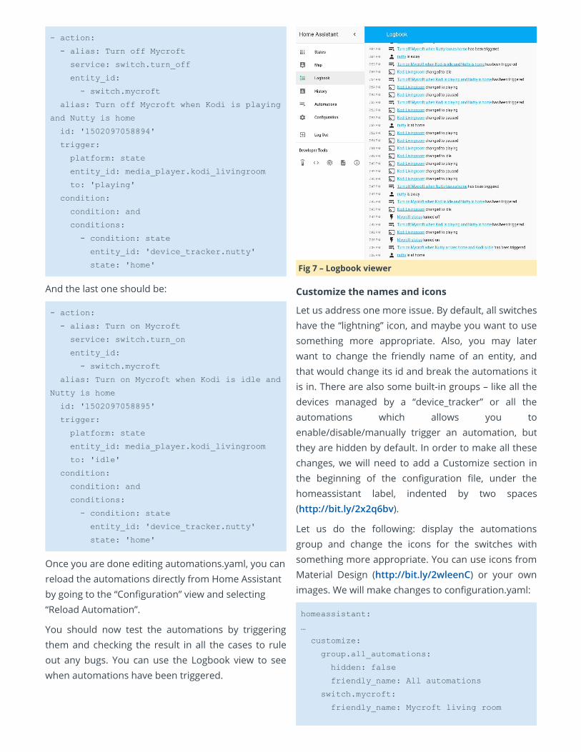
You should now test the automations by triggeringthem and checking the result in all the cases to ruleout any bugs. You can use the Logbook view to seewhen automations have been triggered.
Fig 7 – Logbook viewer
Customize the names and icons
Let us address one more issue. By default, all switcheshave the “lightning” icon, and maybe you want to usesomething more appropriate. Also, you may laterwant to change the friendly name of an entity, andthat would change its id and break the automations itis in. There are also some built-in groups – like all thedevices managed by a “device_tracker” or all theautomations which allows you toenable/disable/manually trigger an automation, butthey are hidden by default. In order to make all thesechanges, we will need to add a Customize section inthe beginning of the conguration le, under thehomeassistant label, indented by two spaces(http://bit.ly/2x2q6bv).
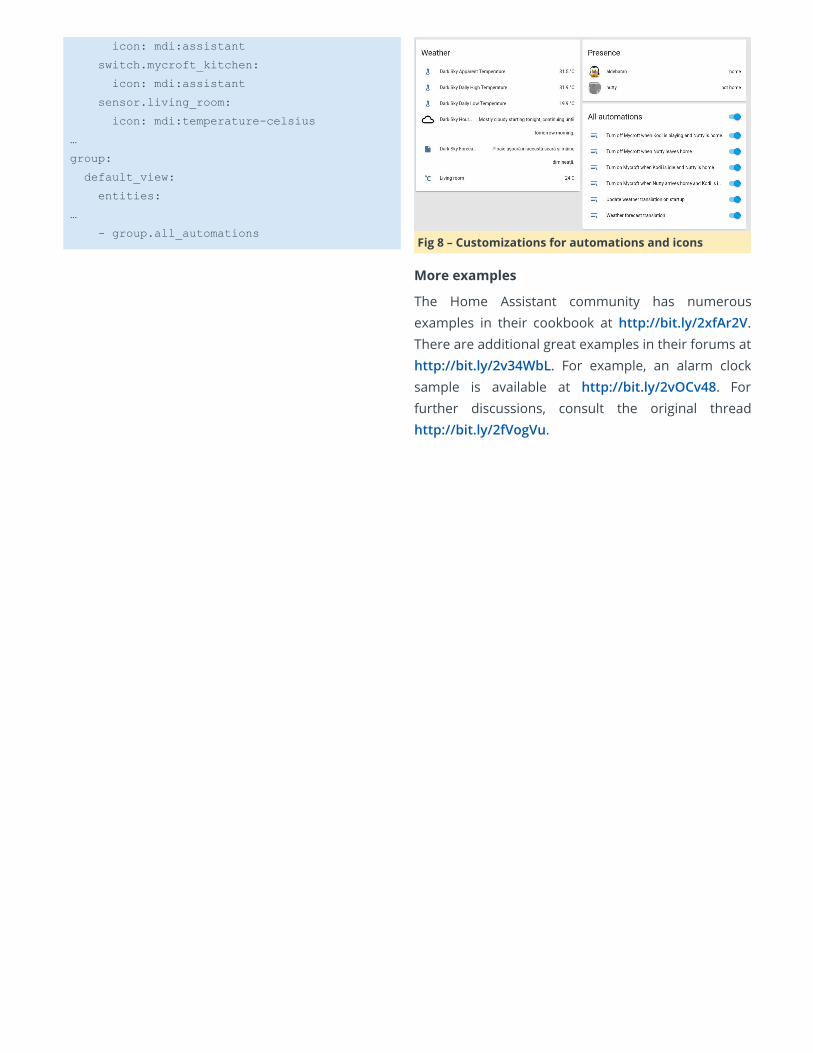
Let us do the following: display the automationsgroup and change the icons for the switches withsomething more appropriate. You can use icons fromMaterial Design (http://bit.ly/2wleenC) or your ownimages. We will make changes to conguration.yaml:
homeassistant:
…
customize:
group.all_automations:
hidden: false
friendly_name: All automations
switch.mycroft:
friendly_name: Mycroft living room
icon: mdi:assistant
switch.mycroft_kitchen:
icon: mdi:assistant
sensor.living_room:
icon: mdi:temperaturecelsius
…
group:
default_view:
entities:
…
group.all_automations Fig 8 – Customizations for automations and icons
More examples
The Home Assistant community has numerousexamples in their cookbook at http://bit.ly/2xfAr2V.There are additional great examples in their forums athttp://bit.ly/2v34WbL. For example, an alarm clocksample is available at http://bit.ly/2vOCv48. Forfurther discussions, consult the original threadhttp://bit.ly/2fVogVu.
Digole Serial Displays: Driving Digole’s Serial Display in UART,I2C, and SPI Modes with an ODROID-C1+ September 1, 2017 By Dennis Chang Linux, ODROID-C1+, Tutorial
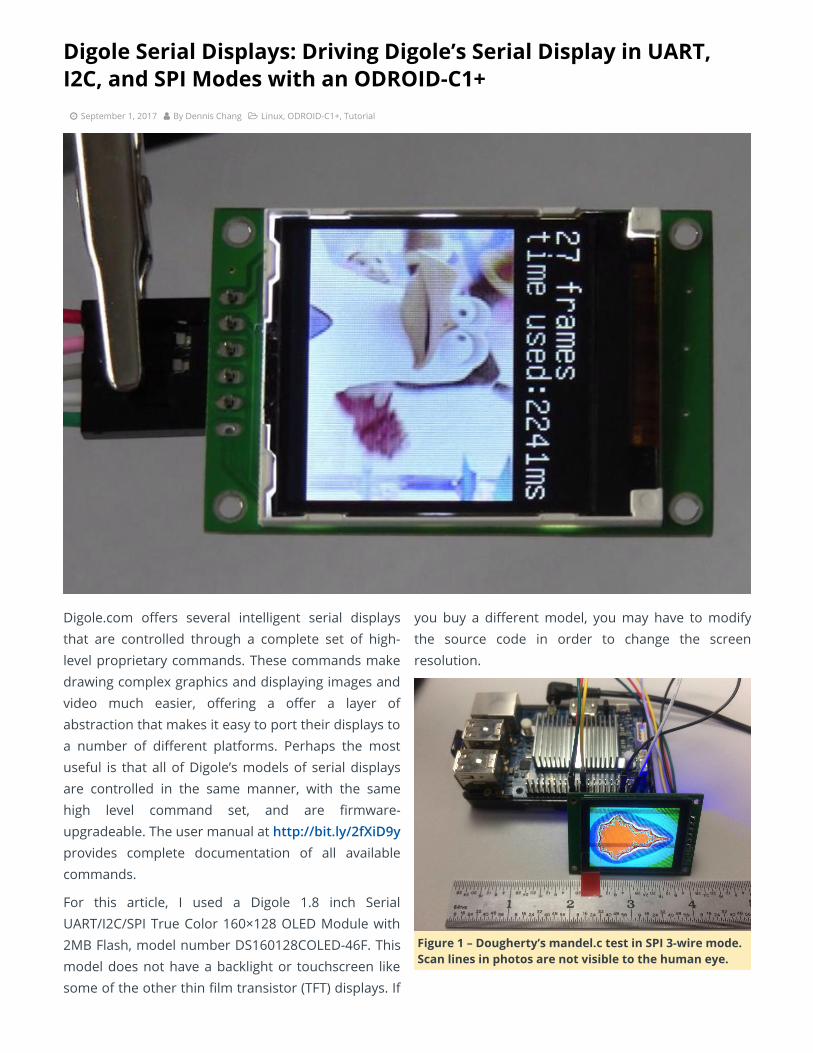
Digole.com oers several intelligent serial displaysthat are controlled through a complete set of high-level proprietary commands. These commands makedrawing complex graphics and displaying images andvideo much easier, oering a oer a layer ofabstraction that makes it easy to port their displays toa number of dierent platforms. Perhaps the mostuseful is that all of Digole’s models of serial displaysare controlled in the same manner, with the samehigh level command set, and are rmware-upgradeable. The user manual at http://bit.ly/2fXiD9yprovides complete documentation of all availablecommands.
For this article, I used a Digole 1.8 inch SerialUART/I2C/SPI True Color 160×128 OLED Module with2MB Flash, model number DS160128COLED-46F. Thismodel does not have a backlight or touchscreen likesome of the other thin lm transistor (TFT) displays. If
you buy a dierent model, you may have to modifythe source code in order to change the screenresolution.
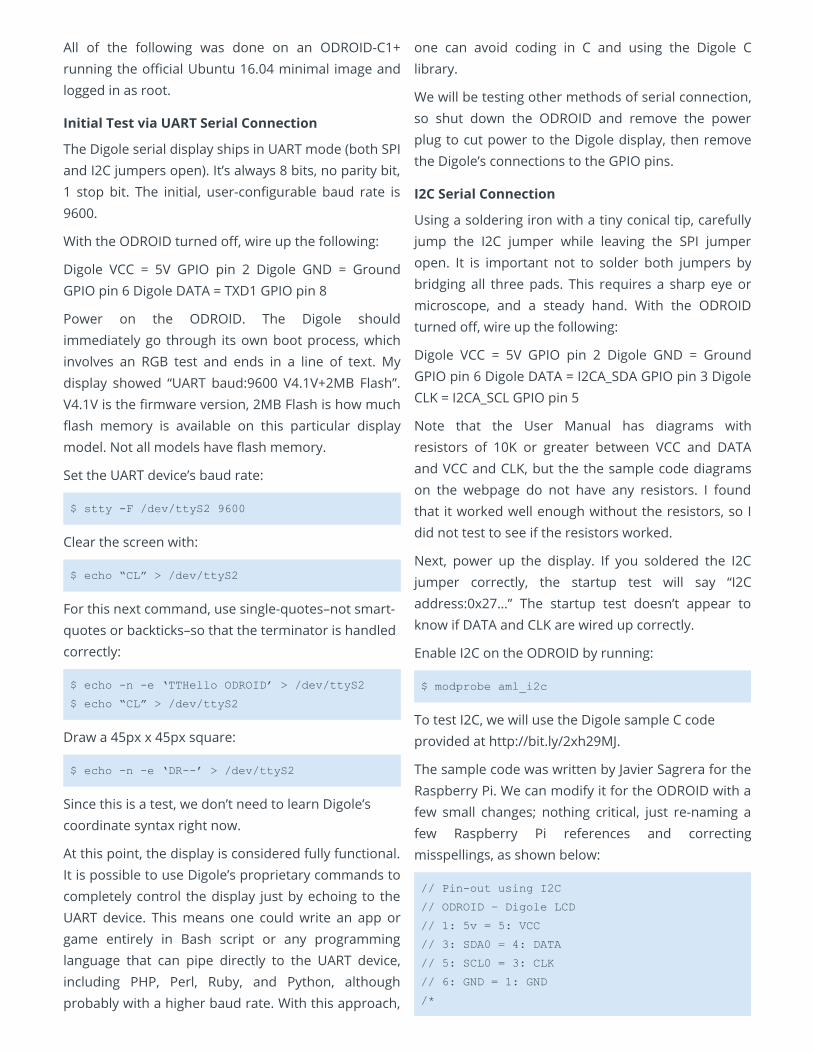
Figure 1 – Dougherty’s mandel.c test in SPI 3-wire mode.Scan lines in photos are not visible to the human eye.
All of the following was done on an ODROID-C1+running the ocial Ubuntu 16.04 minimal image andlogged in as root.
Initial Test via UART Serial Connection
The Digole serial display ships in UART mode (both SPIand I2C jumpers open). It’s always 8 bits, no parity bit,1 stop bit. The initial, user-congurable baud rate is9600.
With the ODROID turned o, wire up the following:
Digole VCC = 5V GPIO pin 2 Digole GND = GroundGPIO pin 6 Digole DATA = TXD1 GPIO pin 8
Power on the ODROID. The Digole shouldimmediately go through its own boot process, whichinvolves an RGB test and ends in a line of text. Mydisplay showed “UART baud:9600 V4.1V+2MB Flash”.V4.1V is the rmware version, 2MB Flash is how muchash memory is available on this particular displaymodel. Not all models have ash memory.
Set the UART device’s baud rate:
$ stty F /dev/ttyS2 9600
Clear the screen with:
$ echo “CL” > /dev/ttyS2
For this next command, use single-quotes–not smart-quotes or backticks–so that the terminator is handledcorrectly:
$ echo n e ‘TTHello ODROID’ > /dev/ttyS2
$ echo “CL” > /dev/ttyS2
Draw a 45px x 45px square:
$ echo n e ‘DR’ > /dev/ttyS2
Since this is a test, we don’t need to learn Digole’scoordinate syntax right now.
At this point, the display is considered fully functional.It is possible to use Digole’s proprietary commands tocompletely control the display just by echoing to theUART device. This means one could write an app orgame entirely in Bash script or any programminglanguage that can pipe directly to the UART device,including PHP, Perl, Ruby, and Python, althoughprobably with a higher baud rate. With this approach,
one can avoid coding in C and using the Digole Clibrary.
We will be testing other methods of serial connection,so shut down the ODROID and remove the powerplug to cut power to the Digole display, then removethe Digole’s connections to the GPIO pins.
I2C Serial Connection
Using a soldering iron with a tiny conical tip, carefullyjump the I2C jumper while leaving the SPI jumperopen. It is important not to solder both jumpers bybridging all three pads. This requires a sharp eye ormicroscope, and a steady hand. With the ODROIDturned o, wire up the following:
Digole VCC = 5V GPIO pin 2 Digole GND = GroundGPIO pin 6 Digole DATA = I2CA_SDA GPIO pin 3 DigoleCLK = I2CA_SCL GPIO pin 5
Note that the User Manual has diagrams withresistors of 10K or greater between VCC and DATAand VCC and CLK, but the the sample code diagramson the webpage do not have any resistors. I foundthat it worked well enough without the resistors, so Idid not test to see if the resistors worked.
Next, power up the display. If you soldered the I2Cjumper correctly, the startup test will say “I2Caddress:0x27…” The startup test doesn’t appear toknow if DATA and CLK are wired up correctly.
Enable I2C on the ODROID by running:
$ modprobe aml_i2c
To test I2C, we will use the Digole sample C codeprovided at http://bit.ly/2xh29MJ.
The sample code was written by Javier Sagrera for theRaspberry Pi. We can modify it for the ODROID with afew small changes; nothing critical, just re-naming afew Raspberry Pi references and correctingmisspellings, as shown below:
// Pinout using I2C
// ODROID – Digole LCD
// 1: 5v = 5: VCC
// 3: SDA0 = 4: DATA
// 5: SCL0 = 3: CLK
// 6: GND = 1: GND
/*

// Communication set up command
* "SB":Baud (ascII bytes end with
0x00/0x0A/0x0D) set UART Baud Rate
* "SI2CA":Address(1 byte <127) Set I2C
address, default address is:0x27
* "DC":1/0(1byte) set config display
on/off, if set to 1, displayer will display
current commucation setting when power on
// Text Function command
* "CL": Clear screenOK
* "CS":1/0 (1 byte) Cursor on/off
* "TP":x(1 byte) y(1 byte) set text
position
* "TT":string(bytes) end with 0x00/0x0A/0x0D
display string under regular mode
// Graphic function command
* "GP":x(1byte) y(1byte) set current
graphic position
* "DM":"C/!/~/&/|/^"(ASCII 1byte) set
drawing modeC="Copy",! and ~ = "Not", & =
"And", | = "Or", ^ = "Xor"
* "SC":1/0 (1byte) set draw coloronly 1
and 0
* "LN":x0(1byte) y0(1byte) x1(1byte)
y2(1byte)draw line from x0,y0 to x1,y1,set
new pot to x1,y1
* "LT":x(1byte) y(1byte) draw line from
current pos to x,y
* "CC":x(1byte) y(1byte) ratio(byte) draw
circle at x,y with ratio
* "DP":x(1byte) y(1byte) Color(1byte) draw
a pixelOK
* "DR":x0(1byte) y0(1byte) x1(1byte)
y2(1byte)draw rectangle, topleft:x0,y0;
rightbottom:x1,y1
* "FR":x0(1byte) y0(1byte) x1(1byte)
y2(1byte)draw filled rectangle, top
left:x0,y0; rightbottom:x1,y1
*/
#include < stdlib.h >
#include < linux/i2cdev.h >
#include < fcntl.h >
#include < string.h >
#include < sys/ioctl.h >
#include < sys/types.h >
#include < sys/stat.h >
#include < unistd.h >
int main(int argc, char **argv)
int fd;
char *fileName = "/dev/i2c1"; // Name
of the port we will be using
int address = 0x27; //
Address of I2C device
char buf[100];
if ((fd = open (fileName, O_RDWR)) < 0)
// Open port for reading and writing
printf("Failed to open i2c port
");
exit(1);
if (ioctl(fd, I2C_SLAVE, address) < 0) //
Set the port options and set the address of
the device printf("Unable to get bus access to
talk to slave
"); exit(1); if (argc>1)
sprintf(buf,argv[1]);
//printf("%s %d %s
",buf,strlen(buf),buf[strlen(buf)]);
if ((write(fd, buf, strlen(buf)+1)) !=
strlen(buf)+1)
printf("Error writing to i2c slave
");
exit(1);
else
printf(" Simple tool to send commands
to Digole graphic adapter
examples:
");
printf(" digolei2ctest "CLTTHello
ODROID" Clear the screen (CL) and prints
"Hello ODROID" (TT)
");
printf(" digolei2ctest "CC002" Draws
a circle at x=30 (0), y=30 (0) with a radius
of 32 (2)
"); //not for Character LCD
return 0;
Save the above source code as digolei2ctest.c, thencompile it:
$ gcc o digolei2ctest digolei2ctest.c
You can then run it to send commands (several areprovided in the comments):
$ ./digolei2ctest "CLTTHello ODROID"
$ ./digolei2ctest "CC002"
Again, you can use every high-level commandavailable in the User Manual.
Note: I2C is the only means of communicating withthe Digole serial display that is capable of two-waycommunication. Considering that we are only drawingon the display, receive capability is not necessary, butI2C is probably required for touchscreen access.
Next, we will try the SPI method of communication.This is the fastest, but most complicated, of availableserial methods. Once again, shut down the ODROIDand remove the power plug to turn o the Digoledisplay, then disconnect the connections between theODROID and the Digole display.
SPI 3-Wire Serial Connection
Using a soldering iron with tiny conical tip, carefullydesolder the I2C jumper and replace it by solderingthe SPI jumper instead. Again, make sure not tosolder both jumpers by bridging all three pads. Withthe ODROID turned o, wire up the following:
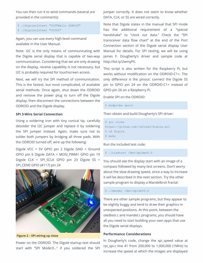
Digole VCC = 5V GPIO pin 2 Digole GND = GroundGPIO pin 6 Digole DATA = MOSI_PWM1 GPIO pin 19Digole CLK = SPI_SCLK GPIO pin 23 Digole SS =SPI_CEN0 GPIO (#117) pin 24
Figure 2 – SPI wiring up close
Power on the ODROID. The Digole startup text shouldstart with “SPI Mode:0…” if you soldered the SPI
jumper correctly. It does not seem to know whetherDATA, CLK, or SS are wired correctly.
Note that Digole states in the manual that SPI modehas the additional requirement of a “specialhandshake” to “clock out data.” Check the “SPItransceiver data ow chart” at the end of the PortConnection section of the Digole serial display UserManual for details. For SPI testing, we will be usingJames F. Dougherty’s driver and sample code athttp://bit.ly/2wmyPIi.
This script is also written for the Raspberry Pi, butworks without modication on the ODROID-C1+. Theonly dierence is the pinout: connect the Digole SSpin to GPIO pin 24 on the ODROID-C1+ instead ofGPIO pin 26 on a Raspberry Pi.
Enable SPI on the ODROID:
$ modprobe spicc
Then obtain and build Dougherty’s SPI driver:
$ git clone
https://github.com/jafrado/digole.git
$ cd digole
$ make
Run the included test code:
$ ./oledtest /dev/spidev0.0
You should see the display start with an image of acompass followed by many test screens. Don’t worryabout the slow drawing speed, since a way to increaseit will be described in the next section. Try the othersample program to display a Mandelbrot fractal:
$ ./mandel /dev/spidev0.0
There are other sample programs, but they appear tobe slightly buggy and tend to draw their graphics inunexpected positions. At this point, between theoledtest.c and mandel.c programs, you should haveall you need to start building your own apps that usethe Digole serial displays.
Performance Considerations
In Dougherty’s code, change the spi_speed value atrpi_spi.c line 41 from 200,000 to 1,000,000 (1MHz) toincrease the speed at which the images are displayed
on the screen. Going faster than 1MHz breaks thedrawing commands badly on my ODROID-C1+.Dougherty commented in the code that he was notable to go faster than 200KHz, but he was using a veryslow Raspberry Pi Zero for testing.
Curious about the limitation, I used a simple whileloop with a “sleep x” command and varying values of xin order to overwhelm the Digole display by sendingsentences of commands too quickly, causing mis-drawn graphics or corrupt images, which is exactlywhat happened when “spi_speed” value wasincreased above 1MHz in Dougherty’s sampleprograms. Theoretically, the SPI bus and the Digoledisplay can go much faster than 1MHz, but I suspectthat the aforementioned “special handshake” andprecise management of SPI communications at thebyte and word level will be necessary to achievemaximum performance.
We do know, however, that these displays are capableof performing very well. Digole links to a YouTubevideo at http://bit.ly/2wfwPRJ showing a fast, smoothvideo sequence of 27 frames in about 2 seconds,which is approximately 14fps.
Unfortunately, they do not detail in the video how toachieve this speed. The title of the video indicatesthey are using the relatively new Video Box feature (asof rmware V4.0V) which allows one to write rawimage data directly to the display. The User Manualsays Video Box runs at “maximum speed: UARTmode-460800bps, I2C->400K bps, SPI-10MHz.” That’sten times faster than our current best performanceusing Dougherty’s samples in SPI mode. It willprobably require contacting Digole tech support tond out how to pull it o.
Regarding the while loop tests, a “sleep 0.05”command appears to be the shortest delay between“TP00TTHello ODROID” sends, resulting in a barely-
perceptible icker of the words “Hello ODROID” beingredrawn in place with no errors. For many projects,especially those that update text periodically, 0.05seconds is plenty fast enough, and one will not haveto wrestle with performance tuning of the serialcommunications.
Conclusion
I’m quite impressed with the Digole serial displays fortheir multiple connection methods and easy, butpowerful, commands. There are many advancedfeatures including stored fonts, stored commandsequences, and integrated touchscreen that other,less intelligent, displays simply don’t have. Most othertouchscreens are a separate device from the display,but the Digole touchscreen is controlled through thesame serial interface as the display. The simple fact isthat there aren’t that many full-color, high-resolutiondisplays in this small of a size, especially in OLED.
I expect that these tiny full-color displays will ndtheir way into many ODROID projects, especiallyportable, battery-powered projects. This is especiallytrue of the models with resistive touchscreens andthe handful of TFT models with dimmable backlights.OLED models do not have a backlight to dim, butdimming can be accomplished by changing the colorsto darker shades.
The performance of the Digole serial displays is goodenough for most uses without any performancetuning. For games and video where frame ratematters, it is certainly possible to achieve decentperformance through managing the serialcommunications management and by takingadvantage of the Digole display’s advanced features.
Meet An ODROIDian: Ted Jack-Philippe Nivan (@TedJack) September 1, 2017 By Ted Jack-Philippe Nivan Meet an ODROIDian
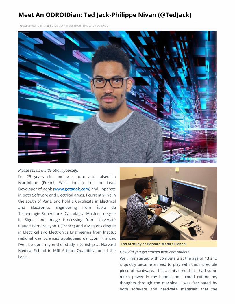
Please tell us a little about yourself. I’m 25 years old, and was born and raised inMartinique (French West Indies). I’m the LeadDeveloper of Adok (www.getadok.com) and I operatein both Software and Electrical areas. I currently live inthe south of Paris, and hold a Certicate in Electricaland Electronics Engineering from École deTechnologie Supérieure (Canada), a Master’s degreein Signal and Image Processing from UniversitéClaude Bernard Lyon 1 (France) and a Master’s degreein Electrical and Electronics Engineering from Institutnational des Sciences appliquées de Lyon (France).I’ve also done my end-of-study internship at HarvardMedical School in MRI Artifact Quantication of thebrain.
End of study at Harvard Medical School
How did you get started with computers? Well, I’ve started with computers at the age of 13 andit quickly became a need to play with this incrediblepiece of hardware. I felt at this time that I had somemuch power in my hands and I could extend mythoughts through the machine. I was fascinated byboth software and hardware materials that the
computer was made of. I’ve been working on variousprojects ever since and one of them that I’mparticularly proud of was turning a bicycle into amotorcycle. It was back in 2012, in my hometown.
Turning a bicycle to a motorcycle
What attracted you to the ODROID platform? It is mainly for the product’s quality and thecommunity. It is easy to start out with ODROIDs andthe platform is well documented.
How do you use your ODROIDs? I use my ODROIDs mainly for developing AndroidApps, Embedded Systems and Learning Linux KernelDevelopment.
Which ODROID is your favorite and why? My favorite ODROID is the XU4 because of its powerand the community behind it. People like @voodikhave been doing such a great job on keeping theplatform up-to-date.
What innovations would you like to see in futureHardkernel products? I would like to see a next-generation board with asystem on module design in order to decrease thetime to market. In addition, a board with Windowssupport would be great as well.
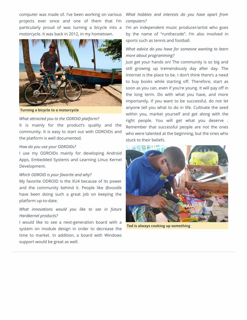
What hobbies and interests do you have apart fromcomputers? I’m an independent music producer/artist who goesby the name of “runthecode”. I’m also involved insports such as tennis and football.
What advice do you have for someone wanting to learnmore about programming? Just get your hands on! The community is so big andstill growing up tremendously day after day. TheInternet is the place to be. I don’t think there’s a needto buy books while starting o. Therefore, start assoon as you can, even if you’re young. It will pay o inthe long term. Do with what you have, and moreimportantly, if you want to be successful, do not letanyone tell you what to do in life. Cultivate the seedwithin you, market yourself and get along with theright people. You will get what you deserve .Remember that successful people are not the oneswho were talented at the beginning, but the ones whostuck to their beliefs.
Ted is always cooking up something