Embed Size (px)
Citation preview

VOL-II (TS) E13-ISOLATORS Rev-1 Page 1 of 19
ODISHA POWER TRANSMISSION CORPORATION LIMITED
TECHNICAL SPECIFICATION FOR ISOLATORS
400KV SINGLE ISOLATOR WITH 1 EARTH SWITCH
400KV SINGLE ISOLATOR WITH 2 EARTH SWITCH
220KV SINGLE ISOLATOR WITHOUT EARTH SWITCH
220KV SINGLE ISOLATOR WITHEARTH SWITCH
220 KV TANDEM ISOLATOR
132 KV DOUBLE ISOLATOR WITH EARTH SWITCH
132 KV SINGLE ISOLATOR WITH EARTH SWITCH
132 KV SINGLE ISOLATOR WITHOUT EARTH SWITCH
132 KV TANDEM ISOLATOR
33 KV DOUBLE ISOLATOR WITH EARTH SWITCH
33 KV SINGLE ISOLATOR WITHOUT EARTH SWITCH
NIT NO.16/2012-13 VOL-II (TS) E13-ISOLATORS Rev-1 Page 2 of 19
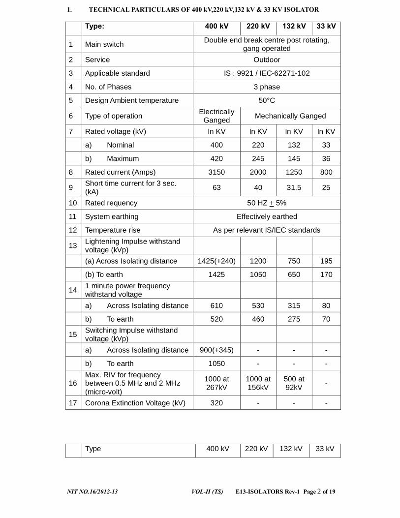
1. TECHNICAL PARTICULARS OF 400 kV,220 kV,132 kV & 33 KV ISOLATOR Type: 400 kV 220 kV 132 kV 33 kV
1 Main switch Double end break centre post rotating, gang operated
2 Service Outdoor
3 Applicable standard IS : 9921 / IEC-62271-102
4 No. of Phases 3 phase
5 Design Ambient temperature 50°C
6 Type of operation Electrically Ganged Mechanically Ganged
7 Rated voltage (kV) In KV In KV In KV In KV
a) Nominal 400 220 132 33
b) Maximum 420 245 145 36
8 Rated current (Amps) 3150 2000 1250 800
9 Short time current for 3 sec. (kA) 63 40 31.5 25
10 Rated requency 50 HZ + 5%
11 System earthing Effectively earthed
12 Temperature rise As per relevant IS/IEC standards
13 Lightening Impulse withstand voltage (kVp)
(a) Across Isolating distance 1425(+240) 1200 750 195
(b) To earth 1425 1050 650 170
14 1 minute power frequency withstand voltage
a) Across Isolating distance 610 530 315 80
b) To earth 520 460 275 70
15 Switching Impulse withstand voltage (kVp)
a) Across Isolating distance 900(+345) - - -
b) To earth 1050 - - -
16 Max. RIV for frequency between 0.5 MHz and 2 MHz (micro-volt)
1000 at 267kV
1000 at 156kV
500 at 92kV -
17 Corona Extinction Voltage (kV) 320 - - - Type 400 kV 220 kV 132 kV 33 kV
NIT NO.16/2012-13 VOL-II (TS) E13-ISOLATORS Rev-1 Page 3 of 19
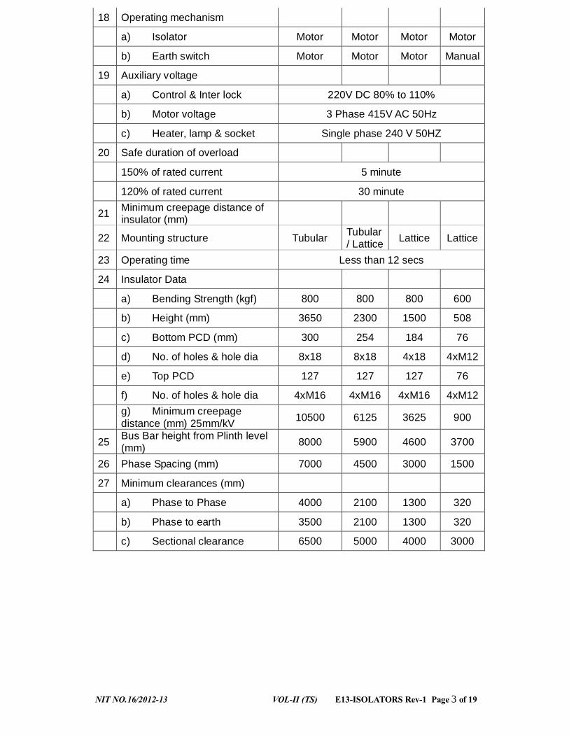
18 Operating mechanism
a) Isolator Motor Motor Motor Motor
b) Earth switch Motor Motor Motor Manual
19 Auxiliary voltage
a) Control & Inter lock 220V DC 80% to 110%
b) Motor voltage 3 Phase 415V AC 50Hz
c) Heater, lamp & socket Single phase 240 V 50HZ
20 Safe duration of overload
150% of rated current 5 minute
120% of rated current 30 minute
21 Minimum creepage distance of insulator (mm)
22 Mounting structure Tubular Tubular / Lattice Lattice Lattice
23 Operating time Less than 12 secs
24 Insulator Data
a) Bending Strength (kgf) 800 800 800 600
b) Height (mm) 3650 2300 1500 508
c) Bottom PCD (mm) 300 254 184 76
d) No. of holes & hole dia 8x18 8x18 4x18 4xM12
e) Top PCD 127 127 127 76
f) No. of holes & hole dia 4xM16 4xM16 4xM16 4xM12
g) Minimum creepage distance (mm) 25mm/kV 10500 6125 3625 900
25 Bus Bar height from Plinth level (mm) 8000 5900 4600 3700
26 Phase Spacing (mm) 7000 4500 3000 1500
27 Minimum clearances (mm)
a) Phase to Phase 4000 2100 1300 320
b) Phase to earth 3500 2100 1300 320
c) Sectional clearance 6500 5000 4000 3000

NIT NO.16/2012-13 VOL-II (TS) E13-ISOLATORS Rev-1 Page 4 of 19
2. SCOPE
This specification provides for design, manufacturer, testing at manufacturer’s Works and delivery ,supervision of erection, commissioning (if required) of outdoor station type 400 kV/220kV /132kV /33kV, 3 phase triple pole double break electrically / mechanically gang operated center rotating type (Single / Double) Isolator with / without earth switches, with electrical interlock, insulators and complete in all respect with connectors, arcing horns, operating mechanism, auxiliary switches, indicating devices etc. as described hereinafter.
3. STANDARDS Isolators covered by this specification shall conform to latest edition of IEC 62271-102 and IS: 9921 and unless specifically stated otherwise in this specification.
4. TYPE
• The Isolators shall be outdoor type with three phase suitable for electrical as well as manual operation and local/remote operation. They shall have crank and reduction gear mechanism.
• All Isolators offered shall be suitable for horizontal upright mounting on steel structures. Each pole unit of the Isolators and earth switches shall be of identical construction and mechanically linked for gang operation for Isolators upto 220kV. 400kV Isolators shall be individual pole electrical gang operated
• Each pole of the Isolator shall be provided with two sets of contacts to be operated in series and the moving contact blades shall rotate in horizontal plane.
• It should suitable for continuous service at the system voltages specified herein. The Isolators shall be suitable to carry the rated current continuously and full short circuit current at site condition without any appreciable rise in temperature. These shall also be suitable for operation at 110% rated (normal) voltage.
• The Isolators shall be suitable for Isolating low capacitive / inductive currents of 0.7amp at 0.15 power factor. The isolators shall be so constructed that they don’t open under the influence of short circuit conditions.
• The Isolators and earth switches are required to be used on electrically exposed installation and this should be taken into account while fixing the clearance between phases and between phase and earth.
5. MAIN CONTACTS
Isolator shall have heavy duty, self-aligning and high pressure line type contacts made of high conductivity, corrosion resistant, hard-drawn electrolytic copper. All copper contact points shall be silver plated to 25 micron thickness or more. Fixed contact should be of reverse loop type with adequate number of copper strips which shall be backed by powerful phosphor bronze/stainless steel springs. The Isolator moving arm/blade shall be made out of high conductivity, corrosion resistant, hard-drawn electrolytic copper of proper length, thickness and contact/surface area for Isolators upto 220kV. For 400kV Isolator, the moving arm shall be made out of High conductivity aluminium tube of outer diameter not less than 120 mm.

NIT NO.16/2012-13 VOL-II (TS) E13-ISOLATORS Rev-1 Page 5 of 19
The dimensions of the contacts should conform to the drawing approved during type test. However the current density of the current carrying parts shall not be more than the values specified below. Current Density in Amps/sq. mm
Tubes Flats Copper 2.5 2.0 Aluminium 1.25 1.0
These fixed and moving contacts shall be able to carry the rated current continuously and the maximum fault current without any appreciable rise in temperature. The Isolator blades shall retain their form and straightness under all conditions of operation including all mechanical stress arising out of operation as well as under rated short circuit condition. The Isolator shall be self-cleaning type so that when Isolator remains closed for long periods in a heavily polluted atmosphere, binding does not occur. No undue wear or scuffing shall be evident during the mechanical endurance tests. Contacts and springs shall be designed so that adjustment of contact pressure shall not be necessary throughout the life of the isolator. Contact springs shall not carry any current and shall not loose their characteristics due to heating effects. Each contact or part of contacts shall be independently sprung so that full pressure is maintained on all contact at all times. The live parts shall be designed to eliminate sharp joints, edges and other corona producing surfaces, where this is impracticable adequate corona rings made out of aluminium tubes shall be provided. Corona shields are not acceptable.
6. Base :
Each single pole of the isolator shall be provided with a complete galvanized steel base provided with holes and designed for mounting on a supporting structure. The base for 400/220/132 kV shall be made out of two channels of size 200x100 / 150x75 / 150x75 or more having thickness not less than 5mm. Base channel shall be rigid in construction and capable of taking all the loads like short circuit force, terminal load, wind load and vibration caused due to seismic / operation of Isolator. Leveling screws of adequate size shall be provided on either side of the base channel under the Insulator for the alignment of Isolator. For 33kV Isolator single base channel of size 100x50 can be provided.
The rotating insulator shall be mounted on a rotating post which shall have two ball bearings of suitable size and housed inside a bearing housing made out of aluminium alloy and greased for life. The distance between the bearings shall not be less than 200/150/125/70 mm for 400/220/132/33 kV respectively.
7. ARCING HORN AND GRADING HORN Suitable arcing horn made of GI shall be provided on the fixed and moving contacts of Isolators if required. The contacts shall be of ‘make before and break after” type.
8. ELECTRICAL INTERLOCK / MECHANICAL INTERLOCK

NIT NO.16/2012-13 VOL-II (TS) E13-ISOLATORS Rev-1 Page 6 of 19
The Isolators shall be equipped with electrical interlock for interlocking with the associated circuit breakers and earth switch. The interlocking scheme shall be approved by OPTCL. Suitable mechanical / constructional interlock shall be provided between Isolator and earth switch which should be rigid in construction and properly mounted to ensure reliable operation.
9. AUXILIARY SWITCHES All isolators and earth switches shall be provided with 220V DC auxiliary switches for remote position indication on the control panel and for electrical interlocking with other equipment. The auxiliary switch shall be provided with a minimum of auxiliary contacts-12 normally open and 12 normally closed and 10 normally open and 10 normally closed for earth switch. The auxiliary switches and auxiliary circuits shall have a continuous current carrying capacity of at least 10 Amps. Auxiliary switches shall not be used as limit switches. Details of make, rating and type of auxiliary switch along with the type test report shall be furnished in the offer.
10. EARTH SWITCH
a) Where earth switches are specified these shall include the complete operating mechanism and auxiliary contacts. The earth switch shall be operated by a separate mechanism.
b) The earth switches shall form an integral part of the isolator and shall be mounted on the base frame of the isolator. c) Earth switches shall be only locally operated. d) The earth switches shall be constructionally interlocked with the isolator so that the earth switches can be operated only when the isolator is open and vice versa. The constructional interlocks shall be built in construction of isolator and shall be in addition to the electrical interlocks. Suitable mechanical arrangement shall be provided for delinking electrical drive for manual operation. e) Each earth switch shall be provided with flexible copper braids or any other improved design for connection to earth terminal. These braids shall have the same short time current carrying capacity as the earth blade. f) The plane of movement and final position of the earth blades shall be such that adequate electrical clearances are obtained from adjacent live parts in the course of its movement between ON and OFF position.
g) Isolator design shall be such as to permit addition of earth switches at a future date. It should be possible to interchange position of earth switch to either side. h) The earth switch should be able to carry the same fault current as the main blades of the Isolators and shall withstand dynamic stresses. i) 400 kV earth switches shall be of double movement type (telescopic) i.e. it has to rotate 90 degree in first movement and then lift upwards to make a contact which ensures a

NIT NO.16/2012-13 VOL-II (TS) E13-ISOLATORS Rev-1 Page 7 of 19
reliable and jerk free operation of the earth switch. Proper locking arrangement shall be provided such that the earth switch shall be locked after lifting upwards to avoid opening during short circuit.
11. OPERATING MACHANISM
a) The bidder shall offer motor operated Isolators and earth switches except for the earth switches of 33 kV Isolator which shall be manual operated with crank and reduction gear mechanism.
b) Control cabinet/operating mechanism box shall be made of cast aluminium / aluminum sheet of adequate thickness (minimum 3 mm) for 33 KV,132KV and stainless steel (grade-316) of minimum thickness 1.6 mm for 400 KV and 220 KV. c) The enclosure shall be painted / powder coated to the Shade no 631 of IS:5(for aluminium enclosure) d) The enclosures of the operating mechanism Box shall conform to the degree of protection IP- 55 e) A “Local/Remote” selector switch and a set of open/ close push buttons shall be provided on the control cabinet of the isolator to permit its operation through local or remote push buttons. f) For 400kV Isolators, Gang / Individual switch shall be provided. g) Provision shall be made in the control cabinet to disconnect power supply through suitable MCBs to prevent local/remote power operation. h) All control switches shall be of MCB/rotary switch type and Toggle/piano switches shall not be accepted. i) Motor shall be an AC motor as per IS:325. Motors rated 373 watt and above shall be used. The motor shall withstand without damage stalled torque for atleast 3 times the time lag of tripping device. j) Suitable reduction gearing shall be provided between the motor and the drive shaft of the isolator. The mechanism shall stop immediately when motor supply is switched off. k) Manual operation facility (with handle) should be provided with necessary interlock to disconnect motor. l) Gear should be of forged material suitably chosen to avoid bending/jamming on operation after a prolonged period of non operation. Also all gear and connected material should be so chosen/surface treated to avoid rusting. The Gears shall be lubricated for life with graphite or better quality non-drawing and non-hardening type grease.
m) The test report for blocked rotor test of motor shall be submitted n) Only stranded copper conductor shall be used for wiring. Minimum size of the conductor for control circuit wiring shall be 2.5 sq.mm Copper. o) The operating mechanism shall be located such that it can be directly mounted on the support structure.
NIT NO.16/2012-13 VOL-II (TS) E13-ISOLATORS Rev-1 Page 8 of 19
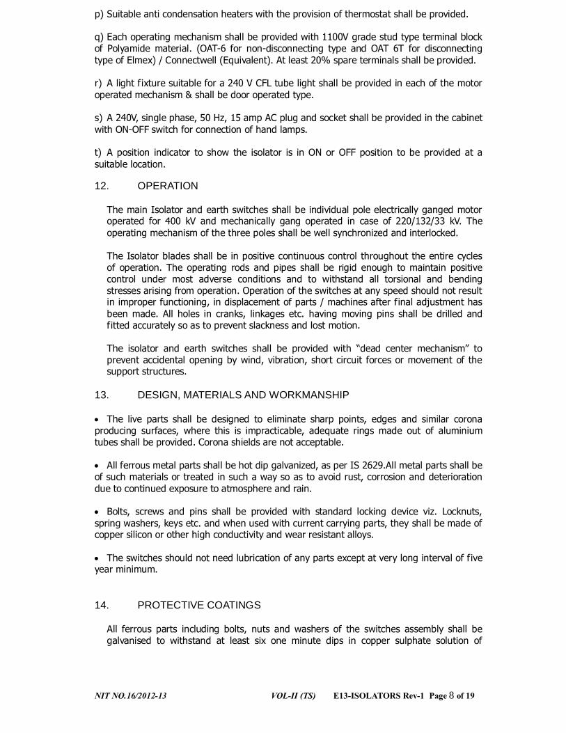
p) Suitable anti condensation heaters with the provision of thermostat shall be provided. q) Each operating mechanism shall be provided with 1100V grade stud type terminal block of Polyamide material. (OAT-6 for non-disconnecting type and OAT 6T for disconnecting type of Elmex) / Connectwell (Equivalent). At least 20% spare terminals shall be provided. r) A light fixture suitable for a 240 V CFL tube light shall be provided in each of the motor operated mechanism & shall be door operated type. s) A 240V, single phase, 50 Hz, 15 amp AC plug and socket shall be provided in the cabinet with ON-OFF switch for connection of hand lamps. t) A position indicator to show the isolator is in ON or OFF position to be provided at a suitable location.
12. OPERATION
The main Isolator and earth switches shall be individual pole electrically ganged motor operated for 400 kV and mechanically gang operated in case of 220/132/33 kV. The operating mechanism of the three poles shall be well synchronized and interlocked. The Isolator blades shall be in positive continuous control throughout the entire cycles of operation. The operating rods and pipes shall be rigid enough to maintain positive control under most adverse conditions and to withstand all torsional and bending stresses arising from operation. Operation of the switches at any speed should not result in improper functioning, in displacement of parts / machines after final adjustment has been made. All holes in cranks, linkages etc. having moving pins shall be drilled and fitted accurately so as to prevent slackness and lost motion. The isolator and earth switches shall be provided with “dead center mechanism” to prevent accidental opening by wind, vibration, short circuit forces or movement of the support structures.
13. DESIGN, MATERIALS AND WORKMANSHIP
• The live parts shall be designed to eliminate sharp points, edges and similar corona producing surfaces, where this is impracticable, adequate rings made out of aluminium tubes shall be provided. Corona shields are not acceptable.
• All ferrous metal parts shall be hot dip galvanized, as per IS 2629.All metal parts shall be of such materials or treated in such a way so as to avoid rust, corrosion and deterioration due to continued exposure to atmosphere and rain. • Bolts, screws and pins shall be provided with standard locking device viz. Locknuts, spring washers, keys etc. and when used with current carrying parts, they shall be made of copper silicon or other high conductivity and wear resistant alloys. • The switches should not need lubrication of any parts except at very long interval of five year minimum.
14. PROTECTIVE COATINGS
All ferrous parts including bolts, nuts and washers of the switches assembly shall be galvanised to withstand at least six one minute dips in copper sulphate solution of
NIT NO.16/2012-13 VOL-II (TS) E13-ISOLATORS Rev-1 Page 9 of 19
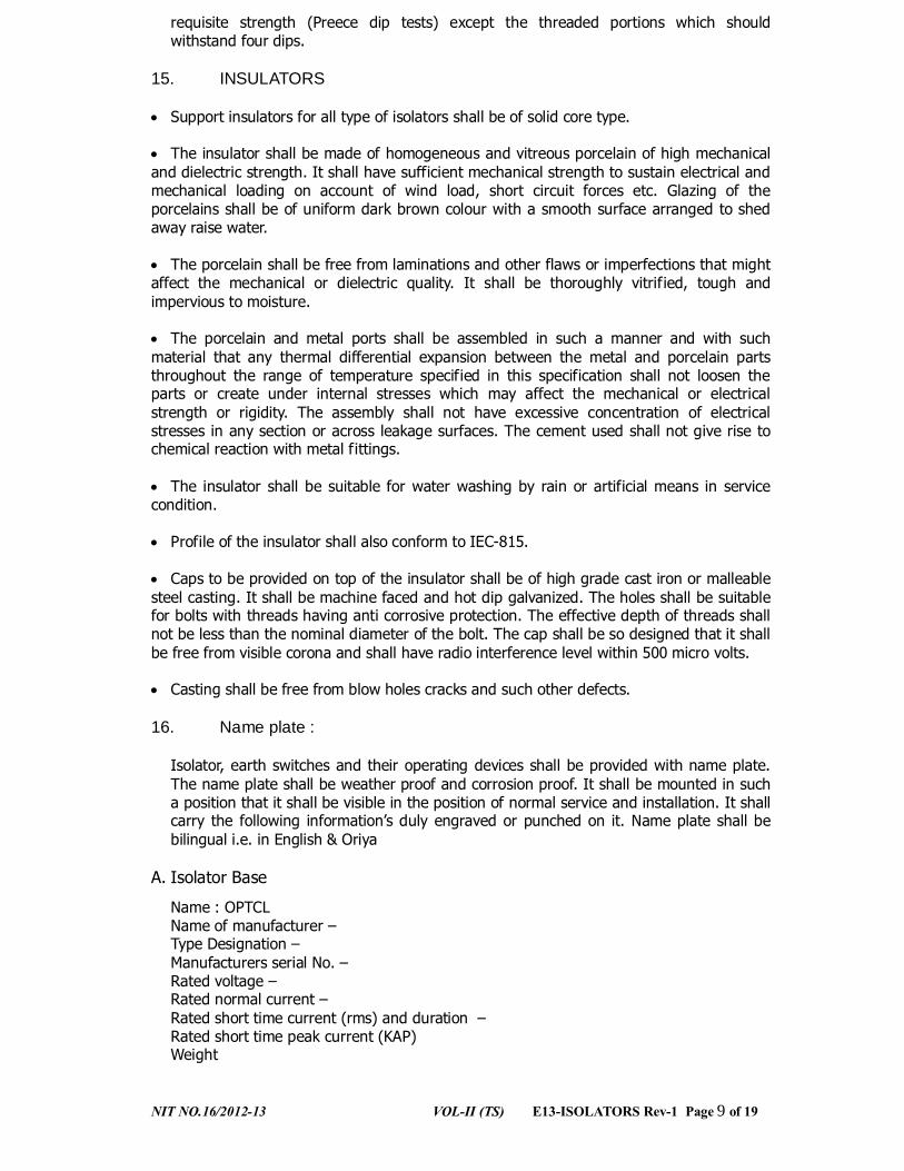
requisite strength (Preece dip tests) except the threaded portions which should withstand four dips.
15. INSULATORS
• Support insulators for all type of isolators shall be of solid core type.
• The insulator shall be made of homogeneous and vitreous porcelain of high mechanical and dielectric strength. It shall have sufficient mechanical strength to sustain electrical and mechanical loading on account of wind load, short circuit forces etc. Glazing of the porcelains shall be of uniform dark brown colour with a smooth surface arranged to shed away raise water. • The porcelain shall be free from laminations and other flaws or imperfections that might affect the mechanical or dielectric quality. It shall be thoroughly vitrified, tough and impervious to moisture. • The porcelain and metal ports shall be assembled in such a manner and with such material that any thermal differential expansion between the metal and porcelain parts throughout the range of temperature specified in this specification shall not loosen the parts or create under internal stresses which may affect the mechanical or electrical strength or rigidity. The assembly shall not have excessive concentration of electrical stresses in any section or across leakage surfaces. The cement used shall not give rise to chemical reaction with metal fittings. • The insulator shall be suitable for water washing by rain or artificial means in service condition. • Profile of the insulator shall also conform to IEC-815. • Caps to be provided on top of the insulator shall be of high grade cast iron or malleable steel casting. It shall be machine faced and hot dip galvanized. The holes shall be suitable for bolts with threads having anti corrosive protection. The effective depth of threads shall not be less than the nominal diameter of the bolt. The cap shall be so designed that it shall be free from visible corona and shall have radio interference level within 500 micro volts. • Casting shall be free from blow holes cracks and such other defects.
16. Name plate :
Isolator, earth switches and their operating devices shall be provided with name plate. The name plate shall be weather proof and corrosion proof. It shall be mounted in such a position that it shall be visible in the position of normal service and installation. It shall carry the following information’s duly engraved or punched on it. Name plate shall be bilingual i.e. in English & Oriya
A. Isolator Base
Name : OPTCL Name of manufacturer – Type Designation – Manufacturers serial No. – Rated voltage – Rated normal current – Rated short time current (rms) and duration – Rated short time peak current (KAP) Weight
NIT NO.16/2012-13 VOL-II (TS) E13-ISOLATORS Rev-1 Page 10 of 19
B. Earthing Switch
Name : OPTCL Name of manufacturer – Type Designation – Manufacturers serial No. – Rated voltage – Rated normal current – Rated short time current (rms) and duration Rated short time peak current (KAP) Weight
C. Operating Device
Name – OPTCL Name of manufacturer – Type Designation – Reduction gear ratio – AC motor
i) Rated auxiliary voltage ii) Starting current iii) Designation of AC motor as per I.S 4722/325 iv) Starting torque at 80% of supply voltage v) Over travel in degrees after cutting off supply
Total operating time in seconds i) Close operation – Electrical ii) Open operation – electrical
Open operation – manual All components shall be given adequate treatment of climate proofing as per IS:3202 so as to withstand corrosive and severe service conditions. All metal parts not suitable for painting such as structural steel, pipes, rods ,levers, linkages, nuts and bolts used in other than current path etc. shall be hot dip gaivanised as per IS -2629 Complete details of painting, galvanizing and climate proofing of the equipment shall be furnished in the offer.
17. TESTS Type Tests Isolators offered, shall be fully type tested as per the relevant standards. The Bidder shall furnish one set of the following valid type test reports for their different type of offered Isolators along with the offer. The Purchaser reserves the right to demand repetition of some or all the type tests in the presence of purchaser’s representative. For this purpose the Bidder may quote unit rates for carrying out each type test and this will be taken during bid price evaluation, if required. The following type test reports shall be submitted for evaluation purpose. In the absence of any one of the following, the bid is liable to reject. a) Short time withstand & peak withstand current test for Isolator & Earth Switch. b) Power frequency (Dry & Wet), Lightening Impulse dry withstand Test c) Radio interference voltage (RIV) test

NIT NO.16/2012-13 VOL-II (TS) E13-ISOLATORS Rev-1 Page 11 of 19
d) Mechanical endurance Test & Terminal load test e) Degree of Protection test (IP-55) f) Corona Test (For 400kV Only) g) Temperature rise test h) Blocked rotor test During type tests the isolator shall be mounted on it’s own support structure or equivalent support structure and installed with its own operating mechanism to make the type tests representative. Drawing of equivalent support structure and mounting arrangements shall be furnished for Purchaser’s approval before conducting the type tests. The type tests shall be conducted on the isolator along with approved insulators and terminal connectors. Mechanical endurance test shall be conducted on the main switch as well as earth switch of one isolator of each voltage class for M0 class (1000 operations) for Isolators upto 220kV. 400kV Isolators shall be tested for extended mechanical endurance test, M2 class (10000 operations) as per IEC 62271-102 which shall be tested at any NABL accredited independent laboratory like CPRI/ERDA. Acceptance and Routine Test : All acceptance and routine test as stipulated in the relevant standards shall be carried out by the supplier in presence of Purchaser’s representative. Mechanical operation test (routine test) shall be conducted on isolator (main switch and earth switch) at the supplier’s works as well as purchaser’s substation site. Immediately after completion of the routine test, the supplier shall give 20 days’ advance intimation along with routine test certificates, valid calibration reports from Govt. approved test laboratories for the equipments, instruments to be used during testing for scrutiny by the purchaser to enable him to depute his representative for witnessing the tests. If there will be any discrepancies in the routine test certificates and calibration reports furnished by the manufacturer, then after settlement of the discrepancies only, purchaser’s representative will be deputed for witnessing the tests. Special tests proposed to be conducted (if decided to conduct) as type test on isolators, are given at Annexure. These special type test charges shall be quoted along with all other type tests as per relevant IEC standard and these charges shall be included in the total bid price. Test certificates of various raw materials and bought out items including but not limited to the following shall be furnished at the time of routine tests.
a) Chemical analysis of copper alongwith a copy of excise certificate indicating genuine source of procurement of electrolytic grade copper. b) Aluminium extrusions c) Aluminium ingots & castings d) Fasteners e) Insulators f) Motor g) Gears h) Auxiliary switch
NIT NO.16/2012-13 VOL-II (TS) E13-ISOLATORS Rev-1 Page 12 of 19
i) Limit switch j) Overload / single phase preventer k) Interlocking devices l) Terminal block
18. INSPECTION
i) The Purchaser shall have access at all times to the works and all other places of manufacture, where the Isolators, earth switches and associated equipment are being manufactured and the supplier shall provide all facilities for unrestricted inspection of the works of raw materials manufacture of all the accessories and for conducting necessary tests as detailed herein. ii) The supplier shall keep the purchaser informed in advance of the time of starting of the progress of manufacture of equipment in its various stages so that arrangements could be made for inspection. iii) No material shall be dispatched from its point of manufacture unless the material has been satisfactorily inspected and tested. iv) The acceptance of any quantity of the equipment shall in no way relieve the supplier of his responsibility for meeting all the requirements of this specification and shall not prevent subsequent rejection if such equipment are later found to be defective.
19. QUALITY ASSURANCE PLAN
The Bidder shall invariably furnish following information along with his offer, failing which his offer shall be liable for rejection.
(i) Names of sub suppliers for raw materials, list of standards according to which the raw materials are tested, list of tests normally carried out on raw materials in presence of Supplier’s representative, copies of test certificate (ii) Information and copies of test certificates as in (I) and (ii) above in respect of bought out accessories. (iii) List of manufacturing facilities available (iv) Level of automation achieved and list of areas where manual processing still exists. (v) List of areas in manufacturing process, where stage inspections are normally carried out for quality control and details of such tests and inspections. (vi) List of testing equipments with calibration certificates from Govt. approved test house available with supplier for final testing equipment and test plant limitation if any, vis-à-vis the type, special acceptance and routine test specified in the relevant standards. These limitations shall be very clearly brought out in the specified test requirements.
The supplier shall within 30 days of placement of order, submit following information to the purchaser.
i) List of raw material as well as bought out accessories and the names of sub-suppliers selected from the lists furnished along with offer. ii) Type test certificates of the raw material and both bought out accessories. iii) Quality Assurance Plan (QAP) with hold points for purchaser’s inspection.
20. DOCUMENTATION All drawings shall conform to relevant international standards organisation (ISO). All drawings shall be in ink and suitable for micro filming. All dimensions and data shall be in S.I. Units.
NIT NO.16/2012-13 VOL-II (TS) E13-ISOLATORS Rev-1 Page 13 of 19
List of Drawings and Documents The Bidder shall furnish four sets of following drawings / documents along with his offer.
a) General outline and assembly drawings of the dis-connector operating mechanism, structure, insulator and terminal connector. b) Sectional views and descriptive details of items such as moving blades, contacts, arms contact pressure, contact support bearing housing of bearings, balancing of heights, phase coupling pipes, base plate, operating shaft, guides, swivel joint operating mechanism and its components etc. c) Loading diagram d) Drawings with structure for the purpose of type tests. e) Name plate. f) Schematic drawing. g) Type test reports. h) Test reports, literature, pamphlets of the bought out items and raw material.
The supplier shall within 2 weeks of placement of order submit four sets of final versions of all the above said drawings for Purchaser’s approval. The purchaser shall communicate his comments / approval on the drawings to the supplier. The supplier shall, if necessary, modify the drawings and resubmit four copies of the modified drawings for Purchaser’s approval within two weeks from the date of comments. After receipt of approval the supplier shall within three weeks submit 5 prints and soft copies in two CD of the approved drawings for purchaser’s use. Six sets of the type test reports, duly approved by the Purchaser shall be submitted by the supplier for distribution, before commencement of supply Adequate copies of acceptance and routine test certificates, duly approved by the Purchaser shall accompany the despatched consignment. The manufacturing of the equipment shall be strictly in accordance with the approved drawings and no deviation shall be permitted without the written approval of the purchaser. All manufacturing and fabrication work in connection with the equipment prior to the approval of the drawing shall be at the supplier risk.
21. INSTRUCTION MANUALS : Five copies of the erection, operation and maintenance manuals in English be supplied for each type of Isolator one month prior to despatch of the equipment. The manual shall be bound volumes and shall contain all drawings and information required for erection, operation and maintenance of the Isolator including but not limited to the following particulars.
(a) Marked erection prints identifying the component parts of the Isolator as shipped with assembly drawings. (b) Detailed dimensions and description of all auxiliaries. (c) Detailed views of the insulator stacks, metallics, operating mechanism, structure, interlocks, spare parts etc.
22. PACKING AND FORWARDING.
The equipment shall be packed in crates suitable for vertical / horizontal transport, as the case may be and suitable to withstand handling during transport and outdoor storage during transit. The supplier shall be responsible for any damage to the equipment during transit, due to improper and inadequate packing. The easily damageable material shall be carefully packed and marked with the appropriate caution symbols. Wherever necessary, proper arrangement for lifting, such as lifting hooks etc. shall be provided. Any material found short inside the packing cases shall be supplied by supplier without any extra cost.

NIT NO.16/2012-13 VOL-II (TS) E13-ISOLATORS Rev-1 Page 14 of 19
Each consignment shall be accompanied by a detailed packing list containing the following information:
(a) Name of the consignee. (b) Details of consignment. (c) Destination. (d) Total weight of consignment. (e) Handling and unpacking instructions. (f) Bill of material indicating contents of each package.
The supplier shall ensure that the bill of material is approved by the purchaser before dispatch.
23. SUPERVISION OF ERECTION TESTING & COMMISSIONING (ET&C)
Purchaser proposes to utilize the services of the supplier for supervision of testing and commissioning of the equipment being supplied by him, if it is required. For this purpose, the supplier should make available the services of trained personnel (Engineers) who shall correct in the field, any errors or omissions in order to make the equipment and material properly perform in accordance with the intent of this specification. The Engineer shall also instruct the plant operators in the operation and maintenance of the commissioned equipment. The supplier shall be responsible for any damage to the equipment on commissioning the same, if such damage results for the faulty or improper ET&C. Purchaser shall provide adequate number of skilled / semi skilled workers as well as general tools and equipment and cranes required for equipment erection, at his own expenses. Apart from the above, the Purchaser shall not be responsible for providing any other facilities to the supplier. Special tools if required for erection and commissioning shall be arranged by the supplier at his cost and on commissioning these shall be supplied to the purchaser free of cost for future use.
24. QUATITITY AND DELIVERY REQUIREMENTS : The scope of supply shall include a supply of 2.5% extra quantity of galvanised bolts, nuts, washers, split pins, cotter pins and such other small loose items free of cost.
ANNEXURE
(Isolators)
LIST OF SPECIAL TESTS TO BE CARRIED OUT (IF DECIDED BY THE PURCHASER)
Sl. No.
Name of the Test Standard to which it conforms.
1. Test for visible Corona and Radio interference voltage (RIV) on Isolators and terminal connector
NEMA Pub No. 107-1964 ISRI Pub No. 1-1972
2. Tests on insulators IS-2544 IEC. 168

NIT NO.16/2012-13 VOL-II (TS) E13-ISOLATORS Rev-1 Page 15 of 19
3. Tests on terminal connectors IS:5561
4. Tests on galvanised components IS:2633
5. Stalled torque test on motor operating mechanism
At 110% of supply voltage
LIST OF MANDATORY SPARES Sl. No.
Item Quantity
1. Copper contact fingers for male and female contact per Isolator
2sets each for each Type of Isolators (400/220/132/33KV)
2. Relay, power contactors, MCBs, Rotary switches for electrical control circuit per Isolator (Indicate the nos of relay, power contactors, MCBs, Rotary switches used in the electrical circuit of each type of isolators)
2sets for each Type of Isolators
3. Support insulator stack for one pole of the isolator
2 stacks for each type of Isolators
4. Terminal pad 2 Nos. for each type of isolators
5. Limit switch and Auxiliary switch per Isolator (Indicate the nos of each switch used in each type of isolators)
2sets for each type of Isolators
6. Terminal connectors per Isolator 2 sets for each type of isolators.
VOL-II (TS) E14-STATION TRANSFORMER- Page 1 of 55 1
ODISHA TRANSMISSION CORPORATION LIMITED
TECHNICAL SPECIFICATION FOR 250 KVA, 33/0.433 KV STATION TRANSFORMER
VOL-II (TS) E14-STATION TRANSFORMER- Page 2 of 55 2
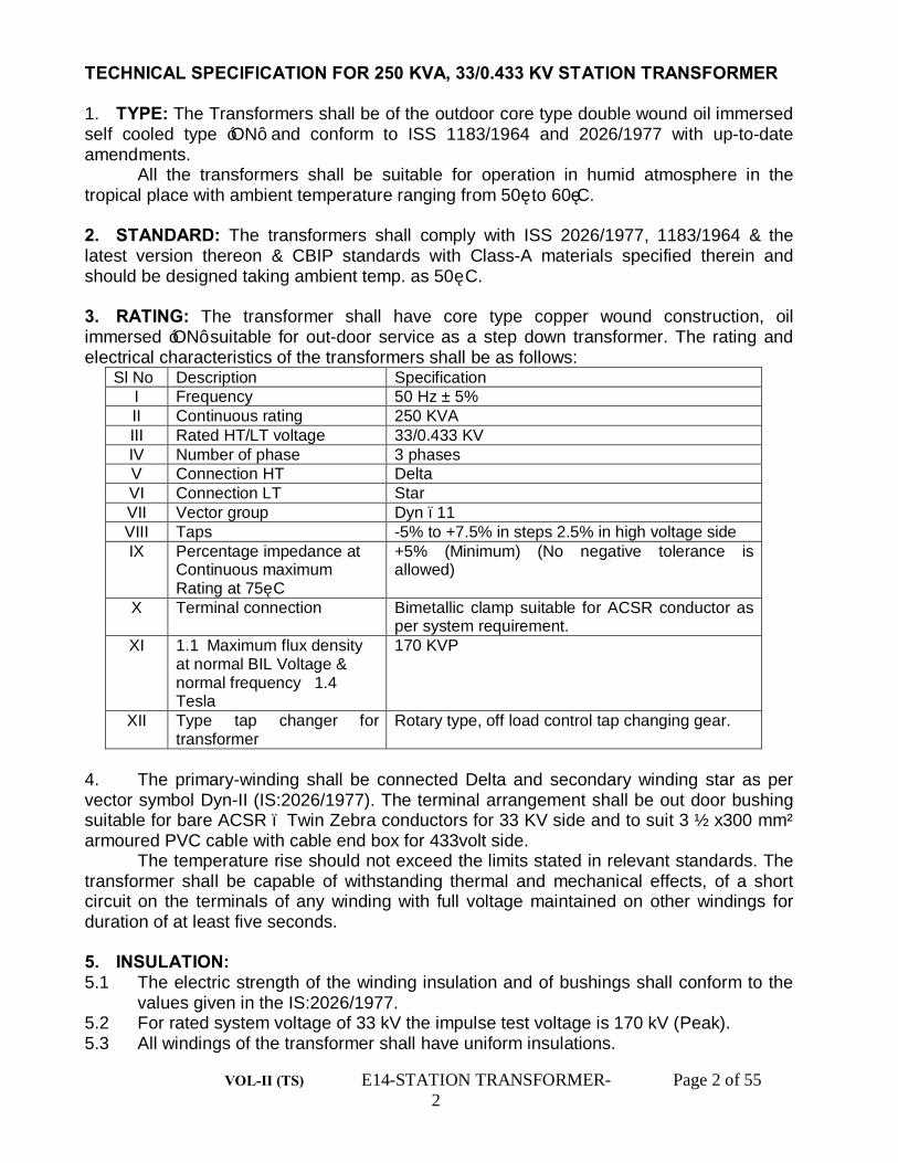
TECHNICAL SPECIFICATION FOR 250 KVA, 33/0.433 KV STATION TRANSFORMER 1. TYPE: The Transformers shall be of the outdoor core type double wound oil immersed self cooled type ‘ON’ and conform to ISS 1183/1964 and 2026/1977 with up-to-date amendments.
All the transformers shall be suitable for operation in humid atmosphere in the tropical place with ambient temperature ranging from 50˚ to 60˚C. 2. STANDARD: The transformers shall comply with ISS 2026/1977, 1183/1964 & the latest version thereon & CBIP standards with Class-A materials specified therein and should be designed taking ambient temp. as 50˚ C. 3. RATING: The transformer shall have core type copper wound construction, oil immersed ‘ON’ suitable for out-door service as a step down transformer. The rating and electrical characteristics of the transformers shall be as follows:
Sl No Description Specification I Frequency 50 Hz ± 5% II Continuous rating 250 KVA III Rated HT/LT voltage 33/0.433 KV IV Number of phase 3 phases V Connection HT Delta VI Connection LT Star VII Vector group Dyn –11 VIII Taps -5% to +7.5% in steps 2.5% in high voltage side IX Percentage impedance at
Continuous maximum Rating at 75˚ C
+5% (Minimum) (No negative tolerance is allowed)
X Terminal connection Bimetallic clamp suitable for ACSR conductor as per system requirement.
XI 1.1 Maximum flux density at normal BIL Voltage & normal frequency 1.4 Tesla
170 KVP
XII Type tap changer for transformer
Rotary type, off load control tap changing gear.
4. The primary-winding shall be connected Delta and secondary winding star as per vector symbol Dyn-II (IS:2026/1977). The terminal arrangement shall be out door bushing suitable for bare ACSR – Twin Zebra conductors for 33 KV side and to suit 3 ½ x300 mm² armoured PVC cable with cable end box for 433volt side. The temperature rise should not exceed the limits stated in relevant standards. The transformer shall be capable of withstanding thermal and mechanical effects, of a short circuit on the terminals of any winding with full voltage maintained on other windings for duration of at least five seconds. 5. INSULATION: 5.1 The electric strength of the winding insulation and of bushings shall conform to the values given in the IS:2026/1977. 5.2 For rated system voltage of 33 kV the impulse test voltage is 170 kV (Peak). 5.3 All windings of the transformer shall have uniform insulations.
VOL-II (TS) E14-STATION TRANSFORMER- Page 3 of 55 3
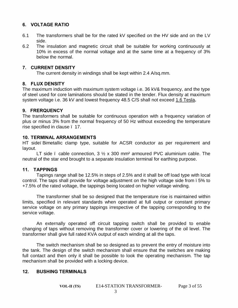
6. VOLTAGE RATIO 6.1 The transformers shall be for the rated kV specified on the HV side and on the LV side. 6.2 The insulation and magnetic circuit shall be suitable for working continuously at 10% in excess of the normal voltage and at the same time at a frequency of 3% below the normal. 7. CURRENT DENSITY The current density in windings shall be kept within 2.4 A/sq.mm. 8. FLUX DENSITY The maximum induction with maximum system voltage i.e. 36 kV& frequency, and the type of steel used for core laminations should be stated in the tender. Flux density at maximum system voltage i.e. 36 kV and lowest frequency 48.5 C/S shall not exceed 1.6 Tesla. 9. FRERQUENCY The transformers shall be suitable for continuous operation with a frequency variation of plus or minus 3% from the normal frequency of 50 Hz without exceeding the temperature rise specified in clause – 17. 10. TERMINAL ARRANGEMENTS HT side–Bimetallic clamp type, suitable for ACSR conductor as per requirement and layout. LT side – cable connection, 3 ½ x 300 mm² armoured PVC aluminium cable. The neutral of the star end brought to a separate insulation terminal for earthing purpose. 11. TAPPINGS Tapings range shall be 12.5% in steps of 2.5% and it shall be off load type with local control. The taps shall provide for voltage adjustment on the high voltage side from –5% to +7.5% of the rated voltage, the tappings being located on higher voltage winding. The transformer shall be so designed that the temperature rise is maintained within limits, specified in relevant standards when operated at full output or constant primary service voltage on any primary tappings irrespective of the tapping corresponding to the service voltage. An externally operated off circuit tapping switch shall be provided to enable changing of taps without removing the transformer cover or lowering of the oil level. The transformer shall give full rated KVA output of each winding at all the taps. The switch mechanism shall be so designed as to prevent the entry of moisture into the tank. The design of the switch mechanism shall ensure that the switches are making full contact and then only it shall be possible to look the operating mechanism. The tap mechanism shall be provided with a locking device. 12. BUSHING TERMINALS

VOL-II (TS) E14-STATION TRANSFORMER- Page 4 of 55 4
All main winding and neutral leads shall be brought out through outdoor type bushing suitable for bare copper or ACSR conductors for 33 kV side and to suit for 3 ½ x 300 mm² armoured PVC cable for 433 volt side & so located that the full flash over strength will be utilized. Each bushing shall be so coordinated with the transformer insulation that all flashovers will occur outside the tank. The porcelain used for the bushings shall be of the wet processed type, homogenous and free from cavities or other defects. The glaze of the porcelain parts shall be uniform in colour and free of blisters, burns and other defects. The bushings should conform to IS:2099/73 and with 3347(Part-I & II Section – 1 & 2) with it’s latest amendments. 13. FLASHOVER CHARACTERISTICS OF BUSHINGS The spacing between the bushings must be adequate to prevent flash over between phases under all condition of operation. Special adjustable coordinating gaps should be provided on the high-tension terminals and the gap setting adjusted with reference to the impulse coordination of the system. The tenderer is requested to give the guaranteed withstand voltage for the impulse and flash over values of the bushings. 14. SUPPRESSION OF HARMONNICS The transformers shall be designed with particular attention for suppression of harmonic voltages especially the 3rd and 5th so as to eliminate wave form distortion and any possibility of high frequency distortion and any possibility of high frequency disturbances, inductive factor or of circulating current between neutral point at the different transformer station reaching such a magnitude as to cause, interference with post office or other communication circuits. 15. CENTRE OF GRAVITY The center of gravity of the assembled transformer shall be low and as near the vertical centerline as possible. The transformer shall be stable with or without oil. If the center of gravity is eccentric to the vertical line either with or without oil, its location shall be shown on the outline drawing. 16. VIBRATIONS AND NOISE The transformers shall operate without undue vibration and noise and shall comply with NEMA publication – TR – 1. 17. TEMPERATURE RISE Each transformer shall be capable of operating continuously at this normal rating without exceeding temperature rise limits as specified below:
(i) Winding 55˚C by resistance measurement. (ii) Top oil 50˚C by thermometer measurement.
The above limits are with an ambient temperature of 50˚ maximum. All transformers shall comply with requirement of IS:2026/77 & it’s latest amendments as regard the rating and temperature rise.

VOL-II (TS) E14-STATION TRANSFORMER- Page 5 of 55 5
18. EFFICIENCY The efficiencies of the transformer corresponding to 25%, 50%, 75%, 100% and 125% load may be specified. Maximum efficiency should occur at 50% load. 19. PERCENTAGE IMPEDENCE The transformer offered must be designed for a minimum impedance of +5% at 75˚ C. No negative tolerance on impedance is allowed. 20. LOSSES The no load & load losses shall not exceed the values given in the following table.
RATINGS NO LOAD LOSS IN WATTS
LOAD LOSS IN WATTS AT 75DEGREE C AT NORMAL TAP
PERCENTAGE IMPEDANCE AT 75 DEGREE C AT NORMAL TAP
250 KVA (Copper wound)
620 3700 5 (Minimum)
The above losses are maximum allowable losses & there shall not be any + ve tolerance on the losses for the transformers. Bid evaluation will be done taking in to consideration the quoted no load & load loss figures. The purchaser reserves the right to reject the whole lot of supply in case the loss figures exceed the limit given in above table at the time of testing. 21. PARALLEL OPERATION The transformers with similar connection shall be capable of operating in parallel on corresponding taps and of sharing loads in proportion to their ratings subject to the tolerances of impedance. 22. WINDING AND INSULATION All permanent current carrying joints shall be welded or brazed. All threaded connections shall be provided with locking facilities. The assembled core and coils shall be properly dried before impregnation. The process of impregnation should be stated. All leads from the winding shall be rigidly supported to prevent injure isolation due to vibration. Flexible tubes shall be used where practicable. - The HT and L T winding of all transformers shall be of the fully insulated type. (a) Special attention should be given to provisions of adequate insulation and clearances between HT and LT windings and live parts must be adequate for normal voltage of operation plus 10%. (b) The end turn insulation of the transformers shall inconformity with latest practice. (c) Windings shall be circular and concentric with the HT windings on the outside. All similar coils shall be inter changeable.

VOL-II (TS) E14-STATION TRANSFORMER- Page 6 of 55 6
(d) The insulation of the transformer winding and connection shall be free from insulating compound which may so often coagulate shrink or collapse during service. None of the materials used shall shrink, disintegrate, carbonized or become brittle under the action of hot oil when the transformer is operated continuously with the conductors at any temperature which may be reached at the specified loading conditions.
The finished width of any oil ducts shall be such and the clamping arrangement shall be so designed as not to impede the free circulation of oil through the ducts. 23. BRACING OF WINDINGS Windings connections and tappings of the transformers shall be braced to withstand the shocks, which may occur during transport and during service due to short circuit, switching or other transient condition. No mechanical movement of coils shall be possible with dead short circuit on either side of the transformer. The short circuit rating shall be as per Clause 9.1 ISS: 2026/1977. 24. MAGNETIC CIRCUITS The transformers core shall be of high grade non-ageing, electrical silicon steel cold-rolled laminations each coated with hot oil proof, lead enamel insulation clamped together firmly to the frame to ensure even pressure over the whole of the core laminations and to prevent undue vibration and noise. After being sheared the laminations shall be treated to remove all burns and shall be re-annealed to remove all strains. Paper or varnish insulation shall not be accepted. The joints in the core shall be inter leaved and in no account will ‘Butt Joints’ be accepted. Suitable axial cooling ducts suitable proportioned to prevent excessive temperature rise must be provided to ensure, free circulation of oil and efficient cooling of the core. The clamping structure shall be so constructed with MS Channels, and insulated bolts and so designed that eddy currents is minimum and hood must not be used for the purpose. The core shall be designed and build up in such a manner as to avoid accidental or slow development of short circuit plates through iron and frame. The core and coils shall be so fixed in the tank that their shifting will not occur when the transformer is moved. Means shall be provided for earthing the core and framework at one point only. 25. TRANSFORMER TANK The tank and cover of each transformer shall be of welded boilerplate with suitable stiffeners so constructed that all joints are hot oil tight and bulging does not occur in service. The tank shall be so designed that with the minimum dismantling necessary, the core and winding can be lifted free of the case. External lugs or eyes for lifting the core or windings shall be provided. Ample space shall be provided with an appropriate arrangement of things, suitable for lifting transformer core with winding. The tank shall be fitted with a substantial under carriage and provided with rollers. 26. OIL Sufficient quantity of oil shall be supplied with each transformer for filling each tank, bushing and conservator to the proper level. The oil shall be in accordance with IS

VOL-II (TS) E14-STATION TRANSFORMER- Page 7 of 55 7
No.335/1972 & it’s latest amendments. Oil test certificates shall be furnished at the time of inspection of transformers in support of the use of new unused oil conforming to IS 335 in the transformer. 27. EARTHINGS The core and tank cover shall be earthed to the tanks by means of copper connection capable of carrying for 30 seconds without injury and over loading with earth fault current not less than full load current of the main transformer. In no case shall the cross sectional area be less than 0.1 sq. inch. Two earthing terminal shall be provided suitable for No 7 SGW bare copper wire with suitable soldering lugs. 28. TANK FITTINGS AND ACCESSORIES The standard fittings to be provided on each transformer in line with manufacturers practice may be provided including the following: a) Oil conservator of sufficient capacity to prevent inadvertent operation of Buchholz relay where used and shall be provided with drain plug/valve oil gauge, with a mark to indicate oil level at a temperature of 50˚ C filling cap. Silica Gel dehydrating breather to contain minimum 0.5 kg dehydrated silicagel. b) Explosion Vent c) A safety valve of chimney type shall be provided. The bottom of the safety valve pipe shall project into the tank. d) Glass Type Thermometer- Mercury in glass type thermometer mounted on the top of the transformer to read the temperature in the hottest part of the oil. e) Drain Valve-1” (15mm) drain valve cum lower filter valve suitable for connection to the flange of the same diameter. The valve should be fitted with an adopter for 16 mm hose for filtering purposes. The valve shall be located so as to enable with drain out of the oil from the tank. This valve shall be equipped with a small sampling cock.
i) Earthing terminal and numbers. ii) Air relief vent. iii) Rating and diagram plate
f) The rating plate should bear the data specified in the proper clauses of ISS- 2026/1977. The diagram plate should also show the internal connection and so the voltage vector relationship of the several windings in accordance with ISS:2026/1977 and in addition a plan view of the transformer giving accurate physical relationship with the terminals. g) Oil filter valve- The oil filter valves should be fitted with adopter for 16 mm hose. These valves are for oil filtration and for draining of oil for sample and test purpose. h) Joint and Gaskets- All joints in the transformer and auxiliary equipment shall be made in such a manner as to prevent ingress of moisture of leakage of oil. (i) Arcing horn with each HT bushings. (ii) Pad lock for tap changing switch.
VOL-II (TS) E14-STATION TRANSFORMER- Page 8 of 55 8
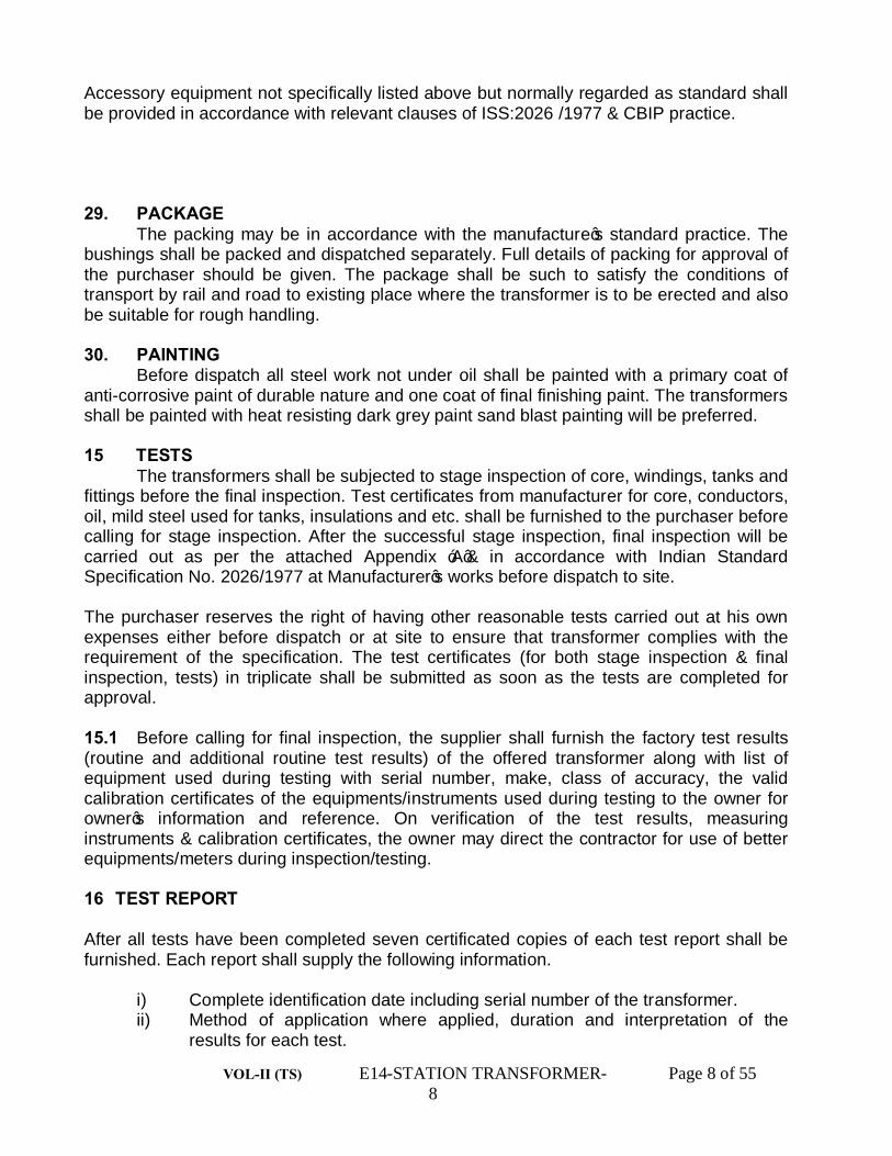
Accessory equipment not specifically listed above but normally regarded as standard shall be provided in accordance with relevant clauses of ISS:2026 /1977 & CBIP practice. 29. PACKAGE The packing may be in accordance with the manufacture’s standard practice. The bushings shall be packed and dispatched separately. Full details of packing for approval of the purchaser should be given. The package shall be such to satisfy the conditions of transport by rail and road to existing place where the transformer is to be erected and also be suitable for rough handling. 30. PAINTING Before dispatch all steel work not under oil shall be painted with a primary coat of anti-corrosive paint of durable nature and one coat of final finishing paint. The transformers shall be painted with heat resisting dark grey paint sand blast painting will be preferred. 15 TESTS
The transformers shall be subjected to stage inspection of core, windings, tanks and fittings before the final inspection. Test certificates from manufacturer for core, conductors, oil, mild steel used for tanks, insulations and etc. shall be furnished to the purchaser before calling for stage inspection. After the successful stage inspection, final inspection will be carried out as per the attached Appendix ‘A’& in accordance with Indian Standard Specification No. 2026/1977 at Manufacturer’s works before dispatch to site. The purchaser reserves the right of having other reasonable tests carried out at his own expenses either before dispatch or at site to ensure that transformer complies with the requirement of the specification. The test certificates (for both stage inspection & final inspection, tests) in triplicate shall be submitted as soon as the tests are completed for approval. 15.1 Before calling for final inspection, the supplier shall furnish the factory test results (routine and additional routine test results) of the offered transformer along with list of equipment used during testing with serial number, make, class of accuracy, the valid calibration certificates of the equipments/instruments used during testing to the owner for owner’s information and reference. On verification of the test results, measuring instruments & calibration certificates, the owner may direct the contractor for use of better equipments/meters during inspection/testing. 16 TEST REPORT After all tests have been completed seven certificated copies of each test report shall be furnished. Each report shall supply the following information.
i) Complete identification date including serial number of the transformer. ii) Method of application where applied, duration and interpretation of the
results for each test.

VOL-II (TS) E14-STATION TRANSFORMER- Page 9 of 55 9
iii) Temperature data corrected to 75 ˚C including ambient temperature. Type test. 16.1.1 Temperature rise test 16.1.2 Oil Leakage & Pressure Test:- The transformer tanks shall be subjected to a pressure equal to the normal pressure + 35 KN/m² measured at the base of the tank. Pressure shall be maintained for a period of 12 hours for oil during oil leakage test and 1 hour for air during Pressure test on the Tank where there shall not be any leakage. In addition to the routine tests, the type and special test certificates for the tests as indicated below, conducted by the supplier on proto type of transformers of identical design at CPRI or any Govt. approved laboratory within the last 5(five) years from the date of opening of this. CPRI/Govt. approved laboratory test certificate along with CPRI/Govt. approved laboratory drgs. (Internal and external drgs.) must accompany along with the drawings for approval.

VOL-II (TS) E14-STATION TRANSFORMER- Page 10 of 55 1
Type & Special Tests 1. Impulse Voltage withstand test 2. Temperature rise test
3. Short Circuit Test. The test results of CPRI tested transformer should confirm with the technical particulars as stipulated in this specification .The bidder shall indicate the values of resistance , stray loss, %Impedance, % regulation, no load losses, load losses at rated output , voltage & frequency along with the drawing submitted for approval. These values will be guaranteed MAXIMUM VALUES. iii) The losses shall be measured during routine tests. If losses will be arrived outside the limits of the guaranteed losses as quoted by the bidder in the Guaranteed technical particulars but will remain within the losses as stipulated. The successful bidder will be penalized at the above rates for any loss in excess of the values stated in the bid considering iron & copper losses separately. No bonus shall be payable for the losses which are less than those stated in the bid. iv) Also on testing if any of the test results do not match with the values given in the guaranteed technical particulars & as per technical specification, the owner reserves the right to reject the transformer or free to take any other decision. v) The owner also reserves the right to retain the rejected transformer & take in to service until the supplier replaces it with a new transformer at no extra cost. The tenderer shall give the guaranteed technical particulars required as indicated in Vol-II-A along with the drawing for approval. The tenderer shall submit the detailed dimensional drawing, short circuit , impulse & temperature rise test reports conducted in a govt. approved laboratory for the transformer offered along with the offer ,failing which the offer will not be considered. 17. REJECTION The transformer may be rejected at the discretion of the purchaser if the test results are not satisfactory and tolerances are exceeded. The supplier should guarantee for after sales service for minimum period of one and half years from the date of receipt of the equipment in complete shape or one year from the date of commissioning of the equipment whichever is earlier. The supplier also should guarantee after sales services beyond the free service period as stipulated in. The supplier also should provide after sales services within 15 days of receipt of intimation from the field engineer in charge of the equipment.

VOL-II (TS) E14-STATION TRANSFORMER- Page 11 of 55 1
APPENDIX – A TESTS Routine & type tests are to be conducted at the manufacturer’s factory as per IS: 2026/1977 & as indicated below, in presence of purchaser’s representative. Routine and type test certificates are to be submitted in support of the tests conducted successfully, after which dispatch clearance will only be issued. Type tests as indicated below will only be conducted on one transformer of each rating. 1. Routine Test All transformers shall be subjected to routine tests at the manufacturer’s works. The tests shall comprise as per the followings:- a) Measurement of winding resistance at normal & extreme taps. b) Ratio, polarity and phase relationship & vector group test..
c) Impedance voltage / short circuit impedance at the normal tap & extreme taps.
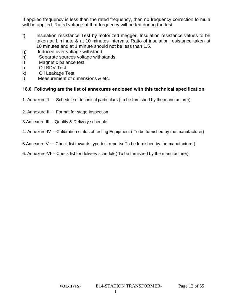
d) Measurement of load loss and neutral unbalance current This test shall be a carried out with three wattmeter’s method with low power factor wattmeter low range Ammeters and phase sequence meters. The measurement shall be made at 100% rated current & rated frequency, but in no case not less than 80% current of the rated current (Principal tapping) or tapping current (in case of extreme taps). Load loss measurement to be done on the normal tap (rated voltage tap) and extreme taps. e) Measurement of no- load loss and no load current. This test to be carried out with 3 wattmeter method by using low power factor watt-meters, 3 power factor meters, phase sequence meters, three low range ammeters and three each average value and RMS value voltmeters. The test voltage from 10% voltage to 121% voltage shall be applied and currents, voltages (Average value and RMS value), wattmeter, power factor and frequency meter readings in all the 3 phases to be recorded during the test. A voltage (RMS) vrs. Measured current graph shall be plotted by the supplier and handed over it to the purchaser for analysis. During the test, supplier’s own generator set shall be used for feeding the rated voltage at rated frequency. If the applied frequency is greater than the rated frequency, then proportionate voltage to the rated frequency will be fed during the test and following frequency correction formula along with the formula given in Clause 16.5 IS:2026(Part-I) shall be used. K = 0.5/f 1 +0.5 (f/f 1)² Where f = rated frequency & f1 = applied frequency. For example: - If measured loss = x, correction factor due to rms & Average voltage as per ISS = k1, and frequency correction factor = k. Then corrected loss will be calculated as = measured loss x * k1 * k.
VOL-II (TS) E14-STATION TRANSFORMER- Page 12 of 55 1
If applied frequency is less than the rated frequency, then no frequency correction formula will be applied. Rated voltage at that frequency will be fed during the test. f) Insulation resistance Test by motorized megger. Insulation resistance values to be taken at 1 minute & at 10 minutes intervals. Ratio of insulation resistance taken at 10 minutes and at 1 minute should not be less than 1.5. g) Induced over voltage withstand. h) Separate sources voltage withstands. i) Magnetic balance test j) Oil BDV Test k) Oil Leakage Test l) Measurement of dimensions & etc. 18.0 Following are the list of annexures enclosed with this technical specification. 1. Annexure-1 --- Schedule of technical particulars ( to be furnished by the manufacturer)
2. Annexure-II--- Format for stage Inspection 3.Annexure-III--- Quality & Delivery schedule 4. Annexure-IV--- Calibration status of testing Equipment ( To be furnished by the manufacturer)
5.Annexure-V---- Check list towards type test reports( To be furnished by the manufacturer) 6. Annexure-VI--- Check list for delivery schedule( To be furnished by the manufacturer)

VOL-II (TS) E14-STATION TRANSFORMER- Page 13 of 55 1
A N N E X U R E-I.
A PP E N D I X-I.
SCHEDULE OF TECHNICAL PARTICULARS TO BE FURNISHED BY THE MANUFACTURER CONFIRMING TO THE TRANSFOMERS PASSED C.P.R.I TYPE TEST, IN RESPECT OF IMPULSE HIGH VOLTAGE SHORT CIRCUIT CURRENT,TEMPERATURE RISE TEST AND OTHER DESIGN DATA. STANDARD FORM OF GUARANTEED TECHNICAL PARTICULARS:- 1. Name of the manufacturer. 2. Service. 3. KVA Rating:- a) H.V. Winding. KVA b) L.V. Winding. KVA 4. Highest system voltage/Nominal voltage. a) H.V. Winding. KV b) L.V.Winding KV 5. Rated frequency. Hz 6. Number of phases. 7. Connections:- a) H.V. Winding. b) L.V. Winding. 8. Connection symbol (See IS: 2026 (Part-IV-1977). 9. Tappings:- a) Range b) Number of steps for high voltages variation. 10. Reference ambient temperature:- a) Maximum ambient air/temperature. ºC. b) Maximum daily average ambient air ºC. temperature. c) Maximum yearly average ambient ºC. air temperature. d) Minimum ambient air temperature. ºC. e) Maximum cooling water temperature. ºC. 11. Type of cooling (See IS-2026 (Part-II)/1977.) 12. Temperature rise (See 2026 (Part-II)/1977)

VOL-II (TS) E14-STATION TRANSFORMER- Page 14 of 55 1
a) Temperature of oil ºC. b) Winding. ºC. 13. i) Total loss at rated nominal voltage KW at normal tap & rated frequency. ii) Stray loss at 75ºC. iii) % Regulation. 14. (A) Component losses. a) No-load loss at rated nominal voltage KW and normal frequency. b) Load loss at rated current and rated frequency at normal tapping at 75ºC. & at extreme taps. (B) Resistance at normal tap & at 75ºC. i) H.V. ii) L.V. 15. Impedance voltage & percentage Impedance at full rated current at 75ºC. for the a) Normal tap. b) Lowest tap position c) Highest tap position. 16. Reactance at rated current and Percentage. rated frequency. i) No load current at rated nominal voltage and rated frequency and at 50%, 75%, 100%, 110% & 121% voltage & at rated frequency. 18. Insulation level (See IS-2026 (Part-III/1977). a) Separate source power frequency voltage withstand i) H.V. Winding KV rms. ii) L.V. Winding. KV rms. b) Induced over voltage withstand. i) H.V. Winding. KV rms. ii) L.V. Winding. KV rms. c) Full wave lighting impulse withstand voltage with time vrs. peak voltage characteristic curves. i) H.V. Winding. KV Peak. ii) L.V. Winding. KV Peak. d) P.I. value. 19. Efficiencies at 75ºC at unity power factor. a) At full load. Percent b) At ¾ full load -do- c) At ½ full load -do- d) At 120% of full load.

VOL-II (TS) E14-STATION TRANSFORMER- Page 15 of 55 1
20. Regulation at full load at 75ºC a) At unity power factor. -do- b) At 0.8 power factor loading & lagging. -do- 21. Equipment for ONAN cooling. a) State. i) No. of Radiators on main tank. ii) Make & type iii) Total radiating surface iv) Thickness of radiator fins v) Clear distance between fins vi) Width of radiator fins 22. Number of coolers or cooler banks per transformer 23. Rating of each cooler or cooler bank. 24. Terminal arrangement. a) High voltage. b) Low voltage. c) Neutral. 25. Approximate masses:- a) Core Kg. b) Winding. Kg. c) Tank, fittings & accessories. (Name of Kg. accessories to be mentioned). d) Oil. Kg. e) Core coil assembly Kg. f) radiators Kg. g) Total mass Kg. 26. a)Approximate quantity of oil required Ltrs. for first filling. b)Name of the manufacturer of oil used 27. Approximate tank dimensions for over all dimensions. a) Length mm b) Breadth. mm c) Height. mm d) Thickness of main tank cover plate, mm side & bottom plate. e) Tank inside & outside dimension. mm Length/breadth/height. No. of tubes in each rediator. Tube length in copper, thickness & dia. Each side tubes (Nos.).

VOL-II (TS) E14-STATION TRANSFORMER- Page 16 of 55 1
28. Despatch details. a) Approximate mass of heaviest package. Kg. b) Approximate dimensions of largest package. i) Length. mm ii) Breadth. mm iii) Height. mm 29. Un-tanking height. mm 30. Additional technical particulars. i) (a) i. Maximum flux density at highest system Tesla or Wo/m². voltage & 48.5 c/s frequency. ii) Maximum flux density at rated system voltage & rated frequency. (b) Maximum current density in windings. Amps/Sq.Cm (c) Size of conductor used. HV/LV High voltage. Low voltage. ii) Efficiency at 75ºC and 0.8 P.F. lagging At full load. Percent. At ¾ full load -do- At ½ full load -do- Over loading capacity & efficiency. iii) Load at which maximum efficiency occurs. -do- iv) Maximum efficiency. Percent. v) Impulse level with 1/50 Micro.S. Wave. High voltage KV Low voltage KV vi) No-load loss at 110% rated nominal voltage and rated frequency. KV vii) No load current at 110% & 121% of nominal voltage & rated frequency. Percentage. viii) Type of winding. High voltage. Low voltage. No. of turns of H.V. No. of turns of L.V. ix) Insulation materials. Turn insulation high voltage. Turn insulation low voltage. Insulation core to low voltage. Insulation high voltage to low voltage. x) Clearance:- Minimum clearance between phases. a) In oil. mm b) Out of oil. mm Maximum clearance high voltage to tank in oil. mm Minimum clearance high voltage to
VOL-II (TS) E14-STATION TRANSFORMER- Page 17 of 55 1
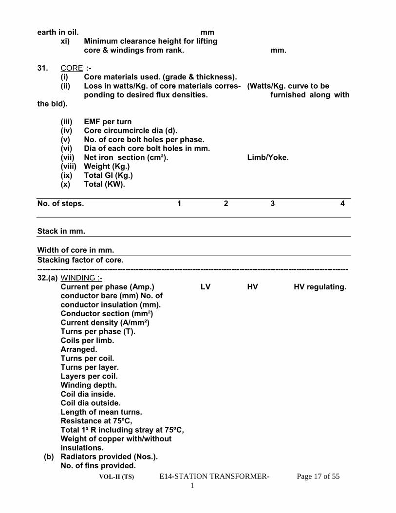
earth in oil. mm xi) Minimum clearance height for lifting core & windings from rank. mm. 31. CORE :- (i) Core materials used. (grade & thickness). (ii) Loss in watts/Kg. of core materials corres- (Watts/Kg. curve to be ponding to desired flux densities. furnished along with the bid). (iii) EMF per turn (iv) Core circumcircle dia (d). (v) No. of core bolt holes per phase. (vi) Dia of each core bolt holes in mm. (vii) Net iron section (cm²). Limb/Yoke. (viii) Weight (Kg.) (ix) Total GI (Kg.) (x) Total (KW). No. of steps. 1 2 3 4 Stack in mm. Width of core in mm. Stacking factor of core. ------------------------------------------------------------------------------------------------------------------------ 32.(a) WINDING :- Current per phase (Amp.) LV HV HV regulating. conductor bare (mm) No. of conductor insulation (mm). Conductor section (mm²) Current density (A/mm²) Turns per phase (T). Coils per limb. Arranged. Turns per coil. Turns per layer. Layers per coil. Winding depth. Coil dia inside. Coil dia outside. Length of mean turns. Resistance at 75ºC, Total 1² R including stray at 75ºC, Weight of copper with/without insulations. (b) Radiators provided (Nos.). No. of fins provided.

VOL-II (TS) E14-STATION TRANSFORMER- Page 18 of 55 1
Radiator size in mm (Length x wide x fin Nos.) Loss to be dissipated by Radiators in KW. Dissipation per fin at 50ºC. Thermal head in mm. Radiator area. 33. Oil data:- 1. Quantity for first filling. Ltr. 2. Grade of oil used. 3. Maker’s name. 4. BOV at the time of filling. 5. Type of oil. 34. Make of breather and type with capacity of silica gal filled in grams. 35. Inter layer insulation provided in design for:- 1. Top and bottom layer. mm 2. In between all layers. mm 3. Details of insulation. mm 4. Whether wedges are provided at 50% turns of the coil. 36. Insulation materials. a) For conductors. H.V. b) For core. L.V. 37. Particulars of bushings:- 1. Maker’s name. 2. Type IS-3347/IS-1180. 3. Rating as per I.S. 4. Dry flash over voltage KV 5. We flash over voltage KV. 38. I.R. value at 30ºC. HV/E LV/E HV/LV 39. Polarisation Index :- Measurement of Insulation resistance at 10 minutes/1 minute. HV/E. LV/E. HV/LV. Bidders Name:-
VOL-II (TS) E14-STATION TRANSFORMER- Page 19 of 55 1
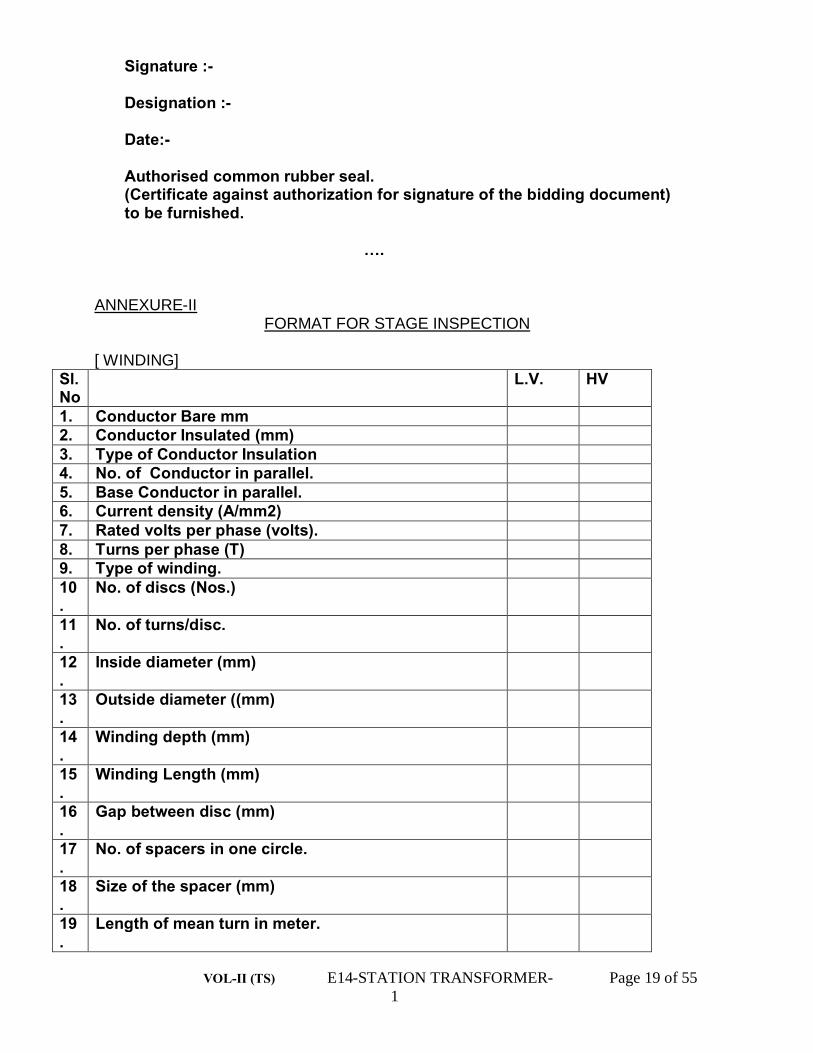
Signature :- Designation :- Date:- Authorised common rubber seal. (Certificate against authorization for signature of the bidding document) to be furnished. …. ANNEXURE-II
FORMAT FOR STAGE INSPECTION
[ WINDING] Sl.No
L.V. HV
1. Conductor Bare mm 2. Conductor Insulated (mm) 3. Type of Conductor Insulation 4. No. of Conductor in parallel. 5. Base Conductor in parallel. 6. Current density (A/mm2) 7. Rated volts per phase (volts). 8. Turns per phase (T) 9. Type of winding. 10.
No. of discs (Nos.)
11.
No. of turns/disc.
12.
Inside diameter (mm)
13.
Outside diameter ((mm)
14.
Winding depth (mm)
15.
Winding Length (mm)
16.
Gap between disc (mm)
17.
No. of spacers in one circle.
18.
Size of the spacer (mm)
19.
Length of mean turn in meter.

VOL-II (TS) E14-STATION TRANSFORMER- Page 20 of 55 2
20.
Weight of winding (Kg/each) (Weight of winding includes the weight of insulated conductor, spacers, runner & other insulations as has been complete required to make the windings).
B. INSULATION. 1. Between core & L.V. Winding (Details like thickness
(mm), length(mm) type of insulation etc. to be mentioned).
2. Between H.V. & L.V. Winding (Details like thickness (mm), length (mm), type of insulation etc. to be mentioned).
3. Between H.V. & L.V. & Stabilising (Tertiary) Winding (Details like thickness (mm), length (mm), type of insulation etc to be mentioned.
4. Between windings to top yoke (Details as above to be mentioned) .
5. Between windings to top yoke (Details as above to be mentioned) .
C CORE 1. Core Diameter in mm= 2. Window Height in mm= 3. Distance between core leg center in
mm=
4. Widths of window in mm= 5.0 OTHER PARAMETERS OF CORE:-
No. of steps
1 2 3 4 5 6 7 8 etc.
Width in mm
Stack in mm
Sectional area of stack.
6. Total gross cross sectional area of the core in mm= 7. Net core iron area=gross C/S area x 0.97 8. Maximum flux density (Bm) in Wb/sq.mm= 9. Total core weight in Kg by weighment= 10. Thickness of core lamination in mm= D. Condition of the Tank:-

VOL-II (TS) E14-STATION TRANSFORMER- Page 21 of 55 2
E. Any other items/tests which have not been covered above and required & indicated in the specification to be carried out by the OPTCL’s representative.

VOL-II (TS) E14-STATION TRANSFORMER- Page 22 of 23
ANNEXURE-IV
CALIBRATION STATUS OF TESTING EQUIPMENT AND INSTRUMENTS/ METERS AVAILABLE IN THE FACTORY.
[FOR CONDUCTING TESTS AS PER CLAUSE 18.1 OF SECTION IV OF TECHNICAL SPECIFICATION]
Name of the Test
Meters & Equipments required for the corresponding test with range accuracy make & Sl.No.
Date of Calibration.
Due date of Calibration
Name of Calibrating Agency.
Whether Calibrating Agency is Govt. approved.
Whether documents relating to Govt. approval of the Calibrating Agency furnished.
Whether the meters/ equipment fulfill the accuracy class as per calibration report.
Whether the Calibration Agency has put any limitation towards the use of the particular meter/ equipment. If yes state the limitation.
Whether Green sticker or Blue sticker or Yellow sticker has been affixed on the body of the particular equipment/ meter. State the colour of the affixed sticker.
Inspite of imposed ,limitations whether the particular meter/ equipment can still be used” Justify its use for corresponding during test(s)
Remarks
1. 2. 3. 4. 5. 6. 7. 8. 9. 10. 11. 12 Signature of the Tenderer with seal & date.

VOL-II (TS) E14-STATION TRANSFORMER- Page 23 of 23
ANNEXURE-V
CHECK LIST TOWARDS TYPE TEST REPORTS. Name of the Type Test.
Date of Test.
Name of the Laboratory where the Test has been conducted.
Whether the Laboratory is Government approved.
Whether the Test report is valid
Whether the copy of Test report in complete shape along with drawings etc furnished or not?
Whether the type tested Transformers full fill the technical requirements as per TS.
Remaks.
1. 2. 3. 4. 5. 6. 7. 8. Signature of the Tenderer with seal & date

VOL-II (TS) TS-STN TRANS- Page 24 of 24
VOL-II (TS) E15-SURGE ARRESTER- Page 1 of 20
ODISHA POWER TRANSMISSION CORPORATION LIMITED
TECHNICAL SPECIFICATION
FOR
390KV,216KV, 120KV & 30KV SURGE ARRESTER
I- 390 KV II- 216KV III- 120KV IV- 30KV

VOL-II (TS) E15-SURGE ARRESTER- Page 2 of 20
TECHNICAL SPECIFICATION FOR SURGE ARRESTERS
FOR 400 KV,220 KV, 132KV & 33KV SYSTEMS. CONTENTS
CLAUSE NO T I T L E
1.0 SCOPE 2.0 STANDARDS 3.0 GENERAL TECHNICAL REQUIREMENTS 4.0 CONSTRUCTION 5.0 TESTS 6.0 INSPECTION 7.0 QUALITY ASSURANCE PLAN 8.0 DOCUMENTATION 9.00 PACKING & FORWARDING 10.0 QUANTITY & DELIVERY REQUIREMENT
APPENDIX – I TECHNICAL REQUIREMENTS
ANNEXURES
A GUARANTEED TECHNICAL PARTICULARS B CHECK – LIST C CALIBRATION STATUS OF TESTING
EQUIPMENTS/METERS D CHECK-LIST TOWARDS TYPE TEST
REPOR

VOL-II (TS) E15-SURGE ARRESTER- Page 3 of 20
TECHNICAL SPECIFICATION FOR SURGE ARRESTERS FOR 400KV, 220KV,
132KV & 33KV SYSTEMS
1.0 SCOPE :
1.1 This Specification provides for the design, manufacture, inspection and testing before despatch, packing and delivery F.O.R. (destination) of metal oxide (gapless) Surge Arresters with discharge counters, insulating base, terminal connectors and other accessories as specified here in.
Following is the list of documents constituting this Specification. : (i) Technical Specification (TS)
(ii) Technical Requirements.
Appendix-I
(iii) Quantity and delivery schedule.
Appendix-II
(iv) Guaranteed Technical Particulars .
Annexure-A
(v) Check-List.
Annexure-B
(vi) Calibration Status of testing equipments and meters/Instruments.
Annexure-C
(vii) Check-list towards Type Test Reports.
Annexure-D
Note : Annexure-A,B,C,& D are to be filled up by the Bidder.
1.1 All the above along with amendments thereof shall be read and interpreted together. However, in case of a contradiction between the Technical Specification and any other volume, the provisions of this volume will prevail.
1.2 The Surge Arrester shall conform in all respects to high standards of engineering, design, workmanship and latest revisions of relevant standards at the time of offer and purchaser shall have the power to reject any work or materials, which in his judgement is not in full accordance therewith. 2.0 STANDARDS:- 2.1 Except to the extent modified in the Specification, the Surge Arrester shall conform to the latest editions and amendments of the standards listed hereunder.

VOL-II (TS) E15-SURGE ARRESTER- Page 4 of 20
Sl. No. Standard Ref. No.
Title.
1 IEC-99-4 Specification for Surge Arresters without gap for AC System.
2 IS:2147 Degree of protection, provided by enclosures for low voltage switchgear and control.
3 IS:2629 Recommended practice for hot dip galvanization of iron and steel.
4 IS:2633 Method for testing uniformity of coating on zinc coated articles.
5 IS:3070 Specification for surge arresters for alternating current system.
6 IS:5621 &IEC-621155
Specification for large hollow porcelain for use in electrical installation.
7 IEC-60-1 High-Voltage Test technique. 8 IEC-270 Partial discharge
measurements. 9 IEC-99-1 Non-linear resistor type
gapped arresters for a.c. systems.
10 Indian Electricity Rules, 1956. 11. IEC-60815 Shed profile of hollow
porcelain Insulator. 2.2 Surge Arresters with the requirement of other authoritative standards, which ensure equal
or better quality than the standards, mentioned above shall also be acceptable. Where the equipment offered by the supplier conforms to other standards, salient points of difference between the standards adopted and the specified standards shall be clearly brought out in the offer. 4 (Four) copies of the reference standards in English language shall be furnished along with the offer.
3.0 GENERAL TECHNICAL REQUIREMENTS :
3.1 The Surge Arrester shall confirm the technical requirements as per Appendix-I
and this TS. 3.2 The energy handling capability of each rating of Arrester offered, supported by calculations,
shall be furnished with the offer.

VOL-II (TS) E15-SURGE ARRESTER- Page 5 of 20
3.3 The Surge Arresters shall be fitted with pressure relief devices and arc diverting paths and shall be tested as per the requirements of IEC for minimum prospective symmetrical fault current as specified in Appendix-I.
3.4 A grading ring shall be provided if required, (for attaining all the relevant technical parameters) on each complete Surge Arrester.
3.5 PROTECTIVE LEVELS : Surge Arresters shall be capable of providing protection to sub-station equipments, designed for the withstand levels, given in the following table.
Sl. No.
Equipment to be protected
Insulation level of 420KV Systems
Insulation level of 245KV Systems.
Insulation Level of 145KV Systems
Insulation Level of 36KV System
L.I. Level (KVP)
L.I. Level (KVP)
L.I. Level (KVP)
L.I. Level (KVP)
1 Auto Transformers/Power Transformers.
± 1300 ± 950 ± 650 ± 170
2 Instrument Transformers. ± 1425 ± 1050 ± 650 ± 170 3 Reactors ± 1300 ± 950 ± 650 ± 170 4 Circuit Breakers/Isolators. (i) Phase to ground. ± 1425 ± 1050 ± 650 ± 170 (ii) Across open contacts. ± 1425(+
240)= 1650 ± 1200

VOL-II (TS) E15-SURGE ARRESTER- Page 6 of 20
Surge arrester shall be suitable for the following duty cycles of circuit breaker at the following system voltages:
1. 420 KV Circuit Breaker. 0-0.3 sec-co-3 min-co 2. 245 KV Circuit Breaker. 0-0.3 sec-co-3 min-co 3. 145 KV Circuit Breaker 0-0.3 sec-co-3 min-co 4 36 KV Circuit Breaker 0-0.3 sec-co-3 min-co
3.6 DUTY REQUIREMENT : 3.6.1 Surge Arresters shall be of heavy-duty station class and gapless type without any series or shunt gaps. 3.6.2 Surge Arresters shall be capable of discharging over voltages occurring during switching of un-loaded transformers, lines, capacitors and reactors. 3.6.3 The Surge Arresters shall be capable of discharging lightning and switching surges and temporary power frequency over-voltages. 3.6.4 The Surge Arresters shall be capable of discharging the energy equivalent to class 3 of IEC-99-4. 3.7 The reference current of the arrester shall be high enough to eliminate the influence of grading and stray capacitance on the measured reference voltage. The supplier shall submit values and the supporting evidence along with calculations on above. 3.8 Surge Arresters shall be fully stabilized thermally to give a life expectancy of 100 years under site conditions. 3.9 Surge Arresters shall be able to withstand maximum wind load of 260 Kg./sq.m. 3.10 Surge Arresters shall be capable of withstanding effects of direct solar radiation 3.11 Surge arresters shall be capable of spark over on severe switching Surges and multiple strokes. 3.12 The Surge Arrester should be adequately designed to operate satisfactorily under temporary power frequency over-voltage as given in specific technical requirements, after discharging two shots of respective long duration surges. 3.13 Unless otherwise brought out separately by the Bidder in the schedule of deviations, the Surge Arresters, offered shall conform to the specification scrupulously. All deviations from the specification shall be brought out in the schedule of deviations. The discrepancies between the specification and the catalogues or literature, submitted as part of the offer shall not be considered as valid deviations unless specifically brought out in the schedule of deviations. 4.0 CONSTRUCTION :

VOL-II (TS) E15-SURGE ARRESTER- Page 7 of 20
4.1 Non linear blocks shall be sintered metal oxide material. These shall be provided in such a way as to obtain robust construction with excellent electrical and mechanical properties even after repeated operations. 4.1.1 All the units of arresters of same rating shall be inter-changeable without adversely affecting the performance. 4.2 The Surge Arresters shall be suitable for pedestal type mounting. 4.3 All the necessary flanges, bolts, nuts, clamps etc. required for assembly of complete arrester with accessories and mounting on support structure to be supplied by the purchaser, shall be included in supplier’s scope of supply. 4.4 The drilling details for mounting the Arrester on owner’s support shall be supplied by the supplier. 4.5 The minimum permissible separation between the Surge Arrester and any earthed object shall be indicated by the Bidder in his offer. 4.6 Surge Arresters shall be designed to incorporate pressure relief devices and arc diverting paths to prevent shattering of the blocks or the porcelain housing, following prolonged current flow or internal flash over and providing path for flow of rated fault currents in the event of arrester failure. 4.7 Surge Arresters shall incorporate anti-contamination feature to prevent arrester failure, caused by uneven voltage gradient across the stack, resulting from contamination of the arrester porcelain. 4.8 Seals shall be provided in such a way that these are always effectively maintained even when discharging rated lightning current. 4.9 The heat treatment cycle details alongwith necessary quality checks used for individual blocks alongwith insulation layer, formed across each block are to be furnished. Metalised coating thickness for reduced resistance between adjacent discs is to be furnished alongwith the procedure for checking the same. Details of thermal stability test for current distribution of current on individual disc is to be furnished. 4.10 Each individual unit of Surge Arresters shall be hermetically sealed and fully protected against ingress of moisture. The hermetic seal shall be effective for the entire lifetime of the arrester and under the service conditions as specified. The supplier shall furnish sectional view of the arrester showing details of sealing employed. 4.11 The Surge Arresters shall be suitable for hot line washing. 4.12 PORCELAIN HOUSING : 4.13.1 All porcelain Housings shall be free from lamination cavities or other flaws, affecting the maximum level of mechanical and electrical strengths.
VOL-II (TS) E15-SURGE ARRESTER- Page 8 of 20
4.13.2 The porcelain shall be well vitrified and non-porous. 4.13.3 The minimum creepage distance of the arrester housing shall be as per Appendix-I. 4.13.4 The porcelain petticoat shall be preferably of self-cleaning type (Aerofoil design). The details of the porcelain housing such as height, angle of inclination, shape of petticoats, gap between the petticoats, diameter (ID and OD) etc. shall be indicated by the Bidder in his offer in the form of detailed drawing. 4.13.5 Porcelain housings shall be so co-ordinated that external flash over will not occur due to application of impulse or switching Surge voltages up to the maximum design value for arrester. 4.14 GALVANISATION, NICKEL PLATING ETC. : 4.14.1 All ferrous parts exposed to atmosphere shall be hot dip galvanised as per IS: 2629, as amended from time to time. Tinned copper/brass lugs shall be used for internal wiring of discharge counter. Screws used for electrical connections shall be either made of brass or shall be nickel-plated. 4.14.2 Ground terminal pads and nameplate brackets shall be hot dip galvanised. 4.14.3 The material shall be galvinised only after completing all shop operations 4.15 ACCESSORIES AND FITTINGS : 4.15.1 Surge Counters; 4.15.1.1 A self- contained Surge counter, suitably enclosed for outdoor use and requiring no auxiliary of battery supply for operation shall be provided for each unit. The surge counter shall be operated by the discharge current, passed by the surge arrester and shall be suitable for mounting on the support structure of the Arrester. 4.15.1.2 Surge counters shall be of the Electro-mechanical type and designed for continuous service. 4.15.1.3 The cyclometer counter shall be visible through an inspection window from ground level. The counter terminals shall be robust and adequate size and shall be so located that the incoming and outgoing connections are made with minimum possible bends. 4.15.1.4 Internal parts shall be unaffected by atmospheric conditions at site. Alternatively, a weather proof housing to IP 55 shall be provided and this shall be designed to allow the recording device to be read from ground level without exposing the internal parts to the atmosphere. 4.15.1.5 The Surge Counter shall be connected in the main earth lead from the arrester in such a manner that the direction of the earth lead is not changed or its surge impedance materially altered. A bolted link shall be provided so that the surge counter may be short circuited and removed without taking the arrester out of service.

VOL-II (TS) E15-SURGE ARRESTER- Page 9 of 20
4.15.1.6 All necessary accessories and earthing connection leads between the bottom of the Arrester and discharge counter shall be in the supplier’s scope of supply. 4.15.2 LEAKAGE CURRENT METERS : 4.15.2.1. Leakage current meters (suitable milli-ammeter) shall be connected in the earthing path of the surge arresters to measure the resistor grading leakage current. Meters shall be designed for continuous service. 4.15.2.2. The ammeter shall be suitable for mounting on the support structure of the arrester. The push buttons shall be mounted such that it can be operated from the ground level. 4.15.2.3. The internal parts shall be fully weather - proof to IP 55 or better with a transparent cover to provide an unobstructed view of the ammeter.. 4.15.3. Arresters shall be complete with insulating base having provision for bolting to flat surface of the structure. 4.15.4. Grading /corona rings shall be provided on each complete Arrester unit, as required, for proper voltage stress distribution. 4.15.5. The grounding terminals shall be suitable for accommodating purchaser’s grounding connection to steel earth mat. 4.15.6. The Bidder has to quote unit rates of the insulting base and the surge counter separately. The purchaser reserves its option to procure insulting base and surge counter. 4.15.7. Clamp type terminal connector, suitable for 400 KV-ACSR MOOSE/AL TUBE,220KV-ACSR MOOSE Conductor 132KV & 33KV-ACSR MOOSE Conductor shall be provided having both horizontal and vertical take-off. 4.15.8. Two clamp type ground terminal connectors, suitable for G. I. Strip (50 x 6) or (50 x 8) should be provided. 4.15.9. All interconnecting hard wares such as nuts, bolts, spring washers etc. with 5% spares shall be supplied for different units 4.15.10. Pollution Shunt (Copper braid) shall be supplied along with each surge Arrester for by-passing the surface current.. 4.15.11. Other standard accessories, which are specifically not mentioned, but are usually, provided with Surge Arrester of such type and rating for efficient and trouble free operation should be supplied. 4.16 NAME PLATE : Each single pole Arrester shall be provided with non-corrosive legible name plate, at the base bearing thereon, voltage rating of the complete pole and the number of demountable sections with the following data, indelibly marked

VOL-II (TS) E15-SURGE ARRESTER- Page 10 of 20
(a) ORISSA POWER TRANSMISSION CORPORATION LIMITED. (b) Purchase order No. & Date. (c) Name of device. (d) Manufacturer’s name and trademark and identification no. Of the arrester being supplied. (e) Year of manufacture (f) Rated voltage (g) Rated Frequency (h) Maximum continuous operating voltage. (i) Type (j) Nominal discharge current. (k) Long duration discharge class. (l) Pressure relief current in KA(rms) (m) Energy discharge capability ( KJ/KV rating). 5.0 TEST : 5.1 Type Tests: The surge Arrester offered should have been subjected to the following type tests in an independent Government approved test laboratory. The bidder shall furnish four sets of type test reports alonglwith the offer. These tests must not have been conducted earlier than five years from the date of opening of technical bid. For any change in the design, type already type tested and the design type offered against this specification, the purchaser reserves the right to demand repetition of some or all type tests without any extra cost to OPTCL in the presence of Purchaser’s representative at the cost of the supplier. 1 Insulation withstands tests : (a) Lightning Impulse Voltage Test. (b) Wet switching impulse test. (For 390KV/216KV only). 2 Residual voltage tests. 3 Long duration current impulse withstand tests. 4 Operating duty tests. 5 Pressure relief tests. (a) High current test. (b) Low current test. 6 Power frequency voltage vs. time curve. (Temporary over voltage test) 7 Contamination test. (artificial pollution test). 8 Seismic withstand test. 9 IP-55 test on surge counter. 10 Minimum current operation tests of the surge counter. 11 Maximum current withstand test of the surge counter. 12 Mechanical terminal load test on bushing. 13 Partial discharge test. N.B. :- Even if the condition i.e. ‘ the dry arcing distance or the sum of the partial dry arcing distances is larger than the test voltage divided by 500 KV/m’, the lightning impulse voltage test must have been conducted or is to be conducted without any financial liability to OPTCL.
VOL-II (TS) E15-SURGE ARRESTER- Page 11 of 20
Even if the type test reports are found to be valid as per this specification, the purchaser reserves the right to demand the repetition of some or all the type tests in the presence of purchaser’s representative. For this purpose, the bidder shall quote unit rates for carrying out each type test. These prices, if necessary, will be taken into consideration for bid evaluation. 5.2 ROUTINE TESTS : The following routine tests shall be conducted at the supplier’s cost on each surge arrester and shall be submitted along with or before offering for inspection for purchaser’s approval. (a) Measurement of reference voltage. (b) Residual voltage tests. (c) Measurement for partial discharge and contact noise. (d) Sealing test for units with sealed housings. 5.3 ACCEPTANCE TESTS : The following tests, considered as acceptance tests, shall be conducted in the presence of purchasers representative for which no charges will be payable by OPTCL. The acceptance tests, whenever possible shall be conducted on the complete arrester unit. The number of samples to be subjected to acceptance test shall be decided by the purchaser at the time of actual testing. I Temperature Cycle Test on Housing. II Measurement of Power Frequency Voltage at the reference current. III Measurement of leakage current and capacitive current at M.C.O.V. IV Lightning Impulse Residual Voltage Test at N.D.C., 50% of N.D.C. & 200% of N.D.C. V Partial Discharge Tests on complete arresters/units at 1.05 times M.C.O.V. VI Special Thermal stability test. VII Porosity test on porcelain components. VIII Galvanisation test on metal parts. IX The functional (operational) test on the Surge Counter by way of checking its operation at following nominal discharge currents : (i) 100 Amps with 8/20 micro second wave shape. (ii) 10 KA with 8/20 micro second wave shape. X Check of calibration of leakage current meters. 6 INSPECTION : I The purchaser shall have access at all time to the works and all other places of manufacture, where the Surge Arresters are being manufactured and the supplier shall provide all facilities for unrestricted inspection of the supplier’s works, raw materials, manufacture of all the accessories and for conducting the necessary tests. II The supplier shall keep the purchaser informed in advance of the time of starting and the progress of manufacture of equipment in its various stages so that arrangements could be made for inspection.

VOL-II (TS) E15-SURGE ARRESTER- Page 12 of 20
III No material shall be despatched from its point of manufacture unless the material has been satisfactorily inspected, tested and despatch schedule attached to this specification. IV The acceptance of any quantity of equipment shall in no way relieve the supplier of his responsibility for meeting all the requirements of this specification and shall not prevent subsequent rejection, if such equipments are later found to be defective. 7 QUALITY ASSURANCE PLAN : 7.1 The Bidder shall invariably furnish following informations alongwith his offer, failing which the offer shall be liable for rejection. (i) Statement giving list of important raw materials, names of sub-suppliers for the raw materials, list of standards according to which the raw materials are tested, list of tests, normally carried out on raw materials in presence of Bidder’s representative, copies of test certificates. (ii) Information and copies of test certificates as in (I) above in respect of bought-out items. (iii) List of manufacturing facilities available. (iv) Level of automation, achieved and list of areas where manual processing exists. (v) List of areas in manufacturing process where stage inspections are normally carried out for quality control and details of such tests and inspections. (vi) Special features provided in the equipment to make it maintenance free (vii) List of testing equipments, meters available with Bidder for final testing of equipment, specified and test plant limitation, if any, vis-à-vis the type, acceptance and routine tests, specified in the relevant standards and this specification. These limitations shall be very clearly brought out in the offer. (viii) All the testing equipments, meters etc. should have been calibrated in a Government approved laboratory. The Bidder must submit the list of testing equipments and meters test-wise as per Annexure-C of this Technical Specification. 7.2 The suppliers, within 30 days of placement of order submit the following informations to the purchaser. (i) List of raw materials as well as bought out accessories and the names of the materials as well as bought-out accessories and the names of sub-suppliers, selected from those, furnished alongwith the offer. (ii) Type test certificates of the raw material and bought out accessories. (iii) Quality Assurance Plan (QAP) with hold points for the purchaser’s inspection. The QAP and hold points shall be discussed between the purchaser and the supplier before the QAP is finalised. 7.3 The supplier shall submit the routine test certificates of bought out item and raw martial at the time of acceptance testing of the fully assembled equipment. 8.0 DOCUMENTATION : 8.1 All drawings shall conform to relevant Indian Standard as per relevant IS. All drawings shall be in ink and suitable for microfilming. All dimensions and data shall be in S.I. Units. 8.2 The supplier shall furnish four sets of following drawings/documents‘ along with his offer. (i) General outline drawings of the complete Arrester with technical parameters.

VOL-II (TS) E15-SURGE ARRESTER- Page 13 of 20
(ii) Drawings showing clearance from grounded and other line objects and between adjacent poles of Surge Arresters, required at various heights of Surge Arresters. (iii) Drawings showing details of pressure relief devices. (iv) Detailed drawing of discharge counters along with the wiring and schematic drawing of discharge counter and meter. (v) Outline drawing of insulating base. (vi) Details of grading rings, if used. (vii) Mounting details of Surge Arresters. (viii) Details of line terminal and ground terminals. (ix) Volt-time characteristics of Surge Arresters. (x) Details of galvanization being provided on different ferrous parts. (xi) The detailed dimensional drawing of porcelain Housing such as ID, OD, thickness and insulator details such as height, profile of petticoats, angle of inclination and gap between successive petticoats, total creepage distance etc. (xii) Cross-sectional view of the Surge Arrester Units showing all components. 8.3 TEST REPORTS : (i) Four copies of type test reports shall be furnished to the purchaser with the tender specification. Copies of acceptance test reports and routine test reports shall be furnished to the purchaser. One copy will be returned duly certified by the purchaser and only thereafter shall the materials be despatched. (ii) All records of routine test reports shall be maintained by the supplier at his works for periodic inspection by the purchaser. (iii) All test reports of tests, conducted during manufacture shall be maintained by the supplier. These shall be produced for verification as and when requested for by the purchaser. 9.0 PACKING AND FORWARDING : 9.1 The equipment shall be packed in suitable crates so as to withstand handling during transport and outdoor storage during transit. The supplier shall be responsible for any damage to the equipment during transit, due to improper and inadequate packing. The easily damageable material shall be carefully packed and marked with the appropriate caution symbols. Wherever necessary, proper arrangement of lifting such as lifting hooks etc. shall be provided. Any material found short inside the packing cases shall be supplied by the supplier without any extra cost. 9.2 Each consignment shall be accompanied by a detailed packing list containing the following informations : (a) Name of the consignee : (b) Details of consignment : (c) Destination : (d) Total weight of consignment : (e) Sign showing upper/lower side of the crate : (f) Handling and unpacking instructions : (g) Bill of materials indicating contents of each package : 9.3 The supplier shall ensure that the bill of materials is approved by the purchaser before despatch. 10.0 QUANTITY AND DELIVERY REQUIREMENT : (i) The scope of supply shall include a supply of 2.5% extra quantity of bolts, nuts, washers, split pins, cotter pins and such other small loose items free of cost.

VOL-II (TS) E15-SURGE ARRESTER- Page 14 of 20

VOL-II (TS) E15-SURGE ARRESTER- Page 15 of 20
APPENDIX – I. (TECHNICAL REQUIREMENTS)
TECHNICAL REQUIREMENTS FOR METAL OXIDE (GAPLESS) SURGE
ARRESTERS The Surge Arrester under this Specification shall conform to the parameters given below :- 390KV 216KV 120KV 30KV Sl. No.
Particulars. Technical Parameters
Technical Parameters.
Technical Parameters
Technical Parameters
1 Nominal system voltage (phase to phase) (KV rms).
400 220 132 33
2 Highest system voltage (phase to phase) (KV rms).
420 245 145 36
3 System Frequency (HZ). 50 ± 5 % 50 ± 5 % 50 ±5% 50 ±5% 4 System Neutral earthing. Effectively
earthed. Effectively earthed.
Effectively earthed
Effectively earthed
5 Installation. Outdoor. Outdoor. Outdoor Outdoor 6 Class. Station class,
10 KA, heavy duty type.
Station class, 10 KA, heavy duty type.
Station class, 10 KA, heavy duty type.
Station class, 10 KA, heavy duty type.
7 Type of construction for 10 KA rated arrester.
Single column, single phase.
Single column, single phase.
Single column, single phase.
Single column, single phase
8 No. of phases. Three Three Three Three 9 Maximum duration of earth
fault (Sec.) 3 3 3 3
10 Maximum prospective symmetrical fault current at arrester location (KA rms.)
40 40 40 40
11 Rated arrester voltage (KV rms)
390 216 120 30
12 Nominal discharge current (KAP) Disscharge current at which insulation co ordination will be done
10 KA of 8/20 micro-second Wave. And 20 KA of 8/20 microsec wave
10 KA of 8/20 micro-second Wave.
10 KA of 8/20 micro-second Wave.
10 KA of 8/20 micro-second Wave.
13 Minimum energy discharge capability (KJ/KV)
As per relevant ISS/IEC
As per relevant ISS/IEC
As per relevant ISS/IEC
As per relevant ISS/IEC

VOL-II (TS) E15-SURGE ARRESTER- Page 16 of 20
14 Maximum continuous operating voltage at 50° C(KV rms)
303
175
102 25
15 Maximum switching surge residual voltage (KVP)
780 at 1KA 496 at 1KA
272 at 1KA
72 at 500A
16 Maximum residual voltage at 8/20 micro second(KVP)
(i) 5 KA. 567 320 85 (ii) 10 KA Nominal
discharge current. 900 KVp 600 340 90
(iii) 20 KA. 975 KVp 668 380 100 17 Long duration discharge
class 3 3 3 2
18 High current short duration test value (KAP)(4/10 Micro-second wave).
100 100 100 100
19 Current for pressure relief test (KA-rms)
40 40 40 40
20 Minimum total creepage distance (mm).
10500 6125 3625 900
21 One minute dry and wet power frequency withstand voltage of Arrester housing (KV-rms).
630 460 275 70
22(a) (b)
Impulse withstand voltage of arrester housing with 1.2/50 micro-second wave (KVP). Switching Impulse Voltage (Wet) (KVP)
+1425
+1050
+ 1050
700
+650 -
+170 -
23 Pressure relief class. A A A A 24 Corona extinction voltage
(KV-rms). 320 min 216 - -
25 RIV at 92 KV rms. Less than 500 micro volts
Less than 500 micro volts.
Less than 500 micro volts.
Less than 500 micro volts
26 Partial discharge at 1.05 times continuous over-voltage.
Nor more than 50 PC.
Nor more than 50 PC.
Nor more than 50 PC
Nor more than 50 PC
27 Seismic acceleration. 0.3g horizontal 0.15g vertical
0.3g horizontal 0.15g vertical.
0.3g horizontal 0.15g vertical.
0.3g horizontal 0.15g vertical
28
Reference ambient temperature.
50°C 50°C 50°C 50°C
29 (a) IR at MCOV. Less than 500 micro amperes.
Less than 500 micro amperes.
Less than 500 micro amperes.
Less than 400 micro amperes

VOL-II (TS) E15-SURGE ARRESTER- Page 17 of 20
(b) IC at MCOV.
Less than 1500 micro amperes.
Less than 1500 micro amperes.
Less than 1500 micro amperes.
Less than 1200 micro amperes
30 a) Reference Current (mA) 1 to 5 mA 1 to 5 mA 1 to 5 mA 1 to 5 mA b) Reference voltage at
reference current. Greater than rated voltage.
Greater than rated voltage.
Greater than rated voltage.
Greater than rated voltage.
31 Maximum steep current Impulse RDV (KVP). at 10 KAP
1050 654 372 100
32 Maximum cantilever strength of the arresters (KGM).
1000 1000
1000 325
33 TOV(KVP). (i) 0.1 sec. 580 382 170 53 (ii) 1.0 sec. 565 366 163 51 (iii) 10.0 sec. 550 351 156 49 (iv) 100.0 sec. 336 149 47
ANNEXURE – B CHECK – LIST
1 Whether calculation towards energy handling capability of the Surge Arrester furnished as per Clause No.3.2 of TS ? 2 Whether there is provision of Corona Grading Ring in the SA as per Clause No.3.4 and 4.15.4 of TS ? ………….. If not, whether justification for non-provision of the same furnished ? 3 Whether calculations and supporting evidence furnished to satisfy Clause No.3.7 of TS ? 4 Whether the heat treatment cycle details alongwith necessary quality checks used for individual blocks furnished as per Clause 4.10 of TS ? 5 Whether sectional view of arrester showing details of sealing provided as per Clause No.4.11 of TS furnished ? 6 Whether S.A. is suitable for hot line washing as per Clause No.4.12 of TS ? 7 Whether porcelain petticoat is of Aero foil design ? Whether drawing of porcelain Housing as per Clause No.4.13.4 of TS furnished ? 8 Whether information as per Clause No.7.1 (i) to (viii) of TS

VOL-II (TS) E15-SURGE ARRESTER- Page 18 of 20
furnished ? 9 Whether drawings and documents as per Clause No.8.2 (i) to (xii) of TS furnished ? 10 Whether special measures in the manufacture of Surge Arrester for operating at ambient temperature of 50°C (against 40°C as per IEC-99-4, Clause No.4.4.1) are to be taken ? ………………….. State the special measures in details …………………. Signature of the Tenderer With Seal & Date

NIT NO. 58/2011-12 (Package-68/2011-12) VOL-II (TS) E15-SURGE ARRESTER- Page 19 of 21
ANNEXURE-D
CHECK LIST TOWARDS TYPE TEST REPORTS. Name of the Type Test.
Date of Test.
Name of the Laboratory where the Test has been conducted.
Whether the Laboratory is Government Approved.
Whether the Test reports are valid as per Clause No.5.1 of T.S.
Whether the copy of Test Report in complete shape alongwith drawings etc. furnished or not ?
Whether the Type Tested Surge Arrester fulfills the technical require-ments as per TS.
If the type tested Surge Arrester does not fulfill the technical requirements as per this specification, whether the bidder agrees to conduct the particular type test again at their own cost without any financial liability to OPTCL in the presence of OPTCL’s representative within the specified delivery period.
Remarks.
1 2 3 4 5 6 7 8 9
Signature of the Tenderer with seal and date.
ANNEXURE –C. CALIBRATION STATUS OF TESTING EQUIPMENTS AND INSTRUMENTS/METERS. Na Meters Date Due Name Whether Whether Whether Whether the Whether Inspite of Rema

NIT NO. 58/2011-12 (Package-68/2011-12) VOL-II (TS) E15-SURGE ARRESTER- Page 20 of 21
me of the test.
and equipments required for the corresponding test with range accuracy make and Sl. No.
of Calibrat- ion.
date of Calibrat-ion.
of the Calibrating Agency
Calibrat- ing Agency is Govt. Approv- ed.
documents relating to Govt. Approval of the cali-brating Agency furnished ?
the meters/eq-uipment fulfill the accuracy class as per calibration report
calibrat- ing agency has put any limitation towards the use of the particular meter/equipment. If yes, state the limitations.
green sticker or blue sticker or yellow sticker has been affixed on the body of the particular equipmet/meter. State the colour of the affixed sticker.
imposed limitations, whether the particular meter/equipment can still be used? Justify its use for corresponding test(s).
rks
1 2 3 4 5 6 7 8 9 10 11 12
Signature of the tenderer with seal and date.

VOL-II (TS) E16-IVT & CVT- Page 1 of 27
ODISHA POWER TRANSMISSION CORPORATION LIMITED
TECHNICAL SPECIFICATION
FOR
220,132 &33 KV IVT
&
400,220 & 132 KV CVT
VOL-II (TS) E16-IVT & CVT- Page 2 of 27
TECHNICAL SPECIFICATION
FOR
220 KV, 132KV, 33KV INDUCTIVE VOLTAGE
& 400 KV,220KV,132KV CAPACITIVE VOLTAGE
TRANSFORMERS WITH METERING WINDING OF
ACCURACY CLASS (0.2)
I- 220KV IVT
II-132KV IVT
III-33KV IVT
IV-400 KV CVT
V-220KV CVT
VI-132KV CVT

VOL-II (TS) E16-IVT & CVT- Page 3 of 27
TECHNICAL SPECIFICATION FOR 220 KV, 132KV, 33KV INDUCTIVE & 400 KV,220KV,132KV CAPACITIVE
VOLTAGE TRANSFORMER
1.0 SCOPE :
Voltage transformers shall be supplied with common marshalling box in a batch of 3 CVT’s/ IVT’s along with terminal connectors and other fittings for providing necessary inter phase and control room interconnections. The design of capacitor/Inductive voltage transformers shall be such that its accuracy shall not be affected by the presence of pollution on the external surface of its insulators. The voltage transformer shall operate satisfactorily in system with high X/R ratio.(Tp=100ms) Voltage transformer tanks along with top metallics shall be galvanised and painted to required shade stipulated under relevant sections of the specification.
1.1 This specification provides for the design, manufacture, assembly inspection and testing at
the manufacturer’s works, packing and delivery FOR [Destination] of outdoor mounted type,
single phase, single unit type Inductive voltage transformers for 220 KV, 132KV & 33KV
systems, & Capacitive Voltage Transformers for 400 kv,220kv, 132KV system to be used for
voltage indication, supply of potential to tariff meters, relays for feeder protection in Grid
Sub-stations of OPTCL, Orissa.. In addition to the above functions the 400 kv,220kv, 132KV
CVT shall be suitable for carrier coupling.
1.2 The IVTs shall be complete in all respects with insulators, bimetallic connectors, fixing
details etc. as described herein.
1.3 Bidders are required to quote for 0.2 accuracy class [metering winding] for 33KV, 132KV,
220KV IVTs &220kv, 132KV CVTs in the following manner.
(a) Guaranteed Technical Particulars.
(b) Technical literatures, brochures and drawings as per this specification.
(c) Type Test reports.
(d) List of orders, executed and Users’ certificates with offer, failing submission of the above
particulars with the offer, the tender may not be considered for evaluation.
2.0 Following is the list of documents constituting this Specification.
(i) Technical Specification (TS).
(ii) Technical requirements. - [Appendix-I]
(iii) Guaranteed Technical Particulars. - [Vol-III)]
(iv) Calibration status of testing equipment
and meters/Instruments. - [Annexure-B]
(vi) Check list towards Type Test Reports.- [Annexure-C]
VOL-II (TS) E16-IVT & CVT- Page 4 of 27
N.B.:- Annexure-A,B & ,C are to be filled up by the Bidder.
3.0 STANDARDS:-
3.1 The IVTs & CVTs shall conform in all respects to high standards of Engineering, design, workmanship and latest revisions of relevant standards at the time of offer and the Purchaser shall have the power to reject any work or material which in his judgement is not in full accordance therewith.
3.2 Except to the extent modified in the specifications, the IVTS & CVTs shall conform to the latest editions and the amendments of the standards listed hereunder: Sl. No. Standard Ref. No. Title.
01 IEC-44(4) Instrument Transformer – measurement of PDS.
02 IEC-60 High voltage testing techniques.
03 IEC-171 Insulation co-ordination.
04 IEC-186 Voltage Transformers.
05 IEC-186(A) Voltage Transformers (first supp. to IEC-186)
06 IEC-270 Partial discharge measurement.
07 IS-335 Insulating oil for transformers and switch gears.
08 IEC-8263 Method for RIV Test on high voltage insulators.
09 IS-2071 Method of high voltage testing.
10 IS-2099 High Voltage porcelain bushings.
11 IS-2147 Degree of protection provided by enclosures for low voltage switch-gear and control.
12 IS-2165 Insulation co-ordination for equipments of 100KV and above.
13 IS-3156 (Part-I to IV). Voltage transformers.
14 IS-3347 Dimensions of porcelain transformer bushings.
15 IS-4146 Application guide for voltage transformers.
16. IS-5547 Application guide for Capacitor Voltage Transformers.
17. IS-9348 Coupling Capacitor & Capacitor Devices.
3.3 All the above alongwith the amendments thereof shall be read and interpreted together.
However, in case of a contradiction between the Technical Specification and any other volume, the
provisions of this Technical Specification will prevail.
3.4 The voltage transformers with the requirements of other authoritative standards, which
ensure equal or better quality than the standards, mentioned above shall also be acceptable. Where
the equipments, offered by the supplier conforms to other standards, salient points of difference
between the standards shall be brought out in the offer. 4 (four) copies of the reference standards in
English language shall be furnished alongwith the offer.
VOL-II (TS) E16-IVT & CVT- Page 5 of 27
3.5 The supplier is to furnish the standards as mentioned above from Sl. 1 to 17 at their own
cost, if required by the purchaser.
4.0 CLIMATIC AND SERVICE CONDITIONS :
4.1 The VTS are required to operate satisfactorily under the following conditions.
(a) Maximum ambient temperature - 50°C.
(b) Maximum daily average ambient air temperature - 45°C.
(c) Maximum relative humidity – 100%.
(d) Average number of rainy days in a year – 120 days.
(e) Average annual rainfall – 150 cms.
(f) Altitude not exceeding – 1000 M.
(g) Maximum wind pressure – 260kg/sq.m.
EARTHQUAKE INCIDENCE:-
The VTS are to be designed to withstand earthquake of an intensity, equivalent to 0.3g in the
horizontal and 0.15g in the vertical direction where, ‘g’ stands for acceleration due to gravity.
5.0 PURCHASER’S AUXILIARY POWER SUPPLY:-
5.1 Following power supplies shall be made available at site:
(a) AC-3 phase, 415V, 50HZ earthed.
(b) AC single phase, 240V, 50HZ earthed.
(c) 220V DC, Ungrounded.
5.2 All equipments and devices shall be capable of continuous satisfactory operation on AC and
DC supplies of nominal voltage, mentioned above with variations as given below.
(a) AC voltage variation. ± 10%
(b) Frequency variation. ± 5%.
(c) Combined voltage & frequency variation. ± 10%
(d) DC voltage variation. 190V to 240V DC.
5.3 The supplier shall make his own arrangements for the power supplies other than those
specified under Clause-5.1 above.
6.0 INSTALLATION:-
The VTS covered under this specification shall be suitable for outdoor installation without
any protection from rain, dust, mist and direct rays of the sun.
7.0. GENERAL TECHNICAL REQUIREMENTS FOR IVT :-
7.1 Each IVT shall be supplied, filled with insulating oil and shall be hermetically sealed to
prevent atmosphere coming in contact with oil, avoiding filtration and change of oil. In case

VOL-II (TS) E16-IVT & CVT- Page 6 of 27
the tenderer intends to use Nitrogen or any other inert gas above the oil level, the gas must
not leak out and the same shall be stated in the tender.
7.2 However, the IVT shall have a provision for draining and filling insulating oil after drying or
preferably must have arrangement for drying the oil by continuous process with oil filters.
7.3 The IVT shall be suitable for transport in horizontal position if the transport limitations so demand.
SECONDARY TERMINAL BOX:-
1.2.1 The secondary terminals shall be brought out in a weather proof terminal box with a rating
not less than IP-55.
1.2.2 All secondary terminals shall be brought out in a compartment on one side of each IVT for
easy access. The exterior of this terminal box shall be Aluminum extruded sheets.
1.2.3 The terminal box shall be provided with removable gland plate and glands suitable for 1100
volts grade. PVC insulated, PVC sheathed multi core 4 sq.mm to 6 sq.mm stranded copper
conductor cable.
1.2.4 The terminal box shall be provided with a door in front so as to have easy access of
secondary terminals. The door shall have a sealing/locking arrangement and shall be suitable to
prevent penetration of moisture and rain water.
1.2.5 The dimensions of the terminal box and its openings shall be adequate to enable easy access
and sufficient working space for use of normal tools.
1.2.6 The terminal blocks shall be standard type and provided with ferrules indelibly marked or
numbered and their identifications shall correspond to the designation on the relevant wiring
diagram.
1.2.7 Secondary wiring terminal studs shall be provided with at least three nuts, plain and spring
washers. The studs, nuts and washers shall be of brass, duly nickel plated. The minimum diameter of
the studs shall be 6 mm. The length of at least 15 mm shall be available on the studs for inserting the
leads.
Polarity shall be indelibly marked on each primary and secondary terminals.
1.3 The IVT shall be filled with oil under vacuum after processing and thereafter hermetically
sealed to eliminate breathing and to prevent air and moisture from entering the tanks. Oil filling
and/or oil sampling cocks, if provided to facilitate factory processing should be properly sealed
before despatching the IVT. The method, adopted for hermetic sealing shall be described in the offer.
1.4 The castings of base, collar etc. shall be diecast and tested before assembly to detect cracks
and voids, if any.
VOL-II (TS) E16-IVT & CVT- Page 7 of 27
1.5 The characteristics of the IVTS shall be such as to provide satisfactory performance such as
voltage error and phase displacement at rated frequency shall not exceed the values as per relevant
standards at any voltage between 80% and 120% of rated voltage and with burdens of between 25%
and 100% of rated burden at a power factor of 0.8 lagging. The error shall be determined at the
terminals of the IVT and shall include the effects of any fuses or resistors as an integral part of the
IVT.
1.6 Inductive voltage transformers shall be designed so as to achieve the minimum risk of
explosion in service. The bidder shall bring out in his offer, measures taken to achieve this.
1.7 PRIMARY WINDING:-
Primary winding of the IVT will be connected phase to neutral with the neutral point solidly
earthed. The arrangement for this shall be included in the scope of supply. The primary
conductor shall be of adequate cross-section so that the maximum permissible current density
shall not be exceeded even during short-circuit conditions.
7.11 SECONDARY WINDING.
Suitably insulated copper wire of electrolytic grade shall be used for secondary windings.
The secondary conductor shall be of adequate cross section so that the maximum permissible
current density shall not be exceeded even during short- circuit conditions. Each 220KV IVT
& 132KV IVT will have two secondary windings, protection-150VA; –Metering-150VA –
burden at 0.8 lagging power factor and rated voltage of 110V/1.732V for protection and
110/1.732V for metering winding. Secondary windings shall be used for metering, relaying
and synchronizing. Each winding shall comply requirements of both Part-II and III of up-to-
date editions of IS-3156/IEC-186. 33KV IVT will have two secondary winding of 75 VA
burden at 0.8 lagging power factor and rated voltage 110/1.732 volts( one metering and one
protection winding).
7.12 CORE:- Core laminations shall be of cold rolled grain oriented silicon steel or other
equivalent alloys of low hysteresis and eddy current losses, high permeability to ensure
accuracy i.e. 0.2 accuracy class at both normal and high over voltage. The core material ,
thickness of lamination, the relevant graphs showing the characteristics of the core materials
shall be submitted along with the offer.
7.13 TANK.
7.13.1 Both expansion chambers and tanks of the IVT shall be made of high quality steel and shall
be able to withstand full vacuum and pressure, occurring during transit and thermal and
mechanical stresses resulting from maximum short circuit current during operation. The tanks
along with all ferrous parts shall be hot- dip galvanized as per relevant standard.
VOL-II (TS) E16-IVT & CVT- Page 8 of 27
7.13.2 The metal tanks shall have bare minimum number of welded joints so as to minimize possible
locations of oil leakage. Welding in horizontal plane is to be avoided as welding at this
location may give way due to vibrations during transport resulting in oil leakage. Supplier
has to obtain specific approval from the purchaser for any horizontal welding, used in the
bottom tank
7.13.3 Paint inside the metallic housing shall be of anti-condensation type.
7.14 PORCELAIN HOUSING.
7.14.1. The housing shall be made up of homogeneous, vitreous porcelain of high mechanical and
dielectric strength, Glazing of porcelain shall be of uniform brown or dark brown colour
with a smooth surface, arranged to shed away rain water or condensed water particles(
fog).The details of location and type of joint, if provided on the porcelain, shall be furnished
by the Bidder along with the offer.
7.14.2.The bushings of the IVTS shall conform to latest edition of IS-2099.The hollow porcelain
insulators shall conform to the latest edition of lS-5621
7.14.3 The insulators shall be cemented with Portland cement to the flanges resulting in high
mechanical, tensile and breaking strength
7.14.4. The bushings shall have ample insulation, mechanical strength and rigidity for the condition
under which they shall be used and shall be used and shall be designed to prevent
accumulation of explosive gases and provide adequate oil circulation to remove the internal
heat.
7.14.5 Cast metal and caps for the bushings shall be of high strength hot dip galvanized malleable
iron. They shall have smooth surface to prevent discharge taking place between the metal
parts and porcelain as a result of ionisation.
7.14.6 The insulation of bushings shall be co-ordinated with that of the IVT such that the flashover,
if any, shall occur only external to the IVT.
7.14.7 Oil level gauge and convenient means of filling, sampling and draining of oil shall be
provided.
7.14.8 End shields should be provided for distribution of stresses.
7.14.9 Corona shields for bushings, if required, should be provided.
7.15 INSULATING OIL.
The quantity of insulating oil for the filling and the complete specification of the insulating
oil shall comply in all respects with the provisions of the latest edition of IS-335. The IVTS
shall be supplied completely filled with purified oil.

VOL-II (TS) E16-IVT & CVT- Page 9 of 27
7.16. PREVENTION OF OIL LEAKAGE AND ENTRY OF MOISTURE:-
The supplier shall ensure that the sealing of the IVT is properly achieved. In this connection,
the arrangement provided by the supplier at various locations including the following ones
shall be described, supported by sectional drawings
(a) Locations of emergence of primary & secondary terminals..
(b) Interface between porcelain housing and metal tank(s).
(d) Cover of the secondary terminal box.
7.16.1 Nuts and bolts or screws used for fixation of the interfacing porcelain bushings for taking out
terminals shall be provided on flanges, cemented to the bushings and not on the porcelain.
7.16.2 For gasketed joints, wherever used, nitrite butyl rubber gaskets shall be used. The gasket shall
be fitted in properly machined groove with adequate space for accommodating the gasket
under compression.
7.17 FITTINGS AND ACCESSORIES:- Fittings and accessories, listed below shall be supplied
with each IVT. Any fitting, required essential other than those listed below shall also be
supplied along with each IVT.
(a) Oil level gauge.
(b) Oil filling hole and cap.
(c) Pressure relieving device.
(d) Lifting lugs for core and windings, bushings & complete transformers.
(e) Phase terminal connectors.
(f) Tank earthing pads/terminals with necessary nuts and bolts and washers for connecting to Purchaser’s strip. (g) Name/Rating plate.
(h) MCB & H.R.C. fuse.
7.18.1 OIL LEVEL GAUGE:- An oil level gauge shall be provided to indicate the oil level in the
IVT. This gauge shall be mounted in such a way that the oil level can be seen from the
ground level.
7.18.2 PRESSURE RELIEVING DEVICE:- Each IVT shall be provided with a pressure relieving
device so as to protect bushing of the IVT even under unfavourable conditions.
7.18.3 OIL DRAIN COCK:- An oil drain cock alongwith a stop cock shall be provided in the bottom
flange so as to permit taking of oil samples for testing, if required.

VOL-II (TS) E16-IVT & CVT- Page 10 of 27
7.18.4 EARTHING:- Metal tank of each IVT shall be provided with two separate earthing terminals
for bolted connection to 50mm x 6mm flat to be provided by the Purchaser for connection to
station earth-mat.
7.18.5 LIFTING ARRANGEMENT:- The IVT shall be provided with suitable lifting arrangement
to lift the entire unit. The lifting arrangement shall be clearly shown in the general
arrangement drawing. Lifting arrangement [Lifting eye] shall be positioned in such a way so
as to avoid any damage to the porcelain housing or the tanks during lifting for
installation/transport. Necessary string guides shall be offered which shall be of removable
type.
7.18.6 NAME PLATE:- The IVT shall be provided with non-corrosive legible name plate with the
information specified in relevant standards, duly engraved/punched on it.
7.18.7 GASKET JOINT:- The manufacturer shall furnish the type of gasket used or setting methods.
7.18.8 TERMINAL CONNECTORS:- All the IVTS shall be provided with bimetallic solderless
clamp type, rigid type terminal connectors, suitable for ACSR Moose Conductor for 220KV
IVT & CVT ACSR .MOOSE /MOOSE Conductor for132KV, 33KV IVT & 132KV
CVT..Each terminal connector shall be of universal type, suitable for both horizontal and
vertical connections to the transmission line conductors/station bus bar.
7.18.8.1 TERMINAL CONNECTORS shall be manufactured and tested as per IS:5561.
7.18.8.2 All castings shall be free from blow holes, surface blisters,cracks and cavities.
All sharp edges and corners shall be blurred and rounded off.
7.18.8.3 No part of a clamp shall be less than 10mm thick.
7.18.8.4 All ferrous parts shall be hot dip galvanized conforming to IS-2633.
For bimetallic connectors, copper alloy linear of minimum thickness of 2 mm shall be
cast integral with aluminium body.
7.18.8.5 All current carrying parts shall be designed and manufactured to have minimum contact
resistance.
7.18.8.6 Connectors shall be designed to be corona free in accordance with the requirements,
stipulated in IS-5561.
7.18.9 SECONDARY WIRING:-
The Secondary wiring shall be enclosed in conduits and shall be brought to a terminal block
ready for external connections. The wiring shall be of adequate cross-section and not less
than 4.00 sq.mm copper wire.
7.18.10The supplier shall supply necessary hardwares, required for connection of
phase side conductor to the line terminal and the grounding strip to the grounding terminal.
VOL-II (TS) E16-IVT & CVT- Page 11 of 27
7..18.11 Necessary nuts and bolts for fixing the IVTS on the supporting structures shall
be in tenderer’s scope of supply.
B.7.0 GENERAL TECHNICAL REQQUIREMENTS FOR 400 kv,220KV & 132KV CAPACITIVE
VOLTAGE TRANSFORMER:-
7.1 The design of capacitor voltage transformers shall such that its accuracy shall not be affected
by the presence of pollution on the external surface of its insulators.
7.2 The CVT shall operate satisfactorily in system with high X/R ratio. (Tp=100 ms).
7,3 The CVT transformer tanks along with top metallic shall be galvanized and painted to
required shade.
7,.4 Impregnation details along with tests and checks to ensure successful completion of
impregnation cycle shall be furnished for purchaser’s approval.
7.5 Bellows, if used to cater for expansion of insulating oil, shall be tested in accordance with
relevant standards. The details shall be subject to the approval of the purchaser.
7.6 The CVT shall be capacitor voltage type with electromagnetic units and shall be suitable for
carrier coupling..
7.7 All windings of voltage transformer secondaries shall be protected by MCB and HRC
cartridge type fuses. In addition, fuses shall be provided for the protection and metering
windings for fuse monitoring scheme. The secondary terminals of the CVTs shall be
terminated to stud type non-disconnecting terminal blocks in the individual phase secondary
boxes via. the fuse
7.8 CVTs shall be suitable for high frequency (HF).coupling, required for power line carrier
communication. The carrier signal must be prevented from flowing into potential transformer
(EMU) circuit by meant of a RF choke/reactor, suitable for effectively blocking the carrier
signal over the entire carrier frequency range i.e. 40 to 500 KHZ. Details of the arrangement
shall be furnished along with the bid. HF terminal of the CVT shall be brought out through a
suitable bushing and shall be easily accessible for connection to the coupling devices of the
carrier communication equipment, when utilized. The bushing shall be fully protected against
rain and vermin so as to avoid the possibility of short circuits to earth. An earthing link with
fastener shall be provided for HF terminal.
7.9 The electromagnetic unit, comprising compensating reactor, intermediate transformer and
protective and damping devices should have a separate terminal box with all secondary
terminals, brought out.
7.10 Voltage transformers should be thermally and dielectrically safe when the secondary
terminals are loaded with the guaranteed thermal burdens.
VOL-II (TS) E16-IVT & CVT- Page 12 of 27
7.11 The accuracy of the windings (3P/3P/0.2) shall be maintained through out the entire burden
range preferably in the frequency range of 48 HZ to 51.5 HZ on all the three windings
without any adjustment during operation. Preference will be given to such bidders who can
offer for maintaining the above accuracy class in the frequency range i.e. 48 HZ to 51.5 HZ
up to the above specified burden values.
7.12 CONSTRUCTIONAL FEATURES:-
7.12.1 The 400kv, 220KV & 132KV CVT shall be suitable for mounting on support structure of
tubular GI pipe of nominal bore of 300/200 mm. or lattice type structures.
7.12.2 Access to secondary terminals shall be possible without any danger of access to high voltage
circuit.
7.12.3 CVTs shall be hermetically sealed units.
7.12.4 A protective surge Arrester/spark gap shall be provided to prevent break down of insulation
by incoming surges and to limit abnormal rise of terminal voltage of shunt capacitor/primary
winding, turning reactor/RF choke etc. due to short circuit in transformer secondaries. In case
of an alternative arrangement, the Bidder shall bring out the details in the Bid.
7.12.5 The CVT secondary terminals shall brought out in to a weather proof terminal box for ease
of access. The terminal box shall have an IP rating of not less than IP 55. The terminal box
shall be provided with a removable gland plate at the bottom and shall be suitable for
accepting the required number of PVC insulated PVC sheathed, 10 core 2.5 mm² standard
copper conductor cable.
7.12.6 All terminals shall be clearly marked to facilitate connection of secondary wiring.
7.12.7 Secondary fuses or MCBs shall be provided on or adjacent to each CVT, located such that
they are accessible while the primary is live and shall be provided with labels indicating their
function and their phase colours CVT secondary circuits shall be complete in themselves and
shall be earthed at one point only. A separate earth link shall be provided for each secondary
winding and shall be situated at the CVT.
7.12.8 Where CVTs are supplied which are, or may be connected to different sections of the bus bar,
it shall not be possible for the CVT secondary circuits, to be connected in parallel.
7.12.9 An auxiliary switch or relay shall be provided in each phase of the secondary circuit of the
synchronizing and metering voltage supply connections to break the circuits automatically as
soon as the circuit breaker is opened.
7.12.10 To prevent ferro resonance, suitable damping devices shall provided for connection to the
transformer secondaries.
7.12.11 CVTs shall meet the requirements, given in this section of the specification.

VOL-II (TS) E16-IVT & CVT- Page 13 of 27
7.12.12 The creepage and flashover distances of the high voltage insulator shall be suitable for the
out door service conditions, specified in the schedules.
7.12.13 The bidder in the offer is to state the suitable precautions/methods, adopted during design
stage of the CVT to avoid the un-desirable effects due to ferro resonance phenomena. The
precautions/methods include lower level of working flux density in EMU, greater utilization
of the linear portion of the magnetization curve, providing an air gap in the magnetic circuit,
connecting a suitable damping resistance permanently across the secondary etc.
7.12.14 It should be stated in the bid offer regarding the steps taken in the design stage for
elimination/minimization of the influence of the transient response on the behavior of high
speed relays.
7.12.15 It shall be ensured by the bidder in the offer that the connection of carrier, frequency
coupling device across the CVT will not affect the designated accuracy class of the CVT
windings.
7.12.16 The capacitor divider unit shall comply to IS: 9348/1979.
7.12.17 It shall also be complied in the offer through a calculation sheet, proving that the designated
accuracy class of the CVT (both metering and protection) are not affected by extreme
temperatures, to be encountered in service conditions (Max. ambient temperature 50º C and
minimum -0º C).
7.12.18 The terminal contractors should be suitable for ACSR MOOSE,/‘ ZEBRA’(as per
requirement) Conductor, complying to Cl.No.A.7.18.8 of this specification.
8.. TESTS:-
8.1 Type Tests:- The offered 220KV, 132KV & 33KV Inductive voltage transformer
&400KV,220kv, 132KV capacitive voltage transformer should have been subjected to the
following type tests in a Government approved Test Laboratory. The bidder shall furnish four
sets of type test reports along with the offer. These tests must not have been conducted earlier
than five years from the date of opening of the bid. For any change in the design/type already
type tested and to the design/type offered against this specification, the purchaser reserves the
right to demand repetition of some or all type tests/special tests without any extra cost to
OPTCL in the presence of purchaser’s representative at the cost of the supplier.
For 220 KV, 132KV & 33KV IVT:
(a) Temperature rise test.
(b) Short circuit withstand capability test.
(c) Lightning Impulse Test.
(d) High Voltage power frequency wet withstand voltage tests.
VOL-II (TS) E16-IVT & CVT- Page 14 of 27
(e) Determination of errors.
(f) IP-55 Test on secondary Terminal Box.
N.B.:- [I] The dielectric type tests should have been carried out on the
same transformer.
(ii) After the IVT was subjected to the dielectric tests, it should have been subjected to all
routine tests as per relevant standards.
(iii) For Temperature Rise Test, the test must have been made with the appropriate rated
burden, connected to each secondary winding.
For 400 kv,220KV & 132KV CVT. TYPE TESTS/SPECIAL TESTS FOR 400 KV, 220KV, 132KV CVT:-
a) Lightning Impulse voltage test on complete CVT unit.
b) Power frequency over-voltage test on complete CVT unit.
c) Partial discharge test.
d) Radio interference voltage test.
e) Corona extinction voltage test.
f) Temperature rise test on complete CVT unit.
g) Ferro resonance test on the complete C.V.T. unit.
h) Transient response tests.
i) Determination of Temperature Co-efficient test.
j) High frequency capacitance and equivalent resistance measurement test (as per IEC-358)
k) Stray capacitance and stray conductance test (as per IEC-358).
l) Accuracy tests.
m) Thermal stability test.
n) Thermal Co-efficient test (as per IEC-358)
o) Fast transient test.
p) Seismic withstand test.
q) IP-55 test on secondary Terminal Box.
r) Magnetization and internal burden tests.
s) Effectiveness of sealing tests.
t) Mechanical Terminal load test on Bushing.
u) Dielectric loss angle test (Tan Delta Test).
N.B:- 1. The dielectric type tests should have been carried out on the same CVT.

VOL-II (TS) E16-IVT & CVT- Page 15 of 27
2. After the CVT was subjected to the dielectric tests, it should have been
subjected to all routine tests as per relevant standards.
3. The ratio errors, phase displacements before, during and after the temperature
rise test on complete CVT unit should have been determined with stipulated
burdens and the same should comply with the designated accuracy class for
each winding of the CVT.
8.2 ROUTINE TESTS:- The following routine tests shall be conducted on each VT in the presence
of Purchaser’s representative for which no charges will be payable by OPTCL. No sampling
is allowed.
(a) Verification of terminal markings.
(b) Power frequency withstand tests on primary windings/capacitor voltage divider for IVT/CVT
(c) Partial discharge measurement for 400 KV,220KV, 132KV IVT & 220KV & 132KV CVT.
(d) Power frequency withstand tests on secondary windings/Low voltage terminal of the
capaciter divider for220KV & 132KV CVT.
(e) Power frequency withstand tests between sections.
(f) Determination of errors on complete IVT./CVT.
(g) Measurement of Insulation resistance.
(h) Oil leakage test.
(i) Measurement of capacitance and dielectric dissipation factor before and after dielectric tests
(as per IEC-358)
(j) Power frequency tests on electromagnetic unit for400 KV, 220KV & 132KV CVT.
(k) Any other test as per relevant national & international standards.
N.B.:- Determination of errors shall be performed after the other tests. The standard reference VT to
be used during testing for determination of ratio error and phase angle error should of 0.05 accuracy
class or better as per standard practice, presently adopted by OPTCL.
9. INSPECTION:
9.1 The Purchaser shall have access at all times to the works and all other places of manufacture,
where the IVTs/CVTs are being manufactured and the supplier shall provide all facilities for
unrestricted inspection of the supplier’s works, raw materials, manufacturer of all the accessories and
for conducting the necessary tests.
9.2 The Supplier shall keep the Purchaser informed in advance of the time of starting and of the
progress of manufacture of equipment in its various stages so that arrangement could be made for
inspection at the discretion of the Purchaser.

VOL-II (TS) E16-IVT & CVT- Page 16 of 27
9.3 No material shall be despatched from its manufacture unless the material has been
satisfactorily inspected, tested and despatch clearance issued. However, the Purchaser reserves the
right to alter the despatch schedule attached to this Specification.
9.4 The acceptance of any quantity of equipment shall in no way relieve the supplier of his
responsibility for meeting all the requirements of this Specification and shall not prevent subsequent
rejection, if such equipments are found to be defective.
9.5 Clear 15 (Fifteen) days notice shall be given to this office for deputing officer(s) for
inspection. The Voltage Transformers shall be despatched only after the inspection is conducted by a
representative of OPTCL and release order, issued from this office after approval of Routine Test
Certificates. The shop routine test certificates in triplicate for all the Voltage Transformers along
with the calibration certificates of all the meters and equipments to be used during testing (as per
Annexure-B of the Specification) should be furnished along with the Inspection Offer. The
Inspecting Officer will be authorised for inspection of the Voltage Transformers subject to the
condition that the routine test certificates and calibration certificates of the testing equipments/meters
will be found to be in order.
10. QUALITY ASSURANCE PLAN:-
10.1 The Bidder shall invariably furnish following informations along with his offer.
[i] Statement giving list of important raw materials, names of sub-suppliers for the raw
materials, list of standards, according to which the raw materials are tested, list of tests,
normally carried out on raw materials in presence of Bidder’s representative, copies of test
certificates.
[ii] Information and copies of test certificates as in [i] above in respect of bought out items.
[iii] List of manufacturing facilities available.
[iv] Level of automation achieved and list of areas where manual processing exists.
[v] List of areas in manufacturing process where stage inspections are normally carried out
for quality control and details of such tests and inspection.
[vi] Special features provided in the equipment to make it maintenance free.
[vii] List of testing equipments, meters and test plant limitation, if any, vis-à-vis the type,
acceptance and routine tests, specified in the relevant standards. These limitations shall be
very clearly brought out in the offer.
[viii] All the testing equipments, meters etc. should have been calibrated in a Government
approved laboratory. The Bidder must submit the list of testing equipments and meters test-
wise as per ANNEXURE-B of the Technical Specification.

VOL-II (TS) E16-IVT & CVT- Page 17 of 27
10.2 The Supplier shall within 30 days of placement of order submit the following information to
the Purchaser.
[i] List of raw materials as well as bought out accessories and the names of the materials
as well as bought out accessories and the name of Sub-suppliers selected from those,
furnished along with the offer.
[ii] Type test certificates of the raw materials and bought out accessories.
[iii] Quality Assurance Plan (QAP) with hold points for the Purchaser’s possible
inspection. The QAP and hold points shall be discussed between the Purchaser and the
Supplier before the QAP if finalised.
10.3 The Supplier shall submit the routine test certificates of bought out items and raw materials at
the time of acceptance testing of the fully assembled equipment.
11 DOCUMENT: The supplier shall furnish four sets of following drawings/documents along
with his offer.
[a] General outline and assembly drawings of the Inductive Voltage Transformers/
Capacitive Voltage Transformers.
[b] Sectional views showing:-
[i] General constructional features.
(ii) Materials/gaskets/sealing used.
iii] The insulation of the winding arrangements, method of connection of
primary/secondary winding to the primary/secondary terminals etc.
[c] Schematic drawing.
[d] Rating & diagram plate as per relevant IEC/ISS
[e] Secondary Terminal Box.
[f] Assembly Sectional view of Primary terminal./ capacitor voltage divider
[g] Assembly drawing for secondary terminal
[h] The detailed dimensional drawing of Porcelain Housing such as ID,OD, thickness
and insulator details such as height, profile of petticoats, angle of inclination and gap
between successive petticoats, total creepage distance etc.
[i] Sectional view of pressure release device.
[j] Drawing showing details of Oil level.
[k] All type test reports relating to the tests as specified in Clause-8.1 of the above.
[l] Ratio and phase angle error curves for IVTS/ CVTS
[m] Magnetization characteristic curves such as B-H curves and Sp. Loss vs. Flux density
curves for core material, used for IVT & EMU unit of CVT.

VOL-II (TS) E16-IVT & CVT- Page 18 of 27
[n] Sectional view of EMU unit of 400 KV,220KV&132KV CVT
12. TEST REPORTS:-
[i] Four copies of type test/special test reports shall be furnished to the Purchaser with the tender
offer.
[ii] Copies of acceptance test reports and routine test reports shall be furnished to the Purchaser.
One copy will be returned, duly certified by the Purchaser and only thereafter shall the
materials be despatched.
[iii] All records of routine test reports shall be maintained by the supplier at his works for periodic
inspection by the Purchaser.
[iv] All test reports of tests, conducted during manufacture shall be maintained by the supplier.
These shall be produced for verification as and when required for by the purchaser.
13. The necessary galvanized flanges, bolts etc. for the base of the Inductive/Capcitive Voltage
Transformers shall be supplied without any extra cost to the purchaser.
14. PACKING AND FORWARDING:-
14.1 The equipment shall be packed in suitable crates so as to withstand handling during transport
and outdoor storage during transit. The supplier shall be responsible for any damage to the
equipment during transit, due to improper and inadequate packing. The easily damageable material
shall be carefully packed and marked with the appropriate caution symbols. Wherever necessary,
proper arrangement for lifting such as lifting hooks etc. shall be provided. Any material found short
inside the packing cases shall be supplied by supplier without any extra cost.
14.2 Each consignment shall be accompanied by a detailed packing list containing the following
informations:
[a] Name of the consignee.
[b] Details of consignment.
[c] Designation.
[d] Total weight of consignment.
[e] Sign showing upper, lower side of the crate.
[f] Handling and unpacking instructions.
[g] Bill of materials indicating contents of each package.
[h] Set of approved drawings.
14.3 The supplier shall ensure that the bill of materials is approved by the Purchaser before
despatch.
15. Any tender without complete information as asked for in the above Specification is likely to be rejected.

VOL-II (TS) E16-IVT & CVT- Page 19 of 27
CVT’s shall be suitable for high frequency (HF) coupling required for power line carrier communication. The carrier signal must be prevented from flowing into potential transformer (EMU) circuit by means of a RF choke/reactor suitable for effectively blocking the carrier signals over the entire carrier frequency range i.e. 40 to 500 kHz. Details of the arrangement shall be furnished along with the bid. HF. terminal of the CVT shall be brought out through a suitable bushing and shall be easily accessible for connection to the coupling devices of the carrier communication equipment, when utilised. The bushing shall be fully protected against rain and vermin so as to avoid the possibility of short circuits to earth. An earthing link with fastener shall be provided for HF terminal. The electromagnetic unit comprising compensating reactor, intermediate transformer and protective and damping devices should have a separate terminal box with all secondary terminals brought out. Voltage transformers should be thermally and dielectrically safe when the secondary terminals are loaded with the guaranteed thermal burdens. The accuracy of the metering winding (0.2) shall be maintained throughout the entire burden range up to 100 VA/100 VA/1100 VA for 420kV CVT’s on all the three windings without any adjustments during operation.
Constructional features 420 KV CVT’s shall be suitable for mounting on support structure of made out of preferably
lattice or tubular GI pipe of nominal bore of 300/200 mm. Access to secondary terminals shall be possible without any danger of access to high voltage circuit. Voltage transformers shall be hermetically sealed units. A protective surge arrester/spark gap shall be provided to prevent breakdown of insulation by incoming surges and to limit abnormal rise of terminal voltage of shunt capacitor/primary winding, tuning reactor/RF choke etc. due to short circuit in transformer secondaries. In case of an alternate arrangement, Bidder shall bring out the details in the Bid. The wiring diagram for the interconnection of the three single phase CVT’s shall be provided inside the marshalling box in such a manner that it does not deteriorate with time. The wiring diagrams shall be fixed The primary and secondary windings of voltage transformers shall be constructed from high purity, annealed, high conductivity copper meeting the requirements of IEC 28. The VT secondary terminals shall be brought out into a weather proof terminal box for ease of access. The terminal box shall have an IP rating of not less than IP 55. The terminal box shall be provided with a removable gland plate at the bottom and shall be suitable for accepting the required number of PVC insulated PVC sheathed 10 core 2.5 mm2 stranded copper conductor cable. All terminals shall be clearly marked to facilitate connection of secondary wiring. Secondary fuses or MCB’s shall be provided on or adjacent to each voltage transformer, located such that they are accessible while the primary is live and shall be provided with labels indicating their function and their phase colours. Voltage transformer secondary circuits shall be complete in themselves and shall be earthed at one point only. A separate earth link shall be provided for each secondary winding and shall be situated at the voltage transformer. Where voltage transformers are supplied which are, or may be, connected to different sections of the busbar, it shall not be possible for the voltage transformer secondary circuits to be connected in parallel. An auxiliary switch or relay shall be provided in each phase of the secondary circuit of the synchronising and metering voltage supply connections to break the circuits automatically as soon as the circuit breaker is opened. To prevent ferro resonance, suitable damping devices shall be provided for connection to the transformer secondaries. Voltage transformers shall meet the requirements given in this section of the Specification.

VOL-II (TS) E16-IVT & CVT- Page 20 of 27
The creep age and flash over distances of the high voltage insulator shall be suitable for the outdoor service conditions specified in the Schedules.
Oil Filled voltage transformers The following facilities shall be provided for oil filled voltage transformers:
• Visual oil level indicator of prismatic or other or means of determining the position of the diaphragm or bellows seal visible from ground level.
• Oil drain cock and sampling valve where applicable.
Requirement Of 420kv Capacitor Voltage Transformer
Particulars
Parameters
Rated primary 420kV Type Single phase capacitor voltage transformer No. of secondaries 3 Rated voltage factor 1.2 continuous
1.5 for 30 seconds Phase angle errors ±20 minutes Capacitance(pF) 4400/8800+10% ,-5%(as per applicable)
Voltage Ratio kVV
Secondary core Nos.
Core-1 400
3110
3
Core-2 400
3110
3
core-3 400
3110
3
Application Protection Protection Metering and
instrumentation Accuracy 3P 3P 0.2 Output burden(VA) minimum* 100 100 100
*The bidder shall also estimate the requirement of burden and offer the same as an alternative for the Employers consideration. REMARKS : C.T., P.T. & CVT consoles. Marshalling box shall be of aluminium alloy of 3mm are to be supplied along with the C.T., P.T. & CVT equipments. One console box is required for 3 nos. equipment. Details of quantities required are to be engineered by the contractor. These consoles are suitable for outdoor mounting and shall have proper slope at the top for easy discharge of water.

NIT NO. 58/2011-12 (Package-68/2011-12) VOL-II (TS) E16-IVT & CVT- Page 21 of 28
APPENDIX – I. TECHNICAL REQUIREMENTS FOR 400 KV,220KV, 132KV & 33KV INDUCTIVE VOLTAGE TRANSFORMERS &400 KV,220KV,
132KV CAPACITIVE VOLTAGE TRANSFORMER.
Sl. No
Particulars. Description. 400 KV/220KV CVT 220KV IVT 132KV CVT 132KV IVT 33KV IVT
1 Type Single phase, 50Hz, oil Filled, self cooled, Hermetically sealed, Outdoor porcelain type.
Single phase, 50Hz, oil filled, self cooled, Hermetically sealed, outdoor porcelain type
Single phase, 50Hz, oil Filled, self cooled, Hermetically sealed, Outdoor porcelain type.
Single phase, 50Hz, oil filled, self cooled, Hermetically sealed, outdoor porcelain type.
Single phase,50Hz, oil filled, self cooled, Hermetically sealed, outdoor porcelain type.
2 Nominal system voltage. 400 KV/220KV 220KV 132KV 132KV. 33KV. 3 Highest system voltage. 420 KV/245KV 245KV 145KV 145KV. 36KV 4 Frequency. 50Hz± 5% 50Hz± 5% 50Hz ± 5% 50Hz± 5% 50Hz± 5% 5 System earthing. Effectively solidly
earthed. Effectively solidly earthed.
Effectively solidly earthed.
Effectively solidly earthed
Effectively solidly earthed
6 Number of phases. 3 [single phase] 3 [single phase] 3 [single phase] 3 [single phase] 3 [single phase] 7 (i)Number of secondary windings.
(ii)Purpose of windings. 3 [three] Protection & metering.
2 (two) Protection & metering
3 [three] Protection & metering.
2 [two] Protection & metering.
2 (two) one protection and one Metering)
8 Rated primary voltage. 400/1.732 KV / 220/1.732 KV 220/1.732 KV 132/1.732 KV 132/1.732KV 33/1.732KV 9 Rated secondary voltage. Winding-I-110/1.732V
Winding-II-110/1.732V Winding-III-110/1.732V
Winding-I-110V /1.732V (Protection) Winding-II-110/1.732V (Metering)
Winding-I-110/1.732V Winding-II-110/1.732V Winding-III-110/1.732V
Winding-I-110V/ 1.732V (Protection) Winding-II-110/ 1.732V(Metering)
110/1.732V (Metering) 110/1.732V Protection
10 Ratio 400 KV/1.732/110V/1.732 & 220KV/1.732/ 110V/1.732
220KV/1.732/ 110V /1.732V
132KV/1.732/ 110V/1.732
132KV/1.732/ 110V/1.732V
33KV/1.732/ 110/1.732
11 Rated burden. Winding-I (P)-100VA Winding-II (P)-100VA Winding-III(M)-100VA/0.2 class & simultaneous burden-100 VA with accu. cl-0.2
Winding-I(P)- 150VA /3P; Winding-II(M)- 150VA/0.2 class & simultaneous burden-150VA with accu. cl-0.2
Winding-I (P)-100VA /3P; Winding-II (P)-100VA/3P; Winding-III (M)-75VA/0.2 class & simultaneous burden-100
Winding-I(P)- 150VA /3P; Winding-II(M)- 150 VA /0.2 & Simultaneous Burden- 150 VA with accu. cl-0.2
Winding-I(P)- 75VA /3P; Winding-II(M)- 75 VA /0.2 & Simultaneous Burden- 75 VA
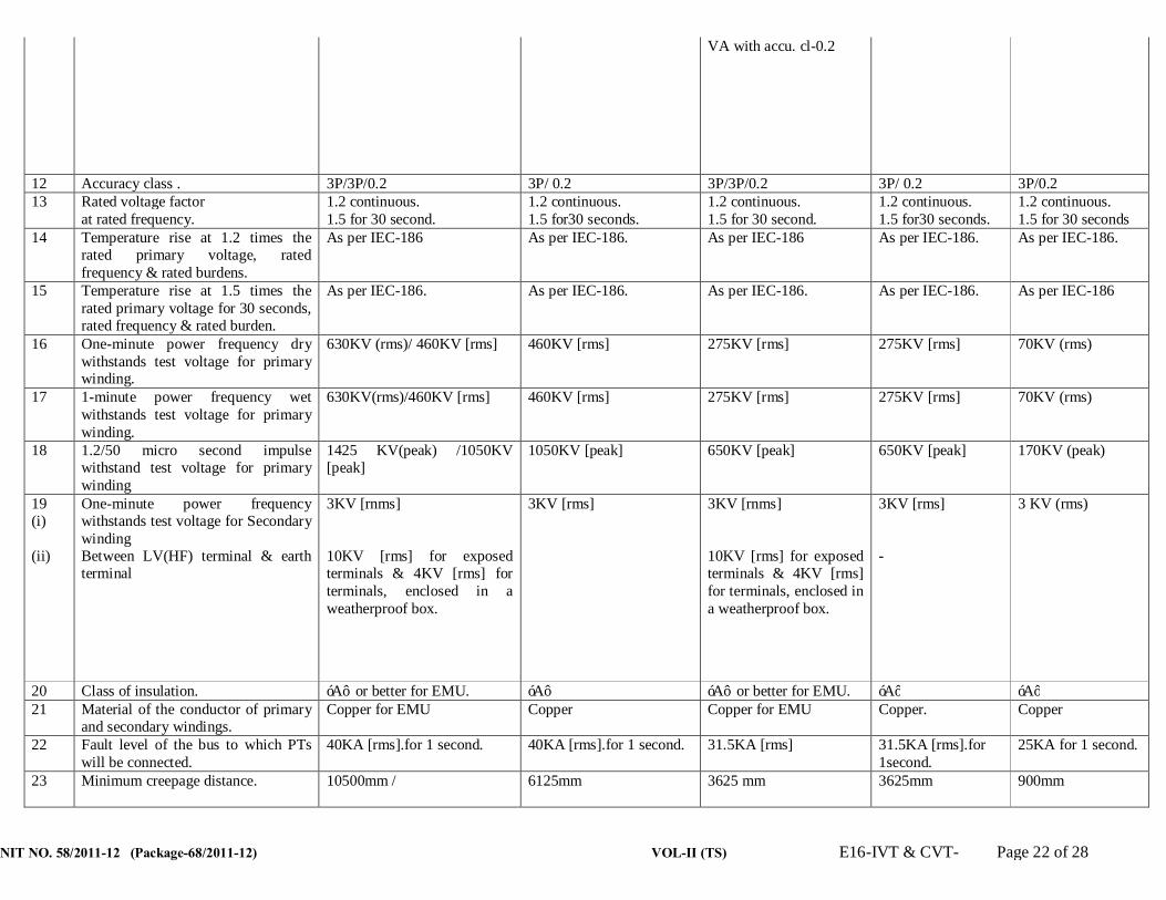
NIT NO. 58/2011-12 (Package-68/2011-12) VOL-II (TS) E16-IVT & CVT- Page 22 of 28
VA with accu. cl-0.2
12 Accuracy class . 3P/3P/0.2 3P/ 0.2 3P/3P/0.2 3P/ 0.2 3P/0.2 13 Rated voltage factor
at rated frequency. 1.2 continuous. 1.5 for 30 second.
1.2 continuous. 1.5 for30 seconds.
1.2 continuous. 1.5 for 30 second.
1.2 continuous. 1.5 for30 seconds.
1.2 continuous. 1.5 for 30 seconds
14 Temperature rise at 1.2 times the rated primary voltage, rated frequency & rated burdens.
As per IEC-186 As per IEC-186. As per IEC-186 As per IEC-186. As per IEC-186.
15 Temperature rise at 1.5 times the rated primary voltage for 30 seconds, rated frequency & rated burden.
As per IEC-186. As per IEC-186. As per IEC-186. As per IEC-186. As per IEC-186
16 One-minute power frequency dry withstands test voltage for primary winding.
630KV (rms)/ 460KV [rms] 460KV [rms] 275KV [rms] 275KV [rms] 70KV (rms)
17 1-minute power frequency wet withstands test voltage for primary winding.
630KV(rms)/460KV [rms] 460KV [rms] 275KV [rms] 275KV [rms] 70KV (rms)
18
1.2/50 micro second impulse withstand test voltage for primary winding
1425 KV(peak) /1050KV [peak]
1050KV [peak]
650KV [peak] 650KV [peak]
170KV (peak)
19 (i) (ii)
One-minute power frequency withstands test voltage for Secondary winding Between LV(HF) terminal & earth terminal
3KV [rnms] 10KV [rms] for exposed terminals & 4KV [rms] for terminals, enclosed in a weatherproof box.
3KV [rms]
3KV [rnms] 10KV [rms] for exposed terminals & 4KV [rms] for terminals, enclosed in a weatherproof box.
3KV [rms] -
3 KV (rms)
20 Class of insulation. ‘A’ or better for EMU. ‘A’ ‘A’ or better for EMU. ‘A’ ‘A’ 21 Material of the conductor of primary
and secondary windings. Copper for EMU Copper Copper for EMU Copper.
Copper
22 Fault level of the bus to which PTs will be connected.
40KA [rms].for 1 second.
40KA [rms].for 1 second.
31.5KA [rms] 31.5KA [rms].for 1second.
25KA for 1 second.
23 Minimum creepage distance. 10500mm / 6125mm 3625 mm 3625mm 900mm

NIT NO. 58/2011-12 (Package-68/2011-12) VOL-II (TS) E16-IVT & CVT- Page 23 of 28
24 Quality of oil. EHV Grade As per IS-335.
EHV Grade As per IS-335.
EHV Grade As per IS-335.
EHV Grade As per IS-335.
EHV Grade As per IS-335
25 Radio interference voltage at 1.1 times maximum rated voltage at 1.0 MHZ.
500 micro volts. 500 micro volts. 500 micro volts. 500 micro volts. -
26 Partial discharge level. Less than 10 piccocoulombs. Less than 10 piccocoulombs.
Less than 10 Piccocoulombs.
Less than 10 piccocoulombs.
27 Seismic acceleration- Horizontal – Vertical.
0.3g. 0.15g.
0.3g. 0.15g.
0.3g. 0.15g.
0.3g. 0.15g.
0.3g. 0.15g.
28 Accuracy class of standard V.T. to be used during testing towards determination of ratio errors and phase angle errors for metering windings.
0.05 or better. 0.05 or better. 0.05 or better. 0.05 or better.
0.05 or better.
29. Capacitance (Pf) 4400/8800 (as applicable) + 10%,-5%
- 4400 + 10%,-5% - -
Name of the test.
Meters and equipments required for the correspondi-ng test
Date of Calibra- tion.
Due date of Cali- bration.
Name of the Cali- brating Agency.
Whether Calibrat- ing Agency is Govt. Approv- ed.
Whether documents relating to Govt. Approval of the cali-brating Agency furnished ?
Whether the meters/ equipment fulfill the accuracy class as per calibration
Whether the calibra ting agency has put any limitation towards the use of the particular
Whether green sticker or blue sticker or yellow sticker has been affixed on the body of the
Inspite of imposed limitations,, whether the particular meter/equipment can still be
Remarks

NIT NO. 58/2011-12 (Package-68/2011-12) VOL-II (TS) E16-IVT & CVT- Page 24 of 28
with range, accuracy, make and Sl. No.
report meter/equipment. If yes, state the limitations.
particular equipment/meter. State the colour of the affixed sticker.
used ? Justify its use for corresponding test(s).
1 2 3 4 5 6 7 8 9 10 11 12
Signature of the tenderer with seal and date.
ANNEXURE-C CHECK LIST TOWARDS TYPE TEST REPORTS.
Name of the Type Test.
Date of Test.
Name of the Laboratory where the Test has been conducted.
Whether the Laboratory is Government Approved.
Whether the Test reports are valid as per Clause No.8.1 of T.S.
Whether the copy of Test Report in complete shape alongwith drawings etc. furnished or not ?
Whether the Tested I.V.T/CVT fulfills the technical require-ments as per TS.
If the type tested I.V.T/CVT
does not fulfill the technical requirements as per this specification, whether the bidder agrees to conduct the particular test(s) again at their own cost without any financial liability to OPTCL in
Re mark

NIT NO. 58/2011-12 (Package-68/2011-12) VOL-II (TS) E16-IVT & CVT- Page 25 of 28
the presence of OPTCL’s representative within the specified delivery period.
1 2 3 4 5 6 7 8 9
Signature of the Tenderer with seal and date.

VOL-II (TS) E17-BATTERY & BATTERY CHARGER-Page1 / 37
ODISHA POWER TRANSMISSION CORPORATION
TECHNICAL SPECIFICATION FOR
220 & 48 V VOLTS LEAD ACID PLANTE & 48 V VRLA TYPE STORAGE
BATTERY ALONGWITH
BATTERY CHARGER I- a) 350AH/ 220 & 48 V BATTERY (FOR 132 and 220KV S/S) b) 645 AH for 220 & 48 V BATTERY(FOR 220 KV & 400 KV S/S). c) 48 V, 300 AH,Maintenance Free VRLA Type Battery. II- BATTERY CHARGER SUITABLE FOR 350 AH & 645 AH for 220V & 48 V LEAD PLANTE ACID & 48 V, 300AH VRLA Type STORAGE BATTERY

VOL-II (TS) E17-BATTERY & BATTERY CHARGER- Page 2 of 37
CONTENTS Clause No. Part A TITLE [Lead Acid Plante & VRLA (48 V) Storage Battery)
A1. SCOPE.
A2.0. Standards
A3.0. Installations
A4.0. Particulars of the System
A5.0. General Requirement of the equipments.
A6.0. Details of specifications of plante Batteries.
A7.0. Design & construction details.
A8.0. Installation of battery.
A9.0. Connectors.
A10.0. Accessories.
A11.0. Maximum Short circuit current.
A12.0. Ventilation.
A13.0. Capacity.
A14.0. Charging.
A15.0. Life.
A16.0. Instruction Manuals.
A17.0. Transport.
A18.0. Tests.
A19.0. Drawings/documents.
A20.0. Guaranteed Tech. Particulars.

VOL-II (TS) E17-BATTERY & BATTERY CHARGER-Page3 / 37
Part – B [CHARGER]
Clause No. TITLES
B.1 Brief description
B.2 Arrangements
B.3 Cubicle
B.4 Design and constructional details
B.4.8 Charger panel
B.5 Transport
B.6 Tests
B.7 Drawings / documents
B.8 Special tools, plants, and spares
B.9 Guaranteed Technical particulars
B.10 Deviation from specification
B.11 General Technical requirements for Battery Charger ANNEXURES
I GTP for 220V Lead Acid Plante storage battery.
II GTP for Battery Charger
III Quantity and delivery schedule
IV-A Calibration status of meters & equipments for testing of
battery.
IV-B Calibration status of meters & equipments for testing of
battery charger.
V-A Check list towards Type Test reports for battery.
V-B Check list towards Type Test reports for battery charger.
VI Check list for delivery schedule
VOL-II (TS) E17-BATTERY & BATTERY CHARGER- Page 4 of 37
PART – A TECHNICAL SPECIFICATION FOR 220 VOLTS LEAD ACID PLANTE STORAGE
BATTERY A.1. SCOPE : A.1.1. These specifications cover the design, manufacturer, assembly, shop testing at
manufacturer’s works before despatch, supply and delivery at SITE and erection testing
and commissioning of 220 volt lead Acid Plante Storage battery.
A.1.2. The scope of supply shall include all parts and accessories etc. which are usual and
necessary for erection, operation and maintenance of the battery banks and the chargers,
as specified, above though not individually and specifically stated or enumerated.
A.2.0. STANDARDS : 2.1. The equipments shall comply in all respects with the latest edition of relevant Indian
Standard Specifications except for the modifications specified herein. The equipments
manufactured according to any other authoritative national / international standard which ensure
an equal or better quality than the provisions of these specifications shall also be acceptable.
Where the equipment offered conform to any other standard, salient points of differences between
the proposed standard and the provisions of these specifications shall be clearly brought out in
the tender. A Xerox copy of such standards [in English shall be enclosed with the offer].
2.2. A LIST OF RELEVANT STANDARDS IS GIVEN BELOW : [i] IS-1652-1991 - Specification for stationery cells and batteries, lead Acid type with Plante Positive Plates [ii] IS : 266-1993 - Specification for Suphuric Acid.
[iii] IS-6071-1986 - Specification for synthetic separators for
lead acid batteries.
[iv] IS:1069-1993 - Specification for quality tolerances water for
storage batteries.
[v] IS:1146-1981 - Specification for rubber and plastic
containers for lead acid storage batteries.
[vi] IS:8320-2000 - General requirements and methods of tests
for lead-acid storage batteries.
[vii] IS:1885-Part-8/1996 Electro technical vocabulary-stationary cells
& batteries.
[viii] IEEE-485/1983 - IEEE recommended practice for sizing large
lead storage batteries for generating stations and sub-
stations.
A3.0 INSTALLATIONS : A3.1. Equipments covered under these specifications shall be suitable for indoor installation.
A4.0 PARTICULARS OF THE SYSTEM:

VOL-II (TS) E17-BATTERY & BATTERY CHARGER-Page5 / 37
A4.1. One set of 220 Volts, 350AH and 645 AH capacity battery alongwith equipments such as
boost charger, trickle charger shall be sufficient to cater to the DC power requirements in
the Sub-stations as proposed. The system offered should be suitable to OPTCL system.
A.5.0 GENERAL REQUIREMENTS OF THE EQUIPMENTS : General requirement of the different components of the Battery system are given below.
A5.1 One set of 220V,350 & 645 AH lead acid type plante storage battery set is required for
meeting the D.C. load requirements of indicating lamps, emergency lighting, relays,
alarms, circuits breakers etc. The battery shall be kept in healthy conditions with the help
of the existing float charging unit. The existing boost charger unit shall supply quick
charging current to bring back the battery to fully charged conditions after it has
discharged to a considerable extent while meeting the emergency load. The battery shall
meet practically all the heavy current demands, as required for operation [closing and / or
operating of circuit breakers, emergency lighting load and field flashing load etc). It should
be noted that, the 220V batteries are to be accommodated in the Battery Room and should
operate satisfactorily over the entire range of ambient temperature of 00 C to 500 C and
relative humidity of 95%.
A.6.0. DETAILS OF SPECIFICATIONS OF PLANTE BATTERIES Type Battery: 6.1. The batteries shall be made of closed type lead acid cells with ‘plante’ type plates
manufactured to conform to IS: 1652-1991.
6.2. CAPACITY : 6.3. The capacity of the batteries shall be as follows :
[i] Voltage. - 220V/48 V
[ii] Output at 270 C - 350AH/550AH at 10 hrs. discharge rate.
The batteries shall normally remain under ‘floating’ condition with the ‘trickle’ charger
supplying the continuous load. However, the batteries shall be capable of supplying the
following loads under emergency conditions without any assistance from the chargers and
without their terminal voltage falling below 200 V [90% of rated voltage]
350AH/645AH
[I] I stage [continuous] - 35A for 10 hours. ,65 A for 10 hours
[ii] Stage emergency - 15A for 3 hours for lighting. 6.4. The number of cells for the 220 V/48V batteries shall be so chosen that for the nominal
floating voltage of the cells, the battery voltage shall be 237.5V/51.85V and for the minimum
[discharged condition] voltage of the cells, the voltage of the battery shall not be less than
198V/43.2V, while the assigned rating of the battery bank can not lowered below its rated voltage
of 220/48V volts.
A7.0 DESIGN AND CONSTRUCTION DETAILS : (For Plante Type)

VOL-II (TS) E17-BATTERY & BATTERY CHARGER- Page 6 of 37
7.1 Containers : The containers for the cells shall be of impervious, moulded transparent,
plastic/glass material having heat-resisting, high strength, non-reacting and low inflammable
properties conforming to IS-1146-1981. The containers shall be mounted on insulators blocks.
The containers shall be of robust construction and free from flaws, bubbles or foreign matter. The
surface of the containers shall have a finish substantially free from blisters, rough spots, scales,
blow holes and other imperfections or deformations. The handle bars, if provided, shall be of such
that sufficient sediment space shall be available and the batteries will not have to be cleared out
during their normal life. Battery containers shall be subjected to type, Routine and Acceptance
Tests as per the requirements of IS-1146-1981. The containers of the label attached firmly to the
containers shall be marked with the information as per requirements of cl No. 2.2 of the above
standard. The supplier’s manufacturer’s test certificates shall be submitted by the tenderer for the
scrutiny of the purchaser.
7.2 Plates : The positive plates shall be of pure lead lamelle type with plante formation. The
negative plates shall be pasted antimonial-lead Grid type so designed as to hold the active
material securely in place and in firm contact with the grid during service. The plates shall be
designed for maximum durability and shall not buckle during all service conditions including high
rate of discharge and the fluctuation of load.
7.3 Separators : The separators shall be of synthetic material conforming to the latest edition
of IS-6071-1986. These shall permit free flow of electrolyte and would not be affected by the
chemical reaction inside the cell and shall last for indefinite time. The internal resistance factor of
the separators shall assure high discharge characteristics under all operating conditions. Proper
arrangement to keep end plates in position shall be furnished by the bidder alongwith his offer.
7.4 Electrolyte : The electrolyte shall be prepared from the battery grade sulphuric acid
conforming to IS-266-1993 and shall have a specific gravity of 1.2 at 270C. The sulphuric acid of
battery grade shall be colourless liquid. The concentrated sulphuric acid on dilution with an equal
volume of distilled water shall be free from suspended matter and other visible impurities. The
sulphuric acid shall meet the requirements of columns – 4 and 5 Table –1 of IS-266-1993. The
requisite quantity shall be despatched in non-returnable containers suitably packed and marked
as per the requirements of the above Indian Standards. The container materials and packing shall
be subject to approval of the purchaser.
Sufficient quantity of distilled water conforming to IS-1069-1993 shall be supplied in non-
returnable containers to correct the level of electrolyte during initial testing and
commissioning. The material of containers and packing shall be subject to the approval of
the purchaser.
7.5. Plate group bar with terminals : The plate group bar with terminals shall conform to IS-
1652-1991. The positive and negative terminals shall be clearly marked for easy identification.
The legs of the plates of like polarity shall be connected to the load, turned to a horizontal group

VOL-II (TS) E17-BATTERY & BATTERY CHARGER-Page7 / 37
bar having an upstanding terminal post adopted for connection to the external circuit. The group
bars shall be sufficiently strong to hold the plates in position.
7.6. Buffers/spring: Suitable buffers / springs shall be provided in the cells to keep the end
plates in position. These shall have adequate length and strength.
7.7. Cell lids : Lids used with sealed or closed type cells shall be of glass, plastic or ebonite
and shall be provided with vent plugs. Terminal post shall be suitably sealed at the lid to prevent
escape of acid spray, by means of rubber grommets, sealing compound or other suitable device.
The positive and negative terminal posts shall be clearly and indelibly marked for easy
identification.
7.8. Water :- Water used for preparation of electrolyte and also to bring the level of electrolyte
to approximately correct height during operation / testing shall conform to relevant standards.
7.9. Venting device : The venting device shall be anti splash type and shall allow gases to
escape freely but shall effectively prevent acid particles or spray from coming out. There shall be
two vent holes, one serving as a guide for acid level indicator for checking the electrolyte level and
other to permit drawing of electrolyte samples, servicing, checking of specific gravity etc.
7.10. Marking : Acid level line shall be permanently and indelibly marked around on all the
containers.
The following information shall be indelibly marked on the outside surface of each cell :
[i] Manufacturer’s name, type and trade mark.
[ii] Nominal voltage.
[iii] AH capacity at 10 hours rate with specified end cell voltage.
[iv] Cell number.
[v] Upper and lower electrolyte level in case of transparent containers.
[vi] Type of positive plate.
[vii] Type of container.
[viii] Date of manufacture [ month and year] or [week and year].
A8.0. INSTALLATION OF BATTERY : 8.1. The battery set shall be installed on wooden racks in a separate battery room non air –
conditioned but ventilated. The tenderer shall offer racks and mounting insulators etc.
8.2. The cell shall be arranged on the racks in a two-tier arrangement with two rows of cells on
each tier or with some other suitable arrangement depending upon the availability of space inside
the battery room. The lay out shall be subject to the approval of the purchaser. The racks shall be
constructed of best quality seasoned teak wood / with metallic stand with at least three [3] coats
of anti-acid paint of approved shade and also flame proof coating. These racks shall be such that
cells are located at convenient height to facilitate maintenance and they may be so constructed so
as to promote free access to the floor directly beneath the rack to facilitate easy cleaning of the
floor. These shall be designed and arranged in such a way that easy handling of the cells is
possible while in operation. Numbering tags for each cell shall be attached on to the racks.
VOL-II (TS) E17-BATTERY & BATTERY CHARGER- Page 8 of 37
8.3. The tenderer shall indicate and include the proposed arrangement of the batteries and
include arrangement for fixing and mounting of inter-bank, inter-row, inter-cell and tap-off
connectors etc.
A9.0. CONNECTORS:
Bars tinned copper lead connectors shall be employed for Inter-cell and inter-row, inter-tier
connections. However, the tee-off connection from the battery unit shall be made with acid
resisting cables of suitable size. A suitable terminal box alongwith acid-resisting cable shall
be provided by the tenderer for this purpose. The connectors shall preferably be of bolted
type and the bolts and nuts shall be of similar material as that of connectors and shall be
provided with corrosion resisting lead coating.
The connectors shall be of sufficient cross-section to withstand all the working conditions
including one minute discharge rate as well as short circuit conditions.
A.10. ACCESSORIES :-
The equipments and accessories, listed below shall be furnished as part of each battery
set and the price of the battery quoted shall be inclusive of these items.
[a] Teak wood racks with three coats of anti-acid paint and flame-proof coating.
[b] Stand insulators +5% extra.
[c] Cell insulators +5% extra.
[d] All Cell interconnectors and end take-offs.
[e] Lead coated connection hardware such as bolts, nuts etc.5% extra. Or any other
connector suitable for VRLA type Battery.
[f] Cell numbering tags with fixing arrangement.
[g] Teakwood, cable clamps with hardware.
[h] Diluted sulphuric acid of sufficient quantity and of specific gravity according to the relevant
ISS and 10% extra shall be supplied in non-returnable acid proof containers, suitable
packed.
[I] Two numbers cell testing centre-zero voltmeters 3-0-3 volts range, Accuracy class shall be
0.5 or better and resistance not less than 1000 ohms.
[j] One number syringe type hydrometer complete with accessories and suitable for
measuring SP gravity between 1.1 to 1.320 with graduation of 0.005 Sp. Gravity together
with temperature correction charts.
[k] One number floating hydrometer.
[l] Two numbers thermo-meters having range 0-100 deg. C whose one division of the
graduated scale shall represent at the most 1 degree centigrade with separate gravity
correction chart.
[Accuracy of calibration shall not be less than 0.50C]
[m] One number wall mounting teak-wood for hydrometers and thermo-meters.
[n] Two numbers acid-resisting plastic jugs [2 litre capacity]
VOL-II (TS) E17-BATTERY & BATTERY CHARGER-Page9 / 37
[o] Two numbers plastic funnels.
[p] Two numbers rubber syphone.
[q] Two numbers rubber aprons.
[r] Two pairs of rubber gloves.
[s] Two pairs of rubber boots-knee height.
[t] Two sets special tools or tools required for connecting the terminals of
the batteries.
[u] The battery terminals shall be brought out in a junction box to be mounted on the battery
stands.
[v] Ampere-hour meter[10 hour discharge rate] of 600 –1250 AH range-1 no.
[w] Any other accessories, not specified but required for installation, satisfactory operation and
maintenance of batteries for a period of 5 [five] years.
A.11.0 MAXIMUM SHORT CIRCUIT CURRENT : The Bidder shall state the maximum short circuit current of each battery alongwith the safe
duration in seconds which it can withstand. Methods, proposed to be adopted for
protecting batteries from the short circuit conditions should also be stated to avoid damage
to the battery and loss to the associated equipment.
A.12. VENTILATION : The bidder shall indicate in his bid the requirements of ventilation in the battery room. The
battery shall operate satisfactorily over the entire range of the temperature and humidity indicted in this specification without affecting its normal life. Bidder shall indicate the percentage reduction in battery capacity at the lowest temperature of 27 deg C. If any special ventilation requirements are necessary, the same shall be indicated.
A.13. CAPACITY : The standard Ampere-hour capacity at ten hour rate shall be 350/550 AH with an end cell
voltage of 1.85 volts/cell.
A.14. CHARGING : The bidders shall state whether an equalising charge is recommended for the battery. If
so, the equalising charge voltage, current, duration and the interval between the equalising
charging shall be specified in the Data sheet. Bidder shall also indicate the requirements
for boost charging.
A.15. LIFE : The bidder shall quote in his offer the Guaranteed life of the battery when operating under
the conditions specified.
A.16. INSTRUCTION MANUALS : Eight sets of instruction manuals for installation, commissioning, charging and
maintenance instruction shall have to be furnished.
A.17. TRANSPORT : The batteries, accessories and racks etc. shall be suitably packed and transported to site.

VOL-II (TS) E17-BATTERY & BATTERY CHARGER- Page 10 of 37
A.18. TESTS: A.18.1 TYPE TESTS : The bidder shall submit the test reports alongwith his offer for the following
type tests, conducted on the offered samples as per relevant National Standard[s] within
five years from the date of opening of the bid and test witnessed by any Government
Department / Government undertaking, failing which the offer is liable for rejection.
[a] Verification of constructional requirements.
[b] Verification of dimensions.
[c] Test for capacity.
[d] Test for retention of charge.
[e] Endurance Test.
[f] Ampere-hour and watt-hour efficiency test.
[g] Test for voltage during discharge.
If the type test report [s] does/do not meet the requirements as per this specification,
OPTCL at its discretion may ask the supplier to conduct the above type tests [s] at the
supplier’s cost in the presence of OPTCL’s representative without any financial liability to
OPTCL
A.18.2 ACCEPTANCE TESTS : Following shall constitute the acceptance tests which shall be
test witnessed by the purchaser’s representative at the works of the manufacturer at the
cost of supplier.
[i] Verification of marking.
[ii] Verification of dimensions.
[iii] Test for capacity for 10 hours discharge rate along with the Test
for voltage during discharge.
[iv] Ampere-hour and watt-hour efficiency test.
A18.3.1 The Purchaser may at his discretion undertake test for capacity
and voltage during discharge after installation of the battery at site without any
extra cost.
A.18.3.2. The supplier shall arrange for all necessary equipments including the variable
resistor, tools, tackles and instruments. If a battery fails to meet the guaranteed
requirement, OPTCL shall have the option of asking the supplier to replace the
same within 15 [fifteen] days from the date of declaring the same to be
insufficient/failed / not as per the specification [s].
A.19. DRAWINGS / DOCUMENTS : The tenderer shall submit the following drawings / documents along with his offer failing
which the offer is liable for rejection.
[a] General battery arrangement, proposed size of individual and
over all dimensions along with sectional views showing all connections etc.
[b] Pamphlets and technical literature giving detailed information of

VOL-II (TS) E17-BATTERY & BATTERY CHARGER-Page11 / 37
the batteries offered.
The manufacturer shall submit the following drawings / documents in 7 [seven] copies
within 15[fifteen] days from the date of issue of the purchase order for purchaser’s
approval. :-
[a] Lay out details of the batteries.
[b] OGA and cross-sectional details for battery cells.
[c] Instruction manuals for initial charging and subsequent charging.
[d] Technical data, curves etc.
A.20. GUARANTEED TECHNICAL PARTICULARS : The Guaranteed technical particulars, as called for in the ‘Annexure – I & II shall be furnished alongwith the tender. Any tender lacking complete information in this respect is likely to be rejected.
A.21. All deviations from the specification shall be separately listed, in the absence of which it will be presumed that the provisions of these specifications are complied with by the tenderer
TECHNICAL SPECIFICATION FOR
220VOLT,350Ah MF-VRLA STORAGE BATTERY A.1.0. SCOPE:- A.1.1. This specification covers the design, manufacture, assembly, shop testing at
manufacturer’s works before despatch, supply and delivery at site and erection, testing and commissioning of 220 volt 350Ah MF- VRLA storage batteries.
A.1.2. It is the intention of the purchaser to install the most up to date type of equipment conforming to modern practices.

VOL-II (TS) E17-BATTERY & BATTERY CHARGER- Page 12 of 37
A.1.3. The scope of supply shall include all parts and accessories etc, which are usual and necessary for erection, operation and maintenance of VRLA batteries as specified above, though not individually and specifically stated or enumerated.
A.2.0. STANDARDS:- A.2.1. All equipment and their accessories, covered by this specification shall be designed,
manufactured and tested in compliance with the latest relevant standards, published by the Bureau of Indian Standards including those, listed at Clause 2.6 in order that specific aspects under Indian climatic conditions are taken care of .
A.2.2. The equipment and accessories for which Indian Standards are not available shall be designed, manufactured and tested in accordance with the latest standards, published by any other recognized National Standards Institution and latest publication of International Electro Technical commission [IEC].
A2.3. The equipment manufactured according to any other authoritative national / international standard, which ensures an equal or better quality than the provisions of these specifications shall also be acceptable. Where the equipment, offered conform to any other standard, salient points of differences between the proposed standard and the provisions of these specification shall be clearly brought out in the tender. A copy of such standards [ in English] shall be enclosed with the offer.
A.2.4. The equipment shall conform to the Indian Electricity Rules, 1956 with latest amendments as regards safety earthling and other essential provisions specified therein for installation and operation of electrical plants.
A.2.5. All equipment shall also comply with the statutory requirements of the Government of Odisha where the equipment will be installed. Nothing shall be construed to relieve the supplier of his responsibility.
A.2.6. GOVERNING SPECIFICATION:- The VRLA batteries and the associated chargers shall unless otherwise specified, conform
to the following standards. The firms are requested to furnish the following specifications for our further reference.
i IS-1651/1991 Specification for stationary cells batteries, leads acid type.
ii IS-1885 [Part-8] / 1986 Electro technical vocabulary: Part- 8-Secondary cells & batteries.
iii IS-266/1977 Sulphuric acid
Iv BS-46290 (Part-4) / 1997
British standard specification for lead acid type valve regulated sealed type batteries.
v ANSI, IEEE STD 450/1987
IEEE recommended practice for maintenance, testing and replacement of large lead storage batteries for generating stations and sub-stations.
vi IEC 896-2/1995 Stationary lead-acid batteries, general requirements and methods of test (part-2, valve regulated types)
vii IS-(1146 / UI-94) / ASTM - d -29863 Plastic container for lead acid storage batteries.
viii IS-3136-1965 Specification for polycrystalline semiconductor rectifier equipment
ix IS-1248-1968
Specification for direct acting indicating analogue electrical measuring instruments and tier accessories. (Part - I)-1983-General Requirements. (Part - II)- 1983 - Ammeters & voltmeters. (Part-III)-1984-Accessories.
x IS-2208-1962 Specification of HRC Cartridge fuse link up to 650V

VOL-II (TS) E17-BATTERY & BATTERY CHARGER-Page13 / 37
xi IS-2959-1966 Specification of contractors for voltages not exceeding 1000V AC or 1200V DC
xii IS-3395-1966 Specification for monocrystalline semiconductor rectified cells and stacks.
xiii IS-4540-1968 Monocrystalline semiconductor rectifier assemblies & equipment
xiv IS-2147/1962 Degree of protection provided by enclosure for low voltage switchgear and control gear
xv IS-5578/1984 Guide for marking of insulated conductors.
xvi IS-8623/1993 [Part 1 to 3] Low voltage switchgear and control gear assemblies.
xvii IS-11171/1985 Dry type power transformers.
xviii IS-11353-1985 Guide for uniform system of marking and identification of conductors and apparatus
xix IS-13947-1993 (Part 1 to 5) Low voltage switchgear and control gear
A.3.0. OTHER REQUIREMENTS:- A.3.1 ACCESSIBILITY AND INTER CHANGEABILITY:- All working parts, in so far as possible, shall be arranged for convenience of operation,
inspection, lubrication and case of replacement with minimum down time. All like parts of the equipment, furnished shall be inter changeable.
A.3.2. QUALITY AND WORKMANSHIP:- Workmanship and materials shall be of good commercial quality, suitable for the purpose,
intended and in accordance with the highest standards and practices for equipment of the class, covered by this specification.
A.3.3. SAFETY A3.3.1.All equipment shall be complete with approved safety devices wherever a potential hazard
to personnel exists and with provision for safe access of personnel to and around the equipment for operational and maintenance functions. The design shall include all necessary precautions and provisions for the safety of operating and maintenance personnel.
A3.3.2.Special care shall be taken to make enclosed equipment proof against entry of rat, lizards
and other creeping reptiles, which may create electrical short circuits inside, live equipment.
A.3.3.3.Continuity of power supply is the first consideration and the design shall be such as to provide facilities to simplify inspection, testing maintenance, clearing and repair at site.
A.3.4. SPECIAL SITE CONDITIONS:- A.3.4.4.The equipment with their accessories shall be designed for smooth, efficient and trouble
free operation tropical humid climate for maximum temperature of 50 degree C and maximum humidity of 98 percent. Maximum temperature and maximum humidity are however not likely to occur simultaneously. De-rating of equipment shall be done for an ambient temperature of 50 degree C.
A.3.5. PAINTING:- All items of equipment and materials shall be thoroughly cleaned and painted in
accordance with IS Specification. The clean surface shall be given two coats of epoxy polyamide resin based red-oxide zinc-phosphate primer, deposited either by immersion or powder spray. They phosphate coated surface shall have one coat of high build epoxy resin based intermediate paint coating and two coats of air drying epoxy polyamide

VOL-II (TS) E17-BATTERY & BATTERY CHARGER- Page 14 of 37
enamel suitably pigmented finish paint. The colour shade for exterior parts of equipment located inside the sub-station control room building shall be as per shade No. 631. Clean and touch-up paint shall be applied at site as required.
A.4.0. CONSTRUCTIONAL DETAILS OF VRLA BATTERY. A.4.1. PLATES: Positive plates shall be made of flat pasted type using lead-Cadmium-antimony alloys for
durability, high corrosion resistant, maintenance free, low discharge rates and long life both in cyclic as well as in the float applications. Negative plates shall be heavy duty, durable flat plate using lead calcium ally pasted box grid. Negative plates shall be designed to match the life of positive plates and combination of positive and negative plates shall ensure long life, durability and trouble free operation of the battery. PLC Operated equipment should be deployed for preparation of paste to ensure consistency in paste quality. Conventional / manual type of plate preparation is not allowed.
A.4.2. SEPARATORS:- The separator shall be absorptive glass mat type or spun glass micro porous matrix type
and shall be resistant to sulphuric acid. It shall be capable of keeping all the electrolyte and shall be electrically insulated. Sufficient separator overlap and PVC shield protection to top and bottom edges of the plates is to be provided to prevent short circuit formation between the edges of adjacent plates. The uncompressed water absorption of the separator shall be at least 5 gm. of water / gm of separator material.
A.4.2.1.REQUIREMENT OF WICKING TEST ON SEPARATORS:- The total wicking height shall not be less than635 mm in 24 hours. The minimum water
content at 125 mm. Height shall be at least 5 gm. of water per gm. of separator. The weight of water per gm. shall be at least 90% of the value at 125 mm when checked at a height of 450 mm.
A.4.3. VALVE:- Safety valve vent plugs shall be provided in each cell. They shall be explosion resistant,
self-resealing and pressure regulating type. They shall not allow gas (air) to enter into the cell but shall allow gas to escape from the cell above a certain internal pressure, which does not lead to deformation or other damage to the cell.
A.4.3.1.The vent plug used shall be explosion resistant and self re-sealing pressure regulating type. Vent plug shall be such tat it cannot be opened without proper tool.
A.4.3.2.The valve shall be so designed that it operates at a pressure between 0.14 Kg / Sq. mm to 0.63 Kg / Sq. mm to release the excess gas and reseal automatically as soon as the gas pressure within the cell drops to atmospheric value.
A.4.3.3.All the cells shall be subjected to pressure test upto 0.7 Kg / Sq. mm. A.4.3.4.The self-discharge rate at room temperature shall not be more than 5 % of the capacity of
each battery per month. A.4.3.5.Each valve opening shall be covered with flame barrier capable in preventing the ingress
of flame into the cell interior when the valve opens and hydrogen / oxygen gas mixture is released.
A.4.4. CONTAINERS AND LID:- A.4.4.1.The container shall be made up of a special grade polypropylene copolymer plastic
material, which should be of flame-retardant. A.4.4.2.The container shall be sufficiently robust and not liable to deformation under internal
operating pressures and within the temperature range, naturally encountered, leak proof, non-absorbent and resistant to the acid with low water vapor permeability.
A.4.4.3.The container shall be enclosed in epoxy coated steel trays. The steel trays shall be so designed as to make both vertical and horizontal stacking of cells / batteries possible.
A.4.5. LIDS / COVERS:- Sealed maintenance free batteries shall have polypropylene copolymer covers. The
complete container along-with lid / cover shall be able to withstand without fracture for 5 hours at 25 degree Celsius at an internal pressure of 5 times the normal operating pressure as declared by the manufacturer. The complete design includes the pillar to lid

VOL-II (TS) E17-BATTERY & BATTERY CHARGER-Page15 / 37
seal, which shall be designed to remain gas-tight and electrolyte-tight during the designated life of the battery.
A.4.6. PILLAR SEAL ASSEMBLY:- A.4.6.1.The pillar to lid seal shall be designed to remain gas-tight and electrolyte-tight during the
designated life of the unit. The terminal shall conform to Class 3.2 of BS: 6290, Part - 4 -1987.
A.4.7. ELECTROLYTE:- The electrolyte shall be prepared form the battery grade H2 SO4 conforming to ISS:266. The batteries shall be supplied in factory filled charged condition. All the acid will be in immobilized condition the AGM separator.
A.4.8. WATER:- Water required for preparation of electrolyte shall conform to IS:1069.
A.4.9. CONNECTORS AND FASTENERS:- Lead or lead coated copper connectors shall be used for connecting up adjacent cells and rows. The thickness of lead coating of connectors should be not less than 0.025 mm. The lead coating thickness shall be measured in accordance with APPENDIX-F of IS : 6848 : 1979. All the terminals and cells inter connectors shall be fully insulated or have insulation shrouds. End take off connections from positive and negative poles of batteries shall be made by single core cable having stranded aluminum / copper conductors and PVC / XPE insulation. Necessary supports and lugs for termination of these cables on batteries shall also be supplied by the supplier. All connectors and lugs shall be capable of continuously carrying the 30 minute discharge current of the respective batteries and through fault short circuit current which the battery can produce and withstand for the period declared. Bidder shall furnish necessary sizing calculations to prove compliance to the same.
A.4.10.PLATE CONNECTIONS:- Lugs of plates of like polarity shall be connected by lead burning to a horizontal strap having an upstanding terminal post adopted for connection to external circuit. Strap and post shall be casted with lead alloy. The positive and negative terminal posts shall be clearly marked for unmistakable identification.
A.4.11.NUT & BOLTS:- Nuts and bolts for connecting the cells shall be made of copper, brass or superior grade
passivated stainless steel which should be resistant to sulphuric acid. Copper & brass shall be coated / plated with suitable materials such as Nickel / Chrominium to prevent sulphation or corrosion.
A.4.12.TERMINALS:- Terminals shall be of integral lead terminal with solid copper core with M6 threading for
fastening. The junction between terminals posts and cover and between the cover and container shall be hermetically sealed.
A.4.13.SEAL:- (i) TIG welding shall be dove for post sealing. (ii) Additional Epoxy resin sealing shall be provided for double assurance against leakage.
A.4.14.SUPPORTING RACKS:- Batteries shall be installed on MS racks to be supplied by the supplier to fit in the battery /battery charger room. Racks / trays shall be powder coated with anticorrosive paint and supplied in unassembled state. Rack / tray shall be subjected to 7 tank process before painting for protection against fungus growth and other harmful effect due to tropical environment.
The steel trays / containers shall be stackable one over the other horizontally in multi-tier arrangement. The bottom most tray shall be mounted on I-channels with 150 mm height. The positive and negative terminals shall be terminated onto the terminal plate assembly, which is fitted to one of the steel tray depending on the convenience at site.
A.4.15.MARKING:- The following informations shall be legibly laid durably marked on each cell battery:- 6. Nominal Voltage. 7. Name of the manufacturer and type reference.

VOL-II (TS) E17-BATTERY & BATTERY CHARGER- Page 16 of 37
8. Rated or nominal capacity expressed in ampere hour (AH) with an indication of the rating expressed either as a current or as time together with the relevant final voltage of each cell. 9. Voltage for float operation 270 C with tolerance of 1%. 10. Cell number. 11. Type of positive plate. 12. Type of container. 13. Date of manufacture (month and year) or (week and year).
A.5.0. MAXIMUM SHORT CIRCUIT CURRENT:- The bidder shall state the maximum short circuit current of each battery along-with the safe duration in seconds, which it can withstand. Complying with clause 5.5 of IEC – 896 – 2/1995. Method proposed to be adopted for protecting batteries from the short circuit conditions should also be stated to avoid damage to the battery and loss to the associated equipment.
A.6.0. VENTILATION:- The Bidder shall indicate in his bid the requirements of ventilation in the battery room. The battery shall operate satisfactory over the entire range of temperature indicated in this specification without affecting its normal life. Bidder shall indicate the percentage reduction in battery capacity at the lowest temperature of 27 Degree C. If any special ventilation requirements are necessary, the same shall be indicated.
A.7.0. CAPACITY:- The standard Ampere-hour capacity at ten hour rate shall be 200, 300 and 500 AH and end cell voltage of 1.80 volts /cells.
A.7.1. SELF DISCHARGE RATE OF BATTERY:- Self discharge rate shall be less than 0.5% of C 10 Capacity per week at 27degree C. A.8.0. CHARGING:-
The bidder shall state whether an equalizing charge is recommended for the battery. If so, the equalizing charge voltage, current, duration and the interval between the equalizing charging shall be specified in the Data Sheet. Bidder shall also indicate the requirements for boost charging.
A.9.0. LIFE:- The bidder shall quote in his offer the guaranteed life of the battery, when operating under the conditions, specified. The bidder shall also quote the change in life of the battery due to change in temperature form 27 degree centigrade in the event the batteries are required to be operated under higher temperature environment.
A.10.0.DESIGN VALIDATION:- Over the range of manufacturer’s capacity, at least one capacity should have been tested and should meet the requirement of Service Life as per ANSI TI : 330 Specification. Necessary evidences maybe enclosed along-with the offer.
A.11.0.MAINTENANCE TOOLS & INSTRUCTION:- A.11.1.One cell – testing –center-zero volt meter 3-0-3 volt range of accuracy class not less than
0.5 shall have to be supplied alongwith each of the battery sets. The resistance of the voltmeter shall not less than be 100 ohms.
A.11.2.Eight sets of instruction manuals for installation, commissioning and initial charging, the calculations of charging / discharge under float and boost charging and maintenance instructions shall have to be furnished.
A.11.3.It is mandatory for the bidder to provide with the spare relating to the batteries including cells for replacement for a minimum period of 8 years and above.
A.12.0.ELECTRICAL CHARACTERISTICS:- DESIGN SHOULD ENSURE THAT:-
(a)Battery shall be suitable for constant current constant voltage charging. (b)Nominal float voltage shall not exceed 2.25 V per cell @ 27 degree C. (c)Recharging shall be done at normal float voltage. (d)Charging current shall not exceed 0.15 C. Where C is the capacity in AH @ 10 hours of discharge to end cell voltage 1.80 V @ 27 deg C.

VOL-II (TS) E17-BATTERY & BATTERY CHARGER-Page17 / 37
(e)Except during commissioning. Battery shall not demand boost charging at any point of time during its operation. (f)Battery shall not demand equalizing charge at any point of time during its operation.
A.13.0.PROCESS REQUIREMENT:- (a) 100% cells shall be tested by Helium. I on leak tester for leak free performance.
Vendor shall attach a copy of the Helium. I on tester report along with the dispatch documents.
(b) Vendor is expected to monitor the voltage and current data of the cells during initial charge and test discharge by means of automatic data logging for treceability. Vendor shall maintain the database of the same and provide the document to the company as and when called for.
A.14.0.TESTS A.14.1.TYPE TESTS:-
The bidder shall submit the test reports along with his offer for the following type tests, conducted on the offered samples as per relevant National Standard (s) within five yeas from the date of opening of the bid and test witnessed by any Government Department / Government undertaking failing which the offer is liable for rejection. (a) Verification of constructional requirements. (b) Verification of dimensions /weight. (c) Test for capacity. (d) Test for charge retention. (e) Endurance test. (f) Ampere-hour and watt-hour efficiency test. (g) Test for voltage during discharge. (h) Test for endurance under short circuit conditions. (i) Test for gas recombination efficiency. (j) Wicking test Separators. (k) Service Life test as per ANSITI : 330 Specification. If the type test report (s) does / do not meet the requirements as per this specification. GRIDCO at its discretion may ask the supplier to conduct the above type test (s) at the supplier’s cost in the presence of GRIDCO’s representative without any financial liability to GRIDCO.
A.14.2.ROUTINE TESTS:- All the routine tests, listed below shall be carried out on all the cells, containers. Hardware being supplied as per latest issue of BS : 6290, Part – 4. IE C89-I or IEEE – 1188 (whichever is applicable) at the cost of the supplier. (a) Container
(i) Verification of constructional requirements. (ii) Verification of marking and packing. (iii) High voltage tests (CI : 7.6 of IS : 1146).
(b) Cells and batteries:- (i) Verification of constructional requirements. (ii) Verification of markings. (iii) Verification of dimensions.
A.14.3.0.ACCEPTANCE TESTS:- Followings shall constitute the acceptance tests which shall be test-witnessed by Purchaser’s representative at the works of the manufacturer at the cost of the supplier.
1. Verification of dimensions. Verification of marking.
3. Tests for capacities for 10 hours discharge rate alongwitht the test for voltage during discharge.
Ampere-hour and watt-hour efficiency test. 5. Short circuit current test of batteries (arrangement for this shall be
provided 6. during testing).
Resistance of cell / batteries.
VOL-II (TS) E17-BATTERY & BATTERY CHARGER- Page 18 of 37
8. Pressure of vent plug connected with battery (measuring shall be provided during testing).
9. Measurement of weight / material type and dimension of cell / racks / batteries and all other accessories as per approval of drawings / technical data submitted during tender process. All these shall be submitted in detail with the submission of tender paper.
A.14.3.1. The purchaser may at his discretion undertake test for capacity and voltage during discharge after installation of the battery at site without any extra cost.
A.14.3.2. The supplier shall arrange for all necessary equipments, including the variable resistor, tools, tackles and instruments. If a battery / battery charger fails to meet the guaranteed requirements, GRIDCO shall have the option of asking the supplier to replace the same.
A.15.0. DRAWINGS / DOCUMENTS:- The tenderer shall submit the following drawings documents along with his offer failing
which the offer is liable for rejection. (a) General battery arrangement including proposed size of individual and over all dimensions along with sectional views showing all connections etc.
(b) Pamphlets and technical literature giving detailed information of the batteries offered. The manufacturer shall submit the following drawings / documents in7 (seven) copies within (fifteen) days from the date of issue of the purchase order for purchaser’s approval. (a) Layout details of the batteries with all accessories. (b) OGA Cross-sectional details for battery cells. (c) Instruction manuals for initial charging and subsequent charging. (d) Technical data, curves etc.
A.17.0. TRAINING:- The bidder shall arrange for training of at least five Telecom. engineering personnel of OPTCL on operation and maintenance of the VRLA type of batteries at free of cost. Every detail regarding the intricacies of these special type batteries need be imparted to the trainee engineers at works of the manufacturer. The bidder in their offer need intimate the duration of training. However the training must be imparted prior to the delivery of the battery sets. A.18.0.TRANSPORT:-
The charged batteries, accessories and racks shall be suitably packed and transported to site in ready to use condition.
ANNEXURE -1A

VOL-II (TS) E17-BATTERY & BATTERY CHARGER-Page19 / 37
SPECIFICATION FOR 350AH 220 VOLT MF-VRLA BATTERY SYSTEM [To be filled in by the bidder]
SL. NO. SPECIFICATION CONFIRM / NOT CONFIRM
1 Maintenance free valve regulated sealed type acid battery 200,300 and 500 AH. 2V per cell [Total 24 Nos. battery cells]
2 The cells should be assembled in stack over insulated steel rack to make 48 Volt / 200,300,400, 510 & 800AH battery system for Power Line Carrier Communication application.
3 The steel rack will be placed over porcelain. Hard rubber insulator of 100 mm Height [approx.] to minimize leakage current to ground
4 All the battery cells are to be assigned with number
5 The final positive and negative terminals are to be brought to the terminal plate assembly (TPA). Suitable arrangement should be made for terminating the cables at the TPA
6 Test for capacity of batteries should conform to IS: 1652 (Clause 11.6)
7 The battery should be supplied with all accessories like connectors, links, S.S. nuts. Bolts and insulator etc.
8 All the portion of connectors and adjacent steel plates are to be sleeved and insulated.
9
Discharge test of batteries at 10 hr. rate of discharge to end cell voltage of 1.85 volt per cell to conform to the requirement of IS : 1652. Clause - 11.7 (Test for capacity) should be carried out by the supplier at the works of manufacturer and at the site. The ambient temperature at the place of installations will be considered for the calculation period of discharge.
10
The battery should have a life expectancy of minimum 8 years at battery room ambient temperature that varies from a minimum of 20 degree centigrade during winter season and a maximum of 50 degree centigrade during peak summer. The tenderer should submit the relevant technical literature preferably in p from with details design calculation graph documents etc. in support of indicated life of the battery taking care of the above seasonal ambient temperature variation.
11
The supplier should submit the documentary evidence ) P.O. copy) for supply, installation land commissioning of battery capacity of 200,300,400,510 & 800 AH or higher capacity to the PLCC. Systems under any GRID Sub-stations and the same is in successful operation for a minimum period of 5.
12 The watt-hour and ampere-hour efficiency and internal resistance value of the battery should be furnished.
13 The supplier should show the values of internal resistance of all the cells at the time of commissioning at site and the same should confirm to the value indicated by them in their technical bid.
14
The procedure of charging the battery before the capacity test should be furnished. The battery et will be inspected tested at works before despatch to store site.
ANNEXURE IIA

VOL-II (TS) E17-BATTERY & BATTERY CHARGER- Page 20 of 37
SCHEDULE OF GUARANTEED TECHNCAL PARTICULARS FOR 220 VOLT 350 AH MF-VRLA LEAD ACID STORAGE BATTERY
(TO BE FILLED IN BY THE BIDDER) 1 Manufacturer’s name and address : 2 Conforming to standards. 3 Type and designation as per IS. 4 Manufacturer’s type and designation 5 Capacity of battery bank at the Cap. Rate of End Cell
following discharge rates at 270C AH Disch. Current voltage a. 15 minutes.
b. 30 minutes. c. 45 minutes. d. 1 hour e. 2 hours f. 3 hours. g. 4 hours. h. 5 hours. i. 6 hours. j. 7 hours. k. 8 hours. l. 9 hours. m. 10 hours.
6 Number of cells in the battery. 7 Method of interconnection between cells. 8 Maximum short circuit current of battery when short circuit is at the end of terminals 9. Recommended float-charging voltage across the battery terminals (volts). 10 Recommended boost charging voltage across battery terminals (volts). 11 Time required for boost charging from discharged conditions (in hours). 12 Recommended trickle / float charging rate 13 Recommended boost charging rate. 14 Trickle charging current range / cell. 15 Shelf life of charged battery bank. 16 Open circuit voltage of battery bank when fully charged. 17 AH capacity at 10 hours rate at room temperatures of:-
a. 150C. b. 270C c. 500C
18 Cell Particulars:-
Material of container. b. Overall dimensions of each cell.
Weight of cell complete with acid. 19 Voltage:-
a. Open circuit voltage of cells. b. Float charging voltage. c. Boost charging voltage.
20 Type of material / thickness / dimension of positive plates. 21 Type of material / thickness / dimension of negative plates. 22 Separators:-

VOL-II (TS) E17-BATTERY & BATTERY CHARGER-Page21 / 37
a. Type. b. Materials. c. Thickness of separator.
23 Type of valve provided. 24 Internal resistance of each cell at 25. Clearance in mm between. a. Top of plates and top of container.
b. Bottom of plates and bottom of container. c. Edges of plates and inner surface of container.
26 Maximum ambient temperature that the cells can withstand. Without injurious effect. a. Continuously.
b. Short periods (duration to be stated along with temperature). 27 Maximum number of charge / discharge cycles that the cell can withstand. 28 Ampere-hour efficiency at ten-hour discharge rate. 29 Watt-hour efficiency at ten hour discharge rage 30 Estimated life of cell under normal operating conditions (in years)
% change in life of battery for change in ambient temperature 27 degree centigrade. 31 a. Maximum short circuit current per battery.
b. Allowable duration of short circuit. 32 Short circuit current for a dead short across the Battery terminals when. a. Float at 2.1V per cell
b. Boost charge to 2.75 V per cell. 33 Recommended floating voltage per cell and the Minimum variation. 34 Recommended interval at which battery should be Discharged at 10 hour rate and quick
charged. 35 Recommended storage period of a fully charged battery. 36 Inter cell connector. a. Inter-cell connector furnished ? (Yes/No).
b. Type of inter-cell connector (bolted or others)? c. Materials of inter cell connector.
37 Inter-row, inter tier connectors and end take- off furnished? Description. Size current rating type and material
38 Battery stack / rack. a. Outline dimensions.
b. Type and material. c. Anti-acid coating type. d. Number of trays. e. Height of bottom tier from ground level. f. No. of cells which can be stacked in tray. g. Dimensions of each tray.
39 Total shipping weight of battery units. 40 A dimensional layout drawing of the battery stock / rack along with battery attached with the
tender (yes /No) 41 The following characteristic curves to be furnished along with the tender (yes/No). a. Battery discharge curves at various rates between 1 minute and 10 hour rate.
b. Curves showing the relation between the cell voltage and charging current, when charged at:
14. Finishing rate. (ii) High starting rate. (iii) Two step charging by starting and finishing rate.

VOL-II (TS) E17-BATTERY & BATTERY CHARGER- Page 22 of 37
PART – B
CHARGER FOR PLANTE BATTERIES
B.1 BRIEF DESCRIPTION
Charging equipment comprising of a float charger and a Float cum boost & Float
Cum Boost Charder suitable for 48 V Battery Type VRLA for Telecommunication Purpose)
charger, is required to meet the D.C. power requirements of the sub-station under
normal conditions, i.e., when AC auxiliary power supply is available and also to keep
all the cells in the state of full charge. The float charger shall supply the
continuous DC load at the bus bars in addition to keeping, the plante batteries
floated in a healthy condition. In case of failure of A.C. mains or sudden requirement
of additional DC power, the battery shall meet the demand as the battery shall be
connected in parallel with the charger. After the battery has discharged to a
considerable extent, it shall be fully recharged by the ‘boost’ charger unit in a
short period so as to prepare it for the next emergency. Even during the ‘boost’
charging of the battery, the continuous DC load at the bus shall be met by the
trickle-charging unit. The ‘boost’ charging unit shall however be provided with
suitable control arrangement to function as a stand-by for float charging unit in case
of necessity.
B.2 ARRANGEMENTS :
B.2.1 Trickle (Float) Charger :
The trickle charger shall have arrangement for regulation of D.C. output voltage
by:-
(i) automatic voltage regulation system.
(ii) Shall be of thyristor control type with both ‘auto/manual’ control
arrangement.
B.2.2. Quick (Boost) Charger :
The quick charger shall be similar type as trickle charging equipment, but shall
have the following features.
(i) Shall be of higher capacity to deliver D.C. output, as stipulated in this
specification for quick charging of the plante batteries.

VOL-II (TS) E17-BATTERY & BATTERY CHARGER-Page23 / 37
(ii) Shall be provided with control arrangement for ‘auto/manual’ current
regulation features, necessary for quick charging
(iii) Shall also have ‘auto/manual’ voltage control arrangement for use when the
charger will be utilised as a trickle charger.
B.3. The ‘Trickle’ and ‘Quick’ charger shall be self supporting cubicle type with
front panels hinged and suitable for mounting instruments, incoming A.C.,
circuit breaker with thermal and instantaneous releases relays, contactors and
control switches etc. The panels shall have access from the backside also. These
cubicles shall also house transformers, rectifiers and other equipment’s,
accessories, as stipulated in this specification.
B.4 DESIGN AND CONSTRUCTION DETAILS:
B.4.1 The ‘trickle’ charger and ‘quick’ charger shall be complete with silicon
controlled rectifier units, dry type air-cooled transformers, control
electronics, smoothing filters etc. suitable for operation from 415V + 10%, 50
HZ + 5%, 3 phase A.C. supply. The charger output shall be stabilized to + 1% of
set value for + 10% input voltage variations and 0-100% load variation.
B.4.2 The battery charger shall have full-wave, Half-controlled thyristor controlled
bridge rectifier circuit. The charger output voltage shall suit the battery
offered. The float voltage shall be adjustable from 80% to 115% of nominal
voltage. The boost voltage shall be adjustable from 80% to 135% of nominal
voltage. Ripple voltage shall be less than 3% RMS voltage.
B.4.3 Each float charger shall be capable of floating each cell of the battery bank at
the specified voltage and supplying specified float current continuously under
normal system operation.
B.4.4 Under normal operation, the float charger shall be supplying the DC load current
and at the same time trickle charge the station battery. When the battery
voltage goes down considerably, automatic transfer arrangement shall be provided
such that the battery is disconnected from the float charger and gets connected
to the boost charger. However, when battery is on boost charge, DC load shall be
fed from the float charger. In addition, means shall be provided to ensure
interruption free availability of control power from the battery whenever there
is a power failure irrespective of whether the battery is on boost charge or
float charge.

VOL-II (TS) E17-BATTERY & BATTERY CHARGER- Page 24 of 37
B.4.5 The selection of electronic components shall be used on ambient temperature of
50 degree C. and shall be of worst-case design to ensure continuous and trouble
free service. The control electronics shall be built on plug in type glass epoxy
printed circuit boards of modular design.
B.4.6 The maximum temperature, attained by any part of trickle charger and quick
charger, when in service at site under continuous full load conditions shall not
exceed the permissible limits as fixed by relevant standards and as corrected to
site condition.
B.4.7 Charger Panel :
B.4.7.1 Charger panels shall be rigid, self supporting structures, completely
assembled and totally enclosed cubicle type construction, made out of structural
steel members with sheet steel-coverings.
B.4.7.2 The enclosure of the charger shall be made of CRCA sheet steel of
thickness not less than 2 mm for load bearing members, 1.6mm for door and non-
load bearing members and 3 mm for gland plates. Panels shall be offered with
base frame of 3.0 mm thick CRCA sheet, painted black all around, suitable for
bolting/ welding/ grouting on to the foundation. Gaskets on doors and inter
panel gaskets shall be of neoprene rubber.
B.4.7.3 The panel shall have hinged front and back doors with concealed type hinged
locks and latches.
B.4.7.4 The panel shall have adequate cross –ventilation arrangement to avoid any
undue rise in temperature.
B.4.7.5 All equipment’s and wiring used in the panel shall be tropicalised dust
proof and vermin-proof.
B.4.7.6 Power wiring for the chargers shall be done with 1.1KV grade, heavy duty,
single core, stranded copper conductor PVC insulated cables or suitable
sized PVC sleeved copper bus bars. Control wiring for the charger shall be
done with 1.1 KV grade PVC insulated copper wires of cross section 2.5 sq.
mm for all control connection. Wire of 2.5 sq. mm cross section shall be
used for control bus. All control wiring shall be ferruled.
B. 4.7.7 Necessary terminals for grounding the panel with two
separate earthings shall be arranged for bottom entry and
suitable cable glands shall be provided for the cables.

VOL-II (TS) E17-BATTERY & BATTERY CHARGER-Page25 / 37
B.4.7.8 Each charger panel shall incorporate all the necessary controls,
Indications, interlocks, protective devices and timing features to ensure
any operation.
Provision shall be made with necessary contact / relays for annunciation in
the event of alternating current power failures to the charger and
automatic shut down of the charger by over-voltage / current devices.
Annunciation shall however be prevented when the charger is manually
shutdown or when A.C. power supply is momentarily interrupted for
adjustable period of 1 to 5 seconds.
B.4.7.9. The float and equaliser charging rates shall both be adjustable from the
front of the charger control panel. Each charger shall be protected
against any damage from over voltage/ load currents and shall be so
designed that it can continuously deliver at least rated current output
without operation of the protective over-load device for abnormal
conditions of low battery voltage down to 175V (80%) of the rated voltage).
But the chargers shall be disconnected from A.C. input supply through an
over-voltage relay, if the input voltage exceeds 10% of the rated voltage
of the equipment. Necessary selector switches for ‘Trickle Charging’ and
‘Quick charging’ shall be provided. There shall be ‘make before break’
type blocking Diodes and other equipments to be shown in the drawing or
otherwise found necessary for charging or otherwise found necessary for
charging the battery without increasing the voltage beyond safe value
across the load shall also be supplied by the tenderer.
B.4.8 The rectifier units of the chargers shall be capable of supplying an
impulse load of 6/7 times its rated capacity. The trickle charger in
conjunction with automatic voltage regulators shall have drooping
characteristics, So as to transfer the load beyond its capacity to the
battery.
B.4.9 The incoming and outgoing circuits shall be provided with MCCBs with static
releases for overload, short circuit and earth fault protections. The
incoming power supply to the chargers will be from two sources with a
facility of changeover switch. The change over facility shall be provided
in the charger itself.
B.4.10 The battery circuit shall be provided with HRC fuse protection over a
suitably rated load break isolator switch and reverse protection circuits.
B.4.11 Input volt meter and ammeter shall be of moving iron type and shall be 96 x
96 mm. Square. These meters shall be of accuracy class not less than 1.0
and shall be of flush mounting type with required PTs and CTs and selector
switches. Output voltmeter and ammeter shall be moving iron type and shall
be 96 x 96 mm square. The meter shall be of accuracy class not less than

VOL-II (TS) E17-BATTERY & BATTERY CHARGER- Page 26 of 37
1.0 and shall be flush mounting type. The ammeter shall be centre zero type
for measurement of charging and discharging current from the battery.
B.4.12 Cluster LED lamps for indicating ‘Input on’ condition and ‘Output on’
condition, float status on / off, boost status on / off etc. shall be
provided. Annunciation with audiovisual alarms shall be provided for the
following.
Ø Input mains failure.
Ø Input phase failure.
Ø Input fuse failure.
Ø Rectifier fuse failure.
Ø Filter fuse failure
Ø DC over voltage
Ø DC under voltage
Ø Output fuse failure
Ø Charger over-load
Ø Earth leakage
Ø Alarm supply fuse failure
Ø Charger trip
Ø Output MCCB tripped
Ø AC under voltage
Ø Battery low condition
ACCEPT, TEST AND RESET push buttons shall be provided. 20% spare annunciation
windows shall be provided.
B.4.13 : Any other item(s), not stipulated in this specification, but required for
installation, operation and maintenance of the battery charger is / are included
in the scope of supply without any extra charge on OPTCL.
B.5 TRANSPORT : The chargers alongwith its accessories shall be suitably packed and
transported to site in ready to use condition.
B.6 TESTS
B.6.1 Type Tests : The bidder shall submit the test reports alongwith his offer for
the following type tests conducted on the offered samples (both float charger and
boost charger) as per relevant National Standard (s) within five years from the date

VOL-II (TS) E17-BATTERY & BATTERY CHARGER-Page27 / 37
of opening of the bid and test-witnessed by any Government Department /Government
undertaking, failing which the offer is liable for rejection.
(a) Measurement of voltage regulation / AVR regulation
(b) Efficiency and power factor measurement test
(c) Temperature rises test so as to determine the temperature rise of SCR,
Transformer primary, Secondary and core, Diode, capacitor, choke and cabinet etc.
(d) Measurement of insulation resistance.
i) AC input to earth.
ii) AC input to DC output.
iii) DC output to earth
(e) Test for rectifier transformer.
(f) DC voltage current characteristic
(g) High Voltage Tests.
(h) Determination of regulation
(i) Measurement of ripple
(j) Reverse leakage test.
B.6.2 Acceptance Tests : Followings shall constitute the acceptance tests which shall
be tested by the purchaser’s representative at the works of the manufacturer at the
cost of the supplier (both for FC & FCBC) for each charger. No sampling is allowed.
(a) Measurement of voltage regulation / AVR Regulation
(b) Efficiency and power factor measurement
(c) Temperature rise test so as to determine the temperature rise of SCR,
Transformer primary, secondary and core, diode, capacitor, choke and cabinet etc.
(d) Measurement of insulation resistance.
(1) AC input to earth
(2) AC input to DC output
(3) DC output to earth
(e) Test for rectifier transformer (all relevant tests as per corresponding ISS)
(f) DC voltage current characteristic
(g) High voltage tests.
(h) Determination of regulation.
(i) Measurement of ripple
(j) Tests for indications and alarms as per this specification
VOL-II (TS) E17-BATTERY & BATTERY CHARGER- Page 28 of 37
(k) Tests for indicating instruments.
(l) Determination of system set points.
(m) Soft start test
N.B. : The supplier shall provide arrangements for monitoring the temperature across
the elements, as stipulated above, continuously during the temperature rise test
without disconnection of any of the temperature measuring devices across the hottest
spot of each of the above elements.
All other tests, as may be necessary to ensure that all equipment’s are satisfactory
shall also be carried out. In addition to the above tests, manufacturer’s test
certificates, vendor’s test certificates for different equipment’s, accessories,
instruments etc. shall be submitted, whenever required by the purchaser.
B.7. DRAWINGS / DOCUMENTS
The tenderer shall submit the following drawings / documents alongwith his offer
failing which the offer is liable for rejection.
(a) OGA of the battery chargers
(b) General layout with overall dimensions
(c) Electrical schematic diagram showing connections and controls.
(d) Leaflets and technical literature giving detailed information of the panels
offered.
The manufacturer shall submit the following drawings / documents in 7 (seven) copies
within 15 (fifteen) days from the date of issue of the purchase order for purchaser’s
approval.
(a) OGA of the battery chargers
(b) General layout with overall dimensions marked alongwith sectional views showing
cable entry position etc.
(c) Rating calculations for transformer, rectifiers, diode, capacitor, inductor etc.
(d) Detailed schematic and connection and control wiring diagram for all the
equipments.
(e) Complete bill of materials
(f) Technical excerpts on operation.
(g) The circuit diagram of charger including circuit diagrams of all cards to
facilitate the maintenance of chargers
VOL-II (TS) E17-BATTERY & BATTERY CHARGER-Page29 / 37
B.8 SPECIAL TOOLS, PLANTS AND SPARES
The tender shall quote for recommended special tools, plants and spares,
considered necessary for installation and maintenance of batteries and charges for a
minimum period of 5 (five years.)
The following mandatory spares are to be quoted by the bidder in the price
bid:-
a) Voltage regulator cards- 1 No/Charger.
b) protection card (if any)- l No/ Charger.
c) Thyristor (SCR)- 2 Nos. for F.C.+ 2 Nos. for B.C./ Charger.
d) Rectifier Diode- 2 Nos. for F.C,+ 2 Nos. for B,.C./Charger.
e) Blocking Diode- 1 No. for F.C. + 1 No. for B.C./ Charger.
f) Filter Capacitor- 1 Set/Charger.
g) Auto-manual switch- 1 No. for F. C. + 1 No. for B.C./ Charger.
h) Indicating LED- 10 Nos./Charger
i) Indicating fuse (if any)- 10 Nos./Charger
j) Input A.C. contactor- 1 No. for F.C,. + l No. for B.C./ Charger
k) Rectifier H.R.C. fuses- 4 Nos. for F.C. + 4 Nos. for B.C./Charger.
B.9 GUARANTED TECHNICAL PARTICULARS
The guaranteed technical particulars of this specification shall be furnished
alongwith the tender. Any tender, lacking complete information in this respect is
likely to be rejected.
B. 10 DEVIATION FROM SPECIFICATION
All deviations from the specification shall be separately listed in the
technical deviation sheet, in the absence of which it will be presumed that the
provisions of these specifications are complied with by the tenderer.
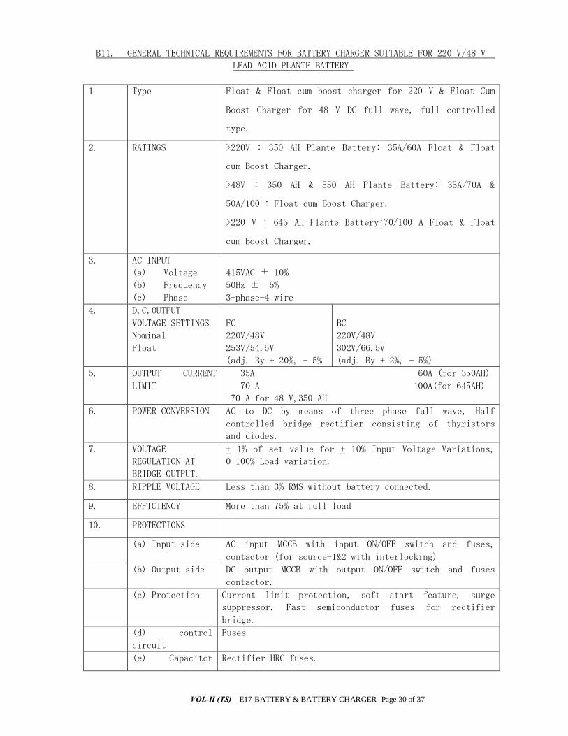
VOL-II (TS) E17-BATTERY & BATTERY CHARGER- Page 30 of 37
B11. GENERAL TECHNICAL REQUIREMENTS FOR BATTERY CHARGER SUITABLE FOR 220 V/48 V
LEAD ACID PLANTE BATTERY
1 Type Float & Float cum boost charger for 220 V & Float Cum
Boost Charger for 48 V DC full wave, full controlled
type.
2. RATINGS >220V : 350 AH Plante Battery: 35A/60A Float & Float
cum Boost Charger.
>48V : 350 AH & 550 AH Plante Battery: 35A/70A &
50A/100 : Float cum Boost Charger.
>220 V : 645 AH Plante Battery:70/100 A Float & Float
cum Boost Charger.
3. AC INPUT
(a) Voltage
(b) Frequency
(c) Phase
415VAC ± 10%
50Hz ± 5%
3-phase-4 wire
4. D.C.OUTPUT
VOLTAGE SETTINGS
Nominal
Float
FC
220V/48V
253V/54.5V
(adj. By + 20%, - 5%
BC
220V/48V
302V/66.5V
(adj. By + 2%, - 5%)
5. OUTPUT CURRENT
LIMIT
35A 60A (for 350AH)
70 A 100A(for 645AH)
70 A for 48 V,350 AH
6. POWER CONVERSION AC to DC by means of three phase full wave, Half
controlled bridge rectifier consisting of thyristors
and diodes.
7. VOLTAGE
REGULATION AT
BRIDGE OUTPUT.
+ 1% of set value for + 10% Input Voltage Variations,
0-100% Load variation.
8. RIPPLE VOLTAGE Less than 3% RMS without battery connected.
9. EFFICIENCY More than 75% at full load
10. PROTECTIONS
(a) Input side AC input MCCB with input ON/OFF switch and fuses,
contactor (for source-1&2 with interlocking)
(b) Output side DC output MCCB with output ON/OFF switch and fuses
contactor.
(c) Protection Current limit protection, soft start feature, surge
suppressor. Fast semiconductor fuses for rectifier
bridge.
(d) control
circuit
Fuses
(e) Capacitor Rectifier HRC fuses.

VOL-II (TS) E17-BATTERY & BATTERY CHARGER-Page31 / 37
circuit
(f) Over-voltage cut-back
(g) Charger over load / short circuit
(h) Blocking diode
11. CONTROLS AND
SWITCHES
Followings controls and switches are provided in the
system
a) AC input source MCCBs with interlocking
b) DC output MCCB
c) Auto/Manual float/boost mode selector switch.
d) Float and boost voltage variable potentiometers.
e) Manual voltage adjustment Potentiometer
f) Test push button
g) Reset push button
h) Battery current adjustment potentiometers
i) Heater’s power supply switch
j) Socket power supply switch
12. FEATURES The following features are provided in the systems:
a) Soft start on DC side
b) Class-F insulation for all magnetic
c) Automatic voltage regulation.
d) Automatic changeover from float to boost and vice
versa based on current, drawn by battery.
e) Filter circuit to eliminate ripple.
f) Charger current limit
g) Separate battery path current limit.
h) Built-in auto phase reversal of operation.
13. Meters F.C. B.C.
(i)Input Voltmeter (i) Common
(ii) Input Ammeter (ii) Input Ammeter
(iii) Output Voltmeter (iii) Output Voltmeter
(iv) Output Ammeter (iv) Output Ammeter.
Battery volt meter
Battery ammeter
Earth leakage ammeter
14. Indications (i) R,Y,B Phase
‘ON’ lamps
(ii) Output ‘ON’
lamp
(i) R.Y.B. phase ‘ON’
lamps
(ii) Output ‘ON’ lamp.
(iii) Charger ‘ON’ float
LED
(iv)Charger ‘ON’ boost
LED.
15. Annunciation
with audiovisual
alarms.
(i) AC input mains failure
(ii) Input phase failure
(iii) AC under voltage
(iv) Input phase failure

VOL-II (TS) E17-BATTERY & BATTERY CHARGER- Page 32 of 37
(iii) Rectifier fuse
failure
(iv) Output fuse failure (v) Filter fuse failure
(vi) DC under voltage (vii) DC over voltage (viii) Charger trip (ix) Capacitor fuse fail (x) Output MCCB tripped
(xi) Charger over load (xii) Earth leakage (xiii) DC earth fault (xiv) Alarm supply fuse
failure
(xv) Battery low
condition.
v) Rectifier fuse failure
vi) Output fuse failure
vii) Filter fuse failure
viii) DC under voltage
ix) DC over Voltage
x) Charger trip
xi) Capacitor fuse fail
xii) Output MCCB tripped.
Note : All the alarms shall be provided through electronic display cards. Audio
alarm through buzzer, visual indication through 10 mm LEDS & alarm ackn. / reset and
LED provision is through push buttons.
16. Operating ambient
temperature
surrounding the
panel
00 to 500C
17. Surrounding the
panel Relative
humidity.
0-95% non-condensing
18. PANEL
(a) Protective
grade
(b) Cooling
(c) Paint
(a) IP – 42
(b) Natural air-cooled
(c) Smoke Grey of ISS-692 shade
19. MAGNETICS :
(a) Average
winding temperature
rise over ambient
temperature
(b) Insulation
class
(c) Insulation
breakdown voltage.
As per relevant ISS.
‘F’
3 KV for 1 min withstand.
20. CABLES 1100 V grade PVC insulated copper. Ferrules shall be
provided for identification of connection.
N.B. : - Besides the above general technical requirements, all other stipulations, as
enumerated in this technical specification shall be followed. Any deviation should be
clearly brought out with clear explanation.

VOL-II (TS) E17-BATTERY & BATTERY CHARGER-Page33 / 37
Any extra feature/ equipment / instrument as necessary for operation and
performance of the battery charger for the 220V /48 V battery set as per this
specification shall be provided without any extra cost to OPTCL..
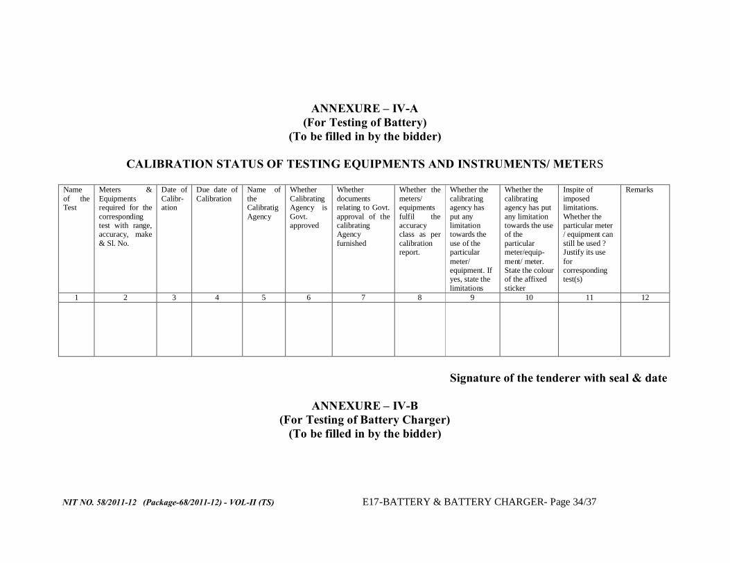
NIT NO. 58/2011-12 (Package-68/2011-12) - VOL-II (TS) E17-BATTERY & BATTERY CHARGER- Page 34/37
ANNEXURE – IV-A (For Testing of Battery)
(To be filled in by the bidder)
CALIBRATION STATUS OF TESTING EQUIPMENTS AND INSTRUMENTS/ METERS Name of the Test
Meters & Equipments required for the corresponding test with range, accuracy, make & Sl. No.
Date of Calibr-ation
Due date of Calibration
Name of the Calibratig Agency
Whether Calibrating Agency is Govt. approved
Whether documents relating to Govt. approval of the calibrating Agency furnished
Whether the meters/ equipments fulfil the accuracy class as per calibration report.
Whether the calibrating agency has put any limitation towards the use of the particular meter/ equipment. If yes, state the limitations
Whether the calibrating agency has put any limitation towards the use of the particular meter/equip-ment/ meter. State the colour of the affixed sticker
Inspite of imposed limitations. Whether the particular meter / equipment can still be used ? Justify its use for corresponding test(s)
Remarks
1 2 3 4 5 6 7 8 9 10 11 12
Signature of the tenderer with seal & date
ANNEXURE – IV-B
(For Testing of Battery Charger) (To be filled in by the bidder)

- VOL-II (TS) E17-BATTERY & BATTERY CHARGER- Page 35 of 33
CALIBRATION STATUS OF TESTING EQUIPMENTS AND INSTRUMENTS/ METERS
Name of the Test
Meters & Equipments required for the corresponding test with range, accuracy, make & Sl. No.
Date of Calibr-ation
Due date of Calibration
Name of the Calibratig Agency
Whether Calibrating Agency is Govt. approved
Whether documents relating to Govt. approval of the calibrating Agency furnished
Whether the meters/ equipments fulfil the accuracy class as per calibration report.
Whether the calibrating agency has put any limitation towards the use of the particular meter/ equipment. If yes state the limitations
Whether the calibrating agency has put any limitation towards the use of the particular meter/equip-ment/ meter. State the colour of the affixed sticker
Inspite of imposed limitations. Whether the particular meter / equipment can still be used ? Justify its use for corresponding test(s)
Remarks
1 2 3 4 5 6 7 8 9 10 11 12
Signature of the tenderer with seal & date
ANNEXURE V – A (To be filled in by the bidder)
CHECK LIST TOWARDS TYPE TEST REPORTS FOR BATTERY Name of the Type Test
Date of Test
Name of the Laboratory where the Test has been conducted
Whether the Laboratory is Government approved
Whether the Test report is valid as per Spn.
Whether the Test report in complete shape alongwith
Whether the type tested Plante lead acid battery fulfills the
If the type tested battery does not fulfill the technical requirements as per this specification, whether the bidder agrees to conduct he particular type test again at their
Remarks

NIT NO. 58/2011-12 (Package-68/2011-12) - VOL-II (TS) E17-BATTERY & BATTERY CHARGER- Page 36/37
drawings etc. furnished or not ?
technical requirements as per TS
own cost without any financial liability to OPTCL in the presence of OPTCL’s representative within the specified delivery period
1 2 3 4 5 6 7 8 9
Signature of the tenderer with seal & date
ANNEXURE V – B
(To be filled in by the bidder)
CHECK LIST TOWARDS TYPE TEST REPORTS FOR BATTERY CHARGER Name of the Type Test
Date of Test
Name of the Laboratory where the Test has been conducted
Whether the Laboratory is Government approved
Whether the Test report is valid as per Spn.
Whether the Test report in complete shape alongwith drawings etc. furnished or not ?
Whether the type tested battery charger fulfills the technical requirements as per TS
If the type tested battery charger does not fulfill the technical requirements as per this specification, whether the bidder agrees to conduct he particular type test again at their own cost without any financial liability to OPTCL in the presence of OPTCL’s representative within the specified delivery period
Remarks
1 2 3 4 5 6 7 8 9

- VOL-II (TS) E17-BATTERY & BATTERY CHARGER- Page 37 of 33
Signature of the tenderer with seal

VOL-II (TS) E18-PLCC- Page 1 of 38
ODISHA POWER TRANSMISSION CORPORATION LIMITED
TECHNICAL SPECIFICATION
FOR
POWER LINE CARRIER COMMUNICATION (THE INDOOR PLCC PANELS WILL BE SUPPLIED BY OPTCL AS A OWNER
SUPPLY ITEMS BUT OTHER MATERIALS AS REQUIRED ARE IN THE
SCOPE OF SUPPLY BY BIDDER)

VOL-II (TS) E18-PLCC- Page 2 of 38
1. GENERAL Power Line Carrier Communication equipment shall be supplied with all associated equipment complete with all material and accessories, and installed at various substations as indicated in relevant schedules. The Contractor shall also include all equipment and accessories including modifications for remote end substations of the PLCC link even though the names of the substations do not appear in the Schedule.
The Contractor shall be responsible for the provision of training engineers of the Employer responsible for maintenance of the above equipment. The Contractor shall also be responsible for maintenance till the equipment is handed over to the Employer.
Panels shall be supplied complete with all accessories, meters, switches, indicating lamps, annunciation, and other devices completely wired and assembled as per approval of the Project Manager. The contractor shall also mount and completely wire the equipment to be supplied by others if any for installation on these panels.
2. LIST OF ABBREVIATIONS The following abbreviations have been used in this document.
AC Alternating Current AIS Alarm Indication Signal BER Bit Error Rate CCIR Consultative Committee International Radio CCITT International Telegraph and Telephone Consultative Committee CPU Central Processing Unit CVT Capacitive Voltage Transformer dB Decibel DC Direct Current DTMF Dual Tone Multi-Frequency EEPROM Electrically Erasable Programmable Read Only Memory EMI Electromagnetic Interfaces Ghz Gigahertz HF High Frequency ic Integrated Circuit IDC Insulation Displacement Connector IEC International Electrotechnical Commission IEC International Electrotechnical Commission IP Ingress Protection kA Kilo Amperes kb/s Kilobits per second kV Kilo Volts LED Light Emitting Diode LED Light Emitting Diode Mb/S Megabits Per Second msec Millisecond

VOL-II (TS) E18-PLCC- Page 3 of 38
MTBF Mean Time Between Failures MTTR Mean Time To Repair nm Nanometers (meters X 10—9) PAX Private Automatic (Telephone) Exchange PCM Pulse Code Modulation PLC Power Line Carrier PSK Phase Shift Keying PSTN Public Switched Telephone Network PSU Power Supply Unit QA Quality Assurance RF Radio Frequency RFI Radio Frequency Interference RFI Radio Frequency Interference RLDC Regional Load Despatch Centre SDH Synchronous Digital Hierarchy SLDC State Load Despatch Centre SPC Stored Programme Control sub-LDC Sub-Load Despatch Centre VF Voice Frequency VSWR Voltage Standing Wave Radio
3. PLCC SYSTEM The PLCC system shall be used to carry speech, protection and control signals, SCADA and computer data traffic. Interface connections shall be made directly with telephone equipment and equipment handling digital data.
The PLCC system shall be suitably designed to work over the high voltage overhead power transmission lines and shall comply with IEC 495. The system shall operate satisfactorily under all power system switching and weather conditions that may be encountered at any time. It shall be capable of operating properly during its period of service.
The mean time between failures shall be stated and proof in the form of calculations or actual in-service failure rates shall be provided.
A panel or enclosure shall be provided for paralleling the HF outputs for connection to the coaxial cable between the PLC and the Line Matching Unit. Suitable coaxial cable shall be used between the PLC and this panel. The HF cables from the PLC shall be terminated on the panel with plug-in connectors to allow each PLC to be interchanged between lines.
The PLCC system shall essentially consist of the following:
• Coupling Device, phase to phase or phase to ground.
• HF cable
• Carrier terminal (Owner supply item)
• Protection coupler(owner supply item)
• Telephone instruments
• Line traps

VOL-II (TS) E18-PLCC- Page 4 of 38
4. STANDARDS All the PLCC equipment covered under the specification shall conform to the requirements of the latest edition of the relevant IEC/IS Specifications or equivalent National Standards, except to the extent modified by this specification.
The IEC/IS Specifications relevant to the equipment covered under this specification shall include but not be limited to standards indicated in relevant schedules of this specification.
5. DRAWINGS
5.1 Reference Drawings
The drawings attached to this specification shall be the reference drawings.
The Contractor shall evolve and furnish a comprehensive protection, control, interlocking and signalling scheme meeting all the requirements of the technical specifications based on these reference drawings.
The Contractor while preparing the drawings for control and relay panels shall co-ordinate with various other equipment suppliers for actual details of equipment to be directly or indirectly associated with the control and relay panels
The current and voltage transformer parameters are given in the relevant sections of this specification. The contractor shall ensure the supply of CVT to meet the needs of relays and meters being supplied by him.
Attached to Specification is a schedule indicating the existing features of PLCC system at the particular site along with details of remote end equipment.
5.2 Contractors Drawings
Contractor shall furnish the complete scheme, system, and supply drawings as called for in this Specification.
Contractor shall provide a list of drawings and a programme for submission in accordance with the requirements of this Specification.
All drawing submitted by the bidder including those submitted at the time of bid shall be in sufficient detail to indicate the type, size, arrangement, material description, bill of material, weight of each component, break-up for packing and shipment, external connection, fixing arrangement required, dimensions required for installation, interconnection with other equipment and components, clearance and space required for installation, interconnection between various points of equipment and any other information as called for in this Specifications.
6. FREQUENCY PLANNING AND SURVEY
6.1 General
A frequency planning study shall be carried out by the Owner / Contractor such that the SNR for various channels shall be as per IEC. For transposed lines the signal attenuation considered for frequency planning shall be justified through study reports.

VOL-II (TS) E18-PLCC- Page 5 of 38
The frequency and output power of the PLCC system for protection shall be planned such that the protection signal is received with full reliability even when one phase is earthed or is open circuit on the line side causing an additional minimum loss of 6 dB.
The frequency plan will be referred to Wireless Adviser/DOP Department for clearance. In case any changes to the Contractor's recommendations for carrier frequency and power output are proposed by these Authorities, the Contractor shall modify his proposal accordingly. Changes of power output shall not, however, involve repeater stations.
The frequency planning exercise shall also include the items outlined in the following sub-clause 6.2, 6.3 and 6.4.
The Contractor’s study report shall includes the followings
6.2 Proposed Arrangement
Facilities shall be provided for immediate opening of local breaker under direct tripping command from remote end. The tripping of local/remote end breakers is to be achieved by exchange of commands on PLC system between the two ends of the line in direct tripping mode.
For security reasons each transmission line shall be protected by Main-I and Main-II protections as given below :
• Main-I Distance protection type with permissive inter- tripping.
• Main-II Distance protection of different design/ philosophy/manufacture to the relay under Main I.
6.3 Carrier requirements 6.3.1 For 400kV Lines
a) Two protection channels for Main-I and two for Main-II distance protection schemes.
b) Two main and two back-up protection channels for direct circuit breaker inter-tripping.
c) One speech channel with facility for superimposed telex and data signals.
d) The arrangement shall be as per plate 7.1.
6.3.2 For 220 kV Lines
a) One protection channel for Main-I and another for Main-II distance protection schemes.
b) One main and one back-up protection channel for direct circuit breaker inter-tripping.
c) One speech channel with facility for superimposed telex and data Signals.
d) The arrangement shall be as per plate 7.2.
6.3.3 For 132 kV lines
a) One protection channel for Main-I protection scheme.
b) One speech channel with facility for superimposed telex and data signals.
c) The arrangement shall be as per plate 7.3.
6.3.4 For 33 kV lines
No PLCC Equipment is envisaged on 33 kV lines.
VOL-II (TS) E18-PLCC- Page 6 of 38
6.3.5 General
The equipment for protection signals shall have high degree of reliability and speed. It shall be guaranteed to function reliably in the presence of noise impulse caused by isolator or breaker operation. The equipment shall be suitable for direct tripping of remote end breaker for fault in unswitched 400 kV shunt reactors. It shall also be possible to effect direct tripping of breaker at one end when the other end breaker is opened either manually or by protection relays such as Bus fault relay etc.
The time intervals between receipt of a trip command on the transmit side, its transmission over the carrier link, reception at the far end and giving command to the trip relays at the distant end shall not exceed 20 milliseconds for permissive inter-tripping and 30 milliseconds for direct inter-tripping. The above timings are inclusive of operating time for auxiliary relays and interposing relays, if any, included in the PLCC equipment.
The requirement of protection signalling channel is such that security against incorrect signals being received shall be at least two to three orders higher than reliability against a signal not being received.
Requirement under speech and telex communication is elaborated elsewhere in this section.
The planning of frequencies for the PLCC terminals shall be done considering the existing PLCC Network as well as full communication channel requirement detailed above so that there is no problem of frequency allocation at a later date when the subsequent section communication requirements come up.
For reasons of security and reliability, phase to phase/inter-circuit coupling shall be employed. Double differential coupling shall also be considered for double circuit lines. Bidders shall furnish details of methods of coupling and recommend suitable coupling mode for double circuit lines along with the bids. The coupling mode shall, however, be fully confirmed by Contractor after conducting detailed computer studies, taking into account the transpositions of 400 kV lines, for optimum coupling mode over these line sections. The coupling arrangement shall be fully optimised by the Contractor after conducting detailed studies of every line section individually, taking into account temperature variations, transpositions, earth resistivity, conductor configuration, carrier channels requirements, security and reliability criteria and other relevant details. The line attenuation shall be calculated for complete range of frequencies. Earth resistivity data, existing frequency networks and other relevant details of each line will be furnished to the Contractor for carrying out computer studies and frequency planning. The Contractor shall complete the computer studies wherever required and submit the frequency plan and optimum coupling details within a period of one month from the date of receipt of above data. The cost of doing the computer studies wherever required shall be included in the lump sum bid price and details of computer study charges shall be indicated in the relevant schedule. Bidder must indicate the links on which computer study is required.
The 400 kV transmission lines may be transposed as shown in the relevant specification drawing. There are two transpositions in each line section at distances shown in the drawing. The third transposition is for achieving proper phase sequence at substation.
Transmission tower configuration and conductor details shall be made available to the successful bidder to enable the bidder to make his own computer study assessment of the carrier path based on wave propagation over transposed lines with each transposition point acting as "Modal Converter".

VOL-II (TS) E18-PLCC- Page 7 of 38
The parameters of the equipment quoted shall be such that the mode of wave propagation on 400 kV /220 kV/132 kV power lines (with transpositions indicated) shall not impose any limitation on the efficient and reliable performance of the information link.
The Contractor shall be required to check and prove, through the results of his computer studies, that attenuation due to transpositions in the EHV lines is within limits and the offered equipment will perform satisfactorily.
The Contractor shall submit curves illustrating `incorrect tripping' and "failure to trip" probability plotted against corona noise level, in the presence of impulse noise due to switching of isolators and circuit breakers etc. Details of field tests and laboratory tests for successful operation of his equipment, under such adverse conditions shall be furnished by the Bidder. These are to be related to end-to-end signalling and shall take into account the type of communication link e.g. account shall be taken of transpositions in the phase to phase coupled HT. line. Details of field tests and laboratory tests for successful operation of the equipment under the above circumstances shall be submitted by the Bidder illustrating the above parameters.
7. LINE TRAP (TO BE SUPPLIED BY THE CONTRACTOR)
7.1 Technical Requirements Line traps shall be inserted into extra high voltage transmissions line to prevent undue loss of carrier signal for all power system conditions. Their impedance shall be negligible at power frequency (50 Hz) so as not to disturb power transmission but shall be relatively high over the frequency band appropriate to carrier transmission.
Line traps shall consist of a main coil designed to carry continuously the rated current without exceeding the limit of temperature rise. It shall be supplemented with a protective device and tuning device.
Line traps shall be broad band tuned for its entire carrier frequency range. Resistive component of impedance of the line trap within its carrier frequency blocking range shall not be less than 450 ohms for 400kV and 570 ohms for 220kV systems.
Line traps shall be provided with a protective device in the form of a lightning arrestor. The protective device shall be designed and arranged such that neither significant alteration in protective function nor physical damage shall result from either temperature rise or the magnetic field of the main coil at continuous rated current or rated short time current. The protective device shall neither enter into operation nor remain in operation, following transient actuation by the power frequency voltage developed across the line trap by the rated short time current. The protective device shall be shunt connected to the main coil and tuning device.
The lightning arrestor shall be station class current limiting active gap type. Its rated discharge current shall be 10 kA. Co-ordination, however, shall be done by taking 20 kA at 8/20 micro-sec. discharge current into account. Bidder has to furnish full justification in case the use of gap-less metal oxide arrestor is recommended by them.
The lightning arrestor provided with the line trap of each rating shall fully comply with the requirements of IS 3070-Part I (1974)/IEC 99-I (1970) Part I. It shall conform to type tests as applicable and type test certificates shall be submitted by the Bidder.
The lightning arrestor provided with the line trap shall be subject to routine and acceptance tests as per IEC 99-1 (1970) (Part-I).
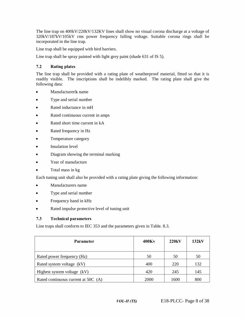
VOL-II (TS) E18-PLCC- Page 8 of 38
The line trap on 400kV/220kV/132KV lines shall show no visual corona discharge at a voltage of 320kV/187kV/105kV rms power frequency falling voltage. Suitable corona rings shall be incorporated in the line trap.
Line trap shall be equipped with bird barriers.
Line trap shall be spray painted with light grey paint (shade 631 of IS 5).
7.2 Rating plates The line trap shall be provided with a rating plate of weatherproof material, fitted so that it is readily visible. The inscriptions shall be indelibly marked. The rating plate shall give the following data:
• Manufacturer’s name
• Type and serial number
• Rated inductance in mH
• Rated continuous current in amps
• Rated short time current in kA
• Rated frequency in Hz
• Temperature category
• Insulation level
• Diagram showing the terminal marking
• Year of manufacture
• Total mass in kg
Each tuning unit shall also be provided with a rating plate giving the following information:
• Manufacturers name
• Type and serial number
• Frequency band in kHz
• Rated impulse protective level of tuning unit
7.3 Technical parameters
Line traps shall conform to IEC 353 and the parameters given in Table. 8.3.
Parameter
400Kv 220kV 132kV
Rated power frequency (Hz) 50 50 50
Rated system voltage (kV) 400 220 132
Highest system voltage (kV) 420 245 145
Rated continuous current at 50C (A) 2000 1600 800

VOL-II (TS) E18-PLCC- Page 9 of 38
Rated short time current for 1 sec. (kA) 40 40 40
Nominal discharge current of protective device at 8/20 micro sec. wave (kA)
10 10 10
Type of tuning Broad band
Rated blocking bandwidth 90-150 & 150-500 (to be approved during detail Engineering)
Minimum resistive component of impedance within rated blocking bandwidth (Ohms).
450 450 450
Rated inductance of main coil (mH) 1.0 1.0 0.5
Corona extinction voltage (kV) ≥320 ≥187 ≥105
Radio interference voltage (micro volts at 1.1. times Ur/√3, where Ur = maximum system voltage)
500
Table 8.3. Parameters for line traps The exact quantities and rating of required line traps shall be decided by the Project Manager based on frequency planning and recommendations of the Contractor.
The Contractor shall indicate continuous current rating of the line trap at 65C ambient.
7.4 Welding or brazing on line trap during manufacture All the welding included in the manufacture of line traps shall be performed in accordance with the relevant section of this Specification.
7.5 Line trap mounting (to be supplied by the contractor) Line traps shall be suitable for outdoor pedestal mounting and shall be mechanically strong enough to withstand the stresses due to maximum wind speed specified in the schedules. The contractor shall recommend the mounting of line traps and prepare the lay out of the substation for the Project Managers approval.
Where pedestal mounting is recommended, each line trap shall be mounted on a structure fitted with insulators to provide mechanical stability and structural rigidity. The Contractor shall submit the design calculations to establish the adequacy of his recommendations. All the accessories and hardware, mounting stool, including bolts for fixing the line trap on insulators, shall be of non-magnetic material.
The Bidder shall submit along with his bid, typical drawings clearly indicating the above mentioned features of the line traps, line trap mounting arrangement and terminal connectors. Each transmission line fitted with line traps shall be charged in the presence of the Contractor's representatives.
8. COUPLING DEVICE (TO BE SUPPLIED BY THE CONTRACTOR) The coupling devices shall be interposed between the capacitor voltage transformer and coaxial line to the PLC transmitter/receiver. The coupling device, in conjunction with the capacitor voltage transformer, shall ensure efficient transmission of carrier frequency signals between the carrier frequency connection and the power line. In addition safety of personnel and protection of

VOL-II (TS) E18-PLCC- Page 10 of 38
the low voltage parts and installation, against the effects of power frequency voltage and transient over voltages shall be ensured.
The coupling device in conjunction with the CVT shall form an electric filter of band pass type and have the following characteristics:
1. It shall match characteristic impedance of HT line to impedance of the carrier frequency connection. Impedance matching between power line and the carrier frequency connection may be done by a transformer or an auto-transformer. The phase to earth characteristic impedance of the HT line may be assumed to be 320 ohms for 400 kV lines and 400 ohms for 220 kV lines. The design details must be submitted along with the Bids.
2. Galvanic isolation between primary and secondary terminals of the coupling device shall be performed by the above mentioned transformer.
3. Power frequency currents derived by the CVT may be drained to the earth by a separate inductance termed drain coil of suitable rating.
4. Voltage surges coming from the power line at the terminals of the coupling device shall be limited by a non-linear surge arrestor of suitable rating in the primary side. Requirement of a gas type voltage arrestor in secondary side of the coupling device shall have to be fully justified, but in any case the input circuit of PLC equipment shall have protective devices in the form of zener diodes and surge suppressors. The surge arrestor shall have power frequency spark over voltage co-ordinated with the equipment ahead of it.
5. For direct and efficient earthing of its primary terminals, the coupling device shall be equipped with an earthing switch. The coupling device shall be designed such that it shall not be possible to remove the cover before the earthing switch is operated to the `earthed' position. Further the earth switch shall be available for earthing of CVT-HT terminals, when the coupling filter units are removed from circuit for maintenance and replacement. The design shall take due regard of requirements for safety in accordance with the Indian Electricity Rules.
Two phase to earth type coupling filters shall be used to achieve secure phase to phase inter-circuit coupling in case of double circuit lines. Connection between secondary of the two phase to earth type coupling devices shall be through a balancing transformer/hybrid such that reliable communication shall be ensured even when one of the coupled phase is earthed or open circuited on the line side.
Coupling devices shall conform to IEC 481 and have the following carrier frequency characteristics as applicable to a phase to earth type coupling device :
• Nominal line side impedance 320 ohms for 400 kV line
400 ohms for 220 kV lines • Nominal equipment side impedance 75 ohms (unbalanced) • Composite loss Not more than 2 dB • Return loss Not less than 12 dB • Bandwidth Shall suit the frequency plan between 36 and
500 kHz • Nominal peak envelope Not less than 650 Watt power (for inter
modulation product 80 dB down)
The coupling device shall be suitable for outdoor mounting. Temperature of metallic equipment mounted outdoor is expected to rise up to 65C during the maximum ambient temperature of 50C specified. The equipment offered by the Bidder shall operate satisfactorily under these conditions.

VOL-II (TS) E18-PLCC- Page 11 of 38
All the elements of coupling device shall be fitted on a base plate and enclosed in a pad lockable metal box with inspection glass on front. The general arrangement and dimensional details of the metal box shall be similar to that shown in the specification drawings. The Contractor shall submit detailed drawing indicating a general arrangement, interconnection and all other details for approval of the Project Manager during detail engineering.
The HT terminal of coupling device shall be connected to HF terminal of the CVT by means of 6mm2 copper wire with suitable lugs and taped with 11 kV insulation by the Contractor.
The coupling device shall have at least two terminals for carrier equipment connection. Bidder shall confirm that such a parallel connection to coupling device directly will not result in any additional attenuation.
9. HIGH FREQUENCY CABLE (TO BE SUPPLIED BY THE CONTRACTOR) High frequency cable shall connect the coupling device installed in the switchyard to the PLC terminal installed indoors. The high frequency cables supplied by the Contractor shall be suitable for laying directly in trenches or in ducts.
The cable shall be steel armoured and its outer covering shall be protected against attack by termites. Bidder shall offer his comments on method employed by him for earthing of screen and submit full justification for the same with due regard to safety requirements.
Bidder shall enclose in his bid a detailed construction drawing of the cable being offered, with mechanical and electrical parameters.
Impedance of the cable shall be such as to match the impedance of the PLC terminal on one side and the coupling device on the other side, over the entire carrier frequency range of 40-500 kHz.
Loop resistance of cable shall not exceed 30 ohm per km at 20C.
The cable shall be designed to withstand a test voltage of 4 kV between conductor and outer sheath for one minute.
Bidder shall specify attenuation per km of cable at various carrier frequencies in the range of 40 to 500 kHz. The typical attenuation figures for HF cable shall be in the range of 1 to 5 dB/km in the frequency range of 40-500 kHz.
The HF cable shall conform to type tests and be subjected to routine tests as per IEC 96-2/ BS 2316/ IS 5802.
The Bidder shall submit along with the bid, copies of type tests and performance reports of the cable being offered.
All HF cables within the scope of this specification shall be supplied, laid and terminated by the Contractor.
Cables shall be supplied wound on drums containing lengths not less than 500 metres each.
10. POWER LINE CARRIER TERMINAL (OWNER SUPPLY ITEMS -OPTCL )
10.1 General As already indicated the information link shall be provided for speech, protection, fax and data services. PLC terminals shall be fully co-ordinated to match with the specific requirements. Because of strict requirement of high speed of operation, security, reliability and efficient operation of protection channel along with the carrier terminals, Bidder shall ensure the complete

VOL-II (TS) E18-PLCC- Page 12 of 38
and fool-proof co-ordination of the PLC and protection equipment. It shall therefore be necessary to have these combinations as one unit without any mismatch or necessity of any intermediate co-ordination unit.
PLC terminal shall use amplitude modulation and shall have single side band transmission mode. These shall be equipped for fixed frequency duplex working and shall be fully solid state.
Characteristic input and output parameters of the PLC terminals shall be as per IEC 495 unless otherwise specified.
10.2 Features of PLC terminals
Each PLCC channel shall be capable of carrying any of the following:
1. One speech channel plus telephone signalling channel, nominally 300 Hz to 3.4 kHz for speech. This is also required to carry facsimile transmission and computer data.
2. One restricted speech channel 300 Hz - 2 kHz plus a band of 2 kHz - 4 kHz for the transmission of data and a telephone signalling channel. Data signalling rates of 50, 200,300, 600 baud shall be possible.
3. Two 600 baud channels or one 1200 baud channel. It shall be stated if higher data rates up to 9600 bit/s can be transmitted.
4. One channel for the transmission of speech and tele-protection signals.
5. One channel for the transmission of speech, tele-protection signals and data.
The equipment shall preferably be capable of operation in all the above modes without the provision of additional modules and components. The telephone signalling channel shall be nominally 3.8 kHz out-of-band.
Subject to frequency allocation considerations, PLC equipment may be required to be expanded by the addition of channels to a link (i.e. upgrade to 2 or 4 channels as appropriate). The PLC equipment shall be modular in construction and shall permit such upgrading to be carried out.
The equipment shall be suitable for use with E and M signalling between telephone exchanges at both ends of the lines. Signalling shall be on the pilot tone using a 50 baud channel. If DTMF signalling is available as an alternative this should be stated.
10.3 Transmitter/receiver
The equipment shall use single channel amplitude modulated single sideband suppressed carrier transmission. The Bidder shall quote for terminals which have an output power of 20, 40 and 80 watts.
PLC equipment shall be designed to operate over a frequency band of 50 kHz to 500 kHz.
For each PLC link, the Bidder shall indicate the required frequency spacing between the transmitters and receivers. Spaced band and contiguous band operation should be possible. In twin channel versions, it shall be possible to operate both transmitters and both receivers in adjacent bands. The Bidder shall state the full range of carrier frequencies over which the equipment may be operated.
The carrier frequency output impedance shall be 75Ω or 125Ω unbalanced. Any alternative shall be stated in the tender. The return loss within the nominal carrier frequency band in the transmit direction shall be not less than 12 dB.

VOL-II (TS) E18-PLCC- Page 13 of 38
The maximum permitted level of spurious emissions shall meet the requirements of IEC 495 Section 8.3.2. Spurious emissions shall be measured as described in Clause 6.2.3 of the recommendations.
The receiver shall have high selectivity and the attenuation of out of band signals shall be as follows:
Frequency out of band (kHz)
Attenuation(dB)
0.3 70
0.3 - 4.0 70 - 90
4.0 90
The generation of carrier frequencies shall be fully synthesised. It shall be possible to select any carrier frequency within the whole carrier frequency range in discreet steps of 4kHz. The frequency synthesis shall be highly accurate such that the actual carrier frequency shall not differ from the nominal by more than 20 Hz.
10.4 Speech and signal levels
The voice frequency input impedance shall be 600Ω balanced. The return loss within the effectively transmitted frequency bands shall be not less than 14 dB.
The minimum send level shall be not more than -14 dBm. The maximum receive level shall be at least +4 dBm. Attenuators to facilitate interfacing and matching should be provided.
The absolute input and output levels for signal channels shall be chosen in accordance with the relevant ITU-T Recommendations.
In a pair of PLC terminals, the frequency difference between a voice frequency signal applied to the transmit end and that received at the receive end shall not exceed 2 Hz.
The linearity as a function of the voice frequency input level, shall be such that the overall loss of the speech circuit, of a pair of PLC terminals without compandors and limiters, does not differ by more than ±0.8 dB from the overall loss at 0 dBm for any input level between -10 dBm and 0 dBm. The measurements shall be made at 800 Hz.
Automatic Gain Control: In the case of a 30 dB change in carrier frequency signal level within the regulation range, the change in voice frequency receive levels of both speech and signals shall be less than 1 dB.
Graphs showing frequency/attenuation response of the line filters shall be included with the tender.
The use of companders shall be optional and the final arrangement shall be agreed with the Project Manager.
10.5 Maintenance facilities Set up and maintenance facilities shall be provided, preferably through the use of a portable PC. The facility shall enable the variable parameters of the equipment to be modifiable.
Details of test equipment required for the set-up and maintenance of the equipment shall be given.
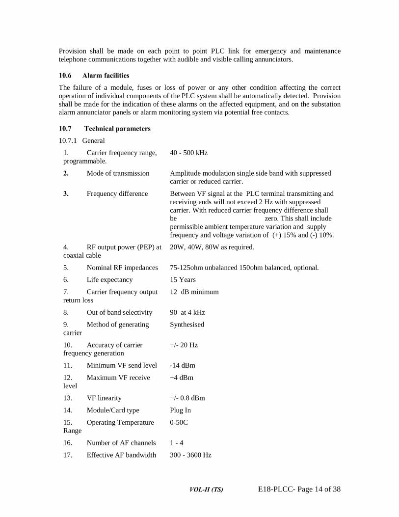
VOL-II (TS) E18-PLCC- Page 14 of 38
Provision shall be made on each point to point PLC link for emergency and maintenance telephone communications together with audible and visible calling annunciators.
10.6 Alarm facilities
The failure of a module, fuses or loss of power or any other condition affecting the correct operation of individual components of the PLC system shall be automatically detected. Provision shall be made for the indication of these alarms on the affected equipment, and on the substation alarm annunciator panels or alarm monitoring system via potential free contacts.
10.7 Technical parameters
10.7.1 General
1. Carrier frequency range, programmable.
40 - 500 kHz
2. Mode of transmission Amplitude modulation single side band with suppressed carrier or reduced carrier.
3. Frequency difference Between VF signal at the PLC terminal transmitting and receiving ends will not exceed 2 Hz with suppressed carrier. With reduced carrier frequency difference shall be zero. This shall include permissible ambient temperature variation and supply frequency and voltage variation of (+) 15% and (-) 10%.
4. RF output power (PEP) at coaxial cable
20W, 40W, 80W as required.
5. Nominal RF impedances 75-125ohm unbalanced 150ohm balanced, optional.
6. Life expectancy 15 Years
7. Carrier frequency output return loss
12 dB minimum
8. Out of band selectivity 90 at 4 kHz
9. Method of generating carrier
Synthesised
10. Accuracy of carrier frequency generation
+/- 20 Hz
11. Minimum VF send level -14 dBm
12. Maximum VF receive level
+4 dBm
13. VF linearity +/- 0.8 dBm
14. Module/Card type Plug In
15. Operating Temperature Range
0-50C
16. Number of AF channels 1 - 4
17. Effective AF bandwidth 300 - 3600 Hz

VOL-II (TS) E18-PLCC- Page 15 of 38
18. Alarms for loss of transmit signal
loss of receive signal
inadequate S/N ratio
19. Power supply, mains 230VAC, +15%, - 15%
20. Power supply, battery 48VDC, +20%,-15% + ve earthed
21. Ambient conditions according to
IEC 495 (revised )
22. Automatic gain For 40 dB change in control carrier frequency signal level within the regulation range, change in VF receive levels of both speech and other signals shall be less than 1 dB.
10.7.2 User interfaces
1. Telephone interface, 4-wire
600 ohm
10.7.3
1. Number of separate audio 1/0 per channel
1
2. Number of commands with plugged-in Protection Coupler
4
10.7.4 Other system components
1. plug-in protection signalling module
plug-in AF modem programmable
10.8 General requirement for PLC terminal All the PLC terminals shall be of multi-purpose type. The Bidder shall confirm that the total transmission time for teleprotection shall not exceed 20 ms for permissive and 30 ms for direct tripping signals. Speech and teleprotection channels shall independently fulfil the SNR requirements out of the power allocated to its channel from the total power of the PLC terminals.
Detailed calculation for SNR requirement and power allocation over different channels should be furnished along with the bid.
Multiplexing equipment, VFT’s and measurand and converters etc. for data are not included in the scope of present specification and shall be procured separately. The successful Bidder shall, however, be required to co-ordinate his carrier equipment with these equipments for successful operation of the system.
The final selection of the output power shall be based on the frequency planning and computer studies conducted by the Contractor. The evaluation of bids shall, however, be done on the basis of prices for carrier sets with power output as stated in this Specification.
VOL-II (TS) E18-PLCC- Page 16 of 38
In the input circuit of the PLC terminal protective devices shall be provided in the form of zener diodes or surge suppressers in order to eliminate any surge transfer through the coupling device or induced in the connecting path of HF cable.
To improve voice transmission characteristics for the system, compressors and expanders (companders) shall be provided. The companders shall have at least 2:1 compression ratio with a corresponding expansion ratio of 1:2. The operating range of compander shall be compatible with the audio power levels specified for four wire operation. The improvement gained by companders shall however not be taken into account for power allocation and shall be in-hand reserve.
Sudden changes in input level to the receiver shall not cause false tripping. The Bidder shall clearly indicate in his offer the methods adopted to ensure above phenomenon. The receiver design shall also provide protection against false tripping from random noise.
Fail safe devices shall be provided, so that a malfunction in one unit or sub-assembly cannot cause damage elsewhere in the system. All plug in equipment shall be fitted with features to prevent improper insertion. The electrical cables shall not be routed across sharp edges or near sources of high temperature. The adjustments, which are susceptible to misadjustment from accidental contact/vibration, shall be equipped with suitable locking devices.
The PLC set shall be designed to give guaranteed performance from 0C to 50C ambient tempera-ture. The thermal capability of the equipment shall be so designed that the equipment remains operational successfully up to 60C ambient temperature. Any ventilation fans provided for circulation of air inside the cabinets shall conform to relevant Standards.
Terminals shall be provided with a built-in indicating instrument to facilitate checking of important voltage and current values and signal levels in different parts of the PLC Terminals. Protection fuses shall be provided in all important circuits, and fuses shall be so mounted as allow their easy inspection and replacement. All test points shall be easily accessible.
The carrier set shall be provided with suitable supervision and alarm facilities. Individual parts of the carrier set should be accessible from front, making it possible to place the carrier cabinets side-by-side. All components and parts of the carrier set shall be suitably tropicalised.
PLC terminals shall be housed in floor mounting sheet metal cabinets, suitable for mounting on concrete plinth as well as channel frame by means of nuts and bolts or welding. The cabinets shall be properly cleaned and spray painted with two coats of synthetic enamel paint. Exterior of the cabinets shall be painted with smoke-glossy finish. Interior of the cabinets shall be painted with white enamel paint with glossy finish. All the panels shall be properly earthed to the Employer’s earthing grid by the Contractor. Contractor shall submit detailed drawings for earthing connec-tions.
All panels shall be protected against moisture ingress and corrosion during storage. Panels shall be properly dried before they are installed and energised. Bidder shall indicate measures adopted to prevent ingress of moisture during operation.
All cabinets having PLC terminals shall be provided with lamps of sufficient wattage for interior illumination with switch.
A name plate shall be provided on the front door of each cabinet indicating channel function, transmitter frequency and direction etc.
10.9 PLC Terminal Speech Communication
PLC equipment offered shall provide telephone communication between the stations where the transmission lines specified in the schedules are terminating.

VOL-II (TS) E18-PLCC- Page 17 of 38
It shall be possible for a subscriber at any of the stations to contact the subscriber at all other sta-tions connected in the system by dialling his call number. To achieve this an EPAX with four wire interface and remote subscriber units shall be provided at different stations.
The equipment shall contain all normal facilities such as ring back tone, dial tone, engage tone and priority tone, and suitable pulses to establish and disconnect communication between subscribers.
The equipment shall be provided with necessary alarm circuits and fuses etc.
The equipment shall be of 4 kHz bandwidth on either direction and be suitable for providing superimposed data and teleprinter facilities at a later date without major modifications and high cost. The Bidder shall clearly indicate in his bid the provision made in his proposal for future development and the extent to which such additional facilities can be added at a later date.
The system shall be completely automatic with a definite number allocated for each telephone. The numbering scheme for telephones, exchange and tie lines shall be developed by the Bidder and indicated in the bid. Final numbering scheme shall be fully co-ordinated with the existing and proposed future systems by the Contractor.
Arrangement for over-riding facilities shall be provided by means of priority keys wherever specified. The over-riding facility shall enable cutting-in on ongoing calls with the priority key to ask the concerned parties to finish their conversation. The wanted number should then be automatically connected without having to redial the number.
All carrier telephone conversations shall be secret and it should not be possible for anybody to over hear a conversation going on between any two parties excepting those provided with over-riding facilities.
The necessary cables for connecting all the telephone instruments ordered for each substation (including wiring and terminations) shall be provided by the Contractor. These telephone instruments shall be located within the control room building at the respective substation.
All relays etc. used in the equipment shall be of sufficiently robust design to cope with the duty imposed on them. Electronic components used in the equipment shall be of long life type and as few types as possible shall be used.
The cabinets housing the equipment for EPAX, four wire E/M interface and remote subscriber units (four wire) shall have mounting arrangements similar to those for PLC terminals as elsewhere in this section of this Specification.
All the terminals for speech shall be supplied fully wired for addition of VFTs and transit filters in future.
Equipment for speech communication must be fully compatible with Employer's existing equipment. Any interfaces required for proper matching and connection with the Employer’s existing equipment shall be provided by the Contractor.
Terminals for protection shall be suitable for operation between the two ends of each transmission line or on tandem operation basis with back to back connection at the intermediate stations.
Each PLC terminal for speech as well as protection purposes shall be provided with a plug-in type service telephone and buzzer. Further, four wire remote telephone instruments (parallel to service telephone) shall also be provided on one PLC terminal for protection for each link. These instruments shall be located in the respective switchyard control rooms to enable the operator to make emergency calls on point-to-point basis. Each such instrument shall be equipped with a buzzer and `press-to-call' key and shall not require any additional power supply units.

VOL-II (TS) E18-PLCC- Page 18 of 38
There is also a requirement for express telephone links between substations and Area and State Load Dispatch Centres. A call from the substation shall be initiated by lifting the handset. This would cause a lamp to light on the communications console (to be provided under another contract) at the control centre.
11. ELECTRONIC PRIVATE AUTOMATIC EXCHANGE (EPAX) (TO BE SUPPLIED BY THE CONTRACTOR)
11.1 General requirements
Private automatic telephone exchanges (PAX) are required at substations as stated in the detailed description of work and Bill of Quantities.
The equipment shall be capable of providing proper performance throughout its fifteen year life expectancy.
All equipment shall be designed for ease of maintenance and shall include a variety of built-in alarms associated with vital operating parameters.
All equipment supplied under this specification shall conform with the latest IEC Specifications and CCITT Recommendations.
The topographical, meteorological and system operating conditions shall be as stated elsewhere in this Specification
Each interface shall be protected so that neither a short circuit nor open circuit on the telephone line shall cause permanent damage to the exchange equipment. The application of a 500 volt, 50 Hz, signal to either or both legs of the line, shall not cause permanent damage to, or malfunctioning of the exchange equipment.
The exchange equipment shall be protected from electrostatic discharges transmitted to, or occurring at the line interface units.
Each interface shall have an insulation resistance of greater than 10 Mohms at 500V DC between line terminals and earth.
Each interface shall be capable of withstanding longitudinal 2kV, 10/1000 microsecond voltage surges.
The equipment shall operate from a 48 V DC positive earthed battery supply.
Switching equipment shall provide for the following:
• Interconnection of calling and called extension.
• Interconnection of PAX’s via circuits conforming to CCITT Rec. G703 and G705 and PLC channels conforming, to IEC 495.
• Interconnection with a central PAX telephone console at the State Load Dispatch Office and Area Load Dispatch Office.
• A traffic monitoring and reporting system.
11.2 PAX interfaces 11.2.1 General
The PAX requires both analogue and digital interfaces. It shall be capable of interfacing to existing and future GRIDCO telecommunications equipment, and to the public telephone system

VOL-II (TS) E18-PLCC- Page 19 of 38
at selected sites. It shall be capable of interfacing with power line carrier, pilot cable, digital multiplexer, and the PSTN.
The PAX shall be capable of handling analogue and digital trunks, tie lines and extensions, and shall be able to provide the following interfaces:
• 2 wire loop extensions
• 2 wire loop tie lines
• 2 wire E and M tie lines
• 4 wire E and M tie lines
• 2 wire loop PSTN lines
The analogue interfaces shall be two and four wire interfaces, with and without E and M signalling and busy/test signalling, to suit telephone, PLC and pilot cable equipment.
The digital interfaces shall be 64 kbit/sec and 2048 kbits/sec with and without common channel signalling, to suit digital data links and inter-exchange trunks.
11.2.2 Two wire analogue telephone interface requirements
The interface shall be suitable for both standard telephone instruments and telephone consoles for control centre, generating station and substation operators, using DTMF signalling. The interfaces shall provide BORSCHT functions, i.e. Battery supply, Overvoltage protection, Ring current supply, Supervision, Code, Hybrid and Testing functions, for each line connection.
The line feed shall be sufficient to ensure the satisfactory performance of two telephones in parallel on a balanced line of between 0 and 1500 metres in length. The range of loop resistance over which the interface will operate will be 0 to 500 ohms, with a similar limit for the Transmission Equivalent Resistance (TER).
The two wire port impedance shall be 600 ohms, nominal, balanced and suited to the telephone instruments during ringing, signalling and voice transmission conditions.
11.2.3 Analogue power line carrier (PLC) interfaces
The interfaces shall operate as four wire plus E and M interconnections, with the facility for equipment busy signalling wire and test signalling wire, for use with existing transmission equipment interfaces, i.e. PLC and pilot cable interfaces.
The electrical interface requirements are as follows:
• Transmit and receive pairs impedance 600 ohms balanced; return loss better than 20 dB; levels - 3.5 dBm;
• E wire 50 volt battery and relay coil;
• M wire voltage free relay contact to earth;
• Test/busy wires voltage free relay contact to earth;
11.2.4 PAX to PAX interfaces operating over digital trunk circuits
The interfaces shall operate as analogue and digital trunk/tie line interfaces to enable existing changes to be interconnected with the digital PAX and multiplex equipment.

VOL-II (TS) E18-PLCC- Page 20 of 38
64 kbit/sec interfaces shall be in accordance with requirements of CCIIT Recommendation G 70J, and shall be complete with channel associated signalling.
The Contractor shall be responsible for ensuring that these 64 kbit/sec interfaces enable the full range of network facilities to be available for the PAX extensions.
11.2.5 Pilot cable interface
The interface shall provide facilities to interconnect telephone and other terminals to multiplex and exchanges sites via existing pilot cable systems. These interfaces generally conform to those of the PLC system, and are suitable for extending four wire analogue telephone interfaces beyond the 500 ohm limit.
64 kbit/s interfaces shall be in accordance with CCITT recommendation G703, and shall be complete with channel associated signalling,
The PAX shall have facilities for handling DTMF, decadic, feature and digital phones. It shall be possible to connect remote extensions directly to the PAX over four wire E and M circuits.
11.3 Exchange equipment
The PAX shall be a full digital stored programme controlled type, suitable for the transmission of 64 kbit/s and 2 Mbit/s digital signals and for interfacing with PSTN and other public ISDN exchanges.
The PAX shall be capable of being connected via analogue PLC and pilot cable voice circuits utilising MF and E and M signalling to other PAXs installed in the GRIDCO PAX network.
The PAX shall be capable of automatically searching for alternative routes if the first choice route is unavailable.
The equipment shall be expandable to at least the specified maximum switching capacity without impairment of reliability or performance, and without the need for replacement of installed major software and equipment.
11.4 Extension features
The PAX shall provide for the interconnection of any two extensions connected to the exchange without the participation of a telephone operator, on the basis of keyed or dialled numbers.
The PAX shall provide for:
• Normal inter extension communication.
• Automatic call-back on "Busy" or "No Reply". The calling extension shall have to enter a prefixed code for this facility to be operable
• Conference call, both three way established by an extension, or a multiple conference up to 20 extensions .
• Call transfer to transfer a calling party to another extension.
• Call transfer/follow me to reroute all incoming calls to another extension.
• Call transfer to allow a called extension to be answered at another extension by dialling a code at the other extension.
• Last number redial to allow a redial by using a code.

VOL-II (TS) E18-PLCC- Page 21 of 38
• Abbreviated dialling to allow codes or a telephone button to dial previously stored numbers.
• Call waiting indication.
• Extension group hunting to allow a number of extensions to be grouped on a common extension number, with incoming calls being assigned in cyclic order to free extensions.
• The facility to hold a call while making a second call.
The features shall be available on an assigned basis.
The exchange transmission performance shall conform with CCITT Recommendations G712, Q507 and Q517 for combined transit/local exchanges and related recommendations in regard to measurement techniques, interface characteristics, and definitions.
11.5 Software
The preferred programming language is CHILL, as described in CCITT Recommendation Z200, Red Book. However other high level languages may be offered which can provide the reliability and maintainability required, and which conform to the basic structural requirements.
The software used on the system shall be of' tried and tested modular construction. The Bidder shall state if software upgrades have been implemented and which version of software is being offered. The procedure for upgrading the system software shall be stated. Details of software licensing arrangements shall be provided.
11.6 Maintenance
The exchange shall provide automatic monitoring and reporting functions to verify the proper execution of call handling and exchange software or hardware malfunctions, and report on the condition of interfaces and exchange resources, e.g. memory occupation, call queue levels, CPU utilisation, traffic levels.
Printed and visual display reports shall be date and time stamped and shall identify exchange and software version codes.
The exchange shall be equipped with the following alarm facilities:
• Urgent alarms indicating a major malfunction
• Non-urgent alarms resulting from transient conditions or self clearing (automatic partial restart) conditions
Local urgent and non-urgent alarm indications shall also be provided.
11.7 Hardware
To meet functionality, reliability and performance requirements, the hardware for the exchange shall use:
• Duplicated call handling processors
• Duplicated memory and memory control
• Duplicated buses for common data, memory and control
• High speed RAM backed by non-volatile, e.g. EPROM, memory and duplicated hard disk storage (storage to have 50% spare capacity)

VOL-II (TS) E18-PLCC- Page 22 of 38
• Duplicated ringing/tone signalling
• Bulk software loading facilities, preferably of the floppy disc or hard cassette disc type
• System control and display panel
11.8 Numbering plan
The PAX shall have facilities to transpose telephone numbers for routing to and from extensions on remote exchanges.
A closed numbering plan is being used for all extensions on new and existing SPC exchanges. There will be four numbering zones. It shall be possible to restrict interconnection between each numbering zone. However it shall be possible to give any extension interzone access.
11.9 Cables and cabling
Supply, storage, and laying of all necessary telephone cables, special cables and other associated cables in order to render the exchanges fully functional and connected with the requisite number of telephones as detailed in the relevant sections of this Specification shall be within the scope of the Bidder.
11.10 Telephone operators console An operators console may be required for some PAXs. It shall be equipped with visual display unit, keyboard, handset, headset and exchange function controls, and be designed for stress free operation. Bidders shall include a cost for this optional item.
11.10.1 Voice message recording system
The exchange shall be capable of incorporating a facility for recording of voice messages on a store and forward basis. Telephones connected to the system shall be able to send a voice message to the PAX, together with the called extension number. A message waiting indication shall be available to telephone stations to advise that a message has been stored when a prefix code is keyed. The system shall be capable of 30 hours message storage, with an indefinite retention period, message repeat and message erase codes.
11.10.2 Telephone signalling
Line, information, tone and ring signalling shall be provided to suit analogue and digital telephone extension equipment.
Analogue telephone extension signalling, shall provide the line, information, tone and ringing facilities as follows:
• The extension line control signalling shall use line loop signalling to initiate and terminate extension calling and answer activities, in accordance with BORSCHT exchange and multiplex interface requirements.
• Information signalling will be DTMF in accordance with CCITT Recommendations Q23, Q16 and associated recommendations.
• Tone signalling will conform to the suppliers standard equipment and appropriate CCITT Recommendations.
• Ringing current shall be to manufacturers standard.

VOL-II (TS) E18-PLCC- Page 23 of 38
11.11 Remote end four wire E/M interface and subscriber unit
The Remote end four wire E/M interface unit, wherever specified, shall be electronic type and be suitable for working on fixed frequency power line carrier systems with E/M signalling. This equipment shall be housed in the carrier set and be fully wired to the carrier terminal equipment.
This unit shall receive and register various signals on PLCC channels from remote end exchanges or other remote end subscriber units and associated four wire interface units.
The unit shall be equipped for routing transit calls and shall be supplied prewired to handle calls from a minimum of eight directions, in a form suitable for transmission over PLCC. The bidder shall indicate the total trunk line capacity for the unit.
The unit shall be suitable for connecting to two wire telephone sets. The associated telephone cables for connecting to the telephones within the control room shall be within the scope of supply.
12. 0 NETWORK PROTECTION EQUIPMENT (PROTECTION COUPLER)(OWNER SUPPLY ITEM – OPTCL)
12.1 General
The Bidder shall offer voice frequency transmission equipment which shall work on frequency shift or coded signal principle for transmission/reception of protection signals as single purpose channel. The equipment shall be suitable for connection to the power line carrier terminal mentioned in Clause above.
The voice frequency transmission equipment shall not only be insensitive to corona noise but shall also remain unaffected by impulse type noise which is generated by electrical discharge and by the opening and closing of circuit breakers, isolators, earthing switches etc. The equipment shall also be made immune to a field strength of 10V/m expected to be caused by portable radio transmitters in the range of 20-1000 MHz. In his offer, the Bidder shall clearly explain what measures have been taken to make the equipment insensitive to corona noise, white noise and to impulse noise of an amplitude larger than the wanted signal, and submit full field test and laboratory test reports. The guarantee on design data shall not be acceptable.
The equipment shall be unaffected by spurious tripping signals. The Bidder shall submit evidence to show how this is achieved satisfactorily.
The equipment shall be designed in accordance with IEC 834-1. All works shall conform with the Indian Electricity Rule, 1956, unless modified by this specification. All materials and equipment offered shall comply with the relevant Standards. These standards shall be stated by the Bidder.
Voice frequency transmission equipment is required for line protection signalling. The equipment shall be used in conjunction with distance protection systems and power line carrier. It shall operate in a duplex mode. It shall be housed in the power line carrier cabinet.
When a line fault occurs, the carrier channel to which the equipment is connected shall be switched over to the teleprotection unit. This shall simultaneously disconnect speech and other signals. This interruption will continue for the short period of the teleprotection command, after which the normal operation of the carrier equipment will be restored. During the transmission of teleprotection signals or when a fault has been detected by the protective relays, the entire output power of the carrier will be made available for transmission of the teleprotection signals. The transmission time of the teleprotection signal, from receipt of command from the transmit end of

VOL-II (TS) E18-PLCC- Page 24 of 38
the channel to the output of the trip command at the receive end of the channel, shall not be more than 20 milliseconds.
The equipment shall allow speech and superimposed data to be transmitted by the carrier along with the teleprotection guard signal. The tripping signal shall be a tone in the speech band which shall be capable of boosting above the guard signal level. Its frequency shall be stable within ±4 Hz.
The operating frequencies of the teleprotection shall be so chosen that under no circumstances shall a spurious tripping signal be transmitted. The equipment shall not issue false commands due to transient phenomena. It shall be insensitive to corona noise and noise generated by the operation of circuit breakers, disconnects and switches, and to electrical surges. It shall be insensitive to harmonics of speech signals.
The teleprotection equipment is to be used together with the PLC equipment. It shall comprise modules, which are directly plugged into reserved slots of the PLC equipment.
The Protection Coupler shall use microprocessor techniques with digital signal processing, to meet the stringent requirements for command transmission over PLC links even under adverse channel conditions.
Full duplex transmission of up to two non-coded permissive or blocking commands plus two coded prioritised direct tripping commands shall be possible for the protection of single and double lines including breaker failure protection.
12.2 Test Facilities
The equipment shall be constructed such that in permissive line protection system, operational reliability of the protection channels may be checked over the carrier link by means of a Local and End To End loop test. It shall be possible to carry out the above test from either end of the carrier link. During healthy condition of the transmission line, the loop test shall not initiate a tripping command. In the event of a system fault, while loop test is in progress, protection signal shall over-ride the test signal.
It shall be possible to test the protection link from either end. This test procedure must not initiate a tripping command.
Facilities shall be provided for displaying and extending alarms (including the tone generator), trip and test conditions and for monitoring and measuring levels. The following operating conditions shall be visually indicated:
• Protection in service
• Protection out of service
• Equipment under test
A cyclic and a manual loop test procedure shall allow in-service testing of the teleprotection channel. Internal self-tests shall continuously supervise the equipment’s operating ability.
A hand-held terminal shall be supplied and shall be connectable to a diagnosis interface to display service and operating information.
12.3 Channel Requirements
The equipment shall be suitable for transmission of direct and permissive trip signal as well as blocking signals for protective gear of power system. The equipment shall be operated in the
VOL-II (TS) E18-PLCC- Page 25 of 38
audio frequency range in speech band or above speech band as superimposed channel in 4 kHz band of SSB carrier. The equipment shall operate with full duplex frequency shift mode of opera-tion. The protection signalling equipment shall be of solid state design, modular in construction and have a proven operating record in similar application over EHV systems. Details regarding application of the equipment over 400kV/220kV systems shall be submitted along with the bid.
In its minimum configuration, the Protection Coupler shall convey four independent commands. The four commands are grouped into two non-coded permissive and two coded direct tripping commands, the latter having priority. The first and second main protection schemes with redundancy features are shown in the relevant drawings in the schedules.
The arrangement shown in the drawings is for guidance only and actual arrangement shall be developed by the Contractor in co-ordination with protective relay supplier. The parallel wiring should however retain the concept of two protection channels of each type of protection with each backing up the other 100% during normal operation and also permit testing without affecting the other. The Contractor shall submit drawings showing inter-connection between PLCC and protection panels for approval by the Owner.
The protection coupler shall be designed for transferring commands in blocking, permissive and direct transfer tripping schemes. An unblocking output to be used in deblocking schemes with overreaching first zones and without starters shall be available on the unit.
The command interfaces to the protection relays and alarms shall be free and d.c. isolated from ground and all other circuits. Each of the tripping outputs shall have associated auxiliary signal output. The standard relay interface modules are to be fitted with tripping signal counters.
The protection coupler shall use the pilot signal of the PLC as a guard signal. The guard signal is to be continuously evaluated on the receive side. In case of insufficient signal quality (signal-to-noise ratio or signal level) the protection coupler shall initiate an alarm.
In the command state, the protection coupler shall cut the guard signal (pilot) and transmit the command signal within the PLC speech frequency band. It shall be possible to boost the command signal to the maximum available transmitter power. The speech and data signals on the same channel are to be interrupted during the short time of command transmission.
As soon as the receiver recognises the missing guard signal and simultaneously detects a valid command signal, the corresponding command output relay is to be operated. Simultaneous loss of a command signal and the guard tone shall lead to an alarm.
A number of frequencies corresponding to the individual commands or command combinations are to be provided in the PLC speech frequency band. Depending on the application (permissive or direct tripping) these frequencies are to be assigned to the actual command. Setting up of the equipment and adapting to field requirements is to be done by means of programming switches on the modules.
It shall be ensured that under no circumstances should the protection channel share the power. Each protection channel shall be able to transmit the power for which the system is designed. For example, a 40 W PLC terminal shall transmit 40 Watt (max) for protection channel alone in the event of fault. Speech and super-imposed data channels, in the same protection terminal must be disconnected momentarily during the operation of protection channels.
The equipment shall be complete with built in counters for counting the number of trip commands sent and number of trip commands received.

VOL-II (TS) E18-PLCC- Page 26 of 38
The Contractor shall develop drawings showing interconnection between protection panels and PLCC panels and submit the drawings for Project Manager’s approval. Supply, laying and terminating of control cables for interconnection between protection panels and PLCC panels at each substation, for the transmission lines covered under this specification, shall be included in the Contractor’s scope of work.
12.4 Operating time The equipment shall be designed for remote tripping/ blocking on permissive basis and direct tripping for reactor fault and others. The overall time of PLC, VFT and transmission path for permissive trip/blocking shall be 20 milliseconds or less.
Operating time lower than that specified above may be offered provided the equipment meets the following requirements of security and reliability:
• False - trip probability (noise burst of any amplitude): 10-5
• Fail to trip probability (for S/N 6dB in 3.1kHz band - white noise measurement): 10-2
The specified time mentioned above comprises the following :
a) Back-to-back signal delay in frequency shift or coded signals protection equipment.
b) Back-to-back delay in PLC terminal.
c) Delay in transmission line.
d) Operation time of interposing relay, if any, in frequency shift or coding equipment.
Reference is invited in this regard to the guide lines expressed in CIGRE Publication “Teleprotection" report by Committee 34 and 35.
12.5 Input/Output criteria
12.5.1 Transmit side
One potential free NO (normally open) contact of protective relays shall be provided for each of the following functions:
• Each Permissive trip command
• Direct trip command
• Contact Rating: Maximum voltage: 660V
Maximum current rating: 5A
Maximum power rating: 1250 W / VA
12.5.2 Receive Side
Voice frequency transmission equipment for network protection shall be provided with one potential free NO (normally open) contact for each of the following functions:
• Permissive trip command
• Direct trip command
• Contact Rating: Rated voltage: 250 Volts DC
Rated current: 0.1 A DC
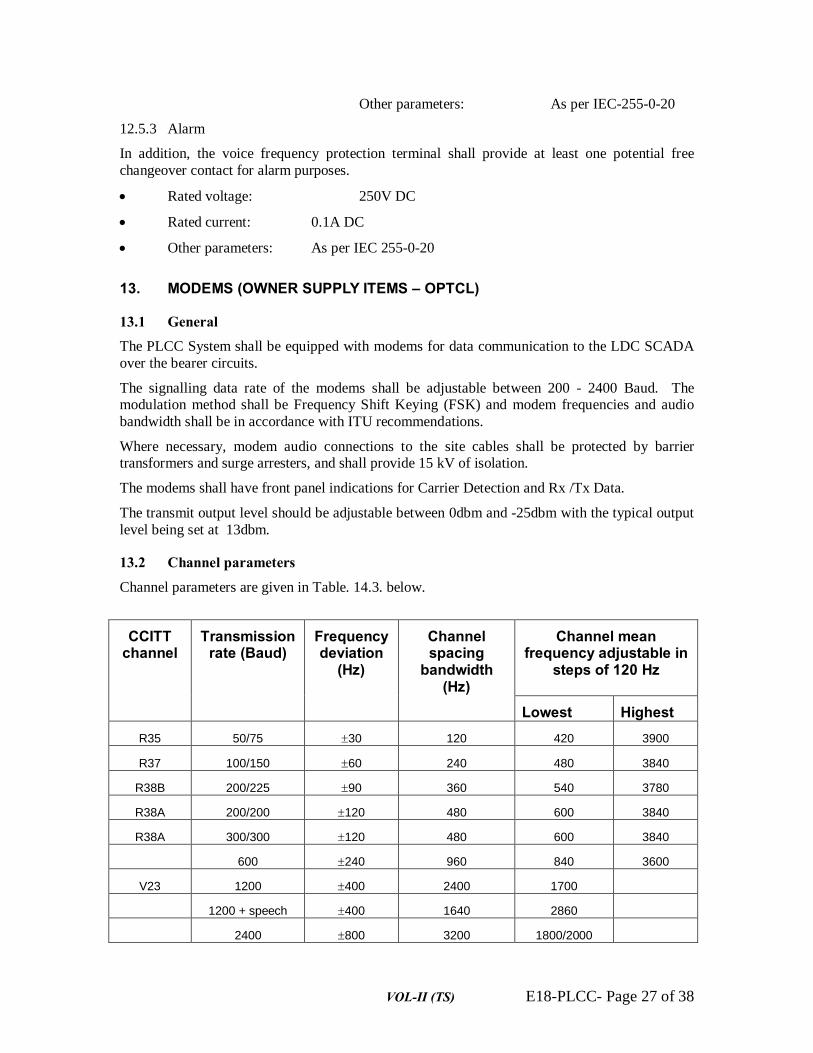
VOL-II (TS) E18-PLCC- Page 27 of 38
Other parameters: As per IEC-255-0-20
12.5.3 Alarm
In addition, the voice frequency protection terminal shall provide at least one potential free changeover contact for alarm purposes.
• Rated voltage: 250V DC
• Rated current: 0.1A DC
• Other parameters: As per IEC 255-0-20
13. MODEMS (OWNER SUPPLY ITEMS – OPTCL)
13.1 General The PLCC System shall be equipped with modems for data communication to the LDC SCADA over the bearer circuits.
The signalling data rate of the modems shall be adjustable between 200 - 2400 Baud. The modulation method shall be Frequency Shift Keying (FSK) and modem frequencies and audio bandwidth shall be in accordance with ITU recommendations.
Where necessary, modem audio connections to the site cables shall be protected by barrier transformers and surge arresters, and shall provide 15 kV of isolation.
The modems shall have front panel indications for Carrier Detection and Rx /Tx Data.
The transmit output level should be adjustable between 0dbm and -25dbm with the typical output level being set at 13dbm.
13.2 Channel parameters
Channel parameters are given in Table. 14.3. below.
CCITT channel
Transmission rate (Baud)
Frequency deviation
(Hz)
Channel spacing
bandwidth (Hz)
Channel mean frequency adjustable in
steps of 120 Hz
Lowest Highest R35 50/75 ±30 120 420 3900
R37 100/150 ±60 240 480 3840
R38B 200/225 ±90 360 540 3780
R38A 200/200 ±120 480 600 3840
R38A 300/300 ±120 480 600 3840
600 ±240 960 840 3600
V23 1200 ±400 2400 1700
1200 + speech ±400 1640 2860
2400 ±800 3200 1800/2000

VOL-II (TS) E18-PLCC- Page 28 of 38
Table. 14.3. Channel parameters
13.3 Fax equipment (To be supplied by the contractor)
The FAX equipment to be supplied shall be compatible to CCITT Group 3 and shall be of plain paper type . The equipment shall be suitable for operation with PLCC equipment as well as with PSTN telephone network. The equipment shall be suitable for operation with 230V single phase supply.
13.4 AC/DC distribution board (To be supplied by the contractor)
13.4.1 General
The Contractor shall provide and install power distribution boards for the PLCC equipment defined in the previous sections. The distribution boards shall distribute power to the equipment and protect against failures on feeder circuits supplying the equipment. The scope of supply shall include distribution boards, installation, cabling, conduit and all associated hardware and accessories required to provide power from the station auxiliary power supplies to the PLC equipment loads.
13.4.2 AC distribution boards
One AC distribution board shall he supplied at each control room/PLCC room for power distribution to the PLC loads. Each panel shall include a minimum of twenty (20) load distribution moulded case circuit breakers. Contractor shall co-ordinate breaker sizing and protection with the PLCC equipment.
13.4.3 DC distribution boards
Separate DC distribution boards shall be provided at each control Room/PLCC room. The DC distribution boards shall provide 48 volt DC power supplies to communication equipment.
DC distribution board shall be fitted with a main MCCB of bi polar type rated for 3,000A at 48V DC and a minimum of 20 manually operated, single pole, feeder circuit. The Contractor shall co-ordinate feeder breaker sizing and protection with the communication equipment. All breakers shall he fitted with magneto thermal tripping and shall comply with IEC 157-1.
14. TESTING AND MAINTENANCE EQUIPMENT (OWNER SUPPLY ITEMS – OPTCL) Besides the stipulations made elsewhere in this Specification the testing and maintenance equipment shall conform to following technical particulars. Each set of these equipment shall consist of one of the following items.
1. 200HZ to 620kHz Selective Level Meter (SLM) including impedance and return loss measuring attachments compatible with level generator (item 2 below).
2. Level Generator with a range of 50Hz to 620kHz including facility for synchronisation with SLM.
3. Eight digit time interval and frequency counter with a frequency range of 1Hz to 10MHz and timer range of one microsecond to one second in decade steps.
4. Dual trace 15MHz oscilloscope with a display screen 8 x 10 cm and input impedance of 1 Mohm/25 pF with a deflection co-efficient of 5mV/div to 20V/div.

VOL-II (TS) E18-PLCC- Page 29 of 38
5. Four and a half digit LCD Multimeter with an input impedance of 10 Mohm and a range of 0.1 mV to 1000V DC, 0.1 mV to 600V AC, 0-10A DC and 0-10A AC (40Hz to 10kHz) and 0 - 20 Mohm with built-in power-supply.
6. Print test kits for PLC terminal, E/M interface, and subscriber unit, protection coupler, EPAX etc..
15.
15.1 General
15.2 Factory tests to be performed on line traps
The following type tests in accordance with IEC 353 shall be performed on each type of line trap in presence of the Project Manager. Test reports shall be subject to the approval of the Project Manager before shipment of the equipment. The cost of doing each of these tests shall be indicat-ed in the relevant Schedule of the Bidding Document.
a) Measurement of inductance of the main coil
b) Measurement of temperature rise
c) Insulation tests
d) Short time current tests
The following additional type tests shall be conducted on line traps along with other type tests mentioned in IEC 353.
a) Corona extinction voltage test
b) Radio interference voltage measurement
Procedure for these tests shall be mutually agreed. Prices for these type tests shall be quoted in relevant Schedule of the Bidding Document.
The line traps shall be subject to routine tests as per IEC 353.
The Bidder shall furnish along with his Bid the reports of type and routine tests conducted on similar equipment earlier as per IEC 353.
15.3 Factory test requirements for coupling device The coupling device including the drainage coil, surge arrester and earthing switch shall conform to type tests and shall be subject to routine tests as per IEC 481/IS 8998.
Routine tests shall include but not be limited to the following :
• Composite loss and return loss tests on coupling device.
• Turns ratio test and insulation tests on the balancing transformer.
• Milli volt drop test, power frequency voltage test and mechanical operation test on earthing switch.
• Power frequency spark over test for lightning arrester as per relevant IS/IEC.
Bidder shall furnish along with his Bid copies of all type and routine test conducted earlier on similar coupling devices in accordance with relevant standards.

VOL-II (TS) E18-PLCC- Page 30 of 38
15.4 Factory test requirements for HF coaxial cables
The HF cable shall conform to type tests and be subjected to routine tests in accordance with IEC 96-2/BS 2316/IS 5802.
15.5 Factory tests on EPAX
The PAX shall be tested in accordance with the relevant CCITT Recommendations and IEC specifications. In addition, all the functions and features specified shall be tested.
15.6 List of commissioning tests on complete system
The following tests shall be carried out on complete system/subsystem during commissioning:
1. Composite loss and return loss on coupling device using dummy load.
2. Composite loss (attenuation) for HF cable coupling device.
3. End to end attenuation measurement for verification of optimum coupling mode. Test shall be done for all combinations.
4. End to end return loss for optimum coupling mode with.
• open behind line trap.
• grounded behind line trap.
5. If end to end return loss for optimum coupling mode is not satisfactory, same shall be measured for other coupling modes also.
6. Adjustment of Tx/Rx levels on PLC equipment as per test schedule.
7. AF frequency response (end to end) for the entire 4kHz bandwidth for speech and operation channels.
8. Measurement of noise in 2kHZ bandwidth with and without line energised.
9. SNR (test-one) with line energised noting down weather conditions.
10. Transmission time for teleprotection and other data channels.
11. Observation of Tx/Rx levels (test-tone) for each channel at both ends by sequential switching on/off parallel channels using dummy load and also with the transmission line.
12. Observation of end to end and trunk dialling performance.
13. Observation of end-to-end protection signalling (command sent and received) in conjunction with protective relays, noting down transmission/receipt of unwanted commands under switching operations in the switchyard during protective relay testing.
15.7 Notes on testing All measurements for link attenuation, composite loss and return loss shall be carried out for the entire range of carrier frequencies with specific attention to the frequencies as follows:
• Frequencies within coupling device bandwidth.
• Frequencies within line trap bandwidth
VOL-II (TS) E18-PLCC- Page 31 of 38
• Operating frequencies.
The following tests shall be carried out independently at each end:
• Composite loss and return loss for coupling device.
• Attenuation test for HF cable + coupling device.
• Levels and other local adjustments (on dummy load). Final adjustment shall be on end to end basis.
• Test for loading by parallel channels with dummy line load. This test can be done along with tests for coupling device.
• Protection signalling under local loop-test (dummy load).
All end to end tests shall require availability of healthy complete line for a duration of approximately 5 days.
Necessary test instruments required for all the above tests shall be brought by commissioning engineers of the contractor.
16. NOTES ON COMMUNICATIONS RELATED ASPECTS
16.1 General The OPTCL have proposed a unified telecommunications and control scheme. Under this scheme the State Load Despatch Centre at Bhubaneswar will be improved and four Sub-Load Despatch Centres will be established. An Interim Augmented Scheme has already been implemented to provide a limited capacity master station and a relatively small number of RTU outstations. A further interim development phase known as the Enhanced Interim Augmented Scheme (EIAS) is currently under examination.
Overall telecommunications planning has to be considered in relation to the complete transmission network. Services required between locations have to be decided as does the bandwidth they require. Transmission media and routing are then to be planned. Services at some stations require links not alone to the adjacent station but also tandem through other stations in the network, for instance SCADA or express speech to the SLDC. Some of the projects under PMU’s scope are included in the EIAS project. The EIAS project has already specified services required to specific locations in respect of :
• Conduction of condition survey in respect of existing PLC equipment, both outdoor and indoor removal of old equipment and addition of new equipment including reallocation of equipment wherever necessary/possible.
• Administrative telephone and fax network requirement and advanced PAX systems
• Express telephone requirement to SLDC/Sub-LDC
• Requisite SCADA data channel network (main/standby)
• Provision of settlement metering data channels only
• Provision of high capacity communication network
EIAS project however does not cover the following :
• Provision of protection couplers for lines under this package for 220 KV and 400 KV lines.
VOL-II (TS) E18-PLCC- Page 32 of 38
• Provision of EPAX for the sub-station:
• As indicated in the BPS sheet.
The scope of work under this contract and the facilities required in the network shall be broadly classified under the following heads.
1) Supply,erection,testing and commissioning of the equipments and materials at remote and new end of the sub-station(except indoor PLC panels, which is owner supply items).
2) The erection, testing,commissioning works at both new sub-station and remote end are to be taken care.
16.2 The administrative telephone network
The purpose of this network is to provide a means of non-urgent operational and/or administrative telephone speech or fax communication throughout the whole OPTCL. This scope includes supply and installation of equipment to sites which require the same.
This will comprise of a mesh of mainly PLC based telephone circuits between adjacent substations, each of which will require a EPAX to cater for telephones at that site, and the switching of incoming and outgoing calls.
It is required that these switches are configured so as to provide a "closed" numbering system, i.e. one in which each station and each telephone has a unique telephone number which can be accessed from anywhere else on the network by simply dialling its unique number, routing then being carried out automatically by the system. This numbering system is to be compatible with the national numbering scheme being developed by POWERGRID.
In order to support FAX traffic it is necessary that the full available bandwidth of the communications circuits is usable and therefore the Administrative telephone network cannot also support data, teleprinter or protection over its constituent circuits. It is planned that the teleprinter system wherever existing be allowed to run down, and that FAX facilities be used instead.
The administrative telephone network, being composed of short lines between adjacent substations, is to be completely supported on PLC circuits and has to be configured with a certain degree of interconnection so as to allow simultaneous calls to be set up over parallel routes in some cases, and to give some resilience against outages. Whenever possible existing PLC’s using modern equipment already in place shall be specified for this network. It shall be possible to extend the network detailed by the addition of extra lines and EPAX’s as necessary. Where optical fibre trunk routes have been specified for administrative speech channels, two or more such channels have been allowed.
At the outer edges of this network there are some less important substations which already have PLC circuits from an adjacent more important site. In these cases a single telephone is to be installed, configured as a 'long-line' extension from the EPAX at the larger site.
Where the remote site is also defined as providing metering data and only has a single channel existing PLC circuit then, rather than installing a separate PLC simply for infrequent use of metering data transfer, the ability to relay FAX traffic has been sacrificed and the data channel superimposed on the existing PLC with consequently reduced bandwidth for only speech.
The plan of the proposed administrative speech and fax network is shown in the sketches with this Specification. The existing /proposed PAX installation list is given in the relevant schedule.

VOL-II (TS) E18-PLCC- Page 33 of 38
16.3 The express speech to SLDC network(Owners supply)
In order to impose effective control, the SLDC will require rapid call set-up to its constituent substations and power stations. For this reason direct speech lines have been planned from the SLDC to each such site, but instead of each terminating on a separate telephone in the SLDC (as in the present SLDC) they will be presented on a communications console with key and lamp control.
The bandwidth of these circuits need not be as wide as that for the administrative network and hence the use of cut-off filters will allow the upper frequencies to be used for data transmission and/or teleprotection as necessary.
16.4 Data to the SLDC (owners supply)
The upper bandwidth of the express speech to the SLDC circuits will be used to carry the associated data from the RTU’s. By cutting off the speech band at 2.0 kHz a 200 baud data path can also be carried, as well as up to two 50 baud metering data channels and teleprotection as needed.
Where required for critical substations, it shall have two such 200 baud data channels to the SLDC and the all other substations have only one data channel. Whenever possible the routes of the main and standby data channels shall be different in order to maximise reliability and resilience.
The plan of the main and standby RTU data networks are shown in the schedules as is a list of the RTU’s giving their facilities and recommended sizes.
16.5 Settlement metering data (owners supply)
The OPTCL distribution system is to be divided into ten distribution 'circles' formed into four distribution 'groups'.
Settlement metering data will be required from the power stations, 400 kV supply points and the inter-state connectors as well as the distribution bulk supply points.
The groups, and the bulk supply points (BSPs) in each group have been decided but the geographic boundaries between the groups are not consistent with the boundaries between the future generation and transmission sub-LDC areas.
Settlement metering data comprising half hourly data on MW, MWhr, MVAR and MVArh is required, initially to be gathered at the SLDC but with facilities to allow the derived data to be available to the future distribution companies.
A metering data network operating at 50 baud will therefore be required. This is shown in the schedules.
This network is to be provided under this Contract. This will allow all distribution metering data to be available at the SLDC, and in due course when the distribution companies are in existence, data links from their respective offices to the SLDC will allow selected distribution metering data to be supplied to them as required.
16.6 Teleprotection (owners supply)
Teleprotection equipment already exists in OPTCL for the protection of most 400 KV AND 220 kV lines and some 132 kV lines.
The protection coupler requirements for 400kV , 220kV, and 132 kV levels have been shown in the schedules.

VOL-II (TS) E18-PLCC- Page 34 of 38
It is proposed that the same philosophy be adopted. Therefore all 400 KV and 220 kV lines will have teleprotection as well as the important 132 kV links.
16.7 Trunk networks (owners supply)
The requirements of the Load Despatch Communications network in the scope of EIAS cannot be met by PLC equipment alone. Therefore there will be an additional trunk network which will interconnect the proposed sub-LDCs and the SLDC. In addition a number of key power stations and substations have been included.
Scope of EIAS already covers the required communications between the SLDC and the future sub-LDC’s. There will be a full network of high capacity optical fibre links/microwave between these sites. These are shown in schedules. While designing the PLC network under the present scope of work these high capacity communication networks shall be kept in view and shall be utilised wherever possible.

VOL-II (TS) E19-DISTRIBUTION BOARD- Page 1 / 26
ODISHA POWER TRANSMISSION CORPORATION LIMITED
TECHNICAL SPECIFICATION
FOR
DISTRUBUTION BOARDS
1) ACDB 2) DCDB 3) OTHER CONSOLES INCLUDING BMK

VOL-II (TS) E19-DISTRIBUTION BOARD- Page 2 / 26
1) TECHNICAL SPECIFICATION FOR DISTRIBUTION BOARDS
General
Requirements of AC and DC systems The electrical auxiliary systems shall be of a quality commensurate with the performance, reliability and availability requirements of the substation. The electrical station services shall be in accordance with all the relevant standards, shall satisfy the requirements specified herein and shall be designed to operate in the environmental conditions specified in the relevant sections of this Specification. The electrical station systems shall be required to provide the voltage classes indicated in Table 1.1. for operation of various plant equipment operating mechanisms, plants, control and communication systems
Nominal Voltage V
Tolerance Frequency Hz or DC
Phases Wires Neutral Connection
430 ±10% 50±5% 3 4 Solidly earthed 240 ±10% 50±5% 1 2 Solidly earthed 220 187V to 242V DC DC 2 Isolated 2 wires 50 ±10% DC DC 2 +ve earthed
Table 1.1. Voltage classes The auxiliaries shall be capable of withstanding all over frequency and undervoltage conditions without loss of supply to the power circuits or shutdown of any auxiliary system meeting the essential loads of the substation plant and equipment.
Configuration The basic design of the substation electrical auxiliary services shall be as shown in the schematic drawing. This drawing is for guidance only and the Contractor may propose an alternative keeping in view the design philosophy stipulated in this section of the Specification. The design philosophy for auxiliary supply systems shall be as follows:
a) The AC supply for station auxiliary systems shall generally be obtained from a single source from the local distribution network having a track record of good power availability. For 400/220kV substations two separate sources shall be used.
b) Where 11kV or 33kV busbars are available at the substation site station auxiliary transformers shall be installed to provide reliable auxiliary power supplies. At least two auxiliary transformers of a rating sufficient to feed the substation load shall be installed. Where specified, in order to meet the station essential loads a back-up supply from a standby diesel generator set shall be provided. The requirement of diesel generator sets have been indicated in the bill of quantity of relevant schedules.
c) The Contractor shall estimate loads of the substation and determine the required capacity of station auxiliary transformers and diesel generator set and submit same for the approval of the Project Manager. The contractor shall classify the loads based on the principles defined in the following clauses.
VOL-II (TS) E19-DISTRIBUTION BOARD- Page 3 / 26
Load Classes
Essential loads These are loads whose failure will affect the capability of the station and station plant and equipment. These loads shall include cooling and other auxiliaries of transformers and reactors, non-interruptible power units, auxiliaries of reactive power compensator, and station services of the relays in the substation.
Emergency loads These are loads that must remain in service during complete loss of the ac power supply. These loads shall include the station battery chargers, disconnecting switch and circuit breaker operating mechanisms, control room air-conditioning and the emergency lighting of the switchyard and control building. Some emergency loads operate on ac voltage and the others on dc voltage.
Normal loads These loads, whose failure does not affect capability, shall include but not be limited to control building and switchyard lighting, control building air-conditioning except in control room, air compressors, normal and fire-fighting water pumps, oil treatment loads, etc.
Basic design criteria The failure or the disconnection for maintenance of any motor, feeder, motor control centre, or 415V power centre or auxiliary transformer shall not affect the power transmission capability of the substation. To achieve the above criteria, the following facilities shall be incorporated, by the Contractor, in the design of the auxiliary systems :
1. Highly reliable duplicate primary supply sources, with automatic change-over facilities.
2. Duplicate essential loads (e.g. cooling pumps, fans, heat exchangers, etc.). Duplicated loads shall be supplied from two different 430VAC distribution boards (ACDB). Essential loads which are not duplicated shall have duplicated supply circuits with the source having auto change over facility.
3. Provision of a diesel generator set for the essential loads. The generator shall start up automatically, in case of loss of all normal and stand by supplies, to feed the essential loads and emergency loads. 4. In order to limit fault currents, to prevent back feed into the AC bus, and to ensure independence of supply sources, parallel operation between station service transformers shall not be permitted at any voltage level. Also parallel operation shall not be permitted between transformers and diesel generator. 5. System shall be clear and simple to operate to minimise the risk of loss of supply due to human error. 6. The Contractor shall design the LV distribution system to ensure that the voltage supply limits are maintained at all times and that the switchboards and cabling are never overloaded. On larger stations it may be necessary to supply more than one main LVAC switchboard.
415V AC distribution system
General The 430V secondary distribution system shall comprise 430V power centres serving the different classes of loads either directly or through motor control centres. Each power centre shall consist of two sections, supplied through two station service transformers of adequate capacity. Each transformer and each section of the 430V power centre shall be designed to carry the total load of both sections. The two sections shall be interconnected through normally open bus tie breakers and normally closed fuse disconnects. An automatic transfer scheme shall be incorporated within each power centre. This transfer

VOL-II (TS) E19-DISTRIBUTION BOARD- Page 4 / 26
scheme shall automatically disconnect the voltage deficient bus and then re-energise it from the healthy bus. Restoration of normal supply conditions shall automatically return the power centre to the normal operating mode. The 430V power centres shall be of the metal enclosed switchgear type according to the relevant IEC or Indian Standards.
AC distribution board. The ACDB’s shall be in accordance with the relevant IEC or Indian Standards and shall also comply with the following requirements:
• The MCC shall be located near the supplied loads or inside the control room at a suitable place.
• The circuit breakers of the MCC shall be individually interlocked to prevent paralleling of two different power centre buses.
• The 240V loads shall be supplied by 240V panels located in the MCC or outside the MCC where it is required.
Supply of essential loads Essential loads shall be fed from ACDB-1 and ACDB-2 respectively. A diesel generator set shall be connected as indicated in schematic drawing so as to meet the complete requirement of the essential loads of the substations. ACDB’s shall be independently fed from two different sections of the main distribution board.
Supply of emergency loads The emergency loads shall also be supplied from essential bus ACDB-1, ACDB-2, 220V DCDB-1 and 220V DCDB-2, and 50V DCDB-1 and DCDB-2 as shown in the schematic drawing.. These loads shall be supplied from the two different buses under duplicate supply philosophy. Switchyard bay kiosks shall be fed from the two different buses alternatively and interconnected locally with auto changeover switches. Power supply to equipment operating Mechanisms shall be fed from the respective bay kiosks.
Supply of normal loads Normal loads shall be fed through motor control centres connected with two cables to two different sections of the 415V power distribution centres. A manual change-over switch shall be installed in each MCC, so that the supply is not lost in case of maintenance of one section of the 415V power centre or for a fault. These MCC shall also supply the lighting and small single-phase loads through 240V lighting or distribution panels, located in the MCC and all over the substation. Some loads, such as switchyard lighting and air-conditioning of the control buildings, normal and fire-fighting water pumps, shall be supplied by duplicate feeders so as not to interrupt working in case of maintenance of one of the sections of the power centre. For oil treatment and welding, special service outlets shall be provided in local 415V motor control or distribution centres.
2.0 LVAC supplies and equipment
General Switchboards shall be of the free standing design, suitable for mounting directly above the cable trenches laid inside the control room. Cable trench walls shall be flush with the control room floor. Switchboards shall be suitable for terminating all incoming and outgoing cables and will normally be of the bottom rear entry type, generally in accordance with IEC 947 and 439 and of metal clad design arranged for drawout isolation. Switchboards shall be equipped with circuit breakers and moulded case or miniature circuit breakers. The use of fuse switches will not be permitted.

VOL-II (TS) E19-DISTRIBUTION BOARD- Page 5 / 26
LVAC scheme
General requirement The 415V incoming supplies shall be derived from the station auxiliary transformers or in the case of a loss of supplies, from the standby diesel generator where ever applicable. The two incoming supplies shall be interlocked to ensure that only one of the two circuit breakers can be closed at any one time. Where a bus section circuit breaker is provided it shall also be suitably interlocked to prevent the station auxiliary transformer from being backfed.
Main distribution board The two sections of the main distribution board shall be supplied from separate station auxiliary transformers. The two sections shall have automatic change over facilities in the event of failure of supply from one source. Each section of the board shall feed the following panels:
• Main lighting distribution board
• Fire fighting pump house.
• AC and ventilation plant • Maintenance equipment and oil treatment plant supplies.
AC distribution board This shall comprise two sections each of which shall be supplied through different cables from both sections of the main distribution board. Each sections shall be equipped with a back up feed from the standby diesel generator set with automatic change-over facility to generator in the event of loss of supply from the main distribution board. The AC distribution board shall supply the following loads:
• Control room supply for panels, computers, etc..
• One section of the 220V battery charger / rectifier.
• One section of the 50V battery charger / rectifier .
• 50% of switchyard bay marshalling kiosks.
• Emergency AC lighting system.
• Transformers and reactors (cooling devices and OLTC panels)
• Fire water and civic water pumps
• Spare feeders for future use.
Main lighting distribution board The main lighting distribution board shall receive incoming supplies from the two sections of the main distribution board as well as a supply from the diesel generator set. This board shall be further connected to lighting panels through a lighting sub-distribution panel. The panel supplying emergency lighting load and the income from the diesel generator shall be equipped to switch on in the event of failure of supply from the primary source.
3.0 Construction
Panels For indoor applications the switchboards shall be of the cubicle pattern, each circuit being self contained within its own cubicle (compartmentalised type). An access door shall be provided for each cubicle such that access can only be obtained to individual circuits. Circuits shall be segregated one from the other by earthed metal. For outdoor installation they shall be of multi-box construction.

VOL-II (TS) E19-DISTRIBUTION BOARD- Page 6 / 26
Sheet steel for fabrication of the panels shall be a minimum of 2 mm thick cold rolled grain oriented sheet steel or 2.5 mm hot rolled sheet steel. All panel edges and cover/door edges shall be reinforced against distortion by rolling, bending or by the addition of welded reinforcement members.
Switchboard Switchboards shall be vermin proof and suitable for use in a tropical climate. All ventilating louvers shall be covered with a fine mesh from inside. All switchboards shall be provided with a degree of protection of IP 52 as per IEC 947 or equivalent Indian standard. Provision shall be made in all compartments for providing IP 52 degree of protection, when circuit breaker or module trolley, has been removed. Switchboards shall be of uniform height and shall not exceeding 2450 mm. Switchboards shall be easily extendible on both sides, by the addition of the vertical sections after removing the end covers. All switchboards shall be divided into distinct vertical sections, each comprising:
1. A completely enclosed busbar compartment for horizontal and vertical busbars. Busbar chamber shall be completely enclosed with metallic partitions. Bolted covers shall be provided for access to horizontal and vertical busbars and all joints for repair and maintenance. Access shall be possible without disturbing feeder compartment.
2. Completely enclosed switchgear compartment(s), one for each circuit for housing circuit breaker or motor starter.
3. A compartment or alley for power and control cables. Cable alley door shall preferably be hinged. Cable alley shall have no exposed live parts, and shall have no communication with busbar chamber. 4. A compartment for relays and other control devices associated with a circuit breaker.
All access doors shall be provided with facilities for locking in the closed position. It shall be possible to move each circuit breaker or MCCB to the disconnected position without the need to open the cubicle access door. Attempted disconnection of a circuit breaker or MCCB when in the closed position shall not result in tripping of the particular equipment.
4.0 Cubicle Cubicles may be arranged vertically in tiers, the number being limited only by the need to ensure that circuits are thermally independent. It shall be possible to work within each cubicle with the equipment withdrawn whilst the incoming contacts are energised. The minimum requirements for protection shall be:
• Insulating barriers installed between phases within the cubicle.
• An insulating cover to be affixed over the protruding feeder and busbar connections when the equipment is withdrawn. Where this is not available, protection shall be provided by automatically operated shutters. It shall be possible to open the shutters intentionally, against spring pressure for testing purpose. Each phase of the down dropper connections from the busbars to the equipment isolating contacts shall be separated from the incoming or outgoing connections and from the other phases by barriers. Cubicles shall be suitable for terminating all necessary cabling whether of copper or aluminium conductor design. It shall be possible to terminate any cable whilst adjacent circuits are energised.
5.0 Busbar and other equipment housing All incoming connections, busbars and feeder connections up to the particular MCCB shall be capable of the short time current rating specified, but connections beyond the MCCB need only be matched to the MCCB characteristic.

VOL-II (TS) E19-DISTRIBUTION BOARD- Page 7 / 26
The overall height of each tier of cubicles shall be such that the operating handles of all equipment are within the reach of a person standing at ground level. Control switches as specified shall be fitted and suitably labelled to indicate their function. The equipment shall be complete with cable boxes and glands suitable for XLPE or PVC insulated cables. The switchboard shall be provided with 240V single phase ac illumination and anti-condensation space heaters and each heater shall be provided with an ON/OFF switch. Sheet steel barriers shall be provided between two adjacent vertical panels running to the full height of the switchboard, except for the horizontal busbar compartment. Each shipping section shall have full metal sheets at both ends for transport and storage. All equipment associated with a single circuit shall be housed in a separate compartment of the vertical section. The compartment shall be sheet steel enclosed on all sides with the with-drawable units in position or removed. The front of the compartment shall be provided with a hinged single leaf door complete with locking facilities. The main switch shall be operable from outside and will be interlocked with the compartment door such that the latter can be opened only when the switch is off. However, it shall be possible to defeat this interlock and open and close the door with the switch ON. The main switch shall have the facility of being pad-locked in both ON and OFF positions. The switch handle shall clearly indicate the position of main switch. After isolation of power and control circuit connections it shall be possible to safely carry out maintenance in a compartment with the busbar and adjacent circuit live. Necessary shrouding arrangement shall be provided for this purpose over the cable termination located in cable alley. The temperature rise of horizontal and vertical busbars when carrying rated current along its full run shall in no case exceed 55C, with silver plated joints and 40C with all other type of joints over an outside ambient temperature of 50C. All single front switchboards shall be provided with removable bolted covers at the rear. The covers shall be provided with danger labels. All identical circuit breakers and module chassis of same test size shall be fully interchangeable without having to carry out modifications. All 415V switchgear cubicles shall be of single front type, with fully withdrawable circuit breakers, which can be drawn out without having to unscrew any connections. The circuit breakers shall be mounted on rollers and guides for smooth movement between SERVICE, TEST and ISOLATED positions and for withdrawal from the switchboard. Testing of the breaker shall be possible in the TEST position. Wherever two breaker compartments are provided in the same vertical section, insulating barriers and shrouds shall be provided in the rear cable compartment to prevent accidental contact with the live parts of one circuit when working on the other circuit. All disconnecting contacts for power circuits shall be of robust design and fully self aligning. Fixed and moving contacts of the power drawout contact system shall be silver plated. Both fixed and moving contacts shall be replaceable. All modules shall be fixed type except circuit breaker and motor feeder modules, which shall be drawout type. The connections from busbars to the main switch shall be fully insulated/shrouded, and securely bolted. The partition between the feeder compartment and cable alley may be non-metallic and shall be of such construction as to allow cable cores with lugs to be easily inserted in the feeder compartment for termination. All equipment and components shall be neatly arranged and shall be easily accessible for operation and maintenance. The internal layout of all modules shall be subject to approval of the Project Manager. All sheet metalwork shall be painted in accordance with the painting clause specified elsewhere in this Specification. The shade of the paint shall be 692 as per IS 5 (smoke grey).
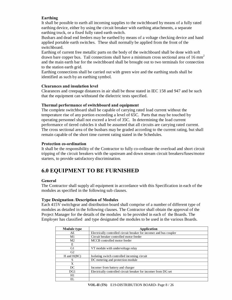
VOL-II (TS) E19-DISTRIBUTION BOARD- Page 8 / 26
Earthing It shall be possible to earth all incoming supplies to the switchboard by means of a fully rated earthing device, either by using the circuit breaker with earthing attachments, a separate earthing truck, or a fixed fully rated earth switch. Busbars and dead end feeders may be earthed by means of a voltage checking device and hand applied portable earth switches. These shall normally be applied from the front of the switchboard. Earthing of current free metallic parts on the body of the switchboard shall be done with soft drawn bare copper bus. Tail connections shall have a minimum cross sectional area of 16 mm2 and the main earth bar for the switchboard shall be brought out to two terminals for connection to the station earth grid. Earthing connections shall be carried out with green wire and the earthing studs shall be identified as such by an earthing symbol.
Clearances and insulation level Clearances and creepage distances in air shall be those stated in IEC 158 and 947 and be such that the equipment can withstand the dielectric tests specified.
Thermal performance of switchboard and equipment The complete switchboard shall be capable of carrying rated load current without the temperature rise of any portion exceeding a level of 65C. Parts that may be touched by operating personnel shall not exceed a level of 35C. In determining the load current performance of tiered cubicles it shall be assumed that all circuits are carrying rated current. The cross sectional area of the busbars may be graded according to the current rating, but shall remain capable of the short time current rating stated in the Schedules.
Protection co-ordination It shall be the responsibility of the Contractor to fully co-ordinate the overload and short circuit tripping of the circuit breakers with the upstream and down stream circuit breakers/fuses/motor starters, to provide satisfactory discrimination.
6.0 EQUIPMENT TO BE FURNISHED
General The Contractor shall supply all equipment in accordance with this Specification in each of the modules as specified in the following sub clauses.
Type Designation /Description of Modules Each 415V switchgear and distribution board shall comprise of a number of different type of modules as detailed in the following clauses. The Contractor shall obtain the approval of the Project Manager for the details of the modules to be provided in each of the Boards. The Employer has classified and type designated the modules to be used in the various Boards.
Module type Application AE Electrically controlled circuit breaker for incomer and bus coupler M1 Circuit breaker controlled motor feeder M2 MCCB controlled motor feeder E
G1 VT module with undervoltage relay G2
H and H(BC) Isolating switch controlled incoming circuit S DC metering and protection module X
DC Incomer from battery and charger DG1 Electrically controlled circuit breaker for incomer from DG set H1 EL
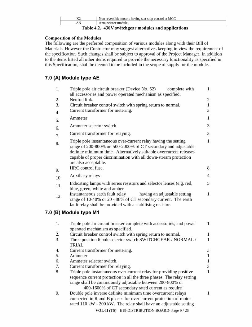
VOL-II (TS) E19-DISTRIBUTION BOARD- Page 9 / 26
K2 Non reversible motors having star stop control at MCC AN Annunciator module
Table 4.2. 430V switchgear modules and applications
Composition of the Modules The following are the preferred composition of various modules along with their Bill of Materials. However the Contractor may suggest alternatives keeping in view the requirement of the specification. Such changes shall be subject to approval of the Project Manager. In addition to the items listed all other items required to provide the necessary functionality as specified in this Specification, shall be deemed to be included in the scope of supply for the module.
7.0 (A) Module type AE
1. Triple pole air circuit breaker (Device No. 52) complete with all accessories and power operated mechanism as specified.
1
2. Neutral link. 2 3. Circuit breaker control switch with spring return to normal. 1 4. Current transformer for metering. 3
5. Ammeter 1
6. Ammeter selector switch. 3
7. Current transformer for relaying. 3
8. Triple pole instantaneous over-current relay having the setting range of 200-800% or 500-2000% of CT secondary and adjustable definite minimum time. Alternatively suitable overcurrent releases capable of proper discrimination with all down-stream protection are also acceptable.
1
9. HRC control fuse. 8
10. Auxiliary relays 4
11. Indicating lamps with series resistors and selector lenses (e.g. red, blue, green, white and amber
5
12. Instantaneous earth fault relay having an adjustable setting range of 10-40% or 20 - 88% of CT secondary current. The earth fault relay shall be provided with a stabilising resistor.
1
7.0 (B) Module type M1
1. Triple pole air circuit breaker complete with accessories, and power operated mechanism as specified.
1
2. Circuit breaker control switch with spring return to normal. 1 3. Three position 6 pole selector switch SWITCHGEAR / NORMAL /
TRIAL. 1
4. Current transformer for metering. 3 5. Ammeter 1 6. Ammeter selector switch. 1 7. Current transformer for relaying. 3 8. Triple pole instantaneous over-current relay for providing positive
sequence current protection in all the three phases. The relay setting range shall be continuously adjustable between 200-800% or 400-1600% of CT secondary rated current as require
1
9. Double pole inverse definite minimum time overcurrent relays connected in R and B phases for over current protection of motor rated 110 kW - 200 kW. The relay shall have an adjustable setting
1

VOL-II (TS) E19-DISTRIBUTION BOARD- Page 10 / 26
range of 50% - 200% of CT secondary current and time setting range of 0-30 seconds. The relay shall be CDGM-22 (GEC Alsthom) or equivalent.
10. Single pole adjustable definite time delay relay for motor overload alarm connected in Y-phase only. The relay shall have resetting ratio of not less than 90%. The relay shall have continuously adjustable time delay range of 2.5 to 25 seconds.
1
11. Instantaneous earth fault relay having an adjustable setting range of 10-40% or 20-80% of CT secondary current. The earth fault relay shall be provided with a stabilising resistor.
1
12. Auxiliary relays 4 13. Indicating lamps with resistors and coloured lenses suitable for
220V DC. - 5
14. HRC control fuses. 8
7.0 (C) Module type M2
1. 415V, 250A, P2 duty 20 kA, 50 Hz MCCB having 4 NO and 4 NC Aux. contacts.
1
2. Auxiliary relays 1 3. Indicating lamps with resistors and coloured lenses suitable for
240V AC. 3
7.1 Module type E
1. Triple pole load break isolating switch 1 2. Neutral link 1 3. HRC fuses 3
7.2 Module type G1
1. (415/√3)/ (110/√3) volts single phase voltage transformer star/star connected with star point solidly earthed mounted on common draw out chassis. Accuracy Class 0.5 for protection and metering with 50VA burden.
3
2. HRC Fuses mounted on the above chassis. 6 3. Four position voltmeter selector switch. 1 4. Voltmeter (0-500V) 1 5. Double pole instantaneous undervoltage relays with continuous
variable setting range of 40-80% of 110 Volts. 1
6. Time delay pick up relay having a time setting range of 0.5 to 3 seconds. With 3 NO self reset contacts, suitable for 220V DC.
1
7. Auxiliary relay 220V DC with 2 NO. self reset contacts. 1 8. Indicating lamps with series resistor and colour lenses (Red, blue
and yellow). 3
7.3 Module type G2
1. HRC Fuse 3 2. Voltmeter (0-500V) 1 3. Voltmeter selector switch four position (R-Y, Y-B, B-R OFF). 1 4. Indication lamps (Red, blue and yellow) 3
7.4 Module type H and H (BC)
1. Triple pole load break isolating switch with padlocking facility in 1

VOL-II (TS) E19-DISTRIBUTION BOARD- Page 11 / 26
OFF position and arrangement to defeat door interlocking 2. Neutral link. 1 3. Red indicating lamp to indicate isolating switch closed position. 1
7.5 Module type S
1. Voltmeter 0-300V DC for 220V DC DB 1 2. Voltmeter 0-75V DC for 50V DCDB. 1 3. Three (3) position voltmeter selector switch 1 4. Instantaneous under voltage relay with 95% of 220V DC. The
resetting ratio of relay of relay should not be more than 1.25. The relay shall be provided with a series resistor and a push button across if for resetting (pick up) the relay at about 105% of the drop out voltage.
1
5. Instantaneous over voltage relay with setting range of 110% of 220V DC. The resetting ratio of relay should not be less than 0.8. The relay shall have a push button in series capable of resetting the relay at about 95% of the operating voltage.
1
6. Earth leakage relay only for 220V DC system having adjustable pick up range between 3 to 7 milliamps the relay shall be suitable for 220V DC/240V AC Auxiliary supply.
1
7. Indicating lamp each for fault annunciation and for 220V DC with earth leakage relay mentioned above.
2
8. HRC control fuses. 2
7.6 Module type X 1. Double pole single throw 250V DC air break isolating switch. 1 2. HRC fuses 2
7.7 Module type DC (Incomer from battery and chargers)
1. HRC fuses for incomer from battery. 2 2. DC ammeter with shunt and range of 40-0-50 Amps. For 220V
DC DB and 60-0-150 Amp for 50V DC DB. 1
3. Double pole single throw 250V DC air break switch. 2 4. HRC fuses for incomer from charger. 2 5. Double pole single throw 250V DC air break switch connecting
battery and charger sections to DCDB 1
7.8 Module type DG1
1. Triple pole circuit breaker complete with all accessories and power operated mechanism as per the relevant sections of this Specification.
1
2. Frequency meter. 1
3. Voltmeter with selector switch. 1
4. Remote/Local selector switch. 1
5. Circuit breaker control switch with spring return to normal. 1
6. Current transformer for metering. 3
7. Current transformers for differential protection (out of this 3 Nos. will be supplied loose for mounting in DG set panel).
6
8. Current transformer for relaying. 3
9. HRC Control fuses 8
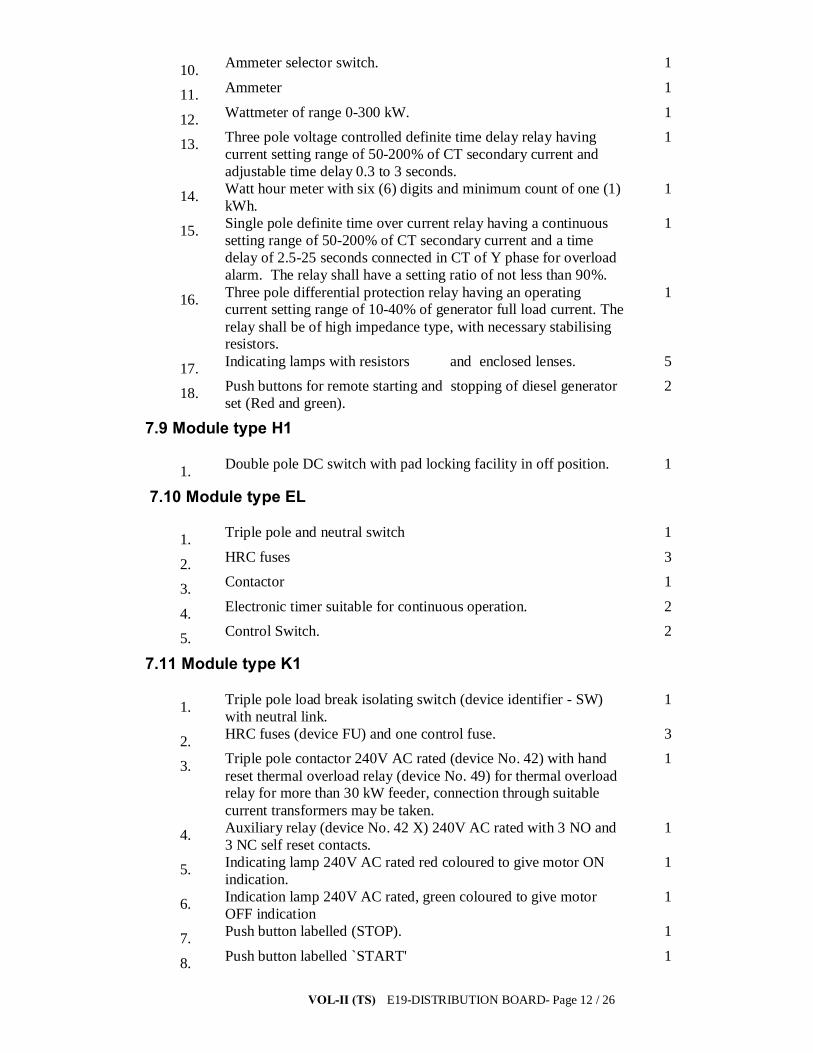
VOL-II (TS) E19-DISTRIBUTION BOARD- Page 12 / 26
10. Ammeter selector switch. 1
11. Ammeter 1
12. Wattmeter of range 0-300 kW. 1
13. Three pole voltage controlled definite time delay relay having current setting range of 50-200% of CT secondary current and adjustable time delay 0.3 to 3 seconds.
1
14. Watt hour meter with six (6) digits and minimum count of one (1) kWh.
1
15. Single pole definite time over current relay having a continuous setting range of 50-200% of CT secondary current and a time delay of 2.5-25 seconds connected in CT of Y phase for overload alarm. The relay shall have a setting ratio of not less than 90%.
1
16. Three pole differential protection relay having an operating current setting range of 10-40% of generator full load current. The relay shall be of high impedance type, with necessary stabilising resistors.
1
17. Indicating lamps with resistors and enclosed lenses. 5
18. Push buttons for remote starting and stopping of diesel generator set (Red and green).
2
7.9 Module type H1
1. Double pole DC switch with pad locking facility in off position. 1
7.10 Module type EL
1. Triple pole and neutral switch 1
2. HRC fuses 3
3. Contactor 1
4. Electronic timer suitable for continuous operation. 2
5. Control Switch. 2
7.11 Module type K1
1. Triple pole load break isolating switch (device identifier - SW) with neutral link.
1
2. HRC fuses (device FU) and one control fuse. 3
3. Triple pole contactor 240V AC rated (device No. 42) with hand reset thermal overload relay (device No. 49) for thermal overload relay for more than 30 kW feeder, connection through suitable current transformers may be taken.
1
4. Auxiliary relay (device No. 42 X) 240V AC rated with 3 NO and 3 NC self reset contacts.
1
5. Indicating lamp 240V AC rated red coloured to give motor ON indication.
1
6. Indication lamp 240V AC rated, green coloured to give motor OFF indication
1
7. Push button labelled (STOP). 1
8. Push button labelled `START' 1

VOL-II (TS) E19-DISTRIBUTION BOARD- Page 13 / 26
9. Switch fuse unit for space heater supply for motors rated 30 kW and above.
1
10. Current transformer and an ammeter for all motors rated 50 kW and above.
1
7.12 Module type K2 (mounted at motor) 1. Triple pole load break isolating switch with neutral link. 1
2. HRC fuses and one (1) Control fuse 3
3. Triple pole contactor rated for 240V AC 1
4. Indicating lamp 240V AC rated red/green coloured to give ON/OFF indication.
2
5. Push button labelled STOP 1
6. Push button labelled START 1
7.13 Module type DG- ( mounted at generator)
1. Indicating lamps 9
2. Push buttons 7
3. DC Ammeter (0-40A) 1
4. DC Voltmeter (0-30V) 1
5. Voltmeter selector switch 1
6. AC ammeter 1
7. AC voltmeter 1
8. Timers (24V DC) 3
9. Auto/Manual selector switch 2
10. Auto/test/Manual selector switch 2
11. CT's for metering 3
12. PS class CT's for differential protection of diesel generator set
3
13. Auxiliary contactors suitable for 24V DC 11
14. Motorised potentiometer for voltage adjustment 1
15. Battery charger as per clause no Error! Reference source not found. of this section
1
16. HRC control fuses 12
17. Set of phase and neutral busbars. 1
Module type AN (Annunciation module) Where an integrated PC based system is not provided at the substation a central alarm annunciator shall be provided for the auxiliary power systems. The annunciation system shall consist of 30 annunciator units each having an engraved translucent plastic window of 35 mm x 50 mm (minimum) size. Engraving shall be black letters and indicate the alarm function. Annunciators shall be suitable for operation on 220V DC and shall have a single common audible alarm. Push buttons with appropriate nameplates shall be provided for audible alarm acknowledge, alarm reset and lamp test. The push buttons shall be common to all alarm points. Annunciators

VOL-II (TS) E19-DISTRIBUTION BOARD- Page 14 / 26
shall be suitable for operation with both normally open and normally closed alarm contacts. Annunciation system shall be solid state type of reputed make. On receiving any alarm pulse, including fleeting pulses, the appropriate alarm relay shall pick up energising the corresponding visible and audible alarm units. It shall be possible for the operator to reset the audible alarm even if the alarm condition persists. However, visible alarm shall not reset unless the alarm condition has disappeared and the reset push button is operated. Annunciator shall provide sealed in lamp indication and audible alarm shall be ready to operate for any new alarm condition immediately after the alarm is reset push button. Annunciator shall operate satisfactorily between 80% and 110% of rated supply voltage.
Module equipment and instrumentation. Circuit breakers, MCCB’s, MCB’s, selector switches, instrumentation, relays and protection equipment for LV supplies etc. shall generally conform to the requirement of the stipulated under relevant sections of this Specification. 7.14 TECHNICAL SPECIFICATION FOR INDOOR TYPE 415/240 V.A.C POWER
DISTRIBUTION SWITCH BOARDS. 7.14.1 SCOPE
The specification covers manufacture, assembly and testing at manufacturer’s Works, supply and delivery at site of Indoor and out door type 415/240 volts A.C. power distribution switch-boards, A.C consoles, Bay Marshalling Kiosk ,Receptacle panels complete in all respects as per system requirement for S/S and switchyards 20% spare feeders shall be provided in each Distribution Boards. 7.14.2 STANDARDS
The equipment covered by this specification shall unless otherwise specified be built to conform to Indian Electricity Rule 2956 wherever applicable and shall satisfy the requirements of the latest Indian Standard. Permissible temperature rise shall be as per relevant ISS.
7.14.3 SWITCH BOARD DESIGN The switch board shall be self supporting, steel cubicle, compartmentalized, fully enclosed with doors for access to the interior. The switch boards shall comprise a non/draw out type panels placed side by side to form a continuous unit with access door for each panel at the rear 3 mm sheet shall be used for fabrication of the panels. Modular type construction for inter-changeability will be preferred. The complete panels shall not be more than 2450 mm. high with the channel base and 500 mm. depth measured form rear to front faces and of suitable with. The working height shall be limited to maximum 2200 mm. The design shall be such as to permit extension at site on either end. The bottom of the switch board frame shall be suitable for erecting flush on concrete floor by securing it by means of evenly spaced grouting bolts projecting through the base channels. The panels shall be designed to facilitate cable entry from the bottom and removable plates shall be supplied along with the panels for this purpose which will be drilled at site to fit the cable glands. The switchboard shall be vermin proof and suitable for use in tropical climate. All ventilating louvers and holes shall be covered with fine wire mesh from inside (for indoor use). All control and power cables will be laid in open distribution trenches running under the A.C. switchboards. The cable will enter the cubicles through entry holes of removable plates provided at the bottom of the cubicles. The cable entry holes required and the position of the foundation bolts. The switchboards shall be supplied complete with channel base, removable bottom plates grouting bolts, lock nuts, washer, etc. and cable glands as specified hereafter. All unfinished surfaces of the steel panels and frame work shall be free from adhesive matter or greases. A suitable rust resisting primer paint shall be applied on the interior and exterior surface of the steel housing allowed by application of an undercoat to serve as base and binder for the finishing coat. The finishing coat on the exterior of the switchboards shall be polished

VOL-II (TS) E19-DISTRIBUTION BOARD- Page 15 / 26
cellulose enamel or dark batter ship grey, evenly sprayed to present a fine appearance while the interior faces shall be sprayed with a finishing coat of light grey paint to provide contrasting background for the wiring inside the cubicle.The internal illumination for working should be of adequate intensity CFL lamps. A small quantity of finishing paint shall be supplied with the consignment of the Switchboards to enable the employer to restore at site any surface finish which may get damaged during transit.
7.14.4 BUS BARS
The bus bars shall be of E.G. copper/aluminum alloy, liberally sized for the specific current ratings (both short circuit and continuous currents). The size of the bus bars shall be such that the current density is not more than 1A/1.75 A per sq.mm. for aluminum alloy and copper respectively at rated capacity. Necessary precaution shall be taken to avoid bimetallic action where copper conductors shall be connected to the aluminum bus. Means shall be provided for identifying various phases of bus bars. Bus support shall be of arc resistant, non-tracking, low absorption type insulators of high impact strength and high creepage surface. Buses shall be spaced with adequate clearance between phases and phases to ground. The bus and connections shall be so supported as to be capable of safety withstanding stresses due to maximum short circuit current and also take care of any thermal expansion. The droppers/riser from or to the bus bars should not be twisted but reasonable bend or joint may be allowed. The bidder shall sbsrish necessary calculations about the adequacy of sleeted bus suyyrot insulator cantilever sireugth w.r to short cicess forces.
7.14.5 AIR CIRCUIT BREAKER FOR INCOMER
A.C. air circuit breaker shall be triple pole, non-draw out type, suitable for 1100 volts grade/650 volts grade service, having continuous current carrying capacity of 400 Amps with breaking capacity of 20 KA at 415 volts. The breaker shall be provided with trip free manually operated mechanism and a push butter to trip the breaker electrically.
The breaker shall be provided with mechanical OFF/ON indicators. The breaker shall be provided with sets of auxiliary contacts for OFF/On indicating lamps, trip circuit and inter-locking circuit along with two sets of spare contacts. The door of the circuit breaker compartment shall be so interlocked that :
i) The door cannot be opened whist the breaker is in closed opposition (i.e. ‘ON’) ii) When the door is opened, the breaker shall be locked so that it can not be closed (i.e. it
cannot be made ‘ON’). The circuit breaker shall comply with the relevant I.S.S. The breaker shall be complete with cable glands suitable for entry of 3 x 400 sq.mm.
1100 V/650 V grade aluminum cables. One number 195 sq.mm. aluminum cable of same voltage grade as above shall be used for neutral, and cable gland suitable for entry of this cable shall also be provided in the switchboard. Thermal overload relay range shall be 100 Amps to 200 Amps calibrated at 55%, 75%, 100% of the height setting and suitable time settings. Drop out and pick up voltage of the under-voltage release shall be 60% and 80% respectively of the rated voltage. For incoming circuit 1 no. ACB( as per requirement, it differs from sub-station to sub-station) of suitable capacity according to the system should be design and furnished provided in the panel.The details of main ACDB is as below. 1) Station Transformer capacity: 33/0.433 KV, 250 KVA . Each substation there will be two nos station transformer, hence in Main ACDB there will be two incomer i.e., as source I and source II. There will be a bus coupler in main ACDB for extending the supply as and when required. All outgoing feeders shall be provided with MCCB & SFU of suitable capacity according to the systems are to be provided. 7.14.6 INDICATING LAMPS

VOL-II (TS) E19-DISTRIBUTION BOARD- Page 16 / 26
Indicating lamps shall be LED type provided with suitable safety resistor, and coloured dust-tight lens. Lamps shall be of very low wattage consumption and heat generated due to continuous burning shall not deteriorate lamp cover. The lamp holders shall preferably be screwed type.
7.14.7 SPACE HEATERS The A.C. switchboards shall be provided with space heaters rated for 240 volts single phase A.C. Each heater shall be provided with ON/OFF switch. The wattage of the heater shall be such as to keep 10 deg. C. above the ambient temperature during rainy season but the temperature shall not damage the wiring.
7.14.8 CABLE TERMINATION
Switchboards shall be designed to facilitate PVC cable entry from the bottom of the switchboards. Removal plates shall be supplied for this purpose which will be drilled at site to fit the cable glands.
Sufficient space shall be provided to avoid sharp bending and for easy connection. Cables shall be PVC insulated, armored and PVC sheathed with 7/0.029” copper conductor for control and Aluminum for cables feeder up to 15 Amp. Rating. Rest of the power cable shall be of aluminum conductor of suitable size as per feeder rating. Multiway terminal blocks of sturdy construction complete with terminating the internal wiring and outgoing cables.
Power terminals shall be complete with lugs and control terminals shall be clamp type. Screw type terminals with screw directly impinging on conductor shall not be supplied. Each terminal for 15 Amps. Feeders shall be capable for connection of 2 Nos. 7/0.029” copper wires at one end without any damage to the connector or any looseness of connection. The terminal shall be properly tagged and ferruled in compliance with approved drawings. The terminal blocks shall be readily accessible and those shall be rust proof and of best quality. Terminal block connector built from cells of moulded dielectric and brass-stud inserts shall be provided. The connection stud shall project at least 6 mm. from the lock nut surface. All blocks shall be shrouded of easily removable shrouds moulded of transparent dielectric material of non-breakable type. 7.14.9 WIRING The wiring shall be complete in all respect so as to ensure proper functioning of control, protection and inter-locking schemes. All wiring shall be complete up to the terminal blocks at the factory. Control wiring shall be carried out with flexible, heat resistant, switchboard wires. PVC insulated with 2.5 sq.mm. stranded copper conductors. Each wire shall be identified at both ends with wire destinations numbered ferrules in accordance with bidder’s wiring diagram. Wires shall not be spliced or tapped between terminal points. Each wire shall be continuous and there shall not be any joint within itself. Individual wire shall be connected only at the connection terminal, blocks, meters, relays, instruments, and other devices used in the switchboards. Red, Yellow, Blue and Black ferrules shall be used for Red. Yellow, Blue phases and Neutral respectively. Wires shall be neatly bunched and adequately supported so as to prevent sagging and strain on termination. All spare contacts of the equipment shall be wired up to the terminal block. The wiring shall be cf 1.1 KV grade. At least 20% spare terminals shall be provided. 7.14.91 Terminal connection shall be such that the conductors. LM10 may be connected by means of screw or other equivalent means so as to ensure that the necessary contact pressure is maintained permanently. 7.14.9.2 Terminal shall be such that they cannot turn or be LM10 displaced when the connecting screws are tightened and such that the conductor can also not become displaced.

VOL-II (TS) E19-DISTRIBUTION BOARD- Page 17 / 26
7.14.9.3 Terminals should be so mounted that the appropriate wire may be connected without impairing the normal performance of the unit.
7.14.10SAFETY EARTHING Earthing of current free metallic parts of metallic bodies of the equipment on the switchboard shall be done with soft drawn bare copper bus. Tail connections shall have minimum area of 16 sq. mm. and the main earth connection for earth switchboard shall be brought out of two terminals for connection with the station earthing system. 7.14.10.1 Earthing terminals should be identified by means of the sign marked on a legible and indelible manner on or adjacent to the terminals. Earthing lugs shall be provided an all earthing connections shall be carried out with green wires. 7.14.10 SWITCHBOARD LIGHTING The switchboard illumination by providing CFL lamps and space heating arrangement to be provided. 7.14.11 INDICATING INSTRUMENT & ENERGY METERS
All instruments shall be switchboard type, back-connected, suitable for flush mounting. The construction shall conform to appropriate Indian Standard Specifications. The instruments shall be capable of indicating freely without error when operated continuously at any ambient temperature from 0 deg. to 50 deg. C. They shall withstand the effects of shock, vibration and humidity. All circuits of instruments shall be capable of withstanding 20% overload for a period of at least 8 hours. All instruments shall be provided with suitable means of adjusting the accuracy in a laboratory. KWH meters specified shall be of commercial grade accuracy. Ammeter and voltmeter shall be with accuracy of +/- 1% of full scale value.
7.14.12 RELAYS
The relays shall be suitable for operation within a temperature range of 0 deg. c to 50 deg. C. The contacts of the relays shall be silvered. When open, the contacts shall withstand a voltage of 110% of the normal circuit voltage of the contacts. The relays shall not deteriorate in performance due to ageing of any constituent material.
The relays shall generally comply with the requirements of I.S.S. 3842.
7.14.13 A.C. DISTRIBUTION BOARD SCHEME Power will be fed to A.C. distribution board through 2 Nos. incoming breakers
separately from one no. 250 KVA station service transformer. Normally two feeders will feed power to two sections of A.C.D.B. coupled through a bus coupler breaker. Normally this coupler breaker will be kept upon when both the incomers are kept on. In case of failure of any one of the incomer, this bus-coupler will be made ON. These two incomers breakers and the bus coupler will be interlocked through castle interlock so that any two of the three breakers can be kept on at a time, Suitable scheme for electrical interlock and automatic switching on of the bus-coupler in the event of tripping of any of the healthy incomer is to be taken up by the bidder. Suitable annunciation for failure of A.C supply and for any of the incomer is to be provided.
A 415 V single line diagram accommodating the above facilities and to suit the system is to be design and submitted to the Employer for approval. However, exact requirement layout is to be taken up by the contractor depending on the layout, rating and type of equipment for preparation of drawing.
7.14.14 PROTECTION SCHEME FOR INCOMING CIRCUIT BREAKER Each incoming circuit to the L.T. switchboard shall be preceded by thermal overload
relays, short circuit release and over current and earth fault relays. The breaker shall also be provided with under-voltage release of tripping out in case
of supply failure.

VOL-II (TS) E19-DISTRIBUTION BOARD- Page 18 / 26
220/240 volts D.C. operated audible as well as visible alarm with cancellation device shall be provided for the auto trip of the breakers.
7.14.15 CURRENT TRANSFORMERS The current transformer to be provided with the incoming/outgoing circuit for
metering shall be air-cooled of class ‘CM’ accuracy. The VA burden should be such as to suit the requirements. C.Ts shall be bar primary type moulded/cast resin type. The current transformer shall be manufactured and tested according to relevant I.S.S.
7.14.16 INSULATION LEVEL The insulation at any point of the wiring in switchboards shall be suitable for
1100/660 volts grade service. TEST – TYPE TEST REPORT shall be furnished.
7.15 DC supply equipment
General scheme At 400kV and 220kV substations, each DC supply system (50V and 220V dc) shall comprise duplicate batteries and battery chargers, a dc distribution board and control gear. The system shall be arranged such that only one of the station batteries and one of the battery chargers shall be in service at any one time, but should either item of equipment fail or need to be taken out of service for maintenance, then the duplicate item of equipment can be brought into service without disruption of supplies. Battery chargers shall be provided with an automatic change-over facility that will operate should one of the charger units fail. At 132kV substations, each DC supply system shall be provided with one battery and one battery charger, dc distribution board and control gear for 220V DC. However the 50V DC system shall be duplicated as in case of 400/220kV substation. Each battery shall be either of the lead acid or alkaline type and comprise a sufficient number of cells to provide the required rating. The battery charger shall be capable of float charging the battery, from the AC supply voltage specified. A facility shall be provided for boost charging individual battery cells in situ, by means of wander leads. The batteries shall be located in a battery room and connected to the distribution boards and battery charger located in an adjacent room via a fuse box located in the battery room. Where the battery size is less than 200 Ah, and the cells are of the totally enclosed type, consideration will be given to housing the battery in a sheet steel cubicle mounted alongside the charger and distribution board so as to form a complete suite of panels. The 220V DC power supplies system will operate with both battery terminals free of earth whilst that for communications equipment ( the 50V DC power supply ) will operate with the positive pole permanently earthed. A suitable earth fault detection scheme shall be provided. The battery rated output shall be that available at the outgoing terminals, after making due allowance for the resistance of inter cell connections. The battery size selected by the Contractor shall be proved by calculation which shall be subject to the approval of the Project Manager. Allowance shall be made for ageing of the battery during its service life. Earthing of current free metallic parts on the body of the distribution boards shall be done with soft drawn bare copper bus. Tail connections shall have a minimum cross sectional area of 16 mm2 and the main earth bar for the distribution shall be brought out to two terminals for connection to the station earth grid. Earthing connections shall be carried out with green wire and the earthing studs shall be identified as such by an earthing symbol. The distribution board shall be provided with 240V single phase ac illumination and anti-condensation space heaters and each heater shall be provided with an ON/OFF switch. 7.15.1 TECHNICAL SPECIFICATION FOR INDOOR TYPE 220 VOLT D.C. SYSTEM
POWER DISTRIBUTION SWITCH BOARDS

VOL-II (TS) E19-DISTRIBUTION BOARD- Page 19 / 26
7.15.2 SCOPE This specification covers manufacture, assembly and testing at manufacturer’s
works, supply and delivery of Indoor Type 230 volts D.C. Power Distribution on Switchboards complete in all respects as per system requirement for 220/132/33 KV substation and switchyards. 20% spare feeders shall be provided in each DCDB.
7.15.3 STANDARDS The equipment covered by this specification shall unless otherwise specified, be
built to conform to Indian Electricity Rules 1956 wherever applicable. Permissible temperature rise shall be as per relevant ISS. Switchboard Design
The switchboards shall be self supporting steel cubicle compartmentalized fully enclosed with doors for access to the interior. The switchboards shall comprise of non/draw out type panels placed side by side to form a continuous unit with access door for each panel at the rear. 12 SWG sheet shall be used for fabrication of the panels. Modular type construction for interchangeability will be preferred.
The complete panels shall not be more than 2250 mm. high with me channel base and 600 mm. depth measured from rear to front faces and of suitable width.
The working height shall be limited to maximum of 2000 mm. The design shall be such as to permit extension at site on either end. The bottom of the switchboard frame shall be suitable for erecting flush on concrete floor by securing it by means of evenly spaced grouting bolts projecting through the base channels. The panels shall be designed to facilitate cable entry from the bottom and removable plants shall be supplied along with the panels for this purpose which will be drilled at site to fit the cable glands.
The switchboards shall be vermin proof and suitable for use in tropical climate. All ventilating louvers and oleos shall be covered with fine wire-mesh from inside or inbuilt type. All control and power cables will be paid in open distribution trenches running under the D.C. Switchboards. The cable will enter the cubicles through entry holes of removable plates provided at the bottom of the cubicles. The successful bidder shall furnish foundation drawings for the switchboards showing the cable entry holes required and the position of the foundation bolts.
The switchboards shall be supplied complete with channel base, removable bottom plates, grounding bolts, lock nuts, washers, etc. and cable glands as specified hereafter. All unfinished surfaces of the steel panels and frame work shall be free from adhering matter or grease. A suitable rust resisting primer paint shall be applied on the interior and exterior surface of the steel housing followed by application of an undercoat to serve as base and binder. The finishing coat on the exterior of the switchboards shall be polished cellulose enamel, or dark battleship grey, evenly sparyed to present a fine appearance, while the interior faces shall be approved with a finishing coat of light grey paint to provide a contrasting background for the wiring inside the cubicle.
A small quantity of finishing paint shall be supplied with each consignment or the switchboards to enable the Employer to restore at site any surface finish which may get damaged during transit.
7.15.4 BUS BARS The bus bar shall be of E.G. copper/aluminum alloy, liberally sized for the
specified current rating (both short circuit and continuous currents). The size of bus bars shall be such that the current density is not more than (1A/1.75A) per sq. mm. for aluminum alloy and copper respectively at rated capacity. Necessary

VOL-II (TS) E19-DISTRIBUTION BOARD- Page 20 / 26
precaution shall be taken to avoid bimetallic action where copper conductors shall be connected to the aluminum bus. Means shall be provided for identifying the positive and negative bus bars. Bus supports shall be of arc resistant, non-tracking, low absorption type insulators of high impact strength and high creep age surface.
The bus and connections shall be so supported as to be capable of safety withstanding stresses due to maximum short circuit current and also take care of any thermal expansion.
The droppers/risers from or to the bus bars should not be twisted but reasonable bend or joint may be allowed.
7.15.5 MCCB/MCB All incomer feeders will be provided with DC MCCB and all outgoing feeders
with DC MCB conforming to latest IS : standards as per system requirements. 7.15.6 FUSE
Fuses shall be HRC link type of renowned make conforming to latest issue of ISS 2208. Rewirable fuses shall not be supplied.
Fuse shall be complete with fuse bases and fittings of such design as to permit easy replacement of the fuse elements.
Link shall also be easily replaceable. Visible indication shall be provides on blowing of the fuse.
7.15.7 INDICATING LAMPS
Indicating lamps shall be LED type provided with suitable safety resistor and coloured dust-tight lens. Lamps shall be of very low wattage consumption and heat generated due to continuous burning shall not deteriorate lamp cover.
7.15.8 CABLE TERMINATION Switch boards shall be designed to facilitate PVC cable entry from the bottom of
the switchboard. Removable places shall be supplied for this purpose which will be drilled at site to fit the cable glands.
Sufficient space shall be provided to avoid sharp bending and for easy connection Cables shall be PVC insulated, armored and PVC sheathed with 7/0.029” copper
conductor for control and for feeders up to 15 Amps. Rating. Rest of the power cable shall be of aluminum conductor of suitable size as per feeder rating.
Multiway terminal blocks of sturdy construction complete with screws, nuts. Washers and marking strips shall be furnished for terminating the internal wiring and outgoing cables.
Power terminal shall be complete with lugs and control terminals shall be clamp type. Scew type terminals with screw directly impinging on conductor shall not be supplied. Connectors built from cells of moulded dielectric and brass stud inserts shall be provided for terminating the internal wiring and outgoing cables.
Each terminal for 25 Amps. Feeders shall be capable for connection of 2 Nos. 7/0.029” copper wires at one end without any damage to the connector or any looseness of connection. The terminals shall be properly tagged and ferruled in compliance with approved drawings. The terminal blocks shall be readily accessible and those shall be rust proof and of best quality.
7.15.9 WIRING The wiring shall be complete in all respect so as to ensure proper functioning of
control, protection and interlocking scheme. All wiring shall be complete up to the terminal blocks at the factory. The
insulation grade of wire to be used for internal wiring if the switch board shall be 1100 volts grade. Wiring shall be carried out with flexible heat resistant, switchboard wires PVC insulated with 2.5 sq.mm. stranded copper conductors.

VOL-II (TS) E19-DISTRIBUTION BOARD- Page 21 / 26
Earth wire shall be identified at both ends with ferrules showing wire designations in accordance with bidder’s wiring diagram. Wires shall not be spliced or tapped between terminal points.
Each wire shall be continuous and there shall not be any joint within itself. Individual wire shall be connected only at the connection terminals, blocks, meters, relays, instruments and other devices used in the switchboards. Red ferrules with positive marking shall be used for positive terminals and white ferrule with negative marking shall be used for negative terminals for D.C. wiring.
Wires shall be beatly bunched and adequately supported so as to prevent sagging and strain on termination. All spare contacts of the equipment shall be wired up to the terminal block.
7.15.10 SAFETY EARTHING Earthing of current free metallic parts of metallic bodies of the equipment on the
switchboards shall be done with soft drawn bare copper bus Tail connections shall have minimum area of 26 sq. mm. and the main earth connection for each switchboards shall be brought out to two terminals for connection with the station earthing system.
Earth terminals should be identified by means of the sign marked in a legible and indelible manner on or adjacent to the terminals. Earth lugs shall be provided and all earthing connections shall be carried out with green wires.
7.15.11 SWITCH BOARD LIGHTING The interior of each panel switchboard shall be illuminated by CFL lamps connected to 230 volts. Single phase A.C. supply and shall be controlled by a door-operated swich. All A.C. wiring shall be carried out with black wires. The incoming A.C. supply to the D.C. boards shall be provided with H.R.C. fuse and link of proper rating.
7.14.17 INDICATING INSTRUMENTS All instruments shall be of switchboard type, back-connected suitable for flush mounting. The construction shall conform to the appropriate Indian Standard Specifications. The instruments shall be capable of indicating freely without error when operated continuously at any ambient temperature from 0 deg. C to 50 deg. C. Those shall withstand the effects of shock, vibration and humidity. All circuits of instruments shall be capable of withstanding 20% overload for a period of at least 8 hours.
7.15.13 COMPLETENESS OF SUPPLY The switchboards offered by the bidder shall be complete in all respects. Any materials necessary which may not have been specifically mentioned but which is usual or necessary for satisfactory and trouble-free operation and maintenance of the switchboards shall be supplied without any extra charge to the employer.
7.15.14SPARES The item wise price for the spares recommended for three years operation and maintenance of each switchboard shall be quoted.
7.15.15INTER CHANGEABILITY All similar materials and removable parts shall be interchangeable with each
other. All switches, contactors, etc. shall be easily removable as a complete unit from
the switchboards and shall be capable of being put in similar position in other switchboards for performing identical functions.
The spares called for in respective sections shall be identical with like parts provided in the main equipments in all respects and shall be capable of replacing the main equipments wherever required to carry out identical functions.
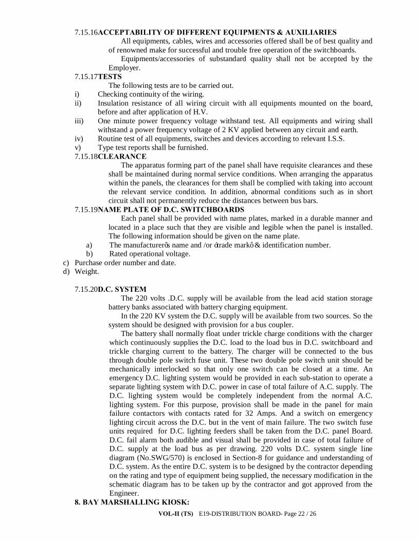
VOL-II (TS) E19-DISTRIBUTION BOARD- Page 22 / 26
7.15.16ACCEPTABILITY OF DIFFERENT EQUIPMENTS & AUXILIARIES All equipments, cables, wires and accessories offered shall be of best quality and
of renowned make for successful and trouble free operation of the switchboards. Equipments/accessories of substandard quality shall not be accepted by the
Employer. 7.15.17TESTS
The following tests are to be carried out. i) Checking continuity of the wiring. ii) Insulation resistance of all wiring circuit with all equipments mounted on the board,
before and after application of H.V. iii) One minute power frequency voltage withstand test. All equipments and wiring shall
withstand a power frequency voltage of 2 KV applied between any circuit and earth. iv) Routine test of all equipments, switches and devices according to relevant I.S.S. v) Type test reports shall be furnished. 7.15.18CLEARANCE
The apparatus forming part of the panel shall have requisite clearances and these shall be maintained during normal service conditions. When arranging the apparatus within the panels, the clearances for them shall be complied with taking into account the relevant service condition. In addition, abnormal conditions such as in short circuit shall not permanently reduce the distances between bus bars.
7.15.19NAME PLATE OF D.C. SWITCHBOARDS Each panel shall be provided with name plates, marked in a durable manner and
located in a place such that they are visible and legible when the panel is installed. The following information should be given on the name plate.
a) The manufacturer’s name and /or ‘trade mark’ & identification number. b) Rated operational voltage.
c) Purchase order number and date. d) Weight.
7.15.20D.C. SYSTEM
The 220 volts .D.C. supply will be available from the lead acid station storage battery banks associated with battery charging equipment.
In the 220 KV system the D.C. supply will be available from two sources. So the system should be designed with provision for a bus coupler.
The battery shall normally float under trickle charge conditions with the charger which continuously supplies the D.C. load to the load bus in D.C. switchboard and trickle charging current to the battery. The charger will be connected to the bus through double pole switch fuse unit. These two double pole switch unit should be mechanically interlocked so that only one switch can be closed at a time. An emergency D.C. lighting system would be provided in each sub-station to operate a separate lighting system with D.C. power in case of total failure of A.C. supply. The D.C. lighting system would be completely independent from the normal A.C. lighting system. For this purpose, provision shall be made in the panel for main failure contactors with contacts rated for 32 Amps. And a switch on emergency lighting circuit across the D.C. but in the vent of main failure. The two switch fuse units required for D.C. lighting feeders shall be taken from the D.C. panel Board. D.C. fail alarm both audible and visual shall be provided in case of total failure of D.C. supply at the load bus as per drawing. 220 volts D.C. system single line diagram (No.SWG/570) is enclosed in Section-8 for guidance and understanding of D.C. system. As the entire D.C. system is to be designed by the contractor depending on the rating and type of equipment being supplied, the necessary modification in the schematic diagram has to be taken up by the contractor and got approved from the Engineer.
8. BAY MARSHALLING KIOSK:
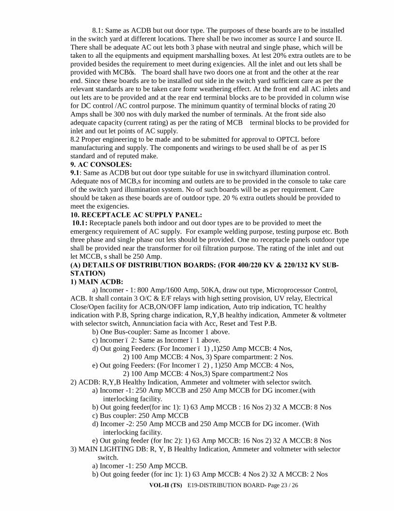
VOL-II (TS) E19-DISTRIBUTION BOARD- Page 23 / 26
8.1: Same as ACDB but out door type. The purposes of these boards are to be installed in the switch yard at different locations. There shall be two incomer as source I and source II. There shall be adequate AC out lets both 3 phase with neutral and single phase, which will be taken to all the equipments and equipment marshalling boxes. At lest 20% extra outlets are to be provided besides the requirement to meet during exigencies. All the inlet and out lets shall be provided with MCB’s. The board shall have two doors one at front and the other at the rear end. Since these boards are to be installed out side in the switch yard sufficient care as per the relevant standards are to be taken care fomr weathering effect. At the front end all AC inlets and out lets are to be provided and at the rear end terminal blocks are to be provided in column wise for DC control /AC control purpose. The minimum quantity of terminal blocks of rating 20 Amps shall be 300 nos with duly marked the number of terminals. At the front side also adequate capacity (current rating) as per the rating of MCB terminal blocks to be provided for inlet and out let points of AC supply. 8.2 Proper engineering to be made and to be submitted for approval to OPTCL before manufacturing and supply. The components and wirings to be used shall be of as per IS standard and of reputed make. 9. AC CONSOLES: 9.1: Same as ACDB but out door type suitable for use in switchyard illumination control. Adequate nos of MCB,s for incoming and outlets are to be provided in the console to take care of the switch yard illumination system. No of such boards will be as per requirement. Care should be taken as these boards are of outdoor type. 20 % extra outlets should be provided to meet the exigencies. 10. RECEPTACLE AC SUPPLY PANEL: 10.1: Receptacle panels both indoor and out door types are to be provided to meet the emergency requirement of AC supply. For example welding purpose, testing purpose etc. Both three phase and single phase out lets should be provided. One no receptacle panels outdoor type shall be provided near the transformer for oil filtration purpose. The rating of the inlet and out let MCCB, s shall be 250 Amp. (A) DETAILS OF DISTRIBUTION BOARDS: (FOR 400/220 KV & 220/132 KV SUB-STATION) 1) MAIN ACDB:
a) Incomer - 1: 800 Amp/1600 Amp, 50KA, draw out type, Microprocessor Control, ACB. It shall contain 3 O/C & E/F relays with high setting provision, UV relay, Electrical Close/Open facility for ACB,ON/OFF lamp indication, Auto trip indication, TC healthy indication with P.B, Spring charge indication, R,Y,B healthy indication, Ammeter & voltmeter with selector switch, Annunciation facia with Acc, Reset and Test P.B.
b) One Bus-coupler: Same as Incomer 1 above. c) Incomer – 2: Same as Incomer – 1 above. d) Out going Feeders: (For Incomer – 1) ,1)250 Amp MCCB: 4 Nos,
2) 100 Amp MCCB: 4 Nos, 3) Spare compartment: 2 Nos. e) Out going Feeders: (For Incomer – 2) , 1)250 Amp MCCB: 4 Nos,
2) 100 Amp MCCB: 4 Nos,3) Spare compartment:2 Nos 2) ACDB: R,Y,B Healthy Indication, Ammeter and voltmeter with selector switch.
a) Incomer -1: 250 Amp MCCB and 250 Amp MCCB for DG incomer.(with interlocking facility.
b) Out going feeder(for inc 1): 1) 63 Amp MCCB : 16 Nos 2) 32 A MCCB: 8 Nos c) Bus coupler: 250 Amp MCCB
d) Incomer -2: 250 Amp MCCB and 250 Amp MCCB for DG incomer. (With interlocking facility.
e) Out going feeder (for Inc 2): 1) 63 Amp MCCB: 16 Nos 2) 32 A MCCB: 8 Nos 3) MAIN LIGHTING DB: R, Y, B Healthy Indication, Ammeter and voltmeter with selector
switch. a) Incomer -1: 250 Amp MCCB.
b) Out going feeder (for inc 1): 1) 63 Amp MCCB: 4 Nos 2) 32 A MCCB: 2 Nos

VOL-II (TS) E19-DISTRIBUTION BOARD- Page 24 / 26
c) Bus coupler: 250 Amp MCCB d) Incomer -2: 250 Amp MCCB
e) Out going feeder (for Inc 2): 1) 63 Amp MCCB: 4 Nos 2) 32 A MCCB: 2 Nos 4) INDOOR RECEPTACLE DB: R,Y,B Healthy indication. a) Incomer: 63 Amp MCB b) Out going: 32 Amp ,3 Phase,MCB: 2 c) Out going: 32 Amp ,1 Phase,MCB: 4 5) EMERGENCY LIGHTING DB: a) Incomer: 100 Amp MCCB b) Out going: 63 Amp ,3 Phase,MCB: 2 c) Out going: 32 Amp ,1 Phase,MCB: 4 d) Out going: 16 Amp ,1 Phase,MCB: 8 6) 220 V DC Indoor Ltg. DB: a) Incomer : 32 Amp DC MCB from DCDB with auto changeover facility having
delay timer with auto/manual selection switch. b) Outgoing feeder: 16 Amp DC MCB: 5 Nos 7) 220 V DCDB (SET): 7.1) 220 V DC DB:1: Having Earth fault relay (Earth leakage), Under and over voltage, DC
Ammeter and Voltmeter. Annunciation scheme. a) Incomer: 100 Amp DC MCCB: b) Out going: 100 Amp DC MCCB : To couple the other DCDB c) Out going feeder: 32 Amp DC MCB: 20 Nos. 7.2) 220 V DC DB:2: Having Earth fault relay (Earth leakage), Under and over voltage, DC
Ammeter and Voltmeter. Annunciation scheme. a) Incomer: 100 Amp DC MCCB: b) Out going: 100 Amp DC MCCB : To couple the other DCDB c) Out going feeder: 32 Amp DC MCB: 20 Nos. (* 220 V DCDB-1 & 220 V DCDB-2 combined shall be treated as 220 V DCDB). 8) 48 V DCDB (SET): 8.1) 50 V DC DB:1: Having Earth fault relay (Earth leakage), Under and over voltage, DC
Ammeter and Voltmeter. Annunciation scheme. a) Incomer: 100 Amp/250 Amp DC MCCB: b) Out going: 100 Amp/250 Amp DC MCCB: To couple the other DCDB c) Out going feeder: 32 Amp DC MCB: 20 Nos. 8.2) 50 V DC DB:2: Having Earth fault relay (Earth leakage), Under and over voltage, DC
Ammeter and Voltmeter. Annunciation scheme. a) Incomer: 100 Amp/250 Amp DC MCCB: b) Out going: 100 Amp/ 250 Amp DC MCCB: To couple the other DCDB c) Out going feeder: 32 Amp DC MCB: 20 Nos. (* 50 V DCDB-1 & 50 V DCDB-2 combined shall be treated as 50 V DCDB) 9) BMK (Suitable for Outdoor type) (Provision of telephone jack points)
a) Incomer : 63 Amp TP MCB : 1 for source - 1 and 1 for source -2 ( with timer,for auto changeover, contactors (two nos each rated 70 Amp) suitable to take care of changeover automatically.)
b) Out going feeder: 16 Amp TP MCB : 10 Nos , 10 Amp DP MCB: 8 Nos (at Front side)
c) 300 Nos of Terminal Block of Elmex/ any renowned make suitable for 35 Amp rated. 10) OUTDOOR RECEPTACLE DB: (Transformer filtration purpose)
a) Near Transformer: Incomer 250 Amp MCCB: 1 No., Outgoing: 250 Amp MCCB : 1 No., Having provision of R,Y,B indication. (For transformer oil filteration)
b) Inside switch yard at Different location: Incomer: 63 Amp TPN MCB, Out going feeder: 2 Nos 32 Amp TP MCB and 2 Nos 16 Amp DP MCB.
VOL-II (TS) E19-DISTRIBUTION BOARD- Page 25 / 26
All outdoor kiosk top cover shall be of Aluminum alloy having 3mm thickness & proper sloping shall be maintained for easy drainage of water. (B) DETAILS OF DISTRIBUTION BOARDS: (FOR 132/33 KV SUB-STATION) 1) MAIN ACDB:
a) Incomer - 1: 800 Amp Amp, 50KA, draw out type, Microprocessor Control, ACB. It shall contain 3 O/C & E/F relays with high setting provision, UV relay, Electrical Close/Open facility for ACB,ON/OFF lamp indication, Auto trip indication, TC healthy indication with P.B, Spring charge indication, R,Y,B healthy indication, Ammeter & voltmeter with selector switch, Annunciation facia with Acc, Reset and Test P.B.
b) One Bus-coupler: Same as Incomer 1 above. c) Incomer – 2: Same as Incomer – 1 above.
INCOMER -1: (a) 250 Amp TPN MCCB: 2 Nos. and (2) 250 Amp TPN MCCB for DG incomer.(with interlocking facility. b) Out going feeder : 1) 63 Amp TP MCCB : 16 Nos (3 phase). 2) 32 A TP MCB: 8 Nos (3 phase) c) Out going feeder: (1) 100 Amp TP MCCB: 02 Nos.(3 phase)
d) Out going feeder: 32 Amp DP MCB (1 phase) INCOMER -2: (a) 250 Amp TPN MCCB: 2 Nos. and (2) 250 Amp TPN MCCB for DG incomer.(with interlocking facility. b) Out going feeder : 1) 63 Amp TP MCCB : 16 Nos (3 phase). 2) 32 A TP MCB: 8 Nos (3 phase) c) Out going feeder: (1) 100 Amp TP MCCB: 02 Nos.(3 phase)
d) Out going feeder: 32 Amp DP MCB (1 phase) 2) MAIN LIGHTING DB: R, Y, B Healthy Indication, Ammeter and voltmeter with selector
switch. a) Incomer -1: 250 Amp MCCB.
b) Out going feeder (for inc 1): 1) 63 Amp MCCB: 4 Nos 2) 32 A MCCB: 2 Nos c) Bus coupler: 250 Amp MCCB
d) Incomer -2: 250 Amp MCCB e) Out going feeder (for Inc 2): 1) 63 Amp MCCB: 4 Nos 2) 32 A MCCB: 2 Nos 3) INDOOR RECEPTACLE DB: R,Y,B Healthy indication. a) Incomer: 63 Amp MCB b) Out going: 32 Amp ,3 Phase,MCB: 2 c) Out going: 32 Amp ,1 Phase,MCB: 4 4) EMERGENCY LIGHTING DB: a) Incomer: 100 Amp MCCB b) Out going: 63 Amp ,3 Phase,MCB: 2 c) Out going: 32 Amp ,1 Phase,MCB: 4 d) Out going: 16 Amp ,1 Phase,MCB: 8 5) 220 V DC Indoor Ltg. DB: a) Incomer : 32 Amp DC MCB from DCDB with auto changeover facility having
delay timer with auto/manual selection switch. b) Outgoing feeder: 16 Amp DC MCB: 5 Nos 6) 220 V DCDB (SET): 6.1) 220 V DC DB:1: Having Earth fault relay (Earth leakage), Under and over voltage, DC
Ammeter and Voltmeter. Annunciation scheme. a) Incomer: 100 Amp DC MCCB: b) Out going: 100 Amp DC MCCB : To couple the other DCDB c) Out going feeder: 32 Amp DC MCB: 20 Nos.

VOL-II (TS) E19-DISTRIBUTION BOARD- Page 26 / 26
6.2) 220 V DC DB:2: Having Earth fault relay (Earth leakage), Under and over voltage, DC Ammeter and Voltmeter. Annunciation scheme.
a) Incomer: 100 Amp DC MCCB: b) Out going: 100 Amp DC MCCB : To couple the other DCDB c) Out going feeder: 32 Amp DC MCB: 20 Nos. (* 220 V DCDB-1 & 220 V DCDB-2 combined shall be treated as 220 V DCDB). 7) 48 V DCDB (SET): 7.1) 50 V DC DB:1: Having Earth fault relay (Earth leakage), Under and over voltage, DC
Ammeter and Voltmeter. Annunciation scheme. a) Incomer: 100 Amp/250 Amp DC MCCB: b) Out going: 100 Amp/250 Amp DC MCCB: To couple the other DCDB c) Out going feeder: 32 Amp DC MCB: 20 Nos. 7.2) 50 V DC DB:2: Having Earth fault relay (Earth leakage), Under and over voltage, DC
Ammeter and Voltmeter. Annunciation scheme. a) Incomer: 100 Amp/250 Amp DC MCCB: b) Out going: 100 Amp/ 250 Amp DC MCCB: To couple the other DCDB c) Out going feeder: 32 Amp DC MCB: 20 Nos. (* 50 V DCDB-1 & 50 V DCDB-2 combined shall be treated as 50 V DCDB) 8) BMK (Suitable for Outdoor type) (Provision of telephone jack points)
a) Incomer : 63 Amp TP MCB : 1 for source - 1 and 1 for source -2 ( with timer,for auto changeover, contactors (two nos each rated 70 Amp) suitable to take care of changeover automatically.)
b) Out going feeder: 16 Amp TP MCB : 10 Nos , 10 Amp DP MCB: 8 Nos (at Front side)
c) 300 Nos of Terminal Block of Elmex/ any renowned make suitable for 35 Amp rated. 9) OUTDOOR RECEPTACLE DB: (Transformer filtration purpose)
a) Near Transformer: Incomer 250 Amp MCCB: 1 No., Outgoing: 250 Amp MCCB : 1 No., Having provision of R,Y,B indication. (For transformer oil filteration)
b) Inside switch yard at Different location: Incomer: 63 Amp TPN MCB, Out going feeder: 2 Nos 32 Amp TP MCB and 2 Nos 16 Amp DP MCB.
All outdoor kiosk top cover shall be of Aluminum alloy having 3mm thickness & proper sloping shall be maintained for easy drainage of water.
TS-Vol-II E20-COND, E/W, INSULATORS- Page1/82
ODISHA POWER TRANSMISSION CORPORATION LIMITED
TECHNICAL SPECIFICATION
FOR
CONDUCTOR, AL TUBE G.I GROUND WIRE,
INSULATORS, HARDWARE, CLAMPS & CONNECTORS
TS-Vol-II E20-COND, E/W, INSULATORS- Page2/82
SECTION-I
S.NO. DESCRIPTION PAGE NO.
1. SCOPE 3
2. STANDARDS 3
3. MATERIALS 3
4. SIZES 3
5. TOLERANCES 3
6. MECHANICAL PROPERTIES 4
7. SURFACE CONDITIONS 4
8. JOINTS IN WIRES 4
9. STRANDING 4
10. PACKING AND MARKING 5
11. LENGTHS 5
12. TESTS AND CERTIFICATES 6
13. RETEST AND REJECTION 11
14. GUARANTEED TECHNICAL PARTICULARS 11
15. SAG TENSION CHARTS AND SAG 11
TEMPLATES
CONDUCTORS
S E C T I O N - I TECHNICAL SPECIFICATION OF ACSR “MOOSE”,”ZEBRA”, AND “ PANTHER” CONDUCTORS 1. SCOPE :-
TS-Vol-II E20-COND, E/W, INSULATORS- Page3/82
1.1. This specification provides for the manufacture, testing, supply and delivery at destination of the steel cored aluminum conductors as per Appendix-I attached. 2. STANDARDS :- 2.1 The conductors shall comply in all respects to the clauses of this specification as indicated below & with the Indian Standard Specification, International standards with latest amendments. Some of the standards are :- i) IS 398 - Specification for Aluminium Conductors for overhead transmission purposes,
IS 398, Part-II-Aluminium conductors for overhead Transmission purpose - Specification
ii) IS 1521, 1972 - Method of tensile testing of steel iii) IS 1778 -1989 – Reel & drums for bare conductors. iv) IEC - 1098 3. MATERIALS :- 3.1 The material offered shall be of best quality and workmanship. The steel Cored Aluminum conductor strands will consist of hard-drawn aluminum wire manufactured from 99.5% pure electrolytic aluminum rods of E.C. Grade. The steel wire shall be made from materials produced either by the acid or basic open hearth process or by electric process. No steel wire drawn from pressmen process shall be used. The steel wire shall not contain sulphur or phosphorus exceeding 0.05 percent, and the total of sulphur and phosphorus shall not exceed 0.085 percent. 3.2 The steel wires shall be evenly and uniformly coated with zinc complying with Indian Standard 4826-1979 specification for galvanized coatings on round steel wires. The uniformity of zinc coating and the weight of coating shall be in accordance with Appendix-II. The coating on the galvanized steel wires may be applied by the hot process or the electrolytic process. 4. SIZES :- 4.1 The size of steel-cored Aluminum Conductors shall be as given in Appendix-I. The resistance and weights shall be in accordance with the values given in the same appendix. 5. TOLERANCES :- 5.1 The following tolerances shall be permitted on standard diameter of aluminum wires. Tolerance on standard diameter of aluminum wire + 1 percent. wires. Note : - The cross-section of any wire shall not depart from circularity by more than an amount corresponding to a tolerance of 2 percent on the standard diameter.

TS-Vol-II E20-COND, E/W, INSULATORS- Page4/82
5.2 A tolerance of + 2 percent shall be permitted on the standard diameter of the galvanized steel wires. The variation from the approximate weights shall not be more than plus or minus 5 percent.
6. MECHANICAL PROPERTIES : - 6.1 The value of the final modules of elasticity for steel cored aluminum conductor in the average of values obtained from actual stress strain tests. The co-efficient of linear expansion for steel Cored Aluminum Conductors has been calculated on the basis of co-efficient of linear expansion of 23.0 x 10⁻⁶ per degree centigrade of aluminum and 11.5 x 10⁻⁶ per degree centigrade for steel and represent only the average values. These values shall however, be given by the bidder under the guaranteed technical particulars. 7. SURFACE CONDITIONS :- 7.1 The wires shall be smooth and free from inequalities, spills and splits. The surface conductor shall be free from points, sharp-edges, abrasions or other departures from smoothness or uniformity of surface contour that would increase radio interference and corona losses. When subjected to tension up to 50% of the ultimate strength of the conductor, the surface shall not depart from its cylindrical form nor any part of the component, parts or strands, move relative to each other in such a way as to get out of place and disturb the longitudinal smoothness of the conductor. 8. JOINTS IN WIRES : - 8.1 Aluminium wires : No joints shall be permitted in the aluminium wires in the outermost layer of the ACSR conductor. Joints in the inner layers are permitted, in addition to those made in the base rod or wire before final drawing, but no two such joints shall be less than 15 meter. apart in the complete stranded conductor. Such joints shall be made by cold pressure butt-welding. Joints are not permitted in the outermost layer of the conductor in order to ensure a smooth conductor finish and reduce radio interference levels and corona losses on the extra high voltage lines. 8.2 Galvanized steel wires : - There shall be no joints except those in the base rod or wire before final drawing, in steel wires forming the core of the steel-reinforced aluminum conductor. Joints have not been permitted in the steel wires after final drawing in order to avoid reduction in the breaking strength of the conductor that may occur as a result of failure of the joints. 9. STRANDING :- 9.1 The wires used in construction of a stranded conductor shall before stranding, satisfy all requirements of IS-398/ (part-II)1976 with latest amendments. For steel-cored aluminum conductors the lay ratio of the different layers shall be within the limits given under Appendix-I.
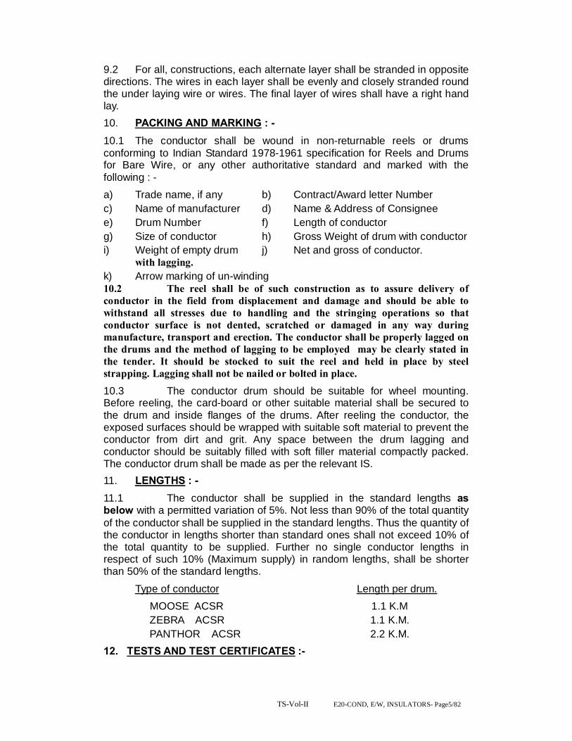
TS-Vol-II E20-COND, E/W, INSULATORS- Page5/82
9.2 For all, constructions, each alternate layer shall be stranded in opposite directions. The wires in each layer shall be evenly and closely stranded round the under laying wire or wires. The final layer of wires shall have a right hand lay. 10. PACKING AND MARKING : - 10.1 The conductor shall be wound in non-returnable reels or drums conforming to Indian Standard 1978-1961 specification for Reels and Drums for Bare Wire, or any other authoritative standard and marked with the following : - a) Trade name, if any b) Contract/Award letter Number c) Name of manufacturer d) Name & Address of Consignee e) Drum Number f) Length of conductor g) Size of conductor h) Gross Weight of drum with conductor i) Weight of empty drum j) Net and gross of conductor. with lagging. k) Arrow marking of un-winding 10.2 The reel shall be of such construction as to assure delivery of conductor in the field from displacement and damage and should be able to withstand all stresses due to handling and the stringing operations so that conductor surface is not dented, scratched or damaged in any way during manufacture, transport and erection. The conductor shall be properly lagged on the drums and the method of lagging to be employed may be clearly stated in the tender. It should be stocked to suit the reel and held in place by steel strapping. Lagging shall not be nailed or bolted in place.
10.3 The conductor drum should be suitable for wheel mounting. Before reeling, the card-board or other suitable material shall be secured to the drum and inside flanges of the drums. After reeling the conductor, the exposed surfaces should be wrapped with suitable soft material to prevent the conductor from dirt and grit. Any space between the drum lagging and conductor should be suitably filled with soft filler material compactly packed. The conductor drum shall be made as per the relevant IS. 11. LENGTHS : - 11.1 The conductor shall be supplied in the standard lengths as below with a permitted variation of 5%. Not less than 90% of the total quantity of the conductor shall be supplied in the standard lengths. Thus the quantity of the conductor in lengths shorter than standard ones shall not exceed 10% of the total quantity to be supplied. Further no single conductor lengths in respect of such 10% (Maximum supply) in random lengths, shall be shorter than 50% of the standard lengths. Type of conductor Length per drum. MOOSE ACSR 1.1 K.M ZEBRA ACSR 1.1 K.M. PANTHOR ACSR 2.2 K.M. 12. TESTS AND TEST CERTIFICATES :-

TS-Vol-II E20-COND, E/W, INSULATORS- Page6/82
The following type tests ,(& any other tests if purchaser decides to do), shall be conducted on the conductor at any Govt. approved laboratory or CPRI, in presence of the representatives of OPTCL, on the samples collected and sealed by the representative of OPTCL from the manufactured & offered drums of conductor at random at free of cost to OPTCL or firm may quote their test charges which will be taken in to account during bid price evaluation. If test charges will not be quoted by the firm, it will be treated as nil during bid price evaluation & firm have to do the type tests at free of cost to OPTCL. Also the tenderer shall furnish valid type test reports, the tests are as per the IS 398 (part-2) conducted in any govt. approved laboratory or CPRI within last 5 years, from the date of opening of the bid (Techno-commercial) document, without which their bids will not be considered for evaluation.
12.1 Individual wire and finished steel cored Aluminum Conductor shall be subjected to before dispatch from the works, to the tests as per the provision of the Indian standard Specification 398 (Part-II-1976) with the latest amendments & as per the tests indicated in this specification below. 12.2 Samples for individual wires for test shall be taken before stranding form not less than 10 percent of the spiels in the case of aluminum wire and ten percent of the wire coils in the case of steel wires. If samples are taken after stranding, they shall be obtained by cutting 5 meters from the outer end of the finished conductor from not more than 10 percent of the finished reels. 12.3 The mechanical tests shall be carried out on single wires only. 12.4 The Tensile test shall apply to wires of all diameters forming part of steel cored aluminum conductors. If it is not possible to test the component wires before stranding the test may be made on wires taken from stranded conductors. The tensile strength of any of the wires shall not be less than the minimum values given in Appendix-II. 12.5 A suitable tensile testing machine shall be used the accuracy of which can easily be checked and the machine adjusted if necessary. The test sample before being placed in the machine, shall be straightened, if necessary in such a way as to cause the minimum alteration in its physical properties. The load shall be applied gradually and rate of separation of the Jaws of the testing machine shall not be greater than 10cm/min. and less than 2.5cm/min.
TYPE TESTS 12.6 Wrapping Test : - 12.6.1 Samples of aluminium wires shall be wrapped round a wire of its own diameter to form a close helix of eight turns. Six turns shall then be

TS-Vol-II E20-COND, E/W, INSULATORS- Page7/82
unwrapped and again clearly wrapped in the same direction as before. The wire shall not break. 12.6.2 Samples of steel wires shall be closely wrapped eight times round a mandrel of diameter equal to four times the wire diameter. Six turns shall then be unwrapped and again closely wrapped in the same direction as before. The wire shall not break. 12.7 Galvanizing Test : - 12.7.1 The uniformity of zinc coating and the weight of coating shall be as given in Appendix-II and shall be determined according to Indian Standard Specification 4826-1979. with latest amendments. 12.7.2 This test shall be made whenever practicable, on wires before stranding and before the specimen has been bent, straightened or tested in any other way. 12.8 Ductility Test : - This test shall be made on galvanized steel wires only by any of the proceedings given in 12.8.1 and 12.8.2. 12.8.1 Torsion Test : - One specimen cut from each of the sample shall be gripped at its ends in two vices, one of which shall be free to move longitudinally during the test. A small tensile bond not exceeding 2% of the breaking load of the wire, shall be applied to the sample during testing. The specimen shall be twisted by consisting one of the vices to revolve until fracture occurs and the number of twists shall be indicated by a counter or other suitable device. The rate of twisting shall not exceed 60 rev/min. When tested before stranding, the number of complete twists before fracture occurs shall not be less than 18 on a length equal to 100 times the diameter of the wire. The fracture shall show a smooth surface at right angles, to the axis of the wire.
When tested after stranding, the number of complete twists before fracture occurs shall be not less than 16 on a length equal to 100 times the diameter of the wire. The fracture shall show a smooth surface at right angles to the axis of the wire. 12.8.2 Elongation Test : - The elongation of one specimen cut from each of the samples shall be determined. The specimen shall be straightened by hand and on original gauge length of 200 mm shall be marked on the wire. A tensile load shall be applied as described in 12.5 and the elongation shall be measured after the fractured ends fitted together. If the fracture occurs outside the gauge marks, or within 25mm of either mark and the required elogation is not obtained, the test shall be disregarded and another test made. When tested before stranding, the elongation shall be not less than 4 percent. When tested after stranding, the elongation shall be not less than 3.5 percent. 12.9 Surface Condition Test A sample of the finished conductor having a minimum recommended length of 5 meters with compression type dead end clamps compressed on both ends in such a manner as to permit the conductor to take its normal straight line shape, shall be subject to a tension of 50% of the UTS of the

TS-Vol-II E20-COND, E/W, INSULATORS- Page8/82
conductor. The surface shall not depart from its cylindrical shape nor shall the strands move relative to each other so as to get out of place of disturb the longitudinal smoothness of conductor. The measured diameter at any place shall be not less than the sum of the minimum specified diameters of the individual aluminum and steel strands. 12.10 Ultimate Strength (UTS) Test on Stranded Conductor Circles perpendicular to the axis of the conductor shall be marked at two places on a sample of conductor of minimum 5 m length suitably compressed with dead end clamps at either end. The load shall be increased at a steady rate up to specified 50% of UTS and held for one minute. The circles drawn shall not be distorted due to Relative movement of strands. Thereafter the load shall be increased at a steady rate to the minimum UTS specified in Appendix-I and held for one minute. The applied load shall then be increased until the failing load is reached and the value recorded. 12.11 Corona Extinction Voltage Test One sample of conductor of 5m length shall be strung. In case of twin conductor, two samples shall be arranged with the actual sub-conductor spacing between them. This sample assembly when subjected to power frequency voltage shall have a corona extinction voltage of not less than 320 KV (rms) for 400 KV and 176 KV (rms) for 220 KV system line to ground under dry condition. There shall be no evidence of corona on any part of sample when all possible sources of corona are photographed in a darkened room. The test shall be conducted without corona control rings. The voltage shall be corrected for standard atmospheric conditions. 12.12 Radio Interference Voltage Test Under the conditions as specified in 12.11 above, the conductor samples shall have a radio interference voltage level below 1500 microvolts at one MHZ when subjected to 50HZ AC voltage of 1.1 times maximum line to ground voltage under dry condition. This test may be carried out with corona control rings and arcing horns. 12.13 D.C. Resistance Test on Stranded Conductor On a conductor sample of minimum 5 m length two contact clamps shall be fixed with a pre-determined bolt torque. The resistance shall be measured by a Kelvin double bridge by placing the clamps initially zero meter and subsequently one meter apart. The test shall be repeated at least five times and the average value recorded. The value obtained shall be corrected to the value at 20 degree centigrade as per clause No.12.8 of IS : 398 (part V). The resistance corrected at 20 degree centigrade shall conform to the requirements of this specification. 12.14 Stress-Strain Test 12.14 (i)This test is contemplated only to collect the creep data of the conductor from the supplier. A sample of conductor of minimum 10 metres length shall be suitably compressed with dead end clamps.
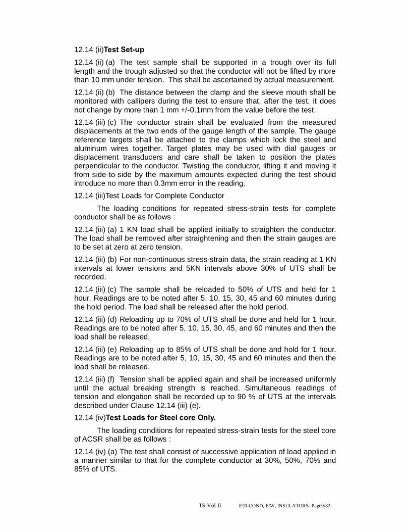
TS-Vol-II E20-COND, E/W, INSULATORS- Page9/82
12.14 (ii)Test Set-up 12.14 (ii) (a) The test sample shall be supported in a trough over its full length and the trough adjusted so that the conductor will not be lifted by more than 10 mm under tension. This shall be ascertained by actual measurement. 12.14 (ii) (b) The distance between the clamp and the sleeve mouth shall be monitored with callipers during the test to ensure that, after the test, it does not change by more than 1 mm +/-0.1mm from the value before the test. 12.14 (iii) (c) The conductor strain shall be evaluated from the measured displacements at the two ends of the gauge length of the sample. The gauge reference targets shall be attached to the clamps which lock the steel and aluminum wires together. Target plates may be used with dial gauges or displacement transducers and care shall be taken to position the plates perpendicular to the conductor. Twisting the conductor, lifting it and moving it from side-to-side by the maximum amounts expected during the test should introduce no more than 0.3mm error in the reading. 12.14 (iii)Test Loads for Complete Conductor
The loading conditions for repeated stress-strain tests for complete conductor shall be as follows : 12.14 (iii) (a) 1 KN load shall be applied initially to straighten the conductor. The load shall be removed after straightening and then the strain gauges are to be set at zero at zero tension. 12.14 (iii) (b) For non-continuous stress-strain data, the strain reading at 1 KN intervals at lower tensions and 5KN intervals above 30% of UTS shall be recorded. 12.14 (iii) (c) The sample shall be reloaded to 50% of UTS and held for 1 hour. Readings are to be noted after 5, 10, 15, 30, 45 and 60 minutes during the hold period. The load shall be released after the hold period. 12.14 (iii) (d) Reloading up to 70% of UTS shall be done and held for 1 hour. Readings are to be noted after 5, 10, 15, 30, 45, and 60 minutes and then the load shall be released. 12.14 (iii) (e) Reloading up to 85% of UTS shall be done and hold for 1 hour. Readings are to be noted after 5, 10, 15, 30, 45 and 60 minutes and then the load shall be released. 12.14 (iii) (f) Tension shall be applied again and shall be increased uniformly until the actual breaking strength is reached. Simultaneous readings of tension and elongation shall be recorded up to 90 % of UTS at the intervals described under Clause 12.14 (iii) (e). 12.14 (iv)Test Loads for Steel core Only. The loading conditions for repeated stress-strain tests for the steel core of ACSR shall be as follows : 12.14 (iv) (a) The test shall consist of successive application of load applied in a manner similar to that for the complete conductor at 30%, 50%, 70% and 85% of UTS.

TS-Vol-II E20-COND, E/W, INSULATORS- Page10/82
12.14 (iv) (b) The steel core shall be loaded until the elongation at the beginning of each hold period corresponds to that obtained on the complete conductor at 30%, 50%, 70% and 85% of UTS respectively. 12.14 (v)Stress Strain Curves The design stress-strain curve shall be obtained by drawing a smooth curve through the 0.5 and 1 hour points at 30%, 50%, and 70% of UTS loadings. The presence of any aluminum slack that can be related to any observed extrusion entering the span from the compression dead ends shall be removed from the lower ends of the design curves. Both the laboratory and design stress-strain curves shall be submitted to the purchaser along with test results. The stress-strain data obtained during the test shall be corrected to the standard temperature i.e. 20 degree centigrade. 12.15 Chemical Analysis of Zinc Samples taken from the Zinc ingots shall be chemically/ spectrographically analyzed. The same shall be in conformity to the requirements stated in this specification. 12.16 Chemical Analysis of Aluminum and Steel
Samples taken from the Aluminum ingots/ coils/ strands shall be chemically/ spectrographically analyzed. The same shall be in conformity to the requirements stated in this specification.
ROUTINE/ACCEPTANCE TESTS 12.17 Visual and Dimensional Check on Drums
The drums shall be visually and dimensionally checked to ensure that they conform to the requirements of this specification. Drum dimensions should confirm to IS: 1778.The flange diameter, traverse width, barrel diameter and flange thickness are to be as per relevant standard. 12.18 Visual Check for Joints, Scratches etc.
Conductor drums shall be rewound in the presence of the inspector. The inspector shall visually check for scratches, joints, etc. and that the conductor generally conforms to the requirements of this specification. 12.19 Dimensional Check of Steel and Aluminum Strands The individual strands shall be dimensionally checked to ensure that they conform to the requirements of this specification. 12.20 Check for Lay-ratios of various Layers The lay-ratios of various layers shall be checked to ensure that they conform to the requirements of this specification. 12.21 Breaking load test on welded Aluminum strand & Individual wires Two Aluminum wires shall be welded as per the approved quality plan and shall be subjected to tensile load. The welded point of the wire shall be able to withstand the minimum breaking load of the individual strand guaranteed by the supplier. 12.22 Ductility Test 12.23 wrapping test 12.24 Resistance test
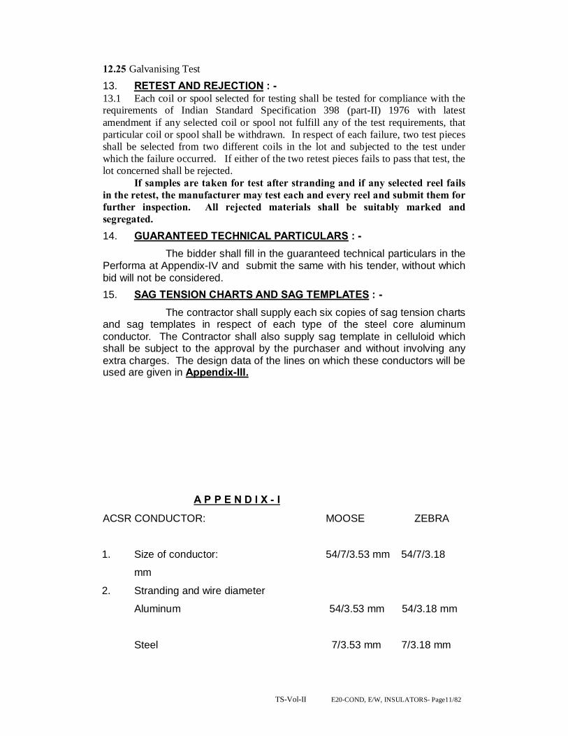
TS-Vol-II E20-COND, E/W, INSULATORS- Page11/82
12.25 Galvanising Test 13. RETEST AND REJECTION : - 13.1 Each coil or spool selected for testing shall be tested for compliance with the requirements of Indian Standard Specification 398 (part-II) 1976 with latest amendment if any selected coil or spool not fulfill any of the test requirements, that particular coil or spool shall be withdrawn. In respect of each failure, two test pieces shall be selected from two different coils in the lot and subjected to the test under which the failure occurred. If either of the two retest pieces fails to pass that test, the lot concerned shall be rejected. If samples are taken for test after stranding and if any selected reel fails in the retest, the manufacturer may test each and every reel and submit them for further inspection. All rejected materials shall be suitably marked and segregated. 14. GUARANTEED TECHNICAL PARTICULARS : -
The bidder shall fill in the guaranteed technical particulars in the Performa at Appendix-IV and submit the same with his tender, without which bid will not be considered. 15. SAG TENSION CHARTS AND SAG TEMPLATES : -
The contractor shall supply each six copies of sag tension charts and sag templates in respect of each type of the steel core aluminum conductor. The Contractor shall also supply sag template in celluloid which shall be subject to the approval by the purchaser and without involving any extra charges. The design data of the lines on which these conductors will be used are given in Appendix-III.
A P P E N D I X - I
ACSR CONDUCTOR: MOOSE ZEBRA
1. Size of conductor: 54/7/3.53 mm 54/7/3.18
mm
2. Stranding and wire diameter
Aluminum 54/3.53 mm 54/3.18 mm
Steel 7/3.53 mm 7/3.18 mm

TS-Vol-II E20-COND, E/W, INSULATORS- Page12/82
3. Sectional area of Aluminum (in mm2) 528.50 428.90
4. Approximate total mass (in Kgs/KM) 2004 1622
5. Calculated resistance at 20°C Max.: 0.05552 0.06868
( in Ohms/Km.)
6. Calculated breaking load of: 161.20 KN 130.32 KN.
composite conductor (in KN)
(U.T.S.) (Min)
7. Lay Rating :-
Steel core Max – 18 Max- 28
Min - 16 Min-13
Aluminium Layers
12 Wire Layer Max – 14 Max-17
(Innermost Layer) Min – 12 Min - 10
18 Wire Layer Max -13 Max - 16
(Lay immediately beneath outside Layer) Min – 11 Min - 10
24 wire layer (outside layer) Max -12 Max - 14
Min -10 Min - 10
8. Modulus of elasticity (in Kg / mm2 ): 6860 8158
0.7036 x 10⁶ Kg x CM2
( 69 GN per Sq. meter )
9. Co-efficient of linear expansion -------------19.3 x 10⁻⁶ -------------------
of conductor per degree centigrade.
10. Standard area of Cross Section in 597.0 mm2 484.5
mm2
Sq. mm of conductor.
11. Diameter of complete conductor in 31.77 mm 28.62 mm

TS-Vol-II E20-COND, E/W, INSULATORS- Page13/82
A P P E N D I X - II Solid Steel and Aluminum Wires used in Steel cored
Aluminum Conductors
ZEBRA MOOSE
1. Diameter Steel Aluminum Steel
Aluminium
Standard (in mm) 3.18 3.18 3.53 3.53
Maximum (in mm) 3.24 3.21 3.60 3.55
Minimum (in mm) 3.12 3.15 3.46 3.51
2. Cross Sectional Area 7.942 7.942 9.791 9.791
of nominal Diameter
Wire (in mm2)
3. Weight (in Kg/KM) 61.95 21.47
4. Minimum tensile strength:As per relevant ISS
5. Minimum breaking load 10.43 1.29 12.86 1.57
before stranding (in KN)
6. Minimum breaking load: 9.91 1.23 12.22 1.49
after stranding (in KN)
7. Zinc coating of steel
strands
Number and duration: 3 (1 Min. dip) 3 dips of 1min
of dips
Minimum Weight of : 260 260
Coating (in gm/ m2)
(A s per IS-4826 –1979)
8. Maximum resistance at: 3.626 2.974 2.921
20°C of Aluminum strands
( in Ohms / KM)
9. Minim Purity of aluminum rod: ------------------------99.5 %---------------
----

TS-Vol-II E20-COND, E/W, INSULATORS- Page14/82

TS-Vol-II E20-COND, E/W, INSULATORS- Page15/82
A P P E N D I X – III
ACSR CONDUCTOR: ZEBRA MOOSE 1. Conductor ---------Steel cored Aluminum----- (a) Copper equivalent: mm2
(b) Stranding (in mm) 54/7/3.18 54/7/3.53 2. Normal Span. 320 Meters Wind Span. 320 Meters Weight Span. (a) Max. 500 Meters (b) Min. 50 Meters 3. Wind Pressure on full 52 Kgf per M2
project area. 4. Temperature (a) Minimum 5 ° C (b) Maximum 67 ° C (c) Every day 32°C 5. Factors of safety : Minimum (i) Every day temperature and no wind. 4.00 (ii) Minimum temperature and 2/3 maximum wind : 2.00 (iii) Every day Temperature and full wind 2.00 This is as per Indian Electricity Rules, 1956. 6. Relative Humidity. Maximum. 100 Percent Minimum. 60 Percent 7. Isoceramic level. 100/Years 8. Number of rainy days per year. 100 days 9. Average rainfall per year 1150 mm. approx. 10. Altitude. Less than 350 Metres.
Technical parameters Sl. No. Description ACSR MOOSE
1 Stranding and wire diameter 54Al /3.53 mm+7 Steel/3.53 mm
2 Number of Strands Steel centre 1 1st Steel Layer 6 1st Aluminium Layer 12 2nd Aluminium Layer 18 3rd Aluminium Layer 24 3 Sectional area of aluminium 528.5 mm2

TS-Vol-II E20-COND, E/W, INSULATORS- Page16/82
4 Total sectional area 597.00 mm2
5 Overall diameter 31.77 mm 6 Approximate weight 2004 kg/km 7 Calculated DC resistance at 2O oC 0.05596 Ω/km 8 Minimum UTS 161.2 kN 9 The details of aluminium strand are as follows:
Minimum breaking load of strand before stranding 1.57 kN
Minimum breaking load of strand after stranding 1.49 kN
Maximum DC resistance of strand at 2O oC 2.921Ω/km 10 The details of steel strand are as follows Minimum breaking load of strand before stranding 12.86 kN
Minimum breaking load of strand after stranding 12.22 kN
11 Minimum number of twist to be with stood in torsion test when tested on a gauge length of 100 times diameter of wire
18 - before stranding 16 - after stranding
12 Tolerances 12a Diameter of aluminium strands
Standard 3.53 mm
Maximum 3.55 mm Minimum 3.51 mm
Diameter of steel strands Standard
3.53 mm
Maximum 3.60 mm Minimum 3.46 mm 13 Lay ratio of Conductor 13a Steel - 6 wire layer
Maximum 18
Minimum 16 13b Aluminium - 12 wire layer
Maximum 14
Minimum 12 13c Aluminium - 18 wire layer
Maximum 13
Minimum 11 13d Aluminium - 24 wire layer
Maximum 12
Minimum 11 14 Materials composition 14a Aluminium 99.5% with copper content less than
0.4% 14b Steel
Carbon 0.50 to 0.85 %
Manganese 0.50 to 1.10 % Phosphorous not more than 0.035 % Sulphur not more than 0.045 % Silicon 0.10 to 0.35 % 14c Zinc for galvanising electrolytic high grade zinc of 99.95%
purity conforming to IS 209-1979.

TS-Vol-II E20-COND, E/W, INSULATORS- Page17/82
A P P E N D I X – PANTHER 1. Size of conductor 30/7/3.00 mm 2. Stranding and wire diameter Aluminum 30/3.00 mm Steel 7/3.00 mm 3. Sectional Area of Aluminum 212.10 mm2
4. Approximate total mass 974 Kgs/KM 5. Calculated resistance at 0.139 Ohm/KM 20° C Max. 6. Calculated breaking load 89.67 KN of composite conductor (U.T.S) (Min) 7. Lay Ratio :- Steel Core Max - 28 Min - 13 Aluminum Layers 12 Wire layer (Layer below Max - 16 outside layer) Min - 10 18 Wire layer (Outside Layer) Max - 14 Min - 10 8. Modulus of elasticity 0.815 x 10⁶Kg/CM2 (80GN/M2) 9. Co-efficient of Linear 17.8 x 10⁻⁶ / °C expansion of conductor. 10. Standard area of cross 261.50 Sq. mm Section in sq. mm of conductor 11. Diameter of complete 21 mm conductor in mm
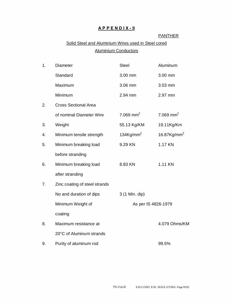
TS-Vol-II E20-COND, E/W, INSULATORS- Page18/82
A P P E N D I X - II
PANTHER
Solid Steel and Aluminium Wires used in Steel cored
Aluminium Conductors
1. Diameter Steel Aluminum
Standard 3.00 mm 3.00 mm
Maximum 3.06 mm 3.03 mm
Minimum 2.94 mm 2.97 mm
2. Cross Sectional Area
of nominal Diameter Wire 7.069 mm2 7.069 mm2
3. Weight 55.13 Kg/KM 19.11Kg/Km
4. Minimum tensile strength 134Kg/mm2 16.87Kg/mm2
5. Minimum breaking load 9.29 KN 1.17 KN
before stranding
6. Minimum breaking load 8.83 KN 1.11 KN
after stranding
7. Zinc coating of steel strands
No and duration of dips 3 (1 Min. dip)
Minimum Weight of As per IS 4826-1979
coating
8. Maximum resistance at 4.079 Ohms/KM
20°C of Aluminum strands
9. Purity of aluminum rod 99.5%

TS-Vol-II E20-COND, E/W, INSULATORS- Page19/82
A P P E N D I X - III PANTHER
1. Conductor Steel cored Aluminum
(a) Copper equivalent 130 mm2
(b) Stranding 30/7/3.00 mm
2. Normal Span. 320 Meters
Wind Span. 320 Meters
Weight Span.
(a) Max. 500 Meters
(b) Min. 50 Meters
3. Wind Pressure on full 52 Kgf per M2
projected area.
4. Temperature
(a) Minimum 5 °C
(b) Maximum 67°C
(c) Every day 32°C
5. Factors of safety : Minimum
(i) Every day temperature
and no wind. 4.00
(ii) Minimum temperature
and 2/3 maximum wind : 2.00
(iii) Every day Temperature and
full wind 2.00
This is as per Indian Electricity Rules, 1956.
6. Relative Humidity.
Maximum. 100 Percent
Minimum. 60 Percent
7. Isoceramic level 100/years
8. Number of rainy days per year. 100 days
9. Average rainfall per year 1150 mm. approx.
10. Altitude. Less than 350 Meters

TS-Vol-II E20-COND, E/W, INSULATORS- Page20/82

TS-Vol-II E20-COND, E/W, INSULATORS- Page21/82
G.I EARTH WIRE
SECTION – II
S.NO. DESCRIPTION PAGE NO.
1. SCOPE 22
2. STANDARDS 22
3. MATERIALS 22
4. SIZE AND CONSTRUCTION 22
5. LENGTH OF JOINING 22
6. TESTS AND TEST CERTIFICATES 22
7. PACKING AND MARKING 23
8. SAG AND TENSION CHARTS AND SAG TEMPLATE 23
9. OVERHEAD
EARTH CONDUCTORS 25
TECHNICAL SPECIFICATION FOR G.I. GROUND WIRE.( 7/3.15 mm and 7/3.66mm ) 1. SCOPE : 1.1 This specification provides for the manufacture, testing before despatch, supply and delivery of Ground wire for the purpose of earthing and protection of power transmission line, as per the particulars given in Appendix-I attached. The ground wire shall consist of standard galvanized steel wire. 2. STANDARDS :

TS-Vol-II E20-COND, E/W, INSULATORS- Page22/82
2.1 The ground wire shall comply in all respect with the Indian Standard (IS) 2141-1979 3. MATERIALS : 3.1 The material offered shall be of best quality and workmanship. The steel wires (Strands) shall be manufactured from steel produced by any suitable process. The steel wire shall not contain sulphur and phosphorous exceeding 0.040 percent each as per IS : 2141-1971. 3.2 The steel wires shall be evenly and uniformity quoted with zinc complying with IS: 209-1965 specification for zinc (Retired). Only virgin zinc shall be used and reclaimed zinc is not permitted. The virgin zinc shall be of zn 99.95 percent quality. 3.3 The content of carbon shall not be more than 0.55 percent, manganese and silicon contents shall be 0.40 to 0.90 and 0.15 to 0.35 respectively. 4. SIZE AND CONSTRUCTION : 4.1 The size of ground wire shall be as given in Appendix-I. The physical properties have been given in the same Appendix. The lay of the strands shall be of lengths as given in the Appendices. The wires shall be so stranded together that when any evenly distributed pulls applied at the end of the completed strands each wire will take on equal share of the pull. 5. LENGTH OF JOINING: 5.1 The ground wire may be supplied in the standard length as per manufacturers standard practice and such length will be specifically indicated in the tender. However random length of ground wire upto a maximum of 10 (Ten) percent may be allowed. 5.2 The length of strand which may be supplied without joints in the individual wires comprising it depends on the length of wire which may be carried by the bobbin in a normal stranding machine. The normal lengths of strand which shall be supplied without joints in individual wires, excluding welds made in the rod before drawing shall be as given in Appendix – I. 5.3 Each coil shall be warranted to contain no weld joints or splice ether than in the rod before it is drawn and those permitted in 5.3 above. The wire shall be circular and shall be free from scale or irregularities, imperfections, flow spite and other defects. The zinc coating shall be smooth even and bright. 6. TESTS AND TEST CERTIFICATES: 6.1 Ground wire shall be subjected to the tests as specified in the IS:2141-1979 before despatch. 6.2 Al the coils of the galvanized strand shall be of the same grade, diameter and construction manufactured under similar condition shall be grounded to constitute one lot. 6.3 Samples from each lot shall be tested for ascertaining the conformity to the requirements of the ground wire specified herein. The coils selected shall be tested for length of the lay and joints. The lot shall be declared conforming to the requirements of these characteristics if all the coils are found satisfactory. One test specimen from each wire of the strand shall be drawn, from every selected coil and subjected to tensil tests, ductility test and coating test. One specimen of the completed strand from each coil shall be subjected to tensil strength. The lot shall be declared conforming to the requirements of these characteristics if the entire best specimen satisfy the relevant requirements. 6.4 Chemical Analysis : One sample shall be drawn from the lot for chemical analysis. Unless otherwise agreed to between the purchase and supplier the chemical analysis shall be carried out.
TS-Vol-II E20-COND, E/W, INSULATORS- Page23/82
6.5 Tensile Test : The wire when tested in accordance with IS : 1521-1960 shall have minimum tensile strength specified in the Appendix – I. The tensile strength of the finished strand shall not be less than 95% of the aggregate of the single wires. 6.6 Ductility test : The wire shall be subjected to wrapping test in accordance with IS : 1755-1961. When wrapped eight times round its own diameter and on being subsequently straightened the wire shall not break or split. 6.7 Coating test : The uniformity of zinc coating shall be tested as per IS: 2633-1964. The wire shall withstand the number of dips specified in Appendix – I. 6.8 Three copies of manufacturers test certificate shall be submitted by the contractor to the purchaser for approval immediately after such tests have been conducted on the strands and the wire. 6.9 The purchaser reserves the right to inspect the material at Manufacturer’s works before despatch. 7. PACKING AND MARKING : 7.1 The ground wire shall be supplied in non-returnable reals or drums of non-perishable or treated wood conforming to IS: 1778-1991 specification for Reals and Drums for Bare wire. Each coil shall be provided with a level fixed firmly on the inner part of the coil, bearing the following information. (a) Trade name, if any. (b) Name of manufacturer (c) Type of wire, size and length of wire. (d) Not weight of the wire. (e) Total weight, and (f) Number of lengths on the real or drum unless otherwise agreed to between the purchaser and the supplier, the stranded wire shall be supplied in 50 Kg. coil. 8. SAG AND TENSION CHARTS AND SAG TEMPLATE : 8.1 The successful tenderer shall be required to submit six copies of sag templates and strings charts for different temperatures and spans, One set of charts shall be ink on tracing cloth. The design date of the lines on which the ground wire will be used are given in Appendix – II
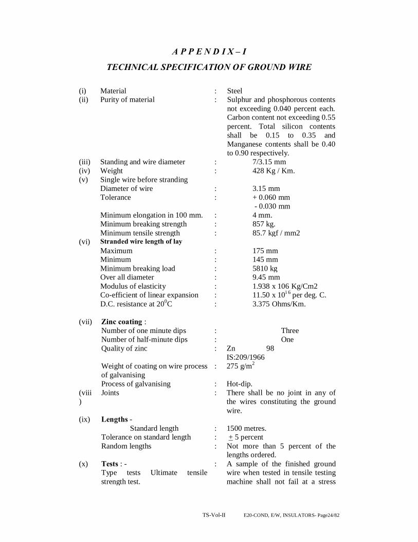
TS-Vol-II E20-COND, E/W, INSULATORS- Page24/82
A P P E N D I X – I
TECHNICAL SPECIFICATION OF GROUND WIRE (i) Material : Steel (ii) Purity of material : Sulphur and phosphorous contents
not exceeding 0.040 percent each. Carbon content not exceeding 0.55 percent. Total silicon contents shall be 0.15 to 0.35 and Manganese contents shall be 0.40 to 0.90 respectively.
(iii) Standing and wire diameter : 7/3.15 mm (iv) Weight : 428 Kg / Km. (v) Single wire before stranding Diameter of wire : 3.15 mm Tolerance : + 0.060 mm
- 0.030 mm Minimum elongation in 100 mm. : 4 mm. Minimum breaking strength : 857 kg. Minimum tensile strength : 85.7 kgf / mm2 (vi) Stranded wire length of lay Maximum : 175 mm Minimum : 145 mm Minimum breaking load : 5810 kg Over all diameter : 9.45 mm Modulus of elasticity : 1.938 x 10⁶ Kg/Cm2 Co-efficient of linear expansion : 11.50 x 10⁻⁶ per deg. C. D.C. resistance at 200C : 3.375 Ohms/Km.
(vii) Zinc coating : Number of one minute dips : Three Number of half-minute dips : One Quality of zinc : Zn 98
IS:209/1966
Weight of coating on wire process of galvanising
: 275 g/m2
Process of galvanising : Hot-dip. (viii)
Joints : There shall be no joint in any of the wires constituting the ground wire.
(ix) Lengths - Standard length : 1500 metres. Tolerance on standard length : + 5 percent Random lengths : Not more than 5 percent of the
lengths ordered. (x) Tests : -
Type tests Ultimate tensile strength test.
: A sample of the finished ground wire when tested in tensile testing machine shall not fail at a stress
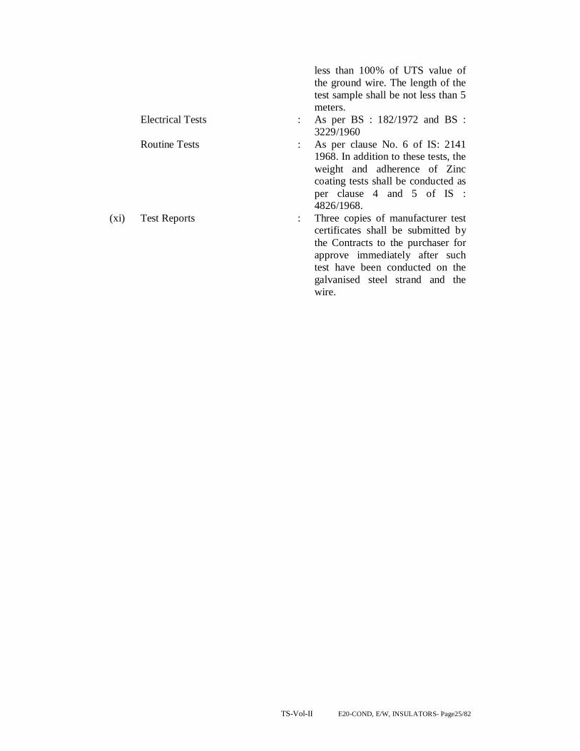
TS-Vol-II E20-COND, E/W, INSULATORS- Page25/82
less than 100% of UTS value of the ground wire. The length of the test sample shall be not less than 5 meters.
Electrical Tests : As per BS : 182/1972 and BS : 3229/1960
Routine Tests : As per clause No. 6 of IS: 2141 1968. In addition to these tests, the weight and adherence of Zinc coating tests shall be conducted as per clause 4 and 5 of IS : 4826/1968.
(xi) Test Reports : Three copies of manufacturer test certificates shall be submitted by the Contracts to the purchaser for approve immediately after such test have been conducted on the galvanised steel strand and the wire.

TS-Vol-II E20-COND, E/W, INSULATORS- Page26/82
9. Overhead earth conductors General(7/3.66mm)
Where earth conductors are erected to provide the specified degree of lightning protection, they shall consist of stranded galvanised steel and shall comply with IEC 888 and IEC 1089 in so far as it applies to steel wires. Galvanising shall comply with the requirements of IS 2141. The arrangement of earth conductors shall be such that failure of a single conductor cannot predictably result in a fall across both bus bars in a duplicate bus bar substation.
Technical parameters SI No. Parameter Value
1 Stranding and wire diameter 7/3.66mm 2 Number of strands 1/6 3 Total sectional area 73.65 mm2
4 Overall diameter 10.98mm 5 Approximate weight 583 kg/km 6 Calculated DC resistance at 20C 2.5 ohms/m 7 Minimum ultimate tensile strength 68.4kN 8 Direction of outer lay Right hand 9 Tolerances 9a Diameter standard 3.66mm maximum 3.75mm minimum 3.57mm
9b Lay length standard 181mm maximum 198mm minimum 165mm
10 Steel composition Carbon ≤ 0.55% Manganese 0.4 to 0.9% Phosphorous ≤ 0.04% Sulphur ≤ 0.04% Silicon 0.1 to 0.35%
11 Zinc for galvanising Electrolytic high grade zinc of 99.95% purity to 209 1979
Table for Technical parameters for earth wires
INSULATORS SECTION-III
S.NO. DESCRIPTION PAGE NO.
TS-Vol-II E20-COND, E/W, INSULATORS- Page27/82
1. SCOPE
2. STANDARDS
3. PRINCIPAL PARAMETERS
4. GENERAL TECHNICAL REQUIREMENTS
5. DETAILS OF SOLID CORE ROD INSULATORS
6. SPECIFICATION DRAWINGS
7. GENERAL TECHNICAL REQUIREMENTS
8. MATERIAL DESIGN AND WORKMANSHIP
9. TESTS (FOR DISC INSULATORS)
10 INSPECTION
11. QUALITY ASSURANCE PLAN
12. TEST DETAILS
INSULATORS
TECHNICAL SPECIFICATION FOR DISC INSULATORS FOR SUBSTATION AND TRANSMISSION LINE WORK
1.0 SCOPE. 1.1 This specification provides for design, manufacture, engineering,
inspection and testing before despatch packing and delivery FOR (destination) for Indian manufacturers of disc. Insulators as per technical requirements furnished in this specification.
These insulators are to be used in suspension and tension insulators strings for the suspension and anchoring of the conductors on EHV transmission line towers.
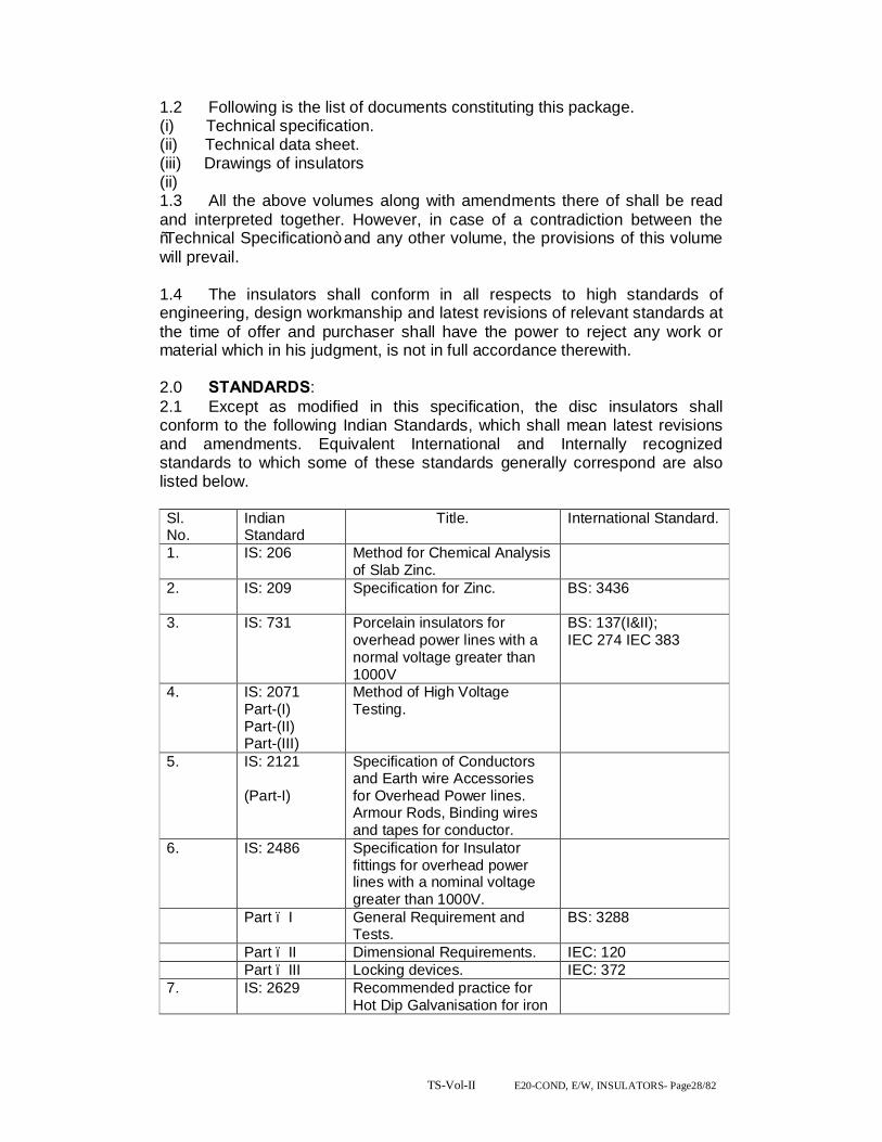
TS-Vol-II E20-COND, E/W, INSULATORS- Page28/82
1.2 Following is the list of documents constituting this package. (i) Technical specification. (ii) Technical data sheet. (iii) Drawings of insulators (ii) 1.3 All the above volumes along with amendments there of shall be read and interpreted together. However, in case of a contradiction between the “Technical Specification” and any other volume, the provisions of this volume will prevail.
1.4 The insulators shall conform in all respects to high standards of engineering, design workmanship and latest revisions of relevant standards at the time of offer and purchaser shall have the power to reject any work or material which in his judgment, is not in full accordance therewith.
2.0 STANDARDS: 2.1 Except as modified in this specification, the disc insulators shall conform to the following Indian Standards, which shall mean latest revisions and amendments. Equivalent International and Internally recognized standards to which some of these standards generally correspond are also listed below.
Sl. No.
Indian Standard
Title. International Standard.
1. IS: 206 Method for Chemical Analysis of Slab Zinc.
2. IS: 209
Specification for Zinc. BS: 3436
3. IS: 731 Porcelain insulators for overhead power lines with a normal voltage greater than 1000V
BS: 137(I&II); IEC 274 IEC 383
4. IS: 2071 Part-(I) Part-(II) Part-(III)
Method of High Voltage Testing.
5. IS: 2121 (Part-I)
Specification of Conductors and Earth wire Accessories for Overhead Power lines. Armour Rods, Binding wires and tapes for conductor.
6. IS: 2486 Specification for Insulator fittings for overhead power lines with a nominal voltage greater than 1000V.
Part – I General Requirement and Tests.
BS: 3288
Part – II Dimensional Requirements. IEC: 120 Part – III Locking devices. IEC: 372 7. IS: 2629 Recommended practice for
Hot Dip Galvanisation for iron

TS-Vol-II E20-COND, E/W, INSULATORS- Page29/82
and steel. 8. IS: 2633 Testing for Uniformity of
Coating of Zinc coated articles.
9. IS: 3138 Hexagonal Bolts & Nuts. ISO/R 947 & ISO/R 272
10. IS: 3188 Dimensions for Disc Insulators.
IEC: 305
11. IS: 4218 Metric Screw Threads ISO/R 68-1969 R 26-1963, R 262-1969 & R965-1969
12. IS: 6745 Determination of weight of zinc coating on zinc coated iron and steel articles.
13. IS: 8263 Methods of RIV Test of HV insulators.
IEC 437 NEMA Publication No.107/1964 CISPR
14. IS: 8269 Methods for switching impulse test on HV insulators.
IEC: 506
15. Thermal mechanical performance test and mechanical performance test on string insulator units.
IEC: 575
16 IEC Long Rod Insulators IEC-433
2.2 The standards mentioned above are available from:
Reference. Abbreviation. Name & Address: BS British Standards, British Standards
Institution, 101, Pentonvile Road, N-19 ND,U
IEC / CISPR International Electro technical commission Electro Technique International. 1, Rue de verembe Geneva SWITZERLAND.
IS Bureau of Indian Standards, Manak Bhavan, 9 Bahadurshah Zafar Marg, New Delhi-110001, ORISSA
ISO International Organisation for Standardization. Danish Board of Standardization Dansk Standardizing Sraat Aurehoegvej-12 DK-2900 Helleprup DENMARK.
NEMA National Electric Manufacturers Association 1`55, East 44th. Street New York, NY 10017 USA
3.0 PRINCIPAL PARAMETERS. 3.1 DETAILS OF DISC INSULATORS:

TS-Vol-II E20-COND, E/W, INSULATORS- Page30/82
3.1.1 The Insulator strings shall consist of standard discs for use in three phases. 50 Hz effectively earthed 33/132/220 KV transmission system of OPTCL in a moderately polluted atmosphere. The discs shall be cap and pin, ball and socket type, radio interference and have characteristics as shown in Table-I and all ferrous parts shall be hot dip galvanized as per the latest edition of IS 2629. The zinc to be used for making sleeves shall be 99.95 % pure.
3.1.2 The size of disc insulator, minimum creepage distance the number to be used in different type of strings, their electromechanical strength and mechanical strength 3.1.3 of insulator string along with hardware shall be as follows: PRINCIPAL PARAMETERS OF THE DISC INSULATORS:- Sl. No.
Type of String.
Size of disc. Insulator (mm)
Minimum creepage distance of each disc (mm),
No. of standard discs 132 KV /220/400 KV
Electro-mechanical strength of insulator string fittings (KN)
1. Single suspension
255 x 145 320 1x9/1x14 70 KN/90 KN Normal Disc Insulator
2. Double suspension.
-do- -do- 2x9/2x14 70 KN/90 KN Normal Disc Insulator
3 Single suspension
255 x 145 430 1x9/1x14 70 KN/90 KN Antifog Insulator
4 Double suspension.
-do- -do- 2x9/2x14 70 KN/90 KN Antifog Disc Insulator
5 Single Tension
280x145 430 1x10/1x15 120 KN Antifog Disc Insulator
6 Double Tension
-do- -do- 2x10/2x15 120 KN Antifog Disc Insulator
7 Single Tension
305x170 475 1x10/1x15/1x25
160 KN Antifog Disc Insulator
8 Double Tension
-do- -do- 2x10/2x15/2x25
160 KN Antifog Disc Insulator
5 Single Suspension
280x145 430 1x10/1x15/1X25
120 KN Antifog Disc Insulator
6 Double Suspension
-do- -do- 2x10/2x15/2X25
120 KN Antifog Disc Insulator
3.2 SPECIFICATION DRAWINGS: 3.2.1 The specification in respect of the disc insulators are described.These
specification for information and guidance of the Bidder only. The drawings to be furnished by the supplier shall be as per his own design and manufacture and in line with the specification.
4.0 GENERAL TECHNICAL REQUIREMENTS: 4.1 Porcelain:
TS-Vol-II E20-COND, E/W, INSULATORS- Page31/82
The porcelain used in the manufacture of the shells shall be ivory white nonporous of high dielectric, mechanical and thermal strength, free from internal stresses blisters, laminations, voids, forgone matter imperfections or other defects which might render it in any way unusable for insulator shells. Porcelain shall remain unaffected by climatic conditions ozone, acid, alkalis, zinc or dust. The manufacturing shall be by the wet process and impervious character obtained by through vetrification. The insulator shall be made of highest grade, dense, homogeneous, wet-process porcelain, completely and uniformly vitrified throughout to produce uniform mechanical and electrical strength and long life service. The porcelain shall be free from warping, roughness, cracks, blisters, laminations, projecting points foreign particles and other defects, except those within the limits of standard accepted practice. Surfaces and grooves shall be shaped for easy cleaning. Shells shall be substantially symmetrical. 4.1.1 Porcelain glaze: Surface to come in contact with cement shall be made rough by stand glazing. All other exposed surfaces shall be glazed with ceramic materials having the same temperature coefficient of expansion as that of the insulator shell. The thickness of the glaze shall be uniform throughout and the colour of the glaze shall be down. The Glaze shall have a visible luster and smooth on surface and be capable of satisfactory performance under extreme tropical climatic weather conditions and prevent ageing of the porcelain. The glaze shall remain under compression on the porcelain body through out the working temperature range.
4.2 METAL PARTS: 4.2.1 Cap and Ball Pins:
Ball pins shall be made with drop forged steel caps with malleable cast iron. They shall be in one single piece and duly hot dip galvanized. They shall not contain parts or pieces joined together welded, shrink fitted or by any other process from more than one piece of materials. The pins shall be of high tensile steel, drop forged and heat-treated. The caps shall be cast with good quality black heart malleable cast iron and annealed. Galvanizing shall be by the hot dip process with a heavy coating of zinc of very high purity. The bidder shall specify the grade composition and mechanical properties of steel used for caps and pins. The cap and pin shall be of such design that it will not yield or distort under the specified mechanical load in such a manner as to change the relative spacing of the insulators or add other stresses to the shells. The insulator caps shall be of the socket type provided with nonferrous metal or stainless steel cotter pins and shall provide positive locking of the coupling.
4.2.2 Security Clips:
TS-Vol-II E20-COND, E/W, INSULATORS- Page32/82
The security cops shall be made of phosphor bronze or of stainless steel.
4.3 FILTER MATERIAL: Cement to be used, as a filler material be quick setting, fast curing Portland cement. It shall not cause fracture by expansion or loosening by contraction. Cement shall not react chemically with metal parts in contact with it and its thickness shall be as small and as uniform as possible.
4.4 MATERIALS DESIGN AND WORKMANSHIP: 4.4.1 GENERAL: (II) All raw materials to be used in the manufacture of these insulators shall be subject to strict raw material quality control and to stage testing/ quality control during manufacturing stage to ensure the quality of the final end product. Manufacturing shall conform to the best engineering practices adopted in the field of extra high voltage transmission. Bidders shall therefore offer insulators as are guaranteed by them for satisfactory performance on Transmission lines. (III) The design, manufacturing process and material control at various stages be such as to give maximum working load, highest mobility, best resistance to corrosion, good finish elimination of sharp edges and corners to limit corona and radio interference voltages.
4.4.2 INSULATOR SHELL:
The design of the insulator shells shall be such that stresses due to expansion and contraction in any part of the insulator shall not lead to deterioration. Shells with cracks shall be eliminated by temperature cycle test followed by mallet test. Shells shall be dried under controlled conditions of humidity and temperature.
4.4.3 METAL PARTS: i) The pin and cap shall be designed to transmit the mechanical stress to the shell by compression and develop uniform mechanical strength in the insulator. The cap shall be circular with the inner and outer surfaces concentric and of such design that it will not yield or distort under loaded conditions. The head portion of the pinball shall be suitably designed so that when the insulator is under tension the stresses are uniformly distributed over the pinhole portion of the shell. The pinball shall move freely in the cap socket either during assembly of a string or during erection of a string or when a string is placed in position. ii) Metal caps shall be free from cracks, seams, shrinks, air holes, blowholes and rough edges. All metal surfaces shall be perfectly smooth with no projecting part or irregularities, which may cause corona. All load bearing surfaces shall be smooth and uniform so as to distribute the loading stress uniformly. Pins shall not show any microscopically visible cracks, inclusions and voids.
4.4.4 GALVANIZING:

TS-Vol-II E20-COND, E/W, INSULATORS- Page33/82
All ferrous parts, shall be hot dip galvanized in accordance with IS: 2629. The zinc to be used for galvanizing shall conform to grade Zn 99.5 as per IS: 209. The zinc coating shall be uniform, smoothly adherent, reasonably light, continuous and free from impurities such as flux, ash, rust stains, bulky white deposits and blisters. Before ball fittings are galvanized, all die flashing on the shank and on the bearing surface of the ball shall be carefully removed without reducing the designed dimensional requirements.
4.4.5 CEMENTING: The insulator design shall. Be such that the insulating medium shall not directly engaged with hard metal. The surface of porcelain and coated with resilient paint to offset the effect of difference in thermal expansions of these materials. High quality Portland cement shall be used for cementing the porcelain to the cap & pin.
4.4.6 SECURITY CLIPS (LOCKING DEVICES) The security clips to be used as locking device for ball and socket coupling shall be ‘R’ shaped hump type to provide for positive locking of the coupling as per IS: 2486 (Part-IV). The legs of the security clips shall allow for spreading after installation to prevent complete withdrawal from the socket. The locking device shall resilient corrosion resistant and of sufficient mechanical strength. There shall be no possibility of the locking device to be displaced or be capable of rotation, which placed in position, and under no circumstances shall it allow separation of insulator units and fittings. ‘W’ type security clips are also acceptable. The hole for the security clip shall be counter sunk and the clip shall be of such design that the eye of the clip may be engaged by a hot line clip puller to provide for disengagement under energized conditions. The force required for pulling the clip into its unlocked positions shall not be less than 50 N (5 kg.) or more than 500 N (50 kgs.).
4.4.7 MARKING: Each insulator shall have the rated combined mechanical and electrical strength marked clearly on the porcelain surface. Each insulator shall also bear symbols identifying the manufacturer, month, and year of manufacture. Marking on porcelain shall be printed, not impressed, and shall be applied before firing.
4.5 BALL AND SOCKET DESIGNATION: The dimensions of the ball and sockets for 70 and 90 KN discs shall be of 16 mm and for 120 KN and 160 KN discs shall be of 20 mm designation in accordance with the standard dimensions stated in IS: 2486 (Part-II).
4.6 DIMENSIONAL TOLERANCE OF INSULATOR DISCS:
It shall be ensured that the dimensions of the disc insulators are within the limits specified below:
4.6 DIMENSIONAL TOLERANCE OF INSULATOR DISCS:
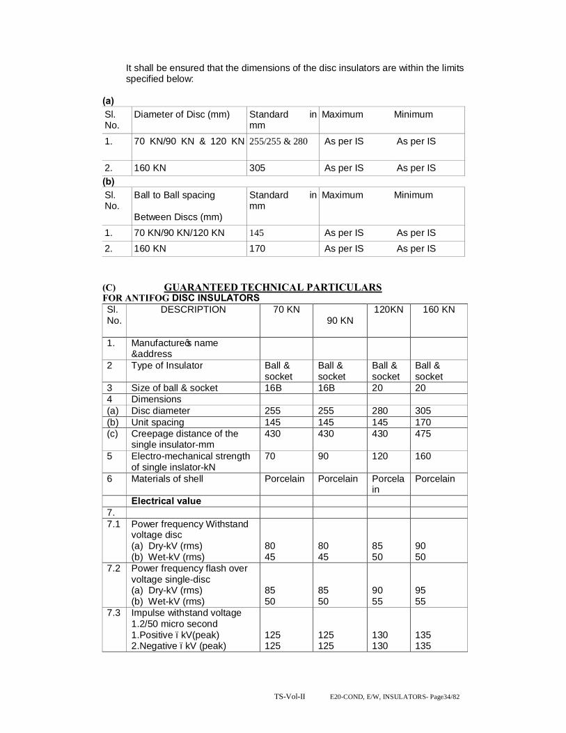
TS-Vol-II E20-COND, E/W, INSULATORS- Page34/82
It shall be ensured that the dimensions of the disc insulators are within the limits specified below:
(a) Sl. No.
Diameter of Disc (mm) Standard in mm
Maximum Minimum
1. 70 KN/90 KN & 120 KN
255/255 & 280 As per IS As per IS
2. 160 KN 305 As per IS As per IS (b) Sl. No.
Ball to Ball spacing Between Discs (mm)
Standard in mm
Maximum Minimum
1. 70 KN/90 KN/120 KN 145 As per IS As per IS 2. 160 KN 170 As per IS As per IS (C) GUARANTEED TECHNICAL PARTICULARS FOR ANTIFOG DISC INSULATORS Sl. No.
DESCRIPTION 70 KN 90 KN
120KN 160 KN
1. Manufacture’s name &address
2 Type of Insulator Ball & socket
Ball & socket
Ball & socket
Ball & socket
3 Size of ball & socket 16B 16B 20 20 4 Dimensions (a) Disc diameter 255 255 280 305 (b) Unit spacing 145 145 145 170 (c) Creepage distance of the
single insulator-mm 430 430 430 475
5 Electro-mechanical strength of single inslator-kN
70 90 120 160
6 Materials of shell Porcelain Porcelain Porcelain
Porcelain
Electrical value 7. 7.1 Power frequency Withstand
voltage disc (a) Dry-kV (rms) (b) Wet-kV (rms)
80 45
80 45
85 50
90 50
7.2 Power frequency flash over voltage single-disc (a) Dry-kV (rms) (b) Wet-kV (rms)
85 50
85 50
90 55
95 55
7.3 Impulse withstand voltage 1.2/50 micro second 1.Positive –kV(peak) 2.Negative –kV (peak)
125 125
125 125
130 130
135 135
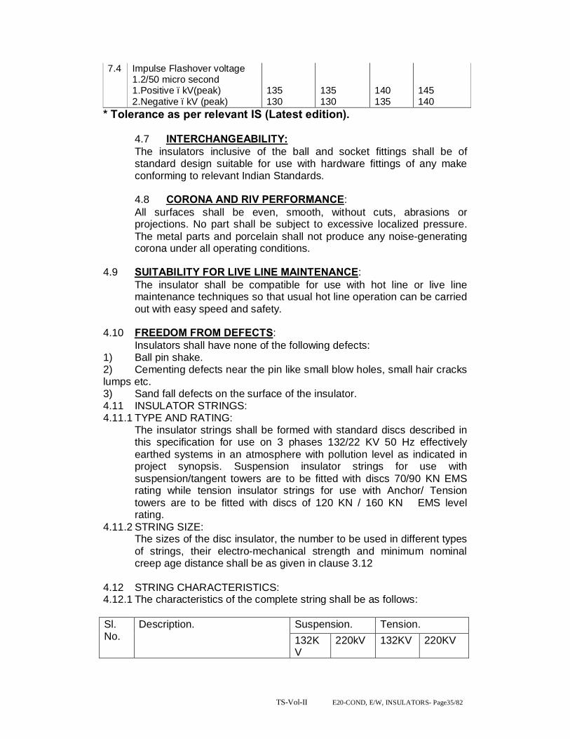
TS-Vol-II E20-COND, E/W, INSULATORS- Page35/82
7.4 Impulse Flashover voltage 1.2/50 micro second 1.Positive –kV(peak) 2.Negative –kV (peak)
135 130
135 130
140 135
145 140
* Tolerance as per relevant IS (Latest edition). 4.7 INTERCHANGEABILITY: The insulators inclusive of the ball and socket fittings shall be of standard design suitable for use with hardware fittings of any make conforming to relevant Indian Standards. 4.8 CORONA AND RIV PERFORMANCE: All surfaces shall be even, smooth, without cuts, abrasions or projections. No part shall be subject to excessive localized pressure. The metal parts and porcelain shall not produce any noise-generating corona under all operating conditions.
4.9 SUITABILITY FOR LIVE LINE MAINTENANCE: The insulator shall be compatible for use with hot line or live line maintenance techniques so that usual hot line operation can be carried out with easy speed and safety.
4.10 FREEDOM FROM DEFECTS: Insulators shall have none of the following defects:
1) Ball pin shake. 2) Cementing defects near the pin like small blow holes, small hair cracks lumps etc. 3) Sand fall defects on the surface of the insulator. 4.11 INSULATOR STRINGS: 4.11.1 TYPE AND RATING:
The insulator strings shall be formed with standard discs described in this specification for use on 3 phases 132/22 KV 50 Hz effectively earthed systems in an atmosphere with pollution level as indicated in project synopsis. Suspension insulator strings for use with suspension/tangent towers are to be fitted with discs 70/90 KN EMS rating while tension insulator strings for use with Anchor/ Tension towers are to be fitted with discs of 120 KN / 160 KN EMS level rating.
4.11.2 STRING SIZE: The sizes of the disc insulator, the number to be used in different types of strings, their electro-mechanical strength and minimum nominal creep age distance shall be as given in clause 3.12
4.12 STRING CHARACTERISTICS: 4.12.1 The characteristics of the complete string shall be as follows: Sl. No.
Description. Suspension. Tension. 132KV
220kV 132KV 220KV

TS-Vol-II E20-COND, E/W, INSULATORS- Page36/82
I Switching surge withstand voltage (dry & wet) KV peak.
- - - -
Ii Lighting impulse withstand voltage (dry) KV Peak.
650 1050 650 1050
Iii Power frequency without voltage (wet) KV r.m.s.
275 460 275 460
Iv. Corona extinction voltage level KV rms
- 176 - 176
v. Max. RIV for comp. Etc. strong including corona rings at 156 KV (rms). … hours clamps etc. at 1.1. times maximum knee to ground voltage (micro volts).
- 500 - 500
vi. Mechanical failing load for each sting (kgf)
6500 11500 11500 15500
Vii. No deformation load for each string (kgf)
- 7705 - 10385
Viii. Max. voltage across any disc. 13% 13% 13% 13%
4.12.2 Insulator units after assembly shall be concentric and coaxial within limits as permitted by Indian Standards.
4.12.3 The strings design shall be such that when units are coupled together there shall be contact between the shell of one unit and metal of the adjacent unit.
5.0 DETAILS OF SOLID CORE LONG ROD INSULATORS: 5.1 The insulator shall consist of standard-discs for a three-phase 50 Hz
effectively earthed 132 KV transmission system heavily polluted atmosphere. The insulator shall be ball and socket type.
5.2 The size of long rod insulator, minimum creepage distance, the number to be used in different type of strings, their electromechanical strength and mechanical strength of insulator string along with hardware shall be as follows: Sl. No.
Type of string.
Size of long rod insulator (mm)/(Unit) 132/220 KV
Minimum creepage distance (mm) 132/220 KV
No.of unit 132/220 KV)
Electromechanical strength of insulator (KN) 132/220 KV)
1.
Single suspension
200X 1305 /210X2030
4000 / 6125
'1/2 90 KN
2.
Double suspension
-do- -do- '2/4 90 KN
3.
Single tension.
205 X 1450 / 215X2550
4300/7130 '1/2 120 KN/160 KN
4. Double -do- -do- '2/4 120 KN/160 KN
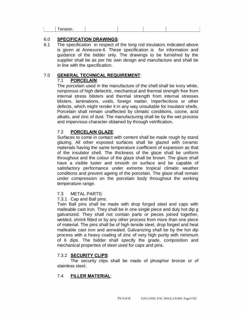
TS-Vol-II E20-COND, E/W, INSULATORS- Page37/82
Tension. 6.0 SPECIFICATION DRAWINGS: 6.1 The specification in respect of the long rod insulators indicated above
is given at Annexure-II. These specification is for information and guidance of the bidder only. The drawings to be furnished by the supplier shall be as per his own design and manufacture and shall be in line with the specification.
7.0 GENERAL TECHNICAL REQUIREMENT: 7.1 PORCELAIN: The porcelain used in the manufacture of the shell shall be ivory white, nonporous of high dielectric, mechanical and thermal strength free from internal stress blisters and thermal strength from internal stresses blisters, laminations, voids, foreign matter. Imperfections or other defects, which might render it in any way unsuitable for insulator shells. Porcelain shall remain unaffected by climatic conditions, ozone, acid alkalis, and zinc of dust. The manufacturing shall be by the wet process and impervious character obtained by through vetrification. 7.2 PORCELAIN GLAZE: Surfaces to come in contact with cement shall be made rough by stand glazing. All other exposed surfaces shall be glazed with ceramic materials having the same temperature coefficient of expansion as that of the insulator shell. The thickness of the glaze shall be uniform throughout and the colour of the glaze shall be brown. The glaze shall have a visible luster and smooth on surface and be capable of satisfactory performance under extreme tropical climatic weather conditions and prevent ageing of the porcelain. The glaze shall remain under compression on the porcelain body throughout the working temperature range. 7.3 METAL PARTS: 7.3.1 Cap and Ball pins: Twin Ball pins shall be made with drop forged steel and caps with malleable cast iron. They shall be in one single piece and duly hot dip g galvanized. They shall not contain parts or pieces joined together, welded, shrink fitted or by any other process from more than one piece of material. The pins shall be of high tensile steel, drop forged and heat malleable cast iron and annealed. Galvanizing shall be by the hot dip process with a heavy coating of zinc of very high purity with minimum of 6 dips. The bidder shall specify the grade, composition and mechanical properties of steel used for caps and pins. 7.3.2 SECURITY CLIPS: The security clips shall be made of phosphor bronze or of stainless steel. 7.4 FILLER MATERIAL:

TS-Vol-II E20-COND, E/W, INSULATORS- Page38/82
Cement to be used as a filler material shall be quick setting, for curing Portland cement. It shall not cause fracture by expansion or loosening by contraction. Cement shall not react chemically with metal parts in contract with it and its thickness shall be as small and as uniform as possible.
8.0 MATERIAL DESIGN AND WORKMANSHIP: 8.1 GENERAL:
i) All raw materials to be used in the manufacture of these insulators shall be subject to strict raw materials quality control and to stage testing quality control during manufacturing stage to ensure the quality of the final end product. Manufacturing shall conform to the best engineering practices adopted in the field of extra high voltage transmission. Bidders shall therefore offer insulators as are guaranteed by them for satisfactory performance on Transmission lines. ii) The design, manufacturing process and material control at various stages be such as to give maximum working load, highest mobility, best resistance to corrosion good finish, elimination of sharp edges and corners to limit corona and radio interference voltage
8.2 INSULATOR SHELL:
The design of the insulator shell shall be such that stresses due to expansion and contraction in any part of the insulator shall not lead to deterioration. Shells with cracks shall be eliminated by temperature cycle test followed by temperature cycle test followed by mallet test. Shells shall be dried under controlled conditions of humidity and temperature.
8.3 METAL PARTS: i) The twin ball pin and cap shall be designed to transmit the mechanical stresses to the shell by compression and develop uniform mechanical strength in the insulator. The cap shall be circular with the inner and outer surfaces concentric and of such design that it will not yield or distort under loaded conditions. The head portion of the insulator or is under tension the stresses are uniformly distributed over the pinhole portion of the shell. The pinball shall move freely in the cap socket either during assembly of a string or during erection of a string or when a string is placed in position. ii) Metal caps shall be free from cracks, seams, shrinks, air holes, blowholes and rough edges. All metal surfaces shall be perfectly smooth with no projecting parts or irregularities which may cause corona. All load bearing surfaces shall be smooth and uniform so as to distribute the loading stresses uniformly. Pins shall not show any macroscopically visible cracks, insulations and voids.
8.4 GALVANIZING:
All ferrous parts shall be hot dip galvanized six times in accordance with IS: 2629. The zinc to be used for galvanizing shall conform to grade Zn 99.5 as per IS: 209. The zinc coating shall be uniform, smoothly adherent, reasonably light, continuous and free from

TS-Vol-II E20-COND, E/W, INSULATORS- Page39/82
impurities such as flux ash, rust stains, bulky white deposits and blisters. Before ball fittings are galvanized, all die flashing on the shank and on the bearing surface of the ball shall be carefully removed without reducing the designed dimensional requirements.
8.4.1 CEMENTING: The insulator design shall be such that the insulating medium shall not directly engage with hard metal. The surfaces of porcelain and coated with resilient paint to offset the effect of difference in thermal expansions of these materials.
8.5 SECURITY CLIPS (LOCKING DEVICES The security clips to be used as locking device for ball and socket coupling shall be ‘R’ shaped hump type to provide for positive locking of the coupling as per IS: 2486 (Part-IV). The legs of the security clips shall allow for sore adding after installation to prevent complete withdrawal from the socket. The locking device shall be resilient corrosion resistant and of sufficient mechanical strength. There shall be no possibility of the locking device to be displaced or be capable of rotation when placed in position and under no circumstances shall it allow separation of insulator units and fitting ‘W’ type security clips are also acceptable. The hole for the security clip shall be countersunk and the clip shall be of such design that the eye of the clip may be engaged by a hot line clip puller to provide for disengagement under energized conditions. The force required for pulling the clip into its unlocked position shall not be less than 50 N (5 Kgs.) or more than 500N (50 Kgs.)
8.6 BALL AND SOCKET DESIGNATION: The dimensions of the balls and sockets for 80 KN long rod insulators shall be of 16mm and for 120 KN shall be of 20mm designation in accordance with the standard dimensions stated in IS: 2486 (Part-III).
8.7 DIMENSIONAL TOLERANCE OF INSULATORS DISCS It shall be ensured that the dimensions of the long rod insulators are within the limits as per relevant IEC/ISS.
9.0 TESTS (FOR DISC INSULATORS) : 9,1 The following tests shall be carried out on the insulator string and disc
insulators.
9.2 TYPE TEST: This shall mean those tests, which are to be carried out to prove the design, process of manufacture and general conformity of the material and product with the intents of this specification. These tests shall be conducted on a representative number of samples prior to commencement of commercial production. The Bidder shall indicate his schedule for carrying out these tests.

TS-Vol-II E20-COND, E/W, INSULATORS- Page40/82
9.3 ACCEPTANCE: This shall mean these tests, which are to be carried out on samples taken from each lot offered for pre-despatch inspection for the purpose of acceptance of the lot.
9.4 ROUTINE TESTS: This shall mean those tests, which are to be carried out on each insulator to check the requirements, which are likely to vary during production.
9.5 TESTS DURING MANUFACTURE: Stage tests during manufacture shall mean those tests, which are to be carried out during the process of manufacture to ensure quality control such that the end product is of the designed quality conforming to the intent of this specification.
9.6 TEST VALUE: For all type and acceptance tests the acceptance values shall be the value guaranteed by the bidder in the guaranteed technical particulars of the acceptance value specified in this specification of the relevant standard whichever is more stringent for that particular test.
9.7 TEST PROCEDURE AND SAMPLING NORMS: The norms and procedure of sampling for the above tests shall be as per the relevant Indian Standard or the Internationally accepted standards. This will be discussed and mutually agreed to between the supplier and purchaser before placement of order. The standards and normal according to which these tests are to be carried out are listed against each test. Where a particular test is a specific requirement of this specification, the norms land procedure for the same shall be as specified in Annexure-IV attached hereto as mutually agreed to between the supplier and the purchaser in the quality assurance programme.
9.8 TYPE TESTS: The following type test shall be conducted on a suitable number of individual unit components, materials or complete strings.
9.8.1 On the complete insulator string with hardware fittings. a) Power frequency voltage withstand test with
corona control rings and under wet condition. : BS:137(Part-I)
b) Switching surge voltage withstand test under wet condition (400 only)
:
c) Impulse voltage withstand test under dry condition.
: IEC: 383
d) Impulse voltage flashover test under dry condition.
:
e) Voltage distribution test. : f) Corona & RIV test under dry condition. : As per this
specification. g) Mechanical strength test. : As per this

TS-Vol-II E20-COND, E/W, INSULATORS- Page41/82
specification. h) Vibration. : 9.8.2 On Insulators: a) Verification of dimensions. : IS: 731 b) Thermal mechanical performance test: : IEC:575 c) Power frequency voltage withstand and
flashover (I) dry (ii) wet.
: BS: 173
d) Impulse voltage withstand flashover test (dry) : IEC: 383 e) Visible discharge test (dry) : IS:731 f) RIV test (dry) : IS:8263 9.8.3 All the type tests given under clause No.6.8.1
above shall be conducted on single suspension and Double Tension insulator string alongwith hardware fittings.
9.9 ACCEPTANCE TESTS: 9.9.1 For insulator: a) Visual examination : IS:731 b) Verification of dimensions. : IS:731 c) Temperature cycle test. : IS:731 d) Galvanizing test. : IS:731 e) Mechanical performance test. : IEC:575 f) Test on locking device for ball and socket
coupling. : IEC:372
g) Eccentricity test. : As per this specification.
h) Electro-mechanical strength test. : i) Puncture test. : IS:731 j) Porosity test. : IS:731 9.10 ROUTINE TESTS: 9.10.1
For insulators:
a) Visual inspection. : IS:731 b) Mechanical routine test. : c) Electrical routine test. : IEC:383 9.11 TEST DURING MANUFACTURE: On all components as applicable. a) Chemical analysis of zinc used for
galvanizing. :
b) Chemical analysis, mechanical and metallographic test and magnetic particle inspection for malleable castings.
:
c) Chemical analysis, hardness test and magnetic particle inspection for forgings.
: As per this specification.
d) Hydraulic Internal Pressure tests on shell. : e) Crack detection test for metal parts. :
9.12 ADDITIONAL TEST:

TS-Vol-II E20-COND, E/W, INSULATORS- Page42/82
The purchaser reserves the right for carrying out any other tests of a reasonable nature at the works of the supplier/ laboratory or at any other recognized laboratory/ research institute in addition to the above mentioned type, acceptance and routine tests at the cost of the purchaser to satisfy that the material complies with the intent of this specification.
9.13 CO-ORDINATION FOR TESTING: For insulator strings, the supplier shall arrange to conduct testing of their disc insulators with the hardware fittings to be supplied to the purchaser by other suppliers. The supplier is also required to guarantee overall satisfactory performance of the disc insulator with the hardware fittings. NOTE: In respect of electrical tests on a complete string consisting of insulators and hardware guarantee of values of responsibility of testing shall be with hardware manufacturer of RIV corona and voltage distribution test and with insulator manufacturer for all other tests.
9.14 TEST CHARGES AND TEST SCHEDULE: 9.14.1 TYPE TEST:
The insulator offered shall be fully type tested as per this specification. In case the equipment of the type and design offered, has already been type tested in an independent test laboratory. The bidder shall furnish four sets of type test reports alongwith the offer. These tests must not have been conducted earlier than five years. The purchaser reserves the right to demand repetition of some or all type tests in the presence of purchasers’ carrying representative. For this purpose the bidder may quote unit rates for carrying out each type test. These prices shall be taken into consideration for bid evaluation. For any change in the design/type already type tested and the design/type offered against this specification, purchaser reserves the right to demand repetition of tests without any extra cost.
9.14.2 ACCEPTANCE AND ROUTINE TEST: All acceptance and routine tests as stipulated herein shall be carried out by the supplier in the presence of purchaser’s representative.
9.14.3 Immediately after finalisation of the programme of type/ acceptance/ routine testing, the supplier shall give sufficient advance intimation to the purchaser to enable him to depute his representative for witnessing the tests.
9.14.4 For type tests involving tests on a complete insulator string with hardware fittings, the purchaser will advice the supplier of the hardware fittings to provide the necessary fittings to the place of the test.
9.14.5 In case of failure of the complete string in any type tests, the supplier whose product has failed in the tests, shall get the tests repeated at his cost.
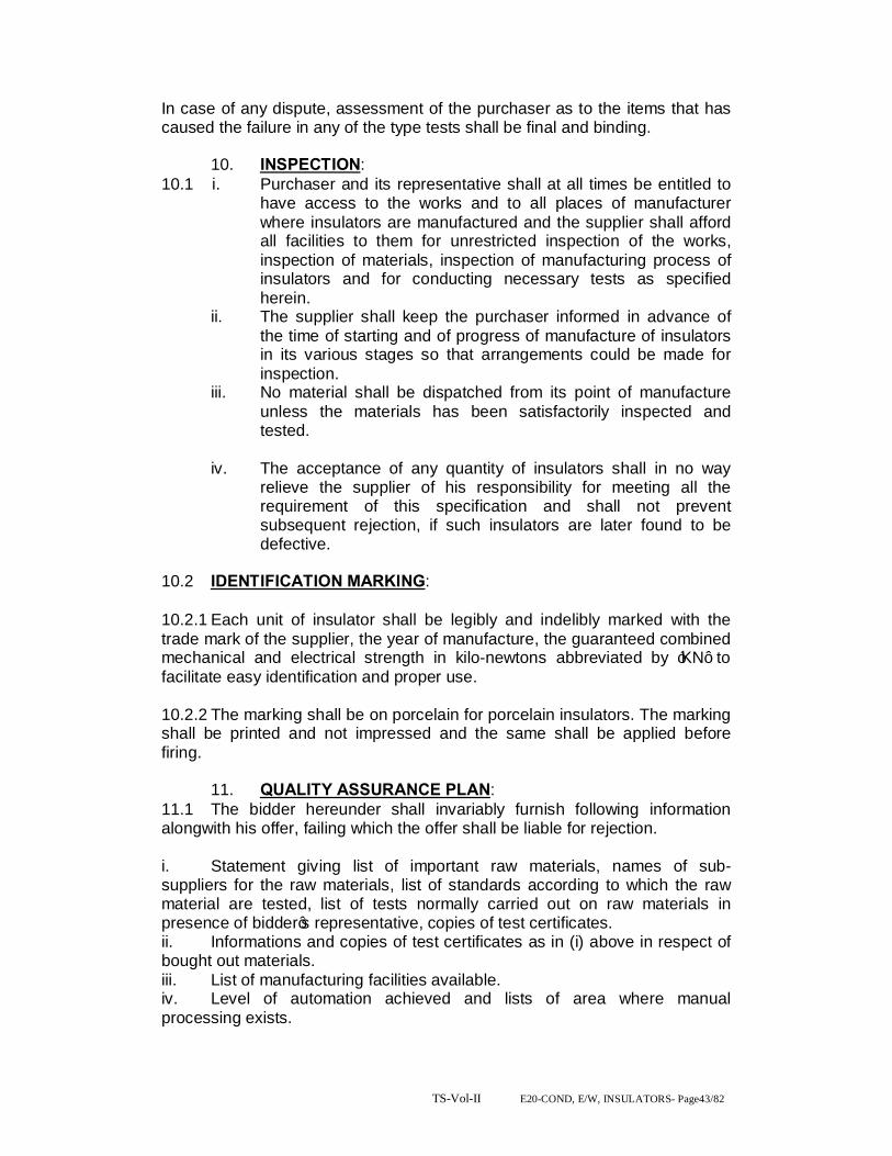
TS-Vol-II E20-COND, E/W, INSULATORS- Page43/82
In case of any dispute, assessment of the purchaser as to the items that has caused the failure in any of the type tests shall be final and binding.
10. INSPECTION:
10.1 i. Purchaser and its representative shall at all times be entitled to have access to the works and to all places of manufacturer where insulators are manufactured and the supplier shall afford all facilities to them for unrestricted inspection of the works, inspection of materials, inspection of manufacturing process of insulators and for conducting necessary tests as specified herein.
ii. The supplier shall keep the purchaser informed in advance of the time of starting and of progress of manufacture of insulators in its various stages so that arrangements could be made for inspection.
iii. No material shall be dispatched from its point of manufacture unless the materials has been satisfactorily inspected and tested.
iv. The acceptance of any quantity of insulators shall in no way
relieve the supplier of his responsibility for meeting all the requirement of this specification and shall not prevent subsequent rejection, if such insulators are later found to be defective.
10.2 IDENTIFICATION MARKING:
10.2.1 Each unit of insulator shall be legibly and indelibly marked with the trade mark of the supplier, the year of manufacture, the guaranteed combined mechanical and electrical strength in kilo-newtons abbreviated by ‘KN’ to facilitate easy identification and proper use. 10.2.2 The marking shall be on porcelain for porcelain insulators. The marking shall be printed and not impressed and the same shall be applied before firing.
11. QUALITY ASSURANCE PLAN:
11.1 The bidder hereunder shall invariably furnish following information alongwith his offer, failing which the offer shall be liable for rejection.
i. Statement giving list of important raw materials, names of sub-suppliers for the raw materials, list of standards according to which the raw material are tested, list of tests normally carried out on raw materials in presence of bidder’s representative, copies of test certificates. ii. Informations and copies of test certificates as in (i) above in respect of bought out materials. iii. List of manufacturing facilities available. iv. Level of automation achieved and lists of area where manual processing exists.

TS-Vol-II E20-COND, E/W, INSULATORS- Page44/82
v. List of areas in manufacturing process, where stage inspections are normally carried out in quality control and details of such tests and inspection. vi. Special features provided in the equipment to make it maintenance free. vii. List of testing equipping available with the bidder for final testing of equipment specified and test plant limitation, if any, vis-à-vis the type, special, acceptance and routine tests specified in the relevant standards. These limitations shall be very clearly brought out in schedule of deviations from specified test requirements. 11.2 The supplier shall within 30 days of placement of order submit the following information to the owner. i) List of raw material and the names of sub-suppliers selected from those furnished alongwith the offer.
POST INSULATORS. Post insulator shall conform in general to IS 2544, IEC 168 and IEC 815. 3.1 constructional features Post type insulators shall consist of a porcelain part permanently secured in a metal base to be mounted on the supporting structures. They shall be capable of being mounted upright and be designed to with stand any shocks to which they may bed subjected to by the operation of the associated equipment. Only solid core insulators will be acceptable. Porcelain used shall be homogeneous, free from lamination, cavities and other flaws or imperfections that might after the mechanical or dielectric quality and shall be thoroughly vitrified, tough and impervious to moisture. Glazing of the porcelain shall be of uniform brown in colour, free from blisters, burrs and other similar defects. The insulator shall have alternate long and short sheds with aerodynamic profile. The shed profile shall also meet the requirements of IEC 815 for the specified pollution level. When operated at normal rated voltage there shall be no electric discharge between conductor and insulators which would cause corrosion or injury to conductors or insulators by the formation of substance produced by chemical action. The design of the insulators shall be such that stresses due to expansion and contraction in any part of the insulator shall not lead to deterioration. All ferrous parts shall be hot dip galvanized in accordance with the latest edition of IS 2633, and IS 4579. The zinc used for galvanizing shall be grade Zn 99.95 as per IS 209. The zinc coating shall be uniform, adherent, smooth, reasonably bright, continuous and free from imperfections such as flux ash, rust stains, bulky while deposits and blisters. The metal parts shall not produce any noise generating corona

TS-Vol-II E20-COND, E/W, INSULATORS- Page45/82
under the operating conditions. Flat washer shall be circular of a diameter 2.5 times that of bolt and of suitable thickness. Where bolt heads/nuts bear upon the beveled surfaces they shall be provided with square tapered washers of suitable thickness to afford a seating square with the axis of the bolt.
Bidder shall make available data on all the essential features of design including the method of assembly of shells and metals parts, number of shells per insulator, the manner in which mechanical stresses are transmitted through shells to adjacent parts, provision for meeting expansion stresses, results of corona and thermal shock tests, recommended working strength and any special design or arrangement employed to increase life under service conditions.
12. TEST DETAILS. 1. VOLTAGE DISTRIBUTION TEST: The voltage across each insulator unit shall be measured by sphere gap method. The result obtained shall be converted into percentage and proportionate correction be applied as to give a total of 100% distribution. The voltage across any disc. Not exceed the values given in clause 4-12.1 2. CORONA EXTINCTION VOLTAGE TEST (DRY): The sample assembly when subjected to power frequency voltage shall have a corona extinction voltage of not less than the value specified at clause 4.12.1 (iv) under dry condition. There shall be no evidence of corona on any part of the sample when all possible sources of corona are photographed in a darkened room. 3. RIV TEST (DRY): Under the conditions as specified in (2) above, the insulator string along with complete hardware fittings shall have a radio interference voltage level below 500 micro volts at one MHz when subjected to 50 Hz AC voltage of 1.1 times maximum time to ground voltage under dry condition. The test procedure shall be in accordance with IS: 8263.
4. The complete insulator string along with its hardware fitting excluding arcing horn corona controlling/grading ring and suspension assembly/dead end assembly shall be subject to a load equal to 50% of the specified minimum ultimate tensile strength (UTS) which shall be increased already rate to 68% of the minimum UTS specified. The load shall be held for five minutes and then removed. After removal of the load, the string components shall not show any visual deformation and it shall be possible to disassemble them by hand,. Hand tools may be used to remove cotter pins and loosen the nuts initially. The string shall then be reassembled and loaded to 50% of UTS and the load shall be further increased at a steady rate till the specified minimum UTS and held for one minute. No fracture should occur during this period. The applied load shall then be increased until the failing loads reached and the value recorded.

TS-Vol-II E20-COND, E/W, INSULATORS- Page46/82
5. VIBRATION TEST: The suspension string shall be tested in suspension mode, and tension string in tension mode itself in laboratory span of minimum 30 meters. In the case of suspensions string a load equal to 600 Kg. shall be applied along with the axis of the suspensions string by means of turn buckle. The insulators string along with hardware fittings and two sub conductors throughout the duration of the test vibration dampers shall not be used on the test span. Both the sub-conductors shall be vertically vibrated simultaneously at one of the resonance frequencies of the insulator string (more than 10Hz) by means of vibration inducing equipment. The amplitude of vibration at the antipode point nearest to the string shall be measured and the same shall not be less than 120.4 being the frequency of vibration. The insulator strings shall be vibrated for five million cycles then rotated by 90 deg and again vibrated for 5 million cycles without any failure, after the test, the disc insulators shall be examined for looseness of pins and cap or any crack in the cement. The hardware fittings shall be examined to fatigue fatter and mechanical strength test. There shall be no deterioration of properties of hardware components and disc insulators after the vibration test. The disc insulators shall be subjected to the following tests as per relevant standards.
Test. Percentage of disc To be tested.
a) Temperature cycle test followed by 60 Mechanical performance test. 40 b) Puncture test (for porcelain insulator only) 6. CHEMICAL ANALYSIS OF ZINC USED FOR GALVANIZING. Samples taken from the zinc ingot shall be chemically analysed as per IS: 209. The purity of zinc shall not be less than 99.95%.
7. TEST FOR FORGINGS: The chemical analysis hardness tests and magnetic particle inspection for forgings will be as per the internationally recognized procedures for these tests. The sampling will be based on heat number and heat treatment batch. The details regarding test will be as discussed and mutually agreed to by the supplier and purchaser in quality assurance programme.
1. TEST ON CASTING: The chemical analysis mechanical and metallographic tests and magnetic particle inspection for castings will be as per the internationally recognized procedures for these tests. The samplings will be based on heat number and heat treatment batch. The details regarding test will be as discussed and mutually agreed to by the supplier and purchaser in quality assurance programme.
2. HYDRAULIC INTERNAL PRESSURE TEST ON SHELLS:
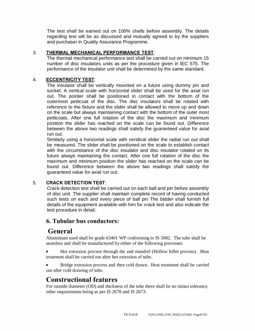
TS-Vol-II E20-COND, E/W, INSULATORS- Page47/82
The test shall be earned out on 100% shells before assembly. The details regarding test will be as discussed and mutually agreed to by the suppliers and purchaser in Quality Assurance Programme.
3. THERMAL MECHANICAL PERFORMANCE TEST: The thermal mechanical performance test shall be carried out on minimum 15 number of disc insulators units as per the procedure given in IEC 575. The performance of the insulator unit shall be determined by the same standard.
4. ECCENTRICITY TEST: The insulator shall be vertically mounted on a future using dummy pin and socket. A vertical scale with horizontal slider shall be used for the axial run out. The pointer shall be positioned in contact with the bottom of the outermost petticoat of the disc. The disc insulators shall be rotated with reference to the fixture and the slider shall be allowed to move up and down on the scale but always maintaining contact with the bottom of the outer most petticoats. After one full rotation of the disc the maximum and minimum position the slider has reached on the scale can be found out. Difference between the above two readings shall satisfy the guaranteed value for axial run out. Similarly using a horizontal scale with veridical slider the radial run out shall be measured. The slider shall be positioned on the scale to establish contact with the circumstance of the disc insulator and disc insulator rotated on its future always maintaining the contact. After one full rotation of the disc the maximum and minimum position the slider has reached on the scale can be found out. Difference between the above two readings shall satisfy the guaranteed value for axial run out.
5. CRACK DETECTION TEST: Crack detection test shall be carried out on each ball and pin before assembly of disc unit. The supplier shall maintain complete record of having conducted such tests on each and every piece of ball pin The bidder shall furnish full details of the equipment available with him for crack test and also indicate the test procedure in detail.
6. Tubular bus conductors: General Aluminium used shall be grade 63401 WP conforming to IS 5082. The tube shall be seamless and shall be manufactured by either of the following processes:
• Hot extrusion process through die and mandrel (Hollow billet process). Heat treatment shall be carried out after hot extrusion of tube.
• Bridge extrusion process and then cold drawn. Heat treatment shall be carried out after cold drawing of tube.
Constructional features For outside diameter (OD) and thickness of the tube there shall be no minus tolerance, other requirements being as per IS 2678 and IS 2673.
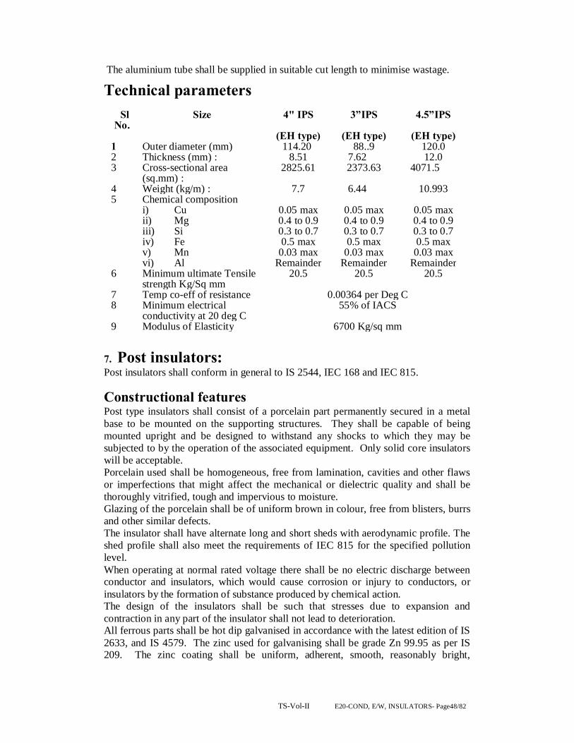
TS-Vol-II E20-COND, E/W, INSULATORS- Page48/82
The aluminium tube shall be supplied in suitable cut length to minimise wastage.
Technical parameters
Sl No.
Size 4" IPS 3”IPS 4.5”IPS
(EH type) (EH type) (EH type) 1 Outer diameter (mm) 114.20 88..9 120.0 2 Thickness (mm) : 8.51 7.62 12.0 3 Cross-sectional area
(sq.mm) : 2825.61 2373.63 4071.5
4 Weight (kg/m) : 7.7 6.44 10.993 5 Chemical composition
i) Cu ii) Mg iii) Si iv) Fe v) Mn vi) Al
0.05 max 0.4 to 0.9 0.3 to 0.7 0.5 max
0.03 max Remainder
0.05 max 0.4 to 0.9 0.3 to 0.7 0.5 max
0.03 max Remainder
0.05 max 0.4 to 0.9 0.3 to 0.7 0.5 max 0.03 max
Remainder 6 Minimum ultimate Tensile
strength Kg/Sq mm 20.5 20.5 20.5
7 Temp co-eff of resistance 0.00364 per Deg C 8 Minimum electrical
conductivity at 20 deg C 55% of IACS
9 Modulus of Elasticity 6700 Kg/sq mm
7. Post insulators: Post insulators shall conform in general to IS 2544, IEC 168 and IEC 815.
Constructional features Post type insulators shall consist of a porcelain part permanently secured in a metal base to be mounted on the supporting structures. They shall be capable of being mounted upright and be designed to withstand any shocks to which they may be subjected to by the operation of the associated equipment. Only solid core insulators will be acceptable. Porcelain used shall be homogeneous, free from lamination, cavities and other flaws or imperfections that might affect the mechanical or dielectric quality and shall be thoroughly vitrified, tough and impervious to moisture. Glazing of the porcelain shall be of uniform brown in colour, free from blisters, burrs and other similar defects. The insulator shall have alternate long and short sheds with aerodynamic profile. The shed profile shall also meet the requirements of IEC 815 for the specified pollution level. When operating at normal rated voltage there shall be no electric discharge between conductor and insulators, which would cause corrosion or injury to conductors, or insulators by the formation of substance produced by chemical action. The design of the insulators shall be such that stresses due to expansion and contraction in any part of the insulator shall not lead to deterioration. All ferrous parts shall be hot dip galvanised in accordance with the latest edition of IS 2633, and IS 4579. The zinc used for galvanising shall be grade Zn 99.95 as per IS 209. The zinc coating shall be uniform, adherent, smooth, reasonably bright,

TS-Vol-II E20-COND, E/W, INSULATORS- Page49/82
continuous and free from imperfections such as flux ash, rust stains, bulky white deposits and blisters. The metal parts shall not produce any noise generating corona under the operating conditions. Flat washer shall be circular of a diameter 2.5 times that of bolt and of suitable thickness. Where bolt heads/nuts bear upon the bevelled surfaces they shall be provided with square tapered washers of suitable thickness to afford a seating square with the axis of the bolt. Bidder shall make available data on all the essential features of design including the method of assembly of shells and metals parts, number of shells per insulator, the manner in which mechanical stresses are transmitted through shells to adjacent parts, provision for meeting expansion stresses, results of corona and thermal shock tests, recommended working strength and any special design or arrangement employed to increase life under service conditions.
Services to be performed by the equipment being furnished The equipment shall be able to withstand forces due to wind load on the equipment and approach conductor and due to short circuit, all forces considered together. The Contractor shall submit detailed calculations proving the satisfactory performance of the equipment under short circuit conditions to meet the layout requirements.
Technical Parameters SI No. Parameter 400kV 245kV 132kV 33klV
1 Type Confirming to IEC 273 (solid core ) 2 Voltage class (kV) 420 245 145 36 3 Dry and wet one minute
withstand voltage (kVrms) 630 460 235 70
4 Dry lightning impulse withstand voltage (kVp)
± 1550 ± 1050 ± 650 ± 250
5 Wet switching surge withstand voltage (kVp)
± 1175 NA NA NA
6 Max. RIV at corona extinction voltage (microvolts)
500 500 500 NA
7 Corona extinction voltage (kVrms)
320 (min) 156 (min) 105
9 Total minimum cantilever strength (kg)
not< 800 not< 800 not< 600 not< 600
10 Minimum torsional moment
As per IEC 273
11 Total height of insulator (mm)
3650 2300 1100 325
12 PCD (mm) top/bottom
127/300 127/254 127/254 76/76
13 No. of bolts top/bottom
4/8 4/8 4/8 4/8
14 Diameter of bolt holes (mm) top/bottom
M16/18 M16/18 M16/18 M16/18
15 Pollution level as per IEC 815
Heavy Heavy Heavy Heavy
16 Minimum total creepage distance (mm)
10500 6125 3625 900

TS-Vol-II E20-COND, E/W, INSULATORS- Page50/82
If corona extinction voltage is to be achieved with the help of corona ring or any other similar device, the same shall be deemed to be included in the scope of the Supplier.
8. Spacers
General Spacers shall conform to IS 10162. Spacers are to be located at a suitable spacing to limit the short circuit forces and also to avoid snapping of sub conductors during short circuit conditions.
Constructional features No magnetic material shall be used in the fabrication of spacers except for GI bolts and nuts. Spacer design shall be made to take care of fixing and removing during installation and maintenance.
The design of the spacers shall be such that the conductor does not come in contact with any sharp edge.
SECTION-IV HARDWARES
S.NO. DESCRIPTION PAGE NO.
1. SCOPE

TS-Vol-II E20-COND, E/W, INSULATORS- Page51/82
2. STANDARDS 3. MATERIALS AND DESIGN 4. GALVANISING
5. ACCESSORIES FOR CONDUCTOR AND GROUND WIRE 6. VIBRATION DAMPER FOR ACSR PANTHER, ZEBRA, MOOSE 54 AND GROUND WIRE 7. REPAIR SLEEVE FOR ACSR PANTHR, ZEBRA, MOOSE AND 54 GROUND WIRE 8. SUSPENSION CLAMPS : FOR GROUND WIRE 9. TENSION CLAMPS (DEAD AND ASSEMBLY) FOR GROUND WIRE 10. BONDING PIECES 11. INSULATORS HARDWARE 12. CLAMP 13. TESTS, TEST CERTIFICATE AND PERFORMANCE REPORTS 58
TECHNICAL SPECIFICATION FOR HARDWARE FITTINGS.
SUITABLE FOR GALVANISED STEEL STRANDED GROUNDWIRE (7/3.15mm and 7/3.66 mm) ACCESSORIES

TS-Vol-II E20-COND, E/W, INSULATORS- Page52/82
AND POWER CONDUCTOR ACSR PANTHER ,ACSR ZEBRA AND MOOSE. 1.0 SCOPE
This Specification covers design (if required), manufacture, testing at manufacturer’s Works, supply and delivery of GSS), power conductor and ground wire accessories, insulator and hardware fittings for string insulators suitable for use in 220 and 132 KV Over-head transmission lines and sub- stations of OPTCL. The hard wares to be supplied shall be as per approved drawings of OPTCL. Any change there of shall be with due permission of Sr. G.M (CPC).The firm shall submit his drawings for approval of OPTCL and only after which the manufacturing shall be started.
The materials/equipment offered, shall be complete with all components, which are necessary or usual for the efficient performance and satisfactory maintenance. Such part shall be deemed to be within the scope of contract.
2.0 STANDARDS The materials covered under this Specification shall comply with the requirement of the latest version of the following standards as amended upto date, except where specified otherwise.
i) IS;2486 Part-II & III
: Insulator fitting for overhead power lines with a nominal voltage greater than 1,000 volts.
ii) IS:2121 Part I & II Conductor & earth wire accessories for overhead power lines.
iii) IS:9708 Stock Bridge Vibration Dampers on overhead power lines.
iv) IS:2633 Method of testing of uniformity of coating on zinc coated articles
v) IS:209 Specification for Zinc. vi) BS:916 Specification for Hexagonal bolts and nuts.
3.0 MATERIALS AND DESIGN
Aluminium and aluminium alloys, malleable iron and forget steel, having required mechanical strength, corrosion resistance and mach inability depending on the types of application for which accessories / fittings are needed, shall be employed.
In manufacturer of the accessories / fittings, the composition of the aluminium alloys used shall be made available to Employer if required for verification. The materials offered shall be of first class quality, workmanship, well finished and approved design. All castings shall be free from blow-holes, flaws, cracks of other defects and shall be smooth, close grained and true forms and dimensions. All machined surfaces should be free, smooth and well finished. Metal fittings of specified material for conductor and earth wire accessories and string insulator fittings are required to have excellent mechanical properties such as strength, toughness and high resistance against corrosion. All current carrying parts shall be so designed and manufactured that contact resistance is reduced to the minimum. All bolts, nuts, bolt-heads shall be the white worth’s standard thread. Bolt heads and nuts shall be hexagonal. Nuts shall be locked in an approved manner. The treads in

TS-Vol-II E20-COND, E/W, INSULATORS- Page53/82
nuts and tapped holes shall be cut after galvanising an shall be well fabricated and greased. All other treads shall be cut before galvanising. The bolt treads shall be undercut to take care of increase in diameter due to galvanising. All nuts shall be made of materials to Clause 4.8 of IS:1367 (latest edition) with regard to its mechanical properties. The general design conductor and earthe wire accessories and insulator fittings shall be such as to ensure uniformity, high strength, free from corona formation and high resistance against corrosion even in case of high level of atmosphere pollution. All hooks, eyes, pins, bolts, suspension clamps and other fittings for attaching to the tower or to the line conductor or to the earthwire shall be so designed that the effects of vibration, both on the conductor and the fittings itself, are minimized. Special attention must be given to ensure smooth finished surface throughout. Adequate bearing area between fittings shall be provided and point or line contacts shall be avoided. All accessories and hardwares shall be free from cracks, shrinks, slender air holes, burrs or rough edges. The design of he accessories and hardwares shall be such as to avoid local corona formation or discharge likely to cause interference to tele-transmission signals of any kind. 4.0 GALVANISING :
All ferrous parts of conductor and ground wire accessories and insulator hardwares shall be galvanised in accordance with IS:2629-Recommended Practice for hot dip galvanising of iron and steel or any other equivalent authoritive standards. The weight of zinc coating shall be determined as per method stipulated in IS:2633 for testing weights, thickness and uniformity of coating of hot dip galvanished articles or as per any other equivalent authoritative standards. The zinc used or galvanisation shall conform to grade zn 98 of IS:209. The galvanised parts shall withstand four (4) dips of 1 minute each time while testing uniformity of zinc coating as per IS:2633.
Spring washers shall be elctro galvanised. 5.0 ACCESSORIES FOR CONDUCTOR AND GROUND WIRE, MID SPAN COMPRESSION JOINTS:FOR ACSR- PANTHER ,ZEBRA, MOOSE AND GROUNDWIRE OF 7/3.15 and 7/3.66 mm.
The Mid-Span Joints for conductor and earthwire shall be of compression type. The conductor mid-span joints shall comprise of outer aluminium sleeve of extruded aluminium (99.5% purity) and inner sleeve HDG Steel. All filler plug shall also be provided. The ground wire mid-span joints shall be of HDG steel. The sleeves shall be of circular shape suitable for compression into hexagonal shape. The compression type mid-span straight joints shall be suitable for making joints in the ACSR “PANTHER,ZEBRA & MOOSE” conductor or in the galvanised steel stranded ground wire.

TS-Vol-II E20-COND, E/W, INSULATORS- Page54/82
The joints shall be so designed that when installed no air space is left within the finished joints. The joints shall have the conductivity as specified in relevant Clause. The joints shall conform to IS:2121 (latest edition) unless specified otherwise. The details of the joints both suitable for ACSR- Panther,Zebra & Moose and ground wire are given in the technical particulars. The inner and outer diameters and lengths of the offered joints before and after compression shall be clearly shown in the drawings. 6.0 VIBRATION DAMPER FOR ACSR PANTHER,ZEBRA MOOSE AND GROUND WIRE(7/3.15 and 7/3.66 mm) Vibration Damper having 4 resonance frequency characteristic commonly called 4R Damper shall be offered. The Damper shall eliminate fatigue on the conductor due to vibration and damp out the vibration effectively so that no damage due to vibration is caused to conductor / ground wire / string. The dampers are proposed to be used at all tension locations and also at suspension locations. One or more dampers are proposed to be used on tension/suspension locations depending upon the span. Bidder shall also recommend the number of damper required to effectively damp out conductor or ground wire vibration for different values of span lengths and the distance of fixation. Vibration dampers shall be of approved design. The clamps of the vibration dampers shall be made of aluminium alloy, so designed as to prevent any damage while fixing on the conductor during erection or in continued operation. The fastening bolts should be approved by the Employer. The spring washers should be elctro galvanised and of minimum 2 mm thickness. The messenger cable shall be made from high tensile strength steel strands in order to prevent subsequent drop of weight in service. Clamping bolts shall be provided with self locking nuts as designed to prevent corrosion of the threads. All ferrous parts including the messenger cable shalal be bot dip galvanised. The end of the messenger cable shall be effectively sealed to prevent corrosion. The vibration dampers and its attachment shall have smooth surface so that no corona occurs on them. The clamps of the stock bridge vibration dampers shall be so designed that in case of loosening of the bolt or changing free parts of the clamp, it does not allow the damper to disengage from the conductor. 7.0 REPAIR SLEEVE FOR ACSR PANTHER,ZEBRA,MOOSE
AND GROUNDWIRE : Compression type repair sleeves shall be offered to provide reinforcement for conductor with broken or damaged aluminium strands/galvanished steel ground wire broken in damaged steel strands. The repair sleeve shall be designed to make good a conductor of which not more than one-sixth (1/6th) of the strands in the outermost layer and damaged or severed. The repair sleeves after compression should present a smooth surface. 8.0 SUSPENSION CLAMPS : FOR GROUND WIRE
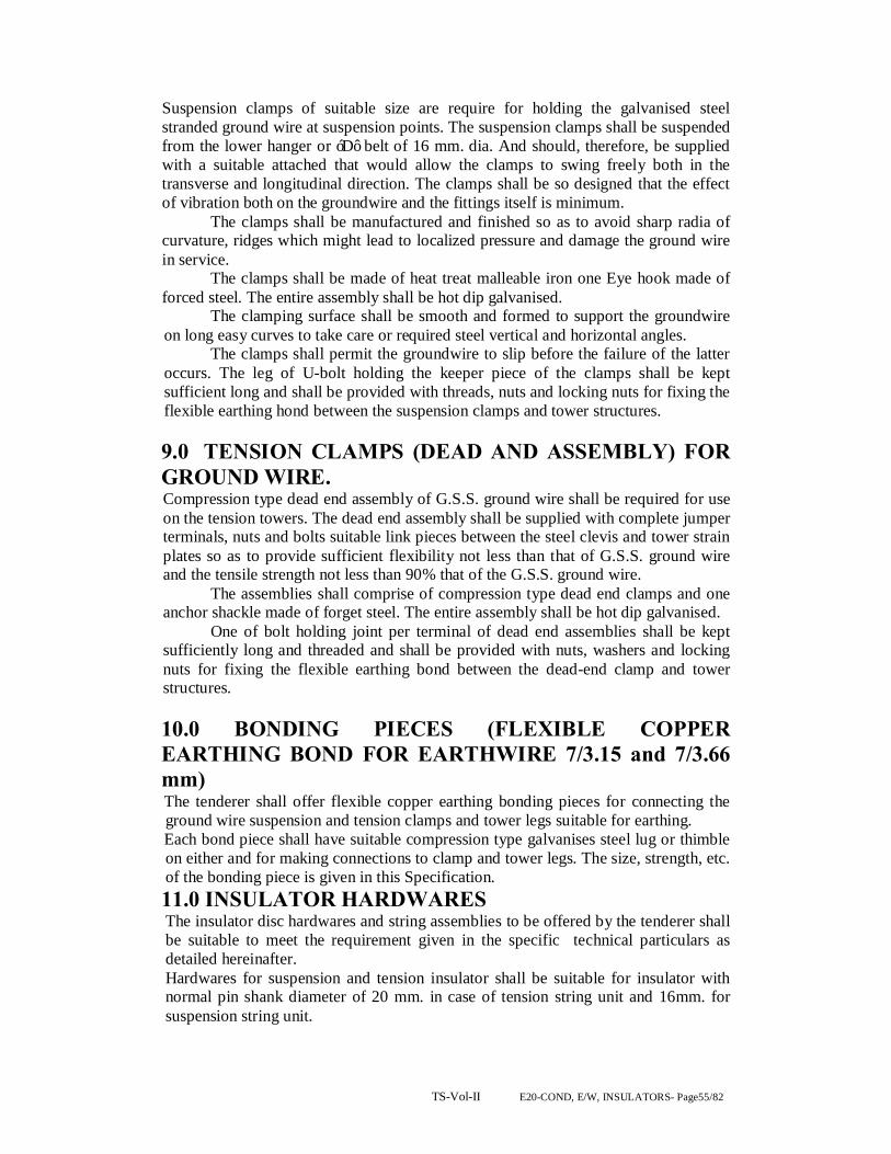
TS-Vol-II E20-COND, E/W, INSULATORS- Page55/82
Suspension clamps of suitable size are require for holding the galvanised steel stranded ground wire at suspension points. The suspension clamps shall be suspended from the lower hanger or ‘D’ belt of 16 mm. dia. And should, therefore, be supplied with a suitable attached that would allow the clamps to swing freely both in the transverse and longitudinal direction. The clamps shall be so designed that the effect of vibration both on the groundwire and the fittings itself is minimum. The clamps shall be manufactured and finished so as to avoid sharp radia of curvature, ridges which might lead to localized pressure and damage the ground wire in service. The clamps shall be made of heat treat malleable iron one Eye hook made of forced steel. The entire assembly shall be hot dip galvanised. The clamping surface shall be smooth and formed to support the groundwire on long easy curves to take care or required steel vertical and horizontal angles. The clamps shall permit the groundwire to slip before the failure of the latter occurs. The leg of U-bolt holding the keeper piece of the clamps shall be kept sufficient long and shall be provided with threads, nuts and locking nuts for fixing the flexible earthing hond between the suspension clamps and tower structures.
9.0 TENSION CLAMPS (DEAD AND ASSEMBLY) FOR GROUND WIRE. Compression type dead end assembly of G.S.S. ground wire shall be required for use on the tension towers. The dead end assembly shall be supplied with complete jumper terminals, nuts and bolts suitable link pieces between the steel clevis and tower strain plates so as to provide sufficient flexibility not less than that of G.S.S. ground wire and the tensile strength not less than 90% that of the G.S.S. ground wire. The assemblies shall comprise of compression type dead end clamps and one anchor shackle made of forget steel. The entire assembly shall be hot dip galvanised. One of bolt holding joint per terminal of dead end assemblies shall be kept sufficiently long and threaded and shall be provided with nuts, washers and locking nuts for fixing the flexible earthing bond between the dead-end clamp and tower structures.
10.0 BONDING PIECES (FLEXIBLE COPPER EARTHING BOND FOR EARTHWIRE 7/3.15 and 7/3.66 mm) The tenderer shall offer flexible copper earthing bonding pieces for connecting the ground wire suspension and tension clamps and tower legs suitable for earthing. Each bond piece shall have suitable compression type galvanises steel lug or thimble on either and for making connections to clamp and tower legs. The size, strength, etc. of the bonding piece is given in this Specification. 11.0 INSULATOR HARDWARES The insulator disc hardwares and string assemblies to be offered by the tenderer shall be suitable to meet the requirement given in the specific technical particulars as detailed hereinafter. Hardwares for suspension and tension insulator shall be suitable for insulator with normal pin shank diameter of 20 mm. in case of tension string unit and 16mm. for suspension string unit.

TS-Vol-II E20-COND, E/W, INSULATORS- Page56/82
Each insulator string shall generally include the following hardware components.
Single Suspension Set.
Double Suspension Set.
a) Ball Hook a) Ball Hook. b) tower side arcing horn b) Socket clevis with R-Type
security clip-3 Nos.
c) Socket Eye with R-Type security clip. c) Yoke Plate-2 Nos. d) Line side arcing horn. d) Tower side arcing horns-
2Nos. e) Armour grip suspension clamps e) Ball clevis – 2 Nos.
f) Line side arcing homs-2 Nos. g) Clevis Eye. h) Armour Grip Suspension Clamp.
Single Tension Set : Double Tension Set : a) Anchor Shackle. a) Anchor Shackle. b) Ball Eye. b) Chain Link c) Tower side arcing horn. c) Yoke Plate – 2 Nos. d) Socket Clevis with R-Type security clip. d) Tower side arching horn. e) Line side arcing horn e) Ball Clevis – 2 Nos. f) Compression type dead end clamp. f) Socket Clevis with R-
Type security clip – 2 Nos. g) Line side arcing horns.
h) Compression type dead end clamps.
12.0 CLAMP 12.1 ARMOUR GRIP SUSPENSION CLAMPS Armour Grip Suspension Clamp shall consist of 2 neoprene insert, one set of armour rods made of aluminium alloy, two aluminium housing having inner profile matching with the profile of the armour rods page and supporting strap made of aluminium alloy. The A.G. type suspension clamp shall be designed, manufactured and finished as to have a suitable shape without sharp edges at the end and to hold the respective conductor properly. It should, however, have sufficient contact surface to minimise damagedue to fault current. The clamp shall be or Armour Grip Type. The A.G. type suspension clamp shall permit the conductor to slip before the occurrence of failure of the conductor and shall have sufficient slip strength to resist the conductor tension under broken wire conditions. The clamp shall have slip strength of not less than 15 % of respective conductors. 12.2 TENSION CLAMPS The Tension Clamps shall be made out of aluminium alloy and of compression type suitable for PANTHER,ZEBRA & MOOSE conductor. The tension clamps shall not permit slipping or damage to failure of the complete conductor or any part thereof at a load less than 90% of the ultimate strength of conductor. The mechanical

TS-Vol-II E20-COND, E/W, INSULATORS- Page57/82
efficiency of tension / clamps shall not be affected by method of erection involving come / along or similar clamps or tension stringing operation during or after assembly and erection of tension clamp itself. The tension clamp shall be of a design that will ensure unrestricted flow of current without use of parallel groove clamps. The clamps shall be as light as possible. 12.3 ARCING HORNS Each hardware assembly shall have provision for attaching arcing horns of both adjustable and non/adjustable type across the suspension and tension strings or tower side. However each hardware assembly shall be provided with arching horn of fixed type on line side only. 12.4 UNIVERSAL JOINTING COMPOUND BENDEX-HV’ Universal jointing compound which is a chemically inert compound to be used as filler for the compression joints and dead end clamps to be supplied. 13.0 TESTS, TEST CERTIFICATE AND PERFORMANCE REPORTS The fittings and accessories for the power conductor and G.S.S. ground wire, insulator and hardwares shall be tested in accordance with IS:2121, IS:2486, IS:9708 (For V Dampers), BS:916 for hexagonal bolts and nuts or any other authoritative equivalent standards. Six sets of type and routine test certificates and performance reports are to be submitted by the bidder. The Employer however, reserves the right to get all the tests performed in accordance with the relevant I.S. Specification as Acceptance Test in presence of Employer-s representatives. The tenderer shall clearly state the testing facilities available in the laboratory at his Works and his ability to carry out the tests in accordance with this Specification. All the specified tests shall be carried out without any extra cost.
Acceptance Test for power conductor and G.S.S. ground wire accessories. a) Visual examination b) Dimensional verification c) Failing load test d) Slip strength test (for clamps) e) Electrical resistance test f) Resonance frequency test (for vibration dampers) g) Fatigue test (for vibration dampers) h) Mass pull off test (for vibration dampers) i) Galvanising test. 13.1 ACCEPTANCE TEST FOR HARDWARES a) Dimensional verification. b) Ultimate tensile test. c) Slip strength test. d) Electrical resistance test. e) Heating cycle test f) Breaking strength of full string assembly.
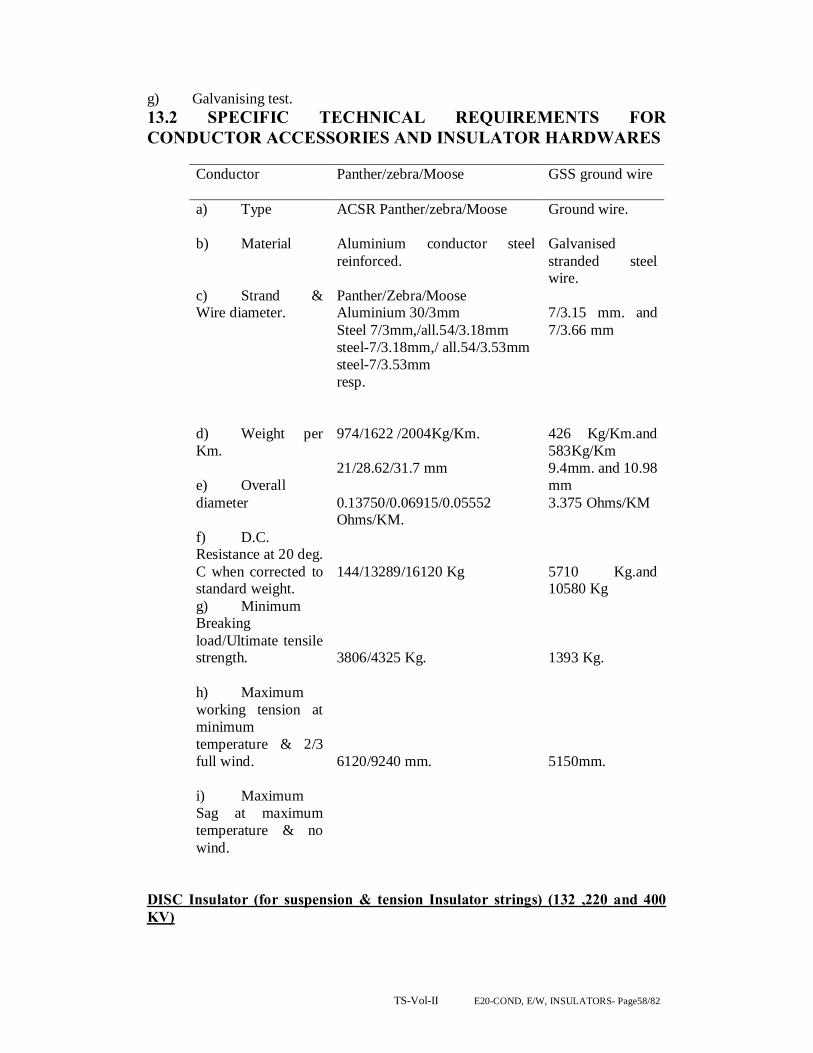
TS-Vol-II E20-COND, E/W, INSULATORS- Page58/82
g) Galvanising test. 13.2 SPECIFIC TECHNICAL REQUIREMENTS FOR CONDUCTOR ACCESSORIES AND INSULATOR HARDWARES
Conductor Panther/zebra/Moose GSS ground wire
a) Type b) Material c) Strand & Wire diameter. d) Weight per Km. e) Overall diameter f) D.C. Resistance at 20 deg. C when corrected to standard weight. g) Minimum Breaking load/Ultimate tensile strength. h) Maximum working tension at minimum temperature & 2/3 full wind. i) Maximum Sag at maximum temperature & no wind.
ACSR Panther/zebra/Moose Aluminium conductor steel reinforced. Panther/Zebra/Moose Aluminium 30/3mm Steel 7/3mm,/all.54/3.18mm steel-7/3.18mm,/ all.54/3.53mm steel-7/3.53mm resp. 974/1622 /2004Kg/Km. 21/28.62/31.7 mm 0.13750/0.06915/0.05552 Ohms/KM. 144/13289/16120 Kg 3806/4325 Kg. 6120/9240 mm.
Ground wire. Galvanised stranded steel wire. 7/3.15 mm. and 7/3.66 mm 426 Kg/Km.and 583Kg/Km 9.4mm. and 10.98 mm 3.375 Ohms/KM 5710 Kg.and 10580 Kg 1393 Kg. 5150mm.
DISC Insulator (for suspension & tension Insulator strings) (132 ,220 and 400 KV)

TS-Vol-II E20-COND, E/W, INSULATORS- Page59/82
Disc Insulators Suspension Tension
a) Type b) Ball size c) Diameter d) Spacing e) E.M. strength
Ball & Socket 16mm. Alt. B (IS:2486 Pt.II) 254/255 mm. 146/145 mm. 90/120 KN,.
Ball & Socket. 20mm. Alt. B/20mm (IS:2486 Pt.II) 255/280 mm 145/170mm. 120/160 KN.
Single Suspension
Single Tension
Double Suspension
Double Tension
132 KV / 220 KV /400 KV String Arrangements : a) No. of insulator discs. b) Length of string assembly (mm)
10/14/25 1672/2340
10/14/25 1851/3003
2x10/2X14 /2X25 1837/2243
2x10/2X14/ 2X25 2132/3082
GENERAL REQUIREMENT FOR POWER
CONDUCTOR & GROUND WIRE: I) ACCESSORIES.
GENERAL REQUIREMENTS POWER CONDUCTOR AND GROUND WIRE ACCESSORIES A) MID-SPAN COMPRESSION JOINTS Suitable for ACSR
“Panther’/zebra/Moose
Suitable for G.S.S. groundwire 7/3.15 and 7/3.66 mm.
i) Type ii) Material a) Outer sleeve
Compression Extruded Aluminium
Compression Extruded aluminium.
b) Inner sleeve
Steel (galvanised) Steel (Galvanised)
Before Compress-ion
After Compre-ssion
Before Compression
After Compression
iii) Dimension of Compression joint
Outer dia:38mm
Adjacent Size 32
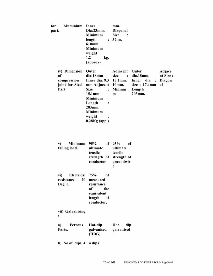
TS-Vol-II E20-COND, E/W, INSULATORS- Page60/82
for Aluminium part.
Inner Dia:23mm. Minimum length : 610mm. Minimum weight 1.2 kg. (approx)
mm. Diagonal Size : 37nn.
iv) Dimension
of compression joint for Steel Part
Outer dia:18mm Inner dia. 9.3 mm Adjacent Size : 15.1mm Minimum Length : 203mm. Minimum weight : 0.28Kg (app.)
Adjacent size : 15.1mm. 10mm. Minimum
Outer dia.18mm. Inner dia : size : 17.4mm Length 203mm.
Adjacent Size : Diagonal
v) Minimum failing load.
95% of ultimate tensile strength of conductor
95% of ultimate tensile strength of groundwire
vi) Electrical resistance 20 Deg. C
75% of measured resistance of the equivalent length of conductor.
vii) Galvanising :
a) Ferrous
Parts. b) No.of dips 4
Hot-dip galvanised (HDG) 4 dips
Hot dip galvanised.
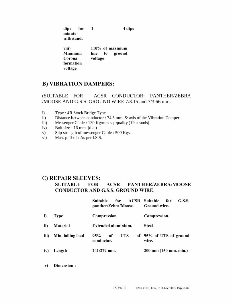
TS-Vol-II E20-COND, E/W, INSULATORS- Page61/82
dips for 1 minute withstand.
4 dips
viii)
Minimum Corona formation voltage
110% of maximum line to ground voltage
B) VIBRATION DAMPERS: (SUITABLE FOR ACSR CONDUCTOR: PANTHER/ZEBRA /MOOSE AND G.S.S. GROUND WIRE 7/3.15 and 7/3.66 mm.
i) Type : 4R Stock Bridge Type ii) Distance between conductor : 74.5 mm. & axis of the Vibration Damper. iii) Messenger Cable : 130 Kg/mm sq. quality (19 strands) iv) Bolt size : 16 mm. (dia.) v) Slip strength of messenger Cable : 500 Kgs. vi) Mass pull-of : As per I.S.S. C) REPAIR SLEEVES:
SUITABLE FOR ACSR PANTHER/ZEBRA/MOOSE CONDUCTOR AND G.S.S. GROUND WIRE.
Suitable for ACSR panther/Zebra/Moose.
Suitable for G.S.S. Ground wire.
i) Type Compression Compression.
ii) Material Extruded aluminium. Steel
iii) Min. failing load 95% of UTS of conductor.
95% of UTS of ground wire.
iv) Length 241/279 mm. 200 mm (150 mm. min.)
v) Dimension :

TS-Vol-II E20-COND, E/W, INSULATORS- Page62/82
a) After compression
(i) Adjacent side
(b) Before Compression : (i)Outerdiameter 38/48mm. (ii)Innerdiameter 23/40mm
21mm 21mm. 11.5mm.
11.5 mm
vii) Electrical
Resistance at 20 deg. C
Not more than 75% of the resi- stance of equivalent length of conductor.
vii) Galvanising : a) Ferrous parts
Hot – dip galvanized
b) No. of dips for one-minute stand.
4 dips
D) SUSPENSION CLAMP: FOR GROUND WIRE 7/3.15 and 7/3.66 mm i) Type : Envelop type ii) Material : Forged Steel / NCL. iii) Minimum slip strength : 25% of UTS of ground wire.
iv) Dimension :
(a) Overall length : 230mm (b) Inner dia. (before : 10mm. compression). (c) Outer diameter : 18mm. (before compression). (d) After Compression : Adjacent : 15.1 mm. Diagonal side : 17.4mm.

TS-Vol-II E20-COND, E/W, INSULATORS- Page63/82
(e) Galvanising : (i) Fwerrous parts. : Hot-dip galvanised. (ii) No. of dips for one- : 4 dips minute withstand.
E) BONDING PIECES:
a) material : flexible copper bond (37/7/ 0.417 mm. tinned copper flexi- ble stranded cable). b) Length : Not less than 750 mm. c) Bolt size : 16mm x 40 mm. d) Copper area. : 34 sq.mm. e) Thickness of long : 6 mm. f) Material for connect - : Tinned Brass ing socket.
F) INSULATOR HARDWARES A) String hardwares :
Material and strength Description of item. Material UTS
i) Bolt hook Forged Steel 11,500 Kgs (90 KN) ii) Anchor Shackle -do- 15,500 Kgs (120 KN) iii) Socket Eye Horn - do- 11,500 Kgs (90 KN) Holder. iv) Socket Clevis. -do- 15,500 Kgs. v) Ball Clevis -do- 15,500 Kgs. vi) Clevis Eye -do- 15,500 Kgs. vii) Socket Eye. -do- 15,500 Kgs.

TS-Vol-II E20-COND, E/W, INSULATORS- Page64/82
vii) Bottom / Top Yoke plate :
Double suspension Mild Steel 11,500 Kgs. Double Tension -do- 15,500 Kgs.
ix) Arcing Horn -do- ___ x) Suspension Clamp. Aluminium ___ Alloy and Neoprene. xi) Tension Clamp. All.Alloy & 11,500 Kgs. Steel. xii) Ball Pin High tensile 90% of UTS of forged steel conductor. (hot-dip galvanised) xiii) Security Clip Brass (R-Type) Mininum failing load Single Suspension : 11,500 String (KN) Single Tension : 11,500/15,500 Double Suspension : 11,500 Double Tension : 11,500/15,500 II) CLAMPS.
Single suspension string
Single tension string
Double suspension string
Double tension string.
i) Type AGS Type Compression Type
AGS Type Compression Type
ii) Material Aluminium Alloy and neoprene
Aluminium Alloy and Steel
Aluminium Ally and Neoprene
Aluminium Alloy and Steel
ii) Minimum slip strength
Not less than 15%
90% of UTS of conductor
Not less than 15% of UTS of conductor
90% of UTS of conductor
iv) Minimum failing load (kg)
11,500
90% of UTS of conductor
11,500 90% Of UTS of conductor
TS-Vol-II E20-COND, E/W, INSULATORS- Page65/82
III). Suspension assembly: armour grip clamp. 1. The armour grip suspension clamp shall comprise of retaining strap,
support housing, elastomer inserts with aluminum reinforcements and AGS preformed rod set.
2. Elastomer insert shall be resistant to the effects of temperature up to 85
deg. C, ozone, Ultraviolet radiation and other atmospheric contaminants likely to be encountered in service. The physical properties of the elastomer shall be of approved standard. It shall be electrically shielded by a cage of AGS preformed rod set. The elastomer insert shall be so designed that the curvature of the AGS rod shall follow the contour of the neoprene insert.
3. The AGS preformed rod set shall be as detailed above in general except
that the length of the AGS preformed rods shall be such that it shall ensure sufficient slipping strength and shall not introduce unfavourable stress on the conductor under all operating conditions.
IV) Fasteners: bolts, nuts & washers. 1. All bolts and nuts shall conform to IS-6639 – 1972. All bolts and nuts
shall be galvanized. All bolts and nuts shall have hexagonal heads, the heads being truly concentric, and square with the shank, which must be perfectly straight.
2. Bolts upto M16 and having length upto ten times the diameter of the bolt
should be manufactured by cold forging and thread rolling process to obtain good and reliable mechanical properties and effective dimensional control. The shear strength of bolt for 5.6 grade should be 310 Mpa minimum as per IS-12427. Bolts should be provided with washer face in accordance with IS-1363 Part-I to ensure proper bearing.
3. Fully threaded bolts shall not be used. The length of the bolt shall be such
that the threaded portion shall not extend into the place of contact of the component parts.
4. All bolts shall be threaded to take the full depth of the nuts and threaded
enough to permit the firm gripping of the component parts but not further. It shall be ensured that the threaded portion of the bolt protrudes not less than 3 mm and not more than 8 mm when fully tightened. All nuts shall fit and be tight to the point where shank of the bolt connects to the head.
TS-Vol-II E20-COND, E/W, INSULATORS- Page66/82
5. Flat washers and spring washers shall be provided wherever necessary and shall be of positive lock type. Spring washers shall be electro-galvanized. The thickness of washers shall conform to IS-2016-1967.
6. The bidder shall furnish bolt schedules giving thickness of components
connected, the nut and the washer and the length of shank and the threaded portion of the bolts and size of holes and any other special details of this nature.
7. To obviate bending stress in bolt, it shall not connect aggregate thickness
more than three time its diameter. 8. Bolts at the joints shall be so staggered that nuts may be tightened with
spanners without fouling. 9. Fasteners of grade higher than 8.8 are not to be used and minimum grade
for bolts shall be 5.6. GENERAL: 1. All ferrous parts including fasteners shall be hot dip galvanized, after all
machining has been completed. Nuts may however be tapped (threaded) after galvanizing and the threads oiled. Spring washers shall be electro-galvanized. The bolt threads shall be undercut to take care of the increase in diameter due to galvanizing. Galvanizing shall be done in accordance with IS-2629-1985 and shall satisfy the tests mentioned in IS 2633-1986. Fasteners shall withstand four dips while spring washers shall withstand three dips of one-minute duration in the standard Preece test. Other galvanized materials shall be guaranteed to withstand at least six successive dips each lasting one minute under the Standard Preece test for galvanizing.
2. The zinc coating shall be perfectly adherent of uniform thickness, smooth,
reasonably bright, continuous and free from imperfections such as flux, ash, rust stains, bulky white deposits and blisters. The zinc used for galvanizing shall be of grade Zn 99.95 as per IS 209-1979.
3. Pin balls shall be checked with the applicable “G)” gauges in at least two
directions, one of which shall be across the line of die flashing and the other 90 deg. to this line. ‘NO GO’ gauges shall not pass in any direction.
4. Socket ends, before galvanizing shall be of uniform contour. The bearing
surface of socket ends shall be uniform about the entire circumference without depressions or high spots. The internal contours of socket ends shall be concentric with the axis of the fittings as per IS 2486/IEC-120. The axis of the bearing surfaces of socket ends shall be coaxial with the axis of the fittings. There shall be no noticeable tilting of the bearing surfaces with the axis of the fittings.

TS-Vol-II E20-COND, E/W, INSULATORS- Page67/82
5. All current carrying parts shall be so designed end manufactured that contact resistance is reduced to minimum.
6. Welding of aluminum shall be by inert gas shielded tungsten are or inert
gas, shielded metal arc process. Welds shall be clean, sound, smooth, and uniform without overlaps, properly fused and completely sealed. There shall be no cracks, voids incomplete penetration, incomplete fusion, under-cutting or inclusions Porosity shall be minimized so that mechanical properties of the aluminum alloys are not affected. All welds shall be properly finished as per good engineering practices.
Electrical Design:
The normal duty and heavy duty suspension, light duty, normal duty and heavy duty tension insulator sets shall all comply with the technical requirements of schedule C and satisfy the test requirements stated in Section-7.
Mechanical design:
The mechanical strength of the insulators and insulator fittings shall be as stated in Schedule-C
The design shall be such that stresses due to expansion and contraction in any part of the insulator shall not lead to the development of defects.
Insulating material shall not engage directly with hard metal. All fixing materials shall be of approved quality, shall be applied in an approved manner and shall not enter into chemical action with the metal parts or cause fracture by expansion in service. Where cement is used as a fixing medium, cement thickness shall be as small and even as possible and proper care shall be taken to correctly centre and locate the individual parts during cementing. Technical Specification for Design, Supply and Testing of Hard ware fittings. Type tests: The following type tests shall be conducted on hardware fittings.
A. On suspension hardware fittings only. (a) Magnetic power loss test. (b) Clamp slip strength Vs torque (c ) Mechanical strength test. (d) On one test on elastomer. B. On Tension hard ware fittings only. Electrical resistance test for IS 2486 (Part-I) 1971 Dead end assembly. (a) Heating cycle test for -do-

TS-Vol-II E20-COND, E/W, INSULATORS- Page68/82
dead end assembly. (b) Slip strength test for IS 2486 (Part-I) dead end assembly. (c ) Mechanical strength test. C. On both suspension and tension hardware fittings. (a) Visual examination. IS-2486 (Part-I) 1971 (b) Verification of dimension. -do- (c ) Galvanizing / electroplating test. -do- (d) Mechanical strength test of each component (including corona control ring/grading ring and arcing horn) (e) Mechanical strength test of welded joint. (f) Mechanical strength test for corona control ring/ grading ring and arcing horn. BS-3288 (Part-I) (g) Test on locking device for ball and socket coupling. IEC – 3721984 (h) Chemical analysis, hardness tests, grain size, inclusion rating and magnetic particle inspection for forging/casting. D. On suspension hardware fittings only. (a) Clamp slip strength ver as torque test for suspension clamp. (b) Shore hardness test of elastomer cushion for AG suspension clamp. (c) Bend test for armour rod set. IS-2121 (Part-I) (d) Resilience test for armour rod set. -do- (e) Conductivity test for armour rod set. -do- E. On tension hardware fittings only Unit. 37/4.00
mm2
MID SPAN COMPRESSION JOINTS FOR CONDUCTORS.
Weight of the joint. Kg. 1.27 Slipping strength. KN 129.6 Resistance of the completed joint. Ohms. 0.000027 Materials of the joints specify alloy type 6201
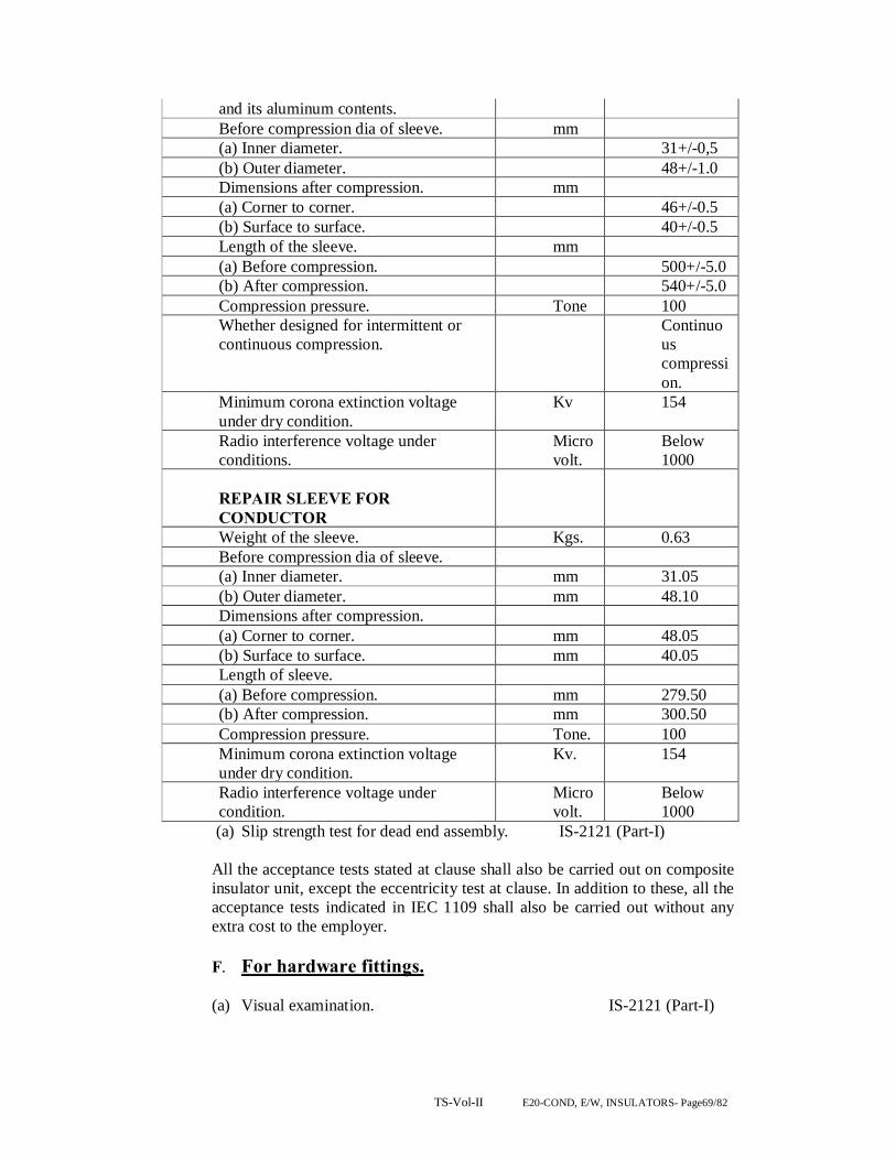
TS-Vol-II E20-COND, E/W, INSULATORS- Page69/82
and its aluminum contents. Before compression dia of sleeve. mm (a) Inner diameter. 31+/-0,5 (b) Outer diameter. 48+/-1.0 Dimensions after compression. mm (a) Corner to corner. 46+/-0.5 (b) Surface to surface. 40+/-0.5 Length of the sleeve. mm (a) Before compression. 500+/-5.0 (b) After compression. 540+/-5.0 Compression pressure. Tone 100 Whether designed for intermittent or continuous compression.
Continuous compression.
Minimum corona extinction voltage under dry condition.
Kv 154
Radio interference voltage under conditions.
Micro volt.
Below 1000
REPAIR SLEEVE FOR CONDUCTOR
Weight of the sleeve. Kgs. 0.63 Before compression dia of sleeve. (a) Inner diameter. mm 31.05 (b) Outer diameter. mm 48.10 Dimensions after compression. (a) Corner to corner. mm 48.05 (b) Surface to surface. mm 40.05 Length of sleeve. (a) Before compression. mm 279.50 (b) After compression. mm 300.50 Compression pressure. Tone. 100 Minimum corona extinction voltage under dry condition.
Kv. 154
Radio interference voltage under condition.
Microvolt.
Below 1000
(a) Slip strength test for dead end assembly. IS-2121 (Part-I) All the acceptance tests stated at clause shall also be carried out on composite insulator unit, except the eccentricity test at clause. In addition to these, all the acceptance tests indicated in IEC 1109 shall also be carried out without any extra cost to the employer. F. For hardware fittings. (a) Visual examination. IS-2121 (Part-I)

TS-Vol-II E20-COND, E/W, INSULATORS- Page70/82
(b) Proof & test. G. Tests on conductor accessories. H. Type tests. I. Mid span compression joint for conductor and earthwire. (a) Chemical analysis of materials. (b) Electrical resistance tests. IS-2121 (Part-II) 1981 clause 6.5 & 6.6 (c) Heating cycle test. -do- (d) Slip strength test. -do- (e) Corona extinction voltage test (dry) (f) Radio interference voltage test (dry) J. Repair sleeve for conductor. (a) Chemical analysis of materials.
VIBRATION DAMPER FOR CONDUCTOR. Vibration Damper for AAC 37/4.00 mm
Unit.
Total weight of the damper. Kgs. 4.5 Weight of each damper mass. Resonance frequencies. 1. First frequency. 2. Second frequency.
Kgs. Hz Hz
Left. Right. 1.6 2.2 12+/- 1 18+/- 2 28+/- 2 36+/- 2
Dimension of each damper mass. Material of: 1. Damper miss. 2. Messenger cable.
Mm 55 Ox165 60 Ox195 Cast iron hot dip galvanized. High tensile galvanized steel wire.
No. of strands in messenger cable strands.
19
Lay ratio of messenger cable strands. 9-11 Min tensile strength of messenger cable.
Kg./ Sq.mm
135
Miss pull-off strength. KN 5 Clamping forque. Kg.m 7 Slipping strength of the damper clamp. 1. Before fatigue test. 2. After fatigue test.
KN
2.5 2.0
Magnetic power loss per vibration damper.
Watts. 1 watt at 500 amps.

TS-Vol-II E20-COND, E/W, INSULATORS- Page71/82
Min. corona extinction voltage under dry conditions.
Kv. 154
Radio interference voltage under dry condition 1MHz, at 154 KV.
Microvolt.
Below 1000
Percentage variation in reactance after fatigue test in compassion with that before the fatigue test.
%
20

TS-Vol-II E20-COND, E/W, INSULATORS- Page72/82
SECTION – V CLAMPS AND CONNECTORS
S.NO. DESCRIPTION PAGE NO.
(A)TECHNICAL SPECIFICATION FOR CLAMPS & CONNECTORS 1. SCOPE 75 2 STANDARDS 75 3. MATERIAL AND WORKMANSHIP 75 4. RATING 76 5. EQUIPMENT CONNECTORS 76 6. TEMPRATURE RISE 77 7. WEIGHTS 77 8. INTERCHANGE ABILITY 77 (B)TECHNICAL SPECIFICATION FOR ACSR BUS-BAR 1. SCOPE 77 2. MATERIALS 77 3. MECHANICAL CHARACTERISTICS 77 4. DIMENSIONAL TOLERANCE 78 5. CHEMICAL COMPOSITION 78 6. ELECTRICAL & MECHANICAL CHARACTERISTICS 78 AND CURRENT RATINGS
TS-Vol-II E20-COND, E/W, INSULATORS- Page73/82
TECHNICAL SPECIFICATION CLAMPS AND CONNECTORS
(A) TECHNICAL SPECIFICATION FOR CLAMPS & CONNECTORS
1. SCOPE
This specification covers design, manufacture, assembly, testing at manufacturer’s works, supply and delivery at site of all terminal connectors of 220,132 & 33KV equipments (mainly breaker, isolator, CT,PT,CVT,BPI and LA) and all other clamps and dropper connectors required for the switch yard as per approved lay out and system design.
2. STANDARDS
The terminal connectors under this specification shall conform strictly to the requirements of the latest version of the following standards as amended up-to-date, except where specified otherwise.
i) IS: 5561 Power Connectors. ii) IS:617 Aluminium & Aluminium Alloy
iii) IS: 2629 Recommended Practice for hot dip galvanizing of iron and steel.
iv) IS: 2633 Method of testing uniformity of coating of zinc coated articles.
The materials conforming to any other authoritative standards which ensure
equal or better performance shall also be acceptable. The salient point of these specifications and points of difference between these and the above specifications, shall be clearly brought out in the bid.
3. MATERIAL & WORKMANSHIP The terminal connectors shall be manufactured from Aluminium Silicon
Alloy and conform to designation A6 of IS: 617 (latest edition) The connectors shall be of best quality and workmanship, well finished
and of approved design. Specific materials for clamps and connectors should have high current carrying capacity, high corrosion resistance and be free from corona formation.
All connectors or its components to be connected with ACSR conductor
shall be of compression type having aluminium purity not less than 99.5%.

TS-Vol-II E20-COND, E/W, INSULATORS- Page74/82
All bus bar clamps shall be made preferably from forged aluminium of purity not less than 99.5%. The thickness and contact surface should be maintained in such a way that the clamp should conform to IS:5561/1970 or any latest revision thereof.
4. RATING The connector rating shall match with the rating of the respective equipments
for the terminal connectors and the connectors for bus bar and dropper should be of the following rating. Minimum thickness at any part of connector shall be 10(ten)mm. Indicative ratings are given below:
Rating 400/220 / 132 KV 1. Main bus bar connectors high level and 3600/2000/2000 low level (Amps) 2. High level bus sectionalisation 3600/2000/2000 isolator(Amps) 3. Connectors along the bay (Amps) 3600/2000/2000 4. Terminal connectors for CB(Amp.) as per rating of CB 5. -do- for Isolator(Amps) as per rating of ISO 6. -do- for CT As per CT rating 7. -do- for PI As per PI rating 8. -do- for LA As per LA rating 9. -do- for PT As per PT rating 10. -do- for CVT As per CVT rating 11. -do- for WT As per WT rating.
5. EQUIPMENT CONNECTORS Bimetallic connectors shall be used to connect conductors of dissimilar metal.
The following bimetallic arrangement shall be preferred.
i) copper clodding of minimum 4 mm. thickness on the aluminium portion of connector coming in contact with the copper palm or stud of the equipment.
ii) alternatively, to provide cold rolled aluminium copper strip between the aluminium portion of the connection, the sheet thickness shall not be less than 2 mm. Sufficient contact pressure should be maintained at the joint by the provision
of the required number of bolts or other fixing arrangements, but the contact pressure should not be so great as to clause relaxation of the joint by cold flow, the joint should be such that the pressure is maintained within this range under all conditions of service, to avoid excessive local pressure, the contact pressure should be evenly distributed by use of pressure plates, washers or suitable saddles of adequate area of thickness should be less than that of an

TS-Vol-II E20-COND, E/W, INSULATORS- Page75/82
equal length of conductor where measured individually test results showing the milli drop test and resistance should be enclosed with the bid.
All connectors shall be so designed and manufactured as to offer ease
of installation as these are to be used in overhead installations, design shall be such that full tightening of nuts and bolts should be possible with the use of double wrench.
The connectors shall be such as to avoid local corona, sound or visible
discharge.
6. TEMPRATURE RISE The temperature rise of connectors when carrying rated current shall not
exceed 45˚ C above reference design temperature of 50˚ C.
i) Acceptance Tests (a) Tensile Test
(b) Temperature rise test © Temperature rise test ii) Routine Test (a) Visual Inspection (b) Dimensional Check Type test reports from a recognized laboratory shall have to be submitted.
7. WEIGHTS
Weights of different materials uses in manufacture, such as aluminium, silicon, copper etc. should be clearly indicated in the bid.
8. INTERCHANGE ABILITY
Corresponding parts of similar clamps and connectors shall be made to gauge or jig and shall be interchangeable in every respect.
(B) TECHNICAL SPECIFICATION FOR ACSR BUS-BAR 1. SCOPE The specification covers design, engineering, manufacture, testing at
manufacturer’s works, supply and delivery of heavy duty ACSR bus-bar for use in 220 KV and 132 kV sub-station.
2. MATERIALS The ACSR bus bar shall be drawn by using MOOSE/ZEBRA as per system
requirement. The strung ACSR bus-bar shall be of heavy duty type and design to operate
within set temperature limits and to withstand thermal and electromechanical forces developed due to short circuits.
3. MECHANICAL CHARACTERISTICS
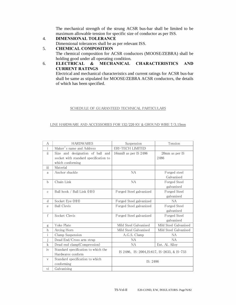
TS-Vol-II E20-COND, E/W, INSULATORS- Page76/82
The mechanical strength of the strung ACSR bus-bar shall be limited to be maximum allowable tension for specific size of conductor as per ISS.
4. DIMENSIONAL TOLERANCE Dimensional tolerances shall be as per relevant ISS. 5. CHEMICAL COMPOSITION The chemical composition for ACSR conductors (MOOSE/ZEBRA) shall be
holding good under all operating condition. 6. ELECTRICAL & MECHANICAL CHARACTERISTICS AND
CURRENT RATINGS Electrical and mechanical characteristics and current ratings for ACSR bus-bar
shall be same as stipulated for MOOSE/ZEBRA ACSR conductors, the details of which has been specified.
SCHEDULE OF GUARANTEED TECHNICAL PARTICULARS
LINE HARDWARE AND ACCESSORIES FOR 132/220 KV & GROUND WIRE 7/3.15mm
A HARDWARES Suspension Tension
i Maker’s name and Address ERI-TECH LIMITED
ii Size and designation of ball and
socket with standard specification to
which conforming
16mmB as per IS 2486 20mm as per IS
2486
iii Material
a Anchor shackle NA Forged steel
Galvanised
b Chain Link NA Forged Steel
galvanised
c Ball hook / Ball Link (HH) Forged Steel galvanized Forged Steel
galvanised
d Socket Eye (HH) Forged Steel galvanized NA
e Ball Clevis Forged Steel galvanized Forged Steel
galvanised
f Socket Clevis Forged Steel galvanized Forged Steel
galvanised
g Yoke Plate Mild Steel Galvanised Mild Steel Galvanised
h Arcing Horn Mild Steel Galvanised Mild Steel Galvanised
i Clamp Suspension A.G.S. Clamp NA
j Dead End/Cross arm strap NA NA
k Dead end clamp(Compression) NA Ext. Al. Alloy
iv Standard specification to which the
Hardwares conform IS 2486, IS: 2004,IS:617, IS-2633, & IS-733
v Standard specification to which
conforming IS: 2486
vi Galvanising

TS-Vol-II E20-COND, E/W, INSULATORS- Page77/82
a Ferrous parts Hot Dip Galvanised
b Spring washers Electro Galvanised
c Quality of zinc used 99.5%
d Number of dips which the clamp can
withstand
4/ 1 minute dips
vii Standard to which conforming IS 2633
viii Reference to drawing No. Drg. Attached
ix Minimum failing load in kg For AAAC
& ACSR
Panther (132
kv)
For AAAC &
ACSR Zebra
(220 kv)
For AAAC &
ACSR Moose
(220 kv/400 KV)
a For Single Tension Hardwire
Fittings
120 kN 160 kN 160 kN
b For Double Tension Hardwire
Fittings
120 kN 160 kN 160 kN
c For Single Suspension Hardwire
Fittings
70 kN 70 kN 90/120 kN
d For Double Suspension Hardwire
Fittings
70 kN 70 kN 120 kN
B. TENSION
CLAMPS
Suitable for Panther, Zebra & Moose
(AAAC/ACSR)
i Type Compression type tension clamp
ii Material Ext. Al. Alloy/ Ext. Al.
iii Breaking Strength 95% of UTS of Conductor
iv Slipping strength 95% of UTS of Conductor
v Galvanising
a Ferrous parts Hot Dip Galvanised
b Spring washers Electro Galvanised
c Quality of zinc used 99.5%
d Number of dips which the clamp can
withstand
4/ 1 minute dips
vi Standard to which conforming IS 2633
vii Electrical Conductivity
a. Results of heating cycle test
carried out T.C. Attached
b. Electrical resistance Not more than 75% of equivalent length of
conductor
viii Reference to type tests and other
tests reports attached T.C. Attached
ix Make of bolts and nuts used Local Make
C SUSPENSION
CLAMPS
Panther
(AAAC/AC
SR)
Zebra
(AAAC/ACSR)
Moose
(AAAC/ACSR
)
i Type AGS Type
ii Type of material used for retaining
rod for AGS assembly giving
reference of ISS
Aluminium
Alloy 6061/
Equivalent
Aluminium Alloy
6061/ Equivalent
Aluminium
Alloy 6061/
Equivalent
iii minimum tensile strength of 35 kg/mm2 35 kg/mm2 35 kg/mm2

TS-Vol-II E20-COND, E/W, INSULATORS- Page78/82
retaining rod material
iv Chemical composition of retaining
rod material
As per
IS:733
As per IS:733 As per IS:733
v Electrical conductivity of Armour
Rod material (in percentage of the
conductivity of IACS i.e.
International Annealed Copper
Standard
Not less
than 40% of
IACS
Not less than 40%
of IACS
Not less than
40% of IACS
vi Slipping strength of cushioned
suspension assembly
8% to 15% of
UTS of
Conductor
20 to 29 KN of
UTS of Conductor
20 to 29 KN of
UTS of
Conductor
vii Breaking strength of suspension
Clamp
7000kgf 7000kgf 9000kgf
viii Physical properties of neoprene
cushion
a Minimum Tensile Strength 2000 psi 2000 psi 2000 psi
b Minimum ultimate Elongation 300% 300% 300%
ix Ageing (guaranteed life of the
assembly)
40 years 40 years 40 years
x Hardness 65 to 80 A 65 to 80 A 65 to 80 A
D Midspan compressions joints for Panther Zebra
AAAC ACSR AAAC ACSR
i Type Compression Type
ii Suitable for AAAC
Panther
ACSR
Panther
AAAC Zebra ACSR
Zebra
iii Materials
a Outer Sleeve Ex. Al.
Alloy Ex. Al. Ex. Al. Alloy Ex. Al.
b Inner Sleeve N.A. Galvanis
ed Steel N.A.
Galvani
sed
Steel
iv Outer Sleeve
a Outer Dia. Before compression (mm) Ø 38 Ø 38 Ø 48 Ø 48
b Flat to Flat After compression (mm) 32 32 40 40
v Length of Outer Sleeve
a Before compression (mm) 610 610 711 711
b After compression (mm) 655 660 760 768
vi Inner Sleeve
a Outer Dia. Before compression (mm) N.A. Ø 18 N.A. Ø 19.2
b Flat to Flat After compression (mm) N.A. 15.1 N.A. 16.1
vii Length of Inner Sleeve
a Before compression (mm) N.A. 203 N.A. 241
b After compression (mm) N.A. 230 N.A. 273
viii Weight of Sleeve
a Aluminium (kg) 1.2 1.2 2.032 2.032
b Galvanised Steel (kg) N.A. 0.295 N.A. 0.410
ix Galvanising
a Ferrous parts Hot Dip Galvanised
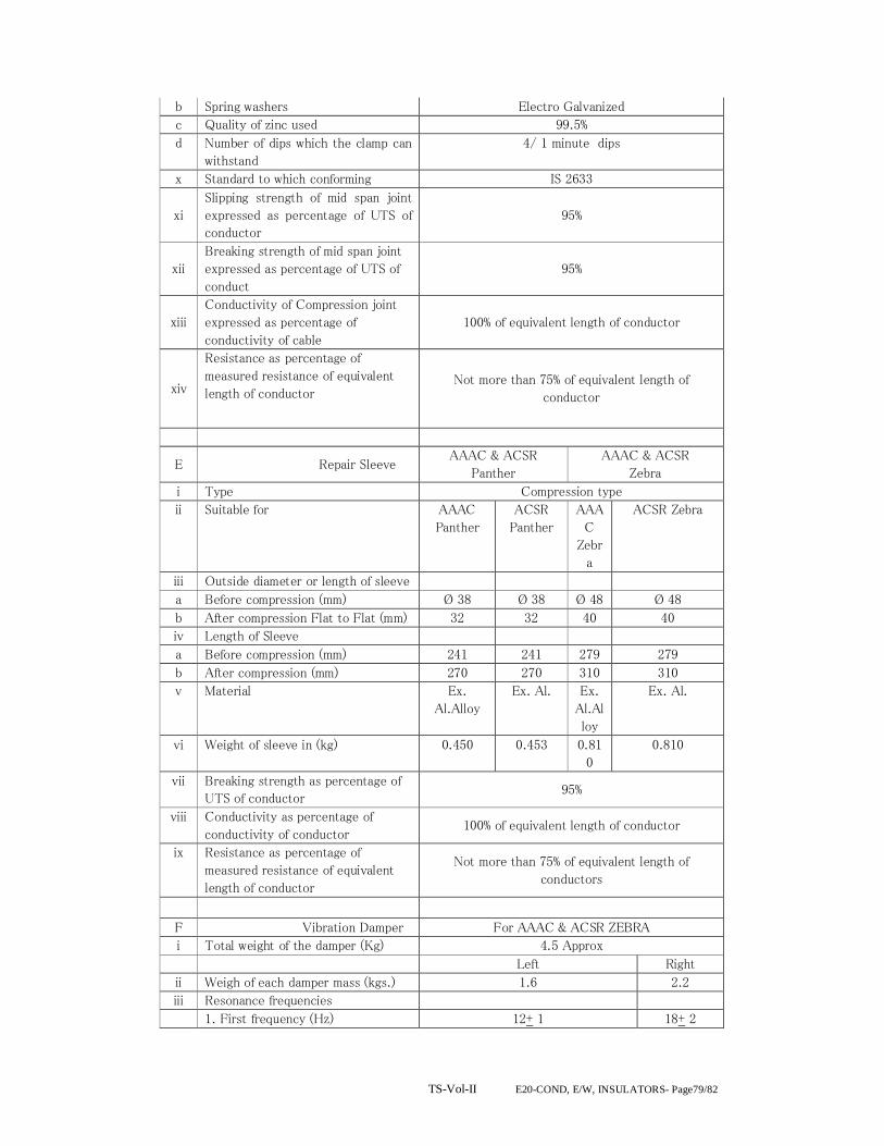
TS-Vol-II E20-COND, E/W, INSULATORS- Page79/82
b Spring washers Electro Galvanized
c Quality of zinc used 99.5%
d Number of dips which the clamp can
withstand
4/ 1 minute dips
x Standard to which conforming IS 2633
xi
Slipping strength of mid span joint
expressed as percentage of UTS of
conductor
95%
xii
Breaking strength of mid span joint
expressed as percentage of UTS of
conduct
95%
xiii
Conductivity of Compression joint
expressed as percentage of
conductivity of cable
100% of equivalent length of conductor
xiv
Resistance as percentage of
measured resistance of equivalent
length of conductor Not more than 75% of equivalent length of
conductor
E Repair Sleeve AAAC & ACSR
Panther
AAAC & ACSR
Zebra
i Type Compression type
ii Suitable for AAAC
Panther
ACSR
Panther
AAA
C
Zebr
a
ACSR Zebra
iii Outside diameter or length of sleeve
a Before compression (mm) Ø 38 Ø 38 Ø 48 Ø 48
b After compression Flat to Flat (mm) 32 32 40 40
iv Length of Sleeve
a Before compression (mm) 241 241 279 279
b After compression (mm) 270 270 310 310
v Material Ex.
Al.Alloy
Ex. Al. Ex.
Al.Al
loy
Ex. Al.
vi Weight of sleeve in (kg) 0.450 0.453 0.81
0
0.810
vii Breaking strength as percentage of
UTS of conductor 95%
viii Conductivity as percentage of
conductivity of conductor 100% of equivalent length of conductor
ix Resistance as percentage of
measured resistance of equivalent
length of conductor
Not more than 75% of equivalent length of
conductors
F Vibration Damper For AAAC & ACSR ZEBRA
i Total weight of the damper (Kg) 4.5 Approx
Left Right
ii Weigh of each damper mass (kgs.) 1.6 2.2
iii Resonance frequencies
1. First frequency (Hz) 12+ 1 18+ 2

TS-Vol-II E20-COND, E/W, INSULATORS- Page80/82
2. Second frequency (Hz) 28+ 2 36+2
iv Dimensions of each damper mass 60 Φ x 195 55 Φ x 165
v Material of :
1. Damper mass Cast iron hot dip galvanised.
2. Messenger cable. High tensile galvanised steel wire.
vi Galvanising
a Ferrous parts Hot Dip Galvanised
b Spring washers Electro Galvanised
c Quality of zinc used 99.5%
d Number of dips which the clamp can
withstand
4/ 1 minute dips
vii Standard to which conforming IS 2486 and IS 2633
viii No of strands in messenger cable
strands 19
ix Lay ratio of messenger cable strands 9 11
x Min tensile strength of messenger
cable ( kg /sq. mm) 135
xi Mass pull – off strength (KN) 5
xii Clamping torque (Kg.m) 7
xiii Slipping strength of the damper
clamp
1.Before fatigue test (KN) 2.5
2. After fatigue test (KN) 2
xiv Magnetic power loss per vibration
damper (Watts) 1 watt at 500 amps
xv Min. corona extinction voltage
under dry conditions (KV) 154
xvi Radio interference voltage under
conditions 1 MHZ, AT 154 KV
(Microvolt)
Below 1000
xvii Percentage variation in reactance
after fatigue test in comparison with
that before the fatigue test (%)
20
G Midspan compression joint For
7/3.15mm Galvanised Stranded
Steel Wire
i Material Galvanized Steel
ii Size OD 20.2 x Length 230
iii Suitable for groundwire Yes (7/3.15)
iv Weight in kg 0.85
v Minimum failing load 50 KN
vi Galvanization
a Ferrous parts Hot Dip Galvanised
b Spring washers Electro Galvanised
c Quality of zinc used 99.5%
d Number of dips which the clamp can
withstand
4 / 1 minute dip
vii Standard to which conforming IS 2633
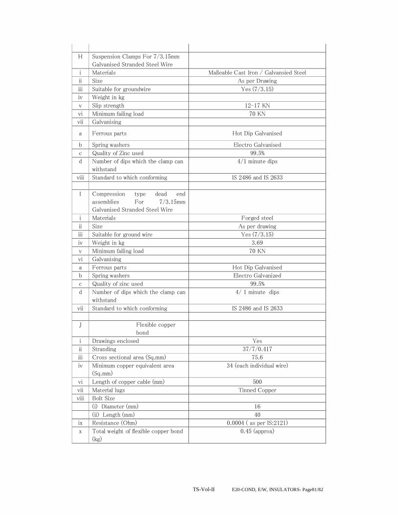
TS-Vol-II E20-COND, E/W, INSULATORS- Page81/82
H Suspension Clamps For 7/3.15mm
Galvanised Stranded Steel Wire
i Materials Malleable Cast Iron / Galvansied Steel
ii Size As per Drawing
iii Suitable for groundwire Yes (7/3.15)
iv Weight in kg
v Slip strength 12-17 KN
vi Minimum failing load 70 KN
vii Galvanising
a Ferrous parts Hot Dip Galvanised
b Spring washers Electro Galvanised
c Quality of Zinc used 99.5%
d Number of dips which the clamp can
withstand
4/1 minute dips
viii Standard to which conforming IS 2486 and IS 2633
I Compression type dead end
assemblies For 7/3.15mm
Galvanised Stranded Steel Wire
i Materials Forged steel
ii Size As per drawing
iii Suitable for ground wire Yes (7/3.15)
iv Weight in kg 3.69
v Minimum failing load 70 KN
vi Galvanising
a Ferrous parts Hot Dip Galvanised
b Spring washers Electro Galvanized
c Quality of zinc used 99.5%
d Number of dips which the clamp can
withstand
4/ 1 minute dips
vii Standard to which conforming IS 2486 and IS 2633
J Flexible copper
bond
i Drawings enclosed Yes
ii Stranding 37/7/0.417
iii Cross sectional area (Sq.mm) 75.6
iv Minimum copper equivalent area
(Sq.mm)
34 (each individual wire)
vi Length of copper cable (mm) 500
vii Material lugs Tinned Copper
viii Bolt Size
(i) Diameter (mm) 16
(ii) Length (mm) 40
ix Resistance (Ohm) 0.0004 ( as per IS:2121)
x Total weight of flexible copper bond
(kg)
0.45 (approx)

TS-Vol-II E20-COND, E/W, INSULATORS- Page82/82


![[Untitled].1 [repo.optcl.co.in]](https://img.pdfslide.us/doc/110x75/619ef39217b9cf322e044360/untitled1-repooptclcoin.jpg)


