Embed Size (px)
DESCRIPTION
VPLS Principles
Citation preview
HUAWEI TECHNOLOGIES CO., LTD. All rights reserved
www.huawei.com
Internal
ODC010017 VPLS Principle
ISSUE 1.0
PDF created with FinePrint pdfFactory Pro trial version www.pdffactory.com
HUAWEI TECHNOLOGIES CO., LTD. Page 2All rights reserved
Virtual Private LAN Service (VPLS) is a service that connects multiple Ethernet LAN segments through the PSN (Packet Switched Network) to make them work like a LAN. This course describes the basic concept and implementation principles of VPLS.
PDF created with FinePrint pdfFactory Pro trial version www.pdffactory.com
HUAWEI TECHNOLOGIES CO., LTD. Page 3All rights reserved
References
l VRP5.30 Operation Manual – VPN volume
l draft-ietf-l2vpn-vpls-ldp-05
l draft-ietf-l2vpn-vpls-bgp-01
l White Paper of VPLS
PDF created with FinePrint pdfFactory Pro trial version www.pdffactory.com
HUAWEI TECHNOLOGIES CO., LTD. Page 4All rights reserved
Upon completion of this course, you will be able to:
[Understand the basic concept of VPLS
[Understand the operating principles of VPLS
[Understand the principles of H-VPLS
PDF created with FinePrint pdfFactory Pro trial version www.pdffactory.com
HUAWEI TECHNOLOGIES CO., LTD. Page 5All rights reserved
Chapter 1 Chapter 1 Basic concept of VPLSBasic concept of VPLS
Chapter 2 Chapter 2 Implementation principles of VPLSImplementation principles of VPLS
Chapter 3 Chapter 3 HH--VPLSVPLS
PDF created with FinePrint pdfFactory Pro trial version www.pdffactory.com
HUAWEI TECHNOLOGIES CO., LTD. Page 6All rights reserved
Basic concept of VPLS
l VPLS is also known as Transparent LAN Service (TLS) and Virtual Private Switched Network service
l VPLS provides L2 VPN service. By function, L2 VPN and L3 VPN are different in whether L2 forwarding or L3 forwarding functions are simulated on the public network
l In VPLS, users are connected through a point-to-multipoint network, rather than the point-to-point connection service provided on the traditional L2 VPN.
l VPLS, in fact, is about creating a series of virtual switches on the PE to be leased to users. Such virtual switches can be networkedin the same way as traditional switches. This way, the users canimplement their own LAN connections through the WAN
VPLS OverviewVPLS Overview
PDF created with FinePrint pdfFactory Pro trial version www.pdffactory.com
HUAWEI TECHNOLOGIES CO., LTD. Page 7All rights reserved
Basic concept of VPLS
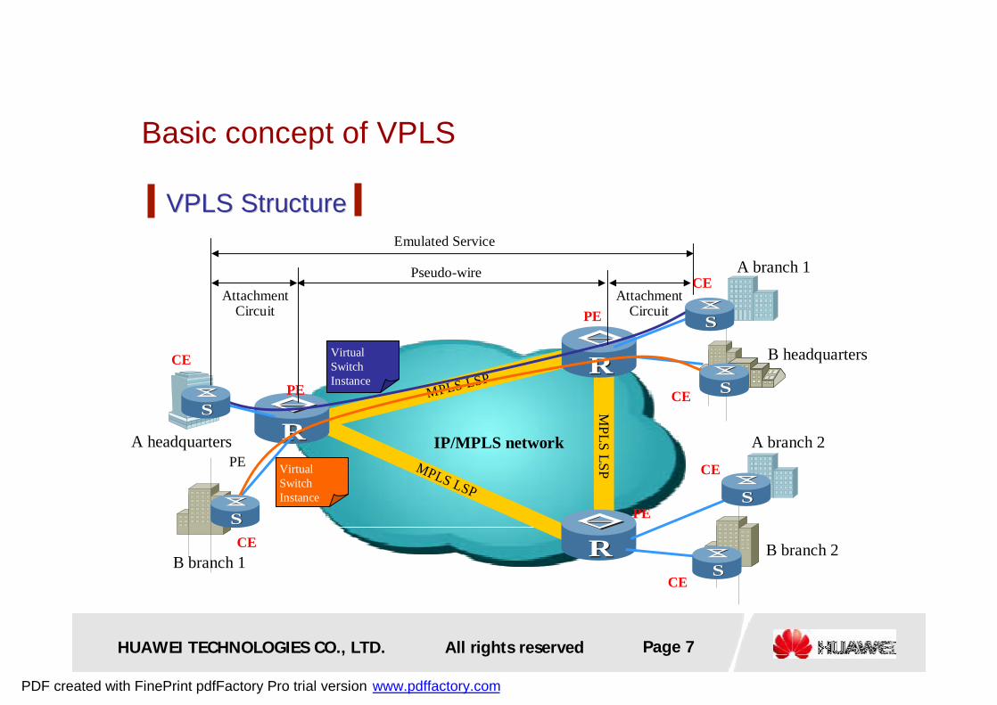
VPLS StructureVPLS Structure
MPLS LSPM
PLS LSPMPLS LSP
RR
RR
RR IP/MPLS network
B headquarters
PE
A branch 1
A branch 2A headquarters
B branch 1B branch 2
PE
PE
CE
CEAttachment
CircuitAttachment
Circuit
Pseudo-wire
Emulated Service
VirtualSwitchInstance
CEVirtualSwitchInstance
PE
CE
SS
SS
SS
SS
SS
SS
CE
CE
PDF created with FinePrint pdfFactory Pro trial version www.pdffactory.com
HUAWEI TECHNOLOGIES CO., LTD. Page 8All rights reserved
Basic concept of VPLS
l Pseudo Wire (PW): It is a virtual connection used to transmit frames between two PEs in VPLS
l Virtual Switch Instance (VSI): Every VSI can offer separate VPLSservice. The VSI implements Ethernet bridge function and terminates Pseudo Wire (PW).
l Virtual Circuit (VC): a logic single directional circuit between two nodes. A PW is constitutes by two opposite directional VCs. A VCcan be used as a single directional PW.
l Attachment Circuit (AC): In L2VPN, CE accesses PE through AC. AC can be either a physical link or a logical link. AC transmitsframes between CE and PE.
VPLS Basic ConceptVPLS Basic Concept
PDF created with FinePrint pdfFactory Pro trial version www.pdffactory.com
HUAWEI TECHNOLOGIES CO., LTD. Page 9All rights reserved
Chapter 1 Chapter 1 Basic concept of VPLSBasic concept of VPLS
Chapter 2 Chapter 2 Implementation principles of VPLSImplementation principles of VPLS
Chapter 3 Chapter 3 HH--VPLSVPLS
PDF created with FinePrint pdfFactory Pro trial version www.pdffactory.com

HUAWEI TECHNOLOGIES CO., LTD. Page 10All rights reserved
Chapter 2 Chapter 2 Implementation principles of VPLSImplementation principles of VPLS
2.1 Basic working principle of VPLS
2.2 Martini VPLS2.2 Martini VPLS
2.3 Kompella VPLS2.3 Kompella VPLS
2.4 Key Technology2.4 Key Technology
PDF created with FinePrint pdfFactory Pro trial version www.pdffactory.com
HUAWEI TECHNOLOGIES CO., LTD. Page 11All rights reserved
Working process of VPLS
l Member relationship discovery (control plane)
l PW creation and maintenance (control plane)
l Forwarding based on MAC addresses in VSI (data plane)
Working process of VPLSWorking process of VPLS
PDF created with FinePrint pdfFactory Pro trial version www.pdffactory.com
HUAWEI TECHNOLOGIES CO., LTD. Page 12All rights reserved
Working process of VPLS
l Member discovery: It is the process to find all other PEs in the same VPLS. This can be implemented either through manual configuration or automatically by the use of some protocols. In the later case, it is called “auto discovery”.
l Signaling mechanism: It is the process to use the signaling protocol between the PEs of the same VPLS to establish, maintain and remove PW.
l Huawei products support the use of the BGP or LDP to implement the control plane of VPLS, referred to as Kompella VPLS and Martini VPLS respectively.
Control PlaneControl Plane
PDF created with FinePrint pdfFactory Pro trial version www.pdffactory.com
HUAWEI TECHNOLOGIES CO., LTD. Page 13All rights reserved
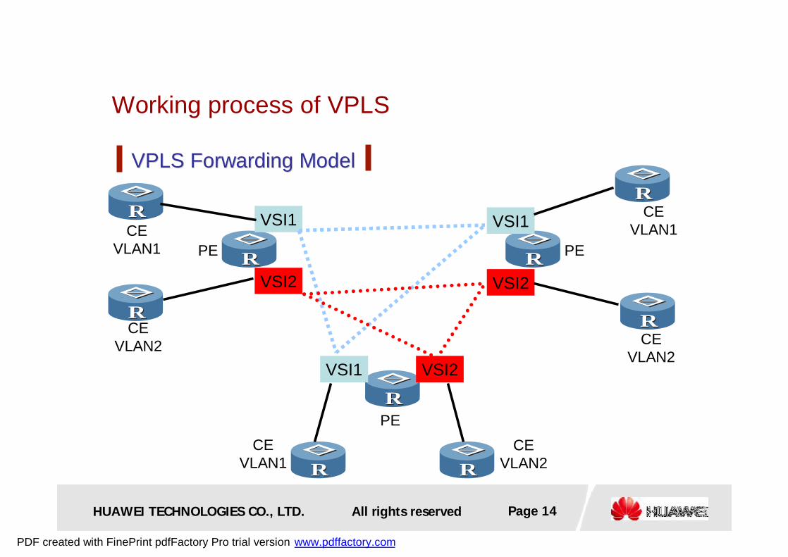
Working process of VPLS
l Encapsulation: When receiving Ethernet frames from CE, PE sends them to PSN after encapsulation.
l Forwarding: How to forward packets depends on the interface receiving the packets and the destination MAC addresses of the packets .
Data PlaneData Plane
PDF created with FinePrint pdfFactory Pro trial version www.pdffactory.com
HUAWEI TECHNOLOGIES CO., LTD. Page 14All rights reserved
Working process of VPLS
RR
RR
RR
VPLS Forwarding ModelVPLS Forwarding Model
RR
RR
RR RR
RR
RRVSI1
VSI2
VSI1
VSI2
VSI1 VSI2
CEVLAN1
CEVLAN2
CEVLAN1
CEVLAN2
CEVLAN2
CEVLAN1
PE PE
PE
PDF created with FinePrint pdfFactory Pro trial version www.pdffactory.com

HUAWEI TECHNOLOGIES CO., LTD. Page 15All rights reserved
Working process of VPLS
Packet transport processPacket transport process
MPLS LSP
MPLS LSPMPLS LSP
RR
RR
RR IP/MPLS network
A branch 1
A branch 2
A headquarters
PE
PE
CE
CE
CEPE
SS
SS
SS
The VPLS tunnel, for the CE equipment, is like a L2 switch that has no protocol started, as it transparently transmitted the packets of the users
According to the VPNs of the users, the PE encapsulates the PDUs with the VC Labels to distinguish different users in the MPLS network. According to the destination MACs of the users, the PSTN labels are encapsulated for transmission to the destination PE: Obviously, the PE in the VPLS network must have the ability to learn the MAC addresses of the users
When the PE forwards the packets from the remote PE, it selects the home VPNs of the PDUs of the users according to the VC label, and it looks for the egress interfaces of the packets according to the destination addresses of the users, removing the VC Label and sending the original PDUs of the users to the CE
User PDUVC IDLableMAC User PDU
VC IDLableMAC User PDU
PDF created with FinePrint pdfFactory Pro trial version www.pdffactory.com
HUAWEI TECHNOLOGIES CO., LTD. Page 16All rights reserved
Chapter 2 Chapter 2 Implementation principles of VPLSImplementation principles of VPLS
2.1 Basic working principle of VPLS 2.1 Basic working principle of VPLS
2.2 Martini VPLS
2.3 Kompella VPLS2.3 Kompella VPLS
2.4 Key Technology2.4 Key Technology
PDF created with FinePrint pdfFactory Pro trial version www.pdffactory.com
HUAWEI TECHNOLOGIES CO., LTD. Page 17All rights reserved
Martini VPLS
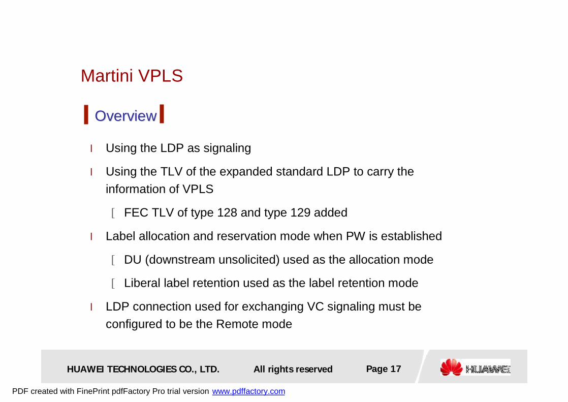
l Using the LDP as signaling
l Using the TLV of the expanded standard LDP to carry the information of VPLS
[FEC TLV of type 128 and type 129 added
l Label allocation and reservation mode when PW is established
[DU (downstream unsolicited) used as the allocation mode
[Liberal label retention used as the label retention mode
l LDP connection used for exchanging VC signaling must be configured to be the Remote mode
OverviewOverview
PDF created with FinePrint pdfFactory Pro trial version www.pdffactory.com

HUAWEI TECHNOLOGIES CO., LTD. Page 18All rights reserved
Martini VPLS
Signaling processSignaling processPE1 PE2
Configuring VSI, and designating
the PE2 as Peer Configuring VSI, and designating
the PE1 as PeerMapping Message
Mapping MessageInterface parameters
match . PW UPInterface parameters
match . PW UP
Withdraw Message
Release MessageRemoving PW
PW Down
Recycle labelPW Down
PDF created with FinePrint pdfFactory Pro trial version www.pdffactory.com
HUAWEI TECHNOLOGIES CO., LTD. Page 19All rights reserved
Martini VPLS
RR RR
SS
Setup PWSetup PW
SS
IP MPLS Network
PE PE
CE CE
Vlan:1020 50 Vlan:1020 50
Trunk VLAN 10-50
Trunk VLAN 10-50
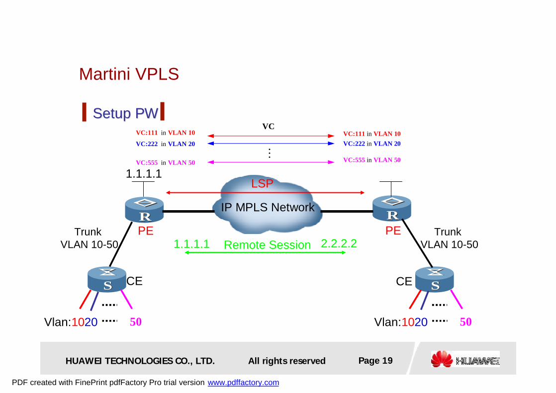
LSP
Remote Session
1.1.1.1
2.2.2.21.1.1.1
VCVC:111 in VLAN 10 VC:111 in VLAN 10VC:222 in VLAN 20 VC:222 in VLAN 20
VC:555 in VLAN 50 VC:555 in VLAN 50...
PDF created with FinePrint pdfFactory Pro trial version www.pdffactory.com
HUAWEI TECHNOLOGIES CO., LTD. Page 20All rights reserved
Martini VPLS
Label allocationLabel allocation
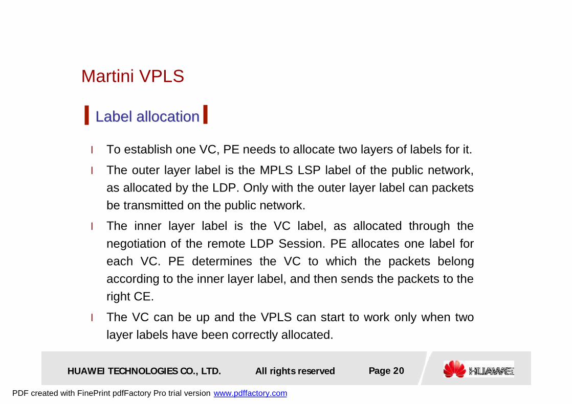
l To establish one VC, PE needs to allocate two layers of labels for it.
l The outer layer label is the MPLS LSP label of the public network, as allocated by the LDP. Only with the outer layer label can packets be transmitted on the public network.
l The inner layer label is the VC label, as allocated through the negotiation of the remote LDP Session. PE allocates one label for each VC. PE determines the VC to which the packets belong according to the inner layer label, and then sends the packets to the right CE.
l The VC can be up and the VPLS can start to work only when two layer labels have been correctly allocated.
PDF created with FinePrint pdfFactory Pro trial version www.pdffactory.com
HUAWEI TECHNOLOGIES CO., LTD. Page 21All rights reserved
Martini VPLS
RR RR
SS
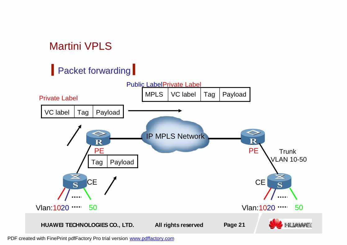
Packet forwardingPacket forwarding
SS
IP MPLS Network
PE PE
CE CE
Vlan:1020 50 Vlan:1020 50
Trunk VLAN 10-50PayloadTag
PayloadTagVC label
PayloadTagVC labelMPLSPrivate Label
Private LabelPublic Label
PDF created with FinePrint pdfFactory Pro trial version www.pdffactory.com
HUAWEI TECHNOLOGIES CO., LTD. Page 22All rights reserved
Chapter 2 Chapter 2 Implementation principles of VPLSImplementation principles of VPLS
2.1 Basic working principle of VPLS 2.1 Basic working principle of VPLS
2.2 Martini VPLS2.2 Martini VPLS
2.3 Kompella VPLS
2.4 Key Technology2.4 Key Technology
PDF created with FinePrint pdfFactory Pro trial version www.pdffactory.com
HUAWEI TECHNOLOGIES CO., LTD. Page 23All rights reserved
Kompella VPLS
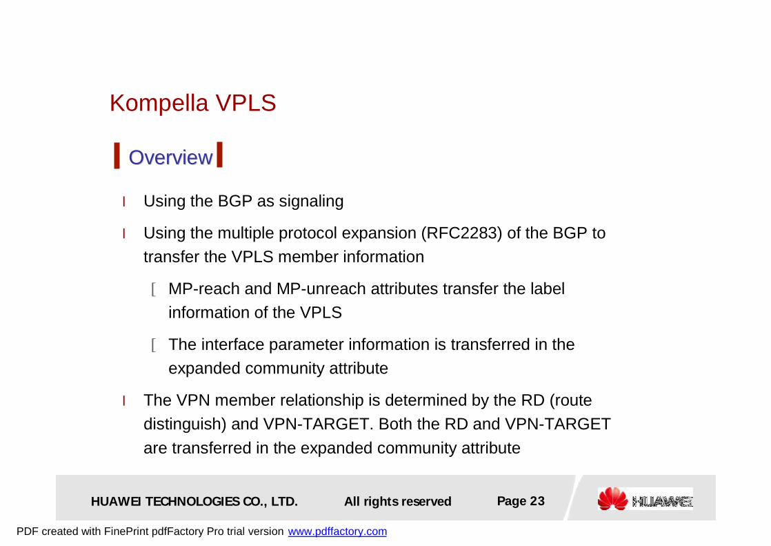
l Using the BGP as signaling
l Using the multiple protocol expansion (RFC2283) of the BGP to transfer the VPLS member information
[MP-reach and MP-unreach attributes transfer the label information of the VPLS
[The interface parameter information is transferred in the expanded community attribute
l The VPN member relationship is determined by the RD (route distinguish) and VPN-TARGET. Both the RD and VPN-TARGET are transferred in the expanded community attribute
OverviewOverview
PDF created with FinePrint pdfFactory Pro trial version www.pdffactory.com
HUAWEI TECHNOLOGIES CO., LTD. Page 24All rights reserved
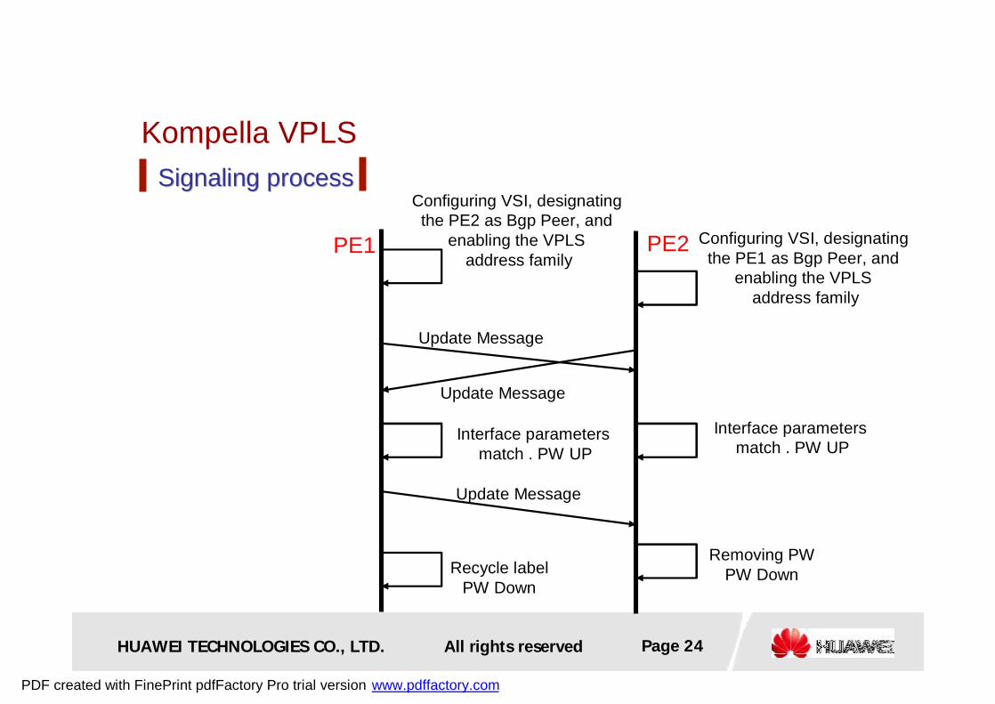
Kompella VPLSSignaling processSignaling process
PE1 PE2
Configuring VSI, designating the PE2 as Bgp Peer, and
enabling the VPLS address family
Update Message
Update Message
Update Message
Configuring VSI, designating the PE1 as Bgp Peer, and
enabling the VPLS address family
Interface parameters match . PW UP
Interface parameters match . PW UP
Recycle labelPW Down
Removing PWPW Down
PDF created with FinePrint pdfFactory Pro trial version www.pdffactory.com

HUAWEI TECHNOLOGIES CO., LTD. Page 25All rights reserved
Kompella VPLS
PW setup and PW setup and Label allocationLabel allocation
l Using the BGP as signaling, it can implement the auto discovery of the VPLS members by configuring the VPN Targets
l The VPN-Target is used to uniquely identify one VPLS
l The inner layer labels are allocated by configuring labels. When PE is added or deleted, few additional operations are needed, providing good expandability
PDF created with FinePrint pdfFactory Pro trial version www.pdffactory.com
HUAWEI TECHNOLOGIES CO., LTD. Page 26All rights reserved
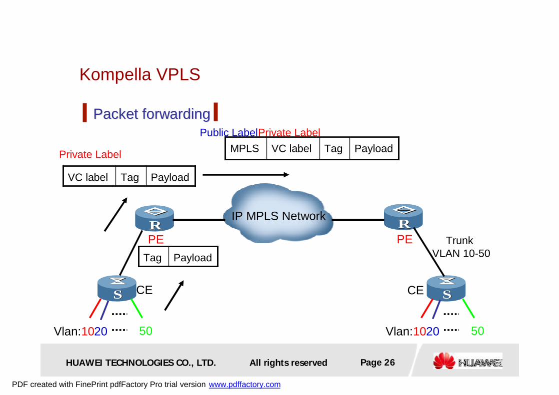
Kompella VPLS
RR RR
SS
Packet forwardingPacket forwarding
SS
IP MPLS Network
PE PE
CE CE
Vlan:1020 50 Vlan:1020 50
Trunk VLAN 10-50PayloadTag
PayloadTagVC label
PayloadTagVC labelMPLSPrivate Label
Private LabelPublic Label
PDF created with FinePrint pdfFactory Pro trial version www.pdffactory.com

HUAWEI TECHNOLOGIES CO., LTD. Page 27All rights reserved
Kompella VPLS
Comparison with the Martini modeComparison with the Martini mode
bigsmallCross-domain restriction
bigsmallConfiguration work
highlowLabel utilization
badgoodExpandability
lowhighImplementation complexity
noyesWhether auto discovery is supported
normalhighCapability requirement for the PE
Martini ModeKompella ModeAttribute Signaling
PDF created with FinePrint pdfFactory Pro trial version www.pdffactory.com
HUAWEI TECHNOLOGIES CO., LTD. Page 28All rights reserved
Chapter 2 Chapter 2 Implementation principles of VPLSImplementation principles of VPLS
2.1 Basic working principle of VPLS 2.1 Basic working principle of VPLS
2.2 Martini VPLS2.2 Martini VPLS
2.3 Kompella VPLS2.3 Kompella VPLS
2.4 Key Technology
PDF created with FinePrint pdfFactory Pro trial version www.pdffactory.com
HUAWEI TECHNOLOGIES CO., LTD. Page 29All rights reserved
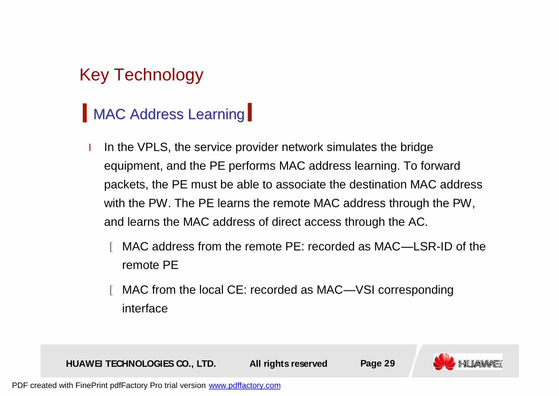
Key Technology
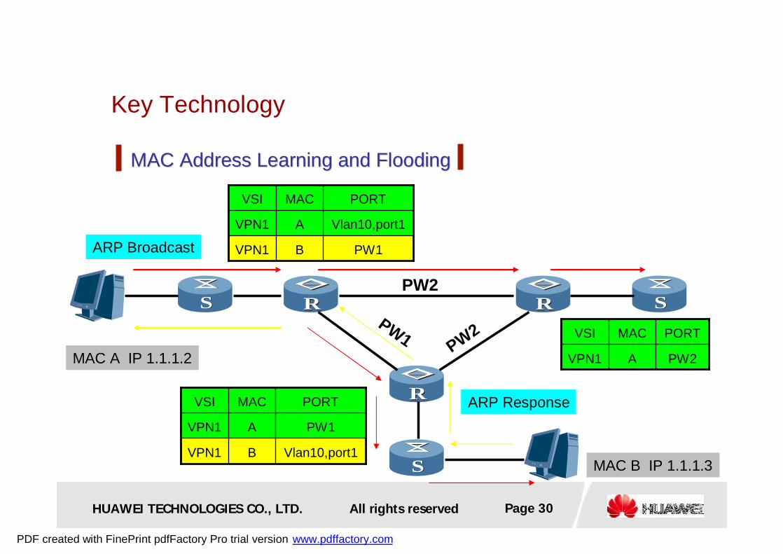
l In the VPLS, the service provider network simulates the bridge equipment, and the PE performs MAC address learning. To forward packets, the PE must be able to associate the destination MAC address with the PW. The PE learns the remote MAC address through the PW, and learns the MAC address of direct access through the AC.
[MAC address from the remote PE: recorded as MAC—LSR-ID of the remote PE
[MAC from the local CE: recorded as MAC—VSI corresponding interface
MAC Address LearningMAC Address Learning
PDF created with FinePrint pdfFactory Pro trial version www.pdffactory.com
HUAWEI TECHNOLOGIES CO., LTD. Page 30All rights reserved
Key Technology
RR
RR
RR
MAC Address Learning and FloodingMAC Address Learning and Flooding
SS
SS
SS
MAC A IP 1.1.1.2
ARP Broadcast PW1BVPN1
Vlan10,port1AVPN1
PORTMACVSI
PW2AVPN1
PORTMACVSI
Vlan10,port1BVPN1
PW1AVPN1
PORTMACVSI
MAC B IP 1.1.1.3
ARP Response
PW2
PW2PW1
PDF created with FinePrint pdfFactory Pro trial version www.pdffactory.com

HUAWEI TECHNOLOGIES CO., LTD. Page 31All rights reserved
Key Technology
l Qualified
[PE learns MAC addresses according to MAC addresses of Ethernet packets and VLAN tags, that is, based on every VLAN of every VSI. In this mode, every VLAN forms its own broadcast domain and has its own independent MAC address range.
l Unqualified
[PE learns MAC addresses according to MAC addresses of Ethernet packets, that is, based on every VSI. In this mode, allVLANs share a broadcast domain and a MAC address range. The MAC address of a VLAN must be unique, and no overlapped address exists.
Two modes of MAC address learningTwo modes of MAC address learning
PDF created with FinePrint pdfFactory Pro trial version www.pdffactory.com
HUAWEI TECHNOLOGIES CO., LTD. Page 32All rights reserved
Key Technology
l If PE receives broadcast flows sent by the local customer, PE forwards it to all other ports and PEs of the same VPLS.
l If PE receives broadcast flow sent by remote PE, PE forwards it to directly-connected VPLS customers, instead of other PEs.
l For the packet whose destination MAC address is non-broadcast address, if PE does not learn such MAC address, then PE broadcasts this packet.
Broadcast Traffic ForwardingBroadcast Traffic Forwarding
PDF created with FinePrint pdfFactory Pro trial version www.pdffactory.com
HUAWEI TECHNOLOGIES CO., LTD. Page 33All rights reserved
Key Technology
l 802.1Q tag,Ethernet access: (also known as QinQ access) The PE
of the carrier ignores the 802.1Q tag in the user packets, and it
selects their home VPNs according to the QinQ VLAN. This mode
requires intervention in the VLAN planning of the user, and one PE
allows the VLAN overlapping of different CEs.
l VLAN access: The carrier allocates a user with a VLAN for access,
and all the packets of the user must be placed with the tag of the
VLAN and sent to the PE. Otherwise, communication is impossible.
This mode requires intervention in the user VLAN planning, and one
PE does not allow the VLAN overlapping of different CEs.
Packet Encapsulation on ACPacket Encapsulation on AC
PDF created with FinePrint pdfFactory Pro trial version www.pdffactory.com

HUAWEI TECHNOLOGIES CO., LTD. Page 34All rights reserved
Chapter 1 Chapter 1 Basic concept of VPLSBasic concept of VPLS
Chapter 2 Chapter 2 Implementation principles of VPLSImplementation principles of VPLS
Chapter 3 Chapter 3 HH--VPLSVPLS
PDF created with FinePrint pdfFactory Pro trial version www.pdffactory.com
HUAWEI TECHNOLOGIES CO., LTD. Page 35All rights reserved
H-VPLS
l Use the “full connection” and “horizontal cutting forwarding” to avoid looping.
[ “Horizontal cutting forwarding” means that the packets received from the PW on the public network side are no longer forwarded to other PWs, but can only be forwarded to the private network side.
[Full-connection LSP tunnels are established between PEs. For each VPLS service, n*(n-1)/2 PWs must be established between PEs. Through hierarchical connection, the number of PWs can be decreased to reduce the load of the PEs for processing signaling protocol and copying packets.
Looping avoidance of VPLSLooping avoidance of VPLS
PDF created with FinePrint pdfFactory Pro trial version www.pdffactory.com
HUAWEI TECHNOLOGIES CO., LTD. Page 36All rights reserved
H-VPLS
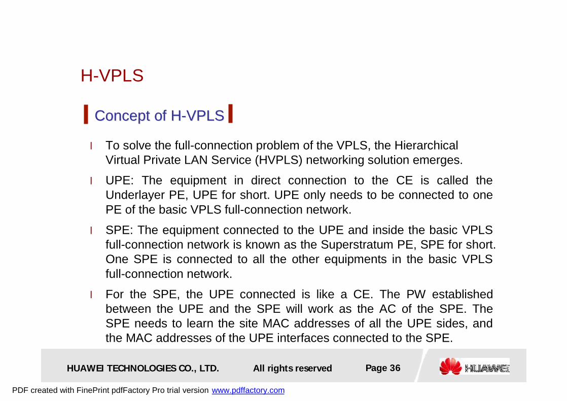
l To solve the full-connection problem of the VPLS, the Hierarchical Virtual Private LAN Service (HVPLS) networking solution emerges.
l UPE: The equipment in direct connection to the CE is called the Underlayer PE, UPE for short. UPE only needs to be connected to one PE of the basic VPLS full-connection network.
l SPE: The equipment connected to the UPE and inside the basic VPLS full-connection network is known as the Superstratum PE, SPE for short. One SPE is connected to all the other equipments in the basic VPLS full-connection network.
l For the SPE, the UPE connected is like a CE. The PW established between the UPE and the SPE will work as the AC of the SPE. The SPE needs to learn the site MAC addresses of all the UPE sides, and the MAC addresses of the UPE interfaces connected to the SPE.
Concept of HConcept of H--VPLSVPLS
PDF created with FinePrint pdfFactory Pro trial version www.pdffactory.com
HUAWEI TECHNOLOGIES CO., LTD. Page 37All rights reserved
H-VPLS
RR
RR
RR
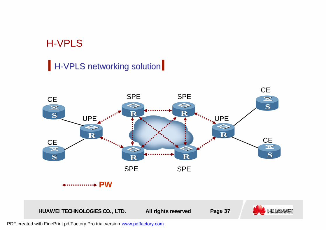
HH--VPLS networking solutionVPLS networking solution
RRRR
RRSS
SS
SS
SS
PW
CE
CE
CE
CE
UPE UPE
SPESPE
SPE SPE
PDF created with FinePrint pdfFactory Pro trial version www.pdffactory.com
HUAWEI TECHNOLOGIES CO., LTD. Page 38All rights reserved
H-VPLS
l The UPE may have PW connection established to only one SPE. However, to avoid single chain failure, it is recommended that dual-homing should be used from the UPE to the SPE.
l When VPLS data are transmitted between the UPE and the SPE, no horizontal cutting principle is followed. To avoid looping, if all the UPEsare in dual-homing, the UPE will block one PW and set its status to backup, so that all the data are forwarded from the Active PW.
Backup mechanism and loop avoidanceBackup mechanism and loop avoidance
PDF created with FinePrint pdfFactory Pro trial version www.pdffactory.com

HUAWEI TECHNOLOGIES CO., LTD. Page 39All rights reserved
l Background of VPLS
l Principle of VPLS
l Principle of H-VPLS
Summary
Microsoft Excel Worksheet
PDF created with FinePrint pdfFactory Pro trial version www.pdffactory.com
www.huawei.com
Thank You
PDF created with FinePrint pdfFactory Pro trial version www.pdffactory.com


![05 Deploy MPLS VPLS - start [APNIC TRAINING WIKI]Virtual Private LAN Service (VPLS) •VPLS defines an architecture allows MPLS networks offer Layer 2 multipoint Ethernet Services](https://img.pdfslide.us/doc/110x75/5e593ce2fc6ae762cb390254/05-deploy-mpls-vpls-start-apnic-training-wiki-virtual-private-lan-service-vpls.jpg)