Embed Size (px)
Citation preview

Oculus Superne
Andy Cottle Sean DuncanLin Haack Afzaal Hassan Brian Roth Dave Stinson Jeff Studtman Justin Wheeler

2
System Definition Review• Mission Objectives
• Concept of Operations
• Aircraft Concept Selection
• Payload
• Constraint Analysis and Diagrams
• Sizing Studies to Date
• Aircraft Concept

3
System Definition Review• Mission Objectives
• Concept of Operations
• Aircraft Concept Selection
• Payload
• Constraint Analysis and Diagrams
• Sizing Studies to Date
• Aircraft Concept

4
To provide a multi-service UAS which acts as the primary detection method and facilitates a rapid response in the event of a system failure or natural disaster.
Mission Statement

5
Target Market
Mission• Power Line• Pipeline• Forest Monitoring
• Business Plan• Target Customers
• DOT• NPS• Private Oil/Gas Companies

6
Customer Attributes
• Patrolling the Right-of-
Way
– Third Party Infringement
• Constant Coverage
• Cost Reduction
• Safety Factors

7
Engineering Requirements

8
System Definition Review• Mission Objectives
• Concept of Operations
• Aircraft Concept Selection
• Payload
• Constraint Analysis and Diagrams
• Sizing Studies to Date
• Aircraft Concept
9
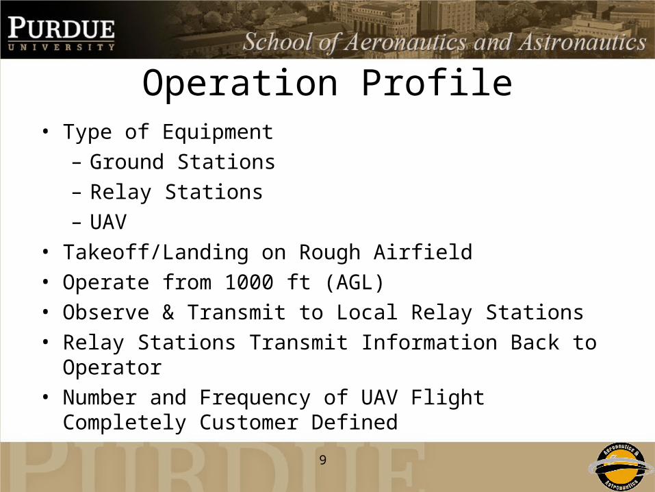
Operation Profile• Type of Equipment
– Ground Stations– Relay Stations– UAV
• Takeoff/Landing on Rough Airfield• Operate from 1000 ft (AGL)• Observe & Transmit to Local Relay Stations• Relay Stations Transmit Information Back to Operator• Number and Frequency of UAV Flight Completely
Customer Defined

10
System Definition Review• Mission Objectives
• Concept of Operations
• Aircraft Concept Selection
• Payload
• Constraint Analysis and Diagrams
• Sizing Studies to Date
• Aircraft Concept

11
Pugh’s Method• Concepts generated by individual group
members
• Picked base line Aircraft
• Compared generated Aircraft to base line
• Narrowed Scope
• Performed method again, with new hybrid ideas

12
Boo
m T
ail
w/ H
igh
AR
Can
ard
s W
ing
lets
/Pus
her
Fly
ing
Win
g-M
any
En
gine
s (s
mal
l)
Ble
nded
Win
g/B
ody
w/
Hig
h A
R (
P o
r T
?)
C-W
ing
Ble
nded
Win
g/B
ody
Elli
ptic
al P
lan
form
(S
tand
ard
Lay
out
)
Sho
rt W
ing
s/L
ong
Fu
sela
ge (
Trac
tor)
Y-T
ail/P
ush
er (
No
Can
ard
)
Goo
se w
ith F
old
ed W
ings
Duc
k w
/ C
anar
d an
d b
oom
Box
Win
g D
esig
n
Qua
si-B
len
d-T
aper
w/ c
anar
ds
& P
ush
er
Tw
o P
rop
Trac
tor
Boo
m T
ail
Ble
nded
Win
g F
usel
age
(T o
r P
?)
Tw
in E
ngin
e/ C
ON
NE
CT
ED
Tail
(No
Sw
eep
Hig
h A
R)
V-T
ail F
lyin
g W
ing
(1) (2) (3) (4) (5) (6) (7) (8) (9) (10) (11) (12) (13) (14) (15) (16)weight (-) - - - - + - - - - + - -
complexity (-) - - - - + - - - - - - -L/D (+) + + + s - - - - + + + -
endurance (+) + + + s - - - - + + + -ceiling (+) s + + s - - - - + + + -
Sensor Location + s s - - + + s s - - sstall speed (C_l max) (-) - + + s - - - - + + + -
Induced Drag (-) s + + - - - - s + - - -development cost (-) - - - - + s - - - - - +power to weight (+) ? - - s + s - - - + - -
Stability - s s + + s - - - - + -AR (+) - s - - - s - - - - s s
+ 3 5 5 1 5 1 1 0 5 0 0 6 5 1- 6 4 5 6 7 7 11 10 6 0 0 6 6 9s 2 3 2 5 0 4 0 2 1 0 0 0 1 2
Pugh's Method
13
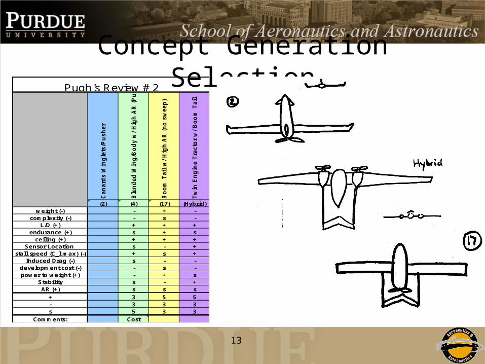
Concept Generation SelectionC
an
ard
s W
ing
lets
/Pu
sh
er
Ble
nd
ed
Win
g/B
od
y w
/ H
igh
AR
(P
ush
)
Bo
om
Tail
w/
Hig
h A
R (
no
sw
eep
)
Tw
in E
ng
ine T
racto
r w
/ B
oo
m T
ail
(2) (4) (17) (Hybrid)weight (-) - + -
complexity (-) - s -L/D (+) + + +
endurance (+) s + sceiling (+) + + +
Sensor Location s - +stall speed (C_l max) (-) + s +
Induced Drag (-) s - -development cost (-) - s -power to weight (+) - + s
Stability s - +AR (+) s s s
+ 3 5 5- 3 3 3s 5 3 3
Comments: Cost
Pugh's Review # 2
14
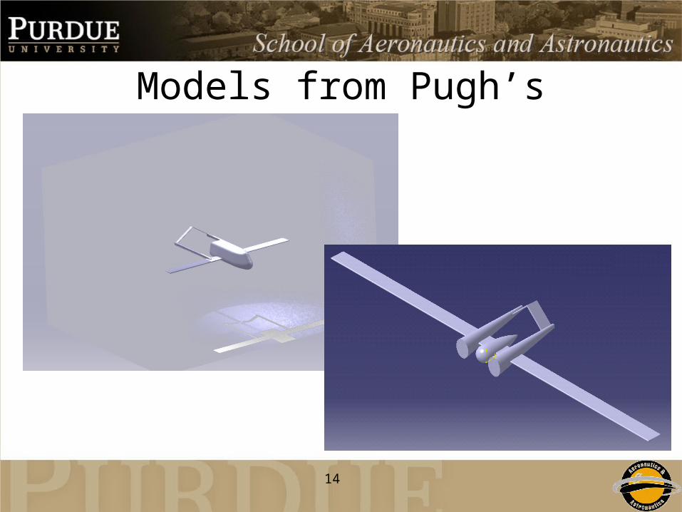
Models from Pugh’s
15
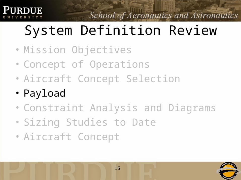
System Definition Review• Mission Objectives
• Concept of Operations
• Aircraft Concept Selection
• Payload
• Constraint Analysis and Diagrams
• Sizing Studies to Date
• Aircraft Concept

16
Sensors• LIDAR (Laser Imaging
Detection and Ranging)– Corridor Mapping– Land Surveying– Vegetation Growth / Density
LiteMapper 5600 components
Airborne Lidar Terrain Mapping System
• IR/Visual Camera
- Thermal Imaging
- Video Tracking
- Detailed Pictures

17
Payload Requirements
Camera Resolutions
• At 1000 ft AGL– 466 ft x 582 ft
• At 12x Zoom– 34 ft x 43 ft
Weight (lbs) Dimensions (ft) Power Consumption (W)LIDAR 13 1.8 x .66 x .71 30CCNS 9 .82 x .69 x .43 25
IR / Visual Camera 20 .66(d) x 1.1(h) 100
TOTAL 42 1.5 ft3 155
18
System Definition Review• Mission Objectives
• Concept of Operations
• Aircraft Concept Selection
• Payload
• Constraint Analysis and Diagrams
• Sizing Studies to Date
• Aircraft Concept
19
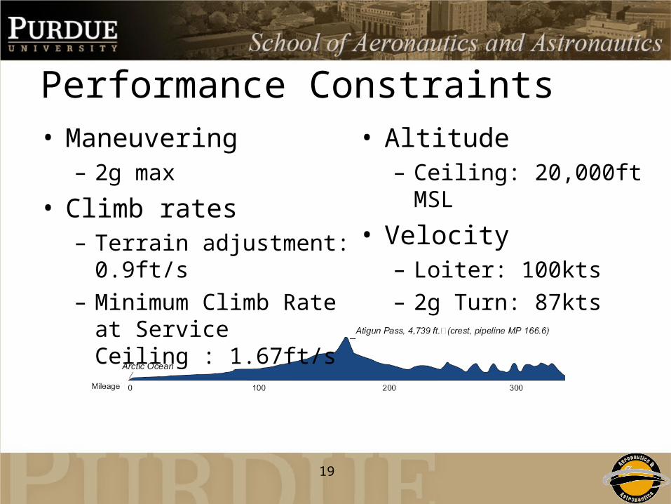
Performance Constraints• Maneuvering
– 2g max
• Climb rates– Terrain adjustment: 0.9ft/s– Minimum Climb Rate at
Service Ceiling : 1.67ft/s
• Altitude– Ceiling: 20,000ft MSL
• Velocity– Loiter: 100kts– 2g Turn: 87kts

20
Constraint Diagram Constants
Cl_max 1.5
C_Do 0.025
Oswald Efficiency Factor 0.8
Lift to Drag Ratio 16
Propeller Efficency 0.7

21
Constraints
• Wing Loading = 16 lb/ft2
• Power to Weight = .08 hp/lb

22
System Definition Review• Mission Objectives
• Concept of Operations
• Aircraft Concept Selection
• Payload
• Constraint Analysis and Diagrams
• Sizing Studies to Date
• Aircraft Concept
23
Aircraft Design Mission• Low Cost Solution for Frequent Area
Coverage
• Long Endurance Time
• Stable Observation Platform
• Designed to Pipeline Constraints
24
Sizing Approach• MATLAB
– From Constraint Diagram• Power to Weight• Wing Loading
• ACS– Results Were Passed Into ACS– Currently Refining Inputs
• Engine Data• Prop Data

25
Current Estimates
Current Target TresholdGross Weight (lbs) 290 300 500Fuel Capacity (hrs) 15 24 12
T/O Length (ft) 900 500 2000Payload Capacity (lbs) 42 30 50
Operational Speed (kts) 100 150 100
Wing Loading (lbs/ft2) 14.5 15 5Power to Weight (hp/lbs) 0.09 0.07 0.11
AR 12 16 10L/D 16 16 12

26
Current Engine Estimate
• UAV Engines ltd– Model AR801-50
Displacement [in3]
Propeller
Efficiency (ηp)
Total Weight [lbs]
0.5
50
8000
18
0.824
57.7
Cruise SFC
[lb/bhp/hr]
Max [hp]
Max [RPM]

27
System Definition Review• Mission Objectives
• Concept of Operations
• Aircraft Concept Selection
• Payload
• Constraint Analysis and Diagrams
• Sizing Studies to Date
• Aircraft Concept

28
Aircraft Configuration• Pusher
– Decreased Vibration (payload)– Clean Air Over Fuselage – Visibility
• High AR– Increased L/D
• Boom Mounted Inverted ‘V’ Tail– Prop Position– Weight Savings– Lower Drag
• Pod Fuselage– Weight Savings

29
Internal Layout• Aircraft Dimensions
– Fuselage Length = 6ft– Width = 1.8 ft– Height = .85 ft– Wingspan = 14 ft
• Payload Volume– 1.5 ft3
• Engine Volume– .86 ft3
• Avionics– .24 ft3
• Wing Box / Extra Fuel– 1.4 ft3

30
3 View Layout

31
Stability AnalysisXcg 3.649
CLα .14
Xac,wing 3.288
Xac,ht 8.313
Cmα -.029
Static Margin .205
•Some basic stability analysis has been done for this aircraft.
•Current estimates of the static margin for a fully loaded aircraft are 20%.
•Current estimates of the static margin with no fuel are 18%.

32
Next Steps• Find more accurate aircraft weights.
• Create a more accurate CATIA model of the aircraft.
• Possible testing of the aircraft shape in FLUENT.
• Final airfoil selection.
• Structural analysis.

33
Summary• Mission Objectives
• Concept of Operations
• Aircraft Concept Selection
• Payload
• Constraint Analysis and Diagrams
• Sizing Studies to Date
• Aircraft Concept

Questions?