Embed Size (px)
Citation preview

OCTOO
www.gardipool.com
Montage handleiding
Notice de montage
Manual
Montage-Anleitung
Manual de montaje
Nota de montagem
Manuale per l’utente

40
MANuAl
1. Introduction
Congratulations on purchasing your
Gardipool swimming pool. Your pool is
manufactured from quality North-Euro-
pean pressure impregnated pinewood.
This treatment offers protection against
rotting and keeps the wood mould-free.
The top border is either in North-Euro-
pean pine or in exotic hardwood, which is
by nature very resistant.
Enclosed, you will find the instructions
for the do-it-yourself assembly of your
Gardipool.
It is advisable that you read the complete
instructions before you start with the
assembly of the pool.
Always follow all safety regulations.
Should you encounter any problems du-
ring the construction, please contact your
Gardipool sales representative, who will
assist you with help and advice.
The assembly instructions are applicable
to all models, unless stated otherwise.
Without supervision,
your child is in danger.
2. Assembly
2.1 Earth works (1, 2)
The pool should preferably be positioned
in a sunny place, away from any trees
whose leaves could fall into the pool.
It is extremely important that your pool
be assembled on a stable foundation.
This should be a 15 cm (6 inch) thick flat
concrete slab. Apply a layer of plastic foil
underneath the concrete slab to obtain
an optimal drying.
In (half) sunken pools, allow an additional
border of ± 50 cm (20 in) around the
pool. In this case, you must cover the
underground wooden structure with a
protective felt layer to ensure that the
structure never touches the ground
directly. This forms the division between
the structure and the stabilized sand
with which you filled the gap after the
assembly of the pool, to ensure
adequate drainage of the ground water
and rainwater. You must also ensure
that the ground and rain water around
the pool is discharged
effectively by means of an adapted
drainage system.
Make sure that the ground or water
never touches the wooden structure
directly.
Provide an adapted felt layer around the
pool as protection. The finishing around
the pool can be chosen according to your
personal taste: wooden terrace, planks,
paving stones, tiles, or lawn (only a top
layer of 10 cm (4 inches)).
CONTENT
1. Introduction
2. Assembly
2.1 Earth works
2.2 Wooden structure
2.2.1 General
2.2.2 Assembly
2.3 Interior finish
2.4 Technical installation
2.4.1 Parts
2.4.2 Monobloc
2.4.3 Connections
2.4.4 Functioning
2.4.5 Malfunctions
2.5 Finishing touches
3. Options
3.1 Summer tarpaulin
3.2 Winter tarpaulin
3.3 Safety tarpaulin
3.4 Technical housing
3.5 Electrical box
3.6 underwater light halogen
3.7 underwater light lED
3.8 Remote control for lED
3.9 Felt
3.10 Slide lock cover roller
3.11 Stainless steel finish for coping
4. Safety instructions
4.1 General
4.2 Technical installation
4.3 Electricity
5. Maintenance
5.1 Wooden structure
5.2 Water
5.3 Technical installation
5.4 Hibernation
6. Guarantee
6.1 Wooden structure
6.2 liner
6.3 Filter / pump
6.4 Summer, winter or
safety cover
6.5 Accessories
6.6 In general
Manual

EN
GL
ISH
41
plastique
anti-bacterial felt
15 cm
plastic foil
anti-bacterial felt
50 cm
15 cm
protective felt
groundground
stabilized
sand
ABOVE GROUND
INGROUND
drainage
sand
1
2
42
MANuAl
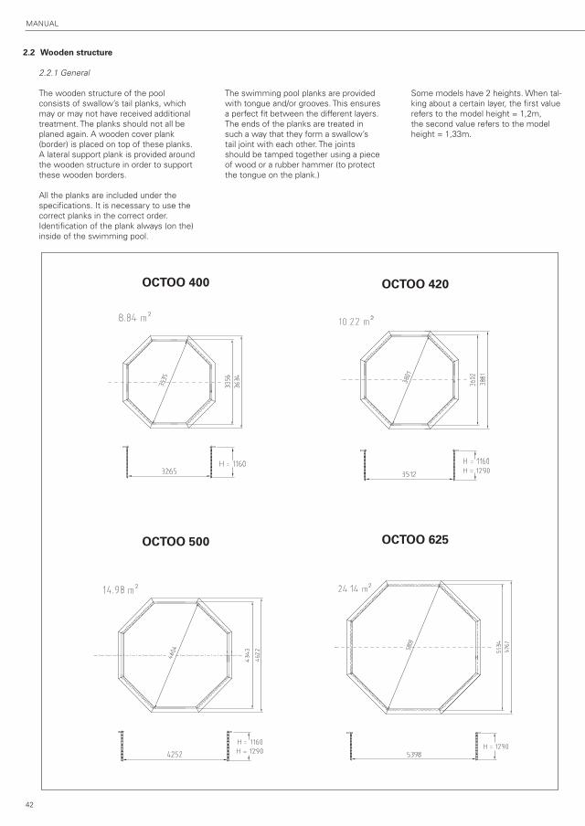
2.2 Wooden structure
2.2.1 General
The wooden structure of the pool
consists of swallow’s tail planks, which
may or may not have received additional
treatment. The planks should not all be
planed again. A wooden cover plank
(border) is placed on top of these planks.
A lateral support plank is provided around
the wooden structure in order to support
these wooden borders.
All the planks are included under the
specifications. It is necessary to use the
correct planks in the correct order.
Identification of the plank always (on the)
inside of the swimming pool.
The swimming pool planks are provided
with tongue and/or grooves. This ensures
a perfect fit between the different layers.
The ends of the planks are treated in
such a way that they form a swallow’s
tail joint with each other. The joints
should be tamped together using a piece
of wood or a rubber hammer (to protect
the tongue on the plank.)
Some models have 2 heights. When tal-
king about a certain layer, the first value
refers to the model height = 1,2m,
the second value refers to the model
height = 1,33m.
OCTOO 400 OCTOO 420
OCTOO 500 OCTOO 625

EN
GL
ISH
43
1
5 6
2.2.2 Assembly
1 2 3 4
anti-bacterial felt
Once the foundation has dried completely, the anti-bacterial felt is
carefully spread across the surface. Avoid unevenness in the felt.
2
3 4
7x110mm
M12
Only for Octoo 500 !
44
MANuAl
7 8
9 10
7654321
87654321
987654321
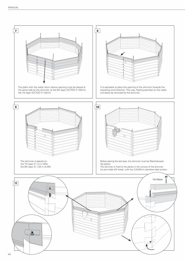
It is advisable to place the opening of the skimmer towards the
prevailing wind direction. This way, floating particles on the water
will easily be removed by the skimmer.
Before placing the last layer, the skimmer must be fitted between
the planks.
The skimmer is fixed to the planks in the corners of the skimmer
(no pre-made drill holes), with four 3,5x20mm stainless steel screws.
The skimmer is placed on:
the 7th layer (h 1,2 m (4ft)),
the 8th layer (h 1,33 m (4,4ft))
The plank with the water return device opening must be placed at
the same side as the skimmer, at the 6th layer (OCTOO H 120cm),
the 7th layer (OCTOO H 133cm)
11
7x110mm

EN
GL
ISH
45
12 m
m
12 13
14
16 17
15
Remark: Do not yet place the
supporting plank there, where
the stainless steel internal steps
will come (see further on :
installation of the stainless
steel steps).
tip: Distribute the border planks equally around the circumference of the pool.
4x30mm
The borders are supported by l-brackets.
Distribute theses equally around the circumference of the pool.
Screw the l-brackets into place 12mm from the top of the wooden
structure (stainless steel screws 4x30mm).
5x50mm4.5x50mm
4x25mm
4x25mm
tip: rough-bore the hardwood coverplanks.
RemaRk: clean the hardwood coverplanks before installation.
Ø10
3x3x
Only for Octoo 500 ! Only for Octoo 500 !
46
MANuAl
2.3 Interior finish
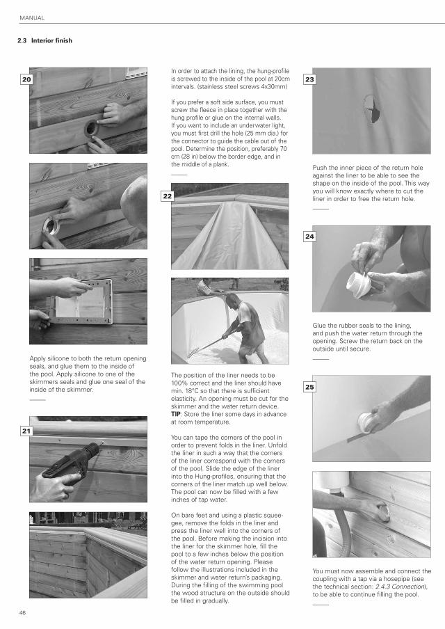
Apply silicone to both the return opening
seals, and glue them to the inside of
the pool. Apply silicone to one of the
skimmers seals and glue one seal of the
inside of the skimmer.
_____
In order to attach the lining, the hung-profile
is screwed to the inside of the pool at 20cm
intervals. (stainless steel screws 4x30mm)
If you prefer a soft side surface, you must
screw the fleece in place together with the
hung profile or glue on the internal walls.
If you want to include an underwater light,
you must first drill the hole (25 mm dia.) for
the connector to guide the cable out of the
pool. Determine the position, preferably 70
cm (28 in) below the border edge, and in
the middle of a plank.
_____
The position of the liner needs to be
100% correct and the liner should have
min. 18°C so that there is sufficient
elasticity. An opening must be cut for the
skimmer and the water return device.
TIP: Store the liner some days in advance
at room temperature.
You can tape the corners of the pool in
order to prevent folds in the liner. unfold
the liner in such a way that the corners
of the liner correspond with the corners
of the pool. Slide the edge of the liner
into the Hung-profiles, ensuring that the
corners of the liner match up well below.
The pool can now be filled with a few
inches of tap water.
On bare feet and using a plastic squee-
gee, remove the folds in the liner and
press the liner well into the corners of
the pool. Before making the incision into
the liner for the skimmer hole, fill the
pool to a few inches below the position
of the water return opening. Please
follow the illustrations included in the
skimmer and water return’s packaging.
During the filling of the swimming pool
the wood structure on the outside should
be filled in gradually.
Push the inner piece of the return hole
against the liner to be able to see the
shape on the inside of the pool. This way
you will know exactly where to cut the
liner in order to free the return hole.
_____
Glue the rubber seals to the lining,
and push the water return through the
opening. Screw the return back on the
outside until secure.
_____
You must now assemble and connect the
coupling with a tap via a hosepipe (see
the technical section: 2.4.3 Connection),
to be able to continue filling the pool.
_____
20 23
21
22
24
25
EN
GL
ISH
47
Draw the outline of the skimmer on the
lining.
_____
Fix the second skimmer seal ring on the
liner. See to it that the screw holes in
the seal ring match with these from the
skimmer. Now screw the finishing cap
on it (you can find the corresponding
screws in the skimmer box).
Now cut out the part of the liner from the
skimmermouth. Then click the covering
plate on it.
You must now assemble and connect the
coupling with a tap via a hosepipe (see
the technical section: 2.4.3 Connection),
to be able to continue filling the pool.
_____
Insert the basket into the skimmer, and
cover the skimmer with its lid.
The pool is now complete, except for the
technical part of the filter installation.
_____
2.4 Technical installation
2.4.1 Parts
Follow the instructions in the enclosed
filter installation manual.
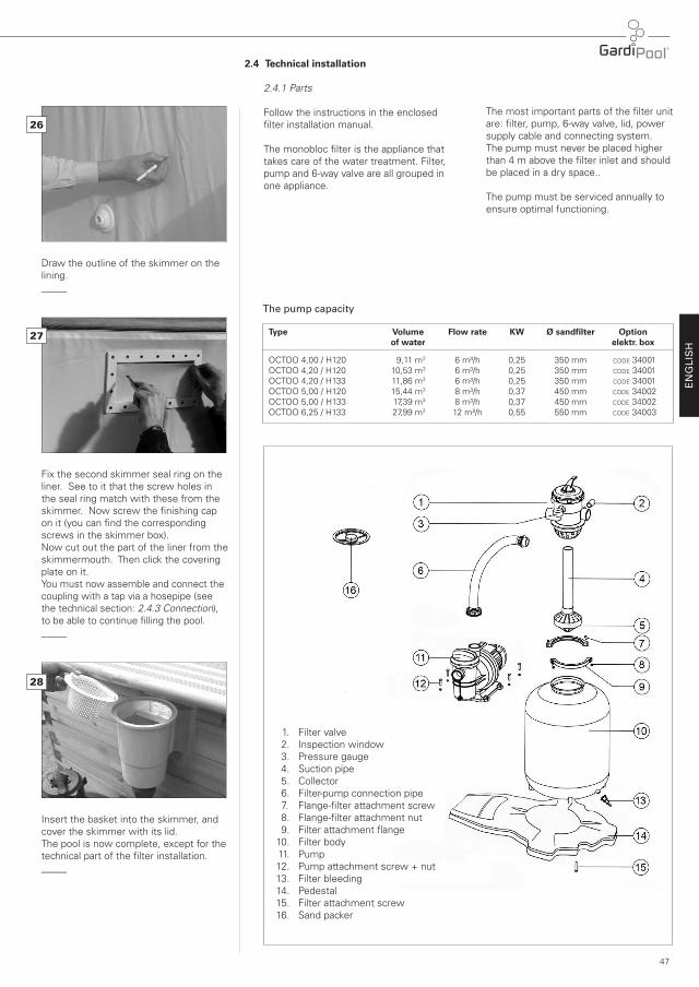
The monobloc filter is the appliance that
takes care of the water treatment. Filter,
pump and 6-way valve are all grouped in
one appliance.
The most important parts of the filter unit
are: filter, pump, 6-way valve, lid, power
supply cable and connecting system.
The pump must never be placed higher
than 4 m above the filter inlet and should
be placed in a dry space..
The pump must be serviced annually to
ensure optimal functioning.
26
27
28
The pump capacity
Type Volume Flow rate KW Ø sandfilter Option of water elektr. box
OCTOO 4,00 / H120 9,11 m3 6 m³/h 0,25 350 mm CODE 34001
OCTOO 4,20 / H120 10,53 m3 6 m³/h 0,25 350 mm CODE 34001
OCTOO 4,20 / H133 11,86 m3 6 m³/h 0,25 350 mm CODE 34001
OCTOO 5,00 / H120 15,44 m3 8 m³/h 0,37 450 mm CODE 34002
OCTOO 5,00 / H133 17,39 m3 8 m³/h 0,37 450 mm CODE 34002
OCTOO 6,25 / H133 27,99 m3 12 m³/h 0,55 550 mm CODE 34003
1. Filter valve
2. Inspection window
3. Pressure gauge
4. Suction pipe
5. Collector
6. Filter-pump connection pipe
7. Flange-filter attachment screw
8. Flange-filter attachment nut
9. Filter attachment flange
10. Filter body
11. Pump
12. Pump attachment screw + nut
13. Filter bleeding
14. Pedestal
15. Filter attachment screw
16. Sand packer
48
MANuAl
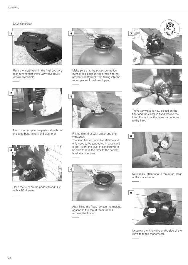
2.4.2 Monobloc
Place the installation in the final position;
bear in mind that the 6-way valve must
remain accessible.
_____
Attach the pump to the pedestal with the
enclosed bolts (+nuts and washers).
_____
Place the filter on the pedestal and fill it
with a 1/3rd water.
_____
Make sure that the plastic protection
(funnel) is placed on top of the filter to
prevent sand/gravel from falling into the
mouthpiece of the branch pipe.
_____
Fill the filter first with gravel and then
with sand.
The sand has an unlimited lifetime and
only need to be topped up in case sand
is lost. Mark the level of sand/gravel to
be able to refill the filter to the correct
level at a later time.
_____
After filling the filter, remove the residue
of sand at the top of the filter and
remove the funnel.
_____
The 6-way valve is now placed on the
filter and the clamp is fixed around the
filter. This is how the valve is connected
to the filter.
_____
Now apply Teflon tape to the outer thread
of the manometer.
_____
unscrew the little valve at the side of the
valve to fit the manometer.
_____
1 74
2
5
3
6
8
9

EN
GL
ISH
49
The pump and filter are interlinked by a
semi-flexible tube.
_____
Screw the connector pieces into the
filter and the pump. Slide the fittings and
the inserts over both ends of the hose.
Connect the fittings to the connector
pieces, and then tighten the fittings.
(see the technical section:
2.4.3 Connections)
_____
IMPORTANT To connect the water return device to
the pump, you need to put an additional intermediate connector (8) at the
entrance of the pump.
2.4.3 Connections
Before you join the connectors, you must
screw the PVC elbow (7) onto the return
opening. Do this as follows. Screw the
PVC elbow carefully onto the return piece
with some Teflon on the thread and en-
sure that this is done in one fluid move-
ment, without stopping or unscrewing
and with the outlet pointing downwards
at a right angle. You must then tighten
the ring with the proper spanner, while
holding the return piece in place on the
inside of the pool. This is to ensure that
the return piece remain in position.
In general, the semi-flexible connector
tubes need to be shortened straight and
square. Prepare the connectors 1, 3, 4
and 6 as follows.
Couplings unscrew the nut completely from the
fitting. Slide the nut with the insert over
the flexible tube. Then slide the white
clamp over the tube until approximately
2 cm of tube sticks out below the white
clamp.
Now push the tube into the fitting up
to the edge and press the white clamp
down onto the fitting. Place the seal into
the fitting.
Tighten the nut of the fitting.
This way it will be perfectly waterproof.
If you have a coupling without a rubber
packing, you are advised to apply Teflon
to the thread or nipple in order to main-
tain it’s waterproof capacity.
Taps Prepare the connectors to the tap in the
same way as the couplings, but in both
directions from the tap.
Connecting the filter unit to the pool. Follow the drawing. Connect the skim-
mer with the semi-flexible connection
tube to the pump and place a ball-valve
in-between (4,5,and 6). 4 and 5 should
have been coupled after the placement
of the skimmer, in order to continue
filling the pool. Then, connect the water
return device to the filter with the
connection tube and fit a ball valve to
this connection too (1,2,and 3). 1 and
2 should have been coupled already
after fitting the return device, in order
to continue filling the pool.
After installation, the filter needs to be
backwashed automatically; in this pro-
cess the filter sand is rinsed to prevent
impurities from entering the pool.
Afterwards, you place the valve in the
filter position and let the pump run; the
needle of the manometer indicates the
nominal pressure to which the filter
is exposed. Write down this pressure
(normally between 0.6 and 1.1 bar).
4
7
1
5
2
3
6
10
11
8
SKIMMER
Pu
MP

50
MANuAl
2.4.4 Functioning
NEVER AlTER THE POSITION OF THE
VAlVE WHIlE THE MOTOR IS RuNNING
FIRST REMOVE THE PluG
NEVER DISMANTlE THE VAlVE WHIlE
THE FIlTER IS STIll uNDER PRESSuRE.
The 6-way valve controls the 6 functions
of the filter: backwash, re-circulation,
rinse, filtration, waste, closed.
To change the position of the valve, you
need to unplug the power supply, press
the upper lever of the valve down force-
fully (to conquer the resistance of the
internal spring), then turn the lever
towards the chosen function and care-
fully release it.
The function of the filter is based on
the retaining properties of the sand in
the filter. The water in the pool is forced
through the filter pump and the sand,
causing the impurities in the water to
remain in the sand – which functions as
a filter element.
REMOVING AIR FROM THE FIlTER
When the air is not properly removed
from the filter, bad water circulation will
follow, consequently the filter’s purifica-
tion effect via the sand will be diminished
and the motor could be damaged.
The filter needs to be de-aired at the first
use of a new appliance or with the reuse
of an appliance that hasn’t been functio-
ning for a while, after using a bottom
cleaner, with absorption of air through
the skimmer due to a low water level in
the pool, due to the incorrect use of the
appliance (suction cap or skimmer cap).
If you notice that too many air bubbles
are released by the water return device,
the filter needs to be de-aired as well.
De-airing takes place by switching the
power supply off and placing the valve
into the backwash position. let the water
flow out through the waste until there
are no more air bubbles visible in the
peak hole on the side.
Shut off the filter again and shift the
valve into the preferred position.
Function 1: FILTER Place the valve in the filter position.
The water comes out of the pump and is
filtered by streaming downwards through
the sand and then returning the pool.
Do not filter for more than 4 hours at
a time. leave the engine to cool for at
least two hours. The number of filtering
hours is calculated by the total volume of
pool water of the (volume of water m³)
divided by the pump capacity (m³/u).
_____
Function 2: BACKWASH Place the valve in the backwash position.
By backwashing, the sand in the filter is
cleaned; for this, the direction of the
water circulation needs to be reversed.
The backwash needs to be done weekly
(when the manometer indicates 0,5 to
0,8 bar higher than the nominal pressure
– pressure between 1,1 and 1,7 bar)
Attach a tube to the waste of the valve
and place the other end of the hose in
the sewer. leave the filter running for
about 2 min. until the water runs clear;
you can verify this through the peak hole
at the side of the valve. Switch the filter
off and leave it standing for 2 min for the
sand to settle down in the filter. Put the
valve into the recycle position to prevent
impurities remaining in the valve, from
streaming back into the pool.
Then move the valve back into the
preferred position (filtering or close) and
remove the hose from the waste.
_____
Function 3: WASTE The pool can be emptied almost com-
pletely via the filter. Move the valve into
the waste position, attach a hose to the
waste and place the other end of the
hose in the sewer.
Connect the vacuum cleaner tube to the
skimmer (remove the inner basket from
the skimmer) and let the water run out.
The pool won’t be emptied completely;
switch the pump off once only a couple
of inches of water remain in the pool.
Remove the rest of the water manually.
_____
Function 4: CLOSED The valve is placed in the closed position
to prevent the water from circulating via
the hoses and the filter. Make sure that
the pump never functions in this position.
_____
EN
GL
ISH
51
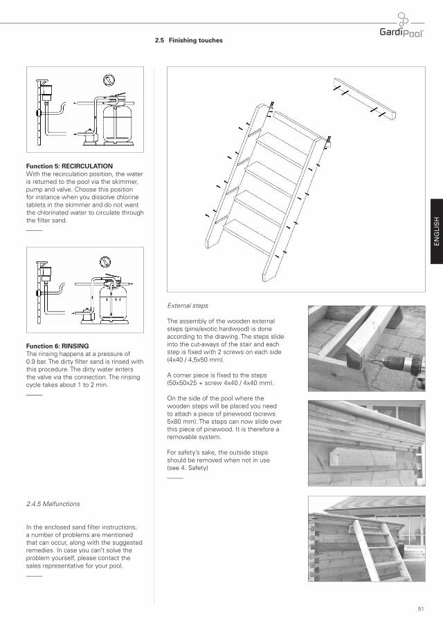
Function 5: RECIRCULATION With the recirculation position, the water
is returned to the pool via the skimmer,
pump and valve. Choose this position
for instance when you dissolve chlorine
tablets in the skimmer and do not want
the chlorinated water to circulate through
the filter sand.
_____
Function 6: RINSING The rinsing happens at a pressure of
0.9 bar. The dirty filter sand is rinsed with
this procedure. The dirty water enters
the valve via the connection. The rinsing
cycle takes about 1 to 2 min.
_____
2.4.5 Malfunctions
In the enclosed sand filter instructions,
a number of problems are mentioned
that can occur, along with the suggested
remedies. In case you can’t solve the
problem yourself, please contact the
sales representative for your pool.
_____
2.5 Finishing touches
External steps
The assembly of the wooden external
steps (pine/exotic hardwood) is done
according to the drawing. The steps slide
into the cut-aways of the stair and each
step is fixed with 2 screws on each side
(4x40 / 4,5x50 mm).
A corner piece is fixed to the steps
(50x50x25 + screw 4x40 / 4x40 mm).
On the side of the pool where the
wooden steps will be placed you need
to attach a piece of pinewood (screws
5x80 mm). The steps can now slide over
this piece of pinewood. It is therefore a
removable system.
For safety’s sake, the outside steps
should be removed when not in use
(see 4. Safety)
_____

52
MANuAl
Stainless steel steps
The stainless steel interior steps are
assembled according to the instructions
and are attached on top of the border.
Not suitable in salted water !
1) Define the place of the steps holders
80 mm from the inside of the coping.
2) Bore out two holes for the holders
with a brace diameter 50 mm.
80 mmø50 mm
3) Place the two holders and screw them
with the earthing. The earthing reduces
corrosion (except with electrolysis).
4) Place the rubber pieces at each end
of the stainless steel steps, for the
protection of the liner.
5) Place the metal covering plates over
the holders and install the steps.
6) Place the supporting plank and screw
it (see assembly 2.2.2.).
1
2
3 4
5
6
ground
eart
hin
g

EN
GL
ISH
53
3. Options
3.1 Summer tarpaulin
A summer tarpaulin can be placed across
the pool. Sunrays can increase the water
temperature. The tarpaulin is simply
placed on the water; when using the
pool the tarpaulin is removed and turned
over to dry. It is best to roll the tarpaulin
up to prevent tears. The tarpaulin should
not be walked upon.
_____
3.2 Winter tarpaulin
During the winter months when the
pool isn’t in use, a winter tarpaulin can
be placed across the pool. Distribute the
hooks equally around the outside of the
pool. Screw them on the sides of the
pool and fix the tarpaulin to the attached
hooks with the rapid binders.
This tarpaulin should also be rolled when
not used, to prevent tears. The winter
tarpaulin should not be walked upon.
_____
3.3 Safety tarpaulin
3.4 Technical housing
A technical housing can either be built in,
or loose standing. The built-in technical
housing is attached to the side of the
pool where the skimmer and water
return device are situated. The filter unit
is also placed inside this. (See 4 Safety)
Follow the instructions in the enclosed
drawing.
Screw one side to the pool, and as-
semble a few planks to the front to get
a perfectly angled structure. Then screw
on the other sides. This built-in technical
housing is available in three different
dimensions.
The loose standing model with 4 sides
is built up in a similar way.
_____
3.5 Electrical box
Follow the instructions in the enclosed
manual.
The electrical box is suitable for the elec-
trical connection of the pump and max.
3 underwater lamps. The box is provided
with a highly sensitive differential and
a transformer for the underwater lamp.
You can program the working of the
pump with the built-in timer.
The installation should be done by an
electrician. The local legislations and
applicable regulations must be respec-
ted. The waterproof IP65 box may be
placed at less than 3.5m from the pool.
The power supply to the electrical board
must be secured upstream by a high
sensitivity differential. (max 30 mA)
_____
54
MANuAl
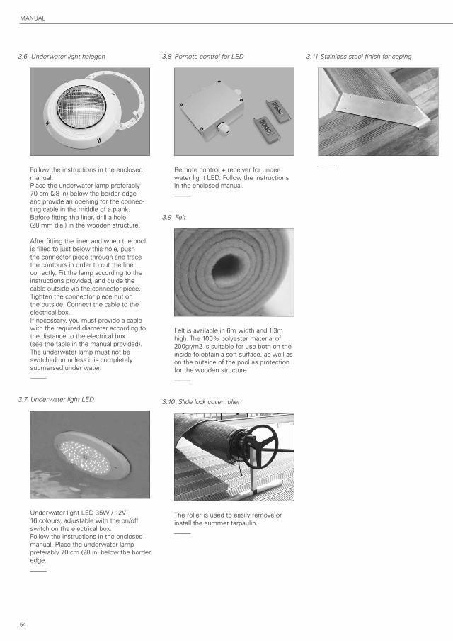
3.6 Underwater light halogen
Follow the instructions in the enclosed
manual.
Place the underwater lamp preferably
70 cm (28 in) below the border edge
and provide an opening for the connec-
ting cable in the middle of a plank.
Before fitting the liner, drill a hole
(28 mm dia.) in the wooden structure.
After fitting the liner, and when the pool
is filled to just below this hole, push
the connector piece through and trace
the contours in order to cut the liner
correctly. Fit the lamp according to the
instructions provided, and guide the
cable outside via the connector piece.
Tighten the connector piece nut on
the outside. Connect the cable to the
electrical box.
If necessary, you must provide a cable
with the required diameter according to
the distance to the electrical box
(see the table in the manual provided).
The underwater lamp must not be
switched on unless it is completely
submersed under water.
_____
3.7 Underwater light LED
underwater light lED 35W / 12V -
16 colours, adjustable with the on/off
switch on the electrical box.
Follow the instructions in the enclosed
manual. Place the underwater lamp
preferably 70 cm (28 in) below the border
edge.
_____
3.8 Remote control for LED
Remote control + receiver for under-
water light lED. Follow the instructions
in the enclosed manual.
_____
3.9 Felt
Felt is available in 6m width and 1.3m
high. The 100% polyester material of
200gr/m2 is suitable for use both on the
inside to obtain a soft surface, as well as
on the outside of the pool as protection
for the wooden structure.
_____
3.10 Slide lock cover roller
The roller is used to easily remove or
install the summer tarpaulin.
_____
3.11 Stainless steel finish for coping
_____
EN
GL
ISH
55
4. Safety instructions
TAKE NOTE
TECHNICAL INSTALLATION Do not activate the appliance if the air
was not properly removed. NEVER touch
the running appliance with wet hands or
a wet body. Always uNPluG the electric
cord in case you need to work on the
appliance.
Make sure the floor is dry before you
touch the electrical device.
Do not put the filter unit in a place where
you might get wet: risk of electrocution.
POSITION OF THE FILTER UNIT Avoid that the filtration kit with pump
is flooded. In a humid environment, it
is recommended to put the filtration kit
above ground or adapt the installation to
avoid deluge. unless you have a technical
housing to place next to the pool, the
filter unit must be placed at least 3,5m
away from the pool (because of electrical
safety) and on the same level as the
water level of the pool to prevent air from
entering the purification circuit, or the
filter.
It is advised to place the filter unit in a
place well protected from sun and rain
and with an ambient temperature below
35°C.
The technical housing can be placed
closer than 3,5 m from the pool, provided
that it is locked and only accessible by
qualified personnel. The power supply
should be cut before opening the tech-
nical room. Only then can you access
the area. Plugs are not accessible in this
case, due to the danger of electrocution.
_____
4.1 General
The borders are not intended to run
on nor to dive from. The steps are only
intended for use to step in and out of the
pool. After use it is advised to remove
the steps, this to enhance the security
level with children. Be careful when
using electrical devices around the pool
(risk of electrocution). Remain alert when
kids are near or in the swimming pool.
When the pool is not in use, it is better
to cover the pool.
_____
4.2 Technical installation
The technical housing may be placed at
a distance of less than 3,5 m from the
pool, provided that it is locked and only
accessible to qualified personnel.
Before opening the technical unit, you
need to interrupt the power supply.
Only after this should you access the
technical housing.
_____
4.3 Electricity
The installation needs to comply to the
general regulation (Belgium: art.90
swimming pools and France standards
NF C15-100).
All electrical devices must comply to the
following requirements:
- exclusively for swimming pool use
- isolating casing and provided with
mechanical protection
- power supply on a very low safety
voltage
- only to be fitted by qualified personnel
Installation should take place by an elec-
trician. The local legislation and applicable
requirements must be respected.
_____

56
MANuAl
5. Maintenance
5.1 Wooden structure
In order to guarantee a long lifetime
for your wood, it can be treated with
a special stain. (Contact your sales
department) If you prefer to maintain the
natural effect, you do not need to treat
the wood; the change in colour does not
reduce the quality.
Because of the natural forces in the
wood – as a result of the humidity and
variation in temperature - the wood can
show some cracks and tears after some
time. This is normal: the mechanical
resistance is not reduced.
_____
5.2 Water
Besides the correct use of the filter unit,
which controls the water treatment, a
couple of other important things need to
be checked on a regular basis.
The pH-value of the pool water needs
to be verified on a regular basis. It is
advised to fill the pool with tap water,
its pH-value normally corresponds better
with the ideal pH-value (between 7,2
and 7,6) than rain water or water from
another source.
Once the pH-value is too high, the water
needs to be treated with a special pro-
duct. In order to treat the water for the
first time, a starter kit is included. If you
live in an area with ‘hard’ water – high
lime content – it is suggested that you fill
the pool partially with ‘softened” treated
water.
During periods of frequent use, the filter
unit needs to function for several hours
per day on a daily basis. The total amount
of water needs to be filtered at least
once a day.
The water of your pool need to be
treated with special products on a
weekly basis in order to keep it clean and
pure. (Please contact a specialist pool
shop regarding water treatment)
There is a maintenance kit included in
your package. The hand net which is
attached to the telescopic rod serves
to scoop up leaves and impurities from
the water. The brush serves to clean the
sides of the pool. There is also a system
to clean the bottom of the pool: the
vacuum cleaner is attached to the brush
(+ telescopic stick) and is connected to
the skimmer.
_____
5.3 Technical installation
Check the pump once a year to ensure
good performance.
Normally no maintenance is required for
the filter pump, but the frequent use of
the filter in heavily polluted swimming
pools may cause the axis of the pump
to stall. When this occurs, the following
procedure is advised:
Switch off the power supply.
Set the valve in the closed position.
Close both the ball valves. Detach the
suction and feeding hoses from the
pump. loosen the screws from the front
filter’s lid. Remove the basket and all dirt.
Replace the basket and close the lid of
the front filter. Make sure that it is well
centred and tightened. Make sure that
there is water in the pump to be able to
start it.
Reconnect the hoses to the pump. Set
the 6-way valve in the filtration position.
Open both ball valves. Switch the motor
on and remove any air from the filter.
_____
5.4 Hibernation
If your pool is not covered, and you want
to keep the water for the following sea-
son, you should keep the following rules
in mind:
- after the last use of the pool, the resi-
due on the bottom should be removed
and the filter should work for eight
hours to obtain perfectly clean water
- add flocculants and additional treatment
- let the water circulate for at least three
hours to thoroughly mix the additives
- bring the water level to 20cm below
the skimmers
- cover the pool with a winter tarpaulin
_____
BRINGING THE POOl BACK IN uSE AGAIN
- two weeks before use, bring the water
level back to normal (do not remove the
tarpaulin yet). let the pump run for one
day (without filtration) while adding a
flocculent and additional treatments
- allow to rest for two weeks
- remove the tarpaulin, vacuum the bot-
tom with the pump on waste. Top the
pool up to normal level, in filter for at
least 12 hours
- check the ph-value, chlorine level and
add the necessary treatment
_____

EN
GL
ISH
57
6. Guarantee
6.1. Wooden structure
• Ten years’ guarantee against insect
infestations and bacterial attacks on the
vertical wooden structure (autoclave
treated wood class IV). This guarantee
does not take into account natural defor-
mations (cracks and tears that do not at
all threaten the mechanical resistance
of the wood), or colour changes due to
climatic influences. This guarantee is only
valid for the autoclave treatment itself.
• One year guarantee on the coping
against abnormal natural deformation
(torsion) and against excessive splinters.
The guarantee does not include any
colour change or difference, cracks or
splits.
• The pool is in accordance with the
standard AFNOR NF P90-302 (french
standard for pools in kit). A possible
aesthetic deformation does not pose any
risk to the stability of the pool, and can
be avoided by partially installing the pool
partially underground and fill in.
• In this last case (pool installed partially
under ground), we remind you to check
legal provisions with regards to safety
of children under 5 years of age
(NFP 306/307/308/309)
_____
6.2. Liner
Ten years’ guarantee (5 years degressive)
under normal usage.
Are not covered by this guarantee :
• Tears, holes, cracks, stains (mainte-
nance products put directly in the water),
decoloration and wear due to friction of
the fabric on different surfaces.
• Deformations of a liner that has been
without water for more than 24 hours
(never empty your pool completely)
• Decoloration of the liner due to
inappropriate water treatment (excessive
concentration of products, inappropriate
pH).
_____
6.3. Filter / pump
Two years’ guarantee on the sealing of
the filtration kit.
Are not covered by this guarantee :
• Problems linked to inadequate use of
the filter and its elements.
• Problems linked to pressure higher than
the maximum usage pressure of 1,2 bar,
or linked to the use of a too powerful
pump in relation to the elements of the
hydraulic circuit and the filter.
• Problems linked to the use of a too
weak pump in relation to the volume of
water in the pool.
• Deterioration due to « dry use » of the
pump.
• Deterioration due to abrasion or
corrosion.
• Deterioration due to a wrong
connection.
• Materials dismantled or repaired by
a third party.
• Breakage of pieces (base of the pump,
lid of the prefilter, grooved end …)
_____
6.4. Summer, winter or safety cover
One year’s guarantee on the welds
between the different bands of fabric.
When the cover is not placed on the
water surface, it should be put in shelter
from direct sunlight.
Are not covered by this guarantee :
• Pulled-out eyelet for the sandows :
this results from an excessive traction on
the sandow.
• Decoloration of the fabric due to
inappropriate water treatment (excessive
concentration of products, inappropriate
pH).
_____
6.5. Accessories
One year’s guarantee on any error in
fabrication or assembly of different acces-
sories of the pool, threatening its good
functioning.
Are not covered by this guarantee:
Maintenance products and cleaning kit
delivered with the pool. They should be
received in good shape, in accordance to
their expiration date.
_____
6.6. In general
Our guarantee is limited to the delivery
of the replacement parts for defective
items. In no case whatsoever, it implies
a demand of damages or indemnity for
incurred damage, or a compensation for
costs of energy et consumables.
The materials to be returned must be sent
on your account. We are not bound to
take back new materials that are returned
for a reason that does not stem from our
responsibility.
Please store all wood elements horizon-
tally, in a fresh and ventilated place,
away from direct sunlight and bad weather
conditions.
The different manuals that are included
in the pool kit stipulate that a regular
check-up and maintenance guarantee an
optional functioning of your pool and its
accessories. These conditions must be
strictly followed in order for the guarantee
to be valid.
Our guarantee does not cover risks of
corrosion that might appear in the course
of time et damages caused by inappro-
priate actions at the time of installing
the pool or using the accessories
(shocks, scrapes, etc., , as well as inci-
dents without any direct relation to normal
usage of the pool and its accessories.
Costs for installation and dismantling
are not taken into account.
_____

Covimex nv - Koolskampstraat 21 - B-8830 Gits
T +32 (0)51 26 37 64 - F +32 (0)51 21 07 64
[email protected] - www.gardipool.com V12
-01-0
2-2
012
-50
0