Embed Size (px)
Citation preview
October 30, 2007 © SKF Group Slide 1
Why is there no ideal bearing concept
EWEC 2012
Presented by Reiner Wagner,
Application Engineering Manager Renewable Energy, Germany
2012-04-17

October 30, 2007 © SKF Group Slide 3
Increased turbine Size
PowerRotor_DmHub Height
2010
Increasing turbine size Higher profitability
10 MW150 m160 m
October 30, 2007 © SKF Group Slide 4
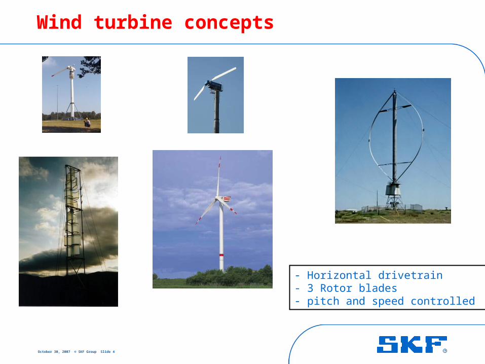
Wind turbine concepts
- Horizontal drivetrain - 3 Rotor blades- pitch and speed controlled
October 30, 2007 © SKF Group Slide 5
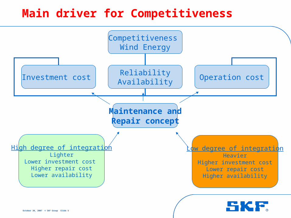
Main driver for Competitiveness
Competitiveness Wind Energy
Investment cost ReliabilityAvailability
Operation cost
Maintenance andRepair concept
High degree of integrationLighter
Lower investment cost Higher repair costLower availability
Low degree of integrationHeavier
Higher investment costLower repair costHigher availability
October 30, 2007 © SKF Group Slide 6
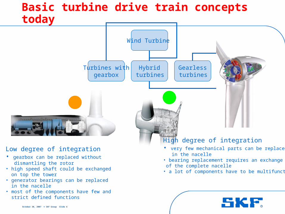
Basic turbine drive train concepts today
Wind Turbine
Turbines with gearbox
Hybrid turbines
Gearless turbines
Low degree of integration• gearbox can be replaced without dismantling the rotor • high speed shaft could be exchanged on top the tower • generator bearings can be replaced in the nacelle• most of the components have few and strict defined functions
High degree of integration• very few mechanical parts can be replaced in the nacelle • bearing replacement requires an exchange of the complete nacelle• a lot of components have to be multifunctional
October 30, 2007 © SKF Group Slide 7
Gearless and Hybrid1
October 30, 2007 © SKF Group Slide 8
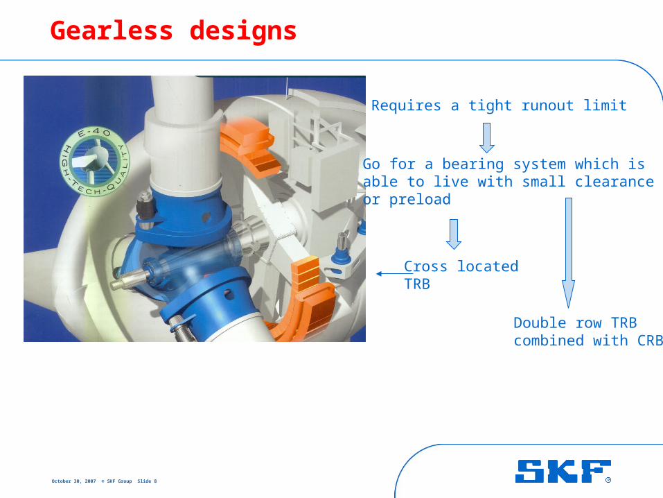
Gearless designs
Requires a tight runout limit
Go for a bearing system which is able to live with small clearance or preload
Cross locatedTRB
Double row TRB combined with CRB
October 30, 2007 © SKF Group Slide 9
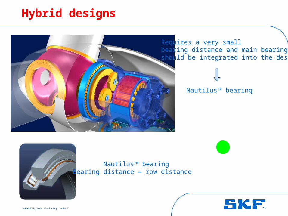
Hybrid designs
Requires a very small bearing distance and main bearing should be integrated into the design
NautilusTM bearing
NautilusTM bearingBearing distance = row distance
October 30, 2007 © SKF Group Slide 10
2Designs with gearbox(a flashback of drive train development)
October 30, 2007 © SKF Group Slide 11
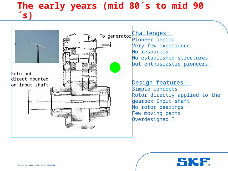
The early years (mid 80´s to mid 90´s)
Challenges: Pioneer period Very few experienceNo resources No established structuresbut enthusiastic pioneers
Design features: Simple concepts Rotor directly applied to the gearbox Input shaftNo rotor bearingsFew moving partsOverdesigned ?
Rotorhub direct mounted on input shaft
To generator
October 30, 2007 © SKF Group Slide 12
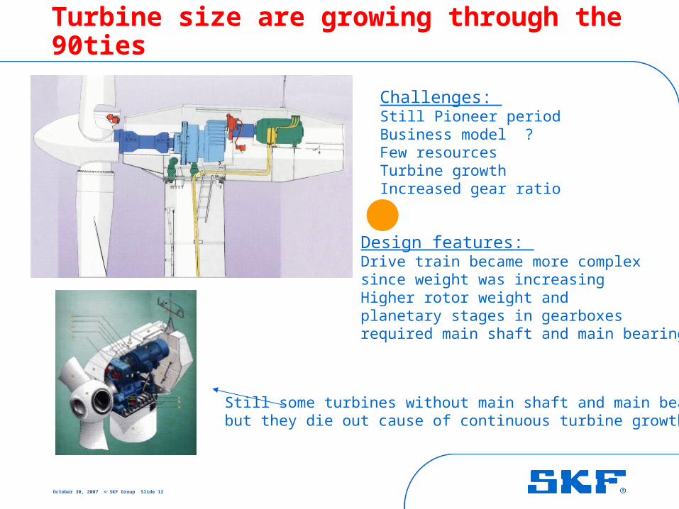
Turbine size are growing through the 90ties
Challenges: Still Pioneer periodBusiness model ?Few resources Turbine growthIncreased gear ratio
Design features: Drive train became more complex since weight was increasingHigher rotor weight and planetary stages in gearboxes required main shaft and main bearing
Still some turbines without main shaft and main bearing but they die out cause of continuous turbine growth
October 30, 2007 © SKF Group Slide 13
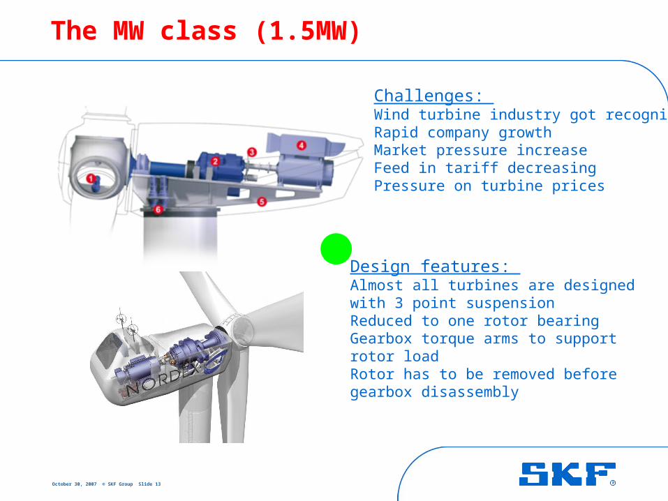
The MW class (1.5MW)
Challenges: Wind turbine industry got recognizedRapid company growth Market pressure increaseFeed in tariff decreasingPressure on turbine prices
Design features: Almost all turbines are designed with 3 point suspensionReduced to one rotor bearing Gearbox torque arms to support rotor loadRotor has to be removed beforegearbox disassembly
October 30, 2007 © SKF Group Slide 14
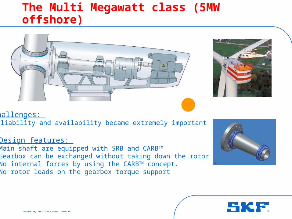
The Multi Megawatt class (5MW offshore)
Challenges: Reliability and availability became extremely important
Design features: Main shaft are equipped with SRB and CARBTM
Gearbox can be exchanged without taking down the rotorNo internal forces by using the CARBTM concept. No rotor loads on the gearbox torque support

October 30, 2007 © SKF Group Slide 15
The multi MW class (stiff design)
Challenges: Reduced drive train dynamic
Design features: Main shaft are equipped with DRTRB and CRB bearing Preloaded bearings
October 30, 2007 © SKF Group Slide 16
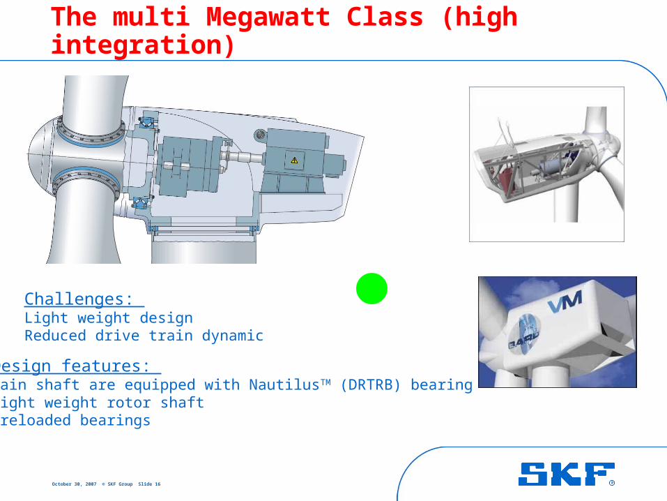
The multi Megawatt Class (high integration)
Challenges: Light weight designReduced drive train dynamic
Design features: Main shaft are equipped with NautilusTM (DRTRB) bearing Light weight rotor shaftPreloaded bearings
October 30, 2007 © SKF Group Slide 17
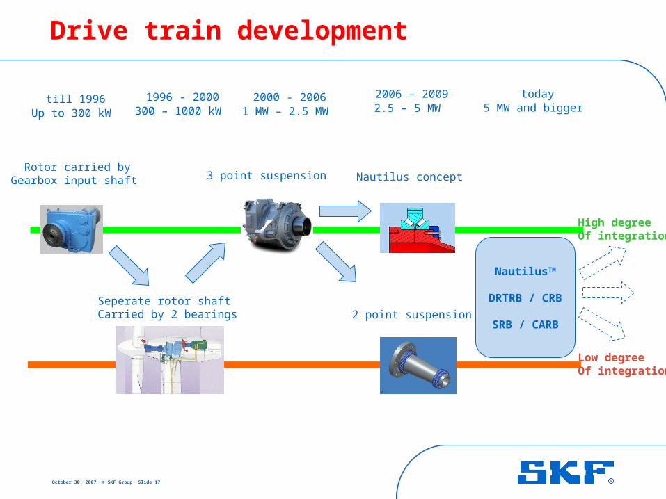
Drive train development
Rotor carried byGearbox input shaft
till 1996Up to 300 kW
2 point suspension
3 point suspension
Seperate rotor shaft Carried by 2 bearings
2006 – 20092.5 – 5 MW
2000 - 20061 MW – 2.5 MW
1996 - 2000300 – 1000 kW
today5 MW and bigger
Nautilus concept
High degreeOf integration
Low degree Of integration
NautilusTM
DRTRB / CRB
SRB / CARB
October 30, 2007 © SKF Group Slide 18
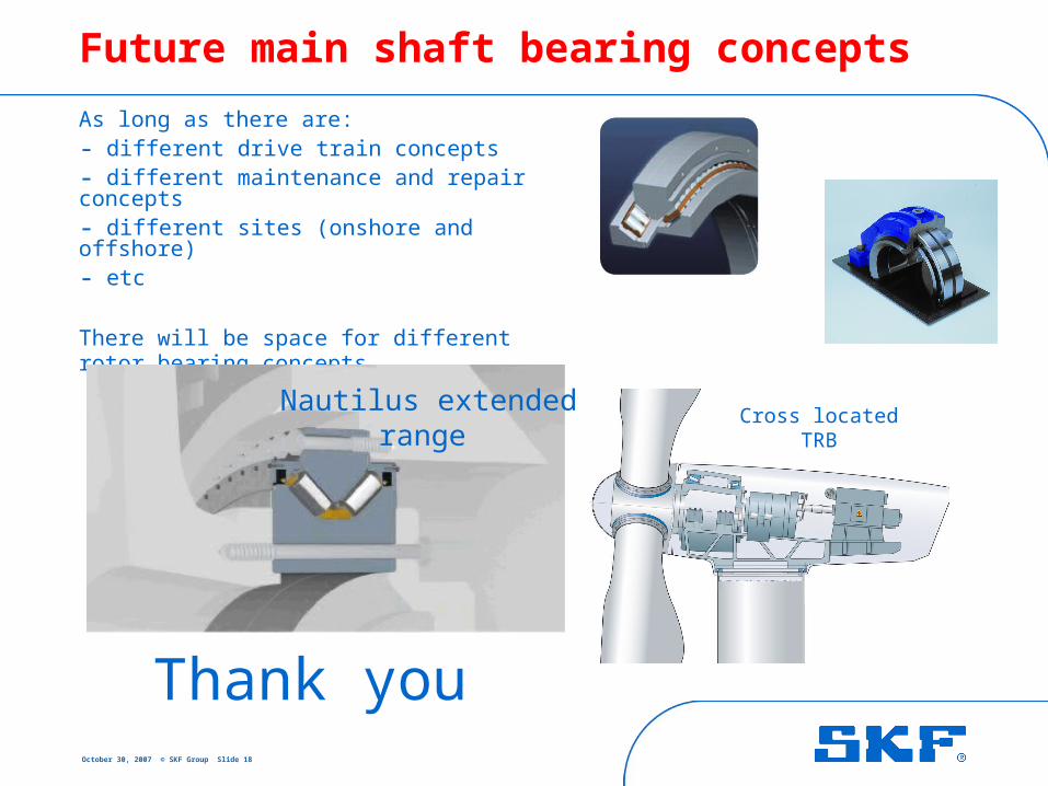
Future main shaft bearing concepts
As long as there are: - different drive train concepts - different maintenance and repair concepts - different sites (onshore and offshore) - etc
There will be space for different rotor bearing concepts
Thank you
Nautilus extendedrange
Cross locatedTRB