Embed Size (px)
Citation preview

2010
BO
DY
BU
ILD
ER
PBB-71000 (Part of CT-471)(October, 2010 Edition)
Diamond LogicControl Systems
®
Features and Programmable Parameters
ECM235
223
252
RVAR
RAS
SCS
ResumeSwitch
SetSwitch
Preset SpeedActive Switch
+ 12Vdc(1Amp source)
MomentarySwitch
ToggleSwitch
223248
Chassis Pocket(Connector #2)
Chassis Pocket(Connector #1)
Remote PTOSwitches
MSM
J1-7J1-8J1-5J1-6
Grey Pocket
J2-4
J2-9
Black Pocket
VIGNGNDCANHCANL
Ignition Switch
Off Run Crank
Batteries+ +
- -Engine / Chassis
GND
V (lgn)
Cruise Enable
Cruise Set/Coast & Resume/AcelIn Cab CruiseControl Switch
Resume/Accel
Set/Coast
V (lgn)

■■■■■■■■■■■■■■■■■■■■■■■■■■■■■■■■■■■■■■■■■■■■■■■■■■■■■■■■■■■■■■■■■■■■■■■■■■■■■■■■■■■■■■■
TABLE OF CONTENTS
TABLE OF CONTENTS
PREFACE .............................................................................................................................................. i
Book 1: MaxxForce® 7, DT, 9, and 10ENGINE SPEED CONTROL FEATURES....................................................................................................................B1-1
What International® Is Doing for You..............................................................................................................B1-1International® Diamond Logic® Electrical System Overview ..................................................................B1-2ServiceMaxx and Feature Programming .......................................................................................................B1-4Engine Speed Control for Power Take-Off (PTO) Applications .............................................................B1-7Transfer Case/Split Shaft Operation .............................................................................................................B1-21Remote Throttle Control....................................................................................................................................B1-24Remote Engine Start and Stop .......................................................................................................................B1-30Body Builder Connections and Circuit Protection .....................................................................................B1-31General Information............................................................................................................................................B1-35
PROGRAMMABLE PARAMETERS...........................................................................................................................B1-39Parameter Tables................................................................................................................................................B1-39Parameter Table Descriptions (by Feature Name)...................................................................................B1-49International® Proprietary Parameters .........................................................................................................B1-65
Book 2: MaxxForce® 11 and 13INTRODUCTION..............................................................................................................................................................B2-1
AUXILIARY ENGINE SPEED CONTROL....................................................................................................................B2-2Preset Engine Speed Control............................................................................................................................B2-2Variable Engine Speed Control ........................................................................................................................B2-6Engine Speed Control for Mobile Applications ..........................................................................................B2-10
TRANSFER CASE / SPLIT SHAFT............................................................................................................................B2-11Transfer Case Switch Operation ....................................................................................................................B2-11EPG Driveline Mode ...........................................................................................................................................B2-11Wheel Based Vehicle Speed ...........................................................................................................................B2-11
REMOTE THROTTLE ...................................................................................................................................................B2-12
Navistar Supplied Pedal Sensor - Notes and Diagnostics .....................................................................B2-13Navistar Supplied Hand Operated Throttle Control Kit ...........................................................................B2-14
REMOTE ENGINE START / STOP.............................................................................................................................B2-15
■■■■■■■■■■■■■■■■■■■■■■■■■■■■■■■■■■■■■■■■■■■■■■■■■■■■■■■■■■■■■■■■■■■■■■■■■■■■■■■■■■■■■■■
CT-471: DIAMOND LOGIC® CONTROL SYSTEMS (October, 2010) i

■■■■■■■■■■■■■■■■■■■■■■■■■■■■■■■■■■■■■■■■■■■■■■■■■■■■■■■■■■■■■■■■■■■■■■■■■■■■■■■■■■■■■■■
TABLE OF CONTENTS
APPENDIX ADiagnostic Service Tools ..............................................................................................Appendix A-1
APPENDIX BReferences And Service Publications...........................................................................Appendix B-1
APPENDIX CATA Data Link Support .................................................................................................Appendix C-1
APPENDIX DEngine Speed Control Parts .........................................................................................Appendix D-1
■■■■■■■■■■■■■■■■■■■■■■■■■■■■■■■■■■■■■■■■■■■■■■■■■■■■■■■■■■■■■■■■■■■■■■■■■■■■■■■■■■■■■■■
ii CT-471: DIAMOND LOGIC® CONTROL SYSTEMS (October, 2010)
■■■■■■■■■■■■■■■■■■■■■■■■■■■■■■■■■■■■■■■■■■■■■■■■■■■■■■■■■■■■■■■■■■■■■■■■■■■■■■■■■■■■■■■
PREFACE
PREFACE
■ ForewordThe CT-471 – Body Builder Books … is a set of booklets of which this Diamond Logic® Control Systems is a part. The complete set includes a General Information Body Builder booklet for information about the International® product line; model series Body Builder booklets which contain information related to the features and specifications for each of their respective models; this Component Body Builder booklet containing information for components which have common application in two or more truck series.
This manual describes engine speed control features for operating auxiliary equipment as applied to the Diamond Logic® Control (DLC) and Diamond Logic® Control II (DLC II) systems. It replaces the manual Body Builder Installation and Use Guidelines TMT-2284 (November, 1994) which concentrated on the three controller system.
■ Technical Service Help LineNavistar, Inc. provides a telephone service that answers technical questions about vehicle maintenance and repair. The telephone number for Customers and Equipment Manufacturers (Body Builders) is:
1 - 800 - 336 - 4500The Technical Service staff will be pleased to assist you with your questions about the installation and use of the engine speed controls reviewed here. You may also contact Technical Service with your programming problems that cannot be resolved locally.
■ Publication PurposeThe purpose of this document is two-fold:
WITH REGARD TO ENGINE SPEED CONTROL FEATURES:• This document provides the information needed to integrate International® MaxxForce®
electronic engines with auxiliary equipment such as air compressors, hydraulic pumps, generators and the equipment they power.
• This manual is not a cookbook. The circuits described in this manual should be used as a guide. You must adapt the principles illustrated and develop designs that suit your durability, installation, and parts availability needs. This manual shows individual examples of engine speed control interfaces. These individual examples can be combined to form multi-function applications. For example, the same vehicle can use multiple engine speed control features such as the remote throttle feature to provide the power needed to operate a crane, or use preset engine speed control to operate an air compressor. The objective of this manual is to provide background and examples to permit you to properly install and operate equipment for your vehicle.
■■■■■■■■■■■■■■■■■■■■■■■■■■■■■■■■■■■■■■■■■■■■■■■■■■■■■■■■■■■■■■■■■■■■■■■■■■■■■■■■■■■■■■■
CT-471: DIAMOND LOGIC® CONTROL SYSTEMS (October, 2010) iii

■■■■■■■■■■■■■■■■■■■■■■■■■■■■■■■■■■■■■■■■■■■■■■■■■■■■■■■■■■■■■■■■■■■■■■■■■■■■■■■■■■■■■■■
PREFACE
WITH REGARD TO PROGRAMMABLE PARAMETERS:• This information is intended to support the process used by MaxxForce® Engine customers to
specify values to be programmed for both factory programmable parameters and field programmable parameters.
• The purpose of this information is to provide general functionality information about programmable parameters available for the Diamond Logic® Control (DLC) and Diamond Logic® Control II (DLC II) systems. In areas where additional detail is desired about a specific parameter or feature, refer to the reference section of this manual for comprehensive documentation.
DISCLAIMER: NAVISTAR, INC. DOES NOT TAKE ANY RESPONSIBILITY FOR CUSTOMER OR BODY BUILDER WIRING.
NOTE: After-market installed wiring for engine speed control must comply with the following guidelines:
1. Sealed switches and connectors must be used for switches and connections that are exposed to the weather or to salt spray emanating from the vehicle's tires.
2. Route and clip wiring to minimize chaffing and exposure to weather. Use conduit, loom, and/or tape to achieve this.
3. Fuse all power leads as close to the power source as possible. Remember fuses protect the wiring — size fuses accordingly.
4. All ground connections that will be made to the frame or body must be connected to clean bare metal. Remove all dirt, paint, grease and rust that would insulate the terminal from ground. After connecting the ground, seal the connection with a good quality grease or surface sealant to protect the connection from corrosion.
5. Spliced wires should be twisted together and soldered. Use a heat shrink tube with a meltable inner wall to seal the connection. Do not expose splices to the weather.
CAUTION: To avoid damage to vehicle electronic components, disconnect both the positive (+) and the negative (-) battery cables prior to electric welding. Attach the welder's ground cable as close as possible to the joint being welded. If it is necessary to weld close to an electronic component, it is recommended that the electronic component be temporarily removed.
WARNING: To avoid serious personal injury, death or possible engine damage, when welding or using an acetylene torch always wear welding goggles and gloves. Insure that acetylene and oxygen tanks are separated by a metal shield and are chained to a cart. Do not weld or heat areas near fuel tanks or fuel lines. Utilize proper shielding around hydraulic lines.
WARNING: To avoid serious personal injury, possible death, or damage to the vehicle, make sure the Transmission is in neutral, parking brake is set, and the wheels are blocked.
■■■■■■■■■■■■■■■■■■■■■■■■■■■■■■■■■■■■■■■■■■■■■■■■■■■■■■■■■■■■■■■■■■■■■■■■■■■■■■■■■■■■■■■
iv CT-471: DIAMOND LOGIC® CONTROL SYSTEMS (October, 2010)

■■■■■■■■■■■■■■■■■■■■■■■■■■■■■■■■■■■■■■■■■■■■■■■■■■■■■■■■■■■■■■■■■■■■■■■■■■■■■■■■■■■■■■■
PREFACE
DisclaimerThe Body Builder Books provide product information to assist those who wish to modify these products for individual applications. International® does not recommend or approve any firm or party nor make any judgements on the quality of the work performed by a particular firm or party. Individuals who use the services of a Body Builder must satisfy themselves as to the quality of the work.
The party installing a body, a fifth wheel, any other equipment, or making any modifications to complete the vehicle for delivery and make it road-ready is responsible to see that the completed vehicle complies with all applicable certification procedures and safety standards, as may be set forth in Federal, State, and local statues, rules and regulations.
Specifications, descriptions and illustrative material in this literature are as accurate as known at time of publication but are subject to change without notice. International® cannot accept responsibility for typographical errors which may have occurred. Illustrations are not always to scale and may include optional equipment and accessories but may not include all standard equipment.
Note: All body builders must fulfill DOT, NHTSA, Federal and State requirements. Since these state requirements may vary it is the duty of the body builder to ensure compliance.
International® and the International® logotype are registered trademarks of International Truck Intellectual Property Company, LLC.
■■■■■■■■■■■■■■■■■■■■■■■■■■■■■■■■■■■■■■■■■■■■■■■■■■■■■■■■■■■■■■■■■■■■■■■■■■■■■■■■■■■■■■■
CT-471: DIAMOND LOGIC® CONTROL SYSTEMS (October, 2010) v
■■■■■■■■■■■■■■■■■■■■■■■■■■■■■■■■■■■■■■■■■■■■■■■■■■■■■■■■■■■■■■■■■■■■■■■■■■■■■■■■■■■■■■■
PREFACE
■ Publication Ordering InformationYou can easily order the CT-471 Body Builder set or any of its components by accessing the Marketing Resource Center and clicking the “Order Literature” link using your regular User ID and password.
Revisions to the following product publications are available automatically by subscribing to the Product Information Revision Service. Also, additional copies of product publications can be ordered individually on a one-time basis. When ordering, include the publication number, description and quantity required.
Body Builder Book – Complete Set................................................................................................................. CT-471
TerraStar™ Series: Medium Conventional Body Builder Diagrams ......................................................... PBB-43100
DuraStar® Series: Medium Conventional Body Builder Diagrams ........................................................... PBB-44100
PayStar® Series: Premium On/Off Highway Conventional Body Builder Diagrams ................................. PBB-45100
WorkStar® Series: Medium & Heavy Conventional Body Builder Diagrams............................................ PBB-50100
Diamond Logic® Control Systems .......................................................................................................... PBB-71000
Body Builder on CD.................................................................................................................................... CT471-CD
■■■■■■■■■■■■■■■■■■■■■■■■■■■■■■■■■■■■■■■■■■■■■■■■■■■■■■■■■■■■■■■■■■■■■■■■■■■■■■■■■■■■■■■
vi CT-471: DIAMOND LOGIC® CONTROL SYSTEMS (October, 2010)

MAXXFORCE® 7, DT, 9, 10
■■■■■■■■■■■■■■■■■■■■■■■■■■■■■■■■■■■■■■■■■■■■■■■■■■■■■■■■■■■■■■■■■■■■■■■■■■■■■■■■■■■■■■■
ENGINE SPEED CONTROL FEATURES
Book 1: MaxxForce® 7, DT, 9, and 10
ENGINE SPEED CONTROL FEATURES
■ What International® is doing for youInternational® vehicles provides a variety of engine speed control features to operate auxiliary equipment. Auxiliary equipment is typically powered by a Power Take Off (PTO) which is interfaced either to the vehicle transmission or tailshaft. PTO features are provided to permit precise management and control of auxiliary equipment.
This document provides information needed to integrate MaxxForce® electronically controlled engines with auxiliary equipment such as air compressors, hydraulic pumps, generators, and the equipment they power. The features for engine speed control offer:
1. More flexible installation locations – control stations can be installed anywhere you can run wires or where a Remote Engine Speed Controller can be mounted. In fact, by using a RESCM the wire lengths can be shortened considerably. Instead of running wires the length of the truck to the engine controller, the wires and switches can be wired to a RESCM which can be located within close proximity of the engine speed control station (currently mounted on the back of the battery box or under the cab, depending on the configuration). Engine speed control can be initiated from outside or inside the vehicle's cab.
2. Capability to use either discrete hardwires to the engine controller or to the multiplexed Remote Engine Speed Controller (RESCM).
3. Precise engine speed governing - the electronic engines will maintain engine speed within 50 RPM (2 percent) of the set point. Accurate engine speed control should provide predictable flow and pressure from hydraulic pumps.
4. Two built-in engine speed selections (besides idle) for operating auxiliary equipment. Variable speed selections are also available through switches to increase or decrease engine speed. Vernier throttle control through a remote throttle potentiometer can also be used.
5. Control stations can be disabled by integrating equipment interlocks into them.
6. Diagnostics and programming are accomplished using either a PC-based software package or an electronic service tool.
7. Increases in engine speed are ramped, instead of accelerating the engine at full fuel levels. The slower load transfer rates can increase the equipment life of some mechanical systems.
8. Soft features. Feature selection and operating set points and limits can be changed to adapt the chassis to the new equipment.
9. A Password protects the configuration and speed settings from tampering.
10. Reduced assembly, maintenance, and repair costs over comparable mechanical control systems.
Hardware and software aspects of each engine speed control feature are discussed in this document. All options for features can be programmed at the factory. Features can be changed in the field after the vehicle has been manufactured using a pc-type computer. Section 2 reviews monitoring feature operation and programing with the PC-based ServiceMaxx.
■■■■■■■■■■■■■■■■■■■■■■■■■■■■■■■■■■■■■■■■■■■■■■■■■■■■■■■■■■■■■■■■■■■■■■■■■■■■■■■■■■■■■■■
CT-471: DIAMOND LOGIC® CONTROL SYSTEMS (October, 2010) B1-1

MAXXFORCE® 7, DT, 9, 10
■■■■■■■■■■■■■■■■■■■■■■■■■■■■■■■■■■■■■■■■■■■■■■■■■■■■■■■■■■■■■■■■■■■■■■■■■■■■■■■■■■■■■■■
ENGINE SPEED CONTROL FEATURES
■ International® Diamond Logic® Electrical System OverviewThe design of the electrical system significantly reduces the direct wiring to the powertrain components. This system uses an Electrical System Controller (ESC) which can be considered a vehicle control module. All of the in-cab switches which were formerly direct wired to the powertrain modules are now connected to this ESC which then communicates the values to the other devices via J1939. Vehicles implementing this system also use a J1939 driven cluster and still, in general, maintain the same powertrain interfacing (Engine-Transmission-ABS) as in previous vehicles. Even with this increased J1939 usage, the standard J1587 communications are still available for uses such as diagnostics as the supplier chooses.
■ ■ ECM Engine Control SystemThe Electronic Control Module (ECM) is one of two electronic controllers on the MaxxForce® engine. The ECM and Injector Drive Module (IDM) are mounted directly on the engine. These two controllers work in conjunction to allow the engine to run and operate. The ECM is considered the computer brain for the engine, while the IDM acts as a computer brain for the fuel injection. The ECM also interfaces with other vehicle features such as communicating with the Cruise Control switches, PTO switches, and Accelerator Pedal to name a few.
The ECM engine control system has been specifically designed to work with the new multiplex system, using the J1939 datalink to communicate with the ESC. As a result, some of the hard wired switches from the days of old have been removed from the engine controller and have been replaced by a multiplexed switch that has its information sent to the engine controller over the J1939 datalink. A few examples of switches that are now multiplexed are: Cruise Control and PTO switches, Brake Pedal switch, and Clutch Pedal switch to name a few.
■ ■ Remote Engine Speed ControllerThe Electrical System utilizes multiplexed wiring technologies for interfacing major functional areas of the vehicle. The electrical system includes the Remote Engine Speed Control Module (RESCM) to provide a means to control engine speed from a remote location on the vehicle. The RESCM is responsible for interfacing control signals to the operator and communicates signal status over J1939 datalink. Furthermore, the system relies on software algorithms to accomplish logic functions instead of implementing similar features using complex wire harness designs with relays and switches. A natural benefit of this system is increased diagnostic capability in terms of on-line, off-line, and off-board testing as well as simplifying the harness design. In layperson's terms, the electrical system uses switches that communicate digital messages over a two-wire datalink, rather than having to hard-wire a large bundle of wires that would often extend from one end of the truck to the other. Also, the RESCM is able to accomplish all of the functionality that the old hard-wire method was able to achieve.
■ ■ Body Builder WiringWhen control over engine speed is required from outside the vehicle cab, a remote mounted switch must be used. Feature code 12VZA {ENGINE CONTROL, REMOTE MOUNTED Provision for; Includes Wiring for Body Builder Installation of PTO Controls; With Ignition Switch Control for
■■■■■■■■■■■■■■■■■■■■■■■■■■■■■■■■■■■■■■■■■■■■■■■■■■■■■■■■■■■■■■■■■■■■■■■■■■■■■■■■■■■■■■■
B1-2 CT-471: DIAMOND LOGIC® CONTROL SYSTEMS (October, 2010)

MAXXFORCE® 7, DT, 9, 10
■■■■■■■■■■■■■■■■■■■■■■■■■■■■■■■■■■■■■■■■■■■■■■■■■■■■■■■■■■■■■■■■■■■■■■■■■■■■■■■■■■■■■■■
ENGINE SPEED CONTROL FEATURES
MaxxForce post 2007 Emissions Electronic Engines} or 12VXY {ENGINE CONTROL, REMOTE MOUNTED Provision for; Includes Module and Connector for Body Builder Installation of Remote Engine Speed Control, With SAE J1939 Communication} can be ordered to facilitate switch installation by the body builder. Even though this electrical system tends not to use discrete hard-wires, International offers both hard-wired and RESCM inputs to facilitate engine speed control messages.
Again, hard-wired body builder wiring connections are provided only when code 12VZA is specified. The control module and the wiring connections for body builder use are generally located underneath the hood of the truck It is highly recommended that a male/female connector pair be used to interface with the body builder wires. Recommended connectors can be found in Appendix D2 and D3. Hard-wired connections should be avoided if possible in order to make electrical diagnostics and servicing convenient. Electrical wires spliced to these connections should be twisted together and then soldered. A heat shrink tube should be used to seal the connections and the splices should not be exposed to the weather. Each wire connection has a circuit number printed on the insulation. Table 1.1 summarizes the circuit numbers and functions available with the hardwired version, 12VZA. In addition, the table includes information on wire gauge sizes and colors.
■■■■■■■■■■■■■■■■■■■■■■■■■■■■■■■■■■■■■■■■■■■■■■■■■■■■■■■■■■■■■■■■■■■■■■■■■■■■■■■■■■■■■■■
CT-471: DIAMOND LOGIC® CONTROL SYSTEMS (October, 2010) B1-3

MAXXFORCE® 7, DT, 9, 10
■■■■■■■■■■■■■■■■■■■■■■■■■■■■■■■■■■■■■■■■■■■■■■■■■■■■■■■■■■■■■■■■■■■■■■■■■■■■■■■■■■■■■■■
ENGINE SPEED CONTROL FEATURES
■ ServiceMaxx and Feature ProgrammingAfter engine assembly, changes can be made using the ServiceMaxx Software package and a PC. The scope of the changes that may be needed is discussed in this section. International® primarily uses the ServiceMaxx Software package for engine control diagnostics and programming. The ServiceMaxx Software permits monitoring of engine speed control functions during engine operation. This tool also permits modification of engine speed control parameters via re-programming. The specific functions for monitoring and programming are discussed in this section. In order to use the software package, a PC-type computer must be interfaced to the controller through the PC's communications port using an adapter harness. Appendix A shows the required part numbers to connect the computer. The software package can be installed on a computer by following the instructions on the installation disk.
■ ■ Monitoring Engine Speed Control Parameters with ServiceMaxx SoftwareServiceMaxx Software can be used to monitor engine speed control parameters during equipment operation. Table 2.1 shows the data display items for engine speed control features that are displayed by the diagnostic software. Beside each item is a short explanation of the data displayed. Switch states and accelerator pedal values contained in Table 2.1 are shown while the engine is not running and the ignition key is on. This Key On/Engine Off functionality permits a particular installation to be verified prior to actual use. Active values for PTO related parameters appear only
Table B1.1 – Functions Available with 12VZA, Hardwired Body Builder Wiring
CIRCUIT NUMBER I6 ECM PIN FUNCTION WIRE
GAUGEWIRE COLOR
I6WIRE COLOR
V8
KQ97CB X1-16 Preset PTO Enable 18 Purple Purple
KQ97CC X1-60 Variable PTO Enable 18 Purple Purple
K4Q46B X1-68 Set PTO Speed 18 Grey Purple
KQ46A X1-49 Resume PTO Speed 18 Grey Purple
KQ47B X1-72 Speedometer 18 Grey Purple
KQ97AR X1-71 Tachometer 18 Purple Purple
KQ97DF 12V 1 Amp Source
Voltage PTO 14 (V8)16 (I6)
Purple Purple
K99F X1-50 REM Accelerator 18 Purple Purple
K97XC X1-11 Transfer Case 18 Purple Purple
K97WA X1-35 (I6)X1-38 (V8)
Signal Return 18 Purple Purple
K97EW X1-22 Engine Warning 18 Purple Purple
K97SE X1-21 Stop Engine 18 Purple Purple
K97FV X1-27 (I6)X1-32 (V8)
Voltage Ref 5V 18 Purple Purple
■■■■■■■■■■■■■■■■■■■■■■■■■■■■■■■■■■■■■■■■■■■■■■■■■■■■■■■■■■■■■■■■■■■■■■■■■■■■■■■■■■■■■■■
B1-4 CT-471: DIAMOND LOGIC® CONTROL SYSTEMS (October, 2010)

MAXXFORCE® 7, DT, 9, 10
■■■■■■■■■■■■■■■■■■■■■■■■■■■■■■■■■■■■■■■■■■■■■■■■■■■■■■■■■■■■■■■■■■■■■■■■■■■■■■■■■■■■■■■
ENGINE SPEED CONTROL FEATURES
when PTO MODE is set to REMOTE, IN-CAB or IN-CAB+REMOTE. The next section discusses programming for each engine speed control feature.
* This display item name is only valid for ServiceMaxx Software. The corresponding parameter name for the EST is “PTO Speed”.
■ ■ Programming Engine Speed Control Parameters with ServiceMaxx Software – What Can You Change with ServiceMaxx Software?
Many of the parameters for PTO Engine Speed Control features can be programmed at the factory. Parameters can be re-programmed in the field after the vehicle has been manufactured. A PC using ServiceMaxx Software is used to modify the factory settings for engine speed control features. Re-programming permits customization of feature operation to exactly match the auxiliary equipment being operated; it also permits changing from one feature to another. Table 2.2 shows which parameters are used for each engine speed control feature. Each of the parameters can be accessed and reprogrammed with the ServiceMaxx Software. Parameter settings can be reviewed and changed by selecting the appropriate engine speed control parameters within the VEHICLE PROGRAMMING menu.
Table 2.1 – Service Tool Display Items for Monitoring Speed Control Features
SERVICEMAXX SOFTWARE DISPLAY ITEM VALUE DISPLAY ITEM CONTENTS
Accel Pedal 0.00% Displays the Throttle Percent of the Driver's Foot Pedal.
Engine Speed 0.00 RPM Displays Engine Speed in revolutions per minute.
PTO On/Off * Off Displays the status of the in-cab ON/OFF switch.
PTO Set Switch Off Displays the status of the SET switch.
PTO Coast Switch Off Displays the status of the SET switch (Hold SET for COAST).
PTO Resume Switch Off Displays the status of the RESUME switch.
PTO Accel Switch Off Displays the status of the RESUME switch (Hold the RESUME switch for the ACCE function).
PTO Brake Switch Off Displays the status of the service brake switch.
PTO Clutch Switch On Displays the status of the clutch or neutral position switch.
PTO Ctrl Mode Inactive Displays ACTIVE when engine speed control is active.
PTO Set RPM 700 RPM Displays desired engine speed in RPM when speed control is active.
Rem VAR PTO Off Displays ON when Remote Variable PTO Switch is enabled.
Rem Preset PTO Off Displays ON when Remote Preset Switch is enabled.
Rem Throttle N/A Displays ON when the remote throttle is enabled to control desired engine speed. Remote throttle displays FAIL when the remote throttle is faulted.
Split Shaft N/A Displays driveline status (neutral or split shaft).
■■■■■■■■■■■■■■■■■■■■■■■■■■■■■■■■■■■■■■■■■■■■■■■■■■■■■■■■■■■■■■■■■■■■■■■■■■■■■■■■■■■■■■■
CT-471: DIAMOND LOGIC® CONTROL SYSTEMS (October, 2010) B1-5

MAXXFORCE® 7, DT, 9, 10
■■■■■■■■■■■■■■■■■■■■■■■■■■■■■■■■■■■■■■■■■■■■■■■■■■■■■■■■■■■■■■■■■■■■■■■■■■■■■■■■■■■■■■■
ENGINE SPEED CONTROL FEATURES
When a feature is added or modified, all parameters should be checked to ensure that the equipment will operate as intended. Particular attention should be given to parameters that have a “Yes” in the column for the feature in Table 2.2. A more comprehensive discussion of all parameters is provided in Section 3.
Additional references for feature programming can be found in “Appendix B” of this manual. For further assistance, contact your International® dealer or call Technical Service at 1-800-336-4500 for help with field re-programming.
Table 2.2 – Speed Control Feature Parameter Matrix
* Program as required for use with the Preset or the Variable Engine Speed Control features when they are used in combination with the Remote Throttle.** Program as required for use with the Remote Throttle when the Remote Throttle is used in combination with the Preset or the Variable Engine Speed Control features.
PROGAMMABLE PARAMETER NAME
PRESET ENGINE SPEED
CONTROL
VARIABLE ENGINE SPEED
CONTROL
REMOTE THROTTLE
PEDAL
REMOTE ENGINE SPEED
CONTROL
MOBILE ENGINE SPEED
CONTROL
SPLIT SHAFT
PTO: Power Take Off Mode Yes Yes Yes Yes
PTO: In-Cab Mode Yes Yes No Yes
PTO: in-Cab Control Yes ** Yes ** No * No
PTO: Remote Pedal No ** No ** No
PTO: Preset RPM 1 (Set) Yes No Yes
PTO: Preset RPM 2 (Resume) Yes No Yes
PTO: Preset RPM 3 Yes No Yes
EPG: Preset RPM 4 Yes No Yes
PTO: Preset RPM 5 Yes No
PTO: Preset RPM 6 Yes No
PTO: Max RPM Yes Yes
PTO: RPM Ramp Rate No Yes
PTO: Max Vehicle Speed No No
EPG: Driveline Mode No No
■■■■■■■■■■■■■■■■■■■■■■■■■■■■■■■■■■■■■■■■■■■■■■■■■■■■■■■■■■■■■■■■■■■■■■■■■■■■■■■■■■■■■■■
B1-6 CT-471: DIAMOND LOGIC® CONTROL SYSTEMS (October, 2010)

MAXXFORCE® 7, DT, 9, 10
■■■■■■■■■■■■■■■■■■■■■■■■■■■■■■■■■■■■■■■■■■■■■■■■■■■■■■■■■■■■■■■■■■■■■■■■■■■■■■■■■■■■■■■
ENGINE SPEED CONTROL FEATURES
■ Engine Speed Control for Power Take Off (PTO) ApplicationsThere are 3 different engine speed control features available for vehicle vocations:
• Preset Engine Speed Control• Variable Engine Speed Control• Mobile Variable Engine Speed ControlThe first two features require a non-moving (stationary) vehicle for operation. The “Preset” feature always controls engine speed to a previously programmed value, while the “Variable” feature permits a desired engine speed to be selected via the in-cab or remote mounted switches. The “Mobile Variable” feature is the same as the “Variable” feature, with the exception that the vehicle can be moving or stationary during PTO operation.
Table 3.1 lists the programmable parameters that apply to these three PTO Engine Speed Control features. For each programmable parameter, this table shows the minimum and maximum permissible values that can be programmed, engineering units, and the resolution (increment) applicable for a particular parameter.
Detailed descriptions are provided for each of the programmable parameters in the “Programmable Parameters”, Section 9.
Table 3.1 –Programmable Parameter Attributes for PTO Engine Speed Control
■ ■ Preset Engine Speed ControlThis feature provides six pre-determined engine speed settings (besides low idle) for equipment operation. Preset Engine Speed Control satisfies the majority of the intended engine speed control
PROGRAMMABLE PARAMETER NAME
PROGRAMMABLE PARAMETER ATTRIBUTES
UNITS LOWER LIMIT UPPER LIMIT INCREMENT
PTO: Power Take Off Mode N/A 0 3 1
PTO: In-Cab Mode N/A 0 3 1
PTO: In-Cab Control N/A 0 1 1
PTO: Preset RPM 1 (Set) RPM LOW IDLE GOVERNED SPEED .25
PTO: Preset RPM 2 (Resume) RPM LOW IDLE GOVERNED SPEED .25
PTO: Preset RPM 3 RPM LOW IDLE GOVERNED SPEED .25
PTO: Preset RPM 4 RPM LOW IDLE GOVERNED SPEED .25
PTO: Preset RPM 5 RPM LOW IDLE GOVERNED SPEED .25
PTO: Preset RPM 6 RPM LOW IDLE GOVERNED SPEED .25
PTO: Max RPM RPM LOW IDLE GOVERNED SPEED .25
PTO: RPM Ramp Rate RPM/SEC 1 1500 .25
PTO: Max VS MPH 0 20 .5
PTO: Remote Pedal Enable N/A 0 1 1
■■■■■■■■■■■■■■■■■■■■■■■■■■■■■■■■■■■■■■■■■■■■■■■■■■■■■■■■■■■■■■■■■■■■■■■■■■■■■■■■■■■■■■■
CT-471: DIAMOND LOGIC® CONTROL SYSTEMS (October, 2010) B1-7

MAXXFORCE® 7, DT, 9, 10
■■■■■■■■■■■■■■■■■■■■■■■■■■■■■■■■■■■■■■■■■■■■■■■■■■■■■■■■■■■■■■■■■■■■■■■■■■■■■■■■■■■■■■■
ENGINE SPEED CONTROL FEATURES
applications. Use Preset Engine Speed Control when a constant engine speed is required to operate equipment. In-cab engine speed controls can be used for presets 1 through 6 where remotely mounted controls may be used for presets 1 and 2.
Typical operation of this system requires the operator to perform the following steps:
1. Activate the system
2. Select the desired engine speed using the SET/CRUISE or RESUME/ACCEL switch. The RESUME/ACCEL switch will increment the six predetermined engine speed settings; SET/CRUISE will decrement the six predetermined engine speed settings.
The desired engine speed set-point can be field programmed to any speed between low idle and high idle speed. Preset Engine Speed Control operates only while the vehicle is stationary. Manipulation of cab located sensor inputs (i.e., Neutral Safety, Service Brake, or Clutch Pedal) will cause the engine speed control to disengage.
Table 3.2 summarizes the operation of preset engine speed control. The columns are labeled with the switch being used. The first row discusses what happens when the switch contacts are momentarily closed. The second row discusses the effect of held switches (continuous contact) or multiple use of the same switch.
Table 3.2 – Preset Engine Speed Control Switch Use
[1] = The held switch acts like the switch is being “hit” multiple times.
- In-Cab Operation of Preset Engine Speed Control
When control over engine speed is not needed outside the vehicle's cab, the in-cab switches can be used to activate engine speed control and select the desired engine speed.
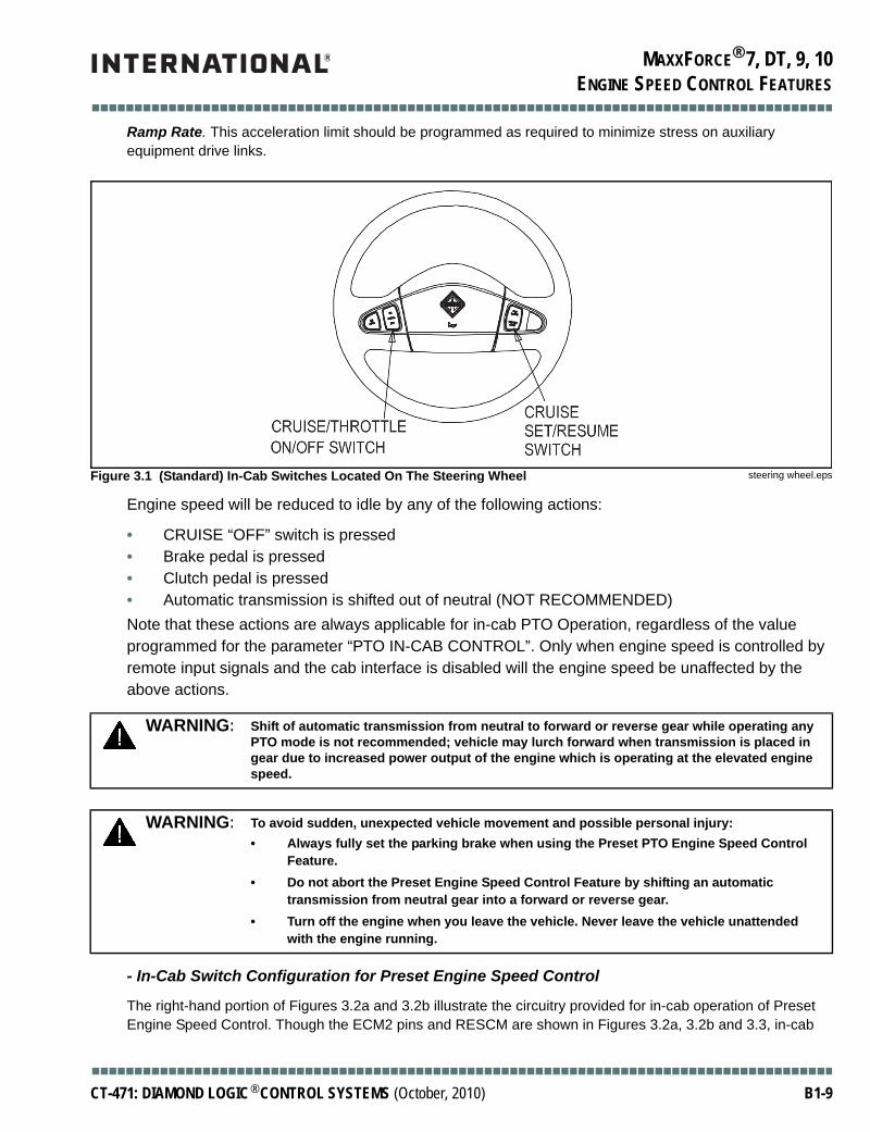
Press the CRUISE “ON” Switch to enable engine speed control. Note: This switch is located on the steering wheel. See Figure . NOTE: There is no indication to the user that the Cruise On switch has been depressed. Next, select the desired engine speed using either the SET/CRUISE or the RESUME/ACCEL switch. The engine speed acceleration will be limited according to the value programmed for the parameter PTO RPM
ON OFF SET/CRUISE RESUME/ACCEL BRAKE CLUTCH
Single Press (Momentary Contact)
Enables engine speed control
Disables engine speed control
Sets the desired engine speed to the “Set” Switch RPPreset speeds 1-6
Sets the desired engine speed to the “Resume” Switch RPMPreset speeds 1-6
Deactivates engine speed control and establishes a standby state. Engine speed returns to low idle rpm.
Deactivates engine speed control and establishes a standby state. Engine speed returns to low idle rpm.
Held Switch (Continuous Contact)
Enables engine speed control
Enables engine speed control
Same [1] Same [1] The change in brake status establishes the standby state.
The change in brake status establishes the standby state.
■■■■■■■■■■■■■■■■■■■■■■■■■■■■■■■■■■■■■■■■■■■■■■■■■■■■■■■■■■■■■■■■■■■■■■■■■■■■■■■■■■■■■■■
B1-8 CT-471: DIAMOND LOGIC® CONTROL SYSTEMS (October, 2010)
MAXXFORCE® 7, DT, 9, 10
■■■■■■■■■■■■■■■■■■■■■■■■■■■■■■■■■■■■■■■■■■■■■■■■■■■■■■■■■■■■■■■■■■■■■■■■■■■■■■■■■■■■■■■
ENGINE SPEED CONTROL FEATURES
Ramp Rate. This acceleration limit should be programmed as required to minimize stress on auxiliary equipment drive links.
Engine speed will be reduced to idle by any of the following actions:
• CRUISE “OFF” switch is pressed • Brake pedal is pressed• Clutch pedal is pressed• Automatic transmission is shifted out of neutral (NOT RECOMMENDED)Note that these actions are always applicable for in-cab PTO Operation, regardless of the value programmed for the parameter “PTO IN-CAB CONTROL”. Only when engine speed is controlled by remote input signals and the cab interface is disabled will the engine speed be unaffected by the above actions.
- In-Cab Switch Configuration for Preset Engine Speed Control
The right-hand portion of Figures 3.2a and 3.2b illustrate the circuitry provided for in-cab operation of Preset Engine Speed Control. Though the ECM2 pins and RESCM are shown in Figures 3.2a, 3.2b and 3.3, in-cab
Figure 3.1 (Standard) In-Cab Switches Located On The Steering Wheel steering wheel.eps
WARNING: Shift of automatic transmission from neutral to forward or reverse gear while operating any PTO mode is not recommended; vehicle may lurch forward when transmission is placed in gear due to increased power output of the engine which is operating at the elevated engine speed.
WARNING: To avoid sudden, unexpected vehicle movement and possible personal injury:• Always fully set the parking brake when using the Preset PTO Engine Speed Control
Feature.• Do not abort the Preset Engine Speed Control Feature by shifting an automatic
transmission from neutral gear into a forward or reverse gear.• Turn off the engine when you leave the vehicle. Never leave the vehicle unattended
with the engine running.
■■■■■■■■■■■■■■■■■■■■■■■■■■■■■■■■■■■■■■■■■■■■■■■■■■■■■■■■■■■■■■■■■■■■■■■■■■■■■■■■■■■■■■■
CT-471: DIAMOND LOGIC® CONTROL SYSTEMS (October, 2010) B1-9

MAXXFORCE® 7, DT, 9, 10
■■■■■■■■■■■■■■■■■■■■■■■■■■■■■■■■■■■■■■■■■■■■■■■■■■■■■■■■■■■■■■■■■■■■■■■■■■■■■■■■■■■■■■■
ENGINE SPEED CONTROL FEATURES
PTO operation does not require any additional wiring to these modules, nor any other module. The circuitry provided by International must not be tampered with.
If Preset PTO Engine Speed Control is already active and a different switch is pressed, engine speed will change from the original speed commanded by the ECM to the new speed corresponding to the latest switch that was pressed by the operator.
Figure 3.2a - In-Cab Switch Layout for Engine Control Using Hard-Wired Body Builder Wiring Present - I6 Engines
Figure 3.2a
OnOff
S/CR/A
BodyController
ECM Pin Designation/Function
Pin X1-16 RPRE (Preset PTO Enable)
Pin X1-60 RVAR (Variable PTO Enable)
Pin X1-68 SCS (Set PTO Speed)
Pin X1-49 RAAS (Resume PTO Speed)
Pin X1-72 VSSCAL (Speedometer)
Pin X1-71 Tach (Tachometer)
Pin X1-27 (Voltage Ref 5V0)
Pin X1-50 (REM Accelerator)
Pin X1-35 (Signal Return)
Pin X1-21 (Stop Engine)
Pin X1-22 (Engine Warning)
Pin X1-11 (Transfer Case)
ECM Engine Controller
J1939Public
Datalink
*K97DF 18PL 12volt 1 Amp Source (Voltage PTO)
12V Ignition
Body / EquipmentManufacturer Supplied International Supplied
*Optional hard-wiredcircuits present onlywith code 12VZA
*K97CB 18PL
*K97CC 18PL
*K46B 18GY
*K46A 18GY
*K47B 18GY
*K97AR 18PL
*K97FV 18PL
*K99F 18PL
*K97WA 18PL
*K97SE 18PL
*K97EW 18PL
*K97XC 18PL
CircuitNo.
Gauge/Color
PL = PurpleGY = Grey
■■■■■■■■■■■■■■■■■■■■■■■■■■■■■■■■■■■■■■■■■■■■■■■■■■■■■■■■■■■■■■■■■■■■■■■■■■■■■■■■■■■■■■■
B1-10 CT-471: DIAMOND LOGIC® CONTROL SYSTEMS (October, 2010)

MAXXFORCE® 7, DT, 9, 10
■■■■■■■■■■■■■■■■■■■■■■■■■■■■■■■■■■■■■■■■■■■■■■■■■■■■■■■■■■■■■■■■■■■■■■■■■■■■■■■■■■■■■■■
ENGINE SPEED CONTROL FEATURES
- Remote Operation of Preset Engine Speed Control
When control over engine speed is required from outside the vehicle's cab, remote mounted switches (either hard-wired, code 12VZA, or multiplexed using the RESCM, code 12VXY) must be used to turn on PTO engine speed control and select the desired engine speed. Figures 3.4a, 3.4b and 3.5 illustrate how remotely located switches must be interfaced to the ECM to accomplish Preset PTO Engine Speed Control. Figures 3.4a and 3.4b detail the hard-wired body builder circuitry (12VZA) while Figure 3.5 shows the circuitry needed for the multiplexing RESCM (12VXY). The hard-wired version does not include such features as Remote Throttle or Transfer Case/Split Shaft. If those features are desired, the Remote Engine Speed Control Module (RESCM) must be ordered. The RESCM uses the J1939 datalink to transmit (multiplex) the messages to the engine controller that were previously hard-wired with past generation International trucks. Switch functionality remains the same as described for the in-cab located switches (see Table 3.2).
A REMOTE PRESET PTO ON/OFF switch (RPRE) is required to remotely turn on the Preset Engine Speed Control. The desired engine speed is then selected using a remotely located SET/CRUISE or RESUME/ACCEL switch. Once a desired engine speed has been selected using one of these switches, engine speed will begin to increase. This rate of increase will be limited according to the value programmed in the parameter PTO RPM Ramp Rate. This acceleration limit should be programmed as required to minimize stress on auxiliary equipment power drive links.
Figure 3.2b - In-Cab Switch Layout for Engine Control Using Hard-Wired Body Builder Wiring Present - V8 Engines
Figure 3.2b
OnOff
S/CR/A
BodyController
ECM Engine Controller
J1939Public
Datalink
*K97DF 14PL 12volt 1 Amp Source (Voltage PTO)
12V Ignition
Body / EquipmentManufacturer Supplied International Supplied
*Optional hard-wiredcircuits present onlywith code 12VZA
CircuitNo.
Gauge/Color
PL = Purple
ECM Pin Designation/Function
Pin X1-16 RPRE (Preset PTO Enable)
Pin X1-60 RVAR (Variable PTO Enable)
Pin X1-68 SCS (Set PTO Speed)
Pin X1-49 RAAS (Resume PTO Speed)
Pin X1-72 VSSCAL (Speedometer)
Pin X1-71 Tach (Tachometer)
Pin X1-32 (Voltage Ref 5V0)
Pin X1-50 (REM Accelerator)
Pin X1-38 (Signal Return)
Pin X1-21 (Stop Engine)
Pin X1-22 (Engine Warning)
Pin X1-11 (Transfer Case)
*K97CB 18PL
*K97CC 18PL
*K46B 18PL
*K46A 18PL
*K47B 18PL
*K97AR 18PL
*K97FV 18PL
*K99F 18PL
*K97WA 18PL
*K97SE 18PL
*K97EW 18PL
*K97XC 18PL
■■■■■■■■■■■■■■■■■■■■■■■■■■■■■■■■■■■■■■■■■■■■■■■■■■■■■■■■■■■■■■■■■■■■■■■■■■■■■■■■■■■■■■■
CT-471: DIAMOND LOGIC® CONTROL SYSTEMS (October, 2010) B1-11

MAXXFORCE® 7, DT, 9, 10
■■■■■■■■■■■■■■■■■■■■■■■■■■■■■■■■■■■■■■■■■■■■■■■■■■■■■■■■■■■■■■■■■■■■■■■■■■■■■■■■■■■■■■■
ENGINE SPEED CONTROL FEATURES
Figure 3.3 - In-Cab Switch layout for Engine Control Using the Remote Engine Speed Controller Present
Figure 3.3
WARNING: Be aware that the Remote Set Switch and Remote Resume Switch are connected in parallel (logic “OR-ed”) with the cab-mounted SET/CRUISE and RESUME/ACCEL switches respectively. This means that once preset PTO Engine Speed Control has been placed in “standby” on-mode (by pressing either the In-Cab located CRUISE ON switch, or the remotely located REMOTE PRESET PTO ON switch), the desired engine speed can be modified both from within the cab or from the remote located PTO Engine Speed Control switches. This is ALWAYS TRUE, even when the PTO MODE parameter is programmed for REMOTE OPERATION ONLY.
OnOff
S/CR/A
BodyController
J1939PrivateDatalink
Body / EquipmentManufacturer Supplied International Supplied
Optional RemoteEngine Speed
Controller presentonly with code 12VXY
J1939Public
Datalink
ECM2Engine Control
Module
RESCMPin J3-10 12volt 1 Amp Source (Voltage PTO)
Pin J3-18 RPRE (Preset PTO Enable)
Pin J3-19 RVAR (Variable PTO Enable)
Pin J3-20 SCS (Set PTO Speed)
Pin J3-21 RAS (Resume PTO Speed)
Pin J3-14 RPS_RTN (Rem Accelerator RTN)
Pin J3-17 RPS Input (Rem Accelerator)
Pin J3-11 VCREF (Voltage Ref 5v)
Pin J3-16 HPS (Hyd Press Sensor)
Pin J3-15 VCREF GND (Signal Return)
Pin J3-22 HPE (HPG Enable)
Pin J3-9 HMI (HPG Mode Indicator)
Pin J3-7 WARN (Engine Warning Light)
Pin J3-8 OWL (Oil/Water Light)
Pin J3-12 VSSCALA (Speedometer)
Pin J3-13 TACA (Tachometer)
Pin J3-23 XCS (Transfer Case Status)
J3 Application I/O Connector
■■■■■■■■■■■■■■■■■■■■■■■■■■■■■■■■■■■■■■■■■■■■■■■■■■■■■■■■■■■■■■■■■■■■■■■■■■■■■■■■■■■■■■■
B1-12 CT-471: DIAMOND LOGIC® CONTROL SYSTEMS (October, 2010)

MAXXFORCE® 7, DT, 9, 10
■■■■■■■■■■■■■■■■■■■■■■■■■■■■■■■■■■■■■■■■■■■■■■■■■■■■■■■■■■■■■■■■■■■■■■■■■■■■■■■■■■■■■■■
ENGINE SPEED CONTROL FEATURES
Figure 3.4a - Remote Installation for Preset Engine Control Using Hard-Wired Body Builder Wiring - I6 Engines
Figure 3.4a
OnOff
S/CR/A
BodyController
J1939Public
Datalink
*K97DF 18PL 12volt 1 Amp Source (Voltage PTO)
12V Ignition
ECM Pin Designation/Function
Pin X1-16 RPRE (Preset PTO Enable)
Pin X1-60 RVAR (Variable PTO Enable)
Pin X1-68 SCS (Set PTO Speed)
Pin X1-49 RAAS (Resume PTO Speed)
Pin X1-72 VSSCAL (Speedometer)
Pin X1-71 Tach (Tachometer)
Pin X1-27 (Voltage Ref 5V0)
Pin X1-50 (REM Accelerator)
Pin X1-35 (Signal Return)
Pin X1-21 (Stop Engine)
Pin X1-22 (Engine Warning)
Pin X1-11 (Transfer Case)
*K97CB 18PL
*K97CC 18PL
*K46B 18GY
*K46A 18GY
*K47B 18GY
*K97AR 18PL
*K97FV 18PL
*K99F 18PL
*K97WA 18PL
*K97SE 18PL
*K97EW 18PL
*K97XC 18PL
ECM Engine Controller
Body / EquipmentManufacturer Supplied International Supplied
*Optional hard-wiredcircuits present onlywith code 12VZA
RESUMESpeed 2
SET Speed 1
Preset Speed Switch #
# Note: Body Builderinterlocks can beadded in this circuitToggle
SwitchMomentary
Switch
PL = PurpleGY = Grey
CircuitNo.
Gauge/Color
■■■■■■■■■■■■■■■■■■■■■■■■■■■■■■■■■■■■■■■■■■■■■■■■■■■■■■■■■■■■■■■■■■■■■■■■■■■■■■■■■■■■■■■
CT-471: DIAMOND LOGIC® CONTROL SYSTEMS (October, 2010) B1-13

MAXXFORCE® 7, DT, 9, 10
■■■■■■■■■■■■■■■■■■■■■■■■■■■■■■■■■■■■■■■■■■■■■■■■■■■■■■■■■■■■■■■■■■■■■■■■■■■■■■■■■■■■■■■
ENGINE SPEED CONTROL FEATURES
Figure 3.4b - Remote Installation for Preset Engine Control Using Hard-Wired Body Builder Wiring - V8 Engines
Figure 3.4b
OnOff
S/CR/A
BodyController
J1939Public
Datalink
12volt 1 Amp Source (Voltage PTO)
12V Ignition
ECM Engine Controller
Body / EquipmentManufacturer Supplied International Supplied
*Optional hard-wiredcircuits present onlywith code 12VZA
RESUMESpeed 2
SET Speed 1
Preset Speed Switch #
# Note: Body Builderinterlocks can beadded in this circuitToggle
SwitchMomentary
Switch
PL = Purple
CircuitNo.
Gauge/Color
*K97DF 14PL
ECM Pin Designation/Function
Pin X1-16 RPRE (Preset PTO Enable)
Pin X1-60 RVAR (Variable PTO Enable)
Pin X1-68 SCS (Set PTO Speed)
Pin X1-49 RAAS (Resume PTO Speed)
Pin X1-72 VSSCAL (Speedometer)
Pin X1-71 Tach (Tachometer)
Pin X1-32 (Voltage Ref 5V0)
Pin X1-50 (REM Accelerator)
Pin X1-38 (Signal Return)
Pin X1-21 (Stop Engine)
Pin X1-22 (Engine Warning)
Pin X1-11 (Transfer Case)
*K97CB 18PL
*K97CC 18PL
*K46B 18PL
*K46A 18PL
*K47B 18PL
*K97AR 18PL
*K97FV 18PL
*K99F 18PL
*K97WA 18PL
*K97SE 18PL
*K97EW 18PL
*K97XC 18PL
■■■■■■■■■■■■■■■■■■■■■■■■■■■■■■■■■■■■■■■■■■■■■■■■■■■■■■■■■■■■■■■■■■■■■■■■■■■■■■■■■■■■■■■
B1-14 CT-471: DIAMOND LOGIC® CONTROL SYSTEMS (October, 2010)

MAXXFORCE® 7, DT, 9, 10
■■■■■■■■■■■■■■■■■■■■■■■■■■■■■■■■■■■■■■■■■■■■■■■■■■■■■■■■■■■■■■■■■■■■■■■■■■■■■■■■■■■■■■■
ENGINE SPEED CONTROL FEATURES
■ ■ Variable Engine Speed ControlVariable engine speed control permits a desired engine speed to be achieved between low idle and high idle speed even without use of the accelerator pedal or Remote Throttle.The switches that must be used to achieve this functionality are ON, OFF, SET/CRUISE, and RESUME/ACCEL. These switches can be remote and/or cab mounted. If only temporary increases in engine speed are needed, consider using Preset Engine Speed Control in combination with the Remote Throttle. Table 3.3 summarizes the operation of Variable Engine Speed Control. Columns are labeled according to the switch being used. The first row presents the control system’s response when the toggle switch position is changed by the operator. The second row documents the control system’s response when the switch contacts are momentarily closed. The third row discusses the effect of maintaining a switch in the closed (pressed) condition; this row also discusses multiple applications of the same switch.
Figure 3.5 - Remote Installation for Preset Engine Control Using the Remote Engine Speed Controller
Figure 3.5
OnOff
S/CR/A
BodyController
J1939PrivateDatalink
Body / EquipmentManufacturer Supplied International Supplied
Optional RemoteEngine Speed
Controller presentonly with code 12VXY
J1939Public
Datalink
ECM2Engine Control
Module
RESCMPin J3-10 12volt 1 Amp Source (Voltage PTO)
Pin J3-18 RPRE (Preset PTO Enable)
Pin J3-19 RVAR (Variable PTO Enable)
Pin J3-20 SCS (Set PTO Speed)
Pin J3-21 RAS (Resume PTO Speed)
Pin J3-14 RPS_RTN (Rem Accelerator RTN)
Pin J3-17 RPS Input (Rem Accelerator)
Pin J3-11 VCREF (Voltage Ref 5v)
Pin J3-16 HPS (Hyd Press Sensor)
Pin J3-15 VCREF GND (Signal Return)
Pin J3-22 HPE (HPG Enable)
Pin J3-9 HMI (HPG Mode Indicator)
Pin J3-7 WARN (Engine Warning Light)
Pin J3-8 OWL (Oil/Water Light)
Pin J3-12 VSSCALA (Speedometer)
Pin J3-13 TACA (Tachometer)
Pin J3-23 XCS (Transfer Case Status)J3 Application I/O Connector
Resume/AccelSpeed 2
Set/Coast Speed 1
Preset Speed Switch #
ToggleSwitch
MomentarySwitch
# Note: Body Builderinterlocks can beadded in this circuit
■■■■■■■■■■■■■■■■■■■■■■■■■■■■■■■■■■■■■■■■■■■■■■■■■■■■■■■■■■■■■■■■■■■■■■■■■■■■■■■■■■■■■■■
CT-471: DIAMOND LOGIC® CONTROL SYSTEMS (October, 2010) B1-15

MAXXFORCE® 7, DT, 9, 10
■■■■■■■■■■■■■■■■■■■■■■■■■■■■■■■■■■■■■■■■■■■■■■■■■■■■■■■■■■■■■■■■■■■■■■■■■■■■■■■■■■■■■■■
ENGINE SPEED CONTROL FEATURES
[1] = Engine speed control stops only when there is a transition from one pedal state (pedal pressed or pedal released) to the other and only when the disable cab controls parameter is not selected.
[2] = The held switch acts like the switch is being “hit” multiple times until the switch is released. When the RESUME switch is held closed, the engine speed will be commanded to accelerate. The standby state will be momentarily recognized, then engine speed will continue to accelerate.
- In-Cab Operation of Variable Engine Speed ControlIn-cab located switches can be used to turn on engine speed control and select the desired engine speed. Press the CRUISE “ON” Switch to enable engine speed control. This switch is located on the steering wheel. NOTE: There is no indication to the user that the Cruise On switch has been depressed. Next, select the desired engine speed using the SET/CRUISE switch. Then press RESUME/ACCEL or SET/CRUISE until the desired engine speed is achieved.
The accelerator pedal can be used, as well, to increase or decrease engine speed as desired; the desired engine speed will be maintained by the engine controller once a momentary press of the SET/CRUISE switch occurs. Once an initial engine operating speed is selected, a momentary press of the RESUME/ACCEL and/or SET/CRUISE switches will cause engine speed to increase or decrease by a small amount. This incremental amount can be used to fine tune the engine speed selected. Should speed control be interrupted (i.e., by the brake or the clutch switch), the RESUME/ACCEL switch can be pressed to return to the last engine speed set point. The engine's acceleration rate will be limited according to the value programmed for the parameter PTO RPM Ramp Rate. This acceleration rate should be programmed as required to minimize stress on auxiliary equipment power drive links. Anytime Variable Engine Speed Control is active, the engine will maintain the selected speed until one of the following events occur:
Table 3.3 – Variable Engine Speed Control Switch Interpretations
ON OFF SET/CRUISE RESUME/ACCEL BRAKE CLUTCH
On/Off Switch (Toggle Switch)
Turns engine speed control ON.
Turns engine speed control OFF.
Not Applicable Not Applicable Not Applicable Not Applicable
Single Press (Momentary Contact)
Not Applicable Not Applicable Latch the current engine speed as the desired engine speed.Decrease engine speed by 25 RPM, if active.
Resume speed control function at the last desired engine speed.Increase engine speed by 25 RPM, if active.
Deactivate vehicle speed control and maintain standby state.(Pedal use returns the engine to the low idle speed.)[1]
Deactivate vehicle speed control and maintain standby state.(Pedal use returns the engine to the low idle speed.)[1]
Held Switch (Continuous Contact)
Not Applicable Not Applicable Decrease engine speed if engine speed control is active.[2]
Increase engine speed if engine speed control is active.[2]
Any change in brake status establishes a standby state.[1]
Any change in driveline status establishes a standby state.[1]
■■■■■■■■■■■■■■■■■■■■■■■■■■■■■■■■■■■■■■■■■■■■■■■■■■■■■■■■■■■■■■■■■■■■■■■■■■■■■■■■■■■■■■■
B1-16 CT-471: DIAMOND LOGIC® CONTROL SYSTEMS (October, 2010)

MAXXFORCE® 7, DT, 9, 10
■■■■■■■■■■■■■■■■■■■■■■■■■■■■■■■■■■■■■■■■■■■■■■■■■■■■■■■■■■■■■■■■■■■■■■■■■■■■■■■■■■■■■■■
ENGINE SPEED CONTROL FEATURES
• CRUISE “OFF” switch is pressed• Brake pedal is pressed• Clutch pedal is pressed• Automatic transmission is shifted out of neutral (NOT RECOMMENDED)Note that these actions are always applicable for in-cab PTO Operation, regardless of the value programmed for the parameter “PTO IN-CAB CONTROL”. Only when engine speed is controlled by remote input signals and the cab interface is disabled will the engine speed be unaffected by the above actions.
- In-Cab Switch Configuration for Operation of Variable Engine Speed ControlOnce again, the right-hand portion of Section 3.2 illustrates the circuitry provided by International® for in-cab operation of Variable Engine Speed Control. This circuitry is provided by International and must not be tampered with.
- Remote Operation of Variable Engine Speed ControlWhen control over engine speed is required from outside the vehicle cab, remote mounted switches must be used to turn on PTO engine speed control and select the desired engine speed. Figures 3.6a, 3.6b and 3.7 illustrate how remotely located switches must be interfaced to the ECM to accomplish Variable Engine Speed Control. Switch functionality remains the same as described for the in-cab located switches (see Table 3.3).
The Remote Throttle (see Section 5) can be used as well to increase or decrease engine speed as desired. The desired engine speed will be maintained by the engine controller once a momentary press of the SET/COAST switch occurs. Once an initial engine operating speed is selected, a momentary press of the RESUME/ACCEL and/or SET/COAST switches will cause engine speed to increase or decrease by a small amount. This incremental amount can be used to fine tune the engine speed selected. Should speed control be interrupted (i.e. by the brake or the clutch switch), the RESUME/ACCEL switch can be pressed to return to the last engine speed set point. The engine’s acceleration rate will be limited according to the value programmed for the parameter PTO RPM Ramp Rate. This acceleration rate should be programmed as required to minimize stress on auxiliary equipment power drive links. Any time Variable Engine Speed Control is active, the engine will maintain the selected speed until one of the following events occur:
• CRUISE “OFF” switch is pressed• Brake pedal is pressed• Clutch pedal is pressed• Automatic transmission is shifted out of neutral (NOT RECOMMENDED)
WARNING: Shift of automatic transmission from neutral to forward or reverse gear while operating any PTO mode is not recommended; vehicle may lurch forward when transmission is placed in gear due to increased power output of the engine which is operating at the elevated engine speed.
WARNING: To avoid sudden, unexpected vehicle movement and possible personal injury:• Always fully set the parking brake. Do not use the gearshift lever instead of the parking
brake.• Turn off the engine when you leave the vehicle. Never leave the vehicle unattended
with the engine running.
■■■■■■■■■■■■■■■■■■■■■■■■■■■■■■■■■■■■■■■■■■■■■■■■■■■■■■■■■■■■■■■■■■■■■■■■■■■■■■■■■■■■■■■
CT-471: DIAMOND LOGIC® CONTROL SYSTEMS (October, 2010) B1-17

MAXXFORCE® 7, DT, 9, 10
■■■■■■■■■■■■■■■■■■■■■■■■■■■■■■■■■■■■■■■■■■■■■■■■■■■■■■■■■■■■■■■■■■■■■■■■■■■■■■■■■■■■■■■
ENGINE SPEED CONTROL FEATURES
CAUTION: Be aware that the Remote Set Switch and Remote Resume Switch are connected in parallel (logic `OR-ed') with the cab-mounted SET/CRUISE and RESUME/ACCEL switches respectively. This means that once preset Variable PTO Engine Speed Control has been placed in “standby” on-mode (by pressing either the in-cab located CRUISE ON switch, or the remotely located REMOTE VARIABLE PTO ON switch), the desired engine speed can be modified both from within the cab or from the remote located PTO Engine Speed Control switches. This is ALWAYS TRUE, even when the PTO MODE parameter is programmed for REMOTE OPERATION ONLY.
Figure 3.6a - Variable Engine Speed Control Schematic Using Hard-Wired Body Builder Wiring - I6 Engines
Figure 3.6a
OnOff
S/CR/A
BodyController
J1939Public
Datalink
*K97DF 18PL 12volt 1 Amp Source (Voltage PTO)
12V Ignition
ECM Pin Designation/Function
Pin X1-16 RPRE (Preset PTO Enable)
Pin X1-60 RVAR (Variable PTO Enable)
Pin X1-68 SCS (Set PTO Speed)
Pin X1-49 RAAS (Resume PTO Speed)
Pin X1-72 VSSCAL (Speedometer)
Pin X1-71 Tach (Tachometer)
Pin X1-27 (Voltage Ref 5V0)
Pin X1-50 (REM Accelerator)
Pin X1-35 (Signal Return)
Pin X1-21 (Stop Engine)
Pin X1-22 (Engine Warning)
Pin X1-11 (Transfer Case)
*K97CB 18PL
*K97CC 18PL
*K46B 18GY
*K46A 18GY
*K47B 18GY
*K97AR 18PL
*K97FV 18PL
*K99F 18PL
*K97WA 18PL
*K97SE 18PL
*K97EW 18PL
*K97XC 18PL
ECM Engine Controller
Body / EquipmentManufacturer Supplied International Supplied
*Optional hard-wiredcircuits present onlywith code 12VZA
RESUMESpeed 2
SET Speed 1
Variable Speed Switch
ToggleSwitch
MomentarySwitch
PL = PurpleGY = Grey
CircuitNo.
Gauge/Color
■■■■■■■■■■■■■■■■■■■■■■■■■■■■■■■■■■■■■■■■■■■■■■■■■■■■■■■■■■■■■■■■■■■■■■■■■■■■■■■■■■■■■■■
B1-18 CT-471: DIAMOND LOGIC® CONTROL SYSTEMS (October, 2010)

MAXXFORCE® 7, DT, 9, 10
■■■■■■■■■■■■■■■■■■■■■■■■■■■■■■■■■■■■■■■■■■■■■■■■■■■■■■■■■■■■■■■■■■■■■■■■■■■■■■■■■■■■■■■
ENGINE SPEED CONTROL FEATURES
Figure 3.6b - Variable Engine Speed Control Schematic Using Hard-Wired Body Builder Wiring - V8 Engines
Figure 3.6b
OnOff
S/CR/A
BodyController
J1939Public
Datalink
12volt 1 Amp Source (Voltage PTO)
12V Ignition
ECM Engine Controller
Body / EquipmentManufacturer Supplied International Supplied
*Optional hard-wiredcircuits present onlywith code 12VZA
RESUMESpeed 2
SET Speed 1
Variable Speed Switch
ToggleSwitch
MomentarySwitch
PL = Purple
CircuitNo.
Gauge/Color
*K97DF 14PL
ECM Pin Designation/Function
Pin X1-16 RPRE (Preset PTO Enable)
Pin X1-60 RVAR (Variable PTO Enable)
Pin X1-68 SCS (Set PTO Speed)
Pin X1-49 RAAS (Resume PTO Speed)
Pin X1-72 VSSCAL (Speedometer)
Pin X1-71 Tach (Tachometer)
Pin X1-32 (Voltage Ref 5V0)
Pin X1-50 (REM Accelerator)
Pin X1-38 (Signal Return)
Pin X1-21 (Stop Engine)
Pin X1-22 (Engine Warning)
Pin X1-11 (Transfer Case)
*K97CB 18PL
*K97CC 18PL
*K46B 18PL
*K46A 18PL
*K47B 18PL
*K97AR 18PL
*K97FV 18PL
*K99F 18PL
*K97WA 18PL
*K97SE 18PL
*K97EW 18PL
*K97XC 18PL
■■■■■■■■■■■■■■■■■■■■■■■■■■■■■■■■■■■■■■■■■■■■■■■■■■■■■■■■■■■■■■■■■■■■■■■■■■■■■■■■■■■■■■■
CT-471: DIAMOND LOGIC® CONTROL SYSTEMS (October, 2010) B1-19

MAXXFORCE® 7, DT, 9, 10
■■■■■■■■■■■■■■■■■■■■■■■■■■■■■■■■■■■■■■■■■■■■■■■■■■■■■■■■■■■■■■■■■■■■■■■■■■■■■■■■■■■■■■■
ENGINE SPEED CONTROL FEATURES
■ ■ Engine Speed Control for Mobile ApplicationsThis section discusses the Variable Mobile Engine Speed Control. Mobile Variable Engine Speed Control functions like cruise control, except that the engine speed (instead of the vehicle speed) is being controlled. Mobile control can be performed only below a programmed maximum vehicle speed. The default vehicle speed limit is 20 MPH.
Functionality for mobile control is identical to the functionality described previously for Variable PTO Engine Speed Control, with the exception that the vehicle is no longer required to be stationary; vehicle movement is permitted up to a maximum threshold, specified by the programmable parameter PTO Max Veh Speed.
When the specified vehicle speed limit is exceeded, Variable Engine Speed Control will be placed in the “standby” mode of operation and engine speed will return to idle. Pressing the RESUME/ACCEL switch after the vehicle speed has slowed to a value less than the programmed maximum speed limit will reestablish engine speed control at the previously selected engine speed. Changes in the status of the brake and clutch switches will also return the engine to its idle speed.
Switch functionality remains the same as described for the Variable Stationary Engine Speed Control switches (see Table 3.3).
Figure 3.7 - Variable Engine Speed Control Schematic Using the Remote Engine Speed Controller
Figure 3.7
OnOff
S/CR/A
BodyController
J1939PrivateDatalink
Body / EquipmentManufacturer Supplied International Supplied
Optional RemoteEngine Speed
Controller presentonly with code 12VXY
J1939Public
Datalink
ECM2Engine Control
Module
RESCMPin J3-10 12volt 1 Amp Source (Voltage PTO)
Pin J3-18 RPRE (Preset PTO Enable)
Pin J3-19 RVAR (Variable PTO Enable)
Pin J3-20 SCS (Set PTO Speed)
Pin J3-21 RAS (Resume PTO Speed)
Pin J3-14 RPS_RTN (Rem Accelerator RTN)
Pin J3-17 RPS Input (Rem Accelerator)
Pin J3-11 VCREF (Voltage Ref 5v)
Pin J3-16 HPS (Hyd Press Sensor)
Pin J3-15 VCREF GND (Signal Return)
Pin J3-22 HPE (HPG Enable)
Pin J3-9 HMI (HPG Mode Indicator)
Pin J3-7 WARN (Engine Warning Light)
Pin J3-8 OWL (Oil/Water Light)
Pin J3-12 VSSCALA (Speedometer)
Pin J3-13 TACA (Tachometer)
Pin J3-23 XCS (Transfer Case Status)J3 Application I/O Connector
Resume/AccelSpeed 2
Set/Coast Speed 1
Variable Speed Switch
ToggleSwitch
MomentarySwitch
■■■■■■■■■■■■■■■■■■■■■■■■■■■■■■■■■■■■■■■■■■■■■■■■■■■■■■■■■■■■■■■■■■■■■■■■■■■■■■■■■■■■■■■
B1-20 CT-471: DIAMOND LOGIC® CONTROL SYSTEMS (October, 2010)

MAXXFORCE® 7, DT, 9, 10
■■■■■■■■■■■■■■■■■■■■■■■■■■■■■■■■■■■■■■■■■■■■■■■■■■■■■■■■■■■■■■■■■■■■■■■■■■■■■■■■■■■■■■■
ENGINE SPEED CONTROL FEATURES
Press the CRUISE ON switch to turn on Engine Speed Control. Press the SET/CRUISE switch to select an engine speed. Then press RESUME/ACCEL or SET/CRUISE until the desired engine speed is achieved. Momentary presses of the RESUME/ACCEL and SET/CRUISE switches will cause the engine speed to increase or decrease by a small amount. This incremental amount can be used to fine tune the engine speed selected. Should speed control be interrupted by the brake or the clutch switches, press the RESUME/ACCEL switch to return to the last engine speed set point. The engine's acceleration will be limited to the PTO RPM Ramp Rate. The acceleration limit can be set to reduce the stress on the auxiliary equipment power couplings.
■ Transfer Case/Split Shaft OperationThis section describes the Transfer Case/Split Shaft feature and its applications. This feature is used in conjunction with Engine Speed Control and is targeted for applications that use a transfer case or auxiliary driveshaft. The auxiliary drive unit is often connected to a pump that performs vacuum functions (i.e. sewage removal truck or fire pumps). Figure 4.1 illustrates the wiring required for a typical Split Shaft application.
■ ■ Transfer Case Switch OperationThe transfer case status switch must be in the proper state indicating that it is “OK” to operate. The transfer case status switch input is provided as a safety interlock feature and must be wired as shown in Figure 4.1. The purpose of the transfer case input is to inihibit the system from entering engine speed control mode if the transfer case is operating in driveline mode versus split shaft mode. The transfer case status switch must be wired such that when the transfer case is in split shift mode, pin J3-23 of the RESCM sees 12 volts.
■ ■ EPG Driveline ModeThis parameter indicates how the driveline disengagement signal should be interpreted by the ECM and is proggrammable by Navistar, Inc. only.
• 0: NEUTRAL OPERATION, driveline must be disengaged at all times for operation of the split shaft feature.
• 1: SPLIT SHAFT, a transition in driveline status will cause the split shaft feature to be deactivated.
■ ■ Wheel Based Vehicle SpeedIf the system is configured to function in Split Shaft mode (EPG driveline mode parameter equals SPLIT SHAFT), then the engine ECM must receive wheel based vehicle speed from a brake system electronic control unit (ECU). This message (PGN 65265, bytes 2 and 3) must be broadcast by the brake system over the Public J1939 data link. At this time, only one brake system supports this message, the Bendix EC-30. The availability of this parameter for the EC-30 system is currently a programmable feature. This programmable feature must be enabled for the EPG system to function, otherwise, it will not allow the system to enter into Engine Speed Control. If the brake system ECU broadcasts the wheel based vehicle speed parameter as being 0 mph, then it will allow the system to function. This is a safety interlock feature to ensure that the vehicle is not moving while the system is functioning in Split Shaft mode.
■■■■■■■■■■■■■■■■■■■■■■■■■■■■■■■■■■■■■■■■■■■■■■■■■■■■■■■■■■■■■■■■■■■■■■■■■■■■■■■■■■■■■■■
CT-471: DIAMOND LOGIC® CONTROL SYSTEMS (October, 2010) B1-21

MAXXFORCE® 7, DT, 9, 10
■■■■■■■■■■■■■■■■■■■■■■■■■■■■■■■■■■■■■■■■■■■■■■■■■■■■■■■■■■■■■■■■■■■■■■■■■■■■■■■■■■■■■■■
ENGINE SPEED CONTROL FEATURES
Figure 4.1a - Split Shaft Engine Speed Control Using Hard-Wired Body Builder Wiring - I6 Engines
Figure 4.1a
OnOff
S/CR/A
BodyController
J1939Public
Datalink
*K97DF 18PL 12volt 1 Amp Source (Voltage PTO)
12V Ignition
ECM Pin Designation/Function
Pin X1-16 RPRE (Preset PTO Enable)
Pin X1-60 RVAR (Variable PTO Enable)
Pin X1-68 SCS (Set PTO Speed)
Pin X1-49 RAAS (Resume PTO Speed)
Pin X1-72 VSSCAL (Speedometer)
Pin X1-71 Tach (Tachometer)
Pin X1-27 (Voltage Ref 5V0)
Pin X1-50 (REM Accelerator)
Pin X1-35 (Signal Return)
Pin X1-21 (Stop Engine)
Pin X1-22 (Engine Warning)
Pin X1-11 (Transfer Case)
*K97CB 18PL
*K97CC 18PL
*K46B 18GY
*K46A 18GY
*K47B 18GY
*K97AR 18PL
*K97FV 18PL
*K99F 18PL
*K97WA 18PL
*K97SE 18PL
*K97EW 18PL
*K97XC 18PL
ECM Engine Controller
Body / EquipmentManufacturer Supplied International Supplied
*Optional hard-wiredcircuits present onlywith code 12VZA
RESUMESpeed 2
SET Speed 1
Variable Speed Switch
ToggleSwitch
MomentarySwitch
PL = PurpleGY = Grey
CircuitNo.
Gauge/Color
■■■■■■■■■■■■■■■■■■■■■■■■■■■■■■■■■■■■■■■■■■■■■■■■■■■■■■■■■■■■■■■■■■■■■■■■■■■■■■■■■■■■■■■
B1-22 CT-471: DIAMOND LOGIC® CONTROL SYSTEMS (October, 2010)

MAXXFORCE® 7, DT, 9, 10
■■■■■■■■■■■■■■■■■■■■■■■■■■■■■■■■■■■■■■■■■■■■■■■■■■■■■■■■■■■■■■■■■■■■■■■■■■■■■■■■■■■■■■■
ENGINE SPEED CONTROL FEATURES
Figure 4.1b - Split Shaft Engine Speed Control Using Hard-Wired Body Builder Wiring - V8 Engines
Figure 4.1b
OnOff
S/CR/A
BodyController
J1939Public
Datalink
12volt 1 Amp Source (Voltage PTO)
12V Ignition
ECM Engine Controller
Body / EquipmentManufacturer Supplied International Supplied
*Optional hard-wiredcircuits present onlywith code 12VZA
RESUMESpeed 2
SET Speed 1
Variable Speed Switch
ToggleSwitch
MomentarySwitch
PL = Purple
CircuitNo.
Gauge/Color
*K97DF 14PL
ECM Pin Designation/Function
Pin X1-16 RPRE (Preset PTO Enable)
Pin X1-60 RVAR (Variable PTO Enable)
Pin X1-68 SCS (Set PTO Speed)
Pin X1-49 RAAS (Resume PTO Speed)
Pin X1-72 VSSCAL (Speedometer)
Pin X1-71 Tach (Tachometer)
Pin X1-32 (Voltage Ref 5V0)
Pin X1-50 (REM Accelerator)
Pin X1-38 (Signal Return)
Pin X1-21 (Stop Engine)
Pin X1-22 (Engine Warning)
Pin X1-11 (Transfer Case)
*K97CB 18PL
*K97CC 18PL
*K46B 18PL
*K46A 18PL
*K47B 18PL
*K97AR 18PL
*K97FV 18PL
*K99F 18PL
*K97WA 18PL
*K97SE 18PL
*K97EW 18PL
*K97XC 18PL
■■■■■■■■■■■■■■■■■■■■■■■■■■■■■■■■■■■■■■■■■■■■■■■■■■■■■■■■■■■■■■■■■■■■■■■■■■■■■■■■■■■■■■■
CT-471: DIAMOND LOGIC® CONTROL SYSTEMS (October, 2010) B1-23

MAXXFORCE® 7, DT, 9, 10
■■■■■■■■■■■■■■■■■■■■■■■■■■■■■■■■■■■■■■■■■■■■■■■■■■■■■■■■■■■■■■■■■■■■■■■■■■■■■■■■■■■■■■■
ENGINE SPEED CONTROL FEATURES
S
■ Remote Throttle ControlThe Remote Throttle Control functions like an additional accelerator pedal or hand throttle. Remote throttles provide equipment operators with direct control over engine speed from a location outside of the vehicle cab. By using a potentiometer, a remote throttle is useful when an infinitely variable range of engine speeds is desired to operate equipment. Remote throttles can be used to provide temporary increases in engine speed when Preset or Variable Engine Speed Control is in use.
The hand and/or foot actuated potentiometer can be located on one or more locations on tehe vehicle (see Figure 5.2). Increasing or decreasing the voltage from the potentiometer will result in a corresponding increase or decrease in engine speed (similar to stepping on or releasing the accelerator foot pedal in the vehicle cab).
Note: To be noticed by the Engine Control System, the engine speed requested by the Remote Throttle must exceed the engine speed requi\ested by the cab accelerator pedal and other engine speed control requests. Reason: The highest engine speed requested becomes the engine speed commanded to the engine.
Figure 4.2 - Split Shaft Engine Speed Control Using the Remote Engine Speed Controller
Figure 4.2
OnOff
S/CR/A
BodyController
J1939PrivateDatalink
Body / EquipmentManufacturer Supplied International Supplied
Optional RemoteEngine Speed
Controller presentonly with code 12VXY
J1939Public
Datalink
ECM2Engine Control
Module
RESCMPin J3-10 12volt 1 Amp Source (Voltage PTO)
Pin J3-18 RPRE (Preset PTO Enable)
Pin J3-19 RVAR (Variable PTO Enable)
Pin J3-20 SCS (Set PTO Speed)
Pin J3-21 RAS (Resume PTO Speed)
Pin J3-14 RPS_RTN (Rem Accelerator RTN)
Pin J3-17 RPS Input (Rem Accelerator)
Pin J3-11 VCREF (Voltage Ref 5v)
Pin J3-16 HPS (Hyd Press Sensor)
Pin J3-15 VCREF GND (Signal Return)
Pin J3-22 HPE (HPG Enable)
Pin J3-9 HMI (HPG Mode Indicator)
Pin J3-7 WARN (Engine Warning Light)
Pin J3-8 OWL (Oil/Water Light)
Pin J3-12 VSSCALA (Speedometer)
Pin J3-13 TACA (Tachometer)
Pin J3-23 XCS (Transfer Case Status)
J3 Application I/O Connector
Resume/AccelSpeed 2
Set/Coast Speed 1
Variable Speed Switch
ToggleSwitch
MomentarySwitch
Emergency On/Off Switch#
Transfer Case Status Switch(closed switch = OK to pump)
# Note: Body Builderinterlocks can beadded in this circuit
■■■■■■■■■■■■■■■■■■■■■■■■■■■■■■■■■■■■■■■■■■■■■■■■■■■■■■■■■■■■■■■■■■■■■■■■■■■■■■■■■■■■■■■
B1-24 CT-471: DIAMOND LOGIC® CONTROL SYSTEMS (October, 2010)

MAXXFORCE® 7, DT, 9, 10
■■■■■■■■■■■■■■■■■■■■■■■■■■■■■■■■■■■■■■■■■■■■■■■■■■■■■■■■■■■■■■■■■■■■■■■■■■■■■■■■■■■■■■■
ENGINE SPEED CONTROL FEATURES
Use of either the Remote Preset PTO Switch or Remote Variable PTO Switch is required to activate or deactivate the Remote Throttle and the Engine Control System must be programmed to accept the Remote Throttle input. Use spring loaded designs for throttle devices so that the engine returns to idle when the throttle is released.
Note: The only way the Remote Throttle Control System can be disabled is to turn it off with the switch previously used to turn it on.
The programmable parameter PTO Remote Pedal must be programmed to “1” to enable operation of the Remote Throttle input. Also, the maximum engine speed permitted when operating with the Remote Throttle will be limited to the value programmed for PTO MAX RPM.
Figure 5.2 shows the circuits needed to operate the Remote Throttle feature. The remote potentiometer circuits are interfaced to the RESCM or the hard-wired ECM pins. The RESCM communicates the status of these circuits via J1939 to the engine control system via the ESC while the hard-wired pins communicate directly to the ECM. The same potentiometer that is used for the cab’s accelerator pedal can be used for this remote potentiometer. Terminals A, B and C are cavities in the 6-way Packard mating connector to the accelerator pedal sensor. Do not cross the wires to terminals A, B and C. Cross wiring terminals B and C will provide a high voltage level on the APS signal at the sensor’s mechanical idle position. The remote throttle input must be turned on and off by an enable switch. Enabling either the Remote Preset PTO Switch or the Remote Variable PTO Switch will turn the Remote Throttle input on. These two switches must not be enabled at the same time - it’s one or the other. Opening the switch circuit disables the Remote Throttle input.
The ServiceMaxx tool can be used for trouble shooting and verifying the Remote Throttle installation.The PTO Remote Pedal parameter must indicate ON and either the Rem Var PTO Switch or the Rem Preset PTO Switch must indicate ON. When these conditions are met, the Accel Pedal parameter will display the percent throttle commanded to the ECM. If the Remote Throttle parameter indicates FAIL, a fault exists in the circuits or in the potentiometer itself.
Display of the parameter Accel Pedal should be used to set mechanical stops for custom throttle designs. Mechanical stops must be used with potentiometer based throttle control systems to prevent the supply of inadequate or excess voltage to the engine controller. The ECM detects under and over voltage conditions for Remote Throttle; occurrence of one of these conditions will result in activation of a fault code.
■■■■■■■■■■■■■■■■■■■■■■■■■■■■■■■■■■■■■■■■■■■■■■■■■■■■■■■■■■■■■■■■■■■■■■■■■■■■■■■■■■■■■■■
CT-471: DIAMOND LOGIC® CONTROL SYSTEMS (October, 2010) B1-25

MAXXFORCE® 7, DT, 9, 10
■■■■■■■■■■■■■■■■■■■■■■■■■■■■■■■■■■■■■■■■■■■■■■■■■■■■■■■■■■■■■■■■■■■■■■■■■■■■■■■■■■■■■■■
ENGINE SPEED CONTROL FEATURES
■ ■ Accelerator Pedal Sensor Notes and DiagnosticsAppendix D lists part numbers for floor mounted and suspended accelerator pedals and the accelerator pedal sensor kits. These parts include a jumper harness for the sensor with a Packard Weather-Pack connector. The typical wire colors for the jumper harness are shown in Table 5.1. The Weather-Pack connector can be cut off and the circuits spliced according to their identifying colors.
Table 5.1 – Accelerator Pedal Sensor Wire Colors and Signals
The RESCM remote throttle input is preloaded with a resistor fixed in connector J3, pins 17 and 14. This resistor fixes the input at 0%. If using a remote throttle pedal of any kind, remove this resistor when installing the remote throttle connections. If not installing a remote throttle, leave this resistor in place. Do not remove the jumper in J3 pins 1-2. These are addressing wires and must be left in place.
The accelerator pedal sensor includes an Idle Validation Switch (IVS). The “Normally Closed” contacts are connected to the common terminal when the sensor is at the idle position. The “Normally Open” contacts are connected to the common terminal when the sensor is in the off-idle position. Due to the thick film construction of the sensor, the IVS has a contact resistance of ~80 Ohms. Do not use this switch in series with the sensor circuits.
The remote throttle potentiometer is protected through circuit diagnostics. Faults are detected when the potentiometer is open or short circuited. These faults recover when the fault condition is corrected. Table 5.2 summarizes typical voltage levels for throttle operation and diagnostics. The voltage levels are designed to be compatible with a total resistance of 2.5K Ohms. As the voltage detected increases, the engine speed demanded by the remote pedal input increases. Diagnostic
Figure 5.1 - Switch Requirements Figure 5.1
APS CAVITY A B C D E F
Signal Sensor Output Sensor Ground Sensor Supply (5Vdc)
Normally Closed Idle Validation
Normally Open Idle Validation
Idle Validation Switch Common
Color Black White Red Green Blue Orange
Toggle or Latched Switch(used for system activation or interlocks)
Potentiometer or Rheostat(used for remote pedal inputs)
■■■■■■■■■■■■■■■■■■■■■■■■■■■■■■■■■■■■■■■■■■■■■■■■■■■■■■■■■■■■■■■■■■■■■■■■■■■■■■■■■■■■■■■
B1-26 CT-471: DIAMOND LOGIC® CONTROL SYSTEMS (October, 2010)

MAXXFORCE® 7, DT, 9, 10
■■■■■■■■■■■■■■■■■■■■■■■■■■■■■■■■■■■■■■■■■■■■■■■■■■■■■■■■■■■■■■■■■■■■■■■■■■■■■■■■■■■■■■■
ENGINE SPEED CONTROL FEATURES
ranges are provided at the top and bottom of the potentiometer voltage. The voltage shown in Table 5.2 is between RESCM pins J3-14 (Rem Accelerator RTN), J3-17 (Rem Accelerator) and J3-11 (Voltage Ref 5V).
Table 5.2 – Remote Accelerator Pedal Sensor Voltage Levels
New designs incorporating the accelerator pedal sensor must include their own return springs to ensure that the sensor returns to the idle position when the control is released. The sensor’s internal stops must not be used to limit the travel of its drive mechanism. To make sure the sensor always returns to the idle position, pre-load the internal return spring by 15.2 degrees. Another reason to pre-load the return spring in this manner is that the voltage output from the sensor will fall into the out of range low diagnostic region if the sensor is not pre-loaded by 15.2 degrees of travel. Sensors that are disconnected from the drive mechanism will generate a diagnostic code. The maximum range of travel applied to the accelerator pedal must be limited to a maximum of 52.3 degrees beyond 15.2 degrees pre-load for the idle position. For additional information, see SAE recommended practice “J1843, Accelerator Pedal Position Sensor for Use with Electronic Controls in Medium and Heavy Duty Vehicle Applications”.
- Hand Operated Throttle Control Kit
See Appendix D for a hand operated throttle parts list.
VOLTAGE RESULT
0 – 0.15 Out of Range Low or Open, Fault Code 213
0.15 – 0.90 0%, Low Idle Speed demanded
0.90 – 3.50 0 – 100%, Normal Operating Range
3.50 –- 4.55 100%, PTO Max RM Demanded
4.55 and above Out of Range High, Fault Code 214
■■■■■■■■■■■■■■■■■■■■■■■■■■■■■■■■■■■■■■■■■■■■■■■■■■■■■■■■■■■■■■■■■■■■■■■■■■■■■■■■■■■■■■■
CT-471: DIAMOND LOGIC® CONTROL SYSTEMS (October, 2010) B1-27

MAXXFORCE® 7, DT, 9, 10
■■■■■■■■■■■■■■■■■■■■■■■■■■■■■■■■■■■■■■■■■■■■■■■■■■■■■■■■■■■■■■■■■■■■■■■■■■■■■■■■■■■■■■■
ENGINE SPEED CONTROL FEATURES
Figure 5.2a - Remote Throttle Interface Using Hard-Wired Body Builder Wiring - I6 Engines
Figure 5.2
OnOff
S/CR/A
BodyController
J1939Public
Datalink
*K97DF 18PL 12volt 1 Amp Source (Voltage PTO)
12V Ignition
ECM Pin Designation/Function
Pin X1-16 RPRE (Preset PTO Enable)
Pin X1-60 RVAR (Variable PTO Enable)
Pin X1-68 SCS (Set PTO Speed)
Pin X1-49 RAAS (Resume PTO Speed)
Pin X1-72 VSSCAL (Speedometer)
Pin X1-71 Tach (Tachometer)
Pin X1-27 (Voltage Ref 5V0)
Pin X1-50 (REM Accelerator)
Pin X1-35 (Signal Return)
Pin X1-21 (Stop Engine)
Pin X1-22 (Engine Warning)
Pin X1-11 (Transfer Case)
*K97CB 18PL
*K97CC 18PL
*K46B 18GY
*K46A 18GY
*K47B 18GY
*K97AR 18PL
*K97FV 18PL
*K99F 18PL
*K97WA 18PL
*K97SE 18PL
*K97EW 18PL
*K97XC 18PL
ECM Engine Controller
Body / EquipmentManufacturer Supplied International Supplied
Variable Speed Switch
ToggleSwitch
PL = PurpleGY = Grey
CircuitNo.
Gauge/Color
Note: Either preset or variablespeed switches may be usedto activate remote throttle
C
A
B
RemoteThrottle Pedal
(Potentiometer)
*Optional hard-wiredcircuits present onlywith code 12VZA
Preset Speed Switch #
# Note: Body Builderinterlocks can beadded in this circuit
■■■■■■■■■■■■■■■■■■■■■■■■■■■■■■■■■■■■■■■■■■■■■■■■■■■■■■■■■■■■■■■■■■■■■■■■■■■■■■■■■■■■■■■
B1-28 CT-471: DIAMOND LOGIC® CONTROL SYSTEMS (October, 2010)

MAXXFORCE® 7, DT, 9, 10
■■■■■■■■■■■■■■■■■■■■■■■■■■■■■■■■■■■■■■■■■■■■■■■■■■■■■■■■■■■■■■■■■■■■■■■■■■■■■■■■■■■■■■■
ENGINE SPEED CONTROL FEATURES
Figure 5.2b - Remote Throttle Interface Using Hard-Wired Body Builder Wiring Engines - V8 Engines
Figure 5.2b
OnOff
S/CR/A
BodyController
J1939Public
Datalink
12volt 1 Amp Source (Voltage PTO)
12V Ignition
ECM Engine Controller
Body / EquipmentManufacturer Supplied International Supplied
Variable Speed Switch
ToggleSwitch
PL = Purple
CircuitNo.
Gauge/Color
Note: Either preset or variablespeed switches may be usedto activate remote throttle
C
A
B
RemoteThrottle Pedal
(Potentiometer)
*Optional hard-wiredcircuits present onlywith code 12VZA
Preset Speed Switch #
# Note: Body Builderinterlocks can beadded in this circuit
*K97DF 14PL
ECM Pin Designation/Function
Pin X1-16 RPRE (Preset PTO Enable)
Pin X1-60 RVAR (Variable PTO Enable)
Pin X1-68 SCS (Set PTO Speed)
Pin X1-49 RAAS (Resume PTO Speed)
Pin X1-72 VSSCAL (Speedometer)
Pin X1-71 Tach (Tachometer)
Pin X1-32 (Voltage Ref 5V0)
Pin X1-50 (REM Accelerator)
Pin X1-38 (Signal Return)
Pin X1-21 (Stop Engine)
Pin X1-22 (Engine Warning)
Pin X1-11 (Transfer Case)
*K97CB 18PL
*K97CC 18PL
*K46B 18PL
*K46A 18PL
*K47B 18PL
*K97AR 18PL
*K97FV 18PL
*K99F 18PL
*K97WA 18PL
*K97SE 18PL
*K97EW 18PL
*K97XC 18PL
■■■■■■■■■■■■■■■■■■■■■■■■■■■■■■■■■■■■■■■■■■■■■■■■■■■■■■■■■■■■■■■■■■■■■■■■■■■■■■■■■■■■■■■
CT-471: DIAMOND LOGIC® CONTROL SYSTEMS (October, 2010) B1-29

MAXXFORCE® 7, DT, 9, 10
■■■■■■■■■■■■■■■■■■■■■■■■■■■■■■■■■■■■■■■■■■■■■■■■■■■■■■■■■■■■■■■■■■■■■■■■■■■■■■■■■■■■■■■
ENGINE SPEED CONTROL FEATURES
■ Remote Engine Start and StopThis section describes the circuit modifications necessary to stop and start the engine from a remote location. Modifications that implement remote start must also implement remote stop. When remote stop is implemented, all ignition sources to the engine control system must be interrupted.
The circuit modifications to implement remotely controlled engine stops and starts are shown in Figure 6.1 and Figure 6.2.
Figure 5.3 - Remote Throttle Interface Using the Remote Engine Speed Controller Figure 5.3
CAUTION: International® does not suggest adding a remote start on vehicles with manual transmissions. The following modifications are suggestions only and do not take into account any interlocking that might be needed to maintain safe vehicle operation. It is our belief that safe modifications to start/stop circuitry will vary with truck application and should be the responsibility of the party making the modification.
OnOff
S/CR/A
BodyController
J1939PrivateDatalink
Body / EquipmentManufacturer Supplied International Supplied
Optional RemoteEngine Speed
Controller presentonly with code 12VXY
J1939Public
Datalink
ECM2Engine Control
Module
RESCMPin J3-10 12volt 1 Amp Source (Voltage PTO)
Pin J3-18 RPRE (Preset PTO Enable)
Pin J3-19 RVAR (Variable PTO Enable)
Pin J3-20 SCS (Set PTO Speed)
Pin J3-21 RAS (Resume PTO Speed)
Pin J3-14 RPS_RTN (Rem Accelerator RTN)
Pin J3-17 RPS Input (Rem Accelerator)
Pin J3-11 VCREF (Voltage Ref 5v)
Pin J3-16 HPS (Hyd Press Sensor)
Pin J3-15 VCREF GND (Signal Return)
Pin J3-22 HPE (HPG Enable)
Pin J3-9 HMI (HPG Mode Indicator)
Pin J3-7 WARN (Engine Warning Light)
Pin J3-8 OWL (Oil/Water Light)
Pin J3-12 VSSCALA (Speedometer)
Pin J3-13 TACA (Tachometer)
Pin J3-23 XCS (Transfer Case Status)J3 Application I/O Connector
Variable Speed Switch
ToggleSwitch
MomentarySwitch
Preset Speed Switch#
# Note: Body Builderinterlocks can beadded in this circuit
Note: Either preset or variablespeed switches may be usedto activate remote throttle
C
A
BRemote
Throttle Pedal(Potentiometer)
■■■■■■■■■■■■■■■■■■■■■■■■■■■■■■■■■■■■■■■■■■■■■■■■■■■■■■■■■■■■■■■■■■■■■■■■■■■■■■■■■■■■■■■
B1-30 CT-471: DIAMOND LOGIC® CONTROL SYSTEMS (October, 2010)

MAXXFORCE® 7, DT, 9, 10
■■■■■■■■■■■■■■■■■■■■■■■■■■■■■■■■■■■■■■■■■■■■■■■■■■■■■■■■■■■■■■■■■■■■■■■■■■■■■■■■■■■■■■■
ENGINE SPEED CONTROL FEATURES
■ Body Builder Connections and Circuit ProtectionThis section discusses general information related to the installation of new circuits to a chassis. Available options for power connections and recommendations for the installation of new power circuits are reviewed. Wire, fuse and circuit breaker sizing for circuit protection are displayed, along with unique ECM circuits that must never see 12 volts with the key switch in the OFF or Accessory positions.
■ ■ Body Builder ConnectionsAn option for connecting to the vehicle lighting system is available from the factory. The feature code for this option is 08HAB. Table 7.1 gives the circuit information available for this feature. For wiring schematic and connector & terminal part numbers, see circuit diagram book.
Figure 6.1 - Circuit Diagram for Remote Engine Stop dmd_0009
Figure 6.2 - Circuit Diagram for Remote Engine Start dmd_0010
12V Relay
NC
NO
A13DH K97UA
Momentary Switch
To Igntitionpost ofKeyswtich
Engine Control Module
Dotted Lines denoteItems supplied by Body/Equipment Manfacturer
Ignition
A13DH K97H Pin X131 Vign
J13C
Momentary Switch
Relay
NC
NO
Dotted Lines denoteItems supplied by Body/
Equipment Manfacturer
J17 To Starter
Relay
To Fuse
Block
A13C
A17
Passthru Dash
Connector
Pin 15
Passthru Dash
Connector
Pin 8
From Start
Post of
Keyswitch
From
Igniton
■■■■■■■■■■■■■■■■■■■■■■■■■■■■■■■■■■■■■■■■■■■■■■■■■■■■■■■■■■■■■■■■■■■■■■■■■■■■■■■■■■■■■■■
CT-471: DIAMOND LOGIC® CONTROL SYSTEMS (October, 2010) B1-31

MAXXFORCE® 7, DT, 9, 10
■■■■■■■■■■■■■■■■■■■■■■■■■■■■■■■■■■■■■■■■■■■■■■■■■■■■■■■■■■■■■■■■■■■■■■■■■■■■■■■■■■■■■■■
ENGINE SPEED CONTROL FEATURES
Note: Any unused circuit cavities must be plugged with sealing plugs provided with chassis harness.
Connectors 9900 and 9910 have their mating connectors attached filled with cavity plugs. To use connectors, remove cavity plugs and use the following:
Table 7.1 Body Builder Connections
CONNECTION CAVITY CIRCUIT DESCRIPTION FUSE (AMPS)
AVAILABLE CURRENT AT CONNECTOR
(AMPS)
SHARING (TRUCK LAMP FED FROM
SAME FUSE)
4450
A N68BB Tail Lamp 20 20 None
B N56BB Left Rear Turn Lamp/Stop
10 8 Truck Left Rear Turn Lamp
C N57BB Right Rear Turn Lamp/Stop
10 8 Truck Right Rear Turn Lamp
D N58BB Marker Lamp 20 20 None
E N71BB Back-Up Lamp 10 6 Truck Back-Up Lamps
F N12BB Accessory Feed 20 20 None
G N11-GBB Ground (12 ga) – – None
4460
A N56BA Left Front Turn Lamp
10 8 Truck Left Front Turn Lamp
B N57BA Right Front Turn Lamp
10 8 Truck Right Front Turn Lamp
Table 7.2 Connectors 4450 & 4460
CONNECTORS
4450 & 4460
Terminals Wire Gauge
2033912C1 12, 14
2033911C1 16, 18, 20
Cavity Seals Wire Gauge
0589390C1 12
0589391C1 14
1652325C1 16, 18, 20
Mating Connector Part Nos.
4450Connector 2039312C91
Lock 2039342C1
4460Connector 1671611C1
Lock 1671608C1
■■■■■■■■■■■■■■■■■■■■■■■■■■■■■■■■■■■■■■■■■■■■■■■■■■■■■■■■■■■■■■■■■■■■■■■■■■■■■■■■■■■■■■■
B1-32 CT-471: DIAMOND LOGIC® CONTROL SYSTEMS (October, 2010)
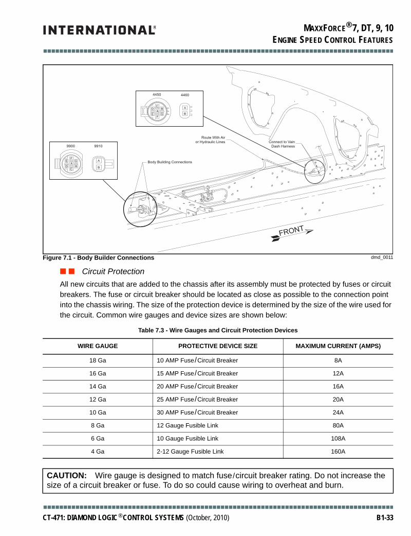
MAXXFORCE® 7, DT, 9, 10
■■■■■■■■■■■■■■■■■■■■■■■■■■■■■■■■■■■■■■■■■■■■■■■■■■■■■■■■■■■■■■■■■■■■■■■■■■■■■■■■■■■■■■■
ENGINE SPEED CONTROL FEATURES
■ ■ Circuit ProtectionAll new circuits that are added to the chassis after its assembly must be protected by fuses or circuit breakers. The fuse or circuit breaker should be located as close as possible to the connection point into the chassis wiring. The size of the protection device is determined by the size of the wire used for the circuit. Common wire gauges and device sizes are shown below:
Figure 7.1 - Body Builder Connections dmd_0011
Table 7.3 - Wire Gauges and Circuit Protection Devices
WIRE GAUGE PROTECTIVE DEVICE SIZE MAXIMUM CURRENT (AMPS)
18 Ga 10 AMP Fuse/Circuit Breaker 8A
16 Ga 15 AMP Fuse/Circuit Breaker 12A
14 Ga 20 AMP Fuse/Circuit Breaker 16A
12 Ga 25 AMP Fuse/Circuit Breaker 20A
10 Ga 30 AMP Fuse/Circuit Breaker 24A
8 Ga 12 Gauge Fusible Link 80A
6 Ga 10 Gauge Fusible Link 108A
4 Ga 2-12 Gauge Fusible Link 160A
CAUTION: Wire gauge is designed to match fuse/circuit breaker rating. Do not increase the size of a circuit breaker or fuse. To do so could cause wiring to overheat and burn.
Body Building Connections
Route With Airor Hydraulic Lines Connect to Vain
Dash Harness
FRONT
4450 4460
CD B
AE G
FB
A
FE G
AD B
C
9900 9910
A
B
■■■■■■■■■■■■■■■■■■■■■■■■■■■■■■■■■■■■■■■■■■■■■■■■■■■■■■■■■■■■■■■■■■■■■■■■■■■■■■■■■■■■■■■
CT-471: DIAMOND LOGIC® CONTROL SYSTEMS (October, 2010) B1-33

MAXXFORCE® 7, DT, 9, 10
■■■■■■■■■■■■■■■■■■■■■■■■■■■■■■■■■■■■■■■■■■■■■■■■■■■■■■■■■■■■■■■■■■■■■■■■■■■■■■■■■■■■■■■
ENGINE SPEED CONTROL FEATURES
International® part numbers for narrow blade circuit breakers according to type and size are shown below. Type III circuit breakers can only be reset manually. Type I circuit breakers continuously try to reset when tripped. Use Type I circuit breakers only where required by the function performed by the circuit to be protected. In general, Type III circuit breakers should be adequate for most needs.
Table 7.4 - Circuit Breaker Part Numbers
Circuit breakers and fuses can be installed in the chassis wiring using the following i-line connectors:
• 1676841C91 – In-line socket and cable for circuit breaker/fuse (20A maximum)• 1682115C91 –- In-line socket and cable for circuit breaker/fuse (30A maximum)
■ ■ Back FeedsThe circuits that are connected to the following Engine Control Module pins must always be connected to switched ignition power. Connecting any one of these circuits to battery power can cause the ECM to remain powered when the ignition switch is turned off. This can produce excess battery current causing the batteries to be discharged overnight.
• Remote PTO (Pre-Set)• Engine Coolant Temperature• Idle Validation Switch• Drive Disengage Signal• Remote PTO (Variable)• Engine Oil Temperature• Warn Engine Lamp
SIZE CIRCUIT BREAKER TYPE PART NUMBER COLOR
3000, DuraStar®, WorkStar® TerraStar™ and TranStar® Series
7.5A Type III - Manual Reset 3536177C1 Brown
10A Type III - Manual Reset 3536178C1 Red
15A Type III - Manual Reset 3536179C1 Blue
20A Type III - Manual Reset 3536180C1 Yellow
25A Type III - Manual Reset 3536181C1 White
30A Type III - Manual Reset 3536182C1 Green
9000i and PayStar® Series
10A Type I - Continuous Reset 2007463C1 Black
20A Type I - Continuous Reset 2007465C1 Black
10A Type III - Manual Reset 2011944C1 Red
20A Type III - Manual Reset 2011946C1 Yellow
25A Type III - Manual Reset 2011947C1 White
30A Type III - Manual Reset 2011948C1 Green
■■■■■■■■■■■■■■■■■■■■■■■■■■■■■■■■■■■■■■■■■■■■■■■■■■■■■■■■■■■■■■■■■■■■■■■■■■■■■■■■■■■■■■■
B1-34 CT-471: DIAMOND LOGIC® CONTROL SYSTEMS (October, 2010)

MAXXFORCE® 7, DT, 9, 10
■■■■■■■■■■■■■■■■■■■■■■■■■■■■■■■■■■■■■■■■■■■■■■■■■■■■■■■■■■■■■■■■■■■■■■■■■■■■■■■■■■■■■■■
ENGINE SPEED CONTROL FEATURES
• Coolant Level Sensor• Injection Pressure Regulator (I6 only)• Ambient Temperature Sensor• Map Sensor Output• Glow Plug Relay (V8 only)• Intake Air Heater Relays (I6 only)
■ ■ WeldingWhenever welding is done on any part of the vehicle, the batteries should be disconnected - both power and ground including the electronic power feeds. The electronic components may easily be damaged from the high voltage used and R.F. energy present in the arc.
■ General InformationThis section reviews information of general interest about the circuits provided with the chassis. Installation of a Master Disconnect switch and two-way radios are reviewed. Access points for the Speedometer and Tachometer Signals and the ATA Data Link (SAE RP J1708/J1587) are reviewed along with other general information.
■ ■ Remote PTO Engine Speed Control CircuitsDo not use the electrical wires provided for Remote Engine Speed Control connections to power other electrical chassis components. The activation switches (i.e., Set/Coast, Resume/Accel) should be momentary with Normally Open contacts. The +12 Volt connection should be used only to power these switches to allow them to activate Remote Engine Speed Control.
■ ■ High Voltages In Harnesses
■ ■ Master Disconnect SwitchSpecify sales order code 08WCS or 08WAD for a factory installed Master Disconnect Switch. The disconnect switch cannot be put into the battery ground cable as was previously done. The electronic modules will provide a ground path around the Master Disconnect switch if this method is employed.
WARNING: To avoid serious personal injury, death or possible engine damage, when welding or using an acetylene torch always wear welding goggles and gloves. Insure that acetylene and oxygen tanks are separated by a metal shield and are chained to a cart. Do not weld or heat areas near fuel tanks or fuel lines. Utilize proper shielding around hydraulic lines.
CAUTION: To avoid damage to vehicle electronic components, disconnect both the positive (+) and the negative (-) battery cables prior to electric welding. Attach the welder's ground cable as close as possible to the joint being welded. If it is necessary to weld close to an electronic component, it is recommended that the electronic component be temporarily removed.
WARNING: Do not probe the harnesses between the engine electronics and the engine. The injector solenoids have a higher electrical potential.
■■■■■■■■■■■■■■■■■■■■■■■■■■■■■■■■■■■■■■■■■■■■■■■■■■■■■■■■■■■■■■■■■■■■■■■■■■■■■■■■■■■■■■■
CT-471: DIAMOND LOGIC® CONTROL SYSTEMS (October, 2010) B1-35

MAXXFORCE® 7, DT, 9, 10
■■■■■■■■■■■■■■■■■■■■■■■■■■■■■■■■■■■■■■■■■■■■■■■■■■■■■■■■■■■■■■■■■■■■■■■■■■■■■■■■■■■■■■■
ENGINE SPEED CONTROL FEATURES
The engine modules must always be connected to the batteries, even when the Master Disconnect switch is opened. On each vehicle, separate power and ground circuits are provided to the engine electronics.
To install a Master Disconnect Switch, break into the positive battery cable going from the batteries to the cranking motor and insert the disconnect switch into that circuit, as shown in Figure 8. Insure that adequate insulation is used between the positive battery cable, the switch mounting, and the surrounding area. Place boots or covers over the disconnect switch studs to protect the batteries and cables from accidental shorting. Do not disturb the direct connections from the battery to the engine electronics.
■ ■ Two-Way Radio InstallationA qualified technician should do all two-way radio installations. The power connections for any radio installation should always go to the vehicle's batteries with proper circuit protection installed closest to the batteries. A filter may have to be added to the radio power feed. Wire routing should always be routed away from all vehicle harnesses to prevent pickup from the vehicle electrical system into the radio and/or from the radio system into the vehicle electrical system. Evaluation of the antenna location should be assessed before permanent mounting is made to assure minimum interference to the radio reception and vehicle electrical system.
■ ■ ATA Data Link ConnectionsThe engine control system provides a data link compatible with the specifications in TMC RP 1202. These requirements are the same as those given by SAE recommended practices J1708 and J1587. Temporary connections can be made using the 9-way Deutsch diagnostic connector located in the cab by the operator's side under left corner of instrument panel. Do not make permanent connections to the ATA data link without a full understanding of load requirements and data protocol required for
Figure 8.1 - Master Disconnect Switch Insertion Point dmd_0012
+
+
To Engine Electronics
Insert Disconnect Sw. here
To Starter Motor Positive Terminal
To Engine Electronics
To Starter Motor Negative Terminal
Ground Strap to
Frame Rail
40A
■■■■■■■■■■■■■■■■■■■■■■■■■■■■■■■■■■■■■■■■■■■■■■■■■■■■■■■■■■■■■■■■■■■■■■■■■■■■■■■■■■■■■■■
B1-36 CT-471: DIAMOND LOGIC® CONTROL SYSTEMS (October, 2010)
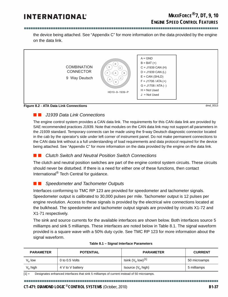
MAXXFORCE® 7, DT, 9, 10
■■■■■■■■■■■■■■■■■■■■■■■■■■■■■■■■■■■■■■■■■■■■■■■■■■■■■■■■■■■■■■■■■■■■■■■■■■■■■■■■■■■■■■■
ENGINE SPEED CONTROL FEATURES
the device being attached. See “Appendix C” for more information on the data provided by the engine on the data link.
■ ■ J1939 Data Link ConnectionsThe engine control system provides a CAN data link. The requirements for this CAN data link are provided by SAE recommended practices J1939. Note that modules on the CAN data link may not support all parameters in the J1939 standard. Temporary connects can be made using the 9-way Deutsch diagnostic connector located in the cab by the operator's side under left corner of instrument panel. Do not make permanent connections to the CAN data link without a a full understanding of load requirements and data protocol required for the device being attached. See “Appendix C” for more information on the data provided by the engine on the data link.
■ ■ Clutch Switch and Neutral Position Switch ConnectionsThe clutch and neutral position switches are part of the engine control system circuits. These circuits should never be disturbed. If there is a need for either one of these functions, then contact International® Tech Central for guidance.
■ ■ Speedometer and Tachometer OutputsInterfaces conforming to TMC RP 123 are provided for speedometer and tachometer signals. Speedometer output is calibrated to 30,000 pulses per mile. Tachometer output is 12 pulses per engine revolution. Access to these signals is provided by the electrical wire connections located at the bulkhead. The speedometer and tachometer output signals are provided by circuits X1-72 and X1-71 respectively.The sink and source currents for the available interfaces are shown below. Both interfaces source 5 milliamps and sink 5 milliamps. These interfaces are noted below in Table 8.1. The signal waveform provided is a square wave with a 50% duty cycle. See TMC RP 123 for more information about the signal waveform.
[1] = Designates enhanced interfaces that sink 5 milliamps of current instead of 50 microamps.
Figure 8.2 - ATA Data Link Connections dmd_0013
Table 8.1 – Signal Interface Parameters
PARAMETER POTENTIAL PARAMETER CURRENT
Vo low 0 to 0.5 Volts Isink (Vo low)[1] 50 microamps
Vo high 4 V to V battery Isource (Vo high) 5 milliamps
A = GND
B = BAT (+)
C = J1939 CAN (H)
D = J1939 CAN (L)
E = CAN (SHLD)
F = J1708 / ATA (+)
G = J1708 / ATA (−)
H = Not Used
J = Not Used
COMBINATION
CONNECTOR
9 Way Deutsch
HD10−9−1939−P
D
A
J
F
E
B
C
G
H
■■■■■■■■■■■■■■■■■■■■■■■■■■■■■■■■■■■■■■■■■■■■■■■■■■■■■■■■■■■■■■■■■■■■■■■■■■■■■■■■■■■■■■■
CT-471: DIAMOND LOGIC® CONTROL SYSTEMS (October, 2010) B1-37

MAXXFORCE® 7, DT, 9, 10
■■■■■■■■■■■■■■■■■■■■■■■■■■■■■■■■■■■■■■■■■■■■■■■■■■■■■■■■■■■■■■■■■■■■■■■■■■■■■■■■■■■■■■■
ENGINE SPEED CONTROL FEATURES
THIS PAGE INTENTIONALLY LEFT BLANK
■■■■■■■■■■■■■■■■■■■■■■■■■■■■■■■■■■■■■■■■■■■■■■■■■■■■■■■■■■■■■■■■■■■■■■■■■■■■■■■■■■■■■■■
B1-38 CT-471: DIAMOND LOGIC® CONTROL SYSTEMS (October, 2010)
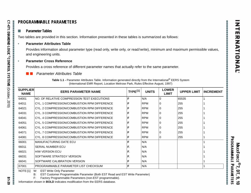
MAXXFORCE ® 7, DT, 9, 10
■■
■■
■■
■■
■■
■■
■■
■■
■■
■■
■■
■■
■■
■■
■■
■■
■■
■■
■■
■■
■■
■■
■■
■■
■■
■■
■■
■■
■■
■■
■■
■■
■■
■■
■■
■■
■■
■■
■■
■■
■■
■■
■■
■
PROGRAMMABLE PARAMETERS
■■
■■
■■
■■
■■
■■
■■
■■
■■
■■
■■
■■
■■
■■
■■
■■
■■
■■
■■
■■
■■
■■
■■
■■
■■
■■
■■
■■
■■
■■
■■
■■
■■
■■
■■
■■
■■
■■
■■
■■
■■
■■
■■
■
CT-471: DIAMOND LOGIC® CONTROL SYSTEMS (October, 2010)
B1-39
PROGRAMMABLE PARAMETERS
permissible values,
R LIMIT INCREMENT
1
1
1
1
1
1
1
1
1
1
1
1
1
1
1
■ Parameter TablesTwo tables are provided in this section. Information presented in these tables is summarized as follows:
• Parameter Attributes TableProvides information about parameter type (read only, write only, or read/write), minimum and maximumand engineering units.
• Parameter Cross ReferenceProvides a cross reference of different parameter names that actually refer to the same parameter.
■ ■ Parameter Attributes TableTable 1.1 - Parameter Attributes Table. Information generated directly from the International® EERS System
(International EMR Report, Location Melrose Park, Rules Effective August, 1997)
SUPPLIERNAME EERS PARAMETER NAME TYPE[1] UNITS LOWER
LIMIT UPPE
64001 NO. OF RELATIVE COMPRESSION TEST EXECUTIONS F N/A 0 65535
64011 CYL. 1 COMPRESSION/COMBUSTION RPM DIFFERENCE F RPM 0 255
64021 CYL. 2 COMPRESSION/COMBUSTION RPM DIFFERENCE F RPM 0 255
64031 CYL. 3 COMPRESSION/COMBUSTION RPM DIFFERENCE F RPM 0 255
64041 CYL. 4 COMPRESSION/COMBUSTION RPM DIFFERENCE F RPM 0 255
64051 CYL. 5 COMPRESSION/COMBUSTION RPM DIFFERENCE F RPM 0 255
64061 CYL. 6 COMPRESSION/COMBUSTION RPM DIFFERENCE F RPM 0 255
64071 CYL. 7 COMPRESSION/COMBUSTION RPM DIFFERENCE F RPM 0 255
64081 CYL. 8 COMPRESSION/COMBUSTION RPM DIFFERENCE F RPM 0 255
66001 MANUFACTURING DATE ECU F N/A
66011 SERIAL NUMBER ECU F. N/A
66021 H/W VERSION ECU F. N/A
66031 SOFTWARE STRATEGY VERSION F. N/A
66041 SOFTWARE CALIBRATION VERSION F N/A
67001 PROGRAMMABLE PARAMETER LIST CHECKSUM F N/A
NOTE:[1] W: EST Write Only ParameterB: EST Customer Programmable Parameter (Both EST Read and EST Write Parameter)F: Factory Programmable Parameters (non-EST programmable).
Information shown in BOLD indicates modification from the EERS database.

MAXXFORCE ® 7, DT, 9, 10
■■
■■
■■
■■
■■
■■
■■
■■
■■
■■
■■
■■
■■
■■
■■
■■
■■
■■
■■
■■
■■
■■
■■
■■
■■
■■
■■
■■
■■
■■
■■
■■
■■
■■
■■
■■
■■
■■
■■
■■
■■
■■
■■
■
PROGRAMMABLE PARAMETERS
■■
■■
■■
■■
■
B1-40
1
1
1
1
1
1
1
1
2 1
1 1
1 1
3 1
1 1
1 1
3 1
120 1
150 .25
150 .25
3 1
20 .5
3 1
1 1
1 1
GOV SPEED .25
GOV SPEED .25
1500 .25
GOV SPEED .25
Table 1.1 - Parameter Attributes Table. Information generated directly from the International® EERS System (International EMR Report, Location Melrose Park, Rules Effective August, 1997) (Continued)
SUPPLIERNAME EERS PARAMETER NAME TYPE[1] UNITS LOWER
LIMIT UPPER LIMIT INCREMENT
■■
■■
■■
■■
■■
■■
■■
■■
■■
■■
■■
■■
■■
■■
■■
■■
■■
■■
■■
■■
■■
■■
■■
■■
■■
■■
■■
■■
■■
■■
■■
■■
■■
■■
■■
■■
■■
■■
■■
CT-471: DIAMOND LOGIC® CONTROL SYSTEMS (October, 2010)
67011 CALIBRATION SOFTWARE CHECKSUM F N/A
67021 STRATEGY SOFTWARE CHECKSUM F N/A
68011 LAST SERVICE TOOL ID - CUSTOMER LEVEL 1 F N/A
68011 LAST SERVICE TOOL ID - CUSTOMER LEVEL 2 F N/A
68021 LAST SERVICE TOOL ID - CALIBRATION F N/A
68031 LAST SERVICE TOOL DATE PROGRAMMED CALIBRATION F N/A
68041 LAST SERVICE TOOL ID - STRATEGY F N/A
68051 LAST SERVICE TOOL DATE PROGRAMMED STRATEGY F N/A
69001 ENG-OILP-SIG-ENAB F, B N/A 0
69011 WATER IN FUEL ENAB F, B N/A 0
69021 FUEL PRESSURE SIGNAL ENAB F, B N/A 0
70001 RETARDER - SERVICE BRAKE INTERFACE F, B N/A 0
71001 GLOW PLUG F, B N/A 0
79021 VNT WARM-UP ENAB F, B N/A 0
74001 IDLE SHUTDOWN MODE F N/A 0
74011 IDLE-SHUTDWN-TIME F, B MINUTES 2
74021 IST-MAX-AIT F, B C -40
74031 IST-MIN-AIT F, B C -40
75001 PTO-CONTROL (ON/OFF) F, B N/A 0
75011 MAX ROAD SPEED FOR MOBILE CONTROL F, B MPH 0
75021 INCAB-PTO-MODE F, B N/A 0
75031 DISABLE CAB INTERFACE FOR PTO F, B N/A 0
75041 REMOTE THROTTLE FOR PTO CONTROL F, B N/A 0
75051 SET ENGINE SPEED (SPEED 1) F, B RPM LIDLE
75061 RESUME ENGINE SPEED (SPEED 2) F, B RPM LIDLE
75071 ENGINE RESPONSE RATE FOR PTO F, B RPM/SEC 1
75081 MAX PTO ENGINE SPEED F, B RPM LIDLE
NOTE:[1] W: EST Write Only ParameterB: EST Customer Programmable Parameter (Both EST Read and EST Write Parameter)F: Factory Programmable Parameters (non-EST programmable).
Information shown in BOLD indicates modification from the EERS database.

MAXXFORCE ® 7, DT, 9, 10
■■
■■
■■
■■
■■
■■
■■
■■
■■
■■
■■
■■
■■
■■
■■
■■
■■
■■
■■
■■
■■
■■
■■
■■
■■
■■
■■
■■
■■
■■
■■
■■
■■
■■
■■
■■
■■
■■
■■
■■
■■
■■
■■
■
PROGRAMMABLE PARAMETERS
■■
■■
■■
■■
■■
■■
■■
■■
■■
■■
■■
■■
■■
■■
■■
■■
■■
■■
■■
■■
■■
■■
■■
■■
■■
■■
■■
■■
■■
■■
■■
■■
■■
■■
■■
■■
■■
■■
■■
■■
■■
■■
■■
■
CT-471: DIAMOND LOGIC® CONTROL SYSTEMS (October, 2010)
B1-41
EED .25
EED .25
EED .25
EED .25
1
1
.25
.0625
.5
.5
1
.5
.5
EED .25
EED .25
EED .25
.5
.5
.5
.5
.5
.5
1
1
DLE .25
.25
1
Table 1.1 - Parameter Attributes Table. Information generated directly from the International® EERS System
R LIMIT INCREMENT
75091 PTO PRESET ENGINE SPEED 3 F, B RPM LIDLE GOV SP
75101 PTO PRESET ENGINE SPEED 4 F, B RPM LIDLE GOV SP
75111 PTO PRESET ENGINE SPEED 5 F, B RPM LIDLE GOV SP
75121 PTO PRESET ENGINE SPEED 6 F, B RPM LIDLE GOV SP
75131 DISABLE RETURN F, B N/A 0 1
76001 CRUISE CONTROL F, B N/A 0 3
76011 CRUISE-MIN-ENG-SPD F RPM 1000 1400
76021 CRUISE-RAMP-RATE F MPH/SEC 0 15
76031 MIN CRUISE CONTROL SPEED F, B MPH 20 100
76041 MAX CRUISE CONTROL SPEED F, B MPH 30 100
77001 ENG-PROT-MODE F, B NA 0 5
77011 ECT-WARNING F C 90 127.5
77021 ECT-CRITICAL F C 90 127.5
77031 PROT-ENGINE SPD 1 F RPM LIDLE GOV SP
77041 PROT-ENGINE SPD 2 F RPM LIDLE GOV SP
77051 PROT-ENGINE SPD 3 F RPM LIDLE GOV SP
77061 OIL-PRESS-WARN-SPD1 F PSI 0 80
77071 OIL-PRESS-WARN-SPD2 F PSI 0 80
77081 OIL-PRESS-WARN-SPD3 F PSI 0 80
77091 OIL-PRES-CRIT-SPD1 F PSI 0 80
77101 OIL-PRES-CRIT-SPD2 F PSI 0 80
77111 OIL-PRES-CRIT-SPD3 F PSI 0 80
78001 OVER TEMPERATURE PROTECTION F N/A 0 3
79001 VEH-ROAD-SPD-GOV F, B N/A 0 1
79011 MAX-ENGINE SPEED (NO VSSN) F, B N/A 700 ENG-HI
79021 VEHICLE SPEED LIMIT F, B MPH 1 100
80001 TWO SPEED AXLE F, B N/A 0 1
(International EMR Report, Location Melrose Park, Rules Effective August, 1997) (Continued)
SUPPLIERNAME EERS PARAMETER NAME TYPE[1] UNITS LOWER
LIMIT UPPE
NOTE:[1] W: EST Write Only ParameterB: EST Customer Programmable Parameter (Both EST Read and EST Write Parameter)F: Factory Programmable Parameters (non-EST programmable).
Information shown in BOLD indicates modification from the EERS database.

MAXXFORCE ® 7, DT, 9, 10
■■
■■
■■
■■
■■
■■
■■
■■
■■
■■
■■
■■
■■
■■
■■
■■
■■
■■
■■
■■
■■
■■
■■
■■
■■
■■
■■
■■
■■
■■
■■
■■
■■
■■
■■
■■
■■
■■
■■
■■
■■
■■
■■
■
PROGRAMMABLE PARAMETERS
■■
■■
■■
■■
■
B1-42
676 .1
20 .001
20 .001
20 .001
157157 1
157157 1
255 1
2 1
255 1
255 1
536,870,911.875 .125
214,748,364.75 .05
429.496,729.5 .1
536,870,911.875 .125
214,748,364.75 .05
536,870,911.875 .125
214,748,364.75 .05
214,748,364.75 .05
214,748,364.75 .05
214,748,364.75 .05
214,748,364.75 .05
214,748,364.75 .05
214,748,364.75 .05
214,748,364.75 .05
214,748,364.75 .05
429,496,729.5 .1
429,496,729.5 .1
Table 1.1 - Parameter Attributes Table. Information generated directly from the International® EERS System (International EMR Report, Location Melrose Park, Rules Effective August, 1997) (Continued)
SUPPLIERNAME EERS PARAMETER NAME TYPE[1] UNITS LOWER
LIMIT UPPER LIMIT INCREMENT
■■
■■
■■
■■
■■
■■
■■
■■
■■
■■
■■
■■
■■
■■
■■
■■
■■
■■
■■
■■
■■
■■
■■
■■
■■
■■
■■
■■
■■
■■
■■
■■
■■
■■
■■
■■
■■
■■
■■
CT-471: DIAMOND LOGIC® CONTROL SYSTEMS (October, 2010)
80011 TIRE-REVS-PER-MILE F, B REVS/MILE 300
80021 REAR-AXLE-RATIO-HI F, B N/A 2.5
80031 REAR-AXLE-RATIO-LO F, B N/A 2.5
80041 TRANS-LO-NUM-RATIO F, B N/A 0.6
80051 VEH-SPEED-CAL-LOW F, B PPM 18017
80061 VEH-SPEED-CAL-HI F, B PPM 18017
80071 TAIL-SHAFT-TEETH F, B N/A 5
81001 TORQUE-TAILORING F N/A 0
81011 TT-LOW-NVS-RATIO F RPM/MPH 0
81021 TT-HI-NVS-RATIO F RPM/MPH 0
83001 TOTAL-FUEL F GALLONS 0
83011 ENGINE-HOURS F HOURS 0
83021 TOTAL-MILES F MILES 0
83111 TOTAL IDLE FUEL USED F GALLONS 0
83121 ENGINE ON TIME AT IDLE F HOURS 0
83131 TOTAL PTO FUEL USED F GALLONS 0
83141 ENGINE ON TIME IN PTO F HOURS 0
84001 EL-OVERSPEED 1 F HOURS
84011 EL-OVERSPEED 2 F HOURS
84021 EL-LOWOILPRS-1 F HOURS
84031 EL-LOWOILPRS-2 F HOURS
84041 EL-OVERHEAT-1 F HOURS
84051 EL-OVERHEAT-2 F HOURS
84061 EL-LOWCOOL-1 F HOURS
84071 EL-LOWCOOL-2 F HOURS
84081 EL-OVERSPEED-MI1 F MILES
84091 EL-OVERSPEED-MI2 F MILES
NOTE:[1] W: EST Write Only ParameterB: EST Customer Programmable Parameter (Both EST Read and EST Write Parameter)F: Factory Programmable Parameters (non-EST programmable).
Information shown in BOLD indicates modification from the EERS database.

MAXXFORCE ® 7, DT, 9, 10
■■
■■
■■
■■
■■
■■
■■
■■
■■
■■
■■
■■
■■
■■
■■
■■
■■
■■
■■
■■
■■
■■
■■
■■
■■
■■
■■
■■
■■
■■
■■
■■
■■
■■
■■
■■
■■
■■
■■
■■
■■
■■
■■
■
PROGRAMMABLE PARAMETERS
■■
■■
■■
■■
■■
■■
■■
■■
■■
■■
■■
■■
■■
■■
■■
■■
■■
■■
■■
■■
■■
■■
■■
■■
■■
■■
■■
■■
■■
■■
■■
■■
■■
■■
■■
■■
■■
■■
■■
■■
■■
■■
■■
■
CT-471: DIAMOND LOGIC® CONTROL SYSTEMS (October, 2010)
B1-43
,729.5 .1
,729.5 .1
,729.5 .1
,729.5 .1
,729.5 .1
,729.5 .1
1
1
1
1
1
1
1
1
1
.25
.25
1
.25
.25
1
1
1
1
1
1
.5
Table 1.1 - Parameter Attributes Table. Information generated directly from the International® EERS System
R LIMIT INCREMENT
84101 EL-LOWOILP-MI1 F MILES 429,496
84113 EL-LOWOILPRS-2 F MILES 429,496
84121 EL-OVERHEAT-MI1 F MILES 429,496
84131 EL-OVERHEAT-MI2 F MILES 429,496
84141 EL-LOWCOOL-MI1 F MILES 429,496
84151 EL-LOWCOOL-MI2 F MILES 429,496
85001 VEHICLE-IDENT F N/A
86001 TOTAL TATTLETALES F N/A 0 65,535
87001 CUSTOMER PASSWORD W N/A ACCEPT VAL
88001 ENG-SERIAL-NO F N/A
89001 VEH-SPD-SIG-MODE F N/A 0 4
89011 DRIVELINE DISENGAGED MODE F N/A 0 5
89021 BRAKE SIGNAL PROCESSING MODE F N/A 0 4
90001 COOL-FAN-ENABLE F N/A 0 5
90011 AC-DEMAND-ENABLE F N/A 0 3
90021 COOL-FAN-ON-TEMP F, B C -40 150
90031 COOL-FAN-OFF-TEMP F, B C -40 150
91001 RAD-SHUT-ENABLE F, B N/A 0 1
91011 SHUTTER-OPEN-ECT F, B C -40 150
91021 SHUTTER-CLOSE-ECT F, B C -40 150
92001 CONDUCT-CLNT-SNSR F, B N/A 0 1
93001 HYD-PRESS-GOV-ENAB F, B N/A 0 1
93011 EPG-DRIVELINE STATUS F, B N/A 0 1
94001 COLD-AMB-PROT-MODE F, B N/A 0 1
95001 SERVICE-INT-ENABLE F, B N/A 0 1
95011 SI-FUEL-INTERVAL F, B GALLONS 0 65535
95021 SI-HOUR-INTERVAL F, B HOURS 0 2000
(International EMR Report, Location Melrose Park, Rules Effective August, 1997) (Continued)
SUPPLIERNAME EERS PARAMETER NAME TYPE[1] UNITS LOWER
LIMIT UPPE
NOTE:[1] W: EST Write Only ParameterB: EST Customer Programmable Parameter (Both EST Read and EST Write Parameter)F: Factory Programmable Parameters (non-EST programmable).
Information shown in BOLD indicates modification from the EERS database.
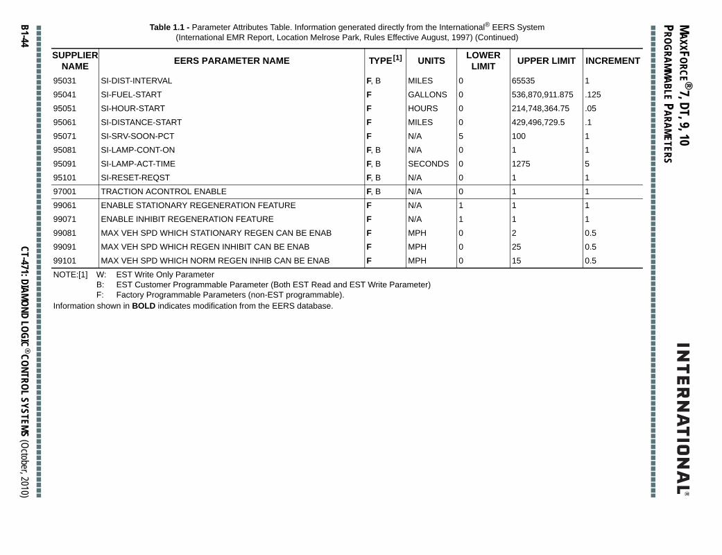
MAXXFORCE ® 7, DT, 9, 10
■■
■■
■■
■■
■■
■■
■■
■■
■■
■■
■■
■■
■■
■■
■■
■■
■■
■■
■■
■■
■■
■■
■■
■■
■■
■■
■■
■■
■■
■■
■■
■■
■■
■■
■■
■■
■■
■■
■■
■■
■■
■■
■■
■
PROGRAMMABLE PARAMETERS
■■
■■
■■
■■
■
B1-44
65535 1
536,870,911.875 .125
214,748,364.75 .05
429,496,729.5 .1
100 1
1 1
1275 5
1 1
1 1
1 1
1 1
2 0.5
25 0.5
15 0.5
Table 1.1 - Parameter Attributes Table. Information generated directly from the International® EERS System (International EMR Report, Location Melrose Park, Rules Effective August, 1997) (Continued)
SUPPLIERNAME EERS PARAMETER NAME TYPE[1] UNITS LOWER
LIMIT UPPER LIMIT INCREMENT
■■
■■
■■
■■
■■
■■
■■
■■
■■
■■
■■
■■
■■
■■
■■
■■
■■
■■
■■
■■
■■
■■
■■
■■
■■
■■
■■
■■
■■
■■
■■
■■
■■
■■
■■
■■
■■
■■
■■
CT-471: DIAMOND LOGIC® CONTROL SYSTEMS (October, 2010)
95031 SI-DIST-INTERVAL F, B MILES 0
95041 SI-FUEL-START F GALLONS 0
95051 SI-HOUR-START F HOURS 0
95061 SI-DISTANCE-START F MILES 0
95071 SI-SRV-SOON-PCT F N/A 5
95081 SI-LAMP-CONT-ON F, B N/A 0
95091 SI-LAMP-ACT-TIME F, B SECONDS 0
95101 SI-RESET-REQST F, B N/A 0
97001 TRACTION ACONTROL ENABLE F, B N/A 0
99061 ENABLE STATIONARY REGENERATION FEATURE F N/A 1
99071 ENABLE INHIBIT REGENERATION FEATURE F N/A 1
99081 MAX VEH SPD WHICH STATIONARY REGEN CAN BE ENAB F MPH 0
99091 MAX VEH SPD WHICH REGEN INHIBIT CAN BE ENAB F MPH 0
99101 MAX VEH SPD WHICH NORM REGEN INHIB CAN BE ENAB F MPH 0
NOTE:[1] W: EST Write Only ParameterB: EST Customer Programmable Parameter (Both EST Read and EST Write Parameter)F: Factory Programmable Parameters (non-EST programmable).
Information shown in BOLD indicates modification from the EERS database.

MAXXFORCE ® 7, DT, 9, 10
■■
■■
■■
■■
■■
■■
■■
■■
■■
■■
■■
■■
■■
■■
■■
■■
■■
■■
■■
■■
■■
■■
■■
■■
■■
■■
■■
■■
■■
■■
■■
■■
■■
■■
■■
■■
■■
■■
■■
■■
■■
■■
■■
■
PROGRAMMABLE PARAMETERS
■■
■■
■■
■■
■■
■■
■■
■■
■■
■■
■■
■■
■■
■■
■■
■■
■■
■■
■■
■■
■■
■■
■■
■■
■■
■■
■■
■■
■■
■■
■■
■■
■■
■■
■■
■■
■■
■■
■■
■■
■■
■■
■■
■
CT-471: DIAMOND LOGIC® CONTROL SYSTEMS (October, 2010)
B1-45
■ ■ Parameter Cross Referencem
VICE DESCRIPTION
ILP-SIG-ENAB
LE-RETARDER
PLUG
UST-BACKPRESS
RANK-INHIBIT
RK-INHIB-TIME
HUTDOWN-CNTRL
D TIME
X AIT
X AIT
ONTROL
D-SPD-IN-PTO
-PTO-MODE
LE-PTO-CAB-IF
EMOTE-PEDAL
NTRL-SET-RPM
NTRL-RES-RPM
PM-RAMP-RATE
TO-SPEED
E-CONTROL
E-MIN-ENG-SPD
E-RAMP-RATE
RUS-CNTRL-SPD
RUS-CNTRL-SPD
ROT-MODE
ARNING
RITICAL
-ENG-SPD1
-ENG-SPD2
Table 1.2 - Parameter Cross Reference Table. Information generated directly from International® EERS Syste(International® EMR Report, Location Melrose Park, Rules Effective August, 1997)
SUPPLIER NAME PARAMETER NAME SALES DESCRIPTION SER
69001 ENG-OILP-SIG-ENAB OIL PRESS SIG ENABLE ENG-O
70001 RETARDER-SERVICE BRAKE INTERFACE RETARDER MODE VEHIC
71001 GLOW PLUG GLOW PLUG ENABLE GLOW
72001 EXHAUS- BACKPRESS EXHAUST BACKPRESS EXHA
73001 ENG-CRANK-INHIBIT CRANK INHIBIT MODE ENG-C
73011 ENG-CRANK-INHIB-TIME CRNK INH RUN MODE TM ENG-C
74001 IDLE SHUTDOWN MODE IDLE SHUTDN TMR MODE ENG-S
74011 IDLE-SHTDWN-TIME IDLE SHUTDOWN TIME IDLE S
74021 IST-MAX-AIT IST MAX INTAKE TEMP IST MA
74031 IST-MIN-AIT IST MIN INTAKE TEMP IST MA
75001 PTO-CONTROL (ON/OFF) PTO MODE PTO-C
75011 MAX ROAD SPEED FOR MOBILE CONTROL PTO MAX ROAD SPEED MAX-R
75021 INCAB-PTO-MODE PTO INCAB MODE INCAB
75031 DISABLE CAB INTERFACE FOR PTO PTO OPER. DISABLE DISAB
75041 REMOTE THROTTLE FOR PTO CONTROL PTO REMOTE PEDAL PTO-R
75051 SET ENGINE SPEED (SPEED 2) PTO PRESET SPEED 1 PTO-C
75061 RESUME ENGINE SPEED (SPEED 1) PTO PRESET SPEED 2 PTO-C
75071 ENGINE RESPONSE RATE FOR PTO PTO SPEED RAMP RATE PTO-R
75081 MAX PTO ENGINE SPEED PTO MAX ENG SPEED MAX-P
76001 CRUISE-CONTROL CRUISE CONTROL CRUIS
76011 CRUISE-MIN-ENG-SPD CRUISE MIN RPM CRUIS
76021 CRUISE-RAMP-RATE CRUSE RAMP RATE CRUIS
76031 MIN CRUISE CONTROL SPEED CRUISE CTL MIN SPEED MIN-C
76041 MAXIMUM CRUISE CONTROL SPEED CRUISE CTL MAX SPEED MAX-C
77001 ENG-PROT-MODE WARN MODE ENG-P
77011 ECT-WARNING COOLANT WARNING TEMP ECT-W
77021 ECT-CRITICAL COOLANT SHUTDOWN TMP ECT-C
77031 PROT-ENG-SPD1 OIL WARNING RPM 1 PROT
77041 PROT-ENG-SPD2 OIL WARNING RPM 2 PROT

MAXXFORCE ® 7, DT, 9, 10
■■
■■
■■
■■
■■
■■
■■
■■
■■
■■
■■
■■
■■
■■
■■
■■
■■
■■
■■
■■
■■
■■
■■
■■
■■
■■
■■
■■
■■
■■
■■
■■
■■
■■
■■
■■
■■
■■
■■
■■
■■
■■
■■
■
PROGRAMMABLE PARAMETERS
■■
■■
■■
■■
■
B1-46
PROT-ENG-SPD3
OIL-PRES-WARN-PSI1
OIL-PRES-WARN-PSI2
OIL-PRES-WARN-PSI3
OIL-PRES-CRIT-PSI1
OIL-PRES-CRIT-PSI2
OIL-PRES-CRIT-PSI3
COOLANT-TEMP-COMP
CTC-INITIAL
CTC-TRANSITION
CTC-TAIL-FACTOR
VEH-ROAD-SPD-GOV
MAX-ENGSPD-NO-VSSN
MAX-VEHICLE-SPEED
TWO-SPEED-AXLE
TIRE-REVS-PER-MILE
REAR-AXLE-RATIO-H
REAR-AXLE-RATIO-LO
TRANS-LO-NUM-RATIO
VEH-SPEED-CAL-HIGH
VEH-SPEED-CAL-LOW
TAIL-SHAFT-TEETH
TORQUE-TAILORING
TT-LOW-NVS-RATIO
TT-HI-NVS-RATIO
TRANSMISSION-TYPE
ENG-FAM-RATING-CD
ENG-LOW-IDLE-SPEED
ENG-HI-IDLE-SPEED
ENG-GOVERNED-SPEED
Table 1.2 - Parameter Cross Reference Table. Information generated directly from International® EERS System(International® EMR Report, Location Melrose Park, Rules Effective August, 1997) (Continued)
SUPPLIER NAME PARAMETER NAME SALES DESCRIPTION SERVICE DESCRIPTION
■■
■■
■■
■■
■■
■■
■■
■■
■■
■■
■■
■■
■■
■■
■■
■■
■■
■■
■■
■■
■■
■■
■■
■■
■■
■■
■■
■■
■■
■■
■■
■■
■■
■■
■■
■■
■■
■■
■■
CT-471: DIAMOND LOGIC® CONTROL SYSTEMS (October, 2010)
77051 PROT-ENG-SPD3 OIL WARNING RPM 3
77061 OIL-PRES-WARN-SPD1 OIL PRESS WARNING 1
77071 OIL-PRES-WARN-SPD2 OIL PRESS WARNING 2
77081 OIL-PRES-WARN-SPD3 OIL PRESS WARNING 3
77091 OIL-PRES-CRIT-SPD1 OIL PRESS SHUTDOWN 1
77101 OIL-PRES-CRIT-SPD2 OIL PRESS SHUTDOWN 2
77111 OIL-PRES-CRIT-SPD3 OIL PRESS SHUTDOWN 3
78001 OVER TEMPERATURE PROTECTION CTC MODE
78011 CTC-INITIAL CTC INIT TEMP
78021 CTC-TRANSITION CTC TRANSITION TEMP
78031 CTC-TAIL-FACTOR CTC TAILORING FACTOR
79001 VEH-ROAD-SPD-GOV SPEED LIMITING
79011 MAX. ENGINE SPEED (NO VSSN) MAX ENG RPM W/O VSS
79021 VEHICLE SPEED LIMIT MAX VEHICLE SPEED
80001 TWO-SPEED-AXLE TWO SPEED AXLE ENBLE
80011 TIRE-REVS-PER-MILE TIRE REVOLUTIONS
80021 REAR-AXLE-RATIO-HI REAR AXLE RATIO 1
80031 REAR-AXLE-RATIO-LO REAR AXLE RATIO 2
80041 TRANS-LO-NUM-RATIO TRANS TOP GEAR RATIO
80051 VEH-SPEED-CAL-HIGH HI AXLE RATIO PULSES
80061 VEH-SPEED-CAL-LOW LO AXLE RATIO PULSES
80071 TAIL-SHAFT-TEETH TAILSHAFT GEAR TEETH
81001 TORQUE-TAILORING TORQUE LVL TAILORING
81011 TT-LOW-NVS-RATIO N/VS LOWER GEAR PT
81021 TT-HI-NVS-RATIO N/VS UPPER GEAR PT
82001 TRANSMISSION-TYPE TRANSMISSION TYPE
82011 ENG-FAM-RATING-CD ENG RATING CODE
82021 ENG-LOW-IDLE-SPEED MIN ENGINE IDLE
82031 ENG-HI-IDLE-SPEED MAX ENGINE IDLE
82041 ENG-GOVERNED-SPEED RATED ENGINE SPEED

MAXXFORCE ® 7, DT, 9, 10
■■
■■
■■
■■
■■
■■
■■
■■
■■
■■
■■
■■
■■
■■
■■
■■
■■
■■
■■
■■
■■
■■
■■
■■
■■
■■
■■
■■
■■
■■
■■
■■
■■
■■
■■
■■
■■
■■
■■
■■
■■
■■
■■
■
PROGRAMMABLE PARAMETERS
■■
■■
■■
■■
■■
■■
■■
■■
■■
■■
■■
■■
■■
■■
■■
■■
■■
■■
■■
■■
■■
■■
■■
■■
■■
■■
■■
■■
■■
■■
■■
■■
■■
■■
■■
■■
■■
■■
■■
■■
■■
■■
■■
■
CT-471: DIAMOND LOGIC® CONTROL SYSTEMS (October, 2010)
B1-47
ATED-SPEED
ATED-HP
AM-EXT
-FUEL
-ENG-HOURS
-MILES
ERSPEED-HRS-1
ERSPEED-HRS-2
WOILP-HRS-1
WOILP-HRS-2
ERHEAT-HRS-1
ERHEAT-HRS-2
WCOOL-HRS-1
WCOOL-HRS-2
ERSPEED-MLS-1
ERSPEED-MLS-2
WOILP-MLS-1
WOILP-MLS-2
ERHEAT-MLS-1
ERHEAT-MLS-2
WCOOL-MLS-1
WCOOL-MLS-2
LE-IDENT
-TATTLETALES
ORD-1
ERIAL-NO
PD-SIG-MODE
ONTROL-MODE
MAND-INPUT
NTRL-ON-TEMP
Table 1.2 - Parameter Cross Reference Table. Information generated directly from International® EERS System®
VICE DESCRIPTION
82041 ENG-RATED-SPEED RATED ENGINE SPEED ENG-R
82051 ENG-RATED-HP RATED ENGINE POWER ENG-R
82061 ENG FAMILY EXT ENG-F
83001 TOTAL-FUEL TOTAL FUEL USED TOTAL
83011 ENGINE-HOURS ENGINE RUN HOURS TOTAL
83021 TOTAL-MILES TOTAL DISTANCE TOTAL
84001 EL-OVERSPEED-1 ENGINE SPEED FAULT 1 EL-OV
84011 EL-OVERSPEED-2 ENGINE SPEED FAULT 2 EL-OV
84021 EL-LOWOILPRS-1 OIL PRESSURE FAULT 1 EL-LO
84031 EL-LOWOILPRS-2 OIL PRESSURE FAULT 2 EL-LO
84041 EL-OVERHEAT-1 COOLANT TEMP FAULT 1 EL-OV
84051 EL-OVERHEAT-2 COOLANT TEMP FAULT 2 EL-OV
84061 EL-LOWCOOL-1 COOLANT LEVEL FAULT1 EL-LO
84071 EL-LOWCOOL-2 COOLANT LEVEL FAULT2 EL-LO
84081 EL-OVERSPEED-MI1 ENGINE SPEED FAULT1 EL-OV
84091 EL-OVERSPEED-MI2 ENGINE SPEED FAULT 2 EL-OV
84101 EL-LOWOILP-MI1 OIL PRESSURE FAULT 1 EL-LO
84113 EL-LOWOILP-MI2 OIL PRESSURE FAULT 2 EL-LO
84121 EL-OVERHEAT-MI1 COOLANT TEMP FAULT 1 EL-OV
84131 EL-OVERHEAT-MI2 COOLANT TEMP FAULT 2 EL-OV
84141 EL-LOWCOOL-MI1 COOLANT LEVEL FAULT1 EL-LO
84151 EL-LOWCOOL-MI2 COOLANT LEVEL FAULT2 EL-LO
85001 VEHICLE-IDENT VIN VEHIC
86001 TOTAL-TATTLETALES TOTAL TATTLE TALES TOTAL
87002 CUSTOMER PASSWORD CUSTOMER PASSWORD PASSW
88001 ENG-SERIAL-NO ENGINE SERIAL # ENG-S
89001 VEH-SPD-SIG-MODE VEH SPEED SIGNAL VEH-S
90001 COOL-FAN-ENABLE FAN CONTROL MODE FAN-C
90011 AC-DEMAND-ENABLE AC DEMAND INPUT AC-DE
90021 COOL-FAN-ON-TEMP FAN ON TEMP FAN-C
(International EMR Report, Location Melrose Park, Rules Effective August, 1997) (Continued)
SUPPLIER NAME PARAMETER NAME SALES DESCRIPTION SER

MAXXFORCE ® 7, DT, 9, 10
■■
■■
■■
■■
■■
■■
■■
■■
■■
■■
■■
■■
■■
■■
■■
■■
■■
■■
■■
■■
■■
■■
■■
■■
■■
■■
■■
■■
■■
■■
■■
■■
■■
■■
■■
■■
■■
■■
■■
■■
■■
■■
■■
■
PROGRAMMABLE PARAMETERS
■■
■■
■■
■■
■
B1-48
FAN-CNTRL-OFF-TEMP
SHUTTER-CNTRL-ENAB
SHUTT OPEN ECT
SHUTT CLOSE ECT
COOLNT-TANK-SELECT
HYD-PRESS-GOV-ENAB
EPG-DRVLINE-STATUS
EPG-MODE-IND-ENABL
EPG-RAMP-RATE
EPG-INTG-GAIN-OFST
EPG-PROP-GAIN-OFST
CAP MODE
SRVC INT ENAB
SI FUEL INT
SI HOUR INT
SI DISTANCE INT
SI FULE START
SI HOUR START
SI DISTANCE START
SI SRV SOON PCT
SI LMP CONT ON
SI LMP ACTV TIME
SI RESET REQUEST
Table 1.2 - Parameter Cross Reference Table. Information generated directly from International® EERS System(International® EMR Report, Location Melrose Park, Rules Effective August, 1997) (Continued)
SUPPLIER NAME PARAMETER NAME SALES DESCRIPTION SERVICE DESCRIPTION
■■
■■
■■
■■
■■
■■
■■
■■
■■
■■
■■
■■
■■
■■
■■
■■
■■
■■
■■
■■
■■
■■
■■
■■
■■
■■
■■
■■
■■
■■
■■
■■
■■
■■
■■
■■
■■
■■
■■
CT-471: DIAMOND LOGIC® CONTROL SYSTEMS (October, 2010)
90031 COOL-FAN-OFF-TEMP FAN OFF TEMP
91001 RAD-SHUT-ENABLE SHUTTER CONTROL
91011 SHUTTER-OPEN-ECT SHUTTER OPEN COOLANT TEMP
91021 SHUTTER-CLOSE-ECT SHUTTER CLOSE COOLANT TEMP
92001 CONDUCT-CLNT-SNSR COOLANT TANK
93001 HYD-PRESS-GOV-ENAB EPG ENABLE
93011 EPG-DRVLINE-STATUS EPG DRVLINE STATUS
93021 EPG-MODE-IND-ENABL EPG MODE INDICATOR
93031 EPG-RAMP-RATE EPG RAMP RATE
93041 EPG-INTG-GAIN-OFST INT GAIN OFFSET
93051 EPG-PROP-GAIN-OFST EPG PROP GAIN OFFSET
94001 COLD-AMB-PROT-MODE COLD AMBIENT PROT MODE
95001 SERVICE-INT-ENABLE SERVICE INTERVAL ENABLE
95011 SI-FUEL-INTERVAL SERV INT FUEL INTERVAL
95021 SI-HOUR-INTERVAL SERV INT HOUR INTERVAL
95031 SI-DIST-INTERVAL SERV INT DISTANCE INTERVAL
95041 SI-FUEL-START SERV INT FULE START
95051 SI-HOUR-START SERV INT HOUR START
95061 SI-DISTANCE-START SERV INT DISTANCE START
95071 SI-SRV-SOON-PCT SERV INT SERV SOON PCT
95081 SI-LAMP-CONT-ON SERV INT LAMP CONT ON
95091 SI-LAMP-ACT-TIME SERV INT LAMP ACTIVE TIME
95101 SI-RESET-REQST SERV INT RESET REQUEST

MAXXFORCE® 7, DT, 9, 10
■■■■■■■■■■■■■■■■■■■■■■■■■■■■■■■■■■■■■■■■■■■■■■■■■■■■■■■■■■■■■■■■■■■■■■■■■■■■■■■■■■■■■■■
PROGRAMMABLE PARAMATERS
■ Parameter Table DescriptionsProgrammable parameters are grouped according to control system feature. Features are listed in alphabetical order. An index is also provided for help in locating parameters.
Since interactions exist between certain control system features, text is provided at the end of each section to clarify what parameters not belonging to the given feature must be considered when programming parameters belonging to the given feature. Refer to the text in each section preceded by the heading: “Other parameters which must be considered when programming this feature:”
■ ■ Feature Name: AccumulatorsTOTAL-FUEL (gallons)Records total fuel usage since installation of this ECM.
ENGINE-HOURS (hours)Records total engine on time since installation of this ECM. “On” time is defined as any time the engine is running.
TOTAL-MILES (miles)Records total distance traveled since installation of this ECM total idle fuel used, engine on time at idle, total PTO.
Other parameters which must be considered when programming this feature:None
■ ■ Feature Name: Cold Ambient ProtectionCOLD AMBIENT PROTECT ENABLEEnable/Disable of Cold Ambient Protection Feature.
• 0: DISABLE, feature is turned off at all times.• 1: ENABLE, feature is enabled and may be activated by the ECM when activation criteria are met.Cold ambient protection permits the engine to idle at an elevated RPM when certain operating temperature conditions are met. For more information, refer to International® publications listed in the reference section of this document.
Other parameters which must be considered when programming this feature:1. IDLE SHUTDOWN MODE (Idle Shutdown Control Feature):
If this parameter is programmed to enable the IST feature, CAP CANNOT be enabled. This is because the functionality of these two features conflicts.
2. PTO-CONTROL ON/OFF (Power Take Off Control Feature):CAP is disabled anytime PTO Control is operating in “Active” mode.
3. ENG-PROT-MODE (Engine Warning and Protection Control Feature):Disables CAP when coolant level is detected to be low.
4. TRANS_MODE (Transmission Type Feature):If this parameter is programmed to indicate a manual or Allison WT transmission, then the maximum engine speed achievable by CAP is limited to CAP_N_NLMX (parameter not yet
■■■■■■■■■■■■■■■■■■■■■■■■■■■■■■■■■■■■■■■■■■■■■■■■■■■■■■■■■■■■■■■■■■■■■■■■■■■■■■■■■■■■■■■
CT-471: DIAMOND LOGIC® CONTROL SYSTEMS (October, 2010) B1-49

MAXXFORCE® 7, DT, 9, 10
■■■■■■■■■■■■■■■■■■■■■■■■■■■■■■■■■■■■■■■■■■■■■■■■■■■■■■■■■■■■■■■■■■■■■■■■■■■■■■■■■■■■■■■
PROGRAMMABLE PARAMETERS
■ ■ Feature Name: Coolant Tank SelectionCONDUCT-CLNT-SNSRSpecifies type of coolant tank and/or coolant level sensor installed on truck.
• 0: Normally open coolant level sensor switch installed (plastic tank).• 1: Conductive coolant level probe installed (metal tank).Other parameters which must be considered when programming this feature:None
■ ■ Feature Name: Coolant Temperature CompensationOVER TEMPERATURE PROTECTIONEnable/Disable Coolant Temperature Compensation feature.
• 0: DISABLE, feature is turned off at all times.• 1: ENABLE, feature is enabled and may become active for certain engine operating conditions.
IMPORTANT: Vehicles using PTO speed control for emergency vehicle applications may need to disable the Coolant Temperature Compensation feature in order to comply with NFPA 1901.
The event logging feature will log occurrence of an engine shutdown event according to engine hours and odometer reading.
Other parameters which must be considered when programming this feature:None
■ ■ Feature Name: Cruise ControlCRUISE-CONTROLEnable/Disable Cruise Control Feature
• 0: DISABLE, feature is turned off at all times.• 1: ENABLE, feature is enabled and may be turned on and activated by the operator.IMPORTANT: If Cruise control is disabled, do not program any additional cruise control parameters. Instead, go to the PTO Control section.
CRUISE-MIN-ENG-SPD (mph)Cruise Control Low RPM Limit
Minimum engine speed permitted for activation of cruise control.
CRUISE-RAMP-RATE (mph/second)Cruise Control Vehicle Speed Ramp Rate
Maximum rate of vehicle acceleration permitted when the Accel button is pressed.
MIN CRUISE CONTROL SPEED (mph)Cruise Control Low Vehicle Speed Limit
Minimum vehicle speed permitted for cruise control engagement (cruise control “active”).
MAXIMUM CRUISE CONTROL SPEED (mph)Cruise Control Maximum Vehicle Speed Limit
■■■■■■■■■■■■■■■■■■■■■■■■■■■■■■■■■■■■■■■■■■■■■■■■■■■■■■■■■■■■■■■■■■■■■■■■■■■■■■■■■■■■■■■
B1-50 CT-471: DIAMOND LOGIC® CONTROL SYSTEMS (June, 2010)

MAXXFORCE® 7, DT, 9, 10
■■■■■■■■■■■■■■■■■■■■■■■■■■■■■■■■■■■■■■■■■■■■■■■■■■■■■■■■■■■■■■■■■■■■■■■■■■■■■■■■■■■■■■■
PROGRAMMABLE PARAMATERS
Maximum vehicle speed permitted for cruise control engagement and operation (cruise control “active”).
If cruise control is disabled, do not enter a value for this parameter. Leave the parameter value blank.
This parameter should not be programmed with a value that exceeds the maximum road speed limit.
Other parameters which must be considered when programming this feature:1. RETARDER-SERVICE BRAKE INTERFACE (Vehicle Retarder Feature):
For this parameter programmed to a non-zero value, VRE will be enabled when the brake pedal is depressed and Cruise Control is in a “standby” or “active” mode of operation.
2. PTO-CONTROL ON/OFF (Power Take Off Control): The PTO Control and Cruise Control features operate in a mutually exclusive manner if they are both programmed to be enabled. Cruise Control will function at vehicle speeds greater than 35 mph; PTO control will function at speeds less than 20 mph when PTO-CONTROL is set to 3 (MOBILE-VARIABLE); otherwise, PTO Control will operate only when the vehicle is not moving.
3. VEH-ROAD-SPD-GOV (Road Speed Limiting)VEHICLE SPEED LIMIT (Road Speed Limiting):In order to encourage use of cruise control for best fuel economy, the MAXIMUM CRUISE CONTROL SPEED should not be programmed to be less than the value programmed for the VEHICLE SPEED LIMIT in the Road Speed Limiting feature.
■ ■ Feature Name: Customer PasswordCUSTOMER PASSWORDSpecifies alphanumeric characters that become the customer password for the engine in this vehicle; 4 characters minimum, 8 characters maximum.
Other parameters which must be considered when programming this feature:None
■ ■ Feature Name: Engine Fan ControlCOOL-FAN ENABLEEnable/Disable different features of the Engine Fan Control.
• 0: DISABLE, feature is turned off at all times.• 1: FOR COOLING ONLY, fan activation is performed for engine cooling and air conditioner performance
requirements only.• 2: FOR COOLING AND VEHICLE RETARDER: fan activation is performed based on engine cooling and
air conditioner requirements, as well as for use as a vehicle retarding device.• 3: Variable Engine Fan Speed Control.• 3: Three Speed Fan Control.
AC-DEMAND-ENABLEIndicates to ECM that an air conditioner pressure demand switch should be used to engage the engine cooling fan.
• 0: DISABLE, air conditioner demand switch is not available.• 1: ENABLE, air conditioner demand switch is available to the ECM.
■■■■■■■■■■■■■■■■■■■■■■■■■■■■■■■■■■■■■■■■■■■■■■■■■■■■■■■■■■■■■■■■■■■■■■■■■■■■■■■■■■■■■■■
CT-471: DIAMOND LOGIC® CONTROL SYSTEMS (October, 2010) B1-51

MAXXFORCE® 7, DT, 9, 10
■■■■■■■■■■■■■■■■■■■■■■■■■■■■■■■■■■■■■■■■■■■■■■■■■■■■■■■■■■■■■■■■■■■■■■■■■■■■■■■■■■■■■■■
PROGRAMMABLE PARAMETERS
COOL-FAN-ON-TEMP (degrees centigrade)Specifies coolant temperature threshold for fan control operation. Engine fan will be turned on by ECM when coolant temperature is above this threshold.
COOL-FAN-OFF-TEMP (degrees centigrade)Specifies coolant temperature threshold for fan control operation. Engine fan will be turned off by ECM when coolant temperature is below this threshold.
Other parameters which must be considered when programming this feature:1. RETARDER-SERVICE-BRAKE-INTERFACE (Vehicle Retarder Feature):
The Vehicle Retarder Feature should be enabled via this parameter if COOL-FAN ENABLE is programmed to a “2”.
2. RAD-SHUT-ENABLE (Radiator Shutter Control):This parameter indicates to the ECM that the position of the radiator shutter is controlled by the ECM. This parameter must be properly programmed to ensure that the radiator shutters are opened when required to achieve engine cooling by the Engine Cooling Fan feature.
■ ■ Feature Name: Engine Serial NumberENG-SERIAL-NOEngine Serial Number
Specifies the 17 alphanumeric characters that make up the engine serial number for the engine in this vehicle.
Other parameters which must be considered when programming this feature:None
■ ■ Feature Name: Event LoggingEL-OVERSPEED-1 (hours)Log of engine hour meter for either the last occurrence of an engine overspeed event, or the next to last occurrence of an engine overspeed event.
EL-OVERSPEED-2 (hours)Log of engine hour meter for either the last occurrence of an engine overspeed event, or the next to last occurrence of an engine overspeed event.
EL-LOWOILP-1 (hours)Log of engine hour meter for either the last occurrence of low oil pressure detected, or the next to last occurrence of low oil pressure detected.
EL-LOWOILP-2 (hours)Log of engine hour meter for either the last occurrence of low oil pressure detected, or the next to last occurrence of low oil pressure detected.
EL-OVERHEAT-1 (hours)Log of engine hour meter for either the last occurrence of engine overheat condition detected, or the next to last occurrence of engine overheat condition detected.
■■■■■■■■■■■■■■■■■■■■■■■■■■■■■■■■■■■■■■■■■■■■■■■■■■■■■■■■■■■■■■■■■■■■■■■■■■■■■■■■■■■■■■■
B1-52 CT-471: DIAMOND LOGIC® CONTROL SYSTEMS (June, 2010)

MAXXFORCE® 7, DT, 9, 10
■■■■■■■■■■■■■■■■■■■■■■■■■■■■■■■■■■■■■■■■■■■■■■■■■■■■■■■■■■■■■■■■■■■■■■■■■■■■■■■■■■■■■■■
PROGRAMMABLE PARAMATERS
EL-OVERHEAT-2 (hours)Log of engine hour meter for either the last occurrence of engine overheat condition detected, or the next to last occurrence of engine overheat condition detected.
EL-LOWCOOL-1 (hours)Log of engine hour meter for either the last occurrence of low coolant level detected, or the next to last occurrence of low coolant level detected.
EL-LOWCOOL-2 (hours)Log of engine hour meter for either the last occurrence of low coolant level detected, or the next to last occurrence of low coolant level detected.
EL-OVERSPEED-MI-1 (miles)Log of vehicle odometer reading for either the last occurrence of an engine overspeed event, or the next to last occurrence of an engine overspeed event.
EL-OVERSPEED-MI-2 (miles)Log of vehicle odometer reading for either the last occurrence of an engine overspeed event, or the next to last occurrence of an engine overspeed event.
EL-LOWOILP-MI-1 (miles)Log of vehicle odometer value for either the last occurrence of low oil pressure condition detected, or the next to last occurrence of low coolant level detected.
EL-LOWOILP-MI-2 (miles)Log of vehicle odometer value for either the last occurrence of low oil pressure condition detected, or the next to last occurrence of low coolant level detected.
EL-OVERHEAT-MI-1 (miles)Log of vehicle odometer value for either the last occurrence of engine overheat condition detected, or the next to last occurrence of engine overheat condition detected.
EL-OVERHEAT-MI-2 (miles)Log of vehicle odometer value for either the last occurrence of engine overheat condition detected, or the next to last occurrence of engine overheat condition detected.
EL-LOWCOOL-MI-1 (miles)Log of vehicle odometer value for either the last occurrence of low coolant level detected, or the next to last occurrence of low coolant level detected.
EL-LOWCOOL-MI-2 (miles)Log of vehicle odometer value for either the last occurrence of low coolant level detected, or the next to last occurrence of low coolant level detected.
Other parameters which must be considered when programming this feature:None
■ ■ Feature Name: Glow Plug EnableGLOW-PLUGSpecifies enable/disable of the glow plug feature for the International® I-6 engine.
■■■■■■■■■■■■■■■■■■■■■■■■■■■■■■■■■■■■■■■■■■■■■■■■■■■■■■■■■■■■■■■■■■■■■■■■■■■■■■■■■■■■■■■
CT-471: DIAMOND LOGIC® CONTROL SYSTEMS (October, 2010) B1-53

MAXXFORCE® 7, DT, 9, 10
■■■■■■■■■■■■■■■■■■■■■■■■■■■■■■■■■■■■■■■■■■■■■■■■■■■■■■■■■■■■■■■■■■■■■■■■■■■■■■■■■■■■■■■
PROGRAMMABLE PARAMETERS
• 0: DISABLE, feature is turned off at all times.• 1: ENABLE, feature is enabled for use on this vehicle. Glow plugs will be activated any time the ECM
determines that glow plugs are required for engine start and warm up.• 2: INLET AIR HEATER ENABLE, intake air heater iwll be activated anytime the ECM determines heaters
are required for engine warmup and start.• 3: WAIT TO START LAMP ENABLE
Other parameters which must be considered when programming this feature:None
■ ■ Feature Name: Electronic Pressure GovernorHYD-PRESS-GOV-ENABEnable/Disable electronic pressure governor feature.
• 0: DISABLE, feature is turned off at all times.• 1: ENABLE, feature is enabled and may be turned on and activated by the operator.
EPG-DRVLINE-STATUSElectronic Pressure Governor DDS
Specifies how the driveline disengaged signal should be processed by the ECM for use by Electronic Pressure Governor feature.
• 0: NEUTRAL OPERATION, driveline must be disengaged at all times for operation of the electronic pressure governor.
• 1: SPLIT SHAFT, driveline must be engaged at all times for operation of the electronic pressure governor.
Other parameters which must be considered when programming this feature:PTO-CONTROL ON/OFF: This parameter must be programmed to “tbd” before the Electronic Pressure Governor feature can be activated.
■ ■ Feature Name: Idle Shutdown TimerIDLE-SHUTDOWN-MODESpecifies configuration of the IDLE SHUTDOWN TIMER feature.
• 0: DISABLE, feature is turned off at all times.• 1: IDLE SHUTDOWN – PTO OPTION, shutdown the engine after a programmed period of time when
PTO Speed Control is NOT active, engine speed is at low-idle, and there is no detectable load on the engine.
• 2: IDLE SHUTDOWN – NO LOAD, shutdown the engine after a programmed period of time when no detectable load is placed on the engine. Shutdown criteria are based completely on engine load. Shutdown will occur independent of PTO Speed Control status or engine speed magnitude.
• 3: IDLE SHUTDOWN – TAMPER PROOF, operation is same as option 2 except IST will continue to function normally when an APS signal fault or a brake signal fault is detected. In addition, a rationality check is performed on the APS signal to ensure tampering has not been performed.
IST-MAIN-AIT (degrees centigrade)Specifies maximum ambient air temperature threshold for operation of the Idle Shutdown feature. Engine Idle shutdown feature must be enabled by programming IDLE-SHUTDOWN-MODE to 1, 2, or 3.
■■■■■■■■■■■■■■■■■■■■■■■■■■■■■■■■■■■■■■■■■■■■■■■■■■■■■■■■■■■■■■■■■■■■■■■■■■■■■■■■■■■■■■■
B1-54 CT-471: DIAMOND LOGIC® CONTROL SYSTEMS (June, 2010)

MAXXFORCE® 7, DT, 9, 10
■■■■■■■■■■■■■■■■■■■■■■■■■■■■■■■■■■■■■■■■■■■■■■■■■■■■■■■■■■■■■■■■■■■■■■■■■■■■■■■■■■■■■■■
PROGRAMMABLE PARAMATERS
If ambient air is above the threshold specified by this parameter, the idle shutdown feature is disabled to permit prolonged use of air conditioning.
IST-MIN-AIT (degrees centigrade)Specifies minimum ambient air temperature threshold for operation of the Idle Shutdown feature. Engine Idle shutdown feature must be enabled by programming IDLE-SHUTDOWN-MODE to 1, 2, or 3.
If ambient air is below the threshold specified by this parameter, the idle shutdown feature is disabled to permit prolonged use of the cab heater/defroster, and to permit operation of the COLD AMBIENT PROTECTION feature.
IDLE SHUTDOWN TIME (minutes)Specifies minimum idle duration time before a shutdown can be commanded by the ECM.
Other parameters which must be considered when programming this feature:COLD AMBIENT PROTECT ENABLE (Cold Ambient Protection Feature):If CAP is enabled (via programming of COLD AMBIENT PROTECT ENABLE to “1”), the IST feature must NOT be enabled. This is because the functionality of CAP and IST are in conflict. If IST is enabled, the CAP feature will be overridden and will not function at any time.
PTO-CONTROL ON/OFF (Power Take Off Control):IST will be disabled when PTO Control is operating in “Active” mode for IDLE-SHUTDOWN-MODE programmed to “1”.
REMOTE THROTTLE FOR PTO CONTROL (Power Take Off Control):For this parameter programmed to a “1” and PTO control actively operating in remote mode, IST will be disabled regardless of the value programmed for IDLE-SHUTDOWN-MODE.
■ ■ Feature Name: Engine Signal EnableENG-OILP-SIG-ENABSpecifies if engine oil pressure sensor is available for processing by the ECM.
• 0: DISABLE, sensor is not available.• 1: ENABLE, sensor is available.• 2: ENABLE EOP switch feature.If enabled, the ECM will process the signal and broadcast engine oil pressure information over the ATA data link.
This feature must be enabled for operation of Oil Pressure Warning and Protection.
WATER IN FUEL ENABLESpecifies if WIF sensor is available for processing by the ECM.
• 0: DISABLE:, sensor is nsot available.• 1: ENABLE, sensor is available.
FUEL PRESSURE SIG-ENAB• 0: DISABLE, sensor is not available.• 1: ENABLE, sensor is available.
Other parameters which must be considered when programming this feature:ENG-PROT-MODE (Engine Warning and Protection Feature):If this parameter is programmed to 2, 3, or 4, ENG-OILP-SIG-ENAB must be programmed to 1.
■■■■■■■■■■■■■■■■■■■■■■■■■■■■■■■■■■■■■■■■■■■■■■■■■■■■■■■■■■■■■■■■■■■■■■■■■■■■■■■■■■■■■■■
CT-471: DIAMOND LOGIC® CONTROL SYSTEMS (October, 2010) B1-55

MAXXFORCE® 7, DT, 9, 10
■■■■■■■■■■■■■■■■■■■■■■■■■■■■■■■■■■■■■■■■■■■■■■■■■■■■■■■■■■■■■■■■■■■■■■■■■■■■■■■■■■■■■■■
PROGRAMMABLE PARAMETERS
■ ■ Feature Name: Power Take-Off ControlPTO CONTROL (ON/OFF)Enable/Disable several different options for PTO Speed Control.
• 0: DISABLE, feature is turned off at all times.• 1: REMOTE OPERATION ONLY, feature is operated only with remote located PTO ON/OFF switches.• 2: IN-CAB OPERATION ONLY, feature is operated only with in-cab located PTO speed control switches.• 3: REMOTE AND IN-CAB OPERATION, feature can be operated with either the remote located or the in-
cab located PTO ON/OFF switches. In cases where both switches are used simultaneously, commands given to the ECM from the remote switches will take precedence over commands given to the ECM from the in-cab located PTO switches.
MAX ROAD SPEED FOR MOBILE CONTROL (mph)Limit maximum vehicle speed when operating in Mobile Engine Speed Control.
Enabled only when the parameter INCAB-PTO-MODE is set to MOBILE VARIABLE.
IN-CAB PTO MODESpecifies how in-cab located Cruise Control switches are interpreted by the PTO Speed Control for in-cab operation of PTO Speed Control.
• 0: DISABLED, in-cab located Cruise Control switches are not used by the PTO Speed Control feature.• 1: STATIONARY PRESET, in-cab located Cruise Control switches are used by the PTO Speed Control
feature for PRESET PTO Control operation when the vehicle is stationary.• 2: STATIONARY VARIABLE, in-cab located Cruise Control switches are used by the PTO Speed Control
for VARIABLE PTO Control operation whenever the vehicle is stationary. VARIABLE operation means the in-cab located cruise control switches can be used only when PTO Speed Control is active to modify the desired engine speed maintained by the ECM.
• 3: MOBILE VARIABLE, in-cab located Cruise Control switches are used by the PTO Speed Control for VARIABLE PTO Control operation when the vehicle is either stationary of moving forward at a speed less than MAX-ROAD-SPEED-FOR-MOBILE-CONTROL.
DISABLE CAB INTERFACE FOR PTODisable use of in-cab located control system interfaces when PTO Speed is controlled by remote input signals.
In-cab interfaces include the accelerator pedal, driveline engagement signal, brake pedal, and cruise control switches.
• 0: ENABLE, use information from all in-cab located operator interfaces• 1: DISABLE, Ignore all information from in-cab located operator interfaces.
NOTE:This parameter should only be set to “1” when in-cab located operator interfaces (accelerator, brake, clutch, and cruise switches) must be ignored during operation of stationary remote PTO speed control.
REMOTE THROTTLE FOR PTO CONTROLEnable/Disable use of remote throttle for PTO Speed control.
• 0: DISABLE, do not use remote throttle.• 1: ENABLE, use remote throttle.
SET ENGINE SPEED (SPEED1) (rpm)SET/COAST decrements through preset settings.
■■■■■■■■■■■■■■■■■■■■■■■■■■■■■■■■■■■■■■■■■■■■■■■■■■■■■■■■■■■■■■■■■■■■■■■■■■■■■■■■■■■■■■■
B1-56 CT-471: DIAMOND LOGIC® CONTROL SYSTEMS (June, 2010)

MAXXFORCE® 7, DT, 9, 10
■■■■■■■■■■■■■■■■■■■■■■■■■■■■■■■■■■■■■■■■■■■■■■■■■■■■■■■■■■■■■■■■■■■■■■■■■■■■■■■■■■■■■■■
PROGRAMMABLE PARAMATERS
Applicable only for PTO_MODE programmed to STATIONARY PRESET mode of operation.
RESUME ENGINE SPEED (SPEED2) (rpm)RESUME/ACCEL increments through preset settings.
Applicable only for PTO_MODE programmed for STATIONARY PRESET mode of operation.
ENGINE SPEED (SPEED 3) (rpm)Applicable only for PTO_MODE programmed for STATIONARY PRESET mode of operation.
ENGINE SPEED (SPEED 4) (rpm)Applicable only for PTO_MODE programmed for STATIONARY PRESET mode of operation.
ENGINE SPEED (SPEED 5) (rpm)Applicable only for PTO_MODE programmed for STATIONARY PRESET mode of operation.
ENGINE SPEED (SPEED 6) (rpm)Applicable only for PTO_MODE programmed for STATIONARY PRESET mode of operation.
MAX PTO ENGINE SPEED (rpm)Maximum engine speed permitted for PTO speed control.
Limits engine speed during variable speed control use and during operation with remote throttle pedal.
Other parameters which must be considered when programming this feature:COLD AMBIENT PROTECT ENABL (Cold Ambient Protection): CAP is disabled anytime PTO Control is operating in “Active” mode.
CRUISE-CONTROL (Cruise Control Feature): The PTO Control and Cruise Control features operate in a mutually exclusive manner if they are both programmed to be enabled. Cruise Control will function at vehicle speeds greater than 35 mph; PTO control will function at speeds less than 20 mph when PTO-CONTROL is set to 3 (MOBILE-VARIABLE); otherwise, PTO Control will operate only when the vehicle is not moving.
RETARDER-SERVICE BRAKE INTERFACE (Vehicle Retarder Feature): For this parameter programmed to a non-zero value, VRE will be enabled when the brake pedal is depressed and PTO Control is in “standby” or “active” modes of operation.
HYD-PRESS-GOV-ENAB (Electronic Pressure Governor Feature): PTO-CONTROL must be programmed to “tbd” before the EPG feature can be activated.
■ ■ Feature Name: Radiator Shutter ControlRAD-SHUT-ENABLEEnable/Disable of Radiator Shutter Control Feature.
• 0: DISABLE, feature is turned off at all times.• 1: ENABLE, feature is enabled, position of radiator shutter is controlled by the ECM.
SHUTTER-OPEN-ECT (degrees centigrade)Specifies coolant temperature threshold for shutter control operation. Radiator shutters will be opened by the ECM when coolant temperature is above this value.
SHUTTER-CLOSE-ECT (degrees centigrade)Specifies coolant temperature threshold for shutter control operation. Radiator shutters will be closed by the ECM when coolant temperature is below this value.
■■■■■■■■■■■■■■■■■■■■■■■■■■■■■■■■■■■■■■■■■■■■■■■■■■■■■■■■■■■■■■■■■■■■■■■■■■■■■■■■■■■■■■■
CT-471: DIAMOND LOGIC® CONTROL SYSTEMS (October, 2010) B1-57

MAXXFORCE® 7, DT, 9, 10
■■■■■■■■■■■■■■■■■■■■■■■■■■■■■■■■■■■■■■■■■■■■■■■■■■■■■■■■■■■■■■■■■■■■■■■■■■■■■■■■■■■■■■■
PROGRAMMABLE PARAMETERS
Other parameters which must be considered when programming this feature:AC-DEMAND-ENABLE (Engine Fan Control Feature)
COOL-FAN-ON-TEMP (Engine Fan Control Feature)
COOL-FAN-OFF-TEMP (Engine Fan Control Feature)
To maximize fuel economy, the above parameters should be programmed to ensure that the engine fan is normally not operating when the radiator shutters are closed (except when the fan is being used as a vehicle retarding device).
■ ■ Feature Name: Road Speed LimitingVEH-ROAD-SPD-GOVEnable/Disable for Road Speed Limiting Feature.
• 0: DISABLE, feature is turned off at all times.• 1: ENABLE, feature is turned on and active at all times.
MAX-ENGINE SPEED (NO VSSN) (rpm)Engine speed will be limited to this value when a vehicle speed sensor fault is present and the Road Speed Limiting feature is enabled.
VEHICLE SPEED LIMIT (mph)Maximum vehicle speed is limited to this value when VEH-ROAD-SPD-GOV is “1” (Road Speed Limiting is enabled).
Other parameters which must be considered when programming this feature:MAXIMUM CRUISE CONTROL SPEED (Cruise Control): In order to encourage use of cruise control for best fuel economy, the MAXIMUM CRUISE CONTROL SPEED should not be programmed to be less than the value programmed for VEHICLE SPEED LIMIT in the Road Speed Limiting feature.
■ ■ Feature Name: Service IntervalSERVICE-INT-ENABLEEnable/Disable operation of SERVICE INTERVAL feature.
• 0: DISABLE, feature is turned off at all times.• 1: ENABLE, feature is turned on, ECM monitors accumulation of specified parameter(s) (distance in
miles, operating time in hours, and/or fuel used in gallons), and activates a CHANGE OIL LAMP when the specified interval(s) is reached.
SI-FUEL-INTERVAL (gallons)Fuel used interval at which the ECM will activate the CHANGE OIL LAMP. Setting SI-FUEL-INTERVAL = 0 will disable the FUEL INTERVAL portion of the feature.
SI-HOUR-INTERVAL (hours)Engine operating hours interval at which the ECM will activate the CHANGE OIL LAMP. Setting SI-HOUR-INTERVAL = 0 will disable the HOUR INTERVAL portion of the feature.
SI-DIST-INTERVAL (miles)Vehicle miles interval at which the ECM will activate the CHANGE OIL LAMP. Setting SI-DIST-INTERVAL = 0 will disable the DISTANCE INTERVAL portion of the feature.
■■■■■■■■■■■■■■■■■■■■■■■■■■■■■■■■■■■■■■■■■■■■■■■■■■■■■■■■■■■■■■■■■■■■■■■■■■■■■■■■■■■■■■■
B1-58 CT-471: DIAMOND LOGIC® CONTROL SYSTEMS (June, 2010)

MAXXFORCE® 7, DT, 9, 10
■■■■■■■■■■■■■■■■■■■■■■■■■■■■■■■■■■■■■■■■■■■■■■■■■■■■■■■■■■■■■■■■■■■■■■■■■■■■■■■■■■■■■■■
PROGRAMMABLE PARAMATERS
SI-FUEL-START (gallons)Accumulated total engine fuel (obtained from ECM ACCUMULATORS) used to reset SERVICE INTERVAL feature. This value is used by the ECM to calculate interval status by comparison with current accumulator value.
SI-HOUR-START (hours)Accumulated total engine hours (obtained from ECM ACCUMULATORS) used to reset SERVICE INTERVAL feature. This value is used by the ECM to calculate interval status by comparison with current accumulator value.
SI-DIST-START (miles)Accumulated total vehicle miles (obtained from ECM ACCUMULATORS) used to reset SERVICE INTERVAL feature. This value is used by the ECM to calculate interval status by comparison with current accumulator value.
SI-SRV-SOON-PCTPercent of specified interval(s) (distance in miles, operating time in hours, and/or fuel used in gallons), at which ECM will activate the CHANGE OIL LAMP. CHANGE OIL LAMP will operate in a flashing mode until 100% of the specified interval(s) is reached.
SI-LAMP-CONT-ONEnable/Disable CHANGE OIL LAMP continuous mode of operation.
• 0: DISABLES continuous OIL CHANGE LAMP operation. Duration of CHANGE OIL LAMP operation will be controlled by SI-LAMP-ACT-TIME parameter when specified interval is reached.
• 1: ENABLES continuous CHANGE OIL LAMP operation. CHANGE OIL LAMP will operate continuously when specified interval is reached.
SI-LAMP-ACT-TIME (seconds)Duration of CHANGE OIL LAMP operation. ECM will activate CHANGE OIL LAMP for this period of time when a specified interval is reached, the SI-LAMP-CONT-ON parameter is disabled (=0), and a key-off/ key-on cycle is performed.
SI-RESET-REQSTPerforms a SERVICE INTERVAL feature reset.
• 0: DISABLE, No reset is performed.• 1: ENABLE, SERVICE INTERVAL feature is reset. Upon a key-off/key-on, SI-FUEL-START, SI-HOUR-
START and SI-DISTANCE-START parameters are updated with current ECM ACCUMULATOR values to begin a new SERVICE INTERVAL feature cycle, and SI-RESET-REQST parameter is automatically reset to 0.
Other parameters which must be considered when programming this feature:None
■ ■ Feature Name: Torque Level TailoringTORQUE-TAILORINGEnable/Disable different options for Torque Level Tailoring.
• 0: DISABLE, feature is turned off at all times.• 1: TRANSMISSION GEAR SELECT, torque curve selection is based on the engine and vehicle operating
conditions only.
■■■■■■■■■■■■■■■■■■■■■■■■■■■■■■■■■■■■■■■■■■■■■■■■■■■■■■■■■■■■■■■■■■■■■■■■■■■■■■■■■■■■■■■
CT-471: DIAMOND LOGIC® CONTROL SYSTEMS (October, 2010) B1-59
MAXXFORCE® 7, DT, 9, 10
■■■■■■■■■■■■■■■■■■■■■■■■■■■■■■■■■■■■■■■■■■■■■■■■■■■■■■■■■■■■■■■■■■■■■■■■■■■■■■■■■■■■■■■
PROGRAMMABLE PARAMETERS
• 2: TORQUE CURVE SWITCH SELECT, torque curve selection is based on a dedicated operator selection switch.
TT-LOW-NVS-RATIOThe tailored torque curve will be used by the ECM for N/VS ratios (ratio of engine speed to vehicle speed) larger than the value programmed for this parameter.
For N/VS ratios less than this value but greater than TT-HI-NVS-RATIO the ECM will interpolate between the tailored torque curve and the regular torque curve, based on the actual value of the N/VS ratio.
TT-HI-NVS-RATIOThe regular torque curve will be used by the ECM for N/VS ratios (ratio of engine speed to vehicle speed) less than the value programmed for this parameter.
For N/VS ratios greater than this value but less than TT-LOW-NVS-RATIO, the ECM will interpolate between the tailored torque curve and the regular torque curve, based on the actual value of the N/VS ratio.
Other parameters which must be considered when programming this feature:TWO-SPEED-AXLE (Two Speed Axle Feature)
TIRE-REVS-PER-MILE (Two Speed Axle Feature)
REAR-AXLE-RATIO-HI (Two Speed Axle Feature)
REAR-AXLE-RATIO-LO (Two Speed Axle Feature)
TRANS-LO-NUM-RATIO (Two Speed Axle Feature)
VEH-SPEED-CAL-HIGH (Two Speed Axle Feature)
3. VEH-SPEED-CAL-LOW (Two Speed Axle Feature)
4. TAIL-SHAFT-TEETH (Two Speed Axle Feature)
For TORQUE TAILORING = 1, all the above parameters in the Two Speed Axle feature must be programmed correctly in order to calculate N/VS ratio properly. N/VS ratio is used to select or interpolate between the standard and tailored torque curves for TORQUE TAILORING = 1.
■ ■ Feature Name: Transmission TypeTRANSMISSION-TYPEType of transmission installed on vehicle. The value programmed into this parameter will determine the type of governing used by the ECM for controlling engine speed. Options for this parameter are as follows:
• 0: MANUAL TRANS - BROAD REGULATION; a manual transmission is installed, broad (10 to 20%) engine speed regulation will be provided by the ECM governor.
• 1: MANUAL TRANS - CLOSE REGULATION, a manual transmission is installed, close (2 to 5%) engine speed regulation will be provided by the ECM governor.
• 2: ALLISON AT/MT, Allison automatic transmission is installed, broad (10 to 20%) engine speed regulation will be provided by the ECM governor.
• 3: NO TRANS, No transmission is specified. Diagnostics for the vehicle speed sensor will be disabled, broad (10 to 20%) engine speed regulation will be provided by the ECM governor.
• 4: ALLISON MD, Allison MD World Transmission is installed.• 4: EATON• 4: DANA
■■■■■■■■■■■■■■■■■■■■■■■■■■■■■■■■■■■■■■■■■■■■■■■■■■■■■■■■■■■■■■■■■■■■■■■■■■■■■■■■■■■■■■■
B1-60 CT-471: DIAMOND LOGIC® CONTROL SYSTEMS (June, 2010)

MAXXFORCE® 7, DT, 9, 10
■■■■■■■■■■■■■■■■■■■■■■■■■■■■■■■■■■■■■■■■■■■■■■■■■■■■■■■■■■■■■■■■■■■■■■■■■■■■■■■■■■■■■■■
PROGRAMMABLE PARAMATERS
IMPORTANT: In order to comply with selected Federal Motor Vehicle Safety Standards, vehicles with an automatic transmission may be required to have the engine starter wired in series with the vehicle neutral switch, or the Engine Crank Inhibit feature must be enabled.
ENG-FAM-RATING-CDSpecifies engine family for the engine installed in this vehicle.
ENG-LOW-IDLE-SPEED (rpm)Low idle engine operating speed used when engine is warm.
ENG-HI-IDLE-SPEED (rpm)Specifies high idle engine operating speed to be used at all times.
ENG-RATED-SPEED (rpm)Specifies rated engine operating speed.
ENG-RATED-HP (horsepower)Specifies rated horsepower.
REGULATION TYPE• 0: Type 0• 1: Type 1• 2: Type 2• 3: Type 3
NEXT GENERATION VEHICLE (Vehicle Type)• 0: QSP• 1: NGV• 2: CCV (common chassis vehicle)• 3: SCV (stripped chassis vehicle)• 4: LCF (low cab forward)
Other parameters which must be considered when programming this feature:None
■ ■ Feature Name: Two-Speed AxleTWO-SPEED-AXLESpecifies presence or absence of two-speed axle on this vehicle.
If a two-speed axle is installed and this parameter is set to a “1” (enabled), the ECM will process the two-speed axle signal as part of the vehicle speed calculation.
TIRE-REVS-PER-MILE (rotations per mile)Specifies tire rotations per mile of distance traveled.
REAR-AXLE-RATIO-HISpecifies rear axle gear ratio for two powertrain operating conditions:
1. Two-speed axle operating in “high” range.
2. Two-speed axle not present.
■■■■■■■■■■■■■■■■■■■■■■■■■■■■■■■■■■■■■■■■■■■■■■■■■■■■■■■■■■■■■■■■■■■■■■■■■■■■■■■■■■■■■■■
CT-471: DIAMOND LOGIC® CONTROL SYSTEMS (October, 2010) B1-61

MAXXFORCE® 7, DT, 9, 10
■■■■■■■■■■■■■■■■■■■■■■■■■■■■■■■■■■■■■■■■■■■■■■■■■■■■■■■■■■■■■■■■■■■■■■■■■■■■■■■■■■■■■■■
PROGRAMMABLE PARAMETERS
REAR-AXLE-RATIO-LOSpecifies rear axle gear ratio for low range operation of the two-speed axle.
TRANS-LO-NUM-RATIOSpecifies top gear ratio (lowest numerical gear ratio) for transmission.
VEH-SPEED-CAL-HIGH (pulses per mile)Specifies relationship between pulses counted by ECM for each mile of distance traveled for two powertrain operating conditions:
1. Two-speed axle operating in “high” range.
2. Two-speed axle not present.
VEH-SPEED-CAL-LOW (pulses per mile)Specifies relationship between pulses counted by ECM for each mile of distance traveled when two-speed axle is operating in “low” range.
TAIL-SHAFT-TEETHSpecifies total number of transmission tailshaft gear teeth, used for calculation of vehicle speed.
Other parameters which must be considered when programming this feature:TORQUE-TAILORING (Torque Level Tailoring)
TT-LOW-NVS-RATIO (Torque Level Tailoring)
TT-HI-NVS-RATIO (Torque Level Tailoring)
Correct functionality of the Torque Level Tailoring feature (for TORQUE TAILORING programmed to “1”) requires that all parameters in the Two-Speed Axle feature be programmed correctly.
■ ■ Feature Name: Vehicle Identification NumberVEHICLE-IDENTSpecifies the 17 Alphanumeric Characters that make up the vehicle identification number for this vehicle.
Other parameters which must be considered when programming this feature:None
■ ■ Feature Name: Vehicle Retarder ModeRETARDER-SERVICE BRAKE INTERFACESpecifies desired mode of operation for the vehicle retarder as follows:
• 0: DISABLE, feature is disabled at all times.• 1: LATCH, feature is enabled for the following conditions:
When cruise control or PTO speed control is in any non-zero mode of operation (standby or active), the vehicle retarder will become active when the brake pedal is depressed. This active condition is latched by the ECM. The vehicle retarder will remain in this active latched condition until the accelerator pedal is depressed or until low idle engine speed is achieved.
• 2: COAST, feature is enabled for the following conditions:When cruise control or PTO speed control is in any non-zero mode of operation (standby or active), the vehicle retarder will be active anytime the brake pedal is depressed. The vehicle retarder will be inactive anytime the brake pedal is released.
■■■■■■■■■■■■■■■■■■■■■■■■■■■■■■■■■■■■■■■■■■■■■■■■■■■■■■■■■■■■■■■■■■■■■■■■■■■■■■■■■■■■■■■
B1-62 CT-471: DIAMOND LOGIC® CONTROL SYSTEMS (June, 2010)

MAXXFORCE® 7, DT, 9, 10
■■■■■■■■■■■■■■■■■■■■■■■■■■■■■■■■■■■■■■■■■■■■■■■■■■■■■■■■■■■■■■■■■■■■■■■■■■■■■■■■■■■■■■■
PROGRAMMABLE PARAMATERS
• 3: TRANSMISSION/DRIVELINE, should be selected whenever a transmission or driveline mounted retarder will be used. The transmission/driveline mounted retarder will be enabled whenever engine speed exceeds a value specified by the engine controller calibration. Otherwise, conditions are the same as for the Latched mode described previously (RETARDER-SERVICE-BRAKE-INTERFACE = 1).
• 4: COMPRESSION BRAKE LATCHED, should be selected whenever a compression brake will be used. The compression brake will be enabled whenever engine speed exceeds a value specified by the engine controller calibration.
• 5. COMPRESSION BRAKE COAST, when cruise control or PTO speed control is in any non-zero mode of operation (standby or active), the compression brake will be active any time the brake pedal is depressed.
• 6: COMPRESSION BRAKE WITH CRUISE CONTROL, while in cruise control mode the compression brake will become active if the cruise set speed is overcome (i.e. going down a grade) and will become inactive after desired speed resumes.
• 7. EXHAUST BRAKE WITH CRUISE CONTROL, while in cruise control mode, the exhaust brake will become active if cruise set speed is overcome (i.e. going down a grade) and will become inactive after desired speed resumes.
The vehicle retarder will be enabled during an engine overspeed condition for any of the above non-zero Vehicle Retarder operating modes.
Other parameters which must be considered when programming this feature:None
■ ■ Feature Name: Vehicle Speed SignalVEH-SPD-SIG-MODESpecifies how vehicle speed information will be provided to the ECM. Parameter should always be a zero.
• 0: VEHICLE SPEED SENSOR, Vehicle speed sensor is available.• 1: J1587, future feature usage.• 2: J1939, future feature usage.
Other parameters which must be considered when programming this feature:All parameters in Cruise, PTO, Road Speed Limiting, and Two-Speed Axle features require proper indication of vehicle speed; therefore, the proper programming of the VEH-SPD-SIG-MODE parameter is required to achieve proper functionality of these features.
■ ■ Feature Name: Warn ModeENG-PROT-MODEEnable/Disable several different options for the Engine Warning and Protection System.
• 0: STANDARD WARNING (RPM, ECT), Detection of engine over speed and engine overheat are provided as the default operating mode. No engine shut down is available. The Oil and Water Lamp (OWL) is illuminated (either flashing or constant) and a fault code is activated.
• 1: 3-WAY WARNING (RPM, ECT, EOP, ECL), Engine over speed, engine overheat, engine pressure low, and loss of engine coolant are provided as the engine warning operating mode. No engine shut down is available. OWL is illuminated (either flashing or constant) and a fault code is activated.
• 2: 3-WAY PROTECTION (RPM, ECT, EOP, ECL), Engine over speed, engine overheat, engine pressure low, and loss of engine coolant are provided as the engine warning operating mode. Engine shut down is available if the critical condition is detected. Critical engine conditions include overheat, low oil pressure, and low coolant level. OWL is illuminated (either flashing or constant) and a fault code is activated.
■■■■■■■■■■■■■■■■■■■■■■■■■■■■■■■■■■■■■■■■■■■■■■■■■■■■■■■■■■■■■■■■■■■■■■■■■■■■■■■■■■■■■■■
CT-471: DIAMOND LOGIC® CONTROL SYSTEMS (October, 2010) B1-63

MAXXFORCE® 7, DT, 9, 10
■■■■■■■■■■■■■■■■■■■■■■■■■■■■■■■■■■■■■■■■■■■■■■■■■■■■■■■■■■■■■■■■■■■■■■■■■■■■■■■■■■■■■■■
PROGRAMMABLE PARAMETERS
• 3: 2-WAY WARNING (RPM, ECT, EOP), Engine over speed, engine overheat, and engine pressure low are provided as the engine warning operating mode. No engine shut down is available. OWL is illuminated (either flashing or constant) and fault codes are activated as required.
• 4. 4-WAY WARNING (RPM, ECT, EOP, ECL, GENSET SPEED CONTROL),
ECT-WARNING (degrees centigrade)Specifies temperature threshold where the OIL/WATER lamp and the warning buzzer should be turned on due to an engine overheat condition.
ECT-CRITICAL (degrees centigrade)Specifies temperature threshold where an engine shut down should be commanded due to an engine overheat condition.
The Engine Warning and Protection System feature must be enabled.
PROT-ENG-SPD1 (rpm)Specifies RPM breakpoint where OIL-PRES-CRIT-SPD1 will be used by the ECM as the oil pressure threshold for detecting low oil pressure.
PROT-ENG-SPD2 (rpm)Specifies RPM breakpoint where OIL-PRES-CRIT-SPD2 will be used by the ECM as the oil pressure threshold for detecting low oil pressure.
PROT-ENG-SPD3 (rpm)Specifies RPM breakpoint where OIL-PRES-CRIT-SPD3 will be used by the ECM as the oil pressure threshold for detecting low oil pressure.
OIL-PRES-WARN-SPD1 (psig)The OIL/WATER lamp and the warning buzzer are turned on for engine oil pressure less than this threshold and engine speed greater than PROT-ENG-SPD1.
The event logging feature will log occurrence of this event according to engine hours and odometer reading.
OIL-PRES-WARN-SPD2 (psig)The OIL/WATER lamp and the warning buzzer are turned on for engine oil pressure less than this threshold and engine speed greater than PROT-ENG-SPD1 and less than PROT-ENG-SPD2.
The event logging feature will log occurrence of this event according to engine hours and odometer reading.
OIL-PRES-WARN-SPD3 (psig)The OIL/WATER lamp and the warning buzzer are turned on for engine oil pressure less than this threshold and engine speed greater than PROT-ENG-SPD2 and less than PROT-ENG-SPD3.
OIL-PRES-CRIT-SPD1 (psig)Specifies when engine shut down will be commanded due to engine oil pressure less than this threshold and engine speed greater than PROT-ENG-SPD1. The event logging feature will log occurrence of this event according to engine hours and odometer reading.
OIL-PRES-CRIT-SPD2 (psig)Specifies when an engine shut down will be commanded due to engine oil pressure less than this threshold and engine speed greater than PROT-ENG-SPD1 and less than PROT-ENG-SPD2. The event logging feature will log occurrence of this event according to engine hours and odometer reading.
■■■■■■■■■■■■■■■■■■■■■■■■■■■■■■■■■■■■■■■■■■■■■■■■■■■■■■■■■■■■■■■■■■■■■■■■■■■■■■■■■■■■■■■
B1-64 CT-471: DIAMOND LOGIC® CONTROL SYSTEMS (June, 2010)

MAXXFORCE® 7, DT, 9, 10
■■■■■■■■■■■■■■■■■■■■■■■■■■■■■■■■■■■■■■■■■■■■■■■■■■■■■■■■■■■■■■■■■■■■■■■■■■■■■■■■■■■■■■■
PROGRAMMABLE PARAMATERS
OIL-PRES-CRIT-SPD3 (psig)Specifies when an engine shut down will be commanded due to engine oil pressure less than this threshold and engine speed greater than PROT-ENG-SPD2 and less than PROT-ENG-SPD3. The event logging feature will log occurrence of this event according to engine hours and odometer reading.
The event logging feature will log occurrence of this event according to engine hours and odometer reading.
Other parameters which must be considered when programming this feature:ENG-OILP-SIG-ENAB (Oil Pressure Signal Enable): This parameter must equal “1” for correct operation of Engine Oil Pressure Warning and Protection.
■■■■■■■■■■■■■■■■■■■■■■■■■■■■■■■■■■■■■■■■■■■■■■■■■■■■■■■■■■■■■■■■■■■■■■■■■■■■■■■■■■■■■■■
CT-471: DIAMOND LOGIC® CONTROL SYSTEMS (October, 2010) B1-65
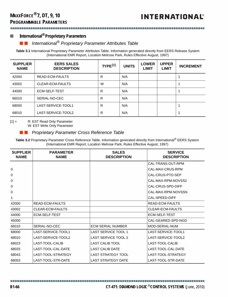
MAXXFORCE® 7, DT, 9, 10
■■■■■■■■■■■■■■■■■■■■■■■■■■■■■■■■■■■■■■■■■■■■■■■■■■■■■■■■■■■■■■■■■■■■■■■■■■■■■■■■■■■■■■■
PROGRAMMABLE PARAMETERS
■ International® Proprietary Parameters■ ■ International® Proprietary Parameter Attributes Table
[1] = R: EST Read Only ParameterW: EST Write Only Parameter
■ ■ Proprietary Parameter Cross Reference Table
Table 3.1 International Proprietary Parameter Attributes Table. Information generated directly from EERS Release System (International EMR Report, Location Melrose Park, Rules Effective August, 1997)
SUPPLIER NAME
EERS SALESDESCRIPTION TYPE[1] UNITS LOWER
LIMITUPPER LIMIT INCREMENT
42000 READ-ECM-FAULTS R N/A 1
43002 CLEAR-ECM-FAULTS W N/A 1
44000 ECM-SELF-TEST R N/A 1
66010 SERIAL-NO-CEC R N/A
68000 LAST-SERVICE-TOOL1 R N/A 1
68010 LAST-SERVICE-TOOL2 R N/A 1
Table 3.2 Proprietary Parameter Cross Reference Table. Information generated directly from International® EERS System (International EMR Report, Location Melrose Park, Rules Effective August, 1997)
SUPPLIER NAME
PARAMETERNAME
SALESDESCRIPTION
SERVICEDESCRIPTION
CAL-TRANS-OUT-RPM
0 CAL-MAX-CRUS-RPM
0 CAL-CRUS-PTO-SEP
0 CAL-MAX-RPM-NOVSS2
0 CAL-CRUS-SPD-DIFF
0 CAL-MAX-RPM-NOVSSN
1 CAL-SPEED-DIFF
42000 READ-ECM-FAULTS READ-ECM-FAULTS
43002 CLEAR-ECM-FAULTS CLEAR-ECM-FAULTS
44000 ECM-SELF-TEST ECM-SELF-TEST
45000 CAL-GEARED-SPD-NGD
66010 SERIAL-NO-CEC ECM SERIAL NUMBER MOD-SERIAL-NUM
68000 LAST-SERVICE-TOOL1 LAST SERVICE TOOL 1 LAST-SERVICE-TOOL1
68010 LAST-SERVICE-TOOL2 LAST SERVICE TOOL 2 LAST-SERVICE-TOOL2
68023 LAST-TOOL-CALIB LAST CALIB TOOL LAST-TOOL-CALIB
68033 LAST-TOOL-CAL-DATE LAST CALIB DATE LAST-TOOL-CAL-DATE
68043 LAST-TOOL-STRATEGY LAST STRATEGY TOOL LAST-TOOL-STRATEGY
68053 LAST-TOOL-STR-DATE LAST STRATEGY DATE LAST-TOOL-STR-DATE
■■■■■■■■■■■■■■■■■■■■■■■■■■■■■■■■■■■■■■■■■■■■■■■■■■■■■■■■■■■■■■■■■■■■■■■■■■■■■■■■■■■■■■■
B1-66 CT-471: DIAMOND LOGIC® CONTROL SYSTEMS (June, 2010)
MAXXFORCE® 7, DT, 9, 10
■■■■■■■■■■■■■■■■■■■■■■■■■■■■■■■■■■■■■■■■■■■■■■■■■■■■■■■■■■■■■■■■■■■■■■■■■■■■■■■■■■■■■■■
PROGRAMMABLE PARAMATERS
■ ■ Feature Name: Clear ECM-FaultsCLEAR-ECM-FAULTSCommand ECM to clear fault codes.
Other parameters which must be considered when programming this feature:None
■ ■ Feature Name: ECM Self-TestECM-SELF-TESTCommand ECM to perform diagnostic self-test.
Other parameters which must be considered when programming this feature:None
■ ■ Feature Name: ECM Compatibility DataPP LIST LEVELIndicates what powertrain control features are configured for this vehicle.
Other parameters which must be considered when programming this feature:None
■ ■ Feature Name: ECM Manufacturing DataMANUFACTURING DATESpecifies manufacturing date of this ECM.
The year, month, day, and hour of manufacture is displayed. Each of the separate fields uses two numbers. For example, the display “97013018” means this ECM was manufactured on January 30, 1997 at 6 PM.
SERIAL-NO-CECECM serial number.
H/W VERSIONECM Hardware level.
S/W STRATEGY VERSIONLevel of software functionality programmed into this ECM.
S/W CALIBRATION VERSIONCalibration level programmed into this ECM.
In general, calibration refers to the set of parameters used by the control system that are not programmable by the customer or by the factory (i.e. control system gains, out-of-range thresholds, ramp rates, etc,).
Other parameters which must be considered when programming this feature:None
■■■■■■■■■■■■■■■■■■■■■■■■■■■■■■■■■■■■■■■■■■■■■■■■■■■■■■■■■■■■■■■■■■■■■■■■■■■■■■■■■■■■■■■
CT-471: DIAMOND LOGIC® CONTROL SYSTEMS (October, 2010) B1-67
MAXXFORCE® 7, DT, 9, 10
■■■■■■■■■■■■■■■■■■■■■■■■■■■■■■■■■■■■■■■■■■■■■■■■■■■■■■■■■■■■■■■■■■■■■■■■■■■■■■■■■■■■■■■
PROGRAMMABLE PARAMETERS
■ ■ Feature Name: Programming TraceLAST-SERVICE-TOOL1Logs identification of last service tool used to modify a programmable parameter.
LAST-SERVICE-TOOL2Logs most recent date when a customer service tool was used to modify a programmable parameter.
LAST-TOOL-CALIBIdentifies identification of programming tool last used to modify engine calibration data. Also indicates locations of calibration parameters modified by the service tool.
LAST-TOOL-CAL-DATEDate when factory programming tool last downloaded calibration data.
LAST-TOOL-STRATEGYIdentifies factory programming tool last used to modify the engine control software. Also indicates memory locations modified in the control system software.
LAST-TOOL-STR-DATELogs most recent date when a programming tool downloaded control system software to the ECM.
Other parameters which must be considered when programming this feature:None
■ ■ Feature Name: Read ECM FaultsREAD-ECM-FAULTSQuery ECM memory for fault codes.
Other parameters which must be considered when programming this feature:None
■ ■ Feature Name: Software Parameter AuditsPP LIST CHECKSUMUsed by ECM to validate integrity of values programmed into memory by factory and/or customer.
S/W CALIBRATION CHECKSUMUsed by ECM to validate integrity of calibration data programmed into memory.
S/W STRATEGY CHECKSUMUsed by ECM to validate integrity of software instructions programmed into memory.
Other parameters which must be considered when programming this feature:None
■■■■■■■■■■■■■■■■■■■■■■■■■■■■■■■■■■■■■■■■■■■■■■■■■■■■■■■■■■■■■■■■■■■■■■■■■■■■■■■■■■■■■■■
B1-68 CT-471: DIAMOND LOGIC® CONTROL SYSTEMS (June, 2010)

MAXXFORCE® 11, 13
■■■■■■■■■■■■■■■■■■■■■■■■■■■■■■■■■■■■■■■■■■■■■■■■■■■■■■■■■■■■■■■■■■■■■■■■■■■■■■■■■■■■■■■
INTRODUCTION
Book 2: MaxxForce® 11 and 13
INTRODUCTIONThere are several other features available for OEM vehicles that are typically associated with truck equipment manufacturers (TEMs) or body builders. These inputs and outputs allow the body builder to configure the final vehicle with such features as auxiliary speed control inputs (also known in the industry as Power Take-Off (PTO), remote accelerator pedal, auxiliary engine shutdown, and a transfer case switch. These optional inputs and outputs can be wired up if required by the application. Some of these I/O were discussed in previous sections under different use cases. It is the responsibility of the OEM to determine which use case most closely corresponds to their vehicle and wire the truck up appropriately. The body builder inputs and outputs available to the OEM are:
• Remove Preset PTO Active Switch (RPRE)• Remote Variable PTO Active Switch (RVAR)• Resume/Accel Switch (RAS)• Set/Coast Switch (SCS)• Transfer Case Switch (XCS)• Remote Pedal Sensor (RPS)
In addition to these, a +5 Vdc and a ground reference are available for the Remote Pedal feature.
■■■■■■■■■■■■■■■■■■■■■■■■■■■■■■■■■■■■■■■■■■■■■■■■■■■■■■■■■■■■■■■■■■■■■■■■■■■■■■■■■■■■■■■
CT-471: DIAMOND LOGIC® CONTROL SYSTEMS (October, 2010) B2-1

MAXXFORCE® 11, 13
■■■■■■■■■■■■■■■■■■■■■■■■■■■■■■■■■■■■■■■■■■■■■■■■■■■■■■■■■■■■■■■■■■■■■■■■■■■■■■■■■■■■■■■
AUXILIARY ENGINE SPEED CONTROL
AUXILIARY ENGINE SPEED CONTROLThere are 3 different engine speed control features available for vehicle vocations:
• Preset Engine Speed Control• Variable Engine Speed Control• Mobile Variable Engine Speed Control
The first two features require a non-moving (stationary) vehicle for operation. The “Preset” feature always controls engine speed to a previously programmed value, while the “Variable” feature permits a desired engine speed to be selected via the in-cab or remote mounted switches. The “Mobile Variable” feature is the same as the “Variable” feature, with the exception that the vehicle can be moving or stationary during PTO operation.
All three Auxiliary Engine Speed Control modes require special programming and setup of programmable parameters covered in the Programmable Parameters section of Book 1. This section only covers the physical wiring and connections required for auxiliary engine speed control.
■ Preset Engine Speed ControlThis feature provides six predetermined engine speed settings (besides low idle) for equipment operation. Preset Engine Speed Control satisfies the majority of the intended engine speed control applications. Use Preset Engine Speed Control when a constant engine speed is required to operate equipment. In-cab engine speed controls (cruise control switches) can be used on a multiplexed vehicle. Remotely mounted controls can be hardwired into these body builder pins of the ECM. On non-multiplexed vehicles that require both the cruise control option as well as the preset engine speed control feature, you must utilize a Multiplex Signal Module (MSM) available from Navistar. As the operation is the same for in-cab or remotely mounted switches, the naming convention of SET/CRUISE and RESUME/ACCEL is used for both applications.
Typical operation of this system requires the operator to perform the following steps:1. Activate the system2. Select the desired engine speed using the SET/CRUISE or RESUME/ACCL switch. The
RESUME/ACCEL switch will increment the six predetermined engine speed settings; SET/CRUISE will decrement the six predetermined engine speed settings according to the following diagram.
dmd_0030
Standby M ode
Preset#1
Preset#2
Preset#3
Preset#4
Preset#5
Preset#6Set
Set
R eset
R esetSet
R eset
R eset R eset R eset
SetSetSet
■■■■■■■■■■■■■■■■■■■■■■■■■■■■■■■■■■■■■■■■■■■■■■■■■■■■■■■■■■■■■■■■■■■■■■■■■■■■■■■■■■■■■■■
B2-2 CT-471: DIAMOND LOGIC® CONTROL SYSTEMS (October, 2010)

MAXXFORCE® 11, 13
■■■■■■■■■■■■■■■■■■■■■■■■■■■■■■■■■■■■■■■■■■■■■■■■■■■■■■■■■■■■■■■■■■■■■■■■■■■■■■■■■■■■■■■
AUXILIARY ENGINE SPEED CONTROL
The desired engine speed set-point can be field programmed to any speed between low idle and high idle speed. Preset Engine Speed Control operates only while the vehicle is stationary. Manipulation of cab located sensor inputs (i.e., Neutral Safety, Service Brake, or Clutch Pedal) will cause the engine speed control to disengage.
The following table summarizes the operation of preset engine speed control. The columns are labeled with the switch being used. The first row discusses what happens when the switch contacts are momentarily closed. The second row discusses the effect of held switches (continuous contact) or multiple use of the same switch.
[1] = The held switch acts like the switch is being “hit” multiple times.
■ ■ In-Cab Operation of Preset Engine Speed Control (Multiplexed Vehicle Required)When control over engine speed is not needed outside the vehicle’s cab, the in-cab switches can be used to activate engine speed control and select the desired engine speed. Press the CRUISE “ON” Switch to enable engine speed control. Next, select the desired engine speed according to the value programmed for the parameter PTO RPM Ramp Rate. This acceleration limit should be programmed as required to minimize stress on auxiliary equipment drive links. Engine speed will be reduced to idle by any of the following actions:
• CRUISE “OFF” switch is pressed• Brake pedal is pressed• Clutch pedal is pressed• Automatic transmission is shifted out of neutral (NOT RECOMMENDED)
Note that these actions are always applicable for in-cab PTO Operation, regardless of the value programmed for the parameter “PTO IN-CAB CONTROL”. Only when engine speed is controlled by remote input signals and the cab interface is disabled will the engine speed be unaffected by the above actions.
Preset Engine Speed Control Switch Use
ON OFF SET/CRUISE RESUME/ACCEL BRAKE CLUTCH
Single Press (Momentary Contact)
Enables engine speed control
Disable engine speed control
Sets the desired engine speed to the “Set” Switch RPMPreset speeds 1-6
Sets the desired engine speed to the “Resume” Switch RPMPreset speeds 1-6
Deactivates engine speed control and establishes a standby state. Engine speed returns to low idle RPM.
Deactivates engine speed control and establishes a standby state. Engine speed returns to low idle RPM.
Held Switch (Continuous Contact)
Enables engine speed control
Enables engine speed control
Same [1] Same [1] The change in brake status establishes the standby state.
The change in driveline status establishes the standby state.
■■■■■■■■■■■■■■■■■■■■■■■■■■■■■■■■■■■■■■■■■■■■■■■■■■■■■■■■■■■■■■■■■■■■■■■■■■■■■■■■■■■■■■■
CT-471: DIAMOND LOGIC® CONTROL SYSTEMS (October, 2010) B2-3

MAXXFORCE® 11, 13
■■■■■■■■■■■■■■■■■■■■■■■■■■■■■■■■■■■■■■■■■■■■■■■■■■■■■■■■■■■■■■■■■■■■■■■■■■■■■■■■■■■■■■■
AUXILIARY ENGINE SPEED CONTROL
■ ■ Remote Operation of Preset Engine Speed Control - Multiplexed Vehicles or Non-Multiplexed Vehicles without Cruise Control
When control over engine speed is required from outside the vehicle’s cab, remote mounted switches must be used to turn on PTO engine speed control and select the desired engine speed. The diagram below illustrates how remotely located switches must be interfaced to the ECM to accomplish Preset PTO Engine Speed Control. This diagram does not show the cruise control switches wired up inside the cab on the multiplexed vehicle. Switch functionality remains the same as described for the in-cab located switches (see Preset Engine Speed Control Switch Use table).
A REMOTE PRESET PTO ON/OFF switch (RPRE) is required to remotely turn on the Preset Engine Speed Control. The desired engine speed is then selected using a remotely located SET/CRUISE or RESUME/ACCEL switch. Once a desired engine speed has been selected using one of these switches, engine speed will begin to increase. This rate of increase will be limited according to the value programmed in the parameter PTO RPM Ramp Rate. This acceleration limit should be programmed as required to minimize stress on auxiliary equipment power drive links.
WARNING: Shift of automatic transmission from neutral to forward or reverse gear while operating any PTO mode is not recommended; vehicle may lurch forward when transmission is placed in gear due to increased power output of the engine which is operating at the elevated engine speed.
WARNING: To avoid sudden, unexpected vehicle movement and possible personal injury:• Always fully set the parking brake when using the Preset PTO Engine Speed Control
Feature.• Do not abort the Preset Engine Speed Control Feature by shifting an automatic
transmission from neutral gear into a forward or reverse gear.• Turn off the engine when you leave the vehicle. Never leave the vehicle unattended
with the engine running.
dmd_0031
ECM248
223
252
ChassisConnector
RPRE
RAS
SCS
ResumeSwitch
SetSwitch
Preset SpeedActive Switch
+ 12Vdc(1Amp source)
MomentarySwitch
ToggleSwitch
■■■■■■■■■■■■■■■■■■■■■■■■■■■■■■■■■■■■■■■■■■■■■■■■■■■■■■■■■■■■■■■■■■■■■■■■■■■■■■■■■■■■■■■
B2-4 CT-471: DIAMOND LOGIC® CONTROL SYSTEMS (October, 2010)

MAXXFORCE® 11, 13
■■■■■■■■■■■■■■■■■■■■■■■■■■■■■■■■■■■■■■■■■■■■■■■■■■■■■■■■■■■■■■■■■■■■■■■■■■■■■■■■■■■■■■■
AUXILIARY ENGINE SPEED CONTROL
- Non-Multiplexed Vehicles with Cruise Control Option
If the OEM is incorporating the powertrain into a non-multiplexed vehicle and cruise control is to be an option, then the Navistar Multiplex Signal Module (MSM) must be used. In this case the MSM will be wired where the in-cab cruise control switches are wired, while the auxiliary engine speed control switches will be wired directly into the body builder pins of the Engine Control Module (ECM).
As before, a REMOTE PRESET PTO ON/OFF switch (RPRE) is required to remotely turn on the Preset Engine Speed Control. The desired engine speed is then selected using a remotely located SET/CRUISE or RESUME/ACCEL switch. Once a desired engine speed has been selected using one of these switches, engine speed will begin to increase. This rate of increase will be limited according to the value programed in the parameter PTO RPM Ramp Rate. This acceleration limit should be programmed as required to minimize stress on auxiliary equipment power drive links.
dmd_0032
ECM248
223
252
RPRE
RAS
SCS
ResumeSwitch
SetSwitch
Preset SpeedActive Switch
+ 12Vdc(1Amp source)
MomentarySwitch
ToggleSwitch
223248
Chassis Pocket(Connector #2)
Chassis Pocket(Connector #1)
Remote PTOSwitches
MSM
J1-7J1-8J1-5J1-6
Grey Pocket
J2-4
J2-9
Black Pocket
VIGNGNDCANHCANL
Ignition Switch
Off Run Crank
Batteries+ +
- -Engine / Chassis
GND
V (lgn)
Cruise Enable
Cruise Set/Coast & Resume/AcelIn Cab CruiseControl Switch
Resume/Accel
Set/Coast
V (lgn)
■■■■■■■■■■■■■■■■■■■■■■■■■■■■■■■■■■■■■■■■■■■■■■■■■■■■■■■■■■■■■■■■■■■■■■■■■■■■■■■■■■■■■■■
CT-471: DIAMOND LOGIC® CONTROL SYSTEMS (October, 2010) B2-5

MAXXFORCE® 11, 13
■■■■■■■■■■■■■■■■■■■■■■■■■■■■■■■■■■■■■■■■■■■■■■■■■■■■■■■■■■■■■■■■■■■■■■■■■■■■■■■■■■■■■■■
AUXILIARY ENGINE SPEED CONTROL
■ Variable Engine Speed ControlVariable Engine Speed Control permits a desired engine speed to be achieved between low idle and high idle speed even without use of the accelerator pedal or Remote Throttle. The switches that must be used to achieve this functionality are ON, OFF, SET/CRUISE, and RESUUME/ACCEL. These switches can be remote and/or cab mounted (cab mounted only on multiplexed vehicles). If only temporary increases in engine speed are needed, consider using Preset Engine Speed Control in combination with the Remote Throttle. On non-multiplexed vehicles that require both the Cruise Control option as well as the Preset Engine Speed Control feature, a Multiplex Signal Module (MSM) available from Navistar, must be utilized.
The following table summarizes the operation of Variable Engine Speed Control. Columns are labeled according to the switch being used, and interpretations include 1) the control system’s response when the toggle switch position is change by the operator, 2) the control system’s response when the switch contacts are momentarily closed, and 3) the effect of maintaining a switch in the closed (pressed) condition, and also multiple applications of the same switch.
[1] = Engine speed control stops only when there is a transition from one pedal state (pedal pressed or pedal released) to the other and only when the disable cab controls parameter is not selected.
[2] = The held switch acts like the switch is being “hit’” multiple times until the switch is released. When the RESUME switch is held closed, the engine speed will be commanded to accelerate. The standby state will be momentarily recognized. Then the engine speed will continue to accelerate.
Variable Engine Speed Control Switch Interpretations
ON OFF SET/CRUISE RESUME/ACCEL BRAKE CLUTCH
On/Off Switch (Toggle Switch)
Turns Engine Speed Control ON
Turns Engine Speed Control OFF
Not Applicable Not Applicable Not Applicable Not Applicable
Single Press (Momentary Contact)
Not Applicable Not Applicable Latch the current engine speed as the desired engine speed. Decrease engine speed by 25 RPM, if active.
Resume speed control function at the last desired engine speed. Increase engine speed by 25 RPM, if active.
Deactivate vehicle speed control and maintain standby state.(Pedal use returns the engine to the low idle speed.) [1]
Deactivate vehicle speed control and maintain standby state. (Pedal use returns the engine to the low idle speed.) [1]
Held Switch (Continuous Contact)
Not Applicable Not Applicable Decrease engine speed if engine speed control is active. [2]
Decrease engine speed if engine speed control is active. [2]
Any change in brake status establishes a standby state.[1]
Any change in driveline status establishes a standby state.[1]
■■■■■■■■■■■■■■■■■■■■■■■■■■■■■■■■■■■■■■■■■■■■■■■■■■■■■■■■■■■■■■■■■■■■■■■■■■■■■■■■■■■■■■■
B2-6 CT-471: DIAMOND LOGIC® CONTROL SYSTEMS (October, 2010)

MAXXFORCE® 11, 13
■■■■■■■■■■■■■■■■■■■■■■■■■■■■■■■■■■■■■■■■■■■■■■■■■■■■■■■■■■■■■■■■■■■■■■■■■■■■■■■■■■■■■■■
AUXILIARY ENGINE SPEED CONTROL
■ ■ In-Cab Operation of Variable Engine Speed Control (Multiplexed Vehicles only)In-cab located switches can be used to turn on engine speed control and select the desired engine speed. Press the CRUISE “ON” Switch to enable engine speed control. Next, select the desired engine speed using the SET/CRUISE switch. Then press RESUME/ACCEL or SET/CRUISE until the desired engine speed is achieved.
The accelerator pedal can be used, as well, to increase or decrease engine speed as desired; the desired engine speed will be maintained by the engine controller once a momentary press of the SET/CRUISE switch occurs. Once an initial engine operating speed is selected, a momentary press of the RESUME/ACCEL and/or SET/CRUISE switches will cause engine speed to increase or decrease by a small amount. This incremental amount can be used to fine tune the engine speed selected. Should speed control be interrupted (i.e., by the brake or the clutch switch), the RESUME/ACCEL switch can be pressed to return to the last engine speed set point. The engine’s acceleration rate will be limited according to the value programmed for the parameter PTO RPM Ramp Rate. This acceleration rate should be programmed as required to minimize stress on auxiliary equipment power drive links. Anytime Variable Engine Speed Control is active, the engine will maintain the selected speed until one of the following events occurs:
• CRUISE “OFF”switch is pressed• Brake pedal is pressed• Clutch pedal is pressed• Automatic transmission is shifted out of neutral (NOT RECOMMENDED)
Note that these actions are always applicable for in-cab PTO operation, regardless of the value programmed for the parameter PTO IN-CAB CONTROL. Only when engine speed is controlled by remote input signals and the cab interface is disabled will the engine speed be unaffected by the above actions.
WARNING: Shift of automatic transmission from neutral to forward or reverse gear while operating any PTO mode is not recommended; vehicle may lurch forward when transmission is placed in gear due to increased power output of the engine which is operating at the elevated engine speed.
WARNING: To avoid sudden, unexpected vehicle movement and possible personal injury:• Always fully set the parking brake when using the Preset PTO Engine Speed Control
Feature.• Do not abort the Preset Engine Speed Control Feature by shifting an automatic
transmission from neutral gear into a forward or reverse gear.• Turn off the engine when you leave the vehicle. Never leave the vehicle unattended with
the engine running.
■■■■■■■■■■■■■■■■■■■■■■■■■■■■■■■■■■■■■■■■■■■■■■■■■■■■■■■■■■■■■■■■■■■■■■■■■■■■■■■■■■■■■■■
CT-471: DIAMOND LOGIC® CONTROL SYSTEMS (October, 2010) B2-7

MAXXFORCE® 11, 13
■■■■■■■■■■■■■■■■■■■■■■■■■■■■■■■■■■■■■■■■■■■■■■■■■■■■■■■■■■■■■■■■■■■■■■■■■■■■■■■■■■■■■■■
AUXILIARY ENGINE SPEED CONTROL
■ ■ Remote Operation of Variable Engine Speed Control
- Multiplexed Vehicles or Non-Multiplexed Vehicles without Cruise Control When control over engine speed is required from outside the vehicle’s cab, remote mounted switches must be used to turn on PTO engine speed control and select the desired engine speed. The next diagram illustrates how remotely located switches must be interfaced to the ECM to accomplish Variable Engine Speed Control. Switch functionality remains the same as described for the in-cab located switches (see Variable Engine Speed Control Switch Interpretations table).
The Remote Throttle can be used as well to increase or decrease engine speed as desired. The desired engine speed will be maintained by the engine controller once a momentary press of the SET/COAST switch occurs. Once an initial engine operating speed is selected, a momentary press of the RESUME/ACCEL and/or SET/COAST switches will cause engine speed to increase or decrease by a small amount. This incremental amount can be used to fine tune the engine speed selected. Should speed control be interrupted (i.e. by the brake or the clutch switch), the RESUME/ACCEL switch can be pressed to return to the last engine speed set point. The engine’s acceleration rate will be limited according to the value programmed for the parameter PTO RMP Ramp Rate. This acceleration rate should be programmed as required to minimize stress on auxiliary equipment power drive links. Any time Variable Engine Speed Control is active, the engine will maintain the selected speed until one of the following events occur:
• CRUISE “OFF” switch is pressed• Brake pedal is pressed• Clutch pedal is pressed• Automatic transmission is shifted out of neutral (NOT RECOMMENDED)
CAUTION: Be aware that on multiplexed vehicles, the Remote Set Switch and Remote Resume Switch are connected in parallel (logic ‘OR-ed’) with the cab-mounted SET/CRUISE and RESUME/ACCEL switches respectively. This means that once preset Variable PTO Engine Speed Control has been placed in “standby” on-mode (by pressing either the in-cab located CRUISE ON switch, or the remotely located REMOTE VARIABLE PTO ON switch), the desired engine speed can be modified both from within the cab or from the remote located PTO Engine Speed Control switches. This is ALWAYS TRUE, even when the PTO MODE parameter is programmed for REMOTE OPERATION ONLY.
■■■■■■■■■■■■■■■■■■■■■■■■■■■■■■■■■■■■■■■■■■■■■■■■■■■■■■■■■■■■■■■■■■■■■■■■■■■■■■■■■■■■■■■
B2-8 CT-471: DIAMOND LOGIC® CONTROL SYSTEMS (October, 2010)
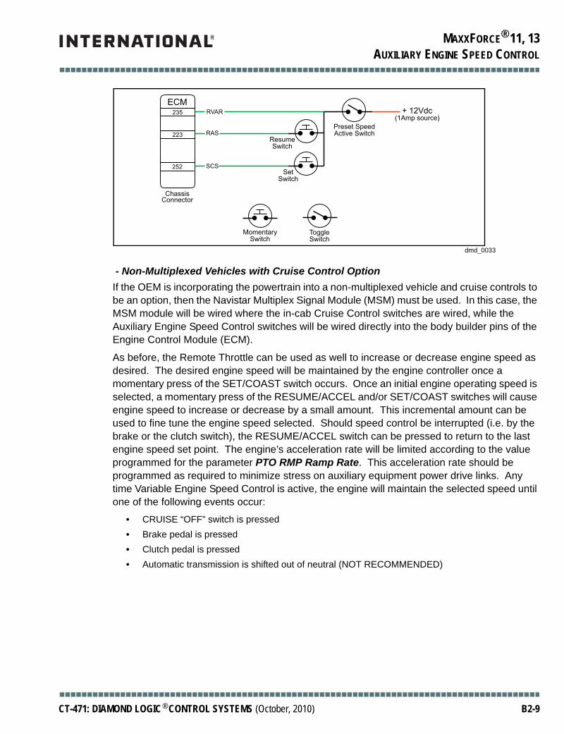
MAXXFORCE® 11, 13
■■■■■■■■■■■■■■■■■■■■■■■■■■■■■■■■■■■■■■■■■■■■■■■■■■■■■■■■■■■■■■■■■■■■■■■■■■■■■■■■■■■■■■■
AUXILIARY ENGINE SPEED CONTROL
- Non-Multiplexed Vehicles with Cruise Control Option If the OEM is incorporating the powertrain into a non-multiplexed vehicle and cruise controls to be an option, then the Navistar Multiplex Signal Module (MSM) must be used. In this case, the MSM module will be wired where the in-cab Cruise Control switches are wired, while the Auxiliary Engine Speed Control switches will be wired directly into the body builder pins of the Engine Control Module (ECM).
As before, the Remote Throttle can be used as well to increase or decrease engine speed as desired. The desired engine speed will be maintained by the engine controller once a momentary press of the SET/COAST switch occurs. Once an initial engine operating speed is selected, a momentary press of the RESUME/ACCEL and/or SET/COAST switches will cause engine speed to increase or decrease by a small amount. This incremental amount can be used to fine tune the engine speed selected. Should speed control be interrupted (i.e. by the brake or the clutch switch), the RESUME/ACCEL switch can be pressed to return to the last engine speed set point. The engine’s acceleration rate will be limited according to the value programmed for the parameter PTO RMP Ramp Rate. This acceleration rate should be programmed as required to minimize stress on auxiliary equipment power drive links. Any time Variable Engine Speed Control is active, the engine will maintain the selected speed until one of the following events occur:
• CRUISE “OFF” switch is pressed• Brake pedal is pressed• Clutch pedal is pressed• Automatic transmission is shifted out of neutral (NOT RECOMMENDED)
dmd_0033
ECM235
223
252
ChassisConnector
RVAR
RAS
SCS
ResumeSwitch
SetSwitch
Preset SpeedActive Switch
+ 12Vdc(1Amp source)
MomentarySwitch
ToggleSwitch
■■■■■■■■■■■■■■■■■■■■■■■■■■■■■■■■■■■■■■■■■■■■■■■■■■■■■■■■■■■■■■■■■■■■■■■■■■■■■■■■■■■■■■■
CT-471: DIAMOND LOGIC® CONTROL SYSTEMS (October, 2010) B2-9

MAXXFORCE® 11, 13
■■■■■■■■■■■■■■■■■■■■■■■■■■■■■■■■■■■■■■■■■■■■■■■■■■■■■■■■■■■■■■■■■■■■■■■■■■■■■■■■■■■■■■■
AUXILIARY ENGINE SPEED CONTROL
■ Engine Speed Control for Mobile ApplicationsThis section discusses the Variable Mobile Engine Speed Control. Variable Mobile Engine Speed Control functions like cruise control, except that the engine speed (instead of the vehicle speed) is being controlled. Mobile control can be performed only below a programmed maximum vehicle speed. The default vehicle speed limit is 20 MPH.
Functionality for mobile control is identical to the functionality described previously for Variable PTO Engine Speed Control, with the exception that the vehicle is no longer required to be stationary; vehicle movement is permitted up to a maximum threshold, specified by the programmable parameter PTO Max Veh Speed.
When the specified vehicle speed limit is exceeded, Variable Engine Speed Control will be placed in the “standby” mode of operation and engine speed will return to idle. Pressing the RESUME/ACCEL switch after the vehicle speed has slowed to a value less than the programmed maximum speed limit, will reestablish engine speed control at the previously selected engine speed. Changes in the status of the brake and clutch switches will also return the engine to its idle speed.
Switch functionality remains the same as described for the Variable Stationary Engine Speed Control switches (see Variable Engine Speed Control Switch Interpretations table).
Press the CRUISE ON switch to turn on Engine Speed Control. Press the SET/CRUISE switch to select an engine speed. Then press RESUME/ACCEL or SET/CRUISE until the desired engine speed is achieved. Momentary presses of the RESUME/ACCEL and SET/CRUISE switches will cause the engine speed to increase or decrease by a small amount. This incremental amount can be
dmd_0034
235
223
252
RVAR
RAS
SCS
ResumeSwitch
SetSwitch
Preset SpeedActive Switch
+ 12Vdc(1Amp source)
MomentarySwitch
ToggleSwitch
223248
Chassis Pocket(Connector #2)
Chassis Pocket(Connector #1)
Remote PTOSwitches
MSM
J1-7J1-8J1-5J1-6
Grey Pocket
J2-4
J2-9
Black Pocket
VIGNGNDCANHCANL
Ignition Switch
Off Run Crank
Batteries+ +
- -Engine / Chassis
GND
V (lgn)
Cruise Enable
Cruise Set/Coast & Resume/AcelIn Cab CruiseControl Switch
Resume/Accel
Set/Coast
V (lgn)
■■■■■■■■■■■■■■■■■■■■■■■■■■■■■■■■■■■■■■■■■■■■■■■■■■■■■■■■■■■■■■■■■■■■■■■■■■■■■■■■■■■■■■■
B2-10 CT-471: DIAMOND LOGIC® CONTROL SYSTEMS (October, 2010)

MAXXFORCE® 11, 13
■■■■■■■■■■■■■■■■■■■■■■■■■■■■■■■■■■■■■■■■■■■■■■■■■■■■■■■■■■■■■■■■■■■■■■■■■■■■■■■■■■■■■■■
TRANSFER CASE / SPLIT SHAFT
used to fine tune the engine speed selected. Should speed control be interrupted by the brake or the clutch switches, press the RESUME/ACCEL switch to return to the last engine speed set point. The engine’s acceleration will be limited to the PTO RPM Ramp Rate. The acceleration limit can be set to reduce the stress on the auxiliary equipment power couplings.
TRANSFER CASE / SPLIT SHAFTThis section describes the Transfer Case/Split Shaft feature and its applications. This feature is used in conjunction with Engine Speed Control and is targeted for applications that use a transfer case or auxiliary driveshaft. The auxiliary drive unit is often connected to a pump that performs vacuum functions (i.s. sewage removal truck or fire pumps).
■ Transfer Case Switch OperationThe transfer case status switch must be in the proper state indicating that it is “OK” to operate. The transfer case status switch input is provided as a safety interlock feature and must be wired as shown in the next diagram. The purpose of the transfer case input is to inhibit the system from entering engine speed control mode if the transfer case is operating in driveline mode versus split shaft mode. The transfer case status switch must be wired such that when the transfer case is in split shaft mode, pin C-11 of the ECM sees 12 volts.
■ EPG Driveline ModeThis parameter indicates how the driveline disengagement signal should be interpreted by the ECM and is programmable by Navistar, Inc. only.
• 0: NEUTRAL OPERATION, driveline must be disengaged at all times for operation of the split shaft feature.
• 1: SPLIT SHAFT, a transition in driveline status will cause the split shaft feature to be deactivated
■ Wheel Based Vehicle SpeedIf the system is configured to function in Split Shaft mode (EPG driveline mode parameter equals SPLIT SHAFT), then the engine ECM must receive wheel based vehicle speed from a brake system electronic control unit (ECU). This message (PGN 65265, bytes 2 and 3) must be broadcast by the brake system over the Public J1939 datalink. At this time, only one brake system supports this message, the Bendix EC-30. The availability of this parameter for the EC-30 system is currently a programmable feature. This programmable feature must be enabled for the EPG system to function; otherwise, it will not allow the system to enter into Engine Speed Control. If the brake system ECU broadcasts the wheel based vehicle speed parameter as being 0 mph, then it will allow the system to function. This is a safety interlock feature to ensure that the vehicle is not moving while the system is functiong in Split Shaft mode.
■■■■■■■■■■■■■■■■■■■■■■■■■■■■■■■■■■■■■■■■■■■■■■■■■■■■■■■■■■■■■■■■■■■■■■■■■■■■■■■■■■■■■■■
CT-471: DIAMOND LOGIC® CONTROL SYSTEMS (October, 2010) B2-11

MAXXFORCE® 11, 13
■■■■■■■■■■■■■■■■■■■■■■■■■■■■■■■■■■■■■■■■■■■■■■■■■■■■■■■■■■■■■■■■■■■■■■■■■■■■■■■■■■■■■■■
REMOTE THROTTLE
REMOTE THROTTLEThe Remote Throttle Control functions like an additional accelerator pedal or hand throttle. Remote throttles provide equipment operators with direct control over engine speed from a location outside of the vehicle cab. By using a potentiometer, a remote throttle is useful when an infinitely variable range of engine speeds is desired to operate equipment. Remote throttle can be used to provide temporary increases in engine speed when either Preset or Variable Engine Speed Control is in use (i.e. enable via either RPRE or RVAR enable switches listed in the Introduction).
The hand and/or foot actuated potentiometer can be located on one or more locations on the vehicle. Increasing or decreasing the voltage from the potentiometer will result in a corresponding increase or decrease in engine speed (similar to stepping on or releasing the accelerator foot pedal in the vehicle cab). Navistar provides many kits to make the selection of a remote pedal easier. It is not required to use Navistar supplied parts, but they are the only parts validated to function. Use of other parts is at the OEM’s discretion.
Note: To be noticed by the Engine Control System, the engine speed requested by the Remote Throttle must exceed the engine speed requested by the cab accelerator pedal and other engine speed control requests. Reason: The highest engine speed requested becomes the engine speed commanded to the engine.
Use of either the Remote Preset PTO Switch or Remote Variable PTO Switch is required to activate or deactivate the Remote Throttle and the Engine Control System must be programmed to accept the Remote Throttle input. Use spring loaded designs for throttle devices so that the engine returns to idle when the throttle is released.
Note: The only way the Remote Throttle Control System can be disabled is to turn it off with the switch previously used to turn it on.
The programmable parameter PTO Remote Pedal must be programmed to “1” to enable operation of the Remote Throttle input. Also, the maximum engine speed permitted when operating with the Remote Throttle will be limited to the value programmed for PTO MAX RPM.
dmd_0035
ECM235
223
252
Chassis Pocket(Connector #2)
RVAR
RAS
SCS
ResumeSwitch
SetSwitch
VariableSpeed Active
Switch
MomentarySwitch
ToggleSwitch
210
+ 12Vdc(1Amp source)
XCS
SystemEnable
TransferCase Switch
■■■■■■■■■■■■■■■■■■■■■■■■■■■■■■■■■■■■■■■■■■■■■■■■■■■■■■■■■■■■■■■■■■■■■■■■■■■■■■■■■■■■■■■
B2-12 CT-471: DIAMOND LOGIC® CONTROL SYSTEMS (October, 2010)
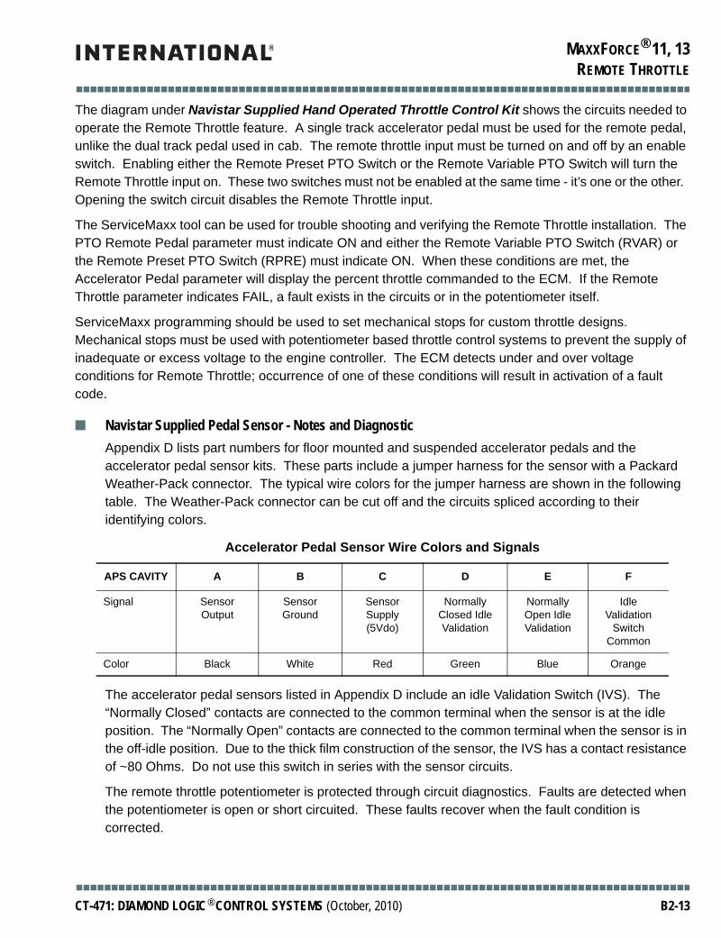
MAXXFORCE® 11, 13
■■■■■■■■■■■■■■■■■■■■■■■■■■■■■■■■■■■■■■■■■■■■■■■■■■■■■■■■■■■■■■■■■■■■■■■■■■■■■■■■■■■■■■■
REMOTE THROTTLE
The diagram under Navistar Supplied Hand Operated Throttle Control Kit shows the circuits needed to operate the Remote Throttle feature. A single track accelerator pedal must be used for the remote pedal, unlike the dual track pedal used in cab. The remote throttle input must be turned on and off by an enable switch. Enabling either the Remote Preset PTO Switch or the Remote Variable PTO Switch will turn the Remote Throttle input on. These two switches must not be enabled at the same time - it’s one or the other. Opening the switch circuit disables the Remote Throttle input.
The ServiceMaxx tool can be used for trouble shooting and verifying the Remote Throttle installation. The PTO Remote Pedal parameter must indicate ON and either the Remote Variable PTO Switch (RVAR) or the Remote Preset PTO Switch (RPRE) must indicate ON. When these conditions are met, the Accelerator Pedal parameter will display the percent throttle commanded to the ECM. If the Remote Throttle parameter indicates FAIL, a fault exists in the circuits or in the potentiometer itself.
ServiceMaxx programming should be used to set mechanical stops for custom throttle designs. Mechanical stops must be used with potentiometer based throttle control systems to prevent the supply of inadequate or excess voltage to the engine controller. The ECM detects under and over voltage conditions for Remote Throttle; occurrence of one of these conditions will result in activation of a fault code.
■ Navistar Supplied Pedal Sensor - Notes and DiagnosticAppendix D lists part numbers for floor mounted and suspended accelerator pedals and the accelerator pedal sensor kits. These parts include a jumper harness for the sensor with a Packard Weather-Pack connector. The typical wire colors for the jumper harness are shown in the following table. The Weather-Pack connector can be cut off and the circuits spliced according to their identifying colors.
The accelerator pedal sensors listed in Appendix D include an idle Validation Switch (IVS). The “Normally Closed” contacts are connected to the common terminal when the sensor is at the idle position. The “Normally Open” contacts are connected to the common terminal when the sensor is in the off-idle position. Due to the thick film construction of the sensor, the IVS has a contact resistance of ~80 Ohms. Do not use this switch in series with the sensor circuits.
The remote throttle potentiometer is protected through circuit diagnostics. Faults are detected when the potentiometer is open or short circuited. These faults recover when the fault condition is corrected.
Accelerator Pedal Sensor Wire Colors and Signals
APS CAVITY A B C D E F
Signal Sensor Output
Sensor Ground
Sensor Supply (5Vdo)
Normally Closed Idle Validation
Normally Open Idle Validation
Idle Validation
Switch Common
Color Black White Red Green Blue Orange
■■■■■■■■■■■■■■■■■■■■■■■■■■■■■■■■■■■■■■■■■■■■■■■■■■■■■■■■■■■■■■■■■■■■■■■■■■■■■■■■■■■■■■■
CT-471: DIAMOND LOGIC® CONTROL SYSTEMS (October, 2010) B2-13

MAXXFORCE® 11, 13
■■■■■■■■■■■■■■■■■■■■■■■■■■■■■■■■■■■■■■■■■■■■■■■■■■■■■■■■■■■■■■■■■■■■■■■■■■■■■■■■■■■■■■■
REMOTE THROTTLE
New designs incorporating the accelerator pedal sensor must include their own return springs to ensure that the sensor reurns to the idle position when the control is released. The sensor’s internal stops must not be used to limit the travel of its drive mechanism. To make sure the sensor always returns to the idle position, pre-load the internal return spring by 15.2 degrees. Another reason to preload the return spring in this manner is that the voltage output from the sensor will fall into the out of range low diagnostic region if the sensor is not pre-loaded by 15.2 degress of travel. Sensors that are disconnected from the drive mechanism will generate a diagnostic code. The maximum range of travel applied to the acceleraor pedal must be limited to a maximum of 52.3 degrees beyond 15.2 degrees pre-load for the idle position. For additional information, see SAE recommended practice “J1843, Accelerator Pedal Position Sensor for Use with Electronic Controls in Medium and Heavy Duty Vehicle Applications”.
■ Navistar Supplied Hand Operated Throttle Control KitSee Appendix D for hand operated throttle parts list options.
dmd_0036
ECM248
223
252
RPRE
RAS
SCS
ResumeSwitch
SetSwitch
Preset SpeedActive Switch
+ 12Vdc(1Amp source)
MomentarySwitch
ToggleSwitch
124
137
Chassis Pocket(Connector #2)
Chassis Pocket(Connector #1)
113
VREF
RPS
SIG RTN
235 RVAREither or Wiring
■■■■■■■■■■■■■■■■■■■■■■■■■■■■■■■■■■■■■■■■■■■■■■■■■■■■■■■■■■■■■■■■■■■■■■■■■■■■■■■■■■■■■■■
B2-14 CT-471: DIAMOND LOGIC® CONTROL SYSTEMS (October, 2010)

MAXXFORCE® 11, 13
■■■■■■■■■■■■■■■■■■■■■■■■■■■■■■■■■■■■■■■■■■■■■■■■■■■■■■■■■■■■■■■■■■■■■■■■■■■■■■■■■■■■■■■
REMOTE ENGINE START / STOP
REMOTE ENGINE START / STOPThis section describes the circuit modifications necessary to stop and start the engine from a remote location. Modifications that emplement remote start must also implement remote stop. When remote stop is implemented, all ignition sources to the engine control system must be interrupted.
CAUTION: Navistar does not suggest adding a remote start on vehicles with manual transmissions. The following modifications are suggestions only and do not take into account any interlocking that might be needed to maintain safe vehicle operation. It is our belief that safe modifications to start/stop circuitry will vary with the truck application and should be the responsibility of the party making the modification.
dmd_0009
dmd_0010
12V Relay
NC
NO
A13DH K97UA
Momentary Switch
To Igntitionpost ofKeyswtich
Engine Control Module
Dotted Lines denoteItems supplied by Body/Equipment Manfacturer
Ignition
A13DH K97H Pin X131 Vign
J13C
Momentary Switch
Relay
NC
NO
Dotted Lines denoteItems supplied by Body/
Equipment Manfacturer
J17 To Sta
Rela
To Fuse
Block
A13C
A17
Passthru Dash
Connector
Pin 15
Passthru Dash
Connector
Pin 8
From Start
Post of
Keyswitch
From
Igniton
■■■■■■■■■■■■■■■■■■■■■■■■■■■■■■■■■■■■■■■■■■■■■■■■■■■■■■■■■■■■■■■■■■■■■■■■■■■■■■■■■■■■■■■
CT-471: DIAMOND LOGIC® CONTROL SYSTEMS (October, 2010) B2-15

MAXXFORCE® 11, 13
■■■■■■■■■■■■■■■■■■■■■■■■■■■■■■■■■■■■■■■■■■■■■■■■■■■■■■■■■■■■■■■■■■■■■■■■■■■■■■■■■■■■■■■
REMOTE ENGINE START / STOP
THIS PAGE INTENTIONALLY LEFT BLANK
■■■■■■■■■■■■■■■■■■■■■■■■■■■■■■■■■■■■■■■■■■■■■■■■■■■■■■■■■■■■■■■■■■■■■■■■■■■■■■■■■■■■■■■
B2-16 CT-471: DIAMOND LOGIC® CONTROL SYSTEMS (October, 2010)

■■■■■■■■■■■■■■■■■■■■■■■■■■■■■■■■■■■■■■■■■■■■■■■■■■■■■■■■■■■■■■■■■■■■■■■■■■■■■■■■■■■■■■■
APPENDIX A
APPENDIX A
■ Diagnostic Service Tools
The ServiceMaxx Software is the primary International® EZ TECH™ service tool.
Diagnostic service tools are available from your International® Dealer. The following kits apply the most to electrical diagnosis and engine control system feature programming:
ZTSE4357 Digital Multimeter
ZTSE4444B EZ-Tech™ IC4 COM Interface
ZTSE4505D Breakout Harness Kit
ZTSE4282 Crimping Tool Set
ZTSE4403 Terminal Release Tool Kit
ZTSE4443 Terminal Extraction Kit
ZTSE4496 Terminal Repair Kit
J-45067 EZ-Tech™ Electronic Service Tool
■■■■■■■■■■■■■■■■■■■■■■■■■■■■■■■■■■■■■■■■■■■■■■■■■■■■■■■■■■■■■■■■■■■■■■■■■■■■■■■■■■■■■■■
CT-471: DIAMOND LOGIC® CONTROL SYSTEMS (October, 2010) Appendix A-1

■■■■■■■■■■■■■■■■■■■■■■■■■■■■■■■■■■■■■■■■■■■■■■■■■■■■■■■■■■■■■■■■■■■■■■■■■■■■■■■■■■■■■■■
APPENDIX A
THIS PAGE INTENTIONALLY LEFT BLANK
■■■■■■■■■■■■■■■■■■■■■■■■■■■■■■■■■■■■■■■■■■■■■■■■■■■■■■■■■■■■■■■■■■■■■■■■■■■■■■■■■■■■■■■
Appendix A-2 CT-471: DIAMOND LOGIC® CONTROL SYSTEMS (October, 2010)

■■■■■■■■■■■■■■■■■■■■■■■■■■■■■■■■■■■■■■■■■■■■■■■■■■■■■■■■■■■■■■■■■■■■■■■■■■■■■■■■■■■■■■■
APPENDIX B
APPENDIX B
■ References And Service PublicationsPublications for diagnosing and repairing International® Electronic Engines are available to assist diagnosis and repair of the engine control system electronics. The circuit diagram books can be valuable aids in diagnosing and repairing electrical and electronic problems. The electrical trouble shooting guides discuss terminal crimping, connector repair and the tools required to perform repairs.
International® DT 466E and 530E Manuals
EGES 175-1 Diagnostic manual
EGES 215 Diagnostic manual (ESN 1194039-above)
EGED 180-2 Hard start diagnostics form
EGED 185-1 Electronic control diagnostics form
EGES 220 Hard start diagnostics form (ESN 1194039-above)
EGES 225 Electronic control diagnostics form (ESN 1194039-above)
EGES 160-2 Service manual (ESN 931164-1205049)
EGES 210-1 Service manual (ESN 1194039-above)
1171734R7 466E Operations manual
1171735R5 530E Operations manual
1171764R2 530E Green Diesel Operations manual
International® DT 466, DT 530 and HT 530 Manuals 2000 and Later (Without EGR)
EGES 215 Diagnostic manual
EGED 220 Hard start diagnostics form
EGED 225 Electronic control diagnostics form
EGES 210-1 Service manual
1171753R3 DT 466 Operations manual
1171755R3 DT 530 and HT 530 Operations manual
■■■■■■■■■■■■■■■■■■■■■■■■■■■■■■■■■■■■■■■■■■■■■■■■■■■■■■■■■■■■■■■■■■■■■■■■■■■■■■■■■■■■■■■
CT-471: DIAMOND LOGIC® CONTROL SYSTEMS (October, 2010) Appendix B-1

■■■■■■■■■■■■■■■■■■■■■■■■■■■■■■■■■■■■■■■■■■■■■■■■■■■■■■■■■■■■■■■■■■■■■■■■■■■■■■■■■■■■■■■
APPENDIX B
International® DT 466, DT 570 and HT 570 Manuals 2004 – 2006 (With EGR)
EGES 265-1 Diagnostics manual
EGED 285 Hard start diagnostics form
EGED 290 Electronic control diagnostics form
EGED 270 Service manual
1171809R5 DT 466, DT 570, and HT 570 Operations manual
1171840R1 DT 466 Green Diesel Operations manual
MaxxForce® DT, MaxxForce® 9 and MaxxForce® 10 Manuals 2007 and Later (With EGR)
EGES 335 Diagnostic manual
EGED 375 Hard start diagnostics form
EGED 380 Performance diagnostics form
EGES 385 Electronic control diagnostics form
EGES 370 Service manual
1171895R1 Operations manual
MaxxForce®11 and MaxxForce®13 Manuals 2010
EGES 470 Diagnostic manual
EGES 465 Service manual
EGED 425 Performance diagnostics form
■■■■■■■■■■■■■■■■■■■■■■■■■■■■■■■■■■■■■■■■■■■■■■■■■■■■■■■■■■■■■■■■■■■■■■■■■■■■■■■■■■■■■■■
Appendix B-2 CT-471: DIAMOND LOGIC® CONTROL SYSTEMS (October, 2010)

■■■■■■■■■■■■■■■■■■■■■■■■■■■■■■■■■■■■■■■■■■■■■■■■■■■■■■■■■■■■■■■■■■■■■■■■■■■■■■■■■■■■■■■
APPENDIX C
APPENDIX C
■ ATA Data Link SupportNOTE: ATA support is obsolete. Not all diagnostic features are supported with ATA.The parameters transmitted by the system over the ATA data link are reviewed below in Table . The parameters are defined by SAE Recommended Practice J1587. For information regarding MIDs, PIDs and their content please refer to Appendix C2, SAE Recommended Practice J1587.
■ ■ EECM Transmitted ATA Parameters – V7.0Appendix C.1 – EECM TRANSMITTED ATA PARAMETERS – V7.0
PARAMETER NAME(Units) PID FREQUENCY
(Hz)DATA LENGTH
(bytes) NOTES[1]
Retarder Inhibit Status 62 1.0 1 10
Torque Limiting Factor (%) 68 1.0 1 1
Two-Speed Axle Switch Status 69 1.0 1
Idle Shutdown Timer Status 71 1.0 1 16
Auxiliary Water Pump Pressure (psi) 73 1.0 1 18
Maximum Road Speed Limit (mph) 74 on request 1 3,11
Road Speed Limit Status 83 1.0 1 11
Road Speed (mph) 84 10.0 1 5
Cruise Control Status 85 5.0 1 12
Cruise Control Set Speed (mph) 86 0.1 1 12
Cruise Control High Set Limit (mph) 87 on request 1 3,12
Cruise Control Low Set Limit (mph) 88 on request 1 3,12
Power Take off Status 89 1.0 1 8
Percent Accelerator Pedal Position (%) 91 10.0 1 5
Percent Engine Load (%) 92 10.0 1
Engine Oil Pressure (psig) 100 1.0 1 5,9
Boost Pressure (psig) 102 1.0 1 5
Barometric Pressure (psia) 108 1.0 1 5
Engine Coolant Temperature (°F) 110 1.0 1 5
Engine Coolant Level (%) 111 0.1 1 1,9
Engine Retarder Status 121 5.0 1 10
■■■■■■■■■■■■■■■■■■■■■■■■■■■■■■■■■■■■■■■■■■■■■■■■■■■■■■■■■■■■■■■■■■■■■■■■■■■■■■■■■■■■■■■
CT-471: DIAMOND LOGIC® CONTROL SYSTEMS (October, 2010) Appendix C-1

■■■■■■■■■■■■■■■■■■■■■■■■■■■■■■■■■■■■■■■■■■■■■■■■■■■■■■■■■■■■■■■■■■■■■■■■■■■■■■■■■■■■■■■
APPENDIX C
[1] = 1. SAE J1587 RP definition is amended as described in Appendix A of IF36 Interface Requirements Specification2. The details of diagnostic messages and responses are discussed in section 3.3.1.2 ATA Diagnostic Data of the IF36 Interface Requirements Specification3. Value may vary from the value programmed as a result of some error conditions. The value will always reflect the operating parameters of the EECM
Engine Crank InhibitTorque Curve Selection Switch StatusEngine Fan Control StatusRadiator Shutter Enable StatusAir Conditioning Demand Status[Auxiliary Input and Output Status #2]
154 1.0 2 1,17
Remote PTO Interface StatusElectronic Pressure Governor StatusElectronic Pressure Governor Mode Indicator[Auxiliary Input and Output Status #1]
155 1.0 2 1,14
Injection Control Pressure (Mpa)[Lubrication Rail Pressure]
164 1.0 2 5
Rated Horsepower (HP)[Rated Engine Power]
166 on request/on change
2 3,7
Battery Voltage (Volts)[Battery Potential Voltage]
168 1.0 2 5
Ambient Air Temperature (°F) 171 0.1 2 5
Engine Oil Temperature (°F) 175 1.0 2 5
Fuel Rate (gal/sec) 183 5.0 2
Power Take Off Set Speed (rpm) 187 0.1 2 4,14,15
Idle Engine Speed (rpm) 188 on request/0.1 2 1,3,6
Rated Engine Speed (rpm) 189 on request 2 3,7
Engine Speed (rpm) 190 10.0 2
Transmission Output Shaft Speed (rpm) 191 10.0 2 5
Transmitter System Diagnostic Code Table 194 on request/1.0 variable 2
Diagnostic Data/Count Clear Response 196 on request variable 2
Vehicle Identification Number 237 on request 17
Change Reference Number 240 on request 9 1
Component Identification 243 on request 17 1
Total Miles (miles) 245 0.1 4
Total Engine Hours (hours) 247 on request 4
Total Fuel Used (gal) 250 on request 4
Appendix C.1 – EECM TRANSMITTED ATA PARAMETERS – V7.0 (Continued)
PARAMETER NAME(Units) PID FREQUENCY
(Hz)DATA LENGTH
(bytes) NOTES[1]
■■■■■■■■■■■■■■■■■■■■■■■■■■■■■■■■■■■■■■■■■■■■■■■■■■■■■■■■■■■■■■■■■■■■■■■■■■■■■■■■■■■■■■■
Appendix C-2 CT-471: DIAMOND LOGIC® CONTROL SYSTEMS (October, 2010)

■■■■■■■■■■■■■■■■■■■■■■■■■■■■■■■■■■■■■■■■■■■■■■■■■■■■■■■■■■■■■■■■■■■■■■■■■■■■■■■■■■■■■■■
APPENDIX C
4. Values will reflect the engine speed commanded for PTO use by the Preset or Variable SCCS inputs5. Not broadcast when signal fault is detected6. Broadcast at 0.1 Hz rate until Idle Engine Speed stabilizes at N_LIDLE[PP]7 Broadcast immediately following a EECM power-up sequence and then broadcast as changes occur8 Only broadcast when the DDS signal is enabled
9. Only broadcast when Engine Warning/Protection System is enabled
10. Only broadcast when Vehicle Retarder is enabled11. Only broadcast when Road Speed Limiting is enabled12. Only broadcast when Cruise Control is enabled13. Only broadcast when Exhaust Back Pressure Control is enabled14. Only broadcast when remote PTO or Electronic Pressure Governor is enabled15. Only broadcast when in-cab PTO is enabled16. Only broadcast when Idle Shutdown Timer is enabled17. Only broadcast when Engine Fan Control, Radiator Shutter Enable, Service Interval Lamp, or TCSS is enabled18. Only broadcast when Electronic Pressure Governor is enabled[ ] Indicates J1587 description
■ ■ Appendix C.2 – Amendments to SAE J1587 RP DefinitionsPID 111, Engine Coolant Level:
A constant value of 100 percent shall be transmitted as long as the sensor determines that there is engine coolant. When the sensor determines that there is no engine coolant (or insufficient coolant level), then the value provided in PID 111 shall be 0 percent.
PID 62, Retarder Inhibit Status:
62 a; where a = Retarder Inhibit Status
Parameter Data Length: 1 CharacterData Type: Binary Bit-MappedResolution: BinaryMaximum Range: 0 to 255Transmission Update Period: On RequestMessage Priority: 8Bit 8-5: Reserved - all bits set to 1Bit 4-3: Engine Brake System Signal #2 StatusBit 2-1: Engine Brake System Signal #1 Status
■■■■■■■■■■■■■■■■■■■■■■■■■■■■■■■■■■■■■■■■■■■■■■■■■■■■■■■■■■■■■■■■■■■■■■■■■■■■■■■■■■■■■■■
CT-471: DIAMOND LOGIC® CONTROL SYSTEMS (October, 2010) Appendix C-3

■■■■■■■■■■■■■■■■■■■■■■■■■■■■■■■■■■■■■■■■■■■■■■■■■■■■■■■■■■■■■■■■■■■■■■■■■■■■■■■■■■■■■■■
APPENDIX C
PID 154, Auxiliary Input/Output Status (Remote Interface):154 a b
a = Auxiliary Input #5 through #8 Status
Bits 1-2, (Aux. Input #5) Reserved – both bits set to 1Bits 3-4, (Aux. Input #6) Reserved – both bits set to 1Bits 5-6, (Aux. Input #7) ATA_ACD_STS (Air Conditioning Demand Status)Bits 7-8, (Aux. Input #8) ATA_TCSS_STS (Torque Curve Selection Switch)
b = Auxiliary Output #5 through #8 Status
Bits 1-2, (Aux. Output #5) ATA_ECI_STS (Engine Crank Inhibit)Bits 3-4, (Aux. Output #6) Reserved – both bits set to 1Bits 5-6, (Aux. Output #7) ATA_RSE_STS (Radiator Shutter Enable Status)Bits 7-8, (Aux. Output #8) ATA_EFC_STS (Engine Fan Control Status)
Each bit field will be coded as follows; 00 = off, 01 = on, 10 = faulted, 11 = not available
Priority 3 shall be used to transmit this PID in lieu of the standard transmission priority specified in SAE J1587 RP.
PID 155, Auxiliary Input/Output Status (Remote Interface):155 a b
a = Auxiliary Input #1 through #4 Status
Bits 1-2, (Aux. Input #1) PTOR_PRE Status (Remote Preset Requested)Bits 3-4, (Aux. Input #2) PTOR_VAR Status, (Remote Variable Requested)Bits 5-6, (Aux. Input #3) RPS_Status, (Remote APS Active or Inactive)Bits 7-8, (Aux. Input #4) HPE Status, (Electronic Pressure Governor Enable)
b = Auxiliary Output #1 through #4 Status
Bits 1-2, (Aux. Output #1) HMI Status, (Electronic Pressure Governor Mode Indicator)Bits 3-4, (Aux. Output #2) Reserved – both bits set to 1Bits 5-6, (Aux. Output #3) Reserved – both bits set to 1Bits 7-8, (Aux. Output #4) Reserved – both bits set to 1
Each bit field will be coded as follows; 00 = off, 01 = on, 10 = faulted, 11 = not available
Priority 3 shall be used to transmit this PID in lieu of the standard transmission priority specified in SAE J1587 RP.
PID 188, Idle Engine Speed:
The Idle Engine Speed is a dynamic quantity as the engine warms up. Thus to reflect the idle speed the Engine seeks to maintain, PID 188 will be transmitted to reflect the changes. The transmission frequency shall not exceed 0.1 Hz. When the normal idle speed has been reached, this value will be transmitted via PID 188 once to reflect the normal idle speed. Thereafter, the value for PID 188 may be obtained only upon request. The data format for PID 188 shall be as described in SAE J1587 RP.
■■■■■■■■■■■■■■■■■■■■■■■■■■■■■■■■■■■■■■■■■■■■■■■■■■■■■■■■■■■■■■■■■■■■■■■■■■■■■■■■■■■■■■■
Appendix C-4 CT-471: DIAMOND LOGIC® CONTROL SYSTEMS (October, 2010)

■■■■■■■■■■■■■■■■■■■■■■■■■■■■■■■■■■■■■■■■■■■■■■■■■■■■■■■■■■■■■■■■■■■■■■■■■■■■■■■■■■■■■■■
APPENDIX C
PID 240, Change Reference Number:
The data content of the change reference number parameter below identifies the hardware and software present for MRD Next Generation Electronics components. The number of data bytes field content reflects this change. The following defines the format of PID 240 to be transmitted by International®:
240 n aaaaaaaa b
Priority 3 shall be used to transmit this PID in lieu of the standard transmission priority specified in SAE J1587 RP. All EECM software contains a unique 16-bit checksum of ROM contents (Program Software and Data).
PID 243, Component Identification Parameter:
243 n 128 ccccc * dddddddddd
240 = Change Reference Number PID
n = 9: number of data bytes in message.
aaaaaaaa = EECM Software Strategy Version number. Display as alphanumeric, such as: EC0B6001.
b = EECM Software Calibration Version number. Display as 001 through 255.
243 = Component Identification PID
n = number of data bytes in message
128 = the MID of the EECM
ccccc = 073 078 084 032 032: “INT” The ATA/VRMS notation for the International® brand of engines and vehicles from International®.
* = 042: “*” field delimiter
dddddddddd = engine model ASCII characters. Up to 10 characters with the last character “*”.example: 084 045 052 052 052 069 042 042 042 042 = “T-444E****”
■■■■■■■■■■■■■■■■■■■■■■■■■■■■■■■■■■■■■■■■■■■■■■■■■■■■■■■■■■■■■■■■■■■■■■■■■■■■■■■■■■■■■■■
CT-471: DIAMOND LOGIC® CONTROL SYSTEMS (October, 2010) Appendix C-5

■■■■■■■■■■■■■■■■■■■■■■■■■■■■■■■■■■■■■■■■■■■■■■■■■■■■■■■■■■■■■■■■■■■■■■■■■■■■■■■■■■■■■■■
APPENDIX C
■ ■ EECM Transmitted ATA Fault Code List – V7.0APPENDIX C.3 – TRANSMITTED ATA FAULT CODE LIST – V7.0
PID SID FMI CODE DESCRIPTION
168 0 3 1112 B+ Out of Range HIGH
168 0 4 1113 B+ Out of Range LOW
110 0 4 1114 Engine Coolant Temperature Signal Out of Range LOW
110 0 3 1115 Engine Coolant Temperature Signal Out of Range HIGH
TBD TBD 10 1116 GSC Input Circuit Fault
102 0 3 1121 Manifold Absoslute Pressure Signal Out of Range HIGH
102 0 4 1122 Manifold Absoslute Pressure Signal Out of Range LOW
164 0 4 1124 Injector Control Pressure Signal Out of Range LOW
164 0 3 1125 Injector Control Press. Signal Out of Range HIGH
0 118 4 1126 Brake Control Pressure Signal Out of Range LOW
0 118 3 1127 Brake Control Pressure signal Out of Range HIGH
91 0 4 1131 Accelerator Position Sensorl Out of Range LOW
91 0 3 1132 Accelerator Position Sensor Out of Range HIGH
91 0 2 1133 Accelerator Position Sensor In-range Fault.
91 0 7 1134 Accelerator Position Sensor and Idle Validation Switch Disagree
0 230 11 1135 Idle Validation Switch Signal Fault
94 0 4 1136 Engine Fuel Pressure Signal Out of Range LOW
94 0 3 1137 Engine Fuel Pressure Signal Out of Range HIGH
TBD TBD 4 1141 Vehicle Speed Sensor Signal Out of Range LOW
TBD TBD 3 1142 Vehicle Speed Sensor Signal Out of Range HIGH
0 21 2 1143 Camshaft Position Signal Incorrect for Crankshaft Position Sync
0 21 8 1144 Camshaft Position Signal Noise Detected
0 64 12 1146 Crankshaft Position Signal Inactive: Open/Short
0 64 2 1147 Crankshaft Position Incorrect Signal Signature
108 0 3 1151 Barometric Pressure Signal Out of Range HIGH
108 0 4 1152 Barometric Press. Signal Out of Range LOW
171 0 4 1154 Intake Air Temperature Signal Out of Range LOW
171 0 3 1155 Intake Air Temperature Signal Out of Range HIGH
102 0 0 1156 Manifold Absolute Pressure In Range HIGH - Manifold Absolute Pressure Above Barometric Absolute Pressure at Start
■■■■■■■■■■■■■■■■■■■■■■■■■■■■■■■■■■■■■■■■■■■■■■■■■■■■■■■■■■■■■■■■■■■■■■■■■■■■■■■■■■■■■■■
Appendix C-6 CT-471: DIAMOND LOGIC® CONTROL SYSTEMS (October, 2010)

■■■■■■■■■■■■■■■■■■■■■■■■■■■■■■■■■■■■■■■■■■■■■■■■■■■■■■■■■■■■■■■■■■■■■■■■■■■■■■■■■■■■■■■
APPENDIX C
102 0 1 1157 Manifold Absolute Pressure In Range HIGH - Manifold Absolute Pressure Above Barometric Absolute Pressure at Start
105 0 4 1161 Manifold Air Temperature Signal Out of Range LOW
105 0 3 1162 Manifold Air Temperature Signal Out of Range HIGH
0 0 0 1178 Variable Geometry Turbocharger Actuator Temperature above High Limit
TBD TBD 10 1181 Manifold Air Temperature Stuck In Range Fault
100 0 4 1211 Engine Oil Pressure Signal Out of Range LOW
100 0 3 1212 Engine Oil Pressure Signal Out of Range HIGH
0 29 4 1213 Remote Throttle Signal Out of Range LOW
0 29 3 1214 Remote Throttle Signal Out of Range HIGH
0 247 2 1222 Brake Switch Circuit Fault
111 0 2 1236 Engine Coolant Level In Range Circuit Fault
97 0 3 1253 Water In Fuel Signal Out of Range LOW
97 0 4 1254 Water In Fuel Signal out of Range HIGH
97 0 5 1255 Water in Fuel Signal Open/Circuit Fault
TBD TBD 3 1276 Injection Pressure Regulator Short to B+, Over Temperature
TBD TBD 4 1277 Injection Pressure Regulator Short to Ground
TBD TBD 5 1278 Injection Pressure Regulator Open/Circuit Fault
TBD TBD 6 1279 Injection Pressure Regulator Current Above Maximum
0 0 1 1287 Intake Throttle Valve Low Control Output Circuit Check Self Test Failed
0 0 0 1288 Intake Throttle Vlve High Control Output Circuit Check Self Test Failed
51 0 0 1289 Intake Throttle Valve In Range Fault - Bottom Adaptation
51 0 1 1291 Intake Throttle Valve In Range Fault - Top Adaptation
0 0 2 1292 Intake Throttle Valve Position In Range Fault
0 0 3 1293 Intake Throttle Valve Position Signal Out of Range HIGH
0 0 4 1294 Intake Throttle Valve Position Signal Out of Range LOW
51 0 3 1295 Intake Throttle Valve Signal Out of Range HIGH
51 0 4 1296 Intake Throttle Valve Signal Out of Range LOW
51 0 5 1297 Intake Throttle Valve Signal Open/Circuit Fault
51 0 2 1298 Intake Throttle valve Operation Fault - Under Voltage, Over Amperage, Over Temp.
0 0 10 1299 Engine Oil Pressure In Range Fault
175 0 4 1311 Engine Oil Pressure Signal out of Range LOW
APPENDIX C.3 – TRANSMITTED ATA FAULT CODE LIST – V7.0 (Continued)
PID SID FMI CODE DESCRIPTION
■■■■■■■■■■■■■■■■■■■■■■■■■■■■■■■■■■■■■■■■■■■■■■■■■■■■■■■■■■■■■■■■■■■■■■■■■■■■■■■■■■■■■■■
CT-471: DIAMOND LOGIC® CONTROL SYSTEMS (October, 2010) Appendix C-7

■■■■■■■■■■■■■■■■■■■■■■■■■■■■■■■■■■■■■■■■■■■■■■■■■■■■■■■■■■■■■■■■■■■■■■■■■■■■■■■■■■■■■■■
APPENDIX C
175 0 3 1312 Engine Oil Pressure Signal Out of Range HIGH
TBD TBD 2 1326 GSC Circuit Fault
TBD TBD 2 1337 Transfer Case In range Fault
0 0 0 1362 EGR Valve Internal High Circuit Failure
0 0 1 1363 EGR valve Internal Low Circuit Failure
27 0 4 1397 EGR Position In Range Fault
0 0 7 1398 EGR Position Stuck In Range Fault
0 0 4 1729 Exhaust Gas Differential Pressure Signal Out of Range LOW
0 0 3 1731 Exhaust Gas Differential Pressure Signal Out of Range HIGH
0 0 4 1737 Exhaust Gas Temperature 1 Signal Out of Range LOW
0 0 4 1738 Exaust Gas Temperature 1 Signal Out of Range HIGH
0 0 4 1741 Exhaust Gas Temperature 2 Signal Out of Range LOW
0 0 3 1742 Exhaust GasTemperature 2 Signal Out of Range HIGH
0 0 4 1744 Exhaust Gas Temperature 3 Signal Out of Range LOW
0 0 3 1744 Exhaust Gas Temperature 3 Signal Out of Range HIGH
TBD TBD 7 2159 Brake Applied While Accelerator Position Sensor Applied
0 0 2 2174 Variable Geometry Turbocharger Communication Fault
0 0 7 2175 (TBD) Variable Geometry Turbocharger Performance Fault
0 27 0 2176 (TBD) Variable Geometry Turbocharger Control Over Duty
0 27 1 2177 (TBD) Variable Geometry Turbocharger Control Under Duty
97 0 2 2179 Water-In-Fuel Detected
0 0 7 2232 Resume Normal Speed control Due to Momentary Controller Area Network Loss
0 42 2 2242 PCV Adaptation In Range Fault
100 0 1 2313 Engine Oil Pressure Below Warning Level
100 0 7 2314 Engine Oil Pressure Below Critical Level
190 0 0 2315 Engine Speed Above Warning Level
0 0 2 2319 Torque Limited to Control Engine Overheat
110 0 0 2321 Engine Coolant Temperature Above Warning Level
110 0 7 2322 Engine Coolant Temperature Above Critical Level
111 0 1 2323 Engine Coolant Level Below Warning/Critical Level
71 0 14 2324 Engine Stopped by IST
APPENDIX C.3 – TRANSMITTED ATA FAULT CODE LIST – V7.0 (Continued)
PID SID FMI CODE DESCRIPTION
■■■■■■■■■■■■■■■■■■■■■■■■■■■■■■■■■■■■■■■■■■■■■■■■■■■■■■■■■■■■■■■■■■■■■■■■■■■■■■■■■■■■■■■
Appendix C-8 CT-471: DIAMOND LOGIC® CONTROL SYSTEMS (October, 2010)

■■■■■■■■■■■■■■■■■■■■■■■■■■■■■■■■■■■■■■■■■■■■■■■■■■■■■■■■■■■■■■■■■■■■■■■■■■■■■■■■■■■■■■■
APPENDIX C
0 0 10 2327 Injector Control Pressure Abnormal Rate of Change
164 0 13 2332 Injector Control Pressure Signal Above Key-On Engine-Off Specification
164 0 1 2335 Injector Control Pressure Unable to Build During Engine Cranking
0 34 1 2351 Exhaust Back Pressure Below Desired Level
0 34 0 2352 Exhaust Back Pressure Above Desired Level
0 146 7 2368 EGR Communication Fault
0 0 2 2369 Engine Oil Service Required
94 0 0 2371 Fuel Pressure Above Normal
94 0 1 2372 Fuel Pressure Below Normal
0 0 0 2388 EGR Flow Excessive - Possible Leak to Atmosphere
0 0 0 2388 EGR Flow Excessive - Possible Leak to Atmosphere
0 0 1 2389 EGR Flow Insufficient - Possible Plugged System
27 0 11 2391 EGR Valve Internal Circuit Failure
27 0 6 2392 EGR Duty Cycle Above Limit
27 0 2 2393 EGR Position Sensor Fault
0 0 2 2394 EGR Valve not Receiving Electronic Control Module Controller Area Network Messages
0 0 3 2395 Exhaust Gas Recirculation High Control OOC Self-Test Failed
0 0 4 2396 Exhaust Gas Recirculation Low Control OOC Self-Test Failed
0 0 7 2544 Electronic Control Module Unable to Send Controller Area Network Messages
0 0 7 2545 Electronic Control Module not Receiving Body Controller Area Network Messages
121 0 1 2546 Brake Control Pressure Below Desired
121 0 0 2547 Brake Control Pressure Above Desired
0 0 2 2549 Electronic Control Module not Receiving Variable Geometry Turbocharger Controller Area Network Messages
0 0 10 2673 Exhaust Gas Temperature 2 not Warning Along with Engine
0 0 2 2674 Exhaust Gas Temperature 2 Reading Off Compared to Exhaust Gas Temperature 1 and Exhaust Gas Temperature 3
0 0 2 2675 Exhaust Gas Temperature 1 Temperature not Increasing with Engine Temperature
0 0 1 2676 Exhaust Gas Temperature 1 too Far Off from Exhaust Gas Temperature 2 and Exhaust Gas Temperature 3
0 0 2 2677 Exhaust Gas Temperature 3 not Warming Along with Engine
APPENDIX C.3 – TRANSMITTED ATA FAULT CODE LIST – V7.0 (Continued)
PID SID FMI CODE DESCRIPTION
■■■■■■■■■■■■■■■■■■■■■■■■■■■■■■■■■■■■■■■■■■■■■■■■■■■■■■■■■■■■■■■■■■■■■■■■■■■■■■■■■■■■■■■
CT-471: DIAMOND LOGIC® CONTROL SYSTEMS (October, 2010) Appendix C-9

■■■■■■■■■■■■■■■■■■■■■■■■■■■■■■■■■■■■■■■■■■■■■■■■■■■■■■■■■■■■■■■■■■■■■■■■■■■■■■■■■■■■■■■
APPENDIX C
0 0 1 2678 Exhaust Gas Temperature 3 Reading Off Compared to Exhaust Gas Temperature 1 and Exhaust Gas Temperature 2
0 0 1 2681 (TBD) Exhaust Gas Temperature 2 Reading Off Compared to Exhaust Gas Temperature 1 and Exhaust Gas Temperature 3
0 0 1 2687 Exhaust Gas Differential Pressure is too Low for Given Engine Conditions
0 0 0 2688 Diesel Particulate Filter Over Temperature - Possible Filter Damage
0 0 7 2691 Diesel Particulate Filter Regeneration Attempt Failed
0 0 8 2692 Diesel Particulate Filter Regeneration Attempt Aborted
0 0 2 2693 Diesel Particulate Filter Regeneration Duration Above Limit
0 0 14 2695 Diesel Particulate Filter Degraded Mode Operation
TBD TBD 0 2698 Exhaust Gas Differential Pressure Above Desired Level
0 0 1 2699 Exhaust Gas Differential Pressure Below Desired Level
0 0 2 2732 Exhaust Gas Differential Pressure Stuck In Range Fault
0 0 10 2733 Exhaust Gas Differential Pressure Mismatch Between Key-On/Off
0 0 7 2773 Diesel Oxidation Catalyst Unable to Reach Regeneration Temperature
0 0 13 2782 Diesel particulate Filter servicing Required
0 0 13 2783 Diesel particulate Filter Load Above Warning Level
0 0 13 2784 Diesel Particulate Filter Load Above Critical Level 1 - Engine Derate
0 0 13 2785 Diesel Particulate Filter Load Above Critical Level 2 - Further Engine Derate
164 0 0 3333 Injector control Pressure Signal Above Desired Level
164 0 1 3334 Injector Control Pressure Signal Below Desired Level
0 34 17 3338 Key-On-Engine-Running STD - Exhaust Back Pressure Unable to Build during Test
0 34 15 3339 Key-On-Engine-Running STD - Exhaust Back Pressure too High during Test
0 34 4 3341 (TBD) Exhaust Back Pressure Signal Out of Range LOW
0 34 3 3342 (TBD) Exhaust Back Pressure Signal Out of Range HIGH
0 27 0 3345 AMT - Exhaust Back Pressure too High during Variable Geometry Turbocharger Test
27 0 0 3346 AMT - Exhaust Back Pressure too High During EGR Test
0 27 1 3347 AMT - Exhaust Back Pressure Unable to Build during Variable Geometry Turbocharger Test
27 0 1 3348 AMT - Exhaust Back Pressure Unable to Build During EGR Test
164 0 15 3373 Injector Control Pressure Key-On Engine-Running STD Signal too High During Test
APPENDIX C.3 – TRANSMITTED ATA FAULT CODE LIST – V7.0 (Continued)
PID SID FMI CODE DESCRIPTION
■■■■■■■■■■■■■■■■■■■■■■■■■■■■■■■■■■■■■■■■■■■■■■■■■■■■■■■■■■■■■■■■■■■■■■■■■■■■■■■■■■■■■■■
Appendix C-10 CT-471: DIAMOND LOGIC® CONTROL SYSTEMS (October, 2010)

■■■■■■■■■■■■■■■■■■■■■■■■■■■■■■■■■■■■■■■■■■■■■■■■■■■■■■■■■■■■■■■■■■■■■■■■■■■■■■■■■■■■■■■
APPENDIX C
164 0 17 3374 Injector Control Pressure Key-On Engine-Runnning STD - Unable to Build During Test
0 0 2 3786 Diesel particulate Filter Test - Test Unsuccessful
0 0 6 4411 Cylinder 1 Close Coil: Open Circuit
0 0 6 4412 Cylinder 2 Close Coil: Open Circuit
0 0 6 4413 Cylinder 3 Close Coil: Open Circuit
0 0 6 4414 Cylinder 4 Close Coil: Open Circuit
0 0 6 4415 Cylinder 5 Close Coil: Open Circuit
0 0 6 4416 Cylinder 6 Close Coil: Open Circuit
0 0 6 4417 Cylinder 7 Close Coil: Open Circuit
0 0 6 4418 Cylinder 8 Close Coil: Open Circuit
0 1 5 4421 Cylinder 1 Open Coil: Open Circuit
0 2 5 4422 Cylinder 2 Open Coil: Open Circuit
0 3 5 4423 Cylinder 3 Open Coil: Open Circuit
0 4 5 4424 Cylinder 4 Open Coil: Open Circuit
0 5 5 4425 Cylinder 5 Open Coil: Open Circuit
0 6 5 4426 Cylinder 6 Open Coil: Open Circuit
0 7 5 4427 Cylinder 7 Open Coil: Open Circuit
0 8 5 4428 Cylinder 8 Open Coil: Open Circuit
0 1 4 4431 Cylinder 1 Open Coil: Short Circuit
0 2 4 4432 Cylinder 2 Open Coil: Short Circuit
0 3 4 4433 Cylinder 3 Open Coil: Short Circuit
0 4 4 4434 Cylinder 4 Open Coil: Short Circuit
0 5 4 4435 Cylinder 5 Open Coil: Short Circuit
0 6 4 4436 Cylinder 6 Open Coil: Short Circuit
0 7 4 4437 Cylinder 7 Open Coil: Short Circuit
0 8 4 4438 Cylinder 8 Open Coil: Short Circuit
0 0 3 4441 Cylinder 1 Close Coil: Short Circuit
0 0 3 4442 Cylinder 2 Close Coil: Short Circuit
0 0 3 4443 Cylinder 3 Close Coil: Short Circuit
0 0 3 4444 Cylinder 4 Close Coil: Short Circuit
0 0 3 4445 Cylinder 5 Close Coil: Short Circuit
APPENDIX C.3 – TRANSMITTED ATA FAULT CODE LIST – V7.0 (Continued)
PID SID FMI CODE DESCRIPTION
■■■■■■■■■■■■■■■■■■■■■■■■■■■■■■■■■■■■■■■■■■■■■■■■■■■■■■■■■■■■■■■■■■■■■■■■■■■■■■■■■■■■■■■
CT-471: DIAMOND LOGIC® CONTROL SYSTEMS (October, 2010) Appendix C-11

■■■■■■■■■■■■■■■■■■■■■■■■■■■■■■■■■■■■■■■■■■■■■■■■■■■■■■■■■■■■■■■■■■■■■■■■■■■■■■■■■■■■■■■
APPENDIX C
0 0 3 4446 Cylinder 6 Close Coil: Short Circuit
0 0 3 4447 Cylinder 7 Close Coil: Short Circuit
0 0 3 4448 Cylinder 8 Close Coil: Short Circuit
0 1 7 4461 Cylinder 1 CCT Failed
0 2 7 4462 Cylinder 2 CCT Failed
0 3 7 4463 Cylinder 3 CCT Failed
0 4 7 4464 Cylinder 4 CCT Failed
0 5 7 4465 Cylinder 5 CCT Failed
0 6 7 4466 Cylinder 6 CCT Failed
0 7 7 4467 Cylinder 7 CCT Failed
0 8 7 4468 Cylinder 8 CCT Failed
0 151 5 4515 Bank 1 Injector Open Coil Short
0 0 6 4516 Bank 1 Injector Close Coil Short
0 152 5 4521 Bank 2 Injector Open Coil Short
0 0 6 4522 Bank 2 Injector Close Coil Short
0 21 12 4551 Camshaft Position Signal Inactive
0 22 2 4552 Camshaft Position Loss of Sync
0 22 12 4553 Camshaft Position Signal Inactive
0 22 7 4454 Crankshaft Position Loss of Sync
0 64 8 4455 Crankshaft Position Signal Noise Detected
0 0 8 4561 Cylinder Balance Below Minimum Limit
0 2 1 4562 Cylinder Balance Below Minimum Limit
0 3 1 4563 Cylinder Balance Below Minimum Limit
0 4 1 4564 Cylinder Balance Below Minimum Limit
0 5 1 4565 Cylinder Balance Below Minimum Limit
0 6 1 4566 Cylinder Balance Below Minimum Limit
0 7 1 4567 Cylinder Balance Below Minimum Limit
0 8 1 4568 Cylinder Balance Below Minimum Limit
0 1 0 4571 Cylinder Balance Maximum Limit Exceeded
0 2 0 4572 Cylinder Balance Maximum Limit Exceeded
0 3 0 4573 Cylinder Balance Maximum Limit Exceeded
APPENDIX C.3 – TRANSMITTED ATA FAULT CODE LIST – V7.0 (Continued)
PID SID FMI CODE DESCRIPTION
■■■■■■■■■■■■■■■■■■■■■■■■■■■■■■■■■■■■■■■■■■■■■■■■■■■■■■■■■■■■■■■■■■■■■■■■■■■■■■■■■■■■■■■
Appendix C-12 CT-471: DIAMOND LOGIC® CONTROL SYSTEMS (October, 2010)

■■■■■■■■■■■■■■■■■■■■■■■■■■■■■■■■■■■■■■■■■■■■■■■■■■■■■■■■■■■■■■■■■■■■■■■■■■■■■■■■■■■■■■■
APPENDIX C
0 4 0 4574 Cylinder Balance Maximum Limit Exceeded
0 5 0 4575 Cylinder Balance Maximum Limit Exceeded
0 6 0 4576 Cylinder Balance Maximum Limit Exceeded
0 7 0 4577 Cylinder Balance Maximum Limit Exceeded
0 8 0 4578 Cylinder Balance Maximum Limit Exceeded
0 0 13 4611 Crankshaft Position Signature One Tooth Off
0 21 7 4612 Camshaft Position to Crankshaft Position Incorrect Reference
0 0 2 5618 SPI-BUS Error 1
0 0 12 5619 SPI-BUS Error 2
0 0 12 5627 Checksum Program
0 0 2 5628 Checksum Dataset
254 0 12 5632 RAM/CPU Self-Test Fault
0 0 0 5633 CPU Load Above Maximum
0 0 12 5634 MQPS Daisy Chain Failure
0 0 12 5635 OCT Daisy Chain Failure
0 0 12 5636 UPS Daisy Chain Failure
0 0 14 5641 (TBD) CC Monitoring Error - Revert to Level 1
0 0 14 5642 Fuel Cut-Off Monitoring error - Revert to Level 1
0 0 14 5643 Post Injection Monitoring Error - Revert to Level 1
0 0 2 5644 Engine Speed Limitation error
253 0 7 5645 Electronic Control Module Internal EEPROM Failure
0 0 14 5646 Engine Speed Monitoring Error - Revert to Level 1
0 0 14 5647 PVS Monitoring Error - Revert to Level 1
0 0 14 5648 (TBD) PTO Monitoring Error - Revert to Level 1
0 0 14 5649 A/D Conversion Monitoring Error - Revert to Level 1
0 0 14 5651 MFMA Monitoring Error - Revert to Level 1
0 0 14 5652 NVMY Channel Error
0 0 14 5653 PPS Monitoring Error - Revert to Level 1
0 0 14 5654 Controller Area Network Monitoring Error - Revert to Level 1
0 0 14 5655 Service Tool Monitoring error - Revert to Level 1
0 0 14 5656 Processor Monitoring Error Detected
APPENDIX C.3 – TRANSMITTED ATA FAULT CODE LIST – V7.0 (Continued)
PID SID FMI CODE DESCRIPTION
■■■■■■■■■■■■■■■■■■■■■■■■■■■■■■■■■■■■■■■■■■■■■■■■■■■■■■■■■■■■■■■■■■■■■■■■■■■■■■■■■■■■■■■
CT-471: DIAMOND LOGIC® CONTROL SYSTEMS (October, 2010) Appendix C-13

■■■■■■■■■■■■■■■■■■■■■■■■■■■■■■■■■■■■■■■■■■■■■■■■■■■■■■■■■■■■■■■■■■■■■■■■■■■■■■■■■■■■■■■
APPENDIX C
0 0 4 5666 (TBD) VCC1 Voltage Below Minimum
0 0 3 5667 (TBD) VCC1 Voltage Above Maximum
0 0 4 5668 (TBD) VCC2 Voltage Below Minimum
0 0 3 5669 (TBD) VCC2 Voltage Above Maximum
0 0 4 5671 (TBD) VCC3 Voltage Below Minimum
0 0 3 5672 (TBD) VCC3 Voltage Above Maximum
APPENDIX C.3 – TRANSMITTED ATA FAULT CODE LIST – V7.0 (Continued)
PID SID FMI CODE DESCRIPTION
■■■■■■■■■■■■■■■■■■■■■■■■■■■■■■■■■■■■■■■■■■■■■■■■■■■■■■■■■■■■■■■■■■■■■■■■■■■■■■■■■■■■■■■
Appendix C-14 CT-471: DIAMOND LOGIC® CONTROL SYSTEMS (October, 2010)

■■■■■■■■■■■■■■■■■■■■■■■■■■■■■■■■■■■■■■■■■■■■■■■■■■■■■■■■■■■■■■■■■■■■■■■■■■■■■■■■■■■■■■■
APPENDIX D
APPENDIX D
■ Engine Speed Control Parts■ ■ Engine Speed Control Related Kits And PartsAppendix D1 provides part information that is useful for building remote engine speed control applications. The following kits and individual parts are available from International® dealers. Consult Parts Information Letter 94-08-04 or your International parts catalog for more information.
Appendix D.1 – Engine Speed Control Related Kits and Parts
PART NUMBER DESCRIPTION
2016250C91 Floor-mounted Accelerator Pedal assembly with integrated pedal sensor and jumper harness.
2016247C92 Suspended accelerator pedal assembly with integrated pedal sensor. Does not include jumper harness.
1698044C1 Jumper harness for the integrated pedal sensor.
1695251C91 Integrated Pedal Sensor with sensor jumper harness. Requires user-supplied method for mechanical actuation of the sensor with a spring return.
2037274C1 Sealed Toggle Switch (for ON/OFF switch)
2037275C1 Sealed Momentary Switch (for SET/RESUME) switch
879630R1 Terminals for switch connections – Packard 56 series (quantity 8)
2644005R1 Heat shrink tubing 9 mm ID by 25 mm long (quantity 8)
2037311C1 Hand-operated Speed Control
587570C91 3-way connector body for Hand-operated Speed Control
587577C1 Terminals for 3-way connector body
1652325C1 Terminal seals for 3-way connector body
Integrated Pedal Sensors provided by 2016250C91, 2016247C92 and 1696727C91 can be used to build remote engine speed controls. Any engine speed from low idle to a programmed maximum engine speed can be selected with such controls. The accelerator pedals provide for foot-operated engine speed controls. Controls incorporating the integrated sensor 1696727C91 can be designed. Such controls must provide mechanical actuation for the remote pedal sensor. Refer to Section 4 for more information on the application of integrated pedal sensors for engine speed control. 1698044C1 provides an interface harness for suspended accelerator pedals (part number 2016247C92). The floor-mounted accelerator pedal and Integrated Pedal Sensor kit include this harness.
2016250C91 Floor-mounted Accelerator Pedal assembly with integrated pedal sensor and jumper harness.
2016247C92 Suspended accelerator pedal assembly with integrated pedal sensor.
1695251C91 Integrated Pedal Sensor with sensor jumper harness. The sensor requires a user-supplied method for mechanical actuation with a spring return.
1698044C1 Jumper harness for the integrated pedal sensor.
■■■■■■■■■■■■■■■■■■■■■■■■■■■■■■■■■■■■■■■■■■■■■■■■■■■■■■■■■■■■■■■■■■■■■■■■■■■■■■■■■■■■■■■
CT-471: DIAMOND LOGIC® CONTROL SYSTEMS (October, 2010) Appendix D-1
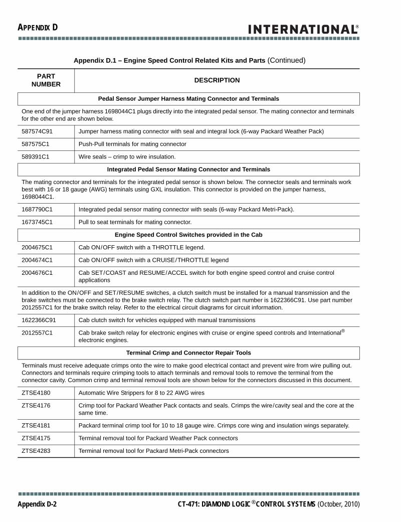
■■■■■■■■■■■■■■■■■■■■■■■■■■■■■■■■■■■■■■■■■■■■■■■■■■■■■■■■■■■■■■■■■■■■■■■■■■■■■■■■■■■■■■■
APPENDIX D
Pedal Sensor Jumper Harness Mating Connector and Terminals
One end of the jumper harness 1698044C1 plugs directly into the integrated pedal sensor. The mating connector and terminals for the other end are shown below.
587574C91 Jumper harness mating connector with seal and integral lock (6-way Packard Weather Pack)
587575C1 Push-Pull terminals for mating connector
589391C1 Wire seals – crimp to wire insulation.
Integrated Pedal Sensor Mating Connector and Terminals
The mating connector and terminals for the integrated pedal sensor is shown below. The connector seals and terminals work best with 16 or 18 gauge (AWG) terminals using GXL insulation. This connector is provided on the jumper harness, 1698044C1.
1687790C1 Integrated pedal sensor mating connector with seals (6-way Packard Metri-Pack).
1673745C1 Pull to seat terminals for mating connector.
Engine Speed Control Switches provided in the Cab
2004675C1 Cab ON/OFF switch with a THROTTLE legend.
2004674C1 Cab ON/OFF switch with a CRUISE/THROTTLE legend
2004676C1 Cab SET/COAST and RESUME/ACCEL switch for both engine speed control and cruise control applications
In addition to the ON/OFF and SET/RESUME switches, a clutch switch must be installed for a manual transmission and the brake switches must be connected to the brake switch relay. The clutch switch part number is 1622366C91. Use part number 2012557C1 for the brake switch relay. Refer to the electrical circuit diagrams for circuit information.
1622366C91 Cab clutch switch for vehicles equipped with manual transmissions
2012557C1 Cab brake switch relay for electronic engines with cruise or engine speed controls and International® electronic engines.
Terminal Crimp and Connector Repair Tools
Terminals must receive adequate crimps onto the wire to make good electrical contact and prevent wire from wire pulling out. Connectors and terminals require crimping tools to attach terminals and removal tools to remove the terminal from the connector cavity. Common crimp and terminal removal tools are shown below for the connectors discussed in this document.
ZTSE4180 Automatic Wire Strippers for 8 to 22 AWG wires
ZTSE4176 Crimp tool for Packard Weather Pack contacts and seals. Crimps the wire/cavity seal and the core at the same time.
ZTSE4181 Packard terminal crimp tool for 10 to 18 gauge wire. Crimps core wing and insulation wings separately.
ZTSE4175 Terminal removal tool for Packard Weather Pack connectors
ZTSE4283 Terminal removal tool for Packard Metri-Pack connectors
Appendix D.1 – Engine Speed Control Related Kits and Parts (Continued)
PART NUMBER DESCRIPTION
■■■■■■■■■■■■■■■■■■■■■■■■■■■■■■■■■■■■■■■■■■■■■■■■■■■■■■■■■■■■■■■■■■■■■■■■■■■■■■■■■■■■■■■
Appendix D-2 CT-471: DIAMOND LOGIC® CONTROL SYSTEMS (October, 2010)
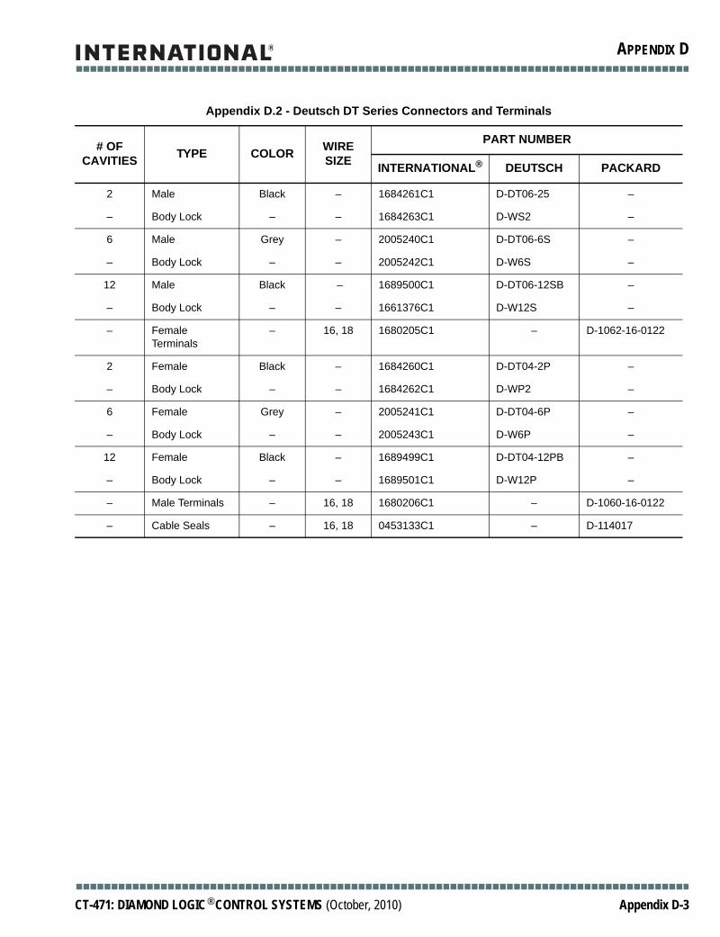
■■■■■■■■■■■■■■■■■■■■■■■■■■■■■■■■■■■■■■■■■■■■■■■■■■■■■■■■■■■■■■■■■■■■■■■■■■■■■■■■■■■■■■■
APPENDIX D
Appendix D.2 - Deutsch DT Series Connectors and Terminals
# OF CAVITIES TYPE COLOR WIRE
SIZE
PART NUMBER
INTERNATIONAL® DEUTSCH PACKARD
2 Male Black – 1684261C1 D-DT06-25 –
– Body Lock – – 1684263C1 D-WS2 –
6 Male Grey – 2005240C1 D-DT06-6S –
– Body Lock – – 2005242C1 D-W6S –
12 Male Black – 1689500C1 D-DT06-12SB –
– Body Lock – – 1661376C1 D-W12S –
– Female Terminals
– 16, 18 1680205C1 – D-1062-16-0122
2 Female Black – 1684260C1 D-DT04-2P –
– Body Lock – – 1684262C1 D-WP2 –
6 Female Grey – 2005241C1 D-DT04-6P –
– Body Lock – – 2005243C1 D-W6P –
12 Female Black – 1689499C1 D-DT04-12PB –
– Body Lock – – 1689501C1 D-W12P –
– Male Terminals – 16, 18 1680206C1 – D-1060-16-0122
– Cable Seals – 16, 18 0453133C1 – D-114017
■■■■■■■■■■■■■■■■■■■■■■■■■■■■■■■■■■■■■■■■■■■■■■■■■■■■■■■■■■■■■■■■■■■■■■■■■■■■■■■■■■■■■■■
CT-471: DIAMOND LOGIC® CONTROL SYSTEMS (October, 2010) Appendix D-3

■■■■■■■■■■■■■■■■■■■■■■■■■■■■■■■■■■■■■■■■■■■■■■■■■■■■■■■■■■■■■■■■■■■■■■■■■■■■■■■■■■■■■■■
APPENDIX D
Nomenclature for wire size:
P = GXLX = SXL
Appendix D.3 - Metri-Pak (Packard) 280 Series Connectors And Terminals
# OF CAVITIES TYPE COLOR WIRE
SIZE
PART NUMBER
INTERNATIONAL® DEUTSCH PACKARD
1 Male Black – 1664531C1 12065172 –
– Body Lock – – 1675053C1 12065249 –
2 Male Black – 1671610C1 15300027 –
– Body Lock – – 1671608C1 15300014 –
5 Male Black – 1661375C2 12084891 –
– Body Lock – – 1661376C1 15300017 –
– Female Terminals
– 16, 18 2033819C1 – 12077411
1 Female Black – 1669834C1 12065171 –
– Body Lock – – 1675053C1 12065249 –
2 Female Black – 1671611C1 15300002 –
– Body Lock – – 1671608C1 15300014 –
5 Female Black – 1677851C1 12085036 –
– Body Lock – 1677914C1 12084673 –
– Male Terminals – 16, 18, 20 2033911C1 – 12048159
– Cable Seals Grey 14P, 16X 0589391C1 – 12010293
Lt. Green 16P, 18P, 20
1652325C1 12015323
Connector Plugs (for Empty Cavities)
Green All 0587579C1 – 12010300
■■■■■■■■■■■■■■■■■■■■■■■■■■■■■■■■■■■■■■■■■■■■■■■■■■■■■■■■■■■■■■■■■■■■■■■■■■■■■■■■■■■■■■■
Appendix D-4 CT-471: DIAMOND LOGIC® CONTROL SYSTEMS (October, 2010)