Embed Size (px)
Citation preview
October 20, 2016 MEMORANDUM TO: William M. Dean, Director Office of Nuclear Reactor Regulation FROM: John W. Lubinski, Director /RA MRoss-Lee for/ Division of Engineering Office of Nuclear Reactor Regulation Joseph G. Giitter, Director /RA/ Division of Risk Assessment Office of Nuclear Reactor Regulation SUBJECT: DEGRADATION OF BAFFLE-FORMER BOLTS IN
PRESSURIZED-WATER REACTORS—DOCUMENTATION OF INTEGRATED RISK-INFORMED DECISIONMAKING PROCESS IN ACCORDANCE WITH NRR OFFICE INSTRUCTION LIC-504
In accordance with Office of Nuclear Reactor Regulation (NRR) Office Instruction LIC-504, Revision 4, “Integrated Risk-Informed Decision-Making Process for Emergent Issues,” effective June 2, 2014, the staff of the U.S. Nuclear Regulatory Commission (NRC) has performed a risk-informed evaluation of the safety significance of recently identified reactor vessel baffle-former bolt (BFB) degradation. As discussed in the enclosed evaluation, the staff has identified the facilities of greatest concern, assessed the need for immediate shutdown of those facilities, and prepared available options. This memorandum presents the staff’s recommendation. Note that the risk-informed assessment of the BFB degradation issue considered risk in conjunction with other factors (e.g., defense-in-depth and safety margins) in order to inform the NRC staff’s recommendation. In the reactor vessel internals of most pressurized-water reactors (PWRs), BFBs connect the vertical baffle plates to the horizontal former plates forming the overall baffle-former assembly, a component of the reactor vessel internals. The main function of the baffle plates is to direct and concentrate the flow of coolant through the core. Detachment or deflection of the baffle plates as a result of degraded BFBs could challenge core coolable geometry and control rod insertion. During the spring 2016 refueling outage inspections, licensees of two PWRs identified unexpected levels of degradation of the BFBs and concluded that the plants were in an unanalyzed condition. The NRC staff evaluated the potential risk and associated consequences of continued plant operation with extensive BFB degradation and determined the regulatory actions that would be needed. The two plants with high levels of BFB degradation are Westinghouse reactors with a 4-loop design, operating in a downflow configuration with Type 347 stainless steel bolts. The NRC staff determined that plants with these characteristics are most susceptible to high levels of BFB degradation and identified a total of seven reactors in this group. Although the two plants that found extensive bolt degradation have taken corrective actions, including replacement of
- 2 - degraded bolts, and have subsequently restarted plant operations, five reactors in the susceptible group have not inspected the bolts to date. The staff, therefore, evaluated the risk represented by continued operation of these plants, where a similar level of bolt degradation may exist, and determined whether immediate shutdown and inspection of the bolts are necessary. The attached Table 1 describes the LIC-504 process initiation for this issue and identifies the evaluation team. The staff’s evaluation identified the following options for the susceptible group: • Option 1: Require immediate shutdown and inspection of the BFBs.
• Option 2: Allow continued operation until the next refueling outage, at which time the
plants have committed to examine all accessible BFBs. • Option 3: Issue a generic communication to gather additional information to support a
future regulatory decision. • Option 4: Maintain the status quo, under which plants would inspect the BFBs
consistent with the current recommended schedule in Materials Reliability Program (MRP)-227-A.
The NRC staff recommends Option 2 because the level of risk represented by operation for only one cycle does not warrant immediate regulatory action per the guidance in LIC-504, i.e., an associated core damage frequency less than 1x10⁻³ per reactor year and a large early release frequency less than 1x10⁻⁴ per reactor year. While this is also true for Option 1, immediate shutdown would place an unnecessary burden on the plants. The staff eliminated Options 3 and 4 because they would extend the time frame for inspections or other corrective actions and increase the uncertainties related to risk. MRP Letter 2016-022, dated July 27, 2016, transmitted interim guidance from the Electric Power Research Institute (EPRI) MRP recommending that all the plants in the most susceptible group (Westinghouse 4-loop, downflow, with Type 347 stainless steel BFBs) conduct ultrasonic testing (UT) of all BFBs at the next scheduled refueling outage. For these plants, the next refueling outage is no later than fall 2017. This guidance is classified as “needed” under the industry materials protocol, Nuclear Energy Institute (NEI) 03-08, “Guideline for Management of Materials Issues,” issued January 2010. The NRC staff plans to review the interim guidance and document its review in a publically available safety assessment. The staff does not expect that any of the plants in the susceptible group will deviate from the recommended EPRI MRP interim guidance. Therefore, the staff does not expect to issue regulatory actions to ensure the implementation of Option 2. However, NEI 03-08 calls for the NRC to be notified of deviations from “needed” guidance. Therefore, if any licensee in the most susceptible group intends to deviate from the interim guidance, the NRC would be notified and could take regulatory action to ensure that the plant performs UT examinations at the next refueling outage. The NRC staff notes that the enclosure references Westinghouse letter NSAL 16-1, Revision 1, dated August 1, 2016. This letter was issued to Westinghouse PWR owners to provide a 10 CFR Part 21 evaluation and recommendations in response to BFB degradation. The NRR
- 3 - staff has not reviewed engineering analyses supporting the evaluation or endorsed its conclusions. It is discussed in this enclosure only to provide context to the staff’s own engineering judgement in evaluating potential risk and regulatory options. The enclosure contains details of the staff’s evaluation. Enclosure: Review of Degraded Reactor Core Baffle-Former Bolts in Westinghouse 4-Loop Pressurized Water Reactors in Accordance With Office of Nuclear Reactor Regulation Office Instruction LIC-504, “Integrated Risk-Informed Decision-Making Process for Emergent Issues” CONTACTS: Jeffrey C. Poehler, NRR/DE/EVIB Steven Laur, NRR/DRA/APLA 301-415-8353 301-415-1465
- 3 -
staff has not reviewed engineering analyses supporting the evaluation or endorsed its conclusions. It is discussed in this enclosure only to provide context to the staff’s own engineering judgement in evaluating potential risk and regulatory options. The enclosure contains details of the staff’s evaluation. Enclosure: Review of Degraded Reactor Core Baffle-Former Bolts in Westinghouse 4-Loop Pressurized Water Reactors in Accordance With Office of Nuclear Reactor Regulation Office Instruction LIC-504, “Integrated Risk-Informed Decision-Making Process for Emergent Issues” CONTACT: Jeffrey C. Poehler, NRR/DE/EVIB Steven Laur, NRR/DRA/APLA 301-415-8353 301-415-1465 Distribution PUBLIC LPL1-1 R/F RidsNrr RidsNrr/Dorl RidsNrrDra RidsNrrDeEvib RidsNrrDraApla RidsNrrDe RidsRgn1MailCenter RidsRgn2MailCenter RidsRgn3MailCenter RidsRgn4MailCenter MRoss-Lee JPoehler SLaur CFong PClifford SLyons JHickey EBenner GWilson RidsNrrPMIndianPoint RidsNrrPMDCCook RidsNrrPMSalem RidsNrrDiabloCanyon MScott, R1 GDentel, R1 MGray, R1 NFloyd, R1 KMangan, R1 BHaagensen, R1 AZiedonis, R1 FBower, R1 PFinney, R1 JKulp, R1 EBurket, R1 TGody, R2 SWalker, R2 AButcavage, R2 KO’Brien, R3 MHolberg, R3 EFernandez, R3 DHills, R3 TVegel, R4 GWerner, R4 RidsAcrsAcnw_MailCTR ITseng, EMCB ADAMS Accession Number: ML16225A341 *concurred by email OFFICE DORL/LPL1-1/LA NRR/DE/EVIB NRR/DRA/APLA NRR/DRA/APLA
NAME KGoldstein* JPoehler* SLaur* CFong DATE 8/16/2016 8/15/2016 8/17/2016 10/04/2016
OFFICE NRR/DE/EVIB/BC QTE NRR/DORL/D RI/DRS/BC
NAME JMcHale JDougherty (EBenner for) ABoland PKrohn*
DATE 8/25/2016 8/19/2016 10/06/2016 10/05/2016
OFFICE OGC NRR/DE/EVIB/BC NRR/DRA/D NRR/DE
NAME BHarris DRudland JGiitter (MRoss-Lee for) JLubinski
DATE 10/13/2016 10/18/2016 10/19/2016 10/20/2016
OFFICIAL RECORD COPY
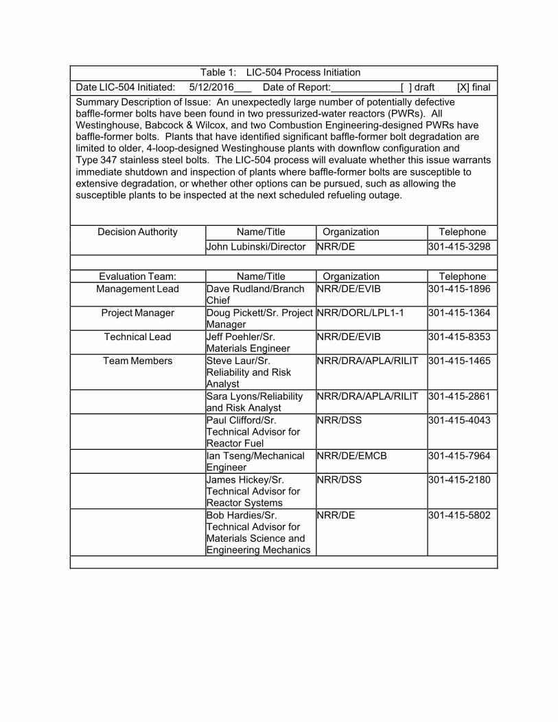
Table 1: LIC-504 Process Initiation
Date LIC-504 Initiated: 5/12/2016 Date of Report: [ ] draft [X] final
Summary Description of Issue: An unexpectedly large number of potentially defective baffle-former bolts have been found in two pressurized-water reactors (PWRs). All Westinghouse, Babcock & Wilcox, and two Combustion Engineering-designed PWRs have baffle-former bolts. Plants that have identified significant baffle-former bolt degradation are limited to older, 4-loop-designed Westinghouse plants with downflow configuration and Type 347 stainless steel bolts. The LIC-504 process will evaluate whether this issue warrants immediate shutdown and inspection of plants where baffle-former bolts are susceptible to extensive degradation, or whether other options can be pursued, such as allowing the susceptible plants to be inspected at the next scheduled refueling outage.
Decision Authority Name/Title Organization Telephone
John Lubinski/Director NRR/DE 301-415-3298
Evaluation Team: Name/Title Organization Telephone Management Lead Dave Rudland/Branch
Chief NRR/DE/EVIB 301-415-1896
Project Manager Doug Pickett/Sr. Project Manager
NRR/DORL/LPL1-1 301-415-1364
Technical Lead Jeff Poehler/Sr. Materials Engineer
NRR/DE/EVIB 301-415-8353
Team Members Steve Laur/Sr. Reliability and Risk Analyst
NRR/DRA/APLA/RILIT 301-415-1465
Sara Lyons/Reliability and Risk Analyst
NRR/DRA/APLA/RILIT 301-415-2861
Paul Clifford/Sr. Technical Advisor for Reactor Fuel
NRR/DSS 301-415-4043
Ian Tseng/Mechanical Engineer
NRR/DE/EMCB 301-415-7964
James Hickey/Sr. Technical Advisor for Reactor Systems
NRR/DSS 301-415-2180
Bob Hardies/Sr. Technical Advisor for Materials Science and Engineering Mechanics
NRR/DE 301-415-5802
Enclosure
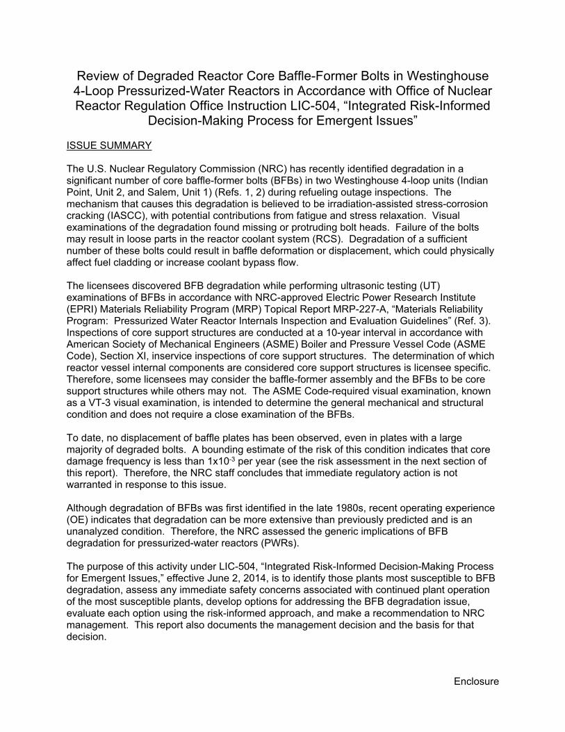
Review of Degraded Reactor Core Baffle-Former Bolts in Westinghouse 4-Loop Pressurized-Water Reactors in Accordance with Office of Nuclear Reactor Regulation Office Instruction LIC-504, “Integrated Risk-Informed
Decision-Making Process for Emergent Issues” ISSUE SUMMARY The U.S. Nuclear Regulatory Commission (NRC) has recently identified degradation in a significant number of core baffle-former bolts (BFBs) in two Westinghouse 4-loop units (Indian Point, Unit 2, and Salem, Unit 1) (Refs. 1, 2) during refueling outage inspections. The mechanism that causes this degradation is believed to be irradiation-assisted stress-corrosion cracking (IASCC), with potential contributions from fatigue and stress relaxation. Visual examinations of the degradation found missing or protruding bolt heads. Failure of the bolts may result in loose parts in the reactor coolant system (RCS). Degradation of a sufficient number of these bolts could result in baffle deformation or displacement, which could physically affect fuel cladding or increase coolant bypass flow. The licensees discovered BFB degradation while performing ultrasonic testing (UT) examinations of BFBs in accordance with NRC-approved Electric Power Research Institute (EPRI) Materials Reliability Program (MRP) Topical Report MRP-227-A, “Materials Reliability Program: Pressurized Water Reactor Internals Inspection and Evaluation Guidelines” (Ref. 3). Inspections of core support structures are conducted at a 10-year interval in accordance with American Society of Mechanical Engineers (ASME) Boiler and Pressure Vessel Code (ASME Code), Section XI, inservice inspections of core support structures. The determination of which reactor vessel internal components are considered core support structures is licensee specific. Therefore, some licensees may consider the baffle-former assembly and the BFBs to be core support structures while others may not. The ASME Code-required visual examination, known as a VT-3 visual examination, is intended to determine the general mechanical and structural condition and does not require a close examination of the BFBs. To date, no displacement of baffle plates has been observed, even in plates with a large majority of degraded bolts. A bounding estimate of the risk of this condition indicates that core damage frequency is less than 1x10⁻³ per year (see the risk assessment in the next section of this report). Therefore, the NRC staff concludes that immediate regulatory action is not warranted in response to this issue. Although degradation of BFBs was first identified in the late 1980s, recent operating experience (OE) indicates that degradation can be more extensive than previously predicted and is an unanalyzed condition. Therefore, the NRC assessed the generic implications of BFB degradation for pressurized-water reactors (PWRs). The purpose of this activity under LIC-504, “Integrated Risk-Informed Decision-Making Process for Emergent Issues,” effective June 2, 2014, is to identify those plants most susceptible to BFB degradation, assess any immediate safety concerns associated with continued plant operation of the most susceptible plants, develop options for addressing the BFB degradation issue, evaluate each option using the risk-informed approach, and make a recommendation to NRC management. This report also documents the management decision and the basis for that decision.
- 2 -
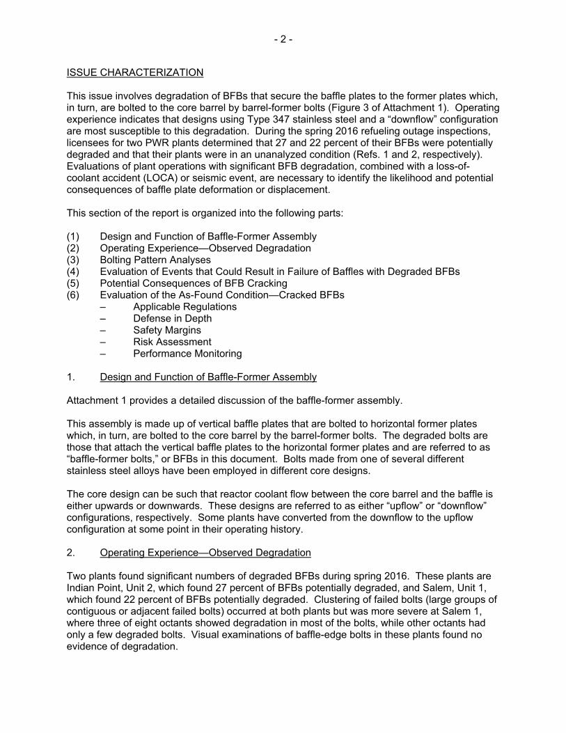
ISSUE CHARACTERIZATION This issue involves degradation of BFBs that secure the baffle plates to the former plates which, in turn, are bolted to the core barrel by barrel-former bolts (Figure 3 of Attachment 1). Operating experience indicates that designs using Type 347 stainless steel and a “downflow” configuration are most susceptible to this degradation. During the spring 2016 refueling outage inspections, licensees for two PWR plants determined that 27 and 22 percent of their BFBs were potentially degraded and that their plants were in an unanalyzed condition (Refs. 1 and 2, respectively). Evaluations of plant operations with significant BFB degradation, combined with a loss-of-coolant accident (LOCA) or seismic event, are necessary to identify the likelihood and potential consequences of baffle plate deformation or displacement. This section of the report is organized into the following parts: (1) Design and Function of Baffle-Former Assembly (2) Operating Experience—Observed Degradation (3) Bolting Pattern Analyses (4) Evaluation of Events that Could Result in Failure of Baffles with Degraded BFBs (5) Potential Consequences of BFB Cracking (6) Evaluation of the As-Found Condition—Cracked BFBs
– Applicable Regulations – Defense in Depth – Safety Margins – Risk Assessment – Performance Monitoring
1. Design and Function of Baffle-Former Assembly Attachment 1 provides a detailed discussion of the baffle-former assembly. This assembly is made up of vertical baffle plates that are bolted to horizontal former plates which, in turn, are bolted to the core barrel by the barrel-former bolts. The degraded bolts are those that attach the vertical baffle plates to the horizontal former plates and are referred to as “baffle-former bolts,” or BFBs in this document. Bolts made from one of several different stainless steel alloys have been employed in different core designs. The core design can be such that reactor coolant flow between the core barrel and the baffle is either upwards or downwards. These designs are referred to as either “upflow” or “downflow” configurations, respectively. Some plants have converted from the downflow to the upflow configuration at some point in their operating history. 2. Operating Experience—Observed Degradation Two plants found significant numbers of degraded BFBs during spring 2016. These plants are Indian Point, Unit 2, which found 27 percent of BFBs potentially degraded, and Salem, Unit 1, which found 22 percent of BFBs potentially degraded. Clustering of failed bolts (large groups of contiguous or adjacent failed bolts) occurred at both plants but was more severe at Salem 1, where three of eight octants showed degradation in most of the bolts, while other octants had only a few degraded bolts. Visual examinations of baffle-edge bolts in these plants found no evidence of degradation.
- 3 -
Voluntary UT examinations of BFBs were performed at four Westinghouse-designed reactors in the late 1990s. Two of these plants were 2-loop designs with Type 347 BFBs, while two were 3-loop designs with Type 316 BFBs. The 2-loop plants found 5–10 percent of BFBs potentially degraded, while the 3-loop plants found no degraded bolts. Bolts were replaced at all four plants. All the potentially defective bolts were replaced at one 2-loop plant, while the defective bolts plus some additional bolts were replaced at the other 2-loop plant. The licensee for the 3-loop plants proactively replaced a subset of the bolts. Before spring 2016, UT examinations, in accordance with MRP-227-A (Ref. 3) at plants with 29–35 effective full-power years (EFPYs) of operation, found 10 percent or less of the BFBs potentially degraded1 in 2-loop and less than 1 percent of the BFBs potentially degraded in 3-loop designs. The total number of degraded bolts in the 2-loop and 3-loop plants does not represent a safety issue because it is bounded by minimum bolting pattern analyses for those plants. In 2010, one Westinghouse 4-loop plant, D.C. Cook Unit 2, conducted a visual examination and identified a cluster of broken bolts on one large baffle plate. The licensee replaced the broken bolts and some additional bolts, finding a total of about 40 defective bolts on the plate. The licensee did not perform UT examinations of the BFBs. Based on a review of operating experience, the potential for significant bolt degradation is currently believed to be limited to Westinghouse 4-loop designs with a downflow configuration and Type 347 stainless steel bolts. Westinghouse Technical Bulletin TB-12-5, issued March 2012 (Ref. 4), following the operating experience at D.C. Cook Unit 2, identified seven operating reactors that were considered most susceptible to BFB degradation—Indian Point Units 2 and 3, Salem Units 1 and 2, D.C. Cook Units 1 and 2, and Diablo Canyon Unit 1. The NRC staff confirmed the bolt material as Type 347 stainless steel for all these plants. Westinghouse Nuclear Safety Advisory Letter (NSAL) 16-12, Revision 1 “Baffle-Former Bolts,” dated August 1, 2016 (Ref. 5), issued in response to the experience at Indian Point, Unit 2, and Salem, Unit 1, identifies the same seven plants as being most susceptible to BFB cracking. NSAL 16-1 classifies the seven 4-loop downflow plants with Type 347 bolts as “Tier 1a.” EPRI Materials Reliability Program (MRP) Letter 2016-022, dated July 27, 2016 (Ref. 6), contains MRP interim guidance that recommended that all plants identified as Tier 1a plants in Westinghouse NSAL-16-1 conduct UT examinations of all BFBs at the next scheduled refueling outage. This guidance is classified as “needed,” as defined in the protocol of NEI 03-08, “Guideline for Management of Materials Issues,” Revision 2, issued January 2010 (Ref. 11). The identification of the most susceptible group of plants to BFB cracking in the NSAL and the MRP letter is consistent with the staff’s assessment based on its OE review. Two 4-loop, downflow plants with Type 316 stainless steel bolts, Sequoyah Units 1 and 2, are classified as Tier 1b in NSAL 16-1. MRP Letter 2016-022 (Ref. 6) recommends that the Tier 1b plants complete a visual VT-3 examination of the full population of BFBs at the next scheduled refueling outage. MRP Letter 2016-022 further recommends that, if degradation is detected, the plants complete actions consistent with the Tier 1a plants; if no degradation is detected during
1 This number is cumulative, counting BFBs found during previous inspections in the late 1990s. 2 NSAL-16-1 was issued to Westinghouse PWR owners to provide a 10 CFR Part 21 evaluation and recommendations in response to recent BFB degradation. The NRR staff has not reviewed the engineering analyses supporting the evaluation or endorsed its conclusions or methods. It is discussed in this enclosure only to provide context to the staff’s own engineering judgement in evaluating potential risk and regulatory options.

- 4 -
the visual VT-3 examination, plants should complete a UT examination consistent with the guidance for Tier 1a during the second refueling outage after issuance of the interim guidance. As discussed above, significant BFB degradation has been observed only in Westinghouse-designed PWRs. All but two Combustion Engineering (CE) units employ a welded, rather than bolted, baffle assembly (referred to as the core shroud in CE designs). UT inspections have not yet been conducted at the CE units with bolted core shrouds, but these units are considered less susceptible to cracking, because annealed Type 316 bolts were used. Babcock & Wilcox-designed PWRs use Type 304 stainless steel BFBs, have an upflow configuration, and have had very few degraded bolts. Based on operating experience, it appears that 4-loop Westinghouse plants with the “downflow” baffle flow configuration and Type 347 stainless steel BFBs are the most susceptible. Table 1 lists the Westinghouse 4-loop downflow plants with Type 347 BFBs. Several plants were originally designed as downflow but were modified to convert to upflow. Because of the lower differential pressure across the baffle plates, upflow plants are considered somewhat less susceptible to BFB cracking. Westinghouse NSAL-16-1 identifies three 4-loop converted upflow plants in the United States—Diablo Canyon Unit 2, and McGuire Unit 1 and Unit 2. The recommendation for these plants in NSAL-16-1 is that, if the 4-loop converted upflow plants have operated for more than 20 calendar years in a downflow configuration, they should evaluate the need to conduct a UT volumetric inspection of BFBs on an accelerated schedule, considering the plant-specific condition and design parameters compared to the 4-loop downflow plants with Type 347 bolts. NSAL-16-1 did not explain the reason for choosing 20 years as the threshold above which converted upflow plants should consider accelerated inspection. However, the NRC staff notes that most Westinghouse PWRs switched to a low-leakage core design well before 20 calendar years; therefore, the 20-year threshold for consideration of accelerated inspections may be reasonable for converted upflow plants, since the combination of lower stresses from the upflow conversion and reduced neutron flux from a low-leakage core would result in fewer bolts initiating IASCC. The NRC staff will continue to gather information on the potential need to expand the group of plants considered most susceptible to degradation.
- 5 -
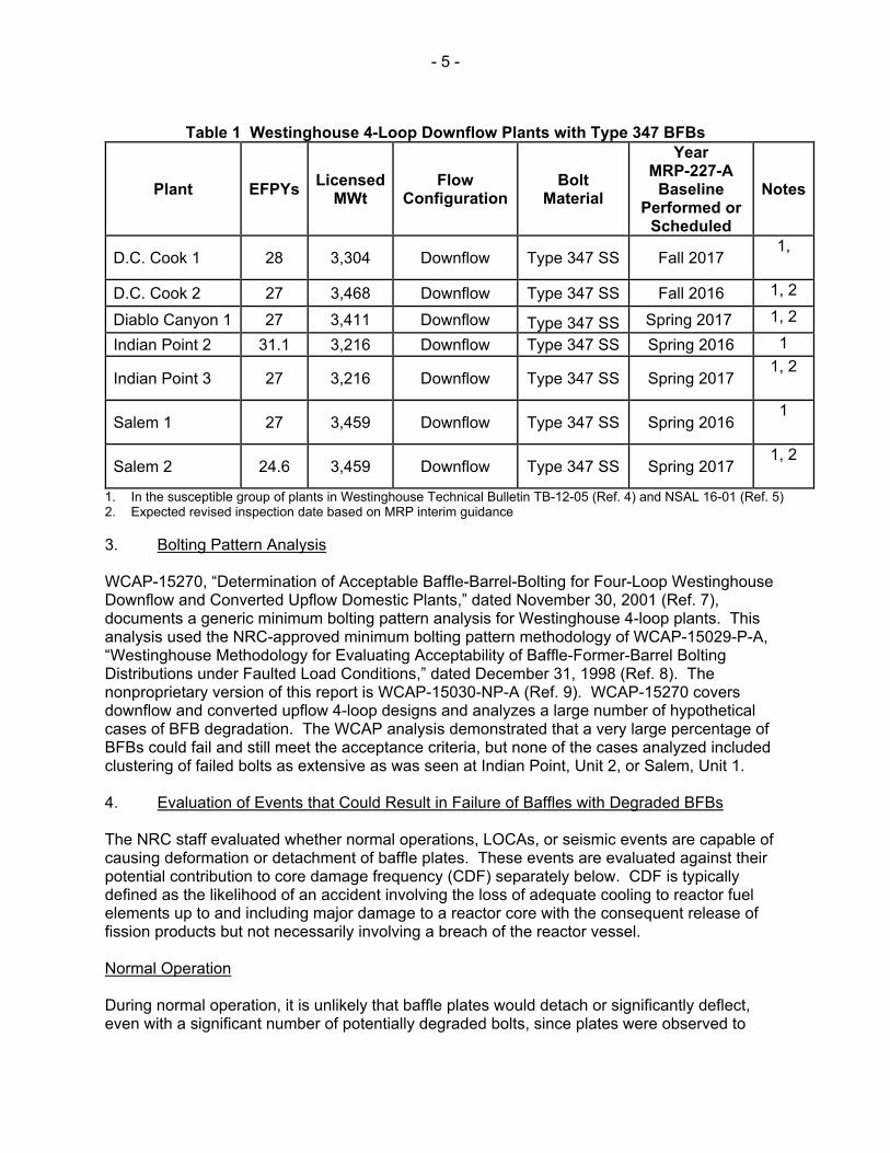
Table 1 Westinghouse 4-Loop Downflow Plants with Type 347 BFBs
Plant EFPYs Licensed
MWt Flow
Configuration Bolt
Material
Year MRP-227-A
Baseline Performed or
Scheduled
Notes
D.C. Cook 1 28 3,304 Downflow Type 347 SS Fall 2017 1,
D.C. Cook 2 27 3,468 Downflow Type 347 SS Fall 2016 1, 2
Diablo Canyon 1 27 3,411 Downflow Type 347 SS Spring 2017 1, 2
Indian Point 2 31.1 3,216 Downflow Type 347 SS Spring 2016 1
Indian Point 3 27 3,216 Downflow Type 347 SS Spring 2017 1, 2
Salem 1 27 3,459 Downflow Type 347 SS Spring 2016 1
Salem 2 24.6 3,459 Downflow Type 347 SS Spring 2017 1, 2
1. In the susceptible group of plants in Westinghouse Technical Bulletin TB-12-05 (Ref. 4) and NSAL 16-01 (Ref. 5) 2. Expected revised inspection date based on MRP interim guidance
3. Bolting Pattern Analysis WCAP-15270, “Determination of Acceptable Baffle-Barrel-Bolting for Four-Loop Westinghouse Downflow and Converted Upflow Domestic Plants,” dated November 30, 2001 (Ref. 7), documents a generic minimum bolting pattern analysis for Westinghouse 4-loop plants. This analysis used the NRC-approved minimum bolting pattern methodology of WCAP-15029-P-A, “Westinghouse Methodology for Evaluating Acceptability of Baffle-Former-Barrel Bolting Distributions under Faulted Load Conditions,” dated December 31, 1998 (Ref. 8). The nonproprietary version of this report is WCAP-15030-NP-A (Ref. 9). WCAP-15270 covers downflow and converted upflow 4-loop designs and analyzes a large number of hypothetical cases of BFB degradation. The WCAP analysis demonstrated that a very large percentage of BFBs could fail and still meet the acceptance criteria, but none of the cases analyzed included clustering of failed bolts as extensive as was seen at Indian Point, Unit 2, or Salem, Unit 1. 4. Evaluation of Events that Could Result in Failure of Baffles with Degraded BFBs The NRC staff evaluated whether normal operations, LOCAs, or seismic events are capable of causing deformation or detachment of baffle plates. These events are evaluated against their potential contribution to core damage frequency (CDF) separately below. CDF is typically defined as the likelihood of an accident involving the loss of adequate cooling to reactor fuel elements up to and including major damage to a reactor core with the consequent release of fission products but not necessarily involving a breach of the reactor vessel. Normal Operation During normal operation, it is unlikely that baffle plates would detach or significantly deflect, even with a significant number of potentially degraded bolts, since plates were observed to
- 6 -
remain in place in the severely affected plants even with plates in which most of the bolts were degraded. It is most likely that only one baffle plate would detach, since not all plates would have the same number of degraded bolts. However, if the plate were detached or had large corner gaps, localized fuel cladding damage might occur that would then be detected by reactor coolant activity monitoring. The most likely effects of BFB degradation during normal operation are the presence of loose parts in the form of bolt heads and locking bars, and possible gaps between the corners of adjacent baffle plates. The loose parts are relatively small and may not be identifiable to control room operators through the loose parts monitoring systems. Based on the previous statements, the contribution of degraded BFBs to CDF during normal operation can be considered negligible. Large-Break LOCA All Westinghouse plants are licensed for leak-before-break (LBB) for the main reactor coolant loop piping. Therefore, the largest size line that must be considered for any LOCA analysis of the baffle plates are in the range of 10-14 inches, which are the largest RCS branch lines (pressurizer surge line, residual heat removal line, or accumulator line). Line breaks in this size range have been analyzed in various generic and plant-specific acceptable bolting pattern analyses, with acceptable results, but not for cases of clustering of degraded BFBs. The NRC staff evaluated the potential for one or more baffle plates detaching from the formers and affecting peripheral fuel assemblies following a LOCA combined with a significant number of degraded BFBs. Based on the observed patterns of bolt degradation at the two plants, it is unlikely that a significant number of baffle plates would detach, but it is possible that one or more plates could detach and affect the fuel. The impact of the plates on the peripheral fuel assemblies from the differential pressure of a LOCA could cause localized damage to the fuel assemblies (grid crush) and possible difficulties inserting control rods associated with the peripheral fuel assemblies. However, based on a sampling of information in the updated final safety analysis reports (UFSARs) for the plants of interest, the plants of most concern (4-loop downflow plants) do not have control rods in peripheral locations, with the exception of Salem Unit 2. During an inspection, the NRC staff reviewed a calculation performed by the licensee for Salem Unit 2, demonstrating that the four control rods in peripheral locations are not needed for safe shutdown. It is expected that the overall flow volume through the core would not be affected if baffle plates detached, although local cooling to some peripheral fuel assemblies could be degraded. Since most plants have switched to low-leakage core designs, peripheral assemblies tend to have higher burnup and are lower power assemblies, which should mitigate cooling concerns. Westinghouse did not perform a coolable geometry analysis considering degraded BFBs for a large break LOCA in support of NSAL-16-1 (Ref. 5). However, the large margin available to the cladding temperature limit associated with a large break LOCA was used to support the evaluation in NSAL-16-1 of a medium break LOCA, as detailed in the next section. Detachment of one or more baffle-former plates would also change the flow pattern, in that some of the bypass flow between the baffle plates and the core barrel would leak into the main flow through the core region, but this should not significantly affect the overall flow volume through the core.
- 7 -
Medium-Break LOCAs It is expected that the forces on the bolts during a medium-break LOCA3 would be smaller than the forces resulting from a 14- or 10-inch line break. The staff bases this opinion on its review of information on bolt stresses and fuel grid loads in WCAP-15270 (Ref. 7) for various different sized line breaks. Thus, unless clustering of degraded bolts exists, coolable geometry would likely be maintained during a medium break LOCA if the percent of degraded bolts is similar to that observed in Indian Point Unit 2, or Salem Unit 1. NSAL-16-1 discussed the potential for loss of coolable geometry if a LOCA occurs, assuming a clustering of degraded bolts. A 4-inch line break was the largest break considered, which would bound the medium break LOCA as defined by the NRC. The evaluation in NSAL-16-1 assumed all the BFBs were failed on one baffle plate, consistent with recent OE showing clustering of failed bolts. The NSAL indicated that there is a potential for grid deformation on the core periphery as well as the potential for limited grid deformation in the inboard fuel assemblies. However, the NSAL concluded that a core-coolable geometry is maintained for assemblies on the core periphery with grid deformation, based on taking credit for the low power generation in the peripheral assembles and the observation that any flow redistribution that may occur would tend to benefit the inboard assemblies. The NSAL indicated that the overall core flow area is unchanged, with only a small difference in the cooling geometry. The NSAL, therefore, concluded that the increase in core bypass and the amount and location of the grid deformation would have little impact on the 4-inch LOCA transient. The NSAL further concluded that, based on this and considering the available margin to the cladding temperature limit and the margins in the small-break LOCA evaluation model, core cooling is maintained for the grid deformation caused by the potentially degraded BFB. The large margin to the cladding temperature limit associated with large break LOCA is used in NSAL-16-1 to support the determination that the predicted fuel grid deformation resulting from a 4-inch line break would not approach the cladding temperature limit, and thus a coolable geometry would be maintained. The NSAL found that BFB degradation would also not compromise long-term core cooling because (1) grid deformation, should it occur, could reduce the rod-to-rod spacing (however, significant margins in the licensing basis analyses exist), (2) slight changes in core geometry, such as those resulting from fuel assembly grid deformation, would not significantly affect long-term heat removal, as coolant flow velocities are low, fuel assembly crossflow would not be fully impeded, and the overall core flow area would be preserved, and (3) BFB degradation would not increase the core decay heat. Small-Break LOCA The loads for a small-break LOCA4 would be even smaller for a medium-break LOCA. Even with significant clustered defective BFBs, it is unlikely that bolt loads or fuel grid impact loads would be high enough to cause baffle plate displacement or localized cladding damage. The LOCA evaluation in NSAL-16-1 described in the previous section bounds the small-break LOCA. Therefore, the conclusions of the medium-break LOCA evaluation are bounding for
3 This is defined in NUREG-1829 as having a flowrate greater than 1,500 gallons per minute (gpm) and equal
to or smaller than 5,000 gpm, correlating to an effective break size greater than 1.5 inches and equal to or smaller than 3 inches for a PWR.
4 In NUREG-1829, “Estimating Loss-of-Coolant Accident (LOCA) Frequencies Through the Elicitation Process,” issued April 2008 (Ref. 10), the NRC staff defines this as having a flow rate greater than 100 gpm but equal to or smaller than 1,500 gpm, correlating to an effective break size of greater than 1/2 inch and equal to or smaller than 1.5 inches.
- 8 -
small-break LOCAs, and little or no fuel grid damage is expected for a small-break LOCA. Based on the above, the risk posed by small-break LOCAs can be considered negligible. Seismic The potential for an earthquake to result in BFB failures was evaluated from two perspectives: traditional engineering and risk. Nuclear plants are designed to withstand earthquakes using accepted engineering principles. Earthquakes equal to or exceeding the SSE are considered to be the only significant seismic events with respect to BFB failures. The generic Westinghouse 4-loop analysis report, WCAP-15270 (Ref. 7), indicates that stresses in the BFBs are much less for an SSE than for a LOCA, and that fuel grid impact loads for an SSE alone have considerable margin before exceeding the allowable loads. NSAL-16-1 stated that the evaluation considered seismic conditions and determined that, for BFB degradation, seismic effects are bounded by LOCA effects. NSAL-16-1 further stated that, when a baffle plate is loose, there is no significant mechanism to excite the plate. NSAL-16-1 stated that there will be minor pressure fluctuations in the baffle-former-barrel region, due to the relative motion of components; however, these pressure fluctuations have been shown to be very small. Therefore, NSAL-16-1 stated that any pressure results are bounded by those reviewed in the LOCA analysis. NSAL-16-1 also stated that vertical seismic effects are not expected to be significant, and intermittent impacts with the upper or lower core plates will not have significant inertia to damage the core plates when considering an SSE. NSAL-16-1 stated that the upper internals holddown forces have significant margin to accommodate any incidental impacts. Therefore, for the purposes of the evaluation described in NSAL-16-1, seismic effects were considered decoupled from a LOCA event. The risk assessment of this event (Attachment 3) was performed to determine whether the seismic risk attributable to BFB degradation approached the LIC-504 thresholds that might indicate that an imminent safety concern exists. The risk assessment concludes that the BFB degradation issue does not represent an imminent safety concern, using a bounding seismic hazard estimate that envelops the latest hazard estimates across all U. S. nuclear power plant sites. The seismic risk assessment considers the full range of earthquakes, of both lesser and greater intensity than the SSE. Summary—Initiating Events Based on the above discussion, the initiating events that could result in baffle deformation or displacement are the large-break LOCA, medium-break LOCA, and an earthquake equal to or exceeding the SSE. 5. Potential Consequences of BFB Cracking BFB cracking has the following potential consequences: • Excessive Fuel Grid Impact Loading from Baffle Plate Detachment or Deflection: The
most significant consequence of a large number of BFB failures is the potential for excessive impact loadings on peripheral fuel assemblies from deflection of the baffle plates or complete or partial detachment of a baffle plate from the former plates. The minimum bolting pattern analyses in Licensee Event Report 16-004-00 (Ref. 1) determined the minimum number of bolts necessary to perform their function; it did not
- 9 -
determine whether plates detach. Even if plates do not detach, degraded BFBs could cause increased deflection of the plates during a LOCA or seismic event, which could cause increased fuel grid impact loading. Excessive fuel grid impact is most likely during a large LOCA but could occur during a medium-break LOCA or seismic event, particularly if defective BFBs are clustered. If fuel grid allowable loads are exceeded, grid crush could occur leading to localized degradation of cooling for affected fuel assemblies, and the capability to insert control rods in peripheral locations could be affected. Such localized degradation to cooling could be evaluated via a coolable geometry evaluation. With respect to a LOCA, all Westinghouse plants are licensed for leak-before-break (LBB) for the main reactor coolant loop piping, so for some plants, the largest line without LBB is a pressurizer surge line, accumulator line, or residual heat removal line (14- or 10-inch line). Some Westinghouse plants have gained NRC approval through a license amendment for expanded LBB, in which LBB is applied to the large branch lines, such that the largest line without LBB is in the range of a 3-inch to 6-inch diameter line. The NRC-approved minimum bolting pattern methodology in WCAP-15029-P-A takes into account LBB such that only line sizes not covered by LBB need to be considered for evaluating acceptable BFB patterns. Should a plant be able to demonstrate applicability of expanded LBB, the LOCA loads on the baffle plates are significantly reduced. For plants to which expanded LBB applies, a fuel grid impact that is severe enough to damage non-peripheral fuel assemblies or affect the ability to insert a control rod is considered extremely unlikely. Most Westinghouse 4-loop plants do not have control rods in peripheral locations or can demonstrate that sufficient margin exists such that peripheral rods are not needed for safe shutdown.
• Baffle Jetting: Baffle jetting can cause localized fuel cladding damage. Failed BFBs may allow gaps to form at the corners of the plates that can cause baffle jetting (i.e., high-velocity flow through the corner gaps driven by the differential pressure between the bypass flow and the main flow regions). Baffle jetting is not considered a safety issue because, although localized fuel cladding damage could cause increased radioactivity levels in the reactor coolant, the type of damage would be limited to isolated cladding damage, not melting. This type of damage, which occurs slowly, would cause an increase in coolant activity that would be detectable during normal operation by technical-specification-required monitoring of coolant activity, typically to be performed every 7 days5. Baffle-edge bolts help prevent the formation of gaps between the plate corners, and no degradation of baffle-edge bolts has been found in operating plants, which lessens the potential for baffle jetting. Based on OE, there has been no observed link between BFB degradation and baffle jetting.
• Increased Bypass Flow: Core bypass flow is defined as the total amount of reactor coolant flow that bypasses the core region, which is not considered effective in the core heat transfer process. Gaps at plate corners from degraded BFBs could also cause an increase in core bypass flow. The potential core bypass flowpaths in the Westinghouse 4-loop plants are the baffle-former-barrel region, head cooling spray nozzles, outlet nozzles, baffle plate-core cavity gap, and fuel assembly thimble tubes. However, only the baffle-former-barrel region bypass flow is significantly affected by the variations in the bolting configurations. The vertical baffle plates follow the bounding periphery of the core. They are joined to the core barrel by horizontal former plates spaced vertically along the baffle plates. For the downflow configuration, the flow that leaks through the
5 Surveillance Requirement 3.4.16.1 is from NUREG-1431, “Standard Technical
Specifications—Westinghouse Plants: Specifications,” Revision 4, Volume 1, dated April 30, 2012 (Agencywide Documents Access and Management System (ADAMS) Accession No. ML12100A222).
- 10 -
baffle joints and into the core before it reaches the bottom of the baffle-former-barrel region constitutes core bypass flow. Bolting pattern analyses evaluate the increase in core bypass flow for normal operation.
• Fatigue: Failed BFBs could also cause increases in fatigue usage as a result of low-cycle fatigue and increased stresses from vibrational fatigue. Both types of fatigue are considered long-term issues and are unlikely to lead to failure during normal operation over one cycle.
• Loose Parts: Failed BFBs could also produce loose parts in the form of detached bolt heads and locking bars during normal operation. In Westinghouse plants that have recently found extensive BFB degradation (i.e., Indian Point Unit 2 and Salem Unit 1), locking bar failures have been observed in conjunction with bolt fracture. When a BFB completely fractures at the head-to-shank transition, resulting in the separation of the bolt head from the shank, either the bolt head can vibrate against the locking bar or the baffle plate can locally separate slightly from the former and cause fatigue failure of the locking bar, allowing locking bars and bolt heads to become loose parts. The bolt shanks remain threaded into the holes and have not been observed to become loose parts. It should be noted that the clearance between the baffle plates and peripheral fuel assemblies is so small that bolt heads cannot become loose parts unless the fuel is removed. Loose bolt heads and locking bars would be small and would not be expected to significantly affect core cooling. Detached baffle plates would constitute a large loose part, but the potential for travel of these plates is not credible because of the small clearance between the plates and the fuel assemblies. In addition, given that clearance, when a bolt head separates from the bolt shaft, the bolt head will not fall out of its location, even if the locking bar later fails, as described above. Therefore, a bolt head trapped in the gap can cause fretting of the adjacent cladding. Localized fuel cladding damage caused by fretting can also be detected by monitoring reactor coolant activity.
Based on the above, the safety-significant potential consequences of bolt degradation are detachment or increased deflection of the baffle plates, leading to increased fuel grid impact loads, and increases in core bypass flow. 6. Evaluation of the As-Found Condition—Cracked BFBs Attachment 2 describes the risk-informed approach to making decisions regarding emergent issues. This approach has five key principles: (1) Compliance with Existing Regulations (2) Consistency with the Defense-in-Depth Philosophy (3) Maintenance of Adequate Safety Margins (4) Demonstration of Acceptable Levels of Risk (5) Implementation of Defined Performance Measurement Strategies The discussion that follows covers each of the five key principles as it relates to the “as-found” condition of degraded BFBs. Note that the same key principles are used to differentiate among the options considered for addressing the BFB degradation issue; the “Evaluation and Assessment of Options” section of this report includes that discussion.
- 11 -
Compliance with Existing Regulations For reactor vessel internals (RVIs), the following regulations are applicable: • Title 10 of the Code of Federal Regulations (10 CFR) 50.46, “Acceptance Criteria for
Emergency Core Cooling Systems for Light-Water Nuclear Power Reactors”
• 10 CFR Part 50, “Domestic Licensing of Production and Utilization Facilities,” Appendix A, “General Design Criteria [GDC] for Nuclear Power Plants,”
o GDC 4, Environmental and Dynamic Effects Design Bases o GDC 27, Combined Reactivity Control Systems Capability o GDC 35, “Emergency Core Cooling” (considered together with 10 CFR 50.46)
• 10 CFR 50.55a, “Codes and Standards”
• 10 CFR 54.21, “Contents of Application—Technical Information” The following discusses the relationship of the BFB degradation issue to each of these regulations. 10 CFR Part 50, General Design Criteria (GDC) for Nuclear Power Plants The staff notes that potential degradation of BFB does not automatically result in noncompliance with the GDC below. A licensee assesses OE related to BFB degradation and evaluates the impact on its plant(s) as necessary. If a licensee determines its plant is in noncompliance with any of the Commission’s regulations, including the GDC, the licensee is responsible for taking appropriate corrective action, which may include shutting down the plant. It should be noted that the Atomic Energy Commission published the final rule that added 10 CFR Part 50, Appendix A, "General Design Criteria for Nuclear Power Plants," in the Federal Register (36 FR 3255) on February 20, 1971, with the rule effective on May 21, 1971. In accordance with an NRC staff requirements memorandum from S. J. Chilk to J. M. Taylor, "SECY-92-223 - Resolution of Deviations Identified during the Systematic Evaluation Program," dated September 18, 1992 (ADAMS Accession No. ML003763736), the Commission decided not to apply the Appendix A GDC to plants with construction permits issued prior to May 21, 1971. As a result, a number of operating plants were not licensed to, nor required to meet, the GDC. However, since the GDC generally bounds the licensing basis for the pre-GDC plants, the staff concludes that use of the current GDC will provide a conservative approach in evaluating the impact of BFB degradation on plant safety. GDC 4 Environmental and dynamic effects design bases. GDC 4 states the following:
“Structures, systems, and components important to safety shall be designed to accommodate the effects of and to be compatible with the environmental conditions associated with normal operation, maintenance, testing, and postulated accidents, including loss-of-coolant accidents. These structures, systems, and components shall be appropriately protected against dynamic effects, including the effects of missiles, pipe
- 12 -
whipping, and discharging fluids, that may result from equipment failures and from events and conditions outside the nuclear power unit. However, dynamic effects associated with postulated pipe ruptures in nuclear power units may be excluded from the design basis when analyses reviewed and approved by the Commission demonstrate that the probability of fluid system piping rupture is extremely low under conditions consistent with the design basis for the piping.”
The RVI were designed to accommodate these environmental effects, such as loads from LOCAs and seismic events. Degradation of BFBs could result in increased stresses on the bolts which could exceed the acceptance criteria of the original analyses. However, in acceptable bolting pattern analyses reviewed by the NRC staff, licensees have been able to show compliance with acceptance criteria for many configurations with a substantial percentage of degraded BFBs. Therefore, BFB degradation does not automatically indicate noncompliance with GDC 4. GDC 27 Combined reactivity control systems capability. In GDC 27, the NRC states that the reactivity control systems shall be designed to have a combined capability, in conjunction with poison addition by the emergency core cooling system, of reliably controlling reactivity changes to assure that under postulated accident conditions and with appropriate margin for stuck rods the capability to cool the core is maintained. If an accident such as a LOCA occurs, failure of degraded BFBs could result in fuel grid allowable loads being exceeded and could affect the capability to insert control rods in certain peripheral locations. Plants with peripheral control rods may be able to demonstrate sufficient shutdown margin without these rods. Therefore, BFB degradation does not automatically indicate noncompliance with GDC 27. The licensees of plants that may have BFB degradation are responsible for determining operability based on plant-specific configurations and assumptions/observations regarding BFB degradation. 10 CFR 50.46 and GDC 35 In 10 CFR 50.46(b)(4), the NRC states that calculated changes in core geometry shall be such that the core remains amenable to cooling. GDC 35 states, “A system to provide abundant emergency core cooling shall be provided. The system safety function shall be to transfer heat from the reactor core following any loss of reactor coolant at a rate such that (1) fuel and clad damage that could interfere with continued effective core cooling is prevented and (2) clad metal-water reaction is limited to negligible amounts.” Degradation of BFBs could cause localized damage to peripheral fuel assemblies if an accident such as a LOCA causes fuel grid allowable loads to be exceeded. It may be possible to demonstrate that a coolable geometry is maintained such that ECCS function is essentially unimpaired even if such damage occurs. Other parts of the ECCS, such as piping, pumps, and heat exchangers, are not affected by BFB degradation. Therefore, the presence of BFB degradation would not automatically imply noncompliance with 10 CFR 50.46 and GDC 35. 10 CFR 50.55a ASME Code Section XI, which is incorporated by reference in 10 CFR 50.55a, requires visual VT-3 examinations of all RVIs classified as “core support structures” once each 10-year inspection interval. The determination of which RVI components are considered core support structures is licensee specific. As a result, some licensees have considered the baffle-former assembly and, thus, the BFBs, to be core support structures and others have not. Further, even
- 13 -
if the baffle-former assembly is inspected under ASME Code Section XI, the VT-3 inspection is not necessarily detailed enough to detect bolt degradation, nor can it detect partially cracked bolts because of the location of these cracks at the head-to-shank transition. For this reason, the MRP-227-A guidelines for aging management (Ref. 3) specify augmented inspections using UT. Therefore, the presence of BFB degradation alone would not imply noncompliance with 10 CFR 50.55a. 10 CFR 54.21 The requirements in 10 CFR 54.21 specify that the aging of systems, structures, and components (SSCs) within the scope of license renewal are to be managed to maintain intended functions consistent with the current licensing basis for the period of extended operation. Inspections specified in MRP-227-A (Ref. 3), along with the associated corrective actions, will ensure that the RVIs will be maintained consistent with the current licensing basis for the period of extended operation. Therefore, the presence of BFB degradation would not imply noncompliance with 10 CFR 54.21. Consistency with the Defense-in-Depth Philosophy
One factor for assessing how an event might degrade defense in depth is to see how it affects the balance among the layers of defense. It is useful to consider the following layers of defense (successive measures) when evaluating the impact of degraded BFBs on defense in depth:
(1) a robust plant design to survive hazards and minimize challenges that could result in an event occurring
(2) prevention of a severe accident (core damage) should an event occur
(3) containment of the source term should a severe accident occur
(4) protection of the public from any releases of radioactive material (e.g., through siting in low-population areas and the ability to shelter or evacuate people, if necessary)
The likelihood of undetected BFB degradation severe enough to cause baffle plate detachment during normal operation is low. As discussed earlier, the plant may be able to continue operating under such a condition or would have to shut down due to increased coolant activity. For plate detachment to occur during normal operation, extremely severe BFB degradation would be required. Such degradation would likely cause cladding damage detectable via the RCS activity sampling which is required by technical specifications, before this degradation became severe enough to cause baffle failure during normal operation. Degradation of BFBs may necessitate a reactor shutdown but does not increase the likelihood of any other event.
The types of accidents that could cause deflection or detachment of baffle plates when BFBs are degraded are a large-break LOCA, a medium-break LOCA, or a seismic event. The SSCs that provide key safety functions following such accidents are not expected to be affected by BFB degradation. Reactivity control is provided by control rods and soluble poison; the BFB issue does not affect the latter. As stated earlier, the failure of the baffle could result in an impact on the peripheral fuel assemblies, but these locations do not typically have control rods, or they can be demonstrated to be unnecessary for safe shutdown. If degradation of BFBs causes localized fuel grid allowable loads to be exceeded, it may be possible to demonstrate that a coolable geometry is maintained such that ECCS function is essentially unimpaired even
- 14 -
if such damage occurs. Pumps, piping and valves associated with decay heat removal systems are not expected to be affected by BFB degradation.
BFB degradation does not affect the containment structure, such that the containment response to these accidents would not be different whether the BFBs were degraded or not. Finally, the BFB degradation issue has no effect on the emergency preparedness functions, such that the fourth layer of defense is not affected.
Another factor of defense in depth to consider involves the effect of the issue on the fission product barriers (i.e., fuel cladding, RCS pressure boundary, and containment). As stated above, BFB degradation does not affect the containment response. BFB degradation could affect fuel cladding in peripheral fuel assemblies as a result of fretting or baffle jetting, as previously discussed. This would affect only a small percentage of the cladding. If this occurred during normal operation, the RCS would remain intact. If baffle failure were the result of a LOCA, the damage to the fuel cladding would be isolated to the peripheral fuel assemblies and limited to a small fraction of the total. A seismic event that resulted in baffle failure would not result in the RCS pressure boundary failure except for earthquakes of very large magnitude, which have a very low frequency.
In summary, BFB degradation does not affect the containment function. The effect on cladding is small and limited to peripheral fuel assemblies. The RCS would remain intact except possibly for a LOCA or large seismic event, both of which are very unlikely. The BFB degradation issue does not indicate that an imminent safety concern exists from any effect on defense in depth, because it does not significantly affect the four layers of defense nor the containment fission product barrier.
Maintenance of Adequate Safety Margins Acceptable bolt pattern analyses, in accordance with the methodology of WCAP-15029-P-A, use the allowable stresses from the ASME Code. Acceptance criteria for other types of analyses, such as fuel grid crush, core bypass flow, high- and low-cycle fatigue, and baffle jetting, are based on vendor design criteria. Degradation of significant numbers of BFBs can cause these acceptance criteria to be exceeded, which represents a potential reduction in safety margins. The safety analysis acceptance criteria for RVIs are plant specific and are documented in each plant’s UFSAR. Typically, the safety analysis criteria for RVIs are based on keeping RVI deflections within a specified limit during concurrent LOCA and SSE conditions. The analyses typically treat the internals as a few major subassemblies (core barrel, upper internals) and do not have specific criteria for the baffle-former assembly or BFBs. While BFB degradation represents a decrease in the safety margin for the baffles, the corresponding decrease in reactor safety is not so significant as to indicate that an imminent safety concern exists. Demonstration of Acceptable Levels of Risk The primary purpose of the risk assessment of the “as-found” condition is to determine whether the risk of the issue is sufficient to create an imminent safety concern, such that prompt action must be taken to provide reasonable assurance of adequate protection of public health and safety. The bounding discussion below supports a conclusion that the risk of this issue does not represent an imminent safety concern.
- 15 -
As stated above, baffle deformation or displacement could be expected to result in localized fuel cladding damage under three conditions—a medium LOCA, a large LOCA, or a seismic event. NUREG-1829 (Ref. 10) estimates plant-wide LOCA frequency. Table 7.19 of that NUREG provides the total PWR LOCA frequencies without contribution from steam generator tube rupture events. The smallest medium LOCA in that study was taken as 1,500 gpm. The mean frequency of a LOCA of that size or larger is given as 5.8x10⁻⁴ per year. Because “1,500 gpm or larger” includes medium and large LOCA events, it represents an upper bound for LOCA challenges to degraded BFBs. As stated previously in the section titled “Evaluation of Events that Could Result in Failure of Baffles with Degraded BFBs,” baffle failure due to a LOCA is not expected to result in fuel damage but could result in a baffle plate mechanically impinging on the cladding, which could result in localized fuel cladding damage. While the LOCA itself may lead to core damage, the contribution to core damage cannot be any larger than the frequency at which these events are expected to occur and is arguably much smaller because BFB degradation does not affect the SSCs designed to mitigate the LOCA, other than localized changes to coolable geometry resulting from damage to peripheral fuel assemblies. Since it is possible that coolable geometry can be demonstrated in such cases, core damage will not necessarily occur even though some peripheral fuel assemblies sustain damage. LIC-504 provides guidance for when the risk of an emergent condition may indicate an imminent safety concern; the acceptance guideline is 1x10⁻³ per year. Therefore, the risk of BFB degradation does not represent an imminent safety hazard from potential LOCAs. Attachment 3 presents a notional seismic assessment of degraded BFBs. A bounding seismic hazard curve was generated that should envelop any nuclear plant in the United States. A generic fragility value for RVIs, taken from one of the NRC’s simplified plant analysis risk (SPAR) models, was used to determine a “baffle failure frequency,” assuming no degradation. Then an assumed percent degradation in the median capacity of the BFBs was used to compute a new failure frequency for the baffles. The 1x10⁻³ per year threshold would be approached if the median capacity of the BFBs were reduced by 75 percent; that is, with only 25-percent median capacity, the baffle failure frequency would be near the guideline that would indicate a possible imminent safety hazard. Such a large reduction in median capacity, before the condition is detected and corrected, is considered unlikely because it would require levels of bolt degradation far in excess of that seen in the worst affected units. The worst affected units observed that approximately 25% of its bolts were degraded, some of which likely retain some load bearing capacity. The staff considers it very unlikely that plants in the most susceptible group that have not yet inspected the BFB would have a 50% greater level of degradation then has been observed to date, given the relatively similar operating time (EFPY) for the group of plants. Also, as stated above, baffle deformation or displacement does not automatically lead to core damage or fuel melt but could result in localized fuel cladding damage. A seismic event can also induce a LOCA. The analysis in Attachment 3 concludes that the frequency of such events would be about two orders of magnitude less than the frequency of a medium or larger LOCA. Therefore, these events do not contribute significantly to BFB degradation risk. LIC-504 also includes an acceptance guideline for when a large early release frequency (LERF) attributable to an emergent condition might indicate a potential imminent safety concern. The dominant contributors to a PWR LERF are bypass events, such as an intersystem LOCA and steam generator tube ruptures. The BFB issue does not affect either of these scenarios. However, the occurrence of one of these scenarios could lead to baffle failure, which could result in some localized fuel cladding damage, even in scenarios where fuel melt was avoided.

- 16 -
Typical initiating event frequencies for intersystem LOCAs are in the mid-10-6 per year range. Table 7.18 in NUREG-1829 (Ref. 10) estimates steam generator tube rupture events with leakage rates greater than 1,500 gpm to occur at a frequency of 6.5x10⁻⁶ per year. Therefore, a bounding estimate of LERF from intersystem LOCAs and steam generator tube ruptures is well below the 1x10⁻⁴ per year guideline in LIC-504, so that the LERF attributable to BFB degradation would also not indicate an imminent safety concern. Implementation of Defined Performance Measurement Strategies All the licensees of plants with high susceptibility to BFB degradation have at least verbally committed to conduct UT examinations of their BFBs by the next refueling outage. As previously stated, the EPRI-MRP interim guidance (Ref. 6) calls for these examinations. Therefore, the time frame for potentially elevated risk is short (less than 18 months); these plants will have either fall 2016, spring 2017, or fall 2017 refueling outages. The UT inspection specified by MRP-227-A for BFBs is the most effective means of performance monitoring of BFBs. Visual VT-3 inspections, which are specified by the ASME Code, Section XI, for core support structures, may detect broken BFBs. However, these strategies require a reactor shutdown and defueling. For online performance monitoring, the most effective method is RCS activity monitoring, which can detect an increase in coolant activity that may be indicative of fuel cladding failures. The most likely mechanism for fuel cladding failures related to BFB degradation is fretting by loose bolt heads. BFB degradation could theoretically lead to baffle jetting, which could also cause fuel cladding failures. However, there is currently no OE linking BFB degradation to baffle jetting. Loose parts monitoring is another means of monitoring BFB performance online. Loose parts monitoring systems may not be sufficiently sensitive to detect bolt heads and lock bars. The systems may detect loose plates. However, the staff considers loose parts monitoring to have limited effectiveness for detecting BFB degradation.
- 17 -
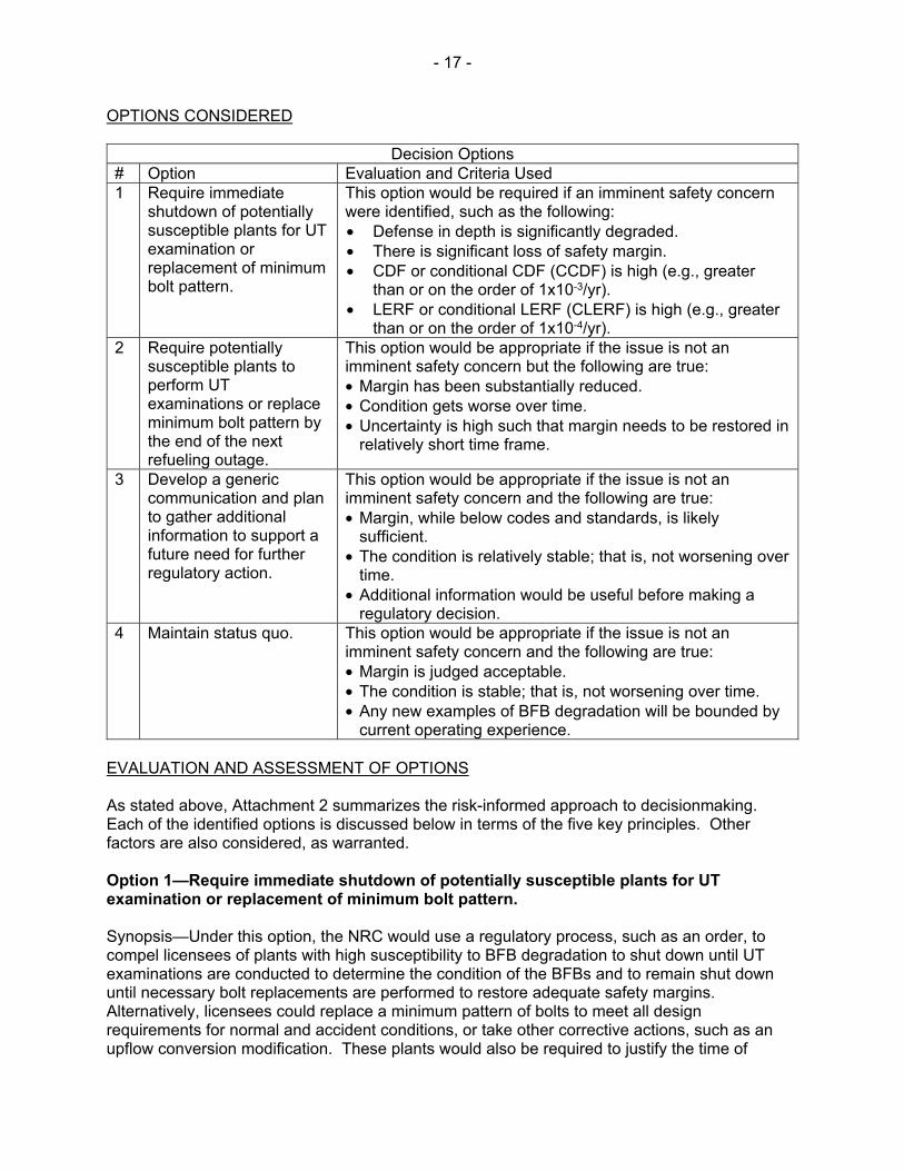
OPTIONS CONSIDERED
Decision Options # Option Evaluation and Criteria Used 1 Require immediate
shutdown of potentially susceptible plants for UT examination or replacement of minimum bolt pattern.
This option would be required if an imminent safety concern were identified, such as the following: • Defense in depth is significantly degraded. • There is significant loss of safety margin. • CDF or conditional CDF (CCDF) is high (e.g., greater
than or on the order of 1x10⁻³/yr). • LERF or conditional LERF (CLERF) is high (e.g., greater
than or on the order of 1x10⁻⁴/yr). 2 Require potentially
susceptible plants to perform UT examinations or replace minimum bolt pattern by the end of the next refueling outage.
This option would be appropriate if the issue is not an imminent safety concern but the following are true: • Margin has been substantially reduced. • Condition gets worse over time. • Uncertainty is high such that margin needs to be restored in
relatively short time frame.
3 Develop a generic communication and plan to gather additional information to support a future need for further regulatory action.
This option would be appropriate if the issue is not an imminent safety concern and the following are true: • Margin, while below codes and standards, is likely
sufficient. • The condition is relatively stable; that is, not worsening over
time. • Additional information would be useful before making a
regulatory decision. 4 Maintain status quo. This option would be appropriate if the issue is not an
imminent safety concern and the following are true: • Margin is judged acceptable. • The condition is stable; that is, not worsening over time. • Any new examples of BFB degradation will be bounded by
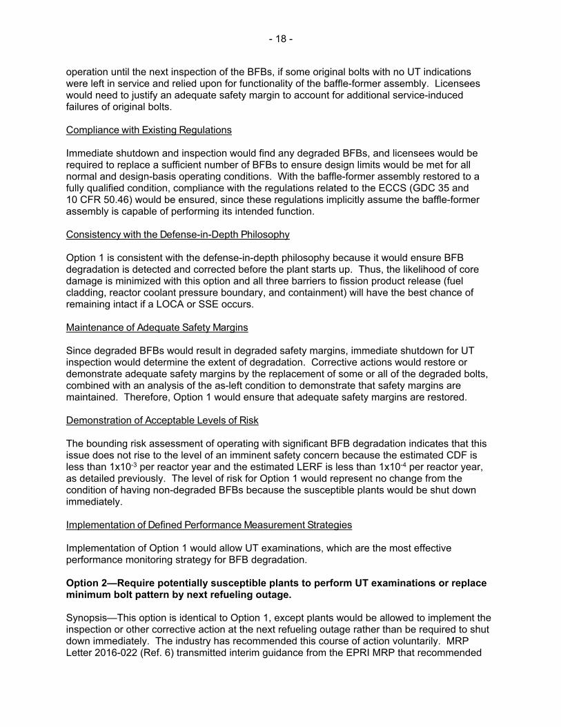
current operating experience. EVALUATION AND ASSESSMENT OF OPTIONS As stated above, Attachment 2 summarizes the risk-informed approach to decisionmaking. Each of the identified options is discussed below in terms of the five key principles. Other factors are also considered, as warranted. Option 1—Require immediate shutdown of potentially susceptible plants for UT examination or replacement of minimum bolt pattern. Synopsis—Under this option, the NRC would use a regulatory process, such as an order, to compel licensees of plants with high susceptibility to BFB degradation to shut down until UT examinations are conducted to determine the condition of the BFBs and to remain shut down until necessary bolt replacements are performed to restore adequate safety margins. Alternatively, licensees could replace a minimum pattern of bolts to meet all design requirements for normal and accident conditions, or take other corrective actions, such as an upflow conversion modification. These plants would also be required to justify the time of
- 18 -
operation until the next inspection of the BFBs, if some original bolts with no UT indications were left in service and relied upon for functionality of the baffle-former assembly. Licensees would need to justify an adequate safety margin to account for additional service-induced failures of original bolts. Compliance with Existing Regulations Immediate shutdown and inspection would find any degraded BFBs, and licensees would be required to replace a sufficient number of BFBs to ensure design limits would be met for all normal and design-basis operating conditions. With the baffle-former assembly restored to a fully qualified condition, compliance with the regulations related to the ECCS (GDC 35 and 10 CFR 50.46) would be ensured, since these regulations implicitly assume the baffle-former assembly is capable of performing its intended function. Consistency with the Defense-in-Depth Philosophy Option 1 is consistent with the defense-in-depth philosophy because it would ensure BFB degradation is detected and corrected before the plant starts up. Thus, the likelihood of core damage is minimized with this option and all three barriers to fission product release (fuel cladding, reactor coolant pressure boundary, and containment) will have the best chance of remaining intact if a LOCA or SSE occurs. Maintenance of Adequate Safety Margins Since degraded BFBs would result in degraded safety margins, immediate shutdown for UT inspection would determine the extent of degradation. Corrective actions would restore or demonstrate adequate safety margins by the replacement of some or all of the degraded bolts, combined with an analysis of the as-left condition to demonstrate that safety margins are maintained. Therefore, Option 1 would ensure that adequate safety margins are restored. Demonstration of Acceptable Levels of Risk The bounding risk assessment of operating with significant BFB degradation indicates that this issue does not rise to the level of an imminent safety concern because the estimated CDF is less than 1x10⁻³ per reactor year and the estimated LERF is less than 1x10⁻⁴ per reactor year, as detailed previously. The level of risk for Option 1 would represent no change from the condition of having non-degraded BFBs because the susceptible plants would be shut down immediately. Implementation of Defined Performance Measurement Strategies Implementation of Option 1 would allow UT examinations, which are the most effective performance monitoring strategy for BFB degradation. Option 2—Require potentially susceptible plants to perform UT examinations or replace minimum bolt pattern by next refueling outage. Synopsis—This option is identical to Option 1, except plants would be allowed to implement the inspection or other corrective action at the next refueling outage rather than be required to shut down immediately. The industry has recommended this course of action voluntarily. MRP Letter 2016-022 (Ref. 6) transmitted interim guidance from the EPRI MRP that recommended
- 19 -
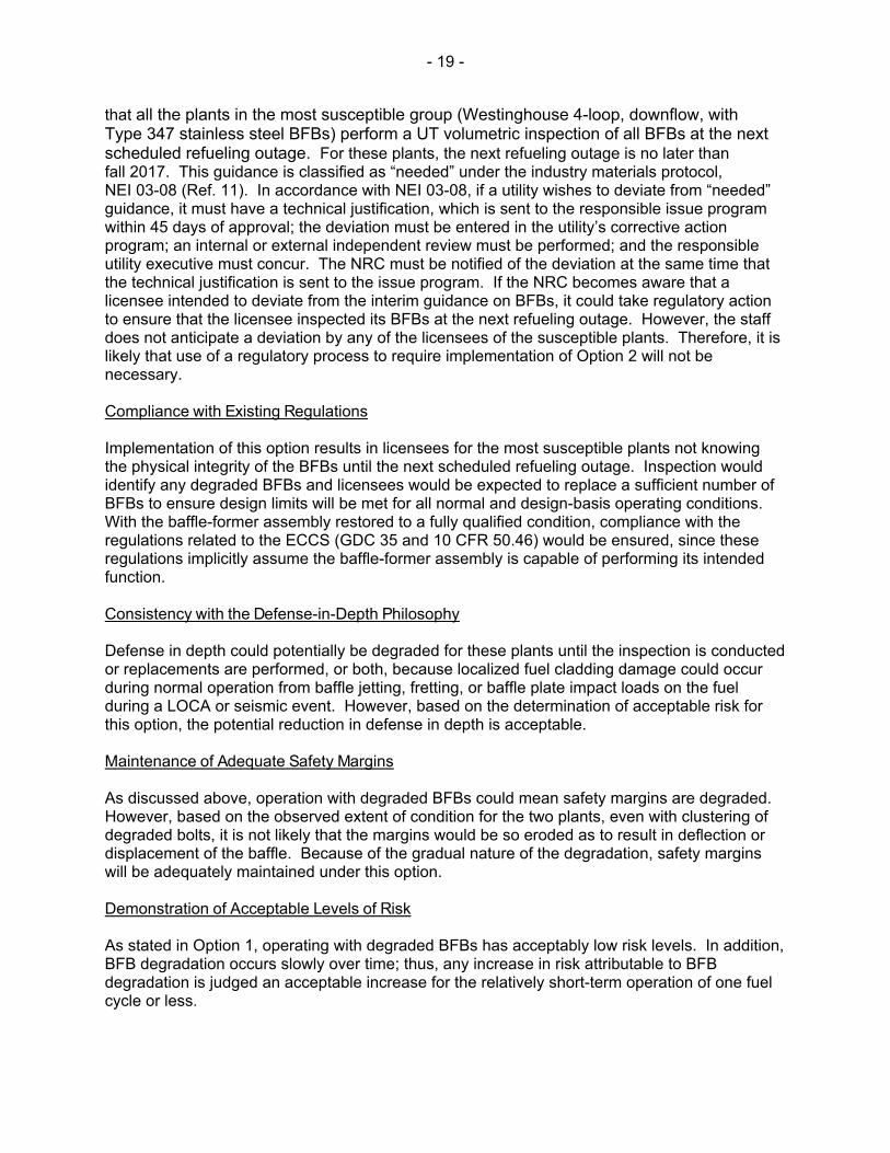
that all the plants in the most susceptible group (Westinghouse 4-loop, downflow, with Type 347 stainless steel BFBs) perform a UT volumetric inspection of all BFBs at the next scheduled refueling outage. For these plants, the next refueling outage is no later than fall 2017. This guidance is classified as “needed” under the industry materials protocol, NEI 03-08 (Ref. 11). In accordance with NEI 03-08, if a utility wishes to deviate from “needed” guidance, it must have a technical justification, which is sent to the responsible issue program within 45 days of approval; the deviation must be entered in the utility’s corrective action program; an internal or external independent review must be performed; and the responsible utility executive must concur. The NRC must be notified of the deviation at the same time that the technical justification is sent to the issue program. If the NRC becomes aware that a licensee intended to deviate from the interim guidance on BFBs, it could take regulatory action to ensure that the licensee inspected its BFBs at the next refueling outage. However, the staff does not anticipate a deviation by any of the licensees of the susceptible plants. Therefore, it is likely that use of a regulatory process to require implementation of Option 2 will not be necessary. Compliance with Existing Regulations Implementation of this option results in licensees for the most susceptible plants not knowing the physical integrity of the BFBs until the next scheduled refueling outage. Inspection would identify any degraded BFBs and licensees would be expected to replace a sufficient number of BFBs to ensure design limits will be met for all normal and design-basis operating conditions. With the baffle-former assembly restored to a fully qualified condition, compliance with the regulations related to the ECCS (GDC 35 and 10 CFR 50.46) would be ensured, since these regulations implicitly assume the baffle-former assembly is capable of performing its intended function. Consistency with the Defense-in-Depth Philosophy Defense in depth could potentially be degraded for these plants until the inspection is conducted or replacements are performed, or both, because localized fuel cladding damage could occur during normal operation from baffle jetting, fretting, or baffle plate impact loads on the fuel during a LOCA or seismic event. However, based on the determination of acceptable risk for this option, the potential reduction in defense in depth is acceptable. Maintenance of Adequate Safety Margins As discussed above, operation with degraded BFBs could mean safety margins are degraded. However, based on the observed extent of condition for the two plants, even with clustering of degraded bolts, it is not likely that the margins would be so eroded as to result in deflection or displacement of the baffle. Because of the gradual nature of the degradation, safety margins will be adequately maintained under this option. Demonstration of Acceptable Levels of Risk As stated in Option 1, operating with degraded BFBs has acceptably low risk levels. In addition, BFB degradation occurs slowly over time; thus, any increase in risk attributable to BFB degradation is judged an acceptable increase for the relatively short-term operation of one fuel cycle or less.
- 20 -
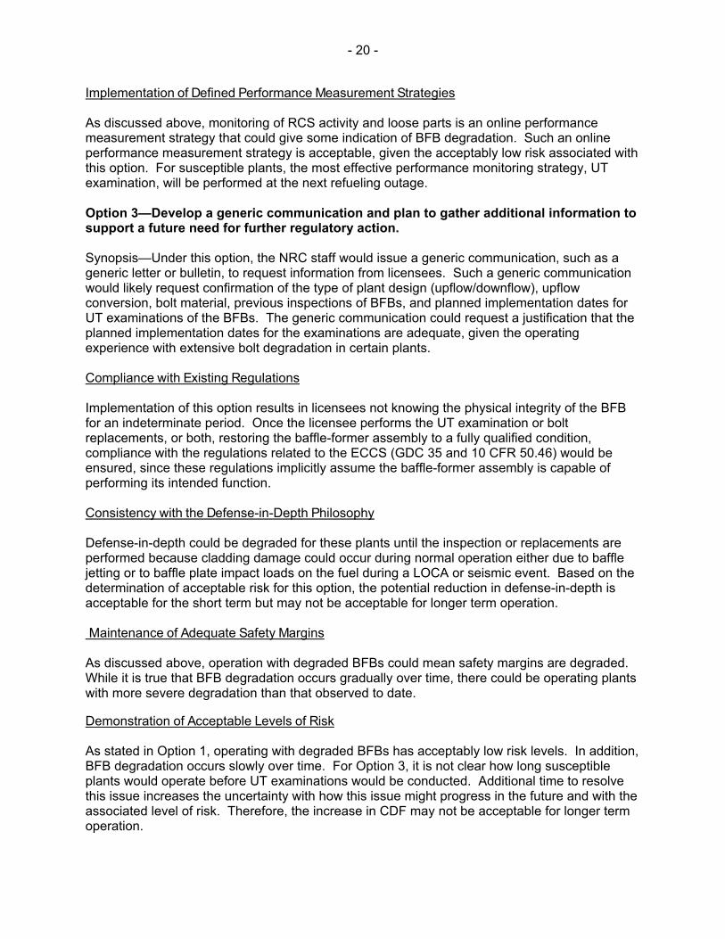
Implementation of Defined Performance Measurement Strategies As discussed above, monitoring of RCS activity and loose parts is an online performance measurement strategy that could give some indication of BFB degradation. Such an online performance measurement strategy is acceptable, given the acceptably low risk associated with this option. For susceptible plants, the most effective performance monitoring strategy, UT examination, will be performed at the next refueling outage. Option 3—Develop a generic communication and plan to gather additional information to support a future need for further regulatory action. Synopsis—Under this option, the NRC staff would issue a generic communication, such as a generic letter or bulletin, to request information from licensees. Such a generic communication would likely request confirmation of the type of plant design (upflow/downflow), upflow conversion, bolt material, previous inspections of BFBs, and planned implementation dates for UT examinations of the BFBs. The generic communication could request a justification that the planned implementation dates for the examinations are adequate, given the operating experience with extensive bolt degradation in certain plants. Compliance with Existing Regulations Implementation of this option results in licensees not knowing the physical integrity of the BFB for an indeterminate period. Once the licensee performs the UT examination or bolt replacements, or both, restoring the baffle-former assembly to a fully qualified condition, compliance with the regulations related to the ECCS (GDC 35 and 10 CFR 50.46) would be ensured, since these regulations implicitly assume the baffle-former assembly is capable of performing its intended function. Consistency with the Defense-in-Depth Philosophy Defense-in-depth could be degraded for these plants until the inspection or replacements are performed because cladding damage could occur during normal operation either due to baffle jetting or to baffle plate impact loads on the fuel during a LOCA or seismic event. Based on the determination of acceptable risk for this option, the potential reduction in defense-in-depth is acceptable for the short term but may not be acceptable for longer term operation. Maintenance of Adequate Safety Margins As discussed above, operation with degraded BFBs could mean safety margins are degraded. While it is true that BFB degradation occurs gradually over time, there could be operating plants with more severe degradation than that observed to date.
Demonstration of Acceptable Levels of Risk As stated in Option 1, operating with degraded BFBs has acceptably low risk levels. In addition, BFB degradation occurs slowly over time. For Option 3, it is not clear how long susceptible plants would operate before UT examinations would be conducted. Additional time to resolve this issue increases the uncertainty with how this issue might progress in the future and with the associated level of risk. Therefore, the increase in CDF may not be acceptable for longer term operation.

- 21 -
Implementation of Defined Performance Measurement Strategies As discussed above, monitoring RCS activity and loose parts is an online performance measurement strategy that could give some indication of BFB degradation and is acceptable, given the low risk associated with this option. Under Option 3, it is not clear when the most effective performance monitoring strategy, UT examination, will be conducted for susceptible plants. Option 4—Maintain status quo. Synopsis—Under this option, the NRC staff would take no action to require that the BFB margin to baffle failure be restored. Response to the operating experience with BFB degradation would be left to the discretion of the EPRI MRP and individual licensees. Licensees would be free to perform BFB inspections in accordance with the original recommended schedule in MRP-227-A (Ref. 3). Note that EPRI has already issued interim guidance for BFB inspections for the susceptible group of plants (Ref. 6). Compliance with Existing Regulations Implementation of this option results in licensees not knowing the physical integrity of the BFBs for an undetermined period. Once UT examinations or bolt replacements are performed, restoring the baffle-former assembly to a fully qualified condition, compliance with the regulations related to the ECCS (GDC 35 and 10 CFR 50.46) would be ensured, since these regulations implicitly assume the baffle-former assembly is capable of performing its intended function. Consistency with the Defense-in-Depth Philosophy Defense-in-depth could potentially be degraded for these plants until the inspection or replacements are performed, because localized fuel cladding damage could occur during normal operation from baffle jetting or to baffle plate impact loads on the fuel during a LOCA or seismic event. Based on the determination of acceptable risk for this option, the potential reduction in defense-in-depth is acceptable for the short term but may not be acceptable for longer term operation. Maintenance of Adequate Safety Margins As discussed above, operation with degraded BFBs could mean safety margins are degraded. While it is true that BFB degradation occurs gradually over time, there could be operating plants with more severe degradation than that observed to date. This option relies on normal inspections to identify plants with significant degradation. The amount of time until plants have been inspected could be longer than the time to gather information in Option 3. Waiting long periods of time to gather additional information results in greater exposure for a LOCA or seismic event or failure during normal operation. Demonstration of Acceptable Levels of Risk As with Option 3, it is not clear how long susceptible plants would operate before conducting UT examinations. Additional time to resolve this issue increases the uncertainty with how this issue might progress in the future, and the associated level of risk. Therefore, the increase in CDF may not be acceptable for longer term operation.

- 22 -
Implementation of Defined Performance Measurement Strategies As discussed above, monitoring RCS activity and loose parts is an online performance measurement strategy that could give some indication of BFB degradation and is acceptable, given the low risk associated with this option. Under Option 4, susceptible plants may not conduct the most effective performance monitoring strategy, UT examinations, until 3–10 years from 2016. Summary of Option Assessment The following table summarizes the four options against the five key principles of risk-informed regulation.
Comparison of Options for Potentially Susceptible Plants
Key Principle Option 1—Immediate Shutdown
Option 2—Restore to Acceptable
Level within 2 Years
Option 3—Generic
Communication & Information
Gathering
Option 4— Status Quo
Regulations No compliance issues are identified.
No compliance issues are identified.
No compliance issues are identified.
No compliance issues are identified.
Defense in Depth There is no impact, once plants are shut down and fully restored before startup.
There is a minor impact given the low likelihood of baffle failure before the next refueling outage.
It may be degraded if baffle failure results in localized fuel cladding damage during normal operation.
This is the same as Option 3.
Safety Margins The extent of degradation would be determined and margin restored before any events occur. There would be no additional erosion of safety margins.
There is a minor potential for further reduction in safety margins in this option, but this is not considered significant for such a short interval.
This is similar to Option 2, except there is increased uncertainty about how much margin will remain over the longer period to gather information. This represents an increased exposure to a LOCA or seismic event.
This is similar to Option 3
Risk This condition is judged to represent a very small increase in risk over the “as-found” condition, because plants would be shut down in the near term.
Degradation occurs slowly over time, so Option 2 is judged acceptable from a risk perspective. The risk during normal operations remains small, and the exposure
The longer time frame to resolve, compared to Option 2, results in increased uncertainty and risk exposure.
This would result in an even longer time frame and greater uncertainty than Option 3
- 23 -
Comparison of Options for Potentially Susceptible Plants
Key Principle Option 1—Immediate Shutdown
Option 2—Restore to Acceptable
Level within 2 Years
Option 3—Generic
Communication & Information
Gathering
Option 4— Status Quo
to a possible LOCA or seismic event is limited to one cycle.
Monitoring This is not applicable, since susceptible plants would shut down in the near term.
RCS activity and loose parts would be monitored. UT examinations would be conducted at the next refueling outage.
This is the same as Option 2, except the schedule for the next UT, which is the best monitoring method, is indeterminate.
As in Option 3, UT would be delayed as much as 10 years for some susceptible plants.
RECOMMENDATION The NRC staff recommends Option 2 as the one that restores margin in a timely manner with fewer burdens on licensees than Option 1. Options 3 and 4 are not preferred, in part because of the extended time that plants may operate with BFBs that continue to degrade. More detailed discussion follows. Option 1, under which immediate shutdown and inspection or bolt replacement would be required, is the option that ensures the following five key regulatory principles are maintained: (1) compliance with existing regulations (2) consistency with the defense-in-depth philosophy (3) maintenance of adequate safety margins (4) demonstration of acceptable levels of risk (5) implementation of defined performance measurement strategies While Option 1 would ensure that the risk associated with degraded BFBs is minimized, comparison with the LIC-504 guidelines does not indicate that this issue represents an imminent safety hazard. Therefore, an immediate shutdown is not required. Option 2, which would allow inspection or bolt replacement at the next refueling outage, may result in some degradation in defense-in-depth because of the potential for localized fuel cladding damage if a LOCA or SSE occurs before the inspection and result in a possible reduction in safety margins because the plant would operate with potentially degraded bolts. Because of the relatively short period of operation with potentially degraded BFBs and the staff’s evaluation that the risk of core damage from BFB degradation over this time period is low, Option 2 is acceptable, based on risk. Option 3, which would involve issuing a generic communication to gather information, and Option 4, which would maintain the status quo, may also result in some degradation of defense in depth and reduced safety margins, but the risk change per reactor year is assumed to be the same as for Option 2. Note, however, that risk-informed decisions should be made with
- 24 -
consideration of uncertainty. It is not known, for example, whether there may be currently operating plants with more severe BFB degradation than that observed in the two recent examples. As a result, the NRC staff is not comfortable with allowing an indeterminate time period before the UT inspections are conducted. The difference is that for Options 3 and 4, the increase in CDF would be for a longer time period than for Option 2. Limited tooling currently exists in the nuclear industry to perform the UT examinations and bolt replacements. Therefore, if Option 1 were chosen, it is likely that many of the susceptible plants would remain shut down for an extended period of time while waiting for tooling. Given that Option 2 has an acceptably low increase in CDF associated with it, imposing Option 1 would likely represent an unnecessary hardship on the licensees, considering the extended outages that could result. Although Option 3 and Option 4 initially have the same increase in CDF per reactor year as Option 2, the time frame under which inspections and bolt replacements would occur under these options is extended, so the increase in CDF becomes more uncertain with time. Based on these considerations, the staff considers Option 2 to be the best option for addressing potential BFB degradation. MRP Letter 2016-022 (Ref. 6) transmitted interim guidance from the EPRI MRP that recommended that the plants in the most susceptible group (Westinghouse 4-loop, downflow, with Type 347 stainless steel BFBs) conduct a UT examination of all BFBs at the next scheduled refueling outage. For these plants, the next refueling outage is no later than fall 2017. This guidance is classified as “needed” under the industry materials protocol, NEI 03-08 (Ref. 11). The NRC staff will review the interim guidance and document its review in a publicly available safety assessment. The staff does not expect that any of the plants in the susceptible group will deviate from the interim guidance. Therefore, since the industry is essentially mandating Option 2 through the NEI 03-08 materials protocol, it is not expected that the staff will need to take regulatory action to ensure that licensees implement Option 2. However, NEI 03-08 requires the NRC to be notified of deviations from “needed” guidance. Therefore, if any of the plants in the most susceptible group intends to deviate from the interim guidance, the NRC would be notified and could take regulatory action to ensure that the plant would conduct a UT examination at the next refueling outage.
- 25 -
REFERENCES 1. Licensee Event Report (LER) 2016-004-00, “Unanalyzed Condition due to Degraded
Reactor Baffle-Former Bolts,” Indian Point Unit No. 2, Docket No. 50-247, DPR-46, May 31, 2016 (ADAMS Accession No. ML16159A219).
2. LER 272/2016-001-00, “Unanalyzed Condition due to Degraded Reactor Baffle to Former Bolts,” Salem Nuclear Generating Station Unit 1, Renewed Facility Operating License No. DPR-70, NRC Docket No. 50-272, July 5, 2016 (ADAMS Accession No. ML16187A330).
3. “Materials Reliability Program: Pressurized Water Reactor Internals Inspection and Evaluation Guidelines (MRP-227-A),” 2011 Technical Report, December 2011, transmitted to the NRC by MRP letter MRP-2011-036, dated January 9, 2012 (ADAMS Accession No. ML120170453).
4. Westinghouse Technical Bulletin TB-12-5, “Baffle Bolt Degradation in a Westinghouse NSSS Plant with Downflow Reactor Internal Design,” March 7, 2012.
5. Westinghouse Nuclear Safety Advisory Letter (NSAL)-16-1 Revision 1, “Baffle-Former Bolts,” Westinghouse Electric Co. LLC, August 1, 2016.
6. Letter from Bernie Rudell and Anne Demma to the NRC, Subject: “Transmittal of NEI-03-08, ‘Needed’ Interim Guidance Regarding Baffle Former Bolt inspections for Tier 1 plants as Defined in Westinghouse NSAL-16-01,” EPRI Materials Reliability Program, transmitted by letter MRP 2016-022, July 27, 2016 (ADAMS Accession No. ML16211A054).
7. Westinghouse Topical Report ENT000654, WCAP-15270, “Determination of Acceptable Baffle-Barrel-Bolting for Four-Loop Westinghouse Downflow and Converted Upflow Domestic Plants,” November 30, 2001 (ADAMS Accession No. ML15222B242).
8. Westinghouse Topical Report WCAP-15029-P-A, “Westinghouse Methodology for Evaluating Acceptability of Baffle-Former-Barrel Bolting Distributions Under Faulted Load Conditions,” Revision 1, December 31, 1998 (ADAMS Legacy Library Accession No. 9905070164).
9. ENT000655—Westinghouse, WCAP 15030-NP-A, “Westinghouse Methodology for Evaluating the Acceptability of Baffle-Former-Barrel Bolting Distributions under Faulted Load Conditions,” March 2, 1999.
10. NUREG-1829, “Estimating Loss-of-Coolant Accident (LOCA) Frequencies Through the Elicitation Process,” U.S. Nuclear Regulatory Commission, April 2008 (ADAMS Accession No. ML080630013).
11. NEI 03-08, “Guideline for the Management of Materials Issues,” Revision 2, Nuclear Energy Institute, January 2010 (ADAMS Accession No. ML101050337).
ATTACHMENTS Attachment 1: Design and Function of Baffle-Former Assembly Attachment 2: Principles of Risk-Informed Decisionmaking Attachment 3: Seismic Risk Assessment of Degraded Baffle-Former Bolts
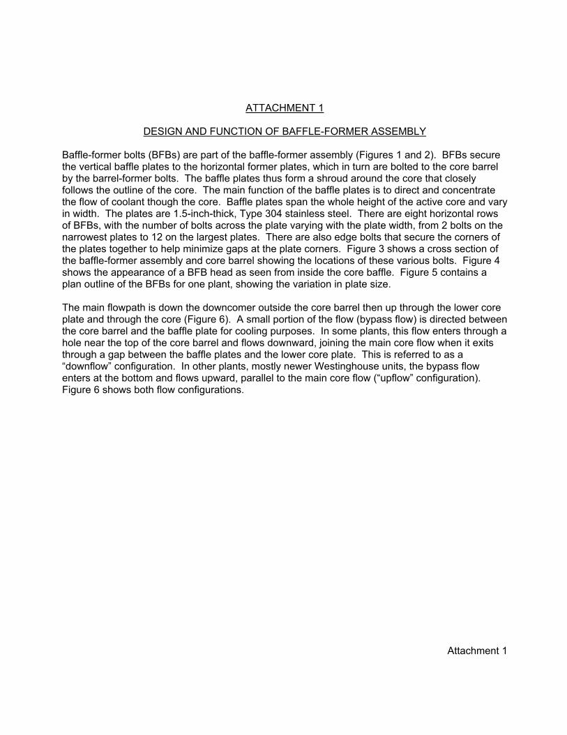
Attachment 1
ATTACHMENT 1
DESIGN AND FUNCTION OF BAFFLE-FORMER ASSEMBLY Baffle-former bolts (BFBs) are part of the baffle-former assembly (Figures 1 and 2). BFBs secure the vertical baffle plates to the horizontal former plates, which in turn are bolted to the core barrel by the barrel-former bolts. The baffle plates thus form a shroud around the core that closely follows the outline of the core. The main function of the baffle plates is to direct and concentrate the flow of coolant though the core. Baffle plates span the whole height of the active core and vary in width. The plates are 1.5-inch-thick, Type 304 stainless steel. There are eight horizontal rows of BFBs, with the number of bolts across the plate varying with the plate width, from 2 bolts on the narrowest plates to 12 on the largest plates. There are also edge bolts that secure the corners of the plates together to help minimize gaps at the plate corners. Figure 3 shows a cross section of the baffle-former assembly and core barrel showing the locations of these various bolts. Figure 4 shows the appearance of a BFB head as seen from inside the core baffle. Figure 5 contains a plan outline of the BFBs for one plant, showing the variation in plate size. The main flowpath is down the downcomer outside the core barrel then up through the lower core plate and through the core (Figure 6). A small portion of the flow (bypass flow) is directed between the core barrel and the baffle plate for cooling purposes. In some plants, this flow enters through a hole near the top of the core barrel and flows downward, joining the main core flow when it exits through a gap between the baffle plates and the lower core plate. This is referred to as a “downflow” configuration. In other plants, mostly newer Westinghouse units, the bypass flow enters at the bottom and flows upward, parallel to the main core flow (“upflow” configuration). Figure 6 shows both flow configurations.
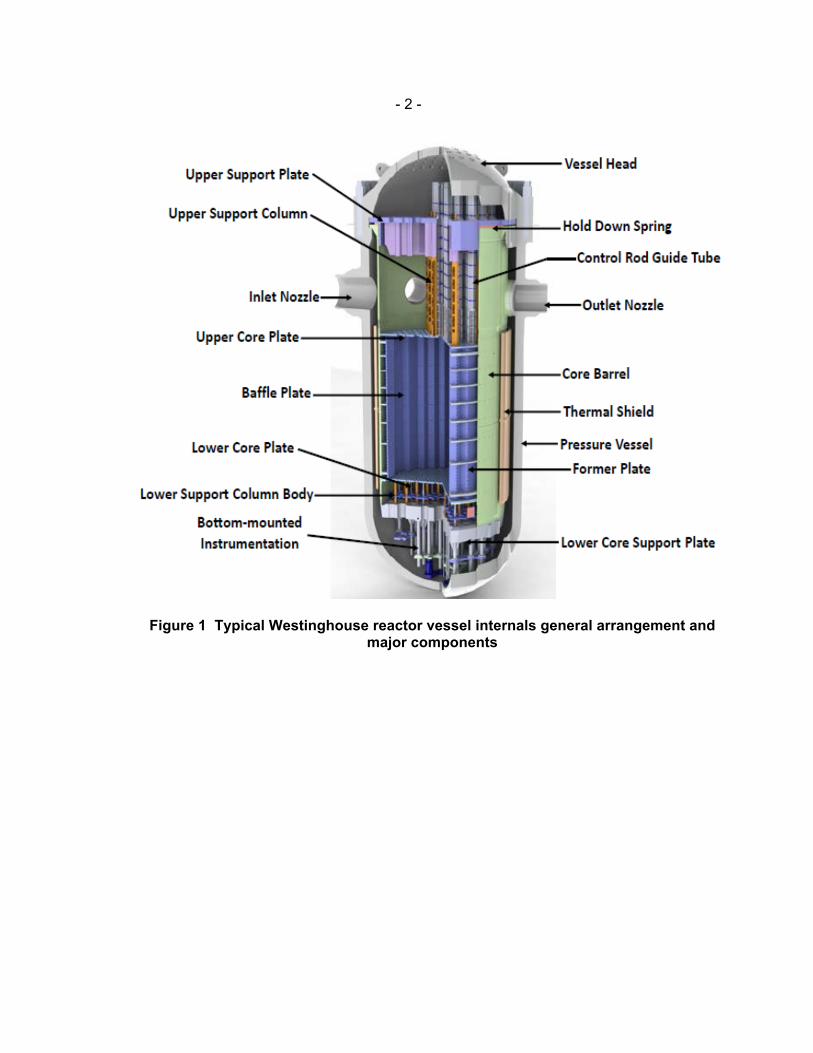
- 2 -
Figure 1 Typical Westinghouse reactor vessel internals general arrangement and major components
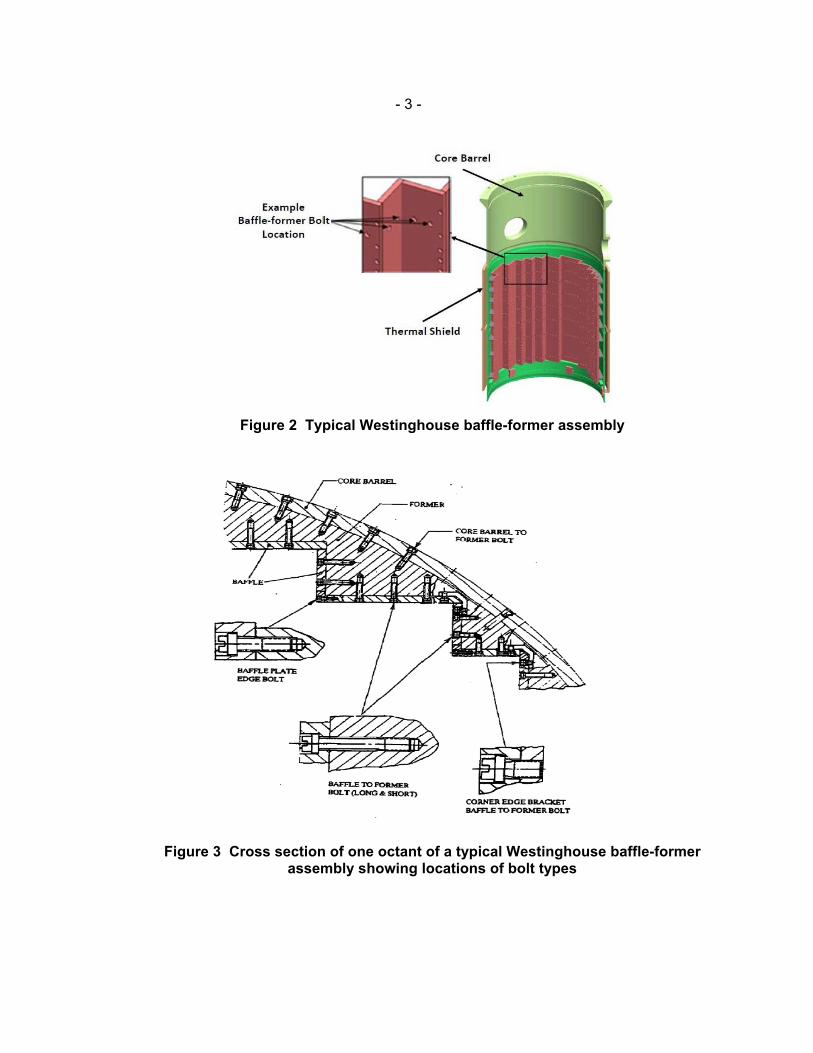
- 3 -
Figure 2 Typical Westinghouse baffle-former assembly
Figure 3 Cross section of one octant of a typical Westinghouse baffle-former assembly showing locations of bolt types
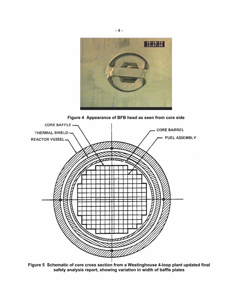
- 4 -
Figure 4 Appearance of BFB head as seen from core side
Figure 5 Schematic of core cross section from a Westinghouse 4-loop plant updated final
safety analysis report, showing variation in width of baffle plates

- 5 -
Figure 6 Schematic of flowpaths in Westinghouse-designed reactor internals, comparing downflow and upflow configurations
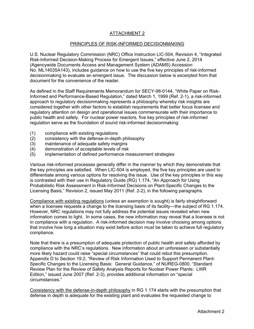
Attachment 2
ATTACHMENT 2
PRINCIPLES OF RISK-INFORMED DECISIONMAKING U.S. Nuclear Regulatory Commission (NRC) Office Instruction LIC-504, Revision 4, “Integrated Risk-Informed Decision-Making Process for Emergent Issues,” effective June 2, 2014 (Agencywide Documents Access and Management System (ADAMS) Accession No. ML14035A143), includes guidance on how to use the five key principles of risk-informed decisionmaking to evaluate an emergent issue. The discussion below is excerpted from that document for the convenience of the reader. As defined in the Staff Requirements Memorandum for SECY-98-0144, “White Paper on Risk-Informed and Performance-Based Regulation,” dated March 1, 1999 (Ref. 2-1), a risk-informed approach to regulatory decisionmaking represents a philosophy whereby risk insights are considered together with other factors to establish requirements that better focus licensee and regulatory attention on design and operational issues commensurate with their importance to public health and safety. For nuclear power reactors, five key principles of risk-informed regulation serve as the foundation of sound risk-informed decisionmaking: (1) compliance with existing regulations (2) consistency with the defense-in-depth philosophy (3) maintenance of adequate safety margins (4) demonstration of acceptable levels of risk (5) implementation of defined performance measurement strategies
Various risk-informed processes generally differ in the manner by which they demonstrate that the key principles are satisfied. When LIC-504 is employed, the five key principles are used to differentiate among various options for resolving the issue. Use of the key principles in this way is contrasted with their use in Regulatory Guide (RG) 1.174, “An Approach for Using Probabilistic Risk Assessment in Risk-Informed Decisions on Plant-Specific Changes to the Licensing Basis,” Revision 2, issued May 2011 (Ref. 2-2), in the following paragraphs. Compliance with existing regulations (unless an exemption is sought) is fairly straightforward when a licensee requests a change to the licensing basis of its facility—the subject of RG 1.174. However, NRC regulations may not fully address the potential issues revealed when new information comes to light. In some cases, the new information may reveal that a licensee is not in compliance with a regulation. A risk-informed decision may involve choosing among options that involve how long a situation may exist before action must be taken to achieve full regulatory compliance. Note that there is a presumption of adequate protection of public health and safety afforded by compliance with the NRC’s regulations. New information about an unforeseen or substantially more likely hazard could raise “special circumstances” that could rebut this presumption. Appendix D to Section 19.2, “Review of Risk Information Used to Support Permanent Plant-Specific Changes to the Licensing Basis: General Guidance,” of NUREG-0800, “Standard Review Plan for the Review of Safety Analysis Reports for Nuclear Power Plants: LWR Edition,” issued June 2007 (Ref. 2-3), provides additional information on “special circumstances.” Consistency with the defense-in-depth philosophy in RG 1.174 starts with the presumption that defense in depth is adequate for the existing plant and evaluates the requested change to
- 2 -
determine whether defense in depth is maintained. For emergent issues, this key principle is used to compare various options proposed for addressing the issue. In some cases, defense in depth may be at the heart of the issue—that is, the new information may reveal insufficient defense in depth for the existing facility. Maintenance of adequate safety margins in RG 1.174 includes compliance with codes and standards and meeting the safety analysis acceptance criteria in a plant’s licensing basis. The LIC-504 approach to this key principle is no different. Appendix D to this office instruction provides questions to assist in evaluating how well each proposed option for addressing an emergent issue maintains safety margins. Demonstration of acceptable levels of risk in RG 1.174 concentrates on the change in risk associated with the proposed amendment to a plant’s licensing basis. For emergent issues, the total risk associated with the new or increased hazard may provide a basis for concluding that an immediate safety concern exists, such that the NRC must take prompt action to put a nuclear power plant in a safe condition. The risk associated with each proposed option for resolving the issue, in conjunction with the other key principles, may help the decision authority in choosing from among the options. Note that a quantitative risk assessment may prove difficult to obtain for many emergent issues. Qualitative risk assessments may be employed, as appropriate. Implementation of defined performance measurement strategies in RG 1.174 means to ensure monitoring is put in place so that (1) the desired outcomes of the change are obtained and (2) unintended adverse consequences of the change can be detected in time to take corrective action. This is the same for LIC-504. The decision regarding an emergent issue may apply for a finite time period (e.g., until a licensee can effect a permanent repair), so that this office instruction includes compensatory measures within the scope of this key principle. Appendix D to the licensing instruction includes guidance for performance monitoring and compensatory measures. Attachment 2 References 2-1 Staff Requirements Memorandum SRM-SECY-98-0144, “White Paper on Risk-Informed
and Performance-Based Regulation,” U.S. Nuclear Regulatory Commission, Washington, DC, March 1, 1999 (ADAMS Accession No. ML003753601).
2-2 Regulatory Guide 1.174, “An Approach for Using Probabilistic Risk Assessment in
Risk-Informed Decisions on Plant-Specific Changes to the Licensing Basis,” Revision 2, U.S. Nuclear Regulatory Commission, Washington, DC, May 2011 (ADAMS Accession No. ML100910006).
2-3 NUREG-0800, “Standard Review Plan for the Review of Safety Analysis Reports for
Nuclear Power Plants: LWR Edition,” Section 19.2, “Review of Risk Information Used to Support Permanent Plant-Specific Changes to the Licensing Basis: General Guidance,” U.S. Nuclear Regulatory Commission, Washington, DC, June 2007 (ADAMS Accession No. ML071700658).
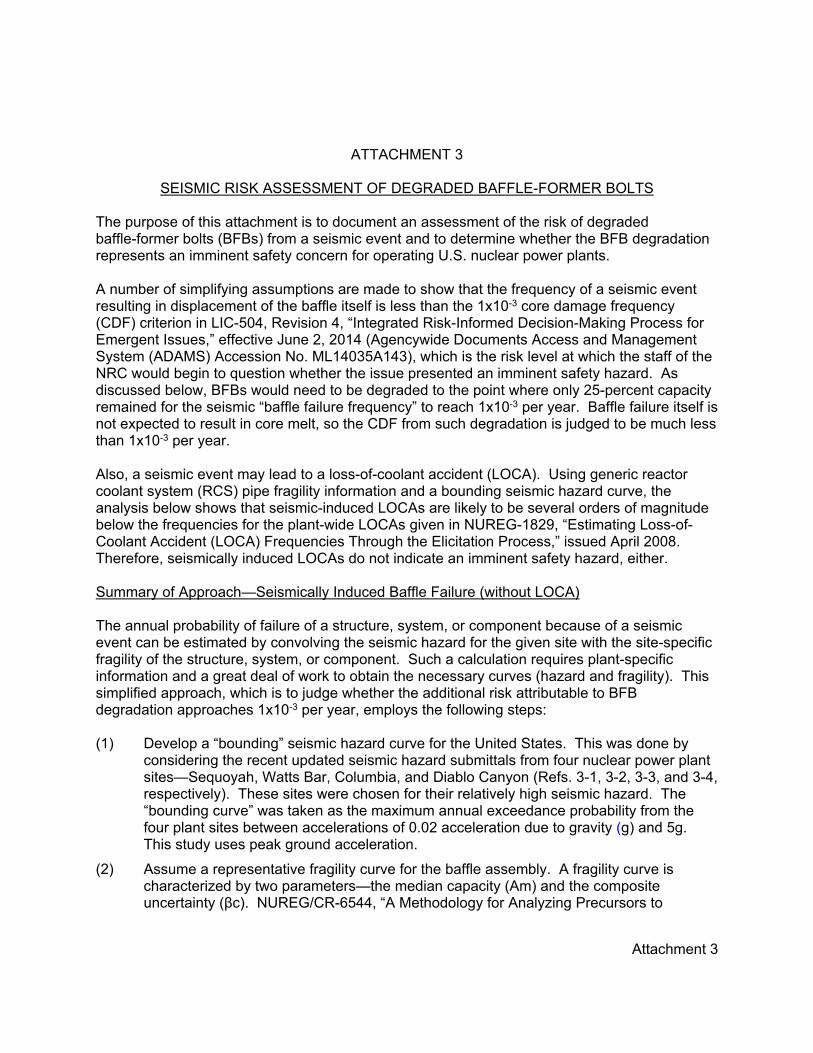
Attachment 3
ATTACHMENT 3
SEISMIC RISK ASSESSMENT OF DEGRADED BAFFLE-FORMER BOLTS The purpose of this attachment is to document an assessment of the risk of degraded baffle-former bolts (BFBs) from a seismic event and to determine whether the BFB degradation represents an imminent safety concern for operating U.S. nuclear power plants. A number of simplifying assumptions are made to show that the frequency of a seismic event resulting in displacement of the baffle itself is less than the 1x10⁻³ core damage frequency (CDF) criterion in LIC-504, Revision 4, “Integrated Risk-Informed Decision-Making Process for Emergent Issues,” effective June 2, 2014 (Agencywide Documents Access and Management System (ADAMS) Accession No. ML14035A143), which is the risk level at which the staff of the NRC would begin to question whether the issue presented an imminent safety hazard. As discussed below, BFBs would need to be degraded to the point where only 25-percent capacity remained for the seismic “baffle failure frequency” to reach 1x10⁻³ per year. Baffle failure itself is not expected to result in core melt, so the CDF from such degradation is judged to be much less than 1x10⁻³ per year. Also, a seismic event may lead to a loss-of-coolant accident (LOCA). Using generic reactor coolant system (RCS) pipe fragility information and a bounding seismic hazard curve, the analysis below shows that seismic-induced LOCAs are likely to be several orders of magnitude below the frequencies for the plant-wide LOCAs given in NUREG-1829, “Estimating Loss-of-Coolant Accident (LOCA) Frequencies Through the Elicitation Process,” issued April 2008. Therefore, seismically induced LOCAs do not indicate an imminent safety hazard, either. Summary of Approach—Seismically Induced Baffle Failure (without LOCA) The annual probability of failure of a structure, system, or component because of a seismic event can be estimated by convolving the seismic hazard for the given site with the site-specific fragility of the structure, system, or component. Such a calculation requires plant-specific information and a great deal of work to obtain the necessary curves (hazard and fragility). This simplified approach, which is to judge whether the additional risk attributable to BFB degradation approaches 1x10⁻³ per year, employs the following steps: (1) Develop a “bounding” seismic hazard curve for the United States. This was done by
considering the recent updated seismic hazard submittals from four nuclear power plant sites—Sequoyah, Watts Bar, Columbia, and Diablo Canyon (Refs. 3-1, 3-2, 3-3, and 3-4, respectively). These sites were chosen for their relatively high seismic hazard. The “bounding curve” was taken as the maximum annual exceedance probability from the four plant sites between accelerations of 0.02 acceleration due to gravity (g) and 5g. This study uses peak ground acceleration.
(2) Assume a representative fragility curve for the baffle assembly. A fragility curve is characterized by two parameters—the median capacity (Am) and the composite uncertainty (βc). NUREG/CR-6544, “A Methodology for Analyzing Precursors to

- 2 -
Earthquake-Initiated and Fire-Initiated Accident Sequences,” issued April 1998 (Ref. 3-5), provides generic fragility information in Table 6-1 for “reactor vessel internals.” The resulting fragility parameters are Am = 1.8 and βc = 0.5. Use of generic fragility parameters ignores the transmission of the seismic energy from the location where the seismic hazard was developed (“control point”) to the specific location of the RCS piping, but the use of this generic estimate is judged acceptable for this notional study (see “assumptions,” below).
(3) For each earthquake severity “bin” above 0.02g, determine the annual probability of an earthquake occurring in that bin (using the bounding hazard curve) and the probability of failure of the baffle assembly (its “fragility”) using the average earthquake intensity in that bin, where the average is taken as the geometric average of the upper and lower acceleration end points.
(4) For each earthquake severity bin, multiply the annual probability of occurrence by the probability of baffle failure for that intensity earthquake. The “baffle failure frequency” is given by the sum of the annual failure frequencies of each bin.
(5) Perform sensitivity studies using reduced values of Am corresponding to a percent reduction in the ability of the baffle assembly to withstand a seismic event.
Summary of Approach—Baffle Failure from a Seismically Induced LOCA The approach for determining the frequency of a seismically induced LOCA is similar to that described above for baffle assembly failure: (1) Use the same bounding hazard curve described above.
(2) The fragility parameters for piping also come from NUREG/CR-6544 and are taken as Am = 3.8 and βc = 0.61.
(3) The annual frequency of a pipe-break LOCA resulting from a seismic event is estimated in the same manner as steps 3 and 4 above for the baffle assembly failure calculation. However, in this case, no sensitivity studies are performed, as the overall seismically induced LOCA frequency is what is desired for this analysis.
Assumptions—Both Methods The analysis described above makes a number of assumptions. Since the goal of this analysis is to determine whether an imminent safety concern might exist, the use of bounding assumptions is useful to add confidence to the result. However, not all of the assumptions can be demonstrated to be bounding. On the other hand, baffle deformation or displacement is not expected to result in core melt, although limited cladding damage might occur if a loose baffle plate affected a peripheral fuel assembly. The assumptions include the following: • The peak ground acceleration seismic hazard curves were used. No spectral
information was used.
• No amplification or attenuation is assumed.
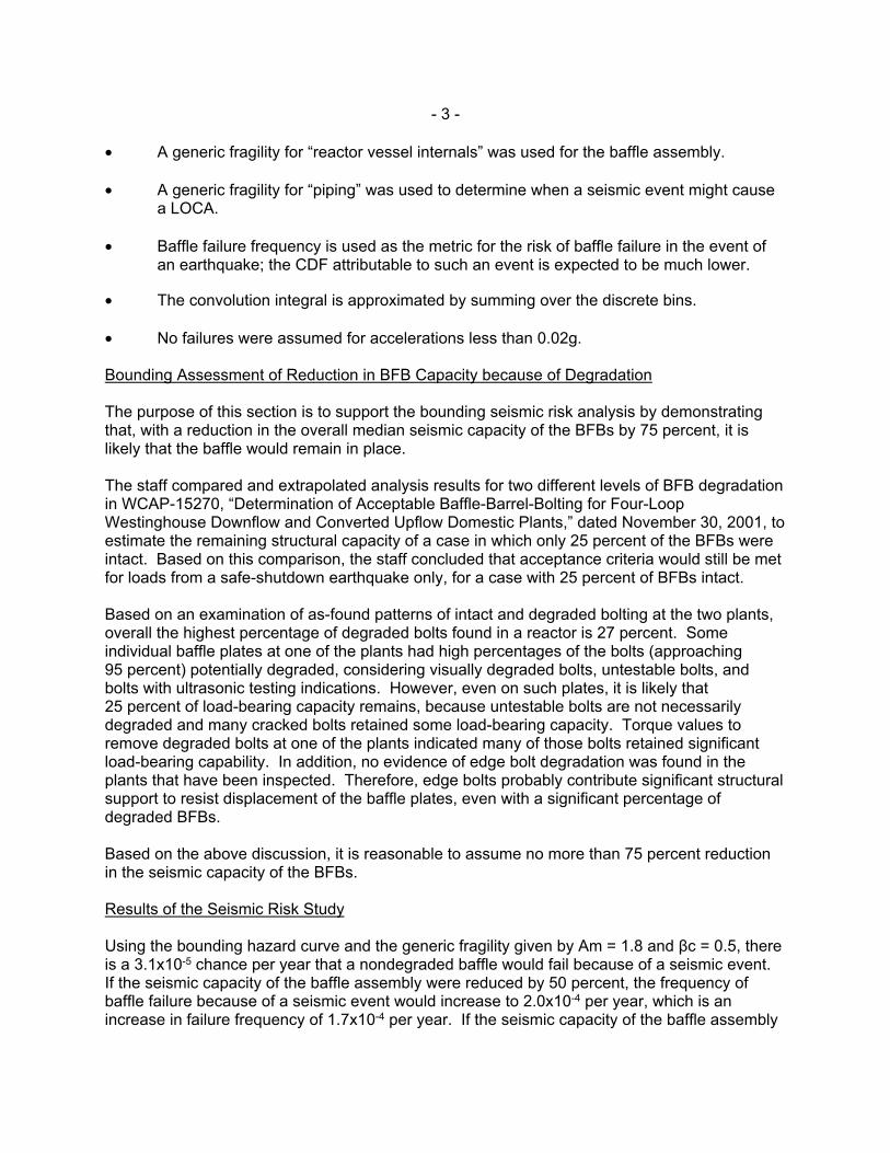
- 3 -
• A generic fragility for “reactor vessel internals” was used for the baffle assembly.
• A generic fragility for “piping” was used to determine when a seismic event might cause a LOCA.
• Baffle failure frequency is used as the metric for the risk of baffle failure in the event of an earthquake; the CDF attributable to such an event is expected to be much lower.
• The convolution integral is approximated by summing over the discrete bins.
• No failures were assumed for accelerations less than 0.02g. Bounding Assessment of Reduction in BFB Capacity because of Degradation The purpose of this section is to support the bounding seismic risk analysis by demonstrating that, with a reduction in the overall median seismic capacity of the BFBs by 75 percent, it is likely that the baffle would remain in place. The staff compared and extrapolated analysis results for two different levels of BFB degradation in WCAP-15270, “Determination of Acceptable Baffle-Barrel-Bolting for Four-Loop Westinghouse Downflow and Converted Upflow Domestic Plants,” dated November 30, 2001, to estimate the remaining structural capacity of a case in which only 25 percent of the BFBs were intact. Based on this comparison, the staff concluded that acceptance criteria would still be met for loads from a safe-shutdown earthquake only, for a case with 25 percent of BFBs intact. Based on an examination of as-found patterns of intact and degraded bolting at the two plants, overall the highest percentage of degraded bolts found in a reactor is 27 percent. Some individual baffle plates at one of the plants had high percentages of the bolts (approaching 95 percent) potentially degraded, considering visually degraded bolts, untestable bolts, and bolts with ultrasonic testing indications. However, even on such plates, it is likely that 25 percent of load-bearing capacity remains, because untestable bolts are not necessarily degraded and many cracked bolts retained some load-bearing capacity. Torque values to remove degraded bolts at one of the plants indicated many of those bolts retained significant load-bearing capability. In addition, no evidence of edge bolt degradation was found in the plants that have been inspected. Therefore, edge bolts probably contribute significant structural support to resist displacement of the baffle plates, even with a significant percentage of degraded BFBs. Based on the above discussion, it is reasonable to assume no more than 75 percent reduction in the seismic capacity of the BFBs. Results of the Seismic Risk Study Using the bounding hazard curve and the generic fragility given by Am = 1.8 and βc = 0.5, there is a 3.1x10⁻⁵ chance per year that a nondegraded baffle would fail because of a seismic event. If the seismic capacity of the baffle assembly were reduced by 50 percent, the frequency of baffle failure because of a seismic event would increase to 2.0x10⁻⁴ per year, which is an increase in failure frequency of 1.7x10⁻⁴ per year. If the seismic capacity of the baffle assembly
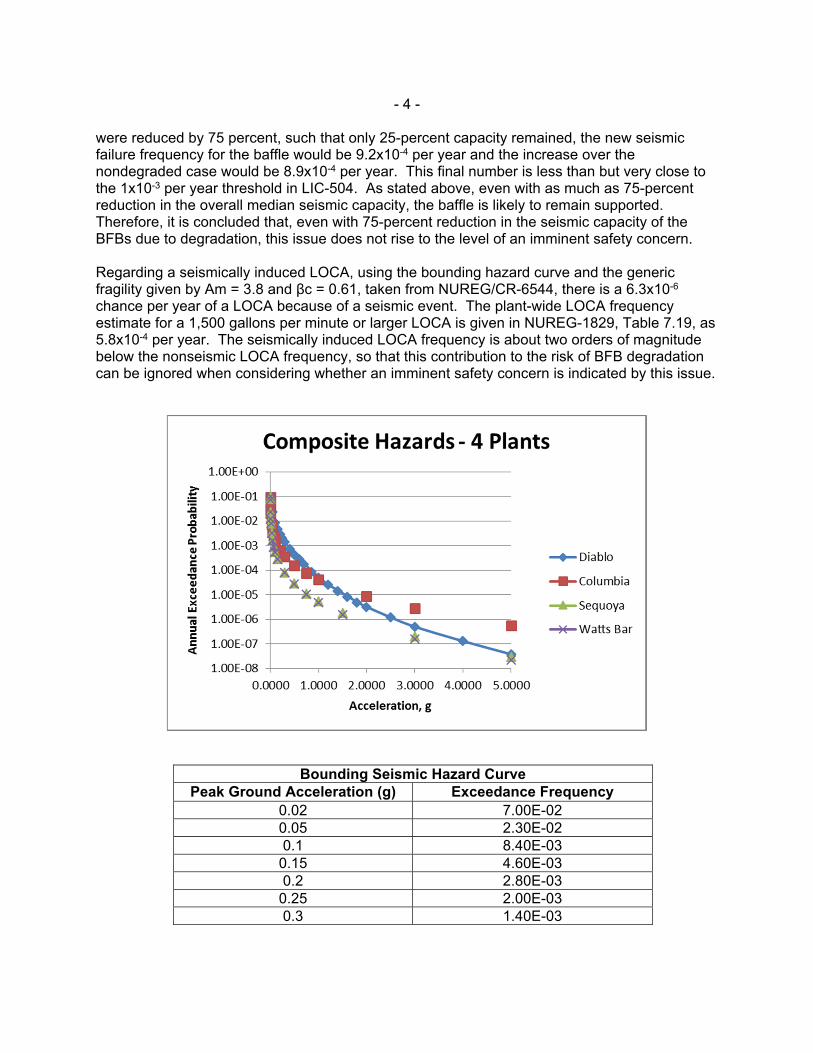
- 4 -
were reduced by 75 percent, such that only 25-percent capacity remained, the new seismic failure frequency for the baffle would be 9.2x10⁻⁴ per year and the increase over the nondegraded case would be 8.9x10⁻⁴ per year. This final number is less than but very close to the 1x10⁻³ per year threshold in LIC-504. As stated above, even with as much as 75-percent reduction in the overall median seismic capacity, the baffle is likely to remain supported. Therefore, it is concluded that, even with 75-percent reduction in the seismic capacity of the BFBs due to degradation, this issue does not rise to the level of an imminent safety concern. Regarding a seismically induced LOCA, using the bounding hazard curve and the generic fragility given by Am = 3.8 and βc = 0.61, taken from NUREG/CR-6544, there is a 6.3x10⁻⁶ chance per year of a LOCA because of a seismic event. The plant-wide LOCA frequency estimate for a 1,500 gallons per minute or larger LOCA is given in NUREG-1829, Table 7.19, as 5.8x10⁻⁴ per year. The seismically induced LOCA frequency is about two orders of magnitude below the nonseismic LOCA frequency, so that this contribution to the risk of BFB degradation can be ignored when considering whether an imminent safety concern is indicated by this issue.
Bounding Seismic Hazard Curve
Peak Ground Acceleration (g) Exceedance Frequency 0.02 7.00E-02 0.05 2.30E-02 0.1 8.40E-03
0.15 4.60E-03 0.2 2.80E-03
0.25 2.00E-03 0.3 1.40E-03

- 5 -
Bounding Seismic Hazard Curve Peak Ground Acceleration (g) Exceedance Frequency
0.40 7.30E-04 0.5 4.30E-04
0.60 2.80E-04 0.70 1.70E-04 0.85 8.60E-05
1. 4.90E-05 2 8.52E-06 3. 2.79E-06 5. 5.43E-07
- 6 -
Attachment 3 References 3-1 Letter, J.W. Shea to NRC, “Tennessee Valley Authority’s Seismic Hazard and Screening
Report (CEUS Sites), Response to NRC Request for Information Pursuant to 10 CFR 50.54(f) Regarding Recommendation 2.1 of the Near-Term Task Force Review of Insights from the Fukushima Dai-ichi Accident,” CNL-14-038, March 31, 2014; Enclosure 3, “Seismic Hazard and Screening Report for Tennessee Valley Authority’s Sequoyah Nuclear Plant,” Table A-1g (ADAMS Accession No. ML14098A478).
3-2 Letter, J.W. Shea to NRC, “Tennessee Valley Authority’s Seismic Hazard and Screening Report (CEUS Sites), Response to NRC Request for Information Pursuant to 10 CFR 50.54(f) Regarding Recommendation 2.1 of the Near-Term Task Force Review of Insights from the Fukushima Dai-ichi Accident,” CNL-14-038, March 31, 2014; Enclosure 4, “Seismic Hazard and Screening Report for Tennessee Valley Authority's Watts Bar Nuclear Plant,” Table A-1g (ADAMS Accession No. ML14098A478).
3-3 Letter, David A. Swank to NRC, “Columbia Generating Station, Docket No. 50-397, Seismic Hazard and Screening Report, Response to NRC Request for Information Pursuant to 10 CFR 50.54(f) Regarding Recommendation 2.1 of the Near-Term Task Force Review of Insights from the Fukushima Dai-ichi Accident,” GO2-15-045, March 12, 2015; Table 2.2.2-2a: “Annual Frequency of Exceedance Mean and Fractile Base Rock Seismic Hazard Curves for PGA at Columbia Generating Station (PNNL, 2014),” (ADAMS Accession No. ML15078A243).
3-4 Letter, Barry S. Allen to NRC, “Response to NRC Request for Information Pursuant to 10 CFR 50.54(f) Regarding the Seismic Aspects of Recommendation 2.1 of the Near-Term Task Force Review of Insights from the Fukushima Dai-ichi Accident: Seismic Hazard and Screening Report,” PG&E Letter DCL-15-035, March 11, 2015; Volume 2, Table A2.0-1: “Mean and Fractiles of Hazard for the Control Point for Peak Acceleration” (ADAMS Accession No. ML15070A607 (Vol. 1) and ML15070A608 (Vol. 2)).
3-5 NUREG/CR-6544, “A Methodology for Analyzing Precursors to Earthquake-Initiated and Fire-Initiated Accident Sequences,” April 1998 (ADAMS Accession No. ML071650470).