Embed Size (px)
Citation preview

AD-AL07 321 FOREIGN TECHNOLOY DIV WIGT-PATUgASON APS ON /55ANTENNA (SELECTED APTICLES1IM .4W9/OCT &1 0 M TUWIANOV. A A PISIOL'KCAS
UNCLASSIFIED FTO-IO(RS)T-093?*-gMENllllllllI*l onrnrnrllll"'IIIIIIIllllllhllllllllllllllllIJl//////l//Ihh

28 52.2
111L- 136
11L15 -4 I .6
MIC ROCOPY RESCL TION U ST CHARTNAIIINA, HUJ61AIl I TA1NI, ( A I 'll1

/1
FTD-ID(RS)T-0937-81
FOREIGN TECHNOLOGY DIVISION
ANTENNA
(Selected Articles)
I- TE
LAW Approved for public release;distribution unlimited.

~L
FTD-ID(RS)T-0937-81
EDITED TRANSLATION
SFTD-ID(RS)T-937-8,// 19 Octotr 1981
MICROFICHE NR: FTD-81-C-000963
ANTENNA (Selected Articles),,
Englih- pages: 91
Sourc -.- Antenny, Nr.-, 1967_, _p. 4-32,
Country of origin:/'(USSR) r / -Translated by: LEO K-ANNER ASSOCIATESF33657-81-D-0264
Requester: FTD/TQFEApproved for public release; distributionunlimited.
/
//
THIS TRANSLATION IS A RENDITION OF THE ORIGI.
NAL FOREIGN TEXT WITHOUT ANY ANALYTICAL OREDITORIAL COMMENT. STATEMENTS OR THEORIES PREPARED BY:ADVOCATED OR IMPLIED ARE THOSE OF THE SOURCEAND DO NOT NECESSARILY REFLECT THE POSITION TRANSLATION DIVISIONOR OPINION OF THE FOREIGN TECHNOLOGY DI. FOREIGN TECHNOLOGY DIVISIONVISION. WP.AF6, OHIO.
FTD-ID (RS )T-0937-81 Date i 9 o-t 19.8
7//

TABLE 01' CONTENTS
U. S. Board on Geographic Names Transliteration System ....... ii
The Developmnet of Domestic Technology for TelevisionTransmitting Antennas, by D. M. Truskanov .................... 1
Discrimination of Hologram and Antenna Theory, byA. A. Pistol'kors ............................................ 38
Radiation of an Antenna in the Form of a Ribbed Shaftof Finite Length, by G. D. Malushkov ......................... 58
Possibilities of Phase Correction on the Small Reflectionin a Two-Reflector Antenna, by A. L. Ayzenberg ............... 75
_Accession For77
NTIS 3R A&ID)TIC TAR
ir

U. S. BOARD ON GEOGRAPHIC NAMES TRANSLITERATION SYSTEM
Block Italic Transliteration Block Italic Transliteratic..
A a A a A, a P p p r
E B, b C c C C S, s
B s B a V v T T T m T, t
Fr- (a Gg Y y y y Uu
)I a D, d 430 0F, fE e E * Ye, ye; E, e* X x X x Kh, kh
H m At e Zh, zh Q 4 L A( Ts, ts
3 3 3 Z' z H 9 V V Ch, ch
m H U I, i W ,, X w Sh, sh
R . Y, y W1 aX W Shch, snch
a R K K ,k b I %
.fa LV Y, y
M m M, m b b IH H H m N, n a 0 E, e
C 0 o ,hj 0 i Yu, yu
F, n 17 it P, R a J7 i Ya, ya
*• . initially, after vowels, and after -, b; e elsewhere.When written as 6 in Russian, transliterate as yg or 9.
RUSSIAN AND ENGLISH TRIGONOMETRIC FUNCTIONS
Russian English Russian English Russian Engltsh
sin sin sh sinh arc sh sitn -cos cos ch cosh arc ch :os, 7tg tan th tanh arc th tinn_-ctg cot cth coth arc cth c-)th 7see sec sch sech arc sch sech-cosec csc csch csch arc csch ,sen
Russian English
rot curllg log
, |,.

THE DEVELOPMENT OF DOMESTIC TECHNOLOGY FOR TELEVISION TRANSMITTINGANTENNAS
D. M. Truskanov
Set forth briefly in the article is thehistory of the development of domestic technologyfor television transmitting antennas and itscontemporary state.
Described herein are the principles ofconstruction of feed circuits of the antennaswith repeated compensation of the reflections.
Also given are the characteristics of typicalmultiprogram, antenna systems mounted on masts 235and 350 m in height, as well as unique towerantenna systems 316 mn in height in Leningrad, and533 m in height in Moscow (Ostankino).
Brief Historical Synopsis
In connection with the vast expansion of the network of
television broadcasting in the Soviet Union, it is of interest
to trace the development of domestic technology for television
transmitting antennas, which determine the quality of the
transmitted image to a considerable extent.
The first studies on the creation of transmitting television
antennas were begun in 1934, when, under the direction of V. V.

Tatarinov, a vertical single-tier antenna was developed, fed by
a symmetrical high-resistance line. In order to improve the
frequency properties, the antenna dipoles were made from tubing
of larger diameter.
In the first functional domestic television station (in
Leningrad), which was put into operation in 1938, a vertical
single-tier antenna of tubular emitters, developed in 1936,
* was also utilized as a transmitting antenna. In contrast to
the Tatarinov antenna, the diameter of the emitters was less,
and feed was accomplished through a circuit with a shunt. It
is interesting to note that, although ultrashort waves were
utilized for transmission of the television image, the sound
track was delivered through a medium-wave station.
During the period from 1936 through 1940, in the laboratory
headed by N. S. Neyman, research studies were carried out on
the study of the properties of various emitting systems, with
the goal of their use during the creation of transmitting
television antennas.
Carried out in 1938 were studies of V-antennas, conical
dipoles, dipoles of special form with low wave resistance,
fed cophasally and in quadrature with horizontal polarization,
and so on. A multi-tier cophasal antenna, consisting of two
mutually-perpendicular horizontal dipoles in each tier, fed
with a 900 phase shift, was proposed by Ramlau and Pistol'kors
as early as 1929 (1]. It was subsequently noted that such
feeding substantially improves the frequency characteristic of
the antenna-feeder circuit. Subsequently, antennas fed in a
similar manner received widespread dissemination, and were called
turnstile antennas.
Monitoring of the operating conditions of the feeder lines
and antennas is important for normal operation of television
antennas. In 1939, A. A. Pistol'kors proposed unidirectional
*12

couplers for measuring the traveling wave coefficient (kbv),
and somewhat later, M. S. Neyman and A. A. Pistol'kors proposedfeeder reflectometers [2], based on the utilization of couplers,
which make it possible to directly measure the traveling wave
coefficient in the feeder. Reflectometers, studied in detail
* by A. R. Vol'pert in 1940-1941 (3], and directional couplers
are widely utilized at the present time for monitoring the" * operation of antenna and feeder devices, not only in the Soviet *
Union, but also abroad.
Developed in 1939 was a preliminary design of a television
antenna for the Palace of Soviets. During the development of
this design, the problem of producing a nondirected pattern,with placement of the emitters around bodies of larger cross-
sections, was first encountered. In the design process, M. S.
Neyman formulated the basic requirements for transmitting
television antennas, and the principles of their construction,
many of which have not lost their value even at the present time
[4].
With the beginning of the Great Patriotic War, studies inthe area of transmitting television antennas were, in essence,
halted.
Begun in the post-war years were intensive research studies
on the creation of directional multi-tier broad-band antennas.At the beginning of 1946, B. V. Braude proposed a planar dipole
for television antennas, which ensures a high level of matchingwith the feeder in a broad band of frequencies [5].
Developed in 1946-1947 under the direction of B. V. Braude,and put into operation in 1948, was a three-tier turnstile
antenna for the Moscow Television Station (MTTs), designed forsimultaneous operation of television and sound transmitters,using the appropriate separator filters. In being the most
powerful antenna at that time, it made it possible, in view of
3

its broad-band nature, to considerably improve the quality of
the television image. A single-tier antenna of planar dipoles
was also installed at the Leningrad Television Station in 1948.
It should be noted that information on similar developments abroad,
particularly in the United States, appeared in the Soviet Union
somewhat later.
Subsequently, in 1951, an antenna, basically similar to the
antenna in the MTTs, was mounted and put into operation in Kiev
(Fig. 1), with the difference that, at the feed point, the dipoles
were fastened with metallic, rather than ceramic, insulators.
By the beginning of the 1950's,
three television stations had been placed
into operation in the Soviet Union:
in Moscow, Kiev, and Leningrad. These
television stations were equipped with
turnstile antennas with planar single
dipoles. Although the antenna gain
of these antennas did not exceed three,
~ they were unique in accommodated power
not only for Soviet, but also foreign
technology of that time.
The subsequent years were devoted
to the creation of typical designs of
antennas on five frequency channels in
the 48.5-100 MHz range. These studies
Fig. 1. Three-tier culminated in roughly 1955 with theantenna of single development of a typical design of aplanar dipoles.
free-standing tower-antenna 180 m high,
designed to accommodate a turnstile
television antenna, and a radio station antenna for two-program
ultrashort wave frequency-modulated broadcasting. The upper part
of the tower was made in the form of a 1.75X 1.75X 25 m3 prism,
around which the dipoles of the ultrashort wave frequency-modulated
4

broadcast antenna were placed, operating at any frequency in the
67-73 MHz range. The television antenna was mounted directly
above the prism. The utilization of high frequencies, up to
100 MHz, for transmission of television programs made it possible
to substantially increase the amplification of the antennas by
means of the use of a larger number of tiers. Duplex planar
dipoles [6], which make it possible to simplify the antenna
feed system, proved more convenient for these antennas.
Given in Table 1 are the basic electrical parameters of
the typical designs of turnstile television antennas developed
in 1953-1954. The overall appearance of the tower with the
antennas is shown in Fig. 2.
The frequency-modulated broadcasting antenna was made of
six stages of cophasally-fed curved wave dipoles, located on
opposite faces of the prism. The adopted configuration of the
antennas was a prototype of the subsequently-developed multi-
program antenna systems.
Table 1 _ _ _ _ __ ____X_____________
3oro nepeaSrqmxua COWoTCN G M oro fepe,'l" KOD COOmeTmiO
R 2.S6am j IS 7,5 .KOM
i*g02 p a~ e) f~ aeum fnauU383- W .. . o cpa.. .(e
,Ma.l Y5ge If MP~g C • P" ., yamea 33N14i0 C • 411
CA= WWtx i 3o~rponia n$o e .IDBkl 3SoTPOn'- na~qones p a o p o i 3 , I S T - q c YKOp atop O . 3 i4 I ' M - qO TO
! 48-.-56 2 3,6 0,85 2 3,6 0,85
2 58-A-0 2 3.6 0,85 2 3,6 0,85
3 76--84 3 5,6 0,85 3 5,6 0,854 84+92 4 7,2 0,85 3 5.6 0.855 92.-100 4 7,2 0,88 3 5.6 0.85
Key: (a) Power of television and sound transmitters,respectively, of 5 and 2.5 kW; (b) Power of televisionand sound transmitters, respectively, of 15 and 7.5 kW;(c) Channel number; (d) Range of frequencies, MHz; (e)number of stages of duplex dipoles; (f) amplification, ascompared with isotropic emitters; (g) traveling wavecoefficient in frequency range.
5
46I
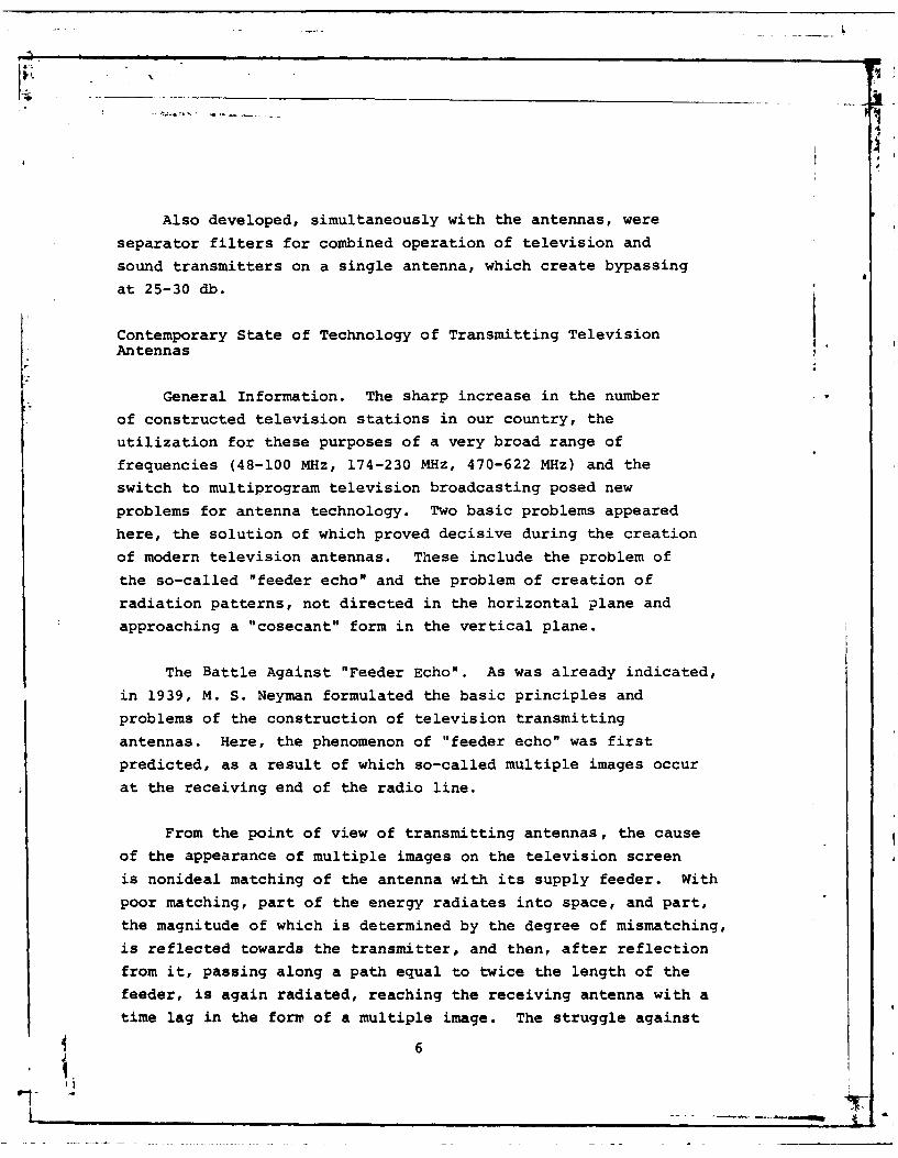
Also developed, simultaneously with the antennas, were
separator filters for combined operation of television and
sound transmitters on a single antenna, which create bypassing
at 25-30 &b.
Contemporary State of Technology of Transmitting Television* Antennas
General Information. The sharp increase in the number
of constructed television stations in our country, the
utilization for these purposes of a very broad range of
frequencies (48-100 MHz, 174-230 MHz, 470-622 MHz) and the
switch to multiprogram television broadcasting posed new
problems for antenna technology. Two basic problems appeared
here, the solution of which proved decisive during the creation
of modern television antennas. These include the problem of
the so-called "feeder echo" and the problem of creation of
radiation patterns, not directed in the horizontal plane and
approaching a "cosecant" form in the vertical plane.
The Battle Against "Feeder Echo". As was already indicated,
in 1939, M. S. Neyman formulated the basic principles and
problems of the construction of television transmitting
antennas. Here, the phenomenon of "feeder echo" was first
predicted, as a result of which so-called multiple images occur
* at the receiving end of the radio line.
From the point of view of transmitting antennas, the cause
of the appearance of multiple images on the television screen
is nonideal matching of the antenna with its supply feeder. With
poor matching, part of the energy radiates into space, and part,
the magnitude of which is determined by the degree of mismatching,
is reflected towards the transmitter, and then, after reflection
from it, passing along a path equal to twice the length of the
feeder, is again radiated, reaching the receiving antenna with a
time lag in the form of a multiple image. The struggle against
6

the phenomenon of "echo" may principally be carried out in
several ways:
- direct improvement of the
frequency properties of the transmitting
antennas in order to reduce reflectionsand, consequently, the intensity of the
multiple circuits to magnitudes which
lie beyond the limits of discernibleness
of the eye;
reduction of the reflection
coefficient of the transmitting device
for electromagnetic waves, traveling
on the side of the antenna;
the creation and radiation on
the transmitting end of the radio line,
along with the basic signal, of an
auxiliary lag signal, the intensity of
which should correspond to the intensity. ... of the "feeder echo" signal, but with
reverse polarity.
As a result of studies on the first
Fig. 2. Typical tower, of the indicated trends, feed schematics180h ightwtelevio were proposed for antennas with repeatedantenna of duplex compensation of the reflections, a
dioatt-hour natdetailed description of which will be
frequency-modulated given below [7], [8].broadcasting.
A decrease in the coefficient ofreflection on the transmitting end of the radio line was achievedusing a power equalizer, the schematic of which for transmitting
devices was proposed by E. S. Glazman [9]. The use of such anequalizer makes it possible to almost completely absorb the
7
energy reflected from the transmitting antenna, and thereby
prevent the appearance of substantial multiple images.
Studies of the third means of creation of an auxiliary
signal with polarity inverse to the "feeder echo" did not provide
completely satisfactory results, as a result of which this
method did not receive dissemination.
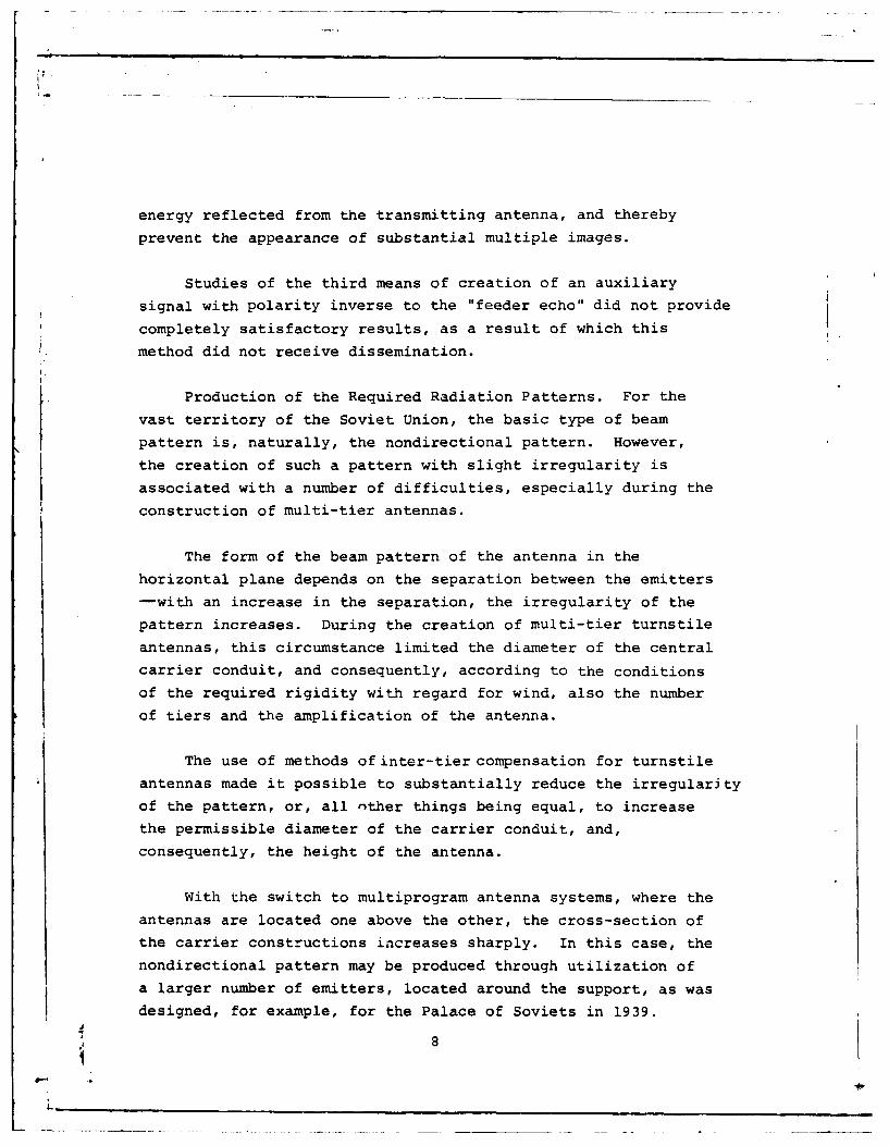
Production of the Required Radiation Patterns. For theFvast territory of the Soviet Union, the basic type of beampattern is, naturally, the nondirectional pattern. However,the creation of such a pattern with slight irregularity is
associated with a number of difficulties, especially during the
construction of multi-tier antennas.
The form of the beam pattern of the antenna in the
horizontal plane depends on the separation between the emitters
-with an increase in the separation, the irregularity of the
pattern increases. During the creation of multi-tier turnstile
antennas, this circumstance limited the diameter of the central
carrier conduit, and consequently, according to the conditions
of the required rigidity with regard for wind, also the number
of tiers and the amplification of the antenna.
The use of methods of inter-tier compensation for turnstile
antennas made it possible to substantially reduce the irregularity
of the pattern, or, all other things being equal, to increase
the permissible diameter of the carrier conduit, and,
consequently, the height of the antenna.
with the switch to multiprogram antenna systems, where the
antennas are located one above the other, the cross-section of
the carrier constructions increases sharply. In this case, the
nondirectional pattern may be produced through utilization of
a larger number of emitters, located around the support, as was
designed, for example, for the Palace of Soviets in 1939.
8

However, an increase in the number of dipoles, and,
consequently, complication of the feeder supply system, leads
to a considerable rise in price of both the antennas themselves,
and of the tower, since the weight and wind load increase
simultaneously.
Thus, in the given case, the problem amounts not simply tothe production of a sufficiently uniform pattern, but to the
production of its most economical systems, i.e., with the minimal
number of emitters in a tier.
As a result of the conduct of lengthy and quite time-
consuming theoretical and experimental studies, it was established
that, in the majority of cases, one must utilize four emitters
in a tier to produce a sufficiently uniform pattern. In this
case, it was revealed that the use of variable-phase feed of
the emitters is possible only on supports with a cross-section
which does not exceed (0.8-1)X. At the same time, with cophasal
feed of the tier emitters, supports are possible with a cross-
section of up tc (1.8-2)X.
Thus, from the point of view of the utilization of supports
of greater cross-section, a cophasal system is preferable in
some cases. However, it lags considerably behind a variable-
phase system in its frequency properties.
The use of a schematic of multiple inter-tier compensation for
the case of cophasal emitter feed inside the tier makes it possible
to combine the advantages of both systems.
Simultaneously with an increase in the amplification of the
antenna, the radiation pattern narrows down in the vertical plane,
and the number of side lobes increases simultaneously. All of
this leads to expansion of the zones of distorted receiving, and
an increase in their number. In order to prevent this, special
measures for the creation of lobeless beam patterns of a special
9

form of the "cosecant" type are envisaged with the utilization
of multi-tier antennas. Such a form of the pattern is usually
combined with a slight inclination of the main lobe in the
direction of the horizon for the best utilization of the power
radiated by the antenna [4].
Principles of Construction of Antenna Feed Schematics with[ Multiple Reflection Compensation
f Previously, during the development of television antennas,
one usually proceeded from the necessity of development of the
emitting elements of the antennas so that the traveling wave
coefficient in the supply feeder lay within limits which ensure
the absence of a substantial repeated outline on the image. In
this case, it was considered successful to obtain a traveling
wave coefficient equal to 0.8-0.85 in the band of only a single
or several television channels. With carrying out of research
studies in the last decade, a different approach was selected,
namely: relatively low requirements were placed on the emitters,
and, at the same time, requirements more rigid than before were
placed on matching of the entire set of emitters, associated
with the feeder supply system.
As was already noted, during the study of turnstile antennas
of two mutually-perpendicular dipoles, it was noted as early as
the 1930's that their feed with phase shift of 900 improves the
traveling wave coefficient in the frequency band. In this case,
the reactances are partially compensated, and the resistances
approach a magnitude of W/2. The varieties of the known feed
schematics of turnstile television antennas, used both in the
Soviet Union and abroad, as well as their equivalent schematics,
are given in Fig. 3. For proper operation of the antenna (Fig.
3a, b), the voltages and currents in the dipoles 2-4 should be
shifted in phase relative to the currents and voltages in the
dipoles 1-3 by 900. In addition, there should be a phase shift
by 1800 between the voltages on the dipoles 1 and 3 and 2 and
4.
10

oz
z C
I 695)Z.1 zWF g. . .
Fig. 3. Various feed schematics of turnstile television
antennas.Key: (a) to generator.
\ - .-j' -
It! - °
Fig. 4. Coefficient of reflection of single-tier
antenna: a - according to schematic in Fig. 3a;
b - according to the schematic in Fig. 3b; c - with
double compensation according to the schematic inFigs. 5 and 6.
The coefficient of reflection for these systems,
1----L____

calculated on the assumption that the input conductivity of
h..ie emitters changes in the frequency range ±12% from 1 to 0.7
is shown in Fig. 4. If four dipoles (or half-dipoles), each
of which differs in phase from the adjacent dipole by 900,
are located in a single tier of the antenna, their feed
schematic may be constructed so that compensation of the
reflections will occur twice (Figs. 5 and 6).
Actually, if the dipoles are fed in pairs with a 90" shift,
then at the point of their inclusion, there occurs the first
stage of compensation. It is easy to see that the combining of
the two groups (of two dipoles each) with a 900 shift will
provide the second stage of compensation at the point of their
inclusion, and, consequently, further improvement of matching
with the supply feeder. In this case, the phasing required for
proper operation of the antenna is assured by "crossed" feed
of one of the dipoles (Fig. 5). The coefficient of reflection
for this schematic is given in Fig. 4.
(e eu At
!W WFig. 5. Feed of one tier of a turnstile antenna accordingto a schematic with two-fold compensation: 1, 2, 3, 4 -
dipoles, 5 - connectors, 6 - carrier conduit, 7 - cable.Key: (a) "crossed" feed; (b) normal feed.
During the constructionof multi-tier antennas, this principle
may be utilized both within the limits of each tier, and with
12

Fig. 6. Feed of one tier of a circularantenna with two-fold compensation.Key: (a) to the generator.
interconnection of the tiers. It is easy to see that, if each
of the stages is implemented according to a schematic with
quadrature feed, then, with feeding of two tiers which are not
-- in phase, as usual, and with 9Q0 shift, one more stage of
compensation appears at the point of their connection. In this
case, for a cophasal composition of the fields created by the
tiers, one of them rotates in an appropriate manner by 900 in
space (Fig. 7). In the figure, the dipoles with a single
number are located one above the other, and the circular arrow
denotes "crossed feed". In case of necessity, the next stage
of compensation may be achieved through joining of the groups of
tiers, and so on. Such compensation received the name "inter-tier".
As was already stated, in this case, the beam pattern improves
substantially in the horizontal plane (Fig. 8).
It goes without saying that multiple compensation is also
possible with feed of an antenna with a different number ofemitters in a tier. In this case, with parallel connection of
n emitters, their supply feeder lines should differ in length by
13
L------

(a)2 i77G3~/3
2 t~iw1
(cl..4
~Wf h~~Afh
Fig. 7. Feed of four-tier antenna accordingto a schematic with four-fold compensation.Key: (a) tier I; (b) tier II; (c) tier III;(d) tier IV; (e) from generator.
2T/in rad from one another. It should, however, be noted that
such compensation will be effective only with the absence of a
mutual effect among the emitters.
Under some conditions, the described principle may also
be utilized during the construction of multi-tier antennas with
cophasal feed in the tier (see below). All that has been said
applies to both turnstile and circular antennas.
It is advisable to examine the schematic in Fig. 9 for the
study of the behavior of schematics with multiple compensation
of the reflections with operation in a broad range of frequencies.
Assuming that the traveling wave coefficient in the connected
lines is equal to k, the summuary dimensionless conductivity of
the entire system may be written as:
14

VZ
Fig. 8. Beam pattern of two-tier turnstileantenna in the horizontal plane (dotted line- pattern with normal feed schematic, solidline - with feed with inter-tier compensation).
iron--I
Yj t . + 10( - -'64)3in iA Cos th
,.n/- k ..'- o + 40 sinsg (1)
Here, h is the difference in feeder
- .. lengths, rad,
n is the number of emitters,i is the ordinal reference number,with i=O at the first emitter.
LV7,' For simplificiation of analysis of
Fig. 9. Schematic of expression (1) with random values of hparallel connection of and n, we will use Euler's formula, whichloads.lexpresses the relationship between the
15I
,1

sum and the integral [10].
Introducing the designations
k + i (I- 0) 3in X COS (2)and cost X + 10 sing X (
nh X0, (3)
we have - -- If(xo) - - I' '+ 0-2n 12A0
0____ [F(x -l_0__.+_-__ -8 * '
7P-1 B
x [ ,- (x ) - f (0) + )p,
•~v si 2VX d (5)
,2P 010,2u+I,,3P+ j
We will now assume that the number n is so great that, with
sufficient accuracy, one may limit oneself to the integral
portion of equation (4) during the calculation. Utilizing theexpression f(x), we obtain the following from formula (2) after
integration
_ arctg(ktgxO) i-i 1 (+ i- oIn(6)
Expression (6) indicates the possibility of obtaining ahigh level of matching even with small values of k, only if the
value of x0 is sufficiently great in this case. Practically,
this means that, if the total length of the system, which is
proportional to the magnitude of x0 , is great as compared with
X, and the sizes of the steps h=xo/n are small as compared with
X, then the entire system proves to be matched in a broad range
of waves. Shown in Fig. 10 is the function yn=f(xO) for severalvalues of k, calculated according to formula (6). As is evident
from these graphs, the greatest degree of mismatching occurs with
a system length which is divisible by an odd number of quarter
16,1I

i4
waves. With a system length divisible by a whole number of
half-waves, matching proves to be ideal (yn=l), with an accuracy
of up to the remainder R2p of expression (5). If one prescribes
Mn
'8 -
47
493
,,:. -- • - '
02 -
o.8 ..- r "-J 2 '
Fig. 10. Input conductivity of a system of n parallelconnected loads according to the schematic in Fig. 9.
the minimal value of the traveling wave coefficient at the input
of the system as equal to K0 with values of the traveling wave
coefficient in the feeder lines which form the system-k, then
the minimum system length required for this, with a large number
n, is determined from the inequality
0.3I 1,
/,, I. (7)
' I /, /'s _ A .
With calculations according to formula (7), one should bear
in mind that v-KO assumes a magnitude which is small as compared
with one. Thus, for example, if it is necessary to obtain avalue of K of no less than 0.95, with a value of k in the feederswhich form the system, equal to 0.5, then the total length of
the system should be at least 2.2 X. Calculation of the magnitude
of the maximum permissible dimensions of the individual steps
proves most complex for the case when the total length of the
it 17
whL or hyseeuao05,tehettlegho

system x0 is divisible by a whole number of half-waves, since,
in this case, all of the additional terms in equation (5) prove
to be equal to zero, and the difference between the sum and
the integral is determined only by the remainder. For this
specific case, a result may be obtained by direct summation of
the series (1).
In place of the traveling wave coefficients, we will
introduce the coefficients of reflections, which correspond to
them, according to the known formulas:
p ; K - K = - fpO4 (8)
pI+ 90 T.-- F. + 1 +IPA
Now, let nh=x0 =mw, where m is any whole number. Then,
summation of the series (1), with regard for formula (8), with
m and n even, gives
a
pe p-, (9)
for all other whole numbers m and n
pe,-P. (10)
The values of K0 are easily determined from formula (8).
The results of calculations for the case m=l and random n are
given in Fig. 11. Using schematics of quadrature compensation
P - (11)
Here, n should be understood to mean the number of tiers of
quadrature compensation.
The formulas and graphs given in the present section are
correct for both parallel and series-connected feed lines. In
18I
p-I

the latter case, it is only necessary that the wave resistance
of the main feeder be n times greater than the wave resistance
of the branching lines.
The principles set forth here provided the basis for the
practical utilization of a number of television transmitting
antennas. Actually, if one needs to implement a multiphase
antenna, upon which strict requirements are placed with respect
to matching in a broad band of frequencies, then the implementation
of the feed system in the form of series, parallel or series-
parallel schematics, in accordance with the principles set forth,
makes it possible to avoid the necessity of precise matching of
the emitters with their supply feeders, and, in this case, to
obtain a high level of output parametersI. Specifically, the use
le
a3 3
'al W IV 0 IV 4 $
Fig. 11. Dependence of the traveling wavecoefficient of the system on the travelingwave coefficient of the emitters with m=l.
IThe principles set forth may also be used for the implementationof load equivalents, which makes it possible to substantially
4simplify their manufacture and adjustment.19

Ii4
of methods of multiple compensation for turnstile antennas
made it possible to utilize a total of three types of antennas
for 12 frequency channels. The parameters of the unified
turnstile television antennas for radio stations with a power
of 5/2.5, 15/7.5 and 5/1.5 kW are given in Table 2. Next, wewill give a description of multiprogram antenna complexes,
constructed utilizing the principles of multiple compensation of
reflections examined above.
Table 2
(b) .. Ra (Cr.. &?Mus cuffu " "X3a .140bwep En~as ccu Sa 1X cMOeum man" *. AUGUAaawa
q&C10?* M84 T=OUU I ?ftum m 7a OCO
1248-r-66 2 3,63-5 76-10 4 7,2 0O. -
6-12 174+-230 6 11,2 O ..-
Key: (a) channel number; (b) frequency range, MHz;(c) number of tiers of duplex dipoles; (d) amplificationas compared with an isotropic emitter at the averagefrequency of the range; (e) traveling wave coefficientin frequency range.
Antenna Systems for Multiprogram Television Stations
General Information. With the creation of multiprogram
antenna complexes utilizing a single support, the antennas are
located one above the other, with the height of the antenna portion,
as a function of the number of programs and the utilized ranges,
comprising 100-150 m. At the same time, the total height of the
tower or mast facility reaches several hundred meters.
Naturally, the cross-section of the supports must be selected
not only for electrical reasons, but, chiefly, from considerations
of ensuring the required strength and rigidity with the effect of
a wind load. With bending of the antenna structure under the
influence of wind, the radiation pattern slants, and, in this
case, quite considerable variations in the magnitude of the signal
20
L

at the receiving point are possible. This phenomenon is displayed
more strongly the higher the antenna support and the greater the
coefficient of amplification of the antenna (the narrower its
beam pattern).
At the same time, the assimilation of ranges right up to 700
MHz for television leads to the necessity of an increase in the
[ amplification of the antennas, since the conditions of propagation
of radiowaves within cities, as well as the receiving conditions
at these frequencies, are less favorable. On the other hand,
narrowing of the beam pattern leads to a considerable increase in
the number of lobes, and, consequently, also to expansion of the
zone of possible distortions of the signal upon receiving. In
order to eliminate such phenomena, as was already indicated,
measures should be taken in the antenna which ensure filling of
the gaps in the radiation between the lobes, and thus liquidation
of zones of distorted receiving. With the creation of single-
program antennas, mounted on typical supports (up to 180 in), and
with the utilization of relatively low frequencies (up to 230 MHz),
this problem did not have an acute nature, since zones of distorted
receiving proved to be quite small, and were primarily located
close to the television station.
One of the most important questions in the creation of
multiprogram antenna complexes i.s the selection of the cross-
section of the supports. It should be noted that the dimensions
of the cross-section of the support, selected for mechanical
considerations, as a rule, preclude the possibility of construction
of any of the antennas according to the turnstile type. In this
case, the most advisable solution is a circular antenna, in which
the emitters are located around the support. On the other hand,
the greater the cross-section of the support, the greater the
irregularity of the radiation pattern in the horizontal plane
(with a given number of emitters in a tier). At the same time,
the cross-section of the support should be sufficient for the
placement of the supply feeder systems of the antennas, the main
21
feeders, elevators, ladders, and so on, as well as to ensure
convenience of maintenance and required preventive maintenance.
It is quite evident that these requirements are contradictory,
and their satisfaction is possible only as a definite compromise.With the location of television stations directly in the boundaries
of a city, free-standing towers are normally utilized as supports.
Te antenna portion of the tower is made in the form of a lattice-
work prism of square cross-section with a decreasing side in
proportion to the switch to the antennas located above. In this
case, the antennas of the low-frequency channels are located at
the bottom. The side of the cross-section of the prisms, as a
function of the design and schematic of the antenna, is (0.5-1.4) X.
With the location of television stations beyond the boundaries
of a city, mast structures are more frequently utilized, which are
composed of tetrahedral prismatic elements, and are fastened by
several tiers of guide wires.
At the present time in the Soviet Union, there is a functional
multiprogram, antenna complex in Leningrad, and construction of the
new Moscow complex is being completed. In addition, a typical
multiprogram antenna complex is being developed for mast supports.
Given below is a brief description of these systems.
The antenna complex of the Leningrad Television Station1 makes
it possible to accomplish broadcasting with three television
(channels 1, 3, and 8) and three ultrashort wave frequency-
modulated programs. The support tower, upon which the antenna
complex is mounted, is a truncated hexahedral structure with a
base equal to 60 m. The tower elements are made of steel tubing.
Because of the use of high-quality grades of steel and the welded
design, the total weight of the tower, together with the antenna
'This was covered in detail by Rushchuk, Brunin, Ivanov and otherauthors at the 20th All-Union Scientific Session, devoted to RadioDay in 1964.
22

equipment, is relatively small (about 1300 tons). The relative
flexure of the body of the tower in any section does not exceed
0.01 with a maximum wind load.
The total height of the tower with the antennas is 316 m,
of which 116 m are occupied by the antennas (Fig. 12), located
in the following order: the lower antenna is mounted on a prism
with a 6 X 6 m2 cross-section, and is intended for ultrashort wave
frequency-modulated broadcasting, then follows the channel 1
antenna on a 3.5 X3.5 m2 prism and the channel 3 antenna on
2.3 X 2.3 m 2 prism, above which is mounted the eight-tier turnstile
channel 8 antenna on a tubular base 245 mm in diameter.
The side of the prism of the frequency-modulated broadcast
antenna, which is the carrier antenna for the three television
antennas located above, was determined from mechancial considerations.
As the calculation showed, with this cross-section with a
1.4 X side, the use of half-wave emitters is inadvisable, since
the irregularity ot the radiation characteristic in t .e horizez.l
plane exceeds the permissible norms. For this reason, wave
dipoles with a cophasal feed schematic were used. The antenna
has eight tiers of dipoles, with a distance of 0.75 X between
the tiers.
The channel 1 and 3 antennas are mounted on prisms, the side
of which is 0.7 X of the corresponding television channel. This
fact made it possible to implement these antennas identically both
in design and in electrical schematic.
In contrast to the frequency-modulated broadcast antenna,
here, it proved advisable to use half-wave dipoles with quadrature
feed, according to a schematic with multiple compensation. The
antenna includes eight tiers of dipoles, the distance bctween
which is equal to 0.75 A. The feed schematic of the " ,nel 1 and
3 antennas is given in Fig. 13. The lengths of the sections of the
239-*

zo;:
(W
Fig. 12. General Fig. 13. Feed schematic
appearance of antenna of channel 1 and 3 televisioncomplex of the antennas.Leningrad Television Key: (a) main feeder.St ation.
feed cables of adjacent dipoles differ by one-fourth of the
average wave length, which is ensured by quadrature feed. The
second stage of compensation is achieved by the introduction of
900 phase shift between pairs of adjacent dipoles. Then, twomore stages of compensation are introduced in the schematic:
24
J~

between pairs of adjacent tiers and at the input of the feed
system between the four-tier groups of dipoles. Such a
schematic made it possible to achieve good matching of the
antenna with the supply feeder (traveling wave coefficient equal
to 0.94), with a sufficiently uniform horizontal radiation
characteristic (±2 db).
The channel 8 antenna is an eight-tier turnstile of
duplex planar dipoles, fed according to a schematic with two-fold compensation of the reflections. The coefficient ofreflection at this antenna does not exceed 0.04 (traveling wave
coefficient equal to 0.92).
The basic parameters of the antenna complex of the Leningrad
Television Station, put into operation in 1962, are given in
Table 3.
Table 3
o Jd) e)7. (..neP timceto nl epawtussio
'4A~a PAMP" ) STAxteA cIlOOT~oflKmU vjvyqarexff al". - saaeqa
50/15 8 10 AxowHW. 0,9 %THuI a Mef.ffoAYWARfO THor. A C
3 50/15 8 10 (hyoMxe 0', H""9"a
8 50/15 8' 14,4 9A-Q,9tW~by
tr~oc~c~nIe xemw.3 3x151) 8 to o@ua 0,7!( )si*Hu*Ia.b.
r133Ot MaxiIop ~ h
1Considered here is simultaneous operation with threetransmitters of 15 kW each.
Key: (a) channel number; (b) frequency-modulatedrange; (c) power, kW (image/sound); (d) number oftiers; Ce) amplification as compared with isotropicemitter; f) type of emitter; (g) conical half-wave;(h) same; Ci) duplex planar; (j) wave dipoles; (k)traveling wave coefficient of antenna; (1) note; (m)antenna of the panel type utilizing the supportstructures as a screen; (n) turnstile antenna; (o)
4panel antenna.
25
L

T:ble .
a UOSUSRA235 &945& PIgeNM117 150
,NO 'MSi amiHn. A"
_; O SUei: 4 4 '
Kr~i~~au ma roeluJHeN I"1i ,RIn. (1(Jll Ann 3. (1)111 aan. 1. "I A l. 2(k) .nan. 3(1)1 .Km V atom. I V AllanS I VAO 2i .M .
1 1V Alan.au~~ll11 jea. 111~iin. ll sia. 1 11 Allan. A1 ASaR.
nB 4M KB4M n5' K B4M )YK LIM YKB 4M
T0%emd11 mA, 16 (n Y 4M4 CD1 MJ 11) 1 ~ (j KB 414
Ko4il4. yl~ ~ll Alie. Aman. Am8s. IAffan . *nporp.IP -lporp. A~hfl. IAHaU. 1 AHSia. IAsian. (0217op a.porp.
cpasmemmo) c noAy.OA-
c.O Npa6 AropoN , 14 125-301 6 3 9,5 14 14 25 30 6 3')
4Wi 3raee of1 18 24g50 8 4 16 1 two a8 41)
C lm npvl 250x 2500 700 X 2500 x 2500 2500 x 2500 700x 2500 x 2500I ____I x 7001 __ _ _ _ _ 1 x 70 _______
i.11) ep~latl~a t %OU 4 q QKOPb&I ir-Ar" gAmO 'AY)11O ,-h2* 4+4 (tY'parosia 1',)IeH* NaAmJ &tj1AOmnh.2* 4+4MOM.h /cam 5/1's 5/1,5 r 1 4 ojgc-3. 4+4+4+4 50/15 I50/15 ra j)IXAicb-3* 4 + 4 +1J+4
__ __ __ _1_ __ _ _ _ _ I 25,5f
With the use of a special 4-program separating filter, the two antennasare included in parallel, and the coefficient of amplification is six.
Key: (a) Total height of mast, m; (b) Total extent of antenna complex, m;(c) Number of antennas; (d) Combination of antenna complex; (e) Type ofantenna; (f) Coefficient of amplification as compared with half-wave di-pole; (g) Number of tiers; (h) Cross-section of support, mm2 ; (i) Type oftransmitter and power, kW; (j) range I; (k) range I; (1) range III; (m)range IV; (n) ultrashort wave frequency-modulated; (o) 2-program; (p) 4-program; (q) "Anchor"; (r) "Needle"; (s) "Ladoga"; (t) "Rain-2"; (u)"Rain-3"; (v) "Hurricane"; (w) "Flax".
26
L,

Typical Multiprogram Antenna Systems. The developed typical
multiprogram antenna systems represent two different complexes,
mounted on supports 235 and 350 m high, and intended for the
basic mass of television stations and the largest regional and
republic stations, respectively. The basic characteristics of the
complexes and the individual antennas are given in Table 4.
The emitting elements in this type of an antenna system are
symmetrical wave or half-wave dipoles, which are laid out
together with the reflecting screen and fastened in parallel to
the faces of the support prism. Both variable-phase and cophasal
feed in the tier may be utilized for producing a nondirectional
pattern.
Cophasal feed provides the
least irregularity of the pattern
in the horizontal plane (with large
cross-sections), while variable-S I" phase feed provides the best fre-
quency characteristic (matching).
In order to improve the pattern withvariable-phase feed, so-called
tangential shift of the panels is
also used (Fig. 14). The emitters
of two faces are not shown in theFig. 14. Circular antenna figure. In this case, the patternwith tangential shift ofemitters. of the antenna in the horizontal
plane is improved (Fig. 15), as
compared with the antenna without
tangential shift (Figs. 16 and 17).
Antennas of television and frequency-modulated broadcasting
ranges I and II of multiprogram complexes are made with tangential
shift of the emitting panels, with the simultaneous use of inter-
tier compensation, which ensured a traveling wave coefficient Z0.9
27
L

I Z
throughout the rangel.
However, with the creation of antennas of television ranges
III and IV, it proved (with the given cross-section of the
V support of 2.5X 2.5 in2 ) impossible to use a schematic with
quadrature feed of the tier and tangential shift of the emitting
elements. The fact of the matter is that, with cross-sections
with a side of (1.5-1.7 X), equalizing of the phases of the
signals of adjacent emitters in the direction of the diagonal
by means of their tangential shifting (Fig. 14), as is done in
antennas of ranges I and II, is possible only in a narrow band
of frequencies. As a result of the large separation of the
dipoles, the change in the phases of the signals of the
tangentially shifted emitters in the frequency range takes place
within large limits, which leads to considerable irregularity of
the radiation pattern on side frequencies. with such cross-
sections of the supports, the obtaining of horizontal characteristics
with small irregularity is possible only with a cophasal feed
schematic of the emitters. In this case, the absence of 900
phase shifts between emitters does not make it possible to
compensate the reflections which occur because of inaccuracy of
matching. However, compensation of the reflections is all the
more possible because of the inter-tier phase shifts. This is
most complete if the magnitude of the phase shifts is selected as
equal to it/n, where n is the number of tiers in the antenna. In
this case, in the case of placement of a vertical row of emitters
parallel to the axis of the support prism, the phase front, and,
consequently, the main lobe of the pattern in the vertical plane,deviates from the perpendicular to the axis of the support by an
angle 0, determined by the relationship of the wave length, the
number of tiers and the distance between the tiers (Fig. 18).
lAntennas, produced by foreign firms, have similar parameters. Inrecent years in the Federated Republic of Germany, they have alsobegun to use schematics of inter-tier compensation with quadraturefeed in the tier.
28

IIS
M5 AS.- -- 4 ~a,
* - f 041364
Fig. 15. Diagram of circular antenna with tangential
shift of emitters in the horizontal plane.
Fig. 16. Circular antenna with symimetrical
placement of emitters.
29

It is quite evident that the selection of a certain angle
of placement of the emitting elements relative to the axis of
the support gives the necessary direction of the main lobe of
the pattern. Thus, the introduction of phase shifts into the
feed system of the tiers simultaneously solves two important
problems: the accomplishment of inter-tier multiple compensation
of the reflections, in accordance with the principles examined
earlier, and inclination of the vertical pattern in order to
best utilize the radiated energy.
'SQS
far
In all antennas, measures are also taken for the creation of
a vertical characteristic of radiation which approaches a "cosecant"
characteristic. This is achieved by both dephasing and feed of
the tiers by unequal powers. Shown in Fig. 19 as an example is
the vertical pattern of a typical antenna of range II.
30
pln ihsmerclpaemn fteeitn aes
9nalatna, esrsaealotknfrth raino
aLetclcaatrsi frdato hc prahsa"oeat

Fig. 18. Feed of tiers of antenna with increasingphase shift.
New Antenna Complex for
It 1Moscow Radio-Transmitting10 12Television Station in Ostankino.
12200 The new antenna complex of the08 70 television station in Ostankino,
1007 10 mounted on a 533-meter free-
standing reinforced concrete
0J tower, will provide transmission
-of five television and six
0.3 - -- .frequency-modulated broadcasting
programs in the 1st (48.5-56.5
- MHz), 3rd (76-84 MHz), 8th
Oi _ (190-198 MHz), llth (214-222 MHz)1 4 82 1Z 2 24 Z 28 32 35 406.
and 33rd (566-574 MHz) televisionFig. 19. Vertical diagramFig.19.Vericaldiaramchannels, and the frequency-of typical range II antenna.
modulated range (67-73 MHz).
In contrast to typical systems, as well as to the complex of
the Leningrad Television Station, the antenna systems are made on
a cylindrical free-standing steeple-like base 140 m high, rather
than on prismatic supports. Insofar as the steeple is a solid tube
of tiered profile, antennas were developed in which, in contrast
to the so-called panel antennas, additional screens are absent.
Such a solution made it possible to considerably reduce the weight
and wind load on the support.
I3
L.

Television antennas of the 1st and 2nd channels and of
frequency-modulated broadcasting were first made, in world
practice, in the form of radial polyrod systems, located on
cylinders of large cross-section. Such a design ensures a
considerable decrease in weight and wind loads on the support,
as well as simplification of operating conditions and maintenance,
I: since the entire antenna feeder system is located inside the1** cylindrical support. Only the emitters are located on the outside,
fastened using metallic and fiberglass insulators, which serve
simultaneously as the casing for the emitter feed assembly.
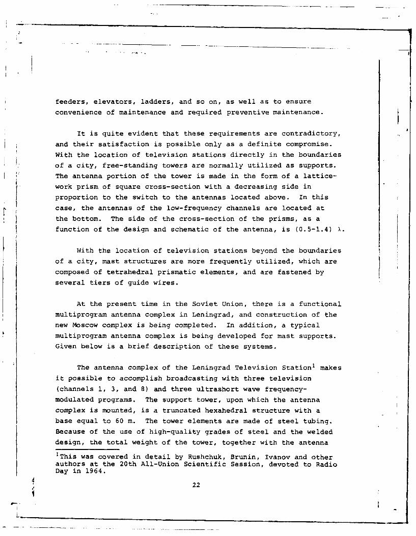
The schematic of placement of all the antennas in the complex
is shown in Fig. 20.
The antennas of the 8th and 11th channels are identical in
their design and schematics. The emitters of these antennas are
half-wave emitters with a built-on reflector. In order to
improve the horizontal pattern, the dipoles are placed with a
tangential shift.
The antenna of the 33rd channel is made in the form of a
seven-tier structure of emitting panels, located around the
central conduit four in a tier. Each panel contains eight tiers
of wave dipoles. The exception is the middle tier, the panels of
which contain only two tiers of dipoles. All of the panels
are covered with casings of fiberglass to protect them from
atmospheric precipitation and icing.
The feed schematics of all the antennas ensure multiple
compensation of the reflections, inclination of the pattern in
the direction of the horizon and elimination of zero radiationzones. The basic technical parameters of the antenna are given
in Table 5. The main feeders, which connect the antennas to the
transmitters and which have considerable dimensions (up to 450-
500 in), ensure a high degree of matching and a high level of
reliability.
32
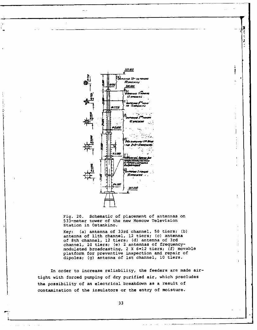
Fig. 20. Schematic of placement of antennas on533-meter tower of the new Moscow TelevisionStation in Ostankino.
Key: (a) antenna of 33rd channel, 50 tiers; (b)antenna of llth channel, 12 tiers; (c) antennaof 8th channel, 12 tiers; (d) antenna of 3rdchannel, 10 tiers; (e) 2 antennas of frequency-modulated broadcasting, 2 X 6-12 tiers; (f) movableplatform for preventive inspection and repair ofdipoles; (g) antenna of ist channel, 10 tiers.
In order to increase reliability, the feeders are made air-
tight with forced pumping of dry purified air, which precludes
the possibility of an electrical breakdown as a result ofcontamination of the insulators or the entry of moisture.
33
L~sx

Table 5.
091 OM coapwa, A525
Wt nPoTiueNN oun"a SW ' Aisan. " ' 140
Homep icamanu mi Tm awmeumw KUM ljft Ug~lu~ B-8Ko" 11 lnan ao AH VK KB 4IM;1u Ml . MAU--M. 1 OeS lXIfHas O6eSiipaRU. n pA"naqU
(2 Kowa.)
C140 ____________ 1 0 1 JO 12 12 50 1 2x 6 n.
BJsa aN.MNII. 'M 1 '3 24 12,5 12,5 22 32
KoX.uuHe4T yCHAIueI no CpamaemO C noJy- 6 6 8 30 3aWloOSM uopaTopom
"IMA eTr onopu. X 4 2,6 1,725 0,72 3,0
"tU.Ien ri) iaT'ica (M3o4aJf./3SyX). 50/15 50/15 25/5 3x 15
m 0cIT I iarpeA7 •u a ropMorf J 4 ay,. "1
KEY: (a) Total height of support, m; Eb) Total extent of antennacomplex, m; (c) Number of antennas; (d) Number of channel and typeof antenna; (e) Number of tiers; (f) Height of antenna; (g) Coeffi-cient of amplification as compared with half-wave dipole; (h) Di--ameter of support, m; (i) Power of transmitter (image/sound), kW;(J) Irregularity of pattern in horizontal plane, dB; Wm) 1stchannel, collapsible-whip radial; (1) 3rd channel, collapsible-whip radial; (m) 8th channel, dipole non-deflector; (n) llthchannel, dipole non-deflector; (o) Range IV, panel; (p) Ultra-short wave frequency-modulated, collapsible-whip radial (2complexes).
434
L _- -

4i4
Fig. 21. Antenna of 8th and llth channelsof the new Moscow Television Station on theadjusting stand.
Taking into account the difficulties in assembly and
adjusting of the antennas under conditions of great height,
the original control assembly and adjustment are carried out on
special stands, located in direct proximity to the tower.
Shown in Fig. 21 are the antennas of the 8th and llth
channels on the adjusting stand, and in Fig. 22- the moment of
assembly of the dipoles on the antenna of frequency-modulated
broadcasting.
Evaluation of the effectiveness of operation of transmitting
television antennas is usually carried out according to its
amplification coefficient, which, in turn, is determined by the
height of the antenna.
35
I
For multiprogram complexes of television antennas, the
evaluation of their effectiveness may be carried out by means of
comparing the summary dimensions of the antenna devices. In
this respect, the complex of antenna structures of the Moscow
Television Station in Ostankino will exceed all known foreign
structures.
Fig. 22. Moment of assembly of antenna offrequency-modulated broadcasting of the newMoscow Television Station.
Thus, the complex of television antennas of the New York
Television Station, which accomplishes broadcasting according tosix television and three ultrashort wave frequency-modulated
programs, has a dimension of 66 m, and the total height of the
television tower of the television station, constructed in Montreal,
is also designed, like that in Moscow, for five television and six
36
'r7L_-
ultrashort wave frequency-modulated programs, which is a total
of 110 m.
A~rTEATYPA
I . Pavnay 11. H. H lblcraabKOPC A. A. CO~erCKHIA n~a~eiH )4 17427,erp. 229, ony6ai. iBeCTHHK KomHwreTa nU Ae.IaM H306pereHhs, 1930, Mh 9.
2- CluClOJbKopc A. A. H HefAMSH M. C. ndpI10 AAIR HenOcpeACTseI4HO-0HNeumx Kc66 a 4)Haepax. 93AeTPOCB153b*, 1941, A 4.j.3. B o 41b Dept A. P. TeopeTHem~oe H zonpmM1bo wcaeAamme 4)[1e1p.iioro peipaeKToMerpa. cPa1ImOTeXHHKa*, 1947. A~ 2.
4. He *ii a M. C. rlepeamoiae ?re.,ieH3HOHHbie aI.TeHHba. c9AeKTpOCBR3b,1939. A& 4.
5. B pa yAe 5. B. Hon wMtPaOKnonoc~aR YES aHTtHHa fAAS Te.ieBHueHHR. (Pa.A.mO'TZUlHXS3, 1947, 1% 7.
- 6. Masters R. W. The Super turnstile. Broodcast news. 42, 1946.7. T p yenxau A.E X Cioco6 fnXTaHHR TYPHHKe'Hbix allTeHH. ABTOPCKoe Csu*
jieTeamcro A& 117712. B"on. J* 2, 1959. erp. 38..T p y c au~os aL. M. Honax cxema aMTaHHRa TeAeSU3HOH~tbEX aHTeHH C gnoro-
,cpamHof KoutieucauXef. RouiaA Ha .Hay"lOft ceccCH HTO HUn. flououa, 1968 r.tPAvolexuasc, 1966, 7* 9. c-rp. 76-77.
9. r aiamas a. c. flornotnab 4si~epnoro 3xa AAR -reaev3l43omtwx aepelnaT-qxM 4PaAxoTexnnxa*, 1959, M* 2.
JI0. Kpusos A. H. Ilescwr 0 fnpfl6Jll2ceHHmx BWHCJ~eMHRX. H3JX 5-e. M.-I.,rocyA. UsA ?Temf-?eopeT. amriepaT.,19.
37

DISCRIMINATION OF HOLOGRAM AND ANTENNA THEORY
A. A. Pistol'kors
This article is devoted to the theoreticalstudy of the matter of the discrimination of thehologram during image reproduction. A two-dimensional electrodynamic problem is examined.Conditions are established for the correct repro-duction of an image of a luminous line with theuse of planar and cylindrical reference flows.Studied on their basis is the discrimination ofthe hologram in the direction parallel to itsplane. A similarity is noted between the obtainedexpression and the integral equation of a linearantenna, which makes it possible to utilize thewell developed theory of directional effect ofantennas for the purposes of the present study.Using this theory, one may specifically show thatthe maximum resolution in the plane parallel to thehologram is equal to the wave length.
The discrimination in the direction perpendicularto the plane of the hologram proves to be much worse.
Derivation of the Basic Expression for the Electrical Field ofthe Image
One of the uses of holography is the production of a three-
dimensional image of some object or another. For this purpose,
an object P (Fig. 1) is illuminated by a monochromatic light
source. The light reflected from the object strikes a photographic
plate AB, which is simultaneously illuminated by a reference flow
38

of light S1 from the very same source (Fig. 1a). The resulting
photograph (hologram) is then transilluminated by a reference
flow S2 (Fig. lb) of monochromatic light of the very same wave
length. In this case, two types of beams emanate from the
pt
Fig. 1. (a) light flows which reach the hologramduring photographing; (b) light flows with theformation of an image using the hologram.
hologram. Some beams (convergent) form a so-called actual image
of the object P, while others (divergent) correspond to a virtual
image of the object P1, which appears to the observer t,) be
located behind ta~e hologram.
Y!'O In the current study (the content ofwhich is set forth briefly in study [11),
k 'I Xwe will apply the methods of electro-
~ All dynamics to the study of the discrimination11 of the hologram; first, it will be
~ ,~ .~ necessary to ascertain the requirementsXr XX2which should be placed on the reference
Fig.2. Clcultion flows in order to obtain an undistortedof the electricalfield on the surface image.of the hologram.
In order to simplify the matter, we will examine a two-
dimensional problem, in which the luminous point is replaced with
a luminous line, parallel to the z-axis. In this case, the hologram
should be represented in the form of an infinite band with a width
1. If, along the z-axis, the parameters of the system are constant,
39
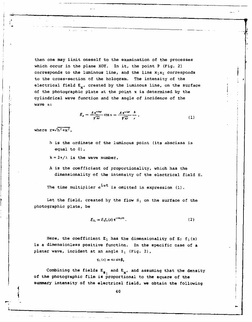
then one may limit oneself to the examination of the processeswhich occur in the plane XOY. In it, the point P (Fig. 2)
corresponds to the luminous line, and the line xjx 2 corresponds
to the cross-section of the hologram. The intensity of theelectrical field Ex , created by the luminous line, on the surface
of the photographic plate at the point x is determined by the
1: cylindrical wave function and the angle of incidence of the
wave A:
A e-1x A C-19 ht,, Co12=
where r-/h 2+x2,
h is the ordinate of the luminous point (its abscissa is
equal to 0),
k =2t/X is the wave number,
A is the coefficient of proportionality, which has the
dimensionality of the intensity of the electrical field E.
The time multiplier ei t is omitted in expression (1).
Let the field, created by the flow S, on the surface of the
photographic plate, be
Es,= E1/ (x) e- ' • (2)
Here, the coefficient El has the dimensionality of E; fl(x)
is a dimensionless positive function. In the specific case of a
planar wave, incident at an angle B1 (Fig. 2),
%I (x) = i sin,.
Combining the fields E and E x , and assuming that the density
of the photographic film is proportional to the square of the
summary intensity of the electrical field, we obtain the following
40
I

I4
for the coefficient of absorption of light Q(x) on the surface
of the film
Q(x) -E'-pf(x)+ 2Ej,(x) cos[Kr - q,(x)l (3)
The produced negative is usually transilluminated in order
I to reproduce the image. This is permissible when fl(x)=const,
- since then, the use of the negative instead of the positiveis equivalent to the change in phase of the field by w, which doesnot show up on the reproduced image. With fl (x)#const, it is
necessary to transilluminate the positive. Let the field,
created in this case by the reference flow S2 on thT surface
of the positive, be
Es. = Elf (x) e- ' 1
Just like for the flow Si,with irradiation of the hologram by
a planar wave, incident at an angle1i , /82 to the external normal (Fig. 3),
(V -W = ,X Sin Pt.
I i; _/X The field created by the middle/ term of expression (3)0 at the point
/ x=u, y=v (Fig. 3), is
Fig. 3. Determination E. =EKhsiI ' xP Cos -i r -%P(x)I ewt(K) dof the position of the ,-luminous point, formed ho.fI (X .during transillumination mE". eij L < " +of the hologram. L, 1'r i
+ fi( I I #)W_. ) e-iK'rfei+ ,
(I.-i,,(,X) d E.,1 -LE. (5)+ Vl(A d-v E)xdx
1Here, we will not dwell on the methods of spatial separation ofthe image and the constant component of the light flow, characterizedby the first and third terms in expression (3).
41
i

Here, E is the coefficient of proportionality with the
dimensionality of E;
ri 0 ,c 2 + (X - U)2.
The first term (EHl) is the field of the actual imageV (convergent beams). The second term corresponds to the divergent
: beams, by continuing which beyond the limits of the hologram
(Fig. 3), we produce the virtual image. The virtual field EM2,which corresponds to this image, we will obtain by substituting
the values of e+ikri in place of e ikr i into the expression forEM2. Then
E,, E, f (X) f 2(x) e- i,(_,.) i,,(x)-i p,(x) dx." " ,V :r (6)
Requirenents for Reference Flows
In order to determine where the luminous line of the actual
image will form, we will find that point u, v in which the waves,
incoming from the elements of a potentially larger segment of
the x-axis, coincident with the hologram, are combined into a
similar or close phases. This means that the exponent in the
expression for EXI:
(x) = K (r - rj) -,F (x) -- T (x) (7)
should be a constant magnitude, or weakly changing function, for
all values of x within the limits x2>_xjx1. We will expand the
function T(x) into a Taylor series:
(X) (X) - i (xe) + (X ) 21 0 (x,) +
Here, x0 is the abscissa of the middle of the hologram.
If the luminous point is correctly reproduced, then thephase of T(x) should be constant for all values of x, and,
consequently, all derivatives of this function will be equal to
zero. With incorrect reproduction of the point, one may find
42
L_

its coordinates u and v, proceeding from the equality to zero of
at least the first two derivatives of '(x) with x=x0 , i.e.,
solving the following equations relative to u and v
, (x = V (X.) = 0. (8)
I. In this case, the maximum permissible width of the holc 4m
LX 2-X1 is determined from the requirement that, at the point of
reproduction of the waves from its extreme points (x I and x2),they differed from the phase, created by x0 , by no more than some
acceptable given magnitude.
By designating 0 1(x)+0 2 (x) via *(x), we obtain
X0 Mo- U --P'(x0) = 0.'(x.V, +/'- ' ' (XO-UP (9)
If the direction to the luminous point P from the middle
of the hologram during photographing was determined by the angle
ao, with respect to the normal, and the direction to the formedpoint P1 during transilluninatio, determined by the angle y0
(Fig. 4), then, from equation (9), it follows that
sin y,=sina.0- q'(x0)= 0. (10)
Fig. 4. Derivation of relationships, thefulfillment of which is necessary for theproduction of an undistorted image.
Consequently, the actual image is formed in the correct
43

direction only in that case when' (x0) = 0
and, specifically, when *(x)= O=const.
For IF"( x0 ), we obtain
3
I "(x) = h2 (h2+ x0) 2 - 1 [ 2 + (x0 - u))2 1 2 -"(xo) 0 (11)
or, switching to angles,
COS' 0 cm2 - ,(x3 ) 0. (12)Ii v
Having determined the angle yo from equation (10), we find
the coordinate v of the formed point from equation (12).
We will examine the case of reference flows in the form of
planar waves, incident at angles B1 and a2. Then
P (x) = Kpx + (P0. (13)
where p = sin§1 + sin P2.
In this case,
q' (x) = p, 9" (x) = 0
and the solutions of the equations (8) are written as:
sin Y = sin 2, - p
h x0 -u=tgo7 (14)
and the distance from the image to the point x0 will be
xoP, = h M..
In order that the image be formed in the correct direction,
in accordance with what has been said above, it should be that*' (x) - p = sin P + sin p, 0.
This equality may be fulfilled in two cases:
and ps= +p1 .
) 44
. -4.

In the former case, the reproducing reference flow S2 falls
on the front of the hologram (Fig. 4), while the actual image is
formed on its rear side. It is not difficult to see that, in this
case, it will be a mirror image with respect to the initial object.
The direct image of the object will he obtained by illuminating
the hologram from the rear, when 82-1+8. In this case,
o= . a=h, 0uO
and the coordinates of the formed point will coincide with the
coordinates of the initial point. All of the derivatives of T(x)
will automatically be equal to zero, and the waves arriving from
any elements of the x-axis will combine in phase at the point
which corresponds to the initial point.
?4. If p#O, then the image will be turned
__ and distorted. As an example, we will
/ take al=O, sin 82#0. Then,
sin y sn so - sin p..
O /xoPoint A (Fig. 5), for which a0 1=0,
will be deflected at an angle y0 =-(ir-8 2),
/and will be located a distance x0Al=hcos2 02
from the middle of the hologram. Point B,
Fig. 5. Example of at which y=h and a02=f-8 2 (Fig. 5), willdistortions of the have Y02 0 , and the distance of its imagereproduced image,obtained with B, to the point x0 will beincorrect selectionof the angle of x0 8incidence of the -'planar referenceflowr whichfrne If, ir the initial image, x0A/x 0B-cos 82,flow, which trans-
illuminates the then, in the formed image, x0Al/x 0Bl=-cos5
hologram. 82, i.e., the mutual placement of points
A and B will be incorrectly reproduced.
Similar conclusions may be obtained for the virtual image as
well, but herep = sin 16 - sin P,,
and in order to have no distortions (so that p-0), it is necessary
45
L --

to fulfill one of the two equalities:
02 01or
0%= - i
In the former case, the hologram is illuminated from the
front, and the image is examined from its rear side. The imageV will be direct (not mirror).
In the latter case - the mirror virtual image - the planar
reference flow illuminates the rear side of the hologram, and the
observer is located to the front.
From what has been said, it follows that, with oblique
illumination of the photographic plate by a planar reference
flow (B1300), one may select the angle of incidence B2 of the
planar flow during reproduction so that the actual image would be
undistorted, and the virtual image would be distorted, or vice
versa. Both images will be simultaneously undistorted only with
normal incidence of the reference planar flows, when B,=O, and
a2=ir or 0.
The requirement p=0, the fulfillment
of which is necessary for the production
of an undistorted image, should be taken/ into account during the examination of
X0 the matter of the discrimination of theal a hologram.
/ ' We will now examine the case whenradiation from a point source is utilized
as the reference light flow. In this
case (Fig. 6),Fig. 6. Case of point =Aihesources of referenceElight flows, where
464

I r
By comparing the obtained expression with expression (2),
we note that, in the given case:
__ h,
VKr, r,q, (x) = Kf,.
Accordingly, for the reference flow during reproduction
(Fig. 6):
f2 (x) = A2 I,
T2 (x) = Xr2,.
It was shown earlier that a necessary condition for the
correct reproduction of the actual image should be
qp(x) = qj (x) + q, ()) = const.
In the given case, when 0j(x)+0 2 (x)=k(rj+r 2), this is
impossible, and one may only speak of the relatively correct
reproduction of the image with restricted dimensions of the
hologram. It is necessary, for this purpose, that equations (10)
and (11) be fulfilled for the middle of the hologram (point x0 ),
or, otherwise, that
(' (x0) = 0and V, (x0) = 0.
The former of these equations givesat - X0 _ 0--z
or
sin 2g = -sin a.
One may satisfy this requirement by placing the point sources
of the reference flows so that the directions to them from the
point x0 would make angles from the normal to the hologram al and
a2 -al or a, and a2=n+aj (Fig. 6).
The latter equation leads to the following
47

p COSa + COS, 0.
+(a, -3 x j 2 j2 +(a,_- -
With the selection of angles a, and a2, given above, it is
impossible to satisfy this requirement using real values of
h2 and, consequently, the requirement 4"(xo)=O may not be
realized. rut, in that case, which follows from equation (12),
the ordinate of the reproduced point will not be equal to h, as
well as its abscissa to zero, and the image of the reproduced
object will be distorted. The distortions will evidently beless the closer 0"(x 0 ) is to zero, and, specifically, the greaterhl and h2 are as compared to h, i.e., the farther the sources
of the reference radiation are from the hologram. From here, it
follows that accurate reproduction of the actual image may be
obtained only using reference flows in the form of planar waves.
At the same time, the virtual image may be obtained without
distortion al*o using point sources of reference light flows.
In this case, it is sufficient that the reproducing source be
located at the point of the former, which forms the phase front
(direct virtual image), or is symmetrical relative to it (Fig. 6,
dotted line); then, we obtain a mirror virtual image. In both
cases, rl=r 2 , and since O(x)= ,(x)-0 2 (x) for the virtual image,
then O(x)=k(rl-r 2 )=0.
Discrimination of the Hologram Along the x-Axis
We will investigate the field intensity at small distances
from the reproduced point along the line which passes through
this point parallel to the x-axis. For this purpose, one may
utilize the first term in expression (5), in which we will now
assume that Oi(X)+0 2 (X)=0, fl(x)f 2 (x)=f(x) and r i=y 2 +(x-) 2
Then
- A;
if E<c r, which corresponds to the posed problem. In this case,
Vrri -r3. Since r=h/cos a, and x/h--xT-sin a, then
48
L

i KiVj h 2 S E=hE f e E__.
E4 . f(x) dx = C (x)cosaIe d.X, Xt
But, x=h tg and dx=hdci/cos 2a; therefore, if f(x)=F(),
then*2
Ec=O,,(17)
or, assuming sin a=u and F(c)=e(u),
E = O,5E,, 4 (u) e'".du. (18)
The very same result is obtained for the virtual image, if01 (x)-02(x)=0.
Expression (18) is similar to the formula for the beam
pattern along the field D(G) of a linear antenna, located along
the z-axis (Fig. 7): -
D(e) = icM F(z) e'= s"' dz. (19)
Here, F(z)=f(z)e i O(z) is the function of distribution of the
current (field) along the antenna,
z, and z2 are the coordinates of its beginning and end,
0 is the angle between the direction to the
point of observation and the normal to the
axis of the antenna,M is the scale coefficient, which has a
dimensionality E.
The coordinate u, the function e(u) and the magnitude in
expression (18) correspond to the coordinate z, the function F(z)
and the magnitude sin 0 in expression (19), with only that
difference that u and sin 0 are dimensionless, while z and have
dimensionality of length. What has been said makes it possible to
utilize the well developed theory of directed effect of antennas
for the analysis of expression (18).
49
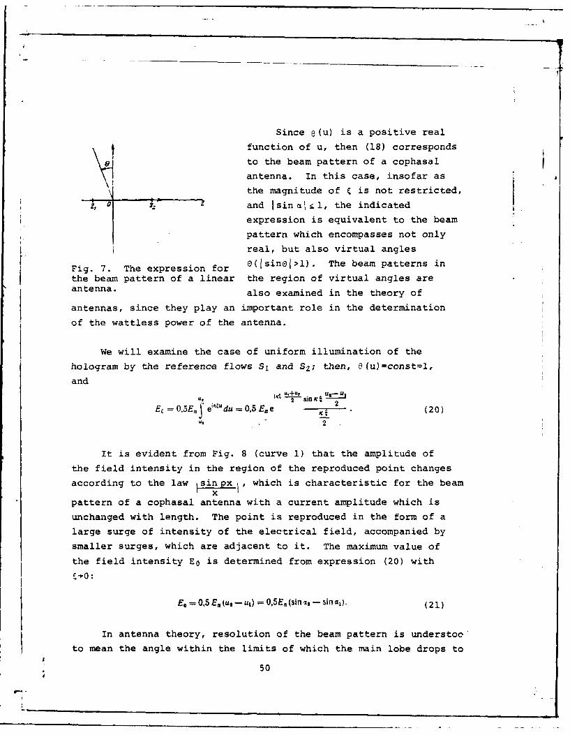
Since 8(u) is a positive real
tfunction of u, then (18) corresponds
to the beam pattern of a cophasal
antenna. In this case, insofar as £
the magnitude of C is not restricted,
and Isin aIl, the indicated
expression is equivalent to the beam
pattern which encompasses not only
real, but also virtual angles
Fig. 7. The expression for O(Isinel>l). The beam patterns inthe beam pattern of a linear the region of virtual angles areantenna. also examined in the theory of
antennas, since they play an important role in the determination
of the wattless power of the antenna.
We will examine the case of uniform illumination of the
hologram by the reference flows S1 and SZ; then, 9(u)=const=l,
and
U- U
Ez =0,5E. e'4 du =0,5E.e . (20)u, 2
It is evident from Fig. 8 (curve 1) that the amplitude of
the field intensity in the region of the reproduced point changes
according to the law s i which is characteristic for the beamx
pattern of a cophasal antenna with a current amplitude which is
unchanged with length. The point is reproduced in the form of a
large surge of intensity of the electrical field, accompanied by
smaller surges, which are adjacent to it. The maximum value of
the field intensity E0 is determined from expression (20) with
Eo = O,5Eu,-ul) = 0,5E,(sinl - sina,). (21)
In antenna theory, resolution of the beam pattern is understoc
to mean the angle within the limits of which the main lobe drops to
50

JJ
S2
06 I
/fo
0 2 4 f 10 12 /4 /6 18 202224
Fig. 8. Curves of intensity of electrical field,created by the hologram in the region of thereproduced luminous point; curve 1 corresponds tothe distribution of the field along the &-axis,parallel to the x-axis, and curve 2 gives thedistribution of the field along the y-axis (n isthe distance from the ordinate of the reproducedpoint).
half power. The discrimination determined thusly characterizes
the possibility of picking out near sources of radiation. In
the case examined here, it is more advisable, evidently, to
understand discrimination to mean the width 2 0 of the main surge
of intensity of the field at the zero point (Fig. 8), which
characterizes the "extent" of the reproduced point. Assumingthat __ 1 1th tsin ic 1 . -- = sin = = 0 H X, >. ,,
2
we find
2A 2X 2),
u,U- sinsi j x __ . (22)
With symmetrical placement of the hologram relative to the
luminous line, when xl=-x 2 ,
E, - E sin 2% (23)
51

I .
and 2Eu = = ,
x, (24)
We will evidently obtain maximum resolution with x2-- or
sin c2-*. In this case (to which curve 1 in Fig. 9 corresponds)
2 , =k. (25)
7-
.3- --- -
A I
ho az 04 0 -- , f 089 7.0G
Fig. 9. Dependence of the resolution of thehologram on its dimensions with symmetricalplacement of the hologram relative to theluminous point; 2 0 is the width of the mainmaximum in wave lengths.
Shown in Fig. 9 is the dependence of the resolution on the
dimensions of the hologram with its symmetrical placement relative
to the luminous line. With small dimensions of the hologram
X, (26)
the dotted line in Fig. 9 corresponds to this expression.
It follows from what has been said that closer illuminated
objects will be resolved better than further objects, since, for
the former, the relationship h/x 2 is less than for the latter.
1A similar expression without derivation is given in study (2].
52

With nonsymmetrical placement of the reproduced line relative
to the hologram, the resolution is impaired with an increase in
the angle ao Given in Fig. 10 are the curves of the dependence
of the resolution on this angle for holograms of various dimensions.
- - --We would note that, for the
- -1-- - -switch to discrimination according to
- ~half power 2 p, it is sufficient to- - I-- - -multiply the obtained results by a
multiplier equal to 4/9. Thus,
2t,= 1 t..(27)
All that has been said concerns
70 ~ the uniform illumination of the
a 10 '0 JO 0 Oa" hologram by reference flows.A
Fig. 10. Dependence of the shortcoming of similar illuminationresolution on the angle cto, is the comparatively high level offormed by the direction to scnaysre ffeditniythe luminous point from the scnaysre ffeditniycenter of the hologram withthe normal to its surface, With other laws of illumination,for holograms of variouswidths 1; 2 0 is the width the level of secondary surges may beof the main maximum. reduced because of slight impairment
of the discrimination. Some of the
relevant data here, which are known from antenna theory, are given
in the Table.
one should also avoid those laws of illumination with which
secondary radiation increases in the range of values of which
correspond to virtual angles. Although such laws are often
applicable in radio technology, they are inapplicable in holography.
It is necessary to bear in mind that the conclusions obtained
here are correct for holograms with ideally flat surfaces.
Actually, these surfaces, from the point of view of light wave
length, are quite rough. The effect of irregularities on the
53

surface of the hologram on the quality of the image may be taken
into consideration using methods developed in studies onstatistical evaluation of antenna parameters.
Table(a'ac k .n0Cwr~an. l(4 'POmub nepl-
M83 wup4ma so tarognou.acnpeAe.mme n * r4a.oro r m0ena,-a ian.e
~I[I11i~i] C 11anomapb~oe 1 212(ej ocHHycoNAaa. b
Hoe 1,36 7.0
~peroj~hi1,246 4.5
Key: (a) distribution of field; (b) relativewidth of main surge; (c) level of first secondarysurge in % of main; (d) uniform; (e) cosinusoidal;(f) triangular.
Discrimination of the Hologram Along the y-Axis
Again utilizing expression (5), we will calculate the fieldintensity at the point withcoordinates x=O, y=h-n, where n is a
small magnitude. Reasoning the same as in the previous section,
we obtain
E, = 0,5 E1h r- 3 e f(x)dx - 0,5E. F(a)e' 'cos a& (28)= (28)
One may calculate En utilizing expansion according to
Besselian functions:
e a'° t =.Ji (,c) - 21s ( ) cos 2a + 2 , (K 7) cos .- .
+ i 2 J, (t c) cos z - J (x 7) cos 3 + Js (q) cos 5 (29)
It follows from this expansion that there will be no purezeros of the field intensity along the y-axis. The maximum field
54
L

intensity (at the point 0, h) will be£g
E, = F0E. F(a)cosada.€|
WithF(a) = const= I E0 = 0,SE.(sina,-sin aj
in accordance with expression (21).
At a sufficient distance from the maximum, when kn is a
comparatively large magnitude, integral (28) may be calculated
by the method of the stationary phase, if the point of the
stationary phase c=O falls within the limits of integration.
In this case
1E~I z=,V F (0). (0levi (30)
Expression (30) is correct for those values of shifting n
with which a sufficiently large number of periods of the
oscillating function eikncosa are contained within the limits
of integration.
With symmetrical placement of the luminous point relative
to the hologram (aj=-a 2 ) and with F(c)=l
E, - E, sin 2,.
We obtain the greatest discrimination with infinite width
of the hologram, when M2 -ir/2. The curve of field intensity, for this
case is designated by the number 2 in Fig. 8. It is constructed
according to the formula
1 '.3 3.5 51
2obtained from expression (29). As we see, curve 2 differs severely
from curve 1 of the field intensity along the F-axis. A slowly
dropping tail is characteristic, because of which, even at a dis-
tance 1.5 X from the maximum (with kn-37r), the field intensity
decreases to only 40%.*55
I

Shown by the dotted line in Fig. 8 is the curve of field
intensity calculated according to the method of the stationary
phase; as we see, it provides good coincidence with the precise
curve with kn>4t. With symmetrical placement of the hologram
and with integration within the limits from 0 to a 2 , the argument
of the oscillating function changes from kn to kn cos 0 2 ;consequently, over the length kn (1-cos a 2 ) = 2kn sin 2
"L, there
V should be n/2 periods, from which X2sins
2
or, for small a2 kri 2nir( ~2)Z.
For the curves in Fig. 8, sin 2 -=0.5 and kn =4n, from2 V1H
which the minimum required number of periods n=4. Consequently,
for symmetrical placement of a hnlogram of any width
2X2
In this case, En=0.5Ensin 12- and E n 0.252 E0 C 2
In view of the fact that, with small width of the hologram,
cos a2 tl, kn corresponds to the distance at which the field2 UMM
intensity drops to one fourth of the maximum value. Since kn
81(.L )2, this distance increases rapidly with a decrease inthe width of the hologram, and the curve E nbecomes all the more
blurred.
We would note that, because of the parity relative to c,
e coszd = 0,0 e5e Cos 2 "d.
This means that the curve-of field intensity, created by a
nonsymmetrically located hologram (when a changes from 0 to az),
is the same as in a symmetrically placed hologram of twice the
56
I "

I '4
width; only the amplitude of the field decreases by twice.
As we see, the discrimination of the hologram along the
y-axis is considerably worse than along the x-axis, especiallywith small dimensions of the holograms. Therefore, it is more
advantageous to view the image from those positions with which
the line of sight is directed roughly along the y-axis, and theimage develops basically in the plane parallel to ZOX. Practically,
it is more convenient to realize such coverage with respect to
the virtual, rather than the actual, image.
DITfEPATVPA
I. Irl I C T 0.1 b K o p c A. A. 0 pa3pewuaiouefl CnOCo6HocTi ro.orpammu. aoKa~aAuAxa,,ieMnw IfayK, t. 172. 1967 .V2 2, CTp. 334-337.
2..Leith E. N., UpatniksJ., Hildebrand B. P.,Haines K. Requirementsfor a wavefront reconstruction television facsimile system. 4. Soc, Mo.L Pict
Telev Eng.*, 1966. v. 74, I'T 10, pp. 893-86. flepesoa 9 %3apy6eyKnoft pa o-3JeKTpomHwe, shi. 5, Mal 1966. crp. 3-11.
57
0-'4- -

RADIATION OF AN ANTENNA IN THE FORM OF A RIBBED SHAFT OF FINITELENGTH
G. D. Malushkov
The method of integral equations of thefirst order is used to solve the problem ofexcitation of an impedance cylinder of finitelength by a short (1<X~/4) symmetrical electricaldipole with sinusoidal distribution of theoutside current. The dipole is located on theaxis of rotation of the cylinder, and isperpendicular to it. Also given are theprocedure and some results of calculation ofthe current distributions on the surface of theimpedance cylinder, and the beam patterns forconstant and variable (linearly-increasing)impedances. The calculated and experimentalbeam patterns are analyzed as a function of thelength, the radius of the cylinder and themagnitude of the surface impedance.
Introduction
The use of antennas in the form of a cylindrical ribbed
structure and a metallic cylinder with a dielectric layer as
emitting systems is widely known. These systems, as well as a
number of other antenna devices, belong to the class of emitters,
on the surface of which boundary impedance conditions are fulfilled.
Usually, the introduction of boundary impedance conditions makes
it possible to comparatively simply determine the characteristics
58

of radiation of the antenna, obtained as a result of the solution
of an external electrodynamic problem.
The method of solution of the electrodynamic problem is
basically determined by the form of the given impedance surface.
Thus, in the case of coincidence of the impedance surface with
one of the coordinate surfaces of the coordinate system, in
which the wave equation is separated according to the variable
in [1], the method of eigen functions is used. In a number
of cases, for example when the impedance surface is the surfaceI. of rotation [21, the problem is solved by the method of integral
Given in the present study are the results of the application
of the method of integral equations of the first order, with
various areas of change of the observation and integration
points [2], to the problem of determination of the characteristics
of radiation of an impedance antenna in the form of a ribbed
shaft, excited by a symmetrical dipole.
The problem of finding the magnitude of the impedance
according to the given parameters of the antenna (depth and
width of the channels of the ribbed structure, thickness and
dielectric permeability of the dielectric layer on the metallic
cylinder, and so on) [3], [4] or, conversely, calculation,
according to the given magnitude of the surface impedance, of
the parameters of the antenna, have independent interest, and are
not examined here.
The coordinate systems utilized in this study are: rotation v,
u, 0 and cylindrical z, R, p. The dependence on time is selected
in the form exp (iwt).
Formulation and Method of Solution of the Problem. CurrentDistribution
Let there be an antenna in the form of an impedance body of
59

rotation, a specific case of which may be a cylinder of finite
length. The antenna is excited by a symmetrical dipole,
located perpendicular to its axis of rotation, with sinusoidal
distribution of the volumetric density of the outside electrical-1, D.CT
current j (Fig. 1). It is necessary to determine the
* radiation field of such an antenna.
Fig. 1. Calculation of an impedance cylindricalantenna.
According to the theorem of equivalence, a complete field
of radiation of an antenna is the sum of the primary and secondary
fields, i.e.
where E 703is the field created by the exciting outside sources
(in the given case, the field of the exciting
symmetrical dipole);
SO is the field created by the electrical and magnetic
currents, excited on the surface of the impedance
body.
Insofar as, on the surface of the body, the electrical and
magnetic currents are associated through the boundary impedance
condition, then, with a known impedance, it is sufficient to
determine only one of these currents.
The system of two integral equations relative to the longi-
tudinal J3 and lateral JO components of the m harmonic of themv msurface density of the electrical current (more precisely, relative
60

to the coefficients of expansion of the desired current into
a Fc Ler series according to the azimuthal coordinate), with
selection of loop antennas with * and z magnetic currents as
auxiliary sources (2], after the switch to cylindrical
coordinates, is written in the form:
[KIL (V, v) 1.11,'M + A1 W,' v) ., ()]Rdo hi Wo)(2
: [K, (W'. v) P,...0 (v) + M , v) P,, (v)] Rdv= f, (')jwhere a
i Z' 0S, a' (s,_+s.,
a s,_, s,,.,. ) cs e(3)
3' (S1.... Zt ,. as ,.
Xj S-+l MOR
.+SmtF - 2 ( - 2(S Mz, s -sn +m ()
M('" =-T.{{- - + [2 -- ,,.
R (- .. 572r-,- Co- ' ,G _ _ L sin -- m O 15
r& Ii_ M (1 i~ce d is m
K,(', I --c..&L_ s coseOc+ W, (8)
=zW k - R'
., ,,, -1 + -S-+" )]. :--1-1 + .) sin. o- -( ,, ST- + ;...2 ~ ~ a. 1,., L ds.Z 2 5
K&, M_ i ._ SMCosO i + -I s
Tn these formulas, ZlEJ'€ and Z 2=-E,/Hv are the surface
impedances, which are random functions of the longitudinal
coordinate v, which do not depend on each other; R, z are the
coordinates of the point on the surface of the excited body ofrotation; R', z' are the coordinates of the point of location of
the auxiliary sources; is the angle between the direction c f
the vector of the normal at the point v and the axis of rotationz; W0 I20 I ohms is the wave resistance of the free space. The
linear dimensions in expressions (3)-(8), and below, are normed,i.e., they are multiplied by the wave number for the free space
L
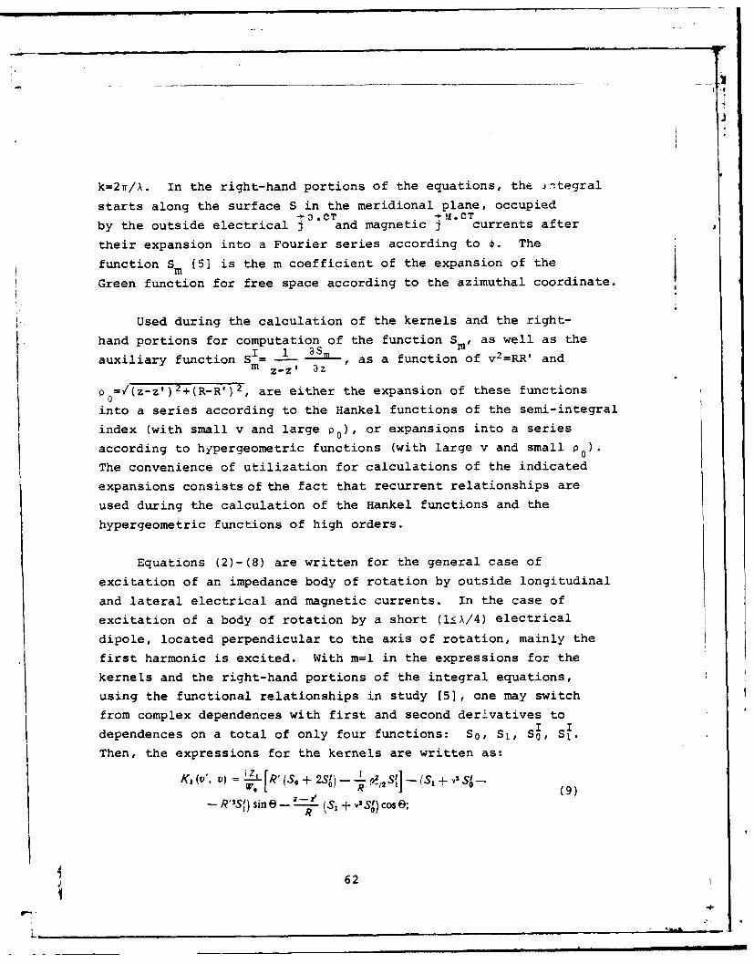
r
k=2n/X. In the right-hand portions of the equations, the integral
starts along the surface S in the meridional plane, occupiedto.CTa tM.CT
by the outside electrical j and magnetic j currents after
their expansion into a Fourier series according to 0. The
function Sm (51 is the m coefficient of the expansion of the
Green function for free space according to the azimuthal coordinate.
Used during the calculation of the kernels and the right-
hand portions for computation of the function S. , as well as the
auxiliary function SI = -- as , as a function of v2=RR' andm z-z' 1aZ
P0=V(z-z')2+(R-R') 2, are either the expansion of these functionsinto a series according to the Hankel functions of the semi-integral
index (with small v and large p0 ), or expansions into a series
according to hypergeometric functions (with large v and small p0) .
The convenience of utilization for calculations of the indicated
expansions consists of the fact that recurrent relationships are
used during the calculation of the Hankel functions and the
hypergeometric functions of high orders.
Equations (2)-(8) are written for the general case of
excitation of an impedance body of rotation by outside longitudinal
and lateral electrical and magnetic currents. In the case of
excitation of a body of rotation by a short (iX/4) electrical
dipole, located perpendicular to the axis of rotation, mainly the
first harmonic is excited. With m=l in the expressions for the
kernels and the right-hand portions of the integral equations,
using the functional relationships in study [5], one may switch
from complex dependences with first and second derivatives toI I
dependences on a total of only four functions: So , S1, S , S1.
Then, the expressions for the kernels are written as:
K, Wv, ro) z Lr° R'(So +± 2) - -L p I,s'] - (,, + .,s-W, IZZ' R 1(9)
- sin e- -_ (S' + VIS) ose;
62
L,

'Vl (V, = i s, + [ z- z') s, sine- (R's,-
R .1) e]1 (10)
m ~'. ) -(i [~ + ' ,zRf)+t (_z,))lK., W", 0- - S, Cos e + -- 'S.1.,. kz., V) =- S, +R'S' - Rsf) + z._ _L f(z - z') x,a WO Y t
[RAj, 3S' - R M S, - -t + 3,.'S0 ( P/2 R Co
-- ,)(S 0 -3 ) + [(z--z')p 1 - S1- (12)Iz - Z') (.R -r R'2) + (R2- R'2)2] St sin @I,
where iV=(z-z') 2+R2-R'2 ; B=v:(z-zv) 2-R 2+R' 2; y= 4 4.
The right-hand portions of expressions (5) and (8), with
sinusoidal distribution of the outside current along the
dipole, perpendicular to the z-axis,jOT=IOsin(l-R) with anVaccuracy of up to the constant multiplier (placing I0/iT=l),
take on the following appearance:
fV)- f (Z z') (S1 + ,2 S) sin (I - R) dR, (13)0
0f ) fS, sin (I - R) dR. (14)0
Writing the integral equations in this form makes it possible
to easily find their solution on an electronic computer. The
method of solution of the integral equation consists of their
reduction to a system of linear algebraic equations by means of
approximation of the desired current by a piece-wise constant
function [2].
The order of the system of algebraic equations is determined
by the number of elementary intervals into which the length of the
generatrix of the body of rotation v is divided. The length of
the elementary intervals Av is selected from the approximated
condition of constancy of the desired current in the given interval.
As a result, the integrals from the kernels of the integral
equations, according to the elementary segments Av, are coefficients
63
L-

of the system of algebraic equations. Thus, the dependence of
the matrix of the system of algebraic equations is fully
determined by the appearance of the kernels of the integral
equations.
With an optimal selection of the type of auxiliary sources
and the place of their location [2], the matrices of the system of
algebraic equations have a distinctly-pronounced diagonal nature.
The determinant of this system has a large magnitude, which makes
it possible to solve the system of algebraic equations with a
high degree of accuracy [6]. This system of algebraic equations
is solved by the method of inversion of the matrix.
Developed in order to find the distributions of the current,
through which the beam patterns are determined, was an algorithm
for solving integral equations, and programs were written for the
computer. Based on the numerous calculations carried out, one may
conclude that the examined method makes it possible to sufficiently
rapidly, and with a high degree of accuracy, determine the
characteristics of antennas in the form of impedance bodies of
rotation.
Given in Fig. 2 are the results of calculation of the
distribution of the surface of density of the electrical current
J*=IJl e i'Y on the impedance cylinder with parameters: ka=l, kL=10.2.
It is assumed during the calculation that the surface impedance
of an inductive nature on the cylindrical portion of length L had
a constant magnitude: ZI=Zl/W 0=il. (Here and elsewhere, it is
further assumed that, throughout the length of the generatrix,
Z2-0, i.e., the anisotropic structure is examined.) The integral
equations relative to the longitudinal I'v and lateral I components
of the electrical current were reduced to a complex system of
algebraic equations of the 40th order (the number of elementary
intervals on the generatrix of the body was equal to 20). The
length of the elementary intervals had values Avf0.6. The
exciting dipole was located a distance from the end of the cylinder
64I

~8
42
o 2-6 '
.5w -44-
2 4 S 1 V
Fig. 2. Distribution of the amplitude (a) andphase (b) of the surface density of the electricalcurrent on the cylinder with constant impedance(ka=l; kL=10.2; zj=il).
kd-l.75, and had a length kl=l.5. For the amplitude of excitation
of the dipole in expressions (13), (14), the coefficient of
norming of the amplitude of the desired current 1=0.173.
The presence of an appreciable reflected wave, brought about
by the irregularity of the impedance at the point of change from
the cylindrical portion of the surface to the end portion, is
characteristic in the current distribution. It is evident from the
distribution of the current phase that, as compared with an ideally-
conducting cylinder, the current wave is slowed. At the point of
change from the cylindrical portion of the surface to the end
portion (it is assumed during the calculation that rounding of the
radius kr 0=0.l takes place at this point), a characteristic
increase in the * current, parallel to the edge, is noted.
For the case of a heterogeneous linearly-increasing impedance,
65

jV.7
0 , g - II .9 6 7 sI '
0 4S6 7 'V
Fig. 3. Law of change in impedance (a) anddistribution of amplitude (b) and phase (c)of the surface density of the electricalcurrent on a cylinder of radius ka=l and lengthkL=6.
the law of change of which along the generatrix of the cylinder
is shown in Fig. 3a, the results of calculation of the current arepresented in Fig. 3b, C. Here, in the current distribution, one
may also note the presence of a wave reflected from the impedanceI drop. However, the amplitudes of the incident and reflected waves
decrease along the surface more rapidly than on a cylinder with
constant reactance, which is evidently brought about by the moreintensive radiation because of irregularity of the impedance along
66
[; o I.

the surface of the cylinder.
Field of Radiation
As a result of the solution of the integral equations (2)
for the problem of excitation of an impedance body of rotation,
the harmonics of the surface density of the currents are found.
The currents of the outside exciting sources are also represented
in the form of an expansion according to harmonics. Therefore,
it is also natural to find the field of radiation in the form of
azimuthal harmonics, and to calculate the summary field as a
Fourier series.
Written down in study [7] were the formulas for the m harmonics
of the field of radiation from electrical longitudinal and
lateral currents. The field of radiation from magnetic currents
may be found in a similar manner through the corresponding vector
potential. Utilized in this case is an asymptotic formula for
the function S [5]:m
S.= i" 1. (R sin 6)elms 0'-r-
r (15)
(where J (x) is the Besselian function; R, z are the cylindricalm
coordinates of the discharge point; r,6 are the spherical
coordinates of the observation point), as well as the functional
relationships [8] for the Besselian functions of different index.
As a result, the general formula for the distribution of the
surface density of the electrical and magnetic Im currents
acquires the form:i,,, e- It n I[ OX)
V
JLj i" ' iin sn V ,J(x) M i-cosecos if dJ (x) +
- I.. J, . - sM(x, e Rdv; (16)*,~dJ~ -~ m -Cs - e Rv
U , dx•
467
L_

+ dx xi + o * (x)dX ~ ~ W, 11;M me. i rn
:' [i' -IsinEsin#j,,.(x) -+ imcoseCosD dj'(x J/e osS Rdv, (17)
where x=R sin 8.
On the surface of an impedance body of rotation, the magnetic
current is determined through the electrical current using the
relationships:
" (18)
It should be noted that formulas (16) and (17) determine both
the amplitude (beam pattern) and phase characteristics of the
field in the far zone, and are applicable for calculation of
secondary and primary fields. For this, it is only necessary to
integrate in the area occupied by the corresponding currents.
In the case, examined here, of excitation of only the
first harmonic, formulas (16) and (17) are simplified:
-- ) -) - I + .(x) -rJ 1(x) IIt W PO ( ~JX) -- X - (19)
- - . cos e J(x) I e" ' Rdv:
E, = A f Pj, cos 0 A(x' .1% i[J,,(X) - -
_I CosF 0 J.9sinE 1sin;, (x) (20)Wo° IT X Wo
+ i Cos e Cos aP.o (X)- }e Rd.
where A=W0 e- ir is the constant multiplier.2r
The design of the studied impedance antenna is shown in
Fig. 4. During experimental verification, the surface impedance
was determined through the structure parameters according to the
well-known formula in [4]:
68

Z' i W. (ka) N, (k - J, (kb) V, (ka)
( a k - ( (J ( a) A', , I
J-1eW N,(kaJ (21)
where NO (x), Nl(x) are the Neyman functions.
Presented in Figs. 5-8 are the experimental beam patterns,
calculated according to formulas (19) and (20), with a change inthe length and thickness of the antenna, and the magnitude of thehomogeneous surface impedance, and examined in Fig. 9 is the case
of heterogeneous impedance. In all of these figures, E8 is the
intensity of the entire electrical field in the plane zx, and E
is the intensity in the plane zy; the solid curve 1 is thecalculated curve; the dot-and-dash curve 2 is the experimental
curve; e is the norming coefficient.
Fig. 4. Design of experimentally-studied antenna in theform of a ribbed shaft:1 - coaxial line, 2 - four-wave cylinder, 3 - excitingdipole, 4 - insulator, 5 - disks, 6 - metallic inserts,7 - central shaft.
It is evident from Figs. 5 and 6 that, with an increase inthe length of the cylinder, the coefficient of directional action
increases in the direction of the axis of the antenna (6=0). In
addition, an increase in the number of side interference lobes is
characteristic, brought about by the nature of the change inamplitude of the current on the surface of the cylinder (see Fig.
69
L________________________________

I
'70
49,
f07 ,0
Fig. 5. Beam pattern of shortcylinder with a constant inductive
impedance (ka~l , kL=5' zl=il).
t 70
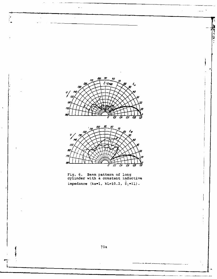
70744
I IV
Fig. 6. Beam pattern of longcylinder with a constant inductive
impedance (ka=l, kL=lO.2, Ziil).
70a

40490 12 04 a65 OW
/0
1800 0? ~4 0?6 -O /0
Fig. 7. Beam pattern of thickcylinder with small constant im-
pedance (kal1.6, kL=5.l, Z1=iO.37).
71
V-

0 0~2 494 /9 ~6
170 I
0 02 0?4 065 48 /a
Fig. 8. Beam pattern of thickcylinder with increased surfaceimpedance (ka=l.6, kL=5, Z1=iO.7.4).
71a

2). In the case of a thicker cylinder ka=l.6 (Figs. 7 and 8),
as a result of the screening effect of the end portion and
weaker excitation of the surface wave, the radiation in the
inverse direction (6=1800) turns out to be considerably greater.
An increase in the magnitude of the surface impedance by twiceleads to a less substantial change in the beam pattern than a
change in length. For a cylinder with a linearly-increasing
impedance (see Fig. 9), comparatively large radiation in the
inverse direction is also noted, brought about by the wave
reflected from the impedance drop on the right end of the cylinder.
During the conduct of the experiment, there is certain
difficulty in obtaining the theoretical beam pattern of the
symmetrical dipole (primary field) because of the presence of a
coaxial feed cable and fastening elements, which introduce certaindistortions into the radiation field. Naturally, this leads to a
slight discrepancy in the calculated and experimental results.
In conclusion, we would note that, insofar as the problemof development of a specific antenna with given characteristics
was not posed, we do not examine the question of optimization of
the parameters of the ribbed-shaft structure and the appearanceof the exciting source in the present article, which is completely
possible in principle. The basic purpose is to show the possibilityand the results of the application of the method of integral
equations to the specific, practically interesting problem ofthe study of the characteristics of an antenna in the form of aribbed shaft of finite length. The advantage of a similar approachto the solution of the problem consists of the sufficiently goodapproximation to a physically actual antenna (finiten~ess of length
of the cylinder, shape, appearance of the exciting source) with ahigh degree of accuracy of calculation, brought about by the useof electronic computers.
72
Ir

1710
.8 006
Fig 9.Bem.ptten f cliderwitmlnealy
- ¢?0
Fig. 9. Beam pattern of cylinder with linearly-increasing impedance.
Conclusion
Thus, we studied both theoretically and experimentally acylindrical impedance antenna in the form of a ribbed shaft offinite length, excited by a symmetrical electrical dipoleperpendicular to the axis of rotation and located on it. Thecurrent distribution on the surface of the antenna is found asa result of the numerical solution of integral equations of thefirst order, with various areas of change in the points ofobservation and integration. Also given are some results of thecalculation of the distribution of the surface density of theelectrical current for impedances which are constant and variablealong the length of the shaft. General expressions are writtendown for determining the field of radiation of the harmonics ofthe electrical and magnetic currents. The calculated beam
73
47

patterns are also compared with the experimental beam patternsfor various lengths and radii of the ribbed shaft with constant
and variable (linearly-increasing) surface impedances.
The author expresses his gratitude to Ye. N. Vasil'ev for
his direction in the present study.
.R'TEPATYPA
1981. Ma PC 0 .M., 0 e 111 a x 1-. ,MeTo.abl Teopcie-ucw~hc iti £K~. r 'I l1958.2. BacH.1beB E H.. M a.lV U.KO,3 " ". 0a. ! i \ A,
H~e HMnelaHcmoro Tena BpatueHHH. v)KT0. T. 37. 1967. .\ 3. CTp III3. B a ii II T e , A H 1. A. 3.1eKTpomtar m TTbe BO.IHbI .. 11,,. .*,,1 - 5 Pa
aHov. 1957.4. 0 e.bl 59. H.. 5ee cnH 1 C AHeH4o ,.1ee .,-- 2
M.. 1959.5. B .1 b . e B E, H 06 OIH')II t !IKUIIII. bCT-'jiO'!,' I
WIN, OKB,%IHM , T_ 5. f965, .%b 5. CTp 8436. j1aBPe HbC AM ,M INAreAaTe.T4 ui~ie c6o pIIK.-, lO8afl Cel q A 176i,.
1954, BUn!. I. N 2. 259.7. B a c W. .I e B E. H. Bo36% aeC ie riamoF,) tj:,ea,6-j I, .
spaweHu.. fH3aecrH BY3a(). Pamo4H3%Ka. 2. 4. 1959. 588.8. 1 H x e E.. 3 \ 1 e 0. Ta6.Oolmu dYHKUlIIH C (POpNv.!ai ItI KpI1Bb\, ', .1..
-HTTi. 1949.
74i

t POSSIBILITIES OF PHASE CORRECTION ON THE SMALL REFLECTOR IN A TWO-REFLECTOR ANTENNA
A. L. Ayzenberg
Analyzed in the approximations of geometricoptics is the effect of redistribution of energyin a two-reflector system on the directive gain andnoise temperature of the antenna with compensationof the phase errors, brought about by flexures ofthe basic (large) reflector, by means of automaticcorrection of the shape of the auxiliary (small)reflector. According to the results of the calcu-lations, one may determine the maximum permissibledeformations of the reflectors with given impairmentsof the antenna characteristics.
Introduction
In controlled reflector antennas of large diameters, it is
difficult to ensure, and especially to maintain, the required
precision of the reflector surface in the process of operation.
In order to combat phase errors, which occur with weight, wind
and temperature deformations of the basic reflector, a method was
proposed for their automatic compensation by means of correction
of the shape of the auxiliary (small) reflector in a two-reflectorantenna [1]. The correction may be accomplished according to a
program (according to the results of preliminary calculations ormeasurements of the deformations of the large mirror) or in a closed
system of automatic regulation with feedback (where continuous
75
V-4-

indication of phase errors and their compensation takes place).
Utilized for indication of phase errors or deviations of the
surface of the large reflector from the theoretical shape may be
a phasometric system with modulation of the reflected signals [l],
[2].
In multi-reflector antennas, the initial surfaces of the
reflectors are calculated proceeding from the requirements for
r producing both a planar phase front and an optimal amplitude
distribution of the field in the antenna aperture (including the
level of irradf'ation of the edges of the reflectors) [3]. Repeated
optimization of the phase-amplitude distribution of the field withdeformations of the large reflector would require a certain change
in the surfaces of the two auxiliary reflectors simultaneously
(two degrees of freedom are required for regulation of the two
field parameters). The compensation, examined here, of errors
of the large reflector, by means of correction of the shape of the
surface of only one small reflector, is therefore unavoidably
accompanied by a change in the amplitude distribution of the field
at the aperture, and the power radiated beyond the edge of the
reflectors. The given study is devoted to analysis of the effect
of the indicated changes on the directive gain and noise temperature
of the antenna. As a result, we will determine the limitations
on the magnitudes of the maximum deformations of the small and,
accordingly, large reflectors, which will be permitted with the
given impairments of the antenna parameters.
Initial Prerequisites
Since deformations of the large and small reflectors vary
slightly, and the diameter of the latter is much less than the
diameter of the former, correction of the shape of the small
reflector has the major effect on the amplitude redistribution of
the field, and changes in the surface of the large reflector may
be disregarded for simplification of analysis. With small
(comparatively with the diameters of the reflectors) deformations,
$ 76

they may be considered directional perpendicular to the initial
surfaces.
It is assumed that deformations of both the large and small
reflectors have a smooth nature. This makes it possible to make
use of the methods of geometrical optics during analysis. A
certain surface of the small reflector, on which the correction is
accomplished, corresponds to the given surface of the large
reflector, if, in this case, the mutual position of the irradiator
and the apexes of the reflectors are fixed. Also assumed is the
absence of shifts of the irradiator and the center of the small
reflector relative to the original axis of symmetry of the system,
i.e., invariability of their position relative to the central
(nondeformed) portion of the large reflector.
We will examine a system of reflectors of parabolic and
confocal hyperbolic profiles, because of which the correspondence
between the angles of irradiation and the coordinates of the
initial and deformed reflectors will be determined by relatively
simple relationships. utilizing this correspondence, and the
principle of conservation of energy in incident and reflected
beam pencils, one may find the redistribution of energy in a two-
reflector antenna with phasing on the small reflector. For
concreteness we will examine some characteristic and practically
important cases of weight deformations2 of the reflectors, which,
however, does not disrupt the generality of the results of the
analysis.
1This may be achieved practically both by purely constructivemeasures, and by means of independent automatic correction of theposition of the small reflector and the irradiator. TheEe measuresfacilitate accurate sighting of the antenna beam and simplify theautophasing system.21n antennas of large diameters, weight deformations are decisivewith moderate wind speeds, if, in addition, measures are taken toreduce temperature deformations.
4 77

r
Phasing with Axiosymmetric Deformations
We will dwell on the case when flexures of the large
reflector are axiosymmetric, directed outward, and increase
monotonously from the center to the periphery (Fig. 1). Weight
deformations have such a nature with orientation of the axis of
the antenna towards the zenith (a=O), and correction of the shape
of the small reflector makes it possible to avoid original
adjustment of the surface of the large reflector.
--la
S' X0
/
(a)
Fig. 1. Axiosymmetric deformations of thereflectors.Key: (a) lost area
Assuming that the curve of flexure in the radial cross-sections
is close to a quadratic parabola, one may assume that the deformed
surface of the large reflector (paraboloid) is also a paraboloid,
the apex of which coincides with the nominal apex (point 0) and
the focal length fn is greater than the initial focal length f0 .
With correction, the small (hyperbolic) reflector, having straightened
outwards, takes on the shape of a hyperboloid, the apex L and first
focus f r of which remain the same as the initial, and the second
focus coincides with the focus of the new paraboloid F (in Fig. 1,7n~78
9-I

the initial profiles of the reflectors are shown by the solid
lines, and the deformed profiles by the dotted line).
We will examine the planar problem in the axial cross- .
section of the system. The initial parabolic and hyperbolic
profiles in the inherent coordinate system x, y and x0 , y0 are
written:y = 4fx,
4-I.2~
where a0 , co are the initial parameters of the hyperbola.
In this case,
X0= X - (to - CO)
yo = Y"
The equations of the profiles of the deformed large and small
reflectors in the inherent coordinate systems x, y and xn, yn have
the form:
y, = 4fx, (1)
4 -4 (2)
where
X. - x.- (c. - C.) (3)
fe= / + 2 (c. - c ) . (4 )
The new parameters of the hyperbola area. -(c. + a) - c.,(5)(5)
V' [(.., + c,). + y.2,J(a + c, -ao + c,)2
S(x, + C)' + yA + x. + co -2 (ag - ce) (6)
where xOn and y on are the coordinates of the edge of the deformedhyperbola in the system xo, Yo.
79I

The latter are determined from the equalities:
X"' =Xoo + Ar1xo1
Yon = Yoo + Arriyo J' (7)
where x 00 and Yoo are the coordinates of the edge of the initial
hyperbola in the system x0 , yo;
A is the displacement of the edge of the small
reflector along the normal to the initial profile;
X. C- - 2
_02 1 20, + Y
and ________ _(8)
are the direction cosines of this normal.
The signs in expressions (8) are determined by the direction
of deformation of the paraboloid (outward or inward). In the given
examination, with nxO, we will take only the "minus" sign into
account, and with ny ,, only the "plus" sign.
We will return to the examination of the effect of deformation
of the reflectors on the antenna characteristics.
Shown in Fig. 1 is the nature of changes in the trajectories
of the extreme beams of the pattern of the irradiator. In the
phasing process, the beam, having passed through the edge of the
nondeformed reflectors earlier, is reflected from the point
k(xnk, Ynk ) of the corrected hyperbolic profile, and intersects
the parabolic reflector at some distance from its edge. Thus, the
deformations of the small reflector outward lead to under-irradiation
of the peripheral portion of the large reflector. The unirradiated
surface of the initial antenna aperture has the shape of a ring
(with practically prevailing levels of initial irradiation of the
edges of the reflectors, the peripheral ring will be partially
illuminated, but the level of irradiation, and, consequently, the
808-. . - w- - --- 0 --
'V.
utilization of the surface are negligible here).
One may show that the radius of the new emitting apertureis
2 2 a2 , _ k( 9
where *0 is half the angle of irradiation of the hyperbolicreflector;
Cn -an V I + tgo I.
XAk = - _ C'tg .
tg To = YeX 0 - C 0
The relative decrease in the area of the aperture is
Carried out as an example were calculations for an antenna
with a diameter D-100 m, with the following initial geometric
parameters:
focal length of the paraboloid f020.36 D;
diameter of the hyperboloid d20.063D;
angle of irradiation of the paraboloid 260=1400;
angle of irradiation of hyperboloid 2002200.
Presented in Fig. 2 are the curves of the dependence of the
relative decrease in the radius Rn/R 0 and the area of the aperture
Sn/S 0 of the examined anteniia on the maximum deformations A It
is evident from the indicated curves that, for example, with
a'u120 mm, Sn/S00m. 7 6 , i.e., the loss in area reaches 24%.
The relative drop in the directive gain of the antenna is
G . S" -,. P.at so ., p.
81

*1
where v and vn are the coefficients of the surface utilization of
initial (radius R0 ) and new (radius Rn) emitting
apertures;
Pn/P0 is the ratio of the powers of the irradiator,
intercepted by the large reflector in the initial
and autophased antennas.
4 - g
0'I 10 O j# 4 J /Co /0 Yt O 90/00110/ 170
Fig. 2. Dependences of the relative decrease inradius and area of the antenna aperture on themaximum deformations of the small reflector.
The calculations for the case of quadratic flexures of the
reflectors showed that the law of distribution of the field ampli-
tude on the new aperture practically coincides with the distribution
at the initial aperture, i.e., the coefficient of surface utilization
of the emitting aperture is maintained unchanged in the phasing
process (vnm"O). (This should be expected because of the fact that,
with quadratic flexures, the change in the angles of inclination of
the elementary sections of the small reflector occurs according to
a linear law.) Since P =aP' then the drop in the directive gain
is determined by the reduction in the area of the aperture:.
G, So
With the examined deformations, the edges of the reflectors
are irradiated at a lesser level than in the initial system, i.e.,
the noise temperature of the antenna is decreased slightly.
82

Phasing with Asymmetric Deformations
Asymmetric weight deformations (Fig. 3) are characteristic
for an antenna oriented at some angle to the zenith: the flexures
of the lower part of the large reflector are directed outwards,
and the flexures of the upper part are directed inwards relativeto the given surface. For the majority of designs, the deformations
in the radial cross-sections increase according to a quadratic
law from zero in the center to the maximum at the periphery of
the reflector, while in circular cross-sections, they dropmonotonously from maximum in the vertical axial plane to zero inthe radial planes, oriented at angles TY to the equatorial plane.
Y Z YV
A;I
Fig 3 Aymmtrc efrmaios f rflctrs
(correc ig. 3. Ahesymmaerictdeoratorsmaof reflector an
its design, the nondeformed radial profiles may lie below or above
the equatorial plane (Tv<O or 'Y>O), and also coincide with it(Y-0). The lower and upper parts of the deformed surface of the
1. 83
L

-~~~~ - -- --- -- -
large reflector may be approximated by two sets of radial
parabolic profiles, which have a general initial apex 0, and
are determined, respectively, by the focal quarter-wavesections F %F and F F", which lie along the original axis of0 0onsymmetry of the system on both sides of the initial focus F,.The focal length f vary between maximum values, which they taken
*on in the vertical plane for the lower (fI~O and upper ffoparts of the reflector (the radial profiles, in which alternation
of the sign of the flexures takes place, maintains the nominal
focal length fo).
During phasing, the hyperbolic reflector deforms so that
the first focuses and the apexes of the radial hyperbolic profiles
remain unchanged (points f, and L), while the second focuses
coincide with the focuses of the corresponding parabolic profiles.
The deformed radial parabolic and hyperbolic profiles of the
lower and upper parts of the reflectors are determined as the
functions of the deformations and atteegsorhcorresponding halves of the small reflector, using formulas (1),
(4), (6), (7), (8) for the large reflector and (2), (3), (5), (6),
(7), (8) for the small reflector. In expression (B) with nxO' in
this case, the "minus" sign is taken for the lower part of the
reflector, and the "plus" sign is taken for the upper part, and
vice versa with ny.*
Correction of the shape of the lower part of the small
reflector leads to partial under-irradiation of the large reflector
(the lost surface of the initial aperture is a curvilinear segment
(Fig. 3)). The relative decrease in the area of the aperture is
where the least radial dimension R n um of the new emitting aperture
is determined according to formula (9), with the substitution in
it of the parameters of the lower vertical radial profiles of the
84
L.'
i-p
reflectors.
Shown in Fig. 2 are the dependences, calculated for a 100-fl Sn2 adn3meter antenna, of the reduction in area - So- and
(respectively for the cases i=n/4, Y=0 and '=-w/8) on the maximum
deformations A' of the lower edge of the small reflector. ForI Fms' SL
example, with A' m=120 mm, a-0n .9, and -0 .95.
Correction of the shape of the upper part of the smallreflector is accompanied by an increase in the level of irradiation
of the upper edges of both reflectors, and an increase in radiationbeyond their edges. We will evaluate the corresponding changes
in the directive gain and noise temperature of the antenna.
The solid angle of the pattern of the irradiator (it isassumed that it is axiosymmetric), which includes the power Pd,
lost beyond the edges of the large reflector, is:
3"' 1 "-" l -- sin us' tg ..... - ; n " _H _\O6 , ..i2 4 2
~tg II-AP4
where UM6 is the minimum angle of the pattern of the irradiator,
in which the energy intersects with the large reflector
(Fig. 3);
'1 a¢ < u is the maximum "miss" angle wide of the large reflector.
The power Pr' lost beyond the edges of the small reflector,
is included in the solid angle:
w ( ! (sin ,oL t , sin T.--A' .tg T.- ,up )2= = 2 4 - sn 2 4
where A¢r uamc is the maximum "miss" angle wide of the small
reflector.
Given in Fig. 4 are the graphs, calculated for a 100-meter
antenna, of the dependence of the "miss" angles A 6 and (AO6+AOP
85

iIV
S ,
F 3 -- -
V 9soI I S204a0 WX I
Fig. 4. Dependences of the "miss" anglesA06 and (A06+A0r) on the deformation and
A; with flexures of the large reflector
inwards.
on the deformations Ar at the edges of the upper part of the small
reflector.
Shown in Fig. 5, for the case T-=0, are the curves of the
dependence of the relative magnitudes of the solid angles - and
r+A 4 on the maximum deformations A" of the upper edge ofrm
the small reflector (wo is the solid angle of the pattern of the
irradiator, in which the power P0 is included).
The calculations, carried out on the basis of these graphs,
showed that the relative power losses beyond the edges of the
reflectors are insignificant. Thus, for 4"m=120 mm, they are 0.05%
with initial irradiation of the edges of the reflectors at a
zero level, and 0.5% with an initial level of the edge irradiationGOn
of 10 db. Thus, a reduction in the directive gain -0 in the case
of asymmetric deformations is primarily determined by the decrease
in the area of the aperture as a result of flexures of the lower
part of the reflector:
a0 So
86
L.

We will return to the noise temperature of the antenna.
An increase in the irradiation level, and, consequently,
intensification of diffraction at the upper edges of the reflectors
are small, as a result of the smallness of the angle tor and
Ao, and, as the calculation showed, they are practically not
reflected on the noise temperature of the antenna. Since
i.O
40$-
Fig. 5. Dependences of the eaie magnitudesof the solid angles - and which0 W0characterize the increase in radiation beyond theedges of the reflectors, on the deformations A"
toand <<to and (Figs. 4 and 5), then Pr<<P . In addition,the power P is disseminated in the rear and distant side
directions of radiation of the antenna, where a high temperature
of the absorbing media is expected. Therefore, subsequently, we
will take into account only the effect of the power P6 which is
predominant. In this case, the noise temperature of the autophased
antenna is
P,
where To is the temperature of the nondeformed antenna, and
T is the temperature of the absorbig medium for the power
P6.
The temperature T. was determined by means of division of the
solid angle Awd into discrete sectors, and subsequent summation of
the magnitudes of the noise from each sector [4].
87
_ _ _ _ _ _ .. .... . . ..

Appreciable weight flexures of the large reflector inwards
appear only with orientation of the antenna at some angle a to
the zenith, and increase with an increase in this angle (the
ratio of the powers % /P0 increases accordingly). At the same
time, with an increase in a, the temperature Td decreases (since
the portion of the power P6, directed at the "hot" earth and
K the high-temperature lower layers of the atmosphere decreases)
I- and the temperature To increases. Calculations for the casea=40* (with this angle, the flexures A" may already reach• rm
substantial values, and the temperature difference T6-T 0 isgreater yet) showed that the relationship of the portions of the
solid angle Awt, which correspond to radiation toward the earth,
the lower layers of the atmosphere (up to 100 above the horizon)
and the relatively "cold sky" (over 100 above the horizon) is
0.25:0.15:0.6. With study at the wave X=3-5 cm, this corresponds
to a temperature T,=I000 K. For c=40 ° , the temperature of a well-
designed antenna T>20 0K. Examining, as an example, a 100-meter
antenna for the case of maximum flexure of the small reflector
Al =120 mm, and assuming that the average power level per unit ofrmthe solid angle Aw 6 is 10 db lower as compared with the level in
AA P6the angle w0 , we have (see Fig. 5) -;=0.04 and -0.004, which
WO p0
corresponds to an increase in the antenna temperature by 0.3*K.
Similar calculations for other angles a (with various values of
T) showed that the permissible deformations of the autophased
antenna are primarily limited because of the reduction in the area
of the aperture, while the relative increase in the antenna
temperature is slight in this case.
The graphs in Figs. 2, 4 and 5, calculated for a 100-meter
antenna, are suitable for antennas of random diameters with a
proportional change in the magnitudes of the maximum deformation
With equal maximum deformations for the examined types of
weight flexures, the greatest losses in area and reduction in
88I
L_

directive gain of the antenna accompany deformations of the
axiosymmetric flexures. The indicated deformations are
practically unequal. As a function of their relationship,
determined by the design and the method of initial phasing of
the antenna, the effect of both symmetric and asymmetric
deformations may prove predominant.
The initial phasing of the antenna may be accomplished:
1) by means of correction of the surface of the small
reflector;
2) by means of correction of the surface of the large
reflector (i.e., elimination of axiosymmetric flexures with
orientation of the axis of the antenna towards the zenith).
In the majority of designs, with asymmetrical deformations,
in the former case, the angle TaO (larger lower portion of the
large reflector is deflected outward, and the smaller upper part
is deflected inward), and in the latter case, TiO (larger upper
portion of the reflector is deflected inwards, smaller lower portion
is deflected outwards). It is evident that with T:>Q, the
deformations A' are great, and the losses in area may reachm so
considerable magnitudes (Fig. 2, curve n); here, the deformations
Alfm s Am and the increase in the antenna temperature because of
a power overflow beyond the edges of the reflectors is negligible.
With <<O, usually Am<A m and, in addition Arm is less, and am
is greater, as compared with the case T>O. Therefore, the lossesSI
in area are less here (Fig. 2, curve S3), and we perceive that
the increase in the antenna temperature is greater than with Y>O.
Nevertheless, in this case, as was already noted, limitations
ensue, primarily because of the loss in area of the aperture.
Thus, during initial phasing of the antenna, both the axio-
symmetric and, to a considerable extent, the asymmetric deformations
of the reflectors are limited on the small reflector because of the
loss in area. During initial phasing of the antenna, the
89
permissible deformations are increased considerably by means of
elimination of axisymmetric flexures on the large reflector.
In the analysis given above, the changes in the characteristics
of the antenna were determined as a function of flexures of the
small reflector. The change to the corresponding flexures of the
large reflector may be accomplished using formula (1). The
connection between the small deviations A and A at the edges
of the small and large reflectors may also be found according to
the approximated formula:
Cos 0
2%0
2
With 2a0=140 and 2 0= 200, A =0.94Lr.
The permissible deformations increase with an increase in
the ratio of the diameters of the small and large reflectors.
It should be noted that the losses in area may be reduced
by means of prescribing the initial amplitude distribution in the
aperture and the level of irradiation of the edges of the reflectors
of the nondeformed antenna with regard for subsequent energy
redistributions during correction on the small reflector.
Conclusions
1. Compensation of phase errors of the antenna by means of
correction of the shape of the small reflector is ac:ompanied
by appreciable losses in area of the aperture (as a result of under-
irradiation of the peripheral part of the large reflector) and
a reduction in the directive gain of the antenna. These losses
determine the maximum deformations which may be permitted on the
small and, accordingly on the large, reflectors of an auto :.s.'
antenna.
2. During initial phasing of the antenna, -
i~
AD-A1O? 321 pfiftgl# TECW4OLOIY DIV lITPATERSON APB OM4 F16 9/5
OCT &1 0 N TNUSAHOV. A A PISTOLIKOMS
UNCLASSIFIED F10-It NI) T-0937-S1 NL
-. 22 KNTWIEITDAICE1

1 1.511111 . 11 M1
MICROCOPY RESOI,[ION TEST CHARTNATIONAL Bklk[AIL JTI SAN)AR[IS 1463 A1,

correction of the shape of the small reflector, the permissible
deformations are considerably less than with elimination of the
initial axiosymmetric flexures by means of correction of thesurface of the large reflector.
3. With correction of the shape of the small reflector,which corresponds to flexures of the upper part of the largereflector inward, one may observe a slight increase in poweroverflow beyond the upper edges of the reflectors, and an increase
in the level of their irradiation. This, however, reflectsweakly on the noise temperature and directive gain of the antenna,
even with considerable deformations.
4. The permissible deformations are proportional to thediameter of the antenna.
5. With the given antenna diameter, operation on shorterwaves makes it possible to accomplish compensation of larger
relative deformations, expressed in wave lengths.
In conclusion, the author expresses his sincere gratitude
to L. N. Deryugin for direction of the study, and L. D. Bakhrakh,I. V. Vavilova, 14. G. Kuznetsov and K. I. Mogil'nikova for theirvaluable advice and discussion of the results.
WIMPATYPA
I.AAaeH6epr A, .1.. Ap iafbescKs I.i A .. t. p.\ . i
JIr H . H.. K Y3 HeLLO m.. rJD\~..b~. ii~rC im . .~tc1OA HoMnencaumehi 4a3oM1X OEA6oc. AsT. cS,:t, CC( P .V'. Ip713..,23/IV 1964 r.. on)6.-i. 12/V .1965 r. Nlo.. ,w 9. M p .
2. AfiseHGepr A. .. Zeptortin .1I. -.. K yHlleitoI .. r. "[.I\,eKd. h, ;Va ,alteRlKl C aEraTi laluqeKwim I 0a3Mpo~a~lie-A R Pe sKC1IIpIMtMIITt.1bl1Ie 11CC1C 10o
4 ~~6SUNe. 4H3BeCThEf BV30D MS 34 CCO C(CI'.. 'tiuit Ik' 2, crp. 93.
3I 59a VG x ,f. ZE., MOCHnab,,Ru osa K [L. Hcvhm-,puic- i-onpc'14 '~>r.-
CCCP. CPSAo4o"SwHfKap. r. 7. 1964, .'t 4. erp. 5M.4. Ditch fie Id C. R. Overall Sistem Requirements for L, Nos. P,, rm.,;i,
tBritish Inst. of Radio En.*. august )961, vol. 22. 1* "2, pp 123--127.
91

DAT
FILMEI
I II

.. ~
b.