Embed Size (px)
Citation preview
NASA Technical Paper 2048
August 1982
Occurrence of
Debris in Indentation. - and Sliding Contact ,
,Kazuhisa Miyoshi and Donald H. Buckley
https://ntrs.nasa.gov/search.jsp?R=19820024615 2018-05-15T17:32:52+00:00Z

TECH LIBRARY KAFB, NM
NASA Technical Paper 2048
1982
National Aeronautics and Space Administration
Scientific and Technical lnforrnatlon Branch
Occurrence of Spherical Ceramic Debris in Indentation and Sliding Contact
Kazuhisa Miyoshi and Donald H. Buckley Lewis Research Center Cleveland, Ohio

Summary An investigation was conducted to examine the nature
of fracture of a brittle ceramic material and the formation of spherical debris in wear. Indenting experiments were conducted with the silicon carbide (O001) surface in contact with a spherical diamond indenter in air at room temperature. Sliding friction experiments were also conducted with the single-crystal silicon carbide (O001 ) surface sliding in the (lOi0) direction in contact with iron and iron-based binary alloys in a vacuum of 30 nPa at room temperature and at 800" C.
The results of the investigation indicate that fracture pits and the formation of a spherical particle and spherical wear debris result from indenting and sliding. Spherical debris may be produced by a mechanism that involves the formation of a spherical-shaped fracture along the circular or spherical stress trajectories under the inelastic deformation zone.
Introduction Recently, there have been a number of reports in the
literature dealing with the occurrence of spherical debris particles (refs. 1 to 11). It has been established that the formation of spherical debris is a characteristic feature of rolling-contact fatigue (refs. 1 and 2). Further, spherical debris has also been observed in the lubricant of a jet engine just prior to fatigue failure of the main rolling bearing (ref. 3). The number of spherical particles in used engine oil is found to increase as ball bearing fatigue progresses (ref. 4). It has been suggested that the number of spheres present in an oil sample can be potentially useful as a diagnostic tool for anticipating the surface fatigue failure of a high-speed ball bearing (refs. 5 and 6).
Spherical debris were also generated in a cavitation erosion apparatus (ref. 7), in grinding (ref. 8), in fretting corrosion studies (refs. 9 and lo), and in simple sliding friction experiments under adhesive conditions (ref. 11). Doroff et al. (ref. 7) have observed spherical debris particles when aluminum and steel were tested in the ASTM standard vibratory cavitation erosion apparatus. They suggested that these tests support the cavitation theory of spherical particle generation during rolling- contact-fatigue crack formation. Komanduri and Shaw (ref. 8) found that a mechanism for spherical metal particles produced during grinding is based on surface energy. Stowers and Robinowicz (ref. 9) revealed that debris particles appear to be deformed by the sliding process and to take on spherical and cylindrical shapes.
Hurricks (ref. 10) has presented spherical debris as a characteristic feature of the fretting wear process. Such debris is mainly found in regions of high adhesion.
In all the foregoing studies, spherical metal debris were observed in solid-solid interactions, but no attention had been paid to spherical nonmetal debris. The present authors were probably the first to observe spherical nonmetal debris particles when conducting a simple sliding friction experiment with a nonmetal such as silicon carbide in contact with a metal (ref. 11). Although the formation mechanism is not clearly understood, it may not be associated with fatigue. The mechanism may be based on the fracture mechanism of nonmetals. It is of interest to develop an understanding of the mechanism of spherical debris generation and fracture behavior of a brittle nonmetal in contact with a solid because of the increasing use of nonmetals in tribological applications.
Because ceramic bearings have the potential for operating reliably at high temperatures with minimal oil lubrication, these bearings offer many advantages over metal bearings in gas turbine engine applications. It is therefore important to know the deformation and fracture mechanisms of nonmetals in tribological systems.
This report examines as its objective the nature of spherical debris generation and the fracture behavior of brittle nonmetals. Indentation experiments were conducted with the single-crystal silicon carbide (O001) surface in contact with spherical diamond indenters in air at atmospheric pressure. Sliding friction experiments were conducted with the silicon carbide (OOO1) surface sliding in the (lOi0) direction in contact with various iron-based binary alloys and iron. All friction experiments were conducted with a load of 0.2 N, at a sliding velocity of 3 mm/min for a total sliding distance of 2.5 mm with single-pass sliding, in a vacuum of 30 nPa at room temperature and at 800" C.
Materials The singlecrystal silicon carbide used in these
experiments was a 99.9-percent-pure compound of silicon and carbon and had a hexagonal, closed-packed crystal structure. The composition of single-crystal silicon carbide is presented in table I. The Knoop hardness was 2830 in the (lOi0) direction and 2670 in the (1130) direction on the basal plane of the silicon carbide
TABLE I. -COMPOSITION OF SINGLE-CRYSTAL SILICON CARBIDE
Silicon, percent.. ........................................................ ..M. 6 Carbon, percent.. ........................................................ .33.3 Oxygen, ppm ............................................................ <500 Boron, ppm .............................................................. < 1 0 0 Phosphorus, ppm. ...................................................... < 200 Others, ppm .............................................................. ~ 0 . 1

(ref. 12). The method of growth of the silicon carbide was by carbon arc. The [ O O O 1 ) plane was nearly parallel to the sliding surfaces examined herein. X-ray back- reflection Laue photographs were taken to establish the exact bulk orientation of the crystal after it had been polished with a diamond powder (3 pm diam) and then with aluminum oxide (Al203) powder (1 pm diam).
Specimens were within *2O of the low-index (OOO1 ] plane. The silicon carbide samples were in the form of flat platelets and had a mean surface area of about 70 mm or more. The roughness of the mirror-polished silicon carbide surfaces measured by surface profilometer was 0.1 pm for the maximum height of irregularities.
The iron-based binary alloys used in this investigation were prepared by arcmelting the high-purity iron and high-purity alloying element (Ti) (ref. 13). The solute concentration was 1.02 at.% for titanium, which forms a continuous series of solid solutions with iron.
The iron was polycrystalline and 99.99 percent pure. The method of preparation was by electron beam zone refining.
The radius of the iron and binary alloy pin specimens was 0.79 mm. Pin specimens were mirror polished with a diamond powder (3 pm diam) and then an A1203 powder (1 pm diam).
The diamonds used in the indentation experiments were natural and spherical in shape. Three radii of curvature of the spherical diamond indenters were used: 0.008, 0.02, and 0.1 mm. The indenters were polished with A1203 before each indentation experiment.
Apparatus Two apparatuses were used in this investigation. One
was a vacuum system capable of measuring adhesion, load, and friction. The apparatus also contained tools for surface analysis such as X-ray photoelectron spectroscopy and Auger electron spectroscopy. The mechanism used for measuring adhesion, load, and friction is shown schematically in figure l(a) and is described in references 13 and 14.
The second apparatus was a microhardness (Vickers) tester (fig. l(b)). A diamond indenter was attached to one end of a rod of a precision balance. The load was applied by placing deadweights on a pan on top of this end of the rod.
Experimental Procedure Specimen Preparation
The disk flats, pin specimens, and diamond indenters were polished with 3-pm-diameter diamond powder and
Tantalum mds-Jdc;(T,- Tantalum sheet
Flat specimen
e Adhesive force
iction force
la1 High-vacuum friction and wear apparatus.
rClamping screw
Diamond \ indenter-"" -
I I \ Specimen:
i
/ LPivot point
/ 'LCounterbalance weight
(b) Indentation appaG3tUS.
Figure 1. -Apparatuses for indentation and sliding friction ~xperiments.
then 1-pm-diameter A1203 powder. All the pin and disk surfaces were rinsed with 200-proof ethyl alcohol.
Friction Experiments
The experimental procedures used are described in detail in references 13 and 14.
Indentation Experiments
The indentation experiments were conducted on silicon carbide (OOO1) surfaces with a spherical diamond indenter. All indentation experiments were conducted at room temperature. The contact time was 20 sec.
Results and Discussion Microfracture in Indentation Contact
Indenting with a spherical diamond indenter on a silicon carbide (OOO1 1 surface results in the formation of circular cracks as well as in plastic deformation. Figure 2 presents scanning electron micrographs of the permanent indentation remaining and circular cracks surrounding the impression generated by Q.l-, 0.02-, and 0.008-mm- radius, spherical diamond indenters. It becomes obvious from an examination of figure 2 that a degree of plastic deformation and nearly perfect circular cracking occurred in the silicon carbide.
It is very interesting that, in the figures, the influence of crystallinity on the geometry of the cracks is not imposed on the solid. In other words, for anisotropic solids such as a single crystal, we expected an orientation
2

* ' .--:Circular ,' crack
~ 1 - . ; l p m
I_
(a) Indentation generated by 0.1-mm-radius spherical indenter. Load, 10 N.
(b) Indentation generated by 0.02-mm-radius spherical indenter. Load, 5 N.
Figure 2. - Indentation and cracks on silicon carbide(000U surface generated by spherical indenter. Scanning electron micrographs.
3
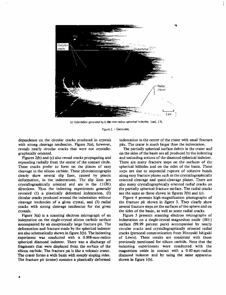
dependence on the circular cracks produced in crystals with strong cleavage tendencies. Figure 2(a), however, reveals nearly circular cracks that were not crystallo- graphically oriented.
Figures 2(b) and (c) also reveal cracks propagating and expanding radially from the center of the contact circle. These cracks prefer to form on the planes of easy cleavage in the silicon carbide. These photomicrographs clearly show several slip lines, caused by plastic deformation, in the indentations. The slip lines are crystallographically oriented and are in the < IIZO) directions. Thus the indenting experiments generally revealed (1) a plastically deformed indentation, (2) circular cracks produced around the indentation without cleavage tendencies of a given crystal, and (3) radial cracks with strong cleavage tendencies for the given crystals.
Figure 3(a) is a scanning electron micrograph of an indentation on the single-crystal silicon carbide surface accompanied by an exceptionally large fracture pit. The deformation and fracture made by the spherical indenter are also schematically shown in figure 3(b). The indenting experiment was conducted with a 0.008-mm-radius spherical diamond indenter. There was a discharge of fragments that were displaced from the surface of the silicon carbide. The fracture pit is like a volcanic crater. ?he crater forms a wide basin with steeply sloping sides. The fracture pit (crater) contains a plastically deformed
(c ) Indentation generated by O.Oa8-mm-radius spherical indenter. Load, 2 N.
Figure 2 - Concluded.
indentation in the center of the crater with small fracture pits. The crater is much larger than the indentation.
The partially spherical surface debris in the crater and on the sides of the basin are all produced by the indenting and unloading actions of the diamond spherical indenter. There are many fracture steps on the surfaces of the spherical hillsides and on the sides of the basin. These steps are due to sequential rupture of cohesive bonds along easy fracture planes such as the crystallographically oriented cleavage and quasi-cleavage planes. There are also many crystallographically oriented radial cracks on the partially spherical fracture surface. The radial cracks are the same as those shown in figures 2(b) and (c).
Figure 4 presents high-magnification photographs of the fracture pit shown in figure 3. They clearly show several fracture steps on the surfaces of the sphere and on the sides of the basin, as well as some radial cracks.
Figure 5 presents scanning electron micrographs of indentation on a single-crystal magnesium oxide (001 ) surface (99.99 percent pure) accompanied by nearly circular cracks and crystallographically oriented radial cracks (personal communication from Hiroyuki Ishigaki of Lewis). These results are consistent with those previously mentioned for silicon carbide. Note that the indenting experiments were conducted with the magnesium oxide in contact with a 0.02-mm-radius diamond indenter and by using the same apparatus shown in figure l(b).
4

Fracture pit (crater)
/
(a) Scanning electron micrograph.
7-
(b) Schematic.
Figure 3. - indentation and fracture pit with a spherical particle.
5
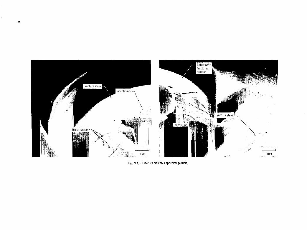
Figure 4. - Fracture pit with a spherical particle.

. .. . '. ;; . - '
(a) In air.
(b) In mineral oil with sulfur additive.
Figure 5. - Indentation and crack on singlecrystal magnesium oxide (001) surface generated by 0.02-mm-radius spherical diamond indenter. MgO crystals cleaved in a i r and in mineral oil with sulfur additive. Indentations made on surface in a i r o r immersed i n t h e oil. Load, 0.25 N; room temperature.
7
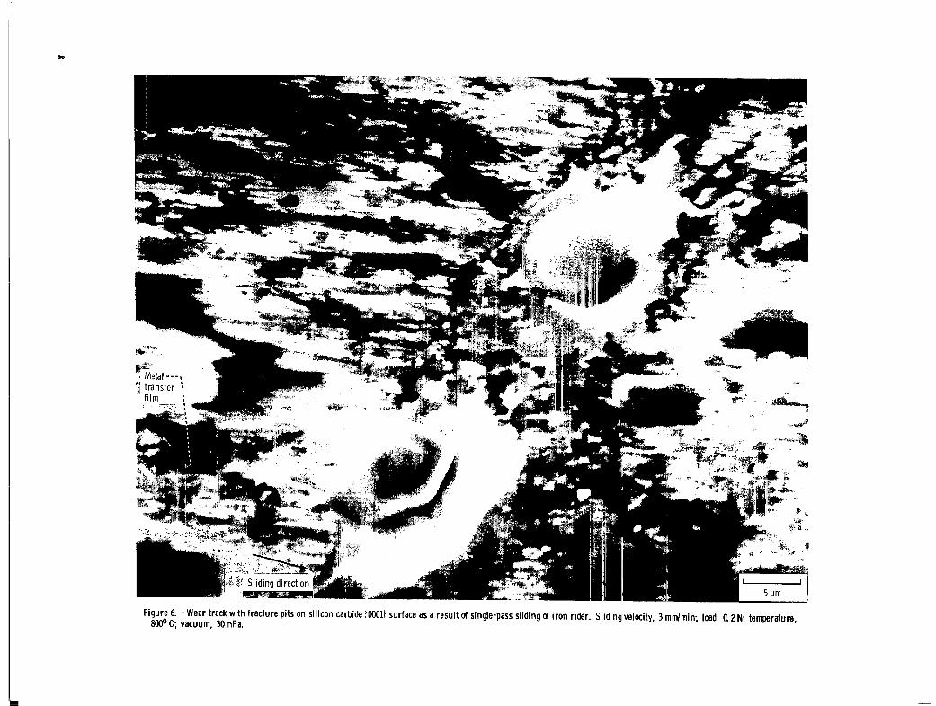
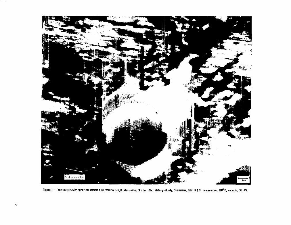
Figure 7. -Fracture pits with spherical particle as a result of single-pass sliding d iron rider. Sliding velocity, 3 rnmlrnin; load, a2 N; temperature, 8oooC; vacuum, 30 n P a

e 0
Figure 7. - Continued.
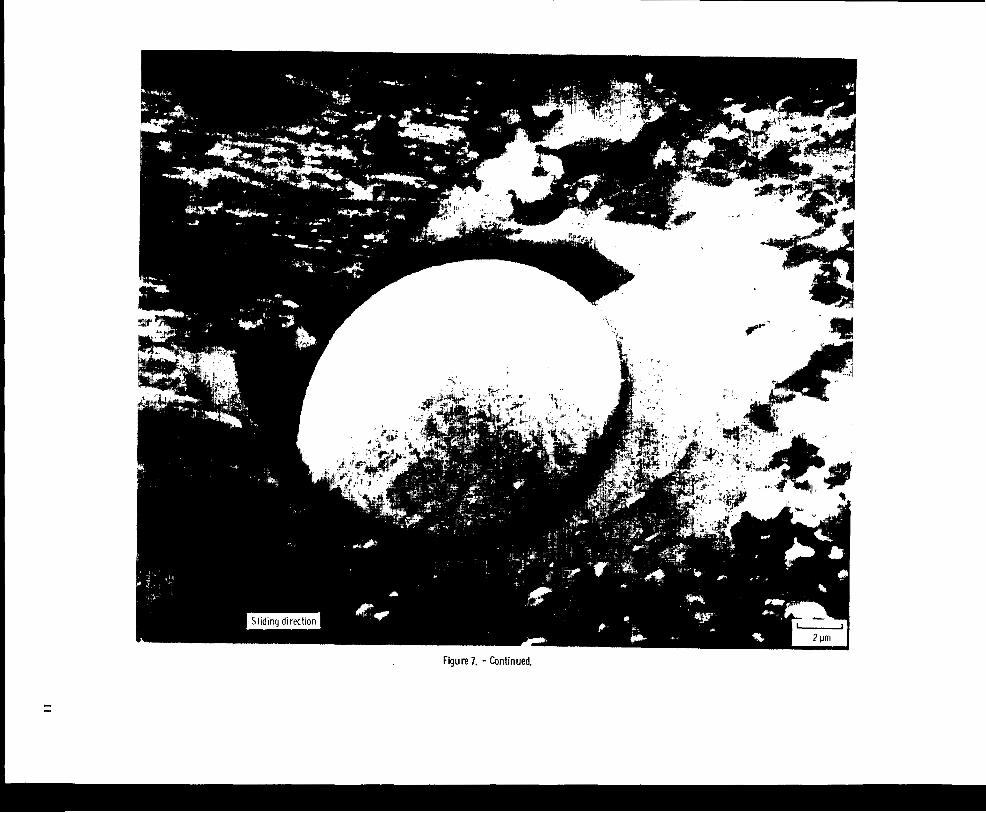
Figure 7. - Continued. I -
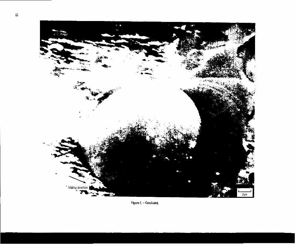
Figure 7. - Concluded
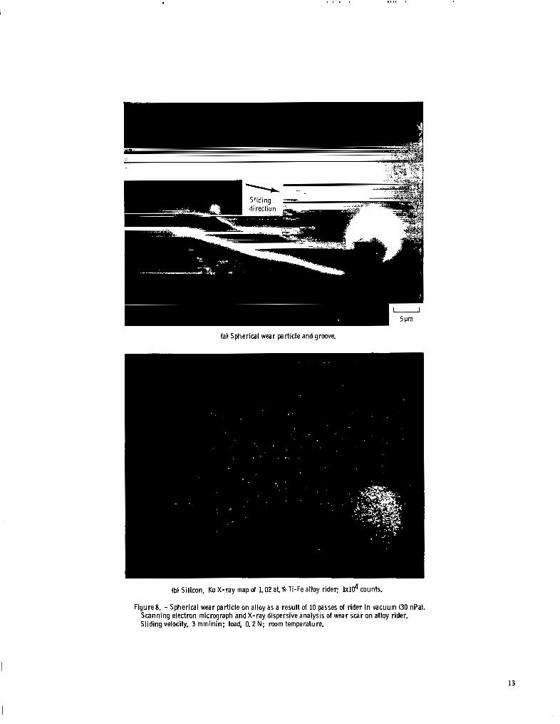
(a) Spherical wear particleand groove.
(b) Silicon, Ka X-ray map of 1.02 a t 70 Ti-Fe alloy rider; lxld counts.
Figure8. - Spherical wear particle on alloy as a result of 10 passes of rider in vacuum (30 nPa). Scanning electron micrograph and X-ray dispersive analysis of wear scar on alloy rider. Sliding velocity, 3 m m h i n ; load, 0.2 N; room temperature.
13

(a) Spherical wear particle.
(b) Spherical and multiangular wear debris.
Figure 9. - Spherical and partially spherical wear particle as results of 10 passes of 1.02 at. 70 Ti-Fe alloy riders in vacuum (30 nPa). Scanning electron micrographs of wear tracks on disk Sliding velocity, 3 mmlmin; load, 0.2 N; mom temperature.
14

(c) Partially spherical and partially multiangular wear particle.
(d) Partially roundedand partially multiangular wear particle.
Figure 9. - Concluded.
15
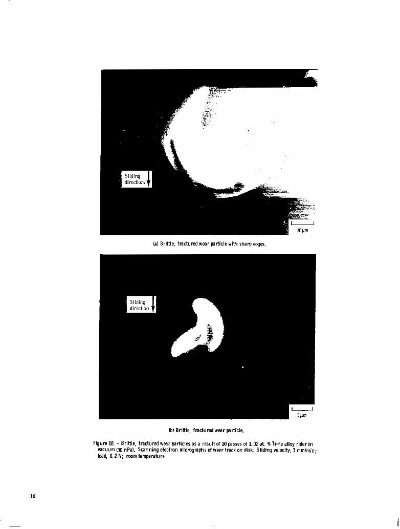
(a) Brittle, fractured wear particle with sharp edges.
(b) Brittle, fractured wear particle.
Figure 10. - Brittle, fractured wear particles as a result of 10 passes of 1.02at 46 Ti-Fe alloy rider i n vacuum (30 nPa). Scanning electron micrographs of wear track on disk. Sliding velocity, 3 mmlmin; load, 0.2 N; room ternperatu re.
16

Spherical Debris in Sliding Contact The present authors have investigated fracture and the
formation of wear debris for ceramic materials in sliding contact with either a metal or a nonmetal (refs. 11, 12, 15, and 16). Fracture and the formation of wear debris were generally geometrically characterized by crystallographic orientation. Multiangular wear particles were produced by primary and secondary cracking of cleavage planes in sliding contacts. However, more detailed examination of the wear track on the silicon carbide in sliding contact with a metal revealed, in addition, evidence for the formation of spherical wear debris particles of silicon carbide.
Sliding friction experiments were conducted with the single-crystal silicon carbide (OOO1) surface in contact with iron or iron-based binary alloys at a temperature to 800" C in a vacuum of 30 nPa. The sliding of iron on a silicon carbide surface at 800" C resulted in the formation of cracks and fracture pits in the silicon carbide surface. The wear due to fracture occurred very locally and in very small areas in the sliding contact region.
Figure 6 presents a scanning electron micrograph of the wear track on the silicon carbide surface, where the wear track was generated by a single-pass sliding of the iron rider. The wear track contained microfracture pits and silicon carbide debris as well as iron transfer films. Two kinds of fracture pits were generally clearly observed in wear tracks: (1) pits with spherical debris and (2) pits with multiangular wear debris that have crystallographically oriented sharp edges and are nearly of a hexagonal platelet shape. (Multiangular wear debris are generated by surface cracking along 1010) or ( 1120) planes and
subsurface cracking along (OOO1) planes, which are parallel to the sliding interface.)
Figure 7 presents scanning electron micrographs of various fracture pits with spherical debris in the very local area of the wear tracks. These results revealed that a nearly spherical debris particle can exist in the fracture pit. In other words, a spherical fracture occurs in even single-crystal silicon carbide under the sliding surface with sliding friction contact.
Figure 8 is a scanning electron micrograph and an X-ray dispersive analysis map of a nearly spherical wear debris particle and a groove produced in a plastic manner by the plowing action of the debris particle. This dislodged spherical wear debris particle was observed near the wear scar of an iron-base binary alloy rider after 10 sliding passes on the silicon carbide surface.
Figure 9 presents a spherical wear debris particle observed on the silicon carbide surface after sliding contact with the binary alloy rider. The neariy spherical particle is very similar to the particle observed on the wear scar shown in figure 8.
Figure 10 presents brittle, fractured wear debris observed near the wear tracks of the silicon carbide surface in contact with an iron-based binary alloy. The wear particles contained both sharp edges and round portions. The formation of sharp edges may be related to cleavage cracking in the formation of the wear debris. The round portion would indicate that the particles had been nearly or partially spherical before fracturing. These figures also indicate that the wear debris is characterized by being hollow, with the outer and inner circles of the particles appearing to be concentric.
Figure 11. - Schematic of a spherical crack formation under plastically deformed zone.
17
I

Generation Mechanism of Spherical Debris
The present authors suggested the possible mechanism for generating a spherical wear debris particle (ref. 11). Briefly, the mechanism has two aspects: (1) a stress concentration, and (2) a circular or spherical fracture.
When two solid surfaces are in contact, stress con- centration at the contact area may produce a small zone of inelastic deformation in the solid. Cracks will subsequently be initiated in the solid. The cracks develop stable growth in a subsurface region and on the surface around the inelastic deformation zone during the loading and unloading processes.
The cracks also grow easily by application of shearing force during sliding. The cracks, which are generally circular, spherical, and radial, are schematically shown in figure 11 with a model.
The spherical cracks may be developed along circular stress trajectories (ref. 17). Although crystallinity, however, is imposed on the crack geometries of anisotropic materials such as silicon carbide, it is possible that the cracks may grow and pile up in atomistic terms by the sequential rupture of cohesive bonds along the circular or spherical stress trajectories shown in figure 11.
Conclusions As a result of indenting and sliding friction
experiments conducted in this investigation with single- crystal silicon carbide in contact with spherical diamond indenters in air or with metal riders in vacuum, the following conclusions were drawn:
1. Fracture pits with a spherical particle and spherical wear debris result from indenting and sliding.
2. Spherical debris may be produced by the following mechanism: A spherical-shaped fracture occurs along the circular or spherical stress trajectories under the inelastic deformation zone.
Lewis Research Center National Aeronautics and Space Administration Cleveland, Ohio, March 18, 1982
References 1. Scott, D.; and Mills, G. H.: Scanning Electron Microscope Study
of Fracture Phenomena Associated with Rolling Contact Surface Fatigue Failure. Wear. vol. 16, 1970, pp. 234-237.
2. Scott, D.; and Blackwell, J.: Accelerated Test for the Study of Materials Under Rolling Contact. Proc. Inst. Mech. Engrs., London, 1964, pp. 201-208.
3. Seifert, W. W.; and Westcott, V. C.: A Method for the Study of Wear Particles in Lubricating Oil. Wear, vol. 21, 1972, pp. 27-42.
4. Middleton, J. L.; Westcott, V. C.; and Wright, R. W.: Number of Spherical Particles Emitted by Propagating Fatigue Cracks in Rolling Bearings. Wear, vol. 30, 1974, pp. 275-277.
5. Scott, D.; and Mills, G. H.: Spherical Particles Formed in Rolling Contact Fatigue. Nature, vol. 241, Jan. 12, 1973, pp. 115-116.
6. Scott, D.; and Mills, G. H.: Spherical Debris-Its Occurrence, Formation and Significance in Rolling Contact Fatigue. Wear,
7. Doroff, S. W.; et al.: Spheroidal Particles Produced by Cavitational Erosion. Nature, vol. 274, Feb. 8, 1974, p. 363.
8. Komanduri, R; and Shaw, M. C.: Formation of Spherical Particles in Grinding. Philos. Mag., vol. 32, no. 4, April 1975, pp. 711-724.
9. Stowers, I. F.; and Rabinowicz, E.: Spherical Particles Formed in the Fretting of Silver. J. Appl. Phys., vol. 43, no. 5 , 1972, pp.
10. Hurricks, P. L.: Occurrence of Spherical Particles in Fretting Wear. Wear, vol. 27, 1974, pp. 319-328.
11. Miyoshi, Kazuhisa; and Buckley, Donald H.: Generation and Morphology of Single-Crystal Silicon Carbide Wear Particles Under Adhesive Conditions. Wear, vol. 67, no. 3, 1981, pp.
12. Miyoshi, Kazuhisa; and Buckley, Donald H.: Anisotropic Tribological Properties of Silicon Carbide. Wear, vol. 75, 1982,
13. Miyoshi, Kazuhisa; and Buckley, Donald H.: Adhesion, Friction and Wear of Binary Alloys in Contact with Single-Crystal Silicon Carbide. J. Lubr. Techno]., vol. 103, 1981, pp. 180-187.
14. Miyoshi, Kazuhisa; and Buckley, Donald H.: Changes in Surface Chemistry of Silicon Carbide (OOOI) Surface with Temperature and Their Effect on Friction. NASA TP-1756, 1980.
15. Miyoshi, Kazuhisa; and Buckley, Donald H.: Friction and Fracture of Single-Crystal Silicon Carbide in Contact with Itself and Titanium. ASLE Trans., vol. 22, no. 2, Apr. 1979, pp. 146-153.
16. Miyoshi, Kazuhisa; and Buckley, Donald H.: Friction and Wear of Single-Crystal Manganese-Zinc Ferrite. Wear, vol. 66, no. 2, 1981,
17. Lawn, B. R.; and Swain, M. V.: Microfracture Beneath Point Indentations in Brittle Solids. J. Mater. Sci., vol. 10, no. 1, 1975,
V O ~ . 24, 1973, pp. 235-242.
2485-2487.
303-319.
pp. 253-268.
pp. 157-173.
pp. 113-122.
18

1. Report No. 1 2. Government Accession No. . .. .
NASA TP-2048
4. Title and Subtitle
OCCURRENCE OF SPHERICAL CERAMIC DEBRIS IN INDENTATION AND SLIDING CONTACT
7. Author(s1
Kazuhisa Miyoshi and Donald H. Buckley ~~ ~. _" -
9. Performing Organization Name and Address .. .
National Aeronautics and Space Administration Lewis Research Center Cleveland, Ohio 44135
National Aeronautics and Space Administration Washington, D. C. 20546
..
12. Sponsoring Agency Name and Address
5. Supplementary Notes . . ..
3. Recipient's Catalog No.
. - "
5. Report Date
Auerust 1982 6. Performing Organization Code
506- 53- 1 2 .. . ~
8. Performing Organization Report No
E-1072 10. Work Unit No.
"-
11. Contract or Grant No.
b 3 . Type of Report and Period Covered
I Technical Paper
r 14. Sponsoring Agency Code
" . -
16. Abstract . " " " ~ . . .
Indenting experiments were conducted with the silicon carbide { 0001) surface in contact with a spherical diamond indenter in air. Sliding friction experiments were also conducted with silicon carbide in contact with iron and iron-based binary alloys at room temperature and 800' C. Fracture pits with a spherical particle and spherical wear debris were observed as a result of indenting and sliding. Spherical debris may be produced by a mechanism that involves a spherical-shaped fracture along the circular o r spherical stress trajectories under the inelastic deformation zone.
7. Key Words (Suggested by Author(s1 1
Spherical debris Silicon carbide
18. Distribution Statement
Unclassified - unlimited STAR Category 27
1 19. Security Classif. (of this report) 20. Security Classif. (of this page)
Unclassified Unclassified
* For sale by the National Technical Information Servlce. Springfield.
21. No. of Pages
20 . .
Virginia 22161 NASA-Langley, 1982
I
National Aeronautics and Space Administration
Washington, D.C. 20546 . .
Official Business Penalty for Private Use, 5300
SPECIAL FOURTH CLASS MAIL Postage and F& Paid
Space Administration BOOK, National Aeronautics and
. NASA451
USMAIL
, . . . . .
:. POSTMASTER: If Undeliverable (Section 158 Postal Manual) Do Not Return '
. .