Embed Size (px)
Citation preview

20 inch Telescope and Observatory
Observatory Design and construction
Operations and Maintenance

Contents 1. Telescope and observatory design and construction......................................................................................................3
1.1. Dome design and construction ..............................................................................................................................3 1.2. Weather station....................................................................................................................................................11 1.4. Dome control room .............................................................................................................................................13 1.5. Telescope design and construction......................................................................................................................14 1.5.1. Telescope drive system...................................................................................................................................15 1.5.2. Telescope axis limits and interlocks ...............................................................................................................16 1.5.3. Telescope focus drive and derotator ...............................................................................................................17 1.5.4. Telescope mirror cover ...................................................................................................................................18 1.5.5. Thermal management......................................................................................................................................18 1.6. Telescope instrumentation...................................................................................................................................18 1.7. Control system and software overview ...............................................................................................................19
2. Observatory operations and maintenance ....................................................................................................................20 3. Telescope operations and maintenance........................................................................................................................21
3.2. Power up procedure ........................................................................................................................................21 3.3. Power down procedure....................................................................................................................................21
4. Astronomers Control Panel (ACP)...............................................................................................................................22 5. Supernova discovery and follow up.............................................................................................................................23 6. MaxImDL.....................................................................................................................................................................25 7. Scope-drive software....................................................................................................................................................26
7.1.1. Scope-drive functionality................................................................................................................................26 7.1.2. Stepper Software.............................................................................................................................................28
7.1.3. Configuration..............................................................................................................................................32 7.1.4. Alazimuth start up sequence.......................................................................................................................43
7.2. The Handpaddle ..................................................................................................................................................53 7.2.1. Program display..........................................................................................................................................55 7.2.2. Setting the altitude axis and azimuth axis fullstep size in the config.dat file .............................................60 7.2.3. Setting the slew (halfstep) speed ................................................................................................................60 7.2.4. Setting the microstepping parameters for smooth motors ..........................................................................61
7.3. Interfacing with other programs ..........................................................................................................................65 7.3.1. To use Guide, a planetarium program by Project Pluto (Bill Gray): ..........................................................65 7.3.2. Communicating With Other Programs .......................................................................................................65 7.7.1. Focusing......................................................................................................................................................75 7.7.2. Parallel Port Interface .................................................................................................................................76 7.7.3. Autoguiding................................................................................................................................................77
8. Drawings ......................................................................................................................................................................80 8.1. Power distribution ...............................................................................................................................................81 8.2. Weather station....................................................................................................................................................83 8.3. Power control ......................................................................................................................................................84 8.4. Dome azimuth drive control................................................................................................................................85 8.5. Dome door control...............................................................................................................................................86 8.6. Telescope control ................................................................................................................................................87 8.7. Hand pad .............................................................................................................................................................88 8.8. Current Limiting Modification............................................................................................................................90 8.9. Stepper circuit......................................................................................................................................................92 8.10. Stepper system heartbeat shut off ...................................................................................................................93 8.11. Field Rotation..................................................................................................................................................94 8.12. Network layout................................................................................................................................................95
9. Material list ..................................................................................................................................................................96 9.1. Software listing....................................................................................................................................................96 9.2. Dome material list ...............................................................................................................................................96 9.3. Weather station material list................................................................................................................................96 9.4. Telescope material list.........................................................................................................................................96
10. Links and references................................................................................................................................................98

1. Telescope and observatory design and construction
The 18inch F5 used at my old house for many years was moved to Church Lane back in 1997. From 1997 to 2000 the telescope did not do any observations due to the building of the 30 inch TROK telescope and two 16 inch F6 Dobsonian (to name a few). The 18 inch telescope ended up being used on an AltAz fork mounting within the old TRO 30inch run off shed at the bottom of the garden at Church Lane. This work reasonably for a few years, but not much in the way of observations had been done. The main problems being wind shake (due to the telescope being in the open air), set up time and awkwardness of moving the run off shed (which by now was getting difficult to move). The offer of the old Pex Hill dome seemed like the answer. The intention from the start was to make the observatory (Dome and Telescope) remotely operable with the potential for automated observations. This requirement was to allow efficient observations to be done either autonomously or remotely in the local control room or anywhere on the planet with an internet connection.
1.1. Dome design and construction The dome was originally located at the Liverpool Astronomical societies Pex Hill Observatory. This was opened by Patrick Moore back in 1994. Unfortunately it never worked properly and on a few occasions sections of the dome door blew off. A new dome was commissioned and the old dome was acquired by me back in May 2003. Work did not start on the dome until the spring of 2004. The dome was stripped on the patio. A new door was needed and the azimuth ring needed major rework.

The site for the dome was to be on top of the run off shed for the 16 inch Dobsonian. The was adjacent the old 30 inch TRO shed (that at this time contained the 18inch AltAz) that can be seen in the image below.
The base is 8 inches of concrete with reinforcing. A 4 inch duct runs from the centre of rotation to the inside of the dome wall. This then continues underground into the control room shed at the end of the garden. A spare 4 inch duct is adjacent the utilised duct. This runs out of the dome underground to just beyond the exterior wall. This will be used in the vent of more capacity or if signal and power cables need to be separated.

The concrete was poured in a few hours with help form LAS members and my Dad.
Work began soon after on laying the bricks for the supporting wall. A single layer was used with an opening for access. A number of holes have been left around the supporting wall to allow for cooling extract fans to be installed.
With the bricks complete, time was required to let the mortar cue before the azimuth lintel was cast. This was created by forming thin ply around the outer and inner walls of the supporting wall. The ring was cast in sections to allow for expansion. Reinforcing tie bars between each lintel section were used to provide strength.

The dome was erected onto the azimuth ring with a temporary door in May 2004, less than two months after starting the ground excavations. The temporary door would remain in place until the end of 2004 due to me working away in Australia on the Faulkes South telescope and that the door design proved to be one of the most difficult parts of the project. The temporary door was painted hardboard.

Another major problem that was overcome in time was water leaking in through the brickwork. This was caused by water running down the dome skirt (damp proof roll was used at the bottom of the dome) directly off the skirt onto the brick. The skirt was eventually spaced off the brick by a ring of plastic tubing fixed to the dome wall. The skirt then runs smoothly on the tubing. In addition, a lip (plastic L angle) was installed at the bottom of the dome before the skirt. This would deflect 90% of the water. The skirt would then deal with the rest. The original dome door was in two sections made of fibre glass that ran over each other through guides. A design for the new door was eventually settled on. This would be in two independently controlled sections of rolled aluminium angle covered with 1.2mm sheet aluminium. The door would run in a ‘C’ channel rails also made of aluminium.
The design of the rails proved to be difficult due to manufacturing problems. I could not find a company that could roll large sections of ‘C’ channel aluminium accurately. The design ended up as a one inch box section of aluminium faced on two sides by 2 inch x 3mm thick aluminium flat bar. This would form a ‘C’ channel when bolted together with stainless steel M6 bolts. This box channel was rolled to very accurate tolerances by a company called Formes Alutek ltd. Cromwell road Ellesmere Port.
The dome wheels in axial and in radial are 100mm diameter nylon wheels. These have a central steel hub that needs to be greased on a 6 month basis to ensure smooth motion.
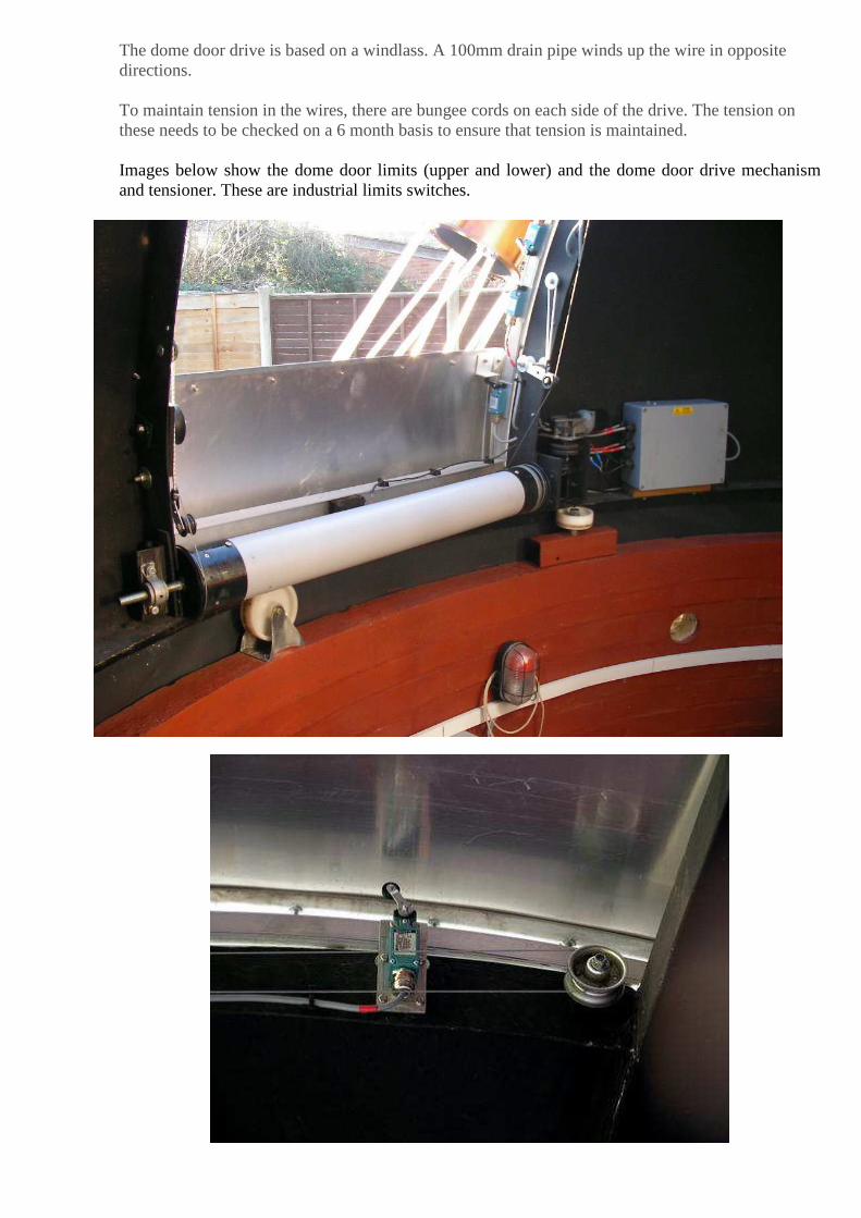
The dome door drive is based on a windlass. A 100mm drain pipe winds up the wire in opposite directions. To maintain tension in the wires, there are bungee cords on each side of the drive. The tension on these needs to be checked on a 6 month basis to ensure that tension is maintained. Images below show the dome door limits (upper and lower) and the dome door drive mechanism and tensioner. These are industrial limits switches.
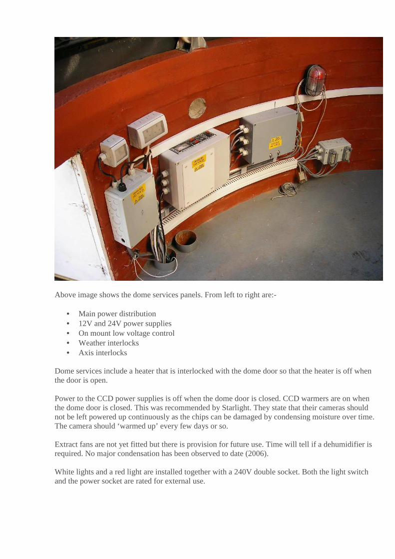
Above image shows the dome services panels. From left to right are:-
• Main power distribution • 12V and 24V power supplies • On mount low voltage control • Weather interlocks • Axis interlocks
Dome services include a heater that is interlocked with the dome door so that the heater is off when the door is open. Power to the CCD power supplies is off when the dome door is closed. CCD warmers are on when the dome door is closed. This was recommended by Starlight. They state that their cameras should not be left powered up continuously as the chips can be damaged by condensing moisture over time. The camera should ‘warmed up’ every few days or so. Extract fans are not yet fitted but there is provision for future use. Time will tell if a dehumidifier is required. No major condensation has been observed to date (2006). White lights and a red light are installed together with a 240V double socket. Both the light switch and the power socket are rated for external use.
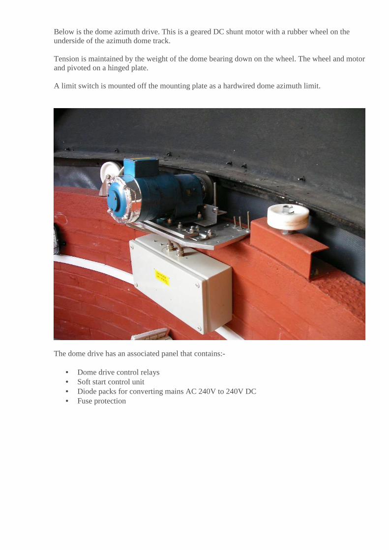
Below is the dome azimuth drive. This is a geared DC shunt motor with a rubber wheel on the underside of the azimuth dome track. Tension is maintained by the weight of the dome bearing down on the wheel. The wheel and motor and pivoted on a hinged plate. A limit switch is mounted off the mounting plate as a hardwired dome azimuth limit.
The dome drive has an associated panel that contains:-
• Dome drive control relays • Soft start control unit • Diode packs for converting mains AC 240V to 240V DC • Fuse protection

1.2. Weather station
1.2.1. Operation
The design of the weather station was kept as simple as possible. I had looked at commercial units, but they were either very expensive or had no hardware interface (cheap versions). I was after a simple hardwired system that would:-
• Not open in daylight • Close when it was too windy • Close when it was raining or high humidity • Close at dawn • Be latched so that a command was required to reopen
The Rain sensor is a Kemo ‘off the shelf item. The Light (dust/dawn) sensor is a Kemo ‘off the shelf item The relative humidity sensor is a Manrose retro fit humidity sensor. Product code 0950. It is mounted lower down on the weather station pole for access to the humidity pot. It is connected into the weather monitoring system via a slave relay in the weather termination box inside the control room.

The wind sensor is a multidirectional switch triggered at 30mph. A funnel mounted on a plastic pipe act as a sail. This was calibrated by hanging the unit out of a car. An additional rain sensor may be required local to the dome, or an additional diverse sensor. The sensor requires cleaning on a regular basis to ensure that it stays sensitive.
1.3. Weather station maintenance The rain sensor requires cleaning with an eraser and clean water every week to ensure that it stays sensitive. The pole that the weather station is mounted on can be lowered by undoing the upper mounting wing nut and pivoting the station on the lower bolt. A fine abrasive may be required to improve sensitivity. It appears that the surface gets contaminated so preventing the gold contacts to operate correctly. It is unclear how long the gold will last when subjected to abrasion. The humidity sensor will need careful cleaning every week to keep out insects.

1.4. Dome control room
The dome control room houses the main computers for the telescope and cameras. It also contains a panel for the scope.exe control board for the steppers on the telescope, and an additional panel for the weather station relay interface box and power supplies for the telescope drive and dome battery backup in the event of a power failure. The computer on the left has ACP, Cartes Du Ceil, MaxImDL, and other software. There is a serial link from this computer to the computer on the right. This serial link handles the LX200 protocol from the telescope drivers to the scope.exe software running on that computer. The computer on the right runs in DOS (6.2) mode only. The parallel port on this computer connects to the scope.exe board that drives the telescope axis.
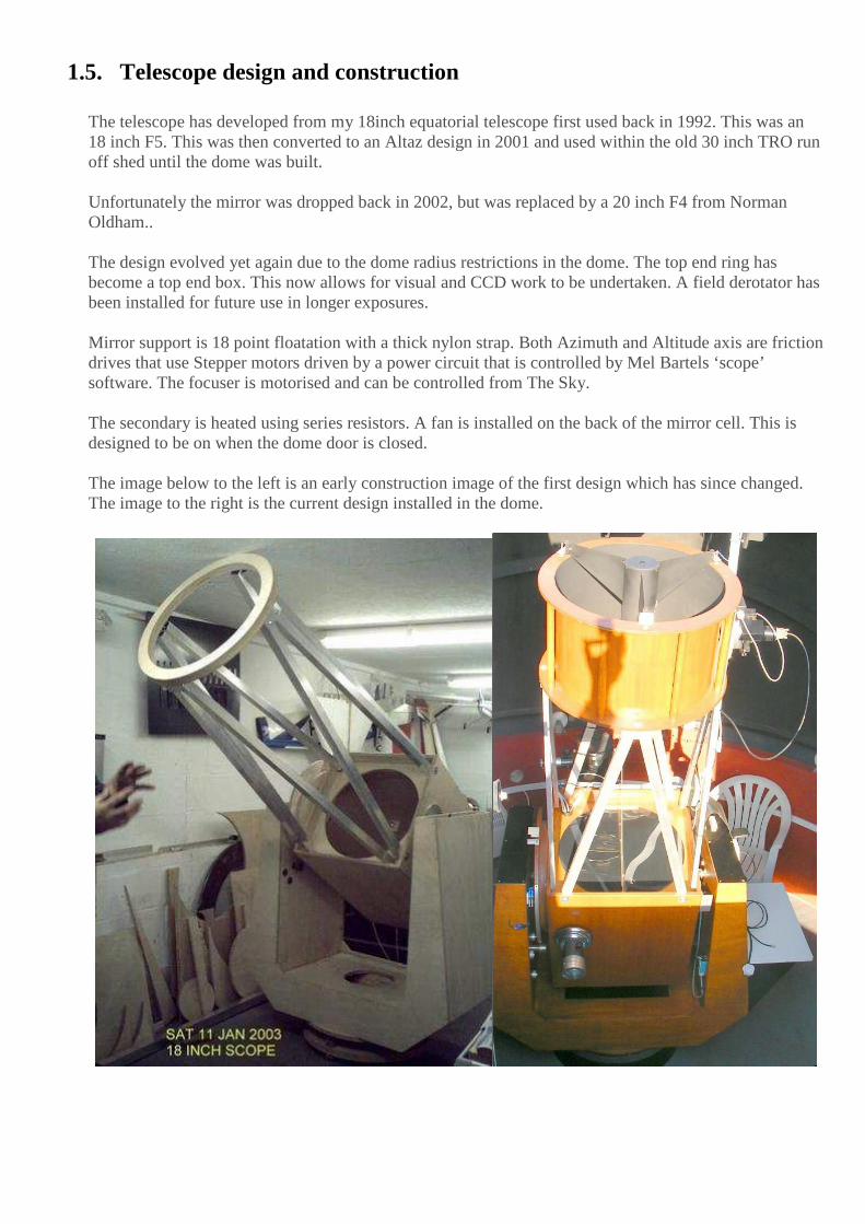
1.5. Telescope design and construction The telescope has developed from my 18inch equatorial telescope first used back in 1992. This was an 18 inch F5. This was then converted to an Altaz design in 2001 and used within the old 30 inch TRO run off shed until the dome was built. Unfortunately the mirror was dropped back in 2002, but was replaced by a 20 inch F4 from Norman Oldham.. The design evolved yet again due to the dome radius restrictions in the dome. The top end ring has become a top end box. This now allows for visual and CCD work to be undertaken. A field derotator has been installed for future use in longer exposures. Mirror support is 18 point floatation with a thick nylon strap. Both Azimuth and Altitude axis are friction drives that use Stepper motors driven by a power circuit that is controlled by Mel Bartels ‘scope’ software. The focuser is motorised and can be controlled from The Sky. The secondary is heated using series resistors. A fan is installed on the back of the mirror cell. This is designed to be on when the dome door is closed. The image below to the left is an early construction image of the first design which has since changed. The image to the right is the current design installed in the dome.

1.5.1.Telescope drive system The telescope drive is friction on both azimuth and altitude. Both axis use stepper motors. Gear reduction (worm and wheel) is used between the stepper motors and the final friction drive to obtain the required on sky arc seconds tracking resolution. Ratios Stepper motor types Noise
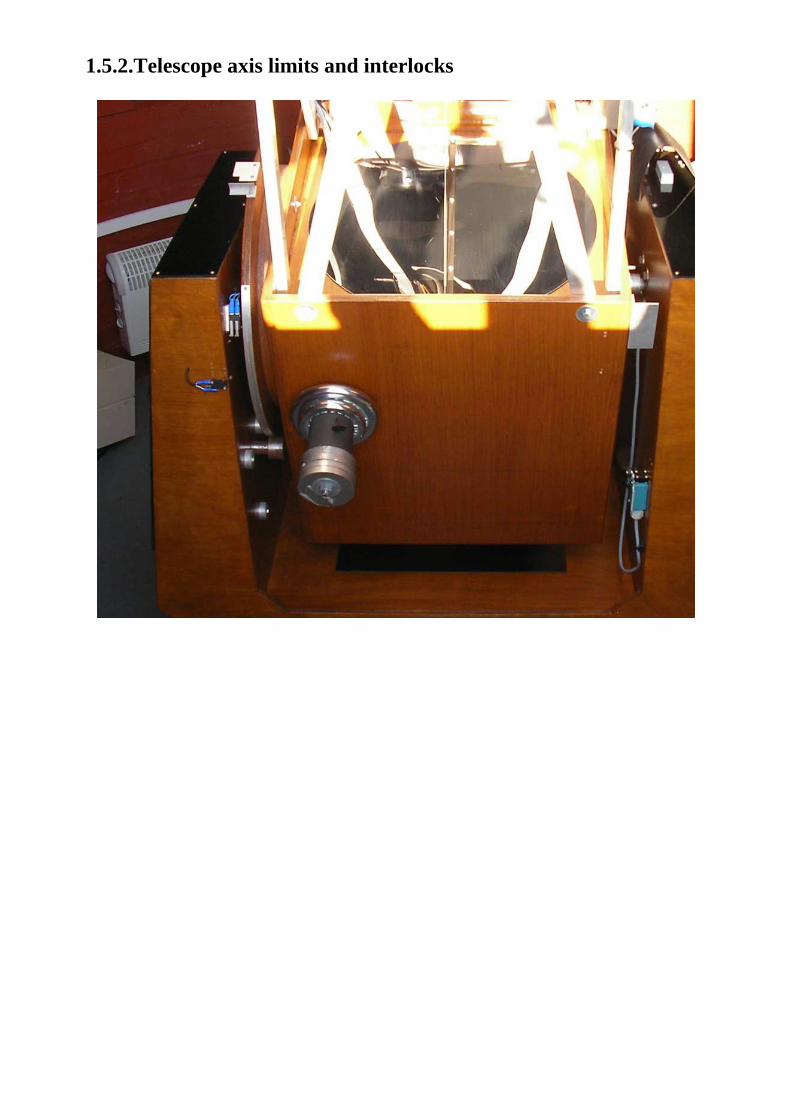
1.5.2.Telescope axis limits and interlocks

1.5.3.Telescope focus drive and derotator
1.5.4.Telescope mirror cover
The mirror cover is a thin black disc of plastic, hinged at the top of the mirror box. The cover is opened and closed using a winding mechanism consisting of a brass rod connected to a geared DC motor. The rod is connected to the cover by strong thin string. This should be inspected for wear every 6 months.
The mirror cover is opened when the associated limit switch on altitude is released and closes when it is activated. The mirror cover should open at an altitude of ??? degrees The mirror cover should close at an attitude of ?? degrees The mirror cover has limit switches to sense position. There is an ultimate power cut off limit switch when opening should the system relay logic get of sync. There is a magnet in the closed position to ensure positive closing of the mirror cover and that the closed limit switch is held down. The mirror cover tends to collect dirt and should be cleaned monthly.
1.5.5.Thermal management The dome has heating when the dome door is closed. The heater is off when the dome is open. The heater is set to a low level purely to ensure no condensation is formed inside the dome during high humidity when the dome is closed. There are external vents in the dome wall for 8 100mm cooling fans. These are not yet installed. The telescope has a mirror box heater that is on when the mirror cover is closed. This again is to prevent the formation of condensation on the primary when not in use. The secondary is permanently heated to a low level. A ring of resistors powered by 12V are wrapped in heat shrink and in contact with the edge of the secondary. The mirror box has a cooling fan installed. This is disabled at the moment as it was found to be cooling the primary too much so that condensation was forming on the optical surface.
1.6. Telescope instrumentation The camera used to date (2006) is a Starlight Xpress MX7, with the SBIG St4 used as an Autoguider on the 6inch F5 telescope that is ‘piggy backed’ onto the 20 inch.

1.7. Control system and software overview
The observatory has a number of software systems that control the telescope. An overview block diagram is given below. The main software packages are:-
• ACP (Astronomers Control Panel) Used as the main Hub • MaxImDL CCD (Camera driver and telescope control) • POTH (ASCOM interface between ACP and scope.exe) • Scope-drive.exe (telescope driver) • Cartes Du Ceil (used for initial set up prior to ACP control)
2. Observatory operations and maintenance
2.1. Dome operations The dome opening is controlled by telescope tube altitude position. Normal operation of the dome door and dome azimuth position is determined by the telescope position. Sensing of altitude position for door opening and closing is done using magnetic reed switches. The home altitude position is 10 degrees. The opening/closing position is 15 degrees. A facility to override the dome door is provided within the dome. Two switches are provided. One is for weather station override; the other is for altitude override so that the door may be opened without moving the telescope in altitude.
Dome Azimuth position is slaved from the telescope Azimuth position. This is achieved using a simple control system. Two magnetic reed switches are positioned on the fork mount either side of the centralised position of the telescope tube to the dome door opening. A magnet is suspended from the dome roof by a rigid bar. As the telescope moves in Azimuth the magnet will move towards the reed switches causing the dome to be ‘bumped’ around in small slews of approximately 4 degree slews. Dome Azimuth home position is 180 degrees. Dome azimuth limits are determined by the telescope Azimuth position. An ultimate power cut off cam switch is installed on the dome Azimuth in the event that the dome and telescope get ‘lost’ with respect to each other. The dome door state is also determined by the weather station (see section **) 2.2. Dome maintenance schedule Door wire tension and adjustment on both sides of the drum Door tensioner (2 either side of the windlass drum) Dome door leaks, seals and bearings Dome Azimuth wheel slippage/contact Dome Azimuth drive wheel bearing Dome Azimuth motor earthing checks Dome Azimuth motor gearbox oil level/leak checks Greasing dome Azimuth guide and load bearings Dome limit switches

3. Telescope operations and maintenance
3.1. Telescope operations
3.2. Power up procedure 1. The dome and weather station are normally powered up prior to observations. 2. Turn on both PC’s 3. DO NOT turn on the power supply to the telescope control box yet. This should only be done when Mel’s
‘scope-drive’ software is running. 4. When the scope-drive PC is powered up, if required, perform 5 to 7 below. Otherwise skip to 9 5. Type CD.. (enter) 6. Type CD\scope (enter) 7. Type scope (enter) 8. On the scope-drive PC, select 5 for previous coordinates (so long as the is not a problem with the previous
initialised position or inits) (enter) 9. Turn on the power supply 10. Start Cartes Du Ceil on the main observatory PC 11. Connect to the telescope using the Meade interface 12. Select a bright star from the database and GOTO 13. Start MaxImDL and connect to the CCD camera 14. Ensure that the scope is pointing at the star in the middle of the field 15. If the star is in the filed, disconnect from the CCD camera and disconnect the telescope from Cartes Du Ceil 16. Start ACP 17. Select the appropriate script for the observation required and press RUN
3.3. Power down procedure 1. The telescope can be left to perform the observations and will close the dome and shut down either due to
poor weather or dawn. If not then proceed as below. 2. Park the scope at its home position 3. Stop tracking 4. Disconnect the battery 5. Quit the programme and say ‘Y’ to saving the config file 6. Switch off the scope PC
3.4. Telescope maintenance schedule
Mirror cover cleaning Worm wheel checks Mirror box heater check Telescope limits

4. Astronomers Control Panel (ACP)
ACP planner ACP scripts ACP browser and FTP Files system and storage Supernova search used as part of MaxImDL Java/Python code used for automated FITS extraction NEO discover and follow up

5. Supernovae discovery and follow up
The open source AudeLA software could be used to acquire, process and visualize images. Instead I use MaxImDL and it’s associated Supernovae search tool
5.1. Confirmation procedure
See: http://alain.klotz.free.fr/snalert/ What to do if a new object is detected ?
At time T+0h, one must confirm that the candidate is not a known star neither an asteroid.
• Step1 : Digital Sky Survey : http://skyview.gsfc.nasa.gov
or enter here the coordinates or the source name: NGC 1591 Go
• Step2 : List of Recent Supernovae : http://cfa-www.harvard.edu/cfa/ps/lists/RecentSupernovae.html
• Step3 : Check your (super)nova suspects for known minor planets : http://scully.harvard.edu/~cgi/CheckSN
• Step4 : Search to the nearest archive image own database where the candidate not appear. • Step5 : Measure the offset (arcsec) of the candidates from the nucleus • Step6 : Measure the magnitude
At T+24h, the goal is to confirm the candidate is really as star, not a ghost (cosmic, etc.).
• Step 7 : Try to make another image of the field of the candidate.
If the first steps are good, repport the discovery :
• Step 8 : How to Report Discovery of a Supernova : http://cfa-www.harvard.edu/cfa/ps/HowToReportDiscovery.html
• Step 9 : Mail to [email protected] and copies to [email protected] & [email protected] .
5.2. Example discovery email SN in NGC 7678
D.Thomson, Great Sutton, Cheshire, UK, reports the discovery of an apparent supernova (mag about 15.1 +/- 0.4) on images (limiting mag about 17.0) taken on 2002 Jun. 18.09 UT and 19.02 UT with a 0.50-m reflector (+ CCD camera).
SN is located at about R.A. = 23h28m30s.4, Decl. = +22o25'44" (equinox 2000.0), which is 30" east and 22" north of the nucleus of NGC 7678. The new object is not present on Palomar Sky Survey images, neither on an image taken on 2001 Sep. 11.94 UT.
You can see images in the following URL :
http://datscope.wikispaces.com/page/edit/20+inch+F4+Telescope+Observations?goto=&responseToken=de758d202048f3a860e96272aeec5a96

Regards Dave Thomson

6. MaxImDL

7. Scope-drive software
A number of software packages are required to run the telescope. The dome and weather station at this time require no software. The following packages are in use or under review/development:- Telescope drive system
7.1.1. Scope-drive functionality
• System is designed for the greatest variety of mounts and motors and mechanical drive designs, including altazimuth mounts, equatorial mounts, GEMs (german equatorial mounts), siderostats. Any type of mechanical drive arrangement that yields a 300:1 to 10,000:1 reduction is acceptable. For stepper systems, use any type of unipolar stepper motor including small motors from old 5.25 inch floppy drives.
• Handles a German Equatorial Mount flipping across the meridian.
• Siderostat option: prevents mount from flipping over and instead moves scope past zenith.
• Fast precise alignment to the sky.
• Single (can be surplus) motor per axis.
• Stepper system will control unipolar stepper motors via the available circuit board, and optionally can control other motor types that accept single step pulse and direction inputs. Stepper system also handles 5 phase motors. Servo system will control any servo motor with an attached optical encoder.
• Simplest possible drive circuit.
• Stepper system utilizes smooth microstepping tracking with up to 40 microsteps per fullstep. Here is a comment from a user on the smoothness of the 20 microsteps: "Increasing the number of microsteps from 10 to 20 was a superb improvement to your software ! You have basically eliminated the need to adjust the PWMs. Or at least. You have now rendered it extremely difficult to actually measure the PWMs variances. The motors run visibly smoother in tracking speed.".
• Stepper system uses high speed overvoltage halfstep slewing, usually achieving 5,000 halfsteps per second, and up to 10,000 halfsteps per second (1800 rpm).
• Servo system has large dynamic range. Given typical 512 count per revolution encoder that quadrature decodes to 2048 counts per revolution, and 5000 rpm servo motor, system can be designed for precise tracking at 0.1 arcsecond resolution yielding 4.7 degrees per second slews, to coarser tracking at 1 arcsecond per encoder count yielding an astounding 47 degrees per second slew rate.
• Low current draw, typically 0.1 amps at 12 volts DC when either tracking or slewing.
• Automatically refines the altitude reading based on the initialization, meaning that the altitude at startup need not be set precisely.
• Optional 3 star init for more precise pointing.
• Analysis of initializations including calculation of 3 major mount errors: axis misalignment and optical vs mechanical axis misalignment in horizon and elevation.

• Pointing errors corrected for the 3 major mount errors.
• Pointint error corrections for altitude vs azimuth (rocker base levelness), called ALTAZTEC, and altitude vs altitude, called ALTALTEC (tube droop and altitude bearing eccentricity)
• Pointing Model Corrections (PMC) for remaining errors, achieving under 1 arcminute RMS error over 100 to 200 degree goto slews.
• For stepper motors, QuarterStep Corrections (QSC) fixes physical variations in stepper motor movement from quarterstep to quarterstep.
• Powered field de-rotation with slew using either the SAA1042 or the ECG1857 or the MC3479 bipolar stepper driver chip on the stepper side, and a servo motor on the servo side..
• Focusing control either by a MC3470 bipolar stepper driver chip or a DC motor by relays on the stepper side, and by a servo motor on the servo side.
• Backlash compensation in both axis.
• Periodic error correction of unlimited length of both axis simultaneously with on the fly PE recording, averaging, analysis, and incorporation.
• Recording of multiple cycles of guiding corrections for later analysis.
• Refraction correction.
• Goto computerized finding from a number of contributed data files (about 100 data files now), or from manual entry of coordinates including offsets. Here is a note from a user: " One down side to your system is that I have just about exhausted new targets in a large portion of the sky. I'm working off a database of ~11,800 objects and last I checked, I've viewed over 70% of them!"
• Tight integration with Project Pluto's DOS and Win95 versions, along with Allstar.
• Receives LX200 protocol commands from an external PC running any of the popular planetarium programs.
• Drift compensation, to track at lunar and solar rates, to follow fast moving comets, and auto generation of drift rates to null tracking.
• Altitude and azimuth software motion limits.
• Recovery of last position and last orientation to the sky.
• Move to a home position for blind storage.
• Optional external encoders so that the scope can keep track of its position when moving by hand, including option to use the mouse encoders.
• Real time display of all coordinates and status.
• Robotic scrolling motions, best described as high magnification 'fly-overs'. • Enhancement of scrolling actions so that initializations and analysis can be done automatically,
and, object coordinates can automatically be pulled from data files.
• Grand tour, where a flip of a switch takes you from object to object in a data file.
• Wireless mouse operation at the eyepiece, so no handpaddle cables or motorized focuser cables. • Ability to record scope position from the eyepiece, for later use in data files.

• A number of test options to test telescope, encoders, motors, hardware, and software.
• Because software is PC based, improvements and changes per user requests can be made quickly, sometimes that afternoon in time for the next night's viewing.
• The disadvantage of this system is that you need a PC or laptop.
7.1.2. Stepper Software
The software has gone through several reincarnations, starting as 6502 assembly code for the Commodore 64, when the Commodore 64 first came out (I bought my Commodore 64 for at the time incredible sales price of $600, and with no floppy or tape drive, and had to reenter my programs everytime I turned the computer back on!). Unfortunately, the stalwart 2 megahertz 6502 processor could only muster recentering the object every couple seconds. The dream of an inexpensive amateur built altaz drive seemed far away, until the AT class machines arrived. The code was then rewritten in C. Later, the code went through its C++ object oriented life on a 386. Now, in interests of making the code as universal and easy to port, the code lives in ANSI C. Functions that are directly tied to low level hardware such as the parallel port and bios clock, use pointers to access the appropriate memory locations. For non-DOS machines, some modification of these parts of the code will be necessary.
The servo version of the software was started in May 2001.
The program is based on the popular two-star conversion algorithm, based on an Feb '89 Sky and Telescope magazine article by Toshimi Taki, to translate between altazimuth and equatorial coordinates. The scope need only be accurately aligned on two widely separated stars using a high power reticle eyepiece; there is no need to level the base. The scope can also be initially set on a planet, say, soon after sunset. After a couple of minutes of microstepping recentering, the scope is initialized on the same object again. The scope will continue to track the object, keeping it in the eyepiece field of view for an hour or two.
In addition, the program will use a third initialization point, for more accuracy than the two star initialization would otherwise give. Any of the three initialization positions can be reinitialized as often as wanted. All init positions are saved to a file for later analysis.
The conversion algorithm allows the input of mount construction errors. For instance, one altitude bearing may be a bit lower than its counterpart. Normally this would cause a pointing error, but the conversion algorithm will compensate once given the amount of the error. The program can refine the altitude angle based on the initialized positions. Per the original Taki routine, the starting azimuth can be any number. Now the starting altitude only needs to be set to within 10 degrees or so. This altitude offset algorithm was contributed by Dave Sopchak. This is the 'Z3' error (offset in elevation between the optical axis and the mechanical axis) so named by Taki. Taki's Z1 (axes non-perpendicularity) and Z2 (offset in horizon between the optical axis and the mechanical axis) errors are also calculated after at least three initializations are done.
The software is event driven by either keyboard or hand paddle input. If no events occur, then the scope moves to the current equatorial coordinates. If the coordinates remain unchanged, the scope tracks. If new coordinates are entered, the scope slews. Slews can only be interrupted by pressing or releasing a button on the handpad, and by the keyboard, and by the altitude or azimuth limits if the interrupt driven halfstepping option is turned on. Tracking should be paused if hot-keying out to another program. When the program is exited, the scope's altazimuth coordinates are saved along with any initialized positions.

The software handles backlash and handles periodic error correction, or PEC, for both axis. A 'guide' function is also included so that guiding for a minute or two nulls occasional tiny residual drift. Drift can be manually entered in both equatorial and altazimuth coordinates.

Files Used:
scope.exe - the executable program *.c, *.h - source code config.dat - the configuration file bstars.dat, messier.dat, are object catalog files along with other *.dat files too numerous to mention *.scr - scroll files *.cdf – comet definition files that include comet positions and equatorial drift values inithist.dat - a history of all initializations, in degrees (Ra, Dec, Alt, Az, Sidereal Time, reason for init) analysis.dat - a file of recorded positions triggered by the handpaddle that is used for later mount analysis analysis.err - errors calculated from the analysis file altazec.dat - correction file for altitude errors vs azimuth (rocker base levelness) altaltec.dat - correction file for altitude errors vs altitude (altitude eccentricity, tube flexure) azazec.dat - correction file for azimuth errors vs azimuth (azimuth eccentricity) pmc.dat - a file containing corrections used by the pointing model corrections routine pec.dat - the file used for periodic error corrections to the motors guidealt.dat and guideaz.dat - a record of guiding corrections outguide.dat - list of exit positions from Project Pluto Guide input.dat - a record of all Ra, Dec, and name, that appear in the equatorial input fields YYMMDDa through YYMMDDz.log, ie, 000313a.log - observer's log: a copy of the input.dat file, saved at program exit record.dat - recorded scope equatorial scope positions via the handpaddle encoders.txt - a recording of encoder threshold violations for each session trenc.txt - file containing encoder readings per each microstep for all windings polealgn.txt – file containing record of polar alignment procedure results
Data object file layout (a single blank space must start each line):
Ra_hrs Ra_min Ra_sec Dec_deg Dec_min Dec_sec name or comment ie, 12 23 14 33 53 09 test position
I have a conversion program available for the asking that will convert Megastar and Sky commander file formats to scope.exe's data file format.
For scroll file data layouts, see the webpage on operating the software - subpage scrolling.
Comet file layout (a single blank space must start each line):
Ra_hrs Ra_min Ra_sec Dec_deg Dec_min Dec_sec Drift_Ra_hrs Drift_Ra_min Drift_Ra_sec Drift_Dec_deg Drift_Dec_min Drift_Dec_sec name or comment ie, 07 14 31 +23 +12 +11 +00 00 +2 -00 -00 -1 31P Schwassmann-Wach note that drift is per hour
In detail, the sequence of events for each bios clock tick (which occurs about 18.2 times a second) is:
add equatorial drift to current equatorial position, update a status field or work with the optional encoders: either a calculation or a direct write to video memory or reading the encoders or setting current coordinates to encoder coordinates, check for keyboard event, if none,

check for handpad event, if none, check for IACA event, if none, check for LX200 events and process all accumulated commands since last bios clock tick, but if none, check to see if field rotation motor needs pulsing, then move to current equatorial coordinates by: calculate new altazimuth coordinates based on new sidereal time that was calculated when bios clock tick occurred, find difference between current altazimuth coordinates and newly calculated altazimuth coordinates, find distances to move in each axis and decide between microstepping or halfstepping, if microstepping, then check for backlash, if none, then spread microsteps over the bios clock tick by dividing # of microsteps into MsTicksRep, the count of PWM's per bios clock tick: if microsteps exceeds MsTicksRep, then reduce # of microsteps per fullstep up to halfstep, and if necessary, halfstep pulse the motors, continuously generate PWMs, checking for bios clock tick at end of each PWM: a PWM consists of outputting to parallel port an already calculated array of ons and offs to the stepper motors' windings, when bios clock tick occurs, PWMs end and new sidereal time is calculated, the field rotation motor calculations are done at the start of the microstepping function, and at the end of every PWM, a check is made to see if the field rotation motor needs pulsing, current altazimuth coordinates updated to reflect # of microsteps that actually occurred, current altitude coordinate updated to include refraction, current altazimuth coordinates updated to include any backlash compensations already moved, current altazimuth coordinates updated to include PEC based on steppers rotors' position, current altazimuth coordinates updated to include altazimuth drift, current altazimuth coordinates updated to include any guiding motions

7.1.3. Configuration
Scope.exe requires a config.dat file. You can specify an alternative config.dat file by using the command line option -c, ie, scope.exe -c \temp\config.tmp
note: all variables, names, and strings are case insensitive, so defaultbackground will work as will DefaultBackground
The following variables set the display colors:
DefaultBackground DefaultColor TitleColor BorderColor MenuColor DisplayColor SelectColor CurrentColor SelectBackground
based on: BLACK=0,Both BLUE=1,Both GREEN=2,Both CYAN=3,Both RED=4,Both MAGENTA=5,Both BROWN=6,Both LIGHTGRAY=7,Both DARKGRAY=8,Foreground only LIGHTBLUE=9,Foreground only LIGHTGREEN=10,Foreground only LIGHTCYAN=11,Foreground only LIGHTRED=12,Foreground only LIGHTMAGENTA=13,Foreground only YELLOW=14,Foreground only WHITE=15,Foreground only BLINK=128,Foreground only
ConfirmQuit: set to 1 if you wish a confirming message before the program quits
DisplayOpeningMsgs: if set to zero, opening and closing messages are suppressed
MoveHsMsgDeg: how long of a slew allowed before a confirming message is displayed
F9Hotkey, F10Hotkey, F11Hotkey, F12Hotkey: optional user specified hotkeys; should only be set via the program; delete from config file if you wish to erase them
InterfacePath: location of controlling planetarium software program, ie, c:\guide\ also location of Project Pluto's planetarium DOS program, dosguide.exe
UseMouseFlag: if 1, use mouse to select menu items, datafiles, objects from datafiles, and move the scope in microstep, halfstep, and auxiliary motions.
IACA_Flag: if 1, use IACA to communicate with other IACA aware programs

GEMFlipPossible: if 1, then GEM flip is possible
AutoGEMFlip: if 1, the GEM flip will occur automatically when the scope is asked to traverse to the opposite hemisphere AutoGEMFlipFuzzDeg: some value entered here, like 7.5 degrees, will give some fuzz or wiggle room so that the scope doesn't flip back and forth from hemisphere to hemisphere as you touch the centering buttons
Siderostat: set to 0 if standard equatorial or altazimuth mount, set to 1 if you are using a siderostat or uranostat flat to focus light into a stationary telescope tube; you must set AzLowLimitDeg to about 90, AzHighLimitDeg to about 270, where due south is about 180, the difference between the limits must be 180 deg or less. This allows the altitude to exceed 90 deg, otherwise the flat mirror will attempt to flip upside down when aimed at northly objects.
HomeAltDeg, HomeAzDeg: these are the home, or park coordinates
MsArcsecSec: microstepping speed when the hand paddle is used to center objects, can be changed while the program is running
AltFullStepSizeArcsec, AzFullStepSizeArcsec: these are the step sizes for the altitude and azimuth steppers. The altitude is measured by using a precision level to set the tube horizontal, resetting alt to 0, then moving the scope via the motors until the precision level indicates the tube is exactly vertical. The ratio between the displayed alt and 90 degrees is the amount to adjust the step size by. Similarly, one complete turn in azimuth can be used to adjust the azimuth step size
RefractFlag: 1 if you wish refraction to be used, 0 if you wish refraction to be display only
UseAltAzECFlag: if 1, ALTAZEC turned on at program startup.
UseAltAltECFlag: if 1, ALTALTEC turned on at program startup.
UseAzAzECFlag: if 1, AZAZEC turned on at program startup.
PointingModelFlag: if 1, PMC turned on at program startup.
BacklashMsArcsecSec: backlash takeup microstepping speed, cannot be changed while the program is running
HandPadPresentFlag: if 1 then handpad present, if 0, then handpad not present and handpad is ignored. If the handpad is not connected or in an error condition at program startup, it is ignored.
StartingHandPadMode: sets starting handpad mode, also ending handpad mode saved at program exit to this variable: values are off: 0 init auto on: 1 init 1: 2 init 2: 3 init 3: 4 polar alignment: 5 analyze on: 6 guide on: 7 guide stay on: 8 guide stay rotate on: 9 guide drag on: 10 scroll tour: 11 scroll auto tour: 12
grand tour: 13 record equat: 14 toggle track: 15 FR mode:16 focus mode:17 Auxiliary control mode : 18
HandpadDesign: 0 if standard handpad, 1 if using the four data lines to represent the four directions (no mode control or speed control available: this is for autoguiders that need simultaneous action in two directions, something not possible with standard handpad design)
UpDownButtonsReversedFlag: if 1, then the handpad's up/down buttons are reversed.
HandpadFlipUpDownWithGEMFlip: if 1 then handpad will flip its up/down direction buttons when GEMFlip is on to match the declination direction reversal that occurs when the GEMFlip has occurred
AltBacklashArcmin, AzBacklashArcmin: these are backlash values (if both are 0, backlash is disabled). If backlash correction is desired, values should be positive. A negative value means that the motor will move in the opposite direction than expected in order to take up backlash
ABacklashSignalPPortPin17: if non-zero, then parallel port pin 17 used to signal the direction of the 'A' motor backlash: logical high if backlash direction is CCW, logical low if backlash direction is CW (can be used to control motorized counterweights); starting value is logical low
AltLowLimitDeg, AltHighLimitDeg, AzLowLimitDeg, AzHighLimitDeg: these limits are active only when HsTimerFlag is set to 1 (on); if HsTimerFlag is on and desiring to disable the alt limits, set both alt limits to 0; if HsTimerFlag is on and desiring to disable the az limits, set both az limits to 0
GuideArcsecSec: guiding correction speed, can be changed while the program is running
The following are drift rates that a star will be dragged across an autoguider with knife-edge detector. These autoguiders work by expecting the tracking rate to be slightly off guaranteeing that the star will always eventually move across the knife-edge. When the star crosses the knife-edge the autoguider gives it a little kick in the opposite direction, then waits for the star to reappear. GuideDragAltArcsecPerMin GuideDragAzArcsecPerMin GuideDragRaArcsecPerMin GuideDragDecArcsecPerMin
HPUpdateDriftFlag: if 1, then the drift is updated at the end of a handpaddle guiding session. Drift is calculated based on accumulated guiding corrections over the session and then automatically adopted.
DriftAltArcsecPerMin: starting value of altitude drift in arcseconds of angular movement per minute of time.
DriftAzArcsecPerMin: starting value of azimuth drift in arcseconds of angular movement per minute of time.
DriftRaDegPerHr: starting value of declination drift in degrees of angular movement per hour of time.
DriftDecDegPerHr: starting value of right ascension drift in degrees of angular movement per hour of time.
PECFlag: if 1, then PEC turned on at program startup time.

AutoAltPECPin: parallel port pin(s) that auto synchronization of altitude will be read from: must be 15, 16 or 17, or 10+12+13 (3 pin combination), or deleted from config.dat (default will be 17 then). If you use the 10+12+13, be careful not to simulate it by any of the following hand paddle key presses: UpKey + DownKey + CCWKey, or CCWKey + CWKey, or UpKey + RightKey, or DownKey + LeftKey
AutoAltPECSyncOnFlag: turns on automatic synchronization of the altitude PEC using the AutoAltPECPin pin of the parallel port
AutoAltPECSyncLowHighFlag: if 0, synch point occurs after +5 VDC has been applied, and at the moment ground is applied; if 1, synch point occurs when +5VDC is applied after pin has been grounded.
AutoAltPECSyncDirFlag: direction that alt PEC must be moving in order to trigger auto-sync: 0 = either direction, 1 = CCW direction, 2 = CW direction
AutoAltPECDeBounce: if 1 or on, then software will debounce the synchronizing signal: the debounce period ends when the PEC index is between the ¼ and ¾ point of the PEC cycle
AutoAzPECPin: parallel port pin that auto synchronization of azimuth will be read from: must be 15, 16 or 17, or 10+12+13 (3 pin combination), or deleted from config.dat (default will be 15 then). If you use the 10+12+13, be careful not to simulate it by any of the following hand paddle key presses: UpKey + DownKey + CCWKey, or CCWKey + CWKey, or UpKey + RightKey, or DownKey + LeftKey
AutoAzPECSyncOnFlag: turns on automatic synchronization of the azimuth PEC using pin 15 of the parallel port
AutoAzPECSyncLowHighFlag: if 0, synch point occurs when ground is removed from pin; if 1, synch point occurs when ground is applied.
AutoAzPECSyncDirFlag: direction that az PEC must be moving in order to trigger auto-sync: 0 = either direction, 1 = CCW direction, 2 = CW direction
AutoAzPECDeBounce: if 1 or on, then software will debounce the synchronizing signal: the debounce period ends when the PEC index is between the ¼ and ¾ point of the PEC cycle
FullstepsPerPECArray: This allows periodic correction for single through quad worms by tying the PEC sequence to an amount of fullsteps, not to a motor's single turn. Positive values in PEC.DAT indicate too much clockwise motion. Values are in tenths of an arc second. A total of 200 values per PEC are used regardless of number of fullsteps per PEC array. PEC must be synchronized by placing the motor shafts in the predetermined starting position and hitting the 'PEC on' keyboard menu item selection or by using the auto-sync option.
PECIxOffset.A, PECIxOffset.Z: index offsets of both axes between rotor position of 0 and synch point, for instance, if the current position coordinate is zero with the rotor in the up position, and you have 200 fullsteps for a PEC cycle, and if the PEC synch point occurs with the rotor in the down position, then the offset will be 100; leave at 0 until PEC is turned on and synchronized, at which point let the program determine these values
FRStepSizeArcsec: field rotation motor step size, set to 0 if you wish field rotation disabled
SectoredFRDrive: if using a sectored field de-rotation drive, set to 1, otherwise field de-rotator motor may slew large angles after the scope finishes a slew.
FRStepSpeedMilliSec: speed of field rotation motor when slewed by hand paddle
ReverseFRMotor: reverse field rotation motor direction

FocusMethod: can be 0, 1, 2, or 3:
0. Connecting parallel port pins 16 and 17 to a pair of relays to control a small DC motor for focusing. Pin 16 focuses 'out' and pin 17 focuses 'in'. This can be operated with the field rotator concurrently.
1. As above in option 0, with the addition of parallel port pins 1 and 14 for slow speed control. Field rotation is disabled with this option.
2. Using the field rotation motor control circuit with a small stepper motor for focusing. This uses parallel port pins 1 and 14 for pulse and direction.
3. Adding a second MC3479 bipolar stepper control circuit with a small stepper motor for focusing. This uses parallel port pins 16 and 17 for pulse and direction. Both the field rotation and focus motors can be operated simultaneously. Along with the altitude/declination and azimuth/hour angle motors, this means that four motors are controlled at the same time.
ReverseFocusMotor: if 1, then reverse direction of focusing motor
FocusFastStepsSec: if using bipolar stepper motor for focusing, then this value contains the fast speed setting in steps per second
FocusSlowStepsSec: if using bipolar stepper motor for focusing, then this value contains the slow speed setting in steps per second
FocusPosition: if using bipolar stepper motor for focusing, then this value contains the focuser position in steps
MotorControlMethod: 0 = pulse width modulation of unipolar stepper motors (if in doubt, pick this option), 2 = pulse and direction control, if option 2, set the fullstep size to the amount moved every motor pulse
MotorWindings: 4 or 5: number of windings that the stepper motors have; almost all have 4 windings, but the software can work with 5 phase motors such as those from Vexta
if going with 5 phase motors then please observe the following notes: An option is provided for driving 5-phase motors by using pins 16 and 17 for the fifth phases of the A and Z motors respectively. To use this option, set MotorWindings to 5 in CONFIG.DATA. Note that the choice of 4 or 5 phases for has no effect on the parallel port outputs for the field rotation motor. The following changes in design or usage apply in the 5-phase case: 1. Driver circuitry must use H-bridge design. Refer to "Jones on Stepping Motors" at http://www.cs.uiowa.edu/~jones/step/ or design data for the SGS Thompson L298 Dual Full Bridge Driver at http://www.st.com/stonline/books/pdf/docs/1773.pdf 2. Interpretation of the 0's in the microstepping table above and in variables such as HsOut changes from "off" to "grounded" (see Jones).
InvertOutput: Original designed called for 7404 inverters to drive the transistors, hence InvertOutput 1 in the original config.dat (parallel port output goes high, hex inverters go low, and drive transistors turn off, hence the need to invert the output). In the original design, if opto-isolators were used, then InvertOutput 0 (parallel port output goes high, hex inverters go low, opto-isolators turn on pulling output low, hex inverters go high, and drive transistors turn on, hence no need to invert output). If using the printed circuit board, the pcb design uses 7408 and gates (parallel port output goes high, 7408 and gates go high, opto-isolators turn off allowing output to return to high, 7408 and gates go high, and drive transistors turn on, hence no need to invert the output). Screw this up and you will pump a lot of current through the steppers!

KeepAlivePPortPin: set to the parallel port pin (1, 14, 16, or 17) you wish to use for input to a keep alive circuit; the pin will pulse at least 9 times per second; design the circuit so that the power supply to the motors is cut off if the pin fails to trigger after a short period of time.
ReverseAMotor: set to 1 if you wish to reverse direction of the 'A' motor (the altitude or declination motor). This is equivalent to swapping winding leads 1 and 3.
ReverseZMotor: set to 1 if you wish to reverse direction of the 'Z' motor (the azimuth or right ascension motor). This is equivalent to swapping winding leads 1 and 3.
HsRampStyle: set to 0 if you wish the old simple ramp, and set to 1 if you wish the new 'S' shaped ramp curve, where the ramp starts slowly, speeds through the middle range, and slows down for the highest speeds at the end of the ramp.
HsTimerFlag: set to 1 if you wish to use IRQ 8 to time the halfstep slews, this allows for realtime updating of scope coordinates, keyboard interruption of slews, and altitude limit checking during a slew, otherwise if set to 0, halfsteps are timed by a delay loop with interrupts disabled to avoid interruption; using IRQ8 works perfectly in DOS, not at all in Win 3.x, and slowly in Win95
MaxDelay, MinDelay, HsDelayX: these set the slowest and fastest slew speeds:
when using IRQ 8 timing of halfsteps, ramp speed starts at MaxDelay and achieves highest speed at MinDelay; with interrupt 8 method of timing the halfsteps, speed can be converted to halfsteps per second by dividing MaxDelay and MinDelay into 1,000,000, so that a MaxDelay value of 1000 means 1000 halfsteps per second, and a MinDelay value of 200 means 5000 halfsteps per second.
when using delay loop timing of halfsteps with interrupts disabled, ramp speed starts at (MaxDelay - MinDelay)* HsDelayX and achieves highest speed of MinDelay * HsDelayX, where HsDelayX is used as a multiplier to keep the MaxDelay and MinDelay values reasonably sized on fast CPUs.
HsRampX: the amount of time to ramp up or ramp down is multiplied by HsRampX
InterruptHs: number of halfsteps before interrupts disabled if using delay loop timing of halfsteps
HoldReps: time to lock stepper rotors at beginning and end of slew to prevent shaft oscillation and overshoot
HsOverVoltageControl: for optional halfstep high speed slewing over-voltage control; if desired, enter a non-zero value. Control line is parallel port pin #17. Value entered here will be the Delay value at which the over-voltage control line will be toggled logical high. Pick a value between MaxDelay (slowest speed or greatest delay) and MinDelay (fastest speed or least delay between halfsteps)
MaxConsecutiveSlews: maximum number of consecutive slew attempts to reach a desired position. If slews cannot reach position, scope begins tracking. This prevents oscillations when MsRepsTick or PWM values are low and tracking speed exceeds maximum microstepping speed.
MsPowerDownSec: number of seconds before idle motor will power down during microstepping.
PWMRepsTick: count of pulse width modulations per bios clock tick. Set to average value of PWMReps displayed on screen.
AvgPWMRepsTickOnFlag: if 1, then auto-averaging of the PWMRepsTick will occur, based on the actual number of PWM repetitions per timer tick as averaged over 3.5 seconds; if 0, then the PWMRepsTick value as entered in the config.dat file will be used.

MsDelayX: repetition value of each value in the microstepping arrays, this allows for smaller arrays when needing large PWM[] values for fast PCs.
MsPause: the number of dummy loop repetitions at the end of every PWM[] loop. This allows for fine low voltage resolution when using a high voltage power supply
Ms: number of microsteps: up to 40 per each fullstep
MaxIncrMsPerPWM: maximum microstep increment per pulse width modulation. In order to microstep faster, microsteps can be skipped. Consequently, this sets the maximum microstepping speed. Microsteps can be skipped up to very roughly 4 per fullstep. For instance, if you have 20 microsteps per fullstep, then you can enter a value of 5 here. Consequently, this variable also controls the maximum microstepping or tracking speed. For instance, if you set it to 1, then your max microstepping speed will be the PWMRepsTick * 18 (ticks per second). The max value that you can set it to will be the number of microsteps in a halfstep, because the fastest the microstepping routine can work at is one halfstep per PWM. (if the number exceeds MsHsToggleIncrMsPerPWM, the routine switches from microstepping per each PWM to halfstepping per each PWM)
MsHsToggleIncrMsPerPWM: while microstepping, the routine will switch into halfstep mode if necessary. This is toggled when the number of microsteps per each PWM repetition exceeds MsHsToggleIncrMsPerPWM. For instance, if the PMW repetitions per timer tick is 50, and if MsHsToggleIncrMsPerPWM is 5, and you ask the program to track at more than 250 (50*5) microsteps per PWM, then the routine will toggle to halfstep movement. Max speed is still the # of microsteps per fullstep divided by 2, equivalent to halfstepping. In this example of 20 microsteps per fullstep, the max speed is 20/2 or 10 microsteps per PWM, or 500 (50*10) microsteps per PWM. Overall speed in any case is still limited by MaxIncrMsPerPWM.
MaxPWM: maximum pulse width modulations, and consequently the maximum value that any PWM[] value can take. This can be set higher than PWM[0] so that PWM[1]... can be set higher than PWM[0] to ameliorate stepper motor cogging
PWM[0] through PWM[19] : These values sets the voltages for individual microsteps. In general, these values should reflect the ratios discussed earlier. If the microstepping is not smooth, adjust these values. If the motors become too warm and take too much current, increase MaxPWM, lower the PWM[0] through PWM[19] values, decrease MsDelayX and/or increase MsPause. When tracking, the steppers should draw no more than approximately 0.1 amp while still producing adequate torque. The rotor is positioned based on the inverse square strength of two adjoining windings, for instance, PWM[0] 100 : 0 means that the first microstep has a current value for winding A of 100 and a current value for winding B of 0 positioning the rotor exactly over winding A, and, PWM[10] 100 : 100 means that the 11th microstep has a current value for winding A of 100 and a current value for winding B of 100 positioning the rotor exactly between winding A and winding B, and, PWM[19] 29 : 100 means that the 20th microstep has a current value for winding A of 29 and a current value for winding B of 100 positioning the rotor 9/10ths of the way between winding A and winding B (there is a slight deadband where a certain amount of counts, usually about 10, are needed for the motor to feel the current pulse at all);
here are the values for 20 microsteps:
PWM[0] 100 : 0 PWM[1] 100 : 29 PWM[2] 100 : 45 PWM[3] 100 : 56 PWM[4] 100 : 65 PWM[5] 100 : 72

PWM[6] 100 : 81 PWM[7] 100 : 88 PWM[8] 100 : 95 PWM[9] 100 : 98 PWM[10] 100 : 100 PWM[11] 98 : 100 PWM[12] 95 : 100 PWM[13] 88 : 100 PWM[14] 81 : 100 PWM[15] 72 : 100 PWM[16] 65 : 100 PWM[17] 56 : 100 PWM[18] 45 : 100 PWM[19] 29 : 100
If you wish different microstepping PWM[] values for the 'Z' or right ascension/azimuth motor, then use a similar array but name each value PWMZ[], ie, PWMZ[0] 100 : 0 PWMZ[1] 100 : 29 PWMZ[2] 100 : 45 and so forth
Optional variables: QSC_..., which stands for QuarterStepCorrection: the '_a' through '_d' indicate the winding, and the extra '2' indicates the intermediate halfstep; enter corrective values in fullsteps, for instance, if the motor moves too far for the 'a' winding by 0.1 fullstep halfway through its range, and no other corrective actions are required, here is what the entries will look like for the 'a' winding (for windings 'b' through 'd', duplicate these entries, replacing the 'a' with the winding letter 'b', 'c', or 'd'):
QSC_a0 0 : 0 QSC_a1 0 : 0 QSC_a2 0.1 : 0 QSC_a3 0 : 0
Optional variables: PWM_... which taken together allow compensation for current variation to each stepper motor winding. It has been discovered that the 8 output lines from the circuit may vary in output current thanks to variations in the parts themselves. In addition, there may be variations in motors. Some of the quarter step correction (QSC) issues may be due to variations in motor winding current. By allowing for individual current adjustment of each output line, one can tune very output line to give the same current. For instance, if one finds that the 2nd output line ('B' winding of the altitude/declination motor) reads a low current compared to the other output lines, the other lines can have their output current lowered by the software to compensate. Default is no compensation and config.dat does not need to be changed. If you wish to use output line/motor winding current compensation, add the following variables to config.dat. A value of 1 means output 100% of available current, a value of 0.5 means output 50% of available current, and so forth. Here is what the entires will appear to handle a compensation for a disparate 'B' winding of the altitude/declination motor:
PWM_A_a_Comp 0.8 PWM_A_b_Comp 1 PWM_A_c_Comp 0.8 PWM_A_d_Comp 0.8 PWM_Z_a_Comp 0.8 PWM_Z_b_Comp 0.8 PWM_Z_c_Comp 0.8 PWM_Z_d_Comp 0.8

PPortAddr: parallel port address: enter a 1 or 2 or 3 for lpt port 1 through 3, or enter the base address in a 3 digit decimal form where portid lpt1 = decimal 888 (hex 378) lpt2 = decimal 632 (hex 278), monochrome video card = decimal 956 (hex 3BC)
COM3Base: com3 base address in decimal form (if entry not listed in the config file, will default to 0x3E8 in hex or 1000 decimal)
COM3IRQ: com3 interrupt from 3 to 15 ( if entry not listed in the config file, will default to 4)
COM4Base: com4 base address in decimal form (if entry not listed in the config file, will default to 0x2E8 or 744 decimal)
COM4IRQ: com4 interrupt from 3 to 15 (if entry not listed in the config file, will default to 3)
EncoderString: options are: NoEncoders, BSeg = Bob Segrest unit, ResetViaR = MicroGuiderIII, Ouranos, StarPort, and types that support reset by 'R...', ResetViaZ = BBox, NGC types, and types that support reset by 'Z...', NoReset = SkyWizard and types that are not resettable, Ek = encoder box as designed by Dave Ek, Mouse = using encoders from mouse (turn off acceleration, etc in mouse driver) LM629Serial = use serial interface to LM629 servo controller
EncoderComPort: enter 1 or 2 for com1 or com2, ignored if using Mouse driver
EncoderBaudRate: baud rate to access the encoder interface box; normally 9600
SerialWriteDelayMs: millisecond wait after querying encoders before reading encoders; some wait is required, often 20-50 milliseconds
AltEncoderCountsPerRev, AzEncoderCountsPerRev: encoder counts per full revolution of the telescope mount; max of 65,534 with some encoder boxes having lower limits; if unable to set limits, then start scope.exe in serial test mode, turn on encoder box, enter commands from encoder box manual to manually set the resolution, check manual for any confirmation commands, if successful, write down what you entered and what the encoder box returned and send to the author, exit scope.exe, restart scope.exe in normal mode - do not turn off encoder box - and continue with normal operation of the telescope
AltEncoderDir, AzEncoderDir: allows changing of direction that encoder counts up, set to 0 to reverse count direction
EncoderErrorThresholdDeg: if encoder readings compared to current coordinates exceed this threshold, then current coordinates reset to encoder readings; if 0, coordinates not reset no matter how great the discrepancy
TrackEncoderErrorThresholdDeg: as above, but the error threshold to be used when tracking or slewing is on
MakeEncoderResetLogFile: set to 1 if you wish encoder threshold violations to be recorded into the file "Encoders.txt"
EncoderOffset.A, EncoderOffset.Z: offsets of encoder position from scope position in radians; let the software calculate these values
LX200ComPort: enter 1 or 2 for the com port to receive LX200 styled commands from external PC; set to 0 if not used

LX200BaudRate: baud rate for LX200 control; normally 9600, but if possible to change the external controlling program, set the baud rate to highest speed for faster data throughput and consequent less impact on motor movement
LX200MotionTimeoutSec: if no LX200 stop motion command received, motion will stop in this many seconds
LX200SlewHs: if no slew stop received, slew distance in halfsteps
LX200_LongFormat: start the program in emulate long format mode
Current.Alt, Current.Az: current telescope altazimuth coordinates in degrees
AccumMs.A, AccumMs.Z: current telescope altazimuth coordinates in accumulated microsteps; these are used for the telescope's starting and ending position. Calculate the current altazimuth coordinates in degrees by multiplying the accumulated microsteps * the microstep size (which is fullstep size divided by number of microsteps).
StartInitState: This controls the startup state of the initializations. It operates exactly as the query at program startup: 0 means ask user per traditional menu options, 1 means adopt equatorial alignment, 2 means adopt altazimuth alignment, 3 means adopt no alignment at all, and 4 means to reuse last alignment. Any other option than 0 means that you will not be queried. This is a config.dat replacement for the query menu at startup time. Use it if your answer to the opening query is always the same. Default is 0, to query the user.
OneInit, TwoInit, ThreeInit: the stored initializations used to orient the telescope to the sky; these are written by the program; each line consists of Ra, Dec, altitude, azimuth, and sidereal time all in degrees
Z1Deg: elevation offset to horizon perpendicular
Z2Deg: optical axis error in same plane
Z3Deg: correction to zero setting of elevation (this can be set to zero permanently and the altitude offset function in the program used to make an automatic Z3 correction)
DataFileCoordYear: year of the data file coordinates. Used for precession calculation. Default is 2000.
LatitudeDeg: used only for rough initial altaz alignment
CMOS_RTC_Access: CMOS Real Time Clock access: 0 = direct port access, 1 = bios call access - use 1 only if machine locks up including during ATimes test (very rare - only one reported instance)
LongitudeDeg: your site's longitude, used to determine HAOffset and local sidereal time
Tz: used to determine sidereal time, the initialization process does not depend on sidereal time or longitude, instead relying completely on the time interval between initializations
DST: also used to determine sidereal time
Eyepieces: number of eyepiece focus positions listed immediately below (maximum is three)
EPFocusPosition[0].Position: focus position of (first listed) eyepiece
EPFocusPosition[0].Name: name of (first listed) eyepiece

TestString: NoTest = normal program execution, PreloadGuidexx.dat = preloads the program with guidealt.dat and guideaz.dat, then runs normally, Track = start 2 motor tracking with default value

7.1.4. Alazimuth start up sequence
There are several methods to initialize the scope with the sky -- they include: previously initialized + scope not moved, the instant eyeball initialization - good enough for visual tracking, tracking initialization, traditional 2 star initialization
previously initialized + scope not moved:
If the scope was previously accurately initialized and the scope has not been moved since then, pick altazimuth option 'reuse coordinates' at program startup.
If the encoder box has been left on, select 'reuse encoder coordinates' at program startup. You are set! If the encoder box was turned off, or if no encoders, then set the altitude and azimuth by 1. center object in eyepiece 2. enter object's coordinates via a data file or if necessary, manually 3. select reset to equat coordinates: this will update the altazimuth coordinates
the instant eyeball initialization - good enough for visual tracking
1. select option to adopt altazimuth alignment at program startup 2. enter best guess altitude and azimuth coordinates where scope is pointing, ie, if scope is horizontal and pointing to the south, enter 0 degrees altitude and 180 degrees azimuth 3. reset to altazimuth coordinates
This gives tracking accuracy good enough for visual purposes.
To improve (assumes that mount is fairly level, that timezone and longitude entered accurately in config.dat file, and that time/date of laptop is correct): 1. center object in eyepiece 2. enter object's coordinates via a data file or if necessary, manually 3. select reset to equat coordinates: this will update the altazimuth coordinates
tracking initialization
1. at program startup, select option to adopt no alignment 2. enter best guess altitude and azimuth coordinates where scope is pointing, ie, if scope is horizontal and pointing to the south, enter 0 degrees altitude and 180 degrees azimuth 3. reset to altazimuth coordinates 4. put handpad mode into init #1 5. enter an object's coordinates (typically a bright star from bstar.dat) 6. center object in eyepiece (use high powered illuminated crosshair eyepiece with barlow for most accurate results) 7. using handpad, init #1 8. put handpad mode into init #2 9. follow object with microstep movements using handpad for a minute or so 10. using handpad, init #2: scope now tracks accurately and can find nearby objects 11. hit shortkey 'i' to display the initialization results and check that the latitude is reasonable 12. continue to follow the object for a few more minutes 13. using handpad, init #2 once again 14. hit shortkey 'a' for altitude offset reset, answering yes 15. the initialization results (shortkey 'i') should show accurate latitude, differing from the real value for the site only by the mount's unlevelness
16. as objects further away from initialization object #1 are slewed to, continue to re-init #2 for increased accuracy of slewing across the sky
traditional 2 star initialization
1. at program startup, select option to adopt no alignment 2. enter best guess altitude and azimuth coordinates where scope is pointing, ie, if scope is horizontal and pointing to the south, enter 0 degrees altitude and 180 degrees azimuth 3. reset to altazimuth coordinates 4. put handpad mode into init #1 5. enter an object's coordinates (typically a bright star from bstar.dat) 6. center object in eyepiece (use high powered illuminated crosshair eyepiece with barlow for most accurate results) 7. using handpad, init #1 8. put handpad mode into init #2 9. enter another object's coordinates (typically a bright star from bstar.dat) 10. center object in eyepiece (use high powered illuminated crosshair eyepiece with barlow for most accurate results) 11. using handpad, init #2 12. hit shortkey 'i' to display the initialization results and check that the latitude is reasonable 13. hit shortkey 'a' for altitude offset reset, answering yes 14. the initialization results (shortkey 'i') should show accurate latitude, differing from the real value for the site only by the mount's unlevelness
Your First Altazimuth Initialization and Goto Run create a scroll file called startup.scr composed of these commands: data_file bstars.dat 1i trackon data_file bstars.dat 2i move_file messier.dat prompt finished the first command says to find an object from the bright star data file the second command says to initialize position #1 using the star's coordinates the third command turns on tracking the fourth command says to find another object from the bright star data file the fifth command says to initialize position #2 using the star's coordinates the sixth command says to move to a Messier object and the last command displays a 'finished' statement indicating that the scroll file has finished a. run scope.exe with the following command scope -x startup.scr this says to run scope and execute the scroll file startup.scr b. answer 3. adopt no alignment and start from scratch and turn on the power supply to the motors when instructed c. start the scroll file by pressing the left mode key on the handpad or the 'B' key on the keyboard as you do so, the program loads and displays the bstars.dat file, where you pick a nearby bright star d. now center the telescope on the star using the handpad the four direction buttons and halfstep/microstep speed switch e. after centering, execute the next scroll command to initialize position #1 via the left mode key or the '<' key on the keyboard f. execute the next scroll command, setting up tracking to start as soon as the 2nd initialization is accomplished g. move onto the next scroll command using handpad left mode switch or keyboard '<', and select the 2nd object from the bstars.dat file

h. center the telescope on the 2nd star by using the handpad as before i. after centering, execute the next scroll command to initialize position #2 via the left mode key or the '<' key on the keyboard j. now move onto the next scroll command and select an object from the messier.dat file; the scope will slew to it k. finish by moving on to the last scroll command which displays the finish command l. exit the scroll function by pressing any key
Useful set up procedure notes taken from the internet:- Setting the altitude axis and azimuth axis fullstep size in the config.dat file Use the move/halfstep menu option to move the telescope a set amount of halfsteps. Assuming fullstep size of 3 arcseconds, and ability to measure angle change down to several arcminutes (8192 count per revolution encoders, or precision bubble), then execute at least 5,000 steps for 1% accuracy. If encoders are used, the program will automatically display the fullstep values for AltFullStepSizeArcsec and AzFullStepSizeArcsec that you should enter into the config.dat file. Try for 0.1% or 1 part in 1000 accuracy (move at least 50,000 steps, or roughly 45 degrees). +++ Azimuth steps Using interrupt-driven half-stepping, SCOPE displays the number of half-steps that it travels, so I requested a MOVE HALFSTEPS - Azimuth for the theoretical number of HS for 360 degrees (1296000 x 2 /Theoretical ArcSec/Fullstep). Needless to say, the slew did not stop in the same exact position after a full revolution, so I noted the total number of steps, and then slewed some more until the laser beam hit the exact same spot again, adding the extra number of steps necessary to complete the 360 degrees into the original (large) number. Actually, I overshot it the first time, and had to back-track, but subtracted the extra steps from the total. The result is the actual no of steps for 360 degrees. A simple calculation (Theoretical Total / Actual Total x Theoretical ArcSec/Fullstep) gave me a new figure. I repeated the test twice more until it stopped in exactly the same position - ie exactly 360 degrees. Paul May +++ To adjust gear ratio when slewing: If slews are short, decrease FullStepSizeArcsec, if slews are long, increase it. Ben Davies +++ Altitude steps I use your method (360 deg spin) to determine the AZ step size, but for ALT , I use a prism from an old binocular that was rebuilt as a finder. These prisms have the angle between the two 90 deg surfaces pretty exact. I just clamp or glue one prism on the center of Alt bearing with the scope horizontal, and mark the laser reflection on the wall, so that when I move the scope 90 deg up the spot will hit the other face of the prism and the laser dot will return to the mark on the wall. Ricardo Dunna Setting the slew (halfstep) speed Because computer capabilities vary greatly and because of widely varying motor and scope mounts, it will be necessary to spend time optimizing the values relating to halfstepping in the configuration file, config.dat. I use a 486/100 laptop. Included is config.386, which were the values I used on my old 386/20 with 387 math coprocessor. To set the halfstep slewing, try to set HsTimerFlag to 1, enabling the interrupt drive timing. The interrupt driven timing is independent of cpu speed, so regardless of the computer's speed, set MaxDelay to 2000, MinDelay to 500, and HsRampX to 5. MinDelay and MaxDelay can be converted to Hertz by dividing them into 1,000,000. For instance, if MaxDelay is 1000, then Hertz is 1000 or step frequency is 1000 steps per second.

Be sure to run scope.exe after booting to DOS, or exiting Win95 to DOS. The motor's starting speed is set by MaxDelay, the fastest speed by MinDelay, and the time to ramp up and down set by HsRampX. Adjust to suit your combination of steppers, drive voltage, and scope's torque loading. If the interrupt drive timing won't work and it is necessary to use the delay method of timing the halfsteps, set HsTimerFlag to 0. If you have a cpu close to a 386/20, start with MaxDelay 8000, MinDelay 3000, and HsDelayX 1. If you have a cpu close to a 486/100, change HsDelayX to 2. Speed starts at (MaxDelay-MinDelay)*HsDelayX, and achieves fastest speed at MinDelay*HsDelayX. HsDelayX is used as a multiplier to keep the MaxDelay and MinDelay values reasonable; otherwise the array size becomes too large. Again, adjust as necessary to fit the motors, the drive voltage, and the scope.. +++ All mounting types need 2 inits. At startup time, scope.exe offers to calculate the two inits for you based on mount type. So if you say equatorial mount, scope.exe will create two inits (you can see them in config.dat after you exit the program) based on your latitude/longitude/timezone et al settings. Mel Bartels +++ When doing) a 2 Star Alignment (you) must optimize for the following: 1. the matrix inversion and directional cosines work best with stars 90 degrees apart in both axes 2. to avoid refraction problems, stars should be at least 30 degrees elevation 3. must avoid all poles, ie, of the scope and of the sky 3. most accurate towards coordinate system equator (if altazimuth, then 2 equators to consider) for instance a good compromise for altaz mount at mid-latitudes: star #1 to south at 25 deg elevation (breaks refraction rule just a tad) star #2 to west at 50 deg elevation (would like higher elevation but getting to close to scope's pole) -in all cases, a crosshair eyepiece used to high accuracy is the most critical parameter Mel Bartels 9708 +++ ....use the i key to display the initializations... Dale Eason +++ I use a barlow with an eyepiece with a crosshair in it. If you do not have such an eyepiece, they are easy to make, but in the meantime, just place the guidestar at the edge of the FOV. All you are really needing is a reference point for keeping the star stationary. Chuck Shaw +++ EQ Never do any initializations when you have a well polar aligned equatorial mount. It is very unlikely that your manual initializations will improve the alignment, and will likely make it worse. Mel Bartels (you might however do the inits if for whatever reason you do not have a well polar aligned equatorial - bd) +++ EQ Alt/AZ Never use Polaris for a star to reset your coordinates with (GEM or Alt/Az) or to use for inits (for alt/az). Very tiny errors in having it perfectly centered can introduce very large errors in RA, which screws everything up...If you were aimed at the NCP (i.e. assumed your mount was perfectly polar aligned and the scope was aimed at the NCP (not Polaris), and you told your mount it WAS aimed at polaris, you introduced a large error in RA, and almost a degree error in Dec. By the time the software got thru with the coordinate calculations to tie RA/Dec and Alt/Az in the sky, it was really confused (as I assume you were <grin>) Pick something further from the pole (and also stay away from the zenith). cs 9553 +++ EQ/AltAz Q. On my Alt/Az scope, when I do inits, I often forget to do an Altitude Offset. This results in good tracking, but terrible goto's. Since I believe its the same bit of code for both Alt/Az and EQ mounts, does this mean if you have an EQ mount, and you do an Init 1 & 2, that you will need to do an Altitude Offset as well James Lerch A. Less necessary for equatorial mounts as the simple 'reset to equat' usually guarantees accurate altitude, ie, declination... Mel Bartels +++ EQ/AltAz
You must have 2 inits in order to track and goto. These 2 inits are needed in order to translate between scope and sky coordinates. Now, you can do these 2 inits manually, or have the program do them at startup for you by assuming certain conditions. For instance, the 'adopt equatorial mount' and 'adopt altaz mount' and 'reuse old inits' all either create the inits based on conditions in the configuration file, or reuse the old inits from the previous session. At any point, you can redo either or both of the inits, if you think it will improve your pointing accuracy. For instance, if 'roughly' equatorially aligned', then tracking and goto will be only 'roughly' accurate, that is, the accuracy will be roughly equivalent to the amount of polar mis-alignment. So, in this case, I suggest going ahead and doing both inits manually. In addition, if your mount suffers from slight inaccuracies, redoing an init when in the general area of objects you wish to observe will improve goto and tracking. That's the reason behind the menu items such as 'reuse an init', and, to do a third init. You can build a file of inits across the sky, and choose from 'reuse init' (most straightforward), do a third init (also good choice), or transform these inits via the analysis routine into Pointing Model Corrections Re-synching via 'reset to equat' will also improve local pointing. As to which is best, well, that depends on many circumstances, so it is best to try some possibilities to see which is best. Again, use the analysis routines to ascertain true pointing errors - don't go by guestimations as to how centered it appeared in the eyepiece. I have found these impressions surprisingly incorrect (which should serve as a note of caution in evaluating other telescopes and goto systems). For more on the exact init routines, see http:\\www.bbastrodesigns.com\cot\first_equat_init_goto.html Mel Bartels +++ EQ / Alt/Az Q. When I initialize my equatorial mount I first do a polar-alignment and then point it at a known star. I then do a Reset to equatorial coordinates. Is this correct? If so, what’s with all the "Init" stuff in the program? Dobs? Soren Madsen A. That's correct. Yes, the init stuff and so forth are for dobs (alt-az) Mel Bartels +++ Alt/Az Q. A question about initializing on two stars...when the scope is centered on a bright star, then initialized through the handpad, and then centered on a second bright star and init 2 done, is it necessary to slew between these stars? My scope does not have encoders, so there would be no way for the scope to know how much it move if I declutch the AZ axis and manually slew it. Norm Willey A. yes - the scope must somehow 'know' the altitude and azimuth of the two initialization stars selected - either through encoders, or through slewing (or you can take a guess using a compass and inclinometer and hope for the best) Mel Bartels 3020 +++ Alt/Az to get best accuracy we should first do an initialization using stars at the same altitude to get best result for altitude offset and then do another initialization using stars at differing altitudes and don't do an altitude offset reset to get the best pointing accuracy. Andrew Martyn +++ AltAz If you kill the inits, then until you do both inits, the reset to equatorial coordinates will not do much. Mel Bartels #8584 +++ Alt/Az you don't have to do a 'closest init' unless you do more than 3 inits - if you do say a dozen inits, you can let the program pick the closest init to your current location for more accuracy, for instance Mel Bartels +++ Alt/Az Q. will the new inits (if I start with old inits form the former session) overwrite the old ones? A. Yes the old inits will be overwritten. That is what an init command is for but it will only overwrite the init that its number is. So if you do and init 1 then init 2 and init 3 if they exists will stay. You must have an init before you turn on tracking if you select startup option of no alignment. If the scope is not aligned then it cannot know how to track. Dale Eason +++ Alt/Az Q. what is the difference between 'initializing' and 'synchronizing'??? A. Well, this can be confusing. Initializing means building a relationship between the telescope's coordinates and the celestial sphere's coordinates. Because the celestial sphere is two dimensional, we

need two points to define this relationship. Each point carries information on the celestial coordinates and telescope coordinates and what time this connection between the two coordinate systems was made (of course, in sidereal or star time). Once we have this relationship, we can calculate coordinates in one system given coordinates in the other. For instance, celestial coordinates are RA 99:99:99 Dec 99:99 (9 means some digit) so what should altitude and azimuth be? Once we have calculated altitude and azimuth, subtracted out the current altitude and azimuth, we now have the distances we should command the motors to move. Now let's say that we have relationship built, that is, we have initialized the telescope to the sky, and we aim the telescope at a star, but the star is to one side. This means that both coordinate systems are equivalently incorrect, and we need to adjust them. Typically, we know what the celestial coordinate system ought to be since we can look up the star's position. We then change the telescope's coordinate system to match. We do NOT change the alignment between the two coordinate systems: instead we merely true up the numbers of one coordinate system based on what the other system should be. This is called synchronizing the telescope to the sky. In my program, I call it 'reset to equatorial coordinates' since we are resetting the telescope's coordinates to that of the sky's. Mel Bartels 9870 +++ Alt/Az Q. One point I still haven't figured out is, when to use the inits and when to use "r". Example yesterday: Input altaz: we always take 48,5 and 0 (we're aiming the scope at polaris), then we do init #1 on atair and init #2 on alpha cas. The we chose M57 an in the 24mm eyepiece (f=2000mm) it is somewhere on the outer part of the eyepiece. Then I'll put it in the middle and push "r". Is this correct? Does this improve only local finding or also global positioning. Or am I screwing up everything with this. Also, would be init (1?? or 2??) better. Generally would the M57 be even better positioned if I do init#3 or do I have to make for better alignment Z1Z2Z3 analysis. A. It mainly depends on your goal. "R" leaves all init data untouched. You basically tell the program that a specific set of input coordinates corresponds to the center of your FOV. It greatly enhances local finding but does nothing for global pointing accuracy. I use it all the time while observing and also in all my scroll files after each object entry as a quick and dirty pointing improvement. Practically speaking, to observe M57, I would for example point the scope to Vega, center it, do a "r" and then move to M57. As mentioned all this can be conveniently included in a scroll file. I would only use the inits to correct bad initial alignment. Once you found a good set of inits, I would not touch them. In my case I have not touched my init in months, but my telescope is also permanently mounted. To be honest, I used init#3 only once in the 4 years I am using the system. It did not help accuracy at all and ever since I only use 2star inits. Analysis would help of course, but make sure you solved all random, mechanical (imbalance) and backlash errors in the system first. Otherwise you will basically analyze random errors of the system. Your flexible rubber shaft couplings would be one source of random error for example. Also make sure your scope is collimated accurately before attempting analysis. That is one important source of pointing errors that is often overlooked. Berthold (a bavarian who is exiled (by joice) in Spain) +++ Alt/Az An old trick to dramatically improve inits is to do the 2 star init, and simply track on the 2nd star for a few minutes, then re-center and re-perform init 2 on the same star as accurately as possible. Then, do the Alt axis offset (hotkey=A) and the tracking accuracy is dramatically improved. This works MUCH better than doing the 3 star init for some reason. Chuck Shaw +++ Alt/Az: I suggest that first you set the scope to a known altitude and azimuth, then set these values with Coord ->InputAltAz, then Reset-AltAz. This will give the scope a rough idea of where it is looking. Then do the initializations on two stars, the value you then get for your position should be much closer. Ultimately you can automate the whole process with a slew file but it may be better to get it working manually first. Chris Rowland 11293 +++ Alt/Az Whenever you get into a situation where tracking and goto are very bad and resets happening all over the place, then the inits and scope position are bad. Kill the inits with the 'k' key, manually enter altitude
and azimuth values (eyeballing is good enough to get going), and try the init sequence again Mel Bartels #10245 +++ Alt/Az have you first deleted ALL older initializations in the program? I forgot this sometimes ,too, and than the older inits would added to the newer, and the scope goes crazy.... Willi Wacker +++ Alt/Az: This is my current alignment procedure. Make sure the PC date and time are correct. Make sure the scope latitude and longitude are correct. Save an easily defined Home position in config.dat, I use Alt 43.667 and Az of 180. Set the scope base level. Set the scope to point to the home position. Start Scope in the AltAz mode (this can be set automatically in config.dat) Run the following scroll file (this can also be started automatically by running Scope from a batch file). ; Set scope base level ; auto scroll reduces the number of key presses reset_home Set scope to home position. auto_scroll ; move to first init position abs_altaz 45 240 0 ; move to the nearest star in navstars.dat, this starts tracking f1 navstars.dat ; locate star accurately in the eyepiece. auto_scroll ; init on first star 1i ; this might help to improve locating the second star reset_equat ; move to second init position abs_altaz 45 150 0 ; move to the nearest star in navstars.dat f1 navstars.dat ; locate the second star accurately in the eyepiece. 2i alt_offset auto_scroll_off ; end of init file Notes: * Setting up the scope level, with the correct time and location means that it is approximately aligned so the location of the nearest star should not be too far out. It seems to be within a few degrees for me. This helps to avoid the most reliable way of getting a poor alignment - initialising on the wrong stars. * If tracking is on then it will be easier to set the star position accurately in the eyepiece as it is not drifting (much). * My navstars.dat has the location of about 60 bright stars, I think it is the LX200 initialisation star list and is around either on Mel's site or the files area of the group. * I use a home Alt of 43.667 degrees because this corresponds to level on the upper surface of my semi circular alt bearings. Chris Rowland +++ Alt/Az 1. Have the scope reasonably level and pointing East and at 0 degrees elevation. 2. Start the scope up in mode 2. 3. Reset the altaz position to 0, 90. 4. Using the handpad slew to approx position of a bright star I can see. 5. Use the the Datafile2 menu option to get the scope to slew to the nearest star in my bright star file
(which contains about 100 stars and means I don't have to remember the names of 100 plus bright stars and know where they are in the sky). 6. Use the handpad to centre on the star. 7. Do an init 1. 8. Use the handpad to slew to the approx position of another bright star. 9. Use the Datafile2 menu option to get the scope to slew to the nearest star in my bright star file (which contains about 100 stars). 10. Use the handpad to centre on the star. 11. Do an init 2. Andy Martyn +++ Alt/Az "Here’s how I initialize my Bino-Scope: #1 Select a bright star from the Bstar database (File/Datafile/Bstars.dat) #2 Manually Slew the scope over to the star and roughly center it #3 Using planetarium software, I find the star’s Local Atl/Az coordinates (Palm Pilot App) #4 I enter the star’s local Alt/Az into Scope.exe (Coord/inputAltaz) #5 I reset scope’s Alt/Az to the input data (Reset/AltAz) #6 Set Handpad mode to Init 1 (Handpad/SelectHPMode/C (init 1 on)) #7 Back to the eyepiece, Center the star and hit upper left option button #8 Select a Second bright star from the Bstar database (File/Datafile/Bstars.dat) #9 Set Handpad mode to Init 2 (Handpad/SelectHPMode/D (Init 2 on)) #10 Manually Slew the scope to the second star #11 Center the star and hit upper Left option button #12 Display inits to see if they seem reasonable (Init/DisplayInits or Hotkey I) #13 Perform an Altitude Offset (Init/altOffset or Hotkey A) #14 Select nearest Messier Object (File/Datafile2/Messier.dat) #15 Slew to object (Move/Equat or Hotkey 1) #16 Mentally do a little ‘Happy Dance’ when you see the object in the eyepiece James Lerch +++ Q. What does the third init give you? A. If you do a 2 star init, the software auto-generates the 3rd init based on the 2 stars' positions. By doing your own 3rd init, you can improve accuracy, particularly close to the 3rd init position. Any time you have more than 2 inits or positions to analyze, you can calculate the Z1Z2 errors. Mel Bartels +++ When initializing, the latitude and longitude enrties in config.dat only matter if you are doing an equatorial alignment. This is because scope.exe uses the lat and long to build initialization points. When you do an init to the sky, the sidereal time is critical. That star is moving! You can fudge this if you wish by entering 0 for both sidereal times, then doing a 'reset equat coord' after centering on an object. What the initialization does is to tie equatorial to altazimuth coordinates at a particular time. So that's why you have to enter Ra, and Dec, then enter Alt and Az, and a time for these coordinates to match. Mel Bartels +++ EQ Q ...can someone tell me if an init3 ( only ) after a start equat ( so init 1 & 2 are "automatically" done ) is something "regular" ? A. Not necessary. Taki's routines builds a third reference point for you based on the first two inits. If you can do a third init that is more accurate than the built one then it may be of some help, otherwise, my tests of plausible scenarios years ago showed that it caused more harm than good. Mel Bartels +++ EQ ..for a non-GEM equatorial...2 init points at HA +3 hrs, dec 60 deg, and HA -3hrs, dec -30deg would be ideal. Mel Bartels +++

Q. is there a way to "reset to equatorial coordinates" via the handpad? A. No. You have to walk over to the keyboard and hit the 'r' key. Mel Bartels 10245 +++ EQ ...consider a third method, which need to be tested since it not "regular" : 1 GEM start 2. reset to equat on a star (alkaid) 3. goto brillinat star (mizar) 4. center 5. do the third init 6. local goto is , in my case and opininon , improved to 1 arc minute over three got ( with reset to equat each time on the new object, alioth, merak duhbe ) Vincent The local init feature was put in just for this reason - I use it a lot myself. It can make pointing within a 15-30 segment of the sky extremely accurate, down to 1 arcminute rms. Remember you can accumulate as many inits/analysis points as you wish, and use the menu option to adopt the closest init/analysis point as one of the inits. After you accumulate a few inits/analysis points, this can make pointing very accurate. +++ EQ Q. I set up using the equatorial mount option, but then did init1 and init2 to get the polar mount error. When entering init1 (with scope pointing at Betelgeuse) it immediately moved about 3 degrees in declination and then said that it was tracking on Betelgeuse. I don't understand this. If I've just told it that it is pointing at Betelgeuse to do the initialization why does it zoom off, especially by this amount?? This was before doing init2. Any suggestions ? A. What is fooling you is that init2 is already done for you automatically when you select any type of alignment. So when you updated or re-did init1, it was combined with the old init2, likely causing all sorts of irregularities. Kill both inits via the menu option before doing your manual init1 and 2. Mel Bartels +++ EQ 1) Polar align scope to within about 1/2deg of true pole using a polar axis alignment scope 2) choose adopt no alignment, and start from scratch - inits should be zero'd at startup 3) put handpad in auto-init mode (if not done by config.dat) 4) using the handpad, slew the scope to a known bright star in the western sky 5) ensure gem flip is off, indicator reading E->W 6) load coordinates of selected star 7) using illuminated cross-hair eyepiece and high power eyepiece center star and do init #1 8) wait about 2 minutes, recenter the SAME STAR and do init #2 -- this gets init close enough for scope to have good GOTO and eliminates the need for lots of long slews. 9) Check Alt and Dec -- they should be about equal. if not, center the star and do a reset to equat coordinates. 10) select second bright western sky star from database, load coordinates and load equatorial coordinates 11) Use MOVE EQUAT to have scope slew to second star 12) Put handpad in Init#2 on 13) use handpad to center second star in eyepiece and re-do init #2 14) adjust alt offset (HA offset) by pressing "a" or using command under INIT menu -- allow program to re-init with error correction. Larry Bell +++ EQ Larry's situation is not everyone's: namely, he has a very roughly aimed equatorial mount that he wishes to improve the pointing with. Normally you do not re-init an equatorial alignment. That is, if you are accurately polar aligned! If you are not, you can iterate your way to a better alignment, to wit: start with equat mount only roughly aligned then reset to equat on an object - this sets scope coordinates more accurate than what you likely have at startup time, scope coordinates being the altitude and azimuth of the mount with respect to the mount - not the ground or the sky now do the standard 2 init sequence do another reset to equat, which improves the scope's coordinates even more now do another 2 init sequence...you should be pretty close

The goal here is to derive the most accurate altitude value possible. There are some other ways, for instance, aim up the polar axis and adjust tube such that when you rotate in right ascension, the field of view rotates about its center. This is 90 degrees altitude. Mel Bartels +++ EQ My first attempt at GOTO did not succeed because my scope was off in the polar-axis. The generic two star init solved this :) (If you choose number 1 at startup, the inits always shows that you have good polar alignment, because this is what is assumed by option 1) soren madsen +++ EQ Q After slew should I turn off tracking. Then center object , Than reset eq or reset to encoders. I am not sure what the difference is in the two kinds of reset. Will this realign the computer to the object. A First of all, as was just said, leave tracking on. Secondly, reset either to equat or encoders depending on which one you think is more accurate. If the motors have not slipped and you have the step size exactly correct, they will be more accurate than encoders. Mel Bartels +++ Q Do you know a way to kill just one init ? ( the third ? ) A To kill an init, quit the program saying 'yes' to save config file. Edit the config file and remove init 3 line. Restart. Mel Bartels +++ Q When I, after two star initialization (and altitude offset), do a 'display > inits', are the lattitude and longitude shown calculated by the program, or are they taken from the config.dat? The displayed long/latt exactly match the ones in the config.dat and (though I did my best) I can't imagine I got it that accurate. Jan van Gastel A. Well, you must have done a very accurate job. The latitude is calculated and thus displays the accuracy of your alignment. The longitude is display only - the hour angle offset is what you want to use to check the accuracy here. Mel Bartels Altazimuth startup sequence Q. My Alt drift is -1009.35 and Az is 563.23. Do these values seem reasonable? A. No....Something is terribly out of whack. Either a bad initialization, or incorrect step sizes, or slippage in the system, or a combination of them. For an Alt/Az mount, start in alt/az init, move the scope to a known alt/az and then input alt/az data to match the position, then update to alt/az (hotkey = 0) Then do init 1 on a known star, then init 2 on another star at about the same alt, but different az. Track it for a few minutes, recenter if required and repeat init 2 on that same star. Then hit an "a" to update the alt offset and answer yes to the questions. If your inits were carefully done, any resulting tracking error should be due to wrong step sizes or slippage. Make sure you are using an eyepiece with a crosshair or are using VERY high power/tiny FOV if trying to center the init star.

7.2. The Handpaddle
The handpaddle has four momentary-on buttons that move the scope in altitude and azimuth. The center switch selects between fast halfstep slewing and smooth slow microstep centering.
The upper two momentary switches select different actions based on the software's current handpad status. 'Left' is the left mode key, and 'right' is the right mode key.
Handpad mode can be:
off: mode switch does nothing
init auto on: pressing either the left or right mode buttons inits the next available init, for instance, if init 1 already accomplished, then init 2 done, if all inits done, then closest init to the new init is replaced by the new init
init 1: pressing either the left or right mode buttons does an init # 1
init 2: pressing either the left or right mode buttons does an init # 2
init 3: pressing either the left or right mode buttons does an init # 3
polar alignment: enters the polar alignment procedure for equatorial mounts
analyze on: if on, the handpad will save a position based on input equatorial and current altazimuth and sidereal time values to the analysis.dat for later mount error analysis
guide on: pressing the left mode button puts the hand paddle into guide mode, where the push buttons act to move the scope very slowly in right ascension and declination by adding or subtracting from the current tracking rate - speed is set by GuideArcsecSec in the config.dat file - moving the switch momentarily to the right ends guide mode, and causes drift values to be calculated, put into use, and displayed - These drift values are used to null out any temporary residual drift due to imprecise initialization of a portable setup or imprecise mount construction, then the scope is moved back to the original Ra, Dec coordinates
guide stay on: as 'guide on' but the scope stays put, adopting the new Ra, Dec coordinates of wherever the guiding corrections took the scope
guide stay save on: as 'guide stay on' with the addition that the guiding corrections are written to the file, 'guide.dat'

guide stay rotate on: when turned on by a press of the left mode hand paddle button, the program will rotate the hand paddle buttons by the guide rotate angle, which is slaved to the field rotation angle
guide drag on: drift or drag values from the config.dat file are added to the current drift when the left mode button is momentarily pressed, and subtracted from the current drift values when the right mode switch is momentarily pressed; this is for knife edge autoguiders that rely on the guide star being constantly dragged back across the knife edge
scroll tour: if the left mode button is pressed, this will cause the scope to continuously move through the scroll file; to stop move press the right mode switch or press any key on the keyboard
scroll auto tour: if the left mode button is pressed, this will cause the scope to continuously move through the scroll file, repeating the scroll tour endlessly; to stop move press the right mode switch or press any key on the keyboard
grand tour: the mode switch moves forward to the next object in the data file, or backwards to the previous object, depending if the left or the right mode button is pressed
record equat: the mode switch will write the current scope equatorial coordinates to the record.dat file when either left or right mode button is pressed
toggle track: the mode switch on the handpaddle can be used to turn tracking off and on (left button = on, right button = off)
the stepper version has separate FR mode: if the left mode button is pressed, the left/right or CW/CCW handpad pushbuttons slew the field rotation motor, when the right mode button is pressed, the pushbuttons return to their normal duty of moving the telescope focus mode: if the left mode button is pressed, the left/right or CW/CCW handpad pushbuttons slew the focus motor, when the right mode button is pressed, the pushbuttons return to their normal duty of moving the telescope while the servo version has a combined FRFocus mode where the mode buttons actives/deactivates FR and focus motor control, where the up/down controls the field rotation motor and the CW/CCW controls the focus motor
Auxiliary control mode (not available in the servo version): the four direction buttons control external auxiliary devices, such as focusers and dome controls. Up button : parallel port pin 1, Down button : parallel port pin 14, Counterclockwise button : parallel port 16, Clockwise button : parallel port 17

7.2.1. Program display
Use the cursor keys to select a menu item. Left-Right cursor keys select the main menu category and Up-Down cursor keys select the submenu item. Just under the menu selections, a more detailed description of the menu item's action is displayed. The "Current" coordinates display where the telescope is currently pointing. The "Input" coordinates display user input coordinates, ready for the telescope to be moved to, if "Move To/Equat" or "Move To/Altaz" is selected from the menu. The "Drift" coordinates show the current drift rate in each axis. Encoder coordinates are displayed in degrees and in raw counts. The "FieldRot" or field rotation shows one value if field rotation motor disabled, otherwise shows four values. The upper value is the current field rotation angle. The second value down is the rate of field rotation in degrees per minute. The next value down is the angle of the field rotation motor. The two numbers immediately below show the accumulated step count (clockwise adds, and counterclockwise subtracts), and the number of resets: all modulus 100. The final angle displayed under this line is the guide buttons rotation angle. The "Focus" position shows the accumulated count of the focuser stepper. If no number is displayed, then the FocusMethod is set to something other than stepper motor control The "AirMass" field shows the airmass number, or number of atmospheres that the telescope is aimed through. The "DomeAzimuth" field shows the angle of the dome rotation in degrees. The "File" area indicates which data file, or external program or device, has sent coordinates to the program. If the coordinates have been reset because the encoder reset threshold values in the config.dat file have been exceeded, the "File" field will display a message stating the scope motion immediately preceeding the reset (enc.res.slew = encoder reset after slew, enc.res.on = encoder reset after tracking on, enc.res.off = encoder reset after tracking off), and a running count of the encoder resets for that particular scope motion. The "Track" field shows if tracking is on or off. The "TrackFRMotor" shows if the field rotation motor tracking is enabled/disabled. The "Init" field shows how many initializations have been done so far. The "GEMFlip" indicates if a german equatorial mount has been flipped across the meridian. The "Object" area shows which object from the data file has been loaded into the input coordinates. The "Handpad" field shows what handpad mode the program is currently in, and if that mode is active (for instance, if the mode is set to focus, and control of the focus motor is activated by the mode switch, then an 'on' will appear), if handpaddle auto-drift-update is on or off (DUon or DUoff), if guiding corrections saved to a file are finished then a "Fn" will appear, and further to the right, which buttons are being pressed and the switches' positions. C=clockwise button pushed, W=counterclockwise button pushed, U=up button pushed, D=down button pushed, m=speed switch in microstep position,H=speed switch in halfstep position, L=mode switch in left position, R=mode switch in right position, x = up, down buttons reversed. The "Mouse" field shows the mouse mode: mouse modes include menu, where the traditional point and click is available, and various move modes, where mouse movement moves the telescope. The "Microstep" field displays the current microstepping speed in arcseconds per second. The "PWM" field shows the actual number of pulse width modulations per bios clock tick (there are about 18.2 clock ticks per second), and the averaged number of PWMs per timer tick that the program is currently using. The "Ms" area shows the number of microsteps moved per timer tick (occurs 18.2 times per second) for altitude and azimuth motors, the winding from 'a' to 'd', the microstep within the winding for altitude and azimuth motors. The "QSC" shows the current quarter step correction values for both motors. The "Guide" field displays the current guiding speed in arcseconds per second. The "FastFocus" displays the fast focus speed in steps per second. The next area shows if the field rotation motor is moving "Fr+" or "Fr-", any auxiliary control lines activiated "A1" or "A14" or "A16" or "A17" and if the focus motor is moving "Ff+" (fast out) or "Ff-" (fast in) or "Fs+" (slow out) or "Fs-" (slow in).

The "SlowFocus" displays the slow focus speed in steps per second. The "PEC" area, if PEC is on, shows the altitude and azimuth indexes and correction values in tenths of an arcsecond, respectively. In addition, if the auto-sync of altitude PEC or azimuth PEC is enabled, the PEC index at synch point is shown, and if an error, the PEC display is highlighted with the current selection color. The "AZEC" shows the altitude vs azimuth error corrections in arcminutes. The "AAEC" shows the altitude vs altitude error corrections in arcminutes. The "ZZEC" shows the azimuth vs azimuth error corrections in arcminutes. The "PMC" shows the pointing model error corrections for altitude and azimuth in arcminutes.
If using interrupt method to time the half steps, the "Slew" field will display the slew status, slew abort reason, the ramp half steps (1/2 of the total steps to move), the ramp up steps (steps taken while ramping up to max speed), the steps taken while at maximum speed up to the midpoint of the move, the remainder of the steps taken at maximum speed, the ramp down steps, and the current speed index (larger numbers = slow speeds, smaller numbers = high speeds).
If the menu option to display LX200 is turned on, then the LX200 field will show the history of commands received with an '*' by the last command, and, the next line down will display the raw characters as received from the external device ouputting the lx200 protocol serial data.
Supported commands are displayed in abbreviated form on the LX200 line in scope.exe if the display LX200 is turned on as follows: NA = no acknowledge yet received AK = acknowledge received (indicates that external controlling program has queried for existence of lx200 device) AA = align altaz AL = align land (turns off tracking) AP = align polar B+ B- B0 B1 B2 B3 = reticle brightness commands (ignored) D = get distance bar F+ = focus out F- = focus in FQ = focus quit FF = focus fast FS = focus slow GR Gr = get right ascension GD Gd = get declination GA = get altitude GZ = get azimuth GS = get sidereal time GL = get local time (24 hr format) Ga = get local time (24 hr format ) GC = get current date Gc = get clock status Gt = get latitude Gg = get longitude GG = get timezone GF, GVF = get field (returns 100) Gq = get minimum quality of the find operation GM GN GO GP get site info ("SCP" returned) LI =return object info (ignored) Lo = load object catalog from library (ignored) Ls = load star catalog from library (ignored) Mn = move north Ms = move south Me = move east

Mw = move west MS = start slew Q = stop slew Qn = end motion north Qs = end motion south Qe = end motion east Qw = end motion west RG = set motion rate to guide speed RC = set motion rate to centering speed RM = set motion rate to find speed RS = set motion rate to slew Sr = set right ascension Sd = set declination Sb = set brighter magnitude limit for find operation (value ignored) Sf = set fainter magnitude limit for find operation (value ignored) SF = sets field (value ignored) Sh = set current higher limit (value ignored) SS = set sidereal time SL = set local time SC = set current date St = set latitude (ignored) Sg = set longitude (ignored) SG = set GMT offset (ignored) SM SN SO SP = set site number (ignored) Sq = set minimum quality of the find operation Sy GPDCO = sets the ‘type' string for the FIND operation (ignored) Sl = sets the larger size limit for the FIND operation (value ignored) Ss = sets the smaller size limit for the FIND operation (value ignored) Sw = ??? CM = synchronize scope TQ = time quartz (ignored) U = toggle long format (coordinates) VF = get full firmware ID string W1 through W4 = set site number (ignored) Ig = ignored command Un = unfinished command (no ending '#') U0 = unknown command: first character uninterpretable U1 = unknown command: second character uninterpretable U2 = unknown command: third character uninterpretable
commands starting with X are customized: XgF gets focusing fast speed in deg/sec, format 999 Xgf gets focusing slow speed in arcsec/sec, format 999 Xgp gets focuser position, format 9999 XsF sets focusing fast speed in deg/sec, format 999 Xsf sets focusing slow speed in arcsec/sec, format 999 XGG get guiding rate in arcseconds per second, format 9999 XGM get MsArcsecSec XGR get field rotation in degrees, format 999.99 XHa through XHt set handpadMode XHL simulate press of handpad left mode key XHR simulate press of handpad right mode key XI1 initialize #1 with current altazimuth and input equatorial coordinates XI2 initialize #2 with current altazimuth and input equatorial coordinates XI3 initialize #3 with current altazimuth and input equatorial coordinates

XS set guiding rate in arcseconds per second, format 9999 XN set object name XX clear LX200 display area
Coordinates' display on the screen:
There are three main coordinates displayed: encoders, current, and input. The current coordinates show the scope's current position. The encoders coordinates show the positioning as relayed from the encoders. The input fields show coordinates that will be used if any of the move or reset to input menu items are selected. Inputting new equatorial coordinates does not change whatever inputted altazimuth coordinates are present, and visa versa.
Shortcut keys:
'1' selects 'move to equat' '2' selects 'track on/off' '3' saves current equatorial coordinates '4' retrieve saved equatorial coordinates into the input fields '5' saves current #2 equatorial coordinates '6' retrieves saved #2 equatorial coordinates into the input fields '7' read slew file from Guide6 '8' write slew file to Guide6 '9' input altaz '0' reset to input altaz 'a' adds in the altitude offset to all initialization altitudes, adds in the altitude offset to the current altitude, and re-initializes 'b' begins an already loaded scroll file, and once started, 'l' continues onto the next scroll action, simulating a leftkey press of the handpaddle 'c' displays PEC graphically 'd' selects 'data file' menu item 'e' averages PEC analysis files and displays results graphically for the altitude axis 'f' averages PEC analysis files and displays results graphically for the azimuth axis 'g' selects menu item 'Guide.bat' (which calls Wguide.exe, passing it the current scope coordinates, the DOS 32 bit version of Guide) 'h' selects menu item hand paddle, toggling through handpad modes 'H' selects a hand paddle mode from a selection palette 'i' displays the initializations 'k' kills the inits 'l' reloads pec.dat file (when scrollfile is underway, 'l' simulates the handpad's leftkey press) 'm' selects microstepping speed 'n' slews to input altazimuth coordinates 'o' reset to input altazimuth coordinates 'p' selects PEC 'q' quits the program 'r' resets to input equat coord 's' selects scroll file 't' toggles tracking on/off 'u' altitude axis: graphically displays guiding efforts with respect to pec - gives options to save and update pec 'v' azimuth axis: graphically displays guiding efforts with respect to pec - gives options to save and update pec 'y' zeroes out the altitude pec array (does not save PEC.DAT) 'z' zeroes out the azimuth pec array (does not save PEC.DAT) F1-F4 moves the scope with microstepping: F1 up, F2 down, F3 CCW, F4 CW '`' (the left apostrophe key in the upper left of most keyboards) selects the menu item 'Guide.bat' '$' or '[' or '{' gem meridian flip

'?' input equatorial coordinates '<' handpad mode left key '>' handpad mode right key '&' restart scroll file '@' toggle right handpad mode to reset equatorial in grand tour '%' zero out backlash '*' do a three star polar alignment
User selectable Hotkeys: Use Cursor Left/Right and Up/Down to select function, then Hotkey highlighted function using F9-F12.
7.2.2. Setting the altitude axis and azimuth axis fullstep size in the config.dat file
Use the move/halfstep menu option to move the telescope a set amount of halfsteps. Assuming fullstep size of 3 arcseconds, and ability to measure angle change down to several arcminutes (8192 count per revolution encoders, or precision bubble), then execute at least 5,000 steps for 1% accuracy. If encoders are used, the program will automatically display the fullstep values for AltFullStepSizeArcsec and AzFullStepSizeArcsec that you should enter into the config.dat file. Try for 0.1% or 1 part in 1000 accuracy (move at least 50,000 steps, or roughly 45 degrees).
7.2.3. Setting the slew (halfstep) speed
Because computer capabilities vary greatly and because of widely varying motor and scope mounts, it will be necessary to spend time optimizing the values relating to halfstepping in the configuration file, config.dat. I use a 486/100 laptop. Included is config.386, which were the values I used on my old 386/20 with 387 math coprocessor.
To set the halfstep slewing, try to set HsTimerFlag to 1, enabling the interrupt drive timing. The interrupt driven timing is independent of cpu speed, so regardless of the computer's speed, set MaxDelay to 2000, MinDelay to 500, and HsRampX to 5. MinDelay and MaxDelay can be converted to Hertz by dividing them into 1,000,000. For instance, if MaxDelay is 1000, then Hertz is 1000 or step frequency is 1000 steps per second.
Be sure to run scope.exe after booting to DOS, or exiting Win95 to DOS. The motor's starting speed is set by MaxDelay, the fastest speed by MinDelay, and the time to ramp up and down set by HsRampX. Adjust to suit your combination of steppers, drive voltage, and scope's torque loading.
If the interrupt drive timing won't work and it is necessary to use the delay method of timing the halfsteps, set HsTimerFlag to 0. If you have a cpu close to a 386/20, start with MaxDelay 8000, MinDelay 3000, and HsDelayX 1. If you have a cpu close to a 486/100, change HsDelayX to 2. Speed starts at (MaxDelay-MinDelay)*HsDelayX, and achieves fastest speed at MinDelay*HsDelayX. HsDelayX is used as a multiplier to keep the MaxDelay and MinDelay values reasonable; otherwise the array size becomes too large. Again, adjust as necessary to fit the motors, the drive voltage, and the scope.

7.2.4. Setting the microstepping parameters for smooth motors
To set the microstepping: start with the suggested PWM[] values ranging from 100 on down. Start with MsDelayX = 1, and MsPause = 0 if on a slower machine, and MsDelayX = 6 if on a faster machine. Adjust MsDelayX such that PWMRepsTick displayed (turn on tracking for a few seconds) is 20 to 40. People have reported mixed success with slow machines and PWMRepsTick values as low as 7. Values as high as 50 to 100 will also work. Find the MsDelayX value that results in smoothest motor rotation, adjusting MsPause to higher values possibly to 500 or more, to reduce voltage and current draw, and to smooth the motor rotation.
Here's how the microstepping is laid out:
To reverse motor direction, swap motor leads #1 and #3, or alternatively, #2 and #4. Finally, you can swap motor directions in the config.dat file.
Adjusting the microsteps:
The program now handles microstepping up to 40 microsteps per fullstep. The following was written with 10 microsteps per fullstep in mind.
For 10 microsteps per fullstep, the windings are combined as follows: ;rotor centered on winding PWM[0] 100 PWM[1] 100 PWM[2] 100 PWM[3] 100 PWM[4] 100 ;rotor between windings PWM[5] 100 PWM[6] 85 PWM[7] 70 PWM[8] 55 PWM[9] 35
For 20 microsteps per fullstep, the windings are combined as follows: ;rotor centered on winding PWM[0] 100 PWM[1] 100 PWM[2] 100

PWM[3] 100 PWM[4] 100 PWM[5] 100 PWM[6] 100 PWM[7] 100 PWM[8] 100 PWM[9] 100 ;rotor between windings PWM[10] 100 PWM[11] 94 PWM[12] 86 PWM[13] 77 PWM[14] 69 PWM[15] 62 PWM[16] 54 PWM[17] 46 PWM[18] 37 PWM[19] 27
(this written with 10 microsteps per fullstep in mind) Set TestString to Track in the config.dat file, and choose 1 microstep per second. Put a piece of masking tape on the motor shaft and watch it carefully for even spacing of the microsteps. If the step is too far apart, bring the voltages closer together. For instance, if the spacing between microstep #0 and #1 is too far, then lower PWM[9], if the motor hardly seems to move between #0 and #1, increase PWM[9]. Again, if the spacing between #3 and #4 is too large, then increase #3, or decrease #4, or a combination of the two. You can change the PWM[] values on the fly. When you get them the way you wish, copy the values to the config.dat file.
Here is a contributed method: "There is a way that I used to find the proper PWM numbers for the drive that can interest you: I started first with approximate numbers in the software. I mounted a 7.96" plastic rod on the shaft to get a 50" circumference or 0.025" per microstep. I put the software in TestString = Track mode with 0.1 step per second. I measure each microstep position with a micrometer head for 4 full steps. I calculate the mean displacement for each microstep 0 to 1, 1 to 2 etc.. And more important I PUT THE CALCULATED DATA ON A GRAPHIC SHEET. This give me a nice smooth curve. I pickup the PWM numbers for 0.025", 0.050", 0.075" and so on. I put back these numbers in the config.dat file and restart the measurement and write down. The result was almost perfect. I had to change the numbers of only plus or minus 1."
Yet another suggestion from Juan Herrero: "I was going nuts trying to measure and adjust the variances between the microsteps in my Altaz controlled motors. I had 4 drinking straws taped end on end. Attached to the stepper motor shaft. The end of the 3' straw comptraction, would only move a couple of millimeters per microstep. It was very difficult to take the measurements. And then...Mel decided to improve his software from 10 to 20 microsteps! How could I measure all those tiny steps ? Well yesterday I saw the light! Laser light that is. I went to RadioShack and got their cheapest laser pen pointer. Taped it to the motor shaft. And projected the beam on the wall. I can now measure microstep movements 20mm big! TA DA!"
Date:________ Computer _________ Dir:_________ Scop e.exe Compiled:__________ Telescope _____PCB ______
InvertOutput 0 0 for PCB FR Step Size 2.25 for ½ step, 4.5 for f ull step HSTimerFlag 1 for IRQ8 (DOS), 0 for Wi ndows Max Delay 2000 (DOS) Min Delay 1000 (DOS) HsDelayX N/A DOS, Multiplier for Wi ndows slews

PWMRepsTick Shoot for 20-60 MsDelayX SlowPC=1, fast PC=6 MsPause Current Control during MS
Motor Current PWM[0] a 100 Ste p0 = PWM[0] PWM[1] b 100 Ste p1=PWM[1]+PWM[9] PWM[2] c 100 Ste p2=PWM[2]+PWM[8] PWM[3] d 100 Ste p3=PWM[3]+PWM[7] PWM[4] e 100 Ste p4=PWM[4]+PWM[6] PWM[5] f 100 Ste p5=PWM[5]+PWM[5] PWM[6] g Ste p6=PWM[6]+PWM[4] PWM[7] h Ste p7=PWM[7]+PWM[3] PWM[8] i Ste p8=PWM[8]+PWM[2] PWM[9] j Ste p9=PWM[9]+PWM[1]
SETUP: Pointer and scale on Motor, 10amp Range on Meter. Calculate current to meet wattage limit on Motor: V =IR, VRated * IRated = WattsRated, Iops = WattsRated / Vops ________________ __________ 1. Start: Default PWM's, MsDelayX=1 for slow and u p to 6 for fast, MsPause=0, PWMRepsTick=display in Track
2. Adjust MsDelayX till PWMRepsTick = 20 <-> 60 (ma y increase current) and motion is smooth. (Motion is smoother at lower PWM's, but cur rent is higher and so is sound)
3. Adjust MsPause to get current within Motor Watta ge Limits: (When current is too low, motion gets jerky) Increase MsPause, Decrease PWM[x]'s or Decr ease MsDelayX to Decrease current Decrease MsPause, Increase PWM[x]'s, or Inc rease MsDelayX to Increase current
4. Adjust PWM[x] Matrix for even steps (Larger PWM[ x]'s decrease PWMRepsTick
If spacing is too big: bring voltages closer toget her; if spacing too small, increase the difference in voltages:
If the move between 0 and 1 is too big, reduce [9] to decrease how much winding B p ulls off of centered on A If motor barely moves between 0 and 1, Increase [9] so winding B pulls it more off of centered on A If spacing between [3] and [4] is too big, increase [3] or decrease [4] (or both) PWM (winding A) Step # PWM (winding B) 100 a 0--0--------------------0 a 100 100 b 1---1-------------------9 j ___ 100 c 2-----2-----------------8 I ___ 100 d 3-------3---------------7 h ___ 100 e 4---------4-------------6 g ___ 100 f 5-----------5-----------5 f 100 ___ g 6-------------6---------4 e 100 ___ h 7---------------7-------3 d 100 ___ i 8-----------------8-----2 c 100 ___ j 9-------------------9---1 b 100
5. Iterate 2-4 till current within wattage limit, PWMRepsTick = 30-60, and motion is smooth/e ven
6. Adjust MinDelay and MaxDelay (and HsDelayX if Wi ndows) to allow smooth and fast slews with no buzz es (Min Delay = Buzz)
7. Copy these values into Config.dat Bob Norgard has written a webpage on adjusting the microstep values. It is at http://home.gci.net/~rnorgard/Scope/Microsteps

Tom Krajci has an Excel spreadsheet to adjust the microstepping. Logon and look at the scope-drive archives.

7.3. Interfacing with other programs
7.3.1. To use Guide, a planetarium program by Project Pluto (Bill Gray):
1. Simply select 'guide.bat' option from scope.exe's menu. Make sure that the 'wguide.exe' program is in c:\guide. Guide will show you where the scope is pointing, and upon exiting Guide, Guide's last coordinates will be displayed in the Input equatorial fields. Select move to input, or reset to input.
2. To run concurrently with Guide6.exe, the Win95 version of Guide, configure Guide6 by going to Settings, then Scope Control. Select an unused comm port, and pick 'altaz'. You will see a new drop down menu option appear, "Scope Pad". Select it. Be careful not to move the mouse as the cursor's position is used to send coordinates. To send coordinates from guide6.exe to scope.exe, select 'slew scope' on the scope pad menu. To receive coordinates into Guide6.exe from scope.exe, select 'slew guide'. To send coordinates from scope.exe to guide6.exe, use the hotkey '8', to receive coordinates into scope.exe from guide6.exe, use the hotkey '7'.
7.3.2. Communicating With Other Programs
There are several methods to communicate with other astronomical software such as planetarium and control programs.
- via explicitedly calling the DOS version of Guide - via the serial/modem port using lx200 protocol commands - via agreed upon slew files - via the IACA
Calling the DOS version of Guide via the menu option 'guide.bat' or the hotkey '`' (left apostrophe), does the following: 1. rewrites the startup.mar file that Guide uses to set its startup position 2. exits to DOS and calls guide.bat, which launches Guide 3. upon Guide's exit, Scope.exe reads startup.mar to ascertain the last coordinates that Guide used 4. these coordinates are placed in the input equatorial fields
Using the serial port to read and write lx200 protocol commands: This is available if the lx200 serial port is set to 1 or 2 in the config.dat file. Realtime display of lx200 commands processed and the character buffer is available if the menu option display LX200 is turned on. Use a serial full null modem cable adapter to connect between the two serial ports. Set the ports to 9600 baud, 8 databits, 1 stop bit, no parity. It may be possible to use the modem. See http://www.ghg.net/cshaw/modem.htm for details.
Scope.exe can also communicate via two agreed upon files, using menu selections read slew and write slew or hotkeys '7' and '8'. These files are located typically in the controlling planetarium program subdirectory, pointed to by the config.dat's InterfacePath variable, ie, c:\guide\ The file that is used to read in coordinates from the controlling planetarium program is called slew.dat and has two lines with the following format: R <Ra degrees> D <Dec degrees> The file that is used to write coordinates to the controlling planetarium program is called slew_out.dat and has one line with the following format: R <Ra degrees> <Dec degrees> Any controlling program can thus add a little software to communicate with Scope.exe in this manner.

Finally, the IACA can be used under DOS multitasking programs such as Windows 3.x: The Intra-Application Communication Area is a 16 byte area starting at 0040:00F0 that DOS sets aside to allow programs to communicate with each other; this area is used to exchange coordinates between the scope control program and graphically oriented CD-ROM planetarium programs such as Guide; the planetarium program's coordinates serve as input to the scope, the scope program tells the planetarium program where the scope is pointing; coordinates are assumed to be precessed to the current date; each program, at startup, sets all coordinates initially to zero: this way, when non-zero coordinates are found, it can be assumed that the other program put them there; ie, long iaca_ra = *(long far*) (0x4f0); long iaca_dec = *(long far*) (0x4f4); long scope_ra = *(long far*) (0x4f8); long scope_dec = *(long far*) (0x4fc); double scope_ra_in_decimal_hours = (double) scope_ra / 1.e+7; double scope_dec_in_decimal_degrees = (double) scope_dec / 1.e+7;

7.4. Improving Goto Pointing and Tracking
Telescope pointing and tracking errors can be divided into three categories: errors that can be tagged to specific telescope issues such as gear error, errors that are caused by the Earth's movement and atmosphere such as refraction, and non-specific errors such as consistent errors in a quadrant of the sky.
Two trends in amateur astronomy conspire to make pointing and tracking accuracy important: the small size of digital imaging (CCD) chips, and the prevalence of low precision mounts designed for casual or visual observing. Required pointing accuracy is on the order of several arcminutes, and ideal accuracy closer to 1 arcminute. Required tracking accuracy is on the order of an arcsecond over minutes of tracking time.
Most amateur telescopes are designed for visual use with the emphasis on low cost and rugged transportable hand pushed mounts. High precision pointing is not required from these scopes as the user will star hop to the destination. Experience with adding digital encoders or a computerized drive system to these telescopes reveal pointing errors in the ¼ degree or greater range. Consequently from a digital imager's viewpoint, or from the viewpoint of using digital setting circles to acquire objects at high power, the telescope points haphazardly. Sometimes the object is in the field of view and sometimes it's nowhere to be found.
If amateurs wish accurate goto pointing and tracking, the mounts need to be designed with precision in mind. A telescope must be precisely built: axes perpendicular, round altitude bearings, matched rocker side bearing points, flat rocket base, rigid tube assembly, and coincident optical and mechanical axes. The gearing should have little backlash and minimal periodic error that is slow changing.
Software corrections can add a great deal of accuracy if the errors are periodic, repeatable, and can be characterized or analyzed.
Consistent pointing to one arcminute is a worthy goal, giving confident centering of objects on small CCD chips and in high power eyepieces. If necessary, offsets accurate to arcseconds are easily obtained by first centering on nearby objects. Blind across the sky arcsecond accuracy enters a new realm. Here a whole barrel of corrective factors must be actively calculated and applied. While necessary for large professional scopes, this level of arcsecond accuracy is not needed by the serious amateur. Errors to either eliminate by better design and construction, and further by software compensation in order of importance and in order that they should be tackled: gear backlash gear periodic error correction (called PEC) for stepper motors, physical variations in the quarterstep spacings over the sequence of windings (called QSC for QuarterStepCorrection) drift guiding corrections atmospheric refraction precession discrepancy between the optical and mechanical axis in the vertical axis (called Z3 or altitude offset) axis misalignment (one side of the rocker is higher than the other) (called Z1 or axis misalignment) discrepancy between the optical and mechanical axis in the horizontal axis (called Z2 or azimuth offset) altitude vs. azimuth error correction (dobsonian rocker base levelness) (called ALTAZEC) altitude vs. altitude error correction (tube droop, altitude bearing unevenness) (called ALTALTEC) azimuth vs. azimuth error correction (azimuth drive gear eccentricity) (called AZAZEC) nutation annual aberration residual errors, captured as pointing model corrections (called PMC) Gear backlash is the deadband or momentary lack of motion when reversing direction. Worms and spur
gears cannot be run tight against the main gear as they will bind or seize thanks to ever present no matter how small gear eccentricity and worm mounting errors. So a tiny gap is left between the worm and gear. When reversing direction, the worm will rotate a small amount before it comes in contact with the preceding gear tooth. During this time the main gear does not move. The main gear is usually spring or gravity loaded by slight mis-balance of the telescope, or, restrained by friction so that it does not bounce back and forth. Multiple geared systems will have additive backlash. Backlash of one gear will be taken out only after the backlash has been taken out in the preceding gear set in the gear train. It's only necessary to characterize the total backlash of the entire gear train since at the eyepiece or focal plane, a multiple gear set appears the same as a single worm and gear. Even in the situation where a Periodic Error Correction curve is generated for each gear set in a gear train, as long as a separate Periodic Error Correction curve can be generated for each gear in both directions, individual backlash of each gear set can be left undetermined. This is because when backlash is entirely taken up in a direction, the gears will have a consistent relative orientation.
To measure backlash, move the motor in one direction until all backlash is taken up. Note the displayed Current Altitude or Azimuth value. In daylight, sight through the telescope at a distance sharp edged landmark, or, aim a laser attached to the telescope at a marked point on a wall. Carefully and slowly move the motor in the opposite direction until the telescope begins to move. Subtract the updated Current Altitude or Azimuth value in degrees to get the backlash value. Multiply by 60 and enter the resulting value in arcminutes in the configuration file.
Gears have periodic errors thanks to slight eccentricities (main gear not precisely centered on shaft) and misalignments. Software can correct for these errors as long as they are periodic and thus predictable. There are two aspects of periodic error to consider: the total extent of the error, and how fast changing is the error. It is most important to have slow changing error. Gears and mounts are typically rated in terms of overall periodic error, especially as a marker of quality, but once the decision is made to guide either manually or by using an auto-guider, the most important rating is rate of change of periodic error. The slower changing the error is, the easier it is to guide out. The absolute total error at any one point is immaterial.
Periodic error can be characterized by recording guiding actions with the motor shaft angle over the desired period of time. Typically the most important gear to characterize periodic error correction for is the gear directly in front of the motor as it has the most impact on tracking errors. The gears further downstream, because they are geared down by the ratio of the immediate gear, change their error very slowly and can be ignored or leisurely guided out. If a quad turn worm, then the periodic error will cover four rotations of the motor. Typically the worm is a single turn worm and the periodic error will cover a single motor rotation. The motor shaft angle is marked arbitrarily to indicate a starting or synchronization point. It is popular to build auto-synch circuits that detect an infrared LED output as a hole in a wheel attached to the motor shaft is rotated to the correct angle.
Several cycles of guiding actions versus motor shaft angle are recorded. Each cycle should have drift subtracted (the difference between starting and ending values), any remaining offset subtracted (a constant value), and median smoothed. Then the cycles are averaged together. When tracking the periodic error curve is played back as motion commands to the motors above and below their otherwise steady movement.
Depending on the quality of the gear and worm, and depending on backlash if the gear in question is further downstream, it may be desirable to build PEC for each direction. When a scope reverses direction, the opposite side of each gear tooth is used along with the opposite side of the worm's threads. There may be enough variability to matter.
For more on PEC and how my software handles periodic error correction, see my page operate_pec.html. Telescope coordinates are translated to celestial coordinates using an alignment model. This model will be very simple in the case of an equatorially aligned telescope where altitude matches declination and azimuth matches hour angle (local sidereal time minus right ascension). For altazimuth telescopes, the modeling is more complex. Lesser used models include algorithms such as matching angular separation, and, more simply, tracking via automated following. More commonly used is a model based on spherical trigonometry

formula. These formula call for entering the latitude and longitude of the observing location, precisely leveling the base, then finding stars using an accurate clock. I use the model popularized by Taki. He uses a matrix of directional cosines to convert between telescope and celestial coordinates. The telescope pointing values are calculated from the telescope's altitude and azimuth, and time at the moment the object is precisely centered in the field of view. For instructions on how to initialize the telescope to the celestial sphere, see the operate software - equat startup, or, operate software - altaz startup webpages. Drift is caused by pointing errors. Positions to track to, or, velocities to track by, are calculated based on assumptions of how the telescope is aligned to the sky. Inaccuracies in this alignment will cause the object to appear to slowly drift away from the center of the field. Drift can be nulled by setting my software in the guide + drift mode, and following an object for a couple of minutes. Centering the object, then pressing a button on the hand paddle, causes drift to be calculated and automatically adopted. Use drift nulling to precisely track an object for long exposure imaging on CCDs or film. Drift will slowly change as the telescope tracks for hours into a new portion of the sky. Drift should be set to zero before slewing to new object. Refraction is caused by the atmosphere, making objects near the horizon appear higher in the sky than they really are. Don't turn this on unless you have an altazimuth mount that is reasonably level. Also, don't turn this on until backlash compensation is working. One advantage of the Taki routines is that the azimuth need not be precisely set at startup time. That is, one does not have to set zero azimuth precisely north or south. Instead, the routine relies upon the difference between azimuths. So the starting azimuth can be any value since we need only measure the change in azimuth as the telescope moves. Unfortunately, the conversion routines require that the starting altitude be precisely known. However, by using the idea of matching the angular separation given by the celestial coordinates to the angular separation given by the telescope's coordinates, the correct altitude can be deduced. This means that the starting angle of neither axis need be precisely known at startup time. The altitude offset can be done as soon as the two stars are initialized. It is best to use two stars at about the same altitude with widely differing azimuths. The altitude offset is called Z3 by Taki. Since the initialization points can vary if Z1 and Z2 are present, altitude offset may not be precisely determined by utilizing only two stars. A series of points well scattered across the sky will allow the Z1 and Z2 errors to be averaged out. The most accurate altitude offset then is obtained by averaging all the altitude offsets found by comparing each possible pairing of coordinates. About a dozen of these analysis points, well placed across the sky, can result in an altitude offset accurate to half an arcminute. A very accurate altitude offset, or Z3 error, is critical in separating the Z1 and Z2 errors from each other. Z2 is the azimuth offset error, or the difference between optical and mechanical axis in the horizontal plane. Z1 is the degree of misalignment between the telescope's two axis. Think of one side of the rocker arms being higher than the other side: the axes are no longer exactly perpendicular. Z1 causes a growing azimuth error as the scope is moved towards the zenith, while Z2 is a constant azimuth error. However, as the scope is aimed further skyward, while Z2 itself stays constant, the affect on the scope's pointing is to make the azimuth error appear to grow. The lines of azimuth shrink as the scope approaches the zenith, so the apparent azimuth error increases. This mimics the Z1 or axis misalignment closely. Not only that, but investigating Taki's coordinate translation matrices shows that Z1 and Z2 are tangled and cannot be separated or solved for independent of each other. Instead, an iterative approach must be adopted, not only in Taki's routines themselves when converting from equatorial to altazimuth coordinates, but also in any routine that attempts to analyze sky positions to deduce the Z1 and Z2 errors.
Consider the following graph. Here I derived Z1 and Z2 errors that result if the scope is centered on a star at 10 degrees elevation, and on a star at 80 degrees elevation. Note that opposite Z2 mimics Z1. The difference between the Z1 and Z2 curves is very subtle, amounting to a handful of arcminutes at a between elevation. The challenge of calculating the proper Z1 Z2 is further compounded when considering that real world Z1 Z2 values are likely 1/4 to 1/2 of those used to generate the graph, that Z1 and Z2 are likely present in some
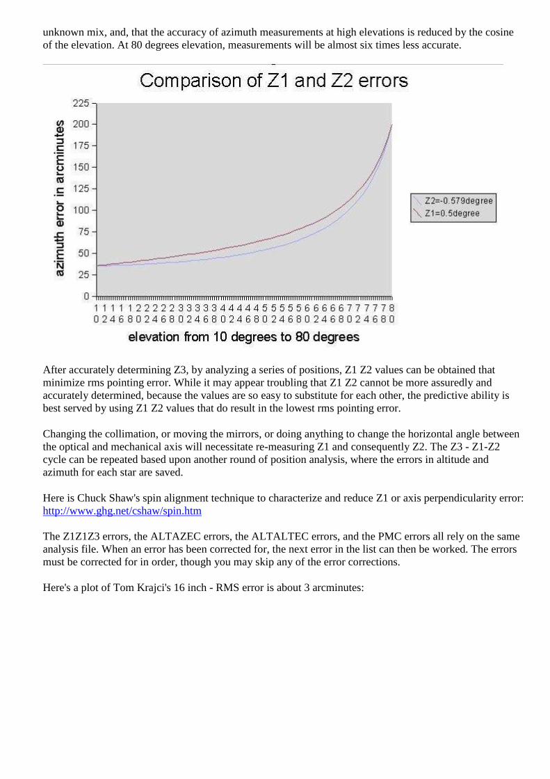
unknown mix, and, that the accuracy of azimuth measurements at high elevations is reduced by the cosine of the elevation. At 80 degrees elevation, measurements will be almost six times less accurate.
After accurately determining Z3, by analyzing a series of positions, Z1 Z2 values can be obtained that minimize rms pointing error. While it may appear troubling that Z1 Z2 cannot be more assuredly and accurately determined, because the values are so easy to substitute for each other, the predictive ability is best served by using Z1 Z2 values that do result in the lowest rms pointing error.
Changing the collimation, or moving the mirrors, or doing anything to change the horizontal angle between the optical and mechanical axis will necessitate re-measuring Z1 and consequently Z2. The Z3 - Z1-Z2 cycle can be repeated based upon another round of position analysis, where the errors in altitude and azimuth for each star are saved.
Here is Chuck Shaw's spin alignment technique to characterize and reduce Z1 or axis perpendicularity error: http://www.ghg.net/cshaw/spin.htm The Z1Z1Z3 errors, the ALTAZEC errors, the ALTALTEC errors, and the PMC errors all rely on the same analysis file. When an error has been corrected for, the next error in the list can then be worked. The errors must be corrected for in order, though you may skip any of the error corrections.
Here's a plot of Tom Krajci's 16 inch - RMS error is about 3 arcminutes:

After Tom analyzed his mount and adopted Z1 Z2 Z3 values, and corrected for a lumpy rocker bottom, his rms improved to 1/2 arcminutes pointing.
After Z1, Z2, and Z3 are set, the ALTAZEC and ATLALTEC and AZAZEC and PMC correction curves can be added.
Finally, residual errors are handled by General Pointing Model Corrections, called PMC, can be analyzed and adopted. These errors, unlike the errors mentioned so far, are not specific to a feature or characteristic of the mount, but instead, are generalized pointing instructions to improve goto and tracking accuracy in specific sections of the sky.

7.5. To set backlash values
Be sure to accurately (within an arcminute or less) determine the exact amount of backlash for each axis. Use a laser pointer attached to the scope, projecting a dot of light onto a wall. Start with both backlash settings (in config.dat) equal to 0. Using the handpad, microstep for awhile in one direction, enough to takeup any backlash, stop, then read the altaz coordinates from the screen. Then reverse the motor direction on the handpad and stop immediately when the scope starts moving. Read the new altaz coordinate to determine the amount of backlash (in degrees). Repeat this several times and use the average value for each axis. Convert this to arcminutes and enter into config.dat. If one does not have a laser pointer, one can focus a cross-hair eyepiece on a stationary object on the horizon (house, tree, etc) to determine when the scope starts to move. The encoders could also be used if their precision is high enough. After entering the correct backlash parameters into config.dat, repeat the backlash test using the laser or encoders. The scope should now "take up the slack" prior to microstepping, for example just quickly depress the handpad pushbutton for a split second and one should hear the motors spin, but the scope should not move much at all, and the altaz coordinates should not change much. This is the key to backlash compensation: even though the motors are spinning fast to take up the backlash, the scope is not moving and thus the altaz coordinates do not change in value. Without backlash compensation, prior to every change of direction for slewing, microstepping, and tracking, the motors will spin for awhile and the PC will think the scope is moving (and thus change the coordinates on the screen) however the scope is not moving yet. This creates errors in pointing accuracy. Backlash can cause serious slewing, finding and tracking errors, especially if the backlash is a significant portion of the field of view.
For example, my (Jerry Pinter's) Cookbook CCD f.o.v. is about 15 arcminutes on my scope, and my backlash is about 7 arcminutes. Thus if I think I have an object nearly centered, without backlash compensation it may actually be 7 arcminutes off-center (depending on which way the motors last spun) which could be off the edge of the chip! Another problem is when doing initializations or "resetting" off a nearby bright star, if backlash is not compensated, then the scope may be pointing in error by the amount of backlash. Also, when tracking an object for CCD imaging, if the backlash is not compensated, then the object will drift across the image before the backlash is taken up. With backlash properly compensated for (as described above), everything is taken care of automatically. The PC knows exactly where the scope is pointing during initialization, resets, and slews. When the scope slews to an object, the object will land on the CCD chip, and tracking will start immediately after the motors take out the slop, leaving the object in the same place within the field of view. It's important to have the scope balanced (alt axis) since any imbalance will tend to make the backlash appear only in one direction, which will screw up the backlash compensation.

7.6. To use the drift/guiding/PEC capabilities
After the initialization, typically high power tracking will show two residual errors.
The first is a slow steady drift, commonly a couple of arcseconds per minute of time. This is caused by small initialization errors such as not precisely centering the star in the crosshairs when initializating, and mount errors such as the azimuth and altitude axes not being exactly perpendicular.
The second is periodic error caused by the gearing, commonly the worm not being centered on its shaft or butting the gear properly. This shows as a slow oscillation of the star back and forth across the crosshairs.
The program has both periodic error and drift error cancellation features.
The PEC, or periodic error correction, file consists of two columns. The first is a counter, 0 to 199, that indicates the index. The index is the resolution or number of steps that the PEC is divided into. Commonly this is spread over a single motor rotation or 200 fullsteps, but may be spread over any number of fullsteps. For instance, spreading the PEC over 400 fullsteps would cover the PEC caused by a double turn worm. Set the number of fullsteps that a PEC cycle will cover with the variable FullstepsPerPECArray. Mark a synchronization point on the motor shaft or the worm shaft that indicates the starting position, corresponding to an index of 0. Next to the index numbers in the PEC.DAT file are numbers that that indicates the amount of PEC in tenths of an arcsecond to apply at each index. For instance, if a single turn worm causes 2.3 arcsecond of periodic error with the motor shaft at a 45 degree angle, then index 50 would have a value of 23 (assuming 200 fullsteps per motor revolution). See the PEC.TXT file to see how to enter these values. The altitude PEC comes first, with indexes of 0-199, then the azimuth motor comes with indexes of 0-199. Remember that you have 200 PEC values per axis, no matter how many fullsteps you spread the PEC over.
Here are more notes on PEC by Chuck Shaw: "I am Chuck Shaw. I recently finished converting my 14.5"f/5 dob into an AltAz system using Mel's plans and software. I concur, it is MUCH more of a "system" than I ever imagined!!! I also just went through coming to grips with nulling out PE and I have a few "lessons learned" that might be helpful.... 1. Use LOTS of power when running in Guide mode to build Guide.dat I used two barlows stacked into each other (a 1.7x and a 2.8x and a 12mm illuminated reticle eyepiece and an ~1808mm scope gives about 720x...... use AT LEAST that much if you can.... (Slightly defocused blobs are easier to guide with than points anyway!!)... You ARE using an illuminated reticle EP aren't you??? Do not try to keep a focused image of the star in the center of the box. Either defocus till the star fills the box, or put the star in the center of an intersection of two lines, or put it in a "corner" where its just touching two lines. Try different techniques to see which works best for you. I found the biggest source of inconsistencies in my data sets was ME and my poor guiding!!!!!! My reaction times usually had the wrong direction and were late..... (duh......) :-) Play with the orientation of the handpaddle also to see if a "fly to" type of guiding is easier..... 2. Use the guide routine several times to nail the drift as well as possible BEFORE you try to write a file to capture PEC data. 3. For Azimuth data collection, be sure and aim the scope due south, near the celestial equator. This will minimize motion from Alt, and maximize the motion in AZ.... 4. Shell out to DOS without stopping tracking after a Guide run, Do a "copy c:\guide.dat PE-AZ1.txt", then a copy "c:\PEC.txt guide.dat" (say YES to overwrite) , then type exit and SHAZAM the scope will slew back to the star you were guiding on and you are ready for another run!!!!! Name the next file PE-AZ2,txt, etc...... This allows you to capture several runs very quickly, and any system config changes between runs are minimized. 5. VERY CLOSELY inspect for any "wobble" in your worm bushing. I use 359:1 Byers gears. I had to make the bushings for the worms and discovered the bushing has a tiny bit more slop than it should (the clearance is about 0.001 and Byers tells me it should be about 0.00005). I decided to fabricate a "tailstock" out of a small aluminum angle and a brass machine screw. I ground a point on the end of the machine screw and it goes through the bracket and presses into the center ground dimple in the end of the worm. That made
a HUGE difference in obtaining repeatable data. I think the problem was the worm's wobble was somewhat random. That, in turn changes the mesh slightly, and that induces PE.... If your worm is on a shaft with bearings/bushings at both ends, you still need to look for this! 6. Look at the couplings for the motor to worm. If they are flexible and you are using the motor bearings to stabilize the worm at all (if there is slop in the bushings you are in this category), you need to go to a precision coupling. I bought several commercial ones and found they were slightly out of round!!!! This in itself introduced PE!!! Thats OK though, since the Software will compensate for it. 7. Reinitialize the motor/worm positions in between runs to make VERY sure that you know what position corresponds to the 0 position in the guide.dat data I failed to do this a couple of times and got accurate but skewed curves..... You have to remember to turn off PEC and then back on after the shafts are positioned !!!!!! 8. Remember the data take will NOT start at zero unless you time it that way. Do not try to get cute and time it, just start it and use your spreadsheet program to cut the four runs of data into separate columns and then move them up/down in the spreadsheet to line up the steps in each run. Then delete the step number columns (all but the far left one). Graph the 4 curves and throw out any that are obvious guiding errors. Then average the rest and you are there!!! 9. Remember after the data file is copied into a file called PEC.dat to reinitialize the shafts to their zero position. I keep forgetting to do this!!!! The system also seems to get lost after a couple of hours of operating.... An occasional reinit of the PEC alignment takes less than 15 sec and helps "clean up" things. I should not have to do this but...... I have the sets of curves from my data takes I can send you. I was having the inconsistencies in taking data initially, and then the phase skewing till I stabilized the worms too.... perplexing, but a methodical working on each potential source of PE will find the culprit!!! The performance of the system is simply astounding when all is completed..... I agree with Mel that software timing errors are the least likely culprit. Too many times I wanted to blame the software for problems but Mel has simply done too good of a job!!!!! It was ALWAYS something I did!!!! (don'tcha hate it when that happens!!??) :-)"
Here is Joe Garlitz's excellently explained analysis method for PEC.
Vincent Steinmetz periodic error analysis of belt and pulley drive http://xmcvs.free.fr/ep/asca_eng.htm
To null residual drift and optionally write GUIDE.DAT, follow the following procedure.
As a pattern to copy, a dummy PEC file is included with PEC values of 0, named PEC.TXT, found in the scope.zip file. Rename it to PEC.DAT if you wish to use it. Turn PEC on after synchronizing both motors' output shafts to a predetermined angle. Turn tracking on, set the handpad function to 'guide', set the speed button to microstepping, and when the guide star is centered on the crosshairs, flip the mode switch momentarily to the left, turning on guide. The scope will now move at GuideMs speed, a slow additive/subtractive speed from the tracking rate. Using the hand paddle direction buttons, keep the guide star centered in the crosshairs. Soon beeps will be heard, signifying the synch point of the PEC cycles, the alt beep being higher in pitch than the az beep. Flip the mode switch on the hand paddle momentarily to the right to end guide after hearing at least two beeps from each axis. A GUIDE.DAT file is written with PEC indexes and the resulting guide values as input from the hand paddle. This can be used to create a real PEC.DAT file. Import the GUIDE.DAT file into a spreadsheet, and graph the curve. You can throw several GUIDE.DAT files into the graph, to get an average PEC. Smooth the values and place them in the PEC.DAT file.
Regardless of whether the PEC.DAT file exists, and regardless of whether PEC is on, drift values are calculated on the spot, displayed on the screen, and adopted immediately by the tracking function.
If only drift calculation is desired, center the star in the crosshairs, initiate guide mode by a momentary flip of the handpaddle switch to the left, guide for a minute or two, then end guide mode by a momentary flip of the handpaddle switch to the right.

Drift nulling can be done again, on top of the last calculated drift null values to further refine the nulling, if desired. Usually once through the drift nulling process is good enough until the scope is pointed at a very different location in the sky. After moving to the new part of the sky, repeat the drift null process after first zeroing the drift values via the menu.
7.7. Updating the PEC data on the fly Since the last section was written, much has been done to enhance the generation of periodic error correction on the fly. The two principal errors affecting guiding accuracy can be fixed at one time: the periodic error of the gear that the stepper connects to, and drift. The drift may need to be tweaked after pointing to another section of the sky. There are two methods to choose from: fixup an already generated PEC or generate a PEC from scratch The PEC in use by scope.exe can be displayed by using the hotkey 'c'. If you wish to save this PEC to PEC.DAT, answer yes. To synchronize the PEC with the motors, use the handpaddle to move both motors to their respective synchronization angle, then select 'p' or pec on/off on the keyboard. PEC is now synchronized with the motors and will remain synchronized unless the motors stall. To generate PEC from scratch, or to to fixup an already generated PEC, put the hand paddle into guide+save mode, and guide until at least two high beeps and two medium beeps are heard, preferably until a low beep is heard, indicating that the guide array has been filled. The higher pitched sound indicates each time the altitude motor crosses the synch point. It must cross twice in order to generate a full motor rotation of data. A medium pitched sound is used to indicate the azimuth motor's crossing of the synch point. Multiple rotations of the motor will yield multiple PEC analysis files. Better results may be obtained by focusing on only one axis, then repeating the entire procedure for the other axis. If using an equatorial telescope, or using an altazimuth telescope where one axis is moving very slowly (altitude axis when on the meridian for instance), then you will have to either misalign the scope or find another section of the sky where both motors are moving at a nice rate. Use the 'u' and 'v' hotkeys to inspect the just completed guiding corrections. If you wish the guiding corrections will be saved to PECALTxx.TXT or PECAZxx.TXT files, where 'xx' starts at '00' and is incremented for each file saved. This allows you to build several iterations of guiding corrections in order to average them for a more accurate PEC. In addition, the drift should shrink to zero as it is refined. Use the 'e' and 'f' hotkeys to read in all the PECALTxx.TXT or PECAZxx.TXT files, average them, then display the results graphically, including how the pec will look if the averaged files are added in. Use the 'L' hotkey to reload PEC.DAT. Set TestString to "PreloadGuidexx.dat" to preload guidealt.dat and guideaz.dat upon program startup. This gives an opportunity to analyze and pull out pec data from earlier guiding efforts.
7.7.1. Focusing
For the stepper system, several methods of controlling focusing are available:
a. Connecting parallel port pins 16 and 17 to a pair of relays to control a small DC motor for focusing. Pin 16 focuses 'out' and pin 17 focuses 'in'. This can be operated with the field rotator concurrently.
b. As above in option 3, with the addition of parallel port pins 1 and 14 for slow speed control. Field rotation is disabled with this option.
c. Using the field rotation motor control circuit with a small stepper motor for focusing. This uses parallel port pins 1 and 14 for pulse and direction.

d. Adding a second MC3479 bipolar stepper control circuit with a small stepper motor for focusing. This uses parallel port pins 16 and 17 for pulse and direction. Both the field rotation and focus motors can be operated simultaneously. Along with the altitude/declination and azimuth/hour angle motors, this means that four motors are controlled at the same time.
If a stepper motor is used, the focus position is kept track of by virtue of counting the stepper pulses. Particular focus positions can be returned to.
7.7.2. Parallel Port Interface
The parallel port is an ideal interface for controlling telescopes, particularly with laptops in the field. The parallel port uses 8 bits of output, typically at port address 0x378. On the 25 pin connector, the 8 bits of output are on pins 2 through 9, from least significant to the most significant bit. These 8 bits of output are perfect for controlling the two stepper motors needed to drive a telescope in altazimuth mode. The parallel port cannot provide or sink large currents directly, hence, 74LS04 hex inverters are used to interface between the parallel port and the driver transistors.
The parallel port has 5 bits of input at port address 0x379. These input bits are on pins 15, 13, 12, 10, and 11 of the 25 pin connector, with pins 11 and 15 being inverted. Pin 15 activates bit 8, pin 13 activates bit 16, pin 12 activates bit 32, pin 10 activates bit 64 and pin 11 activates bit 128. Depending on which lines are raised high, the values can range from 8 through 248. In addition, the parallel port has 4 bits that can be either in or out at port address 0x37A. These 4 bits show up on pins 1, 14, 16 and 17 of the 25 pin connector. Bits 1,14 and 17 are inverted. These values when read range from 0 to 15.

7.7.3. Autoguiding
The computer controlled telescope can accept autoguider input via two methods:
1. LX200 protocol: scope.exe knows about the guiding commands available in the LX200 communications protocol. Simply hook up the serial port from the guiding computer via a null modem cable to the serial port being used as the LX200 communications port on the computer running scope.exe. Martin Niemi's superb quickcam autoguider will do this very inexpensively - see http://www.ameritech.net/users/mniemi000/auto.html
2. Relay box: The autoguider needs to supply a relay for each direction, or, a +5 VDC TTL signal for each direction, or, a serial connection sending LX200 protocol commands.
If using a relay box, wire the interface circuit such that when a relay closes, a +5VDC TTL signal is supplied as follows: If using a control signal, tie the control signals so that the control signal going to logical high raises the input voltage to a +5VDC level as follows:
(this scheme mirrors the four direction buttons on the hand paddle) up or north: to pin 13 of the parallel port, down or south: to pin 12 of the parallel port, left or counterclockwise: to pin 10 of the parallel port, right or clockwise: to pins 13 and 12 of the parallel port.
Here is how Juan Herrero hooked up his SBIG ST4 autoguider to the hand paddle:
Purchase a 2 female to 1 male phone wire adapter. Plug the male side to the control board.. Plug the hand paddle to one of the females. The other female will be for the ST-4. Purchase a phone wire with a male plug at one end to plug into the 2 to 1 adapter at the control board. At the other end of the wire. Install the correct computer plug to connect to the ST-4. You need to install 2 small signal diodes in two of the wires. Install the 2 diodes inside the computer plug. The wire assignment is as follows: ST-4 action HAND PADDLE PARALLEL PORT ST-4 pins ----------------------------------------------------------------- +5v white n/a ----------------------- 11, 5, 14, 8 -Az yellow 10 ----------------------- 10 +Az green 12 ---------|<|----------- 4 * +Az black 13 ---------|<|----------- 4 * -Alt green 12 ----------------------- 7 +Alt black 13 ----------------------- 13 * -----|<|----- This symbol represents a diode and they are a must for thing to work. Both the hand paddle and the ST-4 can be operated at the same time although conflicting simultaneous signals can be sent to the PC in this fashion, resulting in unpredictable actions.

To operate:
• 1. Put the telescope control program hand paddle mode into one of the guide modes. Set the speed of the guiding corrections by adjusting the microstepping guide speed.
• 2. Orient the autoguider by rotating it so that the autoguider's up and down correspond to the telescope's autoguider.
• 3. Calibrate the autoguider. • 4. Initiate guide corrections by the telescope control program by momentarily flipping the hand
paddle mode switch to the left and then center the switch. • 5. Start the autoguider.
All guide functionality continues to exist with the autoguider on. For instance, in guide+stay mode, flipping the hand paddle mode switch momentarily to the right will calculate drift, and null the telescope's drift. Immediately re-initiate telescope control program guiding by momentarily flipping the hand paddle mode switch to the left and then center the switch. In guide+record mode, a record is kept of the autoguider's corrections.
The hand paddle can continue to be used. Pressing a direction button will add its guiding correction to the autoguider.
Guide arrangements include:
• piggyback guide scope • off-axis guider • intercept guider • built-in guider chip ala ST7, ST8


8. Drawings
Drawings have been produced in Tiny CAD. These have then been copied and pasted into Paint Shop Pro, saved as JPEG images and imported into this document. The original Tiny CAD files and the Tiny CAD application are located on the DVD disc with this manual.

8.1. Power distribution


8.2. Weather station

8.3. Power control

8.4. Dome azimuth drive control

8.5. Dome door control

8.6. Telescope control
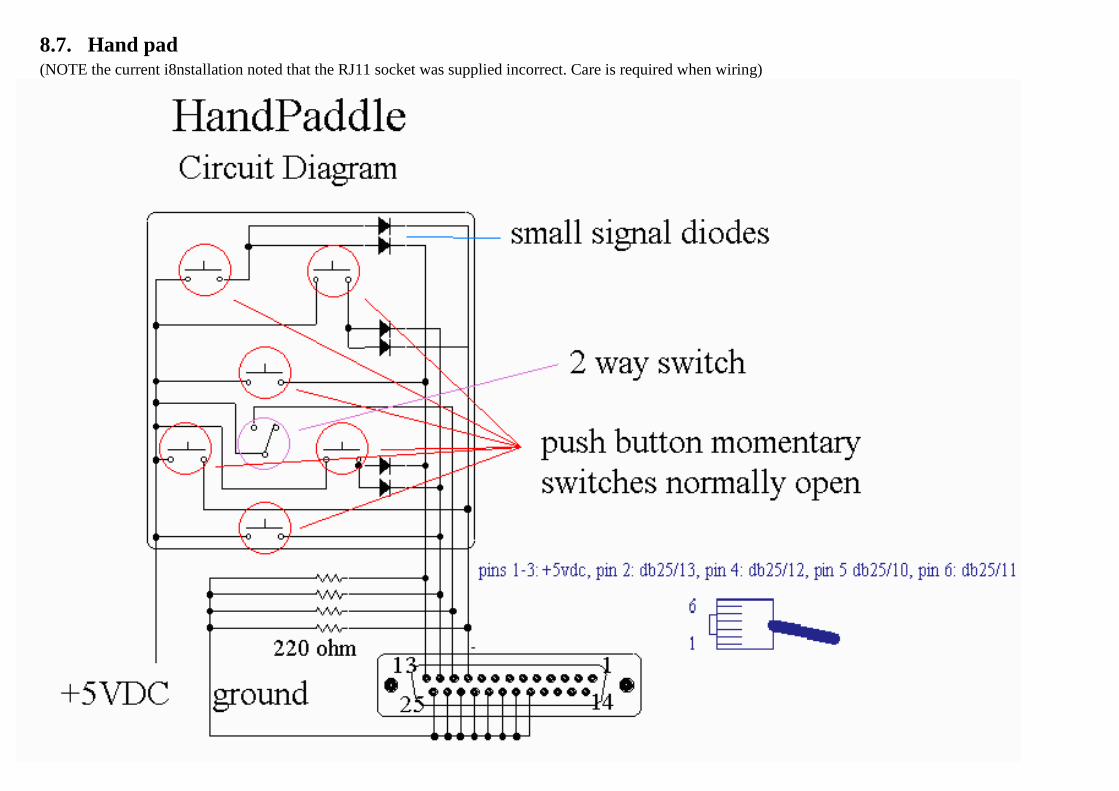
8.7. Hand pad (NOTE the current i8nstallation noted that the RJ11 socket was supplied incorrect. Care is required when wiring)


8.8. Current Limiting Modification

(the following is Jean-Charles' explanatory text, slightly edited)
In the depicted version, the 240 ohms resistor (R3) is connected to a common point with the TIP127 and diode 1N5408. Since there was no ground connection available, the motor itself was used as a return to ground. This is not as good as directly returning to ground, but there was no choice. On a new board this circuit, or a similar one, can be incorporated on the main PC board, or a ground connection can be added on the DB-9 connector.
The other version, not depicted, this resistor (R3) is 1000 ohms and connected directly to ground. This version is more effective.
Now, the current limit value is determined by R2, in my case 0.15 ohms for 4 amperes. This resistor should be a 5 watter. Any current can be chosen and it is calculated the folowing way: R2 = 0.6/ desired current. For example in my case I wanted 4 amperes maximum, so R2 = 0.6/ 4 = 0.15 ohms. In a similar way, if you desire 3 ampere limitation the calculations are: 0.6 / 3 = 0.2 ohms, and so on.
If you use 24 volts I would raise R3 to 470 ohms in the first circuit and to 2200 ohms in circuit 2.
Transistor TIP127 does not heat, but in pure precaution I attached on the alluminium box, I used, a medium size heatsink. I think it is better if used at 24 volts. This depends on the motors of course.
What the circuit does, is to limit the maximum current to the value presetted no mater what is the load, so as I discussed earlier, you will not end with astronomic currents near the 20 ampere mark.

8.9. Stepper circuit (Basic. NOTE: The current installation has Mels assembled and tested board with the derotator chip)

8.10. Stepper system heartbeat shut off

8.11. Field Rotation
In any scope where an axis does not point exactly to the celestial pole, a slow rotation of the field of view occurs. Field rotation is independent of the size of the field of view, for instance, a large scope at high power will experience the same angle of field rotation as a small rich field telescope at low power. Field rotation varies greatly over the sky, non-existent in the east and west, terrible at the zenith, and approximating the sidereal tracking rate when pointed at the meridian. A motor can be added to slowly rotate the focuser to compensate for field rotation.
For visual imaging, a field de-rotator motor is not needed. For CCD imaging, exposing for 5-20 minutes in many sections of the sky with typical chips, a field de-rotator motor is not needed. If you have a CCD chip with very large numbers of pixels, or planning to do prime focus astrophotography, then you will want to add the field de-rotator. The control program shows the field rotation in real time, so that you can plan exposures accordingly. Here's how I judge field rotation: for a CCD chip that is several hundred pixels on a side, the total number of pixels on the perimeter is roughly 1000. That means that we can tolerate a field rotation of 360 degrees/1000 resolution units, or about 1/3 degree. I watch the scope track in realtime, noting the amount of field rotation change over 10 seconds or so. If it looks like I can image for my desired exposure time, then I go ahead. If not, I wait until the object is better positioned in the sky, or adjust my exposure time.
Since the field de-rotator unit need only rotate slowly with finite steps, drive and motor requirements are much more modest than the telescope's main axis drives. A simple single chip driver circuit is all that is needed, with step and direction inputs. To keep vibration minimized, I suggest a field rotation per step size of 1 arcminute. This is also fine enough to prevent field rotation from showing on fine grained 35mm film. For a stepper motor field de-rotator, use the MC3479 chip in place of the discontinued SAA1042 chip.

8.12. Network layout

9. Material list
9.1. Software listing Scope.exe DOS 6.22 ACP MaxImDL Cartes Du Ceil (not used when using ACP) POTH MaxPoint (not used when using ACP) MX7 StarlightXpress camera driver ST4 CCD (not used but installed) Phillips ToU Cam Shutdown (not yet installed or tested)
9.2. Dome material list
9.3. Weather station material list
9.4. Telescope material list Stepper Parts List This is for the basic circuit diagram (printed circuit board calls for different parts list - see the pcb webpage): from Radio Shack: a. (8) TIP-120 transistors b. (8) heat sinks for above c. (8) 1/4W 470 ohm resistors d. (8) 2.5A 100 V PIV diodes e. (4) 1/4W 220 ohm resistors f. (2) 74LS04 hex inverters g. (1) large instrument box h. (1) 276-160 circuit board i. (1) 25-pin cable j. (1) 25-pin connector kit k. (2) 9-pin connector kits l. (4) momentary push buttons - normally off, temporarily on m. (1) 3-way center-off switch n. (1) 2-way switch o. (1) package of small diodes p. (2) IC 14 pin sockets q. (1) 7805 power regulator chip r. (1) heat sink for above s. (3) 0.1 uF capacitors from a local well stocked electronics store:

a. (4) 30V 5W zerner diodes gear reducer: from a motions control outfit such as: Torque Transmissions ([email protected], (http://www.torquetrans.com)1-216-352-8995) (60:1, use final roller reduction of 40:1) or Allied Devices (100:1, use final roller reduction of 24:1) (1-516-223-9100) or Andy Saulietis' hard plastic gear reducers ([email protected]) or Larry Myers' Byers gears (http://www.mountaininstruments.com or [email protected]) or American Science and Surplus (http://www.sciplus.com/) look for motors with gear heads for ~$5 removing the motor or Martin Sprockets (http://www.martinsprocket.com/contact.htm) Harmonic Drives (http://www.harmonicdrive.net/) RS-Components worldwide (http://www.rs-components.com/) Arrick Robotics (http://www.robotics.com/pr23.html) Andantex's cycloidal differentials (http://www.andantex.com/dls.html) Small Parts Co (http://www.smartparts.com) 1 gear reducer per axis ~$100 (aim for gear reducer multiplied by final roller reduction to equal about 2400:1, this gives 1/4 arcsecond per microstep, exact microstep size is entered in the CONFIG.DAT file) 2 stepper motors: Jameco Electronics Oriental Motors (the 400 step motors are very nice) Surplus stocks are a moving target! Look for steppers at surplus houses a. (2) stepper motors: 6-12 VDC .3 to 1 amp/phase 20+ in-oz torque ($2+ and approx 2"x2"x2" size with 1/4" shafts), preferably 6 leads, but 5 or 8 lead motors will do, 4 lead motors are bipolar motors and not suitable, preferably 200 steps per revolution (1.8 deg full step size) b. (2) cables: Jameco DB9 M-F 6' connector 25700 $4.95 + Jameco DB9M connector 15747 $.35 + 15721 hood $.32, c. LED test unit: Jameco 152856 LEDs for winding testers $.12 + Jameco DB9M connector 15747 $.35 + 36 470 ohm resistor Jameco 31165 $.89/100 1 bipolar stepper motor: Jameco's 163408 bipolar stepper: 9 volts 38 ohms coils 240ma current draw 664 g-cm holding torque or MPJA's four lead bipolar stepper 1.8 degree steps rated for 24 volts/.44 amps/55 ohms: $6. servo motors: Pittman Motors from clickautomation.com servo controllers: PIC Servo controller by Kerr, available from Jameco Co #184989 $180, RS232->RS485 converter #184971 $60 2 encoders: part number S2-2500-B from US Digital, seller of Hewlett-Packard encoders The optional MC3479 field derotator chip which replaces the discontinued SAA1042 can be ordered from Jameco Electronics, part number 25216 (MC3469P), price $5.

10. Links and references
RS components: http://rswww.com Maplin Electronics: http://www.maplin.co.uk/ Chester 01244 315484 Starlight Express: http://www.maplin.co.uk/ SBIG cameras: http://www.sbig.com/ Mel Bartels web site: http://www.bbastrodesigns.com/BBAstroDesigns.html#Computer_Operated_Telescopes Formes Alutek ltd. (Cromwell road Ellesmere Port): http://www.formesalutek.co.uk/ ACP (Astronomers Control Panel): http://acp3.dc3.com/ The Sky: MaximDl CCD: http://www.cyanogen.com/ Focus Max MaxPoint: http://www.cyanogen.com/ Tiny CAD: http://tinycad.sourceforge.net/