Embed Size (px)
Citation preview

arX
iv:1
812.
0995
9v1
[ph
ysic
s.pl
asm
-ph]
24
Dec
201
8
Observation of Strong Terahertz Radiation from a Liquid Water
Line
L.-L. Zhang,1 W.-M. Wang,2, 1, 3, ∗ T. Wu,4 S.-J. Feng,4 K. Kang,1 C.-L.
Zhang,1 Y. Zhang,1 Y.-T. Li,2, 3 Z.-M. Sheng,5, 6, 7, 8 and X.-C. Zhang9, 1
1Beijing Advanced Innovation Center for Imaging Technology
and Key Laboratory of Terahertz Optoelectronics (MoE),
Department of Physics, Capital Normal University, Beijing 100048, China
2Beijing National Laboratory for Condensed Matter Physics,
Institute of Physics, CAS, Beijing 100190, China
3Songshan Lake Materials Laboratory,
Dongguan, Guangdong 523808, China
4Beijing Key Laboratory for Precision Optoelectronic Measurement
Instrument and Technology, School of Optoelectronics,
Beijing Institute of Technology, Beijing 100081, China
5SUPA, Department of Physics, University of Strathclyde,
Glasgow G4 0NG, United Kingdom
6Key Laboratory for Laser Plasmas (MoE) and School of Physics and Astronomy,
Shanghai Jiao Tong University, Shanghai 200240, China
7IFSA Collaborative Innovation Center,
Shanghai Jiao Tong University, Shanghai 200240, China
8Tsung-Dao Lee Institute, Shanghai Jiao Tong University, Shanghai 200240, China
9The Institute of Optics, University of Rochester, Rochester, New York 14627, USA
(Dated: December 27, 2018)
1
Abstract
Terahertz radiation generation from liquid water has long been considered to be impossible due
to strong absorption. A few very recent works reported terahertz generation from water, but
the mechanism is not clear and the efficiency demands to be enhanced. We show experimentally
that strong single-cycle terahertz radiation with field strength of 0.2 MVcm−1 is generated from
a water line/column of ∼ 200µm in diameter irradiated by a mJ femtosecond laser beam. This
strength is 100-fold higher than that produced from air. We attribute the mechanism to the
laser-ponderomotive-force-induced current with the symmetry broken around the water-column
interface. This mechanism can explain our following observations: the radiation can be generated
only when the laser propagation axis deviates from the column center; the deviation determines its
field strength and polarity; it is always p-polarized no matter whether the laser is p- or s-polarized.
This study provides a simple and efficient scheme of table-top terahertz sources based on liquid
water.
PACS numbers: 42.65.Re, 32.80.Fb, 52.38.-r, 52.65.Rr
2

Achieving table-top terahertz (THz) sources with high field strength and broad bandwidth
is an outstanding issue in THz science. Such sources can find applications in material
research [1, 2], biomedical imaging [3], non-destructive detection [4], and THz-field matter
interactions [5, 6]. Previous studies have demonstrated THz generation from solids [8–
11] and gases [12–22] via different mechanisms. However, THz generation from liquid, in
particular water, has long been considered impossible because of its strong absorption of
THz radiation. On the other hand, water exists in most biological systems and hence
THz radiation generated from liquid water may carry some information of these systems.
Therefore, how to generate THz radiation from water is fundamental challenge for both basic
and applied research. In 2017, two groups reported THz emission from liquid water [23, 24].
When an intense laser beam of tens of mJ was focused on liquid water in a cuvette, extreme
broadband THz radiation was generated [23], where it is considered that laser spectral
broadening played a key role. In the other work [24], when a mJ laser beam irradiated a
water film with the thickness ∼ 200 µm, THz radiation was produced with 1.8 times higher
strength than that produced from air. So far, the THz radiation mechanism in water has
not yet been well clarified and the yield efficiency demands to be further enhanced.
Here, we demonstrate experimentally that the efficiency can be enhanced by three orders
of magnitude when a water column with the diameter ∼ 200 µm is adopted. With a mJ
femotsecond laser beam, the THz field strength can reach 0.2 MVcm−1 which is as high as
generated via the standard two-color laser scheme in air [12, 13]. To explain our result, we
propose that the THz radiation originates from a net current formed due to the presence of
the column interface. The laser self-focusing in water causes a plasma to be produced. The
laser ponderomotive force forms positive and negative currents distributed on two sides of
the laser propagation axis, respectively. The symmetry of the two currents can be broken
provided the laser axis deviates from the water column center. As the deviation grows, the
net current and resulting THz radiation will be strengthened. This mechanism implies that
the THz polarization is on the column cross-section plane and its strength scales linearly
with the laser energy. These are verified by our experiments and particle-in-cell (PIC)
simulations.
Experimental setup.− Figure 1 shows a schematic of our experiment, where a laser beam
is incident along the +z direction and the water column axis is along the y direction. The
laser beam is delivered from a Ti:Sapphire amplifier (Spitfire, Spectra Physics) with a central
3
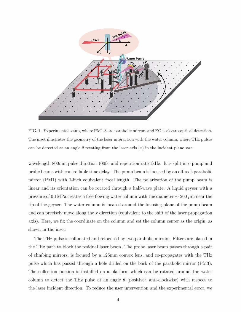
FIG. 1. Experimental setup, where PM1-3 are parabolic mirrors and EO is electro-optical detection.
The inset illustrates the geometry of the laser interaction with the water column, where THz pulses
can be detected at an angle θ rotating from the laser axis (z) in the incident plane xoz.
wavelength 800nm, pulse duration 100fs, and repetition rate 1kHz. It is split into pump and
probe beams with controllable time delay. The pump beam is focused by an off-axis parabolic
mirror (PM1) with 1-inch equivalent focal length. The polarization of the pump beam is
linear and its orientation can be rotated through a half-wave plate. A liquid geyser with a
pressure of 0.1MPa creates a free-flowing water column with the diameter ∼ 200 µm near the
tip of the geyser. The water column is located around the focusing plane of the pump beam
and can precisely move along the x direction (equivalent to the shift of the laser propagation
axis). Here, we fix the coordinate on the column and set the column center as the origin, as
shown in the inset.
The THz pulse is collimated and refocused by two parabolic mirrors. Filters are placed in
the THz path to block the residual laser beam. The probe laser beam passes through a pair
of climbing mirrors, is focused by a 125mm convex lens, and co-propagates with the THz
pulse which has passed through a hole drilled on the back of the parabolic mirror (PM3).
The collection portion is installed on a platform which can be rotated around the water
column to detect the THz pulse at an angle θ (positive: anti-clockwise) with respect to
the laser incident direction. To reduce the user intervention and the experimental error, we
4
minimize the optical path difference between the pump and probe beam arms of rotation.
The THz fields resolved traces are obtained through electro-optic (EO) sampling with a 3
mm thick 〈110〉-cut ZnTe crystal as the detector [25]. In our experiments, the laser beam
is taken as 2 mJ energy, p-polarization (along the x direction), the laser propagation axis is
displaced 60 µm (xL = 60 µm) from the water column center, and the THz pulse is collected
at θ = 0◦, except in Fig. 4.
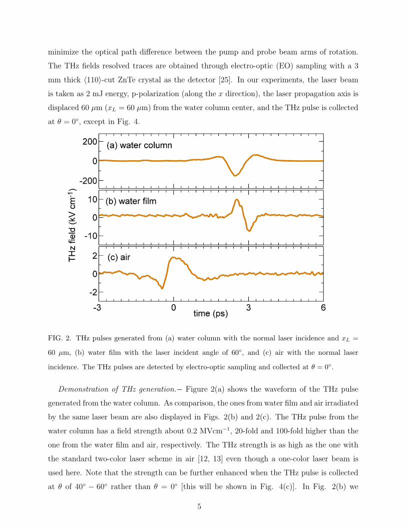
FIG. 2. THz pulses generated from (a) water column with the normal laser incidence and xL =
60 µm, (b) water film with the laser incident angle of 60◦, and (c) air with the normal laser
incidence. The THz pulses are detected by electro-optic sampling and collected at θ = 0◦.
Demonstration of THz generation.− Figure 2(a) shows the waveform of the THz pulse
generated from the water column. As comparison, the ones from water film and air irradiated
by the same laser beam are also displayed in Figs. 2(b) and 2(c). The THz pulse from the
water column has a field strength about 0.2 MVcm−1, 20-fold and 100-fold higher than the
one from the water film and air, respectively. The THz strength is as high as the one with
the standard two-color laser scheme in air [12, 13] even though a one-color laser beam is
used here. Note that the strength can be further enhanced when the THz pulse is collected
at θ of 40◦ − 60◦ rather than θ = 0◦ [this will be shown in Fig. 4(c)]. In Fig. 2(b) we
5

take a 200-µm-thick and 5-mm-wide water film, which is produced by a jet nozzle with
polished sapphire surfaces (Sirah, Germany). The laser incident angle is taken as 60◦ to
optimize the THz strength, in particular, nearly no THz generation with the laser normal
incidence [24]. However, in the water column case, the normal laser incidence along the +z
direction is always taken in our experiments and efficient THz generation is observed (note
that the laser beam with a self-focusing intensity ∼ 1015 Wcm−2 ionizes the water column
to be plasma and then the beam can propagate along its incident direction since the plasma
refractive index approaches 1 in our case). This suggests that there are different generation
mechanisms in the two cases [different THz strength scaling are also observed as shown in
Fig. 4(a)]. Here, we focus on the water column case and exploration of the mechanism in
the water film is beyond the scope of this work.
Mechanism.− The experimental and PIC-simulation results shown in Fig. 3 suggest that
the mechanism can be explained as the laser-ponderomotive-force-induced current with the
symmetry broken around the column interface. Figure 3(a) shows that the THz pulses have
nearly the same amplitude and opposite field signs when the laser axis deviates from the
column center by +60µm and −60µm (xL = ±60µm), respectively. While the laser axis is at
the column center (xL = 0), virtually no THz pulse is generated, as seen in Fig. 3(b). This
figure also shows that the THz strengths have the same absolute value and opposite signs at
the two points ±xL. As |xL| is increased, the amplitude is first enhanced and then lowered.
The amplitude peaks appear around xL = ±(60µm ∼ 70µm). These are in agreement with
our PIC simulation results shown by the line in Fig. 3(b), which are explained below.
Our simulations are performed with the KLAPS code [26], in which we adopt the same
parameters of the water column and laser (energy, duration, and polarization) as in the
experiments. Considering that the laser self-focusing in water should be stronger than in
air, we assume that the laser beam in the water column has the spot radius w0 = 30 µm.
Then, the corresponding intensity is 1.5× 10¹⁴ Wcm−2 − 1.7× 10¹⁵ Wcm−2 when the laser
energy varies within 0.2 mJ− 2.4 mJ. In our simulations, the laser energy is taken as 2mJ
(1.2× 10¹⁵ Wcm−2) except Fig. 4(a). With such laser intensity, plasma is quickly produced
by the laser beam via field ionization. No net current can be formed via the ionization since
the symmetry of the ionization by a one-color 800nm laser beam is not broken [17, 27].
On the other hand, our simulations show in Fig. 3(c) that net currents can be formed in
the laser interactions with the water-column plasma. We examine the quasi-static currents
6

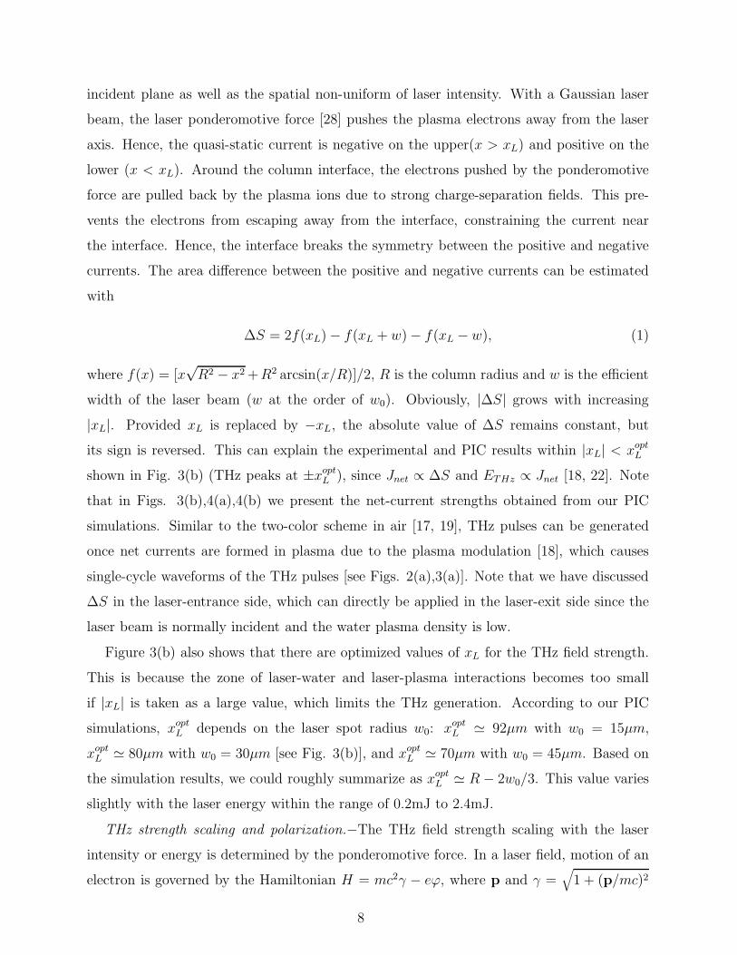
FIG. 3. (a) THz pulses observed in the experimenters with xL = ±60µm. (b) THz strength as
a function of xL, where experimental and PIC results are shown by dots and line, respectively.
(c) PIC results of quasi-static currents 〈Jx〉 with different xL, where the currents are obtained by
temporally averaging Jx over one laser cycle and the broken line in each plots marks the column
interface.
〈Jx〉, 〈Jy〉, and 〈Jz〉, respectively, where these currents are obtained by temporally averaging
Jx, Jy, and Jz over one laser cycle. Here, the laser polarization is along the x direction (p-
polarization). One can see in Fig. 3(c) that the total/net currents∑〈Jx〉 6= 0 unless xL = 0,
where∑
means spatial summation. When xL = 0, the positive and negative currents are
symmetrically distributed, therefore, the net current is zero. When xL = 20 µm, the positive
current is distributed within a larger area than the negative one, therefore, the net current
is positive. While xL = −20 µm, the positive current is distributed within a smaller area,
therefore, the net current is negative. In addition, the net currents∑〈Jy〉 and
∑〈Jz〉 remain
zero with any xL, as in usual cases without special target interfaces.
The net current is formed in the x direction because of the column interface in the laser
7
incident plane as well as the spatial non-uniform of laser intensity. With a Gaussian laser
beam, the laser ponderomotive force [28] pushes the plasma electrons away from the laser
axis. Hence, the quasi-static current is negative on the upper(x > xL) and positive on the
lower (x < xL). Around the column interface, the electrons pushed by the ponderomotive
force are pulled back by the plasma ions due to strong charge-separation fields. This pre-
vents the electrons from escaping away from the interface, constraining the current near
the interface. Hence, the interface breaks the symmetry between the positive and negative
currents. The area difference between the positive and negative currents can be estimated
with
∆S = 2f(xL)− f(xL + w)− f(xL − w), (1)
where f(x) = [x√R2 − x2+R2 arcsin(x/R)]/2, R is the column radius and w is the efficient
width of the laser beam (w at the order of w0). Obviously, |∆S| grows with increasing
|xL|. Provided xL is replaced by −xL, the absolute value of ∆S remains constant, but
its sign is reversed. This can explain the experimental and PIC results within |xL| < xoptL
shown in Fig. 3(b) (THz peaks at ±xoptL ), since Jnet ∝ ∆S and ETHz ∝ Jnet [18, 22]. Note
that in Figs. 3(b),4(a),4(b) we present the net-current strengths obtained from our PIC
simulations. Similar to the two-color scheme in air [17, 19], THz pulses can be generated
once net currents are formed in plasma due to the plasma modulation [18], which causes
single-cycle waveforms of the THz pulses [see Figs. 2(a),3(a)]. Note that we have discussed
∆S in the laser-entrance side, which can directly be applied in the laser-exit side since the
laser beam is normally incident and the water plasma density is low.
Figure 3(b) also shows that there are optimized values of xL for the THz field strength.
This is because the zone of laser-water and laser-plasma interactions becomes too small
if |xL| is taken as a large value, which limits the THz generation. According to our PIC
simulations, xoptL depends on the laser spot radius w0: xopt
L ≃ 92µm with w0 = 15µm,
xoptL ≃ 80µm with w0 = 30µm [see Fig. 3(b)], and xopt
L ≃ 70µm with w0 = 45µm. Based on
the simulation results, we could roughly summarize as xoptL ≃ R − 2w0/3. This value varies
slightly with the laser energy within the range of 0.2mJ to 2.4mJ.
THz strength scaling and polarization.−The THz field strength scaling with the laser
intensity or energy is determined by the ponderomotive force. In a laser field, motion of an
electron is governed by the Hamiltonian H = mc2γ − eϕ, where p and γ =√
1 + (p/mc)2
8

are the momentum and relativistic factor, respectively, e and m are the electron charge and
mass, respectively, c is the light speed in vacuum, and ϕ is the scalar potential generated due
to the plasma response. Taking the spatial derivative of H , one can obtain dpz/dt = ∂(eϕ−mc2γ)/∂z and d(p⊥−eA/c)/dt = ∇⊥(eϕ−mc2γ), where A is the laser vector potential. We
consider a plasma with the plasma oscillating frequency ωp =√
4πe2ne/m much lower than
the laser frequency ω, where ne is the plasma density. Note that the THz pulse frequency,
which is roughly at ωp/2π [18, 22], is close to 1 THz according to Fig. 2(a). Therefore, it can
be assumed that any physical quantity Q in this laser-plasma system can be divided into a
fast varying part and a slowly varying part, i.e., Q = Qf + 〈Q〉, where Qf varies at the order
of ω, 〈Q〉 at the order of ωp, 〈Q〉 = ∫ T0 Qdt/T , and T = 2π/ω is the laser cycle. The fast
varying part of the momentum satisfies dpfz/dt = −mc2∂γf/∂z and d(pf⊥− eA/c)/dt = 0.
The slowly varying part satisfies d〈p⊥〉/dt = e∇⊥ϕ−mc2∇⊥〈γ〉, where the first term on the
right hand is the electrostatic force and the second is the ponderomotive force Fp. In our
case with ωp ≪ ω, basically |〈p〉| ≪ |pf | and |e∇⊥ϕ| ≪ Fp. Therefore, γ ≃ 1+ e2A2/2m2c4
[29] and d〈p⊥〉/dt ≃ Fp = −e2∇⊥〈A2〉/2mc2. By applying 〈J⊥〉 = −ene〈p⊥〉/m in a non-
relativistic case, the quasi-static current induced by the ponderomotive force is given by
〈∂J⊥
∂t〉 ≃ e3ne
2m2c2∇⊥〈A2〉. (2)
This equation gives 〈∂J⊥/∂t〉 ∝ A20/w
20 ∝ εlaser/w
20, where we consider a Gaussian beam
with ∇⊥〈A2〉 ∼ A20/w
20 and the lase energy εlaser ∝ A2
0. According to ETHz ∝ 〈∂J⊥/∂t〉[18, 22], one can obtain:
ETHz ∝εlaserw2
0
. (3)
This linear scaling of the THz field strength with the laser energy is verified by our
experimental and PIC results as shown in Fig. 4(a). Note that this scaling is different from
that in the water film case [24], in which ETHz ∝ √εlaser. Equation (3) also suggests that
the THz strength is decreased with the laser spot radius w0 in the water plasma. This is
difficult to examine by experiments since w0 is mainly determined by the laser self-focusing
in water. Our PIC simulation results roughly follow the scaling with 1/w20. For example, the
net currents with w0 = 15µm is 3-6 times (varying with xL) of those with w0 = 30µm when
the laser intensity is fixed. The deviation from the predicted value 4 could be explained
as ∆S also depends on w0 and xL. Note that the plasma density ne is nearly unchanged
9

when the laser energy is taken between 0.2mJ and 2.4mJ with the corresponding intensity
2 × 10¹⁴ W/cm − 1.7 × 10¹⁵ Wcm−2. In this intensity range, the first order of complete
ionization occurs for both oxygen and hydrogen, but the second order of ionization of the
oxygen can be ignored because it requires an intensity above 2× 10¹⁵ Wcm−2.
The ponderomotive-induced current given in equation (2) is symmetric in any transverse
direction, e.g., it is negative at y > 0 and positive at y < 0, which exactly counteract each
other. Hence, no net current can be formed in a transverse direction, except in the x di-
rection. In this direction, the symmetry of the current can be broken by the water-column
interface, as shown in Fig. 3(c). As a result, the THz polarization is always along the x
direction (p-polarized), no matter whether the laser beam is taken as p-polarization or not.
This is verified by our experiments, as shown in Fig. 4(b). We record the transverse com-
ponents of the THz electric field by electro-optic sampling and then obtain the polarization
trajectory by recomposing the THz fields. When we change the laser polarization angle
from 0◦ (p-polarized) to 90◦ (s-polarized), the THz pulse keeps p-polarized (more results
with different polarization angles are shown in Supplemental Material). These experimental
results are reproduced by our PIC simulations.
Figure 4(c) shows the angular distribution of the THz pulses in the range of 0◦−90◦. The
THz pulses are stronger with xL = −60µm than those with xL = 60µm. This is because
the detector is rotated with θ > 0 and located at x < 0 (see Fig. 1), the THz pulses with
xL = 60µm need to pass through a longer distance of both water and plasma, hence, they
are more strongly absorbed. With xL = −60µm the peak angles appear around 40◦−60◦. In
this case, the pulses propagate mainly in the plasma towards the detector. Considering that
the net current is along the x direction, the strongest emission from the current should be
at θ = 0◦ and it weakens with increasing θ. On the other hand, with θ = 0◦ the THz pulse
propagates the longest distance in the plasma and it is most strongly absorbed and scattered
by the plasma. The propagation distance and the absorption decreases with increasing θ.
The two factors cause the strongest THz pulses to be observed at 40◦ − 60◦. These factors
can also explain the energy decline from θ = 0◦ to 30◦ in the case with xL = 60µm. However,
paths of the pulses detected at larger θ are difficult to obtained because they are affected by
scattering and refraction at plasma-water and water-air boundaries and they significantly
deviate from the initial emission direction. Finally, according to Fig. 4(c) we calculate the
THz yield efficiency to be above 6×10⁻⁵, which is as high as that with the two-color scheme
10

FIG. 4. (a) THz amplitude as a function of the laser energy, where experimental results are shown
by dots and PIC results by the line. (b) Polarization trajectories of the x and y components of THz
fields obtained experimentally, where three laser polarization angles 0◦, 50◦, and 90◦ are taken,
respectively. (c) The THz energy as a function of θ observed in our experiments with xL = ±60µm,
where the detector is located at x < 0.
pumped by 800nm lasers [20, 30].
In summary, we have proposed an efficient scheme to generate liquid-water-based THz
radiation with a single laser beam, where the field strength and yield efficiency are as high
as the standard two-color laser scheme in gases. Our experiments have shown that a water
column irradiated by a 800 nm one-color laser beam of 2 mJ can emit broadband THz
radiation with the strength of 0.2 MVcm−1, two orders of magnitude higher than one from
air or a water film. A laser-ponderomotive-force-induced current model has been proposed
to explain the THz generation mechanism. The model predicts the dependence of the THz
generation on laser energy, polarization, as well as the deviation between the laser axis and
the column center, which has been verified by our experiments and PIC simulations. In
particular, the THz field strength and even polarity can be controlled by the deviation.
This work was supported by National Key R&D Program of China (Grant No. 2018YFA0404801),
National Natural Science Foundation of China (Grants No. 11775302 and 11721091), and
Science Challenge Project of China (Grant No. TZ2016005). Z.-M. S. acknowledges the
11
support of a Leverhulme Trust Research Grant at the University of Strathclyde. X.-C.
Z. was also partially sponsored by the Army Research Office and was accomplished under
Grant No. US ARMY W911NF-17-1-0428. We thank Prof. David R. Jones for useful
discussion.
∗ e-mail: [email protected]
[1] B. Ferguson and X.-C Zhang, Nat. Mater. 1, 26-33 (2002).
[2] B. Clough, J. Dai, and X.-C. Zhang, Mater. Today 15, 50 (2012).
[3] D. Mittleman, Sensing with Terahertz Radiation (Springer-Verlag, 2003).
[4] M. Tonouchi, Nat. Photonics 1, 97-105 (2007).
[5] T. Kampfrath, K. Tanaka, and K. Nelson, Nat. Photonics 7, 680 (2013).
[6] S. Spielman, B. Parks, J. Orenstein, D. T. Nemeth, F. Ludwig, J. Clarke, P. Merchant, and
D. J. Lew, Phys. Rev. Lett. 73, 1537 (1994).
[7] F. Blanchard, G. Sharma, L. Razzari, X. Ropagnol, H.-C. Bandulet, F. Vidal, R. Morandotti,
J.-C. Kieffer, T. Ozaki, and H. Tiedje, IEEE J. Sel. Top. Quantum Electron. 17, 5 (2011).
[8] Z. Jin, Z. L. Chen, H. B. Zhuo, A. Kon, M. Nakatsutsumi, H. B. Wang, B. H. Zhang, Y. Q.
Gu, Y. C. Wu, B. Zhu, L. Wang, M. Y. Yu, Z. M. Sheng, and R. Kodama, Phys. Rev. Lett.
107, 265003 (2011).
[9] J. A. Fulop, L. Palfalvi, M. C. Hoffmann, and J. Hebling, Opt. Express 19, 15090 (2011).
[10] A. Gopal, S. Herzer, A. Schmidt, P. Singh, A. Reinhard, W. Ziegler, D. Brommel, A. Kar-
makar, P. Gibbon, U. Dillner et al., Phys. Rev. Lett. 111, 074802 (2013).
[11] G.-Q. Liao, Y.-T. Li, Y.-H. Zhang, H. Liu, X.-L. Ge, S. Yang, W.-Q. Wei, X.-H. Yuan, Y.-Q.
Deng, B.-J. Zhu, Z. Zhang, W.-M. Wang, Z.-M. Sheng, L.-M. Chen, X. Lu, J.-L. Ma, X.
Wang, and J. Zhang, Phys. Rev. Lett. 116, 205003 (2016).
[12] D. J. Cook and R. M. Hochstrasser, Opt. Lett. 25, 1210 (2000).
[13] M. Kress, T. Loffler, S. Eden, M. Thomson, and H. G. Roskos, Opt. Lett. 29, 1120 (2004).
[14] X. Xie, J. Dai, and X.-C. Zhang, Phys. Rev. Lett. 96, 075005 (2006).
[15] K. Y. Kim, A. J. Taylor, J. H. Glownia, and G. Rodriguez, Nat. Photonics 2, 605 (2008).
[16] H. C. Wu, J. Meyer-ter-Vehn, and Z. M. Sheng, New J. Phys. 10, 043001 (2008).
[17] K. Y. Kim, J. H. Glownia, A. J. Taylor and G. Rodriguez, Opt. Express 15, 4577 (2007).
12

[18] W.-M. Wang, Z.-M. Sheng, H.-C. Wu, M. Chen, C. Li, J. Zhang, and K. Mima, Opt. Express
16, 16999 (2008).
[19] I. Babushkin, W. Kuehn, C. Kohler, S. Skupin, L. Berge, K. Reimann, M. Woerner, J. Her-
rmann, and T. Elsaesser, Phys. Rev. Lett. 105, 053903 (2010).
[20] M. Clerici, M. Peccianti, B. E. Schmidt, L. Caspani, M. Shalaby, M. Giguere, A. Lotti, A.
Couairon, F. Legare, T. Ozaki, D. Faccio, and R. Morandotti, Phys. Rev. Lett. 110, 253901
(2013).
[21] V. A. Andreeva, O. G. Kosareva, N. A. Panov, D. E. Shipilo, P. M. Solyankin, M. N. Esaulkov,
P. Gonzalez de Alaiza Martinez, A. P. Shkurinov, V. A. Makarov, L. Berge, and S. L. Chin,
Phys. Rev. Lett. 116, 063902 (2016).
[22] L.-L. Zhang, W.-M. Wang, T. Wu, R. Zhang, S.-J. Zhang, C.-L. Zhang, Y. Zhang, Z.-M.
Sheng, and X.-C. Zhang, Phys. Rev. Lett. 119, 235001 (2017).
[23] I. Dey, K. Jana, V. Yu. Fedorov, A. D. Koulouklidis, A. Mondal, M. Shaikh, D. Sarkar, A. D.
Lad, S. Tzortzakis, A. Couairon, G. R. Kumar, Nat. Commun. 8, 1184 (2017).
[24] Q. Jin , Y. E, K. Williams, J. Dai, and X.-C. Zhang, Appl. Phys. Lett. 111, 071103 (2017).
[25] Q. Wu and X.-C. Zhang, Appl. Phys. Lett. 67, 3523 (1995).
[26] W.-M. Wang, P. Gibbon, Z.-M. Sheng, and Y.-T. Li, Phys. Rev. E 91, 013101 (2015).
[27] W.-M. Wang, S. Kawata, Z.-M. Sheng, Y.-T. Li, J. Zhang, L. M. Chen, L. J. Qian, J. Zhang,
Opt. Lett. 36, 2608 (2011).
[28] P. Gibbon, Short Pulse Laser Interactions with Matter (Imperial College Press, 2000).
[29] W.-M. Wang, Z.-M. Sheng, Y.-T. Li, L.-M. Chen, S. Kawata, J. Zhang, Phys. Rev. ST Accel.
Beams 13, 071301 (2010).
[30] T.-J. Wang, Y. Chen, C. Marceau, F. Theberge, M. Chateauneuf, J. Dubois, and S. L. Chin,
Appl. Phys. Lett. 95, 131108 (2009).
13