Embed Size (px)
Citation preview
OBO ELECTRICAL CODE JANUARY 2015
2015
2015 OBO ELECTRICAL CODE TABLE OF CONTENTS
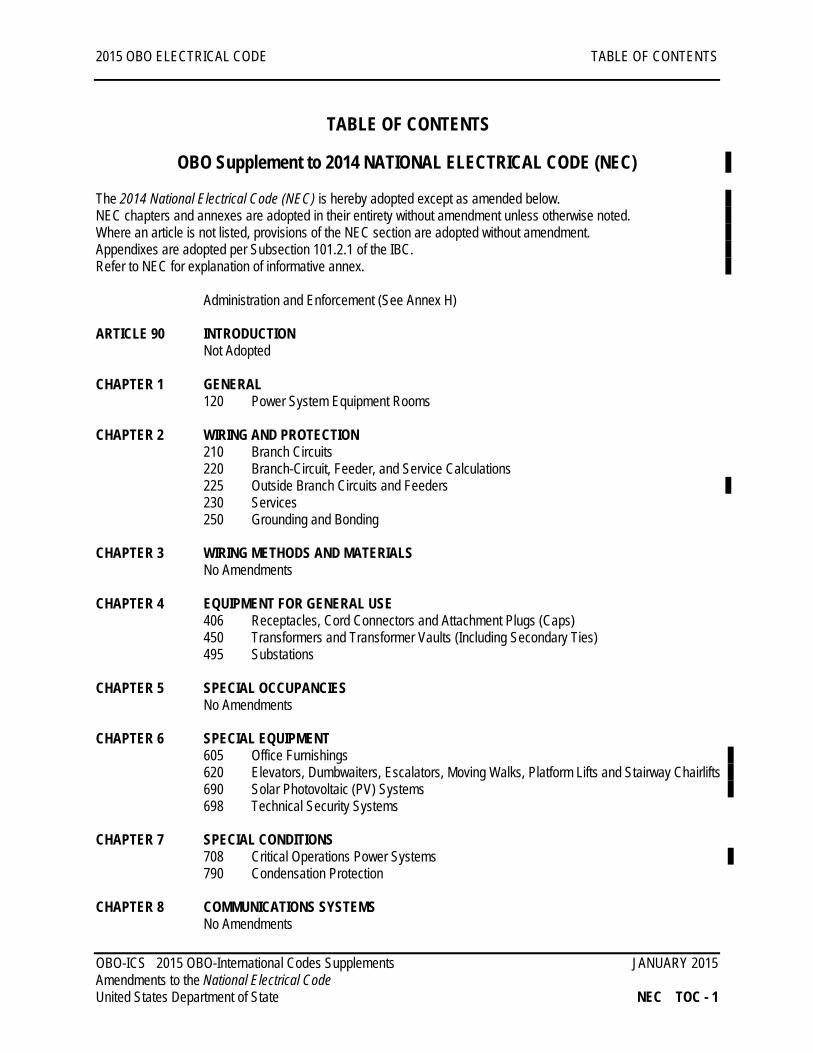
TABLE OF CONTENTS
OBO Supplement to 2014 NATIONAL ELECTRICAL CODE (NEC) The 2014 National Electrical Code (NEC) is hereby adopted except as amended below. NEC chapters and annexes are adopted in their entirety without amendment unless otherwise noted. Where an article is not listed, provisions of the NEC section are adopted without amendment. Appendixes are adopted per Subsection 101.2.1 of the IBC. Refer to NEC for explanation of informative annex. Administration and Enforcement (See Annex H) ARTICLE 90 INTRODUCTION
Not Adopted CHAPTER 1 GENERAL
120 Power System Equipment Rooms
CHAPTER 2 WIRING AND PROTECTION 210 Branch Circuits 220 Branch-Circuit, Feeder, and Service Calculations 225 Outside Branch Circuits and Feeders 230 Services 250 Grounding and Bonding
CHAPTER 3 WIRING METHODS AND MATERIALS
No Amendments CHAPTER 4 EQUIPMENT FOR GENERAL USE
406 Receptacles, Cord Connectors and Attachment Plugs (Caps) 450 Transformers and Transformer Vaults (Including Secondary Ties) 495 Substations
CHAPTER 5 SPECIAL OCCUPANCIES
No Amendments CHAPTER 6 SPECIAL EQUIPMENT
605 Office Furnishings 620 Elevators, Dumbwaiters, Escalators, Moving Walks, Platform Lifts and Stairway Chairlifts 690 Solar Photovoltaic (PV) Systems 698 Technical Security Systems
CHAPTER 7 SPECIAL CONDITIONS
708 Critical Operations Power Systems 790 Condensation Protection
CHAPTER 8 COMMUNICATIONS SYSTEMS
No Amendments OBO-ICS 2015 OBO-International Codes Supplements JANUARY 2015 Amendments to the National Electrical Code United States Department of State NEC TOC - 1
2015 OBO ELECTRICAL CODE TABLE OF CONTENTS
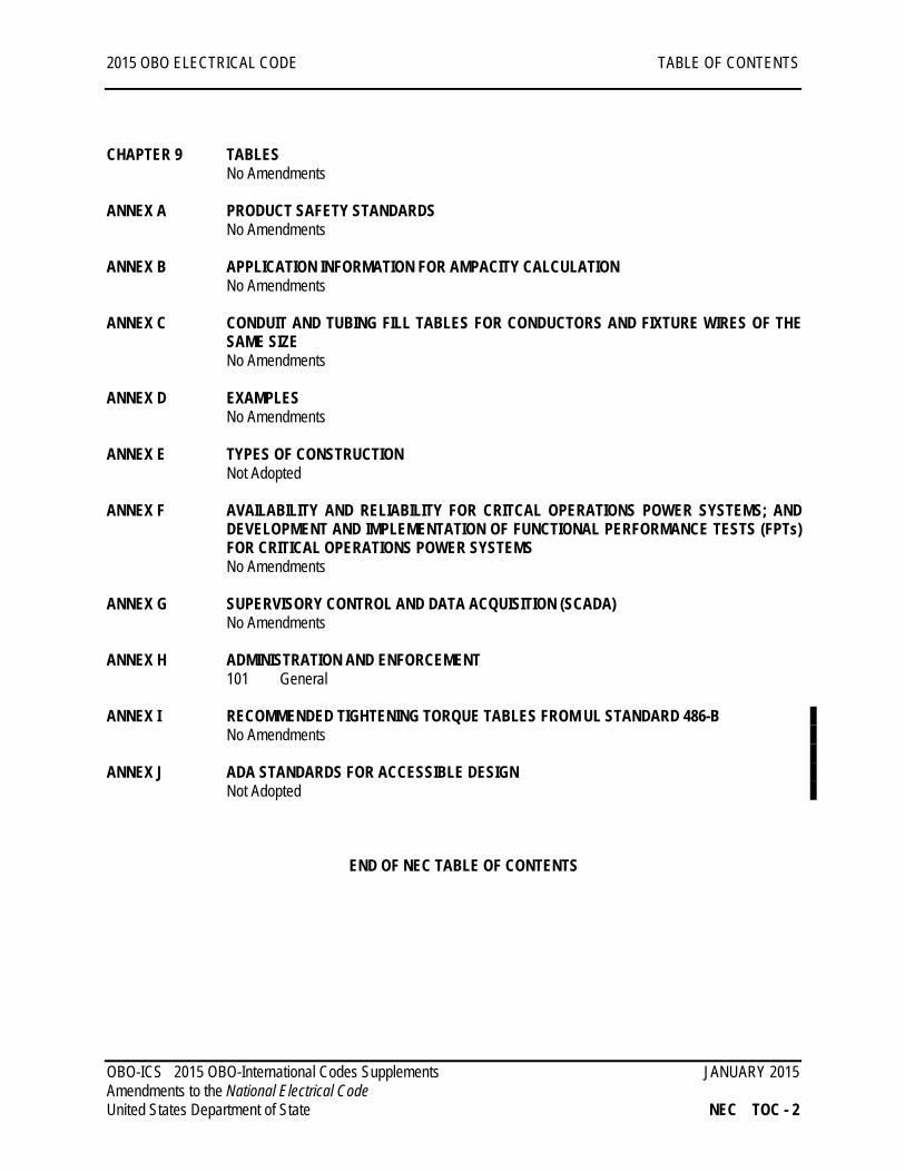
CHAPTER 9 TABLES
No Amendments
ANNEX A PRODUCT SAFETY STANDARDS No Amendments
ANNEX B APPLICATION INFORMATION FOR AMPACITY CALCULATION No Amendments
ANNEX C CONDUIT AND TUBING FILL TABLES FOR CONDUCTORS AND FIXTURE WIRES OF THE
SAME SIZE No Amendments
ANNEX D EXAMPLES
No Amendments ANNEX E TYPES OF CONSTRUCTION Not Adopted
ANNEX F AVAILABILITY AND RELIABILITY FOR CRITCAL OPERATIONS POWER SYSTEMS; AND
DEVELOPMENT AND IMPLEMENTATION OF FUNCTIONAL PERFORMANCE TESTS (FPTs) FOR CRITICAL OPERATIONS POWER SYSTEMS No Amendments
ANNEX G SUPERVISORY CONTROL AND DATA ACQUISITION (SCADA)
No Amendments ANNEX H ADMINISTRATION AND ENFORCEMENT
101 General ANNEX I RECOMMENDED TIGHTENING TORQUE TABLES FROM UL STANDARD 486-B
No Amendments ANNEX J ADA STANDARDS FOR ACCESSIBLE DESIGN Not Adopted END OF NEC TABLE OF CONTENTS
OBO-ICS 2015 OBO-International Codes Supplements JANUARY 2015 Amendments to the National Electrical Code United States Department of State NEC TOC - 2
2015 OBO ELECTRICAL CODE GENERAL Chapter 1
CHAPTER 1 GENERAL
ARTICLE 120 POWER SYSTEM EQUIPMENT ROOMS
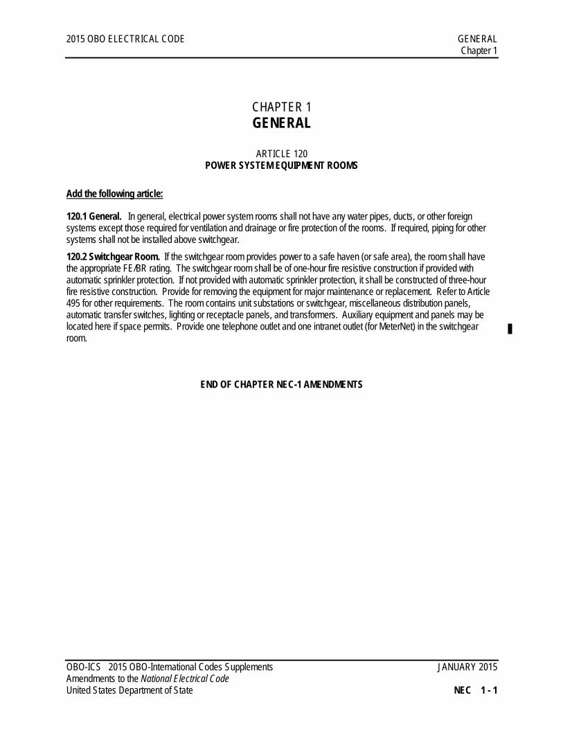
Add the following article:
120.1 General. In general, electrical power system rooms shall not have any water pipes, ducts, or other foreign systems except those required for ventilation and drainage or fire protection of the rooms. If required, piping for other systems shall not be installed above switchgear. 120.2 Switchgear Room. If the switchgear room provides power to a safe haven (or safe area), the room shall have the appropriate FE/BR rating. The switchgear room shall be of one-hour fire resistive construction if provided with automatic sprinkler protection. If not provided with automatic sprinkler protection, it shall be constructed of three-hour fire resistive construction. Provide for removing the equipment for major maintenance or replacement. Refer to Article 495 for other requirements. The room contains unit substations or switchgear, miscellaneous distribution panels, automatic transfer switches, lighting or receptacle panels, and transformers. Auxiliary equipment and panels may be located here if space permits. Provide one telephone outlet and one intranet outlet (for MeterNet) in the switchgear room.
END OF CHAPTER NEC-1 AMENDMENTS
OBO-ICS 2015 OBO-International Codes Supplements JANUARY 2015 Amendments to the National Electrical Code United States Department of State NEC 1 - 1
2015 OBO ELECTRICAL CODE WIRING AND PROTECTION Chapter 2
CHAPTER 2 WIRING AND PROTECTION
ARTICLE 210 BRANCH CIRCUITS
Add the following subarticles:
210.80 Branch Circuit Panel Locations. Install panels near the loads to keep branch circuits as short as possible. Always keep step-down/isolation transformers near panels. 210.90 Circuit Breakers. Except for special applications, circuit breakers shall be used for circuit protection rather than fusible disconnect switches. Combination starters shall be circuit breaker type, using magnetic-only circuit breakers with adjustable trips (motor circuit protectors) in conjunction with thermal overload devices. All circuit breakers in panelboards and switchboards shall be bolt on type.
ARTICLE 220 BRANCH-CIRCUIT, FEEDER, AND SERVICE CALCULATIONS
Add the following subarticle:
220.70 Service Transformer, Compound Generator Plant, Transformer and Building Feeder Calculations. The demand load calculation of the service transformer(s) and generator plant kVA rating supplying embassy compounds shall be as follows.
Lighting Load at 100% Demand Factor Receptacle Load at 100% first 10 kVA or less Remainder Receptacle Load at 50% Demand Factor All Other Loads at 70% Demand Factor Total demand load plus 20% for future growth.
ARTICLE 225 OUTSIDE BRANCH CIRCUITS AND FEEDERS
Add the following subparagraph:
225.41 Fuel Piping. Electrical conductors, raceways, and devices may not be installed with fuel piping. This includes utility trenches, ductbank, or direct buried installations.
Exception: Circuits and raceways that by their very nature monitor or control the fuel system shall be allowed to be co-located.
OBO-ICS 2015 OBO-International Codes Supplements JANUARY 2015 Amendments to the National Electrical Code United States Department of State NEC 2 - 1
2015 OBO ELECTRICAL CODE WIRING AND PROTECTION Chapter 2
ARTICLE 230 SERVICES
Add the following subparagraph:
230.62 Service Equipment – Enclosed or Guarded (B) Guarded.
(1) Where site-mounted transformers, automatic voltage regulators or load banks are located adjacent to vehicular movement areas, provide bollards to protect equipment from vehicular impacts.
(a) Locate bollards to as required to provide working space around transformer. (b) Locate bollards to as required to allow transformer cabinets to be opened without interference from bollards.
(2) Where outside rated medium voltage equipment is located, provide barriers from personnel access with lockable gates. Barriers may be fencing or solid walls. Barriers may not intrude in the working clearances of the equipment per article 110.
230.213 Non-conductive matting. Provide non-conductive electrical-grade dielectric switchboard matting on the floors of all areas enclosing switchgear equipment to insulate workers from electrocution by interrupting the path to ground. Matts shall be provided at all working space (110.26(A)).
1. Switchboard mats shall meet the requirements of ASTM D-178-01, Type II, Class 2.
ARTICLE 250 GROUNDING AND BONDING
Add the following subarticle:
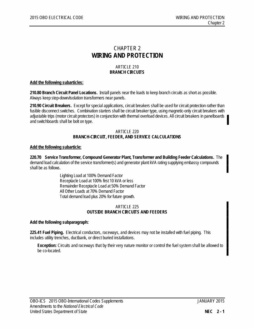
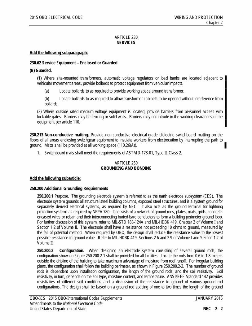
250.200 Additional Grounding Requirements 250.200.1 Purpose. The grounding electrode system is referred to as the earth electrode subsystem (EES). The electrode system grounds all structural steel building columns, exposed steel structures, and is a system ground for separately derived electrical systems, as required by NEC. It also acts as the ground terminal for lightning protection systems as required by NFPA 780. It consists of a network of ground rods, plates, mats, grids, concrete-encased wires or rebar, and their interconnecting buried bare conductors to form a building perimeter ground loop. For further discussion of this system, refer to MIL-STD 188-124A and MIL-HDBK 419, Chapter 2 of Volume I and Section 1.2 of Volume II. The electrode shall have a resistance not exceeding 10 ohms to ground, measured by the fall of potential method. When required by OBO, the design shall reduce the resistance value to the lowest possible resistance-to-ground value. Refer to MIL-HDBK 419, Sections 2.6 and 2.9 of Volume I and Section 1.2 of Volume II. 250.200.2 Configuration. When designing an electrode system consisting of several ground rods, the configuration shown in Figure 250.200.2-1 shall be provided for all facilities. Locate the rods from 0.6 to 1.8 meters outside the dripline of the building to take maximum advantage of moisture from roof runoff. For irregular building plans, the configuration shall follow the building perimeter, as shown in Figure 250.200.2-2. The number of ground rods is dependent upon installation configuration, the length of the ground rods, and the soil resistivity. Soil resistivity, in turn, depends on the soil type, moisture content, and temperature. ANSI/IEEE Standard 142 provides resistivities of different soil conditions and a discussion of the resistance to ground of various ground rod configurations. The design shall be based on a ground rod spacing of one to two times the length of the ground
OBO-ICS 2015 OBO-International Codes Supplements JANUARY 2015 Amendments to the National Electrical Code United States Department of State NEC 2 - 2
2015 OBO ELECTRICAL CODE WIRING AND PROTECTION Chapter 2
rods. In certain high resistivity soils, the use of chemically treated ground rods shall be provided. A ground rod is needed at each lightning protection down-conductor. The down-conductor must be connected directly to the ground rod, not to the connecting wire. In all locations roof mounted equipment must be grounded, all metallic equipment located on roof including but not limited to conduit, structural steel, mounting plates, door frames, mechanical equipment, etc., shall be connected to the grounding system and tied to the grounding system at the point of the downconductor.
Figure 250.200.2-1 Typical Earth Electrode Subsystem Configuration
For Rectangular Shaped Building
OBO-ICS 2015 OBO-International Codes Supplements JANUARY 2015 Amendments to the National Electrical Code United States Department of State NEC 2 - 3
2015 OBO ELECTRICAL CODE WIRING AND PROTECTION Chapter 2
Figure 250.200.2-2 Typical Earth Electrode Subsystem Configuration For Irregular Shaped Building
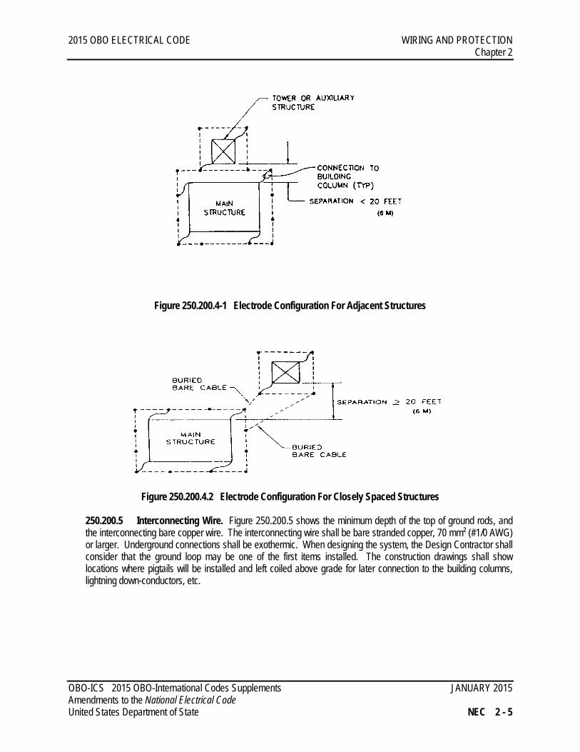
250.200.3 Building Columns. All corner building columns shall be connected to the EES. The structural design must be checked to ensure that all steel is electrically continuous, or is connected to the EES via in-termediate columns or ground wires. Judgment must be used to ensure that sufficient building columns are grounded to provide reasonably short paths to earth for all steel, without unnecessarily increasing the cost of the ground system installation. Special care must be taken to ensure that there is no isolated steel left ungrounded (for example, roof frames supported by concrete block walls). 250.200.4 Multiple Structures. Where two or more structures are located in the same general area and are connected with power, signal, control, or monitor circuits, ensure that the separate EESs are interconnected with buried bare cables. This will minimize voltage differentials between the structures. Structures spaced closer than 6 meters shall have a common ground system that encircles both as shown in Figure 250.200.4-1. Figure 250.200.4-2 shows the recommended arrangement when larger separations are encountered.
OBO-ICS 2015 OBO-International Codes Supplements JANUARY 2015 Amendments to the National Electrical Code United States Department of State NEC 2 - 4
2015 OBO ELECTRICAL CODE WIRING AND PROTECTION Chapter 2
Figure 250.200.4-1 Electrode Configuration For Adjacent Structures
Figure 250.200.4.2 Electrode Configuration For Closely Spaced Structures
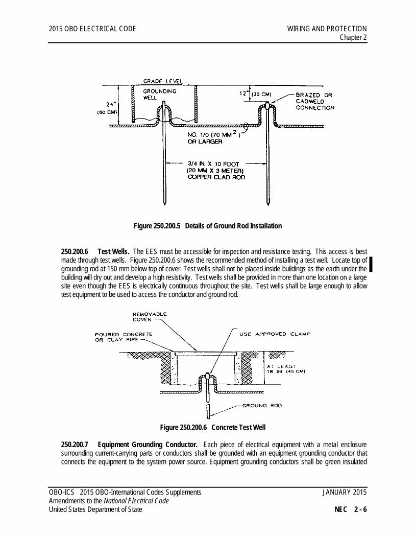
250.200.5 Interconnecting Wire. Figure 250.200.5 shows the minimum depth of the top of ground rods, and the interconnecting bare copper wire. The interconnecting wire shall be bare stranded copper, 70 mm² (#1/0 AWG) or larger. Underground connections shall be exothermic. When designing the system, the Design Contractor shall consider that the ground loop may be one of the first items installed. The construction drawings shall show locations where pigtails will be installed and left coiled above grade for later connection to the building columns, lightning down-conductors, etc.
OBO-ICS 2015 OBO-International Codes Supplements JANUARY 2015 Amendments to the National Electrical Code United States Department of State NEC 2 - 5
2015 OBO ELECTRICAL CODE WIRING AND PROTECTION Chapter 2
Figure 250.200.5 Details of Ground Rod Installation
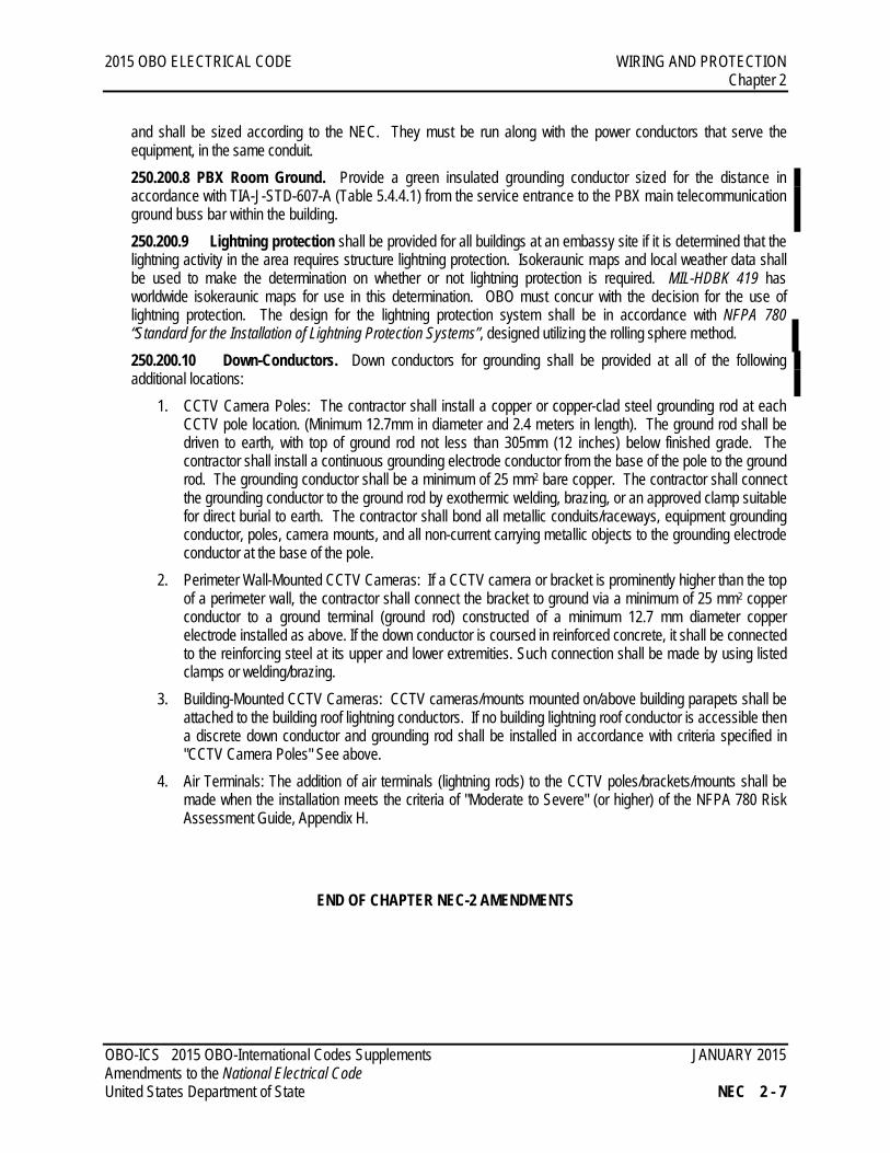
250.200.6 Test Wells. The EES must be accessible for inspection and resistance testing. This access is best made through test wells. Figure 250.200.6 shows the recommended method of installing a test well. Locate top of grounding rod at 150 mm below top of cover. Test wells shall not be placed inside buildings as the earth under the building will dry out and develop a high resistivity. Test wells shall be provided in more than one location on a large site even though the EES is electrically continuous throughout the site. Test wells shall be large enough to allow test equipment to be used to access the conductor and ground rod.
Figure 250.200.6 Concrete Test Well 250.200.7 Equipment Grounding Conductor. Each piece of electrical equipment with a metal enclosure surrounding current-carrying parts or conductors shall be grounded with an equipment grounding conductor that connects the equipment to the system power source. Equipment grounding conductors shall be green insulated
OBO-ICS 2015 OBO-International Codes Supplements JANUARY 2015 Amendments to the National Electrical Code United States Department of State NEC 2 - 6
2015 OBO ELECTRICAL CODE WIRING AND PROTECTION Chapter 2
and shall be sized according to the NEC. They must be run along with the power conductors that serve the equipment, in the same conduit. 250.200.8 PBX Room Ground. Provide a green insulated grounding conductor sized for the distance in accordance with TIA-J-STD-607-A (Table 5.4.4.1) from the service entrance to the PBX main telecommunication ground buss bar within the building. 250.200.9 Lightning protection shall be provided for all buildings at an embassy site if it is determined that the lightning activity in the area requires structure lightning protection. Isokeraunic maps and local weather data shall be used to make the determination on whether or not lightning protection is required. MIL-HDBK 419 has worldwide isokeraunic maps for use in this determination. OBO must concur with the decision for the use of lightning protection. The design for the lightning protection system shall be in accordance with NFPA 780 “Standard for the Installation of Lightning Protection Systems”, designed utilizing the rolling sphere method. 250.200.10 Down-Conductors. Down conductors for grounding shall be provided at all of the following additional locations:
1. CCTV Camera Poles: The contractor shall install a copper or copper-clad steel grounding rod at each CCTV pole location. (Minimum 12.7mm in diameter and 2.4 meters in length). The ground rod shall be driven to earth, with top of ground rod not less than 305mm (12 inches) below finished grade. The contractor shall install a continuous grounding electrode conductor from the base of the pole to the ground rod. The grounding conductor shall be a minimum of 25 mm2 bare copper. The contractor shall connect the grounding conductor to the ground rod by exothermic welding, brazing, or an approved clamp suitable for direct burial to earth. The contractor shall bond all metallic conduits/raceways, equipment grounding conductor, poles, camera mounts, and all non-current carrying metallic objects to the grounding electrode conductor at the base of the pole.
2. Perimeter Wall-Mounted CCTV Cameras: If a CCTV camera or bracket is prominently higher than the top of a perimeter wall, the contractor shall connect the bracket to ground via a minimum of 25 mm2 copper conductor to a ground terminal (ground rod) constructed of a minimum 12.7 mm diameter copper electrode installed as above. If the down conductor is coursed in reinforced concrete, it shall be connected to the reinforcing steel at its upper and lower extremities. Such connection shall be made by using listed clamps or welding/brazing.
3. Building-Mounted CCTV Cameras: CCTV cameras/mounts mounted on/above building parapets shall be attached to the building roof lightning conductors. If no building lightning roof conductor is accessible then a discrete down conductor and grounding rod shall be installed in accordance with criteria specified in "CCTV Camera Poles" See above.
4. Air Terminals: The addition of air terminals (lightning rods) to the CCTV poles/brackets/mounts shall be made when the installation meets the criteria of "Moderate to Severe" (or higher) of the NFPA 780 Risk Assessment Guide, Appendix H.
END OF CHAPTER NEC-2 AMENDMENTS
OBO-ICS 2015 OBO-International Codes Supplements JANUARY 2015 Amendments to the National Electrical Code United States Department of State NEC 2 - 7
2015 OBO ELECTRICAL CODE EQUIPMENT FOR GENERAL USE Chapter 4
CHAPTER 4 EQUIPMENT FOR GENERAL USE
ARTICLE 406 RECEPTACLES, CORD CONNECTORS AND ATTACHMENT PLUGS (CAPS)
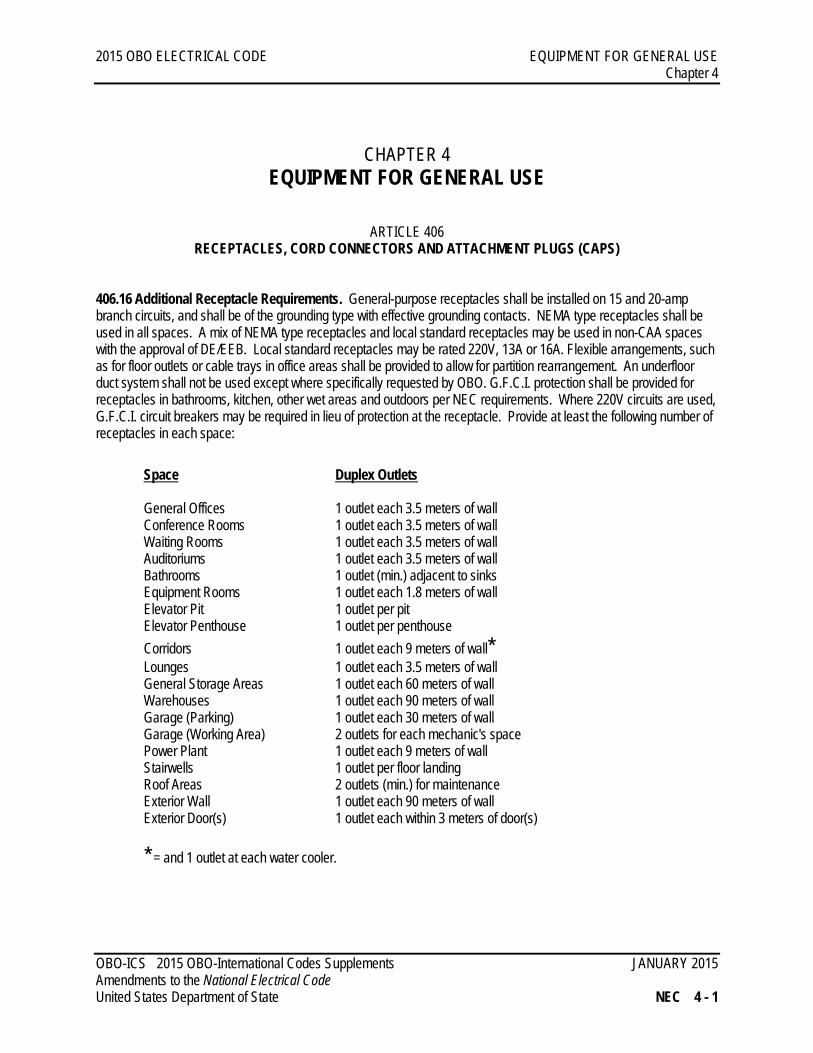
406.16 Additional Receptacle Requirements. General-purpose receptacles shall be installed on 15 and 20-amp branch circuits, and shall be of the grounding type with effective grounding contacts. NEMA type receptacles shall be used in all spaces. A mix of NEMA type receptacles and local standard receptacles may be used in non-CAA spaces with the approval of DE/EEB. Local standard receptacles may be rated 220V, 13A or 16A. Flexible arrangements, such as for floor outlets or cable trays in office areas shall be provided to allow for partition rearrangement. An underfloor duct system shall not be used except where specifically requested by OBO. G.F.C.I. protection shall be provided for receptacles in bathrooms, kitchen, other wet areas and outdoors per NEC requirements. Where 220V circuits are used, G.F.C.I. circuit breakers may be required in lieu of protection at the receptacle. Provide at least the following number of receptacles in each space:
Space Duplex Outlets
General Offices 1 outlet each 3.5 meters of wall Conference Rooms 1 outlet each 3.5 meters of wall Waiting Rooms 1 outlet each 3.5 meters of wall Auditoriums 1 outlet each 3.5 meters of wall Bathrooms 1 outlet (min.) adjacent to sinks Equipment Rooms 1 outlet each 1.8 meters of wall Elevator Pit 1 outlet per pit Elevator Penthouse 1 outlet per penthouse Corridors 1 outlet each 9 meters of wall* Lounges 1 outlet each 3.5 meters of wall General Storage Areas 1 outlet each 60 meters of wall Warehouses 1 outlet each 90 meters of wall Garage (Parking) 1 outlet each 30 meters of wall Garage (Working Area) 2 outlets for each mechanic's space Power Plant 1 outlet each 9 meters of wall Stairwells 1 outlet per floor landing Roof Areas 2 outlets (min.) for maintenance Exterior Wall 1 outlet each 90 meters of wall Exterior Door(s) 1 outlet each within 3 meters of door(s) * = and 1 outlet at each water cooler.
OBO-ICS 2015 OBO-International Codes Supplements JANUARY 2015 Amendments to the National Electrical Code United States Department of State NEC 4 - 1
2015 OBO ELECTRICAL CODE EQUIPMENT FOR GENERAL USE Chapter 4 ARTICLE 450
TRANSFORMERS AND TRANSFORMER VAULTS (INCLUDING SECONDARY TIES) Add the following to the end subarticle (A): 450.8 Guarding. (A) Mechanical Protection.
(1) Where site-mounted transformers are located adjacent to vehicular movement areas, provide bollards to protect transformer from vehicular impacts.
(2) Locate bollards to as required to provide working space around transformer. (3) Locate bollards to as required to allow transformer cabinets to be opened without interference from
bollards. (4) Locate bollards as to not interfere with clear working space as required in Article 110
IV. Additional Transformer Requirements 450.50 Capacity. Provide a minimum of 20 percent spare capacity above demand load without requiring fan cooling. 450.51 Location. There are two transformer location arrangements that are desirable for chancery installations:
1. Indoor Dry Type or Totally Enclosed, Non-Ventilated (TENV) Transformers shall be close-coupled to switchgear located in the electrical equipment room.
2. Outdoor Oil-Filled or TENV Transformers shall be located outside the building adjacent to the electrical
equipment room and in an enclosure as required by the NEC. Transformers are connected to the pad-mounted switchgear in the electrical equipment room via short parallel runs of conduit or bus duct. This arrangement has the disadvantage of requiring close coordination between the transformer and bus vendors during the procurement stage, and a less secure location for the transformers. It is, however, more economical since additional interior space in the chancery is not needed for the transformers.
3. Oil Containment Dykes: Oil-filled transformers shall be installed on a concrete pad with a minimum 300 mm
high concrete dyke around the perimeter of the transformer to contain any oil leaks or spills. The dyke shall be a minimum of 1m from the transformer base. The compartments for the incoming and outgoing feeders shall be arranged such that the oil will not leak into conduits, handholes or ductbanks.
4. Indoor Transformers shall be standard dry type or TENV. Outdoor transformers shall be non-PCB oil-filled,
cast resin core, or TENV. 5. Transformer Windings shall be copper. 6. Grounded Neutrals: Transformers shall be delta primary, wye secondary connected. Transformers with
medium-voltage secondaries shall have high-impedance grounded neutrals to limit ground fault current to non-destructive levels, yet allow sufficient current to activate tripping devices. Transformers with low voltage secondaries shall have solidly grounded neutrals. Each transformer shall have two each 2-½% voltage taps above and two 2-½% taps below nominal operating voltage. The substation transformers for commercial service shall be procured with automatic load tap changers, if available, where commercial load fluctuations exceed acceptable levels (e.g. 10% of nominal). If there are utility company requirements that vary with the above, they shall be coordinated and approved by DE/EE.
OBO-ICS 2015 OBO-International Codes Supplements JANUARY 2015 Amendments to the National Electrical Code United States Department of State NEC 4 - 2
2015 OBO ELECTRICAL CODE EQUIPMENT FOR GENERAL USE Chapter 4
7. Provide high efficiency transformers certified as meeting or exceeding the Department of Energy (DOE) Candidate Standard Level (CSL).
Add the following article:
ARTICLE 495 SUBSTATIONS
495.1 Quantity, Capacity and Location. The number and location of unit substations must be based on the most economical balance between the cost of a secondary distribution system and the cost of transformers, switchgear, and the primary distribution system. Load centers shall be located where they are economical for smaller concentrated loads. Avoid using transformers so large that load side protective devices with greater than normal interrupting duty are required. The use of multiple smaller substations adds flexibility and reliability to the system. Substations shall be sized for full demand load, future load growth plus at least 20% spare capacity. 495.2 General Considerations
495.2.1 Protective Device Selectivity. Circuit protective devices shall be coordinated with each other such that only the protective device closest to the fault will clear.
495.2.2 Short-Circuit Duty. Each device shall be capable of clearing the maximum fault available.
495.2.3 Lightning Arresters and Surge Protection. Install lightning arresters on medium voltage transformer primaries in accordance with Article 280 of the National Electrical Code. Transformer secondaries and building service entrance points shall be protected with secondary surge protectors.
495.2.4 Instrumentation. The incoming service substations shall be provided with metering for reading the kilowatts, kilovars, power factor, frequency, phase currents, phase-to-phase and phase-to-neutral voltages.
495.2.5 Grounding. Unit substation enclosures, including cases of primary and secondary switchgear and the transformer, shall be grounded in accordance with the National Electrical Code.
495.2.6 Incoming Line Switching. The substation shall be designed with a minimum of incoming line switching, consistent with good maintenance and operation practices. Consider the following:
1. Circuit Breakers: Use when the relaying requirements prohibit the use of fused switches. Provide a
disconnect and bypass switching scheme or draw-out-type circuit breakers to remove the feeder circuit breakers for service.
2. Load Interrupter Switches disconnect circuits under full load conditions. 3. Disconnect Switches: interrupt transformer exciting current. An interlock is required with the secondary
main overcurrent protection device to prevent switching under load. 4. Outgoing-Feeder Switchgear: At 600 volts or less, the designer shall select either metal-enclosed low-
voltage power circuit breakers or molded case circuit breakers. Over 600 volts, select either vacuum-type, or SF6 metal-clad medium-voltage circuit breakers.
OBO-ICS 2015 OBO-International Codes Supplements JANUARY 2015 Amendments to the National Electrical Code United States Department of State NEC 4 - 3
2015 OBO ELECTRICAL CODE EQUIPMENT FOR GENERAL USE Chapter 4 495.3 Typical Configurations and Operation. Many typical single line diagrams are shown in the SED drawings. The RFP statement of work identifies the project single line diagram. The needs and conditions of each individual site will dictate the actual scheme to be used. The parallel generator system consisting of multiple 500 kW generators is the SED standard unless identified otherwise in the RFP. The operation of the non-paralleled scheme in the diagram is as follows:
1. Bus Arrangement: The substation is divided into two main buses with a normally open tie breaker. The utility bus feeds all nonessential and electrically noisy loads. The essential bus feeds critical loads that require closer voltage tolerance and cannot tolerate as much noise as normal loads. The normally open tie breaker provides isolation and flexibility.
2. Auxiliary Generators: Upon loss of utility power, each of the two auxiliary generators are sized to serve its
respective bus, and to provide power to the other bus either during nighttime or under emergency conditions when one generator is down for maintenance. In this case the tie breaker will be closed and some of the loads on the utility bus may have to be shed.
3. Restoration of Power: Upon restoration of utility power for a predetermined time (usually 15 minutes) to ensure
power stability, the system will switch back to utility power, and the tie breaker will open if it was closed. Where possible, an arrangement shall be made with the electric utility to have a synchronous transfer from auxiliary generators back to utility power. Synchronous transfer from utility to generators is also preferred during a planned outage.
4. Loads on Essential Bus: See Classified OBO-ICS Section 495.
495.4 Indoor Substation Considerations. The following applies to indoor substations. Construction costs may be reduced by installing the utility (service) transformers outdoors. Outdoor installation of utility transformers is preferable.
1. Safety: All current carrying parts of the unit substations shall be metal enclosed, with all enclosures connected to ground. Interlocking shall be provided to prevent accidental contact with live parts when working within the switchgear enclosure.
2. Removal of Equipment: When locating unit substations, check intended means of removing equipment for
adequate physical clearances, floor loading limits, and access to building exit by required vehicles. 3. Future Expansion: Switchboard or panelboard capacity shall allow for at least 20% for future expansion of
space and load. Space shall be provided in electrical rooms for two additional panelboards for future expansion. Each switchboard or panelboard shall contain a minimum of 10% spare circuit breakers and 10% spaces (provisions for future breakers).
4. Clearances: Unit substations shall be freestanding and clear of foreign objects. Minimum clearance shall be in accordance with the latest revision of the National Electrical Code with the exception that a minimum of 2.15 meters shall be maintained between equipment facing each other.
5. Mounting: A 10 cm concrete base shall be provided for all floor mounted electrical enclosures and
transformers as a minimum.
OBO-ICS 2015 OBO-International Codes Supplements JANUARY 2015 Amendments to the National Electrical Code United States Department of State NEC 4 - 4
2015 OBO ELECTRICAL CODE EQUIPMENT FOR GENERAL USE Chapter 4
6. Primary Protection: Use load interrupter switches close-coupled to the transformer, with current-limiting fuses if necessary. Circuit breakers shall be used if required to provide coordinated tripping, and if required by the utility company providing service.
7. Secondary Protection: Protection shall be either metal-enclosed low-voltage power or insulated or molded
case circuit breakers. Use draw-out construction. "Motor-operated" breakers shall not be used; stored energy operation is required.
8. Unit Substation Rooms: Unit substation rooms shall not contain any water piping, ducts, or other foreign
systems, except those required for ventilation and drainage or fire protection of the room. 9. Access: Equipment rooms, where medium voltage switching equipment other than transformer switching is
installed, shall have two entrances that are limited to authorized personnel only. Safety mats, complying with U.S. Army Corps of Engineers Manual EM385-1 requirements, shall be provided in front of doors.
10. Ventilation: Adequate ventilation shall be provided to dissipate heat generated by transformers and other
associated electrical equipment to maintain safe operating temperatures. 11. Noise: All transformers have an inherent sound caused by the alternating magnetic flux in the core. Take the
following steps to reduce the noise level: (1) use flexible, liquid-tight conduit connections to prevent vibration from being transmitted to other locations - use auxiliary vibration dampers; (2) design transformer rooms of such a size and shape that they will minimize sound; (3) install the transformer away from smooth surfaces, hallways, stairways, and enclosures that may reflect, resonate, or echo the sound; (4) buy a transformer designed for lower noise levels.
495.5 Outdoor Substation Considerations. Design depends on whether the substation supplies secondary distribution voltage or user voltages. OBO must approve the selection of the type of substation to be used prior to commencing the design for construction documents.
1. Substations Supplying Utilization Voltages: These substations usually serve buildings, or a portion of a building. Secondary unit substations shall follow the criteria given previously for indoor unit substations except that the requirements for outdoor installation apply. Metal enclosed pad mounted transformers and associated metal enclosed switchgear are preferred for outdoor substations. If not available, outdoor substations shall be protected from unauthorized entry by a fence of at least 2.13 meters in height. The fence and gate(s) shall be grounded per the NEC or the local code, whichever is more stringent. The fenced area gates shall be lockable. Pad-mounted transformers are essentially tamper-proof and require no fences, but they shall be located away from public access and be coordinated with the architectural design.
2. Substations Supplying Secondary Distribution Voltages: These units serve all or a large portion of the Post
demand. In designing these substations, consider architectural requirements; exposure conditions; physical conditions, such as snow or ice, salt water, sandstorms, and altitude; impact on adjacent terrain such as landscaping, layout, and noise treatment; instrumentation; energy conservation measures; and grounding.
495.6 Safety Considerations for Outdoor Substations
OBO-ICS 2015 OBO-International Codes Supplements JANUARY 2015 Amendments to the National Electrical Code United States Department of State NEC 4 - 5
2015 OBO ELECTRICAL CODE EQUIPMENT FOR GENERAL USE Chapter 4
1. Signage: Provide warning signage in English, host country language, and/or pictograph indicating "DANGER — HIGH VOLTAGE" according to signage requirements of Section 11.8.
2. Metal Enclosures: Metal enclosures shall be used around all live parts. a. Enclosures or protective means shall not interfere with clear working space as defined by article 110 3. Locks on gates with key interlocks shall be provided on switchgear doors to prevent access to live parts.
A. Transformer and Automatic Voltage Regulator (AVR) cabinet doors shall be locked to prevent access to live parts by unauthorized personnel. AVR cabinet locks will be single-keyed.
4. Clearances: Refer to the National Electrical Code (NFPA 70) and National Electrical Safety Code (ANSI C.2) for adequate clearances. 5. The transformer and AVR will be located so that a crane can safely access the gear in the event of a major
repair. 495.7 Utility (Service) Transformers. Incoming commercial service transformers shall be either oil filled or encapsulated dry type pad mounted outdoor type. The transformer shall have a delta connected primary and a grounded wye connected secondary. The transformer shall be capable of being easily replaced or repaired by the local utility company. Encapsulated dry type transformers shall be used where there are known problems with PCB contamination in locally available mineral oil. This reduces the space requirements for interior electrical installation and for economical construction. It also eliminates the requirement for placing the transformers in the switchboard lineup. 495.8 Transformer Impedance. If the source MVA requires excessive interrupting ratings for the protective devices in the secondary, either specify transformers with higher impedances, or specify primary protective devices with the appropriate interrupting capacity. However, if energy considerations are paramount or if the voltage regulation is a problem, lower impedance transformers shall be procured.
END OF CHAPTER NEC-4 AMENDMENTS
OBO-ICS 2015 OBO-International Codes Supplements JANUARY 2015 Amendments to the National Electrical Code United States Department of State NEC 4 - 6
2015 OBO ELECTRICAL CODE SPECIAL EQUIPMENT Chapter 6
CHAPTER 6 SPECIAL EQUIPMENT
ARTICLE 605 OFFICE FURNISHINGS (CONSISTING OF LIGHTING ACCESSORIES AND WIRED PARTITIONS)
Add the following subsection: 605.10 Additional Office Furnishings Requirements
605.10.1 Scope. The State Department uses modular furniture that may be electrified if needed for cluster installation, or the furniture may not be electrified, in which case the equipment is served by wall mounted receptacles. Power poles shall not be used for power or telecom distribution. Modular furniture in private offices and abutting drywall partitions shall be powered by wall outlets. Task lighting will be incorporated into the modular furniture by the manufacturer. This task lighting will be fed from either wall outlets in non-electrified furniture or from integral receptacles in electrified furniture.
605. 10.2 Receptacle Type for Non-Electrified Furniture. The non-electrified furniture configuration is the most common situation. For this configuration two quads (double duplex receptacles) will be required for each workstation mounted on the wall or column. These receptacles shall be mounted at a height of 15” (380 mm) on center. A minimum of two circuits will be needed at each workstation, for computers, lights and other equipment.
605. 10.3 Voltage Considerations for Non-Electrified Furniture. The non-electrified configuration for the 220V/50Hz installations shall utilize wall mounted NEMA 6-20R receptacles, and shall utilize NEMA 5-20R receptacles for 120V/60Hz installations.
605. 10.4 Wiring Scheme. The electrified configuration typically uses a wiring scheme that consists of 4 phase conductors, 4 neutral conductors, one dedicated to each phase, and two shared grounds (shared by two circuits). Two circuits may be used for computers, and two may be used for lighting and general purpose receptacles. Power is normally provided by a factory assembled wiring harness (infeed or "whip") that is used to connect the power conductors at the junction box to each electrified modular furniture cluster. The wiring infeed is GFE and will be connected by the General Contractor. At the junction box, the four circuits from the modular furniture shall be wired to at least two separate branch circuits, one for the computers, and one for the lighting and general purpose receptacles.
605. 10.5 Receptacle Type for Electrified Furniture. The electrified furniture contains either NEMA 5-20R receptacles for 120V circuits, or NEMA 6-20R receptacles for 220V circuits. At posts with a central UPS, special twist-lock receptacles are available to segregate receptacles fed from the central UPS. 605. 10.6 Maximum Stations on Circuit. A maximum of 4 workstations (16 duplex receptacles) may be placed on a 20A, 220V branch circuit. A maximum of 2 workstations (8 duplex receptacles) may be placed on a 20A, 120V branch circuit. In the CAA, workstations with both U-LAN and C-LAN computers shall be considered “two workstations” as both the U-LAN and C-LAN computers may be on at the same time.
OBO-ICS 2015 OBO-International Codes Supplements JANUARY 2015 Amendments to the National Electrical Code United States Department of State NEC 6 - 1
2015 OBO ELECTRICAL CODE SPECIAL EQUIPMENT Chapter 6
605. 10.7 Power. The systems furniture is Government-Furnished and the contractor shall receive, ship, stage, install and execute the hardwire connection to the building. Each of the product lines offers a 10-wire system, 4+4+2, used for new office buildings. Furniture and equipment hardwired to electrical and telecommunications are considered part of the body of the building’s systems. Furniture in private offices and abutting drywall partitions shall not be powered; for these conditions the power shall be accessed from the adjacent wall. When systems furniture is electrified, the power receptacles will be factory-installed in the furniture. NEMA 6-20R receptacles are used in the powered systems furniture where 220V is the building power. NEMA 5-15R receptacles are used in the powered systems furniture where 110V is used in the building power. Each non-CAA work area has eight plug points (or four duplex receptacles). Each CAA work area has ten plug points (or five duplex receptacles). The furniture requirements do not override the building codes established for electrical and telecommunications requirements.
605. 10.8 Telecommunications. All telecommunications wiring and terminations shall be furnished and installed by the Construction Contractor, including those in the systems furniture.
605. 10.9 Lighting. Task lighting is included in the systems furniture, and will be specified and ordered by the government and will be received, shipped, staged and installed by the contractor as GFCI.
605. 10.10 C-LAN. The distribution of C-LAN telecommunications requirements are typically accessed directly from the wall, except when Knoll Currents is used.
ARTICLE 620 ELEVATORS, DUMBWAITERS, ESCALATORS, MOVING WALKS,
WHEELCHAIR LIFTS AND STAIRWAY CHAIR LIFTS
Delete this subsection and replace with the following: 620.51.C Location. The disconnecting means shall be located in the machine room for that elevator car.
ARTICLE 690 SOLAR PHOTOVOLTAIC (PV0 SYSTEMS
Add the following subsections: 690.4 (E) Raceway and conductor labeling requirements. A warning label shall appear on raceways, junction boxes, pullboxes, and manhole/handhole covers that identify the DC maximum voltage of the enclosed conductors. This can be accomplished with warning labels and/or permanently affixed marking tape. This shall be displayed prominently on raceways with maximum spacing of 5M. 690.4 (F) System Requirements. All new design systems shall be building integrated to limit the roof penetrations and allow for access below the array to inspect and repair the roofing as necessary without removal of the array or modules. Access to roof and array shall be provided by limiting the physical size of the array rows to 3 modules between access walkways. 690.4 (G) MicroInverters. The use of micro inverters is prohibited.
Exception. Small residential system installations will allow the use of micro inverters.
OBO-ICS 2015 OBO-International Codes Supplements JANUARY 2015 Amendments to the National Electrical Code United States Department of State NEC 6 - 2
2015 OBO ELECTRICAL CODE SPECIAL EQUIPMENT Chapter 6 690.5 (H) Internet connection. No system shall be permitted to be connected to the internet for operation or monitoring. All components of the PV system (inverters, Data Acquisition System) shall be independently operable without the need to connect to the internet. 690.5 (D) Arc-Fault Protection. The DC input for the incerter from the array shall be provided with arc-fault proterction. Add the following article:
ARTICLE 698 TECHNICAL SECURITY SYSTEMS
698.1 Scope.
698.1.1 Covered.
1. Electrical cabinets (EC) and sub-ECs for technical security systems (TSS). 2. Signal support system infrastructure for TSS. 3. Electrical power infrastructure for TSS.
698.1.2 Not Covered. Requirements for individual TSS are identified in OBO-ICS IBC Section 424.
1. TSS equipment racks. 2. TSS signal wiring. 3. TSS UPS systems. 4. TSS low voltage power supplies. 5. TSS voltage regulators.
698.2 General.
1.. Only DS-certified components are permitted in TSS systems. 2. Security signal conductors and power conductors shall not share same conduit, handholes, electrical
cabinets with non-security signal conductors and power conductors. 698.3 Electrical Cabinets (EC) and Sub-ECs for TSS.
1. TSS EC: Install TSS ECs and sub-ECs in EC Room for each building. 2. Termination Point: The Main EC shall be central termination point for TSS conduits and signal wiring.
Exception: Chemical dispensing system. 3. Physical Security: House ECs and Sub-ECs in rooms with lockable doors using SHW 17A. 4. TSS Cable Path: TSS cabling in each building shall run to Sub-EC for the building, and then connect to
guard facility for the building. For TSS systems which in buildings other than the Chancery require monitoring or override capability in MGS Post 1, provide cabling between Sub-ECs and Chancery Main EC.
5. Component Mounting: Components mounted into the ECs and Sub-ECs shall use DS-certified connectors to minimize space utilization.
6. Only TSS equipment, power, and cabling is permitted in EC Rooms and Sub-EC Rooms. 698.4 Signal Support Infrastructure for TSS.
698.4.1 Conduits. OBO-ICS 2015 OBO-International Codes Supplements JANUARY 2015 Amendments to the National Electrical Code United States Department of State NEC 6 - 3
2015 OBO ELECTRICAL CODE SPECIAL EQUIPMENT Chapter 6
1. Inside Building Hardline: Electrical metallic tubing (EMT) or flexible metal conduit (FMC). 2. Outside Building Hardline in Above Grade Installations: FMC, intermediate rigid metallic conduit
(RMC), or liquid tight flexible conduit. 3. Outside Building Hardline in Below Grade Installation: Rigid non-metallic conduit (RNC) such as heavy
wall PVC. Use metallic elbow when leaving conduction or ductbank to go above grade and change to metallic conduit.
4. Where conduit transits spaces between building hardline, embed conduit in concrete or provide another acceptable means of securing conduit.
698.4.2 Termination (Junction) Boxes.
1. Security Door Control Terminations: Install short conduit from the termination box positioned above door directly into door lintel. Termination boxes shall be on secure side of door, and above accessible ceiling where possible.
698.4.3 Security Management System Enterprise (SMSe) Infrastructure:
1. Workstations in MSG Post 1 and EC Room shall be connected by conduit to EC Room. Connect workstations to TSS Panel EU
2. Install conduit between EC Room and each Chancery entrance door (ingress only) for Automated Access Control System (AACS).
3. Wireless Distribution System (WDS): Provide dedicated EMT conduit, cabling, and power infrastructure for WDS. No other wiring, including other security wiring, is permitted to share conduit with WDS. Use compression box connectors only to connect lengths of conduit. WDS conduit infrastructure shall consist of vertical riser and horizontal runs. The vertical riser originates in Main EC Room through dedicated riser pull boxes located in same location as TSS riser closet. The horizontal run on CAA floors shall be located above ceiling grid outside of each CAA suite entrance door. If necessary, multiple WDS runs may share same conduit run. Run cable from WDS riser pull box to each CAA suite pull box.
698.4.4 Protected Distribution System (PDS): PDS shall be provided for SMSe workstations located in the NOB where there is Marine Security Guard presence. PDS shall be provided for all signal wires transiting GWA space at Lock and Leave posts.
1. Hardened Carrier: EMT, ferrous conduit or pipe, or rigid-sheet steel duct. 2. Pull Boxes: Pull boxes shall be secured with padlock, and covers contain non-removable pin hinges. All
PDS connectors shall be permanently sealed completely around all surfaces e.g., compression connectors, epoxy, etc .
3. Inspectable Installation: Boxes and fittings shall be fully inspectable when installed above ceiling grid. 698.4.5 Door Control System:
1. Route cables to EC Room.
698.4.6 Duress Buttons and IDNS: 1. Route cable to MSG Post 1.
698.4.7 CCTV System: 1. Route cable from cameras to EC cabinet and then to CCTV control equipment in EC Room and
MSG Post 1. OBO-ICS 2015 OBO-International Codes Supplements JANUARY 2015 Amendments to the National Electrical Code United States Department of State NEC 6 - 4
2015 OBO ELECTRICAL CODE SPECIAL EQUIPMENT Chapter 6
2. The CCTV system allows video and control signals to be multiplexed on coaxial cable. No additional control wiring is required.
698.4.8 ENS:
1. Loop speaker cable from speaker to speaker.
698.4.9 IDS: 1. Loop cable through each motion sensor and door contact in its suite to its controller.
698.4.10 Security Intercom: 1. Cabling for CAA suite intercom shall be contained within the suite served for the intercom.
698.4.11 Safe Haven and Safe Area TSS: 1. Cabling shall run between the Safe Haven or Safe Area to the EC Room serving the building.
698.5 Electrical Power Infrastructure for TSS.
698.5.1 Location. Locate power equipment, regulators, UPS units, and panels for TSS systems in EC Rooms or Sub-EC Rooms. 698.5.2 Distribution Panels: Install three separate, surface-mounted, lockable TSS distribution panels in main compound EC Room as identified below. Additional panels may be required in ancillary buildings.
1. Panel E: Panel receives power from main distribution panel (MDP), which is on essential generator bus. Panel shall be three phase with three phase feed have Main circuit breaker
2. Panel ER: Panel receives power from Panel E either through Voltage Regulator or bypass switch. Panels supplies power to door control power supplies, emergency notification system (ENS) power supplies, local guard control booth TSS equipment racks, monitoring and annunciation racks, intrusion detection systems (IDS), security intercoms, walk-through metal detectors (WTMD) connected to dedicated power receptacle, chemical dispensing systems, and explosives detector devices.
Exception: Where distances and line-losses prevent this from being practical ENS power supplies may be placed in Sub-EC Rooms or TSS signal riser closets.
3. Panel EU: Panel receives power from Panel E through an UPS via an UPS bypass switch. Panel supplies power for CCTV cameras, CCTV camera power supplies, CCTV monitoring and control equipment, CCTV recording equipment, MSG Post 1 (or SCC) equipment racks, and SMSe.
698.5.3 Voltage Regulators:
1. Install voltage requlator on primary feeder for Panel ER. 2. Requlator shall be electrically supplied from Panel E in sub-feed arrangement. 3. As part of “separately derived system,” neutral conductor of voltage regulator output shall be
connected to local grounding electrode. 698.5.4 Voltage Regulator (VR) Transfer Switch: In case of regulator failure, Panel ER shall be able to provide unregulated emergency (essential bus) power.
1. Install three-pole double-throw transfer switch. Surface mount switch in EC Room, and label function of each switch position (i.e., Regulated, Off, Unregulated).
OBO-ICS 2015 OBO-International Codes Supplements JANUARY 2015 Amendments to the National Electrical Code United States Department of State NEC 6 - 5
2015 OBO ELECTRICAL CODE SPECIAL EQUIPMENT Chapter 6
698.5.5 UPS Bypass Switch: In the event of UPS failure, provide switch to facilitate ability to provide power to panel EU. 698.5.6 Emergency Power Configuration: See classified OBO-ICS NEC Article 495. 698.5.7 Prohibited connections. Non-TSS systems are not permitted to draw power from TSS power panels. 698.5.8 IDS backup power. IDS power supplies shall have battery-backup capability.
END OF CHAPTER NEC-6 AMENDMENTS
OBO-ICS 2015 OBO-International Codes Supplements JANUARY 2015 Amendments to the National Electrical Code United States Department of State NEC 6 - 6
2015 OBO ELECTRICAL CODE SPECIAL CONDITIONS Chapter 7
CHAPTER 7 SPECIAL CONDITIONS
ARTICLE 708 CRITICAL OPERATIONS POWER SYSTEMS
Add the following subarticle:
708.23 Engine-Generator Sizing. 1. Engine-generators shall be sized so that the minimum load to be served by each generator is 50
percent of its prime rating. 2. Engine-generators shall be sized to maintain stable voltage and frequency during the maximum
expected load swings. 3. Voltage transients in the electrical system shall be limited to 15%, and the frequency deviation shall
be limited to 0.5 Hertz . 4. Engine-generators shall be sized per manufacturer’s sizing calculations for actual motor starting
requirements. A. Provide reduced-voltage motor starters or other methods to minimize generator voltage drop.
5. Connected Loads A. Multiple building facility: Loads to be connected to Post generators shall be approved by DE/EE
through the COR. 1) Generator demand load calculations for large compounds (Greater than 20 acres) shall be
in accordance with Table 2-2 Diversity Factors, listed in the US Army Corps of Engineers TM5-811. The diversity for demands among building feeders and transformers makes the actual maximum load on the generator system less than the sum of the multiple building demand loads.
B. Single building: Size the generator set for 100 percent of the demand load plus 20 percent for future demand.
6. Paralleled systems shall be used for generator system loads at 800 kW and above. A. Reduced load operation: If the day/night or weekday/weekend power demand is less than 50
percent of one generator, provide a small unit sized for the light load operation. 7. Paralleled systems shall be used for prime power generator supplied facility: 8. Fire Pumps.
A. Fire pumps shall be diesel engine driven. Exception: Electric motor driven fire pumps are permitted only where directed by OBO.
1) Temporary automatic load shedding may be utilized to accommodate the starting of electric motor driven fire pumps. See Classified OBO-ICS NEC Article 700.
OBO-ICS 2015 OBO-International Codes Supplements JANUARY 2015 Amendments to the National Electrical Code United States Department of State NEC 7 - 1
2015 OBO ELECTRICAL CODE SPECIAL CONDITIONS Chapter 7
2) Compound engine-generators shall be sized to accommodate electric motor driven fire pumps including the locked-rotor ampere rating per NEC Article 695 Fire Pumps.
Add the following article: ARTICLE 790
CONDENSATION PROTECTION 790.1 Space Heaters. Equipment subject to large swings of temperature and frequent de-energization shall have thermostatically controlled space heaters to prevent condensation. The space heater power source must not depend primarily on the equipment served.
END OF CHAPTER NEC-7 AMENDMENTS
OBO-ICS 2015 OBO-International Codes Supplements JANUARY 2015 Amendments to the National Electrical Code United States Department of State NEC 7 - 2
2015 OBO ELECTRICAL CODE ADMINISTRATION AND ENFORCEMENT Annex H
ANNEX H ADMINISTRATION AND ENFORCEMENT
Replace Annex H in its entirety with the following: 101.1 Title These regulations shall be known as the 2015 OBO Electrical Code hereinafter referred to as "this code."
1. This code incorporates by adoption the 2014 National Electrical Code (NEC) of the National Fire Protection Association as amended by the 2015 OBO International Codes Supplements (OBO-ICS).
101.2 General. The provisions of Chapter 1 - Administration of the OBO Building Code, apply to this code.
END OF NEC-ANNEX H AMENDMENTS
OBO-ICS 2015 OBO-International Codes Supplements JANUARY 2015 Amendments to the National Electrical Code United States Department of State NEC Annex H