Embed Size (px)
Citation preview

Objects in OOAD Things are objects that indirect in the system. An object in object oriented approach is often similar to a data entity in the traditional approach. The main difference is that object do the work in system, they do not just store the information i.e. that is the object have behavior as well as attributes. With object oriented approach each specific thins is an object and the type of thing is called a class a class is the type or classification to which all similar objects belong. The classes, association among classes are modeled using a class diagram. Additionally the class called methods. Methods of a class are behavior all objects in the class are capable of Behavior is an Action that the objects processes itself. Instead of an outside Process updating data values the object updates its own values when asked to. To ask the object to do something, another object sends it a message. One object can send another object a message or an object can be sending to user a message. The information system overall becomes a collection of interacting object. Each object contain values for attributes & methods for operating this attributes, an object is said to encapsulation. Encapsulation is covering or protecting each object so that it contain values for attribute & methods for operating on those attributes , making the object a self contained & protected unit. Input Output Messages
Messages
Object
Data Belonging to the object
Methods that process the data
Process 1
Process 2
Process 3 Data Entity

Analysis: Object Oriented Requirements Five separate but interrelated, object oriented method or diagrams, are use to define the application requirements from object oriented perspective. In most cases, analysts use all five diagrams to get a complete definition of business requirements. However, in some situation, only three or four diagrams may be required to specify the requirements accurately, the five diagrams are 1] The class diagram. 2] The use case diagram. 3] The collaboration diagram. 4] The sequence diagram. 5] The state chart diagram. The purpose of class diagram is to identify & classify the object that will make up new system. In the class diagram, the properties or attributes of each object that need to be recorded are also being identified. Generally, a single comprehensive diagram is to show all class & relationship for the entire system. The purpose of use case diagram is to identify the “uses” or use case of new system i.e. to identify how the system is used. The use case diagrams essentially an extension of event table. The use case diagram convenient way to function that the system must support. Sometime single comprehensive use case diagram is use to describe the entire system. At other times, a set of similar use case diagrams makeup the use case model. The purpose of collaboration diagram is to identify which objects “collaborate” to carry out given business function. For egg. If one of the business uses is to “record customer order”, then the collaboration diagram identify the entire object involved. To record the customer order requirements a customer object, some inventory objects, a new order objects, & so forth. A single collaboration diagram use to identify these object are show interaction & messages, That is send between them to carry out this function. Generally many collaboration diagrams are needed. A sequence diagram is just another view of some information contained in a collaboration diagram but it provides a little different perspective. It is a graphical view that emphasizes the sequence of messages rather than collaboration object. A sequence diagram is drowning to that the sequence of message is graphically depioted by their position on the page. The sequence process from top to bottom. Both collaboration diagrams & the sequential diagrams are referred to as interaction diagram. State chart describe the state & behavior of each individual object. Each object chart has a state chart. Within the state chart are action statements that eventually become the logic in the final system. These logic components in each class are called methods. OO Requirement = Event table + class diagram + Use case diagram + Interaction diagram (collaboration and/or sequence diagrams) + State chart diagrams.
The different between traditional structured approach & the object oriented approach to system development is not the development method, but in the set of methods that is used. The SDLC for each approach has the same phases, planning, analysis, design, and implementation. The activity within the phases is also being same. The set of method uses is the difference. Individual tasks within the activities are focused on building the models, they will be different. For eg. Instead of building the DFDs, the analysts build interacting diagram & state chart. The description of the new system in consists of structural information and behavioral information. The structural information is the component part of the system and behavior the logic performed by the component. The class diagram provides the definition of the component its of the system. The other diagram i.e. use case interaction & state chart diagram focus on the activities that the system perform i.e. they describe the they behavioral aspects of the new system. Thus the class diagram tells what the components of the system are & the other diagrams tell what these components do or the action they perform. The class diagram The object oriented approach models classes of objects instead of data entities. The classes of object have attributes and association. Cardinality also applies among classes. The difference from traditional approach is that the object does the equal processing in the system as well as store information. Thus object have both methods & attributes. The model use by this approach is call as class diagram. The two issues associated with OO approach are 1] Generalization specialization hierarchies 2] Aggregation Generalization specialization hierarchies are base on the idea that people classified the things in term of similarities & differences. Generalization is judgement that group similar type of things. For eg.there are many types of motor vehicles - cars, truck & tanks. All other vehicle certain general characteristics, so a motor vehicle is more general class. Generalization are judgment that categories different type of things. For eg. Special type of cars include sport cars are similar in some ways, yet different in other ways. Thus, sport car is special type of car.

A generalization/specialization hierarchy is use to structure & rank things from more general to more special. Each class of thing is hierarchy might have more general thing & above it, called a super class. At the same time. A class might have a more specialize class below it called a super class. At the same time. below called below it called a sub class. Inheritance is the concept that allows sub class to share characteristics of super class. For eg. A car is everything any other motorsometimes the A generalization Aggregation – It is the relationship between an object & its part. for eg. Learning about a computer system might involve rparts – processor, main memory, keyboard, disk storage. A keyboard is special type of computer.
/specialization hierarchy is use to structure & rank things from more general to more special. Each class of thing is hierarchy might have more general thing & above it, called a super class. At the same time. A class might have a more specialize
ow it called a super class. At the same time. A class has more specialize class below called below it called a sub class.
Inheritance is the concept that allows sub class to share characteristics of super class. For eg. A car is everything any other motor vehicle is, but something special. Thus
A generalization/specialization hierarchy called as inheritance hierarchies.
It is the relationship between an object & its part. for eg. Learning about a computer system might involve recognizing that the computer is composed of different
processor, main memory, keyboard, disk storage. A keyboard is special type of
/specialization hierarchy is use to structure & rank things from more general to more special. Each class of thing is hierarchy might have more general thing & above it, called a super class. At the same time. A class might have a more specialize
more specialize class
Inheritance is the concept that allows sub class to share characteristics of super class. For vehicle is, but something special. Thus
/specialization hierarchy called as inheritance hierarchies.
It is the relationship between an object & its part. for eg. Learning about a ecognizing that the computer is composed of different
processor, main memory, keyboard, disk storage. A keyboard is special type of

The class symbol is a rectangular with three section. The top section contains the name of the class; the middle lists the attribute of the class. Methods are not always shown in the class symbol if they are fairly standard.
Customer
Name Address Phone
Add new Date Claque Come to account
The class symbol is a rectangular with three section. The top section contains the name of the middle lists the attribute of the class. Methods are not always shown in the
class symbol if they are fairly standard.
The class symbol is a rectangular with three section. The top section contains the name of the middle lists the attribute of the class. Methods are not always shown in the

Example:- A class diagram of a system maintains the blank account.
The identified class is those associated with the problem domain.Additional class such as use interfaces class, are also specified in the class diagram. User – identified classes include such classes as windclasses. For e.g. the customer input form window is a user interface class that is designed during development of the user interface. Those type of classes are called the implementation classes. The System Activities:- Use Cases & Actors Use case is a single use or function It is an activity the system carries out in response to an event. For e.g. consider world processing system. Various use cases could be “write a letter” or “print a newsletter”. There are two import concepts here 1] A person is involved. 2] The person uses the system.The person involve in an actor. An actor is a In the world processing example, there may be a student actor who uses the world processor to write an easy an editor actor who uses the worlThe same person plays several rolls, such as the student, an editor or publisher.
of a system maintains the blank account.
The identified class is those associated with the problem domain. Additional class such as use interfaces class, are also specified in the class diagram. User
identified classes include such classes as window for input screens & output report customer input form window is a user interface class that is designed
during development of the user interface. Those type of classes are called the
Use case is a single use or function performed by the system for those whoseIt is an activity the system carries out in response to an event. For e.g. consider world processing system. Various use cases could be “write a letter” or “print a newsletter”. There are two import concepts here
2] The person uses the system. The person involve in an actor. An actor is a role played by the use of the system.In the world processing example, there may be a student actor who uses the world processor to write an easy an editor actor who uses the world processor to edit articles. The same person plays several rolls, such as the student, an editor or publisher.
Additional class such as use interfaces class, are also specified in the class diagram. User ow for input screens & output report
customer input form window is a user interface class that is designed during development of the user interface. Those type of classes are called the
the system for those whose the system. It is an activity the system carries out in response to an event. For e.g. consider world processing system. Various use cases could be “write a letter” or “print a newsletter”.
played by the use of the system. In the world processing example, there may be a student actor who uses the world
d processor to edit articles. The same person plays several rolls, such as the student, an editor or publisher.
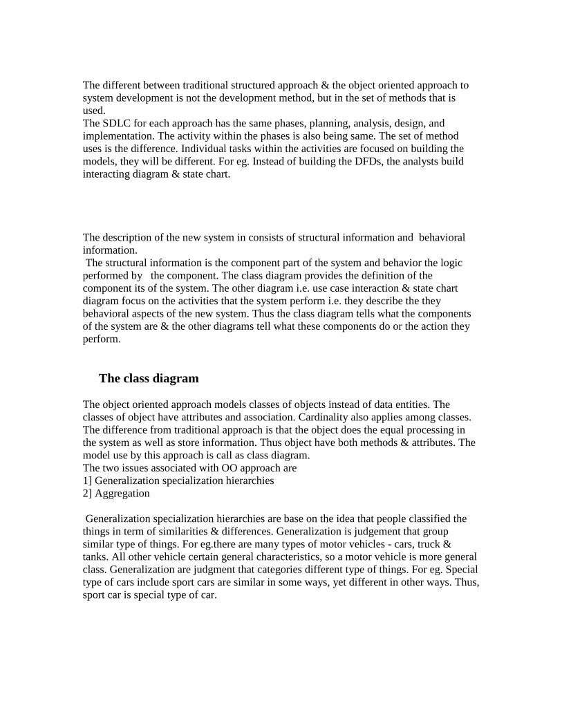
The figure above shows how use case in documentation. A simple stick figure use to represent an actor. The uses case is symbolized by oval wLines between actor & use cases which actors participate with which use case. Scenarios:- A use case only shows that an actor interacts with the computer system to carry out business activity. A use case is the high sequence of individual steps to accomplish the use case. We describe these individual steps with the narrative that is called as flow of activities. A flow of activity describes the internal steps or activities with a useFor example:- “create new order” use case. The steps would be “record customer information”, “reorder order”, “process order transaction” & “produce confirmation”. Each of this case can be further defined.The flow of activities is a general descripneed to extend the description to event more details. Frequently, use case may have several alternative sequences of internal activities. For eq. the exact sequence of tasks will probably different from theDepending from whether it is a customer or clerk interacting with the system. It is a same use case different sequence. We describe these different sequences as scenario. Scenario is the particular sequence of activities withidifferent scenarios. A scenario is a identification & description of a unique set of internal activities within the use case. It represent unique path through a use case. For eg. The “create new order” could have two“customer create web order”. The use case diagram A use case diagram is a graphical model that summarizes the information about the actor & use cases. To do use case analysis, we look at the system as the wall of major uses of the system. These uses normally derived from the business event identified in the event table. It identifies the functions that must be supported by the new system.
The figure above shows how use case in documentation. A simple stick figure use to represent an actor. The uses case is symbolized by oval with name of the use case inside. Lines between actor & use cases which actors participate with which use case.
A use case only shows that an actor interacts with the computer system to carry out business activity. A use case is the high – level description & may include whole sequence of individual steps to accomplish the use case. We describe these individual steps with the narrative that is called as flow of activities. A flow of activity describes the internal steps or activities with a use case.
“create new order” use case. The steps would be “record customer information”, “reorder order”, “process order transaction” & “produce confirmation”. Each of this case can be further defined. The flow of activities is a general description of steps with in the case. In most cases we need to extend the description to event more details. Frequently, use case may have several alternative sequences of internal activities. For eq. the exact sequence of tasks will probably different from the “create new order” use case. Depending from whether it is a customer or clerk interacting with the system. It is a same use case different sequence. We describe these different sequences as scenario. Scenario is the particular sequence of activities within the use case; a use case have several different scenarios. A scenario is a identification & description of a unique set of internal activities within the use case. It represent unique path through a use case. For eg. The “create new order” could have two scenarios “customer create telephone order” & “customer create web order”.
A use case diagram is a graphical model that summarizes the information about the actor & use cases. To do use case analysis, we look at the system as the whole & try to identify all of major uses of the system. These uses normally derived from the business event identified in the event table. It identifies the functions that must be supported by the new
The figure above shows how use case in documentation. A simple stick figure use to ith name of the use case inside.
Lines between actor & use cases which actors participate with which use case.
A use case only shows that an actor interacts with the computer system to carry out el description & may include whole
sequence of individual steps to accomplish the use case. We describe these individual steps with the narrative that is called as flow of activities. A flow of activity describes the
“create new order” use case. The steps would be “record customer information”, “reorder order”, “process order transaction” & “produce confirmation”.
tion of steps with in the case. In most cases we
Frequently, use case may have several alternative sequences of internal activities. For eq. “create new order” use case.
Depending from whether it is a customer or clerk interacting with the system. It is a same use case different sequence. We describe these different sequences as scenario. Scenario
n the use case; a use case have several different scenarios. A scenario is a identification & description of a unique set of internal activities within the use case. It represent unique path through a use case. For eg. The
scenarios “customer create telephone order” &
A use case diagram is a graphical model that summarizes the information about the actor hole & try to identify
all of major uses of the system. These uses normally derived from the business event identified in the event table. It identifies the functions that must be supported by the new

# Automation Boundary and organization.
As indicated by the relationship lines, each actor can use every use cases. A boundary line is drawn around the entire set of use cases. This boundary is the automated system boundary, or the automation boundary. It denotes the boundary between the environwhere the actors reside, & the internal function of the automated system. There are various ways to organize the use cases to depict different points of view. One way is to organize use cases by sub system.
# Automation Boundary and organization.
Inventory System
As indicated by the relationship lines, each actor can use every use cases. A boundary line is drawn around the entire set of use cases. This boundary is the automated system boundary, or the automation boundary. It denotes the boundary between the environwhere the actors reside, & the internal function of the automated system. There are various ways to organize the use cases to depict different points of view. One way is to organize use cases by sub system.
As indicated by the relationship lines, each actor can use every use cases. A boundary line is drawn around the entire set of use cases. This boundary is the automated system boundary, or the automation boundary. It denotes the boundary between the environment, where the actors reside, & the internal function of the automated system. There are various ways to organize the use cases to depict different points of view. One way is to


Another approach is to include all use cases that involve a specific actor.
<<includes>> relationships frequently during the development of a use case diagram, in became necessary for one use case to use the services of another use case. For eg, two of the “osubsystem” use cases are “create new order” & “update order” each of these use cases may need to validate the customer account. A common use case may be defined to carry out this function.
approach is to include all use cases that involve a specific actor.
frequently during the development of a use case diagram, in became necessary for one use case to use the services of another use case. For eg, two of the “order entry subsystem” use cases are “create new order” & “update order” each of these use cases may need to validate the customer account. A common use case may be defined to carry
frequently during the development of a use case diagram, in became necessary for one rder entry
subsystem” use cases are “create new order” & “update order” each of these use cases may need to validate the customer account. A common use case may be defined to carry

Customer Order The relation reads “creates new order<<includes>> validate customer account” Sometime this relationship is referred to as a common subroutine, meaning that it is common to both use cases. The use case diagram compared to structured techniques The objective of use case diagram is to provide an overview of the system, including the actors who use the system & the functions they perform with the system. As they help to define he scope of the system, a use case diagram is like a context diagram. However, the individual use cases appear more like a DFD fragment in that they identify an individual function that the system must support. One of the primary differences between structure & object – oriented modeling is he though process for developing use case diagram begins by defining the automation boundary. In the development of a DFD, the automation boundary. In the development of automation boundary often is not define until the entire process as been detailed. Thus, in a DFD an external agent is always the original source or destination of the information &
Create new order
Look up item availabilty
Validate customer account
Update Order

may not necessarily be the one interacting with the system. In a use case diagram, an actor is the one, who actually interacts with the system. Whatever that actor is the original source of the information or not. For e.g., in “create new order” system. A customer may call the clerk and make an order. The DFD would identify customer as an external entity. An the clerks activity would be embedded in a process described as “enter customer order” while in use case diagram, the clerk would be identified as the actor who used the system to enter or create customer order. Another major difference is that the use case diagram does not initiate data flows. The information flowing i.e. the interacting diagrams. Development of usecase diagram There are two possible points to developed use case diagram. The most common method is to use to even table. We analyze each event in determine the way the system is used to support that event, the actor who initiate the event & other use cases that may be invoked because of the event. Generally each event becomes a use case. Another method is use to start the development of a use case diagram is to identify all the actors who use the system. Build the list of actors based on the event table by looking at the trigger & source columns in the event table. An analysis of those columns helps identify who or what is using the system & what its use is. Sometime the actors are sources, at other time actor may be someone other than the source. Ones the actors are the use cases have been identified, the next step is to develop a flow of activities as the starting point for identifying various scenarios. As the different flows of activities are develop, any common internal use cases can be identified & separated into different use cases. Object interactions: Collaboration & Sequence diagram. There are two type of interactive diagrams to describe the flow of information & interactive between object. A collaboration diagram& a sequence diagram contain same information but each has a slightly different focus. A collaboration diagram emphasis the objects that interact together to support use case while sequence diagram focuses more on the details of the messages themselves. During the development, one may use both or either type of diagram. Through sequence diagram is slightly more complex then collaboration diagram, it use more frequently in industry.
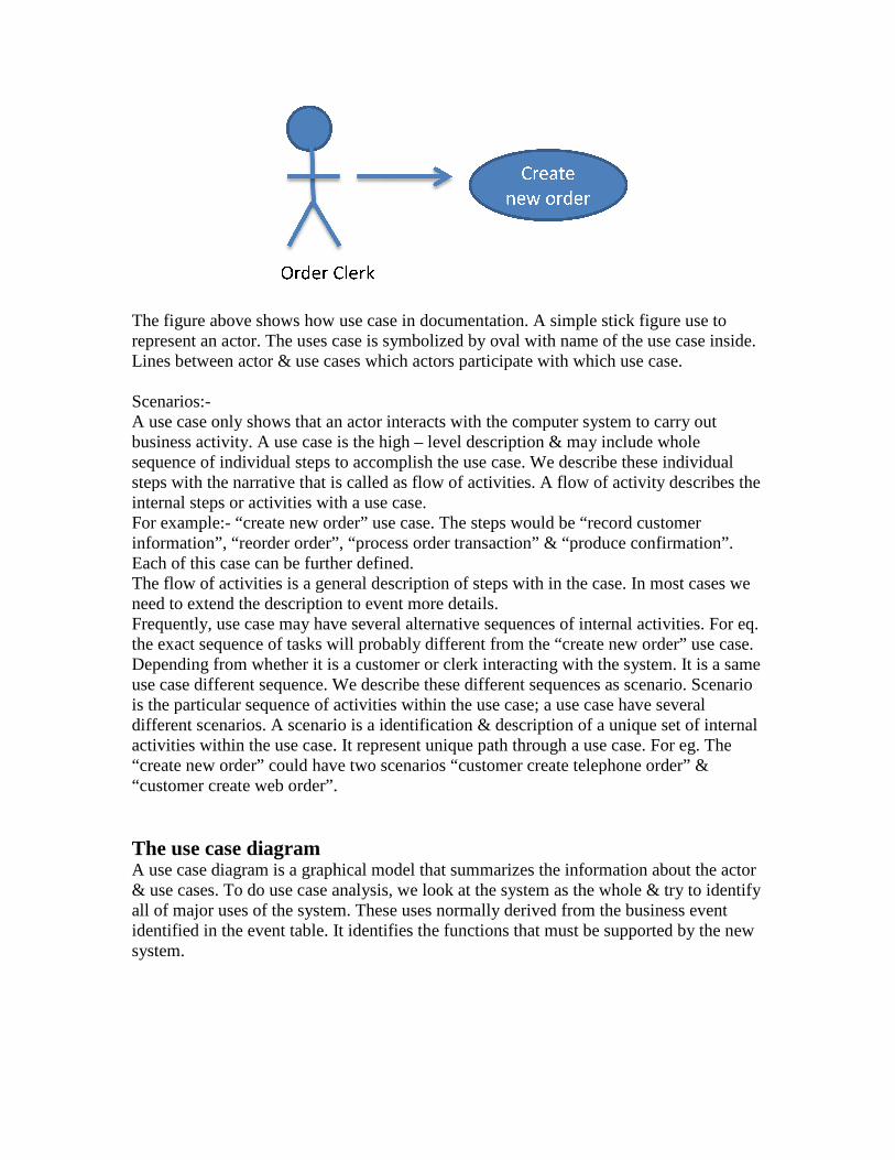
The use case diagram does not show the flow of information into, out of, or within the system. To define the flow of information in object-oriented modeling the next move into interactive diagram. The interactive diagram includes objects from the class diagram & actors from use case diagram. A particular sequence diagram documents the information flows within the single use case, or a single scenario. Order Clerk
Verify Customer
Sequence Diagram Sequence Diagram A sequence diagram shows the sequence of interaction between object that occurs during the flow of events of a single scenario or a use case. Four basic symbols are used on a sequence diagram. 1] The actor symbol, are represented by stick person. 2] The actor symbol, are represented by dashed line & narrow vertical rectangle. 3] The actor symbol, are represented by directional arrow with a message description.
Use Case Diagram .
Look up item Availability
Create new order
Order
Shipment
Customer
Order Customer

Actor & Object The stick figure represents the actors of the use case being described. The object is internal objects involved in use case & is depicted with the rectangles. The object class is object sets – that is, sets of object that have the same characteristic. An object class is represented by a rectangle with the name of the class inside. To identify a particular object within the object class, a rectangular is used, but the text inside the triangle is underlined. An object may have a specific identifier or may just be any random object with in the class. Some time one gets actors & object mixed up. The actor is the external physically person. The object is the internal computer object that maintains information about it self. Ti is an internal computer artifact. Lifeline Each actor an object has a lifeline. It is a vertical line under an object on a sequence diagram to show the passage of time for the object depicts the duration of the actor or object within the scenario. The lifeline shows the sequence of the messages. The messages hire up the lifeline occur before those below. A dashed line is use when the creation & destruction of the actor or object is not important for the scenario. When it is important to show the creation or destruction of an object, then narrow rectangle can be used. The narrow rectangle is use when a particular object comes into existence % letter may be destroyed during the sequences. The narrow box is often referred to as the activation lifeline. The object is activate during the period depict by the narrow rectangle. The point at which the object cases to exist in the system depicted by a big “X” at the end of the activation lifeline. Messages An object – oriented system gets work done by the co –operative affords of individual objects that sends messages to each other. A message symbol has two parts 1] The directionally arrow & the message descriptor. The symbol for the message descriptor is: [true/false condition] return- values: = message – name (parameter - list)
Object1 Object2
Message3
Message1
Message2
Actor

The true/false condition is the test of see whether message can be send. It is like the decision point or if statement is a programming language. A message is request from one actor or object to another to do some action. When one object or actor sends a message to another object, it is a message to invoked a particular method. The receiving object responds by executing the invoked method. In a sequence diagram, actors are like objects because they also perform some functioning when they receive s message, The message – name is usually just some simple descriptor to identify the actor of the message. Several alternatives for a message – name could be:- RingTelephone ItemEnquiry() Create OrderItem(ItemId , Qnt) [FirstItem] OrderNumber:- CreateOrder() The first example has only a message name The second has a message – name with parenthesis but no parameters. The third example include paramers, which are data items that are passing to the destination object as input parameter to the receiving. The last example contain both a condition statement & return value. The condition state (first term) is a test to see whether it is a first term to be added to an order, if yes the send CreateOrder message. For all subsequent term, new order does not need to be created. A return message indicates that the sending objects send the message & then waits for a return value. Sequence Diagram Developments: An object oriented program consist of a group of interacting objects, and the attributes of each objcet are usually hidden or privtae.To view or update attributes, we must send the object a messgae requesting a service.The program logic within an object works only on the attributes and components within the object itself. The following steps are used to develop a sequence diagram. Identify all the actors and objects involved.Use actors and objects from the use case and class diagrams. Based n flow of activities, identify each message that will be requird to carry out the scenario.Next,identify either the source object or actor for the message and the dstination object or actor.A few guidelines to help identify the source of message are. Identify the object that needs the service. Identify the object that has access to the required input parameters. If there is one –to-many association relationship from the class diagram, then frquently the object on the one side willl create and send messages to the object on the many side. 3] Next detewrmine whether each meesage is always sent or whether it is sent only under certain condition. 4] sequence the message correctly & attach them to the appropriate life lines of the actors & objects
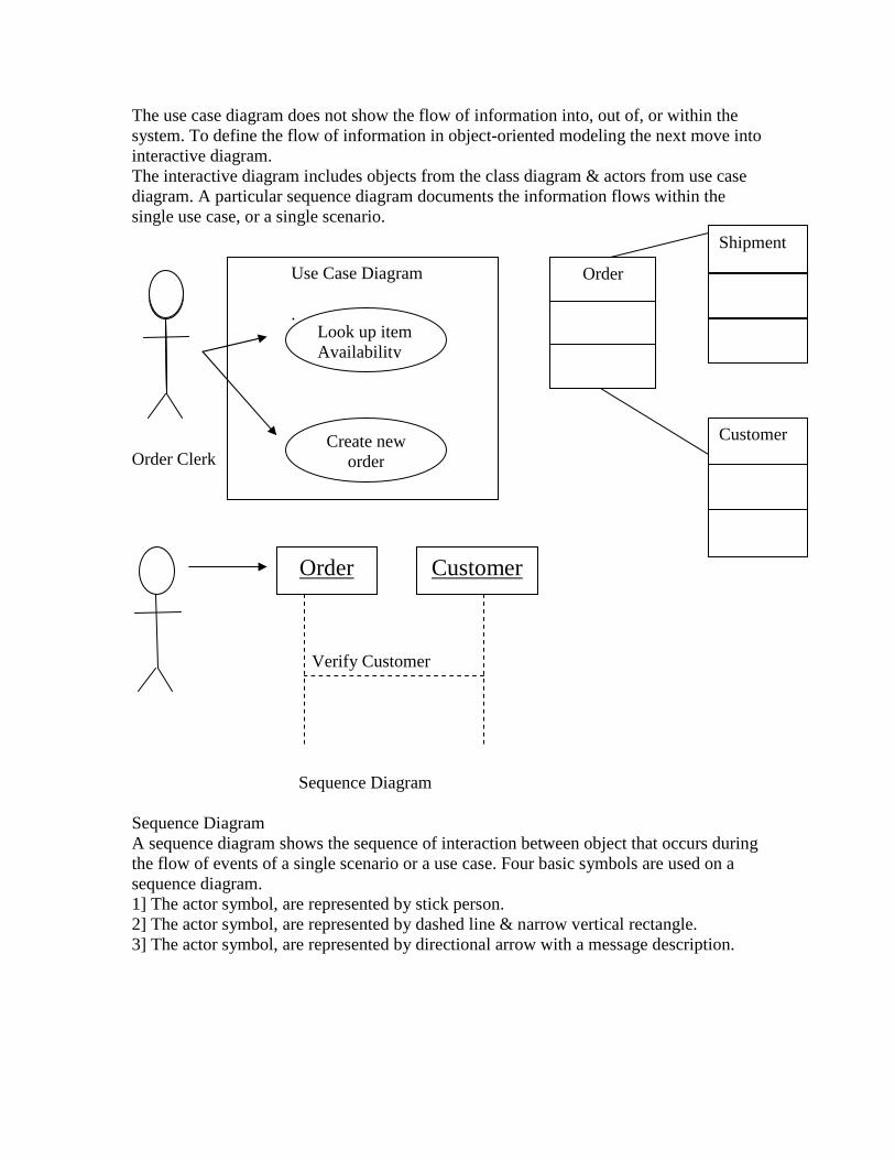
5] Add formal syntax on the message to describe conditions message names & passed parameters 6] If desided add the response messages & communication to make the sequence diagram complete Collaboration diagram The primary use of collaboration diagram is quickly get an overview of all of the object that collaborate to support open scenario. A collaboration diagram uses the same symbol for actors , objects & messages found in the sequence diagram. The lifetime symbol is not used. However, a different symbol, a link symbol is used. Actor: An actor who sends initial message Object:-An object which receives a message & sends other messages Link:- A link between symbols that send or receive messages Arrow:- A message arrow & descriptive name The format of the message descriptor for a collaboration diagram differs slightly from the one for a sequence diagram. There is no lifetime to show the passage of time during a scenario. Each message is numbered sequentially to indicate the order of the message. The syntax of the message is {true/false condition} sequence- number: return – value: = message – name(parameter-list) The connecting lines between the object or between actors & objects represent links. In collaboration diagram, a links. In collaboration diagram, a link shows that two items share messages – that one sends a message & the other receives it. The connecting lines are essentially used only to carry the messages. A collaboration diagram not easily describes information about concurrent messages or messages that are initiated simultaneously. The diagram also does not indicate information about the creation or deletion of objects within the scenario. The sequence diagram is developed to descried the detailed information about the interactions & messages within the scenario.
Object1 Object2
1: FirstMessage() 2: SecondMessage()
4: FinalResponse() 3: ReturnMessage() Actor
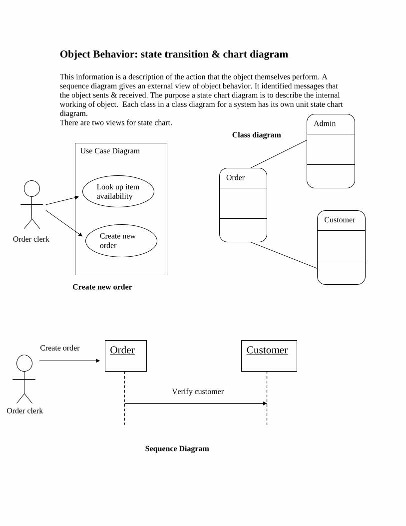
Object Behavior: state transition & chart diagram This information is a description of the action that the object themselves perform. A sequence diagram gives an external view of object behavior. It identified messages that the object sents & received. The purpose a state chart diagram is to describe the internal working of object. Each class in a class diagram for a system has its own unit state chart diagram. There are two views for state chart.
Use Case Diagram
Create new order
Look up item availability
Order clerk
Order
Admin
Customer
Class diagram
Order Customer
Create new order
Create order
Order clerk
Verify customer
Sequence Diagram

Object state:- A state for an object is a condition during its life when it satisfied some criteria performs some action or waits for an event. Each state has a unique name. a state is a Sami-permanent condition of an object i.e. an external event can be interrupt them for example, “on ”,”working”, “in repair”. While the object is in a particular state, there may be nothing happening or it may be active & performing some action. For eg. A computer monitor is in “on” state and is displaying items on the screen. In the “off” state is quiet with no action. An action that may be performs while it is in a state. A state is represented by rectangle with rounded corners with the name of the state placed inside. Any actions that may be performed during period the state is active are placed beneath the state name. A darkened circle denotes an initial state & simply indicates the beginning & the ending of a state chart. A dark end circle denotes an initial state & indicates the entry point to a state chart. This initial state called a pseodostate, as the entry point may be prior to the creation of the object itself. The concentric circle with the inside circle darkened denotes final end state. This state indicate the exit from state chart, frequently indicating the removal of object from the system An object could be in more than one state at a given time called concurrently or concurrent states.(DISCUSSED LATER) A composite state represents a higher level of abstraction & can contain nested states & path.
Sequence Diagram for order class
Item being entered Ready to ship
Idle
Working
Load part Mill part Unload part

Object transition:- A transition is the mechanism that causes an object to leave a state & change to a new state. States are semi-permanent conditions because transactions interrupt them & cause them to end. Generally transitions are considered to be short in duration compared to states & cannot be interrupted. Thus once a transaction begins it runs completion by taking the object to the new state called the destination state. A transition is represented by a arrow from the origin state & destination state & is labeled with a string to describe the components of the transition. The transition label consists of three components Transition name (parameters…) [guard-condition]/action-expression The transition-name is the name of a message event that triggers the transition and causes the object to leave the original state. They are called message events as they are message from other objects and they happen simultaneously like an event. The parameter list identifies any parameters that the message is to pass to the object. The guard-condition is true false test to see whether a transition can be taken. For the transition to fire, first the trigger event must occur and then the guard must also be true. Synchronisation bar is used to represent synchronization
Off
On
Empty Full Low
Working Idle
Activity
Activity Activity

Component Diagram Component diagram describe software components and their relationships within the implementation environment. Components: Components represent all kinds of elements that are put together in a software application. Among many things they may be simple files or libraries loaded dynamically. They are represented as: Specification: The specification contains the class interface, while the body contains the implementation of the same class. For example, in C++, a specification corresponds to a file with .h suffix and a body corresponds to a file with the suffix .cpp. Dependencies between components Dependency relationships are used within components diagram to indicate that a component refer to services offered by other component. A dependency relationship is represented by a dashed arrow drawn from the client to the supplier.
Activity
Activity Activity
Body
BODY
BODY

Process Processes are objects that have their own control flow processes may be contained within components. Subsystems: To speed up the implementation of applications various components may be grouped within packages according to logical criteria. Each subsystem may contain components and other subsystem
Components
<<Process>> Process
<<Subsystem>>
<<Subsystem>>
<<Subsystem>>
Deployment Diagram Deployment diagrams show the physical layout of the various hardware components (nodes) that compose a system as well as the distribution of executable programs on this hardware. Representation of nodes Each hardware resource is represented by a cube. Any system can be described by a small number of deployment diagrams, and a single diagram is often sufficient. The various nodes that appear in the deployment diagram are connected to each other by lines representing a communication infrastructure.
OBJECT ORIENTED DATABASE
i. Object database management systems (OODBMSs) are an extension of the OO design and programming paradigm.
ii. They are designed specially to store objects and to interface with object-oriented programming languages.
iii. Although it is possible to store objects in files or relational database, there are many advantage to using a DBMS specially designed for objects.
iv. These advantages include direct support for method storage; inheritance, nested objects, object linking and programmer defined data types.
v. ODBMs are the database technology of choice for newly designed system s implemented with OO tools, especially for scientific and engineering applications.
vi. Object Definition Language (OOL) is a standard object database description language promulgated by the object Database management group. It is a language for describing the structure and content of an object database. Designing Object Database To create an object database schema from a class diagram, follow these steps 1) Determine which classes require persistence storage. 2) Define persistent classes. 3) Represent relationship among persistent classes. 4) Choose appropriate data types and value restriction for each field.
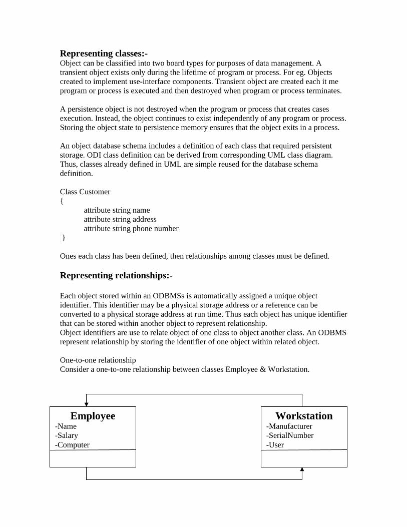
Representing classes:- Object can be classified into two board types for purposes of data management. A transient object exists only during the lifetime of program or process. For eg. Objects created to implement use-interface components. Transient object are created each it me program or process is executed and then destroyed when program or process terminates. A persistence object is not destroyed when the program or process that creates cases execution. Instead, the object continues to exist independently of any program or process. Storing the object state to persistence memory ensures that the object exits in a process. An object database schema includes a definition of each class that required persistent storage. ODI class definition can be derived from corresponding UML class diagram. Thus, classes already defined in UML are simple reused for the database schema definition. Class Customer { attribute string name attribute string address attribute string phone number } Ones each class has been defined, then relationships among classes must be defined. Representing relationships:- Each object stored within an ODBMSs is automatically assigned a unique object identifier. This identifier may be a physical storage address or a reference can be converted to a physical storage address at run time. Thus each object has unique identifier that can be stored within another object to represent relationship. Object identifiers are use to relate object of one class to object another class. An ODBMS represent relationship by storing the identifier of one object within related object. One-to-one relationship Consider a one-to-one relationship between classes Employee & Workstation.
Employee -Name -Salary -Computer
Workstation -Manufacturer -SerialNumber -User

Each employee object has an attribute called computer that contains the object identifier of workstation object assigned to the employee. Each workstation object has matching attributes called use that contains the object identifier of the employee that uses that workstation. The ODBMS uses attributes containing object identifiers to find objects that are related to another objects. The process of extracting an object identifier from one object & using it to access another object is called navigation. For e.g. consider the following query List the manufacturer of the workstation assigned to employee “A” A query processor can find the requested employee object by searching all employee objects for the name attribute “A”. The processor can find “A” s workstation object by searching the object identifier store in computer. Attributes that represent relationships are not usually specified directly by an object database schema designed. Designers specify them directly by declaring relationship between object. Consider the class declaration for ODL schema language: Class employee { attribute string name attribute integer salary relationship workstation uses inverse workstation :: Assigned To } Class workstation { attribute string manufacture attribute string serialnumber relationship employee AssignedTo inverse Employee :: uses } The keyword relationship is used to declare a relationship between one class & another. The class employee has a relationship called uses with the class workstation. The class workstation has a match’s relationship called assigned to with the class employee each relation includes a declaration of matching There are two advantages of declaring a relationship:- 1] The ODBMS assumes responsible for determining how to implement the connection among objects. That is, schema designer has declared an attribute of type relationship & lift into ODBMS to determine an appropriate type of attribute

2] The ODBMS assumes responsibility for maintaining referential integrity. One-to-many relationship:- Consider the one-to-many relationship between class customer & order. Customer can make different orders but only single order made by one customer. As single object identifier is required to represent relationship between one customer & many different orders. ODL class declaration for the class customer & order are Class customer { Attribute String Name Attribute String BillAddress Relationship set<order>Makes Inverse Order :: MadeBy } Class Order { attribute String OrderID attribute String Date } The relationships makes is a declared between a single customer object and a set of order objects. Declaring the relationship as a set instructs the ODBMS to allocate multiple order object identifier attributes dynamically to each customer object. A many to many relationship is represented differently depending on whether the relationship has any attribute. Many-to-Many relationships without any attributes are represented similarly to one-to-many relationships. For example consider many-to-many relationship between the classes catalogue and product ten having no attributes. Here the relationship is represented as:
Customer -Name -Bill Address
Order -OrderID -OrderDate
1 0…

class Catalog { attribute string Description attribute integer year relationships set <productItem>Contains inverse productItem :: AppearsIn } Class productItem { attribute String productId attribute String Description relationship set<Catalog>AppearsIn inverse Catalog :: Contains } This allows an object of either class to be related to multiple objects of the other class. Representing a many-to-many relationship with attributes requires a more complex approach. Let’s assume that the relationship between catalog and productItem has an attribute called price An association class is a class that represents a relationship and stores the attribute of that relationship. Thus the association class catalog product has been created to represent the many-to-many relationship between catalog and productItem. The many-to-many relationship has been decomposed into a pair of one-to-many relationships. Class Catalog { attribute String Description attribute integer Year relationship set<CatalogProduct> Contains1 inverse CatalogProduct :: AppearsIn1 } Class ProductItem {
Catalog -Description -Year
CatalogProduct -Price
ProductItem -OrderID -OrderDate
1 0..* 0…* 1

attribute String ProductId attribute String Description relationship set <CatalogProduct> AppearsIN2 inverse CatalogProduct :: Contains2 } Class CatalogProduct { attribute real Price relationship catalog AprrearsIn1 inverse Catalog :: Contains1 relationship productItem AppearsIn2 inverse ProductItem :: Contains2 } Consider an example of web order, telephone order and Mail order. They are specific version of class order Class order { attribute String OrderId attribute String OrderDate attribute real OrderGrandTotal } Class WebOrder extends order { attribute String EmailAddress attribute String ReplyMethod } Class Telephone extends order
Order -OrderID -OrderDate -OrderGrandTotal
Weborder -EmailAddress -ReplyMethod
Telephoneorder -CallStartTime -LengthOfCall
MailOrder -dateReceived
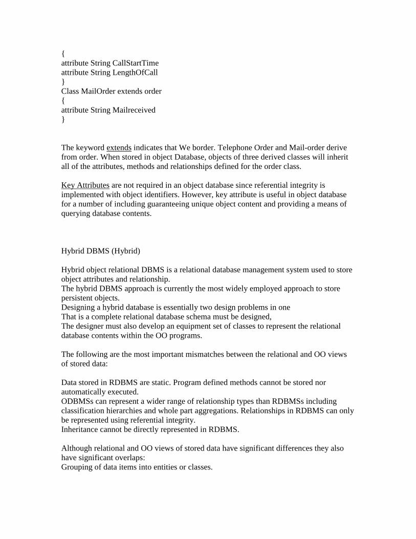
{ attribute String CallStartTime attribute String LengthOfCall } Class MailOrder extends order { attribute String Mailreceived } The keyword extends indicates that We border. Telephone Order and Mail-order derive from order. When stored in object Database, objects of three derived classes will inherit all of the attributes, methods and relationships defined for the order class. Key Attributes are not required in an object database since referential integrity is implemented with object identifiers. However, key attribute is useful in object database for a number of including guaranteeing unique object content and providing a means of querying database contents. Hybrid DBMS (Hybrid) Hybrid object relational DBMS is a relational database management system used to store object attributes and relationship. The hybrid DBMS approach is currently the most widely employed approach to store persistent objects. Designing a hybrid database is essentially two design problems in one That is a complete relational database schema must be designed, The designer must also develop an equipment set of classes to represent the relational database contents within the OO programs. The following are the most important mismatches between the relational and OO views of stored data: Data stored in RDBMS are static. Program defined methods cannot be stored nor automatically executed. ODBMSs can represent a wider range of relationship types than RDBMSs including classification hierarchies and whole part aggregations. Relationships in RDBMS can only be represented using referential integrity. Inheritance cannot be directly represented in RDBMS. Although relational and OO views of stored data have significant differences they also have significant overlaps: Grouping of data items into entities or classes.

Defining one-to-one one-to-many and many-to-many relationships among entities or classes. This overlap provides a basic for representing classes and objects within a relational database Classes and attributes Designers can store classes and object attributes in an RDBMS by defining appropriate tables in which to store them. The following table describes the correspondence between OO, ER and relational database concepts Object-Oriented Entity-Relationship Relational Database Class Entity type Table Object Entity instance Row Attribute Attribute Column A key field (or group of fields) must be chosen for each table. A designer can choose a natural key field from existing attributes or add an invented key field. Primary key fields are needed to guarantee uniqueness within tables and to represent relationships using foreign keys. Relationships ODBMS use object identifiers to represent relationships among objects. But object identifiers are not created by RDBMSs, so relationship among objects stored in a relational database must be represented using foreign key. Foreign key values serve the same purpose as object identifier in an ODBMS. That is, they provide a means for one object to refer to another. To represent one-to-many relationships, add primary key field of the class on the one side of the relationship to the table representing the class on the many sides of relationship. To represent many-to-many relationship, create a new table that contains the primary keys of the related class tables and any attributes of the relationship itself. Thus relational database schemas derived from a class diagram and an ERD representing are similar. Classification (generalization/Specialisation or inheritance) relationships are special case in relational database design. Just as a child class inherits the data and methods of a parent class, a table representing a child class inherits some or all of its data from the table representing its parent class. This inheritance can be represented in two ways Combine all tables into a single table containing the superset of all class attribute but excluding any invented key fields of the child classes. Use separate tables to represents the child classes and substitute the primary key of the parent class table for the invented keys of the child class tables.
1. Either method is an acceptable approach to representing a classification relationship.

2. a data type defines the storage format and allowed able content of a program variable, object state variable or database field or attribute.
3. Primitive data type an data type that are supported directly by computer hardware and programming languages.
4. For example, memory address (a pointer) ,Boolean ,integer unsigned integer ,short integer(one byte) ,log integer (multiple bytes), single character, double precision, real number some procedural programming language (Such as C) and most ()() language enable programmers to define additional data types using the primitive data types as building blocks.
5. As information systems have become more complex, the number of data types used to implement them has increased.
6. For example, data time, currency, audio streams, video images, motion video streams, uniform recourses located (URLs).
7. These are complex data type. A complex data types is not directly supported by computer hardware or a programming language. They are also called user-define data types. They are defined as complex combination of primitive data types.
8. They are called user-define because they may be defined by users during analysis and design or by programmers during design and implementation.
Relational DBMS data Types For each field in a relation database schema, the designer must choose an appropriate data type. For many field, the choice of a data types is relative straightforward. Modern RDBMS s have added an increasing number of new data types to represent the data required the data required by modern information system.
Partial listing of some of the data types available in Oracle RDBMS
Type Description CHAR Fixed length character array. VARCHAR Variable length character array NUMBER Real number DATE Date and time with appropriate
check of validity LONG Variable length character data up to
2 GB LONGRAW Binary long object ROWID Unique Six byte physical storage
address.

Complex data types available in Oracle include LONG,LONGRAW,LONG is typically used to store large quantities of formatted or unformatted text, such as a word processing document LONGRAW can be used to store large binary data values, including encoded pictures, sound and motion video. Modern RDMSs can also perform validity and format checks on data, as they are stored in the database. For example, quantity in hand cannot be negative. The validity and format constraints are automatically shared by all application programs that use the database. Each program is simpler and the possibility for errors due to mismatch among data validation logic is eliminated application program still have to program logic to recover from attempts to add “bad” data ,but they are free from actually performing validity checks.
Object DBMS Data Types ODBMS typically provide a set of primitive and complex data types comparable to those of RDBMS.ODBMS also allow a schema designer to define format and value constraint. But ODBMS s provide an even more powerful way to define useful data types and constrains-a schema designer san define a new data type and its associated constraints as a new class. A class is complex user-define data type that combines the traditional concept of data with processes i.e. methods that manipulated the data. In most OO programming languages, programmer are free to design new data types (classes) that extend those already defined by the programming language. The designer can design classes to specifically meet the requirement. To the ODBMS instance of the new data types are simply meet the requirements. To the ODBMS instances of the new data types are simply objects to be stored in the database. Class methods can perform many of the types and error –checking functions previously performed by application program code and/or by the DBMS itself. The programmer thus constructs a custom designed data type and all of the programming logic required to use it correctly. The DBMS is freed from direct responsibility for managing complex data types and the value Store therein. It directly performs validity checking and format conversion by extracting and execution programmer-define methods store in the database. The flexibility to define new data types is a chief reason that OO tools are so widely employed in non-business information systems. In fields such as engineering, biology and physics, stored data is considerably more complex that simply string, numbers and dates. OO tools enable database designers and programmers to design custom data types are specified to a problem domain.