Embed Size (px)
Citation preview
1
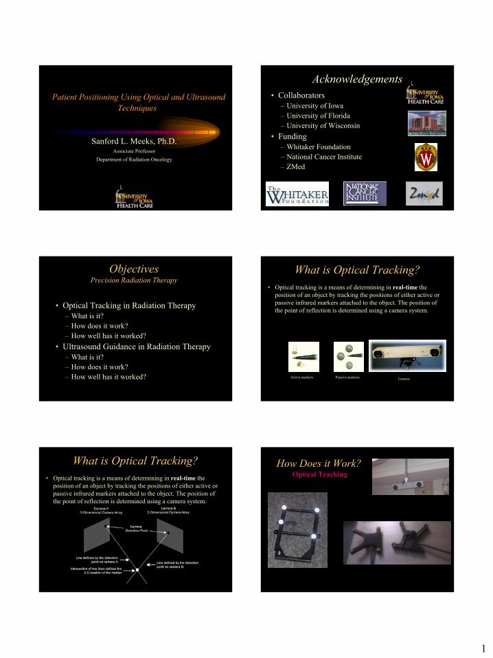
Patient Positioning Using Optical and Ultrasound Techniques
Sanford L. Meeks, Ph.D.Associate Professor
Department of Radiation Oncology
Acknowledgements• Collaborators
– University of Iowa– University of Florida– University of Wisconsin
• Funding– Whitaker Foundation – National Cancer Institute – ZMed
ObjectivesPrecision Radiation Therapy
• Optical Tracking in Radiation Therapy– What is it?– How does it work?– How well has it worked?
• Ultrasound Guidance in Radiation Therapy– What is it?– How does it work?– How well has it worked?
What is Optical Tracking?• Optical tracking is a means of determining in real-time the
position of an object by tracking the positions of either active or passive infrared markers attached to the object. The position ofthe point of reflection is determined using a camera system.
Active markers Passive markers Camera
What is Optical Tracking?• Optical tracking is a means of determining in real-time the
position of an object by tracking the positions of either active or passive infrared markers attached to the object. The position ofthe point of reflection is determined using a camera system.
How Does it Work?Optical Tracking

2
How Does it Work?Calibration of Optical camera
Optical guidance for frameless stereotaxis• For high-precision intracranial radiotherapy
and frameless radiosurgery, we use optical guidance to track the actual patient position using passive markers and a bite-plate linkage.
Frameless Stereotaxis
• Passive Array –Reflective Markers serve as fiducials in both image and real space.
Frameless StereotaxisImmobilization During CT Scan
Patients can move – immobilize using custom pillow, aquaplast, etc.
Frameless StereotaxisPassive Array – CT Scan
Fiducials must be visible in CT scan – use adequate field of view (typically 35-40 cm depending on distance of bracket from patient).
Frameless Localization

3
Frameless Stereotaxis
pi’ = Rp
i +T
Vector for room coordinates
3x3 rotation matrix
Translation vector
Equation can be solved numerically using optimization algorithms (Hook and Jeeves, etc.), or closed form solutions such as single value decomposition or Horn’s method (quaternions)
Vector for image coordinates
Align Patient
Optical Tracking – BrainLab System
Optical Tracking – BrainLab System X-ray Guidance Setup(original model, xray tubes above patient)
aSiDetector
Xray Tubes
4
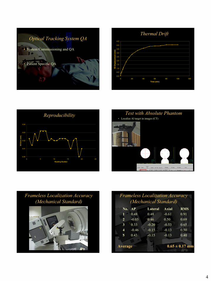
Optical Tracking System QA
• System Commissioning and QA
• Patient Specific QA
Thermal Drift
0.0
0.5
1.0
1.5
2.0
2.5
3.0
3.5
4.0
4.5
0 20 40 60 80 100 120Time (min)
3D D
ispl
acem
ent (
mm
)Reproducibility
0.00
0.01
0.02
0.03
0.04
0 5 10 15 20 25Reading Number
3D E
rror
(mm
)
Test with Absolute Phantom• Localize Al target in images (CT)
Frameless Localization Accuracy (Mechanical Standard)
Frameless Localization Accuracy (Mechanical Standard)
No. AP Lateral Axial RMS1 0.48 0.48 -0.61 0.912 -0.05 0.46 0.50 0.693 0.33 -0.20 -0.53 0.654 -0.46 -0.15 -0.13 0.505 0.43 -0.15 -0.13 0.40
Average 0.65 ± 0.17 mm

5
Putting it All Together - Hidden Targets Test with Absolute Phantom
• Localize Al target in images (CT)• Place on linac using image localized coordinates
and optical guidance.
Frameless Localization Accuracy (Film Tests)
• Localize Al target in images (CT)• Replace Al target with Tungsten target, and place
on linac using image localized coordinates.• Take films from various gantry and table
orientations
Overall error = 0.789mm
Predicted error:
Z-Pixel Size = 1.25mm
X-Pixel Size = 0.703 mm
Y-Pixel Size = 0.703 mm
Predicted Error = 1.59mm
Results:
Z: 0.49 mm to T
X: 0.35 mm to A
Y: 0.50 mm High
ANALYSISFrameless Localization (Patient)
Frameless Localization (10 Patients)
Average Average ±± s.d.s.d. 1.1 1.1 ±± 0.3 mm0.3 mm
compared to conventional stereotactic localization
Meeks, Bova et al., IJROBP, 2000
Can we predict localization errors?
Analogous to frame-based stereotaxis, we have an over-defined fiducial system with a known geometry. Can predict accuracy of patient positioning at isocenter

6
Mean Registration ErrorError between CT model and the real
array after registration.
Provides indication of reference array integrity
and patient motion.
Frameless Localization (In Phantom)
Mean Registration Error (Phantom)
0
0.2
0.4
0.6
0.8
1
1.2
1.4
0 1 2 3 4 5 6
Phantom Run Number
Erro
r (m
m)
predictedmeasured
Mean Registration Error (Patient)
0
0.5
1
1.5
2
2.5
3
3.5
4
0 2 4 6 8 10 12Patient Number
Erro
r (m
m)
predictedmeasured
Indicative of motion during scan.
Frameless Localization (Patient) Motion During Scan
7
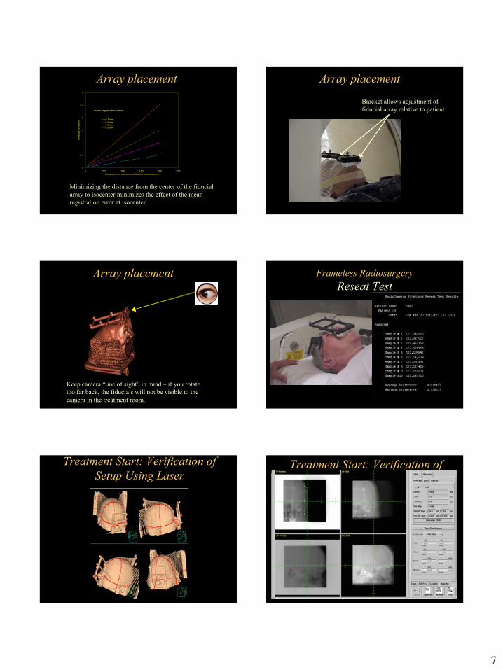
Array placement
0
0.5
1
1.5
2
2.5
3
0 50 100 150 200 250Distance from isocenter to fiducial centroid (mm)
Pred
icted
Erro
r (m
m) 0.1 mm
0.2 mm0.3 mm0.5 mm
mean registration error
Minimizing the distance from the center of the fiducial array to isocenter minimizes the effect of the mean registration error at isocenter.
Array placement
Bracket allows adjustment of fiducial array relative to patient
Array placement
Keep camera “line of sight” in mind – if you rotate too far back, the fiducials will not be visible to the camera in the treatment room.
Frameless RadiosurgeryReseat Test
Treatment Start: Verification of Setup Using Laser
Treatment Start: Verification of Setup using DRR
8
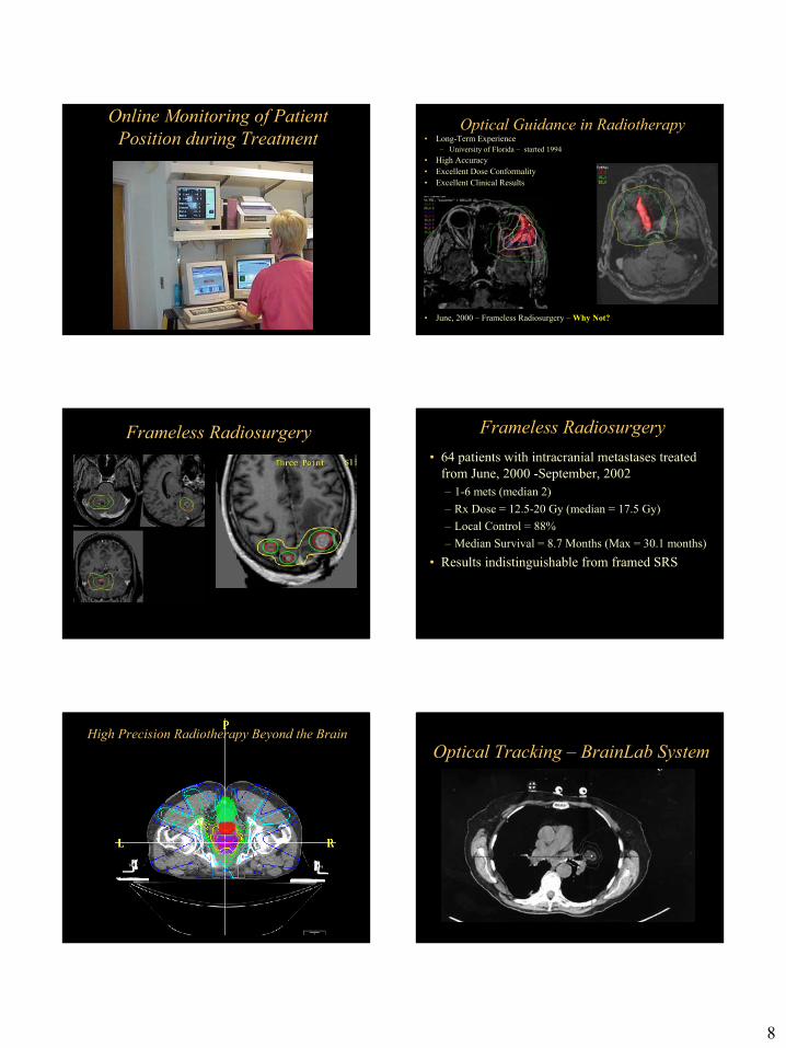
Online Monitoring of Patient Position during Treatment
Optical Guidance in Radiotherapy• Long-Term Experience
– University of Florida – started 1994• High Accuracy• Excellent Dose Conformality• Excellent Clinical Results
• June, 2000 – Frameless Radiosurgery – Why Not?
Frameless Radiosurgery Frameless Radiosurgery• 64 patients with intracranial metastases treated
from June, 2000 -September, 2002– 1-6 mets (median 2)– Rx Dose = 12.5-20 Gy (median = 17.5 Gy)– Local Control = 88%– Median Survival = 8.7 Months (Max = 30.1 months)
• Results indistinguishable from framed SRS
High Precision Radiotherapy Beyond the BrainOptical Tracking – BrainLab System
9
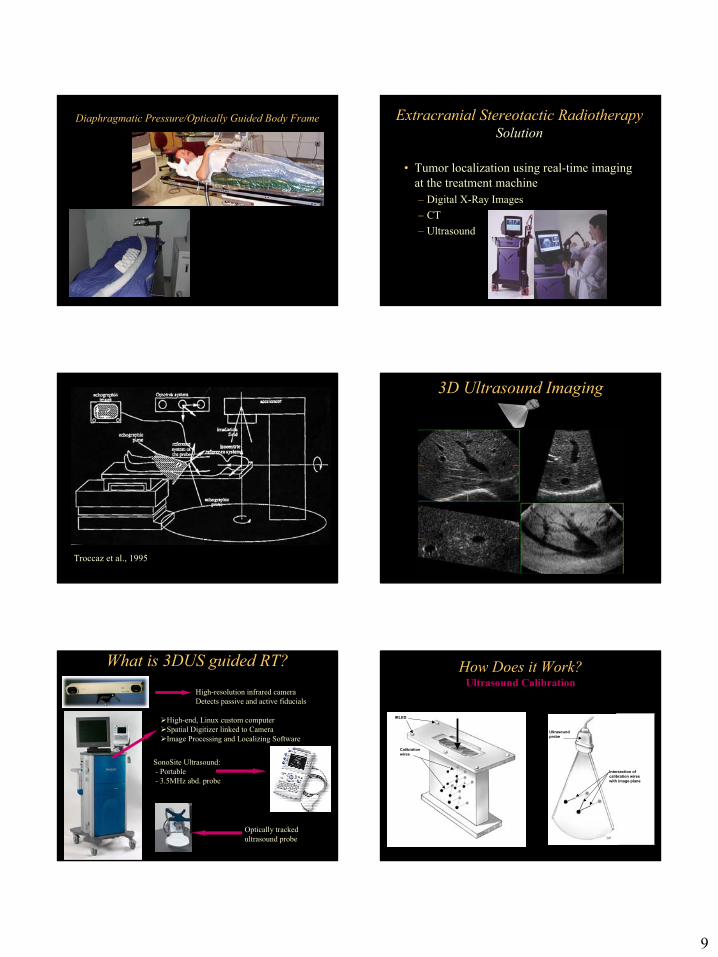
Diaphragmatic Pressure/Optically Guided Body Frame Extracranial Stereotactic RadiotherapySolution
• Tumor localization using real-time imaging at the treatment machine– Digital X-Ray Images – CT– Ultrasound
Troccaz et al., 1995
3D Ultrasound Imaging
What is 3DUS guided RT?
SonoSite Ultrasound:- Portable- 3.5MHz abd. probe
High-end, Linux custom computerSpatial Digitizer linked to CameraImage Processing and Localizing Software
High-resolution infrared cameraDetects passive and active fiducials
Optically tracked ultrasound probe
How Does it Work?Ultrasound Calibration
IRLED
Calibrationwires
B
Ultrasound probe
Intersection of calibration wireswith image plane
DP
10
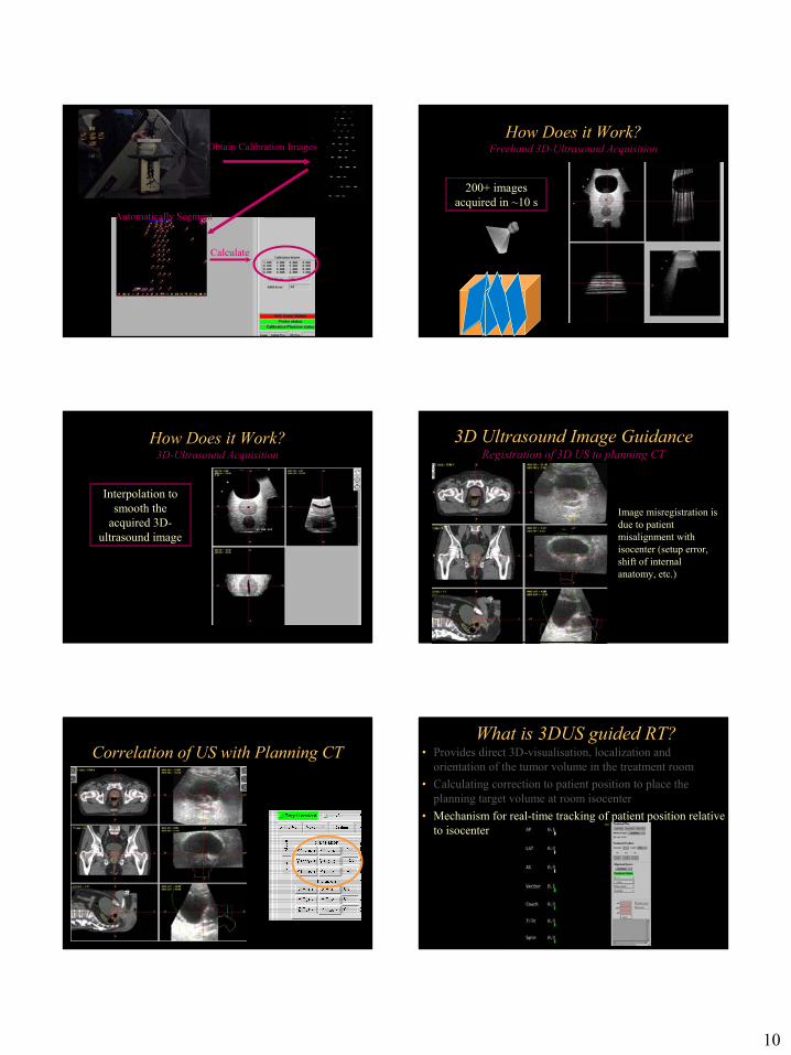
Automatically Segment
Obtain Calibration Images
Calculate
How Does it Work?Freehand 3D-Ultrasound Acquisition
200+ images acquired in ~10 s
How Does it Work?3D-Ultrasound Acquisition
Interpolation to smooth the
acquired 3D-ultrasound image
3D Ultrasound Image GuidanceRegistration of 3D US to planning CT
Image misregistration is due to patient misalignment with isocenter (setup error, shift of internal anatomy, etc.)
Correlation of US with Planning CT • Provides direct 3D-visualisation, localization and orientation of the tumor volume in the treatment room
• Calculating correction to patient position to place the planning target volume at room isocenter
• Mechanism for real-time tracking of patient position relative to isocenter
What is 3DUS guided RT?

11
Ultrasound Guidance QA
W. A. Tomé , S. L. Meeks, N. P. Orton, L. G. Bouchet, F. J. Bova, “Commissioning and Quality Assurance of an Optically Guided 3D-Ultrasound Target Localization System for Radiotherapy,” Med. Phys. 2002.
Tracking AccuracyUsing Optical Tracking as Standard
Depth (mm)
AP Distance
(mm)
Lateral Distance
(mm)
Axial Distance
(mm) All
depths0.03 ± 0.4 -1.2 ± 0.4 -0.7 ± 0.5
Pre-Clinical Prostate Phantom Tests•Using Optical Guidance known shifts are introduced using a translation table.
•Optical Guided System is blinded to introduced shifts by recording the position of a fiducial array that is fixed to the couch.
2D-Translation Table
Fiducial Array Fixed to Table
Fiducial Array Fixed to Phantom
Optically Guided Ultrasound Target Localization for shifted Phantom
Contours are moved to Match US Anatomy Results
Exp AP (mm)
Lat (mm)
Ax (mm)
APm (mm)
Latm (mm)
Axm (mm)
1 0.0 0.0 0.0 0.6±0.46 -0.3±0.69 -0.03±0.1 2 0.0 0.0 5.0 0.67±0.52 -0.38±0.61 4.95±0.12 3 0.0 0.0 -5.0 0.55±0.53 -0.25±0.58 -5.3±0.67 4 0.0 -5.0 0.0 0.55±0.53 4.95±0.17 -0.22±0.22 5 0.0 -5.0 5.0 0.25±0.06 -5.85±0.17 5.3±0.27
W. A. Tomé , S. L. Meeks, N. P. Orton, L. G. Bouchet, F. J. Bova, “Commissioning and Quality Assurance of an Optically Guided 3D-Ultrasound Target Localization System for Radiotherapy,” Med. Phys. 2002.

12
BAT Tracking Accuracy in PatientUsing CT as Standard
AP Distance
(mm)
Lateral Distance
(mm)
Axial Distance
(mm) -0.09 ± 2.8 -0.16 ± 2.4 -0.03 ± 2.3
Lattanzi J, McNeeley S, Pinover W, Horwitz E, Das I, Schultheiss TE, Hanks GE. A Comparison of Daily CT Localization to a Daily Ultrasound-Based System in Prostate Cancer. Int J Radiat Oncol, Biol Phys 1999; 43(4).
How Do I Use it Clinically? Basic Process
Immobilize and CT Scan
Treatment Planning
Laser patient positioning
3D-ultrasound acquisition
Target positioning
Treatment Delivery
How Do I Use it Clinically? Treatment Planning
BEV ConformalIMRT
How Do I Use it Clinically? Treatment Planning
How Do I Use it Clinically? Treatment Planning
• BEV conformal or IMRT treatment planning using Pinnacle
• CT and structure contours transferred to SonArray using Dicom-RT or RTOG
Skin marks Lasers
3D Ultrasound Image GuidanceInitial Alignment from CT Simulation
13
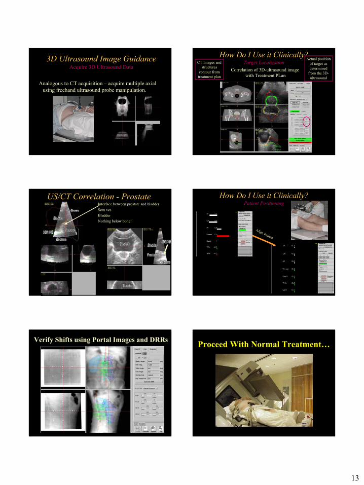
Analogous to CT acquisition – acquire multiple axial using freehand ultrasound probe manipulation.
3D Ultrasound Image GuidanceAcquire 3D Ultrasound Data
How Do I Use it Clinically?Target LocalizationCT Images and
structures contour from treatment plan
Actual position of target as determined
from the 3D-ultrasound
Correlation of 3D-ultrasound image with Treatment PLan
Interface between prostate and bladderSem vesBladderNothing below bone!
US/CT Correlation - Prostate
Align Patient
How Do I Use it Clinically?Patient Positioning
Verify Shifts using Portal Images and DRRs Proceed With Normal Treatment…

14
Pitfalls in Ultrasound GuidanceWhat happens with inter- and intra-fraction organ motion? Pitfalls in Ultrasound Guidance:
User Variability in Image Quality
Probe Placed over treatment isocenter
Probe Placed displaced by 1cm superiorly from treatment isocenter.
Pitfalls in Ultrasound Guidance: Ultrasound Interpretation
Pitfalls in Ultrasound Guidance:User Variability
AP (mm)
Lat (mm)
Axial (mm)
1.2 0.9 1.4
AP (m m)
Lat (mm)
Axial (m m)
3.6 1.5 2.9
AP (m m)
Lat (mm)
Axial (m m)
3.4 2.7 4.5
Retrospective registration of 15 different data sets by 9 different users; 4 users with experience and 5 trained in use of the software, but not US imaging.
Average Shift
Std. Dev. (Trained)
Std. Dev. (Not Trained)
Treatment PlanningUS-Guided Prostate
•• SensibleSensible PTV may be larger than MinimumMinimum• Remember user variability can vary, which increases required
PTV• In practice, we create a PTV with a variable (5-10 mm)
margin on the CTV.
Work in Progress – Automated Ultrasound Registration

15
Work in Progress – Automated Ultrasound Registration
Work in Progress – Automated Ultrasound Registration
US-Guided Prostate Trial• NCI-supported Phase III Randomized Multi-
Center Clinical Trial– Arm 1 - With ultrasound
• Initial fields: 46 Gy/23 fractions, PTV = 1 cm margins on prostate, seminal vesicles, and nodes
• 32 Gy/16 fractions, PTV = 2 mm margin on prostate only
– Arm 2 - With conventional localization• Initial fields: 46 Gy/23 fractions PTV = 1.5 cm margins on
prostate, seminal vesicles, and nodes• 32 Gy/16 fractions, PTV = 1 cm margin on prostate only
US-Guided Prostate TrialPreliminary Results
Arm 1 3DCRT
Arm 2U/S-
3DCRTArm 1
3DCRT
Arm 2U/S-
3DCRT
Grade 0 25% 89% Grade 0 50% 66%
Grade 1 0% 11% Grade 1 25% 33%
Grade 2 Grade 2
Acute GI Toxicity Acute GU Toxicity
75% 0% 25% 0%
p= 0.014 p=0.45
3D Ultrasound Image GuidanceOther Applications at UIHC (to date)
• Liver• Low neck• Paraspinal• Metastatic pelvic lesions• Chest wall
Extracranial US-Guidance

16
Clinical US ExampleResidual neurofibroma at c2-3
Target Target
MRI Ultrasound
Clinical US ExampleLiver
Metastatic lesion
Metastatic lesion
kidney
kidney
CT Ultrasound
Metastasis to Iliopsoas muscleClinical US Example Future Development/Questions
• Reliable Automated image registration techniques –important for all image registration modalities (CT, x-ray, US)
• Technical improvements in organ motion management
• Clinical Trials defining true benefits of image-guidance and IMRT.
• Defining dose/volume tolerances for hypofractionated regimens – Rigorous Phase I dose-seeking studies are required