Embed Size (px)
Citation preview

Oil Acid & Moisture Purge Unit For Use On
Centrifugal Chillers
Utilizing the following refrigerants
R-11, R-113, R-114 & R-123 R-12, R-22, R-134a
Manual for Models
OAM-LPC400-11 OAM-LPC400-113 OAM-LPC400-123
OAM-HPC400
Patent 6,952,938 B2
OAM Purger
Installation, Operation & Maintenance Manual
Redi Controls, Inc. Literature File No. 1149-00

2
Manual Revised as of July 17, 2012 © 2009 REDI CONTROLS, INC., GREENWOOD, INDIANA

3
GENERAL INFORMATION
YOU ARE URGED TO READ THIS MANUAL THOROUGHLY BEFORE INSTALLING, OPERATING OR SERVICING THIS UNIT
Upon Receiving Your Unit Inspect the unit for possible damage caused during shipping. Contact Redi Controls Technical Support before attempting to install a damaged unit.
WARNINGS and Cautions
NOTE: WARNINGS and Cautions appear in highlighted boxes as illustrated below at appropriate points throughout this manual. Give special attention to these items.
WARNINGS: Provided to alert you to special situations that could result in serious personal injury, damage to your equipment, or cause your equipment not to work properly. Warnings may appear in this manual or on the equipment. Heed all Warnings.
Cautions: Alerts installer, servicer and user of situations that could result in damage to OAM Purge Unit and or chiller.
Personal safety and the proper operation of your equipment require strict observance of these precautions.
EQUIPMENT SHOULD BE INSTALLED AND OPERATED ONLY BY QUALIFIED PERSONNEL
WARNING: Certain servicing procedures may expose you to harmful materials and dangerous conditions. To minimize the possibility of injury, follow safety procedures and instructions described in this manual, on product labels and provided in material safety data sheets.
NOTE: The manufacturer has a continuous equipment improvement policy and reserves the right to change specifications and design of its products without notice.

4
T a b l e of C o n t e n t s
GENERAL INFORMATION ........................................................................................................3
OPERATIONAL OVERVIEW ......................................................................................................7
REFRIGERANT-OIL CONTAMINATION CHART.......................................................................9
INSTALLITION .........................................................................................................................10
Figure 1 – OAM Purger Hook-up .................................................................................................................................. 10
PLUMBING THE OAM PURGER .............................................................................................11
Figure 2 – CORRECT Optional Oil Collection Cylinder Hook-up ................................................................................. 17
Figure 3 – WRONG Optional Oil Collection Cylinder Hook-up..................................................................................... 18
ELECTRICAL CONNECTION ..................................................................................................19
Figure 4 – Electrical Control Box Field Wiring ............................................................................................................. 19
Figure 5 – Major Components Electrical Box ................................................................................................................ 19
START-UP PROCEDURE ........................................................................................................20
OAM PURGER COMPONENTS...............................................................................................21
Figure 6 – Major Components of OAM Purger .............................................................................................................. 23
Figure 6 – Major Components (continued)..................................................................................................................... 24
MAINTENANCE........................................................................................................................25
TROUBLE SHOOTING.............................................................................................................26
ELECTRICAL WIRING DIAGRAM ...........................................................................................32
Figure 7. – Electrical wiring diagram ................................ ................................ ................................ ............................ 32
WARRANTY .............................................................................................................................33

5
WARNING: These instructions are intended as an aid to qualified service personnel for proper installation and operation on this equipment. Read these instructions thoroughly before attempting installation or operation of this equipment. Failure to follow these instructions can result in improper installation, servicing or maintenance possibly resulting in fire, electrical shock, property damage, personal injury or death.
SPECIFICATIONS Electrical Power Requirements ……..…120 VAC, 50/60 Hz, 1-Phase, 15 Amp Fused Circuit FLA (approximately) ………………………………………………….……………………….. 4.0 Amp Power Consumption (approximate)……………………………………..…………. 350 watts Operating Distillation Temperature……………………...………………………………155° F Operating pressures…………………………………...……………………… 30 in/hg-250 psi Distillation Tank Test Pressure………………………………..……………….…….. 350 psig Weight of Refrigerant/oil mixture per distillation cycle (average) …………...…. 9 to 10lbs Operating Environment………………………………………………………….. 70°F to 105°F Storage Environment………………………….0 °F to 120°F, 5% to 80% RH, non condensing Dimensions (approximate)………………………………… 17.5" height x 12" Width x 11" depth Weight of OAM unit (approximate) ………………………………………….....… 26 pounds Shipping weight (approximate) …………………………………………….……… 50 pounds

6
Contents of Installation Kit
▪ (1) Installation, Operation and Maintenance Manual ▪ (1) in-line oil Filter ▪ (1) in-line refrigerant Filter Drier ▪ (1) 1/4” ODS check valve (for use in oil return line near OAM). ▪ (1) 3/8” charging valve adapter with copper ferrules and cap ▪ (1)1/2” charging valve adapter with copper ferrules and cap ▪ (2) 5/8” charging valve adapters with copper ferrules and cap ▪ (2) 3/4” to 5/8” reducing flare union (for use with Charging Valve Adapter when necessary) ▪ (1) 5/8” to 1/2” reducing flare union (for use with Charging Valve Adapter when necessary ▪ (1)1/2” to 3/8” reducing flare union (for use with Charging Valve Adapter when necessary) ▪ (1) Brass three-way internal branch Tee and copper ferrule (used with vapor return line) ▪ (2) 1/4” NPT to 1/4” plugs (for use in installing the fill line) ▪ (12) 1/4” flare nuts ▪ (1) section of insulation material for in-line refrigerant drier ▪ (1) six foot length of 3/8” O.D. Armiflex insulation ▪ (1) ten foot length of 1/8” adhesive backed insulation tape ▪ (1)18” x 24”x 1/2” sheet of adhesive backed Insulation ▪ (1) Bag of copper ferrules (3 of each copper ferrule used in installation of OAM Purger) (3) of the 3/8”, --(3) of the 1/2”-- (3) of the 5/8” Field-Provided Items… ▪ OAM unit mounting hardware ▪ Electrical conduit and wiring materials ▪ 1/4-inch refrigerant grade tubing ▪ Refrigerant recovery cylinder for collecting excess oil during initial oil stripping procedure (when required)
Preliminary Inspection…
Before installing the OAM Purger, check the data on the Purge unit nameplate and verify that it is the appropriate model for the refrigerant in the chiller it is to be installed on. Make sure the voltage is correct for the application. Visually inspect unit for shipment damage before installing. Pay particular attention to the Heater Thermostat (HT-1) capillary tube to make sure it has not been damaged or kinked.

7
OPERATIONAL OVERVIEW
The Redi Controls OAM (Oil Acid and Moisture) Purge is designed to remove oil, acids and moisture from the refrigerant charge of a centrifugal chiller and other flooded evaporator type refrigerating machines. However, its primary function is to recover oil from the refrigerant and return it to the chiller’s oil sump. Following installation initial oil stripping is accomplished in two phases. The first phase, or initial oil stripping process, occurs at time of OAM Purge’s initial start-up. At this time all excess oil that has been added to the system over time and accumulated in the evaporator is removed and discarded. Often times the initial stripping process yields several gallons up to tens of gallons of excess oil depending severity of oil contamination.
The second phase begins once all excess oil has been removed from the refrigerant. From this point on the OAM Purger will maintain the system in a continual state of lubrication balance, meaning virtually 100 percent of the oil is kept in the oil sump at all times.
The OAM Purger works by continuously extracting 9 to 10 pounds of oil-logged contaminated refrigerant each purge cycle. The mixture is then heated to 155°F via a 350 watt band heater. The heater causes the liquid refrigerant to boil off as a vapor and returned to the chiller evaporator leaving behind any distilled oil to accumulate in the OAM distillation tank. At the end of the distillation phase any accumulated oil is automatically returned to the chiller’s oil sump. HOW THE OAM WORKS OAM Purger operation is cyclic and continuous as long as power is applied. Each purge cycle is approximately 1½ hours in duration comprising the following three operating phases. 1. Fill Phase: During the Fill Phase oil contaminated refrigerant flows by gravity from the chiller evaporator into the OAM Purger Distillation Tank. At the end of the fill phase the Distillation Phase is initiated.
FILL phase time is field adjustable from 10 to 30 minutes via the FILL TIME Dip Switch on the OAM Controller Module. The typical Fill time setting is 20 minutes.

8
2. Distillation Phase: During the distillation phase the 350w distillation heater is energized heating the refrigerant-oil mixture causing the liquid refrigerant component to vaporize and return to the evaporator via a 20 psid check valve at the vapor return outlet of the distillation tank (10 psid on model OAM LPC400-R113). As the refrigerant boils off any distilled oil accumulates at the bottom of the distillation tank whereupon reaching 155°F the oil return phase is initiated.
Duration of the Distillation Phase is determined by the length of time required to vaporize all liquid refrigerant and raise the temperature of the distilled oil to 155 °F typically about 1 hour. 3. Oil Return Phase: Upon reaching 155°F the oil return phase is initiated and any accumulated oil is returned to the chiller’s oil sump.
Oil Return Phase timing is field adjustable from 1 to 11 minutes duration via the oil return Dip Switch on the OAM Controller module. The typical Oil Return setting is 4 minutes. How oil is returned to the chiller’s oil sump…
During the Distillation Phase pressurized refrigerant vapor builds up in the distillation tank until the vapor return check valve’s 20 psid setting is exceeded (10 psid for model OAM 400LPC-R113) wherein refrigerant vapor in excess of the check valves differential pressure continually flows to the evaporator. At the end of the distillation phase the remaining residual pressure in the OAM distillation tank is used to push the distilled oil back to the oil sump Operating Parameters
Oil Temperature: Distilled oil temperature is controlled by Heater Thermostat (HT-1) at 155ْْ F. The thermostat can be calibrated in the field when necessary. DO NOT alter factory setting unless absolutely necessary. Refer to the Maintenance section for calibration instructions.
Oil Separation Efficiency: The amount of refrigerant returned to the chiller’s oil sump along with returned oil at the completion each distillation cycle is proportionate to the level of oil concentration in the refrigerant. The higher the oil concentration the more refrigerant will be returned with the oil to the oil sump. However, at any level of concentration, the amount of refrigerant reaching the oil sump is insignificant .
Example: during the initial clean-up period a chiller with a 500 pound charge at an average of 12% oil by weight the OAM Purger will return less than 1 ounce of refrigerant to the oil sump on any given cycle. After that only trace amounts of refrigerant (if any) ever reach the oil sump. The trace amount of refrigerant that does reach the chiller oil sump per each approximately 90 minute cycle is inconsequential.

9
The Refrigerant-Oil Contamination Chart is used to estimate the amount of excess oil in the Chiller’s Refrigerant Charge. According to ASHRAE study 601-TRP; the Average Chiller has 12 % oil by weight in its Refrigerant Charge. A 500 lb. Refrigerant Charge at 12% by weight contains 60 lbs., or 8.5 gallons of oil.
REFRIGERANT-OIL CONTAMINATION CHART
CHILLER REFRIGERANT CHARGE BY WEIGHT IN lbs.100 200 300 400 500 600 700 800 900 1000 1100 1200
% OIL lbs. of Oil in Refrigerant Charge based on % by weight1% 1 2 3 4 5 6 7 8 9 10 11 122% 2 4 6 8 10 12 14 16 18 20 22 24
3% 3 6 9 12 15 18 21 24 27 30 33 36
4% 4 8 12 16 20 24 28 32 36 40 44 48
5% 5 10 15 20 25 30 35 40 45 50 55 60
6% 6 12 18 24 30 36 42 48 54 60 66 72
7% 7 14 21 28 35 42 49 56 63 70 77 84
8% 8 16 24 32 40 48 56 64 72 80 88 96
9% 9 18 27 36 45 54 63 72 81 90 99 108
10% 10 20 30 40 50 60 70 80 90 100 110 120
11% 11 22 33 44 55 66 77 88 99 110 121 132
12% 12 24 36 48 60 72 84 96 108 120 132 14413% 13 26 39 52 65 78 91 104 117 130 143 15614% 14 28 42 56 70 84 98 112 126 140 154 16815% 15 30 45 60 75 90 105 120 135 150 165 18016% 16 32 48 64 80 96 112 128 144 160 176 19217% 17 34 51 68 85 102 119 136 153 170 187 20418% 18 36 54 72 90 108 126 144 162 180 198 21619% 19 38 57 76 95 114 133 152 171 190 209 22820% 20 40 60 80 100 120 140 160 180 200 220 24021% 21 42 63 84 105 126 147 168 189 210 231 25222% 22 44 66 88 110 132 154 176 198 220 242 26423% 23 46 69 92 115 138 161 184 207 230 253 27624% 24 48 72 96 120 144 168 192 216 240 264 28825% 25 50 75 100 125 150 175 200 225 250 275 300
OIL WEIGHS APPROXIMATELY 7 Lbs. PER GALLON60 Lbs = approximately 8.5 Gallons

10
INSTALLITION Location and Mounting…
The OAM Purger comes mounted on its own integral base sufficient for proper support. Unit piping is normally sufficient to stabilize the unit. Additional support may be provided as deemed necessary.
1. The OAM Purger must be located within four (4) feet of the chiller’s refrigerant charging valve, or other appropriate valve or port located near the bottom of the evaporator, to which the liquid refrigerant “Fill” line is to be connected.
2. The OAM Purger MUST set directly on the floor in upright position so the liquid refrigerant “Fill” inlet port is as low as possible relative to the refrigerant level in the evaporator.
Figure 1 – OAM Purger Hook-up
NOTICE: Fill Line including Filter Drier MUST BE COMPLETELY INSULATED to prevent vapor locking. Vapor lock will prevent gravity filling of OAM.
Oil Return Solenoid Valve (SOL-3)1/4" Vapor Return Line
Equalization Sol. Val. (SOL-2)
(Equalization Line)Control Box
1/4" Refrigerant Fill Line
Oil Filter-Drier
Evaporator Gauge Line
Valve Adapter
EVAPORATOR
1/4" Fitting
Cap
1/4" Oil Return Line
Insulation
CkeckValve
Fitting
Valve
Cap
Oil Charging
1/4"
Valve
Oil Sump

11
PLUMBING THE OAM PURGER To facilitate connection of the Refrigerant Fill line and the Oil Return line, to their respective chiller valves, special brass “Valve Adapter” fittings with copper ferrules have been provided in the OAM Installation Kit. These special adapters allow hook-up to the chiller’s access valves without interfering with normal service access. NOTE: Each Valve Adapter has opposing ¼” FNPT side ports. To determine which of the ports to use, temporarily screw the Valve Adapter onto the charging valve hand tight. Usually only one of these ports will be accessible. This is the port you will use. The other port will be plugged. From the OAM Installation Kit select the appropriate fitting, as called for in the piping instructions, and install in he unused port. Then, using a ¼” pipe plug from the Installation Kit, plug the unused side port. Each Valve Adapter comes with Flare Cap and Ferrule to cap off the Adapter’s charging access port. Be sure to always use a Ferrule when installing the Valve Adapter and cap.
Liquid Refrigerant Fill Line Piping Where to connect…
NOTE: Although the following instructs you to connect the OAM Refrigerant Fill Line to the Chiller’s refrigerant charging valve, this is not always best. On some chillers the charging valve is located in the liquid line from the condenser to where it connects to the evaporator. In this case an alternate pick-up point should be used. Sometimes it is necessary to weld a new fitting in the evaporator shell. On chillers equipped with an oil recovery eductor system it may be necessary to disconnect the eductor and connect the OAM Fill line connection in its place. On some chillers with an eductor system it may be possible to leave the eductor connected and connect the OAM to a separate location so long as sufficient liquid refrigerant from the evaporator is available to the OAM Purger. However, connecting the OAM to the optimum location assures fastest oil removal.
NOTE: On some Carrier Series D centrifugal chillers the refrigerant charging valve is located about even with the refrigerant level in the cooler. Therefore, for the OAM Purger to fill by gravity it will be necessary to cut into the horizontal section of the refrigerant charging line where it exits the bottom of the cooler and add a fitting and valve for connecting the OAM Purger Fill Line.

12
Fill Line Hook-up (Refer to Figure 1)
1. Select the appropriate size Valve Adapter from the Installation Kit that fits the Chiller’s refrigerant charging valve. Depending on how the Fill Line is to be run, select either a straight or 90 degree brass ¼” NPT x ¼” flare fitting from the Installation Kit and install in the appropriate side port. Install a ¼” pipe plug from the Installation Kit into the unused port.
2. Using the appropriate Copper Ferrule, permanently install the Valve Adapter onto the chiller’s refrigerant charging valve or appropriate fitting on the evaporator vessel.
3. Using ¼” O.D. copper tubing run a ¼” copper line to the Fill Solenoid Valve (S OL-1) from the valve adapter fitting.
4. Next, from the Installation Kit select the filter/drier, two ¼” flare nuts and install in the Fill Line.
5. Before making final connection to the purge unit, INSULATE THE ENTIRE REFRIGERANT FILL LINE and FILTER / DRIER. Insulation materials are provided in the Installation Kit. READ NOTICE BELOW:
NOTICE: The entire Fill Line, Filter/Drier, chiller valve and ALL interconnecting piping UP TO THE EVAPORATOR SHELL MUST be INSULATED. Failure to properly insulate these items may result in vapor lock preventing gravity filling of refrigerant. (See Figure 1, on page 10)
6. DO NOT open the refrigerant charging valve at this time.
Vapor Return Line Piping
NOTICE: If you connect the Vapor Return line to a shrader valve fitting the valve stem MUST be removed, also… DO NOT connect the vapor return line to a port with another device discharging vapor or liquid refrigerant into evaporator.
The Equalizer/Vapor Return Line may be connected to any point on the evaporator above the liquid level. One typical location is to tie into the chiller’s evaporator gauge line.
1. Close the evaporator gauge stop valve. 2. Disconnect the gauge line from valve. 3. From the Installation Kit, select the ¼” Brass T6-4 Branch Tee and Copper
Ferrule. Connect the Tee to the gauge stop valve ¼” port. (See Figure 1, pg 1 1.) 4. Re-connect gauge line to one end of Tee.

13
5. From the other end of the Tee, run a ¼” copper line to the Equalization Solenoid Valve (SOL-2). (See Figure 1, page 10.)
NOTE: Avoid sagging or traps in the Vapor Return (Equalization) Line where vapor can condense and accumulate causing a blockage
6. DO NOT re-open evaporator gauge valve at this time. Oil Return Line piping
NOTE: Based on the severity of oil contamination the amount of excess oil that may be removed by the OAM Purger at time of initial start-up could be several gallons more than the capacity of the Chiller Oil Sump.
For example: a 500 pound refrigerant charge with 12% oil by weight will contain approximately 8.5 gallons of excess oil. Until the Chiller’s refrigerant is purged free of oil, you must decide how you are going to deal with the excess oil before the initial start-up of the OAM Purger. UNDERSTAND: The above example is for illustrative purposes only. A smaller refrigerant charge with a higher percent oil concentration, or a larger refrigerant charge with a lower percentage, may yield much more than 8.5 gallons of excess oil. Before proceeding estimate how much excess oil will likely be accumulated. To estimate the excess oil you are likely to accumulate, refer to the most recent refrigerant analysis for your Chiller. You will also need to know the weight of the Chiller’s refrigerant charge. Then refer to the “Percent of Oil” Chart 1 on Page 9. Once you know approximately how much excess oil you will be dealing with you then have two options:
NOTE: It is important to note that the true percentage of oil in the refrigerant charge can vary by as much as 10 percent depending upon where you take the oil sample. For example, if the sample is taken from a location near where the refrigerant returns to the evaporator from the condenser, where it is mostly pure refrigerant, it will indicate a lower percentage of oil contamination than actually exists in the Chiller. OPTION 1: Plumb the Oil Return Line as per option one piping Instructions. Option one allows excess oil, as it is being stripped from the refr igerant, to flow direct to the chiller’s oil sump where it can accumulate. When using this option it will be necessary to periodically monitor the sump’s oil level and remove excess oil as it accumulates. Once the initial oil stripping process is complete and all excess oil has been removed from the oil sump, further monitoring will no longer be necessary. (See Option (1) Piping Instructions page 14.)
14
Advantage…once the initial oil stripping process is complete no further action is required.
Disadvantage…the main disadvantage is that this option necessitates someone to periodically monitor and drain-off excess oil from the oil sump. This can be both time consuming and inconvenient, especially since the initial oil stripping process can take weeks to complete.
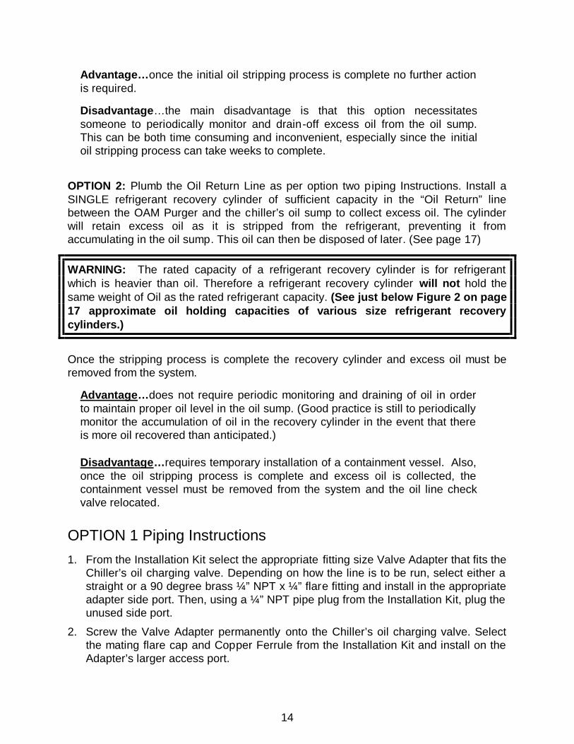
OPTION 2: Plumb the Oil Return Line as per option two piping Instructions. Install a SINGLE refrigerant recovery cylinder of sufficient capacity in the “Oil Return” line between the OAM Purger and the chiller’s oil sump to collect excess oil. The cylinder will retain excess oil as it is stripped from the refrigerant, preventing it from accumulating in the oil sump. This oil can then be disposed of later. (See page 17)
WARNING: The rated capacity of a refrigerant recovery cylinder is for refrigerant which is heavier than oil. Therefore a refrigerant recovery cylinder will not hold the same weight of Oil as the rated refrigerant capacity. (See just below Figure 2 on page 17 approximate oil holding capacities of various size refrigerant recovery cylinders.)
Once the stripping process is complete the recovery cylinder and excess oil must be removed from the system.
Advantage…does not require periodic monitoring and draining of oil in order to maintain proper oil level in the oil sump. (Good practice is still to periodically monitor the accumulation of oil in the recovery cylinder in the event that there is more oil recovered than anticipated.) Disadvantage…requires temporary installation of a containment vessel. Also, once the oil stripping process is complete and excess oil is collected, the containment vessel must be removed from the system and the oil line check valve relocated.
OPTION 1 Piping Instructions
1. From the Installation Kit select the appropriate fitting size Valve Adapter that fits the Chiller’s oil charging valve. Depending on how the line is to be run, select either a straight or a 90 degree brass ¼” NPT x ¼” flare fitting and install in the appropriate adapter side port. Then, using a ¼” NPT pipe plug from the Installation Kit, plug the unused side port.
2. Screw the Valve Adapter permanently onto the Chiller’s oil charging valve. Select the mating flare cap and Copper Ferrule from the Installation Kit and install on the Adapter’s larger access port.

15
3. Next run a ¼” copper line from the Valve Adapter fitting to the ¼” flare outlet fitting on the OAM Purger Oil Return Solenoid Valve (SOL-3). (See Figure 1, page 10.)
4. From the installation kit select the ¼” ODS Check Valve and Oil Filter-Drier. Install in the oil return line near the OAM Purger. Make sure the flow direction arrow is pointing toward the oil sump.
5. DO NOT open the oil-charging valve at this time.
OPTION 2 Piping Instructions
CAUTION: This method is intended to be a temporary arrangement only and should be replaced once the excess oil has been removed and the refrigerant is OIL FREE.
IMPORTANT NOTICE: if you choose option 2 you should be aware that during the initial oil stripping process about 10 to 15% by weight of the oil accumulated in the temporary Collection Cylinder will be refrigerant. Therefore, because of the loss of refrigerant plus the volume of the oil recovered you should be prepared to add make-up refrigerant to the chiller once the initial stripping process is complete. Refrigerant in the temporary collection cylinder may be recovered by applying a low wattage electric band heater to the bottom of recovery tank during the stripping process. It also helps to allow the tank to set with the heater energized for a day or two after the process is complete. After the initial oil stripping process, and once the OAM Purge’s oil return line is connected permanently to the chiller’s oil sump, any trace amount of refrigerant entrained in the oil will be returned to the oil sump and evaporated there.
Option (2) is identical to Option (1) except you will temporarily install ONE containment vessel in the oil return line. The size of the containment vessel (determined by previous calculation) should be of sufficient capacity to collect and hold all excess oil.
CAUTION: NEVER connect multiple cylinders in series. Multiple cylinders MUST only be connected in PARALLEL. 1. Plumb excess oil containment vessel in the Oil-Return line as illustrated in Figure 2 on page 17. Remember to Install the check valve and Oil Filter-Drier (provided in the OAM Purger Installation Kit) in the oil return line. Install the Check Valve between the containment vessel, and the oil sump as shown in figure 2, on page 17. (See warning on next page)

16
WARNING: Failure to install the Check Valve may result in oil draining from the oil sump into the temporary oil containment vessel, causing the Chiller to shut down because of low oil level.
CAUTION: Option (2) is intended only as a convenient method of dealing with excess oil. You MUST still occasionally monitor the oil sump for excessive oil accumulation since there may be more excess oil than anticipated. Refer to approximate oil holding capacities of the refrigerant recovery cylinders under Figure 2 on page 17. 2. Once all excess oil has been stripped from the Chiller’s refrigerant, remove the temporary containment vessel. Using ¼” copper tubing, reconnect the OAM Purger to the Chi ller’s oil sump as per Option 1 Piping Instructions. 3. Relocate oil return line check valve as indicated in Figure 2. DO NOT open valve at this time. Properly dispose of the accumulated excess waste oil.

17
Figure 2 – CORRECT Optional Oil Collection Cylinder Hook-up
Approximate Oil holding capacities at 80% full of various size refrigerant recovery cylinders. 50 lb. Cylinder…….. 23 pounds / 3.3 gallons 100 lb. Cylinder…… 46.4 pounds / 6.6 gallons 200 lb. Cylinder…… 92.8 pounds / 13.2 gallons
NOTE: See Fig. 3 on next page for the Wrong Optional Oil Collection Cylinder Hook-up.
1/4" Oil Return Line
EVAPORATOROil Filter-Drier
Oil Return Solenoid Valve (SOL-3)
Temporary Oil Collection Cylinder
1
Oil Charging
Fitting
Valve
Oil Sump
CheckValve
Cap
Valve
1/4"

18
Figure 3 – WRONG Optional Oil Collection Cylinder Hook-up
DO NOT connect cylinders in series. When multiplecylinders are used they MUST be connected parallel.
1/4" Oil Return LineEVAPORATOR
Oil Filter-Drier
Oil Return Solenoid Valve (SOL-3)
1 2
Valve
Cap
CheckValve
Valve
Fitting1/4"
Oil Sump

19
ELECTRICAL CONNECTION
WARNING: Be sure to open and lockout all electrical disconnects to prevent possible injury or death caused by electrical shock during installation.
NOTE: Use Class 1, 14 AWG copper wire and metal conduit. All field installed wiring must comply with applicable NEC and local electrical codes.
Power Requirement
The OAM Purger requires one power connection to the Chiller's fused control panel. The electrical requirement is: 120 VAC, 50/60 Hz, 1-Phase 15 Amp Fused Circuit.
Connecting Power to OAM Purger
Figure 4 – Electrical Control Box Field Wiring Figure 5 – Major Components Electrical Box
Power leads can be run through any holes in electrical box
Heater Thermostat (HT-1) controls the Distillation Heater limiting distilled oil temperature in the Distillation Tank to 155 degrees F.
Controller Module located inside the electrical box

20
START-UP PROCEDURE NOTE: Even though each OAM Purger Unit is thoroughly leak tested at the factory before shipment, it is possible for a fitting or line, etc. to become loosened during shipment. It is absolutely imperative that there be NO LEAKS anywhere in the OAM Purger system. A leak can either result in air entering the Chiller, or the loss of refrigerant or both. NOTICE: It may be necessary to add refrigerant to the system during the initial oil stripping process. Every pound of oil removed from the refrigerant is equivalent to a volumetric reduction of two (2) pounds of refrigerant from the system. Therefore when significant quantities of oil are removed from the system it may be necessary to compensate for this volumetric loss by adding refrigerant. If the refrigerant level in the evaporator does not result in filling the Distillation Tank up to the sight glass the OAM Purger will either function poorly or not at all. Leak Testing
1. Check all fittings and piping connection to make absolutely sure they are tight.
2. Leak test and evacuate entire OAM installation. When leak testing has been completed and it has been determined there are no leaks, and evacu ation is complete, proceed to step Initial Start-up. Initial Start-up 1. Set FILL TIME Dip Switch to 20 minutes (typical) (comes factory set at 20 minutes)
2. Set FAULT TIME Dip Switch to 40 minutes (typical) (comes factory set at 40 minutes)
3. Set OIL RETURN Dip Switch to 4 minutes (typical) (comes factory set at 4 minutes)
4. Open ALL valves to OAM Purge Unit.
5. Apply power to unit and turn ON-OFF power switch to the ON position.
6. Monitor unit for proper filling.
7. Verify that the heater is energized at the end of the Fill cycle.
8. Monitor a minimum of one complete cycle to verify proper operation.
21
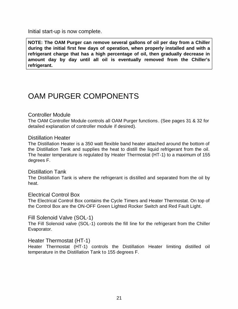
Initial start-up is now complete.
NOTE: The OAM Purger can remove several gallons of oil per day from a Chiller during the initial first few days of operation, when properly installed and with a refrigerant charge that has a high percentage of oil, then gradually decrease in amount day by day until all oil is eventually removed from the Chiller’s refrigerant.
OAM PURGER COMPONENTS Controller Module The OAM Controller Module controls all OAM Purger functions. (See pages 31 & 32 for detailed explanation of controller module if desired). Distillation Heater The Distillation Heater is a 350 watt flexible band heater attached around the bottom of the Distillation Tank and supplies the heat to distill the liquid refrigerant from the oil. The heater temperature is regulated by Heater Thermostat (HT-1) to a maximum of 155 degrees F. Distillation Tank The Distillation Tank is where the refrigerant is distilled and separated from the oil by heat. Electrical Control Box The Electrical Control Box contains the Cycle Timers and Heater Thermostat. On top of the Control Box are the ON-OFF Green Lighted Rocker Switch and Red Fault Light. Fill Solenoid Valve (SOL-1) The Fill Solenoid valve (SOL-1) controls the fill line for the refrigerant from the Chiller Evaporator. Heater Thermostat (HT-1) Heater Thermostat (HT-1) controls the Distillation Heater limiting distilled oil temperature in the Distillation Tank to 155 degrees F.

22
Oil Return Solenoid Valve (SOL-3) Oil Return Solenoid Valve (SOL-3) controls the transfer of distilled oil from the Distillation Tank to the chiller’s oil sump. Oil Return Check Valve (CK-1) The oil return check valve prevents inadvertent back-flow of oil from the Chiller’s oil sump into the OAM Purger Distillation Tank. Power Switch (PS-1) Power Switch (PS-1) controls input power to the purger control circuit and illuminates when switched ON. Pressure Equalization Check Valve (CK-2) The Pressure Equalization Check Valve maintains approximately 10 to 20 psid between the OAM tank and the chiller evaporator during the distillation phase . This residual pressure is used to push distilled oil back to the oil sump during the oil transfer phase. Pressure Equalization Solenoid Valve (SOL-2) During the Fill Phase Pressure Equalization Solenoid Valve (SOL-2) is energized (opened) to allow the pressures in the Distillation Tank and the Chiller evaporator to equalize. Once the pressures are equalized the OAM fills with refrigerant by gravity. Purge Fault Light The Purge Fault light indicates a purge fault condition has occurred and OAM Purger is inoperative. There are two locations for the Purge Fault light, one is on the top of the electrical box and two are on the right side of the OAM controller module inside the electrical box Refrigerant filter/dryer The moisture and acid filter/dryer removes moisture, acids and particulates from the refrigerant before entering the distillation tank. Safety Relief Valve (SRV-1) 300 PSI Atmospheric Pressure Relief Valve protects OAM Purger from over pressurization.

23
Figure 6 – Major Components of OAM Purger (Also See Next Page)
Power and Reset Switch
Fault Warning Light
Distillation Tank
Equalization Solenoid (SOL-2)
Oil Return Line
Connection
Heater Thermostat (HT-1) Bulb, Bulb Well & Capillary
Tube
Oil Return Solenoid (SOL-3)
Refrigerant Fill Line
Connection to Chiller
Charging Valve
Refrigerant Fill Solenoid (SOL-1)
Refrigerant Vapor Line
Connection to Chiller
Evaporator
Safety Relief Valve
Location
Sight Glass
Flexible Band Heater Base
Electrical Box
Safety Relief Valve
Oil Strainer
Pressure Equalization Check Valve
Heater Thermostat (HT-1) is inside Electrical box
See page 20 for picture

24
Figure 6 – Major Components (continued)
Heater Thermostat (HT-1) Bulb Well & Capillary Tube
Heater Thermostat (HT-1) is inside Electrical box
Refrigerant Vapor Line Connection to Chiller Evaporator
Line Connection to
Chiller Charging
Valve (Inlet of Fill Solenoid SOL-1)
Pressure Equalization Check Valve
Electrical Box
Schrader Valve
Location
Safety Relief Valve
Location
Oil Strainer
Oil Return Solenoid (SOL-3)
Equalization Solenoid (SOL-2)
Heater
Base
Fill-Line Refrigerant Filter Drier

25
MAINTENANCE This section discusses the OAM Purger system maintenance requirements and procedures, electrical wiring diagram and basic OAM Purger troubleshooting procedures. The following maintenance procedures are required to assure efficient and reliable OAM Purger operation.
WARNING: Certain servicing procedures may expose you to harmful materials and dangerous conditions. To minimize the possibility of injury, follow safety procedures and instructions described in this manual, on product labels and provided in material safety data sheets.
Periodic Maintenance Quarterly… 1. Replace the Fill Line Refrigerant Filter Dryer.
2. Visually inspect the OAM Purger for possible damage.
3. Visually inspect the entire OAM Purger for signs of leaks.
Heater Thermostat HT-1 Calibration The readings on the Heater Thermostat are approximate only. A calibration thermometer must be used for exact adjustment of the set points . The setting as it appears on the temperature scale may not exactly correspond to the actual set point of 155 degrees F.
Fill-Line Refrigerant Filter Dryer
26
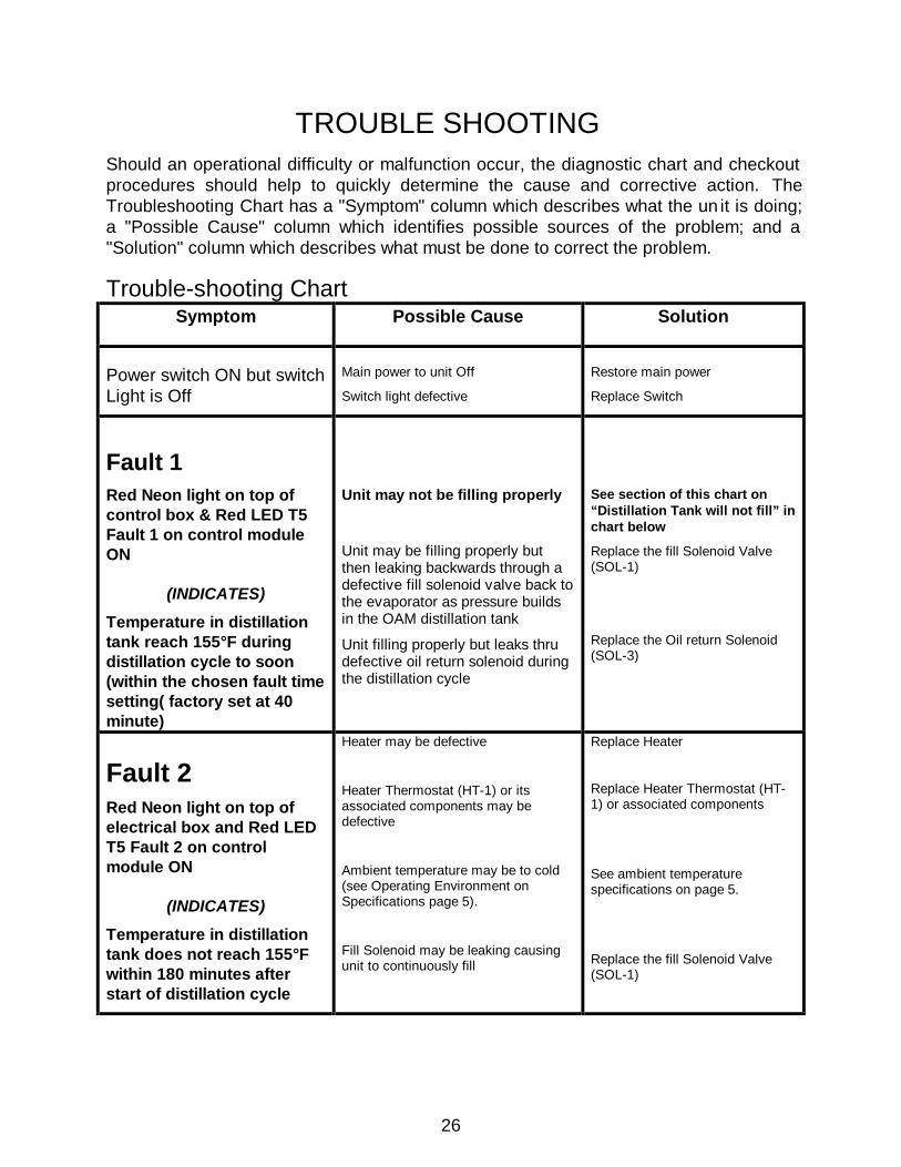
TROUBLE SHOOTING
Should an operational difficulty or malfunction occur, the diagnostic chart and checkout procedures should help to quickly determine the cause and corrective action. The Troubleshooting Chart has a "Symptom" column which describes what the un it is doing; a "Possible Cause" column which identifies possible sources of the problem; and a "Solution" column which describes what must be done to correct the problem.
Trouble-shooting Chart Symptom Possible Cause Solution
Power switch ON but switch Light is Off
Main power to unit Off
Switch light defective
Restore main power
Replace Switch
Fault 1 Red Neon light on top of control box & Red LED T5 Fault 1 on control module ON
(INDICATES)
Temperature in distillation tank reach 155°F during distillation cycle to soon (within the chosen fault time setting( factory set at 40 minute)
Unit may not be filling properly
Unit may be filling properly but then leaking backwards through a defective fill solenoid valve back to the evaporator as pressure builds in the OAM distillation tank Unit filling properly but leaks thru defective oil return solenoid during the distillation cycle
See section of this chart on “Distillation Tank will not fill” in chart below
Replace the fill Solenoid Valve (SOL-1)
Replace the Oil return Solenoid (SOL-3)
Fault 2 Red Neon light on top of electrical box and Red LED T5 Fault 2 on control module ON
(INDICATES)
Temperature in distillation tank does not reach 155°F within 180 minutes after start of distillation cycle
Heater may be defective
Heater Thermostat (HT-1) or its associated components may be defective
Ambient temperature may be to cold (see Operating Environment on Specifications page 5).
Fill Solenoid may be leaking causing unit to continuously fill
Replace Heater
Replace Heater Thermostat (HT-1) or associated components
See ambient temperature specifications on page 5.
Replace the fill Solenoid Valve (SOL-1)
27
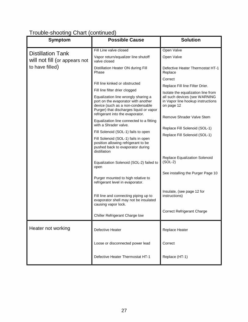
Trouble-shooting Chart (continued) Symptom Possible Cause Solution
Distillation Tank will not fill (or appears not to have filled)
Fill Line valve closed
Vapor return/equalizer line shutoff valve closed
Distillation Heater ON during Fill Phase
Fill line kinked or obstructed
Fill line filter drier clogged
Equalization line wrongly sharing a port on the evaporator with another device (such as a non-condensable Purger) that discharges liquid or vapor refrigerant into the evaporator.
Equalization line connected to a fitting with a Shrader valve.
Fill Solenoid (SOL-1) fails to open
Fill Solenoid (SOL-1) fails in open position allowing refrigerant to be pushed back to evaporator during distillation
Equalization Solenoid (SOL-2) failed to open
Purger mounted to high relative to refrigerant level in evaporator.
Fill line and connecting piping up to evaporator shell may not be insulated causing vapor lock.
Chiller Refrigerant Charge low
Open Valve
Open Valve
Defective Heater Thermostat HT-1 Replace
Correct
Replace Fill line Filter Drier.
Isolate the equalization line from all such devices (see WARNING in Vapor line hookup instructions on page 12
Remove Shrader Valve Stem
Replace Fill Solenoid (SOL-1)
Replace Fill Solenoid (SOL-1)
Replace Equalization Solenoid (SOL-2)
See installing the Purger Page 10
Insulate, (see page 12 for instructions)
Correct Refrigerant Charge
Heater not working
Defective Heater
Loose or disconnected power lead
Defective Heater Thermostat HT-1
Replace Heater
Correct
Replace (HT-1)

28
Trouble-shooting Chart (continued) Symptom Possible Cause Solution
Fill Solenoid Valve (SOL-1) fails to open or close
Solenoid coil defective
SOL-1 Solenoid Valve defective
Loose or disconnected lead
Replace coil
Replace valve
Correct
Equalization Solenoid Valve (SOL-2) fails to open or close
Solenoid coil defective
SOL-2 Solenoid Valve defective
Loose or disconnected lead
Replace coil
Replace valve
Correct
Oil transfer Solenoid Valve (SOL-3) fails to open or close
Solenoid coil defective
SOL-3 Solenoid Valve defective
Loose or disconnected lead
Replace coil
Replace valve
Correct
Oil will not transfer from Distillation Tank to oil sump
Distillation Tank not holding required differential pressure during distillation.
Oil Return Solenoid Valve SOL-3 Solenoid coil defective
SOL-3 Solenoid Valve defective
Oil Sump valve closed
Oil return line kinked or blocked
Equalization Solenoid Valve SOL-2 stuck open or leaking past valve seat
Fill Solenoid (SOL-1) leaking backward
Pressure Equalization Check Valve defective and leaking
Oil Check Valve CK-1 stuck closed
Replace coil
Replace valve
Open Valve
Correct as necessary
Replace valve
Replace Valve
Replace Pressure Equalization Check Valve
Replace oil Check Valve CK-1
For technical assistance or information about factory repair call 317-865-4130

29
PROCEDURE TO CLEAR OIL LOGGED DISTILLATION TANK The following conditions can cause “oil logging” of the OAM Purger Distillation Tank: 1. The oil sump Oil Charging valve has been inadvertently left closed.
2. The Oil Return Solenoid Valve (SOL-3) fails to open.
3. The Oil Return line is kinked, or obstructed, preventing oil return to oil sump.
4. The Pressure Equalization Check Valve is defective preventing the OAM from retaining pressure needed to return oil back to the oil sump during the oil return phase.
Should oil logging occur, clear the Distillation Tank using the following procedure: 1. Troubleshoot the purger to determine which of the above mentioned conditions has caused the oil
logging problem.
2. Correct the problem. Only after the problem has been corrected can you proceed to the next step.
3. Turn OFF power to purger.
4. Isolate the purger from the Chiller by closing all valves to purger, the Refrigerant Charging Valve, Oil Sump Charging Valve and the Evaporator Gauge Stop Valve.
5. Remove cover from Electrical Panel and from the Controls Module temporally remove the black wires from the T1, T2, and T3 terminals. Next, install a temporary electrical jumper between terminal T7 on controller Module to terminal T4 (make sure the black wire originally on terminal T4 stays connected to terminal T4 (this is the Oil return Solenoid (SOL-3) connection. This will bypass the timing function of the control module and temporally apply power to the Oil return Solenoid).
6. Using a manifold gauge set, connect a pressure source, such as nitrogen, to the Shrader Access Fitting located on the top of the Distillation Tank. Pressurize the tank to approximately 10 psig.
7. Now, RE-OPEN the oil sump oil-charging valve.
8. Turn power to purger back ON.
9. The 10 psig pressure will now push the oil from the Distillation Tank back to the Chiller’s oil sump.
10. Carefully monitor pressure and when the manifold gauge indicates a 1 to 2 psig pressure drop in the Distillation Tank turn the OAM power switch OFF.
11. Remove manifold gauge set from purger.
12. Remove the temporary jumper from the T4 connection (make sure the black wire from solenoid (SOL-3) is still attached to T4.
13. Re-attach the black wires (removed in step 5 above) to their respective terminals T1, T2, and T3.
14. Use vacuum pump to evacuate the OAM Purger.
15. Place cover back on electrical panel.
16. OPEN ALL valves to purger.
17. Turn power to purger back ON. The OAM Purger should now function properly.

30
OVERVIEW OF OAM PURGER CONTROLLER MODULE Normal Operation (no faults) When AC line power is applied to T7 and T8 power is immediately applied to the FILL output T1, and the FILL LED is turned on. The timing duration of power applied to T1 is set by the FILL time delay dipswitch. When the FILL time delay expires power is removed from T1, the FILL LED is turned off, power is applied to T2 (DIST), and the DIST LED is turned on. At the same time the FAULT and TEMP time delays are started. If the FLT time delay expires and the TEMP timer doesn’t expire before the thermostat applies power to the TEMP INPUT (terminal T3) then the controls continues to operate normally. The thermostat is wired such that the DIST output power is connected to the DIST load or the TEMP INPUT. When the thermostat applies power to the TEMP INPUT (T3), the TEMP INPUT LED is turned on, power is removed from the DIST output (T2), and the DIST LED is turned off. The OIL output (T4) and OIL LED are turned on 5 seconds after the thermostat closed. The timing duration of power applied to T4 is set by the OIL time delay dipswitch. When the OIL delay expires power is removed from the OIL output (T4), the OIL LED is turned off, the TEMP INPUT LED is turned off, and the control is reset to start of the described operation by applying power to the FILL output, T1. FAULT 1 Operation (IF TEMP IS REACHED WITHIN 40 MINUTES) (T input is energized before the FLT time delay expires) If the TEMP INPUT (T3) is energized before the FLT time delay expires the power is applied to the NEON output (T5), the FAULT 1 LED is turned on, and power is removed from all other outputs (T1, T2, and T4). The control is latched in this state until it is reset by removing and reapplying AC line power. FAULT 2 Operation (IF TEMP IS NOT REACHED WITHIN 180 MINUTES) (T input fails to energize before the TEMP delay expires) If the TEMP INPUT (T3) fails to energize before the TEMP time delay expires then power is applied to the NEON output (T5), the FAULT2 LED is turned on, and power is removed from all other outputs (T1, T2, and T4). The control is latched in this state until it is reset by removing and reapplying AC line power.
FILLT1
T8
POWER
T7
FAULT 1
FAULT 2
DISTILLATIONT2
REDI CONTROLS Inc.OAM CONTROLLER MODULE
TEMP INPUTT3
OIL RETURNT4
T5
FILL TIME FAULT TIME OIL RETURN

31
OAM CONTROL MODULE SPECIFICATIONS 1. Input Voltage: 110VAC or 120VAC, ± 15% (93VAC to 138VAC), 50/60Hz 2. Time Delay: microcontroller 2.1 Normal Mode Time Delays
2.1.1 FILL; adjustable, 10 to 30 minutes (±5%) 2.1.2 FAULT; adjustable 35 to 45 minutes (±5%) 2.1.3 OIL; adjustable 1 to 11 minutes (±5%) 2.1.4 TEMP, fixed, 180 minutes (±5%)
2.2 Test Mode Time Delays 2.2.1 FILL; adjustable, 10 to 30 seconds (±5%) 2.2.2 FAULT; adjustable 35 to 45 Seconds (±5%) 2.2.3 OIL; adjustable 1 to 11 Seconds (±5%) 2.2.4 TEMP, fixed, 180 Seconds (±5%)
2.3 Dipswitch Settings -- in the event that more than one dipswitch position is in the ON position the highest value takes effect.
3. FILL output: 3.1 Type -- solid state, non-isolated. 3.2 Form -- SPST normally open. 3.3 Rating -- 0.5A max at 120VAC, solenoid. 3.4 Voltage drop -- 2.5V max at max rating. 3.5 Leakage -- 3mA max at 120VAC . 4. DIST output 4.1 Type – relay, non-isolated. 4.2 Form -- SPST normally open. 4.3 Rating -- 5A max at 120VAC,Heater element. 4.4 Cycles of operation – 10x10 (to the 6th ) mechanical, 100x10³ electrical. 5. Oil output 5.1 Type -- solid state, non-isolated. 5.2 Form -- SPST normally open. 5.3 Rating -- 0.5A max at 120VAC, solenoid. 5.4 Voltage drop -- 2.5V max at max rating. 5.5 Leakage -- 3mA max at 120VAC . 6. NEON output 6.1 Type -- solid state, non-isolated. 6.2 Form -- SPDT normally open. 6.3 Rating -- 0.1A max at 120VAC,neon light indicator. 6.4 Voltage drop -- 2.0V max at max rating. 6.5 Leakage -- 3mA max at 120VAC . 7. TEMP input: 7.1 Type –mechanical contacts. 7.2 Form -- SPST normally open (common to T2 normally closed to DIST load). 7.3 Rating – 5mA max at 120VAC,opto-isolator interface. 7.4 Allowable leakage – 0.1mA maximum. 8. Protection: 8.1 Input and solid state outputs- transient protected. 8.2 Circuitry -- encapsulated. 8.3 Dielectric breakdown – 1500V RMS, terminals to mounting surface. 8.4 Insulation resistance – ≥ 100MΏ. 9.Mechanical: 9.1 Mounting – surface mount with #6 fasteners, 2 places. 9.2 Package – 6.5” x 3.8” x1.4” case. 9.3 Terminations – ¼” quick connects, 8 places. 10. Environmental: 10.1 Operating temperature -- -20C to 60C or -4 F to 140 F. 10.2 Storage temperature – -40C to 85C or -40 F to 185 F. 10.3 Humidity – 95% relative, non-condensing 11. Agency approvals: None. Designed to meet UL503 standard:

32
ELECTRICAL WIRING DIAGRAM
Figure 7. – Electrical wiring diagram
BLK
FAULT 2
BLK SOL-2 BLK
BLK
BLK
SOL-1 BLK
FILLT1
WHT
Distillation Heater
RED YEL
Heater T-Stat
2
14
WHT
T2DISTILLATION
T3TEMP INPUT
BLK
SOL-3
OIL RETURNT4
2B
WHT
WHT
POWER
T8
T7
2A 2
BLK
FAULT 1REDI CONTROLS Inc.OAM CONTROLLER MODULE
FILL TIME FAULT TIME
REDT5
OIL RETURN
WHT
SW-1 GRN
GND
120 VACBLK
WHT N
WHT
FAULTL1
Pigtail Leads

33
WARRANTY
Equipment Warranty Subject to the terms below, REDI CONTROLS will, within one year after date of purchase, repair any REDI CONTROLS’ product being used by the original purchaser, which is defective due to faulty materials or workmanship. REDI CONTROLS has the right to repair or replace a defective part or replace the entire product. To file a Warranty claim on any system or component, return the defective unit to the address below, or other location as REDI CONTROLS directs, freight prepaid. This Warranty does not apply to or cover:
• Damages beyond REDI CONTROLS’ control.
• Malfunctions that result from failure to properly install, operate or maintain a product in accordance with instructions provided by REDI CONTROLS.
• Failures of equipment due to abuse, accident or negligence.
• Damages from, or part failures due to equipment not being installed per REDI CONTROLS’ instructions, per applicable codes or ordinances, or in accordance with good trade practices.
• Labor or other charges incurred in removing or reinstalling any REDI CONTROLS product or part.
• Damages resulting from use of a REDI CONTROLS product for any purpose other than for which it was designed and manufactured.
• Any implied warranty of merchantability or fitness for any particular purpose, occurring after the Warranty Period.
• Loss of use, loss of time, inconvenience, rental for substitute products, loss of business, loss of income, or any other consequential damages resulting from use or failure of any REDI CONTROLS product.
Inquiries to: REDI CONTROLS at 755 E. Main Street, Greenwood, Indiana, 46143
REDI CONTROLS, INC. (317) 865-4130