Embed Size (px)
Citation preview
. r
8
OAK RIDGE N A T I O N A L LABORATORY operated by
UNION CARBIDE CORPORATION NUCLEAR DIVISION
for the U.S. ATOMIC ENERGY COMMISSION
ORNL- TM- 3014
PHASE REPORT NO. 115-1
on
STRESS INDICES FOR SMALL BRANCH CONNECTIONS WITH EXTERNAL LOADINGS
E . C , Rsdabaugh
Ba'itelJe Merncrrial Institute
NOTICE T h i s document conta ins in format ion of a p re l im ina ry nature
ond was prepared p r imar i l y for in ternal use a t the Oak R idge Na t iona l
Laboratory . It i s sub iec t to r e v i s i o n or co r rec t i on and therefore does
not represent a f i n a l report.
LEGAL NOTICE
T h i s report was prepared as an account of Government sponsored work. Neither the lJnited States,
nor the Commission, nor o n y person act ing on behalf of the Commission:
A. Makes any worranty or representation, expressed or implied, w i th respect to the accuracy.
completeness, or usefulness o f the information contained i n th is report, or thot the use of
any information, apparatus, method, or process disclosed In th is report may not infrlnge
pr ivately owned rights; or
Assumes any l i a b i l i t i e s w i t h respect to the use of, or for damages resul t ing from the use o f
any information, apporotus, method, or process disclosed i n th is report.
5.
A s used i n the above, “person act ing on behal f o f the Commission” includes any employee or
contractor of the Commission, or employee of such contractor, to the extent that such employee
or contractor of the Commission, or employee o f such contractor prepares, disseminates, or
provides access to, any information pursuant t o h i s employment or contract wi th the Commission,
or h i s employment w i t h such contractor.
ORNL-m-3014
Contract No. W-7405-eng-26
Reactor Divis ion
PHASE REPORT NO. 115-1
on
STmSS INDICES FOR SMALL BRANCH CONNECTIONS WITH EXTERNAL LOADINGS
E . C . Rodabaugh
B a t t e l l e Memorial I n s t i t u t e
AUGUST 1970
Subcontract No. 2913
for
OAK RIDGE NATIONAL LABORATORY Oak Ridge, Tennessee
operated by UNION CARBIDE CORPORATION
for the U .S . ATOMIC ENERGY COMMISSION

iii
FOREWORD
The work r epor t ed here was done a t B a t t e l l e Memarial I n s t i t u t e under
subcont rac t t o t h e Oak Ridge Nat iona l Laboratory ( O m ) which i s operated
by Union Carbide Corporat ion f o r t h e U.S. Atomic Energy Commission. This
e f f o r t is p a r t of t h e "Design C r i t e r i a f o r P ip ing , Pumps, and Valves Pro-
gram" (ORNL Pip ing Program) under t h e d i r e c t i o n of w . L . G r e e n s t r e e t , Head,
Applied Mechanics Sec t ion , and S. E . Moore, Program Coordinator . The ORNL
Pip ing Program i s t h e MC supported p o r t i o n of an AEC-Industry coopera t ive
e f f o r t f o r t h e development of des ign c r i t e r i a f o r p ip ing components, pumps,
and va lves t o be used i n nuc lea r power p l a n t p i p i n g systems.
Indus t ry coopera t ive e f f o r t i s coordinated by t h e P res su re Vesse l Research
Committee (WRC) of t h e Welding Research Council.
USAEC cognizant eng inee r .
The AEC-
J . L. Mershon i s t h e


V
TABU OF CON’IIENTS
Page - N O M E N C L A W ................................................... vi
ABSTRACT ....................................................... 1
INTRODUCTION ................................................... 2
LOADINGS AND STRESS INDICES .................................... 4
TEST DATA ...................................................... 14
PROPOSED INDICES FOR B31.7 ..................................... 28
Moment Loading Thru Branch ................................ 28
R e s u l t a n t Moment .......................................... 40 B z - i n d i c e s ................................................ 41 Surmnary and Example ....................................... 43
Moment Loading Thru Run ................................... 35
STRESSES BY B3l.l.O POWER PIPING CODE .......................... 48
FORCE LOADINGS ................................................... 5 1
R E C O W N D E D CKANGES IN B31 .7 ................................... 56
REFERENCES ..................................................... 61

v i
NOMENCLATURE
L
(1 = branch p i p e diameter
I> = run pipe diameter
IS = run p ipe wa l l t h i ckness
(Other dimensional symbols a r e def ined i n F igure 1)
$ 1 , ~ = coord ina te s of p o i n t on branch connect ions; See F igure 3 .
where i = x,y,z, j = 1 , 2 , 3 Se t of n ine or thogonal moments given by a p ip ing system f l e x i b i l i t y a n a l y s i s ; See F igure 2 .
"ij ;
Fij9 *
M. * where i = x,y,z, j = r , b i j '
a s above, except f o r c e s
Se t of s i x independent or thogonal moments used i n t h e t e s t arrangement shown i n F igure 3 .
L = a x i a l f o r c e appl ied t o branch p ipe
Z = = s e c t i o n modulus of p ipe
A = c r o s s s e c t i o n a l meta l a r e a of p ipe
Zb
Zr C , i = (with v a r i o u s s u b s c r i p t s ) a r e stress i n d i c e s
S = a nominal stress
0 = a s p e c i f i c p r i n c i p a l s t r e s s i n a branch connect ion
= s e c t i o n modulus of branch p ipe
= s e c t i o n modulus of run pipe
- cr = a s p e c i f i c s t r e s s i n t e n s i t y i n a branch connect ion
Addi t iona l symbols a r e def ined i n the t e x t a s they occur .
vii
BRANCH PIPE = NOZZLE 7 BRANCH PIPE
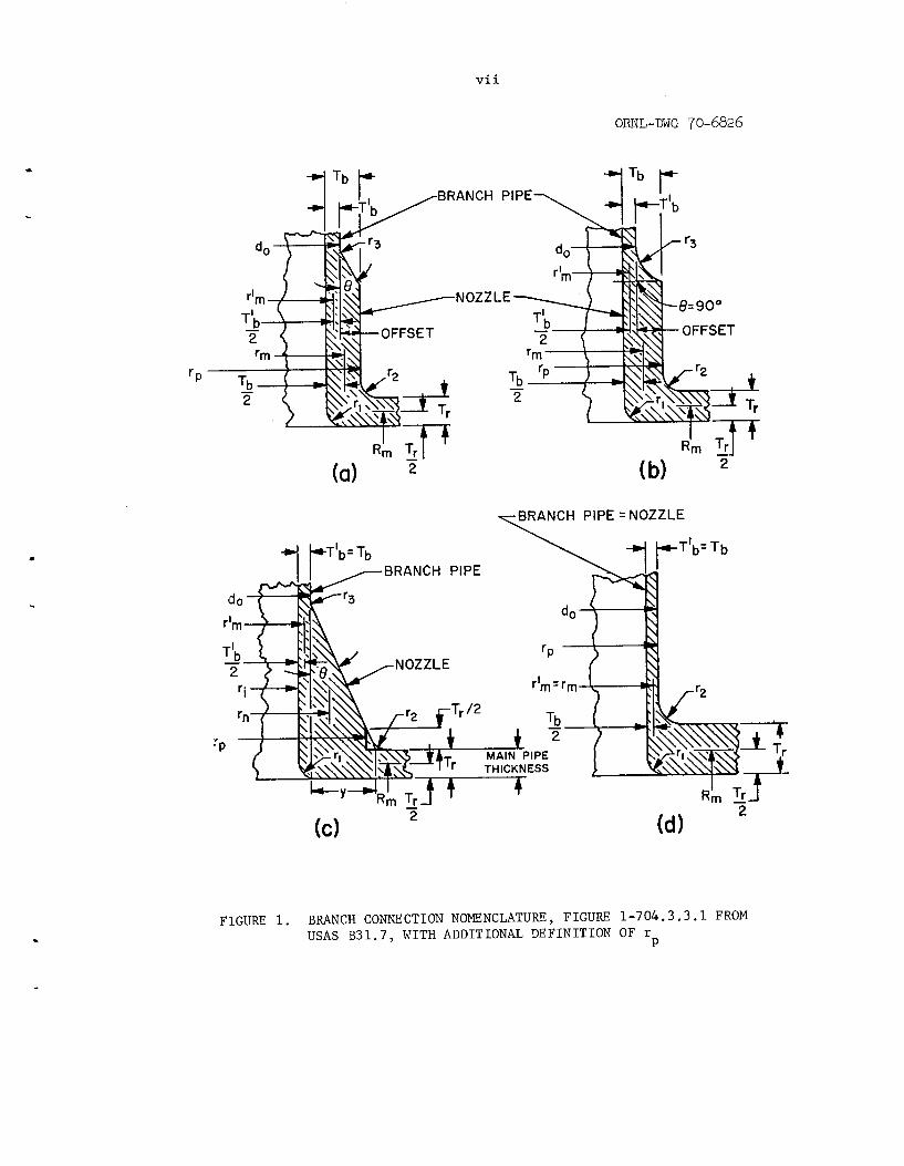
F I G U R E 1. BRANCH CONNECTION NOMENCLATURE, F I G U R E 1-704.3.3.1 FROM USAS B 3 1 . 7 , W I T H ADDITIONAL D E F I N I T I O N OF r P


STRESS INDICES FOR SMALL BRANCH CONNECTIONS WITH EXTERNAL LOADINGS
E . C . Rodabaugh
ABSTRACT
S t r e s s i n d i c e s and s i m p l i f i e d design formulas a r e developed f o r use
i n t h e s t r e s s a n a l y s i s of s m a l l branch connect ions i n Class I p ip ing systems
as requ i r ed by t h e ANSI Standard, Code f o r Pressure P ip ing , Nuclear Power
P ip ing ANSI B31.7. Equat ions a r e given f o r reducing t h e s e t of nine
moments which a c t on a branch connect ion, and whose numerical va lues a r e
obtained from a p ip ing f l e x i b i l i t y a n a l y s i s t o two r e s u l t a n t moments.
i n d i c e s t o be used w i t h t h e s e r e s u l t a n t moments a r e e m p i r i c a l l y developed
from e x i s t i n g t e s t data; and des ign r u l e s a r e proposed f o r i n c l u s i o n i n
ANSI B31.7 . The e f f e c t s of d i r e c t shea r f o r c e loadings on branch connect ions
a r e a l s o d i scussed .
S t r e s s
Keywords: s t r e s s i n d i c e s , s m a l l branch connect ions, p ip ing t e e s , s t r e s s a n a l y s i s , nuc lea r p ip ing , p ip ing code, ANSI B31.7.
2
INTRODUCTION
The Nuclear Power Piping Code, USAS B31.7('), provides s t r e s s
i.ndices f o r two:'; broad types of branch connect ions:
1) Branch connect ions p e r Subpar. 1-704.3.
2) Butt-welding t e e s pe r USAS B16.9 o r MSS SP-48.
This Phase Report i s concerned only w i t h the f i r s t t y p e of branch
connect ions. It should be remarked t h a t t he f i r s t type of branch
connect ions a r e ass igned s t r e s s i n d i c e s i n Table D201 of B31.7 only
f o r d/D < - 0.5, where d = branch d iameter , D = run diameter .
t r i i s t , b u t t welding t e e s a r e normally a v a i l a b l e only f o r d/D > ,., 0.5.
In t h e fol lowing, we w i l l use the term "branch connections" as r e f e r r i n g
s p e c i f i c a l l y t o branch connect ions pe r Subpar. 1-704.3.
I n con-
Two a d d i t i o n a l l i m i t a t i o n s a r e placed oii the a p p l i c a b i l i t y of
s t r e s s i n d i c e s t o branch connect ions:
1)
2 ) Branch pipe axis normal t o the s u r f a c e of t he run pipe
D / t n o t over 100; t = w a l l t h i ckness of run p ipe .
(For example, l a te ra l s are excluded.)
Subparagraph 1-704.3 of B31.7 i s e n t i t l e d " In t e r sec t ions" ;
i t r e q u i r e s 100% cut -out a r e a replacement un le s s d < - 0.1414 fl and
f u r t h e r provides r e i n f o r c i n g zone bounds w i t h i n which r e i n f o r c i n g i s
considered as e f f e c t i v e i n r e p l a c i n g the cu t -out area. The r e i n f o r c i n g
i s based on i n t e r n a l pressure loading only and i s n o t r e l a t e d t o the
magnitude of t he e x t e r n a l loadings . Because e s s e n t i a l l y any branch
.
.
7'; A t h i r d c l a s s of hranch connect ions c o n s i s t s of socket-welding f i t t i n g s such as those purchased t o USAS B16.11. These appa ren t ly p re sen t a des ign problem only a t t he socket weld.
3
. connect ion w i l l meet the r e i n f o r c i n g
p resen t B31.7 formulat ion f o r C f o r 2
r u l e s f o r some p res su re , the
branch connect ions i s s u b j e c t t o n 1- L l J is misappl ica t ion . The p resen t formulat ion f o r C = 1.8 (Rm/3 Tr)
based on the assumption t h a t T i s the th i ckness of the run pipe r equ i r ed
f o r i n t e r n a l pressure and t h a t a d d i t i o n a l r e i n f o r c i n g i s r equ i r ed t o
2
r
meet t h e B31.7 r e i n f o r c i n g r u l e s . Because e i t h e r p a r t o r a l l of the
r e i n f o r c i n g can be suppl ied by the run p ipe , t he p re sen t formulat ion
f o r C may n o t be conserva t ive f o r some configurations;k. 2
USAS B31.1.0-1967, Power P ip ing , g ives some equat ions f o r
c a l c u l a t i n g s t r e s s e s i n branch connec t ions ; bu t i s l i m i t e d t o (1) B16.9
tees, (2) pad o r saddle r e in fo rced t e e s , o r (3) uniform w a l l ( f a b r i c a t e d ,
unre inforced) tees. The f i r s t of t hese i s n o t included i n t h i s r e p o r t ;
t he second i s n o t permiss ib le under B31.7, hence only the t h i r d type
might o f f e r some guidance. These code r u l e s a r e d iscussed l a t e r he re in .
r
7k A l e t t e r from R. N. Zogran t o the au thor , December 27 , 1968, po in ted ou t t h i s p o s s i b i l i t y .
4
L O A D I N G S A N D STRESS I N D I C E S
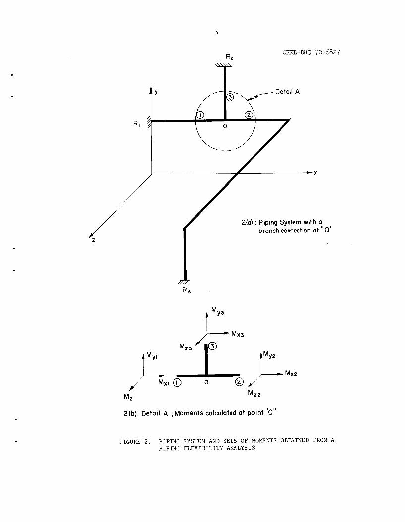
The magnitude of e x t e r n a l loadings app l i ed t o a branch con-
nec t ion i n a p ip ing system i s normally determined by a "piping f l e x i -
b i l i t y ana lys i s" . Figure 2(a) i l l u s t r a t e s a simple p ip ing system
con ta in ing a branch connect ion a t p o i n t "0" . A s implied by Figure 2 ( a ) ,
a p ip ing f l e x i b i l i t y a n a l y s i s assumes t h a t the p ip ing system, which
a c t u a l l y c o n s i s t s of va r ious s h e l l s t r u c t u r e s , can be modeled as an
assemblage of one-dimensional beams. Moments and f o r c e s a r e genera ted
i n the p ip ing system by:
a ) Weight o r i n e r t i a l oads of the p ipe , p ip ing components
(e .g . , va lves ) i n s u l a t i o n , con ten t s , e t c .
L inear o r r o t a t i o n a l displacements of r e s t r a i n t p o i n t s .
For example, R of Figure 2(a) may be a p re s su re v e s s e l
nozz le which moves wi th r e s p e c t t o r e s t r a i n t p o i n t R
and/or R3.
b)
1
2
c ) Change i n the l e n g t h of t he p ip ing due t o change i n
temperature of the p ip ing .
A t a branch i n t e r s e c t i o n p o i n t , such as p o i n t "0" of Figure 2 ( a ) ,
the p ip ing f l e x i b i l i t y a n a l y s i s w i l l g ive t h r e e or thogonal s e t s of
.
moments which e i t h e r a r e d i r e c t l y , o r can be r o t a t e d tq the moment sets
shown i n Figure 2(b) . Equi l ibr ium r e q u i r e s t h a t t h e s e s e t s of moments
be r e l a t e d by:
5
t Y
ORNL-DWG 70-6827
MY3
2(a) : Piping System with a branch connection at "0"
Mz 2
2(b): Detail A , Moments calculated at point "0"
FIGURE 2 . PIPING SYSTEM AND SETS OF MOMENTS OBTAINED FROM A PIPING FLEXIBILITY ANALYSIS
6
f Mx2 + Mx3 = 0 Mxl
M + M + M = O Y l Y 2 Y3
MZ1 + MZ2 + MZ3 = 0
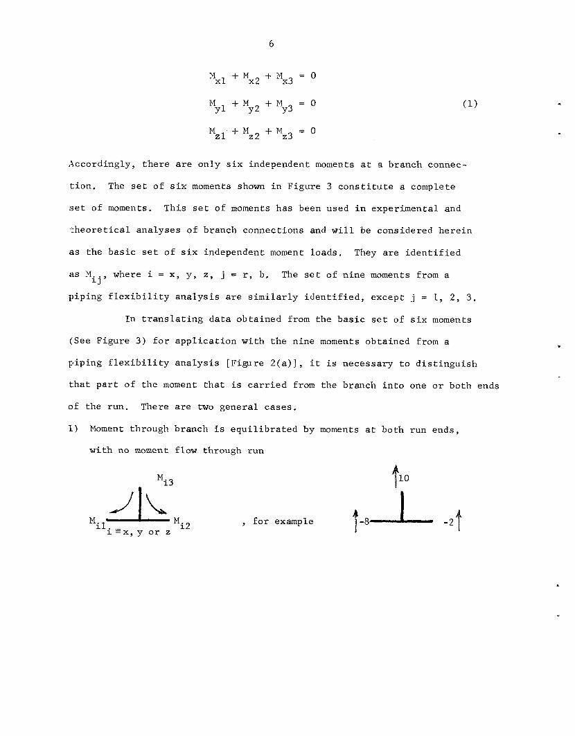
Accordingly, t h e r e a r e only s i x independent moments a t a branch connec-
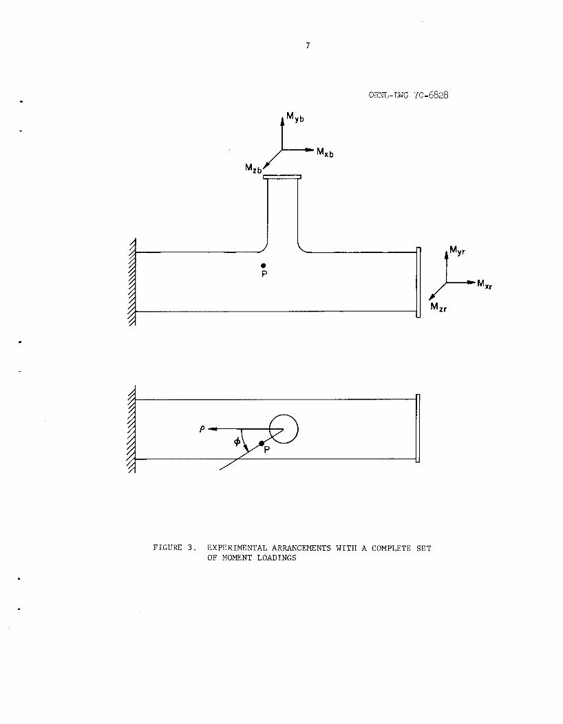
t ion . The se t of s i x moments shown i n F igure 3 c o n s t i t u t e a complete
s e t of moments. This s e t o f moments has been used i n experimental and
ithleoretical ana lyses of branch connect ions and w i l l be considered h e r e i n
as the b a s i c se t of s i x independent moment loads . They a r e i d e n t i f i e d
a s M where i = x , y , z , j = r, b, The s e t of n ine moments from a
p ip ing f l e x i b i l i t y a n a l y s i s a r e s i m i l a r l y i d e n t i f i e d , except j = 1, 2, 3. i j ’
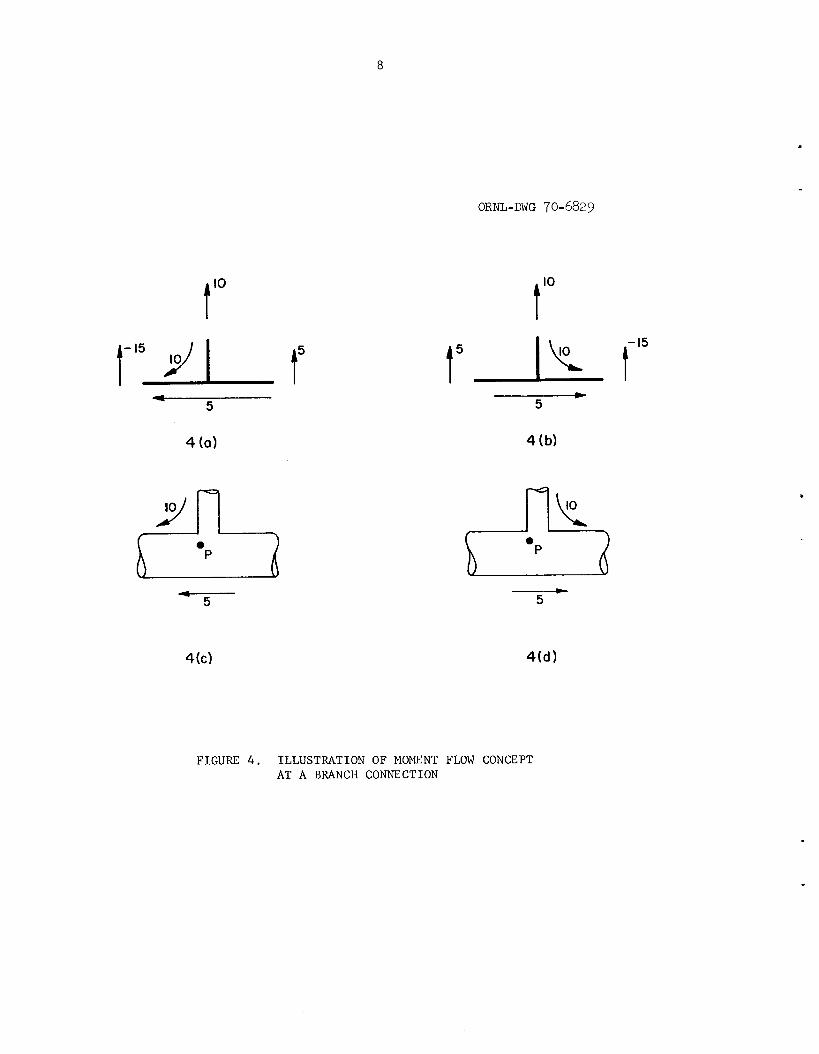
I n t r a n s l a t i n g d a t a obta ined from the b a s i c s e t of s i x moments
(See Figure 3 ) f o r a p p l i c a t i o n wi th the n ine moments obta ined from a
p ip ing f l e x i b i l i t y a n a l y s i s [F igure 2 ( a ) ] , i t is necessary t o d i s t i n g u i s h
t h a t p a r t of t he moment t h a t i s c a r r i e d from the branch i n t o one o r both ends
o f the run. There a r e two genera l ca ses .
1) Moment through branch i s e q u i l i b r a t e d by moments a t both run ends,
w i t h no moment flow through run
, for example il. - Mi 2 M 1 = x , y o r z
7
O m - D W G 70-6828
F I G U R E 3 . EXPERIMENTAL ARRANGEMENTS W I T H A COMPLETE S E T O F MOMENT LOADINGS
8
ORNL-DWG 70-6829
1-15 I t’ 4
5
4 (a)
c--- 5
L 5
4 (b)
-4 5
.
F I G U R E 4 . I L L U S T R A T I O N OF MOMENT FLOW CONCEPT A T A BRANCH CONNECTION

9
2 ) Moment through branch i s e q u i l i b r a t e d by moment a t one run end wi th
a r e s i d u a l moment flow through the run
M
Mi3 Po , f o r example
o r
Mi3
, f o r example
L i 10 i
Rela t ionships between the b a s i c moments and the f l e x i b i l i t y
a n a l y s i s moments, app ropr i a t e f o r a p p l i c a t i o n wi th the B31.7 s i m p l i f i e d
analysis" , a r e as fol lows :
Perhaps a b e t t e r way of s t a t i n g t h e same r e l a t i o n s h i p is: If t h e s ign
of Mil i s t h e same as t h e s ign of M
Mil and Mi2.
Mir = 0; otherwise M = l e s s e r of i2' ir
* The s i g n of t h e moment flow i s l o s t i n t h i s formula t ion ; t h i s i s a s i m p l i f i c a t i o n i n accordance wi th the B31.7 (Par 1.705) s i m p l i f i e d a n a l y s i s philosophy t h a t maximum s t r e s s i n t e n s i t i e s due t o a l l load- ings occur a t the same su r face p o i n t and a r e o r i e n t e d so t h a t they d i r e c t l y add t o each o the r .
10
S t r e s s Indices
Two types of ana lyses a r e covered i n B 3 1 . 7 ; a "s impl i f ied"
a n a l y s i s as covered by 1-705 of B 3 1 . 7 and a "de ta i led" a n a l y s i s as covered
b y Appendix F of B 3 1 . 7 . While the s t r e s s i n d i c e s der ived h e r e i n a r e f o r
t he s i m p l i f i e d a n a l y s i s , some d i scuss ion of what stress ind ices would be
r equ i r ed f o r the d e t a i l e d a n a l y s i s i s p e r t i n e n t ; i n p a r t t o i n d i c a t e
why such d e t a i l e d s t r e s s i n d i c e s a r e n o t a v a i l a b l e a t t h i s t i m e .
S t r e s s i n d i c e s f o r the d e t a i l e d a n a l y s i s of branch connect ions,
wit.h moment loadings , might b e s t be given i n t h e form;?:
where
B = p r i n c i p a l s t r e s s a t a p o i n t , p , on the branch connection P
due t o moment load , M
P i j
i j
i = p r i n c i p a l s t r e s s index f o r M a t p o i n t p
Mi j
Z = s e c t i o n modulus of pipe ( run o r branch, as s p e c i f i e d by
-j appl ied moment
the s t r e s s index nomenclature)
I n o rde r t o c a r r y ou t t h e d e t a i l e d a n a l y s i s of' B 3 1 . 7 , it would
be necessary t o have stress i n d i c e s ( i 1 f o r :
(1:) Each of t he s i x independent moment loads . P
(:2) S u f f i c i e n t s u r f a c e l o c a t i o n s t o adequate ly desc r ibe the s t r e s s f i e l d
f o r each moment (perhaps 50 t o 100 l o c a t i o n s ) . These might be
expressed as func t ions of p, 8 ( see Figure 3) and i.nside, o u t s i d e
o r midwall su r f ace .
+,: Analogous t o t h e i - i n d i c e s f o r curved p ipe o r welding elbows, Table D - 3 0 9 - 2 of B 3 1 . 7 .
11
A t each po in t , a minimum of t h r e e q u a n t i t i e s would have t o be descr ibed
by the s t r e s s index; e . g . , the maximum and minimum p r i n c i p a l s t r e s s e s
and t h e i r o r i e n t a t i o n wi th respect t o e s t a b l i s h e d coord ina te s ,
From the above, i t is apparent t h a t a s e t of d e t a i l e d s t r e s s
i nd ices f o r a given branch connection would c o n s i s t of 1000 t o 2000 quan-
t i t i e s . From these q u a n t i t i e s , the p r i n c i p a l stresses a t any p o i n t
on the branch connect ion f o r any combination of moments could be obta ined;
provided, of course , t h a t supe rpos i t i on i s app l i cab le .
Having obta ined p r i n c i p a l s t r e s s e s due t o moment loads , the
nex t s t e p would be t o add the s t r e s s e s due t o i n t e r n a l p re s su re and t h e r -
m a l g r a d i e n t s t r e s s e s , then t o determine stress i n t e n s i t i e s from the
p r i n c i p a l s t r e s s e s and complete the a n a l y s i s by comparing those s t r e s s
i n t e n s i t i e s w i th the al lowable s t r e s s i n t e n s i t i e s given i n B 3 1 . 7 .
These sets of d e t a i l e d stress i n d i c e s could , i n p r i n c i p a l , be
obtained by e i t h e r a t h e o r e t i c a l o r experimental s t r e s s a n a l y s i s . Un-
f o r t u n a t e l y , a t t h i s time a proven t h e o r e t i c a l a n a l y s i s has n o t been
developed f o r branch connect ions wi th moment loads nor i s s u f f i c i e n t t e s t
d a t a a v a i l a b l e t o e s t a b l i s h d e t a i l e d s t r e s s i nd ices . Even w i t h an
a v a i l a b l e theory and/or t e s t d a t a , t he shear bulk o f the d e t a i l e d s t r e s s
i n d i c e s might make t h e i r p r e s e n t a t i o n i n B 3 1 . 7 imprac t ica l .
There i s however, some tes t d a t a from which a probably conserva-
t i v e e s t ima te of maximum s t r e s s e s i n branch connect ions can be formulated.
This i s the approach taken i n Table D-201 of B 3 1 . 7 i n which the s i m p l i -
f i e d s t r e s s i nd ices ( C ) a r e given. I n p r i n c i p a l , we want t o e s t a b l i s h
va lues of the s i x C - ind ices i n the equat ion:
2
2 i j
1 2
Mzb amax - '2xr z + c 2yr Z """C2zb 7
M M x r - -
whe r e -
= maximum s t r e s s i n t e n s i t y . Omax
.If we cons ide r a tes t se t -up as ind ica t ed i n Figure 3 , wi th a branch
2 i j connect ion thoroughly instrumented w i t h s t r a i n gages, the va lue of C
(can be e s t a b l i s h e d by applying, s e p a r a t e l y , Mxr7 M y r ..... MZb.
choose t o de f ine Z f o r moments app l i ed t o the run (M
:Z = s e c t i o n modulus of t he run pipe and Z f o r moments app l i ed t o the
branch (Mxb, M
From the measured maximum s t r e s s i n t e n s i t y t h e va lue of C i s
obta ined , f o r example, as:
We now
M MZr) as x r ' y r '
r
M ) as Zb = s e c t i o n modulus of the branch p ipe . yb' zb
2 i j
= stress index f o r M 2xr x r
= maximum measured s t r e s s i n t e n s i t y , a s determined from Oxr
s t r a i n gages, under load Mxr
= a p p l i e d moment. Mxr
= s e c t i o n modulus of run p ipe . 'r
I n developing va lues f o r C i n t he subsequent s e c t i o n s o f
t h i s r e p o r t , i t w i l l be noted t h a t two kinds of experimental d a t a a r e
used: (1) s t r a i n gaged tes t models and (2) f a t i g u e t e s t s , The f a t i g u e
2 i j
t e s t s , by an e v a l u a t i o n d iscussed l a t e r h e r e i n , l ead t o C2i j f a c t o r s
13
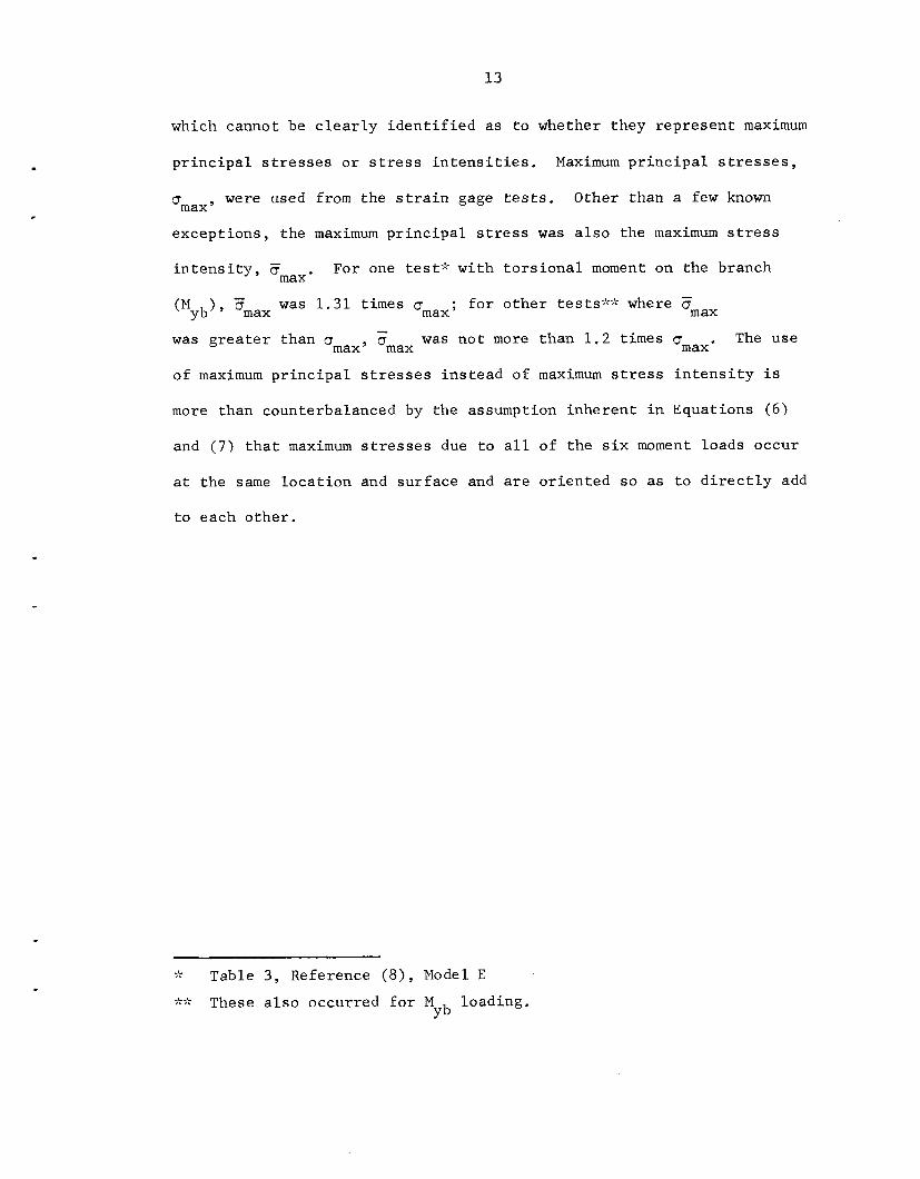
which cannot be c l e a r l y i d e n t i f i e d a s t o whether they r ep resen t maximum
p r i n c i p a l s t r e s s e s o r s t r e s s i n t e n s i t i e s . Maximum p r i n c i p a l s t r e s s e s ,
were used from the s t r a i n gage t e s t s . Other than a few known Bmax 9
except ions , t he maximum p r i n c i p a l s t r e s s was a l s o the maximum s t r e s s
i n t e n s i t y - For one test ' ; wi th t o r s i o n a l moment on the branch
(M
was g r e a t e r than cr w a s no t more than 1 . 2 times CJ The use
of maximum p r i n c i p a l s t r e s s e s in s t ead of maximum s t r e s s i n t e n s i t y i s
' Drnax'
), Fmax was 1.31 times CJ f o r o the r tests"" where Fmax Yb max ' -
max' Omax max
more than counterbalanced by the assumption inherent i n Equations ( 6 )
and ( 7 ) t h a t maximum s t r e s s e s due t o a l l of the s i x moment loads occur
a t t he same l o c a t i o n and sur face and a r e o r i en ted so a s t o d i r e c t l y add
t o each o the r .
~~
7k Table 3 , Reference (8), Model E
;k;k These a l s o occurred f o r M loading. Yb
14
TEST DATA
Complete e t s of t e s t d a t a on branch con e c t i o n s u ing the
t e s t arrangement shown i n Figure 3 a r e q u i t e l i m i t e d ; d a t a known t o the
au thor a r e summarized i n Tables 1 and 2 . Only one of t hese t e s t
specimens f a l l s w i t h i n the class of branch connect ions considered
h e r e i n ; t h a t one being t h e 1 2 x 1 2 x 4 Weldolet connect ion.
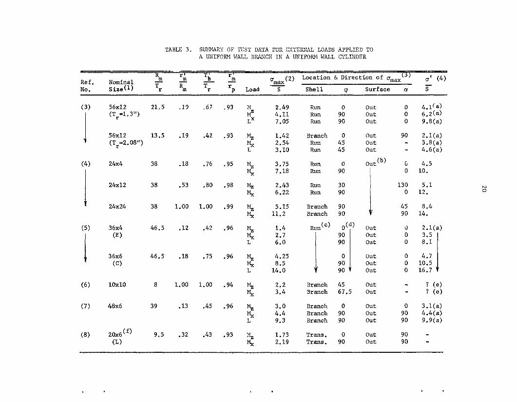
Addi t iona l u s e f u l t e s t d a t a i s shown i n Tables 3 and 4 . A l l
af t h i s d a t a i s f o r moments (and i n a few cases , a x i a l f o r c e s ) app l i ed
t o the branch. The r e fe rences c i t e d do n o t , i n gene ra l , i n d i c a t e
whLere o r what kind of r e a c t i o n fo rces were app l i ed . In most c a s e s ,
i t appears t h a t run p ipe w a s anchored a t bo th ends. For s m a l l d/D
branch connect ions i t probably d o e s n ' t make much d i f f e r e n c e where t h e
r e a c t i o n f o r c e s were app l i ed . This assumption i s implied i n the sub-
sequent a n a l y s i s of t h i s t es t da t a .
Tables 3 and 4 a r e taken from Reference (14) w i t h some modi-
f i c a t i o n s , Table 3 covers "uniform-wall" t es t models whi le Table 4
covers t e s t models w i t h some type of l o c a l r e i n f o r c i n g around the
branch. Some p e r t i n e n t comments on these t a b l e s fol low.
1) The dimensional nomenclature is t h a t of Figure 1-704.3.3.1
of B31.7; reproduced here as F igure 1 f o r r e fe rence con-
venience. The a d d i t i o n a l symbol r i s used f o r the
e f f e c t i v e r a d i u s of a pad r e i n f o r c i n g . It i s de f ined as
the r ad ius i n s i d e which the reinforcement i s t h i c k e r
(measured normal t o the c y l i n d e r ) than 0.5 T
P
r '
15
2 ) Under the "Load" column, Mx, M and M correspond t o Y ' z
Mxb, Myb, and M
f o r c e appl ied t o the branch. Sign r e l a t i o n s h i p between
p o s i t i v e loads and p o s i t i v e s t r e s s e s are n o t - maintained
i n these Tables .
of Figure 3 . L i n d i c a t e s an a x i a l zb
3 ) An e n t r y i n the l a s t column ( a ' / S ) i n d i c a t e s t h a t , i n
t he a u t h o r ' s op in ion , the maximum repor t ed measured s t r e s s
w a s n o t r e p r e s e n t a t i v e of the a c t u a l maximum secondary
s t r e s s .
from th ree o r more s t r a i n gages placed along a 0 = con-
s t a n t l i n e up t o the d i s c o n t i n u i t y po in t . This impl ies
t h a t the s t r a i n gage n e a r e s t t o the d i s c o n t i n u i t y w a s a
s i g n i f i c a n t d i s t ance away from the d i s c o n t i n u i t y . Where
no e n t r y i s shown under u ' /S , i t i s the a u t h o r ' s opinion
t h a t t he maximum repor t ed measured s t r e s s i s reasonably
r e p r e s e n t a t i v e of the a c t u a l maximum s t r e s s .
The va lues of o'/S r ep resen t e x t r a p o l a t i o n s
Table 5 g ives f a t i g u e t e s t d a t a on branch connect ions w i t h
d/D up t o 0.63. Reference (11) t e s t s were c o n t r o l l e d displacement t e s t
analogous t o those r epor t ed by Markl(15).
run wi th an i n e r t i a l loading device whi le Reference (13) t e s t s were run
wi th c o n t r o l l e d moment loading. It i s s i g n i f i c a n t t o no te t h a t f a t i g u e
f a i l u r e s i n a l l bu t one t e s t specimen were a s soc ia t ed wi th welds; t he
one except ion being Reference 13, Model D. Crack l o c a t i o n s and spec i -
mens are descr ibed i n d e t a i l i n Reference ( 1 4 ) .
Reference ( 1 2 ) t e s t s were
1 6
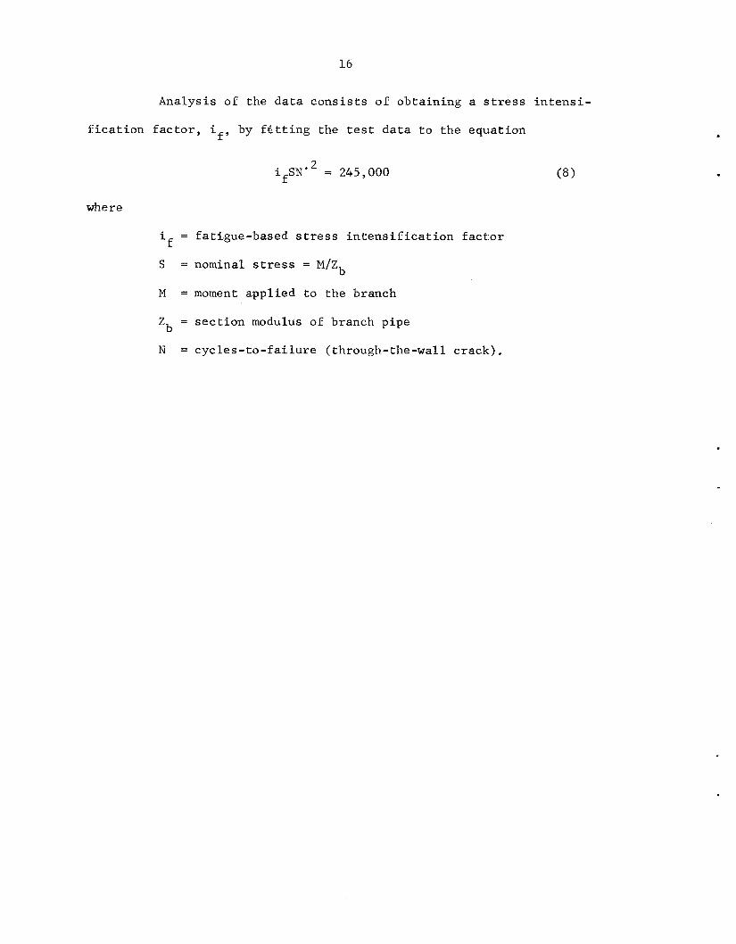
Analysis of t h e d a t a c o n s i s t s of ob ta in ing a s t r e s s i n t e n s i -
f i c a t i o n f a c t o r , i by f g t t i n g the t e s t d a t a t o t h e equat ion f ’
i f S N . * = 245,000
i = fati.gue-based s t r e s s i n t e n s i f i c a t i o n f a c t o r
S
M = moment app l i ed t o t h e branch
Zb = s e c t i o n modulus of branch pipe
N = c y c l e s - t o - f a i l u r e (through-the-wall c r ack ) .
f
= nominal stress = M / Z b

17
mm
o
e4 4
n
m
h
a, a
mm
m
mm
rl
mc
e-
- o+
mc
bC
acc
.I
7
r
co
r- o
cc
m
hl
.#
L
43 4
H
0
0
m
N
03 d
H
0
m
W
N
0 4
4
H
0
m
N
e
PI
Ll 0
w
PI
m
N
N
d
II
n
0
X
N
W 1
m
N
N 4
X
PI
II
U
N 1
!a P
I
II
m
M
C .r
l a.
@d
m
oa
d
aJ
U
a, L
lLl
77
mo
m
w
a, &Id
ad
rd Ll 0
F E
a, I-1 m
00 H
0
00
U
aJ
l-4 0
a
l-4
e x
N
rl
??
9 NO 0
am m
I
00
on0
.. me
m\cv m
m
a 0
eo N
... m
mN
m
mm
...
mrll-4
X N
d
a03 a
mn
m
ma43
nme
aJ 3 w
0 H
H H
O
HH
99
9
no 0
emm
oon
om-
mea
... ad-
man
aaa
mm
m
co
n-
mw
d
II I1
bm
h
W
N
HH
H HOO
II n
n .. c
LlP
P
7
NN
N
ffi no0
em
m
I1
mno
4.m
7
4
I
03
mN
n
mc
v
Nm
N
... &
I 0
F
awa
4.m
m
HH
H
OH
H
.. aJ u
ca w
Ll 1
v)
moo
-0
0
I
... amm
mnn
bb
b
awa
ah
l-
emw
~m
d
...
... o
oaa
mr
lm
In44
...

- Load
Mxr
M Y r
Mz r
Mxb
M
Mzb
Yb
TABLE 2 . SI.TMMARY OF MAXTMIIM PRTNCTPAL STRESSES FROM STRAIN GAGE TESTS ON A 3 x 3 x 3 , Sch lOS, B16,9 TEE AND ON A 10 x 10 x 5: 45" : LATERAL 10.5" O . D . x 0.75" WALL RUN, 5.25 O.D. x 0.375'' WALL BRANCH
Location 3) 0 I 3.42 60
1.20 60
2.45 90
4.24 60
4.19 60
2.14 30
Max. Locat ion Surface '' J
01s (2) 0
4.07 210
.94 285
3.19 285
2.40 285
2 . 1 1 270
2.97 180
E
"4 F
Notes :
(1) S t r a i n gages were placed on o u t s i d e su r face only. Presumably, f o r some loads , h ighe r s t r e s s e s e x i s t e d on t h e i n s i d e su r face .
(2) 0 = maximum measured p r i n c i p a l s t r e s s .
For Branch:
S = M / Z b ; Mzb/Zb; M /2Zb xb Yb
For Run:
S = M / Z r , MZr/zr, Mxr/2zr Y r
Z r = s e c t i o n modulus of run p ipe
Z b = s e c t i o n modulus of branch pipe.
( 3 ) I = i n s i d e , 0 = Outside
(4) Data from Fung & Lind, "Experimental Stress Analysis of a 45" L a t e r a l n e c t i o n Subjected t o Ex te rna l Loadings", U. of Waterloo, Waterloo, Canada, Sept.1968.
Pipe Con-
. I .
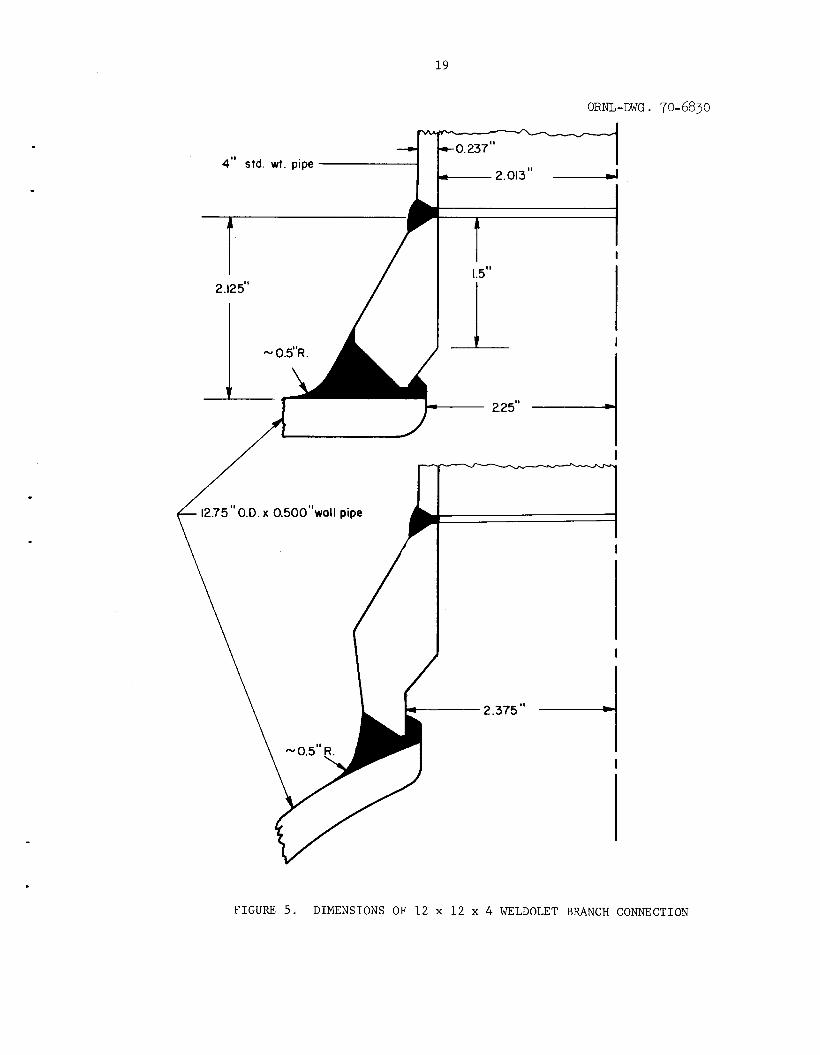
19
ORNL-DWG. 70-6830
--e t 0 . 2 3 7 " 4" std. wt. pipe
I 1.5"
1 I
2.12 5"
- 0.5"R.
2.25"
/ I i 12.75" O.D. x 0.500"wall pipe /
2.375"
I
I
I
F I G U R E 5. DIMENSIONS O F 1 2 x 1 2 x 4 WELDOLET BRANCH CONNECTION
R I
(2) Location & Direction of omax(') 0' (4) r ' r ' m
'max - No. Size(1) Tr Rm Tr P Load S She l l u, Surface cy S
- - m - m - - Ref. Nominal r
90 90
0 90
56x12 21.5 (Tr= l . 3")
56x12 13.5 (Tr=2.08")
24x4 38
24x12 38
24x24 38
36x4 46.5 (E 1
3 6x6 46.5 !a
10x10 8
48x6 39
. 13
.19
.18
.53
1.00
.12
.18
1.00
.13
.32
.67 .93
.42 .93
.76 .95
.80 .98
1.00 .99
.42 .96
.75 .96
1.00 .94
.45 .96
.43 .93
2 .49 4.11 7.05
1.42 2.54 3.10
3.75 7.18
2.43 6.22
5.15 11.2
1.4 2.7 6.0
4.25 8.5
14.0
2.2 3.4
3.0 4.4 9.3
1.73 2.19
Run 0 Run 90 Run 90
Branch 0 Run 45 Run 45
Run 0 Run 90
Run 30 Run 90
Branch 90 Branch 90
Branch 45 Branch 67.5
Branch 0 Branch 90 Branch 90
Trans. 0 Trans. 90
o u t out out
out ou t out
out (b)
I out ou t out
ou t out ou t
out ou t
out ou t ou t
out ou t
0 0 0
90 - - C 0
130 0
45 90
I) 0 0
0 0 0
- - 0
90 90
90 90
4 . l ! a ) 6,2(a) 9.8(a)
2.l(a) 3.8(a) 4.6(a)
4.5 10.
5.1 12.
8.4 14.
2. l (a) 3.5 8.1
4.7 10.5 16.7
N 0

1 ,
TABLE 3. (Continued)
R ( 2 ) Locat ion & D i r e c t i o n o f omaX(’l) Crl ( 4 ) r ‘ m m Tb m r ‘max - rl - - - No. s i ze (1) Tr Rrn Tr p Load S S h e l l cp Sur face c: S
Ref. Nominal
.63
.65
.63
1.00
.50
.69 .95 MZ 2 .70 4.36 8 .70 1.59
Ex
Ex
M Y
.38 .97 MZ 2.03 2.33 5.25 1.7i
.6Y .95 M 3.53
M Y
8.55 12.5
1.00 .95 MZ 5 . 2
23.6 5.25
1.00 .99 MZ 18.5 90.
;x 100.
Trans. Trans. Branch Trans.
Branch Branch Branch Trans . F i l l e t Branch Branch
F i l l e t Run Run
F i l l e t F i l l e t F i l l e t
30 o u t 168 - Y O o u t Y O - 90 I n 90 - 60 I n 31 -
15 ou t 172 - 75 o u t 175 - 75 o u t 24 -
0 o u t 42 - 0 o u t 90 -
YO o u t 90 - 90 o u t 90 -
0 Out 90 - 60 Out 24 - 45 Out 46 - 60 o u t 0 - YO Out 0 - 82.5 Out 0 -
(1) Symbols i n parentheses under the nominal s i z e g ive f u r t h e r i d e n t i f i c a t i o n o f t he t e s t models i n accordance wi th the re ferences c i t e d .
Axial Force
L M Y
( 2 ) S = nominal s t ress MZ o r Mx
s = LIA Omax = maximum measured s = M I % Y S = M / % , 2
i n nozzle
q)= d r m ) A = 2nr ‘ s t ress m
T A U T 7 7 c) Lauuk J . (Continued j
Footnotes to Table 3
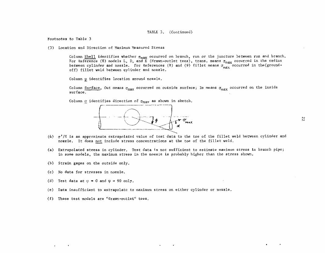
( 3 )
( 4 )
Locat ion and Di rec t ion of Maximum Measured S t r e s s
Column S h e l l i d e n t i f i e s whether omax occurred on branch, run o r t he junc ture between run and branch, For Reference (8) models L, D , and E (drawn-outlet t e e s ) , t r a n s . means omax occurred i n the r ad ius between cy l inde r and nozzle. For References (8) and ( 9 ) f i l l e t means CJ occurred i n the(ground- o f f ) f i l l e t weld between cy l inde r and nozzle . max
Column 9 i d e n t i f i e s l oca t ion around nozzle .
Column Surface , Out means pmax occurred on ou t s ide su r face ; In means omax occurred on the i n s i d e su r face .
o'/S i s an approximate ex t rapola ted va lue of t e s t d a t a t o the toe of the f i l l e t weld between cy l inde r and nozzle . I t does not include s t r e s s concent ra t ions a t the toe of t he f i l l e t w e l d .
Ext rapola ted stress i n cy l inder . i n some models, t he maximum s t r e s s in the nozzle i s probably h igher than the s t r e s s shown.
Test d a t a i s n o t s u f f i c i e n t t o es t imate maximum s t r e s s i n branch pipe;
S t r a i n gages on the ou t s ide only.
No d a t a f o r s t r e s s e s i n nozzle ,
Tes t d a t a a t cp = 0 and 'p = 90 only.
Data i n s u f f i c i e n t t o ex t r apo la t e t o maximum stress on e i t h e r cy l inde r o r nozz le .
These t e s t models are "drawn-outlet" t e e s .
N N

TABLE 4. SUMMARY OF TEST DATA FOR EXTERNAL LOADS APPLIED TO BRANCH, MODELS WITH LOCAL REINFORCING
R ( 2 ) L o c a t i o n & Direction of omax(') 0' ( 4 )
Omax - T b ' - " rn r' rn - - rn - R e f . Nominal - No. S i z e ( 1 ) Tr Rul Tr p L o a d S S h e l l cp S u r f a c e CY S r
38
38
38
38
38
38
8
8
39
9.5
9.5
9.5
.18
.35
.53
.18
.35
.53
1.00
1.00
.13
.32
.32
.32
.76 .44 Mx 2.6
.go .48 M, 4.8
4.9 .80 .53 Mx
76 .55 Mx 3.3
.BO .53 Mx 3.7
.80 .51 Mx 5.7
1.00 .Y4 MZ 1.7 2.0
1.00 .Y4 MZ 1. 4(i)
.45 .60 M 1 . 2 MZ 4.3 LX 8.5
.43 .50 MZ 1.41 1.49 3.28
.43 .54 MZ 1.15 1.14
M*
Run Y OD
Run 9 OD
Run 9O0
Run 9 O0
Run 9 OD
Run goo
B r a n c h 22.5 B r a n c h 61.5
Run a 0
B r a n c h 0 B r a n c h 90 B r a n c h 90
B r a n c h 22.5 B r a n c h 67.5 J u n c t u r e 45
B r a n c h 22.5 J u n c t u r e 90
B r a n c h 22.5 B r a n c h 67.5
o u t
o u t
a u t
o u t
o u t
o u t
o u t o u t
I n
o u t o u t o u t
o u t o u t o u t
o u t o u t
o u t o u t
0
0
0
0
0
0
- -
-
0 0
90
i) 2 9
5 90
7 4
5. ( 8 )
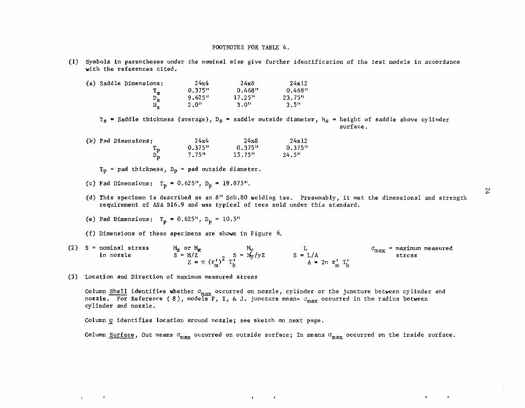
FOOTNOTES FOR TABLE 4.
(1) Symbols i n parentheses under the nominal s i z e g ive f u r t h e r i d e n t i f i c a t i o n of t he test models i n accordance wi th t h e r e f e r e n c e s c i t e d .
( a ) Saddle Dimensions: 2 4x4 2 4x8 24x12 0.375 'I 0.468" 0.468" 9.625" 17.25" 23.75" 2 .O" 3.0" 3.5"
T s DS HS
Ts = Saddle th i ckness (average), Ds = sadd le o u t s i d e diameter , Hs = he igh t of s add l su r f ace.
above c y l i n d e r
(b) Pad Dimensions: 2 4x4 24x8 24x12 0.375" 0.375" 0.375" 7.75" 15.75" 24.5" TP
DP
Tp = pad th i ckness , Dp = pad ou t s ide diameter .
(c) Pad Dimensions:
(d) This specimen i s descr ibed as an 8" Sch.80 welding t e e .
Tp = 0.625", Dp = 19.875". h, .D
Presumably, i t met the dimensional and s t r e n g t h requirement of ASA B16.9 and was t y p i c a l of tees so ld under t h i s s tandard.
( e ) Pad Dimensions:
( f ) Dimensions of these specimens a r e shown i n Figure 6.
Tp = 0,625", Dp = 10.5"
L omax = maximum measured stress s = 2 , Y Z S = L/A
( 2 ) S = nominal stress M, o r %
A = 2rr TL 2 i n nozzle S = M / Z z = n (r:)
(3 ) Location and D i r e c t i o n of maximum measured stress
Column S h e l l i d e n t i f i e s whether omax occurred on nozzle , c y l i n d e r o r t h e junc tu re between c y l i n d e r and nozzle . c y l i n d e r and nozzle .
ColumnIp i d e n t i f i e s l oca t ion around nozz le ; s ee ske tch on nex t page.
Column Surface, Out means omax occurred on o u t s i d e s u r f a c e ; I n means amax occurred on t h e i n s i d e s u r f a c e .
For Reference ( 8 ) , models F, I, & J. junc tu re means gmax occurred i n t h e r a d i u s between
. .
I
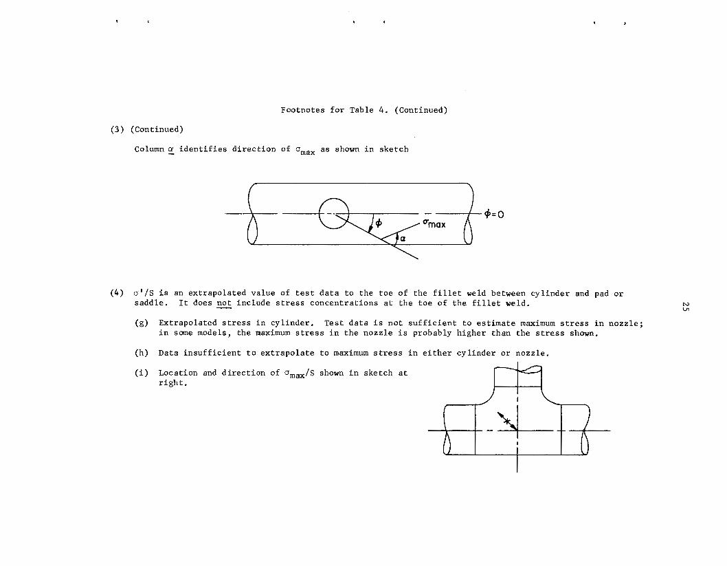
Footnotes f o r Table 4 . (Continued)
( 3 ) (Continued)
Column cy i d e n t i f i e s d i r e c t i o n of amax a s shown i n sket.ch
( 4 ) 0 ' 1 s i s an ex t rapola ted va lue of t e s t d a t a t o the toe of the f i l l e t weld between cy l inde r and pad or saddle .
(g) Extrapolated stress i n cy l inde r .
It does not inc lude s t r e s s concent ra t ions a t t he toe of t he f i l l e t weld.
Tes t da t a i s n o t s u f f i c i e n t t o e s t ima te maximum stress i n nozz le ; i n some models, the maximum stress i n the nozzle i s probably h igher than the stress shown.
(h)
(i)
Data i n s u f f i c i e n t t o e x t r a p o l a t e t o maximum stress i n e i t h e r cy l inde r o r nozzle .
Location and d i r e c t i o n of om,/S shown i n sketch a t r i g h t .
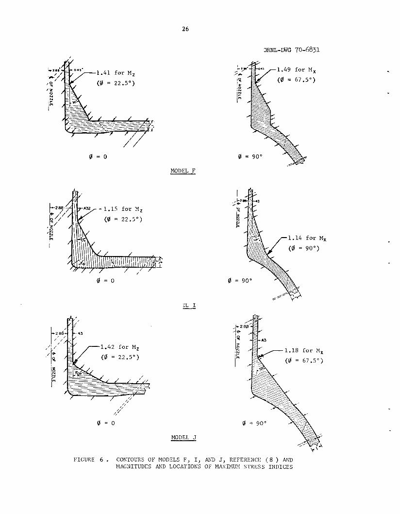
26
/ / 0 = 0
MODEL F
0 = 0
0 = 0
MODEL J
for M, g o o >
- 1.18 f o r M,
F I G U R E 6 . CONTOURS OF MODELS F , I, AND J, REFERENCE ( 8 ) AND bIAGNITUDES AND L O C A T I O N S OF MAXIMUM S T R E S S I N D I C E S

.
TABLE 5 . SUMMARY OF RESULTS OF FATIGUE TESTS OF TEES, DATA FOR ';/I$,, < 1.00
1 (2) i
r ' m r No. of f ,
- Rm - T; - r - m Ref. Nominal Reinforcing No. Size (1) Tr Rm Tr p Load Specimens Tes t Data
4 1.19 2 4.18
(a) 34. .34 .89 .57 MZ (11) 12x4 Saddle
(12) 16x6 Pad 15.5 .41 .56 .52 MZ 1 3 ( f ) 3.6 2.8
( b ) MX
MX i I
2.4 3 1 2.8
4.4
7 2.4
1 . 2 1
I 13 Saddle (') 15.5 .41 .56 .55 MZ 16x6
MX
15.5 .41 .56 .96 MZ
7.5 .42 .28 .96 MZ
9.5 .32 .43 .93 MX
7 l (d)
(d)
(d)
1
16x6 None
16x6 None
(13) 20x6 None (L)
9.5 .63 .69 .95 MX 1 2.5
20x12 None 9.5 .63 .69 .95 1 3.9 MX
( R ) 1
(1) ( a ) Saddle dimensions: 0.368" t h i c k x 7.3125" O.D. x 1.25" he igh t above c y l i n d e r su r face .
Saddle dimensions: 0.500" t h i c k x 11.625" O.D. x 1.5" h e i g h t above c y l i n d e r su r face . (b ) Pad dimensions: 0.500" t h i c k x 12.125" O.D. ( c ) (d) Drawn o u t l e t t e e .
( 2 )
( f )
Value of if i n Equation; i f S N = 245,000.
P a r t of the f a t i g u e t e s t s were run wi th 800 p s i s t a t i c i n t e r n a l p re s su re (nominal pressure s t r e s s of 12,500 p s i f o r DIT = 31; 6000 f o r DIT = 15. l i f e was observed between those specimens wi th p re s su re and those without p re s su re .
No s i g n i f i c a n t d i f f e r e n c e i n f a t i g u e

28
PROPOSED INDICES FOR B31.7
Moment Loading Through Branch
Inspec t ion of t h e t e s t d a t a shown i n Tables 1 through 5 i n d i c a t e
t h a t , i n most a v a i l a b l e comparisons, an out -of -p lane moment (M ) produces
h ighe r s t r e s s e s than an in-p lane moment (M ). Unfor tuna te ly , t h e r e a r e
some excep t ions and a v a i l a b l e d a t a i s no t c o n s i s t e n t enough t o t a k e advan-
t age of t h i s t r end . I n s t e a d , w e seek a g e n e r a l formula t ion f o r C so t h a t
X
z
2b
i t i s i n accord
genera 1 l y , t h i s
tlhrough 4 i s :
'2b
Equation (9) i s
wi th t e s t d a t a f o r t h e moment producing t h e h i g h e s t s t r e s s ;
i s Mx. A formula t ion which f i t s t he t e s t d a t a of Tables 1
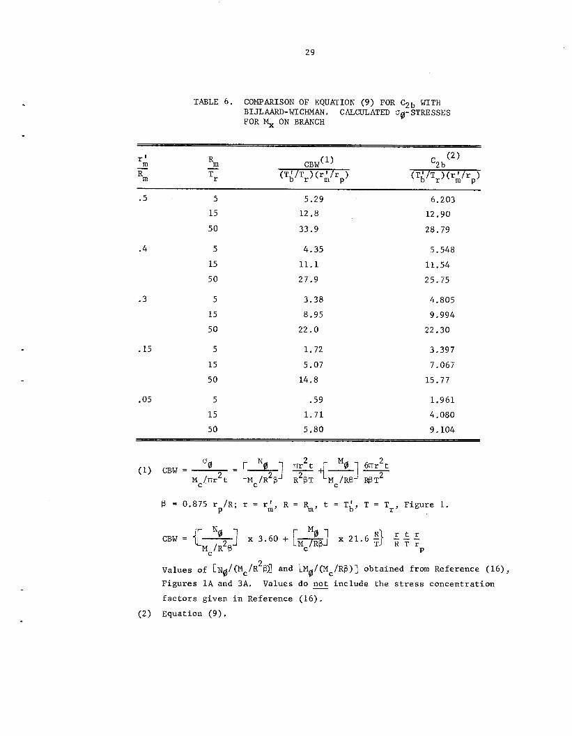
compared wi th Bijlaard-Wichman (I6) a n a l y s i s i n Table 6.
This a n a l y s i s i s based on B i j l a a r d ' s (I7) work us ing s h e l l - t h e o r y f o r a
d i s t r i b u t e d load on t h e s u r f a c e of a c y l i n d e r and e m p i r i c a l mod i f i ca t ion
thereof by Wichman, e t . a l . Equation (9 ) i s compared, i n p a r t i c u l a r , w i th
the a n a l y s i s f o r an out -of -p lane ( c i r c u m f e r e n t i a l ) moment, Mc, and t h e
c i. r c umf e r en t i a 1 s t r e s s , s t : ress combination i s u s u a l l y t h e h i g h e s t ob ta ined from t h e a n a l y s i s . A s
cain be seen i n Table 6, Equation ( 9 ) g ives about the same r e s u l t s a s t h e
Bijlaard-Wichman a n a l y s i s f o r r ' / R
t o t h e Bijlaard-Wichman a n a l y s i s f o r smal l r ' / R . Equation ( 9 ) i s compared
with measured s t r e s s e s i n Table 7 . Equation (9) i s conse rva t ive wi th
due t o t h e c i r c u m f e r e n t i a l moment; t h i s moment- % ,
= 0.5 and i s conse rva t ive wi th r e s p e c t m m
m m
29
r‘ m
Rm -
TABLE 6. COMPARISON OF EQUATION (9) FOR C2b WITH BIJLAARD-WICHMAN. CALCULATED 00- STRESSES FOR ON BRANCH
Rm
Tr -
.5
.4
.3
5 15
50
5 15 50
5 15 50
.15 5 15 50
.05 5 15 50
5.29 12.8
33.9
4.35 11.1 27.9
3.38 8.95 22.0
1.72
5.07 14.8
.59 1.71 5.80
6.203 12.90
28.79
5.548 11.54 25.75
4.805 9.994 22.30
3.397 7.067 15.77
1.961 4.080 9.104
(1) CBW =
B = 0.875 r /R; r = rA, R = Rm, t = T,‘, T = T Figure 1. P r’
T R T r CBW = t 7 ] N0 x 3.60 + [w] M0 x 21.6 5) r 2 M ~ / R B P
Values of [ N ~ / ( M ~ / R ~ @ ] and LMO/(Mc/RB)] ob ta ined from Reference (16), Figures 1 A and 3A. f a c t o r s given i n Reference (16) .
Values do not i nc lude the stress concen t r a t ion
(2) Equation (9).

1 -- 2 3
3 4 4 5 5 7 8 8 8 8 9
4 10 10 10 10 10
1 10 I 7 1 13
13 a 13
I
1
i 1 1 1
f
We Id o l e t 56 x 12(1.3) 56 x 12(2.08)
24 x 4 24 x 12 36 x 4 36 x 6 48 x 6 20 x 6(L)
20 x 12(D) 20 x 12(E) 20 x 12(R)
24 x 12 24 x 4,Saddle 24 x 8,Saddle 24 x 1 2 , Saddle 24 x 4, Pad 24 x 8, Pad 24 x 12, Pad 48 x 6, Pad
20 x 6(F) 20 x 6 ( I ) 20 x 6(J)
12.25 .35 21.5 .19 13.5 .19 38.0 .18 38.0 .53 46.5 . 1 2 46.5 .18 39.0 .13 9.5 .32 9.5 .63 9.5 .65 9.5 .63
115.0 .50 38. .18 38. .35 38. .53 38. .18 38. .35 38. .53 39. .13 9.5 .32 9.5 .32 9.5 .32
.47 .73
.67 .93
.42 .93
. 7 6 .95
.80 .98
.42 .96 0 75 .96 .45 .96 .43 .93 .69 .95 .38 .97 .69 .95
1.00 .99 .76 .44 .80 .48 .80 .53 . 7 6 .55 -80 .53 .80 .51 * 45 - 6 0 .43 .50 .43 .54 e43 * 7 3
3.28 6.30 2.90
10.39 19.35 5.42
11.85 5.37 3.04 7 .OO 4.00 7.00
49.67 4.81 7.70
10.47 6.01 8.51
10.07 3.36 1.64 1 . 7 7 2.39
3.99 1.39 6.2 -- 3.8 --
10. -- 1 2 . -- 3.5 --
10.5 -- 4.4 -- 2.19 -- 4.36 1.59 2.33 1 . 7 1 8.55 --
90. -- 4. -- 7 . 7 . 5. 6. 8 . -- 4.3 -- 1.49 -- 1.14 -- 1.18 --
-- -- -- --
1.32 4 . 1 2 . 1 4.5 5 .1 2 . 1 4.7 3.1 1.73 2.70 2.03 3.53
18.5 -- -- -- -- -- -- 1.4 1.41 1.15 1.42
2.8
5.2 2 . 2 9.7
23.5 4.9
11.3 4.7 2.5 7.3 4.2 7.3 0
3.4
W
65.
* *
4.5 7.7
2.5 1 . 2 1 .3 1 . 4
Jc
(1) CBW i s c a l c u l a t e d from d a t a given i n Reference (16) a s shown by foo tno te (1) t o Table 6. An a s t e r i s k i n t h i s column i n d i c a t e s t h a t B i s above range of the graphs. f a c t o r s given i n Reference (16).
These va lues do not i nc lude the s t r e s s concen t r a t ion
31
r e s p e c t t o maximum measured s t r e s s e s i n almost a l l comparisons, Stresses
obtained from t h e Bijlaard-Wichman a n a l y s i s a r e a l s o shown i n Table 7.
Comparisons of Equation (9) w i th f a t i g u e t e s t d a t a a r e shown i n
Table 8. The stress i n t e n s i f i c a t i o n f a c t o r s shown i n Table 5 a r e r e l a t e d
t o t h e stress i n t e n s i f i c a t i o n of a t y p i c a l g i r t h b u t t w e l d taken a s u n i t y .
Because t h e t y p i c a l g i r t h b u t t weld i t s e l f has a s t r e s s i n t e n s i f i c a t i o n
f a c t o r of around 2 a s compared t o a po l i shed b a r , an appropr i a t e comparison
i s between Equation (9) and two times t h e f a c t o r s shown i n Table 5 . Exami-
n a t i o n of Table 8 shows t h a t Equation (9) i s n o t conse rva t ive a s compared
wi th t h e t e s t r e s u l t s of Reference ( 1 2 ) . However, t h e s e f a t i g u e f a i l u r e s
were a s soc ia t ed wi th welds. I n p a r t i c u l a r , t h e f a i l u r e s i n the heavy wa l l
drawn o u t l e t t e s t models occurred a t a g i r t h b u t t weld a s shown i n F igu re 7 .
A s i g n i f i c a n t peak stress would be expected t o occur a t such a weld.
The proceeding d i s c u s s i o n b r ings up s e v e r a l p e r t i n e n t ques t ions :
(1) I s the stress r ep resen ted by Equation (9) proper ly c l a s s i -
f i e d a s a "secondary s t r e s s " w i t h i n the i n t e n t of B31.7?
( 2 ) I s t h e r e a need f o r a "peakt' stress index f o r t h e des igns
covered by Fig . 1-704.3.3.1 of B31.7 (Figure 1 h e r e i n ) ?
( 3 ) Is Equation ( 9 ) adequate t o cover a l l p o s s i b l e configura-
t i o n s coverd by F ig . 1-704.3.3.1 of B31.7?
The au tho r s comments on t h e s e ques t ions a r e g iven below.
(1) Equation (9), i n t h e sense t h a t i t i s an approximation of a s h e l l
a n a l y s i s , i s r e p r e s e n t a t i v e of a secondary stress, i . e . , a stress con-
s i s t i n g of a membrane p o r t i o n and a l i n e a r bending p o r t i o n .
contended t h a t t he s t r e s s e s a r e h ighly l o c a l i z e d and hence could be
It could be
TABLE 8. COMPARISON OF EQUATION (9) FOR C2b WITH FATIGUE TEST DATA OF TABLE 5
Ref. Test Mode 1
No. Iden t i f i c a t i o n Rm
Tr - r ' m
Rm - CBW f Test Data, 2xi '2b r ' m
P - r E q . (9) Mxb Mzb (1)
(11) 12 x 4, Saddle
(12 1 16 x 6, Pad
16 x 6, Saddle
16 x 6, D.O.
16 x 6, D.O.
(13) 20 x 6, L
20 x 1 2 , D
20 x 1 2 , R
34. .34
15.5 .41
15.5 .41
15.5 .41
7.5 .42
9.5 .32
9.5 63
9.5 .63
.89
.56
.56
.56
.28
.43
.69
.69
.57
.52
.55
.96
.96
.93
.95
.95
9.31
3.48
3.68
6.42
2.00
3.04
7.00
7.00
8.36 ~~
3.38
5.6
5.6
2.4
5.0
7.8
7.2
4.8
8.8
4.8
8.5
* *
6.2
1 . 7 N
2.5
7.3
7.3
w
(1) CBW i s ca lcu la ted from da ta given i n Reference (16) as shown by footnote (1) of Table 6. An a s t e r i s k i n t h i s column indica tes t h a t f3 is above range of the graphs. f ac to r s given i n Reference (16).
These values do not include the stress concentration
33
OWL-DWG 70-6832
F I G U R E 7 . WELD CONFIGURATION AND LOCATION O F FATIGUE F A I L U R E S , REFERENCE (12) T E S T S ON 16 x 6 DRAWN OUTLET BRANCH CONNECTION W I T H R,/T, = 7 .5
34
a t l e a s t p a r t i a l l y c l a s s i f i e d a s peak stresses. However, t h e a u t h o r ' s
recommendation i s t h a t , f o r t h e p r e s e n t , stresses g iven by Equation (9)
be cons idered a s secondary stresses.
(2:) A peak stress i n excess of t h a t i n d i c a t e d by Equation (9) could
e x i s t i f t h e t r a n s i t i o n r a d i u s r of F igure l w e r e smal l . A t p r e s e n t ,
13311.7 does n o t g ive any l i m i t z o n t h e r a d i u s r
s p e c i f i e d a s :
2
I f t h i s r a d i u s i s 2 '
r2 = l a r g e r of T,/2 o r Tb/2 ,
then, i n t h e a u t h o r ' s op in ion , a K2-index of 1.0 i s adequate.
( 3 ) It should be noted t h a t , f o r sma l l branch connec t ions wi th
Rm/Tr = N 10, Equation (9) may g ive a va lue of C
ex,ample, cons ide r a 2" branch i n a 24" p ipe cons t ruc t ed as shown i n
F igu re l ( c ) . Assume t h a t Rm/Tr = 10, rA/Rm = 0.1, rA/r = 0.667, Also,
i3S a l i m i t i n g case , cons ide r t h a t both branch p ipe and run pipe w a l l t h i ck -
nes ses a r e those necessary f o r t h e p re s su re loading , i n which case
T{/Tr = rA/Rm.
less than one. For 2b
P
Iy
Equation (9) then g ives
C2b = 3 . 0 (10)2/3 (O.1)'I2 (0.1)(0.667) = 0.29 .
Obviously, t h i s va lue of C does no t r e p r e s e n t t h e maximum secondary
s t ress i n t h e branch connection because the branch p ipe i t s e l f has a stress
findex of a t l e a s t one. Equation ( 9 ) , t o t h e e x t e n t t h a t i t has a t h e o r e t i c a l
b a s i s , r e p r e s e n t s t h e stress i n t h e run p ipe a t t h e j u n c t u r e wi th t h e nozz le
o r l o c a l r e i n f o r c i n g .
of t h e stress a t t h i s j unc tu re . However, h ighe r stresses may occur a t t h e
2b
The C2b-value of 0.29 i s presumably r e p r e s e n t a t i v e
EKcept i n E-313.1.
35
branch pipe-to-pad junc tu re as shown i n F igure 6 . Accordingly, some
lower bound on C i s necessary f o r those c o n f i g u r a t i o n s where the maxi- 2b
mum stress occurs a t t he j u n c t u r e of t h e r e i n f o r c i n g
p i p e . It i s suggested t h a t a lower bound on C of
vided t h a t t h e va lue of r3 i n F igure 1 i s l i m i t e d a s
2b
The r a d i u s r i s n o t l e s s than t h e g r e a t e r
fo l lowing :
3
wi th t h e branch
1.5 i s adequate, pre-
fo l lows .
of t h e
(1) 0.002 0 do, where 8 (degrees) and do are a s de f ined
i n F igure 1.
(2) 2 (S in t i m e s o f f s e t f o r t h e c o n f i g u r a t i o n s
shown i n F igure l ( a ) and l ( b ) .
I f t h e r e i s a g i r t h b u t t weld a t t h e j u n c t u r e of r e i n f o r c i n g t o t h e
branch p ipe , an appropr i a t e K f a c t o r should be used; 1.8 f o r llas welded"
o r 1.1 f o r "flush" welds. (See Table D-201 of B31.7 f o r d e f i n i t i o n s of t hese . )
2-
Moment Loading Through Run
Tes t d a t a on t h i s loading cond i t ion a r e very s c a r c e ; t h e only
app l i cab le d a t a known t o t h e w r i t e r a r e t h a t shown i n Table 1 f o r t h e
1 2 x 4 Weldolet branch connection. B i j l a a r d ' s a n a l y s i s , of course , i s not
app l i cab le . For small h o l e s i n c y l i n d e r s , some bounds on stress can be
e s t a b l i s h e d , i . e . :
For a smal l ho le i n a c y l i n d e r ,
t h e appl ied moment M o r M - Y r z r '
l oca t ed 90" from t h e plane of
M 0 = 3 - '1:
max
36
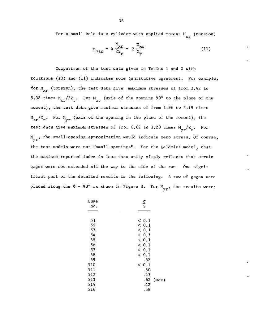
For a smal l ho le i n a c y l i n d e r wi th app l i ed moment M ( t o r s i o n ) x r
x r = 4 - = 2 - Mxr .M
'r 'r 0 m ax
Comparison of t h e t es t d a t a given i n Tables 1 and 2 wi th
'Equations (10) and (11) i n d i c a t e s some q u a l i t a t i v e agreement. For example,
f o r Mxr ( t o r s i o n ) , t h e t e s t d a t a g ive
5.38 t i m e s Mxr /2Zr .
moment), t h e t e s t d a t a g ive maximum stresses of from 1 .96 t o 3.19 t imes
maximum stresses of from 3.42 t o
For MZr ( a x i s of t h e opening 90" t o t h e plane of t h e
IYZr/Zr. For M
tes t d a t a g ive maximum stresses of from 0.62 t o 1 .20 t i m e s M y r / Z r .
]VI t he small-opening approximation would i n d i c a t e ze ro stress. O f course ,
the t e s t models were no t "small openings". For t h e Weldolet model, t h a t
(axis of t h e opening i n t h e plane of t h e moment), t h e Y r
For
Y r "
the maximum repor t ed index i s less than u n i t y simply r e f l e c t s t h a t s t r a i n
gages were n o t extended a l l t h e way t o t h e s i d e of t h e run. One s i g n i -
f i c a n t p a r t of t h e d e t a i l e d r e s u l t s i s t h e fo l lowing . A row of gages were
,placed along t h e 0 = 90' a s shown i n F igure 8. For M t h e r e s u l t s were: Y r '
0 - Gage N o . S - 5 1 52 53 54 55 56 57 58 59
5 10 511 5 1 2 5 13 5 14 5 16
< 0.1 < 0.1 < 0 .1 < 0 .1 < 0.1 < 0.1 < 0.1 < 0.1
.32 < 0.1
.50 * 23 .62 (max) .42 .58
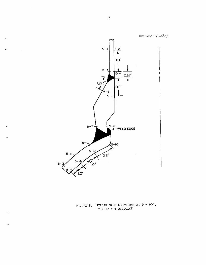
37
I I 1.0'
0.6 3"
ORNL-DWG 70-683
5-
F I G U R E 8 . S T R A I N GAGE L O C A T I O N S A T 0 = go", 12 x 1 2 x 4 WELDOLET
I
38
T h e s e r e s u l t s a r e unusual bu t reasonable i n t h a t they i n d i c a t e t h a t
s t r e s s e s a r e lower i n the v i c i n i t y of t h e branch connect ion than they a r e
away from the connect ion. Gages 513 and 516 a r e loca ted about 50" from
the s i d e where the nominal stress index i s about 0.65, a va lue i n reason-
(able agreement wi th t h e t es t r e s u l t s .
With t h i s admi t ted ly small amount of background, w e now seek
a genera l formula t ion f o r use i n t h e B31.7 s i m p l i f i e d a n a l y s i s . A s f o r
:Loading through t h e branch, we want t o s e l e c t a s t r e s s index which is con-
se:rvat ive f o r t h a t moment which g i v e s t h e h i g h e s t stress, presumably
e i t h e r M o r MZr. The proposed formula t ion f o r C and QF i s : xr 2 r
bu t n o t less than 1.0
%r = 2 .0
The product C2rK2r s h a l l be a minimum
L L
of 3.0.
Table 9 g ives C2r f a c t o r s over t h e range of app l i cab ' l i t y .
F i r s t , it w i l l be noted t h a t stress due t o moments through t h e
run a r e d iv ided i n t o secondary s t r e s s e s and peak stresses. The concept
he re i s t h a t f o r smal l branch connect ions, even wi th l o c a l stresses w e l l
above twice the y i e l d s t r e n g t h , t h e r e cannot be any cont inued p l a s t i c
dleformation because the bulk of t h e run p ipe w i l l c o n t r o l t h e deformations
a t t he smal l branch connect ion.
The (Rm/Tr)2'3 f a c t o r i s used i n Equation ( 1 2 ) f o r cons is tency
wi th the f a c t o r used f o r B16.9 tees and the a u t h o r ' s i n t u i t i o n t h a t t h i s
kind of parameter i s s i g n i f i c a n t , One n o t e s t h a t Equation (12) g ives
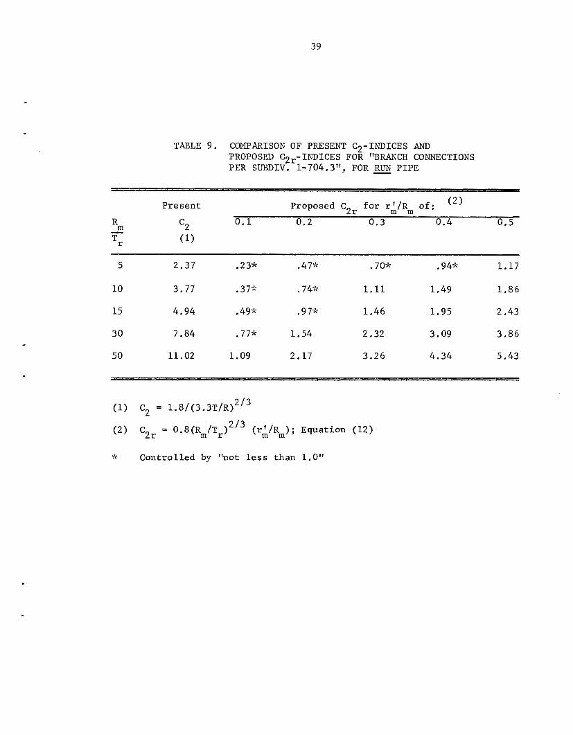
39
TABLE 9. COMPARISON OF PRESENT C2-INDICES AND PROPOSED C2,-INDICES FOR "BRANCH CONNECTIONS PER SUBDIV. 1-704.3", FOR - RUN PIPE
(2 1 Present Proposed C2r for r k / R m of: 0.1 0.2 0.3 0.4 0.5 m c2
Tr (1)
R -
5 2.37 .23* .4 75; .70* ,945; 1.17
10 3.77 .375; .74;'; 1.11 1.49 1.86
15 4.94 .4g5; .9 75: 1.46 1.95 2.43
30 7.84 .775: 1.54 2.32 3.09 3.86
50 11.02 1.09 2.17 3.26 4.34 5.43
2 /3 (1) C2 = 1.8/(3.3T/R)
(2) C2r = (ri/Rm); Equation (12)
Jf Controlled by Itnot less than 1.0"
40
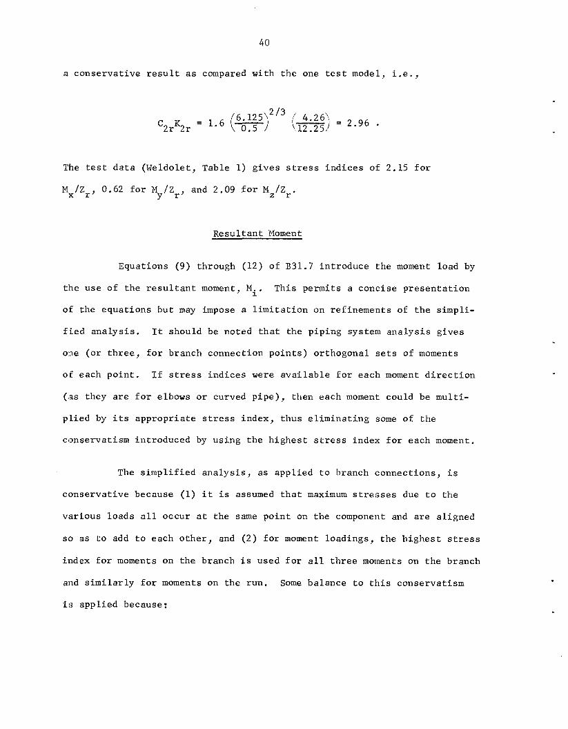
a conse rva t ive r e s u l t a s compared wi th t h e one tes t model, i . e . ,
C2rK2r = 1.6 (-1 6.125\2/3 I- ' 4.26\ = 2.96 . !.12.25)
The tes t d a t a (Weldolet, Table 1) g i v e s stress i n d i c e s of 2.15 f o r
Mx/Zr , 0.62 f o r M / Z and 2.09 f o r MZ/Zr. Y r'
Resu l t an t Moment
Equations (9) through (12 ) of B 3 1 . 7 i n t roduce the moment load by
t ' h e use of t h e r e s u l t a n t moment, Mi.
of t he equa t ions bu t may impose a l i m i t a t i o n on re f inements of t h e s impl i -
f i e d a n a l y s i s . It should be noted t h a t t he p ip ing system a n a l y s i s g ives
one ( o r t h r e e , f o r branch connection p o i n t s ) or thogonal sets of moments
of each po in t . I f stress i n d i c e s were a v a i l a b l e f o r eaclh moment d i r e c t i o n
(as they are f o r elbows o r curved p i p e ) , then each moment could be mul t i -
p l i e d by i t s a p p r o p r i a t e stress index, t hus e l i m i n a t i n g some of t h e
conserva t i sm in t roduced by us ing t h e h i g h e s t stress index f o r each moment.
This p e r m i t s a conc i se p r e s e n t a t i o n
The s i m p l i f i e d a n a l y s i s , a s app l i ed t o branch connec t ions , i s
conse rva t ive because (1) i t i s assumed t h a t maximum stresses due t o t h e
visrious loads a l l occur a t t h e same p o i n t on t h e component and a r e a l igned
so as t o add t o each o t h e r , and ( 2 ) f o r moment loadings , t h e h i g h e s t s t r e s s
index f o r moments on t h e branch i s used f o r a l l t h r e e moments on t h e branch
and s i m i l a r l y f o r moments on t h e run . Some ba lance t o t h i s conserva t i sm
i s appl ied because:
41
(1) The stress i n d i c e s f o r moment loadings a r e a c t u a l l y repre-
s e n t a t i v e of maximum p r i n c i p a l s t r e s ses - -no t stress in t en -
s i t i es . However, i n most tests t h e maximum* p r i n c i p a l
stress was a l so t he maximum stress i n t e n s i t y , i .e . , t h e
p r i n c i p a l stresses a t t he po in t were of the same s i g n and
elsewhere on t h e component t he p r i n c i p a l stress d i f f e r e n c e s
were smal le r than t h e maximum* p r i n c i p a l s t r e s s .
(2) If two or thogonal moments, M. and M a c t u a l l y produced 1 j'
i d e n t i c a l s t r e s s i n t e n s i t i e s a t t h e same p o i n t on a component,
then the s t r e s s a t t h a t p o i n t would be C M . / Z + C M / Z .
However, use of t h e r e s u l t a n t moment would g ive a stress
2 1 2 j
lc) c)
of C2 ,& + ML j / Z . These two are i d e n t i c a l only i f M i
o r M = 0. The maximum discrepancy occurs where M = M j i j
f o r which w e o b t a i n CJ = 2 C M. /Z v s . 2/z C2 Mi/Z. Accor- 2 1
d ing ly , u se of t he r e s u l t a n t moment can, f o r c e r t a i n moment
combinations, decrease the conservat ism of t he s i m p l i f i e d
a n a l y s i s .
B - Ind ices 2
The B2-indices are intended to r ep resen t an u l t i m a t e load a s
represented by t h e development of a p l a s t i c hinge through the body of t h e
component. Nei ther theory nor t es t d a t a e x i s t s f o r " l i m i t f f moments on
branch connect ions i n e i t h e r heads o r c y l i n d e r s . Some theory and
* Maximum he re i s with r e s p e c t t o l o c a t i o n on t h e s u r f a c e of t h e component, no t maximum vs . minimum p r i n c i p a l stress a t a s i n g l e po in t on the s u r f a c e of t h e component.
42
t e s t d a t a (18,19y20) i n d i c a t e t h a t t he l i m i t load on an elbow can be con-
s e r v a t i v e l y es t imated by us ing 0.75 t i m e s t h e e l a s t i c s t ress index. That
i s , t he elbow w i l l c o l l a p s e when the maximum e l a s t i c stress produced by
the moment reaches 1.33 t i m e s t h e y i e l d s t r e n g t h of t h e elbows m a t e r i a l .
Because some analogy between elbows and f u l l s i z e t e e s was
e s t a b l i s h e d by Mark1(l5), and f o r lack of any b e t t e r guidance, t he pro-
posed B2-indices f o r branch connect ions a r e a l s o proposed t o be 0.75 t i m e s
t h e C - i n d i c e s f o r branch connect ions. A lower l i m i t of B = 1.00 i s
necessary t o conform wi th the B - i n d i c e s f o r s t r a i g h t pipe. It i s be-
lfieved t h a t t h e s e B2-indices a r e h ighly conse rva t ive but can be used i n
B 3 1 . 7 because, a t l e a s t so f a r , t h e r e have been no i n d i c a t i o n s t h a t
Equation (9) of B 3 1 . 7 p r e s e n t s a l i m i t a t i o n t o water-cooled r e a c t o r
pip:ing des igns .
2 2
2
4 3
Summary and Example
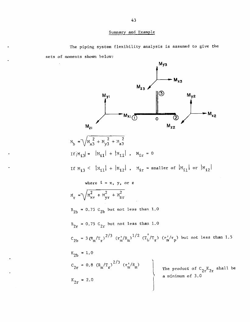
The p ip ing system f l e x i b i l i t y a n a l y s i s i s assumed t o g ive the
s e t s of moments shown below:
Mz 3
Mz2
)' MXI
M* I
2 2 Mb = d M x i My3 + M ~ 3
I f Mi3 < \ M i l l + lMi21 , Mir = smal le r of lMi l l o r lMi21
where i = x, y , o r z
Mr = d F Mxr + M Z r
BZb = 0.75 C2b bu t n o t less than 1.0
= 0.75 CZr bu t n o t l e s s than 1.0 B 2 r
= ~ ( R ~ / T ~ ) ~ / ~ ( T ' / T ) ( r ' / r ) bu t no t l e s s than 1 .5 '2b b r m p
a minimum of 3 .0 KZr = 2.0

44
Moment load ing terms of Equat ions ( 9 ) , ( l o ) , ( l l ) , and (12)
o f B31 .7
Mb Mr + '2r z r '2b ";; 13q. (10) and (12) SnM =
r M
2 r 2 r Mb
Eq. (11) S = C K - + c K pM 2b 2b Z b
45
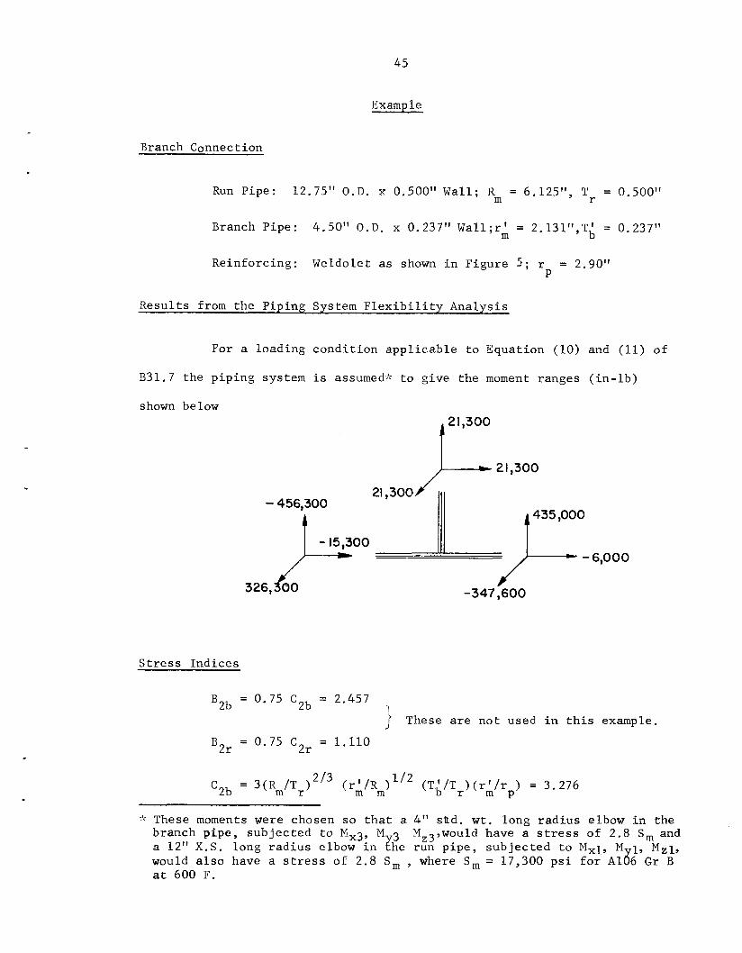
Example
Branch Connection
Run Pipe: 12.75" O.D. x 0.500" Wall; Rm = 6.125", Tr = 0.500"
Branch Pipe : 4.50" O.D. x 0.237" Wal1;r' = 2.131",T{ = 0.237" m
Reinforcing: Weldolet as shown i n Figure 5 ; r = 2.90" P
Resul t s from the Piping System F l e x i b i l i t y Analysis
For a loading cond i t ion app l i cab le t o Equation (10) and (11) of
B31.7 the p ip ing system i s assumed-:? t o g ive the moment ranges ( i n - l b )
shown below
- 456,300
- 15,300 t 326, 60
S t r e s s Indices
B2b = 0.75 C2b = 2.457
B2r = 0.75 C2r = 1.110
2 1,300
I 2 1,300
21,300
J -347,600
1 These a r e n o t used i n t h i s example.
:: These moments Were chosen so t h a t a 4" sUd. w t . long r ad ius elbow i n the branch pipe, subjec ted t o Mx3, M 3 Mz3,would have a s t r e s s of 2 . 8 S, and a 12" X.S. long r ad ius elbow i n ;he run p ipe , subjec ted t o M,1, M 1, M , l , would a l s o have a stress of 2 .8 S, , where S, = 17,300 p s i f o r A186 G r B a t 600 F.

46
K2b = 1.0
2 /3 2 r = 0.8 (Rm/Tr) (rA/R m ) = 1.479
K2r = 2.0
Ca lcu la t ion of Iv$ and M r --
2 2 2 % = \ i 2 1 . 3 + 21.3 + 21.3 x 1000 = 36,893 i n - l b
2 2 Mr = Y O 2 + 435 + 326 x 1000 = 543,780 i n - l b
-- C:allculation of Secondary Stress f o r Moment Loading
Sm = 3.276 x 36 3 1 2 2 893 + 1.479 x 543 5;, 780 =51,719 p s i
(The va lue of S i s equal t o 2.99 x 17,300 as compared t o nM
2.8 x 17,300 f o r elbows under analogous moments. See foo tno te
on preceding page , )
- Calcu la t ion of Peak S t r e s s f o r Moment Loading
S = 3.276 x 1.00 x 36 3 1 2 2 893 + 3 . 0 '4',:',"' = 66,306 p s i Pm
In t h e second t e r m , C K = 1.479 x 2 = 2.958 i s l e s s than 3 .0 ,
hence 3.0 i s the r equ i r ed f a c t o r .
2 r 2 r

47
(Enter ing Fig. 1.705.3(a) of B31.7 wi th S = - 1 S =33,150 a l t 2 pM
shows t h a t t h e branch connection i s s u i t a b l e f o r up t o 15,000
cyc le s of t h i s p a r t i c u l a r loading . )
48
STRESSES BY B31.1.0 POWER PIPING CODE
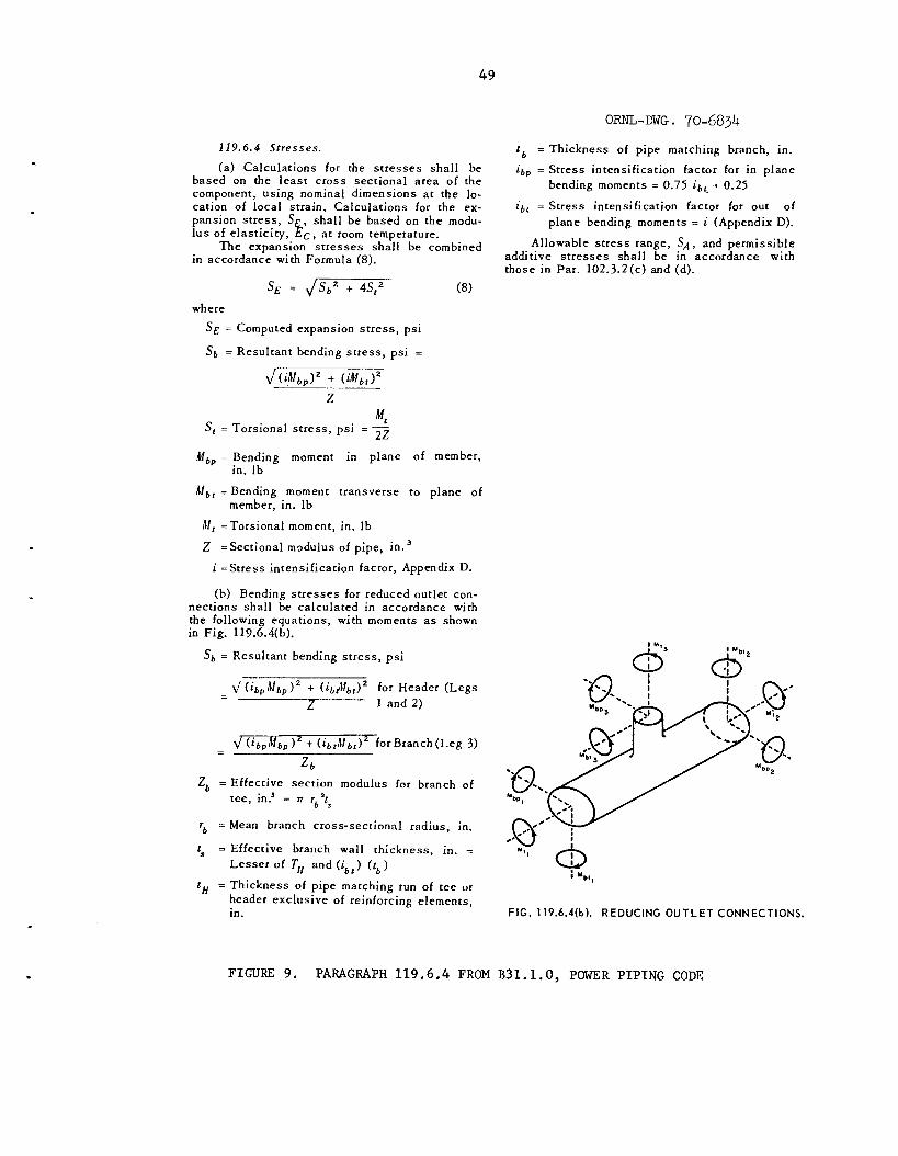
Paragraph 119.6.4 from B31.1.0-1967 i s reproduc.ed h e r e i n as
Figure 9.
cablle t o elbows o r curved pipe. I ts use f o r s t r a i g h t tees r e q u i r e s some
i n t e r p r e t a t i o n . Paragraph (b) g ives equat ions f o r c a l c u l a t i n g S b ' Every-
t h ing i s def ined adequate ly except Z which, i n the preced.ing paragraph ( a ) ,
i s def ined as " sec t ion modulus of p ipe , i n . Presumably, as used i n
Paragraph ( a ) g ives a s e t of r u l e s which a r e d i r e c t l y a p p l i -
3,,
paragraph ( b ) , Z i s more s p e c i f i c a l l y the s e c t i o n modulus of the run pipe.
The au thor would i n t e r p r e t paragraph (b) as r e q u i r i n g the c a l c u l a t i o n of
t h ree va lues of S b ; f o r run end 1, f o r run end 2 , and f o r t he branch.
presumably, one r e t u r n s t o paragraph ( a ) , equa t ion ( 8 ) , t o c a l c u l a t e SE.
The ques t ion arises as t o what i s S Is i t M t 3 / 2 Z
or 14
Now,
f o r M on the branch. t t
/ 2 Z b o r perhaps Mt/2Z,', where Z i i s the a c t u a l sect:ion modulus of t 3
the branch p ipe? These are minor p o i n t s and could be c l e a r e d up w i t h some
e d i t i n g . There a r e , however , some more b a s i c ques t ions concerning these
code r u l e s .
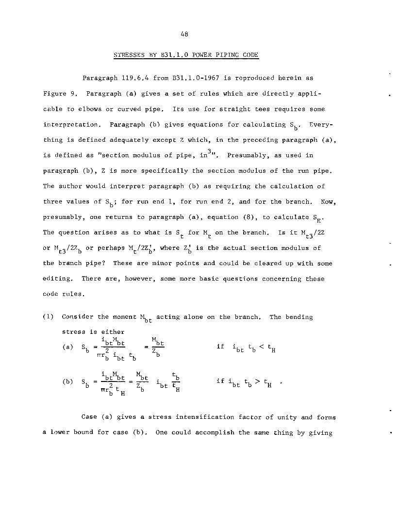
(1) Consider the moment Mbt a c t i n g a lone on the branch.
stress i s e i t h e r
The bending
%t = - - ib t%t (a> 'b - 2
'b rrrb ib t tb
tb i - ibtMbt = - %t
nr2 t 'b (b) 'b = b t tH b H
i f ibt tb < tH
i f ibt tb ? tH .
Case ( a ) g ives a s t r e s s i n t e n s i f i c a t i o n f a c t o r of u n i t y and forms
a lower bound f o r case (b ) . One could accomplish the same t h i n g by g iv ing
49
ORNL-DWG. 70-6834
t b = Thickness of pipe matching branch, in. i b p = Stress intensification factor for in plane
bending moments = 0.75 i b , + 0.25
ib t = Stress intensification factor for out of plane bending moments = i (Appendix D).
Allowable s t ress range, S A , and permissible additive s t resses shal l be in accordance with
119.6.4 Stresses.
(a) Calculations for the s t r e s s e s shal l be based on the leas t cross sectional area of the component, using nominal dimensions at the lo- cation of local strain. Calculations for the ex- pansion s t ress , S,C, shal l be based on the modu- l u s of elasticity, Ec, a t room temperature.
The expansion s t resses shall be combined in accordance with Formula (8).
s, = 4- (8) where
SE = Computed expansion s t ress , psi
S b = Resultant bending s t ress , psi =
Mt sf = Torsional s t ress , ps i = - 2 2
Mbp = Bending moment in plane of member,
h1b1 = Bending moment transverse to plane of
in. Ib
member, in. Ib
hl , =Torsional moment, in. Ib
Z =Sectional mQdulus of pipe, in.'
i =Stress intensification factor, Appendix D.
(b) Bending s t r e s s e s for reduced outlet con- nections shal l be calculated in accordance with the following equations, with moments a s shown in Fig. 119.6.4(b).
Sb = Resultant bending s t ress , p s i
\I ( ibph!bp 1' + ( ib th lb t ) ' forBranch(Leg 3) - -
z b
Z b = Effective section modulus for branch of tee, in? = R rb2ts
rb = Mean branch cross-sectional radius, in.
t, = Effective branch wall thickness, in. = Lesser of T,, and ( i b r ) ( t b )
t,, = Thickness of pipe matching run of tee ur header exclusive of reinforcing elements, in.
those in Par. 102.3.2(c) and (d).
! MI,
: ybl ,
FIG. 119.6.4(b). REDUCING OUTLET CONNECTIONS.
FIGURE 9. PARAGRAPH 119.6.4 FROM B31.1.0, POWER PIPING CODE
50
011l:y (b) wi th t h e r e s t r i c t i o n t h a t ( i t /T ) s h a l l n o t be taken as l e s s
than u n i t y ,
of 1/3 o r sma l l e r , the stress i n t e n s i f i c a t i o n f a c t o r i s l i k e l y t o be u n i t y .
Comlparisons of t e s t d a t a wi th the equat ion f o r case (b) i n d i c a t e i t may
b t b H
One no te s t h a t f o r conf igu ra t ions where t /T i s of the o r d e r b H
(21) be isncon s e rva t ive
( 2 ) The code r u l e s a s s i g n a s t r e s s i n t e n s i t y f a c t o r of 1.00 f o r t o r s i o n a l
moments bu t because the s t r e s s i s considered as a shea r ing stress, t h i s i s
equ iva len t t o a s s ign ing a f a c t o r of 2.00 i n r e l a t i o n s h i p t o s t r e s s i n t e n s i t y .
Avai lab le t e s t d a t a raise some doubts as t o whether t h i s i s conse rva t ive .
( 3 ) I f t h e code i s p rope r ly i n t e r p r e t e d as r e q u i r i n g an independent check
of S f o r each of the t h r e e ends of the t e e , u s ing the s e t of moments a t
eaclh of those ends, then any i n t e r a c t i o n between s t r e s s e s from moments
"through-the-branch" and moments "through-the-run" would be ignored. This
would appear t o be p o t e n t i a l l y unconservat ive f o r some conf igu ra t ions .
b
The above comments on B31.1.0 r u l e s are n o t intended t o be a
s e r i o u s c r i t i c i sm of those r u l e s , s i n c e they are perhaps q u i t e adequate
f o r most p ip ing systems, bu t r a t h e r t o i n d i c a t e why the au thor proposes
a d i f f e r e n t s e t of r u l e s f o r use i n B31 .7 f o r class 1 nuc lea r power p ip ing .
51
FORCE LOADINGS
A t a branch i n t e r s e c t i o n p o i n t , such as p o i n t "0" of Figure 2 ( a ) ,
the p ip ing system a n a l y s i s w i l l g ive t h r e e or thogonal s e t s of fo rces i n
a d d i t i o n t o the t h r e e s e t s of moments. The ques t ion a r i s e s as t o what,
i f anything, should be done wi th these fo rce loads . The p ip ing system
a n a l y s i s assumcs t h a t t hese a r e fo rces a t a po in t which, i n terms of the
a c t u a l s h e l l con f igu ra t ion of branch connect ions, i s n o t even a p o i n t on
the phys ica l s t r u c t u r e . Accordingly, t hese f o r c e s have no d i r e c t phys i ca l
s i g n i f i c a n c e . However, i f we imagine these f o r c e s as e x i s t i n g i n the p ipe
a t some one o r two pipe diameters from the run-branch a x i s i n t e r s e c t i o n ,
some phys ica l s i g n i f i c a n c e can be a t t ached t o the fo rces . Assuming these
f o r c e s do e x i s t some d i s t a n c e from the i n t e r s e c t i o n po in t , i t can be seen
t h a t only one p a i r of fo rces can e x i s t wi thout accompanying moments; t h a t
being Fxl - - -Fx2; i . e . , f o r c e s through the run p ipe ,
connect ions, t he fo rce F r eac t ed by F and/or F may e x i s t wi thout
s i g n i f i c a n t accompanying moments, The remaining fo rces w i l l n e c e s s a r i l y
be accompanied by s i g n i f i c a n t moments.
For s m a l l d/D branch
Y3 Y l Y2
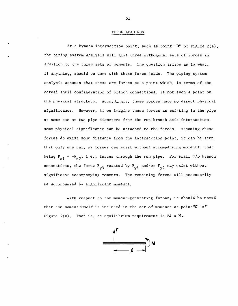
With r e s p e c t t o the moment-generating f o r c e s , i t should be noted
t h a t t he moment i t s e l f i s included i n the s e t o f moments a t point"0" of
Figure 2(a) . That i s , an equ i l ib r ium requirement i s FA = M .
t'

52
The b a s i c ques t ion i s whether t h e r e a r e s i g n i f i c a n t s t r e s s e s i n branch
c:onnections due t o the shear f o r c e i t s e l f ; e . g . , would the s t r e s s e s be
d i f f e r e n t i n t h e two loading cond i t ions sketched below? I
0 0
ln o rd ina ry beam theory ( ignor ing shea r s t r e s s e s ) , no d i f f e r e n c e i n ca l cu -
l a t e d s t r e s s would e x i s t a t p o i n t "0". Inc luding shea r s t r e s s e s would give
some d i f f e r e n c e ; depending upon the r a t i o of depth t o l eng th of t he beam.
'There i s a l i t t l e t es t da t a p e r t i n e n t t o the ques t ion . The t e s t models
13f Table 1 were sub jec t ed t o bo th fo rce loads and moment loads , For t h e s e
p a r t i c u l a r t e s t models, no s i g n i f i c a n t d i f f e r e n c e could be d e t e c t e d from the
r e s u l t s . There are c e r t a i n experimental d i f f i c u l t i e s a s s o c i a t e d wi th fo rce -
load t e s t s , I n o r d e r t o d e t e c t the shear load e f f e c t i t i s d e s i r a b l e t o
in t roduce the shea r fo rce c l o s e t o the branch connect ion. However, i f
we do so then t h e p a r t i c u l a r method of i n t roduc ing the f o r c e w i l l a f f e c t
the s t r e s s e s . For example, i f we t r y t o in t roduce the fo rce uniformly
around the p ipe circumference through a r i n g , then t h a t r i n g would s t i f f e n
the branch connect ion. A p o i n t load a p p l i c a t i o n might even more a f f e c t the
measured s t r e s s . Accordingly, i t i s necessary t o apply the fo rce t o the
p ipe some d i s t a n c e away from the branch; i n t h i s case the moment load i s
s u f f i c i e n t l y l a r g e so t h a t i t e f f e c t i v e l y masks any stress due t o shea r
2M

5 3
loading . A c o r r o l a r y f o r a c t u a l p ip ing s y s t e m s i s t h a t u n l e s s t h e r e i s
an anchor c l o s e t o a branch connection, t h e moment-generating f o r c e s w i l l
produce i n s i g n i f i c a n t stresses a s compared t o t h e stresses produced by t h e
moment.
( f o r both moment and f o r c e loads) w i l l be dependent upon the geometry and
c loseness of t h a t anchor; none of t h e d a t a d i scussed h e r e i n would be
app l i cab le .
I f an anchor i s c l o s e t o a branch connection, then t h e stresses
An a x i a l f o r c e on t h e branch, F w i l l produce a moment i n the Y 3 '
run p lpe ; i t s magnitude w i l l depend upon how f a r ou t t h e r e a c t i n g f o r c e s
F and F a r e app l i ed . There a r e some t e s t d a t a f o r F loading l i s t e d oppo-
s i t e "L" of Table 3. The r e f e r e n c e s do n o t i n d i c a t e where o r what kind of
r e a c t i o n s were used. Presumably, t h e r e a c t i o n s were f a r enough from t h e
branch connection s o t h a t they d id n o t d i r e c t l y a f f e c t t he stresses and
c l o s e enough s o t h a t t h e moment i n t h e run pipe was i n s i g n i f i c a n t . One
no te s from Table 3 t h a t the s t r e s s i n d i c e s f o r a x i a l f o r c e on t h e branch
a r e l a r g e r t han f o r any moment load. However, t h e s e a r e n o t indexed t o t h e
same nominal stress. To compare stresses+: one may use t h e r e l a t i o n :
Y l Y 2 Y3
r f f F m i E 2
i F Z b - f i
imM Ab m - - - f
m
0
0 - =
A t most p o i n t s i n many t y p i c a l p ip ing systems, t h e moment
M ( i n - l b ) i s 2 O r more o r d e r s of magnitude g r e a t e r than F ( l b s ) , f o r which
;'a = stress due t o f o r c e load f
m B = s t r e s s due t o moment load
54
p o i n t s t he va lue of 5 would be n e g l i g i b l e compared t o Ci . One can, of
c.ourse, p o s t u l a t e a p ip ing system w i t h a branch connect ion a t some p o i n t
where the moments on the branch a r e of the same o r d e r , o r even smaller
t:han F r ’ - i n which c a s a stress a n a l y s i s cons ider ing (only moments would m’
be u n c m s e r v a t i v e .
f m
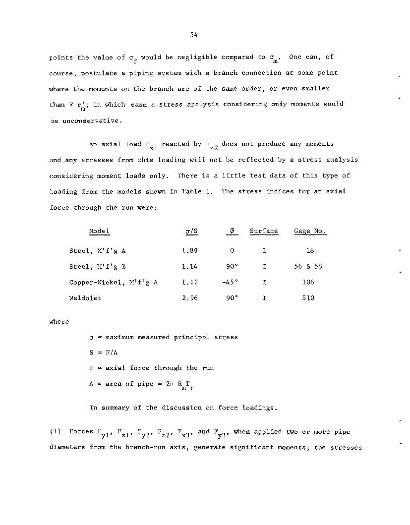
An a x i a l load F r eac t ed by F does n o t produce any moments x l x2
and any stresses from t h i s loading w i l l n o t be r e f l e c t e d by a stress a n a l y s i s
cons ider ing moment loads only. There i s a l i t t l e t e s t d a t a of t h i s type of
:togading from the models shown i n Table 1. The s t r e s s i n d i c e s f o r an a x i a l
fo rce through the run w e r e :
Model
S t e e l , M’f’g A
S t e e l , M’f’g B
Copper-Nickel, M’f’g A
Weldole t
- C?/s
1.89
1.14
1 .12
2.96
8 Surface Gage N o .
0 I 18
90 O I 56 & 58
- --
-45 O I 106
90 O I 5 10
where
CT = maximum measured p r i n c i p a l stress
s = F/A
F = a x i a l fo rce through the run
A = a r e a of p ipe = 2rr RmTr
In summary of t h e d i scuss ion on f o r c e loadings .
and F when app l i ed two o r more p ipe y2’ F Z 2 ’ Fx3’ Y 3 ’ ( 1 ) Forces Fyl, FZ1, F
di.ameters from t h e branch-run a x i s , genera te s i g n i f i c a n t moments; the stresses
55
due t o the f o r c e s are probably small as compared t o those due t o the
moment .
( 2 ) Force F i n s m a l l d/D branch connect ions, may produce a s i g n i f i c a n t
s t r e s s n o t included i n s t r e s s e s due t o the accompanying moment through
the run.
Y3
( 3 ) Force F r eac t ed by fo rce Fx2, does n o t produce a moment. However,
l i m i t e d t e s t d a t a i n d i c a t e these s t r e s s e s w i l l n o t be s i g n i f i c a n t i n
most p ip ing systems.
x l ’
The au thor does not recommend i n c l u s i o n of fo rce loads i n the
B 3 1 . 7 s i m p l i f i e d a n a l y s i s of s t r e s s e s i n branch connect ions.
t h a t the p r e s e n t f a c t o r s and a n a l y s i s are s u f f i c i e n t l y conserva t ive t o
compensate f o r p o s s i b l e s t r e s s e s due t o fo rce loads .
B 3 1 . 7 a n a l y s i s i s equ iva len t t o the B 3 1 . 1 . 0 a n a l y s i s , which a l s o does n o t
cons ider fo rce loads i n c a l c u l a t i n g s t r e s s e s .
It i s be l ieved
In t h i s r e s p e c t , t he
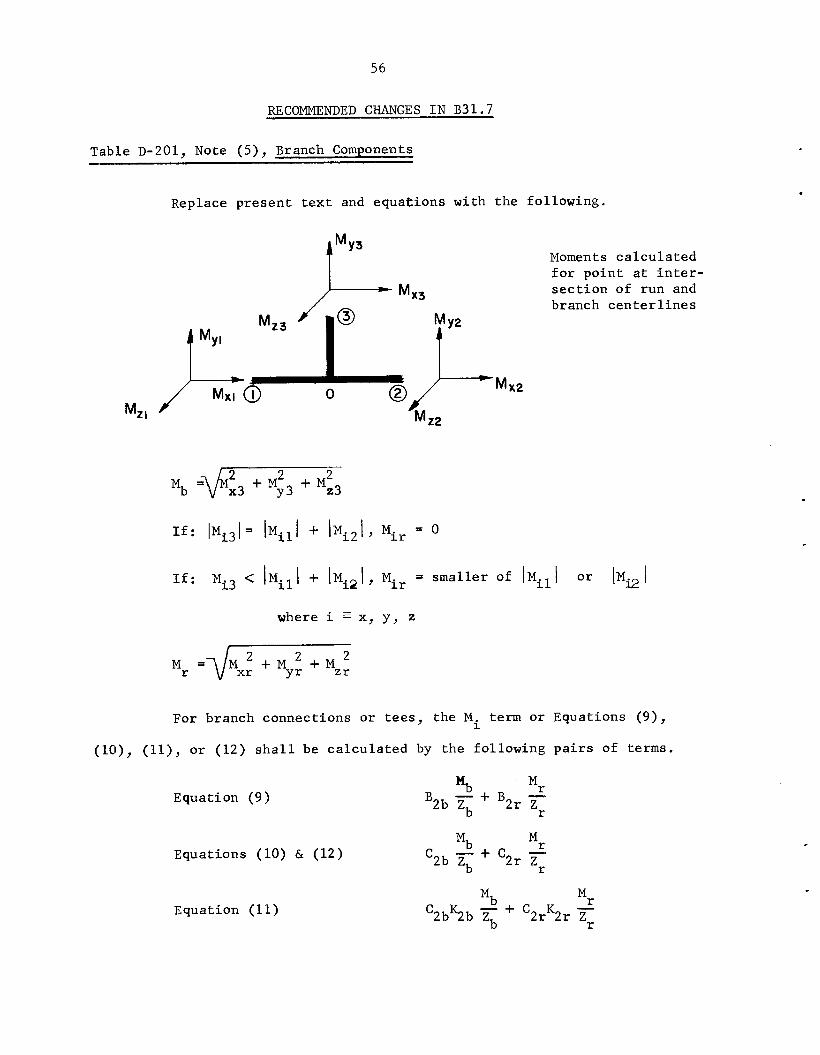
56
RECOMMENDED CHANGES I N B 3 1 . 7
Table D-201, Note (5), Branch Components --
Replace p re sen t t e x t and equa t ions with t h e fol lowing.
Moments c a l c u l a t e d f o r p o i n t a t i n t e r - s e c t i o n of run and branch c e n t e r l i n e s
M x 2
Mz I
~ ~ ~ 1 , M~~ = sma l l e r of I M ~ ~ I o r I M ~ I
where i E X, y , z
For branch connect ions o r tees, the M. term or Equat ions (9), 1
( l o ) , (ll), o r ( 1 2 ) s h a l l be c a l c u l a t e d by t h e fo l lowing p a i r s of t e r m s .
Equat ion (9)
Equat ions (10) & ( 1 2 )
Equation (11)
Mb B2b + B 2 r z‘ r
U
‘2b 7 i- ‘2r f r Mb - + C K ‘2b5b Zb 2 r 2 r
.
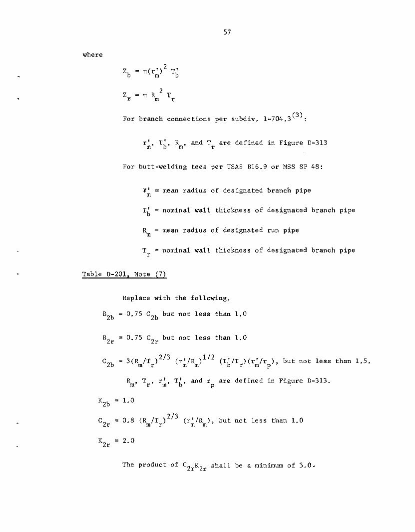
57
where
2 Zb = rr(rk) TL
Zn = rr Rm Tr
For branch connect ions pe r subdiv. 1-704.3 .
2
( 3 ) .
r’ T,’, Rm, and Tr are def ined i n F igure D-313 m’
For but t -welding t e e s pe r USAS B16.9 o r MSS SP 48:
V ’ m = mean r a d i u s of designated branch p ipe
T i = nominal w a l l th ickness of des igna ted branch p ipe
R m = mean r a d i u s of des igna ted run p ipe
T r = nominal w a l l th ickness of des igna ted branch pipe
Table D-201, Note (7)
Replace wi th the fol lowing.
BZb = 0.75 C2b bu t n o t less than 1 .0
B2r = 0.75 C2r bu t no t less than 1 .0
C Z b = 3(Rm/Tr)2’3 (rm/ I R ) l / ’ ( T ; / T ~ H ~ ; / ~ ~ ) , b u t n o t less than 1.5.
r ’ T,‘, and r are def ined i n Figure D-313. Rm, T r , P
KZb = 1.0
2/3 = 0.8 (Rm/Tr) (rA/Rm), b u t n o t l e s s than 1 .0 2r
KZr = 2.0
The product of C 2rK2r s h a l l be a minimum of 3 .0 4
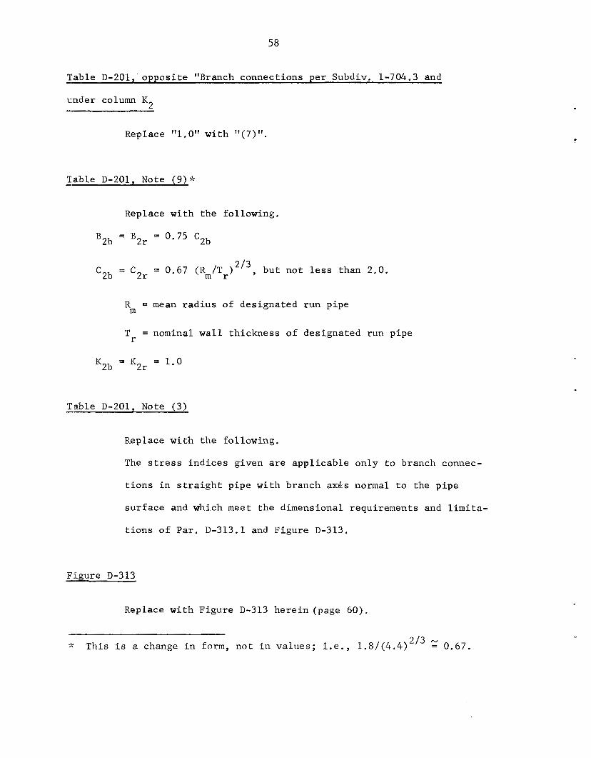
58
-- Table D-201, oppos i t e "Branch connect ions pe r Subdiv. 1-704.3 and
under column K,
Replace "1.0" w i t h ' I ( 7 ) I t .
Table D-201, Note ( 9 ) + --
Replace w i t h the fol lowing.
B2b - - B2r = 0.75 C2b
= 0.67 (Rm/Tr)L'3, bu t no t ,ess than '2b = '2r
R = mean r a d i u s of des igna ted run pipe m
I O .
T = nominal w a l l th ickness of des igna ted run pipe r
K2b - - K2r = 1.0
Table D-201, Note (3) --
Replace w i t h t h e fol lowing.
The stress i n d i c e s given are app l i cab le only t o branch connec-
t i o n s i n s t r a i g h t p ipe wi th branch axLs normal t o the p ipe
s u r f a c e and which meet t h e dimensional requirements and l i m i t a -
t i o n s o f Par . D-313.1 and Figure D-313.
- F&ure D-313
Replace w i t h F igure D-313 h e r e i n ( p a g e 60) .
;k 'This i s a change i n form, n o t i n va lues ; i . e . , 1 .8 / (4 , ,4 )2 /3 0.67.
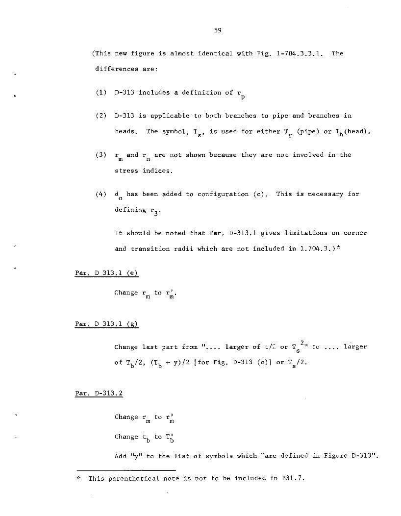
59
(This new f i g u r e i s almost i d e n t i c a l w i th Fig. 1-704.3.3.1. The
d i f f e r e n c e s a r e :
(1) D-313 inc ludes a d e f i n i t i o n of r P
(2) D-313 i s app l i cab le t o both branches t o p ipe and branches i n
heads. The symbol, Ts , i s used f o r e i t h e r T (p ipe) o r Th(head). r
(3) rm and r
s t r e s s i n d i c e s .
a r e n o t shown because they a r e n o t involved i n the n
(4) d has been added t o conf igu ra t ion ( c ) . This i s necessary f o r 0
3' def in ing r
It should be noted t h a t Par. D-313.1 g ives l i m i t a t i o n s on corner
and t r a n s i t i o n r a d i i which are n o t included i n 1.704.3.)'k
Par . D 313.1 ( e )
Change rm t o r:.
Par . D 313.1 ( g )
Change l a s t p a r t from l a r g e r of t/z o r T '11 t o .... l a r g e r S
of T b / 2 , (Tb + y) /2 [ f o r Fig. D-313 ( c ) ] o r T s / 2 .
Par. D-313.2
Change r t o r ' m m
Change tb t o T i
Add "y" t o the l i s t of symbols which "are def ined i n F igure D-313".
;\ This p a r e n t h e t i c a l no te i s n o t t o be included i n B31.7.

60
BRANCH PIPE = N0ZZL.E \
FIGURE D-3 13 NOZZLE DIMENS I O N S
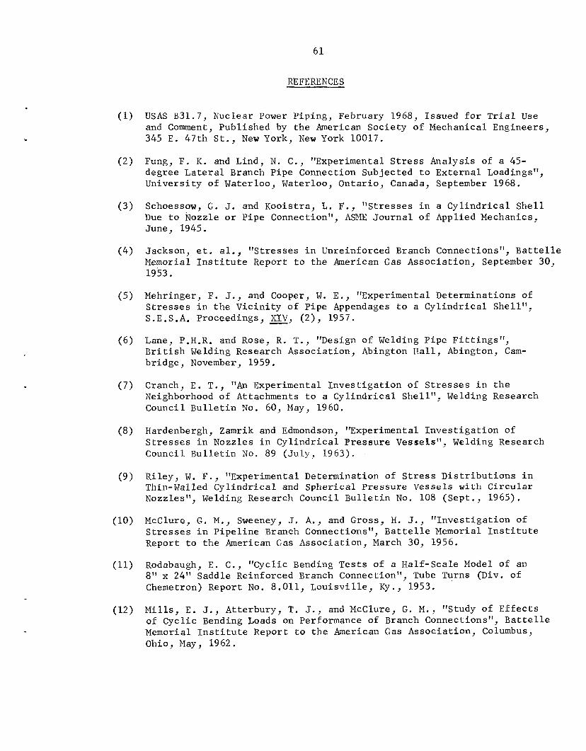
61
REFERENCES
(1) USAS B31.7, Nuclear Power Piping, February 1968, Issued for Trial Use and Comment, Published by the American Society of Mechanical Engineers, 345 E. 47th St., New York, New York 10017.
(2) Fung, F. K. and Lind, N. C., "Experimental Stress Analysis of a 45- degree Lateral Branch Pipe Connection Subjected to External Loadings", University of Waterloo, Waterloo, Ontario, Canada, September 1968.
(3) Schoessow, G. J. and Kooistra, L. F., "Stresses in a Cylindrical Shell Due to Nozzle or Pipe Connection", ASME Journal of Applied Mechanics, June, 1945.
(4) Jackson, et. al., "Stresses in Unreinforced Branch Connections", Battelle Memorial Institute Report to the American Gas Association, September 30, 1953.
(5) Mehringer, F. J., and Cooper, W. E., "Experimental Determinations of Stresses in the Vicinity of Pipe Appendages to a Cylindrical Shell", S.E.S.A. Proceedings, 2, (2), 1957.
(6) Lane, P.H.R. and Rose, R. T., "Design of Welding Pipe Fittings", British Welding Research Association, Abington Hall, Abington, Cam- bridge, November, 1959.
(7) Cranch, E. T., "An Experimental Investigation of Stresses in the Neighborhood of Attachments to a Cylindrical Shell", Welding Research Council Bulletin No. 60, May, 1960.
(8) Hardenbergh, Zamrik and Edmondson, "Experimental Investigation of Stresses in Nozzles in Cylindrical Pressure Vessels", Welding Research Council Bulletin No. 89 (July, 1963).
(9) Riley, W. F., "Experimental Determination of Stress Distributions in Thin-Walled Cylindrical and Spherical Pressure Vessels with Circular Nozzles", Welding Research Council Bulletin No. 108 (Sept., 1965).
(10) McClure, G. M., Sweeney, J. A., and Gross, H. J., "Investigation of Stresses in Pipeline Branch Connections", Battelle Memorial Institute Report to the American Gas Association, March 30, 1956.
(11) Rodabaugh, E. C., "Cyclic Bending Tests of a Half-Scale Model of an 8" x 24" Saddle Reinforced Branch Connection", Tube Turns (Div. of Chemetron) Report No. 8.011, Louisville, Ky., 1953.
(12) Mills, E. J., Atterbury, T. J., and McClure, G. M., "Study of Effects of Cyclic Bending Loads on Performance of Branch Connections", Battelle Memorial Institute Report to the American Gas Association, Columbus, Ohio, May, 1962.
62
(113) P i c k e t t , A. G. , e t . a l . , "Low Cycle F a t i g u e Tes t ing of One-Half Sca le Model P r e s s u r e Vessels", Progress Reports No. 9 through 1 2 , July, 1964 through January 1965. Southwest Research I n s t i t u t e , San Antonio, Texas (Cont rac t No. AT(11-1)-1228, U.S. Atomic Energy Commission)
(114:) Rodabaugh, E . C . , e t . a l . , "Evaluation of Experimental and T h e o r e t i c a l Data on Radia l Nozzles i n P res su re Vessels", TID-24342.
(1-5:) Markl, A.R.C., "Fatigue T e s t s of P ip ing Components", Trans. ASME, Vol. 74, pp. 287-303 (1952).
(1.6:) Wichman, K. R., Hopper, A. G. , and Mershon, J. L . , "Local S t r e s s e s i n Sphe r i ca l and C y l i n d r i c a l S h e l l s Due t o External. Loadings", Welding Research Council B u l l e t i n No. 107, August 1.965.
(1.7:) B i j l a a r d , P. P., "S t r e s ses from Local Loadings i n C y l i n d r i c a l P res su re Vessels", Trans. ASME (August 1955).
B i j l a a r d , P. P., "S t r e s ses from Radia l Loads and Ex te rna l Moments i n C y l i n d r i c a l P res su re Vessels", Welding Research Supplement(Dec., 1955).
B i j l a a r d , P. P., "Additional Data on Stresses i n C y l i n d r i c a l S h e l l s Under Local Loading", Welding Research Council B u l l e t i n No. 50 (May, 1959).
(18)) Marcal, P. V . , " E l a s t i c - P l a s t i c Behavior of P ipe Bends wi th In-Plane Bending", J. of S t r a i n Analys is , Vol. 2 , N o . 1, pp. 84-90 (1967).
(19) Gross, N . , "Experiments on Shor t Radius P ipe Bends", Proc. I n s t n . Mech. Engrs., Vol. l B , p. 465 (1952-1953).
(20) Gross, N. and Ford, H . , "The F l e x i b i l i t y of Short-Radius P ipe Bends", Proc. I n s t n . Mech. Engrs., Vol. l B , p. 480 (1952-1953).
.
(21) Rodabaugh, E. C . , " F l e x i b i l i t y and Stress I n t e n s i f i c a t i o n F a c t o r s of P ip ing Components w i th Moment Loading", B a t t e l l e r e p o r t t o t h e American Gas Assoc ia t ion , Oct. 2 1 , 1966.
6 3
ORNL-TM-3014
INTERNAL DISTRIBUTION
1. S. E . Bea l l 2. H . W . Behrman 3. M . Bender 4. J . P. Blakely 5. S . E . Bol t 6. R . H . Bryan 7. J . W . Bryson 8. J . R . Buchanan 9. J . P . Callahan 10. D. W . Cardwell 11. J. M. Corm 12. W . B . C o t t r e l l 13. F. L . Cul ler 14. W . G . Dodge 15. M . H. Fontana 16. A . P. Fraas 17. W . R . G a l l 18. D. L . Gray
19-20. B . L . Greenstreet 21. R . C . Gwaltney 22. W . 0. H a r m s 23. P. N . Haubenreich 24. P. R . Kasten 25. K . C . Liu 26. M . I. Lundin 27. R . N . Lyon
68. 69.
70 - 71 - 72. 73 ' 74. 75 - 76. 77. 78. 79 * 80.
28. 29 * 30 * 31 32
33-37. 38. 39 * 40. 41. 42. 43 44. 45 46. 47. 48. 49. 50 51 52 *
53-54. 55-56. 57-66.
67.
R . E . MacPherson H . C . McCurdy J . G . Merkle A . J . Mi l le r E . C . Mi l le r S. E . Moore Paul Nelson A . M . Perry C . E . Pugh M . W . Rosenthal A . W . Savolainen M . J . Skinner J . E . Smith I. Spiewak D. A . Sundberg D. B . Trauger R . S . Valachovic A. M . Weinberg G . D . Whitman F. J . W i t t G . T . Yahr Central Re search Library Document Reference Sect ion Laboratory Records Department Laboratory Records ( R C )
EXTERNAL DISTRIBUTION
R . W . Aderholdt, Auburn University, Auburn, Alabama D . E . Allwein, Naval Ship Research and Development Center,
L. E . Alsager, USAEC, Washington, D . C . R . L . Anderson, Pennsylvania Power and Light Co., Allentown, Penna. W . F. Anderson, Liquid Metal Engineering Center, Canoga Park, Cal i f . N . B a l a i , Argonne National Laboratory, Argonne, I l l i n o i s R . E . B a l l , Byron Jackson Pump, Inc. , Los Angeles, Ca l i f . R. E . Benson, Tube Turns Corp., Louisvi l le , Kentucky D . J . Bergman, 683 Locust Road, Winnetka, I l l i n o i s Irwin Berman, Foster Wheeler Corp., Livingston, New Jersey Norman B l a i r , Ralph M. Parsons Co., Los Angeles, C a l i f . F. J . Bogden, Westinghouse E l e c t r i c Corp., Cheswick, Penna. M . Booth, DRDT, USAEC, Washington, D . C .
Annapolis, Maryland
64
81.. 82. 8z1. 84. 85 - 86 . 87. 88. 89. 90. 91 * 32 * 93 * 134. '35 ' 96. '37 - 198. '39 *
E . B . Branch, Sargent and Lundy, Chicago, I l l i n o i s H . F . Brannon, Yankee A t m i c E l e c t r i c Co., Boston, Massachusetts M . N . Bress le r , Taylor Forge, Inc. , Wilmington, Delaware W . E . Bristow, Monsanto Co., S t . Louis, Missouri G. 0 . Bright , Idaho Nuclear Corp., Idaho F a l l s , Idaho R . Broadhead, Westinghouse E l e c t r i c Corp., Pi t tsburgh, Penna. J . E . Brock, U.S. Naval Postgraduate School, Monterey, C a l i f . D . R . Campbell, Liquid Metal Engineering Center, ICanoga Park, Ca l i f . L. H. Carr, Route 1, Box 170, San Luis Obispo, Cal i forn ia J. A . Casner, Youngstown Sheet and Tube Co., Youngstown, Ohio J . R . Chamberlain, Borg-Warner Corp., York, Penna. C . H . men, Auburn University, Auburn, Alabama D . C . Church, General Dynamics Corp., Groton, Connecticut J . R. Clapp, Burns and Roe, Inc . , Kempstead, New York R . L. Cloud, Teledyne Mater ia ls Research Co., Waltham, Massachusetts R . W . Clough, Universi ty of Cal i fornia , Berkeley, Calif. W . S. Clouser, Los Alamos S c i e n t i f i c Laboratory, ],os Alamos, N.M. R . H. Clute, In te rprovinc ia l Pipe Line Co., Edmonton, Alberta, Canada John Conway, U.S. N a v y Department, Bureau of Ship:; Code 609.3C, Washington, D . C .
:LOO. W . E . Cooper, Teledyne Mater ia ls Research Co., Waltham, Massachusetts :101. L. M . Corcoran, MPR Associates, Inc. , Washington, D.C. :LO2. J . E . Corr, General E l e c t r i c Co., San Jose, Cal i forn ia :103. H. T. Corten, University of I l l i n o i s , Urbana, I l l i n o i s :LO!+. A. W . Crit tenden, Niagara Mohawk Power Corp., Buffalo, New York :LO'j. A . J . d e l Buono, Taylor Forge and Pipe Works, Chicago, I l l i n o i s :Lots. R . W . Dickinson, Liquid Metal Engineering Center, Canoga Park, Calif . l07. R . J . Dohrmann, Babcock and Wilcox Research Center, Alliance, Ohio l08. H. W. Dolf i, Combust ion Engineering, Inc . , Chattanooga, Tenn . 1-09. W . L. Dornaus, Bechtel Corp . , San Francisco, Calif. IL10. F. W . Dunham, David Taylor Model Basin, Code 703 .l, Washington, D .C . ILL. A . J. Edmondson, University of Tennessee, Knoxvil1.e 1-12. G . R . Edwards, P i t t sburgh Des Moines S t e e l Co., Pi t tsburgh, Penna. 1-15. R . W . Elkins , Byron Jackson Pump, Inc. , Los Angeles, Ca l i f . lilt. 1-15. E . P. Esztergar , 6046 B e l l e w e Avenue, La J o l l a , Calif. 1.16. J. R . Far r , Babcock and Wilcox Co., Barberton, Ohio 1.1'7. J . H . Faupel, E . I. du Pont de Nemours and Co., Wilmington, Delaware 1.18. D. M. Fischer , Amoco Chemicals Corp., Chicago, 1 l l . i no i s 1-19. J. D . Fishburn, Combustion Engineering, Inc. , Windsor, Connecticut 1.20. R . H . Gallagher, Cornel1 Universi ty , I thaca , New York 1.2l. J. W . Gascoyne, C . F. Braun and Co., Alhambra, Calif . 122. H. H . George, Tube Turns, Inc . , Louisv i l le , Kentucky 1.25. J. C . Gerdeen, Michigan Technological University, Houghton, Michigan 1.24. 125;. J . D. Gilman, General E l e c t r i c Co., San Jose, Ca l i f . 126. 1.27. C . T . Grace, University of New Mexico, Albuquerque, N.M. 128. G . R . Graves, C . F. Braun and Co., Covina, Cal i forn ia 129. R . C . Green, Southwest Fabricat ing and Welding Co., Houston, Texas 130. D . K . Greenwald, Ladish Co., Cudahy, Wisconsin 131.. B i l l G r i f f i t h , Bechtel Corp., San Francisco, Calif .
F. E . E l ly in , University of Sherbrooke , Sherbrooke , Canada
E . F. Gerwin, M. W . Kellogg Co., Williamsport, Penna.
A. B . Gl icks te in , General Dynamics Corp., Groton, Connecticut
65
132. 133 * 134. 135 * 136. 137 * 138. 139 - 140. 141. 142. 143. 144. 145. 146. 147. 148. 149. 150. 151. 152. 153 * 154. 155 * 156. 157 * 158. 159 160. 161. 162. 163.
165. 166. 167. 168. 169. 170. 171. 172.
164.
173 *
175 * 174.
176.
178.
180. 181. 182.
177.
179
J . H . Griff in , Los Alamos S c i e n t i f i c Laboratory, Los Alamos, N.M. S . C . Grigory, Southwest Research I n s t i t u t e , San Antonio, Texas John Grund, Portland General E l e c t r i c Co., Portland, Oregon 0. Hagen, Westinghouse E l e c t r i c Corp., Cheswick, Penna. E . E . Hamer, Argonne National Laboratory, Argonne, I l l i n o i s E . E . Hay, Imperial Chemical Industr ies , Manchester 9, England K . Hayashi, Esso Research and Engineering Co., Florham Park, N . J . J . K. Hayes, Combustion Engineering, Inc. , Chattanooga, Tenn. D . B . Hei l ig , Bechtel Corp., San Francisco, Calif . T. K . Hellen, Berkeley Nuclear Laboratories, Berkeley, England R . W . Holland, University of Tennessee, Knoxville, Tenn. R . J . Hollmeier, Pioneer Service and Engineering Co., Chicago, Ill. A. B . Holt, USAEC, Washington, D.C. F. I . Horan, NASA Langley Field, Hampton, Virginia J . P. Houstrup, Combustion Engineering, Inc. , Chattanooga, Tenn. L. L . Hsu, General E l e c t r i c Corp., San Jose, Calif. K. A . Huber, Byron Jackson Pump, Inc. , Los Angeles, C a l i f . L . E . Hulbert, B a t t e l l e Memorial I n s t i t u t e , Columbus, Ohio H . Huner, Auburn University, Auburn, Alabama J . R . Hunter, RDT, USAEC, Washington, D . C . R . W . Jackson, National Valve and Manufacturing Co., Pit tsburgh, Pa. M . T . Jakub, Battelle-Northwest Laboratory, Richland, Washington R . I . Jetter, Atomics Internat ional , Canoga Park, Cal i f . R . L. Johnson, Westinghouse E l e c t r i c Corp., Pit tsburgh, Penna. A. W . Jones, Rolls Royce and Associates, L t d . , Derby, England Ralph Jones, USAEC, Washington, D.C . S . M . Jorgensen, Foster Wheeler Corp., Livingston, New Jersey L. M. Kaldor, U . S . Navy, Annapolis, Maryland R . J . Kiessel , U. S. Coast Guard, 1300 E S t r e e t , Washington, D.C. E. E . Kintner, RDT, USAEC, Washington, D.C . W . G . Knecht, Darling Valve and Mfg. Co., Williamsport, Penna. Robert Koester, The Wm. Powell Co., Cincinnati , Ohio Z . A. Kravets, Consolidated Edison Co. of New York, New York, N . Y . N . Krishnamurthy, Auburn University, Auburn, A l a b a m a D . F. Landers, Teledyne Materials Research Co., Waltham, Massachusetts G . Landler, A t m i c s Internat ional , Canoga Park, C a l i f . E . P . Lang, Lunkenheimer C o . , Cincinnati , Ohio D. F. Lange, USAEC, Washington, D.C. B . F. Langer, Westinghouse E l e c t r i c Corp., Pit tsburgh, Penna. C . F. Larson, Welding Research Council, 345 E . 47th S t . , New York, N . Y . R . E . Lawther, Westinghouse E l e c t r i c Corp., Pit tsburgh, Penna. M . M . Lemcoe, Liquid Metal Engineering Center,. Canoga Park, Cal i f . M. R . Lesh, Esso Research and Engineering Co., Florham Park, N . J . M . M . Leven, Westinghouse E l e c t r i c Corp., Pit tsburgh, Penna. M . J . Letich, American Bureau of Shipping, New York, N . Y . G . E . Lien, American E l e c t r i c Power Service Corp., New York, N . Y . N . C . Lind, University of Waterloo, Waterloo, Ontario, Canada R . G . Lloyd, Babcock and Wilcox Co., Barberton, Ohio A . Lohmeier, Westinghouse E l e c t r i c Corp., Tampa, Flor ida R . H . Luhta, Darling Valve and Manufacturing Co., Williamsport, Penna. George McClure, B a t t e l l e Memorial I n s t i t u t e , Columbus, Ohio

66
183 .,
185
188 189 ,. 1go. 1y. 192. 193 . 1514. 195. 196. 1537. 198.
184 .I
166 187
1139 200. 201. 202 . 203. 204. 205. 206. 207. 2138. 209. 210. 211. 212.
214. 213.
215. 216. 217. 218. 219. 220. 221.. 222. 223. 224. 225. 2216. 2277. 228. 2251. 2 3 0 . 23:L.
C . M . McCullar, Bechtel Corp., San Francisco, Calif . J . T . McKeon, M. W . Kellogg Co., Piscataway, New Jersey N . R . McKinney, Southern Services, Inc. , Birmingham, Alabama W . N . McLean, Crane Co., Chicago, I l l i n o i s G. R . McNutt, Tennessee Valley Authority, Knoxville, Tenn. E . A . MePhillamy, Sandusky Foundry and Machine Co., Sandusky, Ohio J . B. Mahoney, Applied Technology Associates, L . I . , New York, N . Y . L. J. Malandra, Westinghouse E l e c t r i c Corp., Pittskiurgh, Penna. M . V . Malkmus, Tube Turns, Louisvi l le , Kentucky J . R . Maloney, Westinghouse E l e c t r i c Corp., Cheswick, Penna. M . J . Manjoine, Westinghouse E l e c t r i c Corp., Pi t tsburgh, Penna. W . D. Manly, Union Carbide Corporation, Kokomo, Indiana Pedro Marcal, Brown University, Providence, Rhode Is land L . P. Marchesani, Sun O i l Co., Philadelphia, Penna. A . Mathews, University of Tennessee, Knoxville, Tenn. J . D . Mattimore, 3130 Meadowlark Road, Louisvi l le , Kentucky J . M . Matusz, Rockwell Manufacturing Co., Pit tsburgh, Penna. R . L . Maxwell, University of Tennessee, Knoxville, Tenn. J . L . Mershon, RDT, USAEC, Washington, D . C . W . R . Mikesell, Chicago Bridge and Iron Co., Oak Bi-ook, I l l i n o i s C . E . Mil ler , Jr., Argonne National Laboratory, Argonne, I l l i n o i s B . J . M i l l e v i l l e , Rockwell Manufacturing Co . , P i t t :;burgh, Penna . A . T . Molin, United Engineers and Constructors, Philadelphia, Penna. C . L . Moon, Atomic E n e r a of Canada, L t d . , Ontario, Canada C . A . Moore, Idaho Nuclear Corp., Idaho F a l l s , Idaho J . K . Morse, Combust ion Engineering, Inc . , Chattanooga, Tenn . I. Mortman, General E l e c t r i c Co., KAPL, Schenectady, N . Y. E . D . Mysinger, Tennessee Valley Authority, Knoxvi.Lle, Tenn. A . D . Nalbandian, Gr inne l l Corp., Providence, Rhode Is land R . M . Nelson, Bingham-Willamette Co., Portland, Oregon D. J . Nolan, United Nuclear Corp., Elsmford, New York W . J . O'Donnell, O'Donnell and Associates, 3 6 1 1 M a p l e ~ ~ e Drive,
E . T. Onat, Yale University, New Haven, Conn. J . A . Paget, Gulf General Atomic, Inc . , San Diego, C a l i f . D . H . Pai , Foster Wheeler Corp., Livingston, New Jersey M . Pakstys, General Dynamics, Groton, Connecticut W . B . Pali jenko, Ontario Hydro, Toronto 2, Ontario, Canada A . J. Palmer, Esso Research and Engineering Co., Florham Park, N . J . G . W . Pangborn, Combustion Engineering, Inc. , Windsor, Conn. C . T . Parker, General E l e c t r i c Co., San Jose, C a l i f . G . L . Parkinson, Bechtel Corp., San Francisco, C a l i f . N . T . Pe te rs , Gi f fe l s and Roset t i , Inc. , Detroi t , Michigan D. B . Peterson, KPA Computer Techniques, Inc. , Large, Penna. A . G . P icke t t , Southwest Research I n s t i t u t e , San Antonio, Texas D . L . Platus , Mechanics Research, Inc. , E l Segundo, C a l i f . R . W . Pochmann, U. S . Indus t r ies , Inc. , Houston, Texas J . J . Poer, Commonwealth Edison Co., Chicago, I l l i n o i s C . H . Powell, University of Cal i fornia , Berkeley, C a l i f . A . J . Pressesky, USAEC, Washington, D . C .
Bethel Park, Penna.

67
232. 233 * 234. 235 * 236. 237 * 238. 239 - 240. 241. 242. 243. 244. 245. 246. 247. 248. 249. 250. 251. 252. 253 * 254. 255 ' 256. 257 *
J . C . Quinn, Lunkenheimer Co., Cinc inna t i , Ohio F. C . Ra l ly , General E l e c t r i c Co., Sunnyvale, Calif. Y . R . Rashid, General E l e c t r i c Co., San Jose , C a l i f . G . S . Rasmussen, G . S. Rasmussen and Assoc ia tes , Glendale, C a l i f . R . T . Reid, Aero je t Nuclear Systems Co., Sacramento, C a l i f . B . Roberts, Combustion Engineering, I n c . , Chattanooga, Tenn. E . C . Rodabaugh, B a t t e l l e Memorial I n s t i t u t e , Columbus, Ohio 0. A. Rogers, Y - I 2 P l a n t , Oak Ridge, Tenn. M . A . Rosen, DRDT, USAEC, Washington, D . C . G . S . Rosenberg, Argonne Nat iona l Laboratory, Argonne, I l l i n o i s H . D . Ross, Babcock and Wilcox Co., Lynchburg, V i rg in i a B . J. Round, Combustion Engineering, I n c . , Windsor, Connecticut E . J . Rozic, Babcock and Wilcox Co., Beaver F a l l , Penna. V . L. Sa le rno , 2430 Laconia Avenue, Bronx, New York R . F . Sammataro, General Dynamics Corp., Groton, Connecticut Robert Schmidt, Ladish Co., Cudahy, Wisconsin W . R . Schmidt, MPR Associa tes , Inc . , Washington, D . C . R . W . Schneider , Bonney Forge and Foundry, Inc . , Allentown, Penna. J . J . Schre iber , USAEC, Washington, D.C . J . Schroeder, Un ive r s i ty of Waterloo, Waterloo, Ontar io , Canada J. G . Schumacher, Aerojet-General Corp., Sacramento, Calif . H. R . Selby, Bech te l Corp., Gai thersburg, Maryland Jagmohan Seoni, Bech te l Corp., Gai thersburg, Maryland W . A . Shaw, Auburn Un ive r s i ty , Auburn, Alabama R . L . Shively, General E l e c t r i c Co., San Jose , Ca l i fo rn ia V . Skoglund, Un ive r s i ty of New Mexico, Albuquerque, N .M.
258. R . J. 259. H. B . 260. W . R . 261. A . L . 262. R . E . 263. J. E . 264. J. L. 265. E . D. 266. R . E . 267. E . H . 268. K . 0 . 269. R . G . 270. w . H . 271. E . 0 . 272. w . F. 273. S. W . 274. R . E . 275. B . E . 276. R . E . 277. W . H . 278. A. B. 279. F. E . 280. E . 0 . 281. R . F .
Slember, United Nuclear Corp., Elmsf ord, N . Y . Smith, Combustion Engineering, I n c . , Windsor, Connecticut Smith, S r . , Bech te l Corp., San Franc isco , C a l i f . Snow, Westinghouse E l e c t r i c Corp., Madison, Pennsylvania Soderberg, Walworth Co., Greenburg, Penna. Soehrens, C . F . Braun and Co., Alhambra, C a l i f . V . Sper ry , D e t r o i t Edison Co., D e t r o i t , Michigan Ss inegursk i , Combustion Engineering, I n c . , Windsor, Connecticut Stanbridge, Liquid Metal Engineer ing Center, Canoga Park, C a l i f . S te igerwald, Bech te l Corp., Gai thersburg, Maryland Stein, Babcock and Wilcox C o . , A l l i ance , Ohio Sturm, Teledyne-Brown Engineering, Hun t sv i l l e , Alabama Suther land , Bat te l le-Northwest Laboratory, Richland, Wash. Swain, General E l e c t r i c Co., San Jose , C a l i f . Swinson, Auburn Univers i ty , Auburn, Alabama Tagart , General E l e c t r i c Co., San Jose , Cal i f . Taylor , Reinhold Publ ishing Co., Chicago, I l l i n o i s Tenzer, Ebasco Serv ices , Inc . , New York, N . Y . Tschirch, Har twel l Company, I n c . , E a s t Providence, Rhode I s l a n d Tuppeny, Combustion Engineering, I n c . , Windsor, Connecticut van Weelderen, Westinghouse E l e c t r i c Corp., Tampa, F l o r i d a Vinson, Bech te l Corp., San Francisco, C a l i f . Waters, 2 8 ~ Heri tage Vi l l age , Southbury, Connecticut Webster, U. S . S t e e l Corp., P i t t sbu rgh , Pema .
68
282. 283.
285. 286. 287. 288. 289. 290. 291. 292. 293 - 294. 295 296.
312.
284.
2:9;7-311.
B . Wei, RET, USAEC, Washington, D . C . K . R . Wichman, N a v y Department, Washington, D . C . F . S . G . W i l l i a m s , 5555 N . Sheridan Road, Chicago, I l l i n o i s L. E . Wright, C . F . Braun and Co., Alhambra, C a l i f . W . B . Wright, Westinghouse E l e c t r i c Corp., P i t t s b u r g h , Penna. J. N . Wu, Babcock and Wilcox Co., A l l i ance , Ohio G . Y . Young, Niagara Mohawk Power Corp., Buffa lo , N.Y. J. C . M. Yu, Auburn Un ive r s i ty , Auburn, Alabama Lin Yung-Lo, B l i s s R and D Co., Swarthmore, Penna. S. Y . Z a m r i k , Pennsylvania S t a t e Univ., Un ive r s i ty Park, Penna. Zenons Zudans, F rank l in I n s t i t u t e Research Labs, Ph i l ade lph ia , Pa. M . P . Zyne, Southern Se rv ices , Birmingham, Alabama L i b r a r i a n , Bech te l Corp . , Gaithersburg, Maryhnd NRTS Technica l L ib ra ry , P. 0. Box 1845, Idaho F a l l s , Idaho Libra r i an , Westinghouse E l e c t r i c Corp., P i t t s b u r g h , Penna. Div is ion of Technical Information Extension ( C l r I E ) Laboratory and Un ive r s i ty Div is ion , OR0