Embed Size (px)
Citation preview

Reinforced Concrete Section 5.1
January, 2018 1
Reinforced Concrete Section 5.1
So what’s wrong with using un-reinforced concrete?

Reinforced Concrete Section 5.1
January, 2018 2
Concrete Cracks
Basics of Reinforced Concrete
• Concrete is strong in compression and weak in tension.
• Tensile capacity is approximately 10% of the compressive strength of concrete.
Compression Tension

Reinforced Concrete Section 5.1
January, 2018 3
Beam Exercise
Basics of Reinforced Concrete Cont’d:
• Steel reinforcement is strong in tension.
• Reinforcement is added to carry tensile loads in concrete members.
• Temperature reinforcement is added to carry tensile loads due to thermal expansion of concrete members.

Reinforced Concrete Section 5.1
January, 2018 4
Why Use Rebar?
AppliedLoad
Simply supported beam example
View PCA Video
Fundamentals of Reinforcing and Prestressed Concrete
(PCA VC114 ’88 Mod ‘07)

Reinforced Concrete Section 5.1
January, 2018 5
Structural Engineering Concepts

Reinforced Concrete Section 5.1
January, 2018 6
Shear & Moment Diagram
Uniformly Loaded Simple Beam
Maximum Shear Load at Bridge Ends and Piers
Larger Stirrup Spacing @ Midspan
Tighter Stirrup Spacing Near Abutments

Reinforced Concrete Section 5.1
January, 2018 7
Tighter Stirrup Spacing at Beam Ends
Shear & Moment Diagram
Uniformly Loaded Continuous 3 Span

Reinforced Concrete Section 5.1
January, 2018 8
Uniformly Loaded Continuous Beam 3 Spans
Maximum negative moment in deck over piers.
Additional longitudinal reinforcement added in top mat.
Beam Capacity

Reinforced Concrete Section 5.1
January, 2018 9
Strength of the Beam
Beam Cross-section Beam Side View
M = Astfy(d-1/2a) = 0.85fc′ab(d-1/2a)
Case StudyI-25: Walnut Street
Denver, CO

Reinforced Concrete Section 5.1
January, 2018 10
Thoughts?
Deck To Be Placed Later
Construction Joint

Reinforced Concrete Section 5.1
January, 2018 11
I-25: Walnut Street Pier Collapse
Pier Collapse
I-25: Walnut Street, Denver, CO
Oct. 4, 1985
Fatalities: 1
Injuries: 4

Reinforced Concrete Section 5.1
January, 2018 12
Reinforcement Inspection
View CRSI Video
CRSI Field Insp Reinf Bars Mod 08

Reinforced Concrete Section 5.1
January, 2018 13
Type of Reinforcement
• Source
• Certifications
• Grade
• Epoxy coated or uncoated or stainless

Reinforced Concrete Section 5.1
January, 2018 14
Documentation
Bills of material –what was delivered
Certifications
Rebar (steel) mill certificate

Reinforced Concrete Section 5.1
January, 2018 15

Reinforced Concrete Section 5.1
January, 2018 16
English Rebar Numbers
• #3 - #8; Diameter in 1/8″ units
#8/8 = 1″ dia.
• #9 - #18; Based on area of square barsformerly used with sides of 1″, 1-1/8″, 1-1/4″, 1-1/2″ & 2″ and then rounded to closest 1/8″ unitdiameter.
Metric to English Bar Conversion
• (Bar # - 1) divided by 3 then round to nearest english bar #
• #25 metric = (25-1)/3 = #8 english

Reinforced Concrete Section 5.1
January, 2018 17
QPL Appendix Ahttp://www.oregon.gov/ODOT/HWY/CONSTRUCTION/QPL/Docs/QPL.pdf

Reinforced Concrete Section 5.1
January, 2018 18

Reinforced Concrete Section 5.1
January, 2018 19

Reinforced Concrete Section 5.1
January, 2018 20

Reinforced Concrete Section 5.1
January, 2018 21

Reinforced Concrete Section 5.1
January, 2018 22

Reinforced Concrete Section 5.1
January, 2018 23
Rebar Exercise
Mill:Size:Dia: Type: Grade:

Reinforced Concrete Section 5.1
January, 2018 24
Rebar Exercise Key
Mill:Size:Dia: Type: Grade:
Cascade#16 0.625″Billet (A615M)420
Rebar Exercise
Mill:Size:Dia: Type: Grade:

Reinforced Concrete Section 5.1
January, 2018 25
Rebar Exercise Key
Mill:Size:Dia: Type: Grade:
Cascade#19 0.75″A706M420
Rebar Exercise
Mill:Size:Dia: Type: Grade:

Reinforced Concrete Section 5.1
January, 2018 26
Rebar Exercise Key
Mill:Size:Dia: Type: Grade:
Nucor#13 0.50″Billet (A615M)420
Size & Shape
• Bar size
• Bar length
• Bar shape (correct radius)
• Agrees with shop drawings

Reinforced Concrete Section 5.1
January, 2018 27
REBAR MATERIAL TAG
A. Quantity
B. Size
C. Bend diagram
D. Project
E. Bar ID or mark
→ Verify
A B
C
D
E
Doubled Up Horizontal Bars in Abutment?

Reinforced Concrete Section 5.1
January, 2018 28
Hooked Bar in Middle of Deck by Itself?
Rebar Condition

Reinforced Concrete Section 5.1
January, 2018 29
Condition
• Look for any loose scale or rust, grease, oil, paint, or other foreign material that could harm the bond with the concrete.
• Properly stored off the ground to avoid water and mud which can cause corrosion.
• Do not use cracked or split bars (look at bends).
• Look for epoxy damage.
Field Bent Bars?

Reinforced Concrete Section 5.1
January, 2018 30
Epoxy Damage
Rebar Jobsite StorageTotal exposure time of epoxy-coated bar in storage or in place is not to exceed 2 months without covering. (530.40)
Epoxy breaks down under prolonged UV exposure – it gets chalky

Reinforced Concrete Section 5.1
January, 2018 31
Faded Epoxy & Bare Ties?
View WCI Video
Jobsite Handling Epoxy Coated Rebar

Reinforced Concrete Section 5.1
January, 2018 32
Layout
• Number
• Spacing
• Alignment
Reinforced Concrete Section 5.1
January, 2018 33
PlacementTolerances according to “Manual of Standard Practice” 530.41

Reinforced Concrete Section 5.1
January, 2018 34
Effective Depth “d”
Distance from the compression face of the beam to the centroid of the reinforcement

Reinforced Concrete Section 5.1
January, 2018 35

Reinforced Concrete Section 5.1
January, 2018 36
Transverse Bar Alignment Shift?
Longitudinal Bar Alignment Shift?

Reinforced Concrete Section 5.1
January, 2018 37
Bar Supports
Rail Stirrup Height Uneven?

Reinforced Concrete Section 5.1
January, 2018 38
Transverse Deck Bars Drop at Corner?
Bar Supports530.41(b) & (c)
2′ Centers (plans)
Concrete blocks (Dobies) or other approved devices
No rocks, broken brick, or wood

Reinforced Concrete Section 5.1
January, 2018 39
Bar SupportsPlans, General Notes
Bar SupportsPlans, General Notes
Support the bottom mat reinforcing steel from the forms with precast mortar blocks at 24” max. centers each way. Support the top mat reinforcing steel from the bottom mat reinforcing steel with wire bar supports as shown in Chapter 3 of the CRSI Manual of Standard Practice (SBU, BBU or CHCU). Place wire bar supports at 24” max. centers.
Reinforced Concrete Section 5.1
January, 2018 40
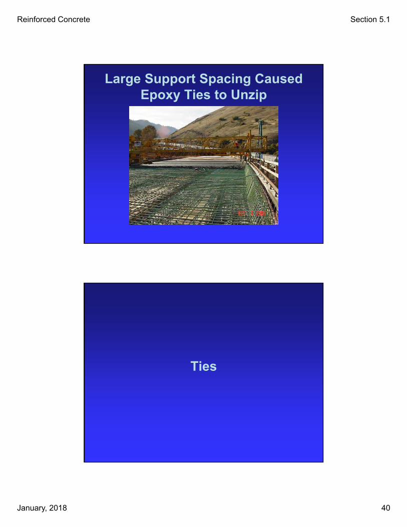
Large Support Spacing Caused Epoxy Ties to Unzip
Ties

Reinforced Concrete Section 5.1
January, 2018 41
Ties530.41(b)
Top mat of footings & decks:
Tie 100%
If spacing < 6″Tie 50%
Other locations:
Tie 100%
If spacing < 1′Tie 50%
Epoxy coated ties for epoxy rebar
No Ties for Up to 10 Feet?

Reinforced Concrete Section 5.1
January, 2018 42
Missing Ties
Clearances

Reinforced Concrete Section 5.1
January, 2018 43
Concrete Cover Affects Rebar Corrosion
Concrete cover
Clearances• Within tolerances recommended in CRSI’s
Manual of Standard Practice, Chapter 8 unless otherwise specified.
(00530.41)
• As specified on the plans.
• Tolerance on top mat of reinforcement to the top of deck surface is (+/-) 1/4″.
(00540.48(g))

Reinforced Concrete Section 5.1
January, 2018 44
Hooked Bar Laying on Form?
Transverse Bar on Chamfer Strip?

Reinforced Concrete Section 5.1
January, 2018 45
Transverse Deck Bar Under Drip Strip?
Transverse Bar Touching Fillet Form?

Reinforced Concrete Section 5.1
January, 2018 46
¾″ Clearance Under Deck Rebar Over Slabs?
Bottom Transverse Bars in Pilecap Touching Forms?

Reinforced Concrete Section 5.1
January, 2018 47
Bar Touching Form in Crossbeam?
High Stirrup in Crossbeam?

Reinforced Concrete Section 5.1
January, 2018 48
Watch Clearances on Rail Windows
½″ Clearance on Vertical Rail Bars to Window Form

Reinforced Concrete Section 5.1
January, 2018 49
How far are rail stirrups from the deck side form?
Clearance Exercise
Calculate the distance from the rail stirrups to the deck side form.
___________________________
___________________________
___________________________
___________________________

Reinforced Concrete Section 5.1
January, 2018 50

Reinforced Concrete Section 5.1
January, 2018 51
Clearance Exercise Key
Calculate the distance from the rail stirrups to the deck side form.
35mm + 25mm + 38mm + 40mm = 138 mm
Clearance = 138 mm (5 7/16″)
Splices

Reinforced Concrete Section 5.1
January, 2018 52
No Splice?
Splices
• As permitted per plans
• Splice bars No. 11 & smaller by Lapping or Approved Mechanical Splice.
• Splice bars No. 14 and larger with an Approved Mechanical Splice Only.
• Welded only with prior approval and with a certified welder.

Reinforced Concrete Section 5.1
January, 2018 53
Lap Splice530.42(b)
• Place bars in contact.
• Fasten with 3 ties/splice minimum.
• Length as shown (General Notes).
• Epoxy coated reinforcement requires longer splice length.

Reinforced Concrete Section 5.1
January, 2018 54
1 Tie on Splice?
1 Tie on Splice?

Reinforced Concrete Section 5.1
January, 2018 55
Mechanical Splice530.42(c)
• Construct per Specifications and Manufacturers Recommendations.
• Construct test splices in the presence of the Engineer.
• Install splices in the presence of the Engineer. Splices made without the Engineer present will be rejected.
Mechanical Splice Installers530.30
• Provide qualified mechanical splice installers.
• Construct test splices in the presence of the Engineer.
• Construct 3 splice samples per type and size for each installer.
• Do not begin splice installation until installers have been approved.

Reinforced Concrete Section 5.1
January, 2018 56
Spliced Bars Project Up?
Spliced Vertical Column Bars

Reinforced Concrete Section 5.1
January, 2018 57
Reinforcement Inspection
Inspection of the forms and reinforcement takes time.
Check early and often to help assure they are doing things correctly and to avoid minimal rework. Do not wait until just before the concrete placement.
Do a final check just prior to the concrete placement to assure everything still looks good.

Reinforced Concrete Section 5.1
January, 2018 58