Embed Size (px)
Citation preview
■-="■»!■•
o=>
o CO o
I
C\J I
CSi i
x i
Q
z o </)
> t—H
Q
o o 0
U w H
0 w
O
t- o t.
IIJ* _ 0)
üKS ■o
V)
i: >> *o> 4-» « Q>f—
e w)« «*- 3 V)
Mr u C 0)0 o £«4-
^— • t- *■> X3 i- • 3 Al «U -a ♦* cu u • 1- «r» •— %m U
(«■- 01 6£i i- C f O 3 O 3 ♦* O Ct
<£ « z > i-4 o O .* Q£ »• O c u. J=
V) o. 3 o tt ex o •
t/) t/> m • ÜJ > _l X X -C TO V) c < ID
El B «
u_ "O c o>
o tn CD o c •
N
52 „, -IN </t u
= >*£
X u a>
äff! s
"§<«c
■O j-g g
a o
J
...
THIS DOCUMENT IS BEST QUALITY AVAILABLE. THE COPY
FURNISHED TO DTIC CONTAINED
A SIGNIFICANT NUMBER OF
PAGES WHICH DO NOT
REPRODUCE LEGIBLYo
fTB-lff 3-256-M
EDITED TRANSLATION
METHODS OF FLASHLESS DROP FORGING
By: A. D. Bogdan and V. S. Kushnikova
English pages: 15
Source: Kuzneehno-Shtampovochnoye Proizvodstvo (Forging and Stamping), No. 7, 1966, pp. 35-10.
Translated by: W. Pearson/TDBRS-3
1
TN» TRANSLATION IS A SINMTMN OP TNI OBIOI- NAL OOllfW TIXT WTNOUT ANY ANALYTICAL OR KNTORIAL CONMINT. STATIMINTS OR TNIORIIf AOVOCATIDOUKPLIIOARaiTNOSIOPTNl SOURCt AMD DO NOT NICBSSARILY RIPLICT TNI POSITION OR OPINION OP TNI PORIMW TICNNOLOOY M. VISION,
PRIPARIO lYi
TRANSLATION DIVISION PORII0N TICNNOLOOY DIVISION WP>API. OMIO.
FTD" HT- P-3-296-69 Date 19
METHODS OP FLASHLESS DROP FORGING
A. D. Bogdan and V. S. Kushnikova
In large-batch ana nass production, such as that of the Gorkiy
Automobile Factory, hot flashless drop forging is done on swaging
hammers, horizontal forging machines and cranking hot-forge presses.
Cylindrical billet sections are used for flashless forging.
The billets are heated in chambered and semi-continuous open-flame
furnaces or in high-induction heating units. When heating in
open-flame furnaces a partial hydraulic cleaning away of scales
from the billets occurs before they are forged.
■
Hammers are usually used for flashless drop forgings of
cylindrical form, i.e., the form of gears, flanges, rings and so on.
The forging process is accomplished in two baric operations. In
the first operation (on the surface area of the forge) the billet is
subjected to swajing and in the second (in a special die impression)
the final forging takes place. Two to three blows from a hammer
are used for the swaging of a billet, and for the final forging
3-^ hammer blows are used.
i The stamp for flashless forging (Fig. 1) consists of two
halves: the upper half, secured on the head of a hammer, and the
lowert which is secured in the anvil cap of an anvil block.
FTD-HT-23-296-69
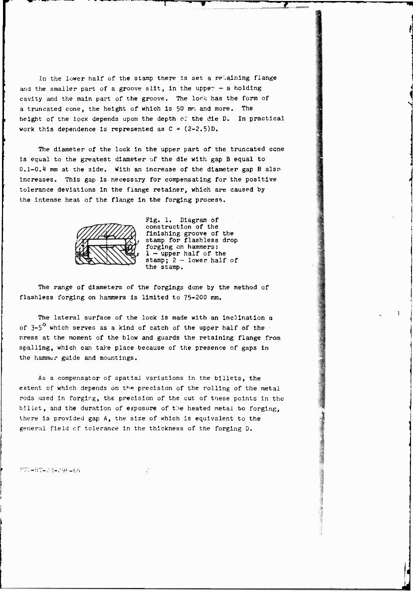
In the lower half of the stamp there is set a re'-alning flange
and the smaller part of a groove silt, in the uppe- - a holding
cavity and the main part of the groove. The lock has the form of
a truncated cone, the height of which is 50 nrns and more. The
height of the IOCK depends upon the depth at the die D. In practical
work this dependence is represented as C * (2-2.5)D.
N
The diameter of the lock in the upper part of the truncated cone
is equal to the greatest diameter of the die with gap B equal to
0.1-0.4 mm at the 3ide. With an increase of the diameter gap B also
Increases. This gap is necessary for compensating for the positive
tolerance deviations in the fiange retainer, which are caused by
the intense heat of the flange in the forging process.
Fig. 1. Diagram of construction of the finishing groove of the stamp for flashless drop forging on hammers: I - upper half of the stamp; 2 - lower half of the stamp.
The range of diameters of the forgings done by the method of
flashless forging on hammers is limited to 75-200 mm.
The lateral surface of the lock is made with an inclination a
of 3-5 which serves as a kind of catch of the upper half of the
press at the moment of the blow and guards the retaining flange from
spalling, which can take place because of the presence of gaps in
the hammer guide and mountings.
As a compensator of spatial variations in the billets, the
extent cf which depends on the precision of the rolling of the metal
rods used in forging, the precision of the cut of these points in the
billet, and the duration of exposure of the heated metal to forging,
there is provided gap A, the size of which is equivalent to the
general field of tolerance in the thickness of the forging D.
KTD-HT-23-r96-69
As a rule, the press grooves are made according to the rated
dimensions of the forgings with a calculated 1.5Ü shrinkage«
Margins of variance and tolerances in the forging are calculated
according to the second class of G03T 7505-55. An exception to this
rule is the gauging of forging D used for the stamp grooves of the
forging equal to the minimum size; gap B and angle a must coordinate
with gap A. Deviation from this condition can lead to the tight
Jamming of the stamp at the moment of its free closing, i.e., when
closing the stamp when there is no billet in the press groove, after
which tne stamp becomes unsuitable for further work because of the
impossibility of its uncoupling.
While there are several advantages in flashless forging on
hammers (such as decreasing metal expenditure, lowering labor
consumption and cutting back means and time expended for the
preparation of production), this process also contains a number_of
deficiencies, which essentially amount to the following:
1. The inevitable appearance of a burr on that part of the
forging adjacent to the upper plane of the truncated cone of the
press lock. The burr can protrude up to 15 mm and be 0.2-3.5 mm
thick, depending on the stage of wear of the stamp lock.
2. The possibility of a forging Jamming in the upper cavity
of the stamp groove. Removing it is accomplished either with a blow
of the upper half of the stamp on the following clinched billet or
with a blow of the upper stamp on a special ring (Pig. 2), which is
superimposed onto the protruding part of the lock in the lower half
of the stamp. Such a ring is made of soft carbon steel. The
interior diameter D of the ring is 15-20 mm greater -han the
diameter of the lower base of the truncated cone of the lock; the
thickness of the ring is equal to approximately half the height of
the look, and the width of the shel] A = ''0-50 mm.
3. The necessity of classifying 100? of the forgings according
to the size of the face of the burr and also the necessity of
deburring the forging in rough-grinding machines, if the burr
exceeds the allowable magnitude.
k. The possibility of a breakdown of the forging metai density
In the area where the burr is located (Fig. i) , which can aria«'
with the clogging or the stamping out of the forging in a cold state
on hammers or presses.
The presence of the enumerated deficiencies strictly limits
the sphere of application of this method of forging, although It Is
also more effective in comparison with the common open-die forging
on hammers (Table 1).
i #-r —
Pig. 3.
Fig. 2. Ring for removal of forgings stuck In a press groove.
Fig. 3- Configuration of a forging made by the method of flashless forging on a hammer: A - the zone of metal failure when eliminating burrs in a cold state.
Table 1. Comparative effectiveness of flashless and open-die drop forging on hammers. IHSr
No««r>c)atur* cf forging»
Hörn or loui-iit. instability! or»«t*l oi»e«i/hrJ°r ™ pr»»*, for on. ln foreliu •»> plteti
Hub rf ■ COUP.' lug a la« j '.tilOJ 1,390 'ran*»ls.iIon reduction ] «•»p» of a dlutrlbut- ,-„., In« ho.«, in* ! 5.2N3 4.589
Kite, or pint*» 17.150 6.299 I I I
in rorglns5" P1
jof forging«.
«liUMiJJ 131
115 140
114 5000
Is 2400
100 . 4000, 2500 140 7500 5200
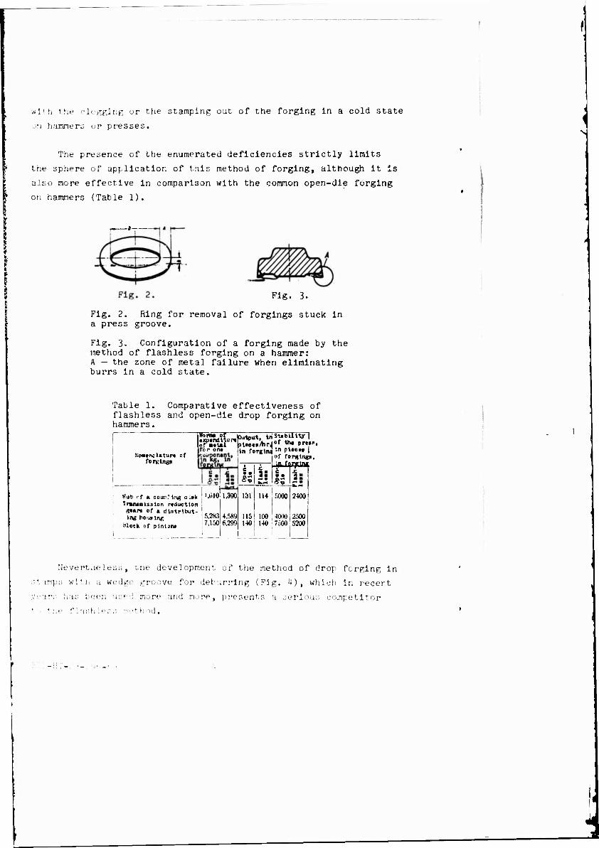
Nevertheless, me development, of the method of drop forging in
•.imp:; with a wedge groove for deburrlng (Fig. 4), which in recert
ears has been usf.l more and more, presents a serious competitor
the fl.-ishlenj -n'thod.
i
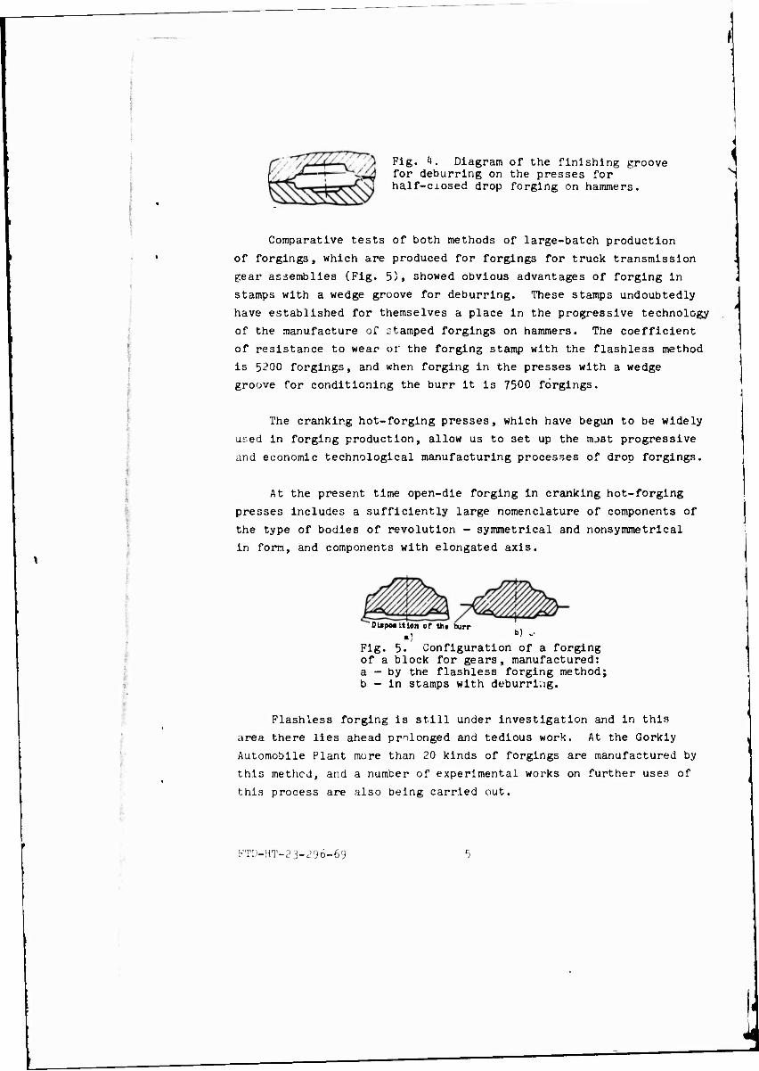
Fig. 4. Diagram of the finishing groove Y/j^—~! ^A^J for deburring on the presses for PO^"r*r [ A-T\N half-closed drop forging on hammers.
Comparative tests of both methods of large-batch production
of forgings, which are produced for forgings for truck transmission
gear assemblies (Fig. 5), showed obvious advantages of forging in
stamps with a wedge groove for deburring. These stamps undoubtedly
have established for themselves a place in the progressive technology
of the manufacture of stamped forgings on hammers. The coefficient
of resistance to wear or the forging stamp with the flashless method
is 5200 forgings, and when forging in the presses with a wedge
groove for conditioning the burr it is 7500 forgings.
The cranking hot-forging presses, which have begun to be widely
used in forging production, allow us to set up the mjst progressive
and economic technological manufacturing processes of drop forgings.
At the present time open-die forging in cranking hot-forging
presses includes a sufficiently large nomenclature of components of
the type of bodies of revolution - symmetrical and nonsymmetrical
in form, and components with elongated axis.
Dl»po»ttlon of ttu burr *! b) ..
Fig. 5. Configuration of a forging of a block for gears, manufactured: a - by the flashless forging method; b - in stamps with deburring.
Flashless forging is still under investigation and In this
area there lies ahead prolonged and tedious work. At the Gorkly
Automobile Plant more than 20 kinds of forgings are manufactured by
this method, and a number of experimental works on further uses of
this process are also being carried out.
FTD-HT-23-296-69
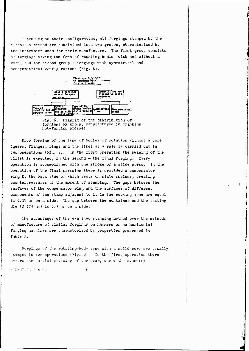
Depending on their configuration, all forgings stamped by the
flashless method are subdivided into two groups, characterized by
the instrument used for their manufacture. The first group consists
of forgings having the form cf rotating bodies with and without a
core, and the second group - forgings with symmetrical and
nonsymmetrical configurations (Fig. 6)..
Flwhlwci forgln ■Ion cranking ho1-
HFlwhUci forging-! on cranking hot- 1 forging i>rw» l
'"■reu? 1 forging! ?rt«s«l In open —trie«
| Croup i forglngo pnoood In apllt
! —trio«»
Tyoo of rotating boon without coro*
IBST6" 1th .lth » tu! MTWon
tlft bul*
S>m«tr<o«l »H fOBM
RONJ To nw
■«trie»!
Fig. 6. Diagram of the distribution of forgings by group, manufactured in cranking hot-forging presses.
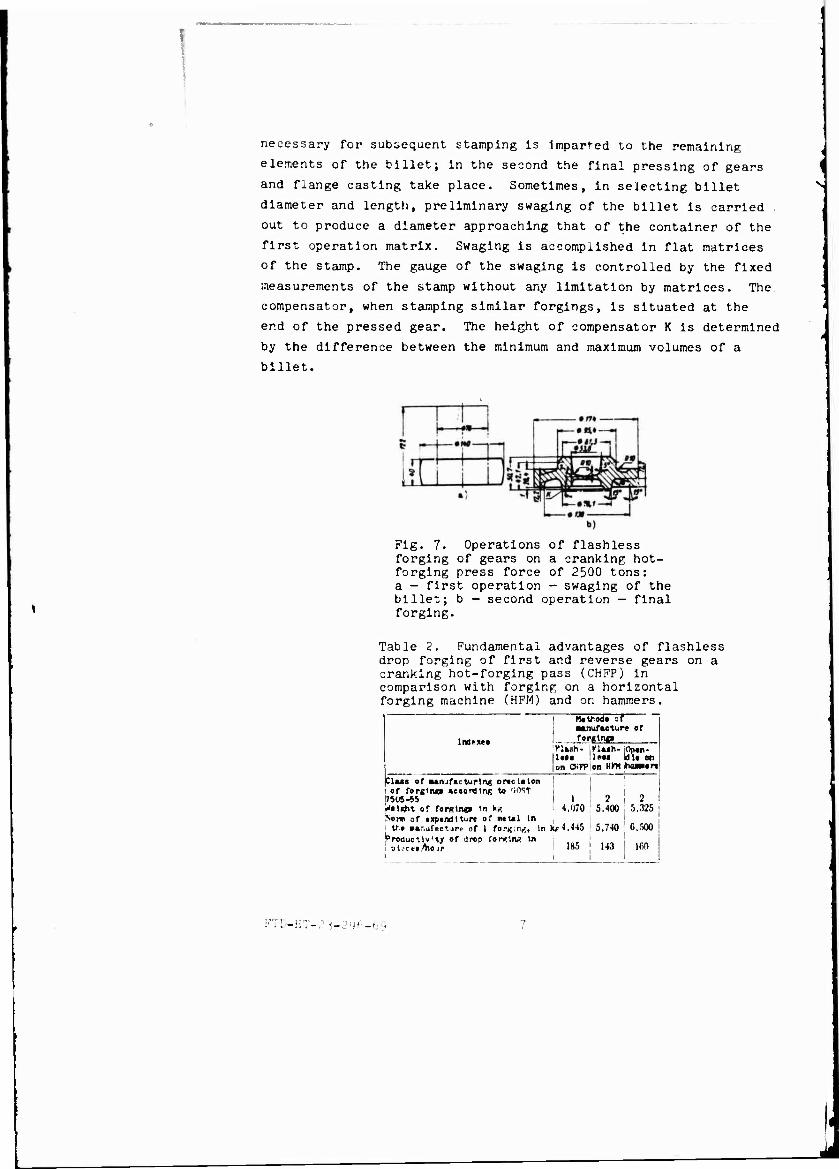
Drop forging of the type of bodies of rotation without a core
(gears, flanges, rings and the like) as a rule is carried out in
two operations (Fig. 7). In the first operation the swaging of the
billet is executed, in the 3econd - the final forging. Every
operation is accomplished with one stroke of a slide press. In the
operation of the final pressing there is provided a compensator
ring K, the back side of which rests on plate springs, creating
counterpressures at the moment of stamping. The gaps between the
surfaces of the compensator ring and the surfaces of different
components of the stamp adjacent to it in the working zone are equal
to 0.15 mm on a side. The gap between the container and the casting
die (0 171 mm) is 0.3 mm on a side.
The advantages of the exanined stamping method over the methods
of manufacture of similar forgings on hammers or on horizontal
forging machines are characterized by properties presented ir.
Table 2.
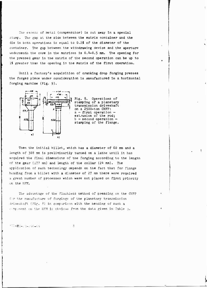
Forgings of the rotating-body type with a solid core are usually
stamped In two operations (Fig. 8). In the first operation there
occurs the partial pressing of the gear, where the symmetry
FTD-HT-2 j-,?'J6-6y
necessary for subsequent stamping Is Imparted to the remaining
elements of the billet; in the second the final pressing of gears
and flange casting take place. Sometimes, in selecting billet
diameter and length, preliminary swaging of the billet is carried .
out to produce a diameter approaching that of the container of the
first operation matrix. Swaging is accomplished in flat matrices
of the stamp. The gauge of the swaging is controlled by the fixed
measurements of the stamp without any limitation by matrices. The
compensator, when stamping similar forgings, is situated at the
end of the pressed gear. The height of compensator K is determined
by the difference between the minimum and maximum volumes of a
billet.
Fig. 7. Operations of flashless forging of gears on a cranking hot- forging press force of 2500 tons: a — first operation - swaging of the billet; b - second operation — final forging.
Table 2. Fundamental drop forging of first cranking hot-forging p comparison with forgln forging machine (HFM)
advantages of flashless and reverse gears on a ass (CHFP) in g on a horizontal and on hammers.
Ind» »i
Httfiodi of ■anufacture of
_ forging Flush- Kluh- Opin- lleii licit bit on 'on CKKPIon HYHtwmurt
Clus of atnjfacturlng orte i» ton I of forgtiup «coord 1ns to HOST [7505-55 »rfoitfit of rornlngo in k« '•or* of txptndlturc of «iul In
tr.t p&r.tifact jrr of 1 forging, in vroductlv'ty of drop Corwin« In i pU'ctiAiour
I 13 2 4.070 5,400 5.325
if 4,445 | 5,740 6,500
! 185 j 143 i 150
FTD-HT-«? 3-2^-69
'
The excess of metal (compensator) is cut away In a special
stamp. The gap at the side between the matrix container anä the
die in both operations Is equal to 0.2Ü of the diameter of the
container. The gap between the withdrawing device and the aperture
underneath the core in the matrices is 0.4-0.5 mm. The opening for
the pressed gear in the matrix of the second operation can be up to
IX greater than the opening in the matrix of the first operation.
Until a factory's acquisition of cranking drop forging presses
the forged piece under consideration is manufactured in a horizontal
forging machine (Fig. 9).
-»» 1 i; -r ji:
*=T7,
t lit —
*'m - • « ,1
i V9.
mi -H
I [,
»III
») m
Fig. 8. Operations of stamping of a planetary transmission driveshaft on a 2500-ton CHFP: a - first operation — extrusion of the rod; b - second operation — stamping of the flange.
»)
Then the initial billet, which has a diameter of 60 mm and a
length of 308 mm is preliminarily turned on a lathe until it has
acquired the final dimensions of the forging according to the length
of the gear (177 mm) and length of the collar (24 mm). The
application of such technology depends on the fact that for flange
heading from a billet with a diameter of 27 mm there were required
a great number of processes which were not placed on first priority
on the HFM.
The advantage of the flashless method of pressing on the CHFP
for the manufacture of forgings of the planetary transmission
driveshaft (Fig. 8) in comparison with the heading of such a
component on the HFM is obvious from the data given in Table j.
-HT-.13-296-69
:Z s~eg~
•—of* —
mi ̂m »m ~i
L±
rrt 1 * »4- +
«77 S
«)
e«;
isff *r
— , O« —i
■)
N T?^
-»w
a/7
o)
Fig. 9. Operations of the heading of a planetary transmission driveshaft on an HFM: a — first operation - swaging of the uiilet to a cone; b — second operation — swaging of the billet to a cylinder; c - third operation - forming of the flange.
Table 3. Comparative indexes of drop forgings of planetary transmission driveshafts on a CHFP and an HFM.
Hüt!:ocJ of production
Indue« Prrtting I Heading on CHfT i on Hfrl
Clata of accuracy of forglnga produc- tion according to COST 7505-55 ,
No» of natal expenditure In ■anufac- turlag 100 forgüwpi par kg j
Staap output In pleeeeAiour 2,97
100
2
7.06
86
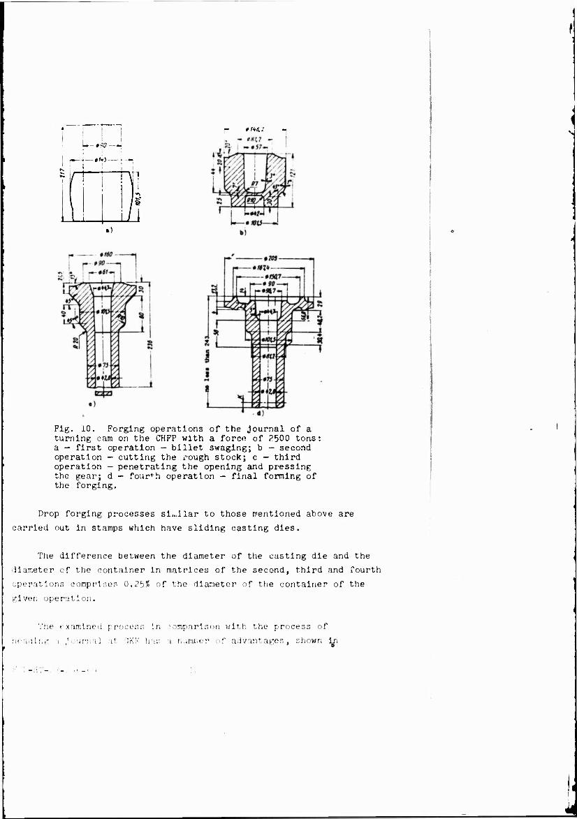
More complicated, but also more interesting, are the processes
of flashless pressing of forgings of the type of rotating bodies
with a tubular core. Figure 10 depicts the stamping operations of
a Journal of the rotating cam of a truck by the press method on a
CHFP. To carry out every operation one strike of the press slide Is
made. In the first operatl .n the swaging of the billet in flat
matrices is done; In the second - the making of a rough draft and
giving to the bille ; the symmetry of a rotating 'ody, necessary for
the correct embossing of the subsequent operations; in the third -
the punching out of an opening and pressing a tubular core; in the
fourth - «"he final forming of all elements of the forgings.
As in the previous case, there is a compensator for eliminating
the volumetric variation of the billets in the end of the tubular
core of the forging. The depth of the cavity of the compensator is
made by mea.is of decreasing the calculated length of the ring of the
lower withdrawing device oV the press.
FTD-HT-23-216-69 ')
/ f,.i,:
U— mo—H
! -_J_#ftj_
1
>
Fig. 10. Forging operations of the journal of a turning cam on the CHFP with a force of ?500 tons: a — first operation — billet swaging; b — second operation - cutting the rough stock; c — third operation - penetrating the opening and pressing the gear; d — fourth operation - final forming of the forging.
Drop forging processes similar to those mentioned above are
carried out in stamps which have sliding casting dies.
The difference between the diameter of the casting die and the
llaneter of the container in matrices of the second, third and fourth
operations comprises 0.2^% of the diameter of the container of the
given operation.
The examined process in comparison with the process of
heading a journal at GKM has a numtier of advantages, shown j^i
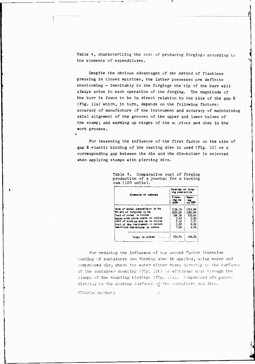
Table k, characterizing the cost of producing forging> according tc
the elements of expenditures.
Despite the obvious advantages of the method of flashless
pressing in closed matrices, the latter possesses ore definite
shortcoming - inevitably in the forgings the tip of the burr will
always arise in each operation of the forging. The magnitude of
the burr is found to be in direct relation to the size of the gap E
(Fig. 11a) which, in turn, depends on the following factors:
accuracy of manufacture of the instrument and accuracy of maintaining
axial alignment of the grooves of the upper and lower halves of
the stamp; and warming up stages of the nx .rices and dies in the
work process.
For lessening the influence of the first factor on the size of
gap E elastic binding of the casting dies is used (Fig. 12) or a
corresponding gap between the die and the die-holder is selected
when applying stamps with piercing dies.
Table 4. Comparative cost of forging production of a journal for a turning cam (100 units).
Motroda »r rorg- 1 1ng prod jetton
P !■•»•- I Hwd- in« on *"«.-. CHH> ! ontfff
Nora of B«tal txponditi-rt tr. kg 1128.70 I 1.174.00 Wti^it of forging tn kg 1010.w 1 128'». 00 foit of rr«t*l m pibloi 101,58 ! 123.C6 Wagts xtth tJrtm costi In rubla* 3,93 1 3,59 1 Cost of working i»»<J I1* in rutl«» 2.52 5,77 ! Cc»t of 1ht lnjtrumnt tn ruhl«i 9,32 O.fiO j Miortlzcd deduction* In rub)« 7,69 4,.58 1
| 1
124,94 „ !
i 144.20 1 1
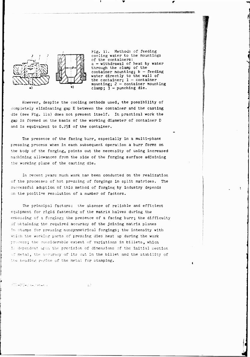
For reducing the influence of the second factor Intensive
cooling of containers and forming dies i-s applied, using water and
compressed air, where the water either neves directly to the surface
of the container mounting (Fig. lib) or withdraws heat through the
clamps of the mounting bindings (Fig. 1.1a). Compressed air' passes
directly to the working surfaces of the containers and dies.
FTD-HT-23-296-69 11
J I I
Öü
Pig. ii. Methods of cooling water to the mountings of the containers: a - withdrawal of heat by water through the clamp of the container mounting; b - feeding water directly to the wall of the container; 1 - container mounting; 2 - container mounting clamp; 3 - punching die.
However, despite the cooling methods used, the possibility of
completely eliminating gap E between the container and the casting
die (see Fig. 11a) does not present itself. In practical work the
gap is formed on the basis of the working diameter of container D
and Is equivalent to 0.25% of the container.
The presence of the facing burr, especially in a multi-phase
pressing process when in each subsequent operation a burr forms on
the body of the forging, points out the necessity of using Increased
machining allowances from the side of the forging surface adjoining
the working plane of the casting die.
In recent years much work has been conducted on the realization
of the processes of hot pressing of forgings in split matrices. The
successful adoption of this method of forging by industry depends
on the positive resolution of a number of factors.
The principal factors: r-he absence of reliable and efficient
equipment for rigid fastening of the matrix halves during the
emücssing of a forging; the presence of a facing burr; the difficulty
of obtaining the required accuracy of the Joining matrix planes
in stamps for pressing nonsymmetrical forgings; the Intensity with
wnich the working parts of pressing dies heat up during the work
process; the considerable extent of variations in billets, which
i. dependent upon the precision of dimensions of the initial section
of metal, the accuracy of its cut in the billet and the stability of
the heading regime of the metal for stamping.
12
Operations on mastering the process of pressing biiiets for
crosspieces of truck differentials for their subsequent stamping in
ordinary open-die matrices, conducted by us jointly with the
Experimental Scientific Research Institute of Forging-and-Pressing
Machinery (ENIKMASh) confirmed the stated conclusions.
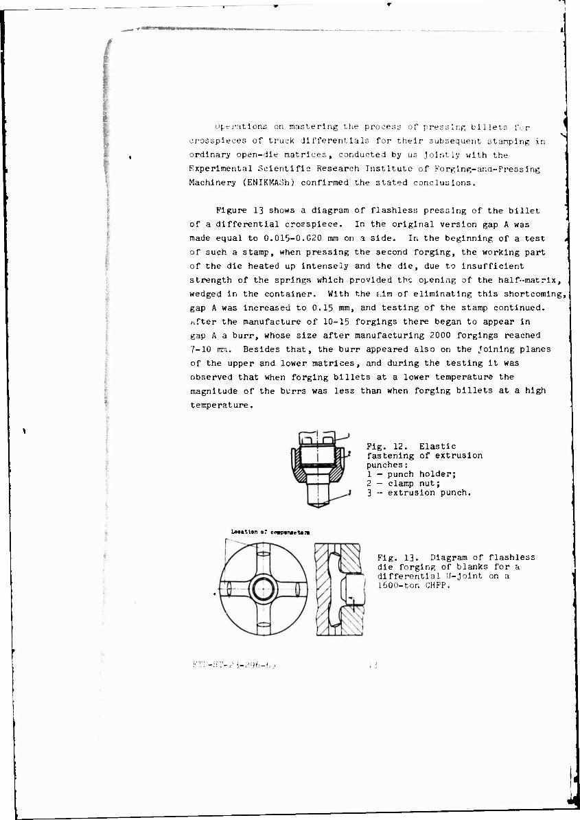
Figure 13 shows a diagram of flashless pressing of the billet
of a differential crosspiece. In the original version gap A was
made equal to 0.015-0.C20 mm on a side. In the beginning of a test
of such a stamp, when pressing the second forging, the working part
of the die heated up intensely and the die, due to insufficient
strength of the springs which provided the opening of the half-matrix,
wedged in the container. With the j.im of eliminating this shortcoming,
gap A was increased to 0.15 mm, and testing of the stamp continued,
/-.fter the manufacture of 10-15 forgings there began to appear in
gap A a burr, whose size after manufacturing 2000 forgings reached
7-10 nrn. Besides that, the burr appeared also on the Joining planes
of the upper and lower matrices, and during the testing it was
observed that when forging billets at a lower temperature the
magnitude of the burrs was less than when forging billets at a high
temperature.
Fig. 12. Elastic fastening of extrusion punches: 1 - punch holder; 2 — clamp nut; 3 - extrusion punch.
LMallon of co»p«n»eton
Fig. 13. Diagram of flashless die forging of blanks for a differential U-Jolnt on a 160 0-ton CHPP.
FTD-HT-2i-296-G; i i
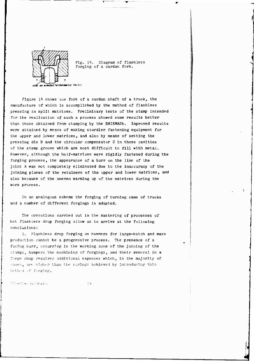
Fig. Ik. Diagram of flashless forging of a cardan fork.
s
In** dtv ii *
Figure 14 shows tue fork of a cardan shaft of a truck, the
manufacture of which is accomplished by the method of flashless
pressing in split matrices. Preliminary tests of the stamp intended
for the realization of such a process showed some results better
than those obtained from stamping by the ENIKMASh. Improved results
were attained by means of making sturdier fastening equipment for
the upper and lower matrices, and also by means of setting the
pressing die B and the circular compensator C in those cavities
of the stamp groove which are most difficult to fill with metal.
However, although the half-matrices were rigidly fastened during the
forging process, the appearance of a burr on the line of the
Joint A was not completely eliminated due to the inaccuracy of the
Joining planes of the retainers of the upper and lower matrices, and
also because of the uneven warming up of the matrices during the
work process.
In an analogous scheme the forging of turning cams of trucks
and a number of different forgings is adapted.
The operations carried out in the mastering of processes of
hot flashless drop forging allow us to arrive at the following
conclusions:
1. Flashless drop forging on hammers for large-batch and mass
production cannot be a progressive process. The presence of a
facing burr, occurring in the working zone of the Joining of the
stamps, hampers the machining of forgings, and their removal in a
forge shap requires additional expenses which, in the majority of
"■me:;, are higher than the savings achieved by introducing this method of forging.
n,-(y> lh
Such a process of forging manufacture can be justified only in
cases of the manufacture of small series of forgings with their
subsequent machining in multi-purpose machines, without applying
complex special devices.
In large-batch and mass production with its great work tempo it
is more expedient to employ semi-flashing forging using stamps with
a wedged sample for deburring which allows us to obtain that
effectiveness achieved with flashless forging.
2. The processes of hot flashless pressing of forgings on the
CHFP in closed and split matrices are obviously the next stages o**
the further development of forge-stamping production.
F7D-HT-23-296-69 lb
__ ii www im
DATA HANDLING PACE
0 "-ACCESS ION NO. 9S-DOCUMENT LOC
TP0000012 os-TiTLE METHODS OF
FLASHLESS DROP FORGING -Ü-
47-SUBJECT AREA
11, 13
I.TOPIC TAÖS
drop forging, forgo press, metallurgic process
«> AUTHOR CO-AUTHORS BOGDAN, A. D. ; I6-KUSHNIKOVA, V. S.
»■DATE OF INFO
66 «-SOURCE
KUZNECHNO SHTAMPOVOCHNOYE PROIZVODSTVO (RUSSIAN) FID
DOCUMENT HO.
HT-?>?flfi-fi9 «»-PROJECT NO.
60108 6J-SECURITY AND DOWNGRADING INFORMATION
IJNCL. 0
««•CONTROL MARKING!
NONE
»7-HEAOER CLASH
UNCL
76-REEL/FRAME NO.
1891 0122
77-suRERSEOEs 70-CHANGES «»-GEOGRAPHICAL AREA
UR
NO. OF PASES
15 CONTRACT NO. X REF ACC. NO.
P33657-68-D- 0865-POO2
PUBLISHING OATE TYPE PRODUCT
TRANSLATION
REVISION FREO
KONE
STEf- NO.
O2-UR/O182/66/000/OO7/O035/O04O ABSTRACT
\ (U) Thi* article examines the problems and methods of flashless drop forging for mass production. It compares these methods with those of open-die forging.
AFSC .'uV« « 'FTD OVERPRINT. PEC 6»)