Embed Size (px)
Citation preview

water solutions
DGODRO
50Hz
D a t a b o o k l e t
O SerieS
EN


3
water solutions
D a t a b o o k l e t
DGODRO
50Hz
O SerieS
4 DATA BOOKLET
DG (Draga)
DR (Dreno)
Q(l/min)
Q(m3/h)
H(m)
14
16
10
12
6
8
2
4
00
200 400 600 800 1000
0 10 20 30 40 50 60
Q(l/min)
Q(m3/h)
H(m)
14
16
10
12
6
8
2
4
00
200 400 600 800 10000 10 20 30 40 50 60
18
DGO DRO
O SERIES
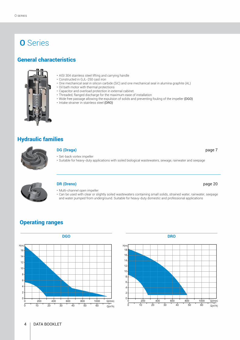
O Series
General characteristics
• AISI 304 stainless steel lifting and carrying handle• Constructed in GJL-250 cast iron• One mechanical seal in silicon carbide (SiC) and one mechanical seal in alumina graphite (AL)• Oil bath motor with thermal protections• Capacitor and overload protection in external cabinet.• Threaded, flanged discharge for the maximum ease of installation• Wide free passage allowing the expulsion of solids and preventing fouling of the impeller (DGO)• Intake strainer in stainless steel (DRO)
page 7
page 20• Multi-channel open impeller• Can be used with clear or slightly soiled wastewaters containing small solids, strained water, rainwater, seepage
and water pumped from underground. Suitable for heavy-duty domestic and professional applications
• Set-back vortex impeller• Suitable for heavy-duty applications with soiled biological wastewaters, sewage, rainwater and seepage
Hydraulic families
Operating ranges

ZENIT.COM 5
(A) (B) (C)
1 53 72 64 8 9
1 5
3 7
2 6
4 8
9
DRO 50/2/G32V A0BM5
N
TTCSTTCSGT
NAE
SICAL
O SERIES
• Electrical variants
• Cooling system
• Set of mechanical seals
Key to product code
Single-phase models
Three-phase models
Versions available
Family
Series
Power (HPx100) / motor poles
Delivery rate (A) TYPE (GAS thread/Flanged) (B) DIAMETER (mm) (C) POSITION V = vertical H = horizontal
Hydraulic model
Version number
Motor size
Motor phases M = Single-phase T = Three-phase
Power supply voltage frequency 5 = 50Hz 6 = 60Hz
Thermal protectionThermal protection, capacitor, electrical cabinet, overload protectionThermal protection, capacitor, float switch, electrical cabinet, overload protection
No electric accessories installed
No cooling and/or seal flushing system
1 mechanical seal in silicon carbide and 1 mechanical seal in alumina graphite (NBR)

6 DATA BOOKLET
O SERIES
Installations
Installation with external coupler
Installation with base coupling foot
Free installation
The electric pump, standing on its feet or base, is connected to the delivery pipe, which is screwed to the discharge if threaded, or fixed to a bend if the port is flanged. The pump-hose connection may be threaded or flanged, depending on the pump fitting.
Available for electric pumps with threaded discharge. The pump unit is supported by a special device fitted to the delivery pipe. This device can be installed at any time without having to empty the tank. It simplifies any maintenance work on the pump, which can be lifted out and resubmerged with great ease. It is recommended in particular for installations of small size, and does not require the pump to be resting on the bottom of the tank.
For submerged installation, available for electric pumps with flanged or threaded horizontal dis-charge. The coupling device is fixed to the bottom of the tank and the pump is lowered in with the aid of two guide pipes fitted earlier, until the connection to the foot is completed. The delivery pipe is fixed to the coupling device discharge. This device makes routine checks, any maintenance work or replacement of the pump extremely easy, with no need to empty the tank. A specific kit also allowing pumps with vertical discharge to be installed with the base coupling foot is available.
The electric pump, standing on its feet or base, is connected to the delivery flexible pipe using a joint fixed to the dis-charge.This installation allows to move easily the electrical pump
Fixed installation

ZENIT.COM 7
DGO
Q(l/min)
Q(m3/h)
H(m)
14
16
10
12
6
8
2
4
00
200 400 600 800 1000
0 10 20 30 40 50 60
40 °C6 ÷ 141 mm2/s20 m1 Kg/dm3
<70dB30
Vortex IMPeLLer
MotorOil bath motor with thermal protections.
ApplicationsSuitable for heavy-duty applications with soiled biological wastewaters, sewage, rainwater and seepage.
Operating specificationsMax operating temperaturePH of treated fluidViscosity of treated fluidMaximum immersion depthDensity of treated fluidAcoustic pressure maxMax starts per hour Construction materials Case Cast iron EN-GJL 250Hydraulic parts Cast iron EN-GJL 250Impeller Cast iron EN-GJL 250Nuts and bolts Stainless steel - Class A2-70Standard gasket Rubber - NBRShaft Stainless steel - AISI 420Paint type Ecological bicomponent epoxy (~ 80 μm)
Installations
Operating ranges
VersionsElectrical variants T, TCST, TCSGT (single-phase models) NAE (three-phase models) Cooling system NMechanical seals SICAL
Range characteristicsMotor power 0.37 ÷ 1.5 kWPoles 2 / 4Insulation class FDegree of protection IP68Discharge GAS 1½ ÷ 2½ vertical GAS 2” DN50 horizontal DN65 DN80 horizontalFree passage max 80 mmMax flow rate 19.0 l/s (1140 l/min)Max head 17.3 m
Mechanical sealsOne silicon carbide mechanical seal (SiC) and one carbon-aluminium oxide mechanical seal (AL)
with EXTERNAL COUPLER with BASE COUPLING FOOTFREE FIXED
Pumps with vortex impeller
Cable H07RN-F - 5 m cable length. Optional 10 m cable length.

8 DATA BOOKLET
l/s 0 2 4 6 8l/min 0 120 240 360 480 m3/h 0 7.2 14.4 21.6 28.8
DGO 100/2/G40V B1CM(T)5 13.6 11.2 7.9 3.5
DGO 150/2/G40V B1CM(T)5 16.0 13.3 10 5.9
DGO 200/2/G40V B1CM(T)5 17.3 14.7 11.6 7.8 2.8
DGO 100/2/G40V B1CT5 400 3 - 0.88 2.3 2900 Dir 4G1 G 1½” 40 mm
DGO 150/2/G40V B1CT5 400 3 - 1.1 2.7 2900 Dir 4G1 G 1½” 40 mm
DGO 200/2/G40V B1CT5 400 3 - 1.5 3.6 2900 Dir 4G1 G 1½” 40 mm
DGO 100/2/G40V B1CM5 230 1 - 0.88 6.4 2900 Dir 4G1 G 1½” 40 mm
DGO 150/2/G40V B1CM5 230 1 - 1.1 8.3 2900 Dir 4G1 G 1½” 40 mm
DGO 200/2/G40V B1CM5 230 1 - 1.5 9.6 2900 Dir 4G1 G 1½” 40 mm
V A RpmP1 (kW) P2 (kW) Start
0 100 200 300 400 5000
5
10
15
0 5 10 15 20 25 30
1 23
Q (l/min)
Q (m3/h)
H (m)
1
3
2
1
3
2
1
3
2
DGO 2/G40V
V A Rpm ØP1 (kW) P2 (kW) Start
Ø
Vortex IMPeLLer
Performances
Technical dataCh
arac
teris
tic c
urve
s ac
cord
ing
to U
NI E
N IS
O 9
906
Phases Cable Freepassage
Phases Cable Freepassage

ZENIT.COM 9
DGO 50/2/G50V B0CM5 230 1 - 0.37 2.9 2900 Dir 4G1 G 2” 40 mm
DGO 75/2/G50V B0CM5 230 1 - 0.55 3.9 2900 Dir 4G1 G 2” 40 mm
DGO 100/2/G50V B0CM5 230 1 - 0.88 6.9 2900 Dir 4G1 G 2” 50 mm
DGO 150/2/G50V B0CM5 230 1 - 1.1 8.7 2900 Dir 4G1 G 2” 50 mm
DGO 200/2/G50V B0CM5 230 1 - 1.5 10.4 2900 Dir 4G1 G 2” 50 mm
DGO 50/2/G50V B0CT5 400 3 - 0.37 1.1 2900 Dir 4G1 G 2” 40 mm
DGO 75/2/G50V B0CT5 400 3 - 0.55 1.4 2900 Dir 4G1 G 2” 40 mm
DGO 100/2/G50V B0CT5 400 3 - 0.88 2.3 2900 Dir 4G1 G 2” 50 mm
DGO 150/2/G50V B0CT5 400 3 - 1.1 2.7 2900 Dir 4G1 G 2” 50 mm
DGO 200/2/G50V B0CT5 400 3 - 1.5 3.6 2900 Dir 4G1 G 2” 50 mm
1
3
2
l/s 0 2 4 6 8 10.0l/min 0 120 240 360 480 600 m3/h 0 7.2 14.4 21.6 28.8 36.0
DGO 50/2/G50V B0CM(T)5 6.0 4.5 2.3
DGO 75/2/G50V B0CM(T)5 8.6 7.2 5.1 2.3
DGO 100/2/G50V B0CM(T)5 12.2 10.1 7.9 5.8 3.6
DGO 150/2/G50V B0CM(T)5 14.2 11.8 9.5 7.3 5.1 2.7
DGO 200/2/G50V B0CM(T)5 15.8 13.6 11.2 8.9 6.6 4.4
1
3
2
0 100 200 300 4000
2
4
10
0 10 20 30
12 3
Q (l/min)
Q (m3/h)
H (m)
6
8
14
12
16
40
45
500 600 700
4
5
4
5
1
3
2
4
5
DGO 2/G50V
V A Rpm ØP1 (kW) P2 (kW) Start
V A Rpm ØP1 (kW) P2 (kW) Start
Vortex IMPeLLer
Performances
Technical data
Char
acte
ristic
cur
ves
acco
rdin
g to
UN
I EN
ISO
990
6
Phases Cable Freepassage
Phases Cable Freepassage

10 DATA BOOKLET
DGO 2/G50H
l/s 0 2 4 6 8 10l/min 0 120 240 360 480 600 m3/h 0 7.2 14.4 21.6 28.8 36.0
DGO 50/2/G50H A1CM(T)5 7.8 5.6 3.3 1.0
DGO 75/2/G50H A1CM(T)5 9.0 6.9 4.7 2.6
DGO 100/2/G50H A0CM(T)5 12.7 10.6 8.2 5.7 3.1
DGO 150/2/G50H A0CM(T)5 14.4 12.1 9.7 7.3 4.8 2.2
DGO 200/2/G50H A0CM(T)5 15.3 13.0 10.6 8.2 5.6 3.0
DGO 50/2/G50H A1CT5 400 3 - 0.37 1.1 2900 Dir 4G1 G 2”- DN50 40 mm
DGO 75/2/G50H A1CT5 400 3 - 0.55 1.4 2900 Dir 4G1 G 2”- DN50 40 mm
DGO 100/2/G50H A0CT5 400 3 - 0.88 2.3 2900 Dir 4G1 G 2”- DN50 50 mm
DGO 150/2/G50H A0CT5 400 3 - 1.1 2.6 2900 Dir 4G1 G 2”- DN50 50 mm
DGO 200/2/G50H A0CT5 400 3 - 1.5 3.6 2900 Dir 4G1 G 2”- DN50 50 mm
DGO 50/2/G50H A1CM5 230 1 - 0.37 2.9 2900 Dir 4G1 G 2”- DN50 40 mm
DGO 75/2/G50H A1CM5 230 1 - 0.55 3.9 2900 Dir 4G1 G 2”- DN50 40 mm
DGO 100/2/G50H A0CM5 230 1 - 0.88 6.5 2900 Dir 4G1 G 2”- DN50 50 mm
DGO 150/2/G50H A0CM5 230 1 - 1.1 8.2 2900 Dir 4G1 G 2”- DN50 50 mm
DGO 200/2/G50H A0CM5 230 1 - 1.5 9.3 2900 Dir 4G1 G 2”- DN50 50 mm
0 100 200 300 400 5000
4
8
14
0 10
12 543
Q (l/min)
Q (m3/h)
H (m)
2
6
10
12
16
600
20 30 40
1
3
2
1
3
2
1
3
2
4
5
4
5
4
5
V A Rpm ØP1 (kW) P2 (kW) Start
V A Rpm ØP1 (kW) P2 (kW) Start
Vortex IMPeLLer
Performances
Technical dataCh
arac
teris
tic c
urve
s ac
cord
ing
to U
NI E
N IS
O 9
906
Phases Cable Freepassage
Phases Cable Freepassage

ZENIT.COM 11
DGO 2/G65V
DGO 150/2/G65V A1CM5 230 1 - 1.1 8.2 2900 Dir 4G1 G 2½” 65 mm
DGO 200/2/G65V A1CM5 230 1 - 1.5 9.9 2900 Dir 4G1 G 2½” 65 mm
DGO 150/2/G65V A1CT5 400 3 - 1.1 2.7 2900 Dir 4G1 G 2½” 65 mm
DGO 200/2/G65V A1CT5 400 3 - 1.5 3.6 2900 Dir 4G1 G 2½” 65 mm
1
2
l/s 0 2 4 6 8 10.0l/min 0 120 240 360 480 600 m3/h 0 7.2 14.4 21.6 28.8 36.0
DGO 150/2/G65V A1CM(T)5 8.0 7.2 6.1 4.7 3.0
DGO 200/2/G65V A1CM(T)5 9.7 8.8 7.7 6.3 4.7 3.0
1
2
0 100 200 300 4000
2
4
10
0 10 20 30
1 2
Q (l/min)
Q (m3/h)
H (m)
6
8
40
500 600 700
1
2
V A Rpm ØP1 (kW) P2 (kW) Start
V A Rpm ØP1 (kW) P2 (kW) Start
Vortex IMPeLLer
Performances
Technical data
Char
acte
ristic
cur
ves
acco
rdin
g to
UN
I EN
ISO
990
6
Phases Cable Freepassage
Phases Cable Freepassage

12 DATA BOOKLET
DGO 2/65
l/s 0 2 4 6 8 10 12 14l/min 0 120 240 360 480 600 720 840 m3/h 0 7.2 14.4 21.6 28.8 36 43.2 50.4
DGO 150/2/65 A1CM(T)5 7.9 7.0 5.9 4.8 3.5 2.3
DGO 200/2/65 A1CM(T)5 9.9 9.4 8.8 7.9 6.9 5.6 4.2 2.5
DGO 150/2/65 A1CT5 400 3 - 1.1 2.7 2900 Dir 4G1 DN65 65 mm
DGO 200/2/65 A1CM5 400 3 - 1.5 3.6 2900 Dir 4G1 DN65 65 mm
DGO 150/2/65 A1CM5 230 1 - 1.1 8.2 2900 Dir 4G1 DN65 65 mm
DGO 200/2/65 A1CM5 230 1 - 1.5 9.9 2900 Dir 4G1 DN65 65 mm
0 100 200 300 400 5000
4
8
0 10
1 2
Q (l/min)
Q (m3/h)
H (m)
2
6
10
600
20 30 40
700 800 900
50
1
2
1
2
1
2
V A Rpm ØP1 (kW) P2 (kW) Start
V A Rpm ØP1 (kW) P2 (kW) Start
Vortex IMPeLLer
Performances
Technical dataCh
arac
teris
tic c
urve
s ac
cord
ing
to U
NI E
N IS
O 9
906
Phases Cable Freepassage
Phases Cable Freepassage

ZENIT.COM 13
DGO 2/80
DGO 200/2/80 A1CM5 230 1 - 1.7 11.2 2900 Dir 4G1 DN80 80 mm
DGO 200/2/80 A1CT5 400 3 - 1.7 3.9 2900 Dir 4G1 DN80 80 mm
1
l/s 0 2 4 6 8 10 12 14 16l/min 0 120 240 360 480 600 720 840 960 m3/h 0 7.2 14.4 21.6 28.8 36 43.2 50.4 57.6
DGO 200/2/80 A1CM(T)5 8.4 7.9 7.2 6.4 5.5 4.5 3.6 2.6 1.71
0 100 200 300 4000
2
4
0 10 20 30
1
Q (l/min)
Q (m3/h)
H (m)
6
8
40
500 600 700 800 900
50
1
V A Rpm ØP1 (kW) P2 (kW) Start
V A Rpm ØP1 (kW) P2 (kW) Start
Vortex IMPeLLer
Performances
Technical data
Char
acte
ristic
cur
ves
acco
rdin
g to
UN
I EN
ISO
990
6
Phases Cable Freepassage
Phases Cable Freepassage

14 DATA BOOKLET
DGO 4/G50V
l/s 0 2 4 6 8l/min 0 120 240 360 480 m3/h 0 7.2 14.4 21.6 28.8
DGO 100/4/G50V B0CM(T)5 5.4 4.8 4.0 3.0 1.8
DGO 100/4/G50V B0CT5 400 3 - 0.7 1.6 1450 Dir 4G1 G2” 45 mm
DGO 100/4/G50V B0CM5 230 1 - 0.7 4.5 1450 Dir 4G1 G2” 45 mm
0 100 200 300 400 5000
2
4
0 10
1
Q (l/min)
Q (m3/h)
H (m)
1
3
5
20 30
1
1
1
V A Rpm ØP1 (kW) P2 (kW) Start
V A Rpm ØP1 (kW) P2 (kW) Start
Vortex IMPeLLer
Performances
Technical dataCh
arac
teris
tic c
urve
s ac
cord
ing
to U
NI E
N IS
O 9
906
Phases Cable Freepassage
Phases Cable Freepassage

ZENIT.COM 15
DGO 4/G50H
DGO 100/4/G50H A0CM5 230 1 - 0.7 5.7 1450 Dir 4G1 G2”-DN50 45 mm
DGO 100/4/G50H A0CT5 400 3 - 0.7 2.2 1450 Dir 4G1 G2”-DN50 45 mm
1
l/s 0 2 4 6 8 10 12 14 16l/min 0 120 240 360 480 600 720 840 960 m3/h 0 7.2 14.4 21.6 28.8 36 43.2 50.4 57.6
DGO 100/4/G50H A0CM(T)5 8.4 7.9 7.2 6.4 5.5 4.5 3.6 2.6 1.71
0 100 200 300 400 5000
2
4
0 10
1
Q (l/min)
Q (m3/h)
H (m)
1
3
5
20 30
1
V A Rpm ØP1 (kW) P2 (kW) Start
V A Rpm ØP1 (kW) P2 (kW) Start
Vortex IMPeLLer
Performances
Technical data
Char
acte
ristic
cur
ves
acco
rdin
g to
UN
I EN
ISO
990
6
Phases Cable Freepassage
Phases Cable Freepassage
16 DATA BOOKLET
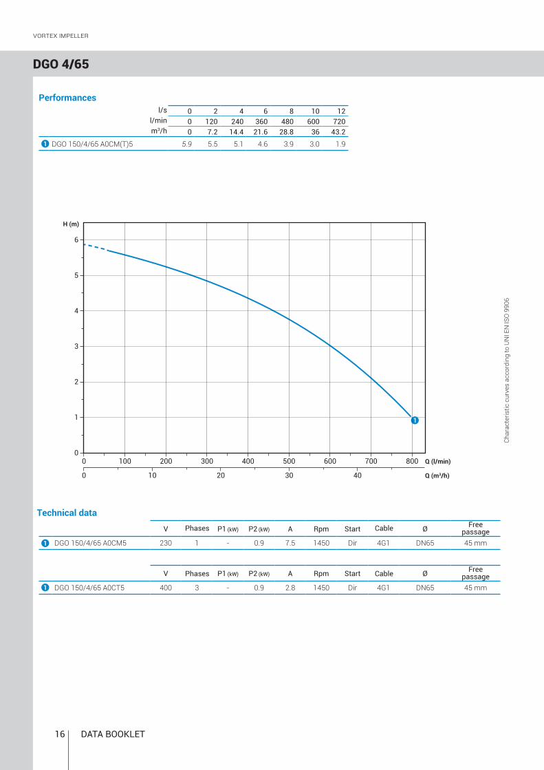
DGO 4/65
l/s 0 2 4 6 8 10 12l/min 0 120 240 360 480 600 720m3/h 0 7.2 14.4 21.6 28.8 36 43.2
DGO 150/4/65 A0CM(T)5 5.9 5.5 5.1 4.6 3.9 3.0 1.9
DGO 150/4/65 A0CT5 400 3 - 0.9 2.8 1450 Dir 4G1 DN65 45 mm
DGO 150/4/65 A0CM5 230 1 - 0.9 7.5 1450 Dir 4G1 DN65 45 mm
0 100 200 300 400 5000
2
4
0 10
1
Q (l/min)
Q (m3/h)
H (m)
1
3
5
600
20 30 40
700 800
6
1
1
1
V A Rpm ØP1 (kW) P2 (kW) Start
V A Rpm ØP1 (kW) P2 (kW) Start
Vortex IMPeLLer
Performances
Technical dataCh
arac
teris
tic c
urve
s ac
cord
ing
to U
NI E
N IS
O 9
906
Phases Cable Freepassage
Phases Cable Freepassage

ZENIT.COM 17
DGO 4/80
DGO 150/4/80 A0CM5 230 1 - 0.9 7.5 1450 Dir 4G1 DN80 60 mm
DGO 150/4/80 A0CT5 400 3 - 0.9 2.8 1450 Dir 4G1 DN80 60 mm
1
l/s 0 2 4 6 8 10 12 14 16 18l/min 0 120 240 360 480 600 720 840 960 1080 m3/h 0 7.2 14.4 21.6 28.8 36 43.2 50.4 57.6 64.8
DGO 150/4/80 A0CM(T)5 5.4 5.1 4.7 4.3 3.8 3.4 2.8 2.3 1.7 1.11
0 200 4000
2
4
0 20
1
Q (l/min)
Q (m3/h)
H (m)
1
3
5
40 60
600 800 1000
1
V A Rpm ØP1 (kW) P2 (kW) Start
V A Rpm ØP1 (kW) P2 (kW) Start
Vortex IMPeLLer
Performances
Technical data
Char
acte
ristic
cur
ves
acco
rdin
g to
UN
I EN
ISO
990
6
Phases Cable Freepassage
Phases Cable Freepassage

18 DATA BOOKLET
A B C D E E1 F
DGO 100/2/G40V B1CM(T)5 260 100 440 125 G 1½” - 205 18DGO 150/2/G40V B10CM(T)5 260 100 440 125 G 1½” - 205 19DGO 200/2/G40V B1CM(T)5 260 100 440 125 G 1½” - 205 20DGO 50/2/G50V B0CM(T)5 230 80 380 120 G 2” - 165 16.5DGO 75/2/G50V B0CM(T)5 230 80 380 120 G 2” - 165 16.5DGO 100/2/G50V B0CM(T)5 270 100 455 130 G 2” - 205 19.5DGO 150/2/G50V B0CM(T)5 270 100 455 130 G 2” - 205 20.5DGO 200/2/G50V B0CM(T)5 270 100 455 130 G 2” - 205 21.5DGO 150/2/G65V A1CM(T)5 300 105 435 140 G 2½” 3xM8 Ø160 210 21DGO 200/2/G65V A1CM(T)5 300 105 435 140 G 2½” 3xM8 Ø160 210 22DGO 100/4/G50V B0CM(T)5 270 100 455 130 G 2” - 205 21
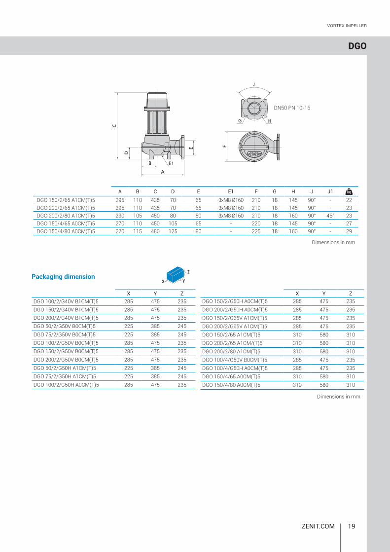
DGO
A B C D E F G H J J1
DGO 50/2/G50H A1CM(T)5 220 80 360 65 G 2” - DN50 160 18 125 90° - 16.5DGO 75/2/G50H A1CM(T)5 220 80 360 65 G 2” - DN50 160 18 125 90° - 16.5DGO 100/2/G50H A0CM(T)5 270 110 455 110 G 2” - DN50 205 18 125 90° - 19.5DGO 150/2/G50H A0CM(T)5 270 110 455 110 G 2” - DN50 205 18 125 90° - 20.5DGO 200/2/G50H A0CM(T)5 270 110 455 110 G 2” - DN50 205 18 125 90° - 21.5DGO 100/4/G50H A0CM(T)5 270 110 450 110 G 2” - DN50 205 18 125 90° - 21
Vortex IMPeLLer
Overall dimensions and weights
Models with vertical discharge
Models with horizontal discharge
Dimensions in mm
Dimensions in mm
ZENIT.COM 19
A B C D E E1 F G H J J1DGO 150/2/65 A1CM(T)5 295 110 435 70 65 3xM8 Ø160 210 18 145 90° - 22DGO 200/2/65 A1CM(T)5 295 110 435 70 65 3xM8 Ø160 210 18 145 90° - 23DGO 200/2/80 A1CM(T)5 290 105 450 80 80 3xM8 Ø160 210 18 160 90° 45° 23DGO 150/4/65 A0CM(T)5 270 110 450 105 65 - 220 18 145 90° - 27DGO 150/4/80 A0CM(T)5 270 115 480 125 80 - 225 18 160 90° - 29
DN50 PN 10-16
X Y ZDGO 100/2/G40V B1CM(T)5 285 475 235DGO 150/2/G40V B1CM(T)5 285 475 235DGO 200/2/G40V B1CM(T)5 285 475 235DGO 50/2/G50V B0CM(T)5 225 385 245DGO 75/2/G50V B0CM(T)5 225 385 245DGO 100/2/G50V B0CM(T)5 285 475 235DGO 150/2/G50V B0CM(T)5 285 475 235DGO 200/2/G50V B0CM(T)5 285 475 235DGO 50/2/G50H A1CM(T)5 225 385 245DGO 75/2/G50H A1CM(T)5 225 385 245DGO 100/2/G50H A0CM(T)5 285 475 235
X
Z
Y
X Y ZDGO 150/2/G50H A0CM(T)5 285 475 235DGO 200/2/G50H A0CM(T)5 285 475 235DGO 150/2/G65V A1CM(T)5 285 475 235DGO 200/2/G65V A1CM(T)5 285 475 235DGO 150/2/65 A1CM(T)5 310 580 310DGO 200/2/65 A1CM/(T)5 310 580 310DGO 200/2/80 A1CM(T)5 310 580 310DGO 100/4/G50V B0CM(T)5 285 475 235DGO 100/4/G50H A0CM(T)5 285 475 235DGO 150/4/65 A0CM(T)5 310 580 310DGO 150/4/80 A0CM(T)5 310 580 310
DGO
Vortex IMPeLLer
Dimensions in mm
Packaging dimension
Dimensions in mm

20 DATA BOOKLET
DRO
Q(l/min)
Q(m3/h)
H(m)
14
16
10
12
6
8
2
4
00
200 400 600 800 10000 10 20 30 40 50 60
18
40 °C6 ÷ 141 mm2/s20 m1 Kg/dm3
<70dB30
Multi-channel open iMpeller
MotorOil bath motor with thermal protections.
ApplicationsCan be used with clear or slightly soiled wastewaters containing small solids, strained water, rainwater, seepage and water pumped from underground.
Operating specificationsMax operating temperaturePH of treated fluidViscosity of treated fluidMaximum immersion depthDensity of treated fluidAcoustic pressure maxMax starts per hour
Construction materials Case Cast iron EN-GJL 250Hydraulic parts Cast iron EN-GJL 250Impeller Cast iron EN-GJL 250Nuts and bolts Stainless steel - Class A2-70Standard gasket Rubber - NBRShaft Stainless steel - AISI 420Paint type Ecological bicomponent epoxy (~ 80 μm)
Operating ranges
VersionsElectrical variants T, TCST, TCSGT (single-phase models) NAE (three-phase models) Cooling system NMechanical seals SICAL
Range characteristicsMotor power 0.37 ÷ 1.5 kWPoles 2Insulation class FDegree of protection IP68Discharge GAS 1¼ ÷ 2” vertical GAS 2” DN50 horizontalFree passage max 15 mmMax flow rate 13.0 l/s (780 l/min)Max head 18.4 m
Mechanical sealsOne silicon carbide mechanical seal (SiC) and one carbon-aluminium oxide mechanical seal (AL)
Installations
Pumps with multi-channel open impeller
CableH07RN-F 4G1 - 5 m cable length. Optional 10 m cable length.
with EXTERNAL COUPLER with BASE COUPLING FOOTFREE FIXED

ZENIT.COM 21
l/s 0 1 2 3 4 5 6l/min 0 60 120 180 240 300 360 m3/h 0 3.6 7.2 10.8 14.4 18.0 21.6
DRO 50/2/G32V A0CM(T)5 8.8 8.1 6.9 5.2 2.7
DRO 75/2/G32V A0CM(T)5 12.1 11.8 10.8 9.1 6.9 4.2 0.9
DRO 50/2/G32V A0CT5 400 3 - 0.37 1.1 2900 Dir 4G1 G 1¼” 15 mm
DRO 75/2/G32V A0CT5 400 3 - 0.55 1.4 2900 Dir 4G1 G 1¼” 15 mm
DRO 50/2/G32V A0CM5 230 1 - 0.37 2.9 2900 Dir 4G1 G 1¼” 15 mm
DRO 75/2/G32V A0CM5 230 1 - 0.55 3.9 2900 Dir 4G1 G 1¼” 15 mm
0 50 100 150 200 2500
2
4
6
0 5 10 15 20
12
Q (l/min)
Q (m3/h)
H (m)
8
10
12
300 350
1
2
1
2
1
2
DRO 2/G32V
V A Rpm ØP1 (kW) P2 (kW) Start
V A Rpm ØP1 (kW) P2 (kW) Start
Multi-channel open iMpeller
Performances
Technical data
Char
acte
ristic
cur
ves
acco
rdin
g to
UN
I EN
ISO
990
6
Phases Cable Freepassage
Phases Cable Freepassage

22 DATA BOOKLET
DRO 2/G50V
l/s 0 2 4 6 8 10 12l/min 0 120 240 360 480 600 720 m3/h 0 7.2 14.4 21.6 28.8 36 43.2
DRO 100/2/G50V A0CM(T)5 12.4 11.5 10.0 7.9 5.0 1.1
DRO 150/2/G50V A0CM(T)5 16.3 15.2 13.8 11.9 9.3 6.0 2.1
DRO 200/2/G50V A0CM(T)5 18.4 17.1 15.6 13.9 11.7 8.6 4.5
DRO 100/2/G50V A0CT5 400 3 - 0.88 2.3 2900 Dir 4G1 G 2” 15 mm
DRO 150/2/G50V A0CT5 400 3 - 1.1 2.7 2900 Dir 4G1 G 2” 15 mm
DRO 200/2/G50V A0CT5 400 3 - 1.5 3.5 2900 Dir 4G1 G 2” 15 mm
DRO 100/2/G50V A0CM5 230 1 - 0.88 6.5 2900 Dir 4G1 G 2” 15 mm
DRO 150/2/G50V A0CM5 230 1 - 1.1 8.2 2900 Dir 4G1 G 2” 15 mm
DRO 200/2/G50V A0CM5 230 1 - 1.5 9.3 2900 Dir 4G1 G 2” 15 mm
0 100 200 300 400 5000
5
0 10
1
2 3
Q (l/min)
Q (m3/h)
H (m)
10
600
20 30 40
15
700 800
1
2
1
2
1
2
V A Rpm ØP1 (kW) P2 (kW) Start
V A Rpm ØP1 (kW) P2 (kW) Start
3
3
3
Multi-channel open iMpeller
Performances
Technical dataCh
arac
teris
tic c
urve
s ac
cord
ing
to U
NI E
N IS
O 9
906
Phases Cable Freepassage
Phases Cable Freepassage

ZENIT.COM 23
DRO 2/G50H
l/s 0 2 4 6 8 10 12l/min 0 120 240 360 480 600 720 m3/h 0 7.2 14.4 21.6 28.8 36 43.2
DRO 100/2/G50H A0CM(T)5 12.4 11.5 10.0 7.9 5.0 1.1
DRO 150/2/G50H A0CM(T)5 16.3 15.2 13.8 11.9 9.3 6.0 2.1
DRO 200/2/G50H A0CM(T)5 18.4 17.1 15.6 13.9 11.7 8.6 4.5
DRO 100/2/G50H A0CT5 400 3 - 0.88 2.3 2900 Dir 4G1 G 2” 15 mm
DRO 150/2/G50H A0CT5 400 3 - 1.1 2.7 2900 Dir 4G1 G 2” 15 mm
DRO 200/2/G50H A0CT5 400 3 - 1.5 3.5 2900 Dir 4G1 G 2” 15 mm
DRO 100/2/G50H A0CM5 230 1 - 0.88 6.5 2900 Dir 4G1 G 2” 15 mm
DRO 150/2/G50H A0CM5 230 1 - 1.1 8.2 2900 Dir 4G1 G 2” 15 mm
DRO 200/2/G50H A0CM5 230 1 - 1.5 9.3 2900 Dir 4G1 G 2” 15 mm
0 100 200 300 400 5000
5
0 10
1
2 3
Q (l/min)
Q (m3/h)
H (m)
10
600
20 30 40
15
700 800
1
2
1
2
1
2
V A Rpm ØP1 (kW) P2 (kW) Start
V A Rpm ØP1 (kW) P2 (kW) Start
3
3
3
Multi-channel open iMpeller
Performances
Technical data
Char
acte
ristic
cur
ves
acco
rdin
g to
UN
I EN
ISO
990
6
Phases Cable Freepassage
Phases Cable Freepassage

24 DATA BOOKLET
DRO
A B C D E F G H JDRO 100/2/G50H A0CM(T)5 250 90 385 65 G 2”-DN50 195 18 125 90° 19.5DRO 150/2/G50H A0CM(T)5 250 90 385 65 G 2”-DN50 195 18 125 90° 20.5DRO 200/2/G50H A0CM(T)5 250 90 385 65 G 2”-DN50 195 18 125 90° 21.5
A B C D E FDRO 50/2/G32V A0CM(T)5 220 75 330 105 G 1¼” 155 15DRO 75/2/G32V A0CM(T)5 220 75 330 105 G 1¼” 155 15.5DRO 100/2/G50V A0CM(T)5 260 95 385 125 G 2” 195 19.5DRO 150/2/G50V A0CM(T)5 260 95 385 125 G 2” 195 20.5DRO 200/2/G50V A0CM(T)5 260 95 385 125 G 2” 195 21.5
X Y CDRO 50/2/G32V A0CM(T)5 225 385 245DRO 75/2/G32V A0CM(T)5 225 385 245DRO 100/2/G50V A0CM(T)5 285 475 235DRO 150/2/G50V A0CM(T)5 285 475 235DRO 200/2/G50V A0CM(T)5 285 475 235DRO 100/2/G50H A0CM(T)5 285 475 235DRO 150/2/G50H A0CM(T)5 285 475 235DRO 200/2/G50H A0CM(T)5 285 475 235
X
Z
Y
Multi-channel open iMpeller
Overall dimensions and weights
Models with vertical discharge Models with horizontal discharge
Dimensions in mm
Dimensions in mm
Dimensions in mm
Packaging dimension
ZENIT.COM 25
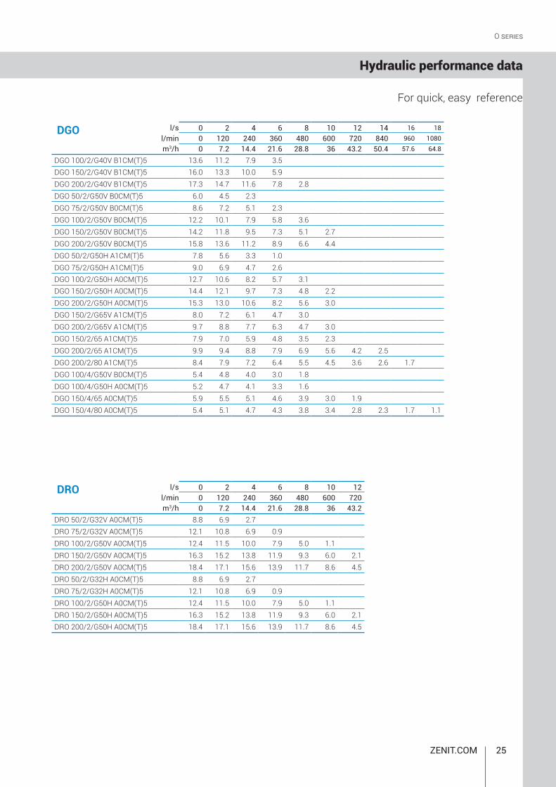
l/s 0 2 4 6 8 10 12 14 16 18l/min 0 120 240 360 480 600 720 840 960 1080m3/h 0 7.2 14.4 21.6 28.8 36 43.2 50.4 57.6 64.8
DGO 100/2/G40V B1CM(T)5 13.6 11.2 7.9 3.5DGO 150/2/G40V B1CM(T)5 16.0 13.3 10.0 5.9DGO 200/2/G40V B1CM(T)5 17.3 14.7 11.6 7.8 2.8DGO 50/2/G50V B0CM(T)5 6.0 4.5 2.3DGO 75/2/G50V B0CM(T)5 8.6 7.2 5.1 2.3DGO 100/2/G50V B0CM(T)5 12.2 10.1 7.9 5.8 3.6DGO 150/2/G50V B0CM(T)5 14.2 11.8 9.5 7.3 5.1 2.7DGO 200/2/G50V B0CM(T)5 15.8 13.6 11.2 8.9 6.6 4.4DGO 50/2/G50H A1CM(T)5 7.8 5.6 3.3 1.0DGO 75/2/G50H A1CM(T)5 9.0 6.9 4.7 2.6DGO 100/2/G50H A0CM(T)5 12.7 10.6 8.2 5.7 3.1DGO 150/2/G50H A0CM(T)5 14.4 12.1 9.7 7.3 4.8 2.2DGO 200/2/G50H A0CM(T)5 15.3 13.0 10.6 8.2 5.6 3.0DGO 150/2/G65V A1CM(T)5 8.0 7.2 6.1 4.7 3.0DGO 200/2/G65V A1CM(T)5 9.7 8.8 7.7 6.3 4.7 3.0DGO 150/2/65 A1CM(T)5 7.9 7.0 5.9 4.8 3.5 2.3DGO 200/2/65 A1CM(T)5 9.9 9.4 8.8 7.9 6.9 5.6 4.2 2.5DGO 200/2/80 A1CM(T)5 8.4 7.9 7.2 6.4 5.5 4.5 3.6 2.6 1.7DGO 100/4/G50V B0CM(T)5 5.4 4.8 4.0 3.0 1.8DGO 100/4/G50H A0CM(T)5 5.2 4.7 4.1 3.3 1.6DGO 150/4/65 A0CM(T)5 5.9 5.5 5.1 4.6 3.9 3.0 1.9DGO 150/4/80 A0CM(T)5 5.4 5.1 4.7 4.3 3.8 3.4 2.8 2.3 1.7 1.1
l/s 0 2 4 6 8 10 12l/min 0 120 240 360 480 600 720m3/h 0 7.2 14.4 21.6 28.8 36 43.2
DRO 50/2/G32V A0CM(T)5 8.8 6.9 2.7DRO 75/2/G32V A0CM(T)5 12.1 10.8 6.9 0.9DRO 100/2/G50V A0CM(T)5 12.4 11.5 10.0 7.9 5.0 1.1DRO 150/2/G50V A0CM(T)5 16.3 15.2 13.8 11.9 9.3 6.0 2.1DRO 200/2/G50V A0CM(T)5 18.4 17.1 15.6 13.9 11.7 8.6 4.5DRO 50/2/G32H A0CM(T)5 8.8 6.9 2.7DRO 75/2/G32H A0CM(T)5 12.1 10.8 6.9 0.9DRO 100/2/G50H A0CM(T)5 12.4 11.5 10.0 7.9 5.0 1.1DRO 150/2/G50H A0CM(T)5 16.3 15.2 13.8 11.9 9.3 6.0 2.1DRO 200/2/G50H A0CM(T)5 18.4 17.1 15.6 13.9 11.7 8.6 4.5
DGO
DRO
O SERIES
Hydraulic performance data
For quick, easy reference

26 DATA BOOKLET
O SERIES
Notes


water solutions
Rev. 0 - 01/03/17
All data made available remain non-binding. Zenit reserves the right to make unannounced product changes it deems appropriate.