Embed Size (px)
Citation preview

Your Partner for Sealing Technology
O-Rings

Your Partner for Sealing Technology
Trelleborg Sealing Solutions is a major international sealing
force, uniquely placed to offer dedicated design and
development from our market leading product and material
portfolio; a one-stop shop providing the best in elastomer,
thermoplastic, PTFE and composite technologies for
applications in aerospace, industrial, and automotive industries.
With 50-years experience, Trelleborg Sealing Solutions
engineers support customers with design, prototyping,
production, test and installation using state-of-the-art design
tools. An international network of over 70 facilities worldwide
research and development centers, including materials and
development laboratories and locations specializing in design
and applications.
Developing and formulating materials in-house, we utilize the
resource of our material database, including over 2,000
proprietary compounds and a range of unique products.
Trelleborg Sealing Solutions fulfills challenging service
requirements, supplying standard parts in volume or a single
custom-manufactured component, through our integrated
logistical support, which effectively delivers over 40,000 sealing
products to customers worldwide.
Facilities are certified to ISO 9001:2000 and ISO/TS 16949:2002,
with many manufacturing sites also working to QS9000 and
VDA 6.1. Trelleborg Sealing Solutions is backed by the
experiences and resources of one of the world's foremost
experts in polymer technology, Trelleborg AB.
The information in this brochure is intended to be for general reference purposes only and is notintended to be a specific recommendation for any individual application. The application limits forpressure, temperature, speed and media given are maximum values determined in laboratoryconditions. In application, due to the interaction of operating parameters, maximum values maynot be achieved. It is vital therefore, that customers satisfy themselves as to the suitability ofproduct and material for each of their individual applications. Any reliance on information istherefore at the user's own risk. In no event will Trelleborg Sealing Solutions be liable for any loss,damage, claim or expense directly or indirectly arising or resulting from the use of any informationprovided in this brochure. While every effort is made to ensure the accuracy of informationcontained herewith, Trelleborg Sealing Solutions cannot warrant the accuracy or completeness ofinformation.
To obtain the best recommendation for a specific application, pleasecontact your local Trelleborg Sealing Solutions marketing company.
This edition supersedes all previous brochures.This brochure or any part of it may not be reproduced without permission.
® All trademarks are the property of Trelleborg AB.
The turquoise colour is a registered trademark of Trelleborg AB.
© Trelleborg AB, 2007. All rights reserved.
includes 30 manufacturing sites, 8 strategically positioned
Content
A General information . . . . . . . . . . . . . . . . . . . . . . . . . . . . . . . . . . . . . . . . . . . . . . . . . . . . . . . . . . . . . . . 3
A.1 Description . . . . . . . . . . . . . . . . . . . . . . . . . . . . . . . . . . . . . . . . . . . . . . . . . . . . . . . . . . . . . . . . . . . . . . . . . . 3
A.2 Applications . . . . . . . . . . . . . . . . . . . . . . . . . . . . . . . . . . . . . . . . . . . . . . . . . . . . . . . . . . . . . . . . . . . . . . . . . 3
A.3 Method of operation . . . . . . . . . . . . . . . . . . . . . . . . . . . . . . . . . . . . . . . . . . . . . . . . . . . . . . . . . . . . . . . . . . 4
B Technical information . . . . . . . . . . . . . . . . . . . . . . . . . . . . . . . . . . . . . . . . . . . . . . . . . . . . . . . . . . . . . 5
B.1 Materials . . . . . . . . . . . . . . . . . . . . . . . . . . . . . . . . . . . . . . . . . . . . . . . . . . . . . . . . . . . . . . . . . . . . . . . . . . . . 5
B.1.1 Elastomers . . . . . . . . . . . . . . . . . . . . . . . . . . . . . . . . . . . . . . . . . . . . . . . . . . . . . . . . . . . . . . . . . . . . . . . . . . . . 5
B.1.2 Application parameters of elastomers . . . . . . . . . . . . . . . . . . . . . . . . . . . . . . . . . . . . . . . . . . . . . . . . . . . . . . . 7
B.1.3 Characteristics and inspection of elastomers . . . . . . . . . . . . . . . . . . . . . . . . . . . . . . . . . . . . . . . . . . . . . . . . . 25
B.1.4 Special requirements - authorities and approvals . . . . . . . . . . . . . . . . . . . . . . . . . . . . . . . . . . . . . . . . . . . . . . 28
B.1.5 Standard materials . . . . . . . . . . . . . . . . . . . . . . . . . . . . . . . . . . . . . . . . . . . . . . . . . . . . . . . . . . . . . . . . . . . . . 30
B.2 Design recommendations . . . . . . . . . . . . . . . . . . . . . . . . . . . . . . . . . . . . . . . . . . . . . . . . . . . . . . . . . . . . . 35
B.2.1 Installation recommendations . . . . . . . . . . . . . . . . . . . . . . . . . . . . . . . . . . . . . . . . . . . . . . . . . . . . . . . . . . . . 35
B.2.2 Initial compression . . . . . . . . . . . . . . . . . . . . . . . . . . . . . . . . . . . . . . . . . . . . . . . . . . . . . . . . . . . . . . . . . . . . . 36
B.2.3 Elongation - compression . . . . . . . . . . . . . . . . . . . . . . . . . . . . . . . . . . . . . . . . . . . . . . . . . . . . . . . . . . . . . . . . 37
B.2.4 Methods of installation and design of seal housing . . . . . . . . . . . . . . . . . . . . . . . . . . . . . . . . . . . . . . . . . . . . 38
C Dimensions and product range . . . . . . . . . . . . . . . . . . . . . . . . . . . . . . . . . . . . . . . . . . . . . . . . . . . 46
C.1 Dimensions and international standards . . . . . . . . . . . . . . . . . . . . . . . . . . . . . . . . . . . . . . . . . . . . . . . . . 46
C.1.1 O—Ring range of sizes (including ordering examples and instructions at the end of the section) . . . . . . . . . . 46
C.1.2 O—Ring Dimensions according to AS 568 B . . . . . . . . . . . . . . . . . . . . . . . . . . . . . . . . . . . . . . . . . . . . . . . . . . 113
C.1.3 O—Ring dimensions for straight thread tube fitting sizes, AS 568 B . . . . . . . . . . . . . . . . . . . . . . . . . . . . . . . . 123
C.1.4 O—Ring dimensions for metric thread with conical recess according to ISO 6149 . . . . . . . . . . . . . . . . . . . . . . 124
C.2 Tolerances of dimensions . . . . . . . . . . . . . . . . . . . . . . . . . . . . . . . . . . . . . . . . . . . . . . . . . . . . . . . . . . . . 125
C.3 O—Ring quality acceptance criteria . . . . . . . . . . . . . . . . . . . . . . . . . . . . . . . . . . . . . . . . . . . . . . . . . . . . . 127
C.4 Seal set . . . . . . . . . . . . . . . . . . . . . . . . . . . . . . . . . . . . . . . . . . . . . . . . . . . . . . . . . . . . . . . . . . . . . . . . . . . 129
D Special O—Rings . . . . . . . . . . . . . . . . . . . . . . . . . . . . . . . . . . . . . . . . . . . . . . . . . . . . . . . . . . . . . . . . . . 130
D.1 Isolast® (FFKM) O—Rings . . . . . . . . . . . . . . . . . . . . . . . . . . . . . . . . . . . . . . . . . . . . . . . . . . . . . . . . . . . . . . 130
D.2 FEP encapsulated O—Rings . . . . . . . . . . . . . . . . . . . . . . . . . . . . . . . . . . . . . . . . . . . . . . . . . . . . . . . . . . . . 130
D.3 PTFE O—Rings . . . . . . . . . . . . . . . . . . . . . . . . . . . . . . . . . . . . . . . . . . . . . . . . . . . . . . . . . . . . . . . . . . . . . . . 135
D.4 Polyurethane O—Rings . . . . . . . . . . . . . . . . . . . . . . . . . . . . . . . . . . . . . . . . . . . . . . . . . . . . . . . . . . . . . . . . 137
D.5 Round cord rings (butt vulcanised) . . . . . . . . . . . . . . . . . . . . . . . . . . . . . . . . . . . . . . . . . . . . . . . . . . . . 141
D.6 O—Ring surface treatments . . . . . . . . . . . . . . . . . . . . . . . . . . . . . . . . . . . . . . . . . . . . . . . . . . . . . . . . . . . . 143
D.6.1 O—Rings free of substances affecting the lacquer coating - “Labs-free“ . . . . . . . . . . . . . . . . . . . . . . . . . . . . 143
D.6.2 O—Ring friction reducing processes . . . . . . . . . . . . . . . . . . . . . . . . . . . . . . . . . . . . . . . . . . . . . . . . . . . . . . . . 144
E General quality criteria and storage guidelines . . . . . . . . . . . . . . . . . . . . . . . . . . . . . . . . . 150
E.1 Quality criteria . . . . . . . . . . . . . . . . . . . . . . . . . . . . . . . . . . . . . . . . . . . . . . . . . . . . . . . . . . . . . . . . . . . . . 150
E.2 Storage and shelf life . . . . . . . . . . . . . . . . . . . . . . . . . . . . . . . . . . . . . . . . . . . . . . . . . . . . . . . . . . . . . . . . 150
Index . . . . . . . . . . . . . . . . . . . . . . . . . . . . . . . . . . . . . . . . . . . . . . . . . . . . . . . . . . . . . . . . . . . . . . . . . . . . 152
O—Ring
Latest information available at www.tss.trelleborg.comEdition April 2007
1

O—Ring
Latest information available at www.tss.trelleborg.com
2Edition April 2007
A General information
A.1 Description
O—Rings offer the designer an efficient and economicalsealing element for a wide range of static or dynamicapplications.
Inexpensive production methods and its ease of use havemade the O—Ring the most widely used seal.
A wide choice of elastomer materials for both standard andspecial applications allow the O—Ring to be used to sealpractically all liquid and gaseous media.
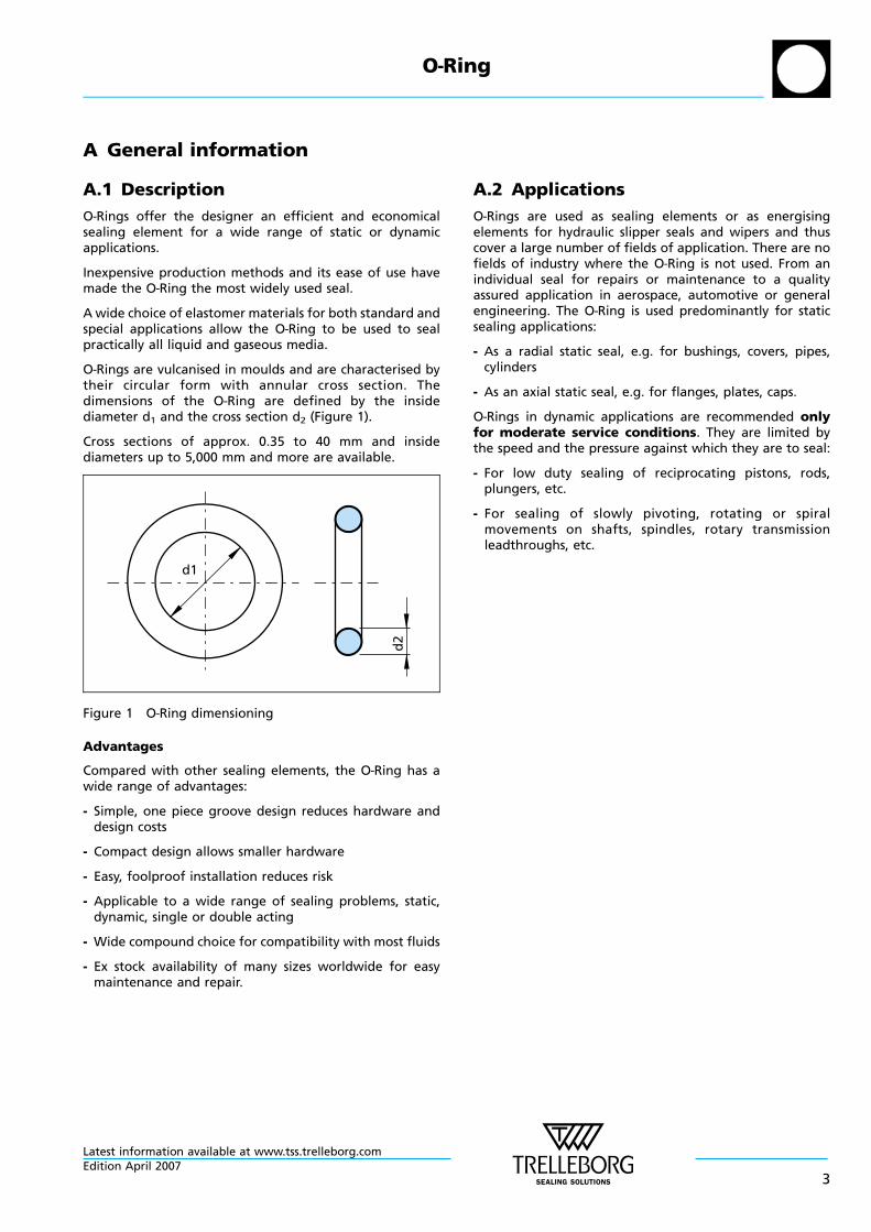
O—Rings are vulcanised in moulds and are characterised bytheir circular form with annular cross section. Thedimensions of the O—Ring are defined by the insidediameter d1 and the cross section d2 (Figure 1).
Cross sections of approx. 0.35 to 40 mm and insidediameters up to 5,000 mm and more are available.
d1
d2
Figure 1 O—Ring dimensioning
Advantages
Compared with other sealing elements, the O—Ring has awide range of advantages:
- Simple, one piece groove design reduces hardware anddesign costs
- Compact design allows smaller hardware
- Easy, foolproof installation reduces risk
- Applicable to a wide range of sealing problems, static,dynamic, single or double acting
- Wide compound choice for compatibility with most fluids
- Ex stock availability of many sizes worldwide for easymaintenance and repair.
A.2 Applications
O—Rings are used as sealing elements or as energisingelements for hydraulic slipper seals and wipers and thuscover a large number of fields of application. There are nofields of industry where the O—Ring is not used. From anindividual seal for repairs or maintenance to a qualityassured application in aerospace, automotive or generalengineering. The O—Ring is used predominantly for staticsealing applications:
- As a radial static seal, e.g. for bushings, covers, pipes,cylinders
- As an axial static seal, e.g. for flanges, plates, caps.
O—Rings in dynamic applications are recommended onlyfor moderate service conditions. They are limited bythe speed and the pressure against which they are to seal:
- For low duty sealing of reciprocating pistons, rods,plungers, etc.
- For sealing of slowly pivoting, rotating or spiralmovements on shafts, spindles, rotary transmissionleadthroughs, etc.
O—Ring
Latest information available at www.tss.trelleborg.comEdition April 2007
3
A.3 Method of operation
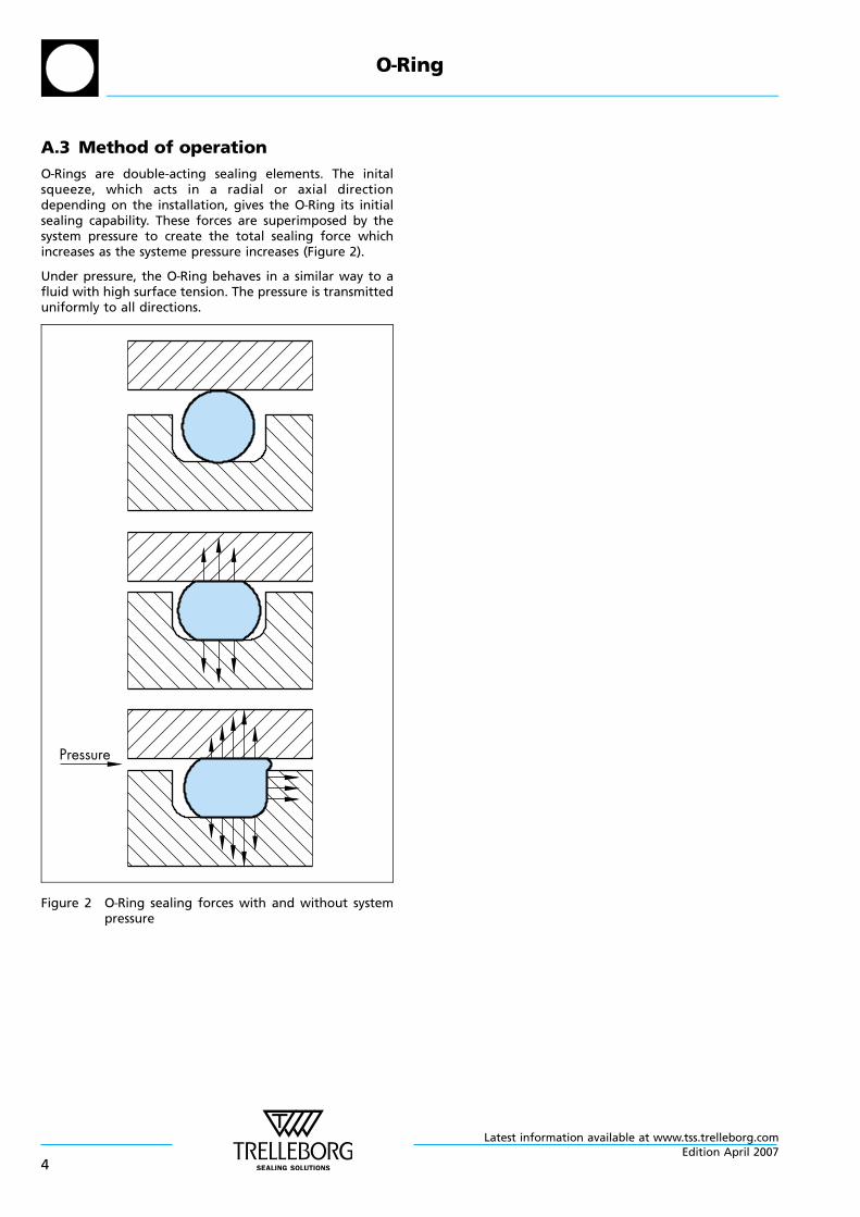
O—Rings are double-acting sealing elements. The initalsqueeze, which acts in a radial or axial directiondepending on the installation, gives the O—Ring its initialsealing capability. These forces are superimposed by thesystem pressure to create the total sealing force whichincreases as the systeme pressure increases (Figure 2).
Under pressure, the O—Ring behaves in a similar way to afluid with high surface tension. The pressure is transmitteduniformly to all directions.
Pressure
Figure 2 O—Ring sealing forces with and without systempressure
O—Ring
Latest information available at www.tss.trelleborg.com
4Edition April 2007
B Technical information
B.1 Materials
B.1.1 ElastomersEquipment manufacturers and end users expect sealingsystems to operate leak free and to maintain long servicelife. Reliability is crucial to effective low maintenance costoperations. To find the perfect sealing solution in eachindividual case both material performance and seal designare critically important. One of the main used material
groups for sealings are the elastomers. They show goodproperties like elasticity or good chemical compatibility.
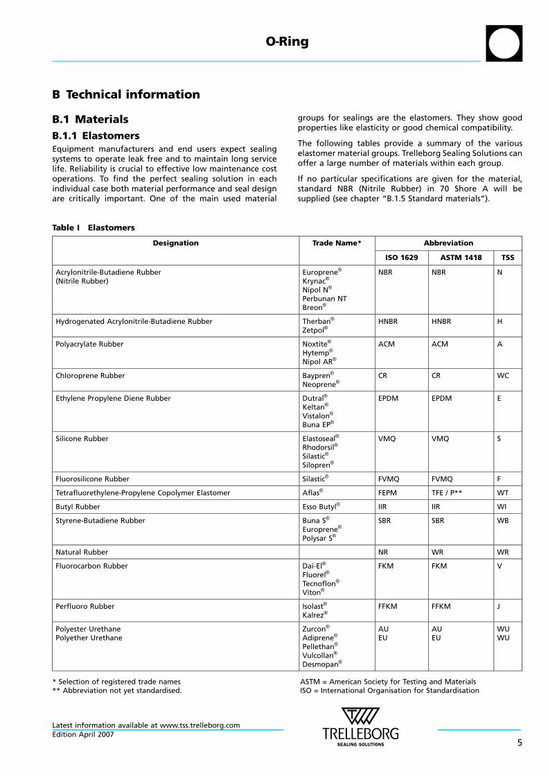
The following tables provide a summary of the variouselastomer material groups. Trelleborg Sealing Solutions canoffer a large number of materials within each group.
If no particular specifications are given for the material,standard NBR (Nitrile Rubber) in 70 Shore A will besupplied (see chapter “B.1.5 Standard materials“).
Table I Elastomers
Designation Trade Name* Abbreviation
ISO 1629 ASTM 1418 TSS
Acrylonitrile-Butadiene Rubber(Nitrile Rubber)
Europrene®
Krynac®
Nipol N®
Perbunan NTBreon®
NBR NBR N
Hydrogenated Acrylonitrile-Butadiene Rubber Therban®
Zetpol®HNBR HNBR H
Polyacrylate Rubber Noxtite®
Hytemp®
Nipol AR®
ACM ACM A
Chloroprene Rubber Baypren®
Neoprene®CR CR WC
Ethylene Propylene Diene Rubber Dutral®
Keltan®
Vistalon®
Buna EP®
EPDM EPDM E
Silicone Rubber Elastoseal®
Rhodorsil®
Silastic®
Silopren®
VMQ VMQ S
Fluorosilicone Rubber Silastic® FVMQ FVMQ F
Tetrafluorethylene-Propylene Copolymer Elastomer Aflas® FEPM TFE / P** WT
Butyl Rubber Esso Butyl® IIR IIR WI
Styrene-Butadiene Rubber Buna S®
Europrene®
Polysar S®
SBR SBR WB
Natural Rubber NR WR WR
Fluorocarbon Rubber Dai-El®
Fluorel®
Tecnoflon®
Viton®
FKM FKM V
Perfluoro Rubber Isolast®
Kalrez®FFKM FFKM J
Polyester UrethanePolyether Urethane
Zurcon®
Adiprene®
Pellethan®
Vulcollan®
Desmopan®
AUEU
AUEU
WUWU
* Selection of registered trade names ASTM = American Society for Testing and Materials** Abbreviation not yet standardised. ISO = International Organisation for Standardisation
O—Ring
Latest information available at www.tss.trelleborg.comEdition April 2007
5
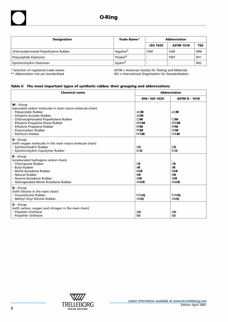
Designation Trade Name* Abbreviation
ISO 1629 ASTM 1418 TSS
Chlorosulphonated Polyethylene Rubber Hypalon® CSM CSM WM
Polysulphide Elastomer Thiokol® - TWT WY
Epichlorohydrin Elastomer Hydrin® - - WO
* Selection of registered trade names ASTM = American Society for Testing and Materials** Abbreviation not yet standardised. ISO = International Organisation for Standardisation
Table II The most important types of synthetic rubber, their grouping and abbreviations
Chemical name Abbreviation
DIN / ISO 1629 ASTM D - 1418
M - Group(saturated carbon molecules in main macro-molecule-chain)- Polyacrylate Rubber- Ethylene Acrylate Rubber- Chlorosulphonated Polyethylene Rubber- Ethylene Propylene Diene Rubber- Ethylene Propylene Rubber- Fluorocarbon Rubber- Perfluoro Rubber
ACMAEMCSMEPDMEPMFKMFFKM
ACM
CSMEPDMEPMFKMFFKM
O - Group(with oxygen molecules in the main macro-molecule chain)- Epichlorohydrin Rubber- Epichlorohydrin Copolymer Rubber
COECO
COECO
R - Group(unsaturated hydrogene carbon chain)- Chloroprene Rubber- Butyl Rubber- Nitrile Butadiene Rubber- Natural Rubber- Styrene Butadiene Rubber- Hydrogenated Nitrile Butadiene Rubber
CRIIRNBRNRSBRHNBR
CRIIRNBRNRSBRHNBR
Q - Group(with Silicone in the main chain)- Fluorosilicone Rubber- Methyl Vinyl Silicone Rubber
FVMQVMQ
FVMQVMQ
U - Group(with carbon, oxygen and nitrogen in the main chain)- Polyester Urethane- Polyether Urethane
AUEU
AUEU
O—Ring
Latest information available at www.tss.trelleborg.com
6Edition April 2007
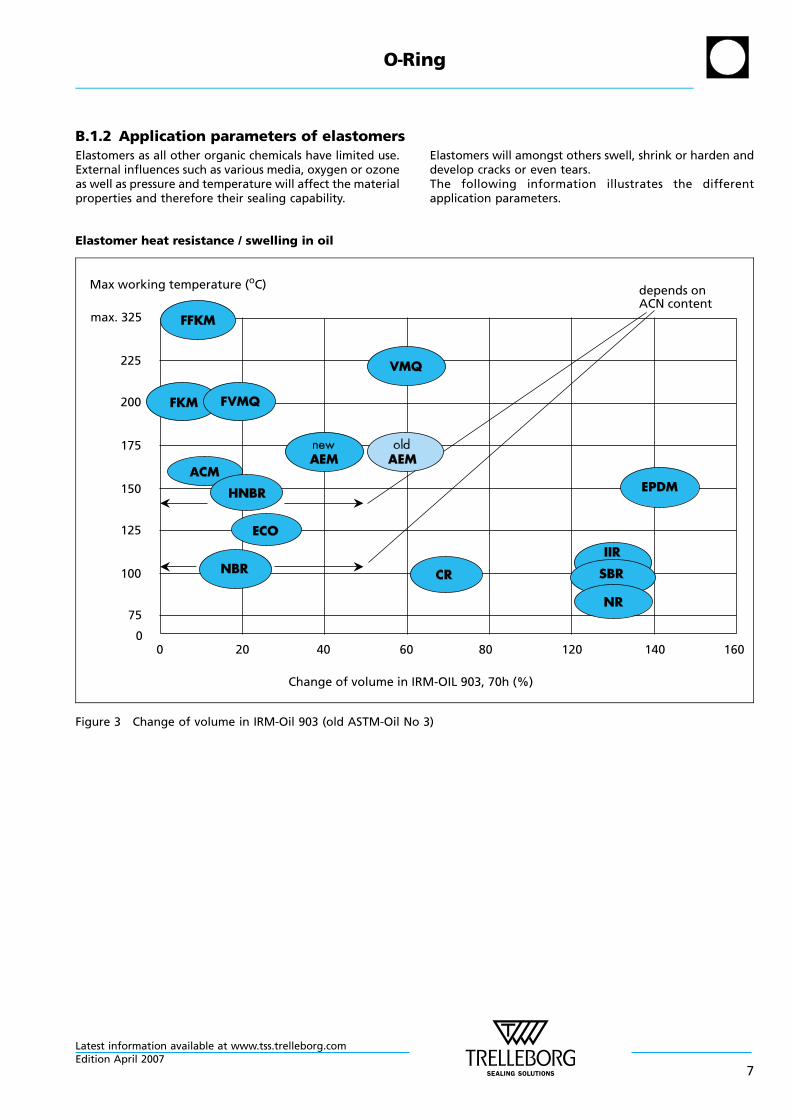
B.1.2 Application parameters of elastomersElastomers as all other organic chemicals have limited use.External influences such as various media, oxygen or ozoneas well as pressure and temperature will affect the materialproperties and therefore their sealing capability.
Elastomers will amongst others swell, shrink or harden anddevelop cracks or even tears.The following information illustrates the differentapplication parameters.
Elastomer heat resistance / swelling in oil
Change of volume in IRM-OIL 903, 70h (%)
Max working temperature (oC)
max. 325
225
200
175
150
125
100
75
0
depends onACN content
200 40 60 80 120 140 160
Figure 3 Change of volume in IRM-Oil 903 (old ASTM-Oil No 3)
O—Ring
Latest information available at www.tss.trelleborg.comEdition April 2007
7
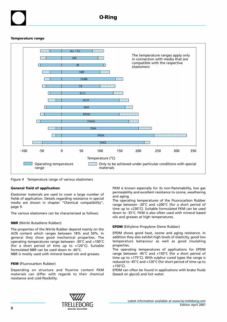
Temperature range
-100 -50 0 50 100 150 200 250 300 350
The temperature ranges apply onlyin connection with media that arecompatible with the respectiveelastomers
Operating temperaturerange
Only to be achieved under particular conditions with specialmaterials
Temperature (°C)
Figure 4 Temperature range of various elastomers
General field of application
Elastomer materials are used to cover a large number offields of application. Details regarding resistance in specialmedia are shown in chapter “Chemical compatibility“,page 9.
The various elastomers can be characterised as follows:
NBR (Nitrile Butadiene Rubber):
The properties of the Nitrile Rubber depend mainly on theACN content which ranges between 18% and 50%. Ingeneral they show good mechanical properties. Theoperating temperatures range between -30°C and +100°C(for a short period of time up to +120°C). Suitableformulated NBR can be used down to -60°C.NBR is mostly used with mineral based oils and greases.
FKM (Fluorocarbon Rubber)
Depending on structure and fluorine content FKMmaterials can differ with regards to their chemicalresistance and cold-flexibility.
FKM is known especially for its non-flammability, low gaspermeability and excellent resistance to ozone, weatheringand aging.The operating temperatures of the Fluorocarbon Rubberrange between -20°C and +200°C (for a short period oftime up to +230°C). Suitable formulated FKM can be useddown to -35°C. FKM is also often used with mineral basedoils and greases at high temperatures.
EPDM (Ethylene Propylene Diene Rubber)
EPDM shows good heat, ozone and aging resistance. Inaddition they also exhibit high levels of elasticity, good lowtemperature behaviour as well as good insulatingproperties.The operating temperatures of applications for EPDMrange between -45°C and +150°C (for a short period oftime up to +175°C). With sulphur cured types the range isreduced to -45°C and +120°C (for short period of time up to+150°C).EPDM can often be found in applications with brake fluids(based on glycol) and hot water.
O—Ring
Latest information available at www.tss.trelleborg.com
8Edition April 2007
HNBR (Hydrogenated Nitrile Butadiene Rubber)
HNBR is made via selective hydrogenation of the NBRbutadiene groups. The properties of the HNBR rubberdepend on the ACN content which ranges between 18%and 50% as well as on the degree of saturation. HNBRshows good mechanical properties.The operating temperature of HNBR ranges between -30°Cand +140°C (for a short period of time up to +160°C) incontact with mineral oils and greases. Special types can beused down to -40°C.
Q (Silicone Rubber)
Silicone rubber shows excellent heat resistance, coldflexibility, dielectric properties and especially goodresistance against oxygen and ozone.Depending on the material the operating temperaturesranges between -60°C and +200°C (for a short period oftime even up to +230°C). Special types can be used down to-90°C. There are also some types with narrow temperatureranges. Silicone is often used in the medical- and foodindustry.
CR (Chloroprene Rubber)
In general the CR materials show relatively goodresistances to ozone, weathering, chemicals and aging.Also they show good non-flammability, good mechanicalproperties and cold flexibility.The operating temperatures range between -40°C and+100°C (for a short period of time up to +120°C). Specialtypes can be used down to -55°C.CR materials are found in sealing applications such asrefrigerants, for outdoor applications and in the glueindustry.
ACM (Polyacrylate Rubber)
ACM shows excellent resistance to ozone, weathering andhot air, although it shows only a medium physical strength,low elasticity and a relatively limited low temperaturecapability.The operating temperatures range from -20°C and +150°C(for a short period of time up to +175°C). Special types canbe used down to -35°C.ACM-materials are mainly used in automotive applicationswhich require special resistance to lubricants containingmany additives (incl. sulphur) at high temperatures.
FFKM (Perfluoro Rubber)
Perfluoroelastomers show broad chemical resistance similarto PTFE as well as good heat resistance. They show lowswelling with almost all media.Depending on the material the operating temperaturesrange between -25°C and +240°C. Special types can be usedup to +325°C.Applications for FFKM can be mostly found in the chemicaland process industries and in all applications with eitheraggressive environments or high temperatures.
Chemical compatibility
It is important to recognise that when using this guide, theratings shown are based on published data and immersiontests. These tests are conducted under laboratoryconditions and may not represent adequately theconditions in the field. Relative short term laboratorytests may not pick up all the additives and impurities whichmay exist in long term service applications.
Care must be taken to ensure that all aspects of theapplication are considered carefully before a material isselected. For example at elevated temperatures someaggressive fluids can cause a much more marked effecton an elastomer than at room temperature.
Physical properties as well as fluid compatibility need to beconsidered. Compression set, hardness, abrasion resistanceand thermal expansion can influence the suitability of amaterial for a particular application.
It is recommended that users conduct their own tests toconfirm the suitability of the selected material for eachapplication.
Our experienced technical staff can be consulted forfurther information on specific applications.
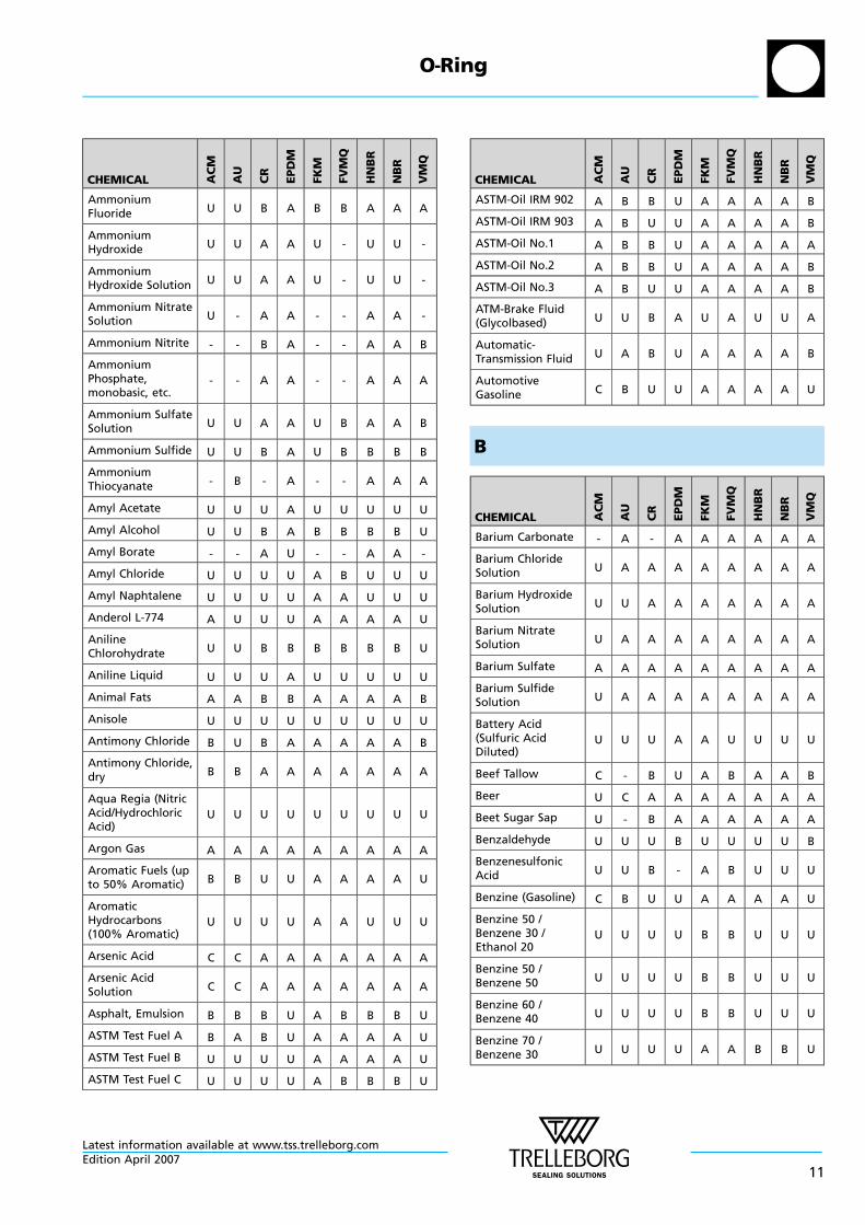
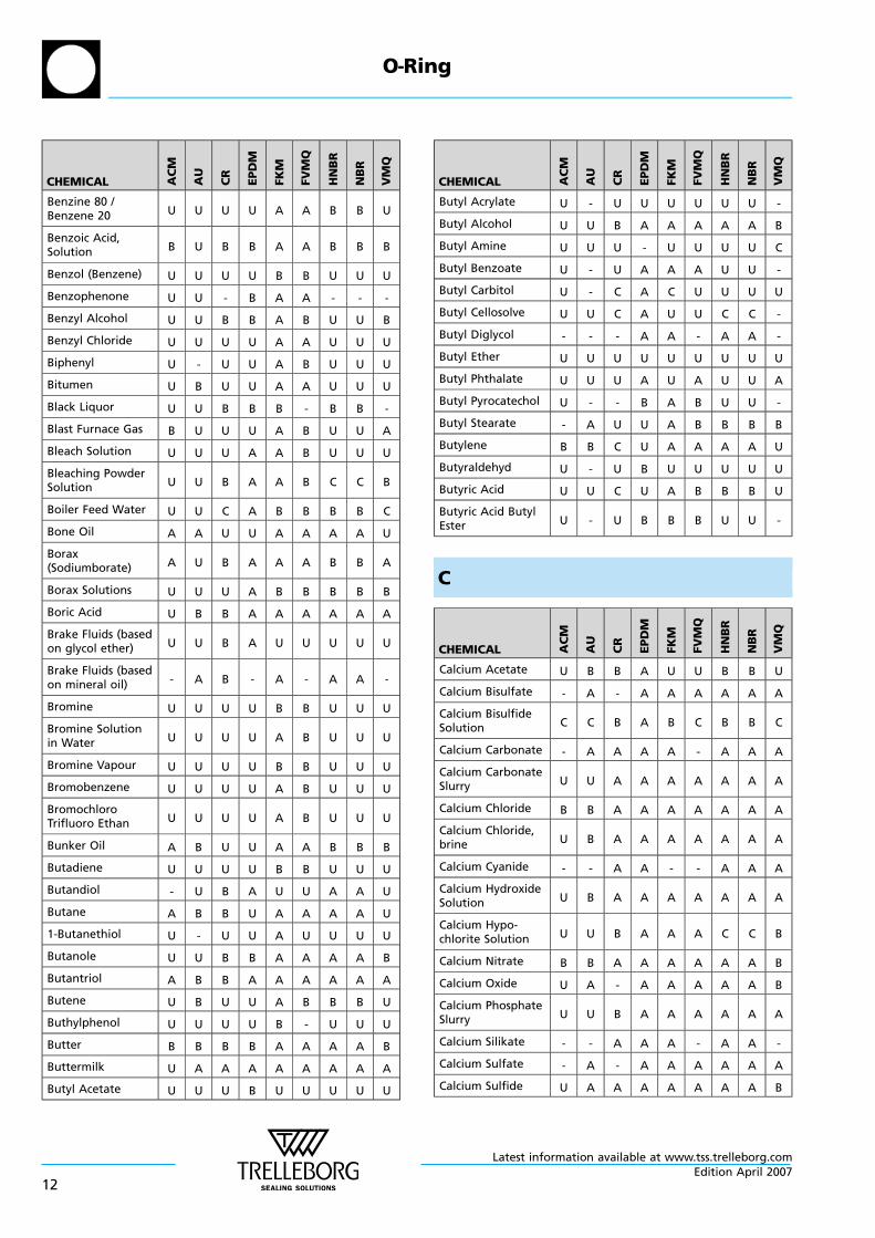
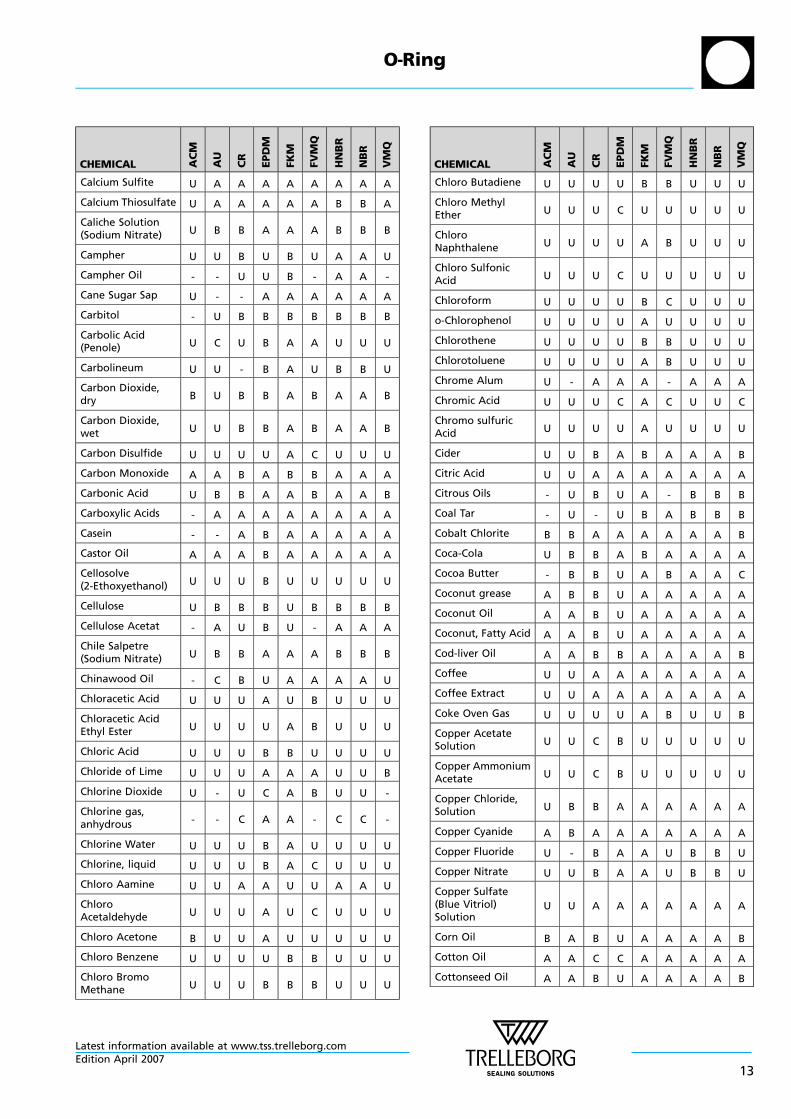
Rating system
A Very good suitabilityElastomer shows little or no effect fromexposure. Little effect on performance andphysical properties. Very good resistance.
B Good suitability.Some effects from exposure with some loss ofphysical properties. Some chemical swelling.
C Limited suitability.Significant swell and loss of physical propertiesafter exposure. Additional tests should be done.
U The elastomer is unsuitable for application in thismedia.
Insufficient information available for service inthis media.
O—Ring
Latest information available at www.tss.trelleborg.comEdition April 2007
9
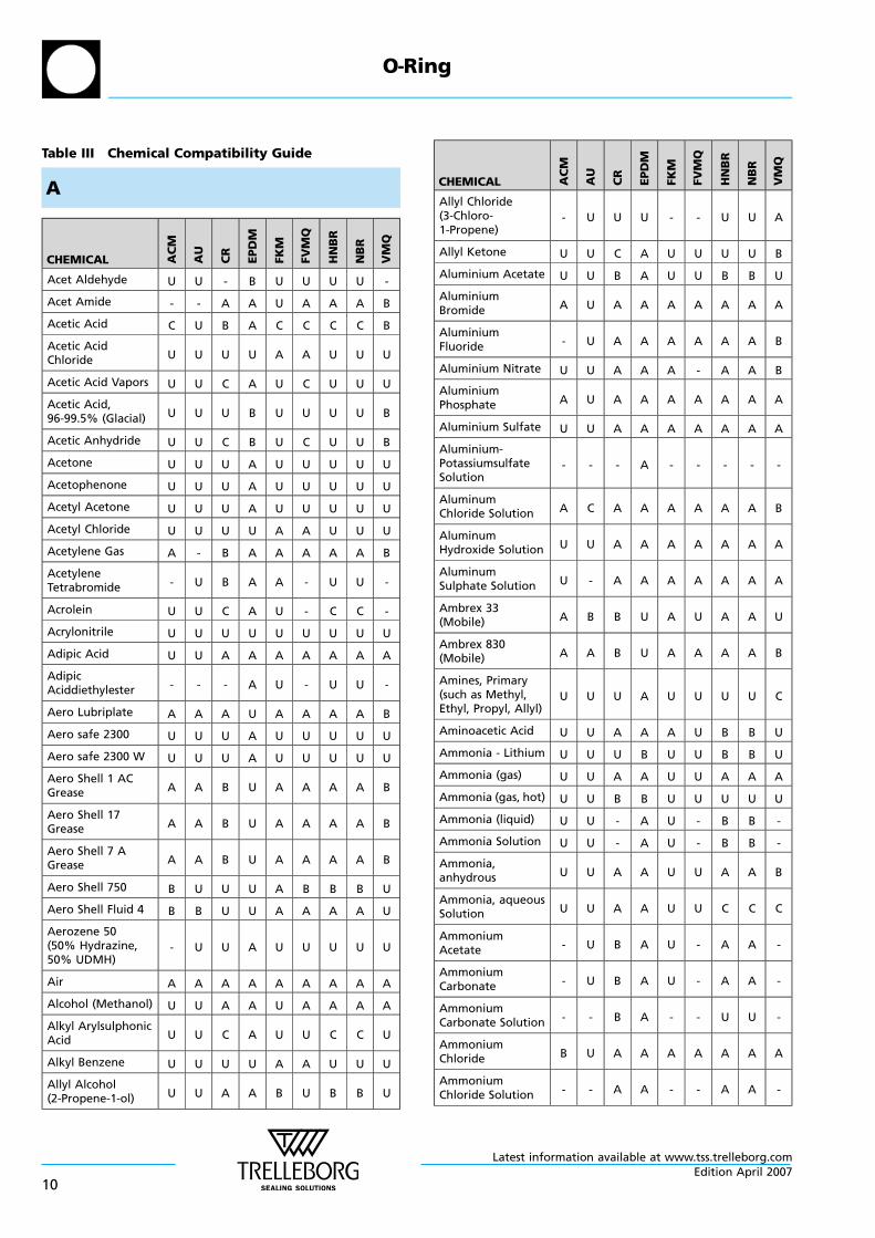
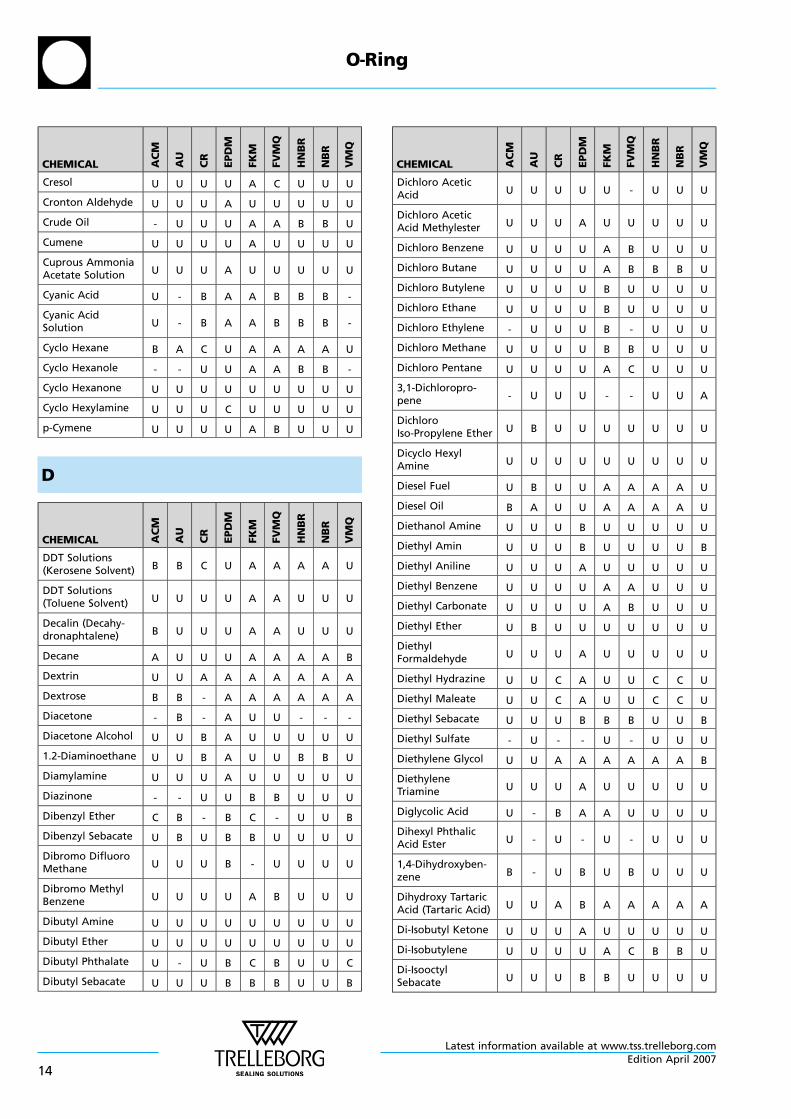
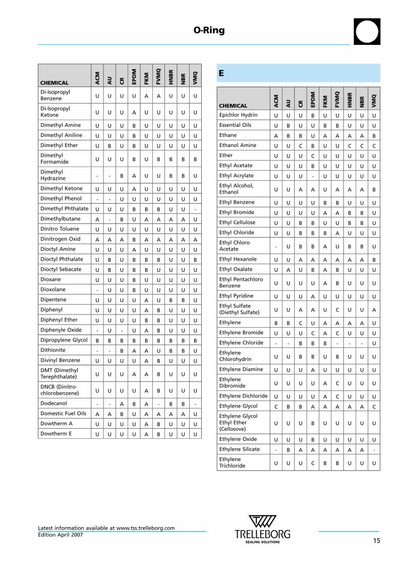
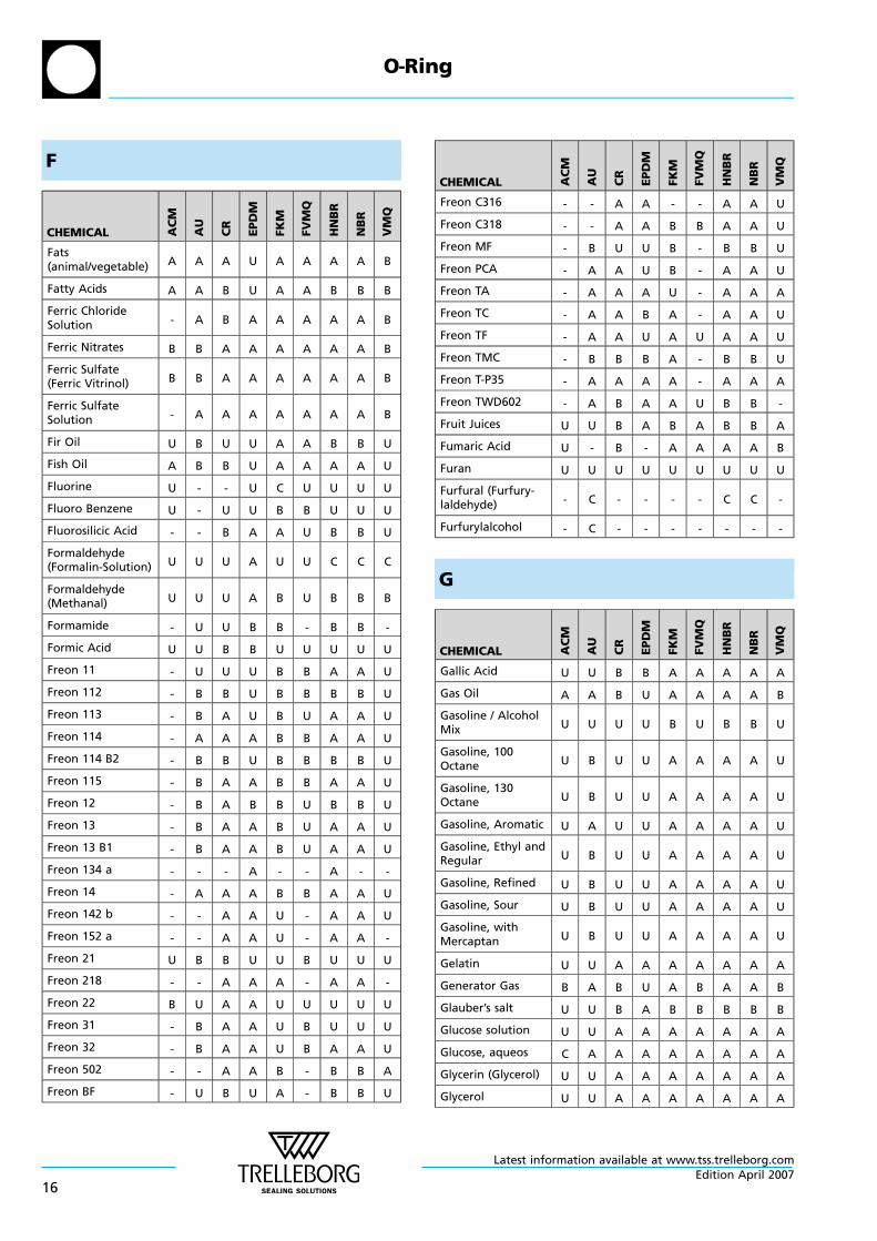
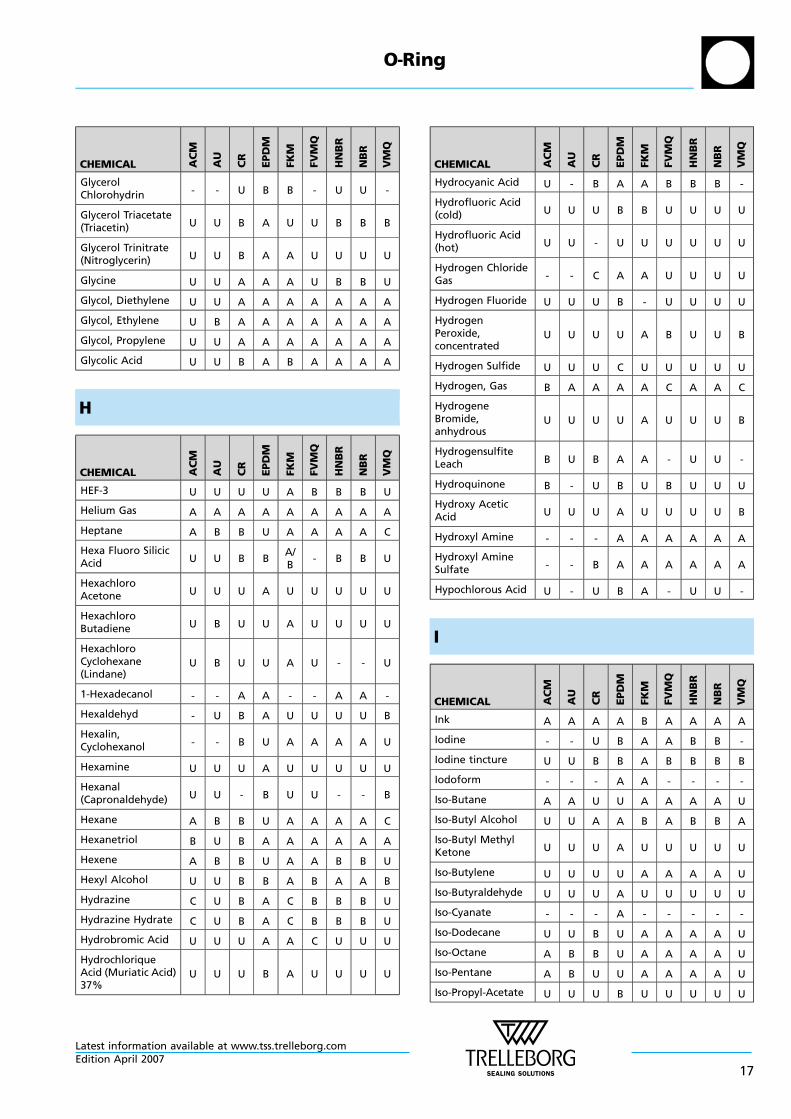
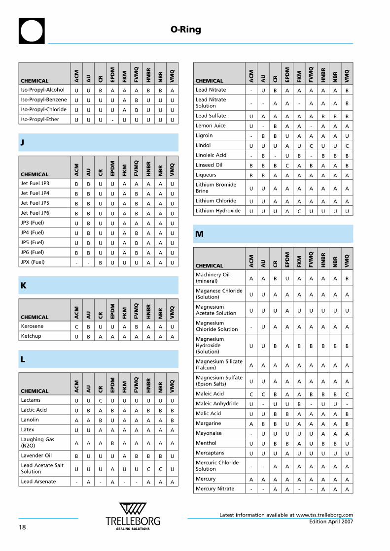
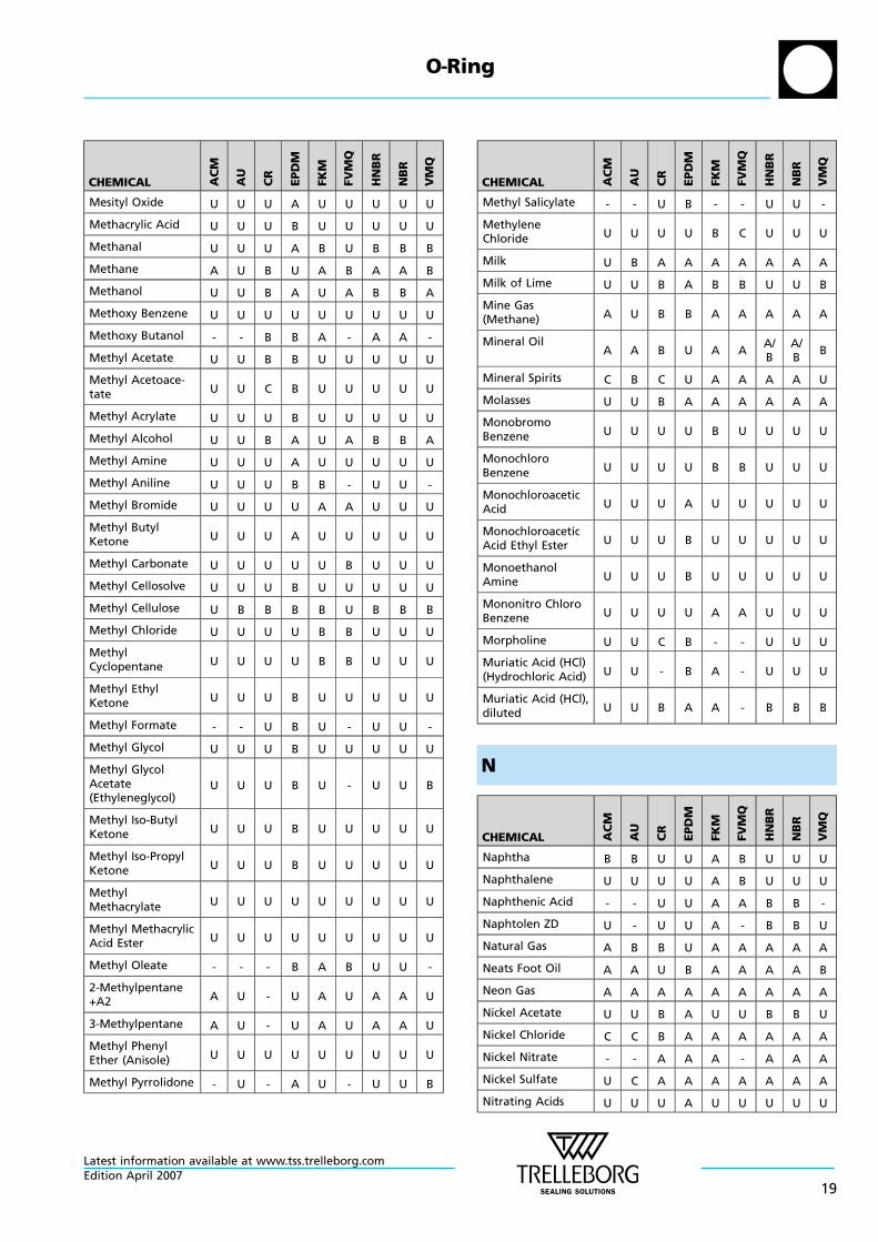
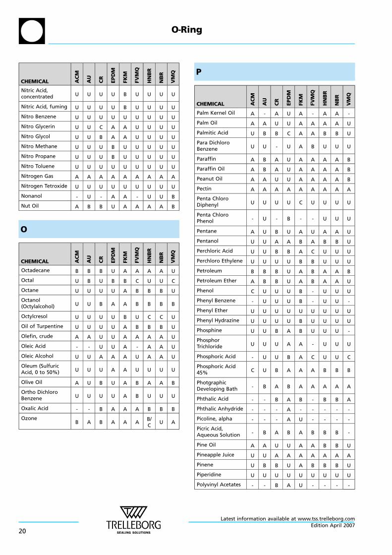
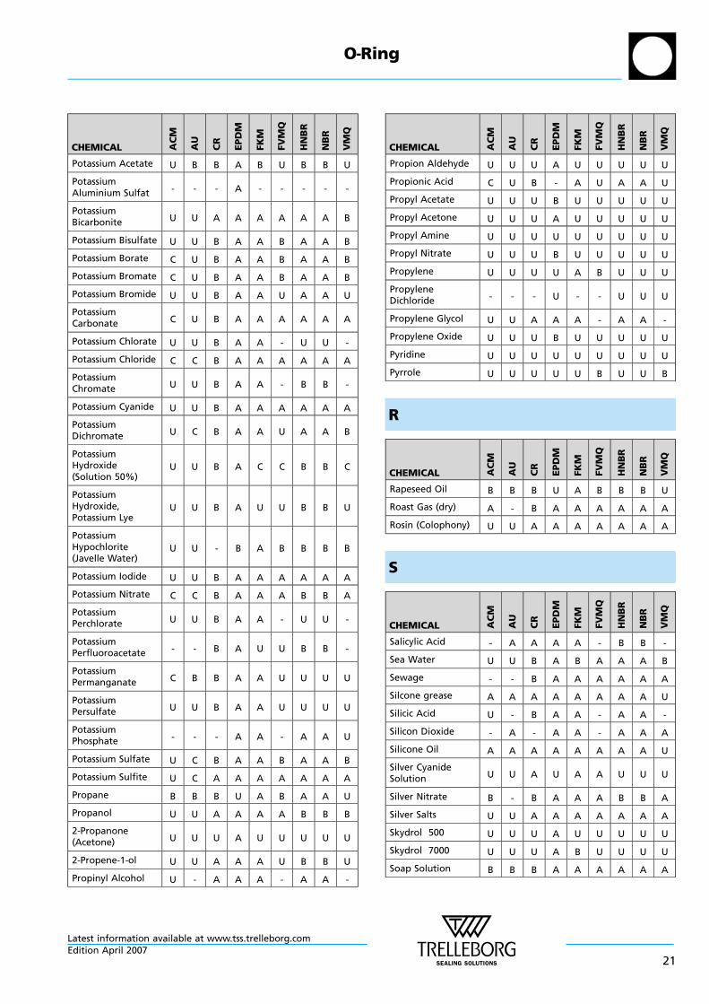
Table III Chemical Compatibility Guide
A
CHEMICAL AC
M
AU
CR
EP
DM
FK
M
FV
MQ
HN
BR
NB
R
VM
Q
Acet Aldehyde U U - B U U U U -
Acet Amide - - A A U A A A B
Acetic Acid C U B A C C C C B
Acetic AcidChloride U U U U A A U U U
Acetic Acid Vapors U U C A U C U U U
Acetic Acid,96-99.5% (Glacial) U U U B U U U U B
Acetic Anhydride U U C B U C U U B
Acetone U U U A U U U U U
Acetophenone U U U A U U U U U
Acetyl Acetone U U U A U U U U U
Acetyl Chloride U U U U A A U U U
Acetylene Gas A - B A A A A A B
AcetyleneTetrabromide - U B A A - U U -
Acrolein U U C A U - C C -
Acrylonitrile U U U U U U U U U
Adipic Acid U U A A A A A A A
AdipicAciddiethylester - - - A U - U U -
Aero Lubriplate A A A U A A A A B
Aero safe 2300 U U U A U U U U U
Aero safe 2300 W U U U A U U U U U
Aero Shell 1 ACGrease A A B U A A A A B
Aero Shell 17Grease A A B U A A A A B
Aero Shell 7 AGrease A A B U A A A A B
Aero Shell 750 B U U U A B B B U
Aero Shell Fluid 4 B B U U A A A A U
Aerozene 50(50% Hydrazine,50% UDMH)
- U U A U U U U U
Air A A A A A A A A A
Alcohol (Methanol) U U A A U A A A A
Alkyl ArylsulphonicAcid U U C A U U C C U
Alkyl Benzene U U U U A A U U U
Allyl Alcohol(2-Propene-1-ol) U U A A B U B B U
CHEMICAL AC
M
AU
CR
EP
DM
FK
M
FV
MQ
HN
BR
NB
R
VM
Q
Allyl Chloride(3-Chloro-1-Propene)
- U U U - - U U A
Allyl Ketone U U C A U U U U B
Aluminium Acetate U U B A U U B B U
AluminiumBromide A U A A A A A A A
AluminiumFluoride - U A A A A A A B
Aluminium Nitrate U U A A A - A A B
AluminiumPhosphate A U A A A A A A A
Aluminium Sulfate U U A A A A A A A
Aluminium-PotassiumsulfateSolution
- - - A - - - - -
AluminumChloride Solution A C A A A A A A B
AluminumHydroxide Solution U U A A A A A A A
AluminumSulphate Solution U - A A A A A A A
Ambrex 33(Mobile) A B B U A U A A U
Ambrex 830(Mobile) A A B U A A A A B
Amines, Primary(such as Methyl,Ethyl, Propyl, Allyl)
U U U A U U U U C
Aminoacetic Acid U U A A A U B B U
Ammonia - Lithium U U U B U U B B U
Ammonia (gas) U U A A U U A A A
Ammonia (gas, hot) U U B B U U U U U
Ammonia (liquid) U U - A U - B B -
Ammonia Solution U U - A U - B B -
Ammonia,anhydrous U U A A U U A A B
Ammonia, aqueousSolution U U A A U U C C C
AmmoniumAcetate - U B A U - A A -
AmmoniumCarbonate - U B A U - A A -
AmmoniumCarbonate Solution - - B A - - U U -
AmmoniumChloride B U A A A A A A A
AmmoniumChloride Solution - - A A - - A A -
O—Ring
Latest information available at www.tss.trelleborg.com
10Edition April 2007
CHEMICAL AC
M
AU
CR
EP
DM
FK
M
FV
MQ
HN
BR
NB
R
VM
Q
AmmoniumFluoride U U B A B B A A A
AmmoniumHydroxide U U A A U - U U -
AmmoniumHydroxide Solution U U A A U - U U -
Ammonium NitrateSolution U - A A - - A A -
Ammonium Nitrite - - B A - - A A B
AmmoniumPhosphate,monobasic, etc.
- - A A - - A A A
Ammonium SulfateSolution U U A A U B A A B
Ammonium Sulfide U U B A U B B B B
AmmoniumThiocyanate - B - A - - A A A
Amyl Acetate U U U A U U U U U
Amyl Alcohol U U B A B B B B U
Amyl Borate - - A U - - A A -
Amyl Chloride U U U U A B U U U
Amyl Naphtalene U U U U A A U U U
Anderol L-774 A U U U A A A A U
AnilineChlorohydrate U U B B B B B B U
Aniline Liquid U U U A U U U U U
Animal Fats A A B B A A A A B
Anisole U U U U U U U U U
Antimony Chloride B U B A A A A A B
Antimony Chloride,dry B B A A A A A A A
Aqua Regia (NitricAcid/HydrochloricAcid)
U U U U U U U U U
Argon Gas A A A A A A A A A
Aromatic Fuels (upto 50% Aromatic) B B U U A A A A U
AromaticHydrocarbons(100% Aromatic)
U U U U A A U U U
Arsenic Acid C C A A A A A A A
Arsenic AcidSolution C C A A A A A A A
Asphalt, Emulsion B B B U A B B B U
ASTM Test Fuel A B A B U A A A A U
ASTM Test Fuel B U U U U A A A A U
ASTM Test Fuel C U U U U A B B B U
CHEMICAL AC
M
AU
CR
EP
DM
FK
M
FV
MQ
HN
BR
NB
R
VM
Q
ASTM-Oil IRM 902 A B B U A A A A B
ASTM-Oil IRM 903 A B U U A A A A B
ASTM-Oil No.1 A B B U A A A A A
ASTM-Oil No.2 A B B U A A A A B
ASTM-Oil No.3 A B U U A A A A B
ATM-Brake Fluid(Glycolbased) U U B A U A U U A
Automatic-Transmission Fluid U A B U A A A A B
AutomotiveGasoline C B U U A A A A U
B
CHEMICAL AC
M
AU
CR
EPD
M
FK
M
FV
MQ
HN
BR
NB
R
VM
Q
Barium Carbonate - A - A A A A A A
Barium ChlorideSolution U A A A A A A A A
Barium HydroxideSolution U U A A A A A A A
Barium NitrateSolution U A A A A A A A A
Barium Sulfate A A A A A A A A A
Barium SulfideSolution U A A A A A A A A
Battery Acid(Sulfuric AcidDiluted)
U U U A A U U U U
Beef Tallow C - B U A B A A B
Beer U C A A A A A A A
Beet Sugar Sap U - B A A A A A A
Benzaldehyde U U U B U U U U B
BenzenesulfonicAcid U U B - A B U U U
Benzine (Gasoline) C B U U A A A A U
Benzine 50 /Benzene 30 /Ethanol 20
U U U U B B U U U
Benzine 50 /Benzene 50 U U U U B B U U U
Benzine 60 /Benzene 40 U U U U B B U U U
Benzine 70 /Benzene 30 U U U U A A B B U
O—Ring
Latest information available at www.tss.trelleborg.comEdition April 2007
11
CHEMICAL AC
M
AU
CR
EP
DM
FK
M
FV
MQ
HN
BR
NB
R
VM
Q
Benzine 80 /Benzene 20 U U U U A A B B U
Benzoic Acid,Solution B U B B A A B B B
Benzol (Benzene) U U U U B B U U U
Benzophenone U U - B A A - - -
Benzyl Alcohol U U B B A B U U B
Benzyl Chloride U U U U A A U U U
Biphenyl U - U U A B U U U
Bitumen U B U U A A U U U
Black Liquor U U B B B - B B -
Blast Furnace Gas B U U U A B U U A
Bleach Solution U U U A A B U U U
Bleaching PowderSolution U U B A A B C C B
Boiler Feed Water U U C A B B B B C
Bone Oil A A U U A A A A U
Borax(Sodiumborate) A U B A A A B B A
Borax Solutions U U U A B B B B B
Boric Acid U B B A A A A A A
Brake Fluids (basedon glycol ether) U U B A U U U U U
Brake Fluids (basedon mineral oil) - A B - A - A A -
Bromine U U U U B B U U U
Bromine Solutionin Water U U U U A B U U U
Bromine Vapour U U U U B B U U U
Bromobenzene U U U U A B U U U
BromochloroTrifluoro Ethan U U U U A B U U U
Bunker Oil A B U U A A B B B
Butadiene U U U U B B U U U
Butandiol - U B A U U A A U
Butane A B B U A A A A U
1-Butanethiol U - U U A U U U U
Butanole U U B B A A A A B
Butantriol A B B A A A A A A
Butene U B U U A B B B U
Buthylphenol U U U U B - U U U
Butter B B B B A A A A B
Buttermilk U A A A A A A A A
Butyl Acetate U U U B U U U U U
CHEMICAL AC
M
AU
CR
EP
DM
FK
M
FV
MQ
HN
BR
NB
R
VM
Q
Butyl Acrylate U - U U U U U U -
Butyl Alcohol U U B A A A A A B
Butyl Amine U U U - U U U U C
Butyl Benzoate U - U A A A U U -
Butyl Carbitol U - C A C U U U U
Butyl Cellosolve U U C A U U C C -
Butyl Diglycol - - - A A - A A -
Butyl Ether U U U U U U U U U
Butyl Phthalate U U U A U A U U A
Butyl Pyrocatechol U - - B A B U U -
Butyl Stearate - A U U A B B B B
Butylene B B C U A A A A U
Butyraldehyd U - U B U U U U U
Butyric Acid U U C U A B B B U
Butyric Acid ButylEster U - U B B B U U -
C
CHEMICAL AC
M
AU
CR
EPD
M
FK
M
FV
MQ
HN
BR
NB
R
VM
Q
Calcium Acetate U B B A U U B B U
Calcium Bisulfate - A - A A A A A A
Calcium BisulfideSolution C C B A B C B B C
Calcium Carbonate - A A A A - A A A
Calcium CarbonateSlurry U U A A A A A A A
Calcium Chloride B B A A A A A A A
Calcium Chloride,brine U B A A A A A A A
Calcium Cyanide - - A A - - A A A
Calcium HydroxideSolution U B A A A A A A A
Calcium Hypo-chlorite Solution U U B A A A C C B
Calcium Nitrate B B A A A A A A B
Calcium Oxide U A - A A A A A B
Calcium PhosphateSlurry U U B A A A A A A
Calcium Silikate - - A A A - A A -
Calcium Sulfate - A - A A A A A A
Calcium Sulfide U A A A A A A A B
O—Ring
Latest information available at www.tss.trelleborg.com
12Edition April 2007
CHEMICAL AC
M
AU
CR
EP
DM
FK
M
FV
MQ
HN
BR
NB
R
VM
Q
Calcium Sulfite U A A A A A A A A
Calcium Thiosulfate U A A A A A B B A
Caliche Solution(Sodium Nitrate) U B B A A A B B B
Campher U U B U B U A A U
Campher Oil - - U U B - A A -
Cane Sugar Sap U - - A A A A A A
Carbitol - U B B B B B B B
Carbolic Acid(Penole) U C U B A A U U U
Carbolineum U U - B A U B B U
Carbon Dioxide,dry B U B B A B A A B
Carbon Dioxide,wet U U B B A B A A B
Carbon Disulfide U U U U A C U U U
Carbon Monoxide A A B A B B A A A
Carbonic Acid U B B A A B A A B
Carboxylic Acids - A A A A A A A A
Casein - - A B A A A A A
Castor Oil A A A B A A A A A
Cellosolve(2-Ethoxyethanol) U U U B U U U U U
Cellulose U B B B U B B B B
Cellulose Acetat - A U B U - A A A
Chile Salpetre(Sodium Nitrate) U B B A A A B B B
Chinawood Oil - C B U A A A A U
Chloracetic Acid U U U A U B U U U
Chloracetic AcidEthyl Ester U U U U A B U U U
Chloric Acid U U U B B U U U U
Chloride of Lime U U U A A A U U B
Chlorine Dioxide U - U C A B U U -
Chlorine gas,anhydrous - - C A A - C C -
Chlorine Water U U U B A U U U U
Chlorine, liquid U U U B A C U U U
Chloro Aamine U U A A U U A A U
ChloroAcetaldehyde U U U A U C U U U
Chloro Acetone B U U A U U U U U
Chloro Benzene U U U U B B U U U
Chloro BromoMethane U U U B B B U U U
CHEMICAL AC
M
AU
CR
EP
DM
FK
M
FV
MQ
HN
BR
NB
R
VM
Q
Chloro Butadiene U U U U B B U U U
Chloro MethylEther U U U C U U U U U
ChloroNaphthalene U U U U A B U U U
Chloro SulfonicAcid U U U C U U U U U
Chloroform U U U U B C U U U
o-Chlorophenol U U U U A U U U U
Chlorothene U U U U B B U U U
Chlorotoluene U U U U A B U U U
Chrome Alum U - A A A - A A A
Chromic Acid U U U C A C U U C
Chromo sulfuricAcid U U U U A U U U U
Cider U U B A B A A A B
Citric Acid U U A A A A A A A
Citrous Oils - U B U A - B B B
Coal Tar - U - U B A B B B
Cobalt Chlorite B B A A A A A A B
Coca-Cola U B B A B A A A A
Cocoa Butter - B B U A B A A C
Coconut grease A B B U A A A A A
Coconut Oil A A B U A A A A A
Coconut, Fatty Acid A A B U A A A A A
Cod-liver Oil A A B B A A A A B
Coffee U U A A A A A A A
Coffee Extract U U A A A A A A A
Coke Oven Gas U U U U A B U U B
Copper AcetateSolution U U C B U U U U U
Copper AmmoniumAcetate U U C B U U U U U
Copper Chloride,Solution U B B A A A A A A
Copper Cyanide A B A A A A A A A
Copper Fluoride U - B A A U B B U
Copper Nitrate U U B A A U B B U
Copper Sulfate(Blue Vitriol)Solution
U U A A A A A A A
Corn Oil B A B U A A A A B
Cotton Oil A A C C A A A A A
Cottonseed Oil A A B U A A A A B
O—Ring
Latest information available at www.tss.trelleborg.comEdition April 2007
13
CHEMICAL AC
M
AU
CR
EP
DM
FK
M
FV
MQ
HN
BR
NB
R
VM
Q
Cresol U U U U A C U U U
Cronton Aldehyde U U U A U U U U U
Crude Oil - U U U A A B B U
Cumene U U U U A U U U U
Cuprous AmmoniaAcetate Solution U U U A U U U U U
Cyanic Acid U - B A A B B B -
Cyanic AcidSolution U - B A A B B B -
Cyclo Hexane B A C U A A A A U
Cyclo Hexanole - - U U A A B B -
Cyclo Hexanone U U U U U U U U U
Cyclo Hexylamine U U U C U U U U U
p-Cymene U U U U A B U U U
D
CHEMICAL AC
M
AU
CR
EPD
M
FK
M
FV
MQ
HN
BR
NB
R
VM
Q
DDT Solutions(Kerosene Solvent) B B C U A A A A U
DDT Solutions(Toluene Solvent) U U U U A A U U U
Decalin (Decahy-dronaphtalene) B U U U A A U U U
Decane A U U U A A A A B
Dextrin U U A A A A A A A
Dextrose B B - A A A A A A
Diacetone - B - A U U - - -
Diacetone Alcohol U U B A U U U U U
1.2-Diaminoethane U U B A U U B B U
Diamylamine U U U A U U U U U
Diazinone - - U U B B U U U
Dibenzyl Ether C B - B C - U U B
Dibenzyl Sebacate U B U B B U U U U
Dibromo DifluoroMethane U U U B - U U U U
Dibromo MethylBenzene U U U U A B U U U
Dibutyl Amine U U U U U U U U U
Dibutyl Ether U U U U U U U U U
Dibutyl Phthalate U - U B C B U U C
Dibutyl Sebacate U U U B B B U U B
CHEMICAL AC
M
AU
CR
EP
DM
FK
M
FV
MQ
HN
BR
NB
R
VM
Q
Dichloro AceticAcid U U U U U - U U U
Dichloro AceticAcid Methylester U U U A U U U U U
Dichloro Benzene U U U U A B U U U
Dichloro Butane U U U U A B B B U
Dichloro Butylene U U U U B U U U U
Dichloro Ethane U U U U B U U U U
Dichloro Ethylene - U U U B - U U U
Dichloro Methane U U U U B B U U U
Dichloro Pentane U U U U A C U U U
3,1-Dichloropro-pene - U U U - - U U A
DichloroIso-Propylene Ether U B U U U U U U U
Dicyclo HexylAmine U U U U U U U U U
Diesel Fuel U B U U A A A A U
Diesel Oil B A U U A A A A U
Diethanol Amine U U U B U U U U U
Diethyl Amin U U U B U U U U B
Diethyl Aniline U U U A U U U U U
Diethyl Benzene U U U U A A U U U
Diethyl Carbonate U U U U A B U U U
Diethyl Ether U B U U U U U U U
DiethylFormaldehyde U U U A U U U U U
Diethyl Hydrazine U U C A U U C C U
Diethyl Maleate U U C A U U C C U
Diethyl Sebacate U U U B B B U U B
Diethyl Sulfate - U - - U - U U U
Diethylene Glycol U U A A A A A A B
DiethyleneTriamine U U U A U U U U U
Diglycolic Acid U - B A A U U U U
Dihexyl PhthalicAcid Ester U - U - U - U U U
1,4-Dihydroxyben-zene B - U B U B U U U
Dihydroxy TartaricAcid (Tartaric Acid) U U A B A A A A A
Di-Isobutyl Ketone U U U A U U U U U
Di-Isobutylene U U U U A C B B U
Di-IsooctylSebacate U U U B B U U U U
O—Ring
Latest information available at www.tss.trelleborg.com
14Edition April 2007
CHEMICAL AC
M
AU
CR
EP
DM
FK
M
FV
MQ
HN
BR
NB
R
VM
Q
Di-IsopropylBenzene U U U U A A U U U
Di-IsopropylKetone U U U A U U U U U
Dimethyl Amine U U U B U U U U U
Dimethyl Aniline U U U B U U U U U
Dimethyl Ether U B U B U U U U U
DimethylFormamide U U U B U B B B B
DimethylHydrazine - - B A U U B B U
Dimethyl Ketone U U U A U U U U U
Dimethyl Phenol - - U U U U U U U
Dimethyl Phthalate U U U B B B U U -
Dimethylbutane A - B U A A A A U
Dinitro Toluene U U U U U U U U U
Dinitrogen Oxid A A A B A A A A A
Dioctyl Amine U U U A U U U U U
Dioctyl Phthalate U B U B B B U U B
Dioctyl Sebacate U B U B B U U U U
Dioxane U U U B U U U U U
Dioxolane - U U B U U U U U
Dipentene U U U U A U B B U
Diphenyl U U U U A B U U U
Diphenyl Ether U U U U B B U U U
Diphenyle Oxide - U - U A B U U U
Dipropylene Glycol B B B B B B B B B
Dithionite - - B A A U B B U
Divinyl Benzene U U U U A B U U U
DMT (DimethylTerephthalate) U U U A A B U U U
DNCB (Dinitro-chlorobenzene) U U U U A B U U U
Dodecanol - - A B A - B B -
Domestic Fuel Oils A A B U A A A A U
Dowtherm A U U U U A B U U U
Dowtherm E U U U U A B U U U
E
CHEMICAL AC
M
AU
CR
EP
DM
FK
M
FV
MQ
HN
BR
NB
R
VM
Q
Epichlor Hydrin U U U B U U U U U
Essential Oils U B U U B B U U U
Ethane A B B U A A A A B
Ethanol Amine U U C B U U C C C
Ether U U U C U U U U U
Ethyl Acetate U U U B U U U U U
Ethyl Acrylate U U U - U U U U U
Ethyl Alcohol,Ethanol U U A A U A A A B
Ethyl Benzene U U U U B B U U U
Ethyl Bromide U U U U A A B B U
Ethyl Cellulose U U B B U U B B U
Ethyl Chloride U U B B B A U U U
Ethyl ChloroAcetate - U B B A U B B U
Ethyl Hexanole U U A A A A A A B
Ethyl Oxalate U A U B A B U U U
Ethyl PentachloroBenzene U U U U A B U U U
Ethyl Pyridine U U U A U U U U U
Ethyl Sulfate(Diethyl Sulfate) U U A A U C U U A
Ethylene B B C U A A A A U
Ethylene Bromide U U U C A C U U U
Ethylene Chloride - - B B B - - - U
EthyleneChlorohydrin U U B B U B U U U
Ethylene Diamine U U U A U U U U U
EthyleneDibromide U U U U A C U U U
Ethylene Dichloride U U U U A C U U U
Ethylene Glycol C B B A A A A A C
Ethylene GlycolEthyl Ether(Cellosove)
U U U B U U U U U
Ethylene Oxide U U U B U U U U U
Ethylene Silicate - B A A A A A A -
EthyleneTrichloride U U U C B B U U U
O—Ring
Latest information available at www.tss.trelleborg.comEdition April 2007
15
F
CHEMICAL AC
M
AU
CR
EP
DM
FK
M
FV
MQ
HN
BR
NB
R
VM
Q
Fats(animal/vegetable) A A A U A A A A B
Fatty Acids A A B U A A B B B
Ferric ChlorideSolution - A B A A A A A B
Ferric Nitrates B B A A A A A A B
Ferric Sulfate(Ferric Vitrinol) B B A A A A A A B
Ferric SulfateSolution - A A A A A A A B
Fir Oil U B U U A A B B U
Fish Oil A B B U A A A A U
Fluorine U - - U C U U U U
Fluoro Benzene U - U U B B U U U
Fluorosilicic Acid - - B A A U B B U
Formaldehyde(Formalin-Solution) U U U A U U C C C
Formaldehyde(Methanal) U U U A B U B B B
Formamide - U U B B - B B -
Formic Acid U U B B U U U U U
Freon 11 - U U U B B A A U
Freon 112 - B B U B B B B U
Freon 113 - B A U B U A A U
Freon 114 - A A A B B A A U
Freon 114 B2 - B B U B B B B U
Freon 115 - B A A B B A A U
Freon 12 - B A B B U B B U
Freon 13 - B A A B U A A U
Freon 13 B1 - B A A B U A A U
Freon 134 a - - - A - - A - -
Freon 14 - A A A B B A A U
Freon 142 b - - A A U - A A U
Freon 152 a - - A A U - A A -
Freon 21 U B B U U B U U U
Freon 218 - - A A A - A A -
Freon 22 B U A A U U U U U
Freon 31 - B A A U B U U U
Freon 32 - B A A U B A A U
Freon 502 - - A A B - B B A
Freon BF - U B U A - B B U
CHEMICAL AC
M
AU
CR
EP
DM
FK
M
FV
MQ
HN
BR
NB
R
VM
Q
Freon C316 - - A A - - A A U
Freon C318 - - A A B B A A U
Freon MF - B U U B - B B U
Freon PCA - A A U B - A A U
Freon TA - A A A U - A A A
Freon TC - A A B A - A A U
Freon TF - A A U A U A A U
Freon TMC - B B B A - B B U
Freon T-P35 - A A A A - A A A
Freon TWD602 - A B A A U B B -
Fruit Juices U U B A B A B B A
Fumaric Acid U - B - A A A A B
Furan U U U U U U U U U
Furfural (Furfury-laldehyde) - C - - - - C C -
Furfurylalcohol - C - - - - - - -
G
CHEMICAL AC
M
AU
CR
EPD
M
FK
M
FV
MQ
HN
BR
NB
R
VM
Q
Gallic Acid U U B B A A A A A
Gas Oil A A B U A A A A B
Gasoline / AlcoholMix U U U U B U B B U
Gasoline, 100Octane U B U U A A A A U
Gasoline, 130Octane U B U U A A A A U
Gasoline, Aromatic U A U U A A A A U
Gasoline, Ethyl andRegular U B U U A A A A U
Gasoline, Refined U B U U A A A A U
Gasoline, Sour U B U U A A A A U
Gasoline, withMercaptan U B U U A A A A U
Gelatin U U A A A A A A A
Generator Gas B A B U A B A A B
Glauber’s salt U U B A B B B B B
Glucose solution U U A A A A A A A
Glucose, aqueos C A A A A A A A A
Glycerin (Glycerol) U U A A A A A A A
Glycerol U U A A A A A A A
O—Ring
Latest information available at www.tss.trelleborg.com
16Edition April 2007
CHEMICAL AC
M
AU
CR
EP
DM
FK
M
FV
MQ
HN
BR
NB
R
VM
Q
GlycerolChlorohydrin - - U B B - U U -
Glycerol Triacetate(Triacetin) U U B A U U B B B
Glycerol Trinitrate(Nitroglycerin) U U B A A U U U U
Glycine U U A A A U B B U
Glycol, Diethylene U U A A A A A A A
Glycol, Ethylene U B A A A A A A A
Glycol, Propylene U U A A A A A A A
Glycolic Acid U U B A B A A A A
H
CHEMICAL AC
M
AU
CR
EPD
M
FK
M
FV
MQ
HN
BR
NB
R
VM
Q
HEF-3 U U U U A B B B U
Helium Gas A A A A A A A A A
Heptane A B B U A A A A C
Hexa Fluoro SilicicAcid U U B B
A/B
- B B U
HexachloroAcetone U U U A U U U U U
HexachloroButadiene U B U U A U U U U
HexachloroCyclohexane(Lindane)
U B U U A U - - U
1-Hexadecanol - - A A - - A A -
Hexaldehyd - U B A U U U U B
Hexalin,Cyclohexanol - - B U A A A A U
Hexamine U U U A U U U U U
Hexanal(Capronaldehyde) U U - B U U - - B
Hexane A B B U A A A A C
Hexanetriol B U B A A A A A A
Hexene A B B U A A B B U
Hexyl Alcohol U U B B A B A A B
Hydrazine C U B A C B B B U
Hydrazine Hydrate C U B A C B B B U
Hydrobromic Acid U U U A A C U U U
HydrochloriqueAcid (Muriatic Acid)37%
U U U B A U U U U
CHEMICAL AC
M
AU
CR
EP
DM
FK
M
FV
MQ
HN
BR
NB
R
VM
Q
Hydrocyanic Acid U - B A A B B B -
Hydrofluoric Acid(cold) U U U B B U U U U
Hydrofluoric Acid(hot) U U - U U U U U U
Hydrogen ChlorideGas - - C A A U U U U
Hydrogen Fluoride U U U B - U U U U
HydrogenPeroxide,concentrated
U U U U A B U U B
Hydrogen Sulfide U U U C U U U U U
Hydrogen, Gas B A A A A C A A C
HydrogeneBromide,anhydrous
U U U U A U U U B
HydrogensulfiteLeach B U B A A - U U -
Hydroquinone B - U B U B U U U
Hydroxy AceticAcid U U U A U U U U B
Hydroxyl Amine - - - A A A A A A
Hydroxyl AmineSulfate - - B A A A A A A
Hypochlorous Acid U - U B A - U U -
I
CHEMICAL AC
M
AU
CR
EPD
M
FK
M
FV
MQ
HN
BR
NB
R
VM
Q
Ink A A A A B A A A A
Iodine - - U B A A B B -
Iodine tincture U U B B A B B B B
Iodoform - - - A A - - - -
Iso-Butane A A U U A A A A U
Iso-Butyl Alcohol U U A A B A B B A
Iso-Butyl MethylKetone U U U A U U U U U
Iso-Butylene U U U U A A A A U
Iso-Butyraldehyde U U U A U U U U U
Iso-Cyanate - - - A - - - - -
Iso-Dodecane U U B U A A A A U
Iso-Octane A B B U A A A A U
Iso-Pentane A B U U A A A A U
Iso-Propyl-Acetate U U U B U U U U U
O—Ring
Latest information available at www.tss.trelleborg.comEdition April 2007
17
CHEMICAL AC
M
AU
CR
EP
DM
FK
M
FV
MQ
HN
BR
NB
R
VM
Q
Iso-Propyl-Alcohol U U B A A A B B A
Iso-Propyl-Benzene U U U U A B U U U
Iso-Propyl-Chloride U U U U A B U U U
Iso-Propyl-Ether U U U - U U U U U
J
CHEMICAL AC
M
AU
CR
EP
DM
FK
M
FV
MQ
HN
BR
NB
R
VM
Q
Jet Fuel JP3 B B U U A A A A U
Jet Fuel JP4 B B U U A B A A U
Jet Fuel JP5 B B U U A B A A U
Jet Fuel JP6 B B U U A B A A U
JP3 (Fuel) U B U U A A A A U
JP4 (Fuel) U B U U A B A A U
JP5 (Fuel) U B U U A B A A U
JP6 (Fuel) B B U U A B A A U
JPX (Fuel) - - B U U U A A U
K
CHEMICAL AC
M
AU
CR
EPD
M
FK
M
FV
MQ
HN
BR
NB
R
VM
Q
Kerosene C B U U A B A A U
Ketchup U B A A A A A A A
L
CHEMICAL AC
M
AU
CR
EPD
M
FK
M
FV
MQ
HN
BR
NB
R
VM
Q
Lactams U U C U U U U U U
Lactic Acid U B A B A A B B B
Lanolin A A B U A A A A B
Latex U U A A A A A A A
Laughing Gas(N2O) A A A B A A A A A
Lavender Oil B U U U A B B B U
Lead Acetate SaltSolution U U U A U U C C U
Lead Arsenate - A - A - - A A A
CHEMICAL AC
M
AU
CR
EP
DM
FK
M
FV
MQ
HN
BR
NB
R
VM
Q
Lead Nitrate - U B A A A A A B
Lead NitrateSolution - - A A - A A A B
Lead Sulfate U A A A A A B B B
Lemon Juice U - B A A - A A A
Ligroin - B B U A A A A U
Lindol U U U A U C U U C
Linoleic Acid - B - U B - B B B
Linseed Oil B B B C A B A A B
Liqueurs B B A A A A A A A
Lithium BromideBrine U U A A A A A A A
Lithium Chloride U U A A A A A A A
Lithium Hydroxide U U U A C U U U U
M
CHEMICAL AC
M
AU
CR
EPD
M
FK
M
FV
MQ
HN
BR
NB
R
VM
Q
Machinery Oil(mineral) A A B U A A A A B
Maganese Chloride(Solution) U U A A A A A A A
MagnesiumAcetate Solution U U U A U U U U U
MagnesiumChloride Solution - U A A A A A A A
MagnesiumHydroxide(Solution)
U U B A B B B B B
Magnesium Silicate(Talcum) A A A A A A A A A
Magnesium Sulfate(Epson Salts) U U A A A A A A A
Maleic Acid C C B A A B B B C
Maleic Anhydride U - U U B - U U -
Malic Acid U U B B A A A A B
Margarine A B B U A A A A B
Mayonaise - U U U U U A A A
Menthol U U B B A U B B U
Mercaptans U U U A U U U U U
Mercuric ChlorideSolution - - A A A A A A A
Mercury A A A A A A A A A
Mercury Nitrate - - A A - - A A A
O—Ring
Latest information available at www.tss.trelleborg.com
18Edition April 2007
CHEMICAL AC
M
AU
CR
EP
DM
FK
M
FV
MQ
HN
BR
NB
R
VM
Q
Mesityl Oxide U U U A U U U U U
Methacrylic Acid U U U B U U U U U
Methanal U U U A B U B B B
Methane A U B U A B A A B
Methanol U U B A U A B B A
Methoxy Benzene U U U U U U U U U
Methoxy Butanol - - B B A - A A -
Methyl Acetate U U B B U U U U U
Methyl Acetoace-tate U U C B U U U U U
Methyl Acrylate U U U B U U U U U
Methyl Alcohol U U B A U A B B A
Methyl Amine U U U A U U U U U
Methyl Aniline U U U B B - U U -
Methyl Bromide U U U U A A U U U
Methyl ButylKetone U U U A U U U U U
Methyl Carbonate U U U U U B U U U
Methyl Cellosolve U U U B U U U U U
Methyl Cellulose U B B B B U B B B
Methyl Chloride U U U U B B U U U
MethylCyclopentane U U U U B B U U U
Methyl EthylKetone U U U B U U U U U
Methyl Formate - - U B U - U U -
Methyl Glycol U U U B U U U U U
Methyl GlycolAcetate(Ethyleneglycol)
U U U B U - U U B
Methyl Iso-ButylKetone U U U B U U U U U
Methyl Iso-PropylKetone U U U B U U U U U
MethylMethacrylate U U U U U U U U U
Methyl MethacrylicAcid Ester U U U U U U U U U
Methyl Oleate - - - B A B U U -
2-Methylpentane+A2 A U - U A U A A U
3-Methylpentane A U - U A U A A U
Methyl PhenylEther (Anisole) U U U U U U U U U
Methyl Pyrrolidone - U - A U - U U B
CHEMICAL AC
M
AU
CR
EP
DM
FK
M
FV
MQ
HN
BR
NB
R
VM
Q
Methyl Salicylate - - U B - - U U -
MethyleneChloride U U U U B C U U U
Milk U B A A A A A A A
Milk of Lime U U B A B B U U B
Mine Gas(Methane) A U B B A A A A A
Mineral OilA A B U A A
A/B
A/B
B
Mineral Spirits C B C U A A A A U
Molasses U U B A A A A A A
MonobromoBenzene U U U U B U U U U
MonochloroBenzene U U U U B B U U U
MonochloroaceticAcid U U U A U U U U U
MonochloroaceticAcid Ethyl Ester U U U B U U U U U
MonoethanolAmine U U U B U U U U U
Mononitro ChloroBenzene U U U U A A U U U
Morpholine U U C B - - U U U
Muriatic Acid (HCl)(Hydrochloric Acid) U U - B A - U U U
Muriatic Acid (HCl),diluted U U B A A - B B B
N
CHEMICAL AC
M
AU
CR
EPD
M
FK
M
FV
MQ
HN
BR
NB
R
VM
Q
Naphtha B B U U A B U U U
Naphthalene U U U U A B U U U
Naphthenic Acid - - U U A A B B -
Naphtolen ZD U - U U A - B B U
Natural Gas A B B U A A A A A
Neats Foot Oil A A U B A A A A B
Neon Gas A A A A A A A A A
Nickel Acetate U U B A U U B B U
Nickel Chloride C C B A A A A A A
Nickel Nitrate - - A A A - A A A
Nickel Sulfate U C A A A A A A A
Nitrating Acids U U U A U U U U U
O—Ring
Latest information available at www.tss.trelleborg.comEdition April 2007
19
CHEMICAL AC
M
AU
CR
EP
DM
FK
M
FV
MQ
HN
BR
NB
R
VM
Q
Nitric Acid,concentrated U U U U B U U U U
Nitric Acid, fuming U U U U B U U U U
Nitro Benzene U U U U U U U U U
Nitro Glycerin U U C A A U U U U
Nitro Glycol U U B A A U U U U
Nitro Methane U U U B U U U U U
Nitro Propane U U U B U U U U U
Nitro Toluene U U U U U U U U U
Nitrogen Gas A A A A A A A A A
Nitrogen Tetroxide U U U U U U U U U
Nonanol - U - A A - U U B
Nut Oil A B B U A A A A B
O
CHEMICAL AC
M
AU
CR
EPD
M
FK
M
FV
MQ
HN
BR
NB
R
VM
Q
Octadecane B B B U A A A A U
Octal U B U B B C U U C
Octane U U U U A B B B U
Octanol(Octylalcohol) U U B A A B B B B
Octylcresol U U U U B U C C U
Oil of Turpentine U U U U A B B B U
Olefin, crude A A U U A A A A U
Oleic Acid - - U U A - A A U
Oleic Alcohol U U A A A U A A U
Oleum (SulfuricAcid, 0 to 50%) U U U A A U U U U
Olive Oil A U B U A B A A B
Ortho DichloroBenzene U U U U A B U U U
Oxalic Acid - - B A A A B B B
OzoneB A B A A A
B/C
U A
P
CHEMICAL AC
M
AU
CR
EP
DM
FK
M
FV
MQ
HN
BR
NB
R
VM
Q
Palm Kernel Oil A - A U A - A A -
Palm Oil A A U U A A A A U
Palmitic Acid U B B C A A B B U
Para DichloroBenzene U U - U A B U U U
Paraffin A B A U A A A A B
Paraffin Oil A B A U A A A A B
Peanut Oil A A U U A A A A B
Pectin A A A A A A A A A
Penta ChloroDiphenyl U U U U C U U U U
Penta ChloroPhenol - U - B - - U U U
Pentane A U B U A U A A U
Pentanol U U A A B A B B U
Perchloric Acid U U B B A C U U U
Perchloro Ethylene U U U U B B U U U
Petroleum B B B U A B A A B
Petroleum Ether A B B U A B A A U
Phenol C U U U B - U U U
Phenyl Benzene - U U U B - U U -
Phenyl Ether U U U U U U U U U
Phenyl Hydrazine U U U U B U U U U
Phosphine U U B A B U U U -
PhosphorTrichloride U U U A A - U U U
Phosphoric Acid - U U B A C U U C
Phosphoric Acid45% C U B A A A B B B
PhotgraphicDeveloping Bath - B A B A A A A A
Phthalic Acid - - B A B - B B A
Phthalic Anhydride - - - A - - - - -
Picoline, alpha - - - A U - - - -
Picric Acid,Aqueous Solution - B A B A B B B -
Pine Oil A A U U A A B B U
Pineapple Juice U U A A A A A A A
Pinene U B B U A B B B U
Piperidine U U U U U U U U U
Polyvinyl Acetates - - B A U - - - -
O—Ring
Latest information available at www.tss.trelleborg.com
20Edition April 2007
CHEMICAL AC
M
AU
CR
EP
DM
FK
M
FV
MQ
HN
BR
NB
R
VM
Q
Potassium Acetate U B B A B U B B U
PotassiumAluminium Sulfat - - - A - - - - -
PotassiumBicarbonite U U A A A A A A B
Potassium Bisulfate U U B A A B A A B
Potassium Borate C U B A A B A A B
Potassium Bromate C U B A A B A A B
Potassium Bromide U U B A A U A A U
PotassiumCarbonate C U B A A A A A A
Potassium Chlorate U U B A A - U U -
Potassium Chloride C C B A A A A A A
PotassiumChromate U U B A A - B B -
Potassium Cyanide U U B A A A A A A
PotassiumDichromate U C B A A U A A B
PotassiumHydroxide(Solution 50%)
U U B A C C B B C
PotassiumHydroxide,Potassium Lye
U U B A U U B B U
PotassiumHypochlorite(Javelle Water)
U U - B A B B B B
Potassium Iodide U U B A A A A A A
Potassium Nitrate C C B A A A B B A
PotassiumPerchlorate U U B A A - U U -
PotassiumPerfluoroacetate - - B A U U B B -
PotassiumPermanganate C B B A A U U U U
PotassiumPersulfate U U B A A U U U U
PotassiumPhosphate - - - A A - A A U
Potassium Sulfate U C B A A B A A B
Potassium Sulfite U C A A A A A A A
Propane B B B U A B A A U
Propanol U U A A A A B B B
2-Propanone(Acetone) U U U A U U U U U
2-Propene-1-ol U U A A A U B B U
Propinyl Alcohol U - A A A - A A -
CHEMICAL AC
M
AU
CR
EP
DM
FK
M
FV
MQ
HN
BR
NB
R
VM
Q
Propion Aldehyde U U U A U U U U U
Propionic Acid C U B - A U A A U
Propyl Acetate U U U B U U U U U
Propyl Acetone U U U A U U U U U
Propyl Amine U U U U U U U U U
Propyl Nitrate U U U B U U U U U
Propylene U U U U A B U U U
PropyleneDichloride - - - U - - U U U
Propylene Glycol U U A A A - A A -
Propylene Oxide U U U B U U U U U
Pyridine U U U U U U U U U
Pyrrole U U U U U B U U B
R
CHEMICAL AC
M
AU
CR
EPD
M
FK
M
FV
MQ
HN
BR
NB
R
VM
Q
Rapeseed Oil B B B U A B B B U
Roast Gas (dry) A - B A A A A A A
Rosin (Colophony) U U A A A A A A A
S
CHEMICAL AC
M
AU
CR
EPD
M
FK
M
FV
MQ
HN
BR
NB
R
VM
Q
Salicylic Acid - A A A A - B B -
Sea Water U U B A B A A A B
Sewage - - B A A A A A A
Silcone grease A A A A A A A A U
Silicic Acid U - B A A - A A -
Silicon Dioxide - A - A A - A A A
Silicone Oil A A A A A A A A U
Silver CyanideSolution U U A U A A U U U
Silver Nitrate B - B A A A B B A
Silver Salts U U A A A A A A A
Skydrol 500 U U U A U U U U U
Skydrol 7000 U U U A B U U U U
Soap Solution B B B A A A A A A
O—Ring
Latest information available at www.tss.trelleborg.comEdition April 2007
21
CHEMICAL AC
M
AU
CR
EP
DM
FK
M
FV
MQ
HN
BR
NB
R
VM
Q
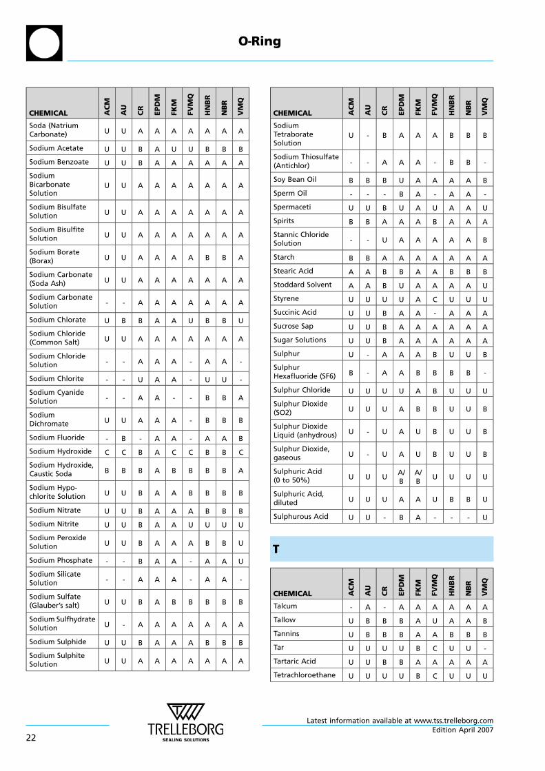
Soda (NatriumCarbonate) U U A A A A A A A
Sodium Acetate U U B A U U B B B
Sodium Benzoate U U B A A A A A A
SodiumBicarbonateSolution
U U A A A A A A A
Sodium BisulfateSolution U U A A A A A A A
Sodium BisulfiteSolution U U A A A A A A A
Sodium Borate(Borax) U U A A A A B B A
Sodium Carbonate(Soda Ash) U U A A A A A A A
Sodium CarbonateSolution - - A A A A A A A
Sodium Chlorate U B B A A U B B U
Sodium Chloride(Common Salt) U U A A A A A A A
Sodium ChlorideSolution - - A A A - A A -
Sodium Chlorite - - U A A - U U -
Sodium CyanideSolution - - A A - - B B A
SodiumDichromate U U A A A - B B B
Sodium Fluoride - B - A A - A A B
Sodium Hydroxide C C B A C C B B C
Sodium Hydroxide,Caustic Soda B B B A B B B B A
Sodium Hypo-chlorite Solution U U B A A B B B B
Sodium Nitrate U U B A A A B B B
Sodium Nitrite U U B A A U U U U
Sodium PeroxideSolution U U B A A A B B U
Sodium Phosphate - - B A A - A A U
Sodium SilicateSolution - - A A A - A A -
Sodium Sulfate(Glauber’s salt) U U B A B B B B B
Sodium SulfhydrateSolution U - A A A A A A A
Sodium Sulphide U U B A A A B B B
Sodium SulphiteSolution U U A A A A A A A
CHEMICAL AC
M
AU
CR
EP
DM
FK
M
FV
MQ
HN
BR
NB
R
VM
Q
SodiumTetraborateSolution
U - B A A A B B B
Sodium Thiosulfate(Antichlor) - - A A A - B B -
Soy Bean Oil B B B U A A A A B
Sperm Oil - - - B A - A A -
Spermaceti U U B U A U A A U
Spirits B B A A A B A A A
Stannic ChlorideSolution - - U A A A A A B
Starch B B A A A A A A A
Stearic Acid A A B B A A B B B
Stoddard Solvent A A B U A A A A U
Styrene U U U U A C U U U
Succinic Acid U U B A A - A A A
Sucrose Sap U U B A A A A A A
Sugar Solutions U U B A A A A A A
Sulphur U - A A A B U U B
SulphurHexafluoride (SF6) B - A A B B B B -
Sulphur Chloride U U U U A B U U U
Sulphur Dioxide(SO2) U U U A B B U U B
Sulphur DioxideLiquid (anhydrous) U - U A U B U U B
Sulphur Dioxide,gaseous U - U A U B U U B
Sulphuric Acid(0 to 50%) U U U
A/B
A/B
U U U U
Sulphuric Acid,diluted U U U A A U B B U
Sulphurous Acid U U - B A - - - U
T
CHEMICAL AC
M
AU
CR
EPD
M
FK
M
FV
MQ
HN
BR
NB
R
VM
Q
Talcum - A - A A A A A A
Tallow U B B B A U A A B
Tannins U B B B A A B B B
Tar U U U U B C U U -
Tartaric Acid U U B B A A A A A
Tetrachloroethane U U U U B C U U U
O—Ring
Latest information available at www.tss.trelleborg.com
22Edition April 2007
CHEMICAL AC
M
AU
CR
EP
DM
FK
M
FV
MQ
HN
BR
NB
R
VM
Q
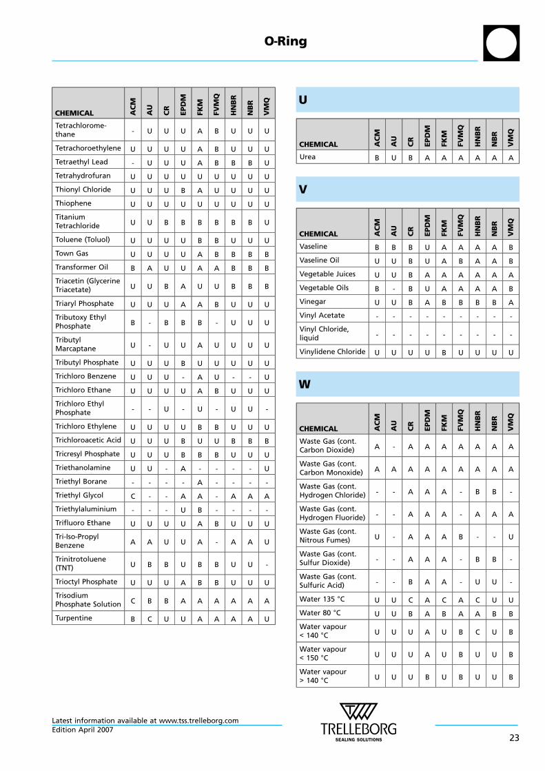
Tetrachlorome-thane - U U U A B U U U
Tetrachoroethylene U U U U A B U U U
Tetraethyl Lead - U U U A B B B U
Tetrahydrofuran U U U U U U U U U
Thionyl Chloride U U U B A U U U U
Thiophene U U U U U U U U U
TitaniumTetrachloride U U B B B B B B U
Toluene (Toluol) U U U U B B U U U
Town Gas U U U U A B B B B
Transformer Oil B A U U A A B B B
Triacetin (GlycerineTriacetate) U U B A U U B B B
Triaryl Phosphate U U U A A B U U U
Tributoxy EthylPhosphate B - B B B - U U U
TributylMarcaptane U - U U A U U U U
Tributyl Phosphate U U U B U U U U U
Trichloro Benzene U U U - A U - - U
Trichloro Ethane U U U U A B U U U
Trichloro EthylPhosphate - - U - U - U U -
Trichloro Ethylene U U U U B B U U U
Trichloroacetic Acid U U U B U U B B B
Tricresyl Phosphate U U U B B B U U U
Triethanolamine U U - A - - - - U
Triethyl Borane - - - - A - - - -
Triethyl Glycol C - - A A - A A A
Triethylaluminium - - - U B - - - -
Trifluoro Ethane U U U U A B U U U
Tri-Iso-PropylBenzene A A U U A - A A U
Trinitrotoluene(TNT) U B B U B B U U -
Trioctyl Phosphate U U U A B B U U U
TrisodiumPhosphate Solution C B B A A A A A A
Turpentine B C U U A A A A U
U
CHEMICAL AC
M
AU
CR
EP
DM
FK
M
FV
MQ
HN
BR
NB
R
VM
Q
Urea B U B A A A A A A
V
CHEMICAL AC
M
AU
CR
EP
DM
FK
M
FV
MQ
HN
BR
NB
R
VM
Q
Vaseline B B B U A A A A B
Vaseline Oil U U B U A B A A B
Vegetable Juices U U B A A A A A A
Vegetable Oils B - B U A A A A B
Vinegar U U B A B B B B A
Vinyl Acetate - - - - - - - - -
Vinyl Chloride,liquid - - - - - - - - -
Vinylidene Chloride U U U U B U U U U
W
CHEMICAL AC
M
AU
CR
EPD
M
FK
M
FV
MQ
HN
BR
NB
R
VM
Q
Waste Gas (cont.Carbon Dioxide) A - A A A A A A A
Waste Gas (cont.Carbon Monoxide) A A A A A A A A A
Waste Gas (cont.Hydrogen Chloride) - - A A A - B B -
Waste Gas (cont.Hydrogen Fluoride) - - A A A - A A A
Waste Gas (cont.Nitrous Fumes) U - A A A B - - U
Waste Gas (cont.Sulfur Dioxide) - - A A A - B B -
Waste Gas (cont.Sulfuric Acid) - - B A A - U U -
Water 135 °C U U C A C A C U U
Water 80 °C U U B A B A A B B
Water vapour< 140 °C U U U A U B C U B
Water vapour< 150 °C U U U A U B U U B
Water vapour> 140 °C U U U B U B U U B
O—Ring
Latest information available at www.tss.trelleborg.comEdition April 2007
23
CHEMICAL AC
M
AU
CR
EP
DM
FK
M
FV
MQ
HN
BR
NB
R
VM
Q
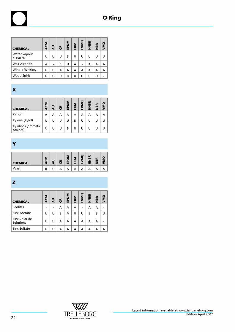
Water vapour> 150 °C U U U B U U U U U
Wax Alcohols A - B U A - A A A
Wine + Whiskey U U A A A A A A A
Wood Spirit U U U B U U U U -
X
CHEMICAL AC
M
AU
CR
EP
DM
FK
M
FV
MQ
HN
BR
NB
R
VM
Q
Xenon A A A A A A A A A
Xylene (Xylol) U U U U B U U U U
Xylidines (aromaticAmines) U U U B U U U U U
Y
CHEMICAL AC
M
AU
CR
EPD
M
FK
M
FV
MQ
HN
BR
NB
R
VM
Q
Yeast B U A A A A A A A
Z
CHEMICAL AC
M
AU
CR
EPD
M
FK
M
FV
MQ
HN
BR
NB
R
VM
Q
Zeolites - - A A A - A A -
Zinc Acetate U U B A U U B B U
Zinc ChlorideSolutions U U A A A A A A -
Zinc Sulfate U U A A A A A A A
O—Ring
Latest information available at www.tss.trelleborg.com
24Edition April 2007
B.1.3 Characteristics and inspection of elastomersHardness
One of the most often named properties regardingPolymer materials is hardness. Even so the values can bequite misleading.
Hardness is the resistance of a body against penetration ofan even harder body - of a standard shape definedpressure.
There are two procedures for hardness tests regarding testsamples and finished parts made out of elastomer material:
1. Shore A/Daccording to ISO 868 / ISO 7619 / DIN 53 505 /ASTM D 2240Measurement for test samples
2. Durometer IRHD (International Rubber HardnessDegree) according to ISO 48 / ASTM 1414 and 1415Measurement of test samples and finished parts
The hardness scale has a range of 0 (softest) to 100(hardest). The measured values depend on the elasticqualities of the elastomers, especially on the tensilestrength.
The test should be carried out at temperatures of 23 ±2°C -not earlier than 16 hours after the last vulcanisationprocess (manufacturing stage). If other temperatures arebeing used this should be mentioned in the test report.
Tests should only be carried out with samples which havenot been previously stressed mechanically.
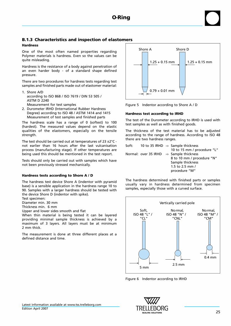
Hardness tests according to Shore A / D
The hardness test device Shore A (indentor with pyramidbase) is a sensible application in the hardness range 10 to90. Samples with a larger hardness should be tested withthe device Shore D (indentor with spike).Test specimen:Diameter min. 30 mmThickness min. 6 mmUpper and lower sides smooth and flatWhen thin material is being tested it can be layeredproviding minimal sample thickness is achieved by amaximum of 3 layers. All layers must be at minimum2 mm thick.
The measurement is done at three different places at adefined distance and time.
Shore A Shore D
1.25 + 0.15 mm 1.25 + 0.15 mm
0.79 + 0.01 mm
Figure 5 Indentor according to Shore A / D
Hardness test according to IRHD
The test of the Durometer according to IRHD is used withtest samples as well as with finished goods.
The thickness of the test material has to be adjustedaccording to the range of hardness. According to ISO 48there are two hardness ranges.
Soft: 10 to 35 IRHD ) Sample thickness10 to 15 mm / procedure “L“
Normal: over 35 IRHD ) Sample thickness8 to 10 mm / procedure “N“Sample thickness1.5 to 2.5 mm /procedure “M“
The hardness determined with finished parts or samplesusually vary in hardness determined from specimensamples, especially those with a curved surface.
Vertically carried pole
2.5 mm
0.4 mm
5 mm
Soft,ISO 48 “L” /
“CL”
Normal,ISO 48 “N” /
“CNL”
Normal,ISO 48 “M” /
“CM”
Figure 6 Indentor according to IRHD
O—Ring
Latest information available at www.tss.trelleborg.comEdition April 2007
25
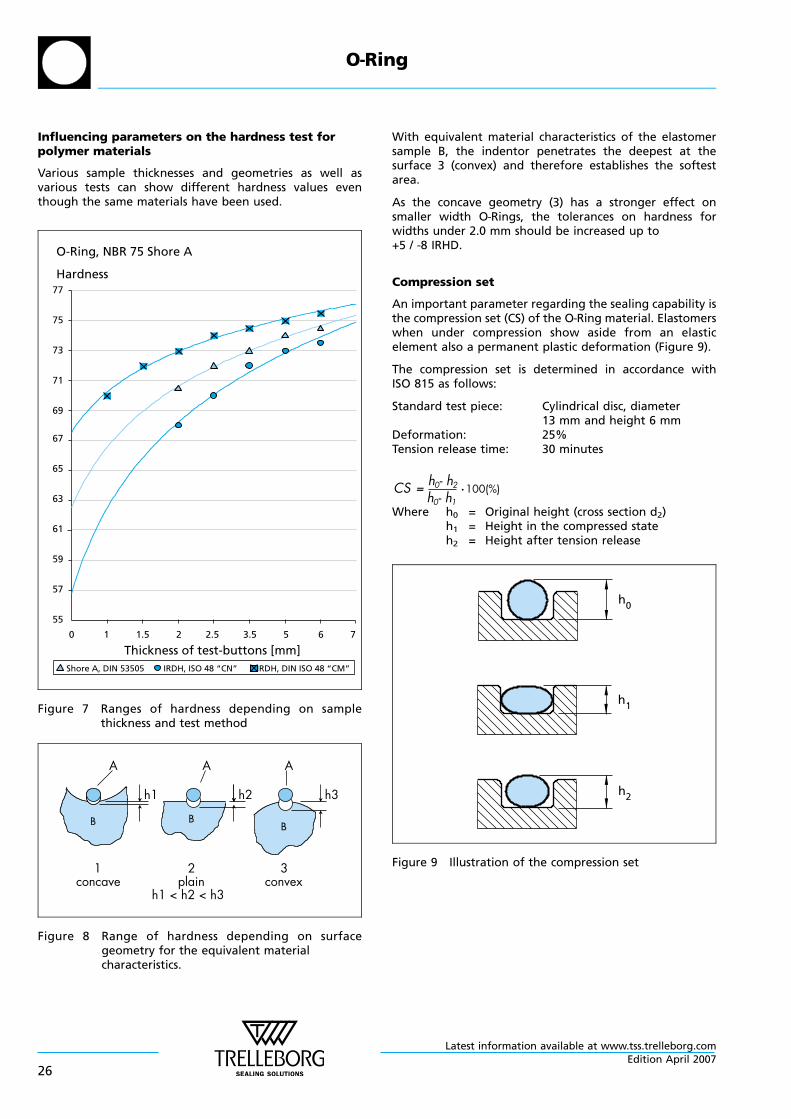
Influencing parameters on the hardness test forpolymer materials
Various sample thicknesses and geometries as well asvarious tests can show different hardness values eventhough the same materials have been used.
O-Ring, NBR 75 Shore A
Hardness
0 1 1.5 2 2.5 3.5 5 6 7
Thickness of test-buttons [mm]
77
75
73
71
69
67
65
63
61
59
57
55
Shore A, DIN 53505 IRDH, ISO 48 “CN” IRDH, DIN ISO 48 “CM”
Figure 7 Ranges of hardness depending on samplethickness and test method
1concave
2plain
h1 < h2 < h3
A A
3convex
A
h3h2h1
Figure 8 Range of hardness depending on surfacegeometry for the equivalent materialcharacteristics.
With equivalent material characteristics of the elastomersample B, the indentor penetrates the deepest at thesurface 3 (convex) and therefore establishes the softestarea.
As the concave geometry (3) has a stronger effect onsmaller width O—Rings, the tolerances on hardness forwidths under 2.0 mm should be increased up to+5 / -8 IRHD.
Compression set
An important parameter regarding the sealing capability isthe compression set (CS) of the O—Ring material. Elastomerswhen under compression show aside from an elasticelement also a permanent plastic deformation (Figure 9).
The compression set is determined in accordance withISO 815 as follows:
Standard test piece: Cylindrical disc, diameter13 mm and height 6 mm
Deformation: 25%Tension release time: 30 minutes
Where h0 = Original height (cross section d2)h1 = Height in the compressed stateh2 = Height after tension release
h2
h1
h0
Figure 9 Illustration of the compression set
O—Ring
Latest information available at www.tss.trelleborg.com
26Edition April 2007
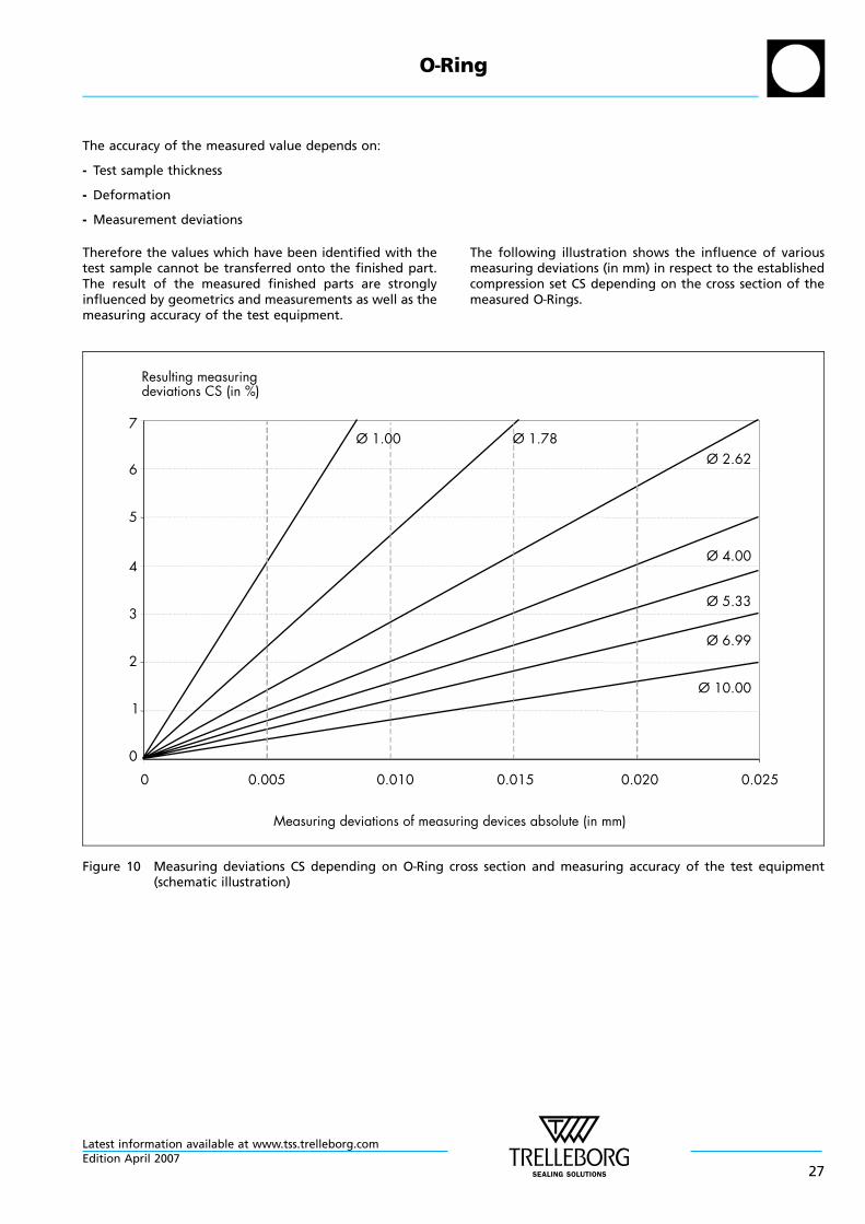
The accuracy of the measured value depends on:
- Test sample thickness
- Deformation
- Measurement deviations
Therefore the values which have been identified with thetest sample cannot be transferred onto the finished part.The result of the measured finished parts are stronglyinfluenced by geometrics and measurements as well as themeasuring accuracy of the test equipment.
The following illustration shows the influence of variousmeasuring deviations (in mm) in respect to the establishedcompression set CS depending on the cross section of themeasured O—Rings.
Resulting measuringdeviations CS (in %)
0 0.005 0.010 0.015 0.020 0.025
Measuring deviations of measuring devices absolute (in mm)
7
6
5
4
3
2
1
0
Ø 1.00 Ø 1.78Ø 2.62
Ø 4.00
Ø 5.33
Ø 6.99
Ø 10.00
Figure 10 Measuring deviations CS depending on O—Ring cross section and measuring accuracy of the test equipment(schematic illustration)
O—Ring
Latest information available at www.tss.trelleborg.comEdition April 2007
27
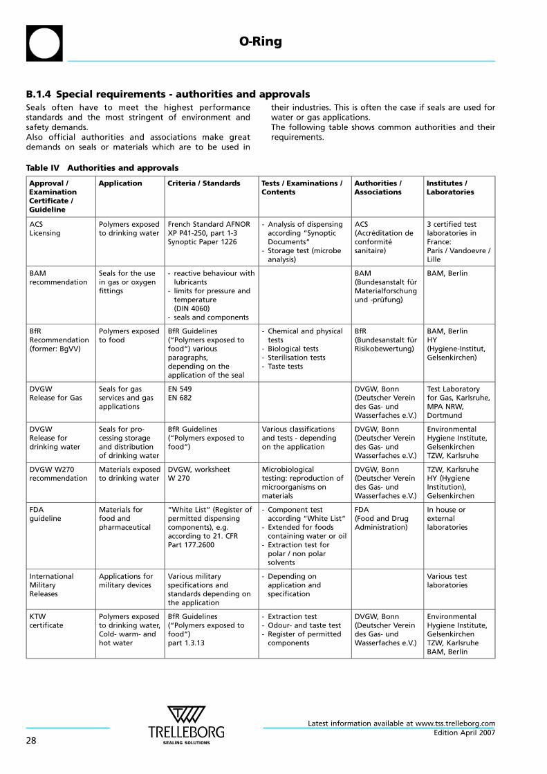
B.1.4 Special requirements - authorities and approvalsSeals often have to meet the highest performancestandards and the most stringent of environment andsafety demands.Also official authorities and associations make greatdemands on seals or materials which are to be used in
their industries. This is often the case if seals are used forwater or gas applications.The following table shows common authorities and theirrequirements.
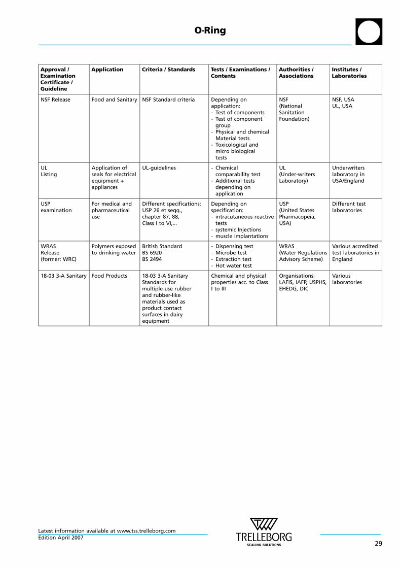
Table IV Authorities and approvals
Approval /ExaminationCertificate /Guideline
Application Criteria / Standards Tests / Examinations /Contents
Authorities /Associations
Institutes /Laboratories
ACSLicensing
Polymers exposedto drinking water
French Standard AFNORXP P41-250, part 1-3Synoptic Paper 1226
- Analysis of dispensingaccording “SynopticDocuments“
- Storage test (microbeanalysis)
ACS(Accreditation deconformitesanitaire)
3 certified testlaboratories inFrance:Paris / Vandoevre /Lille
BAMrecommendation
Seals for the usein gas or oxygenfittings
- reactive behaviour withlubricants
- limits for pressure andtemperature(DIN 4060)
- seals and components
BAM(Bundesanstalt furMaterialforschungund -prufung)
BAM, Berlin
BfRRecommendation(former: BgVV)
Polymers exposedto food
BfR Guidelines(“Polymers exposed tofood“) variousparagraphs,depending on theapplication of the seal
- Chemical and physicaltests
- Biological tests- Sterilisation tests- Taste tests
BfR(Bundesanstalt furRisikobewertung)
BAM, BerlinHY(Hygiene-Institut,Gelsenkirchen)
DVGWRelease for Gas
Seals for gasservices and gasapplications
EN 549EN 682
DVGW, Bonn(Deutscher Vereindes Gas- undWasserfaches e.V.)
Test Laboratoryfor Gas, Karlsruhe,MPA NRW,Dortmund
DVGWRelease fordrinking water
Seals for pro-cessing storageand distributionof drinking water
BfR Guidelines(“Polymers exposed tofood“)
Various classificationsand tests - dependingon the application
DVGW, Bonn(Deutscher Vereindes Gas- undWasserfaches e.V.)
EnvironmentalHygiene Institute,GelsenkirchenTZW, Karlsruhe
DVGW W270recommendation
Materials exposedto drinking water
DVGW, worksheetW 270
Microbiologicaltesting: reproduction ofmicroorganisms onmaterials
DVGW, Bonn(Deutscher Vereindes Gas- undWasserfaches e.V.)
TZW, KarlsruheHY (HygieneInstitution),Gelsenkirchen
FDAguideline
Materials forfood andpharmaceutical
“White List“ (Register ofpermitted dispensingcomponents), e.g.according to 21. CFRPart 177.2600
- Component testaccording “White List“
- Extended for foodscontaining water or oil
- Extraction test forpolar / non polarsolvents
FDA(Food and DrugAdministration)
In house orexternallaboratories
InternationalMilitaryReleases
Applications formilitary devices
Various militaryspecifications andstandards depending onthe application
- Depending onapplication andspecification
Various testlaboratories
KTWcertificate
Polymers exposedto drinking water,Cold- warm- andhot water
BfR Guidelines(“Polymers exposed tofood“)part 1.3.13
- Extraction test- Odour- and taste test- Register of permitted
components
DVGW, Bonn(Deutscher Vereindes Gas- undWasserfaches e.V.)
EnvironmentalHygiene Institute,GelsenkirchenTZW, KarlsruheBAM, Berlin
O—Ring
Latest information available at www.tss.trelleborg.com
28Edition April 2007
Approval /ExaminationCertificate /Guideline
Application Criteria / Standards Tests / Examinations /Contents
Authorities /Associations
Institutes /Laboratories
NSF Release Food and Sanitary NSF Standard criteria Depending onapplication:- Test of components- Test of component
group- Physical and chemical
Material tests- Toxicological and
micro biologicaltests
NSF(NationalSanitationFoundation)
NSF, USAUL, USA
ULListing
Application ofseals for electricalequipment +appliances
UL-guidelines - Chemicalcomparability test
- Additional testsdepending onapplication
UL(Under-writersLaboratory)
Underwriterslaboratory inUSA/England
USPexamination
For medical andpharmaceuticaluse
Different specifications:USP 26 et seqq.,chapter 87, 88,Class I to VI,...
Depending onspecification:- intracutaneous reactive
tests- systemic Injections- muscle implantations
USP(United StatesPharmacopeia,USA)
Different testlaboratories
WRASRelease(former: WRC)
Polymers exposedto drinking water
British StandardBS 6920BS 2494
- Dispensing test- Microbe test- Extraction test- Hot water test
WRAS(Water RegulationsAdvisory Scheme)
Various accreditedtest laboratories inEngland
18-03 3-A Sanitary Food Products 18-03 3-A SanitaryStandards formultiple-use rubberand rubber-likematerials used asproduct contactsurfaces in dairyequipment
Chemical and physicalproperties acc. to ClassI to III
Organisations:LAFIS, IAFP, USPHS,EHEDG, DIC
Variouslaboratories
O—Ring
Latest information available at www.tss.trelleborg.comEdition April 2007
29
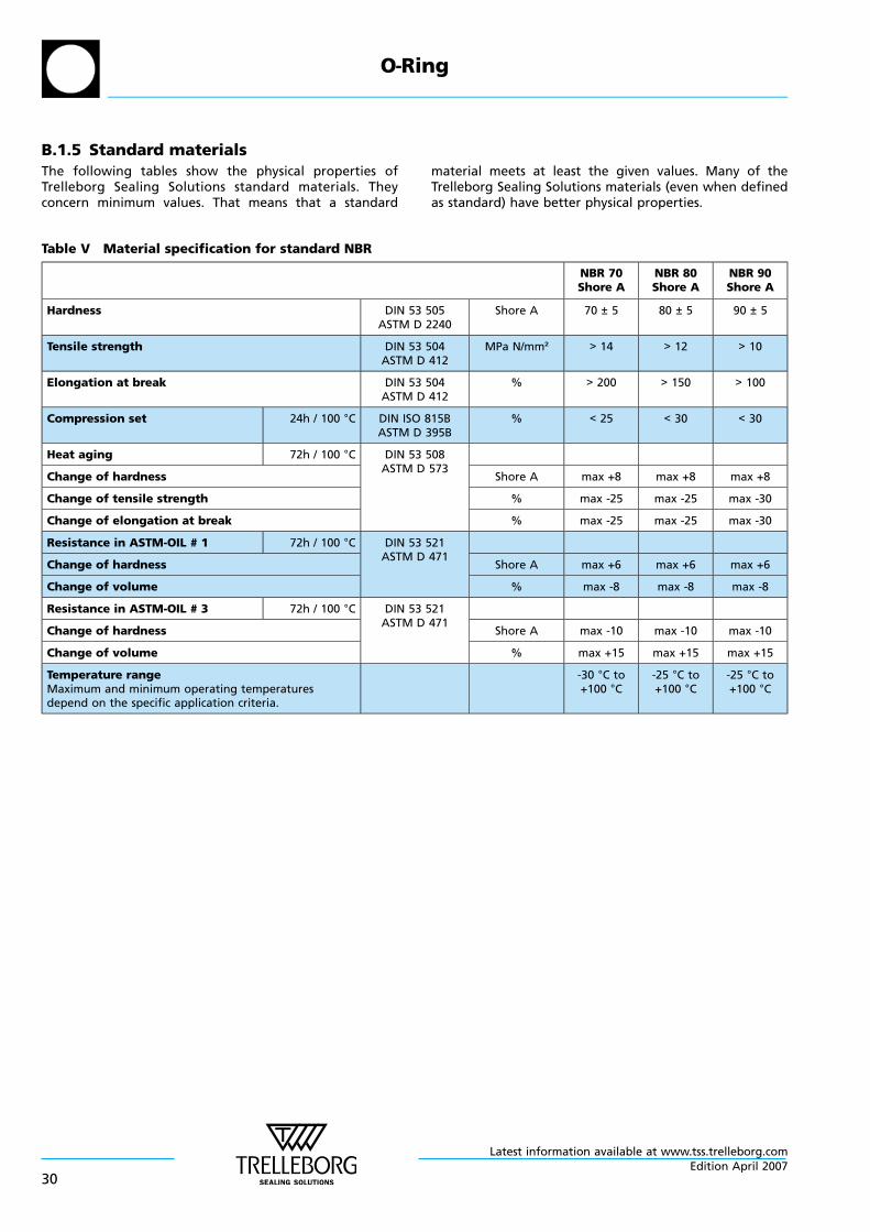
B.1.5 Standard materialsThe following tables show the physical properties ofTrelleborg Sealing Solutions standard materials. Theyconcern minimum values. That means that a standard
material meets at least the given values. Many of theTrelleborg Sealing Solutions materials (even when definedas standard) have better physical properties.
Table V Material specification for standard NBR
NBR 70Shore A
NBR 80Shore A
NBR 90Shore A
Hardness DIN 53 505ASTM D 2240
Shore A 70 ± 5 80 ± 5 90 ± 5
Tensile strength DIN 53 504ASTM D 412
MPa N/mm² > 14 > 12 > 10
Elongation at break DIN 53 504ASTM D 412
% > 200 > 150 > 100
Compression set 24h / 100 °C DIN ISO 815BASTM D 395B
% < 25 < 30 < 30
Heat aging 72h / 100 °C DIN 53 508ASTM D 573
Change of hardness Shore A max +8 max +8 max +8
Change of tensile strength % max -25 max -25 max -30
Change of elongation at break % max -25 max -25 max -30
Resistance in ASTM-OIL # 1 72h / 100 °C DIN 53 521ASTM D 471
Change of hardness Shore A max +6 max +6 max +6
Change of volume % max -8 max -8 max -8
Resistance in ASTM-OIL # 3 72h / 100 °C DIN 53 521ASTM D 471
Change of hardness Shore A max -10 max -10 max -10
Change of volume % max +15 max +15 max +15
Temperature rangeMaximum and minimum operating temperaturesdepend on the specific application criteria.
-30 °C to+100 °C
-25 °C to+100 °C
-25 °C to+100 °C
O—Ring
Latest information available at www.tss.trelleborg.com
30Edition April 2007
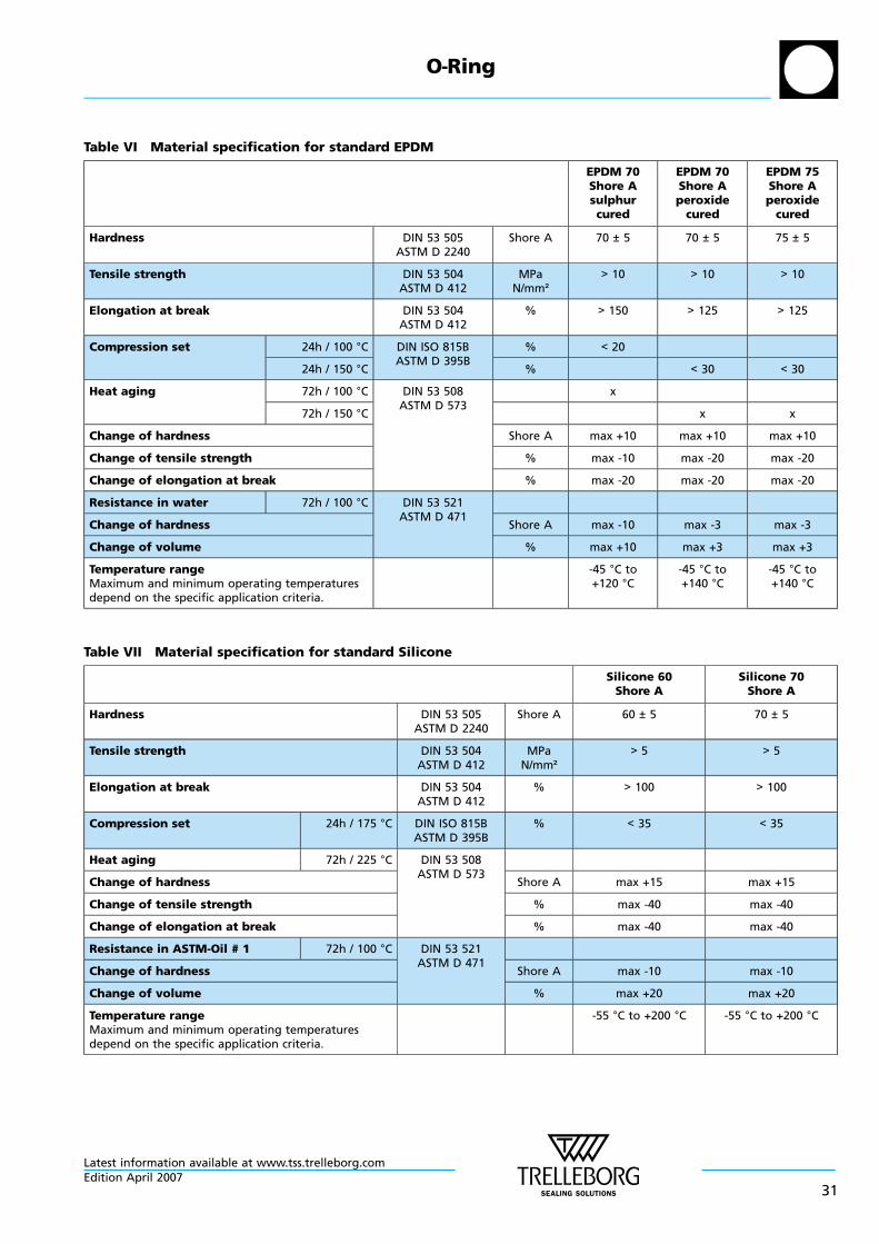
Table VI Material specification for standard EPDM
EPDM 70Shore Asulphurcured
EPDM 70Shore Aperoxide
cured
EPDM 75Shore Aperoxide
cured
Hardness DIN 53 505ASTM D 2240
Shore A 70 ± 5 70 ± 5 75 ± 5
Tensile strength DIN 53 504ASTM D 412
MPaN/mm²
> 10 > 10 > 10
Elongation at break DIN 53 504ASTM D 412
% > 150 > 125 > 125
Compression set 24h / 100 °C DIN ISO 815BASTM D 395B
% < 20
24h / 150 °C % < 30 < 30
Heat aging 72h / 100 °C DIN 53 508ASTM D 573
x
72h / 150 °C x x
Change of hardness Shore A max +10 max +10 max +10
Change of tensile strength % max -10 max -20 max -20
Change of elongation at break % max -20 max -20 max -20
Resistance in water 72h / 100 °C DIN 53 521ASTM D 471
Change of hardness Shore A max -10 max -3 max -3
Change of volume % max +10 max +3 max +3
Temperature rangeMaximum and minimum operating temperaturesdepend on the specific application criteria.
-45 °C to+120 °C
-45 °C to+140 °C
-45 °C to+140 °C
Table VII Material specification for standard Silicone
Silicone 60Shore A
Silicone 70Shore A
Hardness DIN 53 505ASTM D 2240
Shore A 60 ± 5 70 ± 5
Tensile strength DIN 53 504ASTM D 412
MPaN/mm²
> 5 > 5
Elongation at break DIN 53 504ASTM D 412
% > 100 > 100
Compression set 24h / 175 °C DIN ISO 815BASTM D 395B
% < 35 < 35
Heat aging 72h / 225 °C DIN 53 508ASTM D 573
Change of hardness Shore A max +15 max +15
Change of tensile strength % max -40 max -40
Change of elongation at break % max -40 max -40
Resistance in ASTM-Oil # 1 72h / 100 °C DIN 53 521ASTM D 471
Change of hardness Shore A max -10 max -10
Change of volume % max +20 max +20
Temperature rangeMaximum and minimum operating temperaturesdepend on the specific application criteria.
-55 °C to +200 °C -55 °C to +200 °C
O—Ring
Latest information available at www.tss.trelleborg.comEdition April 2007
31
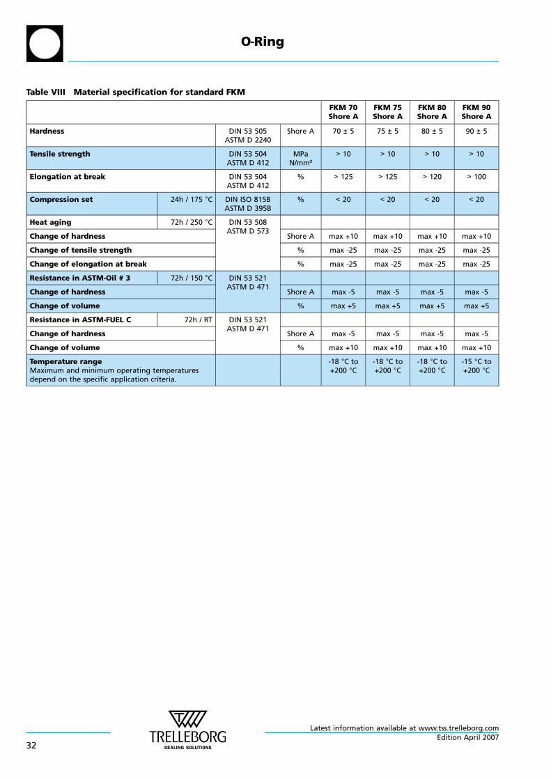
Table VIII Material specification for standard FKM
FKM 70Shore A
FKM 75Shore A
FKM 80Shore A
FKM 90Shore A
Hardness DIN 53 505ASTM D 2240
Shore A 70 ± 5 75 ± 5 80 ± 5 90 ± 5
Tensile strength DIN 53 504ASTM D 412
MPaN/mm²
> 10 > 10 > 10 > 10
Elongation at break DIN 53 504ASTM D 412
% > 125 > 125 > 120 > 100
Compression set 24h / 175 °C DIN ISO 815BASTM D 395B
% < 20 < 20 < 20 < 20
Heat aging 72h / 250 °C DIN 53 508ASTM D 573
Change of hardness Shore A max +10 max +10 max +10 max +10
Change of tensile strength % max -25 max -25 max -25 max -25
Change of elongation at break % max -25 max -25 max -25 max -25
Resistance in ASTM-Oil # 3 72h / 150 °C DIN 53 521ASTM D 471
Change of hardness Shore A max -5 max -5 max -5 max -5
Change of volume % max +5 max +5 max +5 max +5
Resistance in ASTM-FUEL C 72h / RT DIN 53 521ASTM D 471
Change of hardness Shore A max -5 max -5 max -5 max -5
Change of volume % max +10 max +10 max +10 max +10
Temperature rangeMaximum and minimum operating temperaturesdepend on the specific application criteria.
-18 °C to+200 °C
-18 °C to+200 °C
-18 °C to+200 °C
-15 °C to+200 °C
O—Ring
Latest information available at www.tss.trelleborg.com
32Edition April 2007
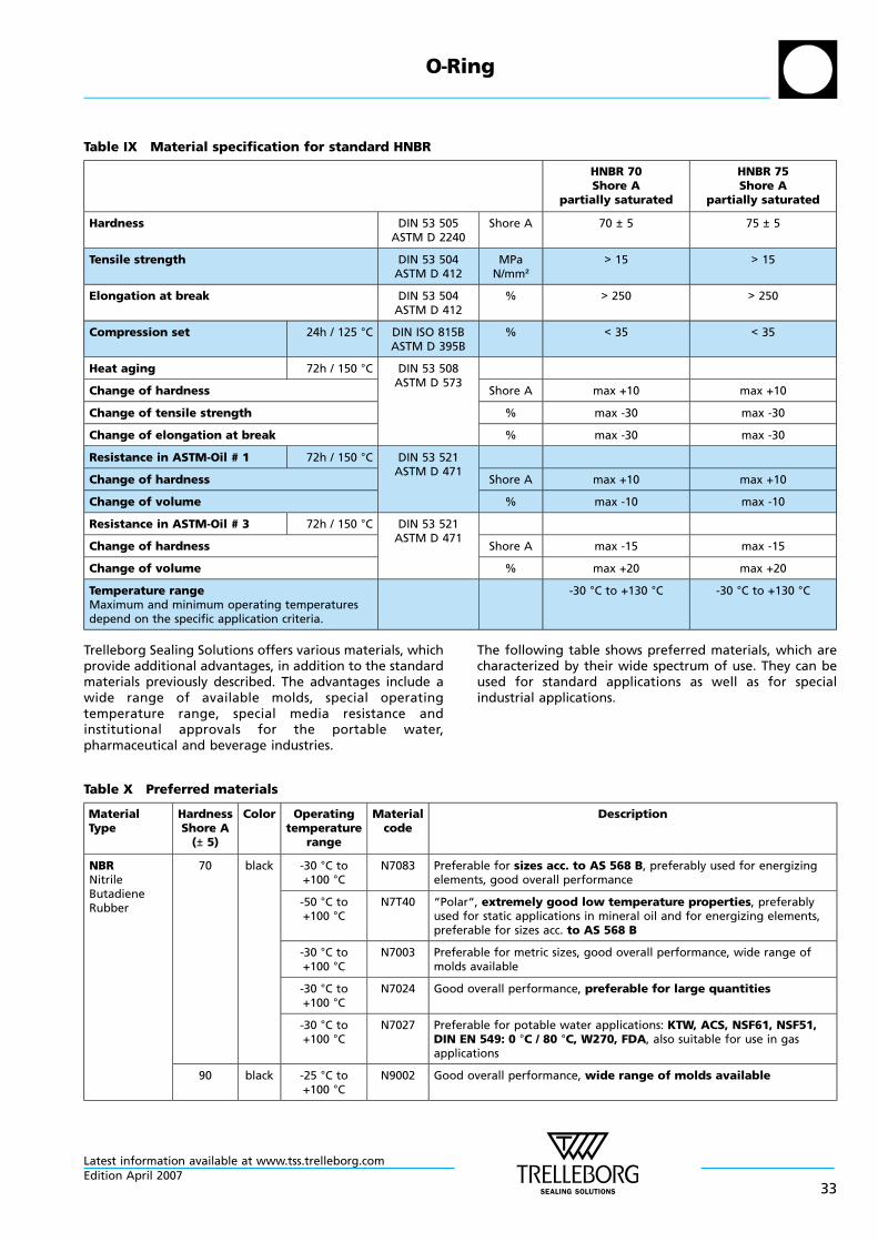
Table IX Material specification for standard HNBR
HNBR 70Shore A
partially saturated
HNBR 75Shore A
partially saturated
Hardness DIN 53 505ASTM D 2240
Shore A 70 ± 5 75 ± 5
Tensile strength DIN 53 504ASTM D 412
MPaN/mm²
> 15 > 15
Elongation at break DIN 53 504ASTM D 412
% > 250 > 250
Compression set 24h / 125 °C DIN ISO 815BASTM D 395B
% < 35 < 35
Heat aging 72h / 150 °C DIN 53 508ASTM D 573
Change of hardness Shore A max +10 max +10
Change of tensile strength % max -30 max -30
Change of elongation at break % max -30 max -30
Resistance in ASTM-Oil # 1 72h / 150 °C DIN 53 521ASTM D 471
Change of hardness Shore A max +10 max +10
Change of volume % max -10 max -10
Resistance in ASTM-Oil # 3 72h / 150 °C DIN 53 521ASTM D 471
Change of hardness Shore A max -15 max -15
Change of volume % max +20 max +20
Temperature rangeMaximum and minimum operating temperaturesdepend on the specific application criteria.
-30 °C to +130 °C -30 °C to +130 °C
Trelleborg Sealing Solutions offers various materials, whichprovide additional advantages, in addition to the standardmaterials previously described. The advantages include awide range of available molds, special operatingtemperature range, special media resistance andinstitutional approvals for the portable water,pharmaceutical and beverage industries.
The following table shows preferred materials, which arecharacterized by their wide spectrum of use. They can beused for standard applications as well as for specialindustrial applications.
Table X Preferred materials
MaterialType
HardnessShore A
(± 5)
Color Operatingtemperature
range
Materialcode
Description
NBRNitrileButadieneRubber
70 black -30 °C to+100 °C
N7083 Preferable for sizes acc. to AS 568 B, preferably used for energizingelements, good overall performance
-50 °C to+100 °C
N7T40 “Polar“, extremely good low temperature properties, preferablyused for static applications in mineral oil and for energizing elements,preferable for sizes acc. to AS 568 B
-30 °C to+100 °C
N7003 Preferable for metric sizes, good overall performance, wide range ofmolds available
-30 °C to+100 °C
N7024 Good overall performance, preferable for large quantities
-30 °C to+100 °C
N7027 Preferable for potable water applications: KTW, ACS, NSF61, NSF51,DIN EN 549: 0 °C / 80 °C, W270, FDA, also suitable for use in gasapplications
90 black -25 °C to+100 °C
N9002 Good overall performance, wide range of molds available
O—Ring
Latest information available at www.tss.trelleborg.comEdition April 2007
33
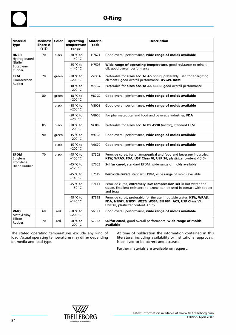
MaterialType
HardnessShore A
(± 5)
Color Operatingtemperature
range
Materialcode
Description
HNBRHydrogenatedNitrileButadieneRubber
70 black -30 °C to+140 °C
H7671 Good overall performance, wide range of molds available
-35 °C to+140 °C
H7503 Wide range of operating temperature, good resistance to mineraloil, good overall performance
FKMFluorocarbonRubber
70 green -20 °C to+200 °C
V70GA Preferable for sizes acc. to AS 568 B, preferably used for energizingelements, good overall performance, DVGW, BAM
-18 °C to+200 °C
V70G2 Preferable for sizes acc. to AS 568 B, good overall performance
80 green -18 °C to+200 °C
V80G2 Good overall performance, wide range of molds available
black -18 °C to+200 °C
V8003 Good overall performance, wide range of molds available
-20 °C to+200 °C
V8605 For pharmaceutical and food and beverage industries, FDA
85 black -20 °C to+200 °C
VC009 Preferable for sizes acc. to BS 4518 (metric), standard FKM
90 green -15 °C to+200 °C
V90G1 Good overall performance, wide range of molds available
black -15 °C to+200 °C
V9670 Good overall performance, wide range of molds available
EPDMEthylenePropyleneDiene Rubber
70 black -45 °C to+150 °C
E7502 Peroxide cured, for pharmaceutical and food and beverage industries,KTW, WRAS, FDA, USP Class VI, USP 26, plasticizer content < 3 %
-45 °C to+125 °C
E7002 Sulfur cured, standard EPDM, wide range of molds available
-45 °C to+140 °C
E7515 Peroxide cured, standard EPDM, wide range of molds available
-45 °C to+150 °C
E7T41 Peroxide cured, extremely low compression set in hot water andsteam. Excellent resistance to ozone, can be used in contact with copperand brass
-45 °C to+140 °C
E7518 Peroxide cured, preferable for the use in potable water: KTW, WRAS,FDA, NSF61, NSF51, W270, W534, EN 681, ACS, USP Class VI,USP 26, plasticizer content < 1 %
VMQMethyl VinylSiliconRubber
60 red -50 °C to+200 °C
S60R1 Good overall performance, wide range of molds available
70 red -50 °C to+200 °C
S70R2 Sulfur cured, good overall performance, wide range of moldsavailable
The stated operating temperatures exclude any kind ofload. Actual operating temperatures may differ dependingon media and load type.
At time of publication the information contained in thisliterature, including availability or institutional approvals,is believed to be correct and accurate.
Further materials are available on request.
O—Ring
Latest information available at www.tss.trelleborg.com
34Edition April 2007
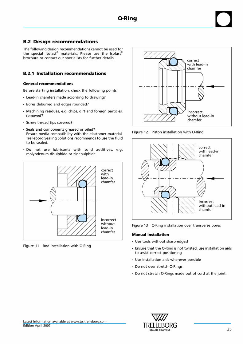
B.2 Design recommendations
The following design recommendations cannot be used forthe special Isolast® materials. Please use the Isolast®
brochure or contact our specialists for further details.
B.2.1 Installation recommendations
General recommendations
Before starting installation, check the following points:
- Lead-in chamfers made according to drawing?
- Bores deburred and edges rounded?
- Machining residues, e.g. chips, dirt and foreign particles,removed?
- Screw thread tips covered?
- Seals and components greased or oiled?Ensure media compatibility with the elastomer material.Trelleborg Sealing Solutions recommends to use the fluidto be sealed.
- Do not use lubricants with solid additives, e.g.molybdenum disulphide or zinc sulphide.
correctwithlead-inchamfer
incorrectwithoutlead-inchamfer
Figure 11 Rod installation with O—Ring
correct
incorrectwithout lead-inchamfer
chamferwith lead-in
Figure 12 Piston installation with O—Ring
correctwith lead-inchamfer
incorrectwithout lead-inchamfer
Figure 13 O—Ring installation over transverse bores
Manual installation
- Use tools without sharp edges!
- Ensure that the O—Ring is not twisted, use installation aidsto assist correct positioning
- Use installation aids wherever possible
- Do not over stretch O—Rings
- Do not stretch O—Rings made out of cord at the joint.
O—Ring
Latest information available at www.tss.trelleborg.comEdition April 2007
35
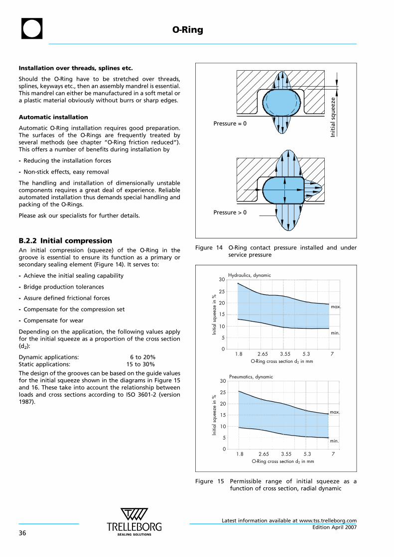
Installation over threads, splines etc.
Should the O—Ring have to be stretched over threads,splines, keyways etc., then an assembly mandrel is essential.This mandrel can either be manufactured in a soft metal ora plastic material obviously without burrs or sharp edges.
Automatic installation
Automatic O—Ring installation requires good preparation.The surfaces of the O—Rings are frequently treated byseveral methods (see chapter “O—Ring friction reduced“).This offers a number of benefits during installation by
- Reducing the installation forces
- Non-stick effects, easy removal
The handling and installation of dimensionally unstablecomponents requires a great deal of experience. Reliableautomated installation thus demands special handling andpacking of the O—Rings.
Please ask our specialists for further details.
B.2.2 Initial compressionAn initial compression (squeeze) of the O—Ring in thegroove is essential to ensure its function as a primary orsecondary sealing element (Figure 14). It serves to:
- Achieve the initial sealing capability
- Bridge production tolerances
- Assure defined frictional forces
- Compensate for the compression set
- Compensate for wear
Depending on the application, the following values applyfor the initial squeeze as a proportion of the cross section(d2):
Dynamic applications: 6 to 20%Static applications: 15 to 30%
The design of the grooves can be based on the guide valuesfor the initial squeeze shown in the diagrams in Figure 15and 16. These take into account the relationship betweenloads and cross sections according to ISO 3601-2 (version1987).
Pressure = 0
Init
ials
qu
eeze
Pressure > 0
Figure 14 O—Ring contact pressure installed and underservice pressure
Hydraulics, dynamic
O-Ring cross section d2 in mm
max.
min.
30
25
20
15
10
5
01.8 2.65 3.55 5.3 7
Pneumatics, dynamic
O-Ring cross section d2 in mm
max.
min.
30
25
20
15
10
5
01.8 2.65 3.55 5.3 7
Initi
alsq
ueez
ein
%In
itial
sque
eze
in%
Figure 15 Permissible range of initial squeeze as afunction of cross section, radial dynamic
O—Ring
Latest information available at www.tss.trelleborg.com
36Edition April 2007
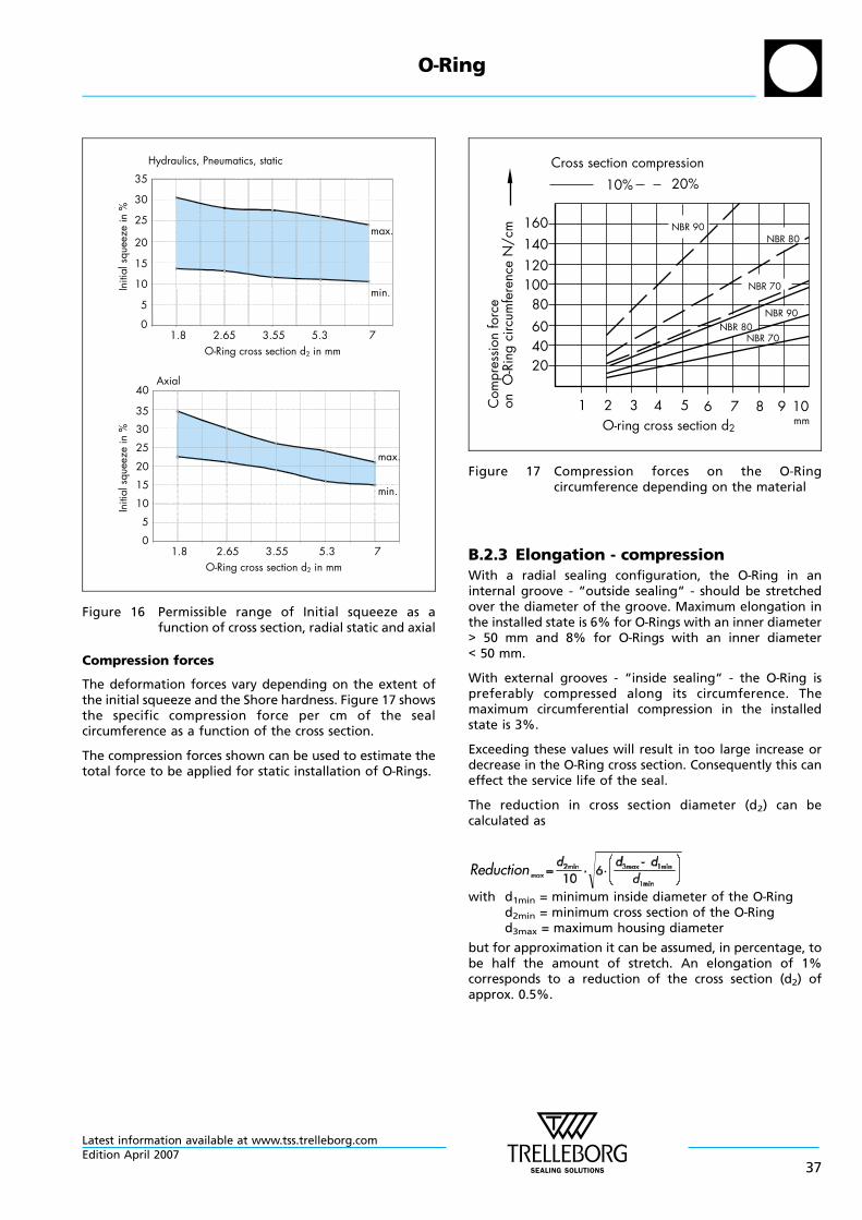
Hydraulics, Pneumatics, static
O-Ring cross section d2 in mm
max.
min.
30
25
20
15
10
5
01.8 2.65 3.55 5.3 7
35
Axial
O-Ring cross section d2 in mm
max.
min.
40
25
20
15
10
5
01.8 2.65 3.55 5.3 7
30
35
Initi
alsq
ueez
ein
%In
itial
sque
eze
in%
Figure 16 Permissible range of Initial squeeze as afunction of cross section, radial static and axial
Compression forces
The deformation forces vary depending on the extent ofthe initial squeeze and the Shore hardness. Figure 17 showsthe specific compression force per cm of the sealcircumference as a function of the cross section.
The compression forces shown can be used to estimate thetotal force to be applied for static installation of O—Rings.
Com
pres
sion
forc
eon
O-R
ing
circ
umfe
renc
eN
/cm 160
120100
80604020
1 2 3 4 5 6 7 8mm10
10% 20%Cross section compression
NBR 90NBR 80
NBR 70
NBR 90NBR 80
NBR 70
140
9O-ring cross section d2
Figure 17 Compression forces on the O—Ringcircumference depending on the material
B.2.3 Elongation - compressionWith a radial sealing configuration, the O—Ring in aninternal groove - “outside sealing“ - should be stretchedover the diameter of the groove. Maximum elongation inthe installed state is 6% for O—Rings with an inner diameter> 50 mm and 8% for O—Rings with an inner diameter< 50 mm.
With external grooves - “inside sealing“ - the O—Ring ispreferably compressed along its circumference. Themaximum circumferential compression in the installedstate is 3%.
Exceeding these values will result in too large increase ordecrease in the O—Ring cross section. Consequently this caneffect the service life of the seal.
The reduction in cross section diameter (d2) can becalculated as
with d1min = minimum inside diameter of the O—Ringd2min = minimum cross section of the O—Ringd3max = maximum housing diameter
but for approximation it can be assumed, in percentage, tobe half the amount of stretch. An elongation of 1%corresponds to a reduction of the cross section (d2) ofapprox. 0.5%.
O—Ring
Latest information available at www.tss.trelleborg.comEdition April 2007
37
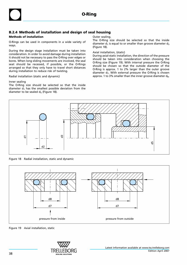
B.2.4 Methods of installation and design of seal housingMethods of installation
O—Rings can be used in components in a wide variety ofways.
During the design stage installation must be taken intoconsideration. In order to avoid damage during installationit should not be necessary to pass the O—Ring over edges orbores. When long sliding movements are involved, the sealseat should be recessed, if possible, or the O—Ringsarranged so that they only have to travel short distancesduring installation to reduce risk of twisting.
Radial installation (static and dynamic)
Inner sealingThe O—Ring size should be selected so that the insidediameter d1 has the smallest possible deviation from thediameter to be sealed d5 (Figure 18).
Outer sealing.The O—Ring size should be selected so that the insidediameter d1 is equal to or smaller than groove diameter d3
(Figure 18).
Axial installation, (static)During axial-static installation, the direction of the pressureshould be taken into consideration when choosing theO—Ring size (Figure 19). With internal pressure the O—Ringshould be chosen so that the outside diameter of theO—Ring is approx. 1 to 2% larger than the outer groovediameter d7. With external pressure the O—Ring is chosenapprox. 1 to 3% smaller than the inner groove diameter d8.
d1
d2
d3
d5
Figure 18 Radial installation, static and dynamic
d8
d7
d8
d7
pressure from inside pressure from outside
Figure 19 Axial installation, static
O—Ring
Latest information available at www.tss.trelleborg.com
38Edition April 2007
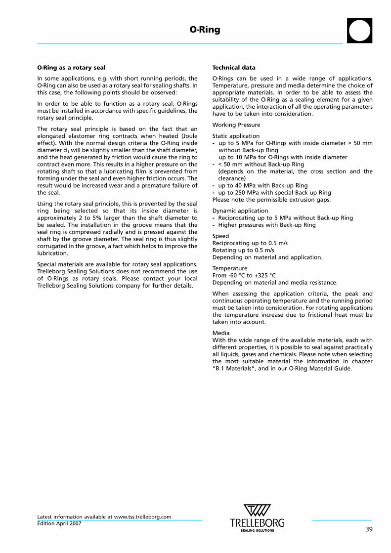
O—Ring as a rotary seal
In some applications, e.g. with short running periods, theO—Ring can also be used as a rotary seal for sealing shafts. Inthis case, the following points should be observed:
In order to be able to function as a rotary seal, O—Ringsmust be installed in accordance with specific guidelines, therotary seal principle.
The rotary seal principle is based on the fact that anelongated elastomer ring contracts when heated (Jouleeffect). With the normal design criteria the O—Ring insidediameter d1 will be slightly smaller than the shaft diameter,and the heat generated by friction would cause the ring tocontract even more. This results in a higher pressure on therotating shaft so that a lubricating film is prevented fromforming under the seal and even higher friction occurs. Theresult would be increased wear and a premature failure ofthe seal.
Using the rotary seal principle, this is prevented by the sealring being selected so that its inside diameter isapproximately 2 to 5% larger than the shaft diameter tobe sealed. The installation in the groove means that theseal ring is compressed radially and is pressed against theshaft by the groove diameter. The seal ring is thus slightlycorrugated in the groove, a fact which helps to improve thelubrication.
Special materials are available for rotary seal applications.Trelleborg Sealing Solutions does not recommend the useof O—Rings as rotary seals. Please contact your localTrelleborg Sealing Solutions company for further details.
Technical data
O—Rings can be used in a wide range of applications.Temperature, pressure and media determine the choice ofappropriate materials. In order to be able to assess thesuitability of the O—Ring as a sealing element for a givenapplication, the interaction of all the operating parametershave to be taken into consideration.
Working Pressure
Static application- up to 5 MPa for O—Rings with inside diameter > 50 mm
without Back-up Ringup to 10 MPa for O—Rings with inside diameter
- < 50 mm without Back-up Ring(depends on the material, the cross section and theclearance)
- up to 40 MPa with Back-up Ring- up to 250 MPa with special Back-up RingPlease note the permissible extrusion gaps.
Dynamic application- Reciprocating up to 5 MPa without Back-up Ring- Higher pressures with Back-up Ring
SpeedReciprocating up to 0.5 m/sRotating up to 0.5 m/sDepending on material and application.
TemperatureFrom -60 °C to +325 °CDepending on material and media resistance.
When assessing the application criteria, the peak andcontinuous operating temperature and the running periodmust be taken into consideration. For rotating applicationsthe temperature increase due to frictional heat must betaken into account.
MediaWith the wide range of the available materials, each withdifferent properties, it is possible to seal against practicallyall liquids, gases and chemicals. Please note when selectingthe most suitable material the information in chapter“B.1 Materials“, and in our O—Ring Material Guide.
O—Ring
Latest information available at www.tss.trelleborg.comEdition April 2007
39
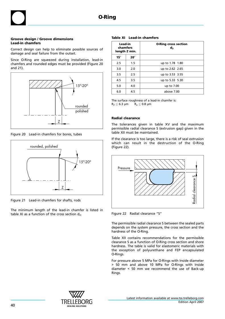
Groove design / Groove dimensionsLead-in chamfers
Correct design can help to eliminate possible sources ofdamage and seal failure from the outset.
Since O—Ring are squeezed during installation, lead-inchamfers and rounded edges must be provided (Figure 20and 21).
Z
roundedpolished
15o-20o
Figure 20 Lead-in chamfers for bores, tubes
rounded, polished
Z
15o-20o
Figure 21 Lead-in chamfers for shafts, rods
The minimum length of the lead-in chamfer is listed intable XI as a function of the cross section d2.
Table XI Lead-in chamfers
Lead-inchamfers
length Z min.
O—Ring cross sectiond2
15° 20°
2.5 1.5 up to 1.78 1.80
3.0 2.0 up to 2.62 2.65
3.5 2.5 up to 3.53 3.55
4.5 3.5 up to 5.33 5.30
5.0 4.0 up to 7.00
6.0 4.5 above 7.00
The surface roughness of a lead-in chamfer is:RZ 6.3 µm Ra 0.8 µm
Radial clearance
The tolerances given in table XV and the maximumpermissible radial clearance S (extrusion gap) given in thetable XII must be maintained.
If the clearance is too large, there is a risk of seal extrusionwhich can result in the destruction of the O—Ring(Figure 22).
Pressure
Radi
alcl
eara
nce
S
Figure 22 Radial clearance “S“
The permissible radial clearance S between the sealed partsdepends on the system pressure, the cross section and thehardness of the O—Ring.
Table XII contains recommendations for the permissibleclearance S as a function of O—Ring cross section and shorehardness. The table is valid for elastomeric materials withthe exception of polyurethane and FEP encapsulatedO—Rings.
For pressure above 5 MPa for O—Rings with Inside diameter> 50 mm and above 10 MPa for O—Rings with Insidediameter < 50 mm we recommend the use of Back-upRings.
O—Ring
Latest information available at www.tss.trelleborg.com
40Edition April 2007
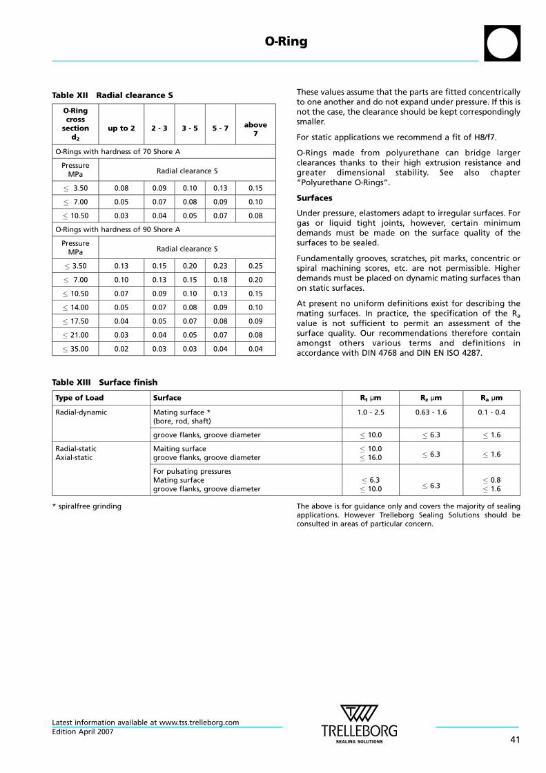
Table XII Radial clearance S
O—Ringcross
sectiond2
up to 2 2 - 3 3 - 5 5 - 7 above7
O—Rings with hardness of 70 Shore A
PressureMPa Radial clearance S
3.50 0.08 0.09 0.10 0.13 0.15
7.00 0.05 0.07 0.08 0.09 0.10
10.50 0.03 0.04 0.05 0.07 0.08
O—Rings with hardness of 90 Shore A
PressureMPa Radial clearance S
3.50 0.13 0.15 0.20 0.23 0.25
7.00 0.10 0.13 0.15 0.18 0.20
10.50 0.07 0.09 0.10 0.13 0.15
14.00 0.05 0.07 0.08 0.09 0.10
17.50 0.04 0.05 0.07 0.08 0.09
21.00 0.03 0.04 0.05 0.07 0.08
35.00 0.02 0.03 0.03 0.04 0.04
These values assume that the parts are fitted concentricallyto one another and do not expand under pressure. If this isnot the case, the clearance should be kept correspondinglysmaller.
For static applications we recommend a fit of H8/f7.
O—Rings made from polyurethane can bridge largerclearances thanks to their high extrusion resistance andgreater dimensional stability. See also chapter“Polyurethane O—Rings“.
Surfaces
Under pressure, elastomers adapt to irregular surfaces. Forgas or liquid tight joints, however, certain minimumdemands must be made on the surface quality of thesurfaces to be sealed.
Fundamentally grooves, scratches, pit marks, concentric orspiral machining scores, etc. are not permissible. Higherdemands must be placed on dynamic mating surfaces thanon static surfaces.
At present no uniform definitions exist for describing themating surfaces. In practice, the specification of the Ra
value is not sufficient to permit an assessment of thesurface quality. Our recommendations therefore containamongst others various terms and definitions inaccordance with DIN 4768 and DIN EN ISO 4287.
Table XIII Surface finish
Type of Load Surface Rt µm Rz µm Ra µm
Radial-dynamic Mating surface *(bore, rod, shaft)
1.0 - 2.5 0.63 - 1.6 0.1 - 0.4
groove flanks, groove diameter 10.0 6.3 1.6
Radial-staticAxial-static
Maiting surfacegroove flanks, groove diameter
10.016.0 6.3 1.6
For pulsating pressuresMating surfacegroove flanks, groove diameter
6.310.0 6.3
0.81.6
* spiralfree grinding The above is for guidance only and covers the majority of sealingapplications. However Trelleborg Sealing Solutions should beconsulted in areas of particular concern.
O—Ring
Latest information available at www.tss.trelleborg.comEdition April 2007
41
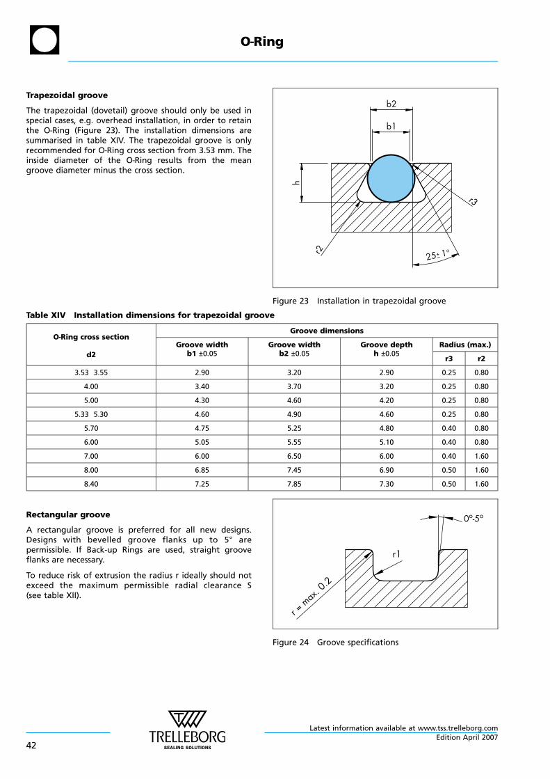
Trapezoidal groove
The trapezoidal (dovetail) groove should only be used inspecial cases, e.g. overhead installation, in order to retainthe O—Ring (Figure 23). The installation dimensions aresummarised in table XIV. The trapezoidal groove is onlyrecommended for O—Ring cross section from 3.53 mm. Theinside diameter of the O—Ring results from the meangroove diameter minus the cross section.
b2
b1
h
r2 25 1°+_
r3
Figure 23 Installation in trapezoidal groove
Table XIV Installation dimensions for trapezoidal groove
O—Ring cross section
d2
Groove dimensions
Groove widthb1 ±0.05
Groove widthb2 ±0.05
Groove depthh ±0.05
Radius (max.)
r3 r2
3.53 3.55 2.90 3.20 2.90 0.25 0.80
4.00 3.40 3.70 3.20 0.25 0.80
5.00 4.30 4.60 4.20 0.25 0.80
5.33 5.30 4.60 4.90 4.60 0.25 0.80
5.70 4.75 5.25 4.80 0.40 0.80
6.00 5.05 5.55 5.10 0.40 0.80
7.00 6.00 6.50 6.00 0.40 1.60
8.00 6.85 7.45 6.90 0.50 1.60
8.40 7.25 7.85 7.30 0.50 1.60
Rectangular groove
A rectangular groove is preferred for all new designs.Designs with bevelled groove flanks up to 5° arepermissible. If Back-up Rings are used, straight grooveflanks are necessary.
To reduce risk of extrusion the radius r ideally should notexceed the maximum permissible radial clearance S(see table XII).
r1
0o-5o
r = max. 0
.2
Figure 24 Groove specifications
O—Ring
Latest information available at www.tss.trelleborg.com
42Edition April 2007
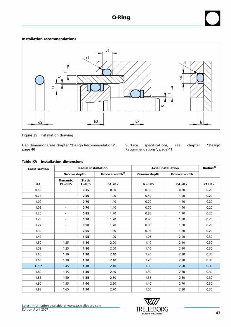
Installation recommendations
d2 b3 b2 h
b1
r1r1
t1
St
S
t1
b4
Figure 25 Installation drawing
Gap dimensions, see chapter “Design Recommendations“,page 40
Surface specifications, see chapter “DesignRecommendations“, page 41
Table XV Installation dimensions
Cross section
d2
Radial installation Axial installation Radius2)
Groove depth Groove width1) Groove depth Groove width
Dynamict1 +0.05
Statict +0.05 b1 +0.2 h +0.05 b4 +0.2 r1± 0.2
0.50 - 0.35 0.80 0.35 0.80 0.20
0.74 - 0.50 1.00 0.50 1.00 0.20
1.00 - 0.70 1.40 0.70 1.40 0.20
1.02 - 0.70 1.40 0.70 1.40 0.20
1.20 - 0.85 1.70 0.85 1.70 0.20
1.25 - 0.90 1.70 0.90 1.80 0.20
1.27 - 0.90 1.70 0.90 1.80 0.20
1.30 - 0.95 1.80 0.95 1.80 0.20
1.42 - 1.05 1.90 1.05 2.00 0.30
1.50 1.25 1.10 2.00 1.10 2.10 0.30
1.52 1.25 1.10 2.00 1.10 2.10 0.30
1.60 1.30 1.20 2.10 1.20 2.20 0.30
1.63 1.30 1.20 2.10 1.20 2.20 0.30
1.78* 1.45 1.30 2.40 1.30 2.60 0.30
1.80 1.45 1.30 2.40 1.30 2.60 0.30
1.83 1.50 1.35 2.50 1.35 2.60 0.30
1.90 1.55 1.40 2.60 1.40 2.70 0.30
1.98 1.65 1.50 2.70 1.50 2.80 0.30
O—Ring
Latest information available at www.tss.trelleborg.comEdition April 2007
43
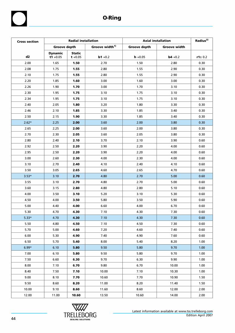
Cross section
d2
Radial installation Axial installation Radius2)
Groove depth Groove width1) Groove depth Groove width
Dynamict1 +0.05
Statict +0.05 b1 +0.2 h +0.05 b4 +0.2 r1± 0.2
2.00 1.65 1.50 2.70 1.50 2.80 0.30
2.08 1.75 1.55 2.80 1.55 2.90 0.30
2.10 1.75 1.55 2.80 1.55 2.90 0.30
2.20 1.85 1.60 3.00 1.60 3.00 0.30
2.26 1.90 1.70 3.00 1.70 3.10 0.30
2.30 1.95 1.75 3.10 1.75 3.10 0.30
2.34 1.95 1.75 3.10 1.75 3.10 0.30
2.40 2.05 1.80 3.20 1.80 3.30 0.30
2.46 2.10 1.85 3.30 1.85 3.40 0.30
2.50 2.15 1.90 3.30 1.85 3.40 0.30
2.62* 2.25 2.00 3.60 2.00 3.80 0.30
2.65 2.25 2.00 3.60 2.00 3.80 0.30
2.70 2.30 2.05 3.60 2.05 3.80 0.30
2.80 2.40 2.10 3.70 2.10 3.90 0.60
2.92 2.50 2.20 3.90 2.20 4.00 0.60
2.95 2.50 2.20 3.90 2.20 4.00 0.60
3.00 2.60 2.30 4.00 2.30 4.00 0.60
3.10 2.70 2.40 4.10 2.40 4.10 0.60
3.50 3.05 2.65 4.60 2.65 4.70 0.60
3.53* 3.10 2.70 4.80 2.70 5.00 0.60
3.55 3.10 2.70 4.80 2.70 5.00 0.60
3.60 3.15 2.80 4.80 2.80 5.10 0.60
4.00 3.50 3.10 5.20 3.10 5.30 0.60
4.50 4.00 3.50 5.80 3.50 5.90 0.60
5.00 4.40 4.00 6.60 4.00 6.70 0.60
5.30 4.70 4.30 7.10 4.30 7.30 0.60
5.33* 4.70 4.30 7.10 4.30 7.30 0.60
5.50 4.80 4.50 7.10 4.50 7.30 0.60
5.70 5.00 4.60 7.20 4.60 7.40 0.60
6.00 5.30 4.90 7.40 4.90 7.60 0.60
6.50 5.70 5.40 8.00 5.40 8.20 1.00
6.99* 6.10 5.80 9.50 5.80 9.70 1.00
7.00 6.10 5.80 9.50 5.80 9.70 1.00
7.50 6.60 6.30 9.70 6.30 9.90 1.00
8.00 7.10 6.70 9.80 6.70 10.00 1.00
8.40 7.50 7.10 10.00 7.10 10.30 1.00
9.00 8.10 7.70 10.60 7.70 10.90 1.50
9.50 8.60 8.20 11.00 8.20 11.40 1.50
10.00 9.10 8.60 11.60 8.60 12.00 2.00
12.00 11.00 10.60 13.50 10.60 14.00 2.00
O—Ring
Latest information available at www.tss.trelleborg.com
44Edition April 2007
nn * Preferred sizes1) When using Back-up Rings the groove is to be widened by the
corresponding Back-up Ring thickness (b2: one Back-up Ring, b3:two Back-up Rings, see figure 25).
2) If a Back-up Ring is used the recommended radius r1 shouldalways be r1=0.25 ±0.2mm.
The given installation dimensions cannot be used for FFKMmaterials (Isolast®). Please use the Isolast® brochure or contactour specialists for further details.
O—Ring
Latest information available at www.tss.trelleborg.comEdition April 2007
45
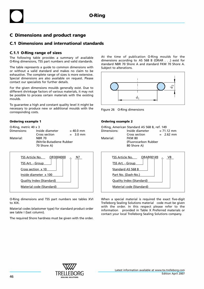
C Dimensions and product range
C.1 Dimensions and international standards
C.1.1 O—Ring range of sizesThe following table provides a summary of availableO—Ring dimensions, TSS part numbers and valid standards.
The table represents a guide to common dimensions withor without a valid standard and makes no claim to beexhaustive. The complete range of sizes is more extensive.Special dimensions are also available on request. Pleasecontact our specialists for further details.
For the given dimensions moulds generally exist. Due todifferent shrinkage factors of various materials, it may notbe possible to process certain materials with the existingmoulds.
To guarantee a high and constant quality level it might benecessary to produce new or additional moulds with thecorresponding costs.
At the time of publication O—Ring moulds for thedimensions according to AS 568 B (ORAR . . .) exist forstandard NBR 70 Shore A and standard FKM 70 Shore A.Subject to alterations.
d
d
1
2
Figure 26 O—Ring dimensions
Ordering example 1
O—Ring, metric 40 x 3Dimensions: Inside diameter = 40.0 mm
Cross section = 3.0 mmMaterial: NBR 70
(Nitrile-Butadiene Rubber70 Shore A)
OR3004000 N7-TSS Article No.
Cross section x 10
Material code (Standard)
TSS Art. - Group
Inside diameter x 100
Quality Index (Standard)
O—Ring dimensions and TSS part numbers see tables XVIto XIX.
Material codes (elastomer type) for standard product ordersee table I (last column).
The required Shore hardness must be given with the order.
Ordering example 2
O—Ring, American Standard AS 568 B, ref. 149Dimensions: Inside diameter = 71.12 mm
Cross section = 2.62 mmMaterial: FKM 80
(Fluorocarbon Rubber80 Shore A)
ORAR00149 V8-TSS Article No.
Standard AS 568 B
Material code (Standard)
TSS Art. - Group
Part No. (Dash-No.)
Quality Index (Standard)
When a special material is required the exact five-digitTrelleborg Sealing Solutions material code must be givenwith the order. In this respect please refer to theinformation provided in Table X Preferred materials orcontact your local Trelleborg Sealing Solutions company.
O—Ring
Latest information available at www.tss.trelleborg.com
46Edition April 2007
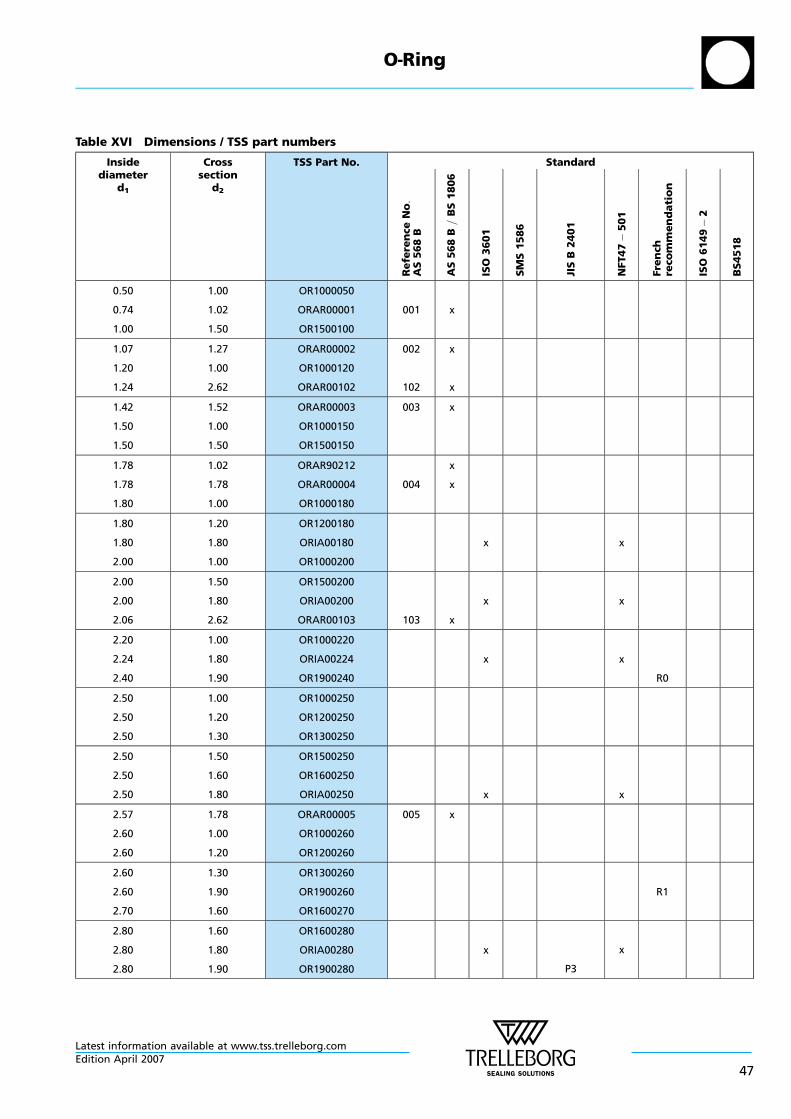
Table XVI Dimensions / TSS part numbers
Insidediameter
d1
Crosssection
d2
TSS Part No. Standard
Re
fere
nce
No:
AS
56
8B
AS
56
8B=
BS
18
06
ISO
36
01
SM
S1
58
6
JIS
B2
40
1
NFT4
75
01
Fre
nch
reco
mm
en
da
tio
n
ISO
61
49
2
BS
45
18
0.50
0.74
1.00
1.00
1.02
1.50
OR1000050
ORAR00001
OR1500100
001 x
1.07
1.20
1.24
1.27
1.00
2.62
ORAR00002
OR1000120
ORAR00102
002
102
x
x
1.42
1.50
1.50
1.52
1.00
1.50
ORAR00003
OR1000150
OR1500150
003 x
1.78
1.78
1.80
1.02
1.78
1.00
ORAR90212
ORAR00004
OR1000180
004
x
x
1.80
1.80
2.00
1.20
1.80
1.00
OR1200180
ORIA00180
OR1000200
x x
2.00
2.00
2.06
1.50
1.80
2.62
OR1500200
ORIA00200
ORAR00103 103 x
x x
2.20
2.24
2.40
1.00
1.80
1.90
OR1000220
ORIA00224
OR1900240
x x
R0
2.50
2.50
2.50
1.00
1.20
1.30
OR1000250
OR1200250
OR1300250
2.50
2.50
2.50
1.50
1.60
1.80
OR1500250
OR1600250
ORIA00250 x x
2.57
2.60
2.60
1.78
1.00
1.20
ORAR00005
OR1000260
OR1200260
005 x
2.60
2.60
2.70
1.30
1.90
1.60
OR1300260
OR1900260
OR1600270
R1
2.80
2.80
2.80
1.60
1.80
1.90
OR1600280
ORIA00280
OR1900280
x
P3
x
O—Ring
Latest information available at www.tss.trelleborg.comEdition April 2007
47

Insidediameter
d1
Crosssection
d2
TSS Part No. Standard
Re
fere
nce
No:
AS
56
8B
AS
56
8B
=B
S1
80
6
ISO
36
01
SM
S1
58
6
JIS
B2
40
1
NFT47
50
1
Fre
nch
reco
mm
en
da
tio
n
ISO
61
49
2
BS
451
8
2.84
2.90
3.00
2.62
1.78
1.00
ORAR00104
ORAR00006
OR1000300
104
006
x
x
3.00
3.00
3.00
1.50
2.00
2.40
OR1500300
OR2000300
OR2400300
3.00
3.00
3.10
2.70
3.00
1.60
OR2700300
OR3000300
OR1600310 x x
3.15
3.20
3.20
1.80
1.60
1.80
ORIA00315
OR1600320
ORIA00320
x x
3.20
3.30
3.30
2.50
1.00
1.50
OR2500320
OR1000330
OR1500330
3.30
3.40
3.50
2.40
1.90
1.00
OR2400330
OR1900340
OR1000350
x
R2
x
3.50
3.50
3.50
1.20
1.50
2.00
OR1200350
OR1500350
OR2000350
3.55
3.60
3.63
1.80
2.40
2.62
ORIA00355
OR2400360
ORAR00105 105 x
x x
x
3.68
3.70
3.80
1.78
1.90
1.50
ORAR00007
OR1900370
OR1500380
007 x
3.80
3.90
4.00
1.90
1.80
1.00
OR1900380
ORIA00390
OR1000400
P4
4.00
4.00
4.00
1.20
1.50
1.80
OR1200400
OR1500400
ORIA00400 x x
4.00
4.00
4.00
2.00
2.50
3.00
OR2000400
OR2500400
OR3000400
O—Ring
Latest information available at www.tss.trelleborg.com
48Edition April 2007

Insidediameter
d1
Crosssection
d2
TSS Part No. Standard
Re
fere
nce
No:
AS
56
8B
AS
56
8B
=B
S1
80
6
ISO
36
01
SM
S1
58
6
JIS
B2
40
1
NFT47
50
1
Fre
nch
reco
mm
en
da
tio
n
ISO
61
49
2
BS
451
8
4.00
4.10
4.20
4.00
1.60
1.90
OR4000400
OR1600410
OR1900420
x
R3
x
4.30
4.34
4.42
2.40
3.53
2.62
OR2400430
ORAR00201
ORAR00106
201
106
x
x
x
4.47
4.50
4.50
1.78
1.00
1.50
ORAR00008
OR1000450
OR1500450
008 x
4.50
4.50
4.60
2.00
2.50
2.00
OR2000450
OR2500450
OR2000460
4.60
4.70
4.70
2.40
1.00
1.42
OR2400460
OR1000470
ORAR00901 901 x
x
4.80
4.80
4.87
1.80
1.90
1.80
ORIA00480
OR1900480
ORIA00487 x
P5
x
4.90
5.00
5.00
1.90
1.00
1.20
OR1900490
OR1000500
OR1200500
R4
5.00
5.00
5.00
1.50
1.80
2.00
OR1500500
ORIA00500
OR2000500
x x
5.00
5.00
5.00
2.50
3.00
5.00
OR2500500
OR3000500
OR5000500
5.10
5.15
5.23
1.60
1.80
2.62
OR1600510
ORIA00515
ORAR00107 107 x
x
x
x
x
5.28
5.30
5.30
1.78
1.80
2.40
ORAR00009
ORIA00530
OR2400530
009 x
x
x
x
x
5.50
5.50
5.50
1.00
1.50
1.60
OR1000550
OR1500550
OR1600550
O—Ring
Latest information available at www.tss.trelleborg.comEdition April 2007
49
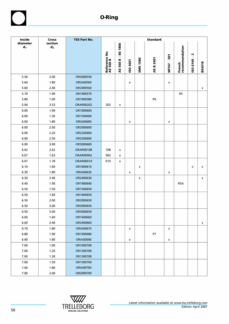
Insidediameter
d1
Crosssection
d2
TSS Part No. Standard
Re
fere
nce
No:
AS
56
8B
AS
56
8B
=B
S1
80
6
ISO
36
01
SM
S1
58
6
JIS
B2
40
1
NFT47
50
1
Fre
nch
reco
mm
en
da
tio
n
ISO
61
49
2
BS
451
8
5.50
5.60
5.60
2.00
1.80
2.40
OR2000550
ORIA00560
OR2400560
x x
x
5.70
5.80
5.94
1.90
1.90
3.53
OR1900570
OR1900580
ORAR00202 202 x
P6
R5
6.00
6.00
6.00
1.00
1.50
1.80
OR1000600
OR1500600
ORIA00600 x x
6.00
6.00
6.00
2.00
2.20
2.50
OR2000600
OR2200600
OR2500600
6.00
6.02
6.07
3.00
2.62
1.63
OR3000600
ORAR00108
ORAR00902
108
902
x
x
6.07
6.10
6.30
1.78
1.60
1.80
ORAR00010
OR1600610
ORIA00630
010 x
x
x
x
x x
6.30
6.40
6.50
2.40
1.90
1.50
OR2400630
OR1900640
OR1500650
x
R5A
x
6.50
6.50
6.50
1.60
2.00
3.00
OR1600650
OR2000650
OR3000650
6.50
6.60
6.60
5.00
1.60
2.40
OR5000650
OR1600660
OR2400660 x
6.70
6.80
6.90
1.80
1.90
1.80
ORIA00670
OR1900680
ORIA00690
x
x
P7
x
x
7.00
7.00
7.00
1.00
1.20
1.30
OR1000700
OR1200700
OR1300700
7.00
7.00
7.00
1.50
1.80
2.00
OR1500700
ORIA00700
OR2000700
O—Ring
Latest information available at www.tss.trelleborg.com
50Edition April 2007
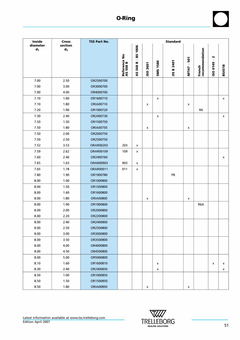
Insidediameter
d1
Crosssection
d2
TSS Part No. Standard
Re
fere
nce
No:
AS
56
8B
AS
56
8B
=B
S1
80
6
ISO
36
01
SM
S1
58
6
JIS
B2
40
1
NFT47
50
1
Fre
nch
reco
mm
en
da
tio
n
ISO
61
49
2
BS
451
8
7.00
7.00
7.00
2.50
3.00
4.00
OR2500700
OR3000700
OR4000700
7.10
7.10
7.20
1.60
1.80
1.90
OR1600710
ORIA00710
OR1900720
x
x
x
R6
x
7.30
7.50
7.50
2.40
1.50
1.80
OR2400730
OR1500750
ORIA00750 x
x
x
x
7.50
7.50
7.52
2.00
2.50
3.53
OR2000750
OR2500750
ORAR00203 203 x
7.59
7.60
7.65
2.62
2.40
1.63
ORAR00109
OR2400760
ORAR00903
109
903
x
x
x
7.65
7.80
8.00
1.78
1.90
1.00
ORAR00011
OR1900780
OR1000800
011 x
P8
8.00
8.00
8.00
1.50
1.60
1.80
OR1500800
OR1600800
ORIA00800 x x
8.00
8.00
8.00
1.90
2.00
2.20
OR1900800
OR2000800
OR2200800
R6A
8.00
8.00
8.00
2.40
2.50
3.00
OR2400800
OR2500800
OR3000800
8.00
8.00
8.00
3.50
4.00
4.50
OR3500800
OR4000800
OR4500800
8.00
8.10
8.30
5.00
1.60
2.40
OR5000800
OR1600810
OR2400830
x
x
x x
x
8.50
8.50
8.50
1.00
1.50
1.80
OR1000850
OR1500850
ORIA00850 x x
O—Ring
Latest information available at www.tss.trelleborg.comEdition April 2007
51
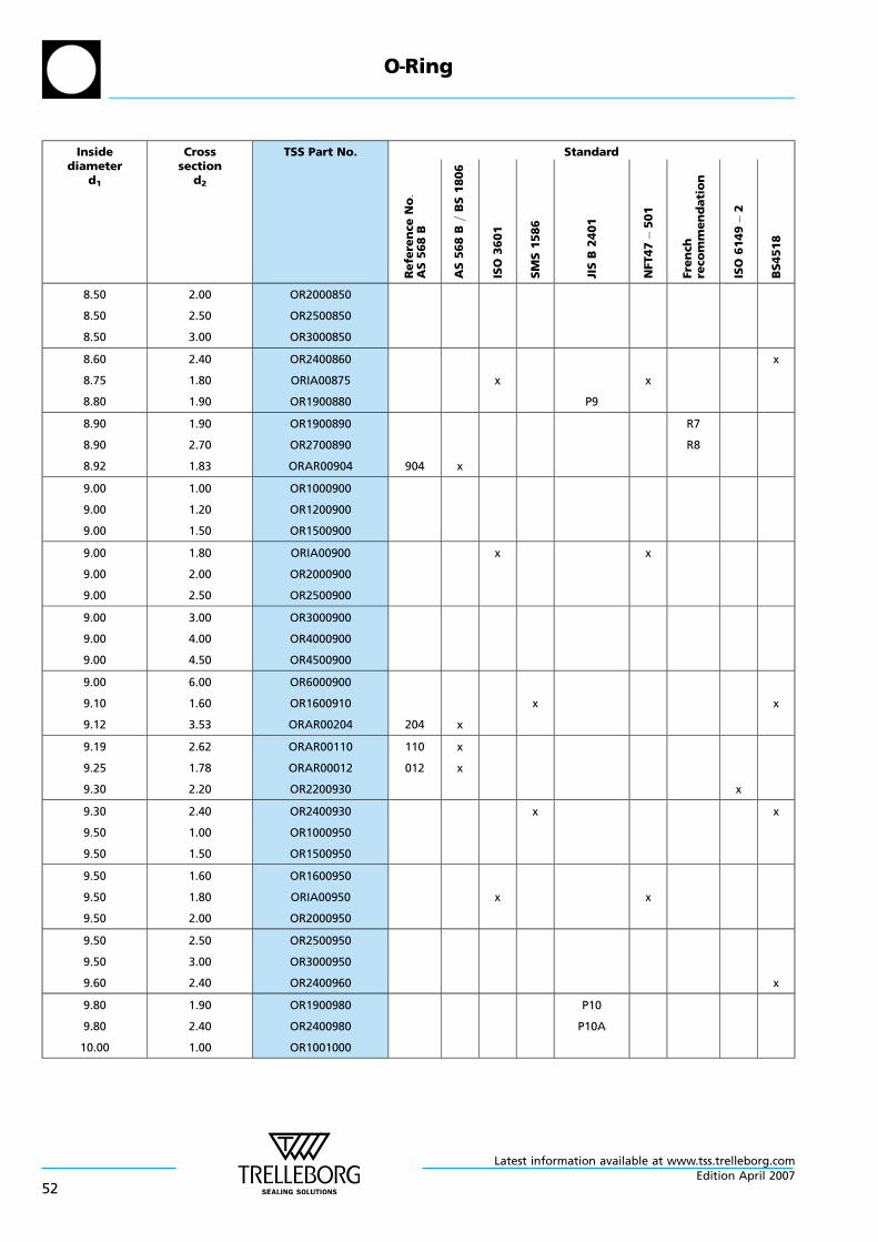
Insidediameter
d1
Crosssection
d2
TSS Part No. Standard
Re
fere
nce
No:
AS
56
8B
AS
56
8B
=B
S1
80
6
ISO
36
01
SM
S1
58
6
JIS
B2
40
1
NFT47
50
1
Fre
nch
reco
mm
en
da
tio
n
ISO
61
49
2
BS
451
8
8.50
8.50
8.50
2.00
2.50
3.00
OR2000850
OR2500850
OR3000850
8.60
8.75
8.80
2.40
1.80
1.90
OR2400860
ORIA00875
OR1900880
x
P9
x
x
8.90
8.90
8.92
1.90
2.70
1.83
OR1900890
OR2700890
ORAR00904 904 x
R7
R8
9.00
9.00
9.00
1.00
1.20
1.50
OR1000900
OR1200900
OR1500900
9.00
9.00
9.00
1.80
2.00
2.50
ORIA00900
OR2000900
OR2500900
x x
9.00
9.00
9.00
3.00
4.00
4.50
OR3000900
OR4000900
OR4500900
9.00
9.10
9.12
6.00
1.60
3.53
OR6000900
OR1600910
ORAR00204 204 x
x x
9.19
9.25
9.30
2.62
1.78
2.20
ORAR00110
ORAR00012
OR2200930
110
012
x
x
x
9.30
9.50
9.50
2.40
1.00
1.50
OR2400930
OR1000950
OR1500950
x x
9.50
9.50
9.50
1.60
1.80
2.00
OR1600950
ORIA00950
OR2000950
x x
9.50
9.50
9.60
2.50
3.00
2.40
OR2500950
OR3000950
OR2400960 x
9.80
9.80
10.00
1.90
2.40
1.00
OR1900980
OR2400980
OR1001000
P10
P10A
O—Ring
Latest information available at www.tss.trelleborg.com
52Edition April 2007

Insidediameter
d1
Crosssection
d2
TSS Part No. Standard
Re
fere
nce
No:
AS
56
8B
AS
56
8B
=B
S1
80
6
ISO
36
01
SM
S1
58
6
JIS
B2
40
1
NFT47
50
1
Fre
nch
reco
mm
en
da
tio
n
ISO
61
49
2
BS
451
8
10.00
10.00
10.00
1.50
1.80
2.00
OR1501000
ORIA01000
OR2001000
x x
10.00
10.00
10.00
2.40
2.50
3.00
OR2401000
OR2501000
OR3001000
10.00
10.00
10.00
3.50
4.00
5.00
OR3501000
OR4001000
OR5001000
10.10
10.30
10.46
1.60
2.40
5.33
OR1601010
OR2401030
ORAR00309 309 x
x
x
x
x
10.50
10.50
10.52
1.50
2.70
1.83
OR1501050
OR2701050
ORAR00905 905 x
R9
10.60
10.60
10.69
1.80
2.40
3.53
ORIA01060
OR2401060
ORAR00205 205 x
x x
x
10.77
10.80
10.82
2.62
2.40
1.78
ORAR00111
OR2401080
ORAR00013
111
013
x
x
P11
11.00
11.00
11.00
1.00
1.50
2.00
OR1001100
OR1501100
OR2001100
11.00
11.00
11.00
2.40
2.50
3.00
OR2401100
OR2501100
OR3001100
P11.2
11.00
11.00
11.10
3.50
4.00
1.60
OR3501100
OR4001100
OR1601110 x x
11.20
11.30
11.30
1.80
2.20
2.40
ORIA01120
OR2201130
OR2401130
x
x
x
x
x
11.60
11.80
11.80
2.40
1.80
2.40
OR2401160
ORIA01180
OR2401180
x
P12
x
x
O—Ring
Latest information available at www.tss.trelleborg.comEdition April 2007
53

Insidediameter
d1
Crosssection
d2
TSS Part No. Standard
Re
fere
nce
No:
AS
56
8B
AS
56
8B
=B
S1
80
6
ISO
36
01
SM
S1
58
6
JIS
B2
40
1
NFT47
50
1
Fre
nch
reco
mm
en
da
tio
n
ISO
61
49
2
BS
451
8
11.89
12.00
12.00
1.98
1.00
1.50
ORAR00906
OR1001200
OR1501200
906 x
12.00
12.00
12.00
2.00
2.50
3.00
OR2001200
OR2501200
OR3001200
12.00
12.00
12.00
4.00
4.50
5.00
OR4001200
OR4501200
OR5001200
12.07
12.10
12.10
5.33
1.60
2.70
ORAR00310
OR1601210
OR2701210
310 x
x
R10
x
12.29
12.30
12.37
3.53
2.40
2.62
ORAR00206
OR2401230
ORAR00112
206
112
x
x
x x
12.42
12.50
12.50
1.78
1.50
1.80
ORAR00014
OR1501250
ORIA01250
014 x
x x
12.50
12.50
12.60
2.00
2.50
2.40
OR2001250
OR2501250
OR2401260 x
13.00
13.00
13.00
1.00
1.50
2.00
OR1001300
OR1501300
OR2001300
13.00
13.00
13.00
2.50
3.00
3.50
OR2501300
OR3001300
OR3501300
13.00
13.10
13.20
4.00
1.60
1.80
OR4001300
OR1601310
ORIA01320 x
x
x
x
13.30
13.30
13.46
2.20
2.40
2.08
OR2201330
OR2401330
ORAR00907 907 x
x
x
x
13.60
13.60
13.64
2.40
2.70
5.33
OR2401360
OR2701360
ORAR00311 311 x
R11
x
O—Ring
Latest information available at www.tss.trelleborg.com
54Edition April 2007

Insidediameter
d1
Crosssection
d2
TSS Part No. Standard
Re
fere
nce
No:
AS
56
8B
AS
56
8B
=B
S1
80
6
ISO
36
01
SM
S1
58
6
JIS
B2
40
1
NFT47
50
1
Fre
nch
reco
mm
en
da
tio
n
ISO
61
49
2
BS
451
8
13.80
13.87
13.94
2.40
3.53
2.62
OR2401380
ORAR00207
ORAR00113
207
113
x
x
P14
14.00
14.00
14.00
1.00
1.50
1.60
OR1001400
OR1501400
OR1601400
14.00
14.00
14.00
1.78
1.80
2.00
ORAR00015
ORIA01400
OR2001400
015 x
x x
14.00
14.00
14.00
2.40
2.50
2.65
OR2401400
OR2501400
ORIB01400 x x
14.00
14.00
14.00
2.70
3.00
4.00
OR2701400
OR3001400
OR4001400
14.00
14.10
14.30
5.00
1.60
2.40
OR5001400
OR1601410
OR2401430
x
x
x
x
14.80
15.00
15.00
2.40
1.00
1.50
OR2401480
OR1001500
OR1501500
P15 x
15.00
15.00
15.00
1.80
2.00
2.50
ORIA01500
OR2001500
OR2501500
x x
15.00
15.00
15.00
2.65
3.00
3.50
ORIB01500
OR3001500
OR3501500
x x
15.00
15.00
15.00
4.00
5.00
6.00
OR4001500
OR5001500
OR6001500
15.00
15.10
15.10
7.00
1.60
2.70
OR7001500
OR1601510
OR2701510
x
R12
x
15.24
15.30
15.30
5.33
2.20
2.40
ORAR00312
OR2201530
OR2401530
312 x
x
x
x
O—Ring
Latest information available at www.tss.trelleborg.comEdition April 2007
55

Insidediameter
d1
Crosssection
d2
TSS Part No. Standard
Re
fere
nce
No:
AS
56
8B
AS
56
8B
=B
S1
80
6
ISO
36
01
SM
S1
58
6
JIS
B2
40
1
NFT47
50
1
Fre
nch
reco
mm
en
da
tio
n
ISO
61
49
2
BS
451
8
15.47
15.54
15.60
3.53
2.62
1.78
ORAR00208
ORAR00114
ORAR00016
208
114
016
x
x
x
15.60
15.80
16.00
2.40
2.40
1.00
OR2401560
OR2401580
OR1001600
P16
x
16.00
16.00
16.00
1.50
1.80
2.00
OR1501600
ORIA01600
OR2001600
x x
16.00
16.00
16.00
2.50
2.65
3.00
OR2501600
ORIB01600
OR3001600
x x
16.00
16.00
16.00
3.50
4.00
4.50
OR3501600
OR4001600
OR4501600
16.00
16.10
16.30
5.00
1.60
2.40
OR5001600
OR1601610
OR2401630
x
x
x
x
16.36
16.81
16.90
2.20
5.33
2.70
ORAR00908
ORAR00313
OR2701690
908
313
x
x
R13
17.00
17.00
17.00
1.00
1.50
1.80
OR1001700
OR1501700
ORIA01700 x x
17.00
17.00
17.00
2.00
2.50
2.65
OR2001700
OR2501700
ORIB01700 x x
17.00
17.00
17.00
3.00
3.50
4.00
OR3001700
OR3501700
OR4001700
17.00
17.04
17.10
5.00
3.53
1.60
OR5001700
ORAR00209
OR1601710
209 x
x x
17.12
17.17
17.20
2.62
1.78
3.00
ORAR00115
ORAR00017
OR3001720
115
017
x
x
x
O—Ring
Latest information available at www.tss.trelleborg.com
56Edition April 2007
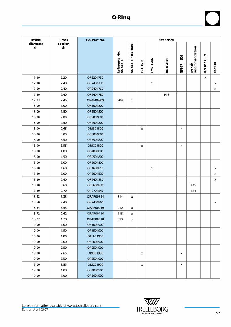
Insidediameter
d1
Crosssection
d2
TSS Part No. Standard
Re
fere
nce
No:
AS
56
8B
AS
56
8B
=B
S1
80
6
ISO
36
01
SM
S1
58
6
JIS
B2
40
1
NFT47
50
1
Fre
nch
reco
mm
en
da
tio
n
ISO
61
49
2
BS
451
8
17.30
17.30
17.60
2.20
2.40
2.40
OR2201730
OR2401730
OR2401760
x
x
x
x
17.80
17.93
18.00
2.40
2.46
1.00
OR2401780
ORAR00909
OR1001800
909 x
P18
18.00
18.00
18.00
1.50
2.00
2.50
OR1501800
OR2001800
OR2501800
18.00
18.00
18.00
2.65
3.00
3.50
ORIB01800
OR3001800
OR3501800
x x
18.00
18.00
18.00
3.55
4.00
4.50
ORIC01800
OR4001800
OR4501800
x x
18.00
18.10
18.20
5.00
1.60
3.00
OR5001800
OR1601810
OR3001820
x x
x
18.30
18.30
18.40
2.40
3.60
2.70
OR2401830
OR3601830
OR2701840
R15
R14
x
18.42
18.60
18.64
5.33
2.40
3.53
ORAR00314
OR2401860
ORAR00210
314
210
x
x
x
18.72
18.77
19.00
2.62
1.78
1.00
ORAR00116
ORAR00018
OR1001900
116
018
x
x
19.00
19.00
19.00
1.50
1.80
2.00
OR1501900
ORIA01900
OR2001900
19.00
19.00
19.00
2.50
2.65
3.50
OR2501900
ORIB01900
OR3501900
x x
19.00
19.00
19.00
3.55
4.00
5.00
ORIC01900
OR4001900
OR5001900
x x
O—Ring
Latest information available at www.tss.trelleborg.comEdition April 2007
57

Insidediameter
d1
Crosssection
d2
TSS Part No. Standard
Re
fere
nce
No:
AS
56
8B
AS
56
8B
=B
S1
80
6
ISO
36
01
SM
S1
58
6
JIS
B2
40
1
NFT47
50
1
Fre
nch
reco
mm
en
da
tio
n
ISO
61
49
2
BS
451
8
19.00
19.10
19.18
6.00
1.60
2.46
OR6001900
OR1601910
ORAR00910 910 x
x x
19.20
19.30
19.30
3.00
2.20
2.40
OR3001920
OR2201930
OR2401930
x
x
x
x
19.50
19.60
19.80
3.00
2.40
2.40
OR3001950
OR2401960
OR2401980 P20
x
x
19.80
19.99
20.00
3.60
5.33
1.00
OR3601980
ORAR00315
OR1002000
315 x
R16
20.00
20.00
20.00
1.30
1.50
2.00
OR1302000
OR1502000
OR2002000
20.00
20.00
20.00
2.50
2.65
3.00
OR2502000
ORIB02000
OR3002000
x x
20.00
20.00
20.00
3.50
3.55
4.00
OR3502000
ORIC02000
OR4002000
x x
20.00
20.00
20.00
4.50
5.00
6.00
OR4502000
OR5002000
OR6002000
20.10
20.20
20.22
1.60
3.00
3.53
OR1602010
OR3002020
ORAR00211 211 x
x
x
20.29
20.30
20.35
2.62
2.40
1.78
ORAR00117
OR2402030
ORAR00019
117
019
x
x
x
20.60
20.80
21.00
2.40
2.40
2.00
OR2402060
OR2402080
OR2002100
P21
x
21.00
21.00
21.00
2.50
3.00
4.00
OR2502100
OR3002100
OR4002100
O—Ring
Latest information available at www.tss.trelleborg.com
58Edition April 2007

Insidediameter
d1
Crosssection
d2
TSS Part No. Standard
Re
fere
nce
No:
AS
56
8B
AS
56
8B
=B
S1
80
6
ISO
36
01
SM
S1
58
6
JIS
B2
40
1
NFT47
50
1
Fre
nch
reco
mm
en
da
tio
n
ISO
61
49
2
BS
451
8
21.00
21.10
21.20
6.00
1.60
2.65
OR6002100
OR1602110
ORIB02120 x x
x
21.20
21.20
21.30
3.00
3.55
2.40
OR3002120
ORIC02120
OR2402130
x x
x
21.30
21.50
21.59
3.60
3.00
5.33
OR3602130
OR3002150
ORAR00316 316 x
R17
x
21.60
21.70
21.80
2.40
3.50
2.40
OR2402160
OR3502170
OR2402180
P22A
P22
x
21.82
21.89
21.92
3.53
2.62
2.95
ORAR00212
ORAR00118
ORAR00911
212
118
911
x
x
x
21.95
22.00
22.00
1.78
1.00
1.30
ORAR00020
OR1002200
OR1302200
020 x
22.00
22.00
22.00
1.50
2.00
2.50
OR1502200
OR2002200
OR2502200
22.00
22.00
22.00
3.00
3.50
4.00
OR3002200
OR3502200
OR4002200
22.00
22.00
22.00
4.50
5.00
6.00
OR4502200
OR5002200
OR6002200
22.10
22.10
22.20
1.60
3.50
3.00
OR1602210
OR3502210
OR3002220
x
x
P22.4
x
x
22.30
22.40
22.40
2.40
2.65
3.55
OR2402230
ORIB02240
ORIC02240
x
x
x
x
x
22.50
23.00
23.00
3.00
1.00
1.50
OR3002250
OR1002300
OR1502300
x
O—Ring
Latest information available at www.tss.trelleborg.comEdition April 2007
59

Insidediameter
d1
Crosssection
d2
TSS Part No. Standard
Re
fere
nce
No:
AS
56
8B
AS
56
8B
=B
S1
80
6
ISO
36
01
SM
S1
58
6
JIS
B2
40
1
NFT47
50
1
Fre
nch
reco
mm
en
da
tio
n
ISO
61
49
2
BS
451
8
23.00
23.00
23.00
2.00
2.50
3.00
OR2002300
OR2502300
OR3002300
23.00
23.00
23.00
3.60
4.00
5.00
OR3602300
OR4002300
OR5002300
R18
23.00
23.00
23.16
5.50
6.00
5.33
OR5502300
OR6002300
ORAR00317 317 x
23.30
23.39
23.47
2.40
3.53
2.62
OR2402330
ORAR00213
ORAR00119
213
119
x
x
x
23.47
23.52
23.60
2.95
1.78
2.65
ORAR00912
ORAR00021
ORIB02360
912
021
x
x
x x
23.60
23.60
23.70
2.90
3.55
3.50
OR2902360
ORIC02360
OR3502370
x
P24
x
x
24.00
24.00
24.00
1.00
1.50
2.00
OR1002400
OR1502400
OR2002400
24.00
24.00
24.00
2.50
3.00
3.50
OR2502400
OR3002400
OR3502400
24.00
24.00
24.00
4.00
5.00
6.00
OR4002400
OR5002400
OR6002400
24.20
24.40
24.50
3.00
3.10
3.00
OR3002420
OR3102440
OR3002450
x
G25
x
x
24.60
24.60
24.70
2.40
3.60
3.50
OR2402460
OR3602460
OR3502470 P25
R19
x
24.77
24.99
25.00
5.33
3.53
1.00
ORAR00318
ORAR00214
OR1002500
318
214
x
x
O—Ring
Latest information available at www.tss.trelleborg.com
60Edition April 2007

Insidediameter
d1
Crosssection
d2
TSS Part No. Standard
Re
fere
nce
No:
AS
56
8B
AS
56
8B
=B
S1
80
6
ISO
36
01
SM
S1
58
6
JIS
B2
40
1
NFT47
50
1
Fre
nch
reco
mm
en
da
tio
n
ISO
61
49
2
BS
451
8
25.00
25.00
25.00
1.50
2.00
2.50
OR1502500
OR2002500
OR2502500
25.00
25.00
25.00
2.65
3.00
3.55
ORIB02500
OR3002500
ORIC02500
x
x
x
x
25.00
25.00
25.00
4.00
4.50
5.00
OR4002500
OR4502500
OR5002500
25.00
25.04
25.07
6.00
2.95
2.62
OR6002500
ORAR00913
ORAR00120
913
120
x
x
25.10
25.12
25.20
1.60
1.78
3.00
OR1602510
ORAR00022
OR3002520
022 x
x x
x
25.20
25.30
25.50
3.50
2.40
3.00
OR3502520
OR2402530
OR3002550
P25.5
x
x
25.70
25.80
25.80
3.50
2.65
3.55
OR3502570
ORIB02580
ORIC02580
x
x
P26
x
x
26.00
26.00
26.00
1.00
1.50
2.00
OR1002600
OR1502600
OR2002600
26.00
26.00
26.00
2.50
3.50
4.00
OR2502600
OR3502600
OR4002600
26.00
26.00
26.20
5.00
6.00
3.00
OR5002600
OR6002600
OR3002620 x x
26.20
26.34
26.50
3.60
5.33
3.00
OR3602620
ORAR00319
OR3002650
319 x
R20
x
26.57
26.62
26.64
3.53
2.95
2.62
ORAR00215
ORAR00914
ORAR00121
215
914
121
x
x
x
O—Ring
Latest information available at www.tss.trelleborg.comEdition April 2007
61
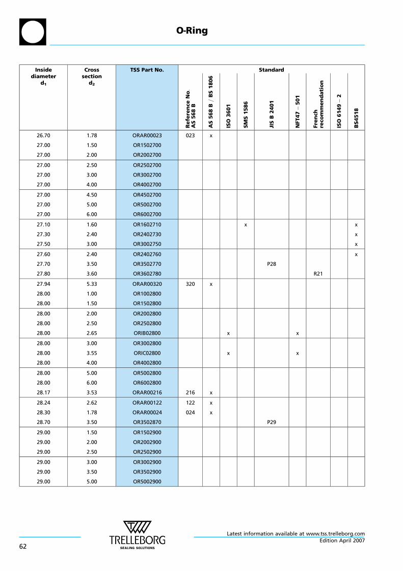
Insidediameter
d1
Crosssection
d2
TSS Part No. Standard
Re
fere
nce
No:
AS
56
8B
AS
56
8B
=B
S1
80
6
ISO
36
01
SM
S1
58
6
JIS
B2
40
1
NFT47
50
1
Fre
nch
reco
mm
en
da
tio
n
ISO
61
49
2
BS
451
8
26.70
27.00
27.00
1.78
1.50
2.00
ORAR00023
OR1502700
OR2002700
023 x
27.00
27.00
27.00
2.50
3.00
4.00
OR2502700
OR3002700
OR4002700
27.00
27.00
27.00
4.50
5.00
6.00
OR4502700
OR5002700
OR6002700
27.10
27.30
27.50
1.60
2.40
3.00
OR1602710
OR2402730
OR3002750
x x
x
x
27.60
27.70
27.80
2.40
3.50
3.60
OR2402760
OR3502770
OR3602780
P28
R21
x
27.94
28.00
28.00
5.33
1.00
1.50
ORAR00320
OR1002800
OR1502800
320 x
28.00
28.00
28.00
2.00
2.50
2.65
OR2002800
OR2502800
ORIB02800 x x
28.00
28.00
28.00
3.00
3.55
4.00
OR3002800
ORIC02800
OR4002800
x x
28.00
28.00
28.17
5.00
6.00
3.53
OR5002800
OR6002800
ORAR00216 216 x
28.24
28.30
28.70
2.62
1.78
3.50
ORAR00122
ORAR00024
OR3502870
122
024
x
x
P29
29.00
29.00
29.00
1.50
2.00
2.50
OR1502900
OR2002900
OR2502900
29.00
29.00
29.00
3.00
3.50
5.00
OR3002900
OR3502900
OR5002900
O—Ring
Latest information available at www.tss.trelleborg.com
62Edition April 2007

Insidediameter
d1
Crosssection
d2
TSS Part No. Standard
Re
fere
nce
No:
AS
56
8B
AS
56
8B
=B
S1
80
6
ISO
36
01
SM
S1
58
6
JIS
B2
40
1
NFT47
50
1
Fre
nch
reco
mm
en
da
tio
n
ISO
61
49
2
BS
451
8
29.10
29.20
29.20
1.60
3.00
3.50
OR1602910
OR3002920
OR3502920
x
x
P29.5
x
x
29.30
29.40
29.50
3.60
3.10
1.50
OR3602930
OR3102940
OR1502950
G30
R22
29.50
29.50
29.51
3.00
4.50
5.33
OR3002950
OR4502950
ORAR00321 321 x
x
29.60
29.60
29.70
2.40
2.90
3.50
OR2402960
OR2902960
OR3502970 P30
x
x
29.74
29.74
29.82
2.95
3.53
2.62
ORAR00916
ORAR00217
ORAR00123
916
217
123
x
x
x
29.87
30.00
30.00
1.78
1.00
1.50
ORAR00025
OR1003000
OR1503000
025 x
30.00
30.00
30.00
2.00
2.50
2.65
OR2003000
OR2503000
ORIB03000 x x
30.00
30.00
30.00
3.00
3.50
3.55
OR3003000
OR3503000
ORIC03000 x x
30.00
30.00
30.00
4.00
4.50
5.00
OR4003000
OR4503000
OR5003000
30.00
30.00
30.20
6.00
7.00
3.00
OR6003000
ORIE03000
OR3003020 x
30.30
30.70
30.80
2.40
3.50
3.60
OR2403030
OR3503070
OR3603080
P31
R23
x
31.00
31.00
31.00
1.50
2.00
2.50
OR1503100
OR2003100
OR2503100
O—Ring
Latest information available at www.tss.trelleborg.comEdition April 2007
63

Insidediameter
d1
Crosssection
d2
TSS Part No. Standard
Re
fere
nce
No:
AS
56
8B
AS
56
8B
=B
S1
80
6
ISO
36
01
SM
S1
58
6
JIS
B2
40
1
NFT47
50
1
Fre
nch
reco
mm
en
da
tio
n
ISO
61
49
2
BS
451
8
31.00
31.00
31.00
3.00
3.50
4.00
OR3003100
OR3503100
OR4003100
31.12
31.20
31.20
5.33
3.00
3.50
ORAR00322
OR3003120
OR3503120
322 P31.5
x
31.34
31.42
31.47
3.53
2.62
1.78
ORAR00218
ORAR00124
ORAR00026
218
124
026
x
x
x
31.50
31.50
31.50
2.65
3.00
3.55
ORIB03150
OR3003150
ORIC03150
x
x
x
x
x
31.60
31.70
32.00
2.40
3.50
1.00
OR2403160
OR3503170
OR1003200
P32
x
32.00
32.00
32.00
1.50
2.00
2.50
OR1503200
OR2003200
OR2503200
32.00
32.00
32.00
3.00
3.50
4.00
OR3003200
OR3503200
OR4003200
32.00
32.10
32.20
5.00
1.60
3.00
OR5003200
OR1603210
OR3003220
x
x
x
x
32.50
32.50
32.50
2.65
3.00
3.55
ORIB03250
OR3003250
ORIC03250
x
x
x
x
x
32.50
32.69
32.92
3.60
5.33
3.53
OR3603250
ORAR00323
ORAR00219
323
219
x
x
R24
32.99
33.00
33.00
2.62
1.50
2.00
ORAR00125
OR1503300
OR2003300
125 x
33.00
33.00
33.00
2.50
3.00
3.50
OR2503300
OR3003300
OR3503300
O—Ring
Latest information available at www.tss.trelleborg.com
64Edition April 2007

Insidediameter
d1
Crosssection
d2
TSS Part No. Standard
Re
fere
nce
No:
AS
56
8B
AS
56
8B
=B
S1
80
6
ISO
36
01
SM
S1
58
6
JIS
B2
40
1
NFT47
50
1
Fre
nch
reco
mm
en
da
tio
n
ISO
61
49
2
BS
451
8
33.00
33.05
33.30
4.00
1.78
2.40
OR4003300
ORAR00027
OR2403330
027 x
x
33.50
33.50
33.70
2.65
3.55
3.50
ORIB03350
ORIC03350
OR3503370
x
x
P34
x
x
34.00
34.00
34.00
1.00
2.00
2.30
OR1003400
OR2003400
OR2303400
34.00
34.00
34.00
2.50
3.00
4.00
OR2503400
OR3003400
OR4003400
34.00
34.00
34.10
5.00
6.00
3.60
OR5003400
OR6003400
OR3603410 R25
34.20
34.29
34.40
3.00
5.33
3.10
OR3003420
ORAR00324
OR3103440
324 x
x
G35
x
34.42
34.50
34.50
2.95
2.65
3.00
ORAR00918
ORIB03450
OR3003450
918 x
x x
x
34.50
34.52
34.59
3.55
3.53
2.62
ORIC03450
ORAR00220
ORAR00126
220
126
x
x
x x
34.60
34.65
34.70
2.40
1.78
3.50
OR2403460
ORAR00028
OR3503470
028 x
P35
x
35.00
35.00
35.00
1.50
2.00
2.50
OR1503500
OR2003500
OR2503500
35.00
35.00
35.00
3.00
3.50
4.00
OR3003500
OR3503500
OR4003500
35.00
35.00
35.00
5.00
6.00
7.00
OR5003500
OR6003500
ORIE03500
O—Ring
Latest information available at www.tss.trelleborg.comEdition April 2007
65

Insidediameter
d1
Crosssection
d2
TSS Part No. Standard
Re
fere
nce
No:
AS
56
8B
AS
56
8B
=B
S1
80
6
ISO
36
01
SM
S1
58
6
JIS
B2
40
1
NFT47
50
1
Fre
nch
reco
mm
en
da
tio
n
ISO
61
49
2
BS
451
8
35.10
35.20
35.20
1.60
3.00
3.50
OR1603510
OR3003520
OR3503520
x
P35.5
x
x
35.20
35.50
35.50
5.70
2.65
3.00
OR5703520
ORIB03550
OR3003550
x x
x
x
35.50
35.60
35.60
3.55
2.40
3.60
ORIC03550
OR2403560
OR3603560
x x
R26
x
35.70
36.00
36.00
3.50
1.50
2.00
OR3503570
OR1503600
OR2003600
P36
36.00
36.00
36.00
2.50
3.00
4.00
OR2503600
OR3003600
OR4003600
36.00
36.00
36.00
4.50
5.00
6.00
OR4503600
OR5003600
OR6003600
36.09
36.17
36.20
3.53
2.62
3.00
ORAR00221
ORAR00127
OR3003620
221
127
x
x
x x
36.20
36.50
36.50
5.70
2.65
3.55
OR5703620
ORIB03650
ORIC03650
x
x
x
x
x
37.00
37.00
37.00
2.00
2.50
3.00
OR2003700
OR2503700
OR3003700
37.00
37.10
37.20
3.50
1.60
3.00
OR3503700
OR1603710
OR3003720
x x
x
37.20
37.30
37.47
5.70
3.60
3.00
OR5703720
OR3603730
ORAR00920 920 x
R27
x
37.47
37.50
37.50
5.33
2.65
3.00
ORAR00325
ORIB03750
OR3003750
325 x
x x
R28
x
O—Ring
Latest information available at www.tss.trelleborg.com
66Edition April 2007
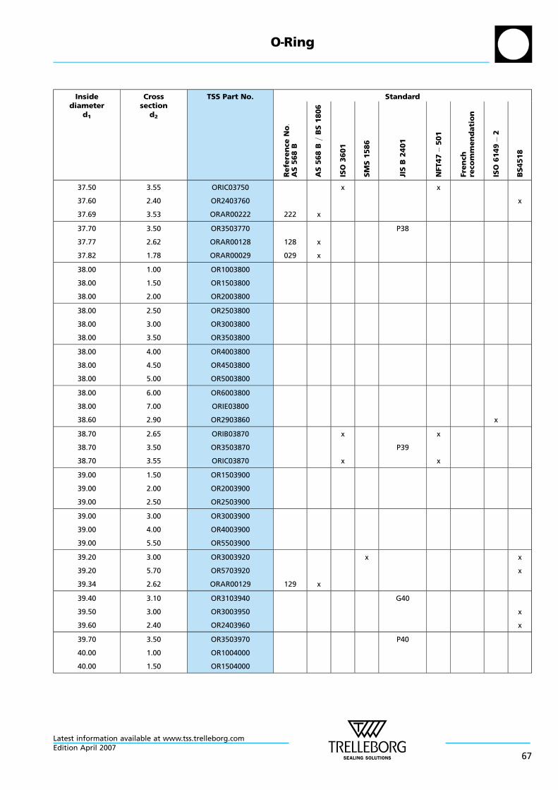
Insidediameter
d1
Crosssection
d2
TSS Part No. Standard
Re
fere
nce
No:
AS
56
8B
AS
56
8B
=B
S1
80
6
ISO
36
01
SM
S1
58
6
JIS
B2
40
1
NFT47
50
1
Fre
nch
reco
mm
en
da
tio
n
ISO
61
49
2
BS
451
8
37.50
37.60
37.69
3.55
2.40
3.53
ORIC03750
OR2403760
ORAR00222 222 x
x x
x
37.70
37.77
37.82
3.50
2.62
1.78
OR3503770
ORAR00128
ORAR00029
128
029
x
x
P38
38.00
38.00
38.00
1.00
1.50
2.00
OR1003800
OR1503800
OR2003800
38.00
38.00
38.00
2.50
3.00
3.50
OR2503800
OR3003800
OR3503800
38.00
38.00
38.00
4.00
4.50
5.00
OR4003800
OR4503800
OR5003800
38.00
38.00
38.60
6.00
7.00
2.90
OR6003800
ORIE03800
OR2903860 x
38.70
38.70
38.70
2.65
3.50
3.55
ORIB03870
OR3503870
ORIC03870
x
x
P39
x
x
39.00
39.00
39.00
1.50
2.00
2.50
OR1503900
OR2003900
OR2503900
39.00
39.00
39.00
3.00
4.00
5.50
OR3003900
OR4003900
OR5503900
39.20
39.20
39.34
3.00
5.70
2.62
OR3003920
OR5703920
ORAR00129 129 x
x x
x
39.40
39.50
39.60
3.10
3.00
2.40
OR3103940
OR3003950
OR2403960
G40
x
x
39.70
40.00
40.00
3.50
1.00
1.50
OR3503970
OR1004000
OR1504000
P40
O—Ring
Latest information available at www.tss.trelleborg.comEdition April 2007
67

Insidediameter
d1
Crosssection
d2
TSS Part No. Standard
Re
fere
nce
No:
AS
56
8B
AS
56
8B
=B
S1
80
6
ISO
36
01
SM
S1
58
6
JIS
B2
40
1
NFT47
50
1
Fre
nch
reco
mm
en
da
tio
n
ISO
61
49
2
BS
451
8
40.00
40.00
40.00
2.00
2.50
3.00
OR2004000
OR2504000
OR3004000
40.00
40.00
40.00
3.50
3.55
4.00
OR3504000
ORIC04000
OR4004000
x x
40.00
40.00
40.00
4.50
5.00
5.30
OR4504000
OR5004000
ORID04000 x x
40.00
40.00
40.00
5.50
6.00
7.00
OR5504000
OR6004000
ORIE04000
40.00
40.20
40.64
7.50
3.00
5.33
OR7504000
OR3004020
ORAR00326 326 x R29
x
40.70
40.87
40.94
3.50
3.53
2.62
OR3504070
ORAR00223
ORAR00130
223
130
x
x
P41
41.00
41.00
41.00
1.78
2.00
3.00
ORAR00030
OR2004100
OR3004100
030 x
41.00
41.00
41.20
4.00
7.50
3.55
OR4004100
OR7504100
ORIC04120 x x
41.20
41.20
41.50
5.30
5.70
3.00
ORID04120
OR5704120
OR3004150
x x
x
x
41.60
41.70
42.00
2.40
3.50
1.00
OR2404160
OR3504170
OR1004200
P42
x
42.00
42.00
42.00
1.50
2.00
2.50
OR1504200
OR2004200
OR2504200
42.00
42.00
42.00
3.00
3.50
4.00
OR3004200
OR3504200
OR4004200
O—Ring
Latest information available at www.tss.trelleborg.com
68Edition April 2007

Insidediameter
d1
Crosssection
d2
TSS Part No. Standard
Re
fere
nce
No:
AS
56
8B
AS
56
8B
=B
S1
80
6
ISO
36
01
SM
S1
58
6
JIS
B2
40
1
NFT47
50
1
Fre
nch
reco
mm
en
da
tio
n
ISO
61
49
2
BS
451
8
42.00
42.00
42.00
4.50
5.00
6.00
OR4504200
OR5004200
OR6004200
42.20
42.50
42.50
3.00
3.55
5.30
OR3004220
ORIC04250
ORID04250
x
x
x
x
x
x
x
42.52
43.00
43.00
2.62
1.60
2.00
ORAR00131
OR1604300
OR2004300
131 x
43.00
43.00
43.00
2.50
3.00
3.50
OR2504300
OR3004300
OR3504300
43.00
43.69
43.70
6.00
3.00
3.50
OR6004300
ORAR00924
OR3504370
924 x
P44
43.70
43.70
43.82
3.55
5.30
5.33
ORIC04370
ORID04370
ORAR00327 327 x
x
x
x
x
R30
44.00
44.00
44.00
2.00
2.50
3.00
OR2004400
OR2504400
OR3004400
44.00
44.00
44.00
4.00
4.50
5.00
OR4004400
OR4504400
OR5004400
44.00
44.04
44.12
6.00
3.53
2.62
OR6004400
ORAR00224
ORAR00132
224
132
x
x
44.17
44.20
44.30
1.78
3.00
5.70
ORAR00031
OR3004420
OR5704420
031 x
x
x
x
x
44.40
44.50
44.60
3.10
3.00
2.40
OR3104440
OR3004450
OR2404460
G45
x
x
44.60
44.70
45.00
2.90
3.50
1.00
OR2904460
OR3504470
OR1004500
P45
x
O—Ring
Latest information available at www.tss.trelleborg.comEdition April 2007
69

Insidediameter
d1
Crosssection
d2
TSS Part No. Standard
Re
fere
nce
No:
AS
56
8B
AS
56
8B
=B
S1
80
6
ISO
36
01
SM
S1
58
6
JIS
B2
40
1
NFT47
50
1
Fre
nch
reco
mm
en
da
tio
n
ISO
61
49
2
BS
451
8
45.00
45.00
45.00
1.50
2.00
2.50
OR1504500
OR2004500
OR2504500
45.00
45.00
45.00
3.00
3.50
3.55
OR3004500
OR3504500
ORIC04500 x x
45.00
45.00
45.00
4.00
4.50
5.00
OR4004500
OR4504500
OR5004500
45.00
45.00
45.00
5.30
5.50
6.00
ORID04500
OR5504500
OR6004500
x x
45.00
45.20
45.30
7.00
3.00
5.70
ORIE04500
OR3004520
OR5704530
x
x
45.60
45.69
45.70
2.40
2.62
3.50
OR2404560
ORAR00133
OR3504570
133 x
P46
x
46.00
46.00
46.00
2.00
2.50
3.00
OR2004600
OR2504600
OR3004600
46.00
46.00
46.00
3.50
4.00
4.50
OR3504600
OR4004600
OR4504600
46.00
46.00
46.20
5.00
6.00
3.00
OR5004600
OR6004600
OR3004620 x
46.20
46.20
46.99
3.55
5.30
5.33
ORIC04620
ORID04620
ORAR00328 328 x
x
x
x
x
R31
47.00
47.00
47.00
2.00
2.50
3.00
OR2004700
OR2504700
OR3004700
47.00
47.00
47.20
4.00
5.00
5.70
OR4004700
OR5004700
OR5704720
O—Ring
Latest information available at www.tss.trelleborg.com
70Edition April 2007
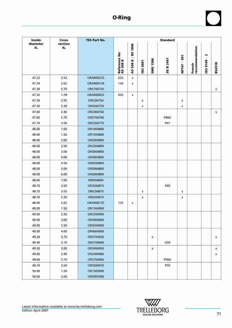
Insidediameter
d1
Crosssection
d2
TSS Part No. Standard
Re
fere
nce
No:
AS
56
8B
AS
56
8B
=B
S1
80
6
ISO
36
01
SM
S1
58
6
JIS
B2
40
1
NFT47
50
1
Fre
nch
reco
mm
en
da
tio
n
ISO
61
49
2
BS
451
8
47.22
47.29
47.30
3.53
2.62
5.70
ORAR00225
ORAR00134
OR5704730
225
134
x
x
x
47.35
47.50
47.50
1.78
3.55
5.30
ORAR00032
ORIC04750
ORID04750
032 x
x
x
x
x
47.60
47.60
47.70
2.40
5.70
3.50
OR2404760
OR5704760
OR3504770
P48A
P47
x
48.00
48.00
48.00
1.00
1.50
2.00
OR1004800
OR1504800
OR2004800
48.00
48.00
48.00
2.50
3.00
4.00
OR2504800
OR3004800
OR4004800
48.00
48.00
48.00
4.50
5.00
6.00
OR4504800
OR5004800
OR6004800
48.00
48.70
48.70
7.00
3.50
3.55
ORIE04800
OR3504870
ORIC04870 x
P49
x
48.70
48.90
49.00
5.30
2.62
1.50
ORID04870
ORAR00135
OR1504900
135 x
x x
49.00
49.00
49.00
2.50
3.00
3.50
OR2504900
OR3004900
OR3504900
49.00
49.20
49.40
4.00
5.70
3.10
OR4004900
OR5704920
OR3104940
x
G50
x
49.50
49.60
49.60
3.00
2.40
5.70
OR3004950
OR2404960
OR5704960
x
P50A
x
x
49.70
50.00
50.00
3.50
1.50
2.00
OR3504970
OR1505000
OR2005000
P50
O—Ring
Latest information available at www.tss.trelleborg.comEdition April 2007
71

Insidediameter
d1
Crosssection
d2
TSS Part No. Standard
Re
fere
nce
No:
AS
56
8B
AS
56
8B
=B
S1
80
6
ISO
36
01
SM
S1
58
6
JIS
B2
40
1
NFT47
50
1
Fre
nch
reco
mm
en
da
tio
n
ISO
61
49
2
BS
451
8
50.00
50.00
50.00
2.50
3.00
3.55
OR2505000
OR3005000
ORIC05000 x x
50.00
50.00
50.00
4.00
4.50
5.00
OR4005000
OR4505000
OR5005000
50.00
50.00
50.00
5.30
5.50
6.00
ORID05000
OR5505000
OR6005000
x x
50.00
50.00
50.17
6.50
7.00
5.33
OR6505000
ORIE05000
ORAR00329 329 x R32
50.20
50.39
50.47
3.00
3.53
2.62
OR3005020
ORAR00226
ORAR00136
226
136
x
x
x
50.52
51.00
51.00
1.78
2.50
3.00
ORAR00033
OR2505100
OR3005100
033 x
51.00
51.00
51.00
4.00
4.50
5.50
OR4005100
OR4505100
OR5505100
51.20
51.50
51.50
5.70
1.50
3.55
OR5705120
OR1505150
ORIC05150 x x
x
51.50
51.60
51.60
5.30
2.40
5.70
ORID05150
OR2405160
OR5705160
x
P52
x
x
52.00
52.00
52.00
1.50
2.00
2.50
OR1505200
OR2005200
OR2505200
52.00
52.00
52.00
3.00
3.50
4.00
OR3005200
OR3505200
OR4005200
52.00
52.00
52.07
5.00
6.00
2.62
OR5005200
OR6005200
ORAR00137 137 x
O—Ring
Latest information available at www.tss.trelleborg.com
72Edition April 2007

Insidediameter
d1
Crosssection
d2
TSS Part No. Standard
Re
fere
nce
No:
AS
56
8B
AS
56
8B
=B
S1
80
6
ISO
36
01
SM
S1
58
6
JIS
B2
40
1
NFT47
50
1
Fre
nch
reco
mm
en
da
tio
n
ISO
61
49
2
BS
451
8
52.30
52.60
53.00
5.70
5.70
1.50
OR5705230
OR5705260
OR1505300
P53
x
53.00
53.00
53.00
2.00
2.50
3.00
OR2005300
OR2505300
OR3005300
53.00
53.00
53.00
3.50
3.55
5.00
OR3505300
ORIC05300
OR5005300
x x
53.00
53.00
53.00
5.30
6.00
7.00
ORID05300
OR6005300
ORIE05300
x x
53.09
53.34
53.57
3.00
5.33
3.53
ORAR00928
ORAR00330
ORAR00227
928
330
227
x
x
x
R33
53.64
53.70
54.00
2.62
1.78
1.50
ORAR00138
ORAR00034
OR1505400
138
034
x
x
54.00
54.00
54.00
2.50
3.00
4.00
OR2505400
OR3005400
OR4005400
54.00
54.00
54.00
5.00
5.50
6.00
OR5005400
OR5505400
OR6005400
54.20
54.30
54.40
5.70
5.70
3.10
OR5705420
OR5705430
OR3105440
x
G55
x
54.50
54.50
54.50
3.00
3.55
5.30
OR3005450
ORIC05450
ORID05450
x
x
x
x
x
x
54.60
54.60
55.00
2.40
5.70
1.50
OR2405460
OR5705460
OR1505500
P55
x
55.00
55.00
55.00
2.00
2.50
3.00
OR2005500
OR2505500
OR3005500
O—Ring
Latest information available at www.tss.trelleborg.comEdition April 2007
73
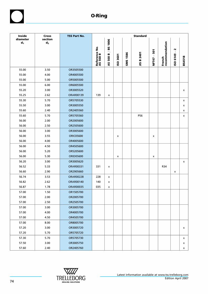
Insidediameter
d1
Crosssection
d2
TSS Part No. Standard
Re
fere
nce
No:
AS
56
8B
AS
56
8B
=B
S1
80
6
ISO
36
01
SM
S1
58
6
JIS
B2
40
1
NFT47
50
1
Fre
nch
reco
mm
en
da
tio
n
ISO
61
49
2
BS
451
8
55.00
55.00
55.00
3.50
4.00
5.00
OR3505500
OR4005500
OR5005500
55.00
55.20
55.25
6.00
3.00
2.62
OR6005500
OR3005520
ORAR00139 139 x
x
55.30
55.50
55.60
5.70
3.00
2.40
OR5705530
OR3005550
OR2405560
x
x
x
55.60
56.00
56.00
5.70
2.00
2.50
OR5705560
OR2005600
OR2505600
P56 x
56.00
56.00
56.00
3.00
3.55
4.00
OR3005600
ORIC05600
OR4005600
x x
56.00
56.00
56.00
4.50
5.20
5.30
OR4505600
OR5205600
ORID05600 x x
56.20
56.52
56.60
3.00
5.33
2.90
OR3005620
ORAR00331
OR2905660
331 x R34
x
x
56.74
56.82
56.87
3.53
2.62
1.78
ORAR00228
ORAR00140
ORAR00035
228
140
035
x
x
x
57.00
57.00
57.00
1.50
2.00
2.50
OR1505700
OR2005700
OR2505700
57.00
57.00
57.00
3.00
4.00
4.50
OR3005700
OR4005700
OR4505700
57.00
57.20
57.20
8.00
3.00
5.70
OR8005700
OR3005720
OR5705720
x
57.30
57.50
57.60
5.70
3.00
2.40
OR5705730
OR3005750
OR2405760
x
x
x
O—Ring
Latest information available at www.tss.trelleborg.com
74Edition April 2007
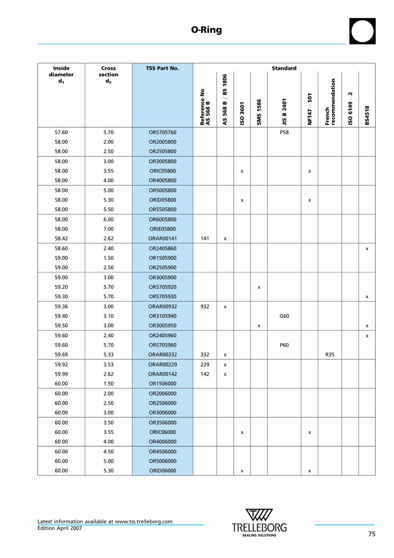
Insidediameter
d1
Crosssection
d2
TSS Part No. Standard
Re
fere
nce
No:
AS
56
8B
AS
56
8B
=B
S1
80
6
ISO
36
01
SM
S1
58
6
JIS
B2
40
1
NFT47
50
1
Fre
nch
reco
mm
en
da
tio
n
ISO
61
49
2
BS
451
8
57.60
58.00
58.00
5.70
2.00
2.50
OR5705760
OR2005800
OR2505800
P58
58.00
58.00
58.00
3.00
3.55
4.00
OR3005800
ORIC05800
OR4005800
x x
58.00
58.00
58.00
5.00
5.30
5.50
OR5005800
ORID05800
OR5505800
x x
58.00
58.00
58.42
6.00
7.00
2.62
OR6005800
ORIE05800
ORAR00141 141 x
58.60
59.00
59.00
2.40
1.50
2.50
OR2405860
OR1505900
OR2505900
x
59.00
59.20
59.30
3.00
5.70
5.70
OR3005900
OR5705920
OR5705930
x
x
59.36
59.40
59.50
3.00
3.10
3.00
ORAR00932
OR3105940
OR3005950
932 x
x
G60
x
59.60
59.60
59.69
2.40
5.70
5.33
OR2405960
OR5705960
ORAR00332 332 x
P60
R35
x
59.92
59.99
60.00
3.53
2.62
1.50
ORAR00229
ORAR00142
OR1506000
229
142
x
x
60.00
60.00
60.00
2.00
2.50
3.00
OR2006000
OR2506000
OR3006000
60.00
60.00
60.00
3.50
3.55
4.00
OR3506000
ORIC06000
OR4006000
x x
60.00
60.00
60.00
4.50
5.00
5.30
OR4506000
OR5006000
ORID06000 x x
O—Ring
Latest information available at www.tss.trelleborg.comEdition April 2007
75
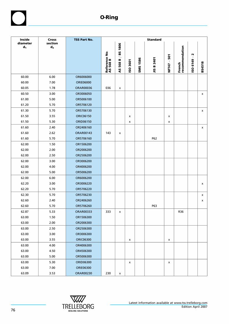
Insidediameter
d1
Crosssection
d2
TSS Part No. Standard
Re
fere
nce
No:
AS
56
8B
AS
56
8B
=B
S1
80
6
ISO
36
01
SM
S1
58
6
JIS
B2
40
1
NFT47
50
1
Fre
nch
reco
mm
en
da
tio
n
ISO
61
49
2
BS
451
8
60.00
60.00
60.05
6.00
7.00
1.78
OR6006000
ORIE06000
ORAR00036 036 x
60.50
61.00
61.20
3.00
5.00
5.70
OR3006050
OR5006100
OR5706120
x
61.30
61.50
61.50
5.70
3.55
5.30
OR5706130
ORIC06150
ORID06150
x
x
x
x
x
61.60
61.60
61.60
2.40
2.62
5.70
OR2406160
ORAR00143
OR5706160
143 x
P62
x
62.00
62.00
62.00
1.50
2.00
2.50
OR1506200
OR2006200
OR2506200
62.00
62.00
62.00
3.00
4.00
5.00
OR3006200
OR4006200
OR5006200
62.00
62.20
62.20
6.00
3.00
5.70
OR6006200
OR3006220
OR5706220
x
62.30
62.60
62.60
5.70
2.40
5.70
OR5706230
OR2406260
OR5706260 P63
x
x
62.87
63.00
63.00
5.33
1.50
2.00
ORAR00333
OR1506300
OR2006300
333 x R36
63.00
63.00
63.00
2.50
3.00
3.55
OR2506300
OR3006300
ORIC06300 x x
63.00
63.00
63.00
4.00
4.50
5.00
OR4006300
OR4506300
OR5006300
63.00
63.00
63.09
5.30
7.00
3.53
ORID06300
ORIE06300
ORAR00230 230 x
x x
O—Ring
Latest information available at www.tss.trelleborg.com
76Edition April 2007
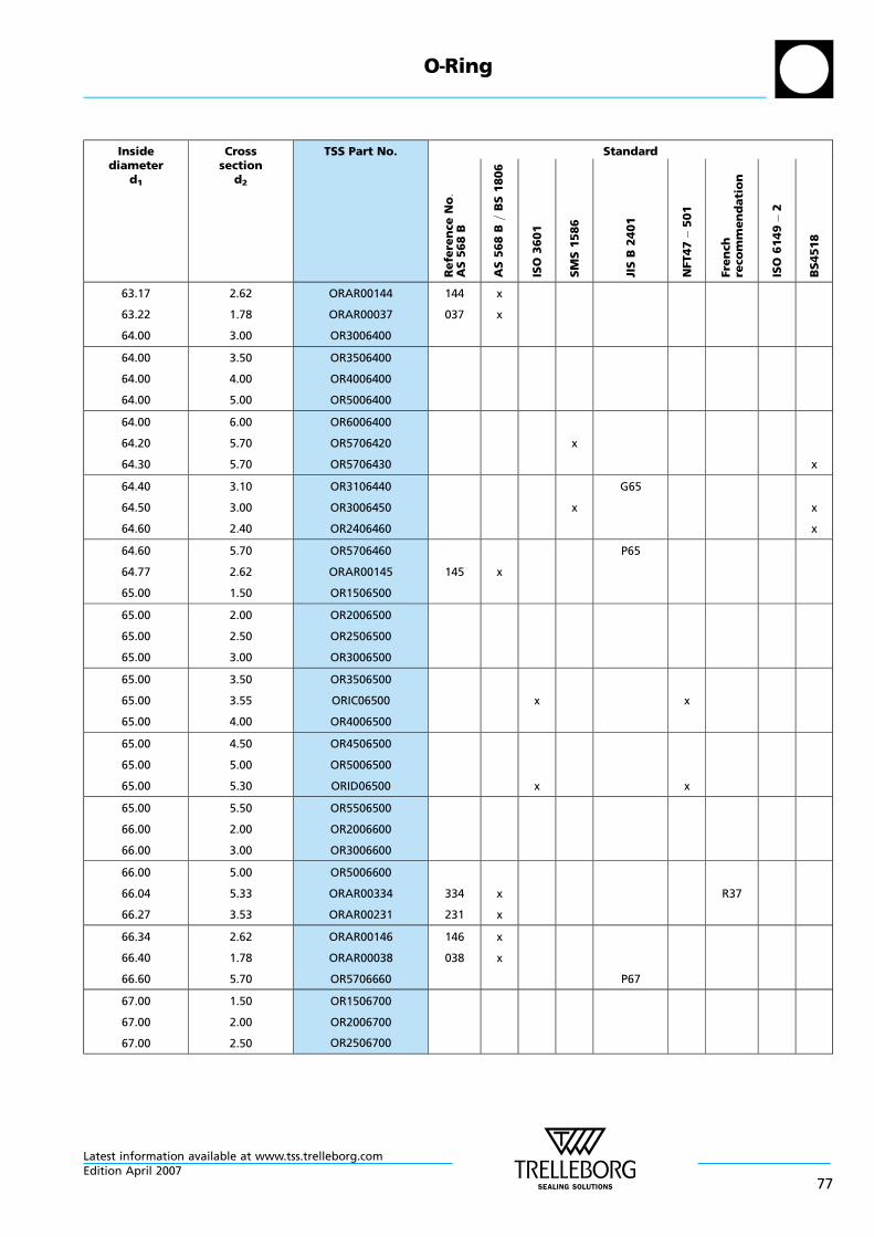
Insidediameter
d1
Crosssection
d2
TSS Part No. Standard
Re
fere
nce
No:
AS
56
8B
AS
56
8B
=B
S1
80
6
ISO
36
01
SM
S1
58
6
JIS
B2
40
1
NFT47
50
1
Fre
nch
reco
mm
en
da
tio
n
ISO
61
49
2
BS
451
8
63.17
63.22
64.00
2.62
1.78
3.00
ORAR00144
ORAR00037
OR3006400
144
037
x
x
64.00
64.00
64.00
3.50
4.00
5.00
OR3506400
OR4006400
OR5006400
64.00
64.20
64.30
6.00
5.70
5.70
OR6006400
OR5706420
OR5706430
x
x
64.40
64.50
64.60
3.10
3.00
2.40
OR3106440
OR3006450
OR2406460
x
G65
x
x
64.60
64.77
65.00
5.70
2.62
1.50
OR5706460
ORAR00145
OR1506500
145 x
P65
65.00
65.00
65.00
2.00
2.50
3.00
OR2006500
OR2506500
OR3006500
65.00
65.00
65.00
3.50
3.55
4.00
OR3506500
ORIC06500
OR4006500
x x
65.00
65.00
65.00
4.50
5.00
5.30
OR4506500
OR5006500
ORID06500 x x
65.00
66.00
66.00
5.50
2.00
3.00
OR5506500
OR2006600
OR3006600
66.00
66.04
66.27
5.00
5.33
3.53
OR5006600
ORAR00334
ORAR00231
334
231
x
x
R37
66.34
66.40
66.60
2.62
1.78
5.70
ORAR00146
ORAR00038
OR5706660
146
038
x
x
P67
67.00
67.00
67.00
1.50
2.00
2.50
OR1506700
OR2006700
OR2506700
O—Ring
Latest information available at www.tss.trelleborg.comEdition April 2007
77
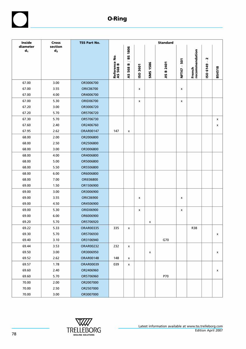
Insidediameter
d1
Crosssection
d2
TSS Part No. Standard
Re
fere
nce
No:
AS
56
8B
AS
56
8B
=B
S1
80
6
ISO
36
01
SM
S1
58
6
JIS
B2
40
1
NFT47
50
1
Fre
nch
reco
mm
en
da
tio
n
ISO
61
49
2
BS
451
8
67.00
67.00
67.00
3.00
3.55
4.00
OR3006700
ORIC06700
OR4006700
x x
67.00
67.20
67.20
5.30
3.00
5.70
ORID06700
OR3006720
OR5706720
x x
67.30
67.60
67.95
5.70
2.40
2.62
OR5706730
OR2406760
ORAR00147 147 x
x
x
68.00
68.00
68.00
2.00
2.50
3.00
OR2006800
OR2506800
OR3006800
68.00
68.00
68.00
4.00
5.00
5.50
OR4006800
OR5006800
OR5506800
68.00
68.00
69.00
6.00
7.00
1.50
OR6006800
ORIE06800
OR1506900
69.00
69.00
69.00
3.00
3.55
4.50
OR3006900
ORIC06900
OR4506900
x x
69.00
69.00
69.20
5.30
6.00
5.70
ORID06900
OR6006900
OR5706920
x
x
x
69.22
69.30
69.40
5.33
5.70
3.10
ORAR00335
OR5706930
OR3106940
335 x
G70
R38
x
69.44
69.50
69.52
3.53
3.00
2.62
ORAR00232
OR3006950
ORAR00148
232
148
x
x
x x
69.57
69.60
69.60
1.78
2.40
5.70
ORAR00039
OR2406960
OR5706960
039 x
P70
x
70.00
70.00
70.00
2.00
2.50
3.00
OR2007000
OR2507000
OR3007000
O—Ring
Latest information available at www.tss.trelleborg.com
78Edition April 2007
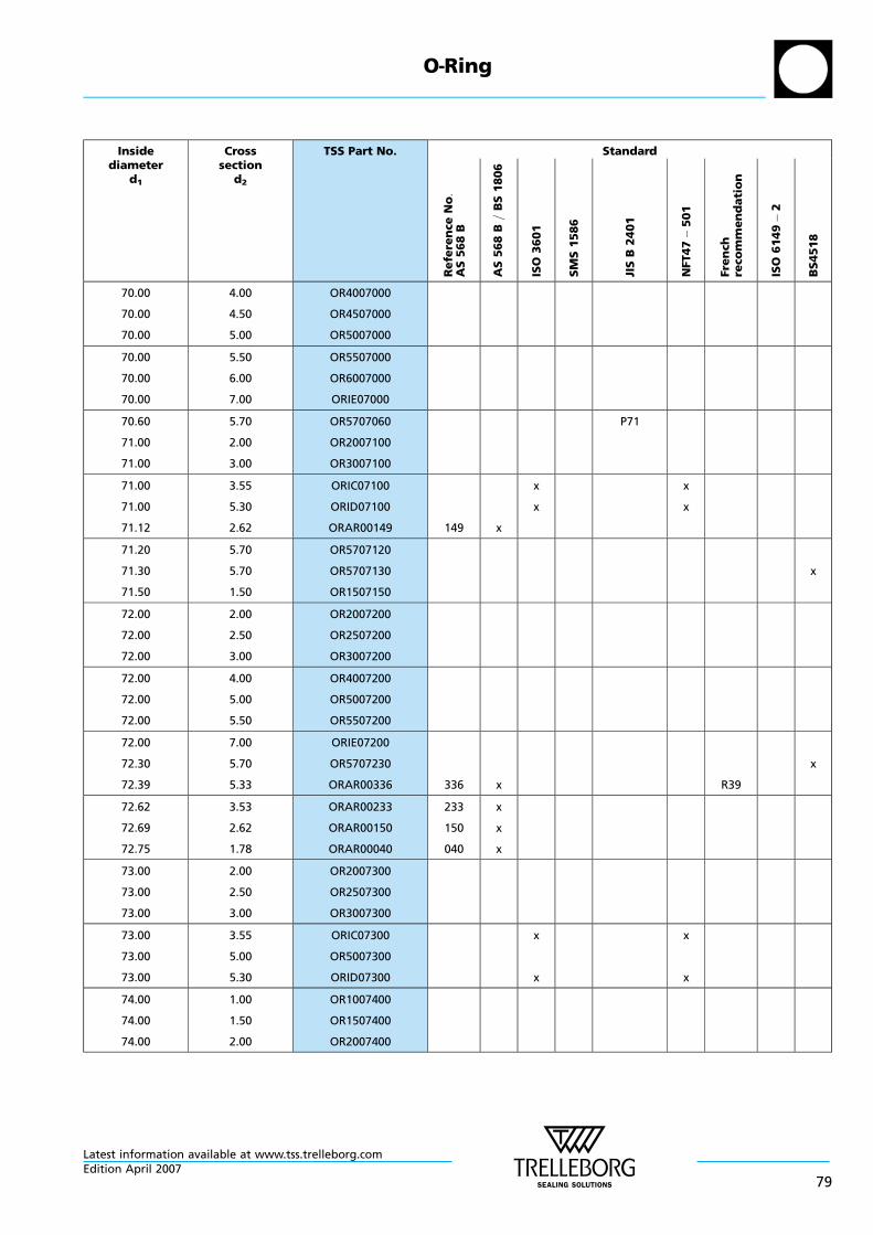
Insidediameter
d1
Crosssection
d2
TSS Part No. Standard
Re
fere
nce
No:
AS
56
8B
AS
56
8B
=B
S1
80
6
ISO
36
01
SM
S1
58
6
JIS
B2
40
1
NFT47
50
1
Fre
nch
reco
mm
en
da
tio
n
ISO
61
49
2
BS
451
8
70.00
70.00
70.00
4.00
4.50
5.00
OR4007000
OR4507000
OR5007000
70.00
70.00
70.00
5.50
6.00
7.00
OR5507000
OR6007000
ORIE07000
70.60
71.00
71.00
5.70
2.00
3.00
OR5707060
OR2007100
OR3007100
P71
71.00
71.00
71.12
3.55
5.30
2.62
ORIC07100
ORID07100
ORAR00149 149 x
x
x
x
x
71.20
71.30
71.50
5.70
5.70
1.50
OR5707120
OR5707130
OR1507150
x
72.00
72.00
72.00
2.00
2.50
3.00
OR2007200
OR2507200
OR3007200
72.00
72.00
72.00
4.00
5.00
5.50
OR4007200
OR5007200
OR5507200
72.00
72.30
72.39
7.00
5.70
5.33
ORIE07200
OR5707230
ORAR00336 336 x R39
x
72.62
72.69
72.75
3.53
2.62
1.78
ORAR00233
ORAR00150
ORAR00040
233
150
040
x
x
x
73.00
73.00
73.00
2.00
2.50
3.00
OR2007300
OR2507300
OR3007300
73.00
73.00
73.00
3.55
5.00
5.30
ORIC07300
OR5007300
ORID07300
x
x
x
x
74.00
74.00
74.00
1.00
1.50
2.00
OR1007400
OR1507400
OR2007400
O—Ring
Latest information available at www.tss.trelleborg.comEdition April 2007
79

Insidediameter
d1
Crosssection
d2
TSS Part No. Standard
Re
fere
nce
No:
AS
56
8B
AS
56
8B
=B
S1
80
6
ISO
36
01
SM
S1
58
6
JIS
B2
40
1
NFT47
50
1
Fre
nch
reco
mm
en
da
tio
n
ISO
61
49
2
BS
451
8
74.00
74.00
74.00
2.50
3.00
4.00
OR2507400
OR3007400
OR4007400
x
74.00
74.00
74.20
4.50
6.00
5.70
OR4507400
OR6007400
OR5707420 x
74.30
74.40
74.50
5.70
3.10
3.00
OR5707430
OR3107440
OR3007450 x
G75
x
x
74.60
75.00
75.00
5.70
2.00
2.50
OR5707460
OR2007500
OR2507500
P75
75.00
75.00
75.00
3.00
3.50
3.55
OR3007500
OR3507500
ORIC07500 x x
75.00
75.00
75.00
4.00
4.50
5.00
OR4007500
OR4507500
OR5007500
75.00
75.00
75.00
5.30
5.50
6.00
ORID07500
OR5507500
OR6007500
x x
75.00
75.57
75.79
7.00
5.33
3.53
ORIE07500
ORAR00337
ORAR00234
337
234
x
x
R40
75.87
75.92
76.00
2.62
1.78
1.50
ORAR00151
ORAR00041
OR1507600
151
041
x
x
76.00
76.00
76.00
2.00
2.50
3.00
OR2007600
OR2507600
OR3007600
76.00
76.00
76.00
4.00
4.50
5.00
OR4007600
OR4507600
OR5007600
77.00
77.30
77.50
5.00
5.70
3.55
OR5007700
OR5707730
ORIC07750 x x
x
O—Ring
Latest information available at www.tss.trelleborg.com
80Edition April 2007
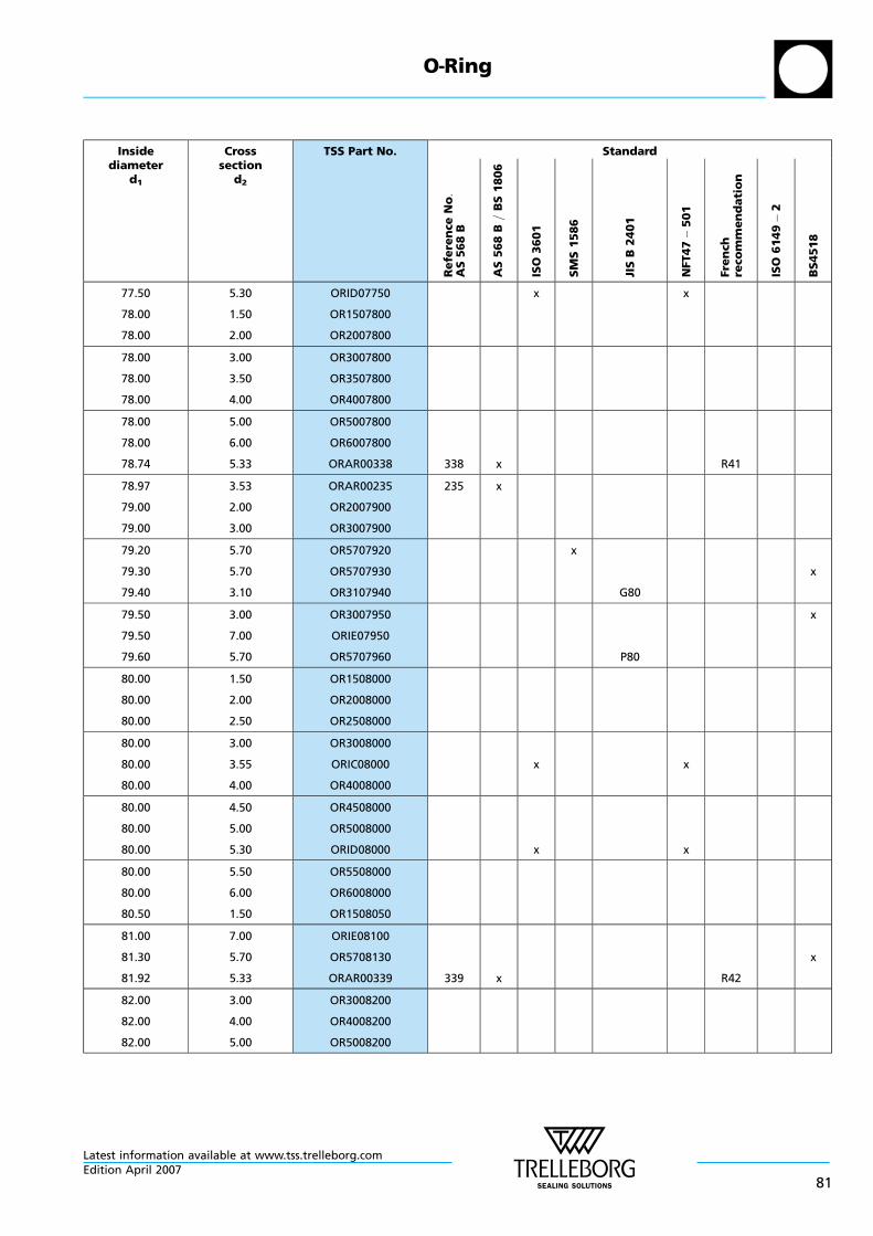
Insidediameter
d1
Crosssection
d2
TSS Part No. Standard
Re
fere
nce
No:
AS
56
8B
AS
56
8B
=B
S1
80
6
ISO
36
01
SM
S1
58
6
JIS
B2
40
1
NFT47
50
1
Fre
nch
reco
mm
en
da
tio
n
ISO
61
49
2
BS
451
8
77.50
78.00
78.00
5.30
1.50
2.00
ORID07750
OR1507800
OR2007800
x x
78.00
78.00
78.00
3.00
3.50
4.00
OR3007800
OR3507800
OR4007800
78.00
78.00
78.74
5.00
6.00
5.33
OR5007800
OR6007800
ORAR00338 338 x R41
78.97
79.00
79.00
3.53
2.00
3.00
ORAR00235
OR2007900
OR3007900
235 x
79.20
79.30
79.40
5.70
5.70
3.10
OR5707920
OR5707930
OR3107940
x
G80
x
79.50
79.50
79.60
3.00
7.00
5.70
OR3007950
ORIE07950
OR5707960 P80
x
80.00
80.00
80.00
1.50
2.00
2.50
OR1508000
OR2008000
OR2508000
80.00
80.00
80.00
3.00
3.55
4.00
OR3008000
ORIC08000
OR4008000
x x
80.00
80.00
80.00
4.50
5.00
5.30
OR4508000
OR5008000
ORID08000 x x
80.00
80.00
80.50
5.50
6.00
1.50
OR5508000
OR6008000
OR1508050
81.00
81.30
81.92
7.00
5.70
5.33
ORIE08100
OR5708130
ORAR00339 339 x R42
x
82.00
82.00
82.00
3.00
4.00
5.00
OR3008200
OR4008200
OR5008200
O—Ring
Latest information available at www.tss.trelleborg.comEdition April 2007
81

Insidediameter
d1
Crosssection
d2
TSS Part No. Standard
Re
fere
nce
No:
AS
56
8B
AS
56
8B
=B
S1
80
6
ISO
36
01
SM
S1
58
6
JIS
B2
40
1
NFT47
50
1
Fre
nch
reco
mm
en
da
tio
n
ISO
61
49
2
BS
451
8
82.14
82.20
82.22
3.53
5.70
2.62
ORAR00236
OR5708220
ORAR00152
236
152
x
x
82.27
82.50
82.50
1.78
3.55
5.30
ORAR00042
ORIC08250
ORID08250
042 x
x
x
x
x
83.00
83.00
84.00
2.00
3.00
2.00
OR2008300
OR3008300
OR2008400
84.00
84.00
84.00
3.00
4.00
6.00
OR3008400
OR4008400
OR6008400
84.10
84.20
84.30
5.70
5.70
5.70
OR5708410
OR5708420
OR5708430
x
x
84.40
84.50
84.60
3.10
3.00
5.70
OR3108440
OR3008450
OR5708460
x
G85
P85
x
85.00
85.00
85.00
2.00
2.50
3.00
OR2008500
OR2508500
OR3008500
85.00
85.00
85.00
3.55
4.00
4.50
ORIC08500
OR4008500
OR4508500
x x
85.00
85.00
85.00
5.00
5.30
5.50
OR5008500
ORID08500
OR5508500
x x
85.00
85.00
85.09
6.00
7.00
5.33
OR6008500
ORIE08500
ORAR00340 340 x R43
85.32
85.50
86.00
3.53
2.50
2.00
ORAR00237
OR2508550
OR2008600
237 x
86.00
86.00
86.00
3.00
4.00
4.50
OR3008600
OR4008600
OR4508600
O—Ring
Latest information available at www.tss.trelleborg.com
82Edition April 2007

Insidediameter
d1
Crosssection
d2
TSS Part No. Standard
Re
fere
nce
No:
AS
56
8B
AS
56
8B
=B
S1
80
6
ISO
36
01
SM
S1
58
6
JIS
B2
40
1
NFT47
50
1
Fre
nch
reco
mm
en
da
tio
n
ISO
61
49
2
BS
451
8
87.00
87.00
87.20
4.00
5.00
5.70
OR4008700
OR5008700
OR5708720
87.30
87.50
87.50
5.70
3.55
5.30
OR5708730
ORIC08750
ORID08750
x
x
x
x
x
88.00
88.00
88.00
1.50
3.00
4.00
OR1508800
OR3008800
OR4008800
88.00
88.00
88.27
5.00
6.00
5.33
OR5008800
OR6008800
ORAR00341 341 x R44
88.49
88.57
88.62
3.53
2.62
1.78
ORAR00238
ORAR00153
ORAR00043
238
153
043
x
x
x
89.00
89.00
89.00
3.00
4.50
7.00
OR3008900
OR4508900
ORIE08900
89.10
89.30
89.40
5.70
5.70
3.10
OR5708910
OR5708930
OR3108940
x
G90
x
89.50
89.60
90.00
3.00
5.70
1.00
OR3008950
OR5708960
OR1009000
x
P90
x
90.00
90.00
90.00
2.00
2.50
3.00
OR2009000
OR2509000
OR3009000
90.00
90.00
90.00
3.55
4.00
4.50
ORIC09000
OR4009000
OR4509000
x x
90.00
90.00
90.00
5.00
5.30
5.50
OR5009000
ORID09000
OR5509000
x x
90.00
90.00
91.44
6.00
7.00
5.33
OR6009000
ORIE09000
ORAR00342 342 x R45
O—Ring
Latest information available at www.tss.trelleborg.comEdition April 2007
83

Insidediameter
d1
Crosssection
d2
TSS Part No. Standard
Re
fere
nce
No:
AS
56
8B
AS
56
8B
=B
S1
80
6
ISO
36
01
SM
S1
58
6
JIS
B2
40
1
NFT47
50
1
Fre
nch
reco
mm
en
da
tio
n
ISO
61
49
2
BS
451
8
91.67
92.00
92.00
3.53
1.50
3.00
ORAR00239
OR1509200
OR3009200
239 x
92.00
92.00
92.00
4.00
4.50
5.00
OR4009200
OR4509200
OR5009200
92.00
92.00
92.30
5.50
7.00
5.70
OR5509200
ORIE09200
OR5709230 x
92.50
92.50
93.00
3.55
5.30
2.00
ORIC09250
ORID09250
OR2009300
x
x
x
x
93.00
93.00
93.50
3.00
4.00
4.50
OR3009300
OR4009300
OR4509350
94.00
94.00
94.00
2.50
3.00
4.00
OR2509400
OR3009400
OR4009400
94.00
94.00
94.10
5.00
7.00
5.70
OR5009400
ORIE09400
OR5709410 x
94.30
94.40
94.50
5.70
3.10
3.00
OR5709430
OR3109440
OR3009450 x
G95
x
x
94.60
94.62
94.84
5.70
5.33
3.53
OR5709460
ORAR00343
ORAR00240
343
240
x
x
P95
R46
94.92
94.97
95.00
2.62
1.78
2.00
ORAR00154
ORAR00044
OR2009500
154
044
x
x
95.00
95.00
95.00
2.50
3.55
4.00
OR2509500
ORIC09500
OR4009500
x x
95.00
95.00
95.00
4.50
5.00
5.30
OR4509500
OR5009500
ORID09500 x x
O—Ring
Latest information available at www.tss.trelleborg.com
84Edition April 2007

Insidediameter
d1
Crosssection
d2
TSS Part No. Standard
Re
fere
nce
No:
AS
56
8B
AS
56
8B
=B
S1
80
6
ISO
36
01
SM
S1
58
6
JIS
B2
40
1
NFT47
50
1
Fre
nch
reco
mm
en
da
tio
n
ISO
61
49
2
BS
451
8
95.00
95.00
95.00
5.50
6.00
7.00
OR5509500
OR6009500
ORIE09500
96.00
96.00
96.00
2.50
3.00
4.00
OR2509600
OR3009600
OR4009600
96.00
96.00
96.50
5.00
6.00
6.50
OR5009600
OR6009600
OR6509650
97.00
97.00
97.30
3.50
5.00
5.70
OR3509700
OR5009700
OR5709730 x
97.50
97.50
97.79
3.55
5.30
5.33
ORIC09750
ORID09750
ORAR00344 344 x
x
x
x
x
R47
98.00
98.00
98.00
2.50
3.00
4.00
OR2509800
OR3009800
OR4009800
98.02
99.00
99.00
3.53
3.00
7.00
ORAR00241
OR3009900
ORIE09900
241 x
99.10
99.30
99.40
5.70
5.70
3.10
OR5709910
OR5709930
OR3109940
x
G100
x
99.50
99.60
100.00
3.00
5.70
1.00
OR3009950
OR5709960
OR1010000
x
P100
x
100.00
100.00
100.00
1.50
2.00
2.50
OR1510000
OR2010000
OR2510000
100.00
100.00
100.00
3.00
3.55
4.00
OR3010000
ORIC10000
OR4010000
x x
100.00
100.00
100.00
5.00
5.30
5.50
OR5010000
ORID10000
OR5510000
x x
O—Ring
Latest information available at www.tss.trelleborg.comEdition April 2007
85

Insidediameter
d1
Crosssection
d2
TSS Part No. Standard
Re
fere
nce
No:
AS
56
8B
AS
56
8B
=B
S1
80
6
ISO
36
01
SM
S1
58
6
JIS
B2
40
1
NFT47
50
1
Fre
nch
reco
mm
en
da
tio
n
ISO
61
49
2
BS
451
8
100.00
100.00
100.00
6.00
7.00
8.00
OR6010000
ORIE10000
OR8010000
100.97
101.19
101.27
5.33
3.53
2.62
ORAR00345
ORAR00242
ORAR00155
345
242
155
x
x
x
R48
101.32
101.60
102.00
1.78
5.70
3.00
ORAR00045
OR5710160
OR3010200
045 x
P102
102.00
103.00
103.00
4.00
2.00
3.55
OR4010200
OR2010300
ORIC10300 x x
103.00
103.00
104.00
5.30
6.00
2.50
ORID10300
OR6010300
OR2510400
x x
104.00
104.00
104.00
3.00
4.00
5.00
OR3010400
OR4010400
OR5010400
104.00
104.10
104.14
6.00
5.70
5.33
OR6010400
OR5710410
ORAR00346 346 x
x
R49
104.30
104.37
104.40
5.70
3.53
3.10
OR5710430
ORAR00243
OR3110440
243 x
G105
x
104.50
104.60
105.00
3.00
5.70
2.00
OR3010450
OR5710460
OR2010500
x
P105
x
105.00
105.00
105.00
2.50
3.00
3.50
OR2510500
OR3010500
OR3510500
105.00
105.00
105.00
4.00
4.50
5.00
OR4010500
OR4510500
OR5010500
105.00
106.00
106.00
6.00
2.00
3.00
OR6010500
OR2010600
OR3010600
O—Ring
Latest information available at www.tss.trelleborg.com
86Edition April 2007
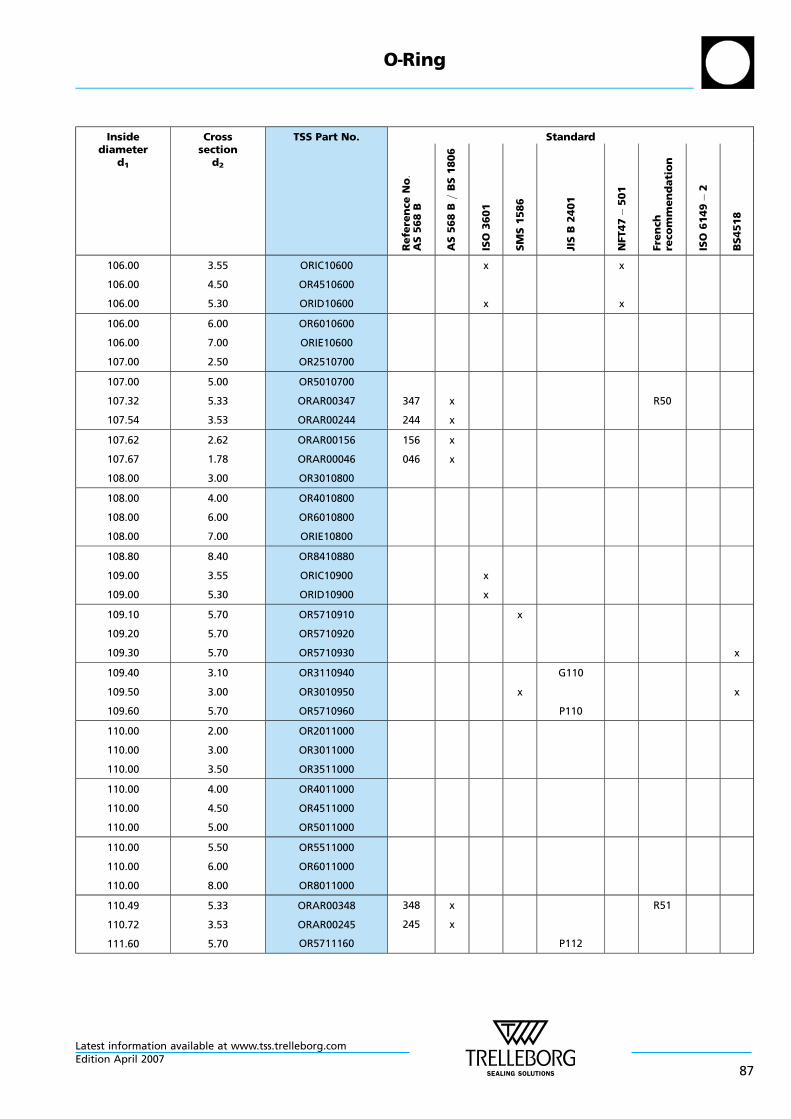
Insidediameter
d1
Crosssection
d2
TSS Part No. Standard
Re
fere
nce
No:
AS
56
8B
AS
56
8B
=B
S1
80
6
ISO
36
01
SM
S1
58
6
JIS
B2
40
1
NFT47
50
1
Fre
nch
reco
mm
en
da
tio
n
ISO
61
49
2
BS
451
8
106.00
106.00
106.00
3.55
4.50
5.30
ORIC10600
OR4510600
ORID10600
x
x
x
x
106.00
106.00
107.00
6.00
7.00
2.50
OR6010600
ORIE10600
OR2510700
107.00
107.32
107.54
5.00
5.33
3.53
OR5010700
ORAR00347
ORAR00244
347
244
x
x
R50
107.62
107.67
108.00
2.62
1.78
3.00
ORAR00156
ORAR00046
OR3010800
156
046
x
x
108.00
108.00
108.00
4.00
6.00
7.00
OR4010800
OR6010800
ORIE10800
108.80
109.00
109.00
8.40
3.55
5.30
OR8410880
ORIC10900
ORID10900
x
x
109.10
109.20
109.30
5.70
5.70
5.70
OR5710910
OR5710920
OR5710930
x
x
109.40
109.50
109.60
3.10
3.00
5.70
OR3110940
OR3010950
OR5710960
x
G110
P110
x
110.00
110.00
110.00
2.00
3.00
3.50
OR2011000
OR3011000
OR3511000
110.00
110.00
110.00
4.00
4.50
5.00
OR4011000
OR4511000
OR5011000
110.00
110.00
110.00
5.50
6.00
8.00
OR5511000
OR6011000
OR8011000
110.49
110.72
111.60
5.33
3.53
5.70
ORAR00348
ORAR00245
OR5711160
348
245
x
x
P112
R51
O—Ring
Latest information available at www.tss.trelleborg.comEdition April 2007
87
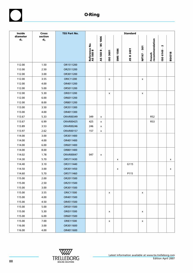
Insidediameter
d1
Crosssection
d2
TSS Part No. Standard
Re
fere
nce
No:
AS
56
8B
AS
56
8B
=B
S1
80
6
ISO
36
01
SM
S1
58
6
JIS
B2
40
1
NFT47
50
1
Fre
nch
reco
mm
en
da
tio
n
ISO
61
49
2
BS
451
8
112.00
112.00
112.00
1.50
2.50
3.00
OR1511200
OR2511200
OR3011200
112.00
112.00
112.00
3.55
4.00
5.00
ORIC11200
OR4011200
OR5011200
x x
112.00
112.00
112.00
5.30
6.00
8.00
ORID11200
OR6011200
OR8011200
x x
113.00
113.00
113.67
3.50
4.00
5.33
OR3511300
OR4011300
ORAR00349 349 x R52
113.67
113.89
113.97
6.99
3.53
2.62
ORAR00425
ORAR00246
ORAR00157
425
246
157
x
x
x
R53
114.00
114.00
114.00
3.00
4.00
6.00
OR3011400
OR4011400
OR6011400
114.00
114.02
114.30
8.00
1.78
5.70
OR8011400
ORAR00047
OR5711430
047 x
x x
114.40
114.50
114.60
3.10
3.00
5.70
OR3111440
OR3011450
OR5711460
x
G115
P115
x
115.00
115.00
115.00
2.00
2.50
3.00
OR2011500
OR2511500
OR3011500
115.00
115.00
115.00
3.55
4.00
4.50
ORIC11500
OR4011500
OR4511500
x x
115.00
115.00
115.00
5.00
5.30
6.00
OR5011500
ORID11500
OR6011500
x x
115.00
116.00
116.00
7.00
3.00
4.00
ORIE11500
OR3011600
OR4011600
x x
O—Ring
Latest information available at www.tss.trelleborg.com
88Edition April 2007
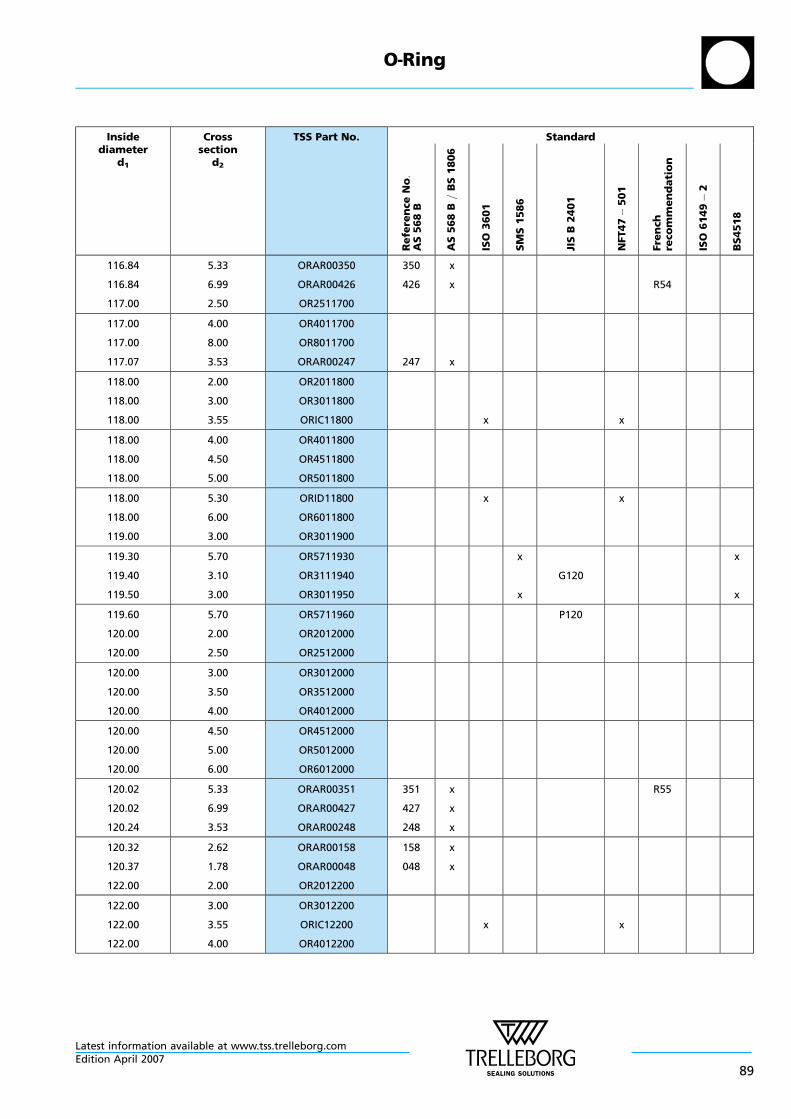
Insidediameter
d1
Crosssection
d2
TSS Part No. Standard
Re
fere
nce
No:
AS
56
8B
AS
56
8B
=B
S1
80
6
ISO
36
01
SM
S1
58
6
JIS
B2
40
1
NFT47
50
1
Fre
nch
reco
mm
en
da
tio
n
ISO
61
49
2
BS
451
8
116.84
116.84
117.00
5.33
6.99
2.50
ORAR00350
ORAR00426
OR2511700
350
426
x
x R54
117.00
117.00
117.07
4.00
8.00
3.53
OR4011700
OR8011700
ORAR00247 247 x
118.00
118.00
118.00
2.00
3.00
3.55
OR2011800
OR3011800
ORIC11800 x x
118.00
118.00
118.00
4.00
4.50
5.00
OR4011800
OR4511800
OR5011800
118.00
118.00
119.00
5.30
6.00
3.00
ORID11800
OR6011800
OR3011900
x x
119.30
119.40
119.50
5.70
3.10
3.00
OR5711930
OR3111940
OR3011950
x
x
G120
x
x
119.60
120.00
120.00
5.70
2.00
2.50
OR5711960
OR2012000
OR2512000
P120
120.00
120.00
120.00
3.00
3.50
4.00
OR3012000
OR3512000
OR4012000
120.00
120.00
120.00
4.50
5.00
6.00
OR4512000
OR5012000
OR6012000
120.02
120.02
120.24
5.33
6.99
3.53
ORAR00351
ORAR00427
ORAR00248
351
427
248
x
x
x
R55
120.32
120.37
122.00
2.62
1.78
2.00
ORAR00158
ORAR00048
OR2012200
158
048
x
x
122.00
122.00
122.00
3.00
3.55
4.00
OR3012200
ORIC12200
OR4012200
x x
O—Ring
Latest information available at www.tss.trelleborg.comEdition April 2007
89
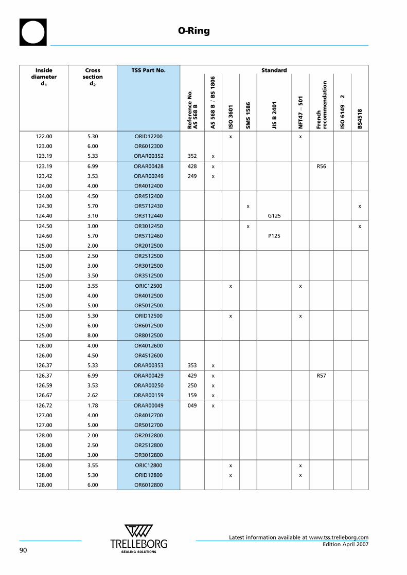
Insidediameter
d1
Crosssection
d2
TSS Part No. Standard
Re
fere
nce
No:
AS
56
8B
AS
56
8B
=B
S1
80
6
ISO
36
01
SM
S1
58
6
JIS
B2
40
1
NFT47
50
1
Fre
nch
reco
mm
en
da
tio
n
ISO
61
49
2
BS
451
8
122.00
123.00
123.19
5.30
6.00
5.33
ORID12200
OR6012300
ORAR00352 352 x
x x
123.19
123.42
124.00
6.99
3.53
4.00
ORAR00428
ORAR00249
OR4012400
428
249
x
x
R56
124.00
124.30
124.40
4.50
5.70
3.10
OR4512400
OR5712430
OR3112440
x
G125
x
124.50
124.60
125.00
3.00
5.70
2.00
OR3012450
OR5712460
OR2012500
x
P125
x
125.00
125.00
125.00
2.50
3.00
3.50
OR2512500
OR3012500
OR3512500
125.00
125.00
125.00
3.55
4.00
5.00
ORIC12500
OR4012500
OR5012500
x x
125.00
125.00
125.00
5.30
6.00
8.00
ORID12500
OR6012500
OR8012500
x x
126.00
126.00
126.37
4.00
4.50
5.33
OR4012600
OR4512600
ORAR00353 353 x
126.37
126.59
126.67
6.99
3.53
2.62
ORAR00429
ORAR00250
ORAR00159
429
250
159
x
x
x
R57
126.72
127.00
127.00
1.78
4.00
5.00
ORAR00049
OR4012700
OR5012700
049 x
128.00
128.00
128.00
2.00
2.50
3.00
OR2012800
OR2512800
OR3012800
128.00
128.00
128.00
3.55
5.30
6.00
ORIC12800
ORID12800
OR6012800
x
x
x
x
O—Ring
Latest information available at www.tss.trelleborg.com
90Edition April 2007
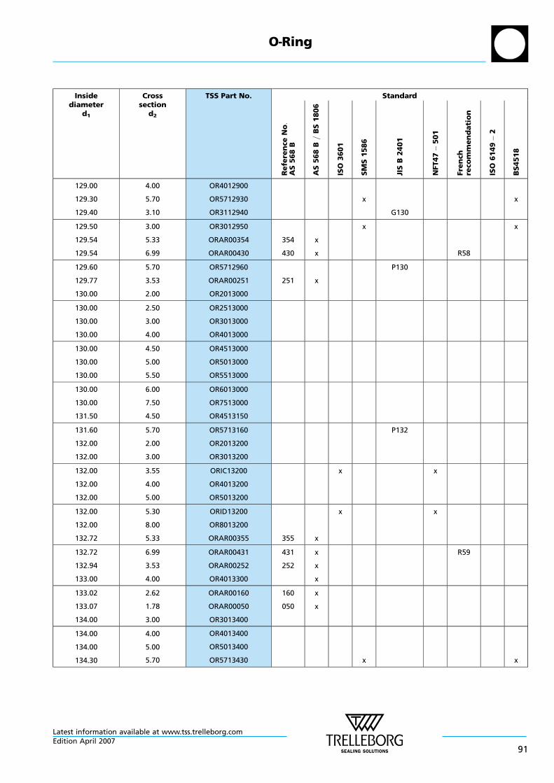
Insidediameter
d1
Crosssection
d2
TSS Part No. Standard
Re
fere
nce
No:
AS
56
8B
AS
56
8B
=B
S1
80
6
ISO
36
01
SM
S1
58
6
JIS
B2
40
1
NFT47
50
1
Fre
nch
reco
mm
en
da
tio
n
ISO
61
49
2
BS
451
8
129.00
129.30
129.40
4.00
5.70
3.10
OR4012900
OR5712930
OR3112940
x
G130
x
129.50
129.54
129.54
3.00
5.33
6.99
OR3012950
ORAR00354
ORAR00430
354
430
x
x
x
R58
x
129.60
129.77
130.00
5.70
3.53
2.00
OR5712960
ORAR00251
OR2013000
251 x
P130
130.00
130.00
130.00
2.50
3.00
4.00
OR2513000
OR3013000
OR4013000
130.00
130.00
130.00
4.50
5.00
5.50
OR4513000
OR5013000
OR5513000
130.00
130.00
131.50
6.00
7.50
4.50
OR6013000
OR7513000
OR4513150
131.60
132.00
132.00
5.70
2.00
3.00
OR5713160
OR2013200
OR3013200
P132
132.00
132.00
132.00
3.55
4.00
5.00
ORIC13200
OR4013200
OR5013200
x x
132.00
132.00
132.72
5.30
8.00
5.33
ORID13200
OR8013200
ORAR00355 355 x
x x
132.72
132.94
133.00
6.99
3.53
4.00
ORAR00431
ORAR00252
OR4013300
431
252
x
x
x
R59
133.02
133.07
134.00
2.62
1.78
3.00
ORAR00160
ORAR00050
OR3013400
160
050
x
x
134.00
134.00
134.30
4.00
5.00
5.70
OR4013400
OR5013400
OR5713430 x x
O—Ring
Latest information available at www.tss.trelleborg.comEdition April 2007
91

Insidediameter
d1
Crosssection
d2
TSS Part No. Standard
Re
fere
nce
No:
AS
56
8B
AS
56
8B
=B
S1
80
6
ISO
36
01
SM
S1
58
6
JIS
B2
40
1
NFT47
50
1
Fre
nch
reco
mm
en
da
tio
n
ISO
61
49
2
BS
451
8
134.40
134.50
135.00
3.10
3.00
2.00
OR3113440
OR3013450
OR2013500
x
G135
x
135.00
135.00
135.00
2.50
3.00
4.00
OR2513500
OR3013500
OR4013500
135.00
135.00
135.60
5.00
6.00
5.70
OR5013500
OR6013500
OR5713560 P135
135.89
135.89
136.00
5.33
6.99
3.55
ORAR00356
ORAR00432
ORIC13600
356
432
x
x
x x
R60
136.00
136.00
136.12
5.30
8.00
3.53
ORID13600
OR8013600
ORAR00253 253 x
x x
138.00
138.00
138.00
3.00
5.00
6.00
OR3013800
OR5013800
OR6013800
139.07
139.07
139.29
5.33
6.99
3.53
ORAR00357
ORAR00433
ORAR00254
357
433
254
x
x
x
R61
139.30
139.37
139.40
5.70
2.62
3.10
OR5713930
ORAR00161
OR3113940
161 x
x
G140
x
139.50
139.60
140.00
3.00
5.70
2.00
OR3013950
OR5713960
OR2014000
x
P140
x
140.00
140.00
140.00
2.50
3.00
3.55
OR2514000
OR3014000
ORIC14000 x x
140.00
140.00
140.00
4.00
4.50
5.00
OR4014000
OR4514000
OR5014000
140.00
142.00
142.00
5.30
4.00
6.00
ORID14000
OR4014200
OR6014200
x x
O—Ring
Latest information available at www.tss.trelleborg.com
92Edition April 2007
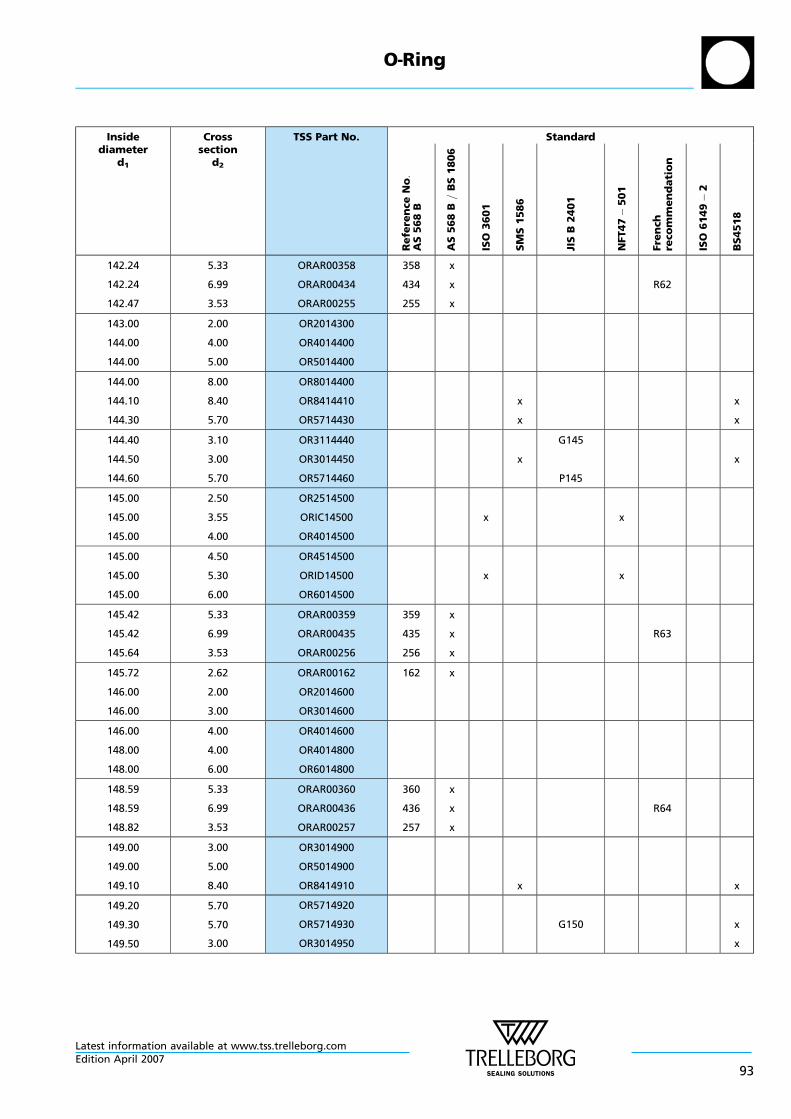
Insidediameter
d1
Crosssection
d2
TSS Part No. Standard
Re
fere
nce
No:
AS
56
8B
AS
56
8B
=B
S1
80
6
ISO
36
01
SM
S1
58
6
JIS
B2
40
1
NFT47
50
1
Fre
nch
reco
mm
en
da
tio
n
ISO
61
49
2
BS
451
8
142.24
142.24
142.47
5.33
6.99
3.53
ORAR00358
ORAR00434
ORAR00255
358
434
255
x
x
x
R62
143.00
144.00
144.00
2.00
4.00
5.00
OR2014300
OR4014400
OR5014400
144.00
144.10
144.30
8.00
8.40
5.70
OR8014400
OR8414410
OR5714430
x
x
x
x
144.40
144.50
144.60
3.10
3.00
5.70
OR3114440
OR3014450
OR5714460
x
G145
P145
x
145.00
145.00
145.00
2.50
3.55
4.00
OR2514500
ORIC14500
OR4014500
x x
145.00
145.00
145.00
4.50
5.30
6.00
OR4514500
ORID14500
OR6014500
x x
145.42
145.42
145.64
5.33
6.99
3.53
ORAR00359
ORAR00435
ORAR00256
359
435
256
x
x
x
R63
145.72
146.00
146.00
2.62
2.00
3.00
ORAR00162
OR2014600
OR3014600
162 x
146.00
148.00
148.00
4.00
4.00
6.00
OR4014600
OR4014800
OR6014800
148.59
148.59
148.82
5.33
6.99
3.53
ORAR00360
ORAR00436
ORAR00257
360
436
257
x
x
x
R64
149.00
149.00
149.10
3.00
5.00
8.40
OR3014900
OR5014900
OR8414910 x x
149.20
149.30
149.50
5.70
5.70
3.00
OR5714920
OR5714930
OR3014950
G150 x
x
O—Ring
Latest information available at www.tss.trelleborg.comEdition April 2007
93
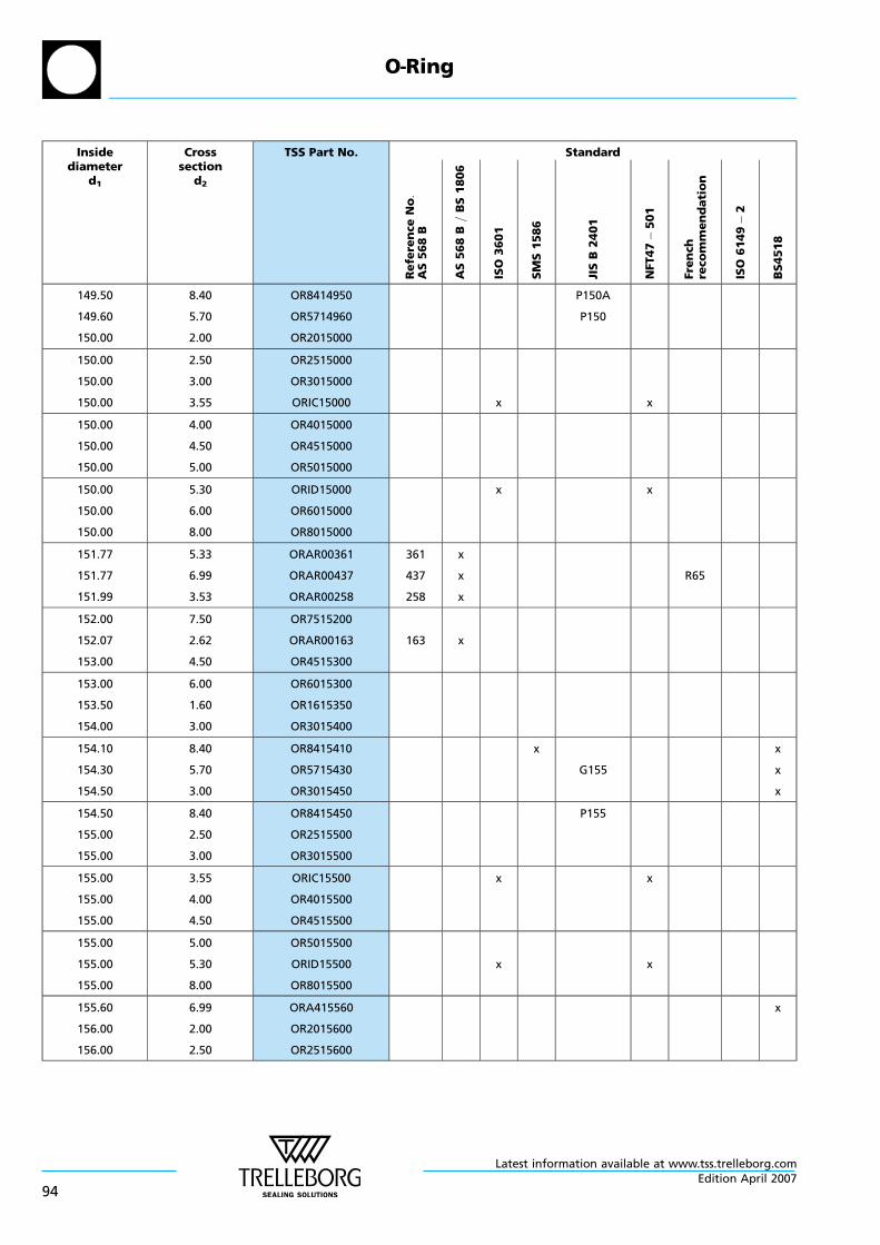
Insidediameter
d1
Crosssection
d2
TSS Part No. Standard
Re
fere
nce
No:
AS
56
8B
AS
56
8B
=B
S1
80
6
ISO
36
01
SM
S1
58
6
JIS
B2
40
1
NFT47
50
1
Fre
nch
reco
mm
en
da
tio
n
ISO
61
49
2
BS
451
8
149.50
149.60
150.00
8.40
5.70
2.00
OR8414950
OR5714960
OR2015000
P150A
P150
150.00
150.00
150.00
2.50
3.00
3.55
OR2515000
OR3015000
ORIC15000 x x
150.00
150.00
150.00
4.00
4.50
5.00
OR4015000
OR4515000
OR5015000
150.00
150.00
150.00
5.30
6.00
8.00
ORID15000
OR6015000
OR8015000
x x
151.77
151.77
151.99
5.33
6.99
3.53
ORAR00361
ORAR00437
ORAR00258
361
437
258
x
x
x
R65
152.00
152.07
153.00
7.50
2.62
4.50
OR7515200
ORAR00163
OR4515300
163 x
153.00
153.50
154.00
6.00
1.60
3.00
OR6015300
OR1615350
OR3015400
154.10
154.30
154.50
8.40
5.70
3.00
OR8415410
OR5715430
OR3015450
x
G155
x
x
x
154.50
155.00
155.00
8.40
2.50
3.00
OR8415450
OR2515500
OR3015500
P155
155.00
155.00
155.00
3.55
4.00
4.50
ORIC15500
OR4015500
OR4515500
x x
155.00
155.00
155.00
5.00
5.30
8.00
OR5015500
ORID15500
OR8015500
x x
155.60
156.00
156.00
6.99
2.00
2.50
ORA415560
OR2015600
OR2515600
x
O—Ring
Latest information available at www.tss.trelleborg.com
94Edition April 2007
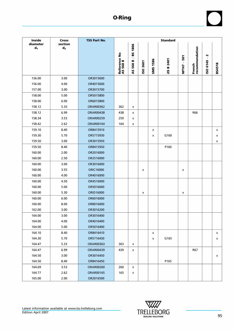
Insidediameter
d1
Crosssection
d2
TSS Part No. Standard
Re
fere
nce
No:
AS
56
8B
AS
56
8B
=B
S1
80
6
ISO
36
01
SM
S1
58
6
JIS
B2
40
1
NFT47
50
1
Fre
nch
reco
mm
en
da
tio
n
ISO
61
49
2
BS
451
8
156.00
156.00
157.00
3.00
4.00
3.00
OR3015600
OR4015600
OR3015700
158.00
158.00
158.12
5.00
6.00
5.33
OR5015800
OR6015800
ORAR00362 362 x
158.12
158.34
158.42
6.99
3.53
2.62
ORAR00438
ORAR00259
ORAR00164
438
259
164
x
x
x
R66
159.10
159.30
159.50
8.40
5.70
3.00
OR8415910
OR5715930
OR3015950
x
x G160
x
x
x
159.50
160.00
160.00
8.40
2.00
2.50
OR8415950
OR2016000
OR2516000
P160
160.00
160.00
160.00
3.00
3.55
4.00
OR3016000
ORIC16000
OR4016000
x x
160.00
160.00
160.00
4.50
5.00
5.30
OR4516000
OR5016000
ORID16000 x x
160.00
160.00
162.00
6.00
8.00
3.00
OR6016000
OR8016000
OR3016200
164.00
164.00
164.00
3.00
4.00
5.00
OR3016400
OR4016400
OR5016400
164.10
164.30
164.47
8.40
5.70
5.33
OR8416410
OR5716430
ORAR00363 363 x
x
x G165
x
x
164.47
164.50
164.50
6.99
3.00
8.40
ORAR00439
OR3016450
OR8416450
439 x
P165
R67
x
164.69
164.77
165.00
3.53
2.62
2.00
ORAR00260
ORAR00165
OR2016500
260
165
x
x
O—Ring
Latest information available at www.tss.trelleborg.comEdition April 2007
95

Insidediameter
d1
Crosssection
d2
TSS Part No. Standard
Re
fere
nce
No:
AS
56
8B
AS
56
8B
=B
S1
80
6
ISO
36
01
SM
S1
58
6
JIS
B2
40
1
NFT47
50
1
Fre
nch
reco
mm
en
da
tio
n
ISO
61
49
2
BS
451
8
165.00
165.00
165.00
2.50
3.00
3.55
OR2516500
OR3016500
ORIC16500 x x
165.00
165.00
165.00
4.00
4.50
5.00
OR4016500
OR4516500
OR5016500
165.00
165.00
165.00
5.30
6.00
8.00
ORID16500
OR6016500
OR8016500
x x
166.00
166.00
167.00
6.00
8.00
2.50
OR6016600
OR8016600
OR2516700
168.00
168.00
169.10
4.00
5.00
8.40
OR4016800
OR5016800
OR8416910 x x
169.30
169.50
169.50
5.70
3.00
8.40
OR5716930
OR3016950
OR8416950
x G170
P170
x
x
170.00
170.00
170.00
2.00
2.50
3.00
OR2017000
OR2517000
OR3017000
170.00
170.00
170.00
3.50
3.55
4.00
OR3517000
ORIC17000
OR4017000
x x
170.00
170.00
170.00
5.00
5.30
6.00
OR5017000
ORID17000
OR6017000
x x
170.00
170.82
170.82
8.00
5.33
6.99
OR8017000
ORAR00364
ORAR00440
364
440
x
x R68
171.04
171.12
172.00
3.53
2.62
4.00
ORAR00261
ORAR00166
OR4017200
261
166
x
x
172.00
174.00
174.10
6.00
3.00
8.40
OR6017200
OR3017400
OR8417410 x x
O—Ring
Latest information available at www.tss.trelleborg.com
96Edition April 2007

Insidediameter
d1
Crosssection
d2
TSS Part No. Standard
Re
fere
nce
No:
AS
56
8B
AS
56
8B
=B
S1
80
6
ISO
36
01
SM
S1
58
6
JIS
B2
40
1
NFT47
50
1
Fre
nch
reco
mm
en
da
tio
n
ISO
61
49
2
BS
451
8
174.30
174.50
174.50
5.70
3.00
8.40
OR5717430
OR3017450
OR8417450
x G175
P175
x
x
175.00
175.00
175.00
2.00
3.55
4.00
OR2017500
ORIC17500
OR4017500
x x
175.00
175.00
175.00
5.00
5.30
6.00
OR5017500
ORID17500
OR6017500
x x
175.00
175.00
177.17
7.00
8.00
5.33
ORIE17500
OR8017500
ORAR00365 365 x
x
177.17
177.39
177.47
6.99
3.53
2.62
ORAR00441
ORAR00262
ORAR00167
441
262
167
x
x
x
179.10
179.30
179.50
8.40
5.70
3.00
OR8417910
OR5717930
OR3017950
x
x
x
x
183.52
183.52
183.74
5.33
6.99
3.53
ORAR00366
ORAR00442
ORAR00263
366
442
263
x
x
x
183.82
184.10
184.30
2.62
8.40
5.70
ORAR00168
OR8418410
OR5718430
168 x
x
x
x
x
184.50
189.10
189.30
3.00
8.40
5.70
OR3018450
OR8418910
OR5718930
x
x
x
x
x
189.50
189.87
189.87
3.00
5.33
6.99
OR3018950
ORAR00367
ORAR00443
367
443
x
x
x
190.09
190.17
194.10
3.53
2.62
8.40
ORAR00264
ORAR00169
OR8419410
264
169
x
x
x
194.30
194.50
196.22
5.70
3.00
5.33
OR5719430
OR3019450
ORAR00368 368 x
x x
x
O—Ring
Latest information available at www.tss.trelleborg.comEdition April 2007
97

Insidediameter
d1
Crosssection
d2
TSS Part No. Standard
Re
fere
nce
No:
AS
56
8B
AS
56
8B
=B
S1
80
6
ISO
36
01
SM
S1
58
6
JIS
B2
40
1
NFT47
50
1
Fre
nch
reco
mm
en
da
tio
n
ISO
61
49
2
BS
451
8
196.22
196.44
196.52
6.99
3.53
2.62
ORAR00444
ORAR00265
ORAR00170
444
265
170
x
x
x
199.10
199.30
199.50
8.40
5.70
3.00
OR8419910
OR5719930
OR3019950
x
x
x
x
x
202.57
202.57
202.79
5.33
6.99
3.53
ORAR00369
ORAR00445
ORAR00266
369
445
266
x
x
x
202.87
204.30
208.92
2.62
5.70
5.33
ORAR00171
OR5720430
ORAR00370
171
370
x
x
x
209.10
209.14
209.22
8.40
3.53
2.62
OR8420910
ORAR00267
ORAR00172
267
172
x
x
x x
209.30
209.50
210.00
5.70
3.00
4.00
OR5720930
OR3020950
OR4021000
x x
x
210.00
210.00
210.00
5.00
6.50
7.00
OR5021000
OR6521000
ORIE21000
210.00
212.00
212.00
8.00
2.50
5.30
OR8021000
OR2521200
ORID21200 x x
212.00
212.00
213.00
6.00
7.00
3.00
OR6021200
ORIE21200
OR3021300
x x
213.00
214.00
214.50
7.00
5.00
8.40
ORIE21300
OR5021400
OR8421450 P215
215.00
215.00
215.00
3.00
5.00
8.00
OR3021500
OR5021500
OR8021500
215.27
215.27
215.49
5.33
6.99
3.53
ORAR00371
ORAR00446
ORAR00268
371
446
268
x
x
x
R74
O—Ring
Latest information available at www.tss.trelleborg.com
98Edition April 2007

Insidediameter
d1
Crosssection
d2
TSS Part No. Standard
Re
fere
nce
No:
AS
56
8B
AS
56
8B
=B
S1
80
6
ISO
36
01
SM
S1
58
6
JIS
B2
40
1
NFT47
50
1
Fre
nch
reco
mm
en
da
tio
n
ISO
61
49
2
BS
451
8
215.57
216.00
216.00
2.62
2.00
4.00
ORAR00173
OR2021600
OR4021600
173 x
217.00
218.00
218.00
5.00
5.30
6.00
OR5021700
ORID21800
OR6021800
x x
218.00
218.50
219.10
7.00
4.50
8.40
ORIE21800
OR4521850
OR8421910
x
x
x
x
219.30
219.50
219.50
5.70
3.00
8.40
OR5721930
OR3021950
OR8421950
x G220
P220
x
220.00
220.00
220.00
2.00
3.00
4.00
OR2022000
OR3022000
OR4022000
220.00
220.00
220.00
5.00
7.00
8.00
OR5022000
ORIE22000
OR8022000
221.62
221.84
221.92
5.33
3.53
2.62
ORAR00372
ORAR00269
ORAR00174
372
269
174
x
x
x
222.00
224.00
224.00
4.00
5.30
7.00
OR4022200
ORID22400
ORIE22400
x
x
x
x
224.50
225.00
225.00
8.40
3.00
4.00
OR8422450
OR3022500
OR4022500
P225
225.00
225.00
225.00
5.00
6.00
7.00
OR5022500
OR6022500
ORIE22500
225.00
226.00
227.97
8.00
6.00
5.33
OR8022500
OR6022600
ORAR00373 373 x
227.97
228.00
228.00
6.99
4.00
7.00
ORAR00447
OR4022800
ORIE22800
447 x R75
O—Ring
Latest information available at www.tss.trelleborg.comEdition April 2007
99

Insidediameter
d1
Crosssection
d2
TSS Part No. Standard
Re
fere
nce
No:
AS
56
8B
AS
56
8B
=B
S1
80
6
ISO
36
01
SM
S1
58
6
JIS
B2
40
1
NFT47
50
1
Fre
nch
reco
mm
en
da
tio
n
ISO
61
49
2
BS
451
8
228.19
228.27
229.00
3.53
2.62
6.00
ORAR00270
ORAR00175
OR6022900
270
175
x
x
229.10
229.30
229.50
8.40
5.70
8.40
OR8422910
OR5722930
OR8422950
x
x G230
P230
x
x
230.00
230.00
230.00
2.00
3.00
4.00
OR2023000
OR3023000
OR4023000
230.00
230.00
230.00
5.00
5.30
7.00
OR5023000
ORID23000
ORIE23000
x
x
x
x
230.00
233.00
234.10
8.00
3.00
8.40
OR8023000
OR3023300
OR8423410 x
234.32
234.50
234.54
5.33
8.40
3.53
ORAR00374
OR8423450
ORAR00271
374
271
x
x
P235
234.62
235.00
235.00
2.62
4.00
5.00
ORAR00176
OR4023500
OR5023500
176 x
235.00
235.00
235.00
6.00
7.00
8.00
OR6023500
ORIE23500
OR8023500
236.00
236.00
238.00
5.30
7.00
2.00
ORID23600
ORIE23600
OR2023800
x
x
x
x
238.00
238.00
238.00
4.00
5.00
8.00
OR4023800
OR5023800
OR8023800
239.10
239.30
239.50
8.40
5.70
3.00
OR8423910
OR5723930
OR3023950
x
x G240
x
x
x
239.50
240.00
240.00
8.40
3.00
4.00
OR8423950
OR3024000
OR4024000
P240
O—Ring
Latest information available at www.tss.trelleborg.com
100Edition April 2007

Insidediameter
d1
Crosssection
d2
TSS Part No. Standard
Re
fere
nce
No:
AS
56
8B
AS
56
8B
=B
S1
80
6
ISO
36
01
SM
S1
58
6
JIS
B2
40
1
NFT47
50
1
Fre
nch
reco
mm
en
da
tio
n
ISO
61
49
2
BS
451
8
240.00
240.00
240.67
5.00
6.00
5.33
OR5024000
OR6024000
ORAR00375 375 x
240.67
240.89
240.97
6.99
3.53
2.62
ORAR00448
ORAR00272
ORAR00177
448
272
177
x
x
x
R76
242.00
242.00
242.00
5.00
6.00
8.00
OR5024200
OR6024200
OR8024200
243.00
243.00
244.00
5.30
7.00
2.00
ORID24300
ORIE24300
OR2024400
x
x
x
x
244.00
244.50
244.50
7.00
3.00
8.40
ORIE24400
OR3024450
OR8424450 P245
x
245.00
245.00
246.00
3.00
5.00
4.00
OR3024500
OR5024500
OR4024600
247.00
247.00
247.02
6.00
7.00
5.33
OR6024700
ORIE24700
ORAR00376 376 x
247.24
247.32
248.00
3.53
2.62
5.00
ORAR00273
ORAR00178
OR5024800
273
178
x
x
249.10
249.30
249.50
8.40
5.70
3.00
OR8424910
OR5724930
OR3024950
x
x G250
x
x
x
249.50
250.00
250.00
8.40
3.00
3.55
OR8424950
OR3025000
ORIC25000
P250
250.00
250.00
250.00
4.00
5.00
6.00
OR4025000
OR5025000
OR6025000
250.00
250.00
253.37
7.00
8.00
5.33
ORIE25000
OR8025000
ORAR00377 377 x
x x
O—Ring
Latest information available at www.tss.trelleborg.comEdition April 2007
101

Insidediameter
d1
Crosssection
d2
TSS Part No. Standard
Re
fere
nce
No:
AS
56
8B
AS
56
8B
=B
S1
80
6
ISO
36
01
SM
S1
58
6
JIS
B2
40
1
NFT47
50
1
Fre
nch
reco
mm
en
da
tio
n
ISO
61
49
2
BS
451
8
253.37
253.59
254.00
6.99
3.53
3.00
ORAR00449
ORAR00274
OR3025400
449
274
x
x
R77
254.50
255.00
255.00
8.40
2.00
3.00
OR8425450
OR2025500
OR3025500
P255
255.00
255.00
258.00
4.00
5.00
5.30
OR4025500
OR5025500
ORID25800 x x
258.00
258.00
259.10
6.00
7.00
8.40
OR6025800
ORIE25800
OR8425910
x x
259.30
259.50
260.00
5.70
8.40
2.50
OR5725930
OR8425950
OR2526000
x G260
P260
x
260.00
260.00
260.00
3.00
4.00
5.00
OR3026000
OR4026000
OR5026000
260.00
260.00
260.00
6.00
7.00
8.00
OR6026000
ORIE26000
OR8026000
262.00
262.00
264.50
2.00
4.00
8.40
OR2026200
OR4026200
OR8426450 P265
265.00
265.00
265.00
3.00
4.00
5.00
OR3026500
OR4026500
OR5026500
265.00
265.00
265.00
5.30
6.50
7.00
ORID26500
OR6526500
ORIE26500
x
x
x
x
265.00
266.00
266.07
8.00
6.00
5.33
OR8026500
OR6026600
ORAR00378 378 x
266.07
266.29
267.00
6.99
3.53
4.50
ORAR00450
ORAR00275
OR4526700
450
275
x
x
R78
O—Ring
Latest information available at www.tss.trelleborg.com
102Edition April 2007

Insidediameter
d1
Crosssection
d2
TSS Part No. Standard
Re
fere
nce
No:
AS
56
8B
AS
56
8B
=B
S1
80
6
ISO
36
01
SM
S1
58
6
JIS
B2
40
1
NFT47
50
1
Fre
nch
reco
mm
en
da
tio
n
ISO
61
49
2
BS
451
8
268.80
269.00
269.30
8.40
2.50
5.70
OR8426880
OR2526900
OR5726930 x G270
269.50
270.00
270.00
8.40
2.50
3.00
OR8426950
OR2527000
OR3027000
P270
270.00
270.00
270.00
4.00
5.00
6.00
OR4027000
OR5027000
OR6027000
270.00
272.00
272.00
8.00
4.00
5.30
OR8027000
OR4027200
ORID27200 x x
272.00
274.00
274.00
7.00
2.00
3.00
ORIE27200
OR2027400
OR3027400
x x
274.00
274.50
275.00
6.50
8.40
4.00
OR6527400
OR8427450
OR4027500
P275
275.00
276.00
278.77
5.00
2.00
5.33
OR5027500
OR2027600
ORAR00379 379 x
278.77
278.99
279.10
6.99
3.53
8.40
ORAR00451
ORAR00276
OR8427910
451
276
x
x
R79
279.30
279.50
280.00
5.70
8.40
2.50
OR5727930
OR8427950
OR2528000
x G280
P280
x
280.00
280.00
280.00
3.00
4.00
5.00
OR3028000
OR4028000
OR5028000
280.00
280.00
280.00
5.30
6.00
7.00
ORID28000
OR6028000
ORIE28000
x
x
x
x
280.00
282.00
284.50
8.00
4.00
8.40
OR8028000
OR4028200
OR8428450 P285
O—Ring
Latest information available at www.tss.trelleborg.comEdition April 2007
103
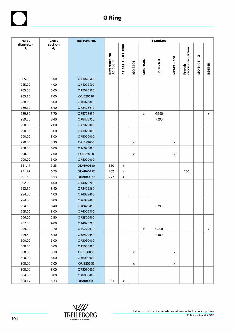
Insidediameter
d1
Crosssection
d2
TSS Part No. Standard
Re
fere
nce
No:
AS
56
8B
AS
56
8B
=B
S1
80
6
ISO
36
01
SM
S1
58
6
JIS
B2
40
1
NFT47
50
1
Fre
nch
reco
mm
en
da
tio
n
ISO
61
49
2
BS
451
8
285.00
285.00
285.00
3.00
4.00
5.00
OR3028500
OR4028500
OR5028500
285.10
288.00
289.10
7.00
6.00
8.40
ORIE28510
OR6028800
OR8428910
289.30
289.50
290.00
5.70
8.40
2.00
OR5728930
OR8428950
OR2029000
x G290
P290
x
290.00
290.00
290.00
3.00
5.00
5.30
OR3029000
OR5029000
ORID29000 x x
290.00
290.00
290.00
6.00
7.00
8.00
OR6029000
ORIE29000
OR8029000
x x
291.47
291.47
291.69
5.33
6.99
3.53
ORAR00380
ORAR00452
ORAR00277
380
452
277
x
x
x
R80
292.00
292.60
294.00
4.00
8.40
4.00
OR4029200
OR8429260
OR4029400
294.00
294.50
295.00
6.00
8.40
6.00
OR6029400
OR8429450
OR6029500
P295
296.00
297.00
299.30
2.50
4.00
5.70
OR2529600
OR4029700
OR5729930 x G300 x
299.50
300.00
300.00
8.40
3.00
5.00
OR8429950
OR3030000
OR5030000
P300
300.00
300.00
300.00
5.30
6.00
7.00
ORID30000
OR6030000
ORIE30000
x
x
x
x
300.00
304.00
304.17
8.00
8.00
5.33
OR8030000
OR8030400
ORAR00381 381 x
O—Ring
Latest information available at www.tss.trelleborg.com
104Edition April 2007

Insidediameter
d1
Crosssection
d2
TSS Part No. Standard
Re
fere
nce
No:
AS
56
8B
AS
56
8B
=B
S1
80
6
ISO
36
01
SM
S1
58
6
JIS
B2
40
1
NFT47
50
1
Fre
nch
reco
mm
en
da
tio
n
ISO
61
49
2
BS
451
8
304.17
304.39
305.00
6.99
3.53
4.00
ORAR00453
ORAR00278
OR4030500
453
278
x
x
R81
305.00
307.00
307.00
5.00
5.30
7.00
OR5030500
ORID30700
ORIE30700
x
x
x
x
309.30
310.00
310.00
5.70
3.00
4.00
OR5730930
OR3031000
OR4031000
x
310.00
310.00
310.00
5.00
7.00
8.00
OR5031000
ORIE31000
OR8031000
314.00
314.50
315.00
8.00
8.40
2.50
OR8031400
OR8431450
OR2531500
P315
315.00
315.00
315.00
4.00
5.00
5.30
OR4031500
OR5031500
ORID31500 x x
315.00
315.00
316.87
6.00
7.00
6.99
OR6031500
ORIE31500
ORAR00454 454 x
x x
R82
319.30
319.50
320.00
5.70
8.40
3.00
OR5731930
OR8431950
OR3032000
x
P320
x
320.00
320.00
320.00
4.00
5.00
6.00
OR4032000
OR5032000
OR6032000
320.00
320.00
324.00
7.00
8.00
4.00
ORIE32000
OR8032000
OR4032400
x
325.00
325.00
325.00
5.00
5.30
6.00
OR5032500
ORID32500
OR6032500
x x
325.00
329.57
329.57
7.00
5.33
6.99
ORIE32500
ORAR00382
ORAR00455
382
455
x
x
x x
R83
O—Ring
Latest information available at www.tss.trelleborg.comEdition April 2007
105

Insidediameter
d1
Crosssection
d2
TSS Part No. Standard
Re
fere
nce
No:
AS
56
8B
AS
56
8B
=B
S1
80
6
ISO
36
01
SM
S1
58
6
JIS
B2
40
1
NFT47
50
1
Fre
nch
reco
mm
en
da
tio
n
ISO
61
49
2
BS
451
8
329.79
330.00
330.00
3.53
4.00
5.00
ORAR00279
OR4033000
OR5033000
279 x
330.00
330.00
330.00
6.00
7.00
8.00
OR6033000
ORIE33000
OR8033000
x
331.00
333.00
334.50
3.00
4.00
8.40
OR3033100
OR4033300
OR8433450 P335
335.00
335.00
335.00
5.00
5.30
6.00
OR5033500
ORID33500
OR6033500
x x
335.00
338.00
339.30
7.00
6.00
5.70
ORIE33500
OR6033800
OR5733930
x
x
x
x
339.50
340.00
340.00
8.40
3.50
4.00
OR8433950
OR3534000
OR4034000
P340
340.00
340.00
340.00
5.00
6.00
8.00
OR5034000
OR6034000
OR8034000
342.00
342.27
345.00
8.00
6.99
5.00
OR8034200
ORAR00456
OR5034500
456 x R84
345.00
345.00
348.00
5.30
7.00
4.00
ORID34500
ORIE34500
OR4034800
x
x
x
x
348.00
349.10
350.00
6.00
8.40
2.50
OR6034800
OR8434910
OR2535000
350.00
350.00
350.00
5.00
6.00
8.00
OR5035000
OR6035000
OR8035000
354.50
354.97
354.97
8.40
5.33
6.99
OR8435450
ORAR00383
ORAR00457
383
457
x
x
P355
R85
O—Ring
Latest information available at www.tss.trelleborg.com
106Edition April 2007
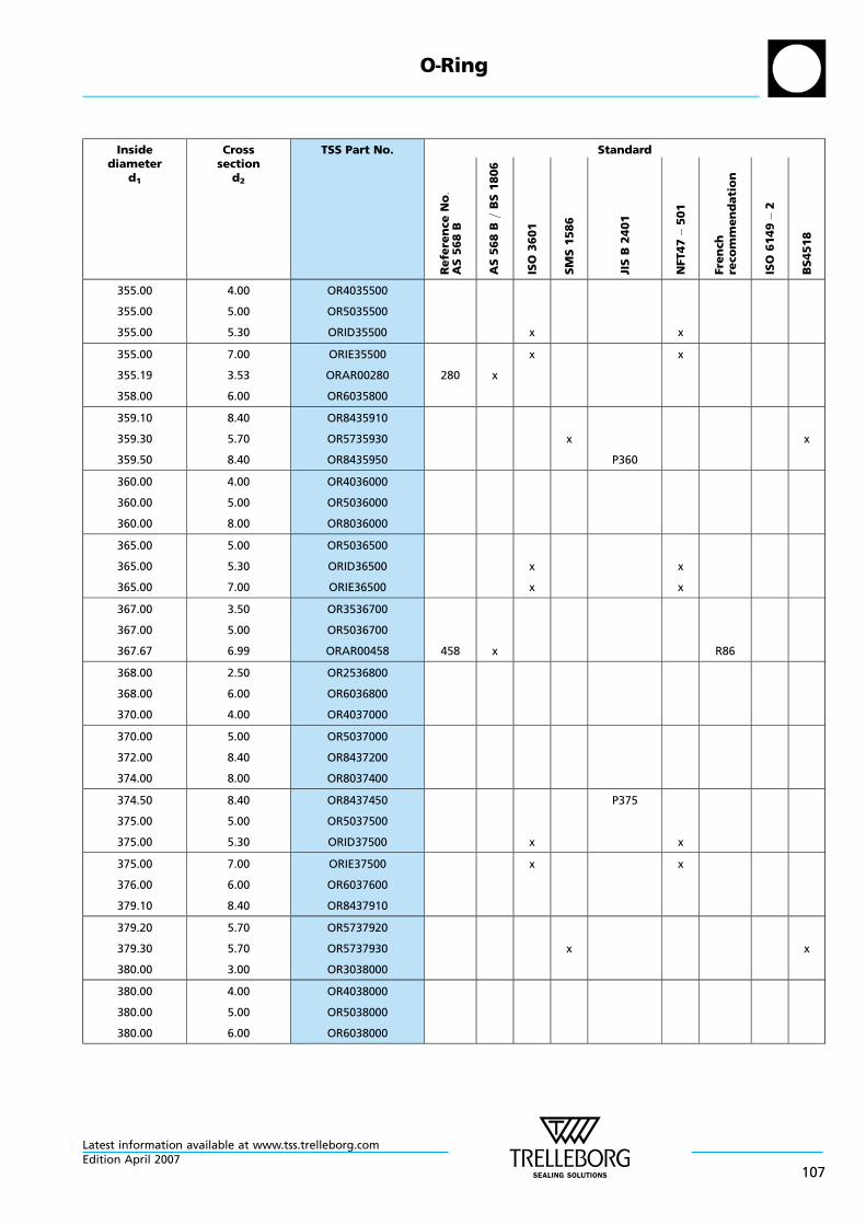
Insidediameter
d1
Crosssection
d2
TSS Part No. Standard
Re
fere
nce
No:
AS
56
8B
AS
56
8B
=B
S1
80
6
ISO
36
01
SM
S1
58
6
JIS
B2
40
1
NFT47
50
1
Fre
nch
reco
mm
en
da
tio
n
ISO
61
49
2
BS
451
8
355.00
355.00
355.00
4.00
5.00
5.30
OR4035500
OR5035500
ORID35500 x x
355.00
355.19
358.00
7.00
3.53
6.00
ORIE35500
ORAR00280
OR6035800
280 x
x x
359.10
359.30
359.50
8.40
5.70
8.40
OR8435910
OR5735930
OR8435950
x
P360
x
360.00
360.00
360.00
4.00
5.00
8.00
OR4036000
OR5036000
OR8036000
365.00
365.00
365.00
5.00
5.30
7.00
OR5036500
ORID36500
ORIE36500
x
x
x
x
367.00
367.00
367.67
3.50
5.00
6.99
OR3536700
OR5036700
ORAR00458 458 x R86
368.00
368.00
370.00
2.50
6.00
4.00
OR2536800
OR6036800
OR4037000
370.00
372.00
374.00
5.00
8.40
8.00
OR5037000
OR8437200
OR8037400
374.50
375.00
375.00
8.40
5.00
5.30
OR8437450
OR5037500
ORID37500 x
P375
x
375.00
376.00
379.10
7.00
6.00
8.40
ORIE37500
OR6037600
OR8437910
x x
379.20
379.30
380.00
5.70
5.70
3.00
OR5737920
OR5737930
OR3038000
x x
380.00
380.00
380.00
4.00
5.00
6.00
OR4038000
OR5038000
OR6038000
O—Ring
Latest information available at www.tss.trelleborg.comEdition April 2007
107

Insidediameter
d1
Crosssection
d2
TSS Part No. Standard
Re
fere
nce
No:
AS
56
8B
AS
56
8B
=B
S1
80
6
ISO
36
01
SM
S1
58
6
JIS
B2
40
1
NFT47
50
1
Fre
nch
reco
mm
en
da
tio
n
ISO
61
49
2
BS
451
8
380.00
380.37
380.37
8.00
5.33
6.99
OR8038000
ORAR00384
ORAR00459
384
459
x
x R87
380.59
382.00
384.50
3.53
8.00
8.40
ORAR00281
OR8038200
OR8438450
281 x
P385
385.00
386.00
387.00
5.00
6.00
5.30
OR5038500
OR6038600
ORID38700 x x
387.00
388.00
388.00
7.00
6.00
7.00
ORIE38700
OR6038800
ORIE38800
x x
389.00
389.30
390.00
8.00
5.70
3.00
OR8038900
OR5738930
OR3039000
x
390.00
393.07
394.00
4.00
6.99
6.00
OR4039000
ORAR00460
OR6039400
460 x R88
394.00
395.00
399.10
8.00
5.00
8.40
OR8039400
OR5039500
OR8439910
399.30
399.50
400.00
5.70
8.40
2.00
OR5739930
OR8439950
OR2040000
x
P400
x
400.00
400.00
400.00
3.00
4.00
5.00
OR3040000
OR4040000
OR5040000
400.00
400.00
400.00
5.30
7.00
8.00
ORID40000
ORIE40000
OR8040000
x
x
x
x
405.26
405.26
405.26
3.53
5.33
6.99
ORAR00282
ORAR00385
ORAR00461
282
385
461
x
x
x
410.00
410.00
410.00
4.00
5.00
6.50
OR4041000
OR5041000
OR6541000
O—Ring
Latest information available at www.tss.trelleborg.com
108Edition April 2007

Insidediameter
d1
Crosssection
d2
TSS Part No. Standard
Re
fere
nce
No:
AS
56
8B
AS
56
8B
=B
S1
80
6
ISO
36
01
SM
S1
58
6
JIS
B2
40
1
NFT47
50
1
Fre
nch
reco
mm
en
da
tio
n
ISO
61
49
2
BS
451
8
412.00
412.00
415.00
7.00
8.00
5.00
ORIE41200
OR8041200
OR5041500
x x
417.96
419.30
420.00
6.99
5.70
4.00
ORAR00462
OR5741930
OR4042000
462 x
x
420.00
422.00
424.00
5.00
6.00
5.00
OR5042000
OR6042200
OR5042400
425.00
425.00
425.00
4.00
7.00
8.00
OR4042500
ORIE42500
OR8042500
x x
427.00
429.00
430.00
5.00
6.00
4.00
OR5042700
OR6042900
OR4043000
430.66
430.66
430.66
3.53
5.33
6.99
ORAR00283
ORAR00386
ORAR00463
283
386
463
x
x
x
433.00
437.00
438.00
4.00
7.00
4.00
OR4043300
ORIE43700
OR4043800
x x
439.30
440.00
440.00
5.70
3.00
4.00
OR5743930
OR3044000
OR4044000
x x
443.36
444.00
445.00
6.99
8.00
5.00
ORAR00464
OR8044400
OR5044500
464 x
448.00
450.00
450.00
6.00
5.00
7.00
OR6044800
OR5045000
ORIE45000 x x
450.00
451.00
456.06
8.00
7.00
3.53
OR8045000
ORIE45100
ORAR00284 284 x
456.06
456.06
459.30
5.33
6.99
5.70
ORAR00387
ORAR00465
OR5745930
387
465
x
x
x x
O—Ring
Latest information available at www.tss.trelleborg.comEdition April 2007
109

Insidediameter
d1
Crosssection
d2
TSS Part No. Standard
Re
fere
nce
No:
AS
56
8B
AS
56
8B
=B
S1
80
6
ISO
36
01
SM
S1
58
6
JIS
B2
40
1
NFT47
50
1
Fre
nch
reco
mm
en
da
tio
n
ISO
61
49
2
BS
451
8
460.00
460.00
460.00
4.00
5.00
8.00
OR4046000
OR5046000
OR8046000
462.00
465.00
465.00
7.00
5.00
9.00
ORIE46200
OR5046500
OR9046500
x x
468.76
470.00
470.00
6.99
4.00
5.00
ORAR00466
OR4047000
OR5047000
466 x
470.00
470.00
472.00
6.00
8.00
8.00
OR6047000
OR8047000
OR8047200
475.00
475.00
479.30
4.00
7.00
5.70
OR4047500
ORIE47500
OR5747930
x
x
x
x
480.00
480.00
480.00
4.00
5.00
6.00
OR4048000
OR5048000
OR6048000
480.00
481.38
481.46
8.00
5.33
6.99
OR8048000
ORAR00388
ORAR00467
388
467
x
x
487.00
487.00
489.20
7.00
8.00
5.70
ORIE48700
OR8048700
OR5748910
x x
489.30
490.00
490.00
5.70
5.00
8.00
OR5748930
OR5049000
OR8049000
x
492.00
494.16
499.30
4.00
6.99
5.70
OR4049200
ORAR00468
OR5749930
468 x
x
500.00
500.00
500.00
5.00
6.00
7.00
OR5050000
OR6050000
ORIE50000 x x
500.00
504.00
506.78
8.00
6.00
5.33
OR8050000
OR6050400
ORAR00389 389 x
O—Ring
Latest information available at www.tss.trelleborg.com
110Edition April 2007

Insidediameter
d1
Crosssection
d2
TSS Part No. Standard
Re
fere
nce
No:
AS
56
8B
AS
56
8B
=B
S1
80
6
ISO
36
01
SM
S1
58
6
JIS
B2
40
1
NFT47
50
1
Fre
nch
reco
mm
en
da
tio
n
ISO
61
49
2
BS
451
8
506.86
508.00
510.00
6.99
6.00
5.00
ORAR00469
OR6050800
OR5051000
469 x
515.00
520.00
525.00
7.00
5.00
8.00
ORIE51500
OR5052000
OR8052500
x x
530.00
530.00
530.00
4.00
5.00
7.00
OR4053000
OR5053000
ORIE53000 x x
532.18
532.26
540.00
5.33
6.99
3.00
ORAR00390
ORAR00470
OR3054000
390
470
x
x
540.00
540.00
540.00
4.00
5.00
8.00
OR4054000
OR5054000
OR8054000
542.00
545.00
545.00
7.00
3.00
7.00
ORIE54200
OR3054500
ORIE54500 x x
549.00
550.00
557.58
6.00
5.00
5.33
OR6054900
OR5055000
ORAR00391 391 x
557.66
560.00
560.00
6.99
4.00
5.00
ORAR00471
OR4056000
OR5056000
471 x
560.00
560.00
569.00
6.00
7.00
6.00
OR6056000
ORIE56000
OR6056900
x x
579.00
580.00
580.00
6.00
7.00
8.00
OR6057900
ORIE58000
OR8058000
x x
582.68
582.68
585.00
5.33
6.99
4.00
ORAR00392
ORAR00472
OR4058500
392
472
x
x
585.00
590.00
592.00
5.00
5.00
8.00
OR5058500
OR5059000
OR8059200
O—Ring
Latest information available at www.tss.trelleborg.comEdition April 2007
111
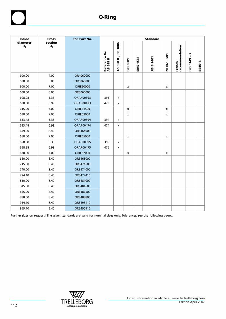
Insidediameter
d1
Crosssection
d2
TSS Part No. Standard
Re
fere
nce
No:
AS
56
8B
AS
56
8B
=B
S1
80
6
ISO
36
01
SM
S1
58
6
JIS
B2
40
1
NFT47
50
1
Fre
nch
reco
mm
en
da
tio
n
ISO
61
49
2
BS
451
8
600.00
600.00
600.00
4.00
5.00
7.00
OR4060000
OR5060000
ORIE60000 x x
600.00
608.08
608.08
8.00
5.33
6.99
OR8060000
ORAR00393
ORAR00473
393
473
x
x
615.00
630.00
633.48
7.00
7.00
5.33
ORIE61500
ORIE63000
ORAR00394 394 x
x
x
x
x
633.48
649.00
650.00
6.99
8.40
7.00
ORAR00474
OR8464900
ORIE65000
474 x
x x
658.88
658.88
670.00
5.33
6.99
7.00
ORAR00395
ORAR00475
ORIE67000
395
475
x
x
x x
680.00
715.00
740.00
8.40
8.40
8.40
OR8468000
OR8471500
OR8474000
774.10
810.00
845.00
8.40
8.40
8.40
OR8477410
OR8481000
OR8484500
865.00
888.00
934.10
8.40
8.40
8.40
OR8486500
OR8488800
OR8493410
959.10 8.40 OR8495910
Further sizes on request! The given standards are valid for nominal sizes only. Tolerances, see the following pages.
O—Ring
Latest information available at www.tss.trelleborg.com
112Edition April 2007

C.1.2 O—Ring Dimensions according to AS 568 B
d1
d2
Figure 27 O—Ring dimensions
Table XVII Dimensions / TSS part numbers AS
TSS Part No. Metric dimensions (mm) Imperial dimensions (inch)
Inside diameterd1
Cross sectiond2
Inside diameterd1
Cross sectiond2
ORAR00001 0.74 1.02 .029 .040
ORAR00002 1.07 1.27 .042 .050
ORAR00003 1.42 1.52 .056 .060
ORAR00004 1.78 1.78 .070 .070
ORAR00005 2.57 1.78 .101 .070
ORAR00006 2.90 1.78 .114 .070
ORAR00007 3.68 1.78 .145 .070
ORAR00008 4.47 1.78 .176 .070
ORAR00009 5.28 1.78 .208 .070
ORAR00010 6.07 1.78 .239 .070
ORAR00011 7.65 1.78 .301 .070
ORAR00012 9.25 1.78 .364 .070
ORAR00013 10.82 1.78 .426 .070
ORAR00014 12.42 1.78 .489 .070
ORAR00015 14.00 1.78 .551 .070
ORAR00016 15.60 1.78 .614 .070
ORAR00017 17.17 1.78 .676 .070
ORAR00018 18.77 1.78 .739 .070
ORAR00019 20.35 1.78 .801 .070
ORAR00020 21.95 1.78 .864 .070
ORAR00021 23.52 1.78 .926 .070
ORAR00022 25.12 1.78 .989 .070
ORAR00023 26.70 1.78 1.051 .070
ORAR00024 28.30 1.78 1.114 .070
ORAR00025 29.87 1.78 1.176 .070
ORAR00026 31.47 1.78 1.239 .070
ORAR00027 33.05 1.78 1.301 .070
O—Ring
Latest information available at www.tss.trelleborg.comEdition April 2007
113
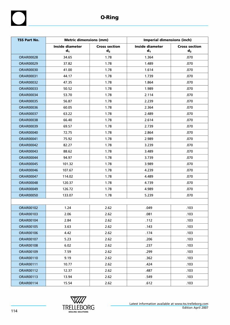
TSS Part No. Metric dimensions (mm) Imperial dimensions (inch)
Inside diameterd1
Cross sectiond2
Inside diameterd1
Cross sectiond2
ORAR00028 34.65 1.78 1.364 .070
ORAR00029 37.82 1.78 1.489 .070
ORAR00030 41.00 1.78 1.614 .070
ORAR00031 44.17 1.78 1.739 .070
ORAR00032 47.35 1.78 1.864 .070
ORAR00033 50.52 1.78 1.989 .070
ORAR00034 53.70 1.78 2.114 .070
ORAR00035 56.87 1.78 2.239 .070
ORAR00036 60.05 1.78 2.364 .070
ORAR00037 63.22 1.78 2.489 .070
ORAR00038 66.40 1.78 2.614 .070
ORAR00039 69.57 1.78 2.739 .070
ORAR00040 72.75 1.78 2.864 .070
ORAR00041 75.92 1.78 2.989 .070
ORAR00042 82.27 1.78 3.239 .070
ORAR00043 88.62 1.78 3.489 .070
ORAR00044 94.97 1.78 3.739 .070
ORAR00045 101.32 1.78 3.989 .070
ORAR00046 107.67 1.78 4.239 .070
ORAR00047 114.02 1.78 4.489 .070
ORAR00048 120.37 1.78 4.739 .070
ORAR00049 126.72 1.78 4.989 .070
ORAR00050 133.07 1.78 5.239 .070
ORAR00102 1.24 2.62 .049 .103
ORAR00103 2.06 2.62 .081 .103
ORAR00104 2.84 2.62 .112 .103
ORAR00105 3.63 2.62 .143 .103
ORAR00106 4.42 2.62 .174 .103
ORAR00107 5.23 2.62 .206 .103
ORAR00108 6.02 2.62 .237 .103
ORAR00109 7.59 2.62 .299 .103
ORAR00110 9.19 2.62 .362 .103
ORAR00111 10.77 2.62 .424 .103
ORAR00112 12.37 2.62 .487 .103
ORAR00113 13.94 2.62 .549 .103
ORAR00114 15.54 2.62 .612 .103
O—Ring
Latest information available at www.tss.trelleborg.com
114Edition April 2007

TSS Part No. Metric dimensions (mm) Imperial dimensions (inch)
Inside diameterd1
Cross sectiond2
Inside diameterd1
Cross sectiond2
ORAR00115 17.12 2.62 .674 .103
ORAR00116 18.72 2.62 .737 .103
ORAR00117 20.29 2.62 .799 .103
ORAR00118 21.89 2.62 .862 .103
ORAR00119 23.47 2.62 .924 .103
ORAR00120 25.07 2.62 .987 .103
ORAR00121 26.64 2.62 1.049 .103
ORAR00122 28.24 2.62 1.112 .103
ORAR00123 29.82 2.62 1.174 .103
ORAR00124 31.42 2.62 1.237 .103
ORAR00125 32.99 2.62 1.299 .103
ORAR00126 34.59 2.62 1.362 .103
ORAR00127 36.17 2.62 1.424 .103
ORAR00128 37.77 2.62 1.487 .103
ORAR00129 39.34 2.62 1.549 .103
ORAR00130 40.94 2.62 1.612 .103
ORAR00131 42.52 2.62 1.674 .103
ORAR00132 44.12 2.62 1.737 .103
ORAR00133 45.69 2.62 1.799 .103
ORAR00134 47.29 2.62 1.862 .103
ORAR00135 48.90 2.62 1.925 .103
ORAR00136 50.47 2.62 1.987 .103
ORAR00137 52.07 2.62 2.050 .103
ORAR00138 53.64 2.62 2.112 .103
ORAR00139 55.25 2.62 2.175 .103
ORAR00140 56.82 2.62 2.237 .103
ORAR00141 58.42 2.62 2.300 .103
ORAR00142 59.99 2.62 2.362 .103
ORAR00143 61.60 2.62 2.425 .103
ORAR00144 63.17 2.62 2.487 .103
ORAR00145 64.77 2.62 2.550 .103
ORAR00146 66.34 2.62 2.612 .103
ORAR00147 67.95 2.62 2.675 .103
ORAR00148 69.52 2.62 2.737 .103
ORAR00149 71.12 2.62 2.800 .103
ORAR00150 72.69 2.62 2.862 .103
ORAR00151 75.87 2.62 2.987 .103
O—Ring
Latest information available at www.tss.trelleborg.comEdition April 2007
115
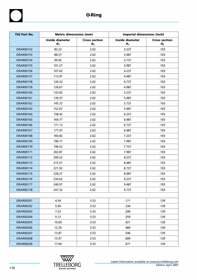
TSS Part No. Metric dimensions (mm) Imperial dimensions (inch)
Inside diameterd1
Cross sectiond2
Inside diameterd1
Cross sectiond2
ORAR00152 82.22 2.62 3.237 .103
ORAR00153 88.57 2.62 3.487 .103
ORAR00154 94.92 2.62 3.737 .103
ORAR00155 101.27 2.62 3.987 .103
ORAR00156 107.62 2.62 4.237 .103
ORAR00157 113.97 2.62 4.487 .103
ORAR00158 120.32 2.62 4.737 .103
ORAR00159 126.67 2.62 4.987 .103
ORAR00160 133.02 2.62 5.237 .103
ORAR00161 139.37 2.62 5.487 .103
ORAR00162 145.72 2.62 5.737 .103
ORAR00163 152.07 2.62 5.987 .103
ORAR00164 158.42 2.62 6.237 .103
ORAR00165 164.77 2.62 6.487 .103
ORAR00166 171.12 2.62 6.737 .103
ORAR00167 177.47 2.62 6.987 .103
ORAR00168 183.82 2.62 7.237 .103
ORAR00169 190.17 2.62 7.487 .103
ORAR00170 196.52 2.62 7.737 .103
ORAR00171 202.87 2.62 7.987 .103
ORAR00172 209.22 2.62 8.237 .103
ORAR00173 215.57 2.62 8.487 .103
ORAR00174 221.92 2.62 8.737 .103
ORAR00175 228.27 2.62 8.987 .103
ORAR00176 234.62 2.62 9.237 .103
ORAR00177 240.97 2.62 9.487 .103
ORAR00178 247.32 2.62 9.737 .103
ORAR00201 4.34 3.53 .171 .139
ORAR00202 5.94 3.53 .234 .139
ORAR00203 7.52 3.53 .296 .139
ORAR00204 9.12 3.53 .359 .139
ORAR00205 10.69 3.53 .421 .139
ORAR00206 12.29 3.53 .484 .139
ORAR00207 13.87 3.53 .546 .139
ORAR00208 15.47 3.53 .609 .139
ORAR00209 17.04 3.53 .671 .139
O—Ring
Latest information available at www.tss.trelleborg.com
116Edition April 2007
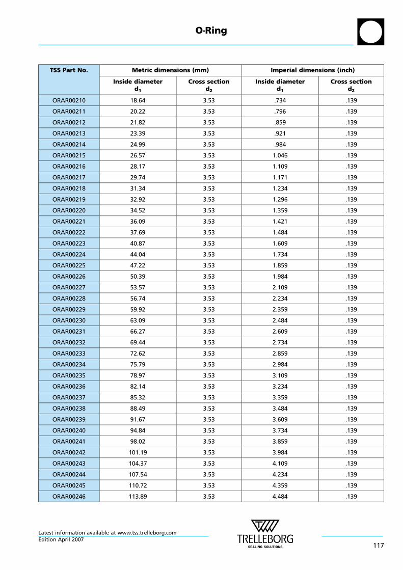
TSS Part No. Metric dimensions (mm) Imperial dimensions (inch)
Inside diameterd1
Cross sectiond2
Inside diameterd1
Cross sectiond2
ORAR00210 18.64 3.53 .734 .139
ORAR00211 20.22 3.53 .796 .139
ORAR00212 21.82 3.53 .859 .139
ORAR00213 23.39 3.53 .921 .139
ORAR00214 24.99 3.53 .984 .139
ORAR00215 26.57 3.53 1.046 .139
ORAR00216 28.17 3.53 1.109 .139
ORAR00217 29.74 3.53 1.171 .139
ORAR00218 31.34 3.53 1.234 .139
ORAR00219 32.92 3.53 1.296 .139
ORAR00220 34.52 3.53 1.359 .139
ORAR00221 36.09 3.53 1.421 .139
ORAR00222 37.69 3.53 1.484 .139
ORAR00223 40.87 3.53 1.609 .139
ORAR00224 44.04 3.53 1.734 .139
ORAR00225 47.22 3.53 1.859 .139
ORAR00226 50.39 3.53 1.984 .139
ORAR00227 53.57 3.53 2.109 .139
ORAR00228 56.74 3.53 2.234 .139
ORAR00229 59.92 3.53 2.359 .139
ORAR00230 63.09 3.53 2.484 .139
ORAR00231 66.27 3.53 2.609 .139
ORAR00232 69.44 3.53 2.734 .139
ORAR00233 72.62 3.53 2.859 .139
ORAR00234 75.79 3.53 2.984 .139
ORAR00235 78.97 3.53 3.109 .139
ORAR00236 82.14 3.53 3.234 .139
ORAR00237 85.32 3.53 3.359 .139
ORAR00238 88.49 3.53 3.484 .139
ORAR00239 91.67 3.53 3.609 .139
ORAR00240 94.84 3.53 3.734 .139
ORAR00241 98.02 3.53 3.859 .139
ORAR00242 101.19 3.53 3.984 .139
ORAR00243 104.37 3.53 4.109 .139
ORAR00244 107.54 3.53 4.234 .139
ORAR00245 110.72 3.53 4.359 .139
ORAR00246 113.89 3.53 4.484 .139
O—Ring
Latest information available at www.tss.trelleborg.comEdition April 2007
117
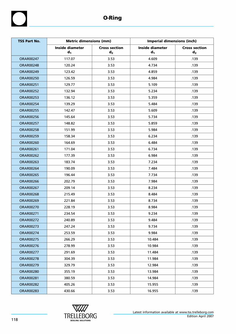
TSS Part No. Metric dimensions (mm) Imperial dimensions (inch)
Inside diameterd1
Cross sectiond2
Inside diameterd1
Cross sectiond2
ORAR00247 117.07 3.53 4.609 .139
ORAR00248 120.24 3.53 4.734 .139
ORAR00249 123.42 3.53 4.859 .139
ORAR00250 126.59 3.53 4.984 .139
ORAR00251 129.77 3.53 5.109 .139
ORAR00252 132.94 3.53 5.234 .139
ORAR00253 136.12 3.53 5.359 .139
ORAR00254 139.29 3.53 5.484 .139
ORAR00255 142.47 3.53 5.609 .139
ORAR00256 145.64 3.53 5.734 .139
ORAR00257 148.82 3.53 5.859 .139
ORAR00258 151.99 3.53 5.984 .139
ORAR00259 158.34 3.53 6.234 .139
ORAR00260 164.69 3.53 6.484 .139
ORAR00261 171.04 3.53 6.734 .139
ORAR00262 177.39 3.53 6.984 .139
ORAR00263 183.74 3.53 7.234 .139
ORAR00264 190.09 3.53 7.484 .139
ORAR00265 196.44 3.53 7.734 .139
ORAR00266 202.79 3.53 7.984 .139
ORAR00267 209.14 3.53 8.234 .139
ORAR00268 215.49 3.53 8.484 .139
ORAR00269 221.84 3.53 8.734 .139
ORAR00270 228.19 3.53 8.984 .139
ORAR00271 234.54 3.53 9.234 .139
ORAR00272 240.89 3.53 9.484 .139
ORAR00273 247.24 3.53 9.734 .139
ORAR00274 253.59 3.53 9.984 .139
ORAR00275 266.29 3.53 10.484 .139
ORAR00276 278.99 3.53 10.984 .139
ORAR00277 291.69 3.53 11.484 .139
ORAR00278 304.39 3.53 11.984 .139
ORAR00279 329.79 3.53 12.984 .139
ORAR00280 355.19 3.53 13.984 .139
ORAR00281 380.59 3.53 14.984 .139
ORAR00282 405.26 3.53 15.955 .139
ORAR00283 430.66 3.53 16.955 .139
O—Ring
Latest information available at www.tss.trelleborg.com
118Edition April 2007
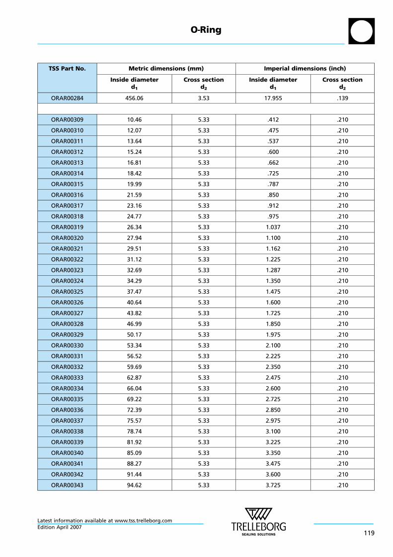
TSS Part No. Metric dimensions (mm) Imperial dimensions (inch)
Inside diameterd1
Cross sectiond2
Inside diameterd1
Cross sectiond2
ORAR00284 456.06 3.53 17.955 .139
ORAR00309 10.46 5.33 .412 .210
ORAR00310 12.07 5.33 .475 .210
ORAR00311 13.64 5.33 .537 .210
ORAR00312 15.24 5.33 .600 .210
ORAR00313 16.81 5.33 .662 .210
ORAR00314 18.42 5.33 .725 .210
ORAR00315 19.99 5.33 .787 .210
ORAR00316 21.59 5.33 .850 .210
ORAR00317 23.16 5.33 .912 .210
ORAR00318 24.77 5.33 .975 .210
ORAR00319 26.34 5.33 1.037 .210
ORAR00320 27.94 5.33 1.100 .210
ORAR00321 29.51 5.33 1.162 .210
ORAR00322 31.12 5.33 1.225 .210
ORAR00323 32.69 5.33 1.287 .210
ORAR00324 34.29 5.33 1.350 .210
ORAR00325 37.47 5.33 1.475 .210
ORAR00326 40.64 5.33 1.600 .210
ORAR00327 43.82 5.33 1.725 .210
ORAR00328 46.99 5.33 1.850 .210
ORAR00329 50.17 5.33 1.975 .210
ORAR00330 53.34 5.33 2.100 .210
ORAR00331 56.52 5.33 2.225 .210
ORAR00332 59.69 5.33 2.350 .210
ORAR00333 62.87 5.33 2.475 .210
ORAR00334 66.04 5.33 2.600 .210
ORAR00335 69.22 5.33 2.725 .210
ORAR00336 72.39 5.33 2.850 .210
ORAR00337 75.57 5.33 2.975 .210
ORAR00338 78.74 5.33 3.100 .210
ORAR00339 81.92 5.33 3.225 .210
ORAR00340 85.09 5.33 3.350 .210
ORAR00341 88.27 5.33 3.475 .210
ORAR00342 91.44 5.33 3.600 .210
ORAR00343 94.62 5.33 3.725 .210
O—Ring
Latest information available at www.tss.trelleborg.comEdition April 2007
119
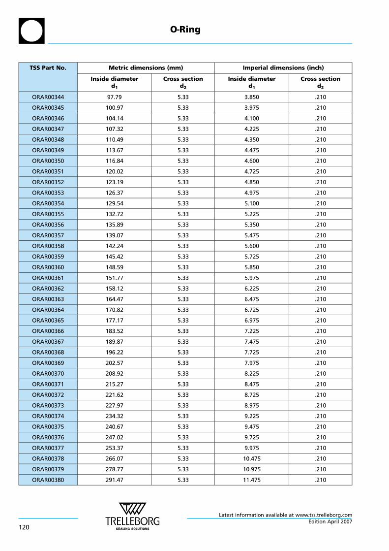
TSS Part No. Metric dimensions (mm) Imperial dimensions (inch)
Inside diameterd1
Cross sectiond2
Inside diameterd1
Cross sectiond2
ORAR00344 97.79 5.33 3.850 .210
ORAR00345 100.97 5.33 3.975 .210
ORAR00346 104.14 5.33 4.100 .210
ORAR00347 107.32 5.33 4.225 .210
ORAR00348 110.49 5.33 4.350 .210
ORAR00349 113.67 5.33 4.475 .210
ORAR00350 116.84 5.33 4.600 .210
ORAR00351 120.02 5.33 4.725 .210
ORAR00352 123.19 5.33 4.850 .210
ORAR00353 126.37 5.33 4.975 .210
ORAR00354 129.54 5.33 5.100 .210
ORAR00355 132.72 5.33 5.225 .210
ORAR00356 135.89 5.33 5.350 .210
ORAR00357 139.07 5.33 5.475 .210
ORAR00358 142.24 5.33 5.600 .210
ORAR00359 145.42 5.33 5.725 .210
ORAR00360 148.59 5.33 5.850 .210
ORAR00361 151.77 5.33 5.975 .210
ORAR00362 158.12 5.33 6.225 .210
ORAR00363 164.47 5.33 6.475 .210
ORAR00364 170.82 5.33 6.725 .210
ORAR00365 177.17 5.33 6.975 .210
ORAR00366 183.52 5.33 7.225 .210
ORAR00367 189.87 5.33 7.475 .210
ORAR00368 196.22 5.33 7.725 .210
ORAR00369 202.57 5.33 7.975 .210
ORAR00370 208.92 5.33 8.225 .210
ORAR00371 215.27 5.33 8.475 .210
ORAR00372 221.62 5.33 8.725 .210
ORAR00373 227.97 5.33 8.975 .210
ORAR00374 234.32 5.33 9.225 .210
ORAR00375 240.67 5.33 9.475 .210
ORAR00376 247.02 5.33 9.725 .210
ORAR00377 253.37 5.33 9.975 .210
ORAR00378 266.07 5.33 10.475 .210
ORAR00379 278.77 5.33 10.975 .210
ORAR00380 291.47 5.33 11.475 .210
O—Ring
Latest information available at www.tss.trelleborg.com
120Edition April 2007
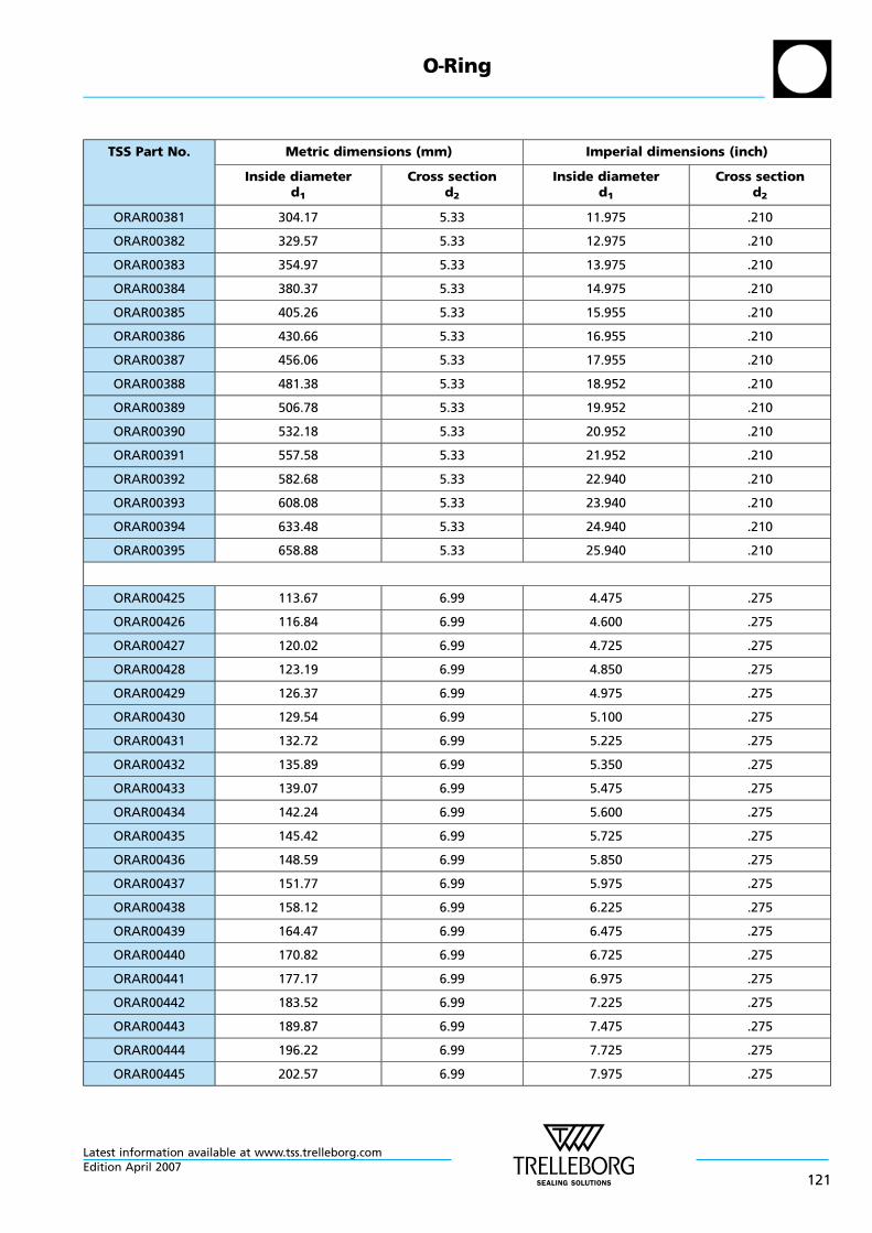
TSS Part No. Metric dimensions (mm) Imperial dimensions (inch)
Inside diameterd1
Cross sectiond2
Inside diameterd1
Cross sectiond2
ORAR00381 304.17 5.33 11.975 .210
ORAR00382 329.57 5.33 12.975 .210
ORAR00383 354.97 5.33 13.975 .210
ORAR00384 380.37 5.33 14.975 .210
ORAR00385 405.26 5.33 15.955 .210
ORAR00386 430.66 5.33 16.955 .210
ORAR00387 456.06 5.33 17.955 .210
ORAR00388 481.38 5.33 18.952 .210
ORAR00389 506.78 5.33 19.952 .210
ORAR00390 532.18 5.33 20.952 .210
ORAR00391 557.58 5.33 21.952 .210
ORAR00392 582.68 5.33 22.940 .210
ORAR00393 608.08 5.33 23.940 .210
ORAR00394 633.48 5.33 24.940 .210
ORAR00395 658.88 5.33 25.940 .210
ORAR00425 113.67 6.99 4.475 .275
ORAR00426 116.84 6.99 4.600 .275
ORAR00427 120.02 6.99 4.725 .275
ORAR00428 123.19 6.99 4.850 .275
ORAR00429 126.37 6.99 4.975 .275
ORAR00430 129.54 6.99 5.100 .275
ORAR00431 132.72 6.99 5.225 .275
ORAR00432 135.89 6.99 5.350 .275
ORAR00433 139.07 6.99 5.475 .275
ORAR00434 142.24 6.99 5.600 .275
ORAR00435 145.42 6.99 5.725 .275
ORAR00436 148.59 6.99 5.850 .275
ORAR00437 151.77 6.99 5.975 .275
ORAR00438 158.12 6.99 6.225 .275
ORAR00439 164.47 6.99 6.475 .275
ORAR00440 170.82 6.99 6.725 .275
ORAR00441 177.17 6.99 6.975 .275
ORAR00442 183.52 6.99 7.225 .275
ORAR00443 189.87 6.99 7.475 .275
ORAR00444 196.22 6.99 7.725 .275
ORAR00445 202.57 6.99 7.975 .275
O—Ring
Latest information available at www.tss.trelleborg.comEdition April 2007
121
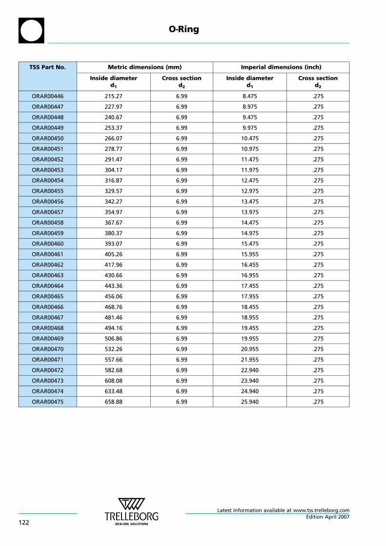
TSS Part No. Metric dimensions (mm) Imperial dimensions (inch)
Inside diameterd1
Cross sectiond2
Inside diameterd1
Cross sectiond2
ORAR00446 215.27 6.99 8.475 .275
ORAR00447 227.97 6.99 8.975 .275
ORAR00448 240.67 6.99 9.475 .275
ORAR00449 253.37 6.99 9.975 .275
ORAR00450 266.07 6.99 10.475 .275
ORAR00451 278.77 6.99 10.975 .275
ORAR00452 291.47 6.99 11.475 .275
ORAR00453 304.17 6.99 11.975 .275
ORAR00454 316.87 6.99 12.475 .275
ORAR00455 329.57 6.99 12.975 .275
ORAR00456 342.27 6.99 13.475 .275
ORAR00457 354.97 6.99 13.975 .275
ORAR00458 367.67 6.99 14.475 .275
ORAR00459 380.37 6.99 14.975 .275
ORAR00460 393.07 6.99 15.475 .275
ORAR00461 405.26 6.99 15.955 .275
ORAR00462 417.96 6.99 16.455 .275
ORAR00463 430.66 6.99 16.955 .275
ORAR00464 443.36 6.99 17.455 .275
ORAR00465 456.06 6.99 17.955 .275
ORAR00466 468.76 6.99 18.455 .275
ORAR00467 481.46 6.99 18.955 .275
ORAR00468 494.16 6.99 19.455 .275
ORAR00469 506.86 6.99 19.955 .275
ORAR00470 532.26 6.99 20.955 .275
ORAR00471 557.66 6.99 21.955 .275
ORAR00472 582.68 6.99 22.940 .275
ORAR00473 608.08 6.99 23.940 .275
ORAR00474 633.48 6.99 24.940 .275
ORAR00475 658.88 6.99 25.940 .275
O—Ring
Latest information available at www.tss.trelleborg.com
122Edition April 2007
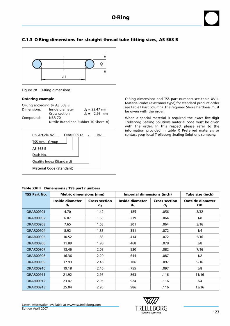
C.1.3 O—Ring dimensions for straight thread tube fitting sizes, AS 568 B
d1
d2
Figure 28 O—Ring dimensions
Ordering example
O—Ring according to AS 568 BDimensions: Inside diameter d1 = 23.47 mm
Cross section d2 = 2.95 mmCompound: NBR 70
Nitrile-Butadiene Rubber 70 Shore A)
ORAR00912 N7-TSS Article No.
AS 568 B
Material Code (Standard)
TSS Art. - Group
Dash No.
Quality Index (Standard)
O—Ring dimensions and TSS part numbers see table XVIII.Material codes (elastomer type) for standard product ordersee table I (last column). The required Shore hardness mustbe given with the order.
When a special material is required the exact five-digitTrelleborg Sealing Solutions material code must be givenwith the order. In this respect please refer to theinformation provided in table X Preferred materials orcontact your local Trelleborg Sealing Solutions company.
Table XVIII Dimensions / TSS part numbers
TSS Part No. Metric dimensions (mm) Imperial dimensions (inch) Tube size (inch)
Inside diameterd1
Cross sectiond2
Inside diameterd1
Cross sectiond2
Outside diameterOD
ORAR00901 4.70 1.42 .185 .056 3/32
ORAR00902 6.07 1.63 .239 .064 1/8
ORAR00903 7.65 1.63 .301 .064 3/16
ORAR00904 8.92 1.83 .351 .072 1/4
ORAR00905 10.52 1.83 .414 .072 5/16
ORAR00906 11.89 1.98 .468 .078 3/8
ORAR00907 13.46 2.08 .530 .082 7/16
ORAR00908 16.36 2.20 .644 .087 1/2
ORAR00909 17.93 2.46 .706 .097 9/16
ORAR00910 19.18 2.46 .755 .097 5/8
ORAR00911 21.92 2.95 .863 .116 11/16
ORAR00912 23.47 2.95 .924 .116 3/4
ORAR00913 25.04 2.95 .986 .116 13/16
O—Ring
Latest information available at www.tss.trelleborg.comEdition April 2007
123
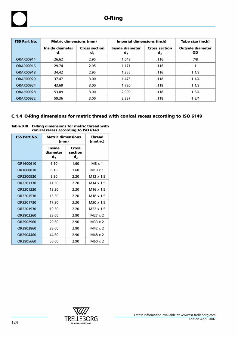
TSS Part No. Metric dimensions (mm) Imperial dimensions (inch) Tube size (inch)
Inside diameterd1
Cross sectiond2
Inside diameterd1
Cross sectiond2
Outside diameterOD
ORAR00914 26.62 2.95 1.048 .116 7/8
ORAR00916 29.74 2.95 1.171 .116 1
ORAR00918 34.42 2.95 1.355 .116 1 1/8
ORAR00920 37.47 3.00 1.475 .118 1 1/4
ORAR00924 43.69 3.00 1.720 .118 1 1/2
ORAR00928 53.09 3.00 2.090 .118 1 3/4
ORAR00932 59.36 3.00 2.337 .118 1 3/4
C.1.4 O—Ring dimensions for metric thread with conical recess according to ISO 6149
Table XIX O—Ring dimensions for metric thread withconical recess according to ISO 6149
TSS Part No. Metric dimensions(mm)
Thread(metric)
Insidediameter
d1
Crosssection
d2
OR1600610
OR1600810
OR2200930
6.10
8.10
9.30
1.60
1.60
2.20
M8 x 1
M10 x 1
M12 x 1.5
OR2201130
OR2201330
OR2201530
11.30
13.30
15.30
2.20
2.20
2.20
M14 x 1.5
M16 x 1.5
M18 x 1.5
OR2201730
OR2201930
OR2902360
17.30
19.30
23.60
2.20
2.20
2.90
M20 x 1.5
M22 x 1.5
M27 x 2
OR2902960
OR2903860
OR2904460
29.60
38.60
44.60
2.90
2.90
2.90
M33 x 2
M42 x 2
M48 x 2
OR2905660 56.60 2.90 M60 x 2
O—Ring
Latest information available at www.tss.trelleborg.com
124Edition April 2007
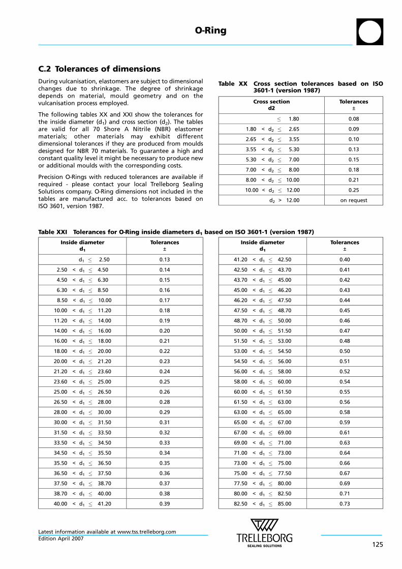
C.2 Tolerances of dimensions
During vulcanisation, elastomers are subject to dimensionalchanges due to shrinkage. The degree of shrinkagedepends on material, mould geometry and on thevulcanisation process employed.
The following tables XX and XXI show the tolerances forthe inside diameter (d1) and cross section (d2). The tablesare valid for all 70 Shore A Nitrile (NBR) elastomermaterials; other materials may exhibit differentdimensional tolerances if they are produced from mouldsdesigned for NBR 70 materials. To guarantee a high andconstant quality level it might be necessary to produce newor additional moulds with the corresponding costs.
Precision O—Rings with reduced tolerances are available ifrequired - please contact your local Trelleborg SealingSolutions company. O—Ring dimensions not included in thetables are manufactured acc. to tolerances based onISO 3601, version 1987.
Table XX Cross section tolerances based on ISO3601-1 (version 1987)
Cross sectiond2
Tolerances±
1.80 0.08
1.80 < d2 2.65 0.09
2.65 < d2 3.55 0.10
3.55 < d2 5.30 0.13
5.30 < d2 7.00 0.15
7.00 < d2 8.00 0.18
8.00 < d2 10.00 0.21
10.00 < d2 12.00 0.25
d2 > 12.00 on request
Table XXI Tolerances for O—Ring inside diameters d1 based on ISO 3601-1 (version 1987)
Inside diameterd1
Tolerances±
d1 2.50 0.13
2.50 < d1 4.50 0.14
4.50 < d1 6.30 0.15
6.30 < d1 8.50 0.16
8.50 < d1 10.00 0.17
10.00 < d1 11.20 0.18
11.20 < d1 14.00 0.19
14.00 < d1 16.00 0.20
16.00 < d1 18.00 0.21
18.00 < d1 20.00 0.22
20.00 < d1 21.20 0.23
21.20 < d1 23.60 0.24
23.60 < d1 25.00 0.25
25.00 < d1 26.50 0.26
26.50 < d1 28.00 0.28
28.00 < d1 30.00 0.29
30.00 < d1 31.50 0.31
31.50 < d1 33.50 0.32
33.50 < d1 34.50 0.33
34.50 < d1 35.50 0.34
35.50 < d1 36.50 0.35
36.50 < d1 37.50 0.36
37.50 < d1 38.70 0.37
38.70 < d1 40.00 0.38
40.00 < d1 41.20 0.39
Inside diameterd1
Tolerances±
41.20 < d1 42.50 0.40
42.50 < d1 43.70 0.41
43.70 < d1 45.00 0.42
45.00 < d1 46.20 0.43
46.20 < d1 47.50 0.44
47.50 < d1 48.70 0.45
48.70 < d1 50.00 0.46
50.00 < d1 51.50 0.47
51.50 < d1 53.00 0.48
53.00 < d1 54.50 0.50
54.50 < d1 56.00 0.51
56.00 < d1 58.00 0.52
58.00 < d1 60.00 0.54
60.00 < d1 61.50 0.55
61.50 < d1 63.00 0.56
63.00 < d1 65.00 0.58
65.00 < d1 67.00 0.59
67.00 < d1 69.00 0.61
69.00 < d1 71.00 0.63
71.00 < d1 73.00 0.64
73.00 < d1 75.00 0.66
75.00 < d1 77.50 0.67
77.50 < d1 80.00 0.69
80.00 < d1 82.50 0.71
82.50 < d1 85.00 0.73
O—Ring
Latest information available at www.tss.trelleborg.comEdition April 2007
125
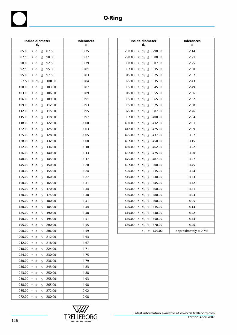
Inside diameterd1
Tolerances±
85.00 < d1 87.50 0.75
87.50 < d1 90.00 0.77
90.00 < d1 92.50 0.79
92.50 < d1 95.00 0.81
95.00 < d1 97.50 0.83
97.50 < d1 100.00 0.84
100.00 < d1 103.00 0.87
103.00 < d1 106.00 0.89
106.00 < d1 109.00 0.91
109.00 < d1 112.00 0.93
112.00 < d1 115.00 0.95
115.00 < d1 118.00 0.97
118.00 < d1 122.00 1.00
122.00 < d1 125.00 1.03
125.00 < d1 128.00 1.05
128.00 < d1 132.00 1.08
132.00 < d1 136.00 1.10
136.00 < d1 140.00 1.13
140.00 < d1 145.00 1.17
145.00 < d1 150.00 1.20
150.00 < d1 155.00 1.24
155.00 < d1 160.00 1.27
160.00 < d1 165.00 1.31
165.00 < d1 170.00 1.34
170.00 < d1 175.00 1.38
175.00 < d1 180.00 1.41
180.00 < d1 185.00 1.44
185.00 < d1 190.00 1.48
190.00 < d1 195.00 1.51
195.00 < d1 200.00 1.55
200.00 < d1 206.00 1.59
206.00 < d1 212.00 1.63
212.00 < d1 218.00 1.67
218.00 < d1 224.00 1.71
224.00 < d1 230.00 1.75
230.00 < d1 236.00 1.79
236.00 < d1 243.00 1.83
243.00 < d1 250.00 1.88
250.00 < d1 258.00 1.93
258.00 < d1 265.00 1.98
265.00 < d1 272.00 2.02
272.00 < d1 280.00 2.08
Inside diameterd1
Tolerances±
280.00 < d1 290.00 2.14
290.00 < d1 300.00 2.21
300.00 < d1 307.00 2.25
307.00 < d1 315.00 2.30
315.00 < d1 325.00 2.37
325.00 < d1 335.00 2.43
335.00 < d1 345.00 2.49
345.00 < d1 355.00 2.56
355.00 < d1 365.00 2.62
365.00 < d1 375.00 2.68
375.00 < d1 387.00 2.76
387.00 < d1 400.00 2.84
400.00 < d1 412.00 2.91
412.00 < d1 425.00 2.99
425.00 < d1 437.00 3.07
437.00 < d1 450.00 3.15
450.00 < d1 462.00 3.22
462.00 < d1 475.00 3.30
475.00 < d1 487.00 3.37
487.00 < d1 500.00 3.45
500.00 < d1 515.00 3.54
515.00 < d1 530.00 3.63
530.00 < d1 545.00 3.72
545.00 < d1 560.00 3.81
560.00 < d1 580.00 3.93
580.00 < d1 600.00 4.05
600.00 < d1 615.00 4.13
615.00 < d1 630.00 4.22
630.00 < d1 650.00 4.34
650.00 < d1 670.00 4.46
d1 > 670.00 approximately ± 0,7%
O—Ring
Latest information available at www.tss.trelleborg.com
126Edition April 2007
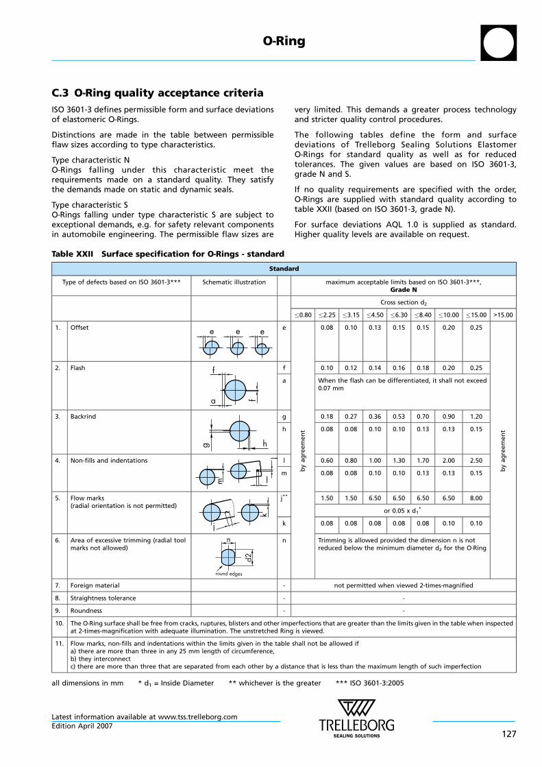
C.3 O—Ring quality acceptance criteria
ISO 3601-3 defines permissible form and surface deviationsof elastomeric O—Rings.
Distinctions are made in the table between permissibleflaw sizes according to type characteristics.
Type characteristic NO—Rings falling under this characteristic meet therequirements made on a standard quality. They satisfythe demands made on static and dynamic seals.
Type characteristic SO—Rings falling under type characteristic S are subject toexceptional demands, e.g. for safety relevant componentsin automobile engineering. The permissible flaw sizes are
very limited. This demands a greater process technologyand stricter quality control procedures.
The following tables define the form and surfacedeviations of Trelleborg Sealing Solutions ElastomerO—Rings for standard quality as well as for reducedtolerances. The given values are based on ISO 3601-3,grade N and S.
If no quality requirements are specified with the order,O—Rings are supplied with standard quality according totable XXII (based on ISO 3601-3, grade N).
For surface deviations AQL 1.0 is supplied as standard.Higher quality levels are available on request.
Table XXII Surface specification for O—Rings - standard
Standard
Type of defects based on ISO 3601-3*** Schematic illustration maximum acceptable limits based on ISO 3601-3***,Grade N
Cross section d2
0.80 2.25 3.15 4.50 6.30 8.40 10.00 15.00 >15.00
1. Offset e e e e
by
ag
ree
me
nt
0.08 0.10 0.13 0.15 0.15 0.20 0.25
by
ag
ree
me
nt
2. Flash
a f
f f 0.10 0.12 0.14 0.16 0.18 0.20 0.25
a When the flash can be differentiated, it shall not exceed0.07 mm
3. Backrind
hg
g 0.18 0.27 0.36 0.53 0.70 0.90 1.20
h 0.08 0.08 0.10 0.10 0.13 0.13 0.15
4. Non-fills and indentations
m
l
l
l 0.60 0.80 1.00 1.30 1.70 2.00 2.50
m 0.08 0.08 0.10 0.10 0.13 0.13 0.15
5. Flow marks(radial orientation is not permitted)
k
j
j** 1.50 1.50 6.50 6.50 6.50 6.50 8.00
or 0.05 x d1*
k 0.08 0.08 0.08 0.08 0.08 0.10 0.10
6. Area of excessive trimming (radial toolmarks not allowed)
d2
n
round edges
n Trimming is allowed provided the dimension n is notreduced below the minimum diameter d2 for the O—Ring
7. Foreign material - not permitted when viewed 2-times-magnified
8. Straightness tolerance - -
9. Roundness - -
10. The O—Ring surface shall be free from cracks, ruptures, blisters and other imperfections that are greater than the limits given in the table when inspectedat 2-times-magnification with adequate illumination. The unstretched Ring is viewed.
11. Flow marks, non-fills and indentations within the limits given in the table shall not be allowed ifa) there are more than three in any 25 mm length of circumference,b) they interconnectc) there are more than three that are separated from each other by a distance that is less than the maximum length of such imperfection
all dimensions in mm * d1 = Inside Diameter ** whichever is the greater *** ISO 3601-3:2005
O—Ring
Latest information available at www.tss.trelleborg.comEdition April 2007
127
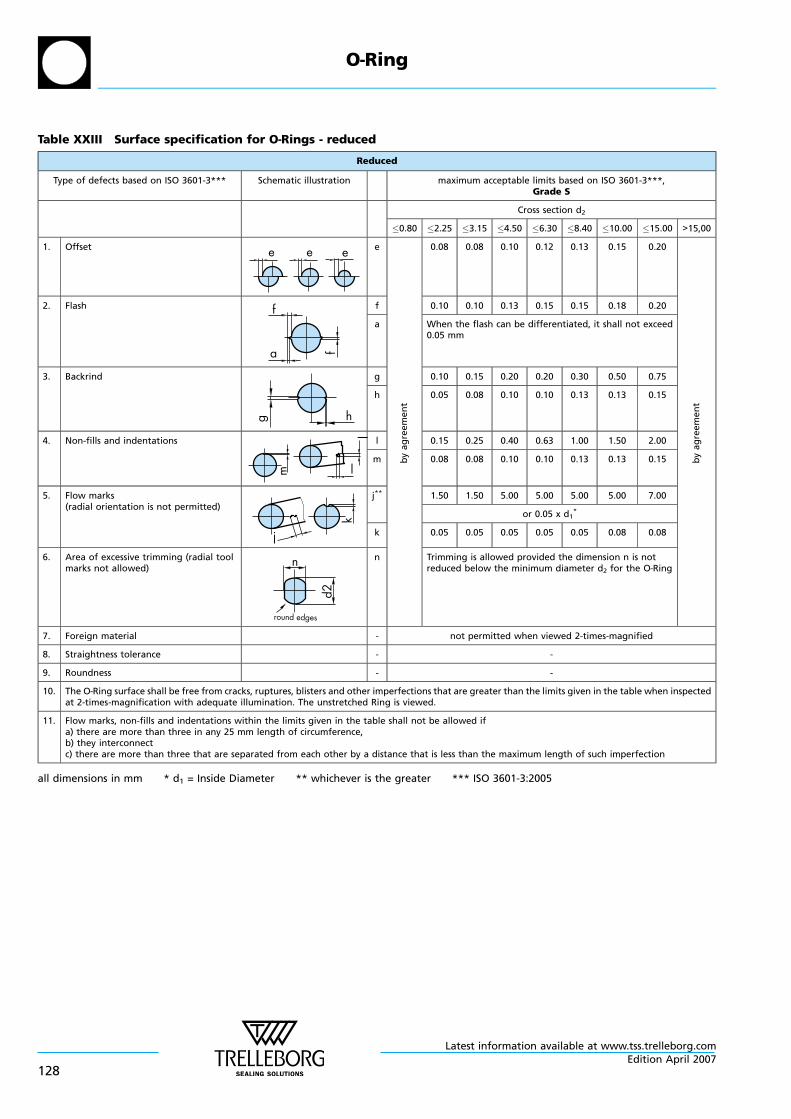
Table XXIII Surface specification for O—Rings - reduced
Reduced
Type of defects based on ISO 3601-3*** Schematic illustration maximum acceptable limits based on ISO 3601-3***,Grade S
Cross section d2
0.80 2.25 3.15 4.50 6.30 8.40 10.00 15.00 >15,00
1. Offset e e e e
by
ag
ree
me
nt
0.08 0.08 0.10 0.12 0.13 0.15 0.20
by
ag
ree
me
nt
2. Flash
a ff f 0.10 0.10 0.13 0.15 0.15 0.18 0.20
a When the flash can be differentiated, it shall not exceed0.05 mm
3. Backrind
hg
g 0.10 0.15 0.20 0.20 0.30 0.50 0.75
h 0.05 0.08 0.10 0.10 0.13 0.13 0.15
4. Non-fills and indentations
m
l
l
l 0.15 0.25 0.40 0.63 1.00 1.50 2.00
m 0.08 0.08 0.10 0.10 0.13 0.13 0.15
5. Flow marks(radial orientation is not permitted)
k
j
j** 1.50 1.50 5.00 5.00 5.00 5.00 7.00
or 0.05 x d1*
k 0.05 0.05 0.05 0.05 0.05 0.08 0.08
6. Area of excessive trimming (radial toolmarks not allowed)
d2
n
round edges
n Trimming is allowed provided the dimension n is notreduced below the minimum diameter d2 for the O—Ring
7. Foreign material - not permitted when viewed 2-times-magnified
8. Straightness tolerance - -
9. Roundness - -
10. The O—Ring surface shall be free from cracks, ruptures, blisters and other imperfections that are greater than the limits given in the table when inspectedat 2-times-magnification with adequate illumination. The unstretched Ring is viewed.
11. Flow marks, non-fills and indentations within the limits given in the table shall not be allowed ifa) there are more than three in any 25 mm length of circumference,b) they interconnectc) there are more than three that are separated from each other by a distance that is less than the maximum length of such imperfection
all dimensions in mm * d1 = Inside Diameter ** whichever is the greater *** ISO 3601-3:2005
O—Ring
Latest information available at www.tss.trelleborg.com
128Edition April 2007
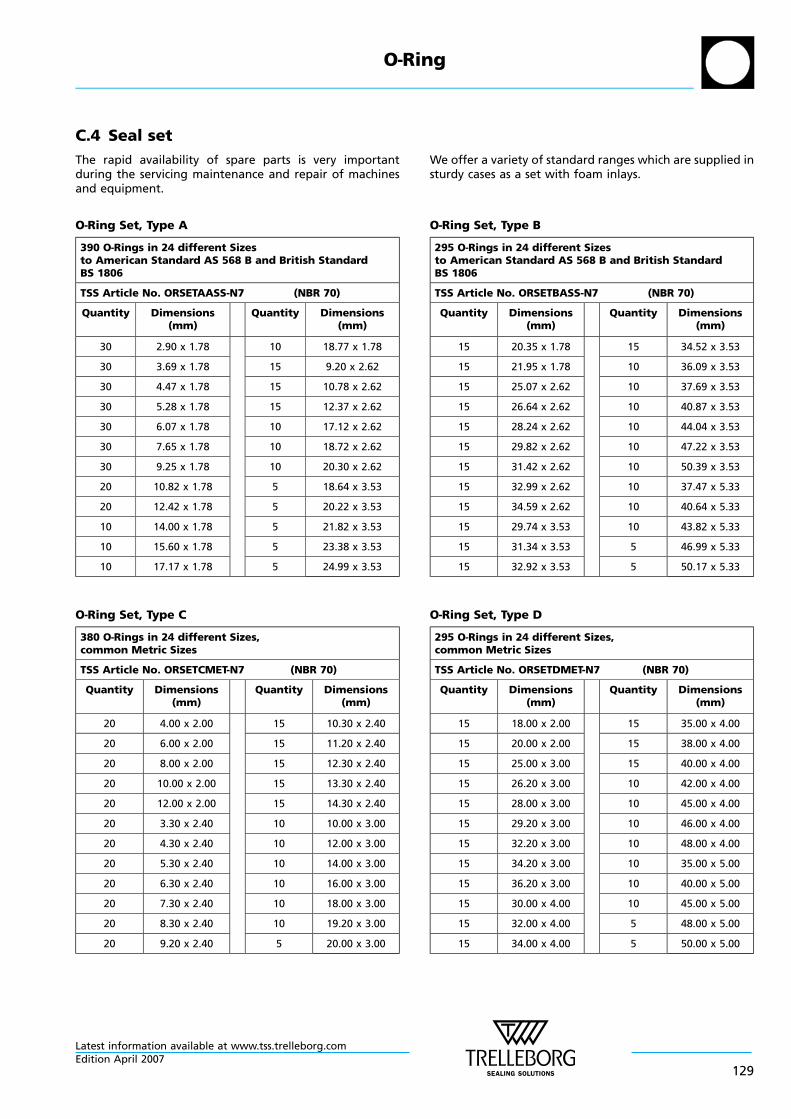
C.4 Seal set
The rapid availability of spare parts is very importantduring the servicing maintenance and repair of machinesand equipment.
O—Ring Set, Type A
390 O—Rings in 24 different Sizesto American Standard AS 568 B and British StandardBS 1806
TSS Article No. ORSETAASS-N7 (NBR 70)
Quantity Dimensions(mm)
Quantity Dimensions(mm)
30 2.90 x 1.78 10 18.77 x 1.78
30 3.69 x 1.78 15 9.20 x 2.62
30 4.47 x 1.78 15 10.78 x 2.62
30 5.28 x 1.78 15 12.37 x 2.62
30 6.07 x 1.78 10 17.12 x 2.62
30 7.65 x 1.78 10 18.72 x 2.62
30 9.25 x 1.78 10 20.30 x 2.62
20 10.82 x 1.78 5 18.64 x 3.53
20 12.42 x 1.78 5 20.22 x 3.53
10 14.00 x 1.78 5 21.82 x 3.53
10 15.60 x 1.78 5 23.38 x 3.53
10 17.17 x 1.78 5 24.99 x 3.53
O—Ring Set, Type C
380 O—Rings in 24 different Sizes,common Metric Sizes
TSS Article No. ORSETCMET-N7 (NBR 70)
Quantity Dimensions(mm)
Quantity Dimensions(mm)
20 4.00 x 2.00 15 10.30 x 2.40
20 6.00 x 2.00 15 11.20 x 2.40
20 8.00 x 2.00 15 12.30 x 2.40
20 10.00 x 2.00 15 13.30 x 2.40
20 12.00 x 2.00 15 14.30 x 2.40
20 3.30 x 2.40 10 10.00 x 3.00
20 4.30 x 2.40 10 12.00 x 3.00
20 5.30 x 2.40 10 14.00 x 3.00
20 6.30 x 2.40 10 16.00 x 3.00
20 7.30 x 2.40 10 18.00 x 3.00
20 8.30 x 2.40 10 19.20 x 3.00
20 9.20 x 2.40 5 20.00 x 3.00
We offer a variety of standard ranges which are supplied insturdy cases as a set with foam inlays.
O—Ring Set, Type B
295 O—Rings in 24 different Sizesto American Standard AS 568 B and British StandardBS 1806
TSS Article No. ORSETBASS-N7 (NBR 70)
Quantity Dimensions(mm)
Quantity Dimensions(mm)
15 20.35 x 1.78 15 34.52 x 3.53
15 21.95 x 1.78 10 36.09 x 3.53
15 25.07 x 2.62 10 37.69 x 3.53
15 26.64 x 2.62 10 40.87 x 3.53
15 28.24 x 2.62 10 44.04 x 3.53
15 29.82 x 2.62 10 47.22 x 3.53
15 31.42 x 2.62 10 50.39 x 3.53
15 32.99 x 2.62 10 37.47 x 5.33
15 34.59 x 2.62 10 40.64 x 5.33
15 29.74 x 3.53 10 43.82 x 5.33
15 31.34 x 3.53 5 46.99 x 5.33
15 32.92 x 3.53 5 50.17 x 5.33
O—Ring Set, Type D
295 O—Rings in 24 different Sizes,common Metric Sizes
TSS Article No. ORSETDMET-N7 (NBR 70)
Quantity Dimensions(mm)
Quantity Dimensions(mm)
15 18.00 x 2.00 15 35.00 x 4.00
15 20.00 x 2.00 15 38.00 x 4.00
15 25.00 x 3.00 15 40.00 x 4.00
15 26.20 x 3.00 10 42.00 x 4.00
15 28.00 x 3.00 10 45.00 x 4.00
15 29.20 x 3.00 10 46.00 x 4.00
15 32.20 x 3.00 10 48.00 x 4.00
15 34.20 x 3.00 10 35.00 x 5.00
15 36.20 x 3.00 10 40.00 x 5.00
15 30.00 x 4.00 10 45.00 x 5.00
15 32.00 x 4.00 5 48.00 x 5.00
15 34.00 x 4.00 5 50.00 x 5.00
O—Ring
Latest information available at www.tss.trelleborg.comEdition April 2007
129
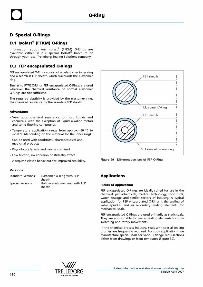
D Special O—Rings
D.1 Isolast® (FFKM) O—Rings
Information about our Isolast® (FFKM) O—Rings areavailable either in our special Isolast® brochure orthrough your local Trelleborg Sealing Solutions company.
D.2 FEP encapsulated O—Rings
FEP encapsulated O—Rings consist of an elastomer inner ringand a seamless FEP sheath which surrounds the elastomerring.
Similar to PTFE O—Rings FEP encapsulated O—Rings are usedwherever the chemical resistance of normal elastomerO—Rings are not sufficient.
The required elasticity is provided by the elastomer ring,the chemical resistance by the seamless FEP sheath.
Advantages
- Very good chemical resistance to most liquids andchemicals, with the exception of liquid alkaline metalsand some fluorine compounds
- Temperature application range from approx. -60 °C to+200 °C (depending on the material for the inner ring)
- Can be used with foodstuffs, pharmaceutical andmedicinal products
- Physiologically safe and can be sterilised
- Low friction, no adhesion or stick-slip effect
- Adequate elastic behaviour for improved sealibility.
Versions
Standard versions: Elastomer O—Ring with FEPsheath
Special versions: Hollow elastomer ring with FEPsheath
FEP sheath
FEP sheath
Elastomer O-Ring
Hollow elastomer ring
Figure 29 Different versions of FEP O—Ring
Applications
Fields of application
FEP encapsulated O—Rings are ideally suited for use in thechemical, petrochemicals, medical technology, foodstuffs,water, sewage and similar sectors of industry. A typicalapplication for FEP encapsulated O—Rings is the sealing ofvalve spindles and as secondary sealing elements formechanical seals.
FEP encapsulated O—Rings are used primarily as static seals.They are also suitable for use as sealing elements for slowswitching and rotary movements.
In the chemical process industry, seals with special sealingprofiles are frequently required. For such applications, wemanufacture special seals for various flange cross sectionseither from drawings or from templates (Figure 30).
O—Ring
Latest information available at www.tss.trelleborg.com
130Edition April 2007
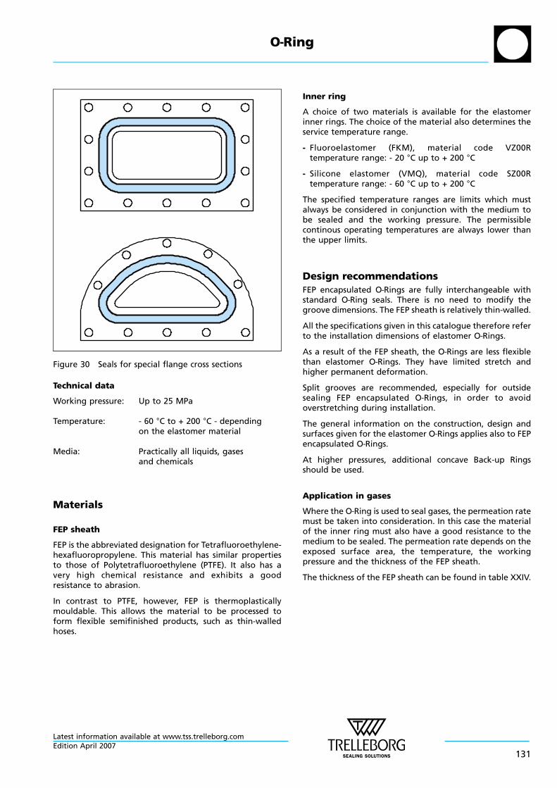
Figure 30 Seals for special flange cross sections
Technical data
Working pressure: Up to 25 MPa
Temperature: - 60 °C to + 200 °C - dependingon the elastomer material
Media: Practically all liquids, gasesand chemicals
Materials
FEP sheath
FEP is the abbreviated designation for Tetrafluoroethylene-hexafluoropropylene. This material has similar propertiesto those of Polytetrafluoroethylene (PTFE). It also has avery high chemical resistance and exhibits a goodresistance to abrasion.
In contrast to PTFE, however, FEP is thermoplasticallymouldable. This allows the material to be processed toform flexible semifinished products, such as thin-walledhoses.
Inner ring
A choice of two materials is available for the elastomerinner rings. The choice of the material also determines theservice temperature range.
- Fluoroelastomer (FKM), material code VZ00Rtemperature range: - 20 °C up to + 200 °C
- Silicone elastomer (VMQ), material code SZ00Rtemperature range: - 60 °C up to + 200 °C
The specified temperature ranges are limits which mustalways be considered in conjunction with the medium tobe sealed and the working pressure. The permissiblecontinous operating temperatures are always lower thanthe upper limits.
Design recommendations
FEP encapsulated O—Rings are fully interchangeable withstandard O—Ring seals. There is no need to modify thegroove dimensions. The FEP sheath is relatively thin-walled.
All the specifications given in this catalogue therefore referto the installation dimensions of elastomer O—Rings.
As a result of the FEP sheath, the O—Rings are less flexiblethan elastomer O—Rings. They have limited stretch andhigher permanent deformation.
Split grooves are recommended, especially for outsidesealing FEP encapsulated O—Rings, in order to avoidoverstretching during installation.
The general information on the construction, design andsurfaces given for the elastomer O—Rings applies also to FEPencapsulated O—Rings.
At higher pressures, additional concave Back-up Ringsshould be used.
Application in gases
Where the O—Ring is used to seal gases, the permeation ratemust be taken into consideration. In this case the materialof the inner ring must also have a good resistance to themedium to be sealed. The permeation rate depends on theexposed surface area, the temperature, the workingpressure and the thickness of the FEP sheath.
The thickness of the FEP sheath can be found in table XXIV.
O—Ring
Latest information available at www.tss.trelleborg.comEdition April 2007
131
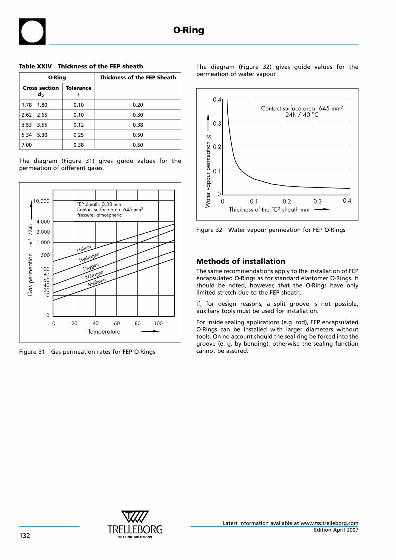
Table XXIV Thickness of the FEP sheath
O—Ring Thickness of the FEP Sheath
Cross sectiond2
Tolerance±
1 78 1 80 0 10 0 20
2 62 2 65 0 10 0 30
3 53 3 55 0 12 0 38
5 34 5 30 0 25 0 50
7 00 0 38 0 50
The diagram (Figure 31) gives guide values for thepermeation of different gases.
Temperature
Gas
perm
eatio
n
10,000
4,000
2,000
1,000
500
1008060402010
00 40 60 80 10020
cm3
/24h
FEP sheath: 0.38 mmContact surface area: 645 mm2
Pressure: atmospheric
Helium
Hydrogen
Oxygen
Nitrogen
Methane
Figure 31 Gas permeation rates for FEP O—Rings
The diagram (Figure 32) gives guide values for thepermeation of water vapour.
Wat
erva
pour
perm
eatio
ng
0.4
0.3
0.2
0.1
00
Thickness of the FEP sheath mm0.1 0.2 0.3 0.4
Contact surface area: 645 mm2
24h / 40 oC
Figure 32 Water vapour permeation for FEP O—Rings
Methods of installation
The same recommendations apply to the installation of FEPencapsulated O—Rings as for standard elastomer O—Rings. Itshould be noted, however, that the O—Rings have onlylimited stretch due to the FEP sheath.
If, for design reasons, a split groove is not possible,auxiliary tools must be used for installation.
For inside sealing applications (e.g. rod), FEP encapsulatedO—Rings can be installed with larger diameters withouttools. On no account should the seal ring be forced into thegroove (e. g. by bending), otherwise the sealing functioncannot be assured.
O—Ring
Latest information available at www.tss.trelleborg.com
132Edition April 2007
. .
. .
. ...
.
.
.
...
.
.
.
.
.
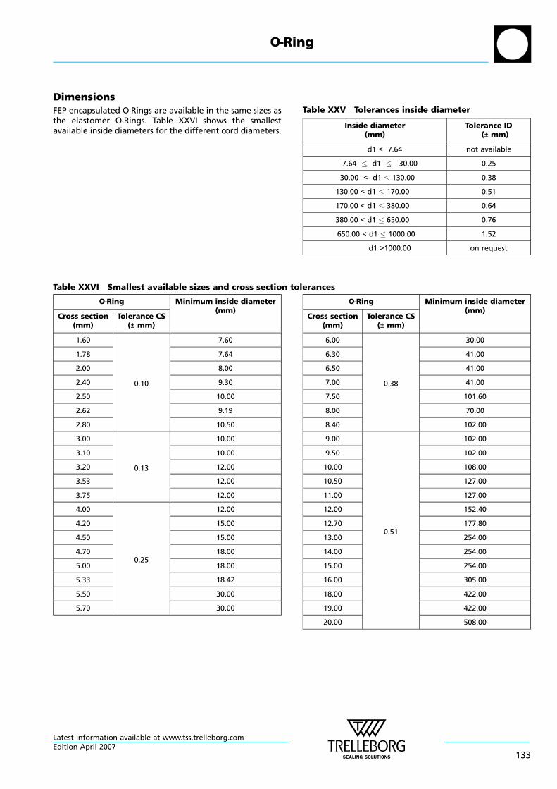
DimensionsFEP encapsulated O—Rings are available in the same sizes asthe elastomer O—Rings. Table XXVI shows the smallestavailable inside diameters for the different cord diameters.
Table XXV Tolerances inside diameter
Inside diameter(mm)
Tolerance ID(± mm)
d1 < 7.64 not available
7.64 d1 30.00 0.25
30.00 < d1 130.00 0.38
130.00 < d1 170.00 0.51
170.00 < d1 380.00 0.64
380.00 < d1 650.00 0.76
650.00 < d1 1000.00 1.52
d1 >1000.00 on request
Table XXVI Smallest available sizes and cross section tolerances
O—Ring Minimum inside diameter(mm)
Cross section(mm)
Tolerance CS(± mm)
1.60
0.10
7.60
1.78 7.64
2.00 8.00
2.40 9.30
2.50 10.00
2.62 9.19
2.80 10.50
3.00
0.13
10.00
3.10 10.00
3.20 12.00
3.53 12.00
3.75 12.00
4.00
0.25
12.00
4.20 15.00
4.50 15.00
4.70 18.00
5.00 18.00
5.33 18.42
5.50 30.00
5.70 30.00
O—Ring Minimum inside diameter(mm)
Cross section(mm)
Tolerance CS(± mm)
6.00
0.38
30.00
6.30 41.00
6.50 41.00
7.00 41.00
7.50 101.60
8.00 70.00
8.40 102.00
9.00
0.51
102.00
9.50 102.00
10.00 108.00
10.50 127.00
11.00 127.00
12.00 152.40
12.70 177.80
13.00 254.00
14.00 254.00
15.00 254.00
16.00 305.00
18.00 422.00
19.00 422.00
20.00 508.00
O—Ring
Latest information available at www.tss.trelleborg.comEdition April 2007
133
Ordering example
O—Ring 30 x 3, FEP sheathed
Dimensions: Inside diameter d1 = 30.0 mmCross section d2 = 3.0 mm
Material of the inner ring: Silicone Rubber (VMQ)
OF3003000 SZ00R-TSS Article No.
Material Code (Standard)
TSS Part No.
Quality Index (Standard)
Further information see page 46
Ordering example
O—Ring, FEP sheathedAmerican Standard AS 568 B, ref. 356Dimensions: Inside diameter d1 = 135.89 mm
Cross section d2 = 5.33 mm
Material of the inner ring: Fluorocarbon Rubber (FKM)
O FAR00356 VZ00R-TSS Article No.
Material Code (Standard)
TSS Part No.
Quality Index (Standard)
Further information see page 46
O—Ring dimensions and TSS Part No. see Table XVI, page47-112.Installation dimensions, see Table XV, page 43.
Ordering can also be made according to O—Ring dimensionsand material.
O—Ring
Latest information available at www.tss.trelleborg.com
134Edition April 2007
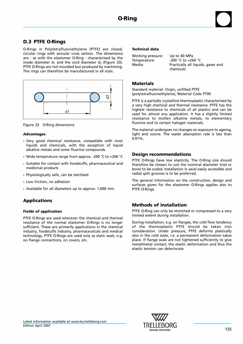
D.3 PTFE O—Rings
O—Rings in Polytetrafluoroethylene (PTFE) are closed,circular rings with annular cross section. The dimensionsare - as with the elastomer O—Ring - characterised by theinside diameter d1 and the cord diameter d2 (Figure 33).PTFE O—Rings are not moulded but produced by machining.The rings can therefore be manufactured in all sizes.
d1d2
Figure 33 O—Ring dimensions
Advantages
- Very good chemical resistance, compatible with mostliquids and chemicals, with the exception of liquidalkaline metals and some fluorine compounds.
- Wide temperature range from approx. -200 °C to +260 °C
- Suitable for contact with foodstuffs, pharmaceutical andmedicinal products
- Physiologically safe, can be sterilised
- Low friction, no adhesion
- Available for all diameters up to approx. 1,000 mm.
Applications
Fields of application
PTFE O—Rings are used wherever the chemical and thermalresistance of the normal elastomer O—Rings is no longersufficient. These are primarily applications in the chemicalindustry, foodstuffs industry, pharmaceuticals and medicaltechnology. PTFE O—Rings are used only as static seals, e.g.on flange connections, on covers, etc.
Technical data
Working pressure: Up to 40 MPaTemperature: -200 °C to +260 °CMedia: Practically all liquids, gases and
chemicals
Materials
Standard material: Virgin, unfilled PTFE(polytetrafluoroethylene), Material Code PT00
PTFE is a partially crystalline thermoplastic characterised bya very high chemical and thermal resistance. PTFE has thehighest resistance to chemicals of all plastics and can beused for almost any application. It has a slightly limitedresistance to molten alkaline metals, to elementaryfluorine and to certain halogen materials.
The material undergoes no changes on exposure to ageing,light and ozone. The water absorption rate is less than0.01%.
Design recommendations
PTFE O—Rings have low elasticity. The O—Ring size shouldtherefore be chosen to suit the nominal diameter (rod orbore) to be scaled. Installation in axial easily accessible andradial split grooves is to be preferred.
The general information on the construction, design andsurfaces given for the elastomer O—Rings applies also toPTFE O—Rings.
Methods of installation
PTFE O—Ring can only be stretched or compressed to a verylimited extent during installation.
During installation, e.g. on flanges, the cold flow tendencyof the thermoplastic PTFE should be taken intoconsideration. Under pressure, PTFE deforms plasticallyalso in the cold state, i.e. a permanent deformation takesplace. If flange seals are not tightened sufficiently to givemetal/metal contact, the elastic deformation and thus theelastic tension can deteriorate.
O—Ring
Latest information available at www.tss.trelleborg.comEdition April 2007
135
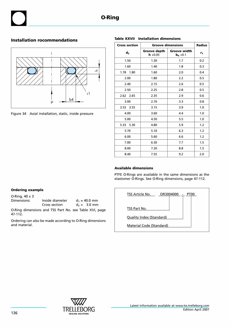
Installation rocommendations
b4r1
hp
Figure 34 Axial installation, static, inside pressure
Table XXVII Installation dimensions
Cross section
d2
Groove dimensions Radius
r1Groove depth
h +0.05Groove width
b4 +0.1
1.50 1.30 1.7 0.2
1.60 1.40 1.8 0.3
1.78 1.80 1.60 2.0 0.4
2.00 1.80 2.2 0.5
2.40 2.15 2.6 0.5
2.50 2.25 2.8 0.5
2.62 2.65 2.35 2.9 0.6
3.00 2.70 3.3 0.8
3.53 3.55 3.15 3.9 1.0
4.00 3.60 4.4 1.0
5.00 4.50 5.5 1.0
5.33 5.30 4.80 5.9 1.2
5.70 5.10 6.3 1.2
6.00 5.60 6.6 1.2
7.00 6.30 7.7 1.5
8.00 7.20 8.8 1.5
8.40 7.55 9.2 2.0
Available dimensions
PTFE O—Rings are available in the same dimensions as theelastomer O—Rings. See O—Ring dimensions, page 47-112.
Ordering example
O—Ring, 40 x 3Dimensions: Inside diameter d1 = 40.0 mm
Cross section d2 = 3.0 mm
O—Ring dimensions and TSS Part No. see Table XVI, page47-112.
Ordering can also be made according to O—Ring dimensionsand material.
OR3004000 PT00-TSS Article No.
Material Code (Standard)
TSS Part No.
Quality Index (Standard)
O—Ring
Latest information available at www.tss.trelleborg.com
136Edition April 2007
D.4 Polyurethane O—Rings
Polyurethane is becoming more and more widely used as asealing material due to its exceptionally high abrasionresistance and high extrusion resistance.
The polyurethane materials from Trelleborg SealingSolutions have a number of improved properties.
Polyurethane is therefore an ideal material for O—Rings andsealing elements.
The outstanding properties of the materials play a majorrole particularly in our Zurcon® materials.
Polyurethane O—Rings are available in dimensions toAmerican Standard AS 568 B (see dimension list, tableXXVIII, page 139).
The dimensions are given with the inside diameter “d1“and the cord diameter “d2“ (Figure 35, page 138).
Advantages
The main adavantages of a polyurethane material forO—Rings compared with other elastomer are theoutstanding mechanical properties:
- High abrasion and wear resistance tolerates aggressiveoperating conditions
- High extrusion resistance allows increased pressures orextrusion gaps
- Good mechanical properties improve service life
- Low friction reduces breakout forces on start up
Applications
Fields of application
Polyurethane O—Rings are especially suited whereverO—Rings are subject to dynamic loads.
This includes for example, applications in hydraulics,pneumatics and in a wide range of other critical areas. Inmany cases, polyurethane O—Rings are used instead of NBRin view of their high mechanical strengths.
Due to their particularly high abrasion resistance,polyurethane O—Rings are more suitable than othermaterials in applications where bores have to be crossedor where frequent opening and closing is demanded, e.g.plug connectors and couplings.
Polyurethane O—Rings in 70 Shore A hardness materialWU7TI can, with advance, be used in applications such aspneumatics where low compression set and low friction areessential.
Technical data
Working pressure: Static up to approx. 60 MPawithout Back-up Ring(depending on the extrusiongap)Dynamic up to 25 MPa
Speed: Reciprocating up to0.2 m/s
Temperature: -45 °C up to +100 °Cdepending on the material
Media: Hydraulic fluids and mineraloil-based greases and air.
Materials
The most important characteristics of these polyurethanesare:
- High tensile strength
- Low compression set
- Very good cold flexibility
- Constant shear modulus even at high temperatures
- Resistant to weathering and ageing
- High damping properties
- Low gas permeability
- Good hydrolysis resistance
- High tear propagation resistance
- Free from substances which hinder paint coverage
O—Ring
Latest information available at www.tss.trelleborg.comEdition April 2007
137
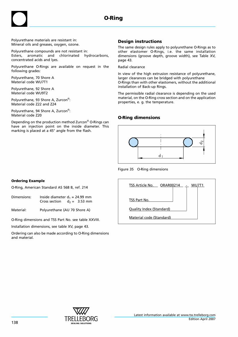
Polyurethane materials are resistant in:Mineral oils and greases, oxygen, ozone.
Polyurethane compounds are not resistant in:Esters, aromatic and chlorinated hydrocarbons,concentrated acids and lyes.
Polyurethane O—Rings are available on request in thefollowing grades:
Polyurethane, 70 Shore AMaterial code WU7T1
Polyurethane, 92 Shore AMaterial code WU9T2
Polyurethane, 93 Shore A, Zurcon®:Material code Z22 and Z24
Polyurethane, 94 Shore A, Zurcon®:Material code Z20
Depending on the production method Zurcon® O—Rings canhave an injection point on the inside diameter. Thismarking is placed at a 45° angle from the flash.
Design instructions
The same design rules apply to polyurethane O—Rings as toother elastomer O—Rings, i.e. the same installationdimensions (groove depth, groove width), see Table XV,page 43.
Radial clearance
In view of the high extrusion resistance of polyurethane,larger clearances can be bridged with polyurethaneO—Rings than with other elastomers, without the additionalinstallation of Back-up Rings.
The permissible radial clearance is depending on the usedmaterial, on the O—Ring cross section and on the applicationproperties, e. g. the temperature.
O—Ring dimensions
d 1
d 2
Figure 35 O—Ring dimensions
Ordering Example
O—Ring, American Standard AS 568 B, ref. 214
Dimensions: Inside diameter d1 = 24.99 mmCross section d2 = 3.53 mm
Material: Polyurethane (AU 70 Shore A)
O—Ring dimensions and TSS Part No. see table XXVIII.
Installation dimensions, see table XV, page 43.
Ordering can also be made according to O—Ring dimensionsand material.
ORAR00214 WU7T1-TSS Article No.
Material code (Standard)
TSS Part No.
Quality Index (Standard)
O—Ring
Latest information available at www.tss.trelleborg.com
138Edition April 2007
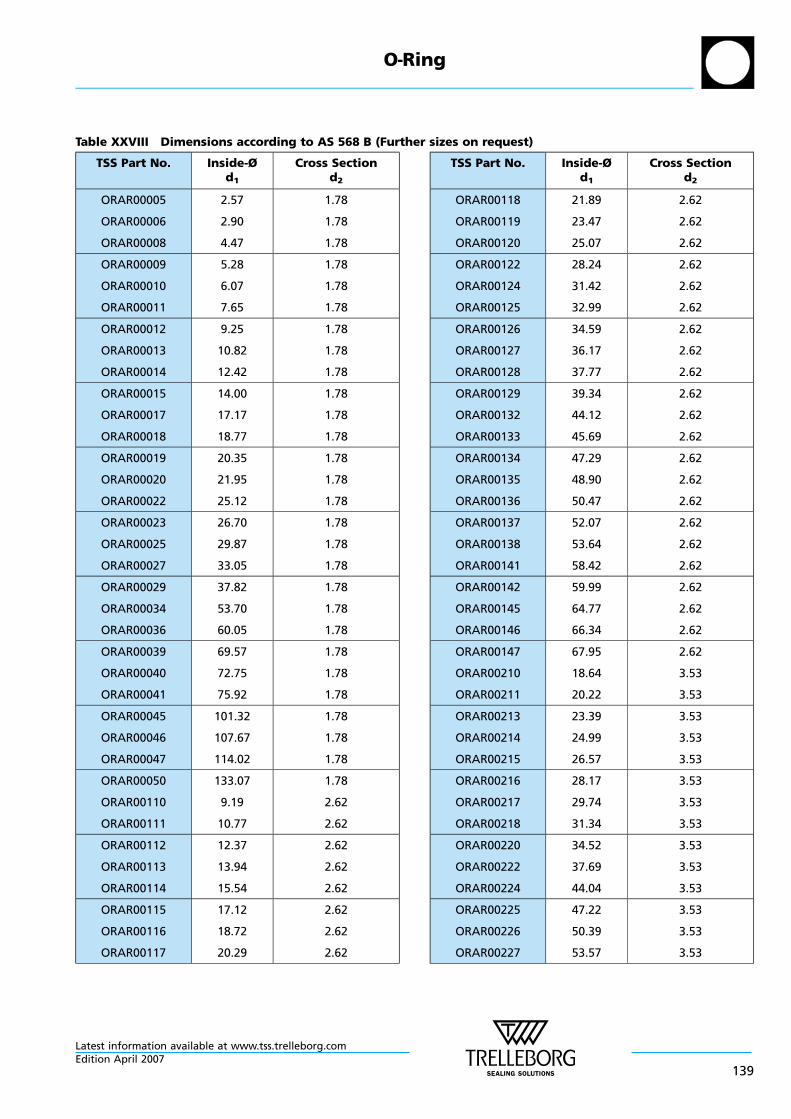
Table XXVIII Dimensions according to AS 568 B (Further sizes on request)
TSS Part No. Inside-Ød1
Cross Sectiond2
ORAR00005
ORAR00006
ORAR00008
2.57
2.90
4.47
1.78
1.78
1.78
ORAR00009
ORAR00010
ORAR00011
5.28
6.07
7.65
1.78
1.78
1.78
ORAR00012
ORAR00013
ORAR00014
9.25
10.82
12.42
1.78
1.78
1.78
ORAR00015
ORAR00017
ORAR00018
14.00
17.17
18.77
1.78
1.78
1.78
ORAR00019
ORAR00020
ORAR00022
20.35
21.95
25.12
1.78
1.78
1.78
ORAR00023
ORAR00025
ORAR00027
26.70
29.87
33.05
1.78
1.78
1.78
ORAR00029
ORAR00034
ORAR00036
37.82
53.70
60.05
1.78
1.78
1.78
ORAR00039
ORAR00040
ORAR00041
69.57
72.75
75.92
1.78
1.78
1.78
ORAR00045
ORAR00046
ORAR00047
101.32
107.67
114.02
1.78
1.78
1.78
ORAR00050
ORAR00110
ORAR00111
133.07
9.19
10.77
1.78
2.62
2.62
ORAR00112
ORAR00113
ORAR00114
12.37
13.94
15.54
2.62
2.62
2.62
ORAR00115
ORAR00116
ORAR00117
17.12
18.72
20.29
2.62
2.62
2.62
TSS Part No. Inside-Ød1
Cross Sectiond2
ORAR00118
ORAR00119
ORAR00120
21.89
23.47
25.07
2.62
2.62
2.62
ORAR00122
ORAR00124
ORAR00125
28.24
31.42
32.99
2.62
2.62
2.62
ORAR00126
ORAR00127
ORAR00128
34.59
36.17
37.77
2.62
2.62
2.62
ORAR00129
ORAR00132
ORAR00133
39.34
44.12
45.69
2.62
2.62
2.62
ORAR00134
ORAR00135
ORAR00136
47.29
48.90
50.47
2.62
2.62
2.62
ORAR00137
ORAR00138
ORAR00141
52.07
53.64
58.42
2.62
2.62
2.62
ORAR00142
ORAR00145
ORAR00146
59.99
64.77
66.34
2.62
2.62
2.62
ORAR00147
ORAR00210
ORAR00211
67.95
18.64
20.22
2.62
3.53
3.53
ORAR00213
ORAR00214
ORAR00215
23.39
24.99
26.57
3.53
3.53
3.53
ORAR00216
ORAR00217
ORAR00218
28.17
29.74
31.34
3.53
3.53
3.53
ORAR00220
ORAR00222
ORAR00224
34.52
37.69
44.04
3.53
3.53
3.53
ORAR00225
ORAR00226
ORAR00227
47.22
50.39
53.57
3.53
3.53
3.53
O—Ring
Latest information available at www.tss.trelleborg.comEdition April 2007
139
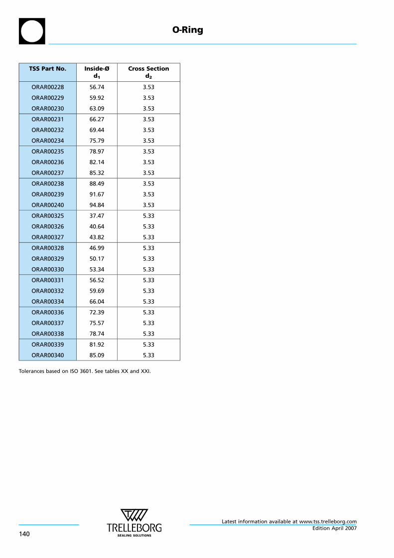
TSS Part No. Inside-Ød1
Cross Sectiond2
ORAR00228
ORAR00229
ORAR00230
56.74
59.92
63.09
3.53
3.53
3.53
ORAR00231
ORAR00232
ORAR00234
66.27
69.44
75.79
3.53
3.53
3.53
ORAR00235
ORAR00236
ORAR00237
78.97
82.14
85.32
3.53
3.53
3.53
ORAR00238
ORAR00239
ORAR00240
88.49
91.67
94.84
3.53
3.53
3.53
ORAR00325
ORAR00326
ORAR00327
37.47
40.64
43.82
5.33
5.33
5.33
ORAR00328
ORAR00329
ORAR00330
46.99
50.17
53.34
5.33
5.33
5.33
ORAR00331
ORAR00332
ORAR00334
56.52
59.69
66.04
5.33
5.33
5.33
ORAR00336
ORAR00337
ORAR00338
72.39
75.57
78.74
5.33
5.33
5.33
ORAR00339
ORAR00340
81.92
85.09
5.33
5.33
Tolerances based on ISO 3601. See tables XX and XXI.
O—Ring
Latest information available at www.tss.trelleborg.com
140Edition April 2007
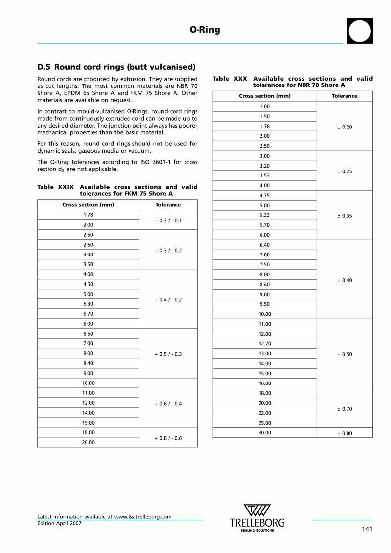
D.5 Round cord rings (butt vulcanised)
Round cords are produced by extrusion. They are suppliedas cut lengths. The most common materials are NBR 70Shore A, EPDM 65 Shore A and FKM 75 Shore A. Othermaterials are available on request.
In contrast to mould-vulcanised O—Rings, round cord ringsmade from continuously extruded cord can be made up toany desired diameter. The junction point always has poorermechanical properties than the basic material.
For this reason, round cord rings should not be used fordynamic seals, gaseous media or vacuum.
The O—Ring tolerances according to ISO 3601-1 for crosssection d2 are not applicable.
Table XXIX Available cross sections and validtolerances for FKM 75 Shore A
Cross section (mm) Tolerance
1.78+ 0.3 / - 0.1
2.00
2.50
+ 0.3 / - 0.22.60
3.00
3.50
4.00
+ 0.4 / - 0.2
4.50
5.00
5.30
5.70
6.00
6.50
+ 0.5 / - 0.3
7.00
8.00
8.40
9.00
10.00
+ 0.6 / - 0.4
11.00
12.00
14.00
15.00
18.00+ 0.8 / - 0.6
20.00
Table XXX Available cross sections and validtolerances for NBR 70 Shore A
Cross section (mm) Tolerance
1.00
± 0.20
1.50
1.78
2.00
2.50
3.00
± 0.253.20
3.53
4.00
4.75
± 0.35
5.00
5.33
5.70
6.00
6.40
± 0.40
7.00
7.50
8.00
8.40
9.00
9.50
10.00
11.00
± 0.50
12.00
12.70
13.00
14.00
15.00
16.00
18.00
± 0.7020.00
22.00
25.00
30.00 ± 0.80
O—Ring
Latest information available at www.tss.trelleborg.comEdition April 2007
141
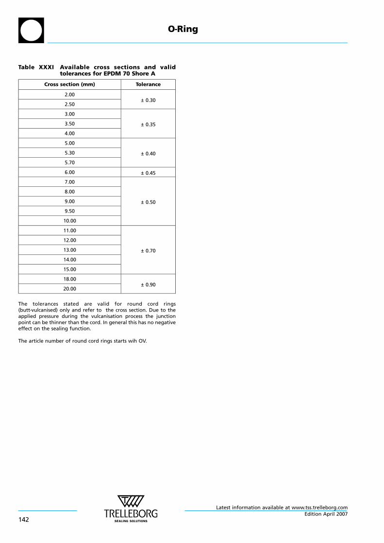
Table XXXI Available cross sections and validtolerances for EPDM 70 Shore A
Cross section (mm) Tolerance
2.00± 0.30
2.50
3.00
± 0.353.50
4.00
5.00
± 0.405.30
5.70
6.00 ± 0.45
7.00
± 0.50
8.00
9.00
9.50
10.00
11.00
± 0.70
12.00
13.00
14.00
15.00
18.00± 0.90
20.00
The tolerances stated are valid for round cord rings(butt—vulcanised) only and refer to the cross section. Due to theapplied pressure during the vulcanisation process the junctionpoint can be thinner than the cord. In general this has no negativeeffect on the sealing function.
The article number of round cord rings starts wih OV.
O—Ring
Latest information available at www.tss.trelleborg.com
142Edition April 2007
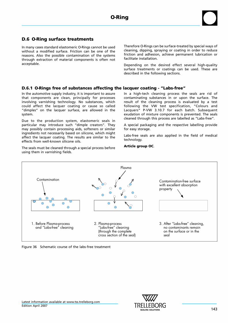
D.6 O—Ring surface treatments
In many cases standard elastomeric O—Rings cannot be usedwithout a modified surface. Friction can be one of thereasons. Also the possible contamination of the systemsthrough extraction of material components is often notacceptable.
Therefore O—Rings can be surface-treated by special ways ofcleaning, dipping, spraying or coating in order to reducefriction and adhesion, achieve permanent lubrication orfacilitate installation.
Depending on the desired effect several high-qualitysurface treatments or coatings can be used. These aredescribed in the following sections.
D.6.1 O—Rings free of substances affecting the lacquer coating - “Labs-free“In the automotive supply industry, it is important to assurethat components are clean, principally for processesinvolving varnishing technology. No substances, whichcould affect the lacquer coating or cause so called“dimples“ on the lacquer surface, are allowed in thesystem.
Due to the production system, elastomeric seals inparticular may introduce such “dimple creators“. Theymay possibly contain processing aids, softeners or similaringredients not necessarily based on silicone, which mightaffect the lacquer coating. The results are similar to theeffects from well-known silicone oils.
The seals must be cleaned through a special process beforeusing them in varnishing fields.
In a high-tech cleaning process the seals are rid ofcontaminating substances in or upon the surface. Theresult of the cleaning process is evaluated by a testfollowing the VW test specification, “Colours andLacquers“ P-VW 3.10.7 for each batch. Subsequentexudation of mixture components is prevented. The sealscleaned through this process are labelled as “Labs-free“.
A special packaging and the respective labelling providefor easy storage.
Labs-free seals are also applied in the field of medicaltechnology.
Article group OC.
Contamination-free surfacewith excellent absorptionproperty
3. After “Labs-free” cleaning,no contaminants remainon the surface or in theseal
Contamination
1. Before Plasma-processand “Labs-free” cleaning
Plasma
2. Plasma-process“Labs-free” cleaning(through the completecross section of the seal)
Figure 36 Schematic course of the labs-free treatment
O—Ring
Latest information available at www.tss.trelleborg.comEdition April 2007
143
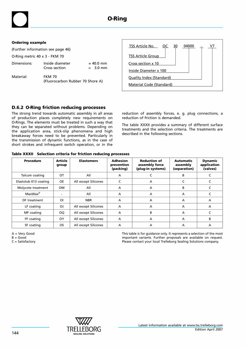
Ordering example
(Further information see page 46)
O—Ring metric 40 x 3 - FKM 70
Dimensions: Inside diameter = 40.0 mmCross section = 3.0 mm
Material: FKM 70(Fluorocarbon Rubber 70 Shore A)
V7-TSS Article No.
Cross section x 10
Material Code (Standard)
04000
TSS Article Group
Inside Diameter x 100
Quality Index (Standard)
30OC
D.6.2 O—Ring friction reducing processesThe strong trend towards automatic assembly in all areasof production places completely new requirements onO—Rings. The elements must be treated in such a way thatthey can be separated without problems. Depending onthe application area, stick-slip phenomena and highbreakaway forces need to be prevented. Particularly inthe transmission of dynamic functions, as in the case ofshort strokes and infrequent switch operation, or in the
reduction of assembly forces, e. g. plug connections, areduction of friction is demanded.
The table XXXII provides a summary of different surfacetreatments and the selection criteria. The treatments aredescribed in the following sections.
Table XXXII Selection criteria for friction reducing processes
Procedure Articlegroup
Elastomers Adhesionprevention(packing)
Reduction ofassembly force
(plug-in systems)
Automaticassembly
(separation)
Dynamicapplication
(valves)
Talcum coating OT All A C B C
Elastolub 013 coating OE All except Silicones C A C C
Molycote treatment OM All A A B C
MaxWax® - All A A A C
DF treatment OI NBR A A A A
LF coating OJ All except Silicones A A A A
MF coating OQ All except Silicones A B A C
FF coating OY All except Silicones A A A B
SF coating OS All except Silicones A A A A
A = Very GoodB = GoodC = Satisfactory
This table is for guidance only. It represents a selection of the mostimportant variants. Further proposals are available on request.Please contact your local Trelleborg Sealing Solutions company.
O—Ring
Latest information available at www.tss.trelleborg.com
144Edition April 2007
LF coating
The LF coating is a transparent, dry coating based on PTFEwhich is applied to the elastomer surface in a computerisedprocess. The seal surface remains elastic.
To ensure permanent surface bonding the parts are pre-treated with plasma.
LF is primarily used to reduce surface friction among otherthings for dynamic applications and beyond that for thestrong reduction up to the prevention of the gluinginclination of elastomeric seals.
- Flexible coating with surface bond
- Transparent with a slight milkiness
- UV-indicator allows 100% inspection
- Water-based, solvent-free
- Coating thickness about 2 - 6 µm(deviations depending on part geometry are possible)
- Operating temperature range of the coatingmaterial -40 °C to +150 °C
- Containes no substances with duty of declarationaccording to VDA 232-101
- Constant process-secure quality
- Reduced mounting forces through friction reduction
- Pieces remain separate in the packing
- Reduction of the gluing inclination of elastomeric seals inthe application
- Excellent usage for automated assembly
- Suitable for dynamic applications, preferred at low rateor for short strokes
- Suitable for various types of elastomers except silicones
- Article group OJ
MF coating
The MF coating is a dry coating which is applied to theelastomer surface in a computerised process. Similar to theLF coating MF is transparent and based on PTFE.
The good surface bond is achieved owing to a priorelevation of surface energy in the seal through a plasmatreatment.
MF is primarily used to facilitate assembly of elastomericseals and provides a better separating of parts. Due to itscomposition it is suited for one-time assembly only.
- Elastic, dry coating
- Transparent with a slight milkiness
- UV-indicator allows 100% inspection
- Water-based, solvent-free
- Coating thickness about 2 - 6 µm(deviations depending on part geometry are possible)
- Containes no substances with duty of declarationaccording to VDA 232-101
- Constant process-secure quality
- Prevents contamination of the assembly facilities
- Pieces remain separate in the packing
- Excellent usage for automated assembly
- Suitable for various types of elastomers except silicones
- Article group OQ
O—Ring
Latest information available at www.tss.trelleborg.comEdition April 2007
145
SF coating
SF coating is a black, dry coating based on PTFE particularlyintended for the use in dynamic applications.
To ensure permanent surface bonding the parts are pre-treated with plasma.
Signs of wear at the seal’s surface are effectively reduced.Gluing phenomenon and stick-slip effects are nearlyeliminated.
- Flexible coating with surface bond
- Black with UV indicator (allows 100 % inspection)
- Water-based, solvent-free
- Coating thickness about 2 - 6 µm(deviations depending on part geometry are possible)
- Containes no substances with duty of declarationaccording to VDA 232-101
- Constant, process-secure quality
- Operating temperature range of the coatingmaterial -40 °C to +150 °C
- Pieces remain separate in the packing
- Reduces mounting forces
- Reduction of the gluing inclination of elastomeric seals inthe application
- Excellent usage for automated assembly
- Friction reduction in dynamic use
- Reduces the seal surface’s signs of wear in dynamic use
- Suitable for various types of elastomers except silicones
- Article group OS
FF coating
The transparent FF coating for elastomeric seals isespecially suitable for the reduction of mounting resp.plugging forces and to ease assembly.
Through the FDA compliance FF can be used incorresponding applications of the food or the potablewater industry.
As well as with SF coating the permanent surface bondingis assured through a pre-treatment with plasma.
- Flexible coating with surface bond based on PTFE
- Transparent resp. milky or dull
- Water-based, solvent free
- FDA compliant (“White list“)
- approved acc. to the Foodstuffs and Commodities Act(LMBG, § 5, paragraph 1)
- complies with the standards of the German FederalEnvironmental Agency (FEA), valid for the area D2 (seals)
- Coating thickness about 2-10 µm (deviations dependingon part geometry are possible)
- Contains no substances with duty of declarationaccording to VDA 232-101
- Constant process-sure quality
- Operating temperature range of the coatingmaterial -40 °C to +150 °C
- Pieces remain separate in the packing
- Reduces considerably mounting resp. plugging forces
- Reduces the risk of the seal shearing off during assembly
- Friction reduction for gentle dynamic use, e.g. infrequentswitching operations with short strokes and at low rate
- Suitable for various types of elastomers except silicones
- Article group OY
O—Ring
Latest information available at www.tss.trelleborg.com
146Edition April 2007
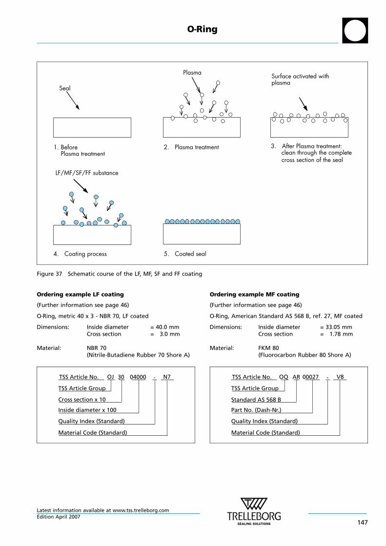
Seal
Plasma Surface activated withplasma
1. BeforePlasma treatment
2. Plasma treatment 3. After Plasma treatment:clean through the completecross section of the seal
4. Coating process 5. Coated seal
LF/MF/SF/FF substance
Figure 37 Schematic course of the LF, MF, SF and FF coating
Ordering example LF coating
(Further information see page 46)
O—Ring, metric 40 x 3 - NBR 70, LF coated
Dimensions: Inside diameter = 40.0 mmCross section = 3.0 mm
Material: NBR 70(Nitrile-Butadiene Rubber 70 Shore A)
N7-TSS Article No.
Cross section x 10
Material Code (Standard)
OJ
TSS Article Group
Inside diameter x 100
Quality Index (Standard)
30 04000
Ordering example MF coating
(Further information see page 46)
O—Ring, American Standard AS 568 B, ref. 27, MF coated
Dimensions: Inside diameter = 33.05 mmCross section = 1.78 mm
Material: FKM 80(Fluorocarbon Rubber 80 Shore A)
V8-TSS Article No.
Standard AS 568 B
Material Code (Standard)
OQ
TSS Article Group
Part No. (Dash-Nr.)
Quality Index (Standard)
AR 00027
O—Ring
Latest information available at www.tss.trelleborg.comEdition April 2007
147
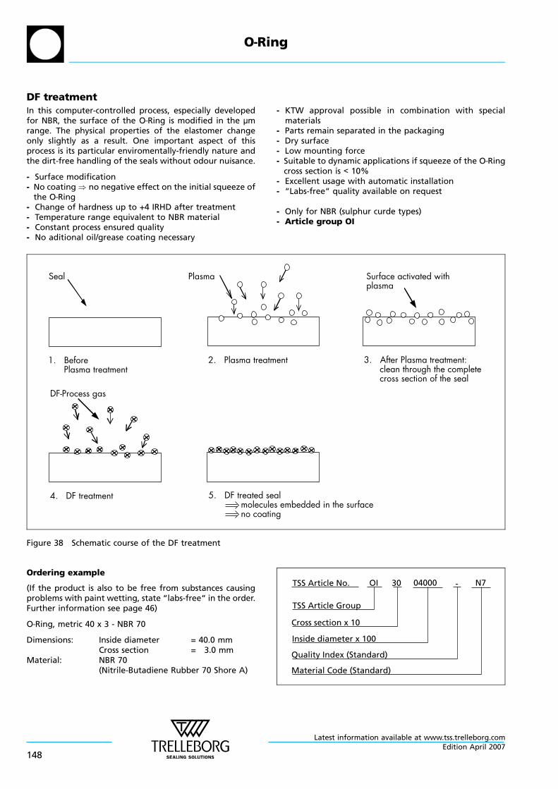
DF treatmentIn this computer-controlled process, especially developedfor NBR, the surface of the O—Ring is modified in the µmrange. The physical properties of the elastomer changeonly slightly as a result. One important aspect of thisprocess is its particular enviromentally-friendly nature andthe dirt-free handling of the seals without odour nuisance.
- Surface modification- No coating ) no negative effect on the initial squeeze of
the O—Ring- Change of hardness up to +4 IRHD after treatment- Temperature range equivalent to NBR material- Constant process ensured quality- No aditional oil/grease coating necessary
- KTW approval possible in combination with specialmaterials
- Parts remain separated in the packaging- Dry surface- Low mounting force- Suitable to dynamic applications if squeeze of the O—Ring
cross section is < 10%- Excellent usage with automatic installation- “Labs-free“ quality available on request
- Only for NBR (sulphur curde types)- Article group OI
Seal Plasma Surface activated withplasma
1. BeforePlasma treatment
2. Plasma treatment 3. After Plasma treatment:clean through the completecross section of the seal
4. DF treatment 5. DF treated sealmolecules embedded in the surfaceno coating
DF-Process gas
Figure 38 Schematic course of the DF treatment
Ordering example
(If the product is also to be free from substances causingproblems with paint wetting, state “labs-free“ in the order.Further information see page 46)
O—Ring, metric 40 x 3 - NBR 70
Dimensions: Inside diameter = 40.0 mmCross section = 3.0 mm
Material: NBR 70(Nitrile-Butadiene Rubber 70 Shore A)
N7-TSS Article No.
Cross section x 10
Material Code (Standard)
04000
TSS Article Group
Inside diameter x 100
Quality Index (Standard)
30OI
O—Ring
Latest information available at www.tss.trelleborg.com
148Edition April 2007
Other variants of friction reducing processes
Molycote treatment
In Molycote treatment, high-purity, micro-finemolybdenum disulphide (MoS2) is applied to the surfaceof the elastomere. The MoS2 is incorporated as a drylubricating film by tumbling onto the sealing surface. Thisgives rise to mechanical interlocking, which over a longperiod, brings about a reduction in friction and wear underdynamic stresses.
- Dry lubricating film by tumbling into the sealing surface(silvery colour)
- Friction force reduction in conjunction with low dynamicstresses
- Long-term friction reduction can be achieved bydeposition of the slide-promoting substances in hollowsin the opposing surface
- Improved separation in automatic assembly
- Low abrasion resistance of MoS2 layer
- Rubbing of the surface layer can lead to dirt build up onthe automatic assembly machine peripherals
- For all types of elastomers
- Article group OM
Elastolub 013 coating
Elastolub 013 is a silicone fluid-based lubricant. Thesubstance is applied to the rings in a drum and combinesvery well with the elastomere surface. Elastolub 013 formsa thin lubricating film.
- A thin lubricating film by tumbling
- Reduction of assembly forces
- Tendency for such O—Rings to stick together slightly
- For all types of elastomers, exept silicone rubber
- Article group OE
Talcum coating
The talcum is applied to the seal in a drum as a loosepowder coating. No interlocking with the surface of theelastomere takes place.
- Loose powder coating
- Prevent components from sticking together after packing
- Not suitable for dynamic applications
- For all types of elastomers
- Article group OT
MaxWax® coating
Ready made parts are covered with a quick-dryingsynthetic hard wax of polythylene in a diffusion process.No changes are made in the material composition.
- Dry surface
- No changes in material composition
- Replaces lubrication at installation
- Reduces friction
- Gives good results in dynamic applications specificallywith short- or medium-length strokes
- For all types of materials
- Only available for Skega materials
Further coating variants are available on request.
O—Ring
Latest information available at www.tss.trelleborg.comEdition April 2007
149
E General quality criteria and storage guidelines
E.1 Quality criteria
The cost-effective use of seals and bearings is highlyinfluenced by the quality criteria applied in production.Seals and bearings from Trelleborg Sealing Solutions arecontinuously monitored according to strict qualitystandards from material acquisition through to delivery.
Certification of our production plants in accordance withinternational standards QS 9000 / ISO 9000 meets thespecific requirements for quality control and managementof purchasing, production and marketing functions.
Our quality policy is consistently controlled by strictprocedures and guidelines which are implemented withinall strategic areas of the company.
All testing of materials and products is performed inaccordance with accepted test standards and specifications,e.g. random sample testing in accordance with DIN ISO2859, part 1.
Inspection specifications correspond to standardsapplicable to individual product groups (e.g. for O—Rings:ISO 3601).
Our sealing materials are produced free ofchlorofluorinated hydrocarbons and carcinogenicelements.
The tenth digit of our part number defines the qualitycharacteristics of the part. A hyphen indicates compliancewith standard quality criteria outlined in this catalogue.Customer-specific requirements are indicated by a differentsymbol in this position. Customers who require specialquality criteria should contact their local Trelleborg SealingSolutions sales office for assistance. We have experience inmeeting all Customer quality requirements.
E.2 Storage and shelf life
Seals and bearings are often stored as spare parts forprolonged periods. Most rubbers change in physicalproperties during storage and ultimately becomeunserviceable due, e.g., to excessive hardening, softening,cracking, crazing or other surface degradation. Thesechanges may be the result of particular factors orcombination of factors, such as the action ofdeformation, oxygen, ozone, light, heat, humidity or oilsand solvents.
With a few simple precautions, the shelf life of theseproducts can be considerably lengthened.
Fundamental instructions on storage, cleaning andmaintenance of elastomeric seal elements are describedin international standards, such as:DIN 7716 / BS 3F68:1977,ISO 2230 orDIN 9088
The standards give several recommendations for thestorage and the shelf life of elastomers, depending onthe material classes.
The following recommendations are based on the severalstandards and are intended to provide the most suitableconditions for storage of rubbers. They should be observedto maintain the optimum physical and chemical values ofthe parts:
Heat
The storage temperature should preferable be between+5 °C and +25 °C. Direct contact with sources of heat suchas boilers, radiators and direct sunlight should be avoided.
If articles are taken from low temperature storage, careshould be taken to avoid distorting them during handlingat that temperature as they may have stiffened. In this casethe temperature of the articles should be raised toapproximately +20 °C before they are put into service.
Humidity
The relative humidity in the store room should be below70 %. Very moist or very dry conditions should be avoided.Condensation should not occur.
Light
Elastomeric seals should be protected from light sources, inparticular direct sunlight or strong artificial light with anultraviolet content. The individual storage bags offer thebest protection as long as they are UV resistant.
It is advisable to cover any windows of storage rooms witha red or orange coating or screen.
Radiation
Precaution should be taken to protect stored articles fromall sources of ionising radiation likely to cause damage tostored articles.
Oxygen and ozone
Where possible, elastomeric materials should be protectedfrom circulating air by wrapping, storage in airtightcontainers or by other suitable means.
As ozone is particular deleterious to some elastomericseals, storage rooms should not contain any equipmentthat is capable of generating ozone, such as mercuryvapour lamps, high voltage electrical equipment, electricmotors or other equipment which may give rise to electricsparks or silent electrical discharges. Combustion gases andorganic vapour should be excluded from storage rooms asthey may give rise to ozone via photochemical processes.
O—Ring
Latest information available at www.tss.trelleborg.com
150Edition April 2007
Deformation
Elastomeric materials should, wherever possible, be storedin a relaxed condition free from tension, compression orother deformation. Where articles are packed in astrain—free condition they should be stored in theiroriginal packaging.
Contact with liquid and semi-solid materials
Elastomeric seals should not be allowed to come intocontact with solvents, oils, greases or any other semi-solidmaterials at any time during storage, unless so packed bythe manufacturer.
Contact with metal and non-metals
Direct contact with certain metals, e.g. manganese, ironand particularly copper and its alloys, e.g. brass andcompounds of these materials are known to havedeleterious effects on some rubbers. Elastomeric sealsshould not be stored in contact with such metals.
Because of possible transfer of plasticisers or otheringredients, rubbers must not be stored in contact withPVC. Different rubbers should preferably be separatedfrom each other.
Cleaning
Where necessary, cleaning should be carried out with theaid of soap and water or methylated spirits. Water shouldnot, however, be permitted to come into contact withfabric reinforced components, bonded seals (because ofcorrosion) or polyurethane rubbers. Disinfectants or otherorganic solvents as well as sharp-edged objects must not beused. The articles should be dried at room temperature andnot placed near a source of heat.
Shelf life and shelf life control
The useful life of a elastomeric seals will depend to a largeextend on the type of rubber. When stored under therecommended conditions (above sections) the below givenshelf life of several materials should be considered.
AU, thermoplastics 4 yearsNBR, HNBR, CR 6 yearsEPDM 8 yearsFKM, VMQ, FVMQ 10 yearsFFKM, Isolast® 18 yearsPTFE unlimited
Elastomeric seals should be inspected after the givenperiod. After this giving an extension period is possible.
Rubber details and components less than 1.5 mm thick areliable to be more seriously affected by oxidationdegradation even when stored in satisfactory conditionsas recommended. Therefore they may be inspected andtested more frequently than it is mentioned above.
Rubber details / seals in assembled components
It is recommended that the units should be exercised atleast every six months and that the maximum period arubber detail be allowed to remain assembled within astored unit, without inspection, be a total of the initialperiod stated above and the extension period. Naturallythis will depend on the design of the unit concerned.
O—Ring
Latest information available at www.tss.trelleborg.comEdition April 2007
151
Index
AACS 28Adhesion 130, 135, 143-144American Standards 46, 113Approval 28-29Authorities 28-29Axial installation 38, 43
BBack-up Rings 40, 42, 131, 138BAM 28BfR 28British standard 46
CChemical compatibility 5, 8-9Chemicals 7, 9, 39, 130-131, 135Chloroprene Rubber 5-6, 9Clearance 40-41Compression 37Compression set 9, 26, 30-33Contact pressure 36
DDesign recommendations 35DF treatment 144DVGW 28Dynamic service 39, 41, 137
EElastolub 013 coating 144, 149Elastomers 5, 7-9, 25-26, 41, 125, 138, 144, 149-150Ethylene-Propylene-Diene 5Extrusion 40-42, 137-138, 141Extrusion gap 39-40, 137
FFDA 28FEP O—Ring 130FF coating 144, 146Fluorocarbon Rubber FKM 5Fluorosilicone Rubber FVMQ 5Foodstuff contact 130Form deviations 127Friction 36, 39, 130, 135, 137, 143-144, 149
GGroove design 3, 40
HHardness 25, 30-33Hydrogenated Nitrile Butadiene 6, 9
IInitial compression 36Installation 36, 134-135, 138Installation recommendations 35IRHD Hardness 25Isolast® O—Rings 35, 130
JJapanese standard 46Joule effect 39
KKTW 28, 148
LLabs-free 148Lead-in chamfers 35, 40LF coating 144-145
MMaterials 28MaxWax® coating 149MF coating 144-145Military standard 46Molycote treatment 144, 149
NNitrile Butadiene Rubber 6, 8NSF 29
OO—Ring sets 129Ordering example 46, 134, 136, 144, 147-148Oxygen 6-7, 9, 138, 150
PPart Number 46, 112, 139Perfluoro Rubber 5-6, 9Permeation 131Polyacrylate Rubber ACM 5-6, 9Polyurethane AU 5, 137Polyurethane O—Rings 137-138PTFE O—Rings 130, 135-136
QQuality Acceptance Criteria 127Quality criteria 150
RRadial installation 38Recommendations 43Rectangular groove 42Rotary service 39Roto principle 39Round cord rings 141
O—Ring
Latest information available at www.tss.trelleborg.com
152Edition April 2007
SSeal Set 129SF coating 144, 146Shelf life 150Shore hardness 40, 46, 123Shrinkage 46, 125Silicone rubber 9, 149Squeeze 4, 36-37, 40, 148Standard materials 5, 30Stick-slip effect 130Storage 28, 150-151Stretching 131Surface finish 41Surface treatment 143Swedish treatment 46Swelling 9
TTalcum coating 144, 149Temperature range 9, 30-33, 131, 135, 148Tetrafluoroethylene Propylene 5Tolerance ID 133Tolerances 26, 36, 40, 125-128, 141Trade names 5Trapezoidal groove 42TSS part numbers 47
UUL 29
VVolume Change 7
WWRAS 29WRC 29
O—Ring
Latest information available at www.tss.trelleborg.comEdition April 2007
153

Notes
O—Ring
Latest information available at www.tss.trelleborg.com
154Edition April 2007

Notes
O—Ring
Latest information available at www.tss.trelleborg.comEdition April 2007
155

Notes
O—Ring
Latest information available at www.tss.trelleborg.com
156Edition April 2007


www.tss.trelleborg.com
For fur ther information:
Europe Telephone
AUSTRIA - Vienna +43 (1) 406 47 33(ALBANIA, BOSNIA AND HERZEGOVINA,CROATIA, HUNGARY, MACEDONIA,SERBIA AND MONTENEGRO, SLOVENIA)
BELGIUM - Dion -Valmont +32 (10) 22 57 50(LUXEMBOURG)
BULGARIA - Sofia +359 2 96 99 510(ROMANIA, RUSSIA)
CZECH REPUBLIC - Rakovnik +420 313 529 111(SLOVAKIA)
DENMARK - Hillerød +45 4822 8080
FINLAND - Vantaa +358 (0)9 8256 110(ESTONIA, LATVIA, LITHUANIA)
FRANCE - Maisons-Laffitte +33 (0)1 30 86 56 00
GERMANY - Stuttgart +49 (711) 7 86 40
GREECE +41 (21) 6314111
ITALY - Livorno +39 (0586) 22 61 11
THE NETHERLANDS - Barendrecht +31 (10) 29 22 111
NORWAY - Oslo +47 22 64 60 80
POLAND - Warsaw +48 (22) 8 63 30 11
SPAIN - Madrid +34 91 710 5730(PORTUGAL)
SWEDEN - Jönköping +46 (36) 34 15 00
SWITZERLAND - Crissier +41 (21) 631 41 11
TURKEY +41 (21) 6314111
UNITED KINGDOM - Solihull +44 (0)121 744 1221(EIRE)
America Telephone
AMERICAS - Fort Wayne, IN +1 (260) 749 9631
BRAZIL - Sao Paulo +55 (11) 3372 4500
CANADA - Ontario +1 (416) 213 9444
MEXICO - Mexico D.F. +52 55 57 19 50 05
USA, East - Philadelphia, PA +1 (610) 828 3209
USA, Great Lakes - Fort Wayne, IN +1 (260) 749 6781
USA, Midwest - Lombard, IL +1 (630) 268 9915
USA, Mountain - Broomfield, CO +1 (303) 469 1357
USA, Northwest - Portland, OR +1 (503) 595 6565
USA, South - N. Charleston, SC +1 (843) 747 7656
USA, Southwest - Houston, TX +1 (713) 461 3495
USA, West - Torrance, CA +1 (310) 371 1025
Asia Telephone
ASIA PACIFIC REGIONAL +65 (6)265 6883
CHINA - Hong Kong +852 (2)366 9165
INDIA - Bangalore +91 (80) 2655 5157
JAPAN - Tokyo +81 (3) 5633 8008
KOREA - Gyunggi-Do +82 (31) 386 3283
MALAYSIA - Kuala Lumpur +60 (0) 3 9059 6388
TAIWAN - Taichung +886 (4) 23 58 00 82
THAILAND - Bangkok +66 (0) 2732-2861
SINGAPORE
and all other countries in Asia +65 (6)293 2500
AFRICA REGIONAL +41 (21) 6314111
MIDDLE EAST REGIONAL +41 (21) 6314111
99G
BO00
11A
E040
7