Embed Size (px)
Citation preview
NAVEDTRA 14069A 7-12
o has a coating over its exterior face to make it moisture-resistant and non- adhesive to concrete
o exterior coating reduces the number of times the form must be oiled
SOFTWOOD PLYWOOD GRADES FOR EXTERIOR USE
GRADE
(Exterior)
FACE BACK INNER
PLYS
USES
A-A A A C Outdoor where appearance of both sides is important.
A-B A A C Alternative for A-A, where appearance of one side is less important
A-C A C C Siding, soffits, fences. Face is finish grade.
B-C B C C For utility uses such as farm buildings, some kind of fences, etc.
C-C
(Plugged)
C C C Excellent base for tile and linoleum, backing for wall coverings.
C-C C C C Unsanded, for backing and rough construction exposed to weather.
B-B
Concrete
forms
B
C Concrete forms. Re-use until wood literally wears out.
MDO B B C or C Plugged
Medium Density Overlay. Ideal for base for paint, siding, built-ins, signs, displays.
HDO A or B A or B
High Density Overlay. Hard surface, no paint needed. For concrete forms, cabinets, counter tops, tanks.

NAVEDTRA 14069A 7-13
Table 7-1 — Softwood plywood grades for interior and exterior use.
SOFTWOOD PLYWOOD GRADES FOR INTERIOR USE
GRADE
(Interior)
FACE BACK INNER
PLYS
USES
A-A A A D Cabinet doors, built-ins, furniture where both sides show.
A-B A B D Alternative of A-A. Face is finish grade, back is solid and smooth.
A-D A D D Finish grade face for paneling, built-ins, backing.
B-D B D D Utility grade. One paintable side. For backing, cabinet sides, etc.
STANDARD C D D Unsanded. Sheathing and structural uses such as temporary enclosures, subfloor.
1.5.0 Common Wood Substitutes
Many common substitutes for wood or plywood are available for use as construction material. Some are significantly less expensive than plywood; others are more suitable because of their decorative appearance and weather-resistant qualities.
1.5.1 Particleboard
Commonly referred to as chip-board or flakeboard
Produced by mixing a resin-bonding agent with wood particles and bonding them together with heat and pressure
Limited to nonstructural use because of its low strength qualities
Most common size sheets are 4 feet by 8 feet and vary from 1/4 to 1 1/2 inches thick.
1.5.2 1.5.2 Hardboard
Made of compressed wood fibers subjected to heat and heavy pressure
Obtainable in a plain, smooth surface or in any number of glossy finishes, some of which imitate tile or stone
Strength is about equal in all directions, and it can be bent into various shapes
Available in thicknesses from 1/8 inch to 3/8 inch.
Most common size sheets are 4 feet by 8 feet.
1.5.3 1.5.3 Fiberboard
Made of wood or vegetable fiber compressed to form sheets or boards
Comparatively soft and provides good insulation and sound-absorbing qualities
Available in sizes from 1/2 inch to 1 inch thick, 2 feet to 4 feet wide, and 8 feet to 12 feet long.
NAVEDTRA 14069A 7-14
1.5.4 Gypsum Wallboard
Composed of gypsum (widely available natural mineral) between two layers of heavy paper
Some types have unfinished surfaces, others have finishes representing wood grain or tile
Most common thickness is 1/2 inch, width is usually 4 feet, and length varies from 4 to 14 feet.
Another type of gypsum wallboard has depressed or tapered edges. Finishers fill the joints with a compound (commonly called mud) and tape so the joints do not show, making the wallboard paintable. They may also use the compound (mud) to provide a texture to the smooth wall. This wallboard, commonly known as dry wall, is particularly useful in areas and spaces where the design calls for sound-deadening and fire- resistant materials.
1.6.0 Treatment
Decay, fungi, boring insects, weathering, or fire can destroy wood if it is not properly treated and installed. Treatment varies from project to project and more importantly, from one geographical area to another. Project specifications will usually provide information on any required type and quantity of treatment, but if not, the drawings should indicate any needed wood treatment.
Manufacturers' commercial standards contain information on wood pretreated by the manufacturer. NAVFAC publications and specifications provide technical information and design requirements for the treatment of wood used in buildings and structures under NAVFAC's cognizance.
Test your Knowledge (Select the Correct Response)
1. Lumber is initially classified by .
A. Yard, Dressed, Timbers B. Use, Size, Extent of Manufacture C. Structural, Factory, Rough D. Worked, Dressed, Boards
2.0.0 WOOD-FRAME STRUCTURES
In a wood frame building or structure, the framework consists mostly of wood load- bearing members joined together to form an internal supporting structure, much like the skeleton of a human body.
A complete set of drawings for a building will include large-scale details for any typical sections, joints, and other unusual construction features. Understanding the functions of the structural members of a frame building will enable you to make these drawings correctly and promptly.
2.1.1 Theory of Framing
Generally, a building has two main parts: the foundation and the superstructure, i.e., that part above the foundation.
Commonly called the framing, the framework of a wooden superstructure has three subdivisions.
Floor Framing - consists mostly of horizontal structural members called joists.

NAVEDTRA 14069A 7-15
Wall Framing - utilizes vertical members called studs.
Roof Framing - consists of both horizontal and vertical structural members.
Sections 2.3.0, 2.4.0, and 2.5.0 will present more information on these subdivisions.
Platform framing (Figure 7-8) (also called Western and Story-by-Story) and balloon framing (Figure 7-9) are the most common framing and construction methods in the United States and Canada. However, balloon framing has diminished in practical use because it requires longer materials.
The striking difference between these two methods:
Platform framing uses separate studs for each floor. These studs are anchored on a soleplate and attached to the floor below.
Figure 7-8 — Typical platform framing.

NAVEDTRA 14069A 7-16
Balloon framing extends the wall studs from the sill of the first floor to the top of the soleplate or end rafter of the second floor and the second floor joists sit upon a ledger.
2.2.0 Sill Framing and Layout
Figure 7-9 — Typical balloon framing.
The first element of the superstructure and the lowest horizontal wood frame member is the sill, a piece of dimensional lumber laid flat and bolted down to the top of the foundation pier or wall. It is the first part of the frame to be set in place and provides a nailing base for the other adjoining members. It may extend all around the building, joined at the corners and spliced when necessary. The type of sill assembly selected depends upon the general type of construction methods used in the framework. Sill assembly is the term for the connection framing the studs to the sill, and they differ for platform and balloon framing.
Figure 7-10 — Box-sill assembly for platform framing.

NAVEDTRA 14069A 7-17
Platform frame construction most frequently uses the box-sill assembly (Figure 7-10). In this type, the ends of joists butt against a header joist, which sits flush with the outer edge of the sill.
Figure 7-11 — Box-sill assembly for platform framing with brick veneer.
For platform framing with a brick veneer as exterior siding, the box sill is similar, except the sill, joist header, and joists recess to allow the brick to rest directly on the foundation wall. This may require a wider foundation wall.
Balloon-frame construction uses the T-sill and Eastern assemblies. Here, the studs anchor on the sill and are continuous in one piece from sill to roof line.
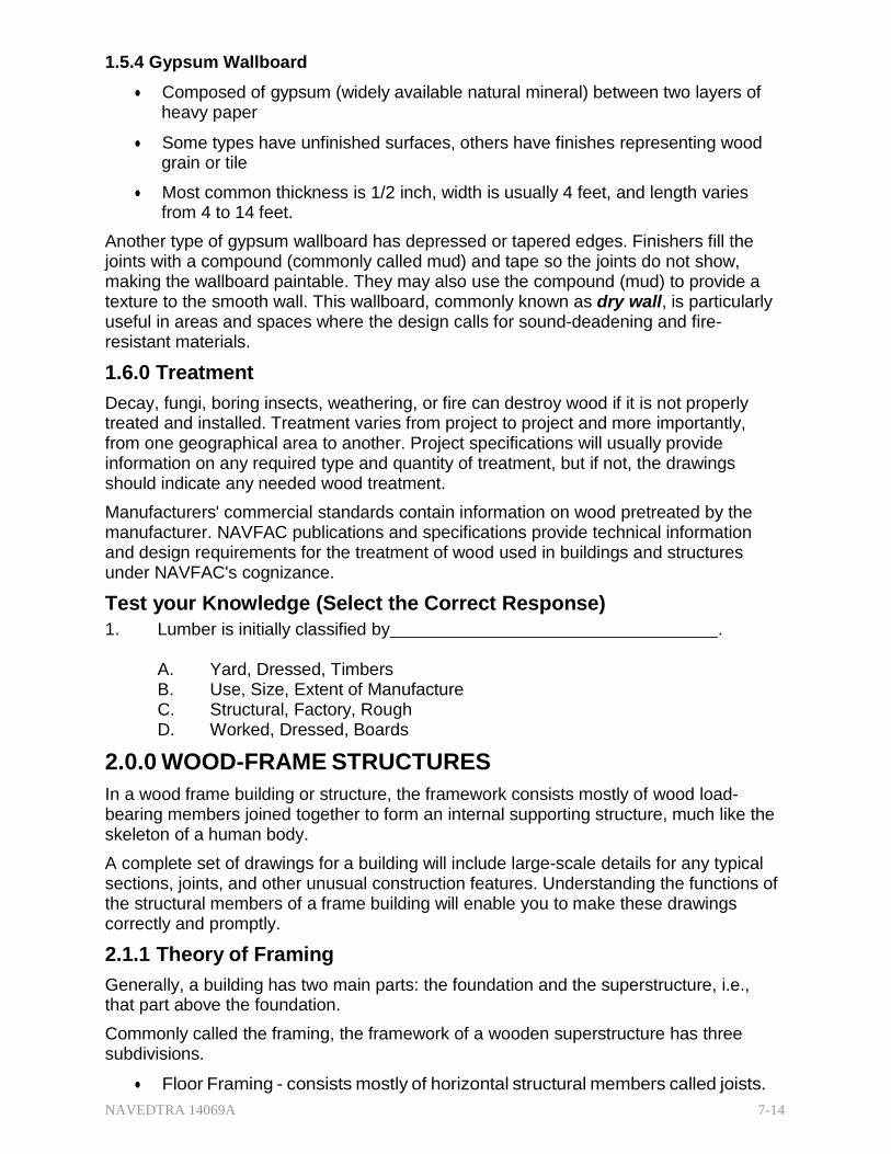
Figure 7-12 — T-sill assembly for balloon framing.
NAVEDTRA 14069A 7-18
In a T-sill assembly for balloon framing, the header joist frames to the inside face of the studs with the joists sitting on the lip of the sill. (Figure 7-12)
Figure 7-13 — Eastern sill assembly for balloon framing.
In an Eastern sill assembly for balloon framing, the joists sit with full bearing on the sill, flush with the outside face of the studs. The joists nail directly to the studs and the header is now a fire-stop header, cut to fit between the joists. (Figure 7-13)
2.3.1 Floor Framing
You must be familiar with a number of floor framing terms. (Figure 7-14)
Joists or Beams---horizontal members that support the floors, depending upon the length of the SPAN (distance between the end supports). Joists are members less than 4 ft apart and beams are members 4 ft or more apart. The usual spacing for wood frame floor members is either 16 inches or 24 inches. O.C. Joists are usually 2 by 8, 2 by 10, or 2 by 12. Laminated joists or beams may be appropriate depending on the floor loading.
Common Joist---a full-length joist that spans from wall to wall or from wall to girder
Cripple Joist---similar to a common joist but does not extend the full span. Floor openings usually determine the number of cripples.
Girder---horizontal member that supports joists at points other than along the outer wall lines. When the span is longer than a single joist can cover, a girder must provide intermediate support for joist ends. Concrete or masonry pillars and pilasters commonly support ground floor girders.
Pillar---a girder support that is clear of the foundation walls.
Pilaster---a girder support set against a foundation wall supporting the end of a girder. Pillars and pilasters are themselves supported by concrete footings with pilasters sometimes formed as part of the foundation wall.
Girts---horizontal framing members that support the outer-wall ends of upper- floor joists in balloon framing.

NAVEDTRA 14069A 7-19
Figure 7-14 — Framing terms and floor openings.
2.3.1 around Floor Openings
For any floor openings such as stairs, builders must cut the common joists and reinforce the opening with headers (at ends of joists) and trimmers (parallel to joists). See Figure 7-14. Specifications usually require headers and trimmers to be doubled- sometimes tripled. Headers up to 6 ft in length can be nailed; those longer than 6 ft are fastened with joist hangers.

NAVEDTRA 14069A 7-20
2.3.2 Bridging
Bridging is the system of bracing joists to each other to hold them plumb and aligned. It also serves to distribute part of a concentrated load over several joists.
There are two types of bridging:
Cross Bridging (Figure 7-15 A)
Solid Bridging (Figure 7-15 B).
Cross bridging consists of pairs of struts set diagonally between the joists. Strut stock comes in sizes of 1 by 3, 1 by 4, 2 by 2, and 2 by 4.
Solid bridging consists of pieces of joist-size stock set at right angles between the joists. They can be staggered for easier installation.
Builders use cross bridging more frequently, but solid bridging is more rigid.
All spans greater than 6 feet should be bridged
Figure 7-15 — Bridging.
2.3.3 flooring
Subflooring is the next layer (or double layer) installed in platform framing. Typically it will be either boards (square-edge or tongue-and-grooved), or plywood 1/2 to 3/4 inch thick. (Figure 7-16).

NAVEDTRA 14069A 7-21
Figure 7-16 — Typical floor framing with subflooring.
Subflooring serves as a working platform, a base for wall soleplates, and additional strength/stability for finish flooring. Builders may install subflooring either diagonally (most common) or at right angles to the joists. Diagonal subflooring lets the builder lay finish flooring either parallel to, or, more commonly, at right angles to, the joists. Changes of direction add rigidity to the building. For parquet finish flooring or finish flooring laid parallel to the joists, joist spacing should not exceed 16 inches. on center.
2.4.1 Wall Framing
Wall framing details will depend on whether the builder is using platform or balloon construction. Builders employ the platform framing method more often due to its simplicity. However, the terminology remains the same for both methods. (Figure 7-17)
Studs, cripples, trimmers, headers, fire blocks (fire stops), top plates, and soleplates compose a typical wall frame. The wall-framing members used in conventional construction are generally nominal 2 by 4 inches but may be 2 by 6 inches depending on local insulation thickness requirements. The requirements for either are good stiffness, good nail-holding ability, freedom from warp, reasonable dryness (about 15- percent moisture content), and ease of working.

NAVEDTRA 14069A 7-22
Figure 7-17 — Typical wall frame for platform framing.
Studs---closely spaced vertical members of the wall framing. They support the top plates and provide the framework to install the exterior wall sheathing and the interior lath and plaster, or dry wall, and insulation.
Cripple Studs---shorter versions of studs where openings interrupted the full height studs.
Top Plates (or Caps) ---horizontal wood framing members nailed to the tops of the wall or partition studs.
Soleplates---horizontal wood framing members that serve as nailing bases for studs in platform-framing construction.
Headers---upper members of a rough doorframe or rough window frame. Also, similar members that form the ends of a rough floor or roof opening (as a skylight).
Subsill---lower members of a rough window frame.
Fire Block---blocking used at the mid span of a wood framed area to inhibit the advance of fire within a concealed space.
2.4.1 Partition
Partition walls divide the interior space of a building. In most cases, builders form them as part of the building, but remodeling efforts often include changes in partition walls.
There are two types of partition walls:
Bearing Wall---supports the ceiling joists and any other loads
Nonbearing Wall---supports only itself and is usually installed after the load bearing framework is in place
Framing for partition walls, including headers and trimmers for openings and doors is the same as for outside walls. However, there are additional elements required to accommodate interior finish.
Corner Posts or T-Posts---used at corners and where one partition wall joins another. They provide nailing surfaces for the inside wall finish (Figure 7-18)

NAVEDTRA 14069A 7-23
Figure 7-18 — Typical Corner Posts and T-Posts for interior finish.
2.4.2 Braces
Braces stiffen framed construction and help buildings resist the twisting or straining effects of wind or storm. Good bracing keeps corners square and plumb. It also helps prevent warping, sagging, and shifts resulting from lateral and external forces that would otherwise tend to distort the frame.
Figure 7-19 — Typical types of bracing.

NAVEDTRA 14069A 7-24
Diagonal bracing is most effective when installed at a 45° to 60° angle and it can be done after the wall has been squared and is still lying on the subfloor.
There are three common methods of bracing frame structures: (Figure 7-19)
Let-In Bracing-notched studs with a 1 by 4 inch board nailed to each stud flush with the exterior surface. This is the most widely used system.
Cut-In Bracing---2 by 4 inch pieces cut at an angle and toenailed between studs at a diagonal from the top of a corner post down to the soleplate.
Diagonal Bracing---each board or panel of the exterior sheathing acts as the brace. Builders typically use let-in or cut-in bracing to minimize any additional damage to exterior sheathing from this bracing method.
2.5.0 Roof Framing
To shed water, all roofs must slope. There are a multitude roof styles and designs to meet a designer's and an owner's interest. The four most common are also the simplest to build. (Figure 7- 20)
Figure 7-20 — Most common types of pitched roofs.
Intersecting Roof---a gable and valley or hip and valley intersecting each other at right angles.
Shed Roof---a single surface that slopes downward from a ridge on one side of the structure.
Gable Roof---two surfaces sloping downward from a ridge located between the sides of the structure, usually, but not always, midway between them.
Hip Roof---pitched on the sides like a gable roof and pitched on one or both ends.

NAVEDTRA 14069A 7-25
2.5.1 Roof Pitch
To calculate roof pitch you must be familiar with the following terms. (Figure 7-21)
Unit of Rise ---the distance the rafter rises per foot of run (unit of run).
Total Rise---the vertical distance from the top plate to the top of the ridge, or the altitude of the right triangle.
Unit of Run---a fixed unit of measure, always 12 inches for the common rafter, always measured on a level plane.
Total Run---equal to half the total span, or the base of one of the right triangles.
Unit of Span---a fixed unit, twice the unit of run, or 24 inches.
Total Span---the horizontal distance from outside one top plate to another
Line Length---the hypotenuse of the triangle whose base equals the total run and whose altitude equals the total rise.
Pitch---the ratio of unit of rise to the unit of span. It describes the slope of a roof.
Figure 7-21 — Roof framing terms.
The pitch (amount of slope) of a roof is expressed as a fraction in which the numerator is the unit rise and the denominator is the unit span. By common practice, unit run is always 12 inches so unit span is always 24 inches (unit run x 2).
Expressed in equation form,
Pitch Unit Rise
Unit Rise
Unit Span 2 x Unit Run
Suppose a roof rises 8 units for every 12 units of run-meaning that unit rise is 8 and unit run is 12. Since the unit span is 24, (unit run x 2) the pitch of the roof is 8/24, or 1/3. Figure 7-21 provides a visual expression with a framing square.
Construction drawings indicate the pitch of a roof by a small roof triangle. The triangle is drawn to scale so that the length of the horizontal side equals the unit run (which is

NAVEDTRA 14069A 7-26
always 12), and the length of the vertical side equals the unit rise. With those two figures, the builder will know the pitch.
2.5.2 Rafter Layout
Rafters are framing members that support a roof. They do for the roof what joists do for the floor and what the studs do for the wall. They are generally inclined members spaced from 16 to 48 inches apart that vary in material size, depending on their intended length and spacing apart.
The type of roof and the intended span will determine the fastening method for the top of the rafters. The bottoms of the rafters rest on the wall top plates, which provides a connecting link between the wall and the roof and is really a functional part of both.
The structural relationship between the rafters and the wall is the same for all types of roofs. Rafters are NOT framed into the top plate. They are simply nailed to it, or in some instances, cut to fit the plate.
In hasty construction, builders merely lay the rafters on the top plate and nail them in place. Rafters may extend a short distance beyond the wall to form eaves and protect the sides of the building. Refer to Figure 7-22 for a typical roof framing plan and relate the figure to the following rafter terms.
Figure 7-22 — Typical roof framing plan.
Common Rafters-extend from the top plates to the ridgeboard at right angles to both.
Hip Rafters-extend diagonally from the corners formed by perpendicular plates to the ridgeboard.
Valley Rafters-extend from the top plates to the ridgeboard along the lines where two roofs intersect.
Hip Jacks-lower ends rest on the top plate and upper ends rest against the hip rafter.
Valley Jacks-lower ends rest against the valley rafters and upper ends rest against the ridgeboard.
Cripple Jacks-nailed between hip and valley rafters.

NAVEDTRA 14069A 7-27
Jack Rafters-Hip jacks, valley jacks, or cripple jacks.
Top or Plumb Cut-cut made at the end of the rafter to be placed against the ridgeboard or, if the ridgeboard is omitted, against the opposite rafters.
Seat, Bottom, or Heel Cut-cut made at the end of the rafter that is to rest on the plate.
Side, or Cheek, Cut-bevel cut on the side of a rafter to fit against another frame member.
Eave or Tail-portion of the rafter extending beyond the outer edge of the plate.
A Bird's-Mouth Cut is often notched into a rafter with a projection (or eave).
The plumb cut of the bird's-mouth that bears against the side of the rafter plate is called the heel cut, whereas the seat cut bears on top of the bird's-mouth.
Figure 7-23 — Bird’s-mouth cut.
Collar ties are horizontal members used as reinforcement in gable or double-pitch roof rafters. In a finished attic, these ties may function as ceiling joists.
Figure 7-24 — Typical collar ties.

NAVEDTRA 14069A 7-28
Purlins serve as nailing or connecting members when rafter spacing is far apart.
Primarily used with metal buildings, purlins may also apply to light wood frame structures when the entire roof framing design incorporates appropriate sheathing and nailing for rigidity.
Figure 7-25 — Typical roof purlins.
There are several roof designs that call for a variety of framing methods and an even greater variety of rafter arrangements. Figures 7-26 through 7-33 present only a few of the simplest and most common. Look to see how many of the examples include bird's- mouth cuts.
Figure 7-26 — Flat and shed roof framings.

NAVEDTRA 14069A 7-29
Figure 7-27 — Gable roof framing.
Figure 7-28 — Equal-pitch roof framing.

NAVEDTRA 14069A 7-30
Figure 7-29 — Addition roof framing.
Figure 7-30 — Gable dormer framing without sidewalls.
NAVEDTRA 14069A 7-31
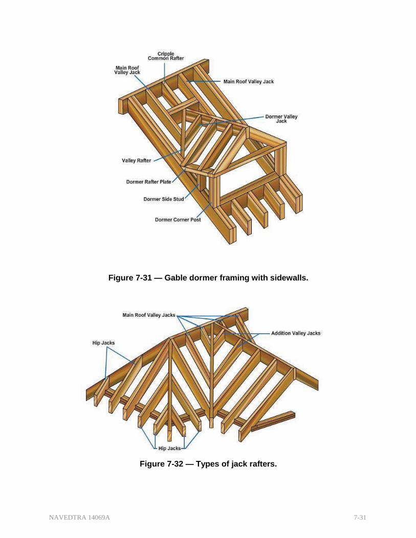
Figure 7-31 — Gable dormer framing with sidewalls.
Figure 7-32 — Types of jack rafters.

NAVEDTRA 14069A 7-32
2.5.3 Roof Trusses
Figure 7-33 — Typical cripple jacks.
When a roof span is too great, or the anticipated roof load (the roof itself, wind, ice, snow) will exceed the capabilities of a simple rafter roof, builders use a truss, an engineered structural frame. Truss designs to accommodate spanning distances and desired roof design are almost limitless. Figure 7-34 shows a number of roof truss designs.
Figure 7-34 — Variety of roof trusses.
The King Post-truss is the simplest type of truss with an upper and lower chord and a vertical center post The W-truss is perhaps the most widely used. It uses four web members assembled in the shape of the letter W instead of a center post. For structures

NAVEDTRA 14069A 7-33
with an interior sloped ceiling, such as a vaulted ceiling, the Scissors-truss is appropriate.
Figure 7-35 — Sample engineered truss
In engineered trusses, gusset plates (metal plates or plywood pieces) connect chords and webs with glue, nails, or bolts. Engineered truss manufacturers usually use specially designed and manufactured gussets. (Figure 7-35)
Test Your Knowledge (Select the Correct Response)
2. In a wood frame building or structure, wood load-bearing members join together to form a supporting structure. Generally, a building has main parts called_ _.
A. 3, Floor Frame, Wall Frame, Roof Frame B. 2, Platform Frame, Balloon Frame C. 2, Foundation, Superstructure
3.0.0 BUILDING FINISH
Building finish is that part of a project that typically completes the project but has nothing to do with the structural elements of the building. General practice divides the finish work into exterior (outside) and interior (inside) finish. Builders refer to this stage of construction to as finish carpentry. Other trade disciplines have a "Finish" stage to their contributions also. Both the electricians and plumbers have a "Rough-in" (non- structural) and "Finish" element to their work. Figure 7-36 provides typical terminology for exterior finish carpentry.

NAVEDTRA 14069A 7-34
Figure 7-36 — Typical terms for exterior finish carpentry.
3.1.0 Exterior Finish
The principal exterior finish items are the roof sheathing and covering, the wall sheathing and/or siding, and the exterior trim. Builders may install the roof sheathing and wall sheathing at the same time, but standard practice dictates that the roof sheathing installation occur first to allow interior work to proceed during inclement weather. In many cases, the exterior wall will already have paneling as part of the structural element of a building, and sheathing the roof provides the next stage to "drying-in" the building. The exterior finish for the walls in this case will consist only of the siding.
3.1.1 and Roof Covering
Roof sheathing is the covering over the rafters or trusses and usually consists of boards, plywood, or oriented strand board (OSB). Local codes will determine the required thickness of the roof sheathing, but 1/2 to 3/4 inch is typical for plywood and OSB, with 3/4 to 1 inch typical for board lumber. Sheathing should be thick enough to span the supports and provide a solid base for fastening the roofing materials. If the design requires boards for roof sheathing, generally, it will be third grade species of lumber, such as pines, redwoods, and hemlocks.
In damp climates when the finish roof consists of wood shingles or shakes, spaced roof boards provide the sheathing. When using asphalt shingles, metal sheet roofing, or other roofing materials that require continuous support, builders should lay the roof sheathing closed (without spacing). When plywood or OSB roof sheathing is used, the grain should run perpendicular to the rafters. (Figure 7-37)
NAVEDTRA 14069A 7-35
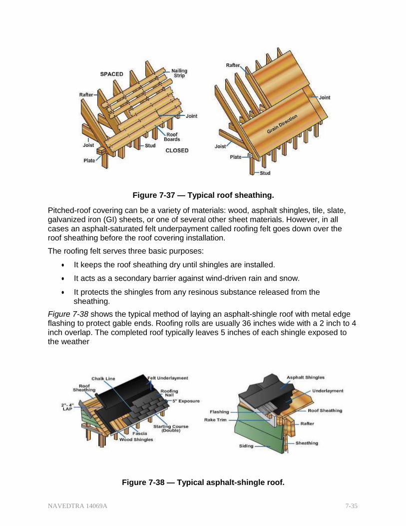
Figure 7-37 — Typical roof sheathing.
Pitched-roof covering can be a variety of materials: wood, asphalt shingles, tile, slate, galvanized iron (GI) sheets, or one of several other sheet materials. However, in all cases an asphalt-saturated felt underpayment called roofing felt goes down over the roof sheathing before the roof covering installation.
The roofing felt serves three basic purposes:
It keeps the roof sheathing dry until shingles are installed.
It acts as a secondary barrier against wind-driven rain and snow.
It protects the shingles from any resinous substance released from the sheathing.
Figure 7-38 shows the typical method of laying an asphalt-shingle roof with metal edge flashing to protect gable ends. Roofing rolls are usually 36 inches wide with a 2 inch to 4 inch overlap. The completed roof typically leaves 5 inches of each shingle exposed to the weather
Figure 7-38 — Typical asphalt-shingle roof.

NAVEDTRA 14069A 7-36
Figure 7-39 shows typical installation of wood shingles. Wood shingles are available in three standard lengths: 16, 18, and 24 inches with the18-inch length perhaps the most popular. Wood shakes are applied the same as wood shingles.
The primary difference between shakes and other types of shingles is that shakes are split while most shingles are sawn on all sides.
Figure 7-39 — Typical wood shingle/shake installation.
On flat or low-pitched roofs, the roof covering is usually built-up. Built-up roofing consists of several layers (plies) of felt, set in a hot binder of melted pitch or asphalt. The number of plies they contain always designates built-up roofs.
Figure 7-40 — Typical built-up roof installation.
Figure 7-40 shows a five-ply built-up roof. Note that the building paper is in addition to the number of designated plies, and the spacing varies for paper, nailer, and hot mop layers. Notice also the use of aggregate surfacing materials, such as gravel, slag, marble, or other suitable materials, to provide a good weathering surface and protect the bitumen from sunlight and external heat.
3.1.2 ashing
Flashing is specially constructed pieces of corrosion-resistant metal or other materials used to protect buildings from water seepage. Its purpose is to prevent moisture (rain or

NAVEDTRA 14069A 7-37
melted snow) from penetrating the junctions where materials change. Builders should install flashing at roof ridges, chimneys, roof-wall intersections, over exposed windows and doors, and at changes of material or direction on sidings. Figures 7-41 through 7-43 demonstrate flashing applications.
Figure 7-41 — Typical flashing at roofing edge and build-up.
Flashing materials used on roofs may be asphalt-saturated felt, metal, or plastic. Felt flashing is generally used at ridges, hips, and valleys. However, when available, metal flashing, either aluminum, galvanized steel, or copper, is superior to felt.
Figure 7-42 — Typical flashing at roofing valley and material change.

NAVEDTRA 14069A 7-38
Figure 7-43 — Typical flashing at siding change of materials and direction.
3.1.3 Wall Sheathing
The exterior wall sheathing is often part of the structural element of a building. For the exterior finish work, the wall covering term is wall siding or just siding. Many local building codes require "house wrap" over the wall sheathing before the installation of exterior siding. The house wrap may be building paper (think tar/felt paper) or commercially available spun-bonded synthetic fiber material. It provides a second layer of weather and wind protection between your wall sheathing and your wall siding.
Exterior wall siding can be stone, brick, stucco, masonry, vinyl, aluminum, plastic ,fiber- cement, plywood, fiberboard, veneers, hardboard, paneling, wood shingles, numerous other materials, or any combination of materials. There are too many options to cover in this lesson, as the only limit is the imagination of the designer, be it the owner or an architect.
However, for wooden board siding here are two main general types: Drop Siding and Common Siding. Drop siding joins edge to edge (rather than overlapping). Common siding consists of boards that overlap each other like shingles. (Figure 7-44)
Figure 7-44 —Typical drop and common siding.

NAVEDTRA 14069A 7-39
Figure 7-45 — Vertical board siding styles.
3.1.4 Exterior Trim
Figure 7-46 — Simple cornice.
Clapboards are boards not more than 4 feet long. Boards in longer lengths but not more than 8 inches wide are called bevel siding.
Builders may install some sidings in either a horizontal or vertical direction if adequate nailing areas were considered in the design. Figure 7-45 shows three different styles of vertical siding application.
When installing the roof sheathing to "dry-in" a structure, the builder must consider the exterior finish at and just below the eaves of the roof, called the cornice.
The practical purpose of a cornice is to seal the joint between wall and roof against weather penetration. Cornices may be simple, open, flat boxed or slope boxed. Figure 7-46 shows a simple type of cornice, used on a roof with no rafter overhang.

NAVEDTRA 14069A 7-40
Figure 7-47 shows an open cornice. Note that in the simple and open cornices, the sheathing and frieze go to the underneath side of the roof sheathing. This requires a backing between the rafters above the top plate. However, the builder must allow for ventilation similar to closed cornices.
Note in the closed cornices, boxed or sloped, that the frieze board goes to the underneath side of the rafters. Figure 7-48
Figure 7-47 — Typical open cornice.
Figure 7-48 — Typical closed cornices, boxed and sloped.

NAVEDTRA 14069A 7-41
A Cornice Return is a short extension of a cornice along the gable-end wall. (Figure 7-49).
Eaves are the rafter-end edges of a roof.
Rakes are the gable-end edges of a roof.
A hip roof has eaves all the way around. A gable roof has two eaves and two rakes.
Just as the frieze trims the eave side at the roof, rake molding and fascia trim the gable side at the roof.
Figure 7-49 — Cornice return, gable fascia and rake molding.
3.1.5 and Downspouts
Figure 7-50 — Typical gutter and downspout.
Gutters and downspouts keep rainwater away from the foundation of the building and need to be part of the building design. (Figure 7-50).
They may be made of galvanized metal, copper, aluminum, or plastic. Some metal types have a factory- applied enamel finish.

NAVEDTRA 14069A 7-42
Some gutters are built into the cornice design and connected to the downspouts (Figure 7-51)
The run off should flow into a "wet line" that caries the water away from the structure into a drain or storm sewer.
3.2.0 Interior Finish
Figure 7-51 — Typical gutter as part of the cornice.
The interior finish consists mainly of the coverings applied to the rough inside walls, ceiling, and subfloors. Other interior finish items are ceiling and wall coverings, doorframes and window frames, stairs, floor covering, and wood trims. When required, installation of kitchen and built-in cabinets are considered part of the interior finish.
3.2.1 ling and Wall Covering
Ceiling and wall covering is broadly divided into plaster and drywall covering. Though some builders still use "lath-and-plaster" finish in construction today, drywall finish has become the most popular.
A plaster covering requires a "plaster base" and a "plaster ground" before installation. The plaster base provides the plane-surface base to which the plaster is applied. The plaster grounds, thin wooden strips on end, serve as a depth guides for the plasterers to ensure uniform plaster thickness around door frames, window frames, and behind casings. In addition to the preparation required, application itself involves water and a drying period of 2-3 weeks between layers with the typical application in 3 layers (Scratch, brown, and finish).
Drywall covering is a general term applied to sheets or panels of wood, plywood, fiberboard, and the most accepted and understood term, gypsum wallboard, or "sheetrock". Drywall finish requires only short drying time since application requires little, if any, water. However, a gypsum drywall demands a moderately low moisture content in the framing members to prevent "nail-pops." Nail-pops result when frame members dry out to moisture equilibrium, causing the nail head to form small "humps" on the surface of the board. Stud alignment is also important for single-layer gypsum finish to prevent a wavy, uneven appearance. Thus, there are advantages and disadvantages to both plaster and gypsum drywall finishes. The choice should consider initial cost as well as maintenance.

NAVEDTRA 14069A 7-43
Thin sheet materials, such as gypsum board or plywood, require that studs and ceiling joists have good alignment to provide a smooth, even surface.
The wood sheathing on exterior walls often corrects any misaligned studs. For interior partitions and ceilings, depending on the alignment of the studs and joists, a "strongback" (Figure 7-52) may be necessary for proper alignment.
Figure 7-52 — Typical ceiling “strongback.”
Gypsum wallboard is the most commonly used wall and ceiling covering in construction today. Because gypsum is nonflammable and durable, it is appropriate for application in most building types. Sheets of drywall are nailed or screwed into place, and nail indentions or "dimples" are filled with joint compound (mud). Joints between adjoining sheets are built up with special tape and several layers (usually three) of joint compound. Drywall is easily installed, though joint work can be tedious. (Figure 7-53)
Figure 7-53 — Typical drywall installation.
Drywall varies in composition, thickness, and edge shape. The most common sizes with tapered edges are 1/2 inch or 5/8 inch in 4 feet by 8 feet and by 4 feet by 12 feet sheets. Type X gypsum board has special additives that make it fire resistant
Figure 7-54 shows typical application of other types of drywall finishes, vertical wood paneling, and tongue and groove horizontal paneling.

NAVEDTRA 14069A 7-44
Figure 7-54 — Additional drywall applications.
A variety of ceiling systems are available to change the appearance of a room, lower a ceiling, finish off exposed joints, or provide acoustical control.
Suspended acoustical ceiling systems can integrate the functions of lighting, air distribution, and fire protection. (Figure 7-55)
Acoustical tiles are available in 12-to 30-inch widths, 12- to 60- inch lengths, and 3/16- to 3/4- inch thicknesses, for use with the other grid system components. (Figure 7-56, View A)
Figure 7-55 — Typical suspended acoustical
ceiling.
As an alternative to a suspended acoustical ceiling, depending on the type of ceiling or roof construction, builders may install tiles directly in various ways, such as with wood strips nailed across the ceiling joists, roof trusses, or drywall. (Figure 7-56, View B).

NAVEDTRA 14069A 7-45
Figure 7-56 — Typical grid system components and alternative installation.
3.2.2 lation and Vapor Barriers
Heating (or air conditioning) has important effects upon the occupants of a building. Insulation improves both functions for comfort conditions and fuel savings. Materials commonly used for insulation fall into these classifications: blanket, batt, loose-fill, reflective, and rigid.
Manufactured in a variety of forms and types, their insulating values vary with the type of construction, kinds of construction materials used, and thickness. Figure 7-57 shows different types of insulation commonly used in construction.
Figure 7-57 — Typical types of insulation.
Vapor barriers help keep moisture from seeping through wall, floor, and ceiling materials. Among the effective vapor-barrier materials are asphalt laminated papers, aluminum foil, and plastic film. Most blanket and batt insulations have paper-backed aluminum foil on one side to serve as a vapor barrier. Foil-backed gypsum lath or gypsum boards are also available and serve as excellent vapor barriers.

NAVEDTRA 14069A 7-46
Most climates in the United States recommend barrier placement on the inside face of the exterior wall, but some climatic conditions recommend the reverse. For the deep-south, the U.S. Department of Energy recommends vapor barrier placement on the exterior side of walls (Figure 7-58).
Where other types of membrane vapor barriers were not installed during construction, several coats of paint provide some protection. Aluminum primer with several coats of flat wall (latex) or oil paint is minimally effective in retarding vapor transmission.
Figure 7-58 — Vapor Barrier Placement By Geographical Location.
(U.S. Dept. of Energy)
Condensation and moisture facilitate decay, attracting termites or carpenter ants depending on the geographical location. Even where vapor barriers are used, condensation of moisture vapor may occur in the attic, roof spaces, or crawl spaces, if any, under the building or porch. Ventilation is the most practical method of removing condensation that may encourage decay. Common practice is to install ventilators. They can be part of the exterior design or placed in the eave soffits. For a building with a foundation wall, vents are part of the initial concrete pour.
Figures 7-59 and 7-60 show several types of venting.
Figure 7-59 — Typical building ventilation at attics and foundations.

NAVEDTRA 14069A 7-47
3.2.3 Stairs
Figure 7-60 — Typical building ventilation at soffits.
Treads, which people walk on, and stringers, which support the treads, are the two principal elements in a stairway. The simplest type of stairway consists of these two elements alone.
Figure 7-61 — Typical stair terms.

NAVEDTRA 14069A 7-48
Figure 7-61 shows commonly used terms for an interior finished stairway. The stairway has three stringers, each of which is cut out of a single timber. Cutout or sawed stringer is the common term for this type of stairs. On some stairways, the treads and risers nail to triangular stair blocks attached to straight-edged stringers.
A stairway that continues in the same straight line from one floor to the next is a Straight-Flight stairway. (Figure 7-61). A Change stairway is one that changes direction one or more times between floors when space does not permit a straight-flight. A change stairway in which there are platforms between sections is a Platform stairway.
A building may have principal stairs and service stairs.
Principal stairs are those extending between floors above the basement and below the attic floor.
Service stairs just provide access to a room such as porch, basement, or attic.
The lower ends of the stringers on porch, basement, and other stairs that anchor on concrete use a kickplate (Figure 7-62).
3.2.4 Flooring
Figure 7-63 — Typical toenailing wood finish flooring.
Figure 7-62 — Typical kickplate.
Wood finish flooring and resilient finish flooring are the two main categories for flooring.
Most wood finish flooring comes in tongue- and-groove for edge-joining; some are end-matched as well.
Usually recessed on the lower face, wood flooring strips typically toenail through the subflooring (usually plywood) into joists. (Figure 7-63)

NAVEDTRA 14069A 7-49
In Navy structures, for maintenance and durability, resilient flooring has supplanted wood finish flooring. Most of it in the form of 6 by 6, 9 by 9, or 12 by 12 floor tiles. Materials commonly used are asphalt, linoleum, cork, rubber, and vinyl. With each type of tile, the manufacturer recommends an appropriate type of adhesive for attaching the tile to the subflooring. On other areas subject to a high degree of dampness, ceramic or glazed interior tile is commonly used. Ceramic tiles are used to cover all or part of bathrooms, shower rooms, and some kitchen floors.
3.2.5 Doors
Standard doors and combination doors (storm and screen) are millwork items usually fully assembled at the factory and ready for use. All wood components are treated with a water-repellent preservative to provide protection against the elements. Manufacturers offer interior and exterior doors in a multitude of different designs to fit the style of almost any building. They may be solid or hollow core. (Figure 7-64)
Panel doors are the traditional pattern type, consisting of stiles (solid vertical members), rails (solid cross members), and filler panels in a number of designs.
Flush doors consist of thin plywood faces over a framework of wood with a wood block or particleboard core.
Exterior flush doors use a solid-core rather than hollow-core type to minimize warping caused by a difference in moisture content on the exposed and unexposed faces of the door. Exterior doors require weatherstripping to reduce both air infiltration and frosting of the glass on the storm door during cold weather.
Exterior doors are usually 1 3/4 inch thick and not less than 6 feet 8 inches high. The main entrance door is 3 feet wide, and the side or rear door is normally 2 feet 8 inches wide. The exterior trim can vary from a simple casing (the trim used around the interior edges of door openings and windows) to a molded or plain pilaster.
Figure 7-64 — Typical exterior and interior door styles.
Interior panel doors (colonial and five-cross type) are similar to the exterior doors. Novelty doors, such as the folding door unit, are commonly used for closets because they provide ventilation and take less swing room.
NAVEDTRA 14069A 7-50
Interior flush doors are usually a hollow core of light framework covered with thin plywood or hardboard. Most standard interior doors are 1 3/8 inch thick.
Hinged doors should open or swing in the direction of natural entry, against a blank wall, and should not be obstructed by other swinging doors. Doors should NEVER be hinged to swing into a hallway.
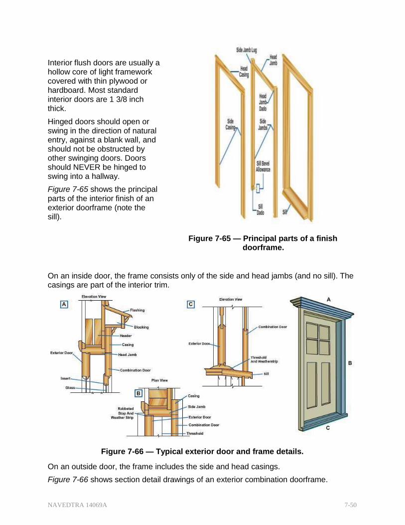
Figure 7-65 shows the principal parts of the interior finish of an exterior doorframe (note the sill).
Figure 7-65 — Principal parts of a finish doorframe.
On an inside door, the frame consists only of the side and head jambs (and no sill). The casings are part of the interior trim.
Figure 7-66 — Typical exterior door and frame details.
On an outside door, the frame includes the side and head casings.
Figure 7-66 shows section detail drawings of an exterior combination doorframe.
NAVEDTRA 14069A 7-51
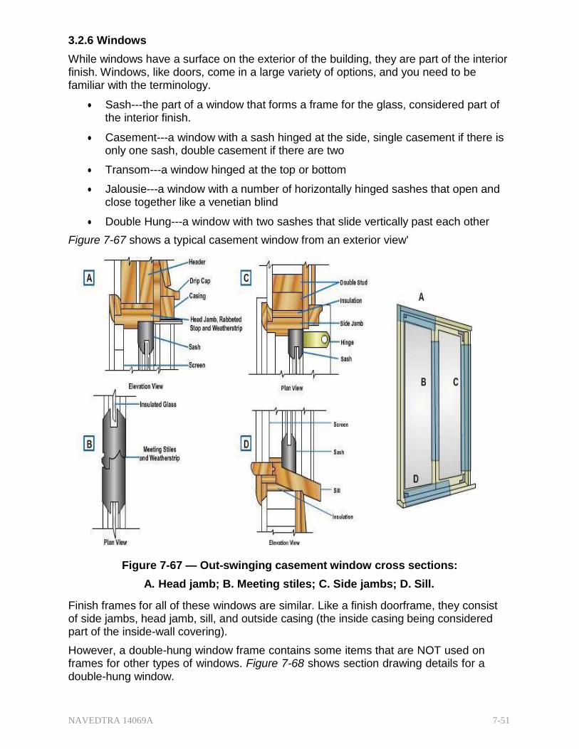
3.2.6 Windows
While windows have a surface on the exterior of the building, they are part of the interior finish. Windows, like doors, come in a large variety of options, and you need to be familiar with the terminology.
Sash---the part of a window that forms a frame for the glass, considered part of the interior finish.
Casement---a window with a sash hinged at the side, single casement if there is only one sash, double casement if there are two
Transom---a window hinged at the top or bottom
Jalousie---a window with a number of horizontally hinged sashes that open and close together like a venetian blind
Double Hung---a window with two sashes that slide vertically past each other
Figure 7-67 shows a typical casement window from an exterior view'
Figure 7-67 — Out-swinging casement window cross sections:
A. Head jamb; B. Meeting stiles; C. Side jambs; D. Sill.
Finish frames for all of these windows are similar. Like a finish doorframe, they consist of side jambs, head jamb, sill, and outside casing (the inside casing being considered part of the inside-wall covering).
However, a double-hung window frame contains some items that are NOT used on frames for other types of windows. Figure 7-68 shows section drawing details for a double-hung window.

NAVEDTRA 14069A 7-52
Figure 7-68 — Double-hung windows cross sections:
A. Head jamb; B. Meeting rails; C. Side jambs; D. Sill.
Construction drawing schedules give the dimensions, type, and number of lights (panes of glass) for each window in the structure. For example, No. 3, DH, 2 feet 4 inches by 3 feet 10 inches 12 LTS means window No. 3 (it will have this number on any drawing in which it appears) is a double-hung window with a finished opening, of 2 feet 4 inches by 3 feet 10 inches with 12 lights of glass. Arrangement of the lights will show in any view in which the window appears. On one of the lights, a figure such as 8/10 will appear, meaning each light of glass has nominal dimensions of 8 by 10 inches. Figure 7-69 shows a double-hung window sash and the names of its parts.
Figure 7-69 — Parts of a double-hung window sash.

NAVEDTRA 14069A 7-53
3.2.7 Wood Trims
Depending on the selection (plain or ornate), the interior wood trims can be the most prominent features of the interior. The inside door and the window casings are at constant eye level, but baseboards are another feature designed to finish off the interior. Baseboards cover the joint between the inside walls and the finish floors which are usually dissimilar materials. Crown (ceiling) molding is not as common since often the wall and ceiling are the same material. Bur crown molding can complete a project with a professional look. Base and crown moldings are available in several widths and forms. Figure 7-70 shows a typical base molding configuration; Figure 7-71 a typical crown molding.
Figure 7-70 — Typical base molding configuration.
Figure 7-71 — Typical crown molding.

NAVEDTRA 14069A 7-54
Test your Knowledge (Select the Correct Response) 3. Finish carpentry involves completing the .
A. Exterior structural elements only B. Interior structural elements only C. Exterior and Interior structural elements D. Exterior and interior non-structural elements
4.1.1 HARDWARE
Hardware is a general term covering a wide variety of accessories, usually made of metal or plastic and ordinarily used in building construction. Hardware includes both finishing and rough hardware.
Finishing Hardware---
o items made in attractive shapes and finishes
o usually visible as an integral part of the finished structure
o includes locks, hinges, door pulls, cabinet hardware, window fastenings, door closers and checks, door holders, automatic exit devices, lock- operating trim, knobs and handles, escutcheon plates, strike plates, knob rosettes. push plates, push bars, kickplates, doorstops, flush bolts.
Rough Hardware---
o items NOT usually finished for attractive appearance
o includes casement and special window hardware, sliding and folding door supports, fastenings for screens, storm windows, shades, venetian blinds, awnings
Other items may be considered hardware. If you are not sure whether an item is hardware or what its function is, refer to a commercial text, such as the Architectural Graphic Standards in your engineering technical library.
5.0.0 FASTENERS
The devices used in fastening or connecting members together to form structures depend on the material the members are made of. The most common fastening devices are nails, screws, and bolts.
5.1.1 Nails
There are many types of nails. Their intended use and form determines their classification. The standard nail is made of steel wire. The wire nail is round-shafted, straight, pointed, and may vary in size, weight, head size and shape, type of point, and finish. The holding power of nails is less than that of screws or bolts.
Common wire nail and box nail (Figure 7-72) are the same, except that box nail wire sizes are one or two numbers smaller for a given length than those of the common nail.
Finishing nail - made from finer wire and has a smaller head than the common nail or box nail. Its head may be driven below the surface of the wood, which leaves only a small hole that is easily puttied.

NAVEDTRA 14069A 7-55
Duplex nail - appears to have two heads. Actually one serves as a shoulder to give maximum holding power while the other projects above the surface of the wood to make withdrawal simple.
Roofing nail - round-shafted and galvanized. It has a relatively short body and comparatively large head. Like the common wire, finishing, or duplex nail, it has a diamond point.
Figure 7-72 — Common wire nails.
Besides the general-purpose nails, there are special-purpose nails. Examples include wire brads, plasterboard nails, concrete nails, and masonry nails. The wire brad has a needlepoint; the plasterboard nail has a large-diameter flathead. The concrete nail is hardened for driving in concrete. So is the masonry nail, although its body is usually grooved or spiraled.
Lengths of wire nails NOT more than 6 inches long are designated by the penny system, in which the letter d is the symbol for a penny. Thus, a 6d nail means a sixpenny nail. The number expresses the wire thickness, which relates to standard wire gauge; the larger the number, the thicker the wire. Figure 7-72 gives nail sizes (penny and length in inches), gauges, and approximate number of nails per pound. The penny does not designate any nails over 6 in; those are called spikes.
5.2.0 Screws
A wood screw is a fastener that threads into wood. Type of head and material from which they are made designates their description; for example, flathead brass or round- head steel. Figure 7-73 shows some common types of screws.

NAVEDTRA 14069A 7-56
Its length in inches and a number relating to its body diameter (the unthreaded part) designate the size of a wood screw. This number runs from 0 (about 1/15-inch diameter) to 24 (about 3/8-inch diameter)
Lag screws (lag bolts) are often required where ordinary wood screws are too short or too light, or where spikes do not hold securely. They are available in lengths of 1 to 16 inches and in body diameters of 1/4 to 1 inch Their heads are either square or hexagonal allowing for more torque advantage for installation.
Sheet metal screws and
thread-cutting screws assemble sheet metal, sheet aluminum, and other thin metal parts.
Sheet metal screws are self- tapping.
They can fasten metals up to about 28 gauge.
Thread-cutting screws can fasten metals that are 1/4 inchc thick or less.
Figure 7-73 — Common types of screws.
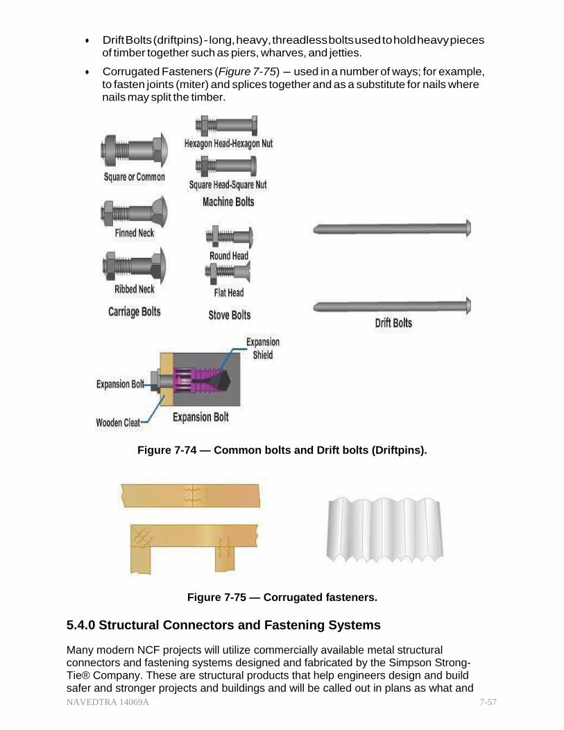
5.3.1 Bolts and Drift Bolts
A bolt is a fastener having a head at one end and threads at the other, as shown in Figure 7-74. Instead of threading into wood like a screw, it goes through a bored hole and is held by a nut.
Stove Bolts - range in length from 3/8 to 4 inches and in body diameter from 1/8 to 3/8 inch. Not especially strong, they are used only for fastening light pieces.
Carriage and Machine Bolts - strong enough to fasten load-bearing members, such as trusses. In length, they range from 3/4 to 20 inches; in diameter, from 3/16 to 3/4 inch. The carriage bolt has a square section below its head, which embeds in the wood as the nut is set up, keeping the bolt from turning.
Expansion Bolts - in conjunction with an expansion shield, provide anchorage in a material or position when a threaded fastener will not function. Expansion bolts often have a concrete application for anchorage.
NAVEDTRA 14069A 7-57
Drift Bolts (driftpins) - long, heavy, threadless bolts used to hold heavy pieces of timber together such as piers, wharves, and jetties.
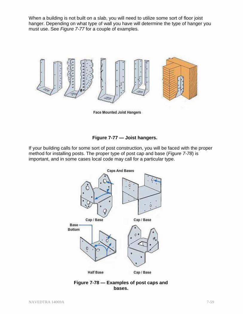
Corrugated Fasteners (Figure 7-75) - used in a number of ways; for example, to fasten joints (miter) and splices together and as a substitute for nails where nails may split the timber.
Figure 7-74 — Common bolts and Drift bolts (Driftpins).
Figure 7-75 — Corrugated fasteners.
5.4.0 Structural Connectors and Fastening Systems
Many modern NCF projects will utilize commercially available metal structural connectors and fastening systems designed and fabricated by the Simpson Strong- Tie® Company. These are structural products that help engineers design and build safer and stronger projects and buildings and will be called out in plans as what and

NAVEDTRA 14069A 7-58
where they are to be used in construction. While there are hundreds of different connector products you should be familiar with the major categories for fastening/connecting wood structural members to wood and concrete. These include Structural Connectors used in trusses, Joist Hangers used in floors, Straps and Ties for securely connecting frame walls to rafters and window and door headers. Anchor Bolts or Embedded Holddowns for single and multi-story buildings. All structural connectors or anchor tiedown systems are made from hot-dip galvanized (HDG) or stainless steel to address corrosion resistance requirements. See Figure 7-76 for just a few examples of possible Structural Connector applications.
Figure 7-76 — Structural connector applications.
5.4.1 Wood to Wood and Wood to Concrete
The use of connectors is designed to form a continuous load path from foundation to the roof system. This load path is critical because it helps hold a structure together when high winds try to pull it apart. Building codes require structures to be built with a continuous load path and the designs vary with code. Straps are designed to transfer tension loads and resist uplift rafter to wall, while the holddown will resist uplift wall to foundation.
NAVEDTRA 14069A 7-59
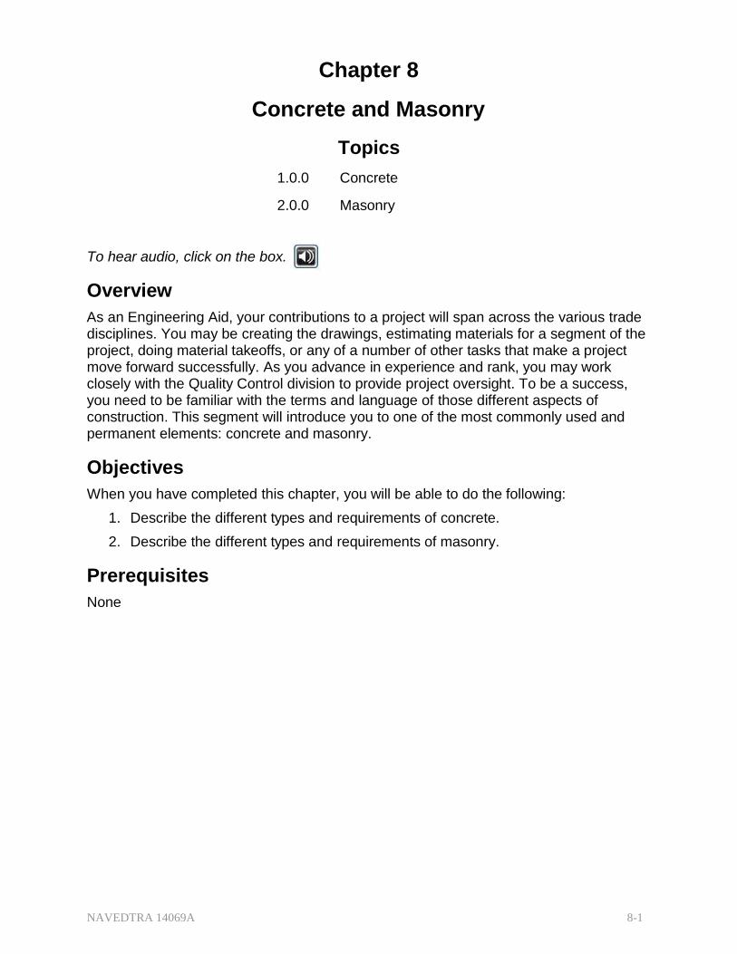
When a building is not built on a slab, you will need to utilize some sort of floor joist hanger. Depending on what type of wall you have will determine the type of hanger you must use. See Figure 7-77 for a couple of examples.
Figure 7-77 — Joist hangers.
If your building calls for some sort of post construction, you will be faced with the proper method for installing posts. The proper type of post cap and base (Figure 7-78) is important, and in some cases local code may call for a particular type.
Figure 7-78 — Examples of post caps and
bases.

NAVEDTRA 14069A 7-60
When you are attaching horizontal and vertical lumber, you will be required to make a good bond between the two or more pieces. Utilizing a tie (Figure 7-79) is a good method, and will make it easier to calculate the angles and nail placement.
Figure 7-79 — Examples of ties.
5.4.2 Connector Fastening
Many Simpson Strong-Tie connectors have been designed and tested for use with specific types and sizes of nails. Some of these nails are built by the Simpson Strong- Tie® Company as in the N54A ring shank nail in Figure 7-80. The specified quantity, type and size of nail must be installed in the correct holes on the connector to achieve published loads. Other factors such as nail material and finish are also important. Incorrect fastener selection or installation can compromise connector performance and could lead to failure. On projects where specific structural connectors are required, the types of nails to be used during construction will also be specified.

NAVEDTRA 14069A 7-61
Figure 7-80 — Structural connector nails.
5.5.0 Glue
Glue, one of the oldest materials for fastening, if applied properly, will form a joint that is stronger than the wood itself. Probably one of the best types of glue for joint work and furniture construction is animal glue, made from hides. Other types of glue are extracted from fish, vegetables, casein, plastic resin, and blood albumin. Glue can be obtained commercially in a variety of forms-liquid, ground, chipped, flaked, powdered, or formed into sticks.
Summary
The construction trades use terminology and stages of construction for wood and light frame structures that may be unfamiliar to you. They are well-established terms that provide a common language for all stages and personnel on a project. The more familiar and comfortable with the language of construction you become the more confident and valuable you will become to your unit, to the Navy and to yourself.

NAVEDTRA 14069A 7-62
Review Questions (Select the Correct Response) 1. Which of the following construction materials is considered the most often used
and the most important?
A. Wood B. Steel C. Concrete D. Plastic
2. For small construction projects that do NOT have written specifications included,
where should you be able to find the type and classification of wood?
A. In the sheets attached to the drawings B. In the drawings themselves C. In the bill of materials D. In the special standards
3. In construction, the terms "wood," "lumber" and "timber" have distinct and
separate meanings. Which of the following definitions is an accurate description?
A. Wood is a soft, fibrous substance B. Timber is lumber with a dimension of not less than 5 inches C. Lumber is trees that have not been cut D. Wood is lumber that has been made into manufactured products
4. Which of the following descriptions best defines "Millwork"?
A. Wood selected for sawmill work B. Timber made into lumber C. Lumber made into manufactured products D. Wood after it has been through the sawmill
5. In what way, if any, can the nominal size of lumber be compared to its dressed
size?
A. It is larger B. It is the same C. It is smaller D. It cannot be compared
6. What designation applies to wood surfaced on two sides only?
A. S2S B. S2E C. SS2 D. 2SS

NAVEDTRA 14069A 7-63
7. In which of the following ways is lumber designated on drawings and purchase orders?
A. Dressed only B. Nominal only C. Dressed or nominal, whichever you chose
8. When classified according to use, manufactured lumber falls into what three
categories?
A. Boards, dimension, and timbers B. Rough, dressed, and worked C. Yard, structural, and factory D. Boards, shop, and yard
9. When classified according to size, manufactured lumber falls into what three
categories?
A. Boards, dimension, and timbers B. Rough, dressed, and worked C. Yard, structural, and factory D. Boards, shop, and yard
10. When classified according to extent of manufacture, manufactured lumber falls
into what three categories?
A. Boards, dimension, and timbers B. Rough, dressed, and worked C. Yard, structural, and factory D. Boards, shop, and yard
11. What are the two major grades for yard lumber?
A. Finish and Common B. Select and Common C. Finish and Utility D. Select and Utility
12. Which type of lumber is primarily graded by its allowable stresses?
A. Factory B. Structural C. Shop D. Yard
13. What lumber grade is considered suitable as watertight lumber?
A. No. 1 common B. No. 2 common C. Grade A select D. Grade B select

NAVEDTRA 14069A 7-64
14. What is the minimum grade that lumber must meet to be considered grain-tight?
A. No. 1 common B. No. 2 common C. Grade A select D. Grade B select
15. What formula should you use to find the board foot measurement of lumber?
A. Thickness (inches) x Width (inches) x Length (inches)
12 B. Thickness (inches) x Width (inches) x Length (yards)
36 C. Thickness (inches) x Width (inches) x Length (feet)
12 D. Thickness (feet) x Width (feet) x Length (feet)
12 16. Which of the following dimensions should you use to compute the amount of
board feet in a dressed 2- by 4-inch board?
A. 1 3/4 by 3/4 in B. 2 by 4 in C. 1 5/8 by 3 5/8 in D. 1 7/8 by 3 5/8 in
17. How are the laminations (pieces) fastened together when you laminate lumber?
A. Nailed and glued together, with the grain of all pieces running
perpendicular B. Nailed or glued together, with the grain of all pieces running parallel C. Nailed, bolted, or glued together, with the grain of all pieces running
perpendicular D. Nailed, bolted, or glued together, with the grain of all pieces running
parallel 18. Plywood is generally made with an number of plies with grains running
.
A. even, parallel B. even, perpendicular C. odd, parallel D. odd, perpendicular

NAVEDTRA 14069A 7-65
19. For which of the following purposes is plywood used?
A. Formwork B. Sheathing C. Furniture D. Each of the above
20. What are the two most common sizes of plywood sheets?
A. 3 by 6 ft and 4 by 8 ft B. 4 by 8 ft and 4 by 10 ft C. 4 by 8 ft and 4 by 12 ft D. 4 by 10 ft and 4 by 12 ft
21. How are plywood panel grades generally designated?
A. By the grade of veneer on the face only B. By the kind of glue only C. By the grade of veneer on the face and back only D. By the kind of glue and the grade of veneer on the face and back
22. What does the number 24 represent when index numbers 48/24 appear on a
grading identification stamp?
A. Minimum on-center spacing of supports for subfloors B. Maximum on-center spacing of supports for roof decking C. Maximum on-center spacing of supports for subfloors D. Maximum on-center spacing of supports for wall studs
23. Which type of plywood is recommended for use in box beams, gusset plates, and
stressed-skin panels?
A. Standard B. Decorative C. Overlaid D. Structural
24. Which of the following types of wood substitute provides good fire resistance?
A. Fiberboard B. Gypsum wallboard C. Particleboard D. Hardboard
25. The type and amount of wood treatment is normally given in the project specifications. When no written specifications exist, where should you be able to find the wood treatment required?
A. Bill of materials B. Commercial standards C. Drawings D. American Plywood Association

NAVEDTRA 14069A 7-66
26. The framework of a wooden superstructure has three distinct framing subdivisions. They are the .
A. platform, balloon, and roof B. platform, wall, and roof C. floor, wall, and roof D. floor, wall, and balloon
27. What is the first wood superstructure member to be set in place?
A. Header B. Joist C. Soleplate D. Sill
28. What is the striking difference between platform framing and balloon framing?
A. Platform-separate studs go from floor to floor, Balloon--studs go from soleplate to top plate
B. Balloon-separate studs go from floor to floor, Platform--studs go from soleplate to top plate
C. Platform--joists support the floor, Balloon--beams support the floor D. Balloon--joists support the floor, Platform--beams support the floor
29. What is the difference between a common joist and a cripple joist?
A. A cripple joist extends the full span, but a common joist does not. B. A common joist extends the full span, but a cripple joist does not. C. A cripple joist may be supported by a girder, but a common joist is never
supported by a girder. D. Common joists are supported by pilasters, while cripple joists are not.
30. At a door opening in an exterior wood-framed wall, the names of the horizontal
members that connect at the (a) top and (b) bottom of the cripple studs are .
A. (a) header (b) soleplate B. (a) top plates (b) soleplate C. (a) top plates (b) header D. (a) header (b) subsill
31. Bridging is a bracing system to keep the plumb and aligned.
A. studs B. rafters C. joists D. headers

NAVEDTRA 14069A 7-67
32. Which of the following method(s) is/are commonly used to brace wood frame structures?
A. Diagonal bracing B. Let-in bracing C. Cut-in bracing D. All of the above
33. What is the rise per unit of run for a 1/4 pitch roof?
A. 12 in B. 6 in C. 8 in D. 4 in
34. A rafter extends from top plates to the ridgeboard at right angles to
the plates.
A. Common B. Valley C. Hip D. Cripple
35. are rafters that are nailed between hip and valley rafters.
A. Common jacks B. Cripple jacks C. Valley jacks D. Hip jacks
36. What is the purpose of purlins in wood frame construction?
A. To serve as a nailer for roofing B. To act as a diagonal brace C. To support align joists D. To serve as trimmer for openings
37. What type of roof covering is generally used on flat or nearly flat roofs?
A. Galvanized iron sheets B. Asphalt shingles C. Tile D. Built-up
38. What material provides the weathering surface on a built-up roof?
A. Asphalt shingles B. Aggregate C. Roofing felt D. Asphalt binder

NAVEDTRA 14069A 7-68
39. What is the exterior finish called at and just below the eaves?
A. Rake B. Return C. Cornice D. Bed
40. What type of common siding comes in lengths of more than 4 feet and widths of
8 inches or less?
A. Bevel B. Drop C. Clapboard
41. What elements are the two principal parts of a stairway?
A. Stringers and risers B. Treads and risers C. Treads and stringers D. Stringers and nosing
42. What type of stairway continues in a straight line from one floor to the next?
A. Change B. Cleat (open-riser) C. Platform D. Straight-flight
43. What are the two categories of stairs?
A. Principal and service B. Main and porch C. Basement and attic D. Front and rear
44. What stairs extend between floors above the basement and below the attic?
A. Basement B. Porch C. Attic D. Principal
45. Which of the following types of stairs is a service stair?
A. Porch B. Principal C. Personnel D. Equipment

NAVEDTRA 14069A 7-69
46. Finish flooring is broadly divided into types.
A. Resilient and carpet B. Wood and concrete C. Resilient and wood D. Carpet and asphalt tile
47. What is the primary difference between exterior and interior flush doors?
A. An exterior flush door always swings to the outside of a building. B. Exterior flush doors have a solid core. C. Plywood is never used as the outside face of an exterior flush door. D. Interior flush doors may be fabricated on the construction site, but exterior
flush doors are always factory-assembled. 48. What are the principal parts of the frame of an inside door?
A. Head jamb and side jambs only B. Head and side jams and head and side casings C. Sill, head jamb, and side casings D. Sill, side jambs, and head casing
49. What part of a window forms a frame for the glass?
A. Casement B. Sash C. Frame D. Finish
50. What type of window contains several horizontal hinged sashes that open and
close together?
A. Casement B. Louver C. Jalousie D. Double-hung
51. What type of information does the window schedule provide on construction
drawings?
A. Type of windows B. Size of windows C. Number of panes of glass for each window D. Each of the above
52. When the figure 6/12 appears on one of the lights in the window schedule, the
dimensions of the glass are _dimensions
A. Nominal B. Rough C. Actual D. Finish

NAVEDTRA 14069A 7-70
53. Which of the following items is/are considered to be the most prominent interior trim?
A. Inside door casing only B. Window casing only C. Inside door and window casings D. Crown molding
54. Which of the following items are considered to be hardware?
A. Sliding door supports B. Fastenings for screens C. Strike plates D. All of the above
55. Which of the following materials are considered to be finishing hardware?
A. Fastenings for screens B. Sliding door supports C. Folding door supports D. Hinges
56. Which of the following material is considered rough hardware?
A. Special window hardware B. Strike plates C. Push plates D. Escutcheon plates
57. Nails are classified according to _.
A. Use and form B. Length and thickness C. Composition D. Holding power
58. What type of nail is made from finer wire and has a smaller head than the
common nail?
A. Box B. Finishing C. Plasterboard D. Roofing
59. What type of nail has two functions: maximum holding power and easy
withdrawal?
A. Roofing B. Finishing C. Box D. Duplex

NAVEDTRA 14069A 7-71
60. Which of the following characteristics should be included in a description of a roofing nail?
A. Round shafted, galvanized, short body, large head B. Square shafted, galvanized steel, long body, medium-sized head C. Specially hardened steel, noncorrosive D. Triangular shafted, nongalvanized
61. What type of nail usually has a grooved or spiraled body?
A. Plasterboard B. Concrete C. Masonry D. Roofing
62. What symbol indicated a penny when used to describe the length of wire nails?
A. a B. b C. c D. d
63. What designation(s) expresses the thickness of a wire nail?
A. Number only B. Letter only C. Both number and letter D. Size
64. What designation expresses a nail longer than 6 inches?
A. Roofing B. Spike C. Concrete D. Plasterboard
65. What factors designate the description of a wood screw?
A. Type of head and material B. Length and pitch C. Type of thread and body diameter D. Length and body diameter
66. What factors designate the size of a wood screw?
A. Type of head and material B. Length and pitch C. Type of thread and body diameter D. Length and body diameter

NAVEDTRA 14069A 7-72
67. What type of screw should be used when ordinary wood screws are too short or too light, or where spikes do NOT hold securely?
A. Lag bolt B. Special purpose C. General purpose D. Thread-cutting
68. What type of screw is self-tapping?
A. Wood B. Sheet metal C. Lag D. Brass
69. Sheet metal screws can fasten metal up to thickness.
A. 28 gauge B. 30 gauge C. 32 gauge D. 34 gauge
70. What type of screws are used to fasten metals up to one-fourth inch thick?
A. Sheet metal B. Thread-cutting C. Lag D. Flathead brass
71. What type of bolts, because of their lack of strength, are used only for fastening
light pieces?
A. Carriage B. Machine C. Stove D. Expansion
72. Which of the following types of bolts should be used to fasten load-bearing
members?
A. Lag B. Expansion C. Stove D. Carriage
73. What type of bolt has a square section below the head that embeds into the
wood to keep the bolt from turning?
A. Carriage B. Expansion C. Machine D. Stove

NAVEDTRA 14069A 7-73
74. What type of bolt is used to provide anchorage in a material or position when a threaded fastener will not function?
A. Carriage B. Expansion C. Machine D. Stove

NAVEDTRA 14069A 7-74
Trade Terms Introduced in this Chapter
Balloon Framing A method of construction in which the wall studs extend from the sill of the first floor to the top of the soleplate or end rafter of the second floor, and the second floor joists sit upon a ledger.
Board Foot The basic unit of quantity for lumber.
Dressed Lumber Lumber planed smooth on two or more sides by a planing machine to attain a smooth surface and uniform size, and designated according to the number of sides or edges surfaced.
Drywall A general term applied to sheets or panels of wood, plywood, fiberboard and the most accepted and understood term, gypsum wallboard, or "sheetrock".
Finish Carpentry That part of a project that typically completes the project but has nothing to do with the structural elements of the building.
Header Upper member of a rough doorframe or rough window frame. Also, similar members that form the ends of a rough floor or roof opening (as a skylight).
Nominal Size Standardized lumber sizes used by the construction industry.
Oriented Strand Board (OSB)
An engineered wood product formed by layering strands (flakes) of wood in specific orientations. It may have a rough and variegated surface appearance.
Pitch The ratio of unit of rise to the unit of span. It describes the slope of a roof.
Plaster A "lath-and-plaster" finish involving a "lath" base and application of a wet "plaster" surface in multiple layers.
Platform Framing A method of construction where the framing uses separate studs for each floor anchored on a soleplate and attached to the floor below.
Purlins Nailing or connecting members used when rafter spacing is far apart.
Sill Assembly The term for the connection that frames the studs to the sill. They differ for platform and balloon framing.
Soleplate Horizontal wood framing member that serves as nailing bases for studs in platform-framing construction.
Subflooring The first layer of flooring over joists in platform framing.
Trimmer Reinforcement for opening, parallel either to joists or at sides of window.

NAVEDTRA 14069A 7-75
Ventilation A method of allowing air circulation, the most practical method of removing condensed moisture that may encourage decay.

NAVEDTRA 14069A 7-76
Additional Resources and References
This chapter is intended to present thorough resources for task training. The following reference works are suggested for further study. This is optional material for continued education rather than for task training.
U.S. Department of Defense, General Drafting, FM 5-553, Headquarters, Department of the Army, Washington, D.C., 1984.
U.S. Department of Defense, Engineering Drawing Practices, DoD-STD-100C, U.S. Army Armament Research and Development Command, Dover, N. J., 1978.
Ramsey and Sleeper, Architectural Graphic Standards, 7th ed., J. Wiley & Sons, Inc., New York, 1981.
U.S. Department of Energy: A Consumer’s Guide to Energy Efficiency and Renewable Energy http://apps1.eere.energy.gov/consumer/your_home/insulation_airsealing/index.cfm/myt opic=11810

NAVEDTRA 14069A 7-77
CSFE Nonresident Training Course – User Update CSFE makes every effort to keep their manuals up-to-date and free of technical errors. We appreciate your help in this process. If you have an idea for improving this manual, or if you find an error, a typographical mistake, or an inaccuracy in CSFE manuals, please write or email us, using this form or a photocopy. Be sure to include the exact chapter number, topic, detailed description, and correction, if applicable. Your input will be brought to the attention of the Technical Review Committee. Thank you for your assistance. Write: CSFE N7A
3502 Goodspeed St. Port Hueneme, CA 93130
FAX: 805/982-5508
E- mail: [email protected]
Rate_ Course Name
Revision Date Chapter Number Page Number(s)
Description
(Optional) Correction
(Optional) Your Name and Address
NAVEDTRA 14069A 8-1
Chapter 8
Concrete and Masonry
Topics
1.0.0 Concrete
2.0.0 Masonry
To hear audio, click on the box.
Overview
As an Engineering Aid, your contributions to a project will span across the various trade disciplines. You may be creating the drawings, estimating materials for a segment of the project, doing material takeoffs, or any of a number of other tasks that make a project move forward successfully. As you advance in experience and rank, you may work closely with the Quality Control division to provide project oversight. To be a success, you need to be familiar with the terms and language of those different aspects of construction. This segment will introduce you to one of the most commonly used and permanent elements: concrete and masonry.
Objectives
When you have completed this chapter, you will be able to do the following:
1. Describe the different types and requirements of concrete.
2. Describe the different types and requirements of masonry.
Prerequisites
None

NAVEDTRA 14069A 8-2
This course map shows all of the chapters in Engineering Aid Basic. The suggested training order begins at the bottom and proceeds up. Skill levels increase as you advance on the course map.
Topographic Surveying and Mapping
E
Indirect Leveling/Level and Traverse Computations N
G Care and Adjustment of Survey Equipment
I
Materials Testing: Soil and Concrete N
Direct Leveling and Basic Engineering Surveys E
Horizontal Control E
Direct Linear Measurements and Field Survey Safety R
I Surveying: Elements and Equipment
N Construction Drawings
G
Electrical: Systems and Plans
Mechanical: Systems and Plans AID
Concrete and Masonry
B
Wood and Light Frame Structures A
Drafting: Projections and Sketching S
Drafting: Geometric Construction I
Drafting: Fundamentals and techniques C
Drafting: Equipment
Mathematics and Units of Measurement
Engineering Aid Rating
Features of this Manual
This manual has several features which make it easy to use online.
Figure and table numbers in the text are italicized. The figure or table is either next to or below the text that refers to it.
The first time a glossary term appears in the text, it is bold and italicized. When your cursor crosses over that word or phrase, a popup box displays with the appropriate definition.
Audio and video clips are included in the text, with italicized instructions telling you where to click to activate it.
Review questions that apply to a section are listed under the Test Your Knowledge banner at the end of the section. Select the answer you choose. If the

NAVEDTRA 14069A 8-3
answer is correct, you will be taken to the next section heading. If the answer is incorrect, you will be taken to the area in the chapter where the information is for review. When you have completed your review, select anywhere in that area to return to the review question. Try to answer the question again.
Review questions are included at the end of this chapter. Select the answer you choose. If the answer is correct, you will be taken to the next question. If the answer is incorrect, you will be taken to the area in the chapter where the information is for review. When you have completed your review, select anywhere in that area to return to the review question. Try to answer the question again.
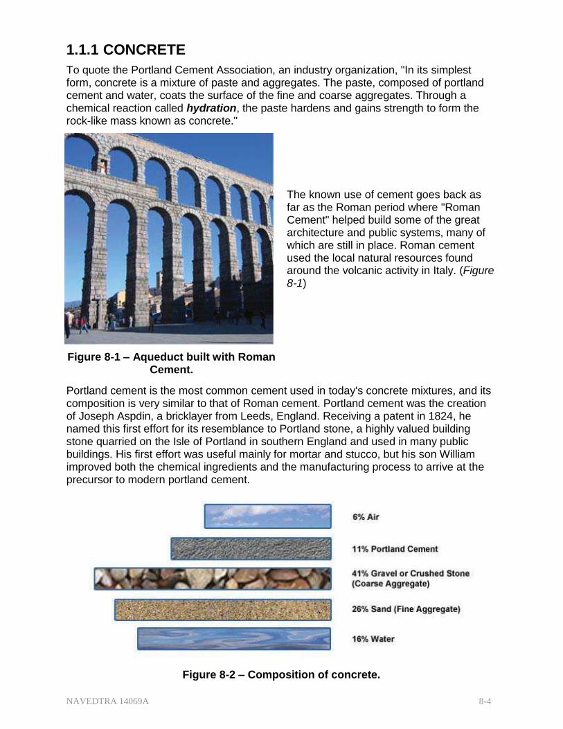
NAVEDTRA 14069A 8-4
1.1.1 CONCRETE
To quote the Portland Cement Association, an industry organization, "In its simplest form, concrete is a mixture of paste and aggregates. The paste, composed of portland cement and water, coats the surface of the fine and coarse aggregates. Through a chemical reaction called hydration, the paste hardens and gains strength to form the rock-like mass known as concrete."
The known use of cement goes back as far as the Roman period where "Roman Cement" helped build some of the great architecture and public systems, many of which are still in place. Roman cement used the local natural resources found around the volcanic activity in Italy. (Figure 8-1)
Figure 8-1 – Aqueduct built with Roman Cement.
Portland cement is the most common cement used in today's concrete mixtures, and its composition is very similar to that of Roman cement. Portland cement was the creation of Joseph Aspdin, a bricklayer from Leeds, England. Receiving a patent in 1824, he named this first effort for its resemblance to Portland stone, a highly valued building stone quarried on the Isle of Portland in southern England and used in many public buildings. His first effort was useful mainly for mortar and stucco, but his son William improved both the chemical ingredients and the manufacturing process to arrive at the precursor to modern portland cement.
Figure 8-2 – Composition of concrete.

NAVEDTRA 14069A 8-5
Concrete, as shown in Figure 8-2, is a mixture in proper proportions of cement (usually portland), fine aggregate (usually sand), coarse aggregate (usually gravel or crushed stone), and water; the product is not concrete unless it contains all four of these ingredients.
A mixture of cement, sand, lime, and water, without coarse aggregate, is not concrete. It is mortar or grout.
Mortar---used mainly for bonding masonry units together
Grout---a water/cement mixture (called neat-cement grout) or water-sand-cement mixture (called sand-cement grout) used to plug holes or cracks in concrete, to seal joints, and for similar plugging or sealing purposes
In concrete, the fine and coarse aggregates are inert, that is, they have no chemical properties and do not react with other chemicals. The cement and water are the active ingredients. To make concrete, you mix the aggregates (inert) and the cement (active) thoroughly together first, then add the water. As soon as you add the water, you have started a chemical reaction between the water and the cement. This chemical reaction, called hydration, causes the concrete to harden.
Always remember: Hydration (the chemical reaction between the cement and water) causes the hardening process! Hardening is not a matter of drying out the mix. Instead, you must keep the concrete as moist as possible during the initial hydration process. Drying out causes a drop in water content below the amount required for satisfactory hydration. The fact that concrete will harden just as well under water as it will in the air demonstrates that drying out is not the hardening factor.
You can cast concrete into bricks, blocks, and other relatively small building units (composed of various but specific ingredients) for assembly with mortar. This is concrete masonry construction.
The proportion of concrete to other materials used in building construction has increased in recent years to the point that designers and builders construct large, multistory modern buildings entirely of reinforced concrete cast in place, or precast.
1.1.1 Requirements for Good Concrete
A good concrete mix must have:
a supply of good cement (a type suitable for the work at hand)
a supply of fine aggregate (satisfactory sand)
a supply of coarse aggregate
water
Workers must weigh and measure the proportions carefully to meet the mix designed for the current concrete pour. Everything else being equal, the mix with the best graded, best shaped, strongest, and cleanest aggregate will make the strongest and most durable concrete.
However, the best designed, best graded, highest quality mix in the world will NOT make a good concrete pour if it is not workable enough to flow and thoroughly fill the spaces of a form. The concrete must be fluid (plastic) enough to flow into the forms and reach any corners without creating voids (rock pockets). On the other hand, too much water will decrease the concrete's strength. Modern concrete mixes often use additives called plasticizers to increase the fluidity of the concrete pour without adding more

NAVEDTRA 14069A 8-6
water.
In addition, improper handling during the whole concrete making process (from the initial aggregate handling, to the mixing, to the final placement of the mix) can cause segregation of aggregate particles by size, resulting in non-uniform, poor concrete.
Finally, if not properly cured, the best designed, best graded, highest quality, and best- placed mix in the world will not produce good concrete. During the early stages of this chemical process, called hydration, concrete needs protection against loss of moisture. Concrete placers or finishers achieve this with a variety of methods from spray mists, to burlap bags, to plastic sheets, to leaving the forms in place for a given period.
Strength, durability, and watertightness are the important properties of good concrete, and the water-cement ratio controls these factors. Generally, using less water produces a higher quality concrete provided the concrete is properly placed, consolidated, and cured.
1.1.1 Strength
Concrete's compressive strength is very high, but its tensile strength is relatively low. Concrete that must only resist compression may not require reinforcement.
However, concrete that must resist stretching, bending, or twisting, (tensile forces) such as concrete in beams, girders, walls, columns, and the like, must be reinforced with steel commonly referred to as rebar. (Figure 8-3)
Figure 8-3 – Examples of stress nomenclature.
1.1.2 1.1.2 Durability
Along with strength, Figure 8-4 shows other properties of good concrete.
Concrete's durability is the extent to which it is capable of resisting deterioration caused by exposure to its intended service conditions.
Ordinary structural concrete intended for exposure to the elements must be watertight and weather resistant. Concrete subject to wear, such as floor slabs and pavements, must be capable of resisting abrasion.
The major factor controlling durability is strength-in other words, the stronger the concrete, the more durable it will be.
As mentioned previously, the chief factor controlling strength is the water-cement ratio,

NAVEDTRA 14069A 8-7
but the character, size, and grading of the aggregate also has important effects on both strength and durability.
Even with a water-cement ratio that produces maximum strength consistent with workability requirements, the concrete will not attain that maximum strength and durability unless the fine (sand) and coarse aggregates are well-graded, clean, hard, and durable particles, free from undesirable substances.
Figure 8-4 – Properties of good concrete.
1.1.3 Watertightness
The ideal concrete mix would be one made with just the right amount of water required for complete hydration of the cement; however, this would be too dry a mix that is, too stiff to pour in the forms.
A concrete mix fluid (plastic) enough to pour into forms always contains a certain amount of water over and above the amount needed for complete hydration, and this extra water will eventually evaporate, leaving voids or pores in the concrete. The concrete would be watertight if these voids were not interconnected.
They are, however, interconnected by the slight sinking of solid particles in the mix during the hardening period. The mix starts after all, as a fluid mix that flows; and as the aggregate particles sink before complete hardening, they leave water-filled channels, which become voids when the water evaporates. The larger and more numerous the voids, the more compromised the watertightness of the concrete.
Since the size and number of the voids vary directly with the amount of water used in excess of the amount required to hydrate the cement, it follows that to keep the
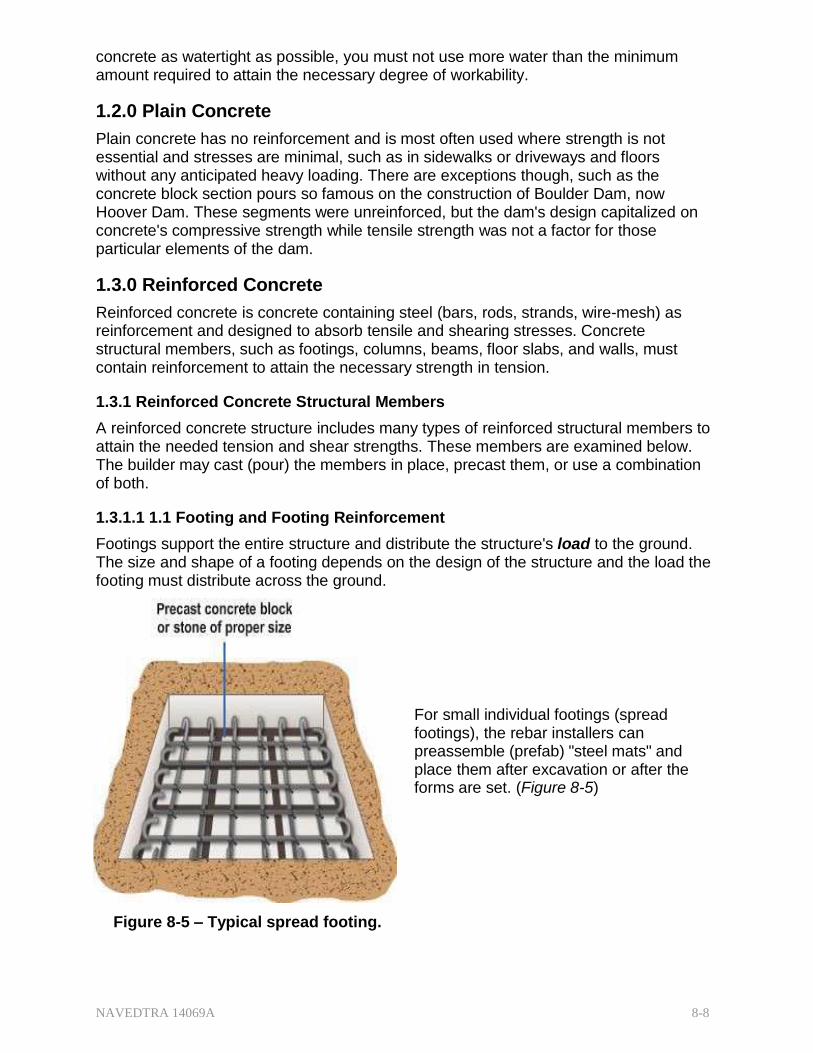
NAVEDTRA 14069A 8-8
concrete as watertight as possible, you must not use more water than the minimum amount required to attain the necessary degree of workability.
1.2.0 Plain Concrete
Plain concrete has no reinforcement and is most often used where strength is not essential and stresses are minimal, such as in sidewalks or driveways and floors without any anticipated heavy loading. There are exceptions though, such as the concrete block section pours so famous on the construction of Boulder Dam, now Hoover Dam. These segments were unreinforced, but the dam's design capitalized on concrete's compressive strength while tensile strength was not a factor for those particular elements of the dam.
1.3.0 Reinforced Concrete
Reinforced concrete is concrete containing steel (bars, rods, strands, wire-mesh) as reinforcement and designed to absorb tensile and shearing stresses. Concrete structural members, such as footings, columns, beams, floor slabs, and walls, must contain reinforcement to attain the necessary strength in tension.
1.3.1 Reinforced Concrete Structural Members
A reinforced concrete structure includes many types of reinforced structural members to attain the needed tension and shear strengths. These members are examined below. The builder may cast (pour) the members in place, precast them, or use a combination of both.
1.3.1.1 1.1 Footing and Footing Reinforcement
Footings support the entire structure and distribute the structure's load to the ground. The size and shape of a footing depends on the design of the structure and the load the footing must distribute across the ground.
For small individual footings (spread footings), the rebar installers can preassemble (prefab) "steel mats" and place them after excavation or after the forms are set. (Figure 8-5)
Figure 8-5 – Typical spread footing.

NAVEDTRA 14069A 8-9
For large, continuous footings or grade beams, such as those found under bearing walls, installers will need to assemble the rebar in place. (Figure 8-6)
Figure 8-6 – Typical continuous footing.
1.3.1.2 Column and Column Reinforcement
A column is a slender, vertical member that carries a superimposed load. Concrete columns, especially those subjected to bending stresses, must always have steel reinforcement. Vertical reinforcement is the principal reinforcement, but a column under loaded stress tends to shorten vertically and expand laterally. Lateral ties serve to counteract those forces and restrain the expansion.
Columns reinforced in this manner are tied columns. If the restraining reinforcement is a continuous winding spiral that encircles the core and longitudinal steel, the column is a spiral column. A spiral column placed below ground level as part of the foundation is a caisson. (Figure 8-7)
Figure 8-7 – Typical tied and spiral column; typical caisson.

NAVEDTRA 14069A 8-10
Like a column, a pier or pedestal (Figure 8-8) is also a member under compression stress but it is short (usually the height is less than three times the shortest lateral dimension) in relation to its cross-sectional area and carries no shear or torsion stress. Consequently, it may or may not need reinforcement.
Figure 8-8 – Typical concrete pedestal.
1.3.1.3 Beam and Beam Reinforcement
Beams are the principal load-carrying horizontal members. They take the loading stresses directly from the floor above and distribute them to the columns supporting the beams. As an engineering principle, the greatest reinforcement is always placed on the opposite (or far side) of the loading/lifting forces (Figure 8-9).
To place the rebar opposite the forces, engineers may design both straight and truss bars to resist the bending tension in the bottom at the central portion of the span between the supports for the beam. Since fewer bars are necessary on the bottom near the ends of the span where the bending moment is small, some bars may be truss bars to serve as additional bars for the bottom central span and serve as additional bars for the top ends of the span as well.
Figure 8-9 – Typical beam with truss bars.
1.3.1.4 Slab and Slab Reinforcement
Concrete slabs come in a variety of forms depending on their location. Ground slabs (also called slabs on grade) take the load directly to the ground or to beams called grade beams placed below ground level. Plain slabs (similar in shape to ground slabs but on a formed surface) take the load directly from the floor and transmit it to beams. In other cases, joists, poured as part of plain slabs, carry the loads to the beams. Joists, similar to but lighter and smaller than beams, strengthen the middle portion of the slab.
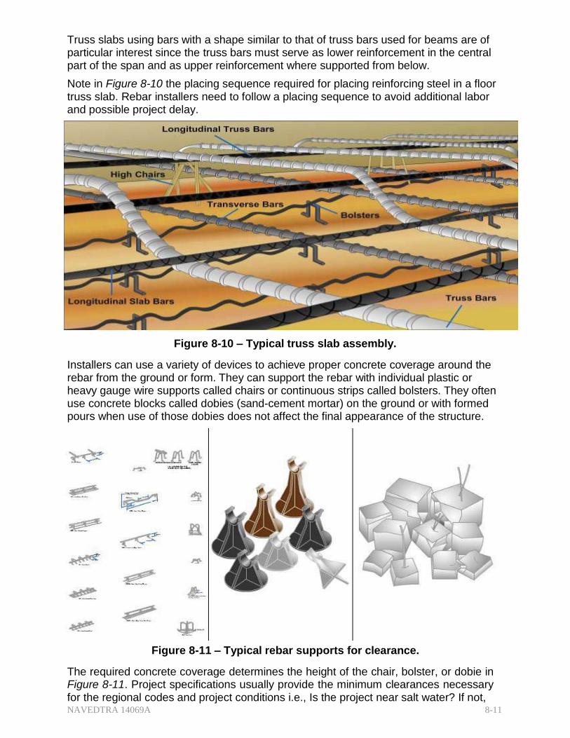
NAVEDTRA 14069A 8-11
Truss slabs using bars with a shape similar to that of truss bars used for beams are of particular interest since the truss bars must serve as lower reinforcement in the central part of the span and as upper reinforcement where supported from below.
Note in Figure 8-10 the placing sequence required for placing reinforcing steel in a floor truss slab. Rebar installers need to follow a placing sequence to avoid additional labor and possible project delay.
Figure 8-10 – Typical truss slab assembly.
Installers can use a variety of devices to achieve proper concrete coverage around the rebar from the ground or form. They can support the rebar with individual plastic or heavy gauge wire supports called chairs or continuous strips called bolsters. They often use concrete blocks called dobies (sand-cement mortar) on the ground or with formed pours when use of those dobies does not affect the final appearance of the structure.
Figure 8-11 – Typical rebar supports for clearance.
The required concrete coverage determines the height of the chair, bolster, or dobie in Figure 8-11. Project specifications usually provide the minimum clearances necessary for the regional codes and project conditions i.e., Is the project near salt water? If not,

NAVEDTRA 14069A 8-12
the American Concrete Institute provides standards in ACI 318 "Building Code Requirements for Reinforced Concrete." Typically, concrete surfaces in contact with the ground require 3 in. clearance and exposure to weathering requires 1/12- 2 in. If no rebar supports are available, wire ties and/or wood blocks may hold the rebar in position on a temporary basis (Figure 8-12) and be removed before the concrete sets. You should not use wood block without removal unless the structure is temporary.
Figure 8-12 – Beam reinforcement with and without support.
1.3.1.5 Wall Reinforcement
Rebar placement for load-bearing walls is the same as columns except that installers usually do it "in-place," that is not preassembled. Vertical and horizontal members need a minimum of three ties in any length. If installers use wood blocks as temporary spacers (Figure 8-13), they must ensure the blocks do not fall into the wall during the pour and must remove them as the concrete nears the top of the pour height.
Figure 8-13 – Wall reinforcement with temporary spacers.
1.3.2 Reinforcing Steel
Steel is the best material for reinforcing concrete; their coefficients of expansion are almost the same, i.e., at a normal temperature, steel and concrete will expand and

NAVEDTRA 14069A 8-13
contract at a nearly equal rate. Under extraordinary circumstances at very high temperatures, the steel will expand more rapidly than the concrete, and the two materials will separate.
Steel is also the best because it makes a good bond with the concrete. This bond strength is in direct proportion to the amount of steel-concrete contact. In other words, the greater the surface of steel exposed to the adherence of the concrete, the stronger the bond.
Concrete adherence depends on the roughness of the steel surface: the rougher the steel, the better the adherence. Thus, steel with a light, firm layer of rust is superior to clean steel, but steel with loose or scaly rust is inferior. Installers can remove loose or scaly rust by rubbing the bars with burlap or using a wire brush.
Reinforcing steel must be strong in tension and, at the same time, ductile enough for shaping or cold bending.
Reinforcing steel includes:
Plain round bars
Deformed bars
Expanded metal
Welded wire fabric (wire mesh)
Each type is useful for a different purpose, and engineers design structures with these purposes in mind.
Plain reinforcing bars are usually round in cross section. They are the least used of the rod type of reinforcement because they offer only smooth, even surfaces for the adherence of concrete. Deformed reinforcing bars are better than plain round bars. In fact, when using plain bars of a given diameter instead of deformed bars, you must increase the quantity by approximately 40 percent. The United States uses deformed bars almost exclusively, while Europe uses both deformed and plain bars.
Deformed bars are like plain bars except that they have indentations, or ridges, or both in a regular pattern. Earlier versions of deformed rebar were available as square or with a spiral twist and workers may still encounter them during demolition or on remodeling projects of older structures. Current rebar suppliers deform the bars at the mill with patterns and markings (Figure 8-14) unique to their mill and to the tensile strength of the material.

NAVEDTRA 14069A 8-14
Figure 8-14 – Sample mill patterns and tensile strength markings.
There are 11 standard sizes of reinforcing bars (Figure 8-15). Bars No. 3 through No. 18 inclusive, are deformed bars. Bar numbers correspond to bar sizes to the nearest 1/8 in. (3. 175 mm) measured at the nominal diameter but not including any deformations.
Note: At 13.6 pounds per foot, a #18 bar of any functional length quickly becomes too heavy for personnel handling and requires mechanical lifting equipment.
Figure 8-15 – Reinforcing steel sizes and their tensile strength markings.
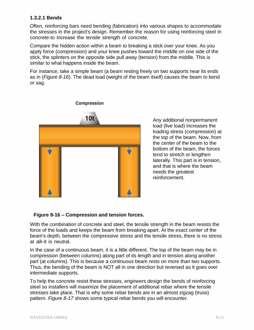
NAVEDTRA 14069A 8-15
1.3.2.1 Bends
Often, reinforcing bars need bending (fabrication) into various shapes to accommodate the stresses in the project's design. Remember the reason for using reinforcing steel in concrete-to increase the tensile strength of concrete.
Compare the hidden action within a beam to breaking a stick over your knee. As you apply force (compression) and your knee pushes toward the middle on one side of the stick, the splinters on the opposite side pull away (tension) from the middle. This is similar to what happens inside the beam.
For instance, take a simple beam (a beam resting freely on two supports near its ends as in (Figure 8-16). The dead load (weight of the beam itself) causes the beam to bend or sag.
Any additional nonpermanent load (live load) increases the loading stress (compression) at the top of the beam. Now, from the center of the beam to the bottom of the beam, the forces tend to stretch or lengthen laterally. This part is in tension, and that is where the beam needs the greatest reinforcement.
Figure 8-16 – Compression and tension forces.
With the combination of concrete and steel, the tensile strength in the beam resists the force of the loads and keeps the beam from breaking apart. At the exact center of the beam's depth, between the compressive stress and the tensile stress, there is no stress at all-it is neutral.
In the case of a continuous beam, it is a little different. The top of the beam may be in compression (between columns) along part of its length and in tension along another part (at columns). This is because a continuous beam rests on more than two supports. Thus, the bending of the beam is NOT all in one direction but reversed as it goes over intermediate supports.
To help the concrete resist these stresses, engineers design the bends of reinforcing steel so installers will maximize the placement of additional rebar where the tensile stresses take place. That is why some rebar bends are in an almost zigzag (truss) pattern. Figure 8-17 shows some typical rebar bends you will encounter.

NAVEDTRA 14069A 8-16
Figure 8-17 – Typical rebar bends.
When bending reinforcing bars, benders in the field or fabricators in the shop must exercise caution to ensure the bends are not too sharp. Rebar may crack or weaken if bent too sharply. The American Concrete Institute (ACI 318 Building Code Requirements for Structural Concrete) has established minimum bend diameters for the different bar sizes and for the various types of hooks.
There are many different types of bends, depending on where the rods are destined to be used. For example, there are hooks for the ends of heavy beams and girders, offset bends for vertical column splices at or near floor levels, beam stirrups, column ties, slab reinforcement, and spiral for round columns or foundation caissons. These bending details are shown in Figure 8-18

NAVEDTRA 14069A 8-17
Figure 8-18 – Typical rebar bender and bending schedule.
1.3.2.2 Splices
A lap splice of proper length can transmit tension stress through the concrete into the adjoining spliced bar. When engineers do not dimension rebar splices on the drawings, installers should lap bars 30 times their diameter, or not less than 12 in. The number of bar diameters expresses "lap." For example, the 30-diameter lap for a #8 (1-in.) bar would be 30 in., and for a #4 (1/2 in.) bar it would be 15 in. If using a #3 bar, make the lap at least 12 in.
1.3.2.3 Expanded Metal and Welded Wire Fabric
Builders also use expanded metal to reinforce concrete where there is only a minimal need for tensile strength. Manufacturers make expanded metal by partially shearing a sheet of steel in parallel lines, as shown in Figure 8-19, and then pulling it out and expanding it. Expanded metal comes in a variety of gauges and shapes, and plastering operations frequently use it to build the base (scratch) coat.
Figure 8-19 – Expanded metal reinforcement.
Welded wire fabric (WWF or wire mesh) is available in rolls of lighter gauge wire for light building construction and in sheets of heavier gauge wire for highways and buildings when roll gauge sizes will not give sufficient reinforcement (Figure 8-20). WWF is available in square and rectangular patterns in a wide variety of wire gauges welded at each intersection.

NAVEDTRA 14069A 8-18
Figure 8-20 – Welded wire fabric (mesh).
When ordering welded wire fabric in either the old or the new designations, the wire spacing (in each direction) comes first followed by the wire gauge (in each direction). The old designation used number (in inches) for spacing and number (in wire gauge) for the size of the WWF. The new designation uses number (in inches) for spacing but a letter and a number (in wire cross-section) for size.
For example, in the old designation, 6x6 - 4x4 mesh would be 6-in. squares with 4- gauge wire in each direction whereas, 4x4 - 6x6 mesh would be 4-in. squares with 6- gauge wire in each direction. In the new designation, these would be 6x6 - W4xW4, and 4x4 - W2.9xW2.9 respectively. Figure 8-21 provides some typical WWF designations used for structural concrete.
Figure 8-21 – Designations for welded wire fabric.
When using WWF, specifications and designs usually indicate the minimum lap. As a practical matter, although a minimum lap of 2 in. may be sufficient for nonstructural concrete, for placement purposes a 1-square lap, regardless of the mesh spacing, is common to facilitate the installer's ability to tie the laps together at intersections.

NAVEDTRA 14069A 8-19
Installers use a number of different ties to join rebar together and hold it in the proper spacing and in place as the concrete pours. (Figure 8-22) The tie wire may come in large rolls (shoulder coils) where installers cut smaller sections off and roll it around the neck and shoulders as they use the wire. However, in today's civilian industry where Ironworkers place the rebar, tie wire reels affixed to belts are the common method of distributing the wire. On small projects when only snap ties are necessary, another alternative is looped end tie wires.
Figure 8-22 – Types of tie wire available.
Figure 8-23 shows typical types of wire ties used by Ironworkers in the commercial industry. They use the ties with the "round turn" periodically for wall installation because as a horizontal bar tends to sag from its own weight or from personnel climbing, the tie tightens up with the round turn around the vertical bar.
Figure 8-23 – Typical reinforcement placing ties.
1.4.0 Precast Concrete
Known as cast-in-place, most concrete structural members are poured in their final position. Precasting is the fabrication of a structural member at a place other than its final position of use. It is best adapted to a factory or yard but jobsite precasting is not uncommon for large projects that require a large number of exact or similar pieces. Precast concrete can produce several different shapes and sizes, including piles, girders, and roof members.

NAVEDTRA 14069A 8-20
Prestressed concrete is especially well adapted to precasting techniques. Fabricators make prestressed units by casting concrete around already tensioned tendons or bars. Prestressed concrete pours require stout anchoring points between which the heavy wire tendons (or bars) stretch under tension, usually in a straight line. The cured concrete adheres and bonds to the tendons (or bars). When the fabricators release the tension, it transfers to the concrete as compression by static friction. Generally, concrete structural members such as standard highway girders, poles, electric poles, masts, and some building members are precast by factory methods unless transportation difficulty makes jobsite casting more desirable.
1.4.1 recast Concrete Floors, Roof Slabs, Walls, and Partitions
Channel and double-T type precast slabs (Figure. 8-24, views A and B.) are the most commonly used panels for floor and roof decks.
Channel slabs can vary in size from 9 to 12 in. deep, 2 to 5 ft. wide, 1 to 2 in. thick and to 50 ft. in length. If desired or needed, the concrete casters may extend the legs of the channels across the ends and, if used in combination with top slabs, can stiffen the channel with occasional cross ribs. Wire mesh may be the reinforcement in a top slab.
Double-T slabs can vary in size from 9 to 16 ft deep, and 4 to 6 ft wide, and as long as 50 ft. When a top slab size ranges from 1 1/2 to 2 in. in thickness, it should be reinforced with wire mesh.
Tongue-and-groove panels (Figure. 8-24 view C) can vary extensively in size, according to the design requirement. They sit in position much like tongue-and-groove lumber; that is, the tongue of one panel fits inside the groove of an adjacent panel. Large pier construction projects often use them as decking panels.
Figure 8-24 – Typical precast panels.
Welders ordinarily connect the floor and roof panels to supporting members with the matching plates built into the precast units.
Builders can also precast vertical panels in a horizontal position in a casting yard or on the floor of the building. Cranes then set the precast units in their final position. (Figure 8-25)

NAVEDTRA 14069A 8-21
Figure 8-25 – Crane with spreader bars erecting precast wall panel.
Usually, these panels are solid, reinforced slabs, 5 to 8 in. thick, with the width varying according to the distances between columns or other supporting members. As it is with wood frame construction, when there are windows and door openings, extra reinforcements is required around the openings.
A concrete floor slab with a smooth, regular surface can be the "casting surface." When used for casting, builders should cover this smooth surface with a liquid or sheet material that prevents bonding between the slab surface and the vertical panel. The upper surface of the panel may be finished in the same way as regular concrete: by trowel, float, or broom.
Sandwich panels are panels that consist of two thin, dense, reinforced concrete-face slabs separated by a core of insulating material, such as lightweight concrete, cellular glass, plastic foam, or some rigid insulating material.
Designers sometimes specify these panels for exterior walls to provide additional heat insulation. The thickness of the sandwich panels varies from 5 to 8 in. and the faces are tied together with wire, small rods, or in some other manner. Matching plates also connect the wall panels to the building frame top and bottom by either welds or bolts. Caulking on the outside and grouting on the inside should make the points between the wall panels watertight.
1.4.2 Precast Concrete Joists, Beams, Girders, and Columns
Joists are small, closely spaced beams used in floor construction. Small, closely spaced beams used in roof construction are purlins. Their shape in cross section is like a T or

NAVEDTRA 14069A 8-22
an I. The ones with the inverted T-sections are usually used in composite construction where they support cast-in-place floor or roof slabs.
The terms beam and girder usually apply to the same type of member but the one with the longer span is the girder. Beams and girders may be conventional precast design or prestressed. Most beams will be I-shaped unless the ends are rectangular but T-shaped ones are also usable.
Precast concrete columns may be solid or hollow. If the designer specifies the hollow type, heavy cardboard tubing forms part of the column's core. A looped rod previously cast in the column footing and projecting upward into the hollow core helps hold the column upright. An opening left in the side of the column allows the core to be filled with grout, which causes the embedded looped rod to become an anchor. The final step is dry packing the opening.
1.4.3 Advantages of Precast Concrete
Precasting concrete has its greatest advantage when a project requires many identical members because the same forms are reusable several times.
Some other advantages are:
Control of concrete quality
Smoother surfaces
Less storage space required
Weather conditions may not affect casting
Better protection for curing
Weather conditions do not affect erection
Faster erection time
1.5.0 Prestressed Concrete
A prestressed concrete unit is one in which engineered stresses have been placed by either pre-tensioning or post-tensioning before it has been subjected to a load.
Pre-tensioning involves high-tensile strength steel strands as reinforcement (as well as other reinforcement) stretched in a straight line through a form between two end abutments or anchors. The steel strands receive a predetermined amount of stress and the concrete pour encases the reinforcement. As the concrete sets, it bonds to the pre- tensioned steel. When the concrete reaches a specified strength, the tension on the reinforcement is released. This pre-stresses the concrete, putting it under compression, thus creating a built-in tensile strength.
Post-tensioning also involves high-tensile strength steel strands as well as other reinforcement, but in this method, workers place the strands under stress with hydraulic equipment after the concrete reaches a predetermined strength.
One method involves hollow tubing placed within the concrete pour through which the workers later add the strands. Another method involves individual strands encased in grease-filled plastic casings. In both methods, unlike pre-tensioning's straight pull, post- tension cables must follow an engineered profile of highs and lows that provides tension at specific locations.
Post-tensioning individual units at a precast location is an option, but common practice

NAVEDTRA 14069A 8-23
has most post-tensioning operations done at the job-site on the cast-in-place concrete pour.
In general, post-tensioning is used if the unit is over 45 ft long or over 7 tons in weight. Members that are relatively small or can be readily precast are normally pre-tensioned. These include precast roof slabs, T-slabs, floor slabs, and roof joists. However, some types of pre-tensioned roof slabs may be considerably longer and heavier than this.
When a beam is prestressed, (Figure 8-26) by either pre- tensioning or post-tensioning, the tensioned steel produces a high compression in the lower part of the beam. This compression creates an upward bow, or camber, in the beam. When a load is placed on the beam, the camber is forced out, creating a level beam with no deflection.
Figure 8-26 – Results of prestressing concrete beams.
1.6.0 Special Types of Concrete
Special types of concrete are those with unique physical properties or those produced with unusual techniques and/or reproduction processes. Portland cement is the binding medium for many special types of concrete but some special cements use other binders.
1.6.1 tweight Concrete
Lightweight concrete is usually classified according to its weight per cubic foot. Conventional concrete weighs approximately 150 lb per cubic foot. Lightweight concrete ranges from 20 to 130 lb per cubic foot, depending on its intended use. Concrete mix designers can use gas-generating chemicals or lightweight aggregates, such as expanded shale, clay, or slag, to make lightweight concrete.
Insulating lightweight concrete has a unit weight ranging from 20 to 70 lb per cubic foot, and its compressive strength seldom exceeds 1,000 psi. This type of concrete is generally used for insulating applications, such as fireproofing. Concrete using perlite or vermiculite as aggregate is very light and used primarily as insulating material. Both perlite, (a volcanic glass) and vermiculite (a natural mineral) expand when exposed to the heat from the hydration process of cement and water.

NAVEDTRA 14069A 8-24
Structural lightweight concrete has a unit weight of 90 to 115 lb per cubic foot and a 28- day compressive strength in excess of 2,000 psi. This type is used primarily to reduce the dead-load weight in concrete structural members, such as floors, walls, and the roof section in high-rise structures, thus reducing the foundation support requirements as well.
Semi-lightweight concrete has a unit weight of 115 to 130 lb per cubic foot and an ultimate compressive strength comparable to normal concrete. In this mix, normal weight sand of is substituted partially or completely for the lightweight fine aggregate.
1.6.2 Heavyweight Concrete
Heavyweight concrete uses special heavy aggregates and has a density of up to 400 lb per cubic foot. This type is principally for radiation shielding, counterweights, and other applications where higher density is desired. Except for density, the physical properties of heavyweight concrete are similar to those of normal- or conventional-weight concrete.
1.7.0 Tilt-Up Construction
Tilt-up concrete construction is a special form of precast concrete building. This method consists of jobsite prefabrication in which the builder casts the wall as a horizontal slab, tilts it to a vertical position, and secures it in place.
Tilt-up construction is best suited for large one-story buildings, but multistory structures can also be "tilt-ups." Usually, multistory structures use platform construction by setting the walls for the first story, placing the floor above, then repeating the procedure for each succeeding floor. An alternate tilt-up method is to cast two- to four-story panels, similar to the balloon framing of wood structures.
Because tilt-up walls are usually cast on the ground floor slab of the structure, builders must ensure the slab is smooth and level, temporarily plug all openings for pipes and other utilities, and treat the casting area with a good bond-breaking agent to ensure the panel does not adhere to the slab when lifted.
1.7.1 Reinforcement of Tilt-Up Panels
The steel in a tilt-up panel is set in the same manner as it is in a floor slab. Placers set mats of rebar on chairs and tie it as needed. If it is a single mat, the reinforcement should be as near the center depth of the panel as possible. The reinforcing bars may run through holes provided in the side forms of the panel for future connection with the vertical supports (usually pilasters). When welded wire fabric or expanded wire mesh is the main reinforcing, reinforcing steel called dowels protrude through the holes to serve that function. Any openings need additional reinforcement. Mechanical lifting devices (usually a crane) pick up and tilt the panel to a vertical position using pickup inserts, specially designed tilt-up hardware. (Figure 8-27) Placers tie these inserts to the reinforcement at specific, designated locations to accommodate the maximum stress that occurs during the lifting process. Additional reinforcement may be necessary at these pickup locations. Some engineering manuals provide information on inserts, their locations, and capacities.

NAVEDTRA 14069A 8-25
Figure 8-27 – Typical pick up insert for a tilt up panel.
1.7.2 oundations
An economical and widely used method to support tilt-up panels is a simple pad footing. (Figure 8-28) The floor slab, though constructed first, is NOT poured to the perimeter of the building. This permits later excavation and pouring of the footings as the tilt-up panels are curing. In this method, again like balloon framing, the panel sits on the footing below the slab level. Placers then complete the perimeter section of slab. It may connect directly to the outside wall panel via dowels placed in the panel before pouring, or the design may call for a trench to run mechanical, electrical, or plumbing lines.
Another commonly used method is to set the panels on a perimeter grade beam or foundation wall at floor level. Regardless of the type of footing, the panel should be set into a mortar bed to ensure a good bond between the foundation wall and the panel.
Figure 8-28 – Tilt-up panel set on a footing beam.
1.7.3 Panel Connections
Designers can use a variety of ways to make tilt-up connections. The strongest method is a cast-in-place pilaster incorporating the doweled out panel rebar. However, this does not allow for expansion and contraction so the designer may prefer to tie only the corner panels into pilasters and allow the remaining panels to move.

NAVEDTRA 14069A 8-26
Other methods are an option:
Butted connection---using grout or a gasket if the wall does NOT contribute any structural strength to the structure
Steel columns---welded to steel angles or plates secured in the wall panel
Precast columns---steel angles or plates secured in both the columns and plate and welded together to secure the panel
When the design calls for panel-to-panel connections that do not actually hold the panels in place, a typical method is to weld them to the foundation and to the roof by using steel angles or plates.
Regardless of the type of connection, they must all be waterproof. This is usually accomplished with expansion joint material placed between panels not closed by any of the other designed connections.
1.7.4 Finishes
Tilt-up panel finish is similar to any other concrete floor or wall. While some unique finish may require an exterior face-up pour, most will require the typical exterior face- down pour. A face-up pour will affect the panel hoisting and the pick up insert locations.
1.8.0 Concrete Construction Joints and Connections
Construction joints (Figure 8-29) are divisions between concrete pours done at intervals spaced widely enough to allow partial hardening. Some are at natural stages of construction, others are necessary due to the capability or availability of the concrete itself depending on the size of the pour.
Construction joint locations must be where they will cause the minimum amount of weakness to the structure; for example, where the shearing stresses and bending moments are relatively small or where other structural members will support the joints.
For horizontal work, such as floor slabs, construction joints should be in a vertical plane, whereas for vertical work, such as columns, the joints should lie in a horizontal plane.
Figure 8-29 – Typical location of construction joints.
Foundation walls bond to footings with vertical dowels which extend from the footings
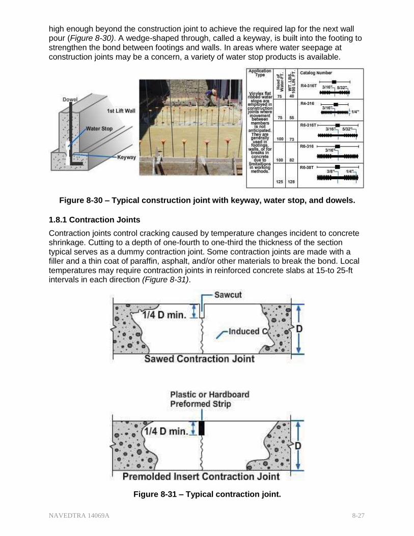
NAVEDTRA 14069A 8-27
high enough beyond the construction joint to achieve the required lap for the next wall pour (Figure 8-30). A wedge-shaped through, called a keyway, is built into the footing to strengthen the bond between footings and walls. In areas where water seepage at construction joints may be a concern, a variety of water stop products is available.
Figure 8-30 – Typical construction joint with keyway, water stop, and dowels.
1.8.1 Contraction Joints
Contraction joints control cracking caused by temperature changes incident to concrete shrinkage. Cutting to a depth of one-fourth to one-third the thickness of the section typical serves as a dummy contraction joint. Some contraction joints are made with a filler and a thin coat of paraffin, asphalt, and/or other materials to break the bond. Local temperatures may require contraction joints in reinforced concrete slabs at 15-to 25-ft intervals in each direction (Figure 8-31).
Figure 8-31 – Typical contraction joint.
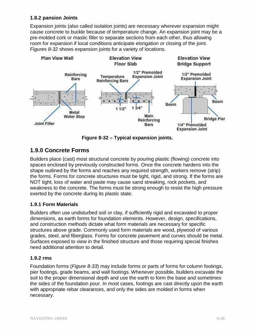
NAVEDTRA 14069A 8-28
1.8.2 pansion Joints
Expansion joints (also called isolation joints) are necessary wherever expansion might cause concrete to buckle because of temperature change. An expansion joint may be a pre-molded cork or mastic filler to separate sections from each other, thus allowing room for expansion if local conditions anticipate elongation or closing of the joint. Figures 8-32 shows expansion joints for a variety of locations.
Figure 8-32 – Typical expansion joints.
1.9.0 Concrete Forms
Builders place (cast) most structural concrete by pouring plastic (flowing) concrete into spaces enclosed by previously constructed forms. Once the concrete hardens into the shape outlined by the forms and reaches any required strength, workers remove (strip) the forms. Forms for concrete structures must be tight, rigid, and strong. If the forms are NOT tight, loss of water and paste may cause sand streaking, rock pockets, and weakness to the concrete. The forms must be strong enough to resist the high pressure exerted by the concrete during its plastic state.
1.9.1 Form Materials
Builders often use undisturbed soil or clay, if sufficiently rigid and excavated to proper dimensions, as earth forms for foundation elements. However, design, specifications, and construction methods dictate what form materials are necessary for specific structures above grade. Commonly used form materials are wood, plywood of various grades, steel, and fiberglass. Forms for concrete pavement and curves should be metal. Surfaces exposed to view in the finished structure and those requiring special finishes need additional attention to detail.
1.9.2 rms
Foundation forms (Figure 8-33) may include forms or parts of forms for column footings, pier footings, grade beams, and wall footings. Whenever possible, builders excavate the soil to the proper dimensional depth and use the earth to form the base and sometimes the sides of the foundation pour. In most cases, footings are cast directly upon the earth with appropriate rebar clearances, and only the sides are molded in forms when necessary.

NAVEDTRA 14069A 8-29
Figure 8-33 – Typical footing form for piers and columns.

NAVEDTRA 14069A 8-30
1.9.3 Wall Forms
Builders often prefabricate wall forms but they can build them in place as well, depending on the shape and the desirability for reuse.
Wall forms have five basic parts: (Figure 8-34)
Sheathing---shapes and retains the concrete until it sets
Studs---form a framework and support the sheathing
Wales---keep the form aligned and support the studs
Braces---hold the forms erect under lateral pressure
Ties and spreaders or tie-spreader units---hold the sides of the forms at the correct spacing
Figure 8-34 – Typical wall form.
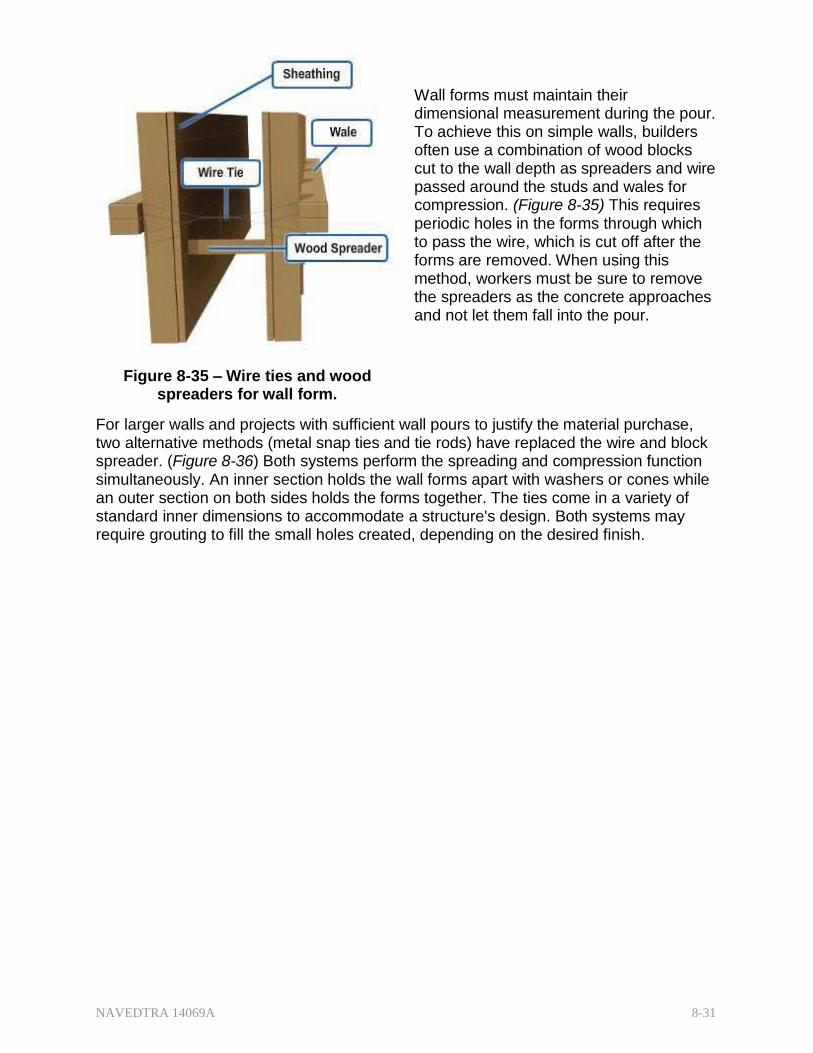
NAVEDTRA 14069A 8-31
Wall forms must maintain their dimensional measurement during the pour. To achieve this on simple walls, builders often use a combination of wood blocks cut to the wall depth as spreaders and wire passed around the studs and wales for compression. (Figure 8-35) This requires periodic holes in the forms through which to pass the wire, which is cut off after the forms are removed. When using this method, workers must be sure to remove the spreaders as the concrete approaches and not let them fall into the pour.
Figure 8-35 – Wire ties and wood spreaders for wall form.
For larger walls and projects with sufficient wall pours to justify the material purchase, two alternative methods (metal snap ties and tie rods) have replaced the wire and block spreader. (Figure 8-36) Both systems perform the spreading and compression function simultaneously. An inner section holds the wall forms apart with washers or cones while an outer section on both sides holds the forms together. The ties come in a variety of standard inner dimensions to accommodate a structure's design. Both systems may require grouting to fill the small holes created, depending on the desired finish.

NAVEDTRA 14069A 8-32
Figure 8-36 – Typical snap tie wall form.
The use of prefabricated (prefab) panels for formwork is on the increase. The panels are reusable many times, thus reducing the time and labor required for erecting forms piecemeal on the site. A potential downside in using prefabbed panels is the cumulative weight of the panel. Careful consideration needs to go into the prefab planning for handling the panels and if necessary make provisions for mechanical handling.
There are many types of prefabricated forms to select. Contractors sometimes build their own panels from wood framing covered with plywood sheathing.
Metal frame with plywood sheathing panels are also in common use and available in a variety of sizes. Special sections provide form for inside corners, pilasters, and so forth. Patented panel clamps hold panels together and flat bar ties lock into place between panels, eliminating the need for spreaders.
Forms are aligned by the use of one or more doubled rows of 2 by 4's secured to the forms by a special device attached to the bar ties.
Panels made completely of steel are also available. Inside and outside corner sections are standard, and insert angles allow the contractor to make up odd-sized panels.

NAVEDTRA 14069A 8-33
Figure 8-37 – Typical ganged wall form system.
With all wall forms, whether built in place or prefabbed, builders must give special attention to corners. (Figure 8-38) These are weak points because the continuity of sheathing and wales is broken, particularly at the inside corner. Forms must pull together tightly at these points to prevent leakage of concrete.
Large placement projects requiring mass concrete often use giant panels or ganged panels. Crews assemble these large forms on the ground, and cranes are necessary to hoist and place them, so equipment availability is the only limit to their size. (Figure 8-37)
Figure 8-38 – Typical wall form at corners.
1.9.4 Column Forms
In Figure 8-39, yokes brace a typical concrete column form to hold the sheathing together against the plastic concrete's bursting pressure, which is created by the height of the pour. The pressure is greater at the bottom than the top, so yokes are closer

NAVEDTRA 14069A 8-34
together at the bottom.
Figure 8-39 – Typical column form.
Notice that yokes on two sides of the panel extend beyond the panel and have bolts running through drilled holes. These hold the sheathing to size in one direction. In the other direction, the yokes fit between the first yokes with wedges driven between the yokes and bolts to tighten the form.
1.9.5 Beam and Girder Forms
The type of construction a builder will use for girder and beam forms will depend on the pour schedule and the concrete curing time. The schedule may allow removal in one piece, but the more common method is to leave the bottom (soffit) of the girder/beam in place and shored to allow additional curing as the project progresses. Usually, if the schedule requires the bottom form of the beam for another area of the project, the builder must reshore the beam immediately after stripping and maintain the reshoring until the concrete achieves its strength.
Figure 8-40 shows a typical girder and beam form designed for stripping while leaving their soffits in place for longer shoring. In these examples, the slab will pour monolithically with the girders/beams. Notice how the sides come down to the bottom of the soffit rather than sitting on the soffit. This allows workers easier access to remove the sides without removing the soffit.

NAVEDTRA 14069A 8-35
Figure 8-40 – Typical girder and beam forms.
Figure 8-41 – Typical components of beam formwork with slab framing.
Beam forms are not usually subject to bursting pressure, but builders must shore them up at frequent intervals to prevent sagging under the weight of the fresh concrete. Figure 8-41 shows the elevated view of a monolithic slab/beam pour (notice the absence of a construction joint in the beams at the bottom of the slab). This drawing indicates that the beam sides are 3/4-in. plywood, the beam soffit is a solid piece of 2-in. dimensioned lumber, with the whole form supported on the bottom by 4x4-in. T-head shores. It is a typical interior beam form with the slab forms supported by the blocking and ledgers on the beam sides. They are transmitting the slab loads down to the supporting shores.

NAVEDTRA 14069A 8-36
Test your Knowledge (Select the Correct Response)
1. The important properties of good concrete are .
A. grade, mix, and water B. shape, flow, and cement C. wear, aggregate, and hardness D. strength, durability, and watertightness
2.0.0 MASONRY
Masonry is the building of structures from individual units laid in and bound together by mortar. The common materials of masonry construction include brick, concrete block, stone, limestone, glass block, and tile. They are all available in a variety of styles although some come in standard manufactured sizes.
2.1.1 Concrete Masonry
Concrete masonry has become increasingly important as a construction material following manufacturers' rapid increase in technological developments. Properly designed and constructed concrete masonry walls satisfy various building requirements including fire, safety, durability, economy, appearance, utility, comfort, and good acoustics.
Concrete Block is the most common concrete masonry unit (CMU) and there are three classifications: heavyweight, middleweight and lightweight. The differences are much like the differences in conventional concrete and lightweight concrete, they are in the aggregate.
The heavyweight block is cement, water, and an aggregate such as sand, gravel, and/or crushed limestone. The lightweight block is cement, water, and a lightweight aggregate such as cinders, pumice, expanded shale, or vermiculite. Middleweight block, of course, is a combination of heavy and light aggregate. Lightweight units weigh about 30 percent less than heavyweight.
In the United States, loadbearing concrete masonry units of any weight must meet American Society for Testing and Materials (ASTM) C 90 standards to be acceptable. Among those are:
Compressive strength---provides a measure of the blocks' ability to carry loads and withstand structural stresses
Absorption---provides a measure of the density of the concrete
Moisture content---indicates if the unit is sufficiently dry for use in wall construction.

NAVEDTRA 14069A 8-37
2.1.1 Block Sizes and Shapes Manufacturers offer concrete block units in sizes and shapes to fit different construction needs. (Figure 8-42) Units are available in full- and half-length sizes, as well as specialty units such as headers, jambs, and pilasters.
Figure 8-42 – Typical sizes and shapes of concrete masonry units.
Like lumber, you refer to concrete units by their nominal dimensions. A unit measuring 7 5/8 in. wide, 7 5/8 in. high, and 15 5/8 in. long is referred to as an 8- by 8- by 16-in. unit (8x8x16). When laid in a wall with 3/8-in. mortar joints, the unit will occupy a space 8 in. deep, 8 in. high, and 16 in. long. Besides the basic 8x8x16 concrete masonry units, there are smaller partition units and units that masons use similar to brick in brick masonry. Besides the shapes shown in Figure 8-42, a number of smaller shapes for various special purposes are available.
Units may be cut (Figure 8-43) to the desired shapes with a bolster (a wide brick chisel available in various sizes) or, more conveniently and accurately, with a power-driven masonry saw with a saw tooth configuration specifically designed for masonry.
Figure 8-43 – Typical bolsters and masonry saw blade.

NAVEDTRA 14069A 8-38
The standard 8x8x16 CMU has specific names for the various parts of its structure: (Figure 8-44)
Face Shell---the long sides
End shell---the recessed ends
Web---the material that forms the partitions between the cores
Cores---the holes between the webs
Edges---the vertical ends of the face shell on either side of the end shell
Figure 8-44 – Concrete block terms.
2.1.2 Wall Patterns
The large number of shapes and sizes of concrete blocks lend themselves to a great many uses. Figure 8-45 shows only a few of the wall patterns possible using various pattern bonds and block sizes.
Figure 8-45 – Wall patterns with concrete masonry units.

NAVEDTRA 14069A 8-39
Figure 8-46 – Samples of architectural block.
Figure 8-47 shows some of the styles of screen blocks (blocks with patterned holes) masons use to make a decorative wall called a pierced or screen wall. Other architectural effects are achievable by laying some block in relief, that is, by having some block faces more prominent, or by varying the type of mortar joint.
In addition, the recent technological developments have created multiple opportunities for architectural relief patterns on the face of the blocks. (Figure 8-46) Commercial publications from the Portland Cement Association show many more.
Figure 8-47– Screen block designs.
2.1.3 Planning
Experienced masons lay out concrete masonry walls to make maximum use of full- and half-length units, thus minimizing cutting and fitting on the job.
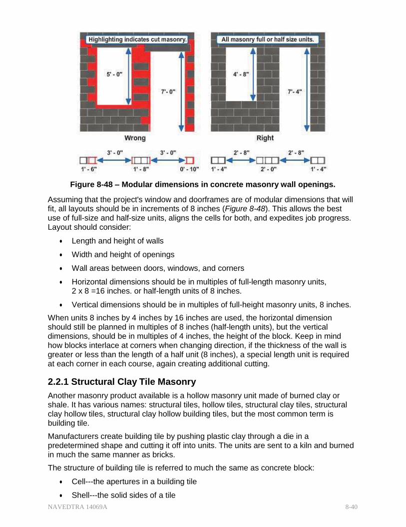
NAVEDTRA 14069A 8-40
Figure 8-48 – Modular dimensions in concrete masonry wall openings.
Assuming that the project's window and doorframes are of modular dimensions that will fit, all layouts should be in increments of 8 inches (Figure 8-48). This allows the best use of full-size and half-size units, aligns the cells for both, and expedites job progress. Layout should consider:
Length and height of walls
Width and height of openings
Wall areas between doors, windows, and corners
Horizontal dimensions should be in multiples of full-length masonry units, 2 x 8 =16 inches. or half-length units of 8 inches.
Vertical dimensions should be in multiples of full-height masonry units, 8 inches.
When units 8 inches by 4 inches by 16 inches are used, the horizontal dimension should still be planned in multiples of 8 inches (half-length units), but the vertical dimensions, should be in multiples of 4 inches, the height of the block. Keep in mind how blocks interlace at corners when changing direction, if the thickness of the wall is greater or less than the length of a half unit (8 inches), a special length unit is required at each corner in each course, again creating additional cutting.
2.2.1 Structural Clay Tile Masonry
Another masonry product available is a hollow masonry unit made of burned clay or shale. It has various names: structural tiles, hollow tiles, structural clay tiles, structural clay hollow tiles, structural clay hollow building tiles, but the most common term is building tile.
Manufacturers create building tile by pushing plastic clay through a die in a predetermined shape and cutting it off into units. The units are sent to a kiln and burned in much the same manner as bricks.
The structure of building tile is referred to much the same as concrete block:
Cell---the apertures in a building tile
Shell---the solid sides of a tile

NAVEDTRA 14069A 8-41
Web---the perforated material enclosed by the shell
A tile laid on one of its shell faces is a side-construction tile; one laid on one of its web faces is an end-construction tile. Figure 8-49 shows sizes and shapes of basic side- and end-construction building units. Special shapes are also available for use at corners, at openings, and as closures.
Figure 8-49 – Standard shapes of structural clay tile.
2.2.1 Physical Characteristics
The qualities by which to judge good structural clay tile are the same as characteristics for good concrete, compressive and tensile strengths, and durability (abrasion resistance).
The compressive strength of the individual tile depends upon the thickness of the shell and web, the materials used, and the method of manufacture. A minimum compressive strength of 300 lb per square inch may be expected.
The tensile strength of structural clay tile masonry is small. In most cases, it is less than 10 percent of the compressive strength.
The abrasion resistance of clay tile depends primarily upon its compressive strength; the stronger the tile, the greater the resistance to wear. The abrasion resistance decreases as the amount of water absorbed increases.
Structural clay facing-tile has excellent resistance to weathering. Freezing and thawing action produces almost no deterioration. Tile that absorbs no more than 16 percent of its weight of water has always given satisfactory performance in resisting the effect of freezing and thawing. Masons should only use portland cement-lime mortar or mortar prepared from masonry cement if the tile is exposed to the weather.
Walls containing structural clay tile have better heat-insulating qualities than walls composed of solid concrete masonry units because of the dead air space that exists in clay tile walls. The resistance to sound penetration compares favorably with solid masonry walls, but is somewhat less.
The fire resistance of tile walls is considerably less than the fire resistance of solid masonry walls but can improve with the application of a coat of plaster. Structural clay tile partition walls 6 inches thick will resist a fire for 1 hour provided the fire produces a temperature of not more than 1700°F.
The solid material in structural clay tile weighs about 125 pounds per cubic foot. Since
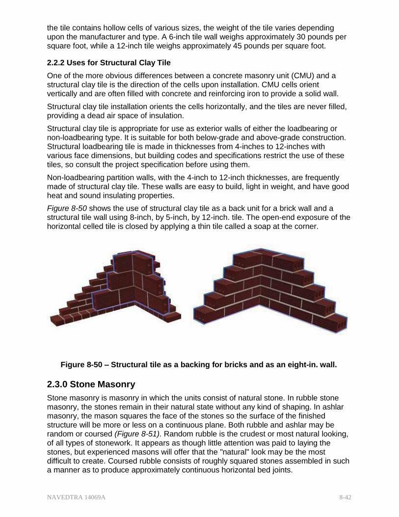
NAVEDTRA 14069A 8-42
the tile contains hollow cells of various sizes, the weight of the tile varies depending upon the manufacturer and type. A 6-inch tile wall weighs approximately 30 pounds per square foot, while a 12-inch tile weighs approximately 45 pounds per square foot.
2.2.2 Uses for Structural Clay Tile
One of the more obvious differences between a concrete masonry unit (CMU) and a structural clay tile is the direction of the cells upon installation. CMU cells orient vertically and are often filled with concrete and reinforcing iron to provide a solid wall.
Structural clay tile installation orients the cells horizontally, and the tiles are never filled, providing a dead air space of insulation.
Structural clay tile is appropriate for use as exterior walls of either the loadbearing or non-loadbearing type. It is suitable for both below-grade and above-grade construction. Structural loadbearing tile is made in thicknesses from 4-inches to 12-inches with various face dimensions, but building codes and specifications restrict the use of these tiles, so consult the project specification before using them.
Non-loadbearing partition walls, with the 4-inch to 12-inch thicknesses, are frequently made of structural clay tile. These walls are easy to build, light in weight, and have good heat and sound insulating properties.
Figure 8-50 shows the use of structural clay tile as a back unit for a brick wall and a structural tile wall using 8-inch, by 5-inch, by 12-inch. tile. The open-end exposure of the horizontal celled tile is closed by applying a thin tile called a soap at the corner.
Figure 8-50 – Structural tile as a backing for bricks and as an eight-in. wall.
2.3.0 Stone Masonry
Stone masonry is masonry in which the units consist of natural stone. In rubble stone masonry, the stones remain in their natural state without any kind of shaping. In ashlar masonry, the mason squares the face of the stones so the surface of the finished structure will be more or less on a continuous plane. Both rubble and ashlar may be random or coursed (Figure 8-51). Random rubble is the crudest or most natural looking, of all types of stonework. It appears as though little attention was paid to laying the stones, but experienced masons will offer that the "natural" look may be the most difficult to create. Coursed rubble consists of roughly squared stones assembled in such a manner as to produce approximately continuous horizontal bed joints.
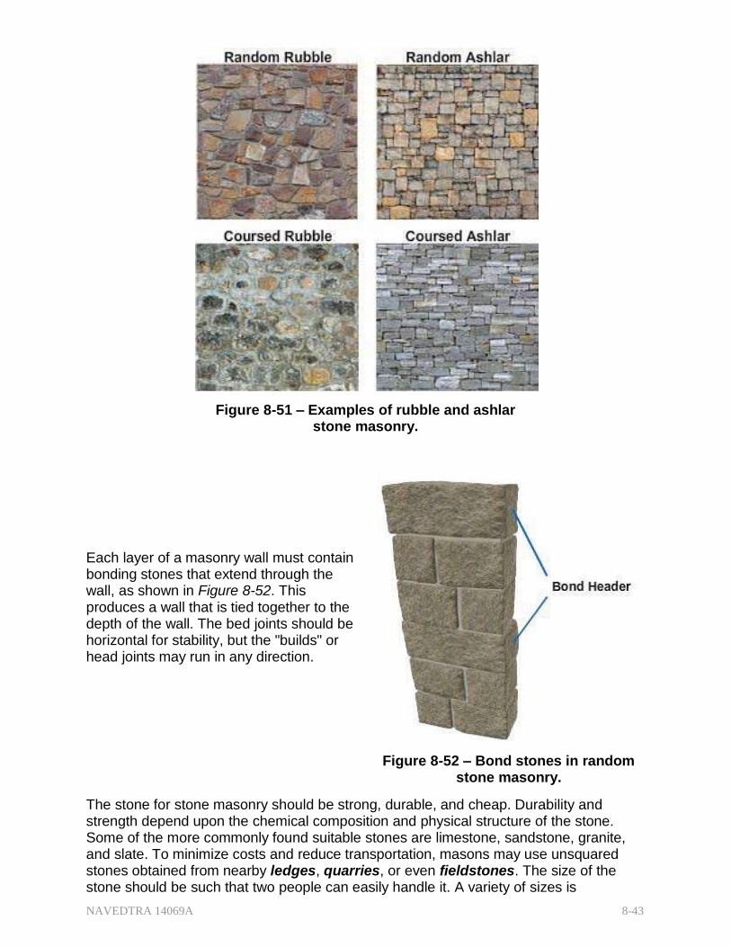
NAVEDTRA 14069A 8-43
Figure 8-51 – Examples of rubble and ashlar stone masonry.
Each layer of a masonry wall must contain bonding stones that extend through the wall, as shown in Figure 8-52. This produces a wall that is tied together to the depth of the wall. The bed joints should be horizontal for stability, but the "builds" or head joints may run in any direction.
Figure 8-52 – Bond stones in random stone masonry.
The stone for stone masonry should be strong, durable, and cheap. Durability and strength depend upon the chemical composition and physical structure of the stone. Some of the more commonly found suitable stones are limestone, sandstone, granite, and slate. To minimize costs and reduce transportation, masons may use unsquared stones obtained from nearby ledges, quarries, or even fieldstones. The size of the stone should be such that two people can easily handle it. A variety of sizes is

NAVEDTRA 14069A 8-44
necessary to avoid using large quantities of mortar.
Stone masonry mortar may consist of portland cement and sand in proportions of one part cement to three parts sand by volume. However, such mortar shrinks excessively and does not trowel well. A better mortar for this application is a portland cement-lime mortar mix. Lime does not usually stain the stone. Also, ordinary portland cement mortar will stain most types of stone. If staining is an issue, masons should use non- staining white portland cement for the mortar mix.
2.4.0 Brick Masonry
In brick masonry, masons lay units of baked clay or shale of uniform size in courses with mortar joints to form walls of virtually unlimited length and height. The units may form the wall itself or be the facade to an existing structural wall. These units are small enough for placing with one hand. The chemical and physical characteristics of the ingredients vary considerably. In some regions, excavators open pits that yield raw material that, when ground and moistened, forms and bakes into durable brick. In other regions, manufacturers must mix clays or shales from several pits to produce bricks. Those varying ingredients, along with kiln temperatures, combine to produce brick in a variety of colors and harnesses.
The nominal dimensions of a U.S. standard building brick are 2 1/4 by 3 3/4 by 8. The actual dimensions may vary a little because of shrinkage during burning.
2.4.1 Brick Nomenclature
Frequently, the mason must cut the brick into various shapes. The most common shapes are shown in Figure 8-53. They are: half or bat, three-quarter closure, quarter closure, king closure, queen closure, and split. They are used to fill in spaces at corners and other places where a full brick will not fit. The six surfaces of a brick are: cull, end, beds, side, and face.
Figure 8-53 – Nomenclature of cut brick and brick surfaces.
2.4.2 Brick Classification
There are three general classifications of brick: common, face, and backup.
Unless the brick is a facade against a structural wall, a finished brick structure contains face brick (placed on the exposed face of the structure) and backup brick (placed behind the face brick). The face brick is usually of higher quality than the backup brick. However, the mason may use common brick to build the entire wall. Common brick is

NAVEDTRA 14069A 8-45
made from pit-run clay, that is, with no attempt at color control and no special surface treatment like glazing or enameling. Most common brick is red.
Although any surface brick is a face brick by virtue of its placement, the term face brick also distinguishes high-quality brick from brick that is of common-brick quality or less. Applying this criterion, the color of face brick is uniformly more even than that of common brick, and locally may be obtainable in a variety of colors as well.
Face brick surface finish has a better appearance than common brick. It may also be more durable, due to the use of select clays and other materials, or from special manufacturing methods.
Backup brick may consist of brick that is inferior in quality even to common brick. Brick that was underburned, overburned, made with inferior clay, or made by inferior methods is often incorporated into the structure as backup brick and may be used as a cost saving measure.
Still another type of classification divides brick into grades according to its probable exposure to climatic conditions.
These are as follows:
GRADE SW---brick designed to withstand exposure to below-freezing temperatures in a moist climate like that of the northern regions of the United States.
GRADE MW---brick designed to withstand exposure to below-freezing temperatures in a drier climate than Grade SW.
GRADE NW---brick primarily intended for interior or backup brick; may be used exposed in a region where no frost action occurs or in a region where frost action occurs but the annual rainfall is less than 15 in.
2.4.3 Types of Bricks
There are many types of brick. Some are different in formation and composition while others vary according to their use.
Some commonly used types of brick are:
COMMON brick---made of ordinary clays or shales
o burned in the usual manner in the kilns
o no special scorings or markings
o no special color or surface texture
o known as hard- and kiln-run brick
o generally used for backing courses in solid or cavity brick walls
FACE brick---used in the exposed face of a wall
o higher quality units than backup brick
o better durability and appearance
o most common colors are various shades of brown, red, gray, yellow, and white

NAVEDTRA 14069A 8-46
CLINKER brick---have been overburned in the kilns
o usually hard and durable
o may be irregular in shape
o describable as rough-hard
PRESS brick---made by the dry press process
o regular smooth faces, sharp edges, and perfectly square corners
o usually used as face brick
GLAZED brick---one surface of each brick glazed in white or other color
o ceramic glazing consists of mineral ingredients that fuse together in a glass- like coating during burning
o particularly suited for walls or partitions in hospitals, dairies, laboratories, or other buildings where cleanliness and ease of cleaning are necessary
FIREBRICK---special type of fire clay
o will withstand the high temperatures of fireplaces, boilers, and similar usages without cracking or decomposing
o larger than regular structural brick and often hand molded
CORED brick---holes extending through the beds to reduce weight
o no significant difference between the strength of cored brick walls compared to solid brick walls
o resistance to moisture penetration about the same for both types of walls
o most easily available brick meeting requirements, cored or solid, can be used
SAND-LIME brick---made from a lean mixture of slaked lime and fine siliceous sand
o under steam pressure molded under mechanical pressure
o hardened
2.4.4 Masonry Terms
Specific terms identify various positions of masonry units, bricks, or groups of bricks and mortar joints in a wall. (Figure 8-54)
These are as follows:
Course---continuous horizontal layer (or row) of masonry that, bonded together, form the masonry structure
Stretcher---masonry unit laid flat with its longest dimension parallel to the face of the wall
Header---masonry unit laid flat with its longest dimension perpendicular to the face of the wall; generally used to tie two wythes of masonry together
Wythe---continuous single vertical wall of brick
Rowlock---brick laid on its edge (face).
Bull-Stretcher---rowlock brick laid with its longest dimension parallel to the face of

NAVEDTRA 14069A 8-47
the wall
Bull-Header---rowlock brick laid with its longest dimension perpendicular to the face of the wall
Soldier---brick laid on its end with its longest dimension parallel to the vertical axis face of the wall
Figure 8-54 – Terms for positions of bricks.
2.4.5 Types of Bonds
In masonry, the word bond has three different references and one (pattern) can have a large number of additional meanings.
STRUCTURAL BOND---a method of interlocking or tying individual masonry units together in one of three ways so that the entire assembly acts as a single structural unit
o overlapping (interlocking) the masonry units
o metal ties embedded in connecting joints
o adhesion of grout to adjacent wythes of masonry
MORTAR BOND---the adhesion of the joint mortar to the masonry units or to the reinforcing steel
PATTERN BOND---pattern formed by the masonry units and the mortar joints on the face of a wall; may result from the type of structural bond or be purely decorative
The following five pattern bonds are the most commonly used today, but there are many combinations and variations available. (Figure 8-55)
RUNNING BOND---the simplest of the basic pattern bonds
o consists of all stretchers, no headers; uses metal ties
o used largely in cavity and veneered walls
o also used as facing for tile wall

NAVEDTRA 14069A 8-48
COMMON or AMERICAN BOND---a variation of running bond with a course of full length headers at regular intervals
o headers provide structural bonding as well as pattern
o header courses usually appear every fifth, sixth, or seventh course, depending on the structural bonding requirements
o a three-quarter brick must start each header course at the corner
o may be varied by using a Flemish header course
STACK BOND---purely a pattern bond
o no overlapping of units, all vertical joints aligned
o usually bonded to backing with rigid steel ties, may use 8-in. thick stretchers
o needs steel pencil rod reinforcement in horizontal mortar joints for large area and loadbearing walls
o requires dimensionally accurate or carefully matched units for alignment
o pattern variety possible with numerous combinations
FLEMISH BOND---made of alternate stretchers and headers with headers in alternate courses centered over stretchers in intervening courses
o if headers not used for structural bond, half-bricks (blind-headers) used
o a three-quarter brick starts each header course at the corner for a Flemish Corner
o a one-quarter brick starts each header course at the corner for an English Corner
ENGLISH BOND---alternate courses of headers and stretchers
o headers are centered on the stretchers and joints between stretchers
o vertical (head) joints between stretchers in all courses line up vertically
o blind headers used in courses that are not structural bonding
o headers alternate between RUNNING BOND courses
ENGLISH CROSS BOND is a variation---headers alternate between STACK BOND courses
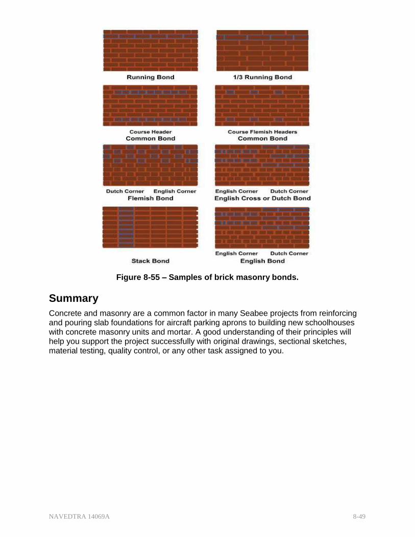
NAVEDTRA 14069A 8-49
Figure 8-55 – Samples of brick masonry bonds.
Summary
Concrete and masonry are a common factor in many Seabee projects from reinforcing and pouring slab foundations for aircraft parking aprons to building new schoolhouses with concrete masonry units and mortar. A good understanding of their principles will help you support the project successfully with original drawings, sectional sketches, material testing, quality control, or any other task assigned to you.

NAVEDTRA 14069A 8-50
Review Questions (Select the Correct Response) 1. What are the ingredients for mixing concrete?
A. Water and cement only B. Water, cement, and fine aggregates only C. Water, cement, and coarse aggregates only D. Water, cement, fine aggregates, and course aggregates
2. What chemical reaction occurs to harden concrete?
A. Dehydration B. Hydration C. Oxidation D. Deoxidation
3. Which two ingredients react to harden concrete?
A. Cement and fine aggregates B. Cement and course aggregates C. Cement and water D. Course aggregates and fine aggregates
4. Concrete is high in strength but relatively weak in _strength.
A. tensile, compressive B. compressive, tensile C. shear, tensile D. tensile, shear
5. is concrete's resistance to deterioration caused by exposure to
service conditions.
A. Strength B. Compressibility C. Flexibility D. Durability
6. During a concrete pour, settle(s) leaving voids filled by _.
A. solid particles, cement B. cement, water C. solid particles, water D. cement, solid particles

NAVEDTRA 14069A 8-51
7. Which of the following actions should you take to ensure concrete is as watertight as possible?
A. Add more water. B. Add less water. C. Use only the amount of water required to attain the necessary workability. D. Add more sand to fill any voids.
8. Which of the following materials can be placed in concrete to reinforce it?
A. Steel bars B. Steel rods C. Steel strands, wire, and welded wire fabric D. All of the above
9. What reinforced concrete structural member supports and distributes building
loads to the ground?
A. Plain slab B. Footing C. Beam D. Column
10. reinforcement is (are) the principle reinforcement(s) in a column.
A. Lateral ties B. Vertical C. Spiral D. Caisson
11. Engineers may design both straight and bars to resist the bending tension
in the bottom of a beam.
A. spiral B. truss C. lateral D. caisson
12. Steel is the best material for reinforcing concrete because their coefficients of
are almost the same.
A. compression B. tension C. shear D. expansion

NAVEDTRA 14069A 8-52
13. The bond strength of steel-concrete is in direct proportion to the amount of .
A. cement B. contact C. fine aggregate D. water
14 Reinforcing bars increase in diameter from one size to the next by
increments.
A. 1/16 inch B. 1/8 inch C. 1/4 inch D. 3/8 inch
15. What might occur if a reinforcing bar is bent too sharply?
A. The bar could crack or be weakened. B. The bar will not adhere to the concrete. C. Concrete strength would be reduced. D. Hydration would not occur.
16. What is the minimum length of a lap splice for (a) No. 3 bars and (b) No. 6 bars
when not dimensioned on the drawings?
A. (a) 11.25 in (b) 22.50 in B. (a) 12.00 in (b) 22.50 in C. (a) 22.50 in (b) 12.00 in D. (a) 22.50 in (b) 11.25 in
17. A concrete structural member fabricated at a location other than its final position
of use is known as ?
A. preconstructed B. cast-in-place C. prefabricated D. precast
18. A concrete structural member cast in its final position of use is known as .
A. preconstructed B. cast-in-place C. prefabricated D. precast

NAVEDTRA 14069A 8-53
19. Small, closely spaced beams used in (a) floor and (b) roof construction are known as and _.
A. (a) joists (b) purlins B. (a) joists (b) joists C. (a) purlins (b) purlins D. (a) purlins (b) joists
20. What primary difference, if any, exists between precast beams and girders?
A. Beams are wider than girders B. Beams are used for different purposes than girders C. Beams are made of different material than girders D. Beams are shorter than girders
21. If not rectangular or T shaped, what cross-sectional shape will the ends of most
precast beams have?
A. W B. D C.I D. C
22. Which of the following is considered the most important advantage to precasting?
A. Less required storage space B. Faster erection time C. Reusable forms D. Quality-controlled concrete
23. Which of the following descriptions most accurately describes pre-tensioning of
concrete members?
A. After the concrete has been placed and has reached a specified strength, reinforcement strands are pulled through formed channels, and a predetermined amount of stress is applied.
B. Reinforcement strands are pulled through tubes and stressed after placement of the concrete.
C. Reinforcement strands are stressed to a predetermined point before placement of the concrete and are released just before the concrete has set.
D. Reinforcement strands are placed in the forms and are stressed to a predetermined point before the concrete is placed; the strands are then released after the concrete has reached a specified strength.

NAVEDTRA 14069A 8-54
24. In what part of a prestressed beam does the tensioned steel produce high compression?
A. Upper B. Lower C. Exact center D. Approximate center
25. What condition occurs when a load (force) is placed on a prestressed beam?
A. The camber is forced out, leaving a beam with positive deflection. B. The upward bow is increased. C. The camber is forced out, leaving a level beam with no deflection. D. The upward bow is forced out, creating deflection in the beam.
26. Conventional concrete's approximate weight is _.
A. 175 lb/cu ft B. 150 lb/cu ft C. 130 lb/cu ft D. 115 lb/cu ft
For questions 8-27 to 8-30, select the type of concrete from the following list that best matches the characteristic given.
1. HEAVYWEIGHT CONCRETE 2. SEMI-LIGHTWEIGHT CONCRETE 3. INSULATING LIGHTWEIGHT CONCRETE 4. STRUCTURAL LIGHTWEIGHT CONCRETE
27. Weighs 115 to 130 lb/cu ft and has a compressive strength comparable to
conventional concrete.
A. 1
B. 2
C. 3
D. 4
28. Weighs 20 to 70 lb/cu ft and is used for fireproofing.
A. 1
B. 2
C. 3
D. 4
29. Weighs up to 400 lb/cu ft and is used for radiation shielding.
A. 1
B. 2
C. 3
D. 4
NAVEDTRA 14069A 8-55
30. Weighs up to 115 lb/cu ft and is used to decrease the dead-load weight of structural members.
A. 1
B. 2
C. 3
D. 4
31. In tilt-up panel construction, where are the wall panels usually cast?
A. On the ground B. Precast off site C. Cast-in-place D. On the ground floor slab
32. In tilt-up panel construction, where is additional reinforcement generally needed?
A. Around any openings B. At the bottom C. Around the edges D. At the top
33. In a tilt-up panel construction, in what manner are pickup inserts installed?
A. Independently of the reinforcement B. Tied to reinforcement C. Welded to reinforcement D. Tied to the panel forms
34. What is the strongest method of connecting tilt-up panels together?
A. A butted connection using grout or gasket B. A cast-in-place column with the panel-reinforcing steel tied into the pilaster C. Steel columns welded to steel angles or plates secured in the panel D. Precast columns tied with the panel
35. Construction joints must be located where .
A. the builder finds it most convenient B. it causes the minimum amount of weakness C. the beam meets the column D. the slab meets the wall

NAVEDTRA 14069A 8-56
36. What is the purpose of contraction joints?
A. To prevent buckling due to expansion of the reinforcing steel caused by temperature changes
B. To prevent buckling due to expansion of the concrete caused by temperature changes
C. To prevent cracking due to shrinkage of the reinforcing steel caused by temperature changes
D. To prevent cracking due to shrinkage of the concrete caused by temperature changes
37. Expansion joints are also known as joints.
A. Construction B. Shrinkage C. Contraction D. Isolation
38. is placing plastic concrete into spaces enclosed by forms.
A. Casting B. Reeling C. Molding D. Premolding
39. (True or False) Builders must always use forms for molding the sides of footings
and only pour against the soil for the bottom of the footings.
A. True B. False
40. What part of a wall form shapes and retains the concrete until it sets?
A. Brace B. Wale C. Stud D. Sheathing
41. What do builders often use on simple walls to maintain wall depth dimensions
during a pour?
A. Sheathing and stakes B. Wales and battens C. Ties and wood spreaders D. Cleats and yokes

NAVEDTRA 14069A 8-57
42. Which of the following devices combines the functions of wire ties and wooden spreaders?
A. Tie holder B. Snap tie C. Tie spreader D. Bar tie
43. are the column form members that brace against bursting pressure.
A. Yokes B. Battens C. Walers D. Studs
44. Where is the bursting pressure greatest in pouring column forms?
A. Middle B. Top C. Bottom D. Beam side
45. Typically, girder and beam form need to remain in place longer for
additional curing.
A. sides B. soffits C. cleats D. chamfers
46. What is the most commonly used unit in concrete masonry?
A. Concrete block B. Clay tile C. Stone D. Brick
47. Which of the following measures a concrete block's ability to carry loads and
withstand structural stresses?
A. Absorption B. Moisture content C. Density D. Compressive strength
48. What is the actual size, in inches, of an 8- by 8- by 16-inch CMU?
A. 7 l/2 by 7 1/2 by 15 1/2 B. 7 5/8 by 7 5/8 by 15 5/8 C. 8 by 8 by 16 D. 8 1/4 by 8 1/4 by 16 1/4

NAVEDTRA 14069A 8-58
49. A concrete masonry unit's face shell is the .
A. partitions between the cores B. hole between the webs C. long side of the block unit D. recessed end of the block
50. Modular planning minimizes cutting and fitting by using _.
A. full-size units only B. half-size units only C. full-size and quarter-size units D. full-size and half-size units
51. In addition to the thickness of the shell and webs, the compressive strength of
structural clay tile depends upon the .
A. materials used and method of manufacture B. the opening and cell size C. its resistance to abrasion D. its resistance to deterioration
52. When structural clay building tiles are used in construction that will be exposed to
the weather, masons should prepare mortar from which of the following materials?
A. Portland cement-lime or waterproofed cement B. Portland cement-lime or masonry cement C. Masonry cement or waterproofed cement D. Masonry cement or straight lime
53. Walls containing structural clay tile have better qualities than solid concrete masonry units.
A. soundproofing B. weather resistant C. abrasion D. heat insulating
54. Which of the following factors restricts the use of structural clay tile?
A. Above or below grade level B. Weight and sizes of the tiles C. Availability of the material D. Building codes and specifications

NAVEDTRA 14069A 8-59
55. Which of the following stone masonry descriptions best describes the term "rubble"?
A. The faces of stone are square and placed in position so the finished
surfaces will present a continuous plane surface appearance. B. The stones used are left in their natural state without any kind of shaping. C. The stones are laid in courses without consideration of size or weight. D. The stones are roughly squared and laid in such a manner to produce
approximately continuous horizontal bed joints. 56. Which of the following is considered to be the crudest of stone masonry?
A. Coursed ashlar B. Coursed rubble C. Random ashlar D. Random rubble
57. Stone for stone masonry should be strong, durable and .
A. absorbent B. cheap C. resistant D. weathered
58. What are the nominal dimensions in inches of a standard U.S building brick?
A. 1 1/4 by 3 3/4 by 8 B. 1 1/2 by 3 3/4 by 8 C. 1 3/4 by 3 3/4 by 8 D. 2 1/4 by 3 3/4 by 8
59. Common brick is best described as _.
A. unglazed, uniform in color, and made from select clay B. unglazed, variable in color, and made from inferior clay C. unglazed, variable in color, and made from pit-run clay D. glazed, uniform in color, and made from select clay
60. brick is the classification designed to withstand exposure to below-
freezing temperatures in a moist climate.
A. SW B. MW C. NW D. MC

NAVEDTRA 14069A 8-60
61. Which of the following types of brick is commonly used as the backing course for a cavity wall?
A. Face B. Common C. Glazed D. Fire
62. What type of brick is made of special clay and is designed to withstand high
temperatures?
A. Press B. Clinker C. Glazed D. Fire
63. A is a continuous single vertical wall of brick.
A. rowlock B. stretcher C. soldier D. wythe
64. Which of the following statements best describes the term rowlock
A. A brick laid flat with its longest dimension perpendicular to the wall. B. A brick laid on its edge (face). C. A brick laid with its longest dimension parallel to the face of the wall. D. A brick laid on its end with its longest dimension parallel to the vertical axis
face of the wall. 65. Structural bonding of brick walls causes the entire assembly to act as a single
unit. Which of the following methods accomplishes this bond?
A. Adhesion of grout to adjacent wythes of masonry B. Embedding metal ties in connecting joints C. Interlocking of the masonry units D. All of the above
66. What is the name of the simplest pattern bond made up entirely of stretchers?
A. Running B. American C. Flemish D. Common

NAVEDTRA 14069A 8-61
67 Which of the following pattern bonds begins with a three-quarter brick at the corner of each header course?
A. Stack B. Flemish C. Block D. Common
68. An English bond pattern wall is composed of alternate courses of .
A. Three-quarter and blind headers B. Stretchers and bull-headers C. Headers and stretchers D. Headers and rigid steel ties

NAVEDTRA 14069A 8-62
Trade Terms Introduced In this Chapter Bending moment A moment of force (often just moment); a synonym for
torque, an important basic concept in physics, civil engineering, and mechanical engineering.
Compressive strength Resistance of a material to fracture under compression.
Dowel A solid cylindrical rod, usually made of wood, plastic or
metal. Dry packing Placing of zero slump, or near zero slump, concrete,
mortar, or grout by ramming into a confined space. Facade Any side of a building facing a public way or space and
finished accordingly. Fieldstone A stone occurring naturally in fields, often used as a
building material. Hydration A chemical reaction in which water takes part with the
formation of a single product. Lap splice When two pieces of rebar are overlapped to create a
continuous line of rebar. The length of the lap varies depend on concrete strength, the rebar grade, size, and spacing.
Ledges A level of rock-bearing ore; a vein.
Monolithically Constituting or acting as a single, often rigid, uniform
whole; in this usage, pouring concrete for slab and beam units at the same time.
Pattern bond Pattern formed by the masonry units and the mortar joints
on the face of a wall. The pattern may result from the type of structural bond used or may be purely a decorative one unrelated to the structural bonding.
Perlite A formless volcanic glass that has a relatively high water
content; occurs naturally and has the property of greatly expanding when heated sufficiently; useful for its light weight after processing.
Quarries An excavation or pit, usually open to the air, from which
building stone, slate, or the like, is obtained by cutting, blasting.
Siliceous Containing, consisting of, or resembling silica, the major
ingredient in sand; used to manufacture a variety of materials, especially glass and concrete.

NAVEDTRA 14069A 8-63
Slaked lime A soft, white, crystalline, very slightly water-soluble powder: used chiefly in mortars, plasters, and cements.
Soffit The underside of a structural component, such as a
beam, arch, staircase, or cornice. Load Any type of force exerted on an object, which may be in
the form of a 'weight' (gravitational force), a pressure, or anything which affects the object in question; includes dead load (weights of material, equipment, or components that are relatively constant throughout the structure's life) and live load (all the forces that are variable within the object's normal operation cycle).
Tensile strength Resistance of a material to a force tending to tear it apart.
Trowel Any of various tools having a flat blade with a handle,
used for depositing and working mortar, plaster, etc. Vermiculite A natural mineral that expands with the application of
heat. Wythe A continuous single vertical wall of brick.
NAVEDTRA 14069A 8-64
Additional Resources and References
This chapter is intended to present thorough resources for task training. The following reference works are suggested for further study. This is optional material for continued education rather than for task training.
U.S. Department of Defense, Engineering Drawing Practices, DoD-STD-100C, U.S. Army Armament Research and Development Command, Dover, N.J 1978 Ramsey and Sleeper, Architectural Graphic Standards, 7th ed., J. Wiley & Sons, Inc., New York, 1981.
Portland Cement Association: http://www.cement.org
American Society for Testing and Materials - http://www.astm.org/Standards/C90.htm

NAVEDTRA 14069A 8-65
CSFE Nonresident Training Course – User Update
CSFE makes every effort to keep their manuals up-to-date and free of technical errors. We appreciate your help in this process. If you have an idea for improving this manual, or if you find an error, a typographical mistake, or an inaccuracy in CSFE manuals, please write or email us, using this form or a photocopy. Be sure to include the exact chapter number, topic, detailed description, and correction, if applicable. Your input will be brought to the attention of the Technical Review Committee. Thank you for your assistance.
Write: CSFE N7A 3502 Goodspeed St. Port Hueneme, CA 93130
FAX: 805/982-5508
E- mail: [email protected]
Rate_ Course Name
Revision Date Chapter Number Page Number(s)
Description
(Optional) Correction
(Optional) Your Name and Address

NAVEDTRA 14069A 9-1
Chapter 9
Mechanical Systems and Plans
Topics
1.0.0 Mechanical Systems (Plumbing)
2.0.0 Mechanical Plans
To hear audio, click on the box.
Overview
Engineering Aids are often called upon to develop drawings for projects. To be able to perform that task successfully, you need to be familiar with the various systems a structure may incorporate to meet the use for which the structure is designed.
Each trade discipline has its own unique requirements, constraints, routings, materials, and methods. Each trade discipline also has its own unique symbols for communicating the information to drawings for common understanding by all involved in a project.
Your accurate drawings could support a project at a number of stages: planning, cost analysis, installation, quality control, or final inspection.
This chapter will acquaint you with the water distribution and drainage aspects of mechanical systems, otherwise known as plumbing.
Objectives
When you have completed this chapter, you will be able to do the following:
1. Describe the different types of mechanical plumbing systems.
2. Interpret different types of mechanical plans.
Prerequisites
None
This course map shows all of the modules in Engineering Aid Basic. The suggested training order begins at the bottom and proceeds up. Skill levels increase as you advance on the course map.

NAVEDTRA 14069A 9-2
Topographic Surveying and Mapping
E
Indirect Leveling/Level and Traverse Computations N
G Care and Adjustment of Survey Equipment
I
Materials Testing: Soil and Concrete N
Direct Leveling and Basic Engineering Surveys E
Horizontal Control E
Direct Linear Measurements and Field Survey Safety R
I Surveying: Elements and Equipment
N Construction Drawings
G
Electrical: Systems and Plans
Mechanical: Systems and Plans AID
Concrete and Masonry
B
Wood and Light Frame Structures A
Drafting: Projections and Sketching S
Drafting: Geometric Construction I
Drafting: Fundamentals and techniques C
Drafting: Equipment
Mathematics and Units of Measurement
Engineering Aid Rating
Features of this Manual
This manual has several features which make it easy to use online.
Figure and table numbers in the text are italicized. The figure or table is either next to or below the text that refers to it.
The first time a glossary term appears in the text, it is bold and italicized. When your cursor crosses over that word or phrase, a popup box displays with the appropriate definition.
Audio and video clips are included in the text, with italicized instructions telling you where to click to activate it.
Review questions that apply to a section are listed under the Test Your Knowledge banner at the end of the section. Select the answer you choose. If the answer is correct, you will be taken to the next section heading. If the answer is incorrect, you will be taken to the area in the chapter where the information is for

NAVEDTRA 14069A 9-3
review. When you have completed your review, select anywhere in that area to return to the review question. Try to answer the question again.
Review questions are included at the end of this chapter. Select the answer you choose. If the answer is correct, you will be taken to the next question. If the answer is incorrect, you will be taken to the area in the chapter where the information is for review. When you have completed your review, select anywhere in that area to return to the review question. Try to answer the question again.
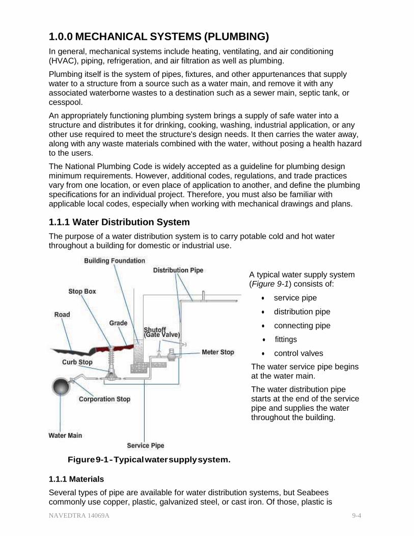
NAVEDTRA 14069A 9-4
1.0.0 MECHANICAL SYSTEMS (PLUMBING)
In general, mechanical systems include heating, ventilating, and air conditioning (HVAC), piping, refrigeration, and air filtration as well as plumbing.
Plumbing itself is the system of pipes, fixtures, and other appurtenances that supply water to a structure from a source such as a water main, and remove it with any associated waterborne wastes to a destination such as a sewer main, septic tank, or cesspool.
An appropriately functioning plumbing system brings a supply of safe water into a structure and distributes it for drinking, cooking, washing, industrial application, or any other use required to meet the structure's design needs. It then carries the water away, along with any waste materials combined with the water, without posing a health hazard to the users.
The National Plumbing Code is widely accepted as a guideline for plumbing design minimum requirements. However, additional codes, regulations, and trade practices vary from one location, or even place of application to another, and define the plumbing specifications for an individual project. Therefore, you must also be familiar with applicable local codes, especially when working with mechanical drawings and plans.
1.1.1 Water Distribution System
The purpose of a water distribution system is to carry potable cold and hot water throughout a building for domestic or industrial use.
A typical water supply system (Figure 9-1) consists of:
service pipe
distribution pipe
connecting pipe
fittings
control valves
The water service pipe begins at the water main.
The water distribution pipe starts at the end of the service pipe and supplies the water throughout the building.
Figure 9-1 - Typical water supply system.
1.1.1 Materials
Several types of pipe are available for water distribution systems, but Seabees commonly use copper, plastic, galvanized steel, or cast iron. Of those, plastic is

NAVEDTRA 14069A 9-5
becoming the most common for both civilian and military use due to the lower cost of materials and ease of installation with its associated lower labor costs.
1.1.1.1 1.1 Copper Pipe and Tubing
Traditionally, copper has been one of the most widely used materials for tubing. It does not rust and is highly resistant to accumulation of scale particles in the pipe.
Copper pipe is manufactured in six grades and thicknesses, three of which are appropriate for water distribution systems from water main to tap; types K, L, and M.
Type K - thickest wall pipe; used primarily underground between water mains and the water meter
o Rigid (hard temper): 12- and 20-ft straight lengths
o Flexible (soft temper): 40-, 60-, 100-ft coils, the latter in smaller diameters
Type L - thinner wall pipe, used outside for water services from water meter, but also widely used in water distribution systems: soft temper tubing is often used as replacement plumbing due to the tube's flexibility allowing easier installation.
o Rigid: 12- and 20-ft straight lengths
o Flexible: 40-, 60-, 100-ft coils, the latter in smaller diameters
Type M - thin wall pipe used mainly inside homes for branch supplies where water pressure is low: some city codes may not allow type M
o Rigid only: 12- and 20- ft lengths
Type DWV - drainage, waste and vent
o Rigid only: 20-ft. lengths
Type ACR - air conditioning, refrigeration, natural and petroleum gas
o Rigid: 20-ft. lengths
o Flexible: 50-ft. coils
Type OXY, MED, OXY/MED, OXY/ACR, ACR/MED - Medical Gas, Compressed Medical Air, Vacuum
o Rigid only: 20-ft. lengths
Figure 9-2 shows some typical fittings for copper tubing. The connections between the fittings are made with solder. Soldering allows all the tubing and fittings to be measured, cut, and set in place before the joints are finished. Generally, this allows faster assembly and completion.

NAVEDTRA 14069A 9-6
Figure 9-2 - Typical copper fittings.
Copper is durable and connects well to valves. However, copper should not be installed if the water has a low-pH (high acidic) level, common to many private well systems. (Figure 9-3)
Figure 9-3 - pH scale.

NAVEDTRA 14069A 9-7
Per Washington State University Department of Ecology:
“The pH scale measures acidic and alkaline materials in water. On this scale, 7.0 is the neural point, indicating a perfect balance between the two. Acidic pH values are below 7.0, and alkaline pH values are above 7.0.
In areas where groundwater trickles through limestone, carbonic acid and limestone form soluble bicarbonates, neutralizing the acid. The result is alkaline water that is usually hard, has low carbon dioxide concentrations, and pH values between 7 and 8.
Where underground strata do not contain limestone, groundwater retains acidity, has pH values between 6 to 7, (sic) and corrodes metals used in plumbing.”
To quote the Environmental Protection Agency: “There are two types of copper corrosion: uniform and nonuniform. Both types are caused by certain characteristics of water chemistry…”
Uniform corrosion is identified by the presence of a relatively uniform deposition of copper corrosion by-products across the inner surface of a pipe wall and is typically associated with elevated copper levels at our taps.
Nonuniform corrosion, or pitting, is the isolated development of corrosion cells across the inner surface of a pipe wall. Although pitting (Figure 9-4) corrosion is seldom associated with elevated levels of copper at our taps, excessive pitting corrosion can lead to “pinhole” leaks in the pipe, which could result in water damage and mold growth.
Water below PH 6.5 is considered acidic and may begin to pit the copper and create pinhole leaks. The majority of public utilities supply water at a PH between 7.2 and 8.0.
Figure 9-4 - Example of copper pitting.
1.1.1.2 Plastic Pipe
Plastic pipe is rapidly replacing copper as the material of choice in both civilian and military applications. (Figure 9-5)
It has a number of advantages over both copper and steel piping:
lighter
flexible
available in different lengths and sizes
no special tools required
superior resistance to rupture from freezing
complete resistance to corrosion
can be installed above- or belowground
Polyvinyl chloride (PVC) is one of the most versatile plastic and polyvinyl resin pipes. Made of tough, strong, thermoplastic material, PVC has an excellent combination of physical strength and chemical resistance properties.

NAVEDTRA 14069A 9-8
Chlorinated polyvinyl chloride (CPVC) is a stiffer design for greater resistance to impact and to temperature extremes. You can use CPVC for cold-water systems and hot-water systems with temperatures up to 210°F.
The principal mechanical difference between CPVC and PVC is that CPVC is significantly more malleable, allowing greater flexibility and crush resistance. CPVC also requires a special solvent cement application.
For water supply, distribution, and sewer drainage systems, plastic pipe is becoming increasingly popular for its economy, ease of installation, and lack of maintenance requirements.
Figure 9-5 - Typical plastic pipe fittings.
1.1.1.3 Galvanized Pipe
Still used but less often, galvanized (coated with zinc) pipe (Figure 9-6) can provide the water service and distribution inside a building for hot and cold fixtures. Manufactured in 21-ft lengths, it is galvanized both inside and outside at the factory to resist corrosion. However, galvanized pipes still have a tendency over time to build up enough scale inside the pipe to reduce water flow in gallons per minute. Galvanized pipe sizes are based on nominal inside diameters, which vary with the thickness of the pipe. Galvanized pipes require threaded connections so outside diameters remain constant for standard fittings.
Figure 9-6 - Standard galvanized pipe fittings.
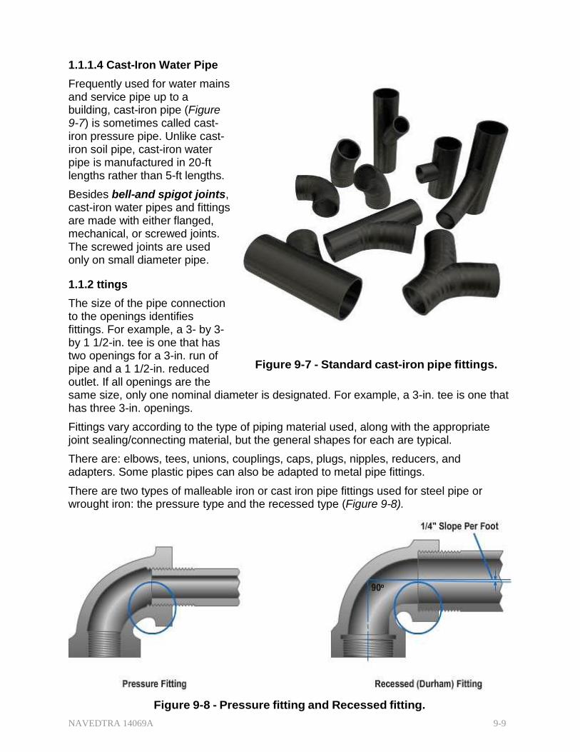
NAVEDTRA 14069A 9-9
1.1.1.4 Cast-Iron Water Pipe
Frequently used for water mains and service pipe up to a building, cast-iron pipe (Figure 9-7) is sometimes called cast- iron pressure pipe. Unlike cast- iron soil pipe, cast-iron water pipe is manufactured in 20-ft lengths rather than 5-ft lengths.
Besides bell-and spigot joints, cast-iron water pipes and fittings are made with either flanged, mechanical, or screwed joints. The screwed joints are used only on small diameter pipe.
1.1.2 ttings
The size of the pipe connection to the openings identifies fittings. For example, a 3- by 3- by 1 1/2-in. tee is one that has two openings for a 3-in. run of pipe and a 1 1/2-in. reduced outlet. If all openings are the
Figure 9-7 - Standard cast-iron pipe fittings.
same size, only one nominal diameter is designated. For example, a 3-in. tee is one that has three 3-in. openings.
Fittings vary according to the type of piping material used, along with the appropriate joint sealing/connecting material, but the general shapes for each are typical.
There are: elbows, tees, unions, couplings, caps, plugs, nipples, reducers, and adapters. Some plastic pipes can also be adapted to metal pipe fittings.
There are two types of malleable iron or cast iron pipe fittings used for steel pipe or wrought iron: the pressure type and the recessed type (Figure 9-8).
Figure 9-8 - Pressure fitting and Recessed fitting.
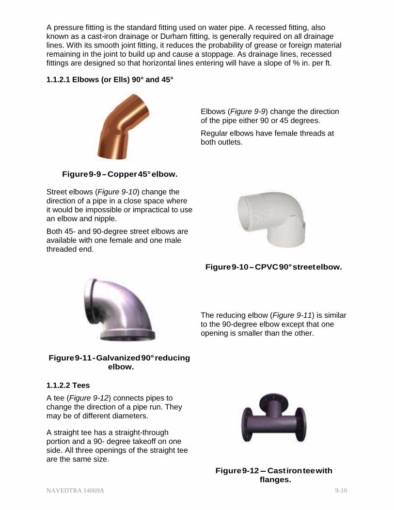
NAVEDTRA 14069A 9-10
A pressure fitting is the standard fitting used on water pipe. A recessed fitting, also known as a cast-iron drainage or Durham fitting, is generally required on all drainage lines. With its smooth joint fitting, it reduces the probability of grease or foreign material remaining in the joint to build up and cause a stoppage. As drainage lines, recessed fittings are designed so that horizontal lines entering will have a slope of % in. per ft.
1.1.2.1 Elbows (or Ells) 90° and 45°
Elbows (Figure 9-9) change the direction of the pipe either 90 or 45 degrees.
Regular elbows have female threads at both outlets.
Figure 9-9 - Copper 45° elbow. Street elbows (Figure 9-10) change the direction of a pipe in a close space where it would be impossible or impractical to use an elbow and nipple.
Both 45- and 90-degree street elbows are available with one female and one male threaded end.
Figure 9-10 - CPVC 90° street elbow.
The reducing elbow (Figure 9-11) is similar to the 90-degree elbow except that one opening is smaller than the other.
Figure 9-11 - Galvanized 90° reducing elbow.
1.1.2.2 Tees
A tee (Figure 9-12) connects pipes to change the direction of a pipe run. They may be of different diameters.
A straight tee has a straight-through portion and a 90- degree takeoff on one side. All three openings of the straight tee are the same size.
Figure 9-12 - Cast iron tee with
flanges.

NAVEDTRA 14069A 9-11
Figure 9-13 - Copper reducing tee.
1.1.2.3 Unions
There are two types of pipe unions.
Both join two pipes together but are designed for easy disconnection.
A ground Joint Union (Figure 9-14) consists of three pieces.
Figure 9-15 - Cast-iron flange union.
1.1.2.4 2.4 Couplings
There are three common types of couplings.
The straight coupling (Figure 9-16) is for joining two lengths of pipe in a straight run. A run is that portion of a pipe or fitting continuing in a straight line in the direction of flow.
A reducing tee (Figure 9-13) is similar to the straight tee except that one of the openings is of a different size than the other.
Figure 9-14 - Galvanized ground joint union.
A flange union (Figure 9-15) has two parts.
Figure 9-16 - CPVC straight coupler.

NAVEDTRA 14069A 9-12
Figure 9-17 - Copper straight reducing coupler.
The eccentric reducer (Figure 9-18) joins pipes of different sizes so the two pieces of pipe will not be in line with each other. It provides optimum drainage of the line.
A reducer (Figure 9-17) joins two pipes of different sizes.
Figure 9-18 - Cast-iron eccentric
coupler with flanges.
1.1.2.5 Caps
Figure 9-19 - A-Galvanized cap.
B-Copper cap.
1.1.2.6 Plugs
Plugs (Figure 9-20) are fittings with male (outside) threads. They screw into other fittings to close openings.
Plugs have various types of heads, such as square, slotted, and hexagonal sockets
Used like a plug, a cap (Figure 9-19) is a fitting with a female (inside) sizing to fit over the pipe diameter. For some pipe materials, caps are threaded.
Figure 9-20 - A-CPVC octagonal head plug. B-Galvanized square head plug.

NAVEDTRA 14069A 9-13
1.1.2.7 Nipples
Figure 9-21 - A-Brass close nipple.
B-Galvanized 10 ft. nipple.
At times, you may use the dielectric or insulating type of fittings. (Figure 9-22) These fittings connect underground tanks or hot-water tanks.
They are also used to join pipes of dissimilar metals.
The purpose of dielectric fittings is to curtail galvanic corrosion or electrolytic action.
The most common dielectric fittings are the union, coupling, and bushing.
A nipple (Figure 9-21) is a length of pipe with a male thread on each end. It is used for extension from a fitting.
Figure 9-22 - Typical dielectric union.
1.1.3 ts and Connections
There are various methods of joining pipes for water distribution systems. Each method is designed to withstand internal (hydrostatic) pressure in the pipe and normal soil loads if joints and connections are belowground. Some of these methods produce the types of joints and connections described below.

NAVEDTRA 14069A 9-14
1.1.3.1 Flared and Sweated Joints
Used with copper pipe and tubing.
Figure 9-23 - Typical flared joint.
A sweated joint (Figure 9-24) uses soft solder instead of threads or flares. This method joins the metals at the 450-800° range.
Figure 9-25 - Typical silver brazed joint.
The end of a copper pipe forms into a funnel-like shape so that it can be held in a threaded fitting. (Figure 9-23) This method is flaring, and the result is called a flared joint.
Figure 9-24 - Typical sweated joint. Occasionally, copper pipe or tubing is fused by heating with a gas flame and silver-aIloy filler metal. This is silver brazing (or hard soldering) (Figure 9-25) and done at temperature ranges of 1100- 1600°.
1.1.3.2 Solvent Welded, Fusion Welded, Fillet Welded, Threaded, and Flanged Joints
Used with plastic pipes.
A solvent welded joint (Figure 9-26) involves applying a primer and the solvent cement.
Before applying the primer and solvent, the pipe and fitting must be at similar temperatures; do not undertake this fitting when the temperature is below 40°F, above 90°F, or when the pipes are exposed to direct sunlight.
Figure 9-26 - Typical solvent welded joint.

NAVEDTRA 14069A 9-15
Figure 9-27 - Typical fusion welded joint.
Fillet welded joints (Figure 9-28) are made with uniform heat and pressure on a welding rod during application of a bead.
This process can also repair leaks in thermoplastics.
Figure 9-29 - A-CPVC threaded joint. B-Teflon tape.
Flanged joints (Figure 9-30) are for process lines that are dismantled frequently.
They join plastic flanges together with soft rubber gaskets.
In fusion welded joints, (Figure 9-27) a gas or electrically heated welding tool simultaneously heats the meeting surfaces of the pipe and fitting to a uniform plastic state. The two components are joined together to fuse in a homogeneous bond and allowed to cool.
Threaded joints (Figure 9-29) are commonly used for temporary and low- pressure piping since threading reduces the pipe wall thickness.
Teflon tape is often used for pipe joint compound.
Figure 9-30 - Typical flanged joint ad gasket.
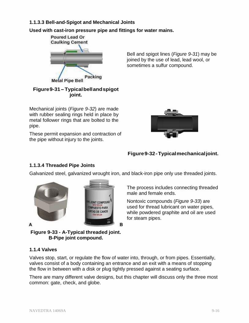
NAVEDTRA 14069A 9-16
1.1.3.3 Bell-and-Spigot and Mechanical Joints
Used with cast-iron pressure pipe and fittings for water mains.
Bell and spigot lines (Figure 9-31) may be joined by the use of lead, lead wool, or sometimes a sulfur compound.
Figure 9-31 - Typical bell and spigot joint.
Mechanical joints (Figure 9-32) are made with rubber sealing rings held in place by metal follower rings that are bolted to the pipe.
These permit expansion and contraction of the pipe without injury to the joints.
Figure 9-32 - Typical mechanical joint.
1.1.3.4 Threaded Pipe Joints
Galvanized steel, galvanized wrought iron, and black-iron pipe only use threaded joints.
The process includes connecting threaded male and female ends.
Nontoxic compounds (Figure 9-33) are used for thread lubricant on water pipes, while powdered graphite and oil are used for steam pipes.
Figure 9-33 - A-Typical threaded joint.
B-Pipe joint compound.
1.1.4 Valves
Valves stop, start, or regulate the flow of water into, through, or from pipes. Essentially, valves consist of a body containing an entrance and an exit with a means of stopping the flow in between with a disk or plug tightly pressed against a seating surface.
There are many different valve designs, but this chapter will discuss only the three most common: gate, check, and globe.
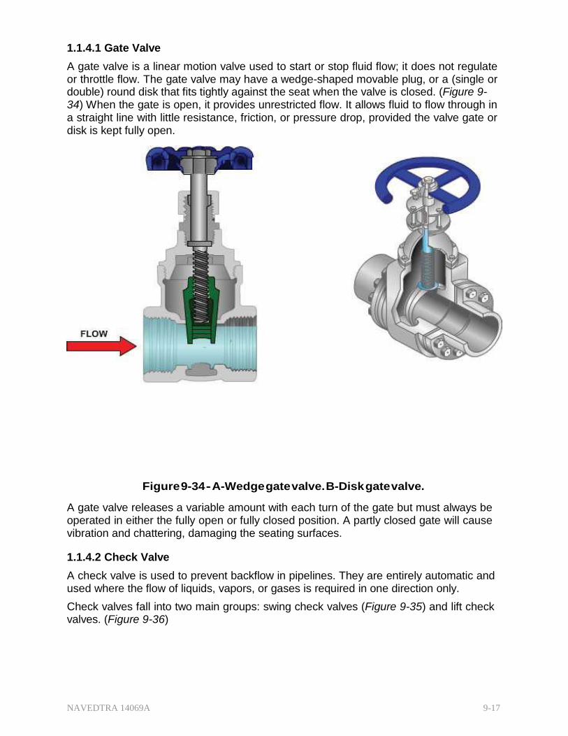
NAVEDTRA 14069A 9-17
1.1.4.1 Gate Valve
A gate valve is a linear motion valve used to start or stop fluid flow; it does not regulate or throttle flow. The gate valve may have a wedge-shaped movable plug, or a (single or double) round disk that fits tightly against the seat when the valve is closed. (Figure 9- 34) When the gate is open, it provides unrestricted flow. It allows fluid to flow through in a straight line with little resistance, friction, or pressure drop, provided the valve gate or disk is kept fully open.
Figure 9-34 - A-Wedge gate valve. B-Disk gate valve.
A gate valve releases a variable amount with each turn of the gate but must always be operated in either the fully open or fully closed position. A partly closed gate will cause vibration and chattering, damaging the seating surfaces.
1.1.4.2 Check Valve
A check valve is used to prevent backflow in pipelines. They are entirely automatic and used where the flow of liquids, vapors, or gases is required in one direction only.
Check valves fall into two main groups: swing check valves (Figure 9-35) and lift check valves. (Figure 9-36)

NAVEDTRA 14069A 9-18
Figure 9-35 - Typical swing check valve. A lift check valve is usually used for air or gases or when a check valve is operated frequently.
A swing check valve is used for unrestricted flow.
Figure 9-36 - Typical lift check valve.
1.1.4.3 Globe Valve
The globe valve, (Figure 9-37) so-called because of its globular-shaped body, regulates the flow of liquids, gases, and vapor flow by means of throttling (adjusting rate of flow).

NAVEDTRA 14069A 9-19
They are well suited for services requiring regulated flow and/or frequent valve settings (throttling).
9-37 - Typical globe valve.
1.1.5 Pipe Supports
Structurally, pipes are only designed to withstanding normal soil loads and internal pressures up to their hydrostatic pressure rating. Therefore, any pipe aboveground or in the interior of buildings supplying air, water, or steam, must be adequately supported to prevent sagging.
The weight of the pipes plus the weight of fluid contained in them may produce strained joints and breaks that can cause leaks in the valves. Figure 9-38 shows several methods of supporting pipe within a structure in both horizontal and vertical positions.

NAVEDTRA 14069A 9-20
Figure 9-38 - Typical pipe supports within a structure.
On water mains, thrust blocks (Figure 9-39) made of concrete or other applicable materials, are installed at all changes of direction to prevent pipe displacement caused by the movement of water under high pressure.
Figure 9-39 - Typical thrust block application.
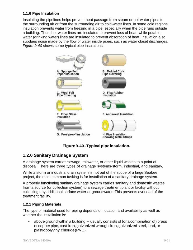
NAVEDTRA 14069A 9-21
1.1.6 Pipe Insulation
Insulating the pipelines helps prevent heat passage from steam or hot-water pipes to the surrounding air or from the surrounding air to cold-water lines. In some cold regions, insulation prevents water from freezing in a pipe, especially when the pipe runs outside a building. Thus, hot-water lines are insulated to prevent loss of heat, while potable- water (drinking water) lines are insulated to prevent absorption of heat. Insulation also subdues noise made by the flow of water inside pipes, such as water closet discharges. Figure 9-40 shows some typical pipe insulations.
Figure 9-40 - Typical pipe insulation.
1.2.0 Sanitary Drainage System
A drainage system carries sewage, rainwater, or other liquid wastes to a point of disposal. There are three types of drainage systems-storm, industrial, and sanitary.
While a storm or industrial drain system is not out of the scope of a large Seabee project, the most common tasking is for installation of a sanitary drainage system.
A properly functioning sanitary drainage system carries sanitary and domestic wastes from a source (or collection system) to a sewage treatment plant or facility without collecting any additional surface water or groundwater. This prevents overload of the treatment facility.
1.2.1 Piping Materials
The type of material used for piping depends on location and availability as well as whether the installation is:
above ground within a building - usually consists of (or a combination of) brass or copper pipe, cast-iron, galvanized wrought iron, galvanized steel, lead, or plastic polyvinyl chloride (PVC).

NAVEDTRA 14069A 9-22
underground within a building - may be cast-iron, galvanized steel, lead, or PVC. Cast-iron and PVC are the most popular.
underground outside a building -may be cast-iron soil pipe, vitrified clay, concrete, or PVC (the most common).
Like water distribution systems, the growing popularity of PVC piping for sanitary drainage is its
unique combination of chemical and physical properties
ease of installation
cost effectiveness
1.2.1.1 Cast-Iron Soil Pipe (CISP)
This type of pipe is composed of gray cast iron made of compact close-grained pig iron, scrap iron and steel, metallurgical coke, or limestone. (Figure 9-41)
CISP is normally used in or under buildings; it usually protrudes at least 5 ft from the building to connect to a concrete or clay sewer line.
5- and 10-ft lengths
nominal inside diameters of 2, 3, 4, 5, 6, 8, 10, 12, and 15 in.
single-hub or double-hub
Hubs (bells) of cast-iron soil pipe are enlarged sleeve-like fittings cast as a part of the pipe to make watertight and pressure-tight joints with oakum and lead.
Figure 9-41 - Single hub cast-iron soil pipe
(CISP) with cutter.
Cast-iron soil pipe is also used under roads or other places of heavy traffic. If the soil is unstable or contains cinder and ashes, vitrified clay pipe is used instead of cast-iron soil pipe.
1.2.1.2 Vitrified Clay Pipe (VCP) and Concrete Pipe
Vitrified clay pipe (VCP) (Figure 9-42) is made of moistened, powdered clay processed to a very hard, inert, glass-like state.

NAVEDTRA 14069A 9-23
VCP is used for house sewer lines, sanitary sewer mains, and storm drains.
2-, 2 �-, and 3-ft lengths
diameters from 4- to 42-in.
hub and a spigot ends
Figure 9-42 - Vitrified soil pipe (VSP) spigot and hub.
Unreinforced concrete pipe is used to meet the requirements for sewer drainage in the smaller sizes -those less than 24 in.
However, reinforced concrete (Figure 9-43) pipe is also available in elliptical as well as round shape with diameters from 1- to over 12-feet.
Figure 9-43 - Concrete pipe.
1.2.1.3 Plastic Pipe
Rigid polyvinyl chloride pipe (Figure 9-44) application has expanded greatly over the years for use in underground sanitary sewage systems. At one time, plastic piping was primarily for limited industrial and domestic uses such as farm water and lawn sprinklers systems. Now, plastic pipe is used for all kinds of water and drainage applications. It has the following qualities:

NAVEDTRA 14069A 9-24
outstanding resistance to nearly all acids, caustics, salt solutions, and other corrosive liquids and gases
does not rust, corrode, scale, or pit inside or outside
nontoxic, nonconductive, and not subject to electrolytic corrosion-a major cause of failure when metal pipe is installed underground
low resistance to abrasion resulting in maximum flow rate and minimum buildup of sludge and slime
Figure 9-44 - Rigid plastic sewer pipe.
1.2.2 ittings
Fittings for sanitary (waste) drainage systems (Figure 9-45) are similar in shape to those used for water distribution systems. However, as in water distributions systems, a system's various fittings can be the same general shape, but vary in specific details according to the type of piping materials used. Special mechanical seal adapters are also available for joining different types of pipes, such as cast-iron soil pipe to vitrified clay pipe, or vice versa.

NAVEDTRA 14069A 9-25
1.2.2.1 Bends
Figure 9-45 - Typical sanitary pipe fittings - bends and reducers.
1.2.2.2 Tees
Tees (Figure 9-46) connect branches to continuous lines.
A test tee is used in stack and waste installations where the vertical stack joins the horizontal sanitary sewer. It allows the plumber to fill the system with water while testing for leakage.
A tapped tee is used with the venting system where it is called the main vent tee.
The sanitary tee is commonly used in a main stack to allow the takeoff of a pipe branch.
A bend is termed by either a fraction or a degree. The fraction term is a fraction of a 360° radius.
Thus, a 1/16 bend is a 22 1/2° turn, a 1/8 bend is 45°, and a 1/4 bend is 90°.
There are also short-radius and long-radius fittings available as well as reducers and increasers.
Figure 9-46 - Typical sanitary pipe fittings - Tees.

NAVEDTRA 14069A 9-26
1.2.2.3 Ninety-Degree Y-Branches
Figure 9-47 - Typical sanitary pipe fittings -
90° Y-Branches.
1.2.2.4 Forty-Five-Degree Y-Branches
45° branches (Figure 9-48) join two or three sanitary sewer branches at a 45° angle in a straight-Y, double-Y or V configuration.
Straight 45° Y-branch-true Y.
Reducing 45° Y-branch-a straight section with a 45° takeoff of a smaller size
(Figure 9-47)
Straight 90° Y-branch-feeds a branch into a main as nearly as possible in a line parallel to the main flow.
Reducing 90° Y-branch-same as straight type except the branch is smaller than the main.
Double 90° Y-branch (or double combination Y and 1/8 bend)- especially useful as an individual vent.
Box type 90° Y-branch-two takeoffs form a 90° angle with the main pipe and also spaced 90° from each other.
Figure 9-48 - Typical sanitary pipe fittings -
45° Y-Branches.
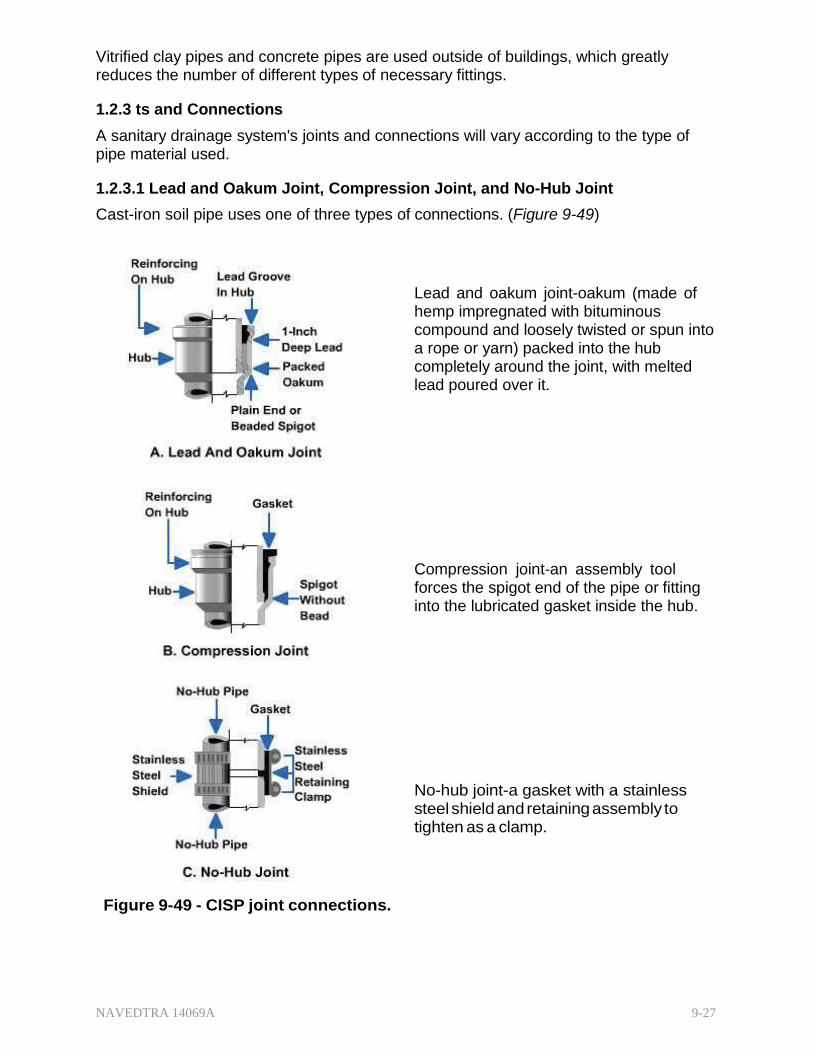
NAVEDTRA 14069A 9-27
Vitrified clay pipes and concrete pipes are used outside of buildings, which greatly reduces the number of different types of necessary fittings.
1.2.3 ts and Connections
A sanitary drainage system's joints and connections will vary according to the type of pipe material used.
1.2.3.1 Lead and Oakum Joint, Compression Joint, and No-Hub Joint
Cast-iron soil pipe uses one of three types of connections. (Figure 9-49)
Lead and oakum joint-oakum (made of hemp impregnated with bituminous compound and loosely twisted or spun into a rope or yarn) packed into the hub completely around the joint, with melted lead poured over it.
Compression joint-an assembly tool forces the spigot end of the pipe or fitting into the lubricated gasket inside the hub.
No-hub joint-a gasket with a stainless steel shield and retaining assembly to tighten as a clamp.
Figure 9-49 - CISP joint connections.

NAVEDTRA 14069A 9-28
1.2.3.2 3.2 Mortar and Bituminous Joints
Common to vitrified clay or concrete pipes and fittings, following an oakum packing, instead of lead, joints are mortared using grout (a mixture of cement, sand, and water).
Speed seal joints (rubber rings) (Figure 9- 50) have become widespread in joining vitrified clay pipe.
They eliminate the oakum and mortar joints thus expediting project completion and lowering labor costs.
This type of seal is made a part of the vitrified pipe joint when manufactured.
Figure 9-50 - VCP speed seal.
1.2.4 Traps
A trap (Figure 9-51) is a device that catches and holds a quantity of water, thus forming a fluid seal that prevents sewage decomposition gases from entering the building through the drainage pipe. A number of different types of traps are available; however, the trap mainly used with plumbing fixtures is the P-trap.
sizes from 1 1/4 in. to 6
in. in diameter
made of nickel or chrome-plated brass, malleable galvanized or wrought iron, copper, other metal alloys, and plastic
commonly installed on fixtures, such as lavatories, sinks, and urinals
designed into the interior of water closets (toilets)
Figure 9-51 - Typical P-trap.

NAVEDTRA 14069A 9-29
1.2.5 Vents
Without a vent, water or waste discharged from one fixture tends to create a vacuum/siphon affect on other fixture traps as it goes through the pipes. A properly functioning vent (pipe) (Figure 9-52) allows sufficient air to enter the system to eliminate that condition. It also directs gasses that develop naturally in a sewage drainage system to vent to the outside. This means that the vent piping system must serve all the various fixtures. It does this by connecting a main vent (with branches) to the main soil and waste vent at a location below the lowest and above the highest waste connection.
Vent piping materials may be galvanized pipe, cast-iron soil pipe, and, at times, brass, or copper, but plastic piping is increasingly the material of choice.
A main vent is the principal artery of the venting system. Vent branches connect and run undiminished in size as directly as possible from the building drain to the open air above
The main soil and waste vent is that portion of the main soil and waste stack that extends above the highest fixture branch through the roof to the exterior of the building.
Figure 9-52 - Typical main vent system.

NAVEDTRA 14069A 9-30
Installers use various configurations to vent fixtures. The selection depends largely on the location and grouping of the plumbing fixtures.
The individual vent (Figure 9-53) (also referred to as a back vent or continuous vent) is the most common. This vent can be adapted to all fixtures and installed as a single or a battery of two or more. It prevents both direct and indirect siphonage.
Figure 9-53 - Individual vent system in single and battery.
A common vent (Figure 9-54) vents two traps to a single vent pipe when lavatory pairs are side-by-side, or back-to-back on either side of a partition.
The waste from both discharges into a double sanitary tee.
Figure 9-54 - Common vent.

NAVEDTRA 14069A 9-31
Figure 9-55 - Circuit vent.
When liquid waste flows through a portion of a vent pipe, it is a wet vent. (Figure 9-56)
A loop vent also has liquid waste through a portion and then connects into the waste stack unit to form a loop. Useable for a small group of bathroom fixtures, such as a lavatory, water closet, and shower, it needs to be sized to accommodate those three units.
A lavatory should be individually vented to prevent loss of the trap seal through siphonage and allow the relatively clean water to scour the wet vent to prevent a buildup of excessive waste material.
A circuit vent (Figure 9-55) extends from the main vent to a connection on the horizontal waste branch between the next to last and last fixtures with a maximum of eight fixtures on any circuit.
Since some fixtures discharge their waste through a part of the pipe that acts as a vent for others, the vent may clog. To reduce clogging, the vent should connect to the top of the branch rather than the side.
Water and waste from the last fixture scours the vents of the other fixtures.
Figure 9-56 - Wet vent and loop vent.
NOTE
A water closet must not drain into a wet vent.
Proper-sized piping must be used in all phases of the venting system. The diameter of the main vent stack must be no less than 2 in. when draining more than four units. The actual diameter depends on the developed length of the vent stack and on the number of fixture units installed on the soil or waste stack. The diameter of a vent stack should be at least as large as that of the soil or waste stack.

NAVEDTRA 14069A 9-32
1.2.6 Branches
Soil and waste pipe branches (Figure 9-57) are horizontal branch takeoffs that connect various fixtures and the vertical stack
Installers can use a Y-branch with a 1/8 bend caulked into it, or a sanitary tee, an extra-short- pattern 90° Y-branch.
The sanitary tee is better to eliminate the extra fitting and caulked joint required for the 1/8 bend takeoff but some local codes allow additional 1/8 bend connections.
Generally, waste pipes have a downward grade to ensure complete drainage.
Horizontal vents should also pitch slightly downward to facilitate discharge of condensation.
Figure 9-57 - Typical branch connections.
Test your Knowledge (Select the Correct Response)
1. Seabees commonly use copper, plastic, galvanized steel, or cast iron. Of those, plastic is becoming the most common for both civilian and military use due its and .
A. strength, lack of friction B. chemical properties, lower cost of materials C. lower cost of materials, ease of installation D. durability, availability
2.0.0 MECHANICAL PLAN
In the Navy, mechanical systems vary greatly depending on whether a system is aboard ship or shore-based. As an EA, your concern will be with shore-based systems ranging from permanent installations with the most modern fixtures, equipment, and appurtenances, to temporary installations at advanced bases that normally use the most economical materials that serve the purpose.
In this chapter, a mechanical plan refers to drawings, layouts, diagrams, and notes that relate to water distribution and sanitary drainage systems only. Heating and air conditioning, refrigeration, and other like systems are not included.

NAVEDTRA 14069A 9-33
2.1.0 Water Supply and Distribution Diagram Normally, a structure's water supply system starts at the water main. A self-tapping tool (Figure 9-58) drills and taps into this source (the source is still under pressure) and a corporation stop is installed during the same process.
Water then enters the building through a cold- water service line that usually runs through a gate valve-meter-gate valve configuration.
Figure 9-58 - Water main self- tapping tool and typical service
line.
As an Engineering Aid, you may be called upon to develop field sketches and drawings from larger sets of plans, or in reverse, to do "as-built" drawings and sketches. You may at some point need to do drawings of existing conditions so planners involved in a remodel or rehabilitation project can design retrofit potential possibilities. The following three isometric diagrams demonstrate typical layout drawings that apply to mechanical systems for plumbing, that is, for water distribution and soil and waste removal.

NAVEDTRA 14069A 9-34
Figure 9-59 - Typical hot-water and cold-water risers diagram.
2.2.1 Waste and Soil Drainage Diagram
Figure 9-60 shows the waste and soil pipes fittings and symbols associated with the hot- and cold-water risers diagram.
The arrow represents the direction of flow; all pipes are sloping towards the building drain.
Figure 9-59 shows typical hot- and cold-water service lines for a single-story residential building and how the lines connect to the fixtures.
This layout is a riser diagram in isometric as a method of visualizing or showing a three dimensional picture of the pipes in one drawing.
Figure 9-60 - Typical waste and soil risers diagram.

NAVEDTRA 14069A 9-35
Figure 9-61 shows the basic layout of a simple but typical drainage system. Refer to it as the chapter presents the function of each element.
Figure 9-61 - Basic drainage system layout and terminology.
Fixture drain - pipe extending from the P-trap of a fixture to a junction with any other drainpipe
Fixture branch - horizontal drainpipe connecting fixtures to the stack
Soil and waste fixture branch - pipe that feeds into a vertical pipe, referred to as a stack
Soil stack - stack that includes human waste (from water closets or other fixtures with similar functions)
Waste stack - stack that carries waste but does not include human waste
Floor drain - receptacle used to receive water drained from the floor; usually located near heating, laundry, or other unit subject to overflow or leakage
Cleanout - fitting with a removable plate or plug that provides access for cleaning out extraneous material
Building drain (house drain) - the lowest piping of the drainage system receiving discharge from all other drainage pipes and extending to a point 3 ft (or local code requirement) outside the building wall
Building sewer - the horizontal piping extending from the end of the building drain to the community sewer or independent disposal unit

NAVEDTRA 14069A 9-36
2.3.0 Plumbing Layout
In construction drafting, a mechanical (or utility) plan normally includes both water distribution and sanitary drainage systems combined, especially on smaller buildings or houses. The plumbing layout is usually drawn into a copy of the floor plan for proper orientation with existing plumbing fixtures, walls and partition outlines, and other utility features. Figure 9-62 shows a typical plumbing layout. For mechanical symbols, refer to ANSI Y32.4-1977, Graphic Symbols Used in Architectural and Building Construction and MIL- STD-17-1, Mechanical Symbols.
Figure 9-62 - Typical plumbing layout plan.
2.4.0 Mechanical Symbols
As previously stated, you are not expected to design a system, but you will be expected to draw a workable plumbing plan for use by the plumbing crew or any other interested parties. To accomplish this, you must be familiar with terms, symbols, definitions, and basic concepts of the plumbing trade.
As a rule, plumbing plans show the location of fixtures and fittings to be installed, along with the size and route of piping. The details are left to the plumber (UT), who is responsible for installing a properly connected system according to applicable codes, specifications, and good plumbing and construction practices.
Generally, plumbing plans make use of four types of symbols: piping, fittings, valves, and fixtures.

NAVEDTRA 14069A 9-37
2.4.1 Symbols
Figure 9-63 - Line symbols for piping.
On plans, line symbols for piping are solid or dashed lines indicating type, location, and proposed use. (Figure 9-63) Size should be noted alongside each route.
Piping up to 12 in. in diameter is referred to by its nominal size, approximately the inside diameter (I.D.). The exact inside diameter depends on the classification of pipe.
Heavy types of piping have smaller inside diameters because their wall thickness is greater. Piping over 12 in. in diameter is referred to by its outside diameter (O.D.).
2.4.2 itting Symbols
The pipe fitting symbols shown in Figure 9-64 are the basic line symbols used in conjunction with valve symbols. They define the size of the pipe, the method of branching and coupling, and the purpose of the pipe. This is important because the purpose of the pipe determines what piping material to use. The inverse is also true; the piping material will determine how it can be used.

NAVEDTRA 14069A 9-38
Figure 9-64 - Fitting symbols for piping.
Only a few of the symbols for fittings, joints, and connections are shown here. For additional symbols on welded and soldered joints, refer ANSI Y32.4-1977, Graphic Symbols Used in Architectural and Building Construction and MIL- STD-17-1, Mechanical Symbols.
2.4.3 Valve Symbols
Figure 9-65 shows symbols used for only the most frequently encountered valves. Normally, type of material and valve sizes are not identified on mechanical drawings but are assumed from the type of material and size of connecting pipe. However, when specified on the lists of materials (plumbing takeoff), valves are called out by size, type of material, and working pressure; for example, 2-in. gate valve, PVC, 175-lb working pressure.

NAVEDTRA 14069A 9-39
Figure 9-65 - Valve symbols for piping.
2.4.4 ixture Symbols
Figure 9-66 provides symbols and abbreviations for general appurtenances such as drains, as well as other basic fixtures such as baths, sinks, and water closets. The latter are often shown on the plans by pictorial or block symbols. The extent to which the symbols are used depends on the nature of the drawing. In some cases, fixtures are specified on a bill of materials or other schedule keyed to the plumbing plan. When the fixtures are identified on a schedule, you can use symbols that closely resemble the actual fixtures or obtain commercially available mechanical symbol templates.

NAVEDTRA 14069A 9-40
Figure 9-66 - Plumbing fixture symbols.
Summary
As an Engineering Aid, you must have wide familiarity with all the construction disciplines, their general terms, materials, equipment, and procedures, to be able to translate drawings into working sketches or the reverse, field sketches into drawings.
Mechanical systems for water distribution and waste removal are only two of many, but they are also two of the most common. A comfortable knowledge of plumbing terminology (Figure 9-67), materials, and symbols will expedite any tasking you may have to produce their drawings.
Figure 9-67 - Typical water supply terminology.

NAVEDTRA 14069A 9-41
Review Questions (Select the Correct Response) 1. The system of pipes, fixtures, and appurtenances used inside a building for
supplying water and removing wastes is known by what general term?
A. Mechanical systems B. Plumbing C. Water distribution D. Piping
2. With which of the following codes must you become familiar when working with
mechanical plans?
A. National Plumbing Code and National Electrical Code® B. National Plumbing Code and local NAVFAC codes C. Local codes and National Plumbing Code D. Local codes and ANSI codes
3. A water service pipe begins at the .
A. hose bib B. water main C. water meter D. water distribution pipe
4. A water distribution pipe begins at the .
A. hose bib B. water main C. water meter D. water service pipe
5. Traditionally, copper has been widely used for tubing in piping systems for which
of the following reasons?
A. It is less costly than other types of pipe. B. It is available in two wall thicknesses and is faster to install. C. It does not rust and is resistant to scale particles in the pipe. D. Fittings are screwed to the pipe which allows for faster completion of the
piping system. 6. Copper pipe is manufactured in grades and thicknesses, of which are
appropriate for water distribution systems from water main to tap.
A. 6, 3 B. 5, 3 C. 4, 2 D. 4, 3
NAVEDTRA 14069A 9-42
7. Copper is durable and connects well to valves but should not be installed if the water has a level.
A. low-pH (high acidic) B. high-pH (low acidic) C. high water table D. low water table
8. Which of the following types of copper tubing is frequently used as replacement
piping because of its flexibility?
A. Type K B. Type L, hard tempered C. Type M D. Type L, soft tempered
9. Which of the following advantages does plastic pipe have over metal?
A. Flexibility B. High resistance to rupture and total resistance to rust C. It can be installed either above or below ground D. All of the above
10. What type of polyvinyl chloride pipe can be used in both cold-water and hot-water systems?
A. PVC B. APVC C. CPVC D. PVC-C
11. The principal mechanical difference between CPVC and PVC is that CPVC is significantly more malleable, allowing greater flexibility and .
A. long runs B. crush resistance C. quick connections D. lighter handling
12. Galvanized steel pipe sizes are based on what nominal size?
A. Inside diameter B. Outside diameter C. Wall thickness D. Inside radius

NAVEDTRA 14069A 9-43
13. What type of pipe material is frequently used for water mains and service pipe up to a building?
A. Galvanized steel B. Copper C. Cast-iron D. Plastic
14. What two types of malleable iron or cast iron pipe fittings are used for steel pipe
or wrought iron?
A. a) pressure, b) recessed B. a) nominal, b) sized C. a) inside diameter, b) outside diameter D. a) nominal, b) recessed
15. A Durham fitting is also known as a fitting.
A. standard B. pressure C. cast-iron drainage D. speed
16. How many parts does a ground joint union have?
A. 1
B. 2
C. 3
D. 4
17. How many parts does a flange union have?
A. 1
B. 2
C. 3
D. 4
18. An eccentric reducer joins pipes of different sizes so the two pieces of pipe will .
A. line up for a straight run B. turn at right angles C. turn vertically for a riser D. not be in line with each other
19. A nipple is a .
A. cast-iron threaded cap B. galvanized threaded plug C. length of pipe with a male thread on each end D. copper reducing coupler

NAVEDTRA 14069A 9-44
20. What type of fitting for joining straight should be used in runs of dissimilar metal pipe that require easy disconnection?
A. Union B. Coupling C. Dielectric union D. Dielectric coupling
21. What type of piping uses flared and sweated joints?
A. Plastic B. Copper C. Cast-iron D. Galvanized steel
22. What type of piping uses solvent welded, fusion welded, fillet welded, threaded,
and flanged joints?
A. Plastic B. Copper C. Cast-iron D. Galvanized steel
23. What type of piping uses bell-and-spigot, and mechanical joints?
A. Plastic B. Copper C. Cast-iron D. Galvanized steel
24. What type of piping uses threaded joints only?
A. Plastic B. Copper C. Cast-iron D. Galvanized steel
IN ANSWERING QUESTIONS 25 THROUGH 28, SELECT THE TYPE OF VALVE FROM THE FOLLOWING LIST THAT BEST MATCHES THE DESCRIPTION GIVEN IN THE QUESTION.
A. Globe Valve B. Gate Valve C. Check Valve
25. This valve has a wedge-shaped, movable plug or round disk that fits tightly
against the seat when closed.
A. A B. B C. C

NAVEDTRA 14069A 9-45
26. This valve is well suited for use when a regulated flow is required.
A. A B. B C. C
27. This valve must be operated in the fully open or fully closed position.
A. A B. B C. C
28. This valve is used to prevent backflow in a pipeline.
A. A B. B C. C
29. Any pipe must be adequately supported to prevent
sagging.
A. from the water main to the meter B. from the meter to the distribution pipes C. aboveground or in the building interior D. corporation stop to the building
30. On water mains, thrust blocks should be installed for what purpose?
A. To prevent pipe displacement caused by high water pressure B. To prevent pipe ruptures caused by high water pressure C. To prevent sagging due to the weight of the piping material D. To prevent sagging due to the weight of the pipe and the water contained
in the pipe 31. What purpose does pipe insulation serve?
A. Helps prevents heat passage from pipes to surrounding air B. Helps prevent lines from absorbing heat C. Subdues noise D. All of the above
32. Where is cast-iron soil pipe (CISP) normally used?
A. Where the soil is unstable B. Under buildings C. In soil containing cinder and ashes D. In light traffic areas

NAVEDTRA 14069A 9-46
33. Vitrified Clay Pipe (VCP) is made of .
A. vitrified crushed rock B. moistened powdered clay C. vitrified glass D. moistened powdered silica
34. Which piping material is becoming increasingly popular for use in underground
sanitary sewage systems?
A. Cast iron B. Polyvinyl chloride C. Concrete D. Wrought iron
35. What cast-iron fitting should you use to make a 22 l/2-degree change in pipe
direction?
A. Combination Y and 1/8 bend B. 1/4 bend C. Short sweep 1/4 bend D. 1/16 bend
36. A test tee is used in stack and waste installations where the vertical stack joins
the .
A. horizontal sanitary sewer B. vent stack C. clean out D. double Y branch
37. Which of the following type of joint is not used for cast-iron soil pipe?
A. Speed seal B. Compression C. No-hub D. Lead and oakum
38. What fittings are used in waste pipe systems to catch and hold water, thereby
forming a seal to prevent sewer gases from backing up into a building?
A. Traps B. Street ells C. Valves D Vents
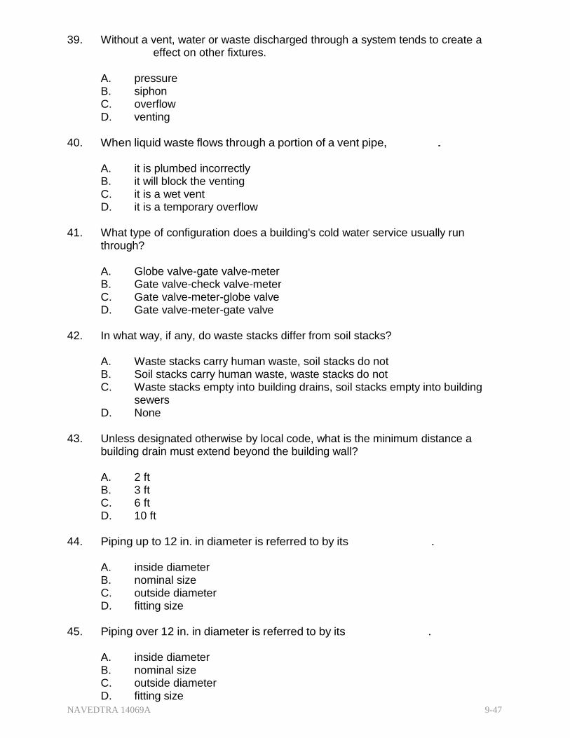
NAVEDTRA 14069A 9-47
39. Without a vent, water or waste discharged through a system tends to create a effect on other fixtures.
A. pressure B. siphon C. overflow D. venting
40. When liquid waste flows through a portion of a vent pipe, .
A. it is plumbed incorrectly B. it will block the venting C. it is a wet vent D. it is a temporary overflow
41. What type of configuration does a building's cold water service usually run
through?
A. Globe valve-gate valve-meter B. Gate valve-check valve-meter C. Gate valve-meter-globe valve D. Gate valve-meter-gate valve
42. In what way, if any, do waste stacks differ from soil stacks?
A. Waste stacks carry human waste, soil stacks do not B. Soil stacks carry human waste, waste stacks do not C. Waste stacks empty into building drains, soil stacks empty into building
sewers D. None
43. Unless designated otherwise by local code, what is the minimum distance a
building drain must extend beyond the building wall?
A. 2 ft B. 3 ft C. 6 ft D. 10 ft
44. Piping up to 12 in. in diameter is referred to by its .
A. inside diameter B. nominal size C. outside diameter D. fitting size
45. Piping over 12 in. in diameter is referred to by its .
A. inside diameter B. nominal size C. outside diameter D. fitting size

NAVEDTRA 14069A 9-48
46 (True or False) For valve symbols, the type of material and valve size should always be identified on the drawings.
A. True B. False

NAVEDTRA 14069A 9-49
Trade Terms Introduced in this Chapter
Bell and spigot joint A connection between two sections of pipe, the straight spigot end of one section is inserted in the flared-out end of the adjoining section
Bell reducer A pipe fitting that extends a run by joining two pipes of different diameter; often called a reducing coupling
Dielectric A nonconducting substance, i.e. an insulator
Galvanic corrosion An electrochemical process in which one metal corrodes preferentially when in contact with a different type of metal
pH A measure of the acidity or basicity (alkali) of a solution
Vitrified clay pipe (VCP) Pipe made from clay that has been subjected to vitrification, a process which fuses the clay particles to a very hard, inert, glass-like state; commonly used in sewer gravity collection mains because of its reasonable price and resistance to almost all domestic and industrial sewage

NAVEDTRA 14069A 9-50
Additional Resources and References
This chapter is intended to present thorough resources for task training. The following reference works are suggested for further study. This is optional material for continued education rather than for task training.
Graphic Symbols for Plumbing Fixtures for Diagrams Used in Architecture and Building Construction, ANSI Y32.4-1977, American Society of Mechanical Engineers, New York, 1977.
U.S. Department of Defense, Mechanical Symbols, MIL-STD-17B-1, Defense Supply Agency, Alexandria, Va., 1963.
United States Environmental Protection Agency
http://www.epa.gov/nrmrl/wswrd/cr/corr res copper ai2.html
Washington State Department of Ecology http://cru.cahe.wsu.edu/CEPublications/eb1581/eb1581.html
U. S. Army Engineering Correspondence Course, Plumber Course 052 M44, https://rdl.train.army.mil/soldierPortal/soldier.portal? nfpb=true&rdlService 1 actionOve rride=%2Fportlets%2FrdlService%2Fquery& windowLabel=rdlService 1& pageLabel=r dlservicespage
NAVEDTRA 14069A 9-51
CSFE Nonresident Training Course - User Update
CSFE makes every effort to keep their manuals up-to-date and free of technical errors. We appreciate your help in this process. If you have an idea for improving this manual, or if you find an error, a typographical mistake, or an inaccuracy in CSFE manuals, please write or email us, using this form or a photocopy. Be sure to include the exact chapter number, topic, detailed description, and correction, if applicable. Your input will be brought to the attention of the Technical Review Committee. Thank you for your assistance.
Write: CSFE N7A 3502 Goodspeed St. Port Hueneme, CA 93130
FAX: 805/982-5508
E- mail: CSFE [email protected]
Rate Course Name
Revision Date Chapter Number Page Number(s)
Description
(Optional) Correction
(Optional) Your Name and Address

NAVEDTRA 14069A 10-1
Chapter 10
Electrical Systems and Plans
Topics
1.0.0 Electrical Systems
2.0.0 Electrical Plans
To hear audio, click on the box.
Overview
As an Engineering Aid, you will be working with drawings to accomplish various tasks depending on your specific assignment. Just as you need to be familiar with wood framing plans and concrete plans for structural elements, and mechanical plans for plumbing and waste removal, you must also be familiar with electrical plans for power service and distribution.
An EA working on a set of drawings or plans must clearly convey his or her ideas (or instructions) to the installer, usually a Construction Electrician (CE). To do so, you must understand and be thoroughly familiar with the basic methods and functions of materials and fixtures used to install an electrical system.
In conjunction with the previous chapters on wood, concrete and masonry, and mechanical systems, this chapter will enable you to prepare construction drawings, revise as-built drawings in the field, and easily incorporate minor design changes.
Objectives
When you have completed this chapter, you will be able to do the following.
1. Describe the different types of electrical power distribution systems.
2. Interpret different types of electrical plans.
Prerequisites
None
This course map shows all of the chapters in Engineering Aid Basic. The suggested training order begins at the bottom and proceeds up. Skill levels increase as you advance on the course map.

NAVEDTRA 14069A 10-2
Topographic Surveying and Mapping
E
Indirect Leveling/Level and Traverse Computations N
G Care and Adjustment of Survey Equipment
I
Materials Testing: Soil and Concrete N
Direct Leveling and Basic Engineering Surveys E
Horizontal Control E
Direct Linear Measurements and Field Survey Safety R
I Surveying: Elements and Equipment
N Construction Drawings
G
Electrical: Systems and Plans
Mechanical: Systems and Plans AID
Concrete and Masonry
B
Wood and Light Frame Structures A
Drafting: Projections and Sketching S
Drafting: Geometric Construction I
Drafting: Fundamentals and techniques C
Drafting: Equipment
Mathematics and Units of Measurement
Engineering Aid Rating
Features of this Manual
This manual has several features which make it easy to use online.
Figure and table numbers in the text are italicized. The figure or table is either next to or below the text that refers to it.
The first time a glossary term appears in the text, it is bold and italicized. When your cursor crosses over that word or phrase, a popup box displays with the appropriate definition.
Audio and video clips are included in the text, with an italicized instruction telling you where to click to activate it.
Review questions that apply to a section are listed under the Test Your Knowledge banner at the end of the section. Select the answer you choose. If the answer is correct, you will be taken to the next section heading. If the answer is incorrect, you will be taken to the area in the chapter where the information is for

NAVEDTRA 14069A 10-3
review. When you have completed your review, select anywhere in that area to return to the review question. Try to answer the question again.
Review questions are included at the end of this chapter. Select the answer you choose. If the answer is correct, you will be taken to the next question. If the answer is incorrect, you will be taken to the area in the chapter where the information is for review. When you have completed your review, select anywhere in that area to return to the review question. Try to answer the question again.

NAVEDTRA 14069A 10-4
1.1.1 ELECTRICAL SYSTEMS
Occupied buildings, as well as most other structures, require an electrical system to provide power for lighting and various appliances and equipment. An electrical system has three distinct elements:
Generation - A power plant generates electrical energy by conversion from some other energy source such as wind, geothermal, coal, nuclear, solar, hydro, etc.
Distribution - An electrical transmission system carries electrical current externally from the generating station via substations and transformers to building locations.
Internal wiring - An internal electrical wiring system distributes electricity to illuminate the building and provide power to appliances and equipment.
This chapter will only present the external power transmission and the interior wiring distribution system, with its various materials and fittings used in installation. For more information, refer to the latest edition of Construction Electrician Basic, NAVEDTRA 14026A, National Electrical Code® (NEC®), and Construction Electrician Advanced, NAVEDTRA 14027A
1.1.0 Electrical (Power) Distribution System
A complete electrical distribution system brings power from the generating plant through substations, feeders, and transformers to a building's premises by overhead power poles or underground lines.
This delivery network is generally considered a combination of two sections, the transmission section and the distribution section. The difference between the two sections depends on the function of each at a particular time.
In a small power system, the distinctive difference tends to disappear, and the transmission section merges with the distribution section. The term "distribution section" normally designates the outside lines but the distribution system frequently continues inside the building to include power outlets.
Most land-based power systems use alternating current (AC) rather than direct current (DC), principally because transformers can be used only with AC. An AC distribution system usually contains one or more generators (technically known as alternators in an ac system); a wiring system of feeders, which carry the generated power to a distribution center; and the distribution center, which distributes the power to wiring systems called primary mains and secondary mains. Figure 10-1 illustrates a typical transmission and distribution system.
Power from the generating station may be distributed by overhead transmission and distribution lines, by underground cable, or by a combination of both.
At most advance bases, Seabees commonly use overhead feeder lines because they are cheaper to build, simpler to inspect, and easier to maintain than underground cables, but underground cable is preferred at airports and runways to prevent hazardous flight conditions.

NAVEDTRA 14069A 10-5
Figure 10-1 — Typical electrical transmission and distribution system.
1.1.1 verhead Power Distribution
A system may be a three-wire or a four-wire system, depending upon whether the alternators are connected in a delta or wye configuration. Figure 10-2 View A is a schematic diagram showing a delta connection. The coil marked "stator" represents the stationary coils of wire in the alternator; the one marked "rotor" represents the coils, which rotate on the armature.
Power is taken off the stator from three connections, which in the drawing form a triangle or delta. All three wires are live (HOT) wires.
Figure 10-2 View B shows a Wye (Y)-connected alternator (three-phase, four-wire). N represents a common or neutral point to which the stator coils are all connected. The current is taken off the stator by the three lines (wires), 1, 2, and 3, connected to the stator coil ends; and also by a fourth line, N, connected to the neutral point. Lines 1, 2, and 3 are hot wires; line N is neutral.
Figure 10-2 — Delta- and Wye-connected alternator diagrams.
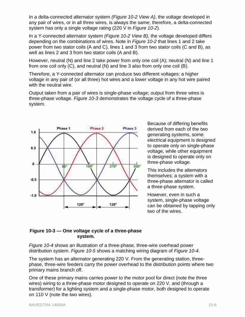
on 110 V (note the two wires).
NAVEDTRA 14069A 10-6
In a delta-connected alternator system (Figure 10-2 View A), the voltage developed in any pair of wires, or in all three wires, is always the same; therefore, a delta-connected system has only a single voltage rating (220 V in Figure 10-2).
In a Y-connected alternator system (Figure 10-2 View B), the voltage developed differs depending on the combinations of wires. Note in Figure 10-2 that lines 1 and 2 take power from two stator coils (A and C), lines 1 and 3 from two stator coils (C and B), as well as lines 2 and 3 from two stator coils (A and B).
However, neutral (N) and line 2 take power from only one coil (A); neutral (N) and line 1 from one coil only (C), and neutral (N) and line 3 also from only one coil (B).
Therefore, a Y-connected alternator can produce two different voltages: a higher voltage in any pair of (or all three) hot wires and a lower voltage in any hot wire paired with the neutral wire.
Output taken from a pair of wires is single-phase voltage; output from three wires is three-phase voltage. Figure 10-3 demonstrates the voltage cycle of a three-phase system.
Because of differing benefits derived from each of the two generating systems, some electrical equipment is designed to operate only on single-phase voltage, while other equipment is designed to operate only on three-phase voltage.
This includes the alternators themselves; a system with a three-phase alternator is called a three-phase system.
However, even in such a system, single-phase voltage can be obtained by tapping only two of the wires.
Figure 10-3 — One voltage cycle of a three-phase system.
Figure 10-4 shows an illustration of a three-phase, three-wire overhead power distribution system. Figure 10-5 shows a matching wiring diagram of Figure 10-4.
The system has an alternator generating 220 V. From the generating station, three- phase, three-wire feeders carry the power overhead to the distribution points where two primary mains branch off.
One of these primary mains carries power to the motor pool for direct (note the three wires) wiring to a three-phase motor designed to operate on 220 V, and (through a transformer) for a lighting system and a single-phase motor, both designed to operate

NAVEDTRA 14069A 10-7
Figure 10-4 — Typical overhead three-phase, three-wire power distribution system.
Figure 10-5 — Wiring diagram of overhead three-phase three-wire power distribution system in Figure 10-4.
The other primary main carries power to operational headquarters, living quarters, and the mess hall. This power is also carried through a transformer that reduces the power to the secondary main to 110 V single phase.
Figure 10-6 shows an illustration of a four-wire system serving the same facilities. Figure 10-7 shows a matching wiring diagram of Figure 10-6.
In this scenario, there is a four-wire Y-connected alternator rated at 110/220 V and no transformers are necessary to reduce the power to 110 V single phase for the

NAVEDTRA 14069A 10-8
secondary mains. The neutral wire in a four-wire system exists so that lower voltage can be used in the system. The secondary mains are developed by simply tapping into pairs of wires, one a hot wire and the other the neutral wire. The 220-V, three-phase motor is tapped into the three hot wires delivering the 220 V, three-phase power from the alternator.
Figure 10-6 — Typical overhead three-phase four-wire power distribution system.
Figure 10-7 — Wiring diagram of overhead three-phase four-wire power distribution system in Figure 10-6.
Since a three-wire three-phase 220V delivery system needs a transformer to reduce the voltage to the common usage 110 V, we need to know a little more about what a transformer is. A transformer (Figure 10-8) is a device for either increasing or reducing

NAVEDTRA 14069A 10-9
the voltage in an electrical circuit. It does this through a number of coil windings around a core.
Figure 10-8 — Example of step up and step down transformer coil windings.
Step down transformers can range in size from small portables like those for a cell phone charger to permanently mounted heavy ones like those commonly hung with cross-arm brackets attached to an electric pole. (Figure 10-9)
Figure 10-9 — Common step down transformer.
Long-distance power transmission requires a voltage higher than is normally generated. In this case, a transformer is used to step-up the voltage to that required for long distance transmission (Figure 10-10).
At the service distribution end, the voltage is reduced again to the voltage required for lights and equipment. A transformer is used there also, but this time it is a step-down transformer.
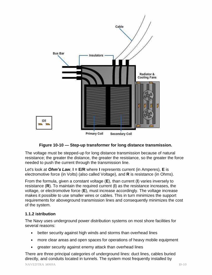
NAVEDTRA 14069A 10-10
Figure 10-10 — Step-up transformer for long distance transmission.
The voltage must be stepped-up for long distance transmission because of natural resistance; the greater the distance, the greater the resistance, so the greater the force needed to push the current through the transmission line.
Let's look at Ohm’s Law, I = E/R where I represents current (in Amperes), E is electromotive force (in Volts) (also called Voltage), and R is resistance (in Ohms).
From the formula, given a constant voltage (E), than current (I) varies inversely to resistance (R). To maintain the required current (I) as the resistance increases, the voltage, or electromotive force (E), must increase accordingly. The voltage increase makes it possible to use smaller wires or cables. This in turn minimizes the support requirements for aboveground transmission lines and consequently minimizes the cost of the system.
1.1.2 istribution
The Navy uses underground power distribution systems on most shore facilities for several reasons:
better security against high winds and storms than overhead lines
more clear areas and open spaces for operations of heavy mobile equipment
greater security against enemy attack than overhead lines
There are three principal categories of underground lines: duct lines, cables buried directly, and conduits located in tunnels. The system most frequently installed by

NAVEDTRA 14069A 10-11
construction battalions is the underground duct system (Figure 10-11), which consists of manholes, handholes, duct lines, and cables.
In general, a representation of the system layout and a list of materials needed to install the system can be found in a standard set of drawings.
Figure 10-11 — Seabees preparing to install an underground duct system.
1.2.1 Interior Electrical Wiring System
In electrical terminology, the term "service" means the electrical system that brings power from the exterior power distribution line to a point inside (or on) the building. From there, it is distributed to the building circuits. The key term is "service" and it is used in conjunction with other terms to identify specific segments:
Service Conductor - supplies power from the exterior distribution system to the entry point of the building
o Service Drop - conductors for overhead service
o Service Lateral - conductors for underground service
Service Entrance - brings power into (or onto) the building from the service conductor entrance to the service equipment
Service Equipment - the equipment located near the entry point of the service conductor. This equipment is the main control and means of cutting off the power supply to the building. It usually consists of a circuit breaker or switch or fuses,
1.2.1 vice Conductors
A service drop conductor runs from a pole to the building. (Figure 10-12) It may be an approved multi-conductor cable or an individual (single) conductor.

NAVEDTRA 14069A 10-12
In either case, it must have thermoplastic, rubber, or other weatherproof insulation.
It must also be of sufficient current carrying capacity to ensure that a prospective maximum load will not create enough temperature change (heat) to damage the insulation.
The NEC® specifies the minimum size conductors allowable for different load (amperage) requirements.
Figure 10-12 — Typical service drop.
A service lateral conductor brings power into a building from below ground. (Figure 10- 13).Sometimes these conductors are tied to an overhead distribution system and run down the pole into the ground before they run into the building. In other cases, the entire distribution system, except for the transformer, is underground.
A service lateral may be connected directly to a secondary main or to a transformer if a separate transformer serves the building. It may be installed in rigid conduit (metallic or nonmetallic) or with underground service entrance (USE) cable. Figure 10-13 shows the layout of an underground service lateral run from a transformer to a junction box and through the service entrance to the service equipment.
Figure 10-13 — Typical service lateral.

NAVEDTRA 14069A 10-13
1.2.2 Service Entrance
The service entrance is the starting point for interior wiring. It brings power from the service conductor (drop or lateral) to the service equipment. (Figure 10-14) The service drop conductor connects to the service entrance conductor just outside the building.
The service entrance conductor may be an approved single conductor run through a protective raceway, such as rigid conduit (metallic or nonmetallic), or an approved type of service entrance cable that does not need raceway protection unless it is likely to be damaged by abrasions or from being struck by passing equipment.
Where single conductors are used, they must be insulated and of the wire size specified by the NEC®.
Figure 10-14 — Typical service entrance
conductors.
Figure 10-14 also shows a service head (also called a weatherhead) which is used with a raceway to provide an entrance for the conductors. The weatherhead is designed to reduce abrasion to the insulation and has a downward facing opening to prevent rain from entering the raceway.
The service entrance conductor leads to the service equipment panel (Figure 10-15) that provides a means of disconnecting the supply source's service conductors from the interior electrical wiring system.
The service entrance panel may consist of a single manually operated switch with a fuse or a circuit breaker. The NEC® sets 60 amperes (A) as the minimum size for fuse type entrance switches and 50A for the circuit breaker type. Rather than burning out like a fuse, a circuit breaker is a protective device that automatically opens the circuit when amperage exceeds its rating. Restoring power is a matter of reducing the amperage draw and closing the circuit again with a switch instead of replacing a fuse.
The NEC® recommends a minimum size of 100-A service for individual residences. However, when no more than two two-wire branch circuits are installed, a 30-A entrance switch may be used.

NAVEDTRA 14069A 10-14
Figure 10-15 — Typical service equipment panels.
1.2.3 Panelboard
NEC® defines a panelboard as a single panel, or a group of panel units designated for assembly in the form of a single panel, including buses. (Figure 10-16).
Figure 10-16 — A-Panelboard with breaker panel. B-Panelboard with fuse panel.
A panelboard comes with or without switches and/or automatic over-current protective devices for the control of light, heat, or power circuits of individual as well as aggregate capacity. It is designed for placement in a cabinet or cutout box, in or against a wall or partition, and is only accessible from the front.
A breaker panel uses a thermal unit built into the switch with the breaker preset at the factory to open automatically at a predetermined ampere setting. It may be reset to the ON position after a short cooling-off period.

NAVEDTRA 14069A 10-15
Lighting panels (Figure 10-17, View A) are normally equipped with 15A single-pole automatic circuit breakers, while power panels (Figure 10-17, View B) may have one-, two-, or three-pole automatic circuit breakers with a capacity to handle the designated load.
In most buildings, the service equipment's entrance switch and panelboards can and should be mounted close to each other. However, they must be placed where service and maintenance can be easily performed.
Figure 10-17 — A-Lighting panel. B-Power panel.
They should not block any passage but should be located as near as possible to the center of the electrical load to minimize any unnecessary electrical resistance due to long runs (remember Ohm's Law). In addition, they should not be placed near exposure to corrosive fumes or dampness.
1.2.4 1.2.4 Conductors
Because of the conducting and ductile properties of copper and aluminum, electrical conductors are usually either drawn copper or aluminum formed into wire. They provide paths for the flow of electrical current. To protect personnel, conductors are usually covered with insulating materials to minimize the chances for short circuits. Atmospheric conditions, voltage requirements, and environmental and operating temperatures are factors to consider in selecting the type of wire with insulating materials for a particular job.
1.2.4.1 S ing le Condu c tors
A single conductor (Figure 10-18) may consist of one solid wire or a number of smaller stranded solid wires that share in carrying the total current. A stranded conductor is more flexible, making it more adaptable for pulling through bends in a conduit.

NAVEDTRA 14069A 10-16
Figure 10-18 — Typical insulated single conductors.
Conductors vary in diameter and use according to their intended electrical current load. Wire manufacturers have established a numerical system to eliminate the cumbersome use of circular mil (fractional-inch diameters) in describing wire sizes. The American Wire Gauge (AWG) Standard (Figure 10-19) provides an easy common reference for wire sizes. Notice the larger the wire gauge number, the smaller the diameter of the wire.
No. 8 and larger wires are normally used for heavy power circuits or as service entrance leads to buildings.
No. 12 AWG is a wire size used most frequently for interior wiring.
No. 16 or 18 AWG stranded wire is used to conduct current from outlet boxes to sockets in lighting fixtures and is called "fixture wire."
Figure 10-19 — American Wire Gauge (AWG)
(partial)

NAVEDTRA 14069A 10-17
1.2.4.2 Multi-wire (Cable) Conductors
A multi-wire conductor (called a cable) is an assembly of two or more conductors insulated from each other with additional insulation or a protective shield formed or wound around the group of conductors. (Figure 10-20) The covering or insulation for individual wires is color coded for proper identification.
Figure 10-20 — Typical insulated multi-wire (cable) conductors.
Two of these common types of cable need more attention.
Romex (trade name) (Figure 10-20, View A) is a nonmetallic-sheathed cable (NMC). It comes in sizes No. 14 through 2 for copper conductors and No. 12 through 2 for aluminum or copper-clad aluminum conductors.
It comes with a bare (uninsulated) ground wire laid in intervals between the circuit conductors and under the outside braid. The ground wire is used to ensure the grounding of all metal boxes in the circuit, and furnishes the ground for the grounded type of convenience outlets required in Navy installations.
Nonmetallic-sheathed cable is used for temporary wiring in locations where using conduit would be unfeasible.
BX (Figure 10-20, View B) is a metallic-armored cable.
BX tends to ground after installation. Small metal burrs on the armor can, because of vibration, penetrate the insulation and cause a ground. The building codes of most cities restrict the use of BX cables to the control circuits for oil burners and similar usage.
BX cables come in sizes from No. 14 to 2 AWG, and each cable may contain one, two, three, or four conductors. The armor on the cable furnishes a continuous ground between boxes.
1.2.5 Insulation
Electrical conductors are available with various kinds of insulating materials. The more common are rubber, thermoplastic, and varnished cambric, but less frequently, special types of paper, glass, silk, and enamel are also used.

NAVEDTRA 14069A 10-18
One factor to consider when selecting properly insulated conductors are the NEC® recommendations of insulation type for use in dry, damp, and wet locations. The NEC® considers installation in the following as wet locations:
underground installations
concrete slabs and masonry
direct contact with the earth
areas subject to saturation with water or other liquids
Another factor to consider is temperature. Different insulations have different maximum temperature ratings. Check the NEC® and any applicable local codes to ensure you use the appropriate insulation for the location and temperature considered in the plans.
The following are a few examples of insulation composition, location application, and maximum temperature rating:
Type RH
o a heat-resistant compound that will stand higher temperature than Type R
o commonly used in dry locations
o maximum temperature rating of 167°F
Type RHW
o moisture-resistant rubber compound for use where the wire may be subject to wet conditions
o used in both wet and dry locations
o maximum temperature rating of 167°F
Type RUH
o high grade rubber compound consisting of 90-percent latex
o often used for direct burial in dry locations
o maximum temperature rating of 140°F
Thermoplastic insulation's advantages are long life, toughness, a dielectric strength (capacity for insulating) equal to rubber, and it requires no protective covering over the insulation.
Common types of thermoplastic insulation are:
Type T - suitable only for dry locations with a maximum temperature rating of 140°F
Type TW - moisture-resistant with a temperature rating of 140°F
Type TA - thermoplastic asbestos compound combining the characteristics of Types T and TW with a maximum temperature rating of 194°F. Its use is restricted to switchboard wiring.
Varnished cambric insulation has an insulating quality midway between that of rubber and paper. It is more flexible than paper; its dielectric strength is greater than that of rubber, and ordinary oil and grease do not adversely affect it. It is manufactured in either standard type (black finish) or heat-resistant type (yellow finish). Varnished insulation is restricted to dry locations with applications such as motor leads, transformer leads, and high-voltage cables.