Embed Size (px)
Citation preview
Availablie Copy
Report 2310
o CAMOUFLAGE AND DECEPTION TECHNIQUES
FOR URBAN WARFARE
by 9
Thomas Stack
This Document October 1980
Reproduced FromBest Available Copy
Approved for public release; distribution unlimited.
U.S. ARMY MOBILITY EQUIPMENT
RESEARCH AND DEVELOPMENT COMMAND
FORT BELVOIR, VIRGINIA
Best Available Copy8 1 2 06 0 6
Destroy this report when it is no longer neeued.Do not return it to the originator.
The citation in this report of trade names of commercially
available products does not constitute official endorsementor approval of the use of such products.
Best Available CopyUNeLASSWIFl0
SECURITY CLASSIFICATION OF THIS PAGE (Wb*. Date 9"fo___________________
REPORT DOCUMENTATrON PAGE BEFORE COMPLETING PORM. REOR MUNGE 1t2. GOVT ACCESSION NO. S.- RECIPIEK~j4XAQQ Mfljfl-
-2320 e~/7 J r~ ' ~ i-
( ( AMOUFLAGE AND DECEPTION TECHNIQUES FOR 7 Final 9epQ-t.UURIBAN WIARFARE,-ý 1 97418W /
7. AU"Olil'a) . CONTRACT GA GRANT NUMBER~o)
06. 01911TRMUINORGANIATIOENT NAME AND ADRSS1. RGRMELM ROETTS
Cappoulagad forpubl apic Leasebdsriationy uTN:iitd.DE RA4WRKUI UD
Sl. CONTRLLIENGA NOFFIESNM MDRS
CommaEY der, S AC.h.wmy. Moblit Eguipme.. ~ nti~ Reeac a~nd Ocll 8
Develpmetio Count;ATN: D e-rT ureilanc TNmactiaCamoulage
Deco UrbOIGAECYMMEAADISSi 011Ian Camourflage Ofc)I.SConTYCLAlment W rpot
- pr-A diforusion ofeae historibaltechniqueandifutued porm.eln wt ofaei
Cmurawaflare. T eotepaieUrrent capfabiites inCamouflage andrdception
and concludes that camouflage and deception techniques when used properly can providesignificant tactical results in urban warfare. ______
DID W 43 Em-nom or I mov. 49is O111ETZ UNCLASSIFIED / 1 )scsYCLASIMPICATION OP THIS PACE (1110 Dot- ff-t--4)
Reproduced FromBest Available Copy
SUMMARY
The purpose of this report is to analyze urban warfare from a camouflage viewpoint.
considering complex mlodes of detection and the intricate character of the urban area.The multiple methods of camouflage and deception have [wen compiled for use in urbanwarfare. The product is a guide for identifying needs for future techniques and equi[-ment and their deployment.
A task of this work was to define the urban area. recognizing its important trans-portation and communications systems. Research included historical analysis, statisticalstudy of urban growth. andi an inquiry into the present worldwide doctrine dealing withurban warfare. Consideration was given to strategic points of view, concentrating onthose tactics deemed relevant to urban warfare: e.g.. aerial reconnaissance. direct sight.and ground line communications.
The report concludes that camouflage and deception can be tactically significant inurban warfare provided that effective materials are provided and that proper training isgiven to the using troops.
Accession ForIFTIS GRA&IDTIC TAB SLU'-n nnno cod e
/ Just ificati n
Dpistribz;t ion/
AvaiIn'b ity Codes;Avnil -and/or
:Di t Sptc i,11
Preceding Page Blank
Itioi
BEST AVAILABLE COPY
PREFACE
The investigation was conducted by Thomas T. Steck. Physicist. under the supervision
if Allan T. Sylvester, Chief. Customer Assistance Branch. The overall supervisor was
Henry R. Atkinson. Chief. Research Technology Division. Camouflage anSd Topographic
Laboratorv.
t
]Itq
iv
Ss • ,A
*1, -
CONTENTS
Section Title Page
SUMMARY iii
PREFACE iv
ILLUSTRATIONS vii
METRIC CONVERSION FACTORS ix
I INTRODUCTION I
If BACKGROUND 2.
III INVESTIGATION 4
IV DISCUSSION
A. Goals for Urban Camouflage and Deception 13B. Achieving Camouflage and Deception in Urban Areas 16C. Car iouflage and Deception Materials and Techniques for 18
Use in Urban/Suburban Aias
I. Urban Camouflage Colors 182. Urban (amouflage Patterns 183. Urbin Camouflage Net (Drape) 194. Urban Flat-top Net 205. Pseudo Masonry Landmine 21
6. Penlight Smoke Stick 227. Decoy Building 238. Camouflage Set/House Extension 239. Brown (Dull) Coated Communication Wire 25
10. Foam Camouflage for Landmines 25I 1. Acoustic Grenade 2612. Glue-on Rubble 2613. Decoy Urban Camoutlage Nets 2714. Claymore Mine Camouflage Set 2815. Urban Spider Hole Covers for Antitank Teams 2916. Vertical Camouflage Screens 3017. Fake-Damage Kit for Buildings and Bridges 3118. Street Sign Kit 32
vBEST AVAILABLE COPY
. . . . I - I
4..
CONTENTS (CONTINUED)
Section Title Page
19. Urban Two- and Three-Dimensional Tank Decoy 3220. Rubble Net (Urban) 3421. Urban Camouflage Uniform 34
D. Camouflage and Deception Materials and Techniques for 34Use in Rural and Urban Areas
I. Decoy Soldier, Inflatable 352. Fire/Flame Simulator 353. Tank-Tread Simulator 364. Non-Reflective Coating and Attachments for Glasses, 37
Binomalars, and Telescope5. Wood/Cardboard Box Decoy Manuals 376. Gun-Blast Dust Apron 37 37. Gun-Blast Dust Simulator 388. Decoy Dragon Teeth 389. Dummy Oil Drums, Blivets, and Pillows 41
10. TOW Missile Simulator 42II. Decoy Landmine 43 212. Machine Gun/Rifle Fire Simulator 4413. Vulcan Simulator 4714. Decoy Ribbon Bridge 4815. Decoy Armored Vehicle Launched Bridge (AVLB) 4816. Railroad Rolling Stock Camouflage 4917. Field Expedient Decoy Machine Gun (7.62 mm. .50 cal.) 49i8. Camouflage Coloring Kit for Engineer Tape 4919. TexturedCoatings for Rifle Barrels and Stocks 4920. Tone Down of Brass Cartridges 5021. Decoy Reflecting Surfaces 5022. Vehicles for Radar Simulation of Weapon Systems 5023. Fuel Tank Truck Camouflage 5024. Thermal Signature Modification Unit 5125. Drone Decoy Helicopter 5126. Decoy Cloth and Paper 5227. Camouflage Tape 52
38. Spray-on and Radar-Reflective Plastic 52
V CONCLUSIONS 52BIBLIOGRAPHY 54
vi
BEST AVA1LABLE COPY
I-,A
-5-
ILLUSTRATIONS
Figure Title Page
I Camouflage of Hamburg Harbor Area 7
2 Arab Decoy SAM Site 0
3 Diagram of German Pillbox Disguised as a House 12
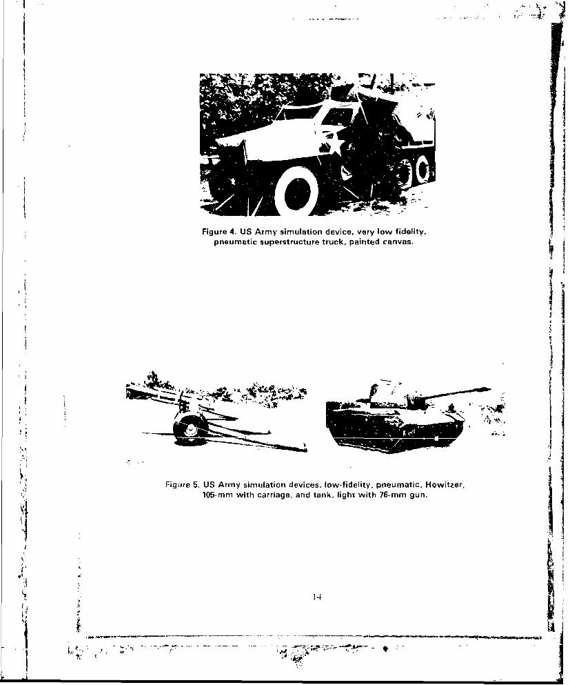
4 US Army Simulation Device. Very Low Fidelity, Pneumatic 14Superstructure Truck, Painted Canvas
5 US Army Simulation Devices, Low-Fidelity, Pneumatic, Howitzer. 14105-mm with Carriage, and Tank, Light with 76-mm Gun
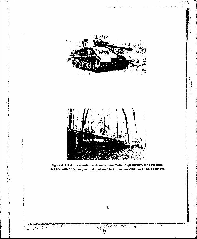
6 US Army Simulation Devices, Pneumatic, High-Fidelity, Tank 15Medium. M4A3. with 14)5-mm Gun. and Medium-Fidelity. Cannon280-mm (Atomic Cannon)
Modified Net Support System for Urban Camouflage Net - 19Triangular Foot with Expandable Clamp - Clamp Spreader
8 Urban Flat-top Net - Top and Side Views 20
9 Pseudo Masonry Landmine M19 21
10 Pscudo Masonry Landmine bA2 22
II Decoy Building - Hiding Vulcan 23
12 Camouflage Set/House Extension - Oblique 24
13 Camouflage Set/House Extension - Vertical 25
14 Trailer-Mounted Foaming Unit 26
is Urban Decoy Net 27
16 Advertisement-Sign Claymore 28
vii
BEST AVAILABLE COPY
-- . Fir
ILLUSTRATIONS (CONTINUED)
Figure Title Page
17 Urban Spider Hole Co!,er Net and Support 29
18 Vertical Wall Screen 30
19 Steps in Simulating Damages to a Building 31
20 Cloth Decoy Tank - Three Dimensions by Addition of Supports 32
21 Cloth Decoy Tank Vertical View 33
22 Decoy Dragon Teeth 39
23 Decoy Dragon Teeth Deployed in a City Street 40
24 Decoy Fuel Drum and Pillow, Decoy Fuel Storage with Kill Zone 41
25 TOW Missile Simulator 42
26 Foam Decoy. M19, Plastic Antitank Mine 43
27 Surface Landmine Decoys. XM-67 and XM-70 44
28 Old Style MG/Rifle Fire Simulator 45
29 Old Style Clockwork and Initiator Mechanism for MG/Rifle Fire 45Simulator
30 Machine Gun Simulator - New Type 46
31 Vulcan Simulator 47
viii BEST AVAILABLE COPY I
Ile9
METRIC CONVERSION FACTORSApproximate Conversions to Metric Measures
Symbol When You Know Multiply by To Find Symbol
LENGTH '"_
in inches 2.5 centimeters cm -It feet 30 centimeters cmVyd yards 0.9 meters In
SInmiles 1.6 kiormeters km
AREA
im2 square inches 6.5 square centimeters Cm'
It2 square feet 0.09 square meters 2
yd2 square yards 0.8 square meters in
2
mi2 square mnies 2.6 square kilometers ki 2
acres 0.4 hectares ha
0In
__MASS (weight)
0z ounces 28 grams t"lb poundh 0,45 kilaerams kg
short tons 0.9 metric tons t
(2000 Ib) ,
VOLUME
tsp teaspokns 5 milliliters mlTbsp tablespoons 15 milliliters l .-Vf Oz fluid ounces 30 milliliters il
c cups 0.24 liters Lpt pints 0.47 liters Lqt quarts 0.95 liters Lgal gallons 3.8 liters Lft
3 cubic feet 0.03 cubic meters nr--
ydj cubic yards 0.76 cr.bL c ,r-m t5-T "3i
TEMPERATURE (exact)
"Fahrenheit 5/9 (after Celsius ctemperature subtracting temperature
32)
I in 2.54 cm (exactly).
a,=
ix
M. ,
Approximate Conversions from Metric Measures
Symbol When You Know Multiply by To Find Symbol
__- __ ,LENGTH
mm millimetort 0.04 inches in
- Cm centimeters 0.4 inches in
m- r meters 3.3 feet ft ]0 m mewter 1.1 yards yd
km kilometers 0.6 miles mi
AREA
cm2 square centimetars 0.16 square inches in2
m2 square meters 1.2 square yards yd
2
2 square kilometers 0.4 sqVare miles mi2
ha hectares (10 000 m2 ) 2.6 acres
I, ~~~~~~-___ i ggam -i~. ~ OneS•MASS (weight)
gI~rams 0.035 ounces oz
kg kilograms 2.2 pounds Ibmetric tons (100O kg) 1.1 short tons
_ _VOLUME
m! milliliters 0.03 fluid ounces f' ozSL liters 2.1 pints pt
L liters 1.06 quarts qt
liters 0.26 gallons gal-mf cubic meters 35 cubic feet ft 3
m3 cubi meters 1.3 c;ubic yards yd
!! _• •TEMPERATURE (exact)
_temperature add 32) temperature
OF 32 9&6 212
-40 0 40 IO I 120 160 200w
-- -40 -20 0 20 140 60 80 100
0 C 2 37 o
oX;
I
* CAMOUFLAGE AND DECEPTION TECHNIQUES FOR URBAN WARFARE
I. INTRODUCTION
The problemis inherent in urban warfare are as old as mankind; the city provided the
defender an area for consolidation of forces and hopeful expulsion of the invader. With
its narrow streets and interior lines, the city prevented the invader from using his mobile
forces (chariots; cavalry; tanks) effectively, thus reducing the speced of the attacking forces
to that of the infantry. In addition, every building became a fortress from which thedefender held off the enemy and inflicted heavy casualties upon him. The inherent defen-sive advantage of a city has continued to the present. The overall effect has been to con-vince the strategists and tacticians to state in their Field Manuals "avoid combat within
cities."
Nevertheless, combat in cities occurs because of overriding conditions: The cities are
astride niajor conmmunication, transportation, and fuel lines; cities occupy or control keyterrain and mineral deposits; and cities are important as political or economic centers.
In addition. comlat in a city may result from its occupation with such a large force asto enable the defenders to use the city as a stepping-off point for a counterattack.Likewise, the city may require such a large force and so much time for investiture andsiege operations as to compel the attacker to eliminate the city as a threat. Furthermore,the cily and its sprawling suburbaan area and nearby conmnunities, have made the doc-Irine of "lby-pass and] isolate -- avoid comblat in [lie city" unrealistic and impossible to
achieve. The end result, then, is combat in the city.
Since tihe city can be transformed into a fortress quickly, the combat frequen:ly
becomes a niassive slugging match; a battle of attrition, consisting of a great number ofindividual conibat actions. The height of the buildings prevents flat trajectory artillery,even howitzers. from being used effectively except as direct-fire weapons.' 2 3 The streetscan be criss-crossed with machine-gun fire of such inlensity that infantry cannot move.'
and tanks and self-propelled artillery become channe!ized into predictable points (i.e.,intersections) where barriers and defensive firepower can lie concentrated. In this type of
battle, mass and firepower are difficult to apply or concentrate. There is no grandstratev., just a grini house-to-house struggle where victory is achieved by the suni of the
indivi(dual batthcs.
A K. Shikih•hih. %1(: F. I. Konasow. Ci)I. and S. I. Tach. COL.: "Com hal Acld cies .*f a Motoriu• Rifle i Battalion
iii a (itv." M-c-O 11971).
1 I. Melrikov. I.TC: 1USSR: "Self Proltel**d Arlilherv in Slreet Fighiing.-" MIlitna Re'iveu" (Frb 416(.
3 I. M,'rviiikov. MAJ. IUSSR: "Artillery in Sireel Fightiiing." Militanr Reriew (.Apr .10).
1 1'. A . deiir. CPT. Spalin: "AIla'.k i ln inid Defe-ndn In.gipulalehl iliie.," .flitnrv Req•iew foci 4-1).
WI
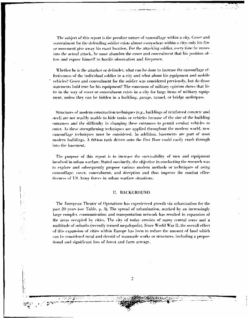
Thei subjvet of this re1 )ort is the p-vuCi ar niatuire of camouflage withini a city. Cove~(r and
conlcealmecnt for the defend i ti soldiler exists almost everywhere with in a1 vity: oniv his fire
or monvemient give a way h is exact location. For the attacking soldier. every time he movesinto tlie actualI attack. he munst abandon thie cover andl concealment that his position if-
fers adfl expose himitselfI to hostile observation andI firepower.
Whether hie is the attacker or dlefendler. what can Ihe dlone to increase the camouflage ef-
fecti~eness (of, the individual soldier in a city and what about his equipment and mobile
-vehicles?~ Cover and concealment for ilie soldier was considlered p~reviotusly. but do thosestatenments hold true for his equipment? The, consenisus of miiayopinion shows that lit-tle in the way of cover or concealnien exists in a city for large itemis of military equ~ipl-menit. unless they can he hidden in a building. garage. tunnel. or bridge underp~ass.
St ructuires of niodern constrtuction techniques (e.g.. hmiiidings of reinforced concerete andlsteel) are not readlily uisable to h ide tanks or veh icles because of the size of the building
entrances anid the difficultIv in clianging these entrances to permiit conmbat vehicles toenwer. As these strengthenling techniques arc applied throughout the imoderni world, new
Caniouiflage techniques imist be considered. hi addition. basements arc p)art of mostmnodernl buildlings. A 60-toui tank driven onto the first floor couild easi ly crash throughinto the basement.
The iiiirptise of' this repiort is to increase the stirvivabi Iitv of men and equipmentinvolved in uirban warfare. Stated suiccinct l. [ lie objective in conductleing the research wasto exp~lore and subsequentlyI prop~ose various modern methods or techniques, of usingcamiouflage. cover. concealment, and deception andl thus impjrove the comibat effec-tiveness of' US Army forces in urban warfare situations.
11. BACKGROUND
Thle E~uropean~ TIheatre of O perations has exp)erienced growth via urbanization for [liepast 20 %var- (see rabme. p. 3). The spread of urbanization. marked byan inicreasinglylarge conmplex comninilication and transportation network has resulted in expansion ofthe areas occupJied by cities. The city of today consists of many central cores and amulti tuide of suburbs (recently term eul megalopolis). Since World War 1I. the overall effectof this exfpaision of cities withini Europe has been to reduce the amount of land w hihcan bre conidselred rural and devoid (if niaiiniaue works or structures. inicluding a wpr
tiona I andI significant loss of forest and farm acreage.
''A,-
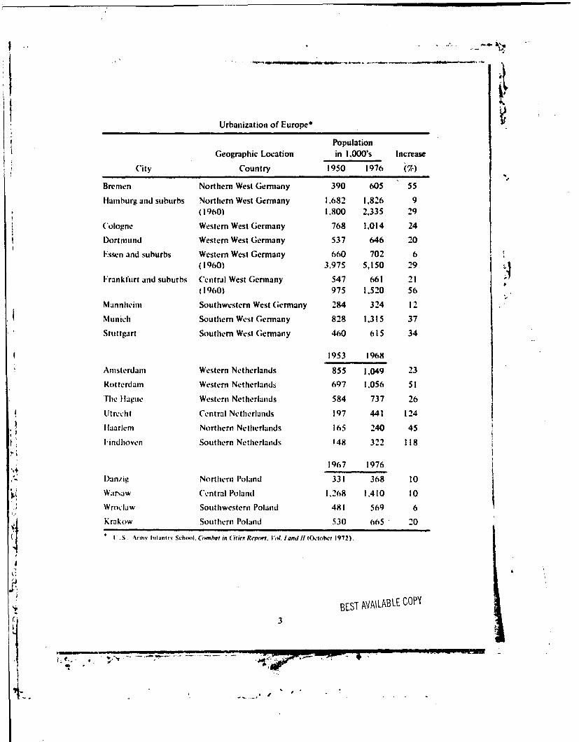
Urbanization of Europe*
PopulationGeographic Location in 1,000's Increase
City Country 1950 1976 (%)
Bremen Northern West Germany 390 605 55
Hamburg and suburbs Northern West Germany 1.682 1.826 9(1960) 1.800 2.335 29
(Cologne Western West Germany 768 1,014 24
Dortmund Western West Germany 537 646 20
Fssen and suburbs Western West Germany 660 702 6(1960) 3,975 5,150 29
Frankfurt and suburbs Central West Germany 547 661 21(1960) 975 1.520 56
Mannheim Southwestern West Germany 284 324 12
Munich Southern West Germany 828 1.315 37
Stuttgart Southern West Germany 460 615 34
1953 1968
Amsterdam Western Netherlands 855 1.049 23
Rotterdam Western Netherlands 697 1.056 51
"The 11agne Western Netherlands 584 737 26
Utrecht Central Netherlands 197 441 124
Ilaarlem Northern Netherlands 165 240 45
1tindhoven Southern Netherlands '48 322 118
1967 1976
Danzie Northern Poland 331 368 10
Warsaw Central Poland 1.268 1,410 10
Wroclaw Southwestern Poland 481 569 6
Krakow Southern Poland 530 665 20
V S. Army hifant r. School. C(ombat in Cifire Report. I'd. I and If (October 1972).
X".
S, BEST AVAILABLE COPY
"- 3
4-. _ wI .. .
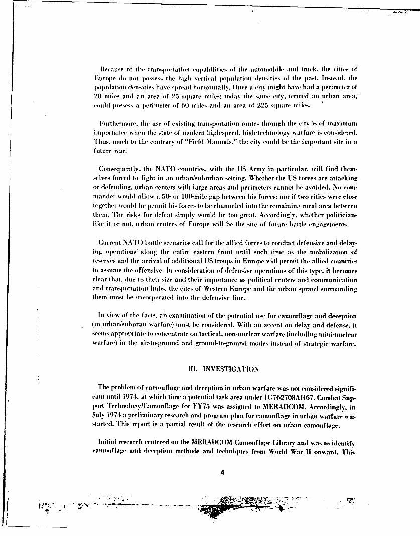
B'cauise of the( I ralsl)ortatioli cajpalilities of the automoioleI and rtriik. the cities ofEuArop~e (do tot p)ossess the high vcrtijal populationi denisities of tile past. lnsteal. Ili(-popuilationl denlsities have spread horizontally. ( nee a eity might have had a p~erimiete'r of20 miles and anl area of 25 square miles; today thle same city, termed ail ujrlaii area.
cldpossess a perimeter of 60 miles and anl area of 225 square miles.
hurthermore, tlie use of existing transportation rouites through the eity is of maximumimportance wheni the state of muodern Ihigh-speedl. high-technology wiarfare is considIered.
Tim,5 nuiuch to thle contrary of "Field Manuals." the ctcolbethe important site in afuture war.
Consequently, the NATO countries,, with the US Army in p)articular. will find themi-selves forced to fight in anl urbanlsuburban setting. Whether thle US forces are. attackingor defendimtr urbaii centlers with largve areas and perimeters cannot fie avoided. No corn-mander would allow a 50- or 100-mile gap) between his forces: nor if two cities were (-losetogether would hie p'rnhil his forces to be channeled into the remaining rural area betweenthem. The risks for defeat simply would lbe too great. Accordling!y. whether politicianslike it or not, urban centers of Europe will b~e lthe sit(e of future battle engagements.
C urrent NATO battle scenarios call for the allied forces ito conduct defensive and delay-in,, operations* along the entire eastern front until such time as thle mobilization ofreserves and the arrival of adlditional US troop~s in Europe vw;Il lpermit the allied countriesto assume the offensive. In considerationi of dlefensive operations of this type, it becomies(clear that. due to) their size andl their importance as political centers and commnunicationand transportation hubs, thle cites of Western Europe and tile urban sprawl surroundingvthein must be incorporated into the defensive line.
Ini view of thle facts, anl examination of thle potential use for camouflage and deception(in urbanlsuburan warfare) must lie considleredl. Withi anl accent onl delay and defense. itseemis appropriate to concentrate onl tactical, noni-nuclear warfare lincluding, Tnini-nuelearwarfare) in the air-to-ground and grmui (-to,-grouind modes intstead of strategic warfare.
Ill. INVESTIG;ATION
Tl'e p~roblemn of camouflage and dlecep)tion in urban warfare was not considered signifi-cant until 1974, at which time a potential task area uinder I (;762708A1167. Combat Sup-poirt TeehntologylCaniouflage for FY75 was assigned to MERADCOM. Accordingly, inJu~ly 1974 a preliminary research and( program plan for camiouflager in urban warfare wasAtartedl. This report is a partial result of thle research effort oin ulrbanl camouflage.
Initial research centered on lthe MEBAI)C()M Camouflage Library and was to identifycamiouflage and deceptlion methodsl- and techniques fronm World 'War 11 onward. 716o.
4
- 17",
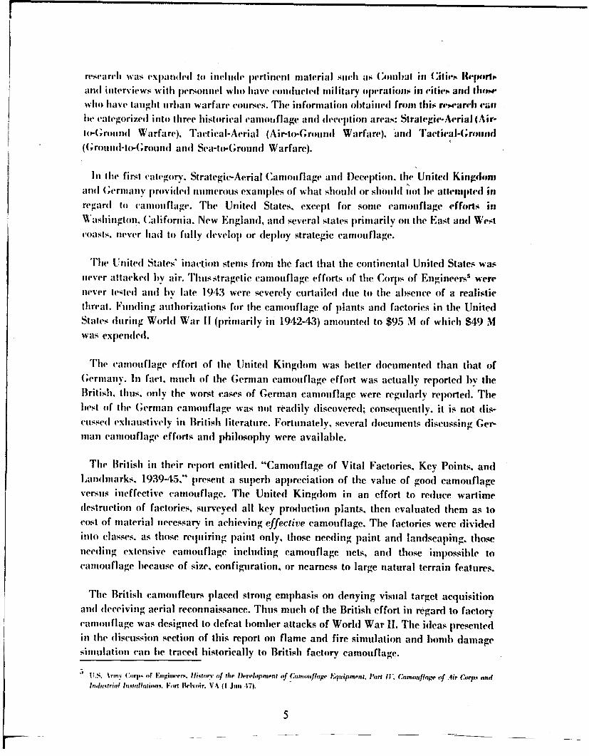
research was expanded to include pertinent material such as (Cmblat il in iet, IMeI1frlt.and interviews witlh personnel who have conducted military operationis in ritie•, and illom.whho havet lautght urlban warfare courses. The information obtained fromt this researc.h 'an
be categorized into thlree historical canlotuflage and decepttion areas: Strategic-Aerial (Air-to-(;Ground Warfare), Tactical-Aerial (Air-to-Ground Warfare). amInu Taetieal-(;rout|id(Grountd-to-Grounnd and Sea-to-Ground Warfare).
In Ihe first categrory. Strategic-Aerial Camouflage and l)eception. the United Kingdomand (;Grmany provided numerous examplles of what should or shouhll ,ot be attenmpted illregard to caiiiouflage. The United States, except for some camouflage efforts inWashington. California, New England, and several states primarily on the East and Westcoasts, never had to fully develop or deploy strategic camouflage.
The United States' inaction stems from the fact that the continental United States wasnever attacked by air. Thusstragetic camouflage efforts of the C orps of Engineers were
never teted and by late 1943 were severely curtailed due to the absence of a realisticthreat. Funding authorizations for the camouflage of plants and factories in the UnitedStates during World War II (primarily in 1942-43) amounted to $95 M of which $49 Mwas expended.
The camouflage effort of the United Kingdom was better docuimented than that ofGermianv. In fact, much of the German camouflage effort was actually reported by theBritish. thus. only the worst cases of German camouflage were regularly reported. Thebest of thie German camouflage was not rta(lily discovered; consequently, it is not dis-cussed exhaustively in British literature. Fortunately, several documents discussing Ger-man camouflage efforts and philosophy were available.
The British in their report entitled. "Camouflage of Vital Factories, Key Points. andLandmarks, 1939-45." present a superb appreciation of the value of good camouflageversus ineffective camouflage. The United Kingdom in an effort to reduce wartimedestruction of factories, surveyed all key production plants, then evaluated them as tocost of material necessary in achieving effective camouflage. The factories were dividedinto classes, as those requiring paint only, those needing paint and landscaping. thoseneeding extensive canouflage including camouflage nets, and those impossible tocamouflage because of size, configuration, or nearness to large natural terrain features.
The British camoufleurs placed strong emphasis on denying visual target acquisitionand( deceiving aerial reconnaissance. Thus much of the British effort in regard to factorycamouflage was designed to defeat bomber attacks of World War II. The ideas presentedin the discussion section of this report on flame and fire simulation and bomb damagesimulation can he traced historically to British factory camouflage.
5 U.S. Army C4,rj,... (f Enigiuwer. Ifist.orv of the Ih,,).i'opment of Camoufhlage Equipment. Part I1. Camoufiagr of Air Corps andIndn..trifl Irixta•tn irm.. Fort Ielvoir. VA (I J,,n 47).
5
Part of the ,leeeljiol effort involved eonstruction of decoy airfielis" near real airfields.The decov airfields were so realistic that friendly aircraft occasionally landed on them.Siniulated artivities were eoniucled on these decoy airfields to confuse the Germans intodropjiing meore honlo, on tlhe decovs than on the real airfields. This deception isremarkable when one considers that given one target. 100 percent of the bombs droppedcouhl fall on the target. (Of course, some bombs usually miss the target entirely.) When
fnil, additional largel is added - a decov of extremely fine deceptive quality - one ofthree otccrre'nces can lbe expected:
"* All bionms are dropped on the real airfield.
"* All bombs are droppedi on the decoy airfield.
"* A percentage of the bombs are dropped on each airfield.
Depending on the number of airfields, the camouflage of the true airfield. and therealism of tiht decoy airfield. the course of operations will turn toward the third uption
with an expected 50 percent of tile bomnbs dropped on each target. The British. however.conductied such simulation and deception efforts as to create a favorable 60- to 40-percentratio (approximately) of hIombs dropped on decoy vs real airfields. For night deception.7
the U.K. created several decov airfield landing light setso and developed a system of bon-fires niear enough to a real target so German night bombing raids were not noticeably offcoul Irse.
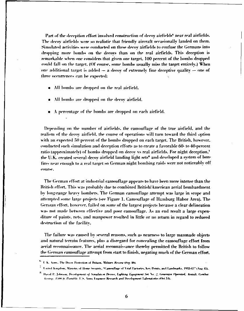
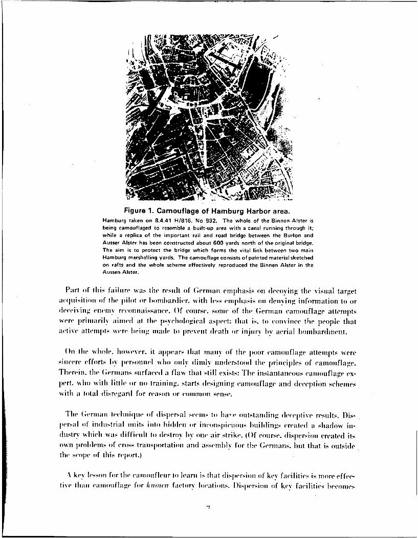
"The (;erman effort at industrial camouflage appears to have been more intense than theBritish effort. T'ihis was lroilally due to comlbined BritishlAmerican aerial bombardmentby long-range heavv iombers. The Genrman camouflage attempt was large in scope andattempted some large projects (see Figure 1. Camouflage of Hamburg Habor Area). The(;ernwian effort. I•owever. failed on some of the largest projects because a clear delineationwas not made belween effective and poor camouflage. As an end result a large expen-diture of paints, nets. and manpower resulted in little or no return in regard to reduceddestruction of the facility.
The failure was caused by several reasons, such as nearness to large manmade objectsand natural terrain fealures, plus a disregard for concealing the camouflage effort fromaerial reconnaissance. The aerial reconnaissanee thereby pernitted the British to followthe (;,.man canmtisflage attempt from start to finish. negating much of the German effort.
I A I Ow 16.. 10,. % t w,,,t'.'-,g, 4. Itritaitu. 118lilan Arm•,.w t.ap .
I | rnsI',I haaM, .... Wltats-tr• ,i II,,m." ,.',ni,. "4 am,,,flaL" 44 Vital Fhi"rw.. K.. Point%.. ans -LMIfflarku., Q3134S-" Ot r-1L
Iiaf.•,,! I'. *,lrt* ., I..fl•,4 .tt. n I l N.,, ltflhl% t'Alg l.4 . . , i tl~iq i tqitp t. i • W Na~.n.'.. 111.1 lo¢ .1pi.h~d. 4;
6
IF
Figure 1. Camouflage of Hamburg Harbor area.Hamburg taken on 8.4.41 H/816. No 932. The whole of the Binnen Aister isbeing camouflaged to resemble a built-up area with a canal running through it;while a replica of the important rail and road bridge between the Burlon andAusser Aister has been constructed about 600 yards north of the original bridge.The aim is to protect the bridge which forms the vital link between two mainHamburg marshalling yards. The camouflage consists of painted material sketchedon rafts and the whole scheme effectively reproduced the Binnen Alster in theAussen Aister.
P~art of th is failuire was the result of German emphasis on decovin g the visuial targetac(fIiisit ion of the pilot or b~ombardIier. with less emlphajsis on dcrie ivig information to or(leeei%-in g enlellI reconnaissance. O f couirse, somie of the Germian camnotflagre attemp)tswvere primarily ainie( at the psychological aspect: that is. to conivinice thw people thatact ive attermpis were being mtade to pirevent death or injiry byv aerial bombardment.
O n the whole. however. it ap)pears that mianNy of thle poor camouiflage attempts wveresincere efforts I iv personntel who ontly dimily understood the principles of camiouflage.Therein. the Ge'rmanIs surfaced a flaw that still exists: The insiantauieous camlouiflage eX-
pert. who withi little or no trainhig, starts (lesinling~ camiouflage and deception scemilleswith a to ta I Iisreg-a r for reason Or commnon senlse.
The (Germani lechini~pie of dIisp~ersalI seemis to hia' i ou tstand i ng deceptive results. lDis-persa I of iuidu-trial un11its inlto hidden or inconspicuious buildhiings created a shia(low inl-dustry which was difficult to destroy byv one air strike. (O f course. dispersion created itsown problems of cross, trans1)ortationi anid assemblfl for the G;trnitauus. huit that is outsidethe sEohWp of this report.)
A key lesson for the camtoti fletir to learn is that (Ii.-persion of key facvilities is m1ore effec-tie hilnai cauinotifI aoe foir known factory local if 11. D ispersion of key facilities becomes
-7
tMlre effective whenl efllttt'W! ill dieionjulntinl with eamouflage and l•e'epifn. it ihi..reganl. t[he v';al industry must im1' moved via deceptioni ant camonlfage Its dispr•,r,Idingli'.gs awnd locations. The old location nmlst li Iliiutai nd in itS triginal e,.ndlliis viadeception ald Ihe new t loca.ionsl mutst lhe camouflaged to cone.al ,-w mioion., Mly"a'eianfhlge-d.' in this contlext. we mean they shouhl nol t•ecome co.nqii'usiJ* in tlwirnew Inlissi'ols.)
Thereby. the erniey continue.s to perceive tle target in its original lo-ation. Aciorling-Iv. the aggressor will concentrate air power on tile acknowledged target and will not ev-panl reconnaissance resources looking for a new target. Thus tile aggn'er will Aa~týrmunition's and aircraft on a worthless target.
A priime example took place in the French theater from 194.3 to 19,-1. AfterPenemiuhde. British reconnaissance detected and correctly identifiled tle V-i rocket Wmobramps in Northern France.' in the fiall of 1943. thei Allies began an intensified boImbingeffort that dropiped over 31.000 tons of limnh- during the pwrimd I)ecemlwr 19,13 to June1944.
"The German Iligh Conmmand realized the vulnerability of the old design V-I rocketramps and (decided to construct new mobile launch ramps. ilowever. to deceive tileBritish and Americans. construction was continued on the old ramps with varions aplinr-priate hut faulty camouflage efforts and concentrated air defense. The Allies'° continuedtheir air attacks on the old style ranmps. realizing their mistake only a few days iefore thestart of the V-i attacks on London. Field Marshal Mil Kh. (General Inspwctor of the Ger-man Army, remarked that "The British and American aerial attacks on thie V-1 rampswere important to uis because, it relieved pressures on other vital war munition areas whilefailing to delay the real construction of the new V-I ramps."
The smoke screen was another method of deception used to hide the target from aimedhombing attacks. Both the British and Germans used smoke extensively to conceal vitaltarget such as key hSihlings, bridges, oil storag e depots, and military installations. Thesmoke generation units were of two types: fixed (semi-permanent) and mlobile. The mobileunits (such as the U.K. I Iaslar) were mounted on tnrcks and could be moved during a hat-tIe to new locations to concentrate their smoke in various areas or to take advantage of tilewind.
"FTie problem with smoke screen was that in terror or mass bomining raids. thie smokescreen was ineffective. In these raids, where the city itself was tile target. rather than aparticular bridge or factory. the random nature of the honlb attack negates tile abilitv of
1). Smi. NilP. IUK. "I' i l, ,,m the FI.•ing Imlih.'" Ifilitur" Reriiw IIhr e -tit.
It, ( It, '. S. I USSR. I 5SI. "BaIghe .gl il-t '%g a imm l I.u'k's.'" .{ntir~irifr I•efen•. Iernll. Aim.•r,, iugar 1I t.
8
the smooke to deny visual acquisition of particular targets. The smoke, itself, if concen-
trated in one area of the city can be used as a guide by the bombing aircraft to concen-
Irate on the most vital areas in the city. This could result in those areas with smoke
screens receiving the heaviest b)ombing effort.
A continuingr smoke screen, however, will make a damage assessment of the area dif-
ficult if not impossible by follow-up homber or reconnaissance aircraft. The end result is
the possible over-kill or under-kill of the target. Since smoke screens can be used by at-tacking aircraft to guide their attack, they can also be, and were, used as part of a decep-tion plan to draw the homhers off target into non-vital areas.
The second category is Tactical-Aerial Warfare Camouflage and Deception (air-to-ground). During World War II, the Germans and Russians provided the preliminary ex-
amples of this type of camouflage effort, with the US, British (except for El Alamein),and others performing efforts of less frequency or scope. The most recent examples of theuse of caniouflage, camouflage patterns, ne's, and decoys were observed in the Arab-Israeli wars.'
In tactical-aerial camouflage. we are still concerned with aerial reconnaissance, targetacquisition. and air attack, but the poteniial targets have shifted from factories, oil pro-duction and storage facilities, and key manufacturing facilities to targets of a moremobile or transient nature such as military depots, artillery batteries, airfields, bridges,and various military units such as Armor, Infantry, etc. The destruction of these targetshas a inore immediate impact on the battle but not necessarily on the war. However. they
can frequently spell the difference between local success or failure.
One interesting factor in regard to air-to-ground warfare is that the speed of the attack-ing aircraft in the visual attack mode has not changed significantly. The speeds of WorldWar II aircraft were 250 to 450 knots when attacking ground targets. Although modernjets are capable of speeds far in excess of 450 knots, the capability of seeing small targets
at speeds greater than 50{) to 600 knots is very low. In addition, the reaction time to"ground obstacles such as trees and hills is small. Conversely, at speeds below 200 knots.the vulnerability of the aircraft appears to increase and, of course, the jet aircraft becomeaerodlvnamicallv sluggish and appronch stall speeds. Therefore, it appears that there isan aerial-attack speed window at which aircraft can engage ground targets with max-
imum effectiveness and minimum danger to themselves.
The British camouflage and deception effort at El Alamein is well documented and%ill not lIt. repeated here. The British effort illustrates that camouflage and deception if11-4,41 a-.siduoisiv is poisilde in arid desert areas even when the reconnaisanPe
im•-iibilitir,, are stulprhl.
4~ ~ ~~~~~~01 'Itfii4~lL~l ~4if ~ U~#".i~I I*4 %19V fF~ill,
9
Tactical camouflagve as *practiced by thle Gernmans and Russians emphasizes the denial
of target acq1uisition. However, the documents and( recordls illustrate that when counter
target acquisition and camouflage were used in conjunction with deception in denying
aerial reconnaissance, the success achieved in the ensuing battle was significantly g'reater.
The scope of tactical camouflage and dlecep)tion operations as practiced by the Russian--
in World War 11 is attested to by one operation of the 2nd Ukranian Army Grou p'2 ill thle
sp~ring of 1945. In this operation. 2500 nien were employed for 5 days anol nights erectinig
122 km of camouflage screens on lateral and radial roadls, 55.000 nl2 of artillery drape
nets. 100 dunirny tanks, and 60 dlumnmy artillery positions.
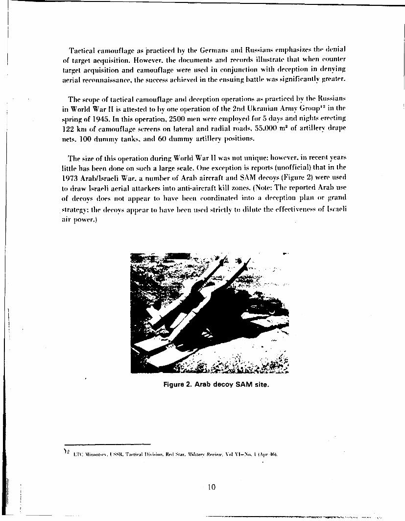
The -size of this operation during World War 11 was not unique: however. in recent years
little has b~een done on such a large scale. One exception is rep~orts (unofficial) that in the
1973 Arab/Israeli War. a number of Arab) aircraft and SAM decoys (Figure 2) were used]
to draw Israeli aerial attackers into anti-aircraft kill zones. (Note: The reported Arab) use
of dlecoys dloes not appear to have beeni coordinated into a dleception p~lanl or grandl
strteg. tile decoys appear to) have been usedl strictly to (Iiluite thle effectiveness of Israeli
air p~owe'r.)
Figure 2. Arab decoy SAM site.
)2 I :I*( Ni )fii -4*t . t ssil. rawtival )1 i-i% oo. vil~ Si ar. IIIrieirr Rerie'n. Vol % - No. I4 Apr 464.
10
In regard to tactical camouflage. the Germans in WorldI War II camoiflaged theirmotor vehicles and tanks' in pIolulated places by building extcnsins with overhangingroofs into the sides of existing l ihlbuiings. 'Ille walls and roofs of these extensions weremade of straw and wood or other natural construction materials.
()ther examples of Gernian tactical camouflage involved trains anid oil storage var-
disguised to look like boxcars and flak (AAA) guns hidden in haystacks. boxcars, andfalse Iuildings. The use of autobahns as runways for aircraft complete with hidden air-craft hangars and taxiwass. plus the use of artificial spotting of airfields in arid. openfields creating (lark areas where aircraft couht l)c hidden anmong the many other (larkspots (useful primarily against high-altitude bombing) and decoy aircraft.
The use of smoke was discussed earlier: however, with regard to mobile units a newturn is taken. Smoke canisters were attached to the vehicles themselves' and detonatedUi[Ofl eonuiniaiui.
In the third category, tactical ground-to-ground camouflage, the effects of lateral line-of-sight and weapon blast must be considered. The ranges are usually short and( are veryshort within the city. The primary method of target detection was and still remains theVIsual mode. Thii,' method of detection has recently been supplemented with thermal in-frared (IR). passive night vision devices. active IR. and radar.
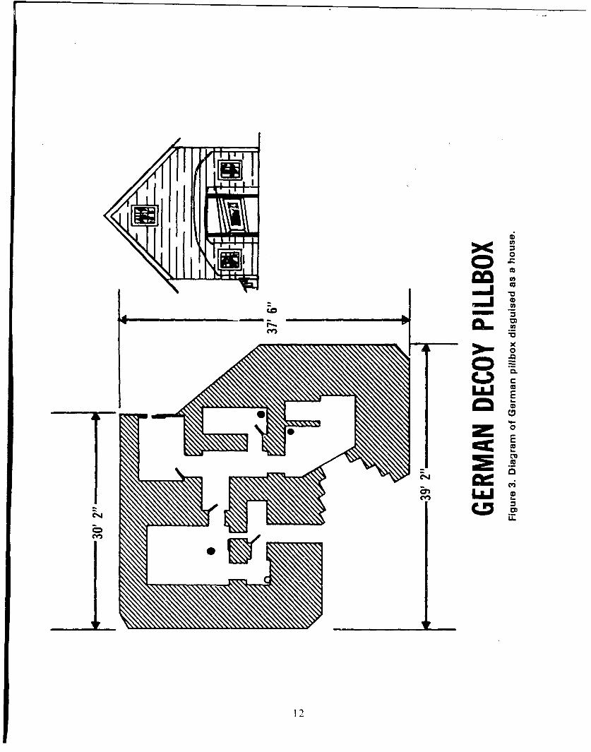
In World War II. the Germans were adept at canmouflaging strong points in cities. Thesestrong points were bunkers and pillboxes frequently camouflaged to look like buildings(Figure 3).'s
Unfortunately, even though tile literature discusses ground-to-ground camouflage, few
pictures or reports exist on tile topic. Two recent reports that go into some discussion onthe topic are:
a. U.S. Army Infantry School: Combat in Cities Report: Vols. I. II. and III; Fort
Benning. GA (1972).
1). U.S.S.R. report. "Combat Actions of a Motorized Rifle Battalion in a City." MG A.K. Shovkilovich. COL F. I. Konasov. and COL S. I. Tkach. Moscow (1971).
13 1 TT L .T. KIn neq . Ca 111f4 ,11 t TeIlhni , * er d I ;o rman Air For'es. V'estnik Vomi.ush•umgo F144a (Aviatimm JIiunm lI. USSR. 1943.traah Ie , ;% & ;S. Firt I ,ave w,,rih. KA... Ililiturv Revieic. V#l XXIV - Nm. 2 (May 0v144).
-It G i, .. N iw D)e'.ehipmenI i. the Germ n -Tige'r" Tank. llfiutrv Review (Mav 19-1-t).
lid: J11h11 E, Kehlley. USA. "-Th i Pillo - A Trap." .1hiifa.rv Reriew (Ati I 19:1).
11
~<0iL LU-
These reports discuss such items as dummy positions, cover. miultiple firing p)orts (sothat the enemv will not know which hole the fire is coming from), and smoke agents.However. ihese reports do not provide significant detail with regard to the utilization ofcaniouflage as a deceptive lactic.
The GernriaIIs16 in World War II and. in particular. the Russians"7 1" empjhasized theheavv uisP of smoke in warfare. The smoke agents are used by the attackers or defendersto conceal the maneuver of men and weapons between strongpoints or, when placed onthe enemy. to blind them from observing and conducting aimed fire on the attackingtroops.
The use of special urban camouflage uniforms or items is not evident except for areference to the World War II U.K. urban camouflage sniper's outfit. The Germans and
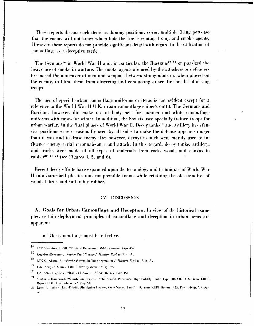
Russians. however. did make use of body nets for summer and white camouflageuniforms with capes for winter. In addition, the Soviets used specially trained troops forurban warfare in the final phases of World War I1. Decoy tanks"9 and artillery in (]efen-sive positions were occasionally uised by all sides to make the defense appear strongerthan it was and to draw enemy fire: however. decoys as such were mainly used to in-
fluence enemy aerial reconnaissance and attack. In this regard, decoy tanks, artillery,
and trucks were made of all types of materials from rock, wood. and canvas torubber"' 21 22 (see Figures 4. 5. and 6).
Recent decoy efforts have expanded upon the technology and techniques of World War1I into hard-shell plastics and complressihle foams while retaining the old standbys ofwood. fabric, and inflatable rubber.
IV. D)ISCUSSION
A. Goals for Urban Camouflage and D)eception. In view of the historical exanl-
ples. certain deployment principles of caniouflage and deception in urban areas areapparent:
Slithe caniouflage nuist be effective.
10 TC Nlit, int..P. I SSR. -Tartival 1Di'•er.&n.'" Ifiiltarv Review I %fr 15).
It) hiT K ,, reiter, i m; m ii. -5,,n Tra il. Ni,,.ir:r,. 11iIfi,,r, Revie ,T N.,P% Mi.
1H 11 . khai~al-,iki. -$nm,,e S.-r.'ett in. Tank 4 ) 1 Iat.n-'lilif,,r, Review I %111, 15.11
I .k . %rim.. "i m,,inr TIuik." I *ilit i I tr rviet Rla ' 16).20 .S. ".rm,• hnintivr-. "Ihfil,,.r Ihe,',,%..*" 1ifiltarv Revie.w ( %11, 161.
21 Marlini J. Danmpiard. "'Simiati,t, I� I., .. vrrfa-ri l,'4ah . I'neimitfii Iligh-FIidelit%. Tll "e "l'Mm MIM I | I . '.. r.S. , ERIIII.
H,-rt 1251. Fort |irk,.ir. N % (Se 52).22 Ja,,., I.. lfarhrr. "*i.,,,,-- i.lit, SihII ii I I .h' li -. G41,. Nam,.. "l.i6.. I .S. %r,, E IIm . ileur)-rl 1375. Fru iII, ,ir. V\ N .i4ep
13
I pS
tM
Figure 5 . US Army simulation devices , verylowfidelity, pnu ai, o izrpneum a wthicasprsriag uen truck, paighte cat 7 ngnva .
' *1
,Figure 4. US; Army simulation devices , vr low- fidelity, pnu ai, o izr!i,•'!•,* 1pneumai suert ruc turra en truck, painhwted 6-am unva .
iII
i 'I
4 Ii?.I.,'4i
""VT
115
41'
e The cariouiflagev or tlccov uised should be iniexpensive coitparedl to the real itemuoIf equipfileItI.1.
e Thle caniiouiflage or decoy tise(1 41(101( req1uire less mnaterial. timec. and effortto set uip or emj)ipace than it costs the enitniy in timie and mnaterial to (lIetect or dIestroy it.
The effectiveniess of the camiotflage or (deception is of lprimie inli1 ortance.Utnless camtouflage is effective it is worthless. In fact. it will spread a false sfe,.se ofsecuirity anid coiisumne valuiable timie, effort. andI materials. Exampil)es citedl earlier con-veriiigr Ge'ntina camnouflage attemplts for local p)olitical reasons are emptilt gestures which%0oon elenionstrate the hypocrisy and foolishness of the authors.
Ineffective camnouflage shouild never be allowed. eveni wheni it is part of at (Ieeeptionschemie. Troops shoould niever be pernifittel to1 pwratice p)oor camnouflage. because they willleanti lessonis that are difficuilt, if niot impolssible. to forget. Ratlher. if at particularilecept i in shemwte calls for poor ( atmot fi age or decep~tion oni the( part of at unit. it miust I1cjila injed. If a tiniti is o) lie dletected oni p riirose-. the canton ifla ge iu issioni ithtist 1we to gaii)that detect ion lby the etigiemy. it muist not I~e left to chance.
The cost of fthe caniot flage should lwe les.s thant the cost of the real item,. unless its(bscovIerv would mtaterially' affect fthe couirse of the conflict. F~or examiple. a $600.00camouiflage niet should not lbe used to htide objects of less value thani the niet. unless thoseob~jects are of a critical niature or their (Iiscoilenl' would lead to the dletection of other near-loy itemns (if high valtie.
Likewise. a decoy should always cost less than the real iftem. This is jiarticuilarlytrue ini regardl to1 decoy itents swecifically designed and eniplaced to b~e fired on andl(lestroiyed liv the enenill. In that instance, the (lecov shouild achieve at (l-cejltioni iln tit,-iuhind 'of the'attacker 1but -shouild cost less (totally) th'an the homis,. rockets. aircraft, fuiel.etc.. it-s(l( lii' the eneniv force toi destroy it.
B. Achieving Camouflage and Deception in Urban Areas. Achieving'a goodlcamiouflage and~ 'eceeptioii postuare in uirban warfare (lepelt(1s on training andI eqluil~netici.I.nifortunately, in bioth oif these are-as the Arntiv is unprep~aredl. If certain units weredJesignated in adlvance as uirban cottnliat units, their et-uipmtzent and( training ad nprticular. their camjouflage andl deception equipmteni ctil h'11le miore specializedl.
1t is c'lear that Camiouflage and l)eception foir Urban Warfare p~rovides tiledlefending, or (delaying force. with niany opportunities to increase its comibat effectiveness.This situation is piarticularly true foir areas where sonic timne is availabile to prepare tile(lefense.
16
.,s state(] p~reviouZsly. the indivjidua~l soldlier has inore than ad~e(pilate (-over in a city.ilowevt-r. when he fires his weapons. he reveals his jiositiori. TIherefore. a soldier~s
camouflage should be oriented toward diluting the effectivenes~s oif the enemny s counter-
fire and( retailhing a concealed position.
I )inimv and decoy positions utilizing lightweighit camiouflage material niust hedeveloped for the soldier's use. causing the enemny to distrib)ute his fire over several loca-
lions rather thli1n concentrate it in one area. Likewise, specific camnouflage gear muist be
provided toreduceeo mask wannos.and the dust raisedl l)V fi~ilqi ubesrw
aireas mutst he eli niinated. G;lint and( shine from eqJuipmenlt mutst be modified to blend in-it) the the vitv's background. Glare fromn glasses. binoculars. or infrared or night vision
dlevices mu1st lbe el iniinated. The sold ier's uniform must lie coloredl. patternedl. and tex-
turedl to iiiatch the tip.' (f wi Ildilng construction materials usedl in the city in which he is.
fighting".
Ali urbaii setting does not provide many' areas for conceal muent of a tank. artillery
piece. or wheeled vehicile. While sonic vehicles may be hiddlen in buildings or under
b~ridges. etc.. the number of areas suitable to hide a tank are small. Thus the tank in an
uirban area muist carry its own camnouflage net an 111 ust be supportedl with add~itional
claimon flage a~nd dec1 mt ýV ion equipment such as false buildings, false camouflage nets, and.Iecoy tanks.
The basic purpose for a tank in the urblan setn is to provide counter attackcap~ability. Thus it tank's camuouflage and deceptive gear initially must be orienltedI
toward the static mnode and provide p~rotectioni against aerial reconnaissance, targetactlllisition. and( attack. The survival of the tank. as thle key element to be uised in theland bilatle to comne (grounid-to-ground). miust first survive the air-to-ground attack madlebv the enemyv. Its survival should he a primec objective of urban camouflage. In the actuallandt( battle, as emphasis shifts front the air attack to the ground attack the tank mutst be
provided with sufficient smnoke aiid noise camouiflage to miask its approach into the imi-
iuiediate battle a rea.
In the Soviet concept of urban warfare, tanks and self-propelled (SP) artillery
-ire used in tile streets to speed up the attack and to help) the infantry stormi strongr points.Barriers and the camouflage and deception of these barriers are needed to slow and chian-nel the attacking, armor and self-propelled artillery into selected kill zones. Landmines.
particularly scatterable Iandmnines. h.ave a great potential for use in urban warfare.provide(] the depth and extent of the mined areas canl be concealed from advancingenemy troopls. In a simiilar manner, dlecoy landmines combined with real and decoydtragons teeth I-icn effectively reduce enemny attack options.
17
Paragraphs C and D contain a number of ideas presenting camouflage materialsand equipment or techniques for use in urban and suburban areas. These camouflageand deception ideas were derived from the historical records and from a study of thevamouflage needs of today's Army equipment.
Some of the techniques and ideas have been nearly forgotten but are just as valid to-day as in World War II. Others are capable of new usage based on the advances of tech-nology or are adaptations of old techniques to new materials and equipment. Still otherideas are original and have never been used. These ideas or techniques are described asprojects, in that, a separate effort is envisioned as being necessary to bring each one tofruition.
C. Camouflage and Deception Materials and Techniques for Use inUrban/Suburban Areas. The following items are proposed for use in urban and subur-ban areas:
1. Urban Camouflage Colors. This project would develop paints suitable foruse in an urban environment. Colors such as gray (several shades), dull brick red, sand-stone, brown (several shades). and several tar/concrete shades would be produced inenamel paints. The paints would be produced with a tinting capability so that the paintscou( l be recolored in the field to better match the terrain.
Tests wouhl be conducted in several urban settings utilizing various vehiclesto evaluate the value of urban camouflage colors vs field/forest camouflage colors. Aerialand ground observations would be made comparing the camouflage effectiveness of thevarious colors in hiding or reducing the detectability and vulnerability of the vehicles.
Upon conclusion of the tests, a recommendation would be forwarded toI)ARCOM and DA concerning their recommended use in urban areas.
The paint, as a minimum, would be added to the inventory of availablecamouflage colors.
2. Urban Camouflage Patterns. This project would develop variouscamouflage patterns for use in urban areas. Patterns would include harsh and softgeometric patterns as well as soft, random curves utilized in the current Army fieldcamouflage patterns.
Aerial and ground observation tests would be conducted in several urban areasutilizing various vehicles (i.e., tank, APC, truck) to evaluate the value of the geometric vsrandom curve camouflage patterns. It is believed the value of the test would be enhancedby simultaneously testing urban vs field camouflage colors.
18
Upon conclusion of the testing, a recommendation would l)e made toDARCOM and DA wheliher to use urban camouflage patterns and colors on vehiclesdesignated for defense of urban areas.
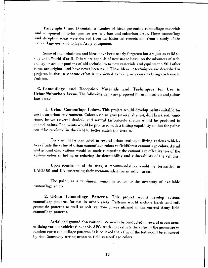
3. Urban Camouflage Net (Drape). This project would developthe coatingand colors for an urban camouflage net. Prototype nets utilizing geometric and randompatterns with urban camouflage colors would be produced. The lightweight camouflagenet and base cloth would be utilized as much as possible. The present pole and supportsvstem woull lw utilized, modified to be free-standing with limited (no stakes) tiedownpoints (Figure 7).
Upon development of the prototype net and modified support system. testswould be conducted in several urban settings to test the value of the urban camouflagenets vs regular camouflage nets. Both aerial and ground observation woull be utilized.
Upon conclusion of the test, a reconmmendation would be made to I)ARCOMand 1)A( oi whether to fully develop and field an urban camouflage net.
MODIFIED NET SUPPORT SYSTEMSFOR URBAN CAMOUFLAGE NET
• CLAMP SPREADER
TRIANGULAR FOOT WITHEXPANDABLE CLAMP
Figure 7. Modified net support system for urban camouflagenet - triangular foot with expandable clamp - clamp spreader.
19
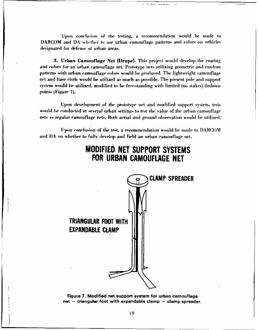
4. Urban Flat-top Net. This project would develop anI urban camouflage eIt of
flat-top design (Figure 8) with the camouflage material thinned on the edges. PrototyjPSof patterned vs solid colors would be mtilized in the net material. 'I'he pole and support
systemi will be modified to be free slanding. with limited (no stakes) tiedowns.
Upon development of the prototype. aerial observation tests, only. would
be conducted. The objective of these tests would be to evaluate the effectiveness of this
Ivpe of net in anl urban environment relative to no camouflage and to regular camouflage
nets. A flat-top net shows great promise for use in an urban area because the height of
buildings will preclude oblique aerial reconnaissance. Accordingly vertical photography
and visual detection can be considered the primary reconnaissance threats.
0 Ie GRAY AND BROWN
LESS GARNISH ON EDGEBLACK ON REVERSE SIDE
URBAN FLAT TOP NET (TOP VIEW)
00
FREE STANDING
Figure 8. Urban flat-top net - top and side views.
20
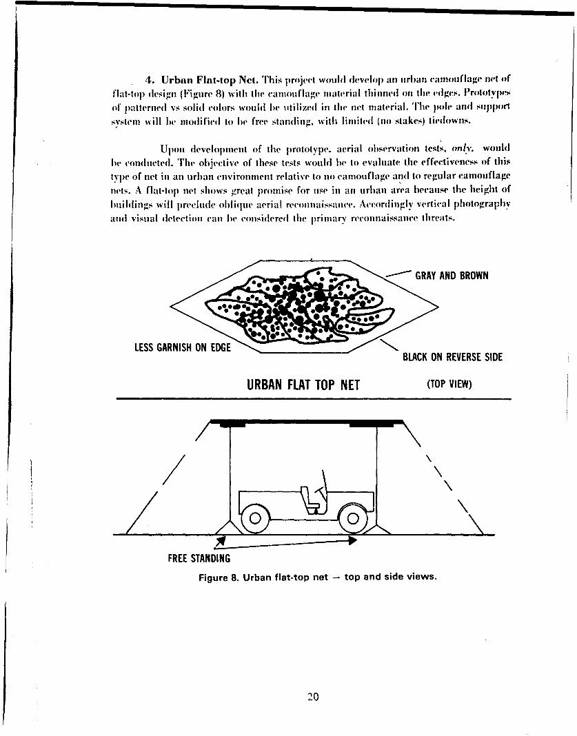
5. Pseudo Masonry Landmine. This project would develop various
coatings for use on antipersonnel and antitank landmines. The coating will give scat-
terahle and other types of landmines the appearance of brick, cinderblock, or masonry.
Distributed semi-randomly on streets and highways among other real rubble,
the pseudo masonry landmine (Figures 9 and 10) would create confusion in the mind of
an enemy tank commander forcing him to go slow or use mine-clearing equipmentiex-
plosives rapidly.
PSEUDO MASONRY LANDMINE
4 1
REGULAR M19 PLASTIC M19 LANDMINE-CAMOUFLAGED TOHEAVY ANTITANK MINE APPEAR AS CONCRETE RUBBLE
WT. 28 LBS. FUZE M606EXPL 21 LBS 350-500 LBS
PRESSURE.
Figure 9. Pseudo masonry landmine M19.
21
PSEUDO MASONRY LANDMINE
REGULAR M6A2 MEDIUM METALLIC ANTITANK LANDMINE
WT-20 LBS FUSE M603
EXPL-12 LBS FUNCTIONING 300 TO 400LBS PRESSURE
PLASTIC-TEXTURED & COLORED TO SIMULATE CONCRETE
IRREGULAR SHAPE TO SIMULATE BROKEN CONCRETE
Figure 10. Pseudo masonry Iandmine M6A2.
6. Penlight Smoke Stick. This project would develop a penlight-sizesmoke canister. The smoke stick will utilize the methodology and technology presentlydeveloped for the heer-can--ize instantaneous smoke canister. A size reduction to that ofthe average penlight flashlight would iw made. the average size should be 6 inches longby ¾ inch diameter with a fuse at the one end. Upon arming the penlight smoke stick, the
) soldier would have 4 to 6 seconds to place the device before it ignited. The stick wouldput out an intense volume of smoke for 5 to 15 seconds without causing a fire in thebuilding.
The penlight smoke stick would be used in urban warfare, that is, in building-to-builling and room-to-room lattles. It wou'd be used to provide smoke cover toindividual soldiers assigned the task of clearing the buildi:ng of enemy soldiers. Due tothe light weight and small size of the penlight smoke stick, several could be carried oneach soldier. If the soldier needed to cross a hall or doorway where the security wasdoubtful, he could ignite a penlight smoke stick to provide cover. The present method ofoperation is to use a hand grenade or continuous rifle fire. Both of these current methodsconsume large quantities of ammunition and do not provide the protection from aimedfire that a smoke cloud would provide.
22
7. Decoy Building. This project would develop lightweight prefabricated decoybuildings of various materials such as metal, wood, and/or cloth over pipe. The decoy isenvisioned as a one-story structure, designed to split open as illustrated in Figure I Ipermitting rapid movement by a vehicle or firing by a AA or SAM unit from within thestructure.
The decoy building would be used in an urban or airfield setting to concealequipment such as tanks, self-propelled artillery, and antiaircraft weapon systems. In.particular, VULCAN or CHAPARRAL air defense weapons could he concealed withinthe structure. Upon attack, the structure's roof and/or roof plus sides would slide open topermit the air defense system to engage the enemy aircraft.
DECOY BUILDING HIDING VULCAN
SPLITS OPEN
, .. .SPLITS OPEN
Figure 11. Decoy building - hiding Vulcan.
8. Camouflage Set/House Extension. This project is to develop a camouflageset to extend the side of a house. The set is envisioned as containing a free-standing sup-
Port system and cloth roof and walls for up to three sides (Figures 12 and 13). The clothroof an(l wall would be colored and textured to appear similar to real masonry walls androofs.
The house extension camouflage set would be utilized in urban/suburbanareas where buildings exist, yet where camouflage nets cannot be utilized effectively.This set would be used to hide items such as tanks, APCs. artillery, or trucks hy extendingthe sides and roof of a building.
23
W L1
c L U 0
2M ;- I--U
I- ý = -=
W O cc L, ~ LL
o cn-'2 LA.~
cm--
0.
L2aJCt,, c
0
I Li.. cc
4:24
AERIAL VIEWFALSE BUILDING EXTENSION
A,,,ROOF
SHADOW
FALSE EXTENSION TO THE BUILDINGFigure 13. Camouflage set/house extension - vertical.
9. Brown (Dull) Coated Communication Wire. Communication wire is cur-rentlv coated with a shiny black plastic coating. This project woul(l develop a (lull browncoating.
Conmmutnication wire has been used heavily in urban warfare where multistorystructures interfere with military radio transmission. This wire has been primarily coatedwith black rilier/plastie sheathing. A (111ll brown coating will make detection of the wiremuch more difficult, a factor inmportant in close-in tirblan fightingu.
10. Foam Camouflage for Landmines. This project would develop a high-persistence. water-based foam and a portal)he foaming unit (Figure 14). The foaming unitwond1(1 lie trailer mounted amnd wouldl be towed by a 5-ton water tanker. The portablefoaming unit. utilizing water from the city fire hvdrait systenm or the water tanker wouldprovi(le water at operational pressure to the foamiing nozzles. There the water woulh liemixe(l with detergent and made into a high-density foam. T'he foam would then be blownoul by a (lirectional fan/nozzle arrangement.
The high-persistence foam would be emplaced in city/urban area streets to cover(eamouflage) scatterable antitank and antipersonnel landnmines. Conversely. mines of theair-scatterahle type couhl be emplaced after the foam was eln)laced. The foam could be'lphloved without landlnines under it as a decov device.
25
TRAILER MOUNTED FOAMING UNIT
U L MESH SCREENS~TURNABLE
GEAR BOX FAN 450
") 450 TURNABLE
FUEL TANK :
NOZZLE ASSEMBLY
TURBINE GAS EXHAUSTEDINTO FOAM TO PROVIDETHERMAL SIGNATURE TO PFOAM
Figure 14. Trailer-mounted foaming unit.
11. Acoustic Grenade. The project would develop a small portaile device whichwould emit intense sound. The device would be alout the size of a hand grenade. The"sound grenade would emit a continuous, selectively changeable, high-pitched sound(whistle) ly means of a battery and motor or a fuel-propellant stick turning a siren-typenoise emitter for up to 5 minules. The sound intensity should be adjustable to as high avolume as required to disorient or damage an unprotected ear drum in an enclosed room.
The sound grenade would be used to cover ity noise the movement of men anldmaterial (i.e.. tanks. AP'(. etc.) in an urban environment. In addition, it could he used todraw attention to itself. Used as a strip flare or in conjunction with an acoustic or thermalsensor it could signal the entry of intruders into unguarded ipart of a buihling. The con-stant sound would be a means to aid the defensive forces to home in on the position of en-
tri of the intruder.
12. Glue-on Rubble. This project would devclop a glue to attach brokenmasonry to the metal surfaces of combat vehicles. The glue should have good metal-to-rock adhesion. be apljiicalhle in the temperature range of 400 to 1200 F. Tih riohhlewould add color and texture to the u.urface of the vehicle. The glue should be removabhle
bv application of a prolwr solvent.
The glue would le used to attach rubble from the urban area to vehicles(in particular. tanks and APCs) operating in tile city to increase their camouflage.
26
13. Decoy Urban Camouflage Nets. The project would develop a low-cost,super-thin, lightweight decoy urban camouflage net (Figure 15). This net is envisioned asbeing approximately 1110 the weight, cost, and bulk of the present camouflage net.Coloration and texture would be similar to urban net. The support system would bereduced in weight bv using air-inflatable poles. The net will consist of colored cloth witha border tie rope but no actual netting.
The decoy net would be employed in urban areas to dilute the effectivenessof enemy attacking aircraft. Based on analysis and availability, one to four decoy netswould be utilized for every real net. The decov net would be used in areas wherecamouflage effectiveness against dletection is low but where camouflage against iden-tification is still desired.
The decoy net wouldh be used in a situation where it is impossible tosuccessfully hide equipment, such as an Armor Platoon (5 tanks) which would use 5regular nets. With sufficient additional decoy camouflage nets (possibly 10). the enemy ispresenhed with the problem of destroying 15 targetable camouflage nets, only 5 of whichhave real largets under them. If the Oieneiv has unlimited offensive eapability, all we havesticcecIded in doing is to cause him to expend valuable ammunition and waste time and(effort. Ilowever. if the case exists where the enemny has a limited offensive capability, theadditional devoyt ntis will substantially reduce the probalbility of destruction of all 5tanks.
URBAN DECOY NET
URBAN COLOR SOLID CONCRETE COLORONE SIDE SIDE TWO
BLACK TANTAN OFF-WHITE
GRAYCONCRETE
CLOTH ONLYNOSUPPORTINGNO B NET /
BORDER CORD
NYLON-3,/" OR LESS
Figure 15. Urban decoy net.
27
14. Claymnore Mine Camouflage Set. The project would develop a carnonflage
claymore mnine set. The mnine would he camnouflaged to look like part of a wall or a adver-
tisemnent sign and he attached to a business estalblishment (Figure 16). This "line wouild
lbe comnmand. trip-wire. or acoustic-sensor detonated.
In an urban setting a clavinore inine camiouflaged to look like part of abuilding, wall or street advertisement sigrn would be placed in a suitable location for
defense against enemny infantry.
MINEE EXPLODINGIN
MMINE EXPLODING
Figure 16. Advertisement-sign Claymore.
28
15. Urban Spider Hole Covers for Antitank Teams~. This project wouldI
dlevelop) a smnall camniflitre net for use over foxholes, made in the street, (tc., in urbaniarea. The tiet' would be irregularly hamped. coloredl tanlbrown/black. textured. and sup-
portedl by air-inflated tubular supp)orts (Figure 17).
URBAN SPIDER HOLE COVER SUPPORT FOR COVER
CbNCETE OLOR(SIDE TWO)
ASPHALT COLOR (SIDE ONE) AIR-INFLATABLE
NET MATERIAL RUBBER OR PLASTIC
DUG IN ANTI-TAN K POSITIONS COVEREDCOVERED WITH URBAN SPIDER HOLE COVER E
Figure 17. Urban spider hole cover net and support.
29
Weapons with a back blast cannot be used in buildings; accordingly, they
must be deployed in the street or on roof tops. A small portable camouflage net for use in
a street foxhole would aid in the protection of antitank teams. This type of camouflage
was used extensively by the North Vietnamese Army and Viet Cong in the defense of Hue
City. South Vietnam. and it proved to be effective.
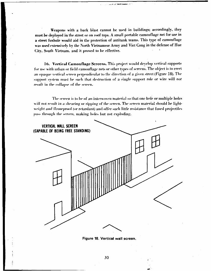
16. Vertical Camouflage Screens. This project would deyclop vertical supports
for use wilh urban or field caniouflage nets or other types of screens. The object is to erect
"anl paqle vertical screen perpendilcular to the direction of a given street (Figure 18). The
?.-t1prl svstemn muiust be siuch that destruction of a single support role or wire will not
resull i) ithe collapse of [he screen.
The srefen is to be (f an interwoven material so that one hole or multiple holeswill not result in a shearing or ripping of tihe screen. The screen material should be light-weighl aind i' ,,ieproof (or relardant) and offer such little resistance that fused projectiles
a hrogln tlite screen. making holes but not ex.plodi rg.
VERTICAL WALL SCREEN(CAPABLE OF BEING FREE STANDING)
Figure 18. Vertical wall screen.
30
This Docuwunt
Rsp'o"W FromBeitMAW*Copy
The screens would Ibe erected ini city streets. to conceal inov'n'intThe screenwould act as a visual and. p.ossilly,. a radar and infrared barrier t) the detection of items,beihind the net. Although the enemy could fire p)rojectiles through the screen. aimed fire
wouhl be prevented. In addition. other obstacles such as nnines. dragon teeth, antitank
weapons. etc.. could he installed behind [he screen without enemyiv observation.
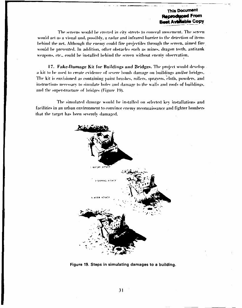
1 7. Fake-Damage Kit for Buildings and Bridges. The project would developa kil to he used to create evidence of severe lonib damage on Imihldings and/or bridges.
The kit is envisioned as containing paint bruslies. rollers, sprayers. cloth. powders. and
instructions necessary to sinulate holes and damnage to the walls and roofs of buildins.
and the sulerstructure of bridges (Figure 19).
The simulated d(amage wotild ie installed on selected key installations and
facilities in an urban environmient to convince enemyv reconnaissance and fighler bombersthat the target has been severely dlama ged.
1 AMR A ATA(I'
J 4 0-JO
.1 . 3
--. .. o .,
Figure 19. Steps in simulating damages to a building.
31
18. Street Sign K it. T'his p)roject will develop) a kit withi which Ihe street-;i-ns in an uirban area could be changed. T'he kit would include lettering sets, paints, andvarious tools for fabricatin g st reet signs. The' Gerinai uise of' this decep)tive ploy iin the
Ardennes offensive of World War 11 is well documiented and causedl tremendous confti
51011 ainong the Ainerican forces.
InI urb~an wa rfare considerable con fiision cani resuilt froin remnovin-, streetsis l-Nei uinore confusion results from making new stree't signs and cinplaving thein in
lie old locadtion~s.
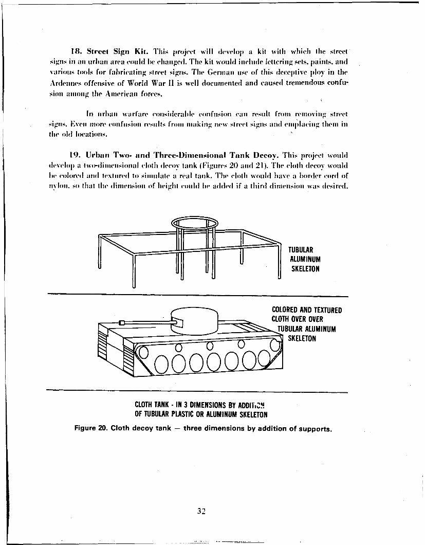
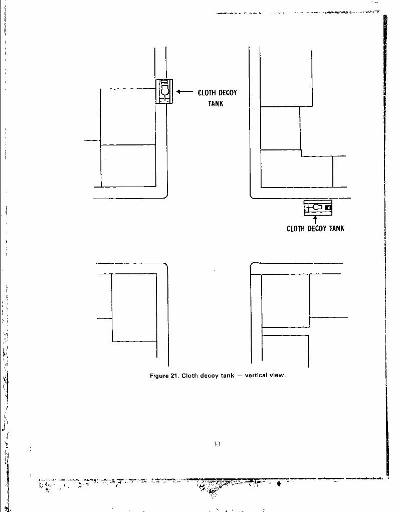
19. Urban rwo- and Three-Dimensional Tank Decov. TIhis project woulddevelop a two-dilnieuisioiial cloth deo ak(Figures 20 anid 21). Th'le cloth decoy wouldhe voloredl aid textui redl to simulitate a real tank. The cloth would have aI border cordl ofnydlon. so that tIhe dimnension of height couild lie added if a third dimiension %%as dlesiredI.
TUBULARALUMINUMSKELETON
COLORED AND TEXTUREDri CLOTH OVER OVER
TUBULAR ALUMINUMSKELETON
CLOTH TANK.- IN 3 DIMENSIONS BY ADDITtu"OF TUBULAR PLASTIC OR ALUMINUM SKELETON
Figure 20. Cloth decoy tank - three dimensions by addition of supports.
32
JJ'j]-- CLOTH DECOYTANK
CLOTH DECOY TANK
Figure 21. Cloth decoy tank - vertical view.
,33
In cities, dile to the height of the I ihli gt .tip liqii.e Idholograalliereconnaissalce is not as aseful as vertical ~Iotiogralplny: accordingly. there i6 a place fortwo-dimensional decoy items. The elemnent of' height emihl loe added by mean. of air-inflatable poles or narrow-diameter aliminimi or plastir pioles to prmrvii. lihret-dintensional targets.
Fighlter-bomber attack in tirbaii areas is affected similarlv. Visuially. litecloth1 tank will i resent an iulentification lroblem to enemy aircraft restillng in theeinemy s exIendling bIombs anti amimuition of) decov targets,
20. Rubble Net (Urban). The project would develop a new camouflage net andSuppIort system which wouhli present the appearance of a l)ile of masonry nibble. Theicloth of the net would ble formed and shaped to simulate thie dej)th and uneven texture ofa ruibble pile. The sul)port system would be free- standing without the unse of tiedownpoints or stakes. As envisioned, the net would be modular. but tiot necessarily of ahexagon/diamond configuration anid wohild present tile radar cross section antiabsorption of a rock liile.
The rubble net would be used over tanks/gun positions in an urban areawhere masonry rutbble existed. In a hiombed city. piles of runible will exist in variousstreets as a result oif street clearing operations. Adding more piles of nubble to the existingpiles would not attract the attention of aerial or grouml ol)servation and would make the
ieney's target detection/acquisition task much more difficiht.
21. Urban Camouflage Uniform.. This plroject would develop and testvarious p)atterned and colored uniforms suitable for use in urban environments. Thecolors evaluated would he several shades of brown. black. gray. sand. etc. These colorswould Ie conbiiied into various raindom geometric matterns and printed on combatuni forms.
The urban camouflage ulniforms would be evaluated in anl urban environment
and compared to the standard monotone olive drab uniform and tile patternedcamouflage iuniform. Upon (onclusion of the tests, a recommendation would be for-warded to I)ARCOI)l anl I)A concerning reconimended uise inl urban/suburban areas.
D. Camouflage and Deception Materials and Techniques for Use in Ruraland Urban Areas. nrie following items are proposed for use in the field as well as in ur-[)att areas:
34
1. Decoy Soldier, Inflatable. This project would develop an in-flathing/eflating, positioiabhe decoy soldier. Using thin. lightweight rubber/plastic. a
weighted-base decov ani would be fabricated. Tl'he decoy would be colored to resemble a
nian and would he inflated by ewans of a tined 12-volt d.c. miuiatuure compressor or
manually. Miniature compressors that fit in the lahn of a hand are capable of 45 11/in.2 .They cost less [han $30 and run on 12-V (i.e. batteries. The decoy's comipressor would re-
qfuire substantially less power. The decoy coull he designed to deflate/reitiflate lIv meansof a clock mechalnism on the miniature comnpressor. The deflater/reinflater cycle could be
utilized in (urban) building window areas or in field (foxhole) positions to create ap-parent movemient. The rubber/plastic of the decoy man could be textured and colored toresemlble a military unitorm. The decoy in a nondeflatable state could also utilize cast-off
military items, such as a real helmet. wel) gear, shirt, etc.
Upon fabrication of the prototype. tests woull le conducted to determinethe realism of the decoy. Operational evaluation tests would he conducted to determine
the impact on troops in a war game situation. The decoy could be deployed in conjunc-tion with machine gun or rifle fire simulators (Acoustic Grenade, described in paragraph
IV C 11) for added realism. In addition, it could be deployed with real but spent equip-iiient such as a used LAW or TOW in order to create an alpparent target to attract the at-
teution of a tank from a real antitank team. The decoy could also be used on live firecombat training or proficiency course where target variability is desired.
2. Fire/Flame Simulator. This project would develop various fire and flamesimulators. A given simiulator would consist- of a fire pan where volatile fuel (primarily
liquid) would be pernmitted to burn producing flame/smoke and the effect of a fire. Igni-tion of the flame simulator would be by electrical remote control using conunarddetonation or ufattenled acoustic or IR sensors. Different types of simulators would be
(designfed to simulate different types of fires. The simulators would be classified into twomain types - fixed and mobile. The fixed types would be redesigned and improvedWorld War I! types such as (non-inclusive):
a. Vertical fire grid for simulating burning walls.
b. Hlorizontal fire grid for simulating burning roofs.
e. Oil-fed fire for long-duration fire.
d. Boiling oil/water fire for producing flashes and explosions.
The mobile type flamne simulator would be designed to simulate. harmlessly, the flameand fire that would result when various mobile targets. both real and decoy. are hit bvenemy gull or rocket fire. Typical examples of the mobile fire simulator are:
35
a. A 2½-Ton Truck Fire Simulator. This simulator would produce thesmoke and flame that would result when a 2½-ton truck is hit by cannon or rocket firefrom an aircraft. The simulator would be designed to work on real or decoy trucks andwould be fired electrically by remote control.
b. A Tank/APC Fire Simulator. 'This simulator would produce thesmoke and flame that would result when a tank/APC is hit by an aerial(primarily) or a ground antitank weapon.
If is important that all decoys explode an(d burn like the real equip-nicnt. Ilv doing so. the deception as originally achieved by the decoy is carried to itslogical conclusion. The value of a deception operation is made more effective if theenemy believes he has destroyed the target. His belief is reinforced by flame/smoke andsecodlary Cxpjlosions.
Real items could carry flame and smoke simulators to help achievedeception. Activation of a simulator on a real vehicle after it has been attacked but notdesiroved should result in the attackers moving on to another potential target rather thanreattacking the original target. Consider an aerial attack by two fighter/bomber aircraft,the lead plane and his wingman. The first aircraft attacks the target, the wingmantightens the attack envelope with infornmation sulpplied by the lead aircraft and initiateshis attack. However, if the lead aircraft believes he has destroyed the target, his wingmanwill noit reattack an already burning target thereby wasting ammunition. The attackleader and his wingman will regroup and attack another target.
3. Tank-Tread Simulator. This project would develop a lightweight trackeddevice for attachment to either a jeep, 2½-ton truck, or othervehicle. The device would bemounted on the rear of the vehicle and consist of wheels and tracks with interchangeabletreads to simulate the track width and size of various tracked vehicles such as APCs.tanks. SP artillerv. etc. The simulator would be designed to produce tracks of the correctdleth. simn, lating the weight impression that a real vehicle would make.
The tank-tread simulator would be used in areas where armored vehicles areoperating or where it is desired to have the enemy believe armored vehicles are operating.
In the first case. false tracks would be used to confuse enemy reconnaissanceas to the number of real tanks by creating confusing multiple tracks. This type of devicecould be particularly useful in snow or desert country where false tracks could be made tolead up to snow mounds or unnatural looking clumps of earth. In the second case, whenused in conjunction with decoys. nets, and flame simulators, the use of tracks would addrealismn to the deceplion operation.
36
4. Non-Reflective Coating and Attachments for Glasses, Binoculars, andTelescopes. This project wouldl develop coatings and lens covers for eyeglasses,binoculars. andi telescopies to decrease tile reflection of light fromi their surface. Forbinoculars and telescopes. Iouvere(I-grid attachnients would be mnade of coated p~lastic oralitaniiiuituu. Trhe louvered attachmient would p('rilit direct sight viewing but wouldl traplindirect light fromn being reflected fromi tihe surface.
Reflection oif incident light onl optical lenses is frequiently the cause fordetect ili oIf pe(rsnniiel. B'.' appjlyiing coatings ail(l louvered attachmients to lenses. in par-tivular sniper telescopes. the problabiility of detection due to reflected light will belilitiimizedl. In addition, it is possible to scan anl area rapiidly with anl IR laser and watch
for tlie Iackscatter fromn potetitial targects that are optically' reflective. lly using coating~sand louvered grids, the reflect ion fromn all anigles except direct incidence would bereduced or elimninated.
5. Wood/Cardboard Box D~ecoy Manual. This p~rojec(t entails a survey of thetyp~es of jiackaging, boxes of mietal. wood, and cardboard used in the Arm'.. Then. via aiitainual. it would11( show trloops how to list- such boxes to create, decoy itemns (if equipmnentsuch as U)Cs. trucks. anid tanks by placing tile boixes together and placing a tarp orCanillliflage net over the( boxes. in such a mnanner as to create thet illusion (if a real itt'iitinder thet net (tarp).
This uiiantial would enable t roo~ps to create their own (levovs fromn fieldexpedient miaterials. While thet conicept is simiple. the mianual would providle the soldier
wit a etaleddescription -of how toarcoinplisli the task. Experience in regatrd to fielpattern Jpaiiiting has shown that goodl instructions are superior thaii relying soilelv on theitna-zitation and~ creative ability (if the average sofldier.
6. Gun-Blast [)lst Apron. This project would dlevelopl a type of lightiweighItcaiiuoii1flagre net muaterial for ust'. directly under the( barrel oif a guin/rocket launcher to slipl-
press the dlust stirred tip lov(lthe firing, (of thet weapon. Tlhe mnaterial mnust he lighltweight vetstrongy e :iollori to resist the effect oif blast (ixe.. flamie. et('.) oif the weaponi.
Thilt-iiii-Bl1tst Dus~t Aproni is placedi direc'tly under the inuzzle (If the gun to*sUjpress the dlust cloud cauisedl by the firing (if the weapon. Two ob~jectiv(es are gained lbyslipp~ressin-, thei dust: De(te'ctionu oif the site (lillt' to loc'alizedl dust positioniiing is reduci(ed:visibility fromi the grun to tile- eneiiiv is imiproved enabling, thet gunl c'rew to fire a secondl
shot withoult auu intervening dust cloudi~.
37
7. Gun-Blast Dust Simulator. This project woulh develop a device to simulatethe gun blast of recoilless rifles and other antitank weapons. As envisioned, the devicewould use (dust/powder in a conical tube projector. This would be expelled by an ex-plosive or compressed gas (similar to a large toy carbide cannon filled with dust). Thedevice would bie fired by remote control using command detonation.
This device would lie used in conjunction with decoy antitank (AT) positionsto simulate the dust and smoke of a real AT site. Used alone or in conjunction with a,ehcov inflatable man. tie simulator would ad(d realism to duynini AT positions and (draw
Ih, fire of enemy tanks.
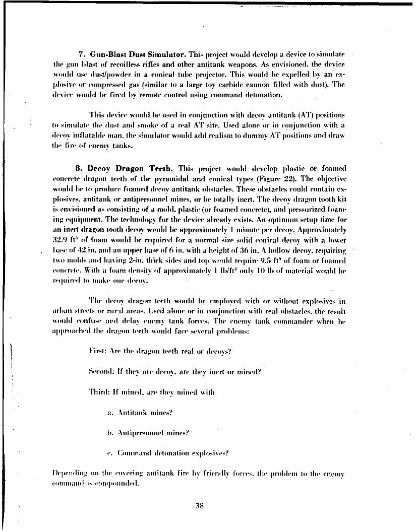
8. Decoy Dragon Teeth. This project wouhl develop plastic or foamedconcrete dragon teeth of the pyramidal and conical types (Figure 22). The objectivewouldi be to produce foamed decoy antitank obstacles. These obstacles could contain ex-plosives. antitank or antipersonnel mines, or bIe totally inert. The decoy dragon tooth kitis envisioned as consisting of a mold. plastic (or foamed concrete), and pressurized foam-ing equilpment. The technology for the device already exists. An optimum setup time forin inert dragon tooth decoy wohlbe approximately I minute per decoy. Approximately
"32.9 ft3 of foam would bW re(quired for a normal size solid conical decoy with a lowerla,,v (if 42 in. and an upper base of 6 in. with a height of 36 in. A hollow decoy. requiringiwo miolds and having 2-in. thick sides and lop um ild require 9.5 ft3 of foam or foamedcon.nrele. With a foam density of aplproximatelv I lb/ft3 only 10 lb of material would bereqfuired to make one deo',.
The dccIv dragon teelh would be emiployed with or without explosives inarban streets or rural areas. UsMl alone or in conjtinction with real obslacles. the resultwi01114i reifuise a1ld delay eneniv tank forces. The enemy tank commander when lieaplproached the dra gon INt'th woild face several problems:
Firsl: .%re the dragon teeth real or devoys?
Second: If they are decoy, are they inert or mined?
Third: If mined. are they mined with
a. Antitank mines?
b. Antipersonnel nlines?
c. (:.remand detonation explosives?
I)i .ndiii-, oni the covering antitank fire by friendly I'orcvs. the probldm to the enemy1'1lii. liIt1d is 'oill tpllll led.
38
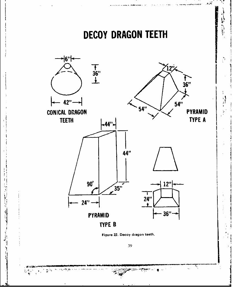
DECOY DRAGON TEETH
6I
T~~ 36"
k- 42".I 1.36"
CONICAL DRAGON 4 PYRAMIDTEETH L4 'JTYPE A
44"
- p
oU -p I I
24 24"
PYRAMID K 36"-9
4 TYPE B
Figure 22. Decoy dragon teeth.
S139
, 77 .I" " f lL '
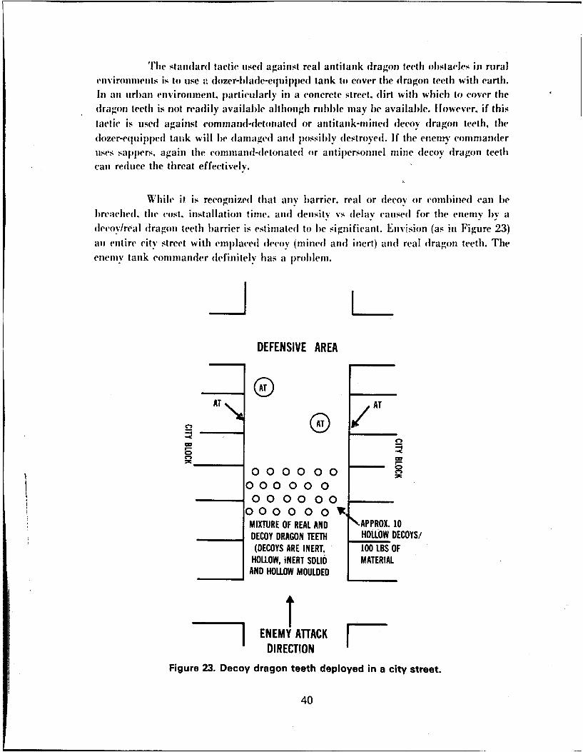
Tlhe standardl tactic used a'gairist real antitank dragon teeth obstacles in ruralenv1ironiments is to usC , dozer-blaldeC( 1 uipp1 ed tank to cover [lhe dragon teeth with earth.In ain tirlan environment, p~articularly in a concrete street, dlirt with which to c-over thedIragon teeth is riot readlily availabl)e although rubbhle may bie availabile. However, if thistactic is tised against cominhland-(letonate(I or antitank-mined decoy dragon teeth, the(lozer-equipped tan~k will be dlamagedl andl possibly dlestroyedl. If the enenry commander
usssppers, again the conmnandl-detonated o antipiersonnel mine dlecoy dao etcan reduce the threat effectively.
While it. is recognized that any b~arrier. real or decov or combined can lbelbreaichedl. the cost. installation time. and diensity vs delay Caused for the enemty by a(Iecoylreal d ragon teeth barrier is estimated to be significant. Envision (as iii Figure 23)an entire city street with emplaced decov' (mined and inert) andl real dIragon teeth. Theenemy tank commander dlefinitely has a p~roblem.
DEFENSIVE AREA
AT AT
0000000000 00
000 00 0 VCMIXTURE OF REAL AND "-APPROX. 10DECOY DRAGON TEETH HOLLOW DECOYS/'(DECOYS ARE INERT, 100 LBS OFHOLLOW, iNERT SOL1D MATERIALAND HOLLOW MOULDED
I ENEMY ATTACK FDIRECTION
Figure 23. Decoy dragon teeth deployed in a city street.
40
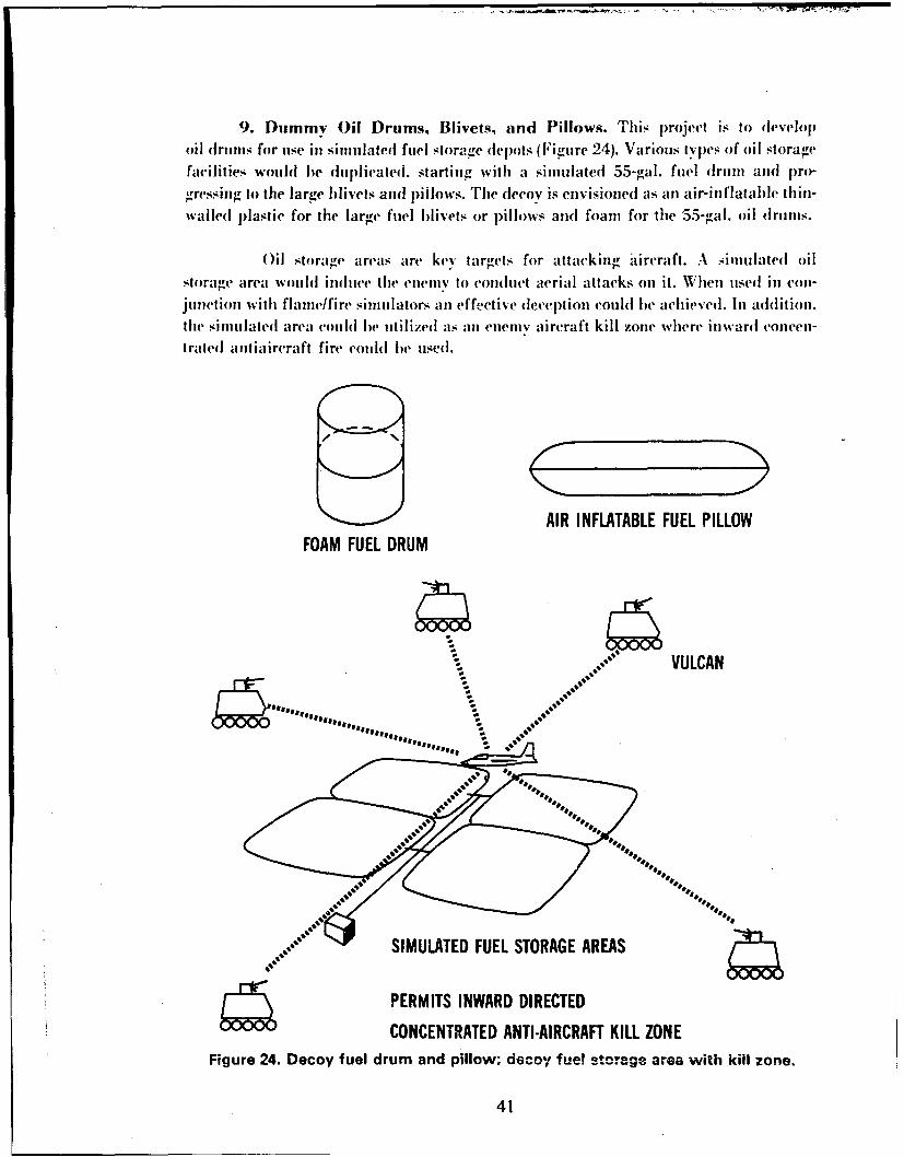
9. Dummy Oil Drums, Blivets, and Pillows. This project is to developoil drums for use in smiulated fuel storage depots (Figure 24). Various types of oil storage
facilities would he duplicaled. starting with a simulated 55-gal. fuel drIun and pro-"gressilg to the large blivets and pillows. The decoy is envisioned as an air-inflatable thin-walled Plastie for the large fuel blivets or pillows and foam for the 55-gal. oil drums.
)il storage areas are key targets for attacking aircraft. A Aimulated oilstorage area wouldi indluce the enietiiv to coiu(luct aerial attacks on it. When used in vloil-junctioni with flame/fire simulators an effective deception could be achieved. In addition.the simulated area could he utilized as an enemy aircraft kill zone where iniward concen-trated antiaircraft fire could he used.
AIR INFLATABLE FUEL PILLOWFOAM FUEL DRUM
"" .VULCAN
-ab
SIMUATEDFUE STOAGE REA
PERMITS INWARD DIRECTED
CONCENTRATED ANTI-AIRCRAFT KILL ZONEFigure 24. Decoy fuel drum and pillow; decoy fue! storage area with kill zone.
41
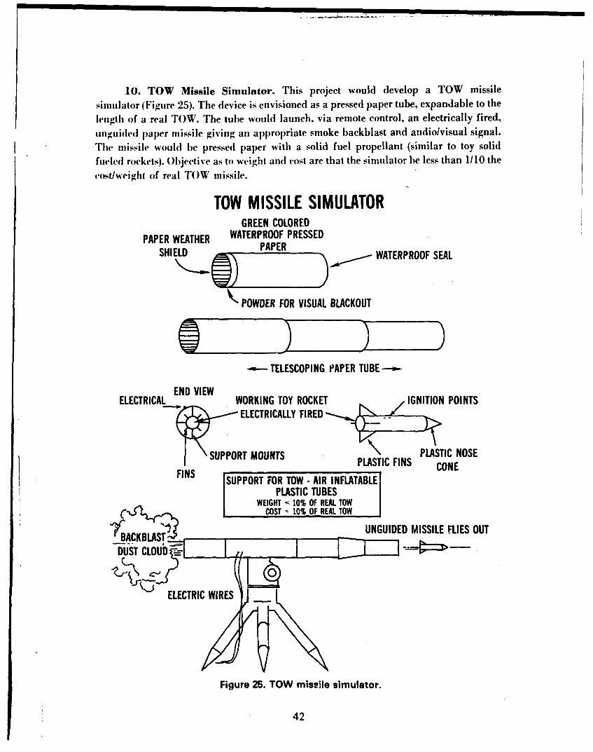
10. TOW Missile Simulator. This project would develop a TOW missilesimulator (Figure 25). The device is envisioned as a pressed paper tube, expandable to the
length of a real TOW. The tube would launch. via remote control, an electrically fired,,nguided paper missile giving an appropriate smoke backblast and audiolvisual signal.
The missile would be pressed paper with a solid fuel propellant (similar to toy solidfueled rockets). Objective as to weight and cost are that the simulator be less than 1/10 thecost/weight of real TOW missile.
TOW MISSILE SIMULATORGREEN COLORED
PAPER WEATHER WATERPROOF PRESSED
SHIELD PAPER WATERPROOF SEAL
POWDER FOR VISUAL BLACKOUT
- TELESCOPING iPAPER TUBE --
END VIEWELECTRICAL WORKING TOY ROCKET IGNITION POINTS
-r ELECTRICALLY FIRED
SUPPORT MOUNTS PLASTIC NOSEPLASTIC FINS CONE
FINS [SUPPORT FOR TOW - AIR INFLATABLEPLASTIC TUBES
WEIGHT • 10% OF REAL TOWC COST 10% OF REAL TOW
ŽUNGUIDED MISSILE FLIES OUT
DUST CLOUD E-
ELECTRIC WIRES _
Figure 25. TOW missile simulator.
42
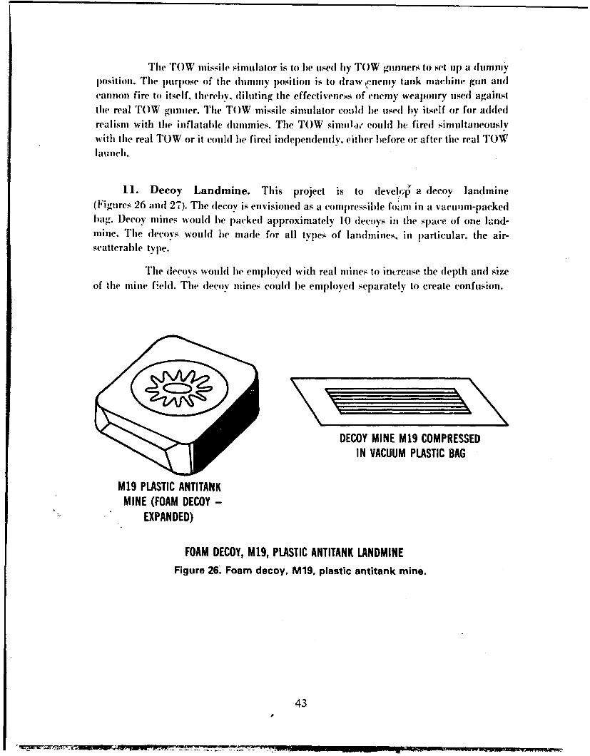
The TOW missile simulator is to be used by TOW gunners to set up a duniniyposition. The purpose of the dunminy position is to draweneiny tank machine gun andcannon fire to itself. thereby, diluting the effectiveness of enemy weaponry used againstthe real TOW gnnuer. The TOW missile simulator could be used by itself or for addedrealism with the inflatable dummies. The TOW sinmau " could be fired simultaneouslywith the real TOW or it could he fired independently, either before or after the real TOWlaunch.
11. Decoy Landmine. This project is to (level y a decoy landmine(Figures 26 and 27). The decoy is envisioned as a conipressible foerni in a vacuum-packedbag. Decoy mines would be packed approximately 10 decoys in the space of one land-mine. The decoys would be made for all types of landmines, in particular, the air-scatterable type.
The decoys would be employed with real mines to increase the depth and sizeof the mine field. The decov mines could be employed separately to create confusion.
DECOY MINE M19 COMPRESSEDIN VACUUM PLASTIC BAG
M19 PLASTIC ANTITANKMINE (FOAM DECOY -
EXPANDED)
FOAM DECOY, M19, PLASTIC ANTITANK LANDMINEFigure 26. Foam decoy. M19. plastic antitank mine.
43
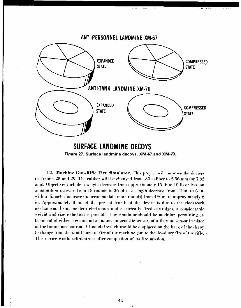
ANTI-PERSONNEL LANDMINE XM-67
EXPANDED COMPRESSEDSTATE STATE
ANTI-TANK LANDMINE XM-70
EXPANDED COM PRESSEDSTATESTE
SURFACE LANDMINE DECOYSFigure 27. Surface landmine decoys, XM-67 and XM-70.
12. Machine (;in/Rlifle Fire Sinitilator.THiis Jprojeel wvill improve tIlec devicesill Pigtures 28 and 29. Thel( caliber will he changed from .30 caliber to 5.56 mim (or 7.62111ii1). ( )ject ivts lilt] ide a weialit tlevrease froml app~roximiately 15 11) to 10 (11) or less, anamintliilititon inerease fromit 18 round(s to 36 phis. a lengtih tdecrease from 12 inl. to 6 in.with ii d iameter increase (to aceonitotalae more rounds) from 4½/ in. to approximately 6II.:iirlill.Apoimately 8 ill. of 1' the resent length of the device is due to the clockworknwli, a Ii sisl. Lisil igModiern electronics and (Iectrica lly fired cartridgIes. a conisitderablewe'ighlt alnd size redluction is possible. '[hle simulator shotuldt he miodlular. per.mitting at-taehtnent of either aI commtnandi actuator. an acoustie sensor, of a thermal senlsor ill placeof, t lieI iimi li" Ineehla iiisil. 'A hi utiodt al switchl would he em iplaced oin tile back of thle decoyIt) tialig' fromn tile raplid burst of fire of the nlaciiine gpin to the dlesultory fire of thet rifle.'1'll is d ev ice wotultd self-destruct a fter comnplet ion of' its fire mlisslion.
44
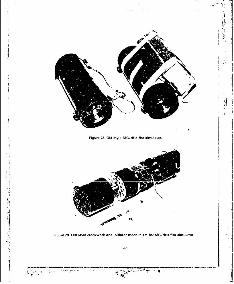
,!
'" '
I I
Figure 28. Old style MG/rifle fire simulator.3
Ii Figure 29. Old style clockwork and initiator mechanism for MG/rifle fire simulator.
•, 45
I ,-, ".;4 '' .. ,
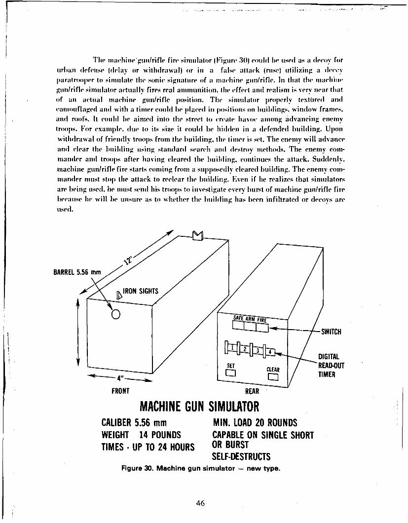
The machhu"gun/rifle fire simulator II:igure 30) cmlhl Iw used as a decoy forurban dcfcnse 0h'lay or withdrawal) or in a false attack (ruse) utilizing a dec,•vparalroopcr to simulate the sonic signature of a nzachine gun/rifle. In that the machilwgun/rifh" simulator actually fires real ammunition. Ihc effect and realism is very near tlalof an act||al machine gun/rifle position. The simulator properly textirred arrdcan|otflaged and with a timer couhl be pI.".ccd in positions on buildings, window frames.and roofs. It couhl Ire ain|ed into the street to crcah' haww among advancing enemvtroops. For example, due to its size it couhl Ire hidden in a defended buihling. Upon
withdrawal of fric||dly troops front tire buihling, the tin|er is set. The enemy will advancearul clear the b||ihling ||sing standard search and destroy n|ethods. The enemy com-mander arnl troops after having cleared the building, continues the attack. Suddenly.machine gunlrifle fire starts coming from a supposedly cleared buihling. The enemy com-mander must stop the attack to rcclear the buihli||g. Even if he realizes that sin|ulatorsare iwing used. Ire |u||st send his troops to investigate every bun of machine gun/rifle firebecause he will Ire unsure as to whether the lmihling has been infihrated or decoys are
IlSed.
BARREL 5.56 mm
•IRON" /S-SWITCHI
SDIGITALSET • READ-OU1
• CLEAR4"• E• • TIMER
FRONT REAR
MACHINE GUN SIMULATORCALIBER 5.56 mm MIN. LOAD 20 ROUNDSWEIGHT 14 POUNDS CAPABLE ON SINGLE SHORTTIMES- UP TO 24 HOURS OR BURST
SELF-DESTRUCTSFigure 30. Machine gun simulator -- new type.
46

W~ith a coinniandl remote control unit. the mnachine gull/rifle fire si Hilllator
cai lbe used illdniv inchine gun/rifle positions to dIraw enetuy fire to itself andI Iiereliv reduc,c the( effect uvenes-s of eiuenui' fire onl thle real mnachinle guin/riflemnan position1.W~hen tused with a cheap thiermnal or avolisti(' sensor, it could he placed inl such a mianneras to lie activated biv enemly voice or thermal emnissions. Thew device has other potenltialIlse.. ill comert fir vover and deception operations which are limitedl only by thle caplabilityandl innovative list- of the planner.
1:3. Vulcaner Simnulator. Thle project will develop a plastic/metal V ulcan giunlnmiarid cannonil smill liator. Th'e( decoy rtill and( inounut (Figure 31) will hle euuil acedl oil
lhe top, of regula r A rioredl Personnel Carriers (A PC). Thel( decoy inuount will ble capable ofb oth traverse anid elevation. 'Iie visuial deception should be good1 at a dlistance of 100ya rd s.
PLASTIC DECOY VULCAN MOUNT
Figure 31. Vulcan simulator.
47
The jiriiiiary. purpose of the Vuilcani simulator will ble to confuse the enemnyreconniaissance as to where the real Vulcan Air l)efense Weapons are located since theVulcant Al) NN'eapon svsteiii will he subijected to reco nnaissanlce, dectection, and targetacqutisitioni (iII a p~riority basis. 'I'1w elnemy will theui atteniijt to destroy all Vulcan
weapons ~ ~ ~ ~ ~~r in I i vsoiae o z one-attery fire and fighter/bonmber aircraft. lint hat there, are ounly two batteries (if Vutlcan Cannons per i)ivision. the itemn is valuableadll of c'rifi cal hiti ortance onl tile battIlefield.
lit anl Armtored or Mechianizedl Infantrv l)ivision there are several APCe(lhipp~edl infantry ctnipjahiies: a nitnilier of the AP~s in these comnpanies would lieeqluippledI with decoy mlounts. Vulcan cannons are frequently' used with Armior andMechanized Infiant ry lead clentients; thus. having several decoy Vulcans amtong tile realN~ulcans would p~reven~t the enemyv fromi coincentrating firepower onl the real Vulcans.
Ini add~itioin. the cilehlly wouldl lie unsure of tile. total firepower of the task forcein tial I he Vulvan can be utsed( in a ground~ support role. The enemny would Ilie less en-tlitisiastic ini attackinig ant Arniored/Mieebdiized Infantry Comlbat tWain po~ssessing thle ad-dled firepower (of 5 to 6 Vulcan cannons thlan a teaiii withl only one.
14. Decoy Ribbon Bridge. This project would develop all air/foanil inflatabledecoy ribbon bridgec. h bridge would be capabile of visual andl radar sitnutlation atrailges lin e'xess of 1.000 ft. Thle decoy b~ridlge should be capiable of carryi ng infantry iiyilcalis oif a sinal I catwalk so that the bridge is functional to foot traffic. Tile bridgeshouuld he self-sealing (puncture proiof) to the fullest extent possible. Up to five deflatedElecovs shlou~ld be capiabile of fitting ill oie 2½2-ton truck. Ani alternative storage locationcouihld be within the interior bay area of the real ribbion l)ri(1we; therebv, eachrelIid,would carry its own decoy. The decciy bridge should lie capablle of acceptinlg foanl-'dplastic or coinerete in place of air to achieve rigidity as well as~ flotation.
lii' dco brdg wohll le iul~lvel iiear real rilbbonl bridlges in order tocon1fuse ellicini recoinnaissanlce and] figliter/bonibers as to thle exact location of the realbridge. The bridlge would be plared near enough toi the real bridge so that fighterlbonibwrvisual acquiisitioin occurs sitliultaneously but far enough apart so tilat explosives droppedon one biridge should nlot (lAmtage the secondl bridge. The decoy inflatable bridge when in-flated withl foamied plastic (or possibly loiw-detlsity/qliick-settinor concrete) could becapabile of supiporting lighlt wheeled vehicles.
15. Decoy Armored Vehicle Launched Bridge (AVI.B). This project woulddevelop a decoy AVLHI lunit. It wouildl utilize foatu an(I reseinble a realAL untfo100 yardls. The( biridlge should( be structurally strong 1 enough to supr foot traffic onsinall gaps.
48
Reproduced FromBest Available Copy
Tlhe dleecv bridge wotill lhe eitnplaeell uia~ra real A V LB inl cirler to coiifliseenemy11% reconniaissance and~ fighter/bombe~r attack. The dIecoy unlit wouldI (1)e' niomite'd onl areal A PC lint wotultl b~e lightl enlollgh to Ile liftedl by two to fotir men uuand emplaced over agrap. The bridge theni eouldl be usedl for foot traffic.
16. Railroad Rolling Stock Camouflage. This h)rojeCt woultl dIevelopj
methods to camouflage railroad eng6ines and rolling,, stock to look idlentival at 1.000 ft(altitude) to b~ox cars. Project is enlvisionedl as produicing a handb~ook describing howvarious materials and Flaiuts canl i~e utilizedl to camouiflage/disguise traiii enigines and
cars, without impairing their operational c-alpablity.
Inl World War 11. sonmc of the key railIroa d rolling~ stock was cariotuflagedlIdlisgulised as less valuiable items. Since World War 11, the types andl kinds of eng-ines allidrolling~ stock havNe chlangcr(t dIrastically. The camiouflage p~atterins anl(l disgiuises. of WorldW~ar 11 are no longer tise fil. anid new instructionus based onl modlern railroad equipmenttuceul to Ile fdevvloped .
1 7. Field Expedienit Decoy' Machine Gun (7.62 nini, .50 cal.). This
1)roject will olcvelopi a handbolok showing several methodIs of muaking and( uising field
expied ient (lermoi i. Iach i ne pills.
lDccov mnachine gins (-aiu b)e used to simulate real machine gun lpositions
therebyv drawingr enlemyI fire to themselves aii(l lessening the effectiveniess of enemy~ fire onlthe real position.
18. Caiouflage -Coloring Kit for Engineer Tape. This project woulild developa fas.t-drving. indelible dyve for coloring, engineer ta rw to miatch the sllrrotindlings.
Ei~neer tape. tisedl for making boundaries. iiine fieldIs. etc.. is coloredI white.lrefluentlv it is olcsiralde to make the bound~ary with1 egin-ieer tap~e. buit to Iimitii the
visib~ility of thiat tap~e from medium to long ohistances so as, to help conceal the markedarea. This kit woidd III lw sed to dyve the enginever talpe to miatchi the surrounding,baickground.
19. Textured Cotitings for Rifle Barrels and Stocks. This 1projec(t woulddevelop a camtouflage coating for rifle barrels andl stocks p)reseinitiiig a texture~l, non1-reflective surface. The coating, would lie available inl several colors of b~rown aii(l greeni. Awhite coating for iise inl snow environments wouild also ble olevelojied. Thie coating~ wouldl6- rvemovahile %ith the application of special .4olvent without (lanuaging the rifle.
The c-oat ig, is to bie musedI to reoluce the glint and glIare, off machinied riflei~arts such as thle I ;urrl amid trigger housing and~ li ea mon flagi' the rifle. 'I' he whitecmainhg is for usc ill snlow areas for vamuni flago'.
49
20. Tone Down of Brass Cartridges. This project is t o identify asuitable additive to color the b~rass cartridIge case fronm yellow to a dull b~rown.
infantr I roops frequenttly carry bells of machine plin animunitioli wrappedaroniid their bodies. The high ,loss and color of the brass cartridlgaes(~1C sigonificantlyreduice the camoti flage capab~ility of the troops. Expended cartridlges bccauise of theircolor aid gloss have a hiigh signatiire, totinlv- iowii the cartri(lge cases will aid inreducingp the detectioni of troops who have used themi. In this regard. all types of brasscartridgze cases including, those from I 05-mnim 0I 5-mm) tank anid howitzer anmiiiiitioiiw(JIlld be tolledl down.
21 . Decoy Reflecting Surfaces. This project would develop a cloth with acheap). Iii igl reflective coating; applied to it. The cloth could then lie cuit into various sizesfor emiplacementb Itroops.
The reflectivec clot Ii wod be eI m placed to shimlate thIli( -itt and reflect ionfrom vehicle whintslieilds mid headlights. Theli objective is to deceive the eniemyi recoil-itaissance aircraft as to whether the glit aid glare they detect is fronm a real IVehicle or is
just a decoi'. therebyv reducing the rel iabilIity of glint as a weaponi signature cue.
22. Vehicles for the Radar Simulation of Weapon Systems. This projectwould develop, a 2- or 3-Imge diagram for inisertioni into tactical field manmials showing,how vehlicles canI he posit ioncil :o simuulate t he radar si guattre of various weaponi systemssuch ais H awk. ( ;appa~irail. V"ulcaii. Pershingv. Ho14witzer bat lerics. etc.
I )tri ng periods oif low visibil it. svnti het ic aperatitre radar or side-lookingairi IIrie radar wil eom mirmary reconnaissancve method. Use of vehicles to simuilateradlar signalt ires has a definitie. though limited. use. A 2- or 3-page diagram can be madefor i iisertiout iii Arm riiield manuals showing- how trucks can he Jpositionief to simulatethle patterns made byv the weapon systems onj a hostile radar screeni.
23. Fuel Tank Truck Camouflage. This project would dlevelop) the attach-metits niecessary to umake a fuel tank truck simulate a cargo truck. The project isenivisionled as having- two phases. Phase I consists (of a fuel tank mounted on 2½-tout truckbod ies. These vehicles would be converted iii 2½-ton carg~o thii(cks by the addit ioiu of a
ctvscover and bows. Phase If would deal with thev large fujel tankers (i.e.. trac-tor/trailers). These would be converted to look like cargo trailers.
50
Due to the individual design of specialized Army equipment, the enemy caln
selectively try to destroy certain items of equipment rather than others (when given theopportunity). For instance, depending on the circumstances, a fuel truck may be of morevalue than a cargo truck. A tank may have more value than an APC.* Accordingly. theenemy will instruct his pilots to search for and destroy one particular type of equipment ifpossible over another.
The more Army items that look alike, the more difficult it is for the enemyto be selective in his destruction ý:rnd to know exactly what lie has detected or destroyed.
24. Thermal Signature Modification Unit. This project would develop
a heating/cooling unit mounted in a 2½-ton truck to change the thermal signature of atank. APC. or olher vehic'le. The thermal signature would lie changed quickly (cooled) byspraving a senmi-frozen shlsh of water and/or dry-ice onto the surface of the vehicle. Thesystem could ibe set lip to decont aminate the vehicle simultaneously. The thermal
signalure couhl] he raised in a similar manner by use of hot water.
ThIe thernmal signalure of a vehicle is becoming a prime detection method.There is no current method of redlucing the thermal signature of a hot vehicle. The ther-
mal signature-changing unit would permit a hot vehicle to be cooled almost immediately,thus reducing its signalure and making the detection problem more difficult. The cooledvehicle could then bw emplaeed under a thermal camouflage net thereby reducing theamount of heat that would have to lie thermally shielded by the net.
With tihe addition of (eertair; chemicals. the thermal signature-changing
unit couhl decontaminate chemically. bacteriologically. and radiologically contaminated
vehicles.
25. Drone Decoy Helicopter. This project, to be conducted in conjunctionwith AVRAI)COM. would develop a drone decoy helicopter. The radio-controlled drone
decoy would lie less than 1/5 size of a real helicopter but would present the correct radar
signature.
The decoy drone helicopter wouhl be used in conjunction with passivehelicopter decoys to more fully simulate an active helicopter site.
"Duering the African campaign. (me anliainrraft mnit made a slalistiral stedv (orf targets strafed Iy (;erman aireraft. Them wen. able1t determine that tih German orer of eri eity was: (I) watere'arts. (2) staff cars. (3) 'trucks. (,1) other. By disguising
wate'rvart- (v.e' ivnpefrlant in the des.eril Ito resemble ortinarv Iniks theyv nimuivd the wat,.riarts hi priority frvm No. I ito Nit. 3.
51
26. Iectov Cloilh and Paper. This p~roject wotuld (leveloJ) thin, waterproofcloth and pa~iper overprinted with camoiiiflage p~atterns or inl camotuflage colors. Thecloth/paper should have anl adhesive hacking andI shouldd remain strong anid flexible in('old templeratulre dlownl to *300 F.
The cloth/pajper would lbe use(I on field fabricated ulcv.Tetse of pre-prinited clothi/paper wotil(I simpli fy tile making of (lecovs.
27. CamITouIflage Tap)e. This project would(ldevelop a patternedl. colon-(d tapesimil ar to a(Illesive or cellophane tape.
This tape would b~e ap~pliedl to c'ables. wires. and( anything that nevededlto be camiouflaged stuch ats rifles, hielmuets. etc.
28. Spray-on Radiir-Reflcctive Plastic. The project woiIdl develop at spraly-tllcoloredl plastic Withl a radiar signature. 'FThe plastic wouldi formn ~i 5li(ler-weh) type ap-
lerai~~lce wheii sprayed onl stems such ats rocks oir trees ahl(l woul(I c'reate it simulated
tarirel with the reflective signature of the meta'kllic' item.
TIhe spray-oni plastic would lbe tisv(I to create false targets within the battlearea and~ wol Ill. imerease thle ra(Iar clutter.
V. C;ONCLUSIONS
From this study of uirbani warfare. mie call concelude that camouflage and deception(G&D1) has at distinct part' to play. Since camoufflage has bieen uitilizedl ill thle past.real isticall * onme must assume that it will be uised inl the future. 1Histoirical referencesestablish that varls' use of camouiflage was haphazard: its utse was limitedl by theimamiiiative utse oif tlile practitionier - thle soldier. (Unifortunately, this is thle type (of inI-dlividlual who -arely publishes thle fruit of hlis efforts.) Camouflage for urban warfare c-anprocure positive resuilts if all inmaginative research anid development program is ptishetl to
dlevelopi mnvw metlodIS. techniques. and( materials for the( soldier to ise51.
Carefuil. apil iedl development niow c-an eliminate the guesswork and the haphazard
"Ril~e ;ojlj~r~r aproah t ii-ha caonfayeall] dcetpion operat ionls. Inl thisregardl. providing the soldier with urban C&l) eqjuipmlent ailI trainillg shouldl stimulateiiew uses aul~l idleas from the soldiers themselves by makinig themi more aware of thepossihii ities aui(l capabilities of camouflage.
52
While distrilution of equipment will. no dolibt, result in somn standardization of
evnployment. more will be atenipted if some camouflage and deception material. prinI-
ciples. and techniques filter down to the troop level. Ilneed, historv23 has shown that
similar (&l) plans and devices have worked time and again because the application is
iever identical. and the persons experiencing the cover an( :teception devices or tech-
niqies are rarely the same.
(Camouflage anod deception is a two-edged sword. the first time it is used the effect is fre-
(jitenlly dramatic. But it requires the enemyv to expect its use again, thereby forcing the,'nelrv 1o consider that C&I) is constantly being used and instilling doubt in his mind as
1o whether the intelligence information before him is true or false.
(:irrentiv. Ithere is nothing in the U.S. Army inventory that could be strictly defined as
itirban camouflage and deception equipment. All of the present equipment has been
developed for field use an(l little of the equipment beyond smoke has ever been used in a
laclical urban warfare silualion where air-to-ground aniid ground-to-ground combat was
occurring. While all of the ideas presented in this report appear practical and feasible.
further research may show that material or design capabilities are not capable of
achie,,ing Ihe performance dlesiredo: the prototype may work well but the cost. logistics, or
tactical usage manv place the item in the unwanted category.
The ideas described are mainly oriented toward air-to-ground and( ground-to-ground
operalions of a tactical nature rather than strategic air-to-ground operations. In this
regard. however. most of western Europe shoutld e considered within the tactical rangeof modern aircraft. The material items described were considered with a view toward the
amouint of time available for emplacement. assuming the materials are in depots or in thehands of the tactical units.
lDue to the specializedl nature of some of the camouflage and, in particular. the decep-
tion equipment. the only realistic approach would be to assume the formation of some
special engineer or intelligence cover and deception team to properly use the equipment.
While regular line troops could use and deploy much of the camouflage devices
presented, it is not possible for them to also have time to deploy the deception equipment
unless that equipment directly pertains to their line function, such as the TOW DecoyMan anol Launcher. Given the line troops' mission and their C&D requirements,. it isevident that in the face of time and( mission urgency. C&D deployment will not always be
accomplished. Accordingly, strong consideration should be given to trained D)ivision orCorps Claouflage and IDeception Teams. The details of such a team. however. are far
afield from the scope of this report anoi the DARCOM mission of materiel design. Conse-
qIuently. this issue will not be addressed further. except to point out that a flag is raised to
the potential solution of urban camouflage organization.
2E ' M i hahY. -sIIVTI'ToG;ENi. D).,.eeioiwn. and Srlrprime in War. U1vi iiidihed. (assanhis-lts Instiltw of *T1'dm0iog. 119i• .'.
53
BIBLIOGR AI'llY
American and British Middle East Command. "Illow the Germans De)fend Buildings."lilittarv Review (October 1944).
"• "Piillboxes in Italy," ulilitarv Review (January 1945).
Australian Military Forces. "Goodenough Bluff," Military Revietil (May 1945).
Bakken. I). A.. S. P. lhit, ct at. "Military Operations in Built-up Areas."Technical Report No. 1. GTE Sylvania. Inc. (December 1972).
Ball. T. C.. 11. R. Blackster, et al. "Advanced Firepower Concepts for Military)perations in Built-Up Areas." Technical Report. I-II, Ketron. Inc. (September 1973).
Barber. Jacob L. "Low Fidelity Simulation D)evices. Code Name Lois," U.S. ArmyEngineer Research and ievclopment Laboratories (September 1954).
Barbarek. Louis A. C. "Urban Warfare Study'" IITRI Corp. (September 1974).
Barisev. V.. C()L. USSR. "Attack on a Fortified Zone in East Prussia.Military Review (August 1945).
Batchelder. J. E. "A Strategy for the Passive Air l)cfense of War Production."unpullished. U.S. Army Engineer Board (March 1944).
Boldvre. P.. COL. and CoL Antcmnvex. USSR. "The Kursk Operation."M1lilitar" Review (October 1944).
British Bombing Research Mission. Camouflage Section. "German Static Camouflage inFrance and Belgium". unpublished report (February 1945). U.S. Army MobilityEquipuient Research and l)evelopmnent Command. Camouflage Reference Center.
Bruce-Briggs. B. "Suburban Warfare." Military Reriew (Jumc 1974).
Bvkov. C.. LIT. USSR. "Self Propelled Artillery in Offensive Combat." MilitaryReview (April 1944)).
( entral Intellignc''e Agency. "Camouflauer in War and Intelligence" (April 1964).
Chibisor. N.. C()L (;EN. USSR. "Closr" Combat.- Military Review (September 1946).
54
Cruickshank. Charles. "D~eep)tionI in World War I[, O?(xford University Press; (1979).
Chtuvkov. V. 1.. LTG. USSR. '"Sireet Fighuting - Thel( Lessons of Stalirigrail."AMilitary Review (July 1944).
"Cities." Scientific American (Septembher 1965).
Chaphan. Richard. "Canmouflag~e" Militalrv Review (April 1942).
Damgaard. Martin J. "Simidation Devices: Prefabricated. Pneumatic. High Fidelity.
Tube Type. Code Name HIRAM.- U.S. Army Engineer Research and Development
Laboratories. Report 1251 (September 1952).
Davison. Warren R.. MAJ. "German Tactical D~octrine." Military Review (May 1945).
"Decoy Missile Study.- U.S. Army Engineer Research and D)evelopment Laboratories
(September 1960).
"lDevov Protection of Britain." .liliiarv Reriew (September 1944).
Del~aig. Merril E.F. LTc. "Airfield Camon fhigt." Military Review, (September 1944).
(de Lara. P. A.. (PT. Spain. "~Attackingr and Defending, Populated Places?"Military Review, (October 19414).
Felts. Robert. "Urban Warfare. Emerging Material Requirements Within thle M IERUC
Mission." U.S. Army Mobility Equipment Research and Development Center
(Januarv 1975).
Fitzgerald. Charles G.. LTC. "Combat in Cities." Infan:rv Mairgazine. p). 5(J anuarv/Febru arv 1965).
Gallusser. R., CPT. France. "Tile Uses (if Positions. Shelters and( Camouflage in
Winter." .lliiarv Review (April 19416).
G;ermani ,%rmy'. "German Armored Trains.' Militarv Reriewt (July 1944).
_____________"Thle Value of Permanent Fort if icat ions?" 3lilitar Reie (Augs 1945).
G;(rm~aii Armv I Iigh Command. Dl~c. IA. "Memorandumn onl Camouflage Techniques and
C amiouiflage in Its Application of D~eceivingr and Outwitting the Enemy?"inpibldislhed translated report (J ulv 194:3). U.S. Arimy Enlgineer Research Office
(January 1945).
55
German Armv. 2nd Panzer, AAA, Det. 173. "Camouflage Memoranduin,"
tinlmhlished IranIaled report. U.S. Army Engineer Research rOffice (May 19,1-4).
(;erman Navy. "()herkommando der Keuegsmarine." Berlin (1943). unpublished
translated report. U.S. Army Mobility Equipmlent Research an(d levelopment
Command. Camouflage Reference Center.
Goda. H lerbert L "Suggested Areas for Modification or I)evelplmlent of Vehicles
and Equipment for Urban Warfare." Al) 711591. IDA (May 1970).
Greiner. Major. and Major Neber, (German. "Attacks on Inhabited Places.".1ililarv Re'ieu- (Octolbr 1943).
"" 'I)efcnse of inhabited Places." Military Review (November 1943).
Gri mm. If. 12.. and R. 1). M inckler. "A Summary of Activities Associated with Military
)peralions in Urban/Suburban Low Intensity Conflict Environments," Battelle Corp.
(April 1973).
llalidanck. (Gert. German. "(;ernian Coastal I)efenses in Norway." Military Reriew
(February 19,14).
lHumpthreys. A. A.. and J. L. Barber. "Study of Camouflage in Future Warfare."
U.S. Army Engineer Research and D)evelopment Laboratories (April 1956).
i_ . ad S. V. Jarvis. "Camouflage Pattern Painting." Report of
L\SAMERi)C's Caamouflage Support Team to MASSTER. Al) 778726. U.S. ArmyMobilitv Equipment Research and Development Center (February 1974).
lakovhev. V.. ITC. USSR. "Notes on Street Fighting." Military Reriew (March 1946).
.Johnson. D)avid P. "1)evelopment of Simulation Device. Lighting Equipmlent Set No. 2.;cnerator-(Operated, Assault. Combat Airstrip. 4500 Ft. Portable." U.S. Army
Engineer Research and D)evelopment Laboratories. Report 1379 (October 1954).
Johnson. Roial Id L. "Evalualio| of a Camoi flage Texturing Adhesive. U.S. ArmyNlfbilitv Equipmennt Research and l)evelopmeut Center. Report 1953 (May 1969).
Kame-nev. TIC(. USSR. "Caniotuflage Techniques of German Air Forces.- MilitaryRerien" M•,a 1944).
Kelhev. John E'.. iT(C,. "The Pillbox - A Tl'rap.-l Militarv Reriew (August 1945).
56
Klianalskii. G.. Irc. USSR. "Smoke Screens in Tank Operations," Military Review
(August 1945).
Kugelen,. (;!,rinan. "Smoke 'Frail Mortars," Military Review (November 1943)•
Kuke. E.. St. (.. COLI1. U.K. "Airfields in War." Military Review (June 1944).
Kupenko. N.. ITC. USSR. "German Antitank Defense." Militar Review (July 1944).
Laawrwnce. Albert. "Proceedings of the U.S. Army MERI)C Symposium 6n Passive
('ountersurveiilance. 3-5 April 1973." Stanford Research Institute (July 1973).
Ialten. Wý. A.. and J. Walroven. "The Role of Stereoscopic Vision in Ground to
Ground iTarget Acquisition," Institute for Perception. Netherlands (February 1974).
Makukhin. M1.. CT'. USSR. "Maneuvers in Battles for Populated Places,".lMiliIrv Review (Januarv 1945).
Managaron. L.. MG. USSR. "Street Fighting in Large Cities," Military Review (January1945).
Marreno. G.. MAJ. and CPT R. I). MeDermotU. "Camouflage Evaluative Report,Phase I.' U.S. Army MASSTER (Janary 1974).
Mechan. John F.. Ill. MAJ. "Urban Combat: The Soviet View," Military Review(Septemlbcr 1974).
NIvlnikov. P.. iLiTC USSR. "Self-propelled Artillery in Street Fighting." Military Review
(February 1946).
Meno,,. Dennis. "The Role of Urban Area in Future Warfare," Research thesis,
U.S. Army V'ar College (March 1967).
Menshikov. G.. MAJ. USSR. "Artillery in Street Fighting." Military Review(April 1916).
Mirontsev. IT(C. USSR. "Tactical Diversion." Military Review (April 1946).
57
Molchanov. A., COL, and Y. (;alkiri. MAJ, USSR. "German Field Fortifications."Military Reviewv (July 1944).
NATO, Military Agency for Standardization, Camouflage and Concealment WorkingParty. "Summary Report on Methods of Support for Camouflage Nets."u~npub~lished report (1971).
Naskov, N., MAJ, USSR. "Employnment of Large Armored Units ixn Street Fighting."Military Review (July 1946).
()rlov. A. S.. COL, USSR. "Battle Against Winged Rockets," Moscow, AntiaircraftDefense Herald (May 1971).
O)tt. David E., MG. "Counterfiak," U.S. Army Aviation Digest (July 1974).
Pavlov. lDmitri V. "Leningrad 1941. The Blockade,' translated] by J. C. Adams(Chicago 1965).
Payne. J. R. Analysis of the Countersurveillance Concepts, Proposed at theCounitersuin'eilhiiice Symposium 3-5 Apr 73. Stanford Research Institute. CA(Juily l973)*.
Poindexter, .J.. A. (;ailblý. et al. "Camiouflagec." unpublished report, 601 Engineer Bn,Ft. Ord, CA (undated). U.S. Army Mobility Equipment Research and DevelopmentCommand CanmoufClage Reference Center.
Retsser. CPT. Spain. "Combat in Inhab~itedl Places." Military Review (November 1944).
Rigg. Robert B., MAJ. "Soviet Underwater Bridges." Military Review (August 1945).
Rolikossovskiv, K.. Marshal of the USSR. "On the -Central -Front in the Winterand] Summter of 1944." Moscow Journal of Russian Military History. No. 6. 1968.Soviet Military Translations. No. 467 (August 1968).
Rubcliinskii. S.. CPT. USSR. "Destruction of Pillboxes by Sap~per Assault G;rou~ps."Military Review (March 1944).
Sandy. D)., MP. UK. "Report on the Flying Bomb," Military Review (December 1944).
58
Shimanskiv. A.. COL. USSR. "Achievement of Strategic Surprise in the Preparation
for the 1944 Winter-Fall Campaign," Moscow. Journal of Military History.Russian. No. 6. 1968. Soviet Military Translations, No. 467 (August 1968).
Shovkilovieh. A. K.. MG. COL F. 1. Konasas, and COL S. I. Tack. USSR."Comibat Actions of a Motorized Rifle Battalion in a City." Moscow (1971).
Shinvrkevick. A.. LTC. USSR. "The German Armored Pillbox," Military Review (May
1 9M.4).
Slesarev. P.. MM. USSR. "Tactics of Combat for Inhalbited Places," Military
Review (June 1944).
Soviet llandllook of the Guerrilla. 3rd Edition. 1942. "Guerrilla Attacks on
PoImualated Places." Miliitarv Rer'iew (August 1944).
Sleck. Thomas T. "Camoniflage Colorant for Scarred Earth and Its Application,"unpbllished report. U.S. Arih Moilitv Equipment Research and Development
(Center (Mlarch 1969).
Tillv. Andrew. "Berlin. Story of a Battle." New York. Simon -nd Schuster (1963).
Tullv. J. C.. LT'. "Street Fighting." Military Review (Febmary 1944).
Tompkins. John S. "-FiTe Weapons of World War Ill." New York, Doubleday
and C(o.. Inc. (1966).
United Kingdom Army. "Camouflage of Large Installations," London, England (1939).
"D)ecovs. U.K.. Inflatable Tnrck and Sherman Tank," MilitaryReview (October 1946).
".. "lDummy Tank. UK." Military, Review (May 1946).
"Street Fighting - Tips from a Platoon Commander in Italy," I'
Mlilitarv Review (November 1944).
United Kingdom Illustrated London News. "The Haslar-Smoke Generator," MilitaryReview (October 1946).
59
United Kingdom Ministry of Hlome Security, "Camouflage of Vital Factories,Key Points. and Landmarks, 1939-1945 (August 1945).
Urbanovick. V.. C(O0. USSR. "Mortars in an Inhabited Place," Military Review(February 1944).
U.S. A:rmy Field Manual 5-200. "Camouflage Materials" (April 1968).
U.S. Army Field Manual 5-20. "Camouflage" (May 1968).
U.S. Army Field Manual 5-23. "Fiehl l)ecoy Installations (October 1956).
U.S. Army Field Manual 31-40. "Tactical Cover and D)eception" (September 1967).
U.S. Army Technical Manual 30-253. "Photographic Interpretation Keys: Deception.Concealment. Camouflage and l)ecoys" (January 1955).
U.S. Army. "Chemical Smoke Generator Company," Military Review (July i943).
"• "Use of Smoke in Attack of a Village," Tactical and TechnicalTrends. No. 11 (November 1942).
"• "Soviet Tanks in City Fighting," Intelligence Bulletin (June 1946).
U.S. Army 84th Engineer Battalion. "Camouflage Antiaircraft Artillery," unpublishedmanual. undated. U.S. Army Mobility Equipment Research and DevelopmentComnmand Camouflage Reference Center.
U.S. Army Engineers. "Paint from Waste Materials," Military Review (June 1944).
"C(amouflave I)o's and Don'ts." Military Review (July 1943).
"• "Rubber Decoys," Military Review (August 1946).
"History of the Development of Camouflage Equipment, Part VICa(iouflage of Air Corps and Industrial Installations" (June 1947).
U.S. Army Engineer Camouflage School. "Operational Deception," California(l)ecelnber 1943).
60
U.S. Army Engineer Camouflage School, Aviation No. 1. "Operation Deception - NorthAfrica." California (December 1943).
U.S. Army Infantry School. "Combat inl Cities Report, Vol. I and 11 (October 1972).
__________"Combat in Buiilt-Up Areas Handbook," ST31-50-171. FY73 (October1972).
U.S. Army Military IntiellIigence Service. "Artillery in the Desert" (November 1942).
U.S. Army Munitions Command and( U.S. Armyv Material Systems; Analysis Agren cy.Symposiumil on Combat inl Urban Areas (Marchi 1973).
U.S. Marine Corps. "Lesson Plait, 130351, Combat in Built-Up Areas " (January1943).
USSR Washington Emblassy Information Bulletin. "Function of Camouflage." MilitaryReview (May 1943).
_____________"Tile Storming of Konigsberg." Mili tary Review (July 194i).
_____________"Street Fighting in Stalingrad," M1ilitary Review (August 1943).
USSR. Krostlava Zvezda. "Fighting for Cities in Offensive and D)efensive Action."Military Reviewv (January 19414).
Valentz. MA.J. USSR. "Reconnaissance inl Large Cites," Military Review (May 1943).
Vvskoastrovski, L. "Snipers inl Stalingarad." Military Review (October 1943).
Walker, Edward M. Rifle Fire Simulator, U.S. Army Enginecer Research andDevelopment Laboratories (November 1953).
Warbel. M., LTC, Germain. "Russia's Fighting Methods and Ability as Seen by theGerman Wehirmaclit," Military Review (May 1947).
Wiligoos. R. A. "Concealment of Important hIstallations." unpublished report.U.S. Army Engineer Board (January 1942).
Whialey. Blarton. ,sTrRATrAGEM. Deception, and Surprise inl War," unlpuiblishled.Mw acs(hmusctts Institute of Technology (1969).
61
White. |larry L.. COL. "Passive Air Defense with Tactical Forces." MilitaryReview (June 1944).
Zilerov. I.. COL. USSR. "Tanks in Combat for Populated Areas." MilitaryReview (March 1941).
_ "German Notes on Street Fighting." Tactical and Technical Trends.No. 12 (January 1943).
" _ "Camouflage.- GPO. Washington. I).C. 11943).
62
This DocumentReprodUced FromBest Available Copy
DISTRIBUTION FOR MERADCOM REPORT 2310
No. Copies Addressee No. Copies Addressee
Department of Defense I CommanderHQ TRADOC
Technical Library ATTN: ATEN-ME
DDR&E Fort Monroe, VA 23651
Room 3E 1039, The PentagonWashington, DC 20310 HQDA (DAMA-CSS-D)
Washington, DC 20310
2 Defense Documentation CenterCameron Station HQDA (DAEN-RDL)
Alexandria, VA 22314 Washington, DC 20314
Director, Technical Information HQDA (DAEN-MCE-D)
Defense Advanced Research Washington, DC 20314
Projects Agency1400 Wilson Blvd Commander
Arlington, VA 22209 US Army Missile R&DCommand
Defense Intelligence Agency ATTN: DRSMI-RR
B Bldg Redstone Aresenal, AL 35809
ATTN: RPS-3Arlington Hall Station 1 Commander
Arlington, VA 22212 US Army Combined ArmsCenter and Fort Leavenworth
Department of the Army ATTN: ATCA-COSFort Leavenworth, KA 66027
CommanderUS Army Intelligence Threat and I Commander
Analysis Center US Army Tank Automotive
ATTN: IAX-Oi-1 Command
Arlington Hall Station Warren, MI 48090
Arlington, VA 22212Commander
HQDA (DAMO-ZA) Harry Diamond Laboratory
Washington, DC 20310 ATTN: DROXBO-RALOffice of Battlefield Technology
Commander Vulneyability Reduction
US Army Material Development and Adelphi, MD 20783
Readiness CommandATTN: DRCDE-DS I Director
5001 Eisenhower Avenue US Army Material Systems
Alexandria, VA 22333 Analysis AgencyATTN: DRXSY-CMAberdeen Proving Ground, MD21005
63
No. Copies Addressee No. Copies Addressee
I Director I Commander
US Army Engineer Waterways Special Forces Detachment
Experiment Station (Airborne), Europe
ATTN: Chief, Library Branch APO New York 09050
Technical Information Ctr
Vicksburg, MS 39180 1 HQ USAREUR & Seventh ArmyDCSENGR,
Commander A'TTN: AEAEN-MO
US Army Troop Support & Aviation APO New York 09403
Material Readiness CommandATTN: DRSTS-K U Commander4300 Goodfellow Blvd US Readiness CommandSt. Louis, MO 63120 MacDill Air Force Base, FL33608
CommanderUS Army Aberdeen Proving Ground U Commander
ATTN: STEAP-MT-U (GE Branch) US Army Forces Command
Aberdeen Proving Ground, MD Fort McPherson, GA 30330
21005 Commander
Commander Rock Island Arsenal
US Army Electronic Proving Grounds ATTN: SARRI-LPL
ATTN: STEEP-MT-SI Rock Island, IL 61201
Fort Huachuca, AZ 85613Commander
Commander US Army Armament Command
US Army Electronics Research and Rock Island, IL 61201
Development CommandATTN: DRSEL-GG-TD Leaming Resources Center
Fort Monmouth. NJ 07703 US Army Engineer SchoolBldg 270
Commander Fort Belvoir, VA 22060
US Army Aviation Research andDevelopment Command President
St. Louis, MO 63166 US Army Airborne,Communications and
I President Electronics Board
US Army Aviation Test Board ATTN: STEBF-ABTD
ATTN: STEBG-PO Fort Bragg, NC 28307
Fort Rucker, AL 363601 Commander
Commandant 2nd Engineer Group
US Army Aviation School ATTN: S4
Fort Rucker, AL 36360 APO San Francisco 96301
This Document64 ReProdaced From
Best Available Copy
No. Copies Addressee No. Copies Addiessee
I Director I Commandant
US Army TRADOC Systems Analysis US Army Engineer School
Activity ATTN: ATSE-CTD
ATTN: ATAA-SL(Tech Lib) Fort Belvoir, VA 22060
White Sands Missile Range, NM 880021 Commandant
Commander US Army Intelligence Center
US Army Natick Laboratories and School
ATTN: Technical Library Fort Huachuca, AZ 85613
Natick, MA 017601 Commandant
38th ADA Brigade US Army Armor School
ATTN: EAAB-OP-P Fort Knox, KY 40121
APO San Francisco 96570Commandant
Commanding Officer US Army Missile & Munitions
US Army Engineer Topographic Center and School
Laboratories Redstone Arsenal, AL 35809
ATTN: Scientific & TechnicalInformation Center I Commandant
Fort Belvoir, VA 22060 US Army Signal Center and FortGordon
Commandant Fort Gordon, GA 30905
US Army Cmd & Gen Staff CollegeATTN: ATSW-RI-L I Commander
Fort Leavenworth, KA 66027 US Army Combat Surveillanceand Electronic Warfare School
Commandant Fort Huachuca, AZ 85613
US Army War CollegeATTN: library I Commander
Carlisle Barracks. PA 27013 Sixth US ArmyPresidio of, San Francisco, CA
Commandant 94129
US Army Air Defense SchoolFort Bliss, TX 79916 1 Commander
Fifth US Army
Commandant Fort Sam Houston, TX 78234
US Army Artillery SchoolATTN: Tactics and Combined I Commander
Arms Department First US Army
Fort Sill, OK 73503 Fort George G. Meade, MD20755
CommandantUS Army Infantry School 1 Commander
Fort Benning, GA 31905 Eighth US ArmyAPO San Francisco, CA 96301
This Document
65 Reproduced FromBest Available Copy
No. copies Addressee No. Copies Addressee
I Commander 1 Commander
US Army Europe and Seventh Army XVIII Abn Corps
APO New York 09403 Fort Bragg, NC 28307
Commander Commander
1st Corps Group 101 Airmobile Division
ATTN: EACICT-P Fort Bragg, NC 28307
APO San Francisco 96358Commander
Commander 4th Infantry Division
III US Army Corps Fort Carson, CO 80913
Fort Hood, TX 76544Commander
Commander 1st Armored Div
1st Cavalry Division APO New York 09326
Fort Hood, TX 76544Commander
Commander 3rd Armored Div
2nd Armored Division APO New York 09039Fort Hood, TX 76544
Commander
Commander Ist Infantry Division (Forward)
7th Inf Div APO New York 09137
Fort Ord, CA 939411 Commander
Commander 3rd Infantry Division
V US Army Corps APO New York 09036
APO New York 090791 Commander
Commander 8th Infantry Division
VII US Army Corps APO New York 09111APO New York 09107
CommanderCommander US Army Engineer Command,
82nd Airborne Division Europe
Fort Bragg, NC 28307 APO New York 09757
Commander 1 Commander9th Infantry Division US Army Southern Eu-.opeanFort Lewis, WA 98433 Task Force
APO New York 09168CommanderIst Infantry Division 1 CommanderFort Riley, KA 66442 56th Field Artillery Brigade
APO New York 09281
66 This DocumentReproduced From
Best Available Copy
This Document
f FromBeet Avtgbb_ Copy
No. Copies Addressee No. Copies Addressee
I Commander 1 Plans, Programs & Ops Ofc,32d Army Air Defense Command DRDME-UAPO New York 09227 1 Pub Affairs Ofc, DRDME-I
1 Ofc of Chief Counsel, DRDME-LI -HQ, USAEUR & Seventh ArmyDeputy Chief of Staff. Engineer Department of the Air ForceATTN: AEAEN-MP-PAPO New York 09403 1 Chief of Staff
Department of the Air ForceHQ, USAEUR & Seventh Army Washington, DC 20330Deputy Chief of Staff, OperationsATTN: AEAGC-FMD I CommanderAPO New York 09403 US Air Force Tactical Air
Warfare CenterCommandant Eglin AFB, FL 32542OS Army Field Artillery SchoolATTN: ATSF-WD-SD I CommanderFort Sill, OK 73503 US Air Force Armament Dev
and Test CenterMERADCOM Eglin AFB, FL 32542
Commander, DRDME-Z I CommanderTechnical Director, DRDME-ZT US Air Force AeronauticalAssoc Tech Dir/R&D, DRDME-ZN Systems DivisionAssoc Tech Dir/Engrg & Acq, Wright-Patterson AFB, OH
DRDME-ZE 45433Stec Asst/Matl Asmt, DRDME-ZGSpec AsstfSci & Tech, DRDME-ZK I Commander
CIRCULATE US Air Forces, EuropeAPO 09012
C, Ctrmine Lab, DRDME-NC, Engy & Wtr Res Lab. DRDME-G I HeadquartersC, Elec Pwr Lab, DRDME-E USAF/DEC, Mar & Br Lab, DRDME-M APO 09012C, Mech & Constr Eqpt Lab, DRDME-HC, Ctr lnt Lab, DRDME-X I CommanderC, Matl Tech Lab, DRDME-V Strategic Air CommandDir, Prod A&T Directorate, DRDME-T Offuti AFB, NE 69153
25 Cam & Topo Lab. DRDME-R I Commander16 Res Tech Div, DRDME-RT Tactical Air Command3 Tech Reports Ofc, DRDME-WP Langley AFB, VA 233653 Security Ofc, DRDME-S2 Tech Library. DRDME-WC I Commandant
USAF Air UniversityMaxwell AFB, AL 36112
67
No. Copies Addressee
CommanderUSAF Systems CommandATTN: DLCAWWashington, DC 20331
CommanderUSAF Tactical Air Reconnaissance
CenterTactic&! Air CommandShaw AFB, SC 29152
CommanderUSAF Civil Engineer CenterTyndall AFB, FL 32401
CommanderUSAF Systems CommandWright-Patterson AFB, OH 45433
Department of the Navy
CommandantUS Marine CorpsATTN: Code LMEWashington, DC 20380
CommanderUS Marine Corps Development
and Education CommandQuantico, VA 22134
Dr. J. Weiss
Tech Dir, HELAberdeen Proving Ground, MD
21010
This DocumentReproduced From
Beet Available Copy
68


![OPTICS] Optical Camouflage - Electronics Makerelectronicsmaker.com/em/admin/pdfs/free/Optical.pdfoptical camouflage is a part of Active camouflage (or Adaptive camouflage) is a group](https://img.pdfslide.us/doc/110x75/5f01e08f7e708231d40178cf/optics-optical-camouflage-electronics-m-optical-camouflage-is-a-part-of-active.jpg)