Embed Size (px)
Citation preview
Number 50756B
Date 11/17/11
NYSEG CAES CAVERNS
CONVERSION WORKOVER PROGRAM Page 1 of 3
PREPARED BY DATE JMc 11/17/11
CHECKED BY DATE
APPROVED BY DATE
REVISION DATE
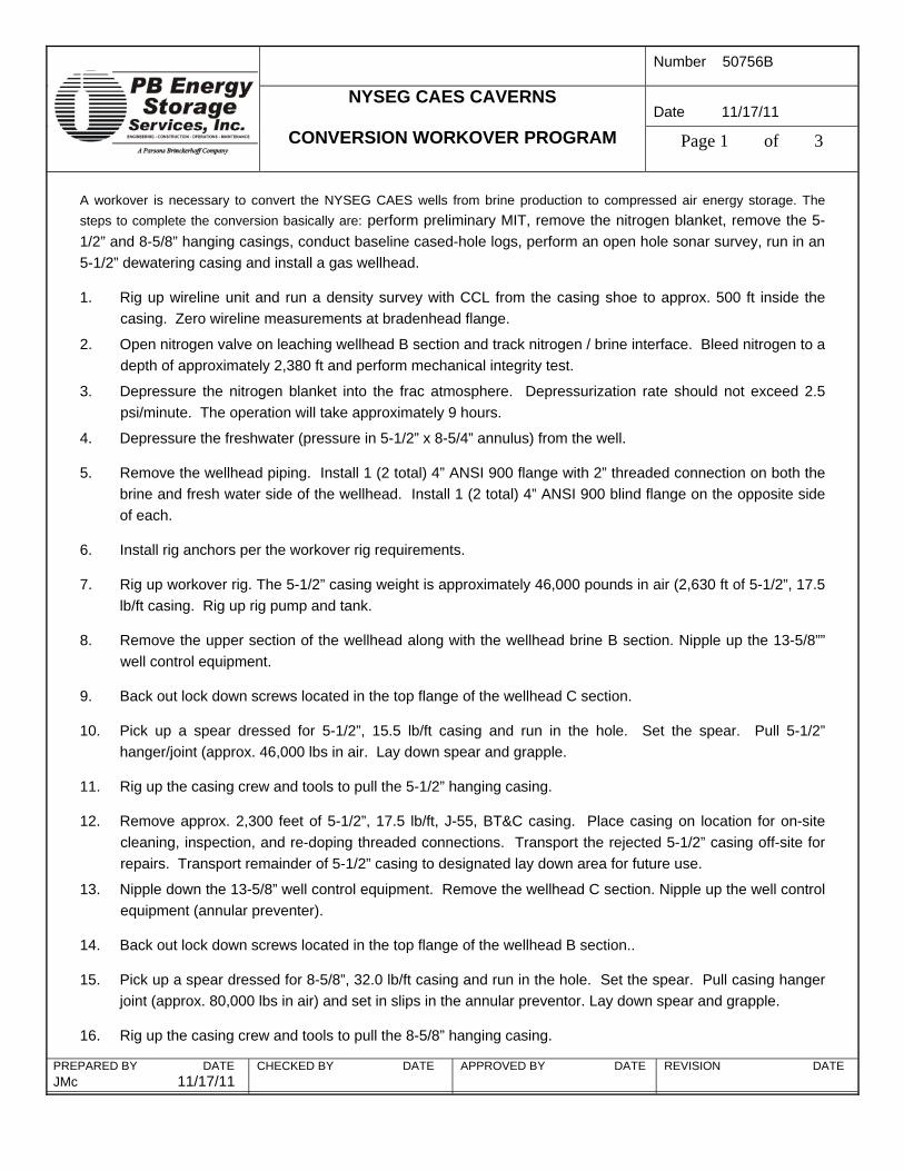
A workover is necessary to convert the NYSEG CAES wells from brine production to compressed air energy storage. The steps to complete the conversion basically are: perform preliminary MIT, remove the nitrogen blanket, remove the 5-1/2” and 8-5/8” hanging casings, conduct baseline cased-hole logs, perform an open hole sonar survey, run in an 5-1/2” dewatering casing and install a gas wellhead.
1. Rig up wireline unit and run a density survey with CCL from the casing shoe to approx. 500 ft inside the casing. Zero wireline measurements at bradenhead flange.
2. Open nitrogen valve on leaching wellhead B section and track nitrogen / brine interface. Bleed nitrogen to a depth of approximately 2,380 ft and perform mechanical integrity test.
3. Depressure the nitrogen blanket into the frac atmosphere. Depressurization rate should not exceed 2.5 psi/minute. The operation will take approximately 9 hours.
4. Depressure the freshwater (pressure in 5-1/2” x 8-5/4” annulus) from the well.
5. Remove the wellhead piping. Install 1 (2 total) 4” ANSI 900 flange with 2” threaded connection on both the brine and fresh water side of the wellhead. Install 1 (2 total) 4” ANSI 900 blind flange on the opposite side of each.
6. Install rig anchors per the workover rig requirements.
7. Rig up workover rig. The 5-1/2” casing weight is approximately 46,000 pounds in air (2,630 ft of 5-1/2”, 17.5 lb/ft casing. Rig up rig pump and tank.
8. Remove the upper section of the wellhead along with the wellhead brine B section. Nipple up the 13-5/8”” well control equipment.
9. Back out lock down screws located in the top flange of the wellhead C section.
10. Pick up a spear dressed for 5-1/2”, 15.5 lb/ft casing and run in the hole. Set the spear. Pull 5-1/2” hanger/joint (approx. 46,000 lbs in air. Lay down spear and grapple.
11. Rig up the casing crew and tools to pull the 5-1/2” hanging casing.
12. Remove approx. 2,300 feet of 5-1/2”, 17.5 lb/ft, J-55, BT&C casing. Place casing on location for on-site cleaning, inspection, and re-doping threaded connections. Transport the rejected 5-1/2” casing off-site for repairs. Transport remainder of 5-1/2” casing to designated lay down area for future use.
13. Nipple down the 13-5/8” well control equipment. Remove the wellhead C section. Nipple up the well control equipment (annular preventer).
14. Back out lock down screws located in the top flange of the wellhead B section..
15. Pick up a spear dressed for 8-5/8”, 32.0 lb/ft casing and run in the hole. Set the spear. Pull casing hanger joint (approx. 80,000 lbs in air) and set in slips in the annular preventor. Lay down spear and grapple.
16. Rig up the casing crew and tools to pull the 8-5/8” hanging casing.

Number 50756B
Date 11/17/11
NYSEG CAES CAVERNS
CONVERSION WORKOVER PROGRAM Page 2 of 3
PREPARED BY DATE JMc 11/17/11
CHECKED BY DATE
APPROVED BY DATE
REVISION DATE
17. Remove approx. 2,530 ft of 8-5/8”, BT&C casing. Place casing on location for on-site cleaning, inspection, and re-doping threaded connections. Transport the rejected 8-5/8” casing off-site for repairs. Transport remainder of 8-5/8” casing to designated lay down area for future use.
18. Rig up wireline unit and run a density survey with CCL from the casing shoe to approx. 500 ft inside the casing.
Note: Have wireline company zero at bradenhead flange (BHF).
19. Rig up wireline unit and run a sonar survey. Rig down wireline unit.
Note: Have sonar company zero at bradenhead flange (BHF). Tie in the sonar tool with the casing shoe and CCL Take sonar survey at 5 ft stations through the entire cavern interval and in the borehole to the cemented casing shoe. Tilt sonar tool and take thorough up shots of the cavern roof.
20. Rig up second wireline unit and run casing and cement evaluation logs (i.e. multi-finger caliper log (Profile Caliper), Vertilog and Segmented Bond Log) on the cemented casing. Rig down wireline unit.
21. Nipple down the 13-5/8” well control equipment.
22. Remove the wellhead B section. Remove the DSA w/pack-off. Nipple up new DSA w/pack-off. Nipple up wellhead B section air annulus casing spool. Activate and test the P-seals (2000-psi for 15 minutes) in the DSA.
23. Nipple up the 21-1/4” well control equipment (2M annular preventer).
24. Rig up a casing crew service and welders and run approx. 2.407’ of type 316 stainless steel l PE casing.
25. Land casing liner hanger joint in wellhead B section hanger bowl.
26. Install wellhead C section DSA and master valve. (Ensure that Master Valve Remains Open). Install wellhead D Section.
27. Run in approx. 2,407 ft of 5-1/2”, 17.5 lb/ft, J-55, LT&C casing. The 5-1/2” LT&C casing connections will be made up to the optimum torque. Externally pressure test (1,600 psi) the 5-1/2” casing and hold for 2 minutes as they are run in.
Note: A digital recorder WILL be run in conjunction with the external tester.
28. Land casing using a casing spear dressed for 5-1/2”, 17.5 lb/ft casing. Screw in lock down screws located in the top flange of the wellhead D section.
29. Nipple down the 21-1/4” well control equipment and install the wellhead D section w/pack-off. Activate and test P-seals (1600-psi for 15 minutes).
30. Install the upper portion of the wellhead F section.
31. Rig down and move out the workover rig.
32. Rig up wireline unit and nitrogen injection unit.

Number 50756B
Date 11/17/11
NYSEG CAES CAVERNS
CONVERSION WORKOVER PROGRAM Page 3 of 3
PREPARED BY DATE JMc 11/17/11
CHECKED BY DATE
APPROVED BY DATE
REVISION DATE
33. Perform nitrogen mechanical integrity test of the well. Warning, nitrogen must be injected simultaneously down the stainless steel nitrogen annulus and inside the stainless steel liner to prevent liner collapse.
34. Rig down MIT equipment, pipe wellhead, and begin dewatering operations.
Number 50756B
Date 11/17/11
NYSEG CAES CAVERNS
SNUBBING PROGRAM Page 1 of 2
PREPARED BY DATE JMc 11/17/11
CHECKED BY DATE
APPROVED BY DATE
REVISION DATE
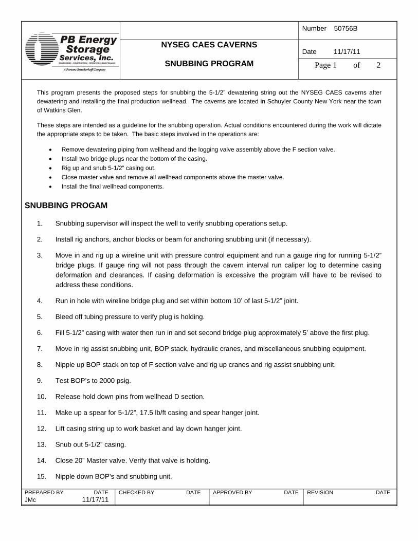
This program presents the proposed steps for snubbing the 5-1/2” dewatering string out the NYSEG CAES caverns after dewatering and installing the final production wellhead. The caverns are located in Schuyler County New York near the town of Watkins Glen.
These steps are intended as a guideline for the snubbing operation. Actual conditions encountered during the work will dictate the appropriate steps to be taken. The basic steps involved in the operations are:
• Remove dewatering piping from wellhead and the logging valve assembly above the F section valve. • Install two bridge plugs near the bottom of the casing. • Rig up and snub 5-1/2” casing out. • Close master valve and remove all wellhead components above the master valve. • Install the final wellhead components.
SNUBBING PROGAM
1. Snubbing supervisor will inspect the well to verify snubbing operations setup.
2. Install rig anchors, anchor blocks or beam for anchoring snubbing unit (if necessary).
3. Move in and rig up a wireline unit with pressure control equipment and run a gauge ring for running 5-1/2” bridge plugs. If gauge ring will not pass through the cavern interval run caliper log to determine casing deformation and clearances. If casing deformation is excessive the program will have to be revised to address these conditions.
4. Run in hole with wireline bridge plug and set within bottom 10’ of last 5-1/2” joint.
5. Bleed off tubing pressure to verify plug is holding.
6. Fill 5-1/2” casing with water then run in and set second bridge plug approximately 5’ above the first plug.
7. Move in rig assist snubbing unit, BOP stack, hydraulic cranes, and miscellaneous snubbing equipment.
8. Nipple up BOP stack on top of F section valve and rig up cranes and rig assist snubbing unit.
9. Test BOP’s to 2000 psig.
10. Release hold down pins from wellhead D section.
11. Make up a spear for 5-1/2”, 17.5 lb/ft casing and spear hanger joint.
12. Lift casing string up to work basket and lay down hanger joint.
13. Snub out 5-1/2” casing.
14. Close 20” Master valve. Verify that valve is holding.
15. Nipple down BOP’s and snubbing unit.

Number 50756B
Date 11/17/11
NYSEG CAES CAVERNS
SNUBBING PROGRAM Page 2 of 2
PREPARED BY DATE JMc 11/17/11
CHECKED BY DATE
APPROVED BY DATE
REVISION DATE
16. Nipple down wellhead D section and install production wellhead.
17. Rig down and move out snubbing unit and associated equipment.
18. Turn over wellpad to NYSEG for well piping.
OPEN HOLE LOGGING Number 50756B
Date 11/11
NYSEG
WATKINS GLEN CAES WELLS Page 1 of 2
PREPARED BY DATE JMc 11/11
CHECKED BY DATE
APPROVED BY DATE
REVISION DATE 0
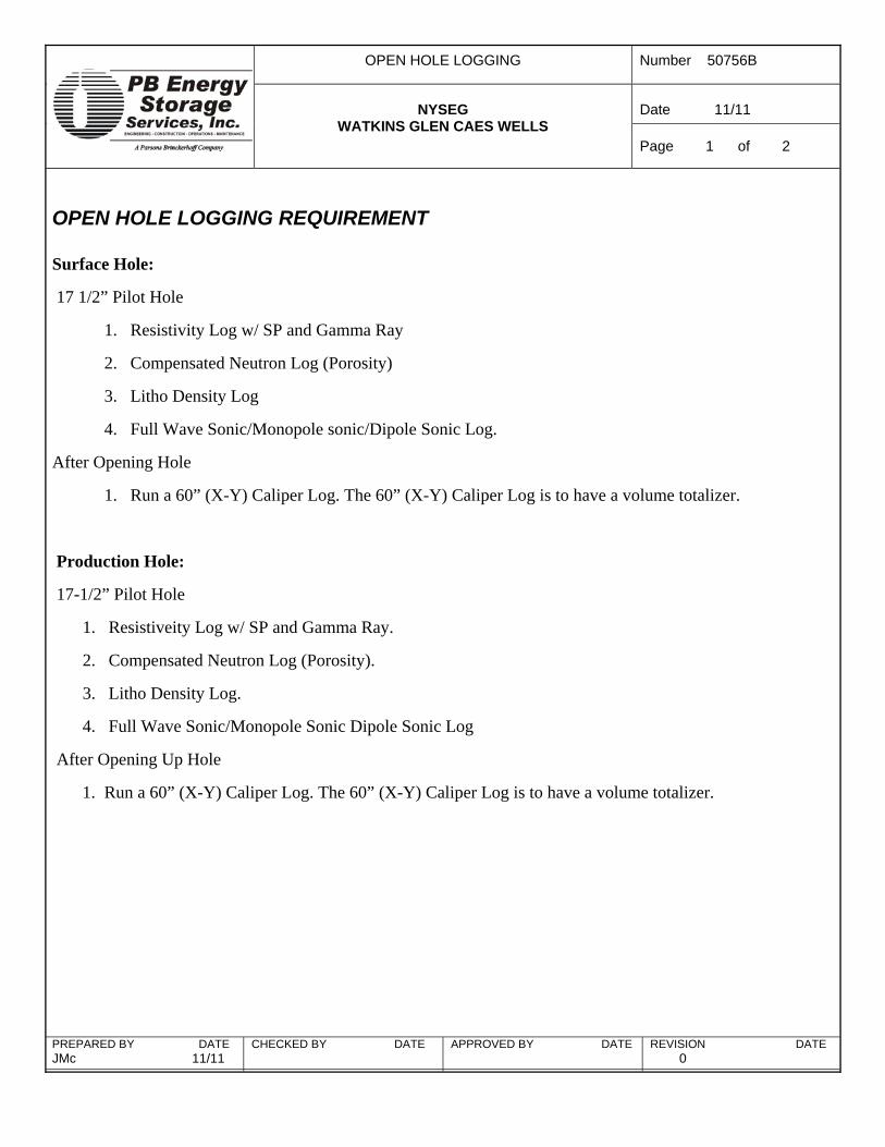
OPEN HOLE LOGGING REQUIREMENT Surface Hole:
17 1/2” Pilot Hole
1. Resistivity Log w/ SP and Gamma Ray
2. Compensated Neutron Log (Porosity)
3. Litho Density Log
4. Full Wave Sonic/Monopole sonic/Dipole Sonic Log.
After Opening Hole
1. Run a 60” (X-Y) Caliper Log. The 60” (X-Y) Caliper Log is to have a volume totalizer.
Production Hole:
17-1/2” Pilot Hole
1. Resistiveity Log w/ SP and Gamma Ray.
2. Compensated Neutron Log (Porosity).
3. Litho Density Log.
4. Full Wave Sonic/Monopole Sonic Dipole Sonic Log
After Opening Up Hole
1. Run a 60” (X-Y) Caliper Log. The 60” (X-Y) Caliper Log is to have a volume totalizer.

A Parsons Brinckerhoff Company
PB Energy Storage
Services, Inc ENGINEERING – CONSTRUCTION – OPERATIONS – MAINTENANCE
16285 Park Ten Place, Suite 400 Houston, Texas 77084 (281) 496-5590 Fax (281) 496-5865 www.pbenergy.com
December 13, 2011 James W. Rettberg, PE Project Manager NYSEG Dear Mr. Rettberg; Re: Dewatering Plan for NYSEG CAES Caverns
Introduction Task 4.4.2.3 of the Technical Specification for the Cavern Development Consultant is to prepare a Preliminary Design for Cavern Dewatering System.
Cavern Description NYSEG proposes to develop 3 storage caverns, each with a dewatered volume of approximately 970,000 bbl. The caverns are to be solution mined on property owned by Inergy near the U.S. Salt Refinery near Watkins Glen, NY. The caverns are designed to have a roof depth of approximately 2,402 ft below ground surface and a floor depth of approximately 2,527 ft. Brine string placement for dewatering is proposed to be at 2,525 ft.
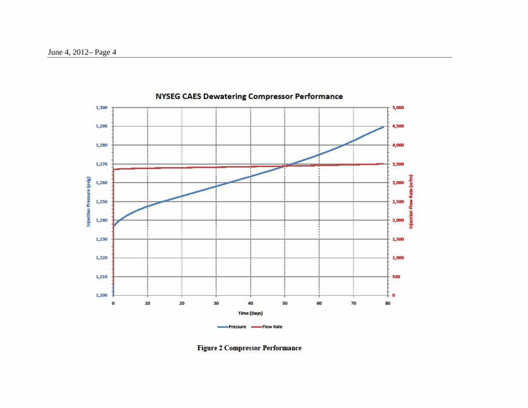
Dewatering Plan At the completion of solution mining a workover will take place to install the stainless steel cavern air injection string to a depth just below the cavern roof and a 5-1/2” dewatering string. Following the workover the cavern will undergo mechanical integrity testing at a nominal pressure of 1,500 psi (surface pressure). The mechanical integrity test will require that nitrogen be pumped down the inside and outside of the stainless steel air injection tubing to prevent collapse. Following the mechanical integrity testing the cavern must be dewatered at a rate of approximately 350 gpm to Inergy. The wellhead configuration (provided in the Cavern Development Plan) will have a 20” isolation valve in place with a 5-1/2” tubing hanger positioned above the valve. The 20” valve must remain open until the dewatering string is snubbed from the cavern at the end of dewatering. Due to the low dewatering rate portable diesel driven compressors will be used during the nominal 80 day dewatering period. A sketch of the proposed compressor arrangement for dewatering is provided in Figure 1. The maximum air pressure anticipated at the surface to dewater the cavern is 1,295 psia and the maximum air flow rate anticipated is approximately

June 4, 2012– Page 2
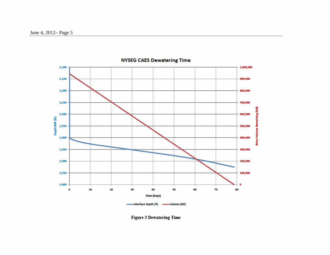
3,750 scfm. A chart showing the surface air pressure and compressor volume flow rate is provided in Figure 2. Since the cavern interval is short (approximately 123 ft) very little dewatering pressure change will occur after the air / brine interface reaches the cavern roof. As air is injected into the well the air / brine interface will fall as the pressure in the cavern increases and brine will be displaced. Figure 3 shows the interface and dewatered volume plotted change during the dewatering process. Please do not hesitate to call or email if you have questions or suggestions. Regards,
James M McHenry

June 4, 2012– Page 4
June 4, 2012– Page 5

CAVERN TESTING PROGRAM
CAES STORAGE CAVERN
Watkins Glen, NY
Prepared for
NYSEG
Binghamton, New York
Prepared by
PB ENERGY STORAGE SERVICES, INC.
Houston, TX
Project No. 50756B
November 2011

Cavern Test Program –NYSEG Watkins Glen CAES Project PBESS Project No. 50756B – November 2011
PB Energy Storage Services, Inc i
TABLE OF CONTENTS
SECTION PAGE
1.0 INTRODUCTION 1
2.0 NITROGEN/BRINE INTERFACE METHOD 1
2.1 Minimum Detectable Leak Rate 2 2.2 Gas Volume Calculations 3 2.3 Calculated Leak Rate (CLR) 5
3.0 CASING INSPECTION 6
3.1 Digital Vertilog 6 3.2 Multi-Finger Imaging Caliper 7 3.3 Gyroscopic Survey 7

Cavern Test Program –NYSEG Watkins Glen CAES Project PBESS Project No. 50756B – November 2011
PB Energy Storage Services, Inc 1
CAVERN TESTING PROGRAM WATKINS GLEN CAES FACILITY
1.0 INTRODUCTION
This document describes the required cavern integrity testing that must take place before the
cavern can be dewatered. Mechanical integrity testing of a storage cavern consists of two distinct
parts. The first part of the testing is a nitrogen test of the cavern to determine gross leakage. The
second part of the testing is an inspection of the well casing.
Each of the NYSEG CAES caverns will undergo nitrogen mechanical integrity testing twice.
The first test will take place after the completion of leaching, but prior to the start of the final
configuration workover. This test will be performed to ascertain the integrity of the cavern prior
to running the welded stainless steel liner. The test will be performed by bleeding off a portion
of the nitrogen blanket and establishing an interface in the borehole below the casing shoe.
After the final configuration workover is completed, the stainless steel liner has been run, and
the dewatering wellhead is in place the cavern will undergo its final nitrogen mechanical
integrity testing. For this test of the cavern it will be necessary to inject nitrogen simultaneously
down the inside of the stainless steel liner and down the annulus to prevent liner collapse.
2.0 NITROGEN/BRINE INTERFACE METHOD
The purpose of performing a mechanical integrity test is to determine if the cavern system has
mechanical integrity, and is therefore suitable for storage. The detailed nitrogen/brine interface
test procedure will be developed prior to testing. The procedure involves an initial injection of
nitrogen into the well to check for wellhead and casing leaks. This initial injection is followed
by continued injection of nitrogen into the storage well to a specified test pressure so that the
nitrogen interface is below the last cemented casing. The nitrogen interface depth can be
affected by pressure and temperature changes caused by temperature equilibration, cavern
leaching, and salt creep effects. In order to distinguish between these effects, and nitrogen
volume losses caused by leaks, the pressure and temperature changes (as they affect nitrogen
volume) must be considered.

Cavern Test Program –NYSEG Watkins Glen CAES Project PBESS Project No. 50756B – November 2011
PB Energy Storage Services, Inc 2
TrVMDLR 365••
=
The nitrogen (annulus) and brine (tubing) pressure and interface depth are monitored during
the test period. Evaluation of the test results involves calculating the volume of nitrogen to the
interface at the start of the test and at the end of the test. The difference in calculated volumes
over the test period yields an apparent volume change. The integrity of the well can be
confirmed if the calculated nitrogen volume change (loss/gains) is within the accuracy limits of
the test method. An annual leak rate can be determined by extrapolating (linearly) the calculated
change in nitrogen volume during the defined interval of the test period (minimum 24 hours).
2.1 MINIMUM DETECTABLE LEAK RATE
The minimum detectable leak rate (MDLR) is the smallest volume of gas loss that can
theoretically be measured considering the accuracy of the interface log and the configuration of
the well. The actual accuracy achievable in the field may be slightly less than the MDLR, but is
of the same order of magnitude, and therefore the MDLR gives a good indication of the test
sensitivity. The MDLR can be calculated using the following relationship:
Where:
MDLR = Minimum Detectable Loss Rate (bbls/year)
V = Unit Volume of Borehole (bbls/ft)
r = Resolution of Interface Detection (ft)
T = Duration of Test (days)
The resolution of the interface detection tool is determined from the logging tool and the
depth scale used to record the interface log. The borehole volume versus depth is calculated
from the metered volume of nitrogen injected, combined with the corresponding interface
location. The wellhead pressure and the nitrogen temperature are also used in the calculations.
Cavern Test Program –NYSEG Watkins Glen CAES Project PBESS Project No. 50756B – November 2011
PB Energy Storage Services, Inc 3
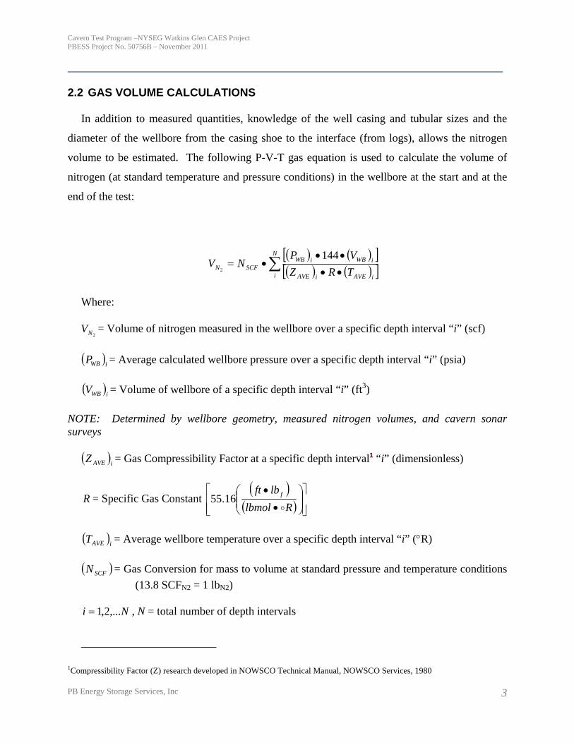
2.2 GAS VOLUME CALCULATIONS
In addition to measured quantities, knowledge of the well casing and tubular sizes and the
diameter of the wellbore from the casing shoe to the interface (from logs), allows the nitrogen
volume to be estimated. The following P-V-T gas equation is used to calculate the volume of
nitrogen (at standard temperature and pressure conditions) in the wellbore at the start and at the
end of the test:
( ) ( )[ ]( ) ( )[ ]∑ ••
•••=
N
i iAVEiAVE
iWBiWBSCFN TRZ
VPNV
1442
Where:
2NV = Volume of nitrogen measured in the wellbore over a specific depth interval “i” (scf)
( )iWBP = Average calculated wellbore pressure over a specific depth interval “i” (psia)
( )iWBV = Volume of wellbore of a specific depth interval “i” (ft3)
NOTE: Determined by wellbore geometry, measured nitrogen volumes, and cavern sonar surveys
( )iAVEZ = Gas Compressibility Factor at a specific depth interval1 “i” (dimensionless)
R = Specific Gas Constant ( )
( ) ⎥⎥⎦
⎤
⎢⎢⎣
⎡⎟⎟⎠
⎞⎜⎜⎝
⎛•
•
Rlbmollbft f
o16.55
( )iAVET = Average wellbore temperature over a specific depth interval “i” (°R)
( )SCFN = Gas Conversion for mass to volume at standard pressure and temperature conditions (13.8 SCFN2 = 1 lbN2)
Ni ,...2,1= , N = total number of depth intervals
1Compressibility Factor (Z) research developed in NOWSCO Technical Manual, NOWSCO Services, 1980
Cavern Test Program –NYSEG Watkins Glen CAES Project PBESS Project No. 50756B – November 2011
PB Energy Storage Services, Inc 4
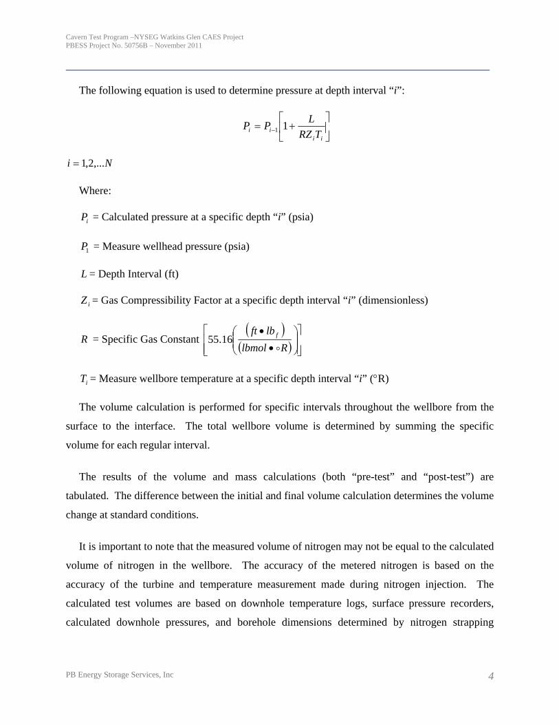
The following equation is used to determine pressure at depth interval “i”:
⎥⎦
⎤⎢⎣
⎡+= −
iiii TRZ
LPP 11
Ni ,...2,1=
Where:
iP = Calculated pressure at a specific depth “i” (psia)
1P = Measure wellhead pressure (psia)
L = Depth Interval (ft)
iZ = Gas Compressibility Factor at a specific depth interval “i” (dimensionless)
R = Specific Gas Constant ( )
( ) ⎥⎥⎦
⎤
⎢⎢⎣
⎡⎟⎟⎠
⎞⎜⎜⎝
⎛•
•
Rlbmollbft f
o16.55
iT = Measure wellbore temperature at a specific depth interval “i” (°R)
The volume calculation is performed for specific intervals throughout the wellbore from the
surface to the interface. The total wellbore volume is determined by summing the specific
volume for each regular interval.
The results of the volume and mass calculations (both “pre-test” and “post-test”) are
tabulated. The difference between the initial and final volume calculation determines the volume
change at standard conditions.
It is important to note that the measured volume of nitrogen may not be equal to the calculated
volume of nitrogen in the wellbore. The accuracy of the metered nitrogen is based on the
accuracy of the turbine and temperature measurement made during nitrogen injection. The
calculated test volumes are based on downhole temperature logs, surface pressure recorders,
calculated downhole pressures, and borehole dimensions determined by nitrogen strapping

Cavern Test Program –NYSEG Watkins Glen CAES Project PBESS Project No. 50756B – November 2011
PB Energy Storage Services, Inc 5
calculations or sonar volumes. All measurements are subject to the accuracy of the
instrumentation being used and the well conditions at the time of the measurements.
At average wellbore conditions (at the conclusion of the test), the nitrogen volume change can
be stated as:
( ) ( ) ( )[ ]( )[ ] ⎟⎟
⎠
⎞⎜⎜⎝
⎛
••Δ•••
=ΔSCFAVEWB
STPAVEAVETEST NP
VTRZV
144
Where:
TESTVΔ = nitrogen volume changes over the test period based on wellbore conditions (ft3)
( )AVEWBP = Average wellbore pressure over the test period (psia)
( )STPVΔ = Nitrogen volume change (scf), based on standard conditions
( )AVEZ = Average Gas Compressibility Factor over the test period
R = Specific Gas Constant ( )
( ) ⎥⎥⎦
⎤
⎢⎢⎣
⎡⎟⎟⎠
⎞⎜⎜⎝
⎛•
•
Rlbmollbft f
o16.55
( )AVET = Average wellbore temperature over the test period (°R)
( )SCFN = Gas Conversion (13.8 SCFN2 = 1 lbN2)
2.3 CALCULATED LEAK RATE (CLR)
The equation below is used to calculate the annual calculated leak rate (CLR) from the
volume change in nitrogen for the specified test period:
( ) ( ) ( )[ ]L
TESTCLR T
yeardaysdayhoursVV
/365/24 ••Δ=
Where:
Cavern Test Program –NYSEG Watkins Glen CAES Project PBESS Project No. 50756B – November 2011
PB Energy Storage Services, Inc 6
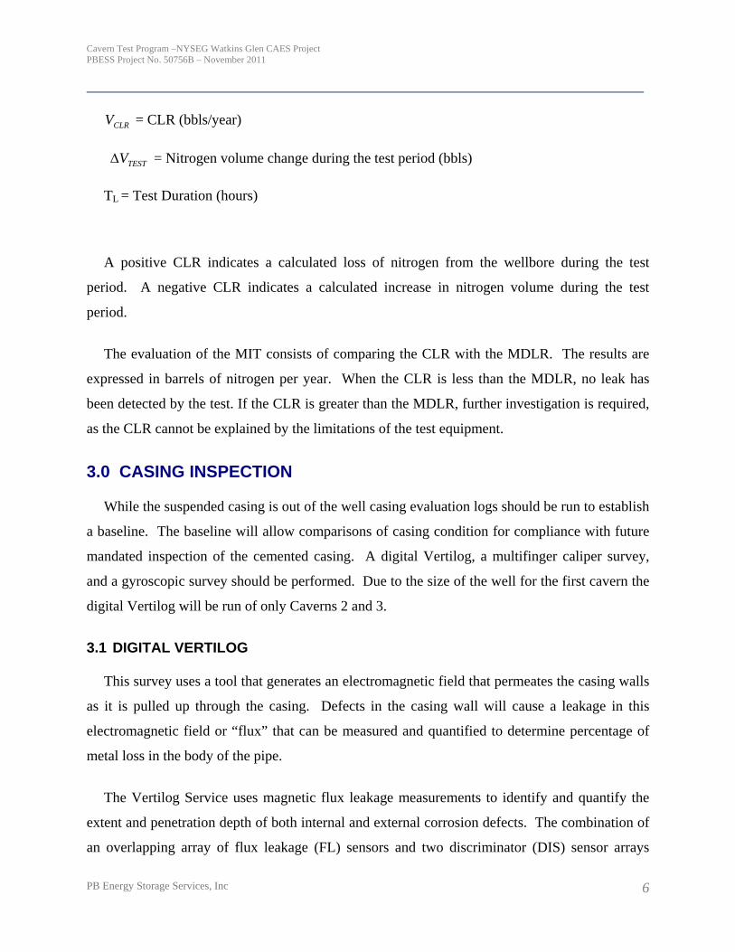
CLRV = CLR (bbls/year)
TESTVΔ = Nitrogen volume change during the test period (bbls)
TL = Test Duration (hours)
A positive CLR indicates a calculated loss of nitrogen from the wellbore during the test
period. A negative CLR indicates a calculated increase in nitrogen volume during the test
period.
The evaluation of the MIT consists of comparing the CLR with the MDLR. The results are
expressed in barrels of nitrogen per year. When the CLR is less than the MDLR, no leak has
been detected by the test. If the CLR is greater than the MDLR, further investigation is required,
as the CLR cannot be explained by the limitations of the test equipment.
3.0 CASING INSPECTION
While the suspended casing is out of the well casing evaluation logs should be run to establish
a baseline. The baseline will allow comparisons of casing condition for compliance with future
mandated inspection of the cemented casing. A digital Vertilog, a multifinger caliper survey,
and a gyroscopic survey should be performed. Due to the size of the well for the first cavern the
digital Vertilog will be run of only Caverns 2 and 3.
3.1 DIGITAL VERTILOG
This survey uses a tool that generates an electromagnetic field that permeates the casing walls
as it is pulled up through the casing. Defects in the casing wall will cause a leakage in this
electromagnetic field or “flux” that can be measured and quantified to determine percentage of
metal loss in the body of the pipe.
The Vertilog Service uses magnetic flux leakage measurements to identify and quantify the
extent and penetration depth of both internal and external corrosion defects. The combination of
an overlapping array of flux leakage (FL) sensors and two discriminator (DIS) sensor arrays

Cavern Test Program –NYSEG Watkins Glen CAES Project PBESS Project No. 50756B – November 2011
PB Energy Storage Services, Inc 7
provides full circumferential inspection of the tubing or casing string, allows for differentiating
between metal loss (corrosion) and metal gain , and distinguishes between general corrosion and
isolated pitting.
Defects in the casing wall as small as 3/8” in diameter can be identified using this technique.
Casing sizes from 13-3/8 to 22 in. can be evaluated. Once a baseline is established, the
technique can be used to detect corrosion and depth of penetration. The tool provides 360 degree
identification and quantification of small, isolated casing defects in real-time or memory mode
3.2 MULTI-FINGER IMAGING CALIPER
This survey uses a multi-finger caliper to measure the ID of the last cemented casing. The
multi-finger caliper tool mechanically measures the inside diameter of downhole casing. Two
channels of information are recorded at the surface. One recording shows the minimum
measured internal radius and the other shows the maximum measured internal radius. When the
casing is relatively new, the Multi-Finger Caliper Log reveals the casing's minimum and
maximum inside diameter. This information is useful for determining whether there is abnormal
casing wear caused by the rubbing of drill pipe on the inside casing wall.
3.3 GYROSCOPIC SURVEY
This survey uses a logging tool with a gyroscopic compass and inclination sensor to measure
the well deviation and direction of the deviation every 25 feet from the surface down to the
bottom of the last cemented casing. This information is necessary to establish the location of the
casing shoe and ultimately the location of the cavern walls in space.

CONSTRUCTION EXECUTION PLAN
CAES STORAGE CAVERN
Watkins Glen, NY
Prepared for
NYSEG
Binghamton, New York
Prepared by
PB ENERGY STORAGE SERVICES, INC.
Houston, TX
Project No. 50756B
November 2011

Construction Execution Plan –NYSEG Watkins Glen CAES Project PBESS Project No. 50756B – November2011
PB Energy Storage Services, Inc i
TABLE OF CONTENTS
SECTION PAGE
1.0 INTRODUCTION.............................................................................................1
2.0 CONSTRUCTION MANAGEMENT ................................................................1
3.0 CONSTRUCTION SCHEDULE.......................................................................3
4.0 CONSTRUCTION TASK SEQUENCE............................................................4
5.0 ENVIRONMENTAL SAFETY AND HEALTH..................................................5
6.0 QUALITY ASSURANCE.................................................................................6

Construction Execution Plan –NYSEG Watkins Glen CAES Project PBESS Project No. 50756B – November2011
PB Energy Storage Services, Inc 1
CONSTRUCTION EXECUTION PLAN WATKINS GLEN CAES FACILITY
1.0 INTRODUCTION
NYSEG proposes to develop a compressed energy storage (CAES) project near Watkins Glen, NY which has a rated generating capacity of 180 MW. The storage chamber for the compressed air will consist of three nominal 970,000 barrel caverns developed in the F Salt Unit of the Salina Formation. The storage caverns are planned for development in the interval between 2,402 ft and 2.632 ft below ground surface and will be developed using solution mining methods. The total duration of the drilling and cavern development is estimated to be 7.4 years. The NYSEG CAES cavern development project is unique, and will require a high level of supervision and monitoring.
This construction execution plan describes the strategy to be employed for executing and managing activities required to build 3 storage caverns at the NYSEG Site near Watkins Glen, NY. Elements of this plan include:
• Construction Management • Construction Schedule • Construction Task Sequence • Environmental Safety and Health • Quality Assurance
2.0 CONSTRUCTION MANAGEMENT
The drilling, completion, cavern development monitoring, and testing required for construction of the NYSEG caverns will require the services of a specialty construction contractor. The Cavern Construction Manager will be responsible for all activities required to drill and complete the wells, solution mine the storage caverns, and prepare the storage caverns for CAES service. The contractor selected will require expertise in drilling and completion of large diameter gas storage wells in salt and the solution mining of storage caverns in salt.
The Construction Manager should be engaged as soon as possible after the decision has been made by NYSEG to proceed with the project. This early engagement will be required to locate, schedule, and place under contract, a drill rig capable of drilling the NYSEG wells. Acquisition of the drilling subcontractor is a critical path item in the cavern construction schedule.
Construction Execution Plan –NYSEG Watkins Glen CAES Project PBESS Project No. 50756B – November2011
PB Energy Storage Services, Inc 2
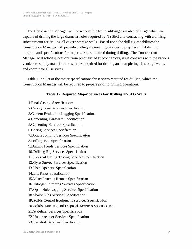
The Construction Manager will be responsible for identifying available drill rigs which are capable of drilling the large diameter holes required by NYSEG and contracting with a drilling subcontractor for drilling all cavern storage wells. Based upon the drill rig capabilities the Construction Manager will provide drilling engineering services to prepare a final drilling program and specifications for major services required during drilling. The Construction Manager will solicit quotations from prequalified subcontractors, issue contracts with the various venders to supply materials and services required for drilling and completing all storage wells, and coordinate all services.
Table 1 is a list of the major specifications for services required for drilling, which the Construction Manager will be required to prepare prior to drilling operations.
Table 1 - Required Major Services For Drilling NYSEG Wells
1. Final Casing Specifications 2. Casing Crew Services Specification 3. Cement Evaluation Logging Specification 4. Cementing Hardware Specification 5. Cementing Services Specification 6. Coring Services Specification 7. Double Jointing Services Specification 8. Drilling Bits Specification 9. Drilling Fluids Services Specification 10. Drilling Rig Services Specification 11. External Casing Testing Services Specification 12. Gyro Survey Services Specification 13. Hole Openers Specification 14. Lift Rings Specification 15. Miscellaneous Rentals Specification 16. Nitrogen Pumping Services Specification 17. Open Hole Logging Services Specification 18. Shock Subs Services Specification 19. Solids Control Equipment Services Specification 20. Solids Handling and Disposal Services Specification 21. Stabilizer Services Specification 22. Under-reamer Services Specification 23. Vertitrak Services Specification

Construction Execution Plan –NYSEG Watkins Glen CAES Project PBESS Project No. 50756B – November2011
PB Energy Storage Services, Inc 3
24. Welding Services Specification 25. Wellpad Construction Services Specification
The Construction Manager will provide resident drilling supervision at the wellsite on a 24 hour per day basis during mobilization, drilling, completion, and demobilization. The drilling supervisor will be responsible for coordination of subcontractor activities, daily progress reporting, and wellsite safety. The drilling supervisors used by the Construction Manager shall be thoroughly experienced in the drilling and completion of large diameter gas storage wells in salt.
The Construction Manager will provide workover supervision services required to perform well workovers for the intermediate workovers, the conversion workovers, and during final wellhead installation.
The MIT, planning, execution, data interpretation, and report preparation.
The construction contractor will provide onsite workover supervision during all workovers and wireline operations. Workover supervisors will be thoroughly experienced in well workover and storage well field intervention operations.
Construction supervisor will provide cavern engineering services required to evaluate data collected by Inergy, monitor solution mining progress, evaluate wireline logging results, and perform solution mining modeling and solution mining program adjustments after sonar surveys and open hole logging.
3.0 CONSTRUCTION SCHEDULE
The schedule submitted by PB ESS for cavern development is based upon an assumed start date of 12/06/2013 for wellpad construction. The actual start of drilling is dependent on the availability of a drill rig of adequate capacity to drill Well No. 1 (24” cemented casing). The schedule assumes that the three wells will be drilled sequentially, one immediately following the other, to ensure that the availability of drill rigs will not impact development of Caverns 2 & 3. Due to high demand for drilling rigs in the Marcellus, PB ESS recommends that a firm commitment be made by NYSEG to a drilling subcontractor at the earliest possible date.
Wellhead components and stainless steel liners will require delivery times of approximately one year. Due to uncertainties in delivery and fabrication time these items should be considered long lead items and should be ordered at the earliest possible date. Tubulars should be welded

Construction Execution Plan –NYSEG Watkins Glen CAES Project PBESS Project No. 50756B – November2011
PB Energy Storage Services, Inc 4
into 80 foot lengths prior to shipment to the drill site to decrease the rig time required to run the stainless steel liner. The fabrication of the bradenhead flanges should be considered as part of the critical path since they will be required prior to well completion.
The cavern development schedule will require monthly update and tracking once the drill rig mobilizes. Due to the geologic uncertainties associated with drilling of large diameter wells and the solution mining of storage caverns unplanned schedule delays can occur. Schedule variances will be reported to NYSEG on a monthly basis.
4.0 CONSTRUCTION TASK SEQUENCE
The overall construction sequence for building the NYSEG caverns is listed below as Table 2.
Table 2 - Construction Sequence
1. Order wellhead components and long lead stainless steel tubulars. 2. Subcontract drilling rig services. 3. Build drilling access road. 4. Subcontract required major drilling services. 5. Build wellpad. 6. Mobilize drilling rig and drill well. 7. Demobilize drilling rig to next hole or off site if all wells drilled. 8. Install wellpad piping and connect to Inergy piping. 9. Hydrotest wellpad piping. 10. Inject nitrogen blanket. 11. Perform data analysis on weekly basis to estimate cavern development progress. 12. Perform periodic blanket interface checks and adjust nitrogen volume as required. 13. Bleed nitrogen blanket, perform sonar survey, and perform workover to adjust tubing
lengths. 14. Inject nitrogen blanket. 15. Leach cavern in reverse. 16. Perform blanket interface surveys as required. 17. Perform casing cuts as required. 18. Perform through pipe sonar surveys after each leaching stage and revise solution mining
models as required. 19. At completion of leaching bleed nitrogen back to establish interface in borehole. 20. Perform preliminary MIT.

Construction Execution Plan –NYSEG Watkins Glen CAES Project PBESS Project No. 50756B – November2011
PB Energy Storage Services, Inc 5
21. Bleed nitrogen from well and perform conversion workover. 22. Perform mechanical integrity test. 23. Connect temporary compressors and inject air, displacing brine from cavern. 24. Snub dewatering string from well. 25. Install remaining wellhead components 26. Solution mine remaining wells.
5.0 ENVIRONMENTAL SAFETY AND HEALTH
All drilling and construction personnel shall observe and enforce all applicable governmental safety regulations and all safety rules that have been or are established during performance of this agreement
Each subcontractor employee is required to complete Basic Orientation Plus® training, which is developed and administered through the Association of Reciprocal Safety Council’s Inc. or an OSHA 10-Hour Construction Industry Outreach training course.
Subcontractor shall provide a Safety Meeting prior to beginning work. Additional "Tailgate Safety Meetings" shall be held on a weekly basis, covering work related safety topics. Subcontractor shall require that all personnel attend meetings and shall provide documentation of this attendance and meeting topics to the Construction Manager
On a daily basis, subcontractors shall develop Job Safety Analysis (JSA) forms for each major work activity. The JSA must list each step for the job, the hazards associated with each step and steps to mitigate each hazard. Any time that the scope of the job changes, the JSA must be revised or a new one must be written.
Subcontractor must notify the Construction Manager, as soon as is reasonably possible, of all injuries that occur during performance of and relative to work performed for NYSEG. A written report of each injury must be submitted to the Construction Manager within 24 hours of the injury.
If services to be performed requires subcontractor to bring chemicals or hazardous products onto the job site, subcontractor must post an inventory of and accurate material Safety Data Sheets for such materials at the job site. All materials brought onto the job site must be properly labeled, handled and stored to comply with OSHA Hazard Communication Standard.

Construction Execution Plan –NYSEG Watkins Glen CAES Project PBESS Project No. 50756B – November2011
PB Energy Storage Services, Inc 6
6.0 QUALITY ASSURANCE
The Construction Manager shall have in place a quality assurance program that meets the standards set forth in ISO 9000. Subcontractors shall perform the work in a quality manner using qualified, efficient and careful workers; in accordance with NYSEG project management plans, quality plans, drawings, and specification; in compliance with all applicable quality, environmental and safety rules and regulations; in a manner to protect the work and NYSEG’s property from damage, and the property and persons or others from injury or loss arising in conjunction with the contract and as not to interfere with operations of others on the premises.

ID Task Name Duration Start
1 3385.5 days Sat 12/31/11
2 NYSEG CAES Project 986.5 days Fri 12/6/13
3 NTP PHASE 2-PLANT CONSTRUCTION 0 days Fri 12/6/13
4 Engineering and Procurement 51 days Fri 12/6/13
5 Long Lead Procurement 364 days Fri 12/13/13
6 Procure Leaching wellhead (all wells) 10 wks Fri 12/13/13
7 Procure Production Wellhead (all wells) 42 wks Fri 12/13/13
8 Procure Stainless Steel Tubulars (all wells) 52 wks Fri 12/13/13
9 Build Wellpad Location No. 1 30 days Fri 12/13/13
10 Move in and rig up drilling rig 7 days Sun 1/12/14
11 Drilling and complete Cavern Well 1 75 days Sun 1/19/14
12 Conductor Hole 8 days Sun 1/19/14
21 Surface Hole 29 days Mon 1/27/14
31 Production Hole 38 days Tue 2/25/14
41 Rig down 5 days Fri 4/4/14
42 Connect wellhead piping and Inject Blanket - Well No. 1 5 days Wed 4/9/14
43 Develop Cavern No. 1 722 days Mon 4/14/14
44 Solution Mining 722 days Mon 4/14/14
45 Sump / Chimney Stage No. 1 130 days Mon 4/14/14
Q3 Q4 Q1 Q2 Q3 Q4 Q1 Q2 Q3 Q4 Q1 Q2 Q3 Q4 Q1 Q2 Q3 Q4 Q1 Q2 Q3 Q4 Q1 Q2 Q3 Q4 Q1 Q2 Q3 Q4 Q1 Q2 Q3 Q4 Q1 Q2 Q3 Q4 Q1 Q2 Q32012 2013 2014 2015 2016 2017 2018 2019 2020 2021
Task
Progress
Milestone
Summary
Rolled Up Task
Rolled Up Milestone
Rolled Up Progress
Split
External Tasks
Project Summary
Group By Summary
Deadline
NYSEG CAES Project Schedule
Watkins Glen, NY
Page 1
Project: 50756B NYSEG CAESDate: Tue 6/5/12

ID Task Name Duration Start
46 Intermediate Workover 8 days Fri 8/22/14
58 Re-Inject Blanket 1 day Sat 8/30/14
59 Reverse No. 1 150 days Sun 8/31/14
60 Through Pipe Sonar and Blanket Move 1 day Wed 1/28/15
61 Reverse No. 2 150 days Thu 1/29/15
62 Through Pipe Sonar and Blanket Move 1 day Sun 6/28/15
63 Reverse No. 3 150 days Mon 6/29/15
64 Through Pipe Sonar 1 day Thu 11/26/15
65 Reverse No. 4 130 days Fri 11/27/15
66 Perform Final Configuration Workover Cavern No. 1 35.5 days Tue 4/5/16
77 Dewater Cavern No. 1 91 days Tue 5/10/16
81 Snub Dewatering String From Cavern No. 1 4 days Tue 8/9/16
88 Install Remaining Wellhead ComponentsConnect CAES Surface Piping 5 days Sat 8/13/16
89 Begin CAES Operation Cavern No. 1 0 days Thu 8/18/16
90 NYSEG - Watkins Glen, NY - CAES Cavern No. 2 2539 days Sat 12/31/11
91 Build Wellpad No. 2 30 days Sun 1/12/14
92 Move in and rig up drilling rig 7 days Wed 4/9/14
93 Drill and complete Cavern Well 2 72 days Wed 4/16/14
94 Conductor Hole 8 days Wed 4/16/14
Q3 Q4 Q1 Q2 Q3 Q4 Q1 Q2 Q3 Q4 Q1 Q2 Q3 Q4 Q1 Q2 Q3 Q4 Q1 Q2 Q3 Q4 Q1 Q2 Q3 Q4 Q1 Q2 Q3 Q4 Q1 Q2 Q3 Q4 Q1 Q2 Q3 Q4 Q1 Q2 Q32012 2013 2014 2015 2016 2017 2018 2019 2020 2021
Task
Progress
Milestone
Summary
Rolled Up Task
Rolled Up Milestone
Rolled Up Progress
Split
External Tasks
Project Summary
Group By Summary
Deadline
NYSEG CAES Project Schedule
Watkins Glen, NY
Page 2
Project: 50756B NYSEG CAESDate: Tue 6/5/12

ID Task Name Duration Start
103 Surface Hole 24 days Thu 4/24/14
112 Production Hole 40 days Sun 5/18/14
130 Rig down 5 days Fri 6/27/14
131 Connect wellhead piping and Inject Blanket - Well No. 2 5 days Sat 12/31/11
132 Develop Cavern No. 2 722 days Tue 8/9/16
133 Solution Mining 722 days Tue 8/9/16
134 Sump / Chimney Stage No. 1 130 days Tue 8/9/16
135 Perform Intermediate Workover Cavern No. 2 9 days Sat 12/17/16
148 Reverse No. 1 150 days Mon 12/26/16
149 Through Pipe Sonar and Blanket Move 1 day Thu 5/25/17
150 Reverse No. 2 150 days Fri 5/26/17
151 Through Pipe Sonar and Blanket Move 1 day Mon 10/23/17
152 Reverse No. 3 150 days Tue 10/24/17
153 Through Pipe Sonar 1 day Fri 3/23/18
154 Reverse No. 4 130 days Sat 3/24/18
155 Perform Final Configuration Workover Cavern No. 2 33.5 days Wed 8/1/18
166 Dewater Cavern No. 2 91 days Tue 9/4/18
170 Snub Dewatering String From Cavern No. 2 4 days Tue 12/4/18
177 Connect CAES Surface Piping Cavern No. 2 5 days Sat 12/8/18
Q3 Q4 Q1 Q2 Q3 Q4 Q1 Q2 Q3 Q4 Q1 Q2 Q3 Q4 Q1 Q2 Q3 Q4 Q1 Q2 Q3 Q4 Q1 Q2 Q3 Q4 Q1 Q2 Q3 Q4 Q1 Q2 Q3 Q4 Q1 Q2 Q3 Q4 Q1 Q2 Q32012 2013 2014 2015 2016 2017 2018 2019 2020 2021
Task
Progress
Milestone
Summary
Rolled Up Task
Rolled Up Milestone
Rolled Up Progress
Split
External Tasks
Project Summary
Group By Summary
Deadline
NYSEG CAES Project Schedule
Watkins Glen, NY
Page 3
Project: 50756B NYSEG CAESDate: Tue 6/5/12

ID Task Name Duration Start
178 Begin CAES Operation Cavern No. 2 0 days Thu 12/13/18
179 NYSEG - Watkins Glen, NY - CAES Cavern No. 3 2612.5 days Tue 2/11/14
180 Build Wellpad No. 3 30 days Tue 2/11/14
181 Move in and rig up drilling rig 7 days Wed 7/2/14
182 Drill and Complete Well No. 3 66 days Wed 7/9/14
183 Conductor Hole 8 days Wed 7/9/14
192 Surface Hole 25 days Thu 7/17/14
201 Production Hole 33 days Mon 8/11/14
212 Rig down 5 days Sat 9/13/14
213 Connect CAES Surface Piping and Inject Blanket - Cavern No. 3 5 days Thu 9/18/14
214 Develop Cavern No. 3 722 days Tue 12/4/18
215 Solution Mining 722 days Tue 12/4/18
216 Sump / Chimney Stage No. 1 130 days Tue 12/4/18
217 Perform Intermediate Workover Cavern No. 3 9 days Sat 4/13/19
230 Reverse No. 1 150 days Mon 4/22/19
231 Through Pipe Sonar 1 day Thu 9/19/19
232 Reverse No. 2 150 days Fri 9/20/19
233 Through Pipe Sonar 1 day Mon 2/17/20
234 Reverse No. 3 150 days Tue 2/18/20
Q3 Q4 Q1 Q2 Q3 Q4 Q1 Q2 Q3 Q4 Q1 Q2 Q3 Q4 Q1 Q2 Q3 Q4 Q1 Q2 Q3 Q4 Q1 Q2 Q3 Q4 Q1 Q2 Q3 Q4 Q1 Q2 Q3 Q4 Q1 Q2 Q3 Q4 Q1 Q2 Q32012 2013 2014 2015 2016 2017 2018 2019 2020 2021
Task
Progress
Milestone
Summary
Rolled Up Task
Rolled Up Milestone
Rolled Up Progress
Split
External Tasks
Project Summary
Group By Summary
Deadline
NYSEG CAES Project Schedule
Watkins Glen, NY
Page 4
Project: 50756B NYSEG CAESDate: Tue 6/5/12

ID Task Name Duration Start
235 Through Pipe Sonar 1 day Fri 7/17/20
236 Reverse No. 4 130 days Sat 7/18/20
237 Perform Final Configuration Workover Cavern No.3 33.5 days Wed 11/25/20
247 Dewater Cavern No.3 91 days Mon 12/28/20
251 Snub Dewatering String From Cavern No. 3 4 days Mon 3/29/21
258 Connect CAES Surface Piping Cavern No. 3 5 days Fri 4/2/21
259 Begin CAES Operation Cavern No. 3 0 days Wed 4/7/21
260 Complete NYSEG CAES Project 0 days Wed 4/7/21
Q3 Q4 Q1 Q2 Q3 Q4 Q1 Q2 Q3 Q4 Q1 Q2 Q3 Q4 Q1 Q2 Q3 Q4 Q1 Q2 Q3 Q4 Q1 Q2 Q3 Q4 Q1 Q2 Q3 Q4 Q1 Q2 Q3 Q4 Q1 Q2 Q3 Q4 Q1 Q2 Q32012 2013 2014 2015 2016 2017 2018 2019 2020 2021
Task
Progress
Milestone
Summary
Rolled Up Task
Rolled Up Milestone
Rolled Up Progress
Split
External Tasks
Project Summary
Group By Summary
Deadline
NYSEG CAES Project Schedule
Watkins Glen, NY
Page 5
Project: 50756B NYSEG CAESDate: Tue 6/5/12

Cost ContractDelivery /
CompletionDuration (Days)
Description: Overnight Cost Basis Date Date
Material
Stainless Steel Air Pipe and Wellheads 5,345,000$ 20-Oct-11 6-Jan-12 5-Jan-13 365Total - Bulks 5,345,000$
Subcontract
Wellpad 1 562,000$ 20-Nov-11 13-Dec-13 12-Jan-14 30Drilling No. 1 7,771,000$ 20-Nov-11 19-Jan-14 4-Apr-14 75Piping and Blanket No. 1 191,000$ 20-Nov-11 9-Apr-14 14-Apr-14 5Intermediate W/O and Blanket No. 1 175,000$ 20-Nov-11 22-Aug-14 30-Aug-14 8Sonar and Blanket No. 1 56,000$ 20-Nov-11 28-Jan-15 29-Jan-15 1Sonar and Blanket No. 1 56,000$ 20-Nov-11 28-Jun-15 29-Jun-15 1Sonar No. 1 25,000$ 20-Nov-11 26-Nov-15 27-Nov-15 1Final Configuration W/O No. 1 1,178,000$ 20-Nov-11 5-Apr-16 10-May-16 35Snub No. 1 194,000$ 20-Nov-11 9-Aug-16 13-Aug-16 4Final Wellhead Install No. 1 61,980$ 20-Nov-11 13-Aug-16 18-Aug-16 5Wellpad No. 2 562,000$ 20-Nov-11 12-Jan-14 11-Feb-14 30Drilling No. 2 7,233,000$ 20-Nov-11 16-Apr-14 27-Jun-14 72Piping and Blanket No. 2 191,000$ 20-Nov-11 2-Jul-14 7-Jul-14 5Intermediate W/O and Blanket No. 2 175,000$ 20-Nov-11 17-Dec-16 26-Dec-16 9Sonar and Blanket No. 2 56,000$ 20-Nov-11 25-May-17 26-May-17 1Sonar and Blanket No. 2 56,000$ 20-Nov-11 23-Oct-17 24-Oct-17 1Sonar No. 2 25,000$ 20-Nov-11 23-Mar-18 24-Mar-18 1Final Configuration W/O No. 2 1,100,000$ 20-Nov-11 1-Aug-18 4-Sep-18 34Snub No. 2 194,000$ 20-Nov-11 04-Dec-18 08-Dec-18 4Final Wellhead Install No. 3 61,980$ 20-Nov-11 8-Dec-18 13-Dec-18 5Wellpad No. 3 562,000$ 20-Nov-11 11-Feb-14 13-Mar-14 30Drilling No. 3 7,067,000$ 20-Nov-11 9-Jul-14 13-Sep-14 66Piping and Blanket No. 3 191,000$ 20-Nov-11 18-Sep-14 23-Sep-14 5Intermediate W/O and Blanket No. 3 175,000$ 20-Nov-11 13-Apr-19 22-Apr-19 9Sonar and Blanket No. 3 56,000$ 20-Nov-11 19-Sep-19 20-Sep-19 1Sonar and Blanket No. 3 56,000$ 20-Nov-11 17-Feb-20 18-Feb-20 1Sonar No. 3 25,000$ 20-Nov-11 17-Jul-20 18-Jul-20 1Final Configuration W/O No. 3 1,100,000$ 20-Nov-11 25-Nov-20 28-Dec-20 33Snub No. 3 194,000$ 20-Nov-11 29-Mar-21 2-Apr-21 4Final Wellhead Install No. 3 61,980$ 20-Nov-11 2-Apr-21 4/7/2021 5
Subtotal - Services 29,412,000$
Operations and Maintenance
Inergy Labor 999,000$ 20-Nov-11 14-Apr-14 25-Nov-20 2417Engineering Labor 196,000$ 20-Nov-11 14-Apr-14 25-Nov-20 2417Miscellaneous Maintenance 688,000$ 20-Nov-11 14-Apr-14 25-Nov-20 2417
Operations Total 1,883,000$
Total Estimate 36,640,000$ Total Estimate (Rounded) 36,640,000$
10/31/2011
Cavern Construction Cost EstimateNYSEG CAES - Watkins Glen NY

PB Energy Storage Services, Inc. Cost EstimateTITLE ESTIM TYPE 10 Percent ESTIMATOR: KS/Jm REVIEWER: JM REV:
DISCIPLINE All DATE: 12/07/11 DATE: 12/07/11 DATE: 12/07/11LINE COVER SHEET UNIT COST TOTAL COSTNO Wellpad and Road LABOR MATL EQUIP SUBCON LABOR MATL EQUIP SUBCON
1 DIVISION 1 - GENERAL REQUIREMENTS2 Labor & Services (1A-1) 2,016 60,896 - - 5,000 65,896 3 Construction Plant (1A-1) - 8,850 - 5,000 8,850 4 Construction Equipment (1B-1) - - - 58,800 - 58,800 56 DIVISION 2 - SITE WORK 8,654 258,308 212,338 284,639 - 774,784 7 DIVISION 3 - CONCRETE - - - - - - 8 DIVISION 5 - METALS - - - - - - 9 DIVISION 9 - FINISHES - - - - - -
10 DIVISION 13 - SPECIAL CONSTRUCTION - - - - - - 11 DIVISION 15 - MECHANICAL - - - - - - 12 DIVISION 16 - ELECTRICAL - - - - - - 13 DIVISION 100 - PROCESS EQUIPMENT - - - - - - 1415161718 SUB-TOTAL 10,670 319,203 221,188 343,439 10,000 908,329 192021 Benefits & Burdens 34% (of Labor) 108,529 22 Sm. Tools & Consumables 2% (of Div 2 - 16) 18,167 23 SUB-TOTAL 1,035,025 2425 Business Tax (4.166% Subtotal) 8.00% (of Subtotal) 82,802 26 SUB-TOTAL 1,117,827 2728 Contractor's Overhead 10% (of Contract) 143,311 29 SUB-TOTAL 1,261,138 3031 Contractor's Profit 10% (of Contract) 143,311 32 SUB-TOTAL 1,404,450 3334 Bond 2% (of Contract) 28,662 35 TOTAL CONSTRUCTION COST 1,433,112 36 Engineering, Design & Inspection 7% (of Contract) 100,318 37 SUB-TOTAL 1,533,430 38 Contingency & Changes 10% (of Subtotal) 153,343 39 TOTAL JOB COST 1,686,773 40 ROUNDED TO 1,686,800
TOTAL
NYSEG Seneca CAES Project
QTY UNIT UNIT MHRS
TOT MHRS
Printed 10:58 AM, 6/5/2012 Page COVER-1

NYSEG Cavern No. 1 10/2/2011Cost Estimate for MIT2011 COST ESTIMATE Est By: JMc
ITEM Budget Estimate01 MANAGEMENT COST
01 LABOR - OFFICE $6,38002 LABOR - FIELD $003 EXPENSES $2,12504 MISCELLANEOUS (PRESSURE RECORDERS) $3,000SUBTOTAL - 01 MANAGEMENT COST $11,505
02 SERVICES AND RENTALS01 LOCATION $002 MOBILIZATION/DEMOBILIZATION $003 RIG $004 FUEL $005 WATER $006 DRILLING FLUIDS $007 BITS $008 RENTAL TOOLS (LOGGING FLANGES) $1,50009 DIRECTIONAL DRILLING $010 CEMENT, CEMENT SERVICES, HARDWARE $011 LOGGING & WIRELINE SERVICES (1 TRIP) $31,25012 CORING & CORE ANALYSIS $013 WORKOVER RIG $014 PERFORATING $015 STIMULATION, NITROGEN, PUMP TRUCKS $20,00016 CASING PULLING & RUNNING SERVICES $017 WELDING $018 WELLHEAD REPLACEMENT, TESTING, & REPAIR SERVICES $019 VACUUM TRUCKS, HAULING, & TRANSPORTATION $020 MISCELLANEOUS MATERIALS & SUPPLIES $021 MISCELLANEOUS SERVICES $3,75022 SITE COMMUNICATIONS $0SUBTOTAL - 02 SUBCONTRACTS, SERVICES & RENTALS $56,500
03 MATERIALS01 CASING $002 WELLHEAD EQUIPMENT $003 DOWNHOLE WELL EQUIPMENT $0SUBTOTAL - 03 MATERIALS $0
04 TAXES @ 7.25% OF CONSUMABLES, RENTALS & MATERIALS $10905 FEE @ 10% OF 02 + 04 AND 5% OF 03 $5,661
COST ESTIMATE W/OUT CONTINGENCY $73,77506 CONTINGENCY @ 0% $0TOTAL COST ESTIMATE WITH CONTINGENCY $73,775
Ver. 1.0, 7/98

NYSEG Wells 2 & 3 10/2/2011Nitrogen MIT Cost Each Well2011 COST ESTIMATE Est By: JMc
ITEM Budget Estimate01 MANAGEMENT COST
01 LABOR - OFFICE $6,38002 LABOR - FIELD $003 EXPENSES $2,12504 MISCELLANEOUS (PRESSURE RECORDERS) $3,000SUBTOTAL - 01 MANAGEMENT COST $11,505
02 SERVICES AND RENTALS01 LOCATION $002 MOBILIZATION/DEMOBILIZATION $003 RIG $004 FUEL $005 WATER $006 DRILLING FLUIDS $007 BITS $008 RENTAL TOOLS (LOGGING FLANGES) $1,50009 DIRECTIONAL DRILLING $010 CEMENT, CEMENT SERVICES, HARDWARE $011 LOGGING & WIRELINE SERVICES (1 TRIP) $31,25012 CORING & CORE ANALYSIS $013 WORKOVER RIG $014 PERFORATING $015 STIMULATION, NITROGEN, PUMP TRUCKS $14,75016 CASING PULLING & RUNNING SERVICES $017 WELDING $018 WELLHEAD REPLACEMENT, TESTING, & REPAIR SERVICES $019 VACUUM TRUCKS, HAULING, & TRANSPORTATION $020 MISCELLANEOUS MATERIALS & SUPPLIES $021 MISCELLANEOUS SERVICES $3,75022 SITE COMMUNICATIONS $0SUBTOTAL - 02 SUBCONTRACTS, SERVICES & RENTALS $51,250
03 MATERIALS01 CASING $002 WELLHEAD EQUIPMENT $003 DOWNHOLE WELL EQUIPMENT $0SUBTOTAL - 03 MATERIALS $0
04 TAXES @ 7.25% OF CONSUMABLES, RENTALS & MATERIALS $10905 FEE @ 10% OF 02 + 04 AND 5% OF 03 $5,136
COST ESTIMATE W/OUT CONTINGENCY $68,00006 CONTINGENCY @ 0% $0TOTAL COST ESTIMATE WITH CONTINGENCY $68,000
Ver. 1.0, 7/98

AFE COST ESTIMATE October 2011Client: NYSEG Revision 1Well: CAES Well No. 1Location: Watkins Glen, NY Original
Cost CostPhase Code Description Estimate
01 LABORSUBTOTAL - 01 LABOR & EXP. 312,963$
02 SUBCONTRACTORS, SERVICES, AND RENTALS01 Location -$ 02 Rig Mobilization/DeMobilization 150,000$ 03 Drilling Rig 1,672,500$ 04 Fuel 361,173$ 05 Drilling Water 40,000$ 06 Drilling Fluids & Solids Control 438,900$ 07 Bits 415,900$ 08 Rental & Fishing Tools & Services 261,013$ 09 Directional Drilling 173,135$ 10 Cement, Cement Services, Hardware & Rental Equipment 328,295$ 11 Open Hole Logging & Wireline Services 63,094$ 12 Coring & Core Analysis -$ 13 Workover Rig -$ 14 Perforating -$ 15 Stimulation, Nitrogen, Pump Units -$ 16 Casing Crews & Tools - External Testers - Spear Services 140,016$ 17 Welding 484,058$ 18 Testing, Inspection & Repair Services 40,600$ 19 Transportation 116,750$ 20 Hauling, Vacuum Trucks & Disposal 255,015$ 21 Miscellaneous Materials & Supplies 7,500$ 22 Miscellaneous Services 449,644$ 23 Site Communications 37,200$ 24 Special Activities -$ SUBTOTAL - 02 SUBCONTRCTORS, SERVICES & RENTALS 5,434,794$
03 MATERIALS01 Casing 702,927$ 02 Wellhead Equipment -$ 03 Downhole Well Equipment -$ SUBTOTAL - 03 MATERIALS 702,927$
04 PROJECT MANAGEMENT FEES01 Subs, Services, & Rentals 10% 543,479$ 02 Materials 10% 70,293$ SUBTOTAL - 04 PROJECT MANAGEMENT FEES 613,772$
Contingency - 10% 706,446$ TOTAL COST ESTIMATE 7,771,000$
Submittal ABe Drilling Cost Estimate - Well No 1.xlsx6/5/2012

AFE COST ESTIMATE October 2011Client: NYSEG Revision 1Well: CAES Well No. 2 Location: Watkins Glen, NY Original
Cost CostPhase Code Description Estimate
01 LABORSUBTOTAL - 01 LABOR & EXP. 292,660$
02 SUBCONTRACTORS, SERVICES, AND RENTALS01 Location -$ 02 Rig Mobilization/DeMobilization 150,000$ 03 Drilling Rig 1,614,000$ 04 Fuel 347,720$ 05 Drilling Water 40,000$ 06 Drilling Fluids & Solids Control 364,650$ 07 Bits 373,900$ 08 Rental & Fishing Tools & Services 232,778$ 09 Directional Drilling 173,135$ 10 Cement, Cement Services, Hardware & Rental Equipment 300,088$ 11 Open Hole Logging & Wireline Services 63,094$ 12 Coring & Core Analysis 40,135$ 13 Workover Rig -$ 14 Perforating -$ 15 Stimulation, Nitrogen, Pump Units -$ 16 Casing Crews & Tools - External Testers - Spear Services 140,016$ 17 Welding 465,500$ 18 Testing, Inspection & Repair Services 40,600$ 19 Transportation 122,000$ 20 Hauling, Vacuum Trucks & Disposal 225,834$ 21 Miscellaneous Materials & Supplies 7,200$ 22 Miscellaneous Services 418,570$ 23 Site Communications 31,300$ 24 Special Activities -$ SUBTOTAL - 02 SUBCONTRCTORS, SERVICES & RENTALS 5,150,520$
03 MATERIALS01 Casing 561,019$ 02 Wellhead Equipment -$ 03 Downhole Well Equipment -$ SUBTOTAL - 03 MATERIALS 561,019$
04 PROJECT MANAGEMENT FEES01 Subs, Services, & Rentals 10% 515,052$ 02 Materials 10% 56,102$ SUBTOTAL - 04 PROJECT MANAGEMENT FEES 571,154$
Contingency - 10% 657,535$ TOTAL COST ESTIMATE 7,233,000$
Submittal ABf Drilling Cost Estimate - Well No 2.xlsx6/5/2012
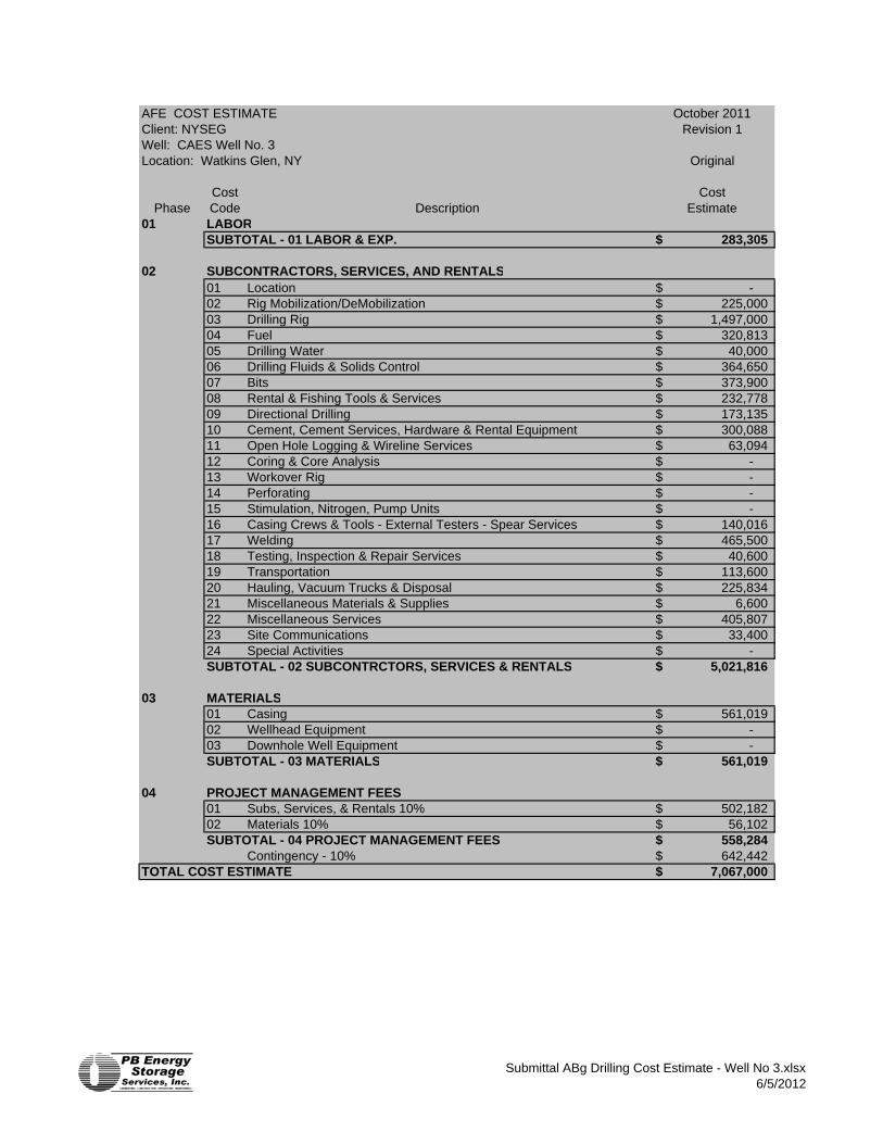
AFE COST ESTIMATE October 2011Client: NYSEG Revision 1Well: CAES Well No. 3Location: Watkins Glen, NY Original
Cost CostPhase Code Description Estimate
01 LABORSUBTOTAL - 01 LABOR & EXP. 283,305$
02 SUBCONTRACTORS, SERVICES, AND RENTALS01 Location -$ 02 Rig Mobilization/DeMobilization 225,000$ 03 Drilling Rig 1,497,000$ 04 Fuel 320,813$ 05 Drilling Water 40,000$ 06 Drilling Fluids & Solids Control 364,650$ 07 Bits 373,900$ 08 Rental & Fishing Tools & Services 232,778$ 09 Directional Drilling 173,135$ 10 Cement, Cement Services, Hardware & Rental Equipment 300,088$ 11 Open Hole Logging & Wireline Services 63,094$ 12 Coring & Core Analysis -$ 13 Workover Rig -$ 14 Perforating -$ 15 Stimulation, Nitrogen, Pump Units -$ 16 Casing Crews & Tools - External Testers - Spear Services 140,016$ 17 Welding 465,500$ 18 Testing, Inspection & Repair Services 40,600$ 19 Transportation 113,600$ 20 Hauling, Vacuum Trucks & Disposal 225,834$ 21 Miscellaneous Materials & Supplies 6,600$ 22 Miscellaneous Services 405,807$ 23 Site Communications 33,400$ 24 Special Activities -$ SUBTOTAL - 02 SUBCONTRCTORS, SERVICES & RENTALS 5,021,816$
03 MATERIALS01 Casing 561,019$ 02 Wellhead Equipment -$ 03 Downhole Well Equipment -$ SUBTOTAL - 03 MATERIALS 561,019$
04 PROJECT MANAGEMENT FEES01 Subs, Services, & Rentals 10% 502,182$ 02 Materials 10% 56,102$ SUBTOTAL - 04 PROJECT MANAGEMENT FEES 558,284$
Contingency - 10% 642,442$ TOTAL COST ESTIMATE 7,067,000$
Submittal ABg Drilling Cost Estimate - Well No 3.xlsx6/5/2012
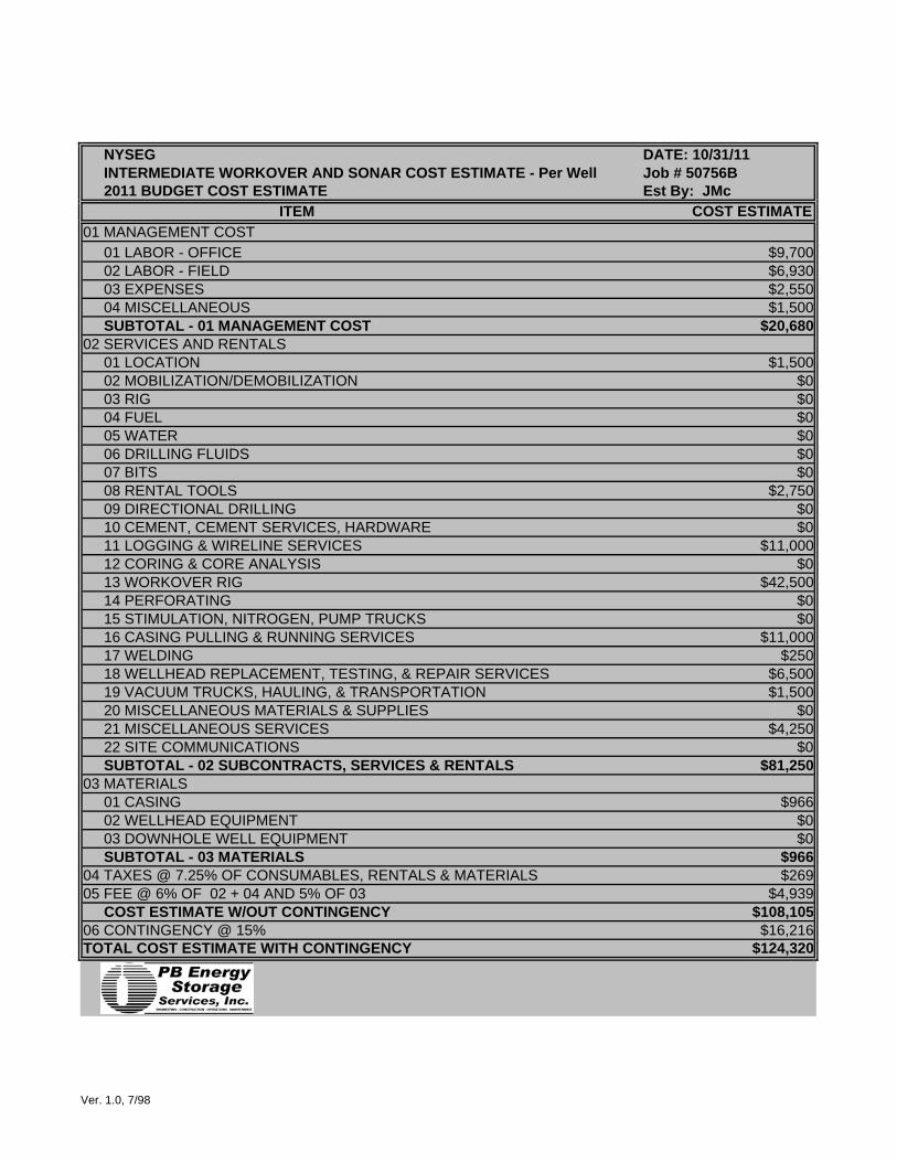
NYSEG DATE: 10/31/11INTERMEDIATE WORKOVER AND SONAR COST ESTIMATE - Per Well Job # 50756B2011 BUDGET COST ESTIMATE Est By: JMc
ITEM COST ESTIMATE01 MANAGEMENT COST
01 LABOR - OFFICE $9,70002 LABOR - FIELD $6,93003 EXPENSES $2,55004 MISCELLANEOUS $1,500SUBTOTAL - 01 MANAGEMENT COST $20,680
02 SERVICES AND RENTALS01 LOCATION $1,50002 MOBILIZATION/DEMOBILIZATION $003 RIG $004 FUEL $005 WATER $006 DRILLING FLUIDS $007 BITS $008 RENTAL TOOLS $2,75009 DIRECTIONAL DRILLING $010 CEMENT, CEMENT SERVICES, HARDWARE $011 LOGGING & WIRELINE SERVICES $11,00012 CORING & CORE ANALYSIS $013 WORKOVER RIG $42,50014 PERFORATING $015 STIMULATION, NITROGEN, PUMP TRUCKS $016 CASING PULLING & RUNNING SERVICES $11,00017 WELDING $25018 WELLHEAD REPLACEMENT, TESTING, & REPAIR SERVICES $6,50019 VACUUM TRUCKS, HAULING, & TRANSPORTATION $1,50020 MISCELLANEOUS MATERIALS & SUPPLIES $021 MISCELLANEOUS SERVICES $4,25022 SITE COMMUNICATIONS $0SUBTOTAL - 02 SUBCONTRACTS, SERVICES & RENTALS $81,250
03 MATERIALS01 CASING $96602 WELLHEAD EQUIPMENT $003 DOWNHOLE WELL EQUIPMENT $0SUBTOTAL - 03 MATERIALS $966
04 TAXES @ 7.25% OF CONSUMABLES, RENTALS & MATERIALS $26905 FEE @ 6% OF 02 + 04 AND 5% OF 03 $4,939
COST ESTIMATE W/OUT CONTINGENCY $108,10506 CONTINGENCY @ 15% $16,216TOTAL COST ESTIMATE WITH CONTINGENCY $124,320
Ver. 1.0, 7/98
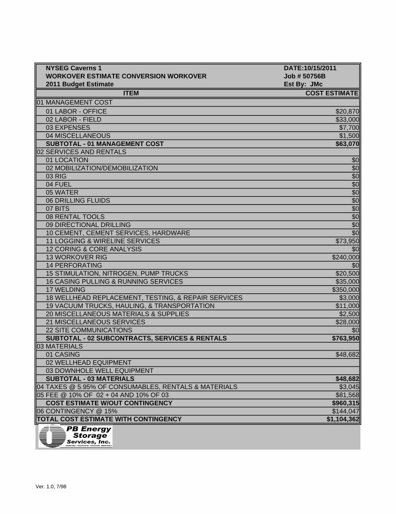
NYSEG Caverns 1 DATE:10/15/2011WORKOVER ESTIMATE CONVERSION WORKOVER Job # 50756B2011 Budget Estimate Est By: JMc
ITEM COST ESTIMATE01 MANAGEMENT COST
01 LABOR - OFFICE $20,87002 LABOR - FIELD $33,00003 EXPENSES $7,70004 MISCELLANEOUS $1,500SUBTOTAL - 01 MANAGEMENT COST $63,070
02 SERVICES AND RENTALS01 LOCATION $002 MOBILIZATION/DEMOBILIZATION $003 RIG $004 FUEL $005 WATER $006 DRILLING FLUIDS $007 BITS $008 RENTAL TOOLS $009 DIRECTIONAL DRILLING $010 CEMENT, CEMENT SERVICES, HARDWARE $011 LOGGING & WIRELINE SERVICES $73,95012 CORING & CORE ANALYSIS $013 WORKOVER RIG $240,00014 PERFORATING $015 STIMULATION, NITROGEN, PUMP TRUCKS $20,50016 CASING PULLING & RUNNING SERVICES $35,00017 WELDING $350,00018 WELLHEAD REPLACEMENT, TESTING, & REPAIR SERVICES $3,00019 VACUUM TRUCKS, HAULING, & TRANSPORTATION $11,00020 MISCELLANEOUS MATERIALS & SUPPLIES $2,50021 MISCELLANEOUS SERVICES $28,00022 SITE COMMUNICATIONS $0SUBTOTAL - 02 SUBCONTRACTS, SERVICES & RENTALS $763,950
03 MATERIALS01 CASING $48,68202 WELLHEAD EQUIPMENT03 DOWNHOLE WELL EQUIPMENTSUBTOTAL - 03 MATERIALS $48,682
04 TAXES @ 5.95% OF CONSUMABLES, RENTALS & MATERIALS $3,04505 FEE @ 10% OF 02 + 04 AND 10% OF 03 $81,568
COST ESTIMATE W/OUT CONTINGENCY $960,31506 CONTINGENCY @ 15% $144,047TOTAL COST ESTIMATE WITH CONTINGENCY $1,104,362
Ver. 1.0, 7/98

NYSEG Caverns 2 & 3 DATE:10/15/2011WORKOVER ESTIMATE CONVERSION WORKOVER Job # 50756B2011 Budget Estimate Est By: JMc
ITEM COST ESTIMATE01 MANAGEMENT COST
01 LABOR - OFFICE $20,87002 LABOR - FIELD $26,40003 EXPENSES $6,80004 MISCELLANEOUS $1,500SUBTOTAL - 01 MANAGEMENT COST $55,570
02 SERVICES AND RENTALS01 LOCATION $002 MOBILIZATION/DEMOBILIZATION $003 RIG $004 FUEL $005 WATER $006 DRILLING FLUIDS $007 BITS $008 RENTAL TOOLS $009 DIRECTIONAL DRILLING $010 CEMENT, CEMENT SERVICES, HARDWARE $011 LOGGING & WIRELINE SERVICES $73,95012 CORING & CORE ANALYSIS $013 WORKOVER RIG $195,00014 PERFORATING $015 STIMULATION, NITROGEN, PUMP TRUCKS $14,75016 CASING PULLING & RUNNING SERVICES $35,00017 WELDING $350,00018 WELLHEAD REPLACEMENT, TESTING, & REPAIR SERVICES $3,00019 VACUUM TRUCKS, HAULING, & TRANSPORTATION $11,00020 MISCELLANEOUS MATERIALS & SUPPLIES $2,50021 MISCELLANEOUS SERVICES $28,00022 SITE COMMUNICATIONS $0SUBTOTAL - 02 SUBCONTRACTS, SERVICES & RENTALS $713,200
03 MATERIALS01 CASING $48,68202 WELLHEAD EQUIPMENT $003 DOWNHOLE WELL EQUIPMENT $0SUBTOTAL - 03 MATERIALS $48,682
04 TAXES @ 5.95% OF CONSUMABLES, RENTALS & MATERIALS $3,04505 FEE @ 10% OF 02 + 04 AND 10% OF 03 $76,493
COST ESTIMATE W/OUT CONTINGENCY $896,99006 CONTINGENCY @ 15% $134,549TOTAL COST ESTIMATE WITH CONTINGENCY $1,031,539
Ver. 1.0, 7/98

NYSEG - Watkins Glen Well No. 1 DATE: 10/31/11Wellhead Installation Production Job # BUDGET COST ESTIMATE Est By: JMc
ITEM COST ESTIMATE01 MANAGEMENT COST
01 LABOR - OFFICE $3,49002 LABOR - FIELD $3,30003 EXPENSES $60004 MISCELLANEOUS $0SUBTOTAL - 01 MANAGEMENT COST $7,390
02 SERVICES AND RENTALS01 LOCATION $002 MOBILIZATION/DEMOBILIZATION $003 RIG - DAYWORK $004 FUEL $005 WATER $006 DRILLING FLUIDS $007 BITS $008 RENTAL TOOLS - SNUBBING STACK $009 DIRECTIONAL DRILLING $010 CEMENT, CEMENT SERVICES, HARDWARE $011 LOGGING & WIRELINE SERVICES - CASING CUTS & BRIDGE PLUGS $012 CORING & CORE ANALYSIS $013 WORKOVER RIG $22,50014 PERFORATING $015 STIMULATION, NITROGEN, PUMP TRUCKS $016 CASING PULLING & RUNNING SERVICES $017 WELDING $018 TESTING , INSPECTION, & REPAIR SERVICES $3,00019 VACUUM TRUCKS, HAULING, & TRANSPORTATION $1,50020 MISCELLANEOUS MATERIALS & SUPPLIES $021 MISCELLANEOUS SERVICES $17,50522 SITE COMMUNICATIONS $0SUBTOTAL - 02 SUBCONTRACTS, SERVICES & RENTALS $44,505
03 MATERIALS01 CASING02 WELLHEAD EQUIPMENT03 DOWNHOLE WELL EQUIPMENTSUBTOTAL - 03 MATERIALS $0
04 TAXES @ 8% OF CONSUMABLES, RENTALS & MATERIALS 8.00% $005 FEE @ 10% OF 02 + 03 + 04 10% $4,451
COST ESTIMATE W/OUT CONTINGENCY $56,34606 CONTINGENCY @ 10% 10% $5,635TOTAL COST ESTIMATE WITH CONTINGENCY $61,980
Ver. 1.0, 7/98

NYSEG - Watkins Glen DATE: 10/10/11Wellhead Installation Production Wells 2 & 3 Job # BUDGET COST ESTIMATE Est By: JMc
ITEM COST ESTIMATE01 MANAGEMENT COST
01 LABOR - OFFICE $3,49002 LABOR - FIELD $3,30003 EXPENSES $60004 MISCELLANEOUS $0SUBTOTAL - 01 MANAGEMENT COST $7,390
02 SERVICES AND RENTALS01 LOCATION $002 MOBILIZATION/DEMOBILIZATION $003 RIG - DAYWORK $004 FUEL $005 WATER $006 DRILLING FLUIDS $007 BITS $008 RENTAL TOOLS - SNUBBING STACK $009 DIRECTIONAL DRILLING $010 CEMENT, CEMENT SERVICES, HARDWARE $011 LOGGING & WIRELINE SERVICES - CASING CUTS & BRIDGE PLUGS $012 CORING & CORE ANALYSIS $013 WORKOVER RIG $22,50014 PERFORATING $015 STIMULATION, NITROGEN, PUMP TRUCKS $016 CASING PULLING & RUNNING SERVICES $017 WELDING $018 TESTING , INSPECTION, & REPAIR SERVICES $3,00019 VACUUM TRUCKS, HAULING, & TRANSPORTATION $1,50020 MISCELLANEOUS MATERIALS & SUPPLIES $021 MISCELLANEOUS SERVICES $17,50522 SITE COMMUNICATIONS $0SUBTOTAL - 02 SUBCONTRACTS, SERVICES & RENTALS $44,505
03 MATERIALS01 CASING02 WELLHEAD EQUIPMENT03 DOWNHOLE WELL EQUIPMENTSUBTOTAL - 03 MATERIALS
04 TAXES @ 8% OF CONSUMABLES, RENTALS & MATERIALS 8.00% $005 FEE @ 10% OF 02 + 03 + 04 10% $4,451
COST ESTIMATE W/OUT CONTINGENCY $56,34606 CONTINGENCY @ 10% 10% $5,635TOTAL COST ESTIMATE WITH CONTINGENCY $61,980
Ver. 1.0, 7/98
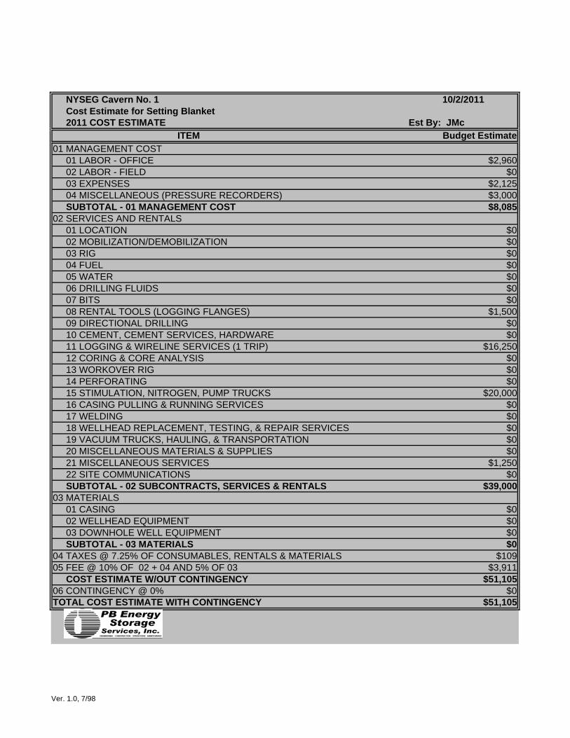
NYSEG Cavern No. 1 10/2/2011Cost Estimate for Setting Blanket2011 COST ESTIMATE Est By: JMc
ITEM Budget Estimate01 MANAGEMENT COST
01 LABOR - OFFICE $2,96002 LABOR - FIELD $003 EXPENSES $2,12504 MISCELLANEOUS (PRESSURE RECORDERS) $3,000SUBTOTAL - 01 MANAGEMENT COST $8,085
02 SERVICES AND RENTALS01 LOCATION $002 MOBILIZATION/DEMOBILIZATION $003 RIG $004 FUEL $005 WATER $006 DRILLING FLUIDS $007 BITS $008 RENTAL TOOLS (LOGGING FLANGES) $1,50009 DIRECTIONAL DRILLING $010 CEMENT, CEMENT SERVICES, HARDWARE $011 LOGGING & WIRELINE SERVICES (1 TRIP) $16,25012 CORING & CORE ANALYSIS $013 WORKOVER RIG $014 PERFORATING $015 STIMULATION, NITROGEN, PUMP TRUCKS $20,00016 CASING PULLING & RUNNING SERVICES $017 WELDING $018 WELLHEAD REPLACEMENT, TESTING, & REPAIR SERVICES $019 VACUUM TRUCKS, HAULING, & TRANSPORTATION $020 MISCELLANEOUS MATERIALS & SUPPLIES $021 MISCELLANEOUS SERVICES $1,25022 SITE COMMUNICATIONS $0SUBTOTAL - 02 SUBCONTRACTS, SERVICES & RENTALS $39,000
03 MATERIALS01 CASING $002 WELLHEAD EQUIPMENT $003 DOWNHOLE WELL EQUIPMENT $0SUBTOTAL - 03 MATERIALS $0
04 TAXES @ 7.25% OF CONSUMABLES, RENTALS & MATERIALS $10905 FEE @ 10% OF 02 + 04 AND 5% OF 03 $3,911
COST ESTIMATE W/OUT CONTINGENCY $51,10506 CONTINGENCY @ 0% $0TOTAL COST ESTIMATE WITH CONTINGENCY $51,105
Ver. 1.0, 7/98

NYSEG Wells 2 & 3 10/2/2011Set Blanket Wells 2 & 32011 COST ESTIMATE Est By: JMc
ITEM Budget Estimate01 MANAGEMENT COST
01 LABOR - OFFICE $6,38002 LABOR - FIELD $003 EXPENSES $2,12504 MISCELLANEOUS (PRESSURE RECORDERS) $3,000SUBTOTAL - 01 MANAGEMENT COST $11,505
02 SERVICES AND RENTALS01 LOCATION $002 MOBILIZATION/DEMOBILIZATION $003 RIG $004 FUEL $005 WATER $006 DRILLING FLUIDS $007 BITS $008 RENTAL TOOLS (LOGGING FLANGES) $1,50009 DIRECTIONAL DRILLING $010 CEMENT, CEMENT SERVICES, HARDWARE $011 LOGGING & WIRELINE SERVICES (1 TRIP) $16,25012 CORING & CORE ANALYSIS $013 WORKOVER RIG $014 PERFORATING $015 STIMULATION, NITROGEN, PUMP TRUCKS $14,75016 CASING PULLING & RUNNING SERVICES $017 WELDING $018 WELLHEAD REPLACEMENT, TESTING, & REPAIR SERVICES $019 VACUUM TRUCKS, HAULING, & TRANSPORTATION $020 MISCELLANEOUS MATERIALS & SUPPLIES $021 MISCELLANEOUS SERVICES $1,25022 SITE COMMUNICATIONS $0SUBTOTAL - 02 SUBCONTRACTS, SERVICES & RENTALS $33,750
03 MATERIALS01 CASING $002 WELLHEAD EQUIPMENT $003 DOWNHOLE WELL EQUIPMENT $0SUBTOTAL - 03 MATERIALS $0
04 TAXES @ 7.25% OF CONSUMABLES, RENTALS & MATERIALS $10905 FEE @ 10% OF 02 + 04 AND 5% OF 03 $3,386
COST ESTIMATE W/OUT CONTINGENCY $48,75006 CONTINGENCY @ 0% $0TOTAL COST ESTIMATE WITH CONTINGENCY $48,750
Ver. 1.0, 7/98

NYSEG - Watkins Glen DATE: 10/31/11SNUB 5-1/2" CASING OUT - Per Well Job # BUDGET COST ESTIMATE Est By: JMc
ITEM COST ESTIMATE01 MANAGEMENT COST
01 LABOR - OFFICE $3,49002 LABOR - FIELD $5,50003 EXPENSES $2,20004 MISCELLANEOUS $1,000SUBTOTAL - 01 MANAGEMENT COST $12,190
02 SERVICES AND RENTALS01 LOCATION $2,00002 MOBILIZATION/DEMOBILIZATION $003 RIG - DAYWORK $004 FUEL $005 WATER $006 DRILLING FLUIDS $007 BITS $008 RENTAL TOOLS - SNUBBING STACK $33,47509 DIRECTIONAL DRILLING $010 CEMENT, CEMENT SERVICES, HARDWARE $011 LOGGING & WIRELINE SERVICES - CASING CUTS & BRIDGE PLUGS $26,52512 CORING & CORE ANALYSIS $013 WORKOVER RIG - RIG ASSIST SNUBBING UNIT $64,60014 PERFORATING $015 STIMULATION, NITROGEN, PUMP TRUCKS $016 CASING PULLING & RUNNING SERVICES $017 WELDING $018 TESTING , INSPECTION, & REPAIR SERVICES $019 VACUUM TRUCKS, HAULING, & TRANSPORTATION $020 MISCELLANEOUS MATERIALS & SUPPLIES $021 MISCELLANEOUS SERVICES $19,70522 SITE COMMUNICATIONS $0SUBTOTAL - 02 SUBCONTRACTS, SERVICES & RENTALS $146,305
03 MATERIALS01 CASING $002 WELLHEAD EQUIPMENT $003 DOWNHOLE WELL EQUIPMENT $0SUBTOTAL - 03 MATERIALS $0
04 TAXES @ 8% OF CONSUMABLES, RENTALS & MATERIALS 8.00% $2,67805 FEE @ 10% OF 02 + 03 + 04 10% $14,898
COST ESTIMATE W/OUT CONTINGENCY $176,07206 CONTINGENCY @ 10% 10% $17,607TOTAL COST ESTIMATE WITH CONTINGENCY $193,679
Ver. 1.0, 7/98
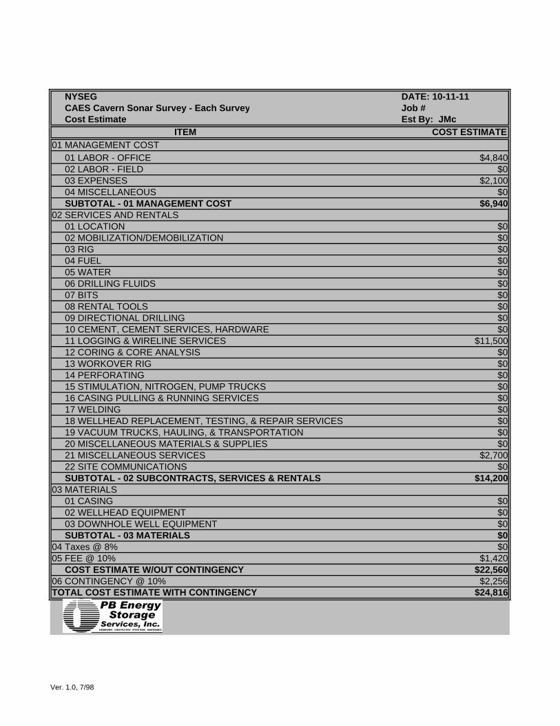
NYSEG DATE: 10-11-11CAES Cavern Sonar Survey - Each Survey Job # Cost Estimate Est By: JMc
ITEM COST ESTIMATE01 MANAGEMENT COST
01 LABOR - OFFICE $4,84002 LABOR - FIELD $003 EXPENSES $2,10004 MISCELLANEOUS $0SUBTOTAL - 01 MANAGEMENT COST $6,940
02 SERVICES AND RENTALS01 LOCATION $002 MOBILIZATION/DEMOBILIZATION $003 RIG $004 FUEL $005 WATER $006 DRILLING FLUIDS $007 BITS $008 RENTAL TOOLS $009 DIRECTIONAL DRILLING $010 CEMENT, CEMENT SERVICES, HARDWARE $011 LOGGING & WIRELINE SERVICES $11,50012 CORING & CORE ANALYSIS $013 WORKOVER RIG $014 PERFORATING $015 STIMULATION, NITROGEN, PUMP TRUCKS $016 CASING PULLING & RUNNING SERVICES $017 WELDING $018 WELLHEAD REPLACEMENT, TESTING, & REPAIR SERVICES $019 VACUUM TRUCKS, HAULING, & TRANSPORTATION $020 MISCELLANEOUS MATERIALS & SUPPLIES $021 MISCELLANEOUS SERVICES $2,70022 SITE COMMUNICATIONS $0SUBTOTAL - 02 SUBCONTRACTS, SERVICES & RENTALS $14,200
03 MATERIALS01 CASING $002 WELLHEAD EQUIPMENT $003 DOWNHOLE WELL EQUIPMENT $0SUBTOTAL - 03 MATERIALS $0
04 Taxes @ 8% $005 FEE @ 10% $1,420
COST ESTIMATE W/OUT CONTINGENCY $22,56006 CONTINGENCY @ 10% $2,256TOTAL COST ESTIMATE WITH CONTINGENCY $24,816
Ver. 1.0, 7/98
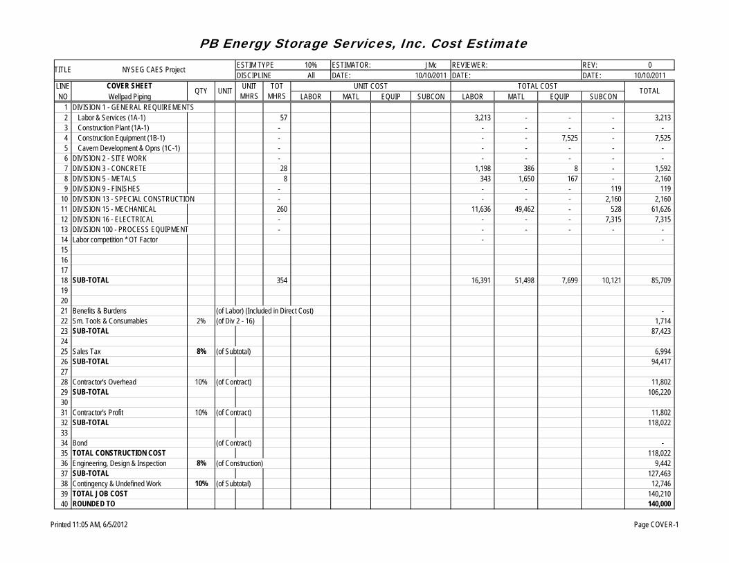
PB Energy Storage Services, Inc. Cost EstimateESTIM TYPE 10% ESTIMATOR: JMc REVIEWER: REV: 0DISCIPLINE All DATE: 10/10/2011 DATE: DATE: 10/10/2011
LINE COVER SHEET UNIT COST TOTAL COSTNO Wellpad Piping LABOR MATL EQUIP SUBCON LABOR MATL EQUIP SUBCON
1 DIVISION 1 - GENERAL REQUIREMENTS2 Labor & Services (1A-1) 57 3,213 - - - 3,213 3 Construction Plant (1A-1) - - - - - - 4 Construction Equipment (1B-1) - - - 7,525 - 7,525 5 Cavern Development & Opns (1C-1) - - - - - - 6 DIVISION 2 - SITE WORK - - - - - - 7 DIVISION 3 - CONCRETE 28 1,198 386 8 - 1,592 8 DIVISION 5 - METALS 8 343 1,650 167 - 2,160 9 DIVISION 9 - FINISHES - - - - 119 119
10 DIVISION 13 - SPECIAL CONSTRUCTION - - - - 2,160 2,160 11 DIVISION 15 - MECHANICAL 260 11,636 49,462 - 528 61,626 12 DIVISION 16 - ELECTRICAL - - - - 7,315 7,315 13 DIVISION 100 - PROCESS EQUIPMENT - - - - - - 14 Labor competition * OT Factor - - 15161718 SUB-TOTAL 354 16,391 51,498 7,699 10,121 85,709 192021 Benefits & Burdens (of Labor) (Included in Direct Cost) - 22 Sm. Tools & Consumables 2% (of Div 2 - 16) 1,714 23 SUB-TOTAL 87,423 2425 Sales Tax 8% (of Subtotal) 6,994 26 SUB-TOTAL 94,417 2728 Contractor's Overhead 10% (of Contract) 11,802 29 SUB-TOTAL 106,220 3031 Contractor's Profit 10% (of Contract) 11,802 32 SUB-TOTAL 118,022 3334 Bond (of Contract) - 35 TOTAL CONSTRUCTION COST 118,022 36 Engineering, Design & Inspection 8% (of Construction) 9,442 37 SUB-TOTAL 127,463 38 Contingency & Undefined Work 10% (of Subtotal) 12,746 39 TOTAL JOB COST 140,210 40 ROUNDED TO 140,000
TOTAL
TITLE NYSEG CAES Project
QTY UNIT UNIT MHRS
TOT MHRS
Printed 11:05 AM, 6/5/2012 Page COVER-1

A Parsons Brinckerhoff Company
PB Energy Storage
Services, Inc ENGINEERING – CONSTRUCTION – OPERATIONS – MAINTENANCE
16285 Park Ten Place, Suite 400 Houston, Texas 77084 (281) 496-5590 Fax (281) 496-5865 www.pbenergy.com
August 11, 2011 Jim Rettberg NYSEG //via email// Dear Mr. Rettberg: Re: Seneca Lake CAES Project – Preliminary Cavern Criteria
Introduction The PB Energy Storage Services (PB ESS) division of PB Americas was commissioned by NYSEG to determine the acceptability of the bedded salt at a site near Seneca Lake for compressed air energy storage (CAES) in accordance with the Technical Specification for the Cavern Development Consultant. Additionally, PB ESS tasking includes:
• Support a study by WorleyParsons (WP) to develop comprehensive cost estimates. • Perform preliminary cavern design. • Perform cavern thermodynamic modeling. • Prepare a solution mining plan. • Specify a program of inspections and tests to monitor cavern development. • Prepare design specifications for wells and wellheads. • Prepare a program to monitor the cavern during CAES operations. • Prepare a mechanical integrity testing program. • Prepare a list of procurement and construction specifications to develop and convert the
cavern to storage operations. This letter report was requested during our phone conversation of August 8, 2011. The purpose of the report is to provide cavern selection criteria for an existing cavern, which will meet the mission requirements of a maximum compression pressure of 1500 psi and the capability to generate electricity for 10 hours at an estimated mass flow rate of 550 lb/sec. Final thermomechanical models have not been run; however, based upon results to date the total cavern volume required is at least 3 MMbbls. Prior to using any cavern, the well(s) and cavern would need to be tested for integrity at pressures in excess of 1500 psi.

June 5, 2012– Page 2
C:\Documents and Settings\HoffmaL2\Desktop\CAES Final Report Exhibits\PBESS\Submittal AC Preliminary Cavern Criteria.docx
Criteria The list of minimum requirements for consideration of an existing cavern for use by NYSEG is provided below.
1. De-waterable volume of at least 3.5 MMbbls. 2. Roof diameter or span of less than 260 ft. 3. Cavern roof at least 50 ft below top of salt (not leached to shale) 4. Proximity to other caverns of not less than 500 ft wall to wall 5. Never been used for LPG storage
Rationale In establishing the criteria above, PB ESS has used the following rationale.
1. All of the preliminary thermomechanical modeling performed to date suggests that a cavern with a volume smaller than 3 MMbbls will exhibit tensile stress in the walls and/or roof. Since salt has a tensile strength of less than 300 psi, storage caverns are designed to have little or no tensile stress imposed during their operational life. At present, a volume of 3.5 MMbbls is believed to be adequate to meet this requirement.
2. Stable cavern roof diameter or roof span is established by assessment of the results of the thermomechanical modeling results. Typical storage industry practice limits cavern roof diameters to a range of 250 ft to 300 ft.
3. A review of available sonar surveys implies that cavern roof established within the shale present in the Camillus Formation has a significant potential for unraveling of the rock. The dolostones of the Bertie Formation are known to contain water. The presence of water implies that a cavern built with a roof in the Bertie Formation will not be pressure tight.
4. A 500 foot spacing is believed to be appropriate for preliminary design. This number is representative of intended cavern spacing at Watkins Glen.
5. Injection of air into a former LPG storage cavern will require initial purging of the cavern with an inert gas (e.g., nitrogen), which could prove difficult and costly.
Please do not hesitate to call or email if you have questions or suggestions. Regards,

June 5, 2012– Page 3
C:\Documents and Settings\HoffmaL2\Desktop\CAES Final Report Exhibits\PBESS\Submittal AC Preliminary Cavern Criteria.docx
Jim McHenry

A Parsons Brinckerhoff Company
PB Energy Storage
Services, Inc ENGINEERING – CONSTRUCTION – OPERATIONS – MAINTENANCE
16285 Park Ten Place, Suite 400 Houston, Texas 77084 (281) 496-5590 Fax (281) 496-5865 www.pbenergy.com
December 15, 2011 James W. Rettberg, PE Project Manager NYSEG Dear Mr. Rettberg; Re: Input to U.S. DOE Environmental Questionnaire
The NYSEG Cavern Development Consultant Technical Specification deliverable 4.4.2.11 directs PB ESS to provide estimates of emissions generated by equipment, solid or hazardous waste that will be generated and disposed of, chemicals and hazardous or toxic materials that will be used in the cavern testing, well installation and cavern dewatering phases of the project. Specifically:
• III.A.8 Activities • III.A.10 Materials and estimates of quantities used / produced • III.D.6.e,f,g Atmospheric Air Quality • III.D.7 Hydrologic / Water Quality • III.D.8 Solid and Hazardous Waste • III.D.9 Health and Safety Factors
III.A.8 – Activities
Summarize the objectives of the proposed work. List activities planned at the location as covered by this Environmental Questionnaire.
Objectives
NYSEG proposes to construct three storage caverns, to be used for Compressed Air Energy Storage, in the Salina Salt near Watkins Glen, NY. Each cavern will be solution mined to have a net volume of 970,000 barrels. The cavern development interval is expected to be from 2,402 – 2,632 feet below ground surface.

June 5, 2012– Page 2
A Parsons Brinckerhoff Company
Activities
1. Build three 400 ft x 400 ft wellpads 2. Drill and Complete Well No. 1
a. Mobilize drilling rig to Wellpad No. 1 b. Drill a 48” diameter hole and cement in place a 42” conductor pipe to a depth of
approximately 175 feet below ground level. c. Drill a 36” diameter hole inside the conductor pipe and cement in place a 30”
surface casing to a depth of approximately 850 feet below ground level. d. Drill a 30” diameter hole inside the surface casing and cement in place a 24”
diameter final cemented casing to a depth of approximately 2,360 feet below ground level.
e. Drill a 24” diameter hole inside the final cemented casing to a depth of approximately 2,632 feet.
f. Install a wellhead and two concentric leaching casings (8-5/8” diameter to 2,530 feet below ground level and 5-1/2” diameter to 2,630 feet below ground level).
3. Drill and Complete Well No. 2 a. Move drilling rig to Wellpad No. 2 b. Drill a 48” diameter hole and cement in place a 42” conductor pipe to a depth of
approximately 175 feet below ground level. c. Drill a 36” diameter hole inside the conductor pipe and cement in place a 26”
surface casing to a depth of approximately 850 feet below ground level. d. Drill a 26” diameter hole inside the surface casing and cement in place a 20”
diameter final cemented casing to a depth of approximately 2,360 feet below ground level.
e. Drill a 24” diameter hole inside the final cemented casing to a depth of approximately 2,632 feet.
f. Install a wellhead and two concentric leaching casings (8-5/8” diameter to 2,530 feet below ground level and 5-1/2” diameter to 2,630 feet below ground level).
g. Fill wellbore with nitrogen. 4. Drill and Complete Well No. 3
a. Move drilling rig to Wellpad No. 3 b. Drill a 48” diameter hole and cement in place a 42” conductor pipe to a depth of
approximately 175 feet below ground level.
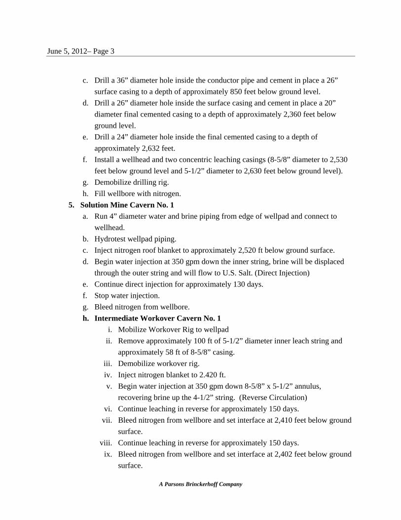
June 5, 2012– Page 3
A Parsons Brinckerhoff Company
c. Drill a 36” diameter hole inside the conductor pipe and cement in place a 26” surface casing to a depth of approximately 850 feet below ground level.
d. Drill a 26” diameter hole inside the surface casing and cement in place a 20” diameter final cemented casing to a depth of approximately 2,360 feet below ground level.
e. Drill a 24” diameter hole inside the final cemented casing to a depth of approximately 2,632 feet.
f. Install a wellhead and two concentric leaching casings (8-5/8” diameter to 2,530 feet below ground level and 5-1/2” diameter to 2,630 feet below ground level).
g. Demobilize drilling rig. h. Fill wellbore with nitrogen.
5. Solution Mine Cavern No. 1 a. Run 4” diameter water and brine piping from edge of wellpad and connect to
wellhead. b. Hydrotest wellpad piping. c. Inject nitrogen roof blanket to approximately 2,520 ft below ground surface. d. Begin water injection at 350 gpm down the inner string, brine will be displaced
through the outer string and will flow to U.S. Salt. (Direct Injection) e. Continue direct injection for approximately 130 days. f. Stop water injection. g. Bleed nitrogen from wellbore. h. Intermediate Workover Cavern No. 1
i. Mobilize Workover Rig to wellpad ii. Remove approximately 100 ft of 5-1/2” diameter inner leach string and
approximately 58 ft of 8-5/8” casing. iii. Demobilize workover rig. iv. Inject nitrogen blanket to 2.420 ft. v. Begin water injection at 350 gpm down 8-5/8” x 5-1/2” annulus,
recovering brine up the 4-1/2” string. (Reverse Circulation) vi. Continue leaching in reverse for approximately 150 days.
vii. Bleed nitrogen from wellbore and set interface at 2,410 feet below ground surface.
viii. Continue leaching in reverse for approximately 150 days. ix. Bleed nitrogen from wellbore and set interface at 2,402 feet below ground
surface.
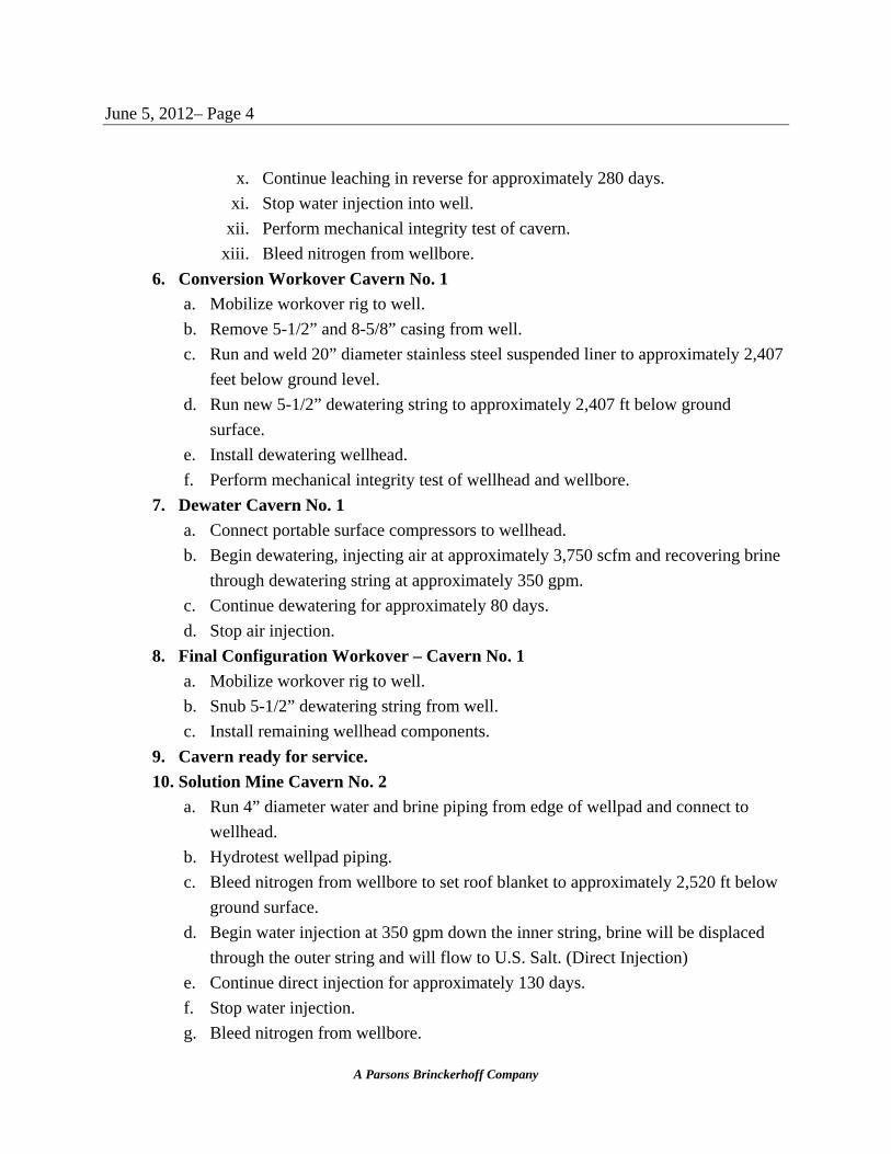
June 5, 2012– Page 4
A Parsons Brinckerhoff Company
x. Continue leaching in reverse for approximately 280 days. xi. Stop water injection into well.
xii. Perform mechanical integrity test of cavern. xiii. Bleed nitrogen from wellbore.
6. Conversion Workover Cavern No. 1 a. Mobilize workover rig to well. b. Remove 5-1/2” and 8-5/8” casing from well. c. Run and weld 20” diameter stainless steel suspended liner to approximately 2,407
feet below ground level. d. Run new 5-1/2” dewatering string to approximately 2,407 ft below ground
surface. e. Install dewatering wellhead. f. Perform mechanical integrity test of wellhead and wellbore.
7. Dewater Cavern No. 1 a. Connect portable surface compressors to wellhead. b. Begin dewatering, injecting air at approximately 3,750 scfm and recovering brine
through dewatering string at approximately 350 gpm. c. Continue dewatering for approximately 80 days. d. Stop air injection.
8. Final Configuration Workover – Cavern No. 1 a. Mobilize workover rig to well. b. Snub 5-1/2” dewatering string from well. c. Install remaining wellhead components.
9. Cavern ready for service. 10. Solution Mine Cavern No. 2
a. Run 4” diameter water and brine piping from edge of wellpad and connect to wellhead.
b. Hydrotest wellpad piping. c. Bleed nitrogen from wellbore to set roof blanket to approximately 2,520 ft below
ground surface. d. Begin water injection at 350 gpm down the inner string, brine will be displaced
through the outer string and will flow to U.S. Salt. (Direct Injection) e. Continue direct injection for approximately 130 days. f. Stop water injection. g. Bleed nitrogen from wellbore.

June 5, 2012– Page 5
A Parsons Brinckerhoff Company
h. Intermediate Workover Cavern No. 2 i. Mobilize Workover Rig to wellpad.
ii. Remove approximately 100 ft of 5-1/2” diameter inner leach string and approximately 58 ft of 8-5/8” casing.
iii. Demobilize workover rig. i. Inject nitrogen blanket to 2.420 ft. j. Begin water injection at 350 gpm down 8-5/8” x 5-1/2” annulus, recovering brine
up the 4-1/2” string. (Reverse Circulation) k. Continue leaching in reverse for approximately 150 days. l. Bleed nitrogen from wellbore and set interface at 2,410 feet below ground
surface. m. Continue leaching in reverse for approximately 150 days. n. Bleed nitrogen from wellbore and set interface at 2,402 feet below ground
surface. o. Continue leaching in reverse for approximately 280 days. p. Stop water injection into well. q. Perform mechanical integrity test of cavern. r. Bleed nitrogen from wellbore.
11. Conversion Workover Cavern No. 2 a. Mobilize workover rig to well. b. Remove 5-1/2” and 8-5/8” casing from well. c. Run and weld 16”stainless steel suspended liner to approximately 2,407 feet
below ground level. d. Run new 5-1/2” dewatering string to approximately 2,407 ft below ground
surface. e. Install dewatering wellhead. f. Perform mechanical integrity test of wellhead and wellbore.
12. Dewater Cavern No. 2 a. Connect portable surface compressors to wellhead. b. Begin dewatering, injecting air at approximately 3,750 scfm and recovering brine
through dewatering string at approximately 350 gpm. c. Continue dewatering for approximately 80 days. d. Stop air injection.
13. Final Configuration Workover – Cavern No. 2 a. Mobilize workover rig to well.
June 5, 2012– Page 6
A Parsons Brinckerhoff Company
b. Snub 5-1/2” dewatering string from well. c. Install remaining wellhead components. d. Demobilize workover rig
14. Cavern ready for service. 15. Solution Mine Cavern No. 3
a. Run 4” diameter water and brine piping from edge of wellpad and connect to wellhead.
b. Hydrotest wellpad piping. c. Bleed nitrogen from wellbore to set roof blanket to approximately 2,520 ft below
ground surface. d. Begin water injection at 350 gpm down the inner string, brine will be displaced
through the outer string and will flow to U.S. Salt. (Direct Injection) e. Continue direct injection for approximately 130 days. f. Stop water injection. g. Bleed nitrogen from wellbore. h. Intermediate Workover Cavern No. 3
i. Mobilize Workover Rig to wellpad. ii. Remove approximately 100 ft of 5-1/2” diameter inner leach string and
approximately 58 ft of 8-5/8” casing. iii. Demobilize workover rig.
i. Inject nitrogen blanket to 2.420 ft. j. Begin water injection at 350 gpm down 8-5/8” x 5-1/2” annulus, recovering brine
up the 4-1/2” string. (Reverse Circulation) k. Continue leaching in reverse for approximately 150 days. l. Bleed nitrogen from wellbore and set interface at 2,410 feet below ground
surface. m. Continue leaching in reverse for approximately 150 days. n. Bleed nitrogen from wellbore and set interface at 2,402 feet below ground
surface. o. Continue leaching in reverse for approximately 280 days. p. Stop water injection into well. q. Perform mechanical integrity test of cavern. r. Bleed nitrogen from wellbore.
16. Conversion Workover Cavern No. 3 a. Mobilize workover rig to well.
June 5, 2012– Page 7
A Parsons Brinckerhoff Company
b. Remove 5-1/2” and 8-5/8” casing from well. c. Run and weld 16”stainless steel suspended liner to approximately 2,407 feet
below ground level. d. Run new 5-1/2” dewatering string to approximately 2,407 ft below ground
surface. e. Install dewatering wellhead. f. Perform mechanical integrity test of wellhead and wellbore.
17. Dewater Cavern No. 3 a. Connect portable surface compressors to wellhead. b. Begin dewatering, injecting air at approximately 3,750 scfm and recovering brine
through dewatering string at approximately 350 gpm. c. Continue dewatering for approximately 80 days. d. Stop air injection.
18. Final Configuration Workover – Cavern No. 3 a. Mobilize workover rig to well. b. Snub 5-1/2” dewatering string from well. c. Install remaining wellhead components. d. Demobilize workover rig
19. Cavern No. 3 ready for service.
III.A.10 - Materials and estimates of quantities used / produced
Identify major materials that would be used and produced by the project when the projects are larger than lab or bench scale.
Material Used Estimated Quantity Comments
Electricity 4,400,000 KWH U.S. Salt power for injection pumps.
Water 1,071,000,000 gal Supplied by U.S. Salt
Others - Diesel Fuel 920,000 gal Drilling/Workover/Dewater
June 5, 2012– Page 8
A Parsons Brinckerhoff Company
Material Produced Estimated Quantity Comments
Air Emissions CO – 136,000 lbs
NMHC -16,000 lbs
NOX – 136,000 lbs
PM – 5,200 lbs
Drilling Rig and Dewatering Compressors
Solid Waste Mud – 12,800 bbl
Cuttings – 8,300 bbl
Drill cuttings, drill mud, and cement waste
Brine 1,071,000,000 gal Brine produced will not be waste product. Brine will be
used by U.S. Salt
III.D.6.e - Materials and estimates of quantities used / produced
What types of air emissions, including fugitive emissions, would be anticipated from the proposed project, and what would be the maximum and minimum annual rate of emissions for the project?
Emitted Maximum Annual Rate Project Total CO 46,000 lbs 136,000 lbs
NOx 46,000 lbs 136,000 lbs PM 1,800 lbs 5,200 lbs
III.D.6.f- Materials and estimates of quantities used / produced
Would any types of emission control or particulate collection devices be used? No. III.D.6.g- Materials and estimates of quantities used / produced
If no control devices are used, how would emissions be vented? Emissions would be from diesel equipment and vented to atmosphere.
June 5, 2012– Page 9
A Parsons Brinckerhoff Company
III.D.7.a- Hydrologic Conditions / Water Quality
What is the closest body of water to the proposed project area and what is its distance from the project site? Tributary 72 (Class C) to Seneca Lake is approximately 100 ft away from the closest well drilling site. III.D.7.b- Hydrologic Conditions / Water Quality
What sources would supply potable water for the proposed project? Water would be supplied by U.S. Salt from their intake structure on Seneca Lake. III.D.7.c- Hydrologic Conditions / Water Quality
Quantify the annual amount of wastewater that would be generated by the proposed project. None. All brine will be used piped to U.S. Salt to be used in their salt plant. III.D.7.d- Hydrologic Conditions / Water Quality
What would be the major components of each type of wastewater? No wastewater generated. III.D.7.e- Hydrologic Conditions / Water Quality
Identify the local treatment facility that would receive wastewater from the proposed project. No wastewater generated. III.D.7.f- Hydrologic Conditions / Water Quality
Describe how wastewater would be collected and treated. No wastewater generated. III.D.7.g- Hydrologic Conditions / Water Quality
Would any runoff or leachates be produced from storage piles or waste disposal sites? No. III.D.7.h- Hydrologic Conditions / Water Quality
Would the project require issuance of new or modified water permits to perform project work or site development? Yes, would require NPDES for storm water runoff from wellpads.

June 5, 2012– Page 10
A Parsons Brinckerhoff Company
III.D.7.i- Hydrologic Conditions / Water Quality
Where would wastewater effluents from the proposed project be discharged? Runoff water would be discharged to surface tributary to Seneca Lake. III.D.7.j- Hydrologic Conditions / Water Quality
Would the proposed project be permitted to discharge effluents into an existing body of water? Yes. No treatment of storm water required. III.D.7.k- Hydrologic Conditions / Water Quality
Would a new or modified National Pollutant Discharge Elimination System (NPDES) permit be required? Yes, required for surface runoff from wellpads. III.D.7.l- Hydrologic Conditions / Water Quality
Would the proposed project adversely affect the quality or movement of groundwater? No. III.D.7.m- Hydrologic Conditions / Water Quality
Would the proposed project require issuance of an Underground Injection Control (UIC) permit? Yes. A UIC permit is required to solution mine the cavern. III.D.8.a- Solid and Hazardous Wastes
Identify and estimate major nonhazardous solid wastes that would be generated from the project. Drilling mud and drill cuttings Freshwater drilling mud 8,400 bbl Saltwater drilling mud 4,500 bbl Freshwater Drill Cuttings 4,700 bbl Saltwater Drill Cuttings 3,700 bbl III.D.8.b- Solid and Hazardous Wastes
Would the project require issuance of new or modified solid waste and / or hazardous waste related permits to perform project activities? No. III.D.8.c- Solid and Hazardous Wastes
How and where would solid waste disposal be accomplished?

June 5, 2012– Page 11
A Parsons Brinckerhoff Company
Drilling mud and cuttings will be contained in a closed loop drilling system. Cuttings would be periodically (as required) transported to a NY State approved solid waste landfill for disposal. Drilling mud will be stabilized and transported to a NY State approved solid waste landfill at the end of freshwater drilling and at the end of drilling a well. III.D.8.d- Solid and Hazardous Wastes
How would wastes be transported? Wastes would be transported to landfill by truck. III.D.8.e- Solid and Hazardous Wastes
Identify hazardous wastes that would be generated, used, or stored under this project. None. III.D.8.f- Solid and Hazardous Wastes
Would hazardous or toxic waste be collected and stored. No. III.D.8.g- Solid and Hazardous Wastes
If hazardous wastes would require off-site disposal, have arrangements been made with a certified TSD facility. No hazardous wastes generated. III.D.9.a- Health / Safety Factors
Identify hazardous or toxic materials that would be used in the proposed project. Caustic soda may be used as part of the drilling fluids. III.D.9.b- Health / Safety Factors
What would be the likely impacts of these project related hazardous materials on human health and the environment. Caustic soda can cause severe chemical burns to unprotected skin. III.D.9.c- Health / Safety Factors
Would there be any special physical hazards or health risks associated with the project? No. Hazards typical of drilling, workover and construction will be present at the work site. NYSEG health and safety programs will be supplemented by programs put in place by specialized contractors who are thoroughly knowledgeable in the construction and operation of underground storage facilities..

June 5, 2012– Page 12
A Parsons Brinckerhoff Company

June 5, 2012– Page 13
A Parsons Brinckerhoff Company
III.D.9.d- Health / Safety Factors
Does a worker safety program exist at the location of the proposed project? No. NYSEG has in place a thorough over riding safety program. This program will be supplemented by a site safety program prior to the start of construction. During construction all NYSEG Subcontractor Personnel will be adequately trained and qualified to perform their duties. Knowledgeable drilling and workover specialists will be assigned to monitor the job site to make sure that the percentage of inexperienced labor being used by any subcontractor is not so great as to pose a safety hazard to themselves or others working around them. Operations that require highly skilled or technical expertise will be performed only by those individuals who by virtue of training, experience or education are capable of safely performing the task.
III.D.9.e- Health / Safety Factors
Would safety training be necessary for any laboratory, equipment, or process involved with the project. Yes. Contractors would have in place a formal safety program for activities. III.D.9.f- Health / Safety Factors
Describe any increases in ambient noise levels to the public from construction and operational activities. The noise generating sources for this project are all intermittent. The drilling rig has not been selected at this time. The rig selection, workover rig selection, and compressor selection will be dependent upon availability, making definitive estimates of noise levels unwarranted. Each of the activities listed below is expected to take place at different times (i.e. the noise for each activity is independent of the other activities). No ambient noise measurement or noise modeling has been performed. Construction activities to build three wellpads are expected to take approximately 4 months. Equipment for building the wellpads includes a backhoe/front end loader, a dozer, a roller compactor, and dump trucks. Activities will be limited to daylight hours. Rig up and down will be accomplished over an aggregate 36 day period. At present a single 600 hp diesel engine is envisioned as the primary noise source. These activities will take place during daylight hours.

June 5, 2012– Page 14
A Parsons Brinckerhoff Company
Drilling activities are anticipated to take place on a 24 hr per day basis for an aggregate of 213 days. During drilling two 600 hp diesel engines are envisioned as the primary noise source. Intermediate workovers are expected to take place over a time period of approximately 15 days. During that time a 500 hp workover rig with a 318 hp mud pump is expected to be operating during daylight hours. Final configuration workover as scheduled to take place for approximately 90 days. During these workovers a 500 hp workover rig with a 318 hp mud pump is expected to be operating during daylight hours. The most significant noise impact during cavern construction will be during dewatering. During dewatering 4 – 600 hp diesel driven compressors are anticipated to be operating during an aggregate time period of 234 days (3 – 78 day periods separated from each other by approximately 2 years). Noise data for a CAT C18 driver indicates a DB(A) = 89.11 at 49.1 ft. for unenclosed engines. Using a chart provided by NYSDEC2 the aggregate noise level from 4 compressors is calculated as 95.1 DB(A) at 49.1 feet. NYSEG wells have a 300’ buffer to public or private property. Using the methodology set forth by the NYSDEC2 an aggregate noise level of 83.1 DB(A) is predicted at a distance 100 ft inside public or private property. III.D.9.g- Health / Safety Factors
Would project construction result in the removal of natural barriers that act as noise screens? Yes. Tree removal for wellpad and drilling road construction. III.D.8.h- Solid and Hazardous Wastes
Would hearing protection be required for workers? Yes. Hearing protection in the form of earplugs, ear muffs, or combinations, as recommended or approved by NIOSH is mandatory when the sound levels exceed the permissible noise exposures. Please do not hesitate to call or email if you have questions or suggestions. Regards,
1 Milton Caterpillar. www.miltoncat.com 2 New York State DEP. Assessing and Mitigating Noise Impacts. DEP-00-1. 2001.

June 5, 2012– Page 15
A Parsons Brinckerhoff Company
James M McHenry


![Alabaster Caverns[1]](https://img.pdfslide.us/doc/110x75/577cc1eb1a28aba7119403cd/alabaster-caverns1.jpg)