Embed Size (px)
Citation preview
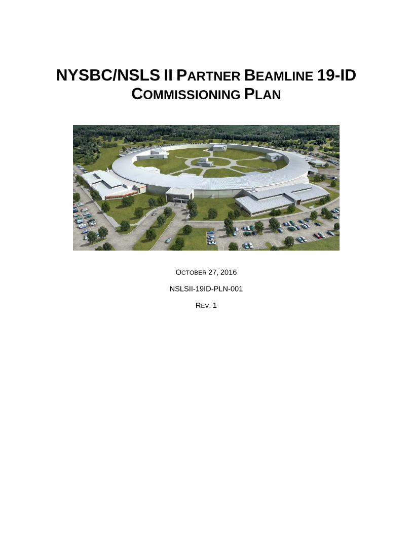
NYSBC/NSLS II PARTNER BEAMLINE 19-ID COMMISSIONING PLAN
OCTOBER 27, 2016
NSLSII-19ID-PLN-001
REV. 1
i National Synchrotron Light Source II
NYSBC/NSLS-II PARTNER BEAMLINE 19-IDCOMMISSIONING PLAN
OCTOBER 27, 2016
PREPARED BY:
XJoseph P. LidestriNYSBC NYX Lead Beamline Scientist
APPROVED BY:
11/9/2016
XPaul ZschackPhoton Science Division DirectorSigned by: Zschack, Paul
ii National Synchrotron Light Source II
REVISION HISTORY
REVISION DESCRIPTION DATE
1 First Issue October 27, 2016
Acronyms
BNL Brookhaven National Laboratory
CSS Control System Studio
EPS Equipment Protection System
ESH Environment, Safety and Health
ESR Experiment Safety Review
FE Front End
FLUKA Fluktuierende Kaskade (Monte Carlo simulation software)
ID Insertion Device
IRR Instrument Readiness Review
mA milli-Ampere
NSLS-II National Synchrotron Light Source II
NPB NSLS II Partner Beamlines
NYSBC New York Structural Biology Center
NYX NYSBC X-ray microdiffraction
PASS Proposal, Allocation, Safety and Scheduling
PPS Personnel Protection System
PSD Photon Science Division
SAF Safety Approval Form
TCP Technical Commissioning Plan
iii National Synchrotron Light Source II
iii
TableofContentsAcronyms ii
1. Introduction 1
2. Shielding 1
3. Beamline Commissioning Sequence 2
3.1 Radiation Survey Commissioning 2
3.2 Optics and Endstation Commissioning 2
3.3 Scientific Commissioning 3
4. Commissioning Activity Approval 3
5. Beamline Equipment Additions 3
6. End of Commissioning; Transition to Operations 4
7. NYX Beamline Technical Commissioning Plan 5
7.1 19‐ID‐NYX Subsystem Definition 5
7.2 NYX Pre‐Commissioning Activities Without Beam 8
7.2.1 Vacuum System Testing 8
7.2.2 Thermal Management System Testing 9
7.2.3 Control System Testing 10
7.3 19‐ID‐NYX Technical Commissioning With Beam 11
7.3.1 Pre‐start Commissioning Milestones 11
7.3.2 First‐light Commissioning and Radiation Surveys 12
7.3.3 Transition to Comprehensive Radiation Survey (CRS) 13
7.3.4 Optics and Endstaion Optimization 13
7.4 Scientific Commissioning 15
8 References 16
9 Appendices 16
Appendix A: 19‐ID‐NYX Beamline Layout 17
1 National Synchrotron Light Source II
1
1. Introduction
This plan outlines the actions needed to commission the NYSBC/NSLS-II NPB beamline 19-ID (NYX, microdiffraction macromolecular crystallography) from the accelerator enclosure ratchet wall to the endstation. Once the readiness process is complete and authorization to begin commissioning the beamline is received, the technical commissioning will proceed, initially hand in hand with a radiation safety commissioning, until the beamline is deemed to be radiation safe in the typical configuration used for x-ray operations. In the latter stages of technical commissioning, the optical elements and end-station instruments will be tested and optimized. Finally, scientific commissioning will concentrate on testing and optimization in preparation for User Operations. There are several processes established to manage the risks associated with this task, which are outlined below.
The scope of this plan includes managing specific commissioning activities for the beamline, reviewing requirements for equipment not needed for commissioning, but planned for operations, and the basis for transitioning to operations. It should be noted that all radiation containment and shielding components as well as all photon delivery components have been designed to handle the combined power of the IDs listed in PA-C-XFD-RSI-NYX-001. This total power includes upgrading NYX with the 7600 watt SAGU and installing a 2500 watt ID in the LAX straight. Technical commissioning of the FEs and IDs is managed separately from the beamline.
2. Shielding
Ray tracing and computer modeling (FLUKA) indicate that 19-ID is shielded for the maximum planned stored electron beam current of 500 mA. The primary Gas Bremsstrahlung ray traces have been completed in accordance with Synchrotron and Bremsstrahlung Ray Trace Procedure (PS-C-XFD-PRC-008) and Insertion Device Front End Ray Tracing Procedure (PS-C-ASD-PRC-147) and top-off safety analyzed. In accordance with NSLS-II shielding guidelines the following radiation shielding components are implemented to contain and attenuate the primary gas bremsstrahlung to allowable levels. Two collimators (one Pb and one W) and one polyethylene shield were located in hutch 19-ID-A. Two collimators (one Pb and one W) and one polyethylene shield were located in hutch 19-ID-C. The tungsten collimator in hutch 19-ID-C additionally acts as the primary bremsstrahlung stop. The following radiation containment components are implemented to occlude the Secondary Gas Bremsstrahlung within an 8 deg. cone in accordance with NSLS-II shielding guidelines: one lead shield is located in hutch 19-ID-A and two lead shields are located in hutch 19-ID-C. The scattering of synchrotron and bremsstrahlung radiation has been simulated using FLUKA, which verified that the 19-ID-NYX shielding geometry is adequate at 500 mA beam current. The summaries of these simulations including the simulation of the monochromatic beam containment in beam transport and endstation enclosures are provided in 19-ID NYX Beamline Radiation Shielding Analysis (Tech Note #231).
2 National Synchrotron Light Source II
2
3. BeamlineCommissioningSequence
The commissioning of the NYX beamline and its transition to operations begins with the IRR. This will be followed by the Technical Commissioning Plan (TCP) in which the electron beam current is gradually increased while monitoring equipment safety. The TCP is conducted in parallel with Radiation Survey Commissioning, which monitors radiation safety as the ring current is increased. When the beamline equipment demonstrates safe function in the configuration utilized in typical x-ray operations, there will be a comprehensive radiation survey. A minimum electron beam current of 100mA is necessary to execute the comprehensive radiation survey; therefore, gradually increasing the current in steps of 3mA, 10mA, 30mA and 100mA is typical in satisfying the minimum requirement for comprehensive radiation survey. Following the comprehensive radiation survey, the TCP will then direct efforts towards the testing, characterization and optimization of optical elements such as the mirror and monochromator. Once nominal optical parameters are determined, the TCP will commence commissioning of endstation instruments in preparation for scientific commissioning. Scientific commissioning will then follow, with the participation of expert users, to validate operating parameters and verify that the beamline meets operational goals. The operational goals are defined to satisfy routine user requirements.
3.1 RadiationSurveyCommissioning
A comprehensive NYX Beamline (19-ID) Radiation Survey Procedure (NSLSII-19ID-PRC-001) was developed in accordance with NSLS-II Beamlines Radiation Safety Commissioning Plan (PS-C-XFD-PRC-004), which guides the steps needed to control radiological hazards. It includes specific hold points to manage identified radiation risks and maintain commissioning within an approved envelope. The Radiation Survey Procedure requires participation and coordination between Beamline, Operations, Radiological Control, and ESH Staff. It identifies specific radiation scatter points along the beamline and provides instruction for mechanical manipulation of the optics to allow for a comprehensive radiological survey along the beamline. Execution of the Radiation Survey Procedure, along with the evaluation of the data collected, will be used as a basis by the PSD Director and ESH Manager to approve commissioning activities at an electron beam current of up to 3 times the electron beam current measured during the survey. Approval of commissioning of the beamline at a higher electron beam current requires re-execution of the Radiation Survey Procedure. The maximum current allowed during commissioning is indicated on the Caution Tag that is applied by Operations Staff to the beamline enable key. Enabling the beamline at a higher current requires re-execution of the full Radiation Survey Procedure and re-approval by the PSD Director and ESH Manager.
3.2 OpticsandEndstationCommissioning
The Technical Commissioning Plan (TCP), described in Section 7 below, documents in some detail the sequence of activities planned to safely commission the beamline. The TCP starts with the lowest ring current and it gradually increases ring current until it reaches the value for standard operations. At the
3 National Synchrotron Light Source II
3
completion of TCP, all major beamline components will be ready to use and parameters that optimize their performance will be documented.
3.3 ScientificCommissioning
The NYX beamline will have a single endstation that will enable microdiffraction experiments. A scientific commissioning plan will be developed while the technical commissioning takes place. The goal of scientific commissioning will be to define the beamline parameters and configurations needed for the anticipated scientific program and to develop the process for bringing the complete beamline into routine operations for users.
4. CommissioningActivityApproval
Work planning needed for safe and efficient commissioning, requires a commissioning Safety Approval Form (SAF) and is performed in accordance with Experiment Safety Review (PS-C-ESH-PRC-039). This process drives definition of scope, identification of hazards and controls, and review and approval requirements for all commissioning activities. A commissioning SAF describing the commissioning tasks to be undertaken by the commissioning team will be submitted. This form will include the equipment and materials that will be used, the personnel authorized to participate in the commissioning, and any controls that will be placed on the beamline (such as a current limit). This form will be submitted to the ESH Manager and PSD Director for approval. This commissioning activity approval process authorizes the commissioning team for a specific task or tasks (such as performing a radiation survey) thereby enforcing a step-by-step and HOLD point approach to commissioning. Most commissioning tasks are expected to take approximately one week to complete, though some may be longer. All commissioning activities will be reviewed on a weekly basis to determine if a new commissioning SAF is needed. This allows for flexibility in the commissioning process, but at the same time ensures that during commissioning the work is periodically reviewed and that the necessary controls are placed on the commissioning activities.
An approved commissioning SAF is required for the beamline to be enabled. Beamline enable is managed in accordance with Enabling Beamlines for Operations (PS-C-XFD-PRC-003). This procedure defines the process for enabling the beamline safety shutter and for giving control of that shutter to the Beamline Staff. The process requires participation and coordination between Beamline, Operations, and ESH Staff. A checklist is employed to assure systems are ready (Personnel Protecction System [PPS] and safety system configuration control) and that staff is prepared to begin.
5. BeamlineEquipmentAdditions
As commissioning moves from technical to scientific, the focus shifts from optimizing the photon beam to preparing the end station instrumentation for the expected scientific program. Most 19ID beamline equipment will be installed prior to the IRR except for future beam diagnostic instruments
4 National Synchrotron Light Source II
4
such as XPMS, screens and energy analyzer. All future additions will be added in accordance with the NSLS-II Process Description: Review Process for Facility Additions and Modifications (PS-C-CMD-PLN-001), which provides a process for determining the type and extent of reviews warranted.
Equipment additions for the beamline have been evaluated, and it has been determined that the addition of this equipment will not constitute a sufficient modification of the beamline instrument to require an IRR. These additions will be reviewed through the BNL Experiment Safety Review (ESR) process in accordance with Experiment Safety Review (PS-C-ESH-PRC-039). This system allows for the treatment of the end stations as experiment areas and provides an electronic mechanism to gather the information needed to define and review equipment and materials in that area. The BNL ESR system contains fields for entry of the equipment and materials to be used, task analyses, control requirement definition, and for ESH review and approval. This approach will be documented in a Tailored Review Plan in accordance with the NSLS-II Process Description: Review Process for Facility Additions and Modifications (PS-C-CMD-PLN-001).
The ESRs will be posted at the end station so that they are readily available and provide an ESH envelope of the allowed equipment and activities in the area. This system is used in experiment spaces throughout BNL. Annual review and approval is required, but any change also triggers a system update with an approval requirement. This system will assure careful management of equipment additions and will be correlated with the ESR process planned for the management of User activities.
6. EndofCommissioning;TransitiontoOperations
Commissioning ends when the beamline has shown, through the execution of procedures and surveys, that it meets the NSLS-II Shielding Policy, that radiation leakage or scatter is controlled to as low as reasonably achievable, that the photon beam is ready for data collection, and that the necessary authorizations for beginning operations have been obtained. Prior to commencing User Operations at the beamline, the process outlined in Beamline User Readiness (PS-C-XFD-PRC-030) will be completed.
The safety of ongoing beamline operations will be managed with the Experiment Safety Review (PS-C-ESH-PRC-039) process, which will control materials, equipment, and tasks at the end station areas through the use of the BNL electronic ESR system. A Cognizant Space Manager is assigned to the area and has responsibility to assure that the system is current and accurate. This system provides a valuable envelope for the resources and allows operations at each location.
Individual experiments will be managed with the electronic SAF section of PASS; a system for Proposal, Allocation, Safety, and Scheduling for User science. The SAF will allow collection of information specific to each experiment and will be reviewed by NSLS-II Staff to determine what hazards are outside the safety envelope established. The SAF will provide the mechanism for definition of scope, analysis of hazards, establishment of controls, and collection of feedback for each
5 National Synchrotron Light Source II
5
experiment. Users must identify the materials and equipment they wish to bring along with a task analysis describing how those items will be used. An iterative review between the User, Beamline, and ESH Staff results in a final approval with definition of requirements.
The SAF process combined with the BNL ESR safety envelope provides the basis needed to assure ongoing control of beamline operation and changes. No additional readiness reviews are expected for the 19-ID beamline at this time.
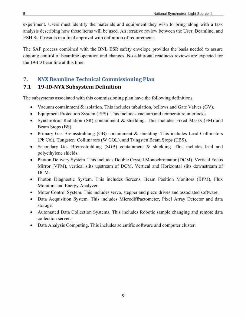
7. NYXBeamlineTechnicalCommissioningPlan7.1 19‐ID‐NYXSubsystemDefinition
The subsystems associated with this commissioning plan have the following definitions:
Vacuum containment & isolation. This includes tubulation, bellows and Gate Valves (GV).
Equipment Protection System (EPS). This includes vacuum and temperature interlocks
Synchrotron Radiation (SR) containment & shielding. This includes Fixed Masks (FM) and Beam Stops (BS).
Primary Gas Bremsstrahlung (GB) containment & shielding. This includes Lead Collimators (Pb Col), Tungsten Collimators (W COL), and Tungsten Beam Stops (TBS).
Secondary Gas Bremsstrahlung (SGB) containment & shielding. This includes lead and polyethylene shields.
Photon Delivery System. This includes Double Crystal Monochromator (DCM), Vertical Focus Mirror (VFM), vertical slits upstream of DCM, Vertical and Horizontal slits downstream of DCM.
Photon Diagnostic System. This includes Screens, Beam Position Monitors (BPM), Flux Monitors and Energy Analyzer.
Motor Control System. This includes servo, stepper and piezo drives and associated software.
Data Acquisition System. This includes Microdiffractometer, Pixel Array Detector and data storage.
Automated Data Collection Systems. This includes Robotic sample changing and remote data collection server.
Data Analysis Computing. This includes scientific software and computer cluster.
6 National Synchrotron Light Source II
6
The following table includes components with corresponding locations relevant to SR, GB and SGB containment and shielding as well as Photon Delivery and Diagnostics.
7 National Synchrotron Light Source II
7
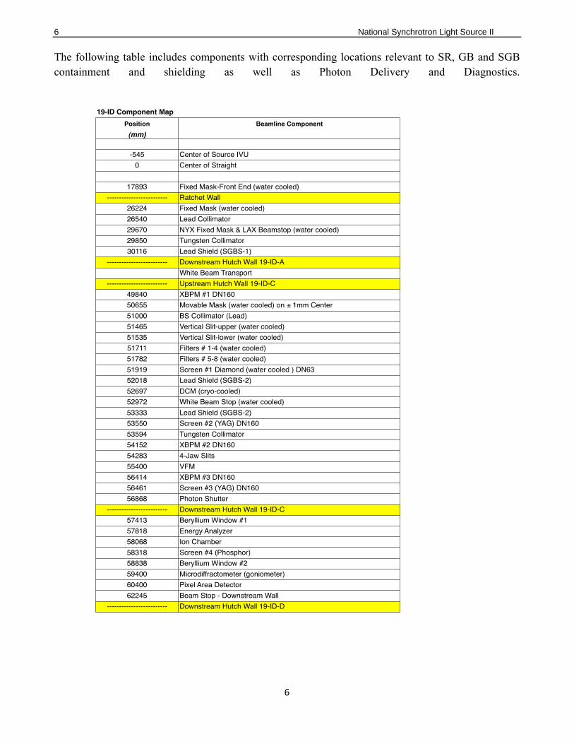
All components listed above will be installed prior to the IRR except for XBPM#1, XBPM#2, XPBM#3 and Energy Analyzer. The components in the above table are shown as plan and elevation views in Figures 1 and 2.
Figure 1: Plan and elevation views beamline major‐component locations in 19‐ID‐A hutch. For more details, see
Appendix: NYX Beamline Component Layout.
8 National Synchrotron Light Source II
8
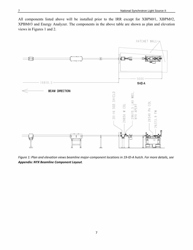
Figure 2: Plan and elevation views beamline major‐component locations in 19‐ID‐C and 19‐ID‐D hutches. For
more details, see Appendix: NYX Beamline Component Layout.
7.2 NYXPre‐CommissioningActivitiesWithoutBeam
7.2.1VacuumSystemTesting
All 19-ID vacuum components shown in the Control System Suite (CSS) screen below will be integrated into the Equipment Protection System (EPS) and systematically tested, following the enumerated procedures, prior to commissioning with beam.

9 National Synchrotron Light Source II
9
1. Verify that all gate valves, ion pumps and gauges are functional.
2. Pump down each isolated vacuum section, leak check and bake out as necessary.
3. Verify trip settings in each vacuum section.
4. Test the functionality of the EPS system in response to vacuum failures, by simulating trip signals from the vacuum gauge controller.
5. Modify the above CSS vacuum screen as necessary.
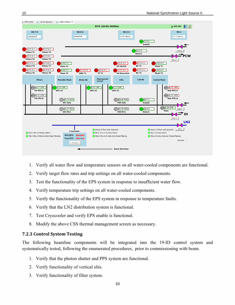
7.2.2ThermalManagementSystemTesting
All 19-ID thermal management components shown in the CSS screen below will be integrated into the EPS and systematically tested, following the enumerated procedures, prior to commissioning with beam.
10 National Synchrotron Light Source II
10
1. Verify all water flow and temperature sensors on all water-cooled components are functional.
2. Verify target flow rates and trip settings on all water-cooled components.
3. Test the functionality of the EPS system in response to insufficient water flow.
4. Verify temperature trip settings on all water-cooled components.
5. Verify the functionality of the EPS system in response to temperature faults.
6. Verify that the LN2 distribution system is functional.
7. Test Cryocooler and verify EPS enable is functional.
8. Modify the above CSS thermal management screen as necessary.
7.2.3ControlSystemTesting
The following beamline components will be integrated into the 19-ID control system and systematically tested, following the enumerated procedures, prior to commissioning with beam.
1. Verify that the photon shutter and PPS system are functional.
2. Verify functionality of vertical slits.
3. Verify functionality of filter system.
11 National Synchrotron Light Source II
11
4. Test beam visualization systems and verify functionality.
5. Test beam visualization systems and verify functionality of pneumatic actuators and camera systems. (Screen#1, Screen#2, Screen#3 and Screen#4).
6. Verify that all cameras are aligned and in focus and survey critical references as required.
7. Verify functionality of Double Crystal Monochromator (DCM) motors and encoders.
8. Verify that all DCM motions are consistent with encoder polarities and limits.
9. Tune the servo amplifier used to drive the primary Bragg angle of DCM.
10. Verify functionality of motors and encoders in 4-Jaw slits.
11. Verify that all 4-Jaw slit motions are consistent with encoder polarities and limits.
12. Integrate electronics used in measuring the drain current from the 4-Jaw slits.
13. Verify functionality of Vertical Focus Mirror (VFM) motors and encoders.
14. Verify that all VFM motions are consistent with encoder polarities and limits.
15. Verify that VFM load cell readings are consistent with required elliptical bending parameters.
16. Integrate all thermocouples in optical elements.
17. Set all motors of the optical elements in default position for radiation survey.
18. Integrate current amplifier and bias power supply for the endstation Ion Chamber (IC).
19. Verify that beam visualization in endstation is functional.
20. Verify that phosphor screen#4 and camera is in focus and aligned in default position for radiation survey.
21. Test Microdiffractometer.
22. Test Pixel Array Detector.
7.3 19‐ID‐NYXTechnicalCommissioningWithBeam
The technical commissioning of 19-ID-NYX will be executed in three steps starting with the initial and Comprehensive Radiation Surveys (CRS), which will be coordinated with vacuum conditioning. Upon completion of the CRS, commissioning will continue to optics and endstaion optimization and then finalized with scientific commissioning as described below.
7.3.1Pre‐startCommissioningMilestones
Prior to the beamline commissioning activities, the following prerequisites shall be satisfied:
The X25 IVU source installed and commissioned at 19-ID by the Accelerator Division.
IRR completed and pre-start findings closed.
12 National Synchrotron Light Source II
12
PPS and EPS are functional.
Accelerator beam current and IVU gap determined by the Accelerator Division.
Front end Radiation Survey
7.3.2First‐lightCommissioningandRadiationSurveys
About half of the accelerator studies time is expected to be required to conduct radiation surveys as described in the Radiation Survey Procedure (NSLSII-11BM-PRC-001) and to extract and transport first light along the beamline.
7.3.2.1 Gas Bremsstrahlung (GB) Radiation Surveys
GB radiation surveys are initially carried out at low electron currents (1-3 mA) during accelerator study time dedicated to this purpose, a succession of successful GB radiation surveys will allow increasing the electron current stepwise with the goal of rapidly obtaining authorization to operate the beamline during regular accelerator operations for the purpose of beamline optics commissioning, beam characterization, and endstation commissioning. It should be noted that 19-ID does not include any optical elements or movable components (slits or XBPMs) in the FE; therefore, upon opening of the FE safety shutters, the GB and SR will enter hutch 19-ID-A and interact first with the water-cooled fixed mask at 26224mm. Hutch 19-ID-A also does not include any optical elements or movable components; therefore, during the GB radiation survey, the unobstructed beam is expected to travel through the white beam transport tube into hutch 19-ID-C. The water-cooled fixed mask at 26224mm in hutch 19-ID-A has a smaller angular acceptance of 158 μrad horizontal and 81 μrad vertical as compared to the water-cooled fixed mask at 17893mm in the FE, which has angular acceptance of 497 μrad horizontal and 285 μrad vertical; therefore, the fixed mask at 26224mm is expected to generate the greatest amount of scatter in the beamline.
In the first configuration of GB radiation survey, with the IVU gap fully open and beamline shutter closed, we do not expect an observable beam in hutch 19-ID-C where beamline diagnostics are located; however, the DCM crystals will be positioned in the horizontal plane such that the lower 50% of the radiation will interact with the first monochromator crystal and the upper 50% of the radiation will interact with the White Beam Stop (WBS) located at 52972mm. Once the radiation survey for this configuration is completed, the first DCM crystal will be rotated to the nominal operating angle that obstructs 100% of the radiation. The final configuration of GB radiation survey will be to translate the upstream vertical slit to the beam centerline to validate the shielding of the secondary GB.
7.3.2.2 Synchrotron Radiation (SR) Surveys
The first part of the SR survey will aim to observe the first-light at Screen #1 located at 51919mm and will also to verify and document that the GB was interacting with the WBS. The alignment of Screen #1 will be surveyed into alignment with the WBS to complete the GB radiation survey documentation. The initial observation of SR with Screen #1 will be made at minimal beam current (3mA). The next configuration for SR radiation survey will be to set the DCM crystals to the nominal angles to transport 12658eV x-rays downstream from the DCM. This will be verified and documented with Screen #2 located at 53550mm. The next configuration for the SR radiation survey of hutch 19-ID-C will be to translate the Vertical Focusing Mirror (VFM) to nominal position and angle to scatter the
13 National Synchrotron Light Source II
13
monochromatic beam and validate SR shielding. The default VFM configuration will be verified prior to starting the radiation surveys. Screen #3 located at 56461mm will be used to visualize and verify the presence of beam upstream of the beamline shutter entering endstation hutch 19-ID-D. Upon completion of radiation surveys in hutch 19-ID-C, the beamline shutter will be opened allowing monochromatic SR to enter the endstation hutch 19-ID-D. Screen #4 located at 58318mm will be used to visualize and verify the presence of beam and an Ion Chamber (IC) will be used to measure the flux. With the beamline shutter open, hutch 19-ID-D will be also be surveyed with the IVU gap fully open to validate shielding of secondary GB.
7.3.3TransitiontoComprehensiveRadiationSurvey(CRS)
Increasing the beam intensity from the minimal current used in the initial first-light commissioning to what is needed for the CRS requires that the following prerequisites be established before starting the stepped current sequence and vacuum conditioning.
7.3.3.1 Prerequisites
Initial radiation surveys are below acceptable limits.
All beam observations are nominal.
Vacuum and temperature measurements are nominal.
7.3.3.2 Vacuum Conditioning
The stepped current sequence will be coordinated with vacuum conditioning to minimize the effects of carbon developing on the surfaces of the beamline optics. Vacuum measurements will be tracked while the current is stepped allowing enough time to maintain acceptable vacuum conditions. Once sufficient current has been reached to satisfy the minimal requirements the CRS will be executed finalizing the first phase of commissioning.
7.3.4OpticsandEndstaionOptimization
The goal of this step of technical commissioning is to characterize beamline instrumentation in order to optimize alignment and to develop operational procedures necessary to maintain optimal experimental configurations. All of the beamline components will be systematically aligned and configured to optimize the quality of experimental data. Each of the beamline systems will be commissioned in the following sequence.
7.3.4.1 White Beam Filters and Screens
White beam filters will be installed to optimize attenuation of the IVU beam for data collection. White beam screens will be aligned, calibrated and optimize for beam visualization.
7.3.4.2 Water‐cooled Fixed Mask
The alignment of the water-cooled fixed mask will be verified and optimize the transmission of power according to beam observations.
14 National Synchrotron Light Source II
14
7.3.4.3 Double Crystal Monchromator (DCM)
The DCM primary Bragg angle will be calibrated using x-ray fluorescence from test samples. The tangential bend radius of the first crystal will be determined and set for each energy setting. The sagittal bend radius of the second crystal will be determined and set for each energy setting. All DCM motions will be systematically tested, tuned and characterized for tracking and stability. Energy resolution will be characterized directly using an energy analyzer crystal and indirectly be analyzing fluorescence scans. Feedback from XBPMs will be integrated into the crystal motion to mitigate vibrational modes.
7.3.4.4 4‐Jaw Monochromatic Slits
Readout electronics will be integrated to measure the drain current from each of the 4 slit blades. Measurements from the slit blades will be used to obtain the beam center position and monitor both the beam flux and position.
7.3.4.5 Vertical Focusing Mirror (VFM)
The mirror will be cleaned in situ, in the vacuum chamber, to mitigate dust on the optical surface. The reflection angle of the VFM will be calibrated using Screen # 3 downstream of the mirror. The VFM will be set to the nominal 3.5 mrad incident angle. The elliptical bending parameters will be optimized and documented for the various foci required for operation. The VFM will be systematically tested and characterized for stability using downstream XBPMs.
7.3.4.6 Microdiffractometer
Most of the subsystems of the microdiffractometer have been tested without x-rays; therefore, the priority will be to start commissioning with the systems that require x-rays for alignment and testing. The microdiffractometer design has a pair of embedded diamond beam-position monitors. These XBPMs which were previously tested with x-rays at NSLS beamline X4A; however, they need integrated with the bias power supply and Libera readout electronics. Beam-defining slits will be aligned and tested. The downstream guard aperture will be aligned and tested. Both the slits and guard aperture will be optimized based on the background scattering. Sample visualization includes a UV imaging system, which will be optimized using samples stimulated with x-rays. Beam alignment will be by visualization with fluorescence screen and used to verify beam stability. The field-of-views (FOVs) of all diagnostic cameras will be aligned and focus will be adjusted using visible references. Ion chambers will be tested and calibrated. The scintillation detector and multi-channel analyzer (MCA) will be tested. Software for automatic sample centering will be tested using the above visualization systems. Finally, software will be developed for the above XBPMs and readout electronics to automatic maintenance of beam alignment into the sample goniometer. Alignment will be maintained for slow thermal changes by tracking the goniometer motors. Alignment corrections from vibrational modes will be achieved by correcting the beam motion with the piezo amplifiers used for fine motion of the DCM. This XBPM feedback will involve software and hardware integration of the Libera readout and piezo amplifier.
15 National Synchrotron Light Source II
15
7.3.4.7 Robotic Sample Changer
Most of the subsystems of the robotic sample changer system have been tested prior to the start of 19-ID-NYX commissioning. The system design implemented on 19-ID-NYX is a second generation version of the system used on NSLS beamline X4A and practical experience shows that the priority for commissioning at NSLS-II will be to establish a procedure to maintain a reliable operation. Included in this will be to establish the hardware requirements for sample mounting and protocols for users to practice.
7.3.4.8 Pixel Array Detector
The Pixel Array Detector (PAD) used at 19-ID-NYX was developed specifically for NYSBC and was delivered and tested prior to commissioning at NSLS-II. The actual detector (HF-4M) installed at 19-ID-NYX was tested with x-rays in December 2015 and February 2016 at NE-CAT beamline 24-ID-E at the APS. Data were obtained for sulfur-SAD structure solutions of lysozyme, insulin and thaumatin. The data collected for the analysis of difference maps and testing results consistently produced diffraction data of high resolution. Additional diffraction data collected from NYSBC protein crystals resulted in two SeMet structure solved; therefore, the goal of detector commissioning at 19-ID-NYX is to reestablish operation of the HF-4M and commence data collection with actual crystal samples.
7.4ScientificCommissioning
The goal of the optics and endstation optimization commissioning described in the sections above is to determine the nominal parameters for scientific data collection. Scientific commissioning will therefore have the goal of verifying that the nominal operating parameters are acceptable. Although scientific commissioning is formally outside the scope of this Technical Commissing Plan, we expect
that technical commissioning will in fact continue concomitantly with our efforts to assure that 19-ID-
NYX will properly address the scientific mission. The data collected from real-life samples will be used as the metric in determining that the operational parameters are optimized. NYSBC crystallographers as well as other participating experts will collect and analyze data in order to validate operating parameters and to verify that the beamline meets operational goals.
NYX is designed to address three major objectives relevant to the anticipated scientific program: microdiffraction capability (5-50 μm), access to effective resonant edges (5-17.5 keV), and optimization of anomalous scatterering by having high energy resolution (~5 x 10⁻⁵ ΔE/E) for at-resonance SAD and MAD and low energy (5-7 keV) for native SAD. Users from the NYSBC community, and others from the General User community will provide samples to test important aspects of these features. Candidate samples will include membrane protein microcrystals grown from lipidic cubic phase (LCP), which are typically very small (5-20 μm); heme proteins (Fe K-edge at 7.1 keV), selenomethionyl (SeMet) proteins (Se K-edge at 12.7 keV) and other phasing resonances; thioredoxin and other SeMet proteins (SSRL K-edge motivation) and lanthanide derivatives (LIII white lines); and membrane protein candidates for native-SAD phasing based on sulfur (7 keV initially, lower later).
16 National Synchrotron Light Source II
16
8 References1. NSLSII-19ID-PRC-001, NYX Beamline (19-ID) Radiation Survey Procedure
2. PS-C-ASD-PRC-147, Insertion Device Front End Ray Tracing Procedure
3. PS-C-CMD-PLN-001, NSLS-II Process Description: Review Process for Facility Additions and Modifications
4. PS-C-ESH-PRC-039, Experiment Safety Review
5. PS-C-XFD-PRC-003, Enabling Beamlines for Operations
6. PS-C-XFD-PRC-004, NSLS-II Beamlines Radiation Safety Commissioning Plan
7. PS-C-XFD-PRC-008, Synchrotron and Bremsstrahlung Ray Trace Procedure
8. PS-C-XFD-PRC-030, Beamline User Readiness
9. Tech Note #231, 19-ID NYX Beamline Radiation Shielding Analysis
9 Appendices
Appendix A, 19-ID-NYX Beamline Layout
17 National Synchrotron Light Source II
17
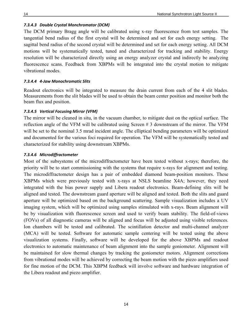
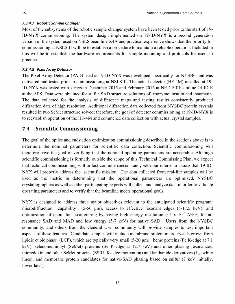
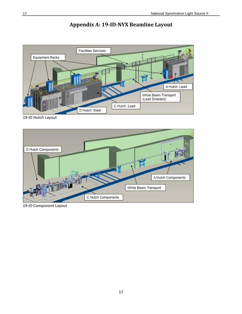
AppendixA:19‐ID‐NYXBeamlineLayout
19‐ID Hutch Layout
19‐ID Component Layout
18 National Synchrotron Light Source II
18
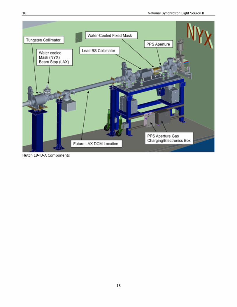
Hutch 19‐ID‐A Components
19 National Synchrotron Light Source II
19
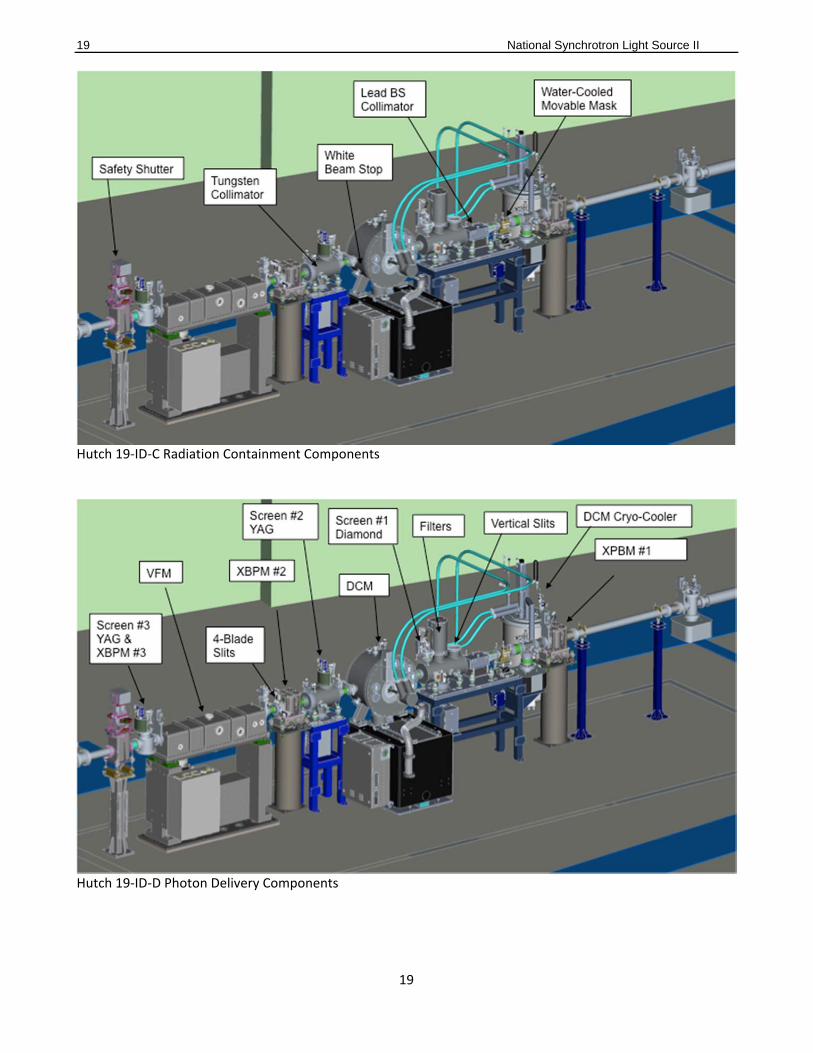
Hutch 19‐ID‐C Radiation Containment Components
Hutch 19‐ID‐D Photon Delivery Components
20 National Synchrotron Light Source II
20
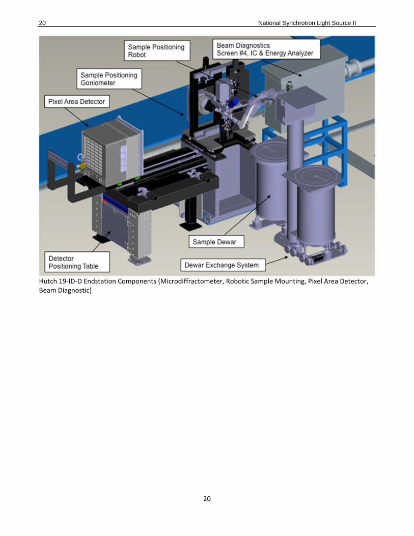
Hutch 19‐ID‐D Endstation Components (Microdiffractometer, Robotic Sample Mounting, Pixel Area Detector, Beam Diagnostic)