Embed Size (px)
Citation preview
NXP ARM +USB. Ethernet. LCD. Motor Control
2
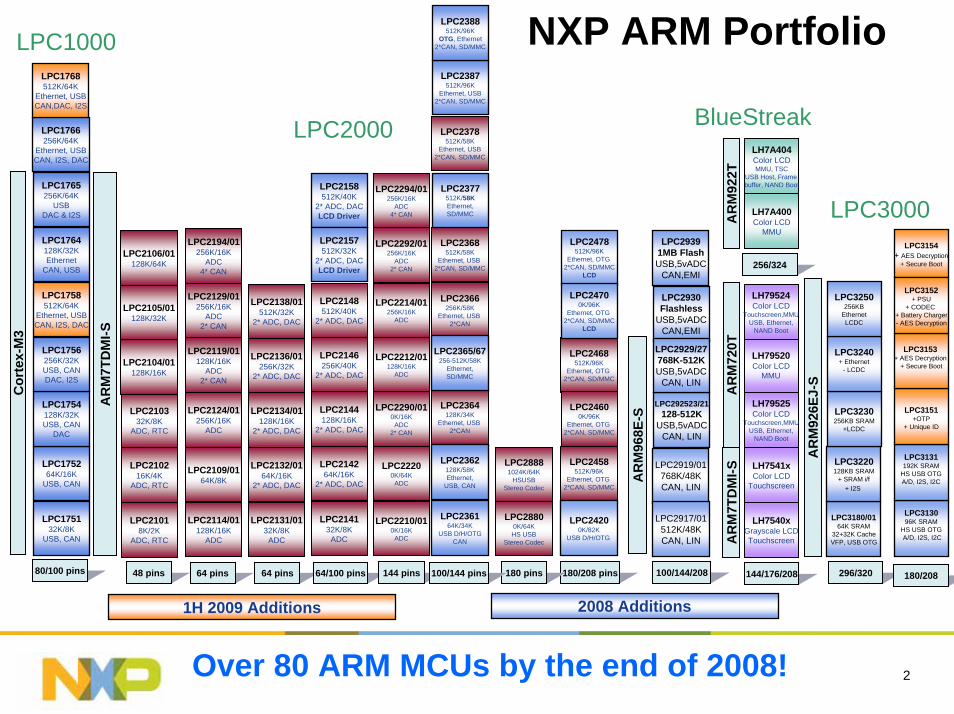
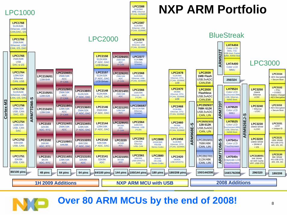
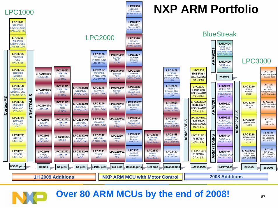
NXP ARM Portfolio
LPC214264K/16K
2* ADC, DAC
LPC214132K/8K
ADC
LPC2144128K/16K
2* ADC, DAC
LPC2146256K/40K
2* ADC, DAC
LPC2148512K/40K
2* ADC, DAC
LPC2132/0164K/16K
2* ADC, DAC
LPC2131/0132K/8K
ADC
LPC2134/01128K/16K
2* ADC, DAC
LPC2136/01256K/32K
2* ADC, DAC
LPC2138/01512K/32K
2* ADC, DAC
LPC2124/01256K/16K
ADC
LPC2114/01128K/16K
ADC
LPC2119/01128K/16K
ADC2* CAN
LPC2129/01256K/16K
ADC2* CAN
LPC2194/01256K/16K
ADC4* CAN
LPC210216K/4K
ADC, RTC
LPC21018K/2K
ADC, RTC
LPC210332K/8K
ADC, RTC
LPC2105/01128K/32K
LPC2106/01128K/64K
LPC22200K/64K
ADC
LPC2210/010K/16K
ADC
LPC2212/01128K/16K
ADC
LPC2214/01256K/16K
ADC
LPC2292/01256K/16K
ADC2* CAN
LPC2290/010K/16K
ADC2* CAN
LPC2294/01256K/16K
ADC4* CAN
LPC2366256K/58K
Ethernet, USB 2*CAN
LPC2364128K/34K
Ethernet, USB 2*CAN
LPC2368512K/58K
Ethernet, USB 2*CAN, SD/MMC
LPC2378512K/58K
Ethernet, USB2*CAN, SD/MMC
LPC28800K/64KHS USB
Stereo Codec
LPC28881024K/64K
HSUSBStereo Codec
48 pins 64 pins 64 pins 64/100 pins 144 pins 180/208 pins180 pins100/144 pins
LPC2468512K/96K
Ethernet, OTG 2*CAN, SD/MMC
LPC2458512K/96K
Ethernet, OTG 2*CAN, SD/MMC
LPC2109/0164K/8K
AR
M92
6EJ-
S
AR
M7T
DM
I-S
296/320
LPC2000
LPC3000
LH7540xGrayscale LCDTouchscreen
LH7541xColor LCD
Touchscreen
LH79520Color LCD
MMU
LH79524Color LCD
Touchscreen,MMUUSB, Ethernet,
NAND Boot
AR
M72
0T
LH7A400Color LCD
MMU
LH7A404Color LCDMMU, TSC
USB Host, Frame buffer, NAND Boot
AR
M92
2T
LH79525Color LCD
Touchscreen,MMUUSB, Ethernet,
NAND Boot
AR
M7T
DM
I-S
144/176/208
256/324
BlueStreak
LPC24600K/96K
Ethernet, OTG 2*CAN, SD/MMC
100/144/208
1H 2009 Additions
LPC2478512K/96K
Ethernet, OTG 2*CAN, SD/MMC
LCD
LPC24700K/96K
Ethernet, OTG 2*CAN, SD/MMC
LCD
LPC2387512K/96K
Ethernet, USB2*CAN, SD/MMC
LPC2388512K/96K
OTG, Ethernet2*CAN, SD/MMC
LPC2158512K/40K
2* ADC, DACLCD Driver
LPC2157512K/32K
2* ADC, DACLCD Driver
80/100 pins
Over 80 ARM MCUs by the end of 2008!
LPC1000
LPC2365/67256-512K/58K
Ethernet,SD/MMC
LPC2377512K/58KEthernet,SD/MMC
LPC24200K/82K
USB D/H/OTG
LPC2362128K/58KEthernet,
USB, CAN
LPC236164K/34K
USB D/H/OTGCAN
LPC2104/01128K/16K
LPC2105/01128K/32K
LPC2106/01128K/64K
LPC3180/0164K SRAM
32+32K CacheVFP, USB OTG
LPC3220128KB SRAM
+ SRAM i/f+ I2S
LPC3230256KB SRAM
+LCDC
LPC3240+ Ethernet
- LCDC
LPC3250256KB
EthernetLCDC
LPC313096K SRAM
HS USB OTGA/D, I2S, I2C
Cor
tex-
M3
LPC175264K/16K
USB, CAN
LPC175132K/8K
USB, CAN
LPC1754128K/32KUSB, CAN
DAC
LPC1756256K/32KUSB, CANDAC, I2S
LPC1764128K/32KEthernet
CAN, USB
LPC1758512K/64K
Ethernet, USBCAN, I2S, DAC
LPC1765256K/64K
USBDAC & I2S
LPC1766256K/64K
Ethernet, USBCAN, I2S, DAC
LPC1768512K/64K
Ethernet, USBCAN,DAC, I2S
LPC3131192K SRAM
HS USB OTGA/D, I2S, I2C
LPC3151+OTP
+ Unique ID
LPC3154+ AES Decryption
+ Secure Boot
180/208
LPC3153+ AES Decryption
+ Secure Boot
LPC3152+ PSU
+ CODEC + Battery Charger- AES Decryption
2008 Additions
AR
M96
8E-S
LPC2919/01768K/48KCAN, LIN
LPC2917/01512K/48KCAN, LIN
LPC292523/21128-512K
USB,5vADCCAN, LIN
LPC29391MB FlashUSB,5vADC
CAN,EMI
LPC2930Flashless
USB,5vADCCAN,EMI
LPC2929/27768K-512KUSB,5vADC
CAN, LIN
33
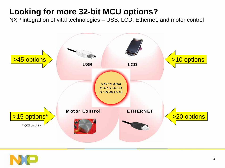
Looking for more 32-bit MCU options?NXP integration of vital technologies – USB, LCD, Ethernet, and motor control
NXP's ARMPORTFOLIOSTRENGTHS
USB LCD
Motor Control ETHERNET
>45 options >10 options
>20 options>15 options** QEI on chip
4
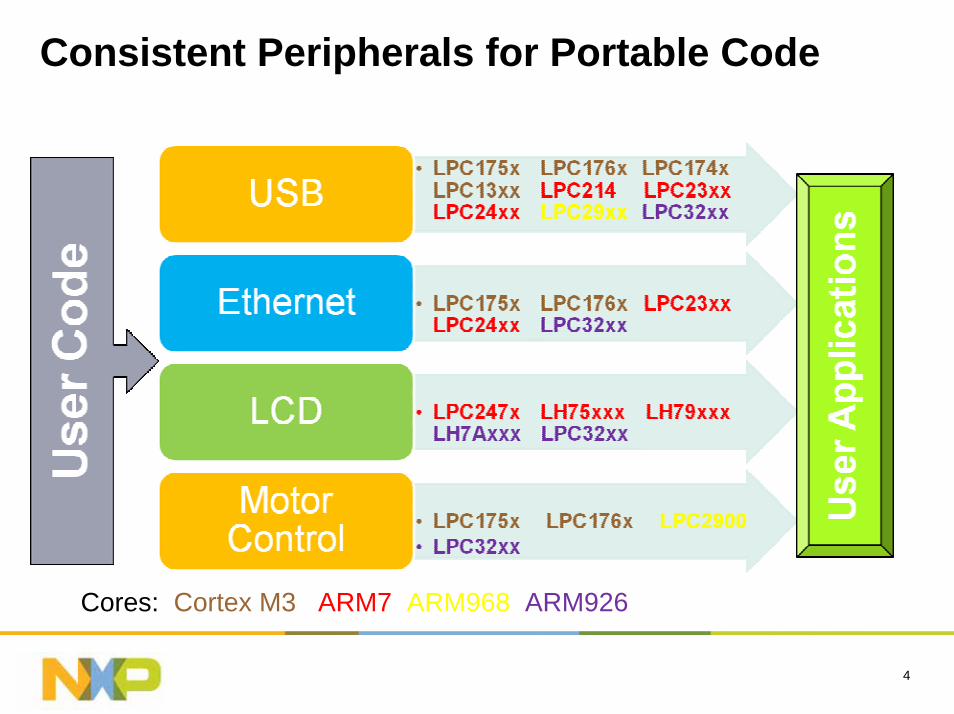
Consistent Peripherals for Portable Code
Cores: Cortex M3 ARM7 ARM968 ARM926
USB
6
Content
USB in NXP ARM MCU
Resource

7
USB in NXP ARM MCU
8
NXP ARM Portfolio
LPC214264K/16K
2* ADC, DAC
LPC214132K/8K
ADC
LPC2144128K/16K
2* ADC, DAC
LPC2146256K/40K
2* ADC, DAC
LPC2148512K/40K
2* ADC, DAC
LPC2132/0164K/16K
2* ADC, DAC
LPC2131/0132K/8K
ADC
LPC2134/01128K/16K
2* ADC, DAC
LPC2136/01256K/32K
2* ADC, DAC
LPC2138/01512K/32K
2* ADC, DAC
LPC2124/01256K/16K
ADC
LPC2114/01128K/16K
ADC
LPC2119/01128K/16K
ADC2* CAN
LPC2129/01256K/16K
ADC2* CAN
LPC2194/01256K/16K
ADC4* CAN
LPC210216K/4K
ADC, RTC
LPC21018K/2K
ADC, RTC
LPC210332K/8K
ADC, RTC
LPC2105/01128K/32K
LPC2106/01128K/64K
LPC22200K/64K
ADC
LPC2210/010K/16K
ADC
LPC2212/01128K/16K
ADC
LPC2214/01256K/16K
ADC
LPC2292/01256K/16K
ADC2* CAN
LPC2290/010K/16K
ADC2* CAN
LPC2294/01256K/16K
ADC4* CAN
LPC2366256K/58K
Ethernet, USB 2*CAN
LPC2364128K/34K
Ethernet, USB 2*CAN
LPC2368512K/58K
Ethernet, USB 2*CAN, SD/MMC
LPC2378512K/58K
Ethernet, USB2*CAN, SD/MMC
LPC28800K/64KHS USB
Stereo Codec
LPC28881024K/64K
HSUSBStereo Codec
48 pins 64 pins 64 pins 64/100 pins 144 pins 180/208 pins180 pins100/144 pins
LPC2468512K/96K
Ethernet, OTG 2*CAN, SD/MMC
LPC2458512K/96K
Ethernet, OTG 2*CAN, SD/MMC
LPC2109/0164K/8K
AR
M92
6EJ-
S
AR
M7T
DM
I-S
296/320
LPC2000
LPC3000
LH7540xGrayscale LCDTouchscreen
LH7541xColor LCD
Touchscreen
LH79520Color LCD
MMU
LH79524Color LCD
Touchscreen,MMUUSB, Ethernet,
NAND Boot
AR
M72
0T
LH7A400Color LCD
MMU
LH7A404Color LCDMMU, TSC
USB Host, Frame buffer, NAND Boot
AR
M92
2T
LH79525Color LCD
Touchscreen,MMUUSB, Ethernet,
NAND Boot
AR
M7T
DM
I-S
144/176/208
256/324
BlueStreak
LPC24600K/96K
Ethernet, OTG 2*CAN, SD/MMC
100/144/208
LPC2478512K/96K
Ethernet, OTG 2*CAN, SD/MMC
LCD
LPC24700K/96K
Ethernet, OTG 2*CAN, SD/MMC
LCD
LPC2387512K/96K
Ethernet, USB2*CAN, SD/MMC
LPC2388512K/96K
OTG, Ethernet2*CAN, SD/MMC
LPC2158512K/40K
2* ADC, DACLCD Driver
LPC2157512K/32K
2* ADC, DACLCD Driver
80/100 pins
Over 80 ARM MCUs by the end of 2008!
LPC1000
LPC2365/67256-512K/58K
Ethernet,SD/MMC
LPC2377512K/58KEthernet,SD/MMC
LPC24200K/82K
USB D/H/OTG
LPC2362128K/58KEthernet,
USB, CAN
LPC236164K/34K
USB D/H/OTGCAN
LPC2104/01128K/16K
LPC2105/01128K/32K
LPC2106/01128K/64K
LPC3180/0164K SRAM
32+32K CacheVFP, USB OTG
LPC3220128KB SRAM
+ SRAM i/f+ I2S
LPC3230256KB SRAM
+LCDC
LPC3240+ Ethernet
- LCDC
LPC3250256KB
EthernetLCDC
LPC313096K SRAM
HS USB OTGA/D, I2S, I2C
Cor
tex-
M3
LPC175264K/16K
USB, CAN
LPC175132K/8K
USB, CAN
LPC1754128K/32KUSB, CAN
DAC
LPC1756256K/32KUSB, CANDAC, I2S
LPC1764128K/32KEthernet
CAN, USB
LPC1758512K/64K
Ethernet, USBCAN, I2S, DAC
LPC1765256K/64K
USBDAC & I2S
LPC1766256K/64K
Ethernet, USBCAN, I2S, DAC
LPC1768512K/64K
Ethernet, USBCAN,DAC, I2S
LPC3131192K SRAM
HS USB OTGA/D, I2S, I2C
LPC3151+OTP
+ Unique ID
LPC3154+ AES Decryption
+ Secure Boot
180/208
LPC3153+ AES Decryption
+ Secure Boot
LPC3152+ PSU
+ CODEC + Battery Charger- AES Decryption
AR
M96
8E-S
LPC2919/01768K/48KCAN, LIN
LPC2917/01512K/48KCAN, LIN
LPC292523/21128-512K
USB,5vADCCAN, LIN
LPC29391MB FlashUSB,5vADC
CAN,EMI
LPC2930Flashless
USB,5vADCCAN,EMI
LPC2929/27768K-512KUSB,5vADC
CAN, LIN
1H 2009 Additions 2008 AdditionsNXP ARM MCU with USB
9
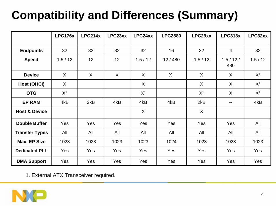
Compatibility and Differences (Summary)LPC176x LPC214x LPC23xx LPC24xx LPC2880
32 16
12 / 480
X1
4kB
Yes
All
1024
Yes
Yes
12
X
4kB
Double Buffer Yes Yes Yes Yes Yes Yes All
Transfer Types All All All All All All All
Max. EP Size 1023 1023 1023 1023 1023 1023 1023
Dedicated PLL Yes Yes Yes Yes Yes Yes Yes
DMA Support Yes Yes Yes Yes Yes Yes Yes
LPC29xx LPC313x LPC32xx
Endpoints 32 32 32 32 4 32
Speed 1.5 / 12 12 1.5 / 12 1.5 / 12 1.5 / 12 / 480
1.5 / 12
Device X X X X X X1
Host (OHCI) X X X X X1
OTG X1 X1 X1 X X1
EP RAM 4kB 2kB 4kB 2kB -- 4kB
Host & Device X X
1. External ATX Transceiver required.
10
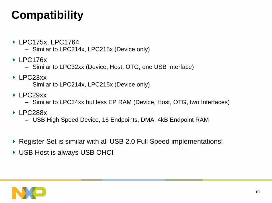
Compatibility
LPC175x, LPC1764– Similar to LPC214x, LPC215x (Device only)
LPC176x– Similar to LPC32xx (Device, Host, OTG, one USB Interface)
LPC23xx– Similar to LPC214x, LPC215x (Device only)
LPC29xx– Similar to LPC24xx but less EP RAM (Device, Host, OTG, two Interfaces)
LPC288x– USB High Speed Device, 16 Endpoints, DMA, 4kB Endpoint RAM
Register Set is similar with all USB 2.0 Full Speed implementations!USB Host is always USB OHCI
11
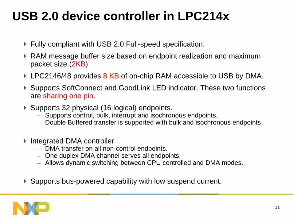
USB 2.0 device controller in LPC214x
Fully compliant with USB 2.0 Full-speed specification.RAM message buffer size based on endpoint realization and maximum packet size.(2KB)LPC2146/48 provides 8 KB of on-chip RAM accessible to USB by DMA.Supports SoftConnect and GoodLink LED indicator. These two functions are sharing one pin.Supports 32 physical (16 logical) endpoints.
– Supports control, bulk, interrupt and isochronous endpoints.– Double Buffered transfer is supported with bulk and isochronous endpoints
Integrated DMA controller– DMA transfer on all non-control endpoints.– One duplex DMA channel serves all endpoints.– Allows dynamic switching between CPU controlled and DMA modes.
Supports bus-powered capability with low suspend current.
12
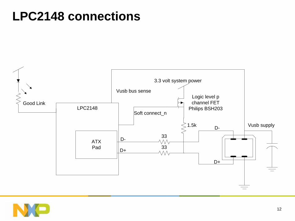
LPC2148 connections
LPC2148
ATXPad
D-
D+
Vusb supply
Good Link
Vusb bus sense
Soft connect_n
D-
D+
33
33
1.5k
Logic level pchannel FET
Philips BSH203
3.3 volt system power
13
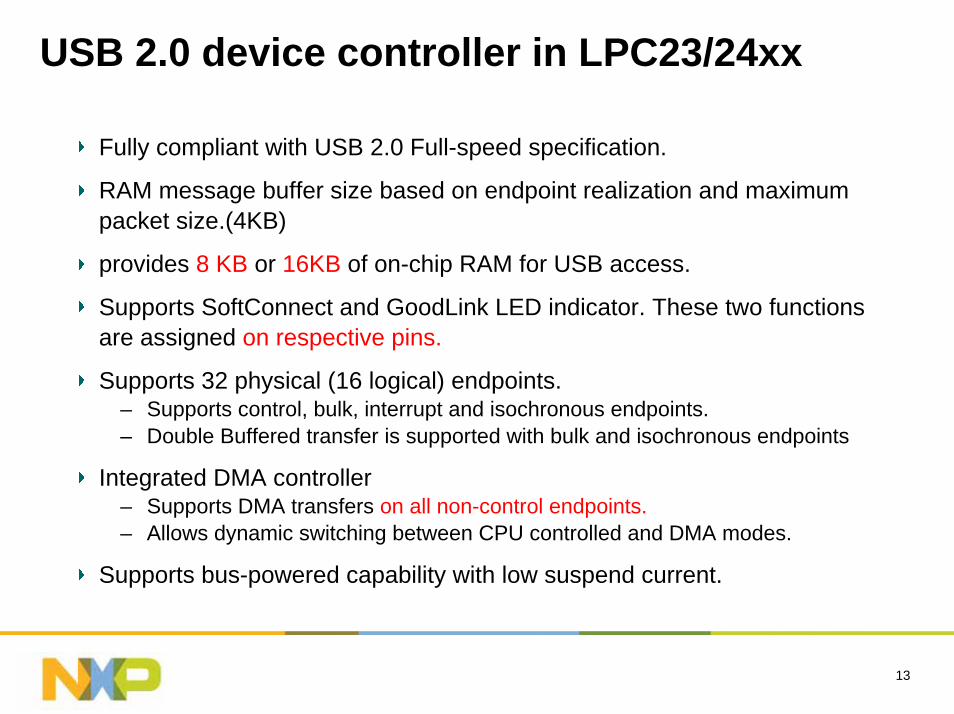
USB 2.0 device controller in LPC23/24xx
Fully compliant with USB 2.0 Full-speed specification.
RAM message buffer size based on endpoint realization and maximum packet size.(4KB)
provides 8 KB or 16KB of on-chip RAM for USB access.
Supports SoftConnect and GoodLink LED indicator. These two functions are assigned on respective pins.
Supports 32 physical (16 logical) endpoints.– Supports control, bulk, interrupt and isochronous endpoints.– Double Buffered transfer is supported with bulk and isochronous endpoints
Integrated DMA controller– Supports DMA transfers on all non-control endpoints.– Allows dynamic switching between CPU controlled and DMA modes.
Supports bus-powered capability with low suspend current.
14
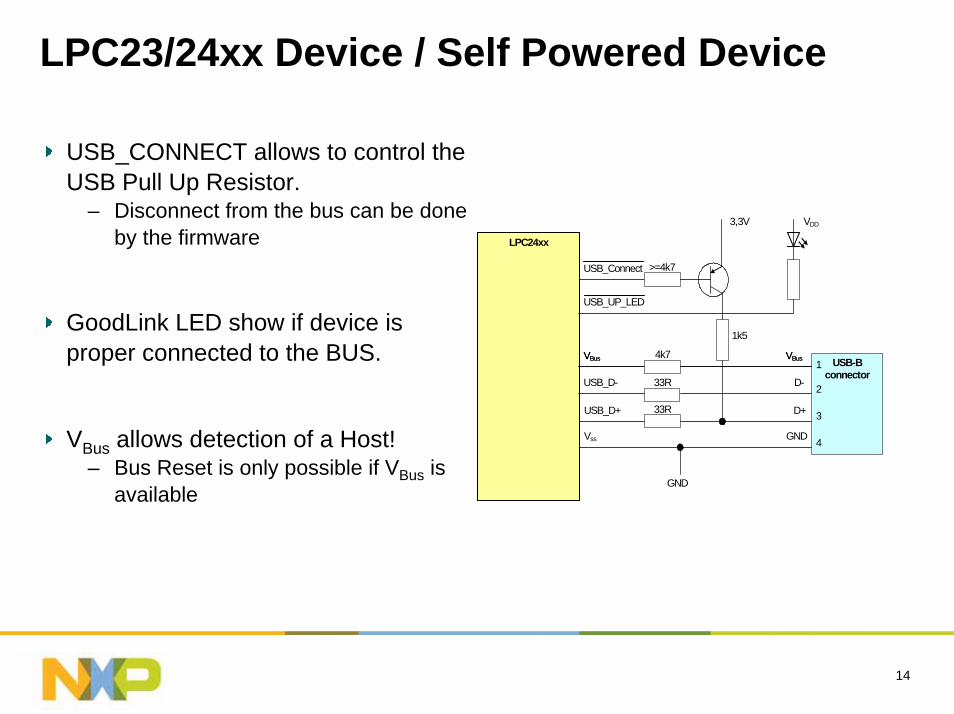
LPC23/24xx Device / Self Powered Device
USB_CONNECT allows to control the USB Pull Up Resistor.
– Disconnect from the bus can be done by the firmware
GoodLink LED show if device is proper connected to the BUS.
VBus allows detection of a Host!– Bus Reset is only possible if VBus is
available
LPC24xx
USB-B connector
1k5
3,3V
33R D+ USB_D+
33R D- USB_D-
Vss
VBus VBus
GND
1
2
3
4
USB_Connect
VDD
USB_UP_LED
VBus VBus 4k7
GND
>=4k7
15
USB 2.0 host controller in LPC23/24xx
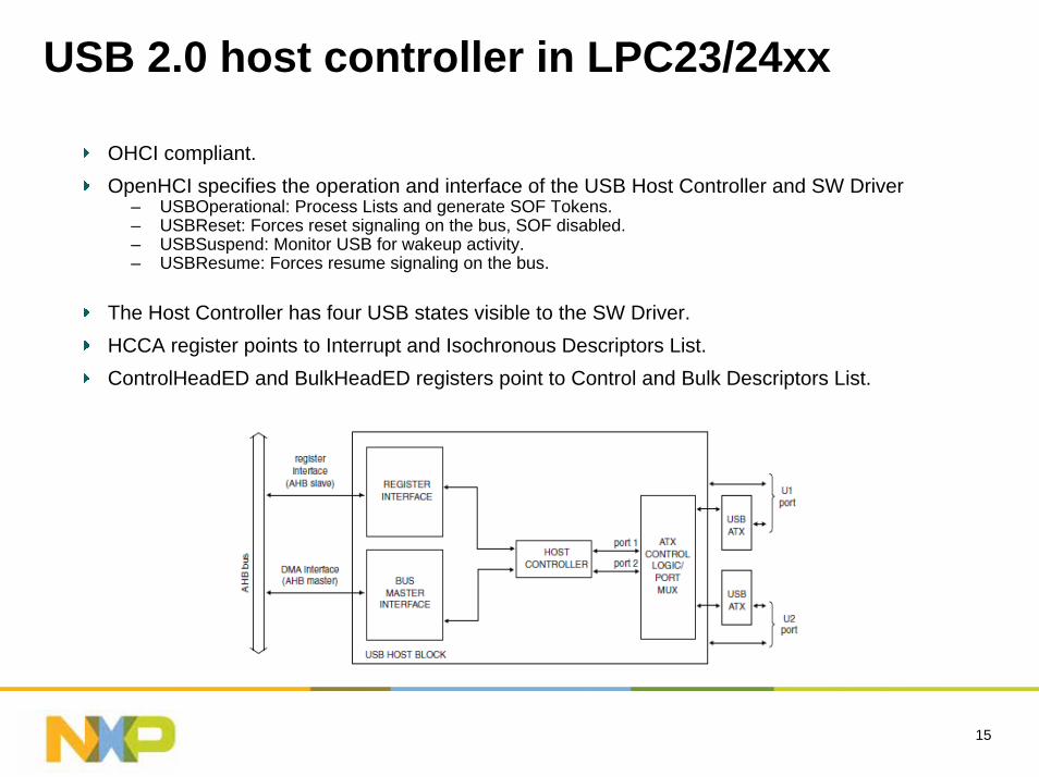
OHCI compliant.OpenHCI specifies the operation and interface of the USB Host Controller and SW Driver
– USBOperational: Process Lists and generate SOF Tokens.– USBReset: Forces reset signaling on the bus, SOF disabled.– USBSuspend: Monitor USB for wakeup activity.– USBResume: Forces resume signaling on the bus.
The Host Controller has four USB states visible to the SW Driver.HCCA register points to Interrupt and Isochronous Descriptors List.ControlHeadED and BulkHeadED registers point to Control and Bulk Descriptors List.
16
USB 2.0 OTG controller in LPC23/24xx
integrates the (OHCI) host controller, device controller, and I2C. The I2C interface (Master only) controls an external OTG transceiver.
Fully compliant with On-The-Go supplement to the USB 2.0 Specification, Revision 1.0a.
Hardware support for Host Negotiation Protocol (HNP).
Includes a programmable timer required for HNP and SRP.
Supports any OTG transceiver compliant with the OTG ransceiverSpecification (CEA-2011), Rev. 1.0.
17
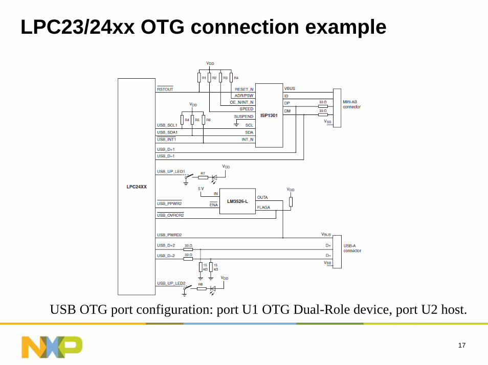
LPC23/24xx OTG connection example
USB OTG port configuration: port U1 OTG Dual-Role device, port U2 host.
18
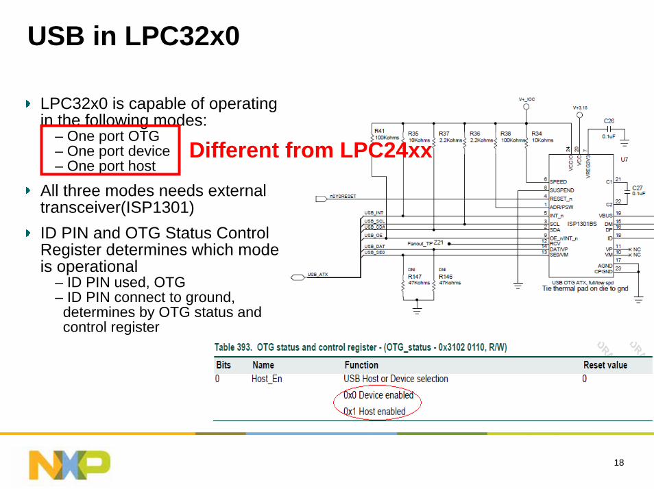
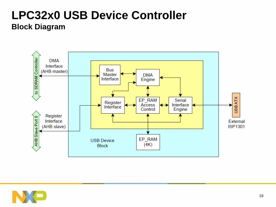
LPC32x0 is capable of operating in the following modes:
– One port OTG– One port device– One port host
All three modes needs external transceiver(ISP1301)ID PIN and OTG Status Control Register determines which mode is operational
– ID PIN used, OTG– ID PIN connect to ground, determines by OTG status and control register
Different from LPC24xx
USB in LPC32x0
19
LPC32x0 USB Device ControllerBlock Diagram
20
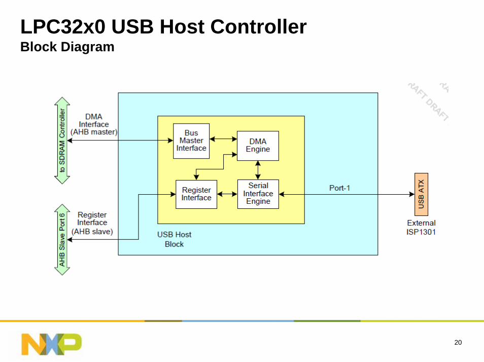
LPC32x0 USB Host ControllerBlock Diagram
21
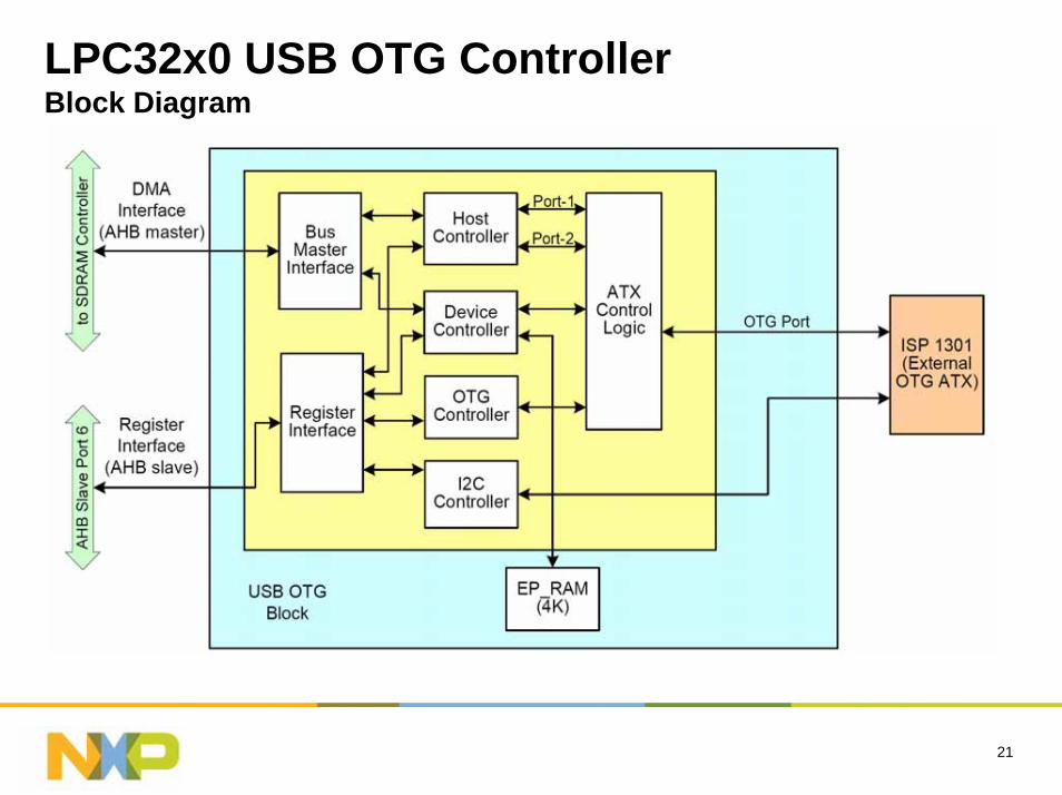
LPC32x0 USB OTG ControllerBlock Diagram

22
Resource
23
Resource
For all the USB resource please click:
http://www.standardics.nxp.com/support/microcontrollers/ethernet/#Introduction
– Discover...
– NXP's advantage– Products– Support– Sales literature and more information– LPC1700 - highest performance Cortex-M3
24
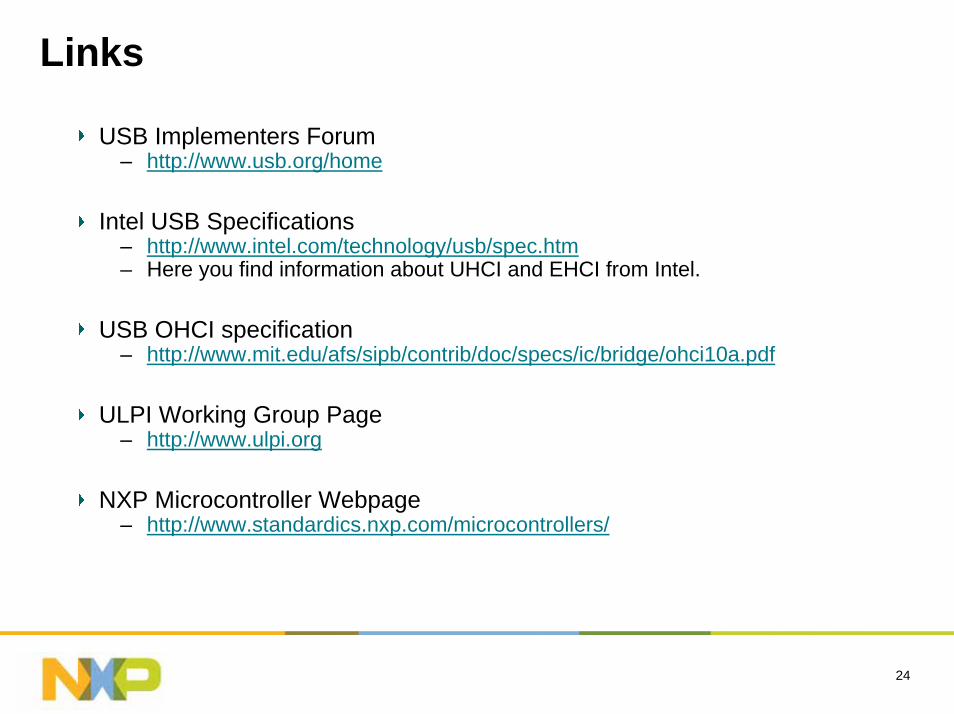
Links
USB Implementers Forum– http://www.usb.org/home
Intel USB Specifications – http://www.intel.com/technology/usb/spec.htm– Here you find information about UHCI and EHCI from Intel.
USB OHCI specification – http://www.mit.edu/afs/sipb/contrib/doc/specs/ic/bridge/ohci10a.pdf
ULPI Working Group Page – http://www.ulpi.org
NXP Microcontroller Webpage– http://www.standardics.nxp.com/microcontrollers/
25
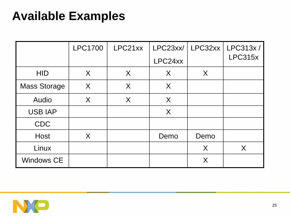
Available Examples
LPC1700 LPC21xx LPC23xx/
LPC24xx
LPC32xx LPC313x / LPC315x
HID X X X X
Mass Storage X X X
Audio X X XUSB IAP X
CDCHost X Demo DemoLinux X X
Windows CE X
Ethernet
27
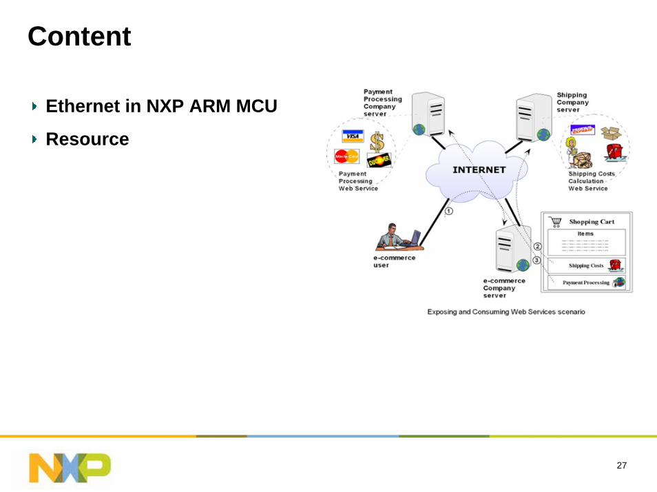
Content
Ethernet in NXP ARM MCU
Resource
28
Ethernet in NXP ARM MCU
29
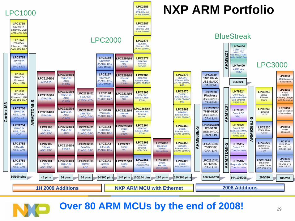
NXP ARM Portfolio
LPC214264K/16K
2* ADC, DAC
LPC214132K/8K
ADC
LPC2144128K/16K
2* ADC, DAC
LPC2146256K/40K
2* ADC, DAC
LPC2148512K/40K
2* ADC, DAC
LPC2132/0164K/16K
2* ADC, DAC
LPC2131/0132K/8K
ADC
LPC2134/01128K/16K
2* ADC, DAC
LPC2136/01256K/32K
2* ADC, DAC
LPC2138/01512K/32K
2* ADC, DAC
LPC2124/01256K/16K
ADC
LPC2114/01128K/16K
ADC
LPC2119/01128K/16K
ADC2* CAN
LPC2129/01256K/16K
ADC2* CAN
LPC2194/01256K/16K
ADC4* CAN
LPC210216K/4K
ADC, RTC
LPC21018K/2K
ADC, RTC
LPC210332K/8K
ADC, RTC
LPC2105/01128K/32K
LPC2106/01128K/64K
LPC22200K/64K
ADC
LPC2210/010K/16K
ADC
LPC2212/01128K/16K
ADC
LPC2214/01256K/16K
ADC
LPC2292/01256K/16K
ADC2* CAN
LPC2290/010K/16K
ADC2* CAN
LPC2294/01256K/16K
ADC4* CAN
LPC2366256K/58K
Ethernet, USB 2*CAN
LPC2364128K/34K
Ethernet, USB 2*CAN
LPC2368512K/58K
Ethernet, USB 2*CAN, SD/MMC
LPC2378512K/58K
Ethernet, USB2*CAN, SD/MMC
LPC28800K/64KHS USB
Stereo Codec
LPC28881024K/64K
HSUSBStereo Codec
48 pins 64 pins 64 pins 64/100 pins 144 pins 180/208 pins180 pins100/144 pins
LPC2468512K/96K
Ethernet, OTG 2*CAN, SD/MMC
LPC2458512K/96K
Ethernet, OTG 2*CAN, SD/MMC
LPC2109/0164K/8K
AR
M92
6EJ-
S
AR
M7T
DM
I-S
296/320
LPC2000
LPC3000
LH7540xGrayscale LCDTouchscreen
LH7541xColor LCD
Touchscreen
LH79520Color LCD
MMU
LH79524Color LCD
Touchscreen,MMUUSB, Ethernet,
NAND Boot
AR
M72
0T
LH7A400Color LCD
MMU
LH7A404Color LCDMMU, TSC
USB Host, Frame buffer, NAND Boot
AR
M92
2T
LH79525Color LCD
Touchscreen,MMUUSB, Ethernet,
NAND Boot
AR
M7T
DM
I-S
144/176/208
256/324
BlueStreak
LPC24600K/96K
Ethernet, OTG 2*CAN, SD/MMC
100/144/208
1H 2009 Additions
LPC2478512K/96K
Ethernet, OTG 2*CAN, SD/MMC
LCD
LPC24700K/96K
Ethernet, OTG 2*CAN, SD/MMC
LCD
LPC2387512K/96K
Ethernet, USB2*CAN, SD/MMC
LPC2388512K/96K
OTG, Ethernet2*CAN, SD/MMC
LPC2158512K/40K
2* ADC, DACLCD Driver
LPC2157512K/32K
2* ADC, DACLCD Driver
80/100 pins
Over 80 ARM MCUs by the end of 2008!
LPC1000
LPC2365/67256-512K/58K
Ethernet,SD/MMC
LPC2377512K/58KEthernet,SD/MMC
LPC24200K/82K
USB D/H/OTG
LPC2362128K/58KEthernet,
USB, CAN
LPC236164K/34K
USB D/H/OTGCAN
LPC2104/01128K/16K
LPC2105/01128K/32K
LPC2106/01128K/64K
LPC3180/0164K SRAM
32+32K CacheVFP, USB OTG
LPC3220128KB SRAM
+ SRAM i/f+ I2S
LPC3230256KB SRAM
+LCDC
LPC3240+ Ethernet
- LCDC
LPC3250256KB
EthernetLCDC
LPC313096K SRAM
HS USB OTGA/D, I2S, I2C
Cor
tex-
M3
LPC175264K/16K
USB, CAN
LPC175132K/8K
USB, CAN
LPC1754128K/32KUSB, CAN
DAC
LPC1756256K/32KUSB, CANDAC, I2S
LPC1764128K/32KEthernet
CAN, USB
LPC1758512K/64K
Ethernet, USBCAN, I2S, DAC
LPC1765256K/64K
USBDAC & I2S
LPC1766256K/64K
Ethernet, USBCAN, I2S, DAC
LPC1768512K/64K
Ethernet, USBCAN,DAC, I2S
LPC3131192K SRAM
HS USB OTGA/D, I2S, I2C
LPC3151+OTP
+ Unique ID
LPC3154+ AES Decryption
+ Secure Boot
180/208
LPC3153+ AES Decryption
+ Secure Boot
LPC3152+ PSU
+ CODEC + Battery Charger- AES Decryption
2008 Additions
AR
M96
8E-S
LPC2919/01768K/48KCAN, LIN
LPC2917/01512K/48KCAN, LIN
LPC292523/21128-512K
USB,5vADCCAN, LIN
LPC29391MB FlashUSB,5vADC
CAN,EMI
LPC2930Flashless
USB,5vADCCAN,EMI
LPC2929/27768K-512KUSB,5vADC
CAN, LIN
NXP ARM MCU with Ethernet
30
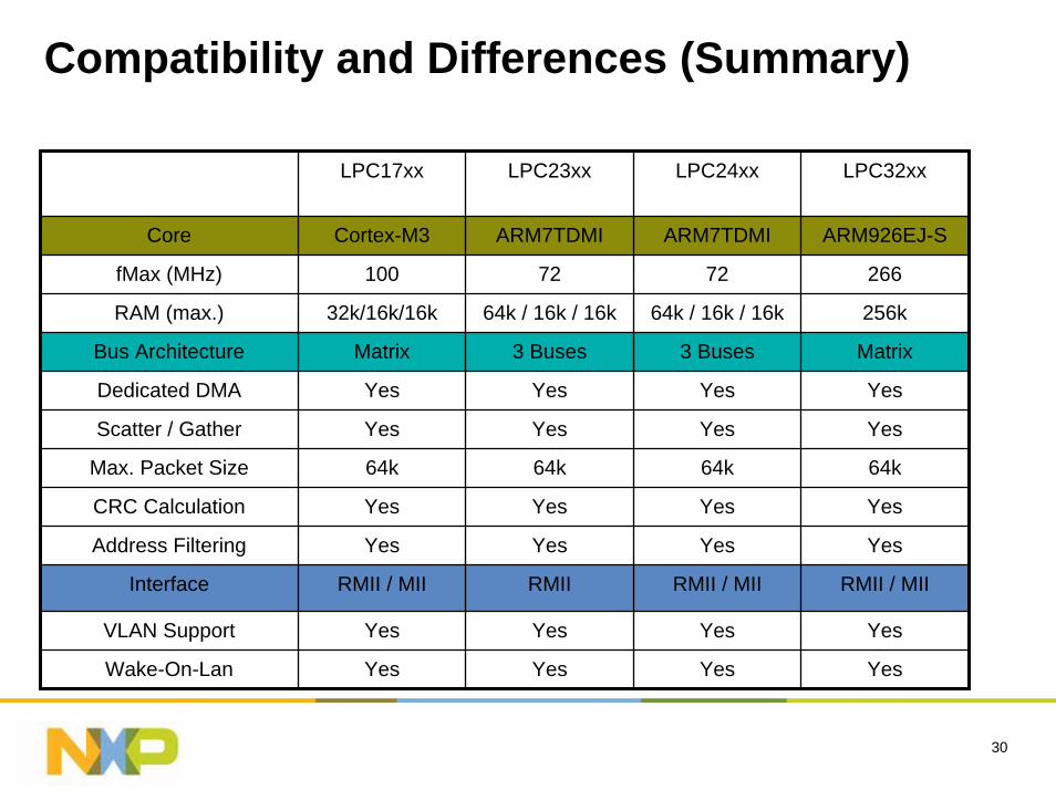
Compatibility and Differences (Summary)
LPC17xx LPC23xx LPC24xx LPC32xx
Core Cortex-M3 ARM7TDMI
72
64k / 16k / 16k
3 Buses
Yes
Yes
Max. Packet Size 64k 64k 64k 64k
CRC Calculation Yes Yes Yes Yes
Address Filtering Yes Yes Yes Yes
Interface RMII / MII RMII RMII / MII RMII / MII
VLAN Support Yes Yes Yes Yes
Wake-On-Lan Yes Yes Yes Yes
ARM7TDMI ARM926EJ-S
fMax (MHz) 100 72 266
RAM (max.) 32k/16k/16k 64k / 16k / 16k 256k
Bus Architecture Matrix 3 Buses Matrix
Dedicated DMA Yes Yes Yes
Scatter / Gather Yes Yes Yes
31
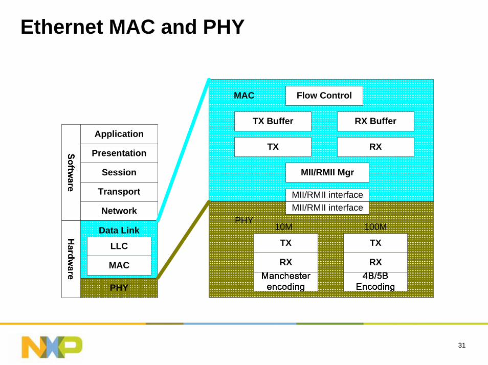
Ethernet MAC and PHY
Application
Presentation
Session
Transport
Network
Data Link
LLC
MAC
PHY
TX
RX
TX
RX
MII/RMII interfaceMII/RMII interface
Flow Control
TX Buffer
TX
RX Buffer
RX
MII/RMII Mgr
10M 100M
MAC
PHY
32
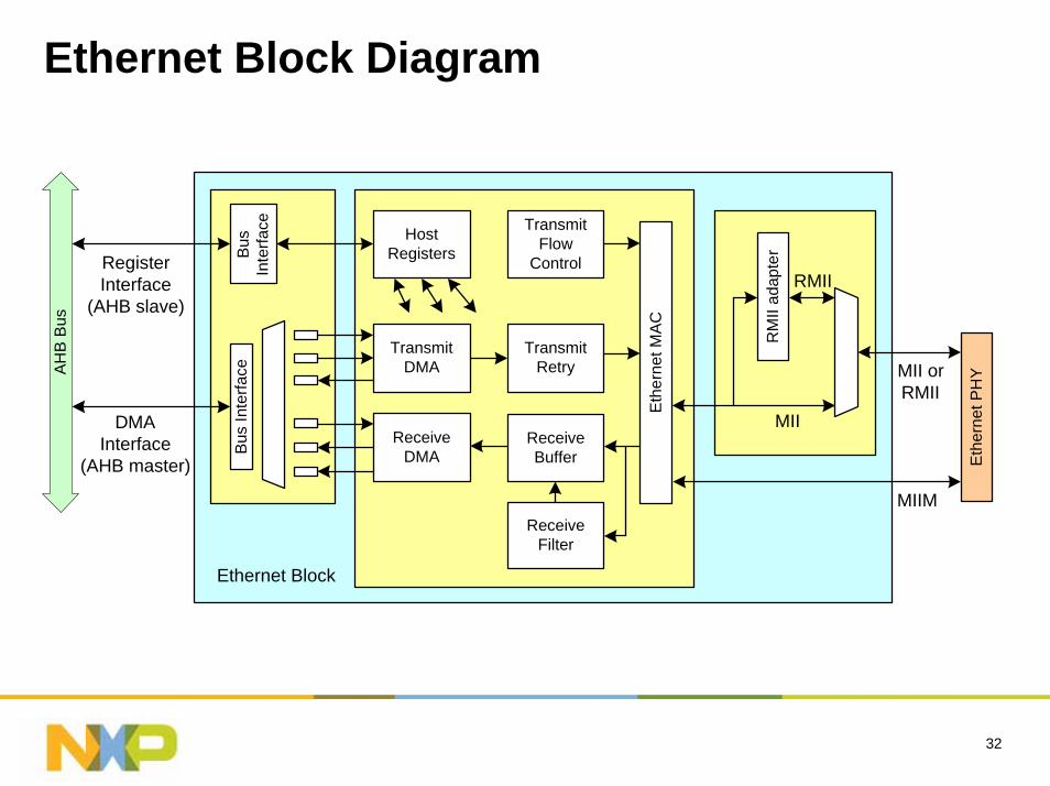
Ethernet Block Diagram
RegisterInterface
(AHB slave)
DMAInterface
(AHB master)
Bus
Inte
rface
ReceiveDMA
TransmitDMA
ReceiveBuffer
ReceiveFilter
TransmitRetry
TransmitFlow
Control
Eth
erne
t MA
C
RM
II ad
apte
r
MII orRMII
MIIM
HostRegisters
AH
B B
us
Ethernet Block
MII
RMII
Eth
erne
t PH
Y
Bus
Inte
rface
33
Ethernet Features: Standards
Supports 10 or 100 Mbps PHY devices including 10Base-T, 100Base-TX, 100 Base-FX, and 100Base-T4.
Fully compliant with IEEE standard 802.3.
Fully compliant with 802.3x Full Duplex Flow Control and Half Duplex back pressure.
Flexible transmit and receive frame options.
VLAN frame support.
34
Ethernet Features: Memory Management
Independent transmit and receive buffers memory mapped to sharedSRAM.
DMA managers with scatter/gather DMA and arrays of frame descriptors.
Memory traffic optimized by buffering and pre-fetching.
35
Ethernet Features: Advanced
Receive filtering: no filter, perfect filter, imperfect filter.
Multicast and broadcast frame support for both transmit and receive.
Optional automatic FCS insertion (CRC) for transmit.
Selectable automatic transmit frame padding (auto 64 byte packet gen.)
Over-length frame support for both transmit and receive allows any length frames.
Promiscuous receive mode (<64 byte packets can be received).
Automatic collision backoff and frame retransmission.
Includes power management by clock switching.
Wake-on-LAN power management support allows system wake-up: using the receive filters or a magic frame detection filter.
36
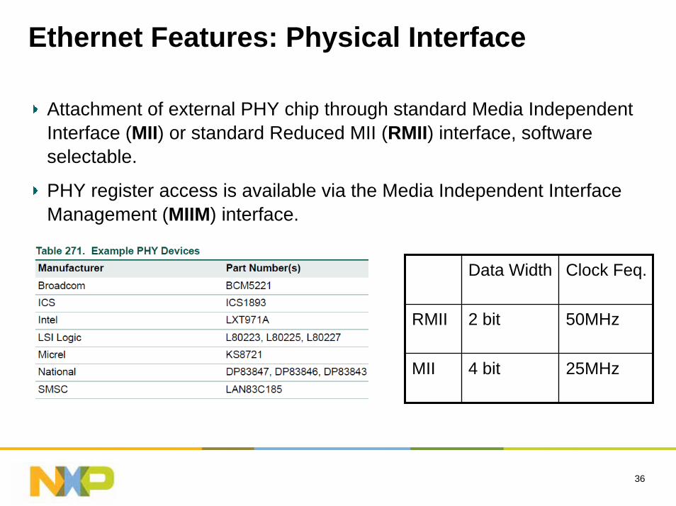
Ethernet Features: Physical Interface
Attachment of external PHY chip through standard Media Independent Interface (MII) or standard Reduced MII (RMII) interface, software selectable.
PHY register access is available via the Media Independent Interface Management (MIIM) interface.
Data Width Clock Feq.
RMII 2 bit 50MHz
MII 4 bit 25MHz

37
Ethernet in LPC23xx/24xx
InternalSRAM
Controller
32 KBSRAM
InternalFlash
Controller
512 KBFlash
ARM7TDMI-S
Em
ul a
tion
Tra
ceM
odul
e
Test/Debug Interface
ARM7 Local Bus
AHBBridge
AHBBridgeAHB2 AHB1
EthernetMAC with
DMA
16 KBSRAM
GP DMAController
VectoredInterrupt
Controller
8 KBSRAM
USB with4KB RAM
& DMAAHB to
APB BridgeAPB
Divider
TR
ST
TD
O
TM
S
TC
K
TD
I
RMII
RS
T
Xta
l1
Xta
l2
SystemFunctions
Internal RCOscillator
PLL
SystemClock
APB
AHB toAHB Bridge
MasterPort
SlavePort
D+, D-,etc.
Tra
ceS
igna
l s
38
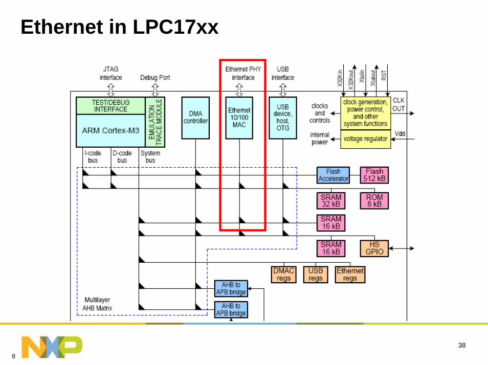
Ethernet in LPC17xx
8
39
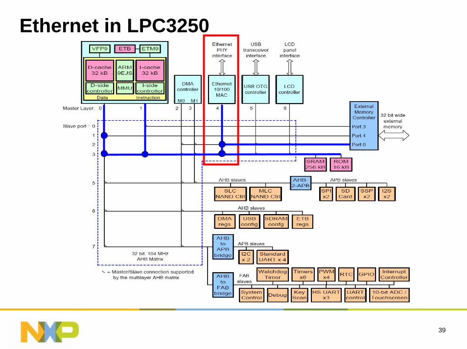
Ethernet in LPC3250

40
Resource
41
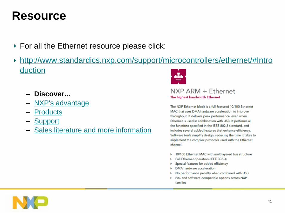
Resource
For all the Ethernet resource please click:
http://www.standardics.nxp.com/support/microcontrollers/ethernet/#Introduction
– Discover...– NXP's advantage– Products– Support– Sales literature and more information
42
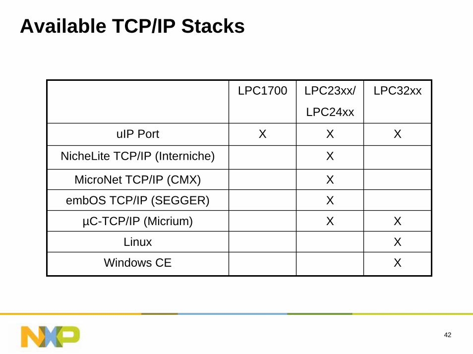
Available TCP/IP Stacks
LPC1700 LPC23xx/
LPC24xx
LPC32xx
uIP Port X X X
NicheLite TCP/IP (Interniche) X
MicroNet TCP/IP (CMX) X
embOS TCP/IP (SEGGER) X
µC-TCP/IP (Micrium) X X
Linux X
Windows CE X
LCD
44
Content
LCD in NXP ARM MCU
System issues to consider
Resource
45
LCD in NXP ARM MCU
46
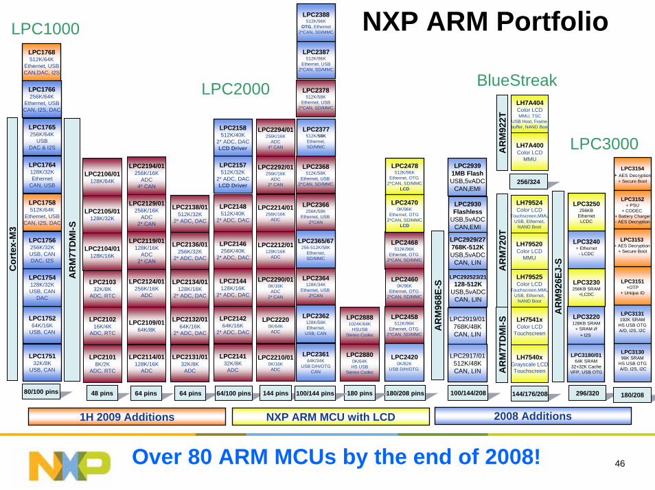
NXP ARM Portfolio
LPC214264K/16K
2* ADC, DAC
LPC214132K/8K
ADC
LPC2144128K/16K
2* ADC, DAC
LPC2146256K/40K
2* ADC, DAC
LPC2148512K/40K
2* ADC, DAC
LPC2132/0164K/16K
2* ADC, DAC
LPC2131/0132K/8K
ADC
LPC2134/01128K/16K
2* ADC, DAC
LPC2136/01256K/32K
2* ADC, DAC
LPC2138/01512K/32K
2* ADC, DAC
LPC2124/01256K/16K
ADC
LPC2114/01128K/16K
ADC
LPC2119/01128K/16K
ADC2* CAN
LPC2129/01256K/16K
ADC2* CAN
LPC2194/01256K/16K
ADC4* CAN
LPC210216K/4K
ADC, RTC
LPC21018K/2K
ADC, RTC
LPC210332K/8K
ADC, RTC
LPC2105/01128K/32K
LPC2106/01128K/64K
LPC22200K/64K
ADC
LPC2210/010K/16K
ADC
LPC2212/01128K/16K
ADC
LPC2214/01256K/16K
ADC
LPC2292/01256K/16K
ADC2* CAN
LPC2290/010K/16K
ADC2* CAN
LPC2294/01256K/16K
ADC4* CAN
LPC2366256K/58K
Ethernet, USB 2*CAN
LPC2364128K/34K
Ethernet, USB 2*CAN
LPC2368512K/58K
Ethernet, USB 2*CAN, SD/MMC
LPC2378512K/58K
Ethernet, USB2*CAN, SD/MMC
LPC28800K/64KHS USB
Stereo Codec
LPC28881024K/64K
HSUSBStereo Codec
48 pins 64 pins 64 pins 64/100 pins 144 pins 180/208 pins180 pins100/144 pins
LPC2468512K/96K
Ethernet, OTG 2*CAN, SD/MMC
LPC2458512K/96K
Ethernet, OTG 2*CAN, SD/MMC
LPC2109/0164K/8K
AR
M92
6EJ-
S
AR
M7T
DM
I-S
296/320
LPC2000
LPC3000
LH7540xGrayscale LCDTouchscreen
LH7541xColor LCD
Touchscreen
LH79520Color LCD
MMU
LH79524Color LCD
Touchscreen,MMUUSB, Ethernet,
NAND Boot
AR
M72
0T
LH7A400Color LCD
MMU
LH7A404Color LCDMMU, TSC
USB Host, Frame buffer, NAND Boot
AR
M92
2T
LH79525Color LCD
Touchscreen,MMUUSB, Ethernet,
NAND Boot
AR
M7T
DM
I-S
144/176/208
256/324
BlueStreak
LPC24600K/96K
Ethernet, OTG 2*CAN, SD/MMC
100/144/208
LPC2478512K/96K
Ethernet, OTG 2*CAN, SD/MMC
LCD
LPC24700K/96K
Ethernet, OTG 2*CAN, SD/MMC
LCD
LPC2387512K/96K
Ethernet, USB2*CAN, SD/MMC
LPC2388512K/96K
OTG, Ethernet2*CAN, SD/MMC
LPC2158512K/40K
2* ADC, DACLCD Driver
LPC2157512K/32K
2* ADC, DACLCD Driver
80/100 pins
Over 80 ARM MCUs by the end of 2008!
LPC1000
LPC2365/67256-512K/58K
Ethernet,SD/MMC
LPC2377512K/58KEthernet,SD/MMC
LPC24200K/82K
USB D/H/OTG
LPC2362128K/58KEthernet,
USB, CAN
LPC236164K/34K
USB D/H/OTGCAN
LPC2104/01128K/16K
LPC2105/01128K/32K
LPC2106/01128K/64K
LPC3180/0164K SRAM
32+32K CacheVFP, USB OTG
LPC3220128KB SRAM
+ SRAM i/f+ I2S
LPC3230256KB SRAM
+LCDC
LPC3240+ Ethernet
- LCDC
LPC3250256KB
EthernetLCDC
LPC313096K SRAM
HS USB OTGA/D, I2S, I2C
Cor
tex-
M3
LPC175264K/16K
USB, CAN
LPC175132K/8K
USB, CAN
LPC1754128K/32KUSB, CAN
DAC
LPC1756256K/32KUSB, CANDAC, I2S
LPC1764128K/32KEthernet
CAN, USB
LPC1758512K/64K
Ethernet, USBCAN, I2S, DAC
LPC1765256K/64K
USBDAC & I2S
LPC1766256K/64K
Ethernet, USBCAN, I2S, DAC
LPC1768512K/64K
Ethernet, USBCAN,DAC, I2S
LPC3131192K SRAM
HS USB OTGA/D, I2S, I2C
LPC3151+OTP
+ Unique ID
LPC3154+ AES Decryption
+ Secure Boot
180/208
LPC3153+ AES Decryption
+ Secure Boot
LPC3152+ PSU
+ CODEC + Battery Charger- AES Decryption
AR
M96
8E-S
LPC2919/01768K/48KCAN, LIN
LPC2917/01512K/48KCAN, LIN
LPC292523/21128-512K
USB,5vADCCAN, LIN
LPC29391MB FlashUSB,5vADC
CAN,EMI
LPC2930Flashless
USB,5vADCCAN,EMI
LPC2929/27768K-512KUSB,5vADC
CAN, LIN
1H 2009 Additions 2008 AdditionsNXP ARM MCU with LCD
47
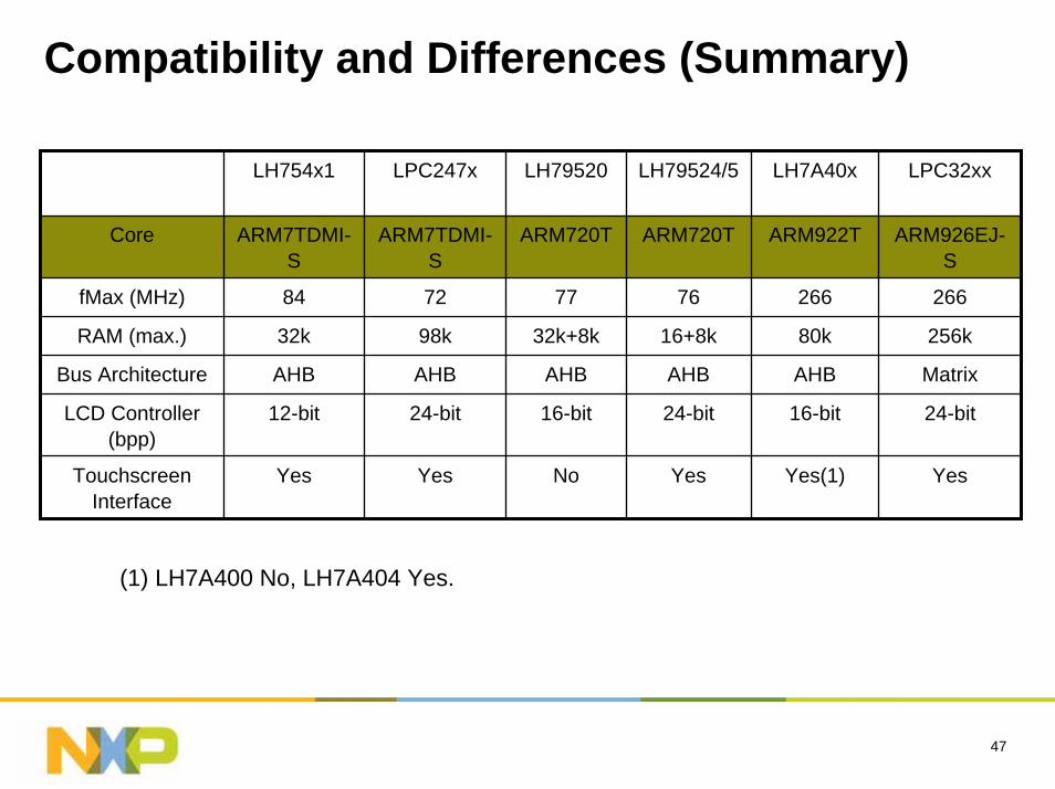
Compatibility and Differences (Summary)
LH754x1 LPC247x LH79520 LH79524/5 LH7A40x
ARM720T ARM922T
266
80k
AHB
16-bit
Yes(1)
76
16+8k
AHB
24-bit
Yes
ARM7TDMI-S
72
98k
AHB
24-bit
Yes
LPC32xx
Core ARM7TDMI-S
ARM720T ARM926EJ-S
fMax (MHz) 84 77 266
RAM (max.) 32k 32k+8k 256k
Bus Architecture AHB AHB Matrix
LCD Controller(bpp)
12-bit 16-bit 24-bit
TouchscreenInterface
Yes No Yes
(1) LH7A400 No, LH7A404 Yes.
48
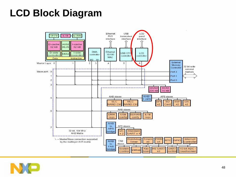
LCD Block Diagram
49
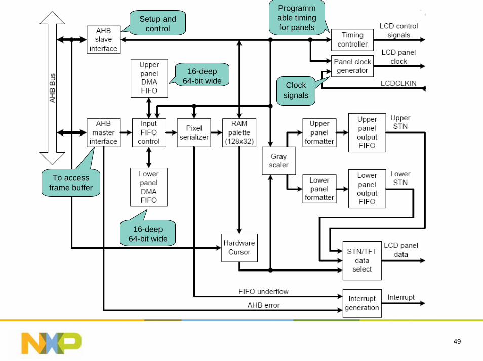
To access frame buffer
Setup and control
16-deep 64-bit wide
16-deep 64-bit wide
Programmable timing for panels
Clock signals
50
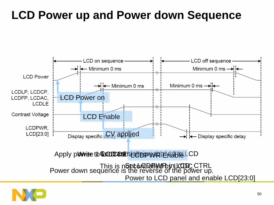
LCD Power up and Power down Sequence
LCD Power on
Apply power to LCD controller
LCD Enable
Write 1 to LCDEN bit in LCD_CTRL
CV applied
Contrast Voltage applied to LCD
This is not controlled by LCDCLCDPWR Enable
Set LCDPWR in LCD_CTRL
Power to LCD panel and enable LCD[23:0]Power down sequence is the reverse of the power up.
51
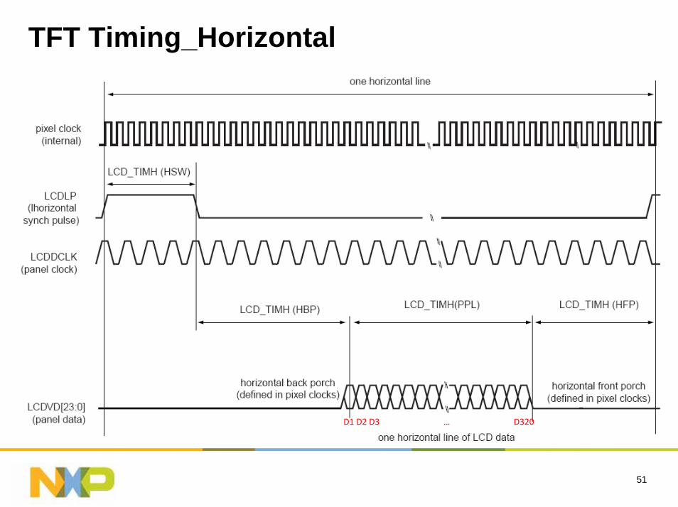
TFT Timing_Horizontal
D1 D2 D3 … D320
52
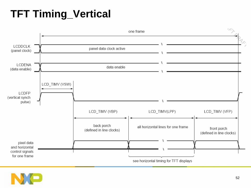
TFT Timing_Vertical
53
TFT Timing
For example:– 320 x 240 pixels– Typically 400 total clocks per line
• 320 clocks for data
• 12 clocks for HSYNC
• Remainder split between front and back porch (use 8 for back porch, 60 for front porch)
– Typically 263 lines per frame• 240 lines
• 2 clocks for VSYNC
• Remainder split between front and back porch (6 required for back porchtherefore use 15 for front porch)
– Assuming 60Hz refresh: 400 x 263 x 60 = 6.31 MHz (spec shows min 4.5 MHz, min 6.8 MHz)
54
System issues to consider
55
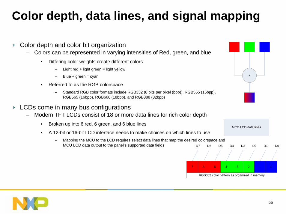
Color depth, data lines, and signal mapping
Color depth and color bit organization– Colors can be represented in varying intensities of Red, green, and blue
• Differing color weights create different colors– Light red + light green = light yellow
– Blue + green = cyan
• Referred to as the RGB colorspace– Standard RGB color formats include RGB332 (8 bits per pixel (bpp)), RGB555 (15bpp),
RGB565 (16bpp), RGB666 (18bpp), and RGB888 (32bpp)
LCDs come in many bus configurations– Modern TFT LCDs consist of 18 or more data lines for rich color depth
• Broken up into 6 red, 6 green, and 6 blue lines
• A 12-bit or 16-bit LCD interface needs to make choices on which lines to use– Mapping the MCU to the LCD requires select data lines that map the desired colorspace and
MCU LCD data output to the panel’s supported data fields
+
2 01347 6 5
RGB332 color pattern as organized in memory
MCD LCD data lines
D0D7 D6 D5 D4 D3 D2 D1
56
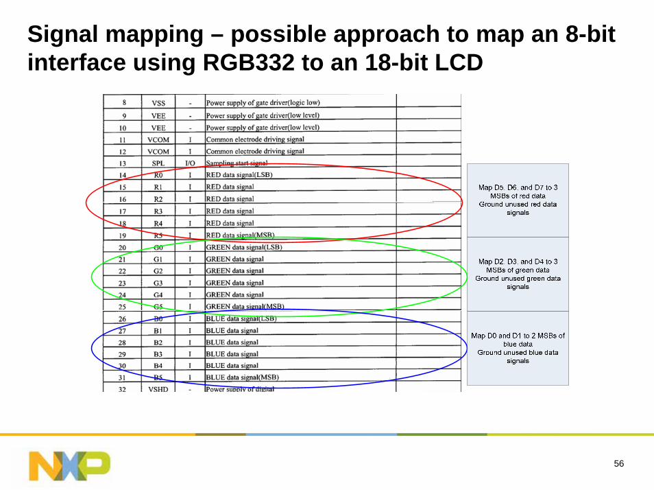
Signal mapping – possible approach to map an 8-bit interface using RGB332 to an 18-bit LCD
57
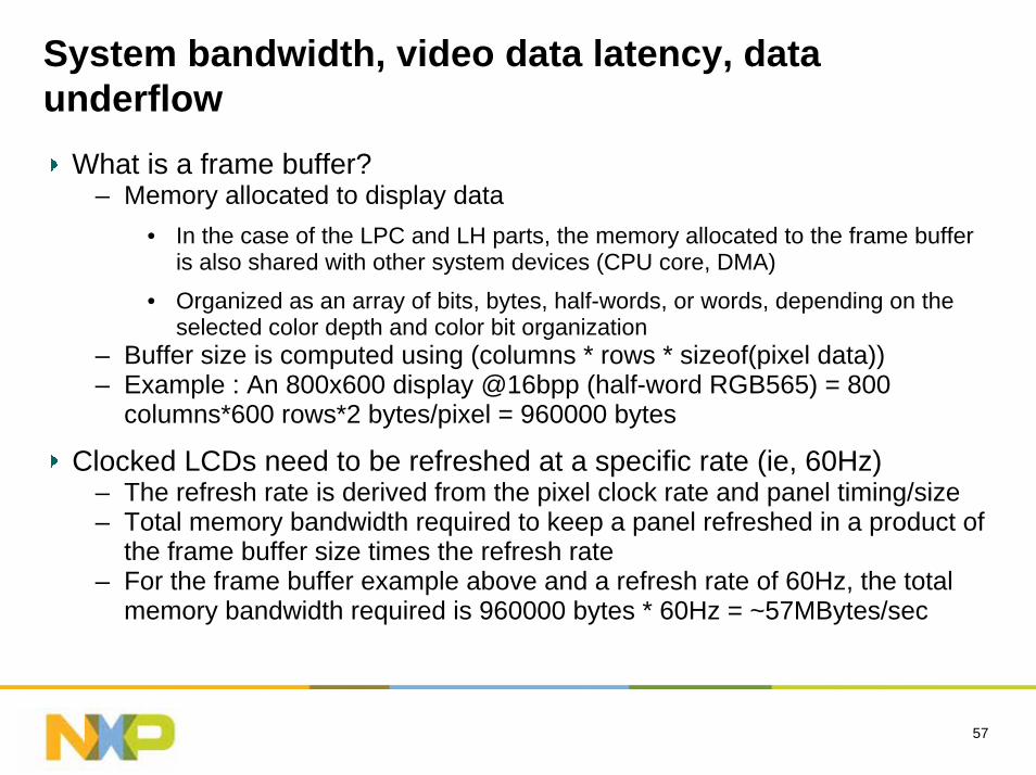
System bandwidth, video data latency, data underflow
What is a frame buffer?– Memory allocated to display data
• In the case of the LPC and LH parts, the memory allocated to the frame buffer is also shared with other system devices (CPU core, DMA)
• Organized as an array of bits, bytes, half-words, or words, depending on the selected color depth and color bit organization
– Buffer size is computed using (columns * rows * sizeof(pixel data))– Example : An 800x600 display @16bpp (half-word RGB565) = 800
columns*600 rows*2 bytes/pixel = 960000 bytes
Clocked LCDs need to be refreshed at a specific rate (ie, 60Hz)– The refresh rate is derived from the pixel clock rate and panel timing/size– Total memory bandwidth required to keep a panel refreshed in a product of
the frame buffer size times the refresh rate– For the frame buffer example above and a refresh rate of 60Hz, the total
memory bandwidth required is 960000 bytes * 60Hz = ~57MBytes/sec
58
System bandwidth, video data latency, data underflow
Memory bandwidth and system bandwidth are different!– System bandwidth takes into account system latencies such as bus
latencies, memory wait states, SDRAM bank/CAS/RAS latencies, etc.– System bandwidth is usually higher (sometimes quite a bit higher) than
memory bandwidth!• This really varies per design, operating system used, etc. and can be really
hard to determine (it’s a estimate at best)– Refreshing the LCD usually takes precedence in a system when getting
control of internal buses• If the LCD is using a lot of system bus bandwidth, other components of the
MCU/system that use the buses will be stalled until the bus is available– This lowers the effective performance of the CPU
– To get an rough idea of LCD system bandwidth used, the LCD calculator can be used
59
System bandwidth, video data latency, data underflow
Systems with high pixel clocks have a greater risk of underflowing the LCD FIFO
– This has little to do with system bandwidth, although systems with high system bandwidth and high pixel clocks are at high risk
– Some system events may prevent the LCD FIFOs from refreshing in time• CPU cache line fills, DMA transfers, CPU burst transfers, etc.
• The LCD FIFO fill is stalled until the bus becomes available again
• The system may seem to perform fine during some testing, but may glitch when brought under load or a specific test
– When the LCD FIFO underflows, a ‘glitch’ will appear on the LCD• Anything under the glitch for the refresh cycle will be skewed
• On the next refresh cycle, the display will return to normal
• The glitch is very noticable– This puts a limit on what the size and refresh rates the LCD controller can
really provide• 1024 x 768 x 24bpp is unrealistic
60
Display driver and off-chip frame buffers
Display driver and off-chip frame buffers– LCDs with MCU buses and built-in frame buffers have unique advantages
and disadvantages• These LCDs are nice in that they only need to be updated when a change is
needed– Reduces use of memory bandwidth when the display doesn’t need constant refresh
– Can kill system performance in systems with lots of video updates
• LCDs with their own frame buffers are usually (much) slower than internal memories, SDRAM/DDR, or other external memories
– Lots of wait states, small bus size (16 bits vs. 32 bits)
– Some operating system write and read the frame buffer– It makes sense to keep a cached copy of the off-chip frame buffer in main
memory and use it as the main frame buffer, flushing out differences to the off-chip frame buffer only when changes occur
– This approach works for some GUI’s such as PEG, but is very hard to manage in WinCE and Linux where it is hard to determine which area has changed
61
Total LCD power usage and backlights
Total LCD power usage– The LCD uses very little power – generation of the electrical fields needed
to position LCD crystals is like driving an open circuit– The ICs used to drive the column/row selection and other active logic uses
very low power• Leakage current and active power current is in the low mW
Backlights– The LCD backlight is a power hog with typical TFT displays using 300mW
or more• Even small TFT LCDs contain 4 LEDs rated at about 20v@18mA total
– STNs aren’t as power hungry as TFTs– The backlight current source circuit will add a little cost to the system
• Usually a fixed or variable current source
• Low-cost reference designs are available

62
Resource
63
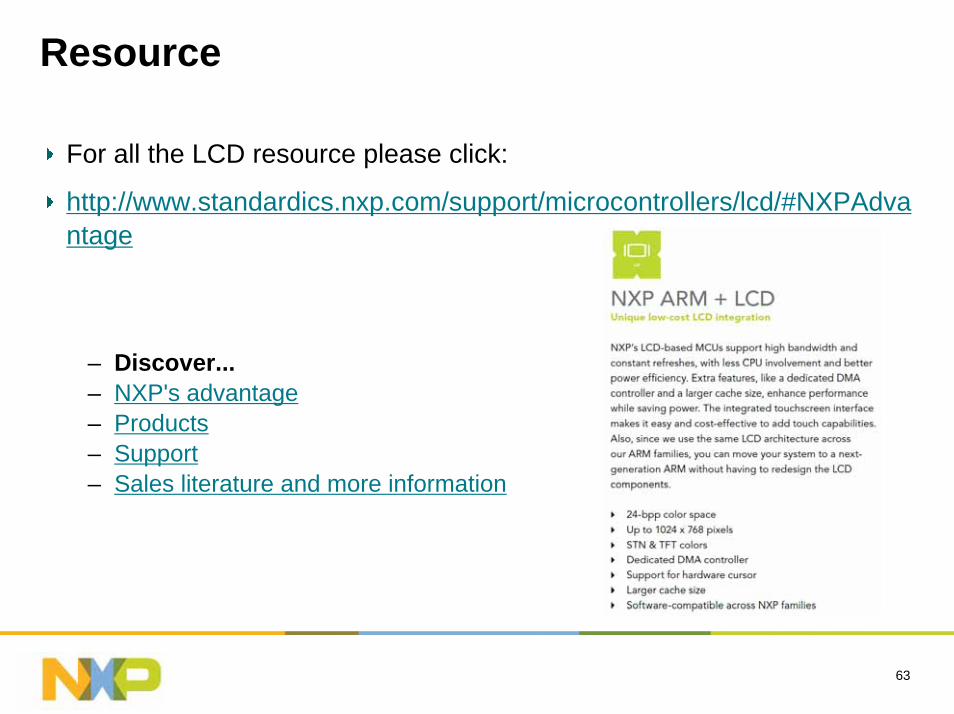
Resource
For all the LCD resource please click:
http://www.standardics.nxp.com/support/microcontrollers/lcd/#NXPAdvantage
– Discover...– NXP's advantage– Products– Support– Sales literature and more information
Motor Control
65
Content
Motor Control in NXP ARM MCU
Control of BLDC Motors using the LPC2900
Resource
66
Motor Control in NXP ARM MCU
67
NXP ARM Portfolio
LPC214264K/16K
2* ADC, DAC
LPC214132K/8K
ADC
LPC2144128K/16K
2* ADC, DAC
LPC2146256K/40K
2* ADC, DAC
LPC2148512K/40K
2* ADC, DAC
LPC2132/0164K/16K
2* ADC, DAC
LPC2131/0132K/8K
ADC
LPC2134/01128K/16K
2* ADC, DAC
LPC2136/01256K/32K
2* ADC, DAC
LPC2138/01512K/32K
2* ADC, DAC
LPC2124/01256K/16K
ADC
LPC2114/01128K/16K
ADC
LPC2119/01128K/16K
ADC2* CAN
LPC2129/01256K/16K
ADC2* CAN
LPC2194/01256K/16K
ADC4* CAN
LPC210216K/4K
ADC, RTC
LPC21018K/2K
ADC, RTC
LPC210332K/8K
ADC, RTC
LPC2105/01128K/32K
LPC2106/01128K/64K
LPC22200K/64K
ADC
LPC2210/010K/16K
ADC
LPC2212/01128K/16K
ADC
LPC2214/01256K/16K
ADC
LPC2292/01256K/16K
ADC2* CAN
LPC2290/010K/16K
ADC2* CAN
LPC2294/01256K/16K
ADC4* CAN
LPC2366256K/58K
Ethernet, USB 2*CAN
LPC2364128K/34K
Ethernet, USB 2*CAN
LPC2368512K/58K
Ethernet, USB 2*CAN, SD/MMC
LPC2378512K/58K
Ethernet, USB2*CAN, SD/MMC
LPC28800K/64KHS USB
Stereo Codec
LPC28881024K/64K
HSUSBStereo Codec
48 pins 64 pins 64 pins 64/100 pins 144 pins 180/208 pins180 pins100/144 pins
LPC2468512K/96K
Ethernet, OTG 2*CAN, SD/MMC
LPC2458512K/96K
Ethernet, OTG 2*CAN, SD/MMC
LPC2109/0164K/8K
AR
M92
6EJ-
S
AR
M7T
DM
I-S
296/320
LPC2000
LPC3000
LH7540xGrayscale LCDTouchscreen
LH7541xColor LCD
Touchscreen
LH79520Color LCD
MMU
LH79524Color LCD
Touchscreen,MMUUSB, Ethernet,
NAND Boot
AR
M72
0T
LH7A400Color LCD
MMU
LH7A404Color LCDMMU, TSC
USB Host, Frame buffer, NAND Boot
AR
M92
2T
LH79525Color LCD
Touchscreen,MMUUSB, Ethernet,
NAND Boot
AR
M7T
DM
I-S
144/176/208
256/324
BlueStreak
LPC24600K/96K
Ethernet, OTG 2*CAN, SD/MMC
100/144/208
LPC2478512K/96K
Ethernet, OTG 2*CAN, SD/MMC
LCD
LPC24700K/96K
Ethernet, OTG 2*CAN, SD/MMC
LCD
LPC2387512K/96K
Ethernet, USB2*CAN, SD/MMC
LPC2388512K/96K
OTG, Ethernet2*CAN, SD/MMC
LPC2158512K/40K
2* ADC, DACLCD Driver
LPC2157512K/32K
2* ADC, DACLCD Driver
80/100 pins
Over 80 ARM MCUs by the end of 2008!
LPC1000
LPC2365/67256-512K/58K
Ethernet,SD/MMC
LPC2377512K/58KEthernet,SD/MMC
LPC24200K/82K
USB D/H/OTG
LPC2362128K/58KEthernet,
USB, CAN
LPC236164K/34K
USB D/H/OTGCAN
LPC2104/01128K/16K
LPC2105/01128K/32K
LPC2106/01128K/64K
LPC3180/0164K SRAM
32+32K CacheVFP, USB OTG
LPC3220128KB SRAM
+ SRAM i/f+ I2S
LPC3230256KB SRAM
+LCDC
LPC3240+ Ethernet
- LCDC
LPC3250256KB
EthernetLCDC
LPC313096K SRAM
HS USB OTGA/D, I2S, I2C
Cor
tex-
M3
LPC175264K/16K
USB, CAN
LPC175132K/8K
USB, CAN
LPC1754128K/32KUSB, CAN
DAC
LPC1756256K/32KUSB, CANDAC, I2S
LPC1764128K/32KEthernet
CAN, USB
LPC1758512K/64K
Ethernet, USBCAN, I2S, DAC
LPC1765256K/64K
USBDAC & I2S
LPC1766256K/64K
Ethernet, USBCAN, I2S, DAC
LPC1768512K/64K
Ethernet, USBCAN,DAC, I2S
LPC3131192K SRAM
HS USB OTGA/D, I2S, I2C
LPC3151+OTP
+ Unique ID
LPC3154+ AES Decryption
+ Secure Boot
180/208
LPC3153+ AES Decryption
+ Secure Boot
LPC3152+ PSU
+ CODEC + Battery Charger- AES Decryption
AR
M96
8E-S
LPC2919/01768K/48KCAN, LIN
LPC2917/01512K/48KCAN, LIN
LPC292523/21128-512K
USB,5vADCCAN, LIN
LPC29391MB FlashUSB,5vADC
CAN,EMI
LPC2930Flashless
USB,5vADCCAN,EMI
LPC2929/27768K-512KUSB,5vADC
CAN, LIN
1H 2009 Additions 2008 AdditionsNXP ARM MCU with Motor Control
68
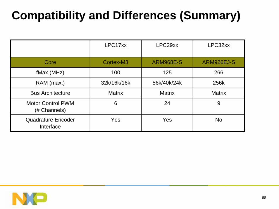
Compatibility and Differences (Summary)
LPC17xx LPC29xx LPC32xx
Core Cortex-M3 ARM968E-S
125
56k/40k/24k
Matrix
Motor Control PWM(# Channels)
6 24 9
Quadrature EncoderInterface
Yes Yes No
ARM926EJ-S
fMax (MHz) 100 266
RAM (max.) 32k/16k/16k 256k
Bus Architecture Matrix Matrix
69
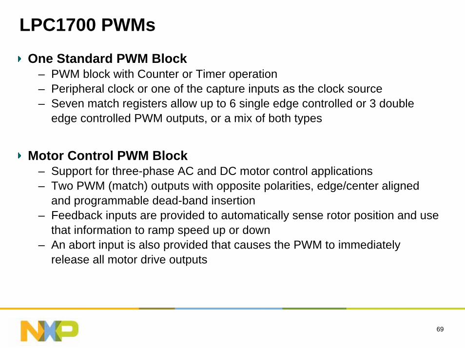
LPC1700 PWMs
One Standard PWM Block– PWM block with Counter or Timer operation– Peripheral clock or one of the capture inputs as the clock source– Seven match registers allow up to 6 single edge controlled or 3 double
edge controlled PWM outputs, or a mix of both types
Motor Control PWM Block– Support for three-phase AC and DC motor control applications– Two PWM (match) outputs with opposite polarities, edge/center aligned
and programmable dead-band insertion– Feedback inputs are provided to automatically sense rotor position and use
that information to ramp speed up or down– An abort input is also provided that causes the PWM to immediately
release all motor drive outputs
70
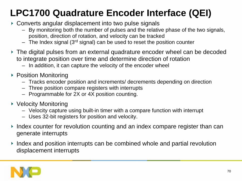
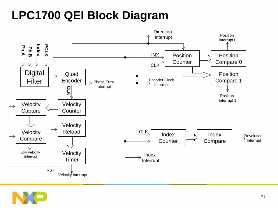
LPC1700 Quadrature Encoder Interface (QEI)Converts angular displacement into two pulse signals
– By monitoring both the number of pulses and the relative phase of the two signals, position, direction of rotation, and velocity can be tracked
– The Index signal (3rd signal) can be used to reset the position counter
The digital pulses from an external quadrature encoder wheel can be decoded to integrate position over time and determine direction of rotation
– In addition, it can capture the velocity of the encoder wheel
Position Monitoring– Tracks encoder position and increments/ decrements depending on direction– Three position compare registers with interrupts– Programmable for 2X or 4X position counting.
Velocity Monitoring– Velocity capture using built-in timer with a compare function with interrupt– Uses 32-bit registers for position and velocity.
Index counter for revolution counting and an index compare register than can generate interrupts
Index and position interrupts can be combined whole and partial revolution displacement interrupts
71
LPC1700 QEI Block Diagram
Digital Filter
Quad Encoder
Velocity Timer
Velocity Counter
Velocity Compare
Velocity Reload
Velocity Capture
Ph APh B
IndexPC
LK
CLK
Velocity InterruptRST
Low Velocity Interrupt
Position Counter
Position Compare 0
Position Compare 1
Index Counter
Index Compare
Direction Interrupt Position
Interrupt 0
Position Interrupt 1
Revolution Interrupt
Phase ErrorInterrupt
CLK
CLK
Encoder ClockInterrupt
INX
Index Interrupt
72
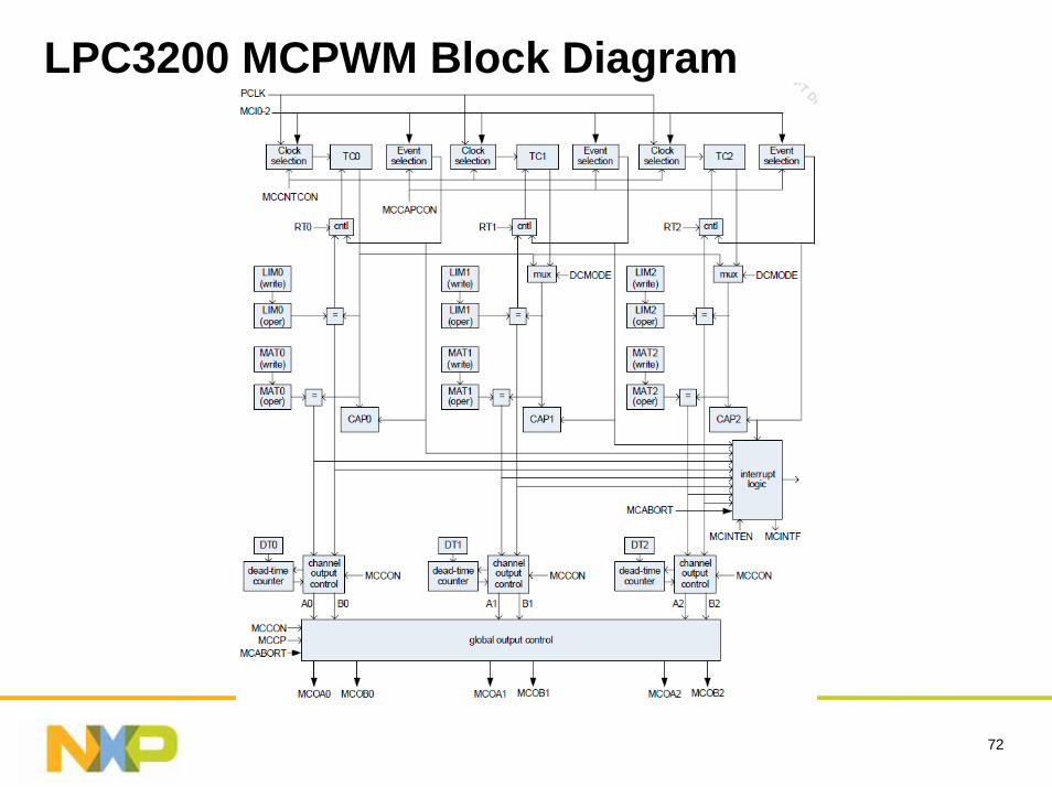
LPC3200 MCPWM Block Diagram
73
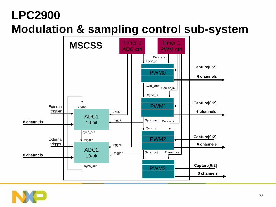
LPC2900Modulation & sampling control sub-system
Timer 0ADC ctrl
Carrier_in
MSCSS Timer 1PWM ctrl
Sync_out
Sync_in
Carrier_in
Externaltrigger
trigger
trigger
trigger
trigger
trigger
Externaltrigger
trigger
sync_out
sync_out
ADC110-bit
ADC210-bit
8 channels
8 channels
Carrier_in
Carrier_in
Sync_out
Sync_out
6 channelsPWM1
Capture[0:2]
6 channelsPWM2 Capture[0:2]
6 channelsPWM3 Capture[0:2]
Sync_in
Sync_in
6 channels
Capture[0:2]PWM0
74
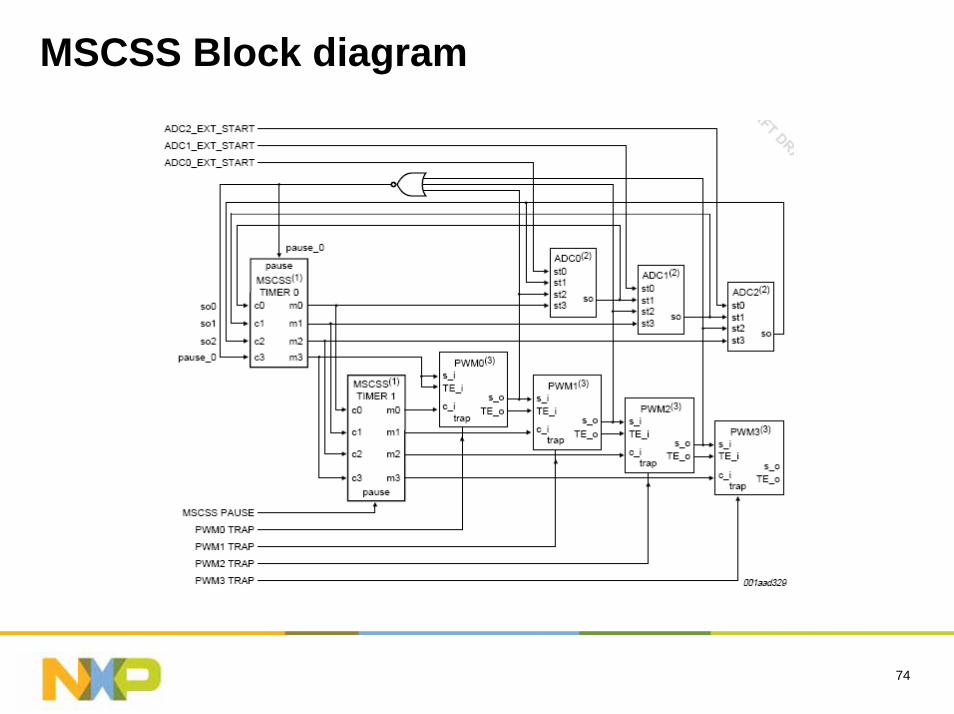
MSCSS Block diagram
75
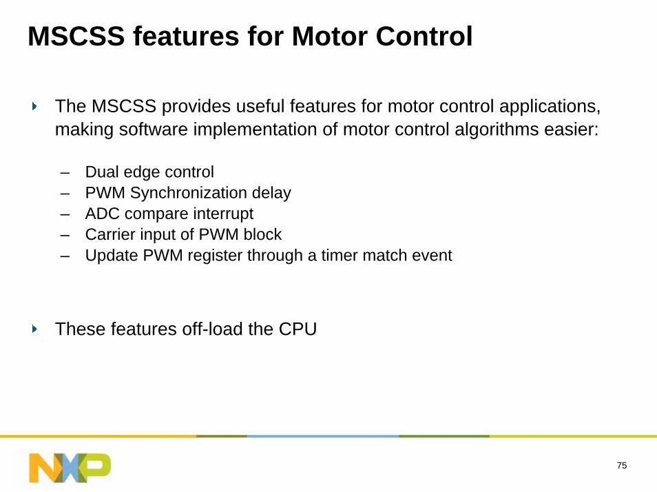
MSCSS features for Motor Control
The MSCSS provides useful features for motor control applications, making software implementation of motor control algorithms easier:
– Dual edge control– PWM Synchronization delay– ADC compare interrupt– Carrier input of PWM block– Update PWM register through a timer match event
These features off-load the CPU
76
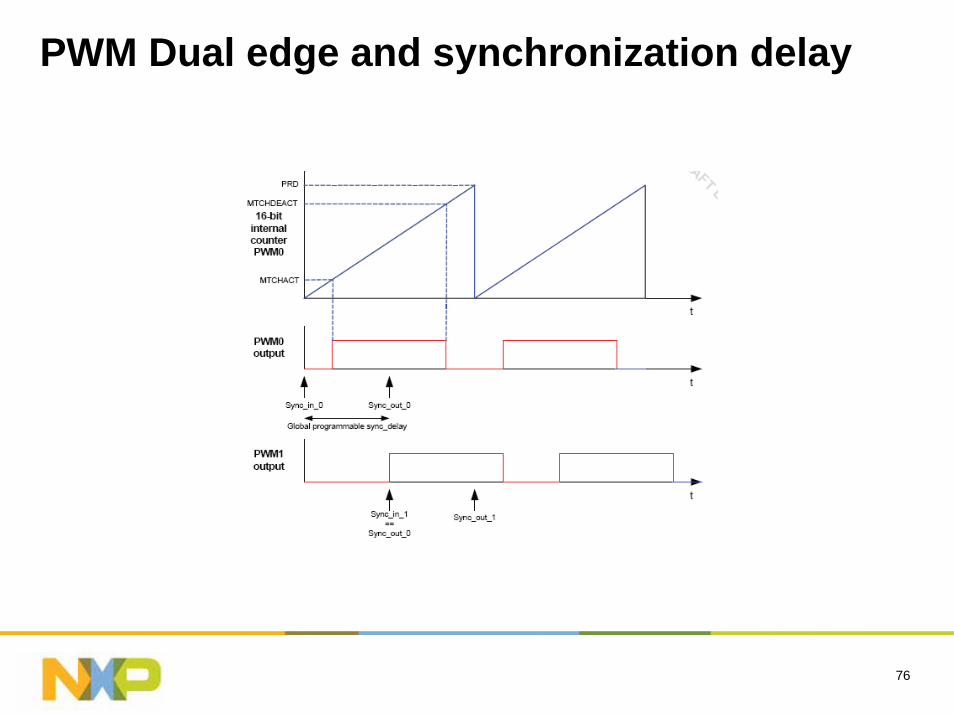
PWM Dual edge and synchronization delay
77
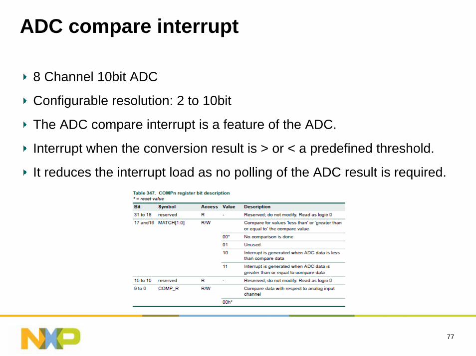
ADC compare interrupt
8 Channel 10bit ADC
Configurable resolution: 2 to 10bit
The ADC compare interrupt is a feature of the ADC.
Interrupt when the conversion result is > or < a predefined threshold.
It reduces the interrupt load as no polling of the ADC result is required.
78
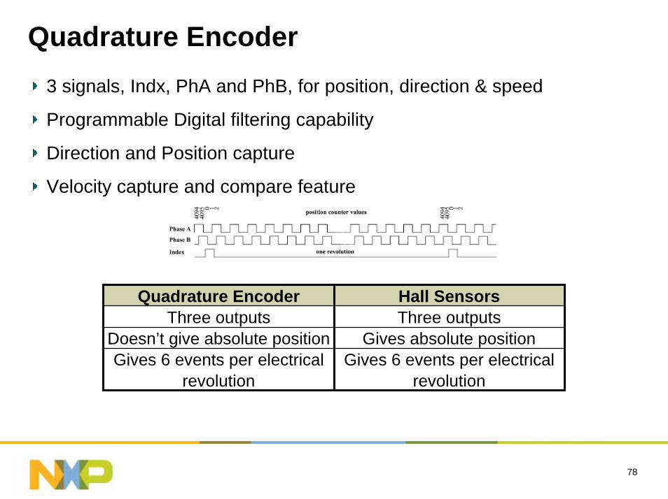
Quadrature Encoder3 signals, Indx, PhA and PhB, for position, direction & speed
Programmable Digital filtering capability
Direction and Position capture
Velocity capture and compare feature
Quadrature Encoder Hall SensorsThree outputs Three outputs
Doesn’t give absolute position Gives absolute positionGives 6 events per electrical
revolutionGives 6 events per electrical
revolution
79
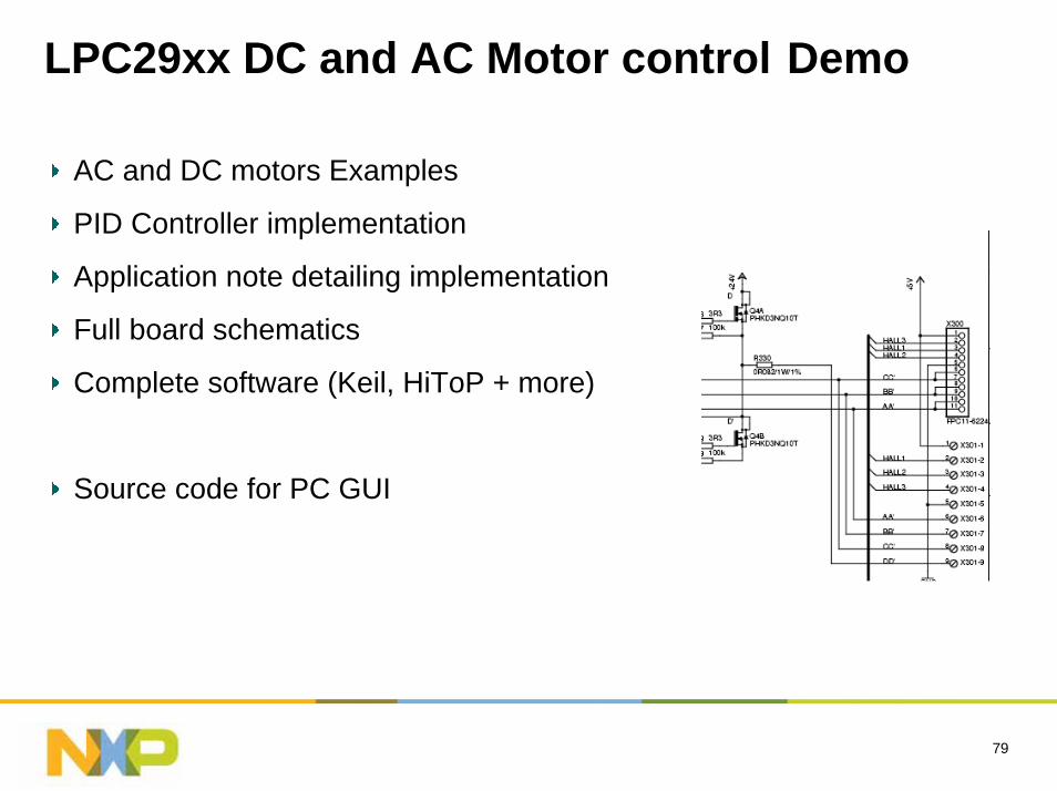
LPC29xx DC and AC Motor control Demo
AC and DC motors Examples
PID Controller implementation
Application note detailing implementation
Full board schematics
Complete software (Keil, HiToP + more)
Source code for PC GUI
80
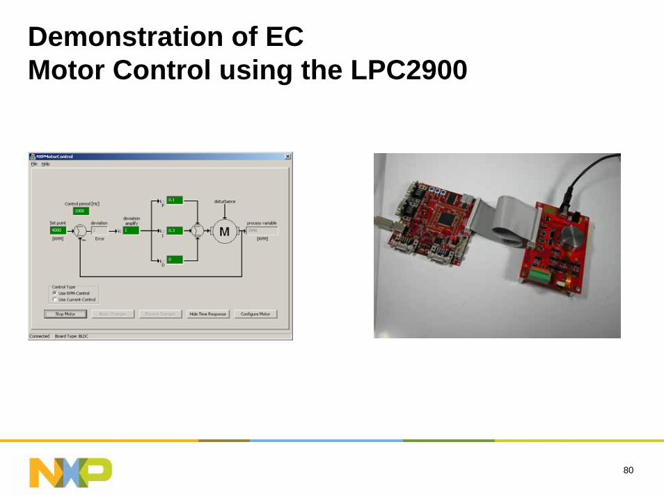
Demonstration of EC Motor Control using the LPC2900
81
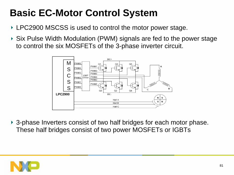
Basic EC-Motor Control SystemLPC2900 MSCSS is used to control the motor power stage.
Six Pulse Width Modulation (PWM) signals are fed to the power stage to control the six MOSFETs of the 3-phase inverter circuit.
3-phase Inverters consist of two half bridges for each motor phase. These half bridges consist of two power MOSFETs or IGBTs
LPC2900
MSCSS

82
Resource
83
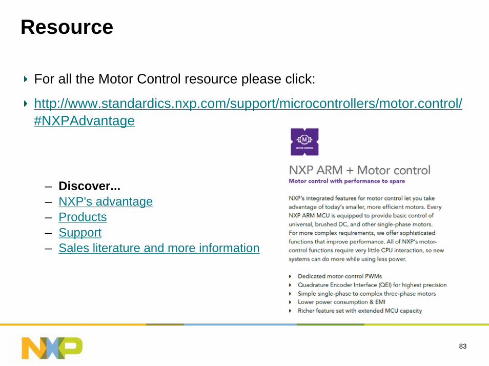
Resource
For all the Motor Control resource please click:
http://www.standardics.nxp.com/support/microcontrollers/motor.control/#NXPAdvantage
– Discover...– NXP's advantage– Products– Support– Sales literature and more information

84
Thanks!