Embed Size (px)
Citation preview

1/15
Technical data sheet: S000092667EN-2 Updated: 18/07/2016 Created: 09/05/2016
Catalogue number(s): 0 026 91KNX Shutter/Blinds actuator 4 outputs, 6A 230V
CONTENT . . . . . . . . . . . . . . . . . . . . . . . . . . . . . . . . . . . . . . . . . . . . . . . . . . . . . . . . . . . . . . . . . . . . . . . . . . . . . . . . . . . . . . . . . . . . . . . . . . . . . . . PAGE
1 . USE . . . . . . . . . . . . . . . . . . . . . . . . . . . . . . . . . . . . . . . . . . . . . . . . . . . . . . . . . . . . . . . . . . . . . . . . . . . . . . . . . . . . . . . . . . . . . . . . . . . . . . . . . . . . . . . . . . . . . . . . . . . . . 2
2 . Technical features . . . . . . . . . . . . . . . . . . . . . . . . . . . . . . . . . . . . . . . . . . . . . . . . . . . . . . . . . . . . . . . . . . . . . . . . . . . . . . . . . . . . . . . . . . . . . . . . . . . . . . . . . . . . . . . 22.1 Electrical features . . . . . . . . . . . . . . . . . . . . . . . . . . . . . . . . . . . . . . . . . . . . . . . . . . . . . . . . . . . . . . . . . . . . . . . . . . . . . . . . . . . . . . . . . . . . . . . . . . . . . . . . . . . . . . . . . . . . . . . . . . . 22.2 Mechanical features . . . . . . . . . . . . . . . . . . . . . . . . . . . . . . . . . . . . . . . . . . . . . . . . . . . . . . . . . . . . . . . . . . . . . . . . . . . . . . . . . . . . . . . . . . . . . . . . . . . . . . . . . . . . . . . . . . . . . . . . . 22.3 Climatic features . . . . . . . . . . . . . . . . . . . . . . . . . . . . . . . . . . . . . . . . . . . . . . . . . . . . . . . . . . . . . . . . . . . . . . . . . . . . . . . . . . . . . . . . . . . . . . . . . . . . . . . . . . . . . . . . . . . . . . . . . . . . 2
3 . Dimensions . . . . . . . . . . . . . . . . . . . . . . . . . . . . . . . . . . . . . . . . . . . . . . . . . . . . . . . . . . . . . . . . . . . . . . . . . . . . . . . . . . . . . . . . . . . . . . . . . . . . . . . . . . . . . . . . . . . . . 2
4 . Connection . . . . . . . . . . . . . . . . . . . . . . . . . . . . . . . . . . . . . . . . . . . . . . . . . . . . . . . . . . . . . . . . . . . . . . . . . . . . . . . . . . . . . . . . . . . . . . . . . . . . . . . . . . . . . . . . . . . . . . 3
5 . Standards and approvals . . . . . . . . . . . . . . . . . . . . . . . . . . . . . . . . . . . . . . . . . . . . . . . . . . . . . . . . . . . . . . . . . . . . . . . . . . . . . . . . . . . . . . . . . . . . . . . . . . . . . . . . . 3
6 . Parameters and communication objects . . . . . . . . . . . . . . . . . . . . . . . . . . . . . . . . . . . . . . . . . . . . . . . . . . . . . . . . . . . . . . . . . . . . . . . . . . . . . . . . . . . . . . . . . . . 36.1 Overview of the function . . . . . . . . . . . . . . . . . . . . . . . . . . . . . . . . . . . . . . . . . . . . . . . . . . . . . . . . . . . . . . . . . . . . . . . . . . . . . . . . . . . . . . . . . . . . . . . . . . . . . . . . . . . . . . . . . . . . 36.1.1 Total move time for UP/DOWN . . . . . . . . . . . . . . . . . . . . . . . . . . . . . . . . . . . . . . . . . . . . . . . . . . . . . . . . . . . . . . . . . . . . . . . . . . . . . . . . . . . . . . . . . . . . . . . . . . . . . . . . . . . . . 36.1.2 Duration of louvre adjustment and Maximum number of louvre adjustments . . . . . . . . . . . . . . . . . . . . . . . . . . . . . . . . . . . . . . . . . . . . . . . . . . . . . . . . . . . . . . . . 36.1.3 Pause on change in direction for the Shutter/Blind movement and louvre adjustment. . . . . . . . . . . . . . . . . . . . . . . . . . . . . . . . . . . . . . . . . . . . . . . . . . . . . . . . 36.1.4 Programming or bus voltage recovery . . . . . . . . . . . . . . . . . . . . . . . . . . . . . . . . . . . . . . . . . . . . . . . . . . . . . . . . . . . . . . . . . . . . . . . . . . . . . . . . . . . . . . . . . . . . . . . . . . . . . . 36.1.5 Reference movement . . . . . . . . . . . . . . . . . . . . . . . . . . . . . . . . . . . . . . . . . . . . . . . . . . . . . . . . . . . . . . . . . . . . . . . . . . . . . . . . . . . . . . . . . . . . . . . . . . . . . . . . . . . . . . . . . . . . . . 46.1.6 Limit move position . . . . . . . . . . . . . . . . . . . . . . . . . . . . . . . . . . . . . . . . . . . . . . . . . . . . . . . . . . . . . . . . . . . . . . . . . . . . . . . . . . . . . . . . . . . . . . . . . . . . . . . . . . . . . . . . . . . . . . . 46.1.7 Preset position . . . . . . . . . . . . . . . . . . . . . . . . . . . . . . . . . . . . . . . . . . . . . . . . . . . . . . . . . . . . . . . . . . . . . . . . . . . . . . . . . . . . . . . . . . . . . . . . . . . . . . . . . . . . . . . . . . . . . . . . . . . . 46.1.8 Move to position 0…100% . . . . . . . . . . . . . . . . . . . . . . . . . . . . . . . . . . . . . . . . . . . . . . . . . . . . . . . . . . . . . . . . . . . . . . . . . . . . . . . . . . . . . . . . . . . . . . . . . . . . . . . . . . . . . . . . . 46.1.9 Status response . . . . . . . . . . . . . . . . . . . . . . . . . . . . . . . . . . . . . . . . . . . . . . . . . . . . . . . . . . . . . . . . . . . . . . . . . . . . . . . . . . . . . . . . . . . . . . . . . . . . . . . . . . . . . . . . . . . . . . . . . . . . 46.1.10 Scene . . . . . . . . . . . . . . . . . . . . . . . . . . . . . . . . . . . . . . . . . . . . . . . . . . . . . . . . . . . . . . . . . . . . . . . . . . . . . . . . . . . . . . . . . . . . . . . . . . . . . . . . . . . . . . . . . . . . . . . . . . . . . . . . . . . . 46.1.11 Automatic sun protection . . . . . . . . . . . . . . . . . . . . . . . . . . . . . . . . . . . . . . . . . . . . . . . . . . . . . . . . . . . . . . . . . . . . . . . . . . . . . . . . . . . . . . . . . . . . . . . . . . . . . . . . . . . . . . . . . 46.1.12 Protect function . . . . . . . . . . . . . . . . . . . . . . . . . . . . . . . . . . . . . . . . . . . . . . . . . . . . . . . . . . . . . . . . . . . . . . . . . . . . . . . . . . . . . . . . . . . . . . . . . . . . . . . . . . . . . . . . . . . . . . . . . . 46.1.13 Manual/Automatic operation . . . . . . . . . . . . . . . . . . . . . . . . . . . . . . . . . . . . . . . . . . . . . . . . . . . . . . . . . . . . . . . . . . . . . . . . . . . . . . . . . . . . . . . . . . . . . . . . . . . . . . . . . . . . . 46.1.14 UP/DOWN buttons . . . . . . . . . . . . . . . . . . . . . . . . . . . . . . . . . . . . . . . . . . . . . . . . . . . . . . . . . . . . . . . . . . . . . . . . . . . . . . . . . . . . . . . . . . . . . . . . . . . . . . . . . . . . . . . . . . . . . . . 46.1.15 LED display . . . . . . . . . . . . . . . . . . . . . . . . . . . . . . . . . . . . . . . . . . . . . . . . . . . . . . . . . . . . . . . . . . . . . . . . . . . . . . . . . . . . . . . . . . . . . . . . . . . . . . . . . . . . . . . . . . . . . . . . . . . . . . . 56.1.16 Working mode . . . . . . . . . . . . . . . . . . . . . . . . . . . . . . . . . . . . . . . . . . . . . . . . . . . . . . . . . . . . . . . . . . . . . . . . . . . . . . . . . . . . . . . . . . . . . . . . . . . . . . . . . . . . . . . . . . . . . . . . . . . 56.2 Description of communication objects . . . . . . . . . . . . . . . . . . . . . . . . . . . . . . . . . . . . . . . . . . . . . . . . . . . . . . . . . . . . . . . . . . . . . . . . . . . . . . . . . . . . . . . . . . . . . . . . . . . . . . . 56.2.1 Communication object “manual” . . . . . . . . . . . . . . . . . . . . . . . . . . . . . . . . . . . . . . . . . . . . . . . . . . . . . . . . . . . . . . . . . . . . . . . . . . . . . . . . . . . . . . . . . . . . . . . . . . . . . . . . . . . 56.2.2 Communication object “general” . . . . . . . . . . . . . . . . . . . . . . . . . . . . . . . . . . . . . . . . . . . . . . . . . . . . . . . . . . . . . . . . . . . . . . . . . . . . . . . . . . . . . . . . . . . . . . . . . . . . . . . . . . . 66.2.3 Communication object “Auto.” . . . . . . . . . . . . . . . . . . . . . . . . . . . . . . . . . . . . . . . . . . . . . . . . . . . . . . . . . . . . . . . . . . . . . . . . . . . . . . . . . . . . . . . . . . . . . . . . . . . . . . . . . . . . . . 76.2.4 Communication object “status response” . . . . . . . . . . . . . . . . . . . . . . . . . . . . . . . . . . . . . . . . . . . . . . . . . . . . . . . . . . . . . . . . . . . . . . . . . . . . . . . . . . . . . . . . . . . . . . . . . . . 76.2.5 Communication object protect function" . . . . . . . . . . . . . . . . . . . . . . . . . . . . . . . . . . . . . . . . . . . . . . . . . . . . . . . . . . . . . . . . . . . . . . . . . . . . . . . . . . . . . . . . . . . . . . . . . . . 7
7 . Parameter setting description in the ETS . . . . . . . . . . . . . . . . . . . . . . . . . . . . . . . . . . . . . . . . . . . . . . . . . . . . . . . . . . . . . . . . . . . . . . . . . . . . . . . . . . . . . . . . . . 87.1 Parameter window “protect” . . . . . . . . . . . . . . . . . . . . . . . . . . . . . . . . . . . . . . . . . . . . . . . . . . . . . . . . . . . . . . . . . . . . . . . . . . . . . . . . . . . . . . . . . . . . . . . . . . . . . . . . . . . . . . . . . 87.2 Parameter window “manual” . . . . . . . . . . . . . . . . . . . . . . . . . . . . . . . . . . . . . . . . . . . . . . . . . . . . . . . . . . . . . . . . . . . . . . . . . . . . . . . . . . . . . . . . . . . . . . . . . . . . . . . . . . . . . . . . . 97.3 Working mode “Venetian Blind” . . . . . . . . . . . . . . . . . . . . . . . . . . . . . . . . . . . . . . . . . . . . . . . . . . . . . . . . . . . . . . . . . . . . . . . . . . . . . . . . . . . . . . . . . . . . . . . . . . . . . . . . . . . . . 107.3.1 Parameter window “channel X” . . . . . . . . . . . . . . . . . . . . . . . . . . . . . . . . . . . . . . . . . . . . . . . . . . . . . . . . . . . . . . . . . . . . . . . . . . . . . . . . . . . . . . . . . . . . . . . . . . . . . . . . . . . . 107.3.2 Parameter window “CHA Drive” . . . . . . . . . . . . . . . . . . . . . . . . . . . . . . . . . . . . . . . . . . . . . . . . . . . . . . . . . . . . . . . . . . . . . . . . . . . . . . . . . . . . . . . . . . . . . . . . . . . . . . . . . . . . 117.3.3 Parameter window “CHA Protect” . . . . . . . . . . . . . . . . . . . . . . . . . . . . . . . . . . . . . . . . . . . . . . . . . . . . . . . . . . . . . . . . . . . . . . . . . . . . . . . . . . . . . . . . . . . . . . . . . . . . . . . . . . 127.3.4 Parameter window “CHA Position” . . . . . . . . . . . . . . . . . . . . . . . . . . . . . . . . . . . . . . . . . . . . . . . . . . . . . . . . . . . . . . . . . . . . . . . . . . . . . . . . . . . . . . . . . . . . . . . . . . . . . . . . . 137.3.5 Parameter window “CHA Scene” . . . . . . . . . . . . . . . . . . . . . . . . . . . . . . . . . . . . . . . . . . . . . . . . . . . . . . . . . . . . . . . . . . . . . . . . . . . . . . . . . . . . . . . . . . . . . . . . . . . . . . . . . . . 137.3.6 Parameter window “CHA Auto.” . . . . . . . . . . . . . . . . . . . . . . . . . . . . . . . . . . . . . . . . . . . . . . . . . . . . . . . . . . . . . . . . . . . . . . . . . . . . . . . . . . . . . . . . . . . . . . . . . . . . . . . . . . . . 147.4 Working mode “Shutter” . . . . . . . . . . . . . . . . . . . . . . . . . . . . . . . . . . . . . . . . . . . . . . . . . . . . . . . . . . . . . . . . . . . . . . . . . . . . . . . . . . . . . . . . . . . . . . . . . . . . . . . . . . . . . . . . . . . . 15

2/15CONTENTS
Technical data sheet: S000092667EN-2 Updated: 18/07/2016 Created: 09/05/2016
Catalogue number(s): 0 026 91KNX Shutter/Blinds actuator 4 outputs, 6A 230V
2 . TECHNICAL FEATURES (continued)
Connections• Load circuits: 4 screw terminals for phase connection, 2 screw
terminals per output for UP and DOWN• 230V AC drive voltage: 2 screw terminals for L, 2 screw terminals for N • EIB/KNX: Bus connecting terminal (black/red) • Wire range:
Finely-stranded: 0.2 – 2.5mm² Single – core: 0.2 – 4.0mm²
2 .2 Mechanical features
Type of protectionIP 20, EN 60 529
2 .3 Climatic features
Temperature range• Operation: -5°C ~ + 45°C • Storage: -25°C ~ + 55°C • Transport: -25°C ~ + 70°C
Ambient conditionHumidity < 93%, except dewing
Weight
0.25kg
3 . DIMENSIONS64.2 mm72.0 mm
90.0
mm
1 . USE
KNX shutter actuator ref. 002691 is a modular controller able to manage up to 4 different shutters/venetian solar protections
Through its application program the main possible functions are:- Select operating mode, Venetian Blind and Shutter- Set or move to preset position (modification of the preset position
during operation)- Adjustment slats to position 0…100% (only Blind working mode) -Scenes- Automatic sun protection- Monitoring of wind, rain and frost protect (cyclical)- Block- Forced operation- Status display of the current position, status display of the current
operating mode
The KNX shutter actuator ref.002691 is power supplied via the KNX BUS and does not need an external power supply
2 . TECHNICAL FEATURES
LED displaying direction and limit postion Man./Auto. LED status
Man./Auto. Button
LED Prog.operation buttons UP/Down/Stop/Step
2 .1 Electrical features
Power supply• Operating voltage: 21~30V DC, via the KNX bus, for automatic operation or manual operation • Current consumption, via KNX bus < 12mA • Power consumption, via KNX bus <360mW
Outputs• Number of outputs: 4 independent outputs, each with 1 changeover contact (UP/DOWN mechanically interlocked) • Nominal voltage: 230V AC • Max. switching current: 6A Operating and display • Red LED and push button For assignment of the physical address • Green LED flashing Indicate the device running normally(OK( • UP/DOWN buttons: 2 push buttons per output for UP and DOWN (by
long operating) or STOP/Louvre adjustment(by short operating)• Display of movement: 2 LEDs per output for UP and DOWN • Direction and position: (Movement/Adjustment) or the very top/
bottom• Man./Auto push button: For switchover between manual operation
and automatic operation.• Man./Auto LED: For displaying the operating mode, manual operation
or automatic operation

3/15CONTENTS
Technical data sheet: S000092667EN-2 Updated: 18/07/2016 Created: 09/05/2016
Catalogue number(s): 0 026 91KNX Shutter/Blinds actuator 4 outputs, 6A 230V
4 . CONNECTION
Warning:It is able to use the Engineering Tool Software ETS (ETS3 version or more) with a VD3/VD4 file to allocate the physical address and set the parameters.
To guarantee all the programmable functions, in particular the UP/DOWN directions of movement, it is important to ensure that the drive has been connected properly. The technical data supplied by the drive manufacturer must be taken into account.
If the outputs are switched several times in rapid sequence, the switching of the output contacts is delayed.
The following process should be carried out during the initial commissioning of the Shutter actuator:1. Install and wire up the Shutter actuator . The Shutter actuator has 4
outputs, has two connection terminals for per output, i.e. a “down” terminals and an “up” terminals. Meanwhile, each output need to be connected to 230V AC operating voltage. (See circuit diagram)
2. Connect the EIB bus voltage.3. The input connected to 230V AC drive voltage for the Shutter
actuator .
If connecting the load to the “Down” terminal instead of the “Up” terminal, then “switchover mode” may be inverted.
After finished installing and wiring up the Shutter actuator and the Shutter/Blind, the manual operation is carried out according to the operation mode. So the Shutter actuator must be programmed first,Only then the manual operation works accordingly.
5 . STANDARDS AND APPROVALS
Certification
KNX approved
CE certified
Note: All technical information is available at
www .legrandoc .com
29V =
6 . PARAMETERS AND COMMUNICATION OBJECTS
6 .1 Overview of the function
Application program
Max. number of communication objects
Max. Number of group address
Max. number of associations
Shutter actuator, 4flod, 6A 230M
78 150 150
Main functions for the Shutter actuator are described as follows:
6 .1 .1 Total move time for UP/DOWN
The total move time is the period that the Shutter/Blind requires to move from the upper limit position to the lower limit position. If the Shutter actuator receives an UP or DOWN movement command, the corresponding output is switched and the Shutter is moved in the required direction, until the Shutter actuator receives a STOP command,or until the set the total move time has elapsed plus a period of the parameterized overflow time, or until the upper or lower limit position has been reached and the motor is switched off via the limit switch.
6 .1 .2 Duration of louvre adjustment and Maximum number of louvre adjustments
The duration of louvre adjustment is the period that louvre adjustment is carried out when the Shutter actuator receives an up or down adjustment louvre command.
The maximum number of louvre adjustments is the number of adjustments needed to move the louvres from fully closed to fully open. The current position of the louvres during operation is determined by the parameter “Max. Number of louvre adjustments”. The maximum number of louvre adjustments must be counted by the commissioning engineer and entered as a parameter.
Whether the louvre adjustment is stopped when reach to louvre Max. or Min. position, which can be set via parameter.
6 .1 .3 Pause on change in direction for the Shutter/Blind movement and louvre adjustment .
To prevent the Shutter drive from being damaged by a sudden change in direction, the output contacts are disconnected from the supply for the duration of the pause on reverse. Only then is the output contact switched for the required direction of travel.
The technical data supplied by the manufacturer of the respective drive mechanism must be taken into account when setting the pause on change in direction. The output contacts for the directions UP and DOWN are mechanically interlocked so that voltage cannot be applied at both contacts at the same time and thus damage the drive mechanism.
6 .1 .4 Programming or bus voltage recovery
On bus voltage failure, the output contact reverts to the neutral position. All the communication objects adopt the value “0” (or “129”) after programming or bus voltage recovery. The shutter/Blind is moved to the set position after bus voltage recovery.
If the option “position X” has been set as the position after bus voltage recovery or a defined position of the shutter/Blind is required for the first time, it is first of all raised to the very top or all lowered to the very bottom (near the target location direction) to determine the current position and then into the target position. Only when the shutter/Blind has been moved to the very top or bottom, determine the current position.
If the option “no reaction” has been set as the position after bus voltage recovery, the Shutter actuator does not detect the current position of the Shutter/Blind. The communication objects “Response Blind/Shutter position” and “Response louvre position” have the value “129” and are not sent on the KNX.

4/15CONTENTS
Technical data sheet: S000092667EN-2 Updated: 18/07/2016 Created: 09/05/2016
Catalogue number(s): 0 026 91KNX Shutter/Blinds actuator 4 outputs, 6A 230V
6 . PARAMETERS AND COMMUNICATION OBJECTS (continued)
6 .1 Overview of the function (continued)
6 .1 .5 Reference movement
The Shutter actuator continually determine the current position of the shutter/Blind as well as the position of the louvre angle using the duration of individual movements. Over longer periods, slight inaccuracies may occur when determining the position due to temperature variations and ageing processes. Here, a reference movement can be triggered via a bus telegram to move the Shutter/Blind right to the top or right to the bottom, then into the target position or back into the saved position.
6 .1 .6 Limit move position
The movement range can be limited for the user for specific applications. For example, the control of the Shutter/Blind can be limited to a range of 20 to 80 %, and then the Shutter/Blind can be only moved up to 20% position, or moved down to 80% position.
6 .1 .7 Preset position
Each output provides two preset positions in the Shutter actuator. These positions can be recalled via a 1 bit command. Meanwhile, the current position can also be stored as a new preset position via the function “set preset position”. After bus voltage failure, the new preset position is not retained, will be restored parameter settings.
6 .1 .8 Move to position 0…100%
The Shutter/Blind can be moved into any position via an 8 bit value. In the “Venetian Blind” operating mode, the louvre can also be positioned into any angle via an 8 bit value. In this way, it can be decided for each movement command which position the Shutter/Blind should move into.
6 .1 .9 Status response
Position status: when the Shutter/Blind reachs to the target position, the Shutter actuator sends the Shutter/Blind position and the louvre position on the bus via two 8bit commands. Operation status: The current status of each output of the Shutter actuator is transmitted in an 8 bit value, such as manual operation, forced operation, wind protect and so on. Only one of the operating states can be active at the same time. The specific definition of the 8 bit value is detailed description in the communication object chapters.
6 .1 .10 Scene
An 8 bits data control, 5 scenes are provided for per output at the same time. In Venetian Blind operating mode, position of the Blind and louvre position can be set in the parameters for per scene. In Shutter operating mode, position of the Shutter can be set. After download programming, these setting scenes can be recalled. When the Shutter actuator receives a setting scene telegram, the Shutter/Blind is moved to the recalled scene position or store the current position as a new default value for this scene number. The highest bit of the 8 bits value is “0”, recall this scene; the highest bit of the 8 bits value is “1”, store a new value for this scene.
6 .1 .11 Automatic sun protection
The Shutter actuator can be combined a very convenient automatic sun protection system with other device on the bus. The automatic sun protection controls the shutter/blind according to the level of sunlight. Depending on the strength and direction of the sun, the shutter/blind is moved into any position via an 8bit object value or into a predefined position depending on the situation.
6 . PARAMETERS AND COMMUNICATION OBJECTS (continued)
6 .1 Overview of the function (continued)
6 .1 .12 Protect function
Protect function: weather protect, forced operation and operation block. Their priority can be set via parameter. Any protect function has been activated for an output, the Shutter/Blind will be moved to the protect position, and the operation of the output is disabled. If more than one protect function are active at the same time, the actuator will control the Shutter/Blind in accordance with defined priority order in the parameter.
Weather protect has wind protect, rain protect and frost protect. Their priority can be set via parameter. If the actuator has not received any signal from the weather sensors during the monitoring period, it will think that the sensors occur fault or bus interrupt, then the protect function is carried out immediately when the period has elapsed. If the actuator receives signal “1”, it will go into protect operation immediately. If the actuator receives signal “0”, the protection is reset and the monitoring period restarts. The monitoring period can be set separately for wind protect, rain product and frost product.
The monitoring period of the Shutter actuator should be twice as long as the cyclical sending time of the sensor so that the Shutter/Blind is not moved immediately to the weather protect position when a signal is omitted (e.g. due to a high bus load).
When the weather protect is reset, the Shutter/Blind is moved to the set position on reset of weather protect, blocked and forced operation, and operation is enabled. If more than one protect function occur, when the high priority protect is reset, the Shutter/Blind is moved to the position of the lower priority protect; when the lower priority protect is reset, the Shutter/Blind will be moved to the reset position of protect. For example, currently there are three protect functions occur, the priority is forced operation> wind protect > block, when the forced operation is reset, the Shutter/Blind will be moved to the set position of the wind protect; when the wind protect is reset, the Shutter/Blind will be moved to the set position of block; when block is reset, the Shutter/Blind will be moved to the set position on reset of weather protect, blocked and forced operation.
6 .1 .13 Manual/Automatic operation
It is possible to switch between manual operation and automatic operation by pressing the Man. /Auto. Button about 2s. When the manual/automatic operations are switched successfully, the Man./Auto. LED will flash for three times. In the manual mode, the Man./Auto. LED is on. In the automatic mode, the Man./Auto. LED is off. The devices are in the automatic operation mode after connection to the bus, and the respective manual operation buttons do not have a function.
In the manual operation mode, the connected drives can only be controlled via the push buttons located on the device. Incoming telegrams on the EIB are not carried out with the exception of telegrams to the “protect” communication objects. If an protect (e.g. a wind protect) is triggered at a “protect” communication object, the respective outputs are moved to the corresponding protect position and can no longer be operated via the manual operation buttons on the device.
Note: In manual operation or protect operation status, it is possible that the current position is stored as a new default value for this scene and stored as a value of the preset position via bus
6 .1 .14 UP/DOWN buttons
In the manual operation mode, each output can be controlled individually via 2 buttons (UP and DOWN). The buttons have different functions, depending on the operation mode.
In “Venetian Blind” operation mode, Long push button action (> 1.5 second) = move UP/DOWN: The Blind is raised after a long operation of the upper push button. A long push button at the lower push button lowers the Blind. Short push button action (< 1.5 second) = STOP/louvre adjustment: If the Blind is in motion, the movement is stopped by pressing one of the two push buttons briefly. If the Blind is idle, a louvre adjustment upwards is carried out with a short operation of the upper push button, a louvre adjustment downwards is carried out with a short operation of the lower push button.

5/15CONTENTS
Technical data sheet: S000092667EN-2 Updated: 18/07/2016 Created: 09/05/2016
Catalogue number(s): 0 026 91KNX Shutter/Blinds actuator 4 outputs, 6A 230V
6 . PARAMETERS AND COMMUNICATION OBJECTS (continued)
6 .1 Overview of the function (continued)
6 .1 .14 UP/DOWN buttons (continued)
In “Shutter” operation mode, Long push button action (> 1.5 second) = move UP/DOWN: The Shutter is raised after a long operation of the upper push button. A long push button at the lower push button lowers the Shutter. Short push button action (< 1.5 second) = STOP: If the Shutter is in motion, the movement is stopped by pressing one of the two push buttons briefly. If the Shutter is idle, no function is carried out after a short push button action.
6 .1 .15 LED display
LEDs are located at the front of the device, which are used to display the status of each output. Each output is display individually via 2 LEDs. The display is identical to the two operation mode “automatic operation” and “manual operation”. In the “Venetian Blind” and “shutter” working mode, the display LEDs is also identical.
The possible states of the display LEDs for the operating modes “Shutter” and “Blinds” are outlined in the following table:
Man./Auto LED
Output UP
LED
Output DOWN
LED
Status
— flashing OFF
Shutter/Blind is being raised, or louvre is being adjusted upward.
—
OFF flashing
Shutter/Blind is being lowered, or louvre is being adjusted downward
— ON OFF Shutter/Blind is in upper limit position
— OFF ON Shutter/Blind is in lower limit position
—
OFF OFF
Shutter/Blind is between lower limit position and upper limit position
OFF — — Operation mode “automatic operation”
ON — — Operation mode “manual operation”
flashing — —Toggling between “automatic operation” and “manual operation”
6 .1 .16
Note: In the “Shutter” working mode, there is no louvre adjustment function except the “Venetian Blind” working mode.
Working mode
Here two operating mode can be freely selected for each individual output of the Shutter actuator .
• Venetian Blind
• Shutter
The “Venetian Blind” operating mode is particularly suitable for controlling Blinds with the functions UP/DOWN and STOP/louvre adjustment. The “Shutter” operating mode is particularly suitable for controlling shutters, awnings, roller Blinds and other hangings with the functions UP/DOWN and STOP as well as for controlling doors and windows.
The functions in the “Shutter” operating mode only differ slightly from the functions in the “Venetian Blind” operating mode. The only difference is that there is no louvre adjustment function in the “Shutter” operating mode.
6 . PARAMETERS AND COMMUNICATION OBJECTS (continued)
6 .2 Description of communication objects
The communication object is a media that the device communicates with the other devices on the bus, which means only communication objects can have the right to communicate on the bus. The following details the role of each communication object.
Note: “C” in “Flag” column in the below table means that the object has a normal link to the bus; “W” means the object value can be modified via the bus; “R” means the value of the object can be read via the bus; “T” means that a telegram is transmitted when the object value has been modified; “U” means that value response telegrams are interpreted as a write command, the value of the object is updated.
6 .2 .1 Communication object “manual”
Here communication objects apply to the whole device, aren't influenced by the protect functions, although their priority is higher.
Fig 6.1 communication object “manual”
No. Function Object name Data type Flags
3 En./Dis.Manual En./Dis.Manual 1bit C,W
The communication object is enabled when the “enable/disable by object” option is selected in the parameter “manual operation”, which is used to disable and enable the Man. /Auto. Button. If the object receives a telegram “0”, the Man. /Auto. Button is disabled; if the object receives a telegram “1”, the Man. /Auto. Button is enabled. Telegram value“0”——disable the Man. /Auto. Button Telegram value“1”—— enable the Man. /Auto. Button
4 Teleg.Status of Manual
Teleg.Status of Manual 1bit C,T
The communication object is enabled when the “yes” option is selected in the parameter “report on Man. / Auto Status change”. The object sends the status telegram after manual/automatic operation status is switched. When the manual operation is switched to the automatic operation, the object sends a telegram “0”; when the automatic operation is switched to the manual operation, the object sends a telegram “1”. Telegram value“0”——the current status for automatic operation Telegram value“1”——the current status for manual operation
5 Tele.Status of Voltage
Tele.Status of Voltage 1bit C,T
The communication object is enabled when the “yes” option is selected in the parameter “report on auxiliary voltage value change”. The object sends the status telegram on auxiliary voltage change. If the voltage drops below 9V, the object sends telegram value “0”; if the voltage is 9V above, the object sends telegram value “1”. Telegram value“0”——the voltage is too low Telegram value“1”——the voltage normal
Table 6.1 communication object table “manual”
6/15CONTENTS
Technical data sheet: S000092667EN-2 Updated: 18/07/2016 Created: 09/05/2016
Catalogue number(s): 0 026 91KNX Shutter/Blinds actuator 4 outputs, 6A 230V
6 . PARAMETERS AND COMMUNICATION OBJECTS (continued)
6 .2 Description of communication objects (continued)
6 .2 .2 Communication object “general”
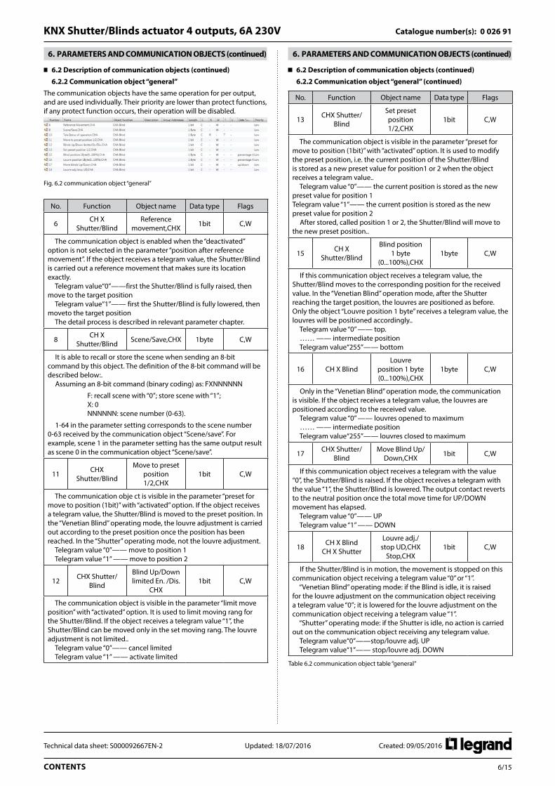
The communication objects have the same operation for per output, and are used individually. Their priority are lower than protect functions, if any protect function occurs, their operation will be disabled.
Fig. 6.2 communication object “general”
No. Function Object name Data type Flags
6 CH X Shutter/Blind
Reference movement,CHX 1bit C,W
The communication object is enabled when the “deactivated” option is not selected in the parameter “position after reference movement”. If the object receives a telegram value, the Shutter/Blind is carried out a reference movement that makes sure its location exactly. Telegram value“0”——first the Shutter/Blind is fully raised, then move to the target position Telegram value“1”—— first the Shutter/Blind is fully lowered, then moveto the target position The detail process is described in relevant parameter chapter.
8 CH X Shutter/Blind Scene/Save,CHX 1byte C,W
It is able to recall or store the scene when sending an 8-bit command by this object. The definition of the 8-bit command will be described below:. Assuming an 8-bit command (binary coding) as: FXNNNNNN
F: recall scene with “0”; store scene with “1”; X: 0 NNNNNN: scene number (0-63).
1-64 in the parameter setting corresponds to the scene number 0-63 received by the communication object “Scene/save”. For example, scene 1 in the parameter setting has the same output result as scene 0 in the communication object “Scene/save”.
11 CHX Shutter/Blind
Move to preset position 1/2,CHX
1bit C,W
The communication obje ct is visible in the parameter “preset for move to position (1bit)” with “activated” option. If the object receives a telegram value, the Shutter/Blind is moved to the preset position. In the “Venetian Blind” operating mode, the louvre adjustment is carried out according to the preset position once the position has been reached. In the “Shutter” operating mode, not the louvre adjustment. Telegram value “0”—— move to position 1 Telegram value “1” —— move to position 2
12 CHX Shutter/Blind
Blind Up/Down limited En. /Dis.
CHX1bit C,W
The communication object is visible in the parameter “limit move position” with “activated” option. It is used to limit moving rang for the Shutter/Blind. If the object receives a telegram value “1”, the Shutter/Blind can be moved only in the set moving rang. The louvre adjustment is not limited.. Telegram value “0”—— cancel limited Telegram value “1” —— activate limited
6 . PARAMETERS AND COMMUNICATION OBJECTS (continued)
6 .2 Description of communication objects (continued)
6 .2 .2 Communication object “general” (continued)
No. Function Object name Data type Flags
13 CHX Shutter/Blind
Set preset position 1/2,CHX
1bit C,W
The communication object is visible in the parameter “preset for move to position (1bit)” with “activated” option. It is used to modify the preset position, i.e. the current position of the Shutter/Blind is stored as a new preset value for position1 or 2 when the object receives a telegram value.. Telegram value “0”—— the current position is stored as the new preset value for position 1 Telegram value “1”—— the current position is stored as the new preset value for position 2 After stored, called position 1 or 2, the Shutter/Blind will move to the new preset position..
15 CH X Shutter/Blind
Blind position 1 byte
(0...100%),CHX1byte C,W
If this communication object receives a telegram value, the Shutter/Blind moves to the corresponding position for the received value. In the “Venetian Blind” operation mode, after the Shutter reaching the target position, the louvres are positioned as before. Only the object “Louvre position 1 byte” receives a telegram value, the louvres will be positioned accordingly.. Telegram value “0” —— top. …… —— intermediate position Telegram value“255”—— bottom
16 CH X BlindLouvre
position 1 byte (0...100%),CHX
1byte C,W
Only in the “Venetian Blind” operation mode, the communication is visible. If the object receives a telegram value, the louvres are positioned according to the received value. Telegram value “0” —— louvres opened to maximum …… —— intermediate position Telegram value“255”—— louvres closed to maximum
17 CHX Shutter/Blind
Move Blind Up/Down,CHX 1bit C,W
If this communication object receives a telegram with the value “0”, the Shutter/Blind is raised. If the object receives a telegram with the value “1”, the Shutter/Blind is lowered. The output contact reverts to the neutral position once the total move time for UP/DOWN movement has elapsed. Telegram value “0”—— UP Telegram value “1” —— DOWN
18 CH X Blind CH X Shutter
Louvre adj./stop UD,CHX
Stop,CHX1bit C,W
If the Shutter/Blind is in motion, the movement is stopped on this communication object receiving a telegram value “0” or “1”. “Venetian Blind” operating mode: if the Blind is idle, it is raised for the louvre adjustment on the communication object receiving a telegram value “0”; it is lowered for the louvre adjustment on the communication object receiving a telegram value “1”. “Shutter” operating mode: if the Shutter is idle, no action is carried out on the communication object receiving any telegram value. Telegram value“0”——stop/louvre adj. UP Telegram value“1”—— stop/louvre adj. DOWN
Table 6.2 communication object table “general”

7/15CONTENTS
Technical data sheet: S000092667EN-2 Updated: 18/07/2016 Created: 09/05/2016
Catalogue number(s): 0 026 91KNX Shutter/Blinds actuator 4 outputs, 6A 230V
6 . PARAMETERS AND COMMUNICATION OBJECTS (continued)
6 .2 Description of communication objects (continued)
6 .2 .3 Communication object “Auto .”
The priority of general operation and automatic operation is the same, but they cannot occur at the same time. Their priority are lower than protect functions, if any protect function occurs, their operation will be disabled.
Fig.6.3 communication object “Auto.”
No. Function Object name Data type Flags
62 CHX Shutter/Blind
En./Dis.Auto. control, CHX 1bit C,W
The communication object is used to disable and enable the Auto. Operation. If the object receives a telegram “0”, the Auto. Operation is deactivated; if the object receives a telegram “1”, the Auto. Operation is activated. Telegram value“0”——deactivate the Auto. Operation Telegram value“1”—— activate the Auto. Operation.
63 CH X Shutter/Blind Sun.CHX 1bit C,W
If the communication object receives a telegram “0” or “1”, the shutter/blind is moved into a predefined position, see the parameter chapter description.
65 CHX Shutter/Blind
Blind/Shutter position for Auto.
(0...100%),CHX
1byte C,W
In Auto. Operation status, if this communication object receives a telegram value, the Shutter/Blind moves to the corresponding position for the received value. In the “Venetian Blind” operation mode, after the Shutter reaching the target position, the louvres are positioned as before. Only the object “Louvre position 1 byte” receives a telegram value, the louvres will be positioned accordingly. Telegram value “0” ——top …… —— intermediate position Telegram value“255”—— bottom
64 CH X BlindLouvre position
for Auto. (0...100%),CHX
1byte C,W
In Auto. Operation status, the communication is visible only in the “Venetian Blind” operation mode. If the object receives a telegram value, the louvres are positioned according to the received value. Telegram value “0” ——louvres opened to maximum …… —— intermediate position Telegram value“255”—— louvres closed to maximum
Table 6.3 communication object table “Auto.”
6 .2 .4 Communication object “status response”
When the position of the Shutter/Blind and the position of louvre have been completed change, the communication objects are updated immediately and send the current position to the bus. When the operation is changed, the corresponding communication object is also updated immediately and sends the current operating status to the bus.
Fig. 6.4 communication object status response
6 . PARAMETERS AND COMMUNICATION OBJECTS (continued)
6 .2 Description of communication objects (continued)
6 .2 .4 Communication object “status response” (continued)
No. Function Object name Data type Flags
10 CHX Shutter/Blind
Teleg.Status of operation,CHX 1byte C,R,T
The communication object is used to send the information about the current operating status of the output for the Shutter actuator. Only one of the following operating states can be activated at the same time. The status of operation is sent after a change. the telegram 0 - direct operation (general operation) the telegram 1 - manual operation (button operation) the telegram 2 - Forced operation the telegram 3 - the blocking operation the telegram 4 - Wind protection the telegram 5 - frost protection the telegram 6 - rain protection The telegram 7 - auto. operation Other are not used
14 CH X Shutter/Blind
Response Blind position,CHX 1byte C,R,T
The communication object is visible in the parameter “Response Blind position” with “activated” option. The object is used to send the current position of the Shutter/Blind after the completion of a movement. Telegram value “0” —— top. …… —— intermediate position Telegram value“255”—— bottom
19 CH X Blind Response Louvre position,CHX 1byte C,R,T
In the “Venetian Blind” mode, the communication object is visible in the parameter “Response louvre position” with “activated” option. The object is used to send the current position of the louvre after the completion of a movement. Telegram value “0” —— louvres opened to maximum …… —— intermediate position Telegram value“255”—— louvres closed to maximum
Table 6.4 communication object table “status response”
6 .2 .5 Communication object protect function"
When the protect functions have occurred, general operations are disabled and their objects are not avail except modifying the preset and storing the scene.
Fig. 6.5 communication object “protect function”
No. Function Object name Data type Flags
0 Wind protect Wind protect 1bit C,W
The communication object is enabled when the “activated” option is selected in the parameter “wind protect”, which is used to receive the cyclical telegrams from the anemometers. If the object receives a telegram “0”, the wind protect is deactivated, and the monitoring period is restarted. If the object receives a telegram “0” again for the first time after wind protect, the Shutter/Blind is moved to the position on reset of weather protect, blocked and forced operation. If the object receives a telegram “1” during the monitoring period, the Shutter/Blind is moved to the set position for wind protect. If no telegram is received during the monitoring period, the Shutter actuator will think the anemometers fault and move the Shutter/Blind to the set position for wind protect. Telegram value “0” —— no wind protect, operation enabled Telegram value “1”—— wind protect, operation disabled

8/15CONTENTS
Technical data sheet: S000092667EN-2 Updated: 18/07/2016 Created: 09/05/2016
Catalogue number(s): 0 026 91KNX Shutter/Blinds actuator 4 outputs, 6A 230V
6 . PARAMETERS AND COMMUNICATION OBJECTS (continued)
6 .2 Description of communication objects (continued)
6 .2 .5 Communication object protect function" (continued)
No. Function Object name Data type Flags
1 Rain protect Rain protect 1bit C,W
The communication ob ject is enabled when the “activated” option is selected in the parameter “rain protect”, which is used to receive the cyclical telegrams from the rain sensors. If the object receives a telegram “0”, the rain protect is deactivated, and the monitoring period is restarted. If the object receives a telegram “0” again for the first time after rain protect, the Shutter/Blind is moved to the position on reset of weather protect, blocked and forced operation. If the object receives a telegram “1” during the monitoring period, the shutter/Blind is moved to the set position for rain protect. If no telegram is received during the monitoring period, the Shutter actuator will think the rain sensor fault and move the Shutter/Blind to the set position for rain protect. Telegram value “0” —— no rain protect, operation enabled Telegram value “1”—— rain protect, operation disabled
2 Frost protect Frost protect 1bit C,W
The communication ob ject is enabled when the “activated” option is selected in the parameter “frost protect”, which is used to receive the cyclical telegrams from the frost sensors. If the object receives a telegram “0”, the frost protect is deactivated, and the monitoring period is restarted. If the object receives a telegram “0” again for the first time after frost protect, the Shutter/Blind is moved to the position on reset of weather protect, blocked and forced operation. If the object receives a telegram “1” during the monitoring period, the shutter/Blind is moved to the set position for frost protect. If no telegram is received during the monitoring period, the Shutter actuator will think the frost sensor fault and move the Shutter/Blind to the set position for frost protect. Telegram value “0” —— no frost protect, operation enabled Telegram value “1”—— frost protect, operation disabled
7 CH X Shutter/Blind
Frost protect,CHX 2 bit C,W
The communication obj ect is enabled in the parameter “force operation (2bit)” with “activated” option. If the object receives a telegram value “2” or “3”, the output moves to the set position for force operation, and the operation of the output via the general communication objects is disabled. If the object receives the telegram value “0” or “1” for the first time after a “2” or “3”, the Shutter/Blind is moved into the position on reset of weather alarm, blocked and forced operation, and the operation via the general communication objects is enabled again. Telegram value “0”(00)—— no control, operation enabled Telegram value “1”(01) —— no control, operation enabled Telegram value “2”(10)—— force, move to the top, operation disabled Telegram value “3”(11) —— force, move to the bottom, operation disabled
9 CH X Shutter/Blind
Operation Block,CHX 1 bit C,W
The communication object is enabled in the parameter “operation block” with “activated” option. If the object receives a telegram value “1”, the output moves to the set position for blocking, and the operation of the output via the general communication objects is disabled. If the object receives the telegram value “0” for the first time after a “1”, the Shutter/Blind is moved into the position on reset of weather alarm, blocked and forced operation, and the operation via the general communication objects is enabled again. Telegram value “0”—— no block, operation enabled Telegram value “1” —— block, operation disabled
Table 6.5 communication object table “protect function”
7 . PARAMETER SETTING DESCRIPTION IN THE ETS
7 .1 Parameter window “protect”
Parameter window “protect” can be shown in fig. 5.1, which applies to every output for the Shutter actuator . Here can set priority of protect functions, and monitoring period and priority for weather protect function. When weather protect function occur, the behaviour can be set separately for per output via parameters. The detailed description for every parameter as follows:
Fig.7.1 parameter window “Protect Setting”
Parameter “priority of protect functions”
The parameter defines the priority between forced operation, the weather protect and block. Options:
Weather protect – block – force operation Weather protect – force operation – block Block – weather protect – force operation Block – force operation – weather protect Force operation – block – weather protect Force operation – weather protect – block
The protect functions of wind protect, rain protect, frost protect, block and forced operation have priority over all the other functions of the Shutter actuator. If one of these functions has been activated of an output, the operation of the output is disabled for other movements.
An order of priority can also be defined among the protect functions to control the Shutter/Blind specifically if more than one protect function is active at the same time.
For example, it is possible to define via a parameter that the forced operation function has priority over other protect functions when the window is being cleaned so that the cleaners cannot be surprised by an command triggered by weather protect when they are cleaning the louvres.
Parameter “priority of weather protect functions”
The parameter defines the priority between the weather protect functions of wind protect, frost protect and rain protect.
Option: Wind – rain – frost Wind – frost – rain Rain – wind – frost Rain – frost – wind Frost – rain – wind Frost – wind – rain
The Shutter actuator can receive 1 bit wind protect, rain protect and frost protect commands to protect the Shutter/Blind in the event of storms, rain and frost. If a protection occurs, the Shutter/Blind is moved to the set position for protect and can no longer be moved until the protection is deactivated again.
The positions for wind protect, rain protect and frost protect can be set separately for each output. The anemometer, the rain sensor and the frost sensor are monitored cyclically by the Shutter actuator i.e. the anemometer and the sensors send the protect status cyclically and the Shutter actuator expects this signal. If there is no signal, the Shutter actuator assumes that the anemometer and the sensors are faulty or that the bus line has been interrupted and moves all the Shutters/Blinds which are influenced to the set protect position and operation is blocked. The monitoring period of the Shutter actuator should be twice as long as the cyclical sending time of the anemometer and the sensor so that the Shutters/Blinds do not move immediately to the wind, the rain or frost protect position when a signal is omitted (e.g. due to a high bus load).

9/15CONTENTS
Technical data sheet: S000092667EN-2 Updated: 18/07/2016 Created: 09/05/2016
Catalogue number(s): 0 026 91KNX Shutter/Blinds actuator 4 outputs, 6A 230V
7 . PARAMETER SETTING DESCRIPTION IN THE ETS (continued)
7 .1 Parameter window “protect” (continued)
Parameter “priority of weather protect functions” (continued)
When the wind, the rain or frost protect is reset, the Shutter/Blind is moved to the set Position on reset of weather protect, block and forced operation and operation is enabled.
Parameter “wind/rain/frost protect”
These parameter is used to set whether wind protect, rain protect or frost protect is active.
Options: Activated Deactivated
If the option “activated” is selected, the communication object “wind protect”, “frost protect” or “rain protect” appears. If these objects receive telegram “1” or no telegram when the monitoring periods have elapsed. The Shutter/Blind is moved to the set position for wind protect, for rain protect or frost protect. If these objects receive telegram “0”, the protect functions are reset. Then lower priority operations can be carried out to control the Shutter/Blind. The monitoring period is restarted after the object each receipt of a telegram “0”.
Parameter “monitoring period for wind/frost/rain protect 0…1000*1s (0=monitoring deactive)”
These parameters are used for setting the monitoring period for the wind protect, for frost protect or rain protect. The monitoring period in the Shutter actuator should be at least twice as long as the cyclical sending time of the sensor so that the Shutter/Blind is not immediately moved to the protect position due to the negligible omission of a signal, e.g. due to a high bus load. If the value of this parameter is set to “0”, the monitoring of the wind protect, frost protect or rain protect is deactivated, and their communications are also invalid.
Parameter “wait for sensor stabilize [0…1000]*1s”
The parameter defines the delay time of starting monitoring for the weather protect after bus voltage recovery, in order to wait for sensor stabilize. Normally, the sensor steady required a period after bus voltage recovery, in order to prevent the Shutter/Blind protect occur false positives due to the sensors don't monitor telegrams send in stable period.
7 .2 Parameter window “manual”
Parameter window “manual” can be shown in fig. 5.2. It is possible to switch between manual operation and automatic operation by pressing the Man./Auto Button about 2s. When the manual/automatic operations are switched successfully, the Man./Auto. LED will flash for three times. In the manual mode the Man./Auto. LED is on. In the automatic mode the Man./Auto. LED is off. The devices are in the automatic mode after connection to the bus, and the manual operation buttons have no function.
Fig.7.2 parameter window “manual”
7 . PARAMETER SETTING DESCRIPTION IN THE ETS (continued)
7 .2 Parameter window “manual” (continued)
Parameter “Manual operation”
The parameter defines whether the switchover between the operating states “manual operation” and “automatic operation” is enabled or disabled via the Man. /Auto. Button on the Shutter actuator.
Options: Enable/Disable by object Enable
If the “Enable/Disable by object” is selected, the “En/Dis. Manual” communication object appears. The object receiving telegram value “0” disable the Man. /Auto. Button, and then the manual / automatic mode cannot be switched. If the object receiving telegram value “1” enable the Man. /Auto. Button, and then the manual/automatic mode can be switched via the button. If the enable is selected, the Man. /Auto Button has been enabled.
Parameter “Manual to automatic method”
This parameter defines how long the Shutter actuator remains in the “manual operation” state after the “Man. / Auto. Button” has been pressed.
Options: By push button Automatically and by push button
If the “by push button” option is selected, the Shutter actuator will remain in the “manual operation” until the Man./Auto. Button is pressed again.
If the “automatically and by push button” option is selected, the Shutter actuator will remain in the “manual operation” until the Man. /Auto. Button is pressed again or the set time for the manual to automatic has elapsed.
Parameter “Manual to automatic after [10 . . .60000]*1s”
The parameter appears when “automatically and by push button” is selected in the parameter “manual to automatic method”. It is used for setting the time for an automatic reset from the “manual operation” to “automatic operation” state after the last push button operation.
Options: 10……60000s
Note: The operation buttons that are located at the front of the device is invalid in the protect functions.
Parameter “Report on Man/Auto status change”
The parameter defines whether the current operation status will be sent to the bus on manual/automatic operation status change.
Options: Yes No
If the “yes” option is selected, the “Teleg. Status of Manual” communication object appears. The object sends telegram value “1”, the current status for manual operation; the object sends telegram value “0”, the current status for automatic operation. When operation status changed, the object sends the current status telegram on the bus immediately.
Parameter “Report on auxiliary voltage change”
The parameter defines whether the auxiliary voltage status will be sent to the bus on auxiliary voltage change. The auxiliary voltage is for the relays operation voltage, if the voltage is too low, the relays may not start.
Options: Yes No
If the “yes” option is selected, the “Teleg. Status of voltage” communication object appears. Normal operating voltage of the relays must be 9V or more, if the voltage drops below 9V, the object sends telegram value “0”, then the relays may fail to start; if the voltage is 9V above, the object sends telegram value “1”, the relays start normally. When the voltage is lower than 9V or higher than 9V, the object sends immediately the current voltage status telegram to the bus.
The actuator sends immediately the current voltage status telegram to the bus after programming or bus reset.
The following detailed description of the channel working mode, and the corresponding parameters and communication objects:

10/15CONTENTS
Technical data sheet: S000092667EN-2 Updated: 18/07/2016 Created: 09/05/2016
Catalogue number(s): 0 026 91KNX Shutter/Blinds actuator 4 outputs, 6A 230V
7 . PARAMETER SETTING DESCRIPTION IN THE ETS (continued)
7 .3 Working mode “Venetian Blind”
7 .3 .1 Parameter window “channel X”
The parameter window “channel X” is shown in fig.5.3. “Channel X” or “X” mentioned below means any output of the switch actuator, which has the same setting parameter interface and communication objects.
Fig.7.3 parameter window “Channel X”
Parameter “working mode”
This parameter is used to define the output mode. Different output modes have different parameters and communications.
Options: No function Venetian Blind Shutter
If selecting “no function”, the output is disabled.
If selecting “Venetian Blind”, the output is for the Blind operation mode, which can operate the Blind with louvres.
If selecting “Shutter”, the output is similar with the Blind operation mode, except that it cannot adjust louvres.
The section 5.3 details the parameters and communication objects for the “venetian Blind” mode.
Parameter “position on bus voltage recovery”
The parameter is used for setting the behavior of the output on bus voltage recovery.
Options: No reaction Up Down Position 1 Position 2
If the option “no reaction” is set, the output contacts remain in their current position. If the option “up” is set, the Blind is moved to the top after bus voltage recovery. If the option “down” is set, the Blind is moved to the bottom after bus voltage recovery. If the option “position 1/2” is selected, the Blind first is moved to the top or the bottom (toward near the target location moving) after bus voltage recovery before it is moved to the set position, then moved to the target location.
All the communication objects adopt the value “0” after programming or bus voltage recovery.
Note: If the option “no reaction” has been set the position after programming or bus voltage recovery, the Shutter actuator does not detect the current position of the Blind. The communication objects “response Blind position” and “response louvre position” have the value “129” and are not sent on the bus. If after programming or bus voltage recovery a defined position of the Blind is required for the first time, it is first of all raised to the top or dropped to the bottom (toward near the target location moving) to determine the current position and then into the target position. Only the Blind finish a full running can confirm position.
7 . PARAMETER SETTING DESCRIPTION IN THE ETS (continued)
7 .3 Working mode “Venetian Blind” (continued)
7 .3 .1 Parameter window “channel X” (continued)
Parameter “position after reference movement”
This parameter specifies how the Shutter actuator behaves after a reference movement.
Options: Deactivated No reaction Move to position 1 Move to position 2 Move to save position
If the option “deactivated” is selected, the reference movement is deactivated, other option is selected, and the communication object “reference movement” appears. If the option “no reaction” is selected, the object receives a telegram “0”, the Blind is moved to the top; the object receives a telegram “1”, the Blind is moved to the bottom. If the option “move to position 1/2” is selected, the object receives a telegram “0”, the Blind is moved to the top, then to position 1/2; the object receives a telegram “1”, the Blind is moved to the bottom, then to position 1/2. If the option “move to save position” is selected, the object receives a telegram “0”, the Blind is moved to the top, then back to its original position; the object receives a telegram “1”, the Blind is moved to the bottom, then back to its original position.
The Shutter actuator continually determine the current position of the Blind as well as the angle position of the louvre using the duration of individual movements. Over longer periods, slight inaccuracies may occur when determining the position due to temperature variations and ageing processes. Therefore the Shutter actuator uses the upper and lower limit positions to clearly define the current position of the Blind. Each time that the Blind is in the upper or lower limit position, the position is updated in the memory of the Shutter actuator.
If the limit positions have not been reached during normal operation, a reference movement can be triggered via a bus telegram to move the Blind right to the top or right to the bottom. Depending on the parameter settings, the Blind either remains in the reference position after the reference movement or moves back into the saved position.
Parameter “limit move position”
The parameter is used to set whether the limit move position is activated. If selected “activated”, the Blind is moved in the set position range.
Options: Deactivated Activated
If the option “activated” is selected, the communication object “Blinds UD limited” appears together with the parameters “limit 1” and “limit 2”. When the object receives a telegram value “1”, the moving range is limited; when the object receives a telegram value “0”, cancelling limit. The moving range is set via the following parameters “limit1/2”
Note: If the Shutter actuator has not gotten a reference position after programming or bus voltage recovery, the Blind is moved completely up or down when receiving a limited command for the output. It is not stopped at the upper or lower limit in this case. After determine the current position, the moving position will be limited in moving range. When a reference movement or protect functions have been carried out, the limit is cancelled. If the Blind is positioned in a higher position than the upper limit, it is only moved down after receiving a limited command. If the Blind is positioned in a lower position than the lower limit, it is only moved up after receiving a limited command.
Parameter “limit 1 /2(0…100%, 0%=top, 100%=bottom)”
The parameter is visible if the parameter “limit move position” is“activated”. It is used for setting the upper or lower limit of the moving range.

11/15CONTENTS
Technical data sheet: S000092667EN-2 Updated: 18/07/2016 Created: 09/05/2016
Catalogue number(s): 0 026 91KNX Shutter/Blinds actuator 4 outputs, 6A 230V
7 . PARAMETER SETTING DESCRIPTION IN THE ETS (continued)
7 .3 Working mode “Venetian Blind” (continued)
7 .3 .2 Parameter window “CHA Drive”
The parameter window “CHA Drive” is shown in fig. 5.4. Here set the relevant parameters with the Blind drive. The current position of the Blinds can be usually calculated based on the total move time. The duration of louvre adjustment and maximum number of louvre adjustments can calculate the current position of louvre. The technical data and running time are different for different Blinds. It is therefore important to know its technical data and running time before using the Blind. It is the only way that the relevant parameters can be set precisely for the Shutter actuator.
Fig.7.4 parameter window “CHA Drive”
Parameter "Total move time [s] [0…50000]*0 .1s"
The parameter is used for setting the total move time in seconds.
The total move time is the period that the Blind requires to travel from the upper limit position to the lower limit position (see following Diagram). If the Shutter actuator receives an UP or DOWN movement command, the corresponding output is switched and the Blind is moved in this direction until the Shutter actuator receives a STOP command, or until the upper or lower limit position has been reached and then the motor is switched off via the limit switch. If the Blind is switch off via the limit switch, the corresponding output contact of the Shutter actuator remains closed until the set total move time has elapsed plus the parameterized overflow time (see parameter outputs are disconnected from voltage after description), only then the output contact reverts to neutral position.
Shutter UPShutter DOWN
Total travel time
Upper limit switch
Lower limit switch
Note: The current position of the Blind during operation can also be determined with the help of the total move time. It is therefore important to measure and set the total move time as accurately as possible, particularly if the functions "Move to position" and "Status response" are used. Only then is it possible to calculate the current position of the Blind precisely.
7 . PARAMETER SETTING DESCRIPTION IN THE ETS (continued)
7 .3 Working mode “Venetian Blind” (continued)
7 .3 .2 Parameter window “CHA Drive” (continued)
Parameter “duration of louvre adjustments [10…250]*5ms”
The parameter is used for setting the duration of louvre adjustment in milliseconds.
After an upward movement of the Blind, the louvres normally are open (horizontal louvre position). If the Blind is now lowered, the louvres are closed first of all (vertical louvre position) and the Blind moves downwards.
If the Blind is now raised again, the louvres are opened again first (horizontal louvre position) and then raised. (See following Diagram)
Blind raised
Blind lowered
Parameter "Max . number of louvre adjustments 1…60 [as reference for 0…100%]"
The parameter is used for setting the maximum number of louvre adjustments. It determines the current position of the louvres during operation. So the maximum number of louvre adjustments must be counted by the commissioning engineer and entered a more precise value in the parameter.
The parameter is used together with above parameter. The louvre adjustment time that the louvres is adjusted from fully closed to fully open is for the duration of louvre adjustment times the Max. number of louvre adjustments.
Parameter “pause on change in direction [0…255]*20ms”
The parameter is used for setting the pause on change in direction in milliseconds. The technical data supplied by the drive manufacturer must be taken into account, to enter a suitable value in the parameter.
Parameter “outputs are disconnected from voltage after”
This parameter is used to set the output off delay time.
Options: End position, no overflow End position + 2% overflow End position + 5% overflow End position + 10% overflow End position + 20% overflow Total travel time + 10% overflow
• If selecting End position, no overflow(, the output is disconnected from voltage without delay, i.e. when the total move time has elapsed, the output is disconnected immediately.
• If selecting End position +2%/…/20% overflow(, when the Blinds reach the end position (completely up or completely down), the output is disconnected after a delay time (the delay time=2%/…/20%×the total move time). If the end position does not reach completely up or completely down, the output will be disconnected without delay.
• If selecting Total travel time + 10% overflow(, the time that the Blinds is moved from the top to the bottom is for the total move time plus the overflow time (the overflow time=10%×the total move time). When the time has elapsed, the output is disconnected immediately. Regardless of whether the Blinds reach the top or the bottom, the time will affect the entire movement.

12/15CONTENTS
Technical data sheet: S000092667EN-2 Updated: 18/07/2016 Created: 09/05/2016
Catalogue number(s): 0 026 91KNX Shutter/Blinds actuator 4 outputs, 6A 230V
7 . PARAMETER SETTING DESCRIPTION IN THE ETS (continued)
7 .3 Working mode “Venetian Blind” (continued)
7 .3 .2 Parameter window “CHA Drive” (continued)
Parameter “Stop when reach Louvre Max . or Min . position”
The parameter is used to set whether the louvre adjustment is stopped when louvres reach Louvre Max. or Min. position.
Options: Yes No
• If selecting "yes", the louvre adjustment is stopped when louvres reach Louvre Max. or Min. position.
• If selecting "no", the louvre adjustment is still continually carried out when louvres reach Louvre Max. or Min. position, then the position of the Blind will be changed.
7 .3 .3 Parameter window “CHA Protect”
The parameter window “CHA Protect” is shown in fig. 5.5. Here set the actions in the event of the protect functions.
Fig.7.5 parameter window “CHA Protect”
Parameter “position for wind/ rain/ frost protect”
These parameters are used for setting the behaviors in the event of weather protect.
Options: Activated-up Activated-down Activated-stop Activated-no reaction Deactivated Activated-position 2 Activated-position 1
If the option “deactivated” is selected, the weather protect is deactivated for the output. If the option “no reaction” is set, the output contact retains in their current status in the event of weather protect. If the option “up” is set, the Blind is moved to the very top when the weather protect occur. If the option “down” is set, the Blind is moved to the very bottom. If the option “position 1/2” is selected, the Blind is moved to the position1/2.
Parameter “force operation [2bit]”
This parameter is used to set whether the forced operation is activated.
The forced operation is controlled by 2bit command. When the forced operation is carried out, the Blind is moved to the top or the bottom, general operation is disabled.
On reset of the forced operation function, the Blind is moved to the set position on reset of weather protect, blocked and forced operation and general operation is enabled. The forced operation function is suitable for example for raising Blinds when the windows are cleaned. The operation of the Blind is blocked at the same time so that the cleaners are not put in danger due to unexpected movements.
Options: Activated Deactivated
If the option “activated” is selected, the communication object “forced operation” appears. If the object receives a telegram value “0”or “1”, the forced operation is reset. If the object receives a telegram value “2”, the Blind is moved to the top. If the object receives a telegram value “3”, the Blind is moved to the bottom.
7 . PARAMETER SETTING DESCRIPTION IN THE ETS (continued)
7 .3 Working mode “Venetian Blind” (continued)
7 .3 .3 Parameter window “CHA Protect” (continued)
Parameter “operation block”
This parameter is used to set whether the operation block is activated.
In the blocked function, the output of the Shutter actuator can be oved to the set position for block when the block function is recalled via a 1bit command and general operation is blocked. After a reset, the Blind is moved to the set position on reset of weather protect, blocked and force operation and general operation is enabled. For example, it is possible to block the operation of an interior Blind via the function if the window has been opened.
Options: Activated Deactivated
If the option “activated” is selected, the communication object “operation block” appears as well as the follow parameter “when block its block”.
Parameter “when block its position”
The parameter is visible if the parameter “operation block” is “activated”. It is used for setting the behavior during block function.
Options: No reaction Up Down Stop Position 1 Position 2
If the option “no reaction” is set, the output contact retains in their current status when the object “operation block” receives a telegram value “1”. If the option “up” is set, the Blind is moved to the very top when the object receives a telegram value “1”. If the option “down” is set, the Blind is moved to the very bottom. If the option “position 1/2” is selected, the Blind is moved to the position1/2. If the option “stop” is set, the Blind is halted immediately, and the output contact reverts to the neutral position.
Parameter “position on reset of weather alarm blocked and forced operation”
Here defines how the output behaves on reset of weather protect, blocked and forced operation.
Options: No action Stop Save position
If selecting “no action”, the object “force operation”, “operation block”, “wind protect”, “rain protect” or “frost protect” receives a telegram value “0”, the output contact retains in their current status. If selecting “stop”, the object receives a telegram value “0”, the Blind is halted immediately, and the output contact reverts to the neutral position. If selecting “save position”, the object receives a telegram value “0”, the Blind is moved to the saved position, if the position is not changed, it is no action.
Note: If selecting “save position” option, here more than one protect function occur at the same time, the Shutter actuator only records the position that the Blind is moved to in the event of the first protect function. Therefore the saved position is the position that the first protect function occurs. If here only a protect function occurs and the action of the protect function is “stop”, the Blind will be not carried out movement on reset of protect function, because of its position no change.

13/15CONTENTS
Technical data sheet: S000092667EN-2 Updated: 18/07/2016 Created: 09/05/2016
Catalogue number(s): 0 026 91KNX Shutter/Blinds actuator 4 outputs, 6A 230V
7 . PARAMETER SETTING DESCRIPTION IN THE ETS (continued)
7 .3 Working mode “Venetian Blind” (continued)
7 .3 .3 Parameter window “CHA Protect” (continued)
Parameter “position on reset of weather alarm blocked and forced operation” (continued)
If here only a protect function occurs, when its object receives a telegram value “0”, the Blind is moved to the set position on reset of the protect functions. If more than one protect function occur, when the object of the highest priority protect function receives a telegram value “0”, the Blind is moved to the set position of the higher priority protect function. For example, currently there are three protect functions occur, the priority is wind protect > operation block > forced operation, when the object “wind protect” receives a telegram value “0”, the Blind will be moved to the set position of the block protect; when the object “operation block” receives a telegram value “0”, the Blind will be moved to the set position of forced operation; when the object “forced operation” receives a telegram value “0”, the Blind will be moved to the set position on reset of weather protect, blocked and forced operation.
7 .3 .4 Parameter window “CHA Position”
The parameter window “CHA Position” is shown in fig. 5.6. Here can set the preset positions for the Blind and louvre adjustment as well as response about the current position status of the Blind and louvre. The current positions of the Blind and louvre are responded after the completion of a movement.
Fig.7.6 parameter window “CHA Position”
Parameter “preset for move to position (1bit)”
The parameter is used to set whether the preset position is activated, to provide two preset positions.
Options: Activated Deactivated
If the option “activated” is selected, the communication object “move to preset position 1/2” appears. If the object receives a telegram value “0”, the Blind is moved to the preset position 1; if the object receives a telegram value “1”, the Blind is moved to the preset position 2. The values of the preset position 1/2 can be set in following parameters “Position 1/2: Blind/Louvre 0…100%”.
Parameter “preset for set position (1bit)”
This parameter is used to set whether the preset position 1/2 can be modified via the bus.
Options: Activated Deactivated
If selecting “activated”, the communication object “Set preset position 1/2” appears. The preset position1/2 can be modified via the object. If the object receives a telegram value “1”, the current position is stored as the new preset value for position 2; if the object receives a telegram value “0”, the current position is stored as the new preset value for position1.
Note: The new preset values for position1 or 2 are not retained on bus
voltage failure. The preset values are reset to the parameterized values.
7 . PARAMETER SETTING DESCRIPTION IN THE ETS (continued)
7 .3 Working mode “Venetian Blind” (continued)
7 .3 .4 Parameter window “CHA Position” (continued)
Parameter “Position 1: Blind 0…100% [0%=top, 100%=bottom]” Parameter “Position 2: Blind 0…100% [0%=top, 100%=bottom]” Parameter “Position 1: Louvres 0…100% [0%=opened, 100%=closed]” Parameter “Position 2: Louvres 0…100% [0%=opened, 100%=closed]”
These parameters are used for setting the preset values for the position of the Blind and louvre adjustment when moving into a preset position.
Parameter “Response Louvre position”
This parameter is used to set whether the current position of the louvre is responded after the completion of a movement.
Options: Activated Deactivated
If the option “activated” is selected, the communication objects “response Louvre position” appears.
Parameter “Response Blind position”
This parameter is used to set whether the current position of the Blind is responded after the completion of a movement.
Options: Activated Deactivated
If the option “activated” is selected, the communication objects “response Blind position” appears.
7 .3 .5 Parameter window “CHA Scene”
The parameter window “CHA Scene” is shown in fig.5.7. Here can set 5 scenes for per output, and their Blind position and louvre position.
Fig.7.7 parameter window “CHA Scene”
Parameter “Assignment Scene NO . (1 . . .64)”
There are 5 various scenes can be set for per output. It is able to allocate 64 different scene numbers for per scene.
Options: Not assignment Assignment to scene 1 … Assignment to scene 64
Note: 1-64 in the parameter setting corresponds to the telegram 0-63 received. On bus voltage failure, the new value that is stored for scene is not retained; the scene recovers to the parameterized value.

14/15CONTENTS
Technical data sheet: S000092667EN-2 Updated: 18/07/2016 Created: 09/05/2016
Catalogue number(s): 0 026 91KNX Shutter/Blinds actuator 4 outputs, 6A 230V
7 . PARAMETER SETTING DESCRIPTION IN THE ETS (continued)
7 .3 Working mode “Venetian Blind” (continued)
7 .3 .5 Parameter window “CHA Scene” (continued)
Parameter “--Blind 0…100%(0%=top,100%=bottom)”
This parameter is used to set the preset position of Blinds for a scene.
0…100%, 0%=top, 100%=bottom
Parameter “--Louvres 0…100%(0%=opened,100%=closed)”
This parameter is used to set the preset position of louvres for a scene.
0…100%, 0%=opened, 100%=closed
7 .3 .6 Parameter window “CHA Auto .”
The parameter window “CHA Auto.” is shown in fig.5.8. Here can set the automatic sun protection operation. Depending on the strength of induction light for the brightness sensor, the Shutter actuator moves the shutter/blind into a set position. For example, the shutter/blind can be raised if the sun is very weak or is not shining on the window at all. As much light as possible is thereby let into the room. If there is blazing sun on the window, the shutter/blind can be lowered and the louvres can be adjusted to the extent that direct sunlight cannot penetrate the room. Meanwhile, the residual opening in the blinds lets in a sufficient level of diffuse light into the room.
Fig.7.8 parameter window “CHA Auto.”
Parameter “Auto . Control operation”
The parameter is used to set whether the Auto. Control operation is activated, i.e. the Automatic sun protection function.
Options: Activated Deactivated
If the option “activated” is selected, the following three parameters will be visible. The communication objects “En. / Dis. Auto. control”, “Sun”, “Louvre position for Auto.(0…100%)” and “Blind position for Auto.(0…100%)” also will be visible.
When the object “En. / Dis. Auto. Control” receives a telegram “1”, the Auto. Operation is activated. When the object “En. / Dis. Auto. Control” receives a telegram “0” or the user sends a direct movement command (e.g. UP/DOWN, move into position etc.), the Auto. Operation is deactivated. If the command is not belong to the direct movement command (e.g. store the current, set the preset position etc.), the Auto. Operation is still activated.
The priority of general operation and automatic operation is the same, but they cannot occur at the same time.
Note: After the automatic operation is deactivated, only when the object “En. / Dis. Auto. Control” receives a telegram “1”, the operation is ctivated again.
7 . PARAMETER SETTING DESCRIPTION IN THE ETS (continued)
7 .3 Working mode “Venetian Blind” (continued)
7 .3 .6 Parameter window “CHA Auto .” (continued)
Parameter “Position for sun= “1” (sun)”
This parameter is used to set the position that the shutter is moved into when there is blazing sun, i.e. when the object “sun” receives a telegram “1”, the shutter is moved into the position.
Options: No reaction Up Down Stop Position1 Position2 Receive 1 byte
If the option “no reaction” is set, the output contacts remain in their current position when the object “sun” receives a telegram “1”.
Parameter “Position for sun= “1” (sun)” (continued)
If the option “receive 1 byte” is set, when the object “sun” receives a telegram “1”, the position depending on the values that the objects “Louvre position for Auto.(0…100%)” and “Blind position for Auto.(0…100%)” received. After programming or bus voltage recovery, the two objects values are uncertain, and then their values are “129” by default. Only when the two objects receive the values, the position is confirmed. In any operating status, the values that the two objects receive can be stored, including the protection operation of the higher priority.
Parameter “Position for sun= “0” (no sun)”
This parameter is similar with last parameter. The difference is that here defined the position that the shutter is moved into when the object “sun” receives a telegram “0”.
Parameter “Delay for sun [0…6000]*s”
This parameter defines the delay time, i.e. the time that the Shutter actuator delays executing action when the object “sun” received a telegram “0” or “1”. Mainly to prevent component damage or affect the motor life due to light frequent fluctuations lead to the Shutter actuator frequent action. Option: 0…6000 s
The follow is a simple automatic sun protection system: • The brightness sensor is used to sense the light intensity. The push button can be connected with the universal interface or substitute for other switch sensor on the bus.
• With the help of the second switch sensor, the user can specify whether to enable the automatic sun protection or to control the shutters/blinds manually. If the automatic sun protection is activated via a switch sensor, the shutter/blind moves automatically until either the automatic sun protection is deactivated via the same switch sensor or the user sends a direct movement command and the automatic function is thus also deactivated.
Automatic control actived
Position for sun = "1"
Position for sun = "0"
Direct positioning
via UP/DOWN or
movement into position
Automatic control
deactived
Brightness sensor
The Shutter actuator receives the information via the brightness sensor as to whether there is direct sunlight on the window. Once the delay period has elapsed, the Shutter actuator positions the shutter/blind according to the set Position for sun= “1” (sun) or Position for sun= “0” (no sun).

15/15CONTENTS
Technical data sheet: S000092667EN-2 Updated: 18/07/2016 Created: 09/05/2016
Catalogue number(s): 0 026 91KNX Shutter/Blinds actuator 4 outputs, 6A 230V
7 . PARAMETER SETTING DESCRIPTION IN THE ETS (continued)
7 .4 Working mode “Shutter”
The “Shutter” operation mode is similar with the “Venetian Blind” operation mode in the parameters and the objects, and their function is also almost the same. The only difference is that there is no louvre adjustment function in the “Shutter” operating mode.
“Venetian Blind (sunBlind)”and “Shutter” difference as shown:
OPE
N
no s
un p
rote
ctio
nO
PEN
no
sun
pro
tect
ion
0% = FINAL UPPER POSITION = 0 mm
100% = FINAL LOWER POSITION = max. mm
Sunblind Shutter
max
. Ran
ge
The functions described in chapters 5.3 for the “Venetian Blind” operating mode also apply to the “Shutter” operating mode (with the exception of the louvre adjustment function).