Embed Size (px)
Citation preview
NX Advanced FEM includes the fundamental modeling functions of automatic and manual meshgeneration, application of loads and boundary conditions and model development and checking. Arobust set of visualization tools generates displays quickly, lets you view multiple results simultane-ously and enables you to easily print the display. In addition, extensive post-processing functions enablereview and export of analysis results to spreadsheets and provide extensive graphing tools for gainingan understanding of results. Post-processing also supports the export of JT data for collaborationacross the enterprise with JT2Go and Teamcenter for lifecycle visualization.
NX Advanced FEM provides seamless, transparent support for anumber of industry-standard solvers, such as NX Nastran, MSCNastran, Ansys and Abaqus. For example, when you create either amesh or a solution in NX Advanced FEM, you specify thesolver environment that you plan to use to solve yourmodel and the type of analysis you want to perform. Thesoftware then presents all meshing, boundary conditionsand solution options using the terminology or “language” ofthat solver and analysis type. Additionally, you can solve yourmodel and view your results directly in Advanced FEM withouthaving to first export a solver file or import your results.
• Advanced FEM features data structures, such as the separate Simulation (.sim) and FEM files (.fem)that help facilitate the development of FE models across a distributed work environment. Thesedata structures also allow analysts to easily share FE data to perform multiple types of analyses.
• Advanced FEM offers world-class meshing capabilities. The software is designed to produce a veryhigh quality mesh while using an economical element count. Advanced FEM supports a completecomplement of element types (0D, 1D, 2D and 3D). Additionally, Advanced FEM gives analystscontrol over specific meshing tolerances that control, for example, how the software meshescomplex geometry, such as fillets.
• Advanced FEM includes multiple geometry abstraction tools that give analysts the ability to tailor theCAD geometry to the needs of their analysis. For example, analysts can use these tools to improvethe overall quality of their mesh by eliminating problematic geometry, such as tiny edges or slivers.
NXAdvanced Simulation
NX
www.siemens.com/plm
fact sheet
BenefitsEmbedded tools for 3D geometrycreation and editing of bothcomponents and assemblies
Association to the design geometryallows the analyst to work closelywith the design engineer
•Knowledge of design changes
•“On-demand” FE model updatesbased on design geometry changes
Support for NX Manager andTeamcenter® software for allcreated FE data sets
Solver environments customizedfor the nomenclature of theselected solver
A full range of tools for FE modelgeneration including predefinedconstraint conditions and automatedmesh mating conditions
Verification of models beforeprocessing with a full set ofgraphical and mathematical toolsthat help check model suitable
Ability to view analysis resultsquickly and easily with a dynamicvisualization tool
Extensive post-processing toolsto continue the iterative phasesof analysis or to export/importinformation
Direct integration with SimulationProcess Studio for CAE "best-practices" knowledge capture;including process wizard templatesfor vibration and stress analysis
Integrated basic durability analysis
SummaryNX® Advanced Simulation software combines the power of an integrated NX Nastran desktop solver with NX Advanced FEM, acomprehensive suite of multi-CAD FE model creation and results visualization tools. Extensive geometry creation, idealization andabstraction capabilities enable the rapid development of complex 3D mathematical models that allow design decisions to be based oninsight into real product performance. NX Advanced Simulation enables a true multi-physics environment via tight integration with NXNastran as well as other industry standard solvers such as Abaqus, Ansys and MSC.Nastran.
Siemens PLM Software
• Advanced FEM also supports the new NX Thermal and NX Flow solutions• NX Thermal is a fully integrated finite difference solver. It allows thermal engineers to predict heat
flow and temperatures in systems subjected to thermal loads• NX Flow is a computational fluid dynamics (CFD) solver. It allows analysts to perform steady-
state, incompressible flow analysis and predict flow rates and pressure gradients for movement offluid in a system
When used in combination, NX Thermal and NX Flow provide fully coupled treatment of convectiveheat transfer, enabling robust simulation of conjugate heat transfer problems.
FE modeling toolsGetting and using geometryWireframe, surface and solid geometry from other CAD systems can be accessed through embeddedstandards-based interfaces (IGES, STEP AP203, STEP AP214, Parasolid and JT) or optional direct CADinterfaces for Catia and Pro/Engineer. A complete set of geometry creation and modification tools isprovided to work directly with native and non-native geometry. Often design geometry must bemodified to build an effective model. Details may need to be suppressed or eliminated, additionalgeometry may be required to control mesh density; or surfaces not present in the geometry may beneeded for meshing. A complete set of idealization tools is provided that works directly on native ornon-native geometry. History support or association is not required.
NX Advanced FEM provides extensive model editing capabilities, including the ability to:• Interactively suppress features defined within the NX part• Perform sensitivity analysis using design parameters as defined in the CAD model• Remove fillets and holes automatically using the idealize command set on both native and non-native
geometry• Add, modify or delete entities (sheet body, solid body)• Extract the mid-surface representation directly from the solid body for modeling thin walled
components; surface thickness is mapped from the solid to the 2D representation• Automatically support relationships between the between the component CAD model and the FE
model within NX Manager and Teamcenter
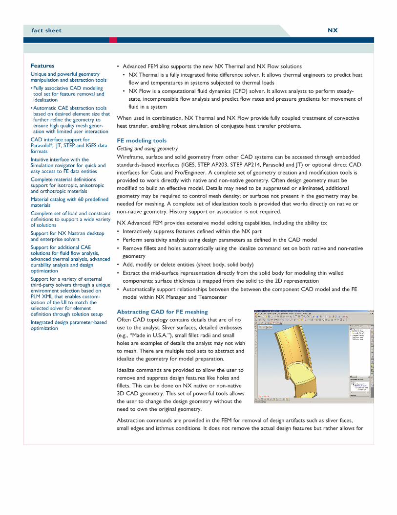
Abstracting CAD for FE meshingOften CAD topology contains details that are of nouse to the analyst. Sliver surfaces, detailed embosses(e.g., “Made in U.S.A.”), small fillet radii and smallholes are examples of details the analyst may not wishto mesh. There are multiple tool sets to abstract andidealize the geometry for model preparation.
Idealize commands are provided to allow the user toremove and suppress design features like holes andfillets. This can be done on NX native or non-native3D CAD geometry. This set of powerful tools allowsthe user to change the design geometry without theneed to own the original geometry.
Abstraction commands are provided in the FEM for removal of design artifacts such as sliver faces,small edges and isthmus conditions. It does not remove the actual design features but rather allows for
fact sheet NX
FeaturesUnique and powerful geometrymanipulation and abstraction tools
•Fully associative CAD modelingtool set for feature removal andidealization
•Automatic CAE abstraction toolsbased on desired element size thatfurther refine the geometry toensure high quality mesh gener-ation with limited user interaction
CAD interface support forParasolid®, JT, STEP and IGES dataformats
Intuitive interface with theSimulation navigator for quick andeasy access to FE data entities
Complete material definitionssupport for isotropic, anisotropicand orthotropic materials
Material catalog with 60 predefinedmaterials
Complete set of load and constraintdefinitions to support a wide varietyof solutions
Support for NX Nastran desktopand enterprise solvers
Support for additional CAEsolutions for fluid flow analysis,advanced thermal analysis, advanceddurability analysis and designoptimization
Support for a variety of externalthird-party solvers through a uniqueenvironment selection based onPLM XML that enables custom-ization of the UI to match theselected solver for elementdefinition through solution setup
Integrated design parameter-basedoptimization
the removal of geometry artifacts that affect the overall quality of the mesh. This set of commandsallows the analyst to mesh the geometry at a level of detail that sufficiently captures the design intentrelevant to a particular FE analysis.
A key concept is that the CAE-driven modifications, either idealized or abstraction, do not change the originaldesign geometry and are completely associated, allowing the user to accept modification to the design geometrywithout the need to rebuild the FE modeling intent.
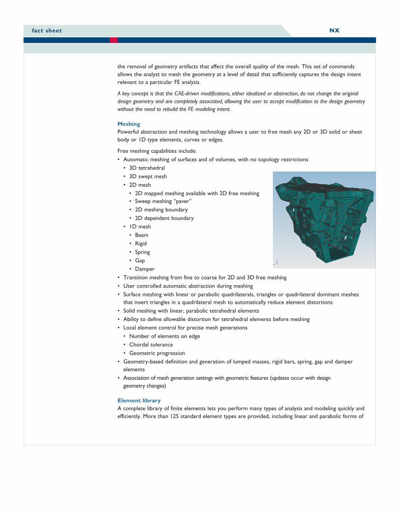
MeshingPowerful abstraction and meshing technology allows a user to free mesh any 2D or 3D solid or sheetbody or 1D type elements, curves or edges.
Free meshing capabilities include:• Automatic meshing of surfaces and of volumes, with no topology restrictions
• 3D tetrahedral• 3D swept mesh• 2D mesh
• 2D mapped meshing available with 2D free meshing• Sweep meshing “paver”• 2D meshing boundary• 2D dependent boundary
• 1D mesh• Beam• Rigid• Spring• Gap• Damper
• Transition meshing from fine to coarse for 2D and 3D free meshing• User controlled automatic abstraction during meshing• Surface meshing with linear or parabolic quadrilaterals, triangles or quadrilateral dominant meshes
that insert triangles in a quadrilateral mesh to automatically reduce element distortions• Solid meshing with linear, parabolic tetrahedral elements• Ability to define allowable distortion for tetrahedral elements before meshing• Local element control for precise mesh generations
• Number of elements on edge• Chordal tolerance• Geometric progression
• Geometry-based definition and generation of lumped masses, rigid bars, spring, gap and damperelements
• Association of mesh generation settings with geometric features (updates occur with designgeometry changes)
Element libraryA complete library of finite elements lets you perform many types of analysis and modeling quickly andefficiently. More than 125 standard element types are provided, including linear and parabolic forms of
fact sheet NX
shells and solids, axisymmetric shells and solids, beams, rods, springs, dampers, masses, rigid links andgaps. Scalars and other special elements have unique graphic symbols. P-elements (solid tetrahedra) aresupported for linear structural analysis.
Beam section propertiesBeam section properties may be defined from a standard set of sections or directly from CADgeometry simplifying the task of generating the appropriate data for the beam definition.
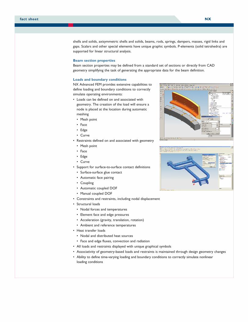
Loads and boundary conditionsNX Advanced FEM provides extensive capabilities todefine loading and boundary conditions to correctlysimulate operating environments:• Loads can be defined on and associated with
geometry. The creation of the load will ensure anode is placed at the location during automaticmeshing• Mesh point• Face• Edge• Curve
• Restraints defined on and associated with geometry• Mesh point• Face• Edge• Curve
• Support for surface-to-surface contact definitions• Surface-surface glue contact• Automatic face pairing• Coupling• Automatic coupled DOF• Manual coupled DOF
• Constraints and restraints, including nodal displacement• Structural loads
• Nodal forces and temperatures• Element face and edge pressures• Acceleration (gravity, translation, rotation)• Ambient and reference temperatures
• Heat transfer loads• Nodal and distributed heat sources• Face and edge fluxes, convection and radiation
• All loads and restraints displayed with unique graphical symbols• Associativity of geometry-based loads and restraints is maintained through design geometry changes• Ability to define time-varying loading and boundary conditions to correctly simulate nonlinear
loading conditions
fact sheet NX
Complete model checking toolsAnalyzing a model with errors can be time-consuming and expensive, and errors are often not detectedeven after analysis. NX Advanced FEM provides a full set of graphical and mathematical tools to helpverify that a model is complete and correct before you submit it for solution:• Coincident node and element checks eliminate duplications• Free-edge and face checks avoid unwanted cracks in a model• Shrink element display verifies that elements are located properly• Element shape checks (distortion, warping, etc.) verify that elements do not violate limits and can
produce accurate results
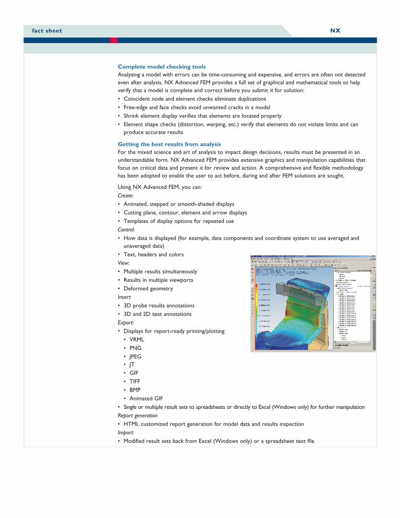
Getting the best results from analysisFor the mixed science and art of analysis to impact design decisions, results must be presented in anunderstandable form. NX Advanced FEM provides extensive graphics and manipulation capabilities thatfocus on critical data and present it for review and action. A comprehensive and flexible methodologyhas been adopted to enable the user to act before, during and after FEM solutions are sought.
Using NX Advanced FEM, you can:Create:• Animated, stepped or smooth-shaded displays• Cutting plane, contour, element and arrow displays• Templates of display options for repeated useControl:• How data is displayed (for example, data components and coordinate system to use averaged and
unaveraged data)• Text, headers and colorsView:• Multiple results simultaneously• Results in multiple viewports• Deformed geometryInsert:• 3D probe results annotations• 3D and 2D text annotationsExport:• Displays for report-ready printing/plotting
• VRML• PNG• JPEG• JT• GIF• TIFF• BMP• Animated GIF
• Single or multiple result sets to spreadsheets or directly to Excel (Windows only) for further manipulationReport generation• HTML customized report generation for model data and results inspectionImport:• Modified result sets back from Excel (Windows only) or a spreadsheet text file
fact sheet NX
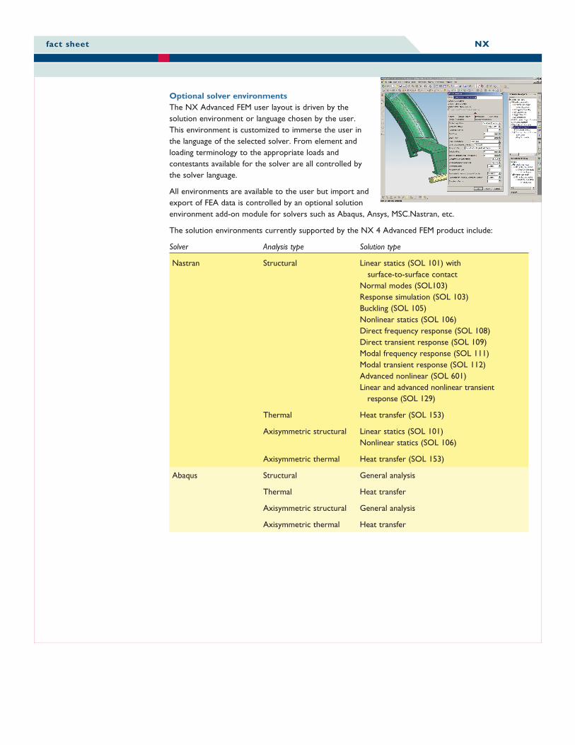
Optional solver environmentsThe NX Advanced FEM user layout is driven by thesolution environment or language chosen by the user.This environment is customized to immerse the user inthe language of the selected solver. From element andloading terminology to the appropriate loads andcontestants available for the solver are all controlled bythe solver language.
All environments are available to the user but import andexport of FEA data is controlled by an optional solutionenvironment add-on module for solvers such as Abaqus, Ansys, MSC.Nastran, etc.
The solution environments currently supported by the NX 4 Advanced FEM product include:
Solver Analysis type Solution type
Nastran Structural Linear statics (SOL 101) withsurface-to-surface contact
Normal modes (SOL103)Response simulation (SOL 103)Buckling (SOL 105)Nonlinear statics (SOL 106)Direct frequency response (SOL 108)Direct transient response (SOL 109)Modal frequency response (SOL 111)Modal transient response (SOL 112)Advanced nonlinear (SOL 601)Linear and advanced nonlinear transient
response (SOL 129)
Thermal Heat transfer (SOL 153)
Axisymmetric structural Linear statics (SOL 101)Nonlinear statics (SOL 106)
Axisymmetric thermal Heat transfer (SOL 153)
Abaqus Structural General analysis
Thermal Heat transfer
Axisymmetric structural General analysis
Axisymmetric thermal Heat transfer
fact sheet NX
fact sheet NX
FeaturesPowerful analysis capabilities
Complete element library includingspot welds
Full range of material models
Easy combination and addition ofload cases
Comprehensive array ofEigensolvers
Design sensitivity analysis forassessing design changes
Efficient solvers
Comprehensive thermal analysiscapabilities
Basic nonlinear capability for largedisplacement and materialnonlinearities
Surface-to-surface contact for linearstatic solutions
Glue connections for joiningdissimilar meshes
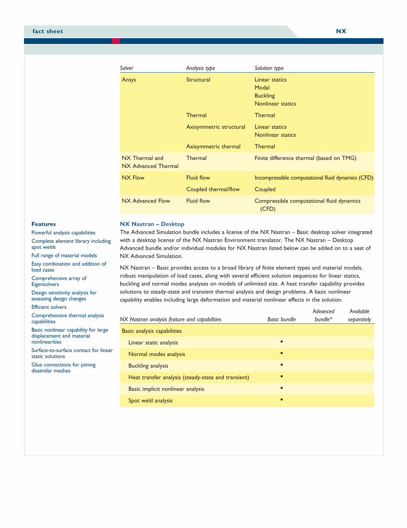
Solver Analysis type Solution type
Ansys Structural Linear staticsModalBucklingNonlinear statics
Thermal Thermal
Axisymmetric structural Linear staticsNonlinear statics
Axisymmetric thermal Thermal
NX Thermal and Thermal Finite difference thermal (based on TMG)NX Advanced Thermal
NX Flow Fluid flow Incompressible computational fluid dynamics (CFD)
Coupled thermal/flow Coupled
NX Advanced Flow Fluid flow Compressible computational fluid dynamics(CFD)
NX Nastran – DesktopThe Advanced Simulation bundle includes a license of the NX Nastran – Basic desktop solver integratedwith a desktop license of the NX Nastran Environment translator. The NX Nastran – DesktopAdvanced bundle and/or individual modules for NX Nastran listed below can be added on to a seat ofNX Advanced Simulation.
NX Nastran – Basic provides access to a broad library of finite element types and material models,robust manipulation of load cases, along with several efficient solution sequences for linear statics,buckling and normal modes analyses on models of unlimited size. A heat transfer capability providessolutions to steady-state and transient thermal analysis and design problems. A basic nonlinearcapability enables including large deformation and material nonlinear effects in the solution.
Advanced AvailableNX Nastran analysis feature and capabilities Basic bundle bundle* separately
Basic analysis capabilities
Linear static analysis •Normal modes analysis •Buckling analysis •Heat transfer analysis (steady-state and transient) •Basic implicit nonlinear analysis •Spot weld analysis •
fact sheet NX
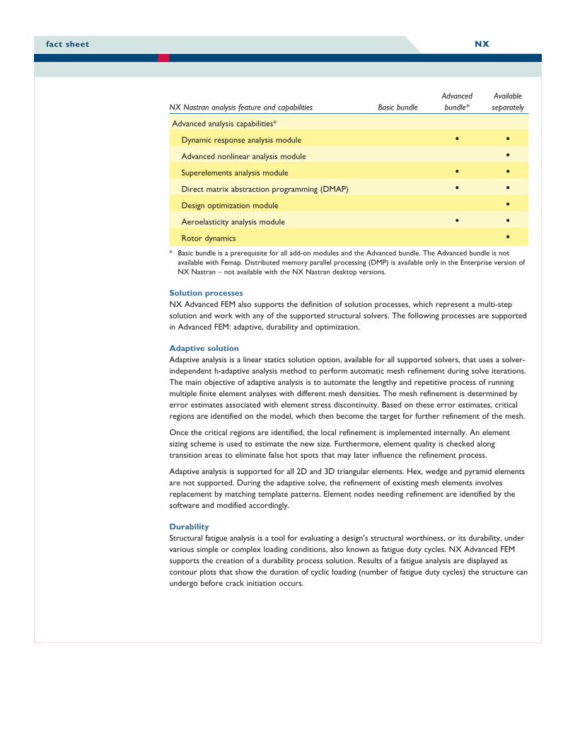
Advanced AvailableNX Nastran analysis feature and capabilities Basic bundle bundle* separately
Advanced analysis capabilities*
Dynamic response analysis module • •Advanced nonlinear analysis module •Superelements analysis module • •Direct matrix abstraction programming (DMAP) • •Design optimization module •Aeroelasticity analysis module • •Rotor dynamics •
* Basic bundle is a prerequisite for all add-on modules and the Advanced bundle. The Advanced bundle is notavailable with Femap. Distributed memory parallel processing (DMP) is available only in the Enterprise version ofNX Nastran – not available with the NX Nastran desktop versions.
Solution processesNX Advanced FEM also supports the definition of solution processes, which represent a multi-stepsolution and work with any of the supported structural solvers. The following processes are supportedin Advanced FEM: adaptive, durability and optimization.
Adaptive solutionAdaptive analysis is a linear statics solution option, available for all supported solvers, that uses a solver-independent h-adaptive analysis method to perform automatic mesh refinement during solve iterations.The main objective of adaptive analysis is to automate the lengthy and repetitive process of runningmultiple finite element analyses with different mesh densities. The mesh refinement is determined byerror estimates associated with element stress discontinuity. Based on these error estimates, criticalregions are identified on the model, which then become the target for further refinement of the mesh.
Once the critical regions are identified, the local refinement is implemented internally. An elementsizing scheme is used to estimate the new size. Furthermore, element quality is checked alongtransition areas to eliminate false hot spots that may later influence the refinement process.
Adaptive analysis is supported for all 2D and 3D triangular elements. Hex, wedge and pyramid elementsare not supported. During the adaptive solve, the refinement of existing mesh elements involvesreplacement by matching template patterns. Element nodes needing refinement are identified by thesoftware and modified accordingly.
DurabilityStructural fatigue analysis is a tool for evaluating a design’s structural worthiness, or its durability, undervarious simple or complex loading conditions, also known as fatigue duty cycles. NX Advanced FEMsupports the creation of a durability process solution. Results of a fatigue analysis are displayed ascontour plots that show the duration of cyclic loading (number of fatigue duty cycles) the structure canundergo before crack initiation occurs.
fact sheet NX
Fatigue analysis uses the cumulative damage approach to estimate fatigue life from stress or strain timehistories. Estimation is accomplished by reducing data to a peak/valley sequence, counting the cyclesand calculating fatigue life. A library containing standard fatigue material properties is provided.
OptimizationOptimization is a process that helps the analyst arrive at the best solution for a given design goal. NXAdvanced FEM allows the user to create an optimization solution process. The user can define a goalsuch as the mass of a part or component, a constraint such as maximum allowable Von Mises stressand the design parameter(s) to vary on the component. The optimization solution process will runbased on the design criteria while varying the design parameters to enable the design engineer todetermine if there is a better structural design alternative vs. the original baseline design.
Product availabilityNX Advanced Simulation is the core CAE package in the integrated suite of NX digital productdevelopment applications. It is a prerequisite for all other add-on NX CAE applications in the NXAdvanced Simulation suite such as NX Nastran Desktop advanced modules, NX Response Simulation,NX Flow, NX Advanced Flow, NX Thermal, NX Advanced Thermal, NX Electronic Systems Cooling,NX Space Systems Thermal Simulation and NX Laminate Composites as well as the customized solverinterfaces for Nastran, Ansys and Abaqus.
NX Advanced Simulation is available on most major hardware platforms and operating systems(Windows, Linux, UNIX) including selected 64-bit systems.
ContactSiemens PLM SoftwareAmericas 800 498 5351Europe +44 (0) 1276 702000Asia-Pacific 852 2230 3333www.siemens.com/plm
© 2007 Siemens Product Lifecycle Management Software Inc. All rights reserved. Siemens and the Siemens logo are registered trademarks of Siemens AG.Teamcenter, NX, Solid Edge, Tecnomatix, Parasolid, Femap, I-deas, JT, UGS Velocity Series, Geolus and the Signs of Innovation trade dress are trademarks orregistered trademarks of Siemens Product Lifecycle Management Software Inc. or its subsidiaries in the United States and in other countries. All other logos,trademarks, registered trademarks or service marks used herein are the property of their respective holders. 10/07