Embed Size (px)
Citation preview

NWSA-CR-195813
Final Report
Contract NAS5-31056
A Study of Low Mass X-ray Binaries
(NASA-CR-195813) A STUDY OF LOWMASS X-RAY BINARIES Final Report, 1Jul. 1991 - 31 Mar. 1994 (LockheedAircraft Corp.) 72 p
N94-34119
Unclas
G3/89 0005478
31 March 1994
Principal Investigator: Dr. Richard C. Catura
Lockheed Palo Alto Research LaboratoryDept. 91-30, Bldg. 252
3251 Hanover St.Palo Alto CA 94304
https://ntrs.nasa.gov/search.jsp?R=19940029613 2018-07-01T06:35:07+00:00Z

Final Report
Contract NAS5-31056
Covering the period 1 July 1991 thru 31 March 1994
SPECTROSPAS STUDY
The entire effort under this contract during the period thru January 1992was devoted to a study of the cost and schedule required to put an upgradedAries payload on the ASTRO-SPAS carrier provided by the German space agency,DARA. The ASTRO-SPAS is flown on the Space Shuttle, deployed by the crew for 5to 7 days of free-flying observations and then recovered and returned to earth.The spectrograph was to be provided by a collaboration involving the LockheedPalo Alto Research Laboratory (LPARL), the Center for Astrophysics and SpaceAstronomy (CASA) at the U. of Colorado and the Mullard Space Science Laboratory(MSSL) in England. The payload for the ASTRO-SPAS mission included our ownspectrograph and an instrument provided by Dr. Joachim Trumper of the Max PlanckInstitute (MPI) in Garching, Germany
A meeting was held in late July, 1991 with German scientists, DARArepresentatives and MBB, the ASTRO-SPAS spacecraft contractor. Sufficientinformation was exchanged to allow us to complete the study and the name LEXSA(Low Energy X-ray Spectrograph on ASTRO-SPAS) was given to our instrument andHERTA (High Energy x-Ray Telescope on ASTRO-SPAS) to the German instrument. Thecombination was called SPECTRO-SPAS. On October 1, 1991 CASA and LPARLsubmitted a cost and brief technical proposal to NASA on results of the study.The total cost over 4 fiscal years was $6.16M, including CASA costs (moredetail below). NASA Headquarters was briefed on 3 October on details of theproposal. They found our costs reasonable, but indicated that the NASA Fy '92budget is extremely tight, they could not readily identify where the ~ $2.3Mfor LEXSA could be found and it was not clear that Fy '93 would improve.
On 29 October, NASA's advisory committee, the High Energy AstrophysicsManagement Operations Working Group (HEAMOWG), was briefed on the science andprogrammatics of the LEXSA investigation. A recommendation for NASA to proceedwith LEXSA was given by the HEAMOWG.
LEXSA is a very capable spectrograph, having a spectral resolution of 100 andan effective area of 100 cm2 in the .15 to 2 keV range. Its capabilities arewithin a factor of 2-4 of those of AXAF or ESA's XMM. It can be flown in 1995,probably 5 years before either of these missions. LEXSA fits therecommendations of the Bahcall Committee, as well as those of several otherNASA advisory committees, that opportunities for low cost and quick access tospace be made more readily available.
A summary of the cost derived from the study is given below:

COST IF LEVELEDIN FY '92 & '93AS BELOW
LPARL COST
Fy '93
$1,110K
$50K
$49K
$22K
$1,231K
($1,696K) ($1,594K)
LABOR
MATERIAL
SUBCONTRACTS
TRAVEL
TOTAL LPARL COST
Fy '92
$1,393K
$417K
$222K
$27K
$2,059K
Fy '93
$1,110K
$50K
$49K
$22K
$1,231K
Fy '94
$795K
$21K
$132K
$948K
Fy '95 TOTAL
$102K $3,400K
$467K
$292K
$46K $227K
$148K $4,386K
The funding requirements could be leveled somewhat without affecting schedule(as shown in parenthesis above) by the following shifts:
1836 hrs can be moved from Fy '92 to Fy '93 - $213K
Material ~ $150K could be shifted from Fy '92 to Fy '93
TOTAL US COST INCLUDING U. OF COLORADO
TOTAL US COST
Fy '92 Fy '93 Fy '94 Fy '95 TOTAL
$2,695 $1,826 $1,488 $148 $6,157
COST FOR FY '91 & '92 ($2,332) ($2,189)IF LEVELED AS ABOVE
Copies of viewgraphs used during presentations of the LEXSA investigationand other materials produced during the study are included in this report asAppendix 1.
FLIGHT OF ARIES 24.017
A PIC for the reflight of Aries 24.017 was held on 20 April 1992 at theNASA Wallops Flight Facility. The only changes to the experiment payload wereto the imaging proportional counter. The high voltage for this detector waspotted to prevent the breakdown that occurred on 24.011.
The telescope was dis-assembled for cleaning and the mirrors inspected.They were found to be covered with a hazy film. This film was not apparentunless the mirror surface was illuminated by an intense collimated visiblelight in a dark room. Under these conditions the mirror scattered some of the

light and the film was visible. Witness samples to the mirror's lacquer andgold depositions did not show this effect. During re-entry a cork heat shieldon the aft bulkhead of the service module burned. Some of this gaseous materialentered the payload thru vents at the aft of the experiment. These vents areshrouded to prevent air flow into the payload during launch, but serve asscoops on re-entry. These thin aluminum shrouds were also burned duringre-entry and it is believed that the aluminum and oxidized cork vapors weredeposited as a film on the mirrors.
Efforts to clean the mirrors were begun. A rinse with a detergent solutionfollowed by de-ionized water, high purity isopropyl alcohol with a final rinseof de-ionized water that was blown dry with nitrogen gas was tried on thewitness flats. X-ray reflectivity measurements before and after the processindicated the reflectivity was unchanged from that measured after deposition inMarch 1990. This cleaning process was tried on the smallest hyperboloid mirror,without success. A cleaning process using dry ice "snow" was tried next. Thistechnique used liquid C02 in a high pressure bottle. The liquid is exhaustedfrom the bottle thru a small orifice where the expansion cools it to form the"snow". This is similar to what occurs in dry ice fire extinguishers. The snowis then directed at the surface to be cleaned. This process has been used toclean mirrors of large optical telescopes and even the surface of CCDs.Measurements on the witness flats indicated that this type of cleaning did notdisturb the reflectivity. When this cleaning was tried on the smallesthyperboloid and paraboloid it improved the surfaces but they still did notappear as clean as the witness flats. Because of their large size it wouldrequire a major effort to measure the x-ray reflectivity of the telescopemirrors. Thus, it was decided to strip and re-lacquer the mirrors.
Since the technician who was involved in the mirror finishing for Aries24.011 in 1990 had left Lockheed, many of the techniques had to bere-established, including the lacquer coating and gold evaporation processes.This required considerably more effort than was included in the proposal forrefurbishment of the telescope for flight on Aries 24.017. A small crane wasinstalled in the self-contained coating facility to lift the mirrors into andout of the methyl ethyl ketone bath used to strip the old gold-coated lacquerfrom the mirrors. The six mirrors were lacquer coated and baked at 130 C for 1hour. Gold was vacuum evaporated onto the lacquer by placing a mirror, with itsaxis vertical, on a rotary table in a large vacuum chamber. A tungstenfilament, wrapped with .25 mm diameter gold wire, was positioned along themirror's axis. A baffle, whose purpose was to restrict the angle of incidenceof the evaporated gold atoms with respect to the mirror's surface to within 20deg of normal incidence, surrounded the filament. After evacuating the chamber,the filament current was increased to its maximum of 70 amps in about 15sec, held there for 30 sec and returned to zero. The evaporation must be donequickly to reduce the heat input to the lacquer and to prevent the liquifiedgold from running down the filament.The telescope mirrors for Aries 24.017 weresuccessfully completed in early May of 1993. X-ray reflectivity measurements ofwitness samples agreed very well with those calculated from the opticalconstants of gold. The mirrors were mounted on the center support plate andthis mirror assembly was installed in the experiment payload.
Collaborators at the Mullard Space Science Laboratory (MSSL) were unableto obtain funding from the UK Science and Engineering Research Council forexplicit expenses to support Aries 24.017. Labor costs could be covered underthe MSSL block grant from the SERC but travel costs and major hardwarepurchases could not be made. Thus, 20 new bellows actuators of the type used toopen the imaging proportional lid were purchased under this contract. During

the flight of 24.011 two such actuators failed to deploy even though theirbridge wires were successfully fired. The newly purchased actuators werex-rayed and the results examined by people at the GSFC Wallops Island FlightFacility (WFF). Eleven were deemed acceptable; two were test fired successfullyand two were chosen for flight from the remaining nine. The residual actuatorsare currantly in the possession of WFF.
Personnel at MSSL potted the high voltage system which suffered electricalbreakdown in the flight of Aries 24.011. This system was tested by slowlyevacuating the entire assembly to a pressure of a few mtorr, where breakdownproblems are most severe, over a period of several hours and then slowlyreturning to atmospheric pressure. The high voltage was turned on during theentire test with no breakdown problems.
Integration was begun on 3 May 1993 at the WFF. The integration went verywell where the only problems encountered were in ground support equipmentoutside the payload.
The grating spectrograph was calibrated at the High Energy Laser SystemTest Facility (HELSTF) at White Sands Missile Range in early June. Asubcontract was initiated with the U.S. Army Space and Strategic DefenseCommand to reimburse HELSTF for their support of the calibration. A copy of thetest plan for this calibration is included in this report as Appendix 2. Alsoincluded, in Appendix 3, are representative plots of some spectra obtainedduring the calibration. The x-ray source anode and filter used are indicated oneach plot, as well as the wavelength of the principal emission line. Thediffraction order is indicated above each peak in the spectra. Aftercalibration, the experiment payload and GSE were transported to the NASA VAB atWSMR for launch in late August to observe the soft x-ray spectrum of the crabnebula.
Aries 24.017 was launched from WSMR at 09:45:00.17 GMT (0345 MDT) on 28August 1993. Following a nominal lift off and initial assent, the vehicleexperienced a series of drops in chamber pressure and anomalous flight dynamicsbeginning at approximately 25.41 seconds after launch. The vehicle experienceda large left yaw at approximately 26.12 seconds that severely increased theangle of attack, causing V-band joints to fail, and splitting the payload intothree parts. The nose cone, impact absorbing section, forward and middleexperiment sections remained together. The aft experiment section separatedfrom the rest of the payload as did the service module which contains systemsfor attitude control, telemetry, instrumentation and recovery. Aerodynamicloads and impact with the ground scattered the experiment payload over an areaof approximately 1/4 square mile, centered about 200 yds west and 400 yds northof the launch pad. Figures 1-4 are photographs of the debris. The x-raytelescope mirror assembly remained intact but is so severely damaged as to beuseless. All of the experiment payload structures were destroyed. The booster,which was separated from the payload, continued to burn until T+42 sec whenrange safety personnel destroyed it. It was tracked by radar and impacted about2.5 miles from the launch pad. One of the nozzles from the booster was foundamong the payload debris and the failure investigation report indicates thatloss of this nozzle was responsible for the vehicle malfunction. This was to bethe last Aries launched by NASA, although another flight may have beenconsidered had 24.017 been successful.

CCD CAMERA
We proposed to use a Tektronix 1024 by 1024 back-illuminated three phaseCCD with 24 micron square pixels as the image sensor for an upgraded soft x-rayspectrograph. It is a Multi Pinned-Phase (MPP) device which provides reduceddark current. The back surface has been specially treated with a Tektronixproprietary.process to provide high and stable quantum efficiency for softx-rays. There is an anti-reflection (AR) coating of MgF2 applied over the backsurface to enhance visible light efficiency and further stabilize the CCDperformance. The thinned CCD is fully supported over its area and is opticallyflat. We have measured the soft x-ray quantum efficiency (QE) of a 512 by 512device, identical to the proposed CCD except in size, and the results are shownin Fig. 5. Since Tektronix will not discuss composition of the back surface andthat dead layer is very thin, the QE of the CCD has been modeled usingabsorption in the MgF2 coating and a 10 micron depletion depth. This model hasbeen fitted to the measured data and the results are shown in Fig. 5 by thesolid line. There is reasonable agreement except for the data point at .53 kev.It may be that the backside treatment involves nitride, whose absorption edgeat .39 kev may explain the discrepancy of this point. Since the absorbingeffects of the back surface are small at higher energies, the CCD QE isdetermined by the depletion depth and is well represented by the model above 1keV. We plan to use a 1500 A Al filter to block visible light and the QEexpected for the CCD and filter is shown by the dashed curve. The CCD will thushave a QE greater than 60 % over most of the .4 to 2 keV range of thespectrograph.
The CCD operates in single photon counting mode and provides sufficientnon-dispersive energy resolution to separate orders in the spectrograph. Thesystem will operate below 10 electrons rms noise level, providing an energyresolution of better than 100 eV below 2 keV. The various orders are separatedby 150 eV, so it will be possible to distinguish one from another. The CCD willbe cooled to -60 C by a cold finger attached to a thermal mass in a LN2 dewar.Temperature regulation is maintained by a thermistor controlled heater on thecold finger. We have fabricated several of these coolers and they have beenoperating reliably in the laboratory for more than three years. The dewar willbe sized appropriately for the flight and prelaunch preparations and will bevented through a one-way valve outside the payload. Because of the coolingrequirement, the CCD must be in vacuum to avoid freezing condensates on itssurface. The CCD and front end electronics will be housed in a small vacuumchamber with a gate valve that opens for the observations and closes beforere-entry. A radioactive Fe-55 source will be mounted on the valve to illuminatethe CCD with 5.9 keV x-rays for the purpose of monitoring system gain beforeand after the observations.
The spectrum will have a resolution element 50 by 250 microns in size andbe dispersed over about 18 mm, including zero order. The CCD will provide 2pixels per resolution element in the dispersion direction. Detection of zeroorder provides an in-flight reference for re-pointing the rocket attitude tocompensate for absolute pointing errors and drift in the attitude controlsystem. The CCD is operated in frame transfer mode with a 512 by 1024 imagearea sensitive to x-rays and the remaining area shielded by a mask. After anintegration period, the image is shifted in 7 ms into the shielded area whereit is read out at a rate of 75 kilo-pixels/sec. This sets the integration timeof 7 sec. The 10 bit charge amplitude in each pixel is fed to the 800kilo-bit/sec PCM encoder via a FIFO buffer and hand-shake electronics. The 512by 1024 images will be displayed on a monitor for real time control of the

rocket pointing. The 7 ms frame transfer time is sufficiently short so that noshutter is required.
The 7 sec integration time poses no problem for single photon detection inthe CCD since the image is dispersed across the device and an emission linefalls onto 20 pixels. For detection of 3 photons per integration period (a lineflux of .02 photons/cm2-sec) the probability of getting 2 photons in one pixelis less than 1 percent. For sources brighter than .02 photons/cm2-sec-keV, morethan 5 photons will be detected in the zero order image of the source in 7 sec,sufficient to identify its location and perform the aspect corrections.
The camera design we proposed to use is that developed over several yearsby Jim Janesick at the Jet Propulsion Laboratory and a block diagram is shownin Fig. 6. As a part of a technology transfer effort, JPL has provided circuitdesigns and circuit board architecture for their proven low noise camera toTalktronics inc., a small firm who is now producing the cameras commercially.An electronic engineer and a mechanical engineer specializing in electronicspackaging, both with over 30 years of experience in fabricating electronics forspace flight, have visited Talktronics to inspect the camera's circuit boardconstruction. Both are confident the camera can be ruggedized and repackagedfor sounding rocket use. This will thus be a very cost effective way to obtaina low noise flight-worthy CCD camera. The following list describes some changesthat will ruggidize the CCD camera and make it better suited for soundingrocket use and for cooled operation.
1. The CCD is to be operated in a "frame transfer" mode where the top half (I)of the chip is to perform image-sensing and the the bottom half (S) is toreceive data from (I) by fast parallel transfer and store it for subsequentslow scan readout. During this transfer (I) and (S) are clocked identically.For the readout of (S) its gates are clocked appropriately, while the (I) gatesare not clocked, but are biased for integration. The readout period for (S) isthe integration period for (I). For a readout rate of 70 kpixels/sec thereadout/integration period is about 7 sec. After this readout/integrationperiod the cycle begins again with another frame transfer. A mask is placedover (S) so it recieves no exposure. The fast parallel frame transfer must bedone in a time short compared to the 7 sec integration time so no shutter willbe required. If one accepts a 1 % image smearing (ie 1 % of the photons aredetected during frame transfer and are thus positioned wrongly) the paralleltransfer can be at a 5 khz rate, if this would be of advantage in configuringthe readout. Some software and hardware for the frame transfer must bedeveloped to meet this frame transfer operation.
2. Since the CCD is to be cooled to reduce noise it must be in a vacuum toprevent water vapor from freezing on the chip. The head board and componentsmust be of low out-gassing materials, as far as practical to minimizecondensation of material on the cooled CCD that would degrade its soft x-rayquantum efficiency.. The board should be made from polyimide material and, ifpossible, without the solder mask, silk screen lettering and componentoutlines. Also, components should be low outgassing where practical. In orderto reduce dark current sufficiently, the CCD should be cooled to -60 C. Anydesign changes to the head board/CCD mounting that would facilitate thiscooling would be valuable.
3. The plated-thru holes on the connector edge of the boards should be placedcloser together, on .100 inch center to center spacing, on each of two columnsto fit connector pins indicated on Figure 7 and 8. No solder terminals arerequired, as are on the present boards. Also, the boards should have two holes

added to accommodate the connector mounting screws as shown in Fig. 8.Elliminate the plastic board extractors but leave the associated holes in theboards. If possible, place the signal chain components on a board similar tothe other boards. (The signal chain board is to be separated from the otherboards by a ground plane in the card cage). The power supply module is notrequired, since light-weight supplies will be purchased for the rocket flight.Elliminate the gold plated edge finger connectors and solder masks on theboards. The' silk screen lettering and component outlines are OK except on thehead board.
4. Conformal coating of the boards will be done here at Lockheed as well assecuring larger components against vibration effects and provisions fordissipating power, where necessary.
5. The above changes will allow the camera electronics to be housed in anelectronics box designed by the AEPI experiment for flight on the spaceshuttle. This box has successfully flown on the shuttle and details are shownin Figs. 9 and 10. The box has provision for 10 cards, while the CCD camerawill require only 7. The remaining space will be used to house the powersupplies and a telemetry interface.

•o10o
(0a
c
"g•HUa>a
14-1
O
Co
•H4-Juoa
(03MO
oM
u-i
03•HMXIa)a
0)M3Cn
•Hfci

Cn
(1)
•Hn3O
4J
i4-1
g•HM(1)ax0)
•OM<8
MOCu
eg0)M3O>
•HCu
*%*?*\-'C. ~r*.'•;..- . If


aor
l-C
0)1-1
o-
OF POOR QUALITY

(J
ca;'o
CODO
QOO
Q_Q_
cO
CD
CN
CDCLd
QOCJ
aEH
a)JJ
o0)
•HO
•H
4J
na
m
0)M3Oi
-Hb
I I J_
00•
OCD
•
OCNO

JJCO
fOM
IT)O
a80)
<HO
<0M
UO
CO
0)M3Cn

ROWConnectors
PC Card toChassis or
Board
WTB26SAOI ISY WTB-WTB
PLUG: WTBRECSTACLE: WTB
2626
PLUG RECEPTACLE
WTB « 2<ow, righKangto, pkig. mntg. em. WTB ring.
lO.14.20242BJa36.40.44j05t.S6.6a66.70
Examples:
PR9SA011
•
i
SYSY
PR7 » Ph. rightengto. dp solder. .109PR9 « Ph. righttngte. dp setter. .140Pfln 3 Pin, rigfeangfe dip sotdar. .172PRW40 > Pin, right-angto, Wlra Wrap. .625
SACSA09SA011SA01SSAF3SAF6SAW40
Sodfat sliajyic solder cup, dosed entrySocket. straight dp aoUac .140Socket, straight, dp aoMat .172
Socket, sliaitfa« fla*circuit, OSOSocket, stitijft, flaMCircut, 1X3Sodat. sliaiytA, WW» Wrap, j62S
SY Guides* I SY Quideset
342 s remove ,25CMong mounting ears. (Add "342* to put number. Example: WTB26PR9SY342.)54B a Include nuts bonded into hex recess in mounting holes. (Add "546" to part number. Example: WTB26PR9SY548.)
• For polarized "D"-shaped guides, add dash and code number to part number (Exampir-7). Sea "Polarization" under next tab for codes.• Face seal gaskets: order separately. See "Gaskets" under next tab for instructions.
413 a Straight pin contacts in right angle plug molding wrtfi solder cup tarrmnaJs extending .100* beyond molding. (Add "4t3* to part number.Example: WTB26PR9SY413.)
Figure 7Ruggedized connectors to be used for rocket flight.
OMG1NAL PAGE IBOF KX» QUALITY
W Series ConnectorsJUL 90 2-3

A/
Oi
u.
\.1 1 — '
f-l-i-L: 4t»_ _ >> l-f-
'f^A^ I"^lI / ' ^ «• ^ «— — _ _ A. V
• ' ' • I
fP
h•— t r
f,
o4Jo<ucoo•a01N
•HT)
IM
MO
0}T)Mmo
3U
O4J
n0)01(0
o•O0)noaon
a>
O)•H

L. «?=
0
,
t
1 1
...
I
NJ
s**
^ 1 1I
II0
1I1!
f • ~••
inI*•••••<«> *« i« i« i« «• i• •
• »•
1 |
s
-1
. . .l<^«A^_AJ•._
8.n)u
n>o
-u
•Hi-(<U
M-lO
•HOJ0)Q
0)M
-HDu

•s
-f-v
KBU
•oM<au
<MO
•H
ftiM•o
'—Ii0)nn
0)M30>
•HEu

APPENDIX 1
VIEW GRAPHS AND OTHER MATERIALS DEVELOPED IN THE SPECTROSPAS STUDY

SPECTRO-SPASLOW ENERGY X-RAY SPECTROGRAPH ON ASTRO-SPAS (LEXSA)HIGH ENERGY X-RAY TELESCOPE ON ASTRO-SPAS (HERTA)
SCIENCE STRATEGY:
LEXSA and HERTA will obtain high sensitivity medium resolution x-rayspectra of a wide variety of both galactic and extra-galactic x-ray sources. Lowenergy dispersive spectroscopy complimented by simultaneous and overlappingbroad band non-dispersive spectroscopy will provide definitive x-ray spectralmeasurements in the 0.15 to 10 keV energy range.
MISSION TYPE:
International
OBJECTIVES:
Spectroscopic investigation of cosmic x-ray sources in the .15 to 10 keVrange will be performed to better understand the emission mechanisms andphysical conditions in the sources. The high sensitivity of SPECTRO-SPAS willprovide a medium resolution (E/dE~100) catalog of the spectra of nearly allclasses of galactic and extragalactic x-ray sources. The temperature andelemental abundances of the interstellar medium can also be studied from theabsorption spectra of material along the line of sight.
DESCRIPTION:
SPECTRO-SPAS consists of a grating x-ray spectrograph, LEXSA, operating inthe 0.15 to 2 keV range and a-non-dispersive spectrometer, HERTA, sensitive tox-ray energies from 0.2 to 10 keV. The LEXSA involves a 5 mirror-pair Wolter Itelescope, a radial groove grating array and a CCD image sensor to provide aneffective area of 100 cm2 and a spectral resolution of better than 100 over mostof its spectral range. It will be developed by the Lockheed Palo Alto ResearchLaboratory (LPARL), the Center for Astrophysics and Space Astronomy (CASA) atthe University of Colorado and the Mallard Space Science Laboratory (MSSL) inthe United Kingdom. The HERTA involves a 3 mirror-pair Wolter I telescope with apn CCD image sensor to provide an effective area greater than 25 cm2 over mostof its spectral range and an energy resolution ranging from 3 to 60 between 0.2and 10 keV, respectively. It will be developed by the Max Planck Institut FurExtraterrestrische Physik-Garching (MPE), Max Planck Institut-Bonn and theUniversity of Tubingen. These instruments are mounted in the ASTRO-SPAS Carrier,a spacecraft that provides attitude control and data handling/transmissionduring the observations. The ASTRO-SPAS is provided by the German Space Agency,DARA and manufactured by Messerschmitt-Bolkow-Blohm Gmbh.
The payload is carried to low-Earth orbit by the Space Shuttle and deployedby the Remote Manipulator System. The payload operates at distances up to 40 kmfrom the Shuttle. Most of the data are recorded on board, with sufficient datatransmitted to the ground to allow SPECTRO-SPAS to be commanded and operatedfrom the Payload Operations Control Center at the Kennedy Space Center. TheSPECTRO-SPAS is subsequently recovered and returned to Earth.

PAYLOAD/PI LIST:
LEXSA: Richard Catura (LPARL)
HERTA: Joachim Trumper (MPE)
LAUNCH DATE: February 1995
PAYLOAD: Two telescope-spectrographs, one dispersive,one non-dispersive.
ORBIT: 300 km at 28.5 degree inclination
MISSION DURATION: 6-7 days
LENGTH: 3.5 meters
WEIGHT: 1200 kg
LAUNCH VEHICLE: Space Shuttle
FOREIGN PARTICIPATION: DARA, the German Space Agency (throughMax Planck Institut-Garching, Max PlanckInstitut-Bonn and University of Tubingen)supplies HERTA. Also DARA provides theASTRO-SPAS Carrier.
PAYLOAD SPECIALISTS: None
CURRENT PHASE:
Phase B Completed
STATUS:
LEXSA and HERTA are awaiting Phase C/D funding
MISSION EVENTS:
Phase B study completed 1 October 1991
MANAGEMENT:
NASA HeadquartersW. Huddleston, Program Manager (Flight Systems Division)L. Kaluzienski, Program Scientist (Astrophysics Division)
Lockheed Palo Alto Research LaboratoryR. C. Catura, Principal InvestigatorR. A. Stern, Project Scientist
University of Colorado, CASAW. C. Cash Jr., Lead InvestigatorJ. Green, Project Scientist

Mullard Space Science LaboratoryJ. L. Culhane, Lead InvestigatorA. Smith, Project Scientist
Max Planck Institut Fur Extraterrestrische PhysikJ. Trumper, Lead Investigator
DARAG. Hartmann, Program ManagerJ. Tjaden, Payload Manager
MAJOR CONTRACTORS:
U.S.Lockheed Palo Alto Research LaboratoryUniversity of Colorado, CASA
U.K.Mullard Space Science Laboratory
GermanyMax Planck Institut Fur Extraterrestrische PhysikMax Planck Institut-BonnUniversity of TubingenMesserschmitt-Bolkow-Blohm Gmbh

TRIP REPORT
CONTRACT NAS5-31056
TRIP OF 20 THRU 25 JULY, 1991
Travel'to Munich, Germany was undertaken during July 20-25 1991 forpurposes of initiating discussions relative to a definition study forplacing an upgraded Aries spectrograph on ASTRO-SPAS 3. Discussions wereheld in three separate locations, described below. Agendas for the firsttwo days meetings are attached to this report: the discussions at thePanter x-ray calibration facility were informal, with no agenda.
MEETING AT MAX PLANCK INSTITUTE (MPE) ON 22 JULY
Presently known details of our investigation, the Low Energy X-raySpectrograph for Astro-spas (LEXSA), were presented as indicated on theattached copies of view graphs.
After lunch Dr. Aschenbach of MPE presented information on theirinstrument, the High Energy x-Ray Telescope for Astrospas (HERTA). Becauseof cost and schedule problems they have found it necessary to descope HERTAfrom the initially proposed telescope from an effective area of 125 cm2 at6keV to 25 cm2. Instead of 12 nested mirrors, 3 mirrors fabricated on aluminumsubstrates are proposed. This poses no problem in the region of overlap ofthe two instruments, between 0.2 and 2 keV, since the higher resolution ofLEXSA requires separating the counts into many more bins than HERTA so thatcounting statistics in each bin will be comparable. However the factor of 5reduction in area at higher energies reduces the sensitivity to iron-lineemission near 7 keV and will require increased observing time for HERTA toacquire adequate spectra on fainter objects for joint analysis with LEXSA.MPE will use a CCD detector that is 280 microns deep with less than a 400 Adead layer on the entrance surface. There was a large overlap in commonscientific interests and in the objects to be observed, so there should belittle difficulty in establishing a mutually acceptable joint observingplan. It was made clear that on ASTRO-SPAS 3 The U.S. has the majorintrument, as opposed to the first two missions where Germany has taken thelead. Data rights were discussed in a preliminary way and agreed that datafrom objects of mutual interest from both HERTA and LEXSA should be sharedbetween U.S. and.German investigators. The remaining observing time shouldbe allocated 50-50 between U.S. and German interests. These agreements, ofcourse, require NASA approval and should be reviewed in light of the datasplit between ORFEUS and IMAPS on ASTRO-SPAS 1, where Germany provides themajor instrument.
MEETING AT MESSERSCHMITT-BOELKOW-BLOHM (MBB) ON 23 JULY
A slightly briefer version of the LEXSA mission was presented at MBBas well as that for HERTA, emphasizing the hardware aspects of theinstruments and their requirements from the ASTROSPAS spacecraft.Characteristics of the ASTROSPAS were discussed and both the spacecraft andits mission support equipment were shown to the group. Some of the majorpoints of the discussions are:
1. Safety of the instruments are the major concern and QA will apply onlyto safety aspects and not to whether the instrument will operate properly.

2. The star tracker can operate within 40 deg of the sun and 10 deg of theearth's limb.
3. The attitude control is in 3 axes so the CCD thermal radiator may alwaysbe pointed in the most advantageous direction. An aspect solution ispossible five times per second. Maximum slew rate is 0.2 deg/sec, but isdone in all three axes simultaneously.
4. A breadboard of\the ASTROSPAS interface electronics is reccommended.
5. Recommended cable insulation is Ray Chem Viton.
6. Instruments must be demounted from the ASTROSPAS spacecraft for shipmentto KSC because otherwise it won't fit into a commercial aircraft.
7. Data are formatted by each experiment into blocks of 512 words. If datarate exceeds allocation, the data are lost.
8. The combined LEXSA and HERTA instruments will be called SPECTRO becausetheir scientific objectives entirely involve spectroscopy and the missionwill be called SPECTRO-SPAS.
We were supplied with several large documents, detailing therequirements for the mission. The personnel at MBB appear to be verycompetent, helpful and experienced at interfacing with JSC.
DISCUSSIONS AT THE PANTER X-RAY CALIBRATION FACILITY ON 24 JULY
The MPE x-ray calibration facility will be used in calibrating LEXSAso a visit to this laboratory was made to understand its capabilities andthe interfaces required. It consists of a 130 m long evacuated tube with anx-ray source at one end and a large vacuum chamber, housing the instrumentunder test, at the other end. The facility is very clean so thatcontamination of the payload should be no problem. A variety of x-ray linesare available and the alignment capabilities and provisions for rotatingthe payload for off-axis measurements are excellent. The entire facilityappears well-suited for calibrating LEXSA.
OMGtNAL PAQC ffiOF POO*

CO
§HEH
I
•KCOrtj04CO
SEHOH04CO
*
7CO
CO
iCO
HHi
i
g
cCOII
CO
04CO
CO
CO
Q
CO
§as
o
1oGO
^^CO
X
iH
§
CO
CO O
EH coHCO Q
U H
CO
04CO
O
EHCO
§COHHi
IH
DCUHasi
oHEH
HEHCO
o
nu
4 W
H HEH EHCO CO
H H O
H
Hi
O
H
04 P4 u
04CO
Q
UH04CO

COXH
CO4cuCO
§EHOW
CO
*

B/01.10.38
3 - 7
3.1 - 3: ASTRO-SPAS ALLOWABLE CARGO ENVELOPE
n
so

E-iCJ
§
COB
§HEH
ICO
CO1h
gHK!
§EH
u
HUCO
H
3U
EHPQI*CO<CMCO
IUw04CO•K
H -^

THE FOLLOWING ARE GRAPHS OF COSMIC X-RAY SPECTRA FROM THE INDICATED SOURCES
\
\
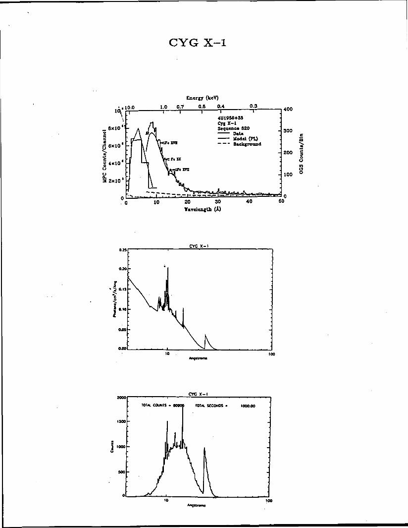
The format is: Top Graph is best current measured spectrum
Middle Graph is a spectrum simulated from the measureddata as an imput to the LEXSA spectrograph.
Bottom graph is the spectrum expected to be measuredby LEXSA in the observing time indicated.

PKS 2155-304
as 1.0ENERGY (ktV)
L5
PKS 2155-304
(MHO -
0.008
i c.oo»
0404
0402
040010 too
Anquromt
1SOO
1000
MO
PKS 2155-304
tOIM. COUKIS • IJ9220 IOM. SCCONOS M0040
too

3C273
10-3
-410
10.-5
;Vl
4 6 8 10 20 40 60E N E R G Y ( k e V )
0.0035 r
0.0030 h
• 0.001SK
0.001 Oh
0.0005 V
JC273
100
JC273
1»h
lOOh
TOTAL COUNTS . 20I71|. || fOMt.StCONOS - 10000.0

0.0 IS
Ii o.oos
Perseus Cluster
PERSEUS CLUSTER
Perseus Cluster
100
MOO
2000
1500
1000
Perseus Cluster
TOfAL COUNIS • O79 f fOMj. SCCONOS - 10000.0
100

Perseus at z = .1
S.OxlO
S.0«10 E-
Perseus ot i«.
500C
400 E
Pefseut ot i-.l
ror«L COUNTS •' M2o| WAI SECONDS - soooo.o
2001
lOOf-
10 100

SCO X-l
10.0
Energy (k«V)
1.0 0.7 0.6 0.4 OJJ1000
SO
2.0
0.010
SCO x-l
100
8000
2000
SCO X-I
TOMt COUNTS . J90 ,1 IOTM. SCCONOS - 300.000
too
CYG X-l
110.0
_ 8x10vcGe
j
§4x10'ou
32x10*
Enerer (keV)
1.0 0.7 0.5 0.4 0.3-\ r
•«zra
T4UI9S6+3S
Sequence 620D»Uilodel (PI)
— — - Background
10
Af-r-.-.— I .-"<-T-
20 30Tarelenctb (k)
40
400
300
200 g
<S
100
50
a.n
OJO
CYC X-l
ais
0,05
OJ»10 too
CYC X-l
I SCO
1000
SCO
IGtAL COUNIS . 4O906 TOM. SCCONOS 1000.00
100

LMC X-l
LMC X- 1
041 &
0.010
OJOOS
too
1500
1000
soo
LUC X-l
toui COUNTS . 7nit roui secoNOS - MOO.OO
100

HER X-l
tO.O 1.0 0.6
Enerjjr (keV)
0.3 02
4UI6S6+3SRcrZ-1S*qtienc« 633.- D»U
(BB)
20 40 80 BO
100
BO
60 '
40
20
8o
100
HCR X-l
M40 -
•420
&010
10 too•nqtlrann
towHER X-l
600
200
tout. COUMIS - io?«is TOTAL SECONDS < 1000.00
10 100

Zeta Puppis
2 o L Ztto Pvp(04Ifi if
0.1I I I I 11 11 t I I I -I
0.5 LOEnergy (keV)
5.0
2.S«IOZeto Puppi»
2.0«IO H
I.O<IO
S.O«IO
100

Capella
CopeMo
OJX»
Angtlnxra100
Copello
tOM«. COUNIS
600
400
200
IOIAI StCONOS •
10 too
CRAB
7
6
>•*? 5o«*
i;
CRAB NEBULAFPCS SPECTRUM
300 500 1000
ENERGY («V)
t-
3000
I T • '.' I
CRAB NEBULAFPCS SPECTRUM
450 900 550 600 650 700
ENERGY teV)
CRAB
10 100
l.0«10*
CRAB
T0t«. COUNfS • 10. tOTM. SECONDS - 1000.00
10 109

§HEH
oH)
HEH
CO
8HEH
CO0O
CO
\°w
CO (0
o or- CM
0)
o
COttoCM
COKoCM
COHoCM
CO
oCM
CO
oCMCM
oCM ID
COEHu
8
CO
B§
ininHCM
O4
COp-CM
OCO
CO«g§CM
r*CO
8
IX
S 04
£
CO
iCM
fCO
QCMCO
COCO
EHU
DV
n0)
8
CM
ftCO
COCO
CO
§EHUH04CO
*
HEHCO
3U
9OB
3A
CO
CO CO
CO
oEH

COZOHCOCOHSCODOH
M
2PI03EHHtf92QCOH
ggOU
4COXwHi
*CO4SCO
1gEHCJHPiCO
*
4 4in inH rH
<2J <2>
cn m•
EH
*co 4 40X o oH co in
CM<2J
0H
inrH CO
co m o8 VO O
H
4 oCO 0 0X 0 HH H AHi
i£iC SS3 o2 H4 &1
PW Hi> oH COEH Wcj 2wCu nJEzi i CM 2
EHfc<{ CJrij pgpq p^Pi CO
oinCM
OEHvo
ovo
OEH
in
in00
vo
"oT
§M4J090>C3.
HCD
S
dPiEHCJHPiCO
U0)CO
m<oH
X
CM•
VO
1 •
20HCOCOH2•7f-tHHEHCOZHH
32H£4
Pi0b
HEH
CDZ
PiUCOPI0COCDO
H]3EH
g
U0)09
CM
§in<oH
Xo
•
•*
IIU0109
in<oH
X
CM
VO
X
*x1invo
•
t •
§HCOCO
gP!ObpaSpCOo
HCOCDO
H]3EH
g
U0)09
in<0H
XCM
•
CM
II
U<U01OovoPO
XA^CM
Xin
•
X•oin• *
§HCOCO
gCO4PlCOICO4
P!ObM§
HEH
CDZH>&HCO
8
UQ)09
<NiU
r-<oH
xCM
•
CM
II
in<oH
XCM
t
CM
X
1ooH
• •
ZOHCOCO
S•oin
gbpn2PCOOPIXH
SiHi
H]
3EHOEH
•
bJ23J^ •
8 XEHH
Pi COo P:H UP5 ^^Pl H
QHH! CDPI S2 jcjijH >H4 EH> H
in 4 Hin 4
fC ^DII Pi O
1 U 03r- 1 in H EH< 1 < Pi O010 CO 0)H H
1 b ZX I X O H
«! °. 88CM ^ H] H]4 3
EH EH
• 33Z CO
W OHK pn HO)D S EH EHco & bO co H! PPi O O ZX PI co 3H X H Pi
H S X4 WCO CO 03X CD CD >•
S o H ni03 H]
Lj g^p
H 3 EH U4 EH CO HH O H EHD EH CD 4•H Pi 22 la
M 2offi HiEH H!
HCO 54a 4
COCO XCD HO Hi

CO§HCOCO
3jj3H3
B
H*
§CO-1323
§u^
lSCOXHi4
2*101
2HJxjll0c
0C)r-i
C0woCLE0ocg
'en(/)VP^
11
IDT—^_(O
. ^Q.OUV)O
"u(DQ.
C/)
(
j" • ' ' ' ' / i1 1 1 • ' ' • ' /i1 • /)•" i i " i • /
: / /x /x /x
*V x x x
/\ / / /x \ x x . /
/ / / CO /
: / ^ / < ^
: / S< / ' \' ' /
/ /
' / / / ^ l / ) / '/ x~s / ^ ?^i / /
i. </ X _J / / _: £< / / /:
/•S- / / / •/ / / /
! X LJ / / / -
oo
oo"o0
Q
O Mr-o c*- .°
oa;
/ X / / ; <
\ |X X / X X 9 QJ
- / / ' ~/\ H ui/ / / / J
/ / / / './ / / / .
' ^ ' / ./ / / /
' / / / /' /
/ / /: / / o x /-
/ / o / / :
s' ';/ :/ x 0 XLJ '
/ / Q. X /
X / U_ X \ /x x x A
41 1 1 1 1 1 1 U 1 1 1 1 1 1 1 U 1 1 1 1 1 1 1 If 1 1 1 l» 1 1 1
D O O O «-
'o^_
•
oO 0 O ' *-o o »-o —
uonniosdxi.1 ' Q

4o;
CO0$niHo£ sw
EH QH! PaO EHSB co
CO
O09
CO
(2)
CM
inCM
EH I
S5X
u pao; co
OO
*co404co
EHUHOiCO*
COUHEH04O
gEHO

EHHHiHfflHCO
8OiCO
§HCO
HQ
COX9
*CO
CO
§Ho
CO•K
HiCO
o _ .,CO O> CO
8 8 S
PiCO
EH

10
CO
COI
O
UHPiCO
*
CnH .
•*CnH
•
onen
H
enH
H^^\
^^\H
&COifljEH
t •
•k•k•k
&i•3
43CO
C0•rl43•rlC•rl
0)Q
urc
es
A.
0090)tfuCO
ao0)0)
o»4
•k•k•k•k•k
•k•k•k
•k
•k•k•k•k•k
•k•K
•k
ti10H0)
9Q
Oi43 Hfi H
6 *"^•H (0i_i _-j^^ »i(I) 43
X CH H
<
VI
0
•Q
H idH 4)
VI» 0)01 ^•rl S
0) Airt u<D
i tC43 U(U
4-1 |k|id ^
CO H
•oCidHCJICw043
pt
•H
CO
•k
tiO CT•rl 643 -HId 43VI 09cn o)0) EH43C CH 0
•rl43 43C Id
J o•rl44
VI -rl0) HCU idH O<
•k•k
43•HH•HUidfa
VI0)43C Cid oOi -H
43o id43 VI
p, -H•H H.c <dCO U
<
(Q
O43
i{,)0)
•HH0)Q
•k
CO
OiCO
oEHCO4
43•H>
Co•rl43idVItJl0)43CH
•k
UCOt£
o
JjVIocu(0CidVIEH
•k
•k•k
Shuttle
A•H
C0•rljjidVI £& u4) C43 Pc idH H)

CO
CO
sEHCJwPiCO*
EHCO
8EHCO
I
COH
CO
CO
Q
oHPiCO

Ulo
*ffiI
0J K
I*COT<
I.C
AO
M C
I_C
V
BLO
CK
Dl
c
J
Ul
ccUlO
CC Z
1"ccgUl
5 \N>X\X<\N>sN>« £
= 0O J
o5uiE3 ^™" "™^
•I
•I
1
-•MM
o
2Z
v «C fc- CC t t3
c
ccUlCO
f \
ac
aout
< °UJ
o
j
o o> zo!jO Q.U) HOUI
CCogcc
Z(0
g
Ul(9Z
FILT
ER
CH
AI
CCUlC
\Laa0
HE
ATE
R
'NS
OR
S
Ul(0aUl
0)
Ul1"
Ul1
£**•
i|lE^Q
tr ZQ,<

CMO
s;o
H
I
HCOH
§U I4) 0)CO^ mco ^
H
HiH
KU
HPi
oin
OH04
§H
iCJ
COEHHmen
X
HCO
£t
CM1inH
C3DBEH
S5H
0)
OOl1oin
1 2HQ2PH
nEHsCJHEH
ffl
CJ
oenI
COEHHA
oH
XCD
U
W
COEHHA
OH
U0)00
0H
OvoCM
*CO404CO
§EHCJH04CO
*
HCO
8CJ
i8

IllQ
8oszPt-ui
sCM
I ' — Ts -J
^jCCQ
3III
I <I CIgISII
III
8
i§oo
1
aI >o zo. o
J
mCO5ssi<Q
Ul
oui
CC>
i
Ul
i
ICO
S
U
li
r—i
KSWSS ^rfcc22
COffl
Iw ' flC I

200LEXSA
Angstroms100

25LEXSA CCD Layoutyout
20
15
10
CL —
10 15 20 25

PARAMETERS OF THE LEXSA TELESCOPE MIRRORS
Entrance Exit Nominal NominalEntrance Exit Flange Flange Cone Grazing Geom.
tirror Radius(mm)
P2
H2
P3
H3
P4
H4
P5
H5
P6
H6
399
373
328
309
274
256
225
210
181
169
.3
.3
.2
.2
.2
.3
.5
.8
.1
.3
Radius(mm)
\ 376.
We.
309.
261.
258.
217.
212.
178.
170.
143.
4
2
2
7
5
1
5
5
7
4
Width(mm)
25.
36.
24.
36.
24.
33.
25.
30.
29.
25.
4
4
9
6
9
0
2
2
0
4
Width(mm)
38
25
36
25
32
25
30
25
25
29
.3
.4
.3
.2
.3
.0
.7
.2
.4
.4
Angle(deg)
2
7
1
5
1
4
1
3
1
3
.25
.00
.85
.76
.56
.84
.27
.97
.02
.19
Angle(deg)
2.3
1.9
1.6
1.3
1.0
Area Weight(cm2) (kg)
570
400
275
185
110
Total 1540
40
30
27.8
20.2
27.0
19.8
21.7
15.9
19
14
235
Mirror Designation, eg. P3 indicates Paraboloid that is the third largestor third paraboloid in from the outside of the mirror array. PI and HI arenot included since only the five innermost mirrors are present in this array.
Design:
Focal Length:
Paraboloid Axial Length:
Hyperboloid Axial Length:
Wolter I, Five nested mirror-pairs
2313.5 mm
584 mm
465 mm
Center Support Plate Thickness: 38.1 mm
Center Support Plate Weight: 66 kg
Plate Scale:
Nominal Wall Thickness:
Material:
Reflecting Surface:
Nominal Flange Thickness:
89 arc-sec/mm
10 mm
5083 Aluminum in 0 Condition
Lacquer, Overcoated by Gold
12.5 mm

LEXSA DISCREET COMMANDS
1. Power System on2. Power System off
3. Camera Electronics on4. Camera Electronics off
5. TM Interface on6. TM Interface off
7. Thermal Elect. Cooler on8. Thermal Elect. Cooler off
9. Cold Finger Heater on10. Cold Finger Heater off
11. Thermal Control Telescope Heaters on12. Thermal Control Telescope Heaters off
13. Precollimator Heaters on14. Precollimators Heaters off
15. CCD Lid open16. CCD Lid open17. CCD Lid close
18. Shutter Door open19. Shutter Door open20. Shutter Door close
21. Filter Change

LEXSA MONITORS
1. + 28 V on/off to Power System Input
2. Power on/off to CCD Camera
3. Power on/off t'o TM Interface
4. Power on/off to\TEC
5. Power on/off to Cold Finger Heater
6. Power on/off to Telescope Thermal Control Heaters
7. Power on/off to Thermal Precollimator Heaters
8. Power on/off to CCD LED Calibrator
9. CCD Lid Closed
10. CCD Lid Open
11 Shutter Door Closed
12. Shutter Door Open
ORIGINAL PAG€ KOf POO* QUALITY

LOW ENERGY X-RAY SPECTROGRAPH FOR ASTRO-SPAS
BRIEFING TO
THE NATIONAL AERONAUTICS AND SPACE ADMINISTRATIONHIGH ENERGY ASTROPHYSICS DIVISION
2 OCTOBER 1991
BY
LOCKHEED PALO ALTO RESEARCH LABORATORY
UNIVERSITY OF COLORADOCENTER FOR ASTROPHYSICS AND SPACE SCIENCE
MULLARD SPACE SCIENCE LABORATORY

LOW ENERGY X-RAY SPECTROGRAPH FOR ASTRO-SPAS
STATEMENT OF WORK
1.0 INTRODUCTION
The Low Energy X-ray Spectrograph for ASTRO-SPAS (LEXSA) is to fly onthe ASTRO-SPAS, a spacecraft launched, deployed, retrieved and returnedfrom orbit by the Space Shuttle. The ASTRO-SPAS is provided by the GermanGovernment thru a contractor, the Messerschmitt-Boelkow-Blohm (MSB) Co. ofOtterbrunn, Germany. The LEXSA is being developed jointly by the LockheedPalo Alto Research Laboratory (LPARL), the University of Colorado Centerfor Astrophysics and Space Astronomy (CASA) and the Mullard Space ScienceLaboratory (MSSL) of the University College London in the United Kingdom.The division of responsibility among these three institutions is givenin Section 6.0 and in more detail in the Work Breakdown Structure.
2.0 SCOPE
LPARL shall provide the necessary skills, services, materials,equipment, documentation, software and facilities to complete the taskslisted below. The division of labor in the LEXSA investigation betweenLPARL, CASA and MSSL is given in detail in the Division of Responsibility.This statement of work only includes the responsibilities assigned to LPARLand does not include the efforts assigned to CASA and MSSL in Section 6.0of this document. In discharging their assigned responsibilities MSSL isto be funded by the United Kingdom and CASA by the NASA under a separategrant. This statement of work and the attached cost proposal assumes thatCASA and MSSL provide their efforts and fulfill their responsibilities in acomplete and timely manner. Further, this statement of work assumes thatMSB provides the services described in the Memorandum of Understandingbetween NASA and the German space agency, DARA. This Statement of workcovers the LPARL efforts in the instrument development phase and ends withlaunch of the Space Shuttle, carrying the LEXSA. A separate investigationfor flight operations, data analysis and publication is to be covered undera follow-on contract.
3.0 PERIOD OF PERFORMANCE
The period of performance proposed for this contract is 38 months,from I January 1992 to February 28 1995.

4.0 CONTRACTOR TASKS
The Lockheed Palo Alto Research Laboratory shall provide the necessarypersonnel/ "material and services to complete the following tasks inconducting a scientific investigation involving a Low Energy X-raySpectrograph for flight on the ASTRO-SPAS.
1. Design, fabricate and calibrate a CCD camera .system involving a1024 by 1024 pixel CCD operated in single photon counting mode.
2. Lacquer coat and vacuum deposit gold on the reflecting surfaces offive grazing incidence mirror-pairs, two of which are to be supplied byCAS A.
3. Design, fabricate or procure the necessary power conditioning, thermalcontrol and command and data handling electronics, including cabling,necessary to operate the LEXSA payload and present the data to theASTRO-SPAS interface for recording and transmission to the ground.
4. Perform the necessary analyses and tests to qualify the LPARL portionof the LEXSA for integration with the ASTRO-SPAS and flight on the STS.
5. Provide a Principal Investigator for the LEXSA investigation andassume the associated responsibilities in seeing the investigation toa successful conclusion.
6. Design, fabricate or procure the necessary ground support equipmentto operate the LEXSA electronics, issue commands and capture and displaythe data.
5.0 ASSUMPTIONS MADE IN THE LEXSA COST PROPOSAL
1. Vibration test of the full-up LEXSA shall be provided at no cost toLPARL except for experiment support personnel required for the test.
2. Use of the MPE Panter facility for x-ray calibration of the LEXSAshall be provided at no cost to LPARL except for experiment supportpersonnel required for the test.
3. Experiment integration, thermal vacuum testing and EMI testing of theLEXSA will be performed in England. Except for the labor of LPARLexperiment support personnel, no costs for qualification testing theassembled LEXSA experiment have been included in the associated costproposal.

WORK BREAKDOWN FOR LEXSA COST PROPOSAL
FOR PERIOD FROM PROJECT INITIATION TO LAUNCH
RESPONSIBILITIES: (L) = LPARI_ (M) = MSSL, (C)=CASA, (A) = ALL
\1FUGHT HARDWARE
1.1
\.
CCD CAMERA (L)
1.1.1- CAMERA HEAD
1.1.2ELECTRONICS
1.1.3ei e/*m/^kiif*c
1.1.4PNPI n^nc
5BOX
IE
1.1.5- UO MECHANISM
1.1.6- FILTER SYSTEM
1.1.6.1— FILTER V
1.1.6.2
/HEEL
L- FILTERS
1.1.7
CCDs
1.1.8^r*r\ os*Bee&i- CCD SCnccNING
1.1.9CAUBRATIGN
1.2
r
*
MECHANICALSTRUCTURES (M)
1.2.1SKINS
1.2.2MOUNT TO
ASTRO-SPAS1.2.3
- SHUTTER DOOR
1.2.4- OPTICAL BENCH
1.2.5STAR TRACKER
MOUNT1.2.6
DYNAMICAL MATHMnnPi
1.3— OPTICS
1.3.1/5BAT1M/*C /f*\laHAIINuo (C)
1.3.1.1- MASTER RULING
1.3.1.2SUBSTRATES
1.3.1.3REPLICA
FABRICATION1 *S -1 A.3.1.4
PERFORMANCEVERIRCATION
1.3.1.5SUPPORT r
STRUCTURE1.3.1.6
ASSEMBLY ANDALIGNMENT
1.
1.3.2MIRRORS
1.3.2.1MIRROR BLANK
FABRICATION (C)1.3.2.3
_ MIRROR HGURINGAND FINISHING (C)
1.3.2.3_ MIRROR POLISHING
AND METAUZ1NG (L)
1.3.2.4TELESCOPE
ASSEMBLY (L)1.3.3CONTAMINATION
CONTROL (A)
4in i cnrAuc
ELECTRONICS (L)
1.5
1.4.1
DIGITAL INTERFACE
1.4.2HOUSEKEEPING
1.4.3-| COMMANDS
1.4.4POWER
CONDITIONING/DISTRIBUTION
1.4.5ELECTRONICS
BOX
•I THERMAL CONTROL
mm
1.5.1\ ELECTRONICS (L)

1.6
I 1.5.2
k
i.i
1.5
FHERMAL CONTROLELECTRONICS (L)
1.5.2.1
2•
HEATERS
1.5.2.2TEMPERATURE
SENSORS1.5.2.3
CONTROLELECTRONICS
5.3OPTICS
1.5.3.1MIRRC
ASSEMBI1.5.3.2
THERMPRE-COLUM
}RLY(L)
ALATOR (L)
1.5.3.3GRATINGS(C)
1.5.3.4-1 OPTICAL BENCH (M)
.4
4GROUND SUPPORT
EQUIPMENT
2.1
- MECHANICAL GSE |
-
2.2
2.1.1HANDLING
FIXTURES (M)2.1.2
LABORATORY CCDCALIBRATION
EQUIPMENT (L)
2.1.3MIRROR FIGURING
EQUIPMENT (C)
Lj ELECTRICAL GSE (L)
2.2.1CCD DATA CAPTURE
AND DISPLAY2.2.2
ASTRO-SPASINTERFACESIMULATOR
2.2.3_£" CCDCOOUNG
1.5
1.5.4.1RADIATIVE
COOLER1.5.4.2
(M)
THERMAL ELECTRICCOOLER
.5(L)
ASTRO-SPASINTERFACE (M)1.5.5.1OVERALL THERMAL
MODEL1.5.5.2THERMAL BLANKET
CABUNG (L)
3
PANTEFCAUBRAT
CABUN(
PROJECTMANAGEMEN
(L OVERALL, A)
3.1
» i ,-ION3 —
CONFIGURATIONMANAGEMENT
3.2
- DOCUMENTATION
3.3QUALITY
ASSURANCE
3.4REVIEWS -
INTERNAL ANDMBB/JSC
3.5
SYSTEMSENGINEERING (L,M)
4.1
INTERFACES
4.1.1
ASTRO-SPAS
4.1.
4.1.1.1
MECHANICAL (M)
4.1.1.2
ELECTRICAL
2
(L)
LjNTRA-EXPERIMENT (L)
4.2OPERATING AND
HANDLINGPROCEDURES
4.2.1- MECHANICAL (M)
4.2.2L ELECTRICAL (L)
SAFETY (A)
5.1STRUCTURAL
INTEGRITYVERIFICATION
5.1.1FRACTURECONTROL
5 1 2
5.1.
-\
3
TESTING
VERIFICATION
5.1.4L- DOCUMENTATION
5.2MATERIALS LISTS
MANAGEMENT

6INTEGRATION AND
TEST
6.1EXPERIMENTINTEGRATION.AND TEST (A, \AS NEEDED)
6.1.1r
EXPERIMENTASSEMBLY (A)
6.1.2
THERMAL VACUUM
6.1.3VIBRATION AND
ACOUSTICS6.1.4
EMI
6.2RANTER X-RAY
TESTS
6.2.1TEST SUPPORT (A)
6.2.2DATA REDUCTIONAND ANALYSIS (Cl
6.3INTEGRATION WITHASTRO-SPAS
6.4INTEGRATION WITH
STS (L,M)
SCIENCE SUPPORT
7.1OBSERVING PLAN
7.1.1
- DEVELOPMENT (A)
7.1.2
OPTIMIZATION (C)
7.2POCC OPERATIONS
PLANNING f A\
7.3MISSION
SIMULATIONS (A>
8SOFTWARE
DEVELOPMENT
8.1QUICK LOOKANALYSIS (U
8.1.1•] SCIENCE DATA
8.1.2L HOUSEKEEPING
DATA
8,2REDUCTION AND
ANALYSIS OFRECORDEDDATA (C,M)
8.2.1INSTRUMENTRESPONSE
CORRECTIONS
8.2.2ASPECT
CORRECTIONS

APPENDIX 2
TEST PLAN FOR 24.017 AT THE HIGH ENERGY LASER SYSTEM TEST FACILITY

Test Plan for the Lockheed Palo Alto Research Laboratory Aries Payload
1.0 PURPOSE
The purpose of this test is to calibrate an x-ray spectrograph to belaunched on a NASA-Aries sounding rocket in early July of this year.The instrument is an objective grating spectrograph having 12 largegratings in front of a nested 3 mirror-pair Wolter I x-ray telescope.The gratings disperse the x-ray spectrum, diffracting x-rays of differentenergies thru different angles, while the telescope images the dispersedx-rays to different positions at its focal plane. An image sensitiveproportional counter (PGI) encodes the position 'of each detected x-ray.During the rocket flight the spectrograph will measure the x-rayspectrum of a bright binary source, Sco X-l in the energy range from.2 to 2.5 keV. While at HELSTF the spectrograph will be calibrated atselected energies in this range. We expect to arrive at HELSTF the lastweek in May and perform the set-up and testing in approximately a period of5 working days.
2.0 Calibration Goals
The goals of this test are to measure the effective area and energy resolutionof the spectrograph, verify optical-mechanical alignment, and verify abilityto perform order separation using the non-dispersive energy resolution of thePGI. X-ray energies of .277, .705, .932, 1.25, and 1.5 keV willbe used for these tests.
3.0 Participants
The calibration will be conducted by personnel from the Lockheed Palo AltoResearch Laboratory (LPARL), the Mullard Space Science Laboratory (MSSL) inEngland and the University of Colorado's Center for Astrophysics and SpaceAstronomy (CASA). The experiment personnel will consist of Richard Catura andLawrence Shing of LPARL, Jon Lapington and Jason Tandy from MSSL and DennisGallagher (and possibly Webster Cash) from CASA. Dick Catura will serve ascoordinator of the tests.
4.0 Test ComponmentsSome support hardware (proportional counter and x-ray source/filter wheel)for this test will be the same as that used for the CASA test of 36.095 UH.
4.1 Instrument: The instrument is contained in a section of an Aries soundingrocket payload. It is 44 inches in diameter, 13 ft 8 in in length and is about1200 Ibs in weight. The payload is self contained but requires an electricalumbilical cable and 3 gas lines for its' operation. The required vacuumfeed-thrus will be provided on an 8 inch ISO flange. MSSL will provide the gasfor the proportional counter. HELSTF is requested to provide a small vacuumroughing pump. The payload and its' support fixture are so large that thevacuum chamber must be opened and a crane used to lift them into position andremove them after the test. HELSTF is requested to provide this crane.
4.2 Alignment Fixture: LPARL will provide a fixture to support the payloadduring the tests. This fixture places the centerline of the payload 48 inchesabove its base. The payload centerline is to be aligned with that of the 1000ft tube and blocks should be provided by HELSTF for this purpose.
4.3 Proportional Counter: A proportional counter will be provided by

CASA that will be mounted stationary in the BSAF. CASA will provide thenecessary vacuum gas feed through to operate the counter. CASA will need abottle of P-10 gas and about 30 feet of 0.25 inch OD tubing to supply thecounter with gas from the vacuum side of the feed throughs to the proportionalcounter. The 8 inch vacuum flange from CASA will have the necessaryelectrical feed throughs for operation of the proportional counter. Thisflange is in addition to the 8 inch ISO flange for the Aries payload. The gasfeed throughs are on a 2.75 inch conflat vacuum flange so these will need to beattached to the BSAF.
4.4 X-ray Source/Filter Wheel: CASA will provide a Hanson Soft X-ray source,a filter wheel to isolate X-ray energies and associated power supplied for isoperation. The X-ray source/filter wheel is a single unit that is to beattached to the end of the LBP. This unit contains a single 5 inch 6-boltflange that contains an o-ring and groove for a vacuum seal to the LBP. Thisunit also contains a 2.5 inch hand operated vacuum gate valve to isolate thesource from the LBP. This is so the source chamber can be brought up toatmospheric pressure to facilitate source anodes changes without having tobring the LBP up to air pressure. This source will be operated by CASA/LPARLpersonnel.
5.0 ACTIVITIES
The activities for these tests divide into four periods: installation andcheck-out of equipment, alignment of the instrument to the source, theactual calibration, and deinstallation. We expect the total time at HELSTFto be 5 working days.
5.1 Installation: Installation is expected to take one working day. Thisinvolves installation of the instrument into the BSAF and attaching the vacuumfeed throughs. The source/filter wheel at the end of the LBP and the Mansonproportional counter with gas feed throughs may still be in place or will beinstalled concurrently by CASA.
5.2 Instrument alignment: The next activity is to align the instrumentoptical axis to the source. Reference mirrors on the payload will be used toretro-reflect a laser beam sent from the source position. Alignment will beaccomplished vertically by shimming beneath the aft part of the support fixtureand horizontally by its' lateral shift. Thus the base of the fixture should besupported on blocks to allow freedom for the alignment. This activity requiresthe 1000 ft tube to be at atmospheric pressure. We expect it will take lessthan 0.5 days for the alignment. The entrance aperture of the spectrograph is30 inches in diameter so that the full unbaffled 36 inch diameter of the tubewill be required.
5.3 Calibrations: The main activity to take place is the calibration ofthe instrument. Verification of grating and telescope alignment andinstrument resolution will be done simultaneously while measuring theinstrument's effective area. This will involve recording spectra of thesource output at the five different energies. This activity will requireonly one cycle of the main vacuum, but will require six to ten cycles ofthe source vacuum which will be isolated from the main vacuum by a gatevalve. We expect this activity to take from two to three days.
5.4 Deinstallation: The last activity is deinstallation of our equipmentand packing. We expect this activity to take 0.5 day.

6.0 OPERATING PROCEDURES
The operating procedures required for a successful test can be divided intofive main categories: Compliance with HELSTF safety procedures throughoutour test, compliance with HELSTF pump down/up to air procedures, sourceoperating procedures, pump down/up air procedures for the proportionalcounters and power-on procedures for the instrument.
The first two of these procedures will be strictly followed by all experimentpersonnel during all phases of the test.
6.1 Source operating procedures are as follows:
The source contains high voltages so all procedures that require personnel nearor touching the source will require that power be turn off to the source. Onlyexperiment personnel will operate the source. The source generates Soft X-rays(1.5 keV) that do not have the energy necessary to pass through the sourcevacuum enclosure or fuse silica windows, so exposure of X-rays to personnel isnot possible with this source. The source emits some UV radiation so duringsource operation the fuse silica window mounted on the source vacuum chamberwill be shielded with UV absorbing plastic.
Before opening the gate valve of the source to the LBP while the LBP isunder vacuum, verification of the source chamber vacuum will be made by anion gauge that is attached to the source chamber. The source chamber willonly be opened to the LBP vacuum if its pressure is below 8X10 (-5) torr.
To change a source anode the source power is turned off and the gate valveclosed. The source chamber is then brought up to air. The source anodeis then replaced and the source chamber evacuated to below 8X10(-5) torrbefore opening the gate valve.
Selection of one of the six filters on the filter wheel is easily done byturning a knob. This presents no risk to the vacuum or electrical systemsand requires only communication between experiment personnel to determinewhich filter is in place.
We will require a video transmission of the source current and high voltagesettings to a trailer located next to the BSAF.
6.2 Pump down procedures are as follows:
The proportional counter gas valves need to be configured for pump down.The source gate valve needs to be in the closed position. Communication toHELSTF personnel by experiment personnel that the following has been done andthat pump down can proceed.
Pump down procedures for the PGI to be supplied by MSSL.
6.3 Up to air procedures are as follows:
The main reason for these up to sir procedures is to protest the thinplastic window on the monitor proportional counter from breakage fromexcessive pressure differentials across the window.
The source gate valve is in the closed position and the source power isturned off. The instrument power is turned off.

The proportional counter power is switched off. The gas line supplying theproportional counter with P-10 gas V3 is shut off. (CASA)
The proportional counter and gas lines are then evacuated by a small pump,N2 fully opened. CASA will provide this pump. (CASA)
Communication to HELSTF personnel by CASA personnel that the cryogenicpump gate valve is to be closed. (CASA)
Communication to CASA personnel by HELSTF personnel that the gate valvehas been closed. (HELSTF)
The small amount of gas in the proportional counter is then vented intothe BSAF/LBP by opening V4. (CASA)
The proportional counter vent line V7 is then opened to let air into theproportional counter and into the BSAF/LBP. The vent rate is then adjustedto maintain the pressure in the proportional counter at 200 torr. (CASA)
Communication to HELSTF personnel that venting of the BSAF/LBP can begin.
During this time the pressure inside the BSAF/LBP is to be communicatedto CASA personnel in increments of 50 torr until a BSAF/LBP pressure of 400torr is reached. (CASA/HELSTF)
Up to air procedures for the PGI to be supplied by MSSL.
Communication to experiment personnel by HELSTF personnel that the BSAF/LBPis at atmospheric pressure and ready to enter. (HELSTF)
6.4 Instrument turn on procedures:
Instrument turn on procedures require communication by HELSTF personnel toexperiment personnel that the BSAF/LBP pressure is below 5X10(-5) torr.Power isthen applied to the instrument by experimentpersonnel and the experiment begun.

APPENDIX 3
SOFT X-RAY SPECTRA ACQUIRED BY THE SPECTROGRAPH DURING THE HELSTF CALIBRATIONS

eno\o\

O\

no%

ooin
oM4J00
OO
ooCO
ooCM
M
•8MO
Oo
ooGO
OOCD
OCD
iOoCM
ono\CM

NASAHMona Aevnaura *xjScacc Aomns'aton
Report Documentation Page
1. Report No. 2. Government Accession No. 3. Recipient's Catalog No.
4. Title and Subtitle
FINAL REPORT CONTRACT NAS5-31056
NASA Aries 24.017
5. Report Date
31 March 1994
6. Performing Organization Code
7. Authorial
Richard C. Catura
8. Performing Organization Report No.
10. Work Unit No.
9. Performing Organization Name and Address
Lockheed Palo Alto Research LaboratoryDept. 91-30, Bldg. 2523251 Hanover St., Palo Alto CA 94304
11. Contract or Grant No.
NAS5-31056
12. Sponsoring Agency Name and AddressNational Aeronautics and Space AdministrationWashington, D.C. 20546-0001Goddard Space Flight CenterWallops Flight Facility
13. Type of Report and Period CoveredFinal Report
. July 1991-31 March 1994
14. Sponsoring Agency Coda
IS. Supplementary Notes
The overall scientific objective of this investigation was to measure the softx-ray spectra of sources of cosmic x-ray emission in the range from 6 A to 60 Aand from analysis of these data to better understand the nature of thesesources. The emission and absorption features in these spectra provideinformation on the temperature, elemental abundance and density of the emittingplasma as well as that of the intervening x-ray absorbing material. Theinvestigation employed an objective reflection grating spectrograph that wasflown on a NASA Aries sounding rocket. This spectrograph consists of twelve3600 lines/mm gratings that disperse incoming x-rays over a range of angles,depending on their wavelength. A Wolter I grazing incidence x-ray telescopeimages these dispersed x-rays onto a position sensitive proportional counter,converting the angular displacements to dispersion in position. Theproportional counter records the position of each detected x-ray and a lowresolution measure of the x-rays energy. By analysis and calibration, the x-rayposition measurement is converted to a determination of the x-ray energy usingthe low resolution energy measurements to aid in separating the diffractionorders from the gratings. :.,
17. Key Words (Suggested by Authorial)
cosmic x-ray spectrax-ray spectrograph
18. Distribution Statement
Unclassified-Unlimited
19. Security Classtf. (of this report)
Unclassified
20. Security Classif. (of this page)
Unclassified
21. No. of pages 22. Price
NASA FORM 1S26 OCT 36