Embed Size (px)
Citation preview

1. General description
The NVT2001/02 are bidirectional voltage level translators operational from 1.0 V to 3.6 V (Vref(A)) and 1.8 V to 5.5 V (Vref(B)), which allow bidirectional voltage translations between 1.0 V and 5 V without the need for a direction pin in open-drain or push-pull applications. Bit widths ranging from 1-bit or 2-bit are offered for level translation application with transmission speeds < 33 MHz for an open-drain system with a 50 pF capacitance and a pull-up of 197 .
When the An or Bn port is LOW, the clamp is in the ON-state and a low resistance connection exists between the An and Bn ports. The low ON-state resistance (Ron) of the switch allows connections to be made with minimal propagation delay. Assuming the higher voltage is on the Bn port when the Bn port is HIGH, the voltage on the An port is limited to the voltage set by VREFA. When the An port is HIGH, the Bn port is pulled to the drain pull-up supply voltage (Vpu(D)) by the pull-up resistors. This functionality allows a seamless translation between higher and lower voltages selected by the user without the need for directional control.
When EN is HIGH, the translator switch is on, and the An I/O are connected to the Bn I/O, respectively, allowing bidirectional data flow between ports. When EN is LOW, the translator switch is off, and a high-impedance state exists between ports. The EN input circuit is designed to be supplied by Vref(B). To ensure the high-impedance state during power-up or power-down, EN must be LOW.
All channels have the same electrical characteristics and there is minimal deviation from one output to another in voltage or propagation delay. This is a benefit over discrete transistor voltage translation solutions, since the fabrication of the switch is symmetrical. The translator provides excellent ESD protection to lower voltage devices, and at the same time protects less ESD-resistant devices.
2. Features and benefits
Provides bidirectional voltage translation with no direction pin
Less than 1.5 ns maximum propagation delay
Allows voltage level translation between:
1.0 V Vref(A) and 1.8 V, 2.5 V, 3.3 V or 5 V Vref(B)
1.2 V Vref(A) and 1.8 V, 2.5 V, 3.3 V or 5 V Vref(B)
1.8 V Vref(A) and 3.3 V or 5 V Vref(B)
2.5 V Vref(A) and 5 V Vref(B)
3.3 V Vref(A) and 5 V Vref(B)
NVT2001; NVT2002Bidirectional voltage level translator for open-drain and push-pull applicationsRev. 4 — 27 January 2014 Product data sheet

NXP Semiconductors NVT2001; NVT2002Bidirectional voltage level translator
Low 3.5 ON-state connection between input and output ports provides less signal distortion
5 V tolerant I/O ports to support mixed-mode signal operation
High-impedance An and Bn pins for EN = LOW
Lock-up free operation
Flow through pinout for ease of printed-circuit board trace routing
ESD protection exceeds 4 kV HBM per JESD22-A114 and 1000 V CDM per JESD22-C101
3. Ordering information
[1] GTL2002 = NVT2002.
[2] ‘X’ will change based on date code.
3.1 Ordering options
Table 1. Ordering informationTamb = 40 C to +85 C.
Type number Topside marking
Number of bits
Package
Name Description Version
NVT2002DP[1] N2002 2 TSSOP8 plastic thin shrink small outline package; 8 leads; body width 3 mm
SOT505-1
NVT2002GD[1] N02 2 XSON8U plastic extremely thin small outline package; no leads; 8 terminals; UTLP based; body 3 2 0.5 mm
SOT996-2
NVT2001GM N1X[2] 1 XSON6 plastic extremely thin small outline package; no leads; 6 terminals; body 1 1.45 0.5 mm
SOT886
Table 2. Ordering options
Type number Orderable part number
Package Packing method Minimum order quantity
Temperature
NVT2002DP NVT2002DP,118 TSSOP8 Reel 13” Q1/T1 *Standard mark SMD
2500 Tamb = 40 C to +85 C
NVT2002GD NVT2002GD,125 XSON8U Reel 7” Q3/T4 *Standard mark
3000 Tamb = 40 C to +85 C
NVT2001GM NVT2001GM,115 XSON6 Reel 7” Q1/T1 *Standard mark SMD
5000 Tamb = 40 C to +85 C
NVT2001_NVT2002 All information provided in this document is subject to legal disclaimers. © NXP B.V. 2014. All rights reserved.
Product data sheet Rev. 4 — 27 January 2014 2 of 26

NXP Semiconductors NVT2001; NVT2002Bidirectional voltage level translator
4. Functional diagram
5. Pinning information
5.1 Pinning
5.1.1 1-bit in XSON6 package
5.1.2 2-bit in TSSOP8 and XSON8U packages
Fig 1. Logic diagram of NVT2001; NVT2002 (positive logic)
002aae132
A1
An
VREFA
GND
VREFB
B1
Bn
EN
SW
SW
NVT20xx
Fig 2. Pin configuration for XSON6
NVT2001GM
VREFA
002aae211
GND
A1
VREFB
EN
B1
Transparent top view
2
3
1
5
4
6
Fig 3. Pin configuration for TSSOP8 Fig 4. Pin configuration for XSON8U
NVT2002DP
GND EN
VREFA VREFB
A1 B1
A2 B2
002aae214
1
2
3
4
6
5
8
7
002aae215
NVT2002GD
Transparent top view
8
7
6
5
1
2
3
4
GND
VREFA
A1
A2
EN
VREFB
B1
B2
NVT2001_NVT2002 All information provided in this document is subject to legal disclaimers. © NXP B.V. 2014. All rights reserved.
Product data sheet Rev. 4 — 27 January 2014 3 of 26

NXP Semiconductors NVT2001; NVT2002Bidirectional voltage level translator
5.2 Pin description
[1] 1-bit NVT2001 available in XSON6 package.
[2] 2-bit NVT2002 available in TSSOP8 and XSON8U packages.
6. Functional description
Refer to Figure 1 “Logic diagram of NVT2001; NVT2002 (positive logic)”.
6.1 Function table
[1] EN is controlled by the Vref(B) logic levels and should be at least 1 V higher than Vref(A) for best translator operation.
Table 3. Pin description
Symbol Pin Description
NVT2001[1] NVT2002[2]
GND 1 1 ground (0 V)
VREFA 2 2 low-voltage side reference supply voltage for An
A1 3 3 low-voltage side; connect to VREFA through a pull-up resistorA2 - 4
B1 4 6 high-voltage side; connect to VREFB through a pull-up resistorB2 - 5
VREFB 5 7 high-voltage side reference supply voltage for Bn
EN 6 8 switch enable input; connect to VREFB and pull-up through a high resistor
Table 4. Function selection (example)H = HIGH level; L = LOW level.
Input EN[1] Function
H An = Bn
L disconnect
NVT2001_NVT2002 All information provided in this document is subject to legal disclaimers. © NXP B.V. 2014. All rights reserved.
Product data sheet Rev. 4 — 27 January 2014 4 of 26

NXP Semiconductors NVT2001; NVT2002Bidirectional voltage level translator
7. Application design-in information
The NVT2001/02 can be used in level translation applications for interfacing devices or systems operating at different interface voltages with one another. The NVT2001/02 is ideal for use in applications where an open-drain driver is connected to the data I/Os. The NVT2001/02 can also be used in applications where a push-pull driver is connected to the data I/Os.
7.1 Enable and disable
The NVT20xx has an EN input that is used to disable the device by setting EN LOW, which places all I/Os in the high-impedance state.
[1] All typical values are at Tamb = 25 C.
(1) The applied voltages at Vref(A) and Vpu(D) should be such that Vref(B) is at least 1 V higher than Vref(A) for best translator operation.
Fig 5. Typical application circuit (switch always enabled)
Table 5. Application operating conditionsRefer to Figure 5.
Symbol Parameter Conditions Min Typ[1] Max Unit
Vref(B) reference voltage (B) Vref(A) + 0.6 2.1 5 V
VI(EN) input voltage on pin EN Vref(A) + 0.6 2.1 5 V
Vref(A) reference voltage (A) 0 1.5 4.4 V
Isw(pass) pass switch current - 14 - mA
Iref reference current transistor - 5 - A
Tamb ambient temperature operating in free-air
40 - +85 C
002aae134
A1
A2
VREFA
GND
3
4
VREFB
1
6
5
B1
B2
8 EN
SW
SW
NVT2002
7
200 kΩ
RPU RPU
Vpu(D) = 3.3 V(1)
I2C-BUSDEVICE
SCL
SDA
VCC
GND
2
Vref(A) = 1.8 V(1)
RPU RPU
I2C-BUSMASTER
SCL
SDA
VCC
GND
NVT2001_NVT2002 All information provided in this document is subject to legal disclaimers. © NXP B.V. 2014. All rights reserved.
Product data sheet Rev. 4 — 27 January 2014 5 of 26

NXP Semiconductors NVT2001; NVT2002Bidirectional voltage level translator
(1) In the Enabled mode, the applied enable voltage VI(EN) and the applied voltage at Vref(A) should be such that Vref(B) is at least 1 V higher than Vref(A) for best translator operation.
(2) Note that the enable time and the disable time are essentially controlled by the RC time constant of the capacitor and the 200 k resistor on the EN pin.
Fig 6. Typical application circuit (switch enable control)
Fig 7. Bidirectional translation to multiple higher voltage levels
002aae135
A1
A2
VREFA
GND
3
4
VREFB
1
6
5
B1
B2
8 EN
SW
SW
NVT2002
7
200 kΩ
RPU RPU
Vpu(D) = 3.3 V
I2C-BUSDEVICE
SCL
SDA
VCC
GND
2
Vref(A) = 1.8 V(1)
RPU RPU
I2C-BUSMASTER
SCL
SDA
VCC
GND
on
off
3.3 V enable signal(1)
(2)
EN
VREFB
002aae133
B1
B2
200 kΩ
CHIPSET I/O
VCC
5 V
totem pole oropen-drain I/O
GND
VREFA
A1
A2
B3VCC
Bn
3.3 V
A3
An
CPU I/O
VCORE
1.8 V1.5 V1.2 V1.0 V
SW
NVT20XX
SW
SW
CHIPSET I/O
SWB4A4
B5A5SW
SWB6A6
SW
NVT2001_NVT2002 All information provided in this document is subject to legal disclaimers. © NXP B.V. 2014. All rights reserved.
Product data sheet Rev. 4 — 27 January 2014 6 of 26

NXP Semiconductors NVT2001; NVT2002Bidirectional voltage level translator
7.2 Bidirectional translation
For the bidirectional clamping configuration (higher voltage to lower voltage or lower voltage to higher voltage), the EN input must be connected to VREFB and both pins pulled to HIGH side Vpu(D) through a pull-up resistor (typically 200 k). This allows VREFB to regulate the EN input. A filter capacitor on VREFB is recommended. The master output driver can be totem pole or open-drain (pull-up resistors may be required) and the slave device output can be totem pole or open-drain (pull-up resistors are required to pull the Bn outputs to Vpu(D)). However, if either output is totem-pole, data must be unidirectional or the outputs must be 3-stateable and be controlled by some direction-control mechanism to prevent HIGH-to-LOW contentions in either direction. If both outputs are open-drain, no direction control is needed.
The reference supply voltage (Vref(A)) is connected to the processor core power supply voltage. When VREFB is connected through a 200 k resistor to a 3.3 V to 5.5 V Vpu(D) power supply, and Vref(A) is set between 1.0 V and (Vpu(D) 1 V), the output of each An has a maximum output voltage equal to VREFA, and the output of each Bn has a maximum output voltage equal to Vpu(D).
7.3 How to size pull-up resistor value
Sizing the pull-up resistor on an open-drain bus is specific to the individual application and is dependent on the following driver characteristics:
• The driver sink current
• The VOL of driver
• The VIL of the driver
• Frequency of operation
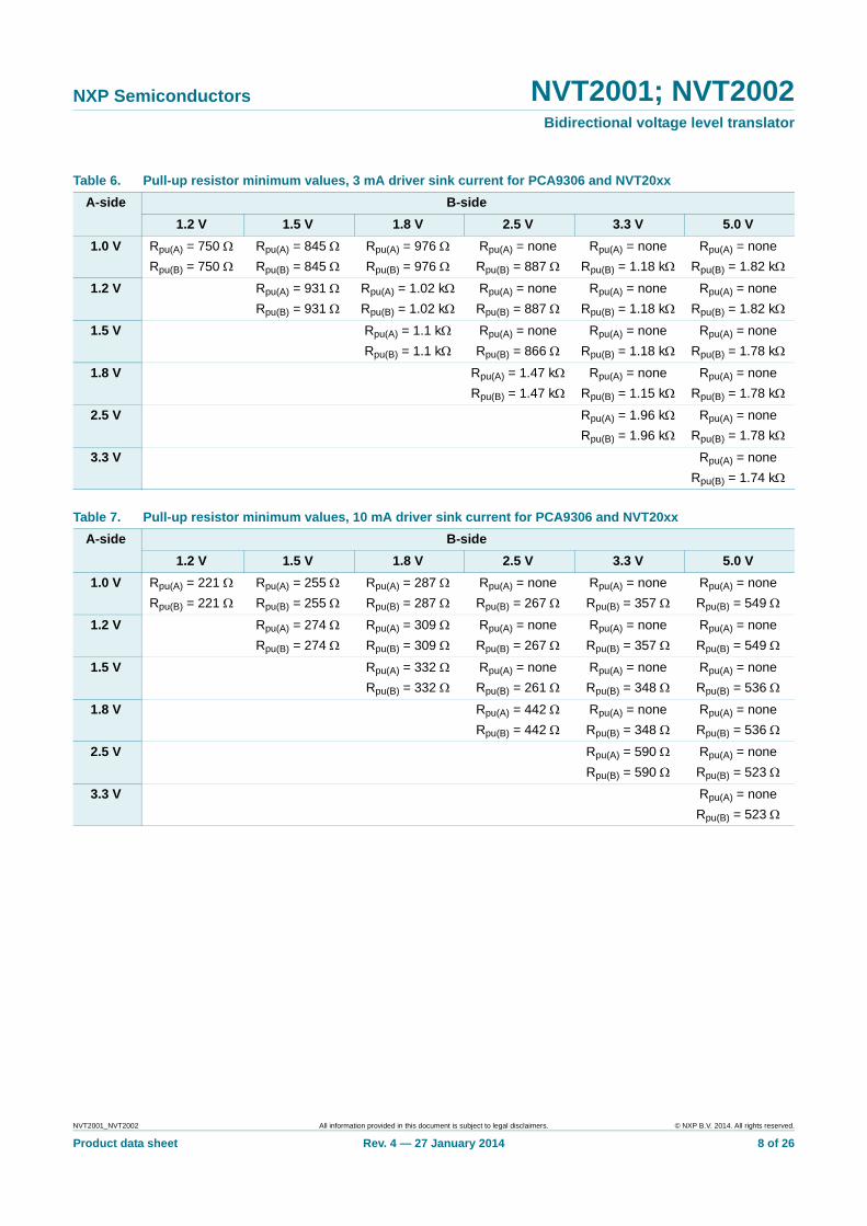
The following tables can be used to estimate the pull-up resistor value in different use cases so that the minimum resistance for the pull-up resistor can be found.
Table 6, Table 7 and Table 8 contain suggested minimum values of pull-up resistors for the PCA9306 and NVT20xx devices with typical voltage translation levels and drive currents. The calculated values assume that both drive currents are the same. VOL = VIL = 0.1 VCC and accounts for a 5 % VCC tolerance of the supplies, 1 % resistor values. It should be noted that the resistor chosen in the final application should be equal to or larger than the values shown in Table 6, Table 7 and Table 8 to ensure that the pass voltage is less than 10 % of the VCC voltage, and the external driver should be able to sink the total current from both pull-up resistors. When selecting the minimum resistor value in Table 6, Table 7 or Table 8, the drive current strength that should be chosen should be the lowest drive current seen in the application and account for any drive strength current scaling with output voltage. For the GTL devices, the resistance table should be recalculated to account for the difference in ON resistance and bias voltage limitations between VCC(B) and VCC(A).
NVT2001_NVT2002 All information provided in this document is subject to legal disclaimers. © NXP B.V. 2014. All rights reserved.
Product data sheet Rev. 4 — 27 January 2014 7 of 26
NXP Semiconductors NVT2001; NVT2002Bidirectional voltage level translator
Table 6. Pull-up resistor minimum values, 3 mA driver sink current for PCA9306 and NVT20xx
A-side B-side
1.2 V 1.5 V 1.8 V 2.5 V 3.3 V 5.0 V
1.0 V Rpu(A) = 750
Rpu(B) = 750
Rpu(A) = 845
Rpu(B) = 845
Rpu(A) = 976
Rpu(B) = 976
Rpu(A) = none
Rpu(B) = 887
Rpu(A) = none
Rpu(B) = 1.18 k
Rpu(A) = none
Rpu(B) = 1.82 k
1.2 V Rpu(A) = 931
Rpu(B) = 931
Rpu(A) = 1.02 k
Rpu(B) = 1.02 k
Rpu(A) = none
Rpu(B) = 887
Rpu(A) = none
Rpu(B) = 1.18 k
Rpu(A) = none
Rpu(B) = 1.82 k
1.5 V Rpu(A) = 1.1 k
Rpu(B) = 1.1 k
Rpu(A) = none
Rpu(B) = 866
Rpu(A) = none
Rpu(B) = 1.18 k
Rpu(A) = none
Rpu(B) = 1.78 k
1.8 V Rpu(A) = 1.47 k
Rpu(B) = 1.47 k
Rpu(A) = none
Rpu(B) = 1.15 k
Rpu(A) = none
Rpu(B) = 1.78 k
2.5 V Rpu(A) = 1.96 k
Rpu(B) = 1.96 k
Rpu(A) = none
Rpu(B) = 1.78 k
3.3 V Rpu(A) = none
Rpu(B) = 1.74 k
Table 7. Pull-up resistor minimum values, 10 mA driver sink current for PCA9306 and NVT20xx
A-side B-side
1.2 V 1.5 V 1.8 V 2.5 V 3.3 V 5.0 V
1.0 V Rpu(A) = 221
Rpu(B) = 221
Rpu(A) = 255
Rpu(B) = 255
Rpu(A) = 287
Rpu(B) = 287
Rpu(A) = none
Rpu(B) = 267
Rpu(A) = none
Rpu(B) = 357
Rpu(A) = none
Rpu(B) = 549
1.2 V Rpu(A) = 274
Rpu(B) = 274
Rpu(A) = 309
Rpu(B) = 309
Rpu(A) = none
Rpu(B) = 267
Rpu(A) = none
Rpu(B) = 357
Rpu(A) = none
Rpu(B) = 549
1.5 V Rpu(A) = 332
Rpu(B) = 332
Rpu(A) = none
Rpu(B) = 261
Rpu(A) = none
Rpu(B) = 348
Rpu(A) = none
Rpu(B) = 536
1.8 V Rpu(A) = 442
Rpu(B) = 442
Rpu(A) = none
Rpu(B) = 348
Rpu(A) = none
Rpu(B) = 536
2.5 V Rpu(A) = 590
Rpu(B) = 590
Rpu(A) = none
Rpu(B) = 523
3.3 V Rpu(A) = none
Rpu(B) = 523
NVT2001_NVT2002 All information provided in this document is subject to legal disclaimers. © NXP B.V. 2014. All rights reserved.
Product data sheet Rev. 4 — 27 January 2014 8 of 26

NXP Semiconductors NVT2001; NVT2002Bidirectional voltage level translator
7.4 How to design for maximum frequency operation
The maximum frequency is limited by the minimum pulse width LOW and HIGH as well as rise time and fall time. See Equation 1 as an example of the maximum frequency. The rise and fall times are shown in Figure 8.
(1)
The rise and fall times are dependent upon translation voltages, the drive strength, the total node capacitance (CL(tot)) and the pull-up resistors (RPU) that are present on the bus. The node capacitance is the addition of the PCB trace capacitance and the device capacitance that exists on the bus. Because of the dependency of the external components, PCB layout and the different device operating states the calculation of rise and fall times is complex and has several inflection points along the curve.
The main component of the rise and fall times is the RC time constant of the bus line when the device is in its two primary operating states: when device is in the ON state and it is low-impedance, the other is when the device is OFF isolating the A-side from the B-side.
A description of the fall time applied to either An or Bn output going from HIGH to LOW is as follows. Whichever side is asserted first, the B-side down must discharge to the VCC(A) voltage. The time is determined by the pull-up resistor, pull-down driver strength and the
Table 8. Pull-up resistor minimum values, 15 mA driver sink current for PCA9306 and NVT20xx
A-side B-side
1.2 V 1.5 V 1.8 V 2.5 V 3.3 V 5.0 V
1.0 V Rpu(A) = 147
Rpu(B) = 147
Rpu(A) = 169
Rpu(B) = 169
Rpu(A) = 191
Rpu(B) = 191
Rpu(A) = none
Rpu(B) = 178
Rpu(A) = none
Rpu(B) = 237
Rpu(A) = none
Rpu(B) = 365
1.2 V Rpu(A) = 182
Rpu(B) = 182
Rpu(A) = 205
Rpu(B) = 205
Rpu(A) = none
Rpu(B) = 178
Rpu(A) = none
Rpu(B) = 237
Rpu(A) = none
Rpu(B) = 365
1.5 V Rpu(A) = 221
Rpu(B) = 221
Rpu(A) = none
Rpu(B) = 174
Rpu(A) = none
Rpu(B) = 232
Rpu(A) = none
Rpu(B) = 357
1.8 V Rpu(A) = 294
Rpu(B) = 294
Rpu(A) = none
Rpu(B) = 232
Rpu(A) = none
Rpu(B) = 357
2.5 V Rpu(A) = 392
Rpu(B) = 392
Rpu(A) = none
Rpu(B) = 357
3.3 V Rpu(A) = none
Rpu(B) = 348
Fig 8. An example waveform for maximum frequency
fmax1
tLOW min tHIGH min tr actual tf actual + + +-------------------------------------------------------------------------------------------------------------=
002aag912
tr(actual) tf(actual)
GNDVOL
VIL
VIHVCC
tHIGH(min)
tLOW(min)
1 / fmax
0.9 × VCC
0.1 × VCC
NVT2001_NVT2002 All information provided in this document is subject to legal disclaimers. © NXP B.V. 2014. All rights reserved.
Product data sheet Rev. 4 — 27 January 2014 9 of 26

NXP Semiconductors NVT2001; NVT2002Bidirectional voltage level translator
capacitance. As the level moves below the VCC(A) voltage, the channel resistance drops so that both A and B sides equal. The capacitance on both sides is connected to form the total capacitance and the pull-up resistors on both sides combine to the parallel equivalent resistance. The Ron of the device is small compared to the pull-up resistor values, so its effect on the pull-up resistance can be neglected and the fall is determined by the driver pulling the combined capacitance and pull-up resistor currents. An estimation of the actual fall time seen by the device is equal to the time it takes for the B-side to fall to the VCC(A) voltage and the time it takes for both sides to fall from the VCC(A) voltage to the VIL level.
A description of the rise time applied to either An or Bn output going from LOW to HIGH is as follows. When the signal level is LOW, the Ron is at its minimum, so the A and B sides are essentially one node. They will rise together with an RC time constant that is the sum of all the capacitance from both sides and the parallel of the resistance from both sides. As the signal approaches the VCC(A) voltage, the channel resistance goes up and the waveforms separate, with the B side finishing its rise with the RC time constant of the B side. The rise to VCC(A) is essentially the same for both sides.
There are some basic guidelines to follow that will help maximize the performance of the device:
• Keep trace length to a minimum by placing the NVT device close to the processor.
• The signal round trip time on trace should be shorter than the rise or fall time of signal to reduce reflections.
• The faster the edge of the signal, the higher the chance for ringing.
• The higher drive strength controlled by the pull-up resistor (up to 15 mA), the higher the frequency the device can use.
The system designer must design the pull-up resistor value based on external current drive strength and limit the node capacitance (minimize the wire, stub, connector and trace length) to get the desired operation frequency result.
8. Limiting values
[1] The input and input/output negative voltage ratings may be exceeded if the input and input/output clamp current ratings are observed.
[2] Low duty cycle pulses, not DC because of heating.
Table 9. Limiting valuesIn accordance with the Absolute Maximum Rating System (IEC 60134).Over operating free-air temperature range.
Symbol Parameter Conditions Min Max Unit
Vref(A) reference voltage (A) 0.5 +6 V
Vref(B) reference voltage (B) 0.5 +6 V
VI input voltage 0.5[1] +6 V
VI/O voltage on an input/output pin 0.5[1] +6 V
Ich channel current (DC) - 128 mA
IIK input clamping current VI < 0 V 50 - mA
IOK output clamping current [2] 50 +50 mA
Tstg storage temperature 65 +150 C
NVT2001_NVT2002 All information provided in this document is subject to legal disclaimers. © NXP B.V. 2014. All rights reserved.
Product data sheet Rev. 4 — 27 January 2014 10 of 26

NXP Semiconductors NVT2001; NVT2002Bidirectional voltage level translator
9. Recommended operating conditions
[1] Vref(A) Vref(B) 1 V for best results in level shifting applications.
10. Static characteristics
[1] All typical values are at Tamb = 25 C.
[2] Not production tested, maximum value based on characterization data of typical parts.
[3] Measured by the voltage drop between the An and Bn terminals at the indicated current through the switch. ON-state resistance is determined by the lowest voltage of the two terminals.
[4] See curves in Figure 9 for typical temperature and VI(EN) behavior.
[5] Guaranteed by design.
Table 10. Operating conditions
Symbol Parameter Conditions Min Max Unit
VI/O voltage on an input/output pin An, Bn 0 5.5 V
Vref(A) reference voltage (A) VREFA [1] 0 5.4 V
Vref(B) reference voltage (B) VREFB [1] 0 5.5 V
VI(EN) input voltage on pin EN 0 5.5 V
Isw(pass) pass switch current - 64 mA
Tamb ambient temperature operating in free-air 40 +85 C
Table 11. Static characteristicsTamb = 40 C to +85 C, unless otherwise specified.
Symbol Parameter Conditions Min Typ[1] Max Unit
VIK input clamping voltage II = 18 mA; VI(EN) = 0 V - - 1.2 V
IIH HIGH-level input current VI = 5 V; VI(EN) = 0 V - - 5 A
Ci(EN) input capacitance on pin EN VI = 3 V or 0 V - 7.1 - pF
Cio(off) off-state input/output capacitance An, Bn; VO = 3 V or 0 V; VI(EN) = 0 V
- 4 6 pF
Cio(on) on-state input/output capacitance An, Bn; VO = 3 V or 0 V; VI(EN) = 3 V
- 9.3 12.5[2] pF
Ron ON-state resistance An, Bn; VI = 0 V; IO = 64 mA; VI(EN) = 4.5 V
[3][4][5] 1 2.4 5.0
VI = 2.4 V; IO = 15 mA; VI(EN) = 4.5 V
[3][4] - 4.8 7.5
NVT2001_NVT2002 All information provided in this document is subject to legal disclaimers. © NXP B.V. 2014. All rights reserved.
Product data sheet Rev. 4 — 27 January 2014 11 of 26

NXP Semiconductors NVT2001; NVT2002Bidirectional voltage level translator
a. IO = 64 mA; VI = 0 V b. IO = 15 mA; VI = 2.4 V; VI(EN) = 4.5 V
c. IO = 15 mA; VI = 2.4 V; VI(EN) = 3.0 V d. IO = 15 mA; VI = 1.7 V; VI(EN) = 2.3 V
Fig 9. Typical ON-state resistance versus ambient temperature
Tamb (°C)−40 100−20
002aaf313
0 20 40 60 80
4
6
2
8
10Ron(typ)
(Ω)
0
VI(EN) = 1.5 V2.3 V3.0 V4.5 V
Tamb (°C)−40 100−20
002aaf314
0 20 40 60 80
2
8Ron(typ)
(Ω)
0
6
4
Tamb (°C)−40 100−20
002aaf315
0 20 40 60 80
20
80Ron(typ)
(Ω)
0
60
40
Tamb (°C)−40 100−20
002aaf316
0 20 40 60 80
20
80Ron(typ)
(Ω)
0
60
40
NVT2001_NVT2002 All information provided in this document is subject to legal disclaimers. © NXP B.V. 2014. All rights reserved.
Product data sheet Rev. 4 — 27 January 2014 12 of 26

NXP Semiconductors NVT2001; NVT2002Bidirectional voltage level translator
11. Dynamic characteristics
11.1 Open-drain drivers
[1] See graphs based on Ron typical and Cio(on) + CL = 50 pF.
Table 12. Dynamic characteristics for open-drain driversTamb = 40 C to +85 C; VI(EN) = Vref(B); Rbias(ext) = 200 k; CVREFB = 0.1 F; unless otherwise specified.
Symbol Parameter Conditions Min Typ Max Unit
Refer to Figure 12
tPLH LOW to HIGH propagation delay
from (input) Bn to (output) An
[1] Ron (CL + Cio(on)) ns
tPHL HIGH to LOW propagation delay
from (input) Bn to (output) An
Ron (CL + Cio(on)) ns
Fig 10. AC test setup Fig 11. Example of typical AC waveform
002aaf347
DUT
EN VREFB
VREFA
1.5 V
200 kΩ
SIGNALGENERATOR
5.5 V
0.1 μF
1.5 V swing
50 pF450 Ω
500 Ω
6.6 V
1 V/div
40 ns/div
002aaf348
Bn
An
GND
GND
a. Load circuit b. Timing diagram; high-impedance scope probe used
S2 = translating down, and same voltage.
CL includes probe and jig capacitance.
All input pulses are supplied by generators having the following characteristics: PRR 10 MHz; Zo = 50 ; tr 2 ns; tf 2 ns.
The outputs are measured one at a time, with one transition per measurement.
Fig 12. Load circuit for outputs
002aab845
VTT
RL
S1S2 (open)
CL
from output under test
002aab846
VIH
VIL
VM VMinput
output
VOH
VOL
VM VM
NVT2001_NVT2002 All information provided in this document is subject to legal disclaimers. © NXP B.V. 2014. All rights reserved.
Product data sheet Rev. 4 — 27 January 2014 13 of 26

NXP Semiconductors NVT2001; NVT2002Bidirectional voltage level translator
12. Performance curves
tPLH up-translation is typically dominated by the RC time constant, i.e., CL(tot) RPU = 50 pF 197 = 9.85 ns, but the Ron CL(tot) = 50 pF 5 = 0.250 ns.
tPHL is typically dominated by the external pull-down driver + Ron, which is typically small compared to the tPLH in an up-translation case.
Enable/disable times are dominated by the RC time constant on the EN pin since the transistor turn off is on the order of ns, but the enable RC is on the order of ms.
Fall time is dominated by the external pull-down driver with only a slight Ron addition.
Rise time is dominated by the RPU CL.
Skew time within the part is virtually non-existent, dominated by the difference in bond wire lengths, which is typically small compared to the board-level routing differences.
Maximum data rate is dominated by the system capacitance and pull-up resistors.
(1) VI(EN) = 1.5 V; IO = 64 mA; VI = 0 V.
(2) VI(EN) = 4.5 V; IO = 15 mA; VI = 2.4 V.
(3) VI(EN) = 2.3 V; IO = 64 mA; VI = 0 V.
(4) VI(EN) = 3.0 V; IO = 64 mA; VI = 0 V.
(5) VI(EN) = 4.5 V; IO = 64 mA; VI = 0 V.
Fig 13. Typical capacitance versus propagation delay
C (pF)0 1008040 6020
002aaf349
0.4
0.2
0.6
0.8
tPD(ns)
0
(1)
(2)
(3)
(5)
(4)
NVT2001_NVT2002 All information provided in this document is subject to legal disclaimers. © NXP B.V. 2014. All rights reserved.
Product data sheet Rev. 4 — 27 January 2014 14 of 26

NXP Semiconductors NVT2001; NVT2002Bidirectional voltage level translator
13. Package outline
Fig 14. Package outline SOT886 (XSON6)
NVT2001_NVT2002 All information provided in this document is subject to legal disclaimers. © NXP B.V. 2014. All rights reserved.
Product data sheet Rev. 4 — 27 January 2014 15 of 26

NXP Semiconductors NVT2001; NVT2002Bidirectional voltage level translator
Fig 15. Package outline SOT505-1 (TSSOP8)
NVT2001_NVT2002 All information provided in this document is subject to legal disclaimers. © NXP B.V. 2014. All rights reserved.
Product data sheet Rev. 4 — 27 January 2014 16 of 26

NXP Semiconductors NVT2001; NVT2002Bidirectional voltage level translator
Fig 16. Package outline SOT996-2 (XSON8U)
NVT2001_NVT2002 All information provided in this document is subject to legal disclaimers. © NXP B.V. 2014. All rights reserved.
Product data sheet Rev. 4 — 27 January 2014 17 of 26

NXP Semiconductors NVT2001; NVT2002Bidirectional voltage level translator
14. Soldering of SMD packages
This text provides a very brief insight into a complex technology. A more in-depth account of soldering ICs can be found in Application Note AN10365 “Surface mount reflow soldering description”.
14.1 Introduction to soldering
Soldering is one of the most common methods through which packages are attached to Printed Circuit Boards (PCBs), to form electrical circuits. The soldered joint provides both the mechanical and the electrical connection. There is no single soldering method that is ideal for all IC packages. Wave soldering is often preferred when through-hole and Surface Mount Devices (SMDs) are mixed on one printed wiring board; however, it is not suitable for fine pitch SMDs. Reflow soldering is ideal for the small pitches and high densities that come with increased miniaturization.
14.2 Wave and reflow soldering
Wave soldering is a joining technology in which the joints are made by solder coming from a standing wave of liquid solder. The wave soldering process is suitable for the following:
• Through-hole components
• Leaded or leadless SMDs, which are glued to the surface of the printed circuit board
Not all SMDs can be wave soldered. Packages with solder balls, and some leadless packages which have solder lands underneath the body, cannot be wave soldered. Also, leaded SMDs with leads having a pitch smaller than ~0.6 mm cannot be wave soldered, due to an increased probability of bridging.
The reflow soldering process involves applying solder paste to a board, followed by component placement and exposure to a temperature profile. Leaded packages, packages with solder balls, and leadless packages are all reflow solderable.
Key characteristics in both wave and reflow soldering are:
• Board specifications, including the board finish, solder masks and vias
• Package footprints, including solder thieves and orientation
• The moisture sensitivity level of the packages
• Package placement
• Inspection and repair
• Lead-free soldering versus SnPb soldering
14.3 Wave soldering
Key characteristics in wave soldering are:
• Process issues, such as application of adhesive and flux, clinching of leads, board transport, the solder wave parameters, and the time during which components are exposed to the wave
• Solder bath specifications, including temperature and impurities
NVT2001_NVT2002 All information provided in this document is subject to legal disclaimers. © NXP B.V. 2014. All rights reserved.
Product data sheet Rev. 4 — 27 January 2014 18 of 26

NXP Semiconductors NVT2001; NVT2002Bidirectional voltage level translator
14.4 Reflow soldering
Key characteristics in reflow soldering are:
• Lead-free versus SnPb soldering; note that a lead-free reflow process usually leads to higher minimum peak temperatures (see Figure 17) than a SnPb process, thus reducing the process window
• Solder paste printing issues including smearing, release, and adjusting the process window for a mix of large and small components on one board
• Reflow temperature profile; this profile includes preheat, reflow (in which the board is heated to the peak temperature) and cooling down. It is imperative that the peak temperature is high enough for the solder to make reliable solder joints (a solder paste characteristic). In addition, the peak temperature must be low enough that the packages and/or boards are not damaged. The peak temperature of the package depends on package thickness and volume and is classified in accordance with Table 13 and 14
Moisture sensitivity precautions, as indicated on the packing, must be respected at all times.
Studies have shown that small packages reach higher temperatures during reflow soldering, see Figure 17.
Table 13. SnPb eutectic process (from J-STD-020D)
Package thickness (mm) Package reflow temperature (C)
Volume (mm3)
< 350 350
< 2.5 235 220
2.5 220 220
Table 14. Lead-free process (from J-STD-020D)
Package thickness (mm) Package reflow temperature (C)
Volume (mm3)
< 350 350 to 2000 > 2000
< 1.6 260 260 260
1.6 to 2.5 260 250 245
> 2.5 250 245 245
NVT2001_NVT2002 All information provided in this document is subject to legal disclaimers. © NXP B.V. 2014. All rights reserved.
Product data sheet Rev. 4 — 27 January 2014 19 of 26

NXP Semiconductors NVT2001; NVT2002Bidirectional voltage level translator
For further information on temperature profiles, refer to Application Note AN10365 “Surface mount reflow soldering description”.
15. Soldering: PCB footprints
MSL: Moisture Sensitivity Level
Fig 17. Temperature profiles for large and small components
001aac844
temperature
time
minimum peak temperature= minimum soldering temperature
maximum peak temperature= MSL limit, damage level
peak temperature
Fig 18. PCB footprint for SOT886 (XSON6); reflow soldering
NVT2001_NVT2002 All information provided in this document is subject to legal disclaimers. © NXP B.V. 2014. All rights reserved.
Product data sheet Rev. 4 — 27 January 2014 20 of 26

NXP Semiconductors NVT2001; NVT2002Bidirectional voltage level translator
Fig 19. PCB footprint for SOT505-1 (TSSOP8); reflow soldering
NVT2001_NVT2002 All information provided in this document is subject to legal disclaimers. © NXP B.V. 2014. All rights reserved.
Product data sheet Rev. 4 — 27 January 2014 21 of 26

NXP Semiconductors NVT2001; NVT2002Bidirectional voltage level translator
16. Abbreviations
Fig 20. PCB footprint for SOT996-2 (XSON8U); reflow soldering
Table 15. Abbreviations
Acronym Description
CDM Charged Device Model
ESD ElectroStatic Discharge
GTL Gunning Transceiver Logic
HBM Human Body Model
I2C-bus Inter-Integrated Circuit bus
I/O Input/Output
LVTTL Low Voltage Transistor-Transistor Logic
PRR Pulse Repetition Rate
RC Resistor-Capacitor network
NVT2001_NVT2002 All information provided in this document is subject to legal disclaimers. © NXP B.V. 2014. All rights reserved.
Product data sheet Rev. 4 — 27 January 2014 22 of 26

NXP Semiconductors NVT2001; NVT2002Bidirectional voltage level translator
17. Revision history
Table 16. Revision history
Document ID Release date Data sheet status Change notice Supersedes
NVT2001_NVT2002 v.4 20140127 Product data sheet - NVT2001_NVT2002 v.3
Modifications: • added Section 3.1 “Ordering options”
• deleted (old) Section 7.3 “Sizing pull-up resistor”
• added (new) Section 7.3 “How to size pull-up resistor value”
• added (new) Section 7.4 “How to design for maximum frequency operation”
• added (new) Section 15 “Soldering: PCB footprints”
NVT2001_NVT2002 v.3 20120426 Product data sheet - NVT2001_NVT2002 v.2
NVT2001_NVT2002 v.2 20111026 Product data sheet - NVT2001_NVT2002 v.1
NVT2001_NVT2002 v.1 20100830 Product data sheet - -
NVT2001_NVT2002 All information provided in this document is subject to legal disclaimers. © NXP B.V. 2014. All rights reserved.
Product data sheet Rev. 4 — 27 January 2014 23 of 26

NXP Semiconductors NVT2001; NVT2002Bidirectional voltage level translator
18. Legal information
18.1 Data sheet status
[1] Please consult the most recently issued document before initiating or completing a design.
[2] The term ‘short data sheet’ is explained in section “Definitions”.
[3] The product status of device(s) described in this document may have changed since this document was published and may differ in case of multiple devices. The latest product status information is available on the Internet at URL http://www.nxp.com.
18.2 Definitions
Draft — The document is a draft version only. The content is still under internal review and subject to formal approval, which may result in modifications or additions. NXP Semiconductors does not give any representations or warranties as to the accuracy or completeness of information included herein and shall have no liability for the consequences of use of such information.
Short data sheet — A short data sheet is an extract from a full data sheet with the same product type number(s) and title. A short data sheet is intended for quick reference only and should not be relied upon to contain detailed and full information. For detailed and full information see the relevant full data sheet, which is available on request via the local NXP Semiconductors sales office. In case of any inconsistency or conflict with the short data sheet, the full data sheet shall prevail.
Product specification — The information and data provided in a Product data sheet shall define the specification of the product as agreed between NXP Semiconductors and its customer, unless NXP Semiconductors and customer have explicitly agreed otherwise in writing. In no event however, shall an agreement be valid in which the NXP Semiconductors product is deemed to offer functions and qualities beyond those described in the Product data sheet.
18.3 Disclaimers
Limited warranty and liability — Information in this document is believed to be accurate and reliable. However, NXP Semiconductors does not give any representations or warranties, expressed or implied, as to the accuracy or completeness of such information and shall have no liability for the consequences of use of such information. NXP Semiconductors takes no responsibility for the content in this document if provided by an information source outside of NXP Semiconductors.
In no event shall NXP Semiconductors be liable for any indirect, incidental, punitive, special or consequential damages (including - without limitation - lost profits, lost savings, business interruption, costs related to the removal or replacement of any products or rework charges) whether or not such damages are based on tort (including negligence), warranty, breach of contract or any other legal theory.
Notwithstanding any damages that customer might incur for any reason whatsoever, NXP Semiconductors’ aggregate and cumulative liability towards customer for the products described herein shall be limited in accordance with the Terms and conditions of commercial sale of NXP Semiconductors.
Right to make changes — NXP Semiconductors reserves the right to make changes to information published in this document, including without limitation specifications and product descriptions, at any time and without notice. This document supersedes and replaces all information supplied prior to the publication hereof.
Suitability for use — NXP Semiconductors products are not designed, authorized or warranted to be suitable for use in life support, life-critical or safety-critical systems or equipment, nor in applications where failure or malfunction of an NXP Semiconductors product can reasonably be expected to result in personal injury, death or severe property or environmental damage. NXP Semiconductors and its suppliers accept no liability for inclusion and/or use of NXP Semiconductors products in such equipment or applications and therefore such inclusion and/or use is at the customer’s own risk.
Applications — Applications that are described herein for any of these products are for illustrative purposes only. NXP Semiconductors makes no representation or warranty that such applications will be suitable for the specified use without further testing or modification.
Customers are responsible for the design and operation of their applications and products using NXP Semiconductors products, and NXP Semiconductors accepts no liability for any assistance with applications or customer product design. It is customer’s sole responsibility to determine whether the NXP Semiconductors product is suitable and fit for the customer’s applications and products planned, as well as for the planned application and use of customer’s third party customer(s). Customers should provide appropriate design and operating safeguards to minimize the risks associated with their applications and products.
NXP Semiconductors does not accept any liability related to any default, damage, costs or problem which is based on any weakness or default in the customer’s applications or products, or the application or use by customer’s third party customer(s). Customer is responsible for doing all necessary testing for the customer’s applications and products using NXP Semiconductors products in order to avoid a default of the applications and the products or of the application or use by customer’s third party customer(s). NXP does not accept any liability in this respect.
Limiting values — Stress above one or more limiting values (as defined in the Absolute Maximum Ratings System of IEC 60134) will cause permanent damage to the device. Limiting values are stress ratings only and (proper) operation of the device at these or any other conditions above those given in the Recommended operating conditions section (if present) or the Characteristics sections of this document is not warranted. Constant or repeated exposure to limiting values will permanently and irreversibly affect the quality and reliability of the device.
Terms and conditions of commercial sale — NXP Semiconductors products are sold subject to the general terms and conditions of commercial sale, as published at http://www.nxp.com/profile/terms, unless otherwise agreed in a valid written individual agreement. In case an individual agreement is concluded only the terms and conditions of the respective agreement shall apply. NXP Semiconductors hereby expressly objects to applying the customer’s general terms and conditions with regard to the purchase of NXP Semiconductors products by customer.
No offer to sell or license — Nothing in this document may be interpreted or construed as an offer to sell products that is open for acceptance or the grant, conveyance or implication of any license under any copyrights, patents or other industrial or intellectual property rights.
Document status[1][2] Product status[3] Definition
Objective [short] data sheet Development This document contains data from the objective specification for product development.
Preliminary [short] data sheet Qualification This document contains data from the preliminary specification.
Product [short] data sheet Production This document contains the product specification.
NVT2001_NVT2002 All information provided in this document is subject to legal disclaimers. © NXP B.V. 2014. All rights reserved.
Product data sheet Rev. 4 — 27 January 2014 24 of 26

NXP Semiconductors NVT2001; NVT2002Bidirectional voltage level translator
Export control — This document as well as the item(s) described herein may be subject to export control regulations. Export might require a prior authorization from competent authorities.
Non-automotive qualified products — Unless this data sheet expressly states that this specific NXP Semiconductors product is automotive qualified, the product is not suitable for automotive use. It is neither qualified nor tested in accordance with automotive testing or application requirements. NXP Semiconductors accepts no liability for inclusion and/or use of non-automotive qualified products in automotive equipment or applications.
In the event that customer uses the product for design-in and use in automotive applications to automotive specifications and standards, customer (a) shall use the product without NXP Semiconductors’ warranty of the product for such automotive applications, use and specifications, and (b) whenever customer uses the product for automotive applications beyond
NXP Semiconductors’ specifications such use shall be solely at customer’s own risk, and (c) customer fully indemnifies NXP Semiconductors for any liability, damages or failed product claims resulting from customer design and use of the product for automotive applications beyond NXP Semiconductors’ standard warranty and NXP Semiconductors’ product specifications.
Translations — A non-English (translated) version of a document is for reference only. The English version shall prevail in case of any discrepancy between the translated and English versions.
18.4 TrademarksNotice: All referenced brands, product names, service names and trademarks are the property of their respective owners.
19. Contact information
For more information, please visit: http://www.nxp.com
For sales office addresses, please send an email to: [email protected]
NVT2001_NVT2002 All information provided in this document is subject to legal disclaimers. © NXP B.V. 2014. All rights reserved.
Product data sheet Rev. 4 — 27 January 2014 25 of 26

NXP Semiconductors NVT2001; NVT2002Bidirectional voltage level translator
20. Contents
1 General description . . . . . . . . . . . . . . . . . . . . . . 1
2 Features and benefits . . . . . . . . . . . . . . . . . . . . 1
3 Ordering information. . . . . . . . . . . . . . . . . . . . . 23.1 Ordering options . . . . . . . . . . . . . . . . . . . . . . . . 2
4 Functional diagram . . . . . . . . . . . . . . . . . . . . . . 3
5 Pinning information. . . . . . . . . . . . . . . . . . . . . . 35.1 Pinning . . . . . . . . . . . . . . . . . . . . . . . . . . . . . . . 35.1.1 1-bit in XSON6 package . . . . . . . . . . . . . . . . . . 35.1.2 2-bit in TSSOP8 and XSON8U packages. . . . . 35.2 Pin description . . . . . . . . . . . . . . . . . . . . . . . . . 4
6 Functional description . . . . . . . . . . . . . . . . . . . 46.1 Function table . . . . . . . . . . . . . . . . . . . . . . . . . . 4
7 Application design-in information . . . . . . . . . . 57.1 Enable and disable . . . . . . . . . . . . . . . . . . . . . . 57.2 Bidirectional translation . . . . . . . . . . . . . . . . . . 77.3 How to size pull-up resistor value. . . . . . . . . . . 77.4 How to design for maximum frequency
operation. . . . . . . . . . . . . . . . . . . . . . . . . . . . . . 9
8 Limiting values. . . . . . . . . . . . . . . . . . . . . . . . . 10
9 Recommended operating conditions. . . . . . . 11
10 Static characteristics. . . . . . . . . . . . . . . . . . . . 11
11 Dynamic characteristics . . . . . . . . . . . . . . . . . 1311.1 Open-drain drivers . . . . . . . . . . . . . . . . . . . . . 13
12 Performance curves . . . . . . . . . . . . . . . . . . . . 14
13 Package outline . . . . . . . . . . . . . . . . . . . . . . . . 15
14 Soldering of SMD packages . . . . . . . . . . . . . . 1814.1 Introduction to soldering . . . . . . . . . . . . . . . . . 1814.2 Wave and reflow soldering . . . . . . . . . . . . . . . 1814.3 Wave soldering . . . . . . . . . . . . . . . . . . . . . . . . 1814.4 Reflow soldering . . . . . . . . . . . . . . . . . . . . . . . 19
15 Soldering: PCB footprints. . . . . . . . . . . . . . . . 20
16 Abbreviations. . . . . . . . . . . . . . . . . . . . . . . . . . 22
17 Revision history. . . . . . . . . . . . . . . . . . . . . . . . 23
18 Legal information. . . . . . . . . . . . . . . . . . . . . . . 2418.1 Data sheet status . . . . . . . . . . . . . . . . . . . . . . 2418.2 Definitions. . . . . . . . . . . . . . . . . . . . . . . . . . . . 2418.3 Disclaimers . . . . . . . . . . . . . . . . . . . . . . . . . . . 2418.4 Trademarks. . . . . . . . . . . . . . . . . . . . . . . . . . . 25
19 Contact information. . . . . . . . . . . . . . . . . . . . . 25
20 Contents . . . . . . . . . . . . . . . . . . . . . . . . . . . . . . 26
© NXP B.V. 2014. All rights reserved.
For more information, please visit: http://www.nxp.comFor sales office addresses, please send an email to: [email protected]
Date of release: 27 January 2014
Document identifier: NVT2001_NVT2002
Please be aware that important notices concerning this document and the product(s)described herein, have been included in section ‘Legal information’.