Embed Size (px)
Citation preview
NVR-SeriesVertical Reciprocators
Customer Product ManualPart 1098602−03
Issued 11/16
NORDSON CORPORATION AMHERST, OHIO USA
For parts and technical support, call the Finishing Customer Support Center at (800) 433-9319.
Check http://emanuals.nordson.com/finishing for the latest version.This document is subject to change without notice.

Part 1098602−03 � 2016 Nordson Corporation
tents
Table of ContentsSafety 1. . . . . . . . . . . . . . . . . . . . . . . . . . . . . . . . . . . . . . .
Qualified Personnel 1. . . . . . . . . . . . . . . . . . . . . . . . .Intended Use 1. . . . . . . . . . . . . . . . . . . . . . . . . . . . . .Regulations and Approvals 1. . . . . . . . . . . . . . . . . .Personal Safety 2. . . . . . . . . . . . . . . . . . . . . . . . . . . .Fire Safety 2. . . . . . . . . . . . . . . . . . . . . . . . . . . . . . . .Grounding 3. . . . . . . . . . . . . . . . . . . . . . . . . . . . . . . . .Action in the Event of a Malfunction 3. . . . . . . . . . .Disposal 3. . . . . . . . . . . . . . . . . . . . . . . . . . . . . . . . . .
Description 4. . . . . . . . . . . . . . . . . . . . . . . . . . . . . . . . . .Specifications 6. . . . . . . . . . . . . . . . . . . . . . . . . . . . . .
Indentification Label 7. . . . . . . . . . . . . . . . . . . . . .Installation 8. . . . . . . . . . . . . . . . . . . . . . . . . . . . . . . . . .
Remove the Reciprocatorfrom the Shipping Container 8. . . . . . . . . . . . . . . . .Mount the Reciprocator 10. . . . . . . . . . . . . . . . . . . . .Install the Ship-With Parts 12. . . . . . . . . . . . . . . . . . .Install the Gun Fixture 14. . . . . . . . . . . . . . . . . . . . . .Position the Top and Bottom Carriage Bumpers 14Counterbalance the Gun Weight 14. . . . . . . . . . . . . .Electrical 16. . . . . . . . . . . . . . . . . . . . . . . . . . . . . . . . . .Functional Check 17. . . . . . . . . . . . . . . . . . . . . . . . . .
Operation 18. . . . . . . . . . . . . . . . . . . . . . . . . . . . . . . . . . .Maintenance 18. . . . . . . . . . . . . . . . . . . . . . . . . . . . . . . .
Cleaning 18. . . . . . . . . . . . . . . . . . . . . . . . . . . . . . . . . .Gear Motor 18. . . . . . . . . . . . . . . . . . . . . . . . . . . . . . . .
When to Change the Oil 18. . . . . . . . . . . . . . . . . .Troubleshooting 19. . . . . . . . . . . . . . . . . . . . . . . . . . . . .Repair 20. . . . . . . . . . . . . . . . . . . . . . . . . . . . . . . . . . . . . .
Secure the Gun Carriageand Counterweight Basket 20. . . . . . . . . . . . . . . . . . .Replace the Belt 22. . . . . . . . . . . . . . . . . . . . . . . . . . .
Remove the Belt 22. . . . . . . . . . . . . . . . . . . . . . . . .Install the Belt 24. . . . . . . . . . . . . . . . . . . . . . . . . . .Adjust the Belt Tension 25. . . . . . . . . . . . . . . . . . .
Replace the Top Pulley 27. . . . . . . . . . . . . . . . . . . . . .Remove the Top Pulley 27. . . . . . . . . . . . . . . . . . .Install the Top Pulley 28. . . . . . . . . . . . . . . . . . . . .
Replace the Bottom Pulley 28. . . . . . . . . . . . . . . . . .Remove the Bottom Pulley 28. . . . . . . . . . . . . . . .Install the Bottom Pulley 30. . . . . . . . . . . . . . . . . .
Repair (continued)Replace the Counterweight Basket Rollers 31. . . . .Replace the Gun Carriage Rollers 32. . . . . . . . . . . .
Remove the Guns and Gun Carriage Mount 32.Remove the Gun Carriage 36. . . . . . . . . . . . . . . . .Replace the Rollers 38. . . . . . . . . . . . . . . . . . . . . .Install the Gun Carriage 40. . . . . . . . . . . . . . . . . . .Install the Gun Carriage Mount 42. . . . . . . . . . . . .
Gear Motor 46. . . . . . . . . . . . . . . . . . . . . . . . . . . . . . . .Remove the Gear Motor 46. . . . . . . . . . . . . . . . . .Install the Gear Motor 46. . . . . . . . . . . . . . . . . . . .
Replace the Drive Bearing or Drive Motor Shaft 48Remove the Drive Bearing and Shaft 48. . . . . . .Install the Drive Bearing and Shaft 48. . . . . . . . .
Parts 49. . . . . . . . . . . . . . . . . . . . . . . . . . . . . . . . . . . . . . .Using the Illustrated Parts List 49. . . . . . . . . . . . . . .Reciprocator Assemblies 50. . . . . . . . . . . . . . . . . . . .Drive Belts 51. . . . . . . . . . . . . . . . . . . . . . . . . . . . . . . .Gear Motors 51. . . . . . . . . . . . . . . . . . . . . . . . . . . . . . .Common Parts 52. . . . . . . . . . . . . . . . . . . . . . . . . . . . .
Carriage Assembly 54. . . . . . . . . . . . . . . . . . . . . .Cables 55. . . . . . . . . . . . . . . . . . . . . . . . . . . . . . . . . . . .
Wiring Diagram 55. . . . . . . . . . . . . . . . . . . . . . . . . . . . . .
Contact UsNordson Corporation welcomes requests for information, comments, andinquiries about its products. General information about Nordson can befound on the Internet using the following address:http://www.nordson.com.Address all correspondence to:
Nordson CorporationAttn: Customer Service555 Jackson StreetAmherst, OH 44001
NoticeThis is a Nordson Corporation publication which is protected by copyright.Original copyright date 2011. No part of this document may bephotocopied, reproduced, or translated to another language without theprior written consent of Nordson Corporation. The information containedin this publication is subject to change without notice.
Trademarks
Nordson and the Nordson logo are registered trademarksof Nordson Corporation.
All other trademarks are the property of their respective owners.

Change Record i
Part 1098602−03� 2016 Nordson Corporation
Change RecordRevision Date Change
01 4/11 Released.
03 11/16 Revised wiring diagram.

Change Recordii
Part 1098602−03 � 2016 Nordson Corporation

NVR-Series Vertical Reciprocators 1
Part 1098602−03� 2016 Nordson Corporation
NVR-Series Vertical Reciprocators
Safety Read and follow these safety instructions. Task- and equipment-specificwarnings, cautions, and instructions are included in equipmentdocumentation where appropriate.
Make sure all equipment documentation, including these instructions, isaccessible to all persons operating or servicing equipment.
Qualified Personnel Equipment owners are responsible for making sure that Nordson equipmentis installed, operated, and serviced by qualified personnel. Qualifiedpersonnel are those employees or contractors who are trained to safelyperform their assigned tasks. They are familiar with all relevant safety rulesand regulations and are physically capable of performing their assignedtasks.
Intended Use Use of Nordson equipment in ways other than those described in thedocumentation supplied with the equipment may result in injury to personsor damage to property.
Some examples of unintended use of equipment include
� using incompatible materials
� making unauthorized modifications
� removing or bypassing safety guards or interlocks
� using incompatible or damaged parts
� using unapproved auxiliary equipment
� operating equipment in excess of maximum ratings
Regulations and Approvals Make sure all equipment is rated and approved for the environment in whichit is used. Any approvals obtained for Nordson equipment will be voided ifinstructions for installation, operation, and service are not followed.
All phases of equipment installation must comply with all federal, state, andlocal codes.

NVR-Series Vertical Reciprocators2
Part 1098602−03 � 2016 Nordson Corporation
Personal Safety To prevent injury follow these instructions.
� Do not operate or service equipment unless you are qualified.
� Do not operate equipment unless safety guards, doors, or covers areintact and automatic interlocks are operating properly. Do not bypass ordisarm any safety devices.
� Keep clear of moving equipment. Before adjusting or servicing anymoving equipment, shut off the power supply and wait until theequipment comes to a complete stop. Lock out power and secure theequipment to prevent unexpected movement.
� Relieve (bleed off) hydraulic and pneumatic pressure before adjusting orservicing pressurized systems or components. Disconnect, lock out,and tag switches before servicing electrical equipment.
� Obtain and read Safety Data Sheets (SDS) for all materials used.Follow the manufacturer’s instructions for safe handling and use ofmaterials, and use recommended personal protection devices.
� To prevent injury, be aware of less-obvious dangers in the workplacethat often cannot be completely eliminated, such as hot surfaces, sharpedges, energized electrical circuits, and moving parts that cannot beenclosed or otherwise guarded for practical reasons.
Fire Safety To avoid a fire or explosion, follow these instructions.
� Do not smoke, weld, grind, or use open flames where flammablematerials are being used or stored.
� Provide adequate ventilation to prevent dangerous concentrations ofvolatile materials or vapors. Refer to local codes or your material SDSfor guidance.
� Do not disconnect live electrical circuits while working with flammablematerials. Shut off power at a disconnect switch first to preventsparking.
� Know where emergency stop buttons, shutoff valves, and fireextinguishers are located. If a fire starts in a spray booth, immediatelyshut off the spray system and exhaust fans.
� Clean, maintain, test, and repair equipment according to the instructionsin your equipment documentation.
� Use only replacement parts that are designed for use with originalequipment. Contact your Nordson representative for parts informationand advice.

NVR-Series Vertical Reciprocators 3
Part 1098602−03� 2016 Nordson Corporation
Grounding
WARNING: Operating faulty electrostatic equipment is hazardous and cancause electrocution, fire, or explosion. Make resistance checks part of yourperiodic maintenance program. If you receive even a slight electrical shockor notice static sparking or arcing, shut down all electrical or electrostaticequipment immediately. Do not restart the equipment until the problem hasbeen identified and corrected.
Grounding inside and around the booth openings must comply with NFPArequirements for Class II Division 1 or 2 Hazardous Locations. Refer toNFPA 33, NFPA 70 (NEC articles 500, 502, and 516), and NFPA 77, latestconditions.
� All electrically conductive objects in the spray areas shall be electricallyconnected to ground with a resistance of not more than 1 megohm asmeasured with an instrument that applies at least 500 volts to the circuitbeing evaluated.
� Equipment to be grounded includes, but is not limited to, the floor of thespray area, operator platforms, hoppers, photoeye supports, andblow-off nozzles. Personnel working in the spray area must begrounded.
� There is a possible ignition potential from the charged human body.Personnel standing on a painted surface, such as an operator platform,or wearing non-conductive shoes, are not grounded. Personnel mustwear shoes with conductive soles or use a ground strap to maintain aconnection to ground when working with or around electrostaticequipment.
� Operators must maintain skin-to-handle contact between their hand andthe gun handle to prevent shocks while operating manual electrostaticspray guns. If gloves must be worn, cut away the palm or fingers, wearelectrically conductive gloves, or wear a grounding strap connected tothe gun handle or other true earth ground.
� Shut off electrostatic power supplies and ground gun electrodes beforemaking adjustments or cleaning powder spray guns.
� Connect all disconnected equipment, ground cables, and wires afterservicing equipment.
Action in the Event of a Malfunction If a system or any equipment in a system malfunctions, shut off the systemimmediately and perform the following steps:
� Disconnect and lock out electrical power. Close pneumatic shutoffvalves and relieve pressures.
� Identify the reason for the malfunction and correct it before restarting theequipment.
Disposal Dispose of equipment and materials used in operation and servicingaccording to local codes.

NVR-Series Vertical Reciprocators4
Part 1098602−03 � 2016 Nordson Corporation
Description See Figure 1. This manual covers the NVR-Series Vertical reciprocators.The reciprocators are available in 1700 m (66.9 in.), 2200 mm (86.6 in.),2700 mm (106.3 in.), and 3200 mm (126 in.) stroke lengths. Refer toTable 1 for component descriptions.
A
B
C
A
B
C
1
5
7
13
8
15
3
4
2
10
14
6
11
12
9
Figure 1 Typical NVR Vertical Reciprocator

NVR-Series Vertical Reciprocators 5
Part 1098602−03� 2016 Nordson Corporation
Table 1 Component Descriptions
Item Component Function
1 Top Pulley Top belt guide
2 Drive Belt Provides motion to the gun carriage
3 Top CarriageBumper Assembly
Prevents the spray guns from crashing into the topof the gun slot
4 Upper Proximity Sensor Sends a signal to the controller to indicate that the gun carriagehas reached the upper limit
5 Gun Carriage Mounting point for the gun mounts and guns
6 Upper Proximity Target Activates the upper proximity sensor
7 Lower Proximity Target Activates the lower proximity sensor
8 Counterweight Carriage Provides balance to the gun carriage; has 21 3.5 kg (7.61 lb)weights
9 Driver Assembly Operates the the belt-driven gun carriage assembly
10 Sensor and MotorJunction Box
Electrical interface between the controller and the reciprocator
11 Bottom CarriageBumper Assembly
Prevents the spray guns from crashing into the bottom
of the gun slot
12 Lower Proximity Sensor Sends a signal to the controller to indicate that the gun carriagehas reached the lower limit
13 Encoder Assembly Monitors the gun carriage position
14 Bottom Pulley Bottom belt guide
15 Weight Carriage Lock Arm Only used for shipping, setup, and replacing the belt; Must beremoved before putting the reciprocator into service

NVR-Series Vertical Reciprocators6
Part 1098602−03 � 2016 Nordson Corporation
Specifications Refer to Table 2 for specifications.
Table 2 Specifications
ItemSpecification
1700 mm (66.9 in.) 2200 mm (86.6 in.) 2700 mm (106.3 in.) 3200 mm (126 in.)
OperatingVoltage/Frequency Customer-specific. Refer to identification plate on the gear motor.
Operating Frequency Refer to Table 3.
Operating Speed Up to 50 mpm (164 fpm)
Maximum Load 80 kg at 50 mpm (176 lb at 164 fpm)
Height 2942 mm(115.8 in.)
3442 mm(135.5 in.)
3942 mm(155 in.)
4442 mm175 in.)
Column Length/Depth 620 mm (24.4 in.)
Column Width 193 mm (7.6 in.)
Base (L x W) 620 x 548 mm (24.4 x 21.6 in.)
Encoder Pulse Rate 1.44 pulse/mm (36 pulse/in.)
Sensor/Encoder Voltage 24 Vdc

NVR-Series Vertical Reciprocators 7
Part 1098602−03� 2016 Nordson Corporation
Identification Label See Figure 2. The Identification label is located on the back of the motorcover and lists the following information:
1. Name of Manufacturer
2. Product Name and Model
3. Product Part Number
4. Serial Number
5. Power Supply Range
6. CE Compliance Mark
7. ATEX Compliance Mark
NOTE: The information on the Identification label shown in Figure 2 isonly an example and is not specific to any reciprocator.
RECIPROCATOR,NVR,3.2M1234567
NC10J099993PH AC 230/380−415 V 50Hz 1.1KW ATEX
II 3D c 125� CNordson Corporation28601 Clemens RoadWestlake, OH 44145www.nordson.com
345
27 6 1
Figure 2 Typical Identification Label

NVR-Series Vertical Reciprocators8
Part 1098602−03 � 2016 Nordson Corporation
Installation WARNING: Allow only qualified personnel to perform the following tasks.Follow the safety instructions in this document and all other relateddocumentation.
Read and understand the following procedures before installing thereciprocator. Contact a local Nordson representative regarding theseprocedures if necessary.
Only use lifting equipment that can support the weight of the reciprocator.
Installation consists of the following tasks:
� Remove the Reciprocator from the Shipping Container
� Mount the Reciprocator
� Install the Ship-With Parts
� Install the Gun Mounts and Guns
� Position the top and bottom carriage bumpers
� Counter Balance the Gun Weight
� Electrical
� Functional Check
Remove the Reciprocator from the Shipping Container
WARNING: Only use approved and tested lifting equipment that can liftat least 630 Kg (1400 lb) or more. Lifting straps, ropes, or chains usedwith the lifting equipment must also be capable of supporting at least630 Kg (1400 lb) or more. Failure to observe this warning could result indeath, injury, or property damage, injury, or death.
See Figure 3.
1. Remove the top (1), cross supports (2), and all of the sides on theshipping container. Remove the support boards (3) at the base ofreciprocator.
2. Remove the boards (4) and pads (5) holding the reciprocator onto the3 padded supports within shipping container.
3. Remove the box of counterweights (6) from the shipping container.
NOTE: Depending on the type of equipment used to remove thereciprocator from the shipping container, perform either step 4 or step 5.
4. Perform the following if using lifting equipment to remove reciprocatorfrom the shipping container:
a. Attach lifting equipment to the lift bracket (7). Carefully lift thereciprocator upright and off of the shipping container.
b. Stand the reciprocator upright onto the floor or onto thein/out positioner.

NVR-Series Vertical Reciprocators 9
Part 1098602−03� 2016 Nordson Corporation
5. Perform the following if using a forklift truck or similar equipment:
a. Install protective covers on the forks of the forklift truck. Position thespacing of each fork as far as possible on the lift.
CAUTION: Before the reciprocator is lifted off of the shipping container,determine the appropriate lift points where the reciprocator weight isbalanced and can be safely lifted.
b. Position the forks under the determined reciprocator lift points.
c. Lift the reciprocator off of the shipping container and move it to theinstallation location. Temporarily set the reciprocator down ontowood blocks.
d. Attach the lifting equipment to the lift bracket (7). Carefully lift thereciprocator upright.
e. Stand the reciprocator upright onto the floor or onto the in/outpositioner.
4
2
2
2
4
4
7
1
5
5
5
3
6
Figure 3 Typical Shipping Container
NVR-Series Vertical Reciprocators10
Part 1098602−03 � 2016 Nordson Corporation
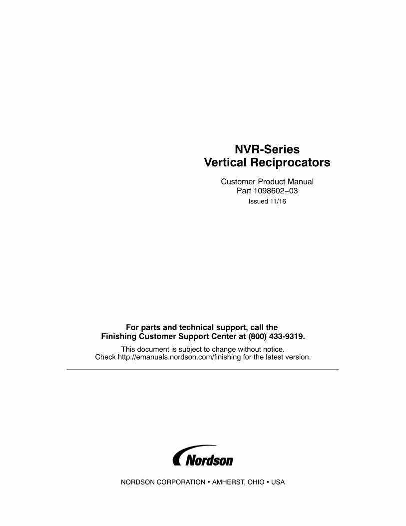
Mount the Reciprocator Reciprocators are typically installed on manual or automatic in/outpositioners, a fixed stand, or bolted to the floor.
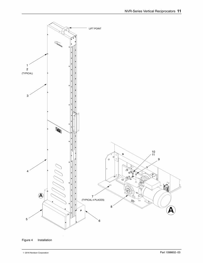
1. See Figure 4. Remove the screws (1) and washers (2) securing theside access panels (3, 4) on the encoder side of the reciprocator, theencoder cover (5), and the drive assembly cover (6).
CAUTION: The reciprocator is designed for use with a Nordson in/outpositioner. If using another type of in/out positioner, make sure that it cansupport at least 630 Kg (1400 lb) or more.
NOTE: Nordson in/out positioners ship with fasteners included in ahardware kit for reciprocator installations. Other fasteners may be requiredif using another type of in/out positioner.
2. Set the reciprocator onto the in/out positioner and secure it to the in/outpositioner carraige.
3. If mounting the reciprocator the floor or fixed stand, use the existing fourmounting holes (7). If necessary, drill new holes into the base or floor.Use properly sized fasteners to secure the reciprocator.
CAUTION: The vent plug must be installed to prevent over pressurizing thedrive assembly and to prevent oil contamination.
4. Remove the plug (9) from the gear motor (8) as shown on Figure 4.
5. Make sure that the gasket (11) is installed onto the vent plug (10).Install the vent plug into the drive assembly and tighten securely.
NVR-Series Vertical Reciprocators 11
Part 1098602−03� 2016 Nordson Corporation
LIFT POINT
12
(TYPICAL)
5 6
9
8
10
7(TYPICAL 4 PLACES)
A
A
11
3
4
Figure 4 Installation

NVR-Series Vertical Reciprocators12
Part 1098602−03 � 2016 Nordson Corporation
Install the Ship-With Parts
1. See Figure 5. Remove the screws (1) and lock washers (2) securing thecarriage weight lock arm (3) to the counterweight basket (8).
NOTE: Do not discard the carriage weight lock arm. It is used during thebelt replacement procedure to secure the counterweight basket and guncarriage assemblies.
2. Remove the nuts (5) and washers (6) from the T−bolts (7). Remove theT-bolts from the gun track (4).
3. Insert the carriage counterweights (12) into the weight basket (8).
4. Install the cable chain bracket (14) to the reciprocator (13) using thescrews (15) and washers (16). Tighten the screws securely.
NOTE: If the counterweights are not sufficient to balance the guns and thegun bars, two supplemental counterweights (11) included with thereciprocator can be installed onto the counterweight basket (8). Thesupplemental weights are required when the gun payload is between 76−80kg (167.5−176.4 lb)
5. If required, install the supplemental weights (11) onto the counterweightbasket (8) using the supplied M8 x 40 screws(9) and washers (10).Tighten the screws securely.

NVR-Series Vertical Reciprocators 13
Part 1098602−03� 2016 Nordson Corporation
9
10
9
10
11
12
3
1
5 4
8
67
11
2
14
1516
13
18
17
19
Figure 5 Installing the Ship-With Components

NVR-Series Vertical Reciprocators14
Part 1098602−03 � 2016 Nordson Corporation
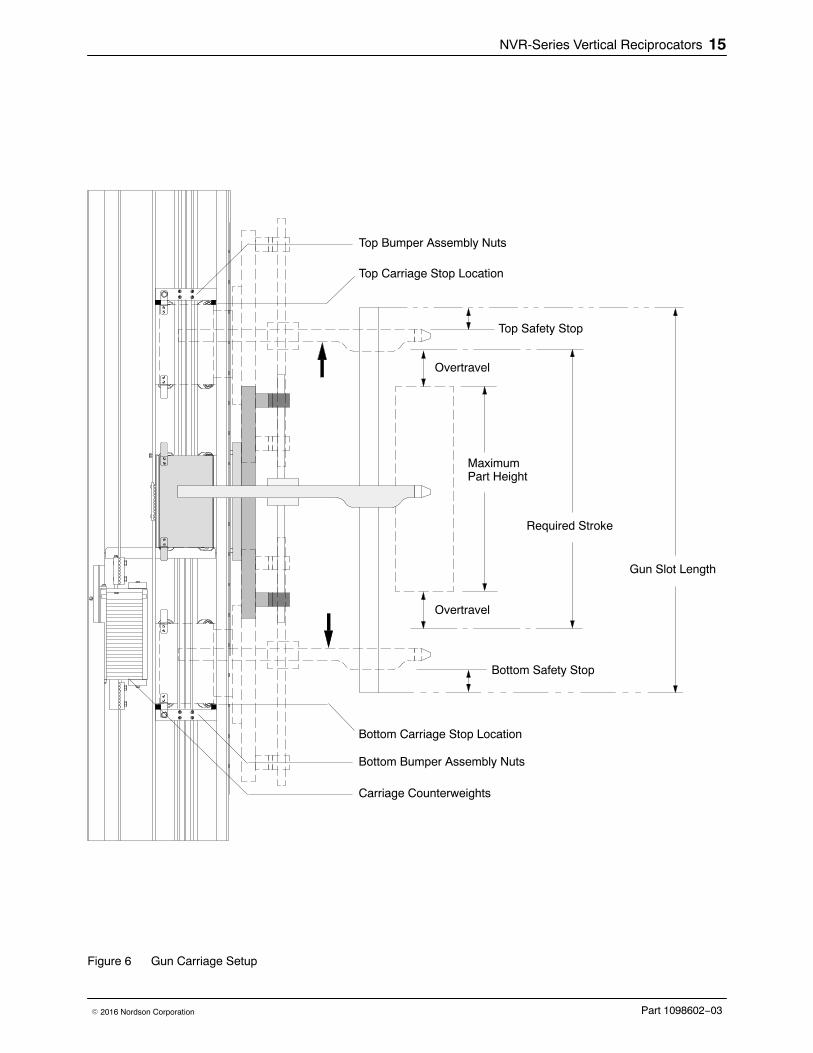
Install the Gun Fixture See Figure 6. Install the spray guns on the carriage mounting bars. Ensurethat the position of the guns on the carriage provides the required strokelength given the position of the parts in relation to the gun slot.
Position the Top and Bottom Carriage Bumpers See Figure 6. The gun carriage bumper assemblies are located above andbelow the gun carriage. Mounted on the carriage bumper assemblies areproximity switches. Adjust the position of the bumpers to prevent the sprayguns from crashing into the top and bottom of the gun slots.
NOTE: If the proximity switches are tripped they will stop the reciprocatorand trigger a fault in the iControl system. The fault must be reset beforeoperation can resume.
Variables to consider before positioning the carriage bumpers are:
� Gun slot length
� Maximum required stroke length—maximum part height plusdesired overtravel
� Position of parts in relation to gun slots
� Gun positioning on mounting bars
1. Move the carriage down until the spray guns are no less than25.4 mm (1 in.) from the bottom of the gun slots.
2. Loosen the bottom bumper assembly nuts and slide it up until thebumpers contact the carriage. Tighten the nuts securely.
3. Move the carriage up until the spray guns are no less than25.4 mm (1 in.) from the top of the gun slots.
4. Loosen the top bumper assembly nuts and slide it down until thebumpers contact the carriage. Tighten the nuts securely.
Counterbalance the Gun Weight See Figure 6. With the guns installed, the gun carriage should not drift upor down when the reciprocator is stopped. The gun carriage should bebalanced so that it takes approximately the same amount of force to move itup and down.
Twenty-one 3.45 kg (7.6 lb) counterweights are provided to balance theweight of the guns. Add or remove counterweights from the weight basketas required. If the gun carriage
� drifts up, remove a weight.
� drifts down, add a weight.
NVR-Series Vertical Reciprocators 15
Part 1098602−03� 2016 Nordson Corporation
MaximumPart Height
Gun Slot Length
Required Stroke
Top Safety Stop
Bottom Safety Stop
Bottom Carriage Stop Location
Top Carriage Stop Location
Overtravel
Overtravel
Top Bumper Assembly Nuts
Bottom Bumper Assembly Nuts
Carriage Counterweights
Figure 6 Gun Carriage Setup
NVR-Series Vertical Reciprocators16
Part 1098602−03 � 2016 Nordson Corporation
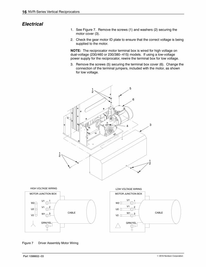
Electrical 1. See Figure 7. Remove the screws (1) and washers (2) securing the
motor cover (3).
2. Check the gear motor ID plate to ensure that the correct voltage is beingsupplied to the motor.
NOTE: The reciprocator motor terminal box is wired for high voltage ondual-voltage (230/460 or 230/380−415) models. If using a low-voltagepower supply for the reciprocator, rewire the terminal box for low voltage.
3. Remove the screws (5) securing the terminal box cover (6). Change theconnection of the terminal jumpers, included with the motor, as shownfor low voltage.
4
12
12
12
3
5
6
U1
V1
W1
1
2
3
GRN/YEL
W2
U2
V2
U1
V1
W1
1
2
3
GRN/YEL
W2
U2
V2
HIGH VOLTAGE WIRING LOW VOLTAGE WIRING
MOTOR JUNCTION BOX MOTOR JUNCTION BOX
CABLE CABLE
Figure 7 Driver Assembly Motor Wiring

NVR-Series Vertical Reciprocators 17
Part 1098602−03� 2016 Nordson Corporation
4. See Figure 5. Connect the motor-to-controller cable to the motorconnector (17) located on the back of the reciprocator.
5. Connect the sensor/encoder-to-controller interface cable to the sensorconnector (18) located on the back of the reciprocator.
6. Connect a ground bonding wire from the spray booth chassis to theground terminal (19). This ground wire may also be connected to theIn/Out Positioner base ground terminal.
The reciprocator gear motor is driven by a variable frequency drive (VFD)unit. Because the reciprocators are available with different voltage ranges,motor speeds (rpm) may differ. The maximum frequency setting for theVFD must be set to the correct frequency, which is dependent on theapplicable gear motor.
Refer to Table 3 for the motor voltage/frequency range and thecorresponding maximum frequency set point value that each VFD needs tobe set. This set point value is entered into VFD as part of initial setup.
Table 3 Component Descriptions
Gear MotorVoltage/Frequency Rating
Main Power SupplyVoltage/Frequency
VFD MaximumFrequency Set
Point Value
230/460 VAC @ 60 Hz 230/460 VAC − 60Hz 60 Hz
200/400VAC @ 50Hz 200 VAC − 50 Hz 60 Hz
230/380−415VAC @ 50Hz 380 VAC − 50 Hz 60 Hz
400 VAC − 50 Hz 58 Hz
415 VAC − 50 Hz 57 Hz
220/380 VAC − 60 Hz 60 Hz
230/400 VAC − 50Hz 58 Hz
332/550−600VAC @ 60Hz 575 VAC − 60 Hz 60 Hz
200−208/360VAC @ 60Hz 200 VAC − 60 Hz 60 Hz
208 VAC − 60 Hz 60 Hz
Functional Check Perform the following:
� Visually inspect the interior of the reciprocator. Remove any foreignobjects that would interfere with operation.
� Make sure the counterweights are stacked properly in the carrier.
� Manually move the gun carriage up and down to ensure that itmoves smoothly.

NVR-Series Vertical Reciprocators18
Part 1098602−03 � 2016 Nordson Corporation
Operation Operation of the reciprocator is controlled by the iControl system or Axiscontroller. Refer to the following manuals for instructions on settingsand controls.
iControl:Refer to the iControl Operator Card and the iControl OperatorInterface Manual.
Axis Controller:Refer to the Axis Controller Operator Interface Manual.
Maintenance Perform preventive maintenance and lubrication procedures according toyour plant maintenance schedule or to the following intervals.
Item Frequency
Cleaning Periodically inspect the interior of the reciprocator. Accumulations of dust, dirt,or overspray may cause premature wear or failure of moving components.Clean all components and lubricate moving components as necessary.
Gear Motor Normal operating temperature of the gear motor is less than 93 �C (200 �F).During the initial break-in period the temperature may rise above93 �C (200 �F). If it exceeds 93 �C (200 �F) for more than 100 hours, contactyour Nordson representative.
The gear motor is shipped with the proper grade and amount of lubricant. Theoil level and quality should be checked on frequent intervals, depending onusage.
Drain and refill the gear motor after 10,000 hours of operation or at least onceevery two years. Refer to the NORD DRIVESYSTEMS gear motor manualthat is included with the reciprocator for more information.
Belt Tension Check the belt tension after the first week of cycling. After the first week ofcycling, check the belt tension every 6 months.
Gun Carriage Track Clean the gun carriage track monthly. Use a nonabrasive material.

NVR-Series Vertical Reciprocators 19
Part 1098602−03� 2016 Nordson Corporation
Troubleshooting WARNING: Allow only qualified personnel to perform the following tasks.Follow the safety instructions in this document and all other relateddocumentation.
These procedures cover only the most common problems that you mayencounter. If you cannot solve the problem with the information given here,contact your local Nordson representative for help.
Problem Possible Cause Corrective Action
1. Noise and excessivevibration duringstroke
Gun carriage rollers worn Replace rollers.
Gun carriage track dirty Clean carriage track using anonabrasive material.
Counterweight guide rollers worn Replace guide rollers.
Counterweight guide tracks dirty orthere is an accumulation of debris.
Clean guide tracks using anonabrasive material.
Gear motor reducer Check oil level. Fill per the motormanufacturer’s service manual.
Insufficient belt tension Check belt tension and readjust ifnecessary.
Bottom pulley Check bottom pulley hub bolts. Makesure pulley is securely fastened togear motor shaft.
Top or bottom pulley worn Check pulleys. If worn or damaged,replace as needed.
2. Noise during reversal;reciprocator willnot start
Motor Make sure proper voltage is being sup-plied to motor. Check all electrical con-nections. Check control panel circuitbreakers, motor controller, and inverter.
Excessive load Make sure load on gun carriage doesnot exceed maximum load. Refer tospecifications.
Gear reducer Make sure reducer is operatingproperly, output shaft is moving freelyand not binding.
Pulleys Make sure pulleys are moving freelyand not binding.

NVR-Series Vertical Reciprocators20
Part 1098602−03 � 2016 Nordson Corporation
Repair WARNING: Allow only qualified personnel to perform the following tasks.Follow the safety instructions in this document and all other relateddocumentation.
Read and understand these procedures before making repairs to thereciprocator. Contact a local Nordson representative regarding theprocedures if necessary.
Some repairs require the use of a ladder. Do not use the reciprocator tosupport the ladder.
WARNING: Lockout power to this equipment before performing repairs.
Secure the Gun Carriage and Counterweight BasketUse this procedure when it is necessary to secure the gun carriage andcounterweight basket to perform repairs.
WARNING: Removing the gun fixture from the gun mount will unbalancethe weight distribution between the gun carriage and the counterweight.Secure the gun carriage to prevent it from moving upward without warning.
1. Disconnect and lock out power to the reciprocator.
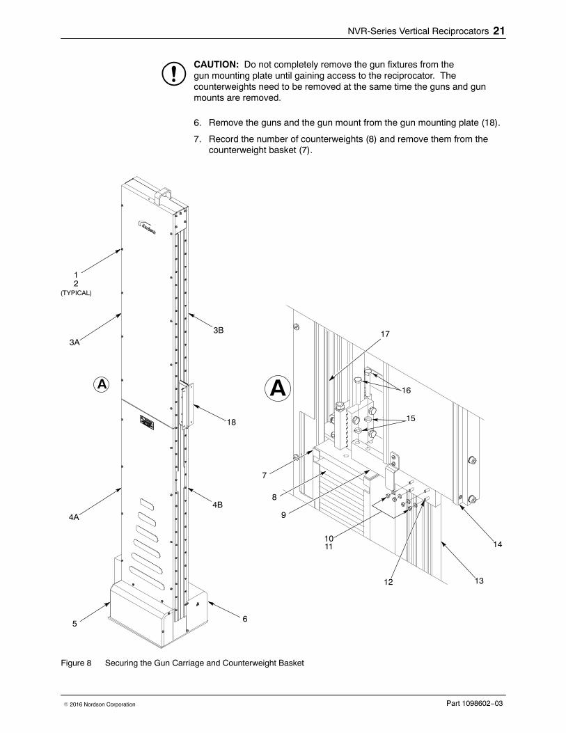
2. See Figure 8. Remove the screws (1) and washers (2) securing theside access panels (3A, 4A) on the encoder side of the reciprocator, andthe encoder cover (5). If repairing the top pulley or gun carriage rollers,remove the access panels (3B, 4B) on the motor side (6).
3. Perform the following:
a. Manually move the gun carriage (14) until the bottom surface ispositioned slightly above the counterweight basket (7).
b. Install the T-bolts (12) through the back of the lock arm (9). Installthe lock arm to the counterweight basket (7) using the lockwashers (15) and screws (16). Tighten the screws securely.
c. Manually move the gun carriage (14) downward until it makescontact with the top of the lock arm (9).
d. Insert the T-bolts (12) into the gun carriage track (13). Install thelock washers (11) and nuts (10) onto the T-bolts. Tighten the nutssecurely.
4. Mark the position of the gun carriage on the gun carriage track (13).
5. Mark the position of the counterweight basket onto the counterweightbasket track (17).
NVR-Series Vertical Reciprocators 21
Part 1098602−03� 2016 Nordson Corporation
CAUTION: Do not completely remove the gun fixtures from thegun mounting plate until gaining access to the reciprocator. Thecounterweights need to be removed at the same time the guns and gunmounts are removed.
6. Remove the guns and the gun mount from the gun mounting plate (18).
7. Record the number of counterweights (8) and remove them from thecounterweight basket (7).
15
16
1410
8
9
12
(TYPICAL)
3A
4A
5
A A
11
12 13
173B
4B
7
6
18
Figure 8 Securing the Gun Carriage and Counterweight Basket

NVR-Series Vertical Reciprocators22
Part 1098602−03 � 2016 Nordson Corporation
Replace the Belt Use the following procedure to replace the belt.
Remove the Belt 1. Secure the gun carriage and counterweight basket. Refer to the Secure
the Gun Carriage and Counterweight Basket procedure.
2. See Figure 9. Mark the belt as follows:
a. Draw a line on the upper belt retainer (5) and mark the belt TOP.
b. Draw a line on the lower belt retainer (7) and mark the beltBOTTOM.
c. Draw two lines on the top and bottom of the gun carriage retainerclamp (12) and mark the belt TOP and BOTTOM.
3. Loosen the tension nuts (3) on top of the pulley belt retainer (13).
4. Loosen the screws (11) securing the belt-clamp retainer (12) to the guncarriage (10).
5. Perform the following:
a. Loosen the screws (8) securing the belt (2) to the lower beltretainer (7).
b. Loosen the screws (4) securing the belt to the upper belt retainer (5).
c. Remove the belt (2) from the belt retainers.
6. Remove the belt (2) from the pulleys (1, 9). Remove the belt frombetween the gun carriage (10) and the carriage belt-clamp retainer (12).
7. Inspect the top and bottom pulleys (1, 9) for wear or damage. Replacethe pulleys if necessary. Refer to the applicable pulley replacementprocedure if required.

NVR-Series Vertical Reciprocators 23
Part 1098602−03� 2016 Nordson Corporation
1
9
10
11
2
3
4
5
(ROTATED 180 DEGREES)
6
8
7
12
13
14
MARK BELT ”TOP”
MARK BELT ”BOTTOM”
MARK BELT ”TOP”
MARK BELT ”BOTTOM”
BOTTOM PULLEY
7 mm(0.28 in.)
TOP PULLEY
14 mm(0.55 in.)
14 mm(0.55 in.)
7 mm(0.28 in.)
BELT
BELT BELT
BELT
Figure 9 Replacing the Belt

NVR-Series Vertical Reciprocators24
Part 1098602−03 � 2016 Nordson Corporation
Install the Belt 1. If applicable, place the old belt flat and level on the floor next to the new
belt. Transfer the marks from the old belt onto the new belt.
2. See Figure 9. Perform the following:
a. Insert the belt (2) into the bottom counterweight basket beltretainer (7).
b. Make sure that the belt is centered side-to-side and engagesthe 8 teeth in the belt retainer. Make sure that the belt does extendabove the top edge of the bottom belt retainer. Tighten thescrews (4) to 20 Nm (180 in.-lb).
3. Route the belt (2) around the bottom pulley (9), between the guncarriage (10) and the counterweight carriage belt retainer (12), andaround the top pulley (1).
4. Perform the following:
a. Loosen the tension nuts (3) on top of the counterweight basket (6)until they are even with the top of the threaded rods.
b. Insert the belt (2) into the top counterweight basket belt retainer (5).
c. Make sure that the belt (2) is centered side-to-side and engages the8 teeth in the belt retainer (5). Make sure that the belt does notextend below the bottom edge of the belt retainer. Tighten thescrews (4) to 20 Nm (180 in.-lb).
d. Make sure that the belt is centered side-to-side on the top andbottom pulleys as shown in Figure 9. The belt is centered when thedistance from the side of the pulley to the edge of the belt is thesame.
5. Adjust the belt tension. Refer to the Adjust the Belt Tension procedure.
6. Make sure that the belt is centered side-to-side in the belt retainer (12)on the back of the gun carriage (10). Tighten the belt clamp retainingscrews (11) to 14 Nm (120 in.-lb).
7. See Figure 8. Remove the nuts (10) and lock washers (11) from theT-bolts (12).
8. Remove the screws (16) and washers (15) securing the lock arm (9) tothe counterweight basket (7).
WARNING: Installing the guns and gun mount will unbalance the weightdistribution between the gun carriage and the counterweight. Secure thegun carriage to prevent it from moving downward without warning.
9. Install the gun mount and guns to the gun carriage.
10. Insert the appropriate counterweight plates (8) into the counterweightbasket (7) to balance the gun carriage.
11. Install the side access panels (3A, 3B, 4A, 4B) and the encodercover (5) using the washers (2) and screws (1). Tighten thescrews securely.

NVR-Series Vertical Reciprocators 25
Part 1098602−03� 2016 Nordson Corporation
Adjust the Belt Tension Check the belt tension using either the Applied Force or Sonic Metermethods. Table 4 lists the necessary data for using the Applied Forcemethod. Table 5 lists the necessary data for using the Sonic Meter method.
1. Check the belt tension using the desired method.
2. See Figure 10. Alternately tighten or loosen the tension nuts (1) on thetop of the pulley belt retainer (2) until the proper reading is obtained.
Table 4 Belt Tension for Applied Load Method
Reciprocator Gun Carriage Position (1) Load (2) Maximum Deflection
1.7-M Stroke 1860 mm (73.2 in.) 8 kg (17.6 ib) 17mm (0.67 in.)
2.2-M Stroke 2300 mm (90.6 in.) 8 kg (17.6 ib) 17mm (0.67 in.)
2.7-M Stroke 2300 mm (90.6 in.) 8 kg (17.6 ib) 17mm (0.67 in.)
3.2-M Stroke 2300 mm (90.6 in.) 8 kg (17.6 ib) 17mm (0.67 in.)
1. This is the distance between the bottom of the gun carriage belt retainer and the top of the base plate.To achieve an accurate belt tension reading, make sure that this measurement is accurate.
2. Apply load to the inside face of the belt in the direction toward the back of the reciprocator. Measuredeflection in the same direction. Measure the belt tension at the middle of the free length of the belt;approximately 1200 mm (47.3 in.) from the top of the base plate to the middle of the belt.
Table 5 Belt Tension for Sonic Method
Reciprocator Gun Carriage Position (1) Static Tension (2)
1.7-M Stroke 1860 mm (73.2 in.) 2900 N (650 lb)
2.2-M Stroke 2300 mm (90.6 in.) 2900 N (650 lb)
2.7-M Stroke 2300 mm (90.6 in.) 2900 N (650 lb)
3.2-M Stroke 2300 mm (90.6 in.) 2900 N (650 lb)
1. This is the distance between the bottom of the gun carriage belt retainer and the top of the base plate.To achieve an accurate belt tension reading, make sure that this measurement is accurate.
2. Refer to the sonic meter operation manual for procedures on measuring static tension. Measure thebelt tension at the middle of the free length of the belt; approximately 1200 mm (47.3 in.) from the topof the base plate to the middle of the belt.

NVR-Series Vertical Reciprocators26
Part 1098602−03 � 2016 Nordson Corporation
1
2
1A
GUN CARRIAGE POSITION FORAPPLICABLE RECIPROCATOR
A
APPLY LOAD OR MEASUREUSING SONIC METER ONTHE FLAT SIDE OF THE BELT.
BOTTOM OF GUNCARRIAGE BELTRETAINER
TOP OF BASE PLATE
Figure 10 Adjusting Belt Tension

NVR-Series Vertical Reciprocators 27
Part 1098602−03� 2016 Nordson Corporation
Replace the Top Pulley Use the following procedures to replace the top pulley.
WARNING: This procedure requires the use of a ladder. Do not use thereciprocator to support the ladder.
Remove the Top Pulley 1. Secure the gun carriage and counterweight basket. Refer to the Secure
the Gun Carriage and Counterweight Basket procedure.
2. See Figure 9. Loosen the tension nuts (3) on top of the pulley beltretainer (13).
3. Loosen the screws (11) securing the belt-clamp retainer (12) to the guncarriage (10).
4. Loosen the screws (4) securing the belt (2) to the pulley belt retainer (5).Remove the belt (2) from the belt retainer.
5. Remove the belt (2) from the top pulley (1).
6. See Figure 11. Remove the nut (5), lock washer (4), and screw (2)securing the pulley (3) to the reciprocator (1). Remove the pulley fromthe reciprocator.
2
3
45
1
Figure 11 Replacing the Top Pulley

NVR-Series Vertical Reciprocators28
Part 1098602−03 � 2016 Nordson Corporation
Install the Top Pulley 1. See Figure 11. Install the new pulley (3) into the reciprocator (1)
using the screw (2), lock washer (4), and nut (5). Tighten the nutto 57 Nm (42 ft-lb)
2. See Figure 9. Route the belt (2) around the top pulley (1).
3. Perform the following:
a. Insert the belt (2) into the top counterweight basket belt retainer (13).
b. Make sure that the belt is centered and engages the 8 teeth in thebelt retainer. Tighten the screws (4) to 20 Nm (180 in.-lb).
4. Adjust the belt tension. Refer to the Adjust the Belt Tension procedure.
5. Make sure that the belt is centered in the belt retainer (12) on the backof the gun carriage (10). Tighten the belt clamp retaining screws (11) to14 Nm (120 in.-lb).
6. See Figure 8. Remove the nuts (8) and lock washers (9) from theT-bolts (10).
7. Remove the screws (14) and washers (13) securing the lock arm (7) tothe counterweight basket (6).
WARNING: Installing the guns and gun mount will unbalance the weightdistribution between the gun carriage and the counterweight. Secure thegun carriage to prevent it from moving downward without warning.
8. Install the gun fixture to the gun carriage.
9. See Figure 9. Insert the appropriate counterweight plates (14) into thecounterweight basket (6) to balance the gun carriage.
10. See Figure 8. Install the side access panels (3A, 4A) and encodercover (5) using the washers (2) and screws (1). Tighten thescrews securely.
Replace the Bottom Pulley Use the following procedures to replace the bottom pulley.
Remove the Bottom Pulley 1. Secure the gun carriage and counterweight basket. Refer to the Secure
the Gun Carriage and Counterweight Basket procedure.
2. See Figure 9. Loosen the tension nuts (3) on top of the pulley beltretainer (13).
3. Loosen the screws (11) securing the belt-clamp retainer (12) to the guncarriage (10).
4. Loosen the screws (8) securing the belt (2) to the lower belt retainer (13)on the counterweight basket (6). Remove the belt (2) from the bottombelt retainer.
5. Remove the belt (2) from the bottom pulley (9).
6. See Figure 12. Loosen the shaft coupling screws (7) securing theencoder assembly (8) to the drive motor shaft (1).

NVR-Series Vertical Reciprocators 29
Part 1098602−03� 2016 Nordson Corporation
7. Cut the cable ties, not shown, securing the encoder cable to the base.Loosen the screw (2) securing the encoder assembly (8) to thebase (10). Remove the encoder assembly from the base.
8. Perform the following:
a. Loosen the bushing screws (6).
b. Install two M6 x 80 screws into the jackscrew holes.
c. Alternate tightening the screws to remove the bushing (5) andbottom pulley (4) from the driver assembly shaft (1).
9. Remove the washer (3) from the driver assembly shaft (1). Check thewasher for wear or damage and replace if necessary.
1
2
3
4
57
8
10
1
2
3
4
5
6
7
8
9
10
11
12
TORQUE SEQUENCE
A
JACKSCREW HOLE
JACKSCREW HOLE5
6
A
Figure 12 Replacing the Bottom Pulley

NVR-Series Vertical Reciprocators30
Part 1098602−03 � 2016 Nordson Corporation
Install the Bottom Pulley 1. See Figure 12. Install the washer (3) onto the driver assembly shaft (1).
2. Install the bushing (5) into the bottom pulley (4).
3. Install the bottom pulley onto the driver assembly shaft (1).
4. Use the following method to tighten the bushing screws (6):
a. Using a torque wrench, thread the screws (6) into the bushing (5) inthe sequence shown. Only tighten to 4 Nm (2.3 ft-lb).
b. Start at TORQUE SEQUENCE 1 and tighten the screws (6) in thesequence shown only to 8 Nm (6 ft-lb).
c. Finally, start at TORQUE SEQUENCE 1 and tighten the screws inthe sequence shown to 15.7 Nm (12 ft-lb).
5. Connect the encoder assembly (8) to the drive motor shaft (1). Tightenthe shaft coupling screws (7) to 3.1 Nm (3 ft-lb).
6. Tighten the screw (2) to secure the encoder assembly (8) to thebase (10).
7. Install new cable ties onto the encoder assembly cable.
8. See Figure 9. Perform the following:
a. Insert the belt (2) into the bottom counterweight basket beltretainer (7).
b. Make sure that the belt is centered and engages the 8 teeth in thebelt retainer. Tighten the screws (8) to 20 Nm (15 ft-lb).
9. Adjust the belt tension. Refer to the Adjust the Belt Tension procedure.
10. Make sure that the belt is centered in the belt retainer (12) on the backof the gun carriage (10). Tighten the belt clamp retaining screws (11) to14 Nm (120 in.-lb).
11. See Figure 8. Remove the nuts (8) and lock washers (9) from theT-bolts (10).
12. Remove the screws (14) and washers (13) securing the lock arm (7) tothe counterweight basket (6).
13. Install the gun fixture to the gun carriage.
WARNING: Installing the guns and gun mount will unbalance the weightdistribution between the gun carriage and the counterweight. Secure thegun carriage to prevent it from moving downward without warning.
14. See Figure 9. Insert the appropriate counterweight plates (14) into thecounterweight basket (6) to balance the gun carriage.
15. See Figure 8. Install the side access panels (3A, 4A) and encodercover (5) using the washers (2) and screws (1). Tighten thescrews securely.

NVR-Series Vertical Reciprocators 31
Part 1098602−03� 2016 Nordson Corporation
Replace the Counterweight Basket Rollers
WARNING: This procedure requires the use of a ladder. Do not use thereciprocator to support the ladder.
Use the following procedure to replace the counterweight basket rollers.
NOTE: The top counterweight basket roller assembly is used as anexample in this procedure. The procedure for replacing the bottomcounterweight basket roller assembly is typical.
1. Secure the gun carriage and counterweight basket. Refer to the Securethe Gun Carriage and Counterweight Basket procedure.
2. Mark the orientation and position of the top counterweight guide on topof the counterweight basket. Repeat this procedure if replacing thebottom counterweight guide.
3. Remove the screws (2) and lock washers (3) securing the rollerassembly (4) to the counterweight basket (1).
4. Move the roller assembly (4) upward to remove it from theroller guides (5).
5. Insert the new roller assembly (4) into the roller guides (5).
6. Secure the roller assembly (3) to the counterweight basket (1) usingthe lock washers (2) and screws (1). Tighten the screwsto 25 Nm (18.5 ft-lb).
2
5
4
3
1
MARK POSITION
MARK POSITION
Figure 13 Replacing the Counterweight Basket Roller Assemblies

NVR-Series Vertical Reciprocators32
Part 1098602−03 � 2016 Nordson Corporation
Replace the Gun Carriage Rollers NOTE: Replacing the gun carriage rollers requires the use of an assistant.
Remove the Guns and Gun Carriage Mount 1. Disconnect and lock out power to the reciprocator.
2. See Figure 8. Remove the screws (1) and washers (2) securing theside access panels (3A, 3B, 4A, 4B). Remove the screws and washerssecuring the encoder cover (5) and motor cover (6).
3. Perform the following:
a. Manually move the gun carriage (14) until the bottom surface ispositioned slightly above the counterweight basket (7).
b. Install the T−bolts (12) through the back of the lock arm (9). Installthe lock arm to the counterweight basket (7) using the lockwashers (15) and the screws (16). Tighten the screws securely.
c. Manually move the gun carriage (14) downward until it makescontact with the top of the lock arm (9).
d. Insert T−bolts (12) into the gun carriage track (13). Install the lockwashers (11) and nuts (10) onto the T−bolts. Tighten the nutssecurely.
e. Mark the gun carriage (21) position on the gun carriage track (11).
f. Mark the counterweight basket (13) position on the counterweightbasket track.
CAUTION: Do not completely remove the gun fixtures from the guncarriage mount plate until gaining access to the reciprocator. Thecounterweights need to be removed at the same time the guns and gunmounts are removed.
4. Remove the guns and the gun bar mount from the gun mount plate (18)
5. Record the number of counterweights (8) and remove them from thecounterweight basket (7).
6. See Figure 14. After all guns, gun bar mounts, and counterweightshave been removed, perform the following:
a. Loosen the lock arm (7) nuts (9) until the T-bolts (8) can be rotated90 degrees and pulled outward from the slots in the carriagetrack (11). Remove the screws (1) and the lock washers (6) securingthe lock arm (7) to the top of the counterweight basket (13).Remove the lock arm (7).
b. Manually move the gun carriage (21) by the notch (20) in the flapretainer.
7. Remove the cross bolts (27), lock washers (29), washers (28), andnuts (30) securing the gun mount plates (31) to the mounting block (32).
8. Remove the screws (17) and lock washers (18) securing the mountingblock (32) to the front of the gun carriage (21).

NVR-Series Vertical Reciprocators 33
Part 1098602−03� 2016 Nordson Corporation
7
1
6
8910
12
14
13
11
153
2
4
34
22
23
21
2
20
11
2728 32
1718
28293032
31
31
34
5
MARK BELT ”TOP”
MARK BELT
25 24
26
BOTTOM OFGUN CARRIAGE (21)
RE-INSTALLEDLOCK ARM (7)
”BOTTOM”
A
AMARK BELT
MARK BELT TOP
”BOTTOM”
19
22
16
Figure 14 Installing the Gun Carriage Mount

NVR-Series Vertical Reciprocators34
Part 1098602−03 � 2016 Nordson Corporation
CAUTION: To prevent damage to the bottom pulley assembly, use blocksto support the counterweight basket.
9. Perform the following:
a. Place a wood block (25) onto the reciprocator cross braces asshown.
b. Position the gun carriage (21) so it is accessible to service, thenblock the counterweight basket with a long block (26) to prevent itfrom moving.
c. Make sure that the bottom of the gun carriage (21) is above the topof the counterweight basket (13).
10. Reinstall the lock arm (7) onto the carriage track (11) against the bottomedge of the gun carriage (21). Install the T-bolts (8) into the gun carriageand tighten the nuts securely.
11. Loosen the tension nuts (15) on top of the pulley retainer (16) untilthe nuts are flush with the top of the threaded rod on the counterweightbasket (13).
12. Perform the following:
a. Draw two lines on the top and bottom of the gun carriage retainerclamp (22) as shown. Mark the belt (2) TOP and BOTTOM. Thesemarks will be used during reassembly.
b. Mark the belt (2) where it contacts the the belt retainer (5) on the topand the belt retainer (34) on the bottom of the counterweightbasket (13). Mark TOP just above the top retainer (5). MarkBOTTOM below the bottom retainer (34). These marks will be usedduring reassembly.
c. Have an assistant hold the counterweight basket (13).
d. Remove the screws (23) and lock washers (32) securing the beltretainer to the gun carriage (21). The gun carriage (21) should beresting on top of lock arm (7)
e. Have an assistant lower the counterweight basket so that it is restingon the blocks (25, 26).
f. Remove the screws (3) and lock washers (4) securing the belt (2) tothe top counterweight basket belt retainers (5) and (34).
g. Remove the belt (2) from the top pulley (19).

NVR-Series Vertical Reciprocators 35
Part 1098602−03� 2016 Nordson Corporation
Notes:

NVR-Series Vertical Reciprocators36
Part 1098602−03 � 2016 Nordson Corporation
Remove the Gun CarriageNOTE: The procedures in the Remove the Guns and Gun Carriage Mountsection must be completed before performing the following procedures.
1. See Figure 15. Remove the belt (18) from the top pulley (19)
2. Remove the screws (7) and lock washers (8) securing the top cover (1)to the reciprocator (9).
3. Remove the nut (19), lock washer (20), and screw (21) securing thepulley (18) to the top side plates (4, 22). Remove the pulley assemblyfrom the reciprocator (9).
4. Remove the screws (5) and lock washers (6) securing the sideplates (4, 22) to the front and back of the reciprocator (9).
5. Remove the two screws (15), lock washers (3), and nuts (2) securingthe U-lift bracket (16) to the gun carriage track (10). Do not remove theother two screws (15) securing top side plates (4, 22) at this time.
WARNING: Support the weight of each side plate when removing thescrews to prevent injury to personnel and damage to reciprocator.
6. While supporting the side plate (4), remove the remaining lockwashers (3) and nuts (2) from the two screws (15) securing the sideplates (4, 22). Remove the side plate (4).
7. While supporting the remaining side plate (22), remove the twoscrews (15) from the carriage the track (10). Remove the sideplate (22).
8. Perform the following:
a. Mark the position of the top bumper assembly (14) on the guncarriage track (10).
b. Remove the nuts (11), lock washers (12), and T-bolts (13) securingthe top bumper assembly to the gun carriage track (10)
CAUTION: To prevent damage to the proximity sensor on the top bumperassembly, use extreme care when removing the gun carriage.
9. Hold the proximity sensor (14) as shown. Carefully slide the guncarriage (17) up and over the top bumper assembly.

NVR-Series Vertical Reciprocators 37
Part 1098602−03� 2016 Nordson Corporation
17
14
10
1
4
7
56
8
15
16
23
91112
14
13
10
2019
21
18
22
RECIPROCATOR
RECIPROCATOR
FRONT SUPPORT
BACK SUPPORT
MARKPOSITION
Figure 15 Removing the Gun Carriage Assembly
NVR-Series Vertical Reciprocators38
Part 1098602−03 � 2016 Nordson Corporation
Replace the Rollers1. See Figure 16. Remove the screws (1) securing the covers (3, 4) to the
roller blocks (2, 5).
2. Slide the covers (3, 4) off of the roller assemblies (2, 5).
NOTE: Install the rollers on each roller assembly as shown.
3. Perform the following to replace a Nylon roller (7):
a. Remove the screw (9) and short bushing (8) securing the Nylonroller to the roller assembly (2).
b. Remove the long bushing (6) from the Nylon roller (7). Insert thelong bushing into the new Nylon roller.
c. Apply several drops of Loctite 242 Medium Strength BlueThreadlocker to the internal threads on the roller block.
d. Insert the Nylon roller (7) into the roller assembly and secure itusing the short bushing (8) and screw (9). Tighten the screwto 25 Nm (18.4 ft-lb).
4. Perform the following to replace a Polyurethane roller (7):
a. Remove the screw (13) and roller bushing (12) securing thePolyurethane roller (11) to the roller block (2).
b. Remove the conformal axle (10) from the Polyurethane roller (11).
c. Insert the new conformal axle into the new Polyurethane roller (11).
d. Apply several drops of Loctite 242 Medium Strength BlueThreadlocker to the internal threads on the roller block.
e. Insert the Polyurethane roller (11) into the wheel block (2) andsecure it using the roller bushing (12) and screw (13). Tighten thescrew to 14 Nm (10.3 ft-lb).
NOTE: Make sure that the roller blocks are oriented to the coversas shown.
5. Install the covers (3, 4) onto the wheel blocks (2, 5). Perform thefollowing:
a. Insert all of the screws (1) into the roller blocks. Alternately handtighten the screws until the ends of the side plates are fully engagedinto both roller blocks.
b. Tighten the screws to 10.5 Nm (7.8 ft-lb).

NVR-Series Vertical Reciprocators 39
Part 1098602−03� 2016 Nordson Corporation
P
P
PP
N
N
N
N
1
2
3
4
5
P
N
N
P
6
7
8
9
10
12
13
11
A
A
BOTTOM PROXIMITYSENSOR TARGET
P = POLYURETHANE ROLLERN = NYLON ROLLER
APPLY SEVERAL DROPS OF LOCTITE 242 MEDIUM STRENGTHBLUE THREAD LOCKER ONLY TO THE INTERNAL THREADS.
2
Figure 16 Replacing the Gun Carriage Rollers

NVR-Series Vertical Reciprocators40
Part 1098602−03 � 2016 Nordson Corporation
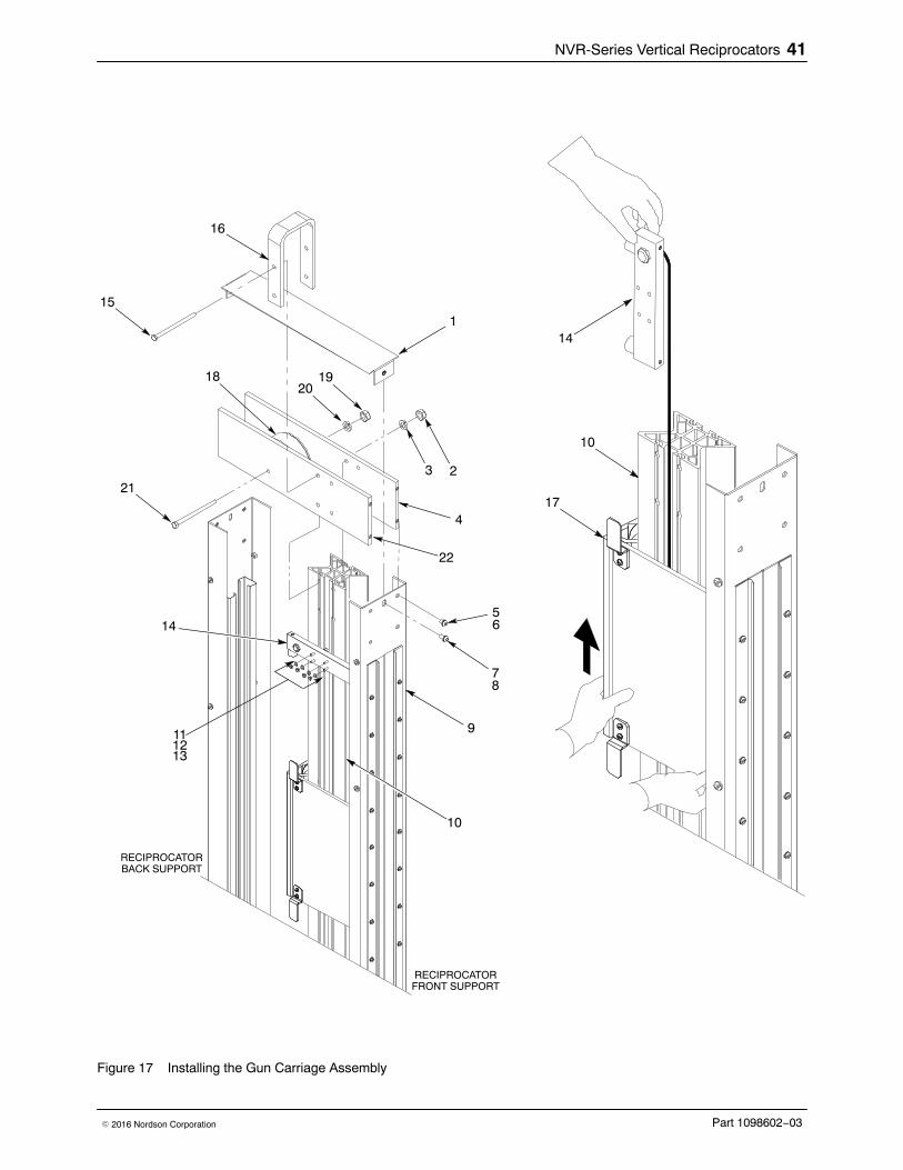
Install the Gun Carriage1. See Figure 17. Hold the the top bumper assembly (14) as shown.
Carefully slide the gun carriage (17) over the bumper assembly until itcontacts the bottom bumper assembly.
2. Install the top bumper assembly (14):
a. Insert the T-bolts (13) into the back of the top bumper assembly.
b. Position the top bumper assembly onto the gun carriage track (10) atthe mark that was made prior to removing it.
c. Insert the T-bolts (13) into the gun carriage track (10). Install thelock washers (12) and nuts (11) onto the T-bolts. Tighten the nutssecurely.
d. Carefully press the top bumper proximity sensor cable into thecenter groove on the side of the gun carriage track.
3. Install the side plates (4, 22) onto gun carriage track (10) using twoscrews (15), lock washers (3) and nuts (2). Only hand tighten thescrews.
4. Install the U-lift bracket (16) to the side plates (4, 22) using the other twoscrews (15), lock washers, and nuts (2). Only hand tighten the screws.
5. Install the top pulley assembly (18) in between the side plates (4, 22)using the screw (21), lock washer (20) and nut (20). Tighten the screwsecurely.
6. Tighten all screws (15), lock washers (3) and nuts (2) to secure the sideplates (22, 4) to the gun carriage track (10).
7. Secure the side plates (4, 22) to the front and back support of thereciprocator using the screws (5) and lock washers (6). Tighten thescrews securely.
8. Install the top cover (1) onto the reciprocator (9) using the screws (7)and lock washers (8). Tighten the screws securely.
NVR-Series Vertical Reciprocators 41
Part 1098602−03� 2016 Nordson Corporation
17
14
10
1
4
7
56
8
15
16
23
91112
14
13
10
2019
21
18
22
RECIPROCATOR
RECIPROCATOR
FRONT SUPPORT
BACK SUPPORT
Figure 17 Installing the Gun Carriage Assembly

NVR-Series Vertical Reciprocators42
Part 1098602−03 � 2016 Nordson Corporation
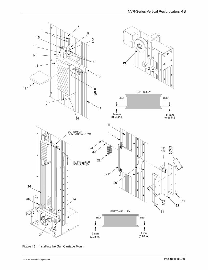
Install the Gun Carriage Mount1. See Figure 18. Install the belt:
NOTE: If reinstalling the same belt, use the markings
� made on the belt to identify the installation orientationand location of the belt ends to the top and bottom ofcounterweight basket.
� to locate the gun carriage retainer attachment location.
If replacing the old belt and it is not broken,
� place the old belt next to the new belt on a level floor andtransfer the marks onto the new belt.
� use the old belt check the over length of new belt to determine ifit needs to be cut.
a. Insert the belt (2) into the top and bottom counterweight basket beltretainers (5, 34). Make sure that the belt is centered side-to-sideand engages the eight teeth in the belt retainers. Make sure that thebelt does not extend below the bottom edge of top retainer (5) orabove the top edge of the bottom retainer (35). Secure the beltusing the lock washers (4) and screws (3). Tighten the screws to14 Nm (10.3 ft-lb).
b. Install the belt retainer (22) onto the back of gun carriage (21) usingthe screws (23) and lock washers (33). Do not tighten the screws atthis time. Make sure that the belt (2) can move freely between thebelt retainer and gun carriage.
c. Have an assistant position the gun carriage (21) so that the top andbottom of the belt retainer (22) aligns with the marks made on thebelt (2). Make sure that the belt (2) is centered side-to-side in thebelt retainer (22). Secure the belt retainer to gun carriage bytightening the screws (23) to 20 Nm (14.75 ft-lb).
d. Make sure that the belt is centered side-to-side on the bottom drivepulley (34). The distance from the outer side face of the pulley to thebelt is approximately 7 mm (0.28 in.). Reposition the belt if required.
e. Make sure the belt is centered side-to-side on the top idlerpulley (19) by checking that distance from outer side face of pulley tobelt is 14 mm (0.55 in.). Reposition the belt if required.
2. Remove the lock arm (7) by loosening the nuts (9) on the T-bolts (8)until the T-bolts can be rotated 90 degrees and can be pulled outwardfrom the slots in carriage track (11).
3. Remove the wood blocks (25, 26) under the counterweight basket (13).Have an assistant manually move the gun carriage (21) by thenotch (20) in the flap retainer on the front of the reciprocator.
4. Position the gun carriage mount (32) in front of the gun carriage (21).Install the screws (17) and lock washers (18) that secure the mountingblock (33) to gun carriage (21). Do not tighten the screws until all ofthem are installed. After the screws are installed, tighten them securely.
5. Install the gun mounting plates (31) to the mounting block (32) using thecross bolts (27), lock washers (29), washers (28), and nuts (30).Tighten the nuts securely.
6. Adjust the belt tension. Refer to the Adjust the Belt Tension procedure.
NVR-Series Vertical Reciprocators 43
Part 1098602−03� 2016 Nordson Corporation
7
1
6
8910
12
14
13
11
153
2
4
34
34
5
25 24
26
19
16
34
BOTTOM OFGUN CARRIAGE (21)
RE-INSTALLEDLOCK ARM (7)
22
23
21
2
20
11
2728 32
1718
28293032
31
31
BOTTOM PULLEY
7 mm(0.28 in.)
TOP PULLEY
14 mm(0.55 in.)
14 mm(0.55 in.)
7 mm(0.28 in.)
BELT
BELT BELT
BELT
Figure 18 Installing the Gun Carriage Mount

NVR-Series Vertical Reciprocators44
Part 1098602−03 � 2016 Nordson Corporation
7. Perform the following:
a. Manually move the gun carriage up and down to ensure that itmoves smoothly. The carriage should slide up and down with noresistance. All visible rollers on carriage should make contact withcarriage track.
b. Temporarily remove the lockout tag to enable the equipment to bepowered up and tested using the controller.
c. Refer to the applicable Operator’s Card or controls unit manual forstartup and run procedure. Start the reciprocator and let it runthrough several cycles to ensure that it operates properly.
8. Perform the following:
a. Disconnect and lockout power to the reciprocator. Lock out andtag the main power to the reciprocator before continuing to thenext step.
b. Manually move the gun carriage (21) until the bottom surface ispositioned slightly above the counterweight basket (13).
c. Install the T-bolts (10) through the back of the lock arm (7). Installthe lock arm to the counterweight basket (13) using the lockwashers (6) and screws (1). Tighten the screws securely.
d. Manually move the gun carriage (21) downward until it makescontact with the top of the lock arm (7).
e. Insert the T-bolts (10) into the gun carriage track (11). Install thelock washers (9) and nuts (8) onto the T-bolts. Tighten the nutssecurely.
9. Insert the counterweights (12) into the counterweight basket (13).
10. Install the gun mount and guns to the gun carriage.
11. Remove the nuts (8) and lock washers (9) from the T-bolts (10).
12. Remove the screws (1) and washers (6) securing the lock arm (7) to thecounterweight basket (13).
13. See Figure 8. Install the side access panels (3A, 3B, 4A, 4B) andencoder cover (5) using the washers (2) and screws (1). Tighten thescrews securely.
14. Remove the lockout tag and reconnect power to the reciprocator.

NVR-Series Vertical Reciprocators 45
Part 1098602−03� 2016 Nordson Corporation
Notes:

NVR-Series Vertical Reciprocators46
Part 1098602−03 � 2016 Nordson Corporation
Gear Motor
WARNING: Lockout power to the reciprocator before performing repairs.
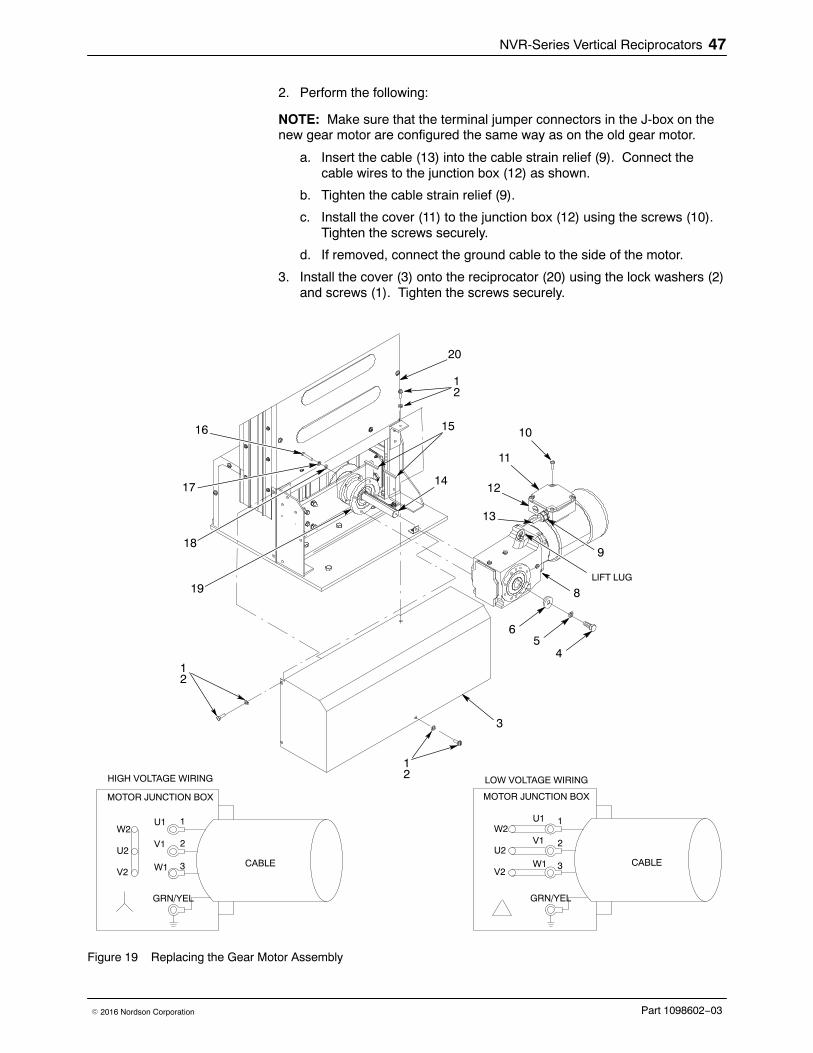
Remove the Gear Motor 1. See Figure19. Remove the screws (1) and lock washers (2) securing
the cover (3) to the reciprocator (20).
2. Perform the following:
a. Remove the screws (10) securing the cover (11) to the gear motorjunction box (12).
NOTE: Make note of the orientation of the terminal jumper connectors inthe junction box. Make sure that the terminal jumper connectors on the newgear motor are configured the same way.
b. Loosen the cable strain relief (9).
c. Disconnect the cable wires in the junction box (12). Carefully pullthe cable (13) out of the junction box (12).
d. If installed, disconnect the ground cable from the side of thegear motor.
3. Remove the screw (4), lock washer (5), and washer (6) securing thegear motor (8) to the driver assembly shaft (14).
4. Remove the screws (16), lock washers (17), and washers (18) securingthe gear motor (8) to the gear motor mount (19).
CAUTION: The gear motor is heavy. Use extreme care when removingit from the reciprocator. Use the lift-lug on the gear motor during removaland installation.
5. Remove the gear motor (8) from the shaft (14). Remove the shaftkeys (15) from the driver assembly shaft (14).
Install the Gear Motor 1. See Figure19. Perform the following:
a. Install the shaft keys (15) onto the driver assembly shaft (14)as shown.
b. Make sure that the keyway on the gear motor (8) is aligned to theshaft keys (15) on the shaft (14). Slide the gear motor onto theshaft. Make sure that there are no gaps between the face of thegear motor (8) and the gear motor mount (19).
c. Secure the gear motor (8) to the gear motor mount (19) using thewashers (18), lock washers (17), and screws (16). Tighten thescrews to 25 Nm (18.5 ft-lb).
d. Secure the driver assembly shaft (14) to the gear motor (8) using thewasher (6), lock washer (5), and screw (4). Tighten the screwto 25 Nm (18.5 ft-lb).
NVR-Series Vertical Reciprocators 47
Part 1098602−03� 2016 Nordson Corporation
2. Perform the following:
NOTE: Make sure that the terminal jumper connectors in the J-box on thenew gear motor are configured the same way as on the old gear motor.
a. Insert the cable (13) into the cable strain relief (9). Connect thecable wires to the junction box (12) as shown.
b. Tighten the cable strain relief (9).
c. Install the cover (11) to the junction box (12) using the screws (10).Tighten the screws securely.
d. If removed, connect the ground cable to the side of the motor.
3. Install the cover (3) onto the reciprocator (20) using the lock washers (2)and screws (1). Tighten the screws securely.
3
45
6
11
14
16
17
18
10
8
9
19
13
12
20
1
1
15
1
U1
V1
W1
1
2
3
GRN/YEL
W2
U2
V2
HIGH VOLTAGE WIRING
MOTOR JUNCTION BOX
CABLE
LIFT LUG
2
2
2
U1
V1
W1
1
2
3
GRN/YEL
W2
U2
V2
LOW VOLTAGE WIRING
MOTOR JUNCTION BOX
CABLE
Figure 19 Replacing the Gear Motor Assembly

NVR-Series Vertical Reciprocators48
Part 1098602−03 � 2016 Nordson Corporation
Replace the Drive Bearing or Drive Motor Shaft Use the following procedure to replace the drive bearing or drive shaft.
Remove the Drive Bearing and Shaft 1. Remove the Bottom Pulley. Refer to the Remove the Bottom Pulley
procedure.
2. Remove the gear motor. Refer to the Remove the Gear Motorprocedure.
3. See Figure 20. Remove the retainer snap ring (1) from the drive motorshaft (3). Remove the drive motor shaft from the adapter (4).
4. Inspect the drive motor shaft (3) for wear or damage and replace ifnecessary.
5. Remove the bearing (2) from the adapter (4).
Install the Drive Bearing and Shaft 1. Install the bearing (2) into the adapter.
2. Install the drive motor shaft (3) into the bearing (2).
3. Install the gear motor. Refer to the Install the Gear Motor procedure.
4. Install the bottom pulley. Refer to the Install the Bottom Pulleyprocedure.
4
3
2
1
Figure 20 Replacing the Bearing or Gear Motor Shaft

NVR-Series Vertical Reciprocators 49
Part 1098602−03� 2016 Nordson Corporation
Parts To order parts, call the Nordson Finishing Customer Support Center at (800)433-9319 or contact your local Nordson representative.
Using the Illustrated Parts List Numbers in the Item column correspond to numbers that identify parts inillustrations following each parts list. The code NS (not shown) indicatesthat a listed part is not illustrated. A dash (—) is used when the part numberapplies to all parts in the illustration.
The number in the Part column is the Nordson Corporation part number. Aseries of dashes in this column (- - - - - -) means the part cannot be orderedseparately.
The Description column gives the part name, as well as its dimensions andother characteristics when appropriate. Indentions show the relationshipsbetween assemblies, subassemblies, and parts.
� If you order the assembly, items 1 and 2 will be included.
� If you order item 1, item 2 will be included.
� If you order item 2, you will receive item 2 only.
The number in the Quantity column is the quantity required per unit,assembly, or subassembly. The code AR (As Required) is used if the partnumber is a bulk item ordered in quantities or if the quantity per assemblydepends on the product version or model.
Letters in the Note column refer to notes at the end of each parts list. Notescontain important information about usage and ordering. Special attentionshould be given to notes.
Item Part Description Quantity Note— 0000000 Assembly 11 000000 � Subassembly 2 A2 000000 � � Part 1

NVR-Series Vertical Reciprocators50
Part 1098602−03 � 2016 Nordson Corporation
Reciprocator Assemblies The following reciprocators are available.
Part Description Note1.7-Meter (1700 mm/66.9 in.) Stroke
1098689 RECIPROCATOR, NVR, 1.7-M, 230/415 AC, 50 Hz, ATEX1099502 RECIPROCATOR, NVR, 1.7-M, 230/460 Vac, 60 Hz1099503 RECIPROCATOR, NVR, 1.7-M, 200 Vac, 50 Hz1099504 RECIPROCATOR, NVR, 1.7-M, 230/380−415 Vac, 50 Hz1099505 RECIPROCATOR, NVR, 1.7-M, 575/600 Vac, 60 Hz1099506 RECIPROCATOR, NVR, 1.7-M, 208 Vac, 60 Hz16000147 RECIPROCATOR, NVR, 1.7-M, 200 Vac, 60 Hz
2.2-Meter (2200/86.6 in,) Stroke1098690 RECIPROCATOR, NVR, 2.2-M, 230/415 AC, 50 Hz, ATEX1099497 RECIPROCATOR, NVR, 2.2-M, 230/460 Vac, 60 Hz1099498 RECIPROCATOR, NVR, 2.2-M, 200 Vac, 50 Hz1099499 RECIPROCATOR, NVR, 2.2-M, 230/380−415 Vac, 50 Hz1099500 RECIPROCATOR, NVR, 2.2-M, 575/600 Vac, 60 Hz1099501 RECIPROCATOR, NVR, 2.2-M, 208 Vac, 60 Hz16000148 RECIPROCATOR, NVR, 2.2-M, 200 Vac, 60 Hz
2.7-Meter (2700 mm/106.3 in.) Stroke1097651 RECIPROCATOR, NVR, 2.7-M, 230/415 AC, 50 Hz, ATEX1099489 RECIPROCATOR, NVR, 2.7-M, 230/460 Vac, 60 Hz1099490 RECIPROCATOR, NVR, 2.7-M, 200 Vac, 50 Hz1099494 RECIPROCATOR, NVR, 2.7-M, 230/380−415 Vac, 50 Hz1099495 RECIPROCATOR, NVR, 2.7-M, 575/600 Vac, 60 Hz1099496 RECIPROCATOR, NVR, 2.7-M, 208 Vac, 60 Hz16000149 RECIPROCATOR, NVR, 2.7-M, 200 Vac, 60 Hz
3.2-Meter (3200 mm/126 in.) Stroke1097650 RECIPROCATOR, NVR, 3.2-M, 230/415 AC, 50 Hz, ATEX1099483 RECIPROCATOR, NVR, 3.2-M, 230/460 Vac, 60 Hz1099484 RECIPROCATOR, NVR, 3.2-M, 200 Vac, 50 Hz1099485 RECIPROCATOR, NVR, 3.2-M, 230/380−415 Vac, 50 Hz1099486 RECIPROCATOR, NVR, 3.2-M, 575/600 Vac, 60 Hz1099487 RECIPROCATOR, NVR, 3.2-M, 208 Vac, 60 Hz16000150 RECIPROCATOR, NVR, 3.2-M, 200 Vac, 60 Hz

NVR-Series Vertical Reciprocators 51
Part 1098602−03� 2016 Nordson Corporation
Drive Belts See Figure 21, Item4.
Part Description Note1104239 KIT, BELT, 1.7 M, 14M−40, 5.26 m length1104237 KIT, BELT, 2.2 M, 14M−40, 6.26 m length1104219 KIT, BELT, 2.7 M, 14M−40, 7.26 m length1104236 KIT, BELT, 3.2 M, 14M−40, 8.26 m length
Gear Motors See Figure 21, Item 8.
Part Description Note1098669 GEAR MOTOR, 230/380−415 AC, 50 Hz, ATEX1098762 GEAR MOTOR, 230/380−415 AC, 50 Hz, NON-ATEX1098763 GEAR MOTOR, 230/460 AC, 60 Hz1098764 GEAR MOTOR, 575/600, 60 Hz1098765 GEAR MOTOR, 200 AC, 50 Hz1098766 GEAR MOTOR, 200−208 AC, 60 Hz

NVR-Series Vertical Reciprocators52
Part 1098602−03 � 2016 Nordson Corporation
Common Parts See Figure 21 and the following parts list. These parts are common to allNVR-Reciprocators, except as noted.
1
11
4
7
9
13
8
10
2
3
12
DRIVER ASSEMBLYFLANGE ADAPTER REF.
14
A
P
P
P
P
N
N
N
N
5
6
A
P = POLYURETHANE ROLLERN = NYLON ROLLER
Figure 21 Reciprocator Parts

NVR-Series Vertical Reciprocators 53
Part 1098602−03� 2016 Nordson Corporation
Item Part Description Quantity Note1 1104234 PULLEY, idler, reciprocator, top 1
27750042 SENSOR, proximity, PNP, 5M IN/OUT 2 A, G7750053 SENSOR, proximity, NPN, 5M IN/OUT 2 G
3 1104231 T-BOLTS, package of 12, M6 x 35 14 − − − − − − BELT, reciprocator 1 B, G5 1104334 ROLLERS, Nylon, gun carriage 4 C6 1104333 ROLLERS, Polyurethane, gun carriage 4 C7 1104232 GUIDE, counterweight 18 − − − − − − GEAR MOTOR 1 D, G9 1104233 PULLEY, driver, reciprocator, bottom 110 1098620 BUSHING, pulley, reciprocator 1 E11 7750029 ENCODER, solid, 635 PPR, 5M IN/OUT 1 G12 7751072 BEARING, 6206−2RS, flange adapter 113 1104230 FLAP, front seal, 8.2 m 1 F14 1098628 BUMPER, reciprocator 4
NOTE A: PNP sensors are only used on reciprocators with 200 VAC or 230/380−415 VAC motors. All otherreciprocators use NPN sensors.
B: Refer to the Drive Belts parts list for ordering information.
C: Refer to the Carriage Assembly parts list for ordering information.
D: Refer to the Gear Motors parts list for ordering information.
E: This part is included with the Driver Pulley.
F: The flap seal comes in an 8.2-m roll and must be cut to size.
G: This part is a recommended spare. Keep it on hand to reduce downtime.

NVR-Series Vertical Reciprocators54
Part 1098602−03 � 2016 Nordson Corporation
Carriage Assembly See Figure 22 and the following parts list.
1
2 4
3
PP
N
N P = POLYURETHANE ROLLERN = NYLON ROLLER
A
P
P
P
P
N
N
N
N
BOTTOM PROXIMITYSENSOR TARGET REF.
A
Figure 22 Carriage Assembly
Item Part Description Quantity Note1 1104235 AXLE, Nylon roller 2 A, B2 1104334 ROLLER, nylon 2 A3 1104330 AXLE, conformal, Polyurethane roller 2 A, B4 1104333 ROLLER, Polyurethane 2 A
NOTE A: The quantity listed is only for one carriage block assembly. Double the quantity to replace all of the rollersin the gun carriage assembly.
B: Always replace the axles when replacing the rollers.

NVR-Series Vertical Reciprocators 55
Part 1098602−03� 2016 Nordson Corporation
Cables NOTE: Each reciprocator assembly requires one motor cable and onesensor cable.
Part Description Note1102278 CABLE, CH7, 12-core assembly, 7 meter, UL A, C1102279 CABLE, CH17, 12-core assembly, 17 meter, CE A, D1600523 CABLE, CH17, 12 core assembly, single end, 17 meter, CE A, D, E, F1102301 CABLE, CG7, 4-core assembly, 7 meter, UL B, C1102302 CABLE, CG17, 4-core assembly, 17 meter, CE B, D1600026 CABLE, CG17, 4 core assembly, single end, 17 meter, CE B, D, E, F
NOTE A: Use this cable for sensors and encoder.
B: Use this cable on 3-phase motors
C: Use this cable on reciprocators that have a control box located near or close to the gun mover.
D: Use this cable on reciprocators that have a control box remotely located a long distance from the gunmover.
E: Not for use in North America.
F: This cable has a “flying lead” connector for termination at a remote control box.
Wiring Diagram See Figure 23.

NVR-Series Vertical Reciprocators56
Part 1098602−03 � 2016 Nordson Corporation
1 2 3 4 5 6 7 8 9 10 11 12
(WH
T)
(BR
N)
(YE
L)
(GR
Y)
(PN
K)
(BLU
)
(RE
D)
(BLK
)
(VIO
)
(GR
Y/P
NK
)
1 2 3 4
(RE
D/B
LU)
6 7 8 9 10 11
1 2 3 4 5 6 7 8 9 10
NC
+24
V D
C S
EN
SO
RS
24V
CO
M S
EN
SO
RS
UP
SE
NS
OR
OU
TP
UT
DO
WN
SE
NS
OR
OU
TP
UT
+24
V D
C E
NC
OD
ER
24V
CO
M E
NC
OD
ER
EN
CO
DE
R C
HA
NN
EL
A
EN
CO
DE
R C
HA
NN
EL
A
EN
CO
DE
R C
HA
NN
EL
B
EN
CO
DE
R C
HA
NN
EL
B
+24
V D
C S
EN
SO
RS
24V
CO
M S
EN
SO
RS
UP
/ F
OR
WA
RD
SE
NS
OR
DO
WN
/ R
EV
ER
SE
SE
NS
OR
NO
T U
SE
D
NC
+24
V D
C E
NC
OD
ER
24V
CO
M E
NC
OD
ER
EN
CO
DE
R C
HA
NN
EL
A
EN
CO
DE
R C
HA
NN
EL
A (−)
EN
CO
DE
R C
HA
NN
EL
B
EN
CO
DE
R C
HA
NN
EL
B (−
)
UP
/ F
OR
WA
RD
SE
NS
OR
N.C
.
DO
WN
/ R
EV
ER
SE
SE
NS
OR
N.C
.
BR
N
BLU
BLK
BR
N
BLU
BLK
RE
D
BLK
WH
ITE
BR
N
BLU
VIO
LET
GR
N
OR
GY
EL
SH
LD (
BA
RE
)
UP
DO
WN
5BR
AID
SH
LD
GR
N/Y
EL
CA
BLE
”C
H”
CA
BLE
”C
G”
SE
NS
OR
/ M
OT
OR
JUN
CT
ION
BO
X
EN
CO
DE
R
MO
TO
R J
UN
CT
ION
BO
X
W2
U2
V2
U1
V1
W1
1 2 3
GR
N/Y
EL
GR
N/Y
EL
1 2 3
SH
LD (
BA
RE
)
1 2 3 4
1 2 3 4
1 2 3 4
1 2 3
GR
N/Y
EL
SH
LD (
BA
RE
)
3-P
HA
SE
RE
CIP
RO
CA
TO
R T
O C
ON
TR
OLL
ER
CA
BLE
(NO
T IN
CLU
DE
D W
ITH
TH
IS A
SS
EM
BLY
)
3-P
HA
SE
MO
TO
R
SE
NS
OR
S A
ND
EN
CO
DE
R W
IRIN
G D
IAG
RA
MS
EN
SO
RS
/ E
NC
OD
ER
TO
CO
NT
RO
LLE
R C
AB
LE(N
OT
INC
LUD
ED
WIT
H T
HIS
AS
SE
MB
LY)
(GR
N)
MO
TO
R J
UN
CT
ION
BO
X
W2
U2
V2
U1
V1
W1
1 2 3
GR
N/Y
EL
GR
N/Y
EL
1 2 3
SH
LD (
BA
RE
)
1 2 3 4
3-P
HA
SE
MO
TO
RH
IGH
VO
LTA
GE
WIR
ING
DIA
GR
AM
LOW
VO
LTA
GE
WIR
ING
DIA
GR
AM
Figure 23 Wiring Diagram