Embed Size (px)
Citation preview
INTRODUCTIONThe refinement of powertrain induced noise and vibration is one of the most important tasks during the vehicle development process. It strongly influences the driving perception of the vehicle together with attributes like drivability and vehicle dynamics. The expectation on NVH refinement from the customer point of view is also continuously increasing, especially in the premium and luxury segments. The task of NVH refinement gets even more challenging when new powertrain technologies like downsizing and down-speeding are introduced to meet both market expectations and legal regulation on CO2 emission reduction. In combination with shorter product development time, due to that the automotive OEMs have to put products faster to the market and which is driven by competition, the reduction of both hardware stages and number of builds in a given hardware stage leads to that NVH refinement becomes even more complex. To minimize the risk of failure, advanced or research projects need to be executed up front of the ordinary product development projects in order to address all new concepts and technologies. The created new knowledge due to these “front-loading” activities may result in new specifications and requirements with associated assessment methods. All of this needs to be used in the later product development projects in terms of
benchmarking, specification of technical requirements including system and component requirement down-cascading, concept evaluation, selection and optimization using virtual and hardware methods and finally validation. To be able to close the loop, the feedback from the learnings during the development projects is transferred back into the specifications, standards and methods.
In the newly developed VEA engine family at Volvo Car Group a twin charger boosting system, i.e. a combination of a belt driven roots type supercharger and a turbo charger, is used for the top performance petrol engine to meet requirements on power and torque as well as fuel efficiency [1,2]. The supercharger provides boosting in the low engine speed range while a single large turbocharger, which is needed to meet peak power and torque requirements, operates from mid to top end engine speeds. The concept of a belt driven supercharger has significant advantages in response time at lower engine speeds compared to a single large turbocharger as the transient response time, or turbo lag, depends on the exhaust gas projection into the turbine geometry and polar inertia of the turbocharger [3]. The supercharger is controlled by an electromagnetic clutch, which enables disengagement and hence improves the fuel economy at steady state driving conditions as well as at the mid to top speed ranges where the
NVH Integration of Twin Charger Direct Injected Gasoline Engine
Ashish Shah, David Lennström, Per-Olof Sturesson, and William EasterlingVolvo Car Group
ABSTRACTThe increased focus and demands on the reduction of fuel consumption and CO2 requires the automotive industry to develop and introduce new and more energy efficient powertrain concepts. The extensive utilisation of downsizing concepts, such as boosting, leads to significant challenges in noise, vibration and harshness (NVH) integration. This is in conflict with the market expectation on the vehicle's acoustic refinement, which plays an increasingly important role in terms of product perception, especially in the premium or luxury segment. The introduction of the twin charger boosting system, i.e. combining super and turbo charging devices, enables downsizing/speeding in order to achieve improved fuel economy as well as short time-to-torque, while maintaining high driving dynamics. This concept requires also extensive consideration to NVH integration. The NVH challenges when integrating a roots type supercharger are very extensive. The high frequency source characteristics of the supercharger result in complex wave propagation inside the intake duct system since exciting pulsation orders are well above duct cut-on frequencies. The source strength in relation to audible interior tonal noise threshold is also very high. In addition the background masking levels in terms of mainly combustion related powertrain and road noise are low with the consequence that the orders (tonal noise components) can be prominent and annoying even with a high degree of acoustic source treatment (remedies). The scope of this paper is to describe quantification of the charging system noise radiation and propagation including subsystem target cascading synthesis.
CITATION: Shah, A., Lennström, D., Sturesson, P., and Easterling, W., "NVH Integration of Twin Charger Direct Injected Gasoline Engine," SAE Int. J. Passeng. Cars - Mech. Syst. 7(3):2014, doi:10.4271/2014-01-2087.
2014-01-2087Published 06/30/2014
Copyright © 2014 SAE Internationaldoi:10.4271/2014-01-2087
saepcmech.saejournals.org
1221
Downloaded from SAE International by Lulea Technical University, Monday, January 12, 2015
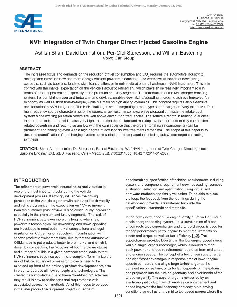
turbocharger provides the boost. The outline of the twin charging system with its operating modes is visualized in Figure 1.
Figure 1. The new VEA twin charger petrol engine with air intake flow through supercharger (red) and bypass (blue).
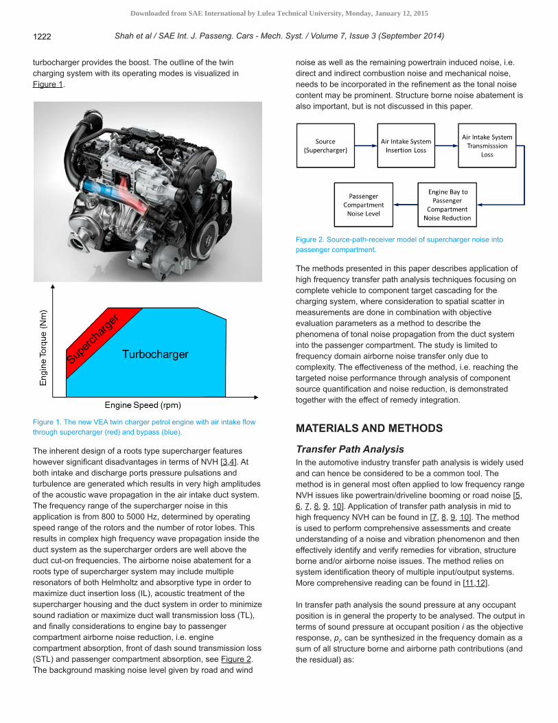
The inherent design of a roots type supercharger features however significant disadvantages in terms of NVH [3,4]. At both intake and discharge ports pressure pulsations and turbulence are generated which results in very high amplitudes of the acoustic wave propagation in the air intake duct system. The frequency range of the supercharger noise in this application is from 800 to 5000 Hz, determined by operating speed range of the rotors and the number of rotor lobes. This results in complex high frequency wave propagation inside the duct system as the supercharger orders are well above the duct cut-on frequencies. The airborne noise abatement for a roots type of supercharger system may include multiple resonators of both Helmholtz and absorptive type in order to maximize duct insertion loss (IL), acoustic treatment of the supercharger housing and the duct system in order to minimize sound radiation or maximize duct wall transmission loss (TL), and finally considerations to engine bay to passenger compartment airborne noise reduction, i.e. engine compartment absorption, front of dash sound transmission loss (STL) and passenger compartment absorption, see Figure 2. The background masking noise level given by road and wind
noise as well as the remaining powertrain induced noise, i.e. direct and indirect combustion noise and mechanical noise, needs to be incorporated in the refinement as the tonal noise content may be prominent. Structure borne noise abatement is also important, but is not discussed in this paper.
Figure 2. Source-path-receiver model of supercharger noise into passenger compartment.
The methods presented in this paper describes application of high frequency transfer path analysis techniques focusing on complete vehicle to component target cascading for the charging system, where consideration to spatial scatter in measurements are done in combination with objective evaluation parameters as a method to describe the phenomena of tonal noise propagation from the duct system into the passenger compartment. The study is limited to frequency domain airborne noise transfer only due to complexity. The effectiveness of the method, i.e. reaching the targeted noise performance through analysis of component source quantification and noise reduction, is demonstrated together with the effect of remedy integration.
MATERIALS AND METHODS
Transfer Path AnalysisIn the automotive industry transfer path analysis is widely used and can hence be considered to be a common tool. The method is in general most often applied to low frequency range NVH issues like powertrain/driveline booming or road noise [5, 6, 7, 8, 9, 10]. Application of transfer path analysis in mid to high frequency NVH can be found in [7, 8, 9, 10]. The method is used to perform comprehensive assessments and create understanding of a noise and vibration phenomenon and then effectively identify and verify remedies for vibration, structure borne and/or airborne noise issues. The method relies on system identification theory of multiple input/output systems. More comprehensive reading can be found in [11,12].
In transfer path analysis the sound pressure at any occupant position is in general the property to be analysed. The output in terms of sound pressure at occupant position i as the objective response, pi, can be synthesized in the frequency domain as a sum of all structure borne and airborne path contributions (and the residual) as:
Shah et al / SAE Int. J. Passeng. Cars - Mech. Syst. / Volume 7, Issue 3 (September 2014)1222
Downloaded from SAE International by Lulea Technical University, Monday, January 12, 2015
(1)
where HSB and HAB are the structure borne and airborne acoustic transfer functions, respectively, and F the structure
borne operating interface force, the acoustic volume velocity source and pres the residual (model error). As only airborne noise is of interest in this paper, Eq. (1) can be simplified into:
(2)
In mid to high frequency noise problems, both the magnitude and the phase of the frequency response function varies considerably and rapidly with frequency [7, 8, 9]. In order to have useful estimations of the sound pressure path contributions, a power-based approach for the contribution analysis may be chosen. Eq. (2) will then be redefined into:
(3)
Instead of using volume velocity as source quantity, the surface radiated noise quantified in terms of sound power may be used. The sound power is proportional to the square of the sound pressure. The following expression was hence used for characterizing the acoustic transfer function (ATF):
(4)
where is the sound pressure level (in dB) and the sound power, respectively. The prime dots in Eq. (4) indicate that the quantities are from a substitution source. Sound power implies spatial averaging, hence appropriate for symmetrically radiating sources. Most of the subcomponents may assume to fulfill this criterion since they are homogenous and have symmetric geometries (e.g. tubes). The characterization of the path or ATF between each subcomponent and occupant position may be then derived by the quotient of interior sound pressure squared and sound power at each subcomponent or by the reciprocal procedure [13].
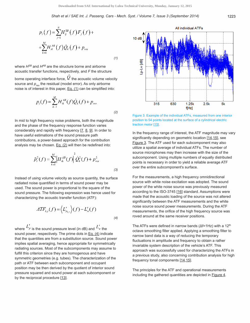
Figure 3. Example of the individual ATFs, measured from one interior position to 54 points located at the surface of a cylindrical electric traction motor [15].
In the frequency range of interest, the ATF magnitude may vary significantly depending on geometric location [14,15], see Figure 3. The ATF used for each subcomponent may also utilize a spatial average of individual ATFs. The number of source microphones may then increase with the size of the subcomponent. Using multiple numbers of equally distributed points is necessary in order to yield a reliable average ATF over the entire subcomponent's surface.
For the measurements, a high frequency omnidirectional source with white noise excitation was adopted. The sound power of the white noise source was previously measured according to the ISO-3745 [16] standard. Assumptions were made that the acoustic loading of the source was not altered significantly between the ATF measurements and the white noise source sound power measurements. During the ATF measurements, the orifice of the high frequency source was roved around at the same receiver positions.
The ATFs were defined in narrow bands (Δf=1Hz) with a 12th octave smoothing filter applied. Applying a smoothing filter to narrow band data is a way of reducing the temporary fluctuations in amplitude and frequency to obtain a rather invariable system description of the vehicle’s ATF. This approach was successfully used for characterizing the ATFs in a previous study, also concerning contribution analysis for high frequency tonal components [14,15].
The principles for the ATF and operational measurements including the gathered quantities are depicted in Figure 4.
Shah et al / SAE Int. J. Passeng. Cars - Mech. Syst. / Volume 7, Issue 3 (September 2014) 1223
Downloaded from SAE International by Lulea Technical University, Monday, January 12, 2015
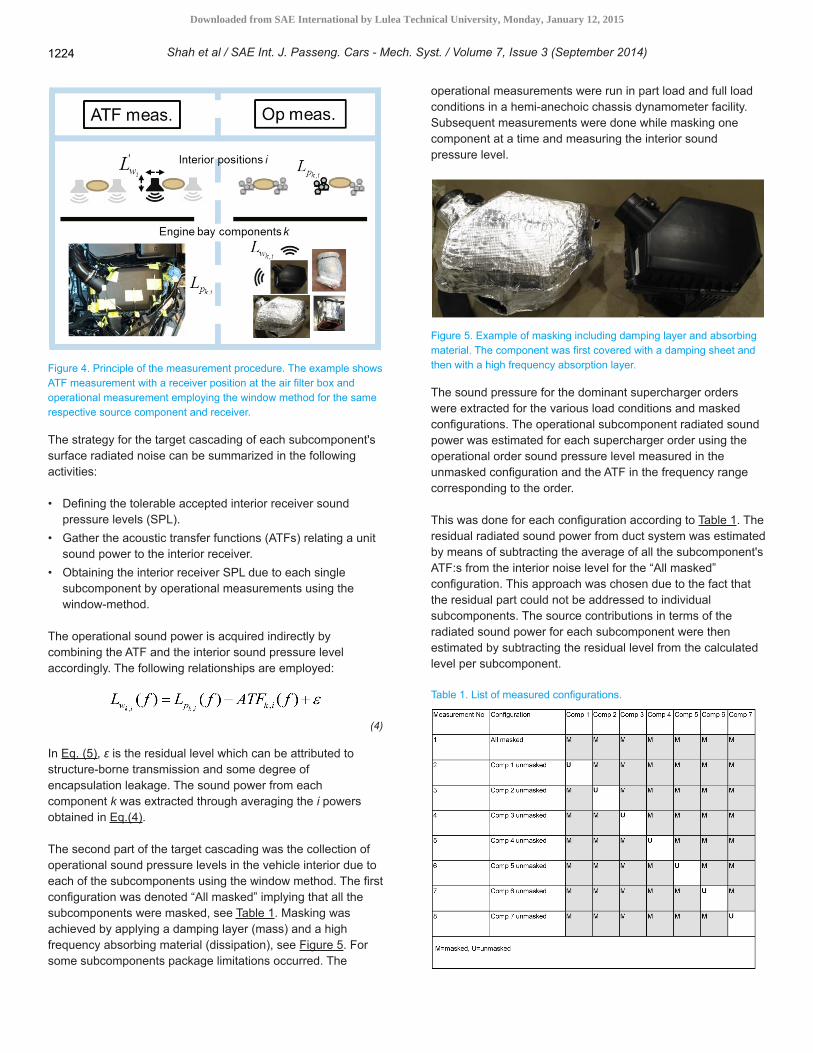
Figure 4. Principle of the measurement procedure. The example shows ATF measurement with a receiver position at the air filter box and operational measurement employing the window method for the same respective source component and receiver.
The strategy for the target cascading of each subcomponent's surface radiated noise can be summarized in the following activities:
• Defining the tolerable accepted interior receiver sound pressure levels (SPL).
• Gather the acoustic transfer functions (ATFs) relating a unit sound power to the interior receiver.
• Obtaining the interior receiver SPL due to each single subcomponent by operational measurements using the window-method.
The operational sound power is acquired indirectly by combining the ATF and the interior sound pressure level accordingly. The following relationships are employed:
(4)
In Eq. (5), ε is the residual level which can be attributed to structure-borne transmission and some degree of encapsulation leakage. The sound power from each component k was extracted through averaging the i powers obtained in Eq.(4).
The second part of the target cascading was the collection of operational sound pressure levels in the vehicle interior due to each of the subcomponents using the window method. The first configuration was denoted “All masked” implying that all the subcomponents were masked, see Table 1. Masking was achieved by applying a damping layer (mass) and a high frequency absorbing material (dissipation), see Figure 5. For some subcomponents package limitations occurred. The
operational measurements were run in part load and full load conditions in a hemi-anechoic chassis dynamometer facility. Subsequent measurements were done while masking one component at a time and measuring the interior sound pressure level.
Figure 5. Example of masking including damping layer and absorbing material. The component was first covered with a damping sheet and then with a high frequency absorption layer.
The sound pressure for the dominant supercharger orders were extracted for the various load conditions and masked configurations. The operational subcomponent radiated sound power was estimated for each supercharger order using the operational order sound pressure level measured in the unmasked configuration and the ATF in the frequency range corresponding to the order.
This was done for each configuration according to Table 1. The residual radiated sound power from duct system was estimated by means of subtracting the average of all the subcomponent's ATF:s from the interior noise level for the “All masked” configuration. This approach was chosen due to the fact that the residual part could not be addressed to individual subcomponents. The source contributions in terms of the radiated sound power for each subcomponent were then estimated by subtracting the residual level from the calculated level per subcomponent.
Table 1. List of measured configurations.
Shah et al / SAE Int. J. Passeng. Cars - Mech. Syst. / Volume 7, Issue 3 (September 2014)1224
Downloaded from SAE International by Lulea Technical University, Monday, January 12, 2015
The operational order levels measured in the ‘All masked’ configuration were used to set a target level on the operational sound power since the sound pressure radiated from the component will be the least with masking while having the same ATF.
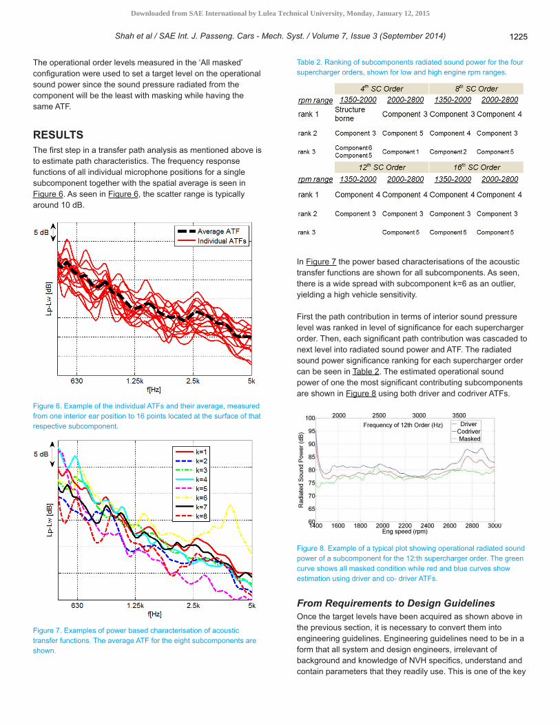
RESULTSThe first step in a transfer path analysis as mentioned above is to estimate path characteristics. The frequency response functions of all individual microphone positions for a single subcomponent together with the spatial average is seen in Figure 6. As seen in Figure 6, the scatter range is typically around 10 dB.
Figure 6. Example of the individual ATFs and their average, measured from one interior ear position to 16 points located at the surface of that respective subcomponent.
Figure 7. Examples of power based characterisation of acoustic transfer functions. The average ATF for the eight subcomponents are shown.
Table 2. Ranking of subcomponents radiated sound power for the four supercharger orders, shown for low and high engine rpm ranges.
In Figure 7 the power based characterisations of the acoustic transfer functions are shown for all subcomponents. As seen, there is a wide spread with subcomponent k=6 as an outlier, yielding a high vehicle sensitivity.
First the path contribution in terms of interior sound pressure level was ranked in level of significance for each supercharger order. Then, each significant path contribution was cascaded to next level into radiated sound power and ATF. The radiated sound power significance ranking for each supercharger order can be seen in Table 2. The estimated operational sound power of one the most significant contributing subcomponents are shown in Figure 8 using both driver and codriver ATFs.
Figure 8. Example of a typical plot showing operational radiated sound power of a subcomponent for the 12:th supercharger order. The green curve shows all masked condition while red and blue curves show estimation using driver and co- driver ATFs.
From Requirements to Design GuidelinesOnce the target levels have been acquired as shown above in the previous section, it is necessary to convert them into engineering guidelines. Engineering guidelines need to be in a form that all system and design engineers, irrelevant of background and knowledge of NVH specifics, understand and contain parameters that they readily use. This is one of the key
Shah et al / SAE Int. J. Passeng. Cars - Mech. Syst. / Volume 7, Issue 3 (September 2014) 1225
Downloaded from SAE International by Lulea Technical University, Monday, January 12, 2015
links in re-using knowledge in the company. Design guidelines will constitute the engineers translation of e.g. decibels to millimeters, kilograms or other tangible quantities.
In the target setting work, described above, the gap needed to fulfill radiated sound from the AIS ducting has been measured and presented. The gap is in dB, which is not the most convenient measure for the engineer to use when wanting to reduce the radiated noise levels. In order to grasp the meaning of e.g. 5 dB, a thorough understanding of the mechanism of sound transmission from ducts must be held and this knowledge written down in the form of clear and easily grasped guidelines.
In duct systems, such as the AIS, the interior sound field will excite vibration in the duct wall structure, vibration that then radiates sound into the surrounding engine bay. This transmission is not simple as the sound field can be generated by many sound sources, such as radiating AIS and engine, structures connected to these two systems, and many other too.
The acceptance of the AIS to excitation power requires knowledge of the wave number decomposition of both the surface pressures and the modal shapes [17]. These surface pressures are composed of a mix of acoustic and turbulent contributions. The radiation of acoustic energy is proportional to the duct radiation efficiency, whilst radiation of turbulence induced energy is proportional to the characteristics of the shape function and wave number spectrum.
The structural-acoustic radiation efficiency determines the level of duct wall vibration that is induced by the internal sound pressure field and the externally radiated sound level due to the induced duct wall vibration. Also, in duct systems e.g. AIS, the acoustic mode shapes of the internal fluid must be taken into account.
Three important factors must thus be taken into consideration and understood if the generation of sound by ducted systems is to be investigated:
1. The creation of internal sound power. 2. The generation of duct wall vibration by either duct wall
turbulence or the internal sound field. 3. The generation of sound by this wall vibration.
Here, the only interest is the sound generated by the supercharger. Due to the high frequency content of the SC as a sound source, care must be taken when designing the duct system so that e.g. duct cut-on and ring frequency behavior is understood and possible countermeasures above and near these frequencies are in sync with the physics. When designing guidelines for the duct system, structural-acoustic radiation efficiency is an important parameter as it determines the level of the duct wall vibration that is induced by internally generated sound, and it determines the externally radiated sound level due to the induced duct wall vibration.
Because the air in the AIS is surrounded by duct walls, the fluid's geometrical acoustic modes need be considered too.
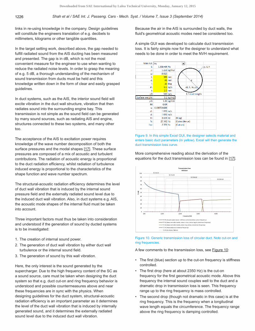
A simple GUI was developed to calculate duct transmission loss. It is fairly simple now for the designer to understand what needs to be done in order to meet the NVH requirement.
Figure 9. In this simple Excel GUI, the designer selects material and enters basic duct parameters (in yellow). Excel will then generate the duct transmission loss curve.
More comprehensive reading about the derivation of the equations for the duct transmission loss can be found in [17].
Figure 10. Generic transmission loss of circular duct. Note cut-on and ring frequencies.
A few comments to the transmission loss, see Figure 10:
• The first (blue) section up to the cut-on frequency is stiffness controlled.
• The first drop (here at about 2350 Hz) is the cut-on frequency for the first geometrical acoustic mode. Above this frequency the internal sound couples well to the duct and a dramatic drop in transmission loss is seen. This frequency range up to the ring frequency is mass controlled.
• The second drop (though not dramatic in this case) is at the ring frequency. This is the frequency when a longitudinal wave length equals the circumference. The frequency range above the ring frequency is damping controlled.
Shah et al / SAE Int. J. Passeng. Cars - Mech. Syst. / Volume 7, Issue 3 (September 2014)1226
Downloaded from SAE International by Lulea Technical University, Monday, January 12, 2015
An interactive guideline has been developed to enable quick “what if” analyses, and that helps the designer to understand how to increase sound transmission loss from ducts and other AIS components, see Figure 9. As mentioned above, it is important that the designer can use his normal design parameters when performing the analysis.
Design ModificationThe information retrieved was then used together with fundamentals duct transmission loss theory, i.e. design guidelines to derive noise abatement in terms of duct design modification.
In Figure 11 and Figure 12, the interior noise at the driver's position are shown for baseline configuration and modification in terms of order cuts and waterfall diagrams. Multiple supercharger orders are suppressed by means of the design modifications.
Figure 11. Example of a change in one of the supercharger orders after design modification from target setting exercise recommendations. Red curve - baseline configuration. Blue curve - after modification.
Figure 12. Example of a change in the interior noise after design modification from target setting exercise recommendations. Left colourmap- baseline configuration. Right colourmap after modification.
SUMMARY/CONCLUSIONSA systematic approach was used to define noise abatement for a roots type supercharger duct system. First, transfer path analysis has been applied to a high frequency airborne noise
problem where the operating data has been estimated using the window method as a method to comprehensively investigate the nature of noise propagation from the duct system of roots type supercharger. Spatial averaging of airborne transfer functions has been applied together with a power based approach in order to get useful estimations of the sound pressure path contributions. Path contribution ranking for the dominant supercharger orders provided next level of information on main contributors to interior noise prominent tonal noise. Path sensitivity together with the source strength in terms of radiated sound power for identified subcomponents yielded in identification of best candidates for remedies. Finally, the countermeasure design was then carried out by using the derived design guidelines on how to translate NVH metrics into engineering tangible quantities.
REFERENCES1. Crabb, D., Fleiss, M., Larsson, J.-E. and Somhorst, J. “New
Modular Engine Platform From Volvo”, MTZworldwide Vol 74 2013.2. Fleiss, M., Crabb, D., Larsson, J.-E., Somhorst, J., Möller,
N. Kvarfordt, J. and Samuelsson, K., “VEA - Volvo Engine Architecture: Extreme downsizing and maximum commonality while maintaining highly competitive customer attributes, 22nd Aachen Colloquium Automobile and Engine Technology, 2013.
3. Heisler, H., Advanced Engine Technology, ISBN 0-340-56822-4. Arnold, 1995.
4. Crocker, M.J., Handbook of Noise and Vibration Control, ISBN 978-0-471-39599-7, John Wiley & Sons, Inc., 2007.
5. Van der Auweraer, H., Mas, P., Dom, S., Vecchio, A. et al., “Transfer Path Analysis in the Critical Path of Vehicle Refinement: The Role of Fast, Hybrid and Operational Path Analysis,” SAE Technical Paper 2007-01-2352, 2007, doi:10.4271/2007-01-2352.
6. Finger, K., Brandes, M., and Schmidt, E., “TPA and NVH Prognosis - Application to Mercedes Benz Car Development of New Hybrid Methods Coupling Digital Simulation with Prototype Testing Results,” SAE Int. J. Passeng. Cars - Mech. Syst. 5(3):1091-1100, 2012, doi:10.4271/2012-01-1535.
7. Sturesson, P., Svensson, C., Johansson, P., and Söhr, P., “Powertrain and Driveline Integration Using Transfer Path Analysis in the New Saab 9-5,” SAE Technical Paper 2010-01-1418, 2010, doi:10.4271/2010-01-1418.
8. Plunt, J., “Examples of Using Transfer Path Analysis (TPA) together with CAE-Models to Diagnose and Find Solutions for NVH Problems Late in the Vehicle Development Process,” SAE Technical Paper 2005-01-2508, 2005, doi:10.4271/2005-01-2508.
9. Plunt, J.: Finding and Fixing Vehicle NVH Problems with Transfer Path Analysis, Sound&Vibration, 2005.
10. Plunt, J., “Strategy for transfer path analysis (TPA) applied to vibro-acoustic systems at medium and high frequencies”, Proc. ISMA 23, September 16-18, Leuven, Belgium, 2005.
11. Brandt, A. Noise and Vibration Analysis: Signal Analysis and Experimental Procedures, ISBN 978-0-470-74644-8, John Wiley & Sons, Inc., 2011.
12. Bendat, J.S. & Piersol, A.G.: Random Data - Analysis and Measurement Procedures, 2nd Edition, John Wiley & Sons, Inc, 1986.
13. Zhu, J., Hammelef, D., and Wood, M., “Power-Based Noise Reduction Concept and Measurement Techniques,” SAE Technical Paper 2005-01-2401, 2005, doi:10.4271/2005-01-2401.
14. Lennström, D., Johnsson, R., Nykänen, A., and Ågren, A., “Determination of Radiated Sound Power from an Electric Rear Axle Drive In-Situ and its Contribution to Interior Noise,” SAE Int. J. Passeng. Cars - Mech. Syst. 6(3):1554-1563, 2013, doi:10.4271/2013-01-9120.
15. Lennström, D. “Methods for Motor Noise Evaluation and Control in Electric Vehicles”. Licenciate thesis, ISBN 978-91-7439-737-6 (pdf), 2013.
Shah et al / SAE Int. J. Passeng. Cars - Mech. Syst. / Volume 7, Issue 3 (September 2014) 1227
Downloaded from SAE International by Lulea Technical University, Monday, January 12, 2015

16. “Acoustics - Determination of Sound Power Levels of Noise Sources Using Sound Pressure - Precision Methods for Anechoic and Hemi-anechoic Rooms”, ISO 3745:2009
17. Blake, W.K., Mechanics of Flow-Induced Sound and Vibration Volume II: Complex Flow-Structure Interactions, Academic Press, ISBN 978-0124142596, 1986.
CONTACT [email protected]
All rights reserved. No part of this publication may be reproduced, stored in a retrieval system, or transmitted, in any form or by any means, electronic, mechanical, photocopying, recording, or otherwise, without the prior written permission of SAE International.
Positions and opinions advanced in this paper are those of the author(s) and not necessarily those of SAE International. The author is solely responsible for the content of the paper.
Shah et al / SAE Int. J. Passeng. Cars - Mech. Syst. / Volume 7, Issue 3 (September 2014)1228
Downloaded from SAE International by Lulea Technical University, Monday, January 12, 2015


![Improving GDI engine efficiency emissions and PM with exhaust …pure-oai.bham.ac.uk/ws/files/18661425/Microsoft_Word... · port fuel injected [17-19] and direct injected [20] gasoline](https://img.pdfslide.us/doc/110x75/5ed32d1f22e12c6fc25d3917/improving-gdi-engine-efficiency-emissions-and-pm-with-exhaust-pure-oaibhamacukwsfiles18661425microsoftword.jpg)