Embed Size (px)
Citation preview
AH7
66
NV (AH7) SWITCHES
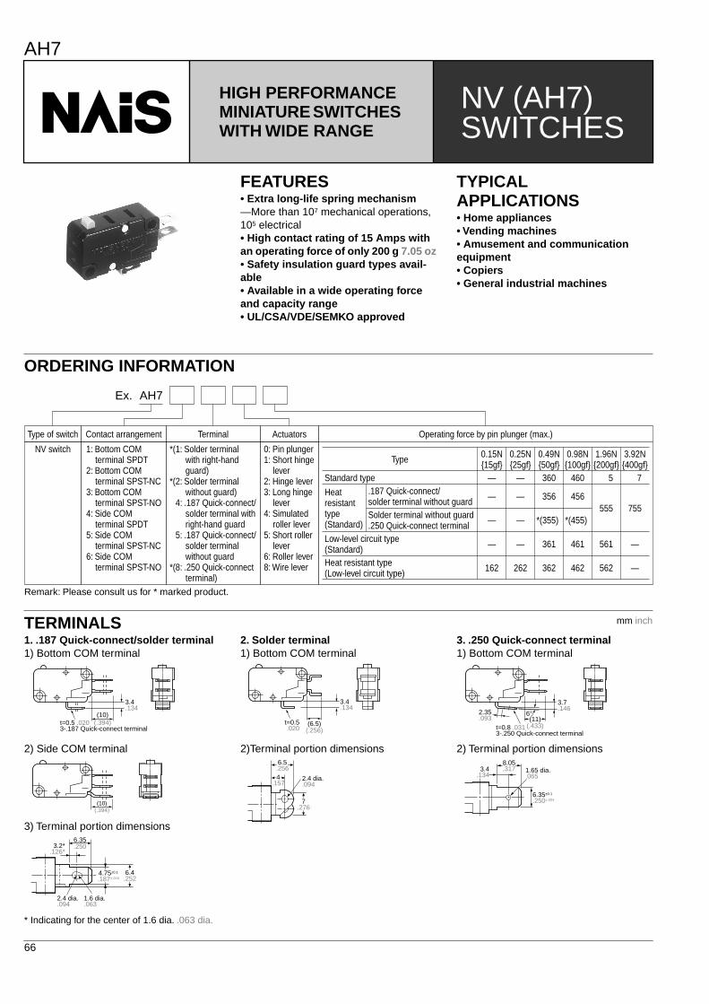
HIGH PERFORMANCE MINIATURE SWITCHES WITH WIDE RANGE
FEATURES
• Extra long-life spring mechanism
—More than 10
7
mechanical operations, 10
5
electrical
• High contact rating of 15 Amps with an operating force of only 200 g 7.05 oz• Safety insulation guard types avail-able• Available in a wide operating force and capacity range• UL/CSA/VDE/SEMKO approved
TYPICAL APPLICATIONS
• Home appliances• Vending machines• Amusement and communication equipment• Copiers• General industrial machines
ORDERING INFORMATION
Type of switch
NV switch
Contact arrangement Terminal Actuators
1: Bottom COM terminal SPDT2: Bottom COM terminal SPST-NC3: Bottom COM terminal SPST-NO4: Side COM terminal SPDT5: Side COM terminal SPST-NC6: Side COM terminal SPST-NO
*(1: Solder terminal with right-hand guard)*(2: Solder terminal without guard)
4: .187 Quick-connect/ solder terminal with right-hand guard
5: .187 Quick-connect/ solder terminal without guard*(8: .250 Quick-connect terminal)
0: Pin plunger1: Short hinge lever2: Hinge lever3: Long hinge lever4: Simulated roller lever5: Short roller lever6: Roller lever8: Wire lever
Operating force by pin plunger (max.)
Ex. AH7
Type 0.15N15gf
0.25N25gf
0.49N50gf
0.98N100gf
1.96N200gf
3.92N400gf
Standard type
Remark: Please consult us for * marked product.
Heat resistant type (Standard)
.187 Quick-connect/solder terminal without guardSolder terminal without guard .250 Quick-connect terminal
Low-level circuit type (Standard)Heat resistant type (Low-level circuit type)
—
—
—
162
—
—
—
262
360
356
361
362
460
456
461
462
5
555
561
562
7
755— — *(355) *(455)
—
—
TERMINALS
1. .187 Quick-connect/solder terminal
1) Bottom COM terminal
2) Side COM terminal
3) Terminal portion dimensions
* Indicating for the center of 1.6 dia. .063 dia.
2. Solder terminal
1) Bottom COM terminal
2)Terminal portion dimensions
3. .250 Quick-connect terminal
1) Bottom COM terminal
2) Terminal portion dimensions
3.4.134
(10)(.394)t=0.5 .020
3-.187 Quick-connect terminal
(10)(.394)
3.2*.126*
2.4 dia..094
1.6 dia..063
6.4.252
6.35.250
4.75±0.1
.187±.004
3.4.134
(6.5)(.256)
t=0.5.020
2.4 dia..094
7.276
6.5.2564
.157
3.7.146
6°2.35.093 (11)
(.433)t=0.8 .0313-.250 Quick-connect terminal
1.65 dia..065
6.35±0.1
.250±.004
8.05.3173.4
.134
mm inch
AH7
67
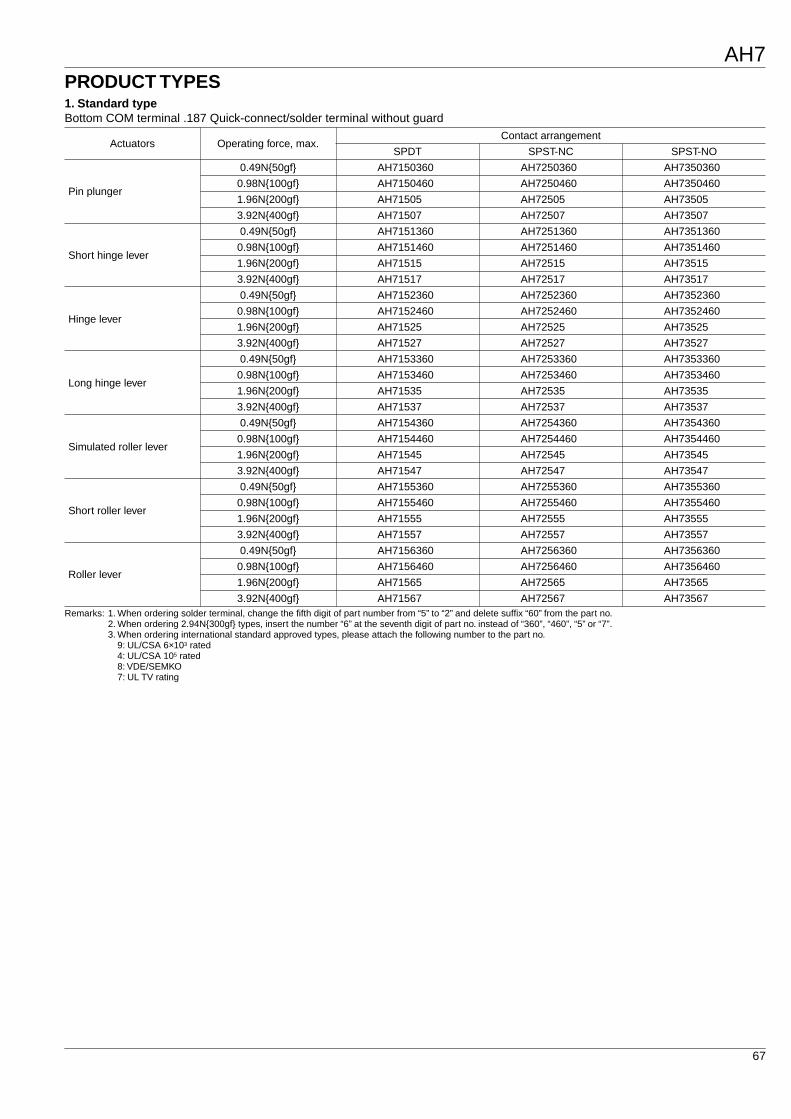
PRODUCT TYPES
1. Standard type
Bottom COM terminal .187 Quick-connect/solder terminal without guard
Remarks: 1. When ordering solder terminal, change the fifth digit of part number from “5” to “2” and delete suffix “60” from the part no.2. When ordering 2.94N300gf types, insert the number “6” at the seventh digit of part no. instead of “360”, “460”, “5” or “7”.3. When ordering international standard approved types, please attach the following number to the part no.
9: UL/CSA 6
×
10
3
rated4: UL/CSA 10
5
rated8: VDE/SEMKO7: UL TV rating
Actuators Operating force, max.Contact arrangement
SPDT SPST-NC SPST-NO
Pin plunger
0.49N50gf AH7150360 AH7250360 AH7350360
0.98N100gf AH7150460 AH7250460 AH7350460
1.96N200gf AH71505 AH72505 AH73505
3.92N400gf AH71507 AH72507 AH73507
Short hinge lever
0.49N50gf AH7151360 AH7251360 AH7351360
0.98N100gf AH7151460 AH7251460 AH7351460
1.96N200gf AH71515 AH72515 AH73515
3.92N400gf AH71517 AH72517 AH73517
Hinge lever
0.49N50gf AH7152360 AH7252360 AH7352360
0.98N100gf AH7152460 AH7252460 AH7352460
1.96N200gf AH71525 AH72525 AH73525
3.92N400gf AH71527 AH72527 AH73527
Long hinge lever
0.49N50gf AH7153360 AH7253360 AH7353360
0.98N100gf AH7153460 AH7253460 AH7353460
1.96N200gf AH71535 AH72535 AH73535
3.92N400gf AH71537 AH72537 AH73537
Simulated roller lever
0.49N50gf AH7154360 AH7254360 AH7354360
0.98N100gf AH7154460 AH7254460 AH7354460
1.96N200gf AH71545 AH72545 AH73545
3.92N400gf AH71547 AH72547 AH73547
Short roller lever
0.49N50gf AH7155360 AH7255360 AH7355360
0.98N100gf AH7155460 AH7255460 AH7355460
1.96N200gf AH71555 AH72555 AH73555
3.92N400gf AH71557 AH72557 AH73557
Roller lever
0.49N50gf AH7156360 AH7256360 AH7356360
0.98N100gf AH7156460 AH7256460 AH7356460
1.96N200gf AH71565 AH72565 AH73565
3.92N400gf AH71567 AH72567 AH73567
AH7
68
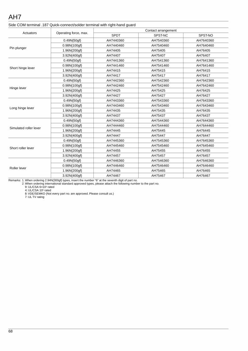
Side COM terminal .187 Quick-connect/solder terminal with right-hand guard
Remarks: 1. When ordering 2.94N300gf types, insert the number “6” at the seventh digit of part no.2. When ordering international standard approved types, please attach the following number to the part no.
9: UL/CSA 6
×
10
3
rated4: UL/CSA 10
5
rated8: VDE/SEMKO (Not every part no. are approved. Please consult us.)7: UL TV rating
Actuators Operating force, max.Contact arrangement
SPDT SPST-NC SPST-NO
Pin plunger
0.49N50gf AH7440360 AH7540360 AH7640360
0.98N100gf AH7440460 AH7540460 AH7640460
1.96N200gf AH74405 AH75405 AH76405
3.92N400gf AH74407 AH75407 AH76407
Short hinge lever
0.49N50gf AH7441360 AH7541360 AH7641360
0.98N100gf AH7441460 AH7541460 AH7641460
1.96N200gf AH74415 AH75415 AH76415
3.92N400gf AH74417 AH75417 AH76417
Hinge lever
0.49N50gf AH7442360 AH7542360 AH7642360
0.98N100gf AH7442460 AH7542460 AH7642460
1.96N200gf AH74425 AH75425 AH76425
3.92N400gf AH74427 AH75427 AH76427
Long hinge lever
0.49N50gf AH7443360 AH7543360 AH7643360
0.98N100gf AH7443460 AH7543460 AH7643460
1.96N200gf AH74435 AH75435 AH76435
3.92N400gf AH74437 AH75437 AH76437
Simulated roller lever
0.49N50gf AH7444360 AH7544360 AH7644360
0.98N100gf AH7444460 AH7544460 AH7644460
1.96N200gf AH74445 AH75445 AH76445
3.92N400gf AH74447 AH75447 AH76447
Short roller lever
0.49N50gf AH7445360 AH7545360 AH7645360
0.98N100gf AH7445460 AH7545460 AH7645460
1.96N200gf AH74455 AH75455 AH76455
3.92N400gf AH74457 AH75457 AH76457
Roller lever
0.49N50gf AH7446360 AH7546360 AH7646360
0.98N100gf AH7446460 AH7546460 AH7646460
1.96N200gf AH74465 AH75465 AH76465
3.92N400gf AH74467 AH75467 AH76467
AH7
69
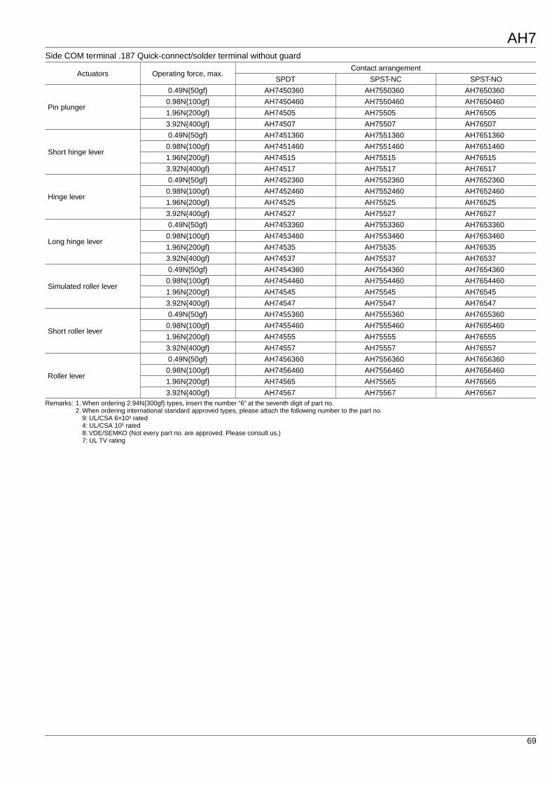
Side COM terminal .187 Quick-connect/solder terminal without guard
Remarks: 1. When ordering 2.94N300gf types, insert the number “6” at the seventh digit of part no.2. When ordering international standard approved types, please attach the following number to the part no.
9: UL/CSA 6
×
10
3
rated4: UL/CSA 10
5
rated8: VDE/SEMKO (Not every part no. are approved. Please consult us.)7: UL TV rating
Actuators Operating force, max.Contact arrangement
SPDT SPST-NC SPST-NO
Pin plunger
0.49N50gf AH7450360 AH7550360 AH7650360
0.98N100gf AH7450460 AH7550460 AH7650460
1.96N200gf AH74505 AH75505 AH76505
3.92N400gf AH74507 AH75507 AH76507
Short hinge lever
0.49N50gf AH7451360 AH7551360 AH7651360
0.98N100gf AH7451460 AH7551460 AH7651460
1.96N200gf AH74515 AH75515 AH76515
3.92N400gf AH74517 AH75517 AH76517
Hinge lever
0.49N50gf AH7452360 AH7552360 AH7652360
0.98N100gf AH7452460 AH7552460 AH7652460
1.96N200gf AH74525 AH75525 AH76525
3.92N400gf AH74527 AH75527 AH76527
Long hinge lever
0.49N50gf AH7453360 AH7553360 AH7653360
0.98N100gf AH7453460 AH7553460 AH7653460
1.96N200gf AH74535 AH75535 AH76535
3.92N400gf AH74537 AH75537 AH76537
Simulated roller lever
0.49N50gf AH7454360 AH7554360 AH7654360
0.98N100gf AH7454460 AH7554460 AH7654460
1.96N200gf AH74545 AH75545 AH76545
3.92N400gf AH74547 AH75547 AH76547
Short roller lever
0.49N50gf AH7455360 AH7555360 AH7655360
0.98N100gf AH7455460 AH7555460 AH7655460
1.96N200gf AH74555 AH75555 AH76555
3.92N400gf AH74557 AH75557 AH76557
Roller lever
0.49N50gf AH7456360 AH7556360 AH7656360
0.98N100gf AH7456460 AH7556460 AH7656460
1.96N200gf AH74565 AH75565 AH76565
3.92N400gf AH74567 AH75567 AH76567
AH7
70
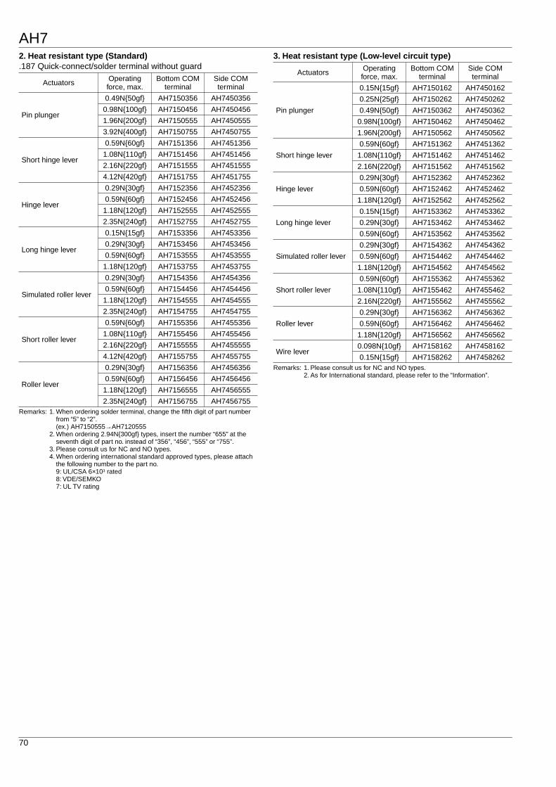
2. Heat resistant type (Standard)
.187 Quick-connect/solder terminal without guard
Remarks: 1. When ordering solder terminal, change the fifth digit of part number from “5” to “2”.(ex.) AH7150555
→
AH71205552. When ordering 2.94N300gf types, insert the number “655” at the
seventh digit of part no. instead of “356”, “456”, “555” or “755”.3. Please consult us for NC and NO types.4. When ordering international standard approved types, please attach
the following number to the part no.9: UL/CSA 6
×
10
3
rated8: VDE/SEMKO7: UL TV rating
3. Heat resistant type (Low-level circuit type)
Remarks: 1. Please consult us for NC and NO types.2. As for International standard, please refer to the “Information”.
Actuators Operating force, max.
Bottom COM terminal
Side COM terminal
Pin plunger
0.49N50gf AH7150356 AH7450356
0.98N100gf AH7150456 AH7450456
1.96N200gf AH7150555 AH7450555
3.92N400gf AH7150755 AH7450755
Short hinge lever
0.59N60gf AH7151356 AH7451356
1.08N110gf AH7151456 AH7451456
2.16N220gf AH7151555 AH7451555
4.12N420gf AH7151755 AH7451755
Hinge lever
0.29N30gf AH7152356 AH7452356
0.59N60gf AH7152456 AH7452456
1.18N120gf AH7152555 AH7452555
2.35N240gf AH7152755 AH7452755
Long hinge lever
0.15N15gf AH7153356 AH7453356
0.29N30gf AH7153456 AH7453456
0.59N60gf AH7153555 AH7453555
1.18N120gf AH7153755 AH7453755
Simulated roller lever
0.29N30gf AH7154356 AH7454356
0.59N60gf AH7154456 AH7454456
1.18N120gf AH7154555 AH7454555
2.35N240gf AH7154755 AH7454755
Short roller lever
0.59N60gf AH7155356 AH7455356
1.08N110gf AH7155456 AH7455456
2.16N220gf AH7155555 AH7455555
4.12N420gf AH7155755 AH7455755
Roller lever
0.29N30gf AH7156356 AH7456356
0.59N60gf AH7156456 AH7456456
1.18N120gf AH7156555 AH7456555
2.35N240gf AH7156755 AH7456755
Actuators Operating force, max.
Bottom COM terminal
Side COM terminal
Pin plunger
0.15N15gf AH7150162 AH7450162
0.25N25gf AH7150262 AH7450262
0.49N50gf AH7150362 AH7450362
0.98N100gf AH7150462 AH7450462
1.96N200gf AH7150562 AH7450562
Short hinge lever
0.59N60gf AH7151362 AH7451362
1.08N110gf AH7151462 AH7451462
2.16N220gf AH7151562 AH7451562
Hinge lever
0.29N30gf AH7152362 AH7452362
0.59N60gf AH7152462 AH7452462
1.18N120gf AH7152562 AH7452562
Long hinge lever
0.15N15gf AH7153362 AH7453362
0.29N30gf AH7153462 AH7453462
0.59N60gf AH7153562 AH7453562
Simulated roller lever
0.29N30gf AH7154362 AH7454362
0.59N60gf AH7154462 AH7454462
1.18N120gf AH7154562 AH7454562
Short roller lever
0.59N60gf AH7155362 AH7455362
1.08N110gf AH7155462 AH7455462
2.16N220gf AH7155562 AH7455562
Roller lever
0.29N30gf AH7156362 AH7456362
0.59N60gf AH7156462 AH7456462
1.18N120gf AH7156562 AH7456562
Wire lever0.098N10gf AH7158162 AH7458162
0.15N15gf AH7158262 AH7458262
AH7
71
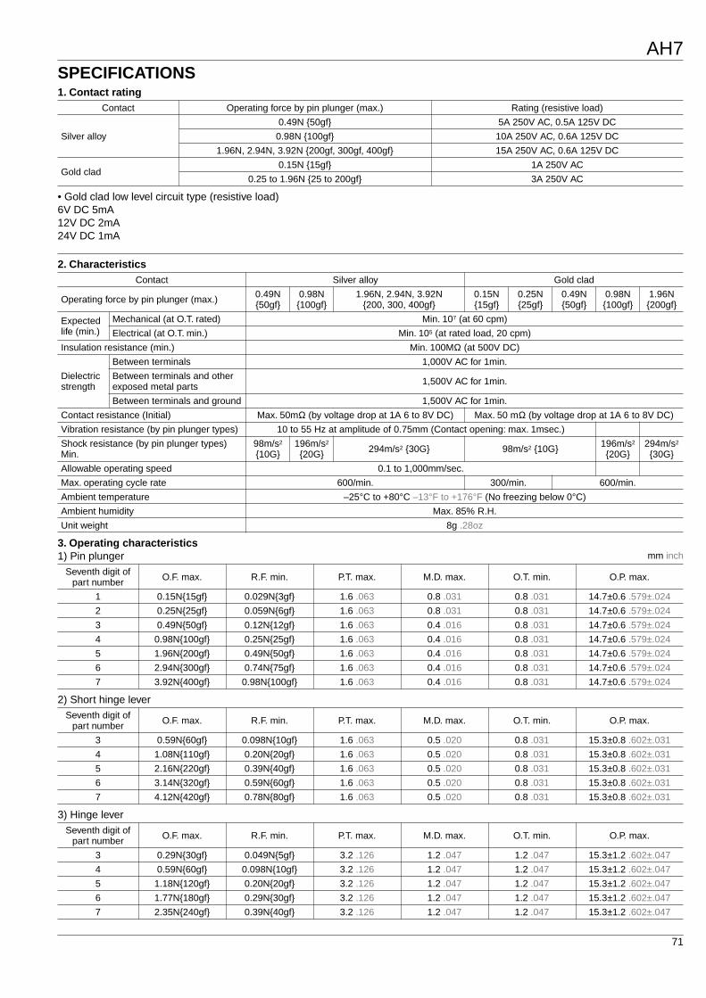
SPECIFICATIONS
1. Contact rating
• Gold clad low level circuit type (resistive load)6V DC 5mA12V DC 2mA24V DC 1mA
Contact Operating force by pin plunger (max.) Rating (resistive load)
Silver alloy
0.49N 50gf 5A 250V AC, 0.5A 125V DC
0.98N 100gf 10A 250V AC, 0.6A 125V DC
1.96N, 2.94N, 3.92N 200gf, 300gf, 400gf 15A 250V AC, 0.6A 125V DC
Gold clad0.15N 15gf 1A 250V AC
0.25 to 1.96N 25 to 200gf 3A 250V AC
2. Characteristics
3. Operating characteristics
1) Pin plunger
mm inch
2) Short hinge lever
3) Hinge lever
Contact Silver alloy Gold clad
Operating force by pin plunger (max.) 0.49N 50gf
0.98N 100gf
1.96N, 2.94N, 3.92N 200, 300, 400gf
0.15N 15gf
0.25N 25gf
0.49N 50gf
0.98N 100gf
1.96N 200gf
Expected life (min.)
Mechanical (at O.T. rated) Min. 10
7
(at 60 cpm)
Electrical (at O.T. min.) Min. 10
5
(at rated load, 20 cpm)
Insulation resistance (min.) Min. 100M
Ω
(at 500V DC)
Dielectric strength
Between terminals 1,000V AC for 1min.
Between terminals and other exposed metal parts 1,500V AC for 1min.
Between terminals and ground 1,500V AC for 1min.
Contact resistance (Initial) Max. 50m
Ω
(by voltage drop at 1A 6 to 8V DC) Max. 50 m
Ω
(by voltage drop at 1A 6 to 8V DC)
Vibration resistance (by pin plunger types) 10 to 55 Hz at amplitude of 0.75mm (Contact opening: max. 1msec.)
Shock resistance (by pin plunger types) Min.
98m/s
2
10G
196m/s
2
20G 294m/s
2
30G 98m/s
2
10G 196m/s
2
20G
294m/s
2
30G
Allowable operating speed 0.1 to 1,000mm/sec.
Max. operating cycle rate 600/min. 300/min. 600/min.
Ambient temperature –25
°
C to +80
°
C –13
°
F to +176
°
F (No freezing below 0
°
C)
Ambient humidity Max. 85% R.H.
Unit weight 8g .28oz
Seventh digit of part number O.F. max. R.F. min. P.T. max. M.D. max. O.T. min. O.P. max.
1 0.15N15gf 0.029N3gf 1.6 .063 0.8 .031 0.8 .031 14.7
±
0.6 .579
±
.024
2 0.25N25gf 0.059N6gf 1.6 .063 0.8 .031 0.8 .031 14.7
±
0.6 .579
±
.024
3 0.49N50gf 0.12N12gf 1.6 .063 0.4 .016 0.8 .031 14.7
±
0.6 .579
±
.024
4 0.98N100gf 0.25N25gf 1.6 .063 0.4 .016 0.8 .031 14.7
±
0.6 .579
±
.024
5 1.96N200gf 0.49N50gf 1.6 .063 0.4 .016 0.8 .031 14.7
±
0.6 .579
±
.024
6 2.94N300gf 0.74N75gf 1.6 .063 0.4 .016 0.8 .031 14.7
±
0.6 .579
±
.024
7 3.92N400gf 0.98N100gf 1.6 .063 0.4 .016 0.8 .031 14.7
±
0.6 .579
±
.024
Seventh digit of part number O.F. max. R.F. min. P.T. max. M.D. max. O.T. min. O.P. max.
3 0.59N60gf 0.098N10gf 1.6 .063 0.5 .020 0.8 .031 15.3
±
0.8 .602
±
.031
4 1.08N110gf 0.20N20gf 1.6 .063 0.5 .020 0.8 .031 15.3
±
0.8 .602
±
.031
5 2.16N220gf 0.39N40gf 1.6 .063 0.5 .020 0.8 .031 15.3
±
0.8 .602
±
.031
6 3.14N320gf 0.59N60gf 1.6 .063 0.5 .020 0.8 .031 15.3
±
0.8 .602
±
.031
7 4.12N420gf 0.78N80gf 1.6 .063 0.5 .020 0.8 .031 15.3
±
0.8 .602
±
.031
Seventh digit of part number O.F. max. R.F. min. P.T. max. M.D. max. O.T. min. O.P. max.
3 0.29N30gf 0.049N5gf 3.2 .126 1.2 .047 1.2 .047 15.3
±
1.2 .602
±
.047
4 0.59N60gf 0.098N10gf 3.2 .126 1.2 .047 1.2 .047 15.3
±
1.2 .602
±
.047
5 1.18N120gf 0.20N20gf 3.2 .126 1.2 .047 1.2 .047 15.3
±
1.2 .602
±
.047
6 1.77N180gf 0.29N30gf 3.2 .126 1.2 .047 1.2 .047 15.3
±
1.2 .602
±
.047
7 2.35N240gf 0.39N40gf 3.2 .126 1.2 .047 1.2 .047 15.3
±
1.2 .602
±
.047
AH7
72
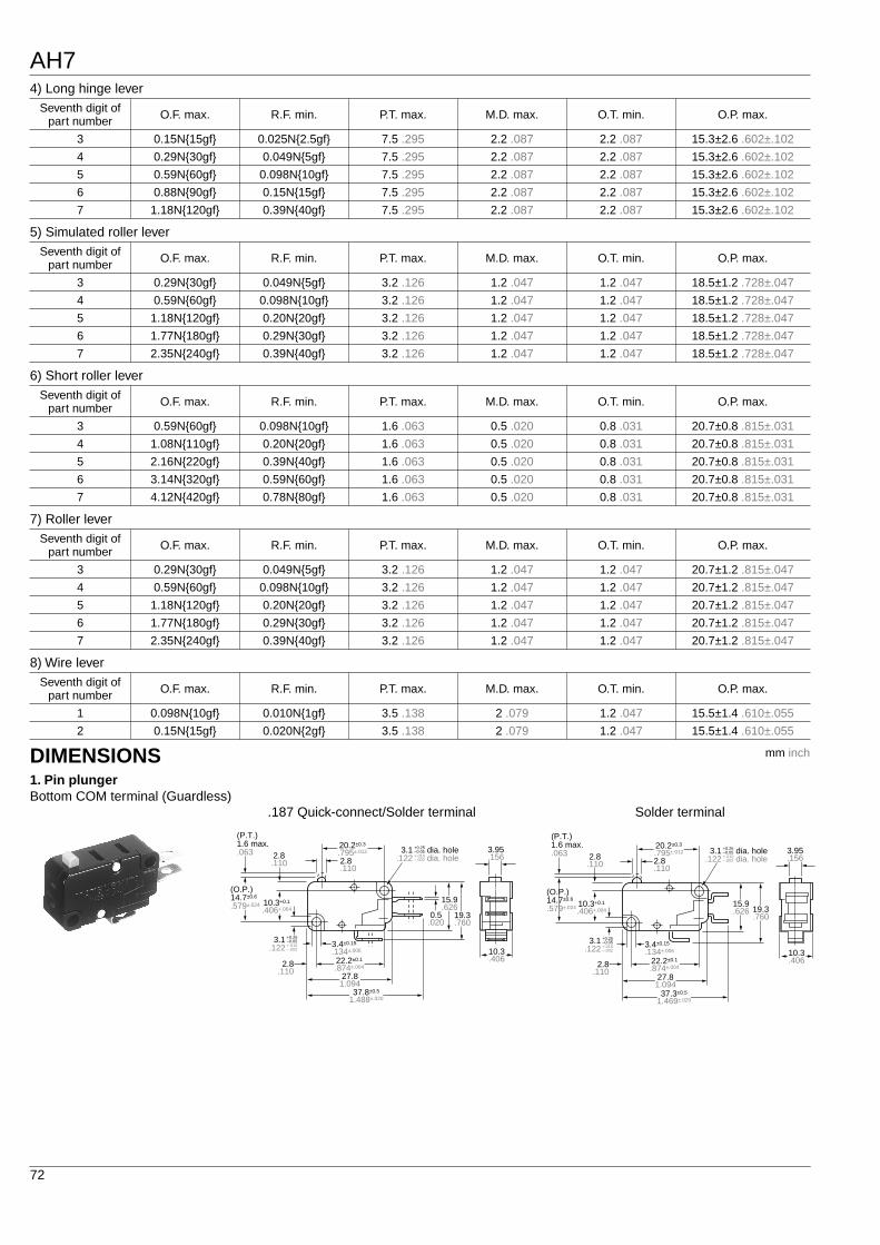
4) Long hinge lever
5) Simulated roller lever
6) Short roller lever
7) Roller lever
8) Wire lever
Seventh digit of part number O.F. max. R.F. min. P.T. max. M.D. max. O.T. min. O.P. max.
3 0.15N15gf 0.025N2.5gf 7.5 .295 2.2 .087 2.2 .087 15.3
±
2.6 .602
±
.102
4 0.29N30gf 0.049N5gf 7.5 .295 2.2 .087 2.2 .087 15.3
±
2.6 .602
±
.102
5 0.59N60gf 0.098N10gf 7.5 .295 2.2 .087 2.2 .087 15.3
±
2.6 .602
±
.102
6 0.88N90gf 0.15N15gf 7.5 .295 2.2 .087 2.2 .087 15.3
±
2.6 .602
±
.102
7 1.18N120gf 0.39N40gf 7.5 .295 2.2 .087 2.2 .087 15.3
±
2.6 .602
±
.102
Seventh digit of part number O.F. max. R.F. min. P.T. max. M.D. max. O.T. min. O.P. max.
3 0.29N30gf 0.049N5gf 3.2 .126 1.2 .047 1.2 .047 18.5
±
1.2 .728
±
.047
4 0.59N60gf 0.098N10gf 3.2 .126 1.2 .047 1.2 .047 18.5
±
1.2 .728
±
.047
5 1.18N120gf 0.20N20gf 3.2 .126 1.2 .047 1.2 .047 18.5
±
1.2 .728
±
.047
6 1.77N180gf 0.29N30gf 3.2 .126 1.2 .047 1.2 .047 18.5
±
1.2 .728
±
.047
7 2.35N240gf 0.39N40gf 3.2 .126 1.2 .047 1.2 .047 18.5
±
1.2 .728
±
.047
Seventh digit of part number O.F. max. R.F. min. P.T. max. M.D. max. O.T. min. O.P. max.
3 0.59N60gf 0.098N10gf 1.6 .063 0.5 .020 0.8 .031 20.7
±
0.8 .815
±
.031
4 1.08N110gf 0.20N20gf 1.6 .063 0.5 .020 0.8 .031 20.7
±
0.8 .815
±
.031
5 2.16N220gf 0.39N40gf 1.6 .063 0.5 .020 0.8 .031 20.7
±
0.8 .815
±
.031
6 3.14N320gf 0.59N60gf 1.6 .063 0.5 .020 0.8 .031 20.7
±
0.8 .815
±
.031
7 4.12N420gf 0.78N80gf 1.6 .063 0.5 .020 0.8 .031 20.7
±
0.8 .815
±
.031
Seventh digit of part number O.F. max. R.F. min. P.T. max. M.D. max. O.T. min. O.P. max.
3 0.29N30gf 0.049N5gf 3.2 .126 1.2 .047 1.2 .047 20.7
±
1.2 .815
±
.047
4 0.59N60gf 0.098N10gf 3.2 .126 1.2 .047 1.2 .047 20.7
±
1.2 .815
±
.047
5 1.18N120gf 0.20N20gf 3.2 .126 1.2 .047 1.2 .047 20.7
±
1.2 .815
±
.047
6 1.77N180gf 0.29N30gf 3.2 .126 1.2 .047 1.2 .047 20.7
±
1.2 .815
±
.047
7 2.35N240gf 0.39N40gf 3.2 .126 1.2 .047 1.2 .047 20.7
±
1.2 .815
±
.047
Seventh digit of part number O.F. max. R.F. min. P.T. max. M.D. max. O.T. min. O.P. max.
1 0.098N10gf 0.010N1gf 3.5 .138 2 .079 1.2 .047 15.5
±
1.4 .610
±
.055
2 0.15N15gf 0.020N2gf 3.5 .138 2 .079 1.2 .047 15.5
±
1.4 .610
±
.055
DIMENSIONS
1. Pin plunger
Bottom COM terminal (Guardless)
mm inch
.187 Quick-connect/Solder terminal
3.95.156
10.3.406
19.3.760
15.9.626
0.5.020
27.81.094
2.8.110
2.8.110
2.8.110
(P.T.)1.6 max..063
(O.P.)14.7±0.6
.579±.024
20.2±0.3
.795±.012
3.4±0.15
.134±.006
22.2±0.1
.874±.004
37.8±0.5
1.488±.020
3.1 dia. hole+0.25–0.05
.122 dia. hole+.010–.002
3.1 +0.25–0.05
.122 +.010–.002
10.3+0.1
.406+.004
Solder terminal
3.95.156
10.3.406
19.3.760
15.9.626
27.81.094
2.8.110
2.8.110
2.8.110
(P.T.)1.6 max..063
(O.P.)14.7±0.6
.579±.024
20.2±0.3
.795±.012
3.4±0.15
.134±.006
22.2±0.1
.874±.004
37.3±0.5
1.469±.020
3.1 dia. hole+0.25–0.05
.122 dia. hole+.010–.002
3.1 +0.25–0.05
.122 +.010–.002
10.3+0.1
.406+.004
AH7
73
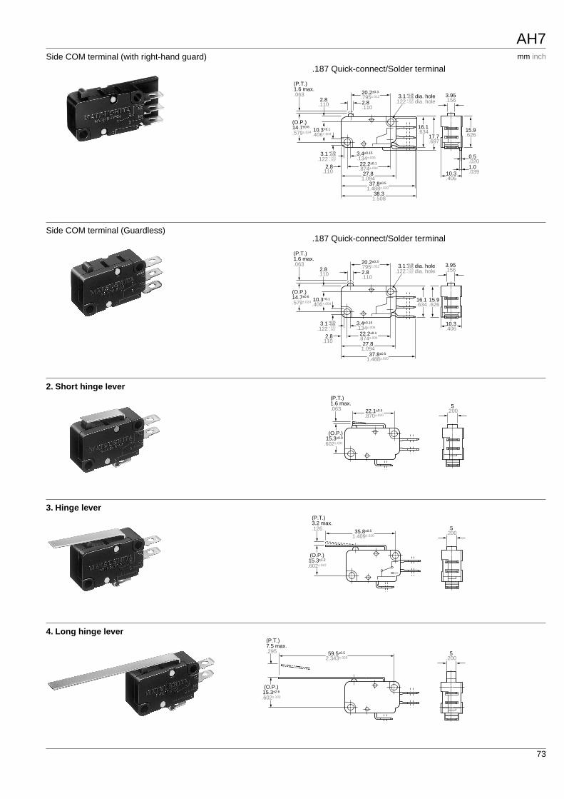
Side COM terminal (with right-hand guard)
.187 Quick-connect/Solder terminal
3.95.156
10.3.406
1.0.039
0.5.020
15.9.626
16.1.634
17.7.697
27.81.094
2.8.110
2.8.110
2.8.110
(P.T.)1.6 max..063
(O.P.)14.7±0.6
.579±.024
20.2±0.3
.795±.012
3.4±0.15
.134±.006
22.2±0.1
.874±.004
37.8±0.5
1.488±.020
38.31.508
3.1 dia. hole+0.25–0.05
.122 dia. hole+.010–.002
3.1 +0.25–0.05
.122 +.010–.002
10.3+0.1
.406+.004
mm inch
Side COM terminal (Guardless)
.187 Quick-connect/Solder terminal
3.95.156
10.3.406
15.9.626
16.1.634
27.81.094
2.8.110
2.8.110
2.8.110
(P.T.)1.6 max..063
(O.P.)14.7±0.6
.579±.024
20.2±0.3
.795±.012
3.4±0.15
.134±.006
22.2±0.1
.874±.004
37.8±0.5
1.488±.020
3.1 dia. hole+0.25–0.05
.122 dia. hole+.010–.002
3.1 +0.25–0.05
.122 +.010–.002
10.3+0.1
.406+.004
2. Short hinge lever
5.200
(P.T.)1.6 max..063
(O.P.)15.3±0.8
.602±.031
22.1±0.5
.870±.020
3. Hinge lever
5.200
(P.T.)3.2 max..126
(O.P.)15.3±1.2
.602±.047
35.8±0.5
1.409±.020
4. Long hinge lever
5.200
(P.T.)7.5 max..295
(O.P.)15.3±2.6
.602±.102
59.5±0.5
2.343±.020
AH7
74
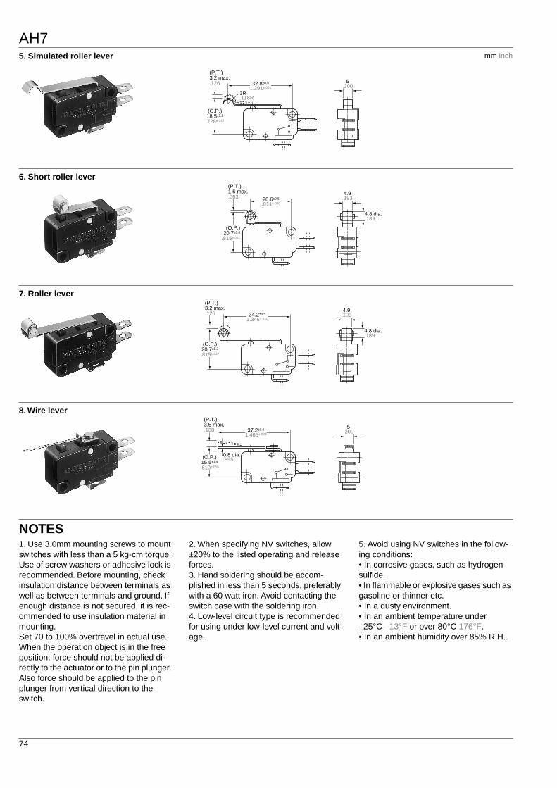
5. Simulated roller lever
mm inch
5.200
(P.T.)3.2 max..126
3R.118R
(O.P.)18.5±1.2
.728±.047
32.8±0.5
1.291±.020
6. Short roller lever
4.9.193
4.8 dia..189
(P.T.)1.6 max..063
(O.P.)20.7±0.8
.815±.031
20.6±0.5
.811±.020
7. Roller lever
34.2±0.5
1.346±.020
4.9.193
4.8 dia..189
(P.T.)3.2 max..126
(O.P.)20.7±1.2
.815±.047
8. Wire lever
37.2±0.6
1.465±.024
0.8 dia..855
5.200
(P.T.)3.5 max..138
(O.P.)15.5±1.4
.610±.055
NOTES
1. Use 3.0mm mounting screws to mount switches with less than a 5 kg-cm torque. Use of screw washers or adhesive lock is recommended. Before mounting, check insulation distance between terminals as well as between terminals and ground. If enough distance is not secured, it is rec-ommended to use insulation material in mounting.Set 70 to 100% overtravel in actual use.When the operation object is in the free position, force should not be applied di-rectly to the actuator or to the pin plunger. Also force should be applied to the pin plunger from vertical direction to the switch.
2. When specifying NV switches, allow
±
20% to the listed operating and release forces.3. Hand soldering should be accom-plished in less than 5 seconds, preferably with a 60 watt iron. Avoid contacting the switch case with the soldering iron.4. Low-level circuit type is recommended for using under low-level current and volt-age.
5. Avoid using NV switches in the follow-ing conditions:• In corrosive gases, such as hydrogen sulfide.• In flammable or explosive gases such as gasoline or thinner etc.• In a dusty environment.• In an ambient temperature under –25
°
C –13
°
F or over 80
°
C 176
°
F.• In an ambient humidity over 85% R.H..