Embed Size (px)
Citation preview
nuSTORM and a Path to aMuon Collider
David Adey,1Ryan Bayes,3Alan D. Bross,1 andPavel Snopok2
1Accelerator Physics Center, Fermi National Accelerator Laboratory, Batavia,
USA, 605152Physics Department, Illinois Institute of Technology, Chicago, USA, 606163School of Physics and Astronomy/University of Glasgow, Glasgow, UK, G12
8QQ
Xxxx. Xxx. Xxx. Xxx. YYYY. AA:1–32
This article’s doi:
10.1146/((please add article doi))
Copyright c© YYYY by Annual Reviews.
All rights reserved
Keywords
sterile neutrinos, neutrino cross sections, ionization cooling, muon
collider
Abstract
This article reviews the current status of the nuSTORM facility and
shows how it can be utilized to perform a next step on the path towards
the realization of a µ+µ− collider. The article includes the physics moti-
vation behind nuSTORM, a detailed description of the facility and the
neutrino beams it can produce and a summary of the short-baseline
neutrino oscillation physics program that can be carried out at the
facility. The basic idea for nuSTORM (the production of neutrino
beams from the decay of muons in a racetrack-like decay ring) was
discussed in the literature over 30 years ago in the context of searching
for non-interacting (“sterile”) neutrinos. However, it was only in the
past five years that the concept was fully developed, motivated again
in large part, by the facility’s unmatched reach in addressing the evolv-
ing data on oscillations involving sterile neutrinos. Finally, the article
reviews the basics of the µ+µ− collider concept and elucidates on how
nu STORM provides a platform to test advanced concepts for 6D muon
ionization cooling.
1
FERMILAB-PUB-15-098-APC ACCEPTED
Operated by Fermi Research Alliance, LLC under Contract No. De-AC02-07CH11359 with the United States Department of Energy.

Contents
1. Overview. . . . . . . . . . . . . . . . . . . . . . . . . . . . . . . . . . . . . . . . . . . . . . . . . . . . . . . . . . . . . . . . . . . . . . . . . . . . . . . . . . . . . . . . . . . . . . . . . . . . . . 22. nuSTORM’s physics program: Three themes . . . . . . . . . . . . . . . . . . . . . . . . . . . . . . . . . . . . . . . . . . . . . . . . . . . . . . . . . . . . . . . 3
2.1. Sterile neutrinos . . . . . . . . . . . . . . . . . . . . . . . . . . . . . . . . . . . . . . . . . . . . . . . . . . . . . . . . . . . . . . . . . . . . . . . . . . . . . . . . . . . . . . . . . 42.2. Neutrino scattering physics: Systematics of LBL oscillation measurements . . . . . . . . . . . . . . . . . . . . . . . . . . . 5
3. The nuSTORM facility . . . . . . . . . . . . . . . . . . . . . . . . . . . . . . . . . . . . . . . . . . . . . . . . . . . . . . . . . . . . . . . . . . . . . . . . . . . . . . . . . . . . . . . 73.1. Decay ring . . . . . . . . . . . . . . . . . . . . . . . . . . . . . . . . . . . . . . . . . . . . . . . . . . . . . . . . . . . . . . . . . . . . . . . . . . . . . . . . . . . . . . . . . . . . . . . 93.2. Low-energy muon beam. . . . . . . . . . . . . . . . . . . . . . . . . . . . . . . . . . . . . . . . . . . . . . . . . . . . . . . . . . . . . . . . . . . . . . . . . . . . . . . . . 103.3. Beam Instrumentation . . . . . . . . . . . . . . . . . . . . . . . . . . . . . . . . . . . . . . . . . . . . . . . . . . . . . . . . . . . . . . . . . . . . . . . . . . . . . . . . . . 11
4. Detector design for the nuSTORM neutrino physics programs . . . . . . . . . . . . . . . . . . . . . . . . . . . . . . . . . . . . . . . . . . . . . 125. Performance of the nuSTORM facility – Neutrino physics . . . . . . . . . . . . . . . . . . . . . . . . . . . . . . . . . . . . . . . . . . . . . . . . . . 14
5.1. Neutrino beams produced at nuSTORM .. . . . . . . . . . . . . . . . . . . . . . . . . . . . . . . . . . . . . . . . . . . . . . . . . . . . . . . . . . . . . . 145.2. nuSTORM’s sensitivity to sterile neutrinos . . . . . . . . . . . . . . . . . . . . . . . . . . . . . . . . . . . . . . . . . . . . . . . . . . . . . . . . . . . . . 16
6. Path to a muon collider . . . . . . . . . . . . . . . . . . . . . . . . . . . . . . . . . . . . . . . . . . . . . . . . . . . . . . . . . . . . . . . . . . . . . . . . . . . . . . . . . . . . . . 226.1. Introduction . . . . . . . . . . . . . . . . . . . . . . . . . . . . . . . . . . . . . . . . . . . . . . . . . . . . . . . . . . . . . . . . . . . . . . . . . . . . . . . . . . . . . . . . . . . . . 226.2. Ionization cooling overview . . . . . . . . . . . . . . . . . . . . . . . . . . . . . . . . . . . . . . . . . . . . . . . . . . . . . . . . . . . . . . . . . . . . . . . . . . . . . 226.3. 6D cooling channels . . . . . . . . . . . . . . . . . . . . . . . . . . . . . . . . . . . . . . . . . . . . . . . . . . . . . . . . . . . . . . . . . . . . . . . . . . . . . . . . . . . . . 256.4. 6D cooling tests . . . . . . . . . . . . . . . . . . . . . . . . . . . . . . . . . . . . . . . . . . . . . . . . . . . . . . . . . . . . . . . . . . . . . . . . . . . . . . . . . . . . . . . . . 26
7. Muon accelerator staging study (MASS): rationale for a staged approach . . . . . . . . . . . . . . . . . . . . . . . . . . . . . . . . . 278. Outlook . . . . . . . . . . . . . . . . . . . . . . . . . . . . . . . . . . . . . . . . . . . . . . . . . . . . . . . . . . . . . . . . . . . . . . . . . . . . . . . . . . . . . . . . . . . . . . . . . . . . . . . 28
1. Overview
The nuSTORM facility (1–3) is the simplest implementation of the Neutrino Factory con-
cept (4) and is based almost entirely on well-demonstrated accelerator technology, thus
making its implementation technically feasible at this writing. At the heart of the facility
is a racetrack-like muon storage ring that can deliver beams of (ν)e and (ν)µ from the decay
of stored µ± beams. At nuSTORM, searches can be carried out to look for the existence
of sterile neutrinos, while simultaneously, a physics program can operate that serves future
long- and short-baseline neutrino-oscillation programs by providing definitive (percent-level
precision) measurements of (ν)eN and (ν)µN scattering cross sections over a wide (0.5 to '4 GeV) neutrino energy range. The facility also provides a platform to develop and test
concepts for 6D muon cooling and thus facilitates the R&D path for a muon collider.
NEUTRINO BEAMS
It has been over 50 years since Simon van der Meer invented the magnetic horn in order to improve the
performance of neutrino beam production. The nuSTORM facility provides a technically-ready opportunity
to finally move beyond this paradigm.
The front end of nuSTORM is essentially identical to a conventional neutrino beam
where protons (80-120 GeV) are used to produce pions off a conventional solid target and
the pions are then focused with a magnetic horn (5). From this point on, nuSTORM departs
significantly from a conventional neutrino beam. After the horn, quadrupole magnets are
2 Adey, Bayes, Bross, and Snopok
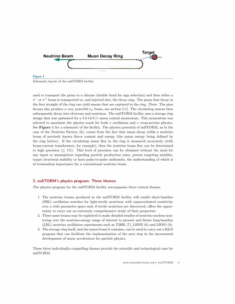
Figure 1
Schematic layout of the nuSTORM facility
used to transport the pions to a chicane (double bend for sign selection) and then either a
π− or π+ beam is transported to, and injected into, the decay ring. The pions that decay in
the first straight of the ring can yield muons that are captured in the ring. [Note: The pion
decays also produce a very powerful νµ beam, see section 5.1]. The circulating muons then
subsequently decay into electrons and neutrinos. The nuSTORM facility uses a storage ring
design that was optimized for a 3.8 GeV/c muon central momentum. This momentum was
selected to maximize the physics reach for both ν oscillation and ν cross-section physics.
See Figure 1 for a schematic of the facility. The physics potential of nuSTORM, as in the
case of the Neutrino Factory (6), comes from the fact that muon decay yields a neutrino
beam of precisely known flavor content and energy (the muon energy being defined by
the ring lattice). If the circulating muon flux in the ring is measured accurately (with
beam-current transformers, for example), then the neutrino beam flux can be determined
to high precision (. 1%). This level of precision can be obtained without the need for
any input or assumptions regarding particle production rates, proton targeting stability,
target structural stability or horn pulse-to-pulse uniformity, the understanding of which is
of tremendous importance for a conventional neutrino beam.
2. nuSTORM’s physics program: Three themes
The physics program for the nuSTORM facility encompasses three central themes.
1. The neutrino beams produced at the nuSTORM facility will enable short-baseline
(SBL) oscillation searches for light-sterile neutrinos with unprecedented sensitivity
over a wide parameter space and, if sterile neutrinos are discovered, offers the oppor-
tunity to carry out an extremely comprehensive study of their properties.
2. These same beams may be exploited to make detailed studies of neutrino-nucleus scat-
tering over the neutrino-energy range of interest to present and future long-baseline
(LBL) neutrino oscillation experiments such as T2HK (7), LBNE (8) and LBNO (9).
3. The storage ring itself, and the muon beam it contains, can be used to carry out a R&D
program that can facilitate the implementation of the next step in the incremental
development of muon accelerators for particle physics.
These three individually-compelling themes provide the scientific and technological case for
nuSTORM.
www.annualreviews.org • nuSTORM 3
2.1. Sterile neutrinos
Sterile neutrinos are a generic ingredient of many extensions of the Standard Model and,
even in models that do not contain them, can usually be easily added. One important
class of sterile neutrino theories are models explaining the smallness of neutrino masses by
means of a seesaw mechanism. In its simplest form, the seesaw mechanism requires at least
two heavy (∼ 1014 GeV) sterile neutrinos that would have very small mixings (∼ 10−12)
with the active neutrinos. However, in slightly non-minimal models, at least one sterile
neutrino can have a much smaller mass and a much larger mixing angle. Examples of this
type of model include the “inverse seesaw” (10; 11) and the split seesaw (12) scenarios.
For a detailed review of models with sterile neutrinos and their associated phenomenology,
see (13).
2.1.1. Experimental status for light-sterile neutrinos. Much of the current interest in light-
sterile neutrinos is motivated by experimental data. Results from the LSND (14) and
MiniBooNE (15) experiments, the GALLEX and SAGE solar-neutrino experiments (16–
20) and a re-analysis (13; 21–23) of short-baseline (L ≤ 100 m) reactor experiments can
be described by a 3+1 model with 3 active neutrinos and 1 sterile neutrino with a mass
of ' 1 eV and small mixing. The appearance signals (νµ → νe and νµ → νe) observed by
LSND and MiniBooNE imply the existence of a corresponding disappearance signal via the
following inequality (24):
〈Pνµ→νe〉 ≤ 4(1− 〈Pνµ→νµ〉
)(1− 〈Pνe→νe〉) (1)
where 〈Pνµ→νe〉, 〈Pνµ→νµ〉 and 〈Pνe→νe〉 are the energy-averaged oscillation probabilities
for νµ → νe appearance and νµ → νµ, νe → νe disappearance, respectively. An analogous
expression is valid for anti-neutrinos. This disappearance signal is observed in GALLEX and
SAGE (νe) and in the short-baseline reactor experiments (νe). In spite of the interesting
results from the experiments described above, the existence of light-sterile neutrinos is
far from established. A number of other short baseline experiments did not observe an
appearance signal (E776, KARMEN, NOMAD, ICARUS) (25–28) and strong constraints on
a disappearance signal have been produced by numerous other experiments (data from long
and short-baseline experiments, solar and atmospheric neutrino data, etc.) (17; 19; 29–57).
These data place strong constraints on the available sterile neutrino parameter space. The
compatibility of the signals from the LSND, MiniBooNE, reactor and gallium experiments
with null results from the large number of other experiments has been assessed in global
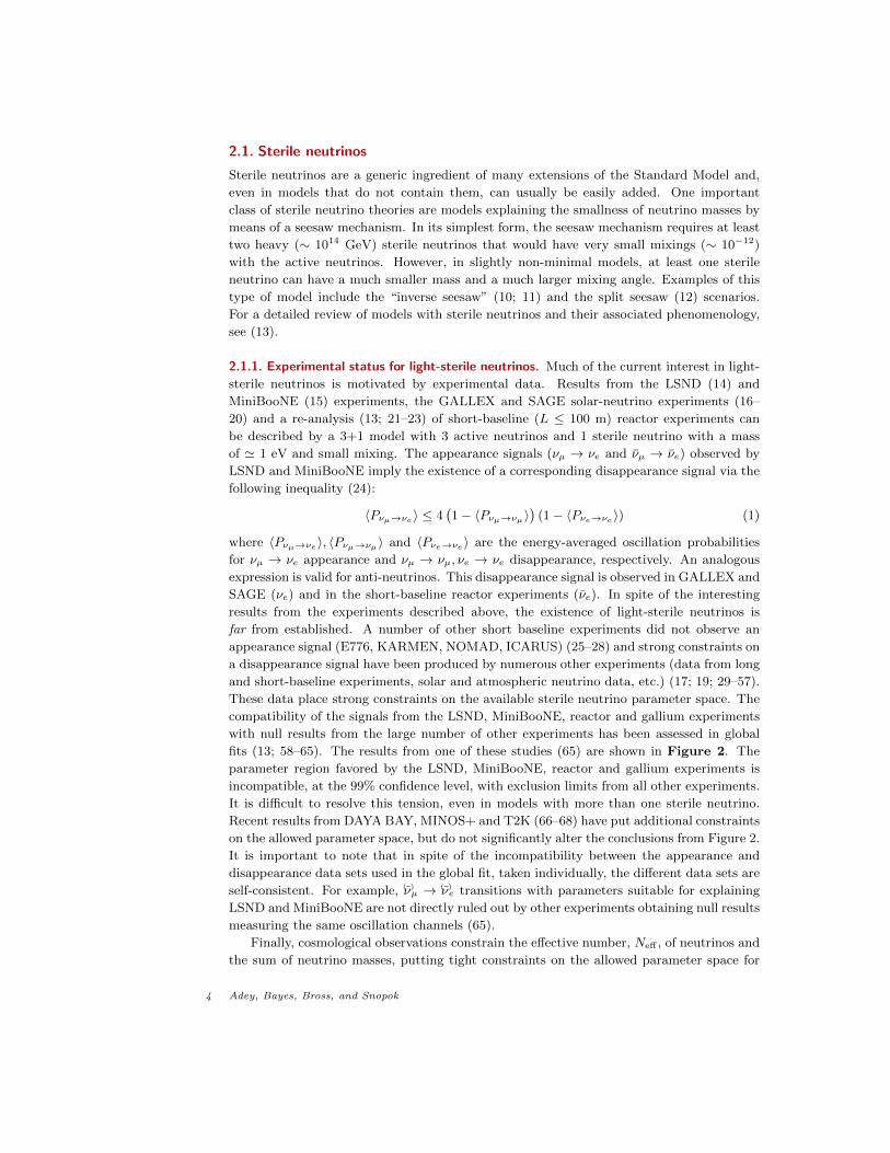
fits (13; 58–65). The results from one of these studies (65) are shown in Figure 2. The
parameter region favored by the LSND, MiniBooNE, reactor and gallium experiments is
incompatible, at the 99% confidence level, with exclusion limits from all other experiments.
It is difficult to resolve this tension, even in models with more than one sterile neutrino.
Recent results from DAYA BAY, MINOS+ and T2K (66–68) have put additional constraints
on the allowed parameter space, but do not significantly alter the conclusions from Figure 2.
It is important to note that in spite of the incompatibility between the appearance and
disappearance data sets used in the global fit, taken individually, the different data sets are
self-consistent. For example, (ν)µ → (ν)e transitions with parameters suitable for explaining
LSND and MiniBooNE are not directly ruled out by other experiments obtaining null results
measuring the same oscillation channels (65).
Finally, cosmological observations constrain the effective number, Neff , of neutrinos and
the sum of neutrino masses, putting tight constraints on the allowed parameter space for
4 Adey, Bayes, Bross, and Snopok
10-4 10- 3 10- 2 10-110-1
100
101
sin 2 2 Θ Μe
Dm
2
LSND + reactors+ Ga + MB app
null resultsappearance
null resultsdisappearance
null resultscombined
99% CL, 2 dof
Figure 2
Results of a global fit (from ref. (65)) to data in a 3+1 sterile-neutrino model . The solid red areas
indicate the regions preferred by the experiments reporting a signal (LSND, MiniBooNE, reactors
and Gallium) versus the constraints imposed by disappearance null results (black), appearancenull results (green) and all null results combined (blue).
light-sterile neutrinos. Recent Planck data (69) yields Neff = 3.30+0.54−0.51 when combined
with polarization data from WMAP (70), high-multipole measurements from ACT (71)
and SPT (72; 73) and data on baryon acoustic oscillations (BAO) (74–77). The same data
impose a constraint on∑mν ≤ 0.230 eV at the 95% C.L. However, cosmology only puts
constraints on sterile neutrinos that are thermalized in the early Universe and models with
sterile neutrinos, with so-called “hidden interactions” (78; 79), have been shown to reconcile
the tension between cosmology and the experimental data indicating a light-sterile neutrino.
A recent paper (80) has extended this argument, showing that this scenario would reduce
Neff down to 2.7.
We end our discussion on the experimental status of light-sterile neutrinos by stating
that, given the current situation, it is impossible to draw firm conclusions regarding their
existence. An experiment with superior sensitivity and precisely-controlled systematic un-
certainties has great potential to clarify the situation by either finding a new type of neutrino
oscillation or by producing a strong and robust constraint against any such oscillation.
2.2. Neutrino scattering physics: Systematics of LBL oscillation measurements
The recent measurement of a large value for the mixing angle, θ13, has made observation
of CP-violation in the lepton sector a fundamental (and now reachable) goal of the next
generation of long baseline neutrino oscillation (LBL) experiments. Measurement of the
CP-violating phase, δCP , can be accessed experimentally through two methods: a non-zero
phase will lead to a difference between the νµ → νe and νµ → νe appearance probabilities as
well as a variation in the relative amplitude of the second oscillation maximum with respect
www.annualreviews.org • nuSTORM 5
10-3
10-2
10-1
sin22θ
13
0
0.1
0.2
0.3
0.4
0.5
δC
P /
π
constraint on σ∼e
/ σ∼µ
σ∼µ @ 1%
σ∼e
@ 1%
T2HK CPV at 3σ
statistics only
all systematics @ default
GLoBES 2007
5%
2%
1% 0
1
2
3
4
0 200 400 600 800 1000
σ=
√ ∆χ2
Exposure (kt.MW.years)
CP Violation Sensitivity75% δCP Coverage
80 GeV BeamSignal/backgrounduncertainty varied
No systematics
5%/10%
2%/5%
1%/5%
3σ
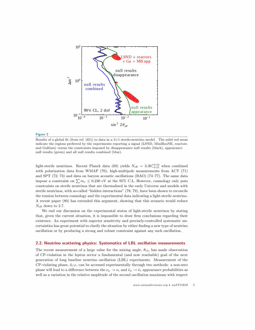
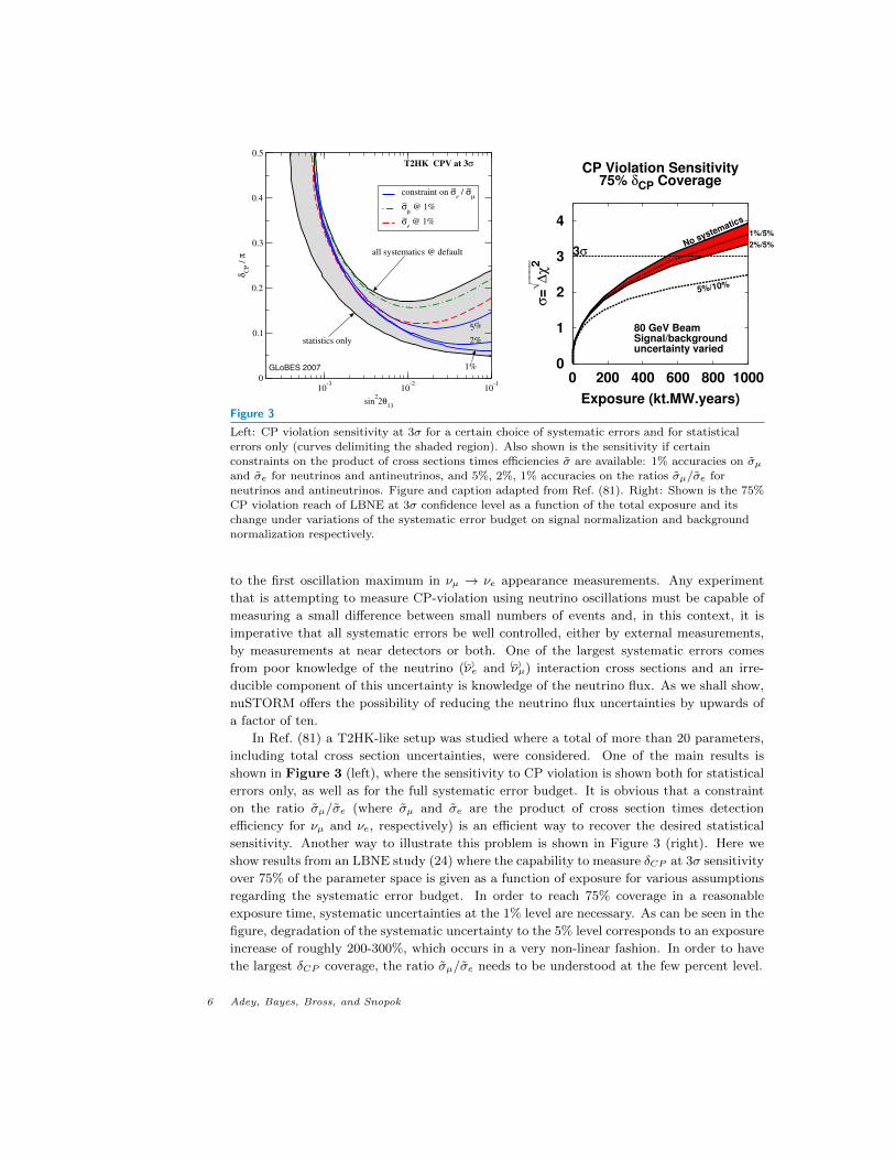
Figure 3
Left: CP violation sensitivity at 3σ for a certain choice of systematic errors and for statistical
errors only (curves delimiting the shaded region). Also shown is the sensitivity if certainconstraints on the product of cross sections times efficiencies σ are available: 1% accuracies on σµand σe for neutrinos and antineutrinos, and 5%, 2%, 1% accuracies on the ratios σµ/σe for
neutrinos and antineutrinos. Figure and caption adapted from Ref. (81). Right: Shown is the 75%CP violation reach of LBNE at 3σ confidence level as a function of the total exposure and its
change under variations of the systematic error budget on signal normalization and background
normalization respectively.
to the first oscillation maximum in νµ → νe appearance measurements. Any experiment
that is attempting to measure CP-violation using neutrino oscillations must be capable of
measuring a small difference between small numbers of events and, in this context, it is
imperative that all systematic errors be well controlled, either by external measurements,
by measurements at near detectors or both. One of the largest systematic errors comes
from poor knowledge of the neutrino ((ν)e and (ν)µ) interaction cross sections and an irre-
ducible component of this uncertainty is knowledge of the neutrino flux. As we shall show,
nuSTORM offers the possibility of reducing the neutrino flux uncertainties by upwards of
a factor of ten.
In Ref. (81) a T2HK-like setup was studied where a total of more than 20 parameters,
including total cross section uncertainties, were considered. One of the main results is
shown in Figure 3 (left), where the sensitivity to CP violation is shown both for statistical
errors only, as well as for the full systematic error budget. It is obvious that a constraint
on the ratio σµ/σe (where σµ and σe are the product of cross section times detection
efficiency for νµ and νe, respectively) is an efficient way to recover the desired statistical
sensitivity. Another way to illustrate this problem is shown in Figure 3 (right). Here we
show results from an LBNE study (24) where the capability to measure δCP at 3σ sensitivity
over 75% of the parameter space is given as a function of exposure for various assumptions
regarding the systematic error budget. In order to reach 75% coverage in a reasonable
exposure time, systematic uncertainties at the 1% level are necessary. As can be seen in the
figure, degradation of the systematic uncertainty to the 5% level corresponds to an exposure
increase of roughly 200-300%, which occurs in a very non-linear fashion. In order to have
the largest δCP coverage, the ratio σµ/σe needs to be understood at the few percent level.
6 Adey, Bayes, Bross, and Snopok
3. The nuSTORM facility
The basic concept for the facility was presented in section 1. After the pions are transported
to the decay ring, they are “stochastically” injected into the decay ring (82; 83) and pion
decays within the first straight of this ring can yield a muon that will be stored in the
ring. Muon decay produces ν beams of known flux and flavor via: µ+ → e+ + νµ + νe or
µ− → e− + νµ + νe. nuSTORM uses a storage ring with a central momentum of 3.8 GeV/c
(±10%) in order to obtain a spectrum of neutrinos that peaks at ' 2 GeV (see section 5.1).
The pion beam line is optimized to capture and transport pions in a momentum band of 5
± 1 GeV/c.
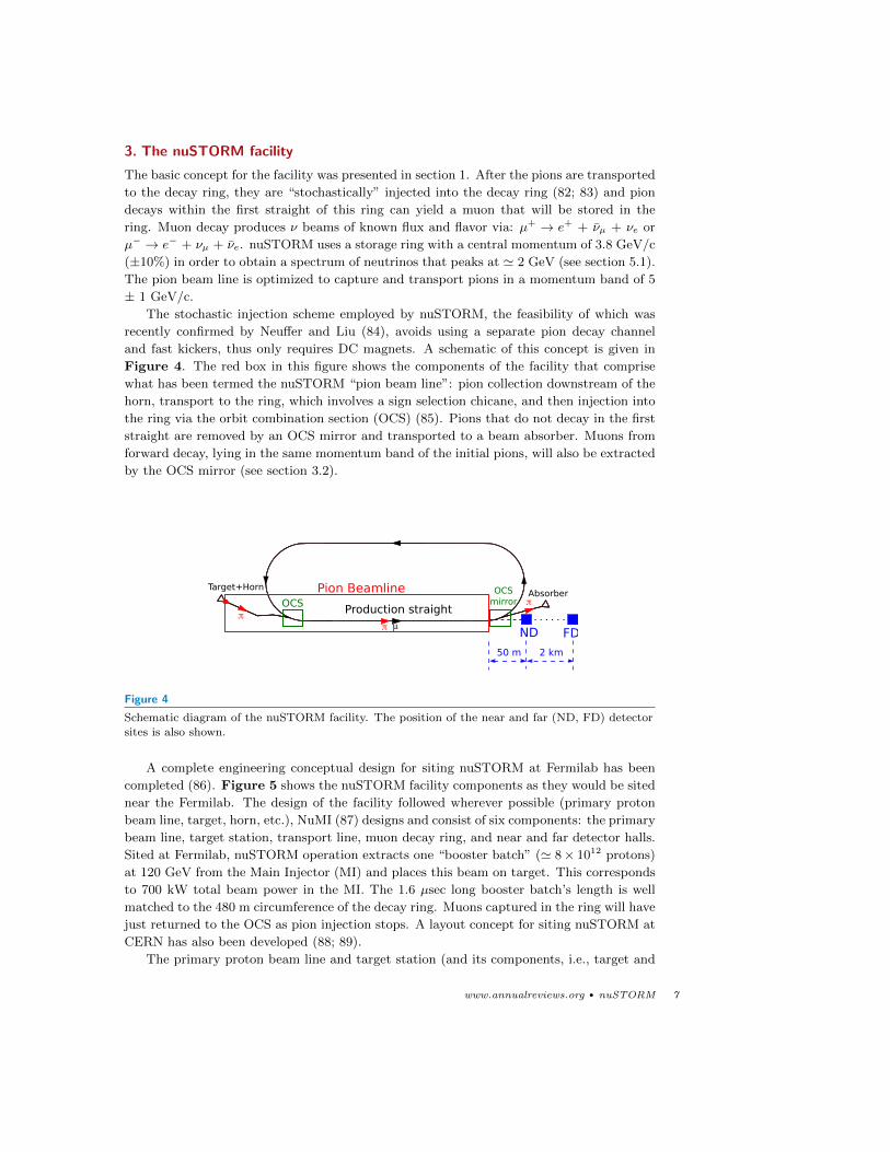
The stochastic injection scheme employed by nuSTORM, the feasibility of which was
recently confirmed by Neuffer and Liu (84), avoids using a separate pion decay channel
and fast kickers, thus only requires DC magnets. A schematic of this concept is given in
Figure 4. The red box in this figure shows the components of the facility that comprise
what has been termed the nuSTORM “pion beam line”: pion collection downstream of the
horn, transport to the ring, which involves a sign selection chicane, and then injection into
the ring via the orbit combination section (OCS) (85). Pions that do not decay in the first
straight are removed by an OCS mirror and transported to a beam absorber. Muons from
forward decay, lying in the same momentum band of the initial pions, will also be extracted
by the OCS mirror (see section 3.2).
Target+HornAbsorberPion Beamline
OCSOCS
mirrorProduction straight
ND FD
2 km50 m
ππ μ
π
Figure 4
Schematic diagram of the nuSTORM facility. The position of the near and far (ND, FD) detector
sites is also shown.
A complete engineering conceptual design for siting nuSTORM at Fermilab has been
completed (86). Figure 5 shows the nuSTORM facility components as they would be sited
near the Fermilab. The design of the facility followed wherever possible (primary proton
beam line, target, horn, etc.), NuMI (87) designs and consist of six components: the primary
beam line, target station, transport line, muon decay ring, and near and far detector halls.
Sited at Fermilab, nuSTORM operation extracts one “booster batch” (' 8× 10¹² protons)
at 120 GeV from the Main Injector (MI) and places this beam on target. This corresponds
to 700 kW total beam power in the MI. The 1.6 µsec long booster batch’s length is well
matched to the 480 m circumference of the decay ring. Muons captured in the ring will have
just returned to the OCS as pion injection stops. A layout concept for siting nuSTORM at
CERN has also been developed (88; 89).
The primary proton beam line and target station (and its components, i.e., target and
www.annualreviews.org • nuSTORM 7
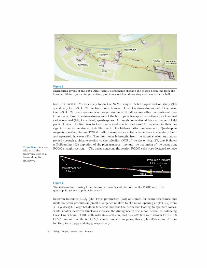
Figure 5
Engineering layout of the nuSTORM facility components showing the proton beam line from the
Fermilab Main Injector, target station, pion transport line, decay ring and near detector hall.
horn) for nuSTORM can closely follow the NuMI designs. A horn optimization study (90)
specifically for nuSTORM has been done, however. From the downstream end of the horn,
the nuSTORM beam system is no longer similar to NuMI or any other conventional neu-
trino beam. From the downstream end of the horn, pion transport is continued with several
radiation-hard (MgO insulated) quadrupoles. Although conventional from a magnetic field
point of view, the first two to four quads need special and careful treatment in their de-
sign in order to maximize their lifetime in this high-radiation environment. Quadrupole
magnets meeting the nuSTORM radiation-resistance criteria have been successfully built
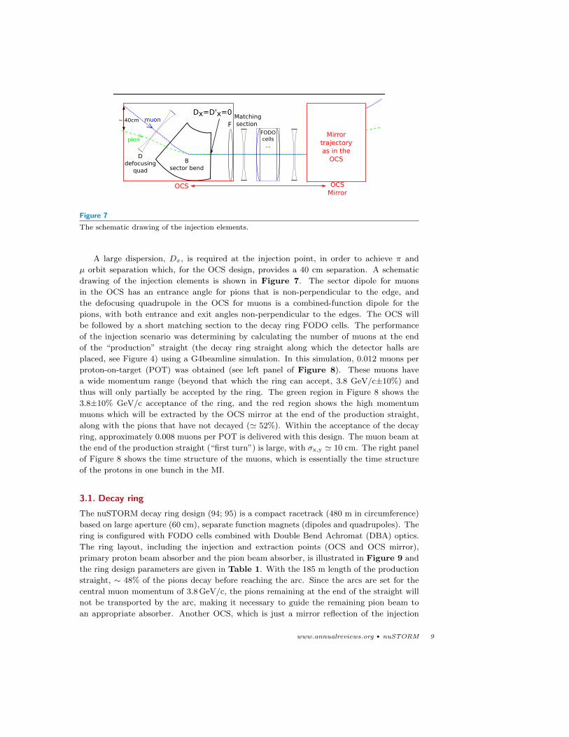
and operated, however (91). The pion beam is brought from the target station and trans-
ported through a chicane section to the injection OCS of the decay ring. Figure 6 shows
a G4Beamline (92) depiction of the pion transport line and the beginning of the decay ring
FODO straight section. The decay ring straight-section FODO cells were designed to haveβ function: Functionrelated to the
transverse size of a
beam along itstrajectory
Figure 6
The G4beamline drawing from the downstream face of the horn to the FODO cells. Red:quadrupole, yellow: dipole, white: drift.
betatron functions βx, βy (the Twiss parameters (93)) optimized for beam acceptance and
neutrino beam production (small divergence relative to the muon opening angle (1/γ) from
π → µ decay). Large betatron functions increase the beam size leading to aperture losses,
while smaller betatron functions increase the divergence of the muon beam. In balancing
these two criteria, FODO cells with βmax=30.2 m, and βmin=23.3 m were chosen for the 3.8
GeV/c muons. For the 5.0 GeV/c center momentum pions, this implies 38.5 m and 31.6 m
for the pion’s βmax and βmin, respectively.
8 Adey, Bayes, Bross, and Snopok
muon
pion
~ 40cmDx=D'x=0
Ddefocusing
quad
F
Bsector bend
OCS
FODOcells
...
OCSMirror
Matching section
Mirrortrajectoryas in the
OCS
Figure 7
The schematic drawing of the injection elements.
A large dispersion, Dx, is required at the injection point, in order to achieve π and
µ orbit separation which, for the OCS design, provides a 40 cm separation. A schematic
drawing of the injection elements is shown in Figure 7. The sector dipole for muons
in the OCS has an entrance angle for pions that is non-perpendicular to the edge, and
the defocusing quadrupole in the OCS for muons is a combined-function dipole for the
pions, with both entrance and exit angles non-perpendicular to the edges. The OCS will
be followed by a short matching section to the decay ring FODO cells. The performance
of the injection scenario was determining by calculating the number of muons at the end
of the “production” straight (the decay ring straight along which the detector halls are
placed, see Figure 4) using a G4beamline simulation. In this simulation, 0.012 muons per
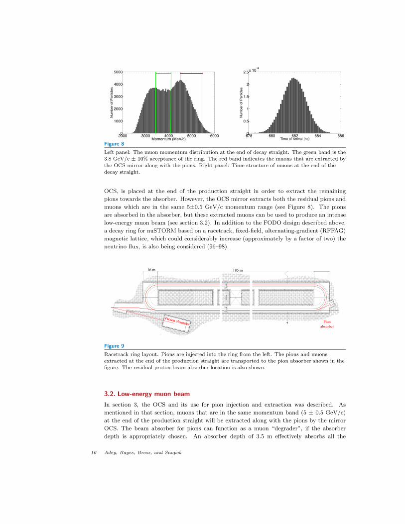
proton-on-target (POT) was obtained (see left panel of Figure 8). These muons have
a wide momentum range (beyond that which the ring can accept, 3.8 GeV/c±10%) and
thus will only partially be accepted by the ring. The green region in Figure 8 shows the
3.8±10% GeV/c acceptance of the ring, and the red region shows the high momentum
muons which will be extracted by the OCS mirror at the end of the production straight,
along with the pions that have not decayed (' 52%). Within the acceptance of the decay
ring, approximately 0.008 muons per POT is delivered with this design. The muon beam at
the end of the production straight (“first turn”) is large, with σx,y ' 10 cm. The right panel
of Figure 8 shows the time structure of the muons, which is essentially the time structure
of the protons in one bunch in the MI.
3.1. Decay ring
The nuSTORM decay ring design (94; 95) is a compact racetrack (480 m in circumference)
based on large aperture (60 cm), separate function magnets (dipoles and quadrupoles). The
ring is configured with FODO cells combined with Double Bend Achromat (DBA) optics.
The ring layout, including the injection and extraction points (OCS and OCS mirror),
primary proton beam absorber and the pion beam absorber, is illustrated in Figure 9 and
the ring design parameters are given in Table 1. With the 185 m length of the production
straight, ∼ 48% of the pions decay before reaching the arc. Since the arcs are set for the
central muon momentum of 3.8 GeV/c, the pions remaining at the end of the straight will
not be transported by the arc, making it necessary to guide the remaining pion beam to
an appropriate absorber. Another OCS, which is just a mirror reflection of the injection
www.annualreviews.org • nuSTORM 9
2000 3000 4000 5000 60000
1000
2000
3000
4000
5000
Momentum (MeV/c)
Num
ber o
f Par
ticle
s
678 680 682 684 6860
0.5
1
1.5
2
2.5x 10¹⁸
Time of Arrival (ns)
Num
ber
of P
artic
les
Figure 8
Left panel: The muon momentum distribution at the end of decay straight. The green band is the
3.8 GeV/c ± 10% acceptance of the ring. The red band indicates the muons that are extracted by
the OCS mirror along with the pions. Right panel: Time structure of muons at the end of thedecay straight.
OCS, is placed at the end of the production straight in order to extract the remaining
pions towards the absorber. However, the OCS mirror extracts both the residual pions and
muons which are in the same 5±0.5 GeV/c momentum range (see Figure 8). The pions
are absorbed in the absorber, but these extracted muons can be used to produce an intense
low-energy muon beam (see section 3.2). In addition to the FODO design described above,
a decay ring for nuSTORM based on a racetrack, fixed-field, alternating-gradient (RFFAG)
magnetic lattice, which could considerably increase (approximately by a factor of two) the
neutrino flux, is also being considered (96–98).
4267
mm
1025
8 m
m42
67 m
m8.
0'6.
0'33
.5'
6.0'
8.0'
DRAWING NO.
PROJECT NO.
DATE
SC
ALE
:
09 APR. 2013
4/12
/201
3 5:
33:3
4 PM
P:\1
5238
.1B
- Fer
mila
b nu
STO
RM
\01-
Dra
win
g Fi
les\
00-R
evit
File
s\01
-Pro
ject
File
s\01
-Cen
tral F
ile\1
5238
1B-A
RC
H-N
EAR
.rvt
6-13-1
PDR-3
DE
CA
Y R
ING
PLA
N
PROJECT
NORTH
W
ES
16 m 185 m
Proton absorber Pion absorber
Figure 9
Racetrack ring layout. Pions are injected into the ring from the left. The pions and muons
extracted at the end of the production straight are transported to the pion absorber shown in the
figure. The residual proton beam absorber location is also shown.
3.2. Low-energy muon beam
In section 3, the OCS and its use for pion injection and extraction was described. As
mentioned in that section, muons that are in the same momentum band (5 ± 0.5 GeV/c)
at the end of the production straight will be extracted along with the pions by the mirror
OCS. The beam absorber for pions can function as a muon “degrader”, if the absorber
depth is appropriately chosen. An absorber depth of 3.5 m effectively absorbs all the
10 Adey, Bayes, Bross, and Snopok
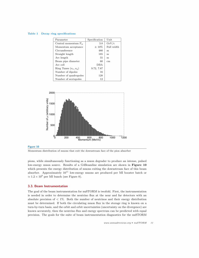
Table 1 Decay ring specifications
Parameter Specification Unit
Central momentum Pµ 3.8 GeV/c
Momentum acceptance ± 10% Full width
Circumference 480 m
Straight length 185 m
Arc length 55 m
Beam pipe diameter 60 cm
Arc cell DBA
Ring Tunes (νx, νy) 9.72, 7.87
Number of dipoles 16
Number of quadrupoles 128
Number of sextupoles 12
0 200 400 600 800 1000 12000
500
1000
1500
2000
Momentum (MeV/c)
Num
ber o
f µ (a
rbitr
ary
units
)
Figure 10
Momentum distribution of muons that exit the downstream face of the pion absorber
pions, while simultaneously functioning as a muon degrader to produce an intense, pulsed
low-energy muon source. Results of a G4Beamline simulation are shown in Figure 10
which presents the energy distribution of muons exiting the downstream face of this beam
absorber. Approximately 1011 low-energy muons are produced per MI booster batch or
' 1.2× 10⁹ per MI bunch (see Figure 8).
3.3. Beam Instrumentation
The goal of the beam instrumentation for nuSTORM is twofold. First, the instrumentation
is needed in order to determine the neutrino flux at the near and far detectors with an
absolute precision of < 1%. Both the number of neutrinos and their energy distribution
must be determined. If both the circulating muon flux in the storage ring is known on a
turn-by-turn basis, and the orbit and orbit uncertainties (uncertainty on the divergence) are
known accurately, then the neutrino flux and energy spectrum can be predicted with equal
precision. The goals for the suite of beam instrumentation diagnostics for the nuSTORM
www.annualreviews.org • nuSTORM 11
decay ring are summarized below:
1. Measure the circulating muon intensity (on a turn by turn basis) to 0.1% absolute.
2. Measure the mean momentum to 0.1% absolute.
3. Measure the momentum spread to 1% (FWHM).
4. Measure the tune to 0.01.
Second, from the accelerator standpoint, in order to commission and run the decay ring,
turn-by-turn measurements of the following parameters are crucial: trajectory, tune, beam
profile and beam loss. The current estimate for these requirements is summarized in Table 2
below.
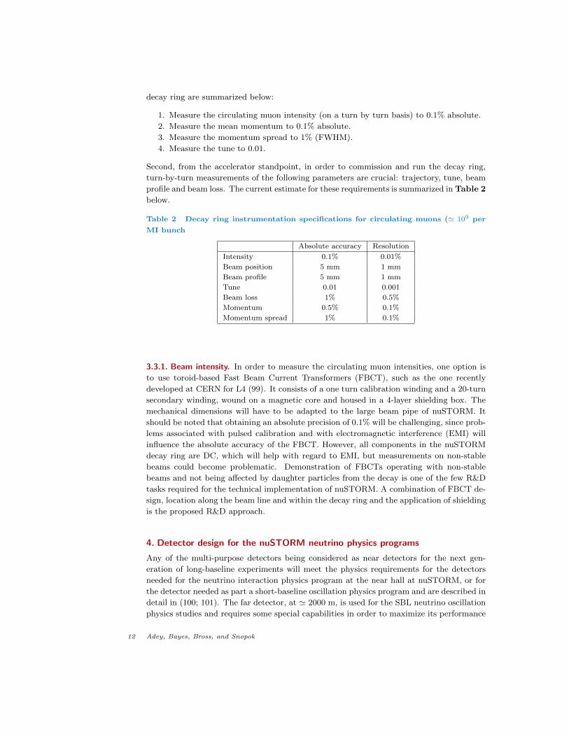
Table 2 Decay ring instrumentation specifications for circulating muons (' 109 per
MI bunch
Absolute accuracy Resolution
Intensity 0.1% 0.01%
Beam position 5 mm 1 mm
Beam profile 5 mm 1 mm
Tune 0.01 0.001
Beam loss 1% 0.5%
Momentum 0.5% 0.1%
Momentum spread 1% 0.1%
3.3.1. Beam intensity. In order to measure the circulating muon intensities, one option is
to use toroid-based Fast Beam Current Transformers (FBCT), such as the one recently
developed at CERN for L4 (99). It consists of a one turn calibration winding and a 20-turn
secondary winding, wound on a magnetic core and housed in a 4-layer shielding box. The
mechanical dimensions will have to be adapted to the large beam pipe of nuSTORM. It
should be noted that obtaining an absolute precision of 0.1% will be challenging, since prob-
lems associated with pulsed calibration and with electromagnetic interference (EMI) will
influence the absolute accuracy of the FBCT. However, all components in the nuSTORM
decay ring are DC, which will help with regard to EMI, but measurements on non-stable
beams could become problematic. Demonstration of FBCTs operating with non-stable
beams and not being affected by daughter particles from the decay is one of the few R&D
tasks required for the technical implementation of nuSTORM. A combination of FBCT de-
sign, location along the beam line and within the decay ring and the application of shielding
is the proposed R&D approach.
4. Detector design for the nuSTORM neutrino physics programs
Any of the multi-purpose detectors being considered as near detectors for the next gen-
eration of long-baseline experiments will meet the physics requirements for the detectors
needed for the neutrino interaction physics program at the near hall at nuSTORM, or for
the detector needed as part a short-baseline oscillation physics program and are described in
detail in (100; 101). The far detector, at ' 2000 m, is used for the SBL neutrino oscillation
physics studies and requires some special capabilities in order to maximize its performance
12 Adey, Bayes, Bross, and Snopok
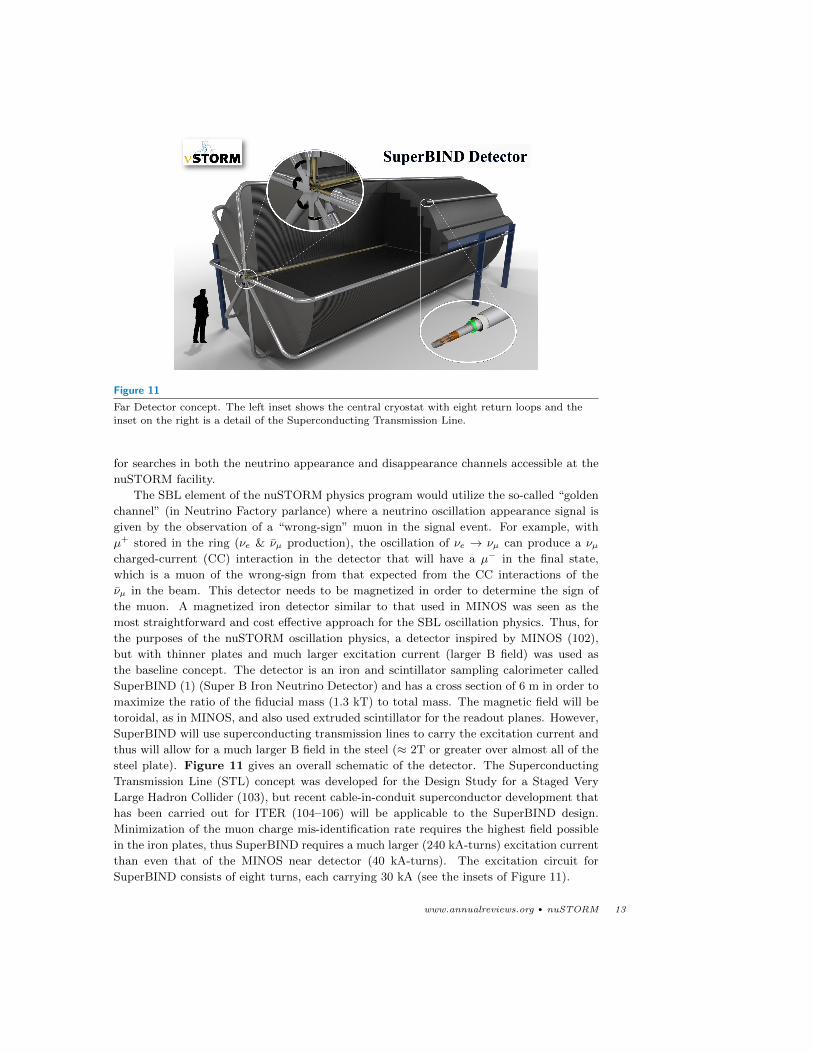
Figure 11
Far Detector concept. The left inset shows the central cryostat with eight return loops and the
inset on the right is a detail of the Superconducting Transmission Line.
for searches in both the neutrino appearance and disappearance channels accessible at the
nuSTORM facility.
The SBL element of the nuSTORM physics program would utilize the so-called “golden
channel” (in Neutrino Factory parlance) where a neutrino oscillation appearance signal is
given by the observation of a “wrong-sign” muon in the signal event. For example, with
µ+ stored in the ring (νe & νµ production), the oscillation of νe → νµ can produce a νµcharged-current (CC) interaction in the detector that will have a µ− in the final state,
which is a muon of the wrong-sign from that expected from the CC interactions of the
νµ in the beam. This detector needs to be magnetized in order to determine the sign of
the muon. A magnetized iron detector similar to that used in MINOS was seen as the
most straightforward and cost effective approach for the SBL oscillation physics. Thus, for
the purposes of the nuSTORM oscillation physics, a detector inspired by MINOS (102),
but with thinner plates and much larger excitation current (larger B field) was used as
the baseline concept. The detector is an iron and scintillator sampling calorimeter called
SuperBIND (1) (Super B Iron Neutrino Detector) and has a cross section of 6 m in order to
maximize the ratio of the fiducial mass (1.3 kT) to total mass. The magnetic field will be
toroidal, as in MINOS, and also used extruded scintillator for the readout planes. However,
SuperBIND will use superconducting transmission lines to carry the excitation current and
thus will allow for a much larger B field in the steel (≈ 2T or greater over almost all of the
steel plate). Figure 11 gives an overall schematic of the detector. The Superconducting
Transmission Line (STL) concept was developed for the Design Study for a Staged Very
Large Hadron Collider (103), but recent cable-in-conduit superconductor development that
has been carried out for ITER (104–106) will be applicable to the SuperBIND design.
Minimization of the muon charge mis-identification rate requires the highest field possible
in the iron plates, thus SuperBIND requires a much larger (240 kA-turns) excitation current
than even that of the MINOS near detector (40 kA-turns). The excitation circuit for
SuperBIND consists of eight turns, each carrying 30 kA (see the insets of Figure 11).
www.annualreviews.org • nuSTORM 13
5. Performance of the nuSTORM facility – Neutrino physics
The reach of the neutrino physics that can be done at the nuSTORM facility is deter-
mined, to a large degree, by the quality of the neutrino beams it produces. The nuSTORM
facility provides bright, flavor-pure beams that can be precisely characterized by beam in-
strumentation in the pion transfer line and in the decay ring. This is what sets nuSTORM
apart from other neutrino sources, giving it many of the qualities of a photon light source
(accurate flux and energy determination). The physics program that can be done at the
near hall at nuSTORM is identical to that being proposed at the near sites of planned
future long-baseline oscillation experiments (T2HK and LBNE, for example) and could use
similar, if not identical, detector systems. However with respect to neutrino interaction
physics, nuSTORM provides large samples of νe and νe beams as well as nearly flavor-pure
νµ and νµ beams. For the short-baseline oscillation physics performance, nuSTORM takes
advantage of the “golden channel” (appearance) mentioned above, as well has having access
to the (ν)µ disappearance channels. The (ν)e appearance and disappearance channels would
be most effectively studied with a magnetized totally active detector such as LAr.
5.1. Neutrino beams produced at nuSTORM
As mentioned in section 1, the neutrino beams produced at nuSTORM can be determined
with excellent precision with the use of conventional beam diagnostic instrumentation to
understand the parent particle distributions, from which the neutrino flux can then be
precisely calculated. In the sections that follow, we describe the neutrino beams expected
from the facility (107), indicating the overall flux (normalized to 1021 protons on target),
neutrino flavor composition and expected bin-to-bin errors.
5.1.1. Neutrino flux from pion beam. Although the design-case of nuSTORM is to produce
neutrinos from muon decay, the neutrino beam from pion decay in the production straight
produces a very intense (ν)µ beam. In order to quantitatively investigate this beam, an
ensemble of particles produced in a MARS (108) simulation of the target and horn were
tracked using G4Beamline from the downstream face of the horn and then through the
transfer line and injection into the decay ring via the OCS. After tracking through the
transfer line, the pion beam was sampled at fifty locations along the production straight to
yield an ensemble of pions representative of the beam. To obtain the muon ensemble, the
pions were allowed to decay and the muons sampled at the end of the production straight,
weighted for the momentum acceptance of the ring.
The sampling of the particles’ energy and momenta in the G4Beamline tracking could
then be used to calculate (from decay kinematics) the neutrino flux at arbitrary locations,
or G4Beamline could be used to simulate the production of the neutrino beam itself. It was
considered that this sampling is analogous to the information of the beam obtained from
standard diagnostic instrumentation.
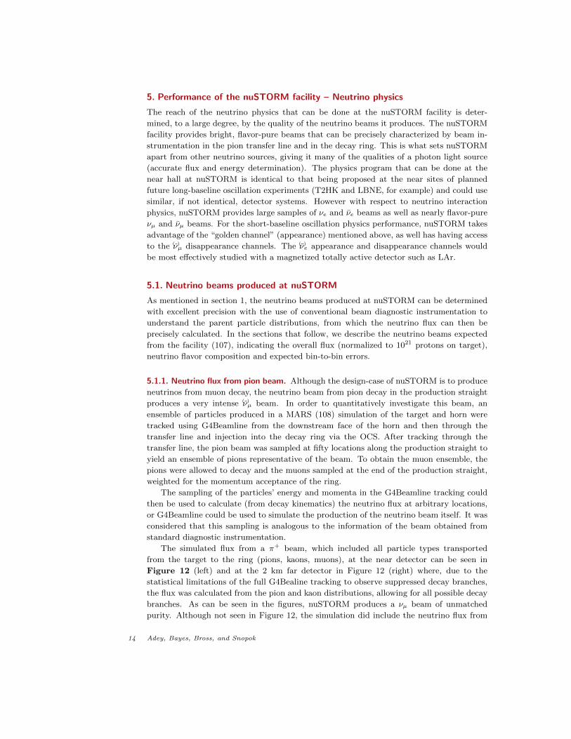
The simulated flux from a π+ beam, which included all particle types transported
from the target to the ring (pions, kaons, muons), at the near detector can be seen in
Figure 12 (left) and at the 2 km far detector in Figure 12 (right) where, due to the
statistical limitations of the full G4Bealine tracking to observe suppressed decay branches,
the flux was calculated from the pion and kaon distributions, allowing for all possible decay
branches. As can be seen in the figures, nuSTORM produces a νµ beam of unmatched
purity. Although not seen in Figure 12, the simulation did include the neutrino flux from
14 Adey, Bayes, Bross, and Snopok
K+ → νe, π− → νµ and π+ → νe. Their contribution to the flux was too small to be seen
on the scale shown in the figure.
MeVνE0 2000 4000
p.o
.t.21
/ 50
MeV
/ 10
2 /
mν
1410
1510
1610 µν → +Kµν → +πµν → +µeν → +µ
µν → +Kµν → +πµν → +µeν → +µ
µν → +πµν → +Keν → +µµν → +µ
µν → +πµν → +Keν → +µµν → +µ
MeVνE0 2000 4000
p.o
.t.21
/ 50
MeV
/ 10
2 /
mν
1110
1210
1310
1410pipe
Entries 10686Mean 4865RMS 464.7
pipeEntries 10686Mean 4865RMS 464.7
µν → +πµν → +Keν → +µµν → +µ
µν → +πµν → +Keν → +µµν → +µ
µν → +πµν → +Keν → +µµν → +µ
µν → +πµν → +Keν → +µµν → +µ
Figure 12
Neutrino flux from π+ beam at the near detector (left) and at the far detector (right)
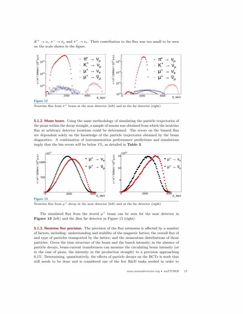
5.1.2. Muon beam. Using the same methodology of simulating the particle trajectories of
the pions within the decay straight, a sample of muons was obtained from which the neutrino
flux at arbitrary detector locations could be determined. The errors on the binned flux
are dependent solely on the knowledge of the particle trajectories obtained by the beam
diagnostics. A combination of instrumentation performance predictions and simulations
imply that the bin errors will be below 1%, as detailed in Table 3.
nue_energy_n
Entries 4.671311e+16Mean 1878RMS 701.5
MeVνE0 2000 4000
p.o
.t21
/ 50
MeV
/ 10
2 /
mν
0
500
1000
1210×
nue_energy_n
Entries 4.671311e+16Mean 1878RMS 701.5
eν → +µ
µν → +µeν → +µ
µν → +µeν → +µ
µν → +µ
e_energy_fEntries 5.796347e+14
Mean 2087
RMS 711.3
MeVνE0 2000 4000
p.o
.t.21
/ 50
MeV
/ 10
2 /
mν
0
5
10
15
1210×
e_energy_fEntries 5.796347e+14
Mean 2087
RMS 711.3
eν → +µ
µν → +µ
eν → +µ
µν → +µ
eν → +µ
µν → +µ
eν → +µ
µν → +µ
eν → +µ
µν → +µ
eν → +µ
µν → +µ
Figure 13
Neutrino flux from µ+ decay at the near detector (left) and at the far detector (right)
The simulated flux from the stored µ+ beam can be seen for the near detector in
Figure 13 (left) and the 2km far detector in Figure 13 (right).
5.1.3. Neutrino flux precision. The precision of the flux estimates is affected by a number
of factors, including: understanding and stability of the magnetic lattice; the overall flux of
and type of particles transported by the lattice; and the momentum distributions of those
particles. Given the time structure of the beam and the bunch intensity, in the absence of
particle decays, beam-current transformers can measure the circulating beam intensity (or
in the case of pions, the intensity in the production straight) to a precision approaching
0.1%. Determining, quantitatively, the effects of particle decays on the BCTs is work that
still needs to be done and is considered one of the few R&D tasks needed in order to
www.annualreviews.org • nuSTORM 15
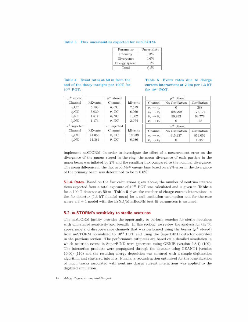
Table 3 Flux uncertainties expected for nuSTORM.
Parameter Uncertainty
Intensity 0.3%
Divergence 0.6%
Energy spread 0.1%
Total .1%
Table 4 Event rates at 50 m from the
end of the decay straight per 100T for
1021 POT.
µ+ stored µ− stored
Channel kEvents Channel kEvents
νeCC 5,188 νeCC 2,519
νµCC 3,030 νµCC 6,060
νeNC 1,817 νeNC 1,002
νµNC 1,174 νµNC 2,074
π+ injected π− injected
Channel kEvents Channel kEvents
νµCC 41,053 νµCC 19,939
νµNC 14,384 νµCC 6,986
Table 5 Event rates due to charge
current interactions at 2 km per 1.3 kT
for 1021 POT.
µ+ Stored
Channel No Oscillation Oscillation
νe → νµ 0 288
νe → νe 188,292 176,174
νµ → νµ 99,893 94,776
νµ → νe 0 133
π+ Stored
Channel No Oscillation Oscillation
νµ → νµ 915,337 854,052
νµ → νe 0 1,587
implement nuSTORM. In order to investigate the effect of a measurement error on the
divergence of the muons stored in the ring, the muon divergence of each particle in the
muon beam was inflated by 2% and the resulting flux compared to the nominal divergence.
The mean difference in the flux in 50 MeV energy bins based on a 2% error in the divergence
of the primary beam was determined to be ' 0.6%.
5.1.4. Rates. Based on the flux calculations given above, the number of neutrino interac-
tions expected from a total exposure of 1021 POT was calculated and is given in Table 4
for a 100 T detector at 50 m. Table 5 gives the number of charge current interactions in
the far detector (1.3 kT fiducial mass) for a null-oscillation assumption and for the case
where a 3 + 1 model with the LSND/MiniBooNE best fit parameters is assumed.
5.2. nuSTORM’s sensitivity to sterile neutrinos
The nuSTORM facility provides the opportunity to perform searches for sterile neutrinos
with unmatched sensitivity and breadth. In this section, we review the analysis for the (ν)µappearance and disappearance channels that was performed using the beams (µ+ stored)
from nuSTORM normalized to 1021 POT and using the SuperBIND detector described
in the previous section. The performance estimates are based on a detailed simulation in
which neutrino events in SuperBIND were generated using GENIE (version 2.8.4) (109).
The interaction products were propagated through the detector using GEANT4 (version
10.00) (110) and the resulting energy deposition was smeared with a simple digitization
algorithm and clustered into hits. Finally, a reconstruction optimized for the identification
of muon tracks associated with neutrino charge current interactions was applied to the
digitized simulation.
16 Adey, Bayes, Bross, and Snopok
True Neutrino Energy0 0.5 1 1.5 2 2.5 3 3.5 4
Fra
ctio
na
l E
ffic
ien
cy
0
0.1
0.2
0.3
0.4
0.5
0.6
0.7
0.8
µν Rec. from µ
µν Rec. from +µ
True Neutrino Energy0 0.5 1 1.5 2 2.5 3 3.5 4
Fra
ctio
na
l C
ha
rge
ID
Eff
icie
ncy
0.1
0.2
0.3
0.4
0.5
0.6
0.7
0.8
0.9
1
µν Rec. from µ
µν Rec. from +µ
Figure 14
Reconstruction (left) and charge identification (right) efficiencies for muons generated from charge
current neutrino interactions in SuperBIND, at typical nuSTORM energies.
The reconstruction used a simple geometric approach to identify potential tracks and
a Kalman filter algorithm to extend the track to the event vertex and to fit for the cur-
vature (111). The pattern recognition algorithm first identified planes with single points
of energy deposition. After the tracks were identified they were passed to the fitting algo-
rithm. The reconstruction and charge identification efficiency of this algorithm is shown
in Figure 14 for muon neutrino charge current interactions in SuperBIND. The algorithm
continues to operate until it cannot find an instance of five or less isolated clusters in the
event. The longest trajectory identified by this algorithm was associated with the muon
track.
In the reconstruction, a number of events will be identified with the incorrect charge
either from failures in the reconstruction algorithm or from pions which are misidentified
as muons. The fractional occurrence of such events is the complement of the charge iden-
tification efficiency shown in Figure 14. Such tracks are the primary background for the
identification of muon-flavored charge current neutrino interactions in both the wrong sign
appearance and disappearance channels. The analysis shown here utilized the Toolkit for
Multi-Variate Analysis (TMVA) (112) included as part of the ROOT package (113). This
analysis takes five variables as input to produce a figure of merit which can be used to
identify signal from background.
After training, the analysis was optimized for signal significance assuming an initial sam-
ple size of signal and background events calculated using the GLoBeS program (114) with
sterile neutrino parameters derived from recent global fits (65) to short baseline appearance
data input assuming a 3+1 sterile neutrino model.
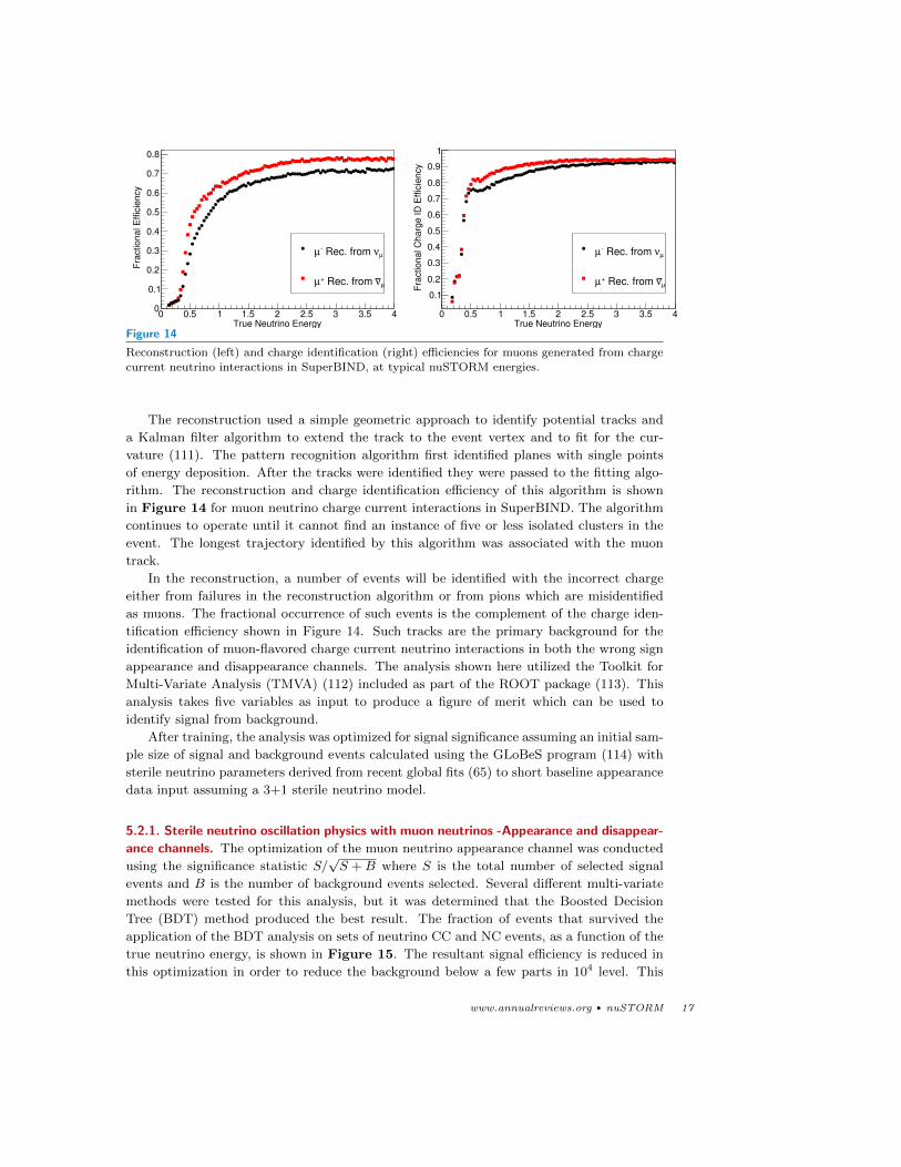
5.2.1. Sterile neutrino oscillation physics with muon neutrinos -Appearance and disappear-
ance channels. The optimization of the muon neutrino appearance channel was conducted
using the significance statistic S/√S +B where S is the total number of selected signal
events and B is the number of background events selected. Several different multi-variate
methods were tested for this analysis, but it was determined that the Boosted Decision
Tree (BDT) method produced the best result. The fraction of events that survived the
application of the BDT analysis on sets of neutrino CC and NC events, as a function of the
true neutrino energy, is shown in Figure 15. The resultant signal efficiency is reduced in
this optimization in order to reduce the background below a few parts in 104 level. This
www.annualreviews.org • nuSTORM 17

True Energy (GeV)0 0.5 1 1.5 2 2.5 3 3.5 4
Fra
ctional E
ffic
iency
610
510
410
310
210
110
1
10 CC Signal
µν
CC misID Bkgd.µ
ν
NC Backgroundµ
ν
CC Backgroundeν
Figure 15
Event selection efficiency of the optimized boosted decision tree analysis for SuperBIND, at the
energies available to the nuSTORM facility.
degree of background suppression is what allows for a measurement in this channel with a
potential for 10σ sensitivity.
The sensitivity for νe → νµ (the CPT invariant channel of the LSND/MiniBooNE sig-
nal) was determined within the GLoBeS framework. The simulation provided the detector
response, as characterized in a “migration matrix” that maps the true neutrino interaction
rates to reconstructed neutrino rates, including both efficiency and resolution effects. The
migration matrix was then used as input to the GLoBeS program. The signal (νµCC) re-
sponse was evaluated with the background (νeCC, νµCC, νµNC) response and the number
of events in each associated channel was evaluated for the potential values of ∆m14 between
0.03 and 30 eV2 and θeµ between 10−6 and 0.1. A representation of the deviation from the
null-oscillation hypothesis was then calculated using a χ2 statistic for each point and the
result then used to map out the sensitivity shown in Figure 16. This sensitivity has been
plotted with contours determined from global fits, shown in Figure 2, to the existing short
baseline oscillation appearance data including LSND, MiniBooNE, ICARUS, and MINOS.
The 10σ significance contour demonstrates that the νµ appearance measurement alone will
provide a definitive statement regarding the existence of a sterile neutrino in the region
consistent with the combination of the fit to the LSND, MiniBooNE, gallium, and reactor
data. Further measurements serve to refine these results.
The muon disappearance channel used a similar analysis with a different optimization.
The disappearance measurement is an analysis of the spectrum shape, so a pure counting
statistic is insufficient. A χ2 was adopted as a figure of merit to determine the largest
separation between the null hypothesis and a test case during optimization before compiling
the sensitivity curves of ∆m14 vs. θµµ shown in Figure 17, where
sin2 2θµµ = 4|Uµ4|2(1− |Uµ4|2). (2)
These curves were again compiled using GloBeS with the response from the signal (νµ CC)
and background (νµ NC and νe CC) simulations. The 99% confidence limits from the
disappearance measurement with a muon decay source can provide an improvement over
the limits from existing data for ∆m214 greater than 0.3 eV2. Assuming a total systematic
18 Adey, Bayes, Bross, and Snopok
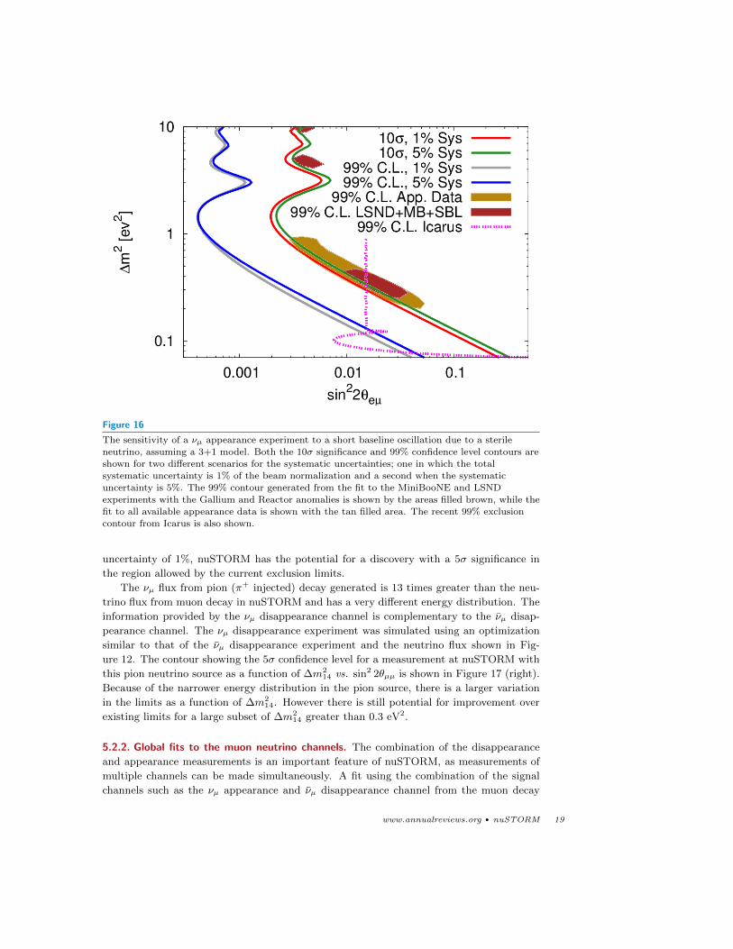
Figure 16
The sensitivity of a νµ appearance experiment to a short baseline oscillation due to a sterileneutrino, assuming a 3+1 model. Both the 10σ significance and 99% confidence level contours are
shown for two different scenarios for the systematic uncertainties; one in which the total
systematic uncertainty is 1% of the beam normalization and a second when the systematicuncertainty is 5%. The 99% contour generated from the fit to the MiniBooNE and LSND
experiments with the Gallium and Reactor anomalies is shown by the areas filled brown, while the
fit to all available appearance data is shown with the tan filled area. The recent 99% exclusioncontour from Icarus is also shown.
uncertainty of 1%, nuSTORM has the potential for a discovery with a 5σ significance in
the region allowed by the current exclusion limits.
The νµ flux from pion (π+ injected) decay generated is 13 times greater than the neu-
trino flux from muon decay in nuSTORM and has a very different energy distribution. The
information provided by the νµ disappearance channel is complementary to the νµ disap-
pearance channel. The νµ disappearance experiment was simulated using an optimization
similar to that of the νµ disappearance experiment and the neutrino flux shown in Fig-
ure 12. The contour showing the 5σ confidence level for a measurement at nuSTORM with
this pion neutrino source as a function of ∆m214 vs. sin2 2θµµ is shown in Figure 17 (right).
Because of the narrower energy distribution in the pion source, there is a larger variation
in the limits as a function of ∆m214. However there is still potential for improvement over
existing limits for a large subset of ∆m214 greater than 0.3 eV2.
5.2.2. Global fits to the muon neutrino channels. The combination of the disappearance
and appearance measurements is an important feature of nuSTORM, as measurements of
multiple channels can be made simultaneously. A fit using the combination of the signal
channels such as the νµ appearance and νµ disappearance channel from the muon decay
www.annualreviews.org • nuSTORM 19
0.1
1
10
0.01 0.1
∆m
2 [
ev
2]
sin22θµµ
5σ, 1% Sys.99% Exclusion
0.1
1
10
0.01 0.1
∆m
2 [
ev
2]
sin22θµµ
5σ, 1% Sys.99% Exclusion
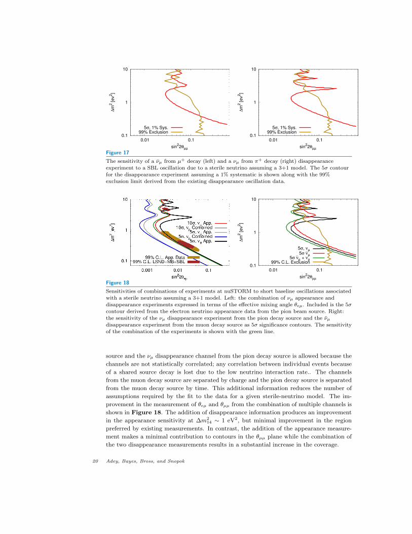
Figure 17
The sensitivity of a νµ from µ+ decay (left) and a νµ from π+ decay (right) disappearance
experiment to a SBL oscillation due to a sterile neutrino assuming a 3+1 model. The 5σ contour
for the disappearance experiment assuming a 1% systematic is shown along with the 99%exclusion limit derived from the existing disappearance oscillation data.
0.1
1
10
0.01 0.1
∆m
2 [
ev
2]
sin22θµµ
5σ, νµ5σ
--νµ
5σ --νµ + νµ
99% C.L. Exclusion
Figure 18
Sensitivities of combinations of experiments at nuSTORM to short baseline oscillations associated
with a sterile neutrino assuming a 3+1 model. Left: the combination of νµ appearance and
disappearance experiments expressed in terms of the effective mixing angle θeµ. Included is the 5σcontour derived from the electron neutrino appearance data from the pion beam source. Right:
the sensitivity of the νµ disappearance experiment from the pion decay source and the νµdisappearance experiment from the muon decay source as 5σ significance contours. The sensitivityof the combination of the experiments is shown with the green line.
source and the νµ disappearance channel from the pion decay source is allowed because the
channels are not statistically correlated; any correlation between individual events because
of a shared source decay is lost due to the low neutrino interaction rate.. The channels
from the muon decay source are separated by charge and the pion decay source is separated
from the muon decay source by time. This additional information reduces the number of
assumptions required by the fit to the data for a given sterile-neutrino model. The im-
provement in the measurement of θeµ and θµµ from the combination of multiple channels is
shown in Figure 18. The addition of disappearance information produces an improvement
in the appearance sensitivity at ∆m214 ∼ 1 eV2, but minimal improvement in the region
preferred by existing measurements. In contrast, the addition of the appearance measure-
ment makes a minimal contribution to contours in the θµµ plane while the combination of
the two disappearance measurements results in a substantial increase in the coverage.
20 Adey, Bayes, Bross, and Snopok
5.2.3. Sterile neutrino oscillations with electron neutrinos. Although a strong case can be
made for nuSTORM using just the muon neutrino oscillation physics, it is also important to
measure oscillations to electron neutrinos to evaluate the consistency of any measurement.
SuperBIND is not optimized for the measurement of electron-neutrino interactions, since
single electrons can not be resolved for charge identification, nor may the interaction vertex
be positively inferred. However an electron shower may be observed in SuperBIND and
a figure of merit may be defined based on the distribution and extent of photo-electrons
observed in the detector, which can differentiate (with high purity) electron neutrino inter-
actions from neutral current interactions (which are the leading background). To achieve
this high purity, hard cuts were imposed on the the observed shower shape and deposited
charge, such that the detection efficiency for electron neutrino charge current events is re-
duced to 10%. The corresponding neutral current background rejection factor is 99.7%.
The cut on the figure of merit was tuned to minimize the number of NC events identified as
electron neutrino CC events, while maintaining a high enough νe CC efficiency to produce a
useful number of candidate events. Of the three electron neutrino oscillation channels, only
the νµ → νe channel available from the pion decays may produce a significant measurement
in SuperBIND, based on these efficiencies.
In the context of the pion sourced neutrino beam, the backgrounds for the νµ → νeappearance channel are from unoscillated νµ as well as from νµ and νe from muon decays
in the first 6 ns after injection. The (ν)µ CC interactions may be clearly distinguished from
NC interactions by the presence of a muon, so a further suppression of more than an order
of magnitude may be expected over the above electron neutrino selection. There is nothing
to distinguish the beam νe from the oscillated νe, so no further suppression is possible for
this background. Even so, a 5σ measurement may be made in the region favored by the
LSND and MiniBooNE data as shown in Figure 18 (left). This will not make a substantial
contribution to the global fit of the nuSTORM channels because of its relatively low overall
significance.
Given that the experiment is not limited by systematic uncertainties in the beam com-
position, great gains in (ν)e appearance measurements can be made with increased detector
resolution and efficiency. A more significant measurement of short baseline νe appearance
from pion decays may be possible with a greater signal efficiency for νe CC interactions with
better background rejection. To achieve the 10σ significance observed in the νµ appearance,
the background must be suppressed by a factor of 10−4 with respect to the signal. Once such
a suppression factor is achieved along with a modest increase in efficiency, a measurement
from νµ → νe appearance (generated by muon decays) may also be achieved, producing a
simultaneous measurement of appearance in both neutrino charge states, similar to what
is achieved with the muon neutrino disappearance. The required 10−4 background sup-
pression can only be achieved in a magnetized, totally active detector with strong particle
identification capabilities. The strongest candidate technology is a magnetized liquid argon
TPC, although it has not yet been demonstrated that the particle and charge identifica-
tion capability of such a detector will provide the required background rejection (115). We
make note that, if the existence of a light-sterile neutrino is confirmed, CP violation in a
3+1 scenario might be observable in a nuSTORM-like facility (116), especially if (ν)e and(ν)µ appearance and disappearance channels are accessible. A magnetized liquid argon TPC
has the potential to make this possible.
www.annualreviews.org • nuSTORM 21
5.2.4. Systematics. The experimental sensitivity obtainable at the nuSTORM facility from
muon decays uses the systematic uncertainties shown in Table 6. These systematic un-
certainties are motivated by the exceptionally low beam uncertainties (see section 5.1 and
expected improvements in the measurements of neutrino cross-sections. With these un-
certainties, the expected interaction physics uncertainty is only limited by the detector
performance. An upper limit on the potential systematic uncertainty is given based on the
existing estimates of systematic uncertainties reported by MINOS. To illustrate the effect
that this would impose on results from nuSTORM, the systematic uncertainties were in-
flated by a factor of 5 to produce the “5%” contours shown in Figure 16. Increasing the
systematic uncertainty in this way has a minimal impact on the measurements of the νµappearance due to the small number of background events surviving selection. Similarly,
the significant backgrounds allowed for the disappearance measurements mean that the
systematic uncertainties have a large impact on the disappearance measurements.
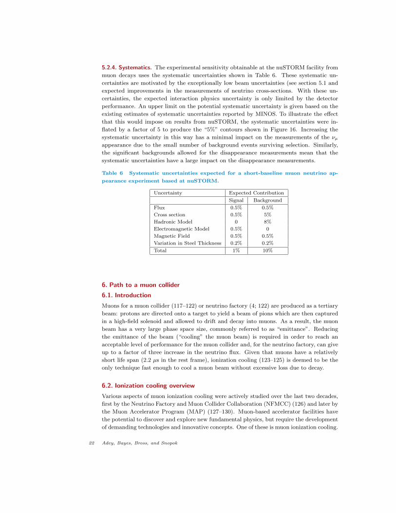
Table 6 Systematic uncertainties expected for a short-baseline muon neutrino ap-
pearance experiment based at nuSTORM.
Uncertainty Expected Contribution
Signal Background
Flux 0.5% 0.5%
Cross section 0.5% 5%
Hadronic Model 0 8%
Electromagnetic Model 0.5% 0
Magnetic Field 0.5% 0.5%
Variation in Steel Thickness 0.2% 0.2%
Total 1% 10%
6. Path to a muon collider
6.1. Introduction
Muons for a muon collider (117–122) or neutrino factory (4; 122) are produced as a tertiary
beam: protons are directed onto a target to yield a beam of pions which are then captured
in a high-field solenoid and allowed to drift and decay into muons. As a result, the muon
beam has a very large phase space size, commonly referred to as “emittance”. Reducing
the emittance of the beam (“cooling” the muon beam) is required in order to reach an
acceptable level of performance for the muon collider and, for the neutrino factory, can give
up to a factor of three increase in the neutrino flux. Given that muons have a relatively
short life span (2.2 µs in the rest frame), ionization cooling (123–125) is deemed to be the
only technique fast enough to cool a muon beam without excessive loss due to decay.
6.2. Ionization cooling overview
Various aspects of muon ionization cooling were actively studied over the last two decades,
first by the Neutrino Factory and Muon Collider Collaboration (NFMCC) (126) and later by
the Muon Accelerator Program (MAP) (127–130). Muon-based accelerator facilities have
the potential to discover and explore new fundamental physics, but require the development
of demanding technologies and innovative concepts. One of these is muon ionization cooling.
22 Adey, Bayes, Bross, and Snopok
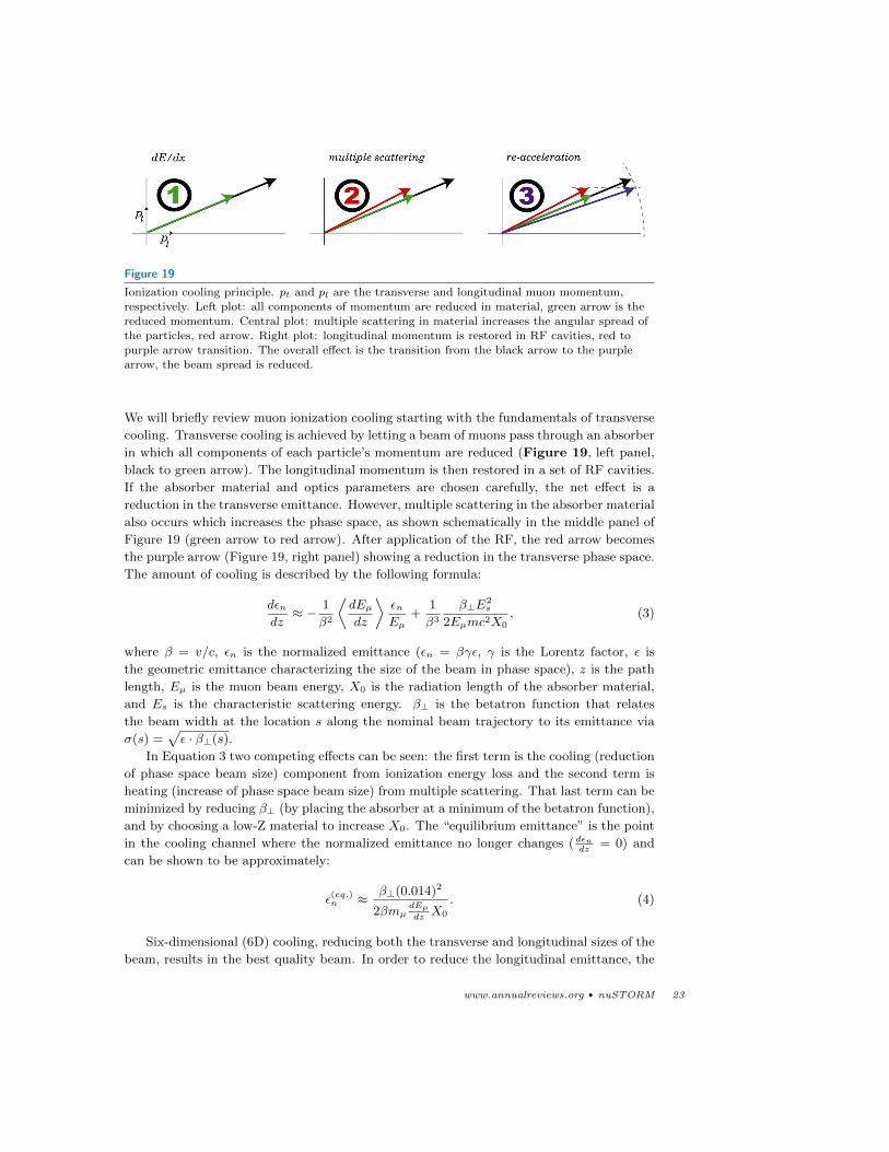
Figure 19
Ionization cooling principle. pt and pl are the transverse and longitudinal muon momentum,respectively. Left plot: all components of momentum are reduced in material, green arrow is the
reduced momentum. Central plot: multiple scattering in material increases the angular spread of
the particles, red arrow. Right plot: longitudinal momentum is restored in RF cavities, red topurple arrow transition. The overall effect is the transition from the black arrow to the purple
arrow, the beam spread is reduced.
We will briefly review muon ionization cooling starting with the fundamentals of transverse
cooling. Transverse cooling is achieved by letting a beam of muons pass through an absorber
in which all components of each particle’s momentum are reduced (Figure 19, left panel,
black to green arrow). The longitudinal momentum is then restored in a set of RF cavities.
If the absorber material and optics parameters are chosen carefully, the net effect is a
reduction in the transverse emittance. However, multiple scattering in the absorber material
also occurs which increases the phase space, as shown schematically in the middle panel of
Figure 19 (green arrow to red arrow). After application of the RF, the red arrow becomes
the purple arrow (Figure 19, right panel) showing a reduction in the transverse phase space.
The amount of cooling is described by the following formula:
dεndz≈ − 1
β2
⟨dEµdz
⟩εnEµ
+1
β3
β⊥E2s
2Eµmc2X0, (3)
where β = v/c, εn is the normalized emittance (εn = βγε, γ is the Lorentz factor, ε is
the geometric emittance characterizing the size of the beam in phase space), z is the path
length, Eµ is the muon beam energy, X0 is the radiation length of the absorber material,
and Es is the characteristic scattering energy. β⊥ is the betatron function that relates
the beam width at the location s along the nominal beam trajectory to its emittance via
σ(s) =√ε · β⊥(s).
In Equation 3 two competing effects can be seen: the first term is the cooling (reduction
of phase space beam size) component from ionization energy loss and the second term is
heating (increase of phase space beam size) from multiple scattering. That last term can be
minimized by reducing β⊥ (by placing the absorber at a minimum of the betatron function),
and by choosing a low-Z material to increase X0. The “equilibrium emittance” is the point
in the cooling channel where the normalized emittance no longer changes ( dεndz
= 0) and
can be shown to be approximately:
ε(eq.)n ≈ β⊥(0.014)2
2βmµdEµdzX0
. (4)
Six-dimensional (6D) cooling, reducing both the transverse and longitudinal sizes of the
beam, results in the best quality beam. In order to reduce the longitudinal emittance, the
www.annualreviews.org • nuSTORM 23
so-called “emittance exchange” technique is commonly used, where a dispersive beam is
passed through a discrete or continuous absorber in such a way that high-energy particles
traverse more material than low-energy particles. The net result is a reduction of the
longitudinal emittance at the cost of simultaneously increasing the transverse emittance.
By controlling the amount of emittance exchange, the six-dimensional emittance can be
reduced.
Muon colliders require a six order of magnitude reduction in the muon beam phase
space, while a neutrino factory benefits from the cooling. Various scenarios were recently
put forward by the Muon Accelerator Staging Study (MASS) (131; 132), and for each of
those scenarios there are corresponding cooling channel options based on vacuum RF or
high-pressure gas-filled RF that can reach the desired design parameters.
10-2 10-1 100 101 102
Transverse emittance [mm]
100
101
102
103
Longit
udin
al em
itta
nce
[m
m] Initial
Front end
Exit front end(15 mm, 45 mm)
Pre-merge 6D coolingPost-merge6D cooling
Final cooling
Initial cooling
For acceleration to NuMAX(3 mm, 24 mm)
Bunch mergeFor accelerationto Higgs Factory(0.3 mm, 1.5 mm)
For accelerationto multi-TeV collider
Emittance evolution, MC/NF
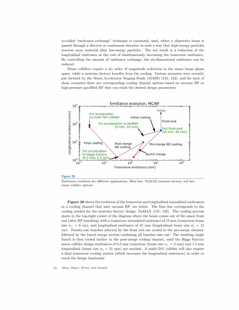
Figure 20
Emittance evolution for different applications. Blue line: NuMAX neutrino factory, red line:
muon collider options.
Figure 20 shows the evolution of the transverse and longitudinal normalized emittances
in a cooling channel that uses vacuum RF, see below. The blue line corresponds to the
cooling needed for the neutrino factory design, NuMAX (131; 132). The cooling process
starts in the top-right corner of the diagram where the beam comes out of the muon front
end (after RF bunching) with a transverse normalized emittance of 15 mm (transverse beam
size σ⊥ = 8 cm), and longitudinal emittance of 45 mm (longitudinal beam size σ‖ = 15
cm). Twenty-one bunches selected by the front end are cooled in the pre-merge channel,
followed by the bunch merge section combining all bunches into one. The resulting single
bunch is then cooled further in the post-merge cooling channel, until the Higgs Factory
muon collider design emittances of 0.3 mm transverse (beam size σ⊥ = 2 mm) and 1.5 mm
longitudinal (beam size σ‖ = 21 mm) are reached. A multi-TeV collider will also require
a final transverse cooling section (which increases the longitudinal emittance) in order to
reach the design luminosity.
24 Adey, Bayes, Bross, and Snopok

Figure 21
6D cooling channels. Left panel: Schematics of one of the stages of the VCC. Yellow: magnetic
coils for focusing and dispersion generation, red: RF cavities for replenishing the energy lost in theabsorbers, magenta: solid LiH or liquid hydrogen, depending on the stage. Right panel:
Conceptual design of the helical cooling channel. RF cavities inside the magnetic coils are shown.
Magnetic coils are semi-transparent.
6.3. 6D cooling channels
The front end of a muon facility (either a muon collider or neutrino factory) has been
optimized (133) to maximize the number muons collected (µ+ and µ− are captured and
transported simultaneously in a system of solenoids) in the momentum range of 100–300
MeV/c. It is in this momentum range that the initial stages of ionization cooling are most
effective. It is also a regime where the number of muons captured per POT is quite high.
For example, the current benchmark for the muon front end is ' 0.1 µ+ in the momentum
range of 100–300 MeV/c, per POT. In comparison, as was stated in section 3, nuSTORM
collects ' 0.008 µ+ in the ∼ 0.8 GeV/c momentum acceptance of the ring, per POT. In
the following two sections, we give an overview of two scenarios that have been shown to
achieve the required 6D cooling necessary for the muon collider.
6.3.1. Vacuum cooling channel. In the vacuum cooling channel (VCC), each cell consists
of solenoids for focusing that are tilted slightly to generate bending and dispersion, wedge-
shaped absorbers where cooling takes place, and vacuum RF cavities to replenish the energy
lost in the absorbers. The channel is tapered by changing the geometry of the lattice
(magnetic field strength, RF frequency, absorber opening angle) progressively (134) to keep
emittance away from the equilibrium thus improving cooling efficiency. The layout of one
of the latter stages is shown in the left panel of Figure 21.
This scheme uses separate 6D ionization cooling channels for the two signs of the particle
charge. In each, a channel first reduces the emittance of a train of muon bunches until they
can be injected into a bunch-merging system. The single muon bunches, one of each sign,
are then sent through a second 6D cooling channel where the transverse emittance is reduced
as much as possible and the longitudinal emittance is cooled to a value below that needed
for the collider. The beam can then be recombined and sent though a final cooling channel
using high-field solenoids that cools the transverse emittance to the required value for a
multi-TeV collider, while allowing the longitudinal emittance to grow.
The performance of the vacuum cooling channel was simulated using G4Beamline, and
after a distance of 490 m (80 stages) the 6D emittance is reduced by a factor of 1000 with a
www.annualreviews.org • nuSTORM 25
transmission of 40%. Decreasing the longitudinal emittance below 1.5 mm leads to severe
particle loss and emittance growth due to space charge effects. Thus, after reaching this
threshold, the beam is cooled in the transverse direction only. The simulated results are
in agreement with theoretical predictions (135). Finally, a transverse emittance of 280 µm
can be achieved, which is below the baseline requirement for a muon collider after the final
6D cooling sequence.
6.3.2. High-pressure gas-filled cooling channel. An alternative to the VCC is a homoge-
neous ionization absorber filled helical cooling channel (HCC) (136–138). The primary
magnetic components in the HCC are the solenoid and counteracting helical dipole to de-
fine the reference trajectory and the helical dipole gradient that controls the dispersion and
provides transverse stability. The right panel of Figure 21 shows the conceptual design
of the helical cooling channel. High-pressure hydrogen gas filled RF (HPRF) cavities are
embedded inside the magnetic coils in the HCC. RF cavities are placed continuously along
the helical beam path in the HCC magnet. High-pressure hydrogen in the cavity acts as a
homogeneous ionization absorber. It also reduces the probability of electric breakdown in
the RF cavity and allows higher operating E fields in strong magnetic fields. The break-
down suppression model has been experimentally verified and no RF degradation due to
the external magnetic field has been observed (139). The ultimate equilibrium emittances
that can be reached are 0.6 mm in transverse direction, and 0.9 mm in the longitudinal
direction, which could be translated into the desired values by using emittance exchange.
6.4. 6D cooling tests
As mentioned above, muon ionization cooling improves the stored-muon flux at the neutrino
factory and is absolutely crucial for a muon collider of any center-of-mass energy in order to
achieve the required luminosity. The Muon Ionization Cooling Experiment (MICE) (140;
141) will study four-dimensional ionization cooling and work is underway to specify the
scope of a follow-on six-dimensional (6D) cooling experiment. MICE is a “single-particle”
experiment; the four-momenta of single muons are measured before and after the cooling cell
and then input and output beam emittances are reconstructed from an ensemble of single-
muon events. For 6D cooling, an experiment with a high-intensity pulsed muon beam is
preferred. One feature of nuSTORM is that an appropriate low-energy muon beam with
these characteristics can be provided in a straightforward fashion (see section 3.2).
Thus, one of the key 6D cooling channel designs described in the previous sections can
be tested at the nuSTORM facility without affecting the main neutrino physics programs.
nuSTORM provides a low-energy muon source (see Figure 10) with significant intensity
(≈ 1010µ/pulse in the 100–300 MeV/c momentum range). This beam can be produced
simultaneously with the neutrino physics program at little additional cost. This is possible
because nuSTORM requires an absorber to absorb pions remaining (about 50% of those
injected into the ring) after the first straight. Pions in the momentum range 5 GeV/c ±10%
are extracted to the absorber along with many muons in the same momentum window
(forward decays). The absorber will act as a degrader for these muons, producing the
desired low-energy muon beam. This is achieved by choosing the length of the degrader to
be 3.54 m of iron.
Once the bench test for the cooling channel is carried out with no beam, a section
of the cooling channel long enough for appreciable 6D cooling could be used at the nuS-
26 Adey, Bayes, Bross, and Snopok
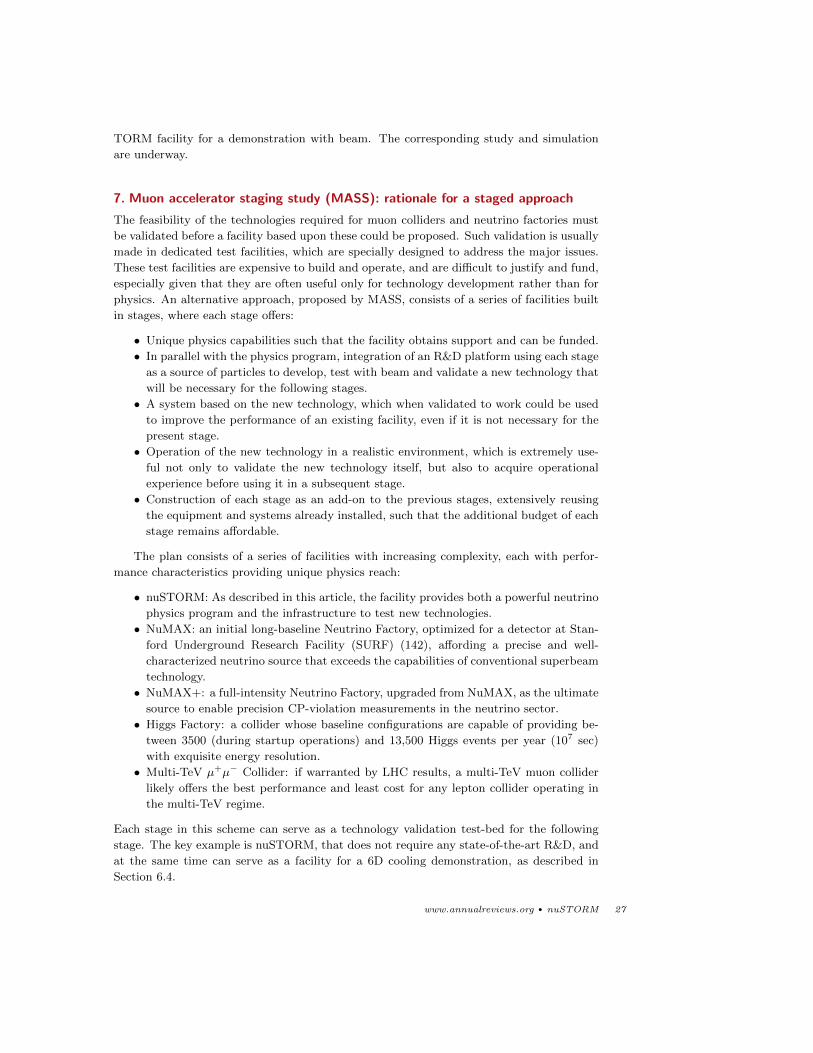
TORM facility for a demonstration with beam. The corresponding study and simulation
are underway.
7. Muon accelerator staging study (MASS): rationale for a staged approach
The feasibility of the technologies required for muon colliders and neutrino factories must
be validated before a facility based upon these could be proposed. Such validation is usually
made in dedicated test facilities, which are specially designed to address the major issues.
These test facilities are expensive to build and operate, and are difficult to justify and fund,
especially given that they are often useful only for technology development rather than for
physics. An alternative approach, proposed by MASS, consists of a series of facilities built
in stages, where each stage offers:
• Unique physics capabilities such that the facility obtains support and can be funded.
• In parallel with the physics program, integration of an R&D platform using each stage
as a source of particles to develop, test with beam and validate a new technology that
will be necessary for the following stages.
• A system based on the new technology, which when validated to work could be used
to improve the performance of an existing facility, even if it is not necessary for the
present stage.
• Operation of the new technology in a realistic environment, which is extremely use-
ful not only to validate the new technology itself, but also to acquire operational
experience before using it in a subsequent stage.
• Construction of each stage as an add-on to the previous stages, extensively reusing
the equipment and systems already installed, such that the additional budget of each
stage remains affordable.
The plan consists of a series of facilities with increasing complexity, each with perfor-
mance characteristics providing unique physics reach:
• nuSTORM: As described in this article, the facility provides both a powerful neutrino
physics program and the infrastructure to test new technologies.
• NuMAX: an initial long-baseline Neutrino Factory, optimized for a detector at Stan-
ford Underground Research Facility (SURF) (142), affording a precise and well-
characterized neutrino source that exceeds the capabilities of conventional superbeam
technology.
• NuMAX+: a full-intensity Neutrino Factory, upgraded from NuMAX, as the ultimate
source to enable precision CP-violation measurements in the neutrino sector.
• Higgs Factory: a collider whose baseline configurations are capable of providing be-
tween 3500 (during startup operations) and 13,500 Higgs events per year (107 sec)
with exquisite energy resolution.
• Multi-TeV µ+µ− Collider: if warranted by LHC results, a multi-TeV muon collider
likely offers the best performance and least cost for any lepton collider operating in
the multi-TeV regime.
Each stage in this scheme can serve as a technology validation test-bed for the following
stage. The key example is nuSTORM, that does not require any state-of-the-art R&D, and
at the same time can serve as a facility for a 6D cooling demonstration, as described in
Section 6.4.
www.annualreviews.org • nuSTORM 27
8. Outlook
In this article we have reviewed the potential of the nuSTORM facility. It can simultane-
ously produce flavor-pure neutrino beams from the decays of both pions and muons and
can, as well, provide an intense low energy muon beam at the same time from the same
proton power. Thus, the nuSTORM facility can simultaneously provide: 1. SBL oscillation
measurements leading to a definitive solution to the sterile neutrino question and, should
they exist, allow for the most comprehensive program to study their properties proposed to
date, 2. Make world-leading measurements of neutrino interactions that could be crucial to
the success of planned LBL neutrino programs and 3. Host an excellent R&D platform for
6D muon ionization cooling channel bench and beam tests and, as such, act as a stepping
stone towards future high-energy high-intensity muon accelerator facilities.
The opportunities afforded by such a facility are great, but at the present time it lacks
the formal support required to become a reality. Because nuSTORM has a relatively short
construction time and leads into a sustained R&D program, it has the potential for en-
hancing the long-term prospects for neutrino physics, as well as sustaining a nascent muon
collider community. The growth and development of neutrino physics and energy-frontier
science will require pursuing new ideas and making them viable. The anticipated long time
scales of the next generation of facilities will eventually limit the growth of the field, if they
completely preclude embracing new ideas and innovation.
ACKNOWLEDGMENTS
The authors want to thank our colleagues in the Muon Collider and Neutrino Factor com-
munities in general and, in particular, our collaborators on nuSTORM, MICE and in MAP.
We want to offer special thanks to David Neuffer, who started down this path over 30
years ago and to Ao Liu who has worked so tirelessly on developing the nuSTORM facility.
This work supported by the Fermi Research Alliance, LLC under Contract No. DE-AC02-
07CH11359 with the United States Department of Energy, the Muon Accelerator Program
within the United States Department of Energy and the Science and Technology Facilities
Council of the United Kingdom.
LITERATURE CITED
1. Adey D, et al. nuSTORM - Neutrinos from STORed Muons: Proposal to the Fermilab PAC
arXiv:1308.6822 [physics.acc-ph] (2013)
2. Bross A. 2013. In Proceedings of the North American Part. Acc. Conf., no. TUOBD4
3. Bross A. 2013. In Proceedings, of the 2013 Euro. Phys. Soc. Conf. on HEP, vol. EPS-HEP2013
4. Geer S. Phys.Rev. D57:6989 (1998)
5. Giesch M, Kuiper B, van der Meer S. Nucl. Instrum. Methods 20:58 (1963)
6. Choubey S, et al. Interim Design Report for the International Design Study for a Neutrino
Factory arXiv:1112.2853 [hep-ex] (2011)
7. Abe K, et al. Measurement of the Inclusive Electron Neutrino Charged Current Cross Section
on Carbon with the T2K Near Detector arXiv:1407.7389 [hep-ex] (2014)
8. Adams C, et al. Scientific Opportunities with the Long-Baseline Neutrino Experiment (2013),
FERMILAB-CONF-13-300
9. Agostino L. J.Phys.Conf.Ser. 566:012002 (2014)
10. Mohapatra R. Phys.Rev.Lett. 56:561 (1986)
11. Mohapatra R. Phys.Rev. D34:3457 (1986)
28 Adey, Bayes, Bross, and Snopok
12. Kusenko A, Takahashi F, Yanagida TT. Phys.Lett. B693:144 (2010)
13. Abazajian K, et al. Light Sterile Neutrinos: A White Paper arXiv:1204.5379 [hep-ph] (2012)
14. Aguilar A, et al. Phys. Rev. D64:112007 (2001)
15. Aguilar-Arevalo A, et al. Phys.Rev.Lett. 110:161801 (2013)
16. Anselmann P, et al. Phys.Lett. B342:440 (1995)
17. Hampel W, et al. Phys.Lett. B420:114 (1998)
18. Abdurashitov D, et al. Phys.Rev.Lett. 77:4708 (1996)
19. Abdurashitov J, et al. Phys.Rev. C59:2246 (1999)
20. Abdurashitov J, et al. Phys.Rev. C73:045805 (2006)
21. Mention G, et al. Phys.Rev. D83:073006 (2011)
22. Mueller T, et al. Phys.Rev. C83:054615 (2011)
23. Huber P. Phys.Rev. C84:024617 (2011)
24. Huber P, Bross A, Palmer M. The Case for Muon-based Neutrino Beams arXiv:1411.0629
[hep-ex] (2014)
25. Borodovsky L, et al. Phys.Rev.Lett. 68:274 (1992)
26. Armbruster B, et al. Phys. Rev. D65:112001 (2002)
27. Astier P, et al. Nucl. Phys. B611:3 (2001)
28. Antonello M, et al. Experimental search for the LSND anomaly with the ICARUS LAr TPC
detector in the CNGS beam arXiv:1209.0122 [hep-ex] (2012)
29. Ashie Y, et al. Phys. Rev. D71:112005 (2005)
30. Cleveland B, et al. Astrophys. J. 496:505 (1998)
31. Kaether F, et al. Phys.Lett. B685:47 (2010)
32. Abdurashitov J, et al. Phys. Rev. C80:015807 (2009)
33. Hosaka J, et al. Phys. Rev. D73:112001 (2006)
34. Aharmim B, et al. Phys. Rev. C75:045502 (2007)
35. Aharmim B, et al. Phys. Rev. C72:055502 (2005)
36. Aharmim B, et al. Phys. Rev. Lett. 101:111301 (2008)
37. Aharmim B, et al. Combined Analysis of all Three Phases of Solar Neutrino Data from the
Sudbury Neutrino Observatory arXiv:1109.0763 [nucl-ex] (2011)
38. Bellini G, et al. Phys.Rev.Lett. 107:141302 (2011)
39. Bellini G, et al. Phys.Rev. D82:033006 (2010)
40. Aguilar-Arevalo AA, et al. Phys.Rev.Lett. 103:061802 (2009)
41. Cheng G, et al. Phys.Rev. D86:052009 (2012)
42. Adamson P, et al. Phys.Rev. D81:052004 (2010)
43. Adamson P, et al. Phys.Rev.Lett. 107:011802 (2011)
44. Declais Y, et al. Nucl.Phys. B434:503 (1995)
45. Declais Y, et al. Phys.Lett. B338:383 (1994)
46. Kuvshinnikov A, et al. JETP Lett. 54:253 (1991)
47. Vidyakin G, et al. Sov.Phys.JETP 66:243 (1987)
48. Kwon H, et al. Phys.Rev. D24:1097 (1981)
49. Zacek G, et al. Phys. Rev. D34:2621 (1986)
50. Apollonio M, et al. Eur. Phys. J. C27:331 (2003)
51. Boehm F, et al. Phys.Rev. D64:112001 (2001)
52. Abe Y, et al. Phys.Rev. D86:052008 (2012)
53. Ahn J, et al. Phys.Rev.Lett. 108:191802 (2012)
54. Gando A, et al. Phys.Rev. D83:052002 (2011)
55. Dydak F, et al. Phys.Lett. B134:281 (1984)
56. Reichenbacher J. Final KARMEN results (2005), Report:FZKA-7093
57. Auerbach L, et al. Phys.Rev. C64:065501 (2001)
58. Kopp J, Maltoni M, Schwetz T. Phys.Rev.Lett. 107:091801 (2011)
59. Giunti C, Laveder M. Phys.Lett. B706:200 (2011)
www.annualreviews.org • nuSTORM 29
60. Karagiorgi G. Confronting Recent Neutrino Oscillation Data with Sterile Neutrinos
arXiv:1110.3735 [hep-ph] (2011)
61. Giunti C, Laveder M. Phys.Rev. D84:093006 (2011)
62. Giunti C, Laveder M. Phys.Rev. D84:073008 (2011)
63. Giunti C, et al. Phys.Rev. D86:113014 (2012)
64. Archidiacono M, et al. Sterile Neutrinos: Cosmology vs Short-Baseline Experiments
arXiv:1302.6720 [astro-ph.CO] (2013)
65. Kopp J, Machado P, Maltoni M, Schwetz T. Sterile Neutrino Oscillations: The Global Picture
arXiv:1303.3011 [hep-ph] (2013)
66. An F, et al. Phys.Rev.Lett. 113:141802 (2014)
67. Sousa A. First MINOS+ Data (2014), Neutrino 2014, Boston MA. USA
68. Abe K, et al. Search for short baseline νe disappearance with the T2K near detector
arXiv:1410.8811 [hep-ex] (2014)
69. Ade P, et al. Astron.Astrophys. 571:A16 (2014)
70. Hinshaw G, et al. Nine-Year Wilkinson Microwave Anisotropy Probe (WMAP) Observations:
Cosmological Parameter Results arXiv:1212.5226 [astro-ph.CO] (2012)
71. Das S, et al. The Atacama Cosmology Telescope: Temperature and Gravitational Lensing
Power Spectrum Measurements from Three Seasons of Data arXiv:1301.1037 [astro-ph.CO]
(2013)
72. Reichardt C, et al. Astrophys.J. 755:70 (2012)
73. Story K, et al. A Measurement of the Cosmic Microwave Background Damping Tail from the
2500-square-degree SPT-SZ survey arXiv:1210.7231 [astro-ph.CO] (2012)
74. Percival WJ, et al. Mon.Not.Roy.Astron.Soc. 401:2148 (2010)
75. Padmanabhan N, et al. A 2Oscillations - I : Methods and Application to the Sloan Digital
Sky Survey arXiv:1202.0090 [astro-ph.CO] (2012)
76. Blake C, et al. Mon.Not.Roy.Astron.Soc. 418:1707 (2011)
77. Anderson L, et al. Mon.Not.Roy.Astron.Soc. 427:3435 (2013)
78. Hannestad S, Hansen RS, Tram T. Phys.Rev.Lett. 112:031802 (2014)
79. Dasgupta B, Kopp J. Phys.Rev.Lett. 112:031803 (2014)
80. Mirizzi A, Mangano G, Pisanti O, Saviano N. Collisional production of sterile neutrinos via
secret interactions and cosmological implications arXiv:1410.1385 [hep-ph] (2014)
81. Huber P, Mezzetto M, Schwetz T. JHEP 0803:021 (2008)
82. Neuffer D. Design Considerations for a Muon Storage Ring (1980), Telmark Conference on
Neutrino Mass, Barger and Cline eds., Telmark, Wisconsin
83. Neuffer D, Liu A. 2013. In Proceedings of the 4th Int. Part. Acc. Conf. , no. TUPFI055
84. Liu A, Bross A, Neuffer D, Lee SY. 2013. In Proceedings of the N. American Part. Acc. Conf.,
no. TUPBA18
85. Liu A, Neuffer D, Bross A, Lee S. Design and simulation of the nustorm injection beam line
To be submitted to PRSTAB
86. Lackowski T, et al. nuSTORM Project Definition Report arXiv:1309.1389 [physics.ins-det]
(2013)
87. Anderson K, et al. The NuMI Facility Technical Design Report (1998)
88. Wildner E. 2014. In Proceedings of the XVIth International Workshop on Neutrino Factories
and Future Neutrino Facilities (to be published)
89. Adey D, et al. Neutrinos from Stored Muons nuSTORM: Expression of Interest
arXiv:1305.1419 [physics.acc-ph] (2013)
90. Liu A, Bross A, Neuffer D. 2014. In Proceedings, 5th Int. Part. Acc. Conf, no. TUPRI005
91. Yamanoi Y, et al. IEEE Trans.Magnetics 32:2147 (1996)
92. Roberts T. G4beamline - A ”Swiss Army Knife” for Geant4, optimized for simulating beamline
(2013), Version 2.12
93. Courant E, Snyder H. Annals Phys. 3:1 (1958)
30 Adey, Bayes, Bross, and Snopok
94. Liu A, Bross A, Neuffer D. 2014. In Proceedings, 5th Int. Part. Acc. Conf, no. IPAC-2014-
TUPRI006
95. Neuffer D. 2014. In Proceedings of the XVIth International Workshop on Neutrino Factories
and Future Neutrino Facilities (to be published)
96. Lagrange J. 2014. In Proceedings of the XVIth International Workshop on Neutrino Factories
and Future Neutrino Facilities (to be published)
97. Lagrange J, et al. 2014. In Proceedings, 5th Int. Part. Acc. Conf, no. IPAC-2014-TUPRO073
98. Appleby R, et al. 2014. In Proceedings, 5th Int. Part. Acc. Conf, no. IPAC-2014-TUPRI013
99. S∅by L. nuSTORM Beam instrumentation (2013), eDMS document number: 1284677, CERN
100. Guardincerri E. J.Phys.Conf.Ser. 404:012036 (2012)
101. Rubbia A. J.Phys.Conf.Ser. 408:012006 (2013)
102. Michael DG, et al. Nucl. Instrum. Meth. A596:190 (2008)
103. Ambrosio G, et al. Design study for a staged very large hadron collider (2001)
104. Vysotsky V, et al. IEEE Trans.Appl.Supercond. 20:402 (2010)
105. Foussart A, et al. IEEE Trans.Appl.Supercond. 22:42000505 (2012)
106. Wesche R, et al. Results of conductor testing in SULTAN: A review (2009)
107. Adey D. 2014. In Proceedings of the XVIth International Workshop on Neutrino Factories
and Future Neutrino Facilities (to be published)
108. Mokhov N, Striganov S. MARS15 Overview (2007), FERMILAB-CONF-07-008
109. Andreopoulos C, et al. Nucl. Instrum. Meth. A 614:87 (2010)
110. Apostolakis J, Wright DH. AIP Conf. Proc. 896:1 (2007)
111. Bayes R, et al. Phys.Rev. D86:093015 (2012)
112. Hoecker A, et al. PoS ACAT:040 (2007)
113. Brun R, Rademakers F. Nucl. Instrum. Meth. A389:81 (1997)
114. Huber P, Lindner M, Winter W. Comput. Phys. Commun. 167:195 (2005)
115. Baller B, et al. JINST 9:T05005 (2014)
116. de Gouvea A, Kelly KJ, Kobach A. CP-Invariance Violation at Short-Baseline Experiments
in 3+1 Scenarios arXiv:1412.1479 [hep-ph] (2014)
117. Gallardo J, et al. eConf C960625:R4 (1996)
118. Ankenbrandt CM, et al. Phys.Rev.ST Accel.Beams 2:081001 (1999)
119. Alsharo’a MM, et al. Phys. Rev. ST Accel. Beams 6:081001 (2003)
120. Parkhomchuk V, Skrinsky A. AIP Conf.Proc. 352:7 (1996)
121. Neuffer D. AIP Conf.Proc. 156:201 (1987)
122. Geer S. Annual Review of Nuclear and Particle Science 59:347 (2009)
123. Budker G. 1970. In Proceedings of 15th International Conference on High Energy Physics.
Kiev
124. Neuffer D. Part.Accel. 14:75 (1983)
125. Palmer R, et al. Phys. Rev. ST Accel. Beams 8:061003 (2005)
126. The Neutrino Factory and Muon Collider Collaboration (NFMCC) http://www.cap.bnl.gov/
mumu/
127. Muon Accelerator Program (MAP) http://map.fnal.gov/
128. Palmer M. 2014. In Proceedings of 5th Int. Part. Acc. Conf., no. TUPME012. Dresden,
Germany
129. Palmer M. 2013. In Proceedings of COOL2013, no. MOAM2HA02. Murren, Switzerland
130. Torun Y, et al. 2010. In Proceedings of IPAC’10, no. WEPE065. Kyoto, Japan
131. Delahaye JP, et al. Enabling Intensity and Energy Frontier Science with a Muon Acceler-
ator Facility in the U.S.: A White Paper Submitted to the 2013 U.S. Community Summer
Study of the Division of Particles and Fields of the American Physical Society arXiv:1308.0494
[physics.acc-ph] (2013)
132. Delahaye JP, et al. 2014. In Proceedings, 5th Int. Part. Acc. Conf, no. IPAC-2014-WEZA02
133. Bogomilov M, et al. Phys.Rev.ST Accel.Beams 17:121002 (2014)
www.annualreviews.org • nuSTORM 31
134. Stratakis D, Fernow R, Berg J, Palmer R. Phys. Rev. ST Accel. Beams 16:091001 (2013)
135. Stratakis D, Neuffer D. 2014. In Proceedings of the 5th Int. Part. Acc. Conf., no. TUPME021.
Dresden, Germany
136. Derbenev Y, Johnson R. Phys. Rev. ST Accel. Beams 8:041002 (2005)
137. Yonehara K. 2014. In Proceedings of 5th Int. Part. Acc. Conf., no. TUPME014. Dresden,
Germany
138. Yonehara K. 2014. In Proceedings of 5th Int. Part. Acc. Conf., no. TUPME015. Dresden,
Germany
139. Hanlet P, et al. 2006. In Proceedings of European Particle Accelerator Conference, no.
TUPCH147. Edinburgh
140. MICE collaboration http://mice.iit.edu/
141. Kaplan D, Snopok P, Dobbs A. 2014. In Proceedings of 5th Int. Part. Acc. Conf., no. TH-
PRI030. Dresden, Germany
142. Heise J. AIP Conf.Proc. 1604:331 (2014)
32 Adey, Bayes, Bross, and Snopok