Embed Size (px)
Citation preview
NUREG/IA-O 121ICSP-AS-SPR-R
InternationalAgreement Report
Assessment of a Pressurizer SprayValve Faulty Opening Transient atAsco Nuclear Power Plantwith RELAP5/MOD2Prepared byF. Reventos, J. S. Baptista, A. P. Navas, P. Moreno
Asociacion Nuclear AscoC/Tres Torres, 70817 - BarcelonaSpain
Office of Nuclear Regulatory ResearchU.S. Nuclear Regulatory CommissionWashington, DC 20555-0001
December 1993
Prepared as part ofThc Agreement on Rcsearch Participation and Technical Exchangeunder the International Thermal-Hydraulic Code Asscssmentand Application Program (ICAP)
Published byU.S. Nuclear Regulatory Commission
NOTICE
This report was prepared under an international cooperative agree-ment for the exchange of technical information. Neither the UnitedStates Government nor any agency thereof, or any of their employ-ees, makes any warranty, expressed or implied, or assumes anylegal liability or responsibility for any third party's use, or the resultsof such use, of any information, apparatus product or process dis-closed in this report, or represents that its use by such third partywould not infringe privately owned rights.
Available from
Superintendent of DocumentsU.S. Government Printing Office
Mail Stop SSOPWashington, DC 20402-9328
and
National Technical Information ServiceSpringfield, VA 22161
NUREG/IA-O 121ICSP-AS-SPR-R
InternationalAgreement Report
Assessment of a Pressurizer SprayValve Faulty Opening Transient atAsco Nuclear Power Plantwith RELAP5/MOD2Prepared byF. Reventos, J. S. Baptista, A. P. Navas, P. Moreno
Asociacion Nuclear AscoCrrres Torres, 70817 - BarcelonaSpain
Office or Nuclear Regulatory ResearchU.S. Nuclear Regulatory CommissionWahshington, DC 20555-0001
December 1993
Prepared as part ofThe Agreemcnt on Research Participation and lbchnical Exchangeunder the International Thermal-Hydraulic Code Assessmentand Application Program ([CAP)
Published byU.S. Nuclear Regulatory Commission

ABSTACr
MThe Asociacibn Nuclear Asc6 has prepared a mocdel of Asc6 NPP using
RELAP5/MOD2. This mrodel, wh~ich include thenzalhydraulics, kinetics and
protection and controls, has been qualified in previous calculations of
several actual plant transients.
one of the transients of the qualification process is a "Pressurizer spray
valve faulty opening" presented in this report. it consists in a primaery
coolant depressurization that causes the reactor trip by overtarrerature and
l~ater on the actuation of' the safety injecin
T0he results are in close agreement with plant data.
iii

TABLE OF CNi'~lr
ABs'rRA=r.............. ....... .. .. .. .. ..
DEtIIV StI'ARY.o....................... o .................. Vi
1. I1NrIT~COUION............ o..... o ..... o . . o ........ o..... o......1I
2.PI.AN AND TANSI=1 DESCRIPTION ....o....................... o. ........4
2.1 PLA~NT DESCRIPTION.......o.....o............... ...o...........o....4
2.2 DA.TA ACQUISITION~ AND ANALYSIS SYSTM4 DESCRIPTION . ... o .... 4
2 .3 TRANSIE~vr DESCRIPTION ..... o ... . .o.o ............... 4
3. MOD1 DESCRIPTION. ....... o.o..o... o... oooos-o.........o 5
3. 1 TI-271'AL-HYDRAtL',IC MOE .. o........................ o..... 5
3.2 K=~~IC MODL..... ..................... 7.. . .
3. 3 CON'TL AN P'R=CTI0 SYSrEMS MOELo....o......... o.... o.........7
4. STEADY STATE CALCUL~ATION.........o....o..... o............ ...oesso11
5. TRANSIM'.r CAI.uIATCt AND CCMPARISON VERSUS XMfM 2 DAIA ....... o..... 12
8. PIEDE .. o...............***.oooooewoooo******o************~ ****e* 17
nMEX OF MABLES .. oooooo. o ........ *o.... o ..... o....... o.*.**..e*... oo 19
3Mxor Fi~u1w ... *.oo*o*******oo****oo****o**a*************e***oos** 30
v

E)t7CIVE SLVMAM
Asc6 Nuclear Powr Plant is a nuclear station with two PWR Qf -930 Mie of
Westinghouse design.
The The~nalhydraulic analysis gru of the Asociaci6n Nuclear Asc6 (ANA) has
prepared a model of the plant using REAP5fYDD2. This model includes
thermaihydraulics, kinetics and protection and controls.
AN-' s =matrm~ent with the International Code Assessment and Application
Program (ICAP) is the participation with two cases.
one of the transients selected for this purpose is the "Assessment of a
Pressurizer Spray valve faulty opening".
T1his transient has been chosen because of two main reasons:
- Plant instrumentaticn data are reasonably accurate for the entire
transient.
- The assessment qualifies the behaviour of different system and
ca, nents; under abnormal conditions (spray valve, safety injection,
Reactor protection system).
The rra.in conclusions of the analysis are the following:
- Close agreement between results and data.
- 1Relap5/nrod2 Asc6 mordel is a valuable tool to analyze plant transients.
Vii


FO0R E WOR D
This report has been prepared by Asociaci6n Nuclear Asc6
in the framework of the ICAP-UNESA Project.
The report represents one of the application calculations
submitted in fulfilment of the bilateral agreement for coo-
peration in thermal hydraulic activities between the Consejo
de Seguridad Nuclear of Spain (CSN) and the United States
Nuclear Regulatory Commission (USWRC) in the form of Spanish
contribution to the International Code Assessment and Appli-
cations Program (ICAP) of the USNRC whose main purpose is
the validation of the TRAC and RELAP system codes.
The Consejo de Seguridad Nuclear has promoted a coordi-
nated Spanish Nuclear Industry effort (ICAP-SPAIN) aiming to
satisfy the requirements of this agreement and to improve
the quality of the technical support groups at the Spanish
Utilities, Spanish Research Establishments, Regulatory Staff
and Engineering Companies, for safety purposes.
This ICAP-SPAIN national program includes agreements
between CSN and each of the following organizations:
- Unidad Elictrica (UNESA)
- Uni6n Iberoamericana de Tecnologia El~ctrica (UITESA)
- Empresa Nacional del Uranio (ENUSA)
- TECNATOM
- LOFT-ESPARA
The program is executed by 12 working groups and a gener-
ic code review group and is coordinated by the "Comiti de
Coordinaci6n ". This committee has approved the distribution
of this document for ICAP purposes.
D-1/90-MPNV ii x

1. NTROD0CtON
In 1986, the Asociaci~n Nuclear Asc6 (ANA) -created a croup for plant and
core thezrmal-hydraulic analysis. The objectives of the group are as
follows:
1. Create and update core and plant thezna 1-hydraulic mrodels based on
best-estinrate criteria.
2. Provide off-lin~e engineering support to the different technical
branches of Ala (i.e., technical services, reactor operation):
a. Analyze operating events that result in event reports.
b. Assess plant systems and/or equipmrent mocdifications as weill as
plant operating procedures and emergency instructions.
c. Analyze plant behavior under incident or accident conditions inthe abovvrentiorned cases.
d. Scenarios and core damage evaluation for probabilistic risk
assessment.
3. Review final safety analysis report transients and accidents based on
best-estimate criteria.
4. In the future and if appropriate, participate in Aso6 individual
plant examination.
The plant analysis activities developed so far include the following:
1. Imrplement~ation of RELAP5/lMt02 (Pef.l) cycle 36.05 in its IBM version
in an MA 4381 and 3090 and cycle 36.04 and its Control Data
Corporation version in a Cyber 180/830. The results of both versions
for the scenarios analyzed are in close agreemnt.
2. Thermal-hydraulic model of both the pr~imay and secondary systems. /2/
-1 -
3. Kinetic --cdel specifically adapted to Aso5
4. Si.rm~lation of control and- protection systems /3/.
5. Revision and detailed study of all start-up tests and every transient
th-at has occurred in either unit. A total of 60 cases were studied.
Because of the influence of plant dynmuics and the quality and
availability of plant data, six cases were selected to validate the
ccuplete plant mod~el:
a. Station blackout
b. Faulty pressurizer spray valve openi~ng.
c. Turbine trip without steam dump~ and secondary relief valves
available.
d. Loss of feedwater MLOMW
e. Tumrbine trip with all systers available
f. Turbine powr step
6. Sinxilation of the above six transients and adjustrrent of control
paramreters /4/, /5/, /6/.
7. Participation in the Internacional Code Assessrent, and Application
Program with two cases.
-2-
8. Analysis of transients such as s-nall-break-loss-of-coolant accident
(SBIJX-A) , anticipated transient without scrxn (A`TWS) , and others for
PA studies.
The adjustment and qualification process is the first and nost inrortant
part of plant analysis. Sufficiently accurate predictions with
rrea~r.ingful sets of rreasu~red data provide validation of both the rrodel
and the procedures to be used in the future to analyze various transient
and accident scenarios of general interest such as SBLC' and AnS
-3-.
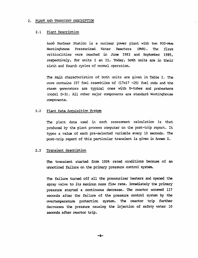
2. PLAINr AND TRANS=~T DESCRIMTON
2.1 Plant Description
Asc6 Nuclear Station is a nuclear power plant with two 930-Mwe
Westinghouse Pressurized Water Reactors (PWR). The first
criticalities were reached in June 1983 and September 1985,respectively, for units I an II. Today, both units are in their
sixth and fourth cycles. of ncrmal operation.
The mirn characteristics of both units are given in Table I. The
core contains 157 fuel asserblies of (17x17 -25) fuel rods arnd the
steam generators are typical ones with U-tubes and preheaters
(rrodel D-3). All other rmajor cat nents are standard Westinghouse
components.
2.2 Plant Data Acqu~isition System
*t.e plant data used in each assessment calculation is that
produced by the plant process computer on the post-trip report. It
types a value of each pre-selected variable every 10 seconds. The
post-trip report of this particular transient is given in Annex I.
2.3 Transient description
The~ transient started fran 100% rated conditions because of an
unnoticed failure on the primrary pressure control system.
The- failure turned off all the pressurizer heaters arid opened the
spray valve to its maxixrmn mass flow rate. Innediately U-4 primary
pressure started a continuous decrease. TIhe reactor scramed 117
seconds after the failure of the pressure control systemi by the
overta.eprature protection system. The reactor trip further
decreases the pressure causing the injection of safety water 10
secnds after reactor trip.
-4-
3. MODEL DESCRIPTION
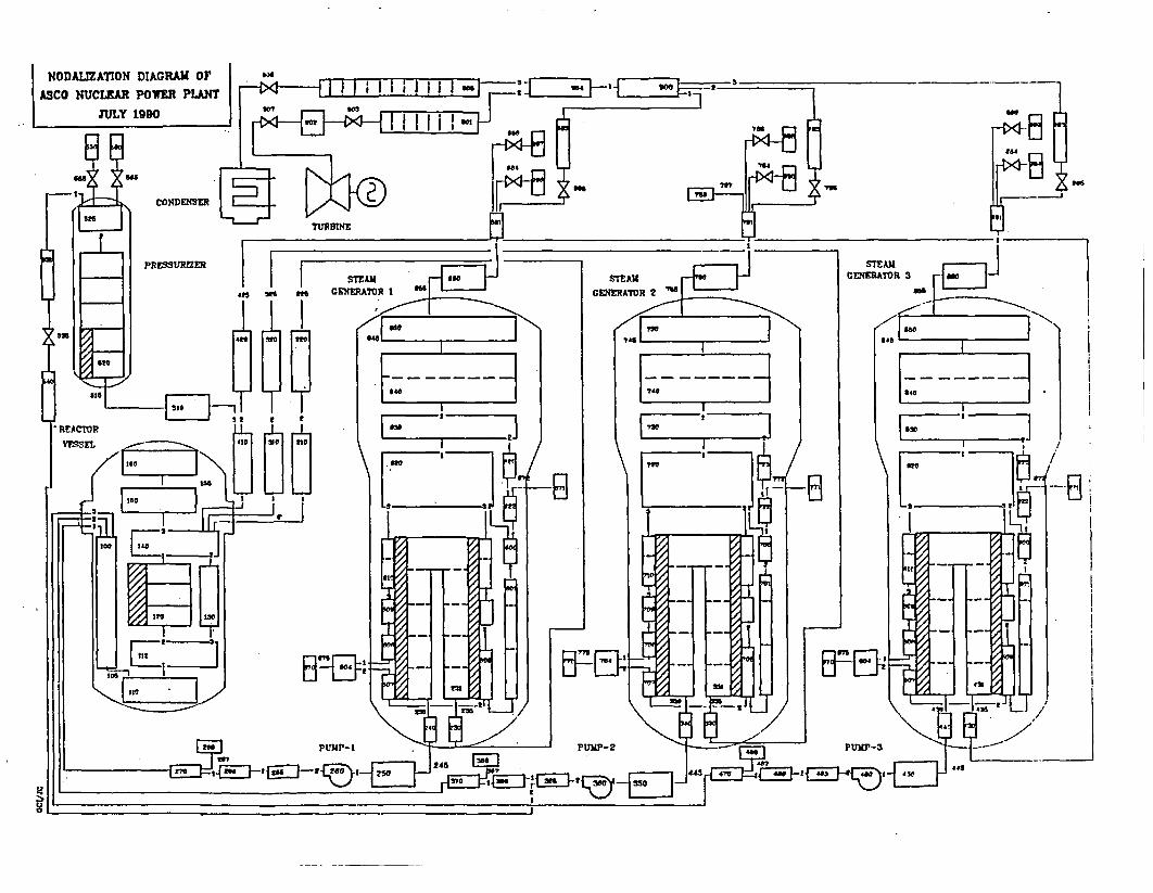
Figure 1 shows the mocdel used to simulate the plant. It consists of 134
volumes, 146 junctions, 32 heat structures, and 259 control variables.
The model includes the vessel, the three primary loops, the pressurizer,
the three steam generator, the three secundary loops, and the steam
lines. The turbine, condenser, and feedwater tank are modeled as tin-.-
dependent volumes.
The usual practice of izrplenenting FPELAPS by homogenizing the multiple
steam generator loops into two loops (one including the pressurizer) is
not followd in this model because of the following reasons:
a) non - synr~mtric distribution of auxiliary feed-water am~ong the three
steam generators
b) Different length of the steam lines of each loop.
c) Different number of plugged tubes in each steam gener ator.
d) Non - symmretric transients (loss of feed water, steam generator tube
break, small break in the primary circuit, one reactor colant pump
trip, and so on) that require mocdeling of different actuations or
boundary conditions, in each loop.
e) Ccaputer availability.
3.1 Thermal - Hydraulic Model
a.- Primary System.
The model / 2/ of the primary system includes the main
components of the plant. The core is mocdeled by volume 120
and the proper heat structures. Volume 130 simulates the
by-pass region between the core baffle and the core barrel.
Volume 1.40 mo~del the upper plenumn and volumes 150 and 160 the
vessel upper head. The three hot lines depart from the core
-5-
pressurizer through volumre 510. The pressurizer is divided
Linto two voltzms.
The locer one (volum~ 520) i~s divided into five nodes. Heatstructures, sixrulating the pressurizer actual heaters, areattached to the first two. nodes. Volume 525 is a branch in
order to mod~el the junctions connecting the pressurizer with
the safety and relief valves and with the spray system.
Volum.r 420 mocdels the remaining of the hot leg. volumes 430
and 440 sirmilate the water boxes of the steam generator. The
prirary side of the steam generator is modeled by volume 431
divided into nine nodes. Volumes 450, 465, 466 and 470
represent the cold leg. Volume: 460 modxel the primary colant
pt~mp, proper hamlolous curves, given by the vendor, have
been used for this purp,.ise. Voltrnm 468 nrioels the Safety
Injection System.
b. - Secondary Systan
The mocdel of the secondary system staurts with Time Dependent
Volume 870 (Loop 3) that represent the feed-water going to
the steam generator. Volume 871 models the Auxiliary Feed
Water. The dcwncomer is simtlated by mreans of -omluaes 800,
801, 822 and 825. The steam generator preheater is modeled by
volumres 806 and 807, and the remning -of the tubes zone by
volumres 808, 806, 809 and 810. The stearn separator with
volumre 820. Volumre 830, 840 and 850 nr:del the steam dryer and
the dczrc of the steam generator. Ste~ steam line starts at
volumre 880. Safety and relief valves (cmponents 886 and 884)
are connected to volume 881. Component Valve 885 moedels the
isolation valve. Tirie- Dependent Volumres 994 and 999 represent
the free atmrosphere. The steam is conducted throughout volumie
883 to the steam-collector, volumre 900. Finally Valves 906,
903 and 907 mo~del the by-pass to condenser valve, and the
turbine stop and control valves, respectively.
-6-
Proper heat struactures are used to connect thermally the
prirrary side of the steam generator wuth the secondlary si-de.Actual values are used for all the var-iables except for thehydraulic diamrter, heat transfer surface, and thenrmlconductivity of the tubes material where scae changes wereintroduced in order to achieve the actual heat transfer ratewithout any change in primary average terperature and
secondary pressure.
The data used to model volumes and junctions as well as heatstructures were taken form plant design information /7/.
3.2 Kinetic Model
The kinetic mtodel /3/ was prepared using the RELAPS/Mod2 space-
independent reactor kinetics option with data from the ANA Nu-.clear Analysis Group. The mrodel includes a scrxn table ofreactivity versus time. The total control rod drop time. is the
actual value mreasured at plant. This table is activated by reactor
trip.
The control model supplies the reactivity of the C and D control
rod banks.
This control reactivity is added to the feedback reactivitiescalculated by the kinetic mocdel from the data supplied for the
specific bur-up condition of each transient.
3.3 Control and Protection System Model
The protection and control systems were mrodeled using RELAPS/l4)D2
control blocks and following specific setpint studies, logical
diagrams~ and technical specifications of the plant /3/, /8/, 19/. The
mrodel includes the following systems:
-.7-
a. - Reactor Trip System
-1he reactor can be tripped in this ASCX7 model because of the
follow.ing effects:
- Lcw primaray pressure.
- High primrary pressure.
- Low speed at any pmp.-
- High pressurizer level.
- High reactor pc;'Aer.
- Low level at any steam generator.
- verte-a~xrat=re.
-Overpower.
-Turbine trip.
-Safety injection.
In Figure 2 the logic of the reactor protection system is
presented.
b. - High pressure Injection System
Using the following signals:
- Very low Average Temerature.
- Low steam generator pressure.
- High steam mass flow rate.
- Low. primary pressure.
- Large pressure difference between S *G.
the logic of the safety injection system was reprodced. The
rnassflow' rate injected is mocdeled by mrans of the purnps
characteristic curves.
c .- Tu\rbine Trip and Control System
The position of the turbine control valve is controlled as a
function of the difference between the Required Powr and
Actual Power, with the proper control block to mocdel the ac-
t-ual logjic of the plant.
The Turbine Trip (closure of the turbine stop valve) is also
mocdeled. The signals of Safety Injection, very high steam
generator level and Reactor trip, are used to trip the turbine.
Turbine run-back has not yet been mocdeled.
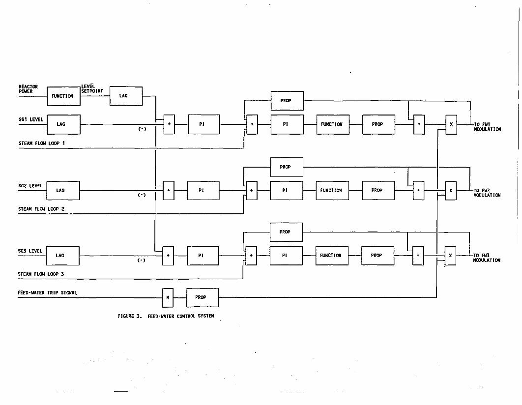
d. - Feed Water Control System
T~he feed water control systemn has been mrodeled as shown in
Figure 3. The rnassflo; rate calculated by the control system
is injected by m~ans of a tire dependent junction.
The auxiliary feed water system is also included in the model.
e .- Pressurizer level and pressure control system
The mocdel of the pressure control systen actuates upon
heaters, spray valve and charging pu.mp. Pressurizer safety and
relief valves and level control systemi are also simulated.
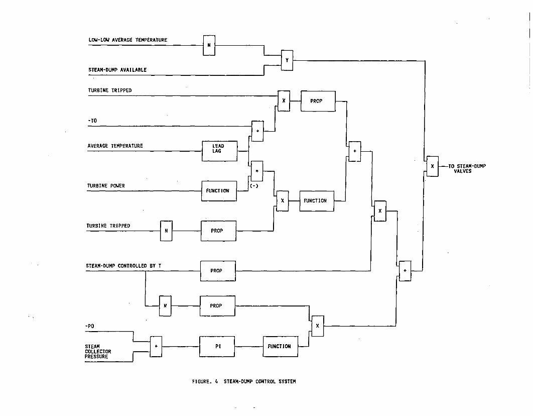
f.- Steam Dua control system
In Figure 4 the model used for the steam dump control system
is represented.
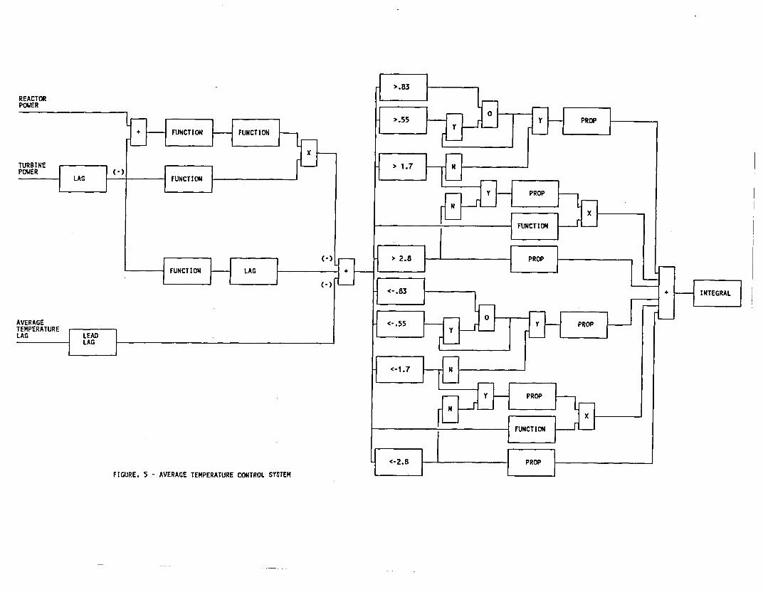
g. - Average Tenprature Control System
The average torperature control system mode led with
PEWA5/MOD2 is shown in Figure 5. As can be observed this
system controls both the primary average temperature and the
prrimary-secorKdary power mistmach.
-9-

other svstc--s nrr'e led are:
h.- Stean-line Isolation logic.
i. - Main Feedwater Isolation logic.
j.- Safety and Relief valves of the secondary.
-10-
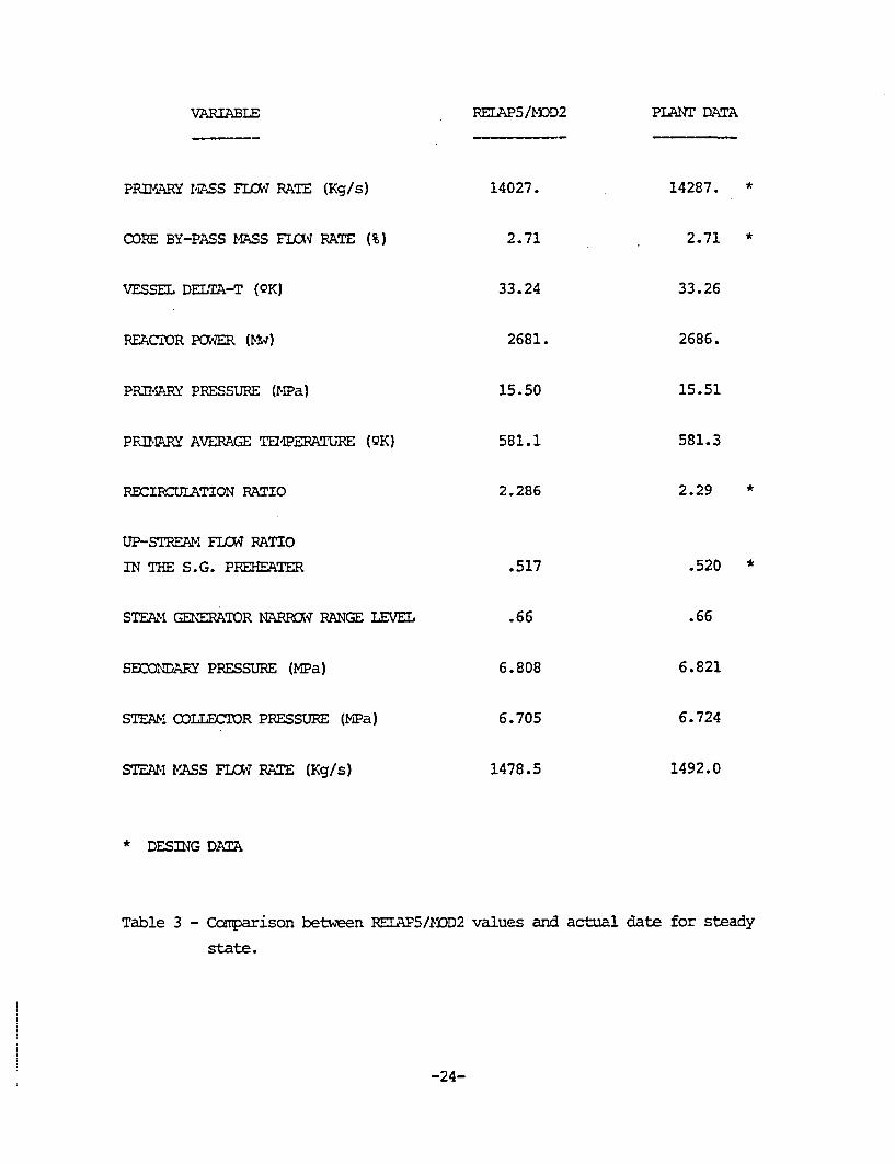
4.- STEADY STATE CALCULATION
Asteady state calculation was performed with the plant at 100% rated
condition. Tkhe objective is to obta~n a stable condition to start
transients.
In Table 3 a ccaparison between the model results and the plant data is
given for the mrain plant variables. A catplete description of the plant
sensors and signals Is given in ref. 10.
-11-
5.- TRANSIENT CALCMlATION AND Ct4PARISON VERSUS ACTUAL DATA
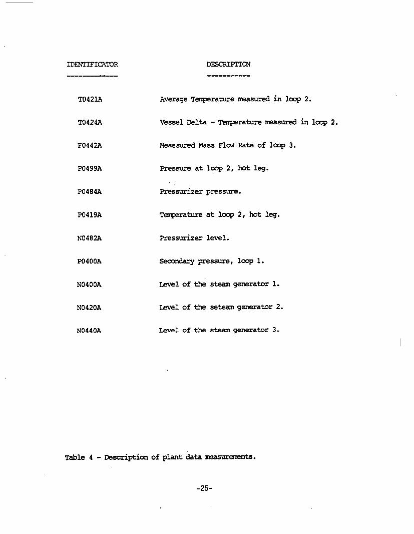
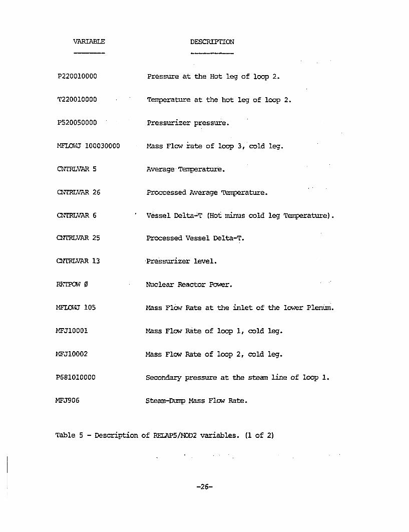
The caniarison between model predictions (see table 5) against plant
data (see table 4) shows an overall grood agreement with some minor
disagreements that will be explained later.
Table 6 shows a carmaarison of the cronology of the main events.
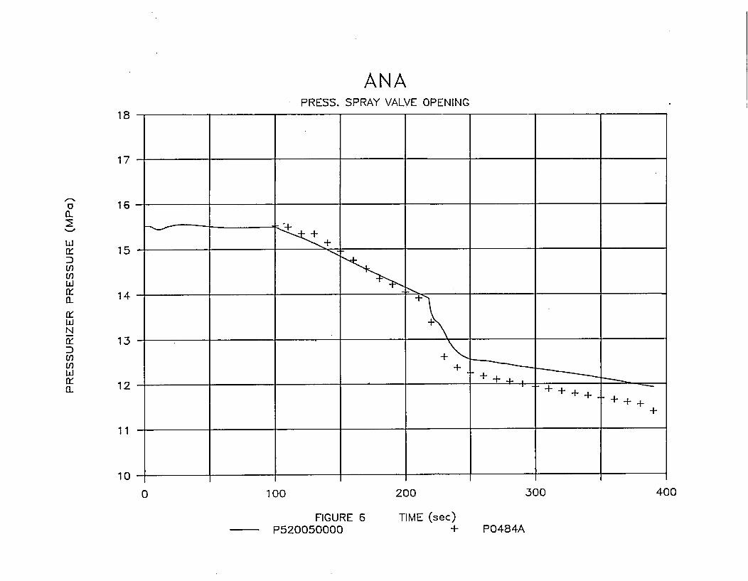
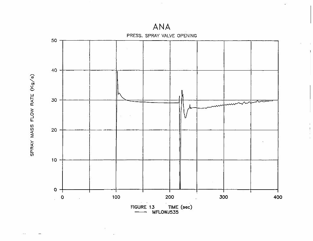
As can be seen in figures .6 to 18 the transient which begun at second
100, starts with an unnoticed opening of the spray valves to its fully
open position (figure 13). This causes a continuous decrease in primary
pressure (figure 6), reactor power because of the correspondent decrease
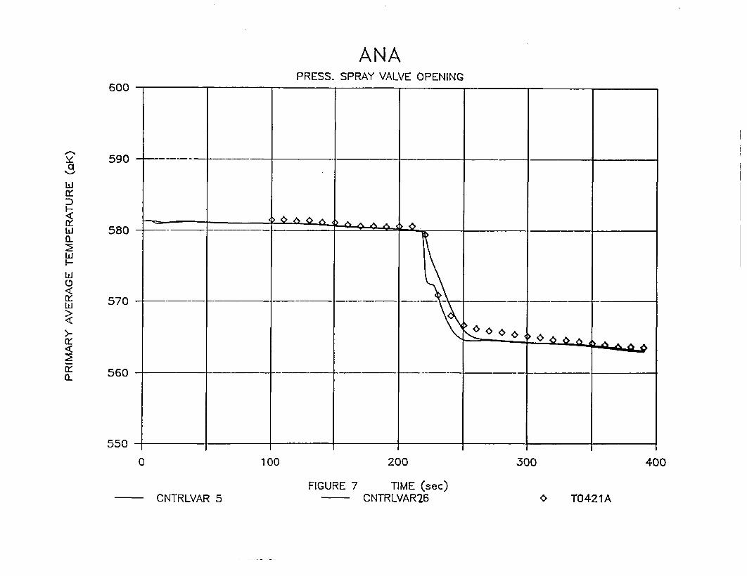
in moderator density, primary average temperature (figure 7) and
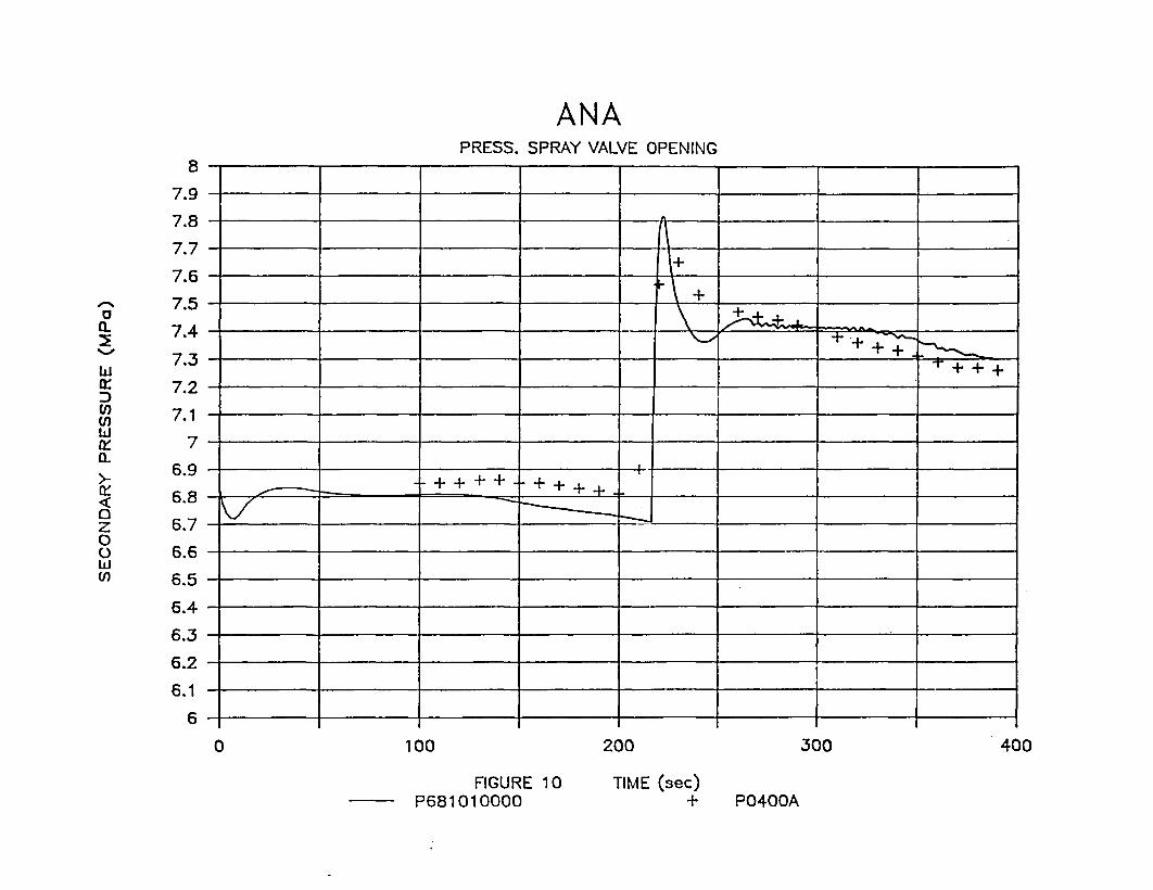
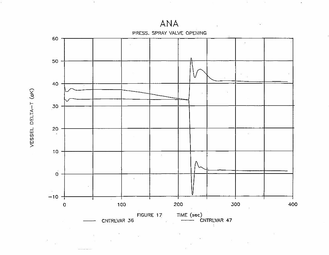
secondary pressure (Figure 10). This event produces a decrease in the
overtemperature setpoint signal that (see Figure 17) reaches the actual
delta-tenperature and trips the reactor. The trip takes place in themo~del at second 216.3 (see Table 6) while in plant it was at seoond 217,
but in both cases for the sane reason: overtemperature. The low pressure
setpoint of the protection system was close to be reached but it is not
the signal that trips the plant.
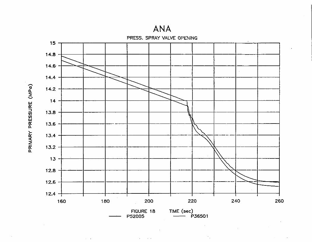
Figure 13 shows the pressurizer spray mass flow rate accordingly with
delta-P between cold leg and pressurizer (see figure 18).
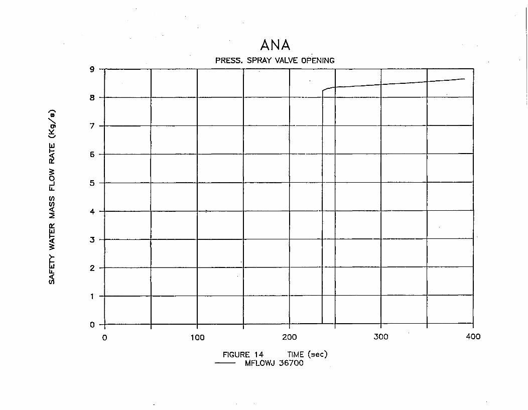
After the trip a further decrease in plant pressure occur, because of
the power reduction and sate 10 seconds later, at second 236.*4, the high
Pressure Injection System becamre active injecting abouat 25 Kg/s into the
primary system (Figure 14) until the end of the transient.
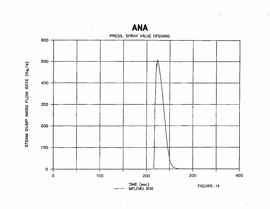
Because of turbine 'trip the steam-dump valves open, controlled by
primra~ry average temperature, (see Figures 10 and 16) lowering secondary
pressure and in same seconds steam dumrp valves close. Afterwards the
continous decrease in secondary pressure is caused by steam extractions.
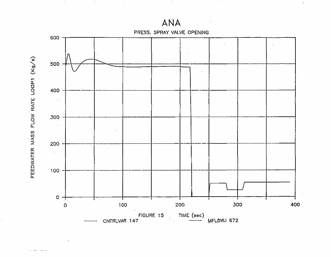
Control system causes main feed water trip (see Figure 15) and auxiliary
feed-water is injected only to steamn generators 1 and 3 (because of loop
2 disfunction).
-12-
The ca~parison in the behaviour of the main variables is explained below.
a.- Primary Pressure.
In figure 6 pressure at the hot leg is presented. As can be seen the
cariparison is good but the pressure decrease predicted by PREAP because
of the spray actuation (second 100 to plant trip), has a lower slope
than the actual one. It may be caused by a mo~re effective vapor
condensation in the plant, caused by the liquid dropplet, than in the
model1.
b. - Primary Temerature
In figure 7 mo~del primary average te-mperature with and without signal
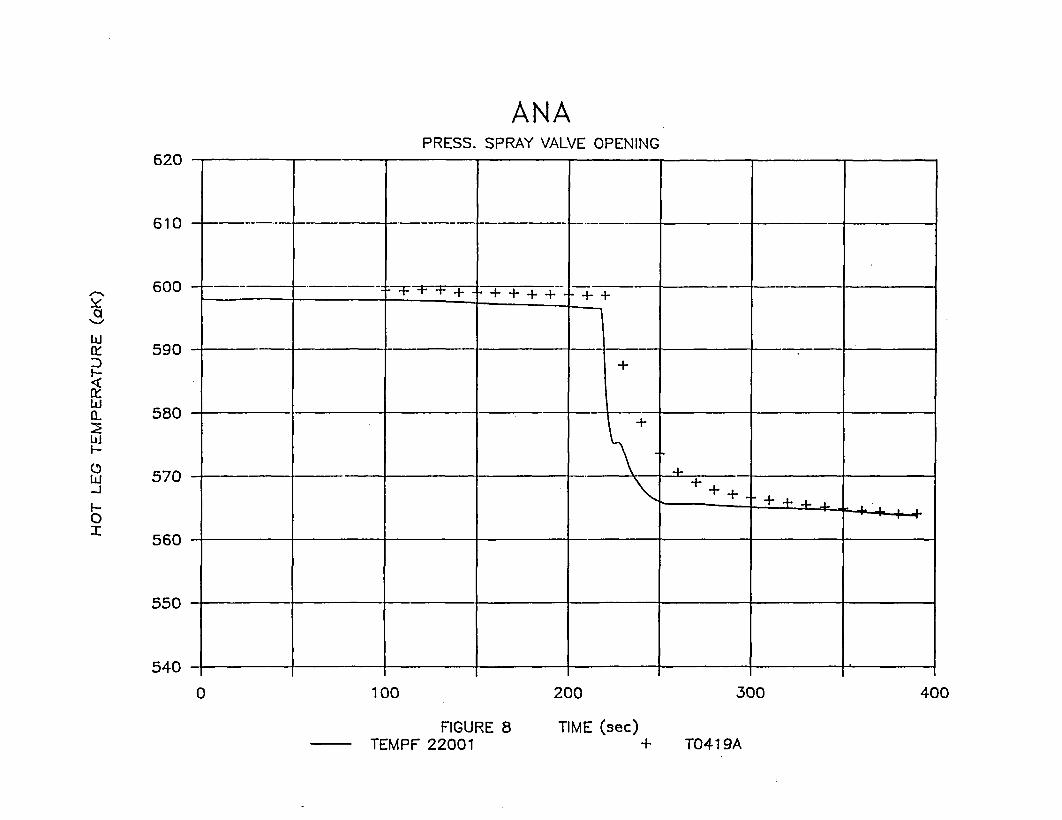
proccesing is compared versus the plant value. In figure 8 model hot leg
temrperature of loop 1, without signal proccesing is ccarar~ed against
plant data.
It can be observed that when signal procces sing is introduced the
comarion is fairly good.
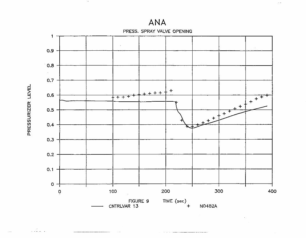
c.- Pressurizer level.
In figure 9 the caTparison between mo~del prediction and plant data is
given. The overall carparison is fair although a larger increase inplant level is observed both before the reactor trip and when level
recovery starts. It may be due to limitations to the actual simrulation
of the surge line in the model.
d. - Secondary Pressure
In figure 10 the ccnparison of this variable versus actual data is
given. It can be observed that the short term behaviour of the steam
dump valves is not well reproduced in the model and a faster decrease of
secondary pressure than the actual one is obtained. The long term
behaviour is correctly predicted. This problem is being studied also
-13-
with other transients. Except for this point a good corrparison is
obtained.
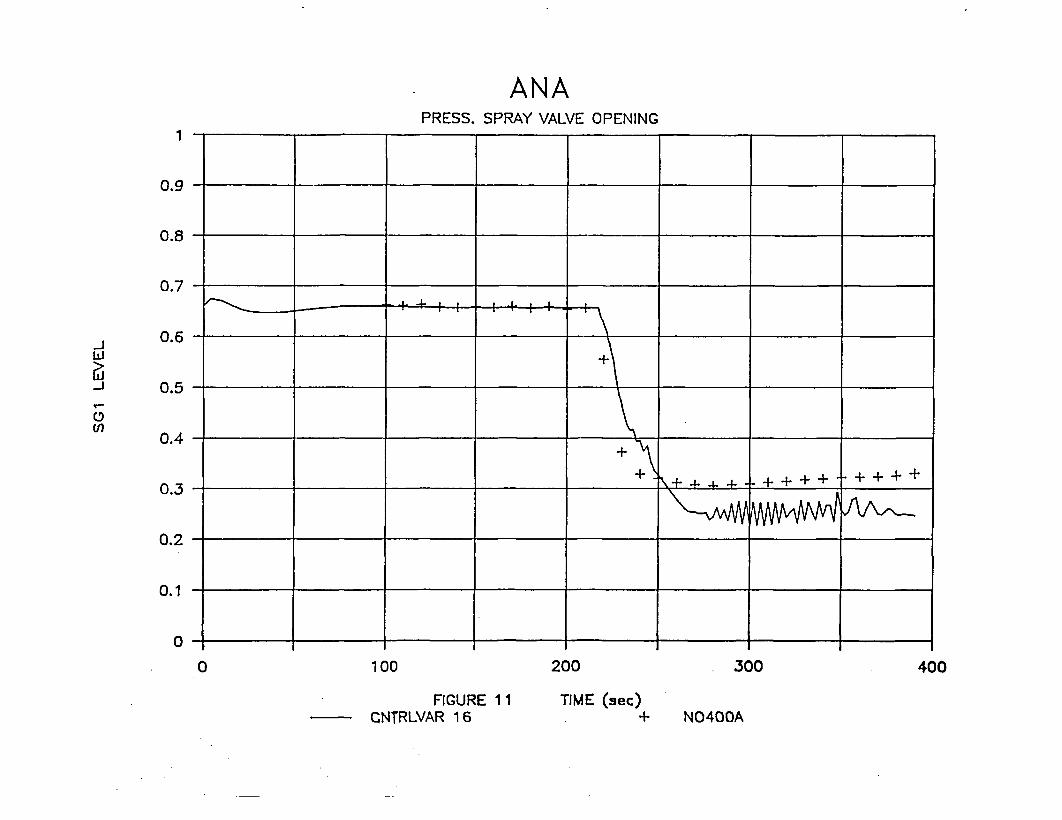
e. - Steam Generators level.
In figure 11 the carparison between steam generator 1 narrow range level
(steam generator 3 behaviour is totally similar since auxiliary feed
water is injected at both steam generators) and actual plant data is
given.
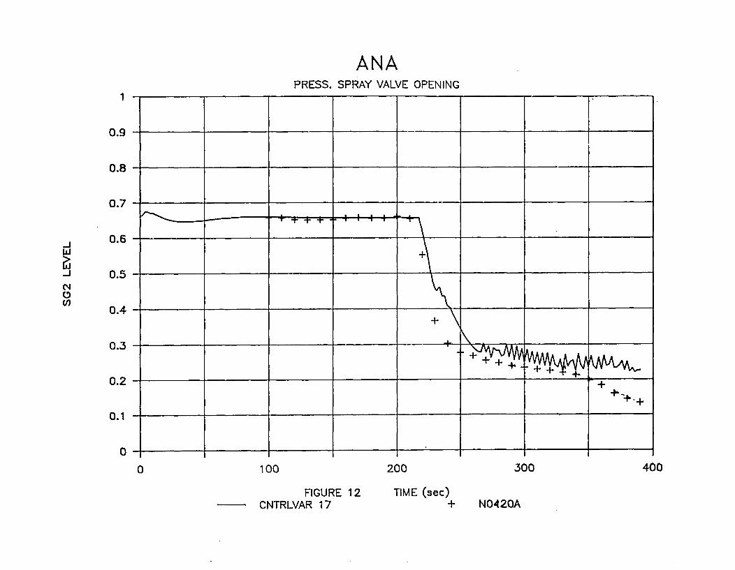
Figure 12 shows the catparison for steam generator 2 which does not
receive auxiliary feed-water in this transient.
In both level predictions saue oscillations can be observed when na~rrow
range level decrease under about 30%. Sam diferent. nodalizaticns have
been tested before chosing the best one in order to minimize theseoscillations. The overall conarisons shoed in figures 11 and 12 ar
good, except for steam generator 2 during the last 40 seconds, where
plant data show a quicker decrease that has not yet an explanation.
-14-
6.- RUN STATISTICS
calculations were- carried out on a CYBER 180/830 NOS 2.5 property ofFundacicn Leonardo Torres Quevedo located at Santander - Spain.
RELAP5/Mcd. 2 cycle 36.04 was used in all the calculations.
In Table 8 a Typical run statistics is presented.
-15-
7.- .)NCLUSIONS
The transient has been simulated with Relap5/zrod2 Asc6 model.
The results are in close agreement with plant data.
This calculation, along with those of the rest of transients of thequalification matrix, provides the validation of the model.
The function of the pressurizer spray valve is correctly predicted bythe model.
The transient provides the assessment of the high pressure SafetyInjection, as well as the reactor protection system.
Although in long term, the actuation of the steam-di-mp seems to becorrectly predicted, in short term this actuation can be =nproved.
Some diferent steam generator nodalizations; have been tested beforechosing the best one in order to min~imize level oscilations. The level
predictions are, any way in fair agreement with actual data.
The mocdel of Asc6 using Relapsfnod.2 is a valuable tool to analyze plant
transients.
-16-
8. - __________
1) V. -H. RAYSON and R.J. WAZR "PELAPS/MC)D2: Cod~e Manual, "EGG-
SAAM-6377, E)G&G Idaho, Inc. (Apr. 2984).
2) F. REVENI1OS, J. S7ANCREZ-BAPTISTA, and P. MORENO, "Modelo
Te~rrhidr5Lulico de la C.N. Ascb", Asociaci6n Nuclear Asc6 (June1987).
3) F. REVRMIS, J. SAHEZ-BA?1'ISTA, and P. MOlRENO, "Modelo
Termzhidraulico y de proteccibn y control de C.N. Asc6," Asocia-
ci~x Nuclear Asc6 (May 1988).
4) F. REVENTOS, J. SANCEZ-BAPTISTA, and P. MORENO, "Analisis de
transitorios en A.N.A. con IELAP5/MOD2," presented at 14th Annual
Mtg. Sociedad Nuclear Espa~fiola, Marbella, Spain, October 26-28,
1988.
5) F. REVENIPOS, J. SA~NCHEZ-BAPTISTA~, P. 14)RENZ), and A. PEREZ NAVAS,
"Transient Analysis for ASCO Nuclear Power Plant Using
RE.AP5 /MDD2,1" Proc. Ist Int. F.AP5 Users' Seminar, College
Station Texas, January 31-February 2, 1989.
6) F. REvmOMS, J. SANCHEZ-BAPTISTA, A. PEREZ-NAVAS and P. MOJREN.
"Transient Analysis in the AsoB NPP using RELAPS/Mt'D2," Nuclear
Technology, voltme 90, Niunrer 3, pp 294-307. June 1990.
7) "Final Safety Analysis Repor-t-Asc6 I" (June 1983), "Final Safety
Analysis peport-Ascb II-" (Sep. 1985), and later revisions, Asocia-
ci6n Nuclear Asc6.
8) F. BA12ERINI, "Setpoint Study Asc6 Units I and 2," Westingt~se
Electric Corporation (m~ar. 1976).
9) "precautions, Lin-itations and Setpoints of Asc6 Units 1 and 2".
E/PS176/068. Rev. 11. Sep. 1988.
-17-

10) C. Simo~n, et al "Central Nuiclear de Asc6 Units 1 and 2. EmrgencyRecovery Guidelines Setpoint Values. Calculation and MethodologyAppendi.x D. Instrumentation channels statistical calculation ofUncertainties". N=C 88-08. Rev. 2. October 1989.
-18-
TABLES
TABLE 1. DESCRIPTION~ OF THE MAIN CHARACTERISTICS OF AS00 I AND II
NUCLEAR STATION.
TABIBE 2. MAIN EVUMTIS THA TOOK PLACE DURIN~G TH TRZANSI=N.
TABLE 3. Cl1tlARISCN BETWEE FMEAP5IMZD2 VALUJES AND ACIIJAIJ DATA FOR
STEADY STATE.
TABLE 4. DESCRIPTION OF PLANT DATA MEASURIEN'T2TS.
TABLE 5.* DESCRIPTION OF FEAP5 fMOD2 VARLIABES.
TABLE 6. COMPARISON OF TkX CRONOIb3 OF THE MAIN EVENTS.
TABLE 7. RUN SEATISTICS.
-19-
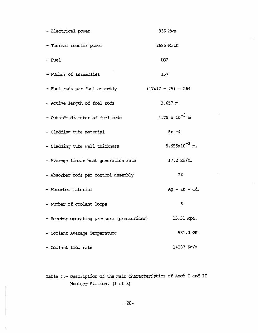
- Electrical power 930 Mw
- Thez~al reactor pow.er 2686 Yh,7th
- Fuel U02
- Number of assemblies 157
- Fuel rod~s per fuel asserbly (17x17 - 25) = 264
- Active length of fuel rods 3.657 m,
- Ouatside diareter of fuel rods 4.75 x 10- i
- Cladding tube imaterial Zr -4
- Cladd~ing tube w-all thickniess 0.655x10⁻³ M.
- Average linear heat generation rate 17.2 Xw/m.
- Absorber rods per control assembly 24
- AZbsorber material Ag- in -Cd.
- Ntrrber of coolant loops 3
- Reactor operating pressure (pressurizer) 15.51 Npa.
- Coolant Average Terrerature 581.3 QK
- Coolant flow rate 14287 Kg/s
Table 1.- Description of the main c-haracteristics of Asc6 I and IINuclear Station. (1 of 3)
-20-
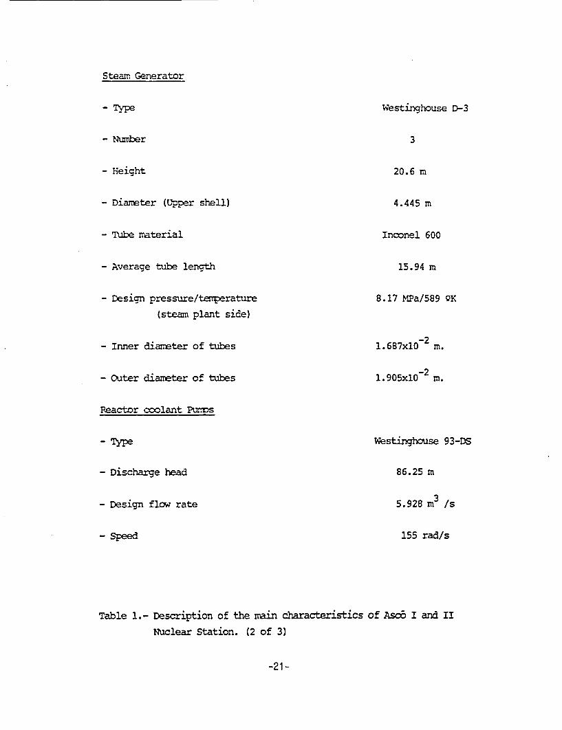
Steam Generator
- Numnber
- Height
- Diaxmter (Upper shell)
- Tube mrterial
- Average tube length
- Design pressure/tenperature
(steam plant side)
- Inner diameter of tubes
- outer dliazreter of tubes
Reactor coolant Punms
- Discharge head
- Design flow rate
- Speed
Westinghouse D-3
3
20.6 m
4.445 m
Inconel 600
15.94 m
8.17 1.2a/589 QK
l.687x10- M.
1.905x10² M.
Westinghouse 93-DS
86.25 m
5.928 m 3 s
155 rad/s
Table 1.- Description of the main characteristics of Asc6 I and ii
Nuclear Station. (2 of 3)
-21-
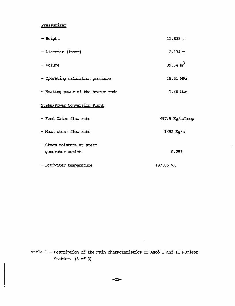
Pressurizer
- Height
- Diameter (inner)
- Volume
- operating saturation pressure
- Heating power of the heater rods
Steam/Power Conversion Plant
- Feed Water flow rate
- Main steam flow rate
- Steam moisture at steam
generator outlet
- Feedwater temperature
12.835 m
2.134 mn
39.64 Mn3
15.51 MPa
1. 40 Mwe
497.5 Kg/s/loop
1492 Kg/s
0.25%
497.05 OK
Table 1 - Description of the ma~in characteristics of Asc6 I and II Nuclear
Station. (3 of 3)
-22-
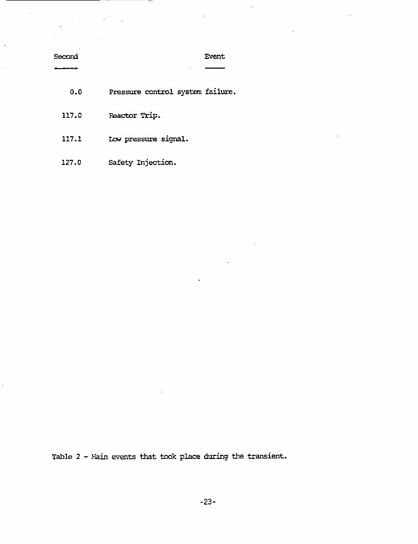
Second Event
0.0 Pressure control system failure.
117.0 Reactor Trip.
117.1 Low pressure signal.
127.0 Safety injection.
Table 2 - main events that took place during the transient.
-23-
VARIABLE
PRIMARY 1H.SS FLOWq RATE (Kgfs)
CORE BY-PASS MA.SS FLCW RATE(%
VESSEL DELTA-T (QK)
REACTOR POWER. (nq)
PRIMARY PRESSURE (MPa.)
PRIJ-7Y AVERAGE T~ERAýTtRE (QK)
RECII UIA TION RATIO
UP-STREA2,M FLOW RATIO
IN THE S.G. PRSHATER.
STEAM GEERATOR NARROW RANGE LEVEL
SBTO\NDARY PRESSURE (MPa)
STEAMv' OJLLECR PRESSURE 02~a)
STEN-M FASS FLCW RATE (Kgfs)
RELAP5/14OD2
14027.
2.71
33.24
2681.
15.50
581.1
2.286
PLANT DAT'A
14287.
2.71
33.26
2686.
15.51
581.3
2.29
.517
.66
6.808
6.705
1478.5
.520
.66
6.821
6.724
1492.0
* DESING DATA
Table 3 - Conparison between RELP5/rflD2 values and actual date for steady
state.
-24-
IDENTIFIC'IOR DESCRIPTION
T04 21A Average Temperature me~asured in loop 2.
T0424A Vessel Delta - Tepe-rature measured in loop 2.
F0442A Meassured Mass Flow Rate of loop 3.
P0499A Pressure at loop 2, hot leg.
P0484A Pressurizer pressure.
P0419A Teuperature at loop 2, hot leg.
N0482A Pressurizer level.
P0400A Secondary pressure, loop 1.
N0400A Level of the steam generator 1.
N0420A Level of the seteamn generator 2.
N0440A Level of the steam generator 3.
Table 4 - Description of plant data umeasurements.
-25-
VARIABIE VARIABLEDESCRIPTION
P220010000
T220010000
P520050000
1vk7M~J 100030000
CNTRLVAR 5
CNTRLVAR 26
CNTRLVAR 6
a.TERLVAR 25
C=RVAR 13
oRTPo1 0
MF10WJ 105
YFJ10001
MFJ10002
P681010000
MFThJ90 6
Pressure at the Hot leg of loop 2.
Temperature at the hot leg of loop 2.
Pressurizer pressure.
Mass Flow rate of loop 3, cold leg.
Average Tezmperature.
Proccessed Average Temperature.
Vessel Delta-T (Hot minus cold leg Temperature).
Processed'Vessel Delta-T.
-Pressurizer level.
Nuclear Reactor Power.
Mass Flow Rate at the inlet of the lower Plenum.
Mass Flow Rate of loop 1, cold leg.
Mass Flow Rate of loop 2, cold leg.
secondary pressure at the steam line of loop 1.
Steam-Dtxrp Mass Flow Rate.
Table 5 - Description of RELAP5/I4?D2 variables. (1 of 2)
-26-
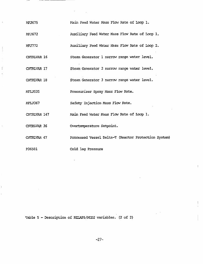
MFThJ675 Main Feed Water Mass Flow Rate of Loop 1.
MFJ672 Auxiliary Feed Water Mass Flow Rate of Loop 1.
MFJ3772 Auxiliary Feed Water Mass Flow Rate of Loop 2.
CNTRLVAR 16 Steamn Generator 1 narrow range water level.
CNT~RLVAR 17 Steam Generator 2 narrow range water level.
Q'NTRLVAR 18 Steam Generator 3 narrow range water level.
YSW535 Pressurizer Spray Mass Flow Rate.
MFL7367 Safety Injection Mass Flow Rate.
CNTRLVAR 147 Mlain Feed Water Mass Flow Rate of Loop 1.
CNTRLVAR 36 Overtemperature Setpoint.
CNTRLVAR 47 Processed Vessel Delta-T (Reactor Protection System)
P36501 Cold leg Pressure
Table 5 - Description of RELAP5/DMD2 variables. (2 of 2)
-27-

Event
Pressure control system failure
Reactor trip (overtemperature)
Steam-Dump starts to open
Low pressure signal
Steam-Dump~ fully open
Safety injection
Low average temperature signal
Tinre (s)
Plant Relap
100.0 100.0
217.0 216.3
- 216.5
217.1 218.0
- 223.5
227.0 236.3
- 236.7
Table 6 - Ccaparison of the cronology of the main events.
-28-
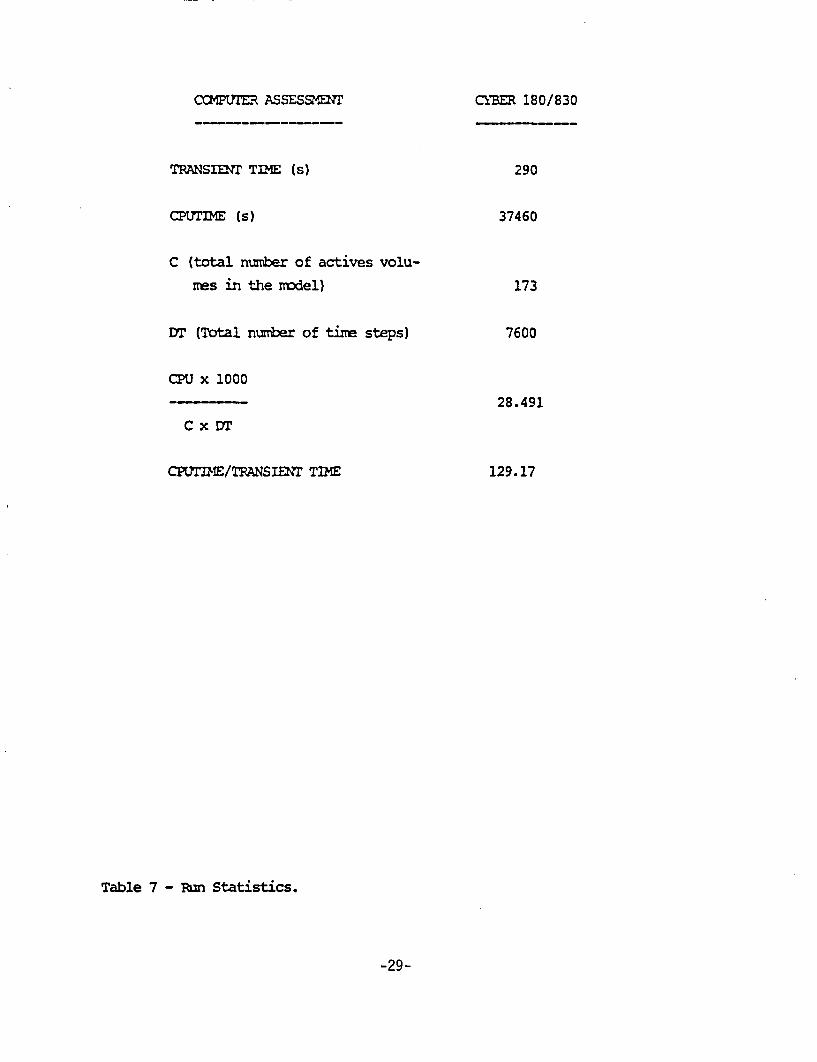
CCMPWtr~ ASSESSMEW
TRANSIENT TflE (s)
CP~rLT (s)
C (total niumiber of actives volu-
Ties in the rodel)
DT (Total numb~er of timre steps)
CPU x 1000
C x DT
CPhMI/TRANSIENT TflE
Table 7 - Ruin Statistics.
C"YMM 180/830
290
37460
173
7600
28. 491
129.17
-29-
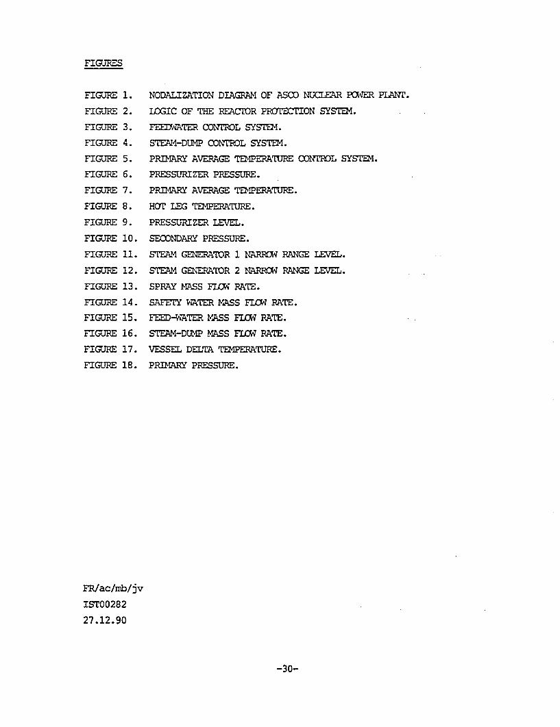
FIGURES
FIGURE 1. NODAIJIZATION DIAGRAM OF ASCO NUCLEAR POWER PULNr.
FIGURE 2. LOGIC OF THE REACTOR PROTECTION SYSTEM4.
FIGURE 3. [email protected] CONTROL SYS=E~.
FIGURE 4. STEAI4-DUMP CON~l!RL SYSTEMY.
FIGURE 5. PPfl'2R AVERAGE TEMERATURE CONTROL SYSTEM.
FIGURE 6. PRESSURIZER PRESSURE.
FIGURE 7. PRIMARY AVERAGE TEMPERATURE.
FIGURE 8. HOT LEG T2ERATURE.
FIGURE 9. PRESSURIZER LEVEL.
FIGURE 10. SECONDARY PRESSURE.
FIGURE 11. STEAM GENERATOR 1 NARRO RANGE LEVEL.
FIGURE 12. STEAM GENERATEOR 2 NARROW RANGE LEVEL.
FIGURE 13. SPRAY MASS FLCM RATE.
FIGURE 14. SAFETY WATER MASS FLW~ RATE.
FIGURE 15. FEE-WATER MASS FLOW RATE.
FIGURE 16. STEAM-DUMP MASS FLOW7 RATE.
FIGURE 17. VESSEL DELTA T PERATURE.
FIGURE 18. PRIMA~RY PRESSURE.
FR/ac/mb/jv
IST00282
27.12.90
-30-
NODALIZATION DIAGRAM OF
A3CO NUCLEAR POWER PLANT
JULY 1990
::4ZZ~j-'UZ~
"son
CONDENSER
PPMUsInZrER
i-El
405

IHIGH PRESSURIZER LEVELPRESSURIZER LEVEL
NIGH RP
iREACTORTRIP
SG2 LEVEL
SG3 LEVEL
SAFETYINJECTION
I RCPFIGURE 2. -LOGIC, OF THE REACTOR PROTECTION SYSTEM4
REACTORPOWER
STEAM4 FLOW LOOP 1
-TO FUIMODULATION
-TO FV2MODULATION
STEAM4 FLOW LOOP 2
kTION
STEAM FLOW LOOP 3
FEED-WATER TRIP SIGNAL
FIGURE 3. FEED-WATER CONTROL SYSTEM
-TO STEAM-DUMPVALVES
FIGURE. 4 STEAM-DUM4P CONTROL SYSTEM
REACTORPOWER
AVERAGETEMPERATURELAG
FIGURE. 5 - AVERAGE TEMPERATURE CONTROL SYSTEM
ANAPRESS. SPRAY VALVE OPENING
18
17
w
(I)
w
N
U)'ina.
16
15
14
13
12
11
10
0 100 200 300 400
FIGURE 6P520050000
TIME (sec)+ P0484A
ANAPRESS. SPRAY VALVE OPENING
600 T r
w
w
w
w
CL
590-
580 -
I-- & -I I
4- -+ - ~ 4 -1-
570
560
550
0 100 200 300 400
FIGURE 7 TIME (sec)CNTLVA 5NTR0VAR2- CNTRLVAR 5 0 T0421A
ANAPRESS. SPRAY VALVE OPENING
620
610
600
ci
wd
2:,
I-.
590
580
570
560
550
540
0 100 200 300 400
FIGURE 8TEMPF 22001
TIME (sec)+ T0419A
ANAPRESS. SPRAY VALVE OPENING
N
FrD,;v)(n
1
0.9
0.8
0.7
0.6
0.5
0.4
0.3
0.2
0.1
0
0100 200 300
FIGURE 9 TIME (sec)
400
- CNTRI-VAR 13 N0482A
It
Cf,
Id
00Id(n)
8
7.9
7.8
7.7
7.6
7.5
7.4
7.3
7.2
7.1
7
6.9
6.8
63.7
6.6
6.5
6.4
6.3
6.2
6.1
6
ANAPRESS. SPRAY VALVE OPENING
++
___________________~~~ ~~~~ +_________ +_________ ___________________ _________
0 100 200
TIME (sec)
300 400
FIGURE 10P681 010000 P0400A
ANAPRESS. SPRAY VALVE OPENING
in
1
0.9
0.8
0.7
0.6
0.5
0.4
0.3
0.2
0.1
0
0 100 200 .300 400
FIGURE 11QNTRLVAR 16
TIME (sec)+ N0400A
ANAPRESS. SPRAY VALVE OPENING
C14
1
0.9
0.8
0.7
0.6
0.5
0.4
0.3
0.2
0.1
0
0 100 200 300
FIGURE 12 TIME (sec)
400
- CNTRLVAR 17 N042-OA
ANAPRESS. SPRAY VALVE OPENING
50
40
0-JLL
(n)in
30
20
10
0
0 100 200 300 400
FIGURE 13 TIME (sec).MFLOWJ535
w
0Li.
9
8
7
6
5
4
3
2
1
0
ANAPRESS. SPRAY VALVE OPENING
0 100 200 300 400
FIGURE 14MFLOWJ
TIME (sec)36700
600
0~00
w
0-J
LL
U)in
w
IdLi-
500
400
300
ANAPRESS. SPRAY VALVE OPENING
200
100
0
0 100 200 300 400
FIGURE 15CNTRLVAR 147
TIME (sec)- MFLOWJ 672
ANAPRESS. SPRAY VALVE OPENING
600
5000K
0-J1±.(I)U)
0~
0
U)
400
300
2-0-0
100
0
.10 100 200 300 400
TIME (sec)MFLOWJ 906
FIGURE. 16
ANAPRESS. SPRAY VALVE OPENING
60
50
40
w
w
30
20
10
0
-10
0 100 200 .300 400
FIGURE 17CNTRL-VAR 36
TIME (sec)CNTRLVAR 47
(n
(L
15
14.8
14.6-
14.4
14.2
14
13.8
13.6
13.4
13.2
13
12.8
12.6
12.4
ANAPRESS. SPRAY VALVE OPENING
160 180 200 220 240 260
FIGURE 18-P52005
TIME (sec)-P36501
NRC FORM 335 U.S. NUCLEAR REGULATORY COMMISSION 1. REPORT NUMBER(2-891 IAuslgnod by NRC. Add Vol., Supp.. Rev..NRCM 1102, and Addendum Numbers, if env.)I3201, 3202 BIBLIOGRAPHIC DATA SHEET
(See instructions on the reverse) NUREG/IA-Ol 212. TITLE AND SUBTITLE ICSP-AS-SPR-R
Assessment of a Pressurizer Spray Valve Faulty OpeningTransient at ASCO Nuclear Power Plant with RELAP5/MOD2 3. DATE REPORT PUBLISHED
December 19934. FIN OR GRANT NUMBER
L22455. AUTHOR(S) 6. TYPE OF REPORT
F. Reventos, J.S. Baptista, A.P. Navas, P. Mor eno
7. PERIOD COVERED (Inclusive Dares)
8. PERFORMING ORGAN IZATION - NAME AND ADDRESS (IfNRC. providelDivision. Office or Region. U.S. Nuclear Regulatory Commission, and mailing address: If contractor, provide
JN11 milngadroucl ear AscoC/Tres Torres, 70817 - BarcelonaSpain
9. SPONSORING ORGANIZATION - NAME AND ADDRESS (if NRC. type "Same as above-,- if contractor, provide NRC Division, Office orRegion. U.S, Nuclear Regulatory Commission,
and mailing eddressj
Office of Nuclear Regulatory ResearchU.S. Nuclear Regulatory CommissionWashington, DC 20555-0001
1D. SUPPLEMENTARY NOTES
11. ABSTRACT 1200 words or les)
The Asociacion Nuclear Asco has prepared a model of Asco Nuclear Power Plant usingRELAP *5/MOD2. This model, which includes thermaihydraulics, kinetics and protectionand controls, has been qualified in previous calculations of several actual planttransients. One of the transients of the qualification proce~ss is a "pressurizedspray valve faulty opening" presented in this report. It consists in a primarycoolant depressurization that causes the reactor trip by overtemperature and lateron the actuation of the safety injection. The results ara in close agreement withplant data.
12. KEY WORDS/DESCR!PTORS (List words or phtrises that will &asist resarcher in locating the report.) 13. AVAILABILITY STATEMENT
ICAP, ASCO, RELAP5/MOD2, Spray Valve unlimited14. SECURITY CLASSIFICATION
(This Page)
unclassified(This Report)
unclassified15. NUMBER OF PAGES
16. PRICE
NRC FORM 335 (2-891

Federal Recycling Program

A3Z)1,ZI~LfN 4- UP A f'l{t~L11SUItE SP1HAY VALVE PAUIJY OJPENINGNUREC/IA-0121 TRANSIENT AT ASCO NUCLEAR POWER PLANT WITH RELAIP5/iNOD2
UNITED STATESNUCLEAR REGULATORY COMMISSION
WASHINGTON, D.C. 20555-0001
DECEMBER 1993
FIRST CLASS MAILPOSTAGE AND FEES PAID
USNRCPERMIT NO. G-67
OFFICIAL BUSINESSPENALTY FOR PRIVATE USE, $300
I