Embed Size (px)
Citation preview

NUREG–2214
Managing Aging Processes In Storage (MAPS) Report
Final Report
Office of Nuclear Material Safety and Safeguards

AVAILABILITY OF REFERENCE MATERIALSIN NRC PUBLICATIONS
NRC Reference Material
As of November 1999, you may electronically access NUREG-series publications and other NRC records at NRC’s Library at www.nrc.gov/reading-rm.html. Publicly released records include, to name a few, NUREG-series publications; Federal Register notices; applicant, licensee, and vendor documents and correspondence; NRC correspondence and internal memoranda; bulletins and information notices; inspection and investigative reports; licensee event reports; and Commission papers and their attachments.
NRC publications in the NUREG series, NRC regulations, and Title 10, “Energy,” in the Code of Federal Regulations may also be purchased from one of these two sources.
1. The Superintendent of DocumentsU.S. Government Publishing OfficeWashington, DC 20402-0001Internet: bookstore.gpo.govTelephone: (202) 512-1800Fax: (202) 512-2104
2. The National Technical Information Service5301 Shawnee RoadAlexandria, VA 22312-0002www.ntis.gov1-800-553-6847 or, locally, (703) 605-6000
A single copy of each NRC draft report for comment isavailable free, to the extent of supply, upon writtenrequest as follows:
Address: U.S. Nuclear Regulatory Commission Office of Administration Multimedia, Graphics, and Storage & Distribution Branch Washington, DC 20555-0001 E-mail: [email protected]: (301) 415-2289
Some publications in the NUREG series that are posted at NRC’s Web site address www.nrc.gov/reading-rm/doc-collections/nuregs are updated periodically and may differ from the last printed version. Although references to material found on a Web site bear the date the material was accessed, the material available on the date cited may subsequently be removed from the site.
Non-NRC Reference Material
Documents available from public and special technical libraries include all open literature items, such as books, journal articles, transactions, Federal Register notices, Federal and State legislation, and congressional reports. Such documents as theses, dissertations, foreign reports and translations, and non-NRC conference proceedings may be purchased from their sponsoring organization.
Copies of industry codes and standards used in asubstantive manner in the NRC regulatory process are maintained at—
The NRC Technical Library Two White Flint North 11545 Rockville Pike Rockville, MD 20852-2738
These standards are available in the library for reference use by the public. Codes and standards are usually copyrighted and may be purchased from the originating organization or, if they are American National Standards, from—
American National Standards Institute11 West 42nd StreetNew York, NY 10036-8002www.ansi.org(212) 642-4900
Legally binding regulatory requirements are stated only in laws; NRC regulations; licenses, including technical speci-fications; or orders, not in NUREG-series publications. The views expressed in contractorprepared publications in this series are not necessarily those of the NRC.
The NUREG series comprises (1) technical and adminis-trative reports and books prepared by the staff (NUREG–XXXX) or agency contractors (NUREG/CR–XXXX), (2)proceedings of conferences (NUREG/CP–XXXX), (3) reportsresulting from international agreements (NUREG/IA–XXXX),(4) brochures (NUREG/BR–XXXX), and (5) compilations oflegal decisions and orders of the Commission and Atomicand Safety Licensing Boards and of Directors’ decisionsunder Section 2.206 of NRC’s regulations (NUREG–0750).
DISCLAIMER: This report was prepared as an account of work sponsored by an agency of the U.S. Government. Neither the U.S. Government nor any agency thereof, nor any employee, makes any warranty, expressed or implied, or assumes any legal liability or responsibility for any third party’s use, or the results of such use, of any information, apparatus, product, or process disclosed in this publication, or represents that its use by such third party would not infringe privately owned rights.

NUREG–2214
Managing Aging Processes In Storage (MAPS) Report
Final Report
Manuscript Completed: March 2019 Date Published: July 2019
Office of Nuclear Material Safety and Safeguards


iii
ABSTRACT
This Managing Aging Processes in Storage (MAPS) Report provides guidance for the U.S. Nuclear Regulatory Commission (NRC) technical reviewer. It establishes a technical basis for the safety review of renewal applications for specific licenses of independent spent fuel storage installations and certificates of compliance for dry storage systems, as codified in Title 10 of the Code of Federal Regulations (10 CFR) Part 72, “Licensing Requirements for the Independent Storage of Spent Nuclear Fuel, High-Level Radioactive Waste, and Reactor-Related Greater Than Class C Waste.”
The MAPS Report evaluates known aging degradation mechanisms to determine if they could affect the ability of dry storage system components to fulfill their safety functions in the 20- to 60-year period of extended operation. The guidance also provides examples of agingmanagement programs that are considered generically acceptable to address the credible agingmechanisms to ensure that the design bases of dry storage systems will be maintained. Anapplicant for a renewed license or certificate of compliance may reference the information inthe MAPS Report to support its aging management review and proposed agingmanagement programs. As new information on materials aging becomes available, applicantsmay need to supplement the information in the MAPS Report to ensure that newly identifiedaging mechanisms are appropriately managed.


v
CONTENTS
ABSTRACT ............................................................................................................................... iii
LIST OF FIGURES .................................................................................................................... ix
LIST OF TABLES ...................................................................................................................... xi
ABBREVIATIONS AND ACRONYMS ..................................................................................... xiii
1 INTRODUCTION ..........................................................................................................1-1 1.1 Purpose and Use of the MAPS Report ..............................................................1- 1 1.2 Scope of Report ................................................................................................1- 2 1.3 Public Comments .............................................................................................. 1-3 1.4 Acknowledgments .............................................................................................1- 3 1.5 References .......................................................................................................1-4
2 DEFINITIONS .............................................................................................................. 2-1 2.1 Materials ...........................................................................................................2-1 2.2 Environments ....................................................................................................2-3 2.3 Aging Mechanisms ............................................................................................2-4 2.4 Aging Effects .....................................................................................................2-9
3 EVALUATION OF AGING MECHANISMS.................................................................. 3-1 3.1 Introduction .......................................................................................................3-1 3.2 Casks and Internals ..........................................................................................3-7
3.2.1 Steel (carbon, low-alloy, high-strength low-alloy) ...................................3-7 3.2.1.1 General Corrosion .................................................................. 3-8 3.2.1.2 Pitting and Crevice Corrosion ............................................... 3-10 3.2.1.3 Galvanic Corrosion ............................................................... 3-11 3.2.1.4 Microbiologically Influenced Corrosion .................................. 3-11 3.2.1.5 Stress Corrosion Cracking .................................................... 3-13 3.2.1.6 Creep ................................................................................... 3-13 3.2.1.7 Fatigue ................................................................................. 3-14 3.2.1.8 Thermal Aging ...................................................................... 3-15 3.2.1.9 Radiation Embrittlement ....................................................... 3-16 3.2.1.10 Stress Relaxation ................................................................. 3-17 3.2.1.11 Wear ..................................................................................... 3-17
3.2.2 Stainless Steel..................................................................................... 3-17 3.2.2.1 General Corrosion ................................................................ 3-18 3.2.2.2 Pitting and Crevice Corrosion ............................................... 3-18 3.2.2.3 Galvanic Corrosion ............................................................... 3-19 3.2.2.4 Microbiologically Influenced Corrosion .................................. 3-19 3.2.2.5 Stress Corrosion Cracking .................................................... 3-20 3.2.2.6 Creep ................................................................................... 3-22 3.2.2.7 Fatigue ................................................................................. 3-23 3.2.2.8 Thermal Aging ...................................................................... 3-23 3.2.2.9 Radiation Embrittlement ....................................................... 3-25 3.2.2.10 Stress Relaxation ................................................................. 3-26

vi
3.2.2.11 Wear ..................................................................................... 3-26 3.2.3 Aluminum Alloys .................................................................................. 3-26
3.2.3.1 General Corrosion ................................................................ 3-26 3.2.3.2 Pitting and Crevice Corrosion ............................................... 3-27 3.2.3.3 Galvanic Corrosion ............................................................... 3-28 3.2.3.4 Microbiologically Influenced Corrosion .................................. 3-29 3.2.3.5 Creep ................................................................................... 3-29 3.2.3.6 Fatigue ................................................................................. 3-31 3.2.3.7 Thermal Aging ...................................................................... 3-31 3.2.3.8 Radiation Embrittlement ....................................................... 3-32
3.2.4 Nickel Alloys ........................................................................................ 3-33 3.2.4.1 General Corrosion ................................................................ 3-33 3.2.4.2 Pitting and Crevice Corrosion ............................................... 3-34 3.2.4.3 Microbiologically Influenced Corrosion .................................. 3-34 3.2.4.4 Stress Corrosion Cracking .................................................... 3-34 3.2.4.5 Fatigue ................................................................................. 3-34 3.2.4.6 Radiation Embrittlement ....................................................... 3-35 3.2.4.7 Stress Relaxation ................................................................. 3-35 3.2.4.8 Wear ..................................................................................... 3-36
3.2.5 Copper Alloys ...................................................................................... 3-36 3.2.5.1 General Corrosion ................................................................ 3-36 3.2.5.2 Pitting and Crevice Corrosion ............................................... 3-36 3.2.5.3 Microbiologically Influenced Corrosion .................................. 3-37 3.2.5.4 Radiation Embrittlement ....................................................... 3-37
3.2.6 Lead .................................................................................................... 3-37 3.2.7 Depleted Uranium ............................................................................... 3-38 3.2.8 Coatings .............................................................................................. 3-38 3.2.9 References .......................................................................................... 3-39
3.3 Neutron Shielding Materials ............................................................................ 3-49 3.3.1 Neutron-Shielding Materials ................................................................ 3-49
3.3.1.1 Boron Depletion (borated materials) ..................................... 3-49 3.3.1.2 Thermal Aging ...................................................................... 3-50 3.3.1.3 Radiation Embrittlement ....................................................... 3-50
3.3.2 References .......................................................................................... 3-51 3.4 Neutron Poison Materials ................................................................................ 3-53
3.4.1 Borated Stainless Steel ....................................................................... 3-53 3.4.1.1 Boron Depletion .................................................................... 3-54 3.4.1.2 Creep ................................................................................... 3-54 3.4.1.3 Thermal Aging ...................................................................... 3-55 3.4.1.4 Radiation Embrittlement ....................................................... 3-55
3.4.2 Borated Aluminum Alloys and Aluminum-Based Composites .............. 3-55 3.4.2.1 General Corrosion ................................................................ 3-56 3.4.2.2 Galvanic Corrosion ............................................................... 3-56 3.4.2.3 Wet Corrosion and Blistering ................................................ 3-56 3.4.2.4 Boron Depletion .................................................................... 3-57 3.4.2.5 Creep ................................................................................... 3-57 3.4.2.6 Thermal Aging ...................................................................... 3-58 3.4.2.7 Radiation Embrittlement ....................................................... 3-58
3.4.3 References .......................................................................................... 3-59 3.5 Concrete Overpacks, Support Pads, and Ceramic Fiber Insulation ................. 3-61
3.5.1 Concrete.............................................................................................. 3-62
vii
3.5.1.1 Freeze and Thaw .................................................................. 3-62 3.5.1.2 Creep ................................................................................... 3-63 3.5.1.3 Reaction with Aggregates ..................................................... 3-63 3.5.1.4 Differential Settlement .......................................................... 3-64 3.5.1.5 Aggressive Chemical Attack ................................................. 3-65 3.5.1.6 Corrosion of Reinforcing Steel .............................................. 3-67 3.5.1.7 Shrinkage ............................................................................. 3-68 3.5.1.8 Leaching of Calcium Hydroxide ............................................ 3-69 3.5.1.9 Radiation Damage ................................................................ 3-70 3.5.1.10 Fatigue ................................................................................. 3-70 3.5.1.11 Dehydration at High Temperature ......................................... 3-71 3.5.1.12 Microbiological Degradation ................................................. 3-72 3.5.1.13 Delayed Ettringite Formation ................................................ 3-73 3.5.1.14 Salt Scaling .......................................................................... 3-74
3.5.2 Ceramic Fiber Insulation ...................................................................... 3-75 3.5.2.1 Radiation Damage ................................................................ 3-75 3.5.2.2 Moisture Absorption .............................................................. 3-76
3.5.3 References .......................................................................................... 3-76 3.6 Spent Fuel Assemblies ................................................................................... 3-86
3.6.1 Cladding Materials ............................................................................... 3-87 3.6.1.1 Hydride Reorientation (high burnup fuel) .............................. 3-87 3.6.1.2 Delayed Hydride Cracking (high burnup fuel) ....................... 3-91 3.6.1.3 Thermal Creep (high burnup fuel) ......................................... 3-93 3.6.1.4 Low-temperature Creep (high burnup fuel) ........................... 3-95 3.6.1.5 Mechanical Overload (high burnup fuel) ............................... 3-96 3.6.1.6 Oxidation .............................................................................. 3-97 3.6.1.7 Pitting Corrosion ................................................................... 3-98 3.6.1.8 Galvanic Corrosion ............................................................... 3-98 3.6.1.9 Stress Corrosion Cracking .................................................... 3-99 3.6.1.10 Radiation Embrittlement ..................................................... 3-101 3.6.1.11 Fatigue ............................................................................... 3-101
3.6.2 Assembly Hardware Materials ........................................................... 3-103 3.6.2.1 Creep ................................................................................. 3-103 3.6.2.2 Hydriding ............................................................................ 3-104 3.6.2.3 General Corrosion .............................................................. 3-104 3.6.2.4 Stress Corrosion Cracking .................................................. 3-105 3.6.2.5 Radiation Embrittlement ..................................................... 3-105 3.6.2.6 Fatigue ............................................................................... 3-106
3.6.3 References ........................................................................................ 3-106
4 ANALYSIS OF DRY STORAGE SYSTEMS AND SPENT FUEL ASSEMBLIES ............................................................................................................. 4-1 4.1 Introduction .......................................................................................................4-1 4.2 NUHOMS® Systems: Standardized and Standardized Advanced .....................4-2
4.2.1 System Description ...............................................................................4-2 4.2.2 Dry Shielded Canister............................................................................4-2 4.2.3 Horizontal Storage Module ....................................................................4-5 4.2.4 Transfer Cask ........................................................................................4-7
4.3 HI-STORM 100 and HI-STAR 100 Systems .................................................... 4-88 4.3.1 System Description ............................................................................. 4-88 4.3.2 Multipurpose Canister.......................................................................... 4-88

viii
4.3.3 HI-STORM Concrete Overpack ........................................................... 4-91 4.3.4 HI-STAR Metal Overpack .................................................................... 4-93 4.3.5 Transfer Cask ...................................................................................... 4-96
4.4 TN-32 and TN-68 Systems ........................................................................... 4-147 4.4.1 System Description ........................................................................... 4-147 4.4.2 Bolted Metal Cask ............................................................................. 4-147
4.5 NAC International Systems ........................................................................... 4-164 4.5.1 System Description ........................................................................... 4-164 4.5.2 NAC-UMS ......................................................................................... 4-164 4.5.3 NAC-MPC ......................................................................................... 4-165 4.5.4 MAGNASTOR ................................................................................... 4-166
4.6 FuelSolutionsTM Storage System ................................................................... 4-254 4.6.1 System Description ........................................................................... 4-254 4.6.2 W21 and W74 Canisters .................................................................... 4-254 4.6.3 W150 Storage Cask .......................................................................... 4-255 4.6.4 W100 Transfer Cask ......................................................................... 4-257
4.7 Concrete Pad ................................................................................................ 4-285 4.8 Spent Fuel Assemblies ................................................................................. 4-291
4.8.1 Spent Fuel Assembly Description ...................................................... 4-291 4.8.2 Fuel Cladding and Assembly Hardware ............................................. 4-291
4.9 References ................................................................................................... 4-297
5 TIME-LIMITED AGING ANALYSES ........................................................................... 5-1 5.1 Introduction .......................................................................................................5-1 5.2 Review ..............................................................................................................5-1 5.3 References .......................................................................................................5-2
6 EXAMPLE AGING MANAGEMENT PROGRAMS ...................................................... 6-1 6.1 Introduction .......................................................................................................6-1 6.2 Alternative Approaches .....................................................................................6-1 6.3 Learning Aging Management ............................................................................6-2 6.4 References .......................................................................................................6-3 6.5 Localized Corrosion and Stress Corrosion Cracking of Welded
Stainless Steel Dry Storage Canisters ..............................................................6-4 6.6 Reinforced Concrete Structures ...................................................................... 6-17 6.7 Monitoring of Metallic Surfaces ....................................................................... 6-30 6.8 Bolted Cask Seal Leakage Monitoring ............................................................ 6-36 6.9 Transfer Casks ............................................................................................... 6-45 6.10 High-Burnup Fuel Monitoring and Assessment ............................................... 6-50

ix
LIST OF FIGURES
Figure 1-1 Use of the MAPS Report in the Renewal Process .............................................1-3 Figure 4-1 NUHOMS Dry Storage System (Pacific Nuclear Fuel Services, Inc., 1991) ...... 4-3 Figure 4-2 NUHOMS-24PT2 DSC Assembly–Spacer Disk Design
(Transnuclear, 2004) ........................................................................................ 4-3 Figure 4-3 NUHOMS-32PT DSC Assembly–tube or Plate Design (Transnuclear, 2004) ... 4-4 Figure 4-4 Pressure and Confinement Boundaries for NUHOMS-32PT DSC
(Transnuclear, 2004) ....................................................................................... 4-4 Figure 4-5 Air Flow Diagram for a Typical Standardized HSM Design (Pacific
Nuclear Fuel Services, Inc., 1991) ................................................................... 4-6 Figure 4-6 Advanced NUHOMS Horizontal Storage Module (AHSM)
(Transnuclear, 2003) ........................................................................................ 4-6 Figure 4-7 Side Elevation and End View of the DSC Support Structure
(Transnuclear, 2004) ....................................................................................... 4-7 Figure 4-8 OS197L Transfer Cask (Transnuclear, 2008) ................................................... 4-8 Figure 4-9 HI-STORM 100 (left) (Holtec International, 2013) and HI-STAR 100 (right)
(Holtec International, 2001) Systems .............................................................. 4-89 Figure 4-10 Cross Section Elevation View of MPC (Holtec International, 2013) ................ 4-89 Figure 4-11 Cross Sectional Views of Different MPC Designs (Holtec
International, 2013)........................................................................................ 4-90 Figure 4-12 MPC Confinement Boundary (Holtec International, 2013) .............................. 4-92 Figure 4-13 Cross Sectional Views of the HI-STORM 100 and 100S Overpacks
with an MPC Inserted (Holtec International, 2013) ......................................... 4-92 Figure 4-14 HI-STAR 100 Overpack Elevation View (Holtec International, 2001) .............. 4-95 Figure 4-15 HI-STAR 100 Overpack Cross Sectional View (Holtec International, 2001) .... 4-95 Figure 4-16 Cross Sectional Views of the HI-TRAC 125 Transfer Cask with Pool
Lid (left) and Transfer Lid (right) (Holtec International, 2013) ......................... 4-97 Figure 4-17 Components of the TN-32 Storage Cask (NRC, 1996) ................................. 4-148 Figure 4-18 TN-68 Cask Confinement Boundary Components (Transnuclear Inc.,
2005) ........................................................................................................... 4-148 Figure 4-19 TN-32 Cask Seal Pressure-monitoring System (NRC, 1996) ....................... 4-149 Figure 4-20 Radial Cross Section of TN-32 Cask Showing Basket, Basket Rails, and
Gamma and Neutron Shields (NRC, 1996) .................................................. 4-150 Figure 4-21 TN-32 Cask Shielding Configuration (NRC, 1996) ....................................... 4-151 Figure 4-22 NAC-UMS (NAC International, 2004) ........................................................... 4-167 Figure 4-23 NAC-UMS Transportable Storage Canister for PWR Fuel
(NAC International, 2004) ............................................................................. 4-168 Figure 4-24 NAC-UMS VCC and Transfer Cask Arrangement (NAC
International, 2004)...................................................................................... 4-168 Figure 4-25 NAC MAGNASTOR TSC and Concrete Cask (NAC International, 2015) ..... 4-169 Figure 4-26 NAC MAGNASTOR Concrete Cask (NAC International, 2014) .................... 4-169 Figure 4-27 Typical FuelSolutionsTM (a) W21 and (b) W74 Canisters
(FuelSolutions, 2007a,b).............................................................................. 4-255 Figure 4-28 FuelSolutionsTM W150 Storage Cask (FuelSolutions, 2007c) ....................... 4-256 Figure 4-29 FuelSolutionsTM W100 Transfer Cask (FuelSolutions, 2007c) ...................... 4-258 Figure 4-30 Typical Pressurized-water Reactor Fuel Assembly (NRC, 2002) .................. 4-292 Figure 4-31 Boiling-water Reactor GE14 Fuel Assembly (GNF, 2005) ............................ 4-293


xi
LIST OF TABLES
Table 2-1 Use of Terms for Materials ............................................................................... 2-1 Table 2-2 Use of Terms for Environments ........................................................................ 2-3 Table 2-3 Use of Terms for Aging Mechanisms ............................................................... 2-4 Table 2-4 Use of Terms for Aging Effects ........................................................................ 2-9 Table 3-1 Environment Abbreviations .............................................................................. 3-1 Table 3-2 Casks and Internals Aging Mechanism Evaluations ......................................... 3-2 Table 3-3 Neutron Shielding Materials Aging Mechanism Evaluations ............................. 3-4 Table 3-4 Neutron Poison Materials Aging Mechanism Evaluations ................................. 3-4 Table 3-5 Concrete Overpacks, Support Pads, and Ceramic Fiber Insulation Aging
Mechanism Evaluations ................................................................................... 3-5 Table 3-6 Spent Fuel Assembly Aging Mechanism Evaluations ....................................... 3-6 Table 4-1 Evaluated Storage System Designs ................................................................. 4-1 Table 4-2 Standardized NUHOMS Dry Shielded Canister ................................................ 4-9 Table 4-3 Standardized Advanced NUHOMS Dry Shielded Canister ............................. 4-21 Table 4-4 Standardized NUHOMS Horizontal Storage Module ...................................... 4-33 Table 4-5 Standardized Advanced NUHOMS Horizontal Storage Module...................... 4-50 Table 4-6 NUHOMS Transfer Cask ................................................................................ 4-66 Table 4-7 HI-STORM / HI-STAR Multipurpose Canister ................................................. 4-98 Table 4-8 HI-STORM 100 Overpack ............................................................................ 4-107 Table 4-9 HI-STAR 100 Overpack ............................................................................... 4-126 Table 4-10 HI-TRAC Transfer Cask ............................................................................... 4-135 Table 4-11 TN Bolted Metal Casks ................................................................................ 4-152 Table 4-12 NAC-UMS Transportable Storage Canister .................................................. 4-170 Table 4-13 NAC-UMS Vertical Concrete Cask ............................................................... 4-179 Table 4-14 NAC-UMS Transfer Cask ............................................................................. 4-189 Table 4-15 NAC-MPC Transportable Storage Canister .................................................. 4-195 Table 4-16 NAC-MPC Vertical Concrete Cask ............................................................... 4-209 Table 4-17 NAC-MPC Transfer Cask ............................................................................. 4-219 Table 4-18 MAGNASTOR Transportable Storage Canister ........................................... 4-224 Table 4-19 MAGNASTOR Concrete Cask ..................................................................... 4-237 Table 4-20 MAGNASTOR Transfer Cask....................................................................... 4-245 Table 4-21 FuelSolutionsTM Canister .............................................................................. 4-259 Table 4-22 FuelSolutionsTM Storage Cask ..................................................................... 4-269 Table 4-23 FuelSolutionsTM Transfer Cask ..................................................................... 4-277 Table 4-24 Concrete Pad ............................................................................................... 4-286 Table 4-25 Spent Fuel Assemblies ................................................................................ 4-294 Table 5-1 Examples of Fatigue Analyses Contained within Storage
System Design Bases ..................................................................................... 5-2 Table 6-1 Example Aging Management Programs ........................................................... 6-1 Table 6-2 Example Aging Management Program for Localized Corrosion
and Stress Corrosion Cracking of Welded Stainless Steel Dry Storage Canisters ............................................................................................ 6-5
Table 6-3 Example Aging Management Program for Reinforced Concrete Structures ...................................................................................................... 6-19
Table 6-4 Example Aging Management Program for Monitoring of Metallic Surfaces .... 6-31
Table 6-6 Example Aging Management Program for Transfer Casks ..............................6-46 Table 6-7 Example Aging Management Program for High-Burnup Fuel Monitoring
and Assessment ............................................................................................. 6-51
Table 6-5 Example Aging Management Program for Bolted Cask Seal Leakage Monitoring ...................................................................................................... 6-37

xiii
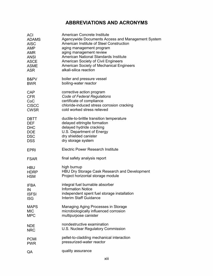
ABBREVIATIONS AND ACRONYMS
ACI ADAMS AISC AMP AMR ANSI ASCE ASME ASR
B&PV BWR
CAP CFR CoC CISCC CWSR
DBTT DEF DHC DOE DSC DSS
EPRI
FSAR
HBU HDRP HSM
IFBA IN ISFSI ISG
MAPS MIC MPC
NDE NRC
PCMI PWR
QA
American Concrete Institute Agencywide Documents Access and Management System American Institute of Steel Construction aging management program aging management review American National Standards Institute American Society of Civil Engineers American Society of Mechanical Engineers alkali-silica reaction
boiler and pressure vessel boiling-water reactor
corrective action program Code of Federal Regulations certificate of compliance chloride-induced stress corrosion cracking cold worked stress relieved
ductile-to-brittle transition temperature delayed ettringite formation delayed hydride cracking U.S. Department of Energy dry shielded canister dry storage system
Electric Power Research Institute
final safety analysis report
high burnup HBU Dry Storage Cask Research and Development Project horizontal storage module
integral fuel burnable absorber Information Notice independent spent fuel storage installation Interim Staff Guidance
Managing Aging Processes in Storage microbiologically influenced corrosion multipurpose canister
nondestructive examination U.S. Nuclear Regulatory Commission
pellet-to-cladding mechanical interaction pressurized-water reactor
quality assurance
xiv
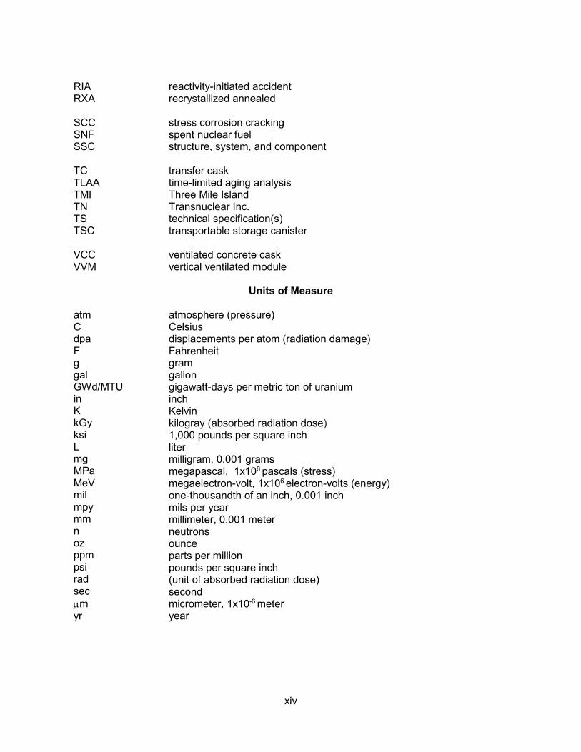
RIA RXA
SCC SNF SSC
TC TLAA TMI TN TS TSC
VCC VVM
atm C dpa F g gal GWd/MTU in K kGy ksi L mg MPa MeV mil mpy mm n oz ppm psi rad sec µm yr
reactivity-initiated accident recrystallized annealed
stress corrosion cracking spent nuclear fuel structure, system, and component
transfer cask time-limited aging analysis Three Mile Island Transnuclear Inc. technical specification(s) transportable storage canister
ventilated concrete cask vertical ventilated module
Units of Measure
atmosphere (pressure) Celsius displacements per atom (radiation damage) Fahrenheit gram gallon gigawatt-days per metric ton of uranium inch Kelvin kilogray (absorbed radiation dose) 1,000 pounds per square inch liter milligram, 0.001 grams megapascal, 1x10⁶ pascals (stress) megaelectron-volt, 1x10⁶ electron-volts (energy) one-thousandth of an inch, 0.001 inch mils per year millimeter, 0.001 meter neutrons ounce parts per million pounds per square inch (unit of absorbed radiation dose) second micrometer, 1x10⁻⁶ meter year
1-1
1 INTRODUCTION
1.1 Purpose and Use of the MAPS Report
The U.S. Nuclear Regulatory Commission (NRC) licenses the storage of spent nuclear fuel (SNF) in dry storage systems (DSSs) under the regulations of Title 10 of the Code of Federal Regulations (10 CFR) Part 72, “Licensing Requirements for the Independent Storage of Spent Nuclear Fuel, High-Level Radioactive Waste, and Reactor-Related Greater Than Class C Waste.” To date, licenses for specific independent spent fuel storage installations (ISFSIs) or certificates of compliance (CoCs) for DSSs have been issued for initial terms of 20 years, although regulations currently allow an initial 40-year storage period. Licenses and CoCs can be renewed for additional terms not to exceed 40 years. In accordance with 10 CFR 72.42, “Duration of License; Renewal,” and 10 CFR 72.240, “Conditions for Spent Fuel Storage Cask Renewal,” renewal applications must include:
i. time-limited aging analyses (TLAAs) that demonstrate that structures, systems, andcomponents (SSCs) important to safety will continue to perform their intended functionfor the requested period of extended operation
ii. aging management programs (AMPs) for management of issues associated with agingthat could adversely affect SSCs important to safety
NUREG–1927, Revision 1, “Standard Review Plan for Renewal of Specific Licenses and Certificates of Compliance for Dry Storage of Spent Nuclear Fuel,” provides guidance for the staff’s review of TLAAs and AMPs (NRC, 2016).
This Managing Aging Processes in Storage (MAPS) Report is a technical basis document that provides additional guidance to NRC staff to improve the effectiveness and efficiency of the renewal process for the dry storage of SNF. The MAPS Report provides a generic evaluation of the aging mechanisms that have the potential to challenge the ability of DSS SSCs to fulfill their important-to-safety functions. The MAPS Report also describes acceptable generic AMPs that an applicant may use to maintain the approved design bases of its storage system during the period of extended operation (from 20 to 60 years of storage1). An applicant for a renewed license or CoC may reference the information in the MAPS Report to support its design-specific aging management review (AMR) and proposed AMPs.
The content of the report is as follows.
• Chapter 1 briefly describes how the MAPS Report is to be used by the NRC staff.
• Chapter 2 defines the terms that are used throughout this report, including descriptionsof materials, environments, aging mechanisms, and aging effects (the manifestations ofaging mechanisms by degraded conditions or performance).
• Chapter 3 evaluates the aging mechanisms that may challenge the ability of SSCs tofulfill their important-to-safety function(s). Those mechanisms that are shown to havethe potential to adversely affect an important-to-safety function in the 60-year timeframe
1Because the NRC has granted, to date, initial storage licenses and CoCs for 20 years only, the MAPS Report considers the effects of aging for 40 years beyond the initial 20-year term (or 60 years total).

1-2
are identified as “credible.” This chapter provides the technical bases for the aging management recommendations that appear in the AMR tables and AMPs in Chapters 4 and 5, respectively.
• Chapter 4 describes selected DSS designs and provides AMR tables for those designs.The AMR tables identify the aging mechanisms and effects that could challenge thecapability of each SSC to fulfill its important-to-safety function(s) in the 20- to 60-yearperiod of extended operation. For those credible aging effects, the AMR tablesrecommend aging management approaches (i.e., AMPs, TLAAs, or other analyses).
• Chapter 5 provides guidance for identifying and evaluating TLAAs.
• Chapter 6 contains example AMPs that an applicant may use to address the credibleaging effects identified in the AMR tables.
Figure 1-1 provides a flowchart that shows how the guidance in the MAPS Report supports the renewal process.
The MAPS Report increases the efficiency of the licensing process by reducing redundant reviews of the same topic. If an applicant credits the information in the MAPS Report in the renewal application, the staff should ensure that the applicant demonstrates that the design features, environmental conditions, and operating experience for the subject ISFSI or DSS are bounded by those evaluated in the MAPS Report. Otherwise, the staff should ensure that the applicant revises its AMR and AMPs, as appropriate, to address the design or operating parameters applicable to its facility or storage system.
The MAPS Report describes acceptable methods to identify and manage credible aging mechanisms and effects for specific-license and CoC renewals. An applicant may propose alternatives for staff review. As such, the staff should not use the MAPS Report as a requirement. Nevertheless, its use should facilitate both the preparation of a specific license or CoC renewal application by an applicant and a timely, consistent review by the NRC staff.
Finally, the MAPS Report does not address the scoping of SSCs for specific-license or CoC renewal; this is addressed in Chapter 2 of NUREG–1927, Revision 1. Although the MAPS Report generically addresses SSCs for several storage system designs, scoping is design and license specific. The inclusion of a certain SSC in the MAPS Report does not necessarily imply that the particular SSC is within the scope of renewal for all ISFSIs or DSSs. Conversely, the omission of a certain SSC in the MAPS Report does not imply that the particular SSC is not within the scope of renewal for any ISFSI or DSS.
1.2 Scope of Report
The MAPS Report addresses the aging mechanisms and effects associated with the following DSS designs: Standardized and Advanced NUHOMS, HI-STORM 100, HI-STAR 100, TN-32 and -68, the NAC UMS, MPC, and MAGNASTOR systems, and the FuelSolutions storage system. The selection of these systems addresses near-term renewal applications and a variety of storage system designs. Although this report was written to specifically address those designs, the staff may consider the general applicability of this guidance to other designs.

1-3
Figure 1-1 Use of the MAPS Report in the Renewal Process
1.3 Public Comments
The draft NUREG–2214 was published for public comment on October 24, 2017 (82 FR 49233). The staff considered public comments on the draft guidance in preparing the final document. The public comments and the staff responses are available in the Agencywide Documents Access and Management System (ADAMS) at Accession No. ML19072A016.
1.4 Acknowledgments
The NRC would like to acknowledge the contributions of the staff at the Center for Nuclear Waste Regulatory Analyses (CNWRA) at the Southwest Research Institute for its role in developing the technical bases for the aging evaluations in this report. This includes the evaluations of the aging mechanisms in Chapter 3 and the associated AMR tables in Chapter 4. The staff at the CNWRA also assisted in the development of the introductory material and combining all portions of this document into a single, cohesive report.
The NRC also would like to acknowledge the contributions of Argonne National Laboratory in support of the U.S. Department of Energy (DOE) Used Fuel Disposition Campaign. Portions of
Scoping Evaluation • Identify SSCs within the Scope of Renewal
(see NUREG–1927, Section 2)
Aging Management Review • Define materials and environments for each SSC (MAPS Chapter 2)• Evaluate potential aging mechanisms and effects (MAPS Chapter 3)• Tabulate aging evaluation results for each SSC (MAPS Chapter 4) • Identify activities to manage credible aging
mechanisms and effects (MAPS Chapter 4)
Time-Limited Aging Analyses or Other Supporting Analyses
• Evaluate time-limited aging analyses• Provide other supporting analyses to
demonstrate that SSCs will continue toperform their intended functions
(see NUREG–1927; MAPS Chapter 5)
Aging Management Programs • Describe programs for the management
of aging issues(MAPS Chapter 6)
1-4
the storage system descriptions in Chapter 4 of the MAPS Report were taken from the information contained in Chapter V of the Argonne/DOE report, “Managing Aging Effects on Dry Cask Storage Systems for Extended Long-Term Storage and Transportation of Used Fuel” (Chopra et al., 2014).
1.5 References
Chopra, O., D. Diercks, R. Fabian, Z. Han, and Y. Liu. “Managing Aging Effects on Dry Cask Storage Systems for Extended Long-Term Storage and Transportation of Used Fuel.” FCRD–UFD–2014–000476. ANL–13/15, Rev. 2. Washington, DC.: U.S. Department of Energy. 2014.
NRC. NUREG–1927, “Standard Review Plan for Renewal of Specific Licenses and Certificates of Compliance for Dry Storage of Spent Nuclear Fuel.” Revision 1. Agencywide Documents Access and Management System Accession No. ML16179A148. Washington, DC: U.S. Nuclear Regulatory Commission. 2016.
2-1
2 DEFINITIONS
This chapter defines the usage of terms in the technical basis discussions in Chapter 3, the aging management review (AMR) tables in Chapter 4, and the aging management programs in Chapter 5. Selected definitions and usage are provided for the materials of construction, service environments, aging mechanisms, and aging effects (the manifestations of aging mechanisms by degraded conditions or performance).
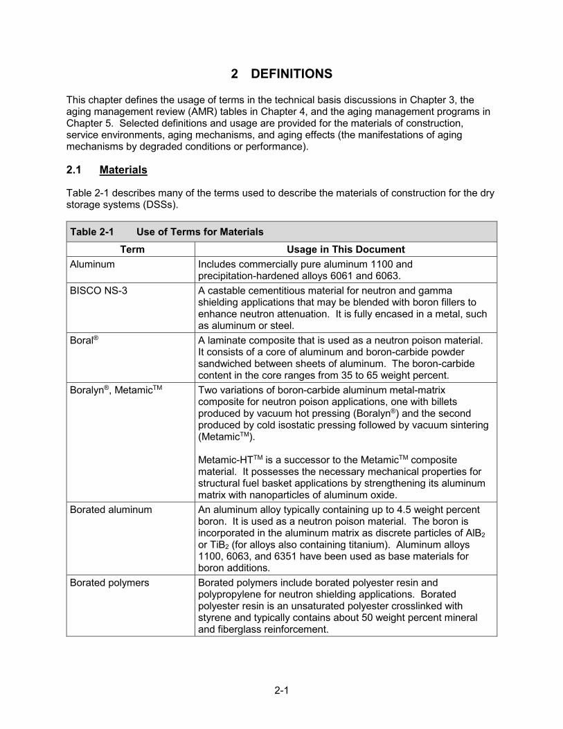
2.1 Materials
Table 2-1 describes many of the terms used to describe the materials of construction for the dry storage systems (DSSs).
Table 2-1 Use of Terms for Materials Term Usage in This Document
Aluminum Includes commercially pure aluminum 1100 and precipitation-hardened alloys 6061 and 6063.
BISCO NS-3 A castable cementitious material for neutron and gamma shielding applications that may be blended with boron fillers to enhance neutron attenuation. It is fully encased in a metal, such as aluminum or steel.
Boral® A laminate composite that is used as a neutron poison material. It consists of a core of aluminum and boron-carbide powder sandwiched between sheets of aluminum. The boron-carbide content in the core ranges from 35 to 65 weight percent.
Boralyn®, MetamicTM Two variations of boron-carbide aluminum metal-matrix composite for neutron poison applications, one with billets produced by vacuum hot pressing (Boralyn®) and the second produced by cold isostatic pressing followed by vacuum sintering (MetamicTM).
Metamic-HTTM is a successor to the MetamicTM composite material. It possesses the necessary mechanical properties for structural fuel basket applications by strengthening its aluminum matrix with nanoparticles of aluminum oxide.
Borated aluminum An aluminum alloy typically containing up to 4.5 weight percent boron. It is used as a neutron poison material. The boron is incorporated in the aluminum matrix as discrete particles of AlB2 or TiB2 (for alloys also containing titanium). Aluminum alloys 1100, 6063, and 6351 have been used as base materials for boron additions.
Borated polymers Borated polymers include borated polyester resin and polypropylene for neutron shielding applications. Borated polyester resin is an unsaturated polyester crosslinked with styrene and typically contains about 50 weight percent mineral and fiberglass reinforcement.

2-2
Table 2-1 Use of Terms for Materials (continued)Term Usage in This Document
Borated stainless steel An austenitic chromium-nickel steel with boron additions up to 2.5 weight percent. It is used as a neutron poison material. The boron in the form of borides is dispersed in the Type 304 stainless steel matrix as an intermetallic phase.
Concrete A mixture of hydraulic cement, aggregates, and water, with or without admixtures, fibers, or other cementitious materials.
Copper alloys Copper alloys used in DSSs include bronzes (copper alloyed with tin) and brasses (copper alloyed with zinc).
Holtite-A™ A Holtec neutron shielding material consisting of epoxy polymer, B4C added as a finely divided powder, and aluminum hydroxide. It is fully encased in a metal enclosure.
Nickel alloys Nickel alloys include Inconel 718 and X750. Inconel is a family of austenitic nickel-chromium-based superalloys. Both Inconel 718 and X750 are precipitation-hardening alloys.
Stainless steel Stainless steel includes Types 304, 316, XM-19, SA193-Gr. B8, SA351-Gr. CF3, and Nitronic 60 austenitic stainless steels and Type 630 precipitation-hardening martensitic stainless steel. Type 630 stainless steel is commonly referred to as 17-4PH and contains 15–17.5 percent chromium, 3–5 percent copper, and 3–5 percent nickel (in weight percent). Chrome-plated stainless steel is also included in the category of stainless steel.
Steel Various carbon steels, alloy steels, and high-strength, low-alloy steels. Examples of steel designations included in this category are ASTM A36, ASTM A320-Gr. L43, ASTM F436, SA36, SA193-Gr. B7, SA203-Gr. D/E, SA266-Cl. 2, SA320-Gr. L43, SA350-Gr. LF2/LF3, SA414, SA508-Cl. 1A/3A, SA516-Gr. 70, SA533-Gr. B, SA537-Cl. 2, SA540-Gr. B23/24, SA620, and SA696-Gr. B. Galvanized steel, aluminum-coated steel, and electroless nickel-plated steel are also included in the category of steel.
Zirconium-based alloys The materials of construction of fuel cladding and fuel assembly hardware. Various zirconium-based materials have been used in commercial reactor applications because of their low neutron cross section and excellent corrosion resistance to a variety of environmental conditions. The cladding types Zircaloy-2, Zircaloy-4, ZIRLOTM, and M5® are included in this category.
2-3
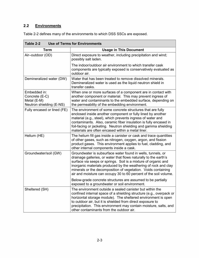
2.2 Environments
Table 2-2 defines many of the environments to which DSS SSCs are exposed.
Table 2-2 Use of Terms for Environments Term Usage in This Document
Air–outdoor (OD) Direct exposure to weather, including precipitation and wind; possibly salt laden. The indoor/outdoor air environment to which transfer cask components are typically exposed is conservatively evaluated as outdoor air.
Demineralized water (DW) Water that has been treated to remove dissolved minerals. Demineralized water is used as the liquid neutron shield in transfer casks.
Embedded in: Concrete (E-C) Metal (E-M) Neutron shielding (E-NS)
When one or more surfaces of a component are in contact with another component or material. This may prevent ingress of water and contaminants to the embedded surface, depending on the permeability of the embedding environment.
Fully encased or lined (FE) The environment of some concrete structures that are fully enclosed inside another component or fully lined by another material (e.g., steel), which prevents ingress of water and contaminants. Also, ceramic fiber insulation is fully encased in foil-facing or jacketing. Neutron shielding and gamma shielding materials are often encased within a metal liner.
Helium (HE) The helium fill gas inside a canister or cask and trace quantities of other gases, such as nitrogen, oxygen, argon, and fission product gases. This environment applies to fuel, cladding, and other internal components inside a cask.
Groundwater/soil (GW) Groundwater is subsurface water found in wells, tunnels, or drainage galleries, or water that flows naturally to the earth’s surface via seeps or springs. Soil is a mixture of organic and inorganic materials produced by the weathering of rock and clay minerals or the decomposition of vegetation. Voids containing air and moisture can occupy 30 to 60 percent of the soil volume. Below-grade concrete structures are assumed to be partially exposed to a groundwater or soil environment.
Sheltered (SH) The environment outside a sealed canister but within the confined internal space of a shielding structure (e.g., overpack or horizontal storage module). The sheltered environment is open to outdoor air, but it is shielded from direct exposure to precipitation. This environment may contain moisture, salts, and other contaminants from the outdoor air.

2-4
2.3 Aging Mechanisms
Table 2-3 defines the aging mechanisms that are evaluated in this report.
Table 2-3 Use of Terms for Aging Mechanisms Term Usage in This Document
Aggressive chemical attack
The degradation of concrete by strong acids. Chlorides and sulfates of potassium, sodium, and magnesium may attack concrete, depending on their concentrations in the soil/groundwater that comes into contact with the concrete. The minimum thresholds causing concrete degradation are 500 ppm chloride and 1,500 ppm sulfate.
Boron depletion The degradation of the neutron-absorbing capacity of neutron poison and shielding materials when they are exposed to neutron fluence.
Corrosion The electrochemical reaction of a metal or metal alloy in an environment that results in oxidation or wastage of the material.
Creep Creep, for a metallic material, refers to a time-dependent continuous deformation process under constant stress. It is a thermally activated process and is generally a concern at temperatures greater than 40 percent of the material’s absolute melting temperature. However, low-temperature creep is an athermal process that is considered as a potential degradation mechanism for some alloys, including zirconium-based alloys. In concrete, creep is related to the loss of absorbed water from the hydrated cement paste. It is a function of the modulus of elasticity of the aggregate.
Crevice corrosion Localized corrosion in joints, connections, and other small, close-fitting regions that develop local aggressive environments.
Dehydration at high temperatures
Dehydration reactions of the hydrated cement paste in concrete when exposed to temperatures greater than 65 degrees C [149 degrees F]. Dehydration can degrade concrete strength and increase susceptibility to cracking. The degree of concrete degradation depends on several factors, including concrete mixing, aggregate type, curing, loading condition, moisture retention and content, and exposure time.
Delayed ettringite formation
During concrete curing, the naturally occurring ettringite (a calcium aluminum sulfate mineral) converts to monosulfoaluminate if curing temperatures are greater than about 70 degrees C [158 degrees F]. After concrete hardens, ettringite will reform if the temperature decreases below about 70 degrees C [158 degrees F], resulting in concrete cracking and spalling. The conditions necessary for the occurrence of delayed ettringite formation are excessive temperatures during concrete casting, the presence of internal sulfates, and a moist environment.

2-5
Table 2-3 Use of Terms for Aging Mechanisms (continued) Term Usage in This Document
Delayed hydride cracking The propagation of a crack in zirconium-based cladding materials as a result of diffusion of hydrogen to a crack tip and the embrittlement of the near-tip region due to hydride precipitation. The operability of the delayed-hydride-cracking mechanism in fuel cladding depends on the stress imposed on the cladding.
Erosion Soil erosion, or removal, is primarily caused by rainfall and surface runoff, floods, or wind. Soil erosion can affect the stability of concrete structures, resulting in scouring that is a localized loss of soil, often around a foundation element. Factors that affect the erosion rates include soil structure and composition, climate, topography, and vegetation cover.
Fatigue Also termed “cyclic loading” or “thermal/mechanical fatigue.” Fatigue is a phenomenon leading to fracture under repeated or fluctuating stresses having a maximum value less than the tensile strength of the material. Fatigue fractures are progressive and grow under the action of the fluctuating stress. Fatigue due to cyclic thermal loads is defined as the structural degradation that can occur from repeated stress/strain cycles caused by fluctuating loads and temperatures. After repeated cyclic loading of sufficient magnitude, microstructural damage may accumulate, leading to macroscopic crack initiation at the most vulnerable regions. Subsequent mechanical or thermal cyclic loading may lead to growth of the initiated crack.
Freeze-thaw Repeated freezing and thawing of water can cause degradation of concrete, characterized by scaling, cracking, and spalling. The cause is water freezing within the pores of the concrete, creating hydraulic pressure.
Galvanic corrosion Accelerated corrosion of a metal when in electrical contact with a more noble metal or nonmetallic conductor in a corrosive electrolyte.
General corrosion Uniform loss of material due to corrosion, proceeding at approximately the same rate over a metal surface.
Hydride reorientation and hydride-induced embrittlement
The precipitation of radial hydrides results in embrittlement of zirconium-based cladding materials under pinch-load stresses at low-to-moderate temperatures. Reorientation of hydrides from the circumferential-axial to radial-axial direction is caused by heating and cooling of the cladding under sufficient cladding hoop tensile stresses.

2-6
Table 2-3 Use of Terms for Aging Mechanisms (continued)Term Usage in This Document
Leaching of calcium hydroxide
The dissolution of calcium-containing concrete components (e.g., calcium hydroxide) when water passes through either cracks, inadequately prepared construction joints, or areas not sufficiently consolidated during placing. Once the calcium hydroxide has been leached away, other cementitious constituents become vulnerable to chemical decomposition, finally leaving only the silica and alumina gels behind and lowering the strength of the concrete. The water’s aggressiveness in the leaching of calcium hydroxide depends on its salt content, pH, and temperature. This leaching action is effective only if the water flows through the concrete.
Mechanical overload The overload of fuel cladding due to fuel pellet swelling. Fuel pellet swelling is the result of decay gas production in the pellet. Pellet swelling can increase stresses on the cladding.
Microbiological degradation
Biodegradation attack of concrete by organisms growing on its surfaces under favorable environmental conditions (e.g., moisture, near neutral pH, presence of nutrients), causing an increase in concrete porosity and permeability and the loss of material by spalling or scaling.
Microbiologically influenced corrosion
Any of the various forms of corrosion influenced by the activity of such microorganisms as bacteria, fungi, and algae, and/or the products of their metabolism. For example, anaerobic bacteria can establish an electrochemical galvanic reaction or disrupt a passive protective film; acid-producing bacteria can produce corrosive metabolites.
Oxidation A corrosion reaction. In this report, oxidation also is a defined aging mechanism describing the reaction of zirconium alloy fuel rod cladding with water to form zirconium oxide.
Pitting corrosion A localized form of corrosion that is confined to a point or small area of a metal surface. It takes the form of cavities called pits.
Radiation damage and radiation embrittlement
The loss of ductility, fracture toughness, and resistance to cracking of metals that may occur under exposure to neutron radiation. In concrete, radiation exposure can cause dissociation of water into hydrogen and oxygen, leading to decreased compressive and tensile strengths. The extent of radiation damage to concrete depends on the neutron and gamma fluence.
Reaction with aggregates The presence of reactive alkalis in concrete can lead to subsequent reactions with aggregates that may lead to cracking, a loss of material, or an increase in porosity and permeability. These alkalis are introduced mainly by cement but also may come from admixtures, salt contamination, seawater penetration, or solutions of deicing salts. These reactions include alkali-silica reactions, cement-aggregate reactions, and aggregate-carbonate reactions.

2-7
Table 2-3 Use of Terms for Aging Mechanisms (continued) Term Usage in This Document
Salt scaling Salt scaling damage manifests as flaking of material from the concrete surface. Salt scaling takes place when concrete is exposed to freezing temperatures, moisture, and dissolved salts (e.g., deicing salts). This degradation mode affects mainly horizontal concrete surfaces where water ponding can be expected.
Settlement Settlement of a concrete structure may occur due to changes in the site conditions (e.g., water table). The amount of settlement depends on the foundation material.
In soil, loss of form due to settlement can occur during the first several years of placement. Factors that control soil settlement include the type of soil particles and particle packing, the amount of water used during the compaction process, and the height of soil fill.
Shrinkage Shrinkage of concrete can result from cement hydration and loss of moisture during drying. Cracking and shortening of concrete due to shrinkage can occur early after concrete placement.
Stress corrosion cracking (SCC)
The cracking of a metal produced by the combined action of corrosion and a tensile stress (applied or residual). SCC is highly chemical specific in that certain alloys are likely to undergo SCC only when exposed to a small number of chemical environments.
Stress relaxation A loss of preload in a heavily loaded bolt. Over time, the clamping force provided by a bolt may decrease due to atomic movement within the stressed bolt material (analogous to the metallic creep mechanism at elevated temperatures).
Thermal aging Also termed “thermal aging embrittlement” or “thermal embrittlement.” Many materials are intentionally thermally aged during their manufacture to achieve desired mechanical properties. Continued exposure to elevated temperatures during operation can, in some cases, result in undesirable properties. For example, at operating temperatures of 300 to 400 degrees C [572 to 752 degrees F], austenitic stainless steel welds that contain ferrite exhibit a spinodal decomposition (separation of a solution into distinct phases) of the ferrite phase into ferrite-rich and chromium-rich phases. This may give rise to embrittlement (reduction in fracture toughness), depending on the amount, morphology, and distribution of the ferrite phase and the composition of the stainless steel.
Wear The removal of surface material due to relative motion between two surfaces or under the influence of hard, abrasive particles. Wear occurs in parts that experience intermittent relative motion or frequent manipulation.

2-8
Table 2-3 Use of Terms for Aging Mechanisms (continued)Term Usage in This Document
Wet corrosion and blistering
A degradation mechanism for neutron poison plates with open porosity (e.g., aluminum-boron carbide laminate composites) as a result of water entering pores in the material during loading, leading to internal corrosion. Blisters could potentially occur from trapped hydrogen produced from corrosion reactions during repeated wetting and drying (i.e., repeated DSS reflooding). Blistering can cause dimensional changes affecting criticality considerations due to moderator displacement and may also hinder the retrieval of fuel assemblies.

2-9
2.4 Aging Effects
An aging effect is the manifestation of an aging mechanism, as evidenced by a degraded condition or performance. Table 2-4 defines the aging effects described in this report.
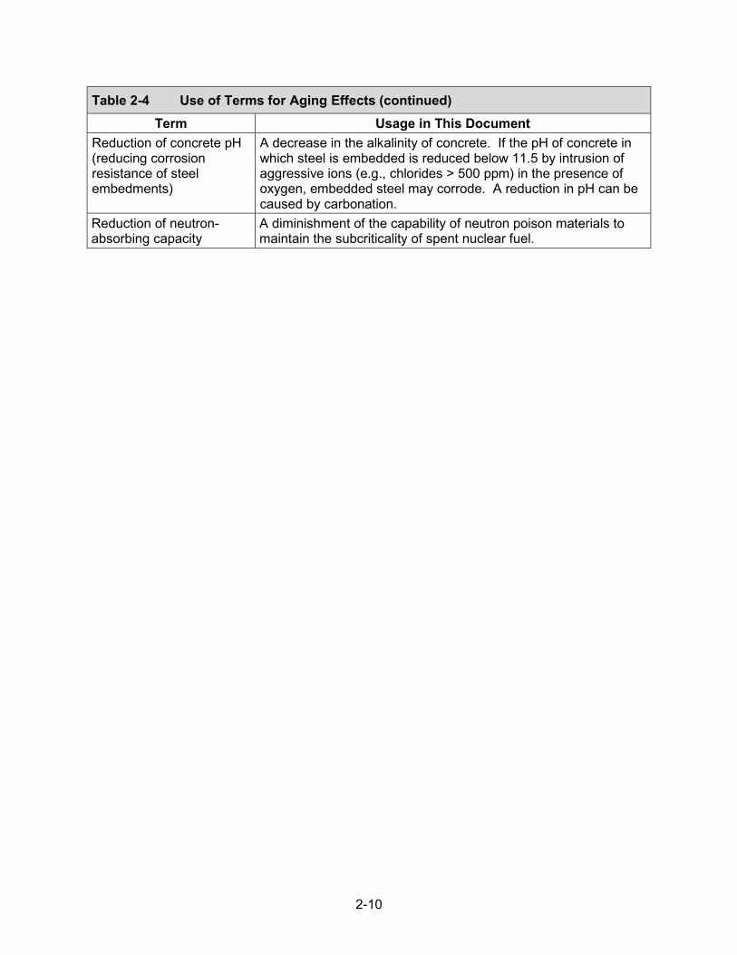
Table 2-4 Use of Terms for Aging Effects Term Usage in This Document
Changes in dimension A change in the size of a component resulting from creep of aluminum and zirconium-based alloys. Changes in dimension also can be caused by wet corrosion and blistering of Boral® neutron poison materials.
Cracking Crack initiation and growth in metallic components as a result of SCC, fatigue, and delayed hydride cracking. Cracking in concrete is a complete or incomplete separation of concrete into two or more parts produced by breaking or fracturing.
Increase in porosity and permeability
An increase in the percentage of the volume of voids in a concrete material or an increase in the susceptibility of concrete to permit liquids or gasses to pass through.
Loss of form A change in the shape or position of soil resulting from settlement due to poor soil consolidation. In addition, soil tends to absorb moisture with time and thus promotes loss of form.
Loss of fracture toughness and loss of ductility
A decrease in the ability of a material to resist fracture. This phenomenon results from thermal aging embrittlement, radiation embrittlement, or hydrogen embrittlement.
Loss of material The destructive removal of material due to general corrosion, pitting corrosion, crevice corrosion, galvanic corrosion, microbiologically influenced corrosion, or aggressive chemical attack. In concrete structures, loss of material can result from local flaking, spalling, or peeling away of the near-surface portion of hardened concrete.
Loss of preload A reduction in the clamping force in a mechanically loaded joint. Loss of shielding A diminishment of the capability of a material to shield radiation. Loss of strength A decrease in the ability of a material to support a mechanical
load. In metals, loss of strength may be due to thermal aging or annealing. In concrete structures, loss of strength can also be caused by the leaching of calcium hydroxide or reaction with aggregates.
None A term used in the AMR tables for certain material and environment combinations that may not be subject to credible aging mechanisms; thus, there are no relevant aging effects that require management.
Precursor to SCC A material condition that initiates SCC. Both pitting and crevice corrosion are known to be precursors to SCC and, as such, can lead to cracking of stainless steel canisters.
2-10
Table 2-4 Use of Terms for Aging Effects (continued)Term Usage in This Document
Reduction of concrete pH (reducing corrosion resistance of steel embedments)
A decrease in the alkalinity of concrete. If the pH of concrete in which steel is embedded is reduced below 11.5 by intrusion of aggressive ions (e.g., chlorides > 500 ppm) in the presence of oxygen, embedded steel may corrode. A reduction in pH can be caused by carbonation.
Reduction of neutron-absorbing capacity
A diminishment of the capability of neutron poison materials to maintain the subcriticality of spent nuclear fuel.
3-1
3 EVALUATION OF AGING MECHANISMS
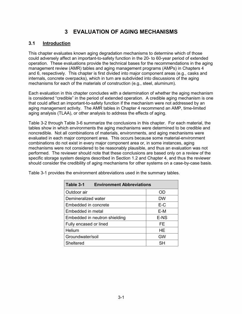
3.1 Introduction
This chapter evaluates known aging degradation mechanisms to determine which of those could adversely affect an important-to-safety function in the 20- to 60-year period of extended operation. These evaluations provide the technical bases for the recommendations in the aging management review (AMR) tables and aging management programs (AMPs) in Chapters 4 and 6, respectively. This chapter is first divided into major component areas (e.g., casks and internals, concrete overpacks), which in turn are subdivided into discussions of the aging mechanisms for each of the materials of construction (e.g., steel, aluminum).
Each evaluation in this chapter concludes with a determination of whether the aging mechanism is considered “credible” in the period of extended operation. A credible aging mechanism is one that could affect an important-to-safety function if the mechanism were not addressed by an aging management activity. The AMR tables in Chapter 4 recommend an AMP, time-limited aging analysis (TLAA), or other analysis to address the effects of aging.
Table 3-2 through Table 3-6 summarize the conclusions in this chapter. For each material, the tables show in which environments the aging mechanisms were determined to be credible and noncredible. Not all combinations of materials, environments, and aging mechanisms were evaluated in each major component area. This occurs because some material-environment combinations do not exist in every major component area or, in some instances, aging mechanisms were not considered to be reasonably plausible, and thus an evaluation was not performed. The reviewer should note that these conclusions are based only on a review of the specific storage system designs described in Section 1.2 and Chapter 4, and thus the reviewer should consider the credibility of aging mechanisms for other systems on a case-by-case basis.
Table 3-1 provides the environment abbreviations used in the summary tables.
Table 3-1 Environment Abbreviations Outdoor air OD Demineralized water DW Embedded in concrete E-CEmbedded in metal E-MEmbedded in neutron shielding E-NSFully encased or lined FE Helium HE Groundwater/soil GW Sheltered SH
3-2
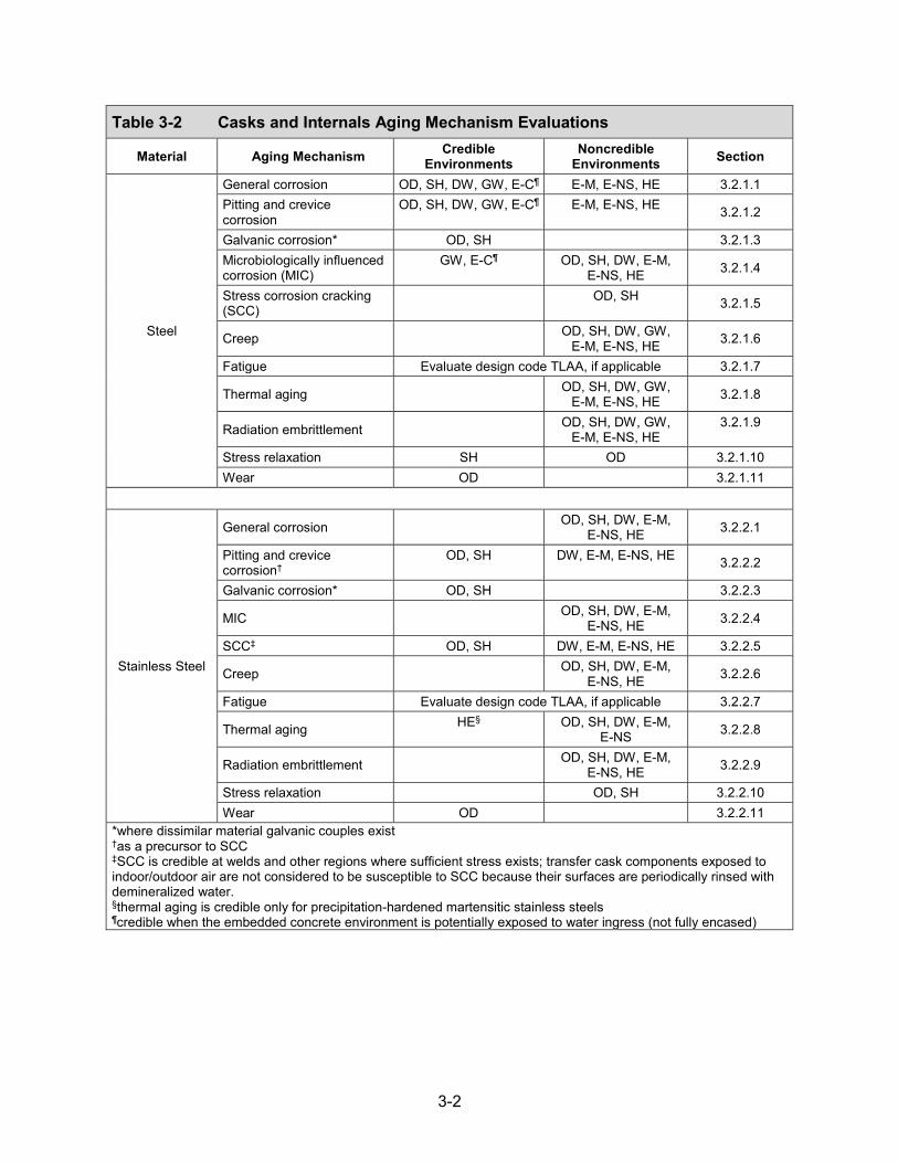
Table 3-2 Casks and Internals Aging Mechanism Evaluations
Material Aging Mechanism Credible Environments
Noncredible Environments Section
Steel
General corrosion OD, SH, DW, GW, E-C¶ E-M, E-NS, HE 3.2.1.1 Pitting and crevice corrosion
OD, SH, DW, GW, E-C¶ E-M, E-NS, HE 3.2.1.2
Galvanic corrosion* OD, SH 3.2.1.3 Microbiologically influenced corrosion (MIC)
GW, E-C¶ OD, SH, DW, E-M, E-NS, HE 3.2.1.4
Stress corrosion cracking (SCC)
OD, SH 3.2.1.5
Creep OD, SH, DW, GW, E-M, E-NS, HE 3.2.1.6
Fatigue Evaluate design code TLAA, if applicable 3.2.1.7
Thermal aging OD, SH, DW, GW, E-M, E-NS, HE 3.2.1.8
Radiation embrittlement OD, SH, DW, GW, E-M, E-NS, HE
3.2.1.9
Stress relaxation SH OD 3.2.1.10 Wear OD 3.2.1.11
Stainless Steel
General corrosion OD, SH, DW, E-M, E-NS, HE 3.2.2.1
Pitting and crevice corrosion†
OD, SH DW, E-M, E-NS, HE 3.2.2.2
Galvanic corrosion* OD, SH 3.2.2.3
MIC OD, SH, DW, E-M, E-NS, HE 3.2.2.4
SCC‡ OD, SH DW, E-M, E-NS, HE 3.2.2.5
Creep OD, SH, DW, E-M, E-NS, HE 3.2.2.6
Fatigue Evaluate design code TLAA, if applicable 3.2.2.7
Thermal aging HE§ OD, SH, DW, E-M, E-NS 3.2.2.8
Radiation embrittlement OD, SH, DW, E-M, E-NS, HE 3.2.2.9
Stress relaxation OD, SH 3.2.2.10 Wear OD 3.2.2.11
*where dissimilar material galvanic couples exist†as a precursor to SCC‡SCC is credible at welds and other regions where sufficient stress exists; transfer cask components exposed toindoor/outdoor air are not considered to be susceptible to SCC because their surfaces are periodically rinsed withdemineralized water.§thermal aging is credible only for precipitation-hardened martensitic stainless steels¶credible when the embedded concrete environment is potentially exposed to water ingress (not fully encased)

3-3
Table 3-2 Casks and Internals Aging Mechanism Evaluations (continued)
Material Aging Mechanism Credible Environments
Noncredible Environments Section
Aluminum Alloys
General corrosion* SH E-M, E-NS, HE 3.2.3.1 Pitting and crevice corrosion SH E-M, E-NS, HE 3.2.3.2 Galvanic corrosion† SH HE 3.2.3.3 MIC SH, E-M, E-NS, HE 3.2.3.4 Creep analyses required‡ 3.2.3.5 Fatigue Evaluate design code TLAA, if applicable 3.2.3.6 Thermal aging analyses required‡ 3.2.3.7 Radiation embrittlement SH, E-M, E-NS, HE 3.2.3.8
Nickel Alloys
General corrosion OD 3.2.4.1 Pitting and crevice corrosion OD 3.2.4.2 MIC OD 3.2.4.3 SCC OD 3.2.4.4 Fatigue Evaluate design code TLAA, if applicable 3.2.4.5 Radiation embrittlement OD 3.2.4.6 Stress relaxation OD 3.2.4.7 Wear OD 3.2.4.8
Copper Alloys
General corrosion OD 3.2.5.1 Pitting and crevice corrosion OD 3.2.5.2 MIC OD 3.2.5.3 Radiation embrittlement OD 3.2.5.4
Lead All E-M 3.2.6 Depleted Uranium All E-M 3.2.7
Coatings Radiation embrittlement analyses required 3.2.8 *general corrosion is not considered to be credible for anodized aluminum†where dissimilar metal couples exist‡creep and thermal aging are relevant only for load-bearing components.

3-4
Table 3-3 Neutron Shielding Materials Aging Mechanism Evaluations
Material Aging Mechanism Credible Environments
Noncredible Environments Section
Neutron Shielding
Boron depletion analyses required 3.3.1.1
Thermal aging FE* 3.3.1.2
Radiation embrittlement FE* 3.3.1.3 *thermal aging and radiation embrittlement are credible only for polymer-based neutron-shielding materials.
Table 3-4 Neutron Poison Materials Aging Mechanism Evaluations
Material Aging Mechanism Credible Environments
Noncredible Environments Section
Borated Stainless Steels
General corrosion HE 3.4.1 Galvanic corrosion HE 3.4.1 Wet corrosion and blistering HE 3.4.1 Boron depletion HE* 3.4.1.1 Creep HE 3.4.1.2 Thermal aging HE 3.4.1.3 Radiation embrittlement HE 3.4.1.4
Borated Aluminum and
Aluminum-based Composites
General corrosion HE 3.4.2.1 Galvanic corrosion HE 3.4.2.2 Wet corrosion and blistering HE 3.4.2.3 Boron depletion HE* 3.4.2.4 Creep HE† 3.4.2.5 Thermal aging HE† 3.4.2.6 Radiation embrittlement HE 3.4.2.7
*when a boron depletion analysis is included in the design bases, applicants must provide a TLAA to demonstratethat depletion will not challenge noncriticality in the period of extended operation†creep and thermal aging are relevant only for load-bearing aluminum components.

3-5
Table 3-5 Concrete Overpacks, Support Pads, and Ceramic Fiber Insulation Aging Mechanism Evaluations
Material Aging Mechanism Credible Environments
Noncredible Environments Section
Concrete
Freeze and thaw OD, GW (above freeze line)
SH, FE, GW (below freeze line) 3.5.1.1
Creep all 3.5.1.2 Reaction with aggregates all* 3.5.1.3 Differential settlement GW OD, SH 3.5.1.4 Aggressive chemical attack OD, GW SH, FE 3.5.1.5 Corrosion of reinforcing steel
OD, GW SH, FE 3.5.1.6
Shrinkage OD, SH, GW, FE 3.5.1.7 Leaching of calcium hydroxide
OD, SH, GW FE 3.5.1.8
Radiation damage OD, SH, GW, FE 3.5.1.9 Fatigue OD, SH, GW, FE 3.5.1.10 Dehydration at high temperature†
OD, SH, GW, FE 3.5.1.11
Microbiological degradation GW OD, SH, FE 3.5.1.12 Delayed ettringite formation OD, SH, GW, FE 3.5.1.13
Salt scaling OD, GW (above freeze line)
SH, FE, GW (below freeze line) 3.5.1.14
Ceramic Fiber Insulation
Radiation damage analysis required 3.5.2.1 Moisture absorption 3.5.2.2 3.5.2.2
*where moisture is available†dehydration at high temperature is relevant only for concrete inlet and outlet vents.
3-6
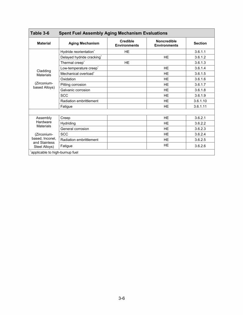
Table 3-6 Spent Fuel Assembly Aging Mechanism Evaluations
Material Aging Mechanism Credible Environments
Noncredible Environments Section
Cladding Materials
(Zirconium-based Alloys)
Hydride reorientation* HE 3.6.1.1 Delayed hydride cracking* HE 3.6.1.2 Thermal creep* HE 3.6.1.3 Low-temperature creep* HE 3.6.1.4 Mechanical overload* HE 3.6.1.5 Oxidation HE 3.6.1.6 Pitting corrosion HE 3.6.1.7 Galvanic corrosion HE 3.6.1.8 SCC HE 3.6.1.9 Radiation embrittlement HE 3.6.1.10 Fatigue HE 3.6.1.11
Assembly Hardware Materials
(Zirconium-based, Inconel, and Stainless Steel Alloys)
Creep HE 3.6.2.1 Hydriding HE 3.6.2.2 General corrosion HE 3.6.2.3 SCC HE 3.6.2.4 Radiation embrittlement HE 3.6.2.5
Fatigue HE 3.6.2.6 *applicable to high-burnup fuel

3-7
3.2 Casks and Internals
“Casks and internals” include various metallic subcomponents of the storage casks or canisters, the fuel baskets and other internal subcomponents (other than spent fuel assemblies), the storage modules or overpacks, and the transfer casks. These subcomponents are exposed to several environments within and outside the dry storage systems (DSSs), such as sheltered environments, indoor air, outdoor air, demineralized water, groundwater or soil, helium, and embedded environments. The spent nuclear fuel (SNF) also exposes subcomponents to elevated temperatures and radiation, with heat exposure and dose depending on the subcomponent location and the SNF characteristics (e.g., burnup and age of spent fuel). The materials of construction for these subcomponents include steel, stainless steel, aluminum alloys, nickel alloys, copper alloys, and lead.
A set of known aging mechanisms for metallic cask and internal subcomponents was established by first broadly identifying all potential mechanisms through a review of gap assessments for DSSs, technical literature, and operating experience from nuclear and nonnuclear applications (NRC, 2014, 2010a; Chopra et al., 2014; Hanson et al., 2012; Sindelar et al., 2011; NWTRB, 2010). The known environmental, thermal, mechanical, and irradiation-induced aging mechanisms are as follows:
• general corrosion• pitting and crevice corrosion• galvanic corrosion• MIC• SCC (including hydrogen embrittlement)• creep• fatigue• thermal aging• radiation embrittlement• stress relaxation• wear
Not all of these mechanisms are considered to be credible for each structure, system, and component (SSC). For example, temperatures are not considered sufficiently high to cause creep of steel and stainless steel subcomponents. Also, general corrosion is not considered to be a credible aging mechanism for subcomponents fabricated from stainless steels, because these materials exhibit passive behavior and negligible general corrosion rates. Detailed discussions regarding potential aging mechanisms for each material and the technical bases for those requiring aging management follow.
3.2.1 Steel (carbon, low-alloy, high-strength low-alloy)
In DSSs, steel subcomponents are commonly used and are exposed to sheltered environments, outdoor air, helium, demineralized water, and groundwater or soil, and also may be embedded in concrete or neutron-shielding materials. The exterior surfaces of some steel subcomponents are coated with epoxy or inorganic zinc to mitigate corrosion; however, these coatings can degrade, resulting in exposure of steel to the atmosphere. Steels used to construct transfer casks are predominately exposed to an indoor environment, except for short periods of outdoor exposure during transfer operations. For such air-indoor/outdoor environment exposure, aging

3-8
effects from aqueous corrosion processes are expected to be bounded by the outdoor environment. As such, the indoor air environment is not discussed separately.
3.2.1.1 General Corrosion
General corrosion, also known as uniform corrosion, proceeds at approximately the same rate over a metal surface (Phull, 2003b). Freely exposed steel surfaces in contact with moist air or water are subject to general corrosion. The corrosion rate depends on solution composition, pH, and temperature. The iron Pourbaix diagram shows that iron undergoes active corrosion forming Fe2+ or Fe3+ ions at pH values lower than 8.5 to 9 (Kodama, 2005). At higher values of pH, iron can be passive, leading to a very low corrosion rate.
Steel subcomponents exposed to outdoor and sheltered environments
If steel is placed in a completely dry atmosphere, oxide film growth is so small that the corrosion rate is virtually negligible. However, in outdoor conditions, rain, fog, snow, and dew condensation can generate moisture layers on the steel surface that cause general corrosion. Atmospheric corrosion rates can vary from 0 to 0.2 millimeters/year (mm/yr) [0 to 7.9 mils/yr] depending on relative humidity, temperature, and levels of chloride and pollutants in the atmosphere (NACE, 2002). Rates can be more significant in industrial and marine environments (McCuen and Albrecht, 1994).
In a sheltered environment, deliquescence1 of airborne salts below the dew point also could generate an aqueous electrolyte initiating general corrosion. These salts may be chloride rich and originate from marine environments, deicing salts, and condensed water from cooling towers, as well as a range of other nonchloride-rich species originating from industrial, agricultural, and commercial activities. Studies have shown that MgCl2, a component of sea salt with a low deliquescence relative humidity, would deliquesce below 52 degrees C [126 degrees F] under realistic absolute humidities in nature (He et al., 2014). The heat generated by the radioactive decay of spent fuel decreases over time. Time-temperature profiles calculated for the stainless steel canister shell suggest that, while initial temperatures are high, the threshold temperature for deliquescence of some salts on the external surface of the shell could be reached during the 60-year timeframe (EPRI, 2006; Meyer et al., 2013).
Because steel subcomponents exposed to sheltered environments are usually located farther away from the fuel compared to the stainless steel canister shell, they are expected to reach these threshold temperatures for deliquescence at an earlier time. As such, the potential for general corrosion of steel subcomponents exposed to a sheltered environment is present.
Because aqueous electrolytes initiating general corrosion of steels exposed to outdoor and sheltered environments are potentially present, and corrosion rates may be sufficient to affect component intended functions, general corrosion is considered to be credible, and therefore, aging management is required during the 60-year timeframe.
Steel subcomponents exposed to demineralized water
Demineralized water is used in the steel water jacket of some transfer casks for radiation shielding. In some cases, 25-percent ethylene glycol is added to the water to decrease the
1Deliquescence refers to a process wherein the species, such as a hygroscopic salt, absorbs water from the air in conditions of high relative humidity.

3-9
freezing point, and this is expected to decrease the corrosivity of water (van Bodegom et al., 1987). The iron Pourbaix diagram shows that iron undergoes active corrosion at neutral pH, as long as water is present (Kodama, 2005). The corrosion rate for iron is approximately 0.1 mm/yr [3.9 mils/yr] in stagnant fresh water at atmospheric temperatures (Kodama, 2005). In 60 years of continuous exposure in such water, the material thinning is expected to be approximately 6 mm [0.2 in]. This is a conservative estimate of the corrosion of steel water jackets, as the jackets are not necessarily filled when the transfer cask is not in use. However, general corrosion of steels exposed to demineralized water is nonetheless considered to be credible, and therefore, aging management is required during the 60-year timeframe.
Steel subcomponents exposed to groundwater or soil
The corrosion rate of steel in groundwater or soil depends on many factors, such as the oxygen level; resistivity; pH, buffer capacity; redox potential; and the presence of chlorides, sulfides, neutral salts, and sulfates. Soils may be acidic, neutral, or alkaline, with pH values typically ranging from 4.5–8.5 (Kodama, 2005), which is in the range of active corrosion discussed previously. Corrosion rate data for iron artifacts buried in soil show that most corrosion rates are 0.1 to 10 micrometers (μm)/yr [0.004 to 0.4 mils/yr], despite the variety of artifacts in terms of origin and environmental conditions (David et al, 2002). In 60 years of continuous soil exposure, the material thinning is expected to be approximately 0.006 to 3.6 mm [0.2 to 142 mils]. As such, general corrosion of steels exposed to groundwater or soil is considered to be credible, and therefore, aging management is required during the 60-year timeframe.
Steel subcomponents exposed to an embedded (concrete) environment
In overpacks, some steel subcomponents are embedded in concrete. The concrete is in contact with air or soil. When the concrete is intact, the alkaline concrete solution passivates the steel. As concrete degrades with time, embedded steel can be exposed to water containing dissolved carbonates and chlorides, and general corrosion can be significant, as discussed previously. As such, general corrosion of steels exposed to an embedded (concrete) environment is considered to be credible, and therefore, aging management is required during the 60-year timeframe. However, when the concrete is fully encased and thus not exposed tomoisture, corrosion of the embedded steel is not considered credible, and aging management isnot required.
Steel subcomponents exposed to an embedded (neutron-shielding) environment
In DSSs, some polymer-based, neutron-shielding materials are poured into a steel structure, leaving one side of the steel embedded. The neutron-shielding materials include Holtite™ and BISCO NS-3. Because the embedded side of the steel has limited exposure to water and oxygen, general corrosion is not considered to be credible, and therefore, aging management is not required during the 60-year timeframe.
Steel subcomponents exposed to helium
As mentioned previously, the iron Pourbaix diagram shows that iron undergoes active corrosion at neutral pH as long as water is present (Kodama, 2005). However, there is very little residual water in internal environments following drying and refilling with inert gas. Moisture levels at or below 0.43 moles [0.008 liter (L) or 0.002 gallons (gal)] of water are expected if adequate vacuum drying is performed (NRC, 2010b). Thus, the corrosion reaction with steel will be limited. In addition, Jung et al. (2013) evaluated the consequences of much greater levels of

3-10
residual water within a cask (up to 55 moles [1 L or 0.26 gal]) and concluded that the available moisture would not be sufficient to lead to significant loss of material due to corrosion. Furthermore, some steel subcomponents are coated by aluminum or electroless nickel, which are more corrosion resistant than steel. As such, general corrosion of steel exposed to helium is not considered to be credible, and therefore, aging management is not required during the 60-year timeframe.
3.2.1.2 Pitting and Crevice Corrosion
Pitting corrosion is a localized form of corrosion that is confined to a point or small area of a metal surface (Frankel, 2003). It takes the form of cavities called pits. Crevice corrosion is another localized form of corrosion that occurs in a wetted environment when a crevice exists (Kelly, 2003). It occurs more frequently in connections, lap joints, splice plates, bolt threads, under bolt heads, or at points of contact between metals and nonmetals. Crevice corrosion is associated with stagnant or low-flow solutions. As discussed previously, the common form of corrosion for steel is general corrosion. However, steel is also known to be susceptible to pitting and crevice corrosion in an oxidizing and alkaline environment, especially in the presence of chlorides. The exterior surfaces of some subcomponents are coated with epoxy or inorganic zinc to mitigate corrosion (e.g., the outer shell of the bolted cask system). Depending on the quality and chemical composition of the coating, water and corrosive agents can permeate coating defects, initiating pitting. After initiation of a coating defect, the coating could function as a crevice former and initiate crevice corrosion.
Steel subcomponents exposed to outdoor and sheltered environments, demineralized water, groundwater or soil, and embedded (concrete) environments
As discussed in Section 3.2.1.1, the potential to form aqueous electrolytes on surfaces exposed to outdoor and sheltered environments is present, either via direct exposure to precipitation or through deliquescence of deposited salts. These electrolytes, demineralized water, and groundwater or soil could be conducive to pitting and crevice corrosion of steel. For steel embedded in concrete, as concrete degrades with time, steel can be exposed to water containing dissolved carbonates and chlorides, which could be conducive to pitting and crevice corrosion as well. However, when the concrete is fully encased in a metal shell and thus not exposed to moisture, corrosion of the embedded steel is not considered credible.
Localized corrosion of steels is attributed to the presence of macro-galvanic cells, where local differences in electrochemical potential are created by conditions such as chemical composition differences within the steel matrix, discontinuous surface films (e.g., mill scale), and differences in oxygen supply (Revie, 2000).
Because steel subcomponents exposed to outdoor and sheltered environments are likely to come into contact with aqueous electrolytes, and the localized corrosion in these environments is possible, loss of material due to pitting and crevice corrosion is considered to be credible. Therefore, aging management is required during the 60-year timeframe.
Steel subcomponents exposed to embedded (neutron-shielding materials) environments
Because of the limited water and oxygen in embedded environments, pitting and crevice corrosion are not considered to be credible, and therefore, aging management is not required during the 60-year timeframe.
3-11
Steel subcomponents exposed to helium
As discussed in Section 3.2.1.1., very little residual water is expected within a cask following drying, and thus the corrosion reaction with steel will be limited. Furthermore, some steel subcomponents are coated by aluminum or electroless nickel, which are more corrosion resistant than steel. As such, localized corrosion of steel exposed to helium is considered to be insignificant, and therefore, aging management is not required during the 60-year timeframe, regardless of the coating.
3.2.1.3 Galvanic Corrosion
Galvanic corrosion occurs when two dissimilar metals or conductive materials are in physical contact in the presence of a conducting solution (Baboian, 2003; Hack, 1993). Under these conditions, an electrolytic cell is formed, transmitting an electrical current between an anode (i.e., less noble material) and a cathode (i.e., more noble material). Oxidation occurs at the anode, and reduction occurs at the cathode. The relative nobility of different materials has been most commonly constructed from measurements in seawater (Baboian, 2003). With certain exceptions, it is broadly applicable to other natural waters and in uncontaminated atmospheres. It is used here to infer the relative nobility of the canister materials during extended storage (e.g., steel is less noble than stainless steel, graphite, nickel, and brass). The extent of galvanic corrosion depends on potential differences between the two metals, surface area ratio of the anode and cathode, environment, reaction kinetics, corrosion products, and other factors (Baboian, 2003). In DSSs, galvanic coupling exists between steel and other more noble materials such as stainless steel, graphite, nickel, and brass. These galvanic couples can be exposed to sheltered and outdoor air environments.
Steel subcomponents exposed to outdoor and sheltered environments
Aqueous electrolytes for subcomponents exposed to outdoor and sheltered environments are present during the 60-year timeframe. Because these electrolytes could initiate steel corrosion, and corrosion of steel is expected to be enhanced under galvanic coupling, loss of material due to galvanic corrosion of steel is considered to be credible in dissimilar metal couples, and therefore, aging management is required during the 60-year timeframe.
3.2.1.4 Microbiologically Influenced Corrosion
MIC is corrosion caused or promoted by the metabolic activity of microorganisms (Dexter, 2003). Active microbial metabolism requires water in the form of water vapor, condensation, or deliquescence, and available nutrients to support microbial activity (Horn and Meike, 1995). Biofilms can form even under radiation environments (Bruhn et al., 2009). Bacteria resistant to radiation include Micrococcus radiodurans, which can tolerate 10 kilograys (kGy) [106 rads] of irradiation. MIC is limited where relative humidity is below 90 percent and negligible for relative humidity below 60 percent (King, 2009). MIC has been found to be operable within a temperature range of −5 degrees C to 110 degrees C [23 to 230 degrees F].
Several types of microbes can exist within a biofilm. For instance, sulfate-reducing bacteria are of primary concern in wet, cool, and anoxic environments (Little and Wagner, 1996). Another type of microbe is the acid-producing bacteria, which can promote depassivation of oxide films on metals. Other types of bacteria are created by ammonia production, metal deposition, and hydrogen production (Walch and Mitchell, 1983; Little and Wagner, 1996). Although most of the evidence of MIC for metallic components is from conditions under which the metal surface is
3-12
kept continuously wet, microorganisms can live in many environments, such as water, soil, and air, where aerobic bacteria (e.g., iron-manganese oxidizing bacteria, sulfur/sulfide oxidizing bacteria, methane producers, organic acid-producing bacteria), fungi, and algae can develop. This is borne out by research studies on MIC in soils (Jack et al., 1996) and in tropical environments (Caprio et al., 1995).
Steel subcomponents exposed to groundwater/soil and embedded (concrete) environments
For soils, MIC rates for steel and iron have been correlated with the pH, oxidation reduction potential, resistivity, and water content of the soil, as well as with the type of soil. Moist, aerobic soils, where oxygen can readily reach exposed steel, show MIC rates typically in the range of 0.04 to 0.2 mm/yr [2 to 8 mils/yr] (Jack et al., 1996). Anaerobic soil environments show intermediate MIC rates of steel on the order of 0.002 to 0.01 mm/yr [0.08 to 0.3 mils/yr]. Typical MIC rates of metal loss for unprotected line pipe steel in a sulfate-reducing bacteria/FeS environment are 0.2 mm/yr [8 mils/yr] for general corrosion and 0.7 mm/yr [28 mils/yr] for pitting corrosion. When steel is embedded in concrete, it can be exposed to groundwater or soil, as concrete degrades with time, which could be conducive to MIC as well. As such, MIC of steel in soil and concrete environments is considered to be credible, and therefore, aging management is required during the 60-year timeframe.
Steel subcomponents exposed to sheltered and outdoor environments
As discussed in Section 3.2.1.1, the potential to form aqueous electrolytes for subcomponents exposed to outdoor and sheltered environments is present, either from direct exposure to precipitation or by deliquescence of deposited salts. These electrolytes have the potential to support microbial activity.
A limited number of research studies have shown that MIC may occur on steel surfaces exposed to tropical and polluted atmospheric conditions (Caprio et al., 1995; Parra et al., 1996; Maruthamuthu et al., 2008). However, there is no operating experience of MIC degradation of steel engineering components that are exposed to environments similar to those of dry cask storage systems, where continuous exposure to a relative humidity above 90 percent is not expected. The operating experience of MIC for metallic components is largely from instances in which the metal surface was kept continuously wet. Because there is no applicable operating experience of MIC damage of steel under relevant atmospheric conditions, MIC is not considered to be credible, and therefore, aging management is not required during the 60-year timeframe.
Steel subcomponents exposed to demineralized water
The transfer cask water jackets are filled with demineralized water and drained during each loading campaign. If any bacteria are introduced during these operations, the concentration is expected to be insignificant. Microbial metabolism and growth depends upon adequate supplies of essential macro and micro nutrients. Critical nutrients, such as carbon, nitrogen, and phosphorous, must be present in appropriate concentrations (Dragun, 1988). It is expected that the concentrations of these species in demineralized water are well below the critical values. As such, MIC of steel in this environment is considered to be insignificant, and therefore, aging management is not required during the 60-year timeframe.

3-13
Steel subcomponents exposed to helium and embedded (neutron shielding) environments
Because of the limited amount of water and nutrients in the helium environments within casks and canisters, and the limited water in embedded environments, MIC of steel is not credible for the 60-year timeframe, and therefore, aging management is not required.
3.2.1.5 Stress Corrosion Cracking
SCC is the cracking of a metal produced by the combined action of corrosion and tensile stress (applied or residual) (Jones, 1992). SCC is highly chemical specific in that certain alloys are likely to undergo SCC only when exposed to a small number of chemical environments. SCC is the result of a combination of three factors: (1) a susceptible material, (2) exposure to a corrosive environment, and (3) tensile stresses. High-strength steels with yield strengths greater than or equal to 150,000 pounds per square inch [150 ksi] have been found to be susceptible to SCC under exposure to aqueous electrolytes, particularly when containing H2S (Jones, 2003; McMahon, 2001; EPRI, 2007).
Steel subcomponents exposed to sheltered and outdoor environments
In DSSs, some steels with moderately high strength are used as bolting material, such as the lid bolts for the direct-load bolted cask systems. These steel subcomponents are exposed to sheltered and outdoor environments, and thus an aqueous electrolyte necessary to support SCC could be present.
SCC also requires the presence of a sufficient tensile stress. Calculations using the approach proposed by Baggerly (1999) show that the stress threshold to initiate SCC of steel bolts is usually larger than 70 percent of the bolting material’s minimum yield strength, while the Electric Power Research Institute (EPRI, 2007) states that stresses near the yield strength are required to initiate SCC. The high-strength steel bolting in DSSs is expected to be loaded to stresses much lower than these SCC thresholds. For example, under normal conditions, the stress experienced by the lid bolts of bolted cask systems is primarily from the bolt preload applied to seat, or engage, the lid gaskets, and these preloads are well below the bolting material’s yield strength. Also, in the Standardized NUHOMS system, the high-strength structural bolts in the horizontal storage module (HSM) are installed “snug tight” and are not loaded close to critical stresses.
Because of the low applied stresses, SCC of steel bolts exposed to sheltered and outdoor environments is not considered to be credible, and therefore, aging management is not required during the 60-year timeframe.
3.2.1.6 Creep
Creep is the time-dependent inelastic deformation that takes place at an elevated temperature and a constant stress (Gibeling, 2000). Because the deformation processes that produce creep are thermally activated, the rate of this time-dependent deformation is a strong function of the temperature. The creep rate also depends on the applied stress but does not generally vary with the environment. As a general rule of thumb, at temperatures below 0.4Tm, where Tm is the melting point of the metal in Kelvin (K), thermal activation is insufficient to produce creep (Cadek, 1988) that could compromise the intended functions of SSCs. With a melting point of 1,789 K {1,516 degrees C [2,760 degrees F]}, temperatures of at least 716 K {443 degrees C [829 degrees F]} are required to initiate creep in steels. However, the 0.4Tm rule of thumb

3-14
underestimates the minimum creep temperature for steels, as temperatures above 500 degrees C [932 degrees F] have been found to be required for creep in steels (Samuels, 1988).
Steel subcomponents exposed to helium
The highest temperatures within the DSSs are at locations close to the fuel rods. The maximum expected temperature of fuel cladding has been estimated to be 400 degrees C [752 degrees F] at the beginning of storage (Jung et. al., 2013). This cladding temperature is expected to decrease to around 266 degrees C [510 degrees F] after 20 years and to approximately 127 degrees C [261 degrees F] after 60 years. These estimates depend on many factors, such as the initial heat load of the SNF. Because the fuel rods are the only heat source within the system, these temperatures provide upper temperature limits for all subcomponents. It is apparent from these temperatures that internal subcomponents will not approach the minimum 500 degrees C [932 degrees F] temperature that has been found to be required for creep to occur in steels. Hence, creep of steel internals exposed to helium is not expected to be credible, and therefore, aging management is not required during the 60-year timeframe.
Steel subcomponents exposed to sheltered, outdoor air, demineralized water, groundwater or soil, and embedded (all) environments
Because steel subcomponents exposed to sheltered, outdoor air, demineralized water, groundwater or soil, and embedded environments experience significantly lower temperatures than those experienced by the internal subcomponents, creep of these steel subcomponents is not considered to be credible, and therefore, aging management is not required during the 60-year timeframe.
3.2.1.7 Fatigue
Fatigue is the progressive structural damage that occurs when a metal is subjected to cyclic loading (Hoeppner, 1996). Because spent fuel storage is a static application, cyclic loading by a purely mechanical means is largely limited to transfer cask lifting trunnions, which are loaded each time a canister is moved from the spent fuel pool to the dry storage pad. Other subcomponents, however, could experience cyclic loads due to thermal effects.
The reviewer should review all fatigue analyses contained in the applicant’s design bases documents to determine whether the renewal application adequately addresses the implications of extending the operating period to 60 years. This re-examination of the original fatigue analyses are defined as TLAAs.
As described in greater detail in Chapter 5 of this report, the reviewer should review the design codes and standards to identify any required fatigue analyses and ensure that the applicant addresses those analyses with a TLAA. For example, components that were designed in accordance with the American Society of Mechanical Engineers Boiler and Pressure Vessel Code (ASME Code) Section III, Division 1, Subsections NB or NC (ASME, 2007a) were evaluated for the effects of cyclic loading per subparagraphs NB-3222.4 and NC-3219.2, respectively. Also, the designs of some steel support structures may be performed in accordance with the American Institute of Steel Construction (AISC) Standard 360, “Specifications for Structural Steel Buildings” (AISC, 2010). Appendix 3 of AISC 360, “Design for Fatigue,” provides criteria for the evaluation of cyclic loading.

3-15
The staff’s guidance for the review of TLAAs is provided in NUREG–1927, Revision 1, and Chapter 5 of this report. In its evaluation of a TLAA, an applicant may conclude that an analysis can no longer support a determination that aging will not adversely affect an important-to-safety function in the 60-year timeframe of the period of extended operation. In that case, the applicant may manage the aging of the associated SSC with an AMP.
The AMR tables in Chapter 4 recommend that applicants address any applicable TLAAs associated with components with a structural function. If no fatigue analysis was performed in support of the component design, no action is required of the applicant.
3.2.1.8 Thermal Aging
The microstructures of most steels will change when exposed to elevated temperatures, and this can affect mechanical properties. This process is commonly called thermal aging. The degree to which thermal aging occurs depends on the steel grade and the exposure time and temperature.
Steel subcomponents exposed to helium
The maximum expected temperature of fuel cladding has been estimated to be 400 degrees C [752 degrees F] at the beginning of storage (Jung et. al., 2013). This upper-bound cladding temperature is expected to decrease to around 266 degrees C [510 degrees F] after 20 years and to approximately 127 degrees C [261 degrees F] after 60 years. Although the temperature of steel components within the cask will be considerably lower than that of the fuel cladding, consideration of the cladding temperatures provides a conservative estimate of the effects of thermal aging of steel components within the cask.
Carbon steels in the normalized condition (ferrite/pearlite microstructures) are commonly used in the petroleum and chemical industry with exposure temperatures similar to those in DSS internal environments, approximately 400 degrees C [752 degrees F] and lower (ASM International, 1998). ASME Code Section II, Part D, provides allowable operating stresses for carbon steels at these temperatures (ASME, 2007b).
The ASME Code also provides for the use of hardened (quenched and tempered) alloy steels at temperatures typically expected within storage systems during the 20- to 60-year period of extended operation. For example, ASME type SA-537 Grade 2 alloy steel receives a tempering heat treatment of at least 595 degrees C [1,100 degrees F] following quenching, and the ASME Code provides allowable operating stresses up to 371 degrees C [700 degrees F]. This compares to the estimated upper-bound 266 degrees C [510 degrees F] temperature during the period of extended operation. Some hardened alloy steels can experience reductions in fracture toughness when tempered at temperatures greater than 200 degrees C [392 degrees F]. The degree of the reduction in toughness depends on the carbon content and the tempering conditions that were employed during processing (Krauss, 2005).
The effects of elevated storage temperatures on material properties are evaluated during the initial license application (typically first 20 years of storage). Although the temperatures inside the canister after 20 years may still have the capacity to alter mechanical properties, it is likely that the steel tempering that occurs during manufacture and the higher temperatures present during the initial storage period would dominate any effects of tempering at the lower temperatures during the period of extended operation.

3-16
It can thus be concluded that thermal aging generally is not expected to produce degradation of the mechanical properties of steels in the period of extended operation, and therefore, aging management is not required during the 60-year timeframe. Nevertheless, the reviewer should verify this conclusion on a case-by-case basis.
Steel subcomponents exposed to sheltered, outdoor air, demineralized water, groundwater or soil, and embedded (all) environments
As stated above, undesireable changes in material properties due to tempering of hardened steels could occur at temperatures greater than 200 degrees C [392 degrees F]. The temperatures of steel subcomponents exposed to sheltered, outdoor air, demineralized water, groundwater or soil, and embedded environments are bounded by the stainless steel canister shell temperature, because these subcomponents are located farther away from the fuel. Time-temperature profiles calculated for the stainless steel canister shell estimate that the peak temperature is below 200 degrees C [392 degrees F] (EPRI, 2006; Meyer et al., 2013). Because the peak temperatures for steel subcomponents exposed to sheltered, outdoor air, demineralized water, and embedded environments are below the temperature required to cause reductions in toughness, thermal aging is not considered to be credible for these subcomponents, and therefore, aging management is not required during the 60-year timeframe.
3.2.1.9 Radiation Embrittlement
Embrittlement of metals may occur under exposure to neutron radiation. Depending on the neutron fluence, radiation can cause changes in mechanical properties, such as loss of ductility, reduced fracture toughness, and decreased resistance to cracking.
Neutron irradiation has the potential to increase the tensile and yield strength and decrease the toughness of carbon and alloy steels (Nikolaev et al., 2002). Neutron fluence levels greater than 1019 neutrons/square centimeter (n/cm2) [6.5 × 10¹⁹ n/in2] are required to produce a measureable degradation of the mechanical properties (Nikolaev et al., 2002; Odette and Lucas, 2001).
For dry cask storage, a neutron flux of 104–106 n/cm2-s [6.5 × 10⁴–6.5 × 10⁶ n/in2-s] is typical (Sindelar et al., 2011). At these flux levels, the accumulated neutron fluence after 60 years is about 1013–1015 n/cm2 [6.5 × 10¹³–6.5 × 10¹⁵ n/in2]. To verify the conservatism of this estimate, the NRC staff performed an independent calculation of the maximum potential accumulated neutron fluence on DSS components. The staff considered components most directly exposed to the radiation source (middle of the fuel basket) and assumed fuel is loaded immediately after it is removed from the reactor vessel and stored for 100 years. To further provide a bounding estimate, the staff assumed a cask design that uses 40 Westinghouse 17×17 PWR fuel assembles with an average burnup of 70 GWd/MTU and 4.0 percent fuel enrichment. The staff calculated the neutron source term for neutrons with energy at or greater than 1 MeV using the Origen/Arp computer code of the SCALE 6.1 computer code system. At this location, the total accumulated neutron fluence after 100 years of storage was calculated to be 2.63 × 10¹⁶ n/cm2 [1.70 × 10¹⁷ n/in2]. This worst-case estimate is greater than that calculated using the flux levels reported in Sindelar; however, the NRC estimated fluence level is still three orders of magnitude below the levels reported to degrade the fracture resistance of carbon and alloy steels.
Thus, radiation embrittlement of steel exposed to any environment is not a credible aging mechanism, and therefore, aging management is not required during the 60-year timeframe.

3-17
3.2.1.10 Stress Relaxation
Stress relaxation of bolting or other tightening subcomponents is the steady loss of elastic stress in a loaded part due to atomic movement at elevated temperature (Earthman, 2000). It results in a loss of clamping forces or preload in a heavily loaded joint. In the stress relaxation process, the total strain is constant and the stress reduction at constant temperature occurs as an elastic strain is converted to an inelastic strain. Stress relaxation is a strong function of temperature and bolt material. It also depends on geometry of the bolt and thread quality (Sachs and Evans, 1973). It decreases with time, as the tensile stress in the bolt decreases (Kulak et al., 2001). Steel bolting is used in several DSS applications in sheltered and outdoor environments, such as in the NUHOMS canister support structure and the HI-STORM overpack lid.
Steel subcomponents exposed to sheltered environments
Bickford (2008) demonstrated that the residual stress of carbon steel bolts due to relaxation is about 85 percent of the initial applied stress at temperatures greater than about 100 degrees C [212 degrees F]. Meyer et al. (2013) show that the external surface temperature of storage canisters witin an overpack can be greater than 200 degrees C [392 degrees F] at the beginning of the storage period. Thus, stress relaxation of steel bolting exposed to sheltered environments adjacent to the canister is considered to be credible, and therefore, aging management is required during the 60-year timeframe.
Steel subcomponents exposed to outdoor environments
Bolting in outdoor environments is not considered to be exposed to sufficiently high temperatures to cause stress relaxation. For example, the temperatures of the closure plates of bolted cask systems have been shown to be significantly less than 100 degrees C [212 degrees F] immediately after loading (Holtec International, 2011). Similarly, transfer cask closure bolting exposed to indoor and outdoor environments during the short-duration canister transfer operations is not considered to be exposed to high temperatures for a sufficient amount of time to cause stress relaxation. Thus, for steel bolting exposed to outdoor environments, aging management is not required during the 60-year timeframe.
3.2.1.11 Wear
Rolling contact wear results from the repeated mechanical stressing of the surface of a body rolling on another body (Blau, 1992). For the HI-TRAC transfer cask exposed to indoor and outdoor air, ASME SA36 steel is used to construct the transfer lid wheel track, which could experience rolling contact during SNF loading and unloading operations. Thus, wear of these steel subcomponents is considered to be credible, and therefore, aging management is required during the 60-year timeframe.
3.2.2 Stainless Steel
Austenitic, ferritic, martensitic, duplex, and precipitation-hardened stainless steels are used in constructing DSS subcomponents. They are exposed to outdoor, sheltered, embedded, helium, and demineralized water environments. Some stainless steels are used to construct the transfer cask, which is predominately exposed to an indoor environment or otherwise encased without direct air ingress, except for short periods of air exposure during transfer operations. For such air-indoor/outdoor environments, the aging mechanisms from aqueous corrosion

3-18
processes are expected to be bound by the outdoor environment, because it is more corrosive. As such, the indoor air environment is only discussed separately for the evaluation of SCC, where periodic rinsing of the transfer cask external surfaces is expected to minimize halide deposition.
3.2.2.1 General Corrosion
Stainless steels exhibit passive behavior in all DSS environments, resulting in negligible general corrosion rates (Grubb, 2005). As such, general corrosion of stainless steel exposed to all environments is not considered to be credible, and therefore, aging management is not required during the 60-year timeframe.
3.2.2.2 Pitting and Crevice Corrosion
As discussed in Section 3.2.1.2, pitting corrosion is a localized form of corrosion that is confined to a point or small area of a metal surface (Frankel, 2003), and crevice corrosion occurs in a wetted environment when a crevice exists that allows a corrosive environment to develop in a component (Kelly, 2003). In DSSs, crevice corrosion may occur (i) where the canister contacts the support rails for horizontal canister designs and (ii) between canister and guide rails or the support pedestal in some vertical designs. Stainless steels are susceptible to pitting and crevice corrosion, with chloride being the most common agent for initiation (Grubb et al., 2005). Other halides, notably bromides, and hypochlorites are also initiation agents (EPRI, 2007).
Stainless steel subcomponents exposed to outdoor and sheltered environments
As discussed in Section 3.2.1.1, the potential to form aqueous electrolytes for subcomponents exposed to outdoor and sheltered environments is present, either via direct exposure to precipitation or by deliquescence of deposited salts. These electrolytes could be conducive to pitting and crevice corrosion of stainless steel. Atmospheric corrosion of stainless steels typically proceeds in the form of localized corrosion (Cook et al., 2010; Shirai et al., 2011; Tani et al., 2009). However, experimentally measured penetration rates for pitting and crevice corrosion are quite low. Stainless steel exposed to a saturated NaCl steam mist at 60 degrees C [140 degrees F] and 95 percent relative humidity (NWTRB, 2010) yielded maximum penetration rates of 0.02 mm/yr [8 mils/yr] for pitting and 0.03 mm/yr [11 mils/yr] for crevice corrosion. These maximum rates suggest that penetration of a 15-mm [0.59-in]-thick canister wall by pitting or crevice corrosion would require 750 years and 495 years, respectively. Davison et al. (1987) reported pitting penetration of 0.028 mm [1.1 mils] after 15 years, which yields a penetration rate of 0.0019 mm/yr [0.075 mils/yr]. Using the penetration depth versus time equation in Eq. (3.2-1) from NRC (2014):
d = At n and n= 0.33 to 0.5, (3.2-1)
the penetration rate in Davison et al. (1987), and n = 0.5 yields a penetration time for a 15-mm [0.59-in]-thick canister wall of 4.3 million years. Based on these penetration rates, the canister wall would not be penetrated in the 60-year timeframe. The rate of pit propagation can be much higher in aggressive environments. Morrison (1972) reported pit penetrations exceeding 0.5 mm [20 mils] in 304 and 316 stainless steels after a 28-month exposure at the Kennedy Space Center, Florida. However, the pitting rates measured under aggressive marine environments would require more than 250 years to penetrate 12.7-mm [0.5-in]-thick stainless steel. Hence, neither pitting nor crevice corrosion itself is expected to produce damage to the stainless steel subcomponents in the 60-year timeframe.

3-19
However, both pitting and crevice corrosion are known to be precursors to SCC if sufficient stress exists. He et al. (2014) observed that all the SCC cracks started at the bottom of the pits. Therefore, pitting and crevice corrosion are also considered to be credible during the 60-year timeframe, due to their role as precursors to SCC, and aging management isrequired accordingly.
Stainless steel subcomponents exposed to helium, demineralized water, and embedded (all) environments
Stainless steel exposed to helium and demineralized water is not susceptible to pitting and crevice corrosion due to the lack of halides. Because of limited water and oxygen, stainless steel is also not susceptible to pitting and crevice corrosion in embedded environments. As such, pitting and crevice corrosion of stainless steel exposed to helium, demineralized water, and embedded environments are not considered to be credible, and therefore, aging management is not required during the 60-year timeframe.
3.2.2.3 Galvanic Corrosion
As discussed in Section 3.2.1.3, galvanic corrosion occurs when two dissimilar metals or conductive materials are in physical contact in the presence of a conducting solution (Baboian, 2003; Hack, 1993). In DSSs, graphite is used to lubricate stainless steel subcomponents such as the stainless steel upper trunnion for the TN-68 bolted cask and the interface between the NUHOMS canister shell and support structure, resulting in galvanic contact between stainless steel and graphite. Because graphite is strongly cathodic and the contact is close, the galvanic coupling effect is expected to be strong. These galvanic couples are exposed to sheltered and outdoor environments.
Because these electrolytes conducive to galvanic corrosion exist in both sheltered and outdoor environments, galvanic corrosion of stainless steel in contact with graphite lubricants is considered to be credible, and therefore, aging management is required during the 60-year timeframe.
3.2.2.4 Microbiologically Influenced Corrosion
As discussed in Section 3.2.1.4, MIC is caused or promoted by the metabolic activity of microorganisms (Dexter, 2003). Microorganisms can live in many environments, such as water, soil, and air, where aerobic bacteria (e.g., iron-manganese oxidizing bacteria, sulfur/sulfide oxidizing bacteria, methane producers, organic acid-producing bacteria), fungi, and algae can develop.
Stainless steel subcomponents exposed to sheltered and outdoor environments
As discussed in Section 3.2.1.1, the potential to form aqueous electrolytes for subcomponents exposed to outdoor and sheltered environments is present during the 60-year timeframe, either from direct exposure to precipitation or by deliquescence of deposited salts. These electrolytes could support microbial activity; however, there has not yet been any operating experience of MIC in atmospheric environments where stainless steel surfaces are only intermittently wetted. Due to the absence of any operating experience of MIC damage of stainless steel under atmospheric conditions, MIC is not considered to be credible, and therefore, aging management is not required during the 60-year timeframe.

3-20
Stainless steel subcomponents exposed to demineralized water
The transfer cask water jackets are filled with demineralized water and drained during each loading campaign. If any bacteria are introduced during these operations, the concentration is expected to be insignificant. Microbial metabolism and growth depends upon adequate supplies of essential macro and micro nutrients. Critical nutrients such as carbon, nitrogen, and phosphorous must be present in appropriate concentrations (Dragun, 1988). It is expected that the concentrations of these species in demineralized water are well below the critical values. As such, MIC of stainless steel exposed to demineralized water is not considered to be credible, and therefore, aging management is not required during the 60-year timeframe.
Stainless steel subcomponents exposed to helium and embedded (all) environments
Because of the limited amount of water and nutrients in the helium environments within casks and canisters, and the limited water in embedded environments, MIC of stainless steel is not credible for the 60-year timeframe, and therefore, aging management is not required.
3.2.2.5 Stress Corrosion Cracking
SCC is the cracking of a metal produced by the combined action of corrosion and tensile stress and is highly chemical specific (Jones, 1992, 2003). Most ferritic and duplex stainless steels are either immune or highly resistant to SCC; however, all austenitic grades, especially Types 304, 304L, 304LN, 316, 316L, and 316LN, have long been reported in the literature to be susceptible to chloride-induced SCC in the normal wrought condition (Grubb et al., 2005; Morgan, 1980; Kain, 1990). This susceptibility increases when the material is sensitized (He et al., 2014). In the welded condition, the heat-affected zone, which is a thin band located adjacent to the weld, can be sensitized by the precipitation of carbides that extract chromium out of the metal matrix.
The Electric Power Research Institute (EPRI, 2005, 2006) and the Nuclear Decommissioning Authority in the United Kingdom (Nuclear Decommissioning Authority, 2007) published review reports on SCC of stainless steel. More recently, the NRC released Information Notice (IN) 2012-20, “Potential for Chloride-Induced Stress Corrosion Cracking of Austenitic Stainless Steel and Maintenance of Dry Cask Storage Systems” (NRC, 2012). The IN describes several incidents in commercial nuclear power plants where SCC of austenitic stainless steel components was attributed to atmospheric chloride exposure (NRC, 1999, 2010c; FPL, 2005; Alexander et al., 2010). These events involved components such as emergency core cooling system piping, SNF pool cooling lines, and outdoor tanks. The IN notes that chlorides may be present in the atmosphere, not only in marine environments but also near cooling towers, salted roads, or other locations. The susceptibility of austenitic stainless steels to SCC tends to increase as the chloride concentration in the solution increases, but the level of chlorides required to produce SCC is very low and is dependent on the type of chloride salts present. The material is more resistant to SCC in NaCl solutions but cracks readily in MgCl2 solutions (Grubb et al., 2005). Increased temperature and the presence of oxygen tend to aggravate chloride-induced SCC.
Stainless steel subcomponents exposed to outdoor and sheltered environments
As discussed in Section 3.2.1.1, the potential to form electrolytes for subcomponents exposed to outdoor and sheltered environments is present, either via direct exposure to precipitation or by deliquescence of deposited salts. These electrolytes could be conducive to SCC of stainless steel. SCC also requires the presence of a tensile stress, which commonly exists at welds

3-21
originating from fabrication processes, contacts between components, and bolted structures. Fuhr et al. (2013) stated that stresses well below yield can cause SCC and the required stress for SCC initiation decreases as chloride concentration and temperature increase. SCC tests were performed with Type 304L C-ring specimens strained to 0.4 or 1.5 percent (He et al., 2014). At the strain of 0.4 percent, the stress on the C-ring specimen was approximately equal to the material yield stress. SCC initiation was observed on specimens deposited with 1 or 10 grams/square meter (g/m2) [0.003 or 0.03 ounces/square foot (oz/ft2)] of simulated sea salt at both strain levels. Constant load tensile tests were performed on Type 304 between 0.5 and 1.75 times the material yield stress (Mayuzumi et al., 2008). Surface chloride concentration was estimated to exceed 10 g/m2 [0.03 oz/ft2], while test conditions were 80 degrees C [176 degrees F] at 35 percent relative humidity. Specimens failed at the stress level of 0.5 times the yield stress.
For DSS subcomponents, the stainless steel canister shell is welded. Welds also exist in other subcomponents, such as the cover plates for the vent and drain ports, grapple ring and grapple support, and the Nitronic 60 support rail plate of the NUHOMS system used to support the canister. Fuhr et al. (2013) concluded that the driving stress for SCC of the welded canister is expected to be weld residual stress, considering that the applied stresses are low and residual compressive stresses are believed to be present on the shell outer diameter due to rolling. Their calculations indicate that residual stresses parallel to the weld are tensile through-wall and significantly above the original yield strength of the base metal, while those transverse to the weld are either compressive along the outer canister surface or slightly tensile on the outer diameter but compressive along the midwall. Based on these calculated residual weld stresses, it was concluded that through-wall SCC is most likely to occur transverse to the weld direction. Weld residual stress modeling conducted by the NRC (2013) also indicates that through-wall tensile stresses of sufficient magnitude to support SCC are likely to exist in the weld heat-affected zone.
Because sufficient weld residual stresses and more susceptible material conditions are present near the welds, and aqueous electrolytes conducive to SCC are present in sheltered and outdoor environments, the potential for SCC of the welds in the canister shell and other stainless steel subcomponents is present in the 60-year timeframe. Additionally, the SCC initiation times are relatively short (NWTRB, 2010) with reported crack growth rates of austenitic stainless steels at the weld heat-affected zones ranging from 0.1 mm/yr [3.9 mils/yr] (Hosler, 2010) to 0.67 mm/yr [26.1 mils/yr] (Basson and Wicker, 2002). As a result, through-wall penetration could occur during the 60-year timeframe. This is consistent with the observation of outer-diameter-initiated through-wall SCC in stainless steel piping after 20 to 30 years of exposure in marine environments (Fuhr et al., 2013). As such, SCC of stainless steel subcomponents with welds exposed to sheltered and outdoor air is considered to be credible, and therefore, aging management is required during the 60-year timeframe.
For weld-free austenitic stainless steel subcomponents or regions away from welds, such as the canister body, SCC is a likely aging mechanism if sufficient stress exists. Its significance and corresponding aging management requirement will need to be assessed case by case, based on applied and residual stresses, operating temperatures, and the presence of chlorides in the environment.

3-22
Stainless steel subcomponents exposed to indoor/outdoor environments and demineralized water
Stainless steel transfer casks are exposed to both indoor and outdoor environments. However, the transfer cask external surfaces are periodically rinsed with demineralized water as they are removed from the spent fuel pool, which would be expected to remove any halides present. As a result, SCC is not considered to be a credible degradation mechanism. In the demineralized water environments of transfer cask neutron shields, SCC is also not considered to be a credible degradation mechanism because of the lack of halides. Therefore, aging management of stainless steel subcomponents exposed to the transfer cask indoor/outdoor environment and demineralized water is not required during the 60-year timeframe.
Stainless steel subcomponents exposed to helium and embedded (all) environments
Because of the lack of halides and the small amount of water in helium and embedded environments, SCC of stainless steel is not considered to be credible. Therefore, aging management of stainless steel subcomponents exposed to helium and embedded environments is not required during the 60-year timeframe.
3.2.2.6 Creep
As discussed in Section 3.2.1.6, as a general rule of thumb, thermal activation is insufficient to produce significant creep at temperatures below 0.4Tm, where Tm is the melting point of the metal in Kelvin (Cadek, 1988). The term “stainless steel” covers a wide range of compositions and microstructures, including austenitic, ferritic, martensitic, duplex, and precipitation hardening stainless steels. This discussion will focus on the austenitic or 300 series stainless steels, because they are most commonly used in DSSs and have the lowest melting point and minimum creep temperature. With a melting point of 1,698 K [1,425 degrees C; 2,597 degrees F], temperatures of at least 679 K [406 degrees C; 763 degrees F] are required to initiate creep in the austenitic stainless steels.
Stainless steel subcomponents exposed to helium
The highest temperatures within the DSSs are at locations close to the fuel rods where the environment is helium. The maximum expected temperature of fuel cladding has been estimated to be 400 degrees C [752 degrees F] at the beginning of storage (Jung et. al., 2013). This cladding temperature is expected to decrease to around 266 degrees C [510 degrees F] after 20 years and to approximately 127 degrees C [261 degrees F] after 60 years. These estimates depend on many factors, such as the initial heat load of the SNF. Because the fuel rods are the only heat source within the canister, the temperatures above provide upper temperature limits for all subcomponents within the canister. It is apparent from these temperatures that subcomponents within the canister will not reach the 406 degrees C [763 degrees F] minimum temperature that is required for significant creep to occur in austenitic stainless steels. Similarly, significant creep would also not be expected to occur in the other classes of stainless steel, which all have higher minimum creep temperatures. Hence, creep of stainless steel internals exposed to helium is not credible, and therefore, aging management is not required during the 60-year timeframe.

3-23
Stainless steel subcomponents exposed to sheltered, outdoor air, demineralized water, and embedded (all) environments
Because stainless steel subcomponents exposed to sheltered, outdoor air, demineralized water, and embedded environments experience significantly lower temperatures than those experienced by the internal subcomponents, creep of these stainless steel subcomponents is not considered to be credible, and therefore, aging management is not required during the 60-year timeframe.
3.2.2.7 Fatigue
As discussed previously in Section 3.2.1.7, because spent fuel storage is a static application, cyclic loading by a purely mechanical means is largely limited to transfer cask lifting trunnions, which are loaded each time a canister is moved from the spent fuel pool to the dry storage pad. Other subcomponents, however, could experience cyclic loads due to thermal effects, such as those caused by daily and seasonal fluctuations in the temperature of the external environment.
The NRC reviewer should review the fatigue analyses contained in the applicant’s original design-basis documents to determine whether the renewal application adequately addresses the implications of extending the operating period to 60 years. This reexamination of the original fatigue analyses would typically be defined as TLAAs.
As described in greater detail in Chapter 5 of this report, the reviewer should review the design codes and standards to identify any required fatigue analyses and ensure that the applicant addresses those analyses with a TLAA. For example, components that were designed in accordance with the American Society of Mechanical Engineers Boiler and Pressure Vessel Code (ASME Code) Section III, Division 1, Subsections NB or NC (ASME, 2007a) were evaluated for the effects of cyclic loading per subparagraphs NB 3222.4 and NC 3219.2, respectively.
The staff’s guidance for the review of TLAAs is provided in NUREG–1927, Revision 1, and Chapter 5 of this report. In its evaluation of a TLAA, an applicant may conclude that an analysis can no longer support a determination that aging will not adversely affect an important-to-safety function in the 60-year timeframe of the period of extended operation. In that case, the applicant may manage the aging of the associated SSC with an AMP.
The AMR tables in Chapter 4 recommend that applicants address any applicable TLAAs associated with components with a structural function. If no fatigue analysis was performed in support of the component design, no action is required of the applicant.
3.2.2.8 Thermal Aging
The microstructures of most stainless steels will change, given sufficient time at temperature, and these changes may alter the material’s strength and fracture toughness. This process is commonly called thermal aging. The degree to which thermal aging occurs depends on the stainless steel grade and the exposure time and temperature. For stainless steel subcomponents, the thermal aging process differs for welded and nonwelded subcomponents.

3-24
Welded austenitic stainless steel subcomponents exposed to helium
The ferrite present in austenitic stainless steel welds can transform by spinodal decomposition (separation of a solution into distinct phases) to form Fe-rich alpha and Cr-rich alpha prime phases, and further aging can produce an intermetallic G-phase. The spinodal decomposition and the formation of the intermetallic G-phase takes place during extended exposure to temperatures between 300 and 400 degrees C [572 and 752 degrees F] (Alexander and Nanstad, 1995; Chandra et al., 2012). The maximum expected temperature of fuel cladding has been estimated to be 400 degrees C [752 degrees F] at the beginning of storage (Jung et. al., 2013). This cladding temperature is expected to decrease to around 266 degrees C [510 degrees F] after 20 years and to approximately 127 degrees C [261 degrees F] after 60 years. Based on these temperature estimates, subcomponents located inside the canister and near the fuel could be above the 300 degrees C [572 degrees F] minimum temperature required for these phase changes. Because the phase transformations take place only within the ferrite phase, they increase the hardness and reduce the toughness of the ferrite phase but do not alter the mechanical properties of the austenite phase. Hence, the degree of embrittlement of a weld will depend on a number of factors, including the amount and distribution of ferrite present in the weld and the time spent within the 300 to 400 degrees C [572 and 752 degrees F] temperature range.
Based on Charpy impact toughness testing of cast duplex stainless steels, Kim and Kim (1998) concluded that ferrite levels above 15 percent are required for significant embrittlement, because ferrite resides in discrete islands below this level and does not provide a continuous low-toughness fracture path. Because most welds contain around 4 to 15 percent ferrite (Gavendra et al., 1996), substantial embrittlement of austenitic stainless steel welds is not expected. Gavendra et al. (1996) in NUREG/CR-6428, “Effects of Thermal Aging on Fracture Toughness and Charpy-Impact Strength of Stainless Steel Pipe Welds,” concluded that thermal aging produced moderate decreases (no more than 25 percent) in the upper shelf Charpy impact energy and relatively small decreases in the fracture toughness of a wide range of austenitic welds. Although the phase changes associated with thermal embrittlement of austenitic stainless steel welds could take place in subcomponents near the fuel within the 60-year timeframe, the minor reductions in fracture toughness that would be produced in theweld indicate that this is not a credible aging mechanism for subcomponents in proximity to thefuel rods, and therefore, aging management is not required.
Subcomponents near the internal wall of a canister or cask would experience temperatures lower than those closer to the fuel rods. Time-temperature profiles calculated for a canister surface (EPRI, 2006; Meyer et al., 2013) suggest that maximum canister temperatures would be well below the 300 degrees C [572 degrees F] minimum temperature required for the embrittling phase changes. Hence, thermal aging would not produce any degradation in these subcomponents constructed from austenitic stainless steel, and therefore, aging management is not required during the 60-year timeframe.
Nonwelded austenitic stainless steel subcomponents exposed to helium
Because the phase changes described previously occur only within the ferrite-containing, heat-affected zone of a weld, embrittlement will not occur in austenitic stainless steel subcomponents that do not contain a weld. The only significant thermal aging possible in nonwelded austenitic stainless steels would be a decrease in strength due to a decrease in dislocation density, recrystallization, and an increase in grain size. These processes occur during annealing at temperatures above 1,000 degrees C [1,832 degrees F]. The temperatures

3-25
of less than 400 degrees C [752 degrees F] that will be experienced by cask internal subcomponents will not degrade nonwelded austenitic stainless steels. Thus, thermal aging of nonwelded austenitic stainless steel is not credible, and therefore, aging management is not required during the 60-year timeframe.
Precipitation-hardened martensitic stainless steel subcomponents exposed to helium
Type 17-4 precipitation-hardened (PH) martensitic stainless steel with copper and niobium additions is used to construct some fuel basket subcomponents. Operating experience has shown that this material is susceptible to thermal embrittlement, in both welded and nonwelded conditions, at temperatures above 243 degrees C [470 degrees F] (Andresen et al., 2007; Olender et al., 2015; NRC, 2007). The embrittlement mechanism arises from an intra-granular decomposition of the martensitic matrix into two phases, α and α’, which are rich in iron and chromium, respectively, and formation of copper rich ε-phase upon further aging. This process leads to an increase in hardness, but decrease in fracture toughness. Olender et al. (2015) reviewed reactor operating experience with 17-4 PH stainless steels. Susceptibility to thermal embrittlement is dependent on several factors including the alloy composition within the allowable specifications, the initial heat treatment and the operating temperature. For operating temperatures between 243 and 316 degrees C [470 to 600 degrees F] Olender et al (2015) recommends an evaluation of conditions on a per-component basis considering operating temperature, exposure time, operating environment, stress levels, and material composition. Above 316 degrees C [600 degrees F] the use of 17-4 PH stainless steel in any condition is not recommended. Subcomponents located inside the canister and near the fuel could be above the temperature threshold for thermal aging. As such, thermal aging of Type 17-4 PH stainless steel is considered to be credible.
Although the above generic evaluation identifies thermal aging of Type 17-4 PH stainless steel as a credible aging mechanism, the degree of embrittlement of a specific SSC will depend on the service temperature and time duration, as well as the initial heat treatment condition of the SSC. As such, a review of the thermal aging effects should be performed on a case-by-case basis for all subcomponents constructed from Type 17-4 PH stainless steel. The reviewer should ensure that the application provides a bounding analysis to show that reduction in mechanical properties due to thermal aging is not expected to compromise the SSC’s intended function during the period of extended operation.
Stainless steel subcomponents exposed to sheltered, outdoor, demineralized water, and embedded (all) environments
Because the peak temperatures for stainless steel subcomponents exposed to sheltered, outdoor air, demineralized water, and embedded environments are below the temperature required for the phase changes associated with thermal embrittlement of stainless steels, thermal aging is not considered to be credible for these subcomponents, and therefore, aging management is not required during the 60-year timeframe.
3.2.2.9 Radiation Embrittlement
Embrittlement of metals may occur under exposure to neutron radiation. Depending on the neutron fluence, radiation can cause changes in stainless steel mechanical properties, such as loss of ductility, fracture toughness, and resistance to cracking (Was et al., 2006).
3-26
Cracking has been observed in stainless steel components exposed to boiling-water reactor oxygenated water at fluences above 2 to 5 × 10²⁰ n/cm2 [1.3 to 3.2 × 10²¹ n/in2] (Was et al., 2006). Gamble (2006) found that neutron fluence levels greater than 1 × 10²⁰ n/cm2 [6.5 × 10²⁰ n/in2] are required to produce measureable degradation of the mechanical properties. Caskey et al. (1990) also indicates that neutron fluence levels of up to 2 × 10²¹ n/cm2 [1.3 × 10²² n/in2] were not found to enhance SCC susceptibility.
As discussed in Section 3.2.1.9 of this report, the maximum potential accumulated neutron fluence on DSS components after 100 years was calculated to be 2.63 × 10¹⁶ n/cm2 [1.70 × 10¹⁷ n/in2]. This fluence level is four orders of magnitude below the level that would degrade the mechanical properties of stainless steels. As such, radiation embrittlement of stainless steel exposed to any environment is not credible.
3.2.2.10 Stress Relaxation
In DSSs, some stainless steel bolts or screws are used in applications exposed to sheltered and outdoor environments. Section 3.2.1.10 explained that stress relaxation of bolting is the steady loss of stress due to atomic movement at elevated temperature in a loaded part with dimensions that are fixed (Earthman, 2000). The loss of initial applied stress in austenitic stainless steel bolting due to stress relaxation is negligible at temperatures below 300 degrees C [572 degrees F] (Bickford, 2008). This temperature is significantly higher than those expected in sheltered and outdoor environments. Thus, stress relaxation of stainless steel subcomponents exposed to sheltered and outdoor environments is not considered to be credible, and therefore, aging management is not required during the 60-year timeframe.
3.2.2.11 Wear
Adhesive wear occurs when two metallic components slide against each other under an applied load where no abrasives are present (Magee, 1992). For the NUHOMS transfer cask exposed to indoor and outdoor air, Nitronic® 60 stainless steel (UNS S21800) is used to construct the rails in the cask cavity. The additions of silicon and manganese make this alloy best known for its wear and galling resistance, even in the annealed condition (Magee, 1992). The rails could experience repeated sliding contact over multiple canister transfer operations. Thus, wear of these stainless steel rails is considered to be credible, and therefore, aging management is required during the 60-year timeframe.
3.2.3 Aluminum Alloys
Aluminum and its 6000 series alloys are used in the fuel basket assemblies of several storage system designs to support the fuel assemblies and transfer heat. In the NUHOMS HSM (overpack), anodized Al 1100 is used to construct part of the heat shield assemblies, which are exposed to a sheltered environment. In the TN-32 and 68 systems, the lid seal is a double metallic O-ring exposed to a sheltered environment, where the outer jacket of the O-ring is aluminum. Also, Al 6063-T5 is used in the TN systems to hold the radial neutron shield material, in which one side of the aluminum is embedded in borated polyester resin and the other side is in contact with steel.
3.2.3.1 General Corrosion
General corrosion, also known as uniform corrosion, proceeds at approximately the same rate over a metal surface (Phull, 2003b). Freely exposed aluminum surfaces in contact with moist

3-27
air or water are subject to general corrosion. The corrosion rate depends on solution composition, pH, and temperature. The corrosion rate of aluminum is normally controlled by the formation of a passive film of Al2O3 at the metal and water interface. The Pourbaix diagram for aluminum shows that aluminum is passive in the pH range of approximately 4 to 8.5 at 25 degrees C [77 degrees F] (Kaufman, 1999). However, the aluminum passive film is reported to be more porous than the chromium oxide film that passivates stainless steel materials (Bass, 1956).
Aluminum subcomponents exposed to helium
Above a temperature of about 230 degrees C [446 degrees F], an aluminum protective film no longer develops in the presence of water or steam (Ghali 2010; 2011). As such, general corrosion of aluminum is possible if exposed to moisture, because initial temperatures near the spent fuel are above 200 degrees C [392 degrees F]. However, there is very little residual water in the cask internal environment following drying. Assuming a residual water content of 1 L [0.26 gal], Jung et al. (2013) calculated that oxidation of all aluminum in the basket assembly is limited to just 0.54 g [0.019 oz], which is equivalent to a 20- or 2-µm [0.79- or 0.079-mils]-thick layer of aluminum over a surface area of 100 or 1,000 cm2 [15.5 or 155 in2]. This suggests that material thinning from oxidation is a very small fraction of the millimeter-thick [tens of mils-thick] aluminum materials used inside the system. As a result, sufficient general corrosion to challenge SSC functions is not credible, and therefore, aging management is not required during the 60-year timeframe in helium environments.
Aluminum subcomponents exposed to sheltered and embedded (all) environments
Section 3.2.1.1 discussed how an aqueous electrolyte can be developed under a sheltered environment through deliquescence of deposited salts. The deliquescent brine can be concentrated and acidic, initiating general corrosion. Therefore, general corrosion of aluminum lid seals exposed to a sheltered environment is considered to be credible, and aging management is required during the 60-year timeframe.
Anodized aluminum, in which a surface oxide film is deliberately formed in an electrochemical process, can increase the resistance to corrosion (Vargel, 2004). The successful formation of a protective oxide during manufacture depends on the anodizing solution, applied voltages, and sealing operations. Because of its anodized film and the relatively low temperatures present, general corrosion of the NUHOMS aluminum heat shield is not considered to be credible. However, if defects develop in the anodized film, deep pitting in the underlying metal could occur, and this is discussed below in Section 3.2.3.2. In the embedded environment, because it is moisture free, general corrosion is also not considered to be credible. Therefore, aging management is not required during the 60-year timeframe for anodized aluminum exposed to a sheltered environment and standard aluminum exposed to embedded environments.
3.2.3.2 Pitting and Crevice Corrosion
As discussed in Section 3.2.1.2, pitting corrosion is a localized form of corrosion that is confined to a point or small area of a metal surface (Frankel, 2003), and crevice corrosion occurs in a wetted environment when a crevice exists that allows a corrosive environment to develop in a component (Kelly, 2003). Aluminum and its alloys form a passive film on the surface. However, localized corrosion in the form of pitting or crevice corrosion could occur on aluminum subcomponents, especially in the presence of halides.

3-28
Aluminum subcomponents exposed to sheltered environments
Section 3.2.1.1 discussed how an aqueous electrolyte can be developed on a stainless steel canister surface in a sheltered environment through deliquescence of deposited salts. The aluminum heat shield would be expected to be cooler than the canister surface, because it is farther away from the fuel, and thus the time to reach the critical temperatures for the development of an aqueous electrolyte in sheltered environments is much lower.
The protection of aluminum against corrosion, especially the anodized material, depends on the stability of the passivating oxide films. In chloride-rich environments, the passive layer breaks down and pitting corrosion becomes the predominant corrosion mode (Foley, 1986; Nguyen and Foley, 1979). Analyses of surface deposits demonstrate that aluminum exposed to sheltered environments accumulates adherent particles containing large concentrations of chloride and sulfate ions (Munier, 1982). Pitting corrosion rates on the order of 25 µm/yr [0.98 mils/yr] have been reported in seawater (Summerson et al., 1957). In 1 molar NaCl solution, crevice corrosion rates of aluminum can be as large as 1.3 mm/yr [51 mils/yr] (Baumgärtner and Kaesche, 1988).
Because temperatures of aluminum heat-shield surfaces are expected to drop below the deliquescence threshold for airborne salts during the 60-year timeframe, and the corrosion rate is not negligible, pitting and crevice corrosion of aluminum in sheltered environments is considered to be credible, and therefore, aging management is required.
Aluminum subcomponents exposed to helium and embedded environments
Pitting and crevice corrosion of aluminum is not considered to be credible in helium and embedded environments because of (i) the lack of moisture and halides in helium environments within the cask or canister and (ii) low moisture and oxygen in the embedded environment. Therefore, aging management of pitting and crevice corrosion is not required for aluminum exposed to helium and embedded environments during the 60-year timeframe.
3.2.3.3 Galvanic Corrosion
As discussed in Section 3.2.1.3, galvanic corrosion occurs when two dissimilar metals or conductive materials are in physical contact in the presence of a conducting solution (Baboian, 2003; Hack, 1993). In DSSs, galvanic coupling exists between aluminum and steel, stainless steel, and nickel (where aluminum is less noble in each case). For example, the aluminum lid seal is in contact with stainless steel in the TN-32 and TN-68 systems and an aluminum plate is in contact with the stainless steel fuel compartment within the TN-32 bolted cask.
Aluminum subcomponents exposed to sheltered environments
Section 3.2.1.1 discussed how an aqueous electrolyte conducive to corrosion can be developed in sheltered environments through deliquescence of deposited salts. Caseres (2007) reported corrosion rates of aluminum coupled to carbon steel of about 0.2 mm/yr [8 mils/yr] in solutions containing chloride ions. The galvanic corrosion rate of aluminum coupling to stainless steel is expected to be larger, because the corrosion potential difference between stainless steel and aluminum is larger than carbon steel and aluminum. Because an aqueous electrolyte conducive to corrosion may be present and corrosion of aluminum is expected to be enhanced under

3-29
galvanic coupling, loss of material due to galvanic corrosion of aluminum is considered to be credible, and therefore, aging management is required during the 60-year timeframe.
Aluminum subcomponents exposed to helium
There is very little residual water within a cask or canister following drying. Assuming a residual water content of 1 L [0.26 gal], Jung et al. (2013) calculated that oxidation of all aluminum in the basket assembly is limited to 0.54 g [0.019 oz], which is equivalent to a 20- or 2-µm [0.79- or 0.079-mils]-thick layer of aluminum over a surface area of 100 or 1,000 cm2
[15.5 or 155 in2]. This suggests that material thinning from oxidation is a very small fraction of the aluminum materials used inside the system. In conclusion, loss of material due to galvanic corrosion in helium environments is not considered to be credible, and therefore, aging management is not required during the 60-year timeframe.
3.2.3.4 Microbiologically Influenced Corrosion
As discussed in Section 3.2.1.4, MIC is corrosion caused or promoted by the metabolic activity of microorganisms (Dexter, 2003). Microorganisms can live in many environments, such as water, soil, and air, where aerobic bacteria (e.g., iron-manganese oxidizing bacteria, sulfur/sulfide oxidizing bacteria, methane producers, organic acid-producing bacteria), fungi, and algae can develop.
Aluminum subcomponents exposed to sheltered environments
Section 3.2.1.1 discussed how an aqueous electrolyte conducive to corrosion can be developed in sheltered environments through deliquescence of deposits. This electrolyte also has the potential to support microbial activity.
A single research study found MIC on an aluminum compact disc exposed to tropical atmospheres (Garcia-Guinea et al., 2001). However, there is no operating experience of MIC degradation of aluminum engineering components that operate in environments similar to those of dry cask storage systems. All of the operating experience of MIC for metallic components is from conditions in which the metal surface is kept continuously wet. Due to the absence of any applicable experience of MIC damage of aluminum components under atmospheric conditions, MIC is not considered to be significant in sheltered environments, and therefore, aging management is not required during the 60-year timeframe.
Aluminum subcomponents exposed to helium and embedded (all) environments
Because of the limited amount of water and nutrients in the helium environments within casks and canisters, and because of the limited water in embedded environments, MIC of aluminum is not credible for the 60-year timeframe, and therefore, aging management is not required.
3.2.3.5 Creep
Section 3.2.1.6 explained that, as a general rule of thumb, thermal activation is insufficient to produce significant creep at temperatures below 0.4Tm, where Tm is the melting point of the metal in Kelvin (Cadek, 1988). With melting points of 911 to 930 K [638 to 657 degrees C; 1,180 to 1,215 degrees F]; temperatures of at least 364 to 372 K [91 to 99 degrees C; 196 to 210 degrees F] are required to initiate significant creep in aluminum. These temperatures are consistent with Sindelar et al. (2011), which indicates that creep in aluminum

3-30
is possible at temperatures greater than 100 degrees C [212 degrees F]. Microstructure also plays a significant role in a metal’s resistance to creep. Hence, while this 100 degrees C [212 degrees F] minimum temperature for creep is representative for pure aluminum, creep in precipitation hardened aluminum alloys does not become significant until about 200 degrees C [392 degrees F] (Samuels, 1988). Additionally, at temperatures near these threshold values, high stresses are required to produce creep.
Aluminum subcomponents exposed to helium
The highest temperatures within the DSSs are at locations close to the fuel rods, where the environment is helium. The maximum expected temperature of fuel cladding has been estimated to be 400 degrees C [752 degrees F] at the beginning of storage (Jung et. al., 2013). This cladding temperature is expected to decrease to around 266 degrees C [510 degrees F] after 20 years and to approximately 127 degrees C [261 degrees F] after 60 years. These estimates depend on many factors, such as the initial heat load of the SNF. Because the fuel rods are the only heat source within the cask or canister, these temperatures provide upper temperature limits for all subcomponents. It is apparent from these temperatures that subcomponents within the cask or canister could be exposed to temperatures above the minimum creep temperatures for aluminum during at least the first 40 years.
Because the minimum creep temperature will be exceeded during a portion of the 60-year period, it is necessary to consider the load applied to the subcomponent to determine whether creep deformation will occur and whether the creep affects safety. Subcomponents that do not serve a structural function are not expected to be under loads other than their own weight, and in many instances, their weight is also supported by adjacent structures. Due to the minimal applied loads, creep of nonstructural subcomponents will not produce significant damage during the 60-year timeframe. Conversely, aluminum subcomponents that serve a structural function may experience loads that are high enough to produce sufficient creep deformation to affect the subcomponents’ safety functions.
Aluminum subcomponents exposed to sheltered and embedded (all) environments
Aluminum subcomponents exposed to sheltered and embedded environments experience lower temperatures than those experienced by the internal subcomponents. Time-temperature profiles calculated for the canister surface (EPRI, 2006; Meyer et al., 2013) suggest that temperatures in excess of 200 degrees C [392 degrees F] could initially be present on portions of the canister surface and temperatures above 100 degrees C [212 degrees F] could persist for 30 years. Based on these temperatures, creep is credible during the 60-year timeframe but only on aluminum subcomponents that are attached directly to the canister shell or cask wall and have a structural function.
The NRC reviewer should review the creep analyses for aluminum structural components that are exposed to the elevated temperatures discussed above, as contained in the applicant’s original design-bases documents, to determine whether the renewal application adequately addresses the implications of extending the operating period to 60 years. This reexamination of the original analyses would typically be defined as TLAAs in the renewal application. The staff’s guidance for the review of TLAAs is provided in NUREG–1927, Revision 1. If the original design bases does not include the pertinent analyses, the reviewer nevertheless should ensure that the application addresses this potential aging mechanism.

3-31
If the TLAA or other supplemental analyses demonstrate that creep does not have the potential to challenge an important-to-safety function, aging management is not required during the 60-year timeframe.
Conversely, an applicant may conclude that an analysis cannot support a determination that creep damage will not challenge an important-to-safety function in the 60-year timeframe of the period of extended operation. In that case, the applicant may manage the aging of the associated SSC with an AMP.
3.2.3.6 Fatigue
As discussed previously in Section 3.2.1.7, because spent fuel storage is a static application, cyclic loading by a purely mechanical means is largely limited to transfer cask lifting trunnions. Some aluminum subcomponents, however, could experience cyclic loads due to thermal effects, such as those caused by daily and seasonal fluctuations in the temperature of the external environment.
The NRC reviewer should review the fatigue analyses contained in the applicant’s original design-basis documents to determine whether the renewal application adequately addresses the implications of extending the operating period to 60 years. This reexamination of the original fatigue analyses would typically be defined as TLAAs.
As described in greater detail in Chapter 5 of this report, the reviewer should review the design codes and standards to identify any required fatigue analyses and ensure that the applicant addresses those analyses with a TLAA. For example, components that were designed in accordance with the American Society of Mechanical Engineers Boiler and Pressure Vessel Code (ASME Code) Section III, Division 1, Subsections NB or NC (ASME, 2007a) were evaluated for the effects of cyclic loading per subparagraphs NB 3222.4 and NC 3219.2, respectively.
The staff’s guidance for the review of TLAAs is provided in NUREG–1927, Revision 1, and Chapter 5 of this report. In its evaluation of a TLAA, an applicant may conclude that an analysis can no longer support a determination that aging will not adversely affect an important-to-safety function in the 60-year timeframe of the period of extended operation. In that case, the applicant may manage the aging of the associated SSC with an AMP.
The AMR tables in Chapter 4 recommend that applicants address any applicable TLAAs associated with components with a structural function. If no fatigue analysis was performed in support of the component design, no action is required of the applicant.
3.2.3.7 Thermal Aging
The microstructures of many aluminum alloys will change, given sufficient time at temperature. This process is commonly called thermal aging. The effect of the thermal aging on mechanical properties will depend on the time at temperature and the microstructure and chemical composition of the aluminum components. In some DSSs, Al 1100 and its 6000 series alloys are used inside and outside the system to transfer heat because of their good thermal conductivity.
3-32
Aluminum subcomponents exposed to helium, sheltered, and embedded (all) environments
The 6000 series aluminum alloys, such as 6061 and 6063 used in the system internals, are precipitation-hardened alloys. The precipitation treatment is performed between 163 and 204 degrees C [325 and 399 degrees F] (ASM International, 1991). Prolonged elevated temperature exposure is known to significantly reduce the strength of these alloys due to microstructural changes. For example, Farrell (1995) shows that, when alloy 6061-T6 is held at 200 degrees C [392 degrees F], its yield strength drops from approximately 18 ksi at 10,000 hours [1.14 years] to approximately 11.5 ksi at 100,000 hours [11.4 years]. Because of this sensitivity to exposure time, ASME Code Section II requires that time-dependent properties be used for exposures above 177 degrees C [350 degrees F] for this alloy.
The maximum expected temperature of fuel cladding has been estimated to be 400 degrees C [752 degrees F] at the beginning of storage (Jung et. al., 2013). This cladding temperature is expected to decrease to around 266 degrees C [510 degrees F] after 20 years and to approximately 127 degrees C [261 degrees F] after 60 years. It is apparent from these temperatures that the 6061 and 6063 aluminum alloys may experience significant overaging at a higher temperature than that for precipitation treatment, leading to loss of strength. This loss of strength could be an issue for any subcomponents that perform a structural function. Because AI 1100 aluminum is not a precipitation-hardened alloy, it will not experience any overaging. However, if it is used in the cold worked state, it will anneal at temperatures above 300 degrees C [572 degrees F] (ASM International, 1991). This annealing will reduce strength, which could be significant for subcomponents that serve a structural function.
Aluminum subcomponents exposed to sheltered and embedded environments experience lower temperatures than the internal subcomponents. Time-temperature profiles calculated for the canister surface (EPRI, 2006; Meyer et al., 2013) suggest that temperatures in excess of 200 degrees C [392 degrees F] could initially be present on portions of the canister surface and temperatures above 100 degrees C [212 degrees F] could persist for 30 years. Based on these temperatures, thermal aging could occur on aluminum subcomponents that have a structural function and are near, or are in contact with, a canister shell or cask wall.
Because thermal aging of aluminum is a possible aging mechanism, the NRC reviewer should review any aging analyses for aluminum structural components that are exposed to the elevated temperatures discussed above, as contained in the applicant’s original design-bases documents, to determine whether the renewal application adequately addresses the implications of extending the operating period to 60 years. This reexamination of the original analyses would typically be defined as TLAAs in the renewal application. The staff’s guidance for the review of TLAAs is provided in NUREG–1927, Revision 1. If the original design bases does not include the pertinent analyses, the reviewer nevertheless should ensure that the application addresses the potential for thermal aging to adversely affect the structural function of aluminum components.
3.2.3.8 Radiation Embrittlement
Embrittlement of metals may occur under exposure to neutron radiation. Depending on the neutron fluence, radiation can cause changes in mechanical properties, such as loss of ductility, fracture toughness, and resistance to cracking.
Farrell and King (1973) showed that pure aluminum had increased strength but decreased ductility after being irradiated to fast fluences in the range of 1 to 3 × 10²² n/cm2

3-33
[6.5 to 19.4 × 10²² n/in2] from a research reactor for 8 years. Alexander (1999) showed that irradiation at 1022 n/cm2 [6.5 × 10²² n/in2] simulating reactor conditions affected the mechanical properties of aluminum alloy 6061-T651.
Some results from radiation testing of aluminum-based neutron poisons are reported in the literature (EPRI, 2009a). Gamma, thermal neutron, and fast neutron radiation testing of an aluminum-based laminate composite in water for 9 years and exposed to up to 7 × 10¹¹ rad gamma, 3.6 × 10¹⁸ n/cm2 [2.2 × 10¹⁹ n/in2] fast neutron fluence, and 2.7 × 10¹⁹ n/cm2 [1.7 × 10²⁰ n/in2] thermal neutron fluence showed no change in ultimate strength and no other signs of physical deterioration except for severe oxidation because of the presence of water. Also, radiation testing of an aluminum-based, sintered composite subjected to up to 1.5 × 10²⁰ n/cm2 [9.7 × 10²⁰ n/in2] fast neutron fluence and a maximum of 3.8 × 10¹¹ rad gamma exposure showed little change in the yield strength and ultimate strength (EPRI, 2009a). Finally, neutron radiation of borated aluminum to fluences of 1017 n/cm2 [6.5 × 10¹⁷ n/in2] showed no dimensional change or radiation damage (EPRI, 2009a). These test conditions are expected to be more severe than those experienced by aluminum alloys in the extended storage application (EPRI, 2009a).
As discussed in Section 3.2.1.9 of this report, the maximum potential accumulated neutron fluence on DSS components after 100 years was calculated to be 2.63 × 10¹⁶ n/cm2 [1.70 × 10¹⁷ n/in2]. This fluence is well below the levels that have been found degrade the mechanical properties of aluminum alloys. Thus, radiation embrittlement of aluminum subcomponents exposed to any environment is expected to be insignificant, and therefore, aging management is not required during the 60-year timeframe.
3.2.4 Nickel Alloys
Nickel alloys are used in only a few DSS applications. In the HI-STAR overpack, nickel alloy 718 (ASME SB637) is used to construct closure plate bolts and trunnion bolts, and nickel alloy X750 is used to construct seals. These components are exposed to an outdoor environment. Nickel alloy 718 (ASME SB637) is also used to construct the trunnion for the HI-TRAC transfer cask, which is predominantly exposed to an indoor environment or otherwise encased without direct air ingress except for short periods of air exposure during transfer operations. For such air-indoor/outdoor environments, the aging effects from aqueous corrosion processes are expected to be bounded by those from the outdoor environment. Both nickel alloys 718 and X750 are precipitation-hardened alloys that contain chromium to form a passive oxide film on the surface (Crook, 2005).
3.2.4.1 General Corrosion
The high chromium contents of alloys 718 and X750 (greater than 17 and 14 weight percent, respectively), make these alloys very resistant to general corrosion, even in such reducing acids as hydrochloric acid (Crook, 2005). Because of its passive behavior and high corrosion resistance, general corrosion of nickel alloys exposed to outdoor environments is not considered to be credible, and therefore, aging management is not required during the 60-year timeframe.

3-34
3.2.4.2 Pitting and Crevice Corrosion
As discussed in Section 3.2.1.2, pitting corrosion is a localized form of corrosion that is confined to a point or small area of a metal surface (Frankel, 2003) and crevice corrosion occurs in a wetted environment when a crevice exists that allows a corrosive environment to develop in a component (Kelly, 2003).
Section 3.2.1.1 discussed how an aqueous electrolyte can be developed in outdoor air. This electrolyte could contain chemical species such as halides and sulfides. Localized corrosion in the form of pitting and/or crevice corrosion may occur for some passive nickel alloys, but overall, nickel alloys are more resistant to localized corrosion than stainless steels (Crook, 2005). Nickel alloy 718 is used in sea water applications, where the chloride concentration is much higher than that from outdoor air. Furthermore, for many nickel alloys in different environmental systems, localized corrosion growth is often observed to slow down or stop, which is referred to as the stifling and arrest phenomena (He and Dunn, 2007). Because of the high corrosion resistance, pitting or crevice corrosion of nickel subcomponents exposed to outdoor air is not considered to be credible, and therefore, aging management is not required during the 60-year timeframe.
3.2.4.3 Microbiologically Influenced Corrosion
As discussed in Section 3.2.1.4, MIC is corrosion caused or promoted by the metabolic activity of microorganisms (Dexter, 2003). Although the moisture necessary to support microbial activity may be present on surfaces exposed to outdoor environments, all of the operating experience of MIC of metallic components is from conditions where the surface is continuously wet. Also, there is no operational or experimental evidence of MIC degradation of nickel-chromium alloys similar to 718 and X750 (Little and Lee, 2009). Due to the absence of any operating experience of MIC damage to nickel alloys under atmospheric conditions, MIC of nickel subcomponents exposed to outdoor air is not considered to be credible, and therefore, aging management is not required during the 60-year timeframe.
3.2.4.4 Stress Corrosion Cracking
As discussed in Section 3.2.1.5, SCC is the cracking of a metal produced by the combined action of corrosion and tensile stress (applied or residual) (Jones, 1992, 2003). SCC of nickel alloys has been experienced in high-temperature water and hot caustic solutions (Phull, 2003). These conditions do not exist in the outdoor air environment of DSSs. Although chloride-containing electrolytes could develop in outdoor air, as discussed in Section 3.2.1.1, nickel-based alloys are known to be highly resistant to the chloride-induced SCC that affects stainless steels. In indoor air, the probability of developing a corrosive aqueous electrolyte is negligible. Because alloys 718 and X750 are not susceptible to the dry storage outdoor air environments, SCC is not expected to be credible. Therefore, aging management is not required during the 60-year timeframe.
3.2.4.5 Fatigue
As discussed previously in Section 3.2.1.7, because spent fuel storage is a static application, cyclic loading by a purely mechanical means is largely limited to transfer cask lifting trunnions, which are loaded each time a canister is moved from the spent fuel pool to the dry storage pad. Other subcomponents, however, could experience cyclic loads due to thermal effects, such as those caused by daily and seasonal fluctuations in the temperature of the external environment.
3-35
The NRC reviewer should review the fatigue analyses contained in the applicant’s original design-basis documents to determine whether the renewal application adequately addresses the implications of extending the operating period to 60 years. This reexamination of the original fatigue analyses would typically be defined as TLAAs.
In some cases, fatigue analyses may have been performed to support the original design but are not explicitly discussed in the design bases documentation. As a result, the reviewer should review the design codes and standards to identify any required fatigue analyses and ensure that the applicant addresses those analyses with a TLAA. For example, components that were designed in accordance with the American Society of Mechanical Engineers Boiler and Pressure Vessel Code (ASME Code) Section III, Division 1, Subsections NB or NC (ASME, 2007a) were evaluated for the effects of cyclic loading per subparagraphs NB 3222.4 and NC 3219.2, respectively.
The staff’s guidance for the review of TLAAs is provided in NUREG–1927, Revision 1, and summarized in Chapter 5 of this report. In its evaluation of a TLAA, an applicant may conclude that an analysis can no longer support a determination that aging will not adversely affect an important-to-safety function in the 60-year timeframe of the period of extended operation. In that case, the applicant may manage the aging of the associated SSC with an AMP.
The AMR tables in Chapter 4 recommend that applicants address any applicable TLAAs associated with components with a structural function. If no fatigue analysis was performed in support of the component design, no action is required of the applicant.
3.2.4.6 Radiation Embrittlement
Depending on the neutron fluence, radiation can cause changes in mechanical properties such as loss of ductility, fracture toughness, and resistance to cracking. Nickel-based alloys experienced significant reductions in tensile ductility during neutron irradiation at elevated temperatures of 400–600 degrees C [752–1,112 degrees F] for neutron doses approaching 10–15 displacements per atom (dpa), which corresponds to a neutron fluence of about 1021–1022 n/cm2 [6.5 × 10²¹–6.5 × 10²² n/in2] (Was et al., 2006; Rowcliffe, 2009). Nickel alloy X-750 cracking has been observed extensively in nuclear power plant applications after attaining an end-of-life fluence of 1 to 10 × 1021 n/cm2 [6.5 to 65 × 1021 n/in2] (Was et al., 2006).
As discussed in Section 3.2.1.9 of this report, the maximum potential accumulated neutron fluence on DSS basket components after 100 years was calculated to be 2.63 × 10¹⁶ n/cm2 [1.70 × 10¹⁷ n/in2]. This fluence is five to six orders of magnitude below the level at which the mechanical properties of nickel have been observed to be degraded. In addition, for the nickel overpack and transfer cask subcomponents, the neutron exposure is significantly lower than the calculated exposure for the basket components in Section 3.2.1.9. Thus, radiation embrittlement of nickel alloys is expected to be insignificant, and therefore, aging management is not required during the 60-year timeframe.
3.2.4.7 Stress Relaxation
Section 3.2.1.10 explained that stress relaxation of bolting is the steady loss of stress due to atomic movement at elevated temperature in a loaded part where dimensions are fixed (Earthman, 2000). The service temperature limit for nickel alloy 718 is 649 degrees C [1,200 degrees F] (Bickford, 2008), which is much higher than the external temperature of the HI-STAR overpack in which nickel bolts are used. Below the service temperature limit, the bolts
3-36
are expected to maintain their original clamping force. Thus, stress relaxation of nickel alloy subcomponents exposed to the outdoor environment is not considered to be credible, and therefore, aging management is not required during the 60-year timeframe.
3.2.4.8 Wear
Fretting wear is the repeated cyclical rubbing between two surfaces. For the HI-TRAC transfer cask exposed to air-indoor/outdoor environments, the nickel alloy used to construct the lifting trunnion may experience cyclic rubbing during loading and unloading. Thus, wear of the nickel alloy is considered to be credible, and therefore, aging management is required during the 60-year timeframe.
3.2.5 Copper Alloys
Copper alloys are used in only a few DSS applications. In the HI-STAR overpack, brass, which is a copper-zinc alloy containing more than 50 percent copper, is used as the rupture disk material. In the NUHOMS HSM, copper is used to construct the lightning protection system. Both subcomponents are exposed to outdoor air.
3.2.5.1 General Corrosion
General corrosion, also known as uniform corrosion, proceeds at approximately the same rate over a metal surface (Phull, 2003b). Freely exposed copper surfaces in contact with moist air or water are subject to general corrosion. The corrosion rate depends on solution composition, pH, and temperature. The copper Pourbaix diagram (Pourbaix, 1974) indicates that copper and copper alloys are reactive with water in the presence of oxygen, but the low corrosion rate has allowed their wide use in industrial, marine, and rural atmospheres (Cohen, 2005). General corrosion of copper and its alloys is the predominant corrosion mode, because they do not form a truly passive oxide film on the surface.
Atmospheric corrosion of copper has been observed and studied extensively (Leidheiser, 1974; Rozenfeld, 1972). The corrosion rate of copper is strongly dependent on relative humidity and the concentration of pollutants in the air (e.g., chlorides, sulfur dioxide, hydrogen sulfide). The presence of NaCl in a marine environment has a strong corrosive effect toward copper under thin electrolyte layers and in alternating wet and dry cyclic conditions. Copper corrosion rates usually decrease with time, following an exponential decay law (Feliu et al., 1993). Typical corrosion rates of copper exposed to marine and industrial environments are 0.6–2.5 µm/yr [0.024–0.098 mils/yr] and 1.3 µm/yr [0.051 mils/yr], respectively (Tracy, 1955; Herman and Castillo, 1974). Fonseca et al. (2004) recorded copper corrosion in marine environments as high as 7.8 µm/yr [0.31 mils/yr]. In atmospheric marine environments, copper corrosion is on the order of 16 µm/yr [0.62 mils/yr] (Farro et al., 2009). Assuming a corrosion rate of 10 µm/yr [0.39 mils/yr], the metal loss could be 0.6 mm [23.6 mils] over 60 years. As such, general corrosion of copper alloys exposed to an outdoor air environment is considered to be credible, and therefore, aging management is required during the 60-year timeframe.
3.2.5.2 Pitting and Crevice Corrosion
As discussed in Section 3.2.1.2, pitting corrosion is a localized form of corrosion that is confined to a point or small area of a metal surface (Frankel, 2003), and crevice corrosion occurs in a wetted environment when a crevice exists that allows a corrosive environment to develop in a component (Kelly, 2003).

3-37
The common form of atmospheric corrosion for copper exposed to outdoor air is general corrosion, because copper alloys do not have a true protective film (Cohen, 2005). In an oxidizing environment, copper could experience surface roughening, initially appearing like localized corrosion; however, localized corrosion tends to converge with general corrosion (i.e., the penetration front of localized corrosion merges with that of general corrosion). Long-term tests of copper alloys show that the average pit depth does not continually increase with extended times of exposure (Cohen, 2005). Copper has been commonly used for architectural components exposed to outdoor air for many years, such as when used for roofing, building fronts, and statues, where localized corrosion is not shown to be evident. Because localized corrosion is not a primary corrosion mechanism for copper alloys exposed to outdoor air, and it tends to converge with general corrosion, it is not considered to be credible, and therefore, aging management is not required during the 60-year timeframe.
3.2.5.3 Microbiologically Influenced Corrosion
As discussed in Section 3.2.1.4, MIC is corrosion caused or promoted by the metabolic activity of microorganisms (Dexter, 2003). Although the moisture necessary to support microbial activity may be present on surfaces exposed to the outdoor environment, all of the operating experience of MIC of metallic materials is from conditions under which the surface is continuously wet, and it is unclear whether these rates could be sustained if the conditions to support MIC are only present on an intermittent basis. Furthermore, there is no experimental evidence of MIC degradation of copper alloys under atmospheric conditions. Due to the absence of any operating experience of MIC damage of copper alloys under atmospheric conditions, MIC is not considered to be significant, and therefore, aging management is not required during the 60-year timeframe.
3.2.5.4 Radiation Embrittlement
Depending on the neutron fluence, radiation can cause changes in mechanical properties, such as loss of ductility, fracture toughness, and resistance to cracking. Radiation hardening and embrittlement of pure copper and copper-based alloys have been observed at temperatures in the range of 60–90 degrees C [140–194 degrees F] in the dose range of 10−3–10−1 dpa (Fabritsiev et al., 2004). Blewitt et al. (1957) observed yield drop on stress–strain curves, hardening, and a decrease in uniform and total elongation upon irradiation of pure copper at 60 degrees C [140 degrees F] to doses of 1019 n/cm2 [6.5 ×10¹⁹ n/in2].
As discussed in Section 3.2.1.9 of this report, the maximum potential accumulated neutron fluence on DSS basket components after 100 years was calculated to be 2.63 × 10¹⁶ n/cm2 [1.70 × 10¹⁷ n/in2]. This fluence is at least three orders of magnitude below the level at which the mechanical properties of copper alloys have been reported to be degraded. In addition, for locations outside of the overpack where copper alloys are used, the accumulated dose is much lower than the level calculated in Section 3.2.1.9. Thus, radiation embrittlement of copper alloys exposed to outdoor air is expected to be insignificant, and therefore, aging management is not required during the 60-year timeframe.
3.2.6 Lead
Lead is used as gamma radiation shielding in the NUHOMS and Holtec transfer casks, as well as some NUHOMS dry shielded canister designs. In each case, the lead is encased in steel or stainless steel and thus is not exposed to water or atmospheric contaminants. Lead is well known to be very resistant to corrosion in a variety of environments (Alhasan, 2005). Because
3-38
there are no credible aging mechanisms that could challenge the ability of lead to perform its shielding (and, in some cases, heat transfer) functions, aging management of this material is not required during the 60-year timeframe.
3.2.7 Depleted Uranium
Depleted uranium is used as a shield plug in the FuelSolutions canister. The material is encased in steel or stainless steel and thus is not exposed to water or atmospheric contaminants. Uranium is known to be resistant to corrosion in a variety of environments (Lillard and Hanrahan, 2005). Because there are no credible aging mechanisms that could challenge the ability of depleted uranium to perform its shielding functions, aging management of this material is not required during the 60-year timeframe.
3.2.8 Coatings
Coatings in DSSs are used primarily for corrosion mitigation, to facilitate decontamination, and to improve heat-rejection capability by increasing the emissivity of cask internal components. A wide array of coating materials is used to fulfill these functions, such as organic epoxy, inorganic zinc-rich coatings, galvanized zinc, aluminum, nickel, and cadmium. However, coatings are often present for operational purposes and may not be credited as supporting an important-to-safety function. Thus, the reviewer should examine the DSS design-basis documentation to verify that the renewal applicant appropriately identified the coatings that meet the renewal scoping criteria in NUREG–1927, Revision 1.
Coatings are exposed to outdoor air, indoor/outdoor air (transfer cask), and sheltered environments, which are characterized by elevated temperature and radiation exposure. As discussed in greater detail for neutron shielding materials in Section 3.3.1, polymeric materials may be susceptible to heat- and radiation-induced molecular scission (breaking) and cross-linking that can cause embrittlement and cracking.
The variety of coatings and the proprietary nature of many coating systems make a generic evaluation of specific degradation mechanisms impractical. Nevertheless, the NRC recognizes that coatings may degrade, either through aging or inappropriate application methods, and recommends in-service condition assessments of coatings to ensure that they continue to support their important-to-safety functions. NRC Regulatory Guide 1.54, Revision 2, “Service Level I, II, and III Protective Coatings Applied to Nuclear Power Plants,” references American Society for Testing and Materials (ASTM) standards that are considered appropriate guidance for coating maintenance in nuclear power plants (NRC, 2010d). The ASTM standards typically recommend periodic visual inspections for blistering, cracking, flaking/peeling, and rusting, which may be followed by physical tests when degradation is identified. Regulatory Guide 1.54 also notes that the Electric Power Research Institute (EPRI) Report 1019157, “Guideline on Nuclear Safety-Related Coatings,” Revision 2, provides additional information on the maintenance of coatings (EPRI, 2009b).
The reviewer should verify that the renewal applicant has an existing coating maintenance program or proposes a new AMP for coatings that are credited with performing an important-to-safety function or protecting an important-to-safety component. The AMR tables identify thermal and radiation effects as most likely to degrade coatings, and a site-specific AMP consistent with ASTM guidelines is recommended to manage aging.

3-39
3.2.9 References
AISC. ANSI/AISC 360-10, “Specification for Structural Steel Buildings.” Chicago, Illinois: American Institute of Steel Construction. 2010.
Alexander, D.J. “Effects of Irradiation on the Mechanical Properties of 6061-T651 Aluminum Base Metal and Weldments.” ASTM Special Technical Publication. Vol. 1325. pp. 1,027–1,044. 1999.
Alexander, D.J. and R.K. Nanstand. “The Effects of Aging for 50,000 Hours at 343°C on the Mechanical Properties of Type 308 Stainless Steel Weldments.” Proceedings of the Seventh International Symposium on Environmental Degradation of Materials in Nuclear Power Systems–Water Reactors. Breckenridge, Colorado. NACE. Houston, Texas. pp. 747–758. 1995.
Alexander, D., P. Doubell, and C. Wicker. “Degradation of Safety Injection Systems and Containment Spray Piping and Tank—Fracture Toughness Analysis.” Presentation at Fontevraud 7, Contribution of Materials Investigations to Improve the Safety and Performance of LWRs, September 26–30, 2010. Avignon, France. 2010.
Alhasan, S.J. “Corrosion of Lead and Lead Alloys.” In ASM Handbook, Vol. 13B, Corrosion: Materials. Materials Park, Ohio: ASM International. pp. 195–204. 2005.
Andresen, P.L., F.P. Ford, K. Gott, R.L. Jones, P.M. Scott, T. Shoji, Staehle, and R.L. Tapping. “Expert Panel Report on Proactive Materials Degradation Assessment.” NUREG/CR-6923. Washington, DC: U.S. Nuclear Regulatory Commission. 2007.
ASM International. Metals Handbook, Desk Edition, Second Edition. Materials Park, Ohio: ASM International. pp. 280–285. 1998.
_____. “Heat Treating of Aluminum Alloys.” In ASM Handbook, Vol. 4, Heat Treating. Materials Park, Ohio: ASM International. pp. 841–879. 1991.
ASME. Boiler and Pressure Vessel (B&PV) Code, Section III, “Rules for Construction of Nuclear Facility Components,” Division 1, Subsection NB, “Class 1 Components,” and Subsection NC, “Class 2 Components”; American Society of Mechanical Engineers. 2007a.
_____. Boiler and Pressure Vessel (B&PV) Code, Section II, “Materials,” Part D, “Properties,” American Society of Mechanical Engineers. 2007b.
Baboian, R. “Galvanic Corrosion.” In ASM Handbook, Vol. 13A, Corrosion: Fundamentals, Testing, and Protection. Materials Park, Ohio: ASM International. pp. 210–213. 2003.
Baggerly, R. “Environmental Failures of High Strength Bolts.” Bicego V., Nitta A., Price J.W.H., Viswanathan R. (eds.) Proceedings of an International Symposium on Case Histories on Integrity and Failures in Industry, September 28–October 1, 1999. Milan, Italy. 1999.
Bass, H.K. “The Corrosion of Aluminum in Boric Acid Solutions.” Master’s thesis. Agricultural and Mechanical College of Texas. College Station, Texas. 1956.

3-40
Basson, J.P. and C. Wicker. “Environmentally Induced Transgranular Stress Corrosion Cracking of 304L Stainless Steel Components at Koeberg.” Fontevraud 5 International Symposium, Contributions of Materials Investigations to Resolution of Problems Encountered in Pressurized Water Reactors. Société Française d’Energie Nucléaire–SFEN. Paris, France. Vol. 1–2. 1,175p. September 2002.
Baumgärtner, M. and H. Kaesche. “The Nature of Crevice Corrosion of Aluminum in Chloride Solutions.” Werkstoffe und Korrosion. Vol. 39. pp. 129–135. 1988.
Bickford, J.H. Introduction to the Design and Behavior of Bolted Joints. 4th Edition. Boca Raton, Florida: CRC Press. 2008.
Blau, P.J. “Rolling Contact Wear.” In ASM Handbook Vol. 18, Friction, Lubrication, and Wear Technology. Materials Park, Ohio: ASM International. pp. 257–262. 1992.
Blewitt, T.H., R.R. Coltman, C.E. Klabunde, and T.S. Noggle. “Low‐Temperature Reactor Irradiation Effects in Metals.” Journal of Applied Physics. Vol. 28. pp. 639–644. 1957.
Bruhn, D.F., S.M. Frank, F.F. Roberto, P.J. Pinhero, and S.G. Johnson. “Microbial Biofilm Growth on Irradiated, Spent Nuclear Fuel Cladding. Journal of Nuclear Materials. Vol. 384, No. 2. pp. 140–145. 2009.
Cadek, J. Creep of Metallic Materials. Elsevier Science Publishing Company, Inc. 1988.
Caprio, J.J., A. Parra, and L. Martinez. “Scanning Electron Microscopy and Infrared Spectroscopic Studies of Marine Atmospheric Corrosion Products of Steel.” Paper No. 242. Houston, Texas: NACE International. 1995.
Caseres, L. “Electrochemical behavior of aluminized steel type 2 in scale-forming waters.” Ph.D. dissertation. Tampa, Florida: University of South Florida. 2007.
Caskey, G.R., R.S. Ondrejcin, P. Aldred, R.B. Davis, and S.A. Wilson. “Effects of Irradiation on Intergranular Stress Corrosion Cracking of Type 304 Stainless Steel.” Proceedings of 45th NACE Annual Conference, April 23–27, 1990, Las Vegas, Nevada. 1990.
Chandra, K., K. Vivekanand, V.S. Raja, R. Tewari, and G.K. Dey. “Low Temperature Thermal Ageing Embrittlement of Austenitic Stainless Steel Welds and its Electrochemical Assessment.” Corrosion Science. Vol. 54. pp. 278–290. 2012.
Chopra, O., D. Diercks, R. Fabian, Z. Han, and Y. Liu. “Managing Aging Effects on Dry Cask Storage Systems for Extended Long-Term Storage and Transportation of Used Fuel.” FCRD–UFD–2014–000476. ANL–13/15, Rev. 2. Washington, DC: U.S. Department of Energy. 2014.
Code of Federal Regulations. Title 10, Energy,” Part 50, “Domestic Licensing of Production and Utilization Facilities,” Appendix H, “Reactor Vessel Material Surveillance Program Requirements.” Washington, DC: U.S. Government Printing Office. 2015.
Cohen, A. “Corrosion of Copper and Copper Alloys.” In ASM Handbook, Vol. 13B, Corrosion: Materials. Materials Park, Ohio: ASM International. pp. 125–163. 2005.
3-41
Cook, A., J. Duff, N. Stevens, S. Lyon, A. Sherry, and T.J. Marrow. “Preliminary Evaluation of Digital Image Correlation for In-Situ Observation of Low Temperature Atmospheric-Induced Chloride Stress Corrosion Cracking in Austenitic Stainless Steels.” ECS Transactions. Vol. 25, No. 37. pp. 119–132. 2010.
Crook, P. “Corrosion of Nickel and Nickel-Base Alloys.” In ASM Handbook, Vol. 13B, Corrosion: Materials. Materials Park, Ohio: ASM International. pp. 228–251. 2005.
David, D., C. Lemaitre, and C. Crusset. “Archaeological Analogue Studies for the Prediction of Long-Term Corrosion on Buried Metals.” D. Feron and D. D. Macdonald, eds. EFC Series Vol. 36, Prediction of Long-Term Corrosion Behavior in Nuclear Waste Systems. 242p. Maney, London, United Kingdom. European Federation of Corrosion Publications. 2002.
Davison, R.M., T. DeBold, and M.J. Johnson. “Corrosion of Stainless Steels.” In ASM Handbook Vol. 13, Corrosion. Materials Park, Ohio: ASM International. pp. 547–565. 1987.
Dexter, S.C. “Microbiologically Influenced Corrosion.” In ASM Handbook, Vol. 13A, Corrosion: Fundamentals, Testing, and Protection. Materials Park, Ohio: ASM International. pp. 398–416. 2003.
Dragun, J. “The Soil Chemistry of Hazardous Materials.” Silver Spring, Maryland: Hazardous Materials Control Research Institute. pp. 325–445. 1988.
Earthman, J.C. “Introduction to Creep and Stress-Relaxation Testing.” In ASM Handbook. Vol. 8, Mechanical Testing and Evaluation. Materials Park, Ohio: ASM International. pp. 361–362. 2000.
EPRI. “Handbook of Neutron Absorber Materials for Spent Nuclear Fuel Transportation and Storage Applications,” Report 1019110. Palo Alto, California: Electric Power Research Institute. 2009a.
_____. “Guideline on Nuclear Safety-Related Coatings,” Revision 2, Report 1019157. Palo Alto, California: Electric Power Research Institute. 2009b.
_____. “Aging Effects for Structures and Structural Components (Structural Tools).” Report 1015078. Palo Alto, California: Electric Power Research Institute. 2007.
_____. “Climatic Corrosion Considerations for Independent Spent Fuel Storage Installations in Marine Environments.” Report 1013524. Palo Alto, California: Electric Power Research Institute. 2006.
_____. “Effects of Marine Environments on Stress Corrosion Cracking of Austenitic Stainless Steels.” Report 1011820. Palo Alto, California: Electric Power Research Institute. 2005.
Fabritsiev, S.A., A.S. Pokrovsky, and S.E. Ostrovsky. “Effect of the Irradiation–Annealing–Irradiation Cycle on the Mechanical Properties of Pure Copper and Copper Alloy.” Journal of Nuclear Materials. Vol. 324. pp. 23–32. 2004.
Ferrell, K., “Assessment of Aluminum Structural Materials for Service Within the ANS Reflector Vessel,” ORNL/TM-13049, Oak Ridge National Laboratory, August, 1995.
3-42
Farrell, K. and R.T. King. “Radiation-Induced Strengthening and Embrittlement in Aluminum.” Metallurgical Transactions A. Physical Metallurgy and Materials Science. Vol. 4, Issue 5. pp. 1,223–1,231. 1973.
Farro, N.W., L. Veleva, and P. Aguilar. “Copper Marine Corrosion: I. Corrosion Rates in Atmospheric and Seawater Environments of Peruvian Port.” The Open Corrosion Journal. Vol. 2. pp. 130–138. 2009.
Feliu, S., M. Morcillo, and S. Feliu, Jr. “The Prediction of Atmospheric Corrosion from Meteorological and Pollution Parameters-II, Long-Term Forecasts.” Corrosion Science. Vol. 34, No. 3. pp. 415−422. 1993.
Foct, F. and J.-M. Gras. “Semi-Empirical Model for Carbon Steel Corrosion in Long Term Geological Nuclear Waste Disposal.” D. Feron and D.D. Macdonald, eds. EFC Series. Vol. 36. Prediction of Long-Term Corrosion Behavior in Nuclear Waste Systems. Maney, London, United Kingdom. 91p. 2002.
Foley, R.T. “Localized Corrosion of Aluminum Alloys—A Review.” Corrosion. Vol. 42. pp. 277–288. 1986.
Fonseca, I.T.E., R. Picciochi, M.H. Mendonca, and A.C. Ramos. “The Atmospheric Corrosion of Copper at Two Sites in Portugal: A Comparative Study.” Corrosion Science. Vol. 46. pp. 547–561. 2004.
FPL. “Turkey Point Nuclear Plant Unit 3, Docket No. 50-250, 10 CFR 50.55a, Request for Temporary Non-Code Repair, Spent Fuel Pool Cooling Line.” Florida Power and Light. ADAMS Accession No ML052780060. 2005.
Frankel. G.S. “Pitting Corrosion.” In ASM Handbook, Vol. 13A, Corrosion: Fundamentals, Testing, and Protection. Materials Park, Ohio: ASM International. pp. 236–241. 2003.
Fuhr, K., J. Gorman, J. Broussard, and G. White. “Failure Modes and Effects Analysis (FMEA) of Welded Stainless Steel Canisters for Dry Cask Storage Systems.” Palo Alto, California: Electric Power Research Institute. 2013.
Gamble, R. “BWRVIP-100-A: BWR Vessel and Internal Project, Updated Assessment of the Fracture Toughness of Irradiated Stainless Steel for BWR Core Shrouds.” EPRI-1013396. Palo Alto, California: Electric Power Research Institute. 2006.
Garcia-Guinea, J., V. Cardenes, A.T. Martınez, and M.J. Martınez. “Fungal Bioturbation Paths in a Compact Disk.” Naturwissenschaften (The Science of Nature). Vol. 88. pp. 351–354. 2001.
Gavendra, D.J., W.F. Michaud, T.M. Galvin, W.F. Burke, and O.K. Chopra. NUREG/CR–6428, “Effects of Thermal Aging on Fracture Toughness and Charpy-Impact Strength of Stainless Steel Pipe Welds.” Washington, DC: U.S. Nuclear Regulatory Commission. May 1996.
Ghali, E. “Aluminum and Aluminum Alloys.” In Uhlig’s Corrosion Handbook. 3rd Edition. R.W. Revie, eds. John Wiley & Sons, Inc. pp. 715–745. 2011.
3-43
_____. Corrosion Resistance of Aluminum and Magnesium Alloys Understanding, Performance, and Testing. Hoboken, New Jersey: John Wiley & Sons, Inc. 2010.
Gibeling, J.C. “Creep Deformation of Metals, Polymers, Ceramics, and Composites.” In ASM Handbook, Vol. 8, Mechanical Testing and Evaluation. Materials Park, Ohio: ASM International. pp. 363–368. 2000.
Grubb, J.F., T. DeBold, and J.D. Fritz. “Corrosion of Wrought Stainless Steels.” In ASM Handbook. Vol. 13B. Corrosion: Materials. Materials Park, Ohio: ASM International. pp. 54–77. 2005.
Hack, H.P. Galvanic Corrosion Test Methods. Houston, Texas: NACE International. 1993.
Hanson, B., H. Alsaed, C. Stockman, D. Enos, R. Meyer, and K. Sorenson. “Used Fuel Disposition Campaign: Gap Analysis to Support Extended Storage of Used Nuclear Fuel, Rev. 0.” Richland, Washington: Pacific Northwest National Laboratory. 2012.
He, X., T. Mintz, R. Pabalan, L. Miller, and G. Oberson. NUREG/CR–7170, “Assessment of Stress Corrosion Cracking Susceptibility for Austenitic Stainless Steels Exposed to Chloride and Non-chloride Atmospheric Salts.” Washington, DC: U.S. Nuclear Regulatory Commission. 2014.
He, X. D. Dunn. “Crevice Corrosion Penetration Rates of Alloy 22 in Chloride-Containing Waters.” Corrosion. Vol. 63. pp. 145–158. 2007.
Herman, R.S. and A.P. Castillo. ASTM-STP 558, “Short-Term Atmospheric Corrosion of Various Copper-Base Alloys—Two- and Four-Year Results.” West Conshohocken, Pennsylvania: ASTM International. pp. 82–96. 1974.
Hoeppner, D.W. “Industrial Significance of Fatigue Problems.” In ASM Handbook, Vol. 19. Fatigue and Fracture.” Materials Park, Ohio: ASM International. pp. 3–4. 1996.
Holtec International. “Final Safety Analysis Report for the Holtec International Storage, Transport, and Repository Cask System (HI-STAR 100 System),” Non-proprietary. Docket 72-1008. HI-2012610, Rev. 3. Holtec International. ADAMS Accession No. ML11285A100.October 2011.
Horn, J.M. and A. Meike. “Microbial Activity at Yucca Mountain.” UCRL-ID-122256. Livermore, California: Lawrence Livermore National Laboratory. 1995.
Hosler, R. “Screening Criteria for ID and OD-Initiated SCC of Pressure Boundary Stainless Steel Components (Phase 1 of I&E Guideline Development).” AREVA document 51-9142337-000. October 18, 2010.
Jack, T.R., M.J. Wilmott, R.L. Sutherby, and R.G. Worthingham. “External Corrosion of Line Pipe—A Summary of Research Activities.” Materials Performance. Vol. 35. pp. 18–24. 1996.
Jones, R.H. “Stress corrosion Cracking.” In ASM Handbook, Vol. 13A, Corrosion: Fundamentals, Testing, and Protection. Materials Park, Ohio: ASM International. pp. 346–366. 2003.

3-44
Jones, R.H. Stress corrosion Cracking. Materials Park, Ohio: ASM International: 1992.
Jung, H., P. Shukla, T. Ahn, L. Tipton, K. Das, X. He, and D. Basu. “Extended Storage and Transportation: Evaluation of Drying Adequacy.” San Antonio, Texas: Center for Nuclear Waste Regulatory Analyses. 2013.
Kain, R. “Marine Atmospheric Stress Corrosion Cracking of Austenitic Stainless Steel.” Materials Performance. Vol. 29, No. 12. pp. 60–62. 1990.
Kaufman, J.G. Properties of Aluminum Alloys: Tensile, Creep, and Fatigue Data at High and Low Temperatures. Materials Park, Ohio. ASM International. 1999.
Kelly, R.G. “Crevice Corrosion.” In ASM Handbook, Vol. 13A, Corrosion: Fundamentals, Testing, and Protection. Materials Park, Ohio: ASM International. pp. 242–247. 2003.
Kim, S. and Y. Kim. “Estimation of Thermal Aging Embrittlement of LWR Primary Pressure Boundary Components.” Journal of the Korean Nuclear Society. Vol. 30, No. 6. pp. 609–616. 1998.
King F. “Microbiologically Influenced Corrosion of Nuclear Waste Containers.” Corrosion. Vol. 65. pp. 233–251. 2009.
Kodama, T. “Corrosion of Wrought Carbon Steels.” In ASM Handbook, Vol. 13B, Corrosion: Materials. Materials Park, Ohio: ASM International. pp. 5–10. 2005.
Krauss, G., Steels: Processing, Structure, and Performance. Materials Park, Ohio. ASM International. pp. 396–402. 2005.
Kulak, G.L, J.W. Fisher, and J.H.A. Struik. Guide to Design Criteria for Bolted and Riveted Joints. 2nd ed. Chicago, Illinois: AISC Inc. 2001.
Leidheiser, H. The Corrosion of Copper, Tin, and Their Alloys. New York, New York: John Wiley & Sons, Inc. 1974.
Lillard, J.A. and R.J. Hanrahan, Jr. “Corrosion of Uranium and Uranium Alloys, Corrosion: Materials.” Vol 13B, ASM Handbook. ASM International. pp. 370–384. 2005.
Little, B.J. and P.A. Wagner. “An Overview of Microbiologically Influenced Corrosion of Metals and Alloys Used in the Storage of Nuclear Wastes.” Canadian Journal of Microbiology. Vol. 42. pp. 367–374. 1996.
Little, B.J. and J.S. Lee. “Microbiologically Influenced Corrosion.” U.S. Naval Research Laboratory Report NRL/BC/7303-08-8209. 2009.
Magee, J.H. “Wear of Stainless Steels.” In ASM Handbook, Vol. 18, Friction, Lubrication, and Wear Technology. Materials Park, Ohio: ASM International. pp. 710–724. 1992.
Manaktala, H.K. “Degradation Modes in Candidate Copper-Based Materials for High-Level Radwaste Canisters.” Corrosion/90. Paper No. 512. Las Vegas, Nevada: NACE. 1990.
Maruthamuthu, S., N. Muthukumar, M. Natesan, and N. Palaniswamy. “Role of Air Microbes on Atmospheric Corrosion.” Current Science. Vol. 94. pp. 359–363. 2008.

3-45
Mayuzumi, M., J. Tani, and T. Arai. “Chloride Induced Stress Corrosion Cracking of Candidate Canister Materials for Dry Storage of Spent Fuel.” Nuclear Engineering and Design. Vol. 238, No. 5. pp. 1,227–1,232. 2008.
McCuen, R.H. and P. Albrecht. “Composite Modeling of Atmospheric Corrosion Penetration Data.” STP 1194, Application of Accelerated Corrosion Testing to Service Life Prediction of Materials. ASTM International. West Conshohocken, Pennsylvania. 1994.
McMahon, C.J. “Hydrogen-Induced Intergranular Fracture of Steels.” Engineering Fracture Mechanics. Vol. 68. pp. 773–788. 2001.
Meyer, R.M., A.F. Pardini, J.M. Cuta, H.E. Adkins, A.M. Casella, A. Qiao, A.A. Diaz, and S.R. Doctor. “NDE to Manage Atmospheric SCC in Canisters for Dry Storage of Spent Fuel: An Assessment.” PNNL–22495. Richland, Washington: Pacific Northwest National Laboratory. 2013.
Morgan, J.D. “Report on Relative Corrosivity of Atmospheres at Various Distances From the Seacoast.” NASA Report MTB 099-74. National Aeronautics and Space Administration. Cape Canaveral, Florida: Kennedy Space Center. 1980.
Morrison, J.D. “Corrosion Study of Bare and Coated Stainless Steel.” NASA TN D-6519. Washington, DC: National Aeronautics and Space Administration. 1972.
Munier, G.B., L.A. Psota-Kelty, and J.D. Sinclair. Atmospheric Corrosion. W.H. Ailor, ed. Wiley-Interscience. New York, New York. 275p. 1982.
NACE. Corrosion Engineer's Reference Book. Third Edition. Edited by R. Baboian. Houston, Texas: NACE International. 2002.
Nguyen, T.H. and R.T. Foley. “On the Mechanism of Pitting of Aluminum.” Journal of Electrochemical Society. Vol. 126. pp. 1,855–1,860. 1979.
Nikolaev, Yu., A.V. Nikolaeva, and Ya.I. Shtrombakh. “Radiation Embrittlement of Low-Alloy Steels.” International Journal of Pressure Vessels and Piping. Vol. 79. pp. 619–636. 2002.
NRC. NUREG–1927, “Standard Review Plan for Renewal of Specific Licenses and Certificates of Compliance for Dry Storage of Spent Nuclear Fuel.” Revision 1. Washington, DC: U.S. Nuclear Regulatory Commission. ADAMS Accession No. ML16179A148. 2016.
_____. “Identification and Prioritization of the Technical Information Needs Affecting Potential Regulation of Extended Storage and Transportation of Spent Nuclear Fuel.” Washington, DC: U.S. Nuclear Regulatory Commission. May 2014.
_____. “Finite Element Analysis of Weld Residual Stresses in Austenitic Stainless Steel Dry Cask Storage System Canisters.” NRC Technical Letter Report. Washington, DC: U.S. Nuclear Regulatory Commission. ADAMS Accession No. ML13330A512. 2013.
_____. “Potential Chloride-Induced Stress Corrosion Cracking of Austenitic Stainless Steel and Maintenance of Dry Cask Storage System Canisters.” NRC Information Notice 2012-20. Washington, DC: U.S. Nuclear Regulatory Commission. ADAMS Accession No. ML12319A440. 2012.
3-46
_____. NUREG−1801, “Generic Aging Lessons Learned (GALL) Report.” Rev. 2. Washington, DC: U.S. Nuclear Regulatory Commission. ADAMS Accession No. ML103490041. 2010a.
_____. NUREG–1536, “Standard Review Plan for Spent Fuel Dry Storage Systems at a General License Facility.” Rev. 1. Washington, DC: U.S. Nuclear Regulatory Commission. 2010b.
_____. “Outside Diameter Initiated Stress Corrosion Cracking Revised Final White Paper.” PA–MSC–0474.” Letter (October 14) to NRC From M.L. Arey, Jr. (PWROG Owners Group). Washington, DC: U.S. Nuclear Regulatory Commission. ADAMS Accession No. ML110400241. 2010c.
_____. Regulatory Guide 1.54, “Service Level I, II, and III Protective Coatings Applied to Nuclear Power Plants,” Rev. 2. Washington, DC: U.S. Nuclear Regulatory Commission. 2010d.
_____. “Failure of Control Rod Drive Mechanism Lead Screw Male Coupling at a Babcock and Wilcox-designed Facility.” NRC Information Notice 2007-02. Washington, DC: U.S. Nuclear Regulatory Commission. ADAMS Accession No. ML070100459. 2007.
_____. NUREG–1567, “Standard Review Plan for Spent Fuel Dry Storage Facilities,” Rev. 0. Washington, DC: U.S. Nuclear Regulatory Commission. ADAMS Accession No. ML003686776. 2000.
_____. “ECCS Suction Header Leaks Result in Both ECCS Trains Inoperable and TS 3.0.3 Entry.” Licensee Event Report 1999-003-00. ADAMS Legacy Library Accession No. 9905130085. Washington, DC: U.S. Nuclear Regulatory Commission. April 1999.
Nuclear Decommissioning Authority. “Literature Review of Atmospheric Stress Corrosion Cracking of Stainless Steels Report to Nirex.” Report No. NR3090/043. Cumbria, United Kingdom: Nuclear Decommissioning Authority. 2007.
NWTRB. “Evaluation of the Technical Basis for Extended Dry Storage and Transportation of Used Nuclear Fuel.” Washington, DC: Nuclear Waste Technical Review Board. 2010.
Odette, G.R. and G.E. Lucas. “Embrittlement of Nuclear Reactor Pressure Vessels.” Journal of Metals. Vol. 53, Issue 7. pp.18-22. 2001.
Olender, A., J. Gorman, C. Marks, and G. Ilevbare. “Recent Operating Experience Issues with 17-4 PH in LWRs.” Fontevraud 8: Conference on Contribution of Materials Investigations andOperating Experience to LWRs’ Safety, Performance and Reliability. France. 2015.
Parra, A., J. Carpio, and L. Martinez. “Microbial Corrosion of Metals Exposed to Air in Tropical Marine Environments.” Materials Performance. Vol. 35. pp. 44–50. 1996.
Phull, B. “Evaluating Stress corrosion Cracking.” In ASM Handbook, Vol. 13A, Corrosion: Fundamentals, Testing, and Protection. Materials Park, Ohio: ASM International. pp. 575–616. 2003a.

3-47
_____. “Evaluating Uniform Corrosion.” In ASM Handbook, Vol. 13A, Corrosion: Fundamentals, Testing, and Protection. Materials Park, Ohio: ASM International. pp. 542–544. 2003b.
Pourbaix, M. Atlas of Electrochemical Equilibria in Aqueous Solutions. 2nd ed. Houston, Texas: NACE. 1974.
Revie, R.W. Uhlig’s Corrosion Handbook. Second Edition. Hoboken, New Jersey: John Wiley and Sons. 2000.
Rowcliffe, A.F., L.K. Mansur, D.T. Hoelzer, and R.K. Nanstad. “Perspectives on Radiation Effects in Nickel-Base Alloys for Applications in Advanced Reactors.” Journal of Nuclear Materials. Vol. 392. pp. 341–352. 2009.
Rozenfeld, I.L. “Atmospheric Corrosion of Metals.” Houston, Texas: NACE. 1972.
Sachs, K. and D.G. Evans. “The Relaxation of Bolts at High Temperatures.” Report C364/73. Wolverhampton, United Kingdom: GKN Group Technological Center. 1973.
Samuels, l.E. Metals Engineering: A Technical Guide. Metals Park, Ohio: ASM International. 1988.
Shirai, K., J. Tani, T. Arai, M. Wataru, H. Takeda, and T. Saegusa. “SCC Evaluation Test of a Multi-Purpose Canister.” Presentation at the 13th International High-Level Radioactive Waste Management Conference, Albuquerque, New Mexico, April 10–14, 2011. LaGrange Park, Illinois: American Nuclear Society. 2011.
Sindelar, R.L., A.J. Duncan, M.E. Dupont, P.-S. Lam, M.R. Louthan, Jr., and T.E. Skidmore. NUREG/CR-7116, “Materials Aging Issues and Aging Management for Extended Storage and Transportation of Spent Nuclear Fuel.” Washington, DC: U.S. Nuclear Regulatory Commission. 2011.
Summerson, T.J., M.J. Pryor, D.S. Keir, and R.J. Hogan. “Pit Depth Measurements as a Means of Evaluating the Corrosion Resistance of Aluminum in Seawater.” ASTM STP 196. pp. 157–175. West Conshohocken, Pennsylvania: ASTM International. 1957.
Tani, J.I., M. Mayuzurmi, and N, Hara. “Initiation and Propagation of Stress Corrosion Cracking of Stainless Steel Canister for Concrete Cask Storage of Spent Nuclear Fuel.” Corrosion. Vol. 65, No. 3. pp. 187–194. 2009.
Tator, K.B. “Degradation of Protective Coatings.” Corrosion: Materials. Vol 13B. ASM Handbook. ASM International. pp. 589–599. 2005.
Tracy, A.W. “Effect of Natural Atmospheres on Copper Alloys: 20 Year Test.” Atmospheric Corrosion of Nonferrous Metals. ASTM-STP 175. 67p. West Conshohocken, Pennsylvania: ASTM International. 1955.
Vargel, C. Corrosion of Aluminum. San Diego, California: Elsevier, Inc. 2004.

3-48
van Bodegom, L., K. van Gelder, M.K.F. Paksa, and L. van Raam. “Effect of Glycol and Methanol on CO2 Corrosion of Carbon Steel.” Proceeding of CORROSION Conference. Paper No. 55. Houston, Texas: NACE International. 1987.
Walch, M. and R. Mitchell. “The Role of Microorganisms in Hydrogen Embrittlement of Metals.” Proceeding of CORROSION Conference. Paper No. 249. Houston, Texas: NACE International. 1983.
Was, G.S., J. Busby, and P.L. Andresen. “Effect of Irradiation on Stress corrosion Cracking and Corrosion in Light Water Reactors.” In ASM Handbook, Vol. 13C, Corrosion: Environments and Industries. Materials Park, Ohio: ASM International. pp. 386–414. 2006.
West, G.A. and C.D. Watson. “Gamma Radiation Damage and Decontamination Evaluation of Protective Coatings and Other Materials for Hot Laboratory and Fuel Processing Facilities.” ORNL-3589. Oak Ridge, Tennessee: Oak Ridge National Laboratory. 1965.

3-49
3.3 Neutron Shielding Materials
Neutron shielding typically is provided by either borated or nonborated polymeric or cementitious materials, discussed below. Hydrogen and oxygen in shielding materials reduce the energy of the neutrons such that the neutrons are more effectively absorbed by the boron. The degradation and possible changes in the physical configuration of shielding materials may be mitigated by encasing or reinforcing materials. For example, shielding is often cast within a metal liner, which prevents ingress of water and contaminants. Also, some shielding materials include reinforcements (e.g., fiberglass) for stability.
3.3.1 Neutron-Shielding Materials
Polymer based
The TN-32 and TN-68 systems use both a borated polyester resin and polypropylene for shielding, while Holtec’s HI-STAR overpack and HI-TRAC transfer cask use Holtite-A.TM Holtite-ATM is a composite material consisting of an epoxy polymer, boron carbide powder, and aluminum hydroxide.
Cement based
The cementitious BISCO NS-3 material is used in one of the NUHOMS transfer cask designs for neutron shielding. The structural concrete used to construct overpacks also serves as neutron and gamma shielding; the degradation of such concrete is discussed separately in Section 3.5.
A set of known aging mechanisms with the potential to affect the performance of shielding materials was identified from reviews of a range of information. Sources of the information include gap assessments for DSSs, relevant technical literature, and operating experience from nuclear applications (NRC, 2014a, 2010; Chopra et al., 2014; Hanson et al., 2012; Sindelar et al., 2011; NWTRB, 2010; EPRI, 2011). These mechanisms, which are induced by thermal and irradiation conditions, include boron depletion, thermal aging, and radiation embrittlement. Detailed discussions regarding each of these aging mechanisms follow.
3.3.1.1 Boron Depletion (borated materials)
The boron concentration in the neutron shields decreases as boron atoms in the borated materials absorb neutrons. Boron-10 nuclei capture neutrons, yielding excited Boron-11 nuclei, which in turn decay into high-energy alpha particles and Lithium-7 nuclei. The neutron shielding material will lose one boron-10 atom per such a reaction. Significant depletion of boron-10 atoms may occur over time, if the shielding material is exposed to sufficient neutron fluence.
The NRC reviewer should ensure that the applicant provides a bounding analysis to show that boron-10 depletion is not a credible aging mechanism for its specific DSS design. The reviewer should review any boron depletion analyses contained in the applicant’s original design-bases documents, if present, to determine whether the design-basis analysis or license renewal application adequately addresses the implications of extending the operating period to 60 years. This reexamination of the original analyses would typically be defined as TLAAs in the renewal application. The staff’s guidance for the review of TLAAs is provided in NUREG–1927, Revision 1 (NRC, 2016). If the original design bases does not include an analysis for loss of boron-10, the reviewer, nevertheless, should ensure that the renewal application adequately addresses this aging mechanism.

3-50
Rather than demonstrating performance through an analysis, an applicant may choose to manage loss of neutron shielding, such as through radiation monitoring, to confirm the shielding’s continued effectiveness. In that case, the reviewer should refer to NRC guidance on the review of AMPs in NUREG–1927, Revision 1.
3.3.1.2 Thermal Aging
Polymers may be susceptible to heat-induced changes to material properties and configuration due to a number of mechanisms. At elevated temperatures, the long chain backbone of a polymer can undergo molecular scission (breaking) and cross linking. Also, gaseous products may be formed, including H2, CH4, and CO2. These reactions may cause embrittlement (e.g., loss of fracture toughness or ductility), shrinkage, decomposition, and changes in physical configuration (e.g., loss of hydrogen or water) (EPRI, 2002; McManus and Chamis, 1996). Shrinkage and embrittlement can locally displace shielding material and potentially diminish shielding effectiveness, although this may be mitigated in part by reinforcement materials within the polymer matrix and the support provided by the encasing metal. Because many polymers are known to degrade at elevated temperatures, thermal aging for polymer-based neutron-shielding materials is a credible aging mechanism. Therefore, either a supporting analysis for the material’s continued use or an AMP is required during the 60-year timeframe.
The cementitious BISCO NS-3 shielding material used in one of the NUHOMS transfer cask designs may experience some loss of hydrogen (neutron moderator) when exposed to elevated temperatures. However, the material is subjected to elevated temperatures only during relatively brief periods when the storage canister is being transported from the spent fuel pool to the storage pad. Thus, the time of thermal exposure in the transfer cask is minimal compared to the continuous thermal exposure NS-3 experiences in other NRC-approved applications (e.g., the MC-10 metal storage cask) (NRC, 2005). As a result, thermal aging of the NS-3 shielding material is not considered to be a credible aging mechanism in the transfer cask, and therefore, aging management is not required during the 60-year timeframe.
3.3.1.3 Radiation Embrittlement
Similar to the thermal aging mechanism discussed above, radiation can alter polymer structures by molecular scission and cross linking to reduce ductility, fracture toughness, and resistance to cracking (Fu et al., 1988; Cota et al., 2007). For example, the threshold for radiation embrittlement has been found to be about 106 rad for polyethylene and significantly lower for other polymers, such as polytetrafluoroethylene (EPRI, 1998). Depending on the DSS design and the specific SNF, this dose can be reached in 10–100 years (EPRI, 1998). Embrittlement can locally displace shielding material and potentially reduce shielding effectiveness, although this may be mitigated, in part, by reinforcement materials within the polymer matrix and the support provided by the encasing metal. As a result, radiation embrittlement of polymer-based neutron-shielding materials is a credible aging mechanism, and therefore, either a supporting analysis for the material’s continued use or an AMP is required during the 60-year timeframe. An acceptable AMP may include monitoring and trending of radiation dose to confirm the absence of an decreasing trend in shielding effectiveness.
An analysis of the effects of radiation on the shielding properties of BISCO NS-3 has shown that both the gamma and neutron radiation dose the shielding material receives over 60 years in the NUHOMS transfer cask are several orders of magnitude below the material’s exposure limit (BISCO, 1986; NRC, 2014b). As a result, radiation embrittlement of the NS-3 shielding material

3-51
is not considered to be a credible aging mechanism, and therefore, aging management is not required during the 60-year timeframe.
3.3.2 References
BISCO Products, Inc. “NS-3 Specification Sheet.” (ADAMS ML110730731), June 23, 1986.
Chopra, O., D. Diercks, R. Fabian, Z. Han, and Y. Liu. “Managing Aging Effects on Dry Cask Storage Systems for Extended Long-Term Storage and Transportation of Used Fuel.” FCRD–UFD–2014–000476. ANL–13/15, Rev. 2. Washington, DC: U.S. Department of Energy. 2014.
Cota, S.S., V. Vasconcelos, M. Senne, Jr., L.OL. Carvalho, D.B. Rezende, and R.F. Cõrrea. “Changes in Mechanical Properties Due to Gamma Irradiation of High-Density Polyethylene.” Brazilian Journal of Chemical Engineering. Volume 24, No. 02. pp. 259–265. 2007.
EPRI. “Extended Storage Collaboration Program (ESCP) Progress Report and Review of Gap Analyses.” Report 1022914. Palo Alto, California: Electric Power Research Institute. 2011.
_____. “Technical Bases for Extended Dry Storage of Spent Nuclear Fuel.” Report 1003416. Palo Alto, California: Electric Power Research Institute. 2002.
_____. “Data Needs for Long-Term Dry Storage of LWR Fuel.” Report TR-108757. Palo Alto, California: Electric Power Research Institute. 1998.
Fu, L., R.A. Fouracre, and H.M. Banford. “An Investigation of Radiation Damage in Cured Epoxy Resin System Using Regression Experiment Design, Electrical Insulation and Dielectric Phenomena.” 1988 Annual Report, Conference on Electrical Insulation and Dielectric Phenomena. IEEE Dielectrics and Electrical Insulation Society. 1988.
Hanson, B., H. Alsaed, C. Stockman, D. Enos, R. Meyer, and K. Sorenson. “Used Fuel Disposition Campaign: Gap Analysis to Support Extended Storage of Used Nuclear Fuel.” Rev. 0. Richland, Washington: Pacific Northwest National Laboratory. 2012.
McManus, H.L. and C.C. Chamis. “Stress and Damage in Polymer Matrix Composite Materials Due to Material Degradation at High Temperatures.” NASA Technical Memorandum 4682. Cambridge, Massachusetts: Massachusetts Institute of Technology. 1996.
NRC. NUREG–1927, “Standard Review Plan for Renewal of Specific Licenses and Certificates of Compliance for Dry Storage of Spent Nuclear Fuel.” Revision 1. ADAMS Accession No. ML16179A148. Washington, DC: U.S. Nuclear Regulatory Commission. 2016.
_____. “Identification and Prioritization of the Technical Information Needs Affecting Potential Regulation of Extended Storage and Transportation of Spent Nuclear Fuel.” Washington, DC: U.S. Nuclear Regulatory Commission. 2014a.
_____. “Safety Evaluation Report for License Renewal: Calvert Cliffs Nuclear Power Plant Independent Spent Fuel Storage Installation.” Washington, DC: U.S. Nuclear Regulatory Commission. 2014b.

3-52
_____. NUREG−1801, “Generic Aging Lessons Learned (GALL) Report.” Rev. 2. Washington, DC: U.S. Nuclear Regulatory Commission. 2010.
_____. “Safety Evaluation Report for License Renewal: Surry Independent Spent Fuel Storage Installation.” Washington, DC: U.S. Nuclear Regulatory Commission. ADAMS Accession No. ML050590266. 2005.
NWTRB. “Evaluation of the Technical Basis for Extended Dry Storage and Transportation of Used Nuclear Fuel.” Washington, DC: Nuclear Waste Technical Review Board. 2010.
Sindelar, R.L., A.J. Duncan, M.E. Dupont, P.-S. Lam, M.R. Louthan, Jr., and T.E. Skidmore. NUREG/CR-7116, “Materials Aging Issues and Aging Management for Extended Storage and Transportation of Spent Nuclear Fuel.” Washington, DC: U.S. Nuclear Regulatory Commission. 2011.

3-53
3.4 Neutron Poison Materials
Subcriticality of the SNF in DSSs may be maintained, in part, by the placement of neutron absorbers, or poison plates, around the fuel assemblies. Commonly used neutron poisons include borated stainless steel, borated aluminum alloys, aluminum metal-matrix composites such as MetamicTM and Boralyn®, and aluminum-boron carbide laminate composites, commonly referred to as cermets, such as Boral®. These materials are exposed to helium environments, where temperature and radiation levels are expected to be high because of their proximity to the fuel assemblies. This environment also could include small amounts of water left after the drying operations.
A list of known aging mechanisms that have the potential to affect the performance of neutron poison plates was identified from reviews of a range of information sources, including gap assessments for DSSs, relevant technical literature, and operating experience from nuclear and nonnuclear applications (NRC, 2014, 2010; Chopra et al., 2014; Hanson et al., 2012; Sindelar et al., 2011; NWTRB, 2010). These mechanisms, which are induced by various physicochemical, thermal-mechanical, and irradiation conditions, include general corrosion, galvanic corrosion, wet corrosion and blistering, creep, thermal aging, radiation embrittlement, and boron depletion.
3.4.1 Borated Stainless Steel
The Type 304 borated stainless steels used as neutron poison plates are similar in composition to standard Type 304 stainless steels used in other engineering applications, except that the borated steels contain boron, which has a much higher thermal neutron absorption cross section. ASTM A887–89 defines eight types of borated stainless steels (304B and 304B1–304B7) with natural boron concentrations (including both B-10 and B-11 isotopes) ranging from 0.2 to 2.25 weight percent (ASTM International, 2009). Boron is essentially insoluble in stainless steel, and thus it is present as iron and chromium borides (Fe2B, Cr2B) in a steel matrix.
Of the identified aging mechanisms for neutron poison plates discussed in Section 3.4 above, the following were removed from consideration for aging effects of borated stainless steels, because they were determined not to be reasonably credible: (i) general corrosion, (ii) galvanic corrosion and (iii) wet corrosion and blistering. The technical justifications for the decisions to eliminate these aging mechanisms follow.
• General corrosion: Similar to other austenitic stainless steel alloys, borated stainlesssteel exhibits passive behavior in helium environments, and thus, general corrosionrates are expected to be negligible.
• Galvanic corrosion: Borated stainless steel could be coupled to steel, aluminum, orother stainless steel alloys. The galvanic corrosion behavior of stainless steel iscomplicated by the fact that its relative nobility with respect to other materials maydepend on whether a passivating oxide film is present. Nevertheless, both passivatedand nonpassivated stainless steels are generally more noble than steel and aluminum(Baboian, 2003). In addition, there is no aqueous electrolyte inside the cask or canisterto support galvanic corrosion in the helium environment.
3-54
• Wet corrosion and blistering: Because borated stainless steel is solid without porosity,no water can be trapped inside the material. Thus, wet corrosion and blistering are notconsidered to be credible.
More detailed discussions regarding the other aforementioned potential aging mechanisms for borated stainless steel are provided below.
3.4.1.1 Boron Depletion
As discussed in Section 3.3.1.1, boron depletion refers to the loss of boron and hence the loss of the neutron-absorbing capacity of a material when it is exposed to neutron fluence.
Borated stainless steel typically has an areal density of 1019 to 1021 boron-10 atoms/cm2
[6.5 × 10¹⁹ to 1021 boron-10 atoms/in2] (EPRI, 2009). The boron areal density can reach this level by adjusting the thickness of the poison plate, by adjusting the weight fraction of added boron, and through the use of enriched boron (i.e., boron-10) (EPRI, 2009). A neutron flux of 104–106 n/cm2-s [6.5 × 10⁴–6.5 × 10⁶ n/in2-s] is typical for dry cask storage (Sindelar et al., 2011). At a typical neutron flux and boron-10 concentration, the neutron poison plates would deplete at most 0.0002 percent of the available boron-10 atoms after 60 years of storage. Using the highest expected neutron flux and the lowest boron-10 concentration as a most conservative scenario, only 0.02 percent of the available boron-10 atoms would be depleted after 60 years, an amount too small to decrease the criticality control function of the neutron-absorbing materials. As such, boron depletion is not considered to be credible, and therefore, aging management is not required during the 60-year timeframe.
Although boron depletion in borated stainless steel is not considered to be a credible aging mechanism, the reviewer nevertheless should ensure that the renewal application addresses any depletion analyses that exist in the original design bases to consider the implication of extending the operating period to 60 years. Staff guidance for the review of such TLAAs is provided in NUREG–1927.
3.4.1.2 Creep
As discussed in Section 3.2.1.6, as a general rule of thumb, significant creep can occur at temperatures above 0.4Tm, where Tm is the melting point of the metal in Kelvin (Cadek, 1988). At these temperatures, plastic deformation or distortion can occur over long times, even under stresses that normally would not be considered sufficient to cause yielding of the material. Robino and Cieslak (1997) show that borated stainless steel has a melting range of 1,250−1,340 degrees C [2,282−2,444 degrees F], corresponding to the melting of borides and the austenitic structure, which is slightly lower than standard nonborated stainless steel. Applying the 0.4Tm rule, a temperature range of 336−372 degrees C [637−702 degrees F] is required to initiate significant creep in borated stainless steels, which is below the estimated peak fuel cladding temperature of 400 degrees C [752 degrees F] at the beginning of the storage period (Jung et al, 2013). The maximum cladding temperature is estimated to drop below the creep range {336 degrees C [637 degrees F]} in fewer than 9 years, well before the period of extended operation. Also, the borated stainless steel poison plates, which are used in the vertical DSSs, are not expected to be under loads other than their own weight, and in many instances, their weight is also supported by adjacent structures. As such, creep of borated stainless steel is not considered to be credible, and therefore, aging management is not required during the 60-year timeframe.

3-55
3.4.1.3 Thermal Aging
As previously discussed in Section 3.2.2.8, the microstructures of most stainless steels will change, given sufficient time at elevated temperatures, and this can affect its mechanical properties. The thermal aging resistance highly depends on material chemical composition and microstructure. Borated stainless steel alloys consist of (Fe,Cr)2B precipitates dispersed in an austenite stainless steel matrix. Considering that fuel cladding temperatures can be as high as 400 degrees C [752 degrees F] in storage (Jung et al, 2013), Robino and Cieslak (1997) demonstrated that this cladding temperature is well below the temperatures needed to cause a change in the boride precipitates. Also, as discussed in Section 3.2.2.8, the austenite matrix is not expected to be susceptible to microstructure changes until temperatures exceed 1,000 degrees C [1,832 degrees F]. As such, thermal aging of borated stainless steel is not considered to be credible, and therefore, aging management is not required during the 60-year timeframe.
3.4.1.4 Radiation Embrittlement
Embrittlement of metals occurs when radiation displaces atoms in metal crystal structures, creating defects. Neutron radiation (rather than gamma radiation) has the greatest potential to cause this phenomenon. Depending on the neutron fluence, radiation can cause changes in mechanical properties such as loss of ductility, fracture toughness, and resistance to cracking.
Neutron embrittlement effects on the mechanical properties and the microstructures of borated stainless steel were studied by irradiating borated stainless steel to different radiation levels, from 1013 to 1017 n/cm2 [6.5 × 10¹³ to 1017 n/in2] (Soliman et al., 1991). Tests included samples manufactured by both powder metallurgical and conventional wrought processes. The energy of the neutron source was such that approximately 20 percent of the neutron flux had an energy above 0.1 megaelectron-volt (MeV), meaning that a significant portion of the flux contained the most damaging intermediate or fast neutrons. The investigators reported that there was almost no change in mechanical properties with the fluence level up to 1017 n/cm2 [6.5 × 10¹⁷ n/in2]. As discussed in Section 3.2.1.9, for dry cask storage, the maximum potential accumulated neutron fluence on DSS basket components after 100 years was calculated to be 2.63 × 10¹⁶ n/cm2 [1.70 × 10¹⁷ n/in2], which is about one order of magnitude below the level of that used in the tests by Soliman et al. (1991). In addition, neutron flux decreases with time during storage, which will limit the radiation effects. As such, radiation embrittlement of borated stainless steel is not considered to be credible, and therefore, aging management is not required during the 60-year timeframe.
3.4.2 Borated Aluminum Alloys and Aluminum-Based Composites
As in stainless steels, boron is essentially insoluble in aluminum. In borated aluminum, boron is present in the form of aluminum or titanium boride precipitates (AlB2, TiB2) that reside in an aluminum matrix. In aluminum metal-matrix composites, boron is in the form of boron carbides (B4C) in an aluminum matrix. Metal matrix composites are produced from an ingot that is formed by casting or via a powder metallurgy process under high pressures to maximize density and create a porosity-free final rolled plate. The Metamic™ composite material is used in the Standardized NUHOMS, HI-STORM 100, and HI-STAR 100 systems for neutron poisons, while Metamic-HT™ is used to construct one of Holtec’s multipurpose canister fuel basket designs to fulfill neutron absorbing and structural functions. The laminate composites (e.g., Boral®) consist of (i) a core of uniformly distributed boron carbide and aluminum alloy particles and (ii) a surface cladding of aluminum alloy on both sides of the core.

3-56
Of the identified potential aging mechanisms for neutron poison plates listed in Section 3.4 above, wet corrosion and blistering are considered to be credible only for Boral®, because only this material has porosity that can trap water and initiate this mechanism. Detailed discussions of all aging mechanisms for aluminum-based poison materials are provided below.
3.4.2.1 General Corrosion
Because aluminum is present as a continuous matrix (borated aluminum and aluminum metal-matrix composites) or used as an outer cladding (Boral®), the degree of general corrosion of each of the neutron poison plate materials is considered to be largely governed by the corrosion of aluminum. As discussed in Section 3.2.3.1 for other aluminum components, aluminum forms a protective oxide film at temperatures below approximately 230 degrees C [446 degrees F]. Above this temperature, the protective film no longer forms if water or steam is present. As such, general corrosion of aluminum is possible if aluminum were exposed to moisture in the internal helium environment. However, there is very little residual water in the cask or canister internal environment following drying. Assuming a residual water content of 1 L [0.26 gal], Jung et al. (2013) calculated that oxidation of all aluminum in the basket assembly is limited to 0.54 g [0.019 oz], which is equivalent to a 2-µm [0.079-mils]-thick layer of aluminum over a surface area of 1,000 cm2 [155 in2]. Thus, the potential for material thinning from oxidation is a very small fraction of the aluminum poison materials used inside the system. As a result, general corrosion is not considered to be credible, and therefore, aging management is not required during the 60-year timeframe.
3.4.2.2 Galvanic Corrosion
The aluminum-based neutron poison materials used inside DSSs can be in galvanic contact with stainless steel, where aluminum is less noble. However, as discussed above in the evaluation of general corrosion, there is very little residual water within a cask or canister following drying. Thus, there is a limited potential for the presence of a conducting solution that can support galvanic corrosion. As a result, loss of material due to galvanic corrosion is not considered to be credible, and therefore, aging management is not required during the 60-year timeframe.
3.4.2.3 Wet Corrosion and Blistering
The core of aluminum-boron carbide laminate composites is not fully sintered and, as a result, can have a porosity of 1 to 8 percent with varying degrees of interconnectivity among pores. This may allow water ingress into the core, where the water can react with the aluminum to form aluminum oxide and hydrogen gas (EPRI, 2009; 2012). Blistering has been experimentally observed in the Boral® cladding during repeated wetting and drying representative of dry storage operations. Tests simulating the wetting and vacuum drying cycles during canister closure operations show that Boral® can form blisters in the aluminum cladding because of water ingress through its exposed edges (EPRI, 2004). The blisters are characterized by a local area where the aluminum cladding separates from the underlying boron carbide-aluminum core, and the cladding is physically deformed outward.
There is no operating experience recorded in the United States, however, on the blistering of aluminum-boron carbide laminate composites used in loaded DSSs. Although indications of wet corrosion have been observed during DSS loadings (via indirect measurements of generated hydrogen), this aging mechanism has not been observed to result in blistering or reduce the neutron-absorbing capability of Boral® in loaded DSSs. Further, because only a trace amount of

3-57
water will be left in a dry storage cask after dehydration and helium backfill, wet corrosion is not expected to compromise the intended function of aluminum-boron carbide laminate composites during the period of extended operation. Therefore, wet corrosion and blistering are not considered to be an aging mechanism requiring aging management and aging management is not required for Boral® in the DSSs during the 60-year timeframe.
3.4.2.4 Boron Depletion
As discussed in Section 3.4.1.1., boron depletion refers to the loss of the capability of a material to absorb neutrons when the neutron fluence significantly consumes boron-10 atoms. Neutron poison plates typically contain 1019 to 1021 boron-10 atoms/cm2 [6.5 × 10¹⁹ to 1021 boron-10 atoms/in2] (EPRI, 2009). A neutron flux of 104–106 n/cm2-s [6.5 × 10⁴–6.5 × 10⁶ n/in2-s] is typical for dry cask storage (Sindelar et al., 2011). Under a neutron flux, boron-10 nuclei capture neutrons, yielding excited boron-11 nuclei, which, in turn, decay into high-energy alpha particles and lithium-7 nuclei. In this nuclear reaction, one neutron would deplete one boron-10 atom. At typical levels of neutron flux and boron-10 concentration, the neutron dose after 60 years would deplete at most 0.0002 percent of the available boron-10 atoms. Using the highest expected neutron flux and the lowest boron-10 concentration as a worst case scenario, only 0.02 percent of the available boron-10 atoms would be depleted after 60 years, which is too small to challenge the criticality control function of the neutron poisons. As such, boron depletion for borated aluminum alloys, aluminum metal matrix composites, and Boral® is not expected to result in significant changes in the criticality control function. As such, boron depletion is not considered to be credible, and therefore, aging management is not required during the 60-year timeframe.
Although the above generic evaluation does not identify boron depletion as a significant aging mechanism, this conclusion does not remove the need for applicants to identify boron depletion TLAAs, per the requirements of 10 CFR 72.42(a)(1) and 72.240(c)(2). The reviewer should ensure that the renewal application addresses any depletion analyses that exist in the original design bases to consider the implication of extending the operating period to 60 years. Staff guidance for the review of such TLAAs is provided in NUREG–1927.
3.4.2.5 Creep
As discussed in Section 3.2.1.6, as a general rule of thumb, significant creep occurs at temperatures above 0.4Tm, where Tm is the melting point of the metal in Kelvin (Cadek, 1988). At these temperatures, plastic deformation or distortion can occur over long times, even under stresses that normally would not be considered sufficient to cause yielding of the material. Because aluminum is present as a continuous matrix and as an external cladding in the neutron poison plates, and aluminum has a lower melting point than the other portions of the material microstructures (e.g., aluminum and titanium borides, boron carbides), the creep behavior of poison materials is considered to be governed by the behavior of aluminum. Applying the 0.4Tm rule, the critical creep temperature for aluminum is 100 degrees C [212 degrees F].
The highest temperatures within DSSs are at locations close to the fuel rods. For example, the maximum expected temperature of the cladding on the fuel rods has been estimated to be 400 degrees C [752 degrees F] at the beginning of the storage period, and the cladding temperatures are expected to decrease to approximately 266 degrees C [510 degrees F] after 20 years and 127 degrees C [261 degrees F] after 60 years (Jung et al., 2013). These estimates depend on many factors, such as the initial heat load of the SNF. It is apparent from
3-58
these temperatures that subcomponents within the cask or canister could be exposed to temperatures above the minimum creep temperatures for aluminum during at least the first 40 years.
Because temperatures within DSSs have the potential to exceed the minimum creep temperature of aluminum, it is necessary to consider the load applied to the subcomponent to determine whether significant creep deformation will occur, as well as the specific application to determine whether the creep affects safety. Typically, neutron poison plates do not serve a structural function and are thus not expected to be under loads other than their own weight. Also, in many instances, their weight is also supported by adjacent structures. For example, the neutron poison plates in the Holtec HI-STORM 100 system are completely enclosed in stainless steel sheathing (Holtec International, 2014). Due to the minimal applied loads and presence of adjacent supporting structures, the impact of creep on the criticality control function of the neutron poisons is not considered to be credible, and therefore, aging management is not required during the 60-year timeframe.
3.4.2.6 Thermal Aging
Prolonged exposure to elevated temperatures can lead to a loss of fracture toughness and ductility in some materials as a result of changes to their microstructure. Testing of aluminum-based neutron poison plates, however, has shown that these materials typically increase in ductility when they are aged at high temperatures. For example, a series of elevated temperature tensile tests on an aluminum metal-matrix composite (Metamic™) found an increase in elongation to break (a measure of ductility) when the material was aged at 399 degrees C [750 degrees F] for 8,523 hours (EPRI, 2009). These and other material qualification tests performed on neutron poisons demonstrate that microstructural changes induced by aging typically make the aluminum softer and more ductile as it is annealed, while the boride and carbide particulates are thermally stable at cask internal temperatures.
Also, as discussed above for the creep mechanism, decreases in strength due to thermal aging are not expected to affect the criticality control function of the poison plates, because they typically do not serve a structural function and may be supported by adjacent structures. Consequently, thermal aging of neutron poison materials is not considered to be credible, and therefore, aging management is not required over the 60-year timeframe.
3.4.2.7 Radiation Embrittlement
As discussed in Section 3.4.1.4 above, embrittlement of metals may occur under exposure to radiation. Neutron radiation (rather than gamma radiation) has the greatest potential to cause this phenomenon.
Depending on the neutron fluence, radiation can cause changes in mechanical properties such as loss of ductility, fracture toughness, and resistance to cracking. Farrell and King (1973) showed that pure aluminum had increased strength but decreased ductility after being irradiated to fast neutron fluences (energy greater than 0.1 MeV) in the range of 1 to 3 × 10²² n/cm2 [6.5 to 19.4 × 10²² n/in2] from a research reactor for 8 years. However, these radiation levels are six orders of magnitude higher than the estimated fluence after dry storage for 100 years as discussed in Section 3.2.1.9.
Some results from radiation testing of aluminum-based neutron poisons are reported in the literature (EPRI, 2009). Gamma, thermal neutron, and fast neutron radiation testing of Boral® in

3-59
water was performed for 9 years. With exposures of to up to 7 × 10¹¹ rad of gamma, 3.6 × 10¹⁸ n/cm2 [2.3 × 10¹⁹ n/in2] fast neutron fluence, and 2.7 × 10¹⁹ n/cm2 [1.7 × 10²⁰ n/in2] thermal neutron fluence, the specimen showed no change in ultimate strength and no other signs of physical deterioration, except for severe oxidation because of the presence of water. Also, radiation testing of a sintered composite subjected to up to 1.5 × 10²⁰ n/cm2 [9.7 × 10²⁰ n/in2] fast neutron fluence and a maximum of 3.8 × 10¹¹ rad gamma exposure showed little change in the yield strength and ultimate strength (EPRI, 2009). Finally, neutron radiation of borated aluminum to fluences of 1017 n/cm2 [6.5 × 10¹⁷ n/in2] showed no dimensional change or radiation damage (EPRI, 2009). These test conditions are expected to be more severe than those experienced by the aluminum-based neutron poison materials in the extended storage application (EPRI, 2009). Therefore, radiation embrittlement of borated aluminum alloys, aluminum metal-matrix composites, and Boral® is not expected to be credible. Consequently, aging management is not required during the 60-year timeframe.
3.4.3 References
ASTM International. “Standard Specification for Borated Stainless Steel Plate, Sheet, and Strip for Nuclear Application.” ASTM A887–89. West Conshohocken, Pennsylvania: ASTM International. 2009.
Baboian, R. “Galvanic Corrosion.” In ASM Handbook, Vol. 13A, Corrosion: Fundamentals, Testing, and Protection. Materials Park, Ohio: ASM International. pp. 210–213. 2003.
Cadek, J. Creep in Metallic Materials. Elsevier Science Publishing Company, Inc. 1988.
Chopra, O., D. Diercks, R. Fabian, Z. Han, and Y. Liu. “Managing Aging Effects on Dry Cask Storage Systems for Extended Long-Term Storage and Transportation of Used Fuel.” FCRD–UFD–2014–000476. ANL–13/15, Rev. 2. Washington, DC: U.S. Department of Energy. 2014.
EPRI. “Strategy for Managing the Long-Term Use of BORAL® in Spent Fuel Storage Pools.” Report 1025204. Palo Alto, California: Electric Power Research Institute. 2012.
_____. “Handbook of Neutron Absorber Materials for Spent Nuclear Fuel Transportation and Storage Applications.” Report 1019110. Palo Alto, California: Electric Power Research Institute. 2009.
_____. “BORAL® Behavior Under Simulated Cask Vacuum Drying. Part 2 Test Results.” Report 1009696. Palo Alto, California: Electric Power Research Institute. 2004.
Farrell, K. and R.T. King. “Radiation-Induced Strengthening and Embrittlement in Aluminum.” Metallurgical Transactions A. Physical Metallurgy and Materials Science. Vol. 4. pp. 1,223–1,231. 1973.
Hack, H.P. Galvanic Corrosion Test Methods. Houston, Texas: NACE International. 1993.
Hanson, B., H. Alsaed, C. Stockman, D. Enos, R. Meyer, and K. Sorenson. “Gap Analysis to Support Extended Storage of Used Nuclear Fuel.” Rev. 0. FCRD–USED–2011–000136. PNNL–20509. Washington, DC: U.S. Department of Energy. 2012.

3-60
Holtec International. “Final Safety Analysis Report for the HI-STORM 100 Cask System, Revision 12.” Holtec Report No. HI-2002444. USNRC Docket No. 72-1014. ADAMS Accession No. ML14086A410. pp. 1.2-18. 2014
Jung, H., P. Shukla, T. Ahn, L. Tipton, K. Das, X. He, and D. Basu. “Extended Storage and Transportation: Evaluation of Drying Adequacy.” ADAMS Accession No. ML13169A039. San Antonio, Texas: Center for Nuclear Waste Regulatory Analyses. 2013.
Kaufman, J.G. Properties of Aluminum Alloys—Tensile, Creep, and Fatigue Data at High and Low Temperatures. Materials Park, Ohio: ASM International. 1999.
NRC. “Identification and Prioritization of the Technical Information Needs Affecting Potential Regulation of Extended Storage and Transportation of Spent Nuclear Fuel.” Washington, DC: U.S. Nuclear Regulatory Commission. May 2014.
_____. NUREG−1801, “Generic Aging Lessons Learned (GALL) Report.” Rev. 2. Washington, DC: U.S. Nuclear Regulatory Commission. 2010.
NWTRB. “Evaluation of the Technical Basis for Extended Dry Storage and Transportation of Used Nuclear Fuel.” Washington, DC: Nuclear Waste Technical Review Board. 2010.
Robino, C.V. and M.J. Cieslak. “Fusion Welding of a Modern Borated Stainless Steel.” Welding Journal. Vol. 76, No. 1. pp. 11-s – 23-s. 1997.
Sindelar, R.L., A.J. Duncan, M.E. Dupont, P.-S. Lam, M.R. Louthan, Jr., and T.E. Skidmore. NUREG/CR–7116, “Materials Aging Issues and Aging Management for Extended Storage and Transportation of Spent Nuclear Fuel.” Washington, DC: U.S. Nuclear Regulatory Commission. 2011.
Soliman, S.E., D.L. Youchison, A.J. Baratta, and T.A. Ballrelt. “Neutron Effects on Borated Stainless Steel.” Nuclear Technology. Vol. 96. pp. 346–352. 1991.
3-61
3.5 Concrete Overpacks, Support Pads, and Ceramic Fiber Insulation
Concrete overpacks and support pad designs include various structural subcomponents constructed of concrete and reinforcing steel, as well as pad-supporting materials constructed of engineered fill, natural soil, or treated soil. These overpack and pad subcomponents may be exposed to several environments, such as outdoor air, sheltered, groundwater or soil, and flowing water, or they may be embedded within another subcomponent. The environment may also include elevated temperatures due to heat released by the SNF and radiation, with dose rates depending on the SNF characteristics (e.g., burnup and age of fuel), exposure time, and location of the subcomponent.
Potential aging mechanisms for the concrete overpack and pad subcomponents were identified from reviews of gap assessments of DSSs, relevant technical literature, American Concrete Institute (ACI) guides and reports, and operating experience from nuclear and nonnuclear applications (NRC, 2014, 2011a, 2010a; Chopra et al., 2014; Hanson et al., 2011; NWTRB, 2010). Additional mechanisms were identified during a NRC concrete expert panel workshop (NRC, 2015). Thermal, mechanical, chemical, and irradiation-induced degradation mechanisms were identified as follows:
• freeze and thaw• creep• reaction with aggregates• aggressive chemical attack• corrosion of reinforcing steel• differential settlement• shrinkage• leaching of calcium hydroxide• radiation damage• fatigue• dehydration at high temperature• microbiological degradation• delayed ettringite formation• salt scaling
In addition, a review of known degradation modes for ceramic fiber insulation was performed, which resulted in consideration of the following:
• radiation damage• moisture absorption
Potential mechanisms were refined by considering the thermal, mechanical, chemical, and irradiation conditions specific to each subcomponent. This process eliminated several mechanisms from consideration for some subcomponents in the AMR tables in Chapter 4. Detailed discussions regarding potential aging mechanisms for each material and the technical bases for those requiring aging management are included in the following sections.
These discussions do not consider potential synergistic effects, if any, due to coupled degradation mechanisms. Coupled degradation mechanisms in concrete refer to degradation modes that can interact, affecting their relative times for initiation and progression (e.g., freeze-thaw cracking that leads to water ingress and subsequent leaching of calcium

3-62
hydroxide). Few in-depth studies have been published on the effects of concrete damage caused by these potential coupled degradation mechanisms. However, the staff expects that an AMP is an adequate approach for addressing potential synergistic effects due to coupled degradation mechanisms.
The example of an AMP for concrete structures in Chapter 6 relies on the licensee’s corrective action program to ensure that conditions that may lead to a loss of intended function will be reviewed and dispositioned by trained personnel. If a particular aging effect is detected, part of the licensee’s corrective action may include a root-cause evaluation to determine the cause of the aging effect. If the root-cause evaluation determines that the rate of degradation is being accelerated by the effects of coupled degradation modes, follow-up corrective actions may include a review of the inspection or monitoring procedures to ensure that aging management activities remain adequate for the remaining period of extended operation.
3.5.1 Concrete
3.5.1.1 Freeze and Thaw
Concretes exposed to outdoor and groundwater/soil (below-grade) environments above the freeze line
Concretes that are nearly or fully saturated with water can be damaged by repeated freezing and thawing cycles in environments with weathering indexes (i.e., the product of the average annual number of freezing cycle days and the average annual winter rainfall in inches) on the order of 100 day-in/yr or greater (NRC, 2010a). For environments with weathering indexes less than 100 day-in/yr, freeze and thaw degradation is not considered to be significant. The weathering index for the continental United States and adequate data sourcing for determining the weathering for any locality can be found in ASTM C216 (ASTM, 2016). For below-grade concrete structures above the freeze line, water that resides in soil can also be subject to freezing conditions, potentially promoting freeze and thaw damage.
Freeze and thaw damage has been observed in outdoor concrete structures in nuclear power plants (NRC, 1995; 2012). Because water expands when freezing, fully or mostly saturated concrete will experience internal stresses from the expanding ice, which can cause concrete cracking or scaling when pressures exceed the concrete tensile strength (ACI, 2008c; Pigeon, 1994; Marchand et al., 1994; Sawan, 1987; Fagerlund, 1977).
The degradation mode would initiate at the outer concrete surface of the DSS exposed to outdoor environments, primarily at horizontal surfaces where water ponding can occur. Operating experience has identified freeze and thaw damage in the roofs of the concrete storage modules at the Three Mile Island Unit 2 (TMI-2) and the Millstone independent spent fuel storage installation (ISFSI) (NRC, 2012).
Therefore, freeze and thaw damage is considered credible in concrete exposed to outdoor and groundwater or soil (below-grade) environments above the freeze line, and aging management is required during the 60-year timeframe.

3-63
Concretes exposed to sheltered environments, fully encased (lined) in steel, and exposed to groundwater/soil (below-grade) environments under the freeze line
Freeze and thaw degradation of concrete exposed to sheltered environments with low water availability is not considered credible; the heat load from the fuel in the DSS is expected to aid in drying the interior concrete surfaces of the overpacks, preventing freeze and thaw damage.
Freeze and thaw degradation of concrete exposed to groundwater or soil (below-grade) environments at temperatures above freezing is not considered credible.
Freeze and thaw damage also is not considered credible for concrete fully encased in metallic liners (not in direct contact with outdoor environments or proven to be protected from water ingress); the lack of water transfer from the outside environment into the concrete prevents the degradation mechanism.
Therefore, aging management of concrete for freeze and thaw degradation in these environments is not required.
3.5.1.2 Creep
Creep in concrete is the time-dependent deformation resulting from sustained loads (Wang and Salmon, 1998). Cement paste in concrete exhibits creep due to its porous structure and a large internal surface area that is sensitive to water movements. Creep manifests as cracking on the concrete outer surfaces and causes redistributions of internal forces. Factors affecting creep are concrete constituents (composition and fineness of the cement; admixtures; and size, grading, and mineral content of aggregates), water content and water-cement ratio, curing temperature, relative humidity, concrete age at loading, duration and magnitude of loading, surface-volume ratio, and slump (Wang and Salmon, 1998; Neville and Dilger, 1970). However, the most important parameter controlling creep is concrete sustained loading. Creep increases with increasing load and temperature (McDonald, 1972). However, the creep rate decreases exponentially with time (Branson, 1977; NRC, 2014; Wang and Salmon, 1998). In summary, in the case of a given concrete mix design, concrete creep is generally understood to be a phenomenon that would affect concrete structures early in the service life under sustained loading. Thus, the age of concrete and the magnitude and duration of sustained loading are the primary factors that determine the magnitude of the creep of concrete (Neville and Dilger, 1970). For example, if a sustained load is applied on 2-year-old and 40-year-old concrete, the 2-year-old concrete will have significantly more creep. Also, the creep in concrete could largelybe mitigated by proper design practices, in accordance with ACI 318-05 (ACI, 2005) orACI 349-06 (ACI, 2007). Furthermore, creep-induced concrete cracks are not generally largeenough to reduce the compressive strength of concrete, cause deterioration of concrete, orcause exposure of reinforcing steel to the environment. In a DSS, the initial sustained load isnormally low, and no significant change of load is expected during the 40-year timeframebeyond initial licensing. Thus, creep is not considered credible for any environment, and agingmanagement is not required during the 60-year timeframe.
3.5.1.3 Reaction with Aggregates
The two most common alkali-aggregate reactions are alkali-silica reaction (ASR) and alkali-carbonate reaction, with ASR being the more common and damaging. ASR is a chemical reaction between hydroxyl ions (present in the alkaline cement pore solution) and reactive forms of silica present in some aggregates (e.g., opal, chert, chalcedony, tridymide, cristabolite,

3-64
strained quartz). An aggregate that presents a large surface area for reaction (i.e., amorphous, glassy) is susceptible to ASR (Poole, 1992). The resulting chemical reaction produces an alkali-silica gel that swells with the absorption of moisture, exerting expansive pressures within the concrete (Figg, 1987). ASR damage in the concrete manifests as a characteristic map cracking on the concrete surface (ACI, 2008a). The internal damage results in the degradation of concrete mechanical properties, and in severe cases, the expansion can result in undesirable dimensional changes and popouts. In reinforced concrete, cracks tend to align parallel to the direction of maximum restraint and rarely progress below the level of the reinforcement. In general, ASR is a slow degradation mechanism that can cause serviceability issues and may exacerbate other deterioration mechanisms.
The requisite conditions for initiation and propagation of ASR include (i) a sufficiently high alkali content of the cement (or alkali from other sources, such as deicing salts, seawater, and groundwater), (ii) a reactive aggregate, and (iii) available moisture, generally accepted to be relative humidity greater than 80 percent (Pedneault, 1996; Stark, 1991). A study by the California Department of Transportation (Glauz et al., 1996) revealed that (i) ASR increases proportionally to the cement content, (ii) alkali content greater than 0.6 percent can accelerate ASR, (iii) high calcium oxide content can promote ASR, and (iv) the use of various types of admixtures in certain doses can mitigate ASR (ACI, 2008a; ASTM, 1998). At higher concentrations of alkali hydroxides, even the more stable forms of silica are susceptible to ASR attack (Xu, 1987). Repeated cycles of wetting and drying can accelerate ASR (ACI, 1998). As a result, it is desirable to minimize both available moisture and wet-dry cycles by providing good drainage. Moreover, concretes exposed to warm environments are more susceptible to ASR than those exposed to colder environments (Perenchio et al., 1991).
As mentioned earlier, ASR is generally a slow degradation mechanism. ASR may take from 3 to more than 25 years to develop in concrete structures, depending on the nature (reactivity level) of the aggregates, the moisture and temperature conditions to which the structures are exposed, and the concrete alkali content (Thomas et al., 2013). The delay in exhibiting deterioration indicates that there may be less reactive forms of silica that can eventually cause deterioration (Mindess and Young, 1981).
Recent operating experience has revealed degradation of the concrete in the Seabrook reactor containment as a result of ASR (NRC, 2011b). The concrete used at the Seabrook plant passed all industry standard ASR screening tests (ASTM, 2007, 2012) at the time of construction. However, ASR-induced degradation was identified in August 2010. In addition, ASR screening tests are not conducted on each aggregate source but rather in select batches, which increases the risk for use of aggregates of different reactivities when procured from different sources. Due to the uncertainties in screening tests that can effectively be used to eliminate the potential for ASR and previous ASR operating experience at a nuclear facility, the aging mechanism is considered credible in concrete exposed to any environment with available moisture, and therefore, aging management is required during the 60-year timeframe.
3.5.1.4 Differential Settlement
Differential settlement is a result of the uneven deformation of the supporting foundation soil (Das, 1999; NAVFAC, 1986). The factors affecting structural settlement include the type of foundation soil (e.g., clayey soil, sandy soil) and its physical properties, thickness of soil layers, water-table level, depth of foundation pad below the ground surface, liquefaction during seismic

3-65
events, and load. Differential settlement, which causes distortion (loss of form) and damage (cracking) to concrete structures, is a function of the uniformity of the soil, stiffness of the structure, stiffness of the soil, and distribution of loads within the structure (U.S. Department of the Army, 1990; NAVFAC, 1996).
The settlement of saturated cohesive soil consists of three components: (1) immediate settlement occurring due to the applied load, (2) consolidation settlement occurring gradually due to dissipation of the excess pore pressures generated by the applied load, and (3) secondary compression that depends on the composition and structure of the soil skeleton(NAVFAC, 1986). The settlement of course-grained granular soils subject to applied loadoccurs immediately, primarily from the compression of the soil skeleton due to rearrangementof particles. However, most settlement issues involving a combination of immediatesettlement and progressing long-term settlement are typically discovered in less than 1 yearof construction.
Differential settlement is initially addressed during the design-basis calculations. The analyses generally predict differential settlement based on the sequential DSS placement and are used to determine an optimum DSS placement sequence to limit differential settlement of the ISFSI support pad. However, operating experience has shown that it can occur. Periodic walkdowns as part of routine ISFSI pad inspections ensure these limited occurrences are evaluated on a case-by-case basis.
NUREG–1522, “Assessment of In-service Conditions of Safety-Related Nuclear Plant Structures” (NRC, 1995), stated that foundation settlement of concrete structures at Point Beach and Beaver Valley, inspected during walkdowns, experienced appreciable differential settlement. In addition, the loads on the concrete pad are expected to increase over time as more loaded DSSs are placed on the pad. Therefore, differential settlement of concrete exposed to groundwater or soil (below-grade) environments is considered credible, and aging management is required during the 60-year timeframe. It should be noted that, although portions of concrete structures in contact with air can exhibit the effects of settlement, the direct interaction with the underlying soil is the mechanism that causes the aging. As a result, differential settlement of concrete exposed to sheltered and outdoor air environments is not considered credible.
3.5.1.5 Aggressive Chemical Attack
The intrusion of aggressive ions or acids into the pore network of the concrete can cause various degradation phenomena. The aggressive chemical attack typically originates from an external source of sulfate or magnesium ions as well as acidic environmental conditions. Depending on the type of aggressive chemical, the degradation of concrete can manifest in the form of cracking, loss of strength, concrete spalling and scaling, and reduction in concrete pH.
Concretes exposed to outdoor and groundwater/soil (below-grade) environments
External sulfate attack
External sulfate attack is a process whereby ions in species such as potassium, sodium, calcium, and magnesium sulfates (K2SO4, Na2SO4, CaSO4, and MgSO4), which are present in groundwater, seawater, and rainwater, penetrate the concrete and chemically react with alkali and calcium ions to form a precipitate of calcium sulfate in addition to other forms of calcium and sulfate-based compounds (e.g., ettringite). The manifestation of sulfate attack is cracking,

3-66
increase in concrete porosity and permeability, loss of strength, and surface scaling generated by the expansion associated with the formation of ettringite within the concrete and the pressure generated by the precipitated calcium and sulfate-base compounds inside the concrete pore network (Poe, 1998; NWTRB, 2010). Unlike the alkali sulfates, no decalcification of the calcium silicate hydrate phase occurs in the CaSO4 attack. On the other hand, the MgSO4 attack is significantly faster and more thorough than the attack by the other sulfate compounds because of the limited solubility of magnesium hydroxide (Mg(OH)2) in the high pH of concrete (Drimalas et al., 2010). In addition, magnesium ions present in deicing salts can react with calcium silicate hydrate, gradually converting it to magnesium silicate hydrate, which is not cementitious in nature.
A service life model for sulfate attack in concrete was developed by Atkinson and Hearne (1990). Cases of sulfate attack in the field are fairly uncommon, mainly because most transportation regulatory agencies have adopted specifications aimed at preventing this damage mode (Weiss et al., 2009; Van Dam and Peshkin, 2009). In particular, degradation due to external sulfate attack has not been reported in nuclear applications. Atkinson and Hearne (1990) developed a concrete service life model to assess degradation due to sulfate attack. Using aggressive soil and groundwater conditions [sulfate concentration of 1,500 ppm as specified in ASME Code Section XI, Subsection IWL (ASME, 1995)] and typical concrete properties (i.e., elastic modulus, roughness factor, Poisson’s ratio, and concrete porosity), the model predicts that sulfate damage can occur within 60 years of exposure (Berntz et al., 2001).
Magnesium attack
Magnesium ions can rapidly replace calcium ions in the silica hydrate compounds. In groundwater, magnesium ions are commonly found in the form of MgSO4. The magnesium ion attack is more commonly observed in arid western U.S. areas and in below-grade structures. At present, there is no stipulation on the threshold concentration of magnesium ions needed to promote damage to concrete structures for nuclear and nonnuclear applications. Because magnesium attack could be part of the sulfate attack, the timeframe implications and exposure conditions are expected to be comparable to those of sulfate attack.
Acid attack
Acids with a pH less than 3 can dissolve both hydrated and unhydrated cement compounds (e.g., calcium hydroxide, calcium silicate hydrates, and calcium aluminate hydrates) as well as calcareous aggregate in concrete without any significant expansion reaction (Gutt and Harrison, 1997; Mehta, 1986). In most cases, the chemical reaction forms water-soluble calcium compounds, which are then leached away by aqueous solutions. The dissolution of concrete commences at the surface and propagates inward as the concrete degrades. The signs of acidic attack are loss of alkalinity (also disturbing of electrochemical passive conditions for the embedded steel reinforcement), loss of material (i.e., concrete cover), and loss of strength.
The extent and rate of concrete degradation depends on the type, concentration and pH of the acidic solution, concrete permeability, calcium content in the cement, the water-to-cement ratio, and the type of cement and mineral admixtures (Pavlik and Uncik, 1997). Sulfuric acid is particularly aggressive to concrete, because the calcium sulfate formed from the acid reaction will also deteriorate concrete via sulfate attack (Pavlik, 1994). Even slightly acidic solutions that are lime deficient can attack concrete by dissolving calcium from the cement binder (paste), leaving behind a deteriorated paste consisting primarily of silica gel.

3-67
Acids can come from groundwater as well as from acid rain containing sulfur dioxide (SO2), nitrogen oxides (NOx), and hydrochloric acid (HCl) from polluted regions, which can compromise the durability of concrete (Webster and Kukacka, 2009). Ueda et al. (2001) proposed a model for acid rain deterioration, which is dependent on the amount of acid absorption into the concrete, type of acid, mix proportion, and contact time or interval of rainfalls. The model can predict the depth of concrete damage as a function of environmental pH. A study by Manjeeth and Rama (2015) found that the compressive strength and mass loss of concrete samples decreased after 28 days of exposure to sulfuric acid solutions with pH ranging from 1 to 7. As such, this degradation mode is expected to affect the concrete shortly after the concrete surface is in contact with the acid solution.
In summary, aggressive chemical attack of concretes exposed to outdoor and groundwater or soil (below-grade) environments is considered to be credible, and therefore, aging management is required during the 60-year timeframe.
Concretes exposed to sheltered and fully encased (lined) in steel environments
With regard to concrete in sheltered environments and fully encased (lined) in steel, external sources of sulfate, magnesium, and acid entering concrete are considered to be insignificant. In addition, the heat load from the fuel in the DSS is expected to aid in drying the interior concrete surfaces, thus decreasing water availability at the concrete surface, which is necessary to promote this degradation mode. Thus, aggressive chemical attack of sheltered and fully encased (lined) concrete is not considered credible, and therefore, aging management is not required during the 60-year timeframe.
3.5.1.6 Corrosion of Reinforcing Steel
Concretes exposed to outdoor and groundwater/soil (below-grade) environments
Corrosion of the reinforcing steel embedded in the concrete is mainly caused by the presence of chloride ions in the concrete pore solution and carbonation1 of the concrete. Chloride attack of concrete structures is well established in the literature (Cheung et al., 2009). The highly alkaline environment provided by the concrete (normally with pore water pH>13.0) results in the formation of a metal-adherent oxide film on the reinforcement steel bar surface, which passivates the steel (Page, 1982). However, chloride ions may penetrate the concrete matrix and break down the steel passive layer, once the chloride concentration at the reinforcing steel surface exceeds a threshold value, triggering corrosion of the reinforcing steel and shortening the service life of a concrete structure. Also, chlorides may already exist at low levels within the base mix constituents. In most practical situations, chloride ions penetrate from the outside environment, such as when using deicing salts, from groundwater, and in marine environments (Tang and Sandberg, 1996). The presence of corrosion products at the steel surface can generate internal stresses within the concrete matrix, causing cracks and spalling of the concrete cover with consequent structural damage.
The threshold chloride concentration in concrete required to promote corrosion of the reinforcing steel depends on the pH of the concrete pore solution. The onset of corrosion can be enhanced
1 Carbonation results from the chemical reaction between the hydrated cement material and atmospheric carbon dioxide, which lowers the pH of the concrete and reduces the passivation effect of calcium hydroxide in preventing the corrosion of reinforcing steel. The carbonation rate depends on the external CO2 concentration, concrete type, temperature, time of wetness of the concrete surface, and degree of moisture (Bertolini et al., 2004).
3-68
when acid attack or concrete carbonation reduces the concrete pH at the steel surface. Thus, the chloride-to-hydroxide ratio is an important parameter in evaluating the steel corrosion. The present literature does not provide a clear agreement on the value of the critical chloride ion concentration required for corrosion initiation. Glass and Buenfeld (1997) have reviewed the chloride threshold values reported for steel embedded in concrete structures. From this investigation, it was concluded that a universal, well-defined chloride threshold value does not exist. The lowest limit of chloride threshold value in concrete ranged from 0.2 to 2.5 percent (by weight of cement). Factors such as the chemical composition of the rebar, as well as its surface roughness, can influence the chloride threshold (Szklarska-Smialowska, 1986). Groundwater aggressiveness is defined based on the chloride threshold concentration of 500 ppm [milligram (mg)/kilogram (kg)] with a pH less than 5.5 (ASME, 1995, Section XI, Subsection IWL). This value is consistent with those recommended in ACI 201.2R-08 (ACI, 2008c).
Concrete durability is directly related to the quality of the concrete, the external concentration of chlorides on the concrete surface, and the reinforcement material. The service life of concretes exposed to chloride attack depends on the concrete cover, the surface chloride concentration, the chloride diffusion coefficient, the type of cementitious material, and the reinforcing steel material. Several service life models have been proposed to determine the durability of concrete subject to chloride-induced corrosion (Schiessl et al., 2006; DuraCrete, 2000; Berntz et al., 2001). For example, for a constant surface chloride concentration of 0.05 percent by weight of concrete [i.e., the maximum chloride concentration in soil and groundwater per ASME Code Section XI, Subsection IWL ASME, (ASME, 1995)], a 2.54-cm [1-in] concrete cover, and a chloride threshold of 0.03 percent by weight of concrete, the onset of chloride-induced corrosion in concrete occurs in about 6, 20, and 120 years for constant chloride diffusion coefficients of 6.45 × 10⁻⁷ cm2/second (sec) [10−7 in2/sec] (poor concrete quality), 6.45 × 10⁻⁸ cm2/sec [10−8 in2/sec] (moderate concrete quality), and 6.45 × 10⁻⁹ cm2/sec [10−9 in2/sec] (good concrete quality), respectively (Berntz et al., 2001).
Although no cases of corrosion-induced damage have been reported, the results of the durability model presented by Berntz et al. (2001) show that corrosion of the reinforcing steel in concrete can potentially initiate and propagate within the 60-year timeframe for concretes of moderate to low quality. Thus, corrosion of reinforcing steel in concrete exposed to outdoor and groundwater or soil (below-grade) environments is considered to be credible, and therefore, aging management is required during the 60-year timeframe.
Concretes exposed to sheltered environments and fully encased (lined) in steel
Chloride ingress is expected to be insignificant for steel reinforcement embedded in concrete in sheltered environments with limited exposure to water. In addition, the heat load from the fuel in the DSS is expected to aid in drying the interior concrete surfaces, thus decreasing water availability at the concrete surface, which is necessary to promote this degradation mode. Chloride ingress will also be impeded in concrete fully encased (lined) in steel. Thus, corrosion of reinforcing steel is not considered credible for concrete in these environments, and therefore, aging management is not required during the 60-year timeframe.
3.5.1.7 Shrinkage
Shrinkage occurs when hardened concrete dries from a saturated condition to a state of equilibrium in about 50 percent relative humidity (NRC, 2012). As excess concrete water evaporates, tensile stresses are induced in the concrete due to internal pressure from the

3-69
capillary action of water movement, which results in cracking. The factors affecting shrinkage are cement content, water-to-cement ratio, degree of hydration, elastic modulus of aggregates, amount and characteristics of concrete admixtures, temperature and humidity during curing, and size and shape of concrete (NRC, 2014; Branson, 1977; Mindess and Young, 1981).
Maximum shrinkage of concrete has been observed to be in the range of 400 × 10−6 to 780 × 10−6 cm/cm [400 × 10−6 to 780 × 10−6 in/in] (NRC, 2014; Branson, 1977) and decreases exponentially with time (Branson, 1977). Shrinkage of concrete occurs initially during curing, which can be controlled through concrete formulation and the density and distribution of internal reinforcement (ACI, 2005, 2007). According to ACI 209R-92 (ACI, 2008b), over 90 percent of the shrinkage occurs during the first year, reaching 98 percent by the end of the first 5 years. Thus, shrinkage is not expected to influence concrete performance after the initial storage or licensing period, because most of the shrinkage will take place early on in the life of the concrete. As a result, shrinkage of concretes exposed to sheltered, outdoor, groundwater or soil (below grade), and fully encased environments is not considered to be credible, and therefore, aging management is not required during the 60-year timeframe.
3.5.1.8 Leaching of Calcium Hydroxide
Concretes exposed to outdoor, sheltered, and groundwater/soil (below-grade) environments
A constant or intermittent flux of water through a concrete surface can result in the removal or leaching of calcium hydroxide (Hanson et al., 2011). Calcium hydroxide leaching is observed in the form of white leachate deposits (calcium carbonate) on the concrete surface. Calcium hydroxide leaching causes loss of concrete strength, converting the cement into gels that have no strength. Leaching also increases the concrete porosity and permeability, making it more susceptible to other forms of aggressive attack. In addition, leaching of calcium hydroxide in concrete lowers the concrete pH, affecting the integrity of the protective oxide film of the reinforcing steel (EPRI, 2007).
The extent of the leaching depends on the environmental salt content and temperature (Sindelar et al., 2011), and it can take place above and below ground. However, the leaching rate is generally slow and controlled by diffusion (Berner, 1992). For example, interior inspections conducted at the Calvert Cliffs ISFSI revealed the presence of white-colored stalactite debris in the gap between the heat shield and the concrete ceiling of two sheltered DSS concrete structures after 15–20 years in service. Stalactites are formed when water leaches calcium hydroxide out of the concrete, which precipitates as calcium carbonate on contact with carbon dioxide in the air. The licensee concluded that water entering the outlet vent stack promoted calcium hydroxide leaching (Gellrich, 2012). Other exterior inspections conducted at the TMI-2 ISFSI revealed efflorescence growth on multiple DSS concrete structures exposed to an outdoor environment. The licensee concluded that the efflorescence deposits were formed by water entering freeze and thaw cracks in the anchor blockout holes on the roof of the HSMs. The licensee conducted core sample testing to verify concrete compressive strength. Therefore, operating experience indicates that leaching of calcium hydroxide is a mechanism that can be exacerbated by other degradation mechanisms or designs that do not adequately prevent ingress of precipitation into the sheltered structure. As such, leaching of calcium hydroxide in concrete exposed to outdoor, sheltered, and groundwater or soil (below-grade) environments is considered to be credible, and therefore, aging management is required during the 60-year timeframe.

3-70
Concretes fully encased (lined) in steel
Leaching of calcium hydroxide is not considered a credible mechanism for concrete fully encased (lined) in steel because of the lack of water ingress, and therefore, aging management is not required during the 60-year timeframe.
3.5.1.9 Radiation Damage
Radiation effects on concrete properties will depend on the gamma and neutron radiation doses, temperature, and exposure period. Gamma radiation can decompose and evaporate water in concrete (Bouniol and Aspart, 1998). Because most of the water is contained in the cement paste, the effect of gamma radiation on cement paste is more significant than on the aggregates. Gamma radiation can also decompose the SiO bond within calcium silicate hydrate (Kontani et al., 2010). Neutron radiation deteriorates concrete by reducing stiffness, forming cracks by swelling, and changing the microstructure of the aggregates. This consequently reduces concrete strength (Kontani et al., 2010). The changes in aggregate microstructure also can lead to higher reactivity of aggregates to certain aggressive chemicals.
NUREG/CR-7171, “A Review of the Effects of Radiation on Microstructure and Properties of Concretes Used in Nuclear Power Plants,” provides a comprehensive review of the effects of gamma and neutron radiation on the microstructure and properties of concrete used in nuclear power plants (NRC, 2013). Concrete structures have been regarded as being sound as long as the cumulative radiation does not exceed critical levels over the life of the structure. In general, the critical radiation levels to reduce concrete strength and elastic modulus are considered to be approximately 1 × 10¹⁹ n/cm2 [6.5 × 10¹⁹ n/in2] for fast neutrons (neutron energy >1 MeV) and 1-2 × 10¹⁰ rad [1-2 × 10⁸ grays] for gamma rays (Hilsdorf et al., 1978; EPRI, 2012; IAEA, 1998;ASME, 2007).
As discussed in Section 3.2.1.9, the maximum potential accumulated neutron fluence on DSS basket components after 100 years was calculated to be 2.63 × 10¹⁶ n/cm2 [1.70 × 10¹⁷ n/in2], which is three orders of magnitude below the level that would lead to a reduction of concrete strength and elastic modulus. The gamma dose is also expected to be several orders of magnitude less than the limits defined in the above references, per the specific DSS design bases. Thus, radiation damage is not considered credible for concrete, and therefore, aging management is not required during the 60-year timeframe.
3.5.1.10 Fatigue
Concrete fatigue strength is defined as the maximum stress that the concrete can sustain without failure under a given number of stress cycles (NRC, 2014). Because dry storage is a static application, mechanical cyclic loading is not expected. However, restraint of the concrete from expanding and contracting as it is exposed to rapid changes in temperature will lead to internal stresses in the structure. If the changes in temperature are severe and the resulting strains are sufficient, local plastic deformation can occur. Repeated application of this thermal loading can lead to crack initiation and propagation in low-cycle fatigue.
Concrete fatigue in the DSS reinforced concrete may be caused by diurnal and seasonal temperature gradients through the wall of the DSS assembly. The inside surface of the concrete wall is hotter than the outside surface of the concrete wall, which causes compressive

3-71
stresses in the DSS concrete near the inside of the concrete wall and tensile stresses in the rebar near the outside of the concrete wall.
Extreme seasonal temperature variations are expected to be significantly higher than diurnal variations; these would be capable of producing higher cyclic stress amplitudes. Assuming ambient temperatures of −40 degrees C [−40 degrees F] (winter) and 52 degrees C [125 degrees F] (summer), the maximum thermal gradient across the DSS concrete is expected to be less than 16 degrees C [60 degrees F]. The number of extreme seasonal temperature cycles, conservatively postulated to occur 10 times per year, is 600 over 60 years.
Diurnal temperature fluctuations in ambient air temperatures are assumed to occur once per day. For conservatism, it is assumed that the diurnal temperature fluctuations are 25 degrees C [77 degrees F] (the largest mean daily change of temperature in the United States). Therefore, the total number of thermal cycles due to diurnal temperature variations in ambient temperatures over 60 years is 21,900 thermal cycles. Thus, the total number of thermal cycles due to seasonal and daily variations over 60 years is 22,500 cycles. The thermally induced stress, σ, defined in Section 3.2.1.7, can be used to determine the stress in the concrete during each temperature cycle. Using a thermal expansion coefficient of 1.1 × 10⁻⁵ cm/cm/degrees C [6.5 × 10⁻⁶ in/in/degrees F] and an elastic modulus of 2.764 × 10⁴ megapascals (MPa) [4.035 × 10³ ksi], which are typical for concretes, the computed values of σ are 7.53 MPa [1.09 ksi] and 9.99 MPa [1.45 ksi] for each diurnal and seasonal temperature fluctuation, respectively.
The seasonal change in stress is assumed bounding for the cumulative number of cycles of both diurnal and seasonal temperature fluctuations. Assuming that these cyclic stresses are the only cyclic mechanical loading experienced by the DSS (an adequate assumption for a passive system), the ratio of the concrete compressive stress to its design strength is less than 0.29 (i.e., 1.45 ksi/5 ksi). This calculated ratio at 22,500 cycles is lower than the lowest stress/cycles-to-failure (S-N) curve for concrete reported in ACI 215R (ACI, 1997). Thus, fatigue of concrete exposed to sheltered, outdoor, groundwater or soil (below-grade), and fully encased environments is not considered to be credible, and therefore, aging management is not required during the 60-year timeframe.
Notwithstanding the conclusion above, the NRC reviewer must review any fatigue analyses for concrete structures contained in the applicant’s original design-bases documents to determine whether the renewal application adequately addresses the implications of extending the operating period to 60 years. This reexamination of the original fatigue analyses should be defined as TLAAs in the renewal application. The staff’s guidance for the review of TLAAs is provided in NUREG–1927, Revision 1, and is summarized in Chapter 5 of this report.
3.5.1.11 Dehydration at High Temperature
Exposure of concrete to elevated temperatures can affect its mechanical and physical properties (Phan and Carino, 2000). It is well known that concretes can degrade at high temperatures due to dehydration of the hydrated cement paste, thermal incompatibility between the cement and aggregates, and physicochemical deterioration of the aggregates (NRC, 2006). As the temperature increases to about 105 degrees C [221 degrees F], all evaporable water is removed from the concrete. At temperatures above 105 degrees C [221 degrees F], the strongly absorbed and chemically combined water are gradually lost, with the dehydration essentially complete at 850 degrees C [1,562 degrees F] (Harmathy, 1970).

3-72
High-temperature degradation in concrete manifests as a change in compressive strength and stiffness, as well as an increase in concrete shrinkage and transient creep, resulting in the formation of cracks (Naus, 1981, 1988; Schneider et al., 1981). The effect of the elevated temperature is most significant on the concrete’s modulus of elasticity, which can decrease up to 40 percent (Freskakis, 1979). Concretes in the temperature range of 20 to 200 degrees C [68 to 392 degrees F] show small changes in compressive strength. Beyond 350 degrees C [662 degrees F], concrete compressive strength decreases rapidly (NRC, 2006).
NUREG–1536, “Standard Review Plan for Spent Fuel Dry Storage Systems at a General License Facility” (NRC, 2010b), provides staff guidance for acceptable temperature limits during operation of DSS concrete structures. By design, general or local concrete temperatures should be kept below 93 degrees C [200 degrees F] to avoid mechanical deterioration. For DSS concrete designs that satisfy additional acceptance criteria, the maximum temperature during operation can exceed 93 degrees C [200 degrees F] but should remain less than 149 degrees C [300 degrees F]. Therefore, the effects of thermal dehydration are addressed during the initial ISFSI licensing or DSS approval. Because the fuel temperature decreases over time, the design temperature considerations in NUREG–1536 are expected to continue to be adequate. Therefore, dehydration of the concrete at high temperature is not considered to be credible in sheltered, outdoor, groundwater or soil (below grade), and fully encased (lined) environments.
The staff recognizes that approved licenses and certificates of compliance may contain technical specification requirements for the monitoring of DSS inlet and outlet vents in order to ensure that design-basis temperature limits are not exceeded. These requirements generally involve either the monitoring of vents for blockages or the direct measurement of DSS temperatures. The continued implementation of these requirements is a critical activity for ensuring that thermal dehydration of the concrete remains noncredible in sheltered, outdoor, and fully encased (lined) environments. Therefore, these activities are to be credited as a preventive action for aging management of these DSSs during the 60-year timeframe.
3.5.1.12 Microbiological Degradation
Concretes exposed to groundwater/soil (below-grade) environments
Biodeterioration is caused by colonization of microbes and microorganisms that grow on concrete surfaces that offer favorable environmental conditions (e.g., available moisture, near neutral pH, presence of nutrients). Conducive environments may have elevated relative humidity (i.e., greater than about 60 percent), long cycles of humidification and drying, freezing and thawing, high carbon dioxide concentrations, high concentrations of chloride ions or other salts, or high concentrations of sulfates and small amounts of acids (Wei et al., 2013). According to Sanchez-Silva and Rosowsky (2008), biodeterioration may lead to reduction of the protective cover depth and increase both concrete porosity and the transport of aggressive chemicals. In addition, this degradation mode can promote a reduction in concrete pH, loss of concrete strength, and spalling/scaling.
Evidence shows that a wide variety of organisms can cause concrete deterioration in polluted soils and groundwater. The biodeterioration of concrete typically is confined to the surface. The rate of deterioration is slow, but the degradation mode has been observed within 40 years of exposure (Hu et al., 2011). Recent observations in Texas, Alabama, Georgia, and Mississippi have identified several sites where microorganisms have caused deterioration of the columns of concrete bridges embedded in soil (Trejo et al., 2008). Giannantonio et al. (2009), Magniont et al. (2011), Vollertsen et al. (2008), and Ghafoori and Mathis (1997) provide a list of

3-73
microorganisms that can promote degradation in concrete in soils and waters. According to Bastidas-Arteaga et al. (2008), biodeterioration of concrete is mainly caused by bacteria, fungi, algae and lichens, and mussels (Perez et al., 2003). Once the pH of the surface of the concrete drops below 9 in the presence of sufficient nutrients, moisture, and oxygen, some species of sulfur bacteria, such as Thiobacillus sp., can attach to the concrete surface and reproduce (Mori et al., 1992). As the pH continues to fall to moderate or weakly acidophilic conditions, T. novellus, T. neapolitanus, and T. intermedius establish on the surface of concrete(Milde et al., 1983). The type of bacteria is strongly dependent on the concrete pH andenvironmental conditions (Okabe et al., 2007).
Although no cases of microbiological degradation of concrete have been reported in nuclear applications, the degradation mode is considered credible, as below-grade environments may be conducive to microbe and bacteria growth. Thus, microbiological degradation of concrete structures exposed to groundwater or soil (below-grade) environments is considered credible, and therefore, aging management is required during the 60-year timeframe.
Concretes exposed to outdoor, sheltered, and fully encased (lined) environments
The outdoor and sheltered environments may provide favorable conditions for microbiological degradation mechanisms because of the potential presence of moisture. However, the conditions may be intermittent, and there is no evidence that actual concrete subcomponents in the DSS environment microbiologically degrade. In addition, fully encased concrete is considered to be largely protected from moisture intrusion. Thus, microbiological degradation of concretes exposed to outdoor, sheltered, and fully encased (lined) environments is not considered credible, and therefore, aging management is not required during the 60-year timeframe.
3.5.1.13 Delayed Ettringite Formation
At the initial stage of fresh concrete curing, ettringite,2 commonly referred to as “naturally occurring ettringite,” is formed by the reaction of tricalcium aluminate and gypsum in the presence of water. The formation of naturally occurring ettringite in fresh concrete is not detrimental to the overall concrete performance. At the still-early stage of concrete curing, the naturally occurring ettringite may convert to monosulfoaluminate if curing temperatures are greater than about 70 degrees C [158 degrees F] (Fu, 1996). After concrete hardens, if the temperature decreases below this value, the monosulfoaluminate becomes unstable and, in the presence of sulfates released by the calcium-silicate-hydrate gel, ettringite will reform. This mechanism is called “delayed ettringite formation” (DEF), which results in volume expansion and increased internal pressures in the concrete (Fu, 1996). Because the concrete has hardened at this stage, the volume expansion leads to cracking and spalling, with greatest severity commonly observed in below-ground structures with elevated temperatures from curing and heat of hydration (Shayan and Quick, 1992; Hobbs, 1999). DEF has been reported in precast concrete railroad ties in Sweden (Sahu and Thaulow, 2004), cast-in-place concrete structures in the southern United States after 10 years in service (Thomas et al., 2008), and mass concretes with high cement contents in the United Kingdom (Hobbs, 1999; Johansen and
2Ettringite (3CaO·Al2O3·3CaSO4·32H2O) is the product of the reaction of gypsum and other sulfate compounds with calcium aluminate in the cement within the first few hours after mixing with water.

3-74
Thaulow, 1999). However, to date, no operating experiences exist for DEF degradation of concrete structures at nuclear power plants.
The conditions necessary for the occurrence of DEF are excessive temperatures during concrete placement and curing, the presence of internal sulfates, and a moist environment. ACI 318-05 (ACI, 2005) indicates that inspection reports shall document concrete temperature and protection during placement when the ambient temperature is above 35 degrees C [95 degrees F]. Protection measures during concrete placement include lowering the temperature of the batch water, cement, and aggregates as referenced in ACI 305R-10 (ACI, 2010). As such, following the ACI 318-05, ACI 305R-10, and ACI 308R-01 (ACI, 2008d) guidelines during concrete placement and curing can effectively limit the concrete temperature to below 70 degrees C [158 degrees F], therefore preventing the development of DEF.
NUREG–1536 (NRC, 2010b) cites ACI 349 (ACI, 2007) and ACI 318 as applicable codes for the design and construction of concrete structures of the DSSs. In addition to the adequate placement and curing standards, no occurrences of DEF-related degradation of concrete have been reported in nuclear applications. Thus, DEF of concrete is not considered credible in outdoor, sheltered, groundwater or soil (below-grade), and fully encased (lined) environments, and therefore, aging management is not required during the 60-year timeframe.
3.5.1.14 Salt Scaling
Concretes exposed to outdoor environments and groundwater/soil (below-grade) environments above the freeze line
Salt scaling is defined as superficial damage caused by freezing a saline solution on the surface of a concrete body. The damage is progressive and consists of the removal of small chips or flakes of material. Similar to freeze and thaw damage, salt scaling takes place when concrete is exposed to freezing temperatures, moisture, and dissolved salts. The degradation is maximized at a moderate concentration of salt (e.g., from deicing salts), called the pessimum concentration (Marchand et al., 1999). Verbeck and Klieger (1957) reported that the pessimum concentration is independent of the types of salt species and is about 3 to 4 percent of the solute by weight. The most common deicing salts are sodium chloride and calcium chloride. Other deicing chemicals include magnesium chloride, urea, potassium chloride, ammonium sulfate, and ammonium nitrate.
Salt scaling of concrete roadways, pavements, sidewalks, driveways, decks, and other slabs is a common problem in locations exposed to cyclic freezing and thawing and deicing salts. For vertical surfaces, this damage mechanism is not expected to be operative unless the DSS concrete structure is surrounded by standing water containing salts. Therefore, this degradation mode is only expected to initiate and manifest in horizontal structures exposed to outdoor environments where water ponding can occur. For below-grade concrete structures above the freeze line, saline water that can reside in soil in contact with concrete can be subject to freezing conditions, potentially promoting salt scaling. Because salt scaling is closely related to freeze and thaw damage, the timeframe associated with the initiation of salt scaling of concrete could be relevant for both short- and long-term exposures. Thus, salt scaling damage is considered credible within the 60-year timeframe for DSS concrete structures exposed to outdoor and groundwater or soil (below-grade) environments above the freeze line, and therefore, aging management is required during the 60-year timeframe.
3-75
Concretes exposed to sheltered environments, fully encased (lined) in steel, and exposed to groundwater/soil (below-grade) environments under the freeze line
Concretes exposed to sheltered environments with low water availability or below-grade concrete maintained above freezing temperatures are not susceptible to salt scaling degradation. The heat load from the emplaced fuel in DSSs is expected to aid in drying the internal concrete surface, preventing the development of salt scaling inside the DSSs’ concrete structure. Salt scaling damage is also expected to be insignificant for concretes fully encased by liners (e.g., metallic compartments)—even under freezing conditions—due to the lack of water and salt transfer between the concrete and the outside environment. Thus, interior DSS concrete surfaces, below-grade concretes maintained under the freeze line, and fully encased (lined) concrete not in direct contact with outdoor environments are not expected to undergo salt scaling damage within the 60-year timeframe, and therefore, aging management is not required.
3.5.2 Ceramic Fiber Insulation
The HI-STORM 100U underground system uses a divider shell to separate the intake cooling air from the heated air that streams up around the canister. This shell is insulated to minimize the preheating of the intake cooling air, with Kaowool® ceramic fiber insulation being a preferred insulation material in this DSS design.
3.5.2.1 Radiation Damage
Neutron radiation has been shown to affect the strength and thermal diffusivity of ceramic fiber insulation. The effects will generally depend on the radiation dose, moisture content, temperature, and exposure period.
Snead et al. (1992) provide an example of the effects of neutron irradiation on ceramic-fiber interfacial strength. Results comparing unirradiated and 1-dpa neutron-irradiated ceramic fiber insulation samples (SiC/C/Nicalon) exhibited a marked decrease in both interfacial shear strength and frictional resistance to sliding. The decrease in interfacial shear strength resulted in the decrease of the ultimate strength of the ceramic fibers by about 25 percent. Similarly, the decrease in frictional resistance resulted in increased fiber toughness. The changes in the mechanical properties were attributed to the fiber shrinkage that causes a partial debonding of the fiber and matrix interface.
Other research provides examples of the effects of neutron irradiation on the thermal diffusivity of ceramic fiber insulation (Akiyoshi and Yano, 2008; Snead et al., 2000; Akiyoshi, 2009; Akiyoshi et al., 2006; Yano et al., 2000; and Snead et al., 2005). For example, Akiyoshi and Yano (2008) showed a degradation of thermal diffusivity in neutron-irradiated specimens by studying the macroscopic property changes in as-irradiated and annealed specimens under different temperatures from 373 to 766 degrees C [703 to 1,411 degrees F] and different neutron doses from 0.4 to 8.0 × 10²² n/cm2 [2.6 to 51.6 × 10²² n/in2]. The thermal diffusivity of as-irradiated specimens showed dependence on the neutron-irradiation dose and the irradiation temperature. Snead et al. (2000) have also demonstrated that the thermal conductivity of most ceramic fiber insulation materials undergoes a rapid reduction with irradiation when subjected to a fast-neutron fluence up to about 3.4 × 10²¹ n/cm2 [2.2 × 10²² n/in2] and irradiation temperature of about 200–700 degrees C [392–1,292 degrees F]. Gamma irradiation also results in a permanent decrease in the volume and surface resistivity of ceramic fibers at gamma values of around 1 × 10⁹ rads [1 × 10⁷ grays] (Davies, 1966). In general, the reduction of thermal diffusivity of ceramic fiber insulation should result in improved thermal insulation performance.

3-76
While the reduction of strength of ceramic fiber insulation due to radiation is not expected to compromise the SSC’s intended function, a review of the radiation effects should be performed on a case-by-case basis.
The NRC reviewer should review the analyses contained in the applicant’s original design-bases documents to determine whether the renewal application adequately addresses radiation damage of ceramic fiber insulation for an extended operating period of 60 years. This reexamination of the original analyses would typically be defined as TLAAs in the renewal application. The staff’s guidance for the review of TLAAs is provided in NUREG–1927, Revision 1. If the original design bases does not include an analysis for an SSC that could reasonably be expected to be subject to radiation damage in the 60-year timeframe, the reviewer nevertheless should ensure that the application addresses this potential aging effect.
An applicant may conclude that an analysis cannot support a determination that radiation damage will not challenge an important-to-safety function in the 60-year timeframe of the period of extended operation. In that case, the applicant may manage the aging of the associated SSC with an AMP.
3.5.2.2 Moisture Absorption
Ceramic fiber insulation materials are generally porous (either open- or closed-pore network) and filled with atmospheric air in the dry condition. In non-encased SSCs, moisture transport through the insulation can be realized by diffusion and/or capillary suction. Vafai and Sarkar (1986) first modeled the transient heat and moisture transfer with condensation. The effect of condensates on the effective thermal conductivity and radiative heat transfer have also been considered in a transient model in porous media (Fan et al., 2000). This model suggests that the initial water content, service temperature, and insulation thickness are key factors influencing the insulation performance. Other parameters, such as the water vapor resistance, the thermal conductivity, and the insulation porosity were found to have smaller effects. The presence of moisture can significantly increase the insulation thermal conductivity (Cai et al., 2012).
The ceramic fiber insulation is foil faced or jacketed and therefore encased and protected from moisture. The high zinc content in the coating of the adjacent divider shell in the HI-STORM 100U system provides protection for the foil/jacket from galvanic corrosion. In addition, SCC of the foil/jacket is not a credible aging mechanism due to low stresses derived from the dead weight of the foil or jacket. Therefore, the integrity of the foil or jacket is not expected to be compromised, which will prevent moisture entering the ceramic fiber insulation. As such, moisture absorption of ceramic fiber insulation is not considered to be credible, and therefore, aging management is not required during the 60-year timeframe.
3.5.3 References
ACI. ACI 305R-10, “Guide to Hot Weather Concreting.” Farmington Hills, Michigan: American Concrete Institute. 2010.
_____. ACI 221.1R-98, “State-of-the-Art Report on Alkali-Aggregate Reactivity.” Farmington Hills, Michigan: American Concrete Institute. 2008a.

3-77
_____. ACI 209R-92, “Prediction of Creep, Shrinkage, and Temperature Effects in Concrete Structures (Reapproved 2008).” Farmington Hills, Michigan: American Concrete Institute. 2008b.
_____. ACI 201.2R-08, “Guide to Durable Concrete.” Farmington Hills, Michigan: American Concrete Institute. 2008c.
_____. ACI 308R-01, “Guide to Curing Concrete.” Farmington Hills, Michigan: American Concrete Institute. 2008d.
_____. ACI 349-06, “Evaluation of Existing Nuclear Safety-Related Concrete Structures.” Farmington Hills, Michigan: American Concrete Institute. 2007.
_____. ACI 318-05, “Building Code Requirements for Structural Concrete and Commentary.” Farmington Hills, Michigan: American Concrete Institute. 2005.
_____. ACI 221.1R-98, “State-of-the-Art Report on Alkali-Aggregate Reactivity.” Farmington Hills, Michigan: American Concrete Institute. 1998.
_____. ACI 215R-74, “Considerations for Design of Concrete Structures Subjected to Fatigue Loading.” Farmington Hills, Michigan: American Concrete Institute. 1997.
Akiyoshi, M. “Thermal Diffusivity of Ceramics at the Neutron Irradiation Temperature Estimated from Post-Irradiation Measurements at 123–413 K.” Journal of Nuclear Materials. Vol. 386–388. pp. 303–306. 2009.
Akiyoshi, M. and T. Yano. “Neutron-Irradiation Effect in Ceramics Evaluated from Macroscopic Property Changes in As-Irradiated and Annealed Specimens.” Progress in Nuclear Energy. Vol. 50. pp. 567–574. 2008.
Akiyoshi, M., I. Takagi, T. Yano, N. Akasaka, and Y. Tachi. “Thermal Conductivity of Ceramics During Irradiation.” Fusion Engineering and Design. Vol. 81. pp. 321–325. 2006.
ASME. “ASME Boiler and Pressure Vessel Code, Section III, Division 2.” New York, New York: American Society of Mechanical Engineers. 2007.
_____. “ASME Boiler and Pressure Vessel Code, Section XI, Subsection IWL.” New York, New York: American Society of Mechanical Engineers. 1995.
ASTM International. ASTM C33, “Standard Specification for Concrete Aggregates.” West Conshohocken, Pennsylvania: American Society for Testing and Materials. 2013.
_____. ASTM C295, “Standard Guide for Petrographic Examination of Aggregates for Concrete.” West Conshohocken, Pennsylvania: American Society for Testing and Materials. 2012.
_____. ASTM C216, “Standard Specification for Facing Brick (Solid Masonry Units made from Clay or Shale.” West Conshohocken, Pennsylvania: American Society for Testing and Materials. 2016.

3-78
_____. ASTM C289, “Standard Test Method for Potential Alkali-Silica Reactivity of Aggregates (Chemical Method).” West Conshohocken, Pennsylvania: American Society for Testing and Materials. 2007.
_____. ASTM C618, “Standard Specification for Coal Fly Ash and Raw or Calcined Natural Pozzolan for Use as a Mineral Admixture in Concrete.” West Conshohocken, Pennsylvania: American Society for Testing and Materials. 1998.
Atkinson, A. and J.A. Hearne. “Mechanistic Model for the Durability of Concrete Barriers Exposed to Sulphate-Bearing Groundwaters.” Proceedings of the Materials Research Society Conference. Symposium Proceedings. Pittsburgh, Pennsylvania: Materials Research Society. Vol. 176. pp. 149–156. 1990.
Bastidas-Arteaga, E., M. Sanchez-Silva, A. Chateauneuf, and M. Ribas-Silva. “Coupled Reliability Model of Biodeterioration.” Chloride Ingress and Cracking for Reinforced Concrete Structures, Structural Safety. Vol. 30. pp. 110–129. 2008.
Berner, U.R. “Evolution of Pore Water Chemistry During Degradation of Cement in a Radioactive Waste Repository Environment.” Waste Management. Vol. 12. pp. 201–219. 1992.
Berntz, D.P, M.A. Ehlen, C.F. Ferraris, and E.J. Garboczi. “Sorptivity-Based Service Life Predictions for Concrete Pavements.” 7th International Conference on Concrete Pavements, Proceedings, Vol. 1, Orlando, Florida, September 9–13, 2001. International Society for Concrete Pavements. pp. 181–193. 2001.
Bertolini, L., B. Elsener, P. Pedeferri, and R.P. Polder. Corrosion of Steel in Concrete: Prevention, Diagnosis, Repair, 2nd Edition, Wiley-VCH. p. 409. 2004.
Bickford, J.H. An Introduction to the Design and Behavior of Bolted Joints. 3rd Edition. New York, New York: Marcel Decker. 1995.
Bouniol, P. and A. Aspart. “Disappearance of Oxygen in Concrete Under Irradiation: The Role of Peroxides in Radiolysis.” Cement and Concrete Research. Vol. 28. pp. 1,669–1,681. 1998.
Branson, D.E. Deformation of Concrete Structures. New York, New York: McGraw-Hill International Book Company. 1977.
Cai, S., L. Cremaschi, and A.J. Ghajar. “Moisture Accumulation and its Impact on the Thermal Performance of Pipe Insulation for Chilled Water Pipes in High Performance Buildings.” International Refrigeration and Air Conditioning Conference at Purdue, Indiana. July 16–19, 2012. 2012
Cheung, M.M.S., J. Zhao, and Y.B. Chan. “Service Life Prediction of RC Bridge Structures Exposed to Chloride Environments.” Journal of Bridge Engineering. Vol. 14. pp. 164–178. 2009.
Chopra, O., D. Diercks, R. Fabian, Z. Han, and Y. Liu. “Managing Aging Effects on Dry Cask Storage Systems for Extended Long-Term Storage and Transportation of Used Fuel.” FCRD–UFD–2014–000476. ANL–13/15, Rev. 2. Washington, DC: U.S. Department of Energy. 2014.

3-79
Das, B.J. Principles of Foundation Engineering. 4th Edition. Pacific Grove, California: Brooks/Cole Publishing Company. 1999.
Davies, N.F. “Developmental Irradiation Test of SNAP 8 Electrical Components (HF-8), North American Rockwell Corp.” NAA-SR- 11924, AT(11- 1)-Gen-8. Canoga Park, California: Atomics International. p. 25. 1966.
Drimalas T., J.C. Clement, K.J. Folliard, R. Dhole, and M.D.A. Thomas. “Laboratory and Field Evaluations of External Sulfate Attack in Concrete.” Austin, Texas: Center for Transportation Research, The University of Texas at Austin. 2010.
DuraCrete R17. “Final Technical Report, Probabilistic Performance Based Durability Design of Concrete Structures.” BE95-1347/R17. CUR, Gouda, The Netherlands. The European Union–Brite EuRam III. 2000.
EPRI. “Effect of Radiation on Concrete–A Literature Survey and Path Forward.” Report 1025584. Palo Alto, California: Electric Power Research Institute. 2012.
_____. “Aging Effects for Structures and Structural Components (Structural Tools).” Rev. 2, Report 1015078, Palo Alto, California: Electric Power Research Institute. 2007.
Fagerlund, G. “The International Cooperative Test of the Critical Degree of Saturation Method of Assessing the Freeze/Thaw Resistance of Concrete.” Materials and Structures. Vol. 10. pp. 231–253. 1977.
Fan, J., Z. Luo, and Y. Li. “Heat and Moisture Transfer with Sorption and Condensation in Porous Clothing Assemblies and Numerical Simulation.” International Journal of Heat Mass Transfer. Vol. 43. pp. 2,989–3,000. 2000.
Figg, J. “ASR-Inside Phenomena and Outside Effects (Crack Origin and Pattern).” Concrete Alkali-Aggregate Reactions. E. Patrick, eds. Proceedings of the 7th International Conference. Grattan-Bellew and E. Patrick, eds. Park Ridge, New Jersey: 7th International Conference Organizers. pp. 152–156. 1987.
Freskakis, G.N. “Strength Properties of Concrete at Elevated Temperature.” Civil Engineering Nuclear Power. Vol. 1. ASCE National Convention. Boston, Massachusetts: American Society of Civil Engineers. 1979.
Fu, Y. “Delayed ettringite formation in portland cements products.” Thesis (Ph.D.). Dept. Civil Engineering. University of Ottawa. Ottawa, Ontario, Canada. 1996.
Gellrich, G. “Calvert Cliffs Nuclear Power Plant.” Letter to U.S. Nuclear Regulatory Commission, Response to Request for Supplemental Information. RE: Calvert Cliffs Independent Spent Fuel Storage Installation License Renewal Application (TAC No. L24475). ADAMS Accession No. ML12212A216. 2012.
Ghafoori, N. and R. Mathis. “Sulfate Resistance of Concrete Pavers.” Journal of Materials in Civil Engineering. Vol. 9. pp. 35–40. 1997.

3-80
Giannantonio, D.J., J.C. Kurth, K.E. Kurtis, and P.A. Sobechy. “Effects of Concrete Properties and Nutrients on Fungal Colonization and Fouling.” International Biodeterioration and Biodegradation. Vol. 63. pp. 252–259. 2009.
Glass, G.K. and N.R. Buenfeld. “The Presentation of the Chloride Threshold Level for Corrosion of Steel in Concrete.” Corrosion Science. Vol. 39. pp. 1,001–1,013. 1997.
Glauz, D.L., D. Roberts, V. Jain, H. Moussavi, R. Llewellen, and B. Lenz. “Evaluate the Use of Mineral Admixtures in Concrete to Mitigate Alkali-Silica Reactivity.” Report
FHWA/CA/OR 97-01. Sacramento, California: Office of Materials Engineering and Testing Services. California Department of Transportation. 1996.
Gutt, W.H. and W.H. Harrison. “Chemical Resistance of Concrete.” Concrete. Vol. 11. pp. 35–37. 1997.
Hanson, B., H. Alsaed, C. Stockman, D. Enos, R. Meyer, and K. Sorenson. “Gap Analysis to Support Extended Storage of Used Nuclear Fuel, Rev. 0.” FCRD–USED–2011–000136. PNNL–20509. 2011.
Harmathy, T.Z. “Thermal Properties of Concrete at Elevated Temperatures.” Journal of Materials. Vol. 5. pp. 47–74. 1970.
Hilsdorf, H.R., J. Kroop, and H.J. Koch. “The Effects of Nuclear Radiation on the Mechanical Properties of Concrete.” Douglas McHenry International Symposium on Concrete and Concrete Structures. American Concrete Institute Publication SP-55. 1978.
Hobbs, D.W. “Expansion and Cracking in Concrete Associated with Delayed Ettringite Formation.” Ettringite, the Sometimes Host of Destruction. B. Erlin, ed. SP177 Farmington Hills, Michigan: American Concrete Institute International. pp. 159–181. 1999.
Hu, J., D. Hahn, W. Rudzinski, Z. Wang, and L. Estrada. “Evaluation, Presentation and Repair of Microbial Acid-Produced Attack of Concrete.” Report No. FHWA/TX-11/0-6137-1. Texas Department of Transportation Research and Technology Implementation Office. 2011.
IAEA. “Assessment and Management of Ageing of Major Nuclear Power Plant Components Important to Safety: Concrete Containment Buildings.” IAEA–TECDOC–1025. Vienna, Austria. 1998.
Johansen, V. and N. Thaulow. “Heat Curing and Late Formation of Ettringite.” ACI SP-177. Bernard Erlin, ed. Farmington Hills, Michigan: American Concrete Institute. pp. 199–206. 1999.
Kontani, O., Y. Ichikawa, A. Ishizawa, M. Takizawa, and O. Sato. “Irradiation Effects on Concrete Structures.” Proceedings of International Symposium on the Ageing Management & Maintenance of Nuclear Power Plants. pp. 173–182. 2010.
Magniont, C., M. Coutand, A. Bertron, X. Cameleyre, C. Lafforgue, S. Beaufort, and G. Escadeillas. “A New Test Method to Assess the Bacterial Deterioration of CementitiousMaterials.” Cement Concrete Research. Vol. 41. pp. 429–438. 2011.

3-81
Manjeeth K.V. and J.S.K. Rama. “An Experimental Investigation on the Behavior of Portland Cement Concrete and Geopolymer Concrete in Acidic Environment.” SSRG International Journal of Civil Engineering. Vol. 2, Issue 5. 2015.
Marchand J., M. Pigeon, D. Bager, and C. Talbot. “Influence of Chloride Solution Concentration of Salt Scaling Deterioration of Concrete.” ACI Materials Journal. pp. 429–435. 1999.
Marchand, J., E.J. Sellevold, and M. Pigeon. “Deicer Salt Scaling Deterioration–An Overview.” SP-145. American Concrete Institute. pp. 1–46. 1994.
McDonald, J.E. “An Experimental Study of Multiaxial Creep in Concrete.” American Concrete Institute Special Publication No. 34. Detroit, Michigan: Concrete for Nuclear Reactors. pp. 732–768. 1972.
Mehta, P.K. Concrete, Structure, Properties and Materials. Upper Saddle River, New Jersey: Prentice-Hall, Inc., 1986.
Milde, K., W. Sand, W. Wolff, and E. Bock. “Thiobacilli of the Corroded Concrete Walls of the Hamburg Sewer System.” Journal of General Microbiology. Vol. 129. pp. 1,327–1,333. 1983.
Mindess S. and J.F. Young. Concrete. Englewood Cliffs, New Jersey: Prentice-Hall, Inc. 1981.
Mori, T., T. Nonaka, K. Tazak, M. Koga, Y. Hikosaka, and S. Nota. “Interactions of Nutrients, Moisture, and pH on Microbial Corrosion of Concrete Sewer Pipes. Water Research. Vol. 26. pp. 29–37. 1992.
Naus, D.J. “A Review of the Effects of Elevated Temperature on Concrete Materials and Components with Particular Reference to the Modular High-Temperature Gas-Cooled Reactor (MHTGR).” ORNL/NRC/LTR-88/2, LTR Report CTP-88-01. Concrete Technology Program. Oak Ridge, Tennessee: Oak Ridge National Laboratory. 1988.
_____. “Concrete Properties in Nuclear Environment–A Review of Concrete Material Systems for Application to Pre-stressed Concrete Pressure Vessels.” ORNL/TM-7632. Oak Ridge, Tennessee: Oak Ridge National Laboratory. 1981.
NAVFAC. “Foundations and Earth Structures.” Design Manual NAVFAC DM-7.02. Alexandria, Virginia: U.S. Naval Facilities Engineering Command. 1996.
_____. “Soil Mechanics.” Design Manual NAVFAC DM-7.01. Alexandria, Virginia: U.S. Naval Facilities Engineering Command. 1986.
Neville, A.M. and W. Dilger. “Creep of Concrete: Plain, Reinforced and Prestressed.” Amsterdam, Holland: North-Holland Publishing Co. 1970.
NRC. “Expert Panel Workshop on Degradation of Concrete in Spent Nuclear Fuel Dry Cask Storage Systems, Official Transcript of Proceedings.” ADAMS Accession Nos. ML15093A003, ML15093A004. Washington, DC: U.S. Nuclear Regulatory Commission. 2015.

3-82
NRC. “Three Mile Island, Unit 2, ISFSI—NRC Inspection of the Independent Spent Fuel Storage Installation—Inspection Report 07200020/2012-001.” ADAMS Accession No. ML12228A457. Washington, DC: U.S. Nuclear Regulatory Commission. 2012.
NRC. “Concrete Degradation by Alkali-Silica Reaction.” NRC Information Notice 2011-20. ADAMS Accession No. ML112241029. Washington, DC: U.S. Nuclear Regulatory Commission. 2011.
_____. NUREG–1801, “Generic Aging Lessons Learned (GALL) Report.” Rev. 2. Washington, DC: U.S. Nuclear Regulatory Commission. 2010a.
_____. NUREG–1536, “Standard Review Plan for Spent Fuel Dry Storage Systems at a General License Facility.” Rev. 1. Washington, DC: U.S. Nuclear Regulatory Commission. 2010b.
_____. NUREG/CR-6900, “The Effect of Elevated Temperature on Concrete Materials and Structures—A Literature Review.” Washington, DC: U.S. Nuclear Regulatory Commission. 2006.
_____. NUREG–1557, “Summary of Technical Information and Agreements from Nuclear Management and Resources Council Industry Reports Addressing License Renewal.” Washington, DC: U.S. Nuclear Regulatory Commission. 1996.
_____. NUREG–1522, “Assessment of In-service Conditions of Safety-Related Nuclear Plant Structures.” Washington, DC: U.S. Nuclear Regulatory Commission. 1995.
Nuclear Waste Technical Review Board. “Evaluation of the Technical Basis for Extended Dry Storage and Transportation of Used Nuclear Fuel.” Washington, DC: Nuclear Waste Technical Review Board. 2010.
Okabe, S., O. Mitsunori, I. Tsukasa, and S. Hisashi. “Succession of Sulfur-Oxidizing Bacteria in the Microbial Community on Corroding Concrete in Sewer Systems.” Applied Environmental Microbiology. Vol. 73. pp. 971–980. 2007.
Page, C.L. Nature. Vol. 297, No. 5,862. pp. 109–115. 1982.
Pavlik, V. “Corrosion of Hardened Cement Paste by Acetic and Nitric Acids: Part I. Calculation of Corrosion Depth.” Cement and Concrete Research. Vol. 24. pp. 551–562. 1994.
Pavlik, V. and S. Uncik. “The Rate of Corrosion of Hardened Cement Pastes and Mortars with Additive of Silica Fume in Acids.” Cement and Concrete Research. Vol. 27. pp. 1,731–1,745. 1997.
Pedneault, A. “Development of testing and analytical procedures for the evaluation of the residual potential of reaction, expansion, and deterioration of concrete affected by ASR.” M.Sc. Memoir. Laval University. Québec City, Canada. p. 133. 1996.
Perenchio, W.F., I. Kaufman, and R. J. Krause. “Concrete Repair in a Desert Environment.” Concrete International. Vol. 13, No. 2. Farmington Hills, Michigan: American Concrete Institute. pp. 23–25. 1991.
3-83
Perez, M., M. Garcia, L. Transversa and M. Stupak. “Concrete Deterioration by Golden Mussels.” Proceedings of International RILEM Conference on Microbial Impact on Building Materials. M. Ribas Silva ed. Lisbon, Portugal. pp. 39-47. 2003.
Phan, L.T. and N.J. Carino. “Fire Performance of High Strength Concrete: Research Needs.” Advanced Technology in Structural Engineering. ASCE/SEI Structures Congress 2000. Proceedings. Philadelphia, Pennsylvania. 2000.
Pigeon, M. “Frost Resistance, A Critical Look.” Concrete Technology, Past, Present, and Future. Proceedings of V. Mohan Malhotra Symposium. American Concrete Institute. SP-144. pp. 141–158. 1994.
Poe, W.L. “Final Long-Term Degradation of Concrete Facilities Presently Used for Storage of Spent Nuclear Fuel and High-Level Waste.” Rev. 1. Tetra Tech NUS, Inc. Aiken, South Carolina: Degradation Mechanisms for Concrete and Reinforcing Steel. 1998.
Poole, A.B. “Introduction to Alkali-Aggregate Reaction in Concrete.” R.N. Swamy and R. Van Nostrand, eds. New York, New York: The Alkali-Silica Reaction in Concrete. 1992.
Sahu, S. and N. Thaulow “Delayed Ettringite Formation in Swedish Concrete Railroad Ties.” Cement and Concrete Research. Vol. 34. pp. 1,675–1,681. 2004.
Sanchez-Silva, M. and D. Rosowsky. “Biodeterioration of Construction Materials: State of the Art and Future Challenges.” Journal of Materials in Civil Engineering. Vol. 20. pp. 352–365. 2008.
Sawan, J. “Cracking Due to Frost Action in Portland Cement Concrete Pavements–A Literature Survey, Concrete Durability.” Proceedings of Katharine and Bryant Mather International Conference. American Concrete Institute. SP-100. pp. 781–802. 1987.
Schiessl, P., P. Bamforth, V. Baroghel-Bouny, G. Corley, M. Faber, J. Forbes, C. Gehlen, P. Helene, S. Helland, T. Ishida, G. Markeset, L. Nilsson, S. Rostam, A.J.M. Siemes, andJ. Walraven. “Model Code for Service Life Design.” Lausanne, Switzerland:Fib Bulletin No. 34. 2006
Schneider, U., U. Diederichs, and C. Ehm. “Effect of Temperature on Steel and Concrete for PCRV’s.” Nuclear Engineering and Design. Vol. 67. pp. 245–258. 1981.
Shayan, A. and G.W. Quick. “Microscopic Features of Cracked and Uncracked Concrete Railway Sleepers.” ACI Materials Journal. Vol. 89. pp. 348–361. 1992.
Sindelar, R.L., A.J. Duncan, M.E. Dupont, P.S Lam, M.R. Louthan, and T.E. Skidmore. NUREG/CR-7116, “Materials Aging Issues and Aging Management for Extended Storage and Transportation of Spent Nuclear Fuel.” Washington, DC: U.S. Nuclear Regulatory Commission. 2011.
Snead, L.L., S.J. Zinkle, and D.P. White. “Thermal Conductivity Degradation of Ceramic Materials Due to Low Temperature, Low Dose Neutron Irradiation.” Journal of Nuclear Materials. Vol. 340. pp. 187–202. 2005.

3-84
Snead, L.L., D. Steiner, and S.J. Zinkle. “Measurement of the Effect of Radiation Damage to Ceramic Composite Interfacial Strength.” Journal of Nuclear Materials. Vol. 191–194. pp. 566–570. 1992.
Snead, L.L., R. Yamada, K. Noda, Y. Katoh, S.J. Zinkle, W.S. Eatherly, and A.L. Qualls. “In Situ Thermal Conductivity Measurement of Ceramics in a Fast Neutron Environment.” Journal of Nuclear Materials. Vol. 283–287. pp. 545–550. 2000.
Stark, D. “The Moisture Condition of Field Concrete Exhibiting Alkali-Silica Reactivity.” CANMET/ACI Second International Conference on Durability of Concrete. SP-126. Farmington Hills, Michigan. American Concrete Institute. pp. 973–987. 1991.
Szklarska-Smialowska, Z. Pitting Corrosion of Metals. Houston, Texas: National Association of Corrosion Engineers. 1986.
Tang, L. and P. Sandberg. “Chloride Penetration into Concrete Exposed Under Different Conditions.” Durability of Building Materials and Components 7. Vol. 1. C. Sjöström, eds. Stockholm, Sweden. 1996.
Thomas, M.D.A., B. Fournier, and K.J. Folliard. Alkali-Aggregate Reactivity (AAR) Facts Book. Austin, Texas: The Transtec Group, Inc. 2013.
Thomas, M., K. Folliard, T. Drimalas, and T. Ramlochan “Diagnosing Delayed Ettringite Formation in Concrete Structures.” Cement and Concrete Research. Vol. 38. pp. 841–847. 2008.
Trejo, D., P.D. Figueiredo, M. Sanchez, C. Gonzalez, S. Wei, and L. Li. “Analysis and Assessment of Microbial Biofilm-Mediated Concrete Deterioration.” Texas Transportation System. Texas Transportation System. The Texas A&M University System. 2008.
Ueda, H., Y. Kimachi, S. Ushijima, and K. Shyuttoh. “Deterioration Model of Acid-Rain-Affected Concrete and Test Results of Ordinary and Super Quality Concrete.” 26th Conference on Our World in Concrete & Structures. Singapore. 2001.
U.S. Department of the Army. “Engineering and Design: Settlement Analysis.” EM 1110-1-1904. Washington, DC: U.S. Army Corps of Engineers. September 30, 1990.
Vafai, K. and S. Sarkar. “Condensation Effects in a Fibrous Insulation Slab. Journal of Heat Transfer. Vol. 108, No. 8. pp. 667–675. 1986.
Van Dam, T. and D. Peshkin. “Concrete Aggregate Durability Study.” Final Report 5756. Urbana, Illinois: Applied Pavement Technology, Inc. 2009.
Verbeck, C.J. and P. Klieger. “Studies of Salt Scaling of Concrete.” Highway Research Bulletin. Vol. 150. pp. 1–17. 1957.
Vollertsen, J., A.H. Nielsen, H.S. Jensen, W.A. Tove, and H.J. Thorkild. “Corrosion of Concrete Sewers—The Kinetics of Hydrogen Sulfide Oxidation.” Science of the Total Environment. Vol. 394. pp. 162–170. 2008.

3-85
Wang, C.K and C.G. Salmon. Reinforced Concrete Design. 6th Edition. New York, New York: Addison-Wesley. 1998.
Webster, R.P. and L.E. Kukacka. “Effects of Acid Deposition on Portland Cement Concrete.” Materials Degradation Caused by Acid Rain. ACS Symposium Series. Vol. 318. pp. 239–249. 2009.
Wei, S., Z. Jiang, H. Liu., D. Zhou, and M. Sanchez-Silva. “Microbiologically Induced Deterioration of Concrete—A Review.” Brazilian Journal of Microbiology. Vol. 44. pp. 1,001–1,007. 2013.
Weiss, C. A., Jr., M.C. Sykes, T.S. Poole, J.G. Tom, B.H. Green, B.D. Neeley, and P.G. Malone. “Controlling Sulfate Attack in Mississippi Department of Transportation Structures.” Vicksburg, Mississippi: U.S. Army Engineer Research and Development Center. 2009.
Xu, H. “On the Alkali Content of Cement in AAR.” Concrete Alkali Aggregate Reactions. Proceedings of the 7th International Conference. Grattan-Bellew and E. Patrick, eds. Park Ridge, New Jersey: 7th International Conference Organizers. pp. 451–455. 1987.
Yano, T., K. Ichikawa, M. Akiyoshi, and Y. Tachi. “Neutron Irradiation Damage in Aluminum Oxide and Nitride Ceramics Up to a Fluence of 4.2 × 1026 n/m2” Journal of Nuclear Materials. Vol. 283–287. pp. 947–951. 2000.

3-86
3.6 Spent Fuel Assemblies
The SNF assembly components evaluated in this section include the zirconium-based cladding and fuel assembly hardware that provide structural support to ensure that the spent fuel is maintained in a known geometric configuration. The safety analyses for the ISFSI or DSS rely on the fuel assembly having a specific configuration (e.g., geometric form, a certain number of fuel rods or solid replacement filler rods in the assembly lattice). Although the spent fuel assembly is not an SSC of the ISFSI or DSS, depending on the particular design bases, the spent fuel must remain in its analyzed configuration during the period of extended operation for continuation of the approved design bases. Therefore, for these ISFSIs and DSSs, the condition of the SNF assembly and cladding are within the scope of renewal and are reviewed for aging mechanisms and effects that may lead to a change in the analyzed fuel configuration.
The experimental confirmatory basis that low-burnup fuel [≤45 gigawatt days per metric ton of uranium (GWd/MTU)] will remain in its analyzed configuration during the period of extended operation was provided in NUREG/CR-6745, “Dry Cask Storage Characterization Project—Phase 1; CASTOR V/21 Cask Opening and Examination” (Bare and Torgerson, 2001), and NUREG/CR-6831, “Examination of Spent PWR Fuel Rods after 15 Years in Dry Storage” (Einziger et al., 2003). This research demonstrated that low-burnup fuel cladding and other cask internals had no deleterious effects after 15 years of storage and confirmed the basis for the guidance on creep deformation and radial hydride reorientation in Interim Staff Guidance (ISG)-11, “Cladding Considerations for the Transportation and Storage of Spent Fuel, Revision 3” (NRC, 2003). In ISG-11, Revision 3, the NRC staff indicated that the spent fuel configuration is expected to be maintained as analyzed in the safety analyses for the ISFSI or DSS, provided certain acceptance criteria (regarding maximum fuel clad temperature and thermal cycling) are met and the fuel is stored in a dry inert atmosphere. The research results in NUREG/CR-6745 and NUREG/CR-6831 support a determination that degradation of low-burnup fuel cladding and assembly hardware should not result in changes to the approved design bases during the first period of extended operation, provided that the cask/canister internal environment is maintained. The U.S. Department of Energy (DOE) is expected to gather similar experimental confirmatory data to support the technical basis for storage of high-burnup (HBU) fuel during the first period of extended operation (EPRI, 2014).
The staff reviewed gap assessments for DSSs, relevant technical literature, and operating experience from nuclear applications (NRC, 2014a; Chopra et al., 2014; Hanson et al., 2012; Sindelar et al., 2011; NWTRB, 2010) to identify potential degradation mechanisms in consideration of the materials and condition of the SNF at loading and the environment in dry storage. The SNF cladding materials are zirconium-based alloys. The primary components of the fuel assembly hardware are spacer grids, end fittings, guide tubes (PWR only), and assembly channels (BWR only). The materials of construction for these components include zirconium-based alloys, nickel alloys, and stainless steel.
The staff’s assessment of the condition of the SNF assembly at loading considered changes to the fuel pellets and the zirconium-based cladding during reactor service, including hydrogen absorption by the cladding, swelling of the fuel pellets, increased rod pressurization due to helium and fission gas release, and pellet-cladding interactions. The storage environment is helium or an alternative cover gas in high radiation and temperature. A minimal amount of water (about 0.43 gram mole) is also considered to be retained inside the cask/canister (NRC, 2010). This moisture content is based on a design-bases drying process that evacuates the cask/canister to less than or equal to 3 torr [0.06 psi] and maintains a constant pressure for 30 minutes before closure.

3-87
The aging mechanisms considered for high burnup zirconium-based cladding (i.e., average assembly burnups exceeding 45 GWd/MTU) include hydride reorientation, delayed hydride cracking, thermal and athermal (low-temperature) creep and localized mechanical overload. These mechanisms are primarily driven by the cladding hoop stresses, which are lower in low burnup fuel. The technical bases for these mechanisms (Sections 3.6.1.1–3.6.1.5) considered cladding hoop stresses for high burnup fuel, therefore these discussions are considered bounding to low burnup fuel. In addition, the demonstration program discussed in NUREG/CR-6745 (Bare and Torgerson, 2001) and NUREG/CR-6831 (Einziger et al., 2003) provided confirmation that hydride reorientation and creep will not compromise the configuration of low burnup fuel during the renewal period. Other aging mechanisms considered for both low and high burnup zirconium-based cladding include radiation embrittlement, fatigue, oxidation, pitting corrosion, galvanic corrosion, and SCC and MIC. Of these potential mechanisms, MIC was not considered to be applicable, as the aging mechanism is not expected to be operable under the inert atmosphere of dry storage. Detailed discussions regarding each of the potential aging mechanisms for zirconium-based cladding are provided in Section 3.6.1.
The degradation mechanisms considered for the assembly hardware include creep, fatigue, hydriding, general corrosion, SCC, and radiation embrittlement. Detailed discussions regarding each of these applicable aging mechanisms for assembly hardware are provided in Section 3.6.2.
3.6.1 Cladding Materials
3.6.1.1 Hydride Reorientation (high burnup fuel)
In reactor service, the zirconium-based fuel cladding absorbs hydrogen, which leads to the precipitation of hydride platelets as the dissolved hydrogen exceeds the solubility limit of the cladding. The primary source of the hydrogen is water-side corrosion (oxidation) of the cladding (Hanson et al., 2012; IAEA, 1993). The total concentration of hydrogen absorbed by the cladding (i.e., dissolved in the zirconium matrix and in precipitated hydrides) increases with burnup and varies axially across the fuel rods.
For burnups above 45 GWd/MTU and up to 62 GWd/MTU, the total hydrogen content for Zircaloy-2 is expected to be in the range of 260–300 weight parts per million [wppm] (NRC, 2015a; Geelhood and Luscher, 2014), 200–1,200 wppm for Zircaloy-4 (Mardon et al., 2010; Thomazet et al., 2005; King et al., 2002; Bossis et al., 2007; Hanson, 2016), ≤ 100 wppm for M5® (King et al., 2002; Bossis et al., 2007; Mardon et al., 2010; Thomazet et al., 2005, Billone, 2013, Hanson, 2016), and up to 550± 300 wppm for ZIRLO™ (Billone et al., 2013, Billone et al., 2015). When discharged from the reactor and during wet storage, the hydride platelets are mostly oriented in the circumferential-axial direction, with a smaller fraction oriented in the radial-axial direction.
Once the SNF assemblies are removed from wet storage and loaded into a DSS, the cask/canister cavity is vacuum dried and backfilled with an inert gas. During vacuum drying, the temperature of the SNF assemblies and the temperature-dependent solubility limit of hydrogen in the cladding will also increase. As a result, some of the hydrides present in the cladding will redissolve as hydrogen. The amount of dissolved hydrogen will depend on the peak cladding temperature during the vacuum drying operations, which, per ISG-11, Revision 3 (NRC, 2003), is not to exceed 400 degrees C [752 degrees F] for HBU fuel. For example, the maximum dissolved hydrogen at 400 degrees C [752 degrees F] is approximately 200 wppm for Zircaloy-2 and Zircaloy-4 based on representative solubility correlations (Kammenzind et al., 1996;

3-88
Kearns et al., 1967). Once the loaded cask/canister is dried and backfilled, the cladding temperature will decrease over time, and upon a sufficient temperature drop {~65 degrees C [117 degrees F]}, some of the hydrogen in solution will reprecipitate as new hydrides. During this process, the orientation of these precipitated hydrides may change from the circumferential-axial to the radial-axial direction. The degree of reorientation is primarily driven by the metallurgical microstructure of the cladding alloy and the cladding hoop stresses during drying operations and subsequent cooling, which are determined by the rod internal pressure at a given gas temperature.
The primary driving force for radial hydride reorientation is the cladding hoop stresses. The minimum level or threshold hoop stress for hydride reorientation depends on temperature, alloy composition, and fabrication process. A review indicates that there is no consensus in the literature on threshold hoop stresses needed to reorient hydrides for a given cladding alloy and temperature, as discussed in the following references:
• Zircaloy-4: Data from Chung (2004), Daum et al. (2006), and Chu et al. (2008) suggestthat the threshold hoop stress for hydride reorientation in Zircaloy-4 is about 90 MPa[13 ksi] for peak temperatures at or near 400 degrees C [752 degrees F] for bothirradiated and unirradiated rods. Other data obtained from irradiated cladding(Einziger and Kohli, 1984; Cappelaere et al., 2001; and Goll et al., 2001) suggest thathoop stresses greater than 120 MPa [17 ksi] may be required. Most recently, Kim et al(2015a) showed threshold stresses for hydride reorientation in unirradiated Zircaloy-4 of60 ± 5 MPa [8.7 ± 0.7 ksi] at 400 degrees C [752 degrees F], 68 ± 5 MPa [9.8 ± 0.7 ksi]at 335 degrees C [635 degrees F], 75 ± 6 MPa [10.9 ± 0.9 ksi] at 300 degrees C[572 degrees F], and 90 ± 6 MPa [13.0 ± 0.9 ksi] at 235 degrees C [455 degrees F].Kamimura (2010) also reported a threshold stress for Zircaloy-4 of about 100 MPa[16 ksi] at 275 degrees C [527 degrees F] for a nominal burnup of 48 GWd/MTU.
• Zircaloy-2: Kamimura (2010) reported a threshold hoop stress of 70 MPa [10 ksi] forZircaloy-2 (no zirconium liner) of nominal burnup of 40 GWd/MTU at 200 degrees C[392 degrees F], and 70 MPa [10 ksi] for Zircaloy-2 (with zirconium liner) of nominal50 GWd/MTU and 55 GWd/MTU burnups at 300 degrees C [572 degrees F].
• Advanced alloys: Kamimura (2010) reported a threshold stress of 90 MPa [13 ksi] forZIRLO™ at 250 degrees C [482 degrees F] for a nominal burnup of 55 GWd/MTU.Billone et al. (2013) reported reorientation of M5® cladding at their lowest studied hoopstress of 90 MPa [16 ksi] for a peak cladding temperature of 400 degrees C[752 degrees F] and nominal burnup of 68 GWd/MTU.
These threshold hoop stresses for hydride reorientation were compared to estimated hoop stresses for representative BWR and PWR fuel assemblies. Raynaud and Einziger (2015) estimated the hoop stresses for 10 × 10 BWR and 17 × 17 PWR fuel assemblies as a function of decay gas release and fuel pellet swelling, which accounted for decay gas released to the pellet-clad gap. The maximum calculated hoop stress during drying operations for the BWR cladding was approximately 40 MPa [5.8 ksi] at a peak cladding temperature close to 400 degrees C [752 degrees F]. Similarly, the maximum calculated hoop stress during drying operations for PWR cladding was approximately 100 MPa [14.5 ksi] at 400 degrees C [752 degrees F], which rapidly decays and falls well below 50 MPa after a few decades in dry storage. These calculations did not account for ZIRLO™-clad integral fuel burnable absorber (IFBA) rods with hollow and solid blanket pellets; however, these rods are expected to experience higher maximum hoop stresses (Bratton et. al, 2015). Since the calculated hoop
3-89
stresses exceed the experimental values in the literature for when radial hydride reorientation was observed, the staff considers that the radial hydride precipitation is credible in both in BWR and PWR fuel claddings in dry storage.
The cladding alloy and corresponding fabrication process are also important factors for defining the extent of hydride reorientation. Two predominant cladding microstructures are produced during fabrication: (1) recrystallized annealed (RXA) and (2) cold worked stress relieved (CWSR) annealed. Zircaloy-4 (PWR) and ZIRLOTM (PWR) are generally CWSR, whereas Zircaloy-2 and M5® are RXA. RXA claddings are more susceptible to hydride reorientation because hydrides tend to precipitate in the grain boundaries and these cladding types have a larger fraction of grain boundaries in the radial direction (equiaxed grains) relative to CWSR claddings (which have more elongated grains). However, it is important to note that RXA claddings have lower hydrogen contents following reactor irradiation and, therefore, a lower overall concentration of hydrides.
The staff also considered the effect of the cladding cooling rate on the degree of hydride reorientation. The cooling rate post-drying and under dry storage is expected to be in the range of 10−3 to 10−5 degrees C/hr [1.8 × 10⁻³ to 1.8 × 10⁻⁵ degrees F/hr]. Most of the experimental studies reported in the literature have used cooling rates in the range of 0.6–30 degrees C/hr [1.08–54 degrees F/hr] (Aomi et al., 2008). However, an analysis of ductility data collected at different cooling rates in Aomi et al. (2008) does not show a clear trend. Chan (1996) also developed a micromechanical model to determine the effect of slow cooling rates on hydride reorientation and morphology, including volume fraction of both radial and circumferential hydrides and continuity of the hydride network. Using experimental data to validate the model, Chan (1996) concluded that the cooling rate exerts no direct influence on radial hydride precipitation; instead, hydride orientation is dictated by the cladding stresses during hydride precipitation, regardless of the cooling rate. Therefore, the staff concludes that the slow cooling rates experienced post-drying and during dry storage are not expected to inhibit the precipitation of radial hydrides.
Cladding with a high concentration of radial hydrides (as determined by the DSS drying conditions) has been shown to have reduced ductility under pinch-load stresses at sufficiently low temperatures, thereby affecting the ability to retrieve the HBU fuel (Billone at al., 2013; Aomi et al., 2008). The degradation of the mechanical properties at a particular temperature (described as the “ductile-to-brittle transition temperature” or DBTT) depends on the interconnectivity and number density of radial hydrides (as determined by their length, distribution, and orientation), and the thickness of the outer-surface hydride rim. This formation of a rim of radial hydrides has led the staff to express concern about potential cladding failures when subjected to pinch-load stresses higher than the fuel’s mechanical limit, if the cladding temperature decreases below the corresponding DBTT (NRC, 2015b). Therefore, as the cladding cools down during the 60-year timeframe, the extent of radial hydride reorientation and the DBTT have been considered important for evaluating the cladding performance and ensuring that the HBU fuel remains in the analyzed configuration.
Available DBTT data on HBU fuel cladding samples with radial hydrides have been obtained under conservative conditions and acceptance criteria (e.g., testing was performed on defueled samples, which do not account for the composite pellet-clad mechanical behavior) (Fuketa et al., 2003; Billone et al., 2013; Aomi et al., 2008). For example, Billone et al. (2013) showed that Zircaloy-4, ZIRLO™, and M5® cladding samples subjected to a radial hydride reorientation treatment exhibited lower ductility under pinch-load stresses at low relative temperatures {less than 200 degrees C [392 degrees F]}. The radial hydride treatment was designed to
3-90
simulate drying and storage conditions {i.e., peak cladding temperature of 400 degrees C [752 degrees F] and peak hoop stresses of ~110 MPa [16.0 ksi] and ~140 MPa [20.3 ksi]}. General conclusions from Billone et al. (2013) were that: (1) the DBTT generally increases with increasing hoop stresses (i.e., the degradation of cladding mechanical properties shifts to higher cladding temperature), (2) both the susceptibility to radial hydride precipitation and degradation of mechanical properties depend on cladding type and initial hydrogen content, and (3) depending on the cladding and test conditions, the DBTT can occur at temperatures in therange of approximately 20 degrees C to 185 degrees C [68 to 328 degrees F]. The results foras-irradiated Zircaloy-4 are consistent with studies by Wisner and Adamson (1998) and Bai etal. (1994).
The staff has long expected that hydride reorientation would not compromise HBU fuel cladding integrity as a result of fuel rod bending experienced during dry storage operations, as the principal tensile stress field associated with rod bending caused by lateral inertia loads is parallel to both radial and circumferential hydrides (Tang et al., 2015). The staff has considered that any reduced cladding ductility resulting from hydride reorientation could only potentially compromise the analyzed fuel configuration for pinch loads experienced during design-basis drop accidents (i.e., postulated drops during the removal or transfer of a canister or cask retrieval at the end of storage operations, as described in the approved design bases). Pinch loads could occur because of rod-to-grid spacer contact, rod-to-rod contact, or rod-to-basket contact during the drop accident. If the fuel temperature were sufficiently low at the time of the accident, these pinch loads could compromise the analyzed fuel configuration.
The NRC has since sponsored confirmatory research at Oak Ridge National Laboratory, as discussed in NUREG/CR-7198, Revision 1, “Mechanical Fatigue Testing of High-Burnup Fuel for Transportation Applications” (Wang and Wang, 2017), to obtain results to compare to the staff’s expectations. The research discussed in NUREG/CR-7198, Revision 1, provided results on both the static bending response and the fatigue strength of HBU fuel rods when considered as a composite system of cladding and fuel pellets. These results have allowed the staff to conduct a more accurate engineering assessment of the structural behavior of the composite fuel rod system during dry storage (i.e., the structural support imparted by the fuel pellet). The staff has documented this assessment in a separate technical report, NUREG–2224, “Dry Storage and Transportation of High Burnup Spent Nuclear Fuel—Draft Report for Comment,” (NRC, 2018), which provides a technical basis supporting the conclusion that hydride reorientation is inconsequential to the expected loads during design-basis drop accidents in storage and during seismic loading conditions.
Considering the hydrogen content, peak drying temperatures, and corresponding hoop stresses, the staff concludes that hydride reorientation in zirconium-based HBU cladding is credible during the 60-year timeframe. However, in accordance with the technical bases discussed in NUREG–2224, hydride reorientation is not expected to result in cladding failures and reconfiguration of the fuel, if the approved design bases are consistent with the acceptance criteria in ISG-11, Revision 3. The staff also recognizes that the experimental evidence used in support of the conclusions in NUREG–2224 is based on short-term testing. Therefore, the staff considers it prudent that evidence from HBU fuel in dry storage beyond 20 years be gathered in the field and reviewed. One acceptable approach relies on the evaluation of data from a demonstration (surrogate) program consistent with the guidance in Appendix D to NUREG–1927, Revision 1 (NRC, 2016). For example, destructive examination from the DOE/EPRI cask demonstration project (EPRI, 2014) may be used as confirmation that hydride reorientation has not compromised the assumed cladding mechanical properties in accordance
3-91
with the approved design bases. Chapter 6 provides an example AMP consistent with the guidance in Appendix D to NUREG–1927, Revision 1.
An alternative approach would rely on the applicant performing defense-in-depth analyses, assuming credible reconfiguration based on 1-percent fuel failure for normal conditions of storage, 10-percent failure for off-normal conditions of storage, and 100 percent or other justifiable value for accident conditions. The staff has issued a generic consequence analysis for both vertical and horizontal storage configurations in NUREG/CR-7203, “A Quantitative Impact Assessment of Hypothetical Spent Fuel Reconfiguration in Spent Fuel Storage Casks and Transportation Packages” (Scaglione et al., 2015), which can be used by applicants in the development of their defense-in-depth analyses. An applicant may refer to NUREG–2224 for additional details.
3.6.1.2 Delayed Hydride Cracking (high burnup fuel)
Delayed hydride cracking (DHC) is a time-dependent mechanism traditionally thought to occur by the diffusion of hydrogen to an incipient crack tip (notch, flaw) in the cladding, followed by nucleation, growth, and subsequent fracture of the precipitated hydrides at the crack tip (Hanson et al., 2012). Hydrogen dissolved in the cladding (see Section 3.6.1.1) can diffuse up a stress gradient in the crystalline lattice, or into the stress field at the core of an edge dislocation (Cox, 1997). The concentration gradient established by the stress gradient may lead to hydrogen supersaturation (i.e., solubility limit being exceeded) leading to the precipitation of hydrides at the crack tip. The precipitated hydride will continue to grow by the dissolution of hydrides in the low-stress regions of the material and by the continued diffusion of hydrogen up the stress gradient. Once the hydride reaches a critical size, it will crack and propagate to the end of the hydride, where it will blunt. The cycle could then repeat, until the crack propagates through the thickness of the material. DHC of spent fuel cladding has been studied under thermal transients representative of reactor operation (Kubo, 2012; Kim, 2009b) and representative of dry storage (Sasahara and Matsumura, 2008; EPRI, 2002).
Requisite conditions for DHC are the presence of: (i) hydrides, (ii) existing crack tips (notch, flaws) that act as initiating sites, and (iii) sufficient cladding hoop stresses. Regarding requisite hydrides, a threshold for crack initiation cannot be readily defined. Simpson and Ells (1974) observed DHC with hydrogen concentration as little as 10 ppm in Zr-2.5 percent niobium (Nb) cladding, although testing was performed at room temperature (i.e., a much lower temperature than those expected during the renewal period). Similarly, Coleman et al. (2009) were able to induce DHC in Zircaloy-4 at 200 wppm of hydrogen. Regarding requisite existing (incipient) crack tips, EPRI (2002) estimated the maximum initial depth of existing crack tips to be 140 µm [5.5 mils] or approximately 28 percent of the remaining wall of a typical 17 × 17 PWR cladding with 600 µm [23.6 mils] of original cladding thickness, and 100 µm [4 mils] of oxidation during its exposure in the reactor. Conversely, Raynaud and Einziger (2015) estimated the maximum initial depth of existing crack tips to be 120 µm [4.7 mils] for a cladding oxide thickness of 100 µm [4 mils]. Regarding requisite hoop stresses for crack initiation, the mechanism requires that the stress intensity factor at the crack tip exceed a threshold value, denoted as KIH.
Most DHC studies have been performed under thermal transients representative of reactor operation, primarily on CANDU pressure tubes (Zr–2.5 percent Nb) and Zircaloy-2 cladding. Chan (2013) conducted an extensive literature review of experimentally determined KIH values for DHC crack initiation. In that review, KIH values for Zircaloy-2 are in the range of 5–14 MPa√m [4.55–12.74 ksi√in] at 25–300 degrees C [77–572 degrees F], and in the range of
3-92
5–10 MPa√m [4.55–9.10 ksi√in] for Zr-2.5 percent Nb cladding at 75–300 degrees C [167–572 degrees F] (Chan, 2013, Figures 2 and 3). Kubo et al. (2012) also compiled KIH values for Zircaloy-2 in the range of 3–13 MPa√m [2.73–11.8 ksi√in]. Kim (2009a) also measured a KIH value of 2.5 MPa√m [2.28 ksi√in] for Zr-2.5 Nb cladding at 160 degrees C [320 degrees F]. Based on the available data, the staff considered a reference KIH value of 5.0 MPa√m [2.73 ksi√in] to be reasonable for determining the potential for DHC initiation.
Raynaud and Einziger (2015) estimated the cladding hoop stresses while conservatively accounting for release of fission gases and decay gases during storage, including stresses due to radiation-induced pellet swelling during storage. Raynaud and Einziger concluded that DHC cannot occur for a KIH of 5 MPa√m [4.55 ksi√in], because the flaw size needed to induce DHC is much larger than the initial depth of potential existing cracks {120 µm [4.7 mils]}. The estimated critical flaw size needed to initiate DHC in BWR fuel cladding is larger than 50 percent of the cladding thickness for 300 years of dry storage. For PWR cladding, the critical flaw size is larger than 30 percent of the cladding thickness for the first 5 years of the dry storage and larger than 50 percent of the cladding thickness beyond the first 5 years up to 300 years of dry storage. The calculations in Raynaud and Einziger did not account for the hoop stresses in ZIRLO™-clad IFBA rods with hollow and solid blanket pellets, which are expected to be higher than standard rods (Bratton et al., 2015). Therefore, the staff performed similar calculations to those in Raynaud and Einziger for IFBA rods, assuming a KIH value of 5 MPa√m [2.73 ksi√in] and a conservative IFBA-rod hoop stress of 130 MPa [21.75 ksi]. These calculations show that the critical flaw size for the PWR cladding is still larger than 30 percent of the cladding thickness for the first 5 years of dry storage and larger than approximately 45 percent of the cladding thickness beyond the first 5 years up to 300 years of dry storage. Therefore, the staff concludes that the critical flaw size needed to induce DHC, in both standard and IFBA rods, is much larger than the initial depth of potentially existing cracks {120 µm [4.7 mils]}. The staff considers that the hoop stress value assumed for IFBA rods is adequately conservative for this calculation, since a limited (less than 1 percent) population of the rods is expected to experience these pressures (Bratton et al., 2015). In addition, most design-bases peak cladding temperatures are well below the limit defined in ISG-11, Revision 3 {i.e., 400 degrees C [752 degrees F]}, which would considerably decrease the cladding hoop stresses. Therefore, the assumptions and analyses discussed above are considered reasonably bounding and indicate that DHC is not a credible aging mechanism during the 60-year timeframe.
The staff also considered a DHC model proposed by Kim (2008, 2009b), which evaluated cladding absent thermal cycling, where multiple parameters were analyzed, including creep deformation, cladding burnup, temperatures of hydride formation and dissolution (solvus hysteresis), and the δ-to-γ (face-centered cubic to faced-centered tetragonal) hydride phase transition. This model, still under review by the international DHC research community (NRC, 2014a), suggests that KIH may be reduced (i) upon cooling below 180 degrees C [356 degrees F] (due to a hydride phase transformation from the γ to δ phase) and (ii) if there are sufficient stresses and stress risers in the rod (e.g., residual stresses at the end cap weld region, incipient cracks due to fuel-cladding interaction). Thermal gradients may also affect the kinetics of hydride precipitation. The staff reviewed this study, in light of the assumptions made in the previous discussion. However, Kim (2008, 2009b) does not quantify KIH values; therefore, adequate conclusions cannot be made with respect to threshold stresses. The NRC (2014a) and Hanson et al, (2012) summarized Kim’s (2008, 2009b) work and proposed additional research for confirmation.
Finally, the staff considered the contribution of cladding stresses due to pellet-clad bonding and its potential to facilitate DHC initiation (Wang, 2014a, b). The previously-discussed Raynaud

3-93
and Einziger (2015) study did not account for potential stress concentration effects due to pellet-pellet interfaces and pellet fragment-to-fragment friction forces that could result in more severe pellet-to-cladding mechanical interaction (PCMI) than for a perfectly cylindrical pellet (as assumed in the paper). Ahn et al. (2013) estimated stress concentrations from pellet-clad mechanical stresses due to the radiation-induced pellet swelling up to 100 years, independent of hoop stresses due to continued fission and decay gas release. The work estimated that, for HBU fuel, the average pellet-swelling-induced PCMI stress concentration was on the order of 200 MPa [29 ksi] locally.3 Literature indicates that radiation-induced pellet swelling is expected to reach its maximum value beyond the 60-year timeframe (Rondinella et al., 2010a, b; 2012). Therefore, the staff does not have evidence that the potential for high PCMI stress concentrations due to radiation-induced pellet swelling would facilitate DHC crack initiation until past the first renewal period.
Based on the above analyses and discussion, the staff concludes that delayed hydride cracking of the zirconium-based cladding is not credible during the 60-year timeframe and therefore, aging management is not required.
3.6.1.3 Thermal Creep (high burnup fuel)
Creep is the time-dependent deformation of a material under stress. Creep in zirconium-based cladding is caused by the hoop stresses from the rod internal pressure at a given fuel temperature. Therefore, the mechanism is expected to be self-limiting, due to the decreasing temperatures and creep-induced volume expansion, which results in lower internal rod pressures with time. Excessive creep of the cladding during dry storage could lead to thinning, hairline cracks, or gross ruptures (Hanson et al., 2012), which may affect the ability to safely retrieve the HBU fuel on a single-assembly basis (if required by the design bases).
The main driving force for cladding creep at a given temperature is the hoop stress caused by internal rod pressure, which accounts for the fission and decay gases released to the interspace between the fuel and cladding. Fuel pellet swelling also may result in localized stresses due to the mechanical interaction between the cladding and the fuel. Pellet swelling may occur due to (i) the incorporation of soluble and insoluble solid fission products in the fuel matrix, (ii) theformation of intra- and intergranular fission gas bubbles, particularly in the hot interior region ofa fuel pellet, and (iii) the formation of a large number of small gas bubbles in the fine-grainedceramic structure that builds inward from the outer pellet surface for HBU fuel.
Raynaud and Einziger (2015) estimated the transient cladding hoop stresses during dry storage for typical 10 × 10 BWR and 17 × 17 PWR fuel assemblies. These estimates accounted for a credible release of fission and decay gases to the fuel-cladding interspace, pellet swelling, and fuel and cladding temperature decay with time. The study reported peak cladding hoop stresses less than 50 MPa [7.25 ksi] for BWR and less than 100 MPa [14.5 ksi] for PWR fuel assemblies. Raynaud and Einziger (2015) used these hoop stress estimates to calculate cumulative cladding strains for the representative assemblies over a 60-year period of dry storage. The authors reported a maximum cladding strain of 0.54 percent for the representative 10 × 10 BWR fuel cladding and 1.04 percent for the representative 17 × 17 PWR fuel cladding. However, these calculations did not account for the hoop stresses in ZIRLO™-clad IFBA rods with hollow and solid blanket pellets, which are expected to be higher than those for standard
3For low-burnup fuel, pellet expansion stresses will be minimal, because the gap between the cladding and the pellet will accommodate the swelling.

3-94
rods (Bratton et al., 2015). Therefore, the staff performed calculations to estimate the cladding strain for IFBA rods using the Raynaud and Einziger (2015) approach. Using a conservatively bounding hoop stress of 150 MPa [21.75 ksi], the maximum cladding strain was estimated to be near 2.1 percent. The elastic strain limit for various zirconium-based cladding alloys with circumferential hydrides is less than 1 percent (Geelhood et al., 2008) and is expected to be lower for cladding containing both circumferential and radial hydrides. Therefore, the staff concludes that the cladding in both standard and IFBA fuel rods is expected to undergo creep strains during the 60-year timeframe.
The staff has discussed the potential for creep deformation in ISG-11, Revision 3 (NRC, 2003), which includes acceptance criteria (regarding maximum fuel clad temperature during dry storage operations and adequate thermal cycling limits) to provide reasonable assurance that the spent fuel assemblies will remain in the configuration analyzed in the approved design bases. The references cited in ISG-11, Revision 3, provide experimental evidence that cladding failures are not expected for creep strains below 2 percent. These references provide support that gross ruptures of the cladding are unlikely due to creep during dry storage, because the creep-induced strain is expected to be near or less than 2 percent for the majority of the cladding alloys and close to 2 percent for the ZIRLO™-clad IFBA rods. For example, no failures were observed for creep strains below 2 percent strain for in-creep tests at temperatures between 250 and 400 degrees C [482 and 752 degrees F] for Zircaloy cladding irradiated up to burnup of 64 GWd/MTU (Spilker et al., 1997; Goll et al., 2001; EPRI, 2002). In addition, Bouffioux and Rupa (1998) conducted various cladding creep tests with unirradiated, prehydrided, stress-relief annealed low-Sn Zircaloy-4 PWR cladding tubes, with hydrogen levels in the range of 100–1,100 wppm. The authors observed gross ruptures of the cladding only after creep strains exceeding 8 percent. Tsai and Billone (2003) also tested irradiated stress-relief annealed Zircaloy-4 with varying levels of hydrogen levels at various temperature and hoop stresses, which did not reveal cladding failures at a strain of 5.83 percent. More recent data on optimized ZIRLO™ by Pan et al. (2013) also indicate a plastic strain range in the same range as Zircaloy.
The staff concludes that thermal creep of zirconium-based cladding is credible during the 60-year timeframe. However, due to the high creep capacity of zirconium-based alloys, thermalcreep is not expected to result in cladding failures and reconfiguration of the fuel, if theapproved design bases are consistent with the acceptance criteria in ISG-11, Revision 3. Thestaff recognizes that the experimental evidence used in support of ISG-11, Revision 3, is basedon short-term testing. Therefore, the staff issued guidance in Appendix D of NUREG–1927,Revision 1 (NRC, 2016) for the use of a demonstration program to confirm these expected fuelconditions after a substantial storage period (~10 years). The program would provideconfirmation for accelerated cladding creep testing used as basis for the guidancerecommendation for the maximum temperature in ISG-11 (NRC, 2003), and that sufficient creepcapacity exists for the renewal period. For example, nondestructive and destructiveexamination from the DOE/EPRI cask demonstration project (EPRI, 2014) may be used asconfirmation that the design-basis fuel remains in the analyzed configuration and that sufficientcreep margin exists for the first renewal period. An example AMP consistent with the guidancein Appendix D of NUREG–1927, Revision 1, is provided in Chapter 5.
As discussed in Section 3.6.1.1 (hydride embrittlement), an alternative approach would rely on the applicant performing defense-in-depth analyses, assuming justified fuel reconfiguration scenarios.

3-95
3.6.1.4 Low-temperature Creep (high burnup fuel)
Low-temperature creep (also called “athermal creep”) may occur when sustained hoop stresses operate on the cladding material at or near ambient temperature (NRC, 2014a). Various athermal creep mechanisms have been proposed at low stresses (e.g., Nabarro-Herring, Coble, and Harper-Dorn creep mechanisms) (Murty, 2000), although there is no evidence or literature information to support that these will be operational on zirconium-based alloys. However, the literature shows that low-temperature creep has been shown to occur in titanium and its alloys, which leads to deformation twinning (Jaworski and Ankem, 2006). Since both titanium and zirconium have the same crystalline structure (hexagonal close packed crystalline), the zirconium-based cladding was reviewed for its susceptibility to low-temperature creep.
In materials such as α and α-β titanium alloys, which are comparable to the zirconium-based alloys used for fuel cladding, low-temperature creep has been observed when tensile stresses exceed 25 percent of the yield strength (Ankem and Wilt, 2006). For example, Ankem and Wilt (2006) reported a threshold stress in the range of 25–50 percent of the yield stress for Ti Grade 7, and 35–60 percent of the yield stress for Ti Grade 24. The yield strength of the irradiated zirconium-based cladding at low temperatures (550–1,000 MPa [79.8–145 ksi]; Geelhood et al, 2008; Forgeaud, et al., 2009; Cazalis et al., 2005) is expected to be close to the yield strength of Ti Grade 24 {825 MPa [119.6 ksi]} and well above the yield strength of Ti Grade 7 {275 MPa [39.9 ksi]} (Ibarra et al., 2007). Therefore, the staff considered the results in Ankem and Wilt (2006) to provide reasonable acceptance criteria for determining if low-temperature creep is a credible aging mechanism in the 60-year time frame.
The main sources of sustained hoop stresses at low temperatures are expected to be the rod internal pressure and pellet-cladding mechanical interaction. Raynaud and Einziger (2015) estimated the cladding hoop stresses after 300 years of storage to be approximately 25 MPa [3.62 ksi] and 35 MPa [5.07 ksi] for representative BWR and PWR fuel cladding, respectively. These estimates accounted for a credible release of fission and decay gases to the fuel-cladding interspace, pellet swelling, and fuel and cladding temperature. The hoop stresses for IFBA rods are conservatively expected to be around or less than 75 MPa [10.87 ksi] (Bratton et al., 2015). These hoop stress estimates are all less than 25 percent of the yield strength of zirconium-based cladding {i.e., below the expected range of 550–1,000 MPa [79.8–145 ksi] near ambient temperature for cladding with circumferential hydrides only (Geelhood et al., 2008; Fourgeaud et al., 2015; Cazalis et al., 2005)}. Further, more recent data (Kim et al., 2015a, 2015b) suggest that, even with the potential decrease in yield strength due to radial hydrides (which conservatively does not account for a potential increase in yield strength due to irradiation), the hoop stresses in the cladding are still maintained below 25 percent of the yield strength of irradiated cladding with both circumferential and radial hydrides.
Raynaud and Einziger acknowledged that the low-temperature creep models are not programmed into FRAPCON-DATING, which the authors used to predict the elevated temperature cladding creep (see Section 3.6.1.3). The authors noted that extrapolations of the high-temperature cladding creep model results in immeasurably small values of cladding strains at low temperature. However, the lack of cladding creep beyond 50 years {corresponding to temperatures below approximately 200 degrees C [392 degrees F]} results in smaller strains being predicted in these calculations. Therefore, the calculated cladding hoop stresses are conservative when compared to the 25-percent criteria, as athermal creep-induced strains would reduce these stresses.

3-96
The staff further considered the contribution of cladding stresses due to pellet-clad bonding and its potential to facilitate athermal creep. The previously discussed Raynaud and Einziger (2015) study did not account for potential stress concentration effects due to pellet-pellet interfaces and pellet fragment-to-fragment friction forces that could result in more severe PCMI than for a perfectly cylindrical pellet (as assumed in the paper). Recently, Ahn et al. (2013) estimated stress concentrations from pellet-clad mechanical stresses caused by the radiation-induced pellet swelling up to 100 years, independent of hoop stresses due to fission and decay gas release. The work estimated that, for HBU fuel, the average pellet-swelling-induced PCMI stress concentration was on the order of 200 MPa [29 ksi] locally. Literature indicates that radiation-induced pellet swelling is expected to reach its maximum value beyond the 60-year timeframe (Rondinella et al., 2010a, b; 2012). Therefore, PCMI stress concentrations due to radiation-induced pellet swelling are not expected to exceed a threshold stress of 25 percent of the yield stress (similar to the titanium data in Ankem and Wilt, 2006) during the 60-year timeframe.
In summary, literature on the creep strain and creep rate of the zirconium-based cladding materials at room temperature per the hoop stresses expected during extended storage is not available. Therefore, it is not possible to directly assess the low-temperature creep of the zirconium-based cladding materials. However, the staff has reviewed the threshold levels of tensile stresses for low-temperature creep in the similar crystalline-structured (hexagonal close packed crystalline) materials, which indicate that cladding hoop stresses on the cladding must exceed approximately 25 percent of yield strength for athermal creep to be credible. The room temperature hoop stresses on the zirconium-based cladding are expected to be less than 25 percent of the yield strength. Therefore, the low-temperature (athermal) creep mechanism is not considered credible, even for the unlikely scenario where fuel reaches room temperature during the 60-year timeframe. Therefore aging management is not required during the 60-year timeframe.
3.6.1.5 Mechanical Overload (high burnup fuel)
Mechanical overload is generally associated with PCMI, which could compromise the cladding integrity during storage. PCMI is likely during reactor operations when the reactivity transient during a reactivity-initiated accident (RIA) results in a rapid increase in a fuel rod power, leading to a nearly adiabatic heating of the fuel pellets and potential failure of the fuel cladding. In either commercial BWRs or PWRs, cladding failures have not been attributed to PCMI. However, data generated in experimental reactors conducting ramp testing of heavily hydrided fuel claddings indicate that hydride rims with large hydride number density at the cladding outer surface may lead to crack initiation (Adamson et al., 2006). The cracks could propagate from the outside toward the inner cladding surface, potentially resulting in failures.
During dry storage, PCMI stresses could develop due to pellet swelling and release of fission gases to the gap between the fuel and cladding. PCMI could lead to the opening of existing flaws in the cladding, potentially resulting in the release of fission gases and other fission products into the cask environment. The existing flaws in undamaged fuel are likely to be of any of the following: (i) surface (nonthrough-wall) cracks on the inner or outer wall, (ii) hairline cracks, (iii) wall thinning due to oxide spallation on the outer surface, or (iv) wall thinning due to fretting wear on the outer surface (NRC, 2014a).
Jernkvist et al. (2004) developed a criterion to determine the likelihood of PCMI during RIA, which relies on estimating a threshold strain as a function of temperature, strain rate, hydrogen concentration in cladding, and neutron fluence. However, this criterion is only

3-97
applicable when the cladding temperature is increasing, making it inapplicable to dry storage, where temperatures decrease with time, barring any fluctuations from changes in ambient temperature.
A method previously used to characterize PCMI failures in the cladding involves measuring the creep strain capacity at a given creep strain rate (Jernkvist et al., 2004). More specifically, PCMI-induced failures are observed when the cladding strain at a given strain rate exceeds a threshold (Jernkvist et al., 2004; Fuketa et al., 2003). The threshold strain is a function of cladding temperature, irradiation, and hydrogen concentration. PCMI-induced failures have been reported at cladding strains exceeding 1 percent for strain rates in the range of 10−5 to 10−3 s−1 at room temperature for various levels of hydrogen concentration (Jernkvist et al., 2004). At higher temperatures, the strain at failure is above 6 percent between 523 and 673 K [482 to 752 degrees F] for strain rates in the range of 10−5 to 10−3 s−1 (Jernkvist et al., 2004). This threshold strain at higher temperature is applicable for cladding hydrogen content up to 1,200 wppm. These results are consistent with those by Fuketa et al. (2003), which exhibited similar threshold strains between 373 and 573 K [212 to 572 degrees F] with hydrogen concentrations up to 1,450 wppm. These results can be compared with data discussed in Section 3.6.1.3, which show that, for comparable strain rates in the order of 10−4 s−1 to 10−5 s−1, no failures were observed for creep strains below 2 percent for in-creep tests at temperatures between 150 and 400 degrees C [423 and 752 degrees F] for Zircaloy cladding irradiated up to burnup of 64 GWd/MtU (Spilker et al., 1997; Goll et al., 2001; EPRI, 2002).
The staff reviewed the aforementioned creep strain and strain rate threshold criteria against the results in Raynaud and Einziger (2015), which estimated the temperature-dependent hoop stresses on the cladding while accounting for credible release of fission and decay gases and pellet swelling. Raynaud and Einziger estimated maximum cladding strains of 0.54 percent for the 10 × 10 BWR fuel cladding and 1.04 percent for the 17 × 17 PWR fuel cladding at a strain rate of 10−10 s−1 expected during dry storage. The authors stated that all of the cladding strain is expected to occur during the first 50 years of storage. These calculations did not account for the hoop stresses in ZIRLO™-clad IFBA rods with hollow and solid blanket pellets, which are expected to be higher than standard rods (Bratton et al., 2015).
The staff performed calculations to estimate the cladding strain for IFBA rods using the Raynaud and Einziger (2015) approach. Using a conservatively bounding hoop stress of 150 MPa [21.75 ksi], the maximum cladding strain was estimated to be near 2.1 percent for IFBA rods. These values indicate sufficient strain capacity per the previously discussed creep strain and strain rate threshold criteria (Jernkvist et al., 2004; Fuketa et al., 2003), which is considered conservatively bounding as the strain rates in dry storage are expected to be approximately five to seven orders of magnitude lower than 10−5 to 10−3 s−1. Therefore, the staff concludes that cladding failures due to PCMI-induced mechanical overload are not considered credible during the 60-year timeframe, and aging management is not required.
3.6.1.6 Oxidation
In the presence of residual amounts of water and high enough temperature, zirconium-based cladding can be oxidized according to the following chemical reaction: Zr + 2H2O = ZrO2 + 2H2 (Jung et al., 2013; Cox, 1976, 1988; Rothman, 1984).
Jung et al. (2013) conducted various scoping calculations to determine the extent of cladding oxidation during dry storage in the presence of up to 1 L [0.26 gal] (equivalent to 55.5 moles) of residual water. The amount of residual water considered is significantly higher than the residual

3-98
water amount of 0.43 moles expected after vacuum drying, as per NUREG–1536 (NRC, 2010). The scoping calculations were based on a representative storage system loaded with the equivalent of 21 Babcock & Wilcox SNF assemblies, each containing 208 fuel rods in a storage canister. Jung et al. (2013) discussed temperature-dependent cladding oxidation kinetics for both Zircaloy-2 and Zircaloy-4, concluding that the maximum cladding thickness loss due to oxidation is not expected to exceed 10 µm [0.4 mils], even with complete consumption of the assumed 1 L [0.26 gal] of residual water. The loss of cladding thickness due to oxidation represents less than 2 percent of the original cladding thickness. Therefore, cladding oxidation is considered to be insignificant, and aging management is not required during the 60-year timeframe.
3.6.1.7 Pitting Corrosion
Pitting corrosion initiates and propagates when (i) there is an aggressive chemical environment that results in corrosion potential being greater than the repassivation potential and (ii) there is enough cathodic capacity to sustain the propagation of the pitting corrosion (Shukla et al., 2008). Zirconium is a passive material and is protected by a ZrO2 surface film (Palit and Gadiyar, 1987). The surface oxide readily reforms if broken, but zirconium is not completely immune to pitting. Halides (i.e., anions of fluorine, chlorine, bromine, and iodine) in aqueous or gaseous forms could initiate pitting. For example, pitting of zirconium has been shown to occur in hydrochloric acid solutions containing ferric (Fe3+) or cupric (Cu2+) ions (Palit and Gadiyar, 1987).
Inside the cask or canister’s internal environment, a limited amount of residual water is expected to be retained following drying, which will be in the liquid state once temperatures are near or below 100 degrees C [212 degrees F]. The residual water amount is expected to be less than 1 mole per NUREG–1536 (NRC, 2010). During storage, most residual water is expected to decompose into hydrogen and oxidizing species, such as oxygen and hydrogen peroxide, with time (Jung et al., 2013). It is possible for trace amounts of water to remain in the vapor phase but is not expected to be in the liquid phase during dry storage, due to the low relative humidity in the cask or canister cavity. Jung et al. (2013) also evaluated the consequences of much greater levels of residual water within a cask (up to 55 moles [1 L]) and concluded that the available moisture would not be sufficient to lead to localized corrosion, as any residual water in the vapor phase is expected to be spread throughout the cavity and would not be sufficient to provide enough cathodic capacity to initiate and propagate pitting corrosion of the cladding. Confirmation of this expectation is provided in Einziger et al. (2003), which did not observe any evidence of pitting corrosion in cladding after 15 years of dry storage. Therefore, pitting corrosion of the cladding is not considered credible, and aging management is not required during the 60-year timeframe.
3.6.1.8 Galvanic Corrosion
Galvanic corrosion can occur due to a mismatch in corrosion potentials between two metals in an aqueous solution. In fuel assemblies, the mismatch can occur when the cladding is in contact with other metallic components, which could result in the formation in a galvanic cell, provided there is an aqueous solution between the two subcomponents. For example, some of the PWR and BWR fuel assemblies contain spacer grids that are made of Inconel alloys, such as Inconel 718 and Inconel 625. The dominant constituents of these Inconel alloys include nickel, chromium, molybdenum, iron, niobium, and tantalum. A galvanic cell could form if residual water condenses in the gap between the rod and a spacer grid, simultaneously

3-99
contacting both materials. The cladding could also be covered with a crud layer deposit during reactor operations, which could further facilitate formation of the contact.
The standard electrode potential for zirconium and ZrO2 in aqueous solution at 25 degrees C [77 degrees F] is approximately in the range of −1.5 to −1.6 VSHE, where the subscript “SHE” stands for standard hydrogen electrode (Haynes et al., 2013). The standard electrode potentials for chromium, nickel, molybdenum, and iron are approximately equal to −0.74, −0.20, −0.26, and −0.44 VSHE, respectively, at 25 degrees C [77 degrees F] (Bard and Faulkner, 1980; Haynes et al, 2013). The standard electrode potential data indicate that zirconium would be oxidized to zirconium ions during the galvanic reaction, and oxidizing species, such as oxygen and hydrogen peroxide in aqueous solution, would be reduced at the Inconel alloy.
The extent of loss of cladding material would depend on the amount of oxidants present in the condensed water. For example, per the stoichiometry of the oxidation and reduction reactions (Jung et al, 2013), reduction of 1 mole of hydrogen peroxide would result in oxidation of 0.5 mole of zirconium. Similarly, reduction of 1 mole of oxygen would result in oxidation of 1.0 mole of zirconium. Jung et al. reported scoping calculations to determine the extent of zirconium oxidation with 1 mole of a 5 weight percent H2O2 aqueous solution saturated with oxygen at 25 degrees C [77 degrees F] and 1 atm [14.7 psi]. Jung et al. (2013) concluded that the extent of oxidation would depend on the spread of the condensed water over the large surface area. Therefore, the effect of galvanic corrosion is not expected to be localized.
The amount of residual water inside the cask or canister following drying is expected to be less than 1 mole after vacuum drying, as per guidance in NUREG–1536 (NRC, 2010). Most residual water is expected to decompose over time into hydrogen and oxidizing species, such as oxygen and hydrogen peroxide (Jung et al., 2013). It is possible for some trace amount of water to remain in the vapor phase inside the canister after the first renewal period but is not expected to condense into liquid phase during dry storage due to the low relative humidity of the containment cavity. Jung et al. (2013) also evaluated the consequences of much greater levels of residual water within a cask (up to 55 moles [1 L or 0.26 gal]) and concluded that the available moisture would not be sufficient to lead to galvanic corrosion, as any residual water in the vapor phase is expected to be spread throughout the containment cavity and is not expected to be sufficient to form a corrosion cell between the cladding and the spacer grids made of Inconel alloys. Therefore, galvanic corrosion of the zirconium-based cladding alloys is not considered credible, and aging management is not required during the 60-year timeframe.
3.6.1.9 Stress Corrosion Cracking
SCC occurs as a result of a synergistic combination of a susceptible material, an aggressive environment, and sufficiently high tensile stress. The corrosive environment associated with SCC of fuel rods has been attributed to specific fission products, such as iodine, cesium, and cadmium, generated during reactor irradiation (Wisner and Adamson, 1982; Sidky, 1998). SCC of the cladding can occur at the rod’s inner surface where the fuel pellet and cladding mechanically interact and is related to PCMI hoop stresses on the cladding. SCC of zirconium-based cladding has been observed in BWRs during power ramp-up (NRC, 1985; Adamson, 2006). PWR cladding is unlikely to undergo similar SCC because of the more gradual power ramp-up. Fuel pellets in PWR cladding are unlikely to undergo sudden expansion and induce high stresses, as in BWR cladding. No cladding failures from SCC are known to have occurred either during pool storage or under dry storage conditions.
3-100
Prescatore and Cowgill (EPRI, 1997) compiled SCC failure data from Yagee et al. (1979, 1980), Mattas et al. (1982), Shimada and Nagai (1983), Kreyns et al. (1976), and Crescimanno (1984) for the following irradiated cladding materials:
• recrystallized Zircaloy-2,• stress-relieved Zircaloy-2,• recrystallized Zircaloy-4, and• stress-relived Zircaloy-4.For Zircaloy-2, the reported data’s temperature and tensile stress ranges were 325 to 350 degrees C [617 to 662 degrees F], and 119 to 513 MPa [17.3 to 74.4 ksi], respectively. Similarly for Zircaloy-4, the reported SCC data’s temperature and tensile stress ranges were 316 to 350 degrees C [601 to 662 degrees F], and 164 to 414 MPa [23.8 to 60 ksi], respectively. The SCC-induced failure was reported at 157 MPa [22.8 ksi] and 325 degrees C [617 degrees F] for Zircaloy-2, and at 205 MPa [29.7 ksi] and 360 degrees C [680 degrees F] for Zircaloy-4 (Yagee, 1979).
Regarding the two failure data points, Prescatore and Cowgill (EPRI, 1997) argued that failures were misclassified as SCC-induced failures and were more akin to nondetrimental pinhole breaches. Prescatore and Cowgill stated that gross rupture, in the form of axial splitting, was noted in many instances when the stress was greater than about 270 MPa [39.2 ksi], but at lower stresses, pinhole leakage was by far the more common failure mode. If the 157 MPa [22.8 ksi] failure data point is excluded from the data for Zircaloy-2, as argued by Prescatore and Cowgill, the next incident of the SCC-induced failure is noted at 247 MPa [35.8 ksi]. Similarly, if the 205 MPa [29.7 ksi] failure data point is excluded for Zircaloy-4, as argued by Prescatore and Cowgill, the next incident of the SCC-induced failure is noted at 273 MPa [39.6 ksi]. This analysis indicates that at least 240 MPa [34.8 ksi] of hoop stresses are needed to induce SCC for both Zircaloy-2 and Zircaloy-4.
Recent work by Raynaud and Einziger (2015) shows that hoop stresses are expected to be below 100 MPa [14.5 ksi], with the most realistic estimate of release of the decay and fission gases from fuel pellets and with the best estimate of fuel swelling during a 300-year dry storage period. However, hoop stresses in ZIRLO™-clad IFBA rods with hollow and solid blanket pellets could be considerably higher. The Raynaud and Einziger (2015) study did not account for potential stress concentration effects due to pellet-pellet interfaces and pellet fragment-to-fragment friction forces that could result in more severe PCMI than for a perfectly cylindrical pellet [as assumed in Raynaud and Einziger (2015)].
Ahn et al. (2013) estimated stress concentrations from pellet-clad mechanical stresses due to the radiation-induced pellet swelling up to 100 years, independent of hoop stresses due to fission and decay gas release. The work estimated that, for HBU fuel, the average pellet-swelling-induced PCMI stress concentration was on the order of 200 MPa [29 ksi] locally. For low-burnup fuel, pellet expansion stresses will be minimal, because the gap between the cladding and the pellet will accommodate the swelling. Literature indicates that radiation-induced pellet swelling is expected to reach its maximum beyond the first renewal period (Rondinella et al., 2010a, b; 2012). Even with the PCMI-induced hoop stresses, the cladding stresses will remain well below the 240 MPa [34.8 ksi] criterion for inducing SCC. Therefore, SCC of the cladding is not considered credible, and aging management is not required during the 60-year timeframe.
3-101
3.6.1.10 Radiation Embrittlement
Radiation embrittlement of cladding can result in degradation of the mechanical properties of the cladding, such as ductility and strength (PNNL, 2012; NRC, 2014a). Embrittlement is largely observed during reactor operation due to cumulative fast neutron fluence on the order of 1022 n/cm2 [6.5 × 10²² n/in2] (Hermann et al., 2001) for recrystallized annealed Zircaloy-2 and cold-worked stress-relieved Zircaloy-4 (Morize et al., 1987). During normal operation in the reactor, the cladding material is bombarded with fast neutrons that cause atomic displacement cascades, resulting in the formation of point defects (PNNL, 2012; NRC, 2014a; NWTRB, 2010). This leads to the reduction in the mechanical properties of the cladding material. The staff evaluates these effects in its review of initial licenses to store spent fuel. To date, the staff has concluded that the changes in properties during reactor operation do not prevent the cladding from fulfilling its intended functions during the initial dry storage term.
In dry storage, the cumulative neutron fluence is expected be five orders of magnitude less than in reactor service (Jung et al., 2013). In addition, annealing of irradiation hardening could occur during storage, which would help recover some ductility. It has been shown in literature (Masafumi et al., 2007; Torimaru et al., 1996) that a post-irradiation heat treatment performed at a temperature above the irradiation temperature can lead to the recovery of the radiation-induced hardening and increased ductility of the cladding. Ito et al. (2004) further showed that hardness also recovers at temperatures lower than an irradiation temperature of 360 degrees C [680 degrees F]. More specifically, Ito et al. (2004) showed that hardness continued to recover, albeit quite slowly, at temperatures as low as 330 degrees C [626 degrees F] for 8,000 hours (0.9 year), and nearly 50 percent recovery was observed compared to the annealing over the same time at 360 degrees C [680 degrees F]. Thus, over many years of extended storage, it is possible that thermal annealing could increase cladding ductility, thereby reducing the effects of radiation embrittlement.
As stated above, the staff has concluded that irradiation during reactor operation does not reduce cladding properties to an extent that prevents the cladding from fulfilling its intended fuctions. Also, the effects of additional irradiation during dry storage (five orders of magnitude less than in reactor service) are expected to be negligible. As a result, radiation embrittlement of cladding is not considered credible, and therefore, aging management is not required during the 60-year timeframe.
3.6.1.11 Fatigue
Fatigue occurs when a material is subjected to repeated loading and unloading stresses. If the loads are above a certain threshold, microscopic cracks will begin to form at stress concentrators at the surface, persistent slip bands, and grain interfaces. As a crack reaches a critical size, it will propagate until fracture. Because dry storage is a passive application, purely mechanical cyclic loading is not expected. However, the cladding will experience thermal cycles due to daily and seasonal fluctuations in ambient temperature, as well as extreme weather events within a larger seasonal pattern. These thermal cycles will induce cyclic stresses on the cladding due to either (i) changes in fission and decay gas pressure, as governed by gas laws, which would result in fluctuations in cladding hoop stresses, and (ii) partial restraint on cladding thermal expansion and contraction due to top and bottom nozzles, hold-down springs, and spacer grids. These thermally induced stresses and corresponding strains can produce fatigue damage in the same manner as purely mechanical cyclic loading.

3-102
Devoe and Robb (2015) conducted steady-state analyses to show that the change in peak cladding temperature is directly proportional to the change in external air temperature of the canister. Although the large thermal mass of the DSS is likely to reduce the amplitude and frequency of the thermal cycles on fuel and cladding temperature, Devoe and Robb (2015) assumed a correlation coefficient of unity between the peak cladding and external air temperature. Thus, a 1 degree C [1.8 degree F] change in air temperature would result in approximately 1 degree C [1.8 degree F] change in cladding temperature. When evaluating daily temperature fluctuations, the analysis assumed a conservative 25 degrees C [77 degrees F] maximum daily change [equivalent to 45 degrees F change], which is the mean daily temperature change in the United States. The model further assumes a total of 21,900 thermal cycles, corresponding to steady-state temperature cycle every day for 60 years. The staff assumed these conditions to determine if the resulting changes in cladding hoop stresses could lead to fatigue-induced failure of the cladding.
Raynaud and Einziger (2015) estimated the cladding hoop stresses while accounting for release of fission gases and decay gases during storage, including pellet swelling stresses due to radiation damage during storage. Raynaud and Einziger (2015) estimates included the effect of fuel temperature on cladding hoop stresses. As per the Raynaud and Einziger (2015) estimates, a 25 degree C [77 degree F] variation [45 degree F variation] in cladding temperature will cause up to 10 and 30 MPa [1.45 and 4.35 ksi] fluctuations in hoop stress of the BWR and PWR claddings, respectively.
Lin and Haicheng (1998) conducted experimental studies to determine fatigue properties of zirconium and Zircaloy-4. Lin and Haicheng (1998) provided a fatigue lifetime curve for zirconium and Zircaloy-4 under reversal bending as a function of the cyclic stress. As per the fatigue lifetime curve in Lin and Haicheng, a cyclic stress amplitude of more than 260 MPa [37.7 ksi] is needed for fatigue-induced failure in Zircaloy-4 in 107 cycles. The curve also bounds the data for zirconium, and hence, is also assumed to be applicable for other zirconium-based cladding materials, such as Zircaloy-2, ZIRLO™, and M5®. Therefore, using the fatigue lifetime curve in Lin and Haicheng, these fluctuations in hoop stresses (per the assumed conditions in Devoe and Robb, 2015) are not sufficient for fatigue-induced failure in the cladding.
The staff also evaluated the effects of extreme seasonal temperature variations, as these are expected to be significantly higher than daily variations and could result in higher cyclic stress amplitudes. Using the off-normal DSS operating conditions of −40 degrees C [−40 degrees F] (winter) and 103 degrees C [217 degrees F] (summer) yields a maximum seasonal temperature variation of 143 degrees C [variation of 257 degrees F]. Similar to the previous analysis, per the Raynaud and Einziger (2015) estimates, a 143 degree C variation [257.4 degree F variation] in cladding temperature will cause up to 10 and 55 MPa [1.45 and 7.8 ksi] fluctuations in hoop stress of the BWR and PWR claddings, respectively. Using the fatigue lifetime curve in Lin and Haicheng (1998), these fluctuations in hoop stresses (per the assumed conditions in Devoe and Robb, 2015) are also not sufficient for fatigue-induced failure in the cladding.
As discussed in Section 3.2.1.7, the cyclic stress, 𝜎𝜎, induced by the thermal variations also depends on the material’s coefficient of thermal expansion (α0) and Young’s modulus of elasticity (E), the actual change in temperature (∆𝑇𝑇), and the degree of constraint on the component. Since the degree of constraint for the cladding is not readily available for cladding, a conservative approach is employed to estimate the cyclic stresses and associated potential impact of thermal fatigue. The coefficient of thermal expansion is estimated to be approximately 4.16 × 10⁻⁶/K, based on the data in Luscher and Geelhood (2010). The Young’s modulus of

3-103
elasticity of various zirconium-based cladding materials ranges between 32 and 100 GPa [4,641 and 14,504 ksi] (Luscher and Geelhood, 2010); a value of 100 GPa [14,504 ksi] is conservatively used. The assumed values of α0 and E result in a thermally induced cyclic stress of 10.4 MPa [1.5 ksi] and 59.5 MPa [8.6 ksi] for ∆𝑇𝑇 equal to 25 and 143 degrees C [45 and 257 degrees F], respectively. As per the fatigue lifetime curve in Lin and Haicheng (1998), these fluctuations in hoop stresses are also not sufficient for fatigue-induced failure in the cladding.
The staff further considered the cumulative cyclic stresses for all cases described above, which results in stresses ranging from 20 to 70 MPa [2.9 and 10.2 ksi] for BWR and from 65 to 115 MPa [9.4 and 16.7 ksi] for PWR claddings. Even the combined conservative values are well below the threshold of 260 MPa [37.7 ksi] needed for fatigue-induced failure in the cladding, per Lin and Haicheng (1998). Therefore, the staff concludes that fatigue-induced failure of the cladding is not credible during the 60-year timeframe, and aging management is not required.
3.6.2 Assembly Hardware Materials
The assembly hardware considered here includes guide tubes, spacer grids, and lower and upper end fittings. The guide tubes are fabricated using zirconium-based alloys. The other components are fabricated using various nickel alloys and stainless steels. These subcomponents are not expected to experience sustained external loads during passive dry storage except for their own weight.
3.6.2.1 Creep
Creep is defined as the time-dependent deformation that takes place at an elevated temperature and constant stress. Because the deformation processes that produce creep are thermally activated, the rate of this time-dependent deformation (i.e., the creep rate) is a strong function of the temperature. The creep rate also depends on the applied stress but does not generally vary with the environment. As a general rule of thumb, at temperatures below 0.4Tm, where Tm is the melting point of the metal in Kelvin, thermal activation is insufficient to produce significant creep (Cadek, 1988). The melting temperature of various zirconium alloys is above 1,800 degrees C [3,272 degrees F]. Similarly, the melting temperature of various Inconel alloys is above 1,260 degrees C [2,300 degrees F]. In addition, the melting temperature of 304L stainless steels is close to 1,400 degrees C [2,552 degrees F].
Regarding the zirconium alloys, the 0.4Tm criterion yields a creep threshold of 556 degrees C [1,033 degrees F]. The maximum expected temperature of fuel cladding has been estimated to be 400 degrees C [752 degrees F] at the beginning of storage (Jung et. al., 2013). This cladding temperature is expected to decrease to around 266 degrees C [510 degrees F] after 20 years and to approximately 127 degrees C [261 degrees F] after 60 years. This indicates that creep of the zirconium alloys is unlikely during the renewal period.
Regarding Inconel alloys, the 0.4Tm criterion yields a creep threshold of 340 degrees C [644 degrees F]. As stated previously, the peak temperature inside the storage canister is expected to be below 266 degrees C [510 degrees F] after 20 years of storage. This indicates that creep of various Inconel alloys is unlikely during the renewal period.
Regarding 304L stainless steel, the 0.4Tm criterion yields a creep threshold of 396 degrees C [755 degrees F]. As stated previously, the peak temperature inside the storage canister is expected to be below 300 degrees C [572 degrees F] after 20 years of storage. Further, the

3-104
0.4Tm rule of thumb underestimates the minimum creep temperature for steels, because temperatures above 500 degrees C [932 degrees F] are required for significant creep in steels (Samuels, 1988). This indicates that creep of 304L stainless steel is unlikely during the renewal period.
Therefore, creep of the assembly hardware is not considered credible, and aging management is not required during the 60-year timeframe.
3.6.2.2 Hydriding
Assembly hardware such as guide tubes and spacer grid materials made from zirconium alloys could potentially be subjected to hydriding effects that could reduce the material’s ductility and fracture toughness, particularly at lower temperatures {less than 200 degrees C [392 degrees F]}, once the fuel has cooled (PNNL, 2012).
Hydriding may occur in zirconium alloys that experience hydrogen pickup in reactor service (NRC, 2014a). As the temperature of the assembly hardware decreases, zirconium hydrides precipitate due to the decreasing hydrogen solubility in the zirconium matrix. The hydride precipitation will occur when the hardware cools in the spent fuel pools after reactor discharge. Some of the hydride will dissolve during the drying process and will reprecipitate due to subsequent cooling during storage. Unlike fuel rods with cladding, there is no hoop stress for the zirconium-based assembly hardware to cause hydride reorientation. Any load on the assembly hardware is predominantly expected due to its own weight, which is not sufficient to be equivalent to hoop stresses to cause hydride reorientation. In addition, any additional hydriding of the assembly hardware during extended storage is expected to be negligible (Jung et al., 2013).
In summary, the impact of hydriding effects on assembly hardware, especially guide tubes, is far less severe than for cladding with fuel (EPRI, 2011; PNNL, 2012; Hanson et al., 2012). Because there is limited load during storage on assembly hardware, it is unlikely that hydriding will affect the ability of the assembly hardware to ensure that the spent fuel remains in the as-analyzed configuration. Confirmation of this expectation is provided by Einziger et al. (2003), which did not observe any hydriding effects on assembly hardware after 15 years of dry storage. Therefore, hydriding of assembly hardware components is not considered to be significant, and aging management is not required during the 60-year timeframe.
3.6.2.3 General Corrosion
Various assembly hardware components made of stainless steel or Inconel may be subjected to general corrosion in the presence of humid air or an aqueous solution. General corrosion of assembly hardware made of zirconium alloys is not considered here; it is excluded per the technical basis discussed in Section 3.6.1.6. The amount of residual water in the canister during the extended storage is expected to be less than 1 mole per the guidance in NUREG–1536 (NRC, 2010). Most residual water is expected to decompose into hydrogen and oxidizing species, such as oxygen and hydrogen peroxide, with time (Jung et al., 2013). However, it is possible for trace amounts of water to remain in the vapor phase in the canister’s internal environment for the extended period.
The general corrosion rate of the nickel-based Inconel alloys due to humid air is expected to be on the order of 25 nm/yr [10‒3 mils/yr] (Van Rooyen and Copson, 1968). The general corrosion rate of 304 stainless steel in the presence of humid air has been reported to be

3-105
negligible (INCO, 1970), and the low-carbon grade 304L is expected to behave similarly. Further, as corrosion proceeds, the residual water would deplete with time. Considering the low general corrosion rate of the Inconel alloy, the negligible corrosion rate of 304 stainless steel under humid air conditions, and the radiolysis of the residual water, it is concluded that the effect of general corrosion in the presence of trace amounts of water is insignificant on assembly hardware components during the renewal period. As such, general corrosion of assembly hardware is considered to be insignificant, and therefore, aging management is not required during the 60-year timeframe.
3.6.2.4 Stress Corrosion Cracking
Various stainless steel and Inconel assembly hardware components could be susceptible to SCC in the presence of an aggressive environment and sufficient residual tensile stresses. SCC of the structural components may lead to cracking, which can compromise the structural integrity of the component. SCC of assembly hardware made of zirconium alloys is not considered here; it is excluded per the technical basis discussed in Section 3.6.1.9.
Residual tensile stresses are expected to be present in the assembly hardware, primarily in welded areas. Regarding the chemical environment, various types of stainless steels are prone to SCC, even in high-purity demineralized water at the temperatures of the BWRs, typically 290 degrees C [554 degrees F] (Kain, 2011). This observation is attributed to the presence of dissolved oxygen and other oxidizing species in the primary coolant water (Kain, 2011) of a BWR. Various types of nickel-based alloys, including Inconel, are susceptible to SCC in the presence of hot water, hot caustic solution, hot wet hydrofluoric acid solution, or aqueous solution containing a sufficient amount of chloride at high temperatures (Rebak, 2011).
In the canister environment, the water could exist in the liquid state only when the temperature is near or below 100 degrees C [212 degrees F]. The residual water content inside the canister is expected to be less than 1 mole during dry storage, as per guidance in NUREG–1536 (NRC, 2010). During storage, most residual water would decompose into hydrogen and oxidizing species, such as oxygen and hydrogen peroxide, due to radiolysis (Jung et al., 2013). However, it is possible for a trace amount of residual water to persist in the vapor phase of the containment cavity. The trace amount of water is unlikely to condense into the liquid phase during dry storage because the relative humidity of the DSS internal environment cannot reach 100 percent when the residual amount of water is less than 1 mole. Jung et al. (2013) also evaluated the consequences of much greater levels of residual water within a cask and found that moisture levels up to 17.4 moles [0.313 L]) of water were not sufficient to cause condensation. Further, SCC of stainless steel and Inconel has not been reported in a nonchloride humid air environment.
Because of the lack of halides and the small amount of water in helium and embedded environments, SCC of stainless steel is not considered to be credible. Therefore, aging management of SCC of stainless steel subcomponents exposed to helium is not required during the 60-year timeframe.
3.6.2.5 Radiation Embrittlement
Radiation embrittlement of assembly hardware such as guide tubes and spacer grid materials made from zirconium alloys is excluded using the basis provided in Section 3.6.1.10. Similarly, radiation embrittlement of assembly hardware made of stainless steel or Inconel is not considered credible per the technical bases provided in Sections 3.2.1.9, 0, and 0. Therefore,

3-106
aging management of radiation embrittlement of assembly hardware subcomponents exposed to helium and embedded environments is not required during the 60-year timeframe.
3.6.2.6 Fatigue
Fatigue of assembly hardware such as guide tubes and spacer grid materials made from zirconium alloys is excluded using the basis provided in Section 3.6.1.11. Similarly, fatigue of assembly hardware made of stainless steel or Inconel is not considered credible per the technical bases provided in Sections 3.2.1.7, 3.2.2.7, and 3.2.4.5. Therefore, aging management of fatigue of assembly hardware subcomponents exposed to helium is not required during the 60-year timeframe.
3.6.3 References
Adamson, R., B. Cox, J. Davies, P. Rudling, S. Vidyanathan. “IZNA-6 Special Topical Report: Pellet-Cladding Interaction (PCI and PCMI),” R. Adamson, ed. Skultuna, Sweden: Advanced Nuclear Technology International. 2006.
Ahn, T., V. Rondinella, and T. Wiss. “Potential Stress on Cladding Imposed by the Matrix Swelling from Alpha Decay in High Burnup Spent Nuclear Fuel.” Paper 6830. 2013 International High-Level Radioactive Waste Management Conference, April 28–May 2. Albuquerque, New Mexico: American Nuclear Society. 2013.
Ankem, R. and T. Wilt. “A Literature Review of Low Temperature (< 0.25 Tmp) Creep Behavior of α, α-β, and β Titanium Alloys.” ADAMS Accession No. ML072060401. San Antonio, Texas: Center for Nuclear Waste Regulatory Analyses. 2006.
Aomi, M., T. Baba, T. Miyashita, K. Kamimura, T. Yasuda, Y. Shinohara, and T. Takeda. “Evaluation of Hydride Reorientation Behavior and Mechanical Property for High-Burnup Fuel-Cladding Tubes in Interim Dry Storage.” Journal of ASTM International. Vol. 5. pp. 651–673. 2008.
Bai, J., J. Gilbon, C. Prioul, and D. Francois. “Hydride Embrittlement in Zircaloy-4 Plate, Part I, Influence of Microstructure on the Hydride Embrittlement in Zircaloy-4 at 20°C and 350°C” and Part II, “Interaction Between the Tensile Stress and the Hydride Morphology.” Metallurgical and Materials Transactions A. Vol. 25A, Issue 6. pp. 1,185–1,197. June 1994.
Bard, A.J. and L.R. Faulkner. Electrochemical Methods, Fundamentals and Applications. New York, New York: John Wiley & Sons, Inc. 1980.
Bare, W.C. and L.D. Torgerson. “Dry Cask Storage Characterization Project-Phase 1: CASTOR V/21 Cask Opening and Examination.” NUREG/CR-6745, INEEL/EXT-01-00183, September 2001.
Billone, M.C., T.A. Burtseva, and Y.Y. Liu. “Characterization and Effects of Hydrides in High-Burnup PWR Cladding Alloys.” Proceedings of the International High-Level Radioactive Waste Management Conference, Charleston, South Carolina. Paper No. 12617. American Nuclear Society. April 12–16, 2015.
3-107
Billone, M.C., T.A. Burtseva, Z. Han, and Y.Y. Liu. “Embrittlement and DBTT of High-Burnup PWR Fuel Cladding Alloys.” FCRD-UFD-2013-000401, ANL-13/16. Lemont, Illinois: Argonne National Laboratory. 2013.
Bratton, R., M. Jessee, and W. Wieselquist. “Rod Internal Pressure Quantification and Distribution Analysis Using FRAPCON.” FCRD-UFD-2015-000636, ORNL/TM-2015/557. Oak Ridge, Tennessee: Oak Ridge National Laboratory. 2015.
Bossis, P., B. Verhaeghe, S. Doriot, D. Gilbon, V. Chabretou, A. Dalmais, J.P. Mardon, M. Blat and A. Miquet. “In PWR Comprehensive Study of High Burn-up Corrosion and Growth Behavior of M5 and Recrystallized Low-Tin Zircaloy-4.” 15th ASTM International Symposium: Zirconium in the Nuclear Industry. Sun River, Oregon. ASTM International. June 20, 2007.
Bouffioux, P. and N. Rupa. “Impact of Hydrogen on Plasticity and Creep of Unirradiated Zircaloy-4 Cladding Tubes.” 12th International Symposium on Zirconium in the Nuclear Industry. ASTM STP 1354. Toronto, Canada. ASTM International. pp. 399–422. 1998.
Cadek, J. Creep of Metallic Materials. Elsevier Science Publishing Company, Inc. 1988.
Cappelaere, C., R. Limon, T. Bredel, P. Herter, D. Gilbon, S. Allegre, P. Bouffioux and J.P. Mardon. “Long Term Behavior of the Spent Fuel Cladding in Dry Storage Conditions.” 8th International Conference on Radioactive Waste Management and Environmental Remediation. October 2001. Vol. 2. Bruges, Belgium. American Society of Mechanical Engineers. 2001.
Cazalis, B., C. Bernaudat, P. Yvon, J. Desquines, C. Poussard, and X. Averty. “The PROMETRA program: A Reliable Material Database for Highly Irradiated Zircaloy-4, ZIRLO™ and M5™ fuel claddings.” Proceeding of the 18th International Conference on Structural Mechanics in Reactor Technology. 18th ed., Paper SMiRT18-C02-1. August 2005.
Chan, K.S. “A Micromechanical Model for Predicting Hydride Embrittlement in Nuclear Fuel Cladding Material.” Journal of Nuclear Materials. Vol. 227. pp. 220–236. 1996.
Chan, K.S. “An Assessment of Delayed Hydride Cracking in Zirconium Alloy Cladding Tubes Under Stress Transients.” International Materials Reviews. Vol. 58, No. 6. pp. 349–373. 2013.
Chopra, O., D. Diercks, R. Fabian, Z. Han, and Y. Liu. “Managing Aging Effects on Dry Cask Storage Systems for Extended Long-Term Storage and Transportation of Used Fuel.” FCRD–UFD–2014–000476. ANL–13/15, Revision 2. Washington, DC: U.S. Department of Energy. 2014.
Chu, H.C., S.K. Wu, and R.C. Kuo. “Hydride Reorientation in Zircaloy-4 Cladding.” Journal of Nuclear Materials. Vol. 373. pp. 319–327. 2008.
Chung, H.M. “Understanding Hydride- and Hydrogen-related Processes in High-Burnup Cladding in Spent-Fuel-Storage and Accident Situations.” 2004 International Meeting on LWR Fuel Performance, Orlando, Florida, September 19–22, 2004. Paper No. 1064. 2004.
Coleman, C., V. Grigoriev, V. Inozemtsev, V. Markelov, M. Roth, V. Makaevicius, Y.S. Kim, K.L. Ali, J.K. Chakravartty, R. Mizrahi, and R. Lalgud. “Delayed Hydride Cracking in Zircaloy

3-108
Fuel Cladding—An IAEA Coordinated Research Programme.” Nuclear Engineering and Technology. Vol. 41, No. 2. pp. 171–177. 2009.
Cox, B. “Hydrogen Trapping by Oxygen and Dislocations in Zirconium Alloys.” Journal of Alloys and Compositions. Vol. 256 pp. L4–L7. 1997.
_____. “Degradation of Zirconium Alloys in Water Cooled Reactors.” Proceedings of the Third International Symposium on Environmental Degradation of Materials in Nuclear Power Systems-Water Reactors, Warrendale, Pennsylvania: The Metallurgical Society. pp. 65–76. 1988.
_____. “Oxidation of Zirconium and its Alloys.” Advances in Corrosion Science and Technology. M. Fontana and R.W. Staehle, eds. New York, New York: Plenum Press. 1976.
Crescimanno, P.J., W.R. Campbell, and I. Goldberg. “A Fracture Mechanics Mode for Iodine Stress Corrosion Crack Propagation in Zircaloy Tubing.” In Environment-Sensitive Fracture Evaluation and Comparison of Test Methods. ASTM STP 821 (S.W. Dean, E.N. Pugh and O.M. Ugiansky, eds). Philadelphia, Pennsylvania: American Society for Testing and Materials.pp.150–169. 1984.
Daum, R.S., S. Majumdar, Y. Liu, and M.C. Billone. “Radial-hydride Embrittlement of High-Burnup Zircaloy-4 Fuel Cladding.” Journal of Nuclear Science and Technology. Vol. 43, No. 9. pp. 1,054–1,067. 2006.
Devoe, R. and K.R. Robb. “COBRA-SFS Dry Cask Modeling Sensitivities in High-Capacity Canisters.” Proceedings of the International High-Level Radioactive Waste Management Conference, April 12–16, 2015. Paper No. 12701. Charleston, South Carolina. 2015.
Einziger, R.E. and R. Kohli. “Low Temperature Rupture Behavior of Zircaloy-Clad Pressurized Water Reactor Spent Fuel Rods Under Dry Storage Conditions.” Nuclear Technology. Vol. 67. p. 107. 1984.
Einziger, E. R., H. C. Tsia, M. C. Billone, and B. A. Hilton. “Examination of Spent Fuel Rods After 15 Years in Dry Storage.” NUREG/CR-6831. ANL-03/17. September 2003.
EPRI. “High Burnup Dry Storage Cask Research and Development Project: Final Test Plan.” DE-NE-0000593. Palo Alto, California: Electric Power Research Institute. 2014.
_____. “Extended Storage Collaboration Program (ESCP) Progress Report and Review of Gap Analyses.” Report 1022914. Palo Alto, California: Electric Power Research Institute. 2011.
_____. “Technical Bases for Extended Dry Storage of Spent Nuclear Fuel.” Report 1003416. Palo Alto, California: Electric Power Research Institute. 2002.
_____. “Temperature Limit Determination of the Inert Dry Storage of Spent Nuclear Fuel.” Report TR-103949. Palo Alto, California: Electric Power Research Institute. 1997.
Foregeaud, S., J. Desquines, M. Petit, C. Getrey, and G. Sert. “Mechanical Characteristics of Fuel Rod Claddings in Transport Conditions,” Packaging, Transport, Storage, & Security of Radioactive Material. Vol. 20. pp. 69–76. 2009.

3-109
Fuketa, T., T. Sugiyama, T. Nakamura, H. Sasajima, and F. Nagase. NUREG/CP-01 85, “Effects of Pellet Expansion and Cladding Hydrides on PCMI Failure of High Burnup LWR Fuel During Reactivity Transients.” Nuclear Safety Research Conference. Washington, DC. 2003.
Gilbert, E.R., E.P. Simonen, C.E. Beyer, and P.G. Medvedev. “Update of CSFM Methodology for Determining Temperature Limits for Spent Fuel Dry Storage in Inert Gas.” ADAMS Accession No. ML022250067. Washington, DC: U.S. Nuclear Regulatory Commission. 2001.
Goll, W., H. Spilker and E.H. Toscano. “Short-Term Creep and Rupture Tests on High Burnup Fuel Rod Cladding.” Journal of Nuclear Materials. Vol. 289. p. 247. 2001.
Geelhood, K.J., C.E Beyer, and W.G Luscher. “PNNL Stress/Strain Correlation for Zircaloy.” Pacific Northwest National Laboratory. PNNL-17700. July 2008.
Geelhood, K.J. and W.G. Luscher. “FRAPCON-3.5: A Computer Code for the Calculation of Steady-State, Thermal-Mechanical Behavior of Oxide Fuel Rods for High Burnup.” Pacific Northwest National Laboratory. PNNL-19418 Vol. 1. Rev. 1. NUREG/CR-7022. Vol. 1, Rev. 1. ADAMS Accession No. ML14295A539. October 2014.
Hanson, B, H. Alsaed, C. Stockman, D. Enos, R. Meyer, and K. Sorenson. “Used Fuel Disposition Campaign: Gap Analysis to Support Extended Storage of Used Nuclear Fuel Rev. 0.” Richland, Washington: Pacific Northwest National Laboratory. 2012.
Hanson, B. D. “High Burnup Fuel, Associated Data Gaps, and Integrated Approach for Addressing the Gaps,” Presented to Nueclear Waste Technical Review Board. <http://www.nwtrb.gov/meetings/2016/feb/hanson.pdf> February 29, 2016.
Haynes, W.M., D.R. Lide, and T.J. Bruno. CRC Handbook of Chemistry and Physics. 93rd Edition. CRC Press. Boca Raton, Florida. 2013.
Hermann, A., M. Martin, P. Porschke, and S. Yagnik. “Ductility Degradation of Irradiated Fuel Cladding.” 2001. <https://inis.iaea.org/search/search.aspx?orig_q=RN:32030458>
International Atomic Energy Agency (IAEA). “Corrosion of zirconium alloys in nuclear power plants.” Vienna, Austria: TECDOC-684. January 1993.
Ibarra, L., T. Wilt, G. Ofoegbu, and A. Chowdhury. “Structural Performance of Drip Shield Subjected to Static and Dynamic Loading.” ADAMS Accession No. ML070240131. San Antonio, Texas: Center for Nuclear Waste Regulatory Analyses. 2007.
INCO. “Corrosion Resistance of the Austenitic Chromium-Nickel Stainless Steels in Atmospheric Environments.” The International Nickel Company (INCO), Inc. Suffern, New York. 1970. <http://www.ohiogratings.com/pdfs/StainlessSteelCorrosionStudy.pdf>
Ito, K., K. Kamimura, and Y. Tsukuda. “Evaluation of Irradiation Effect on Spent Fuel Cladding Creep Properties.” 2004 International Meeting on LWR Fuel Performance, Orlando, Florida: September 19–22, 2004. American Nuclear Society. p. 440. 2004.
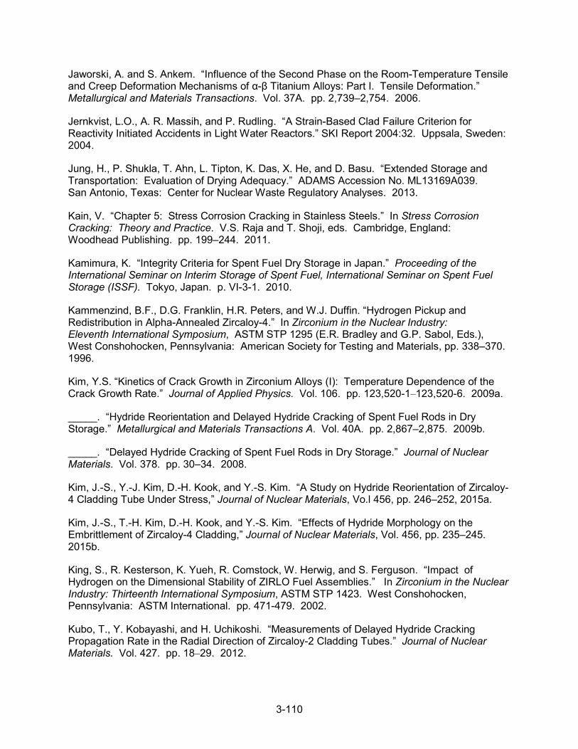
3-110
Jaworski, A. and S. Ankem. “Influence of the Second Phase on the Room-Temperature Tensile and Creep Deformation Mechanisms of α-β Titanium Alloys: Part I. Tensile Deformation.” Metallurgical and Materials Transactions. Vol. 37A. pp. 2,739–2,754. 2006.
Jernkvist, L.O., A. R. Massih, and P. Rudling. “A Strain-Based Clad Failure Criterion for Reactivity Initiated Accidents in Light Water Reactors.” SKI Report 2004:32. Uppsala, Sweden: 2004.
Jung, H., P. Shukla, T. Ahn, L. Tipton, K. Das, X. He, and D. Basu. “Extended Storage and Transportation: Evaluation of Drying Adequacy.” ADAMS Accession No. ML13169A039. San Antonio, Texas: Center for Nuclear Waste Regulatory Analyses. 2013.
Kain, V. “Chapter 5: Stress Corrosion Cracking in Stainless Steels.” In Stress Corrosion Cracking: Theory and Practice. V.S. Raja and T. Shoji, eds. Cambridge, England: Woodhead Publishing. pp. 199–244. 2011.
Kamimura, K. “Integrity Criteria for Spent Fuel Dry Storage in Japan.” Proceeding of the International Seminar on Interim Storage of Spent Fuel, International Seminar on Spent Fuel Storage (ISSF). Tokyo, Japan. p. VI-3-1. 2010.
Kammenzind, B.F., D.G. Franklin, H.R. Peters, and W.J. Duffin. “Hydrogen Pickup and Redistribution in Alpha-Annealed Zircaloy-4.” In Zirconium in the Nuclear Industry: Eleventh International Symposium, ASTM STP 1295 (E.R. Bradley and G.P. Sabol, Eds.), West Conshohocken, Pennsylvania: American Society for Testing and Materials, pp. 338–370. 1996.
Kim, Y.S. “Kinetics of Crack Growth in Zirconium Alloys (I): Temperature Dependence of the Crack Growth Rate.” Journal of Applied Physics. Vol. 106. pp. 123,520-1–123,520-6. 2009a.
_____. “Hydride Reorientation and Delayed Hydride Cracking of Spent Fuel Rods in Dry Storage.” Metallurgical and Materials Transactions A. Vol. 40A. pp. 2,867–2,875. 2009b.
_____. “Delayed Hydride Cracking of Spent Fuel Rods in Dry Storage.” Journal of Nuclear Materials. Vol. 378. pp. 30–34. 2008.
Kim, J.-S., Y.-J. Kim, D.-H. Kook, and Y.-S. Kim. “A Study on Hydride Reorientation of Zircaloy-4 Cladding Tube Under Stress,” Journal of Nuclear Materials, Vo.l 456, pp. 246–252, 2015a.
Kim, J.-S., T.-H. Kim, D.-H. Kook, and Y.-S. Kim. “Effects of Hydride Morphology on the Embrittlement of Zircaloy-4 Cladding,” Journal of Nuclear Materials, Vol. 456, pp. 235–245. 2015b.
King, S., R. Kesterson, K. Yueh, R. Comstock, W. Herwig, and S. Ferguson. “Impact of Hydrogen on the Dimensional Stability of ZIRLO Fuel Assemblies.” In Zirconium in the Nuclear Industry: Thirteenth International Symposium, ASTM STP 1423. West Conshohocken, Pennsylvania: ASTM International. pp. 471-479. 2002.
Kubo, T., Y. Kobayashi, and H. Uchikoshi. “Measurements of Delayed Hydride Cracking Propagation Rate in the Radial Direction of Zircaloy-2 Cladding Tubes.” Journal of Nuclear Materials. Vol. 427. pp. 18–29. 2012.

3-111
Kearns, J.J. “Thermal Solubility and Partitioning of Hydrogen in the Alpha Phase of Zirconium, Zircaloy-2 and Zircaloy-4.” Journal of Nuclear Materials. Vol. 22. pp. 292–303. 1967.
Kreyns, P.H., G.L. Spahr, and J.E. McCauley. “An Analysis of Iodine Stress Corrosion Cracking of Zircaloy-4 Tubing.” Journal of Nuclear Materials. Vol. 61. pp. 203–212. 1976.
Lin, X. and G. Haicheng. “High Cycle Fatigue Properties and Microstructure of Zirconium and Zircaloy-4 Under Reversal Bending.” Materials Science and Engineering A. Vol. 252. pp. 166–173. 1998.
Luscher, W.G and K.J. Geelhood. “Material Property Correlations: Comparisons Between FRAPCON-3.4, FRAPTRAN 1.4, and MATPRO.” PNNL-19417 (NUREG/CR-7024). Richland, Washington: Pacific Northwest National Laboratory. 2010.
Mattas, R.F., F.L. Yagee and L.A. Neimark. “Effect of Zirconium Oxide on the Stress corrosion Susceptibility of Irradiated Zircaloy Cladding.” In Zirconium in the Nuclear Industry: Fifth International Symposium. ASTM STP 754, (D.G Franklin, ed. West Conshohocken, Pennsylvania: American Society for Testing and Materials. pp. 158–170. 1982.
Mardon, J. P., G.L. Garner, and P.B. Hoffmann. “M5® A Breakthrough in Zr Alloy.” Proceedings of 2010 LWR Fuel Performance/TopFuel/WRFPM, Orlando, Florida, September 26–29, 2010. American Nuclear Society. 2010.
Masafumi, N., K. Uchida, A. Miyazaki, and Y. Ishii. “Annealing Study on Neutron Irradiation Effects in Resonance Frequencies of Zircaloy Plates by EMAR Method.” Journal of Nuclear Science and Technology, Vol. 44, No. 10. pp. 1,285–1,294. 2007.
Morize P., J. Baicry, and J. P. Mardon. “Effect of Irradiation at 588 K on Mechanical Properties and Deformation Behavior of Zirconium Alloy Strip.” Zirconium in the Nuclear Industry: Seventh International Symposium. ASTM STP 939. R.B. Adamson and L.F.P. Van Swam, eds. ASTM. pp. 101–119. 1987.
Murty, K.L. “The Internal Pressurization Creep of Zr Alloys for Spent-Fuel Dry Storage Feasibility.” Journal of the Minerals, Metals and Materials Society. Vol. 52, No. 9. pp. 34–43. 2000.
NRC. NUREG–2224, “Dry Storage and Transportation of High Burnup Spent Nuclear Fuel—Draft Report for Comment.” ADAMS Accession No. ML18214A132. Washington, DC: U.S. Nuclear Regulatory Commission. 2018.
_____. NUREG–1927, Rev. 1, “Standard Review Plan for Renewal of Specific Licenses and Certificates of Compliance for Dry Storage of Spent Nuclear Fuel.” Revision 1. ADAMS Accession No. ML16179A148. Washington, DC: U.S. Nuclear Regulatory Commission. 2016.
_____. “Acceptable Fuel Cladding Hydrogen Uptake Models.” ADAMS Accession No. ML15133A306. Washington, DC: U.S. Nuclear Regulatory Commission. 2015a.
_____. Draft Regulatory Issue Summary 2015-XXX, “Considerations in Licensing High Burnup Spent Fuel in Dry Storage and Transportation.” ADAMS Accession No. ML14175A203. Washington, D.C: U.S. Nuclear Regulatory Commission. 2015b.

3-112
_____. “Identification and Prioritization of the Technical Information Needs Affecting Potential Regulation of Extended Storage and Transportation of Spent Nuclear Fuel.” ADAMS Accession No. ML14043A423. Washington, DC: U.S. Nuclear Regulatory Commission. 2014a.
_____. NUREG–1536, “Standard Review Plan for Spent Fuel Dry Storage Systems at a General License Facility.” Rev 1. Washington, DC: U.S. Nuclear Regulatory Commission. 2010.
_____. Interim Staff Guidance-1, “Classifying the Condition of Spent Nuclear Fuel for Interim Storage and Transportation Based on Function.” Rev 2. ADAMS Accession No. ML071420268. Washington, DC: U.S. Nuclear Regulatory Commission. 2007.
_____. Interim Staff Guidance 11, “Cladding Considerations for the Transportation and Storage of Spent Fuel.” Rev. 3. ADAMS Accession No. ML033230335. Washington, DC: U.S. Nuclear Regulatory Commission. 2003.
_____. “Safety Evaluation Report Related to the Topical Report for Castor V/21 Dry Spent Fuel Storage Cask Submitted by General Nuclear Systems, Inc..” NRC-SER-85-9. Washington, DC: U.S. Nuclear Regulatory Commission. 1985.
NWTRB. “Evaluation of the Technical Basis for Extended Dry Storage and Transportation of Used Nuclear Fuel.” Arlington, Virginia: United States Nuclear Waste Technical Review Board. December 2010.
Palit, G.C. and H.S. Gadiyar. “Pitting Corrosion of Zirconium in Chloride Solution.” CORROSION. Vol. 43, No. 3. pp. 140–148. 1987.
Pan, G., A.M. Garde, and A.R. Atwood. “Performance and Property Evaluation of High Burn-up Optimized ZIRLO™ Cladding.” In Proceedings of 17th International ASTM Symposium on Zirconium in the Nuclear Industry. Hyderabad, India. 2013.
PNNL. “Used Fuel Disposition Campaign: Gap Analysis to Support Extended Storage of Used Nuclear Fuel Rev. 0.” FCRD-USED-2011-000136. Rev. 0. PNNL-20509. Richland, Washington. Pacific Northwest National Laboratory. January 31, 2012.
Raynaud, P.A.C. and R.E. Einziger. “Cladding Stress During Extended Storage of High Burnup Spent Nuclear Fuel.” Journal of Nuclear Materials. Vol. 464. pp. 304–312. 2015.
Rebak, R.B. “Chapter 7: Stress Corrosion Cracking (SCC) of Nickel-Based Alloys.” In Stress Corrosion Cracking: Theory and Practice. V.S. Raja and T. Shoji, eds. Cambridge, England: Woodhead Publishing. pp. 273–306. 2011.
Rondinella, V.V., T. Wiss, E. Maugeri, J.Y. Colle, D. Wegen, and D. Papaioannou. “Effects of He Build-up on Nuclear Fuel Evolution during Storage.” International Workshop on Spent Fuel Integrity in Dry Storage. Korea Atomic Energy Research Institute. Korea. November 4–5, 2010a.
Rondinella, V.V and T. Wiss. “The High Burnup Structure in Nuclear Fuel,” Materials Today, Vol. 13, pp. 24–32, 2010b.

3-113
Rondinella, V.V., T. Wiss, D. Papaioannou, and R. Nasyrow. “Studies on Nuclear Fuel Evolution during Storage and Testing of Used Fuel Response to Impact Loadings.” PSAM11 ESREL2012. Helsinki, June 25–29, 2012.
Rothman, A.J. “Potential Corrosion and Degradation Mechanisms of Zircaloy Cladding on Spent Nuclear in a Tuff Repository.” UCID-20172. Livermore, California: Lawrence Livermore National Laboratory. 1984.
Samuels, l.E. Metals Engineering: A Technical Guide. Metals Park, Ohio: ASM International. p. 116. 1988.
Sasahara, A. and T. Matsumura. “Post-Irradiation Examinations Focused on Fuel Integrity of Spent BWR-MOX and PWR-UO2 Fuels Stored for 20 Years.” Nuclear Engineering and Design. Vol. 238. pp. 1,250–1,259. 2008.
Scaglione, J.M., G. Radulescu, W.J. Marshall, and K.R. Robb. “A Quantitative Impact Assessment of Hypothetical Spent Fuel Reconfiguration in Spent Fuel Storage Casks and Transportation Packages.” NUREG/CR-7203, ORNL/TM-2013/92. Oak Ridge, Tennessee: Oak Ridge National Laboratory. 2015.
Shimada, S. and M. Nagai. “A Fractographic Study of Iodine-Induced Stress Corrosion Cracking in Irradiated Zircaloy-2 Cladding.” Journal of Nuclear Materials. Vol. 114. pp. 222–230. 1983.
Shukla, P.K., R. Pabalan, T. Ahn, L. Yang, X. He, and H. Jung. “Cathodic Capacity of Alloy 22 in the Potential Yucca Mountain Repository Environment.” Proceedings of the CORROSION 2008 Conference, Corrosion in Nuclear Systems Symposium, New Orleans, Louisiana, March 16–20, 2008. Paper No. 08583. Houston, Texas: NACE International. 2008.
Sidky, P.S. “Iodine Stress Corrosion Cracking of Zircaloy Reactor Cladding: Iodine Chemistry (A Review),” Journal of Nuclear Materials, Vol. 256, pp. 1–17. 1998.
Simpson, C.J. and C.E. Ells. “Delayed Hydrogen Embrittlement in Zr-2.5 wt % Nb.” Journal of Nuclear Materials. Vol. 52. pp. 289–295. 1974.
Sindelar, R.L., A.J. Duncan, M.E. Dupont, P.-S. Lam, M.R. Louthan, Jr., and T.E. Skidmore. NUREG/CR-7116, “Materials Aging Issues and Aging Management for Extended Storage and Transportation of Spent Nuclear Fuel.” Washington, DC: U.S. Nuclear Regulatory Commission. 2011.
Spilker, H.M., H.-P Dyck Peehs, G. Kaspar, and K. Nissen. “Spent LWR Fuel Dry Storage in Large Transport and Storage Casks after Extended Burnup.” Journal of Nuclear Materials. Vol. 250. pp. 63–74. 1997.
Tang, D., A. Rigato, and R.E. Einziger. “Flaw Effects and Flaw Reorientation on Spent Fuel Rod Performance, a Simulation with Finite Element Analysis.” Proceedings of the ASME 2015 Pressure Vessels and Piping Conference, July 19–23, 2015, Boston, Massachusetts. 2015.
Thomazet, J. et al. “The Corrosion of the Alloy M5™: An Overview.” IAEA Technical Committee Meeting on Behavior of High Corrosion Zr-Based Alloys. Buenos Aires, Argentina: October 24–28, 2005.

3-114
Torimaru, T., T. Yasuda, and M. Nakatsuka. “Changes in Mechanical Properties of Irradiated Zircaloy-2 Fuel Cladding Due to Short-Term Annealing.” Journal of Nuclear Materials. Vol. 238. pp. 169–174. 1996.
Tsai, H. and M.C. Billone. NUREG/CP-0180, “Characterization of High-Burnup PWR and BWR Rods, and PWR Rods After Extended Dry-Cask Storage.” Proceedings of the 2002 Nuclear Safety Research Conference, October 28–30, 2002. pp. 157–168. Washington, DC: U.S. Nuclear Regulatory Commission. 2003.
Van Rooyen, D. and H.R. Copson. “Metal Corrosion in the Atmosphere.” Report No. STP 435. West Conshohocken, Pennsylvania: ASTM International. 1968.
Wang, J-A. and H. Wang. NUREG/CR-7198, Rev. 1, “Mechanical Fatigue Testing of High-Burnup Fuel for Transportation Applications.” ADAMS Accession No. ML17292B057. Washington, DC: U.S. Nuclear Regulatory Commission. October 2017.
Wang, J. J.-A. “Cyclic Integrated Reversible-bending Fatigue Tester (CIRFT) Framework Approaches and Analytical Evaluations.” Oak Ridge National Laboratory (ORNL). Presented at Extended Storage Collaboration Program (ESCP) Meeting. Electric Power Research Institute (EPRI). Charlotte, North Carolina, December 2–4, 2014a.
Wang, J. J.-A. ORNL, 2014 ASTM C26 Committee Meeting, June, 2014b.
Wisner, S. and R. Adamson. “Combined Effects of Radiation Damage and Hydrides on the Ductility of Zircaloy-2.” Nuclear Engineering and Design. Vol. 185. pp. 33–49. 1998.
Wisner, S.B. and R.B. Adamson. “Embrittlement of Irradiated Zircaloy by Cadmium and Iodine.” Embrittlement by Liquid and Solid Metals. M.H. Kamdar, ed. Metallurgical Society of AIME. pp. 437–456. 1982.
Yagee, F.L., R.F. Mattas, and L.A. Neimark. “Characterization of Irradiated Zircaloys: Susceptibility to Stress Corrosion Cracking.” Interim Report. EPRI NP-1557. Palo Alto, California: Electric Power Research Institute. October 1980.
_____. “Characterization of Irradiated Zircaloys: Susceptibility to Stress Corrosion Cracking.” Interim Report, EPRI NP-1155. Palo Alto, California: Electric Power Research Institute. September 1979.

4-1
4 ANALYSIS OF DRY STORAGE SYSTEMS AND SPENT FUEL ASSEMBLIES
4.1 Introduction
This chapter provides (1) a brief description of selected storage system designs and (2) aging management tables for each design that identify the aging mechanisms and effects that must be managed to ensure that the functions of structures, systems, and components (SSCs) are maintained in the period of extended operation. The analyses in Chapter 3 provide the technical bases for those determinations. The aging management tables also identify the use of either a time-limited aging analysis (TLAA), aging management program (AMP), or other analysis to address the aging effects that require management.
The following system descriptions are for general information only, and the aging management tables for each system generically address SSCs for several amendments. As stated in Section 1.1, the inclusion or exclusion of a certain SSC in the tables does not necessarily indicate whether the SSC is within the scope of renewal for a particular application. In the review of a renewal application, the technical reviewer should refer to the application, safety analysis report, and drawings to identify the SSCs within the scope of renewal and their functions, materials of construction, and operating environment.
Table 4-1 describes the storage system designs that are discussed below and evaluated in the aging management tables.
Table 4-1 Evaluated Storage System Designs MAPS
Section No. Name NRC Docket
No. Amendments
Evaluated
4.2 Standardized NUHOMS®* 72-1004 1–11 and 13
Standardized Advanced NUHOMS® 72-1029 1 and 3
4.3 HI-STORM 100 72-1014 1–10
HI-STAR 100 72-1008 1–2
4.4 TN-32 72-1021 1
TN-68 72-1027 1
4.5
NAC-UMS 72-1015 1–5
NAC-MPC 72-1025 1–6
MAGNASTOR 72-1031 1–6
4.6 FuelSolutions 72-1026 1–4
4.7 Concrete Pad (generic) — —
4.8 Spent Fuel Assemblies (generic) — —
*The staff’s review of the Calvert Cliffs specific license renewal application (NRC, 2014) informed the evaluation ofthe NUHOMS system, and thus the aging management tables for this system may include some unique elementsof this site.
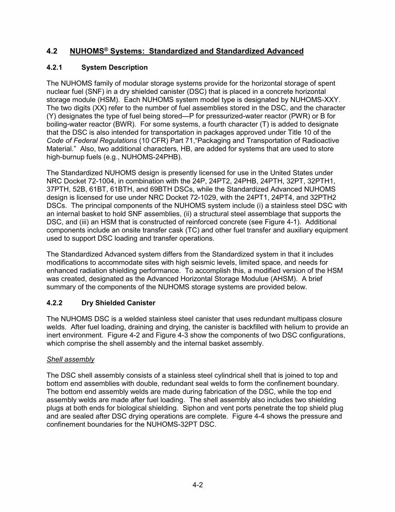
4-2
4.2 NUHOMS® Systems: Standardized and Standardized Advanced
4.2.1 System Description
The NUHOMS family of modular storage systems provide for the horizontal storage of spent nuclear fuel (SNF) in a dry shielded canister (DSC) that is placed in a concrete horizontal storage module (HSM). Each NUHOMS system model type is designated by NUHOMS-XXY. The two digits (XX) refer to the number of fuel assemblies stored in the DSC, and the character (Y) designates the type of fuel being stored—P for pressurized-water reactor (PWR) or B forboiling-water reactor (BWR). For some systems, a fourth character (T) is added to designatethat the DSC is also intended for transportation in packages approved under Title 10 of theCode of Federal Regulations (10 CFR) Part 71,“Packaging and Transportation of RadioactiveMaterial.” Also, two additional characters, HB, are added for systems that are used to storehigh-burnup fuels (e.g., NUHOMS-24PHB).
The Standardized NUHOMS design is presently licensed for use in the United States under NRC Docket 72-1004, in combination with the 24P, 24PT2, 24PHB, 24PTH, 32PT, 32PTH1, 37PTH, 52B, 61BT, 61BTH, and 69BTH DSCs, while the Standardized Advanced NUHOMS design is licensed for use under NRC Docket 72-1029, with the 24PT1, 24PT4, and 32PTH2 DSCs. The principal components of the NUHOMS system include (i) a stainless steel DSC with an internal basket to hold SNF assemblies, (ii) a structural steel assemblage that supports the DSC, and (iii) an HSM that is constructed of reinforced concrete (see Figure 4-1). Additional components include an onsite transfer cask (TC) and other fuel transfer and auxiliary equipment used to support DSC loading and transfer operations.
The Standardized Advanced system differs from the Standardized system in that it includes modifications to accommodate sites with high seismic levels, limited space, and needs for enhanced radiation shielding performance. To accomplish this, a modified version of the HSM was created, designated as the Advanced Horizontal Storage Modulue (AHSM). A brief summary of the components of the NUHOMS storage systems are provided below.
4.2.2 Dry Shielded Canister
The NUHOMS DSC is a welded stainless steel canister that uses redundant multipass closure welds. After fuel loading, draining and drying, the canister is backfilled with helium to provide an inert environment. Figure 4-2 and Figure 4-3 show the components of two DSC configurations, which comprise the shell assembly and the internal basket assembly.
Shell assembly
The DSC shell assembly consists of a stainless steel cylindrical shell that is joined to top and bottom end assemblies with double, redundant seal welds to form the confinement boundary. The bottom end assembly welds are made during fabrication of the DSC, while the top end assembly welds are made after fuel loading. The shell assembly also includes two shielding plugs at both ends for biological shielding. Siphon and vent ports penetrate the top shield plug and are sealed after DSC drying operations are complete. Figure 4-4 shows the pressure and confinement boundaries for the NUHOMS-32PT DSC.

4-3
Figure 4-1 NUHOMS Dry Storage System (Pacific Nuclear Fuel Services, Inc., 1991)
Figure 4-2 NUHOMS-24PT2 DSC Assembly–Spacer Disk Design (Transnuclear, 2004)

4-4
Figure 4-3 NUHOMS-32PT DSC Assembly–tube or Plate Design (Transnuclear, 2004)
Figure 4-4 Pressure and Confinement Boundaries for NUHOMS-32PT DSC (Transnuclear, 2004)

4-5
Internal Basket Assembly
The internal basket assembly contains a storage position for each fuel assembly. The basket assembly may consist of an assemblage of spacer disc plates supported on vertical rods that extend the length of the DSC cavity (spacer disc design) or individual tubes or plates welded to form a grid-like structure (tube or plate design).
The 24P, 24PT1, 24PT2, 24PT4, 24PHB, and 52B DSCs use the spacer disc basket design, as shown in Figure 4-2. Subcriticality is maintained through the geometric separation of the fuel assemblies by the DSC basket assembly and the neutron absorbing capability of the DSC materials of construction. The 52B DSC contains fixed neutron poison material for additional criticality control.
The 61BT, 32PT, 24PTH, 61BTH, 32PTH1, 32PTH2, 69BTH, and 37PTH DSCs use the tube or plate grid basket design, as shown in Figure 4-3. Fixed neutron poison material provides the necessary criticality control. Aluminum sheets or plates are used to provide the heat conduction paths from the fuel assemblies to the canister shell. Transition rails, consisting of welded stainless steel plates or aluminum parts, form the transition between the box-like fuel compartment structure and the cylindrical DSC shell.
Table 4-2 and Table 4-3 evaluate potential aging mechanisms and effects requiring management for specific components of the Standardized and Standardized Advanced NUHOMS DSC shell and basket designs. The tables also identify AMPs that provide an acceptable approach to managing the aging effects.
4.2.3 Horizontal Storage Module
Both the HSM and AHSM storage modulus are low-profile structures constructed from reinforced concrete and structural steel that provides a means for passive removal of spent fuel decay heat, structural support and environmental protection of the DSC, and radiation shielding. The AHSM design is similar to the HSM; however, the AHSM contains improved shielding and resistance to high seismic events. The AHSM consists a base storage unit and a top shield block that is tied to the base unit by steel rods in the vertical direction and interlocking concrete keys in the horizontal direction.
Heat removal is achieved by a combination of radiation, conduction, and convection. As shown in Figure 4-5 and Figure 4-6, ambient air enters the HSMs through ventilation inlet openings located in the lower region of the front or side walls and circulates around the DSC. Air exits through outlet openings in the top regions of the HSM walls. Thermal monitoring or visual inspections are used to provide indication of HSM performance or a blocked vent condition. Heat shields are placed above and to either side of the DSC to protect the concrete surfaces of the storage module from thermal radiation effects. Environmental protection and radiation shielding are provided by the thick side walls and roof of the HSM, supplemented by thick wall units attached at the ends of the array and at the rear walls of the HSM if the array is of single row configuration. Each HSM has an access opening or docking flange in the front wall to accommodate transfer of DSCs from and into the shielded TC. The access opening is covered by a thick shielded access door.
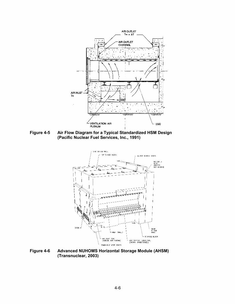
4-6
Figure 4-5 Air Flow Diagram for a Typical Standardized HSM Design (Pacific Nuclear Fuel Services, Inc., 1991)
Figure 4-6 Advanced NUHOMS Horizontal Storage Module (AHSM) (Transnuclear, 2003)
4-7
Structural support of the loaded DSC is provided by a structural steel frame structure (HSM model 80 and model 102) anchored to the floor slab and walls of the HSM, or a structural steel rail assembly (HSM models HSM-H, -152, -202, HSM-HS, AHSM, and AHSM-HS). Figure 4-7 shows drawings of the side elevation and end view of the DSC rail assembly. Stainlesssteel cover plates coated with a dry film lubricant are attached to the rails to provide a slidingsurface for DSC insertion and retrieval. In some designs, Nitronic 60 plates are welded to thecover plates because of this material’s good high-temperature properties and resistance tooxidation, wear, and galling. Seismic restraints using steel plates or tubes are welded to therear and front of the rails for retaining the DSC in place during seismic events.
Table 4-4 and Table 4-5 provide a generic evaluation of potential aging mechanisms and effects requiring management for specific components of the Standardized NUHOMS HSM and Standardized Advanced NUHOMS AHSM. The tables also identify the AMPs that provide an acceptable approach to managing the effects of aging.
Figure 4-7 Side Elevation and End View of the DSC Support Structure (Transnuclear, 2004)
4.2.4 Transfer Cask
The NUHOMS TC is a cylindrical vessel with a bolted top cover plate and a welded bottom end assembly (Transnuclear, 2014). There are five alternate configurations of the cask.
• The basic configuration, where the TC is provided with a solid neutron shield, is denotedas the standardized onsite cask.
• A second configuration includes the OS197 and OS197H (H: modified for increasedstrength), in which water is used to provide neutron shielding.
• The third configuration, designated as OS197FC, OS197HFC OS197FC-B, orOS197HFC-B TC, is equipped with a modified top lid to allow air circulation through theannulus between the DSC and the TC.
• The fourth configuration, designated as OS197L TC and shown in Figure 4-8, is areduced weight version of the OS197 TC.

4-8
Figure 4-8 OS197L Transfer Cask (Transnuclear, 2008)
• The fifth configuration is designated as OS200 or OS200FC TC and has a largerdiameter to accommodate the larger diameter DSCs with 32PTH1, 37PTH, or 69BTHSNF assemblies.
For all the configurations except the OS197L TC, the TCs are constructed from two concentric cylindrical shells: a stainless steel inner shell and a structural shell made of stainless steel or carbon steel. The annulus formed by these two shells is filled with cast lead to provide gamma shielding. The TC also includes an outer jacket made of stainless steel or carbon steel, which is filled with BISCO NS-3 material or water for neutron shielding. The inner and structural shells are welded to heavy forged ring assemblies at the top and bottom ends. The bottom end plate has a removable stainless steel ram access penetration ring. A stainless steel bottom cover plate is provided to seal the hydraulic ram access penetration of the cask during fuel loading. Rails fabricated from a nongalling, wear-resistant stainless steel coated with a high contact pressure dry film lubricant are provided to facilitate DSC transfer.
The OS197L TC is constructed from a single, thicker stainless steel structural shell. To compensate for the lack of lead shielding, the OS197L TC relies on the use of supplemental shielding in conjunction with remote operations during handling in the fuel or reactor building, transfer to the ISFSI, and insertion into the HSM operations. The cask support skid supplemental shielding consists of a thick carbon steel upper shielding bell and a lower shielding sleeve that enclose the TC in the decontamination area, and thick carbon steel plates and covers that enclose the TC while on the transfer trailer.
The NUHOMS TCs have four trunnions made of stainless steel or nickel alloy that are welded to the structural shell. Two upper lifting trunnions are located near the top of the cask for lifting the cask in the SNF pool building. The lower trunnions, located near the base of the cask, serve as the axis of rotation and as supports during transport to the HSM.
Table 4-6 provides a generic evaluation of potential aging mechanisms and effects requiring management for specific components of the NUHOMS transfer casks. The table also identifies the AMPs that provide an acceptable approach to managing the aging effects.
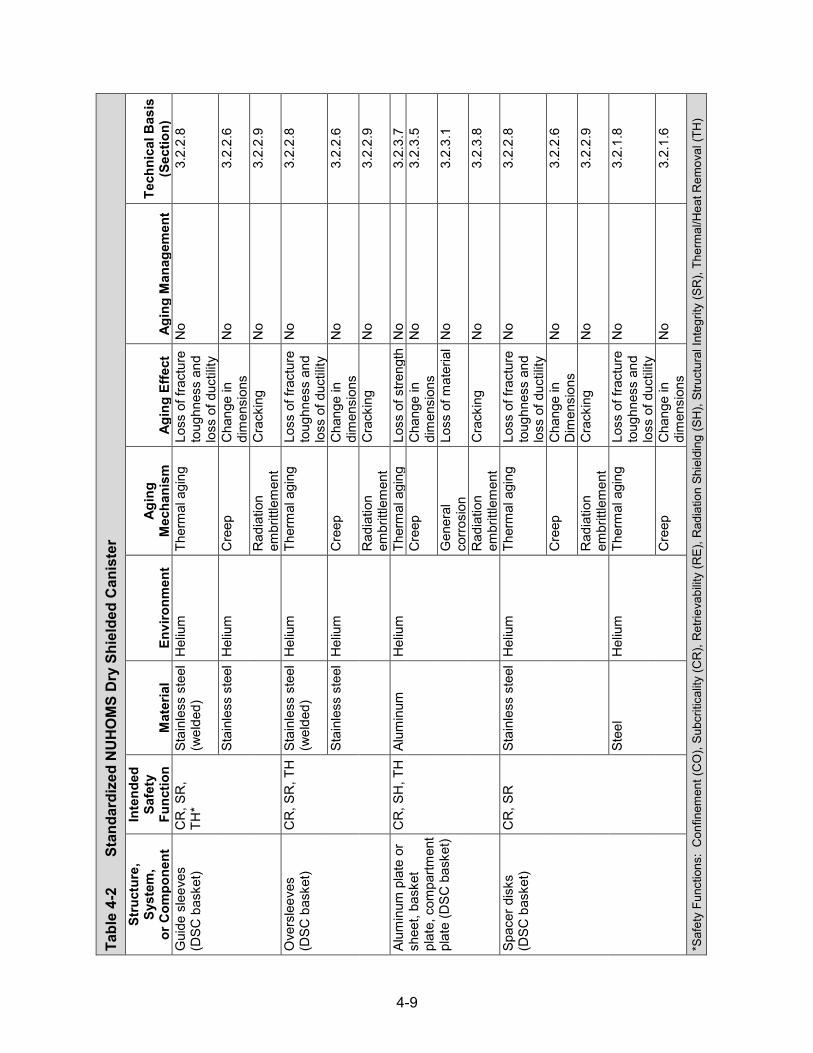
4-9
Tabl
e 4-
2
Stan
dard
ized
NU
HO
MS
Dry
Shi
elde
d C
anis
ter
Stru
ctur
e,
Syst
em,
or C
ompo
nent
Inte
nded
Sa
fety
Fu
nctio
n M
ater
ial
Envi
ronm
ent
Agin
g M
echa
nism
Ag
ing
Effe
ct
Agin
g M
anag
emen
t Te
chni
cal B
asis
(S
ectio
n)
Gui
de s
leev
es
(DSC
bas
ket)
CR
, SR
, TH
* St
ainl
ess
stee
l (w
elde
d)
Hel
ium
Th
erm
al a
ging
Lo
ss o
f fra
ctur
e to
ughn
ess
and
loss
of d
uctil
ity
No
3.2.
2.8
Stai
nles
s st
eel
Hel
ium
C
reep
C
hang
e in
di
men
sion
s N
o 3.
2.2.
6
Rad
iatio
n em
britt
lem
ent
Cra
ckin
g N
o 3.
2.2.
9
Ove
rsle
eves
(D
SC b
aske
t) C
R, S
R, T
H S
tain
less
ste
el
(wel
ded)
H
eliu
m
Ther
mal
agi
ng
Loss
of f
ract
ure
toug
hnes
s an
d lo
ss o
f duc
tility
No
3.2.
2.8
Stai
nles
s st
eel
Hel
ium
C
reep
C
hang
e in
di
men
sion
s N
o 3.
2.2.
6
Rad
iatio
n em
britt
lem
ent
Cra
ckin
g N
o 3.
2.2.
9
Alum
inum
pla
te o
r sh
eet,
bask
et
plat
e, c
ompa
rtmen
t pl
ate
(DSC
bas
ket)
CR
, SH
, TH
Alu
min
um
Hel
ium
Th
erm
al a
ging
Lo
ss o
f stre
ngth
No
3.2.
3.7
Cre
ep
Cha
nge
in
dim
ensi
ons
No
3.2.
3.5
Gen
eral
co
rrosi
on
Loss
of m
ater
ial
No
3.2.
3.1
Rad
iatio
n em
britt
lem
ent
Cra
ckin
g N
o 3.
2.3.
8
Spac
er d
isks
(D
SC b
aske
t) C
R, S
R
Stai
nles
s st
eel
Hel
ium
Th
erm
al a
ging
Lo
ss o
f fra
ctur
e to
ughn
ess
and
loss
of d
uctil
ity
No
3.2.
2.8
Cre
ep
Cha
nge
in
Dim
ensi
ons
No
3.2.
2.6
Rad
iatio
n em
britt
lem
ent
Cra
ckin
g N
o 3.
2.2.
9
Stee
l H
eliu
m
Ther
mal
agi
ng
Loss
of f
ract
ure
toug
hnes
s an
d lo
ss o
f duc
tility
No
3.2.
1.8
Cre
ep
Cha
nge
in
dim
ensi
ons
No
3.2.
1.6
*Saf
ety
Func
tions
: C
onfin
emen
t (C
O),
Subc
ritic
ality
(CR
), R
etrie
vabi
lity
(RE)
, Rad
iatio
n Sh
ield
ing
(SH
), St
ruct
ural
Inte
grity
(SR
), Th
erm
al/H
eat R
emov
al (T
H)

4-10
Tabl
e 4-
2
Stan
dard
ized
NU
HO
MS
Dry
Shi
elde
d C
anis
ter (continued)
Stru
ctur
e,
Syst
em,
or C
ompo
nent
Inte
nded
Sa
fety
Fu
nctio
n M
ater
ial
Envi
ronm
ent
Agin
g M
echa
nism
Ag
ing
Effe
ct
Agin
g M
anag
emen
t Te
chni
cal B
asis
(S
ectio
n)
Spac
er d
isks
(D
SC b
aske
t) C
R, S
R
Stee
l H
eliu
m
Gen
eral
co
rrosi
on
Loss
of m
ater
ial
No
3.2.
1.1
Rad
iatio
n em
britt
lem
ent
Cra
ckin
g N
o 3.
2.1.
9
Supp
ort r
ods
(D
SC b
aske
t) C
R, S
R
Stai
nles
s st
eel
(wel
ded)
H
eliu
m
Ther
mal
agi
ng
Loss
of f
ract
ure
toug
hnes
s an
d lo
ss o
f duc
tility
No
3.2.
2.8
Stai
nles
s st
eel
Hel
ium
C
reep
C
hang
e in
di
men
sion
s N
o 3.
2.2.
6
Rad
iatio
n em
britt
lem
ent
Cra
ckin
g N
o 3.
2.2.
9
Stai
nles
s st
eel
(wel
ded
17-4
PH
)
Hel
ium
Th
erm
al a
ging
Lo
ss o
f fra
ctur
e to
ughn
ess
and
loss
of d
uctil
ity
TLAA
/AM
P or
a
supp
ortin
g an
alys
is is
re
quire
d
3.2.
2.8
Stai
nles
s st
eel
(17-
4 PH
) H
eliu
m
Cre
ep
Cha
nge
in
dim
ensi
ons
No
3.2.
2.6
Rad
iatio
n em
britt
lem
ent
Cra
ckin
g N
o 3.
2.2.
9
Stee
l H
eliu
m
Ther
mal
agi
ng
Loss
of f
ract
ure
toug
hnes
s an
d lo
ss o
f duc
tility
No
3.2.
1.8
Cre
ep
Cha
nge
in
dim
ensi
ons
No
3.2.
1.6
Gen
eral
co
rrosi
on
Loss
of m
ater
ial
No
3.2.
1.1
Rad
iatio
n em
britt
lem
ent
Cra
ckin
g N
o 3.
2.1.
9
Spac
er s
leev
es
(DSC
bas
ket)
CR
, SR
St
ainl
ess
stee
l (w
elde
d 17
-4
PH)
Hel
ium
Th
erm
al a
ging
Lo
ss o
f fra
ctur
e to
ughn
ess
and
loss
of d
uctil
ity
TLAA
/AM
P or
a
supp
ortin
g an
alys
is is
re
quire
d
3.2.
2.8
Stai
nles
s st
eel
Hel
ium
C
reep
C
hang
e in
di
men
sion
s N
o 3.
2.2.
6
Rad
iatio
n em
britt
lem
ent
Cra
ckin
g N
o 3.
2.2.
9

4-11
Tabl
e 4-
2
Stan
dard
ized
NU
HO
MS
Dry
Shi
elde
d C
anis
ter (continued)
Stru
ctur
e,
Syst
em,
or C
ompo
nent
Inte
nded
Sa
fety
Fu
nctio
n M
ater
ial
Envi
ronm
ent
Agin
g M
echa
nism
Ag
ing
Effe
ct
Agin
g M
anag
emen
t Te
chni
cal B
asis
(S
ectio
n)
Bask
et ra
ils
(DSC
bas
ket)
CR
, SH
, SR
, TH
St
ainl
ess
stee
l (w
elde
d)
Hel
ium
Th
erm
al a
ging
Lo
ss o
f fra
ctur
e to
ughn
ess
and
loss
of d
uctil
ity
No
3.2.
2.8
Stai
nles
s st
eel
Hel
ium
C
reep
C
hang
e in
di
men
sion
s N
o 3.
2.2.
6
Rad
iatio
n em
britt
lem
ent
Cra
ckin
g N
o 3.
2.2.
9
Bask
et ra
il in
serts
an
d sh
ims
(D
SC b
aske
t)
SR, T
H
Alum
inum
H
eliu
m
Ther
mal
agi
ng
Loss
of s
treng
th T
LAA/
AMP
or a
su
ppor
ting
anal
ysis
is
requ
ired
3.2.
3.7
Cre
ep
Cha
nge
in
dim
ensi
ons
TLAA
/AM
P or
a
supp
ortin
g an
alys
is is
re
quire
d
3.2.
3.5
Gen
eral
co
rrosi
on
Loss
of m
ater
ial
No
3.2.
3.1
Rad
iatio
n em
britt
lem
ent
Cra
ckin
g N
o 3.
2.3.
8
Bask
et a
ssem
bly
plat
es (D
SC
bask
et)
CR
, SH
, SR
, TH
St
ainl
ess
stee
l (w
elde
d)
Hel
ium
Th
erm
al a
ging
Lo
ss o
f fra
ctur
e to
ughn
ess
and
loss
of d
uctil
ity
No
3.2.
2.8
Stai
nles
s st
eel
Hel
ium
C
reep
C
hang
e in
di
men
sion
s N
o 3.
2.2.
6
Rad
iatio
n em
britt
lem
ent
Cra
ckin
g N
o 3.
2.2.
9
Grid
ass
embl
y (D
SC b
aske
t) SR
St
ainl
ess
stee
l H
eliu
m
Ther
mal
agi
ng
Loss
of f
ract
ure
toug
hnes
s an
d lo
ss o
f duc
tility
No
3.2.
2.8
Cre
ep
Cha
nge
in
dim
ensi
ons
No
3.2.
2.6
Rad
iatio
n em
britt
lem
ent
Cra
ckin
g N
o 3.
2.2.
9

4-12
Tabl
e 4-
2
Stan
dard
ized
NU
HO
MS
Dry
Shi
elde
d C
anis
ter (continued)
Stru
ctur
e,
Syst
em,
or C
ompo
nent
Inte
nded
Sa
fety
Fu
nctio
n M
ater
ial
Envi
ronm
ent
Agin
g M
echa
nism
Ag
ing
Effe
ct
Agin
g M
anag
emen
t Te
chni
cal B
asis
(S
ectio
n)
Hol
ddow
n rin
g as
sem
bly
and
plat
es (D
SC
bask
et)
SR
Stai
nles
s st
eel
(wel
ded)
H
eliu
m
Ther
mal
agi
ng
Loss
of f
ract
ure
toug
hnes
s an
d lo
ss o
f duc
tility
No
3.2.
2.8
Stai
nles
s st
eel
Hel
ium
C
reep
C
hang
e in
di
men
sion
s N
o 3.
2.2.
6
Rad
iatio
n em
britt
lem
ent
Cra
ckin
g N
o 3.
2.2.
9
Fuel
com
partm
ent
tube
s, w
raps
, in
serts
(DSC
ba
sket
)
CR
, SH
, SR
, TH
St
ainl
ess
stee
l (w
elde
d)
Hel
ium
Th
erm
al a
ging
Lo
ss o
f fra
ctur
e to
ughn
ess
and
loss
of d
uctil
ity
No
3.2.
2.8
Stai
nles
s st
eel
Hel
ium
C
reep
C
hang
e in
di
men
sion
s N
o 3.
2.2.
6
Rad
iatio
n em
britt
lem
ent
Cra
ckin
g N
o 3.
2.2.
9
Tran
sitio
n ra
ils
(DSC
bas
ket)
CR
, SH
, SR
, TH
St
ainl
ess
stee
l (w
elde
d)
Hel
ium
Th
erm
al a
ging
Lo
ss o
f fra
ctur
e to
ughn
ess
and
loss
of d
uctil
ity
No
3.2.
2.8
Stai
nles
s st
eel
Hel
ium
C
reep
C
hang
e in
di
men
sion
s N
o 3.
2.2.
6
Rad
iatio
n em
britt
lem
ent
Cra
ckin
g N
o 3.
2.2.
9
Alum
inum
H
eliu
m
Ther
mal
agi
ng
Loss
of s
treng
th T
LAA/
AMP
or a
su
ppor
ting
anal
ysis
is
requ
ired
3.2.
3.7
Cre
ep
Cha
nge
in
dim
ensi
ons
TLAA
/AM
P or
a
supp
ortin
g an
alys
is is
re
quire
d
3.2.
3.5
Gen
eral
co
rrosi
on
Loss
of m
ater
ial
No
3.2.
3.1
Rad
iatio
n em
britt
lem
ent
Cra
ckin
g N
o 3.
2.3.
8

4-13
Tabl
e 4-
2
Stan
dard
ized
NU
HO
MS
Dry
Shi
elde
d C
anis
ter (continued)
Stru
ctur
e,
Syst
em,
or C
ompo
nent
Inte
nded
Sa
fety
Fu
nctio
n M
ater
ial
Envi
ronm
ent
Agin
g M
echa
nism
Ag
ing
Effe
ct
Agin
g M
anag
emen
t Te
chni
cal B
asis
(S
ectio
n)
Neu
tron
abso
rbin
g pl
ates
, poi
son
plat
es (D
SC
bask
et)
CR
, TH
Bo
rate
d st
ainl
ess
stee
l H
eliu
m
Boro
n de
plet
ion
Red
uctio
n of
ne
utro
n-ab
sorb
ing
capa
city
No;
a T
LAA
may
be
requ
ired
3.4.
1.1
Ther
mal
agi
ng
Loss
of f
ract
ure
toug
hnes
s an
d lo
ss o
f duc
tility
No
3.4.
1.3
Cre
ep
Cha
nge
in
dim
ensi
ons
No
3.4.
1.2
Rad
iatio
n em
britt
lem
ent
Loss
of f
ract
ure
toug
hnes
s an
d lo
ss o
f duc
tility
No
3.4.
1.4
Neu
tron
abso
rbin
g pl
ates
or s
heet
s,
pois
on p
late
s,
chev
ron
neut
ron
abso
rber
s (D
SC
bask
et)
CR
, SH
, TH
Bor
alyn
®,
Met
amic
TM
Hel
ium
Bo
ron
depl
etio
n R
educ
tion
of
neut
ron-
abso
rbin
g ca
paci
ty
No;
a T
LAA
may
be
requ
ired
3.4.
2.4
Ther
mal
agi
ng
Loss
of s
treng
th N
o 3.
4.2.
6
Gen
eral
co
rrosi
on
Loss
of m
ater
ial
No
3.4.
2.1
Cre
ep
Cha
nge
in
dim
ensi
ons
No
3.4.
2.5
Rad
iatio
n em
britt
lem
ent
Loss
of f
ract
ure
toug
hnes
s an
d lo
ss o
f duc
tility
No
3.4.
2.7
Bora
l®
Hel
ium
Bo
ron
depl
etio
n R
educ
tion
of
neut
ron-
abso
rbin
g ca
paci
ty
No;
a T
LAA
may
be
requ
ired
3.4.
2.4
Ther
mal
agi
ng
Loss
of s
treng
th N
o 3.
4.2.
6 W
et c
orro
sion
an
d bl
iste
ring
Cha
nge
in
dim
ensi
ons
No
3.4.
2.3

4-14
Tabl
e 4-
2
Stan
dard
ized
NU
HO
MS
Dry
Shi
elde
d C
anis
ter (continued)
Stru
ctur
e,
Syst
em,
or C
ompo
nent
Inte
nded
Sa
fety
Fu
nctio
n M
ater
ial
Envi
ronm
ent
Agin
g M
echa
nism
Ag
ing
Effe
ct
Agin
g M
anag
emen
t Te
chni
cal B
asis
(S
ectio
n)
Neu
tron
abso
rbin
g pl
ates
or s
heet
s,
pois
on p
late
s,
chev
ron
neut
ron
abso
rber
s (D
SC
bask
et)
CR
, SH
, TH
Bor
al®
Hel
ium
C
reep
C
hang
e in
di
men
sion
s N
o 3.
4.2.
5
Rad
iatio
n em
britt
lem
ent
Loss
of f
ract
ure
toug
hnes
s an
d lo
ss o
f duc
tility
No
3.4.
2.7
Bora
ted
alum
inum
H
eliu
m
Boro
n de
plet
ion
Red
uctio
n of
ne
utro
n-ab
sorb
ing
capa
city
No;
a T
LAA
may
be
requ
ired
3.4.
2.4
Ther
mal
agi
ng
Loss
of s
treng
th N
o 3.
4.2.
6
Gen
eral
co
rrosi
on
Loss
of m
ater
ial
No
3.4.
2.1
Cre
ep
Cha
nge
in
dim
ensi
ons
No
3.4.
2.5
Rad
iatio
n em
britt
lem
ent
Loss
of f
ract
ure
toug
hnes
s an
d lo
ss o
f duc
tility
No
3.4.
2.7
Supp
ort b
ars
(DSC
ba
sket
) SR
St
eel
Hel
ium
Th
erm
al a
ging
Lo
ss o
f fra
ctur
e to
ughn
ess
and
loss
of d
uctil
ity
No
3.2.
1.8
Cre
ep
Cha
nge
in
dim
ensi
ons
No
3.2.
1.6
Gen
eral
co
rrosi
on
Loss
of m
ater
ial
No
3.2.
1.1
Rad
iatio
n em
britt
lem
ent
Cra
ckin
g N
o 3.
2.1.
9
Fast
ener
co
mpo
nent
s SR
St
ainl
ess
stee
l H
eliu
m
Ther
mal
agi
ng
Loss
of f
ract
ure
toug
hnes
s an
d lo
ss o
f duc
tility
No
3.2.
2.8
Cre
ep
Cha
nge
in
dim
ensi
ons
No
3.2.
2.6
Rad
iatio
n em
britt
lem
ent
Cra
ckin
g N
o 3.
2.2.
9

4-15
Tabl
e 4-
2
Stan
dard
ized
NU
HO
MS
Dry
Shi
elde
d C
anis
ter (continued)
Stru
ctur
e,
Syst
em,
or C
ompo
nent
Inte
nded
Sa
fety
Fu
nctio
n M
ater
ial
Envi
ronm
ent
Agin
g M
echa
nism
Ag
ing
Effe
ct
Agin
g M
anag
emen
t Te
chni
cal B
asis
(S
ectio
n)
Fast
ener
co
mpo
nent
s SR
St
eel
Hel
ium
Th
erm
al a
ging
Lo
ss o
f fra
ctur
e to
ughn
ess
and
loss
of d
uctil
ity
No
3.2.
1.8
Cre
ep
Cha
nge
in
dim
ensi
ons
No
3.2.
1.6
Gen
eral
co
rrosi
on
Loss
of m
ater
ial
No
3.2.
1.1
Rad
iatio
n em
britt
lem
ent
Cra
ckin
g N
o 3.
2.1.
9
Tool
soc
ket a
nd
clos
ure
plat
e SR
St
ainl
ess
stee
l H
eliu
m
Cre
ep
Cha
nge
in
dim
ensi
ons
No
3.2.
2.6
Rad
iatio
n em
britt
lem
ent
Cra
ckin
g N
o 3.
2.2.
9
Com
pone
nts
for
dam
aged
fuel
C
O, S
R
Stai
nles
s st
eel
(wel
ded)
H
eliu
m
Ther
mal
agi
ng
Loss
of f
ract
ure
toug
hnes
s an
d lo
ss o
f duc
tility
No
3.2.
2.8
Stai
nles
s st
eel
Hel
ium
Fa
tigue
C
rack
ing
Eval
uate
des
ign
code
TL
AA, i
f app
licab
le
3.2.
2.7
Cre
ep
Cha
nge
in
dim
ensi
ons
No
3.2.
2.6
Rad
iatio
n em
britt
lem
ent
Cra
ckin
g N
o 3.
2.2.
9
Cov
er p
late
s (in
ner)
C
O, S
H, S
R S
tain
less
ste
el
(wel
ded)
H
eliu
m
Ther
mal
agi
ng
Loss
of f
ract
ure
toug
hnes
s an
d lo
ss o
f duc
tility
No
3.2.
2.8
Stai
nles
s st
eel
Hel
ium
Fa
tigue
C
rack
ing
Eval
uate
des
ign
code
TL
AA, i
f app
licab
le
3.2.
2.7
Cre
ep
Cha
nge
in
Dim
ensi
ons
No
3.2.
2.6
Rad
iatio
n em
britt
lem
ent
Cra
ckin
g N
o 3.
2.2.
9

4-16
Tabl
e 4-
2
Stan
dard
ized
NU
HO
MS
Dry
Shi
elde
d C
anis
ter (continued)
Stru
ctur
e,
Syst
em,
or C
ompo
nent
Inte
nded
Sa
fety
Fu
nctio
n M
ater
ial
Envi
ronm
ent
Agin
g M
echa
nism
Ag
ing
Effe
ct
Agin
g M
anag
emen
t Te
chni
cal B
asis
(S
ectio
n)
Shie
ld p
lug
(top)
C
O, S
H,
SR, T
H
Stai
nles
s st
eel
Hel
ium
Th
erm
al a
ging
Lo
ss o
f fra
ctur
e to
ughn
ess
and
loss
of d
uctil
ity
No
3.2.
2.8
Fatig
ue
Cra
ckin
g Ev
alua
te d
esig
n co
de
TLAA
, if a
pplic
able
3.
2.2.
7
Cre
ep
Cha
nge
in
dim
ensi
ons
No
3.2.
2.6
Rad
iatio
n em
britt
lem
ent
Cra
ckin
g N
o 3.
2.2.
9
Stee
l H
eliu
m
Ther
mal
agi
ng
Loss
of f
ract
ure
toug
hnes
s an
d lo
ss o
f duc
tility
No
3.2.
1.8
Fatig
ue
Cra
ckin
g Ev
alua
te d
esig
n co
de
TLAA
, if a
pplic
able
3.
2.1.
7
Cre
ep
Cha
nge
in
dim
ensi
ons
No
3.2.
1.6
Gen
eral
co
rrosi
on
Loss
of m
ater
ial
No
3.2.
1.1
Rad
iatio
n em
britt
lem
ent
Cra
ckin
g N
o 3.
2.1.
9
Shie
ld p
lug
(bot
tom
) C
O, S
H,
SR, T
H
Stai
nles
s st
eel
Hel
ium
Th
erm
al a
ging
Lo
ss o
f fra
ctur
e to
ughn
ess
and
loss
of d
uctil
ity
No
3.2.
2.8
Fatig
ue
Cra
ckin
g Ev
alua
te d
esig
n co
de
TLAA
, if a
pplic
able
3.
2.2.
7
Cre
ep
Cha
nge
in
dim
ensi
ons
No
3.2.
2.6
Rad
iatio
n em
britt
lem
ent
Cra
ckin
g N
o 3.
2.2.
9
Stee
l H
eliu
m
Ther
mal
agi
ng
Loss
of f
ract
ure
toug
hnes
s an
d lo
ss o
f duc
tility
No
3.2.
1.8
Fatig
ue
Cra
ckin
g Ev
alua
te d
esig
n co
de
TLAA
, if a
pplic
able
3.
2.1.
7

4-17
Tabl
e 4-
2
Stan
dard
ized
NU
HO
MS
Dry
Shi
elde
d C
anis
ter (continued)
Stru
ctur
e,
Syst
em,
or C
ompo
nent
Inte
nded
Sa
fety
Fu
nctio
n M
ater
ial
Envi
ronm
ent
Agin
g M
echa
nism
Ag
ing
Effe
ct
Agin
g M
anag
emen
t Te
chni
cal B
asis
(S
ectio
n)
Shie
ld p
lug
(bot
tom
) C
O, S
H,
SR, T
H
Stee
l H
eliu
m
Cre
ep
Cha
nge
in
dim
ensi
ons
No
3.2.
1.6
Gen
eral
co
rrosi
on
Loss
of m
ater
ial
No
3.2.
1.1
Rad
iatio
n em
britt
lem
ent
Cra
ckin
g N
o 3.
2.1.
9
Lead
shi
eldi
ng
SH
Lead
Em
bedd
ed
(ste
el, s
tain
less
st
eel)
Non
e id
entif
ied
Non
e id
entif
ied
No
3.2.
6
Siph
on a
nd v
ent
bloc
k C
O, S
H, S
R S
tain
less
ste
el
(wel
ded)
H
eliu
m
Ther
mal
agi
ng
Loss
of f
ract
ure
toug
hnes
s an
d lo
ss o
f duc
tility
No
3.2.
2.8
Stai
nles
s st
eel
Hel
ium
Fa
tigue
C
rack
ing
Eval
uate
des
ign
code
TL
AA, i
f app
licab
le
3.2.
2.7
Cre
ep
Cha
nge
in
dim
ensi
ons
No
3.2.
2.6
Rad
iatio
n em
britt
lem
ent
Cra
ckin
g N
o 3.
2.2.
9
Siph
on a
nd v
ent
port
cove
r pla
te
CO
, SH
, SR
Sta
inle
ss s
teel
(w
elde
d)
Hel
ium
Th
erm
al a
ging
Lo
ss o
f fra
ctur
e to
ughn
ess
and
loss
of d
uctil
ity
No
3.2.
2.8
Stai
nles
s st
eel
Hel
ium
Fa
tigue
C
rack
ing
Eval
uate
des
ign
code
TL
AA, i
f app
licab
le
3.2.
2.7
Cre
ep
Cha
nge
in
dim
ensi
ons
No
3.2.
2.6
Rad
iatio
n em
britt
lem
ent
Cra
ckin
g N
o 3.
2.2.
9
Test
por
t plu
g C
O
Stai
nles
s st
eel
(wel
ded)
H
eliu
m
Ther
mal
agi
ng
Loss
of f
ract
ure
toug
hnes
s an
d lo
ss o
f duc
tility
No
3.2.
2.8
Stai
nles
s st
eel
Hel
ium
Fa
tigue
C
rack
ing
Eval
uate
des
ign
code
TL
AA, i
f app
licab
le
3.2.
2.7
Cre
ep
Cha
nge
in
dim
ensi
ons
No
3.2.
2.6

4-18
Tabl
e 4-
2
Stan
dard
ized
NU
HO
MS
Dry
Shi
elde
d C
anis
ter (continued)
Stru
ctur
e,
Syst
em,
or C
ompo
nent
Inte
nded
Sa
fety
Fu
nctio
n M
ater
ial
Envi
ronm
ent
Agin
g M
echa
nism
Ag
ing
Effe
ct
Agin
g M
anag
emen
t Te
chni
cal B
asis
(S
ectio
n)
Test
por
t plu
g C
O
Stai
nles
s st
eel
Hel
ium
R
adia
tion
embr
ittle
men
t C
rack
ing
No
3.2.
2.9
Key,
she
ar k
ey
SR
Stai
nles
s st
eel
Hel
ium
Th
erm
al a
ging
Lo
ss o
f fra
ctur
e to
ughn
ess
and
loss
of d
uctil
ity
No
3.2.
2.8
Cre
ep
Cha
nge
in
dim
ensi
ons
No
3.2.
2.6
Rad
iatio
n em
britt
lem
ent
Cra
ckin
g N
o 3.
2.2.
9
Pin,
ant
i-rot
atio
n pi
n SR
St
ainl
ess
stee
l H
eliu
m
Ther
mal
agi
ng
Loss
of f
ract
ure
toug
hnes
s an
d lo
ss o
f duc
tility
No
3.2.
2.8
Cre
ep
Cha
nge
in
dim
ensi
ons
No
3.2.
2.6
Rad
iatio
n em
britt
lem
ent
Cra
ckin
g N
o 3.
2.2.
9
DSC
sup
port
ring
SR
Stai
nles
s st
eel
(wel
ded)
H
eliu
m
Ther
mal
agi
ng
Loss
of f
ract
ure
toug
hnes
s an
d lo
ss o
f duc
tility
No
3.2.
2.8
Stai
nles
s st
eel
Hel
ium
C
reep
C
hang
e in
D
imen
sion
s N
o 3.
2.2.
6
Rad
iatio
n em
britt
lem
ent
Cra
ckin
g N
o 3.
2.2.
9
Lifti
ng lu
gs
SR
Stai
nles
s st
eel
(wel
ded)
H
eliu
m
Ther
mal
agi
ng
Loss
of f
ract
ure
toug
hnes
s an
d lo
ss o
f duc
tility
No
3.2.
2.8
Stai
nles
s st
eel
Hel
ium
C
reep
C
hang
e in
di
men
sion
s N
o 3.
2.2.
6
Rad
iatio
n em
britt
lem
ent
Cra
ckin
g N
o 3.
2.2.
9

4-19
Tabl
e 4-
2
Stan
dard
ized
NU
HO
MS
Dry
Shi
elde
d C
anis
ter (continued)
Stru
ctur
e,
Syst
em,
or C
ompo
nent
Inte
nded
Sa
fety
Fu
nctio
n M
ater
ial
Envi
ronm
ent
Agin
g M
echa
nism
Ag
ing
Effe
ct
Agin
g M
anag
emen
t Te
chni
cal B
asis
(S
ectio
n)
DSC
she
ll C
O, S
H,
SR, T
H
Stai
nles
s st
eel
(wel
ded)
Sh
elte
red
Stre
ss c
orro
sion
cr
acki
ng
Cra
ckin
g Lo
caliz
ed C
orro
sion
an
d St
ress
cor
rosi
on
Cra
ckin
g of
Wel
ded
Stai
nles
s St
eel D
ry
Stor
age
Can
iste
rs
AMP
3.2.
2.5
Stai
nles
s st
eel
Shel
tere
d Pi
tting
and
cr
evic
e co
rrosi
on
Loss
of m
ater
ial
(pre
curs
or to
st
ress
co
rrosi
on
crac
king
)
Loca
lized
Cor
rosi
on
and
Stre
ss c
orro
sion
C
rack
ing
of W
elde
d St
ainl
ess
Stee
l Dry
St
orag
e C
anis
ters
AM
P
3.2.
2.2
Gal
vani
c co
rrosi
on
Loss
of m
ater
ial
Loca
lized
Cor
rosi
on
and
Stre
ss c
orro
sion
C
rack
ing
of W
elde
d St
ainl
ess
Stee
l Dry
St
orag
e C
anis
ters
AM
P
3.2.
2.3
Mic
robi
olog
ical
ly
influ
ence
d co
rrosi
on
Loss
of m
ater
ial
No
3.2.
2.4
Fatig
ue
Cra
ckin
g Ev
alua
te d
esig
n co
de
TLAA
, if a
pplic
able
3.
2.2.
7
Rad
iatio
n em
britt
lem
ent
Cra
ckin
g N
o 3.
2.2.
9
Hel
ium
R
adia
tion
embr
ittle
men
t C
rack
ing
No
3.2.
2.9
Cov
er p
late
s (o
uter
) C
O, S
H,
SR, T
H
Stai
nles
s st
eel
(wel
ded)
Sh
elte
red
Stre
ss c
orro
sion
cr
acki
ng
Cra
ckin
g Lo
caliz
ed C
orro
sion
an
d St
ress
cor
rosi
on
Cra
ckin
g of
Wel
ded
Stai
nles
s St
eel D
ry
Stor
age
Can
iste
rs
AMP
3.2.
2.5

4-20
Tabl
e 4-
2
Stan
dard
ized
NU
HO
MS
Dry
Shi
elde
d C
anis
ter (continued)
Stru
ctur
e,
Syst
em,
or C
ompo
nent
Inte
nded
Sa
fety
Fu
nctio
n M
ater
ial
Envi
ronm
ent
Agin
g M
echa
nism
Ag
ing
Effe
ct
Agin
g M
anag
emen
t Te
chni
cal B
asis
(S
ectio
n)
Cov
er p
late
s (o
uter
) C
O, S
H,
SR, T
H
Stai
nles
s st
eel
Shel
tere
d Pi
tting
and
cr
evic
e co
rrosi
on
Loss
of m
ater
ial
(pre
curs
or to
st
ress
co
rrosi
on
crac
king
)
Loca
lized
Cor
rosi
on
and
Stre
ss c
orro
sion
C
rack
ing
of W
elde
d St
ainl
ess
Stee
l Dry
St
orag
e C
anis
ters
AM
P
3.2.
2.2
Mic
robi
olog
ical
ly
influ
ence
d co
rrosi
on
Loss
of m
ater
ial
No
3.2.
2.4
Fatig
ue
Cra
ckin
g Ev
alua
te d
esig
n co
de
TLAA
, if a
pplic
able
3.
2.2.
7
Rad
iatio
n em
britt
lem
ent
Cra
ckin
g N
o 3.
2.2.
9
Gra
pple
ring
and
gr
appl
e su
ppor
t SR
St
ainl
ess
stee
l (w
elde
d)
Shel
tere
d St
ress
cor
rosi
on
crac
king
C
rack
ing
Loca
lized
Cor
rosi
on
and
Stre
ss c
orro
sion
C
rack
ing
of W
elde
d St
ainl
ess
Stee
l Dry
St
orag
e C
anis
ters
AM
P
3.2.
2.5
Stai
nles
s st
eel
Shel
tere
d Pi
tting
and
cr
evic
e co
rrosi
on
Loss
of m
ater
ial
(pre
curs
or to
st
ress
co
rrosi
on
crac
king
)
Loca
lized
Cor
rosi
on
and
Stre
ss c
orro
sion
C
rack
ing
of W
elde
d St
ainl
ess
Stee
l Dry
St
orag
e C
anis
ters
AM
P
3.2.
2.2
Mic
robi
olog
ical
ly
influ
ence
d co
rrosi
on
Loss
of m
ater
ial
No
3.2.
2.4
Rad
iatio
n em
britt
lem
ent
Cra
ckin
g N
o 3.
2.2.
9

4-21
Tabl
e 4-
3
Stan
dard
ized
Adv
ance
d N
UH
OM
S D
ry S
hiel
ded
Can
iste
r
Stru
ctur
e,
Syst
em,
or C
ompo
nent
Inte
nded
Sa
fety
Fu
nctio
n M
ater
ial
Envi
ronm
ent
Agin
g M
echa
nism
Ag
ing
Effe
ct
Agin
g M
anag
emen
t Te
chni
cal
Bas
is (S
ectio
n)
Gui
de s
leev
es
(DSC
bas
ket)
CR
, SR
, TH
* St
ainl
ess
stee
l (w
elde
d)
Hel
ium
Th
erm
al a
ging
Lo
ss o
f fra
ctur
e to
ughn
ess
and
loss
of d
uctil
ity
No
3.2.
2.8
Stai
nles
s st
eel
Hel
ium
C
reep
C
hang
e in
di
men
sion
s N
o 3.
2.2.
6
Rad
iatio
n em
britt
lem
ent
Cra
ckin
g N
o 3.
2.2.
9
Ove
rsle
eves
, st
op p
late
s (D
SC
bask
et)
CR
, SR
, TH
St
ainl
ess
stee
l (w
elde
d)
Hel
ium
Th
erm
al a
ging
Lo
ss o
f fra
ctur
e to
ughn
ess
and
loss
of d
uctil
ity
No
3.2.
2.8
Stai
nles
s st
eel
Hel
ium
C
reep
C
hang
e in
di
men
sion
s N
o 3.
2.2.
6
Rad
iatio
n em
britt
lem
ent
Cra
ckin
g N
o 3.
2.2.
9
Spac
er d
isks
(D
SC b
aske
t) C
R, S
R
Stee
l H
eliu
m
Ther
mal
agi
ng
Loss
of
fract
ure
toug
hnes
s an
d lo
ss o
f duc
tility
No
3.2.
1.8
Cre
ep
Cha
nge
in
dim
ensi
ons
No
3.2.
1.6
Gen
eral
co
rrosi
on
Loss
of
mat
eria
l N
o 3.
2.1.
1
Rad
iatio
n em
britt
lem
ent
Cra
ckin
g N
o 3.
2.1.
9
*Saf
ety
Func
tions
: C
onfin
emen
t (C
O),
Subc
ritic
ality
(CR
), R
etrie
vabi
lity
(RE)
, Rad
iatio
n Sh
ield
ing
(SH
), St
ruct
ural
Inte
grity
(SR
), Th
erm
al/H
eat R
emov
al (T
H)

4-22
Tabl
e 4-
3
Stan
dard
ized
Adv
ance
d N
UH
OM
S D
ry S
hiel
ded
Can
iste
r (continued)
Stru
ctur
e,
Syst
em,
or C
ompo
nent
Inte
nded
Sa
fety
Fu
nctio
n M
ater
ial
Envi
ronm
ent
Agin
g M
echa
nism
Ag
ing
Effe
ct
Agin
g M
anag
emen
t Te
chni
cal
Bas
is (S
ectio
n)
Supp
ort r
ods
(DSC
bas
ket)
CR
, SR
St
ainl
ess
stee
l (w
elde
d)
Hel
ium
Th
erm
al a
ging
Lo
ss o
f fra
ctur
e to
ughn
ess
and
loss
of d
uctil
ity
No
3.2.
2.8
Stai
nles
s st
eel
Hel
ium
C
reep
C
hang
e in
di
men
sion
s N
o 3.
2.2.
6
Rad
iatio
n em
britt
lem
ent
Cra
ckin
g N
o 3.
2.2.
9
Stai
nles
s st
eel
(wel
ded
17-4
PH
) H
eliu
m
Ther
mal
agi
ng
Loss
of f
ract
ure
toug
hnes
s an
d lo
ss o
f duc
tility
TLAA
/AM
P or
a
supp
ortin
g an
alys
is
is re
quire
d
3.2.
2.8
Stai
nles
s st
eel
(17-
4 PH
) H
eliu
m
Cre
ep
Cha
nge
in
dim
ensi
ons
No
3.2.
2.6
Rad
iatio
n em
britt
lem
ent
Cra
ckin
g N
o 3.
2.2.
9
Spac
er s
leev
es
(DSC
bas
ket)
CR
, SR
St
ainl
ess
stee
l (w
elde
d)
Hel
ium
Th
erm
al a
ging
Lo
ss o
f fra
ctur
e to
ughn
ess
and
loss
of d
uctil
ity
No
3.2.
2.8
Stai
nles
s st
eel
Hel
ium
C
reep
C
hang
e in
di
men
sion
s N
o 3.
2.2.
6
Rad
iatio
n em
britt
lem
ent
Cra
ckin
g N
o 3.
2.2.
9
Stai
nles
s st
eel
(wel
ded
17-4
PH
) H
eliu
m
Ther
mal
agi
ng
Loss
of f
ract
ure
toug
hnes
s an
d lo
ss o
f duc
tility
TLAA
/AM
P or
a
supp
ortin
g an
alys
is
is re
quire
d
3.2.
2.8
Stai
nles
s st
eel
(17-
4 PH
) H
eliu
m
Cre
ep
Cha
nge
in
dim
ensi
ons
No
3.2.
2.6
Rad
iatio
n em
britt
lem
ent
Cra
ckin
g N
o 3.
2.2.
9
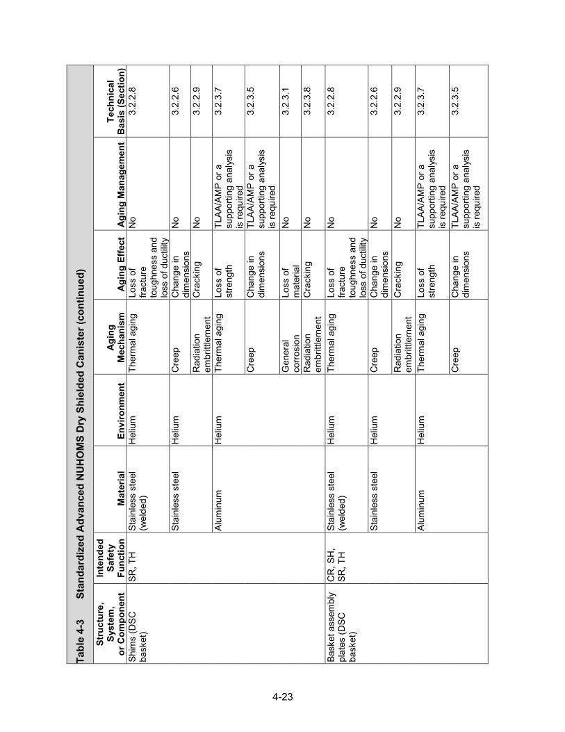
4-23
Tabl
e 4-
3
Stan
dard
ized
Adv
ance
d N
UH
OM
S D
ry S
hiel
ded
Can
iste
r (continued)
Stru
ctur
e,
Syst
em,
or C
ompo
nent
Inte
nded
Sa
fety
Fu
nctio
n M
ater
ial
Envi
ronm
ent
Agin
g M
echa
nism
Ag
ing
Effe
ct
Agin
g M
anag
emen
t Te
chni
cal
Bas
is (S
ectio
n)
Shim
s (D
SC
bask
et)
SR, T
H
Stai
nles
s st
eel
(wel
ded)
H
eliu
m
Ther
mal
agi
ng
Loss
of
fract
ure
toug
hnes
s an
d lo
ss o
f duc
tility
No
3.2.
2.8
Stai
nles
s st
eel
Hel
ium
C
reep
C
hang
e in
di
men
sion
s N
o 3.
2.2.
6
Rad
iatio
n em
britt
lem
ent
Cra
ckin
g N
o 3.
2.2.
9
Alum
inum
H
eliu
m
Ther
mal
agi
ng
Loss
of
stre
ngth
TL
AA/A
MP
or a
su
ppor
ting
anal
ysis
is
requ
ired
3.2.
3.7
Cre
ep
Cha
nge
in
dim
ensi
ons
TLAA
/AM
P or
a
supp
ortin
g an
alys
is
is re
quire
d
3.2.
3.5
Gen
eral
co
rrosi
on
Loss
of
mat
eria
l N
o 3.
2.3.
1
Rad
iatio
n em
britt
lem
ent
Cra
ckin
g N
o 3.
2.3.
8
Bask
et a
ssem
bly
plat
es (D
SC
bask
et)
CR
, SH
, SR
, TH
St
ainl
ess
stee
l (w
elde
d)
Hel
ium
Th
erm
al a
ging
Lo
ss o
f fra
ctur
e to
ughn
ess
and
loss
of d
uctil
ity
No
3.2.
2.8
Stai
nles
s st
eel
Hel
ium
C
reep
C
hang
e in
di
men
sion
s N
o 3.
2.2.
6
Rad
iatio
n em
britt
lem
ent
Cra
ckin
g N
o 3.
2.2.
9
Alum
inum
H
eliu
m
Ther
mal
agi
ng
Loss
of
stre
ngth
TL
AA/A
MP
or a
su
ppor
ting
anal
ysis
is
requ
ired
3.2.
3.7
Cre
ep
Cha
nge
in
dim
ensi
ons
TLAA
/AM
P or
a
supp
ortin
g an
alys
is
is re
quire
d
3.2.
3.5

4-24
Tabl
e 4-
3
Stan
dard
ized
Adv
ance
d N
UH
OM
S D
ry S
hiel
ded
Can
iste
r (continued)
Stru
ctur
e,
Syst
em,
or C
ompo
nent
Inte
nded
Sa
fety
Fu
nctio
n M
ater
ial
Envi
ronm
ent
Agin
g M
echa
nism
Ag
ing
Effe
ct
Agin
g M
anag
emen
t Te
chni
cal
Bas
is (S
ectio
n)
Bask
et a
ssem
bly
plat
es (D
SC
bask
et)
CR
, SH
, SR
, TH
Al
umin
um
Hel
ium
G
ener
al
corro
sion
Lo
ss o
f m
ater
ial
No
3.2.
3.1
Rad
iatio
n em
britt
lem
ent
Cra
ckin
g N
o 3.
2.3.
8
Fuel
co
mpa
rtmen
t (D
SC b
aske
t)
CR
, SH
, SR
, TH
St
ainl
ess
stee
l (w
elde
d)
Hel
ium
Th
erm
al a
ging
Lo
ss o
f fra
ctur
e to
ughn
ess
and
loss
of d
uctil
ity
No
3.2.
2.8
Stai
nles
s st
eel
Hel
ium
C
reep
C
hang
e in
di
men
sion
s N
o 3.
2.2.
6
Rad
iatio
n em
britt
lem
ent
Cra
ckin
g N
o 3.
2.2.
9
Tran
sitio
n ra
ils
(DSC
bas
ket)
CR
, SH
, SR
, TH
Al
umin
um
Hel
ium
Th
erm
al a
ging
Lo
ss o
f st
reng
th
TLAA
/AM
P or
a
supp
ortin
g an
alys
is
is re
quire
d
3.2.
3.7
Cre
ep
Cha
nge
in
dim
ensi
ons
TLAA
/AM
P or
a
supp
ortin
g an
alys
is
is re
quire
d
3.2.
3.5
Gen
eral
co
rrosi
on
Loss
of
mat
eria
l N
o 3.
2.3.
1
Rad
iatio
n em
britt
lem
ent
Cra
ckin
g N
o 3.
2.3.
8
Neu
tron
abso
rbin
g po
ison
pl
ate
(DSC
ba
sket
)
CR
, SH
, TH
Bo
ron
carb
ide/
al
umin
um m
etal
-m
atrix
com
posi
te
Hel
ium
Bo
ron
depl
etio
n R
educ
tion
of
neut
ron-
abso
rbin
g ca
paci
ty
No;
a T
LAA
may
be
requ
ired
3.4.
2.4
Ther
mal
agi
ng
Loss
of
stre
ngth
N
o 3.
4.2.
6

4-25
Tabl
e 4-
3
Stan
dard
ized
Adv
ance
d N
UH
OM
S D
ry S
hiel
ded
Can
iste
r (continued)
Stru
ctur
e,
Syst
em,
or C
ompo
nent
Inte
nded
Sa
fety
Fu
nctio
n M
ater
ial
Envi
ronm
ent
Agin
g M
echa
nism
Ag
ing
Effe
ct
Agin
g M
anag
emen
t Te
chni
cal
Bas
is (S
ectio
n)
Neu
tron
abso
rbin
g po
ison
pl
ate
(DSC
ba
sket
)
CR
, SH
, TH
Bo
ron
carb
ide/
al
umin
um m
etal
-m
atrix
com
posi
te
Hel
ium
G
ener
al
corro
sion
Lo
ss o
f m
ater
ial
No
3.4.
2.1
Cre
ep
Cha
nge
in
dim
ensi
ons
No
3.4.
2.5
Rad
iatio
n em
britt
lem
ent
Loss
of
fract
ure
toug
hnes
s an
d lo
ss o
f duc
tility
No
3.4.
2.7
Neu
tron
abso
rbin
g sh
eets
(D
SC b
aske
t)
CR
, SH
, TH
Bo
ral®
H
eliu
m
Boro
n de
plet
ion
Red
uctio
n of
ne
utro
n-ab
sorb
ing
capa
city
No;
a T
LAA
may
be
requ
ired
3.4.
2.4
Ther
mal
agi
ng
Loss
of
stre
ngth
N
o 3.
4.2.
6
Wet
cor
rosi
on
and
blis
terin
g C
hang
e in
di
men
sion
s N
o 3.
4.2.
3
Cre
ep
Cha
nge
in
dim
ensi
ons
No
3.4.
2.5
Rad
iatio
n em
britt
lem
ent
Loss
of
fract
ure
toug
hnes
s an
d lo
ss o
f duc
tility
No
3.4.
2.7
Fast
ener
co
mpo
nent
s SR
St
eel
Hel
ium
Th
erm
al a
ging
Lo
ss o
f fra
ctur
e to
ughn
ess
and
loss
of d
uctil
ity
No
3.2.
1.8
Cre
ep
Cha
nge
in
dim
ensi
ons
No
3.2.
1.6
Gen
eral
co
rrosi
on
Loss
of
mat
eria
l N
o 3.
2.1.
1
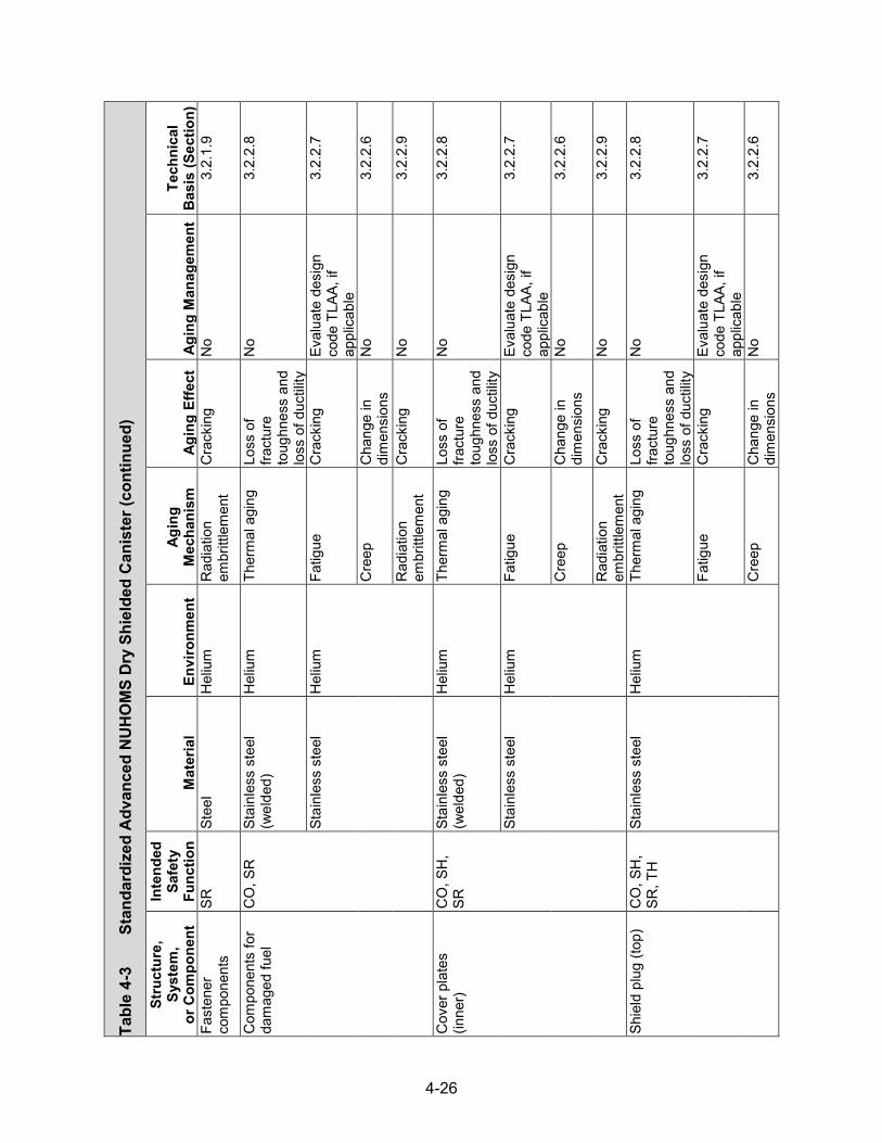
4-26
Tabl
e 4-
3
Stan
dard
ized
Adv
ance
d N
UH
OM
S D
ry S
hiel
ded
Can
iste
r (continued)
Stru
ctur
e,
Syst
em,
or C
ompo
nent
Inte
nded
Sa
fety
Fu
nctio
n M
ater
ial
Envi
ronm
ent
Agin
g M
echa
nism
Ag
ing
Effe
ct
Agin
g M
anag
emen
t Te
chni
cal
Bas
is (S
ectio
n)
Fast
ener
co
mpo
nent
s SR
St
eel
Hel
ium
R
adia
tion
embr
ittle
men
t C
rack
ing
No
3.2.
1.9
Com
pone
nts
for
dam
aged
fuel
C
O, S
R
Stai
nles
s st
eel
(wel
ded)
H
eliu
m
Ther
mal
agi
ng
Loss
of
fract
ure
toug
hnes
s an
d lo
ss o
f duc
tility
No
3.2.
2.8
Stai
nles
s st
eel
Hel
ium
Fa
tigue
C
rack
ing
Eval
uate
des
ign
code
TLA
A, if
ap
plic
able
3.2.
2.7
Cre
ep
Cha
nge
in
dim
ensi
ons
No
3.2.
2.6
Rad
iatio
n em
britt
lem
ent
Cra
ckin
g N
o 3.
2.2.
9
Cov
er p
late
s (in
ner)
C
O, S
H,
SR
Stai
nles
s st
eel
(wel
ded)
H
eliu
m
Ther
mal
agi
ng
Loss
of
fract
ure
toug
hnes
s an
d lo
ss o
f duc
tility
No
3.2.
2.8
Stai
nles
s st
eel
Hel
ium
Fa
tigue
C
rack
ing
Eval
uate
des
ign
code
TLA
A, if
ap
plic
able
3.2.
2.7
Cre
ep
Cha
nge
in
dim
ensi
ons
No
3.2.
2.6
Rad
iatio
n em
britt
lem
ent
Cra
ckin
g N
o 3.
2.2.
9
Shie
ld p
lug
(top)
C
O, S
H,
SR, T
H
Stai
nles
s st
eel
Hel
ium
Th
erm
al a
ging
Lo
ss o
f fra
ctur
e to
ughn
ess
and
loss
of d
uctil
ity
No
3.2.
2.8
Fatig
ue
Cra
ckin
g Ev
alua
te d
esig
n co
de T
LAA,
if
appl
icab
le
3.2.
2.7
Cre
ep
Cha
nge
in
dim
ensi
ons
No
3.2.
2.6

4-27
Tabl
e 4-
3
Stan
dard
ized
Adv
ance
d N
UH
OM
S D
ry S
hiel
ded
Can
iste
r (continued)
Stru
ctur
e,
Syst
em,
or C
ompo
nent
Inte
nded
Sa
fety
Fu
nctio
n M
ater
ial
Envi
ronm
ent
Agin
g M
echa
nism
Ag
ing
Effe
ct
Agin
g M
anag
emen
t Te
chni
cal
Bas
is (S
ectio
n)
Shie
ld p
lug
(top)
C
O, S
H,
SR, T
H
Stai
nles
s st
eel
Hel
ium
R
adia
tion
embr
ittle
men
t C
rack
ing
No
3.2.
2.9
Stee
l H
eliu
m
Ther
mal
agi
ng
Loss
of
fract
ure
toug
hnes
s an
d lo
ss o
f duc
tility
No
3.2.
1.8
Fatig
ue
Cra
ckin
g Ev
alua
te d
esig
n co
de T
LAA,
if
appl
icab
le
3.2.
1.7
Cre
ep
Cha
nge
in
dim
ensi
ons
No
3.2.
1.6
Gen
eral
co
rrosi
on
Loss
of
mat
eria
l N
o 3.
2.1.
1
Rad
iatio
n em
britt
lem
ent
Cra
ckin
g N
o 3.
2.1.
9
Shie
ld p
lug
casi
ng (b
otto
m)
CO
, SH
, SR
, TH
St
ainl
ess
stee
l (w
elde
d)
Shel
tere
d St
ress
cor
rosi
on
crac
king
C
rack
ing
Loca
lized
Cor
rosi
on
and
Stre
ss c
orro
sion
C
rack
ing
of W
elde
d St
ainl
ess
Stee
l Dry
St
orag
e C
anis
ters
AM
P
3.2.
2.5
Stai
nles
s st
eel
Shel
tere
d Pi
tting
and
cr
evic
e co
rrosi
on
Loss
of
mat
eria
l (P
recu
rsor
to
stre
ss
corro
sion
cr
acki
ng)
Loca
lized
Cor
rosi
on
and
Stre
ss c
orro
sion
C
rack
ing
of W
elde
d St
ainl
ess
Stee
l Dry
St
orag
e C
anis
ters
AM
P
3.2.
2.2
Mic
robi
olog
ical
ly
influ
ence
d co
rrosi
on
Loss
of
mat
eria
l N
o 3.
2.2.
4
Fatig
ue
Cra
ckin
g Ev
alua
te d
esig
n co
de T
LAA,
if
appl
icab
le
3.2.
2.7

4-28
Tabl
e 4-
3
Stan
dard
ized
Adv
ance
d N
UH
OM
S D
ry S
hiel
ded
Can
iste
r (continued)
Stru
ctur
e,
Syst
em,
or C
ompo
nent
Inte
nded
Sa
fety
Fu
nctio
n M
ater
ial
Envi
ronm
ent
Agin
g M
echa
nism
Ag
ing
Effe
ct
Agin
g M
anag
emen
t Te
chni
cal
Bas
is (S
ectio
n)
Shie
ld p
lug
casi
ng (b
otto
m)
CO
, SH
, SR
, TH
St
ainl
ess
stee
l Sh
elte
red
Rad
iatio
n em
britt
lem
ent
Cra
ckin
g N
o 3.
2.2.
9
Embe
dded
(le
ad)
Rad
iatio
n em
britt
lem
ent
Cra
ckin
g N
o 3.
2.2.
9
Shie
ld p
lug
(bot
tom
) C
O, S
H,
SR, T
H
Stee
l H
eliu
m
Ther
mal
agi
ng
Loss
of
fract
ure
toug
hnes
s an
d lo
ss o
f duc
tility
No
3.2.
1.8
Fatig
ue
Cra
ckin
g Ev
alua
te d
esig
n co
de T
LAA,
if
appl
icab
le
3.2.
1.7
Cre
ep
Cha
nge
in
dim
ensi
ons
No
3.2.
1.6
Gen
eral
co
rrosi
on
Loss
of
mat
eria
l N
o 3.
2.1.
1
Rad
iatio
n em
britt
lem
ent
Cra
ckin
g N
o 3.
2.1.
9
Lead
shi
eldi
ng
SH
Lead
Em
bedd
ed
(sta
inle
ss s
teel
) N
one
iden
tifie
d N
one
iden
tifie
d N
o 3.
2.6
Siph
on a
nd v
ent
bloc
k C
O, S
H,
SR
Stai
nles
s st
eel
(wel
ded)
H
eliu
m
Ther
mal
agi
ng
Loss
of
fract
ure
toug
hnes
s an
d lo
ss o
f duc
tility
No
3.2.
2.8
Stai
nles
s st
eel
Hel
ium
Fa
tigue
C
rack
ing
Eval
uate
des
ign
code
TLA
A, if
ap
plic
able
3.2.
2.7
Cre
ep
Cha
nge
in
dim
ensi
ons
No
3.2.
2.6
Rad
iatio
n em
britt
lem
ent
Cra
ckin
g N
o 3.
2.2.
9

4-29
Tabl
e 4-
3
Stan
dard
ized
Adv
ance
d N
UH
OM
S D
ry S
hiel
ded
Can
iste
r (continued)
Stru
ctur
e,
Syst
em,
or C
ompo
nent
Inte
nded
Sa
fety
Fu
nctio
n M
ater
ial
Envi
ronm
ent
Agin
g M
echa
nism
Ag
ing
Effe
ct
Agin
g M
anag
emen
t Te
chni
cal
Bas
is (S
ectio
n)
Siph
on a
nd v
ent
port
cove
r pla
te
CO
, SH
, SR
St
ainl
ess
stee
l (w
elde
d)
Hel
ium
Th
erm
al a
ging
Lo
ss o
f fra
ctur
e to
ughn
ess
and
loss
of d
uctil
ity
No
3.2.
2.8
Stai
nles
s st
eel
Hel
ium
Fa
tigue
C
rack
ing
Eval
uate
des
ign
code
TLA
A, if
ap
plic
able
3.2.
2.7
Cre
ep
Cha
nge
in
dim
ensi
ons
No
3.2.
2.6
Rad
iatio
n em
britt
lem
ent
Cra
ckin
g N
o 3.
2.2.
9
Test
por
t plu
g C
O
Stai
nles
s st
eel
(wel
ded)
H
eliu
m
Ther
mal
agi
ng
Loss
of
fract
ure
toug
hnes
s an
d lo
ss o
f duc
tility
No
3.2.
2.8
Stai
nles
s st
eel
Hel
ium
Fa
tigue
C
rack
ing
Eval
uate
des
ign
code
TLA
A, if
ap
plic
able
3.2.
2.7
Cre
ep
Cha
nge
in
dim
ensi
ons
No
3.2.
2.6
Rad
iatio
n em
britt
lem
ent
Cra
ckin
g N
o 3.
2.2.
9
Pin
SR
Stai
nles
s st
eel
Hel
ium
Th
erm
al a
ging
Lo
ss o
f fra
ctur
e to
ughn
ess
and
loss
of d
uctil
ity
No
3.2.
2.8
Cre
ep
Cha
nge
in
dim
ensi
ons
No
3.2.
2.6
Rad
iatio
n em
britt
lem
ent
Cra
ckin
g N
o 3.
2.2.
9

4-30
Tabl
e 4-
3
Stan
dard
ized
Adv
ance
d N
UH
OM
S D
ry S
hiel
ded
Can
iste
r (continued)
Stru
ctur
e,
Syst
em,
or C
ompo
nent
Inte
nded
Sa
fety
Fu
nctio
n M
ater
ial
Envi
ronm
ent
Agin
g M
echa
nism
Ag
ing
Effe
ct
Agin
g M
anag
emen
t Te
chni
cal
Bas
is (S
ectio
n)
DSC
sup
port
ring
SR
Stai
nles
s st
eel
(wel
ded)
H
eliu
m
Ther
mal
agi
ng
Loss
of
fract
ure
toug
hnes
s an
d lo
ss o
f duc
tility
No
3.2.
2.8
Stai
nles
s st
eel
Hel
ium
C
reep
C
hang
e in
di
men
sion
s N
o 3.
2.2.
6
Rad
iatio
n em
britt
lem
ent
Cra
ckin
g N
o 3.
2.2.
9
DSC
she
ll C
O, S
H,
SR, T
H
Stai
nles
s st
eel
(wel
ded)
Sh
elte
red
Stre
ss c
orro
sion
cr
acki
ng
Cra
ckin
g Lo
caliz
ed C
orro
sion
and
Stre
ss C
orro
sion
Cra
ckin
g of
Wel
ded
Stai
nles
s St
eel D
ry
Stor
age
Can
ister
s AM
P
3.2.
2.5
Stai
nles
s st
eel
Shel
tere
d Pi
tting
and
cr
evic
e co
rrosi
on
Loss
of
mat
eria
l (P
recu
rsor
to
stre
ss
corro
sion
cr
acki
ng)
Loca
lized
Cor
rosio
n an
d St
ress
Cor
rosio
n C
rack
ing
of W
elde
d St
ainl
ess
Stee
l Dry
St
orag
e C
anist
ers
AMP
3.2.
2.2
Gal
vani
c co
rrosi
on
Loss
of
mat
eria
l Lo
caliz
ed C
orro
sion
and
Stre
ss C
orro
sion
Cra
ckin
g of
Wel
ded
Stai
nles
s St
eel D
ry
Stor
age
Can
ister
s AM
P
3.2.
2.3
Mic
robi
olog
ical
ly
influ
ence
d co
rrosi
on
Loss
of
mat
eria
l N
o 3.
2.2.
4
Fatig
ue
Cra
ckin
g Ev
alua
te d
esig
n co
de T
LAA,
if
appl
icab
le
3.2.
2.7
Rad
iatio
n em
britt
lem
ent
Cra
ckin
g N
o 3.
2.2.
9
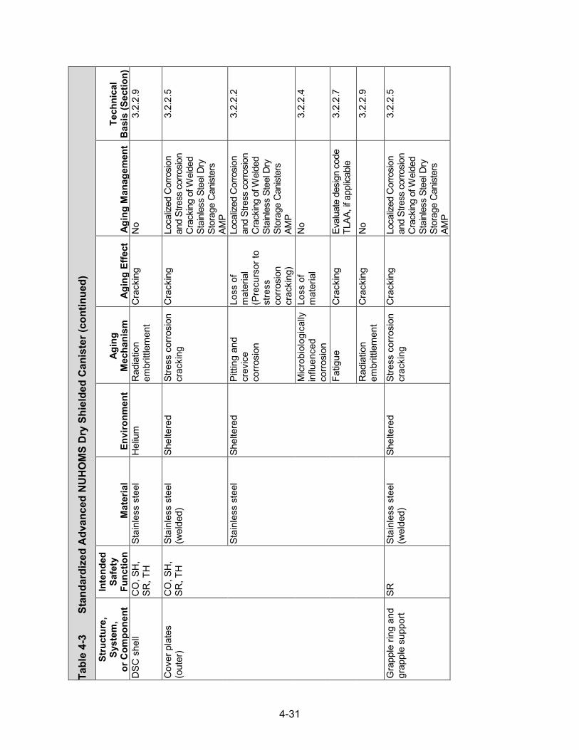
4-31
Tabl
e 4-
3
Stan
dard
ized
Adv
ance
d N
UH
OM
S D
ry S
hiel
ded
Can
iste
r (co
ntin
ued)
Stru
ctur
e,
Syst
em,
or C
ompo
nent
Inte
nded
Sa
fety
Fu
nctio
n M
ater
ial
Envi
ronm
ent
Agin
g M
echa
nism
Ag
ing
Effe
ct
Agin
g M
anag
emen
t Te
chni
cal
Bas
is (S
ectio
n)
DSC
she
ll C
O, S
H,
SR, T
H
Stai
nles
s st
eel
Hel
ium
R
adia
tion
embr
ittle
men
t C
rack
ing
No
3.2.
2.9
Cov
er p
late
s (o
uter
) C
O, S
H,
SR, T
H
Stai
nles
s st
eel
(wel
ded)
Sh
elte
red
Stre
ss c
orro
sion
cr
acki
ng
Cra
ckin
g Lo
caliz
ed C
orro
sion
and
Stre
ss c
orro
sion
Cra
ckin
g of
Wel
ded
Stai
nles
s St
eel D
ry
Stor
age
Can
ister
s AM
P
3.2.
2.5
Stai
nles
s st
eel
Shel
tere
d Pi
tting
and
cr
evic
e co
rrosi
on
Loss
of
mat
eria
l (P
recu
rsor
to
stre
ss
corro
sion
cr
acki
ng)
Loca
lized
Cor
rosio
n an
d St
ress
cor
rosio
n C
rack
ing
of W
elde
d St
ainl
ess
Stee
l Dry
St
orag
e C
anist
ers
AMP
3.2.
2.2
Mic
robi
olog
ical
ly
influ
ence
d co
rrosi
on
Loss
of
mat
eria
l N
o 3.
2.2.
4
Fatig
ue
Cra
ckin
g Ev
alua
te d
esig
n co
de
TLAA
, if a
pplic
able
3.
2.2.
7
Rad
iatio
n em
britt
lem
ent
Cra
ckin
g N
o 3.
2.2.
9
Gra
pple
ring
and
gr
appl
e su
ppor
t SR
St
ainl
ess
stee
l (w
elde
d)
Shel
tere
d St
ress
cor
rosi
on
crac
king
C
rack
ing
Loca
lized
Cor
rosio
n an
d St
ress
cor
rosio
n C
rack
ing
of W
elde
d St
ainl
ess
Stee
l Dry
St
orag
e C
anist
ers
AMP
3.2.
2.5
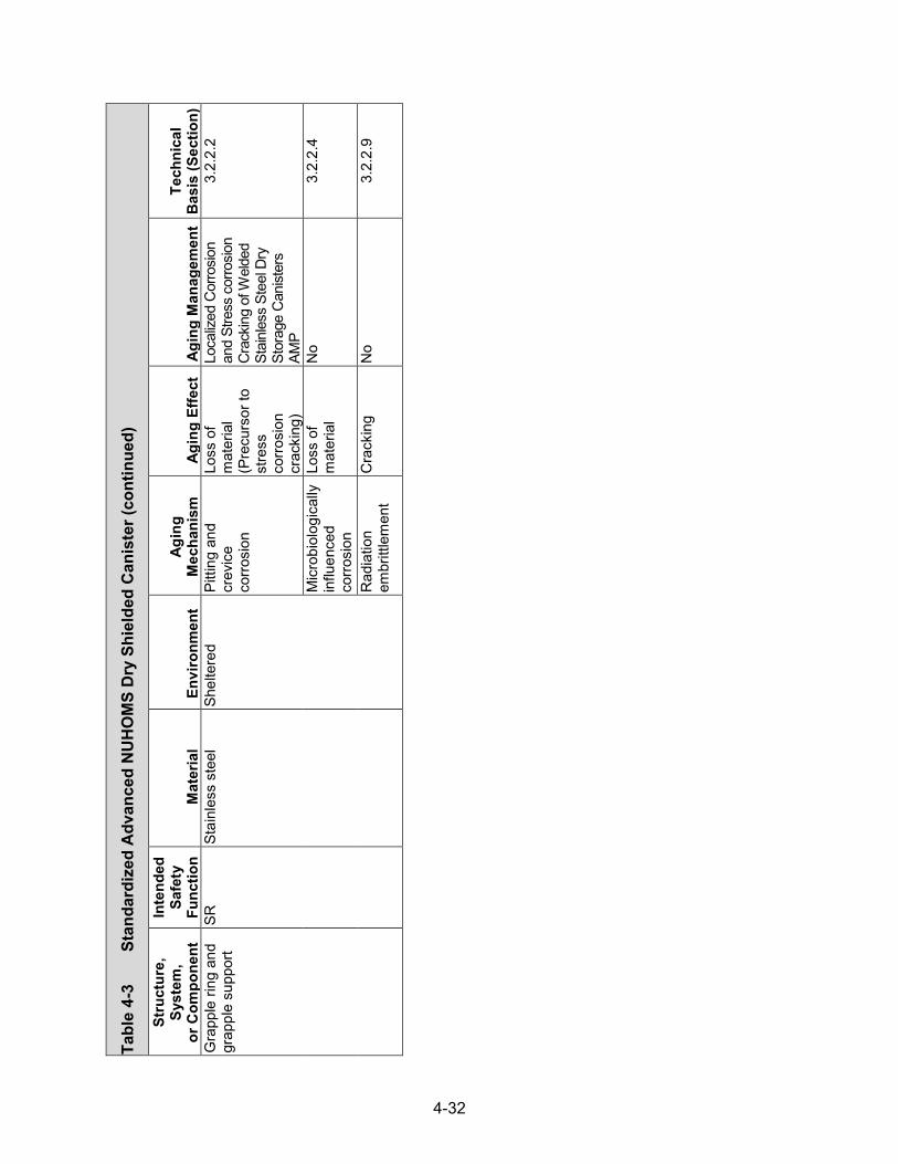
4-32
Tabl
e 4-
3
Stan
dard
ized
Adv
ance
d N
UH
OM
S D
ry S
hiel
ded
Can
iste
r (continued)
Stru
ctur
e,
Syst
em,
or C
ompo
nent
Inte
nded
Sa
fety
Fu
nctio
n M
ater
ial
Envi
ronm
ent
Agin
g M
echa
nism
Ag
ing
Effe
ct
Agin
g M
anag
emen
t Te
chni
cal
Bas
is (S
ectio
n)
Gra
pple
ring
and
gr
appl
e su
ppor
t SR
St
ainl
ess
stee
l Sh
elte
red
Pitti
ng a
nd
crev
ice
corro
sion
Loss
of
mat
eria
l (P
recu
rsor
to
stre
ss
corro
sion
cr
acki
ng)
Loca
lized
Cor
rosio
n an
d St
ress
cor
rosio
n C
rack
ing
of W
elde
d St
ainl
ess
Stee
l Dry
St
orag
e C
anist
ers
AMP
3.2.
2.2
Mic
robi
olog
ical
ly
influ
ence
d co
rrosi
on
Loss
of
mat
eria
l N
o 3.
2.2.
4
Rad
iatio
n em
britt
lem
ent
Cra
ckin
g N
o 3.
2.2.
9
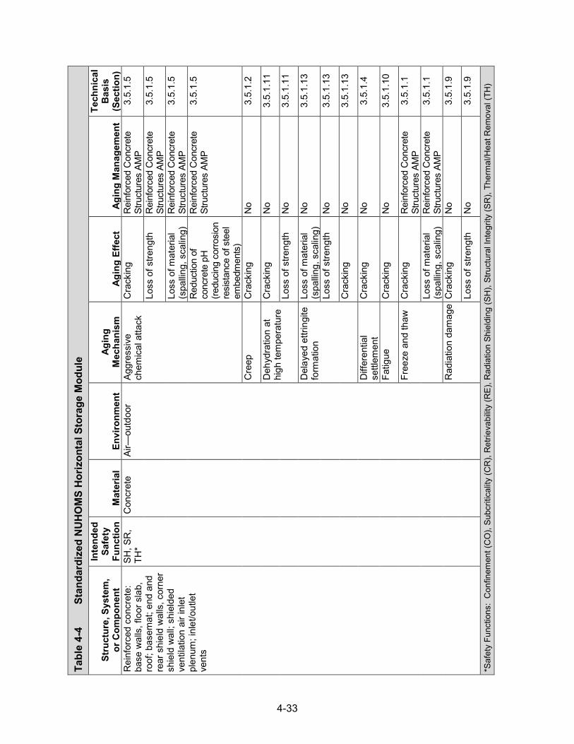
4-33
Tabl
e 4-
4
Stan
dard
ized
NU
HO
MS
Hor
izon
tal S
tora
ge M
odul
e
Stru
ctur
e, S
yste
m,
or C
ompo
nent
Inte
nded
Sa
fety
Fu
nctio
n M
ater
ial
Envi
ronm
ent
Agin
g M
echa
nism
Ag
ing
Effe
ct
Agin
g M
anag
emen
t
Tech
nica
l B
asis
(S
ectio
n)
Rei
nfor
ced
conc
rete
: ba
se w
alls
, flo
or s
lab,
ro
of; b
asem
at; e
nd a
nd
rear
shi
eld
wal
ls, c
orne
r sh
ield
wal
l; sh
ield
ed
vent
ilatio
n ai
r inl
et
plen
um; i
nlet
/out
let
vent
s
SH, S
R,
TH*
Con
cret
e Ai
r—ou
tdoo
r Ag
gres
sive
ch
emic
al a
ttack
C
rack
ing
Rei
nfor
ced
Con
cret
e St
ruct
ures
AM
P 3.
5.1.
5
Loss
of s
treng
th
Rei
nfor
ced
Con
cret
e St
ruct
ures
AM
P 3.
5.1.
5
Loss
of m
ater
ial
(spa
lling,
sca
ling)
R
einf
orce
d C
oncr
ete
Stru
ctur
es A
MP
3.5.
1.5
Red
uctio
n of
co
ncre
te p
H
(redu
cing
cor
rosi
on
resi
stan
ce o
f ste
el
embe
dmen
ts)
Rei
nfor
ced
Con
cret
e St
ruct
ures
AM
P 3.
5.1.
5
Cre
ep
Cra
ckin
g N
o 3.
5.1.
2
Deh
ydra
tion
at
high
tem
pera
ture
C
rack
ing
No
3.5.
1.11
Loss
of s
treng
th
No
3.5.
1.11
Del
ayed
ettr
ingi
te
form
atio
n Lo
ss o
f mat
eria
l (s
pallin
g, s
calin
g)
No
3.5.
1.13
Loss
of s
treng
th
No
3.5.
1.13
Cra
ckin
g N
o 3.
5.1.
13
Diff
eren
tial
settl
emen
t C
rack
ing
No
3.5.
1.4
Fatig
ue
Cra
ckin
g N
o 3.
5.1.
10
Free
ze a
nd th
aw
Cra
ckin
g R
einf
orce
d C
oncr
ete
Stru
ctur
es A
MP
3.5.
1.1
Loss
of m
ater
ial
(spa
lling,
sca
ling)
R
einf
orce
d C
oncr
ete
Stru
ctur
es A
MP
3.5.
1.1
Rad
iatio
n da
mag
e C
rack
ing
No
3.5.
1.9
Loss
of s
treng
th
No
3.5.
1.9
*Saf
ety
Func
tions
: C
onfin
emen
t (C
O),
Subc
ritic
ality
(CR
), R
etrie
vabi
lity
(RE)
, Rad
iatio
n Sh
ield
ing
(SH
), St
ruct
ural
Inte
grity
(SR
), Th
erm
al/H
eat R
emov
al (T
H)

4-34
Tabl
e 4-
4
Stan
dard
ized
NU
HO
MS
Hor
izon
tal S
tora
ge M
odul
e (con
tinued)
Stru
ctur
e, S
yste
m,
or C
ompo
nent
Inte
nded
Sa
fety
Fu
nctio
n M
ater
ial
Envi
ronm
ent
Agin
g M
echa
nism
Ag
ing
Effe
ct
Agin
g M
anag
emen
t
Tech
nica
l B
asis
(S
ectio
n)
Rei
nfor
ced
conc
rete
: ba
se w
alls
, flo
or s
lab,
ro
of; b
asem
at; e
nd a
nd
rear
shi
eld
wal
ls, c
orne
r sh
ield
wal
l; sh
ield
ed
vent
ilatio
n ai
r inl
et
plen
um; i
nlet
/out
let
vent
s
SH, S
R,
TH
Con
cret
e Ai
r—ou
tdoo
r R
eact
ion
with
ag
greg
ates
C
rack
ing
Rei
nfor
ced
Con
cret
e St
ruct
ures
AM
P 3.
5.1.
3
Loss
of s
treng
th
Rei
nfor
ced
Con
cret
e St
ruct
ures
AM
P 3.
5.1.
3
Salt
scal
ing
Loss
of m
ater
ial
(spa
lling,
sca
ling)
R
einf
orce
d C
oncr
ete
Stru
ctur
es A
MP
3.5.
1.14
Shrin
kage
C
rack
ing
No
3.5.
1.7
Leac
hing
of
calc
ium
hy
drox
ide
Loss
of s
treng
th
Rei
nfor
ced
Con
cret
e St
ruct
ures
AM
P 3.
5.1.
8
Incr
ease
in
poro
sity
an
d pe
rmea
bilit
y
Rei
nfor
ced
Con
cret
e St
ruct
ures
AM
P 3.
5.1.
8
Red
uctio
n of
co
ncre
te p
H
(redu
cing
co
rrosi
on
resi
stan
ce o
f ste
el
embe
dmen
ts)
Rei
nfor
ced
Con
cret
e St
ruct
ures
AM
P 3.
5.1.
8
Shel
tere
d Ag
gres
sive
ch
emic
al a
ttack
Lo
ss o
f stre
ngth
N
o 3.
5.1.
5
Cra
ckin
g N
o 3.
5.1.
5
Loss
of m
ater
ial
(spa
lling,
sca
ling)
N
o 3.
5.1.
5
Cre
ep
Cra
ckin
g N
o 3.
5.1.
2
Deh
ydra
tion
at
high
tem
pera
ture
C
rack
ing
No
3.5.
1.11
Loss
of s
treng
th
No
3.5.
1.11
Del
ayed
ettr
ingi
te
form
atio
n Lo
ss o
f mat
eria
l (s
pallin
g, s
calin
g)
No
3.5.
1.13

4-35
Tabl
e 4-
4
Stan
dard
ized
NU
HO
MS
Hor
izon
tal S
tora
ge M
odul
e (con
tinued)
Stru
ctur
e, S
yste
m,
or C
ompo
nent
Inte
nded
Sa
fety
Fu
nctio
n M
ater
ial
Envi
ronm
ent
Agin
g M
echa
nism
Ag
ing
Effe
ct
Agin
g M
anag
emen
t
Tech
nica
l B
asis
(S
ectio
n)
Rei
nfor
ced
conc
rete
: ba
se w
alls
, flo
or s
lab,
ro
of; b
asem
at; e
nd a
nd
rear
shi
eld
wal
ls, c
orne
r sh
ield
wal
l; sh
ield
ed
vent
ilatio
n ai
r inl
et
plen
um; i
nlet
/out
let
vent
s
SH, S
R,
TH
Con
cret
e Sh
elte
red
Del
ayed
ettr
ingi
te
form
atio
n Lo
ss o
f stre
ngth
N
o 3.
5.1.
13
Cra
ckin
g N
o 3.
5.1.
13
Diff
eren
tial
settl
emen
t C
rack
ing
No
3.5.
1.4
Fatig
ue
Cra
ckin
g N
o 3.
5.1.
10
Free
ze a
nd th
aw
Cra
ckin
g N
o 3.
5.1.
1
Loss
of m
ater
ial
(spa
lling,
sca
ling)
N
o 3.
5.1.
1
Rad
iatio
n da
mag
e C
rack
ing
No
3.5.
1.9
Loss
of s
treng
th
No
3.5.
1.9
Rea
ctio
n w
ith
aggr
egat
es
Cra
ckin
g R
einf
orce
d C
oncr
ete
Stru
ctur
es A
MP
3.5.
1.3
Loss
of s
treng
th
Rei
nfor
ced
Con
cret
e St
ruct
ures
AM
P 3.
5.1.
3
Salt
scal
ing
Loss
of m
ater
ial
(spa
lling,
sca
ling)
N
o 3.
5.1.
14
Shrin
kage
C
rack
ing
No
3.5.
1.7
Gro
undw
ater
/soi
l Ag
gres
sive
ch
emic
al a
ttack
C
rack
ing
Rei
nfor
ced
Con
cret
e St
ruct
ures
AM
P 3.
5.1.
5
Loss
of m
ater
ial
(spa
lling,
sca
ling)
R
einf
orce
d C
oncr
ete
Stru
ctur
es A
MP
3.5.
1.5
Loss
of s
treng
th
Rei
nfor
ced
Con
cret
e St
ruct
ures
AM
P 3.
5.1.
5

4-36
Tabl
e 4-
4
Stan
dard
ized
NU
HO
MS
Hor
izon
tal S
tora
ge M
odul
e (con
tinued)
Stru
ctur
e, S
yste
m,
or C
ompo
nent
Inte
nded
Sa
fety
Fu
nctio
n M
ater
ial
Envi
ronm
ent
Agin
g M
echa
nism
Ag
ing
Effe
ct
Agin
g M
anag
emen
t
Tech
nica
l B
asis
(S
ectio
n)
Rei
nfor
ced
conc
rete
: ba
se w
alls
, flo
or s
lab,
ro
of; b
asem
at; e
nd a
nd
rear
shi
eld
wal
ls, c
orne
r sh
ield
wal
l; sh
ield
ed
vent
ilatio
n ai
r inl
et
plen
um; i
nlet
/out
let
vent
s
SH, S
R,
TH
Con
cret
e G
roun
dwat
er/s
oil
Aggr
essi
ve
chem
ical
atta
ck
Red
uctio
n of
co
ncre
te p
H
(redu
cing
co
rrosi
on
resi
stan
ce o
f ste
el
embe
dmen
ts)
Rei
nfor
ced
Con
cret
e St
ruct
ures
AM
P 3.
5.1.
5
Cre
ep
Cra
ckin
g N
o 3.
5.1.
2
Deh
ydra
tion
at
high
tem
pera
ture
C
rack
ing
No
3.5.
1.11
Loss
of s
treng
th
No
3.5.
1.11
Del
ayed
ettr
ingi
te
form
atio
n Lo
ss o
f mat
eria
l (s
pallin
g, s
calin
g)
No
3.5.
1.13
Loss
of s
treng
th
No
3.5.
1.13
Cra
ckin
g N
o 3.
5.1.
13
Diff
eren
tial
settl
emen
t C
rack
ing
Rei
nfor
ced
Con
cret
e St
ruct
ures
AM
P 3.
5.1.
4
Fatig
ue
Cra
ckin
g N
o 3.
5.1.
10
Free
ze a
nd th
aw
Cra
ckin
g R
einf
orce
d C
oncr
ete
Stru
ctur
es A
MP
3.5.
1.1
Loss
of m
ater
ial
(spa
lling,
sca
ling)
R
einf
orce
d C
oncr
ete
Stru
ctur
es A
MP
3.5.
1.1
Mic
robi
olog
ical
de
grad
atio
n Lo
ss o
f stre
ngth
R
einf
orce
d C
oncr
ete
Stru
ctur
es A
MP
3.5.
1.12
Loss
of m
ater
ial
(spa
lling,
sca
ling)
R
einf
orce
d C
oncr
ete
Stru
ctur
es A
MP
3.5.
1.12
Incr
ease
in
poro
sity
an
d pe
rmea
bilit
y
Rei
nfor
ced
Con
cret
e St
ruct
ures
AM
P 3.
5.1.
12
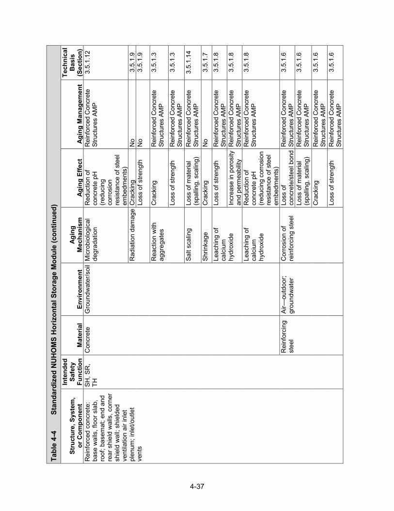
4-37
Tabl
e 4-
4
Stan
dard
ized
NU
HO
MS
Hor
izon
tal S
tora
ge M
odul
e (con
tinued)
Stru
ctur
e, S
yste
m,
or C
ompo
nent
Inte
nded
Sa
fety
Fu
nctio
n M
ater
ial
Envi
ronm
ent
Agin
g M
echa
nism
Ag
ing
Effe
ct
Agin
g M
anag
emen
t
Tech
nica
l B
asis
(S
ectio
n)
Rei
nfor
ced
conc
rete
: ba
se w
alls
, flo
or s
lab,
ro
of; b
asem
at; e
nd a
nd
rear
shi
eld
wal
ls, c
orne
r sh
ield
wal
l; sh
ield
ed
vent
ilatio
n ai
r inl
et
plen
um; i
nlet
/out
let
vent
s
SH, S
R,
TH
Con
cret
e G
roun
dwat
er/s
oil
Mic
robi
olog
ical
de
grad
atio
n R
educ
tion
of
conc
rete
pH
(re
duci
ng
corro
sion
re
sist
ance
of s
teel
em
bedm
ents
)
Rei
nfor
ced
Con
cret
e St
ruct
ures
AM
P 3.
5.1.
12
Rad
iatio
n da
mag
e C
rack
ing
No
3.5.
1.9
Loss
of s
treng
th
No
3.5.
1.9
Rea
ctio
n w
ith
aggr
egat
es
Cra
ckin
g R
einf
orce
d C
oncr
ete
Stru
ctur
es A
MP
3.5.
1.3
Loss
of s
treng
th
Rei
nfor
ced
Con
cret
e St
ruct
ures
AM
P 3.
5.1.
3
Salt
scal
ing
Loss
of m
ater
ial
(spa
lling,
sca
ling)
R
einf
orce
d C
oncr
ete
Stru
ctur
es A
MP
3.5.
1.14
Shrin
kage
C
rack
ing
No
3.5.
1.7
Leac
hing
of
calc
ium
hy
drox
ide
Loss
of s
treng
th
Rei
nfor
ced
Con
cret
e St
ruct
ures
AM
P 3.
5.1.
8
Incr
ease
in p
oros
ity
and
perm
eabi
lity
Rei
nfor
ced
Con
cret
e St
ruct
ures
AM
P 3.
5.1.
8
Leac
hing
of
calc
ium
hy
drox
ide
Red
uctio
n of
co
ncre
te p
H
(redu
cing
cor
rosi
on
resi
stan
ce o
f ste
el
embe
dmen
ts)
Rei
nfor
ced
Con
cret
e St
ruct
ures
AM
P 3.
5.1.
8
Rei
nfor
cing
st
eel
Air—
outd
oor;
grou
ndw
ater
C
orro
sion
of
rein
forc
ing
stee
l Lo
ss o
f co
ncre
te/s
teel
bon
d R
einf
orce
d C
oncr
ete
Stru
ctur
es A
MP
3.5.
1.6
Loss
of m
ater
ial
(spa
lling,
sca
ling)
R
einf
orce
d C
oncr
ete
Stru
ctur
es A
MP
3.5.
1.6
Cra
ckin
g R
einf
orce
d C
oncr
ete
Stru
ctur
es A
MP
3.5.
1.6
Loss
of s
treng
th
Rei
nfor
ced
Con
cret
e St
ruct
ures
AM
P 3.
5.1.
6
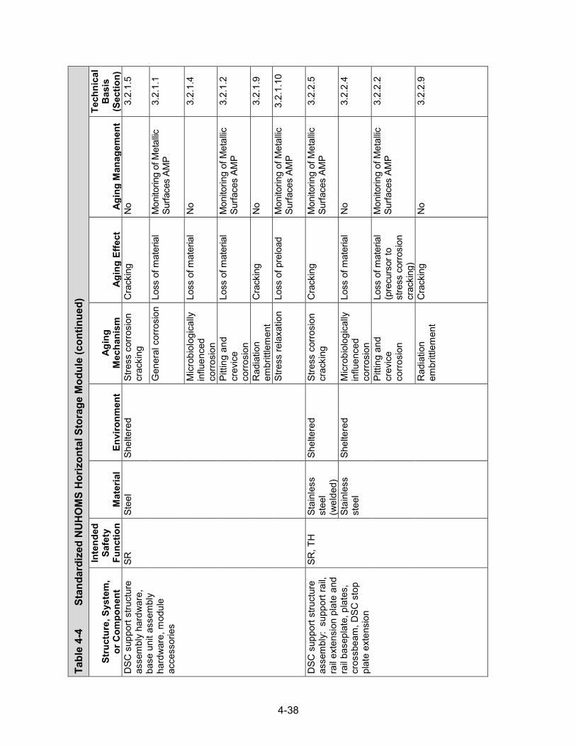
4-38
Tabl
e 4-
4
Stan
dard
ized
NU
HO
MS
Hor
izon
tal S
tora
ge M
odul
e (con
tinued)
Stru
ctur
e, S
yste
m,
or C
ompo
nent
Inte
nded
Sa
fety
Fu
nctio
n M
ater
ial
Envi
ronm
ent
Agin
g M
echa
nism
Ag
ing
Effe
ct
Agin
g M
anag
emen
t
Tech
nica
l B
asis
(S
ectio
n)
DSC
sup
port
stru
ctur
e as
sem
bly
hard
war
e,
base
uni
t ass
embl
y ha
rdw
are,
mod
ule
acce
ssor
ies
SR
Stee
l Sh
elte
red
Stre
ss c
orro
sion
cr
acki
ng
Cra
ckin
g N
o 3.
2.1.
5
Gen
eral
cor
rosi
on
Loss
of m
ater
ial
Mon
itorin
g of
Met
allic
Su
rface
s AM
P 3.
2.1.
1
Mic
robi
olog
ical
ly
influ
ence
d co
rrosi
on
Loss
of m
ater
ial
No
3.2.
1.4
Pitti
ng a
nd
crev
ice
corro
sion
Loss
of m
ater
ial
Mon
itorin
g of
Met
allic
Su
rface
s AM
P 3.
2.1.
2
Rad
iatio
n em
britt
lem
ent
Cra
ckin
g N
o 3.
2.1.
9
Stre
ss re
laxa
tion
Loss
of p
relo
ad
Mon
itorin
g of
Met
allic
Su
rface
s AM
P 3.
2.1.
10
DSC
sup
port
stru
ctur
e as
sem
bly:
sup
port
rail,
ra
il ex
tens
ion
plat
e an
d ra
il ba
sepl
ate,
pla
tes,
cr
ossb
eam
, DSC
sto
p pl
ate
exte
nsio
n
SR, T
H
Stai
nles
s st
eel
(wel
ded)
Shel
tere
d St
ress
cor
rosi
on
crac
king
C
rack
ing
Mon
itorin
g of
Met
allic
Su
rface
s AM
P 3.
2.2.
5
Stai
nles
s st
eel
Shel
tere
d M
icro
biol
ogic
ally
in
fluen
ced
corro
sion
Loss
of m
ater
ial
No
3.2.
2.4
Pitti
ng a
nd
crev
ice
corro
sion
Loss
of m
ater
ial
(pre
curs
or to
st
ress
cor
rosi
on
crac
king
)
Mon
itorin
g of
Met
allic
Su
rface
s AM
P 3.
2.2.
2
Rad
iatio
n em
britt
lem
ent
Cra
ckin
g N
o 3.
2.2.
9

4-39
Tabl
e 4-
4
Stan
dard
ized
NU
HO
MS
Hor
izon
tal S
tora
ge M
odul
e (con
tinued)
Stru
ctur
e, S
yste
m,
or C
ompo
nent
Inte
nded
Sa
fety
Fu
nctio
n M
ater
ial
Envi
ronm
ent
Agin
g M
echa
nism
Ag
ing
Effe
ct
Agin
g M
anag
emen
t
Tech
nica
l B
asis
(S
ectio
n)
DSC
sup
port
stru
ctur
e as
sem
bly:
sup
port
rail
beam
s, s
uppo
rt st
ruct
ure
mis
cella
neou
s st
eel,
plat
es, a
ttach
men
t/ in
stal
latio
n ha
rdw
are,
D
SC s
top
plat
e as
sem
bly,
rail
exte
nsio
n em
bedm
ent,
tube
ste
el
leg
colu
mn
SR, T
H
Stee
l Sh
elte
red
Gal
vani
c co
rrosi
on
Loss
of m
ater
ial
Mon
itorin
g of
Met
allic
Su
rface
s AM
P 3.
2.1.
3
Gen
eral
cor
rosi
on
Loss
of m
ater
ial
Mon
itorin
g of
Met
allic
Su
rface
s AM
P 3.
2.1.
1
Mic
robi
olog
ical
ly
influ
ence
d co
rrosi
on
Loss
of m
ater
ial
No
3.2.
1.4
Pitti
ng a
nd
crev
ice
corro
sion
Loss
of m
ater
ial
Mon
itorin
g of
Met
allic
Su
rface
s AM
P 3.
2.1.
2
Rad
iatio
n em
britt
lem
ent
Cra
ckin
g N
o 3.
2.1.
9
DSC
sup
port
stru
ctur
e as
sem
bly:
sup
port
rail
plat
e
SR, T
H
Stai
nles
s st
eel
Shel
tere
d St
ress
cor
rosi
on
crac
king
C
rack
ing
Mon
itorin
g of
Met
allic
Su
rface
s AM
P 3.
2.2.
5
Mic
robi
olog
ical
ly
influ
ence
d co
rrosi
on
Loss
of m
ater
ial
No
3.2.
2.4
Pitti
ng a
nd
crev
ice
corro
sion
Loss
of m
ater
ial
(pre
curs
or to
st
ress
cor
rosi
on
crac
king
)
Mon
itorin
g of
Met
allic
Su
rface
s AM
P 3.
2.2.
2
Rad
iatio
n em
britt
lem
ent
Cra
ckin
g N
o 3.
2.2.
9
DSC
axi
al re
tain
er
asse
mbl
y: a
xial
re
tain
er, p
late
SR
Stee
l Sh
elte
red
Gen
eral
cor
rosi
on
Loss
of m
ater
ial
Mon
itorin
g of
Met
allic
Su
rface
s AM
P 3.
2.1.
1
Mic
robi
olog
ical
ly
influ
ence
d co
rrosi
on
Loss
of m
ater
ial
No
3.2.
1.4

4-40
Tabl
e 4-
4
Stan
dard
ized
NU
HO
MS
Hor
izon
tal S
tora
ge M
odul
e (con
tinued)
Stru
ctur
e, S
yste
m,
or C
ompo
nent
Inte
nded
Sa
fety
Fu
nctio
n M
ater
ial
Envi
ronm
ent
Agin
g M
echa
nism
Ag
ing
Effe
ct
Agin
g M
anag
emen
t
Tech
nica
l B
asis
(S
ectio
n)
DSC
axi
al re
tain
er
asse
mbl
y: a
xial
re
tain
er, p
late
SR
Stee
l Sh
elte
red
Pitti
ng a
nd
crev
ice
corro
sion
Loss
of m
ater
ial
Mon
itorin
g of
Met
allic
Su
rface
s AM
P 3.
2.1.
2
Rad
iatio
n em
britt
lem
ent
Cra
ckin
g N
o 3.
2.1.
9
Stai
nles
s st
eel
Shel
tere
d St
ress
cor
rosi
on
crac
king
C
rack
ing
No
3.2.
2.5
Mic
robi
olog
ical
ly
Influ
ence
d co
rrosi
on
Loss
of m
ater
ial
No
3.2.
2.4
Pitti
ng a
nd
crev
ice
corro
sion
Loss
of m
ater
ial
No
3.2.
2.2
Rad
iatio
n em
britt
lem
ent
Cra
ckin
g N
o 3.
2.2.
9
Cas
k re
stra
in a
ssem
bly:
em
bedm
ent a
ssem
bly
(rods
, hex
nut
s, s
leev
e nu
ts),
cask
rest
rain
t em
bedm
ent
SR
Stee
l Sh
elte
red
Stre
ss c
orro
sion
cr
acki
ng
Cra
ckin
g N
o 3.
2.1.
5
Gen
eral
cor
rosi
on
Loss
of m
ater
ial
Mon
itorin
g of
Met
allic
Su
rface
s AM
P 3.
2.1.
1
Mic
robi
olog
ical
ly
influ
ence
d co
rrosi
on
Loss
of m
ater
ial
No
3.2.
1.4
Pitti
ng a
nd
crev
ice
corro
sion
Loss
of m
ater
ial
Mon
itorin
g of
Met
allic
Su
rface
s AM
P 3.
2.1.
2
Rad
iatio
n em
britt
lem
ent
Cra
ckin
g N
o 3.
2.1.
9
Stre
ss re
laxa
tion
Loss
of p
relo
ad
Mon
itorin
g of
Met
allic
Su
rface
s AM
P 3.
2.1.
10
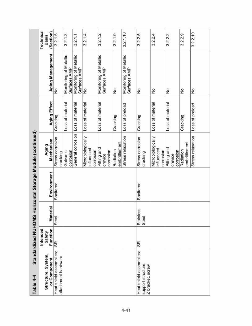
4-41
Tabl
e 4-
4
Stan
dard
ized
NU
HO
MS
Hor
izon
tal S
tora
ge M
odul
e (con
tinued)
Stru
ctur
e, S
yste
m,
or C
ompo
nent
Inte
nded
Sa
fety
Fu
nctio
n M
ater
ial
Envi
ronm
ent
Agin
g M
echa
nism
Ag
ing
Effe
ct
Agin
g M
anag
emen
t
Tech
nica
l B
asis
(S
ectio
n)
Hea
t shi
eld
asse
mbl
ies:
at
tach
men
t har
dwar
e SR
St
eel
Shel
tere
d St
ress
cor
rosi
on
crac
king
C
rack
ing
No
3.2.
1.5
Gal
vani
c co
rrosi
on
Loss
of m
ater
ial
Mon
itorin
g of
Met
allic
Su
rface
s AM
P 3.
2.1.
3
Gen
eral
cor
rosi
on
Loss
of m
ater
ial
Mon
itorin
g of
Met
allic
Su
rface
s AM
P 3.
2.1.
1
Mic
robi
olog
ical
ly
influ
ence
d co
rrosi
on
Loss
of m
ater
ial
No
3.2.
1.4
Pitti
ng a
nd
crev
ice
corro
sion
Loss
of m
ater
ial
Mon
itorin
g of
Met
allic
Su
rface
s AM
P 3.
2.1.
2
Rad
iatio
n em
britt
lem
ent
Cra
ckin
g N
o 3.
2.1.
9
Stre
ss re
laxa
tion
Loss
of p
relo
ad
Mon
itorin
g of
Met
allic
Su
rface
s AM
P 3.
2.1.
10
Hea
t shi
eld
asse
mbl
ies:
su
ppor
t stru
ctur
e,
Z br
acke
t, sc
rew
SR
Stai
nles
s St
eel
Shel
tere
d St
ress
cor
rosi
on
crac
king
C
rack
ing
No
3.2.
2.5
Mic
robi
olog
ical
ly
influ
ence
d co
rrosi
on
Loss
of m
ater
ial
No
3.2.
2.4
Pitti
ng a
nd
crev
ice
corro
sion
Loss
of m
ater
ial
No
3.2.
2.2
Rad
iatio
n em
britt
lem
ent
Cra
ckin
g N
o 3.
2.2.
9
Stre
ss re
laxa
tion
Loss
of p
relo
ad
No
3.2.
2.10

4-42
Tabl
e 4-
4
Stan
dard
ized
NU
HO
MS
Hor
izon
tal S
tora
ge M
odul
e (con
tinued)
Stru
ctur
e, S
yste
m,
or C
ompo
nent
Inte
nded
Sa
fety
Fu
nctio
n M
ater
ial
Envi
ronm
ent
Agin
g M
echa
nism
Ag
ing
Effe
ct
Agin
g M
anag
emen
t
Tech
nica
l B
asis
(S
ectio
n)
Hea
t shi
eld
asse
mbl
ies:
ro
of a
nd s
ide
wal
l m
ount
ed h
eat s
hiel
ds, Z
br
acke
t
TH
Stee
l (g
alva
nize
d) Sh
elte
red
Gal
vani
c co
rrosi
on
Loss
of m
ater
ial
Mon
itorin
g of
Met
allic
Su
rface
s AM
P 3.
2.1.
3
Gen
eral
cor
rosi
on
Loss
of m
ater
ial
Mon
itorin
g of
Met
allic
Su
rface
s AM
P 3.
2.1.
1
Mic
robi
olog
ical
ly
influ
ence
d co
rrosi
on
Loss
of m
ater
ial
No
3.2.
1.4
Pitti
ng a
nd
crev
ice
corro
sion
Loss
of m
ater
ial
Mon
itorin
g of
Met
allic
Su
rface
s AM
P 3.
2.1.
2
Rad
iatio
n em
britt
lem
ent
Cra
ckin
g N
o 3.
2.1.
9
Hea
t shi
eld
asse
mbl
ies:
ro
of a
nd s
ide
wal
l m
ount
ed h
eat s
hiel
ds/Z
br
acke
t, si
de h
eat s
hiel
d fin
s, b
acki
ng s
heet
, top
lo
uver
ed h
eat s
hiel
d
TH
Alum
inum
Sh
elte
red
Gal
vani
c co
rrosi
on
Loss
of m
ater
ial
Mon
itorin
g of
Met
allic
Su
rface
s AM
P 3.
2.3.
3
Mic
robi
olog
ical
ly
influ
ence
d co
rrosi
on
Loss
of m
ater
ial
No
3.2.
3.4
Pitti
ng a
nd
crev
ice
corro
sion
Lo
ss o
f mat
eria
l M
onito
ring
of M
etal
lic
Surfa
ces
AMP
3.2.
3.2
Rad
iatio
n em
britt
lem
ent
Cra
ckin
g N
o 3.
2.3.
8
Hea
t shi
eld
asse
mbl
ies:
si
de h
eat s
hiel
d, to
p he
at s
hiel
d
TH
Stai
nles
s st
eel
Shel
tere
d St
ress
cor
rosi
on
crac
king
C
rack
ing
No
3.2.
2.5
Mic
robi
olog
ical
ly
influ
ence
d co
rrosi
on
Loss
of m
ater
ial
No
3.2.
2.4

4-43
Tabl
e 4-
4
Stan
dard
ized
NU
HO
MS
Hor
izon
tal S
tora
ge M
odul
e (con
tinued)
Stru
ctur
e, S
yste
m,
or C
ompo
nent
Inte
nded
Sa
fety
Fu
nctio
n M
ater
ial
Envi
ronm
ent
Agin
g M
echa
nism
Ag
ing
Effe
ct
Agin
g M
anag
emen
t
Tech
nica
l B
asis
(S
ectio
n)
Hea
t shi
eld
asse
mbl
ies:
si
de h
eat s
hiel
d, to
p he
at s
hiel
d
TH
Stai
nles
s st
eel
Shel
tere
d Pi
tting
and
cr
evic
e co
rrosi
on
Loss
of m
ater
ial
No
3.2.
2.2
Rad
iatio
n em
britt
lem
ent
Cra
ckin
g N
o 3.
2.2.
9
Shie
lded
doo
r ass
embl
y:
door
atta
chm
ent
hard
war
e
SR
Stee
l Ai
r—ou
tdoo
r St
ress
cor
rosi
on
crac
king
C
rack
ing
No
3.2.
1.5
Gen
eral
cor
rosi
on
Loss
of m
ater
ial
Mon
itorin
g of
Met
allic
Su
rface
s AM
P 3.
2.1.
1
Mic
robi
olog
ical
ly
influ
ence
d co
rrosi
on
Loss
of m
ater
ial
No
3.2.
1.4
Pitti
ng a
nd
crev
ice
corro
sion
Loss
of m
ater
ial
Mon
itorin
g of
Met
allic
Su
rface
s AM
P 3.
2.1.
2
Rad
iatio
n em
britt
lem
ent
Cra
ckin
g N
o 3.
2.1.
9
Stre
ss re
laxa
tion
Loss
of p
relo
ad
No
3.2.
1.10
Sh
ield
ed d
oor
asse
mbl
y: s
teel
pla
tes
SH, S
R
Stee
l Ai
r—ou
tdoo
r G
ener
al c
orro
sion
Lo
ss o
f mat
eria
l M
onito
ring
of M
etal
lic
Surfa
ces
AMP
3.2.
1.1
Mic
robi
olog
ical
ly
influ
ence
d co
rrosi
on
Loss
of m
ater
ial
No
3.2.
1.4
Pitti
ng a
nd
crev
ice
corro
sion
Loss
of m
ater
ial
Mon
itorin
g of
Met
allic
Su
rface
s AM
P 3.
2.1.
2
Rad
iatio
n em
britt
lem
ent
Cra
ckin
g N
o 3.
2.1.
9
Shel
tere
d G
ener
al c
orro
sion
Lo
ss o
f mat
eria
l M
onito
ring
of M
etal
lic
Surfa
ces
AMP
3.2.
1.1
Mic
robi
olog
ical
ly
influ
ence
d co
rrosi
on
Loss
of m
ater
ial
No
3.2.
1.4

4-44
Tabl
e 4-
4
Stan
dard
ized
NU
HO
MS
Hor
izon
tal S
tora
ge M
odul
e (con
tinued)
Stru
ctur
e, S
yste
m,
or C
ompo
nent
Inte
nded
Sa
fety
Fu
nctio
n M
ater
ial
Envi
ronm
ent
Agin
g M
echa
nism
Ag
ing
Effe
ct
Agin
g M
anag
emen
t
Tech
nica
l B
asis
(S
ectio
n)
Shie
lded
doo
r as
sem
bly:
ste
el p
late
s SH
, SR
St
eel
Shel
tere
d Pi
tting
and
cr
evic
e co
rrosi
on
Loss
of m
ater
ial
Mon
itorin
g of
Met
allic
Su
rface
s AM
P 3.
2.1.
2
Rad
iatio
n em
britt
lem
ent
Cra
ckin
g N
o 3.
2.1.
9
Shie
lded
doo
r ass
embl
y:
conc
rete
cor
e SH
, SR
R
einf
orce
d co
ncre
te,
nons
hrin
k gr
out o
r pea
gr
avel
or
mor
tar m
ix
Fully
enc
ased
(s
teel
) D
elay
ed e
ttrin
gite
fo
rmat
ion
Loss
of m
ater
ial
(spa
lling,
sca
ling)
N
o 3.
5.1.
13
Cra
ckin
g N
o 3.
5.1.
13
Loss
of s
treng
th
No
3.5.
1.13
Rad
iatio
n da
mag
e C
rack
ing
No
3.5.
1.9
Rad
iatio
n da
mag
e Lo
ss o
f stre
ngth
N
o 3.
5.1.
9
Rea
ctio
n w
ith
aggr
egat
es
Cra
ckin
g N
o 3.
5.1.
3
Loss
of s
treng
th
No
3.5.
1.3
Inle
t/out
let v
ents
: out
let
vent
atta
chm
ents
SR
St
eel
Air—
outd
oor
Stre
ss c
orro
sion
cr
acki
ng
Cra
ckin
g N
o 3.
2.1.
5
Gen
eral
cor
rosi
on
Loss
of m
ater
ial
Mon
itorin
g of
Met
allic
Su
rface
s AM
P 3.
2.1.
1
Mic
robi
olog
ical
ly
influ
ence
d co
rrosi
on
Loss
of m
ater
ial
No
3.2.
1.4
Pitti
ng a
nd
crev
ice
corro
sion
Loss
of m
ater
ial
Mon
itorin
g of
Met
allic
Su
rface
s AM
P 3.
2.1.
2
Rad
iatio
n em
britt
lem
ent
Cra
ckin
g N
o 3.
2.1.
9
Stre
ss re
laxa
tion
Loss
of p
relo
ad
No
3.2.
1.10
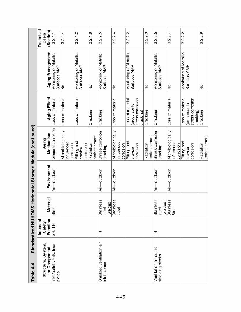
4-45
Tabl
e 4-
4
Stan
dard
ized
NU
HO
MS
Hor
izon
tal S
tora
ge M
odul
e (con
tinued)
Stru
ctur
e, S
yste
m,
or C
ompo
nent
Inte
nded
Sa
fety
Fu
nctio
n M
ater
ial
Envi
ronm
ent
Agin
g M
echa
nism
Ag
ing
Effe
ct
Agin
g M
anag
emen
t
Tech
nica
l B
asis
(S
ectio
n)
Inle
t/out
let v
ents
: lin
er
plat
es
SH, T
H
Stee
l Ai
r—ou
tdoo
r G
ener
al c
orro
sion
Lo
ss o
f mat
eria
l M
onito
ring
of M
etal
lic
Surfa
ces
AMP
3.2.
1.1
Mic
robi
olog
ical
ly
influ
ence
d co
rrosi
on
Loss
of m
ater
ial
No
3.2.
1.4
Pitti
ng a
nd
crev
ice
corro
sion
Loss
of m
ater
ial
Mon
itorin
g of
Met
allic
Su
rface
s AM
P 3.
2.1.
2
Rad
iatio
n em
britt
lem
ent
Cra
ckin
g N
o 3.
2.1.
9
Shie
lded
ven
tilat
ion
air
inle
t ple
num
TH
St
ainl
ess
stee
l (w
elde
d)
Air—
outd
oor
Stre
ss c
orro
sion
cr
acki
ng
Cra
ckin
g M
onito
ring
of M
etal
lic
Surfa
ces
AMP
3.2.
2.5
Stai
nles
s st
eel
Air—
outd
oor
Mic
robi
olog
ical
ly
influ
ence
d co
rrosi
on
Loss
of m
ater
ial
No
3.2.
2.4
Pitti
ng a
nd
crev
ice
corro
sion
Loss
of m
ater
ial
(pre
curs
or to
st
ress
cor
rosi
on
crac
king
)
Mon
itorin
g of
Met
allic
Su
rface
s AM
P 3.
2.2.
2
Rad
iatio
n em
britt
lem
ent
Cra
ckin
g N
o 3.
2.2.
9
Vent
ilatio
n ai
r out
let
shie
ldin
g bl
ocks
TH
St
ainl
ess
stee
l (w
elde
d)
Air—
outd
oor
Stre
ss c
orro
sion
cr
acki
ng
Cra
ckin
g M
onito
ring
of M
etal
lic
Surfa
ces
AMP
3.2.
2.5
Stai
nles
s St
eel
Air—
outd
oor
Mic
robi
olog
ical
ly
influ
ence
d co
rrosi
on
Loss
of m
ater
ial
No
3.2.
2.4
Pitti
ng a
nd
crev
ice
corro
sion
Loss
of m
ater
ial
(pre
curs
or to
st
ress
cor
rosi
on
crac
king
)
Mon
itorin
g of
Met
allic
Su
rface
s AM
P 3.
2.2.
2
Rad
iatio
n em
britt
lem
ent
Cra
ckin
g N
o 3.
2.2.
9

4-46
Tabl
e 4-
4
Stan
dard
ized
NU
HO
MS
Hor
izon
tal S
tora
ge M
odul
e (con
tinued)
Stru
ctur
e, S
yste
m,
or C
ompo
nent
Inte
nded
Sa
fety
Fu
nctio
n M
ater
ial
Envi
ronm
ent
Agin
g M
echa
nism
Ag
ing
Effe
ct
Agin
g M
anag
emen
t
Tech
nica
l B
asis
(S
ectio
n)
Roo
f atta
chm
ent
asse
mbl
y: a
ngle
s,
plat
es, d
owel
bar
spl
icer
SR
Stee
l Sh
elte
red
Gen
eral
cor
rosi
on
Loss
of m
ater
ial
Mon
itorin
g of
Met
allic
Su
rface
s AM
P 3.
2.1.
1
Mic
robi
olog
ical
ly
influ
ence
d co
rrosi
on
Loss
of m
ater
ial
No
3.2.
1.4
Pitti
ng a
nd
crev
ice
corro
sion
Loss
of m
ater
ial
Mon
itorin
g of
Met
allic
Su
rface
s AM
P 3.
2.1.
2
Rad
iatio
n em
britt
lem
ent
Cra
ckin
g N
o 3.
2.1.
9
Roo
f atta
chm
ent
asse
mbl
y: r
oof
atta
chm
ent h
ardw
are
SR
Stee
l Sh
elte
red
Stre
ss c
orro
sion
cr
acki
ng
Cra
ckin
g N
o 3.
2.1.
5
Gen
eral
cor
rosi
on
Loss
of m
ater
ial
Mon
itorin
g of
Met
allic
Su
rface
s AM
P 3.
2.1.
1
Mic
robi
olog
ical
ly
influ
ence
d co
rrosi
on
Loss
of m
ater
ial
No
3.2.
1.4
Pitti
ng a
nd
crev
ice
corro
sion
Loss
of m
ater
ial
Mon
itorin
g of
Met
allic
Su
rface
s AM
P 3.
2.1.
2
Rad
iatio
n em
britt
lem
ent
Cra
ckin
g N
o 3.
2.1.
9
Stre
ss re
laxa
tion
Loss
of p
relo
ad
Mon
itorin
g of
Met
allic
Su
rface
s AM
P 3.
2.1.
10
End
and
rear
shi
eld
wal
ls a
ttach
men
t ha
rdw
are
SR
Stee
l Sh
elte
red
Stre
ss c
orro
sion
cr
acki
ng
Cra
ckin
g N
o 3.
2.1.
5
Gen
eral
cor
rosi
on
Loss
of m
ater
ial
Mon
itorin
g of
Met
allic
Su
rface
s AM
P 3.
2.1.
1

4-47
Tabl
e 4-
4
Stan
dard
ized
NU
HO
MS
Hor
izon
tal S
tora
ge M
odul
e (con
tinued)
Stru
ctur
e, S
yste
m,
or C
ompo
nent
Inte
nded
Sa
fety
Fu
nctio
n M
ater
ial
Envi
ronm
ent
Agin
g M
echa
nism
Ag
ing
Effe
ct
Agin
g M
anag
emen
t
Tech
nica
l B
asis
(S
ectio
n)
End
and
rear
shi
eld
wal
ls a
ttach
men
t ha
rdw
are
SR
Stee
l Sh
elte
red
Mic
robi
olog
ical
ly
influ
ence
d co
rrosi
on
Loss
of m
ater
ial
No
3.2.
1.4
Pitti
ng a
nd
crev
ice
corro
sion
Loss
of m
ater
ial
Mon
itorin
g of
Met
allic
Su
rface
s AM
P 3.
2.1.
2
Rad
iatio
n em
britt
lem
ent
Cra
ckin
g N
o 3.
2.1.
9
Stre
ss re
laxa
tion
Loss
of p
relo
ad
Mon
itorin
g of
Met
allic
Su
rface
s AM
P 3.
2.1.
10
HSM
-to-H
SM s
pace
r ch
anne
ls
SR
Stee
l Ai
r—ou
tdoo
r G
ener
al c
orro
sion
Lo
ss o
f mat
eria
l M
onito
ring
of M
etal
lic
Surfa
ces
AMP
3.2.
1.1
Mic
robi
olog
ical
ly
influ
ence
d co
rrosi
on
Loss
of m
ater
ial
No
3.2.
1.4
Pitti
ng a
nd
crev
ice
corro
sion
Loss
of m
ater
ial
Mon
itorin
g of
Met
allic
Su
rface
s AM
P 3.
2.1.
2
Rad
iatio
n em
britt
lem
ent
Cra
ckin
g N
o 3.
2.1.
9
Dos
e re
duct
ion
hard
war
e: d
ose
redu
ctio
n as
sem
bly
SH
Stee
l Ai
r—ou
tdoo
r G
alva
nic
corro
sion
Lo
ss o
f mat
eria
l M
onito
ring
of M
etal
lic
Surfa
ces
AMP
3.2.
1.3
Gen
eral
cor
rosi
on
Loss
of m
ater
ial
Mon
itorin
g of
Met
allic
Su
rface
s AM
P 3.
2.1.
1
Mic
robi
olog
ical
ly
influ
ence
d co
rrosi
on
Loss
of m
ater
ial
No
3.2.
1.4
Pitti
ng a
nd
crev
ice
corro
sion
Loss
of m
ater
ial
Mon
itorin
g of
Met
allic
Su
rface
s AM
P 3.
2.1.
2
Rad
iatio
n em
britt
lem
ent
Cra
ckin
g N
o 3.
2.1.
9

4-48
Tabl
e 4-
4
Stan
dard
ized
NU
HO
MS
Hor
izon
tal S
tora
ge M
odul
e (con
tinued)
Stru
ctur
e, S
yste
m,
or C
ompo
nent
Inte
nded
Sa
fety
Fu
nctio
n M
ater
ial
Envi
ronm
ent
Agin
g M
echa
nism
Ag
ing
Effe
ct
Agin
g M
anag
emen
t
Tech
nica
l B
asis
(S
ectio
n)
Dos
e re
duct
ion
hard
war
e: d
ose
redu
ctio
n as
sem
bly
SH
Stai
nles
s st
eel
Air—
outd
oor
Stre
ss c
orro
sion
cr
acki
ng
Cra
ckin
g N
o 3.
2.2.
5
Mic
robi
olog
ical
ly
influ
ence
d co
rrosi
on
Loss
of m
ater
ial
No
3.2.
2.4
Pitti
ng a
nd
crev
ice
corro
sion
Loss
of m
ater
ial
No
3.2.
2.2
Rad
iatio
n em
britt
lem
ent
Cra
ckin
g N
o 3.
2.2.
9
Mod
ule-
to-m
odul
e co
nnec
tions
SR
St
eel
Air—
outd
oor
Stre
ss c
orro
sion
cr
acki
ng
Cra
ckin
g N
o 3.
2.1.
5
Gen
eral
cor
rosi
on
Loss
of m
ater
ial
Mon
itorin
g of
Met
allic
Su
rface
s AM
P 3.
2.1.
1
Mic
robi
olog
ical
ly
influ
ence
d co
rrosi
on
Loss
of m
ater
ial
No
3.2.
1.4
Pitti
ng a
nd
crev
ice
corro
sion
Loss
of m
ater
ial
Mon
itorin
g of
Met
allic
Su
rface
s AM
P 3.
2.1.
2
Rad
iatio
n em
britt
lem
ent
Cra
ckin
g N
o 3.
2.1.
9
Stre
ss re
laxa
tion
Loss
of p
relo
ad
No
3.2.
1.10
Li
ghtn
ing
prot
ectio
n sy
stem
SR
C
oppe
r Ai
r—ou
tdoo
r G
ener
al c
orro
sion
Lo
ss o
f mat
eria
l M
onito
ring
of M
etal
lic
Surfa
ces
AMP
3.2.
5.1
Mic
robi
olog
ical
ly
influ
ence
d co
rrosi
on
Loss
of m
ater
ial
No
3.2.
5.3
Pitti
ng a
nd
crev
ice
corro
sion
Loss
of m
ater
ial
No
3.2.
5.2
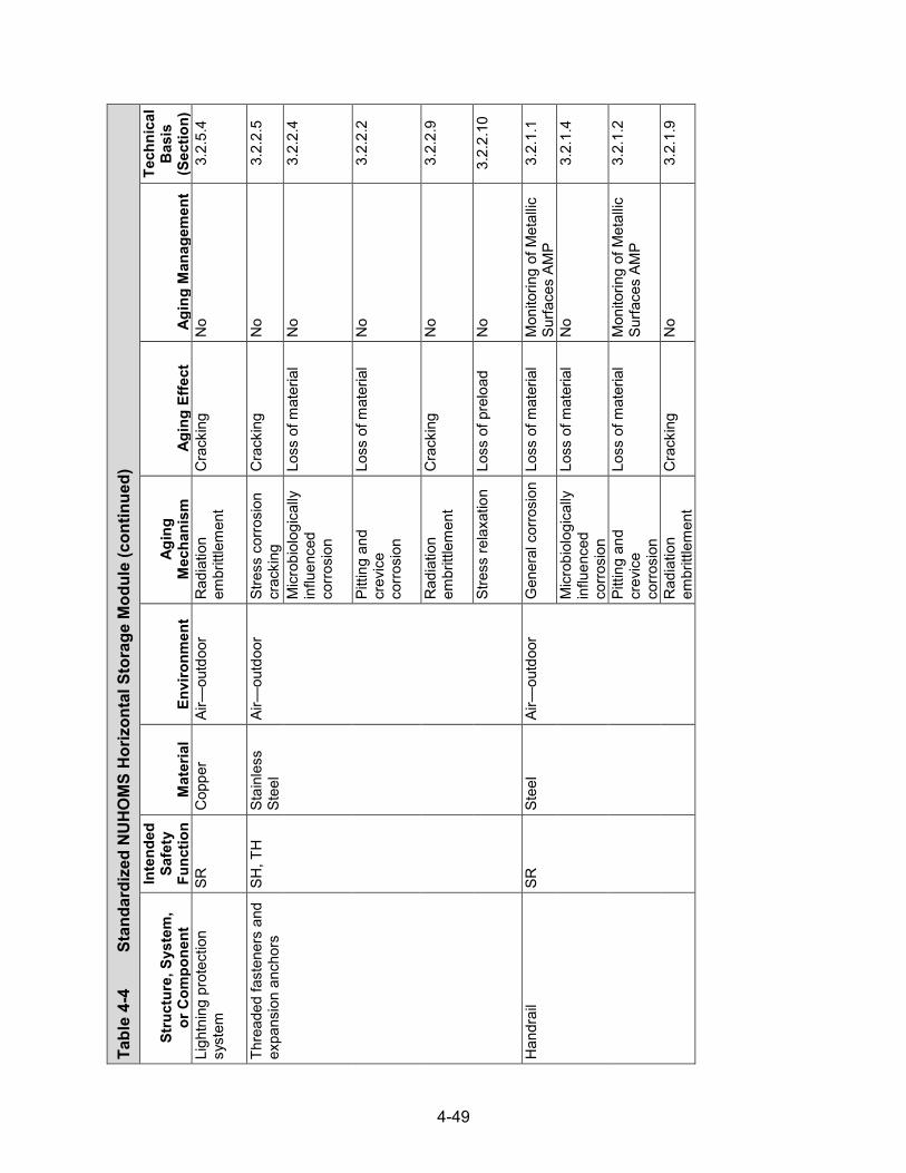
4-49
Tabl
e 4-
4
Stan
dard
ized
NU
HO
MS
Hor
izon
tal S
tora
ge M
odul
e (con
tinued)
Stru
ctur
e, S
yste
m,
or C
ompo
nent
Inte
nded
Sa
fety
Fu
nctio
n M
ater
ial
Envi
ronm
ent
Agin
g M
echa
nism
Ag
ing
Effe
ct
Agin
g M
anag
emen
t
Tech
nica
l B
asis
(S
ectio
n)
Ligh
tnin
g pr
otec
tion
syst
em
SR
Cop
per
Air—
outd
oor
Rad
iatio
n em
britt
lem
ent
Cra
ckin
g N
o 3.
2.5.
4
Thre
aded
fast
ener
s an
d ex
pans
ion
anch
ors
SH, T
H
Stai
nles
s St
eel
Air—
outd
oor
Stre
ss c
orro
sion
cr
acki
ng
Cra
ckin
g N
o 3.
2.2.
5
Mic
robi
olog
ical
ly
influ
ence
d co
rrosi
on
Loss
of m
ater
ial
No
3.2.
2.4
Pitti
ng a
nd
crev
ice
corro
sion
Loss
of m
ater
ial
No
3.2.
2.2
Rad
iatio
n em
britt
lem
ent
Cra
ckin
g N
o 3.
2.2.
9
Stre
ss re
laxa
tion
Loss
of p
relo
ad
No
3.2.
2.10
Han
drai
l SR
St
eel
Air—
outd
oor
Gen
eral
cor
rosi
on
Loss
of m
ater
ial
Mon
itorin
g of
Met
allic
Su
rface
s AM
P 3.
2.1.
1
Mic
robi
olog
ical
ly
influ
ence
d co
rrosi
on
Loss
of m
ater
ial
No
3.2.
1.4
Pitti
ng a
nd
crev
ice
corro
sion
Loss
of m
ater
ial
Mon
itorin
g of
Met
allic
Su
rface
s AM
P 3.
2.1.
2
Rad
iatio
n em
britt
lem
ent
Cra
ckin
g N
o 3.
2.1.
9

4-50
Tabl
e 4-
5
Stan
dard
ized
Adv
ance
d N
UH
OM
S H
oriz
onta
l Sto
rage
Mod
ule
Stru
ctur
e, S
yste
m,
or C
ompo
nent
Inte
nded
Sa
fety
Fu
nctio
n M
ater
ial
Envi
ronm
ent
Agin
g M
echa
nism
Ag
ing
Effe
ct
Agin
g M
anag
emen
t
Tech
nica
l B
asis
(S
ectio
n)
Rei
nfor
ced
conc
rete
: ba
se u
nit w
alls
, flo
or s
lab,
ro
of, t
op s
hiel
d bl
ock,
ba
sem
at, e
nd a
nd re
ar
shie
ld w
alls
, cor
ner s
hiel
d w
all,
inle
t/out
let v
ents
SH, S
R,
TH*
Con
cret
e Ai
r—ou
tdoo
r Ag
gres
sive
ch
emic
al a
ttack
C
rack
ing
Rei
nfor
ced
Con
cret
e St
ruct
ures
AM
P 3.
5.1.
5
Loss
of s
treng
th
Rei
nfor
ced
Con
cret
e St
ruct
ures
AM
P 3.
5.1.
5
Loss
of m
ater
ial
(spa
lling,
sca
ling)
R
einf
orce
d C
oncr
ete
Stru
ctur
es A
MP
3.5.
1.5
Red
uctio
n of
co
ncre
te p
H
(redu
cing
cor
rosi
on
resi
stan
ce o
f ste
el
embe
dmen
ts)
Rei
nfor
ced
Con
cret
e St
ruct
ures
AM
P 3.
5.1.
5
Cre
ep
Cra
ckin
g N
o 3.
5.1.
2
Deh
ydra
tion
at
high
tem
pera
ture
s C
rack
ing
No
3.5.
1.11
Loss
of s
treng
th
No
3.5.
1.11
Del
ayed
ettr
ingi
te
form
atio
n Lo
ss o
f mat
eria
l (s
pallin
g, s
calin
g)
No
3.5.
1.13
Loss
of s
treng
th
No
3.5.
1.13
Cra
ckin
g N
o 3.
5.1.
13
Diff
eren
tial
settl
emen
t C
rack
ing
No
3.5.
1.4
Fatig
ue
Cra
ckin
g N
o 3.
5.1.
10
Free
ze a
nd th
aw
Cra
ckin
g R
einf
orce
d C
oncr
ete
Stru
ctur
es A
MP
3.5.
1.1
Loss
of m
ater
ial
(spa
lling,
sca
ling)
R
einf
orce
d C
oncr
ete
Stru
ctur
es A
MP
3.5.
1.1
*Saf
ety
Func
tions
: C
onfin
emen
t (C
O),
Subc
ritic
ality
(CR
), R
etrie
vabi
lity
(RE)
, Rad
iatio
n Sh
ield
ing
(SH
), St
ruct
ural
Inte
grity
(SR
), Th
erm
al/H
eat R
emov
al (T
H)

4-51
Tabl
e 4-
5
Stan
dard
ized
Adv
ance
d N
UH
OM
S H
oriz
onta
l Sto
rage
Mod
ule (con
tinued)
Stru
ctur
e, S
yste
m,
or C
ompo
nent
Inte
nded
Sa
fety
Fu
nctio
n M
ater
ial
Envi
ronm
ent
Agin
g M
echa
nism
Ag
ing
Effe
ct
Agin
g M
anag
emen
t
Tech
nica
l B
asis
(S
ectio
n)
Rei
nfor
ced
conc
rete
: ba
se u
nit w
alls
, flo
or s
lab,
ro
of, t
op s
hiel
d bl
ock,
ba
sem
at, e
nd a
nd re
ar
shie
ld w
alls
, cor
ner s
hiel
d w
all,
inle
t/out
let v
ents
SH, S
R,
TH
Con
cret
e Ai
r—ou
tdoo
r R
adia
tion
dam
age
Cra
ckin
g N
o 3.
5.1.
9
Loss
of s
treng
th
No
3.5.
1.9
Rea
ctio
n w
ith
aggr
egat
es
Cra
ckin
g R
einf
orce
d C
oncr
ete
Stru
ctur
es A
MP
3.5.
1.3
Loss
of s
treng
th
Rei
nfor
ced
Con
cret
e St
ruct
ures
AM
P 3.
5.1.
3
Salt
scal
ing
Loss
of m
ater
ial
(spa
lling,
sca
ling)
R
einf
orce
d C
oncr
ete
Stru
ctur
es A
MP
3.5.
1.14
Shrin
kage
C
rack
ing
No
3.5.
1.7
Leac
hing
of
calc
ium
hyd
roxi
de
Loss
of s
treng
th
Rei
nfor
ced
Con
cret
e St
ruct
ures
AM
P 3.
5.1.
8
Incr
ease
in
poro
sity
and
pe
rmea
bilit
y
Rei
nfor
ced
Con
cret
e St
ruct
ures
AM
P 3.
5.1.
8
Red
uctio
n of
co
ncre
te p
H
(redu
cing
co
rrosi
on
resi
stan
ce o
f ste
el
embe
dmen
ts)
Rei
nfor
ced
Con
cret
e St
ruct
ures
AM
P 3.
5.1.
8
Shel
tere
d Ag
gres
sive
ch
emic
al a
ttack
Lo
ss o
f stre
ngth
N
o 3.
5.1.
5
Cra
ckin
g N
o 3.
5.1.
5 Lo
ss o
f mat
eria
l (s
pallin
g, s
calin
g)
No
3.5.
1.5
Cre
ep
Cra
ckin
g N
o 3.
5.1.
2

4-52
Tabl
e 4-
5
Stan
dard
ized
Adv
ance
d N
UH
OM
S H
oriz
onta
l Sto
rage
Mod
ule (con
tinued)
Stru
ctur
e, S
yste
m,
or C
ompo
nent
Inte
nded
Sa
fety
Fu
nctio
n M
ater
ial
Envi
ronm
ent
Agin
g M
echa
nism
Ag
ing
Effe
ct
Agin
g M
anag
emen
t
Tech
nica
l B
asis
(S
ectio
n)
Rei
nfor
ced
conc
rete
: ba
se u
nit w
alls
, flo
or s
lab,
ro
of, t
op s
hiel
d bl
ock,
ba
sem
at, e
nd a
nd re
ar
shie
ld w
alls
, cor
ner s
hiel
d w
all,
inle
t/out
let v
ents
SH, S
R,
TH
Con
cret
e Sh
elte
red
Deh
ydra
tion
at
high
tem
pera
ture
s C
rack
ing
No
3.5.
1.11
Loss
of s
treng
th
No
3.5.
1.11
Del
ayed
ettr
ingi
te
form
atio
n Lo
ss o
f mat
eria
l (s
pallin
g, s
calin
g)
No
3.5.
1.13
Loss
of s
treng
th
No
3.5.
1.13
Cra
ckin
g N
o 3.
5.1.
13
Diff
eren
tial
settl
emen
t C
rack
ing
No
3.5.
1.4
Fatig
ue
Cra
ckin
g N
o 3.
5.1.
10
Free
ze a
nd th
aw
Cra
ckin
g N
o 3.
5.1.
1
Loss
of m
ater
ial
(spa
lling,
sca
ling)
N
o 3.
5.1.
1
Rad
iatio
n da
mag
e C
rack
ing
No
3.5.
1.9
Loss
of s
treng
th
No
3.5.
1.9
Rea
ctio
n w
ith
aggr
egat
es
Cra
ckin
g R
einf
orce
d C
oncr
ete
Stru
ctur
es A
MP
3.5.
1.3
Loss
of s
treng
th
Rei
nfor
ced
Con
cret
e St
ruct
ures
AM
P 3.
5.1.
3
Salt
scal
ing
Loss
of m
ater
ial
(spa
lling,
sca
ling)
N
o 3.
5.1.
14
Shrin
kage
C
rack
ing
No
3.5.
1.7

4-53
Tabl
e 4-
5
Stan
dard
ized
Adv
ance
d N
UH
OM
S H
oriz
onta
l Sto
rage
Mod
ule (con
tinued)
Stru
ctur
e, S
yste
m,
or C
ompo
nent
Inte
nded
Sa
fety
Fu
nctio
n M
ater
ial
Envi
ronm
ent
Agin
g M
echa
nism
Ag
ing
Effe
ct
Agin
g M
anag
emen
t
Tech
nica
l B
asis
(S
ectio
n)
Rei
nfor
ced
conc
rete
: ba
se u
nit w
alls
, flo
or s
lab,
ro
of, t
op s
hiel
d bl
ock,
ba
sem
at, e
nd a
nd re
ar
shie
ld w
alls
, cor
ner s
hiel
d w
all,
inle
t/out
let v
ents
SH, S
R,
TH
Con
cret
e G
roun
dwat
er/s
oil
Aggr
essi
ve
chem
ical
atta
ck
Cra
ckin
g R
einf
orce
d C
oncr
ete
Stru
ctur
es A
MP
3.5.
1.5
Loss
of m
ater
ial
(spa
lling,
sca
ling)
R
einf
orce
d C
oncr
ete
Stru
ctur
es A
MP
3.5.
1.5
Loss
of s
treng
th
Rei
nfor
ced
Con
cret
e St
ruct
ures
AM
P 3.
5.1.
5
Red
uctio
n of
co
ncre
te p
H
(redu
cing
cor
rosi
on
resi
stan
ce o
f ste
el
embe
dmen
ts)
Rei
nfor
ced
Con
cret
e St
ruct
ures
AM
P 3.
5.1.
5
Cre
ep
Cra
ckin
g N
o 3.
5.1.
2
Deh
ydra
tion
at
high
tem
pera
ture
s C
rack
ing
No
3.5.
1.11
Loss
of s
treng
th
No
3.5.
1.11
Del
ayed
ettr
ingi
te
form
atio
n Lo
ss o
f mat
eria
l (s
pallin
g, s
calin
g)
No
3.5.
1.13
Loss
of s
treng
th
No
3.5.
1.13
Cra
ckin
g N
o 3.
5.1.
13
Diff
eren
tial
settl
emen
t C
rack
ing
Rei
nfor
ced
Con
cret
e St
ruct
ures
AM
P 3.
5.1.
4
Fatig
ue
Cra
ckin
g N
o 3.
5.1.
10
Free
ze a
nd th
aw
Cra
ckin
g R
einf
orce
d C
oncr
ete
Stru
ctur
es A
MP
3.5.
1.1
Loss
of m
ater
ial
(spa
lling,
sca
ling)
R
einf
orce
d C
oncr
ete
Stru
ctur
es A
MP
3.5.
1.1

4-54
Tabl
e 4-
5
Stan
dard
ized
Adv
ance
d N
UH
OM
S H
oriz
onta
l Sto
rage
Mod
ule (con
tinued)
Stru
ctur
e, S
yste
m,
or C
ompo
nent
Inte
nded
Sa
fety
Fu
nctio
n M
ater
ial
Envi
ronm
ent
Agin
g M
echa
nism
Ag
ing
Effe
ct
Agin
g M
anag
emen
t
Tech
nica
l B
asis
(S
ectio
n)
Rei
nfor
ced
conc
rete
: ba
se u
nit w
alls
, flo
or s
lab,
ro
of, t
op s
hiel
d bl
ock,
ba
sem
at, e
nd a
nd re
ar
shie
ld w
alls
, cor
ner s
hiel
d w
all,
inle
t/out
let v
ents
SH, S
R,
TH
Con
cret
e G
roun
dwat
er/
soil
Mic
robi
olog
ical
de
grad
atio
n Lo
ss o
f stre
ngth
R
einf
orce
d C
oncr
ete
Stru
ctur
es A
MP
3.5.
1.12
Loss
of m
ater
ial
(spa
lling,
sca
ling)
R
einf
orce
d C
oncr
ete
Stru
ctur
es A
MP
3.5.
1.12
Incr
ease
in
poro
sity
and
pe
rmea
bilit
y
Rei
nfor
ced
Con
cret
e St
ruct
ures
AM
P 3.
5.1.
12
Red
uctio
n of
co
ncre
te p
H
(redu
cing
co
rrosi
on
resi
stan
ce o
f ste
el
embe
dmen
ts)
Rei
nfor
ced
Con
cret
e St
ruct
ures
AM
P 3.
5.1.
12
Rad
iatio
n da
mag
e C
rack
ing
No
3.5.
1.9
Loss
of s
treng
th
No
3.5.
1.9
Rea
ctio
n w
ith
aggr
egat
es
Cra
ckin
g R
einf
orce
d C
oncr
ete
Stru
ctur
es A
MP
3.5.
1.3
Loss
of s
treng
th
Rei
nfor
ced
Con
cret
e St
ruct
ures
AM
P 3.
5.1.
3
Salt
scal
ing
Loss
of m
ater
ial
(spa
lling,
sca
ling)
R
einf
orce
d C
oncr
ete
Stru
ctur
es A
MP
3.5.
1.14
Shrin
kage
C
rack
ing
No
3.5.
1.7
Leac
hing
of
calc
ium
hyd
roxi
de
Loss
of s
treng
th
Rei
nfor
ced
Con
cret
e St
ruct
ures
AM
P 3.
5.1.
8
Incr
ease
in
poro
sity
and
pe
rmea
bilit
y
Rei
nfor
ced
Con
cret
e St
ruct
ures
AM
P 3.
5.1.
8

4-55
Tabl
e 4-
5
Stan
dard
ized
Adv
ance
d N
UH
OM
S H
oriz
onta
l Sto
rage
Mod
ule (con
tinued)
Stru
ctur
e, S
yste
m,
or C
ompo
nent
Inte
nded
Sa
fety
Fu
nctio
n M
ater
ial
Envi
ronm
ent
Agin
g M
echa
nism
Ag
ing
Effe
ct
Agin
g M
anag
emen
t
Tech
nica
l B
asis
(S
ectio
n)
Rei
nfor
ced
conc
rete
: ba
se u
nit w
alls
, flo
or s
lab,
ro
of, t
op s
hiel
d bl
ock,
ba
sem
at, e
nd a
nd re
ar
shie
ld w
alls
, cor
ner s
hiel
d w
all,
inle
t/out
let v
ents
SH, S
R,
TH
Rei
nfor
cing
st
eel
Air—
outd
oor,
grou
ndw
ater
Le
achi
ng o
f ca
lciu
m h
ydro
xide
R
educ
tion
of
conc
rete
pH
(re
duci
ng
corro
sion
re
sist
ance
of s
teel
em
bedm
ents
)
Rei
nfor
ced
Con
cret
e St
ruct
ures
AM
P 3.
5.1.
8
Cor
rosi
on o
f re
info
rcin
g st
eel
Loss
of
conc
rete
/ste
el
bond
Rei
nfor
ced
Con
cret
e St
ruct
ures
AM
P 3.
5.1.
6
Loss
of m
ater
ial
(spa
lling,
sca
ling)
R
einf
orce
d C
oncr
ete
Stru
ctur
es A
MP
3.5.
1.6
Cra
ckin
g R
einf
orce
d C
oncr
ete
Stru
ctur
es A
MP
3.5.
1.6
Loss
of s
treng
th
Rei
nfor
ced
Con
cret
e St
ruct
ures
AM
P 3.
5.1.
6
DSC
sup
port
stru
ctur
e as
sem
bly
hard
war
e SR
St
ainl
ess
stee
l Sh
elte
red
Stre
ss c
orro
sion
cr
acki
ng
Cra
ckin
g N
o 3.
2.2.
5
Mic
robi
olog
ical
ly
influ
ence
d co
rrosi
on
Loss
of m
ater
ial
No
3.2.
2.4
Pitti
ng a
nd c
revi
ce
corro
sion
Lo
ss o
f mat
eria
l N
o 3.
2.2.
2
Rad
iatio
n em
britt
lem
ent
Cra
ckin
g N
o 3.
2.2.
9
Stre
ss re
laxa
tion
Loss
of p
relo
ad
No
3.2.
2.10
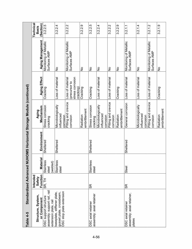
4-56
Tabl
e 4-
5
Stan
dard
ized
Adv
ance
d N
UH
OM
S H
oriz
onta
l Sto
rage
Mod
ule (con
tinued)
Stru
ctur
e, S
yste
m,
or C
ompo
nent
Inte
nded
Sa
fety
Fu
nctio
n M
ater
ial
Envi
ronm
ent
Agin
g M
echa
nism
Ag
ing
Effe
ct
Agin
g M
anag
emen
t
Tech
nica
l B
asis
(S
ectio
n)
DSC
sup
port
stru
ctur
e as
sem
bly:
sup
port
rail,
rail
exte
nsio
n pl
ate,
rail
base
plat
e, s
tiffe
ner p
late
, gu
sset
pla
te, c
ross
beam
, D
SC s
top
plat
e ex
tens
ion
SR, T
H
Stai
nles
s st
eel
(wel
ded)
Shel
tere
d St
ress
cor
rosi
on
crac
king
C
rack
ing
Mon
itorin
g of
Met
allic
Su
rface
s AM
P 3.
2.2.
5
Stai
nles
s st
eel
Shel
tere
d M
icro
biol
ogic
ally
in
fluen
ced
corro
sion
Loss
of m
ater
ial
No
3.2.
2.4
Pitti
ng a
nd c
revi
ce
corro
sion
Lo
ss o
f mat
eria
l (p
recu
rsor
to
stre
ss c
orro
sion
cr
acki
ng)
Mon
itorin
g of
Met
allic
Su
rface
s AM
P 3.
2.2.
2
Rad
iatio
n em
britt
lem
ent
Cra
ckin
g N
o 3.
2.2.
9
DSC
axi
al re
tain
er
asse
mbl
y: a
xial
reta
iner
SR
St
ainl
ess
stee
l Sh
elte
red
Stre
ss c
orro
sion
cr
acki
ng
Cra
ckin
g N
o 3.
2.2.
5
Mic
robi
olog
ical
ly
influ
ence
d co
rrosi
on
Loss
of m
ater
ial
No
3.2.
2.4
Pitti
ng a
nd c
revi
ce
corro
sion
Lo
ss o
f mat
eria
l N
o 3.
2.2.
2
Rad
iatio
n em
britt
lem
ent
Cra
ckin
g N
o 3.
2.2.
9
DSC
axi
al re
tain
er
asse
mbl
y: a
xial
reta
iner
, pl
ates
SR
Stee
l Sh
elte
red
Gen
eral
cor
rosi
on
Loss
of m
ater
ial
Mon
itorin
g of
Met
allic
Su
rface
s AM
P 3.
2.1.
1
Mic
robi
olog
ical
ly
influ
ence
d co
rrosi
on
Loss
of m
ater
ial
No
3.2.
1.4
Pitti
ng a
nd c
revi
ce
corro
sion
Lo
ss o
f mat
eria
l M
onito
ring
of M
etal
lic
Surfa
ces
AMP
3.2.
1.2
Rad
iatio
n em
britt
lem
ent
Cra
ckin
g N
o 3.
2.1.
9

4-57
Tabl
e 4-
5
Stan
dard
ized
Adv
ance
d N
UH
OM
S H
oriz
onta
l Sto
rage
Mod
ule (con
tinued)
Stru
ctur
e, S
yste
m,
or C
ompo
nent
Inte
nded
Sa
fety
Fu
nctio
n M
ater
ial
Envi
ronm
ent
Agin
g M
echa
nism
Ag
ing
Effe
ct
Agin
g M
anag
emen
t
Tech
nica
l B
asis
(S
ectio
n)
Hea
t shi
eld
asse
mbl
ies:
at
tach
men
t har
dwar
e SR
St
ainl
ess
stee
l Sh
elte
red
Stre
ss c
orro
sion
cr
acki
ng
Cra
ckin
g N
o 3.
2.2.
5
Mic
robi
olog
ical
ly
influ
ence
d co
rrosi
on
Loss
of m
ater
ial
No
3.2.
2.4
Pitti
ng a
nd c
revi
ce
corro
sion
Lo
ss o
f mat
eria
l N
o 3.
2.2.
2
Rad
iatio
n em
britt
lem
ent
Cra
ckin
g N
o 3.
2.2.
9
Stre
ss re
laxa
tion
Loss
of p
relo
ad
No
3.2.
2.10
Stee
l Sh
elte
red
Stre
ss c
orro
sion
cr
acki
ng
Cra
ckin
g N
o 3.
2.1.
5
Gal
vani
c co
rrosi
on
Loss
of m
ater
ial
Mon
itorin
g of
Met
allic
Su
rface
s AM
P 3.
2.1.
3
Gen
eral
cor
rosi
on
Loss
of m
ater
ial
Mon
itorin
g of
Met
allic
Su
rface
s AM
P 3.
2.1.
1
Mic
robi
olog
ical
ly
influ
ence
d co
rrosi
on
Loss
of m
ater
ial
No
3.2.
1.4
Pitti
ng a
nd c
revi
ce
corro
sion
Lo
ss o
f mat
eria
l M
onito
ring
of M
etal
lic
Surfa
ces
AMP
3.2.
1.2
Rad
iatio
n em
britt
lem
ent
Cra
ckin
g N
o 3.
2.1.
9
Stre
ss re
laxa
tion
Loss
of p
relo
ad
Mon
itorin
g of
Met
allic
Su
rface
s AM
P 3.
2.1.
10

4-58
Tabl
e 4-
5
Stan
dard
ized
Adv
ance
d N
UH
OM
S H
oriz
onta
l Sto
rage
Mod
ule (con
tinued)
Stru
ctur
e, S
yste
m,
or C
ompo
nent
Inte
nded
Sa
fety
Fu
nctio
n M
ater
ial
Envi
ronm
ent
Agin
g M
echa
nism
Ag
ing
Effe
ct
Agin
g M
anag
emen
t
Tech
nica
l B
asis
(S
ectio
n)
Hea
t shi
eld
asse
mbl
ies:
si
de h
eat s
hiel
d, to
p he
at
shie
ld
TH
Stai
nles
s st
eel
Shel
tere
d St
ress
cor
rosi
on
crac
king
C
rack
ing
No
3.2.
2.5
Mic
robi
olog
ical
ly
influ
ence
d co
rrosi
on
Loss
of m
ater
ial
No
3.2.
2.4
Pitti
ng a
nd c
revi
ce
corro
sion
Lo
ss o
f mat
eria
l N
o 3.
2.2.
2
Rad
iatio
n em
britt
lem
ent
Cra
ckin
g N
o 3.
2.2.
9
Shie
lded
doo
r ass
embl
y:
door
atta
chm
ent
hard
war
e
SR
Stai
nles
s st
eel
Air—
outd
oor
Stre
ss c
orro
sion
cr
acki
ng
Cra
ckin
g N
o 3.
2.2.
5
Mic
robi
olog
ical
ly
influ
ence
d co
rrosi
on
Loss
of m
ater
ial
No
3.2.
2.4
Pitti
ng a
nd c
revi
ce
corro
sion
Lo
ss o
f mat
eria
l N
o 3.
2.2.
2
Rad
iatio
n em
britt
lem
ent
Cra
ckin
g N
o 3.
2.2.
9
Stre
ss re
laxa
tion
Loss
of p
relo
ad
No
3.2.
2.10
St
eel
Air—
outd
oor
Stre
ss c
orro
sion
cr
acki
ng
Cra
ckin
g N
o 3.
2.1.
5
Gen
eral
cor
rosi
on
Loss
of m
ater
ial
Mon
itorin
g of
Met
allic
Su
rface
s AM
P 3.
2.1.
1
Mic
robi
olog
ical
ly
influ
ence
d co
rrosi
on
Loss
of m
ater
ial
No
3.2.
1.4
Pitti
ng a
nd c
revi
ce
corro
sion
Lo
ss o
f mat
eria
l M
onito
ring
of M
etal
lic
Surfa
ces
AMP
3.2.
1.2
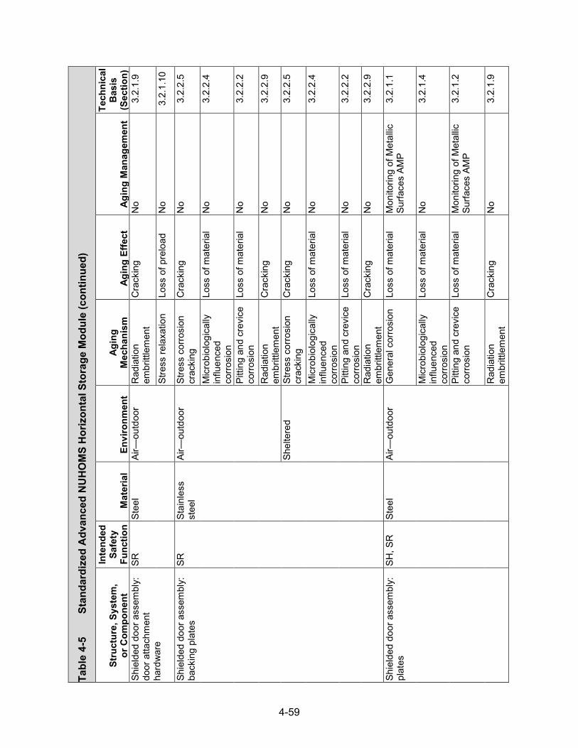
4-59
Tabl
e 4-
5
Stan
dard
ized
Adv
ance
d N
UH
OM
S H
oriz
onta
l Sto
rage
Mod
ule (con
tinued)
Stru
ctur
e, S
yste
m,
or C
ompo
nent
Inte
nded
Sa
fety
Fu
nctio
n M
ater
ial
Envi
ronm
ent
Agin
g M
echa
nism
Ag
ing
Effe
ct
Agin
g M
anag
emen
t
Tech
nica
l B
asis
(S
ectio
n)
Shie
lded
doo
r ass
embl
y:
door
atta
chm
ent
hard
war
e
SR
Stee
l Ai
r—ou
tdoo
r R
adia
tion
embr
ittle
men
t C
rack
ing
No
3.2.
1.9
Stre
ss re
laxa
tion
Loss
of p
relo
ad
No
3.2.
1.10
Shie
lded
doo
r ass
embl
y:
back
ing
plat
es
SR
Stai
nles
s st
eel
Air—
outd
oor
Stre
ss c
orro
sion
cr
acki
ng
Cra
ckin
g N
o 3.
2.2.
5
Mic
robi
olog
ical
ly
influ
ence
d co
rrosi
on
Loss
of m
ater
ial
No
3.2.
2.4
Pitti
ng a
nd c
revi
ce
corro
sion
Lo
ss o
f mat
eria
l N
o 3.
2.2.
2
Rad
iatio
n em
britt
lem
ent
Cra
ckin
g N
o 3.
2.2.
9
Shel
tere
d St
ress
cor
rosi
on
crac
king
C
rack
ing
No
3.2.
2.5
Mic
robi
olog
ical
ly
influ
ence
d co
rrosi
on
Loss
of m
ater
ial
No
3.2.
2.4
Pitti
ng a
nd c
revi
ce
corro
sion
Lo
ss o
f mat
eria
l N
o 3.
2.2.
2
Rad
iatio
n em
britt
lem
ent
Cra
ckin
g N
o 3.
2.2.
9
Shie
lded
doo
r ass
embl
y:
plat
es
SH, S
R
Stee
l Ai
r—ou
tdoo
r G
ener
al c
orro
sion
Lo
ss o
f mat
eria
l M
onito
ring
of M
etal
lic
Surfa
ces
AMP
3.2.
1.1
Mic
robi
olog
ical
ly
influ
ence
d co
rrosi
on
Loss
of m
ater
ial
No
3.2.
1.4
Pitti
ng a
nd c
revi
ce
corro
sion
Lo
ss o
f mat
eria
l M
onito
ring
of M
etal
lic
Surfa
ces
AMP
3.2.
1.2
Rad
iatio
n em
britt
lem
ent
Cra
ckin
g N
o 3.
2.1.
9

4-60
Tabl
e 4-
5
Stan
dard
ized
Adv
ance
d N
UH
OM
S H
oriz
onta
l Sto
rage
Mod
ule (con
tinued)
Stru
ctur
e, S
yste
m,
or C
ompo
nent
Inte
nded
Sa
fety
Fu
nctio
n M
ater
ial
Envi
ronm
ent
Agin
g M
echa
nism
Ag
ing
Effe
ct
Agin
g M
anag
emen
t
Tech
nica
l B
asis
(S
ectio
n)
Shie
lded
doo
r ass
embl
y:
plat
es
SH, S
R
Stee
l Sh
elte
red
Gen
eral
cor
rosi
on
Loss
of m
ater
ial
Mon
itorin
g of
Met
allic
Su
rface
s AM
P 3.
2.1.
1
Mic
robi
olog
ical
ly
influ
ence
d co
rrosi
on
Loss
of m
ater
ial
No
3.2.
1.4
Pitti
ng a
nd c
revi
ce
corro
sion
Lo
ss o
f mat
eria
l M
onito
ring
of M
etal
lic
Surfa
ces
AMP
3.2.
1.2
Rad
iatio
n em
britt
lem
ent
Cra
ckin
g N
o 3.
2.1.
9
Shie
lded
doo
r ass
embl
y:
conc
rete
cor
e SH
, SR
R
einf
orce
d co
ncre
te,
non-
shrin
k gr
out o
r pea
gr
avel
or
mor
tar m
ix
Embe
dded
(s
teel
or
stai
nles
s st
eel)
Del
ayed
ettr
ingi
te
form
atio
n Lo
ss o
f mat
eria
l (s
pallin
g, s
calin
g)
No
3.5.
1.13
Cra
ckin
g N
o 3.
5.1.
13
Loss
of s
treng
th
No
3.5.
1.13
Rad
iatio
n da
mag
e C
rack
ing
No
3.5.
1.9
Loss
of s
treng
th
No
3.5.
1.9
Rea
ctio
n w
ith
aggr
egat
es
Cra
ckin
g R
einf
orce
d C
oncr
ete
Stru
ctur
es A
MP
3.5.
1.3
Loss
of s
treng
th
Rei
nfor
ced
Con
cret
e St
ruct
ures
AM
P 3.
5.1.
3

4-61
Tabl
e 4-
5
Stan
dard
ized
Adv
ance
d N
UH
OM
S H
oriz
onta
l Sto
rage
Mod
ule (con
tinued)
Stru
ctur
e, S
yste
m,
or C
ompo
nent
Inte
nded
Sa
fety
Fu
nctio
n M
ater
ial
Envi
ronm
ent
Agin
g M
echa
nism
Ag
ing
Effe
ct
Agin
g M
anag
emen
t
Tech
nica
l B
asis
(S
ectio
n)
Inle
t/out
let v
ents
: out
let
vent
atta
chm
ent h
ardw
are
SR
Stai
nles
s st
eel
Air—
outd
oor
Stre
ss c
orro
sion
cr
acki
ng
Cra
ckin
g N
o 3.
2.2.
5
Mic
robi
olog
ical
ly
influ
ence
d co
rrosi
on
Loss
of m
ater
ial
No
3.2.
2.4
Pitti
ng a
nd c
revi
ce
corro
sion
Lo
ss o
f mat
eria
l N
o 3.
2.2.
2
Rad
iatio
n em
britt
lem
ent
Cra
ckin
g N
o 3.
2.2.
9
Stre
ss re
laxa
tion
Loss
of p
relo
ad
No
3.2.
2.10
Stee
l Ai
r—ou
tdoo
r St
ress
cor
rosi
on
crac
king
C
rack
ing
No
3.2.
1.5
Gen
eral
cor
rosi
on
Loss
of m
ater
ial
Mon
itorin
g of
Met
allic
Su
rface
s AM
P 3.
2.1.
1
Mic
robi
olog
ical
ly
influ
ence
d co
rrosi
on
Loss
of m
ater
ial
No
3.2.
1.4
Pitti
ng a
nd c
revi
ce
corro
sion
Lo
ss o
f mat
eria
l M
onito
ring
of M
etal
lic
Surfa
ces
AMP
3.2.
1.2
Rad
iatio
n em
britt
lem
ent
Cra
ckin
g N
o 3.
2.1.
9
Stre
ss re
laxa
tion
Loss
of p
relo
ad
No
3.2.
1.10
In
let/o
utle
t ven
ts: l
iner
pl
ates
SH
, TH
St
ainl
ess
stee
l Ai
r—ou
tdoo
r St
ress
cor
rosi
on
crac
king
C
rack
ing
No
3.2.
2.5
Mic
robi
olog
ical
ly
influ
ence
d co
rrosi
on
Loss
of m
ater
ial
No
3.2.
2.4

4-62
Tabl
e 4-
5
Stan
dard
ized
Adv
ance
d N
UH
OM
S H
oriz
onta
l Sto
rage
Mod
ule (con
tinued)
Stru
ctur
e, S
yste
m,
or C
ompo
nent
Inte
nded
Sa
fety
Fu
nctio
n M
ater
ial
Envi
ronm
ent
Agin
g M
echa
nism
Ag
ing
Effe
ct
Agin
g M
anag
emen
t
Tech
nica
l B
asis
(S
ectio
n)
Inle
t/out
let v
ents
: lin
er
plat
es
SH, T
H
Stai
nles
s st
eel
Air—
outd
oor
Pitti
ng a
nd c
revi
ce
corro
sion
Lo
ss o
f mat
eria
l (p
recu
rsor
to
stre
ss c
orro
sion
cr
acki
ng)
No
3.2.
2.2
Rad
iatio
n em
britt
lem
ent
Cra
ckin
g N
o 3.
2.2.
9
Roo
f atta
chm
ent
asse
mbl
y: a
ngle
s, p
late
s,
dow
el b
ar s
plic
er
SR
Stai
nles
s st
eel
Shel
tere
d St
ress
cor
rosi
on
crac
king
C
rack
ing
No
3.2.
2.5
Mic
robi
olog
ical
ly
influ
ence
d co
rrosi
on
Loss
of m
ater
ial
No
3.2.
2.4
Pitti
ng a
nd c
revi
ce
corro
sion
Lo
ss o
f mat
eria
l (p
recu
rsor
to
stre
ss c
orro
sion
cr
acki
ng)
No
3.2.
2.2
Rad
iatio
n em
britt
lem
ent
Cra
ckin
g N
o 3.
2.2.
9
Stee
l Sh
elte
red
Gen
eral
cor
rosi
on
Loss
of m
ater
ial
Mon
itorin
g of
Met
allic
Su
rface
s AM
P 3.
2.1.
1
Mic
robi
olog
ical
ly
influ
ence
d co
rrosi
on
Loss
of m
ater
ial
No
3.2.
1.4
Pitti
ng a
nd c
revi
ce
corro
sion
Lo
ss o
f mat
eria
l M
onito
ring
of M
etal
lic
Surfa
ces
AMP
3.2.
1.2
Rad
iatio
n em
britt
lem
ent
Cra
ckin
g N
o 3.
2.1.
9

4-63
Tabl
e 4-
5
Stan
dard
ized
Adv
ance
d N
UH
OM
S H
oriz
onta
l Sto
rage
Mod
ule (con
tinued)
Stru
ctur
e, S
yste
m,
or C
ompo
nent
Inte
nded
Sa
fety
Fu
nctio
n M
ater
ial
Envi
ronm
ent
Agin
g M
echa
nism
Ag
ing
Effe
ct
Agin
g M
anag
emen
t
Tech
nica
l B
asis
(S
ectio
n)
Roo
f atta
chm
ent
asse
mbl
y: ro
of
atta
chm
ent h
ardw
are
SR
Stai
nles
s st
eel
Shel
tere
d St
ress
cor
rosi
on
crac
king
C
rack
ing
No
3.2.
2.5
Mic
robi
olog
ical
ly
influ
ence
d co
rrosi
on
Loss
of m
ater
ial
No
3.2.
2.4
Pitti
ng a
nd c
revi
ce
corro
sion
Lo
ss o
f mat
eria
l N
o 3.
2.2.
2
Rad
iatio
n em
britt
lem
ent
Cra
ckin
g N
o 3.
2.2.
9
Stre
ss re
laxa
tion
Loss
of p
relo
ad
No
3.2.
2.10
Stee
l Sh
elte
red
Stre
ss c
orro
sion
cr
acki
ng
Cra
ckin
g N
o 3.
2.1.
5
Gen
eral
cor
rosi
on
Loss
of m
ater
ial
Mon
itorin
g of
Met
allic
Su
rface
s AM
P 3.
2.1.
1
Mic
robi
olog
ical
ly
influ
ence
d co
rrosi
on
Loss
of m
ater
ial
No
3.2.
1.4
Pitti
ng a
nd c
revi
ce
corro
sion
Lo
ss o
f mat
eria
l M
onito
ring
of M
etal
lic
Surfa
ces
AMP
3.2.
1.2
Rad
iatio
n em
britt
lem
ent
Cra
ckin
g N
o 3.
2.1.
9
Stre
ss re
laxa
tion
Loss
of p
relo
ad
Mon
itorin
g of
Met
allic
Su
rface
s AM
P 3.
2.1.
10
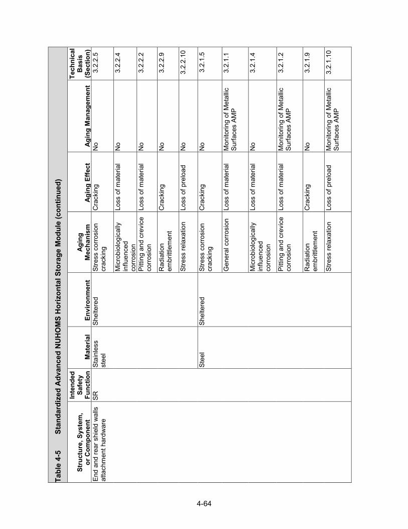
4-64
Tabl
e 4-
5
Stan
dard
ized
Adv
ance
d N
UH
OM
S H
oriz
onta
l Sto
rage
Mod
ule (con
tinued)
Stru
ctur
e, S
yste
m,
or C
ompo
nent
Inte
nded
Sa
fety
Fu
nctio
n M
ater
ial
Envi
ronm
ent
Agin
g M
echa
nism
Ag
ing
Effe
ct
Agin
g M
anag
emen
t
Tech
nica
l B
asis
(S
ectio
n)
End
and
rear
shi
eld
wal
ls
atta
chm
ent h
ardw
are
SR
Stai
nles
s st
eel
Shel
tere
d St
ress
cor
rosi
on
crac
king
C
rack
ing
No
3.2.
2.5
Mic
robi
olog
ical
ly
influ
ence
d co
rrosi
on
Loss
of m
ater
ial
No
3.2.
2.4
Pitti
ng a
nd c
revi
ce
corro
sion
Lo
ss o
f mat
eria
l N
o 3.
2.2.
2
Rad
iatio
n em
britt
lem
ent
Cra
ckin
g N
o 3.
2.2.
9
Stre
ss re
laxa
tion
Loss
of p
relo
ad
No
3.2.
2.10
Stee
l Sh
elte
red
Stre
ss c
orro
sion
cr
acki
ng
Cra
ckin
g N
o 3.
2.1.
5
Gen
eral
cor
rosi
on
Loss
of m
ater
ial
Mon
itorin
g of
Met
allic
Su
rface
s AM
P 3.
2.1.
1
Mic
robi
olog
ical
ly
influ
ence
d co
rrosi
on
Loss
of m
ater
ial
No
3.2.
1.4
Pitti
ng a
nd c
revi
ce
corro
sion
Lo
ss o
f mat
eria
l M
onito
ring
of M
etal
lic
Surfa
ces
AMP
3.2.
1.2
Rad
iatio
n em
britt
lem
ent
Cra
ckin
g N
o 3.
2.1.
9
Stre
ss re
laxa
tion
Loss
of p
relo
ad
Mon
itorin
g of
Met
allic
Su
rface
s AM
P 3.
2.1.
10

4-65
Tabl
e 4-
5
Stan
dard
ized
Adv
ance
d N
UH
OM
S H
oriz
onta
l Sto
rage
Mod
ule (con
tinued)
Stru
ctur
e, S
yste
m,
or C
ompo
nent
Inte
nded
Sa
fety
Fu
nctio
n M
ater
ial
Envi
ronm
ent
Agin
g M
echa
nism
Ag
ing
Effe
ct
Agin
g M
anag
emen
t
Tech
nica
l B
asis
(S
ectio
n)
Mod
ule-
to-m
odul
e co
nnec
tion
hard
war
e SR
St
ainl
ess
stee
l Ai
r—ou
tdoo
r St
ress
cor
rosi
on
crac
king
C
rack
ing
No
3.2.
2.5
Mic
robi
olog
ical
ly
influ
ence
d co
rrosi
on
Loss
of m
ater
ial
No
3.2.
2.4
Pitti
ng a
nd c
revi
ce
corro
sion
Lo
ss o
f mat
eria
l N
o 3.
2.2.
2
Rad
iatio
n em
britt
lem
ent
Cra
ckin
g N
o 3.
2.2.
9
Stre
ss re
laxa
tion
Loss
of p
relo
ad
No
3.2.
2.10
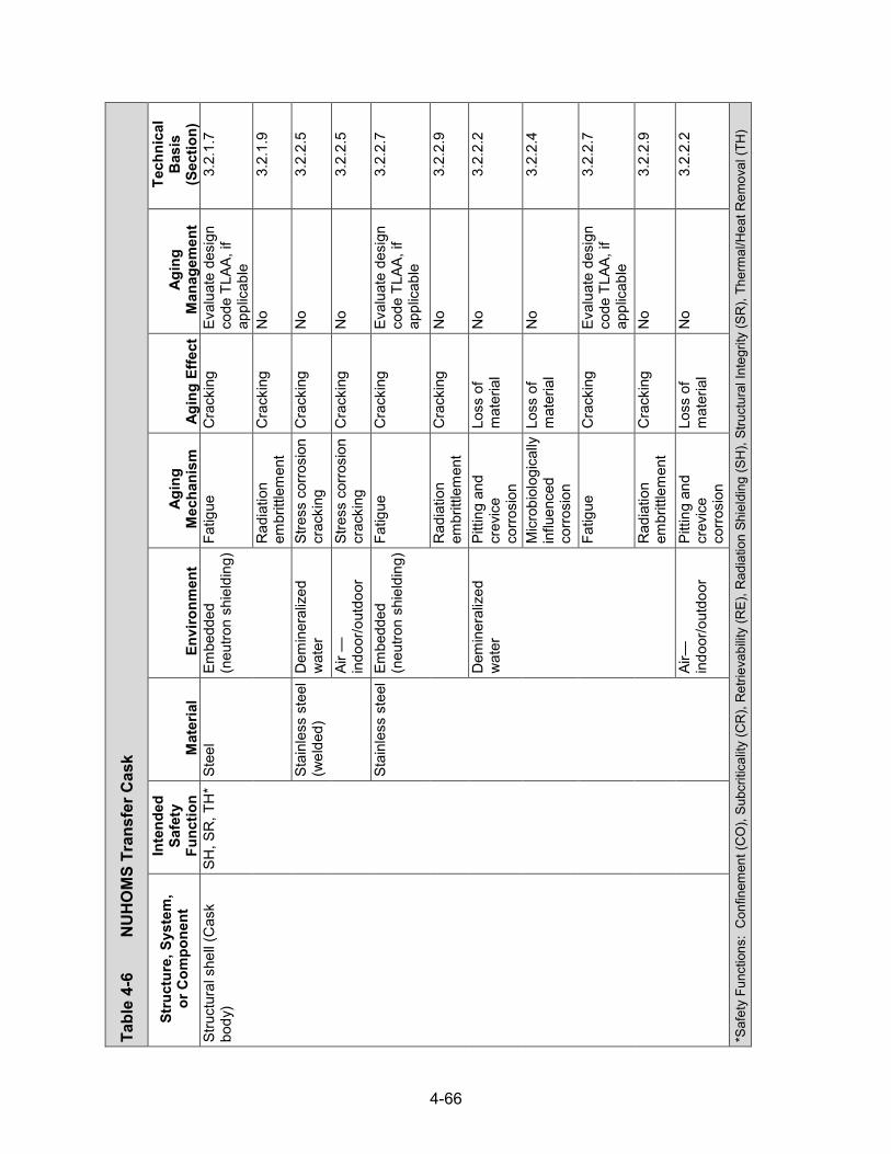
4-66
Tabl
e 4-
6
NU
HO
MS
Tran
sfer
Cas
k
Stru
ctur
e, S
yste
m,
or C
ompo
nent
In
tend
ed
Safe
ty
Func
tion
Mat
eria
l En
viro
nmen
t Ag
ing
Mec
hani
sm
Agin
g Ef
fect
Ag
ing
Man
agem
ent
Tech
nica
l B
asis
(S
ectio
n)
Stru
ctur
al s
hell
(Cas
k bo
dy)
SH, S
R, T
H*
Stee
l Em
bedd
ed
(neu
tron
shie
ldin
g) Fa
tigue
C
rack
ing
Eval
uate
des
ign
code
TLA
A, if
ap
plic
able
3.2.
1.7
Rad
iatio
n em
britt
lem
ent
Cra
ckin
g N
o 3.
2.1.
9
Stai
nles
s st
eel
(wel
ded)
D
emin
eral
ized
w
ater
St
ress
cor
rosi
on
crac
king
C
rack
ing
No
3.2.
2.5
Air —
indo
or/o
utdo
or
Stre
ss c
orro
sion
cr
acki
ng
Cra
ckin
g N
o 3.
2.2.
5
Stai
nles
s st
eel
Embe
dded
(n
eutro
n sh
ield
ing)
Fatig
ue
Cra
ckin
g Ev
alua
te d
esig
n co
de T
LAA,
if
appl
icab
le
3.2.
2.7
Rad
iatio
n em
britt
lem
ent
Cra
ckin
g N
o 3.
2.2.
9
Dem
iner
aliz
ed
wat
er
Pitti
ng a
nd
crev
ice
corro
sion
Loss
of
mat
eria
l N
o 3.
2.2.
2
Mic
robi
olog
ical
ly
influ
ence
d co
rrosi
on
Loss
of
mat
eria
l N
o 3.
2.2.
4
Fatig
ue
Cra
ckin
g Ev
alua
te d
esig
n co
de T
LAA,
if
appl
icab
le
3.2.
2.7
Rad
iatio
n em
britt
lem
ent
Cra
ckin
g N
o 3.
2.2.
9
Air—
indo
or/o
utdo
or
Pitti
ng a
nd
crev
ice
corro
sion
Loss
of
mat
eria
l N
o 3.
2.2.
2
*Saf
ety
Func
tions
: C
onfin
emen
t (C
O),
Subc
ritic
ality
(CR
), R
etrie
vabi
lity
(RE)
, Rad
iatio
n Sh
ield
ing
(SH
), St
ruct
ural
Inte
grity
(SR
), Th
erm
al/H
eat R
emov
al (T
H)

4-67
Tabl
e 4-
6
NU
HO
MS
Tran
sfer
Cas
k (con
tinued)
Stru
ctur
e, S
yste
m,
or C
ompo
nent
In
tend
ed
Safe
ty
Func
tion
Mat
eria
l En
viro
nmen
t Ag
ing
Mec
hani
sm
Agin
g Ef
fect
Ag
ing
Man
agem
ent
Tech
nica
l B
asis
(S
ectio
n)
Stru
ctur
al s
hell
(Cas
k bo
dy)
SH, S
R, T
H
Stai
nles
s st
eel
Air—
indo
or/o
utdo
or
Mic
robi
olog
ical
ly
influ
ence
d co
rrosi
on
Loss
of
mat
eria
l N
o 3.
2.2.
4
Fatig
ue
Cra
ckin
g Ev
alua
te d
esig
n co
de T
LAA,
if
appl
icab
le
3.2.
2.7
Rad
iatio
n em
britt
lem
ent
Cra
ckin
g N
o 3.
2.2.
9
Inne
r she
ll (C
ask
body
) SH
, SR
, TH
St
ainl
ess
stee
l (w
elde
d)
Air—
indo
or/o
utdo
or
Stre
ss c
orro
sion
cr
acki
ng
Cra
ckin
g N
o 3.
2.2.
5
Stai
nles
s st
eel
Air—
indo
or/o
utdo
or
Pitti
ng a
nd
crev
ice
corro
sion
Loss
of
mat
eria
l N
o 3.
2.2.
2
Mic
robi
olog
ical
ly
influ
ence
d co
rrosi
on
Loss
of
mat
eria
l N
o 3.
2.2.
4
Fatig
ue
Cra
ckin
g Ev
alua
te d
esig
n co
de T
LAA,
if
appl
icab
le
3.2.
2.7
Rad
iatio
n em
britt
lem
ent
Cra
ckin
g N
o 3.
2.2.
9
Embe
dded
(Lea
d)
Fatig
ue
Cra
ckin
g Ev
alua
te d
esig
n co
de T
LAA,
if
appl
icab
le
3.2.
2.7
Rad
iatio
n em
britt
lem
ent
Cra
ckin
g N
o 3.
2.2.
9
Top
flang
e (C
ask
body
) SH
, SR
St
ainl
ess
stee
l Ai
r—in
door
/out
door
Pi
tting
and
cr
evic
e co
rrosi
on
Loss
of
mat
eria
l N
o 3.
2.2.
2
Mic
robi
olog
ical
ly
influ
ence
d co
rrosi
on
Loss
of
mat
eria
l N
o 3.
2.2.
4

4-68
Tabl
e 4-
6
NU
HO
MS
Tran
sfer
Cas
k (con
tinued)
Stru
ctur
e, S
yste
m,
or C
ompo
nent
In
tend
ed
Safe
ty
Func
tion
Mat
eria
l En
viro
nmen
t Ag
ing
Mec
hani
sm
Agin
g Ef
fect
Ag
ing
Man
agem
ent
Tech
nica
l B
asis
(S
ectio
n)
Top
flang
e (C
ask
body
) SH
, SR
St
ainl
ess
stee
l Ai
r—in
door
/out
door
St
ress
cor
rosi
on
crac
king
C
rack
ing
No
3.2.
2.5
Fatig
ue
Cra
ckin
g Ev
alua
te d
esig
n co
de T
LAA,
if
appl
icab
le
3.2.
2.7
Rad
iatio
n em
britt
lem
ent
Cra
ckin
g N
o 3.
2.2.
9
Embe
dded
(n
eutro
n sh
ield
ing)
Fatig
ue
Cra
ckin
g Ev
alua
te d
esig
n co
de T
LAA,
if
appl
icab
le
3.2.
2.7
Rad
iatio
n em
britt
lem
ent
Cra
ckin
g N
o 3.
2.2.
9
Dem
iner
aliz
ed
wat
er
Pitti
ng a
nd
crev
ice
corro
sion
Loss
of
mat
eria
l N
o 3.
2.2.
2
Mic
robi
olog
ical
ly
influ
ence
d co
rrosi
on
Loss
of
mat
eria
l N
o 3.
2.2.
4
Stre
ss c
orro
sion
cr
acki
ng
Cra
ckin
g N
o 3.
2.2.
5
Fatig
ue
Cra
ckin
g Ev
alua
te d
esig
n co
de T
LAA,
if
appl
icab
le
3.2.
2.7
Rad
iatio
n em
britt
lem
ent
Cra
ckin
g N
o 3.
2.2.
9
Botto
m s
uppo
rt rin
g an
d bo
ttom
end
forg
ing
(Cas
k bo
dy)
SH, S
R
Stai
nles
s st
eel
Air—
indo
or/o
utdo
or
Pitti
ng a
nd
crev
ice
corro
sion
Loss
of
mat
eria
l N
o 3.
2.2.
2

4-69
Tabl
e 4-
6
NU
HO
MS
Tran
sfer
Cas
k (con
tinued)
Stru
ctur
e, S
yste
m,
or C
ompo
nent
In
tend
ed
Safe
ty
Func
tion
Mat
eria
l En
viro
nmen
t Ag
ing
Mec
hani
sm
Agin
g Ef
fect
Ag
ing
Man
agem
ent
Tech
nica
l B
asis
(S
ectio
n)
Botto
m s
uppo
rt rin
g an
d bo
ttom
end
forg
ing
(Cas
k bo
dy)
SH, S
R
Stai
nles
s st
eel
Air—
indo
or/o
utdo
or
Mic
robi
olog
ical
ly
influ
ence
d co
rrosi
on
Loss
of
mat
eria
l N
o 3.
2.2.
4
Stre
ss c
orro
sion
cr
acki
ng
Cra
ckin
g N
o 3.
2.2.
5
Fatig
ue
Cra
ckin
g Ev
alua
te d
esig
n co
de T
LAA,
if
appl
icab
le
3.2.
2.7
Rad
iatio
n em
britt
lem
ent
Cra
ckin
g N
o 3.
2.2.
9
Embe
dded
(lea
d,
neut
ron
shie
ldin
g)
Fatig
ue
Cra
ckin
g Ev
alua
te d
esig
n co
de T
LAA,
if
appl
icab
le
3.2.
2.7
Rad
iatio
n em
britt
lem
ent
Cra
ckin
g N
o 3.
2.2.
9
Botto
m e
nd p
late
(Cas
k bo
dy)
SH, S
R
Stai
nles
s st
eel
(wel
ded)
Ai
r—in
door
/out
door
St
ress
cor
rosi
on
crac
king
C
rack
ing
No
3.2.
2.5
Stai
nles
s st
eel
Air—
indo
or/o
utdo
or
Pitti
ng a
nd
crev
ice
corro
sion
Loss
of
mat
eria
l N
o 3.
2.2.
2
Mic
robi
olog
ical
ly
influ
ence
d co
rrosi
on
Loss
of
mat
eria
l N
o 3.
2.2.
4
Fatig
ue
Cra
ckin
g Ev
alua
te d
esig
n co
de T
LAA,
if
appl
icab
le
3.2.
2.7
Rad
iatio
n em
britt
lem
ent
Cra
ckin
g N
o 3.
2.2.
9

4-70
Tabl
e 4-
6
NU
HO
MS
Tran
sfer
Cas
k (con
tinued)
Stru
ctur
e, S
yste
m,
or C
ompo
nent
In
tend
ed
Safe
ty
Func
tion
Mat
eria
l En
viro
nmen
t Ag
ing
Mec
hani
sm
Agin
g Ef
fect
Ag
ing
Man
agem
ent
Tech
nica
l B
asis
(S
ectio
n)
Botto
m e
nd p
late
(Cas
k bo
dy)
SH, S
R
Stai
nles
s st
eel
Embe
dded
(s
tain
less
ste
el)
Fatig
ue
Cra
ckin
g Ev
alua
te d
esig
n co
de T
LAA,
if
appl
icab
le
3.2.
2.7
Rad
iatio
n em
britt
lem
ent
Cra
ckin
g N
o 3.
2.2.
9
Lead
gam
ma
shie
ldin
g (C
ask
body
) SH
, TH
Le
ad
Embe
dded
(ste
el,
stai
nles
s st
eel)
Non
e id
entif
ied
Non
e id
entif
ied
No
3.2.
6
Rai
ls (C
ask
atta
chm
ents
) SR
St
ainl
ess
stee
l Ai
r—in
door
/out
door
Pi
tting
and
cr
evic
e co
rrosi
on
Loss
of
mat
eria
l N
o 3.
2.2.
2
Mic
robi
olog
ical
ly
influ
ence
d co
rrosi
on
Loss
of
mat
eria
l N
o 3.
2.2.
4
Stre
ss c
orro
sion
cr
acki
ng
Cra
ckin
g N
o 3.
2.2.
5
Fatig
ue
Cra
ckin
g Ev
alua
te d
esig
n co
de T
LAA,
if
appl
icab
le
3.2.
2.7
Rad
iatio
n em
britt
lem
ent
Cra
ckin
g N
o 3.
2.2.
9
Wea
r Lo
ss o
f m
ater
ial
Tran
sfer
Cas
ks
AMP
3.2.
2.11
Scre
w th
read
inse
rt (C
ask
atta
chm
ents
) SH
, SR
St
ainl
ess
stee
l Em
bedd
ed
(sta
inle
ss s
teel
) Fa
tigue
C
rack
ing
Eval
uate
des
ign
code
TLA
A, if
ap
plic
able
3.2.
2.7
Rad
iatio
n em
britt
lem
ent
Cra
ckin
g N
o 3.
2.2.
9

4-71
Tabl
e 4-
6
NU
HO
MS
Tran
sfer
Cas
k (con
tinued)
Stru
ctur
e, S
yste
m,
or C
ompo
nent
In
tend
ed
Safe
ty
Func
tion
Mat
eria
l En
viro
nmen
t Ag
ing
Mec
hani
sm
Agin
g Ef
fect
Ag
ing
Man
agem
ent
Tech
nica
l B
asis
(S
ectio
n)
Upp
er tr
unni
ons
(C
ask
atta
chm
ents
) SH
, SR
St
ainl
ess
stee
l (w
elde
d)
Air—
indo
or/o
utdo
or
Stre
ss c
orro
sion
cr
acki
ng
Cra
ckin
g N
o 3.
2.2.
5
Dem
iner
aliz
ed
wat
er
Stre
ss c
orro
sion
cr
acki
ng
Cra
ckin
g N
o 3.
2.2.
5
Stai
nles
s st
eel
Air—
indo
or/o
utdo
or
Pitti
ng a
nd
crev
ice
corro
sion
Loss
of
mat
eria
l N
o 3.
2.2.
2
Mic
robi
olog
ical
ly
influ
ence
d co
rrosi
on
Loss
of
mat
eria
l N
o 3.
2.2.
4
Rad
iatio
n em
britt
lem
ent
Cra
ckin
g N
o 3.
2.2.
9
Fatig
ue
Cra
ckin
g Ev
alua
te d
esig
n co
de T
LAA,
if
appl
icab
le
3.2.
2.7
Dem
iner
aliz
ed
wat
er
Pitti
ng a
nd
crev
ice
corro
sion
Loss
of
mat
eria
l N
o 3.
2.2.
2
Mic
robi
olog
ical
ly
influ
ence
d co
rrosi
on
Loss
of
mat
eria
l N
o 3.
2.2.
4
Rad
iatio
n em
britt
lem
ent
Cra
ckin
g N
o 3.
2.2.
9
Fatig
ue
Cra
ckin
g Ev
alua
te d
esig
n co
de T
LAA,
if
appl
icab
le
3.2.
2.7
Upp
er tr
unni
on s
leev
es
(Cas
k at
tach
men
ts)
SH, S
R
Stee
l Ai
r—in
door
/out
door
G
ener
al
corro
sion
Lo
ss o
f m
ater
ial
Tran
sfer
Cas
ks
AMP
3.2.
1.1
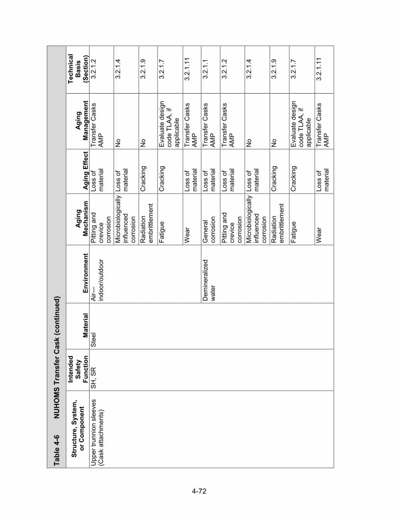
4-72
Tabl
e 4-
6
NU
HO
MS
Tran
sfer
Cas
k (con
tinued)
Stru
ctur
e, S
yste
m,
or C
ompo
nent
In
tend
ed
Safe
ty
Func
tion
Mat
eria
l En
viro
nmen
t Ag
ing
Mec
hani
sm
Agin
g Ef
fect
Ag
ing
Man
agem
ent
Tech
nica
l B
asis
(S
ectio
n)
Upp
er tr
unni
on s
leev
es
(Cas
k at
tach
men
ts)
SH, S
R
Stee
l Ai
r—in
door
/out
door
Pi
tting
and
cr
evic
e co
rrosi
on
Loss
of
mat
eria
l Tr
ansf
er C
asks
AM
P 3.
2.1.
2
Mic
robi
olog
ical
ly
influ
ence
d co
rrosi
on
Loss
of
mat
eria
l N
o 3.
2.1.
4
Rad
iatio
n em
britt
lem
ent
Cra
ckin
g N
o 3.
2.1.
9
Fatig
ue
Cra
ckin
g Ev
alua
te d
esig
n co
de T
LAA,
if
appl
icab
le
3.2.
1.7
Wea
r Lo
ss o
f m
ater
ial
Tran
sfer
Cas
ks
AMP
3.2.
1.11
Dem
iner
aliz
ed
wat
er
Gen
eral
co
rrosi
on
Loss
of
mat
eria
l Tr
ansf
er C
asks
AM
P 3.
2.1.
1
Pitti
ng a
nd
crev
ice
corro
sion
Loss
of
mat
eria
l Tr
ansf
er C
asks
AM
P 3.
2.1.
2
Mic
robi
olog
ical
ly
influ
ence
d co
rrosi
on
Loss
of
mat
eria
l N
o 3.
2.1.
4
Rad
iatio
n em
britt
lem
ent
Cra
ckin
g N
o 3.
2.1.
9
Fatig
ue
Cra
ckin
g Ev
alua
te d
esig
n co
de T
LAA,
if
appl
icab
le
3.2.
1.7
Wea
r Lo
ss o
f m
ater
ial
Tran
sfer
Cas
ks
AMP
3.2.
1.11
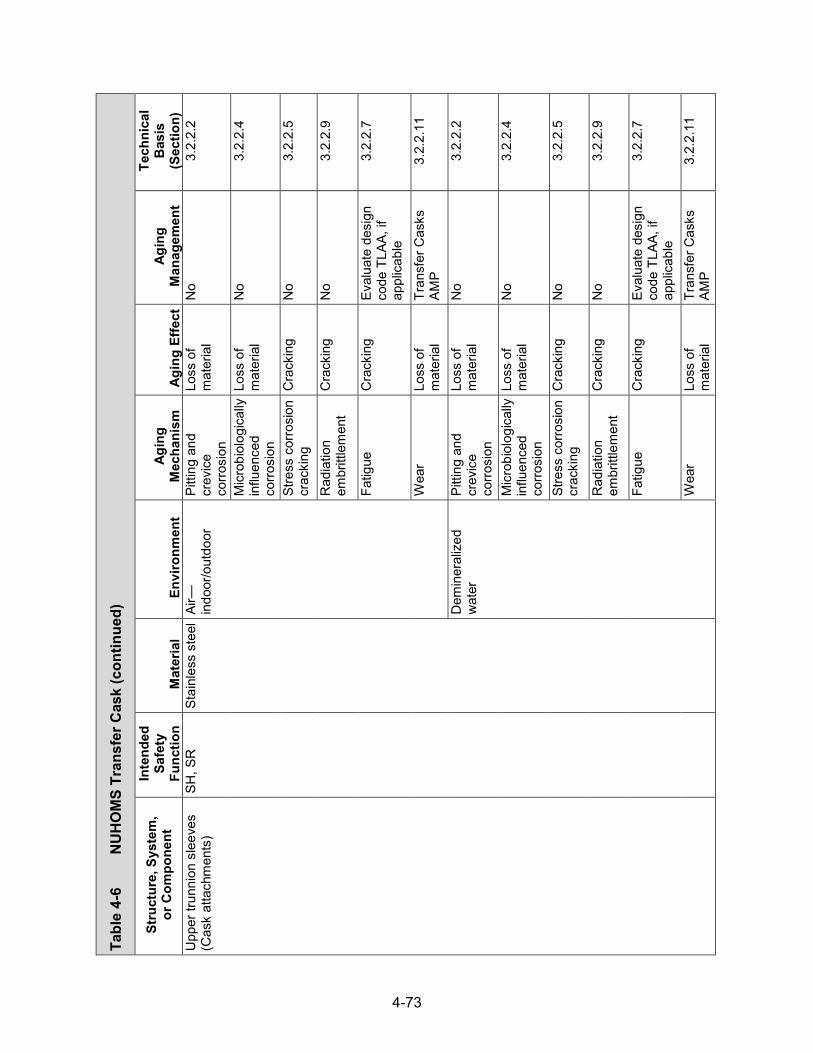
4-73
Tabl
e 4-
6
NU
HO
MS
Tran
sfer
Cas
k (con
tinued)
Stru
ctur
e, S
yste
m,
or C
ompo
nent
In
tend
ed
Safe
ty
Func
tion
Mat
eria
l En
viro
nmen
t Ag
ing
Mec
hani
sm
Agin
g Ef
fect
Ag
ing
Man
agem
ent
Tech
nica
l B
asis
(S
ectio
n)
Upp
er tr
unni
on s
leev
es
(Cas
k at
tach
men
ts)
SH, S
R
Stai
nles
s st
eel
Air—
indo
or/o
utdo
or
Pitti
ng a
nd
crev
ice
corro
sion
Loss
of
mat
eria
l N
o 3.
2.2.
2
Mic
robi
olog
ical
ly
influ
ence
d co
rrosi
on
Loss
of
mat
eria
l N
o 3.
2.2.
4
Stre
ss c
orro
sion
cr
acki
ng
Cra
ckin
g N
o 3.
2.2.
5
Rad
iatio
n em
britt
lem
ent
Cra
ckin
g N
o 3.
2.2.
9
Fatig
ue
Cra
ckin
g Ev
alua
te d
esig
n co
de T
LAA,
if
appl
icab
le
3.2.
2.7
Wea
r Lo
ss o
f m
ater
ial
Tran
sfer
Cas
ks
AMP
3.2.
2.11
Dem
iner
aliz
ed
wat
er
Pitti
ng a
nd
crev
ice
corro
sion
Loss
of
mat
eria
l N
o 3.
2.2.
2
Mic
robi
olog
ical
ly
influ
ence
d co
rrosi
on
Loss
of
mat
eria
l N
o 3.
2.2.
4
Stre
ss c
orro
sion
cr
acki
ng
Cra
ckin
g N
o 3.
2.2.
5
Rad
iatio
n em
britt
lem
ent
Cra
ckin
g N
o 3.
2.2.
9
Fatig
ue
Cra
ckin
g Ev
alua
te d
esig
n co
de T
LAA,
if
appl
icab
le
3.2.
2.7
Wea
r Lo
ss o
f m
ater
ial
Tran
sfer
Cas
ks
AMP
3.2.
2.11

4-74
Tabl
e 4-
6
NU
HO
MS
Tran
sfer
Cas
k (con
tinued)
Stru
ctur
e, S
yste
m,
or C
ompo
nent
In
tend
ed
Safe
ty
Func
tion
Mat
eria
l En
viro
nmen
t Ag
ing
Mec
hani
sm
Agin
g Ef
fect
Ag
ing
Man
agem
ent
Tech
nica
l B
asis
(S
ectio
n)
Upp
er tr
unni
on c
over
pl
ate
and
pad
(Cas
k at
tach
men
ts)
SH, S
R
Stai
nles
s st
eel
Air—
indo
or/o
utdo
or
Pitti
ng a
nd
crev
ice
corro
sion
Loss
of
mat
eria
l N
o 3.
2.2.
2
Mic
robi
olog
ical
ly
influ
ence
d co
rrosi
on
Loss
of
mat
eria
l N
o 3.
2.2.
4
Stre
ss c
orro
sion
cr
acki
ng
Cra
ckin
g N
o 3.
2.2.
5
Rad
iatio
n em
britt
lem
ent
Cra
ckin
g N
o 3.
2.2.
9
Fatig
ue
Cra
ckin
g Ev
alua
te d
esig
n co
de T
LAA,
if
appl
icab
le
3.2.
2.7
Upp
er tr
unni
on n
icke
l al
loy
(Cas
k at
tach
men
ts)
SR
Inco
nel
Air—
indo
or/o
utdo
or
Pitti
ng a
nd
crev
ice
corro
sion
Loss
of
mat
eria
l N
o 3.
2.4.
2
Mic
robi
olog
ical
ly
influ
ence
d co
rrosi
on
Loss
of
mat
eria
l N
o 3.
2.4.
3
Stre
ss c
orro
sion
cr
acki
ng
Cra
ckin
g N
o 3.
2.4.
4
Rad
iatio
n em
britt
lem
ent
Cra
ckin
g N
o 3.
2.4.
6
Fatig
ue
Cra
ckin
g Ev
alua
te d
esig
n co
de T
LAA,
if
appl
icab
le
3.2.
4.5
Upp
er a
nd lo
wer
trun
nion
ne
utro
n sh
ield
ing
(Cas
k at
tach
men
ts)
SH, T
H
Bisc
o N
S-3
Embe
dded
(ste
el,
stai
nles
s st
eel)
Ther
mal
agi
ng
Loss
of
fract
ure
toug
hnes
s an
d lo
ss o
f du
ctilit
y
No
3.3.
1.2

4-75
Tabl
e 4-
6
NU
HO
MS
Tran
sfer
Cas
k (con
tinued)
Stru
ctur
e, S
yste
m,
or C
ompo
nent
In
tend
ed
Safe
ty
Func
tion
Mat
eria
l En
viro
nmen
t Ag
ing
Mec
hani
sm
Agin
g Ef
fect
Ag
ing
Man
agem
ent
Tech
nica
l B
asis
(S
ectio
n)
Upp
er a
nd lo
wer
trun
nion
ne
utro
n sh
ield
ing
(Cas
k at
tach
men
ts)
SH, T
H
Bisc
o N
S-3
Embe
dded
(ste
el,
stai
nles
s st
eel)
Rad
iatio
n em
britt
lem
ent
Cra
ckin
g N
o 3.
3.1.
3
Boro
n de
plet
ion
Loss
of
shie
ldin
g TL
AA/A
MP
or a
su
ppor
ting
anal
ysis
is
requ
ired
3.3.
1.1
Low
er tr
unni
ons
(Cas
k at
tach
men
ts)
SH, S
R
Stai
nles
s st
eel
(wel
ded)
Ai
r—in
door
/out
door
St
ress
cor
rosi
on
crac
king
C
rack
ing
No
3.2.
2.5
Stai
nles
s st
eel
Air—
indo
or/o
utdo
or
Pitti
ng a
nd
crev
ice
corro
sion
Loss
of
mat
eria
l N
o 3.
2.2.
2
Mic
robi
olog
ical
ly
influ
ence
d co
rrosi
on
Loss
of
mat
eria
l N
o 3.
2.2.
4
Rad
iatio
n em
britt
lem
ent
Cra
ckin
g N
o 3.
2.2.
9
Fatig
ue
Cra
ckin
g Ev
alua
te d
esig
n co
de T
LAA,
if
appl
icab
le
3.2.
2.7
Low
er tr
unni
ons
slee
ves
(Cas
k at
tach
men
ts)
SH, S
R
Stee
l Ai
r—in
door
/out
door
G
ener
al
corro
sion
Lo
ss o
f m
ater
ial
Tran
sfer
Cas
ks
AMP
3.2.
1.1
Pitti
ng a
nd
crev
ice
corro
sion
Loss
of
mat
eria
l Tr
ansf
er C
asks
AM
P 3.
2.1.
2
Mic
robi
olog
ical
ly
influ
ence
d co
rrosi
on
Loss
of
mat
eria
l N
o 3.
2.1.
4
Rad
iatio
n em
britt
lem
ent
Cra
ckin
g N
o 3.
2.1.
9

4-76
Tabl
e 4-
6
NU
HO
MS
Tran
sfer
Cas
k (con
tinued)
Stru
ctur
e, S
yste
m,
or C
ompo
nent
In
tend
ed
Safe
ty
Func
tion
Mat
eria
l En
viro
nmen
t Ag
ing
Mec
hani
sm
Agin
g Ef
fect
Ag
ing
Man
agem
ent
Tech
nica
l B
asis
(S
ectio
n)
Low
er tr
unni
ons
slee
ves
(Cas
k at
tach
men
ts)
SH, S
R
Stee
l Ai
r—in
door
/out
door
Fa
tigue
C
rack
ing
Eval
uate
des
ign
code
TLA
A, if
ap
plic
able
3.2.
1.7
Wea
r Lo
ss o
f m
ater
ial
Tran
sfer
Cas
ks
AMP
3.2.
1.11
Dem
iner
aliz
ed
wat
er
Gen
eral
co
rrosi
on
Loss
of
mat
eria
l Tr
ansf
er C
asks
AM
P 3.
2.1.
1
Pitti
ng a
nd
crev
ice
corro
sion
Loss
of
mat
eria
l Tr
ansf
er C
asks
AM
P 3.
2.1.
2
Mic
robi
olog
ical
ly
influ
ence
d co
rrosi
on
Loss
of
mat
eria
l N
o 3.
2.1.
4
Rad
iatio
n em
britt
lem
ent
Cra
ckin
g N
o 3.
2.1.
9
Fatig
ue
Cra
ckin
g Ev
alua
te d
esig
n co
de T
LAA,
if
appl
icab
le
3.2.
1.7
Wea
r Lo
ss o
f m
ater
ial
Tran
sfer
Cas
ks
AMP
3.2.
1.11
Stai
nles
s st
eel
Air—
indo
or/o
utdo
or
Pitti
ng a
nd
crev
ice
corro
sion
Loss
of
mat
eria
l N
o 3.
2.2.
2
Mic
robi
olog
ical
ly
influ
ence
d co
rrosi
on
Loss
of
mat
eria
l N
o 3.
2.2.
4
Stre
ss c
orro
sion
cr
acki
ng
Cra
ckin
g N
o 3.
2.2.
5
Rad
iatio
n em
britt
lem
ent
Cra
ckin
g N
o 3.
2.2.
9
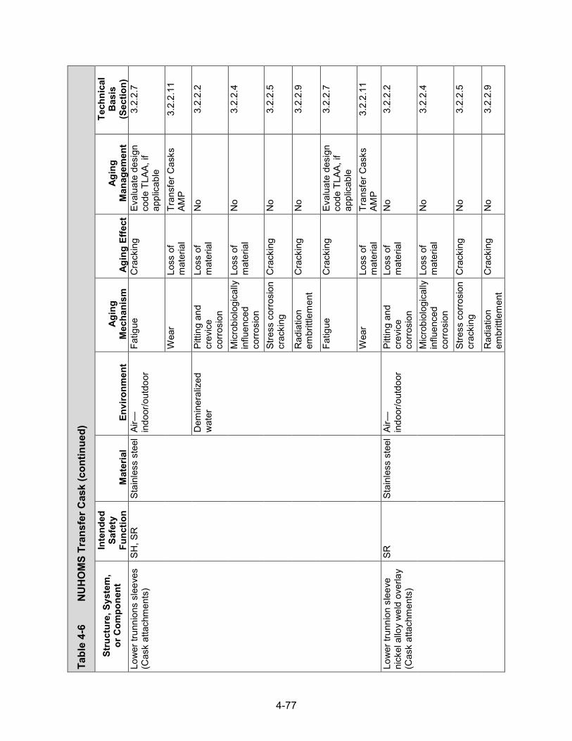
4-77
Tabl
e 4-
6
NU
HO
MS
Tran
sfer
Cas
k (con
tinued)
Stru
ctur
e, S
yste
m,
or C
ompo
nent
In
tend
ed
Safe
ty
Func
tion
Mat
eria
l En
viro
nmen
t Ag
ing
Mec
hani
sm
Agin
g Ef
fect
Ag
ing
Man
agem
ent
Tech
nica
l B
asis
(S
ectio
n)
Low
er tr
unni
ons
slee
ves
(Cas
k at
tach
men
ts)
SH, S
R
Stai
nles
s st
eel
Air—
indo
or/o
utdo
or
Fatig
ue
Cra
ckin
g Ev
alua
te d
esig
n co
de T
LAA,
if
appl
icab
le
3.2.
2.7
Wea
r Lo
ss o
f m
ater
ial
Tran
sfer
Cas
ks
AMP
3.2.
2.11
Dem
iner
aliz
ed
wat
er
Pitti
ng a
nd
crev
ice
corro
sion
Loss
of
mat
eria
l N
o 3.
2.2.
2
Mic
robi
olog
ical
ly
influ
ence
d co
rrosi
on
Loss
of
mat
eria
l N
o 3.
2.2.
4
Stre
ss c
orro
sion
cr
acki
ng
Cra
ckin
g N
o 3.
2.2.
5
Rad
iatio
n em
britt
lem
ent
Cra
ckin
g N
o 3.
2.2.
9
Fatig
ue
Cra
ckin
g Ev
alua
te d
esig
n co
de T
LAA,
if
appl
icab
le
3.2.
2.7
Wea
r Lo
ss o
f m
ater
ial
Tran
sfer
Cas
ks
AMP
3.2.
2.11
Low
er tr
unni
on s
leev
e ni
ckel
allo
y w
eld
over
lay
(Cas
k at
tach
men
ts)
SR
Stai
nles
s st
eel
Air—
indo
or/o
utdo
or
Pitti
ng a
nd
crev
ice
corro
sion
Loss
of
mat
eria
l N
o 3.
2.2.
2
Mic
robi
olog
ical
ly
influ
ence
d co
rrosi
on
Loss
of
mat
eria
l N
o 3.
2.2.
4
Stre
ss c
orro
sion
cr
acki
ng
Cra
ckin
g N
o 3.
2.2.
5
Rad
iatio
n em
britt
lem
ent
Cra
ckin
g N
o 3.
2.2.
9

4-78
Tabl
e 4-
6
NU
HO
MS
Tran
sfer
Cas
k (con
tinued)
Stru
ctur
e, S
yste
m,
or C
ompo
nent
In
tend
ed
Safe
ty
Func
tion
Mat
eria
l En
viro
nmen
t Ag
ing
Mec
hani
sm
Agin
g Ef
fect
Ag
ing
Man
agem
ent
Tech
nica
l B
asis
(S
ectio
n)
Low
er tr
unni
on s
leev
e ni
ckel
allo
y w
eld
over
lay
(Cas
k at
tach
men
ts)
SR
Stai
nles
s st
eel
Air—
indo
or/o
utdo
or
Fatig
ue
Cra
ckin
g Ev
alua
te d
esig
n co
de T
LAA,
if
appl
icab
le
3.2.
2.7
Dem
iner
aliz
ed
wat
er
Pitti
ng a
nd
crev
ice
corro
sion
Loss
of
mat
eria
l N
o 3.
2.2.
2
Mic
robi
olog
ical
ly
influ
ence
d co
rrosi
on
Loss
of
mat
eria
l N
o 3.
2.2.
4
Stre
ss c
orro
sion
cr
acki
ng
Cra
ckin
g N
o 3.
2.2.
5
Rad
iatio
n em
britt
lem
ent
Cra
ckin
g N
o 3.
2.2.
9
Fatig
ue
Cra
ckin
g Ev
alua
te d
esig
n co
de T
LAA,
if
appl
icab
le
3.2.
2.7
Inte
rnal
sle
eve
com
pone
nts
(C
ask
atta
chm
ents
)
SR
Alum
inum
Em
bedd
ed
(sta
inle
ss s
teel
) R
adia
tion
embr
ittle
men
t C
rack
ing
No
3.2.
3.8
Fatig
ue
Cra
ckin
g Ev
alua
te d
esig
n co
de T
LAA,
if
appl
icab
le
3.2.
3.6
Botto
m h
ead
cap
scre
w
for i
nter
nal s
leev
e
(Cas
k at
tach
men
ts)
SR
Stee
l Em
bedd
ed
(sta
inle
ss s
teel
, al
umin
um)
Rad
iatio
n em
britt
lem
ent
Cra
ckin
g N
o 3.
2.1.
9
Fatig
ue
Cra
ckin
g Ev
alua
te d
esig
n co
de T
LAA,
if
appl
icab
le
3.2.
1.7
Stre
ss re
laxa
tion
Loss
of
prel
oad
No
3.2.
1.10

4-79
Tabl
e 4-
6
NU
HO
MS
Tran
sfer
Cas
k (con
tinued)
Stru
ctur
e, S
yste
m,
or C
ompo
nent
In
tend
ed
Safe
ty
Func
tion
Mat
eria
l En
viro
nmen
t Ag
ing
Mec
hani
sm
Agin
g Ef
fect
Ag
ing
Man
agem
ent
Tech
nica
l B
asis
(S
ectio
n)
Was
her f
or in
tern
al
slee
ve (C
ask
atta
chm
ents
)
SR
Stai
nles
s st
eel
Embe
dded
(ste
el,
stai
nles
s st
eel)
Rad
iatio
n em
britt
lem
ent
Cra
ckin
g N
o 3.
2.2.
9
Fatig
ue
Cra
ckin
g Ev
alua
te d
esig
n co
de T
LAA,
if
appl
icab
le
3.2.
2.7
Spac
er a
ssem
bly
(C
ask
atta
chm
ents
) SR
St
ainl
ess
stee
l Ai
r—in
door
/out
door
Pi
tting
and
cr
evic
e co
rrosi
on
Loss
of
mat
eria
l N
o 3.
2.2.
2
Mic
robi
olog
ical
ly
influ
ence
d co
rrosi
on
Loss
of
mat
eria
l N
o 3.
2.2.
4
Stre
ss c
orro
sion
cr
acki
ng
Cra
ckin
g N
o 3.
2.2.
5
Rad
iatio
n em
britt
lem
ent
Cra
ckin
g N
o 3.
2.2.
9
Fatig
ue
Cra
ckin
g Ev
alua
te d
esig
n co
de T
LAA,
if
appl
icab
le
3.2.
2.7
Ram
acc
ess
pene
tratio
n rin
g (C
ask
pene
tratio
n)
SH, S
R
Stai
nles
s st
eel
Air—
indo
or/o
utdo
or
Pitti
ng a
nd
crev
ice
corro
sion
Loss
of
mat
eria
l N
o 3.
2.2.
2
Mic
robi
olog
ical
ly
influ
ence
d co
rrosi
on
Loss
of
mat
eria
l N
o 3.
2.2.
4
Stre
ss c
orro
sion
cr
acki
ng
Cra
ckin
g N
o 3.
2.2.
5
Rad
iatio
n em
britt
lem
ent
Cra
ckin
g N
o 3.
2.2.
9
Fatig
ue
Cra
ckin
g Ev
alua
te d
esig
n co
de T
LAA,
if
appl
icab
le
3.2.
2.7

4-80
Tabl
e 4-
6
NU
HO
MS
Tran
sfer
Cas
k (con
tinued)
Stru
ctur
e, S
yste
m,
or C
ompo
nent
In
tend
ed
Safe
ty
Func
tion
Mat
eria
l En
viro
nmen
t Ag
ing
Mec
hani
sm
Agin
g Ef
fect
Ag
ing
Man
agem
ent
Tech
nica
l B
asis
(S
ectio
n)
Upp
er a
nd lo
wer
ring
s,
oute
r she
ll re
lief v
alve
su
ppor
t pla
tes
(Cas
k ne
utro
n sh
ield
)
SH, S
R, T
H
Stai
nles
s st
eel
Air—
indo
or/o
utdo
or
Pitti
ng a
nd
crev
ice
corro
sion
Loss
of
mat
eria
l N
o 3.
2.2.
2
Mic
robi
olog
ical
ly
influ
ence
d co
rrosi
on
Loss
of
mat
eria
l N
o 3.
2.2.
4
Stre
ss c
orro
sion
cr
acki
ng
Cra
ckin
g N
o 3.
2.2.
5
Rad
iatio
n em
britt
lem
ent
Cra
ckin
g N
o 3.
2.2.
9
Fatig
ue
Cra
ckin
g Ev
alua
te d
esig
n co
de T
LAA,
if
appl
icab
le
3.2.
2.7
Embe
dded
(n
eutro
n sh
ield
ing)
Rad
iatio
n em
britt
lem
ent
Cra
ckin
g N
o 3.
2.2.
9
Fatig
ue
Cra
ckin
g Ev
alua
te d
esig
n co
de T
LAA,
if
appl
icab
le
3.2.
2.7
Dem
iner
aliz
ed
wat
er
Pitti
ng a
nd
crev
ice
corro
sion
Loss
of
mat
eria
l N
o 3.
2.2.
2
Mic
robi
olog
ical
ly
influ
ence
d co
rrosi
on
Loss
of
mat
eria
l N
o 3.
2.2.
4
Stre
ss c
orro
sion
cr
acki
ng
Cra
ckin
g N
o 3.
2.2.
5
Rad
iatio
n em
britt
lem
ent
Cra
ckin
g N
o 3.
2.2.
9
Fatig
ue
Cra
ckin
g Ev
alua
te d
esig
n co
de T
LAA,
if
appl
icab
le
3.2.
2.7

4-81
Tabl
e 4-
6
NU
HO
MS
Tran
sfer
Cas
k (con
tinued)
Stru
ctur
e, S
yste
m,
or C
ompo
nent
In
tend
ed
Safe
ty
Func
tion
Mat
eria
l En
viro
nmen
t Ag
ing
Mec
hani
sm
Agin
g Ef
fect
Ag
ing
Man
agem
ent
Tech
nica
l B
asis
(S
ectio
n)
Neu
tron
shie
ld p
anel
su
ppor
t ang
les
(Cas
k ne
utro
n sh
ield
)
SH, S
R, T
H
Stai
nles
s st
eel
Embe
dded
(n
eutro
n sh
ield
ing)
Rad
iatio
n em
britt
lem
ent
Cra
ckin
g N
o 3.
2.2.
9
Fatig
ue
Cra
ckin
g Ev
alua
te d
esig
n co
de T
LAA,
if
appl
icab
le
3.2.
2.7
Dem
iner
aliz
ed
wat
er
Pitti
ng a
nd
crev
ice
corro
sion
Loss
of
mat
eria
l N
o 3.
2.2.
2
Mic
robi
olog
ical
ly
influ
ence
d co
rrosi
on
Loss
of
mat
eria
l N
o 3.
2.2.
4
Stre
ss c
orro
sion
cr
acki
ng
Cra
ckin
g N
o 3.
2.2.
5
Rad
iatio
n em
britt
lem
ent
Cra
ckin
g N
o 3.
2.2.
9
Fatig
ue
Cra
ckin
g Ev
alua
te d
esig
n co
de T
LAA,
if
appl
icab
le
3.2.
2.7
Neu
tron
shie
ld p
anel
s an
d pl
ates
(Cas
k ne
utro
n sh
ield
)
SH, S
R, T
H
Stai
nles
s st
eel
Air—
indo
or/o
utdo
or
Pitti
ng a
nd
crev
ice
corro
sion
Loss
of
mat
eria
l N
o 3.
2.2.
2
Mic
robi
olog
ical
ly
influ
ence
d co
rrosi
on
Loss
of
mat
eria
l N
o 3.
2.2.
4
Stre
ss c
orro
sion
cr
acki
ng
Cra
ckin
g N
o 3.
2.2.
5
Rad
iatio
n em
britt
lem
ent
Cra
ckin
g N
o.
3.2.
2.9

4-82
Tabl
e 4-
6
NU
HO
MS
Tran
sfer
Cas
k (con
tinued)
Stru
ctur
e, S
yste
m,
or C
ompo
nent
In
tend
ed
Safe
ty
Func
tion
Mat
eria
l En
viro
nmen
t Ag
ing
Mec
hani
sm
Agin
g Ef
fect
Ag
ing
Man
agem
ent
Tech
nica
l B
asis
(S
ectio
n)
Neu
tron
shie
ld p
anel
s an
d pl
ates
(Cas
k ne
utro
n sh
ield
)
SH, S
R, T
H
Stai
nles
s st
eel
Air—
indo
or/o
utdo
or
Fatig
ue
Cra
ckin
g Ev
alua
te d
esig
n co
de T
LAA,
if
appl
icab
le
3.2.
2.7
Embe
dded
(n
eutro
n sh
ield
ing)
Rad
iatio
n em
britt
lem
ent
Cra
ckin
g N
o 3.
2.2.
9
Fatig
ue
Cra
ckin
g Ev
alua
te d
esig
n co
de T
LAA,
if
appl
icab
le
3.2.
2.7
Dem
iner
aliz
ed
wat
er
Pitti
ng a
nd
crev
ice
corro
sion
Loss
of
mat
eria
l N
o 3.
2.2.
2
Mic
robi
olog
ical
ly
influ
ence
d co
rrosi
on
Loss
of
mat
eria
l N
o 3.
2.2.
4
Stre
ss c
orro
sion
cr
acki
ng
Cra
ckin
g N
o 3.
2.2.
5
Rad
iatio
n em
britt
lem
ent
Cra
ckin
g N
o 3.
2.2.
9
Fatig
ue
Cra
ckin
g Ev
alua
te d
esig
n co
de T
LAA,
if
appl
icab
le
3.2.
2.7
Cas
tabl
e ne
utro
n sh
ield
ing
mat
eria
l (C
ask
neut
ron
shie
ld)
SH, T
H
Bisc
o N
S-3
Embe
dded
(ste
el,
stai
nles
s st
eel)
Ther
mal
agi
ng
Loss
of
fract
ure
toug
hnes
s an
d lo
ss o
f du
ctilit
y
No
3.3.
1.2
Rad
iatio
n em
britt
lem
ent
Cra
ckin
g N
o 3.
3.1.
3

4-83
Tabl
e 4-
6
NU
HO
MS
Tran
sfer
Cas
k (con
tinued)
Stru
ctur
e, S
yste
m,
or C
ompo
nent
In
tend
ed
Safe
ty
Func
tion
Mat
eria
l En
viro
nmen
t Ag
ing
Mec
hani
sm
Agin
g Ef
fect
Ag
ing
Man
agem
ent
Tech
nica
l B
asis
(S
ectio
n)
Cas
tabl
e ne
utro
n sh
ield
ing
mat
eria
l (C
ask
neut
ron
shie
ld)
SH, T
H
Bisc
o N
S-3
Embe
dded
(ste
el,
stai
nles
s st
eel)
Boro
n de
plet
ion
Loss
of
shie
ldin
g TL
AA/A
MP
or a
su
ppor
ting
anal
ysis
is
requ
ired
3.3.
1.1
Inne
r, ou
ter,
and
side
top
cove
r pla
tes
(Cas
k co
ver
asse
mbl
y)
SH, S
R
Stee
l Ai
r—in
door
/out
door
G
ener
al
corro
sion
Lo
ss o
f m
ater
ial
Tran
sfer
Cas
ks
AMP
3.2.
1.1
Pitti
ng a
nd
crev
ice
corro
sion
Loss
of
mat
eria
l Tr
ansf
er C
asks
AM
P 3.
2.1.
2
Mic
robi
olog
ical
ly
influ
ence
d co
rrosi
on
Loss
of
mat
eria
l N
o 3.
2.1.
4
Rad
iatio
n em
britt
lem
ent
Cra
ckin
g N
o 3.
2.1.
9
Fatig
ue
Cra
ckin
g Ev
alua
te d
esig
n co
de T
LAA,
if
appl
icab
le
3.2.
1.7
Stai
nles
s st
eel
Air—
indo
or/o
utdo
or
Pitti
ng a
nd
crev
ice
corro
sion
Loss
of
mat
eria
l N
o 3.
2.2.
2
Mic
robi
olog
ical
ly
influ
ence
d co
rrosi
on
Loss
of
mat
eria
l N
o 3.
2.2.
4
Stre
ss c
orro
sion
cr
acki
ng
Cra
ckin
g N
o 3.
2.2.
5
Rad
iatio
n em
britt
lem
ent
Cra
ckin
g N
o 3.
2.2.
9
Fatig
ue
Cra
ckin
g Ev
alua
te d
esig
n co
de T
LAA,
if
appl
icab
le
3.2.
2.7
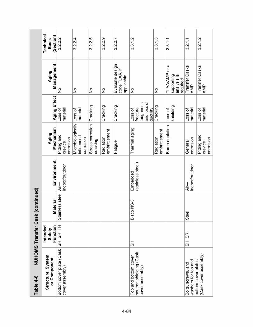
4-84
Tabl
e 4-
6
NU
HO
MS
Tran
sfer
Cas
k (con
tinued)
Stru
ctur
e, S
yste
m,
or C
ompo
nent
In
tend
ed
Safe
ty
Func
tion
Mat
eria
l En
viro
nmen
t Ag
ing
Mec
hani
sm
Agin
g Ef
fect
Ag
ing
Man
agem
ent
Tech
nica
l B
asis
(S
ectio
n)
Botto
m c
over
pla
te (C
ask
cove
r ass
embl
y)
SH, S
R, T
H
Stai
nles
s st
eel
Air—
indo
or/o
utdo
or
Pitti
ng a
nd
crev
ice
corro
sion
Loss
of
mat
eria
l N
o 3.
2.2.
2
Mic
robi
olog
ical
ly
influ
ence
d co
rrosi
on
Loss
of
mat
eria
l N
o 3.
2.2.
4
Stre
ss c
orro
sion
cr
acki
ng
Cra
ckin
g N
o 3.
2.2.
5
Rad
iatio
n em
britt
lem
ent
Cra
ckin
g N
o 3.
2.2.
9
Fatig
ue
Cra
ckin
g Ev
alua
te d
esig
n co
de T
LAA,
if
appl
icab
le
3.2.
2.7
Top
and
botto
m c
over
ne
utro
n sh
ield
ing
(Cas
k co
ver a
ssem
bly)
SH
Bisc
o N
S-3
Embe
dded
(s
tain
less
ste
el)
Ther
mal
agi
ng
Loss
of
fract
ure
toug
hnes
s an
d lo
ss o
f du
ctilit
y
No
3.3.
1.2
Rad
iatio
n em
britt
lem
ent
Cra
ckin
g N
o 3.
3.1.
3
Boro
n de
plet
ion
Loss
of
shie
ldin
g TL
AA/A
MP
or a
su
ppor
ting
anal
ysis
is
requ
ired
3.3.
1.1
Bolts
, scr
ews,
and
w
ashe
rs fo
r top
and
bo
ttom
cov
er p
late
s (C
ask
cove
r ass
embl
y)
SH, S
R
Stee
l Ai
r—in
door
/out
door
G
ener
al
corro
sion
Lo
ss o
f m
ater
ial
Tran
sfer
Cas
ks
AMP
3.2.
1.1
Pitti
ng a
nd
crev
ice
corro
sion
Loss
of
mat
eria
l Tr
ansf
er C
asks
AM
P 3.
2.1.
2

4-85
Tabl
e 4-
6
NU
HO
MS
Tran
sfer
Cas
k (con
tinued)
Stru
ctur
e, S
yste
m,
or C
ompo
nent
In
tend
ed
Safe
ty
Func
tion
Mat
eria
l En
viro
nmen
t Ag
ing
Mec
hani
sm
Agin
g Ef
fect
Ag
ing
Man
agem
ent
Tech
nica
l B
asis
(S
ectio
n)
Bolts
, scr
ews,
and
w
ashe
rs fo
r top
and
bo
ttom
cov
er p
late
s (C
ask
cove
r ass
embl
y)
SH, S
R
Stee
l Ai
r—in
door
/out
door
M
icro
biol
ogic
ally
in
fluen
ced
corro
sion
Loss
of
mat
eria
l N
o 3.
2.1.
4
Rad
iatio
n em
britt
lem
ent
Cra
ckin
g N
o 3.
2.1.
9
Fatig
ue
Cra
ckin
g Ev
alua
te d
esig
n co
de T
LAA,
if
appl
icab
le
3.2.
1.7
Stre
ss re
laxa
tion
Loss
of
prel
oad
No
3.2.
1.10
Sock
et h
ead
cap
scre
ws
for b
otto
m c
over
pla
te
(Cas
k co
ver a
ssem
bly)
SH, S
R
Stai
nles
s st
eel
Air—
indo
or/o
utdo
or
Pitti
ng a
nd
crev
ice
corro
sion
Loss
of
mat
eria
l N
o 3.
2.2.
2
Mic
robi
olog
ical
ly
influ
ence
d co
rrosi
on
Loss
of
mat
eria
l N
o 3.
2.2.
4
Stre
ss c
orro
sion
cr
acki
ng
Cra
ckin
g N
o 3.
2.2.
5
Rad
iatio
n em
britt
lem
ent
Cra
ckin
g N
o 3.
2.2.
9
Fatig
ue
Cra
ckin
g Ev
alua
te d
esig
n co
de T
LAA,
if
appl
icab
le
3.2.
2.7
Stre
ss re
laxa
tion
Loss
of
prel
oad
No
3.2.
2.10
Airfl
ow w
edge
pla
tes
(Cas
k co
ver a
ssem
bly)
SH
, SR
, TH
St
ainl
ess
stee
l Ai
r—in
door
/out
door
Pi
tting
and
cr
evic
e co
rrosi
on
Loss
of
mat
eria
l N
o 3.
2.2.
2

4-86
Tabl
e 4-
6
NU
HO
MS
Tran
sfer
Cas
k (con
tinued)
Stru
ctur
e, S
yste
m,
or C
ompo
nent
In
tend
ed
Safe
ty
Func
tion
Mat
eria
l En
viro
nmen
t Ag
ing
Mec
hani
sm
Agin
g Ef
fect
Ag
ing
Man
agem
ent
Tech
nica
l B
asis
(S
ectio
n)
Airfl
ow w
edge
pla
tes
(Cas
k co
ver a
ssem
bly)
SH
, SR
, TH
St
ainl
ess
stee
l Ai
r—in
door
/out
door
M
icro
biol
ogic
ally
in
fluen
ced
corro
sion
Loss
of
mat
eria
l N
o 3.
2.2.
4
Stre
ss c
orro
sion
cr
acki
ng
Cra
ckin
g N
o 3.
2.2.
5
Rad
iatio
n em
britt
lem
ent
Cra
ckin
g N
o 3.
2.2.
9
Fatig
ue
Cra
ckin
g Ev
alua
te d
esig
n co
de T
LAA,
if
appl
icab
le
3.2.
2.7
Supp
ort s
kid
supp
lem
enta
l sh
ield
ing
SH, S
R
Stee
l Ai
r—in
door
/out
door
G
ener
al
corro
sion
Lo
ss o
f m
ater
ial
Tran
sfer
Cas
ks
AMP
3.2.
1.1
Pitti
ng a
nd
crev
ice
corro
sion
Loss
of
mat
eria
l Tr
ansf
er C
asks
AM
P 3.
2.1.
2
Mic
robi
olog
ical
ly
influ
ence
d co
rrosi
on
Loss
of
mat
eria
l N
o 3.
2.1.
4
Rad
iatio
n em
britt
lem
ent
Cra
ckin
g N
o 3.
2.1.
9
Fatig
ue
Cra
ckin
g Ev
alua
te d
esig
n co
de T
LAA,
if
appl
icab
le
3.2.
1.7
Bolts
and
was
hers
for
supp
ort s
kid
supp
lem
enta
l shi
eldi
ng
SR
Stee
l Ai
r—in
door
/out
door
G
ener
al
corro
sion
Lo
ss o
f m
ater
ial
Tran
sfer
Cas
ks
AMP
3.2.
1.1
Pitti
ng a
nd
crev
ice
corro
sion
Loss
of
mat
eria
l Tr
ansf
er C
asks
AM
P 3.
2.1.
2
Mic
robi
olog
ical
ly
influ
ence
d co
rrosi
on
Loss
of
mat
eria
l N
o 3.
2.1.
4

4-87
Tabl
e 4-
6
NU
HO
MS
Tran
sfer
Cas
k (con
tinued)
Stru
ctur
e, S
yste
m,
or C
ompo
nent
In
tend
ed
Safe
ty
Func
tion
Mat
eria
l En
viro
nmen
t Ag
ing
Mec
hani
sm
Agin
g Ef
fect
Ag
ing
Man
agem
ent
Tech
nica
l B
asis
(S
ectio
n)
Bolts
and
was
hers
for
supp
ort s
kid
supp
lem
enta
l shi
eldi
ng
SR
Stee
l Ai
r—in
door
/out
door
R
adia
tion
embr
ittle
men
t C
rack
ing
No
3.2.
1.9
Fatig
ue
Cra
ckin
g Ev
alua
te d
esig
n co
de T
LAA,
if
appl
icab
le
3.2.
1.7
Stre
ss re
laxa
tion
Loss
of
prel
oad
No
3.2.
1.10
Upp
er a
nd lo
wer
dec
on
area
cas
k sh
ield
ing
SH, S
R
Stee
l Ai
r—in
door
/out
door
G
ener
al
corro
sion
Lo
ss o
f m
ater
ial
Tran
sfer
Cas
ks
AMP
3.2.
1.1
Pitti
ng a
nd
crev
ice
corro
sion
Loss
of
mat
eria
l Tr
ansf
er C
asks
AM
P 3.
2.1.
2
Mic
robi
olog
ical
ly
influ
ence
d co
rrosi
on
Loss
of
mat
eria
l N
o 3.
2.1.
4
Rad
iatio
n em
britt
lem
ent
Cra
ckin
g N
o 3.
2.1.
9
Fatig
ue
Cra
ckin
g Ev
alua
te d
esig
n co
de T
LAA,
if
appl
icab
le
3.2.
1.7

4-88
4.3 HI-STORM 100 and HI-STAR 100 Systems
4.3.1 System Description
Holtec International developed the HI-STORM (Holtec International–Storage and Transfer Operation Reinforced Module) 100 system and the HI-STAR (Holtec International–Storage, Transport, and Repository) 100 system. The HI-STORM 100 system consists of a metallic multipurpose canister (MPC) that contains the SNF assemblies, a vertical concrete storage overpack that contains the MPC during storage, and a HI-TRAC (Holtec International–Transfer Cask) TC that contains the MPC during loading, unloading, and transfer operations. The HI-STAR 100 system consists of an MPC and a vertical metal overpack, which is used to load, unload, transfer, and store the SNF assemblies contained in the MPC. The HI-STORM 100 system is certified only for storage, while the HI-STAR 100 system (including its metal overpack) is certified for both storage and transportation. Figure 4-9 presents schematics of the HI-STORM 100 and HI-STAR 100 systems.
The HI-STORM design is presently licensed for use in the United States under NRC Docket 72-1014, in combination with the MPC-24, MPC-32, and MPC-68 canisters, while the HI-STAR design is licensed for use under NRC Docket 72-1008, with the MPC-24 and MPC-68 canisters. As in the case for the NUHOMS DSCs, the names of the Holtec MPCs reflect the number of fuel assemblies each MPC can hold. In addition, a variant design of the HI-STAR overpack, designated HI-STAR HB, is being used in conjunction with the MPC-HB canister under a site-specific license at the Humboldt Bay ISFSI. The details of the components of the two storage systems are provided below.
4.3.2 Multipurpose Canister
The MPCs are welded cylindrical structures with an identical outer diameter, so that any MPC will fit into either the HI-STORM or HI-STAR overpacks. However, only certain MPC and overpack combinations are currently licensed for use. Each MPC is an assembly consisting of a honeycombed fuel basket, baseplate, canister shell, lid, and closure ring. A cross sectional elevation view of a fuel basket for the MPC-68 series is shown in Figure 4-10. The number of spent fuel storage locations in each of the MPCs depends on the SNF assembly characteristics.
Ten MPC models, distinguished by the type and number of SNF assemblies authorized for loading, are presently certified by the NRC for use in the United States. These are the MPC-24 series (including the MPC-24E and MPC-24EF), the MPC-32 series (including the MPC-32F), and the MPC-68 series (including the MPC-68F, MPC-68FF, MPC-68M, and MPC-HB), shown in cross sectional views in Figure 4-11. The numerical suffix for each canister series denotes the maximum number of fuel elements that it can accommodate. Those canisters with “E” and “F” designations are designed for the storage of damaged fuel rods and fuel debris. The MPC-68M design contains a fuel basket constructed of Metamic-HT™, a neutron absorbing material that also has a structural function.
The fuel storage cells in the MPC-24 series are physically separated from one another by a water gap, also called a flux trap, for criticality control. Flux traps are not used in the MPC-32 and MPC-68 series. The MPC-32 design includes credit for soluble boron in the MPC water during wet fuel loading and unloading operations for criticality control. The MPC fuel basket is positioned and supported within the MPC shell by a set of basket supports welded to the inside of the MPC shell. In the early-vintage MPCs that were loaded under the original HI-TORM 100 design, optional heat conduction elements (fabricated from thin aluminum Alloy 1100) may have
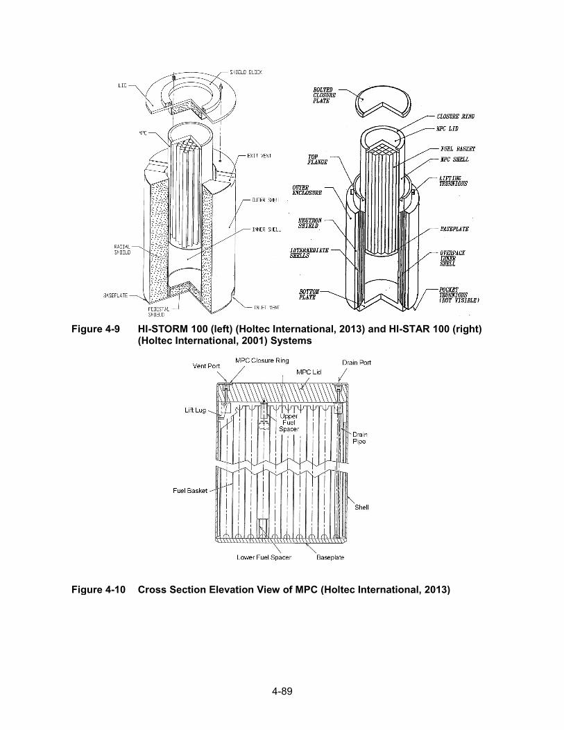
4-89
Figure 4-9 HI-STORM 100 (left) (Holtec International, 2013) and HI-STAR 100 (right) (Holtec International, 2001) Systems
Figure 4-10 Cross Section Elevation View of MPC (Holtec International, 2013)

4-90
(a) MPC-24/24E/24EF (b) MPC-32/32F
(c) MPC-68/68F/68FF
Figure 4-11 Cross Sectional Views of Different MPC Designs (Holtec International, 2013)
been installed between the periphery of the basket, the MPC shell, and the basket supports. For shorter SNF assemblies, upper and lower fuel spacers, as appropriate, maintain the axial position of the SNF assembly within the MPC basket.
All structural components in MPCs are made of a material designated by the manufacturer as Alloy X. Candidate Alloy X materials include Types 304, 304LN, 316, and 316LN austenitic stainless steels. All MPC components that are likely to come in contact with spent fuel pool water or the ambient environment are constructed from stainless steel, with the exception of neutron poison plates, aluminum seals on vent and drain port caps, and optional aluminum heat conduction elements.
Lifting lugs attached to the inside surface of the MPC canister shell (shown in Figure 4-10) permit placement of the empty MPC into the HI-TRAC transfer cask and also serve to axially locate the MPC lid before welding. They are not used to handle a loaded MPC, because the MPC lid is installed before any handling of a loaded canister.
The top end of the MPC incorporates a redundant closure system. The MPC lid is a circular plate (fabricated from one piece or two pieces—split top and bottom) that is welded to the MPC

4-91
outer shell. In the two-piece lid design, only the top piece comprises a part of the enclosure vessel’s pressure boundary; the bottom piece is attached to the top piece with a nonstructural, nonpressure-retaining weld and acts as a radiation shield. The lid is equipped with vent and drain ports that are used to remove moisture and air from the MPC and backfill the MPC with helium. The vent and drain ports are covered and seal-welded before the closure ring is installed. The closure ring is a circular ring edge-welded to the MPC shell and lid. The MPC lid provides sufficient rigidity to allow the entire MPC, loaded with spent nuclear fuel, to be lifted by the threaded holes in the MPC lid.
For fuel baskets not constructed of Metamic-HT™, either Boral® or Metamic™ neutron poison panels are used in the basket and are enclosed in Alloy X stainless steel sheathing that is stitch-welded to the MPC basket cell walls along their entire periphery. Thus, these neutron poison materials are contained in a tight, welded pocket enclosure. The shear strength of the pocket weld joint, which is an order of magnitude greater than the weight of a fuel assembly, ensures that the neutron poison and its enveloping sheathing pocket will maintain their as-installed position under all loading, storage, and transport conditions. In addition, the pocket joint detail ensures that fuel assembly insertion or withdrawal into or out of the MPC basket will not lead to a disconnection of the sheathing from the cell wall.
The MPC does not require any valves, gaskets or mechanical seals for confinement. Figure 4-12 shows the MPC confinement boundary. All components of the confinement boundary are safety significant and are fabricated entirely of stainless steel. The primary confinement boundary is defined by the outline formed by the sealed, cylindrical enclosure of the MPC shell (including any associated axial or circumferential welds) welded to the baseplate at the bottom, the MPC lid welded around the top circumference to the shell wall, and the port cover plates welded to the lid.
The helium backfill gas plays an important role in the MPC thermal performance. It fills all the spaces between solid components and provides an improved conduction medium relative to air for dissipating decay heat in the MPC. Furthermore, the pressurized helium environment within the MPC sustains a closed-loop thermo-siphon action, removing SNF decay heat by upward flow of helium through the storage cells.
Table 4-7 provides a generic evaluation of potential aging mechanisms and effects requiring management for specific components of the MPC. The AMPs that provide an acceptable approach to managing the aging effects are also identified in the table.
4.3.3 HI-STORM Concrete Overpack
The HI-STORM overpacks are thick-walled concrete cylindrical vessels enclosed in a steel shell. There are three base HI-STORM overpack designs: (i) HI-STORM 100, (ii) HI-STORM 100S, and (iii) HI-STORM 100S Version B. The significant differences amongthe three are overpack height, MPC pedestal height, location of the air outlet ducts, and verticalalignment of the inlet and outlet air ducts. The HI-STORM 100S Version B overpack designdoes not include a concrete-filled pedestal to support the MPC. Instead, the MPC rests upon asteel plate that maintains the MPC sufficiently above the inlet air ducts to prevent directradiation shine through the ducts. Figure 4-13 shows cross sectional views of theHI-STORM 100 and 100S overpacks. The HI-STORM 100A and 100SA overpack designs arethe anchored variant of the HI-STORM 100 and 100S designs.

4-92
Figure 4-12 MPC Confinement Boundary (Holtec International, 2013)
Figure 4-13 Cross Sectional Views of the HI-STORM 100 and 100S Overpacks with an MPC Inserted (Holtec International, 2013)
A base HI-STORM overpack design is capable of storing each type of MPC. The overpack inner shell is provided with channels distributed around the inner cavity that provide guidance for MPC insertion and removal, and a flexible medium to absorb some of the impact during a tipover. They also allow the flow of cooling air through the overpack. The main structural function of the HI-STORM overpack is provided by carbon steel, and the main shielding function is provided by concrete. The concrete, enclosed by cylindrical inner and outer steel shells, a thick baseplate, and a top plate, is specified to provide the necessary shielding properties and compressive strength. The overpack lid has appropriate concrete shielding to provide neutron and gamma attenuation in the vertical direction.

4-93
The HI-STORM overpack has air ducts to allow for passive natural convection cooling of the contained MPC. A minimum of four air inlets and four air outlets are located at the lower and upper extremities of the storage system, respectively. The vertical annulus between the MPC and the inner shell of the overpack facilitates an upward flow of air by buoyancy forces, drawing ambient air from the inlet vents and releasing it from the outlet vents at the top of the HI-STORM storage system. The annulus ventilation flow cools the hot MPC surfaces and transfers decay heat to the outside environment.
The principal function of the concrete is to provide shielding against gamma and neutron radiation. However, it also imparts a large thermal inertia to the HI-STORM overpack, allowing it to moderate the rise in temperature of the system under hypothetical conditions when all ventilation passages are assumed to be blocked. The high thermal inertia characteristics of the HI-STORM concrete also control the temperature of the MPC in the event of a postulated fire accident at the ISFSI. Although the annular concrete mass in the overpack shell is not a structural member, it does act as an elastic/plastic filler of the intershell space.
Four threaded anchor blocks, located at 90-degree intervals around the circumference of the top of the overpack lid, are provided for lifting. The anchor blocks are integrally welded to the radial plates, which in turn are full-length welded to the overpack inner shell, outer shell, and baseplate (HI-STORM 100) or the inlet air duct horizontal plates (HI-STORM 100S).
The HI-STORM 100S Version B overpack design incorporates partial-length radial plates at the top of the overpack to secure the anchor blocks and uses both gussets and partial-length radial plates at the bottom of the overpack for structural stability. The overpack may also be lifted from the bottom using specially designed lifting transport devices, including hydraulic jacks, air pads, Hillman rollers, or other designs based on site-specific needs and capabilities.
For anchoring, the HI-STORM 100A overpack baseplate is extended to allow it to be attached to the reinforced concrete structure of the ISFSI. Sector lugs are bolted to the ISFSI pad using anchor studs. The lateral load-bearing capacity of the HI-STORM/pad interface is many times greater than the horizontal sliding force exerted on the cask under the postulated design-basis earthquake seismic event. Thus, the potential for lateral sliding of the HI-STORM 100A system during a seismic event is precluded, as is the potential for any bending action on the anchor studs.
The HI-STORM 100 system also includes a variant 100U underground module design. The HI-STORM 100U design provides storage of an MPC inside a cylindrical cavity located entirely below the top of the grade of the ISFSI. HI-STORM 100U comprises the cavity enclosure container, consisting of the container shell welded to the bottom plate and the container flange, and the closure lid, divider shell, insulation, and bearing pads, as well as the interfacing and proximate structures, such as interface pad, support foundation pad, subgrade surrounding the module, top surface pad, and retaining wall.
Table 4-8 provides a generic evaluation of potential aging mechanisms and effects requiring management for specific components of the HI-STORM overpack, respectively. The AMPs that provide an acceptable approach to managing the aging effects are also identified in the tables.
4.3.4 HI-STAR Metal Overpack
The HI-STAR 100 overpack is a sealed, thick-walled carbon and low-alloy steel cylindrical vessel. The overpack containment boundary is formed by an inner shell welded at the bottom to
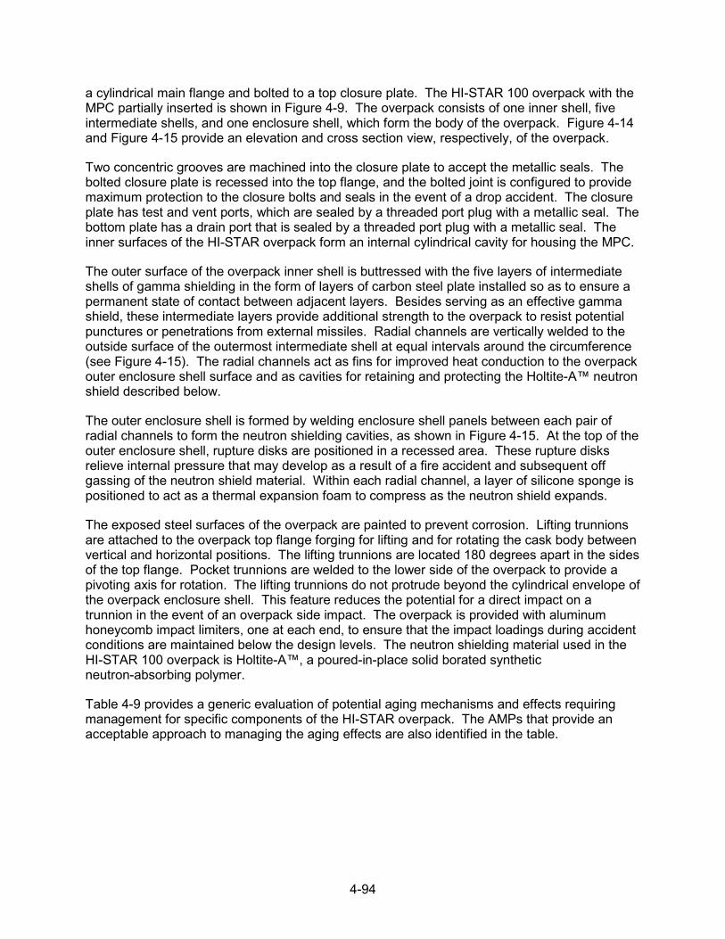
4-94
a cylindrical main flange and bolted to a top closure plate. The HI-STAR 100 overpack with the MPC partially inserted is shown in Figure 4-9. The overpack consists of one inner shell, five intermediate shells, and one enclosure shell, which form the body of the overpack. Figure 4-14 and Figure 4-15 provide an elevation and cross section view, respectively, of the overpack.
Two concentric grooves are machined into the closure plate to accept the metallic seals. The bolted closure plate is recessed into the top flange, and the bolted joint is configured to provide maximum protection to the closure bolts and seals in the event of a drop accident. The closure plate has test and vent ports, which are sealed by a threaded port plug with a metallic seal. The bottom plate has a drain port that is sealed by a threaded port plug with a metallic seal. The inner surfaces of the HI-STAR overpack form an internal cylindrical cavity for housing the MPC.
The outer surface of the overpack inner shell is buttressed with the five layers of intermediate shells of gamma shielding in the form of layers of carbon steel plate installed so as to ensure a permanent state of contact between adjacent layers. Besides serving as an effective gamma shield, these intermediate layers provide additional strength to the overpack to resist potential punctures or penetrations from external missiles. Radial channels are vertically welded to the outside surface of the outermost intermediate shell at equal intervals around the circumference (see Figure 4-15). The radial channels act as fins for improved heat conduction to the overpack outer enclosure shell surface and as cavities for retaining and protecting the Holtite-A™ neutron shield described below.
The outer enclosure shell is formed by welding enclosure shell panels between each pair of radial channels to form the neutron shielding cavities, as shown in Figure 4-15. At the top of the outer enclosure shell, rupture disks are positioned in a recessed area. These rupture disks relieve internal pressure that may develop as a result of a fire accident and subsequent off gassing of the neutron shield material. Within each radial channel, a layer of silicone sponge is positioned to act as a thermal expansion foam to compress as the neutron shield expands.
The exposed steel surfaces of the overpack are painted to prevent corrosion. Lifting trunnions are attached to the overpack top flange forging for lifting and for rotating the cask body between vertical and horizontal positions. The lifting trunnions are located 180 degrees apart in the sides of the top flange. Pocket trunnions are welded to the lower side of the overpack to provide a pivoting axis for rotation. The lifting trunnions do not protrude beyond the cylindrical envelope of the overpack enclosure shell. This feature reduces the potential for a direct impact on a trunnion in the event of an overpack side impact. The overpack is provided with aluminum honeycomb impact limiters, one at each end, to ensure that the impact loadings during accident conditions are maintained below the design levels. The neutron shielding material used in the HI-STAR 100 overpack is Holtite-A™, a poured-in-place solid borated synthetic neutron-absorbing polymer.
Table 4-9 provides a generic evaluation of potential aging mechanisms and effects requiring management for specific components of the HI-STAR overpack. The AMPs that provide an acceptable approach to managing the aging effects are also identified in the table.

4-95
Figure 4-14 HI-STAR 100 Overpack Elevation View (Holtec International, 2001)
Figure 4-15 HI-STAR 100 Overpack Cross Sectional View (Holtec International, 2001)

4-96
4.3.5 Transfer Cask
The HI-TRAC TC is a heavy-walled carbon steel cylindrical vessel composed of an inner shell and an outer shell with lead in between to provide gamma shielding (Holtec International, 2013). The TC also includes an exterior carbon steel water jacket for neutron shielding. There are four basic HI-TRAC TC designs: two standard designs, which are a 125-ton HI-TRAC 125 and a 100-ton HI-TRAC 100, and two optional designs with a dual-purpose lid for loading and transferoperations, which are the 125-ton HI-TRAC 125D and the 100-ton HI-TRAC 100D. Figure 4-16shows the cross section of a standard HI-TRAC 125 TC with both a pool lid and a transfer lidattached. Since all the MPCs have the same outer diameter, the inner diameter of all HI-TRACTCs is the same. However, the external dimensions of the HI-TRAC TCs are different, becausethe 100-ton TCs have a reduced thickness of lead and water shielding.
The main structural function of the HI-TRAC TCs is provided by carbon steel, and the main neutron and gamma shielding functions are provided by water and lead, respectively. The top lid of the HI-TRAC 125 and HI-TRAC 125D TCs contains additional Holtite-A™ neutron shielding material. The MPC access hole through the HI-TRAC top lid allows the lowering or raising of the MPC between the TC and the overpack.
The standard design HI-TRAC TCs (including HI-TRAC 100 and HI-TRAC 125) include two bottom lids (pool lid and transfer lid). The pool lid is bolted to the bottom flange of the HI-TRAC and is used during MPC fuel loading and sealing operations. In addition to providing shielding in the axial direction, the pool lid incorporates a seal between the pool lid and the bottom flange that is designed to hold clean demineralized water in the HI-TRAC inner cavity. The seal provides a barrier from contamination of the exterior of the MPC by the spent fuel pool water. After the MPC has been drained, dried, and sealed, the pool lid is removed and the transfer lid is attached. The transfer lid incorporates two sliding doors that allow the opening of the HI-TRAC bottom for the MPC to be raised or lowered. Unlike the standard designs, the HI-TRAC 100D and HI-TRAC 125D TCs do not require swapping the pool lid for a transfer lid to facilitate transfer of the MPC. The HI-STORM mating device is used to remove the pool lid during MPC transfer operations.
In the standard designs, the HI-TRAC TC is equipped with two lifting trunnions located below the top flange and two pocket trunnions located above the bottom flange. The lifting trunnions, made of nickel alloy or stainless steel, are used to vertically handle the HI-TRAC TC. The carbon steel pocket trunnions provide a pivot point for the rotation of the HI-TRAC TC for downending or upending the HI-TRAC TC with a loaded MPC. The HI-TRAC 100D and HI-TRAC 125D TCs are equipped with only lifting trunnions.
Table 4-10 provides a generic evaluation of potential aging mechanisms and effects requiring management for specific components of the HI-TRAC TC. The AMPs that provide an acceptable approach to managing the aging effects are also identified in the table.
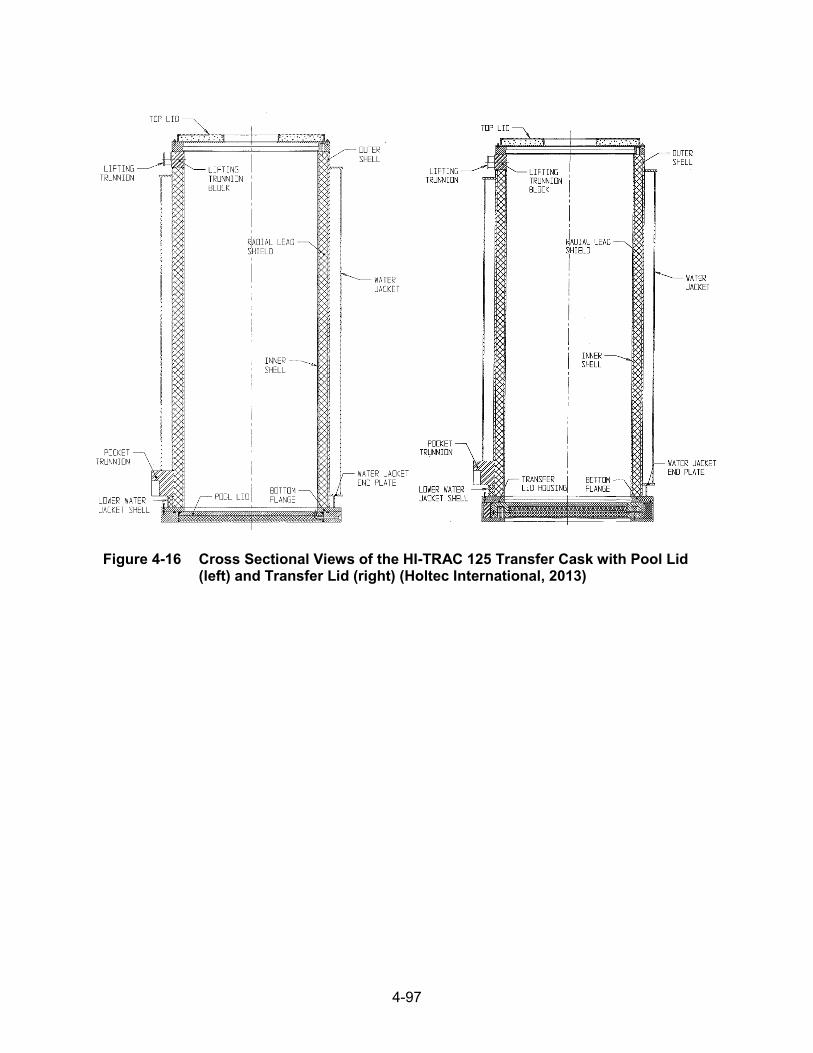
4-97
Figure 4-16 Cross Sectional Views of the HI-TRAC 125 Transfer Cask with Pool Lid (left) and Transfer Lid (right) (Holtec International, 2013)
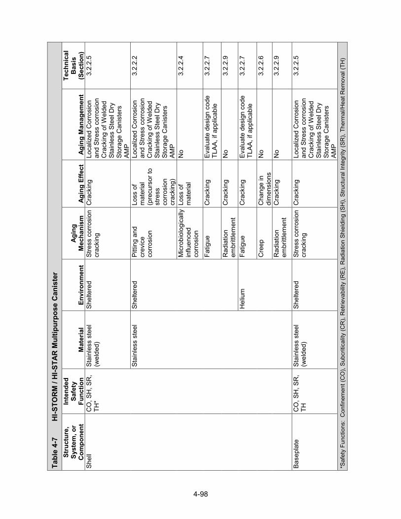
4-98
Tabl
e 4-
7 H
I-STO
RM
/ HI
-STA
R M
ultip
urpo
se C
anis
ter
Stru
ctur
e,
Syst
em, o
r C
ompo
nent
Inte
nded
Sa
fety
Fu
nctio
n M
ater
ial
Envi
ronm
ent
Agin
g M
echa
nism
Ag
ing
Effe
ct
Agin
g M
anag
emen
t
Tech
nica
l B
asis
(S
ectio
n)
Shel
l C
O, S
H, S
R,
TH*
Stai
nles
s st
eel
(wel
ded)
Sh
elte
red
Stre
ss c
orro
sion
cr
acki
ng
Cra
ckin
g Lo
caliz
ed C
orro
sion
an
d St
ress
cor
rosi
on
Cra
ckin
g of
Wel
ded
Stai
nles
s St
eel D
ry
Stor
age
Can
iste
rs
AMP
3.2.
2.5
Stai
nles
s st
eel
Shel
tere
d Pi
tting
and
cr
evic
e co
rrosi
on
Loss
of
mat
eria
l (p
recu
rsor
to
stre
ss
corro
sion
cr
acki
ng)
Loca
lized
Cor
rosi
on
and
Stre
ss c
orro
sion
C
rack
ing
of W
elde
d St
ainl
ess
Stee
l Dry
St
orag
e C
anis
ters
AM
P
3.2.
2.2
Mic
robi
olog
ical
ly
influ
ence
d co
rrosi
on
Loss
of
mat
eria
l N
o 3.
2.2.
4
Fatig
ue
Cra
ckin
g Ev
alua
te d
esig
n co
de
TLAA
, if a
pplic
able
3.
2.2.
7
Rad
iatio
n em
britt
lem
ent
Cra
ckin
g N
o 3.
2.2.
9
Hel
ium
Fa
tigue
C
rack
ing
Eval
uate
des
ign
code
TL
AA, i
f app
licab
le
3.2.
2.7
Cre
ep
Cha
nge
in
dim
ensi
ons
No
3.2.
2.6
Rad
iatio
n em
britt
lem
ent
Cra
ckin
g N
o 3.
2.2.
9
Base
plat
e C
O, S
H, S
R,
TH
Stai
nles
s st
eel
(wel
ded)
Sh
elte
red
Stre
ss c
orro
sion
cr
acki
ng
Cra
ckin
g Lo
caliz
ed C
orro
sion
an
d St
ress
cor
rosi
on
Cra
ckin
g of
Wel
ded
Stai
nles
s St
eel D
ry
Stor
age
Can
iste
rs
AMP
3.2.
2.5
*Saf
ety
Func
tions
: C
onfin
emen
t (C
O),
Subc
ritic
ality
(CR
), R
etrie
vabi
lity
(RE)
, Rad
iatio
n Sh
ield
ing
(SH
), St
ruct
ural
Inte
grity
(SR
), Th
erm
al/H
eat R
emov
al (T
H)

4-99
Tabl
e 4-
7 H
I-STO
RM
/ HI
-STA
R M
ultip
urpo
se C
anis
ter (continued)
Stru
ctur
e,
Syst
em, o
r C
ompo
nent
Inte
nded
Sa
fety
Fu
nctio
n M
ater
ial
Envi
ronm
ent
Agin
g M
echa
nism
Ag
ing
Effe
ct
Agin
g M
anag
emen
t
Tech
nica
l B
asis
(S
ectio
n)
Base
plat
e C
O, S
H, S
R,
TH
Stai
nles
s st
eel
Shel
tere
d Pi
tting
and
cr
evic
e co
rrosi
on
Loss
of
mat
eria
l (p
recu
rsor
to
stre
ss
corro
sion
cr
acki
ng)
Loca
lized
Cor
rosi
on
and
Stre
ss c
orro
sion
C
rack
ing
of W
elde
d St
ainl
ess
Stee
l Dry
St
orag
e C
anis
ters
AM
P
3.2.
2.2
Mic
robi
olog
ical
ly
influ
ence
d co
rrosi
on
Loss
of
mat
eria
l N
o 3.
2.2.
4
Fatig
ue
Cra
ckin
g Ev
alua
te d
esig
n co
de
TLAA
, if a
pplic
able
3.
2.2.
7
Rad
iatio
n em
britt
lem
ent
Cra
ckin
g N
o 3.
2.2.
9
Hel
ium
Fa
tigue
C
rack
ing
Eval
uate
des
ign
code
TL
AA, i
f app
licab
le
3.2.
2.7
Cre
ep
Cha
nge
in
dim
ensi
ons
No
3.2.
2.6
Rad
iatio
n em
britt
lem
ent
Cra
ckin
g N
o 3.
2.2.
9
Lid
CO
, SH
, SR
, TH
St
ainl
ess
stee
l (w
elde
d)
Shel
tere
d St
ress
cor
rosi
on
crac
king
C
rack
ing
Loca
lized
Cor
rosi
on
and
Stre
ss c
orro
sion
C
rack
ing
of W
elde
d St
ainl
ess
Stee
l Dry
St
orag
e C
anis
ters
AM
P
3.2.
2.5
Stai
nles
s st
eel
Shel
tere
d Pi
tting
and
cr
evic
e co
rrosi
on
Loss
of
mat
eria
l (p
recu
rsor
to
stre
ss
corro
sion
cr
acki
ng)
Loca
lized
Cor
rosi
on
and
Stre
ss c
orro
sion
C
rack
ing
of W
elde
d St
ainl
ess
Stee
l Dry
St
orag
e C
anis
ters
AM
P
3.2.
2.2
Mic
robi
olog
ical
ly
influ
ence
d co
rrosi
on
Loss
of
mat
eria
l N
o 3.
2.2.
4

4-100
Tabl
e 4-
7 H
I-STO
RM
/ HI
-STA
R M
ultip
urpo
se C
anis
ter (continued)
Stru
ctur
e,
Syst
em, o
r C
ompo
nent
Inte
nded
Sa
fety
Fu
nctio
n M
ater
ial
Envi
ronm
ent
Agin
g M
echa
nism
Ag
ing
Effe
ct
Agin
g M
anag
emen
t
Tech
nica
l B
asis
(S
ectio
n)
Lid
CO
, SH
, SR
, TH
St
ainl
ess
stee
l Sh
elte
red
Fatig
ue
Cra
ckin
g Ev
alua
te d
esig
n co
de
TLAA
, if a
pplic
able
3.
2.2.
7
Rad
iatio
n em
britt
lem
ent
Cra
ckin
g N
o 3.
2.2.
9
Hel
ium
Fa
tigue
C
rack
ing
Eval
uate
des
ign
code
TL
AA, i
f app
licab
le
3.2.
2.7
Cre
ep
Cha
nge
in
dim
ensi
ons
No
3.2.
2.6
Rad
iatio
n em
britt
lem
ent
Cra
ckin
g N
o 3.
2.2.
9
Clo
sure
ring
C
O
Stai
nles
s st
eel
(wel
ded)
Sh
elte
red
Stre
ss c
orro
sion
cr
acki
ng
Cra
ckin
g Lo
caliz
ed C
orro
sion
an
d St
ress
cor
rosi
on
Cra
ckin
g of
Wel
ded
Stai
nles
s St
eel D
ry
Stor
age
Can
iste
rs
AMP
3.2.
2.5
Stai
nles
s st
eel
Shel
tere
d Pi
tting
and
cr
evic
e co
rrosi
on
Loss
of
mat
eria
l (p
recu
rsor
to
stre
ss
corro
sion
cr
acki
ng)
Loca
lized
Cor
rosi
on
and
Stre
ss c
orro
sion
C
rack
ing
of W
elde
d St
ainl
ess
Stee
l Dry
St
orag
e C
anis
ters
AM
P
3.2.
2.2
Mic
robi
olog
ical
ly
influ
ence
d co
rrosi
on
Loss
of
mat
eria
l N
o 3.
2.2.
4
Fatig
ue
Cra
ckin
g Ev
alua
te d
esig
n co
de
TLAA
, if a
pplic
able
3.
2.2.
7
Rad
iatio
n em
britt
lem
ent
Cra
ckin
g N
o 3.
2.2.
9
Port
cove
r pla
tes
CO
St
ainl
ess
stee
l (w
elde
d)
Hel
ium
Th
erm
al a
ging
Lo
ss o
f fra
ctur
e to
ughn
ess
and
loss
of d
uctil
ity
No
3.2.
2.8

4-101
Tabl
e 4-
7 H
I-STO
RM
/ HI
-STA
R M
ultip
urpo
se C
anis
ter (continued)
Stru
ctur
e,
Syst
em, o
r C
ompo
nent
Inte
nded
Sa
fety
Fu
nctio
n M
ater
ial
Envi
ronm
ent
Agin
g M
echa
nism
Ag
ing
Effe
ct
Agin
g M
anag
emen
t
Tech
nica
l B
asis
(S
ectio
n)
Port
cove
r pla
tes
CO
St
ainl
ess
stee
l H
eliu
m
Fatig
ue
Cra
ckin
g Ev
alua
te d
esig
n co
de
TLAA
, if a
pplic
able
3.
2.2.
7
Cre
ep
Cha
nge
in
dim
ensi
ons
No
3.2.
2.6
Rad
iatio
n em
britt
lem
ent
Cra
ckin
g N
o 3.
2.2.
9
Bask
et c
ell p
late
s C
R, S
H, S
R,
TH
Stai
nles
s st
eel
(wel
ded)
H
eliu
m
Ther
mal
agi
ng
Loss
of
fract
ure
toug
hnes
s an
d lo
ss o
f duc
tility
No
3.2.
2.8
Stai
nles
s st
eel
Hel
ium
Fa
tigue
C
rack
ing
Eval
uate
des
ign
code
TL
AA, i
f app
licab
le
3.2.
2.7
Cre
ep
Cha
nge
in
dim
ensi
ons
No
3.2.
2.6
Rad
iatio
n em
britt
lem
ent
Cra
ckin
g N
o 3.
2.2.
9
BWR
fuel
bas
ket
CR
, SH
, SR
, TH
M
etam
ic-H
T™
Hel
ium
Bo
ron
depl
etio
n R
educ
tion
of
neut
ron-
abso
rbin
g ca
paci
ty
No;
a T
LAA
may
be
requ
ired
3.4.
2.4
Ther
mal
agi
ng
Loss
of
stre
ngth
N
o 3.
4.2.
6
Gen
eral
co
rrosi
on
Loss
of
mat
eria
l N
o 3.
4.2.
1
Cre
ep
Cha
nge
in
dim
ensi
ons
No
3.4.
2.5
Rad
iatio
n em
britt
lem
ent
Loss
of
fract
ure
toug
hnes
s an
d lo
ss o
f duc
tility
No
3.4.
2.7

4-102
Tabl
e 4-
7 H
I-STO
RM
/ HI
-STA
R M
ultip
urpo
se C
anis
ter (continued)
Stru
ctur
e,
Syst
em, o
r C
ompo
nent
Inte
nded
Sa
fety
Fu
nctio
n M
ater
ial
Envi
ronm
ent
Agin
g M
echa
nism
Ag
ing
Effe
ct
Agin
g M
anag
emen
t
Tech
nica
l B
asis
(S
ectio
n)
Neu
tron
abso
rber
C
R, S
H, T
H
Bora
l®
Hel
ium
Bo
ron
depl
etio
n R
educ
tion
of
neut
ron-
abso
rbin
g ca
paci
ty
No;
a T
LAA
may
be
requ
ired
3.4.
2.4
Ther
mal
agi
ng
Loss
of
stre
ngth
N
o 3.
4.2.
6
Neu
tron
abso
rber
C
R, S
H, T
H
Bora
l®
Hel
ium
W
et c
orro
sion
an
d bl
iste
ring
Cha
nge
in
dim
ensi
ons
No
3.4.
2.3
Cre
ep
Cha
nge
in
dim
ensi
ons
No
3.4.
2.5
Rad
iatio
n em
britt
lem
ent
Loss
of
fract
ure
toug
hnes
s an
d lo
ss o
f duc
tility
No
3.4.
2.7
Met
amic
TM
Hel
ium
Bo
ron
depl
etio
n R
educ
tion
of
neut
ron-
abso
rbin
g ca
paci
ty
No;
a T
LAA
may
be
requ
ired
3.4.
2.4
Ther
mal
agi
ng
Loss
of
stre
ngth
N
o 3.
4.2.
6
Gen
eral
co
rrosi
on
Loss
of
mat
eria
l N
o 3.
4.2.
1
Cre
ep
Cha
nge
in
dim
ensi
ons
No
3.4.
2.5
Rad
iatio
n em
britt
lem
ent
Loss
of
fract
ure
toug
hnes
s an
d lo
ss o
f duc
tility
No
3.4.
2.7
Dra
in a
nd v
ent
shie
ld b
lock
s SH
St
ainl
ess
stee
l (w
elde
d)
Hel
ium
Th
erm
al a
ging
Lo
ss o
f fra
ctur
e to
ughn
ess
and
loss
of d
uctil
ity
No
3.2.
2.8
4-103
Tabl
e 4-
7 H
I-STO
RM
/ HI
-STA
R M
ultip
urpo
se C
anis
ter (continued)
Stru
ctur
e,
Syst
em, o
r C
ompo
nent
Inte
nded
Sa
fety
Fu
nctio
n M
ater
ial
Envi
ronm
ent
Agin
g M
echa
nism
Ag
ing
Effe
ct
Agin
g M
anag
emen
t
Tech
nica
l B
asis
(S
ectio
n)
Dra
in a
nd v
ent
shie
ld b
lock
s SH
St
ainl
ess
stee
l H
eliu
m
Cre
ep
Cha
nge
in
dim
ensi
ons
No
3.2.
2.6
Rad
iatio
n em
britt
lem
ent
Cra
ckin
g N
o 3.
2.2.
9
Botto
m p
ortio
n of
tw
o-pi
ece
lid
SH
Stai
nles
s st
eel
(wel
ded)
H
eliu
m
Ther
mal
agi
ng
Loss
of
fract
ure
toug
hnes
s an
d lo
ss o
f duc
tility
No
3.2.
2.8
Stai
nles
s st
eel
Hel
ium
C
reep
C
hang
e in
di
men
sion
s N
o 3.
2.2.
6
Rad
iatio
n em
britt
lem
ent
Cra
ckin
g N
o 3.
2.2.
9
Stee
l coa
ted
with
st
ainl
ess
stee
l
Hel
ium
Th
erm
al a
ging
Lo
ss o
f fra
ctur
e to
ughn
ess
and
loss
of d
uctil
ity
No
3.2.
1.8
Cre
ep
Cha
nge
in
dim
ensi
ons
No
3.2.
1.6
Rad
iatio
n em
britt
lem
ent
Cra
ckin
g N
o 3.
2.1.
9
Gen
eral
co
rrosi
on
Loss
of
mat
eria
l N
o 3.
2.2.
1
Shea
thin
g SR
St
ainl
ess
stee
l (w
elde
d)
Hel
ium
Th
erm
al a
ging
Lo
ss o
f fra
ctur
e to
ughn
ess
and
loss
of d
uctil
ity
No
3.2.
2.8
Stai
nles
s st
eel
Hel
ium
C
reep
C
hang
e in
di
men
sion
s N
o 3.
2.2.
6
Rad
iatio
n em
britt
lem
ent
Cra
ckin
g N
o 3.
2.2.
9

4-104
Tabl
e 4-
7 H
I-STO
RM
/ HI
-STA
R M
ultip
urpo
se C
anis
ter (continued)
Stru
ctur
e,
Syst
em, o
r C
ompo
nent
Inte
nded
Sa
fety
Fu
nctio
n M
ater
ial
Envi
ronm
ent
Agin
g M
echa
nism
Ag
ing
Effe
ct
Agin
g M
anag
emen
t
Tech
nica
l B
asis
(S
ectio
n)
Bask
et s
uppo
rts
SR, C
R
Stai
nles
s st
eel
(wel
ded)
H
eliu
m
Ther
mal
agi
ng
Loss
of
fract
ure
toug
hnes
s an
d lo
ss o
f duc
tility
No
3.2.
2.8
Stai
nles
s st
eel
Hel
ium
Fa
tigue
C
rack
ing
Eval
uate
des
ign
code
TL
AA, i
f app
licab
le
3.2.
2.7
Cre
ep
Cha
nge
in
dim
ensi
ons
No
3.2.
2.6
Rad
iatio
n em
britt
lem
ent
Cra
ckin
g N
o 3.
2.2.
9
Lifti
ng lu
gs
SR
Stai
nles
s st
eel
(wel
ded)
H
eliu
m
Ther
mal
agi
ng
Loss
of
fract
ure
toug
hnes
s an
d lo
ss o
f duc
tility
No
3.2.
2.8
Stai
nles
s st
eel
Hel
ium
C
reep
C
hang
e in
di
men
sion
s N
o 3.
2.2.
6
Rad
iatio
n em
britt
lem
ent
Cra
ckin
g N
o 3.
2.2.
9
Lifti
ng lu
g ba
se
plat
e SR
St
ainl
ess
stee
l (w
elde
d)
Hel
ium
Th
erm
al a
ging
Lo
ss o
f fra
ctur
e to
ughn
ess
and
loss
of d
uctil
ity
No
3.2.
2.8
Stai
nles
s st
eel
Hel
ium
C
reep
C
hang
e in
di
men
sion
s N
o 3.
2.2.
6
Rad
iatio
n em
britt
lem
ent
Cra
ckin
g N
o 3.
2.2.
9
Upp
er fu
el s
pace
r co
lum
n SR
St
ainl
ess
stee
l (w
elde
d)
Hel
ium
Th
erm
al a
ging
Lo
ss o
f fra
ctur
e to
ughn
ess
and
loss
of d
uctil
ity
No
3.2.
2.8
Stai
nles
s st
eel
Hel
ium
Fa
tigue
C
rack
ing
Eval
uate
des
ign
code
TL
AA, i
f app
licab
le
3.2.
2.7
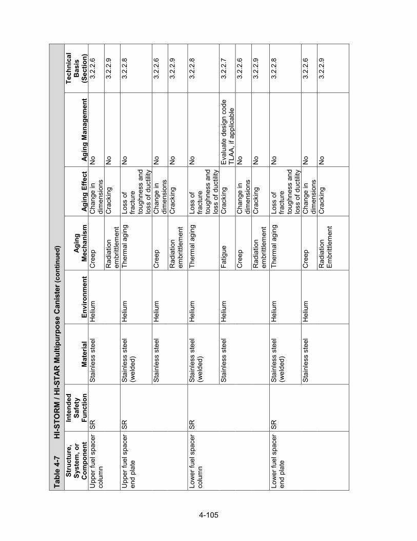
4-105
Tabl
e 4-
7 H
I-STO
RM
/ HI
-STA
R M
ultip
urpo
se C
anis
ter (continued)
Stru
ctur
e,
Syst
em, o
r C
ompo
nent
Inte
nded
Sa
fety
Fu
nctio
n M
ater
ial
Envi
ronm
ent
Agin
g M
echa
nism
Ag
ing
Effe
ct
Agin
g M
anag
emen
t
Tech
nica
l B
asis
(S
ectio
n)
Upp
er fu
el s
pace
r co
lum
n SR
St
ainl
ess
stee
l H
eliu
m
Cre
ep
Cha
nge
in
dim
ensi
ons
No
3.2.
2.6
Rad
iatio
n em
britt
lem
ent
Cra
ckin
g N
o 3.
2.2.
9
Upp
er fu
el s
pace
r en
d pl
ate
SR
Stai
nles
s st
eel
(wel
ded)
H
eliu
m
Ther
mal
agi
ng
Loss
of
fract
ure
toug
hnes
s an
d lo
ss o
f duc
tility
No
3.2.
2.8
Stai
nles
s st
eel
Hel
ium
C
reep
C
hang
e in
di
men
sion
s N
o 3.
2.2.
6
Rad
iatio
n em
britt
lem
ent
Cra
ckin
g N
o 3.
2.2.
9
Low
er fu
el s
pace
r co
lum
n SR
St
ainl
ess
stee
l (w
elde
d)
Hel
ium
Th
erm
al a
ging
Lo
ss o
f fra
ctur
e to
ughn
ess
and
loss
of d
uctil
ity
No
3.2.
2.8
Stai
nles
s st
eel
Hel
ium
Fa
tigue
C
rack
ing
Eval
uate
des
ign
code
TL
AA, i
f app
licab
le
3.2.
2.7
Cre
ep
Cha
nge
in
dim
ensi
ons
No
3.2.
2.6
Rad
iatio
n em
britt
lem
ent
Cra
ckin
g N
o 3.
2.2.
9
Low
er fu
el s
pace
r en
d pl
ate
SR
Stai
nles
s st
eel
(wel
ded)
H
eliu
m
Ther
mal
agi
ng
Loss
of
fract
ure
toug
hnes
s an
d lo
ss o
f duc
tility
No
3.2.
2.8
Stai
nles
s st
eel
Hel
ium
C
reep
C
hang
e in
di
men
sion
s N
o 3.
2.2.
6
Rad
iatio
n Em
britt
lem
ent
Cra
ckin
g N
o 3.
2.2.
9
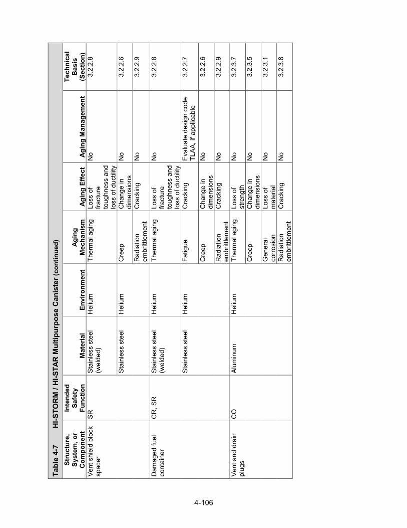
4-106
Tabl
e 4-
7 H
I-STO
RM
/ HI
-STA
R M
ultip
urpo
se C
anis
ter (continued)
Stru
ctur
e,
Syst
em, o
r C
ompo
nent
Inte
nded
Sa
fety
Fu
nctio
n M
ater
ial
Envi
ronm
ent
Agin
g M
echa
nism
Ag
ing
Effe
ct
Agin
g M
anag
emen
t
Tech
nica
l B
asis
(S
ectio
n)
Vent
shi
eld
bloc
k sp
acer
SR
St
ainl
ess
stee
l (w
elde
d)
Hel
ium
Th
erm
al a
ging
Lo
ss o
f fra
ctur
e to
ughn
ess
and
loss
of d
uctil
ity
No
3.2.
2.8
Stai
nles
s st
eel
Hel
ium
C
reep
C
hang
e in
di
men
sion
s N
o 3.
2.2.
6
Rad
iatio
n em
britt
lem
ent
Cra
ckin
g N
o 3.
2.2.
9
Dam
aged
fuel
co
ntai
ner
CR
, SR
St
ainl
ess
stee
l (w
elde
d)
Hel
ium
Th
erm
al a
ging
Lo
ss o
f fra
ctur
e to
ughn
ess
and
loss
of d
uctil
ity
No
3.2.
2.8
Stai
nles
s st
eel
Hel
ium
Fa
tigue
C
rack
ing
Eval
uate
des
ign
code
TL
AA, i
f app
licab
le
3.2.
2.7
Cre
ep
Cha
nge
in
dim
ensi
ons
No
3.2.
2.6
Rad
iatio
n em
britt
lem
ent
Cra
ckin
g N
o 3.
2.2.
9
Vent
and
dra
in
plug
s C
O
Alum
inum
H
eliu
m
Ther
mal
agi
ng
Loss
of
stre
ngth
N
o 3.
2.3.
7
Cre
ep
Cha
nge
in
dim
ensi
ons
No
3.2.
3.5
Gen
eral
co
rrosi
on
Loss
of
mat
eria
l N
o 3.
2.3.
1
Rad
iatio
n em
britt
lem
ent
Cra
ckin
g N
o 3.
2.3.
8

4-107
Tabl
e 4-
8 H
I-STO
RM
100
Ove
rpac
k St
ruct
ure,
Sy
stem
, or
Com
pone
nt
Inte
nded
Sa
fety
Fu
nctio
n M
ater
ial
Envi
ronm
ent
Agin
g M
echa
nism
Ag
ing
Effe
ct
Agin
g M
anag
emen
t
Tech
nica
l B
asis
(S
ectio
n)
Con
cret
e sh
ield
: ra
dial
shi
eld,
sh
ield
blo
ck,
pede
stal
shi
eld,
lid
shi
eld
SH*
Con
cret
e Fu
lly e
ncas
ed
(ste
el)
Del
ayed
ettr
ingi
te
form
atio
n Lo
ss o
f mat
eria
l (s
pallin
g,
scal
ing)
No
3.5.
1.13
Cra
ckin
g N
o 3.
5.1.
13
Loss
of s
treng
th
No
3.5.
1.13
Rad
iatio
n da
mag
e C
rack
ing
No
3.5.
1.9
Loss
of s
treng
th
No
3.5.
1.9
Rea
ctio
n w
ith
aggr
egat
es
Cra
ckin
g N
o 3.
5.1.
3
Loss
of s
treng
th
No
3.5.
1.3
Shie
ld b
lock
(b
ase,
ring
, sh
ell)
SH
Stee
l Ai
r—ou
tdoo
r G
ener
al c
orro
sion
Lo
ss o
f mat
eria
l M
onito
ring
of
Met
allic
Sur
face
s AM
P
3.2.
1.1
Mic
robi
olog
ical
ly
influ
ence
d co
rrosi
on
Loss
of m
ater
ial
No
3.2.
1.4
Pitti
ng a
nd c
revi
ce
corro
sion
Lo
ss o
f mat
eria
l M
onito
ring
of
Met
allic
Sur
face
s AM
P
3.2.
1.2
Rad
iatio
n em
britt
lem
ent
Cra
ckin
g N
o 3.
2.1.
9
Embe
dded
(c
oncr
ete)
R
adia
tion
Embr
ittle
men
t C
rack
ing
No
3.2.
1.9
Lid
inne
r rin
g SH
, SR
St
eel
Embe
dded
(c
oncr
ete)
R
adia
tion
embr
ittle
men
t C
rack
ing
No
3.2.
1.9
*Saf
ety
Func
tions
: C
onfin
emen
t (C
O),
Subc
ritic
ality
(CR
), R
etrie
vabi
lity
(RE)
, Rad
iatio
n Sh
ield
ing
(SH
), St
ruct
ural
Inte
grity
(SR
), Th
erm
al/H
eat R
emov
al (T
H)

4-108
Tabl
e 4-
8 H
I-STO
RM 1
00 O
verp
ack (con
tinued)
Stru
ctur
e,
Syst
em, o
r C
ompo
nent
Inte
nded
Sa
fety
Fu
nctio
n M
ater
ial
Envi
ronm
ent
Agin
g M
echa
nism
Ag
ing
Effe
ct
Agin
g M
anag
emen
t
Tech
nica
l B
asis
(S
ectio
n)
Lid
oute
r rin
g SH
, SR
St
eel
Air—
outd
oor
Gen
eral
cor
rosi
on
Loss
of m
ater
ial
Mon
itorin
g of
M
etal
lic S
urfa
ces
AMP
3.2.
1.1
Mic
robi
olog
ical
ly
influ
ence
d co
rrosi
on
Loss
of m
ater
ial
No
3.2.
1.4
Pitti
ng a
nd c
revi
ce
corro
sion
Lo
ss o
f mat
eria
l M
onito
ring
of
Met
allic
Sur
face
s AM
P
3.2.
1.2
Rad
iatio
n em
britt
lem
ent
Cra
ckin
g N
o 3.
2.1.
9
Shie
ld s
hell
SH
Stee
l Em
bedd
ed
(con
cret
e)
Rad
iatio
n em
britt
lem
ent
Cra
ckin
g N
o 3.
2.1.
9
Gam
ma
shie
ld
cros
s pl
ates
SH
St
ainl
ess
stee
l (w
elde
d)
Shel
tere
d St
ress
cor
rosi
on
crac
king
C
rack
ing
Mon
itorin
g of
M
etal
lic S
urfa
ces
AMP
3.2.
2.5
Air—
outd
oor
Stre
ss c
orro
sion
cr
acki
ng
Cra
ckin
g M
onito
ring
of
Met
allic
Sur
face
s AM
P
3.2.
2.5
Stai
nles
s st
eel
Shel
tere
d M
icro
biol
ogic
ally
in
fluen
ced
corro
sion
Lo
ss o
f mat
eria
l N
o 3.
2.2.
4
Pitti
ng a
nd c
revi
ce
corro
sion
Lo
ss o
f mat
eria
l (p
recu
rsor
to
stre
ss c
orro
sion
cr
acki
ng)
Mon
itorin
g of
M
etal
lic S
urfa
ces
AMP
3.2.
2.2
Rad
iatio
n em
britt
lem
ent
Cra
ckin
g N
o 3.
2.2.
9
Air—
outd
oor
Mic
robi
olog
ical
ly
influ
ence
d co
rrosi
on
Loss
of m
ater
ial
No
3.2.
2.4
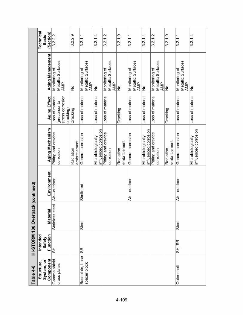
4-109
Tabl
e 4-
8 H
I-STO
RM 1
00 O
verp
ack (con
tinued)
Stru
ctur
e,
Syst
em, o
r C
ompo
nent
Inte
nded
Sa
fety
Fu
nctio
n M
ater
ial
Envi
ronm
ent
Agin
g M
echa
nism
Ag
ing
Effe
ct
Agin
g M
anag
emen
t
Tech
nica
l B
asis
(S
ectio
n)
Gam
ma
shie
ld
cros
s pl
ates
SH
St
ainl
ess
stee
l Ai
r—ou
tdoo
r Pi
tting
and
cre
vice
co
rrosi
on
Loss
of m
ater
ial
(pre
curs
or to
st
ress
cor
rosi
on
crac
king
)
Mon
itorin
g of
M
etal
lic S
urfa
ces
AMP
3.2.
2.2
Rad
iatio
n em
britt
lem
ent
Cra
ckin
g N
o 3.
2.2.
9
Base
plat
e, b
ase
spac
er b
lock
SR
St
eel
Shel
tere
d G
ener
al c
orro
sion
Lo
ss o
f mat
eria
l M
onito
ring
of
Met
allic
Sur
face
s AM
P
3.2.
1.1
Mic
robi
olog
ical
ly
influ
ence
d co
rrosi
on
Loss
of m
ater
ial
No
3.2.
1.4
Pitti
ng a
nd c
revi
ce
corro
sion
Lo
ss o
f mat
eria
l M
onito
ring
of
Met
allic
Sur
face
s AM
P
3.2.
1.2
Rad
iatio
n em
britt
lem
ent
Cra
ckin
g N
o 3.
2.1.
9
Air—
outd
oor
Gen
eral
cor
rosi
on
Loss
of m
ater
ial
Mon
itorin
g of
M
etal
lic S
urfa
ces
AMP
3.2.
1.1
Mic
robi
olog
ical
ly
influ
ence
d co
rrosi
on
Loss
of m
ater
ial
No
3.2.
1.4
Pitti
ng a
nd c
revi
ce
corro
sion
Lo
ss o
f mat
eria
l M
onito
ring
of
Met
allic
Sur
face
s AM
P
3.2.
1.2
Rad
iatio
n em
britt
lem
ent
Cra
ckin
g N
o 3.
2.1.
9
Out
er s
hell
SH, S
R
Stee
l Ai
r—ou
tdoo
r G
ener
al c
orro
sion
Lo
ss o
f mat
eria
l M
onito
ring
of
Met
allic
Sur
face
s AM
P
3.2.
1.1
Mic
robi
olog
ical
ly
influ
ence
d co
rrosi
on
Loss
of m
ater
ial
No
3.2.
1.4

4-110
Tabl
e 4-
8 H
I-STO
RM 1
00 O
verp
ack (con
tinued)
Stru
ctur
e,
Syst
em, o
r C
ompo
nent
Inte
nded
Sa
fety
Fu
nctio
n M
ater
ial
Envi
ronm
ent
Agin
g M
echa
nism
Ag
ing
Effe
ct
Agin
g M
anag
emen
t
Tech
nica
l B
asis
(S
ectio
n)
Out
er s
hell
SH, S
R
Stee
l Ai
r—ou
tdoo
r Pi
tting
and
cre
vice
co
rrosi
on
Loss
of m
ater
ial
Mon
itorin
g of
M
etal
lic S
urfa
ces
AMP
3.2.
1.2
Rad
iatio
n em
britt
lem
ent
Cra
ckin
g N
o 3.
2.1.
9
Embe
dded
(c
oncr
ete)
R
adia
tion
embr
ittle
men
t C
rack
ing
No
3.2.
1.9
Inne
r she
ll, li
d bo
ttom
pla
te,
and
lid s
hell
SH, S
R
Stee
l Sh
elte
red
Gen
eral
cor
rosi
on
Loss
of m
ater
ial
Mon
itorin
g of
M
etal
lic S
urfa
ces
AMP
3.2.
1.1
Mic
robi
olog
ical
ly
influ
ence
d co
rrosi
on
Loss
of m
ater
ial
No
3.2.
1.4
Pitti
ng a
nd c
revi
ce
corro
sion
Lo
ss o
f mat
eria
l M
onito
ring
of
Met
allic
Sur
face
s AM
P
3.2.
1.2
Rad
iatio
n em
britt
lem
ent
Cra
ckin
g N
o 3.
2.1.
9
Embe
dded
(c
oncr
ete)
R
adia
tion
embr
ittle
men
t C
rack
ing
No
3.2.
1.9
Pede
stal
she
ll SR
St
eel
Shel
tere
d G
ener
al c
orro
sion
Lo
ss o
f mat
eria
l M
onito
ring
of
Met
allic
Sur
face
s AM
P
3.2.
1.1
Mic
robi
olog
ical
ly
influ
ence
d co
rrosi
on
Loss
of m
ater
ial
No
3.2.
1.4
Pitti
ng a
nd c
revi
ce
corro
sion
Lo
ss o
f mat
eria
l M
onito
ring
of
Met
allic
Sur
face
s AM
P
3.2.
1.2
Rad
iatio
n em
britt
lem
ent
Cra
ckin
g N
o 3.
2.1.
9
Embe
dded
(c
oncr
ete)
R
adia
tion
embr
ittle
men
t C
rack
ing
No
3.2.
1.9

4-111
Tabl
e 4-
8 H
I-STO
RM 1
00 O
verp
ack (con
tinued)
Stru
ctur
e,
Syst
em, o
r C
ompo
nent
Inte
nded
Sa
fety
Fu
nctio
n M
ater
ial
Envi
ronm
ent
Agin
g M
echa
nism
Ag
ing
Effe
ct
Agin
g M
anag
emen
t
Tech
nica
l B
asis
(S
ectio
n)
Pede
stal
pl
atfo
rm, M
PC
supp
ort
SH
Stee
l Sh
elte
red
Gen
eral
cor
rosi
on
Loss
of m
ater
ial
Mon
itorin
g of
M
etal
lic S
urfa
ces
AMP
3.2.
1.1
Mic
robi
olog
ical
ly
influ
ence
d co
rrosi
on
Loss
of m
ater
ial
No
3.2.
1.4
Pitti
ng a
nd c
revi
ce
corro
sion
Lo
ss o
f mat
eria
l M
onito
ring
of
Met
allic
Sur
face
s AM
P
3.2.
1.2
Rad
iatio
n em
britt
lem
ent
Cra
ckin
g N
o 3.
2.1.
9
Embe
dded
(c
oncr
ete)
R
adia
tion
embr
ittle
men
t C
rack
ing
No
3.2.
1.9
Inle
t/out
let v
ent,
verti
cal a
nd
horiz
onta
l pl
ates
, top
pl
ate,
lid
top
plat
e, s
hear
ring
SR
Stee
l Ai
r—ou
tdoo
r G
ener
al c
orro
sion
Lo
ss o
f mat
eria
l M
onito
ring
of
Met
allic
Sur
face
s AM
P
3.2.
1.1
Mic
robi
olog
ical
ly
influ
ence
d co
rrosi
on
Loss
of m
ater
ial
No
3.2.
1.4
Pitti
ng a
nd c
revi
ce
corro
sion
Lo
ss o
f mat
eria
l M
onito
ring
of
Met
allic
Sur
face
s AM
P
3.2.
1.2
Rad
iatio
n em
britt
lem
ent
Cra
ckin
g N
o 3.
2.1.
9
Embe
dded
(c
oncr
ete)
R
adia
tion
embr
ittle
men
t C
rack
ing
No
3.2.
1.9
Hea
t shi
eld,
he
at/li
d sh
ield
rin
g
TH
Stee
l Sh
elte
red
Gen
eral
cor
rosi
on
Loss
of m
ater
ial
Mon
itorin
g of
M
etal
lic S
urfa
ces
AMP
3.2.
1.1
Mic
robi
olog
ical
ly
influ
ence
d co
rrosi
on
Loss
of m
ater
ial
No
3.2.
1.4
Pitti
ng a
nd c
revi
ce
corro
sion
Lo
ss o
f mat
eria
l M
onito
ring
of
Met
allic
Sur
face
s AM
P
3.2.
1.2
Rad
iatio
n em
britt
lem
ent
Cra
ckin
g N
o 3.
2.1.
9

4-112
Tabl
e 4-
8 H
I-STO
RM 1
00 O
verp
ack (con
tinued)
Stru
ctur
e,
Syst
em, o
r C
ompo
nent
Inte
nded
Sa
fety
Fu
nctio
n M
ater
ial
Envi
ronm
ent
Agin
g M
echa
nism
Ag
ing
Effe
ct
Agin
g M
anag
emen
t
Tech
nica
l B
asis
(S
ectio
n)
Rad
ial p
late
, ra
dial
gus
set
SR
Stee
l Em
bedd
ed
(con
cret
e)
Rad
iatio
n em
britt
lem
ent
Cra
ckin
g N
o 3.
2.1.
9
Lid
stud
and
nu
t, lid
clo
sure
bo
lt
SR
Stee
l Ai
r—ou
tdoo
r St
ress
cor
rosi
on
crac
king
C
rack
ing
No
3.2.
1.5
Gen
eral
cor
rosi
on
Loss
of m
ater
ial
Mon
itorin
g of
M
etal
lic S
urfa
ces
AMP
3.2.
1.1
Mic
robi
olog
ical
ly
influ
ence
d co
rrosi
on
Loss
of m
ater
ial
No
3.2.
1.4
Pitti
ng a
nd c
revi
ce
corro
sion
Lo
ss o
f mat
eria
l M
onito
ring
of
Met
allic
Sur
face
s AM
P
3.2.
1.2
Rad
iatio
n em
britt
lem
ent
Cra
ckin
g N
o 3.
2.1.
9
Stre
ss re
laxa
tion
Loss
of p
relo
ad
No
3.2.
1.10
Li
d st
ud
SR
Stai
nles
s st
eel
Air—
outd
oor
Stre
ss c
orro
sion
cr
acki
ng
Cra
ckin
g N
o 3.
2.2.
5
Mic
robi
olog
ical
ly
influ
ence
d co
rrosi
on
Loss
of m
ater
ial
No
3.2.
2.4
Pitti
ng a
nd c
revi
ce
corro
sion
Lo
ss o
f mat
eria
l N
o 3.
2.2.
2
Rad
iatio
n em
britt
lem
ent
Cra
ckin
g N
o 3.
2.2.
9
Stre
ss re
laxa
tion
Loss
of p
relo
ad
No
3.2.
2.10
Li
d w
ashe
r SR
St
ainl
ess
stee
l Ai
r—ou
tdoo
r M
icro
biol
ogic
ally
in
fluen
ced
corro
sion
Lo
ss o
f mat
eria
l N
o 3.
2.2.
4
Pitti
ng a
nd c
revi
ce
corro
sion
Lo
ss o
f mat
eria
l N
o 3.
2.2.
2
Rad
iatio
n em
britt
lem
ent
Cra
ckin
g N
o 3.
2.2.
9
Bolt
anch
or
bloc
k SR
St
eel
Embe
dded
(c
oncr
ete)
R
adia
tion
embr
ittle
men
t C
rack
ing
No
3.2.
1.9

4-113
Tabl
e 4-
8 H
I-STO
RM 1
00 O
verp
ack (con
tinued)
Stru
ctur
e,
Syst
em, o
r C
ompo
nent
Inte
nded
Sa
fety
Fu
nctio
n M
ater
ial
Envi
ronm
ent
Agin
g M
echa
nism
Ag
ing
Effe
ct
Agin
g M
anag
emen
t
Tech
nica
l B
asis
(S
ectio
n)
Cha
nnel
SR
St
eel
(gal
vani
zed)
Sh
elte
red
Gal
vani
c co
rrosi
on
Loss
of m
ater
ial
Mon
itorin
g of
M
etal
lic S
urfa
ces
AMP
3.2.
1.3
Gen
eral
cor
rosi
on
Loss
of m
ater
ial
Mon
itorin
g of
M
etal
lic S
urfa
ces
AMP
3.2.
1.1
Mic
robi
olog
ical
ly
influ
ence
d co
rrosi
on
Loss
of m
ater
ial
No
3.2.
1.4
Pitti
ng a
nd c
revi
ce
corro
sion
Lo
ss o
f mat
eria
l M
onito
ring
of
Met
allic
Sur
face
s AM
P
3.2.
1.2
Rad
iatio
n em
britt
lem
ent
Cra
ckin
g N
o 3.
2.1.
9
Stai
nles
s st
eel
(wel
ded)
Sh
elte
red
Stre
ss
corro
sion
cra
ckin
g C
rack
ing
Mon
itorin
g of
M
etal
lic S
urfa
ces
AMP
3.2.
2.5
Stai
nles
s st
eel
Shel
tere
d M
icro
biol
ogic
ally
in
fluen
ced
corro
sion
Lo
ss o
f mat
eria
l N
o 3.
2.2.
4
Pitti
ng a
nd c
revi
ce
corro
sion
Lo
ss o
f mat
eria
l (p
recu
rsor
to
stre
ss c
orro
sion
cr
acki
ng)
Mon
itorin
g of
M
etal
lic S
urfa
ces
AMP
3.2.
2.2
Rad
iatio
n em
britt
lem
ent
Cra
ckin
g N
o 3.
2.2.
9
Cha
nnel
mou
nts
SR
Stee
l Sh
elte
red
Gal
vani
c co
rrosi
on
Loss
of m
ater
ial
Mon
itorin
g of
M
etal
lic S
urfa
ces
AMP
3.2.
1.3
Gen
eral
cor
rosi
on
Loss
of m
ater
ial
Mon
itorin
g of
M
etal
lic S
urfa
ces
AMP
3.2.
1.1
Mic
robi
olog
ical
ly
influ
ence
d co
rrosi
on
Loss
of m
ater
ial
No
3.2.
1.4

4-114
Tabl
e 4-
8 H
I-STO
RM 1
00 O
verp
ack (con
tinued)
Stru
ctur
e,
Syst
em, o
r C
ompo
nent
Inte
nded
Sa
fety
Fu
nctio
n M
ater
ial
Envi
ronm
ent
Agin
g M
echa
nism
Ag
ing
Effe
ct
Agin
g M
anag
emen
t
Tech
nica
l B
asis
(S
ectio
n)
Cha
nnel
mou
nts
SR
Stee
l Sh
elte
red
Pitti
ng a
nd c
revi
ce
corro
sion
Lo
ss o
f mat
eria
l M
onito
ring
of
Met
allic
Sur
face
s AM
P
3.2.
1.2
Rad
iatio
n em
britt
lem
ent
Cra
ckin
g N
o 3.
2.1.
9
Lid
lift b
lock
SR
St
eel
Air—
outd
oor
Gen
eral
cor
rosi
on
Loss
of m
ater
ial
Mon
itorin
g of
M
etal
lic S
urfa
ces
AMP
3.2.
1.1
Mic
robi
olog
ical
ly
influ
ence
d co
rrosi
on
Loss
of m
ater
ial
No
3.2.
1.4
Pitti
ng a
nd c
revi
ce
corro
sion
Lo
ss o
f mat
eria
l M
onito
ring
of
Met
allic
Sur
face
s AM
P
3.2.
1.2
Rad
iatio
n em
britt
lem
ent
Cra
ckin
g N
o 3.
2.1.
9
Lug
supp
ort
ring,
gus
set
SR
Stee
l Ai
r—ou
tdoo
r G
ener
al c
orro
sion
Lo
ss o
f mat
eria
l M
onito
ring
of
Met
allic
Sur
face
s AM
P
3.2.
1.1
Mic
robi
olog
ical
ly
influ
ence
d co
rrosi
on
Loss
of m
ater
ial
No
3.2.
1.4
Pitti
ng a
nd c
revi
ce
corro
sion
Lo
ss o
f mat
eria
l M
onito
ring
of
Met
allic
Sur
face
s AM
P
3.2.
1.2
Rad
iatio
n em
britt
lem
ent
Cra
ckin
g N
o 3.
2.1.
9
Stud
with
nut
SR
St
eel
Air—
outd
oor
Stre
ss c
orro
sion
cr
acki
ng
Cra
ckin
g N
o 3.
2.1.
5
Gen
eral
cor
rosi
on
Loss
of m
ater
ial
Mon
itorin
g of
M
etal
lic S
urfa
ces
AMP
3.2.
1.1
Mic
robi
olog
ical
ly
influ
ence
d co
rrosi
on
Loss
of m
ater
ial
No
3.2.
1.4

4-115
Tabl
e 4-
8 H
I-STO
RM 1
00 O
verp
ack (con
tinued)
Stru
ctur
e,
Syst
em, o
r C
ompo
nent
Inte
nded
Sa
fety
Fu
nctio
n M
ater
ial
Envi
ronm
ent
Agin
g M
echa
nism
Ag
ing
Effe
ct
Agin
g M
anag
emen
t
Tech
nica
l B
asis
(S
ectio
n)
Stud
with
nut
SR
St
eel
Air—
outd
oor
Pitti
ng a
nd c
revi
ce
corro
sion
Lo
ss o
f mat
eria
l M
onito
ring
of
Met
allic
Sur
face
s AM
P
3.2.
1.2
Rad
iatio
n em
britt
lem
ent
Cra
ckin
g N
o 3.
2.1.
9
Stre
ss re
laxa
tion
Loss
of p
relo
ad
No
3.2.
1.10
C
losu
re li
d co
ncre
te
(HI-S
TOR
M
100U
)
SH
Con
cret
e Fu
lly e
ncas
ed
(ste
el)
Deh
ydra
tion
at h
igh
tem
pera
ture
s C
rack
ing
No
3.5.
1.11
Lo
ss o
f stre
ngth
N
o 3.
5.1.
11
Del
ayed
ettr
ingi
te
form
atio
n Lo
ss o
f mat
eria
l (s
pallin
g,
scal
ing)
No
3.5.
1.13
Loss
of s
treng
th
No
3.5.
1.13
C
rack
ing
No
3.5.
1.13
R
adia
tion
dam
age
Cra
ckin
g N
o 3.
5.1.
9 Lo
ss o
f stre
ngth
N
o 3.
5.1.
9 R
eact
ion
with
ag
greg
ates
C
rack
ing
No
3.5.
1.3
Rea
ctio
n w
ith
aggr
egat
es
Loss
of s
treng
th
No
3.5.
1.3
Clo
sure
lid
stee
l (H
I-STO
RM
10
0U)
SH, S
R
Stee
l Sh
elte
red
Gen
eral
cor
rosi
on
Loss
of m
ater
ial
Mon
itorin
g of
M
etal
lic S
urfa
ces
AMP
3.2.
1.1
Mic
robi
olog
ical
ly
influ
ence
d co
rrosi
on
Loss
of m
ater
ial
No
3.2.
1.4
Pitti
ng a
nd c
revi
ce
corro
sion
Lo
ss o
f mat
eria
l M
onito
ring
of
Met
allic
Sur
face
s AM
P
3.2.
1.2
Rad
iatio
n em
britt
lem
ent
Cra
ckin
g N
o 3.
2.1.
9
Air—
outd
oor
Gen
eral
cor
rosi
on
Loss
of m
ater
ial
Mon
itorin
g of
M
etal
lic S
urfa
ces
AMP
3.2.
1.1
Mic
robi
olog
ical
ly
influ
ence
d co
rrosi
on
Loss
of m
ater
ial
No
3.2.
1.4

4-116
Tabl
e 4-
8 H
I-STO
RM 1
00 O
verp
ack (con
tinued)
Stru
ctur
e,
Syst
em, o
r C
ompo
nent
Inte
nded
Sa
fety
Fu
nctio
n M
ater
ial
Envi
ronm
ent
Agin
g M
echa
nism
Ag
ing
Effe
ct
Agin
g M
anag
emen
t
Tech
nica
l B
asis
(S
ectio
n)
Clo
sure
lid
stee
l (H
I-STO
RM
10
0U)
SH, S
R
Stee
l Ai
r—ou
tdoo
r Pi
tting
and
cre
vice
co
rrosi
on
Loss
of m
ater
ial
Mon
itorin
g of
M
etal
lic S
urfa
ces
AMP
3.2.
1.2
Rad
iatio
n em
britt
lem
ent
Cra
ckin
g N
o 3.
2.1.
9
Embe
dded
(c
oncr
ete)
R
adia
tion
embr
ittle
men
t C
rack
ing
No
3.2.
1.9
Con
tain
er s
hell,
bo
ttom
pla
te
(HI-S
TOR
M
100U
)
SR
Stee
l Sh
elte
red
Gen
eral
cor
rosi
on
Loss
of m
ater
ial
Mon
itorin
g of
M
etal
lic S
urfa
ces
AMP
3.2.
1.1
Mic
robi
olog
ical
ly
influ
ence
d co
rrosi
on
Loss
of m
ater
ial
No
3.2.
1.4
Pitti
ng a
nd c
revi
ce
corro
sion
Lo
ss o
f mat
eria
l M
onito
ring
of
Met
allic
Sur
face
s AM
P
3.2.
1.2
Rad
iatio
n em
britt
lem
ent
Cra
ckin
g N
o 3.
2.1.
9
Gro
undw
ater
/soi
l G
ener
al c
orro
sion
Lo
ss o
f mat
eria
l M
onito
ring
of
Met
allic
Sur
face
s AM
P
3.2.
1.1
Mic
robi
olog
ical
ly
influ
ence
d co
rrosi
on
Loss
of m
ater
ial
Mon
itorin
g of
M
etal
lic S
urfa
ces
AMP
3.2.
1.4
Pitti
ng a
nd c
revi
ce
corro
sion
Lo
ss o
f mat
eria
l M
onito
ring
of
Met
allic
Sur
face
s AM
P
3.2.
1.2
Rad
iatio
n em
britt
lem
ent
Cra
ckin
g N
o 3.
2.1.
9

4-117
Tabl
e 4-
8 H
I-STO
RM 1
00 O
verp
ack (con
tinued)
Stru
ctur
e,
Syst
em, o
r C
ompo
nent
Inte
nded
Sa
fety
Fu
nctio
n M
ater
ial
Envi
ronm
ent
Agin
g M
echa
nism
Ag
ing
Effe
ct
Agin
g M
anag
emen
t
Tech
nica
l B
asis
(S
ectio
n)
Con
tain
er s
hell,
bo
ttom
pla
te
(HI-S
TOR
M
100U
)
SR
Stee
l Em
bedd
ed
(con
cret
e)
Gen
eral
cor
rosi
on
Loss
of m
ater
ial
TLAA
/AM
P or
a
supp
ortin
g an
alys
is
is re
quire
d
3.2.
1.1
Mic
robi
olog
ical
ly
influ
ence
d co
rrosi
on
Loss
of m
ater
ial
No
3.2.
1.4
Pitti
ng a
nd c
revi
ce
corro
sion
Lo
ss o
f mat
eria
l TL
AA/A
MP
or a
su
ppor
ting
anal
ysis
is
requ
ired
3.2.
1.2
Rad
iatio
n em
britt
lem
ent
Cra
ckin
g N
o 3.
2.1.
9
Embe
dded
(ste
el)
Rad
iatio
n em
britt
lem
ent
Cra
ckin
g N
o 3.
2.1.
9
Con
tain
er fl
ange
(H
I-STO
RM
10
0U)
SR
Stee
l Ai
r—ou
tdoo
r G
ener
al c
orro
sion
Lo
ss o
f mat
eria
l M
onito
ring
of
Met
allic
Sur
face
s AM
P
3.2.
1.1
Mic
robi
olog
ical
ly
influ
ence
d co
rrosi
on
Loss
of m
ater
ial
No
3.2.
1.4
Pitti
ng a
nd c
revi
ce
corro
sion
Lo
ss o
f mat
eria
l M
onito
ring
of
Met
allic
Sur
face
s AM
P
3.2.
1.2
Rad
iatio
n em
britt
lem
ent
Cra
ckin
g N
o 3.
2.1.
9
Div
ider
she
ll an
d di
vide
r she
ll re
stra
ints
(H
I-STO
RM
10
0U)
TH
Stee
l Sh
elte
red
Gen
eral
cor
rosi
on
Loss
of m
ater
ial
Mon
itorin
g of
M
etal
lic S
urfa
ces
AMP
3.2.
1.1
Mic
robi
olog
ical
ly
influ
ence
d co
rrosi
on
Loss
of m
ater
ial
No
3.2.
1.4
Pitti
ng a
nd c
revi
ce
corro
sion
Lo
ss o
f mat
eria
l M
onito
ring
of
Met
allic
Sur
face
s AM
P
3.2.
1.2
Rad
iatio
n em
britt
lem
ent
Cra
ckin
g N
o 3.
2.1.
9

4-118
Tabl
e 4-
8 H
I-STO
RM 1
00 O
verp
ack (con
tinued)
Stru
ctur
e,
Syst
em, o
r C
ompo
nent
Inte
nded
Sa
fety
Fu
nctio
n M
ater
ial
Envi
ronm
ent
Agin
g M
echa
nism
Ag
ing
Effe
ct
Agin
g M
anag
emen
t
Tech
nica
l B
asis
(S
ectio
n)
Upp
er a
nd lo
wer
M
PC g
uide
s (H
I-STO
RM
10
0U)
SR
Stee
l Sh
elte
red
Gen
eral
cor
rosi
on
Loss
of m
ater
ial
Mon
itorin
g of
M
etal
lic S
urfa
ces
AMP
3.2.
1.1
Mic
robi
olog
ical
ly
influ
ence
d co
rrosi
on
Loss
of m
ater
ial
No
3.2.
1.4
Pitti
ng a
nd c
revi
ce
corro
sion
Lo
ss o
f mat
eria
l M
onito
ring
of
Met
allic
Sur
face
s AM
P
3.2.
1.2
Rad
iatio
n em
britt
lem
ent
Cra
ckin
g N
o 3.
2.1.
9
MPC
bea
ring
pads
(H
I-STO
RM
10
0U)
SR
Stee
l (w
ith
stai
nles
s st
eel
liner
s)
Shel
tere
d G
alva
nic
corro
sion
Lo
ss o
f mat
eria
l M
onito
ring
of
Met
allic
Sur
face
s AM
P
3.2.
1.3
Gen
eral
cor
rosi
on
Loss
of m
ater
ial
Mon
itorin
g of
M
etal
lic S
urfa
ces
AMP
3.2.
1.1
Mic
robi
olog
ical
ly
influ
ence
d co
rrosi
on
Loss
of m
ater
ial
No
3.2.
1.4
Pitti
ng a
nd c
revi
ce
corro
sion
Lo
ss o
f mat
eria
l M
onito
ring
of
Met
allic
Sur
face
s AM
P
3.2.
1.2
Rad
iatio
n em
britt
lem
ent
Cra
ckin
g N
o 3.
2.1.
9
Insu
latio
n (H
I-STO
RM
10
0U)
TH
Kaow
ool
(cer
amic
fibe
r) or
equ
ival
ent
Fully
enc
ased
(s
teel
) M
oist
ure
abso
rptio
n Lo
ss o
f in
sula
tion
effic
ienc
y (in
crea
sing
th
erm
al
cond
uctiv
ity)
No
3.5.
2
Rad
iatio
n em
britt
lem
ent
Cra
ckin
g TL
AA/A
MP
or a
su
ppor
ting
anal
ysis
is
requ
ired
3.5.
2

4-119
Tabl
e 4-
8 H
I-STO
RM 1
00 O
verp
ack (con
tinued)
Stru
ctur
e,
Syst
em, o
r C
ompo
nent
Inte
nded
Sa
fety
Fu
nctio
n M
ater
ial
Envi
ronm
ent
Agin
g M
echa
nism
Ag
ing
Effe
ct
Agin
g M
anag
emen
t
Tech
nica
l B
asis
(S
ectio
n)
Rei
nfor
ced
conc
rete
: VV
M
inte
rface
pad
, to
p su
rface
pad
(H
I-STO
RM
10
0U)
SR, S
H
Con
cret
e Ai
r—ou
tdoo
r Ag
gres
sive
che
mic
al
atta
ck
Cra
ckin
g R
einf
orce
d C
oncr
ete
Stru
ctur
es A
MP
3.5.
1.5
Loss
of s
treng
th
Rei
nfor
ced
Con
cret
e St
ruct
ures
AM
P 3.
5.1.
5
Loss
of m
ater
ial
(spa
lling,
sc
alin
g)
Rei
nfor
ced
Con
cret
e St
ruct
ures
AM
P 3.
5.1.
5
Red
uctio
n of
co
ncre
te p
H
(redu
cing
co
rrosi
on
resi
stan
ce o
f st
eel
embe
dmen
ts)
Rei
nfor
ced
Con
cret
e St
ruct
ures
AM
P 3.
5.1.
5
Cre
ep
Cra
ckin
g N
o 3.
5.1.
2 D
ehyd
ratio
n at
hig
h te
mpe
ratu
res
Cra
ckin
g N
o 3.
5.1.
11
Loss
of s
treng
th
No
3.5.
1.11
D
elay
ed e
ttrin
gite
fo
rmat
ion
Loss
of m
ater
ial
(spa
lling,
sc
alin
g)
No
3.5.
1.13
Loss
of s
treng
th
No
3.5.
1.13
C
rack
ing
No
3.5.
1.13
D
iffer
entia
l se
ttlem
ent
Cra
ckin
g N
o 3.
5.1.
4
Fatig
ue
Cra
ckin
g N
o 3.
5.1.
10
Free
ze a
nd th
aw
Cra
ckin
g R
einf
orce
d C
oncr
ete
Stru
ctur
es A
MP
3.5.
1.1
Loss
of m
ater
ial
(spa
lling,
sc
alin
g)
Rei
nfor
ced
Con
cret
e St
ruct
ures
AM
P 3.
5.1.
1

4-120
Tabl
e 4-
8 H
I-STO
RM 1
00 O
verp
ack (con
tinued)
Stru
ctur
e,
Syst
em, o
r C
ompo
nent
Inte
nded
Sa
fety
Fu
nctio
n M
ater
ial
Envi
ronm
ent
Agin
g M
echa
nism
Ag
ing
Effe
ct
Agin
g M
anag
emen
t
Tech
nica
l B
asis
(S
ectio
n)
Rei
nfor
ced
conc
rete
: VV
M
inte
rface
pad
, to
p su
rface
pad
(H
I-STO
RM
10
0U)
SR, S
H
Con
cret
e Ai
r—ou
tdoo
r R
adia
tion
dam
age
Cra
ckin
g N
o 3.
5.1.
9 Lo
ss o
f stre
ngth
N
o 3.
5.1.
9
Rea
ctio
n w
ith
aggr
egat
es
Cra
ckin
g R
einf
orce
d C
oncr
ete
Stru
ctur
es A
MP
3.5.
1.3
Loss
of s
treng
th
Rei
nfor
ced
Con
cret
e St
ruct
ures
AM
P 3.
5.1.
3
Salt
scal
ing
Loss
of m
ater
ial
(spa
lling,
sc
alin
g)
Rei
nfor
ced
Con
cret
e St
ruct
ures
AM
P 3.
5.1.
14
Shrin
kage
C
rack
ing
No
3.5.
1.7
Leac
hing
of c
alci
um
hydr
oxid
e Lo
ss o
f stre
ngth
R
einf
orce
d C
oncr
ete
Stru
ctur
es A
MP
3.5.
1.8
Leac
hing
of c
alci
um
hydr
oxid
e In
crea
se in
po
rosi
ty
and
perm
eabi
lity
Rei
nfor
ced
Con
cret
e St
ruct
ures
AM
P 3.
5.1.
8
Red
uctio
n of
co
ncre
te p
H
(redu
cing
co
rrosi
on
resi
stan
ce o
f st
eel
embe
dmen
ts)
Rei
nfor
ced
Con
cret
e St
ruct
ures
AM
P 3.
5.1.
8
Gro
undw
ater
/soi
l Ag
gres
sive
che
mic
al
atta
ck
Cra
ckin
g R
einf
orce
d C
oncr
ete
Stru
ctur
es A
MP
3.5.
1.5
Loss
of s
treng
th
Rei
nfor
ced
Con
cret
e St
ruct
ures
AM
P 3.
5.1.
5
Loss
of m
ater
ial
(spa
lling,
sc
alin
g)
Rei
nfor
ced
Con
cret
e St
ruct
ures
AM
P 3.
5.1.
5

4-121
Tabl
e 4-
8 H
I-STO
RM 1
00 O
verp
ack (con
tinued)
Stru
ctur
e,
Syst
em, o
r C
ompo
nent
Inte
nded
Sa
fety
Fu
nctio
n M
ater
ial
Envi
ronm
ent
Agin
g M
echa
nism
Ag
ing
Effe
ct
Agin
g M
anag
emen
t
Tech
nica
l B
asis
(S
ectio
n)
Rei
nfor
ced
conc
rete
: VV
M
inte
rface
pad
, to
p su
rface
pad
(H
I-STO
RM
10
0U)
SR, S
H
Con
cret
e G
roun
dwat
er/s
oil
Aggr
essi
ve c
hem
ical
at
tack
R
educ
tion
of
conc
rete
pH
(re
duci
ng
corro
sion
re
sist
ance
of
stee
l em
bedm
ents
)
Rei
nfor
ced
Con
cret
e St
ruct
ures
AM
P 3.
5.1.
5
Cre
ep
Cra
ckin
g N
o 3.
5.1.
2 D
ehyd
ratio
n at
hig
h te
mpe
ratu
res
Cra
ckin
g N
o 3.
5.1.
11
Loss
of s
treng
th
No
3.5.
1.11
D
elay
ed e
ttrin
gite
fo
rmat
ion
Loss
of m
ater
ial
(spa
lling,
sc
alin
g)
No
3.5.
1.13
Loss
of s
treng
th
No
3.5.
1.13
Cra
ckin
g N
o 3.
5.1.
13
Diff
eren
tial s
ettle
men
t C
rack
ing
Rei
nfor
ced
Con
cret
e St
ruct
ures
AM
P 3.
5.1.
4
Fatig
ue
Cra
ckin
g N
o 3.
5.1.
10
Free
ze a
nd th
aw
Cra
ckin
g R
einf
orce
d C
oncr
ete
Stru
ctur
es A
MP
3.5.
1.1
Loss
of m
ater
ial
(spa
lling,
sc
alin
g)
Rei
nfor
ced
Con
cret
e St
ruct
ures
AM
P 3.
5.1.
1
Mic
robi
olog
ical
de
grad
atio
n Lo
ss o
f stre
ngth
R
einf
orce
d C
oncr
ete
Stru
ctur
es A
MP
3.5.
1.12
Loss
of m
ater
ial
(spa
lling,
sc
alin
g)
Rei
nfor
ced
Con
cret
e St
ruct
ures
AM
P 3.
5.1.
12

4-122
Tabl
e 4-
8 H
I-STO
RM 1
00 O
verp
ack (con
tinued)
Stru
ctur
e,
Syst
em, o
r C
ompo
nent
Inte
nded
Sa
fety
Fu
nctio
n M
ater
ial
Envi
ronm
ent
Agin
g M
echa
nism
Ag
ing
Effe
ct
Agin
g M
anag
emen
t
Tech
nica
l B
asis
(S
ectio
n)
Rei
nfor
ced
conc
rete
: VV
M
inte
rface
pad
, to
p su
rface
pad
(H
I-STO
RM
10
0U)
SR, S
H
Con
cret
e G
roun
dwat
er/s
oil
Mic
robi
olog
ical
de
grad
atio
n In
crea
se in
po
rosi
ty
and
perm
eabi
lity
Rei
nfor
ced
Con
cret
e St
ruct
ures
AM
P 3.
5.1.
12
Mic
robi
olog
ical
de
grad
atio
n R
educ
tion
of
conc
rete
pH
(re
duci
ng
corro
sion
re
sist
ance
of
stee
l em
bedm
ents
)
Rei
nfor
ced
Con
cret
e St
ruct
ures
AM
P 3.
5.1.
12
Rad
iatio
n da
mag
e C
rack
ing
No
3.5.
1.9
Loss
of s
treng
th
No
3.5.
1.9
Rea
ctio
n w
ith
aggr
egat
es
Cra
ckin
g R
einf
orce
d C
oncr
ete
Stru
ctur
es A
MP
3.5.
1.3
Loss
of s
treng
th
Rei
nfor
ced
Con
cret
e St
ruct
ures
AM
P 3.
5.1.
3
Salt
scal
ing
Loss
of m
ater
ial
(spa
lling,
sc
alin
g)
Rei
nfor
ced
Con
cret
e St
ruct
ures
AM
P 3.
5.1.
14
Shrin
kage
C
rack
ing
No
3.5.
1.7
Leac
hing
of c
alci
um
hydr
oxid
e Lo
ss o
f stre
ngth
R
einf
orce
d C
oncr
ete
Stru
ctur
es A
MP
3.5.
1.8
Incr
ease
in
poro
sity
an
d pe
rmea
bilit
y
Rei
nfor
ced
Con
cret
e St
ruct
ures
AM
P 3.
5.1.
8
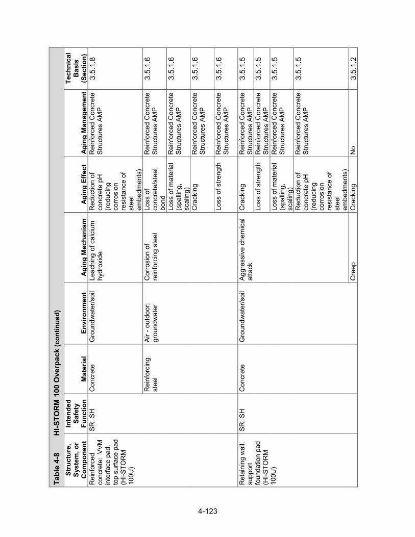
4-123
Tabl
e 4-
8 H
I-STO
RM 1
00 O
verp
ack (con
tinued)
Stru
ctur
e,
Syst
em, o
r C
ompo
nent
Inte
nded
Sa
fety
Fu
nctio
n M
ater
ial
Envi
ronm
ent
Agin
g M
echa
nism
Ag
ing
Effe
ct
Agin
g M
anag
emen
t
Tech
nica
l B
asis
(S
ectio
n)
Rei
nfor
ced
conc
rete
: VV
M
inte
rface
pad
, to
p su
rface
pad
(H
I-STO
RM
10
0U)
SR, S
H
Con
cret
e G
roun
dwat
er/s
oil
Leac
hing
of c
alci
um
hydr
oxid
e R
educ
tion
of
conc
rete
pH
(re
duci
ng
corro
sion
re
sist
ance
of
stee
l em
bedm
ents
)
Rei
nfor
ced
Con
cret
e St
ruct
ures
AM
P 3.
5.1.
8
Rei
nfor
cing
st
eel
Air -
out
door
; gr
ound
wat
er
Cor
rosi
on o
f re
info
rcin
g st
eel
Loss
of
conc
rete
/ste
el
bond
Rei
nfor
ced
Con
cret
e St
ruct
ures
AM
P 3.
5.1.
6
Loss
of m
ater
ial
(spa
lling,
sc
alin
g)
Rei
nfor
ced
Con
cret
e St
ruct
ures
AM
P 3.
5.1.
6
Cra
ckin
g R
einf
orce
d C
oncr
ete
Stru
ctur
es A
MP
3.5.
1.6
Loss
of s
treng
th
Rei
nfor
ced
Con
cret
e St
ruct
ures
AM
P 3.
5.1.
6
Ret
aini
ng w
all,
supp
ort
foun
datio
n pa
d (H
I-STO
RM
10
0U)
SR, S
H
Con
cret
e G
roun
dwat
er/s
oil
Aggr
essi
ve c
hem
ical
at
tack
C
rack
ing
Rei
nfor
ced
Con
cret
e St
ruct
ures
AM
P 3.
5.1.
5
Loss
of s
treng
th
Rei
nfor
ced
Con
cret
e St
ruct
ures
AM
P 3.
5.1.
5
Loss
of m
ater
ial
(spa
lling,
sc
alin
g)
Rei
nfor
ced
Con
cret
e St
ruct
ures
AM
P 3.
5.1.
5
Red
uctio
n of
co
ncre
te p
H
(redu
cing
co
rrosi
on
resi
stan
ce o
f st
eel
embe
dmen
ts)
Rei
nfor
ced
Con
cret
e St
ruct
ures
AM
P 3.
5.1.
5
Cre
ep
Cra
ckin
g N
o 3.
5.1.
2

4-124
Tabl
e 4-
8 H
I-STO
RM 1
00 O
verp
ack (con
tinued)
Stru
ctur
e,
Syst
em, o
r C
ompo
nent
Inte
nded
Sa
fety
Fu
nctio
n M
ater
ial
Envi
ronm
ent
Agin
g M
echa
nism
Ag
ing
Effe
ct
Agin
g M
anag
emen
t
Tech
nica
l B
asis
(S
ectio
n)
Ret
aini
ng w
all,
supp
ort
foun
datio
n pa
d (H
I-STO
RM
10
0U)
SR, S
H
Con
cret
e G
roun
dwat
er/s
oil
Deh
ydra
tion
at h
igh
tem
pera
ture
s C
rack
ing
No
3.5.
1.11
Lo
ss o
f stre
ngth
N
o 3.
5.1.
11
Del
ayed
ettr
ingi
te
form
atio
n Lo
ss o
f mat
eria
l (s
pallin
g,
scal
ing)
No
3.5.
1.13
Loss
of s
treng
th
No
3.5.
1.13
C
rack
ing
No
3.5.
1.13
D
iffer
entia
l se
ttlem
ent
Cra
ckin
g R
einf
orce
d C
oncr
ete
Stru
ctur
es A
MP
3.5.
1.4
Fatig
ue
Cra
ckin
g N
o 3.
5.1.
10
Free
ze a
nd th
aw
Cra
ckin
g N
o 3.
5.1.
1 Lo
ss o
f mat
eria
l (s
pallin
g,
scal
ing)
No
3.5.
1.1
Mic
robi
olog
ical
de
grad
atio
n Lo
ss o
f stre
ngth
R
einf
orce
d C
oncr
ete
Stru
ctur
es A
MP
3.5.
1.12
Loss
of m
ater
ial
(spa
lling,
sc
alin
g)
Rei
nfor
ced
Con
cret
e St
ruct
ures
AM
P 3.
5.1.
12
Mic
robi
olog
ical
de
grad
atio
n In
crea
se in
po
rosi
ty
and
perm
eabi
lity
Rei
nfor
ced
Con
cret
e St
ruct
ures
AM
P 3.
5.1.
12
Red
uctio
n of
co
ncre
te p
H
(redu
cing
co
rrosi
on
resi
stan
ce o
f st
eel
embe
dmen
ts)
Rei
nfor
ced
Con
cret
e St
ruct
ures
AM
P 3.
5.1.
12
Rad
iatio
n da
mag
e C
rack
ing
No
3.5.
1.9
Loss
of s
treng
th
No
3.5.
1.9

4-125
Tabl
e 4-
8 H
I-STO
RM 1
00 O
verp
ack (con
tinued)
Stru
ctur
e,
Syst
em, o
r C
ompo
nent
Inte
nded
Sa
fety
Fu
nctio
n M
ater
ial
Envi
ronm
ent
Agin
g M
echa
nism
Ag
ing
Effe
ct
Agin
g M
anag
emen
t
Tech
nica
l B
asis
(S
ectio
n)
Ret
aini
ng w
all,
supp
ort
foun
datio
n pa
d (H
I-STO
RM
10
0U)
SR, S
H
Con
cret
e G
roun
dwat
er/s
oil
Rea
ctio
n w
ith
aggr
egat
es
Cra
ckin
g R
einf
orce
d C
oncr
ete
Stru
ctur
es A
MP
3.5.
1.3
Loss
of s
treng
th
Rei
nfor
ced
Con
cret
e St
ruct
ures
AM
P 3.
5.1.
3
Salt
scal
ing
Loss
of m
ater
ial
(spa
lling,
sc
alin
g)
No
3.5.
1.14
Leac
hing
of c
alci
um
hydr
oxid
e Lo
ss o
f stre
ngth
R
einf
orce
d C
oncr
ete
Stru
ctur
es A
MP
3.5.
1.8
Incr
ease
in
poro
sity
an
d pe
rmea
bilit
y
Rei
nfor
ced
Con
cret
e St
ruct
ures
AM
P 3.
5.1.
8
Red
uctio
n of
co
ncre
te p
H
(redu
cing
co
rrosi
on
resi
stan
ce o
f st
eel
embe
dmen
ts)
Rei
nfor
ced
Con
cret
e St
ruct
ures
AM
P 3.
5.1.
8
Rei
nfor
cing
st
eel
Air -
out
door
; gr
ound
wat
er
Cor
rosi
on o
f re
info
rcin
g st
eel
Loss
of
conc
rete
/ste
el
bond
Rei
nfor
ced
Con
cret
e St
ruct
ures
AM
P 3.
5.1.
6
Loss
of m
ater
ial
(spa
lling,
sc
alin
g)
Rei
nfor
ced
Con
cret
e St
ruct
ures
AM
P 3.
5.1.
6
Cra
ckin
g R
einf
orce
d C
oncr
ete
Stru
ctur
es A
MP
3.5.
1.6
Loss
of s
treng
th
Rei
nfor
ced
Con
cret
e St
ruct
ures
AM
P 3.
5.1.
6
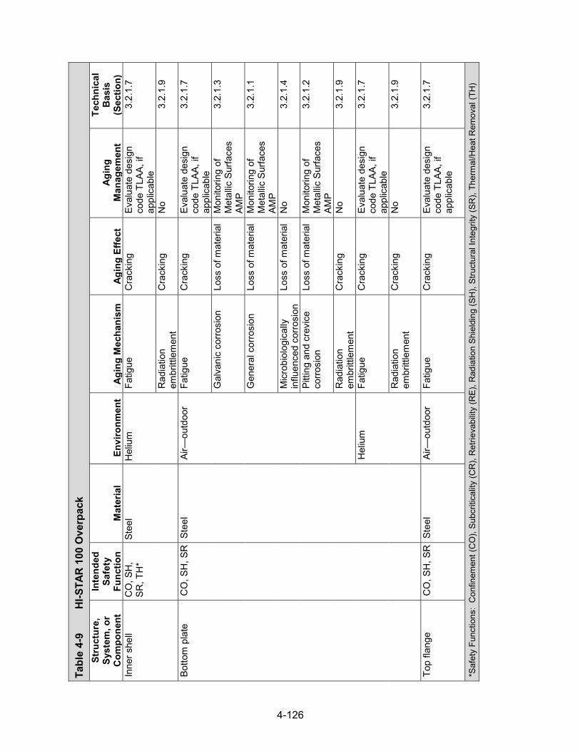
4-126
Tabl
e 4-
9 H
I-STA
R 10
0 O
verp
ack
Stru
ctur
e,
Syst
em, o
r C
ompo
nent
Inte
nded
Sa
fety
Fu
nctio
n M
ater
ial
Envi
ronm
ent
Agin
g M
echa
nism
Ag
ing
Effe
ct
Agin
g M
anag
emen
t
Tech
nica
l B
asis
(S
ectio
n)
Inne
r she
ll C
O, S
H,
SR, T
H*
Stee
l H
eliu
m
Fatig
ue
Cra
ckin
g Ev
alua
te d
esig
n co
de T
LAA,
if
appl
icab
le
3.2.
1.7
Rad
iatio
n em
britt
lem
ent
Cra
ckin
g N
o 3.
2.1.
9
Botto
m p
late
C
O, S
H, S
R S
teel
Ai
r—ou
tdoo
r Fa
tigue
C
rack
ing
Eval
uate
des
ign
code
TLA
A, if
ap
plic
able
3.2.
1.7
Gal
vani
c co
rrosi
on
Loss
of m
ater
ial
Mon
itorin
g of
M
etal
lic S
urfa
ces
AMP
3.2.
1.3
Gen
eral
cor
rosi
on
Loss
of m
ater
ial
Mon
itorin
g of
M
etal
lic S
urfa
ces
AMP
3.2.
1.1
Mic
robi
olog
ical
ly
influ
ence
d co
rrosi
on
Loss
of m
ater
ial
No
3.2.
1.4
Pitti
ng a
nd c
revi
ce
corro
sion
Lo
ss o
f mat
eria
l M
onito
ring
of
Met
allic
Sur
face
s AM
P
3.2.
1.2
Rad
iatio
n em
britt
lem
ent
Cra
ckin
g N
o 3.
2.1.
9
Hel
ium
Fa
tigue
C
rack
ing
Eval
uate
des
ign
code
TLA
A, if
ap
plic
able
3.2.
1.7
Rad
iatio
n em
britt
lem
ent
Cra
ckin
g N
o 3.
2.1.
9
Top
flang
e C
O, S
H, S
R S
teel
Ai
r—ou
tdoo
r Fa
tigue
C
rack
ing
Eval
uate
des
ign
code
TLA
A, if
ap
plic
able
3.2.
1.7
*Saf
ety
Func
tions
: C
onfin
emen
t (C
O),
Subc
ritic
ality
(CR
), R
etrie
vabi
lity
(RE)
, Rad
iatio
n Sh
ield
ing
(SH
), St
ruct
ural
Inte
grity
(SR
), Th
erm
al/H
eat R
emov
al (T
H)

4-127
Tabl
e 4-
9 H
I-STA
R 10
0 O
verp
ack (con
tinued)
Stru
ctur
e,
Syst
em, o
r C
ompo
nent
Inte
nded
Sa
fety
Fu
nctio
n M
ater
ial
Envi
ronm
ent
Agin
g M
echa
nism
Ag
ing
Effe
ct
Agin
g M
anag
emen
t
Tech
nica
l B
asis
(S
ectio
n)
Top
flang
e C
O, S
H, S
R S
teel
Ai
r—ou
tdoo
r G
alva
nic
corro
sion
Lo
ss o
f mat
eria
l M
onito
ring
of
Met
allic
Sur
face
s AM
P
3.2.
1.3
Gen
eral
cor
rosi
on
Loss
of m
ater
ial
Mon
itorin
g of
M
etal
lic S
urfa
ces
AMP
3.2.
1.1
Mic
robi
olog
ical
ly
influ
ence
d co
rrosi
on
Loss
of m
ater
ial
No
3.2.
1.4
Pitti
ng a
nd c
revi
ce
corro
sion
Lo
ss o
f mat
eria
l M
onito
ring
of
Met
allic
Sur
face
s AM
P
3.2.
1.2
Rad
iatio
n em
britt
lem
ent
Cra
ckin
g N
o 3.
2.1.
9
Hel
ium
Fa
tigue
C
rack
ing
Eval
uate
des
ign
code
TLA
A, if
ap
plic
able
3.2.
1.7
Rad
iatio
n em
britt
lem
ent
Cra
ckin
g N
o 3.
2.1.
9
Clo
sure
pla
te
CO
, SH
, SR
Ste
el
Air—
outd
oor
Fatig
ue
Cra
ckin
g Ev
alua
te d
esig
n co
de T
LAA,
if
appl
icab
le
3.2.
1.7
Gal
vani
c co
rrosi
on
Loss
of m
ater
ial
Mon
itorin
g of
M
etal
lic S
urfa
ces
AMP
3.2.
1.3
Gen
eral
cor
rosi
on
Loss
of m
ater
ial
Mon
itorin
g of
M
etal
lic S
urfa
ces
AMP
3.2.
1.1
Mic
robi
olog
ical
ly
influ
ence
d co
rrosi
on
Loss
of m
ater
ial
No
3.2.
1.4
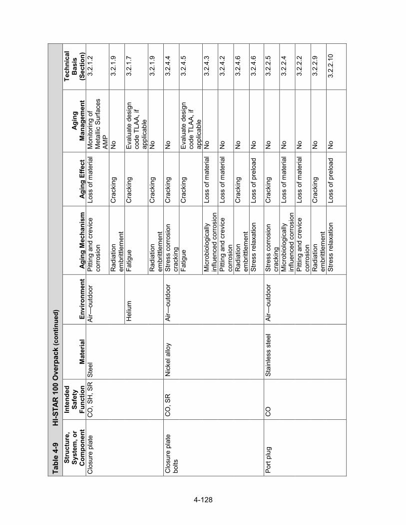
4-128
Tabl
e 4-
9 H
I-STA
R 10
0 O
verp
ack (con
tinued)
Stru
ctur
e,
Syst
em, o
r C
ompo
nent
Inte
nded
Sa
fety
Fu
nctio
n M
ater
ial
Envi
ronm
ent
Agin
g M
echa
nism
Ag
ing
Effe
ct
Agin
g M
anag
emen
t
Tech
nica
l B
asis
(S
ectio
n)
Clo
sure
pla
te
CO
, SH
, SR
Ste
el
Air—
outd
oor
Pitti
ng a
nd c
revi
ce
corro
sion
Lo
ss o
f mat
eria
l M
onito
ring
of
Met
allic
Sur
face
s AM
P
3.2.
1.2
Rad
iatio
n em
britt
lem
ent
Cra
ckin
g N
o 3.
2.1.
9
Hel
ium
Fa
tigue
C
rack
ing
Eval
uate
des
ign
code
TLA
A, if
ap
plic
able
3.2.
1.7
Rad
iatio
n em
britt
lem
ent
Cra
ckin
g N
o 3.
2.1.
9
Clo
sure
pla
te
bolts
C
O, S
R
Nic
kel a
lloy
Air—
outd
oor
Stre
ss c
orro
sion
cr
acki
ng
Cra
ckin
g N
o 3.
2.4.
4
Fatig
ue
Cra
ckin
g Ev
alua
te d
esig
n co
de T
LAA,
if
appl
icab
le
3.2.
4.5
Mic
robi
olog
ical
ly
influ
ence
d co
rrosi
on
Loss
of m
ater
ial
No
3.2.
4.3
Pitti
ng a
nd c
revi
ce
corro
sion
Lo
ss o
f mat
eria
l N
o 3.
2.4.
2
Rad
iatio
n em
britt
lem
ent
Cra
ckin
g N
o 3.
2.4.
6
Stre
ss re
laxa
tion
Loss
of p
relo
ad
No
3.2.
4.6
Port
plug
C
O
Stai
nles
s st
eel
Air—
outd
oor
Stre
ss c
orro
sion
cr
acki
ng
Cra
ckin
g N
o 3.
2.2.
5
Mic
robi
olog
ical
ly
influ
ence
d co
rrosi
on
Loss
of m
ater
ial
No
3.2.
2.4
Pitti
ng a
nd c
revi
ce
corro
sion
Lo
ss o
f mat
eria
l N
o 3.
2.2.
2
Rad
iatio
n em
britt
lem
ent
Cra
ckin
g N
o 3.
2.2.
9
Stre
ss re
laxa
tion
Loss
of p
relo
ad
No
3.2.
2.10

4-129
Tabl
e 4-
9 H
I-STA
R 10
0 O
verp
ack (con
tinued)
Stru
ctur
e,
Syst
em, o
r C
ompo
nent
Inte
nded
Sa
fety
Fu
nctio
n M
ater
ial
Envi
ronm
ent
Agin
g M
echa
nism
Ag
ing
Effe
ct
Agin
g M
anag
emen
t
Tech
nica
l B
asis
(S
ectio
n)
Port
plug
sea
l and
po
rt co
ver s
eal
CO
N
icke
l allo
y Ai
r—ou
tdoo
r M
icro
biol
ogic
ally
in
fluen
ced
corro
sion
Lo
ss o
f mat
eria
l N
o 3.
2.4.
3
Pitti
ng a
nd c
revi
ce
corro
sion
Lo
ss o
f mat
eria
l N
o 3.
2.4.
2
Rad
iatio
n em
britt
lem
ent
Cra
ckin
g N
o 3.
2.4.
6
Clo
sure
pla
te
seal
s C
O
Nic
kel a
lloy
Air—
outd
oor
Mic
robi
olog
ical
ly
influ
ence
d co
rrosi
on
Loss
of m
ater
ial
No
3.2.
4.3
Pitti
ng a
nd c
revi
ce
corro
sion
Lo
ss o
f mat
eria
l N
o 3.
2.4.
2
Rad
iatio
n em
britt
lem
ent
Cra
ckin
g N
o 3.
2.4.
6
Inte
rmed
iate
sh
ells
SH
, SR
, TH
St
eel
Embe
dded
(H
oltit
e-A™
) R
adia
tion
embr
ittle
men
t C
rack
ing
No
3.2.
1.9
Neu
tron
shie
ld
SH
Hol
tite-
A™
Embe
dded
(s
teel
) R
adia
tion
embr
ittle
men
t C
rack
ing
TLAA
/AM
P or
a
supp
ortin
g an
alys
is
is re
quire
d
3.3.
1.3
Ther
mal
agi
ng
Loss
of f
ract
ure
toug
hnes
s an
d lo
ss o
f duc
tility
TLAA
/AM
P or
a
supp
ortin
g an
alys
is
is re
quire
d
3.3.
1.2
Boro
n de
plet
ion
Loss
of s
hiel
ding
TL
AA/A
MP
or a
su
ppor
ting
anal
ysis
is
requ
ired
3.3.
1.1
Rem
ovab
le s
hear
rin
g SR
St
eel
Air—
outd
oor
Gen
eral
cor
rosi
on
Loss
of m
ater
ial
Mon
itorin
g of
M
etal
lic S
urfa
ces
AMP
3.2.
1.1
Mic
robi
olog
ical
ly
influ
ence
d co
rrosi
on
Loss
of m
ater
ial
No
3.2.
1.4
Pitti
ng a
nd c
revi
ce
corro
sion
Lo
ss o
f mat
eria
l M
onito
ring
of
Met
allic
Sur
face
s AM
P
3.2.
1.2
Rad
iatio
n em
britt
lem
ent
Cra
ckin
g N
o 3.
2.1.
9
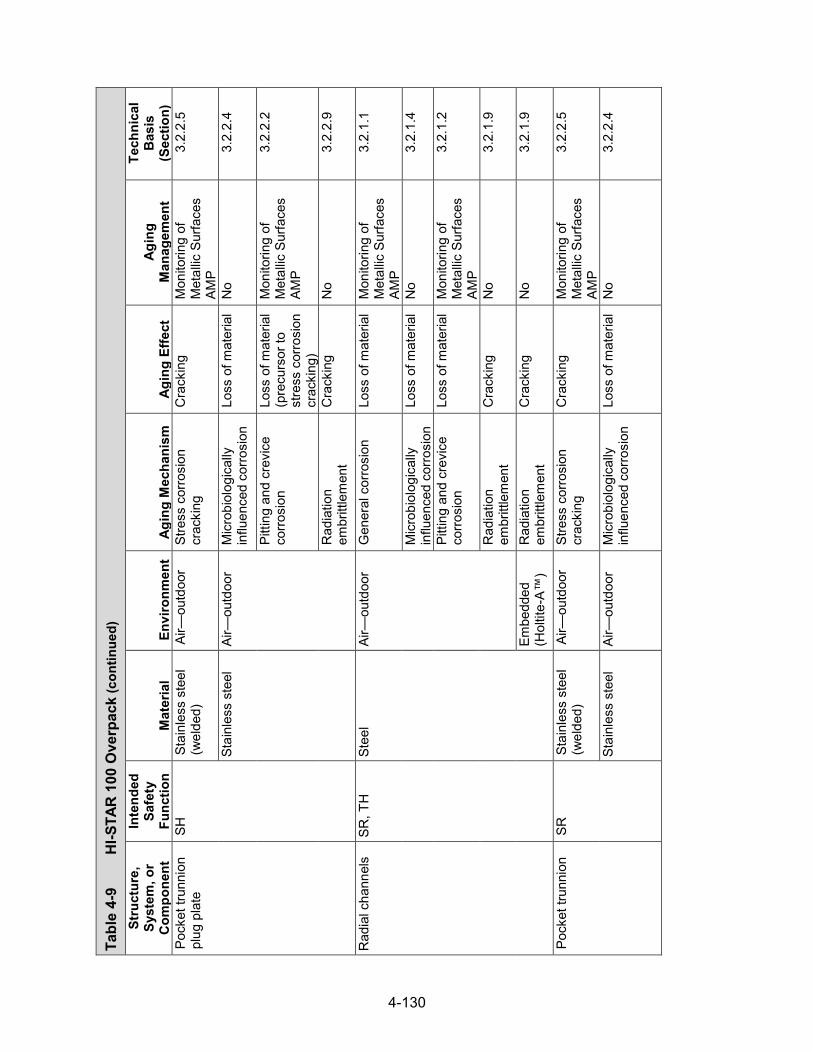
4-130
Tabl
e 4-
9 H
I-STA
R 10
0 O
verp
ack (con
tinued)
Stru
ctur
e,
Syst
em, o
r C
ompo
nent
Inte
nded
Sa
fety
Fu
nctio
n M
ater
ial
Envi
ronm
ent
Agin
g M
echa
nism
Ag
ing
Effe
ct
Agin
g M
anag
emen
t
Tech
nica
l B
asis
(S
ectio
n)
Pock
et tr
unni
on
plug
pla
te
SH
Stai
nles
s st
eel
(wel
ded)
Ai
r—ou
tdoo
r St
ress
cor
rosi
on
crac
king
C
rack
ing
Mon
itorin
g of
M
etal
lic S
urfa
ces
AMP
3.2.
2.5
Stai
nles
s st
eel
Air—
outd
oor
Mic
robi
olog
ical
ly
influ
ence
d co
rrosi
on
Loss
of m
ater
ial
No
3.2.
2.4
Pitti
ng a
nd c
revi
ce
corro
sion
Lo
ss o
f mat
eria
l (p
recu
rsor
to
stre
ss c
orro
sion
cr
acki
ng)
Mon
itorin
g of
M
etal
lic S
urfa
ces
AMP
3.2.
2.2
Rad
iatio
n em
britt
lem
ent
Cra
ckin
g N
o 3.
2.2.
9
Rad
ial c
hann
els
SR, T
H
Stee
l Ai
r—ou
tdoo
r G
ener
al c
orro
sion
Lo
ss o
f mat
eria
l M
onito
ring
of
Met
allic
Sur
face
s AM
P
3.2.
1.1
Mic
robi
olog
ical
ly
influ
ence
d co
rrosi
on
Loss
of m
ater
ial
No
3.2.
1.4
Pitti
ng a
nd c
revi
ce
corro
sion
Lo
ss o
f mat
eria
l M
onito
ring
of
Met
allic
Sur
face
s AM
P
3.2.
1.2
Rad
iatio
n em
britt
lem
ent
Cra
ckin
g N
o 3.
2.1.
9
Embe
dded
(H
oltit
e-A™
) R
adia
tion
embr
ittle
men
t C
rack
ing
No
3.2.
1.9
Pock
et tr
unni
on
SR
Stai
nles
s st
eel
(wel
ded)
Ai
r—ou
tdoo
r St
ress
cor
rosi
on
crac
king
C
rack
ing
Mon
itorin
g of
M
etal
lic S
urfa
ces
AMP
3.2.
2.5
Stai
nles
s st
eel
Air—
outd
oor
Mic
robi
olog
ical
ly
influ
ence
d co
rrosi
on
Loss
of m
ater
ial
No
3.2.
2.4

4-131
Tabl
e 4-
9 H
I-STA
R 10
0 O
verp
ack (con
tinued)
Stru
ctur
e,
Syst
em, o
r C
ompo
nent
Inte
nded
Sa
fety
Fu
nctio
n M
ater
ial
Envi
ronm
ent
Agin
g M
echa
nism
Ag
ing
Effe
ct
Agin
g M
anag
emen
t
Tech
nica
l B
asis
(S
ectio
n)
Pock
et tr
unni
on
SR
Stai
nles
s st
eel
Air—
outd
oor
Pitti
ng a
nd c
revi
ce
corro
sion
Lo
ss o
f mat
eria
l (p
recu
rsor
to
stre
ss c
orro
sion
cr
acki
ng)
Mon
itorin
g of
M
etal
lic S
urfa
ces
AMP
3.2.
2.2
Rad
iatio
n em
britt
lem
ent
Cra
ckin
g N
o 3.
2.2.
9
Lifti
ng tr
unni
on
SH, S
R
Nic
kel a
lloy
Air—
outd
oor
Stre
ss-
corro
sion
cra
ckin
g C
rack
ing
No
3.2.
4.4
Mic
robi
olog
ical
ly
influ
ence
d co
rrosi
on
Loss
of m
ater
ial
No
3.2.
4.3
Pitti
ng a
nd c
revi
ce
corro
sion
Lo
ss o
f mat
eria
l N
o 3.
2.4.
2
Rad
iatio
n em
britt
lem
ent
Cra
ckin
g N
o 3.
2.4.
6
Rup
ture
dis
k SR
Br
ass
Air—
outd
oor
Gen
eral
cor
rosi
on
Loss
of m
ater
ial
Mon
itorin
g of
M
etal
lic S
urfa
ces
AMP
3.2.
5.1
Mic
robi
olog
ical
ly
influ
ence
d co
rrosi
on
Loss
of m
ater
ial
No
3.2.
5.3
Pitti
ng a
nd c
revi
ce
corro
sion
Lo
ss o
f mat
eria
l N
o 3.
2.5.
2
Rad
iatio
n em
britt
lem
ent
Cra
ckin
g N
o 3.
2.5.
4
Rup
ture
dis
k pl
ate
SR
Stee
l Ai
r—ou
tdoo
r G
alva
nic
corro
sion
Lo
ss o
f mat
eria
l M
onito
ring
of
Met
allic
Sur
face
s AM
P
3.2.
1.3
Gen
eral
cor
rosi
on
Loss
of m
ater
ial
Mon
itorin
g of
M
etal
lic S
urfa
ces
AMP
3.2.
1.1
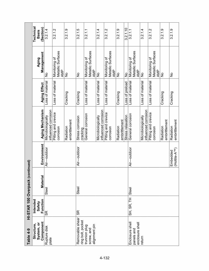
4-132
Tabl
e 4-
9 H
I-STA
R 10
0 O
verp
ack (con
tinued)
Stru
ctur
e,
Syst
em, o
r C
ompo
nent
Inte
nded
Sa
fety
Fu
nctio
n M
ater
ial
Envi
ronm
ent
Agin
g M
echa
nism
Ag
ing
Effe
ct
Agin
g M
anag
emen
t
Tech
nica
l B
asis
(S
ectio
n)
Rup
ture
dis
k pl
ate
SR
Stee
l Ai
r—ou
tdoo
r M
icro
biol
ogic
ally
in
fluen
ced
corro
sion
Lo
ss o
f mat
eria
l N
o 3.
2.1.
4
Pitti
ng a
nd c
revi
ce
corro
sion
Lo
ss o
f mat
eria
l M
onito
ring
of
Met
allic
Sur
face
s AM
P
3.2.
1.2
Rad
iatio
n em
britt
lem
ent
Cra
ckin
g N
o 3.
2.1.
9
Rem
ovab
le s
hear
rin
g bo
lt, p
ocke
t tru
nnio
n pl
ug
scre
w, a
nd
alig
nmen
t pin
SR
Stee
l Ai
r—ou
tdoo
r St
ress
cor
rosi
on
crac
king
C
rack
ing
No
3.2.
1.5
Gen
eral
cor
rosi
on
Loss
of m
ater
ial
Mon
itorin
g of
M
etal
lic S
urfa
ces
AMP
3.2.
1.1
Mic
robi
olog
ical
ly
influ
ence
d co
rrosi
on
Loss
of m
ater
ial
No
3.2.
1.4
Pitti
ng a
nd c
revi
ce
corro
sion
Lo
ss o
f mat
eria
l M
onito
ring
of
Met
allic
Sur
face
s AM
P
3.2.
1.2
Rad
iatio
n em
britt
lem
ent
Cra
ckin
g N
o 3.
2.1.
9
Stre
ss re
laxa
tion
Loss
of p
relo
ad
No
3.2.
1.10
En
clos
ure
shel
l pa
nels
and
en
clos
ure
shel
l re
turn
SH, S
R, T
H
Stee
l Ai
r—ou
tdoo
r G
ener
al c
orro
sion
Lo
ss o
f mat
eria
l M
onito
ring
of
Met
allic
Sur
face
s AM
P
3.2.
1.1
Mic
robi
olog
ical
ly
influ
ence
d co
rrosi
on
Loss
of m
ater
ial
No
3.2.
1.4
Pitti
ng a
nd c
revi
ce
corro
sion
Lo
ss o
f mat
eria
l M
onito
ring
of
Met
allic
Sur
face
s AM
P
3.2.
1.2
Rad
iatio
n em
britt
lem
ent
Cra
ckin
g N
o 3.
2.1.
9
Embe
dded
(H
oltit
e-A™
) R
adia
tion
embr
ittle
men
t C
rack
ing
No
3.2.
1.9

4-133
Tabl
e 4-
9 H
I-STA
R 10
0 O
verp
ack (con
tinued)
Stru
ctur
e,
Syst
em, o
r C
ompo
nent
Inte
nded
Sa
fety
Fu
nctio
n M
ater
ial
Envi
ronm
ent
Agin
g M
echa
nism
Ag
ing
Effe
ct
Agin
g M
anag
emen
t
Tech
nica
l B
asis
(S
ectio
n)
Port
cove
r SR
St
eel
Air—
outd
oor
Gal
vani
c co
rrosi
on
Loss
of m
ater
ial
Mon
itorin
g of
M
etal
lic S
urfa
ces
AMP
3.2.
1.3
Gen
eral
cor
rosi
on
Loss
of m
ater
ial
Mon
itorin
g of
M
etal
lic S
urfa
ces
AMP
3.2.
1.1
Mic
robi
olog
ical
ly
influ
ence
d co
rrosi
on
Loss
of m
ater
ial
No
3.2.
1.4
Pitti
ng a
nd c
revi
ce
corro
sion
Lo
ss o
f mat
eria
l M
onito
ring
of
Met
allic
Sur
face
s AM
P
3.2.
1.2
Rad
iatio
n em
britt
lem
ent
Cra
ckin
g N
o 3.
2.1.
9
Port
cove
r bol
t SR
St
eel
Air—
outd
oor
Stre
ss c
orro
sion
cr
acki
ng
Cra
ckin
g N
o 3.
2.1.
5
Gen
eral
cor
rosi
on
Loss
of m
ater
ial
Mon
itorin
g of
M
etal
lic S
urfa
ces
AMP
3.2.
1.1
Mic
robi
olog
ical
ly
influ
ence
d co
rrosi
on
Loss
of m
ater
ial
No
3.2.
1.4
Pitti
ng a
nd c
revi
ce
corro
sion
Lo
ss o
f mat
eria
l M
onito
ring
of
Met
allic
Sur
face
s AM
P
3.2.
1.2
Rad
iatio
n em
britt
lem
ent
Cra
ckin
g N
o 3.
2.1.
9
Stre
ss re
laxa
tion
Loss
of p
relo
ad
No
3.2.
1.10
Tr
unni
on lo
ckin
g pa
d an
d en
d ca
p bo
lts
SR
Stee
l Ai
r—ou
tdoo
r St
ress
cor
rosi
on
crac
king
C
rack
ing
No
3.2.
1.5

4-134
Tabl
e 4-
9 H
I-STA
R 10
0 O
verp
ack (con
tinued)
Stru
ctur
e,
Syst
em, o
r C
ompo
nent
Inte
nded
Sa
fety
Fu
nctio
n M
ater
ial
Envi
ronm
ent
Agin
g M
echa
nism
Ag
ing
Effe
ct
Agin
g M
anag
emen
t
Tech
nica
l B
asis
(S
ectio
n)
Trun
nion
lock
ing
pad
and
end
cap
bolts
SR
Stee
l Ai
r—ou
tdoo
r G
alva
nic
corro
sion
Lo
ss o
f mat
eria
l M
onito
ring
of
Met
allic
Sur
face
s AM
P
3.2.
1.3
Gen
eral
cor
rosi
on
Loss
of m
ater
ial
Mon
itorin
g of
M
etal
lic S
urfa
ces
AMP
3.2.
1.1
Mic
robi
olog
ical
ly
influ
ence
d co
rrosi
on
Loss
of m
ater
ial
No
3.2.
1.4
Pitti
ng a
nd c
revi
ce
corro
sion
Lo
ss o
f mat
eria
l M
onito
ring
of
Met
allic
Sur
face
s AM
P
3.2.
1.2
Rad
iatio
n em
britt
lem
ent
Cra
ckin
g N
o 3.
2.1.
9
Stre
ss re
laxa
tion
Loss
of p
relo
ad
No
3.2.
1.10
Li
fting
trun
nion
en
d ca
p an
d lo
ckin
g pa
d
SR
Stee
l Ai
r—ou
tdoo
r G
alva
nic
corro
sion
Lo
ss o
f mat
eria
l M
onito
ring
of
Met
allic
Sur
face
s AM
P
3.2.
1.3
Gen
eral
cor
rosi
on
Loss
of m
ater
ial
Mon
itorin
g of
M
etal
lic S
urfa
ces
AMP
3.2.
1.1
Mic
robi
olog
ical
ly
influ
ence
d co
rrosi
on
Loss
of m
ater
ial
No
3.2.
1.4
Pitti
ng a
nd c
revi
ce
corro
sion
Lo
ss o
f mat
eria
l M
onito
ring
of
Met
allic
Sur
face
s AM
P
3.2.
1.2
Rad
iatio
n em
britt
lem
ent
Cra
ckin
g N
o 3.
2.1.
9
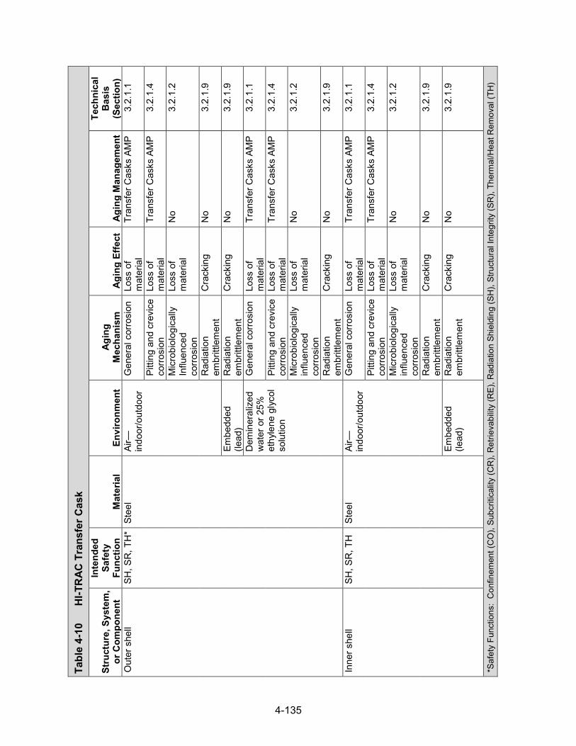
4-135
Tabl
e 4-
10
HI-T
RAC
Tra
nsfe
r Cas
k
Stru
ctur
e, S
yste
m,
or C
ompo
nent
Inte
nded
Sa
fety
Fu
nctio
n M
ater
ial
Envi
ronm
ent
Agin
g M
echa
nism
Ag
ing
Effe
ct
Agin
g M
anag
emen
t
Tech
nica
l B
asis
(S
ectio
n)
Out
er s
hell
SH, S
R, T
H*
Stee
l Ai
r—in
door
/out
door
G
ener
al c
orro
sion
Lo
ss o
f m
ater
ial
Tran
sfer
Cas
ks A
MP
3.2.
1.1
Pitti
ng a
nd c
revi
ce
corro
sion
Lo
ss o
f m
ater
ial
Tran
sfer
Cas
ks A
MP
3.2.
1.4
Mic
robi
olog
ical
ly
Influ
ence
d co
rrosi
on
Loss
of
mat
eria
l N
o 3.
2.1.
2
Rad
iatio
n em
britt
lem
ent
Cra
ckin
g N
o 3.
2.1.
9
Embe
dded
(le
ad)
Rad
iatio
n em
britt
lem
ent
Cra
ckin
g N
o 3.
2.1.
9
Dem
iner
aliz
ed
wat
er o
r 25%
et
hyle
ne g
lyco
l so
lutio
n
Gen
eral
cor
rosi
on
Loss
of
mat
eria
l Tr
ansf
er C
asks
AM
P 3.
2.1.
1
Pitti
ng a
nd c
revi
ce
corro
sion
Lo
ss o
f m
ater
ial
Tran
sfer
Cas
ks A
MP
3.2.
1.4
Mic
robi
olog
ical
ly
influ
ence
d co
rrosi
on
Loss
of
mat
eria
l N
o 3.
2.1.
2
Rad
iatio
n em
britt
lem
ent
Cra
ckin
g N
o 3.
2.1.
9
Inne
r she
ll SH
, SR
, TH
St
eel
Air—
indo
or/o
utdo
or
Gen
eral
cor
rosi
on
Loss
of
mat
eria
l Tr
ansf
er C
asks
AM
P 3.
2.1.
1
Pitti
ng a
nd c
revi
ce
corro
sion
Lo
ss o
f m
ater
ial
Tran
sfer
Cas
ks A
MP
3.2.
1.4
Mic
robi
olog
ical
ly
influ
ence
d co
rrosi
on
Loss
of
mat
eria
l N
o 3.
2.1.
2
Rad
iatio
n em
britt
lem
ent
Cra
ckin
g N
o 3.
2.1.
9
Embe
dded
(le
ad)
Rad
iatio
n em
britt
lem
ent
Cra
ckin
g N
o 3.
2.1.
9
*Saf
ety
Func
tions
: C
onfin
emen
t (C
O),
Subc
ritic
ality
(CR
), R
etrie
vabi
lity
(RE)
, Rad
iatio
n Sh
ield
ing
(SH
), St
ruct
ural
Inte
grity
(SR
), Th
erm
al/H
eat R
emov
al (T
H)

4-136
Tabl
e 4-
10
HI-T
RAC
Tran
sfer
Cas
k (c
ontin
ued)
Stru
ctur
e, S
yste
m,
or C
ompo
nent
Inte
nded
Sa
fety
Fu
nctio
n M
ater
ial
Envi
ronm
ent
Agin
g M
echa
nism
Ag
ing
Effe
ct
Agin
g M
anag
emen
t
Tech
nica
l B
asis
(S
ectio
n)
Rad
ial r
ibs
SH, S
R, T
H
Stee
l D
emin
eral
ized
w
ater
or 2
5%
ethy
lene
gly
col
solu
tion
Gen
eral
cor
rosi
on
Loss
of
mat
eria
l Tr
ansf
er C
asks
AM
P 3.
2.1.
1
Pitti
ng a
nd c
revi
ce
corro
sion
Lo
ss o
f m
ater
ial
Tran
sfer
Cas
ks A
MP
3.2.
1.4
Mic
robi
olog
ical
ly
influ
ence
d co
rrosi
on
Loss
of
mat
eria
l N
o 3.
2.1.
2
Rad
iatio
n em
britt
lem
ent
Cra
ckin
g N
o 3.
2.1.
9
Rad
ial l
ead
shie
ld
SH, T
H
Lead
—AS
TM
B29
Embe
dded
(s
teel
) N
one
iden
tifie
d N
one
iden
tifie
d N
o 3.
2.5.
4
Wat
er ja
cket
en
clos
ure
shel
l pa
nels
SH, S
R, T
H
Stee
l Ai
r—in
door
/out
door
G
ener
al c
orro
sion
Lo
ss o
f m
ater
ial
Tran
sfer
Cas
ks A
MP
3.2.
1.1
Pitti
ng a
nd c
revi
ce
corro
sion
Lo
ss o
f m
ater
ial
Tran
sfer
Cas
ks A
MP
3.2.
1.4
Mic
robi
olog
ical
ly
influ
ence
d co
rrosi
on
Loss
of
mat
eria
l N
o 3.
2.1.
2
Rad
iatio
n em
britt
lem
ent
Cra
ckin
g N
o 3.
2.1.
9
Dem
iner
aliz
ed
wat
er o
r 25%
et
hyle
ne g
lyco
l so
lutio
n
Gen
eral
cor
rosi
on
Loss
of
mat
eria
l Tr
ansf
er C
asks
AM
P 3.
2.1.
1
Pitti
ng a
nd c
revi
ce
corro
sion
Lo
ss o
f m
ater
ial
Tran
sfer
Cas
ks A
MP
3.2.
1.4
Mic
robi
olog
ical
ly
influ
ence
d co
rrosi
on
Loss
of
mat
eria
l N
o 3.
2.1.
2
Rad
iatio
n em
britt
lem
ent
Cra
ckin
g N
o 3.
2.1.
9
Low
er w
ater
jack
et
shel
l SH
, SR
, TH
St
eel
Air—
indo
or/o
utdo
or
Gen
eral
cor
rosi
on
Loss
of
mat
eria
l Tr
ansf
er C
asks
AM
P 3.
2.1.
1
Pitti
ng a
nd c
revi
ce
corro
sion
Lo
ss o
f m
ater
ial
Tran
sfer
Cas
ks A
MP
3.2.
1.4

4-137
Tabl
e 4-
10
HI-T
RAC
Tran
sfer
Cas
k (con
tinued)
Stru
ctur
e, S
yste
m,
or C
ompo
nent
Inte
nded
Sa
fety
Fu
nctio
n M
ater
ial
Envi
ronm
ent
Agin
g M
echa
nism
Ag
ing
Effe
ct
Agin
g M
anag
emen
t
Tech
nica
l B
asis
(S
ectio
n)
Low
er w
ater
jack
et
shel
l SH
, SR
, TH
St
eel
Air—
indo
or/o
utdo
or
Mic
robi
olog
ical
ly
influ
ence
d co
rrosi
on
Loss
of
mat
eria
l N
o 3.
2.1.
2
Rad
iatio
n em
britt
lem
ent
Cra
ckin
g N
o 3.
2.1.
9
Dem
iner
aliz
ed
wat
er o
r 25%
et
hyle
ne g
lyco
l so
lutio
n
Gen
eral
cor
rosi
on
Loss
of
mat
eria
l Tr
ansf
er C
asks
AM
P 3.
2.1.
1
Pitti
ng a
nd c
revi
ce
corro
sion
Lo
ss o
f m
ater
ial
Tran
sfer
Cas
ks A
MP
3.2.
1.4
Mic
robi
olog
ical
ly
influ
ence
d co
rrosi
on
Loss
of
mat
eria
l N
o 3.
2.1.
2
Rad
iatio
n em
britt
lem
ent
Cra
ckin
g N
o 3.
2.1.
9
Wat
er ja
cket
end
pl
ate,
sho
rt rib
SH
, SR
, TH
St
eel
Air—
indo
or/o
utdo
or
Gen
eral
cor
rosi
on
Loss
of
mat
eria
l Tr
ansf
er C
asks
AM
P 3.
2.1.
1
Pitti
ng a
nd c
revi
ce
corro
sion
Lo
ss o
f m
ater
ial
Tran
sfer
Cas
ks A
MP
3.2.
1.4
Mic
robi
olog
ical
ly
influ
ence
d co
rrosi
on
Loss
of
mat
eria
l N
o 3.
2.1.
2
Rad
iatio
n em
britt
lem
ent
Cra
ckin
g N
o 3.
2.1.
9
Dem
iner
aliz
ed
wat
er o
r 25%
et
hyle
ne g
lyco
l so
lutio
n
Gen
eral
cor
rosi
on
Loss
of
mat
eria
l Tr
ansf
er C
asks
AM
P 3.
2.1.
1
Pitti
ng a
nd c
revi
ce
Cor
rosi
on
Loss
of
mat
eria
l Tr
ansf
er C
asks
AM
P 3.
2.1.
4
Mic
robi
olog
ical
ly
influ
ence
d co
rrosi
on
Loss
of
mat
eria
l N
o 3.
2.1.
2
Rad
iatio
n em
britt
lem
ent
Cra
ckin
g N
o 3.
2.1.
9
Pool
lid
oute
r rin
g SH
, SR
, TH
St
eel
Air—
indo
or/o
utdo
or
Gen
eral
cor
rosi
on
Loss
of
mat
eria
l Tr
ansf
er C
asks
AM
P 3.
2.1.
1
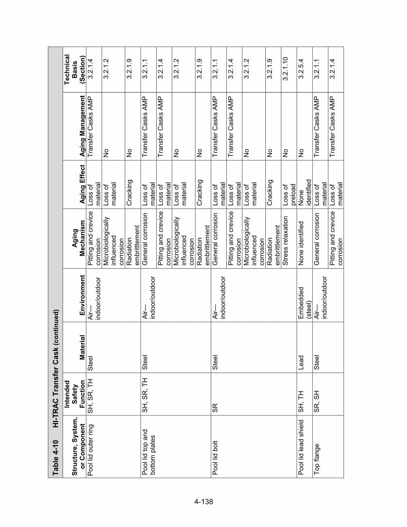
4-138
Tabl
e 4-
10
HI-T
RAC
Tran
sfer
Cas
k (con
tinued)
Stru
ctur
e, S
yste
m,
or C
ompo
nent
Inte
nded
Sa
fety
Fu
nctio
n M
ater
ial
Envi
ronm
ent
Agin
g M
echa
nism
Ag
ing
Effe
ct
Agin
g M
anag
emen
t
Tech
nica
l B
asis
(S
ectio
n)
Pool
lid
oute
r rin
g SH
, SR
, TH
St
eel
Air—
indo
or/o
utdo
or
Pitti
ng a
nd c
revi
ce
corro
sion
Lo
ss o
f m
ater
ial
Tran
sfer
Cas
ks A
MP
3.2.
1.4
Mic
robi
olog
ical
ly
influ
ence
d co
rrosi
on
Loss
of
mat
eria
l N
o 3.
2.1.
2
Rad
iatio
n em
britt
lem
ent
Cra
ckin
g N
o 3.
2.1.
9
Pool
lid
top
and
botto
m p
late
s SH
, SR
, TH
St
eel
Air—
indo
or/o
utdo
or
Gen
eral
cor
rosi
on
Loss
of
mat
eria
l Tr
ansf
er C
asks
AM
P 3.
2.1.
1
Pitti
ng a
nd c
revi
ce
corro
sion
Lo
ss o
f m
ater
ial
Tran
sfer
Cas
ks A
MP
3.2.
1.4
Mic
robi
olog
ical
ly
influ
ence
d co
rrosi
on
Loss
of
mat
eria
l N
o 3.
2.1.
2
Rad
iatio
n em
britt
lem
ent
Cra
ckin
g N
o 3.
2.1.
9
Pool
lid
bolt
SR
Stee
l Ai
r—in
door
/out
door
G
ener
al c
orro
sion
Lo
ss o
f m
ater
ial
Tran
sfer
Cas
ks A
MP
3.2.
1.1
Pitti
ng a
nd c
revi
ce
corro
sion
Lo
ss o
f m
ater
ial
Tran
sfer
Cas
ks A
MP
3.2.
1.4
Mic
robi
olog
ical
ly
influ
ence
d co
rrosi
on
Loss
of
mat
eria
l N
o 3.
2.1.
2
Rad
iatio
n em
britt
lem
ent
Cra
ckin
g N
o 3.
2.1.
9
Stre
ss re
laxa
tion
Loss
of
prel
oad
No
3.2.
1.10
Pool
lid
lead
shi
eld
SH, T
H
Lead
Em
bedd
ed
(ste
el)
Non
e id
entif
ied
Non
e id
entif
ied
No
3.2.
5.4
Top
flang
e SR
, SH
St
eel
Air—
indo
or/o
utdo
or
Gen
eral
cor
rosi
on
Loss
of
mat
eria
l Tr
ansf
er C
asks
AM
P 3.
2.1.
1
Pitti
ng a
nd c
revi
ce
corro
sion
Lo
ss o
f m
ater
ial
Tran
sfer
Cas
ks A
MP
3.2.
1.4

4-139
Tabl
e 4-
10
HI-T
RAC
Tran
sfer
Cas
k (con
tinued)
Stru
ctur
e, S
yste
m,
or C
ompo
nent
Inte
nded
Sa
fety
Fu
nctio
n M
ater
ial
Envi
ronm
ent
Agin
g M
echa
nism
Ag
ing
Effe
ct
Agin
g M
anag
emen
t
Tech
nica
l B
asis
(S
ectio
n)
Top
flang
e SR
, SH
St
eel
Air—
indo
or/o
utdo
or
Mic
robi
olog
ical
ly
influ
ence
d co
rrosi
on
Loss
of
mat
eria
l N
o 3.
2.1.
2
Rad
iatio
n em
britt
lem
ent
Cra
ckin
g N
o 3.
2.1.
9
Top
lid o
uter
and
in
ner r
ings
, top
and
bo
ttom
pla
tes,
lif
ting
bloc
k
SR, S
H
Stee
l Ai
r—in
door
/out
door
G
ener
al c
orro
sion
Lo
ss o
f m
ater
ial
Tran
sfer
Cas
ks A
MP
3.2.
1.1
Pitti
ng a
nd c
revi
ce
corro
sion
Lo
ss o
f m
ater
ial
Tran
sfer
Cas
ks A
MP
3.2.
1.4
Mic
robi
olog
ical
ly
influ
ence
d co
rrosi
on
Loss
of
mat
eria
l N
o 3.
2.1.
2
Rad
iatio
n em
britt
lem
ent
Cra
ckin
g N
o 3.
2.1.
9
Embe
dded
(H
oltit
e-A™
) R
adia
tion
embr
ittle
men
t C
rack
ing
No
3.2.
1.9
Top
lid s
tud
or b
olt
SR
Stee
l Ai
r—in
door
/out
door
G
ener
al c
orro
sion
Lo
ss o
f m
ater
ial
Tran
sfer
Cas
ks A
MP
3.2.
1.1
Pitti
ng a
nd c
revi
ce
corro
sion
Lo
ss o
f m
ater
ial
Tran
sfer
Cas
ks A
MP
3.2.
1.4
Mic
robi
olog
ical
ly
influ
ence
d co
rrosi
on
Loss
of
mat
eria
l N
o 3.
2.1.
2
Rad
iatio
n em
britt
lem
ent
Cra
ckin
g N
o 3.
2.1.
9
Stre
ss re
laxa
tion
Loss
of
prel
oad
No
3.2.
1.10
Top
lid n
ut
SR
Stee
l Ai
r—in
door
/out
door
G
ener
al c
orro
sion
Lo
ss o
f m
ater
ial
Tran
sfer
Cas
ks A
MP
3.2.
1.1
Pitti
ng a
nd c
revi
ce
corro
sion
Lo
ss o
f m
ater
ial
Tran
sfer
Cas
ks A
MP
3.2.
1.4
Mic
robi
olog
ical
ly
influ
ence
d co
rrosi
on
Loss
of
mat
eria
l N
o 3.
2.1.
2

4-140
Tabl
e 4-
10
HI-T
RAC
Tran
sfer
Cas
k (con
tinued)
Stru
ctur
e, S
yste
m,
or C
ompo
nent
Inte
nded
Sa
fety
Fu
nctio
n M
ater
ial
Envi
ronm
ent
Agin
g M
echa
nism
Ag
ing
Effe
ct
Agin
g M
anag
emen
t
Tech
nica
l B
asis
(S
ectio
n)
Top
lid n
ut
SR
Stee
l Ai
r—in
door
/out
door
R
adia
tion
embr
ittle
men
t C
rack
ing
No
3.2.
1.9
Stre
ss re
laxa
tion
Loss
of
prel
oad
No
3.2.
1.10
Top
lid s
hiel
ding
SH
H
oltit
e-A™
Em
bedd
ed
(ste
el)
Rad
iatio
n em
britt
lem
ent
Cra
ckin
g TL
AA/A
MP
or a
su
ppor
ting
anal
ysis
is
requ
ired
3.3.
1.3
Ther
mal
agi
ng
Loss
of
fract
ure
toug
hnes
s an
d lo
ss o
f duc
tility
TLAA
/AM
P or
a
supp
ortin
g an
alys
is is
re
quire
d
3.3.
1.2
Boro
n de
plet
ion
Loss
of
shie
ldin
g TL
AA/A
MP
or a
su
ppor
ting
anal
ysis
is
requ
ired
3.3.
1.1
Fill
port
plug
s SR
St
eel
Air—
indo
or/o
utdo
or
Gen
eral
cor
rosi
on
Loss
of
mat
eria
l Tr
ansf
er C
asks
AM
P 3.
2.1.
1
Pitti
ng a
nd c
revi
ce
corro
sion
Lo
ss o
f m
ater
ial
Tran
sfer
Cas
ks A
MP
3.2.
1.4
Mic
robi
olog
ical
ly
influ
ence
d co
rrosi
on
Loss
of
mat
eria
l N
o 3.
2.1.
2
Rad
iatio
n em
britt
lem
ent
Cra
ckin
g N
o 3.
2.1.
9
Stre
ss re
laxa
tion
Loss
of
prel
oad
No
3.2.
1.10
Embe
dded
(le
ad)
Rad
iatio
n em
britt
lem
ent
Cra
ckin
g N
o 3.
2.1.
9
Lifti
ng tr
unni
on
bloc
k SR
St
eel
Air—
indo
or/o
utdo
or
Gen
eral
cor
rosi
on
Loss
of
mat
eria
l Tr
ansf
er C
asks
AM
P 3.
2.1.
1
Pitti
ng a
nd c
revi
ce
corro
sion
Lo
ss o
f m
ater
ial
Tran
sfer
Cas
ks A
MP
3.2.
1.4
Mic
robi
olog
ical
ly
influ
ence
d co
rrosi
on
Loss
of
mat
eria
l N
o 3.
2.1.
2

4-141
Tabl
e 4-
10
HI-T
RAC
Tran
sfer
Cas
k (con
tinued)
Stru
ctur
e, S
yste
m,
or C
ompo
nent
Inte
nded
Sa
fety
Fu
nctio
n M
ater
ial
Envi
ronm
ent
Agin
g M
echa
nism
Ag
ing
Effe
ct
Agin
g M
anag
emen
t
Tech
nica
l B
asis
(S
ectio
n)
Lifti
ng tr
unni
on
bloc
k SR
St
eel
Air—
indo
or/o
utdo
or
Rad
iatio
n em
britt
lem
ent
Cra
ckin
g N
o 3.
2.1.
9
Lifti
ng tr
unni
on
SR
Nic
kel a
lloy
Air—
indo
or/o
utdo
or
Pitti
ng a
nd c
revi
ce
corro
sion
Lo
ss o
f m
ater
ial
No
3.2.
4.2
Mic
robi
olog
ical
ly
influ
ence
d co
rrosi
on
Loss
of
mat
eria
l N
o 3.
2.4.
3
Stre
ss c
orro
sion
cr
acki
ng
Cra
ckin
g N
o 3.
2.4.
4
Rad
iatio
n em
britt
lem
ent
Cra
ckin
g N
o 3.
2.4.
6
Wea
r Lo
ss o
f m
ater
ial
Tran
sfer
Cas
ks A
MP
3.2.
4.8
Stai
nles
s st
eel
Air—
indo
or/o
utdo
or
Pitti
ng a
nd c
revi
ce
corro
sion
Lo
ss o
f m
ater
ial
No
3.2.
2.2
Mic
robi
olog
ical
ly
influ
ence
d co
rrosi
on
Loss
of
mat
eria
l N
o 3.
2.2.
4
Stre
ss c
orro
sion
cr
acki
ng
Cra
ckin
g N
o 3.
2.2.
5
Rad
iatio
n em
britt
lem
ent
Cra
ckin
g N
o 3.
2.2.
9
Wea
r Lo
ss o
f m
ater
ial
Tran
sfer
Cas
ks A
MP
3.2.
2.11
Lifti
ng tr
unni
on e
nd
cap
SR
Stee
l Ai
r—in
door
/out
door
G
ener
al c
orro
sion
Lo
ss o
f m
ater
ial
Tran
sfer
Cas
ks A
MP
3.2.
1.1
Pitti
ng a
nd c
revi
ce
corro
sion
Lo
ss o
f m
ater
ial
Tran
sfer
Cas
ks A
MP
3.2.
1.4
Mic
robi
olog
ical
ly
influ
ence
d co
rrosi
on
Loss
of
mat
eria
l N
o 3.
2.1.
2

4-142
Tabl
e 4-
10
HI-T
RAC
Tran
sfer
Cas
k (con
tinued)
Stru
ctur
e, S
yste
m,
or C
ompo
nent
Inte
nded
Sa
fety
Fu
nctio
n M
ater
ial
Envi
ronm
ent
Agin
g M
echa
nism
Ag
ing
Effe
ct
Agin
g M
anag
emen
t
Tech
nica
l B
asis
(S
ectio
n)
Lifti
ng tr
unni
on e
nd
cap
SR
Stee
l Ai
r—in
door
/out
door
R
adia
tion
embr
ittle
men
t C
rack
ing
No
3.2.
1.9
Pock
et tr
unni
on,
rem
ovab
le p
ocke
t tru
nnio
n, p
ocke
t tru
nnio
n ba
se
SR
Stee
l Ai
r—in
door
/out
door
G
ener
al c
orro
sion
Lo
ss o
f m
ater
ial
Tran
sfer
Cas
ks A
MP
3.2.
1.1
Pitti
ng a
nd c
revi
ce
corro
sion
Lo
ss o
f m
ater
ial
Tran
sfer
Cas
ks A
MP
3.2.
1.4
Mic
robi
olog
ical
ly
influ
ence
d co
rrosi
on
Loss
of
mat
eria
l N
o 3.
2.1.
2
Rad
iatio
n em
britt
lem
ent
Cra
ckin
g N
o 3.
2.1.
9
Dow
el p
ins,
poc
ket
trunn
ion
bolts
SR
St
ainl
ess
stee
l Ai
r—in
door
/out
door
Pi
tting
and
cre
vice
co
rrosi
on
Loss
of
mat
eria
l N
o 3.
2.2.
2
Mic
robi
olog
ical
ly
influ
ence
d co
rrosi
on
Loss
of
mat
eria
l N
o 3.
2.2.
4
Stre
ss c
orro
sion
cr
acki
ng
Cra
ckin
g N
o 3.
2.2.
5
Rad
iatio
n em
britt
lem
ent
Cra
ckin
g N
o 3.
2.2.
9
Stre
ss re
laxa
tion
Loss
of
prel
oad
No
3.2.
2.10
Botto
m fl
ange
SR
, SH
St
eel
Air—
indo
or/o
utdo
or
Gen
eral
cor
rosi
on
Loss
of
mat
eria
l Tr
ansf
er C
asks
AM
P 3.
2.1.
1
Pitti
ng a
nd c
revi
ce
corro
sion
Lo
ss o
f m
ater
ial
Tran
sfer
Cas
ks A
MP
3.2.
1.4
Mic
robi
olog
ical
ly
influ
ence
d co
rrosi
on
Loss
of
mat
eria
l N
o 3.
2.1.
2
Rad
iatio
n Em
britt
lem
ent
Cra
ckin
g N
o 3.
2.1.
9
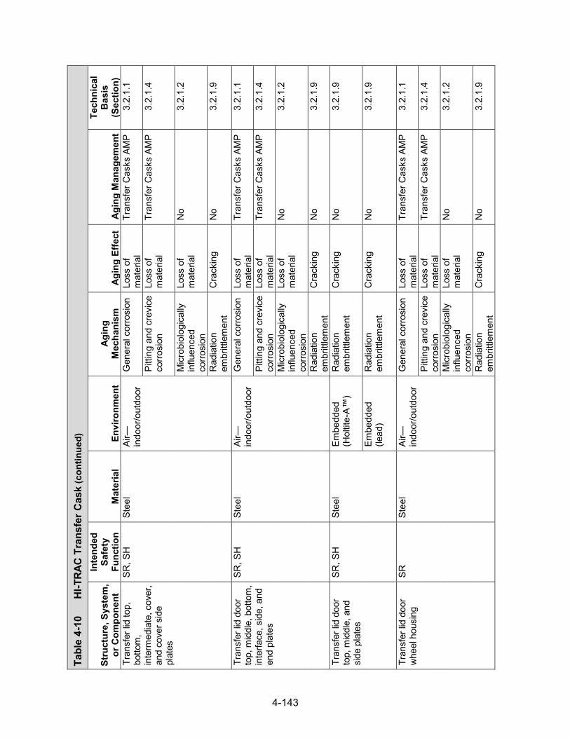
4-143
Tabl
e 4-
10
HI-T
RAC
Tran
sfer
Cas
k (con
tinued)
Stru
ctur
e, S
yste
m,
or C
ompo
nent
Inte
nded
Sa
fety
Fu
nctio
n M
ater
ial
Envi
ronm
ent
Agin
g M
echa
nism
Ag
ing
Effe
ct
Agin
g M
anag
emen
t
Tech
nica
l B
asis
(S
ectio
n)
Tran
sfer
lid
top,
bo
ttom
, in
term
edia
te, c
over
, an
d co
ver s
ide
plat
es
SR, S
H
Stee
l Ai
r—in
door
/out
door
G
ener
al c
orro
sion
Lo
ss o
f m
ater
ial
Tran
sfer
Cas
ks A
MP
3.2.
1.1
Pitti
ng a
nd c
revi
ce
corro
sion
Lo
ss o
f m
ater
ial
Tran
sfer
Cas
ks A
MP
3.2.
1.4
Mic
robi
olog
ical
ly
influ
ence
d co
rrosi
on
Loss
of
mat
eria
l N
o 3.
2.1.
2
Rad
iatio
n em
britt
lem
ent
Cra
ckin
g N
o 3.
2.1.
9
Tran
sfer
lid
door
to
p, m
iddl
e, b
otto
m,
inte
rface
, sid
e, a
nd
end
plat
es
SR, S
H
Stee
l Ai
r—in
door
/out
door
G
ener
al c
orro
sion
Lo
ss o
f m
ater
ial
Tran
sfer
Cas
ks A
MP
3.2.
1.1
Pitti
ng a
nd c
revi
ce
corro
sion
Lo
ss o
f m
ater
ial
Tran
sfer
Cas
ks A
MP
3.2.
1.4
Mic
robi
olog
ical
ly
influ
ence
d co
rrosi
on
Loss
of
mat
eria
l N
o 3.
2.1.
2
Rad
iatio
n em
britt
lem
ent
Cra
ckin
g N
o 3.
2.1.
9
Tran
sfer
lid
door
to
p, m
iddl
e, a
nd
side
pla
tes
SR, S
H
Stee
l Em
bedd
ed
(Hol
tite-
A™)
Rad
iatio
n em
britt
lem
ent
Cra
ckin
g N
o 3.
2.1.
9
Embe
dded
(le
ad)
Rad
iatio
n em
britt
lem
ent
Cra
ckin
g N
o 3.
2.1.
9
Tran
sfer
lid
door
w
heel
hou
sing
SR
St
eel
Air—
indo
or/o
utdo
or
Gen
eral
cor
rosi
on
Loss
of
mat
eria
l Tr
ansf
er C
asks
AM
P 3.
2.1.
1
Pitti
ng a
nd c
revi
ce
corro
sion
Lo
ss o
f m
ater
ial
Tran
sfer
Cas
ks A
MP
3.2.
1.4
Mic
robi
olog
ical
ly
influ
ence
d co
rrosi
on
Loss
of
mat
eria
l N
o 3.
2.1.
2
Rad
iatio
n em
britt
lem
ent
Cra
ckin
g N
o 3.
2.1.
9

4-144
Tabl
e 4-
10
HI-T
RAC
Tran
sfer
Cas
k (con
tinued)
Stru
ctur
e, S
yste
m,
or C
ompo
nent
Inte
nded
Sa
fety
Fu
nctio
n M
ater
ial
Envi
ronm
ent
Agin
g M
echa
nism
Ag
ing
Effe
ct
Agin
g M
anag
emen
t
Tech
nica
l B
asis
(S
ectio
n)
Tran
sfer
lid
door
w
heel
hou
sing
SR
St
eel
Embe
dded
(le
ad)
Rad
iatio
n em
britt
lem
ent
Cra
ckin
g N
o 3.
2.1.
9
Embe
dded
(H
oltit
e-A™
) R
adia
tion
embr
ittle
men
t C
rack
ing
No
3.2.
1.9
Tran
sfer
lid
whe
el
shaf
t SR
St
eel
Air—
indo
or/o
utdo
or
Gen
eral
cor
rosi
on
Loss
of
mat
eria
l Tr
ansf
er C
asks
AM
P 3.
2.1.
1
Pitti
ng a
nd c
revi
ce
corro
sion
Lo
ss o
f m
ater
ial
Tran
sfer
Cas
ks A
MP
3.2.
1.4
Mic
robi
olog
ical
ly
influ
ence
d co
rrosi
on
Loss
of
mat
eria
l N
o 3.
2.1.
2
Rad
iatio
n em
britt
lem
ent
Cra
ckin
g N
o 3.
2.1.
9
Tran
sfer
lid
hous
ing
stiff
ener
SR
St
eel
Air—
indo
or/o
utdo
or
Gen
eral
cor
rosi
on
Loss
of
mat
eria
l Tr
ansf
er C
asks
AM
P 3.
2.1.
1
Pitti
ng a
nd c
revi
ce
corro
sion
Lo
ss o
f m
ater
ial
Tran
sfer
Cas
ks A
MP
3.2.
1.4
Mic
robi
olog
ical
ly
influ
ence
d co
rrosi
on
Loss
of
mat
eria
l N
o 3.
2.1.
2
Rad
iatio
n em
britt
lem
ent
Cra
ckin
g N
o 3.
2.1.
9
Tran
sfer
lid
door
lo
ck b
olt
SR
Stee
l Ai
r—in
door
/out
door
G
ener
al c
orro
sion
Lo
ss o
f m
ater
ial
Tran
sfer
Cas
ks A
MP
3.2.
1.1
Pitti
ng a
nd c
revi
ce
corro
sion
Lo
ss o
f m
ater
ial
Tran
sfer
Cas
ks A
MP
3.2.
1.4
Mic
robi
olog
ical
ly
influ
ence
d co
rrosi
on
Loss
of
mat
eria
l N
o 3.
2.1.
2
Rad
iatio
n em
britt
lem
ent
Cra
ckin
g N
o 3.
2.1.
9

4-145
Tabl
e 4-
10
HI-T
RAC
Tran
sfer
Cas
k (con
tinued)
Stru
ctur
e, S
yste
m,
or C
ompo
nent
Inte
nded
Sa
fety
Fu
nctio
n M
ater
ial
Envi
ronm
ent
Agin
g M
echa
nism
Ag
ing
Effe
ct
Agin
g M
anag
emen
t
Tech
nica
l B
asis
(S
ectio
n)
Tran
sfer
lid
door
lo
ck b
olt
SR
Stee
l Ai
r—in
door
/out
door
St
ress
rela
xatio
n Lo
ss o
f pr
eloa
d N
o 3.
2.1.
10
Tran
sfer
lid
liftin
g lu
g, lu
g pa
d SR
St
eel
Air—
indo
or/o
utdo
or
Gen
eral
cor
rosi
on
Loss
of
mat
eria
l Tr
ansf
er C
asks
AM
P 3.
2.1.
1
Pitti
ng a
nd c
revi
ce
corro
sion
Lo
ss o
f m
ater
ial
Tran
sfer
Cas
ks A
MP
3.2.
1.4
Mic
robi
olog
ical
ly
influ
ence
d co
rrosi
on
Loss
of
mat
eria
l N
o 3.
2.1.
2
Rad
iatio
n em
britt
lem
ent
Cra
ckin
g N
o 3.
2.1.
9
Tran
sfer
lid
whe
el
track
SR
St
eel
Air—
indo
or/o
utdo
or
Gen
eral
cor
rosi
on
Loss
of
mat
eria
l Tr
ansf
er C
asks
AM
P 3.
2.1.
1
Pitti
ng a
nd c
revi
ce
corro
sion
Lo
ss o
f m
ater
ial
Tran
sfer
Cas
ks A
MP
3.2.
1.4
Mic
robi
olog
ical
ly
influ
ence
d co
rrosi
on
Loss
of
mat
eria
l N
o 3.
2.1.
2
Rad
iatio
n em
britt
lem
ent
Cra
ckin
g N
o 3.
2.1.
9
Wea
r Lo
ss o
f m
ater
ial
Tran
sfer
Cas
ks A
MP
3.2.
1.11
Tran
sfer
lid
door
st
op b
lock
SR
St
eel
Air—
indo
or/o
utdo
or
Gen
eral
cor
rosi
on
Loss
of
mat
eria
l Tr
ansf
er C
asks
AM
P 3.
2.1.
1
Pitti
ng a
nd c
revi
ce
corro
sion
Lo
ss o
f m
ater
ial
Tran
sfer
Cas
ks A
MP
3.2.
1.4
Mic
robi
olog
ical
ly
influ
ence
d co
rrosi
on
Loss
of
mat
eria
l N
o 3.
2.1.
2
Rad
iatio
n Em
britt
lem
ent
Cra
ckin
g N
o 3.
2.1.
9

4-146
Tabl
e 4-
10
HI-T
RAC
Tran
sfer
Cas
k (con
tinued)
Stru
ctur
e, S
yste
m,
or C
ompo
nent
Inte
nded
Sa
fety
Fu
nctio
n M
ater
ial
Envi
ronm
ent
Agin
g M
echa
nism
Ag
ing
Effe
ct
Agin
g M
anag
emen
t
Tech
nica
l B
asis
(S
ectio
n)
Tran
sfer
lid
door
st
op b
lock
bol
t SR
St
eel
Air—
indo
or/o
utdo
or
Gen
eral
cor
rosi
on
Loss
of
mat
eria
l Tr
ansf
er C
asks
AM
P 3.
2.1.
1
Pitti
ng a
nd c
revi
ce
corro
sion
Lo
ss o
f m
ater
ial
Tran
sfer
Cas
ks A
MP
3.2.
1.4
Mic
robi
olog
ical
ly
influ
ence
d co
rrosi
on
Loss
of
mat
eria
l N
o 3.
2.1.
2
Rad
iatio
n em
britt
lem
ent
Cra
ckin
g N
o 3.
2.1.
9
Stre
ss re
laxa
tion
Loss
of
prel
oad
No
3.2.
1.10
Tran
sfer
lid
door
sh
ield
ing
SH, T
H
Hol
tite-
A™
Embe
dded
(s
teel
) R
adia
tion
embr
ittle
men
t C
rack
ing
TLAA
/AM
P or
a
supp
ortin
g an
alys
is is
re
quire
d
3.3.
1.3
Ther
mal
agi
ng
Loss
of
fract
ure
toug
hnes
s an
d lo
ss o
f duc
tility
TLAA
/AM
P or
a
supp
ortin
g an
alys
is is
re
quire
d
3.3.
1.2
Boro
n de
plet
ion
Loss
of
shie
ldin
g TL
AA/A
MP
or a
su
ppor
ting
anal
ysis
is
requ
ired
3.3.
1.1
Tran
sfer
lid
door
le
ad s
hiel
d SH
, TH
Le
ad
Embe
dded
(s
teel
) N
one
iden
tifie
d N
one
iden
tifie
d N
o 3.
2.5.
4
Tran
sfer
lid
side
le
ad s
hiel
d SH
, TH
Le
ad
Embe
dded
(s
teel
) N
one
iden
tifie
d N
one
iden
tifie
d N
o 3.
2.5.
4

4-147
4.4 TN-32 and TN-68 Systems
4.4.1 System Description
The Transnuclear Inc. (TN) spent-fuel storage cask is a vertical metal cask with a bolted lid closure and two metallic O-rings forming the seal. As a storage cask, it provides confinement, shielding, criticality control, and passive heat removal. There are three types of TN metal storage casks: TN-32, TN-40 (TN-40HT), and TN-68. Only the TN-32 (NRC Docket 72-1021) and TN-68 (NRC Docket 72-1027) casks are evaluated here. The TN-32 cask accommodates 32 PWR fuel assemblies. The TN-68 cask accommodates up to 68 BWR fuel assemblies and is also licensed for transportation. Damaged fuel that can be handled by normal means may be stored in eight peripheral compartments of the TN-68 cask that are fitted with damaged-fuel end caps designed to retain gross fragments of fuel.
4.4.2 Bolted Metal Cask
The TN-32 and TN-68 cask body is a right circular cylinder composed of the following components: (i) confinement vessel with bolted lid closure, (ii) basket for fuel assemblies, (iii) gamma and neutron shield, (iv) pressure/leak-tightness monitoring system, (v) weathercover, and (vi) and trunnions. Figure 4-17 shows the components of the TN-32 cask, andFigure 4-18 shows the confinement-boundary components of the TN-68 cask. The details of thecomponents of the TN-32 cask are provided below as an example of both TN metal casks.
Confinement boundary, closure lid, and pressure-monitoring system
The TN-32 cask confinement boundary consists of a welded cylindrical low-alloy steel inner shell with an integrally welded low-alloy steel bottom closure. A flange forging is welded to the top of the inner shell to accommodate a bolted low-alloy steel lid closure. The inner shell has a sprayed metallic aluminum coating for corrosion protection. The confinement vessel is surrounded by a carbon steel gamma shield wall and bottom. The cask is sealed with a carbon steel closure lid, which is secured to the top flange of the containment vessel by 48 bolts.
The closure lid uses a double-barrier seal system with two metallic O-rings (Helicoflex seals) forming the seal. The annular space between the metallic O-rings is connected to a pressure monitoring system placed between the lid and the protective cover, also called the weather cover, shown in Figure 4-19. Pressure in the tank of the pressure-monitoring system is maintained above the pressure in the cask cavity to prevent either flow of fission gases out of or air into the cask cavity, which, under normal storage conditions, is pressurized above atmospheric pressure with helium. The transducers/switches monitor the pressure in the annular space between the metallic O-rings to provide an indication of seal failure before any release is possible. Two identical transducers/switches are provided to ensure a functional system through redundancy.
The TN-32 cask body has four carbon steel trunnions that are welded to the gamma shield. Two of these are located near the top of the cylindrical steel forging, spaced 180 degrees apart, and are used for lifting the cask. The remaining two trunnions are 180 degrees apart and located near the bottom of the cask. The lower trunnions are used to rotate the unloaded cask between vertical and horizontal positions. The lifting trunnions are hollow to permit installation of neutron-shielding material and eliminate a path for neutron streaming. The TN-68 design differs from the TN-32 design in that its two top trunnions are bolted to the gamma shield.

4-148
Figure 4-17 Components of the TN-32 Storage Cask (NRC, 1996)
Figure 4-18 TN-68 Cask Confinement Boundary Components (Transnuclear Inc., 2005)

4-149
Figure 4-19 TN-32 Cask Seal Pressure-monitoring System (NRC, 1996)
The TN-32 cask lid has three confinement access ports—a drain port, a vent port, and an overpressure system port. The drain and vent ports are covered by a bolted stainless steel closure plate having a double-barrier seal system with two metallic O-rings forming the seal, similar to the one used for the lid closure. The overpressure port is also covered by a bolted stainless steel closure plate but has a single metallic O-ring forming the seal. The closure lid has drilled interseal passageways connecting the annular space between the seals at each port to the annular space between the closure-lid seals, as shown in Figure 4-19. The cavity drain line penetrates the closure lid and terminates in the bottom of the cask cavity. This line is used to drain water from the cask cavity after underwater fuel loading. It is also used during the drying and helium backfilling of the cask cavity.
The all-metal Helicoflex seal used in the TN metal casks has a central helical energizing spring with inner and outer liners. Sealing is accomplished by plastic flow of the outer liner against the mating sealing surfaces. The helical spring aids in keeping a sufficient load against the outer liner to follow temperature fluctuations and small deformations.
The TN-32 confinement vessel has a cylindrical cavity that holds a fuel basket with 32 compartments to locate and support the PWR fuel assemblies. The basket assembly also transfers heat from the fuel assembly to the cask body wall and provides neutron absorption to satisfy nuclear criticality requirements, especially during loading and unloading operations that occur underwater. During storage, with the cavity dry, filled with inert gas, and sealed from the environment, criticality control measures within the cask are not necessary because of the low reactivity of the fuel in the dry cask and the assurance that no water can enter the cask during storage.
Fuel basket assemblies and shielding
The fuel cavities in the basket are formed by a sandwich of aluminum plates, Boral® plates, and stainless steel boxes. The stainless steel fuel-compartment box sections are attached by a

4-150
series of stainless steel plugs that pass through the aluminum plates and the poison plates and are fusion-welded to both adjacent stainless steel box sections. The aluminum provides the heat-conduction paths from the fuel assemblies to the cask cavity wall. The poison material provides the necessary criticality control. The basket is held in place by aluminum rails that run the axial length of the cask body, as shown in Figure 4-20.
Surrounding the outside of the confinement vessel wall is a steel gamma shield, as shown in Figure 4-21. The bolted closure lid provides the gamma shielding at the upper end of the cask body. Neutron emissions from the stored fuel are attenuated by a neutron shield, consisting of a borated polyester resin compound, enclosed in long aluminum boxes that surround the gamma shield. These aluminum containers are held in place by a steel shell. Neutron emissions from the top of the cask are attenuated by a polypropylene disc, encased in a steel shell and placed on the top of the closure lid. There is no neutron shielding provided on the bottom of the cask.
The inside surfaces of the inner shell and bottom have a sprayed metallic coating of aluminum for corrosion protection. The external surfaces of the cask are metal-sprayed with aluminum and/or painted for ease of decontamination and corrosion protection. The neutron shield, pressure-monitoring system, and shield cap are placed on top of the cask after fuel is loaded into the cask. A stainless steel overlay is applied to the O-ring seating surfaces on the body for corrosion protection. A protective cover is bolted to the top of the cask body to provide weather protection for the lid penetrations and other components.
Table 4-11 provides a generic evaluation of potential aging mechanisms and effects requiring management for specific components of the TN-32 and TN-68 casks. The AMPs that provide an acceptable approach to managing the aging effects are also identified in the table.
Figure 4-20 Radial Cross Section of TN-32 Cask Showing Basket, Basket Rails, and Gamma and Neutron Shields (NRC, 1996)

4-151
Figure 4-21 TN-32 Cask Shielding Configuration (NRC, 1996)

4-152
Tabl
e 4-
11
TN B
olte
d M
etal
Cas
ks
Stru
ctur
e,
Syst
em, o
r C
ompo
nent
Inte
nded
Sa
fety
Fu
nctio
n M
ater
ial
Envi
ronm
ent
Agin
g M
echa
nism
Ag
ing
Effe
ct
Agin
g M
anag
emen
t
Tech
nica
l B
asis
(S
ectio
n)
Out
er s
hell
SH, S
R,
TH*
Stee
l Ai
r—ou
tdoo
r G
ener
al c
orro
sion
Lo
ss o
f mat
eria
l M
onito
ring
of M
etal
lic
Surfa
ces
AMP
3.2.
1.1
Pitti
ng a
nd
crev
ice
corro
sion
Lo
ss o
f mat
eria
l M
onito
ring
of M
etal
lic
Surfa
ces
AMP
3.2.
1.2
Mic
robi
olog
ical
ly
influ
ence
d co
rrosi
on
Loss
of m
ater
ial
No
3.2.
1.4
Rad
iatio
n em
britt
lem
ent
Cra
ckin
g N
o 3.
2.1.
9
Rad
ial n
eutro
n sh
ield
SH
, TH
Bo
rate
d po
lyes
ter r
esin
Em
bedd
ed
(alu
min
um)
Rad
iatio
n em
britt
lem
ent
Cra
ckin
g TL
AA/A
MP
or a
su
ppor
ting
anal
ysis
is
requ
ired
3.3.
1.3
Ther
mal
ag
ing
Loss
of f
ract
ure
toug
hnes
s an
d lo
ss o
f duc
tility
TLAA
/AM
P or
a
supp
ortin
g an
alys
is is
re
quire
d
3.3.
1.2
Boro
n de
plet
ion
Loss
of s
hiel
ding
TL
AA/A
MP
or a
su
ppor
ting
anal
ysis
is
requ
ired
3.3.
1.1
Rad
ial n
eutro
n sh
ield
box
TH
Al
umin
um
Embe
dded
(b
orat
ed
poly
este
r re
sin)
Ther
mal
agi
ng
Loss
of s
treng
th
No
3.2.
3.7
Cre
ep
Cha
nge
in
dim
ensi
ons
No
3.2.
3.5
Rad
iatio
n em
britt
lem
ent
Cra
ckin
g N
o 3.
2.3.
8
Gam
ma
shie
ld
SH, S
R,
TH
Stee
l Ai
r—ou
tdoo
r G
ener
al c
orro
sion
Lo
ss o
f mat
eria
l M
onito
ring
of M
etal
lic
Surfa
ces
AMP
3.2.
1.1
Pitti
ng a
nd
crev
ice
corro
sion
Lo
ss o
f mat
eria
l M
onito
ring
of M
etal
lic
Surfa
ces
AMP
3.2.
1.2
*Saf
ety
Func
tions
: C
onfin
emen
t (C
O),
Subc
ritic
ality
(CR
), R
etrie
vabi
lity
(RE)
, Rad
iatio
n Sh
ield
ing
(SH
), St
ruct
ural
Inte
grity
(SR
), Th
erm
al/H
eat R
emov
al (T
H)
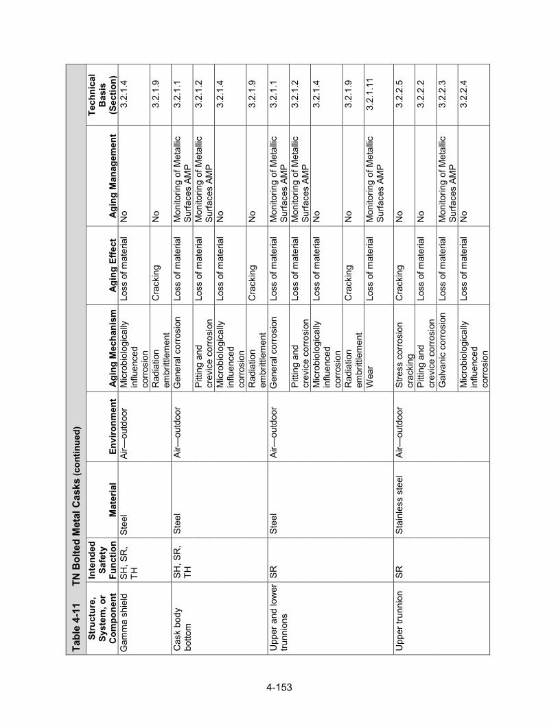
4-153
Tabl
e 4-
11
TN B
olte
d M
etal
Cas
ks (con
tinued)
Stru
ctur
e,
Syst
em, o
r C
ompo
nent
Inte
nded
Sa
fety
Fu
nctio
n M
ater
ial
Envi
ronm
ent
Agin
g M
echa
nism
Ag
ing
Effe
ct
Agin
g M
anag
emen
t
Tech
nica
l B
asis
(S
ectio
n)
Gam
ma
shie
ld
SH, S
R,
TH
Stee
l Ai
r—ou
tdoo
r M
icro
biol
ogic
ally
in
fluen
ced
corro
sion
Loss
of m
ater
ial
No
3.2.
1.4
Rad
iatio
n em
britt
lem
ent
Cra
ckin
g N
o 3.
2.1.
9
Cas
k bo
dy
botto
m
SH, S
R,
TH
Stee
l Ai
r—ou
tdoo
r G
ener
al c
orro
sion
Lo
ss o
f mat
eria
l M
onito
ring
of M
etal
lic
Surfa
ces
AMP
3.2.
1.1
Pitti
ng a
nd
crev
ice
corro
sion
Lo
ss o
f mat
eria
l M
onito
ring
of M
etal
lic
Surfa
ces
AMP
3.2.
1.2
Mic
robi
olog
ical
ly
influ
ence
d co
rrosi
on
Loss
of m
ater
ial
No
3.2.
1.4
Rad
iatio
n em
britt
lem
ent
Cra
ckin
g N
o 3.
2.1.
9
Upp
er a
nd lo
wer
tru
nnio
ns
SR
Stee
l Ai
r—ou
tdoo
r G
ener
al c
orro
sion
Lo
ss o
f mat
eria
l M
onito
ring
of M
etal
lic
Surfa
ces
AMP
3.2.
1.1
Pitti
ng a
nd
crev
ice
corro
sion
Lo
ss o
f mat
eria
l M
onito
ring
of M
etal
lic
Surfa
ces
AMP
3.2.
1.2
Mic
robi
olog
ical
ly
influ
ence
d co
rrosi
on
Loss
of m
ater
ial
No
3.2.
1.4
Rad
iatio
n em
britt
lem
ent
Cra
ckin
g N
o 3.
2.1.
9
Wea
r Lo
ss o
f mat
eria
l M
onito
ring
of M
etal
lic
Surfa
ces
AMP
3.2.
1.11
Upp
er tr
unni
on
SR
Stai
nles
s st
eel
Air—
outd
oor
Stre
ss c
orro
sion
cr
acki
ng
Cra
ckin
g N
o 3.
2.2.
5
Pitti
ng a
nd
crev
ice
corro
sion
Lo
ss o
f mat
eria
l N
o 3.
2.2.
2
Gal
vani
c co
rrosi
on
Loss
of m
ater
ial
Mon
itorin
g of
Met
allic
Su
rface
s AM
P 3.
2.2.
3
Mic
robi
olog
ical
ly
influ
ence
d co
rrosi
on
Loss
of m
ater
ial
No
3.2.
2.4

4-154
Tabl
e 4-
11
TN B
olte
d M
etal
Cas
ks (con
tinued)
Stru
ctur
e,
Syst
em, o
r C
ompo
nent
Inte
nded
Sa
fety
Fu
nctio
n M
ater
ial
Envi
ronm
ent
Agin
g M
echa
nism
Ag
ing
Effe
ct
Agin
g M
anag
emen
t
Tech
nica
l B
asis
(S
ectio
n)
Upp
er tr
unni
on
SR
Stai
nles
s st
eel
Air—
outd
oor
Rad
iatio
n em
britt
lem
ent
Cra
ckin
g N
o 3.
2.2.
9
Wea
r Lo
ss o
f mat
eria
l M
onito
ring
of M
etal
lic
Surfa
ces
AMP
3.2.
2.11
Trun
nion
bol
ts
SR
Stee
l Ai
r—ou
tdoo
r St
ress
rela
xatio
n Lo
ss o
f pre
load
N
o 3.
2.1.
10
Stre
ss c
orro
sion
cr
acki
ng
Cra
ckin
g N
o 3.
2.1.
5
Gen
eral
cor
rosi
on
Loss
of m
ater
ial
Mon
itorin
g of
Met
allic
Su
rface
s AM
P 3.
2.1.
1
Gal
vani
c co
rrosi
on
Loss
of m
ater
ial
Mon
itorin
g of
Met
allic
Su
rface
s AM
P 3.
2.1.
3
Pitti
ng a
nd
crev
ice
corro
sion
Lo
ss o
f mat
eria
l M
onito
ring
of M
etal
lic
Surfa
ces
AMP
3.2.
1.2
Mic
robi
olog
ical
ly
influ
ence
d co
rrosi
on
Loss
of m
ater
ial
No
3.2.
1.4
Rad
iatio
n em
britt
lem
ent
Cra
ckin
g N
o 3.
2.1.
9
Trun
nion
cov
er
scre
w
SH, S
R
Stai
nles
s st
eel
Air—
outd
oor
Stre
ss re
laxa
tion
Loss
of p
relo
ad
No
3.2.
2.10
St
ress
cor
rosi
on
crac
king
C
rack
ing
No
3.2.
2.5
Pitti
ng a
nd
crev
ice
corro
sion
Lo
ss o
f mat
eria
l N
o 3.
2.2.
2
Mic
robi
olog
ical
ly
influ
ence
d co
rrosi
on
Loss
of m
ater
ial
No
3.2.
2.4
Rad
iatio
n em
britt
lem
ent
Cra
ckin
g N
o 3.
2.2.
9
Top
neut
ron
shie
ld
SH, T
H
Poly
prop
ylen
e Em
bedd
ed
(ste
el)
Ther
mal
agi
ng
Loss
of f
ract
ure
toug
hnes
s an
d lo
ss o
f duc
tility
TLAA
/AM
P or
a
supp
ortin
g an
alys
is is
re
quire
d
3.3.
1.2
Rad
iatio
n em
britt
lem
ent
Cra
ckin
g N
o 3.
3.1.
3

4-155
Tabl
e 4-
11
TN B
olte
d M
etal
Cas
ks (con
tinued)
Stru
ctur
e,
Syst
em, o
r C
ompo
nent
Inte
nded
Sa
fety
Fu
nctio
n M
ater
ial
Envi
ronm
ent
Agin
g M
echa
nism
Ag
ing
Effe
ct
Agin
g M
anag
emen
t
Tech
nica
l B
asis
(S
ectio
n)
Top
neut
ron
shie
ld b
olt,
vent
& d
rain
po
rt co
ver
bolts
SR
Stai
nles
s st
eel
Shel
tere
d St
ress
rela
xatio
n Lo
ss o
f pre
load
N
o 3.
2.2.
10
Stre
ss c
orro
sion
cr
acki
ng
Cra
ckin
g N
o 3.
2.2.
5
Pitti
ng a
nd
crev
ice
corro
sion
Lo
ss o
f mat
eria
l N
o 3.
2.2.
2
Mic
robi
olog
ical
ly
influ
ence
d co
rrosi
on
Loss
of m
ater
ial
No
3.2.
2.4
Fatig
ue
Cra
ckin
g Ev
alua
te d
esig
n co
de
TLAA
, if a
pplic
able
3.
2.2.
7
Rad
iatio
n em
britt
lem
ent
Cra
ckin
g N
o 3.
2.2.
9
Stee
l Sh
elte
red
Stre
ss re
laxa
tion
Loss
of p
relo
ad
Bolte
d C
ask
Seal
Le
akag
e M
onito
ring
AMP
3.2.
1.10
Stre
ss c
orro
sion
cr
acki
ng
Cra
ckin
g N
o 3.
2.1.
5
Gen
eral
cor
rosi
on
Loss
of m
ater
ial
Bolte
d C
ask
Seal
Le
akag
e M
onito
ring
AMP
3.2.
1.1
Gal
vani
c co
rrosi
on
Loss
of m
ater
ial
Bolte
d C
ask
Seal
Le
akag
e M
onito
ring
AMP
3.2.
1.3
Pitti
ng a
nd
crev
ice
corro
sion
Lo
ss o
f mat
eria
l Bo
lted
Cas
k Se
al
Leak
age
Mon
itorin
g AM
P
3.2.
1.2
Mic
robi
olog
ical
ly
influ
ence
d co
rrosi
on
Loss
of m
ater
ial
No
3.2.
1.4
Fatig
ue
Cra
ckin
g Ev
alua
te d
esig
n co
de
TLAA
, if a
pplic
able
3.
2.1.
7
Rad
iatio
n em
britt
lem
ent
Cra
ckin
g N
o 3.
2.1.
9
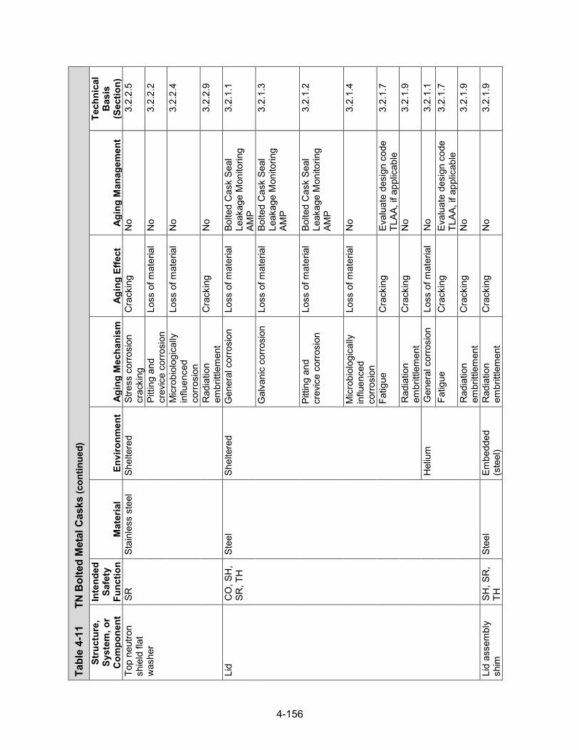
4-156
Tabl
e 4-
11
TN B
olte
d M
etal
Cas
ks (con
tinued)
Stru
ctur
e,
Syst
em, o
r C
ompo
nent
Inte
nded
Sa
fety
Fu
nctio
n M
ater
ial
Envi
ronm
ent
Agin
g M
echa
nism
Ag
ing
Effe
ct
Agin
g M
anag
emen
t
Tech
nica
l B
asis
(S
ectio
n)
Top
neut
ron
shie
ld fl
at
was
her
SR
Stai
nles
s st
eel
Shel
tere
d St
ress
cor
rosi
on
crac
king
C
rack
ing
No
3.2.
2.5
Pitti
ng a
nd
crev
ice
corro
sion
Lo
ss o
f mat
eria
l N
o 3.
2.2.
2
Mic
robi
olog
ical
ly
influ
ence
d co
rrosi
on
Loss
of m
ater
ial
No
3.2.
2.4
Rad
iatio
n em
britt
lem
ent
Cra
ckin
g N
o 3.
2.2.
9
Lid
CO
, SH
, SR
, TH
St
eel
Shel
tere
d G
ener
al c
orro
sion
Lo
ss o
f mat
eria
l Bo
lted
Cas
k Se
al
Leak
age
Mon
itorin
g AM
P
3.2.
1.1
Gal
vani
c co
rrosi
on
Loss
of m
ater
ial
Bolte
d C
ask
Seal
Le
akag
e M
onito
ring
AMP
3.2.
1.3
Pitti
ng a
nd
crev
ice
corro
sion
Lo
ss o
f mat
eria
l Bo
lted
Cas
k Se
al
Leak
age
Mon
itorin
g AM
P
3.2.
1.2
Mic
robi
olog
ical
ly
influ
ence
d co
rrosi
on
Loss
of m
ater
ial
No
3.2.
1.4
Fatig
ue
Cra
ckin
g Ev
alua
te d
esig
n co
de
TLAA
, if a
pplic
able
3.
2.1.
7
Rad
iatio
n em
britt
lem
ent
Cra
ckin
g N
o 3.
2.1.
9
Hel
ium
G
ener
al c
orro
sion
Lo
ss o
f mat
eria
l N
o 3.
2.1.
1 Fa
tigue
C
rack
ing
Eval
uate
des
ign
code
TL
AA, i
f app
licab
le
3.2.
1.7
Rad
iatio
n em
britt
lem
ent
Cra
ckin
g N
o 3.
2.1.
9
Lid
asse
mbl
y sh
im
SH, S
R,
TH
Stee
l Em
bedd
ed
(ste
el)
Rad
iatio
n em
britt
lem
ent
Cra
ckin
g N
o 3.
2.1.
9

4-157
Tabl
e 4-
11
TN B
olte
d M
etal
Cas
ks (con
tinued)
Stru
ctur
e,
Syst
em, o
r C
ompo
nent
Inte
nded
Sa
fety
Fu
nctio
n M
ater
ial
Envi
ronm
ent
Agin
g M
echa
nism
Ag
ing
Effe
ct
Agin
g M
anag
emen
t
Tech
nica
l B
asis
(S
ectio
n)
Flan
ge
CO
, SH
, SR
, TH
St
eel
Air—
outd
oor
Gen
eral
cor
rosi
on
Loss
of m
ater
ial
Mon
itorin
g of
Met
allic
Su
rface
s AM
P 3.
2.1.
1
Gal
vani
c co
rrosi
on
Loss
of m
ater
ial
Mon
itorin
g of
Met
allic
Su
rface
s AM
P 3.
2.1.
3
Pitti
ng a
nd
crev
ice
corro
sion
Lo
ss o
f mat
eria
l M
onito
ring
of M
etal
lic
Surfa
ces
AMP
3.2.
1.2
Mic
robi
olog
ical
ly
influ
ence
d co
rrosi
on
Loss
of m
ater
ial
No
3.2.
1.4
Fatig
ue
Cra
ckin
g Ev
alua
te d
esig
n co
de
TLAA
, if a
pplic
able
3.
2.1.
7
Rad
iatio
n em
britt
lem
ent
Cra
ckin
g N
o 3.
2.1.
9
Shel
tere
d G
ener
al c
orro
sion
Lo
ss o
f mat
eria
l Bo
lted
Cas
k Se
al
Leak
age
Mon
itorin
g AM
P
3.2.
1.1
Gal
vani
c co
rrosi
on
Loss
of m
ater
ial
Bolte
d C
ask
Seal
Le
akag
e M
onito
ring
AMP
3.2.
1.3
Pitti
ng a
nd
crev
ice
corro
sion
Lo
ss o
f mat
eria
l Bo
lted
Cas
k Se
al
Leak
age
Mon
itorin
g AM
P
3.2.
1.2
Mic
robi
olog
ical
ly
influ
ence
d co
rrosi
on
Loss
of m
ater
ial
No
3.2.
1.4
Fatig
ue
Cra
ckin
g Ev
alua
te d
esig
n co
de
TLAA
, if a
pplic
able
3.
2.1.
7
Rad
iatio
n em
britt
lem
ent
Cra
ckin
g N
o 3.
2.1.
9
Hel
ium
G
ener
al c
orro
sion
Lo
ss o
f mat
eria
l N
o 3.
2.1.
1
Fatig
ue
Cra
ckin
g Ev
alua
te d
esig
n co
de
TLAA
, if a
pplic
able
3.
2.1.
7
Rad
iatio
n em
britt
lem
ent
Cra
ckin
g N
o 3.
2.1.
9

4-158
Tabl
e 4-
11
TN B
olte
d M
etal
Cas
ks (con
tinued)
Stru
ctur
e,
Syst
em, o
r C
ompo
nent
Inte
nded
Sa
fety
Fu
nctio
n M
ater
ial
Envi
ronm
ent
Agin
g M
echa
nism
Ag
ing
Effe
ct
Agin
g M
anag
emen
t
Tech
nica
l B
asis
(S
ectio
n)
Lid
bolts
C
O, S
H,
SR, T
H
Stee
l Sh
elte
red
Stre
ss re
laxa
tion
Loss
of p
relo
ad
Bolte
d C
ask
Seal
Le
akag
e M
onito
ring
AMP
3.2.
1.10
Stre
ss c
orro
sion
cr
acki
ng
Cra
ckin
g N
o 3.
2.1.
5
Gen
eral
cor
rosi
on
Loss
of m
ater
ial
Bolte
d C
ask
Seal
Le
akag
e M
onito
ring
AMP
3.2.
1.1
Gal
vani
c co
rrosi
on
Loss
of m
ater
ial
Bolte
d C
ask
Seal
Le
akag
e M
onito
ring
AMP
3.2.
1.3
Pitti
ng a
nd
crev
ice
corro
sion
Lo
ss o
f mat
eria
l Bo
lted
Cas
k Se
al
Leak
age
Mon
itorin
g AM
P
3.2.
1.2
Mic
robi
olog
ical
ly
influ
ence
d co
rrosi
on
Loss
of m
ater
ial
No
3.2.
1.4
Fatig
ue
Cra
ckin
g Ev
alua
te d
esig
n co
de
TLAA
, if a
pplic
able
3.
2.1.
7
Rad
iatio
n em
britt
lem
ent
Cra
ckin
g N
o 3.
2.1.
9
Lid
thre
aded
in
sert
SR
Stai
nles
s st
eel
Shel
tere
d St
ress
cor
rosi
on
crac
king
C
rack
ing
No
3.2.
2.5
Pitti
ng a
nd
crev
ice
corro
sion
Lo
ss o
f mat
eria
l N
o 3.
2.2.
2
Mic
robi
olog
ical
ly
influ
ence
d co
rrosi
on
Loss
of m
ater
ial
No
3.2.
2.4
Rad
iatio
n em
britt
lem
ent
Cra
ckin
g N
o 3.
2.2.
9

4-159
Tabl
e 4-
11
TN B
olte
d M
etal
Cas
ks (con
tinued)
Stru
ctur
e,
Syst
em, o
r C
ompo
nent
Inte
nded
Sa
fety
Fu
nctio
n M
ater
ial
Envi
ronm
ent
Agin
g M
echa
nism
Ag
ing
Effe
ct
Agin
g M
anag
emen
t
Tech
nica
l B
asis
(S
ectio
n)
Lid
seal
, ven
t &
drai
n po
rt co
ver
seal
CO
, SH
, SR
, TH
Al
umin
um
Shel
tere
d G
ener
al c
orro
sion
Lo
ss o
f mat
eria
l Bo
lted
Cas
k Se
al
Leak
age
Mon
itorin
g AM
P
3.2.
3.1
Gal
vani
c co
rrosi
on
Loss
of m
ater
ial
Bolte
d C
ask
Seal
Le
akag
e M
onito
ring
AMP
3.2.
3.3
Pitti
ng a
nd
crev
ice
corro
sion
Lo
ss o
f mat
eria
l Bo
lted
Cas
k Se
al
Leak
age
Mon
itorin
g AM
P
3.2.
3.2
Mic
robi
olog
ical
ly
influ
ence
d co
rrosi
on
Loss
of m
ater
ial
No
3.2.
3.4
Rad
iatio
n em
britt
lem
ent
Cra
ckin
g N
o 3.
2.3.
8
Hel
ium
G
ener
al c
orro
sion
Lo
ss o
f mat
eria
l N
o 3.
2.3.
1
Ther
mal
ag
ing
Loss
of s
treng
th
Bolte
d C
ask
Seal
Le
akag
e M
onito
ring
AMP
3.2.
3.7
Cre
ep
Cha
nge
in
dim
ensi
ons
Bolte
d C
ask
Seal
Le
akag
e M
onito
ring
AMP
3.2.
3.5
Rad
iatio
n em
britt
lem
ent
Cra
ckin
g N
o 3.
2.3.
8
Dra
in p
ort
cove
r, ve
nt p
ort
cove
r
CO
, SH
, SR
, TH
St
ainl
ess
stee
l Sh
elte
red
Stre
ss c
orro
sion
cr
acki
ng
Cra
ckin
g N
o 3.
2.2.
5
Pitti
ng a
nd
crev
ice
corro
sion
Lo
ss o
f mat
eria
l N
o 3.
2.2.
2
Mic
robi
olog
ical
ly
influ
ence
d co
rrosi
on
Loss
of m
ater
ial
No
3.2.
2.4
Rad
iatio
n em
britt
lem
ent
Cra
ckin
g N
o 3.
2.2.
9

4-160
Tabl
e 4-
11
TN B
olte
d M
etal
Cas
ks (con
tinued)
Stru
ctur
e,
Syst
em, o
r C
ompo
nent
Inte
nded
Sa
fety
Fu
nctio
n M
ater
ial
Envi
ronm
ent
Agin
g M
echa
nism
Ag
ing
Effe
ct
Agin
g M
anag
emen
t
Tech
nica
l B
asis
(S
ectio
n)
Dra
in p
ort
cove
r, ve
nt p
ort
cove
r
CO
, SH
, SR
, TH
St
ainl
ess
stee
l H
eliu
m
Fatig
ue
Cra
ckin
g Ev
alua
te d
esig
n co
de
TLAA
, if a
pplic
able
3.
2.2.
7
Cre
ep
Cha
nge
in
dim
ensi
ons
No
3.2.
2.6
Rad
iatio
n em
britt
lem
ent
Cra
ckin
g N
o 3.
2.2.
9
Lid
shie
ld p
late
SH
, SR
, TH
St
eel
Hel
ium
G
ener
al c
orro
sion
Lo
ss o
f mat
eria
l N
o 3.
2.1.
1
Ther
mal
agi
ng
Loss
of f
ract
ure
toug
hnes
s an
d lo
ss o
f duc
tility
No
3.2.
1.8
Cre
ep
Cha
nge
in
dim
ensi
ons
No
3.2.
1.6
Rad
iatio
n em
britt
lem
ent
Cra
ckin
g N
o 3.
2.1.
9
Inne
r co
nfin
emen
t sh
ell,
botto
m
conf
inem
ent
plat
e
CO
, SH
, SR
, TH
St
eel
Hel
ium
G
ener
al c
orro
sion
Lo
ss o
f mat
eria
l N
o 3.
2.1.
1
Ther
mal
agi
ng
Loss
of f
ract
ure
toug
hnes
s an
d lo
ss o
f duc
tility
No
3.2.
1.8
Fatig
ue
Cra
ckin
g Ev
alua
te d
esig
n co
de
TLAA
, if a
pplic
able
3.
2.1.
7
Cre
ep
Cha
nge
in
dim
ensi
ons
No
3.2.
2.6
Rad
iatio
n em
britt
lem
ent
Cra
ckin
g N
o 3.
2.1.
9
Bask
et ra
ils
SR, T
H
Alum
inum
H
eliu
m
Gen
eral
cor
rosi
on
Loss
of m
ater
ial
No
3.2.
3.1
Ther
mal
agi
ng
Loss
of s
treng
th
TLAA
/AM
P or
a
supp
ortin
g an
alys
is is
re
quire
d
3.2.
3.7

4-161
Tabl
e 4-
11
TN B
olte
d M
etal
Cas
ks (con
tinued)
Stru
ctur
e,
Syst
em, o
r C
ompo
nent
Inte
nded
Sa
fety
Fu
nctio
n M
ater
ial
Envi
ronm
ent
Agin
g M
echa
nism
Ag
ing
Effe
ct
Agin
g M
anag
emen
t
Tech
nica
l B
asis
(S
ectio
n)
Bask
et ra
ils
SR, T
H
Alum
inum
H
eliu
m
Cre
ep
Cha
nge
in
dim
ensi
ons
TLAA
/AM
P or
a
supp
ortin
g an
alys
is is
re
quire
d
3.2.
3.5
Rad
iatio
n em
britt
lem
ent
Cra
ckin
g N
o 3.
2.3.
8
Bask
et ra
il sh
im
TH
Alum
inum
H
eliu
m
Gen
eral
cor
rosi
on
Loss
of m
ater
ial
No
3.2.
3.1
Cre
ep
Cha
nge
in
dim
ensi
ons
TLAA
/AM
P or
a
supp
ortin
g an
alys
is is
re
quire
d
3.2.
3.5
Rad
iatio
n em
britt
lem
ent
Cra
ckin
g N
o 3.
2.3.
8
Bask
et s
him
SR
, TH
St
ainl
ess
stee
l H
eliu
m
Cre
ep
Cha
nge
in
dim
ensi
ons
No
3.2.
2.6
Rad
iatio
n em
britt
lem
ent
Cra
ckin
g N
o 3.
2.2.
9
Alum
inum
pla
te
TH
Alum
inum
H
eliu
m
Gen
eral
cor
rosi
on
Loss
of m
ater
ial
No
3.2.
3.1
Gal
vani
c co
rrosi
on
Loss
of m
ater
ial
No
3.2.
3.3
Cre
ep
Cha
nge
in
dim
ensi
ons
No
3.2.
3.5
Rad
iatio
n em
britt
lem
ent
Cra
ckin
g N
o 3.
2.3.
8
Pois
on p
late
C
R, T
H
Bora
ted
alum
inum
H
eliu
m
Gen
eral
cor
rosi
on
Loss
of m
ater
ial
No
3.4.
2.1
Gal
vani
c co
rrosi
on
Loss
of m
ater
ial
No
3.4.
2.2
Ther
mal
agi
ng
Loss
of
stre
ngth
N
o 3.
4.2.
6
Cre
ep
Cha
nge
in
dim
ensi
ons
No
3.4.
2.5
Rad
iatio
n em
britt
lem
ent
Cra
ckin
g N
o 3.
4.2.
7

4-162
Tabl
e 4-
11
TN B
olte
d M
etal
Cas
ks (con
tinued)
Stru
ctur
e,
Syst
em, o
r C
ompo
nent
Inte
nded
Sa
fety
Fu
nctio
n M
ater
ial
Envi
ronm
ent
Agin
g M
echa
nism
Ag
ing
Effe
ct
Agin
g M
anag
emen
t
Tech
nica
l B
asis
(S
ectio
n)
Pois
on p
late
C
R, T
H
Bora
ted
alum
inum
H
eliu
m
Boro
n de
plet
ion
Red
uctio
n of
ne
utro
n-ab
sorb
ing
capa
city
No;
a T
LAA
may
be
requ
ired
3.4.
2.4
Boro
n ca
rbid
e/
alum
inum
m
etal
-mat
rix
com
posi
te
Hel
ium
G
ener
al c
orro
sion
Lo
ss o
f mat
eria
l N
o 3.
4.2.
1 G
alva
nic
corro
sion
Lo
ss o
f mat
eria
l N
o 3.
4.2.
2 Th
erm
al a
ging
Lo
ss o
f stre
ngth
N
o 3.
4.2.
6 C
reep
C
hang
e in
di
men
sion
s N
o 3.
4.2.
5
Rad
iatio
n em
britt
lem
ent
Cra
ckin
g N
o 3.
4.2.
7
Boro
n de
plet
ion
Red
uctio
n of
ne
utro
n-ab
sorb
ing
capa
city
No;
a T
LAA
may
be
requ
ired.
3.
4.2.
4
Bora
l®
Hel
ium
G
ener
al c
orro
sion
Lo
ss o
f mat
eria
l N
o 3.
4.2.
1 G
alva
nic
corro
sion
Lo
ss o
f mat
eria
l N
o 3.
4.2.
2 Th
erm
al a
ging
Lo
ss o
f st
reng
th
No
3.4.
2.6
Wet
cor
rosi
on
and
blis
terin
g C
hang
e in
di
men
sion
s N
o 3.
4.2.
3
Cre
ep
Cha
nge
in
dim
ensi
ons
No
3.4.
2.5
Rad
iatio
n em
britt
lem
ent
Cra
ckin
g N
o 3.
4.2.
7
Boro
n de
plet
ion
Red
uctio
n of
ne
utro
n-ab
sorb
ing
capa
city
No;
a T
LAA
may
be
requ
ired
3.4.
2.4

4-163
Tabl
e 4-
11
TN B
olte
d M
etal
Cas
ks (con
tinued)
Stru
ctur
e,
Syst
em, o
r C
ompo
nent
Inte
nded
Sa
fety
Fu
nctio
n M
ater
ial
Envi
ronm
ent
Agin
g M
echa
nism
Ag
ing
Effe
ct
Agin
g M
anag
emen
t
Tech
nica
l B
asis
(S
ectio
n)
Fuel
co
mpa
rtmen
t, st
ruct
ural
pl
ates
, bas
ket
hold
dow
n
CR
, SR
, TH
St
ainl
ess
stee
l (w
elde
d)
Hel
ium
Th
erm
al a
ging
Lo
ss o
f fra
ctur
e to
ughn
ess
and
loss
of d
uctil
ity
No
3.2.
2.8
Stai
nles
s st
eel
Hel
ium
Fa
tigue
C
rack
ing
Eval
uate
des
ign
code
TL
AA, i
f app
licab
le
3.2.
2.7
Cre
ep
Cha
nge
in
dim
ensi
ons
No
3.2.
2.6
Rad
iatio
n em
britt
lem
ent
Cra
ckin
g N
o 3.
2.2.
9
Bask
et s
hear
ke
y SR
St
eel
Hel
ium
G
ener
al c
orro
sion
Lo
ss o
f mat
eria
l N
o 3.
2.1.
1
Ther
mal
agi
ng
Loss
of f
ract
ure
toug
hnes
s an
d lo
ss o
f duc
tility
No
3.2.
1.8
Cre
ep
Cha
nge
in
dim
ensi
ons
No
3.2.
1.6
Rad
iatio
n em
britt
lem
ent
Cra
ckin
g N
o 3.
2.1.
9

4-164
4.5 NAC International Systems
4.5.1 System Description
NAC International Inc. (NAC) has three dry storage systems (DSSs) approved for use under a general license: the Universal Storage System (NAC-UMS), the Multi-Purpose Canister (NAC-MPC) system, and the Modular Advanced Generation Nuclear All-Purpose Storage (MAGNASTOR) system. These systems are canister-plus-overpack designs that use a vertical concrete storage cask to house a stainless steel storage canister with a welded closure. The sections below describe the details of the three storage systems.
4.5.2 NAC-UMS
The principal components of NAC-UMS are the transportable storage canister (TSC), vertical concrete cask (VCC), and transfer cask (TC), as shown in Figure 4-22 (NAC International, 2004). There are five TSC configurations of different lengths for storage of different classes of PWR and BWR fuel assemblies. The TSC assembly consists of a right circular cylindrical shell with a welded bottom plate, fuel basket, shield lid, two penetration port covers, and a structural lid. The cylindrical shell, bottom plate, and lids constitute the confinement boundary. Figure 4-23 shows the various components of the NAC-UMS TSC for PWR fuel. All TSC componentsare made of stainless steel, with the exception of neutron poison plates, heat transfer disks, andsupport disks (BWR TSC fuel baskets only). The fuel basket is designed to accommodate up to24 PWR or 56 BWR fuel assemblies. The fuel tubes are laterally supported by a series ofstainless steel support disks in the PWR basket or carbon steel support disks in the BWRbasket, which are retained by spacers on radially located tie rods. The carbon steel supportdisks are coated with electroless nickel. The square fuel tubes in the PWR basket includestainless-steel encased Boral® sheets on all four sides for criticality control. The square fueltubes in the BWR basket, including four oversized cross section fuel tubes, may includestainless-steel encased Boral® sheets on up to two sides for criticality control. Aluminum heattransfer disks are spaced midway between the support disks and are the primary path forconducting heat from the fuel assemblies to the TSC wall.
The VCC is the storage overpack for the TSC and provides structural support, shielding, protection from environmental conditions, and natural convection cooling of the TSC during storage. Five concrete casks of different lengths are designed to accommodate different TSC configurations. The VCC side walls consist of reinforced concrete and a carbon steel inner liner. The VCC has an annular air passage to allow the natural circulation of air around the canister to remove the decay heat from the spent fuel stored in the TSC. The steel-lined air inlet and outlet vents take nonplanar paths to the cask cavity to minimize radiation streaming. The base plate assembly contains the air inlets and the pedestal that supports the TSC inside the VCC. The top of the VCC is closed by a shield plug consisting of a carbon steel plate for gamma shielding and solid neutron shielding of Bisco NS-3 or NS-4-FR, and a carbon steel lid. The carbon steel lid is installed above the shield plug and is bolted in place. The VCC is lifted from the bottom using an air-pad system. In an alternative design, a set of four carbon steel lifting lugs at the top of the VCC allows for lifting the cask with a loaded TSC from the top end.
The transfer cask is used for the vertical transfer of the TSC between workstations and the VCC. Five TCs of different lengths are designed to handle the five TSC configurations. The TC incorporates a multiwall (steel/lead/neutron shield/steel) design and a top retaining ring that is bolted in place to prevent a loaded canister from being inadvertently removed through the top of the TC. All transfer cask structural components are fabricated with high-strength, low-alloy
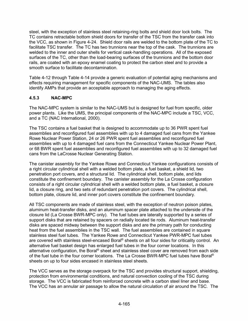
4-165
steel, with the exception of stainless steel retaining-ring bolts and shield door lock bolts. The TC contains retractable bottom shield doors for transfer of the TSC from the transfer cask into the VCC, as shown in Figure 4-24. Shield door rails are welded to the bottom plate of the TC to facilitate TSC transfer. The TC has two trunnions near the top of the cask. The trunnions are welded to the inner and outer shells for vertical cask-handling operations. All of the exposed surfaces of the TC, other than the load-bearing surfaces of the trunnions and the bottom door rails, are coated with an epoxy enamel coating to protect the carbon steel and to provide a smooth surface to facilitate decontamination.
Table 4-12 through Table 4-14 provide a generic evaluation of potential aging mechanisms and effects requiring management for specific components of the NAC-UMS. The tables also identify AMPs that provide an acceptable approach to managing the aging effects.
4.5.3 NAC-MPC
The NAC-MPC system is similar to the NAC-UMS but is designed for fuel from specific, older power plants. Like the UMS, the principal components of the NAC-MPC include a TSC, VCC, and a TC (NAC International, 2000).
The TSC contains a fuel basket that is designed to accommodate up to 36 PWR spent fuel assemblies and reconfigured fuel assemblies with up to 4 damaged fuel cans from the Yankee Rowe Nuclear Power Station, 24 or 26 PWR spent fuel assemblies and reconfigured fuel assemblies with up to 4 damaged fuel cans from the Connecticut Yankee Nuclear Power Plant, or 68 BWR spent fuel assemblies and reconfigured fuel assemblies with up to 32 damaged fuel cans from the LaCrosse Nuclear Generating Station.
The canister assembly for the Yankee Rowe and Connecticut Yankee configurations consists of a right circular cylindrical shell with a welded bottom plate, a fuel basket, a shield lid, two penetration port covers, and a structural lid. The cylindrical shell, bottom plate, and lids constitute the confinement boundary. The canister assembly for the La Crosse configuration consists of a right circular cylindrical shell with a welded bottom plate, a fuel basket, a closure lid, a closure ring, and two sets of redundant penetration port covers. The cylindrical shell, bottom plate, closure lid, and inner port covers constitute the confinement boundary.
All TSC components are made of stainless steel, with the exception of neutron poison plates, aluminum heat-transfer disks, and an aluminum spacer plate attached to the underside of the closure lid (La Crosse BWR-MPC only). The fuel tubes are laterally supported by a series of support disks that are retained by spacers on radially located tie rods. Aluminum heat-transfer disks are spaced midway between the support disks and are the primary path for conducting heat from the fuel assemblies in the TSC wall. The fuel assemblies are contained in square stainless steel fuel tubes. The Yankee Rowe and Connecticut Yankee PWR-MPC fuel tubes are covered with stainless steel-encased Boral® sheets on all four sides for criticality control. An alternative fuel basket design has enlarged fuel tubes in the four corner locations. In this alternative configuration, the Boral® sheet and stainless steel cover are removed from each side of the fuel tube in the four corner locations. The La Crosse BWR-MPC fuel tubes have Boral® sheets on up to four sides encased in stainless steel sheets.
The VCC serves as the storage overpack for the TSC and provides structural support, shielding, protection from environmental conditions, and natural convection cooling of the TSC during storage. The VCC is fabricated from reinforced concrete with a carbon steel liner and base. The VCC has an annular air passage to allow the natural circulation of air around the TSC. The

4-166
air inlet and outlet vents are steel-lined penetrations that take nonplanar paths to the cask cavity to minimize radiation streaming. The base-plate assembly contains the air inlets and the pedestal that supports the TSC inside the VCC. The top of the VCCs for the Yankee Rowe and Connecticut Yankee configurations is closed by a shield plug and a carbon steel lid bolted in place. The shield plug incorporates a carbon steel plate for gamma shielding and Bisco NS-3 or NS-4-FR for neutron shielding. For the La Crosse configuration, the top of the VCC is closed by a carbon steel and concrete lid bolted in place. The steel-enclosed concrete extends into the cask cavity from the bottom surface of the carbon steel lid.
The TC is similar in design and construction to that of the UMS described in Section 4.5.2. It is a multiwall (steel/lead/neutron shield/steel) design with retractable bottom shield doors to allow the TSC to be lowered into the VCC.
Table 4-15 through Table 4-17 provide a generic evaluation of potential aging mechanisms and effects requiring management for specific components of the NAC-MPC system. The tables also identify AMPs that provide an acceptable approach to managing the effects of aging.
4.5.4 MAGNASTOR
NAC developed the MAGNASTOR system to improve upon its previous designs in terms of storage capacity, thermal performance, and operations. The principal components of the MAGNASTOR system include a TSC with a welded closure, a concrete cask, and a TC (NAC International, 2015). Figure 4-25 presents schematics of the MAGNASTOR system.
The TSC consists of a right circular cylindrical shell with a welded bottom plate, a fuel basket, a closure lid, a closure ring, and two sets of redundant penetration port covers. There are two TSC lengths to accommodate fuel of different lengths. The cylindrical shell plus the bottom plate, closure lid, and welded inner port covers are constructed of stainless steel and constitute the confinement boundary. The closure ring and the outer redundant port covers are also stainless steel and provide the required redundant closure for a welded canister system. There is an alternative closure lid design with a two-piece composite lid assembly that consists of a stainless steel closure lid and a carbon steel shield plate. The shield plate is coated with electroless nickel and bolted to the closure lid. The fuel basket, fabricated from carbon steel and coated with electroless nickel, is designed to accommodate up to 87 BWR fuel assemblies or 37 PWR fuel assemblies, including up to four damaged fuel can locations. The fuel basket design is an arrangement of square fuel tubes held in a right circular cylinder configuration using support weldments that are bolted to the outer fuel tubes. The fuel assembly cells in the fuel baskets include neutron absorber panels on up to four sides for criticality control. The materials of construction for the neutron absorber panels include Boral®, borated aluminum, and borated metal matrix composite. Each neutron absorber panel is covered by a stainless steel sheet to protect the material during fuel loading and unloading and to maintain it in position. The neutron absorber and stainless steel cover are secured to the fuel tube using weld posts located across the width and along the length of the fuel tube.
The concrete cask is the storage overpack for the TSC and provides structural support, shielding, protection from environmental conditions, and natural convection cooling of the TSC during storage. The concrete cask is a reinforced concrete structure with a carbon steel inner liner and base, shown in Figure 4-26 (NAC International, 2014). There are four concrete cask configurations of different lengths and design variations. The concrete cask provides an annular air passage to allow the natural circulation of air around the TSC to remove the decay heat from the stored spent fuel. The lower air inlets and upper air outlets are steel-lined penetrations in
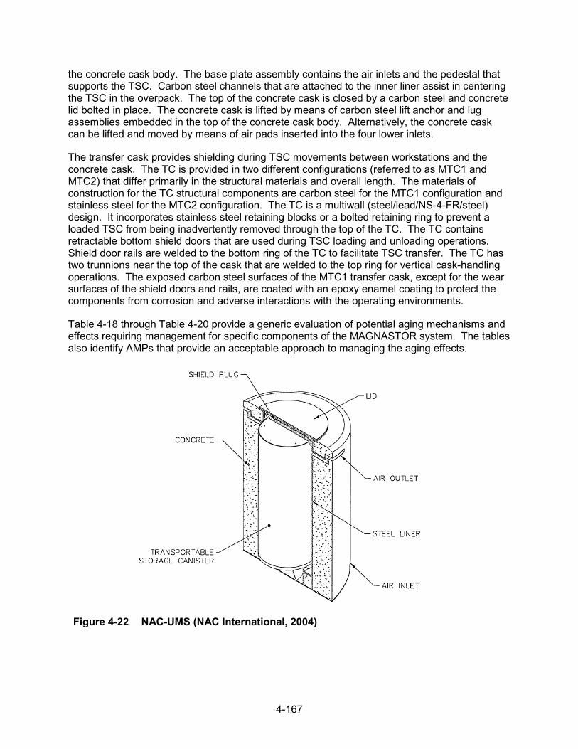
4-167
the concrete cask body. The base plate assembly contains the air inlets and the pedestal that supports the TSC. Carbon steel channels that are attached to the inner liner assist in centering the TSC in the overpack. The top of the concrete cask is closed by a carbon steel and concrete lid bolted in place. The concrete cask is lifted by means of carbon steel lift anchor and lug assemblies embedded in the top of the concrete cask body. Alternatively, the concrete cask can be lifted and moved by means of air pads inserted into the four lower inlets.
The transfer cask provides shielding during TSC movements between workstations and the concrete cask. The TC is provided in two different configurations (referred to as MTC1 and MTC2) that differ primarily in the structural materials and overall length. The materials of construction for the TC structural components are carbon steel for the MTC1 configuration and stainless steel for the MTC2 configuration. The TC is a multiwall (steel/lead/NS-4-FR/steel) design. It incorporates stainless steel retaining blocks or a bolted retaining ring to prevent a loaded TSC from being inadvertently removed through the top of the TC. The TC contains retractable bottom shield doors that are used during TSC loading and unloading operations. Shield door rails are welded to the bottom ring of the TC to facilitate TSC transfer. The TC has two trunnions near the top of the cask that are welded to the top ring for vertical cask-handling operations. The exposed carbon steel surfaces of the MTC1 transfer cask, except for the wear surfaces of the shield doors and rails, are coated with an epoxy enamel coating to protect the components from corrosion and adverse interactions with the operating environments.
Table 4-18 through Table 4-20 provide a generic evaluation of potential aging mechanisms and effects requiring management for specific components of the MAGNASTOR system. The tables also identify AMPs that provide an acceptable approach to managing the aging effects.
Figure 4-22 NAC-UMS (NAC International, 2004)
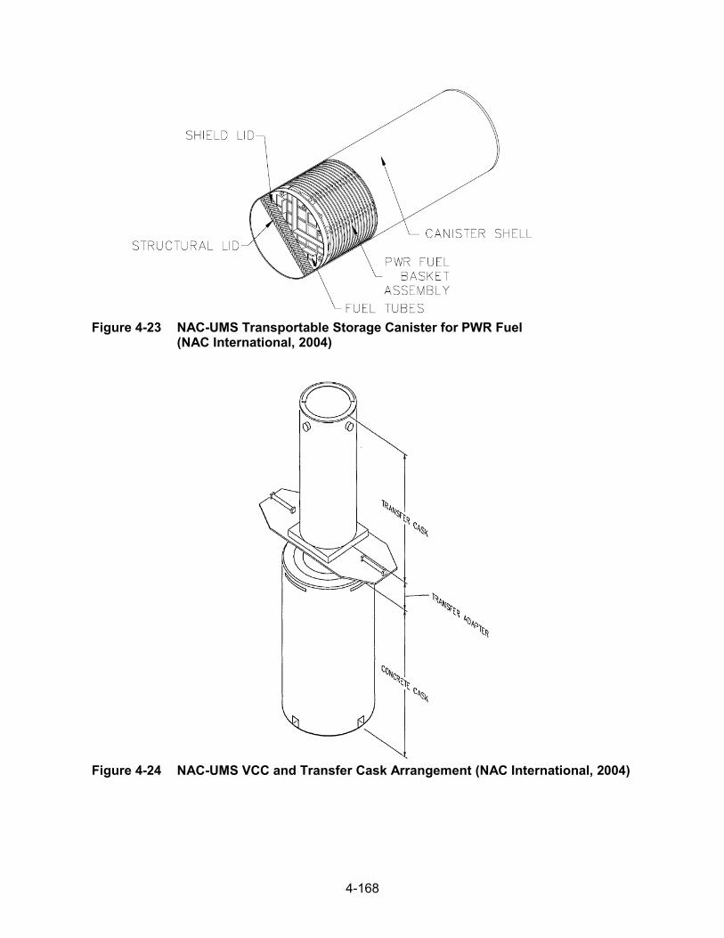
4-168
Figure 4-23 NAC-UMS Transportable Storage Canister for PWR Fuel (NAC International, 2004)
Figure 4-24 NAC-UMS VCC and Transfer Cask Arrangement (NAC International, 2004)

4-169
Figure 4-25 NAC MAGNASTOR TSC and Concrete Cask (NAC International, 2015)
Figure 4-26 NAC MAGNASTOR Concrete Cask (NAC International, 2014)

4-170
Tabl
e 4-
12
NAC
-UM
S Tr
ansp
orta
ble
Stor
age
Can
iste
r
Stru
ctur
e,
Syst
em,
or C
ompo
nent
Inte
nded
Sa
fety
Fu
nctio
n M
ater
ial
Envi
ronm
ent
Agin
g M
echa
nism
Ag
ing
Effe
ct
Agin
g M
anag
emen
t
Tech
nica
l Ba
sis
(Sec
tion)
Sh
ell
CO
, SR
* St
ainl
ess
stee
l (w
elde
d)
Shel
tere
d St
ress
cor
rosi
on
crac
king
C
rack
ing
Loca
lized
Cor
rosi
on
and
Stre
ss c
orro
sion
C
rack
ing
of W
elde
d St
ainl
ess
Stee
l Dry
St
orag
e C
anis
ters
AM
P
3.2.
2.5
Stai
nles
s st
eel
Shel
tere
d Pi
tting
and
cr
evice
cor
rosi
on
Loss
of m
ater
ial
(Pre
curs
or to
st
ress
cor
rosi
on
crac
king
)
Loca
lized
Cor
rosi
on
and
Stre
ss c
orro
sion
C
rack
ing
of W
elde
d St
ainl
ess
Stee
l Dry
St
orag
e C
anis
ters
AM
P
3.2.
2.2
Micr
obio
logi
cally
in
fluen
ced
corro
sion
Loss
of m
ater
ial
No
3.2.
2.4
Fatig
ue
Cra
ckin
g Ev
alua
te d
esig
n co
de
TLAA
, if a
pplic
able
3.
2.2.
7
Rad
iatio
n em
britt
lem
ent
Cra
ckin
g N
o 3.
2.2.
9
Hel
ium
R
adia
tion
embr
ittle
men
t C
rack
ing
No
3.2.
2.9
Botto
m
CO
, SR
St
ainl
ess
stee
l (w
elde
d)
Shel
tere
d St
ress
cor
rosi
on
crac
king
C
rack
ing
Loca
lized
Cor
rosi
on
and
Stre
ss c
orro
sion
C
rack
ing
of W
elde
d St
ainl
ess
Stee
l Dry
St
orag
e C
anis
ters
AM
P
3.2.
2.5
Stai
nles
s st
eel
Shel
tere
d Pi
tting
and
cr
evice
cor
rosi
on
Loss
of m
ater
ial
(Pre
curs
or to
st
ress
cor
rosi
on
crac
king
)
Loca
lized
Cor
rosi
on
and
Stre
ss c
orro
sion
C
rack
ing
of W
elde
d St
ainl
ess
Stee
l Dry
St
orag
e C
anis
ters
AM
P
3.2.
2.2
*Saf
ety
Func
tions
: C
onfin
emen
t (C
O),
Subc
ritica
lity (C
R),
Ret
rieva
bility
(RE)
, Rad
iatio
n Sh
ield
ing
(SH
), St
ruct
ural
Inte
grity
(SR
), Th
erm
al/H
eat R
emov
al (T
H)

4-171
Tabl
e 4-
12
NAC-
UM
S Tr
ansp
orta
ble
Stor
age
Can
iste
r (continued)
Stru
ctur
e,
Syst
em,
or C
ompo
nent
Inte
nded
Sa
fety
Fu
nctio
n M
ater
ial
Envi
ronm
ent
Agin
g M
echa
nism
Ag
ing
Effe
ct
Agin
g M
anag
emen
t
Tech
nica
l Ba
sis
(Sec
tion)
Bo
ttom
C
O, S
R
Stai
nles
s st
eel
Shel
tere
d M
icrob
iolo
gica
lly
influ
ence
d co
rrosi
on
Loss
of m
ater
ial
No
3.2.
2.4
Fatig
ue
Cra
ckin
g Ev
alua
te d
esig
n co
de
TLAA
, if a
pplic
able
3.
2.2.
7
Rad
iatio
n em
britt
lem
ent
Cra
ckin
g N
o 3.
2.2.
9
Hel
ium
R
adia
tion
embr
ittle
men
t C
rack
ing
No
3.2.
2.9
Stru
ctur
al lid
SR
St
ainl
ess
stee
l (w
elde
d)
Shel
tere
d St
ress
cor
rosi
on
crac
king
C
rack
ing
Loca
lized
Cor
rosi
on
and
Stre
ss c
orro
sion
C
rack
ing
of W
elde
d St
ainl
ess
Stee
l Dry
St
orag
e C
anis
ters
AM
P
3.2.
2.5
Stai
nles
s st
eel
Shel
tere
d Pi
tting
and
cr
evice
cor
rosi
on
Loss
of m
ater
ial
(Pre
curs
or to
st
ress
cor
rosi
on
crac
king
)
Loca
lized
Cor
rosi
on
and
Stre
ss c
orro
sion
C
rack
ing
of W
elde
d St
ainl
ess
Stee
l Dry
St
orag
e C
anis
ters
AM
P
3.2.
2.2
Micr
obio
logi
cally
in
fluen
ced
corro
sion
Loss
of m
ater
ial
No
3.2.
2.4
Fatig
ue
Cra
ckin
g Ev
alua
te d
esig
n co
de
TLAA
, if a
pplic
able
3.
2.2.
7
Rad
iatio
n em
britt
lem
ent
Cra
ckin
g N
o 3.
2.2.
9
Embe
dded
(s
tain
less
ste
el)
Rad
iatio
n em
britt
lem
ent
Cra
ckin
g N
o 3.
2.2.
9

4-172
Tabl
e 4-
12
NAC-
UM
S Tr
ansp
orta
ble
Stor
age
Can
iste
r (continued)
Stru
ctur
e,
Syst
em,
or C
ompo
nent
Inte
nded
Sa
fety
Fu
nctio
n M
ater
ial
Envi
ronm
ent
Agin
g M
echa
nism
Ag
ing
Effe
ct
Agin
g M
anag
emen
t
Tech
nica
l Ba
sis
(Sec
tion)
Sp
acer
ring
SR
St
ainl
ess
stee
l (w
elde
d)
Embe
dded
(s
tain
less
ste
el)
Stre
ss c
orro
sion
cr
acki
ng
Cra
ckin
g N
o 3.
2.2.
5
Stai
nles
s st
eel
Em
bedd
ed
(sta
inle
ss s
teel
) Pi
tting
and
cr
evice
cor
rosi
on
Loss
of m
ater
ial
(Pre
curs
or to
st
ress
cor
rosi
on
crac
king
)
No
3.2.
2.2
Micr
obio
logi
cally
in
fluen
ced
corro
sion
Loss
of m
ater
ial
No
3.2.
2.4
Rad
iatio
n em
britt
lem
ent
Cra
ckin
g N
o 3.
2.2.
9
Shie
ld lid
SH
, SR
St
ainl
ess
stee
l (w
elde
d)
Embe
dded
(s
tain
less
ste
el)
Stre
ss c
orro
sion
cr
acki
ng
Cra
ckin
g N
o 3.
2.2.
5
Stai
nles
s st
eel
Embe
dded
(s
tain
less
ste
el)
Pitti
ng a
nd
crev
ice c
orro
sion
Lo
ss o
f mat
eria
l (P
recu
rsor
to
stre
ss c
orro
sion
cr
acki
ng)
No
3.2.
2.2
Micr
obio
logi
cally
in
fluen
ced
corro
sion
Loss
of m
ater
ial
No
3.2.
2.4
Rad
iatio
n em
britt
lem
ent
Cra
ckin
g N
o 3.
2.2.
9
Hel
ium
R
adia
tion
embr
ittle
men
t C
rack
ing
No
3.2.
2.9

4-173
Tabl
e 4-
12
NAC-
UM
S Tr
ansp
orta
ble
Stor
age
Can
iste
r (continued)
Stru
ctur
e,
Syst
em,
or C
ompo
nent
Inte
nded
Sa
fety
Fu
nctio
n M
ater
ial
Envi
ronm
ent
Agin
g M
echa
nism
Ag
ing
Effe
ct
Agin
g M
anag
emen
t
Tech
nica
l Ba
sis
(Sec
tion)
Su
ppor
t rin
g SH
, SR
St
ainl
ess
stee
l (w
elde
d)
Hel
ium
Th
erm
al a
ging
Lo
ss o
f fra
ctur
e to
ughn
ess
and
loss
of d
uctili
ty
No
3.2.
2.8
Stai
nles
s st
eel
Hel
ium
C
reep
C
hang
e in
di
men
sion
s N
o 3.
2.2.
6
Rad
iatio
n em
britt
lem
ent
Cra
ckin
g N
o 3.
2.2.
9
Port
cove
r C
O
Stai
nles
s st
eel
(wel
ded)
Em
bedd
ed
(sta
inle
ss s
teel
) St
ress
cor
rosi
on
crac
king
C
rack
ing
No
3.2.
2.5
Stai
nles
s st
eel
Embe
dded
(s
tain
less
ste
el)
Pitti
ng a
nd
crev
ice c
orro
sion
Lo
ss o
f mat
eria
l (P
recu
rsor
to
stre
ss c
orro
sion
cr
acki
ng)
No
3.2.
2.2
Micr
obio
logi
cally
in
fluen
ced
corro
sion
Loss
of m
ater
ial
No
3.2.
2.4
Fatig
ue
Cra
ckin
g Ev
alua
te d
esig
n co
de
TLAA
, if a
pplic
able
3.
2.2.
7
Rad
iatio
n em
britt
lem
ent
Cra
ckin
g N
o 3.
2.2.
9
Hel
ium
R
adia
tion
embr
ittle
men
t C
rack
ing
No
3.2.
2.9
Fuel
tube
, cla
ddin
g,
flang
e C
R, S
R
Stai
nles
s st
eel
(wel
ded)
H
eliu
m
Ther
mal
agi
ng
Loss
of f
ract
ure
toug
hnes
s an
d lo
ss o
f duc
tility
No
3.2.
2.8
Stai
nles
s st
eel
Hel
ium
Fa
tigue
C
rack
ing
Eval
uate
des
ign
code
TL
AA, i
f app
licab
le
3.2.
2.7
Cre
ep
Cha
nge
in
dim
ensi
ons
No
3.2.
2.6
Rad
iatio
n em
britt
lem
ent
Cra
ckin
g N
o 3.
2.2.
9

4-174
Tabl
e 4-
12
NAC-
UM
S Tr
ansp
orta
ble
Stor
age
Can
iste
r (continued)
Stru
ctur
e,
Syst
em,
or C
ompo
nent
Inte
nded
Sa
fety
Fu
nctio
n M
ater
ial
Envi
ronm
ent
Agin
g M
echa
nism
Ag
ing
Effe
ct
Agin
g M
anag
emen
t
Tech
nica
l Ba
sis
(Sec
tion)
N
eutro
n ab
sorb
er
CR
Bo
ral
Hel
ium
G
ener
al c
orro
sion
Los
s of
mat
eria
l N
o 3.
4.2.
1
Gal
vani
c co
rrosi
on
Loss
of m
ater
ial
No
3.4.
2.2
Ther
mal
agi
ng
Loss
of s
treng
th
No
3.4.
2.6
Wet
cor
rosi
on
and
blist
erin
g C
hang
e in
di
men
sion
s N
o 3.
4.2.
3
Cre
ep
Cha
nge
in
dim
ensi
ons
No
3.4.
2.5
Rad
iatio
n em
britt
lem
ent
Cra
ckin
g N
o 3.
4.2.
7
Boro
n de
plet
ion
Red
uctio
n of
ne
utro
n-ab
sorb
ing
capa
city
No;
a T
LAA
may
be
requ
ired.
3.
4.2.
4
Fuel
bas
ket
botto
m w
eldm
ent
SR
Stai
nles
s st
eel
(wel
ded)
H
eliu
m
Ther
mal
agi
ng
Loss
of f
ract
ure
toug
hnes
s an
d lo
ss o
f duc
tility
No
3.2.
2.8
Stai
nles
s st
eel
Hel
ium
Fa
tigue
C
rack
ing
Eval
uate
des
ign
code
TL
AA, i
f app
licab
le
3.2.
2.7
Cre
ep
Cha
nge
in
dim
ensi
ons
No
3.2.
2.6
Rad
iatio
n em
britt
lem
ent
Cra
ckin
g N
o 3.
2.2.
9
Fuel
bas
ket t
op
wel
dmen
t SR
St
ainl
ess
stee
l (w
elde
d)
Hel
ium
Th
erm
al a
ging
Lo
ss o
f fra
ctur
e to
ughn
ess
and
loss
of d
uctili
ty
No
3.2.
2.8

4-175
Tabl
e 4-
12
NAC-
UM
S Tr
ansp
orta
ble
Stor
age
Can
iste
r (continued)
Stru
ctur
e,
Syst
em,
or C
ompo
nent
Inte
nded
Sa
fety
Fu
nctio
n M
ater
ial
Envi
ronm
ent
Agin
g M
echa
nism
Ag
ing
Effe
ct
Agin
g M
anag
emen
t
Tech
nica
l Ba
sis
(Sec
tion)
Fu
el b
aske
t top
w
eldm
ent
SR
Stai
nles
s st
eel
Hel
ium
Fa
tigue
C
rack
ing
Eval
uate
des
ign
code
TL
AA, i
f app
licab
le
3.2.
2.7
Cre
ep
Cha
nge
in
dim
ensi
ons
No
3.2.
2.6
Rad
iatio
n em
britt
lem
ent
Cra
ckin
g N
o 3.
2.2.
9
Fuel
bas
ket t
ie ro
d,
spac
er, w
ashe
r SR
St
ainl
ess
stee
l (w
elde
d)
Hel
ium
Th
erm
al a
ging
Lo
ss o
f fra
ctur
e to
ughn
ess
and
loss
of d
uctili
ty
No
3.2.
2.8
Stai
nles
s st
eel
Hel
ium
Fa
tigue
C
rack
ing
Eval
uate
des
ign
code
TL
AA, i
f app
licab
le
3.2.
2.7
Cre
ep
Cha
nge
in
dim
ensi
ons
No
3.2.
2.6
Rad
iatio
n em
britt
lem
ent
Cra
ckin
g N
o 3.
2.2.
9
Fuel
bas
ket s
uppo
rt di
sk
SR
Stai
nles
s st
eel
(17-
4 PH
) H
eliu
m
Ther
mal
agi
ng
Loss
of f
ract
ure
toug
hnes
s an
d lo
ss o
f duc
tility
TLAA
/AM
P or
a
supp
ortin
g an
alys
is is
re
quire
d
3.2.
2.8
Fatig
ue
Cra
ckin
g Ev
alua
te d
esig
n co
de
TLAA
, if a
pplic
able
3.
2.2.
7
Cre
ep
Cha
nge
in
dim
ensi
ons
No
3.2.
2.6
Rad
iatio
n em
britt
lem
ent
Cra
ckin
g N
o 3.
2.2.
9
Stee
l H
eliu
m
Gen
eral
cor
rosi
on L
oss
of m
ater
ial
No
3.2.
1.1

4-176
Tabl
e 4-
12
NAC-
UM
S Tr
ansp
orta
ble
Stor
age
Can
iste
r (continued)
Stru
ctur
e,
Syst
em,
or C
ompo
nent
Inte
nded
Sa
fety
Fu
nctio
n M
ater
ial
Envi
ronm
ent
Agin
g M
echa
nism
Ag
ing
Effe
ct
Agin
g M
anag
emen
t
Tech
nica
l Ba
sis
(Sec
tion)
Fu
el b
aske
t su
ppor
t disk
SR
St
eel
Hel
ium
Th
erm
al a
ging
Lo
ss o
f fra
ctur
e to
ughn
ess
and
loss
of d
uctili
ty
No
3.2.
1.8
Fatig
ue
Cra
ckin
g Ev
alua
te d
esig
n co
de
TLAA
, if a
pplic
able
3.
2.1.
7
Cre
ep
Cha
nge
in
dim
ensi
ons
No
3.2.
1.6
Rad
iatio
n em
britt
lem
ent
Cra
ckin
g N
o 3.
2.1.
9
Fuel
bas
ket t
op n
ut
SR
Stai
nles
s st
eel
Hel
ium
Th
erm
al a
ging
Lo
ss o
f fra
ctur
e to
ughn
ess
and
loss
of d
uctili
ty
No
3.2.
2.8
Fatig
ue
Cra
ckin
g Ev
alua
te d
esig
n co
de
TLAA
, if a
pplic
able
3.
2.2.
7
Cre
ep
Cha
nge
in
dim
ensi
ons
No
3.2.
2.6
Rad
iatio
n em
britt
lem
ent
Cra
ckin
g N
o 3.
2.2.
9
Stre
ss re
laxa
tion
Loss
of p
relo
ad
No
3.2.
2.10
Fuel
bas
ket h
eat
trans
fer d
isk
TH
Alum
inum
H
eliu
m
Gen
eral
cor
rosi
on L
oss
of m
ater
ial
No
3.2.
3.1
Ther
mal
agi
ng
Loss
of s
treng
th
No
3.2.
3.7
Cre
ep
Cha
nge
in
dim
ensi
ons
No
3.2.
3.5
Rad
iatio
n em
britt
lem
ent
Cra
ckin
g N
o 3.
2.3.
8

4-177
Tabl
e 4-
12
NAC-
UM
S Tr
ansp
orta
ble
Stor
age
Can
iste
r (continued)
Stru
ctur
e,
Syst
em,
or C
ompo
nent
Inte
nded
Sa
fety
Fu
nctio
n M
ater
ial
Envi
ronm
ent
Agin
g M
echa
nism
Ag
ing
Effe
ct
Agin
g M
anag
emen
t
Tech
nica
l Ba
sis
(Sec
tion)
M
aine
Yan
kee
dam
aged
fuel
can
tu
be b
ody
CR
, SR
St
ainl
ess
stee
l (w
elde
d)
Hel
ium
Th
erm
al a
ging
Lo
ss o
f fra
ctur
e to
ughn
ess
and
loss
of d
uctili
ty
No
3.2.
2.8
Stai
nles
s st
eel
Hel
ium
Fa
tigue
C
rack
ing
Eval
uate
des
ign
code
TL
AA, i
f app
licab
le
3.2.
2.7
Cre
ep
Cha
nge
in
dim
ensi
ons
No
3.2.
2.6
Rad
iatio
n em
britt
lem
ent
Cra
ckin
g N
o 3.
2.2.
9
Mai
ne Y
anke
e da
mag
ed fu
el c
an
botto
m a
nd s
ide
plat
es
CR
, SR
St
ainl
ess
stee
l (w
elde
d)
Hel
ium
Th
erm
al a
ging
Lo
ss o
f fra
ctur
e to
ughn
ess
and
loss
of d
uctili
ty
No
3.2.
2.8
Stai
nles
s st
eel
Hel
ium
Fa
tigue
C
rack
ing
Eval
uate
des
ign
code
TL
AA, i
f app
licab
le
3.2.
2.7
Cre
ep
Cha
nge
in
dim
ensi
ons
No
3.2.
2.6
Rad
iatio
n em
britt
lem
ent
Cra
ckin
g N
o 3.
2.2.
9
Mai
ne Y
anke
e da
mag
ed fu
el c
an
lid p
late
, lid
bot
tom
CR
, SR
St
ainl
ess
stee
l (w
elde
d)
Hel
ium
Th
erm
al a
ging
Lo
ss o
f fra
ctur
e to
ughn
ess
and
loss
of d
uctili
ty
No
3.2.
2.8
Stai
nles
s st
eel
Hel
ium
Fa
tigue
C
rack
ing
Eval
uate
des
ign
code
TL
AA, i
f app
licab
le
3.2.
2.7
Cre
ep
Cha
nge
in
dim
ensi
ons
No
3.2.
2.6
Rad
iatio
n em
britt
lem
ent
Cra
ckin
g N
o 3.
2.2.
9

4-178
Tabl
e 4-
12
NAC-
UM
S Tr
ansp
orta
ble
Stor
age
Can
iste
r (continued)
Stru
ctur
e,
Syst
em,
or C
ompo
nent
Inte
nded
Sa
fety
Fu
nctio
n M
ater
ial
Envi
ronm
ent
Agin
g M
echa
nism
Ag
ing
Effe
ct
Agin
g M
anag
emen
t
Tech
nica
l Ba
sis
(Sec
tion)
M
aine
Yan
kee
dam
aged
fuel
can
lift
tee,
sup
port
ring
SR
Stai
nles
s st
eel
(wel
ded)
H
eliu
m
Ther
mal
agi
ng
Loss
of f
ract
ure
toug
hnes
s an
d lo
ss o
f duc
tility
No
3.2.
2.8
Stai
nles
s st
eel
Hel
ium
Fa
tigue
C
rack
ing
Eval
uate
des
ign
code
TL
AA, i
f app
licab
le
3.2.
2.7
Cre
ep
Cha
nge
in
dim
ensi
ons
No
3.2.
2.6
Rad
iatio
n em
britt
lem
ent
Cra
ckin
g N
o 3.
2.2.
9
Mai
ne Y
anke
e da
mag
ed fu
el c
an
lid c
olla
r, sc
reen
CO
St
ainl
ess
stee
l H
eliu
m
Ther
mal
agi
ng
Loss
of f
ract
ure
toug
hnes
s an
d lo
ss o
f duc
tility
No
3.2.
2.8
Cre
ep
Cha
nge
in
dim
ensi
ons
No
3.2.
2.6
Rad
iatio
n em
britt
lem
ent
Cra
ckin
g N
o 3.
2.2.
9

4-179
Tabl
e 4-
13
NAC
-UM
S Ve
rtic
al C
oncr
ete
Cas
k
Stru
ctur
e,
Syst
em,
or C
ompo
nent
Inte
nded
Sa
fety
Fu
nctio
n M
ater
ial
Envi
ronm
ent
Agin
g M
echa
nism
Ag
ing
Effe
ct
Agin
g M
anag
emen
t Te
chni
cal
Basi
s (S
ectio
n)
Con
cret
e sh
ell
SH, S
R*
Con
cret
e Ai
r—ou
tdoo
r Ag
gres
sive
ch
emic
al a
ttack
C
rack
ing
Rei
nfor
ced
Con
cret
e St
ruct
ures
AM
P 3.
5.1.
5
Loss
of s
treng
th
Rei
nfor
ced
Con
cret
e St
ruct
ures
AM
P 3.
5.1.
5
Loss
of m
ater
ial
(spa
lling,
sca
ling)
Rei
nfor
ced
Con
cret
e St
ruct
ures
AM
P 3.
5.1.
5
Cre
ep
Cra
ckin
g N
o 3.
5.1.
2
Deh
ydra
tion
at
high
te
mpe
ratu
res
Cra
ckin
g N
o 3.
5.1.
11
Loss
of s
treng
th
No
3.5.
1.11
Del
ayed
ettr
ingi
te
form
atio
n Lo
ss o
f mat
eria
l (s
pallin
g, s
calin
g) N
o 3.
5.1.
13
Loss
of s
treng
th
No
3.5.
1.13
Cra
ckin
g N
o 3.
5.1.
13
Fatig
ue
Cra
ckin
g N
o 3.
5.1.
10
Free
ze a
nd th
aw
Cra
ckin
g R
einf
orce
d C
oncr
ete
Stru
ctur
es A
MP
3.5.
1.1
Loss
of m
ater
ial
(spa
lling,
sca
ling)
Rei
nfor
ced
Con
cret
e St
ruct
ures
AM
P 3.
5.1.
1
Rad
iatio
n da
mag
e C
rack
ing
No
3.5.
1.9
Loss
of s
treng
th
No
3.5.
1.9
*Saf
ety
Func
tions
: C
onfin
emen
t (C
O),
Subc
ritica
lity (C
R),
Ret
rieva
bility
(RE)
, Rad
iatio
n Sh
ield
ing
(SH
), St
ruct
ural
Inte
grity
(SR
), Th
erm
al/H
eat R
emov
al (T
H)

4-180
Tabl
e 4-
13
NAC-
UM
S Ve
rtic
al C
oncr
ete
Cas
k (con
tinued)
Stru
ctur
e,
Syst
em,
or C
ompo
nent
Inte
nded
Sa
fety
Fu
nctio
n M
ater
ial
Envi
ronm
ent
Agin
g M
echa
nism
Ag
ing
Effe
ct
Agin
g M
anag
emen
t Te
chni
cal
Basi
s (S
ectio
n)
Con
cret
e sh
ell
SH, S
R
Con
cret
e Ai
r—ou
tdoo
r R
eact
ion
with
ag
greg
ates
C
rack
ing
Rei
nfor
ced
Con
cret
e St
ruct
ures
AM
P 3.
5.1.
3
Loss
of s
treng
th
Rei
nfor
ced
Con
cret
e St
ruct
ures
AM
P 3.
5.1.
3
Salt
scal
ing
Loss
of m
ater
ial
(spa
lling,
sca
ling)
Rei
nfor
ced
Con
cret
e St
ruct
ures
AM
P 3.
5.1.
14
Shrin
kage
C
rack
ing
No
3.5.
1.7
Leac
hing
of
calci
um
hydr
oxid
e
Loss
of s
treng
th
Rei
nfor
ced
Con
cret
e St
ruct
ures
AM
P 3.
5.1.
8
Incr
ease
in
poro
sity
and
pe
rmea
bility
Rei
nfor
ced
Con
cret
e St
ruct
ures
AM
P 3.
5.1.
8
Red
uctio
n of
co
ncre
te p
H
(redu
cing
co
rrosi
on
resi
stan
ce o
f st
eel
embe
dmen
ts)
Rei
nfor
ced
Con
cret
e St
ruct
ures
AM
P 3.
5.1.
8
Rei
nfor
cing
ste
el
Air—
outd
oor
Cor
rosi
on o
f re
info
rcin
g st
eel
Loss
of
conc
rete
/ste
el
bond
Rei
nfor
ced
Con
cret
e St
ruct
ures
AM
P 3.
5.1.
6
Loss
of m
ater
ial
(spa
lling,
sca
ling)
Rei
nfor
ced
Con
cret
e St
ruct
ures
AM
P 3.
5.1.
6
Cra
ckin
g R
einf
orce
d C
oncr
ete
Stru
ctur
es A
MP
3.5.
1.6
Loss
of s
treng
th
Rei
nfor
ced
Con
cret
e St
ruct
ures
AM
P 3.
5.1.
6
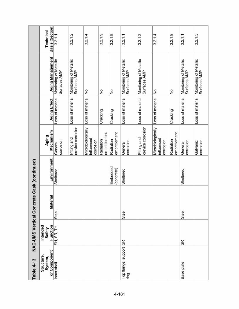
4-181
Tabl
e 4-
13
NAC-
UM
S Ve
rtic
al C
oncr
ete
Cas
k (con
tinued)
Stru
ctur
e,
Syst
em,
or C
ompo
nent
Inte
nded
Sa
fety
Fu
nctio
n M
ater
ial
Envi
ronm
ent
Agin
g M
echa
nism
Ag
ing
Effe
ct
Agin
g M
anag
emen
t Te
chni
cal
Basi
s (S
ectio
n)
Inne
r she
ll SH
, SR
, TH
St
eel
Shel
tere
d G
ener
al
corro
sion
Lo
ss o
f mat
eria
l M
onito
ring
of M
etal
lic
Surfa
ces
AMP
3.2.
1.1
Pitti
ng a
nd
crev
ice c
orro
sion
Lo
ss o
f mat
eria
l M
onito
ring
of M
etal
lic
Surfa
ces
AMP
3.2.
1.2
Micr
obio
logi
cally
in
fluen
ced
corro
sion
Loss
of m
ater
ial
No
3.2.
1.4
Rad
iatio
n em
britt
lem
ent
Cra
ckin
g N
o 3.
2.1.
9
Embe
dded
(c
oncr
ete)
R
adia
tion
embr
ittle
men
t C
rack
ing
No
3.2.
1.9
Top
flang
e, s
uppo
rt rin
g SR
St
eel
Shel
tere
d G
ener
al
corro
sion
Lo
ss o
f mat
eria
l M
onito
ring
of M
etal
lic
Surfa
ces
AMP
3.2.
1.1
Pitti
ng a
nd
crev
ice c
orro
sion
Lo
ss o
f mat
eria
l M
onito
ring
of M
etal
lic
Surfa
ces
AMP
3.2.
1.2
Micr
obio
logi
cally
in
fluen
ced
corro
sion
Loss
of m
ater
ial
No
3.2.
1.4
Rad
iatio
n em
britt
lem
ent
Cra
ckin
g N
o 3.
2.1.
9
Base
pla
te
SR
Stee
l Sh
elte
red
Gen
eral
co
rrosi
on
Loss
of m
ater
ial
Mon
itorin
g of
Met
allic
Su
rface
s AM
P 3.
2.1.
1
Gal
vani
c co
rrosi
on
Loss
of m
ater
ial
Mon
itorin
g of
Met
allic
Su
rface
s AM
P 3.
2.1.
3
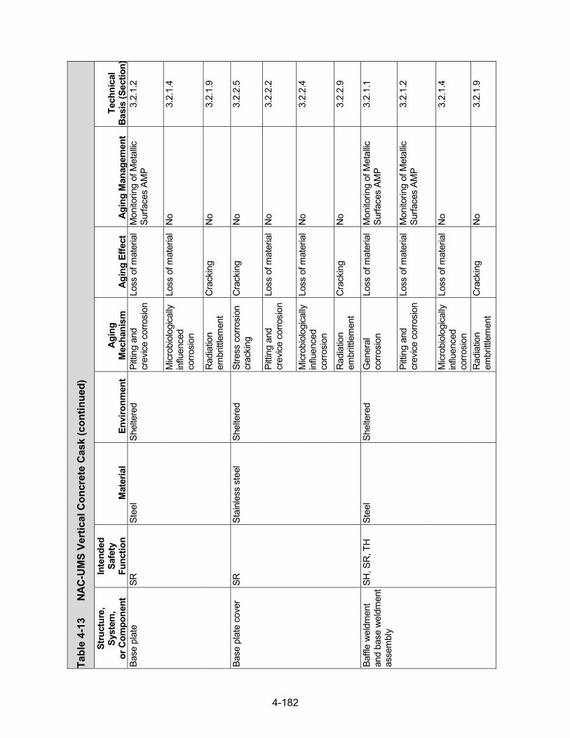
4-182
Tabl
e 4-
13
NAC-
UM
S Ve
rtic
al C
oncr
ete
Cas
k (con
tinued)
Stru
ctur
e,
Syst
em,
or C
ompo
nent
Inte
nded
Sa
fety
Fu
nctio
n M
ater
ial
Envi
ronm
ent
Agin
g M
echa
nism
Ag
ing
Effe
ct
Agin
g M
anag
emen
t Te
chni
cal
Basi
s (S
ectio
n)
Base
pla
te
SR
Stee
l Sh
elte
red
Pitti
ng a
nd
crev
ice c
orro
sion
Lo
ss o
f mat
eria
l M
onito
ring
of M
etal
lic
Surfa
ces
AMP
3.2.
1.2
Micr
obio
logi
cally
in
fluen
ced
corro
sion
Loss
of m
ater
ial
No
3.2.
1.4
Rad
iatio
n em
britt
lem
ent
Cra
ckin
g N
o 3.
2.1.
9
Base
pla
te c
over
SR
St
ainl
ess
stee
l Sh
elte
red
Stre
ss c
orro
sion
cr
acki
ng
Cra
ckin
g N
o 3.
2.2.
5
Pitti
ng a
nd
crev
ice c
orro
sion
Lo
ss o
f mat
eria
l N
o 3.
2.2.
2
Micr
obio
logi
cally
in
fluen
ced
corro
sion
Loss
of m
ater
ial
No
3.2.
2.4
Rad
iatio
n em
britt
lem
ent
Cra
ckin
g N
o 3.
2.2.
9
Baffl
e w
eldm
ent
and
base
wel
dmen
t as
sem
bly
SH, S
R, T
H
Stee
l Sh
elte
red
Gen
eral
co
rrosi
on
Loss
of m
ater
ial
Mon
itorin
g of
Met
allic
Su
rface
s AM
P 3.
2.1.
1
Pitti
ng a
nd
crev
ice c
orro
sion
Lo
ss o
f mat
eria
l M
onito
ring
of M
etal
lic
Surfa
ces
AMP
3.2.
1.2
Micr
obio
logi
cally
in
fluen
ced
corro
sion
Loss
of m
ater
ial
No
3.2.
1.4
Rad
iatio
n em
britt
lem
ent
Cra
ckin
g N
o 3.
2.1.
9

4-183
Tabl
e 4-
13
NAC-
UM
S Ve
rtic
al C
oncr
ete
Cas
k (con
tinued)
Stru
ctur
e,
Syst
em,
or C
ompo
nent
Inte
nded
Sa
fety
Fu
nctio
n M
ater
ial
Envi
ronm
ent
Agin
g M
echa
nism
Ag
ing
Effe
ct
Agin
g M
anag
emen
t Te
chni
cal
Basi
s (S
ectio
n)
Base
pla
te n
elso
n st
uds
SR
Stee
l Em
bedd
ed
(con
cret
e)
Gen
eral
co
rrosi
on
Loss
of m
ater
ial
TLAA
/AM
P or
a
supp
ortin
g an
alys
is is
re
quire
d
3.2.
1.1
Pitti
ng a
nd
crev
ice c
orro
sion
Lo
ss o
f mat
eria
l TL
AA/A
MP
or a
su
ppor
ting
anal
ysis
is
requ
ired
3.2.
1.2
Micr
obio
logi
cally
in
fluen
ced
corro
sion
Loss
of m
ater
ial
No
3.2.
1.4
Rad
iatio
n em
britt
lem
ent
Cra
ckin
g N
o 3.
2.1.
9
Out
let v
ent
asse
mbl
y SH
, SR
, TH
St
eel
Shel
tere
d G
ener
al
corro
sion
Lo
ss o
f mat
eria
l M
onito
ring
of M
etal
lic
Surfa
ces
AMP
3.2.
1.1
Gal
vani
c co
rrosi
on
Loss
of m
ater
ial
Mon
itorin
g of
Met
allic
Su
rface
s AM
P 3.
2.1.
3
Pitti
ng a
nd
crev
ice c
orro
sion
Lo
ss o
f mat
eria
l M
onito
ring
of M
etal
lic
Surfa
ces
AMP
3.2.
1.2
Micr
obio
logi
cally
in
fluen
ced
corro
sion
Loss
of m
ater
ial
No
3.2.
1.4
Rad
iatio
n em
britt
lem
ent
Cra
ckin
g N
o 3.
2.1.
9
Inle
t and
out
let v
ent
hard
war
e SH
, SR
, TH
St
ainl
ess
stee
l Sh
elte
red
Stre
ss c
orro
sion
cr
acki
ng
Cra
ckin
g N
o 3.
2.2.
5
Pitti
ng a
nd
crev
ice c
orro
sion
Lo
ss o
f mat
eria
l N
o 3.
2.2.
2

4-184
Tabl
e 4-
13
NAC-
UM
S Ve
rtic
al C
oncr
ete
Cas
k (con
tinued)
Stru
ctur
e,
Syst
em,
or C
ompo
nent
Inte
nded
Sa
fety
Fu
nctio
n M
ater
ial
Envi
ronm
ent
Agin
g M
echa
nism
Ag
ing
Effe
ct
Agin
g M
anag
emen
t Te
chni
cal
Basi
s (S
ectio
n)
Inle
t and
out
let v
ent
hard
war
e SH
, SR
, TH
St
ainl
ess
stee
l Sh
elte
red
Micr
obio
logi
cally
in
fluen
ced
corro
sion
Loss
of m
ater
ial
No
3.2.
2.4
Rad
iatio
n em
britt
lem
ent
Cra
ckin
g N
o 3.
2.2.
9
Stre
ss re
laxa
tion
Loss
of p
relo
ad
No
3.2.
2.10
Inle
t ven
t su
pple
men
tal
shie
ldin
g as
sem
bly
SH
Stee
l Sh
elte
red
Gen
eral
co
rrosi
on
Loss
of m
ater
ial
Mon
itorin
g of
Met
allic
Su
rface
s AM
P 3.
2.1.
1
Pitti
ng a
nd
crev
ice c
orro
sion
Lo
ss o
f mat
eria
l M
onito
ring
of M
etal
lic
Surfa
ces
AMP
3.2.
1.2
Micr
obio
logi
cally
in
fluen
ced
corro
sion
Loss
of m
ater
ial
No
3.2.
1.4
Rad
iatio
n em
britt
lem
ent
Cra
ckin
g N
o 3.
2.1.
9
Lid
SR
Stee
l Ai
r—ou
tdoo
r G
ener
al
corro
sion
Lo
ss o
f mat
eria
l M
onito
ring
of M
etal
lic
Surfa
ces
AMP
3.2.
1.1
Gal
vani
c co
rrosi
on
Loss
of m
ater
ial
Mon
itorin
g of
Met
allic
Su
rface
s AM
P 3.
2.1.
3
Pitti
ng a
nd
crev
ice c
orro
sion
Lo
ss o
f mat
eria
l M
onito
ring
of M
etal
lic
Surfa
ces
AMP
3.2.
1.2
Micr
obio
logi
cally
in
fluen
ced
corro
sion
Loss
of m
ater
ial
No
3.2.
1.4

4-185
Tabl
e 4-
13
NAC-
UM
S Ve
rtic
al C
oncr
ete
Cas
k (con
tinued)
Stru
ctur
e,
Syst
em,
or C
ompo
nent
Inte
nded
Sa
fety
Fu
nctio
n M
ater
ial
Envi
ronm
ent
Agin
g M
echa
nism
Ag
ing
Effe
ct
Agin
g M
anag
emen
t Te
chni
cal
Basi
s (S
ectio
n)
Lid
SR
Stee
l Ai
r—ou
tdoo
r R
adia
tion
embr
ittle
men
t C
rack
ing
No
3.2.
1.9
Shel
tere
d G
ener
al
corro
sion
Lo
ss o
f mat
eria
l M
onito
ring
of M
etal
lic
Surfa
ces
AMP
3.2.
1.1
Pitti
ng a
nd
crev
ice c
orro
sion
Lo
ss o
f mat
eria
l M
onito
ring
of M
etal
lic
Surfa
ces
AMP
3.2.
1.2
Micr
obio
logi
cally
in
fluen
ced
corro
sion
Loss
of m
ater
ial
No
3.2.
1.4
Rad
iatio
n em
britt
lem
ent
Cra
ckin
g N
o 3.
2.1.
9
Lid
hard
war
e SR
St
ainl
ess
stee
l Ai
r—ou
tdoo
r St
ress
cor
rosi
on
crac
king
C
rack
ing
No
3.2.
2.5
Pitti
ng a
nd
crev
ice c
orro
sion
Lo
ss o
f mat
eria
l N
o 3.
2.2.
2
Micr
obio
logi
cally
in
fluen
ced
corro
sion
Loss
of m
ater
ial
No
3.2.
2.4
Rad
iatio
n em
britt
lem
ent
Cra
ckin
g N
o 3.
2.2.
9
Stre
ss re
laxa
tion
Loss
of p
relo
ad
No
3.2.
2.10
Shie
ld p
lug
asse
mbl
y SH
, SR
St
eel
Shel
tere
d G
ener
al
corro
sion
Lo
ss o
f mat
eria
l M
onito
ring
of M
etal
lic
Surfa
ces
AMP
3.2.
1.1

4-186
Tabl
e 4-
13
NAC-
UM
S Ve
rtic
al C
oncr
ete
Cas
k (con
tinued)
Stru
ctur
e,
Syst
em,
or C
ompo
nent
Inte
nded
Sa
fety
Fu
nctio
n M
ater
ial
Envi
ronm
ent
Agin
g M
echa
nism
Ag
ing
Effe
ct
Agin
g M
anag
emen
t Te
chni
cal
Basi
s (S
ectio
n)
Shie
ld p
lug
asse
mbl
y SH
, SR
St
eel
Shel
tere
d Pi
tting
and
cr
evice
cor
rosi
on
Loss
of m
ater
ial
Mon
itorin
g of
Met
allic
Su
rface
s AM
P 3.
2.1.
2
Micr
obio
logi
cally
in
fluen
ced
corro
sion
Loss
of m
ater
ial
No
3.2.
1.4
Rad
iatio
n em
britt
lem
ent
Cra
ckin
g N
o 3.
2.1.
9
Neu
tron
shie
ld
(Shi
eld
plug
) SH
N
S-4-
FR
Fully
enc
ased
(s
teel
) Th
erm
al a
ging
Lo
ss o
f fra
ctur
e to
ughn
ess
and
loss
of d
uctili
ty
TLAA
/AM
P or
a
supp
ortin
g an
alys
is is
re
quire
d
3.3.
1.2
Rad
iatio
n em
britt
lem
ent
Cra
ckin
g TL
AA/A
MP
or a
su
ppor
ting
anal
ysis
is
requ
ired
3.3.
1.3
Boro
n de
plet
ion
Loss
of s
hiel
ding
TLA
A/AM
P or
a
supp
ortin
g an
alys
is is
re
quire
d
3.3.
1.1
NS-
3 Fu
lly e
ncas
ed
(ste
el)
Ther
mal
agi
ng
Loss
of f
ract
ure
toug
hnes
s an
d lo
ss o
f duc
tility
No
3.3.
1.2
Rad
iatio
n em
britt
lem
ent
Cra
ckin
g N
o 3.
3.1.
3
Boro
n de
plet
ion
Loss
of s
hiel
ding
TLA
A/AM
P or
a
supp
ortin
g an
alys
is is
re
quire
d
3.3.
1.1
Lift
anch
or
SR
Stee
l Ai
r—ou
tdoo
r G
ener
al
corro
sion
Lo
ss o
f mat
eria
l M
onito
ring
of M
etal
lic
Surfa
ces
AMP
3.2.
1.1
Pitti
ng a
nd
crev
ice c
orro
sion
Lo
ss o
f mat
eria
l M
onito
ring
of M
etal
lic
Surfa
ces
AMP
3.2.
1.2
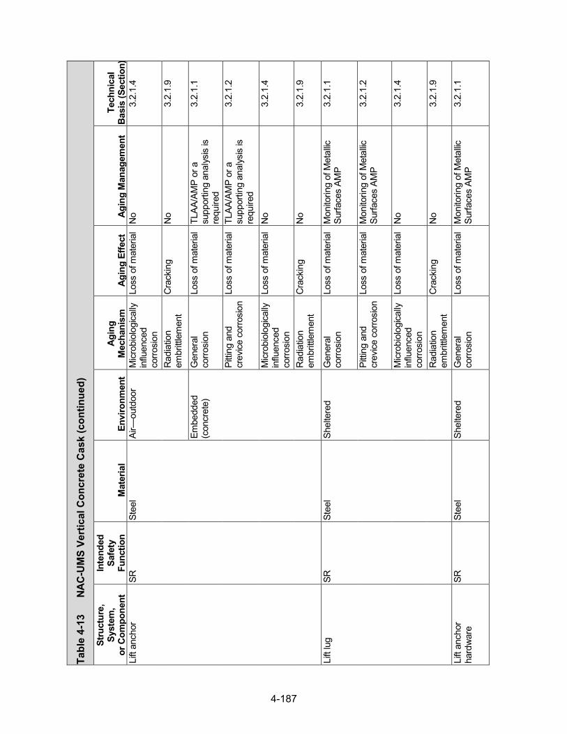
4-187
Tabl
e 4-
13
NAC-
UM
S Ve
rtic
al C
oncr
ete
Cas
k (con
tinued)
Stru
ctur
e,
Syst
em,
or C
ompo
nent
Inte
nded
Sa
fety
Fu
nctio
n M
ater
ial
Envi
ronm
ent
Agin
g M
echa
nism
Ag
ing
Effe
ct
Agin
g M
anag
emen
t Te
chni
cal
Basi
s (S
ectio
n)
Lift
anch
or
SR
Stee
l Ai
r—ou
tdoo
r M
icrob
iolo
gica
lly
influ
ence
d co
rrosi
on
Loss
of m
ater
ial
No
3.2.
1.4
Rad
iatio
n em
britt
lem
ent
Cra
ckin
g N
o 3.
2.1.
9
Embe
dded
(c
oncr
ete)
G
ener
al
corro
sion
Lo
ss o
f mat
eria
l TL
AA/A
MP
or a
su
ppor
ting
anal
ysis
is
requ
ired
3.2.
1.1
Pitti
ng a
nd
crev
ice c
orro
sion
Lo
ss o
f mat
eria
l TL
AA/A
MP
or a
su
ppor
ting
anal
ysis
is
requ
ired
3.2.
1.2
Micr
obio
logi
cally
in
fluen
ced
corro
sion
Loss
of m
ater
ial
No
3.2.
1.4
Rad
iatio
n em
britt
lem
ent
Cra
ckin
g N
o 3.
2.1.
9
Lift
lug
SR
Stee
l Sh
elte
red
Gen
eral
co
rrosi
on
Loss
of m
ater
ial
Mon
itorin
g of
Met
allic
Su
rface
s AM
P 3.
2.1.
1
Pitti
ng a
nd
crev
ice c
orro
sion
Lo
ss o
f mat
eria
l M
onito
ring
of M
etal
lic
Surfa
ces
AMP
3.2.
1.2
Micr
obio
logi
cally
in
fluen
ced
corro
sion
Loss
of m
ater
ial
No
3.2.
1.4
Rad
iatio
n em
britt
lem
ent
Cra
ckin
g N
o 3.
2.1.
9
Lift
anch
or
hard
war
e SR
St
eel
Shel
tere
d G
ener
al
corro
sion
Lo
ss o
f mat
eria
l M
onito
ring
of M
etal
lic
Surfa
ces
AMP
3.2.
1.1

4-188
Tabl
e 4-
13
NAC-
UM
S Ve
rtic
al C
oncr
ete
Cas
k (con
tinued)
Stru
ctur
e,
Syst
em,
or C
ompo
nent
Inte
nded
Sa
fety
Fu
nctio
n M
ater
ial
Envi
ronm
ent
Agin
g M
echa
nism
Ag
ing
Effe
ct
Agin
g M
anag
emen
t Te
chni
cal
Basi
s (S
ectio
n)
Lift
anch
or
hard
war
e SR
St
eel
Shel
tere
d Pi
tting
and
cr
evice
cor
rosi
on
Loss
of m
ater
ial
Mon
itorin
g of
Met
allic
Su
rface
s AM
P 3.
2.1.
2
Micr
obio
logi
cally
in
fluen
ced
corro
sion
Loss
of m
ater
ial
No
3.2.
1.4
Rad
iatio
n em
britt
lem
ent
Cra
ckin
g N
o 3.
2.1.
9
Stre
ss re
laxa
tion
Loss
of p
relo
ad
Mon
itorin
g of
Met
allic
Su
rface
s AM
P 3.
2.1.
10

4-189
Tabl
e 4-
14
NAC
-UM
S Tr
ansf
er C
ask
Stru
ctur
e,
Syst
em,
or C
ompo
nent
Inte
nded
Sa
fety
Fu
nctio
n M
ater
ial
Envi
ronm
ent
Agin
g M
echa
nism
Ag
ing
Effe
ct
Agin
g M
anag
emen
t Te
chni
cal
Basi
s (S
ectio
n)
Out
er s
hell
SR*
Stee
l Ai
r—in
door
/out
door
G
ener
al
corro
sion
Lo
ss o
f m
ater
ial
Tran
sfer
Cas
ks A
MP
3.2.
1.1
Pitti
ng a
nd
crev
ice c
orro
sion
Lo
ss o
f m
ater
ial
Tran
sfer
Cas
ks A
MP
3.2.
1.2
Gal
vani
c co
rrosi
on
Loss
of
mat
eria
l Tr
ansf
er C
asks
AM
P 3.
2.1.
3
Micr
obio
logi
cally
in
fluen
ced
corro
sion
Loss
of
mat
eria
l N
o 3.
2.1.
4
Rad
iatio
n em
britt
lem
ent
Cra
ckin
g N
o 3.
2.1.
9
Embe
dded
(N
S-4-
FR)
Rad
iatio
n em
britt
lem
ent
Cra
ckin
g N
o 3.
2.1.
9
Inne
r she
ll SR
St
eel
Air—
indo
or/o
utdo
or
Gen
eral
co
rrosi
on
Loss
of
mat
eria
l Tr
ansf
er C
asks
AM
P 3.
2.1.
1
Pitti
ng a
nd
crev
ice c
orro
sion
Lo
ss o
f m
ater
ial
Tran
sfer
Cas
ks A
MP
3.2.
1.2
Micr
obio
logi
cally
in
fluen
ced
corro
sion
Loss
of
mat
eria
l N
o 3.
2.1.
4
Rad
iatio
n em
britt
lem
ent
Cra
ckin
g N
o 3.
2.1.
9
Embe
dded
(le
ad)
Rad
iatio
n em
britt
lem
ent
Cra
ckin
g N
o 3.
2.1.
9
Gam
ma
shie
ld
(Cas
k bo
dy)
SH
Lead
Fu
lly e
ncas
ed
(ste
el)
Non
e id
entif
ied
Non
e id
entif
ied
No
3.2.
6
*Saf
ety
Func
tions
: C
onfin
emen
t (C
O),
Subc
ritica
lity (C
R),
Ret
rieva
bility
(RE)
, Rad
iatio
n Sh
ield
ing
(SH
), St
ruct
ural
Inte
grity
(SR
), Th
erm
al/H
eat R
emov
al (T
H)

4-190
Tabl
e 4-
14
NAC-
UM
S Tr
ansf
er C
ask (con
tinued)
Stru
ctur
e,
Syst
em,
or C
ompo
nent
Inte
nded
Sa
fety
Fu
nctio
n M
ater
ial
Envi
ronm
ent
Agin
g M
echa
nism
Ag
ing
Effe
ct
Agin
g M
anag
emen
t Te
chni
cal
Basi
s (S
ectio
n)
Neu
tron
shie
ld
(Cas
k bo
dy)
SH
NS-
4-FR
Fu
lly e
ncas
ed
(ste
el)
Ther
mal
agi
ng
Loss
of f
ract
ure
toug
hnes
s an
d lo
ss o
f duc
tility
TLAA
/AM
P or
a
supp
ortin
g an
alys
is is
re
quire
d
3.3.
1.2
Rad
iatio
n em
britt
lem
ent
Cra
ckin
g TL
AA/A
MP
or a
su
ppor
ting
anal
ysis
is
requ
ired
3.3.
1.3
Boro
n de
plet
ion
Loss
of
shie
ldin
g TL
AA/A
MP
or a
su
ppor
ting
anal
ysis
is
requ
ired
3.3.
1.1
Top
plat
e SR
St
eel
Air—
indo
or/o
utdo
or
Gen
eral
co
rrosi
on
Loss
of
mat
eria
l Tr
ansf
er C
asks
AM
P 3.
2.1.
1
Pitti
ng a
nd
crev
ice c
orro
sion
Lo
ss o
f m
ater
ial
Tran
sfer
Cas
ks A
MP
3.2.
1.2
Micr
obio
logi
cally
in
fluen
ced
corro
sion
Loss
of
mat
eria
l N
o 3.
2.1.
4
Rad
iatio
n em
britt
lem
ent
Cra
ckin
g N
o 3.
2.1.
9
Botto
m p
late
SR
St
eel
Air—
indo
or/o
utdo
or
Gen
eral
co
rrosi
on
Loss
of
mat
eria
l Tr
ansf
er C
asks
AM
P 3.
2.1.
1
Pitti
ng a
nd
crev
ice c
orro
sion
Lo
ss o
f m
ater
ial
Tran
sfer
Cas
ks A
MP
3.2.
1.2
Micr
obio
logi
cally
in
fluen
ced
corro
sion
Loss
of
mat
eria
l N
o 3.
2.1.
4
Rad
iatio
n em
britt
lem
ent
Cra
ckin
g N
o 3.
2.1.
9

4-191
Tabl
e 4-
14
NAC-
UM
S Tr
ansf
er C
ask (con
tinued)
Stru
ctur
e,
Syst
em,
or C
ompo
nent
Inte
nded
Sa
fety
Fu
nctio
n M
ater
ial
Envi
ronm
ent
Agin
g M
echa
nism
Ag
ing
Effe
ct
Agin
g M
anag
emen
t Te
chni
cal
Basi
s (S
ectio
n)
Ret
aini
ng ri
ng
SR
Stee
l Ai
r—in
door
/out
door
G
ener
al
corro
sion
Lo
ss o
f m
ater
ial
Tran
sfer
Cas
ks A
MP
3.2.
1.1
Pitti
ng a
nd
crev
ice c
orro
sion
Lo
ss o
f m
ater
ial
Tran
sfer
Cas
ks A
MP
3.2.
1.2
Gal
vani
c co
rrosi
on
Loss
of
mat
eria
l Tr
ansf
er C
asks
AM
P 3.
2.1.
3
Micr
obio
logi
cally
in
fluen
ced
corro
sion
Loss
of
mat
eria
l N
o 3.
2.1.
4
Rad
iatio
n em
britt
lem
ent
Cra
ckin
g N
o 3.
2.1.
9
Ret
aini
ng ri
ng b
olts
SR
St
ainl
ess
stee
l (fe
rritic
) Ai
r—in
door
/out
door
Pi
tting
and
cr
evice
cor
rosi
on
Loss
of
mat
eria
l N
o 3.
2.2.
2
Micr
obio
logi
cally
in
fluen
ced
corro
sion
Loss
of
mat
eria
l N
o 3.
2.2.
4
Stre
ss c
orro
sion
cr
acki
ng
Cra
ckin
g N
o 3.
2.2.
5
Rad
iatio
n em
britt
lem
ent
Cra
ckin
g N
o 3.
2.2.
9
Stre
ss re
laxa
tion
Loss
of p
relo
ad N
o 3.
2.2.
10
Trun
nion
SR
St
eel
Air—
indo
or/o
utdo
or
Gen
eral
co
rrosi
on
Loss
of
mat
eria
l Tr
ansf
er C
asks
AM
P 3.
2.1.
1
Pitti
ng a
nd
crev
ice c
orro
sion
Lo
ss o
f m
ater
ial
Tran
sfer
Cas
ks A
MP
3.2.
1.2

4-192
Tabl
e 4-
14
NAC-
UM
S Tr
ansf
er C
ask (con
tinued)
Stru
ctur
e,
Syst
em,
or C
ompo
nent
Inte
nded
Sa
fety
Fu
nctio
n M
ater
ial
Envi
ronm
ent
Agin
g M
echa
nism
Ag
ing
Effe
ct
Agin
g M
anag
emen
t Te
chni
cal
Basi
s (S
ectio
n)
Trun
nion
SR
St
eel
Air—
indo
or/o
utdo
or
Micr
obio
logi
cally
in
fluen
ced
corro
sion
Loss
of
mat
eria
l N
o 3.
2.1.
4
Rad
iatio
n em
britt
lem
ent
Cra
ckin
g N
o 3.
2.1.
9
Wea
r Lo
ss o
f mat
eria
l Tra
nsfe
r Cas
ks A
MP
3.2.
1.11
Shie
ld d
oor p
late
s SH
, SR
St
eel
Air—
indo
or/o
utdo
or
Gen
eral
co
rrosi
on
Loss
of
mat
eria
l Tr
ansf
er C
asks
AM
P 3.
2.1.
1
Pitti
ng a
nd
crev
ice c
orro
sion
Lo
ss o
f m
ater
ial
Tran
sfer
Cas
ks A
MP
3.2.
1.2
Micr
obio
logi
cally
in
fluen
ced
corro
sion
Loss
of
mat
eria
l N
o 3.
2.1.
3
Rad
iatio
n em
britt
lem
ent
Cra
ckin
g N
o 3.
2.1.
9
Shie
ld d
oor r
ails
SH
, SR
St
eel
Air—
indo
or/o
utdo
or
Gen
eral
co
rrosi
on
Loss
of
mat
eria
l Tr
ansf
er C
asks
AM
P 3.
2.1.
1
Pitti
ng a
nd
crev
ice c
orro
sion
Lo
ss o
f m
ater
ial
Tran
sfer
Cas
ks A
MP
3.2.
1.2
Gal
vani
c co
rrosi
on
Loss
of
mat
eria
l Tr
ansf
er C
asks
AM
P 3.
2.1.
3
Micr
obio
logi
cally
in
fluen
ced
corro
sion
Loss
of
mat
eria
l N
o 3.
2.1.
4
Rad
iatio
n em
britt
lem
ent
Cra
ckin
g N
o 3.
2.1.
9
Wea
r Lo
ss o
f m
ater
ial
Tran
sfer
Cas
ks A
MP
3.2.
1.11

4-193
Tabl
e 4-
14
NAC-
UM
S Tr
ansf
er C
ask (con
tinued)
Stru
ctur
e,
Syst
em,
or C
ompo
nent
Inte
nded
Sa
fety
Fu
nctio
n M
ater
ial
Envi
ronm
ent
Agin
g M
echa
nism
Ag
ing
Effe
ct
Agin
g M
anag
emen
t Te
chni
cal
Basi
s (S
ectio
n)
Shie
ld d
oor l
ock
bolts
SR
St
ainl
ess
stee
l Ai
r—in
door
/out
door
Pi
tting
and
cr
evice
cor
rosi
on
Loss
of
mat
eria
l N
o 3.
2.2.
2
Micr
obio
logi
cally
in
fluen
ced
corro
sion
Loss
of
mat
eria
l N
o 3.
2.2.
4
Stre
ss c
orro
sion
cr
acki
ng
Cra
ckin
g N
o 3.
2.2.
5
Rad
iatio
n em
britt
lem
ent
Cra
ckin
g N
o 3.
2.2.
9
Stre
ss re
laxa
tion
Loss
of p
relo
ad N
o 3.
2.2.
10
Tran
sfer
ada
pter
SH
St
eel
Air—
indo
or/o
utdo
or
Gen
eral
co
rrosi
on
Loss
of
mat
eria
l Tr
ansf
er C
asks
AM
P 3.
2.1.
1
Pitti
ng a
nd
crev
ice c
orro
sion
Lo
ss o
f m
ater
ial
Tran
sfer
Cas
ks A
MP
3.2.
1.2
Micr
obio
logi
cally
in
fluen
ced
corro
sion
Loss
of
mat
eria
l N
o 3.
2.1.
4
Rad
iatio
n em
britt
lem
ent
Cra
ckin
g N
o 3.
2.1.
9
Wea
r stri
p SR
St
ainl
ess
stee
l Ai
r—in
door
/out
door
Pi
tting
and
cr
evice
cor
rosi
on
Loss
of
mat
eria
l N
o 3.
2.2.
2
Micr
obio
logi
cally
in
fluen
ced
corro
sion
Loss
of
mat
eria
l N
o 3.
2.2.
4
Stre
ss c
orro
sion
cr
acki
ng
Cra
ckin
g N
o 3.
2.2.
5

4-194
Tabl
e 4-
14
NAC-
UM
S Tr
ansf
er C
ask (con
tinued)
Stru
ctur
e,
Syst
em,
or C
ompo
nent
Inte
nded
Sa
fety
Fu
nctio
n M
ater
ial
Envi
ronm
ent
Agin
g M
echa
nism
Ag
ing
Effe
ct
Agin
g M
anag
emen
t Te
chni
cal
Basi
s (S
ectio
n)
Wea
r stri
p SR
St
ainl
ess
stee
l Ai
r—in
door
/out
door
R
adia
tion
embr
ittle
men
t C
rack
ing
No
3.2.
2.9
Wea
r Lo
ss o
f m
ater
ial
Tran
sfer
Cas
ks A
MP
3.2.
2.11
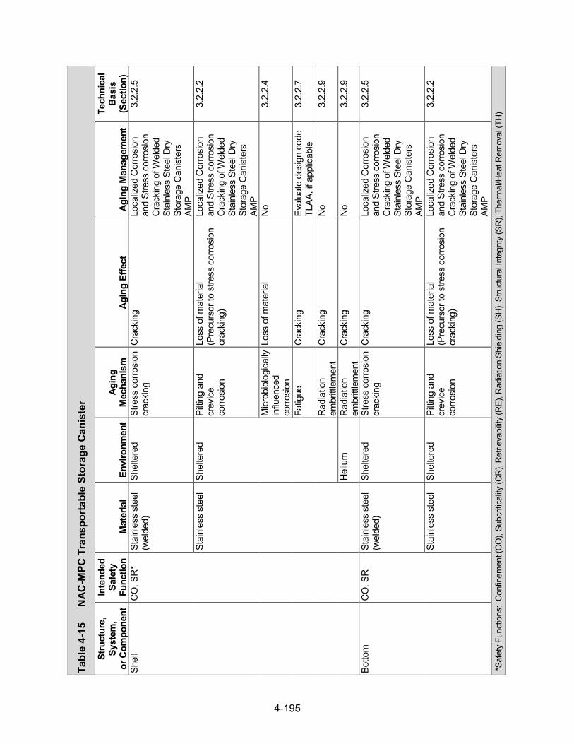
4-195
Tabl
e 4-
15
NAC
-MPC
Tra
nspo
rtab
le S
tora
ge C
anis
ter
Stru
ctur
e,
Syst
em,
or C
ompo
nent
Inte
nded
Sa
fety
Fu
nctio
n M
ater
ial
Envi
ronm
ent
Agin
g M
echa
nism
Ag
ing
Effe
ct
Agin
g M
anag
emen
t
Tech
nica
l Ba
sis
(Sec
tion)
Sh
ell
CO
, SR
* St
ainl
ess
stee
l (w
elde
d)
Shel
tere
d St
ress
cor
rosi
on
crac
king
C
rack
ing
Loca
lized
Cor
rosi
on
and
Stre
ss c
orro
sion
C
rack
ing
of W
elde
d St
ainl
ess
Stee
l Dry
St
orag
e C
anis
ters
AM
P
3.2.
2.5
Stai
nles
s st
eel
Shel
tere
d Pi
tting
and
cr
evice
co
rrosi
on
Loss
of m
ater
ial
(Pre
curs
or to
stre
ss c
orro
sion
cr
acki
ng)
Loca
lized
Cor
rosi
on
and
Stre
ss c
orro
sion
C
rack
ing
of W
elde
d St
ainl
ess
Stee
l Dry
St
orag
e C
anis
ters
AM
P
3.2.
2.2
Micr
obio
logi
cally
in
fluen
ced
corro
sion
Loss
of m
ater
ial
No
3.2.
2.4
Fatig
ue
Cra
ckin
g Ev
alua
te d
esig
n co
de
TLAA
, if a
pplic
able
3.
2.2.
7
Rad
iatio
n em
britt
lem
ent
Cra
ckin
g N
o 3.
2.2.
9
Hel
ium
R
adia
tion
embr
ittle
men
t C
rack
ing
No
3.2.
2.9
Botto
m
CO
, SR
St
ainl
ess
stee
l (w
elde
d)
Shel
tere
d St
ress
cor
rosi
on
crac
king
C
rack
ing
Loca
lized
Cor
rosi
on
and
Stre
ss c
orro
sion
C
rack
ing
of W
elde
d St
ainl
ess
Stee
l Dry
St
orag
e C
anis
ters
AM
P
3.2.
2.5
Stai
nles
s st
eel
Shel
tere
d Pi
tting
and
cr
evice
co
rrosi
on
Loss
of m
ater
ial
(Pre
curs
or to
stre
ss c
orro
sion
cr
acki
ng)
Loca
lized
Cor
rosi
on
and
Stre
ss c
orro
sion
C
rack
ing
of W
elde
d St
ainl
ess
Stee
l Dry
St
orag
e C
anis
ters
AM
P
3.2.
2.2
*Saf
ety
Func
tions
: C
onfin
emen
t (C
O),
Subc
ritica
lity (C
R),
Ret
rieva
bility
(RE)
, Rad
iatio
n Sh
ield
ing
(SH
), St
ruct
ural
Inte
grity
(SR
), Th
erm
al/H
eat R
emov
al (T
H)

4-196
Tabl
e 4-
15
NAC-
MPC
Tra
nspo
rtab
le S
tora
ge C
anis
ter (continued)
Stru
ctur
e,
Syst
em,
or C
ompo
nent
Inte
nded
Sa
fety
Fu
nctio
n M
ater
ial
Envi
ronm
ent
Agin
g M
echa
nism
Ag
ing
Effe
ct
Agin
g M
anag
emen
t
Tech
nica
l Ba
sis
(Sec
tion)
Bo
ttom
C
O, S
R
Stai
nles
s st
eel
Shel
tere
d M
icrob
iolo
gica
lly
influ
ence
d co
rrosi
on
Loss
of m
ater
ial
No
3.2.
2.4
Fatig
ue
Cra
ckin
g Ev
alua
te d
esig
n co
de
TLAA
, if a
pplic
able
3.
2.2.
7
Rad
iatio
n em
britt
lem
ent
Cra
ckin
g N
o 3.
2.2.
9
Hel
ium
R
adia
tion
embr
ittle
men
t C
rack
ing
No
3.2.
2.9
Clo
sure
lid;
stru
ctur
al lid
SR
St
ainl
ess
stee
l (w
elde
d)
Shel
tere
d St
ress
cor
rosi
on
crac
king
C
rack
ing
Loca
lized
Cor
rosi
on
and
Stre
ss c
orro
sion
C
rack
ing
of W
elde
d St
ainl
ess
Stee
l Dry
St
orag
e C
anis
ters
AM
P
3.2.
2.5
Stai
nles
s st
eel
Shel
tere
d Pi
tting
and
cr
evice
co
rrosi
on
Loss
of m
ater
ial
(Pre
curs
or to
stre
ss c
orro
sion
cr
acki
ng)
Loca
lized
Cor
rosi
on
and
Stre
ss c
orro
sion
C
rack
ing
of W
elde
d St
ainl
ess
Stee
l Dry
St
orag
e C
anis
ters
AM
P
3.2.
2.2
Micr
obio
logi
cally
in
fluen
ced
corro
sion
Loss
of m
ater
ial
No
3.2.
2.4
Fatig
ue
Cra
ckin
g Ev
alua
te d
esig
n co
de
TLAA
, if a
pplic
able
3.
2.2.
7
Rad
iatio
n em
britt
lem
ent
Cra
ckin
g N
o 3.
2.2.
9
Hel
ium
R
adia
tion
embr
ittle
men
t C
rack
ing
No
3.2.
2.9

4-197
Tabl
e 4-
15
NAC-
MPC
Tra
nspo
rtab
le S
tora
ge C
anis
ter (continued)
Stru
ctur
e,
Syst
em,
or C
ompo
nent
Inte
nded
Sa
fety
Fu
nctio
n M
ater
ial
Envi
ronm
ent
Agin
g M
echa
nism
Ag
ing
Effe
ct
Agin
g M
anag
emen
t
Tech
nica
l Ba
sis
(Sec
tion)
C
losu
re ri
ng
SR
Stai
nles
s st
eel
(wel
ded)
Sh
elte
red
Stre
ss
corro
sion
cr
acki
ng
Cra
ckin
g Lo
caliz
ed C
orro
sion
an
d St
ress
cor
rosi
on
Cra
ckin
g of
Wel
ded
Stai
nles
s St
eel D
ry
Stor
age
Can
iste
rs
AMP
3.2.
2.5
Stai
nles
s st
eel
Shel
tere
d Pi
tting
and
cr
evice
co
rrosi
on
Loss
of m
ater
ial
(Pre
curs
or to
stre
ss c
orro
sion
cr
acki
ng)
Loca
lized
Cor
rosi
on
and
Stre
ss c
orro
sion
C
rack
ing
of W
elde
d St
ainl
ess
Stee
l Dry
St
orag
e C
anis
ters
AM
P
3.2.
2.2
Micr
obio
logi
cally
in
fluen
ced
corro
sion
Loss
of m
ater
ial
No
3.2.
2.4
Rad
iatio
n em
britt
lem
ent
Cra
ckin
g N
o 3.
2.2.
9
Spac
er ri
ng
SR
Stai
nles
s st
eel
(wel
ded)
Em
bedd
ed
(sta
inle
ss s
teel
) Stre
ss c
orro
sion
cr
acki
ng
Cra
ckin
g N
o 3.
2.2.
5
Stai
nles
s st
eel
Embe
dded
(s
tain
less
ste
el) Pi
tting
and
cr
evice
co
rrosi
on
Loss
of m
ater
ial (
Prec
urso
r to
stre
ss c
orro
sion
cra
ckin
g)
No
3.2.
2.2
Micr
obio
logi
cally
in
fluen
ced
corro
sion
Loss
of m
ater
ial
No
3.2.
2.4
Rad
iatio
n em
britt
lem
ent
Cra
ckin
g N
o 3.
2.2.
9

4-198
Tabl
e 4-
15
NAC-
MPC
Tra
nspo
rtab
le S
tora
ge C
anis
ter (
cont
inue
d)
Stru
ctur
e,
Syst
em,
or C
ompo
nent
Inte
nded
Sa
fety
Fu
nctio
n M
ater
ial
Envi
ronm
ent
Agin
g M
echa
nism
Ag
ing
Effe
ct
Agin
g M
anag
emen
t
Tech
nica
l Ba
sis
(Sec
tion)
C
losu
re lid
as
sem
bly
bolt,
w
ashe
r
SR
Stai
nles
s st
eel
Hel
ium
Th
erm
al a
ging
Lo
ss o
f fra
ctur
e to
ughn
ess
and
loss
of d
uctili
ty
No
3.2.
2.8
Cre
ep
Cha
nge
in d
imen
sion
s N
o 3.
2.2.
6
Rad
iatio
n em
britt
lem
ent
Cra
ckin
g N
o 3.
2.2.
9
Stre
ss re
laxa
tion
Loss
of p
relo
ad
No
3.2.
2.10
Clo
sure
lid
asse
mbl
y sp
acer
SR
Alum
inum
H
eliu
m
Gen
eral
co
rrosi
on
Loss
of m
ater
ial
No
3.2.
3.1
Gal
vani
c co
rrosi
on
Loss
of m
ater
ial
No
3.2.
3.3
Ther
mal
agi
ng
Loss
of s
treng
th
TLAA
/AM
P or
a
supp
ortin
g an
alys
is is
re
quire
d
3.2.
3.7
Cre
ep
Cha
nge
in d
imen
sion
s TL
AA/A
MP
or a
su
ppor
ting
anal
ysis
is
requ
ired
3.2.
3.5
Rad
iatio
n em
britt
lem
ent
Cra
ckin
g N
o 3.
2.3.
8
Shie
ld lid
SH
, SR
St
ainl
ess
stee
l (w
elde
d)
Embe
dded
(s
tain
less
ste
el) St
ress
cor
rosi
on
crac
king
C
rack
ing
No
3.2.
2.5
Stai
nles
s st
eel
Embe
dded
(s
tain
less
ste
el) Pi
tting
and
cr
evice
co
rrosi
on
Loss
of m
ater
ial (
Prec
urso
r to
stre
ss c
orro
sion
cra
ckin
g)
No
3.2.
2.2

4-199
Tabl
e 4-
15
NAC-
MPC
Tra
nspo
rtab
le S
tora
ge C
anis
ter (continued)
Stru
ctur
e,
Syst
em,
or C
ompo
nent
Inte
nded
Sa
fety
Fu
nctio
n M
ater
ial
Envi
ronm
ent
Agin
g M
echa
nism
Ag
ing
Effe
ct
Agin
g M
anag
emen
t
Tech
nica
l Ba
sis
(Sec
tion)
Sh
ield
lid
SH, S
R
Stai
nles
s st
eel
Embe
dded
(s
tain
less
ste
el) M
icrob
iolo
gica
lly
influ
ence
d co
rrosi
on
Loss
of m
ater
ial
No
3.2.
2.4
Rad
iatio
n em
britt
lem
ent
Cra
ckin
g N
o 3.
2.2.
9
Hel
ium
R
adia
tion
embr
ittle
men
t C
rack
ing
No
3.2.
2.9
Supp
ort r
ing
SH, S
R
Stai
nles
s st
eel
(wel
ded)
H
eliu
m
Ther
mal
agi
ng
Loss
of f
ract
ure
toug
hnes
s an
d lo
ss o
f duc
tility
N
o 3.
2.2.
8
Stai
nles
s st
eel
Hel
ium
C
reep
C
hang
e in
dim
ensi
ons
No
3.2.
2.6
Rad
iatio
n em
britt
lem
ent
Cra
ckin
g N
o 3.
2.2.
9
Port
cove
r C
O
Stai
nles
s st
eel
(wel
ded)
Sh
elte
red
Stre
ss c
orro
sion
cr
acki
ng
Cra
ckin
g Lo
caliz
ed C
orro
sion
an
d St
ress
cor
rosi
on
Cra
ckin
g of
Wel
ded
Stai
nles
s St
eel D
ry
Stor
age
Can
iste
rs
AMP
3.2.
2.5
Stai
nles
s st
eel
Shel
tere
d Pi
tting
and
cr
evice
co
rrosi
on
Loss
of m
ater
ial (
Prec
urso
r to
stre
ss c
orro
sion
cra
ckin
g)
Loca
lized
Cor
rosi
on
and
Stre
ss c
orro
sion
C
rack
ing
of W
elde
d St
ainl
ess
Stee
l Dry
St
orag
e C
anis
ters
AM
P
3.2.
2.2
Micr
obio
logi
cally
in
fluen
ced
corro
sion
Loss
of m
ater
ial
No
3.2.
2.4
Fatig
ue
Cra
ckin
g Ev
alua
te d
esig
n co
de
TLAA
, if a
pplic
able
3.
2.2.
7
Rad
iatio
n em
britt
lem
ent
Cra
ckin
g N
o 3.
2.2.
9
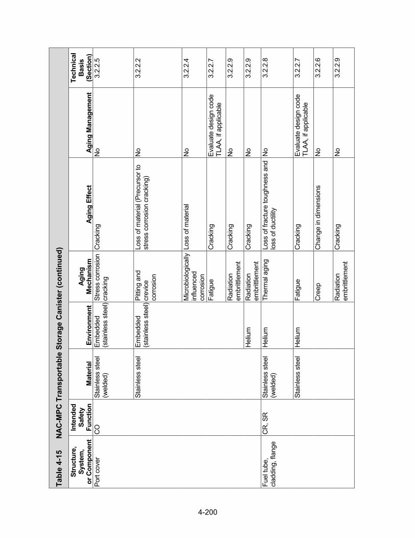
4-200
Tabl
e 4-
15
NAC-
MPC
Tra
nspo
rtab
le S
tora
ge C
anis
ter (continued)
Stru
ctur
e,
Syst
em,
or C
ompo
nent
Inte
nded
Sa
fety
Fu
nctio
n M
ater
ial
Envi
ronm
ent
Agin
g M
echa
nism
Ag
ing
Effe
ct
Agin
g M
anag
emen
t
Tech
nica
l Ba
sis
(Sec
tion)
Po
rt co
ver
CO
St
ainl
ess
stee
l (w
elde
d)
Embe
dded
(s
tain
less
ste
el) St
ress
cor
rosi
on
crac
king
C
rack
ing
No
3.2.
2.5
Stai
nles
s st
eel
Embe
dded
(s
tain
less
ste
el) Pi
tting
and
cr
evice
co
rrosi
on
Loss
of m
ater
ial (
Prec
urso
r to
stre
ss c
orro
sion
cra
ckin
g)
No
3.2.
2.2
Micr
obio
logi
cally
in
fluen
ced
corro
sion
Loss
of m
ater
ial
No
3.2.
2.4
Fatig
ue
Cra
ckin
g Ev
alua
te d
esig
n co
de
TLAA
, if a
pplic
able
3.
2.2.
7
Rad
iatio
n em
britt
lem
ent
Cra
ckin
g N
o 3.
2.2.
9
Hel
ium
R
adia
tion
embr
ittle
men
t C
rack
ing
No
3.2.
2.9
Fuel
tube
, cl
addi
ng, f
lang
e C
R, S
R
Stai
nles
s st
eel
(wel
ded)
H
eliu
m
Ther
mal
agi
ng
Loss
of f
ract
ure
toug
hnes
s an
d lo
ss o
f duc
tility
N
o 3.
2.2.
8
Stai
nles
s st
eel
Hel
ium
Fa
tigue
C
rack
ing
Eval
uate
des
ign
code
TL
AA, i
f app
licab
le
3.2.
2.7
Cre
ep
Cha
nge
in d
imen
sion
s N
o 3.
2.2.
6
Rad
iatio
n em
britt
lem
ent
Cra
ckin
g N
o 3.
2.2.
9
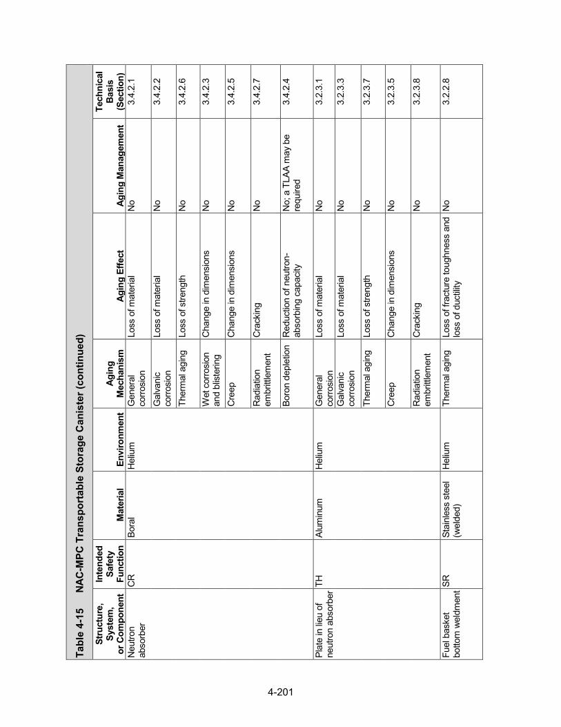
4-201
Tabl
e 4-
15
NAC-
MPC
Tra
nspo
rtab
le S
tora
ge C
anis
ter (continued)
Stru
ctur
e,
Syst
em,
or C
ompo
nent
Inte
nded
Sa
fety
Fu
nctio
n M
ater
ial
Envi
ronm
ent
Agin
g M
echa
nism
Ag
ing
Effe
ct
Agin
g M
anag
emen
t
Tech
nica
l Ba
sis
(Sec
tion)
N
eutro
n ab
sorb
er
CR
Bo
ral
Hel
ium
G
ener
al
corro
sion
Lo
ss o
f mat
eria
l N
o 3.
4.2.
1
Gal
vani
c co
rrosi
on
Loss
of m
ater
ial
No
3.4.
2.2
Ther
mal
agi
ng
Loss
of s
treng
th
No
3.4.
2.6
Wet
cor
rosi
on
and
blist
erin
g C
hang
e in
dim
ensi
ons
No
3.4.
2.3
Cre
ep
Cha
nge
in d
imen
sion
s N
o 3.
4.2.
5
Rad
iatio
n em
britt
lem
ent
Cra
ckin
g N
o 3.
4.2.
7
Boro
n de
plet
ion
Red
uctio
n of
neu
tron-
abso
rbin
g ca
paci
ty
No;
a T
LAA
may
be
requ
ired
3.4.
2.4
Plat
e in
lieu
of
neut
ron
abso
rber
TH
Alum
inum
H
eliu
m
Gen
eral
co
rrosi
on
Loss
of m
ater
ial
No
3.2.
3.1
Gal
vani
c co
rrosi
on
Loss
of m
ater
ial
No
3.2.
3.3
Ther
mal
agi
ng
Loss
of s
treng
th
No
3.2.
3.7
Cre
ep
Cha
nge
in d
imen
sion
s N
o 3.
2.3.
5
Rad
iatio
n em
britt
lem
ent
Cra
ckin
g N
o 3.
2.3.
8
Fuel
bas
ket
botto
m w
eldm
ent SR
St
ainl
ess
stee
l (w
elde
d)
Hel
ium
Th
erm
al a
ging
Lo
ss o
f fra
ctur
e to
ughn
ess
and
loss
of d
uctili
ty
No
3.2.
2.8
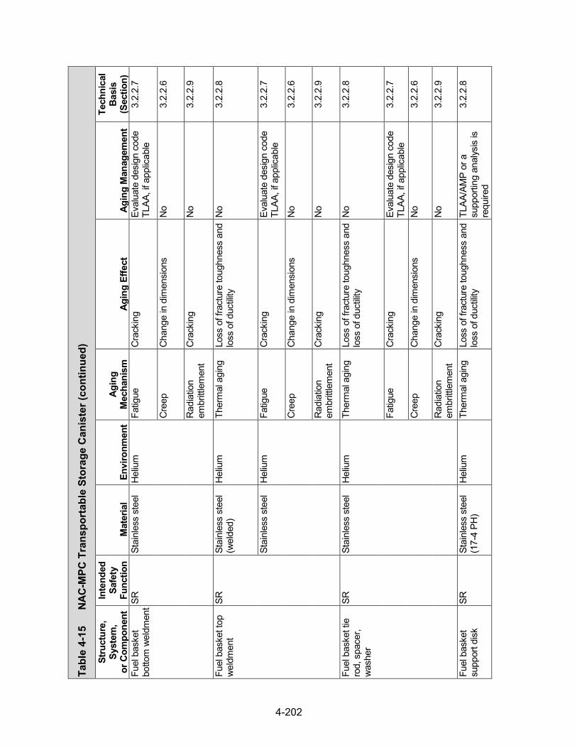
4-202
Tabl
e 4-
15
NAC-
MPC
Tra
nspo
rtab
le S
tora
ge C
anis
ter (continued)
Stru
ctur
e,
Syst
em,
or C
ompo
nent
Inte
nded
Sa
fety
Fu
nctio
n M
ater
ial
Envi
ronm
ent
Agin
g M
echa
nism
Ag
ing
Effe
ct
Agin
g M
anag
emen
t
Tech
nica
l Ba
sis
(Sec
tion)
Fu
el b
aske
t bo
ttom
wel
dmen
t SR
Stai
nles
s st
eel
Hel
ium
Fa
tigue
C
rack
ing
Eval
uate
des
ign
code
TL
AA, i
f app
licab
le
3.2.
2.7
Cre
ep
Cha
nge
in d
imen
sion
s N
o 3.
2.2.
6
Rad
iatio
n em
britt
lem
ent
Cra
ckin
g N
o 3.
2.2.
9
Fuel
bas
ket t
op
wel
dmen
t SR
St
ainl
ess
stee
l (w
elde
d)
Hel
ium
Th
erm
al a
ging
Lo
ss o
f fra
ctur
e to
ughn
ess
and
loss
of d
uctili
ty
No
3.2.
2.8
Stai
nles
s st
eel
Hel
ium
Fa
tigue
C
rack
ing
Eval
uate
des
ign
code
TL
AA, i
f app
licab
le
3.2.
2.7
Cre
ep
Cha
nge
in d
imen
sion
s N
o 3.
2.2.
6
Rad
iatio
n em
britt
lem
ent
Cra
ckin
g N
o 3.
2.2.
9
Fuel
bas
ket t
ie
rod,
spa
cer,
was
her
SR
Stai
nles
s st
eel
Hel
ium
Th
erm
al a
ging
Lo
ss o
f fra
ctur
e to
ughn
ess
and
loss
of d
uctili
ty
No
3.2.
2.8
Fatig
ue
Cra
ckin
g Ev
alua
te d
esig
n co
de
TLAA
, if a
pplic
able
3.
2.2.
7
Cre
ep
Cha
nge
in d
imen
sion
s N
o 3.
2.2.
6
Rad
iatio
n em
britt
lem
ent
Cra
ckin
g N
o 3.
2.2.
9
Fuel
bas
ket
supp
ort d
isk
SR
Stai
nles
s st
eel
(17-
4 PH
) H
eliu
m
Ther
mal
agi
ng
Loss
of f
ract
ure
toug
hnes
s an
d lo
ss o
f duc
tility
TL
AA/A
MP
or a
su
ppor
ting
anal
ysis
is
requ
ired
3.2.
2.8

4-203
Tabl
e 4-
15
NAC-
MPC
Tra
nspo
rtab
le S
tora
ge C
anis
ter (continued)
Stru
ctur
e,
Syst
em,
or C
ompo
nent
Inte
nded
Sa
fety
Fu
nctio
n M
ater
ial
Envi
ronm
ent
Agin
g M
echa
nism
Ag
ing
Effe
ct
Agin
g M
anag
emen
t
Tech
nica
l Ba
sis
(Sec
tion)
Fu
el b
aske
t su
ppor
t disk
SR
St
ainl
ess
stee
l (1
7-4
PH)
Hel
ium
Fa
tigue
C
rack
ing
Eval
uate
des
ign
code
TL
AA, i
f app
licab
le
3.2.
2.7
Cre
ep
Cha
nge
in d
imen
sion
s N
o 3.
2.2.
6
Rad
iatio
n em
britt
lem
ent
Cra
ckin
g N
o 3.
2.2.
9
Fuel
bas
ket t
op
nut
SR
Stai
nles
s st
eel
Hel
ium
Th
erm
al a
ging
Lo
ss o
f fra
ctur
e to
ughn
ess
and
loss
of d
uctili
ty
No
3.2.
2.8
Fatig
ue
Cra
ckin
g Ev
alua
te d
esig
n co
de
TLAA
, if a
pplic
able
3.
2.2.
7
Cre
ep
Cha
nge
in d
imen
sion
s N
o 3.
2.2.
6
Rad
iatio
n em
britt
lem
ent
Cra
ckin
g N
o 3.
2.2.
9
Stre
ss re
laxa
tion
Loss
of p
relo
ad
No
3.2.
2.10
Fuel
bas
ket h
eat
trans
fer d
isk
TH
Alum
inum
H
eliu
m
Gen
eral
co
rrosi
on
Loss
of m
ater
ial
No
3.2.
3.1
Ther
mal
agi
ng
Loss
of s
treng
th
No
3.2.
3.7
Cre
ep
Cha
nge
in d
imen
sion
s N
o 3.
2.3.
5
Rad
iatio
n em
britt
lem
ent
Cra
ckin
g N
o 3.
2.3.
8
Dam
aged
fuel
ca
n tu
be b
ody
CR
, SR
St
ainl
ess
stee
l (w
elde
d)
Hel
ium
Th
erm
al a
ging
Lo
ss o
f fra
ctur
e to
ughn
ess
and
loss
of d
uctili
ty
No
3.2.
2.8
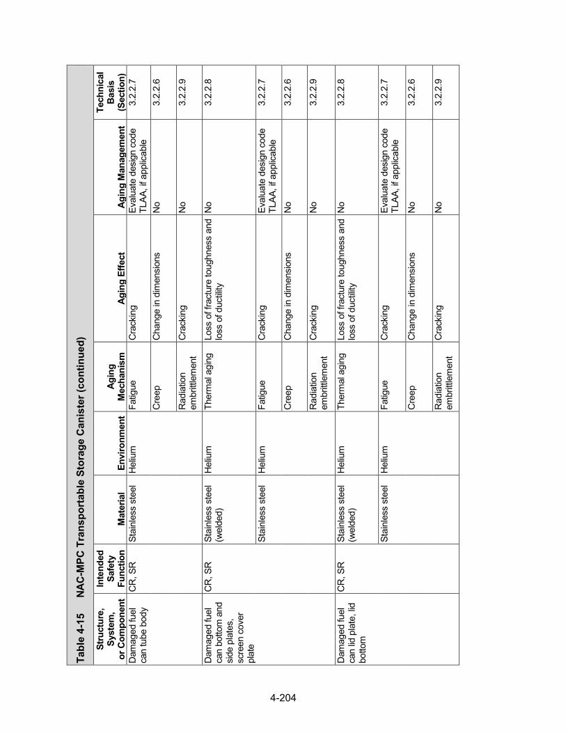
4-204
Tabl
e 4-
15
NAC-
MPC
Tra
nspo
rtab
le S
tora
ge C
anis
ter (continued)
Stru
ctur
e,
Syst
em,
or C
ompo
nent
Inte
nded
Sa
fety
Fu
nctio
n M
ater
ial
Envi
ronm
ent
Agin
g M
echa
nism
Ag
ing
Effe
ct
Agin
g M
anag
emen
t
Tech
nica
l Ba
sis
(Sec
tion)
D
amag
ed fu
el
can
tube
bod
y C
R, S
R
Stai
nles
s st
eel
Hel
ium
Fa
tigue
C
rack
ing
Eval
uate
des
ign
code
TL
AA, i
f app
licab
le
3.2.
2.7
Cre
ep
Cha
nge
in d
imen
sion
s N
o 3.
2.2.
6
Rad
iatio
n em
britt
lem
ent
Cra
ckin
g N
o 3.
2.2.
9
Dam
aged
fuel
ca
n bo
ttom
and
si
de p
late
s,
scre
en c
over
pl
ate
CR
, SR
St
ainl
ess
stee
l (w
elde
d)
Hel
ium
Th
erm
al a
ging
Lo
ss o
f fra
ctur
e to
ughn
ess
and
loss
of d
uctili
ty
No
3.2.
2.8
Stai
nles
s st
eel
Hel
ium
Fa
tigue
C
rack
ing
Eval
uate
des
ign
code
TL
AA, i
f app
licab
le
3.2.
2.7
Cre
ep
Cha
nge
in d
imen
sion
s N
o 3.
2.2.
6
Rad
iatio
n em
britt
lem
ent
Cra
ckin
g N
o 3.
2.2.
9
Dam
aged
fuel
ca
n lid
pla
te, l
id
botto
m
CR
, SR
St
ainl
ess
stee
l (w
elde
d)
Hel
ium
Th
erm
al a
ging
Lo
ss o
f fra
ctur
e to
ughn
ess
and
loss
of d
uctili
ty
No
3.2.
2.8
Stai
nles
s st
eel
Hel
ium
Fa
tigue
C
rack
ing
Eval
uate
des
ign
code
TL
AA, i
f app
licab
le
3.2.
2.7
Cre
ep
Cha
nge
in d
imen
sion
s N
o 3.
2.2.
6
Rad
iatio
n em
britt
lem
ent
Cra
ckin
g N
o 3.
2.2.
9

4-205
Tabl
e 4-
15
NAC-
MPC
Tra
nspo
rtab
le S
tora
ge C
anis
ter (continued)
Stru
ctur
e,
Syst
em,
or C
ompo
nent
Inte
nded
Sa
fety
Fu
nctio
n M
ater
ial
Envi
ronm
ent
Agin
g M
echa
nism
Ag
ing
Effe
ct
Agin
g M
anag
emen
t
Tech
nica
l Ba
sis
(Sec
tion)
D
amag
ed fu
el
can
lift te
e,
supp
ort r
ing
SR
Stai
nles
s st
eel
(wel
ded)
H
eliu
m
Ther
mal
agi
ng
Loss
of f
ract
ure
toug
hnes
s an
d lo
ss o
f duc
tility
N
o 3.
2.2.
8
Stai
nles
s st
eel
Hel
ium
Fa
tigue
C
rack
ing
Eval
uate
des
ign
code
TL
AA, i
f app
licab
le
3.2.
2.7
Cre
ep
Cha
nge
in d
imen
sion
s N
o 3.
2.2.
6
Rad
iatio
n em
britt
lem
ent
Cra
ckin
g N
o 3.
2.2.
9
Dam
aged
fuel
ca
n sc
reen
C
O
Stai
nles
s st
eel
Hel
ium
Th
erm
al a
ging
Lo
ss o
f fra
ctur
e to
ughn
ess
and
loss
of d
uctili
ty
No
3.2.
2.8
Cre
ep
Cha
nge
in d
imen
sion
s N
o 3.
2.2.
6
Rad
iatio
n em
britt
lem
ent
Cra
ckin
g N
o 3.
2.2.
9
Rem
ovab
le fu
el
rod
reta
iner
as
sem
bly
(Yan
kee-
MPC
)
SR
Stai
nles
s st
eel
(wel
ded)
H
eliu
m
Ther
mal
agi
ng
Loss
of f
ract
ure
toug
hnes
s an
d lo
ss o
f duc
tility
N
o 3.
2.2.
8
Stai
nles
s st
eel
Hel
ium
C
reep
C
hang
e in
dim
ensi
ons
No
3.2.
2.6
Rad
iatio
n em
britt
lem
ent
Cra
ckin
g N
o 3.
2.2.
9

4-206
Tabl
e 4-
15
NAC-
MPC
Tra
nspo
rtab
le S
tora
ge C
anis
ter (continued)
Stru
ctur
e,
Syst
em,
or C
ompo
nent
Inte
nded
Sa
fety
Fu
nctio
n M
ater
ial
Envi
ronm
ent
Agin
g M
echa
nism
Ag
ing
Effe
ct
Agin
g M
anag
emen
t
Tech
nica
l Ba
sis
(Sec
tion)
R
econ
figur
ed
fuel
ass
embl
y sh
ell c
asin
g,
top
ring
(Yan
kee-
MPC
)
SR
Stai
nles
s st
eel
(wel
ded)
H
eliu
m
Ther
mal
agi
ng
Loss
of f
ract
ure
toug
hnes
s an
d lo
ss o
f duc
tility
N
o 3.
2.2.
8
Stai
nles
s st
eel
Hel
ium
C
reep
C
hang
e in
dim
ensi
ons
No
3.2.
2.6
Rad
iatio
n em
britt
lem
ent
Cra
ckin
g N
o 3.
2.2.
9
Rec
onfig
ured
fu
el a
ssem
bly
top
end
fittin
g as
sem
bly
(Yan
kee-
MPC
)
CR
, SR
St
ainl
ess
stee
l (w
elde
d)
Hel
ium
Th
erm
al a
ging
Lo
ss o
f fra
ctur
e to
ughn
ess
and
loss
of d
uctili
ty
No
3.2.
2.8
Stai
nles
s st
eel
Hel
ium
C
reep
C
hang
e in
dim
ensi
ons
No
3.2.
2.6
Rad
iatio
n em
britt
lem
ent
Cra
ckin
g N
o 3.
2.2.
9
Rec
onfig
ured
fu
el a
ssem
bly
botto
m e
nd
fittin
g as
sem
bly
(Yan
kee-
MPC
)
CR
, SR
St
ainl
ess
stee
l (w
elde
d)
Hel
ium
Th
erm
al a
ging
Lo
ss o
f fra
ctur
e to
ughn
ess
and
loss
of d
uctili
ty
No
3.2.
2.8
Stai
nles
s st
eel
Hel
ium
C
reep
C
hang
e in
dim
ensi
ons
No
3.2.
2.6
Rad
iatio
n em
britt
lem
ent
Cra
ckin
g N
o 3.
2.2.
9

4-207
Tabl
e 4-
15
NAC-
MPC
Tra
nspo
rtab
le S
tora
ge C
anis
ter (continued)
Stru
ctur
e,
Syst
em,
or C
ompo
nent
Inte
nded
Sa
fety
Fu
nctio
n M
ater
ial
Envi
ronm
ent
Agin
g M
echa
nism
Ag
ing
Effe
ct
Agin
g M
anag
emen
t
Tech
nica
l Ba
sis
(Sec
tion)
R
econ
figur
ed
fuel
ass
embl
y to
p no
zzle
bol
t (Y
anke
e-M
PC)
CR
, SR
St
ainl
ess
stee
l H
eliu
m
Ther
mal
agi
ng
Loss
of f
ract
ure
toug
hnes
s an
d lo
ss o
f duc
tility
N
o 3.
2.2.
8
Cre
ep
Cha
nge
in d
imen
sion
s N
o 3.
2.2.
6
Rad
iatio
n em
britt
lem
ent
Cra
ckin
g N
o 3.
2.2.
9
Stre
ss re
laxa
tion
Loss
of p
relo
ad
No
3.2.
2.10
Rec
onfig
ured
fu
el a
ssem
bly
fuel
bas
ket
corn
er a
ngle
, tie
pla
te
(Yan
kee-
MPC
)
CR
, SR
St
ainl
ess
stee
l (w
elde
d)
Hel
ium
Th
erm
al a
ging
Lo
ss o
f fra
ctur
e to
ughn
ess
and
loss
of d
uctili
ty
No
3.2.
2.8
Stai
nles
s st
eel
Hel
ium
Fa
tigue
C
rack
ing
Eval
uate
des
ign
code
TL
AA, i
f app
licab
le
3.2.
2.7
Cre
ep
Cha
nge
in d
imen
sion
s N
o 3.
2.2.
6
Rad
iatio
n em
britt
lem
ent
Cra
ckin
g N
o 3.
2.2.
9
Rec
onfig
ured
fu
el a
ssem
bly
fuel
tube
, top
an
d bo
ttom
ca
ps (Y
anke
e-M
PC)
CR
, SR
St
ainl
ess
stee
l (w
elde
d)
Hel
ium
Th
erm
al a
ging
Lo
ss o
f fra
ctur
e to
ughn
ess
and
loss
of d
uctili
ty
No
3.2.
2.8
Stai
nles
s st
eel
Hel
ium
Fa
tigue
C
rack
ing
Eval
uate
des
ign
code
TL
AA, i
f app
licab
le
3.2.
2.7
Cre
ep
Cha
nge
in d
imen
sion
s N
o 3.
2.2.
6
Rad
iatio
n em
britt
lem
ent
Cra
ckin
g N
o 3.
2.2.
9

4-208
Tabl
e 4-
15
NAC-
MPC
Tra
nspo
rtab
le S
tora
ge C
anis
ter (continued)
Stru
ctur
e,
Syst
em,
or C
ompo
nent
Inte
nded
Sa
fety
Fu
nctio
n M
ater
ial
Envi
ronm
ent
Agin
g M
echa
nism
Ag
ing
Effe
ct
Agin
g M
anag
emen
t
Tech
nica
l Ba
sis
(Sec
tion)
R
econ
figur
ed
fuel
ass
embl
y fu
el tu
be,
corn
er a
ngle
, su
ppor
t grid
(C
Y-M
PC)
SR
Stai
nles
s st
eel
(wel
ded)
H
eliu
m
Ther
mal
agi
ng
Loss
of f
ract
ure
toug
hnes
s an
d lo
ss o
f duc
tility
N
o 3.
2.2.
8
Stai
nles
s st
eel
Hel
ium
Fa
tigue
C
rack
ing
Eval
uate
des
ign
code
TL
AA, i
f app
licab
le
3.2.
2.7
Cre
ep
Cha
nge
in d
imen
sion
s N
o 3.
2.2.
6
Rad
iatio
n em
britt
lem
ent
Cra
ckin
g N
o 3.
2.2.
9
Rec
onfig
ured
fu
el a
ssem
bly
scre
ens
(CY-
MPC
)
CO
St
ainl
ess
stee
l H
eliu
m
Ther
mal
agi
ng
Loss
of f
ract
ure
toug
hnes
s an
d lo
ss o
f duc
tility
N
o 3.
2.2.
8
Cre
ep
Cha
nge
in d
imen
sion
s N
o 3.
2.2.
6
Rad
iatio
n em
britt
lem
ent
Cra
ckin
g N
o 3.
2.2.
9
Rec
onfig
ured
fu
el a
ssem
bly
top
and
botto
m
hous
ing,
re
tain
ing
plat
e an
d rin
g, g
uide
pl
ate,
rod
reta
inin
g pl
ate,
sc
reen
ring
and
ho
usin
g (C
Y-M
PC)
SR
Stai
nles
s st
eel
Hel
ium
Th
erm
al a
ging
Lo
ss o
f fra
ctur
e to
ughn
ess
and
loss
of d
uctili
ty
No
3.2.
2.8
Cre
ep
Cha
nge
in d
imen
sion
s N
o 3.
2.2.
6
Rad
iatio
n em
britt
lem
ent
Cra
ckin
g N
o 3.
2.2.
9

4-209
Tabl
e 4-
16
NAC
-MPC
Ver
tical
Con
cret
e C
ask
Stru
ctur
e,
Syst
em,
or C
ompo
nent
Inte
nded
Sa
fety
Fu
nctio
n M
ater
ial
Envi
ronm
ent
Agin
g M
echa
nism
Ag
ing
Effe
ct
Agin
g M
anag
emen
t
Tech
nica
l Ba
sis
(Sec
tion)
C
oncr
ete
shel
l SH
, SR
* C
oncr
ete
Air—
outd
oor
Aggr
essi
ve
chem
ical
atta
ck
Cra
ckin
g R
einf
orce
d C
oncr
ete
Stru
ctur
es A
MP
3.5.
1.5
Loss
of s
treng
th
Rei
nfor
ced
Con
cret
e St
ruct
ures
AM
P 3.
5.1.
5
Loss
of m
ater
ial
(spa
lling,
sca
ling)
Rei
nfor
ced
Con
cret
e St
ruct
ures
AM
P 3.
5.1.
5
Cre
ep
Cra
ckin
g N
o 3.
5.1.
2 D
ehyd
ratio
n at
hi
gh te
mpe
ratu
re
Cra
ckin
g N
o 3.
5.1.
11
Loss
of s
treng
th
No
3.5.
1.11
Del
ayed
ettr
ingi
te
form
atio
n Lo
ss o
f mat
eria
l (s
pallin
g, s
calin
g) N
o 3.
5.1.
13
Loss
of s
treng
th
No
3.5.
1.13
Cra
ckin
g N
o 3.
5.1.
13
Fatig
ue
Cra
ckin
g N
o 3.
5.1.
10
Free
ze a
nd th
aw
Cra
ckin
g R
einf
orce
d C
oncr
ete
Stru
ctur
es A
MP
3.5.
1.1
Loss
of m
ater
ial
(spa
lling,
sca
ling)
Rei
nfor
ced
Con
cret
e St
ruct
ures
AM
P 3.
5.1.
1
Rad
iatio
n da
mag
e C
rack
ing
No
3.5.
1.9
Loss
of s
treng
th
No
3.5.
1.9
*Saf
ety
Func
tions
: C
onfin
emen
t (C
O),
Subc
ritica
lity (C
R),
Ret
rieva
bility
(RE)
, Rad
iatio
n Sh
ield
ing
(SH
), St
ruct
ural
Inte
grity
(SR
), Th
erm
al/H
eat R
emov
al (T
H)

4-210
Tabl
e 4-
16
NAC-
MPC
Ver
tical
Con
cret
e C
ask (con
tinued)
Stru
ctur
e,
Syst
em,
or C
ompo
nent
Inte
nded
Sa
fety
Fu
nctio
n M
ater
ial
Envi
ronm
ent
Agin
g M
echa
nism
Ag
ing
Effe
ct
Agin
g M
anag
emen
t
Tech
nica
l Ba
sis
(Sec
tion)
C
oncr
ete
shel
l SH
, SR
C
oncr
ete
Air—
outd
oor
Rea
ctio
n w
ith
aggr
egat
es
Cra
ckin
g R
einf
orce
d C
oncr
ete
Stru
ctur
es A
MP
3.5.
1.3
Loss
of s
treng
th
Rei
nfor
ced
Con
cret
e St
ruct
ures
AM
P 3.
5.1.
3
Salt
scal
ing
Loss
of m
ater
ial
(spa
lling,
sca
ling)
Rei
nfor
ced
Con
cret
e St
ruct
ures
AM
P 3.
5.1.
14
Shrin
kage
C
rack
ing
No
3.5.
1.7
Leac
hing
of
calci
um h
ydro
xide
Loss
of s
treng
th
Rei
nfor
ced
Con
cret
e St
ruct
ures
AM
P 3.
5.1.
8
Incr
ease
in
poro
sity
and
pe
rmea
bility
Rei
nfor
ced
Con
cret
e St
ruct
ures
AM
P 3.
5.1.
8
Red
uctio
n of
co
ncre
te p
H
(redu
cing
co
rrosi
on
resi
stan
ce o
f st
eel
embe
dmen
ts)
Rei
nfor
ced
Con
cret
e St
ruct
ures
AM
P 3.
5.1.
8
Rei
nfor
cing
ste
el
Air—
outd
oor,
grou
ndw
ater
C
orro
sion
of
rein
forc
ing
stee
l Lo
ss o
f co
ncre
te/s
teel
bo
nd
Rei
nfor
ced
Con
cret
e St
ruct
ures
AM
P 3.
5.1.
6
Loss
of m
ater
ial
(spa
lling,
sca
ling)
Rei
nfor
ced
Con
cret
e St
ruct
ures
AM
P 3.
5.1.
6
Cra
ckin
g R
einf
orce
d C
oncr
ete
Stru
ctur
es A
MP
3.5.
1.6
Loss
of s
treng
th
Rei
nfor
ced
Con
cret
e St
ruct
ures
AM
P 3.
5.1.
6
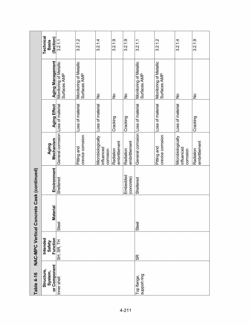
4-211
Tabl
e 4-
16
NAC-
MPC
Ver
tical
Con
cret
e C
ask (con
tinued)
Stru
ctur
e,
Syst
em,
or C
ompo
nent
Inte
nded
Sa
fety
Fu
nctio
n M
ater
ial
Envi
ronm
ent
Agin
g M
echa
nism
Ag
ing
Effe
ct
Agin
g M
anag
emen
t
Tech
nica
l Ba
sis
(Sec
tion)
In
ner s
hell
SH, S
R, T
H
Stee
l Sh
elte
red
Gen
eral
cor
rosi
on L
oss
of m
ater
ial
Mon
itorin
g of
Met
allic
Su
rface
s AM
P 3.
2.1.
1
Pitti
ng a
nd
crev
ice c
orro
sion
Lo
ss o
f mat
eria
l M
onito
ring
of M
etal
lic
Surfa
ces
AMP
3.2.
1.2
Micr
obio
logi
cally
in
fluen
ced
corro
sion
Loss
of m
ater
ial
No
3.2.
1.4
Rad
iatio
n em
britt
lem
ent
Cra
ckin
g N
o 3.
2.1.
9
Embe
dded
(c
oncr
ete)
R
adia
tion
embr
ittle
men
t C
rack
ing
No
3.2.
1.9
Top
flang
e,
supp
ort r
ing
SR
Stee
l Sh
elte
red
Gen
eral
cor
rosi
on L
oss
of m
ater
ial
Mon
itorin
g of
Met
allic
Su
rface
s AM
P 3.
2.1.
1
Pitti
ng a
nd
crev
ice c
orro
sion
Lo
ss o
f mat
eria
l M
onito
ring
of M
etal
lic
Surfa
ces
AMP
3.2.
1.2
Micr
obio
logi
cally
in
fluen
ced
corro
sion
Loss
of m
ater
ial
No
3.2.
1.4
Rad
iatio
n em
britt
lem
ent
Cra
ckin
g N
o 3.
2.1.
9

4-212
Tabl
e 4-
16
NAC-
MPC
Ver
tical
Con
cret
e C
ask (con
tinued)
Stru
ctur
e,
Syst
em,
or C
ompo
nent
Inte
nded
Sa
fety
Fu
nctio
n M
ater
ial
Envi
ronm
ent
Agin
g M
echa
nism
Ag
ing
Effe
ct
Agin
g M
anag
emen
t
Tech
nica
l Ba
sis
(Sec
tion)
Pe
dest
al p
late
SR
St
eel
Shel
tere
d G
ener
al c
orro
sion
Los
s of
mat
eria
l M
onito
ring
of M
etal
lic
Surfa
ces
AMP
3.2.
1.1
Gal
vani
c co
rrosi
on
Loss
of m
ater
ial
Mon
itorin
g of
Met
allic
Su
rface
s AM
P 3.
2.1.
3
Pitti
ng a
nd
crev
ice c
orro
sion
Lo
ss o
f mat
eria
l M
onito
ring
of M
etal
lic
Surfa
ces
AMP
3.2.
1.2
Micr
obio
logi
cally
in
fluen
ced
corro
sion
Loss
of m
ater
ial
No
3.2.
1.4
Rad
iatio
n em
britt
lem
ent
Cra
ckin
g N
o 3.
2.1.
9
Pede
stal
cov
er
SR
Stai
nles
s st
eel
Shel
tere
d St
ress
cor
rosi
on
crac
king
C
rack
ing
No
3.2.
2.5
Pitti
ng a
nd
crev
ice c
orro
sion
Lo
ss o
f mat
eria
l N
o 3.
2.2.
2
Micr
obio
logi
cally
in
fluen
ced
corro
sion
Loss
of m
ater
ial
No
3.2.
2.4
Rad
iatio
n em
britt
lem
ent
Cra
ckin
g N
o 3.
2.2.
9

4-213
Tabl
e 4-
16
NAC-
MPC
Ver
tical
Con
cret
e C
ask (con
tinued)
Stru
ctur
e,
Syst
em,
or C
ompo
nent
Inte
nded
Sa
fety
Fu
nctio
n M
ater
ial
Envi
ronm
ent
Agin
g M
echa
nism
Ag
ing
Effe
ct
Agin
g M
anag
emen
t
Tech
nica
l Ba
sis
(Sec
tion)
Ba
se p
late
as
sem
bly
SH, S
R, T
H
Stee
l Sh
elte
red
Gen
eral
cor
rosi
on L
oss
of m
ater
ial
Mon
itorin
g of
Met
allic
Su
rface
s AM
P 3.
2.1.
1
Pitti
ng a
nd
crev
ice c
orro
sion
Lo
ss o
f mat
eria
l M
onito
ring
of M
etal
lic
Surfa
ces
AMP
3.2.
1.2
Micr
obio
logi
cally
in
fluen
ced
corro
sion
Loss
of m
ater
ial
No
3.2.
1.4
Rad
iatio
n em
britt
lem
ent
Cra
ckin
g N
o 3.
2.1.
9
Base
pla
te n
elso
n st
uds
SR
Stee
l Em
bedd
ed
(con
cret
e)
Gen
eral
cor
rosi
on L
oss
of m
ater
ial
TLAA
/AM
P or
a
supp
ortin
g an
alys
is is
re
quire
d
3.2.
1.1
Pitti
ng a
nd
crev
ice c
orro
sion
Lo
ss o
f mat
eria
l TL
AA/A
MP
or a
su
ppor
ting
anal
ysis
is
requ
ired
3.2.
1.2
Micr
obio
logi
cally
in
fluen
ced
corro
sion
Loss
of m
ater
ial
No
3.2.
1.4
Rad
iatio
n em
britt
lem
ent
Cra
ckin
g N
o 3.
2.1.
9
Out
let v
ent
asse
mbl
y SH
, SR
, TH
St
eel
Shel
tere
d G
ener
al c
orro
sion
Los
s of
mat
eria
l M
onito
ring
of M
etal
lic
Surfa
ces
AMP
3.2.
1.1

4-214
Tabl
e 4-
16
NAC-
MPC
Ver
tical
Con
cret
e C
ask (con
tinued)
Stru
ctur
e,
Syst
em,
or C
ompo
nent
Inte
nded
Sa
fety
Fu
nctio
n M
ater
ial
Envi
ronm
ent
Agin
g M
echa
nism
Ag
ing
Effe
ct
Agin
g M
anag
emen
t
Tech
nica
l Ba
sis
(Sec
tion)
O
utle
t ven
t as
sem
bly
SH, S
R, T
H
Stee
l Sh
elte
red
Gal
vani
c co
rrosi
on
Loss
of m
ater
ial
Mon
itorin
g of
Met
allic
Su
rface
s AM
P 3.
2.1.
3
Pitti
ng a
nd
crev
ice c
orro
sion
Lo
ss o
f mat
eria
l M
onito
ring
of M
etal
lic
Surfa
ces
AMP
3.2.
1.2
Micr
obio
logi
cally
in
fluen
ced
corro
sion
Loss
of m
ater
ial
No
3.2.
1.4
Rad
iatio
n em
britt
lem
ent
Cra
ckin
g N
o 3.
2.1.
9
Inle
t and
out
let
vent
har
dwar
e SH
, SR
, TH
St
ainl
ess
stee
l Sh
elte
red
Stre
ss c
orro
sion
cr
acki
ng
Cra
ckin
g N
o 3.
2.2.
5
Pitti
ng a
nd
crev
ice c
orro
sion
Lo
ss o
f mat
eria
l N
o 3.
2.2.
2
Micr
obio
logi
cally
in
fluen
ced
corro
sion
Loss
of m
ater
ial
No
3.2.
2.4
Rad
iatio
n em
britt
lem
ent
Cra
ckin
g N
o 3.
2.2.
9
Stre
ss re
laxa
tion
Loss
of p
relo
ad
No
3.2.
2.10
Inle
t ven
t su
pple
men
tal
shie
ldin
g as
sem
bly
SH
Stee
l Sh
elte
red
Gen
eral
cor
rosi
on L
oss
of m
ater
ial
Mon
itorin
g of
Met
allic
Su
rface
s AM
P 3.
2.1.
1
Pitti
ng a
nd
crev
ice c
orro
sion
Lo
ss o
f mat
eria
l M
onito
ring
of M
etal
lic
Surfa
ces
AMP
3.2.
1.2

4-215
Tabl
e 4-
16
NAC-
MPC
Ver
tical
Con
cret
e C
ask (con
tinued)
Stru
ctur
e,
Syst
em,
or C
ompo
nent
Inte
nded
Sa
fety
Fu
nctio
n M
ater
ial
Envi
ronm
ent
Agin
g M
echa
nism
Ag
ing
Effe
ct
Agin
g M
anag
emen
t
Tech
nica
l Ba
sis
(Sec
tion)
In
let v
ent
supp
lem
enta
l sh
ield
ing
asse
mbl
y
SH
Stee
l Sh
elte
red
Micr
obio
logi
cally
in
fluen
ced
corro
sion
Loss
of m
ater
ial
No
3.2.
1.4
Rad
iatio
n em
britt
lem
ent
Cra
ckin
g N
o 3.
2.1.
9
Lid
asse
mbl
y SH
, SR
, TH
St
eel
Air—
outd
oor
Gen
eral
cor
rosi
on L
oss
of m
ater
ial
Mon
itorin
g of
Met
allic
Su
rface
s AM
P 3.
2.1.
1
Gal
vani
c co
rrosi
on
Loss
of m
ater
ial
Mon
itorin
g of
Met
allic
Su
rface
s AM
P 3.
2.1.
3
Pitti
ng a
nd
crev
ice c
orro
sion
Lo
ss o
f mat
eria
l M
onito
ring
of M
etal
lic
Surfa
ces
AMP
3.2.
1.2
Micr
obio
logi
cally
in
fluen
ced
corro
sion
Loss
of m
ater
ial
No
3.2.
1.4
Rad
iatio
n em
britt
lem
ent
Cra
ckin
g N
o 3.
2.1.
9
Shel
tere
d G
ener
al c
orro
sion
Los
s of
mat
eria
l M
onito
ring
of M
etal
lic
Surfa
ces
AMP
3.2.
1.1
Pitti
ng a
nd
crev
ice c
orro
sion
Lo
ss o
f mat
eria
l M
onito
ring
of M
etal
lic
Surfa
ces
AMP
3.2.
1.2
Micr
obio
logi
cally
in
fluen
ced
corro
sion
Loss
of m
ater
ial
No
3.2.
1.4

4-216
Tabl
e 4-
16
NAC-
MPC
Ver
tical
Con
cret
e C
ask (con
tinued)
Stru
ctur
e,
Syst
em,
or C
ompo
nent
Inte
nded
Sa
fety
Fu
nctio
n M
ater
ial
Envi
ronm
ent
Agin
g M
echa
nism
Ag
ing
Effe
ct
Agin
g M
anag
emen
t
Tech
nica
l Ba
sis
(Sec
tion)
Li
d as
sem
bly
SH, S
R, T
H
Stee
l Sh
elte
red
Rad
iatio
n em
britt
lem
ent
Cra
ckin
g N
o 3.
2.1.
9
Con
cret
e Fu
lly e
ncas
ed
(ste
el)
Del
ayed
ettr
ingi
te
form
atio
n Lo
ss o
f mat
eria
l (s
pallin
g, s
calin
g) N
o 3.
5.1.
13
Cra
ckin
g N
o 3.
5.1.
13
Loss
of s
treng
th
No
3.5.
1.13
R
adia
tion
dam
age
Cra
ckin
g N
o 3.
5.1.
9
Loss
of s
treng
th
No
3.5.
1.9
Rea
ctio
n w
ith
aggr
egat
es
Cra
ckin
g N
o 3.
5.1.
3
Loss
of s
treng
th
No
3.5.
1.3
Lid
cent
er s
uppo
rt,
nels
on s
tuds
SR
St
eel
Embe
dded
(c
oncr
ete
fully
en
case
d in
st
eel)
Gen
eral
cor
rosi
on L
oss
of m
ater
ial
No
3.2.
1.1
Pitti
ng a
nd
crev
ice c
orro
sion
Lo
ss o
f mat
eria
l N
o 3.
2.1.
2
Micr
obio
logi
cally
in
fluen
ced
corro
sion
Loss
of m
ater
ial
No
3.2.
1.4
Rad
iatio
n em
britt
lem
ent
Cra
ckin
g N
o 3.
2.1.
9

4-217
Tabl
e 4-
16
NAC-
MPC
Ver
tical
Con
cret
e C
ask (con
tinued)
Stru
ctur
e,
Syst
em,
or C
ompo
nent
Inte
nded
Sa
fety
Fu
nctio
n M
ater
ial
Envi
ronm
ent
Agin
g M
echa
nism
Ag
ing
Effe
ct
Agin
g M
anag
emen
t
Tech
nica
l Ba
sis
(Sec
tion)
Li
d ha
rdw
are
SR
Stai
nles
s st
eel
Air—
outd
oor
Stre
ss c
orro
sion
cr
acki
ng
Cra
ckin
g N
o 3.
2.2.
5
Pitti
ng a
nd
crev
ice c
orro
sion
Lo
ss o
f mat
eria
l N
o 3.
2.2.
2
Micr
obio
logi
cally
in
fluen
ced
corro
sion
Loss
of m
ater
ial
No
3.2.
2.4
Rad
iatio
n em
britt
lem
ent
Cra
ckin
g N
o 3.
2.2.
9
Stre
ss re
laxa
tion
Loss
of p
relo
ad
No
3.2.
2.10
Shie
ld p
lug
asse
mbl
y SH
St
eel
Shel
tere
d G
ener
al c
orro
sion
Los
s of
mat
eria
l M
onito
ring
of M
etal
lic
Surfa
ces
AMP
3.2.
1.1
Pitti
ng a
nd
crev
ice c
orro
sion
Lo
ss o
f mat
eria
l M
onito
ring
of M
etal
lic
Surfa
ces
AMP
3.2.
1.2
Micr
obio
logi
cally
in
fluen
ced
corro
sion
Loss
of m
ater
ial
No
3.2.
1.4
Rad
iatio
n em
britt
lem
ent
Cra
ckin
g N
o 3.
2.1.
9
Neu
tron
shie
ld
(Shi
eld
plug
) SH
N
S-4-
FR
Fully
enc
ased
(s
teel
) Th
erm
al a
ging
Lo
ss o
f fra
ctur
e to
ughn
ess
and
loss
of d
uctili
ty
TLAA
/AM
P or
a
supp
ortin
g an
alys
is is
re
quire
d
3.3.
1.2

4-218
Tabl
e 4-
16
NAC-
MPC
Ver
tical
Con
cret
e C
ask (con
tinued)
Stru
ctur
e,
Syst
em,
or C
ompo
nent
Inte
nded
Sa
fety
Fu
nctio
n M
ater
ial
Envi
ronm
ent
Agin
g M
echa
nism
Ag
ing
Effe
ct
Agin
g M
anag
emen
t
Tech
nica
l Ba
sis
(Sec
tion)
N
eutro
n sh
ield
(S
hiel
d pl
ug)
SH
NS-
4-FR
Fu
lly e
ncas
ed
(ste
el)
Rad
iatio
n em
britt
lem
ent
Cra
ckin
g TL
AA/A
MP
or a
su
ppor
ting
anal
ysis
is
requ
ired
3.3.
1.3
Boro
n de
plet
ion
Loss
of s
hiel
ding
TL
AA/A
MP
or a
su
ppor
ting
anal
ysis
is
requ
ired
3.3.
1.1
NS-
3 Fu
lly e
ncas
ed
(ste
el)
Ther
mal
agi
ng
Loss
of f
ract
ure
toug
hnes
s an
d lo
ss o
f duc
tility
No
3.3.
1.2
Rad
iatio
n em
britt
lem
ent
Cra
ckin
g N
o 3.
3.1.
3
Boro
n de
plet
ion
Loss
of s
hiel
ding
TL
AA/A
MP
or a
su
ppor
ting
anal
ysis
is
requ
ired
3.3.
1.1
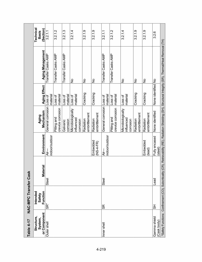
4-219
Tabl
e 4-
17
NAC
-MPC
Tra
nsfe
r Cas
k
Stru
ctur
e,
Syst
em,
or C
ompo
nent
Inte
nded
Sa
fety
Fu
nctio
n M
ater
ial
Envi
ronm
ent
Agin
g M
echa
nism
Ag
ing
Effe
ct
Agin
g M
anag
emen
t
Tech
nica
l Ba
sis
(Sec
tion)
O
uter
she
ll SR
* St
eel
Air—
indo
or/o
utdo
or
Gen
eral
cor
rosi
on L
oss
of
mat
eria
l Tr
ansf
er C
asks
AM
P 3.
2.1.
1
Pitti
ng a
nd
crev
ice c
orro
sion
Lo
ss o
f m
ater
ial
Tran
sfer
Cas
ks A
MP
3.2.
1.2
Gal
vani
c co
rrosi
on
Loss
of
mat
eria
l Tr
ansf
er C
asks
AM
P 3.
2.1.
3
Micr
obio
logi
cally
in
fluen
ced
corro
sion
Loss
of
mat
eria
l N
o 3.
2.1.
4
Rad
iatio
n em
britt
lem
ent
Cra
ckin
g N
o 3.
2.1.
9
Embe
dded
(N
S-4-
FR)
Rad
iatio
n em
britt
lem
ent
Cra
ckin
g N
o 3.
2.1.
9
Inne
r she
ll SR
St
eel
Air—
indo
or/o
utdo
or
Gen
eral
cor
rosi
on L
oss
of
mat
eria
l Tr
ansf
er C
asks
AM
P 3.
2.1.
1
Pitti
ng a
nd
crev
ice c
orro
sion
Lo
ss o
f m
ater
ial
Tran
sfer
Cas
ks A
MP
3.2.
1.2
Micr
obio
logi
cally
in
fluen
ced
corro
sion
Loss
of
mat
eria
l N
o 3.
2.1.
4
Rad
iatio
n em
britt
lem
ent
Cra
ckin
g N
o 3.
2.1.
9
Embe
dded
(le
ad)
Rad
iatio
n em
britt
lem
ent
Cra
ckin
g N
o 3.
2.1.
9
Gam
ma
shie
ld
(Cas
k bo
dy)
SH
Lead
Fu
lly e
ncas
ed
(ste
el)
Non
e id
entif
ied
Non
e id
entif
ied
No
3.2.
6
*Saf
ety
Func
tions
: C
onfin
emen
t (C
O),
Subc
ritica
lity (C
R),
Ret
rieva
bility
(RE)
, Rad
iatio
n Sh
ield
ing
(SH
), St
ruct
ural
Inte
grity
(SR
), Th
erm
al/H
eat R
emov
al (T
H)

4-220
Tabl
e 4-
17
NAC-
MPC
Tra
nsfe
r Cas
k (con
tinued)
Stru
ctur
e,
Syst
em,
or C
ompo
nent
Inte
nded
Sa
fety
Fu
nctio
n M
ater
ial
Envi
ronm
ent
Agin
g M
echa
nism
Ag
ing
Effe
ct
Agin
g M
anag
emen
t
Tech
nica
l Ba
sis
(Sec
tion)
N
eutro
n sh
ield
(C
ask
body
) SH
N
S-4-
FR
Fully
enc
ased
(s
teel
) Th
erm
al a
ging
Lo
ss o
f fra
ctur
e to
ughn
ess
and
loss
of d
uctili
ty TL
AA/A
MP
or a
su
ppor
ting
anal
ysis
is
requ
ired
3.3.
1.2
Rad
iatio
n em
britt
lem
ent
Cra
ckin
g TL
AA/A
MP
or a
su
ppor
ting
anal
ysis
is
requ
ired
3.3.
1.3
Boro
n de
plet
ion
Loss
of
shie
ldin
g TL
AA/A
MP
or a
su
ppor
ting
anal
ysis
is
requ
ired
3.3.
1.1
Top
plat
e SR
St
eel
Air—
indo
or/o
utdo
or
Gen
eral
cor
rosi
on L
oss
of
mat
eria
l Tr
ansf
er C
asks
AM
P 3.
2.1.
1
Pitti
ng a
nd
crev
ice c
orro
sion
Lo
ss o
f m
ater
ial
Tran
sfer
Cas
ks A
MP
3.2.
1.2
Micr
obio
logi
cally
in
fluen
ced
corro
sion
Loss
of
mat
eria
l N
o 3.
2.1.
4
Rad
iatio
n em
britt
lem
ent
Cra
ckin
g N
o 3.
2.1.
9
Botto
m p
late
SR
St
eel
Air—
indo
or/o
utdo
or
Gen
eral
cor
rosi
on L
oss
of
mat
eria
l Tr
ansf
er C
asks
AM
P 3.
2.1.
1
Pitti
ng a
nd
crev
ice c
orro
sion
Lo
ss o
f m
ater
ial
Tran
sfer
Cas
ks A
MP
3.2.
1.2
Micr
obio
logi
cally
in
fluen
ced
corro
sion
Loss
of
mat
eria
l N
o 3.
2.1.
4
Rad
iatio
n em
britt
lem
ent
Cra
ckin
g N
o 3.
2.1.
9
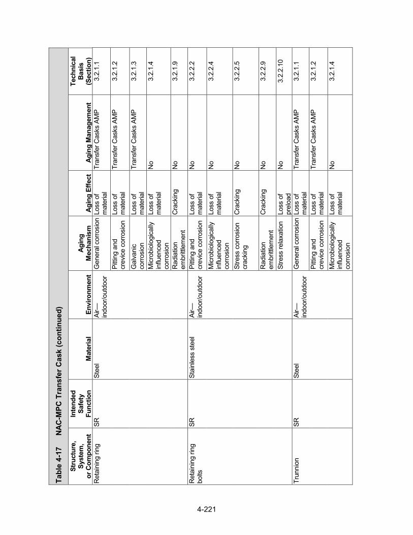
4-221
Tabl
e 4-
17
NAC-
MPC
Tra
nsfe
r Cas
k (con
tinued)
Stru
ctur
e,
Syst
em,
or C
ompo
nent
Inte
nded
Sa
fety
Fu
nctio
n M
ater
ial
Envi
ronm
ent
Agin
g M
echa
nism
Ag
ing
Effe
ct
Agin
g M
anag
emen
t
Tech
nica
l Ba
sis
(Sec
tion)
R
etai
ning
ring
SR
St
eel
Air—
indo
or/o
utdo
or
Gen
eral
cor
rosi
on L
oss
of
mat
eria
l Tr
ansf
er C
asks
AM
P 3.
2.1.
1
Pitti
ng a
nd
crev
ice c
orro
sion
Lo
ss o
f m
ater
ial
Tran
sfer
Cas
ks A
MP
3.2.
1.2
Gal
vani
c co
rrosi
on
Loss
of
mat
eria
l Tr
ansf
er C
asks
AM
P 3.
2.1.
3
Micr
obio
logi
cally
in
fluen
ced
corro
sion
Loss
of
mat
eria
l N
o 3.
2.1.
4
Rad
iatio
n em
britt
lem
ent
Cra
ckin
g N
o 3.
2.1.
9
Ret
aini
ng ri
ng
bolts
SR
St
ainl
ess
stee
l Ai
r—in
door
/out
door
Pi
tting
and
cr
evice
cor
rosi
on
Loss
of
mat
eria
l N
o 3.
2.2.
2
Micr
obio
logi
cally
in
fluen
ced
corro
sion
Loss
of
mat
eria
l N
o 3.
2.2.
4
Stre
ss c
orro
sion
cr
acki
ng
Cra
ckin
g N
o 3.
2.2.
5
Rad
iatio
n em
britt
lem
ent
Cra
ckin
g N
o 3.
2.2.
9
Stre
ss re
laxa
tion
Loss
of
prel
oad
No
3.2.
2.10
Trun
nion
SR
St
eel
Air—
indo
or/o
utdo
or
Gen
eral
cor
rosi
on L
oss
of
mat
eria
l Tr
ansf
er C
asks
AM
P 3.
2.1.
1
Pitti
ng a
nd
crev
ice c
orro
sion
Lo
ss o
f m
ater
ial
Tran
sfer
Cas
ks A
MP
3.2.
1.2
Micr
obio
logi
cally
in
fluen
ced
corro
sion
Loss
of
mat
eria
l N
o 3.
2.1.
4

4-222
Tabl
e 4-
17
NAC-
MPC
Tra
nsfe
r Cas
k (con
tinued)
Stru
ctur
e,
Syst
em,
or C
ompo
nent
Inte
nded
Sa
fety
Fu
nctio
n M
ater
ial
Envi
ronm
ent
Agin
g M
echa
nism
Ag
ing
Effe
ct
Agin
g M
anag
emen
t
Tech
nica
l Ba
sis
(Sec
tion)
Tr
unni
on
SR
Stee
l Ai
r—in
door
/out
door
R
adia
tion
embr
ittle
men
t C
rack
ing
No
3.2.
1.9
Wea
r Lo
ss o
f m
ater
ial
Tran
sfer
Cas
ks A
MP
3.2.
1.11
Shie
ld d
oor p
late
s SH
St
eel
Air—
indo
or/o
utdo
or
Gen
eral
cor
rosi
on L
oss
of
mat
eria
l Tr
ansf
er C
asks
AM
P 3.
2.1.
1
Pitti
ng a
nd
crev
ice c
orro
sion
Lo
ss o
f m
ater
ial
Tran
sfer
Cas
ks A
MP
3.2.
1.2
Micr
obio
logi
cally
in
fluen
ced
corro
sion
Loss
of
mat
eria
l N
o 3.
2.1.
4
Rad
iatio
n em
britt
lem
ent
Cra
ckin
g N
o 3.
2.1.
9
Shie
ld d
oor r
ails
SH
, SR
St
eel
Air—
indo
or/o
utdo
or
Gen
eral
cor
rosi
on L
oss
of
mat
eria
l Tr
ansf
er C
asks
AM
P 3.
2.1.
1
Pitti
ng a
nd
crev
ice c
orro
sion
Lo
ss o
f m
ater
ial
Tran
sfer
Cas
ks A
MP
3.2.
1.2
Gal
vani
c co
rrosi
on
Loss
of
mat
eria
l Tr
ansf
er C
asks
AM
P 3.
2.1.
3
Micr
obio
logi
cally
in
fluen
ced
corro
sion
Loss
of
mat
eria
l N
o 3.
2.1.
4
Rad
iatio
n em
britt
lem
ent
Cra
ckin
g N
o 3.
2.1.
9
Wea
r Lo
ss o
f m
ater
ial
Tran
sfer
Cas
ks A
MP
3.2.
1.11
Shie
ld d
oor l
ock
bolts
SR
St
ainl
ess
stee
l Ai
r—in
door
/out
door
Pi
tting
and
cr
evice
cor
rosi
on
Loss
of
mat
eria
l N
o 3.
2.2.
2

4-223
Tabl
e 4-
17
NAC-
MPC
Tra
nsfe
r Cas
k (con
tinued)
Stru
ctur
e,
Syst
em,
or C
ompo
nent
Inte
nded
Sa
fety
Fu
nctio
n M
ater
ial
Envi
ronm
ent
Agin
g M
echa
nism
Ag
ing
Effe
ct
Agin
g M
anag
emen
t
Tech
nica
l Ba
sis
(Sec
tion)
Sh
ield
doo
r loc
k bo
lts
SR
Stai
nles
s st
eel
Air—
indo
or/o
utdo
or
Micr
obio
logi
cally
in
fluen
ced
corro
sion
Loss
of
mat
eria
l N
o 3.
2.2.
4
Stre
ss c
orro
sion
cr
acki
ng
Cra
ckin
g N
o 3.
2.2.
5
Rad
iatio
n em
britt
lem
ent
Cra
ckin
g N
o 3.
2.2.
9
Stre
ss re
laxa
tion
Loss
of
prel
oad
No
3.2.
2.10

4-224
Tabl
e 4-
18
MAG
NAS
TOR
Tra
nspo
rtab
le S
tora
ge C
anis
ter
Stru
ctur
e,
Syst
em,
or C
ompo
nent
Inte
nded
Sa
fety
Fu
nctio
n M
ater
ial
Envi
ronm
ent
Agin
g M
echa
nism
Ag
ing
Effe
ct
Agin
g M
anag
emen
t
Tech
nica
l Ba
sis
(Sec
tion)
Sh
ell
CO
, SR
* St
ainl
ess
stee
l (w
elde
d)
Shel
tere
d St
ress
cor
rosi
on
crac
king
C
rack
ing
Loca
lized
Cor
rosi
on a
nd
Stre
ss c
orro
sion
C
rack
ing
of W
elde
d St
ainl
ess
Stee
l Dry
St
orag
e C
anis
ters
AM
P
3.2.
2.5
Stai
nles
s st
eel
Shel
tere
d Pi
tting
and
cr
evice
cor
rosi
on
Loss
of
mat
eria
l (P
recu
rsor
to
stre
ss
corro
sion
cr
acki
ng)
Loca
lized
Cor
rosi
on a
nd
Stre
ss c
orro
sion
C
rack
ing
of W
elde
d St
ainl
ess
Stee
l Dry
St
orag
e C
anis
ters
AM
P
3.2.
2.2
Micr
obio
logi
cally
in
fluen
ced
corro
sion
Loss
of
mat
eria
l N
o 3.
2.2.
4
Fatig
ue
Cra
ckin
g Ev
alua
te d
esig
n co
de
TLAA
, if a
pplic
able
3.
2.2.
7
Rad
iatio
n em
britt
lem
ent
Cra
ckin
g N
o 3.
2.2.
9
Hel
ium
R
adia
tion
embr
ittle
men
t C
rack
ing
No
3.2.
2.9
Botto
m
CO
, SR
St
ainl
ess
stee
l (w
elde
d)
Shel
tere
d St
ress
cor
rosi
on
crac
king
C
rack
ing
Loca
lized
Cor
rosi
on a
nd
Stre
ss c
orro
sion
C
rack
ing
of W
elde
d St
ainl
ess
Stee
l Dry
St
orag
e C
anis
ters
AM
P
3.2.
2.5
Pitti
ng a
nd
crev
ice c
orro
sion
Lo
ss o
f m
ater
ial
(Pre
curs
or to
st
ress
co
rrosi
on
crac
king
)
Loca
lized
Cor
rosi
on a
nd
Stre
ss c
orro
sion
C
rack
ing
of W
elde
d St
ainl
ess
Stee
l Dry
St
orag
e C
anis
ters
AM
P
3.2.
2.2
*Saf
ety
Func
tions
: C
onfin
emen
t (C
O),
Subc
ritica
lity (C
R),
Ret
rieva
bility
(RE)
, Rad
iatio
n Sh
ield
ing
(SH
), St
ruct
ural
Inte
grity
(SR
), Th
erm
al/H
eat R
emov
al (T
H)

4-225
Tabl
e 4-
18
MA
GN
AST
OR
Tra
nspo
rtab
le S
tora
ge C
anis
ter (continued)
Stru
ctur
e,
Syst
em,
or C
ompo
nent
Inte
nded
Sa
fety
Fu
nctio
n M
ater
ial
Envi
ronm
ent
Agin
g M
echa
nism
Ag
ing
Effe
ct
Agin
g M
anag
emen
t
Tech
nica
l Ba
sis
(Sec
tion)
Bo
ttom
C
O, S
R
Stai
nles
s st
eel
Shel
tere
d M
icrob
iolo
gica
lly
influ
ence
d co
rrosi
on
Loss
of
mat
eria
l N
o 3.
2.2.
4
Fatig
ue
Cra
ckin
g Ev
alua
te d
esig
n co
de
TLAA
, if a
pplic
able
3.
2.2.
7
Rad
iatio
n em
britt
lem
ent
Cra
ckin
g N
o 3.
2.2.
9
Hel
ium
R
adia
tion
embr
ittle
men
t C
rack
ing
No
3.2.
2.9
Clo
sure
lid
CO
, SR
St
ainl
ess
stee
l (w
elde
d)
Shel
tere
d St
ress
cor
rosi
on
crac
king
C
rack
ing
Loca
lized
Cor
rosi
on a
nd
Stre
ss c
orro
sion
C
rack
ing
of W
elde
d St
ainl
ess
Stee
l Dry
St
orag
e C
anis
ters
AM
P
3.2.
2.5
Stai
nles
s st
eel
Shel
tere
d Pi
tting
and
cr
evice
cor
rosi
on
Loss
of
mat
eria
l (P
recu
rsor
to
stre
ss
corro
sion
cr
acki
ng)
Loca
lized
Cor
rosi
on a
nd
Stre
ss c
orro
sion
C
rack
ing
of W
elde
d St
ainl
ess
Stee
l Dry
St
orag
e C
anis
ters
AM
P
3.2.
2.2
Micr
obio
logi
cally
in
fluen
ced
corro
sion
Loss
of
mat
eria
l N
o 3.
2.2.
4
Fatig
ue
Cra
ckin
g Ev
alua
te d
esig
n co
de
TLAA
, if a
pplic
able
3.
2.2.
7
Rad
iatio
n em
britt
lem
ent
Cra
ckin
g N
o 3.
2.2.
9
Hel
ium
R
adia
tion
embr
ittle
men
t C
rack
ing
No
3.2.
2.9
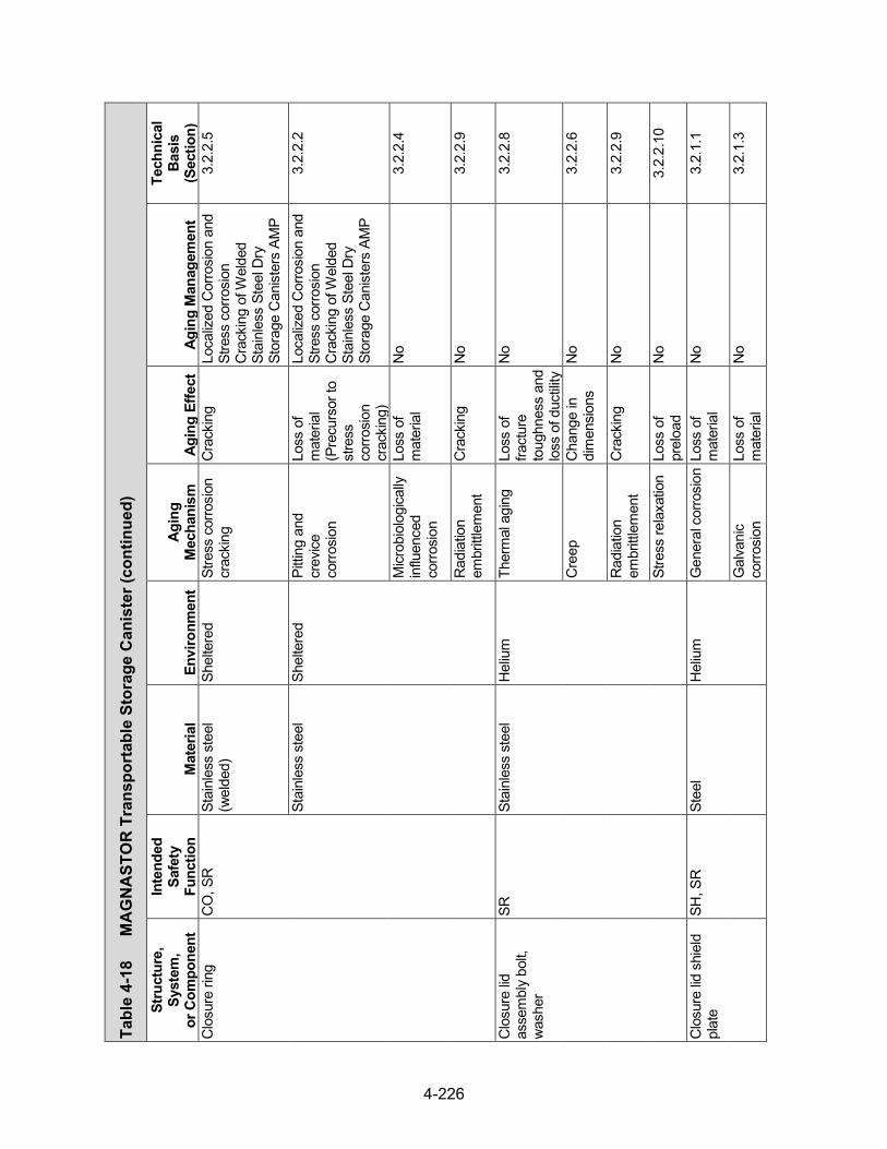
4-226
Tabl
e 4-
18
MA
GN
AST
OR
Tra
nspo
rtab
le S
tora
ge C
anis
ter (continued)
Stru
ctur
e,
Syst
em,
or C
ompo
nent
Inte
nded
Sa
fety
Fu
nctio
n M
ater
ial
Envi
ronm
ent
Agin
g M
echa
nism
Ag
ing
Effe
ct
Agin
g M
anag
emen
t
Tech
nica
l Ba
sis
(Sec
tion)
C
losu
re ri
ng
CO
, SR
St
ainl
ess
stee
l (w
elde
d)
Shel
tere
d St
ress
cor
rosi
on
crac
king
C
rack
ing
Loca
lized
Cor
rosi
on a
nd
Stre
ss c
orro
sion
C
rack
ing
of W
elde
d St
ainl
ess
Stee
l Dry
St
orag
e C
anis
ters
AM
P
3.2.
2.5
Stai
nles
s st
eel
Shel
tere
d Pi
tting
and
cr
evice
co
rrosi
on
Loss
of
mat
eria
l (P
recu
rsor
to
stre
ss
corro
sion
cr
acki
ng)
Loca
lized
Cor
rosi
on a
nd
Stre
ss c
orro
sion
C
rack
ing
of W
elde
d St
ainl
ess
Stee
l Dry
St
orag
e C
anis
ters
AM
P
3.2.
2.2
Micr
obio
logi
cally
in
fluen
ced
corro
sion
Loss
of
mat
eria
l N
o 3.
2.2.
4
Rad
iatio
n em
britt
lem
ent
Cra
ckin
g N
o 3.
2.2.
9
Clo
sure
lid
asse
mbl
y bo
lt,
was
her
SR
Stai
nles
s st
eel
Hel
ium
Th
erm
al a
ging
Lo
ss o
f fra
ctur
e to
ughn
ess
and
loss
of d
uctili
ty N
o 3.
2.2.
8
Cre
ep
Cha
nge
in
dim
ensi
ons
No
3.2.
2.6
Rad
iatio
n em
britt
lem
ent
Cra
ckin
g N
o 3.
2.2.
9
Stre
ss re
laxa
tion
Loss
of
prel
oad
No
3.2.
2.10
Clo
sure
lid s
hiel
d pl
ate
SH, S
R
Stee
l H
eliu
m
Gen
eral
cor
rosi
on L
oss
of
mat
eria
l N
o 3.
2.1.
1
Gal
vani
c co
rrosi
on
Loss
of
mat
eria
l N
o 3.
2.1.
3

4-227
Tabl
e 4-
18
MA
GN
AST
OR
Tra
nspo
rtab
le S
tora
ge C
anis
ter (continued)
Stru
ctur
e,
Syst
em,
or C
ompo
nent
Inte
nded
Sa
fety
Fu
nctio
n M
ater
ial
Envi
ronm
ent
Agin
g M
echa
nism
Ag
ing
Effe
ct
Agin
g M
anag
emen
t
Tech
nica
l Ba
sis
(Sec
tion)
C
losu
re lid
shi
eld
plat
e SH
, SR
St
eel
Hel
ium
Th
erm
al a
ging
Lo
ss o
f fra
ctur
e to
ughn
ess
and
loss
of d
uctili
ty N
o 3.
2.1.
8
Cre
ep
Cha
nge
in
dim
ensi
ons
No
3.2.
1.6
Rad
iatio
n em
britt
lem
ent
Cra
ckin
g N
o 3.
2.1.
9
Port
cove
r C
O
Stai
nles
s st
eel
(wel
ded)
Sh
elte
red
Stre
ss c
orro
sion
cr
acki
ng
Cra
ckin
g Lo
caliz
ed C
orro
sion
and
St
ress
cor
rosi
on
Cra
ckin
g of
Wel
ded
Stai
nles
s St
eel D
ry
Stor
age
Can
iste
rs A
MP
3.2.
2.5
Stai
nles
s st
eel
Shel
tere
d Pi
tting
and
cr
evice
cor
rosi
on
Loss
of
mat
eria
l (P
recu
rsor
to
stre
ss
corro
sion
cr
acki
ng)
Loca
lized
Cor
rosi
on a
nd
Stre
ss c
orro
sion
C
rack
ing
of W
elde
d St
ainl
ess
Stee
l Dry
St
orag
e C
anis
ters
AM
P
3.2.
2.2
Micr
obio
logi
cally
in
fluen
ced
corro
sion
Loss
of
mat
eria
l N
o 3.
2.2.
4
Fatig
ue
Cra
ckin
g Ev
alua
te d
esig
n co
de
TLAA
, if a
pplic
able
3.
2.2.
7
Rad
iatio
n em
britt
lem
ent
Cra
ckin
g N
o 3.
2.2.
9
Hel
ium
R
adia
tion
embr
ittle
men
t C
rack
ing
No
3.2.
2.9

4-228
Tabl
e 4-
18
MA
GN
AST
OR
Tra
nspo
rtab
le S
tora
ge C
anis
ter (continued)
Stru
ctur
e,
Syst
em,
or C
ompo
nent
Inte
nded
Sa
fety
Fu
nctio
n M
ater
ial
Envi
ronm
ent
Agin
g M
echa
nism
Ag
ing
Effe
ct
Agin
g M
anag
emen
t
Tech
nica
l Ba
sis
(Sec
tion)
Li
fting
lug,
ant
i-ro
tatio
n lu
g SR
St
ainl
ess
stee
l (w
elde
d)
Hel
ium
Th
erm
al a
ging
Lo
ss o
f fra
ctur
e to
ughn
ess
and
loss
of d
uctili
ty N
o 3.
2.2.
8
Stai
nles
s st
eel
Hel
ium
C
reep
C
hang
e in
di
men
sion
s N
o 3.
2.2.
6
Rad
iatio
n em
britt
lem
ent
Cra
ckin
g N
o 3.
2.2.
9
Fuel
tube
C
R, S
R
Stee
l H
eliu
m
Gen
eral
cor
rosi
on L
oss
of
mat
eria
l N
o 3.
2.1.
1
Ther
mal
agi
ng
Loss
of
fract
ure
toug
hnes
s an
d lo
ss o
f duc
tility
No
3.2.
1.8
Fatig
ue
Cra
ckin
g Ev
alua
te d
esig
n co
de
TLAA
, if a
pplic
able
3.
2.1.
7
Cre
ep
Cha
nge
in
dim
ensi
ons
No
3.2.
1.6
Rad
iatio
n em
britt
lem
ent
Cra
ckin
g N
o 3.
2.1.
9
Neu
tron
abso
rber
C
R
Bora
ted
alum
inum
H
eliu
m
Gen
eral
cor
rosi
on L
oss
of
mat
eria
l N
o 3.
4.2.
1
Gal
vani
c co
rrosi
on
Loss
of
mat
eria
l N
o 3.
4.2.
2
Ther
mal
agi
ng
Loss
of
stre
ngth
N
o 3.
4.2.
6
Cre
ep
Cha
nge
in
dim
ensi
ons
No
3.4.
2.5

4-229
Tabl
e 4-
18
MA
GN
AST
OR
Tra
nspo
rtab
le S
tora
ge C
anis
ter (continued)
Stru
ctur
e,
Syst
em,
or C
ompo
nent
Inte
nded
Sa
fety
Fu
nctio
n M
ater
ial
Envi
ronm
ent
Agin
g M
echa
nism
Ag
ing
Effe
ct
Agin
g M
anag
emen
t
Tech
nica
l Ba
sis
(Sec
tion)
N
eutro
n ab
sorb
er
CR
Bo
rate
d al
umin
um
Hel
ium
R
adia
tion
embr
ittle
men
t C
rack
ing
No
3.4.
2.7
Boro
n de
plet
ion
Red
uctio
n of
ne
utro
n-ab
sorb
ing
capa
city
No;
a T
LAA
may
be
requ
ired
3.4.
2.4
Bora
l H
eliu
m
Gen
eral
cor
rosi
on L
oss
of
mat
eria
l N
o 3.
4.2.
1
Gal
vani
c co
rrosi
on
Loss
of
mat
eria
l N
o 3.
4.2.
2
Ther
mal
agi
ng
Loss
of
stre
ngth
N
o 3.
4.2.
6
Wet
cor
rosi
on
and
blist
erin
g C
hang
e in
di
men
sion
s N
o 3.
4.2.
3
Cre
ep
Cha
nge
in
dim
ensi
ons
No
3.4.
2.5
Rad
iatio
n em
britt
lem
ent
Cra
ckin
g N
o 3.
4.2.
7
Boro
n de
plet
ion
Red
uctio
n of
ne
utro
n-ab
sorb
ing
capa
city
No;
a T
LAA
may
be
requ
ired
3.4.
2.4
Bora
ted
met
al
mat
rix c
ompo
site
H
eliu
m
Gen
eral
cor
rosi
on L
oss
of
mat
eria
l N
o 3.
4.2.
1
Gal
vani
c co
rrosi
on
Loss
of
mat
eria
l N
o 3.
4.2.
2
Ther
mal
agi
ng
Loss
of
stre
ngth
N
o 3.
4.2.
6
Cre
ep
Cha
nge
in
dim
ensi
ons
No
3.4.
2.5
Rad
iatio
n em
britt
lem
ent
Cra
ckin
g N
o 3.
4.2.
7

4-230
Tabl
e 4-
18
MA
GN
AST
OR
Tra
nspo
rtab
le S
tora
ge C
anis
ter (continued)
Stru
ctur
e,
Syst
em,
or C
ompo
nent
Inte
nded
Sa
fety
Fu
nctio
n M
ater
ial
Envi
ronm
ent
Agin
g M
echa
nism
Ag
ing
Effe
ct
Agin
g M
anag
emen
t
Tech
nica
l Ba
sis
(Sec
tion)
N
eutro
n ab
sorb
er
CR
Bo
rate
d m
etal
m
atrix
com
posi
te
Hel
ium
Bo
ron
depl
etio
n R
educ
tion
of
neut
ron-
abso
rbin
g ca
paci
ty
No;
a T
LAA
may
be
requ
ired
3.4.
2.4
Plat
e in
lieu
of
neut
ron
abso
rber
TH
Al
umin
um
Hel
ium
G
ener
al c
orro
sion
Los
s of
m
ater
ial
No
3.2.
3.1
Gal
vani
c co
rrosi
on
Loss
of
mat
eria
l N
o 3.
2.3.
3
Ther
mal
agi
ng
Loss
of
stre
ngth
N
o 3.
2.3.
7
Cre
ep
Cha
nge
in
dim
ensi
ons
No
3.2.
3.5
Rad
iatio
n em
britt
lem
ent
Cra
ckin
g N
o 3.
2.3.
8
Neu
tron
abso
rber
re
tain
er
SR
Stai
nles
s st
eel
(wel
ded)
H
eliu
m
Ther
mal
agi
ng
Loss
of
fract
ure
toug
hnes
s an
d lo
ss o
f duc
tility
No
3.2.
2.8
Stai
nles
s st
eel
Hel
ium
C
reep
C
hang
e in
di
men
sion
s N
o 3.
2.2.
6
Rad
iatio
n em
britt
lem
ent
Cra
ckin
g N
o 3.
2.2.
9
Wel
d po
st
SR
Stai
nles
s st
eel
(wel
ded)
H
eliu
m
Ther
mal
agi
ng
Loss
of
fract
ure
toug
hnes
s an
d lo
ss o
f duc
tility
No
3.2.
2.8
Stai
nles
s st
eel
Hel
ium
Fa
tigue
C
rack
ing
Eval
uate
des
ign
code
TL
AA, i
f app
licab
le
3.2.
2.7
Cre
ep
Cha
nge
in
dim
ensi
ons
No
3.2.
2.6

4-231
Tabl
e 4-
18
MA
GN
AST
OR
Tra
nspo
rtab
le S
tora
ge C
anis
ter (continued)
Stru
ctur
e,
Syst
em,
or C
ompo
nent
Inte
nded
Sa
fety
Fu
nctio
n M
ater
ial
Envi
ronm
ent
Agin
g M
echa
nism
Ag
ing
Effe
ct
Agin
g M
anag
emen
t
Tech
nica
l Ba
sis
(Sec
tion)
W
eld
post
SR
St
ainl
ess
stee
l H
eliu
m
Rad
iatio
n em
britt
lem
ent
Cra
ckin
g N
o 3.
2.2.
9
Fuel
bas
ket
supp
ort p
late
s &
guss
ets,
co
nnec
tor p
in
was
her
SR
Stee
l H
eliu
m
Gen
eral
cor
rosi
on L
oss
of
mat
eria
l N
o 3.
2.1.
1
Ther
mal
agi
ng
Loss
of
fract
ure
toug
hnes
s an
d lo
ss o
f duc
tility
No
3.2.
1.8
Fatig
ue
Cra
ckin
g Ev
alua
te d
esig
n co
de
TLAA
, if a
pplic
able
3.
2.1.
7
Cre
ep
Cha
nge
in
dim
ensi
ons
No
3.2.
1.6
Rad
iatio
n em
britt
lem
ent
Cra
ckin
g N
o 3.
2.1.
9
Neu
tron
abso
rber
re
tain
er c
lip, f
uel
bask
et s
uppo
rt tu
be, v
ent a
nd
drai
n tu
be
rest
ricto
r pla
te,
fuel
bas
ket p
ins,
sp
acer
SR
Stee
l H
eliu
m
Gen
eral
cor
rosi
on L
oss
of
mat
eria
l N
o 3.
2.1.
1
Ther
mal
agi
ng
Loss
of
fract
ure
toug
hnes
s an
d lo
ss o
f duc
tility
No
3.2.
1.8
Fatig
ue
Cra
ckin
g Ev
alua
te d
esig
n co
de
TLAA
, if a
pplic
able
3.
2.1.
7
Cre
ep
Cha
nge
in
dim
ensi
ons
No
3.2.
1.6
Rad
iatio
n em
britt
lem
ent
Cra
ckin
g N
o 3.
2.1.
9

4-232
Tabl
e 4-
18
MA
GN
AST
OR
Tra
nspo
rtab
le S
tora
ge C
anis
ter (continued)
Stru
ctur
e,
Syst
em,
or C
ompo
nent
Inte
nded
Sa
fety
Fu
nctio
n M
ater
ial
Envi
ronm
ent
Agin
g M
echa
nism
Ag
ing
Effe
ct
Agin
g M
anag
emen
t
Tech
nica
l Ba
sis
(Sec
tion)
Fu
el b
aske
t cor
ner
supp
ort b
ar,
supp
ort p
in, f
uel
tube
pin
, con
nect
or
pin
SR
Stee
l H
eliu
m
Gen
eral
cor
rosi
on L
oss
of
mat
eria
l N
o 3.
2.1.
1
Ther
mal
agi
ng
Loss
of
fract
ure
toug
hnes
s an
d lo
ss o
f duc
tility
No
3.2.
1.8
Fatig
ue
Cra
ckin
g Ev
alua
te d
esig
n co
de
TLAA
, if a
pplic
able
3.
2.1.
7
Cre
ep
Cha
nge
in
dim
ensi
ons
No
3.2.
1.6
Rad
iatio
n em
britt
lem
ent
Cra
ckin
g N
o 3.
2.1.
9
Bask
et re
stra
inin
g bl
ock
SR
Stai
nles
s st
eel
(wel
ded)
H
eliu
m
Ther
mal
agi
ng
Loss
of
fract
ure
toug
hnes
s an
d lo
ss o
f duc
tility
No
3.2.
2.8
Stai
nles
s st
eel
Hel
ium
Fa
tigue
C
rack
ing
Eval
uate
des
ign
code
TL
AA, i
f app
licab
le
3.2.
2.7
Cre
ep
Cha
nge
in
dim
ensi
ons
No
3.2.
2.6
Rad
iatio
n em
britt
lem
ent
Cra
ckin
g N
o 3.
2.2.
9
Bask
et s
uppo
rt m
ount
ing
bolt
SR
Stai
nles
s st
eel
Hel
ium
Fa
tigue
C
rack
ing
Eval
uate
des
ign
code
TL
AA, i
f app
licab
le
3.2.
2.7
Ther
mal
agi
ng
Loss
of
fract
ure
toug
hnes
s an
d lo
ss o
f duc
tility
No
3.2.
2.8

4-233
Tabl
e 4-
18
MA
GN
AST
OR
Tra
nspo
rtab
le S
tora
ge C
anis
ter (continued)
Stru
ctur
e,
Syst
em,
or C
ompo
nent
Inte
nded
Sa
fety
Fu
nctio
n M
ater
ial
Envi
ronm
ent
Agin
g M
echa
nism
Ag
ing
Effe
ct
Agin
g M
anag
emen
t
Tech
nica
l Ba
sis
(Sec
tion)
Ba
sket
sup
port
mou
ntin
g bo
lt SR
St
ainl
ess
stee
l H
eliu
m
Cre
ep
Cha
nge
in
dim
ensi
ons
No
3.2.
2.6
Rad
iatio
n em
britt
lem
ent
Cra
ckin
g N
o 3.
2.2.
9
Stre
ss re
laxa
tion
Loss
of
prel
oad
No
3.2.
2.10
Bask
et s
uppo
rt w
ashe
r, bl
ocki
ng
stra
p
SR
Stai
nles
s st
eel
Hel
ium
Fa
tigue
C
rack
ing
Eval
uate
des
ign
code
TL
AA, i
f app
licab
le
3.2.
2.7
Ther
mal
agi
ng
Loss
of
fract
ure
toug
hnes
s an
d lo
ss o
f duc
tility
No
3.2.
2.8
Cre
ep
Cha
nge
in
dim
ensi
ons
No
3.2.
2.6
Rad
iatio
n em
britt
lem
ent
Cra
ckin
g N
o 3.
2.2.
9
Bask
et s
him
SR
St
ainl
ess
stee
l H
eliu
m
Fatig
ue
Cra
ckin
g Ev
alua
te d
esig
n co
de
TLAA
, if a
pplic
able
3.
2.2.
7
Ther
mal
agi
ng
Loss
of
fract
ure
toug
hnes
s an
d lo
ss o
f duc
tility
No
3.2.
2.8
Cre
ep
Cha
nge
in
dim
ensi
ons
No
3.2.
2.6
Rad
iatio
n em
britt
lem
ent
Cra
ckin
g N
o 3.
2.2.
9
Dam
aged
fuel
can
tu
be b
ody
CR
, SR
St
ainl
ess
stee
l (w
elde
d)
Hel
ium
Th
erm
al a
ging
Lo
ss o
f fra
ctur
e to
ughn
ess
and
loss
of d
uctili
ty N
o 3.
2.2.
8

4-234
Tabl
e 4-
18
MA
GN
AST
OR
Tra
nspo
rtab
le S
tora
ge C
anis
ter (continued)
Stru
ctur
e,
Syst
em,
or C
ompo
nent
Inte
nded
Sa
fety
Fu
nctio
n M
ater
ial
Envi
ronm
ent
Agin
g M
echa
nism
Ag
ing
Effe
ct
Agin
g M
anag
emen
t
Tech
nica
l Ba
sis
(Sec
tion)
D
amag
ed fu
el c
an
tube
bod
y C
R, S
R
Stai
nles
s st
eel
Hel
ium
Fa
tigue
C
rack
ing
Eval
uate
des
ign
code
TL
AA, i
f app
licab
le
3.2.
2.7
Cre
ep
Cha
nge
in
dim
ensi
ons
No
3.2.
2.6
Rad
iatio
n em
britt
lem
ent
Cra
ckin
g N
o 3.
2.2.
9
Dam
aged
fuel
can
bo
ttom
, sid
e pl
ates
CR
, SR
St
ainl
ess
stee
l (w
elde
d)
Hel
ium
Th
erm
al a
ging
Lo
ss o
f fra
ctur
e to
ughn
ess
and
loss
of d
uctili
ty N
o 3.
2.2.
8
Stai
nles
s st
eel
Hel
ium
Fa
tigue
C
rack
ing
Eval
uate
des
ign
code
TL
AA, i
f app
licab
le
3.2.
2.7
Cre
ep
Cha
nge
in
dim
ensi
ons
No
3.2.
2.6
Rad
iatio
n em
britt
lem
ent
Cra
ckin
g N
o 3.
2.2.
9
Dam
aged
fuel
can
lid
pla
te, l
id g
uide
, lid
bot
tom
CR
, SR
St
ainl
ess
stee
l (w
elde
d)
Hel
ium
Th
erm
al a
ging
Lo
ss o
f fra
ctur
e to
ughn
ess
and
loss
of d
uctili
ty N
o 3.
2.2.
8
Stai
nles
s st
eel
Hel
ium
Fa
tigue
C
rack
ing
Eval
uate
des
ign
code
TL
AA, i
f app
licab
le
3.2.
2.7
Cre
ep
Cha
nge
in
dim
ensi
ons
No
3.2.
2.6
Rad
iatio
n em
britt
lem
ent
Cra
ckin
g N
o 3.
2.2.
9

4-235
Tabl
e 4-
18
MA
GN
AST
OR
Tra
nspo
rtab
le S
tora
ge C
anis
ter (continued)
Stru
ctur
e,
Syst
em,
or C
ompo
nent
Inte
nded
Sa
fety
Fu
nctio
n M
ater
ial
Envi
ronm
ent
Agin
g M
echa
nism
Ag
ing
Effe
ct
Agin
g M
anag
emen
t
Tech
nica
l Ba
sis
(Sec
tion)
D
amag
ed fu
el c
an
colla
r, lift
tee,
su
ppor
t rin
g, lid
tab
SR
Stai
nles
s st
eel
(wel
ded)
H
eliu
m
Ther
mal
agi
ng
Loss
of
fract
ure
toug
hnes
s an
d lo
ss o
f duc
tility
No
3.2.
2.8
Stai
nles
s st
eel
Hel
ium
Fa
tigue
C
rack
ing
Eval
uate
des
ign
code
TL
AA, i
f app
licab
le
3.2.
2.7
Cre
ep
Cha
nge
in
dim
ensi
ons
No
3.2.
2.6
Rad
iatio
n em
britt
lem
ent
Cra
ckin
g N
o 3.
2.2.
9
Dam
aged
fuel
can
sc
reen
s, w
iper
C
O
Stai
nles
s st
eel
Hel
ium
Th
erm
al a
ging
Lo
ss o
f fra
ctur
e to
ughn
ess
and
loss
of d
uctili
ty N
o 3.
2.2.
8
Cre
ep
Cha
nge
in
dim
ensi
ons
No
3.2.
2.6
Rad
iatio
n em
britt
lem
ent
Cra
ckin
g N
o 3.
2.2.
9
Dam
aged
fuel
sp
acer
pla
te
SR
Stai
nles
s st
eel
Hel
ium
Fa
tigue
C
rack
ing
Eval
uate
des
ign
code
TL
AA, i
f app
licab
le
3.2.
2.7
Ther
mal
agi
ng
Loss
of
fract
ure
toug
hnes
s an
d lo
ss o
f duc
tility
No
3.2.
2.8
Cre
ep
Cha
nge
in
dim
ensi
ons
No
3.2.
2.6
Rad
iatio
n em
britt
lem
ent
Cra
ckin
g N
o 3.
2.2.
9

4-236
Tabl
e 4-
18
MA
GN
AST
OR
Tra
nspo
rtab
le S
tora
ge C
anis
ter (continued)
Stru
ctur
e,
Syst
em,
or C
ompo
nent
Inte
nded
Sa
fety
Fu
nctio
n M
ater
ial
Envi
ronm
ent
Agin
g M
echa
nism
Ag
ing
Effe
ct
Agin
g M
anag
emen
t
Tech
nica
l Ba
sis
(Sec
tion)
D
amag
ed fu
el
clos
ure
lid s
hiel
d pl
ate
SH
Stai
nles
s st
eel
Shel
tere
d St
ress
cor
rosi
on
crac
king
C
rack
ing
No
3.2.
2.5
Pitti
ng a
nd
crev
ice c
orro
sion
Lo
ss o
f m
ater
ial
No
3.2.
2.2
Micr
obio
logi
cally
in
fluen
ced
corro
sion
Loss
of
mat
eria
l N
o 3.
2.2.
4
Rad
iatio
n em
britt
lem
ent
Cra
ckin
g N
o 3.
2.2.
9

4-237
Tabl
e 4-
19
MAG
NAS
TOR
Con
cret
e C
ask
Stru
ctur
e,
Syst
em,
or C
ompo
nent
Inte
nded
Sa
fety
Fu
nctio
n M
ater
ial
Envi
ronm
ent
Agin
g M
echa
nism
Ag
ing
Effe
ct
Agin
g M
anag
emen
t
Tech
nica
l Ba
sis
(Sec
tion)
C
oncr
ete
shel
l SH
, SR
* C
oncr
ete
Air—
outd
oor
Aggr
essi
ve
chem
ical
atta
ck
Cra
ckin
g R
einf
orce
d C
oncr
ete
Stru
ctur
es A
MP
3.5.
1.5
Loss
of s
treng
th R
einf
orce
d C
oncr
ete
Stru
ctur
es A
MP
3.5.
1.5
Loss
of m
ater
ial
(spa
lling,
sc
alin
g)
Rei
nfor
ced
Con
cret
e St
ruct
ures
AM
P 3.
5.1.
5
Cre
ep
Cra
ckin
g N
o 3.
5.1.
2
Deh
ydra
tion
at
high
tem
pera
ture
s C
rack
ing
No
3.5.
1.11
Loss
of s
treng
th N
o 3.
5.1.
11
Del
ayed
ettr
ingi
te
form
atio
n Lo
ss o
f mat
eria
l (s
pallin
g,
scal
ing)
No
3.5.
1.13
Loss
of s
treng
th N
o 3.
5.1.
13
Cra
ckin
g N
o 3.
5.1.
13
Fatig
ue
Cra
ckin
g N
o 3.
5.1.
10
Free
ze a
nd th
aw
Cra
ckin
g R
einf
orce
d C
oncr
ete
Stru
ctur
es A
MP
3.5.
1.1
Loss
of m
ater
ial
(spa
lling,
sc
alin
g)
Rei
nfor
ced
Con
cret
e St
ruct
ures
AM
P 3.
5.1.
1
Rad
iatio
n da
mag
e C
rack
ing
No
3.5.
1.9
Loss
of s
treng
th N
o 3.
5.1.
9
*Saf
ety
Func
tions
: C
onfin
emen
t (C
O),
Subc
ritica
lity (C
R),
Ret
rieva
bility
(RE)
, Rad
iatio
n Sh
ield
ing
(SH
), St
ruct
ural
Inte
grity
(SR
), Th
erm
al/H
eat R
emov
al (T
H)
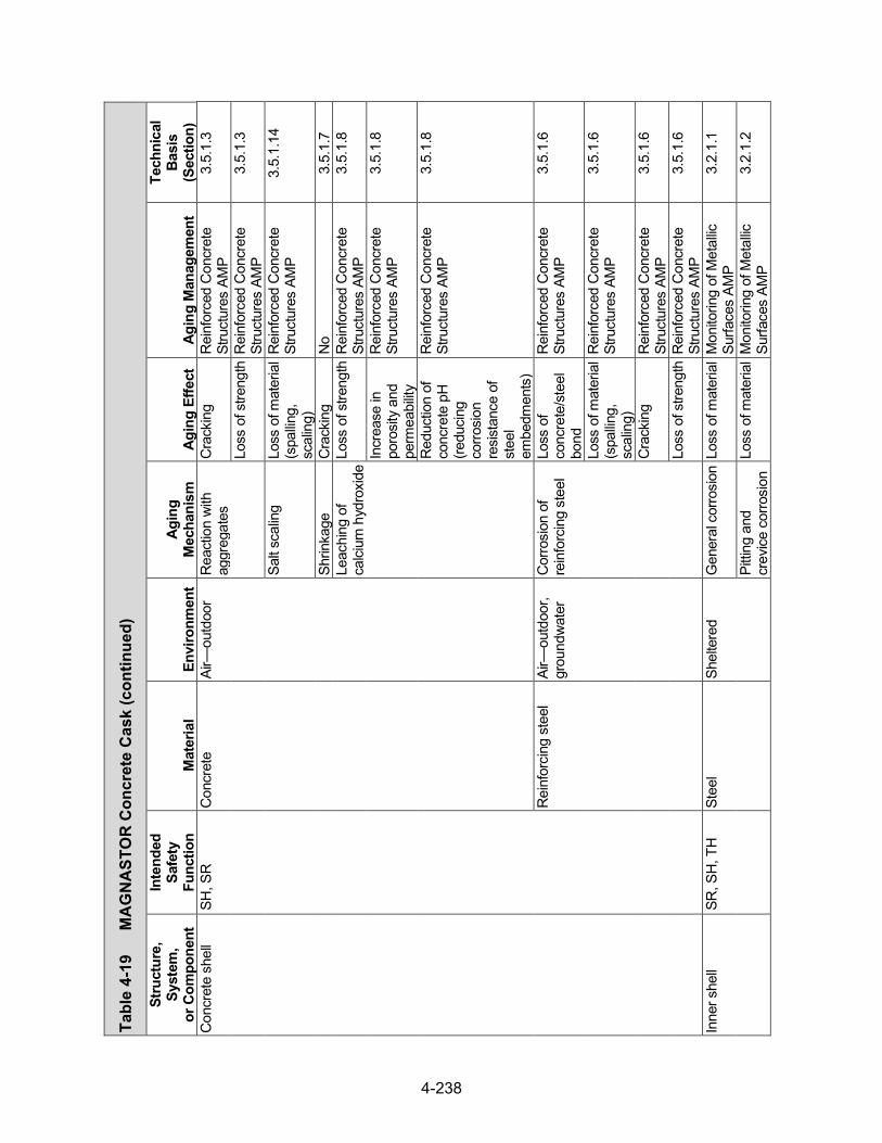
4-238
Tabl
e 4-
19
MA
GN
AST
OR
Con
cret
e C
ask (con
tinued)
Stru
ctur
e,
Syst
em,
or C
ompo
nent
Inte
nded
Sa
fety
Fu
nctio
n M
ater
ial
Envi
ronm
ent
Agin
g M
echa
nism
Ag
ing
Effe
ct
Agin
g M
anag
emen
t
Tech
nica
l Ba
sis
(Sec
tion)
C
oncr
ete
shel
l SH
, SR
C
oncr
ete
Air—
outd
oor
Rea
ctio
n w
ith
aggr
egat
es
Cra
ckin
g R
einf
orce
d C
oncr
ete
Stru
ctur
es A
MP
3.5.
1.3
Loss
of s
treng
th R
einf
orce
d C
oncr
ete
Stru
ctur
es A
MP
3.5.
1.3
Salt
scal
ing
Loss
of m
ater
ial
(spa
lling,
sc
alin
g)
Rei
nfor
ced
Con
cret
e St
ruct
ures
AM
P 3.
5.1.
14
Shrin
kage
C
rack
ing
No
3.5.
1.7
Leac
hing
of
calci
um h
ydro
xide
Loss
of s
treng
th R
einf
orce
d C
oncr
ete
Stru
ctur
es A
MP
3.5.
1.8
Incr
ease
in
poro
sity
and
pe
rmea
bility
Rei
nfor
ced
Con
cret
e St
ruct
ures
AM
P 3.
5.1.
8
Red
uctio
n of
co
ncre
te p
H
(redu
cing
co
rrosi
on
resi
stan
ce o
f st
eel
embe
dmen
ts)
Rei
nfor
ced
Con
cret
e St
ruct
ures
AM
P 3.
5.1.
8
Rei
nfor
cing
ste
el
Air—
outd
oor,
grou
ndw
ater
C
orro
sion
of
rein
forc
ing
stee
l Lo
ss o
f co
ncre
te/s
teel
bo
nd
Rei
nfor
ced
Con
cret
e St
ruct
ures
AM
P 3.
5.1.
6
Loss
of m
ater
ial
(spa
lling,
sc
alin
g)
Rei
nfor
ced
Con
cret
e St
ruct
ures
AM
P 3.
5.1.
6
Cra
ckin
g R
einf
orce
d C
oncr
ete
Stru
ctur
es A
MP
3.5.
1.6
Loss
of s
treng
th R
einf
orce
d C
oncr
ete
Stru
ctur
es A
MP
3.5.
1.6
Inne
r she
ll SR
, SH
, TH
St
eel
Shel
tere
d G
ener
al c
orro
sion
Los
s of
mat
eria
l M
onito
ring
of M
etal
lic
Surfa
ces
AMP
3.2.
1.1
Pitti
ng a
nd
crev
ice c
orro
sion
Lo
ss o
f mat
eria
l M
onito
ring
of M
etal
lic
Surfa
ces
AMP
3.2.
1.2

4-239
Tabl
e 4-
19
MA
GN
AST
OR
Con
cret
e C
ask (con
tinued)
Stru
ctur
e,
Syst
em,
or C
ompo
nent
Inte
nded
Sa
fety
Fu
nctio
n M
ater
ial
Envi
ronm
ent
Agin
g M
echa
nism
Ag
ing
Effe
ct
Agin
g M
anag
emen
t
Tech
nica
l Ba
sis
(Sec
tion)
In
ner s
hell
SR, S
H, T
H
Stee
l Sh
elte
red
Micr
obio
logi
cally
in
fluen
ced
corro
sion
Loss
of m
ater
ial
No
3.2.
1.4
Rad
iatio
n em
britt
lem
ent
Cra
ckin
g N
o 3.
2.1.
9
Embe
dded
(c
oncr
ete)
R
adia
tion
embr
ittle
men
t C
rack
ing
No
3.2.
1.9
Top
flang
e SR
St
eel
Air—
outd
oor
Gen
eral
cor
rosi
on L
oss
of m
ater
ial
Mon
itorin
g of
Met
allic
Su
rface
s AM
P 3.
2.1.
1
Pitti
ng a
nd
crev
ice c
orro
sion
Lo
ss o
f mat
eria
l M
onito
ring
of M
etal
lic
Surfa
ces
AMP
3.2.
1.2
Micr
obio
logi
cally
in
fluen
ced
corro
sion
Loss
of m
ater
ial
No
3.2.
1.4
Rad
iatio
n em
britt
lem
ent
Cra
ckin
g N
o 3.
2.1.
9
Shel
tere
d G
ener
al c
orro
sion
Los
s of
mat
eria
l M
onito
ring
of M
etal
lic
Surfa
ces
AMP
3.2.
1.1
Pitti
ng a
nd
crev
ice c
orro
sion
Lo
ss o
f mat
eria
l M
onito
ring
of M
etal
lic
Surfa
ces
AMP
3.2.
1.2
Micr
obio
logi
cally
in
fluen
ced
corro
sion
Loss
of m
ater
ial
No
3.2.
1.4
Rad
iatio
n em
britt
lem
ent
Cra
ckin
g N
o 3.
2.1.
9
Pede
stal
pla
te
SR
Stee
l Sh
elte
red
Gen
eral
cor
rosi
on L
oss
of m
ater
ial
Mon
itorin
g of
Met
allic
Su
rface
s AM
P 3.
2.1.
1
Gal
vani
c co
rrosi
on
Loss
of m
ater
ial
Mon
itorin
g of
Met
allic
Su
rface
s AM
P 3.
2.1.
3
Pitti
ng a
nd
crev
ice c
orro
sion
Lo
ss o
f mat
eria
l M
onito
ring
of M
etal
lic
Surfa
ces
AMP
3.2.
1.2
Micr
obio
logi
cally
in
fluen
ced
corro
sion
Loss
of m
ater
ial
No
3.2.
1.4
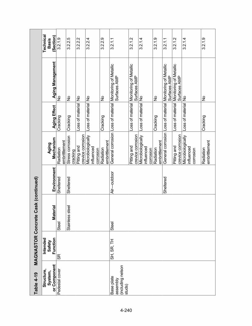
4-240
Tabl
e 4-
19
MA
GN
AST
OR
Con
cret
e C
ask (con
tinued)
Stru
ctur
e,
Syst
em,
or C
ompo
nent
Inte
nded
Sa
fety
Fu
nctio
n M
ater
ial
Envi
ronm
ent
Agin
g M
echa
nism
Ag
ing
Effe
ct
Agin
g M
anag
emen
t
Tech
nica
l Ba
sis
(Sec
tion)
Pe
dest
al c
over
SR
St
eel
Shel
tere
d R
adia
tion
embr
ittle
men
t C
rack
ing
No
3.2.
1.9
Stai
nles
s st
eel
Shel
tere
d St
ress
cor
rosi
on
crac
king
C
rack
ing
No
3.2.
2.5
Pitti
ng a
nd
crev
ice c
orro
sion
Lo
ss o
f mat
eria
l N
o 3.
2.2.
2
Micr
obio
logi
cally
in
fluen
ced
corro
sion
Loss
of m
ater
ial
No
3.2.
2.4
Rad
iatio
n em
britt
lem
ent
Cra
ckin
g N
o 3.
2.2.
9
Base
pla
te
asse
mbl
y (in
clud
ing
nelso
n st
uds)
SH, S
R, T
H
Stee
l Ai
r—ou
tdoo
r G
ener
al c
orro
sion
Los
s of
mat
eria
l M
onito
ring
of M
etal
lic
Surfa
ces
AMP
3.2.
1.1
Pitti
ng a
nd
crev
ice c
orro
sion
Lo
ss o
f mat
eria
l M
onito
ring
of M
etal
lic
Surfa
ces
AMP
3.2.
1.2
Micr
obio
logi
cally
in
fluen
ced
corro
sion
Loss
of m
ater
ial
No
3.2.
1.4
Rad
iatio
n em
britt
lem
ent
Cra
ckin
g N
o 3.
2.1.
9
Shel
tere
d G
ener
al c
orro
sion
Los
s of
mat
eria
l M
onito
ring
of M
etal
lic
Surfa
ces
AMP
3.2.
1.1
Pitti
ng a
nd
crev
ice c
orro
sion
Lo
ss o
f mat
eria
l M
onito
ring
of M
etal
lic
Surfa
ces
AMP
3.2.
1.2
Micr
obio
logi
cally
in
fluen
ced
corro
sion
Loss
of m
ater
ial
No
3.2.
1.4
Rad
iatio
n em
britt
lem
ent
Cra
ckin
g N
o 3.
2.1.
9

4-241
Tabl
e 4-
19
MA
GN
AST
OR
Con
cret
e C
ask (con
tinued)
Stru
ctur
e,
Syst
em,
or C
ompo
nent
Inte
nded
Sa
fety
Fu
nctio
n M
ater
ial
Envi
ronm
ent
Agin
g M
echa
nism
Ag
ing
Effe
ct
Agin
g M
anag
emen
t
Tech
nica
l Ba
sis
(Sec
tion)
C
hann
els
SR
Stee
l Sh
elte
red
Gen
eral
cor
rosi
on L
oss
of m
ater
ial
Mon
itorin
g of
Met
allic
Su
rface
s AM
P 3.
2.1.
1
Pitti
ng a
nd
crev
ice c
orro
sion
Lo
ss o
f mat
eria
l M
onito
ring
of M
etal
lic
Surfa
ces
AMP
3.2.
1.2
Micr
obio
logi
cally
in
fluen
ced
corro
sion
Loss
of m
ater
ial
No
3.2.
1.4
Rad
iatio
n em
britt
lem
ent
Cra
ckin
g N
o 3.
2.1.
9
Lid
asse
mbl
y SH
, SR
, TH
St
eel
Air—
outd
oor
Gen
eral
cor
rosi
on L
oss
of m
ater
ial
Mon
itorin
g of
Met
allic
Su
rface
s AM
P 3.
2.1.
1
Gal
vani
c co
rrosi
on
Loss
of m
ater
ial
Mon
itorin
g of
Met
allic
Su
rface
s AM
P 3.
2.1.
3
Pitti
ng a
nd
crev
ice c
orro
sion
Lo
ss o
f mat
eria
l M
onito
ring
of M
etal
lic
Surfa
ces
AMP
3.2.
1.2
Micr
obio
logi
cally
in
fluen
ced
corro
sion
Loss
of m
ater
ial
No
3.2.
1.4
Rad
iatio
n em
britt
lem
ent
Cra
ckin
g N
o 3.
2.1.
9
Shel
tere
d G
ener
al c
orro
sion
Los
s of
mat
eria
l M
onito
ring
of M
etal
lic
Surfa
ces
AMP
3.2.
1.1
Pitti
ng a
nd
crev
ice c
orro
sion
Lo
ss o
f mat
eria
l M
onito
ring
of M
etal
lic
Surfa
ces
AMP
3.2.
1.2
Micr
obio
logi
cally
in
fluen
ced
corro
sion
Loss
of m
ater
ial
No
3.2.
1.4
Rad
iatio
n em
britt
lem
ent
Cra
ckin
g N
o 3.
2.1.
9
Con
cret
e Fu
lly e
ncas
ed
(ste
el)
Del
ayed
ettr
ingi
te
form
atio
n Lo
ss o
f mat
eria
l (s
pallin
g,
scal
ing)
No
3.5.
1.13
Cra
ckin
g N
o 3.
5.1.
13
Loss
of s
treng
th N
o 3.
5.1.
13

4-242
Tabl
e 4-
19
MA
GN
AST
OR
Con
cret
e C
ask (con
tinued)
Stru
ctur
e,
Syst
em,
or C
ompo
nent
Inte
nded
Sa
fety
Fu
nctio
n M
ater
ial
Envi
ronm
ent
Agin
g M
echa
nism
Ag
ing
Effe
ct
Agin
g M
anag
emen
t
Tech
nica
l Ba
sis
(Sec
tion)
Li
d as
sem
bly
SH, S
R, T
H
Con
cret
e Fu
lly e
ncas
ed
(ste
el)
Rad
iatio
n da
mag
e C
rack
ing
No
3.5.
1.9
Loss
of s
treng
th N
o 3.
5.1.
9 R
eact
ion
with
ag
greg
ates
C
rack
ing
No
3.5.
1.3
Rea
ctio
n w
ith
aggr
egat
es
Loss
of s
treng
th N
o 3.
5.1.
3
Lid
hard
war
e SR
St
ainl
ess
stee
l Ai
r—ou
tdoo
r St
ress
cor
rosi
on
crac
king
C
rack
ing
No
3.2.
2.5
Pitti
ng a
nd
crev
ice c
orro
sion
Lo
ss o
f mat
eria
l N
o 3.
2.2.
2
Micr
obio
logi
cally
in
fluen
ced
corro
sion
Loss
of m
ater
ial
No
3.2.
2.4
Rad
iatio
n em
britt
lem
ent
Cra
ckin
g N
o 3.
2.2.
9
Stre
ss re
laxa
tion
Loss
of p
relo
ad
No
3.2.
2.10
Li
ft an
chor
(s
tand
ard
conf
igur
atio
n)
SR
Stee
l Ai
r—ou
tdoo
r G
ener
al c
orro
sion
Los
s of
mat
eria
l M
onito
ring
of M
etal
lic
Surfa
ces
AMP
3.2.
1.1
Pitti
ng a
nd
crev
ice c
orro
sion
Lo
ss o
f mat
eria
l M
onito
ring
of M
etal
lic
Surfa
ces
AMP
3.2.
1.2
Micr
obio
logi
cally
in
fluen
ced
corro
sion
Loss
of m
ater
ial
No
3.2.
1.4
Rad
iatio
n em
britt
lem
ent
Cra
ckin
g N
o 3.
2.1.
9
Lift
anch
or
(sta
ndar
d an
d al
tern
ativ
e co
nfig
urat
ions
)
SR
Stee
l Em
bedd
ed
(con
cret
e)
Gen
eral
cor
rosi
on L
oss
of m
ater
ial
TLAA
/AM
P or
a
supp
ortin
g an
alys
is is
re
quire
d
3.2.
1.1

4-243
Tabl
e 4-
19
MA
GN
AST
OR
Con
cret
e C
ask (con
tinued)
Stru
ctur
e,
Syst
em,
or C
ompo
nent
Inte
nded
Sa
fety
Fu
nctio
n M
ater
ial
Envi
ronm
ent
Agin
g M
echa
nism
Ag
ing
Effe
ct
Agin
g M
anag
emen
t
Tech
nica
l Ba
sis
(Sec
tion)
Li
ft an
chor
(s
tand
ard
and
alte
rnat
ive
conf
igur
atio
ns)
SR
Stee
l Em
bedd
ed
(con
cret
e)
Pitti
ng a
nd
crev
ice c
orro
sion
Lo
ss o
f mat
eria
l TL
AA/A
MP
or a
su
ppor
ting
anal
ysis
is
requ
ired
3.2.
1.2
Micr
obio
logi
cally
in
fluen
ced
corro
sion
Loss
of m
ater
ial
No
3.2.
1.4
Rad
iatio
n em
britt
lem
ent
Cra
ckin
g N
o 3.
2.1.
9
Lift
lug
SR
Stee
l Sh
elte
red
Gen
eral
cor
rosi
on L
oss
of m
ater
ial
Mon
itorin
g of
Met
allic
Su
rface
s AM
P 3.
2.1.
1
Pitti
ng a
nd
crev
ice c
orro
sion
Lo
ss o
f mat
eria
l M
onito
ring
of M
etal
lic
Surfa
ces
AMP
3.2.
1.2
Micr
obio
logi
cally
in
fluen
ced
corro
sion
Loss
of m
ater
ial
No
3.2.
1.4
Rad
iatio
n em
britt
lem
ent
Cra
ckin
g N
o 3.
2.1.
9
Lift
lug
bolt
SR
Nick
el a
lloy
Shel
tere
d St
ress
cor
rosi
on
crac
king
C
rack
ing
No
3.2.
4.4
Pitti
ng a
nd
crev
ice
corro
sion
Loss
of m
ater
ial
No
3.2.
4.2
Micr
obio
logi
cally
in
fluen
ced
corro
sion
Loss
of m
ater
ial
No
3.2.
4.3
Rad
iatio
n em
britt
lem
ent
Cra
ckin
g N
o 3.
2.4.
6
Stre
ss re
laxa
tion
Loss
of p
relo
ad
No
3.2.
4.7
Lift
lug
was
her,
base
pla
te d
owel
pi
n
SR
Stai
nles
s st
eel
Shel
tere
d St
ress
cor
rosi
on
crac
king
C
rack
ing
No
3.2.
2.5
Pitti
ng a
nd
crev
ice c
orro
sion
Lo
ss o
f mat
eria
l N
o 3.
2.2.
2

4-244
Tabl
e 4-
19
MA
GN
AST
OR
Con
cret
e C
ask (con
tinued)
Stru
ctur
e,
Syst
em,
or C
ompo
nent
Inte
nded
Sa
fety
Fu
nctio
n M
ater
ial
Envi
ronm
ent
Agin
g M
echa
nism
Ag
ing
Effe
ct
Agin
g M
anag
emen
t
Tech
nica
l Ba
sis
(Sec
tion)
Li
ft lu
g w
ashe
r, ba
se p
late
dow
el
pin
SR
Stai
nles
s st
eel
Shel
tere
d M
icrob
iolo
gica
lly
influ
ence
d co
rrosi
on
Loss
of m
ater
ial
No
3.2.
2.4
Rad
iatio
n em
britt
lem
ent
Cra
ckin
g N
o 3.
2.2.
9
Cov
er p
late
SR
St
eel
Air—
outd
oor
Gen
eral
cor
rosi
on L
oss
of m
ater
ial
Mon
itorin
g of
Met
allic
Su
rface
s AM
P 3.
2.1.
1
Gal
vani
c co
rrosi
on
Loss
of m
ater
ial
Mon
itorin
g of
Met
allic
Su
rface
s AM
P 3.
2.1.
3
Pitti
ng a
nd
crev
ice c
orro
sion
Lo
ss o
f mat
eria
l M
onito
ring
of M
etal
lic
Surfa
ces
AMP
3.2.
1.2
Micr
obio
logi
cally
in
fluen
ced
corro
sion
Loss
of m
ater
ial
No
3.2.
1.4
Rad
iatio
n em
britt
lem
ent
Cra
ckin
g N
o 3.
2.1.
9
Cov
er p
late
ha
rdw
are
SR
Stai
nles
s st
eel
Air—
outd
oor
Stre
ss-c
orro
sion
cr
acki
ng
Cra
ckin
g N
o 3.
2.2.
5
Pitti
ng a
nd
crev
ice c
orro
sion
Lo
ss o
f mat
eria
l N
o 3.
2.2.
2
Micr
obio
logi
cally
in
fluen
ced
corro
sion
Loss
of m
ater
ial
No
3.2.
2.4
Rad
iatio
n em
britt
lem
ent
Cra
ckin
g N
o 3.
2.2.
9
Stre
ss re
laxa
tion
Loss
of p
relo
ad
No
3.2.
2.10
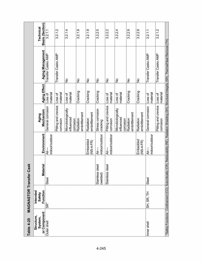
4-245
Tabl
e 4-
20
MAG
NAS
TOR
Tra
nsfe
r Cas
k
Stru
ctur
e,
Syst
em,
or C
ompo
nent
Inte
nded
Sa
fety
Fu
nctio
n M
ater
ial
Envi
ronm
ent
Agin
g M
echa
nism
Ag
ing
Effe
ct
Agin
g M
anag
emen
t Te
chni
cal
Basi
s (S
ectio
n)
Out
er s
hell
SR*
Stee
l Ai
r—in
door
/out
door
G
ener
al c
orro
sion
Lo
ss o
f m
ater
ial
Tran
sfer
Cas
ks A
MP
3.2.
1.1
Pitti
ng a
nd c
revic
e co
rrosi
on
Loss
of
mat
eria
l Tr
ansf
er C
asks
AM
P 3.
2.1.
2
Micr
obio
logi
cally
in
fluen
ced
corro
sion
Loss
of
mat
eria
l N
o 3.
2.1.
4
Rad
iatio
n em
britt
lem
ent
Cra
ckin
g N
o 3.
2.1.
9
Embe
dded
(N
S-4-
FR)
Rad
iatio
n em
britt
lem
ent
Cra
ckin
g N
o 3.
2.1.
9
Stai
nles
s st
eel
(wel
ded)
Ai
r—in
door
/out
door
St
ress
cor
rosi
on
crac
king
C
rack
ing
No
3.2.
2.5
Stai
nles
s st
eel
Air—
indo
or/o
utdo
or
Pitti
ng a
nd c
revic
e co
rrosi
on
Loss
of
mat
eria
l N
o 3.
2.2.
2
Micr
obio
logi
cally
in
fluen
ced
corro
sion
Loss
of
mat
eria
l N
o 3.
2.2.
4
Rad
iatio
n em
britt
lem
ent
Cra
ckin
g N
o 3.
2.2.
9
Embe
dded
(N
S-4-
FR)
Rad
iatio
n em
britt
lem
ent
Cra
ckin
g N
o 3.
2.2.
9
Inne
r she
ll SH
, SR
, TH
St
eel
Air—
indo
or/o
utdo
or
Gen
eral
cor
rosi
on
Loss
of
mat
eria
l Tr
ansf
er C
asks
AM
P 3.
2.1.
1
Pitti
ng a
nd c
revic
e co
rrosi
on
Loss
of
mat
eria
l Tr
ansf
er C
asks
AM
P 3.
2.1.
2
*Saf
ety
Func
tions
: C
onfin
emen
t (C
O),
Subc
ritica
lity (C
R),
Ret
rieva
bility
(RE)
, Rad
iatio
n Sh
ield
ing
(SH
), St
ruct
ural
Inte
grity
(SR
), Th
erm
al/H
eat R
emov
al (T
H)

4-246
Tabl
e 4-
20
MA
GN
AST
OR
Tra
nsfe
r Cas
k (con
tinued)
Stru
ctur
e,
Syst
em,
or C
ompo
nent
Inte
nded
Sa
fety
Fu
nctio
n M
ater
ial
Envi
ronm
ent
Agin
g M
echa
nism
Ag
ing
Effe
ct
Agin
g M
anag
emen
t Te
chni
cal
Basi
s (S
ectio
n)
Inne
r she
ll SH
, SR
, TH
St
eel
Air—
indo
or/o
utdo
or
Micr
obio
logi
cally
in
fluen
ced
corro
sion
Loss
of
mat
eria
l N
o 3.
2.1.
4
Rad
iatio
n em
britt
lem
ent
Cra
ckin
g N
o 3.
2.1.
9
Embe
dded
(le
ad)
Rad
iatio
n em
britt
lem
ent
Cra
ckin
g N
o 3.
2.1.
9
Stai
nles
s st
eel
(wel
ded)
Ai
r—in
door
/out
door
St
ress
cor
rosi
on
crac
king
C
rack
ing
No
3.2.
2.5
Stai
nles
s st
eel
Air—
indo
or/o
utdo
or
Pitti
ng a
nd c
revic
e co
rrosi
on
Loss
of
mat
eria
l N
o 3.
2.2.
2
Micr
obio
logi
cally
in
fluen
ced
corro
sion
Loss
of
mat
eria
l N
o 3.
2.2.
4
Rad
iatio
n em
britt
lem
ent
Cra
ckin
g N
o 3.
2.2.
9
Embe
dded
(le
ad)
Rad
iatio
n em
britt
lem
ent
Cra
ckin
g N
o 3.
2.2.
9
Gam
ma
shie
ld
(Cas
k bo
dy)
SH
Lead
Em
bedd
ed
(ste
el,
NS-
4-FR
)
Non
e id
entif
ied
Non
e id
entif
ied
No
3.2.
6
Embe
dded
(s
tain
less
ste
el,
NS-
4-FR
)
Non
e id
entif
ied
Non
e id
entif
ied
No
3.2.
6
Neu
tron
shie
ld
(Cas
k bo
dy)
SH
NS-
4-FR
Em
bedd
ed
(ste
el, l
ead)
Th
erm
al a
ging
Lo
ss o
f fra
ctur
e to
ughn
ess
and
loss
of
duct
ility
TLAA
/AM
P or
a
supp
ortin
g an
alys
is is
re
quire
d
3.3.
1.2
Rad
iatio
n em
britt
lem
ent
Cra
ckin
g TL
AA/A
MP
or a
su
ppor
ting
anal
ysis
is
requ
ired
3.3.
1.3

4-247
Tabl
e 4-
20
MA
GN
AST
OR
Tra
nsfe
r Cas
k (con
tinued)
Stru
ctur
e,
Syst
em,
or C
ompo
nent
Inte
nded
Sa
fety
Fu
nctio
n M
ater
ial
Envi
ronm
ent
Agin
g M
echa
nism
Ag
ing
Effe
ct
Agin
g M
anag
emen
t Te
chni
cal
Basi
s (S
ectio
n)
Neu
tron
shie
ld
(Cas
k bo
dy)
SH
NS-
4-FR
Em
bedd
ed
(ste
el, l
ead)
Bo
ron
depl
etio
n Lo
ss o
f sh
ield
ing
TLAA
/AM
P or
a
supp
ortin
g an
alys
is is
re
quire
d
3.3.
1.1
Embe
dded
(s
tain
less
ste
el,
lead
)
Ther
mal
agi
ng
Loss
of
fract
ure
toug
hnes
s an
d lo
ss o
f du
ctilit
y
TLAA
/AM
P or
a
supp
ortin
g an
alys
is is
re
quire
d
3.3.
1.2
Rad
iatio
n em
britt
lem
ent
Cra
ckin
g TL
AA/A
MP
or a
su
ppor
ting
anal
ysis
is
requ
ired
3.3.
1.3
Boro
n de
plet
ion
Loss
of
shie
ldin
g TL
AA/A
MP
or a
su
ppor
ting
anal
ysis
is
requ
ired
3.3.
1.1
Top
ring
SR
Stee
l Ai
r—in
door
/out
door
G
ener
al c
orro
sion
Lo
ss o
f m
ater
ial
Tran
sfer
Cas
ks A
MP
3.2.
1.1
Pitti
ng a
nd c
revic
e co
rrosi
on
Loss
of
mat
eria
l Tr
ansf
er C
asks
AM
P 3.
2.1.
2
Micr
obio
logi
cally
in
fluen
ced
corro
sion
Loss
of
mat
eria
l N
o 3.
2.1.
4
Rad
iatio
n em
britt
lem
ent
Cra
ckin
g N
o 3.
2.1.
9
Stai
nles
s st
eel
(wel
ded)
Ai
r—in
door
/out
door
St
ress
cor
rosi
on
crac
king
C
rack
ing
No
3.2.
2.5
Stai
nles
s st
eel
Air—
indo
or/o
utdo
or
Pitti
ng a
nd c
revic
e co
rrosi
on
Loss
of
mat
eria
l N
o 3.
2.2.
2
Micr
obio
logi
cally
in
fluen
ced
corro
sion
Loss
of
mat
eria
l N
o 3.
2.2.
4
Stre
ss c
orro
sion
cr
acki
ng
Cra
ckin
g N
o 3.
2.2.
5
Rad
iatio
n em
britt
lem
ent
Cra
ckin
g N
o 3.
2.2.
9

4-248
Tabl
e 4-
20
MA
GN
AST
OR
Tra
nsfe
r Cas
k (con
tinued)
Stru
ctur
e,
Syst
em,
or C
ompo
nent
Inte
nded
Sa
fety
Fu
nctio
n M
ater
ial
Envi
ronm
ent
Agin
g M
echa
nism
Ag
ing
Effe
ct
Agin
g M
anag
emen
t Te
chni
cal
Basi
s (S
ectio
n)
Botto
m ri
ng
SR
Stee
l Ai
r—in
door
/out
door
G
ener
al c
orro
sion
Lo
ss o
f m
ater
ial
Tran
sfer
Cas
ks A
MP
3.2.
1.1
Pitti
ng a
nd c
revic
e co
rrosi
on
Loss
of
mat
eria
l Tr
ansf
er C
asks
AM
P 3.
2.1.
2
Micr
obio
logi
cally
in
fluen
ced
corro
sion
Loss
of
mat
eria
l N
o 3.
2.1.
4
Rad
iatio
n em
britt
lem
ent
Cra
ckin
g N
o 3.
2.1.
9
Stai
nles
s st
eel
(wel
ded)
Ai
r—in
door
/out
door
St
ress
cor
rosi
on
crac
king
C
rack
ing
No
3.2.
2.5
Stai
nles
s st
eel
Air—
indo
or/o
utdo
or
Pitti
ng a
nd c
revic
e co
rrosi
on
Loss
of
mat
eria
l N
o 3.
2.2.
2
Micr
obio
logi
cally
in
fluen
ced
corro
sion
Loss
of
mat
eria
l N
o 3.
2.2.
4
Stre
ss c
orro
sion
cr
acki
ng
Cra
ckin
g N
o 3.
2.2.
5
Rad
iatio
n em
britt
lem
ent
Cra
ckin
g N
o 3.
2.2.
9
Trun
nion
SR
St
eel
Air—
indo
or/o
utdo
or
Gen
eral
cor
rosi
on
Loss
of
mat
eria
l Tr
ansf
er C
asks
AM
P 3.
2.1.
1
Pitti
ng a
nd c
revic
e co
rrosi
on
Loss
of
mat
eria
l Tr
ansf
er C
asks
AM
P 3.
2.1.
2
Micr
obio
logi
cally
in
fluen
ced
corro
sion
Loss
of
mat
eria
l N
o 3.
2.1.
4
Rad
iatio
n em
britt
lem
ent
Cra
ckin
g N
o 3.
2.1.
9
Stai
nles
s st
eel
Air—
indo
or/o
utdo
or
Pitti
ng a
nd c
revic
e co
rrosi
on
Loss
of
mat
eria
l N
o 3.
2.2.
2
Micr
obio
logi
cally
in
fluen
ced
corro
sion
Loss
of
mat
eria
l N
o 3.
2.2.
4

4-249
Tabl
e 4-
20
MA
GN
AST
OR
Tra
nsfe
r Cas
k (con
tinued)
Stru
ctur
e,
Syst
em,
or C
ompo
nent
Inte
nded
Sa
fety
Fu
nctio
n M
ater
ial
Envi
ronm
ent
Agin
g M
echa
nism
Ag
ing
Effe
ct
Agin
g M
anag
emen
t Te
chni
cal
Basi
s (S
ectio
n)
Trun
nion
SR
St
ainl
ess
stee
l Ai
r—in
door
/out
door
St
ress
cor
rosi
on
crac
king
C
rack
ing
No
3.2.
2.5
Rad
iatio
n em
britt
lem
ent
Cra
ckin
g N
o 3.
2.2.
9
Trun
nion
bus
hing
, ro
tatin
g bu
shin
g SR
St
ainl
ess
stee
l Ai
r—in
door
/out
door
Pi
tting
and
cre
vice
corro
sion
Lo
ss o
f m
ater
ial
No
3.2.
2.2
Micr
obio
logi
cally
in
fluen
ced
corro
sion
Loss
of
mat
eria
l N
o 3.
2.2.
4
Stre
ss c
orro
sion
cr
acki
ng
Cra
ckin
g N
o 3.
2.2.
5
Rad
iatio
n em
britt
lem
ent
Cra
ckin
g N
o 3.
2.2.
9
Wea
r Lo
ss o
f m
ater
ial
Tran
sfer
Cas
ks A
MP
3.2.
2.11
Shie
ld d
oor p
late
s SH
St
eel
Air—
indo
or/o
utdo
or
Gen
eral
cor
rosi
on
Loss
of
mat
eria
l Tr
ansf
er C
asks
AM
P 3.
2.1.
1
Pitti
ng a
nd c
revic
e co
rrosi
on
Loss
of
mat
eria
l Tr
ansf
er C
asks
AM
P 3.
2.1.
2
Micr
obio
logi
cally
in
fluen
ced
corro
sion
Loss
of
mat
eria
l N
o 3.
2.1.
4
Rad
iatio
n em
britt
lem
ent
Cra
ckin
g N
o 3.
2.1.
9
Stai
nles
s st
eel
Air—
indo
or/o
utdo
or
Pitti
ng a
nd c
revic
e co
rrosi
on
Loss
of
mat
eria
l N
o 3.
2.2.
2
Micr
obio
logi
cally
in
fluen
ced
corro
sion
Loss
of
mat
eria
l N
o 3.
2.2.
4
Stre
ss c
orro
sion
cr
acki
ng
Cra
ckin
g N
o 3.
2.2.
5
Rad
iatio
n em
britt
lem
ent
Cra
ckin
g N
o 3.
2.2.
9

4-250
Tabl
e 4-
20
MA
GN
AST
OR
Tra
nsfe
r Cas
k (con
tinued)
Stru
ctur
e,
Syst
em,
or C
ompo
nent
Inte
nded
Sa
fety
Fu
nctio
n M
ater
ial
Envi
ronm
ent
Agin
g M
echa
nism
Ag
ing
Effe
ct
Agin
g M
anag
emen
t Te
chni
cal
Basi
s (S
ectio
n)
Shie
ld d
oor r
ails
SH
, SR
St
eel
Air—
indo
or/o
utdo
or
Gen
eral
cor
rosi
on
Loss
of
mat
eria
l Tr
ansf
er C
asks
AM
P 3.
2.1.
1
Pitti
ng a
nd c
revic
e co
rrosi
on
Loss
of
mat
eria
l Tr
ansf
er C
asks
AM
P 3.
2.1.
2
Micr
obio
logi
cally
in
fluen
ced
corro
sion
Loss
of
mat
eria
l N
o 3.
2.1.
4
Rad
iatio
n em
britt
lem
ent
Cra
ckin
g N
o 3.
2.1.
9
Wea
r Lo
ss o
f m
ater
ial
Tran
sfer
Cas
ks A
MP
3.2.
1.11
Stai
nles
s st
eel
Air—
indo
or/o
utdo
or
Pitti
ng a
nd c
revic
e co
rrosi
on
Loss
of
mat
eria
l N
o 3.
2.2.
2
Micr
obio
logi
cally
in
fluen
ced
corro
sion
Loss
of
mat
eria
l N
o 3.
2.2.
4
Stre
ss c
orro
sion
cr
acki
ng
Cra
ckin
g N
o 3.
2.2.
5
Rad
iatio
n em
britt
lem
ent
Cra
ckin
g N
o 3.
2.2.
9
Wea
r Lo
ss o
f m
ater
ial
Tran
sfer
Cas
ks A
MP
3.2.
2.11
Shie
ld d
oor t
ab
SR
Stee
l Ai
r—in
door
/out
door
G
ener
al c
orro
sion
Lo
ss o
f m
ater
ial
Tran
sfer
Cas
ks A
MP
3.2.
1.1
Pitti
ng a
nd c
revic
e co
rrosi
on
Loss
of
mat
eria
l Tr
ansf
er C
asks
AM
P 3.
2.1.
2
Micr
obio
logi
cally
in
fluen
ced
corro
sion
Loss
of
mat
eria
l N
o 3.
2.1.
4
Rad
iatio
n em
britt
lem
ent
Cra
ckin
g N
o 3.
2.1.
9

4-251
Tabl
e 4-
20
MA
GN
AST
OR
Tra
nsfe
r Cas
k (con
tinued)
Stru
ctur
e,
Syst
em,
or C
ompo
nent
Inte
nded
Sa
fety
Fu
nctio
n M
ater
ial
Envi
ronm
ent
Agin
g M
echa
nism
Ag
ing
Effe
ct
Agin
g M
anag
emen
t Te
chni
cal
Basi
s (S
ectio
n)
Shie
ld d
oor t
ab
SR
Stai
nles
s st
eel
Air—
indo
or/o
utdo
or
Pitti
ng a
nd c
revic
e co
rrosi
on
Loss
of
mat
eria
l N
o 3.
2.2.
2
Micr
obio
logi
cally
in
fluen
ced
corro
sion
Loss
of
mat
eria
l N
o 3.
2.2.
4
Stre
ss c
orro
sion
cr
acki
ng
Cra
ckin
g N
o 3.
2.2.
5
Rad
iatio
n em
britt
lem
ent
Cra
ckin
g N
o 3.
2.2.
9
Shie
ld d
oor l
ock
pin
SR
Stai
nles
s st
eel
Air—
indo
or/o
utdo
or
Pitti
ng a
nd c
revic
e co
rrosi
on
Loss
of
mat
eria
l N
o 3.
2.2.
2
Micr
obio
logi
cally
in
fluen
ced
corro
sion
Loss
of
mat
eria
l N
o 3.
2.2.
4
Stre
ss c
orro
sion
cr
acki
ng
Cra
ckin
g N
o 3.
2.2.
5
Rad
iatio
n em
britt
lem
ent
Cra
ckin
g N
o 3.
2.2.
9
Ret
aini
ng b
lock
an
d rin
g SR
St
ainl
ess
stee
l Ai
r—in
door
/out
door
Pi
tting
and
cre
vice
corro
sion
Lo
ss o
f m
ater
ial
No
3.2.
2.2
Micr
obio
logi
cally
in
fluen
ced
corro
sion
Loss
of
mat
eria
l N
o 3.
2.2.
4
Stre
ss c
orro
sion
cr
acki
ng
Cra
ckin
g N
o 3.
2.2.
5
Rad
iatio
n em
britt
lem
ent
Cra
ckin
g N
o 3.
2.2.
9
Ret
aini
ng p
in
SR
Stee
l Ai
r—in
door
/out
door
G
ener
al c
orro
sion
Lo
ss o
f m
ater
ial
Tran
sfer
Cas
ks A
MP
3.2.
1.1
Pitti
ng a
nd c
revic
e co
rrosi
on
Loss
of
mat
eria
l Tr
ansf
er C
asks
AM
P 3.
2.1.
2
Micr
obio
logi
cally
in
fluen
ced
corro
sion
Loss
of
mat
eria
l N
o 3.
2.1.
4

4-252
Tabl
e 4-
20
MA
GN
AST
OR
Tra
nsfe
r Cas
k (con
tinued)
Stru
ctur
e,
Syst
em,
or C
ompo
nent
Inte
nded
Sa
fety
Fu
nctio
n M
ater
ial
Envi
ronm
ent
Agin
g M
echa
nism
Ag
ing
Effe
ct
Agin
g M
anag
emen
t Te
chni
cal
Basi
s (S
ectio
n)
Ret
aini
ng p
in
SR
Stee
l Ai
r—in
door
/out
door
R
adia
tion
embr
ittle
men
t C
rack
ing
No
3.2.
1.9
Stai
nles
s st
eel
Air—
indo
or/o
utdo
or
Pitti
ng a
nd c
revic
e co
rrosi
on
Loss
of
mat
eria
l N
o 3.
2.2.
2
Micr
obio
logi
cally
in
fluen
ced
corro
sion
Loss
of
mat
eria
l N
o 3.
2.2.
4
Stre
ss c
orro
sion
cr
acki
ng
Cra
ckin
g N
o 3.
2.2.
5
Rad
iatio
n em
britt
lem
ent
Cra
ckin
g N
o 3.
2.2.
9
Ret
aine
r ass
embl
y sp
ring
plun
ger,
guid
e bo
lt, h
andl
e bo
lt
SR
Stai
nles
s st
eel
Air—
indo
or/o
utdo
or
Pitti
ng a
nd c
revic
e co
rrosi
on
Loss
of
mat
eria
l N
o 3.
2.2.
2
Micr
obio
logi
cally
in
fluen
ced
corro
sion
Loss
of
mat
eria
l N
o 3.
2.2.
4
Stre
ss c
orro
sion
cr
acki
ng
Cra
ckin
g N
o 3.
2.2.
5
Rad
iatio
n em
britt
lem
ent
Cra
ckin
g N
o 3.
2.2.
9
Stre
ss re
laxa
tion
Loss
of
prel
oad
No
3.2.
2.10
Ret
aine
r ass
embl
y ha
ndle
SR
St
ainl
ess
stee
l Ai
r—in
door
/out
door
Pi
tting
and
cre
vice
corro
sion
Lo
ss o
f m
ater
ial
No
3.2.
2.2
Micr
obio
logi
cally
in
fluen
ced
corro
sion
Loss
of
mat
eria
l N
o 3.
2.2.
4
Stre
ss c
orro
sion
cr
acki
ng
Cra
ckin
g N
o 3.
2.2.
5
Rad
iatio
n em
britt
lem
ent
Cra
ckin
g N
o 3.
2.2.
9
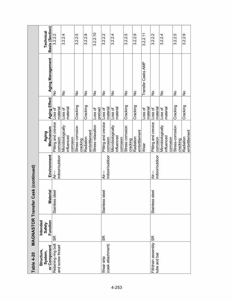
4-253
Tabl
e 4-
20
MA
GN
AST
OR
Tra
nsfe
r Cas
k (con
tinued)
Stru
ctur
e,
Syst
em,
or C
ompo
nent
Inte
nded
Sa
fety
Fu
nctio
n M
ater
ial
Envi
ronm
ent
Agin
g M
echa
nism
Ag
ing
Effe
ct
Agin
g M
anag
emen
t Te
chni
cal
Basi
s (S
ectio
n)
Ret
aini
ng ri
ng b
olt
and
scre
w th
read
SR
St
ainl
ess
stee
l Ai
r—in
door
/out
door
Pi
tting
and
cre
vice
corro
sion
Lo
ss o
f m
ater
ial
No
3.2.
2.2
Micr
obio
logi
cally
in
fluen
ced
corro
sion
Loss
of
mat
eria
l N
o 3.
2.2.
4
Stre
ss c
orro
sion
cr
acki
ng
Cra
ckin
g N
o 3.
2.2.
5
Rad
iatio
n em
britt
lem
ent
Cra
ckin
g N
o 3.
2.2.
9
Stre
ss re
laxa
tion
Loss
of
prel
oad
No
3.2.
2.10
Wea
r stri
p (c
ask
atta
chm
ent)
SR
Stai
nles
s st
eel
Air—
indo
or/o
utdo
or
Pitti
ng a
nd c
revic
e co
rrosi
on
Loss
of
mat
eria
l N
o 3.
2.2.
2
Micr
obio
logi
cally
in
fluen
ced
corro
sion
Loss
of
mat
eria
l N
o 3.
2.2.
4
Stre
ss c
orro
sion
cr
acki
ng
Cra
ckin
g N
o 3.
2.2.
5
Rad
iatio
n em
britt
lem
ent
Cra
ckin
g N
o 3.
2.2.
9
Wea
r Lo
ss o
f m
ater
ial
Tran
sfer
Cas
ks A
MP
3.2.
2.11
Fill/d
rain
ass
embl
y tu
be a
nd b
ar
SR
Stai
nles
s st
eel
Air—
indo
or/o
utdo
or
Pitti
ng a
nd c
revic
e co
rrosi
on
Loss
of
mat
eria
l N
o 3.
2.2.
2
Micr
obio
logi
cally
in
fluen
ced
corro
sion
Loss
of
mat
eria
l N
o 3.
2.2.
4
Stre
ss-c
orro
sion
cr
acki
ng
Cra
ckin
g N
o 3.
2.2.
5
Rad
iatio
n em
britt
lem
ent
Cra
ckin
g N
o 3.
2.2.
9

4-254
4.6 FuelSolutionsTM Storage System
4.6.1 System Description
The FuelSolutionsTM storage system uses a stainless steel storage canister stored within a vertical cylindrical concrete storage cask. The principal components of the storage system are the W21 and W74 canisters, the W150 concrete storage cask, and the W100 transfer cask. The W21 canister is designed to accommodate nearly all domestic commercial spent nuclear fuel with a capacity of up to 21 PWR fuel assemblies. The W74 canister is designed to accommodate the three assembly types used at the Big Rock Point Nuclear Plant, including mixed oxide, partial, and damaged fuel assemblies, with a capacity of up to 64 BWR fuel assemblies. The W150 concrete storage cask provides radiation shielding and contains internal air flowpaths that allow decay heat from the canister spent fuel contents to be removed by natural air circulation around the canister wall. The W100 TC is used to move the loaded canisters to and from the storage cask. The sections below summarize the components of the FuelSolutionsTM storage system.
4.6.2 W21 and W74 Canisters
The W21 and W74 canisters, shown in Figure 4-27, each have several design configurations consisting of different materials of construction and dimensions. A typical W21 or W74 canister consists of a shell assembly, top and bottom inner closure plates, vent and drain port covers, internal basket assembly, top and bottom shield plugs, and top and bottom outer closure plates. All structural components of the canister are constructed of high-strength carbon or stainless steel. Any carbon steel used in the canister is coated with electroless nickel for corrosion protection. The canister shell, top and bottom inner closure plates, and vent and drain port covers form the confinement boundary and are fabricated from stainless steel.
W21 basket assembly
The W21 PWR fuel basket assembly is a right circular cylinder configuration with 21 stainless steel guide tubes for PWR contents (FuelSolutions, 2007a). The guide tubes are laterally supported by a series of spacer plates, held in position by support rods that run through support rod sleeves placed between the spacer plates. The square guide tubes include Boral® neutron poison sheets on all four sides for criticality control. There are two classes of canister for the W21 canister based on different materials of construction: W21M and W21T. Each class of canister has four different types, which differ in dimension (exterior canister length and internal cavity length) and the material used for end plug shielding (steel, lead, or depleted uranium (W21M only)).
W74 basket assembly
The W74 BWR fuel basket assembly consists of two right circular cylindrical baskets, with a total of 56 guide tubes and a capacity of up to 64 assemblies (FuelSolutions, 2007b). The guide tubes are supported by a series of spacer plates held in position by support rods that run through support rod sleeves placed between the spacer plates. The square guide tubes include neutron poison sheets made of borated stainless steel, either on one side or on two opposite sides, in an arrangement within the basket that assures that there is a poison sheet between all of the assemblies. There are two classes of canister for the W74 canister based on different

4-255
materials of construction (W74M and W74T). Unlike the W21 design, each W74 canister class has only one canister length and one cavity size, and carbon steel is used for end plug shielding material.
Table 4-21 provides a generic evaluation of potential aging mechanisms and effects requiring management for specific components of the W21 and W74 canisters. The table also identifies AMPs that provide an acceptable approach to managing the aging effects.
(a) (b) Figure 4-27 Typical FuelSolutionsTM (a) W21 and (b) W74 Canisters
(FuelSolutions, 2007a,b)
4.6.3 W150 Storage Cask
The W150 storage cask, shown in Figure 4-28, is the overpack for storing both the long and short versions of the W21 and W74 canisters by varying the length of the middle concrete segment (FuelSolutions, 2007c). The overpack consists of a standard reinforced concrete structure with three precast segments (top, middle, and bottom) and a top cover made of steel and concrete. Stainless steel tie rods are used to tie the concrete segments together. A shear key between each two concrete segments provides positive lateral engagement and alignment

4-256
and serves to minimize radiation streaming. Grout is installed between the keyed joints of the concrete segments to provide a weather barrier. The exterior surfaces of the concrete are exposed to the outdoor environment.
Figure 4-28 FuelSolutionsTM W150 Storage Cask (FuelSolutions, 2007c)
The top cover of the overpack is bolted to the overpack top end segment shielding ring and is sealed with weather sealant. Inside the cavity of the overpack are a steel liner, an aluminum thermal shield, steel support and guide rails, and stainless steel canister support tubes. Guide rails are welded to the steel liner for centering the canister radially in the cavity. Canister support tubes are welded to the bottom plate of the steel liner plate to provide vertical support of the canister and to limit the g-load on the canister in a postulated accident. All steel components, such as the liner, top cover, and support and guide rails, are coated with temperature- and radiation-resistant coatings.
The overpack concrete bottom segment includes four inlet vents that converge into a single cylindrical inlet duct at the bottom center of the cask cavity. The center inlet duct also provides hydraulic ram access during horizontal canister transfer operations. The inlet and outlet vents have protective screens to prevent debris or wildlife from entering the ventilation ducts.

4-257
Table 4-22 provides a generic evaluation of potential aging mechanisms and effects requiring management for specific components of the W150 storage cask. The table also identifies AMPs that provide an acceptable approach to managing the aging effects.
4.6.4 W100 Transfer Cask
The W100 TC, shown in Figure 4-29, is a multiwall, stainless steel cylindrical vessel with covers on both ends (FuelSolutions, 2007c). The TC is composed of a structural shell and a stainless steel inner liner, with lead in the annular space to provide gamma shielding. The TC also includes an outer stainless steel jacket filled with demineralized water for neutron shielding. The penetrations in the neutron shield cavity consist of two quick-connect fittings that are used to drain and fill the neutron shield cavity and to prevent intrusion of contaminated spent fuel pool water. A pressure relief device is used to provide over-pressure protection for the neutron shield.
The structural shell and inner liner are welded to stainless steel flanges at the top and bottom ends. Both the top and bottom covers are made of stainless steel plates and an encased solid neutron shielding of RX-277 or BISCO NS-3. The top cover includes a secondary central cover for ram access during horizontal loading and unloading operations. The bottom cover has O-rings to prevent spent fuel pool water from entering the cask during loading operations.Nitronic 60 stainless steel guide rails are welded to the inner shell cavity to facilitate horizontalcanister transfer.
The W100 TC has four stainless steel trunnions. Two upper lifting trunnions located near the top of the cask for vertical cask handling operations are welded to the structural shell and inner liner. The lower trunnions used for upending and downending the TC are welded to the structural shell. Heat removal from the TC is primarily by conduction through the cask wall. A high emissivity, low absorptivity coating is applied to the exterior of the liquid neutron shield jacket to facilitate radiative heat transfer to the environment.
Table 4-23 provides a generic evaluation of potential aging mechanisms and effects requiring management for specific components of the W100 TC. The table also identifies AMPs that provide an acceptable approach to managing the aging effects.
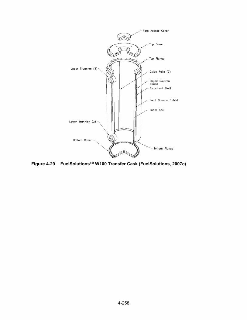
4-258
Figure 4-29 FuelSolutionsTM W100 Transfer Cask (FuelSolutions, 2007c)

Tabl
e 4-
21
Fuel
Solu
tions
TM C
anis
ter
Stru
ctur
e,
Syst
em, o
r Co
mpo
nent
Inte
nded
Sa
fety
Fu
nctio
n M
ater
ial
Envi
ronm
ent
Agin
g M
echa
nism
Ag
ing
Effe
ct
Agin
g M
anag
emen
t
Tech
nica
l Ba
sis
(Sec
tion)
Sh
ell
CO
, SR
* St
ainl
ess
stee
l (w
elde
d)
Shel
tere
d St
ress
-cor
rosi
on
crac
king
C
rack
ing
Loca
lized
Cor
rosi
on a
nd
Stre
ss c
orro
sion
C
rack
ing
of W
elde
d St
ainl
ess
Stee
l Dry
St
orag
e C
anis
ters
AM
P
3.2.
2.5
Stai
nles
s st
eel
Shel
tere
d Pi
tting
and
cr
evice
cor
rosi
on
Loss
of m
ater
ial
(Pre
curs
or to
st
ress
cor
rosi
on
crac
king
)
Loca
lized
Cor
rosi
on a
nd
Stre
ss c
orro
sion
C
rack
ing
of W
elde
d St
ainl
ess
Stee
l Dry
St
orag
e C
anis
ters
AM
P
3.2.
2.2
Micr
obio
logi
cally
in
fluen
ced
corro
sion
Loss
of m
ater
ial
No
3.2.
2.4
Fatig
ue
Cra
ckin
g Ev
alua
te d
esig
n co
de
TLAA
, if a
pplic
able
3.
2.2.
7
Rad
iatio
n em
britt
lem
ent
Cra
ckin
g N
o 3.
2.2.
9
Hel
ium
R
adia
tion
embr
ittle
men
t C
rack
ing
No
3.2.
2.9
Botto
m c
losu
re
plat
e C
O, S
R
Stai
nles
s st
eel
(wel
ded)
H
eliu
m
Ther
mal
agi
ng
Loss
of f
ract
ure
toug
hnes
s an
d lo
ss o
f duc
tility
No
3.2.
2.8
Stai
nles
s st
eel
Hel
ium
Fa
tigue
C
rack
ing
Eval
uate
des
ign
code
TL
AA, i
f app
licab
le
3.2.
2.7
Cre
ep
Cha
nge
in
dim
ensi
ons
No
3.2.
2.6
*Saf
ety
Func
tions
: C
onfin
emen
t (C
O),
Subc
ritica
lity (C
R),
Ret
rieva
bility
(RE)
, Rad
iatio
n Sh
ield
ing
(SH
), St
ruct
ural
Inte
grity
(SR
), Th
erm
al/H
eat R
emov
al (T
H)
4-259
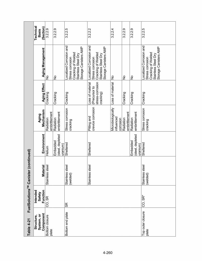
Tabl
e 4-
21
Fuel
Solu
tions
TM C
anis
ter (continued)
Stru
ctur
e,
Syst
em, o
r Co
mpo
nent
Inte
nded
Sa
fety
Fu
nctio
n M
ater
ial
Envi
ronm
ent
Agin
g M
echa
nism
Ag
ing
Effe
ct
Agin
g M
anag
emen
t
Tech
nica
l Ba
sis
(Sec
tion)
Bo
ttom
clo
sure
pl
ate
CO
, SR
St
ainl
ess
stee
l H
eliu
m
Rad
iatio
n em
britt
lem
ent
Cra
ckin
g N
o 3.
2.2.
9
Embe
dded
(s
teel
, dep
lete
d ur
aniu
m)
Rad
iatio
n em
britt
lem
ent
Cra
ckin
g N
o 3.
2.2.
9
Botto
m e
nd p
late
SR
St
ainl
ess
stee
l (w
elde
d)
Shel
tere
d St
ress
cor
rosi
on
crac
king
C
rack
ing
Loca
lized
Cor
rosi
on a
nd
Stre
ss c
orro
sion
C
rack
ing
of W
elde
d St
ainl
ess
Stee
l Dry
St
orag
e C
anis
ters
AM
P
3.2.
2.5
Stai
nles
s st
eel
Shel
tere
d Pi
tting
and
cr
evice
cor
rosi
on
Loss
of m
ater
ial
(Pre
curs
or to
st
ress
-cor
rosi
on
crac
king
)
Loca
lized
Cor
rosi
on a
nd
Stre
ss c
orro
sion
C
rack
ing
of W
elde
d St
ainl
ess
Stee
l Dry
St
orag
e C
anis
ters
AM
P
3.2.
2.2
Micr
obio
logi
cally
in
fluen
ced
corro
sion
Loss
of m
ater
ial
No
3.2.
2.4
Rad
iatio
n em
britt
lem
ent
Cra
ckin
g N
o 3.
2.2.
9
Embe
dded
(s
teel
, dep
lete
d ur
aniu
m)
Rad
iatio
n em
britt
lem
ent
Cra
ckin
g N
o 3.
2.2.
9
Top
oute
r clo
sure
pl
ate
CO
, SR
* St
ainl
ess
stee
l (w
elde
d)
Shel
tere
d St
ress
cor
rosi
on
crac
king
C
rack
ing
Loca
lized
Cor
rosi
on a
nd
Stre
ss c
orro
sion
C
rack
ing
of W
elde
d St
ainl
ess
Stee
l Dry
St
orag
e C
anis
ters
AM
P
3.2.
2.5
4-260

Tabl
e 4-
21
Fuel
Solu
tions
TM C
anis
ter (continued)
Stru
ctur
e,
Syst
em, o
r Co
mpo
nent
Inte
nded
Sa
fety
Fu
nctio
n M
ater
ial
Envi
ronm
ent
Agin
g M
echa
nism
Ag
ing
Effe
ct
Agin
g M
anag
emen
t
Tech
nica
l Ba
sis
(Sec
tion)
To
p ou
ter c
losu
re
plat
e C
O, S
R
Stai
nles
s st
eel
Shel
tere
d Pi
tting
and
cr
evice
cor
rosi
on
Loss
of m
ater
ial
(Pre
curs
or to
st
ress
cor
rosi
on
crac
king
)
Loca
lized
Cor
rosi
on a
nd
Stre
ss c
orro
sion
C
rack
ing
of W
elde
d St
ainl
ess
Stee
l Dry
St
orag
e C
anis
ters
AM
P
3.2.
2.2
Micr
obio
logi
cally
in
fluen
ced
corro
sion
Loss
of m
ater
ial
No
3.2.
2.4
Fatig
ue
Cra
ckin
g Ev
alua
te d
esig
n co
de
TLAA
, if a
pplic
able
3.
2.2.
7
Rad
iatio
n em
britt
lem
ent
Cra
ckin
g N
o 3.
2.2.
9
Hel
ium
R
adia
tion
embr
ittle
men
t C
rack
ing
No
3.2.
2.9
Top
inne
r clo
sure
pl
ate
CO
, SR
St
ainl
ess
stee
l (w
elde
d)
Hel
ium
Th
erm
al a
ging
Lo
ss o
f fra
ctur
e to
ughn
ess
and
loss
of d
uctili
ty
No
3.2.
2.8
Stai
nles
s st
eel
Hel
ium
Fa
tigue
C
rack
ing
Eval
uate
des
ign
code
TL
AA, i
f app
licab
le
3.2.
2.7
Cre
ep
Cha
nge
in
dim
ensi
ons
No
3.2.
2.6
Rad
iatio
n em
britt
lem
ent
Cra
ckin
g N
o 3.
2.2.
9
Alig
nmen
t bar
, ad
apte
r SR
St
ainl
ess
stee
l H
eliu
m
Ther
mal
agi
ng
Loss
of f
ract
ure
toug
hnes
s an
d lo
ss o
f duc
tility
No
3.2.
2.8
Cre
ep
Cha
nge
in
dim
ensi
ons
No
3.2.
2.6
Rad
iatio
n em
britt
lem
ent
Cra
ckin
g N
o 3.
2.2.
9
4-261

Tabl
e 4-
21
Fuel
Solu
tions
TM C
anis
ter (continued)
Stru
ctur
e,
Syst
em, o
r Co
mpo
nent
Inte
nded
Sa
fety
Fu
nctio
n M
ater
ial
Envi
ronm
ent
Agin
g M
echa
nism
Ag
ing
Effe
ct
Agin
g M
anag
emen
t
Tech
nica
l Ba
sis
(Sec
tion)
Sh
ield
plu
g SH
St
eel
Hel
ium
G
ener
al c
orro
sion
Los
s of
mat
eria
l N
o 3.
2.1.
1 G
alva
nic
corro
sion
Lo
ss o
f mat
eria
l N
o 3.
2.1.
3
Ther
mal
agi
ng
Loss
of f
ract
ure
toug
hnes
s an
d lo
ss o
f duc
tility
No
3.2.
1.8
Cre
ep
Cha
nge
in
dim
ensi
ons
No
3.2.
1.6
Rad
iatio
n em
britt
lem
ent
Cra
ckin
g N
o 3.
2.1.
9
Embe
dded
(s
tain
less
ste
el)
Rad
iatio
n em
britt
lem
ent
Cra
ckin
g N
o 3.
2.1.
9
Embe
dded
(s
tain
less
ste
el,
depl
eted
ur
aniu
m)
Rad
iatio
n em
britt
lem
ent
Cra
ckin
g N
o 3.
2.1.
9
Lead
Em
bedd
ed
(sta
inle
ss s
teel
) N
one
iden
tifie
d N
one
iden
tifie
d N
o 3.
2.6
Dep
lete
d ur
aniu
m
Embe
dded
(s
tain
less
ste
el)
Non
e id
entif
ied
Non
e id
entif
ied
No
3.2.
7
Embe
dded
(s
tain
less
ste
el,
stee
l)
Non
e id
entif
ied
Non
e id
entif
ied
No
3.2.
7
Shie
ld p
lug
supp
ort
asse
mbl
y SR
St
ainl
ess
stee
l (w
elde
d)
Hel
ium
Th
erm
al a
ging
Lo
ss o
f fra
ctur
e to
ughn
ess
and
loss
of d
uctili
ty
No
3.2.
2.8
Stai
nles
s st
eel
Hel
ium
C
reep
C
hang
e in
di
men
sion
s N
o 3.
2.2.
6
Rad
iatio
n em
britt
lem
ent
Cra
ckin
g N
o 3.
2.2.
9
4-262

Tabl
e 4-
21
Fuel
Solu
tions
TM C
anis
ter (continued)
Stru
ctur
e,
Syst
em, o
r Co
mpo
nent
Inte
nded
Sa
fety
Fu
nctio
n M
ater
ial
Envi
ronm
ent
Agin
g M
echa
nism
Ag
ing
Effe
ct
Agin
g M
anag
emen
t
Tech
nica
l Ba
sis
(Sec
tion)
Le
ak te
st p
ort c
over
CO
St
ainl
ess
stee
l (w
elde
d)
Shel
tere
d St
ress
cor
rosi
on
crac
king
C
rack
ing
Loca
lized
Cor
rosi
on a
nd
Stre
ss c
orro
sion
C
rack
ing
of W
elde
d St
ainl
ess
Stee
l Dry
St
orag
e C
anis
ters
AM
P
3.2.
2.5
Stai
nles
s st
eel
Shel
tere
d Pi
tting
and
cr
evice
cor
rosi
on
Loss
of m
ater
ial
(Pre
curs
or to
st
ress
cor
rosi
on
crac
king
)
Loca
lized
Cor
rosi
on a
nd
Stre
ss c
orro
sion
C
rack
ing
of W
elde
d St
ainl
ess
Stee
l Dry
St
orag
e C
anis
ters
AM
P
3.2.
2.2
Micr
obio
logi
cally
in
fluen
ced
corro
sion
Loss
of m
ater
ial
No
3.2.
2.4
Fatig
ue
Cra
ckin
g Ev
alua
te d
esig
n co
de
TLAA
, if a
pplic
able
3.
2.2.
7
Rad
iatio
n em
britt
lem
ent
Cra
ckin
g N
o 3.
2.2.
9
Hel
ium
R
adia
tion
embr
ittle
men
t C
rack
ing
No
3.2.
2.9
Inst
rum
ent p
ort
cove
r, ve
nt/d
rain
po
rt co
ver
CO
St
ainl
ess
stee
l (w
elde
d)
Hel
ium
Th
erm
al a
ging
Lo
ss o
f fra
ctur
e to
ughn
ess
and
loss
of d
uctili
ty
No
3.2.
2.8
Stai
nles
s st
eel
Hel
ium
Fa
tigue
C
rack
ing
Eval
uate
des
ign
code
TL
AA, i
f app
licab
le
3.2.
2.7
Cre
ep
Cha
nge
in
dim
ensi
ons
No
3.2.
2.6
Rad
iatio
n em
britt
lem
ent
Cra
ckin
g N
o 3.
2.2.
9
Vent
and
dra
in p
ort
SR
Stai
nles
s st
eel
(wel
ded)
H
eliu
m
Ther
mal
agi
ng
Loss
of f
ract
ure
toug
hnes
s an
d lo
ss o
f duc
tility
No
3.2.
2.8
Stai
nles
s st
eel
Hel
ium
C
reep
C
hang
e in
di
men
sion
s N
o 3.
2.2.
6
4-263
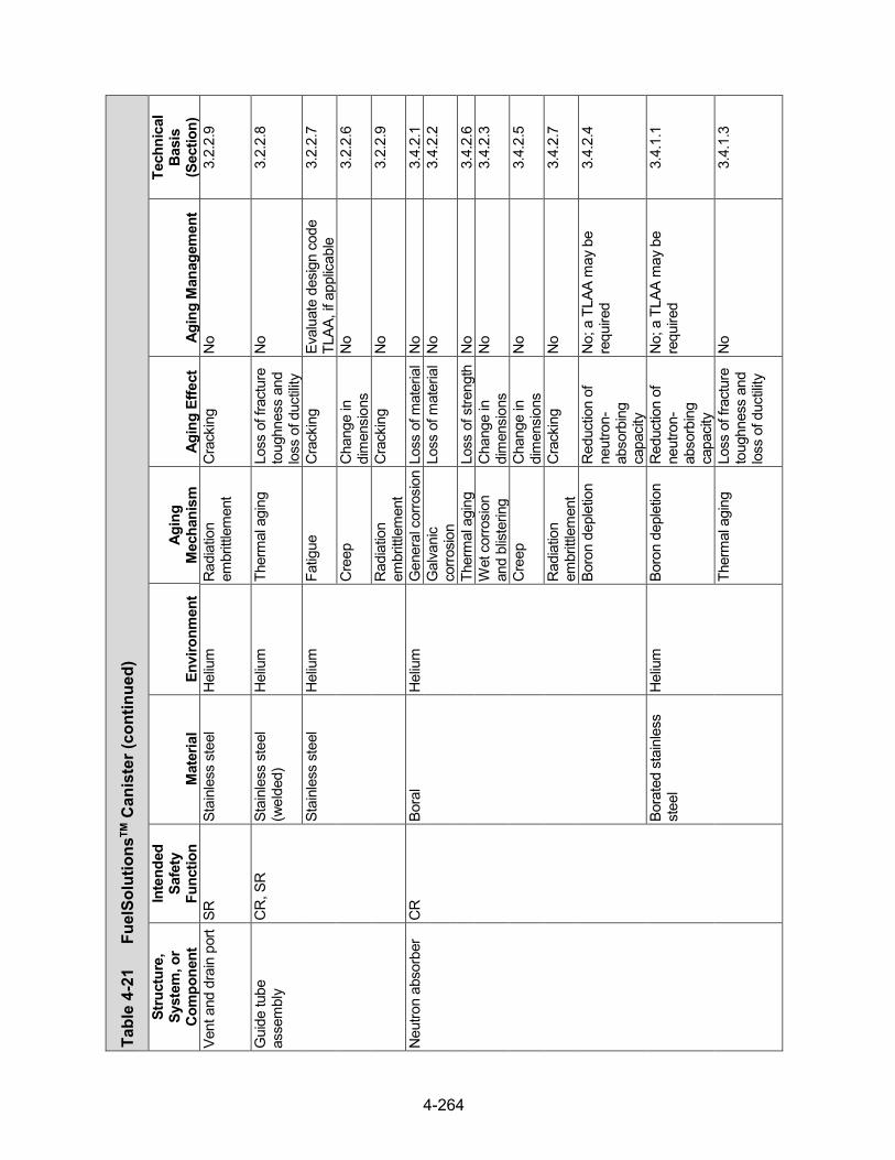
Tabl
e 4-
21
Fuel
Solu
tions
TM C
anis
ter (continued)
Stru
ctur
e,
Syst
em, o
r Co
mpo
nent
Inte
nded
Sa
fety
Fu
nctio
n M
ater
ial
Envi
ronm
ent
Agin
g M
echa
nism
Ag
ing
Effe
ct
Agin
g M
anag
emen
t
Tech
nica
l Ba
sis
(Sec
tion)
Ve
nt a
nd d
rain
por
t SR
St
ainl
ess
stee
l H
eliu
m
Rad
iatio
n em
britt
lem
ent
Cra
ckin
g N
o 3.
2.2.
9
Gui
de tu
be
asse
mbl
y C
R, S
R
Stai
nles
s st
eel
(wel
ded)
H
eliu
m
Ther
mal
agi
ng
Loss
of f
ract
ure
toug
hnes
s an
d lo
ss o
f duc
tility
No
3.2.
2.8
Stai
nles
s st
eel
Hel
ium
Fa
tigue
C
rack
ing
Eval
uate
des
ign
code
TL
AA, i
f app
licab
le
3.2.
2.7
Cre
ep
Cha
nge
in
dim
ensi
ons
No
3.2.
2.6
Rad
iatio
n em
britt
lem
ent
Cra
ckin
g N
o 3.
2.2.
9
Neu
tron
abso
rber
C
R
Bora
l H
eliu
m
Gen
eral
cor
rosi
on L
oss
of m
ater
ial
No
3.4.
2.1
Gal
vani
c co
rrosi
on
Loss
of m
ater
ial
No
3.4.
2.2
Ther
mal
agi
ng
Loss
of s
treng
th
No
3.4.
2.6
Wet
cor
rosi
on
and
blist
erin
g C
hang
e in
di
men
sion
s N
o 3.
4.2.
3
Cre
ep
Cha
nge
in
dim
ensi
ons
No
3.4.
2.5
Rad
iatio
n em
britt
lem
ent
Cra
ckin
g N
o 3.
4.2.
7
Boro
n de
plet
ion
Red
uctio
n of
ne
utro
n-ab
sorb
ing
capa
city
No;
a T
LAA
may
be
requ
ired
3.4.
2.4
Bora
ted
stai
nles
s st
eel
Hel
ium
Bo
ron
depl
etio
n R
educ
tion
of
neut
ron-
abso
rbin
g ca
paci
ty
No;
a T
LAA
may
be
requ
ired
3.4.
1.1
Ther
mal
agi
ng
Loss
of f
ract
ure
toug
hnes
s an
d lo
ss o
f duc
tility
No
3.4.
1.3
4-264

Tabl
e 4-
21
Fuel
Solu
tions
TM C
anis
ter (continued)
Stru
ctur
e,
Syst
em, o
r Co
mpo
nent
Inte
nded
Sa
fety
Fu
nctio
n M
ater
ial
Envi
ronm
ent
Agin
g M
echa
nism
Ag
ing
Effe
ct
Agin
g M
anag
emen
t
Tech
nica
l Ba
sis
(Sec
tion)
N
eutro
n ab
sorb
er
CR
Bo
rate
d st
ainl
ess
stee
l H
eliu
m
Cre
ep
Cha
nge
in
dim
ensi
ons
No
3.4.
1.2
Rad
iatio
n em
britt
lem
ent
Loss
of f
ract
ure
toug
hnes
s an
d lo
ss o
f duc
tility
No
3.4.
1.4
Fuel
bas
ket
supp
ort r
od,
supp
ort s
leev
e
SR
Stai
nles
s st
eel
Hel
ium
Th
erm
al a
ging
Lo
ss o
f fra
ctur
e to
ughn
ess
and
loss
of d
uctili
ty
No
3.2.
2.8
Fatig
ue
Cra
ckin
g Ev
alua
te d
esig
n co
de
TLAA
, if a
pplic
able
3.
2.2.
7
Cre
ep
Cha
nge
in
dim
ensi
ons
No
3.2.
2.6
Rad
iatio
n em
britt
lem
ent
Cra
ckin
g N
o 3.
2.2.
9
Fuel
bas
ket
supp
ort r
od
SR
Stai
nles
s st
eel
(17-
4 PH
) H
eliu
m
Ther
mal
agi
ng
Loss
of f
ract
ure
toug
hnes
s an
d lo
ss o
f duc
tility
TLAA
/AM
P or
a
supp
ortin
g an
alys
is is
re
quire
d
3.2.
2.8
Fatig
ue
Cra
ckin
g Ev
alua
te d
esig
n co
de
TLAA
, if a
pplic
able
3.
2.2.
7
Cre
ep
Cha
nge
in
dim
ensi
ons
No
3.2.
2.6
Rad
iatio
n em
britt
lem
ent
Cra
ckin
g N
o 3.
2.2.
9
Fuel
bas
ket
supp
ort s
leev
e SR
St
eel
Hel
ium
G
ener
al c
orro
sion
Los
s of
mat
eria
l N
o 3.
2.1.
1 G
alva
nic
corro
sion
Lo
ss o
f mat
eria
l N
o 3.
2.1.
3
Ther
mal
agi
ng
Loss
of f
ract
ure
toug
hnes
s an
d lo
ss o
f duc
tility
No
3.2.
1.8
Fatig
ue
Cra
ckin
g Ev
alua
te d
esig
n co
de
TLAA
, if a
pplic
able
3.
2.1.
7
Cre
ep
Cha
nge
in
dim
ensi
ons
No
3.2.
1.6
4-265
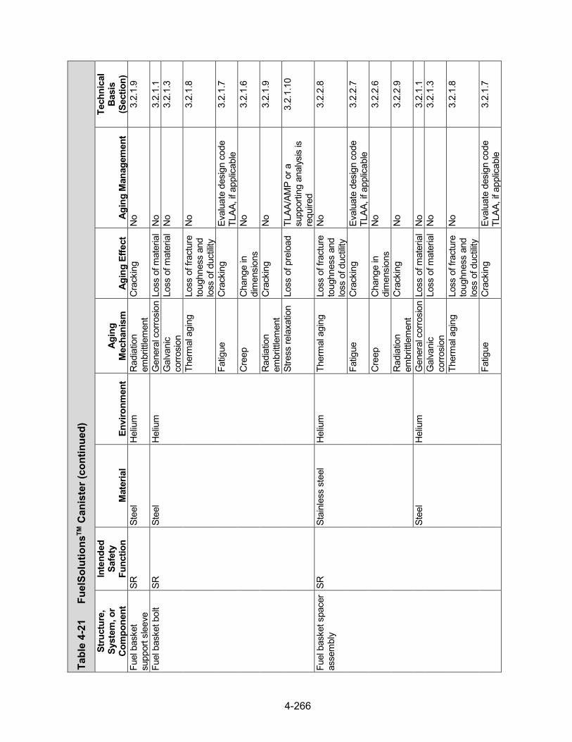
Tabl
e 4-
21
Fuel
Solu
tions
TM C
anis
ter (continued)
Stru
ctur
e,
Syst
em, o
r Co
mpo
nent
Inte
nded
Sa
fety
Fu
nctio
n M
ater
ial
Envi
ronm
ent
Agin
g M
echa
nism
Ag
ing
Effe
ct
Agin
g M
anag
emen
t
Tech
nica
l Ba
sis
(Sec
tion)
Fu
el b
aske
t su
ppor
t sle
eve
SR
Stee
l H
eliu
m
Rad
iatio
n em
britt
lem
ent
Cra
ckin
g N
o 3.
2.1.
9
Fuel
bas
ket b
olt
SR
Stee
l H
eliu
m
Gen
eral
cor
rosi
on L
oss
of m
ater
ial
No
3.2.
1.1
Gal
vani
c co
rrosi
on
Loss
of m
ater
ial
No
3.2.
1.3
Ther
mal
agi
ng
Loss
of f
ract
ure
toug
hnes
s an
d lo
ss o
f duc
tility
No
3.2.
1.8
Fatig
ue
Cra
ckin
g Ev
alua
te d
esig
n co
de
TLAA
, if a
pplic
able
3.
2.1.
7
Cre
ep
Cha
nge
in
dim
ensi
ons
No
3.2.
1.6
Rad
iatio
n em
britt
lem
ent
Cra
ckin
g N
o 3.
2.1.
9
Stre
ss re
laxa
tion
Loss
of p
relo
ad
TLAA
/AM
P or
a
supp
ortin
g an
alys
is is
re
quire
d
3.2.
1.10
Fuel
bas
ket s
pace
r as
sem
bly
SR
Stai
nles
s st
eel
Hel
ium
Th
erm
al a
ging
Lo
ss o
f fra
ctur
e to
ughn
ess
and
loss
of d
uctili
ty
No
3.2.
2.8
Fatig
ue
Cra
ckin
g Ev
alua
te d
esig
n co
de
TLAA
, if a
pplic
able
3.
2.2.
7
Cre
ep
Cha
nge
in
dim
ensi
ons
No
3.2.
2.6
Rad
iatio
n em
britt
lem
ent
Cra
ckin
g N
o 3.
2.2.
9
Stee
l H
eliu
m
Gen
eral
cor
rosi
on L
oss
of m
ater
ial
No
3.2.
1.1
Gal
vani
c co
rrosi
on
Loss
of m
ater
ial
No
3.2.
1.3
Ther
mal
agi
ng
Loss
of f
ract
ure
toug
hnes
s an
d lo
ss o
f duc
tility
No
3.2.
1.8
Fatig
ue
Cra
ckin
g Ev
alua
te d
esig
n co
de
TLAA
, if a
pplic
able
3.
2.1.
7
4-266
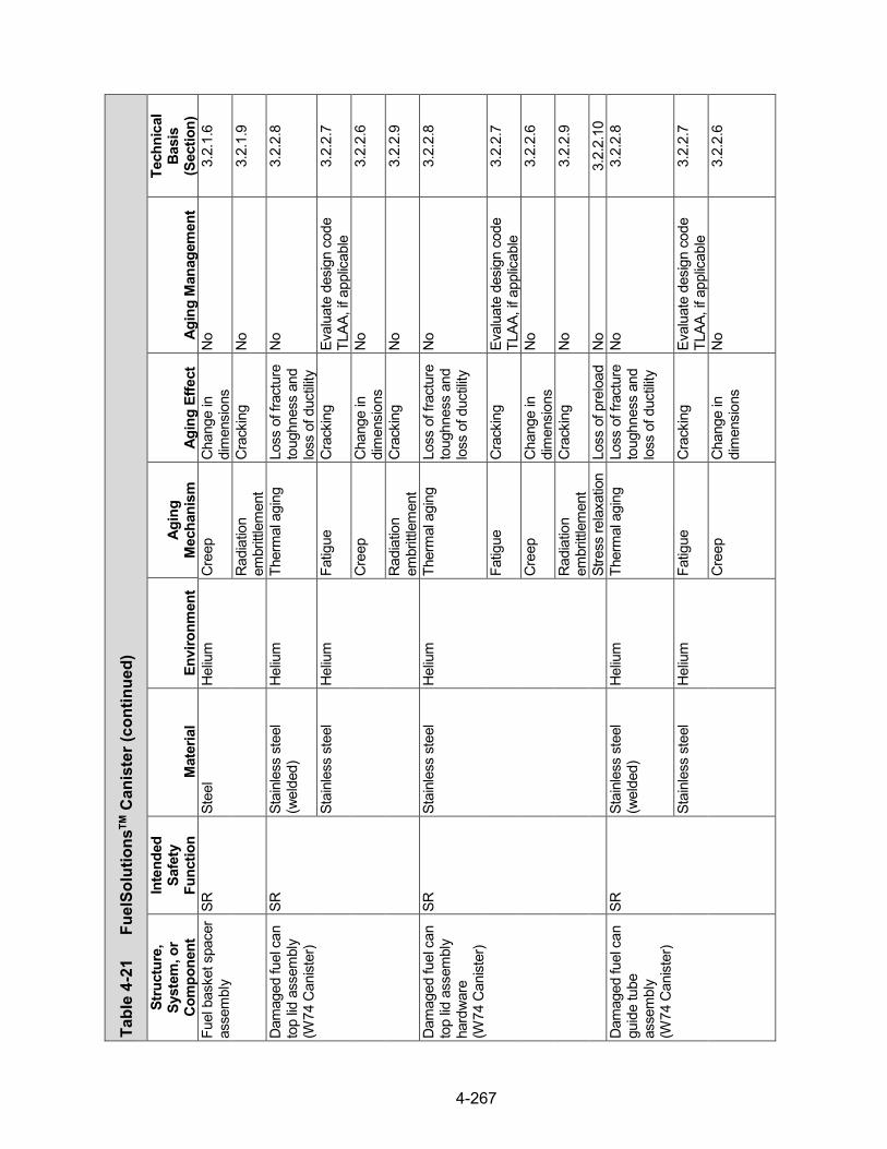
Tabl
e 4-
21
Fuel
Solu
tions
TM C
anis
ter (continued)
Stru
ctur
e,
Syst
em, o
r Co
mpo
nent
Inte
nded
Sa
fety
Fu
nctio
n M
ater
ial
Envi
ronm
ent
Agin
g M
echa
nism
Ag
ing
Effe
ct
Agin
g M
anag
emen
t
Tech
nica
l Ba
sis
(Sec
tion)
Fu
el b
aske
t spa
cer
asse
mbl
y SR
St
eel
Hel
ium
C
reep
C
hang
e in
di
men
sion
s N
o 3.
2.1.
6
Rad
iatio
n em
britt
lem
ent
Cra
ckin
g N
o 3.
2.1.
9
Dam
aged
fuel
can
to
p lid
ass
embl
y (W
74 C
anist
er)
SR
Stai
nles
s st
eel
(wel
ded)
H
eliu
m
Ther
mal
agi
ng
Loss
of f
ract
ure
toug
hnes
s an
d lo
ss o
f duc
tility
No
3.2.
2.8
Stai
nles
s st
eel
Hel
ium
Fa
tigue
C
rack
ing
Eval
uate
des
ign
code
TL
AA, i
f app
licab
le
3.2.
2.7
Cre
ep
Cha
nge
in
dim
ensi
ons
No
3.2.
2.6
Rad
iatio
n em
britt
lem
ent
Cra
ckin
g N
o 3.
2.2.
9
Dam
aged
fuel
can
to
p lid
ass
embl
y ha
rdw
are
(W
74 C
anist
er)
SR
Stai
nles
s st
eel
Hel
ium
Th
erm
al a
ging
Lo
ss o
f fra
ctur
e to
ughn
ess
and
loss
of d
uctili
ty
No
3.2.
2.8
Fatig
ue
Cra
ckin
g Ev
alua
te d
esig
n co
de
TLAA
, if a
pplic
able
3.
2.2.
7
Cre
ep
Cha
nge
in
dim
ensi
ons
No
3.2.
2.6
Rad
iatio
n em
britt
lem
ent
Cra
ckin
g N
o 3.
2.2.
9
Stre
ss re
laxa
tion
Loss
of p
relo
ad
No
3.2.
2.10
D
amag
ed fu
el c
an
guid
e tu
be
asse
mbl
y
(W74
Can
ister
)
SR
Stai
nles
s st
eel
(wel
ded)
H
eliu
m
Ther
mal
agi
ng
Loss
of f
ract
ure
toug
hnes
s an
d lo
ss o
f duc
tility
No
3.2.
2.8
Stai
nles
s st
eel
Hel
ium
Fa
tigue
C
rack
ing
Eval
uate
des
ign
code
TL
AA, i
f app
licab
le
3.2.
2.7
Cre
ep
Cha
nge
in
dim
ensi
ons
No
3.2.
2.6
4-267

Tabl
e 4-
21
Fuel
Solu
tions
TM C
anis
ter (continued)
Stru
ctur
e,
Syst
em, o
r Co
mpo
nent
Inte
nded
Sa
fety
Fu
nctio
n M
ater
ial
Envi
ronm
ent
Agin
g M
echa
nism
Ag
ing
Effe
ct
Agin
g M
anag
emen
t
Tech
nica
l Ba
sis
(Sec
tion)
D
amag
ed fu
el c
an
guid
e tu
be
asse
mbl
y
(W74
Can
ister
)
SR
Stai
nles
s st
eel
Hel
ium
R
adia
tion
embr
ittle
men
t C
rack
ing
No
3.2.
2.9
Dam
aged
fuel
can
ne
utro
n ab
sorb
er
(W74
Can
ister
)
CR
Bo
rate
d st
ainl
ess
stee
l H
eliu
m
Boro
n de
plet
ion
Red
uctio
n of
ne
utro
n-ab
sorb
ing
capa
city
No;
a T
LAA
may
be
requ
ired
3.4.
1.1
Ther
mal
agi
ng
Loss
of f
ract
ure
toug
hnes
s an
d lo
ss o
f duc
tility
No
3.4.
1.3
Cre
ep
Cha
nge
in
dim
ensi
ons
No
3.4.
1.2
Rad
iatio
n em
britt
lem
ent
Loss
of f
ract
ure
toug
hnes
s an
d lo
ss o
f duc
tility
No
3.4.
1.4
4-268

Tabl
e 4-
22
Fuel
Solu
tions
TM S
tora
ge C
ask
Stru
ctur
e,
Syst
em,
or C
ompo
nent
Inte
nded
Sa
fety
Fu
nctio
n M
ater
ial
Envi
ronm
ent
Agin
g M
echa
nism
Ag
ing
Effe
ct
Agin
g M
anag
emen
t
Tech
nica
l B
asis
(S
ectio
n)
Con
cret
e sh
ell,
shea
r key
SH
, SR
* C
oncr
ete,
gro
ut
Air—
outd
oor
Aggr
essi
ve
chem
ical
atta
ck
Cra
ckin
g R
einf
orce
d C
oncr
ete
Stru
ctur
es A
MP
3.5.
1.5
Loss
of s
treng
th R
einf
orce
d C
oncr
ete
Stru
ctur
es A
MP
3.5.
1.5
Loss
of m
ater
ial
(spa
lling,
sc
alin
g)
Rei
nfor
ced
Con
cret
e St
ruct
ures
AM
P 3.
5.1.
5
Cre
ep
Cra
ckin
g N
o 3.
5.1.
2
Deh
ydra
tion
at
high
te
mpe
ratu
re
Cra
ckin
g N
o 3.
5.1.
11
Loss
of s
treng
th N
o 3.
5.1.
11
Del
ayed
et
tring
ite
form
atio
n
Loss
of m
ater
ial
(spa
lling,
sc
alin
g)
No
3.5.
1.13
Loss
of s
treng
th N
o 3.
5.1.
13
Cra
ckin
g N
o 3.
5.1.
13
Fatig
ue
Cra
ckin
g N
o 3.
5.1.
10
Free
ze a
nd th
aw C
rack
ing
Rei
nfor
ced
Con
cret
e St
ruct
ures
AM
P 3.
5.1.
1
Loss
of m
ater
ial
(spa
lling,
sc
alin
g)
Rei
nfor
ced
Con
cret
e St
ruct
ures
AM
P 3.
5.1.
1
Rad
iatio
n da
mag
e C
rack
ing
No
3.5.
1.9
Loss
of s
treng
th N
o 3.
5.1.
9
*Saf
ety
Func
tions
: C
onfin
emen
t (C
O),
Subc
ritic
ality
(CR
), R
etrie
vabi
lity
(RE)
, Rad
iatio
n Sh
ield
ing
(SH
), St
ruct
ural
Inte
grity
(SR
), Th
erm
al/H
eat R
emov
al (T
H)
4-269

Tabl
e 4-
22
Fuel
Solu
tions
TM S
tora
ge C
ask (con
tinued)
Stru
ctur
e,
Syst
em,
or C
ompo
nent
Inte
nded
Sa
fety
Fu
nctio
n M
ater
ial
Envi
ronm
ent
Agin
g M
echa
nism
Ag
ing
Effe
ct
Agin
g M
anag
emen
t
Tech
nica
l B
asis
(S
ectio
n)
Con
cret
e sh
ell,
shea
r key
SH
, SR
C
oncr
ete
Air—
outd
oor
Rea
ctio
n w
ith
aggr
egat
es
Cra
ckin
g R
einf
orce
d C
oncr
ete
Stru
ctur
es A
MP
3.5.
1.3
Loss
of s
treng
th R
einf
orce
d C
oncr
ete
Stru
ctur
es A
MP
3.5.
1.3
Salt
scal
ing
Loss
of m
ater
ial
(spa
lling,
sc
alin
g)
Rei
nfor
ced
Con
cret
e St
ruct
ures
AM
P 3.
5.1.
14
Shrin
kage
C
rack
ing
No
3.5.
1.7
Leac
hing
of
calc
ium
hy
drox
ide
Loss
of s
treng
th R
einf
orce
d C
oncr
ete
Stru
ctur
es A
MP
3.5.
1.8
Incr
ease
in
poro
sity
and
pe
rmea
bilit
y
Rei
nfor
ced
Con
cret
e St
ruct
ures
AM
P 3.
5.1.
8
Red
uctio
n of
co
ncre
te p
H
(redu
cing
co
rrosi
on
resi
stan
ce o
f st
eel
embe
dmen
ts)
Rei
nfor
ced
Con
cret
e St
ruct
ures
AM
P 3.
5.1.
8
Con
cret
e sh
ell
SH, S
R
Rei
nfor
cing
ste
el
Air—
outd
oor,
grou
ndw
ater
C
orro
sion
of
rein
forc
ing
stee
l Lo
ss o
f co
ncre
te/s
teel
bo
nd
Rei
nfor
ced
Con
cret
e St
ruct
ures
AM
P 3.
5.1.
6
Loss
of m
ater
ial
(spa
lling,
sc
alin
g)
Rei
nfor
ced
Con
cret
e St
ruct
ures
AM
P 3.
5.1.
6
Cra
ckin
g R
einf
orce
d C
oncr
ete
Stru
ctur
es A
MP
3.5.
1.6
Loss
of s
treng
th R
einf
orce
d C
oncr
ete
Stru
ctur
es A
MP
3.5.
1.6
4-270
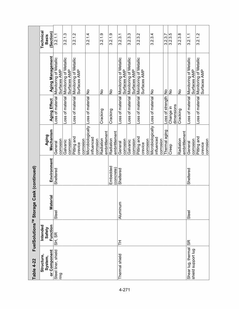
Tabl
e 4-
22
Fuel
Solu
tions
TM S
tora
ge C
ask (con
tinued)
Stru
ctur
e,
Syst
em,
or C
ompo
nent
Inte
nded
Sa
fety
Fu
nctio
n M
ater
ial
Envi
ronm
ent
Agin
g M
echa
nism
Ag
ing
Effe
ct
Agin
g M
anag
emen
t
Tech
nica
l B
asis
(S
ectio
n)
Stee
l lin
er, s
hiel
d rin
g SH
, SR
St
eel
Shel
tere
d G
ener
al
corro
sion
Lo
ss o
f mat
eria
l M
onito
ring
of M
etal
lic
Surfa
ces
AMP
3.2.
1.1
Gal
vani
c co
rrosi
on
Loss
of m
ater
ial
Mon
itorin
g of
Met
allic
Su
rface
s AM
P 3.
2.1.
3
Pitti
ng a
nd
crev
ice
corro
sion
Loss
of m
ater
ial
Mon
itorin
g of
Met
allic
Su
rface
s AM
P 3.
2.1.
2
Mic
robi
olog
ical
ly
influ
ence
d co
rrosi
on
Loss
of m
ater
ial
No
3.2.
1.4
Rad
iatio
n em
britt
lem
ent
Cra
ckin
g N
o 3.
2.1.
9
Embe
dded
(c
oncr
ete)
R
adia
tion
embr
ittle
men
t C
rack
ing
No
3.2.
1.9
Ther
mal
shi
eld
TH
Alum
inum
Sh
elte
red
Gen
eral
co
rrosi
on
Loss
of m
ater
ial
Mon
itorin
g of
Met
allic
Su
rface
s AM
P 3.
2.3.
1
Gal
vani
c co
rrosi
on
Loss
of m
ater
ial
Mon
itorin
g of
Met
allic
Su
rface
s AM
P 3.
2.3.
3
Pitti
ng a
nd
crev
ice
corro
sion
Loss
of m
ater
ial
Mon
itorin
g of
Met
allic
Su
rface
s AM
P 3.
2.3.
2
Mic
robi
olog
ical
ly
influ
ence
d co
rrosi
on
Loss
of m
ater
ial
No
3.2.
3.4
Ther
mal
agi
ng
Loss
of s
treng
th N
o 3.
2.3.
7 C
reep
C
hang
e in
di
men
sion
s N
o 3.
2.3.
5
Rad
iatio
n em
britt
lem
ent
Cra
ckin
g N
o 3.
2.3.
8
Shea
r lug
, the
rmal
sh
ield
sup
port
lug
SR
Stee
l Sh
elte
red
Gen
eral
co
rrosi
on
Loss
of m
ater
ial
Mon
itorin
g of
Met
allic
Su
rface
s AM
P 3.
2.1.
1
Pitti
ng a
nd
crev
ice
corro
sion
Loss
of m
ater
ial
Mon
itorin
g of
Met
allic
Su
rface
s AM
P 3.
2.1.
2
4-271
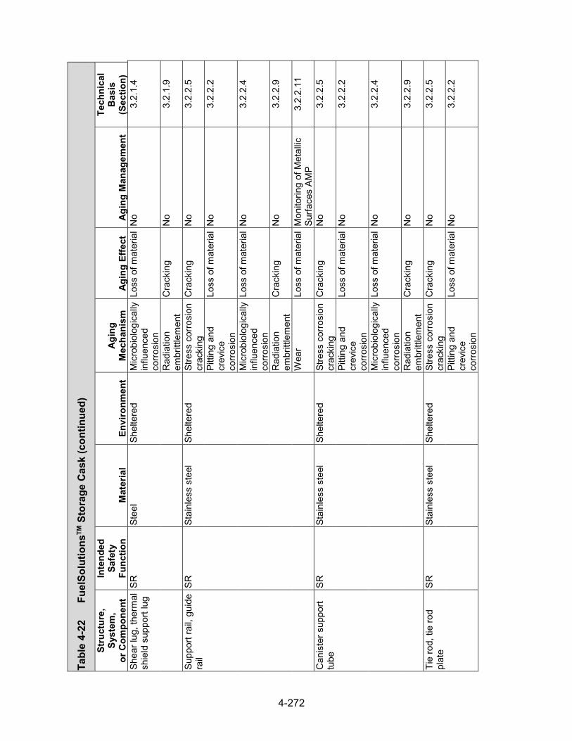
Tabl
e 4-
22
Fuel
Solu
tions
TM S
tora
ge C
ask (con
tinued)
Stru
ctur
e,
Syst
em,
or C
ompo
nent
Inte
nded
Sa
fety
Fu
nctio
n M
ater
ial
Envi
ronm
ent
Agin
g M
echa
nism
Ag
ing
Effe
ct
Agin
g M
anag
emen
t
Tech
nica
l B
asis
(S
ectio
n)
Shea
r lug
, the
rmal
sh
ield
sup
port
lug
SR
Stee
l Sh
elte
red
Mic
robi
olog
ical
ly
influ
ence
d co
rrosi
on
Loss
of m
ater
ial
No
3.2.
1.4
Rad
iatio
n em
britt
lem
ent
Cra
ckin
g N
o 3.
2.1.
9
Supp
ort r
ail,
guid
e ra
il SR
St
ainl
ess
stee
l Sh
elte
red
Stre
ss c
orro
sion
cr
acki
ng
Cra
ckin
g N
o 3.
2.2.
5
Pitti
ng a
nd
crev
ice
corro
sion
Loss
of m
ater
ial
No
3.2.
2.2
Mic
robi
olog
ical
ly
influ
ence
d co
rrosi
on
Loss
of m
ater
ial
No
3.2.
2.4
Rad
iatio
n em
britt
lem
ent
Cra
ckin
g N
o 3.
2.2.
9
Wea
r Lo
ss o
f mat
eria
l M
onito
ring
of M
etal
lic
Surfa
ces
AMP
3.2.
2.11
Can
iste
r sup
port
tube
SR
St
ainl
ess
stee
l Sh
elte
red
Stre
ss c
orro
sion
cr
acki
ng
Cra
ckin
g N
o 3.
2.2.
5
Pitti
ng a
nd
crev
ice
corro
sion
Loss
of m
ater
ial
No
3.2.
2.2
Mic
robi
olog
ical
ly
influ
ence
d co
rrosi
on
Loss
of m
ater
ial
No
3.2.
2.4
Rad
iatio
n em
britt
lem
ent
Cra
ckin
g N
o 3.
2.2.
9
Tie
rod,
tie
rod
plat
e SR
St
ainl
ess
stee
l Sh
elte
red
Stre
ss c
orro
sion
cr
acki
ng
Cra
ckin
g N
o 3.
2.2.
5
Pitti
ng a
nd
crev
ice
corro
sion
Loss
of m
ater
ial
No
3.2.
2.2
4-272

Tabl
e 4-
22
Fuel
Solu
tions
TM S
tora
ge C
ask (con
tinued)
Stru
ctur
e,
Syst
em,
or C
ompo
nent
Inte
nded
Sa
fety
Fu
nctio
n M
ater
ial
Envi
ronm
ent
Agin
g M
echa
nism
Ag
ing
Effe
ct
Agin
g M
anag
emen
t
Tech
nica
l B
asis
(S
ectio
n)
Tie
rod,
tie
rod
plat
e SR
St
ainl
ess
stee
l Sh
elte
red
Mic
robi
olog
ical
ly
influ
ence
d co
rrosi
on
Loss
of m
ater
ial
No
3.2.
2.4
Rad
iatio
n em
britt
lem
ent
Cra
ckin
g N
o 3.
2.2.
9
Tie
rod
hard
war
e SR
St
ainl
ess
stee
l Sh
elte
red
Stre
ss c
orro
sion
cr
acki
ng
Cra
ckin
g N
o 3.
2.2.
5
Pitti
ng a
nd
crev
ice
corro
sion
Loss
of m
ater
ial
No
3.2.
2.2
Mic
robi
olog
ical
ly
influ
ence
d co
rrosi
on
Loss
of m
ater
ial
No
3.2.
2.4
Rad
iatio
n em
britt
lem
ent
Cra
ckin
g N
o 3.
2.2.
9
Stre
ss re
laxa
tion
Loss
of p
relo
ad
No
3.2.
2.10
St
eel
Shel
tere
d G
ener
al
corro
sion
Lo
ss o
f mat
eria
l M
onito
ring
of M
etal
lic
Surfa
ces
AMP
3.2.
1.1
Gal
vani
c co
rrosi
on
Loss
of m
ater
ial
Mon
itorin
g of
Met
allic
Su
rface
s AM
P 3.
2.1.
3
Pitti
ng a
nd
crev
ice
corro
sion
Loss
of m
ater
ial
Mon
itorin
g of
Met
allic
Su
rface
s AM
P 3.
2.1.
2
Mic
robi
olog
ical
ly
influ
ence
d co
rrosi
on
Loss
of m
ater
ial
No
3.2.
1.4
Rad
iatio
n em
britt
lem
ent
Cra
ckin
g N
o 3.
2.1.
9
Stre
ss re
laxa
tion
Loss
of p
relo
ad
Mon
itorin
g of
Met
allic
Su
rface
s AM
P 3.
2.1.
10
4-273

Tabl
e 4-
22
Fuel
Solu
tions
TM S
tora
ge C
ask (con
tinued)
Stru
ctur
e,
Syst
em,
or C
ompo
nent
Inte
nded
Sa
fety
Fu
nctio
n M
ater
ial
Envi
ronm
ent
Agin
g M
echa
nism
Ag
ing
Effe
ct
Agin
g M
anag
emen
t
Tech
nica
l B
asis
(S
ectio
n)
Ram
anc
hor
SR
Stee
l Sh
elte
red
Gen
eral
co
rrosi
on
Loss
of m
ater
ial
Mon
itorin
g of
Met
allic
Su
rface
s AM
P 3.
2.1.
1
Pitti
ng a
nd
crev
ice
corro
sion
Loss
of m
ater
ial
Mon
itorin
g of
Met
allic
Su
rface
s AM
P 3.
2.1.
2
Mic
robi
olog
ical
ly
influ
ence
d co
rrosi
on
Loss
of m
ater
ial
No
3.2.
1.4
Rad
iatio
n em
britt
lem
ent
Cra
ckin
g N
o 3.
2.1.
9
Top
cove
r as
sem
bly
SR
Stee
l Ai
r—ou
tdoo
r G
ener
al
corro
sion
Lo
ss o
f mat
eria
l M
onito
ring
of M
etal
lic
Surfa
ces
AMP
3.2.
1.1
Pitti
ng a
nd
crev
ice
corro
sion
Loss
of m
ater
ial
Mon
itorin
g of
Met
allic
Su
rface
s AM
P 3.
2.1.
2
Mic
robi
olog
ical
ly
influ
ence
d co
rrosi
on
Loss
of m
ater
ial
No
3.2.
1.4
Rad
iatio
n em
britt
lem
ent
Cra
ckin
g N
o 3.
2.1.
9
Shel
tere
d G
ener
al
corro
sion
Lo
ss o
f mat
eria
l M
onito
ring
of M
etal
lic
Surfa
ces
AMP
3.2.
1.1
Pitti
ng a
nd
crev
ice
corro
sion
Loss
of m
ater
ial
Mon
itorin
g of
Met
allic
Su
rface
s AM
P 3.
2.1.
2
Mic
robi
olog
ical
ly
influ
ence
d co
rrosi
on
Loss
of m
ater
ial
No
3.2.
1.4
Rad
iatio
n em
britt
lem
ent
Cra
ckin
g N
o 3.
2.1.
9
4-274

Tabl
e 4-
22
Fuel
Solu
tions
TM S
tora
ge C
ask (con
tinued)
Stru
ctur
e,
Syst
em,
or C
ompo
nent
Inte
nded
Sa
fety
Fu
nctio
n M
ater
ial
Envi
ronm
ent
Agin
g M
echa
nism
Ag
ing
Effe
ct
Agin
g M
anag
emen
t
Tech
nica
l B
asis
(S
ectio
n)
Top
cove
r as
sem
bly
SR
Con
cret
e Fu
lly e
ncas
ed
(ste
el)
Del
ayed
et
tring
ite
form
atio
n
Loss
of m
ater
ial
(spa
lling,
sc
alin
g)
No
3.5.
1.13
Cra
ckin
g N
o 3.
5.1.
13
Loss
of s
treng
th N
o 3.
5.1.
13
Rad
iatio
n da
mag
e C
rack
ing
No
3.5.
1.9
Loss
of s
treng
th N
o 3.
5.1.
9 R
eact
ion
with
ag
greg
ates
C
rack
ing
No
3.5.
1.3
Loss
of s
treng
th N
o 3.
5.1.
3 To
p co
ver b
olt
SR
Stee
l Sh
elte
red
Gen
eral
co
rrosi
on
Loss
of m
ater
ial
Mon
itorin
g of
Met
allic
Su
rface
s AM
P 3.
2.1.
1
Pitti
ng a
nd
crev
ice
corro
sion
Loss
of m
ater
ial
Mon
itorin
g of
Met
allic
Su
rface
s AM
P 3.
2.1.
2
Mic
robi
olog
ical
ly
influ
ence
d co
rrosi
on
Loss
of m
ater
ial
No
3.2.
1.4
Rad
iatio
n em
britt
lem
ent
Cra
ckin
g N
o 3.
2.1.
9
Stre
ss re
laxa
tion
Loss
of p
relo
ad
Mon
itorin
g of
Met
allic
Su
rface
s AM
P 3.
2.1.
10
Coa
ting
on c
arbo
n st
eel c
ompo
nent
s SR
C
oatin
g Ai
r—ou
tdoo
r R
adia
tion
embr
ittle
men
t C
oatin
g de
grad
atio
n TL
AA/A
MP
or a
su
ppor
ting
anal
ysis
is
requ
ired
3.2.
8
Ther
mal
agi
ng
Coa
ting
degr
adat
ion
TLAA
/AM
P or
a
supp
ortin
g an
alys
is is
re
quire
d
3.2.
8
4-275

Tabl
e 4-
22
Fuel
Solu
tions
TM S
tora
ge C
ask (con
tinued)
Stru
ctur
e,
Syst
em,
or C
ompo
nent
Inte
nded
Sa
fety
Fu
nctio
n M
ater
ial
Envi
ronm
ent
Agin
g M
echa
nism
Ag
ing
Effe
ct
Agin
g M
anag
emen
t
Tech
nica
l B
asis
(S
ectio
n)
Coa
ting
on c
arbo
n st
eel c
ompo
nent
s SR
C
oatin
g Sh
elte
red
Rad
iatio
n em
britt
lem
ent
Coa
ting
degr
adat
ion
TLAA
/AM
P or
a
supp
ortin
g an
alys
is is
re
quire
d
3.2.
8
Ther
mal
agi
ng
Coa
ting
degr
adat
ion
TLAA
/AM
P or
a
supp
ortin
g an
alys
is is
re
quire
d
3.2.
8
4-276

Tabl
e 4-
23
Fuel
Solu
tions
TM T
rans
fer C
ask
Stru
ctur
e,
Syst
em,
or C
ompo
nent
Inte
nded
Sa
fety
Fu
nctio
n M
ater
ial
Envi
ronm
ent
Agin
g M
echa
nism
Ag
ing
Effe
ct
Agin
g M
anag
emen
t
Tech
nica
l B
asis
(S
ectio
n)
Stru
ctur
al s
hell
SR*
Stai
nles
s st
eel
(wel
ded)
Ai
r—in
door
/out
door
St
ress
cor
rosi
on
crac
king
C
rack
ing
No
3.2.
2.5
Stai
nles
s st
eel
Air—
indo
or/o
utdo
or
Pitti
ng a
nd
crev
ice
corro
sion
Loss
of m
ater
ial
No
3.2.
2.2
Mic
robi
olog
ical
ly
influ
ence
d co
rrosi
on
Loss
of m
ater
ial
No
3.2.
2.4
Fatig
ue
Cra
ckin
g Ev
alua
te d
esig
n co
de
TLAA
, if a
pplic
able
3.
2.2.
7
Rad
iatio
n em
britt
lem
ent
Cra
ckin
g N
o 3.
2.2.
9
Inne
r lin
er
SR
Stai
nles
s st
eel
(wel
ded)
Ai
r—in
door
/out
door
St
ress
cor
rosi
on
crac
king
C
rack
ing
No
3.2.
2.5
Stai
nles
s st
eel
Air—
indo
or/o
utdo
or
Pitti
ng a
nd
crev
ice
corro
sion
Loss
of m
ater
ial
No
3.2.
2.2
Mic
robi
olog
ical
ly
influ
ence
d co
rrosi
on
Loss
of m
ater
ial
No
3.2.
2.4
Fatig
ue
Cra
ckin
g Ev
alua
te d
esig
n co
de
TLAA
, if a
pplic
able
3.
2.2.
7
Rad
iatio
n em
britt
lem
ent
Cra
ckin
g N
o 3.
2.2.
9
Neu
tron
shie
ld
jack
et, t
runn
ion
supp
ort p
late
, th
erm
owel
l
SR
Stai
nles
s st
eel
Air—
indo
or/o
utdo
or
Pitti
ng a
nd
crev
ice
corro
sion
Loss
of m
ater
ial
No
3.2.
2.2
*Saf
ety
Func
tions
: C
onfin
emen
t (C
O),
Subc
ritic
ality
(CR
), R
etrie
vabi
lity
(RE)
, Rad
iatio
n Sh
ield
ing
(SH
), St
ruct
ural
Inte
grity
(SR
), Th
erm
al/H
eat R
emov
al (T
H)
4-277

Tabl
e 4-
23
Fuel
Solu
tions
TM T
rans
fer C
ask (con
tinued)
Stru
ctur
e,
Syst
em,
or C
ompo
nent
Inte
nded
Sa
fety
Fu
nctio
n M
ater
ial
Envi
ronm
ent
Agin
g M
echa
nism
Ag
ing
Effe
ct
Agin
g M
anag
emen
t
Tech
nica
l B
asis
(S
ectio
n)
Neu
tron
shie
ld
jack
et, t
runn
ion
supp
ort p
late
, th
erm
owel
l
SR
Stai
nles
s st
eel
Air—
indo
or/o
utdo
or
Mic
robi
olog
ical
ly
influ
ence
d co
rrosi
on
Loss
of m
ater
ial
No
3.2.
2.4
Stre
ss c
orro
sion
cr
acki
ng
Cra
ckin
g N
o 3.
2.2.
5
Fatig
ue
Cra
ckin
g Ev
alua
te d
esig
n co
de
TLAA
, if a
pplic
able
3.
2.2.
7
Rad
iatio
n em
britt
lem
ent
Cra
ckin
g N
o 3.
2.2.
9
Neu
tron
shie
ld
jack
et s
uppo
rt rib
SR
St
ainl
ess
stee
l D
emin
eral
ized
w
ater
Pi
tting
and
cr
evic
e co
rrosi
on Lo
ss o
f mat
eria
l N
o 3.
2.2.
2
Mic
robi
olog
ical
ly
influ
ence
d co
rrosi
on
Loss
of m
ater
ial
No
3.2.
2.4
Stre
ss c
orro
sion
cr
acki
ng
Cra
ckin
g N
o 3.
2.2.
5
Fatig
ue
Cra
ckin
g Ev
alua
te d
esig
n co
de
TLAA
, if a
pplic
able
3.
2.2.
7
Rad
iatio
n em
britt
lem
ent
Cra
ckin
g N
o 3.
2.2.
9
Gam
ma
shie
ld
SH
Lead
Em
bedd
ed
(sta
inle
ss
stee
l)
Non
e id
entif
ied
Non
e id
entif
ied
No
3.2.
6
Gui
de ra
il SR
St
ainl
ess
stee
l Ai
r—in
door
/out
door
Pi
tting
and
cr
evic
e co
rrosi
on Lo
ss o
f mat
eria
l N
o 3.
2.2.
2
Mic
robi
olog
ical
ly
influ
ence
d co
rrosi
on
Loss
of m
ater
ial
No
3.2.
2.4
Stre
ss c
orro
sion
cr
acki
ng
Cra
ckin
g N
o 3.
2.2.
5
Fatig
ue
Cra
ckin
g Ev
alua
te d
esig
n co
de
TLAA
, if a
pplic
able
3.
2.2.
7
Rad
iatio
n em
britt
lem
ent
Cra
ckin
g N
o 3.
2.2.
9
4-278

Tabl
e 4-
23
Fuel
Solu
tions
TM T
rans
fer C
ask (con
tinued)
Stru
ctur
e,
Syst
em,
or C
ompo
nent
Inte
nded
Sa
fety
Fu
nctio
n M
ater
ial
Envi
ronm
ent
Agin
g M
echa
nism
Ag
ing
Effe
ct
Agin
g M
anag
emen
t
Tech
nica
l B
asis
(S
ectio
n)
Gui
de ra
il SR
St
ainl
ess
stee
l Ai
r—in
door
/out
door
W
ear
Loss
of m
ater
ial
Tran
sfer
Cas
ks A
MP
3.2.
2.11
Top
flang
e,
botto
m fl
ange
SR
St
ainl
ess
stee
l (w
elde
d)
Air—
indo
or/o
utdo
or
Stre
ss c
orro
sion
cr
acki
ng
Cra
ckin
g N
o 3.
2.2.
5
Stai
nles
s st
eel
Air—
indo
or/o
utdo
or
Pitti
ng a
nd
crev
ice
corro
sion
Loss
of m
ater
ial
No
3.2.
2.2
Mic
robi
olog
ical
ly
influ
ence
d co
rrosi
on
Loss
of m
ater
ial
No
3.2.
2.4
Fatig
ue
Cra
ckin
g Ev
alua
te d
esig
n co
de
TLAA
, if a
pplic
able
3.
2.2.
7
Rad
iatio
n em
britt
lem
ent
Cra
ckin
g N
o 3.
2.2.
9
Scre
w th
read
in
sert
SR
Stai
nles
s st
eel
Embe
dded
(s
tain
less
st
eel)
Fatig
ue
Cra
ckin
g Ev
alua
te d
esig
n co
de
TLAA
, if a
pplic
able
3.
2.2.
7
Rad
iatio
n em
britt
lem
ent
Cra
ckin
g N
o 3.
2.2.
9
Bloc
k SR
St
ainl
ess
stee
l Em
bedd
ed
(sta
inle
ss s
teel
, le
ad)
Fatig
ue
Cra
ckin
g Ev
alua
te d
esig
n co
de
TLAA
, if a
pplic
able
3.
2.2.
7
Rad
iatio
n em
britt
lem
ent
Cra
ckin
g N
o 3.
2.2.
9
Swag
elok
qui
ck
conn
ect b
ody,
co
uplin
g, fi
tting
, ca
p
SR
Stai
nles
s st
eel
Air—
indo
or/o
utdo
or
Pitti
ng a
nd
crev
ice
corro
sion
Loss
of m
ater
ial
No
3.2.
2.2
Mic
robi
olog
ical
ly
influ
ence
d co
rrosi
on
Loss
of m
ater
ial
No
3.2.
2.4
Stre
ss c
orro
sion
cr
acki
ng
Cra
ckin
g N
o 3.
2.2.
5
Fatig
ue
Cra
ckin
g Ev
alua
te d
esig
n co
de
TLAA
, if a
pplic
able
3.
2.2.
7
Rad
iatio
n em
britt
lem
ent
Cra
ckin
g N
o 3.
2.2.
9
4-279

Tabl
e 4-
23
Fuel
Solu
tions
TM T
rans
fer C
ask (con
tinued)
Stru
ctur
e,
Syst
em,
or C
ompo
nent
Inte
nded
Sa
fety
Fu
nctio
n M
ater
ial
Envi
ronm
ent
Agin
g M
echa
nism
Ag
ing
Effe
ct
Agin
g M
anag
emen
t
Tech
nica
l B
asis
(S
ectio
n)
Upp
er tr
unni
on,
low
er tr
unni
on
SR
Stai
nles
s st
eel
(wel
ded)
Ai
r—in
door
/out
door
St
ress
cor
rosi
on
crac
king
C
rack
ing
No
3.2.
2.5
Dem
iner
aliz
ed
wat
er
Stre
ss c
orro
sion
cr
acki
ng
Cra
ckin
g N
o 3.
2.2.
5
Stai
nles
s st
eel
Air—
indo
or/o
utdo
or
Pitti
ng a
nd
crev
ice
corro
sion
Loss
of m
ater
ial
No
3.2.
2.2
Mic
robi
olog
ical
ly
influ
ence
d co
rrosi
on
Loss
of m
ater
ial
No
3.2.
2.4
Fatig
ue
Cra
ckin
g Ev
alua
te d
esig
n co
de
TLAA
, if a
pplic
able
3.
2.2.
7
Rad
iatio
n em
britt
lem
ent
Cra
ckin
g N
o 3.
2.2.
9
Dem
iner
aliz
ed
wat
er
Pitti
ng a
nd
crev
ice
corro
sion
Loss
of m
ater
ial
No
3.2.
2.2
Mic
robi
olog
ical
ly
influ
ence
d co
rrosi
on
Loss
of m
ater
ial
No
3.2.
2.4
Fatig
ue
Cra
ckin
g Ev
alua
te d
esig
n co
de
TLAA
, if a
pplic
able
3.
2.2.
7
Rad
iatio
n em
britt
lem
ent
Cra
ckin
g N
o 3.
2.2.
9
Trun
nion
reta
iner
, tru
nnio
n sl
eeve
SR
St
ainl
ess
stee
l Ai
r—in
door
/out
door
Pi
tting
and
cr
evic
e co
rrosi
on Lo
ss o
f mat
eria
l N
o 3.
2.2.
2
Mic
robi
olog
ical
ly
influ
ence
d co
rrosi
on
Loss
of m
ater
ial
No
3.2.
2.4
Stre
ss c
orro
sion
cr
acki
ng
Cra
ckin
g N
o 3.
2.2.
5
Fatig
ue
Cra
ckin
g Ev
alua
te d
esig
n co
de
TLAA
, if a
pplic
able
3.
2.2.
7
Rad
iatio
n em
britt
lem
ent
Cra
ckin
g N
o 3.
2.2.
9
Wea
r Lo
ss o
f mat
eria
l Tr
ansf
er C
asks
AM
P 3.
2.2.
11
4-280

Tabl
e 4-
23
Fuel
Solu
tions
TM T
rans
fer C
ask (con
tinued)
Stru
ctur
e,
Syst
em,
or C
ompo
nent
Inte
nded
Sa
fety
Fu
nctio
n M
ater
ial
Envi
ronm
ent
Agin
g M
echa
nism
Ag
ing
Effe
ct
Agin
g M
anag
emen
t
Tech
nica
l B
asis
(S
ectio
n)
Trun
nion
reta
iner
, tru
nnio
n sl
eeve
SR
St
ainl
ess
stee
l D
emin
eral
ized
w
ater
Pi
tting
and
cr
evic
e co
rrosi
on Lo
ss o
f mat
eria
l N
o 3.
2.2.
2
Mic
robi
olog
ical
ly
influ
ence
d co
rrosi
on
Loss
of m
ater
ial
No
3.2.
2.4
Stre
ss c
orro
sion
cr
acki
ng
Cra
ckin
g N
o 3.
2.2.
5
Fatig
ue
Cra
ckin
g Ev
alua
te d
esig
n co
de
TLAA
, if a
pplic
able
3.
2.2.
7
Rad
iatio
n em
britt
lem
ent
Cra
ckin
g N
o 3.
2.2.
9
Wea
r Lo
ss o
f mat
eria
l Tr
ansf
er C
asks
AM
P 3.
2.2.
11
Trun
nion
bol
t SR
St
ainl
ess
stee
l Ai
r—in
door
/out
door
Pi
tting
and
cr
evic
e co
rrosi
on Lo
ss o
f mat
eria
l N
o 3.
2.2.
2
Mic
robi
olog
ical
ly
influ
ence
d co
rrosi
on
Loss
of m
ater
ial
No
3.2.
2.4
Stre
ss c
orro
sion
cr
acki
ng
Cra
ckin
g N
o 3.
2.2.
5
Fatig
ue
Cra
ckin
g Ev
alua
te d
esig
n co
de
TLAA
, if a
pplic
able
3.
2.2.
7
Rad
iatio
n em
britt
lem
ent
Cra
ckin
g N
o 3.
2.2.
9
Stre
ss re
laxa
tion
Loss
of p
relo
ad
No
3.2.
2.10
Bo
lt fo
r top
cov
er,
botto
m c
over
, ram
ac
cess
cov
er
SR
Stee
l Ai
r—in
door
/out
door
G
ener
al
corro
sion
Lo
ss o
f mat
eria
l Tr
ansf
er C
asks
AM
P 3.
2.1.
1
Pitti
ng a
nd
crev
ice
corro
sion
Loss
of m
ater
ial
Tran
sfer
Cas
ks A
MP
3.2.
1.2
Gal
vani
c co
rrosi
on
Loss
of m
ater
ial
Tran
sfer
Cas
ks A
MP
3.2.
1.3
4-281

Tabl
e 4-
23
Fuel
Solu
tions
TM T
rans
fer C
ask (con
tinued)
Stru
ctur
e,
Syst
em,
or C
ompo
nent
Inte
nded
Sa
fety
Fu
nctio
n M
ater
ial
Envi
ronm
ent
Agin
g M
echa
nism
Ag
ing
Effe
ct
Agin
g M
anag
emen
t
Tech
nica
l B
asis
(S
ectio
n)
Bolt
for t
op c
over
, bo
ttom
cov
er, r
am
acce
ss c
over
SR
Stee
l Ai
r—in
door
/out
door
M
icro
biol
ogic
ally
in
fluen
ced
corro
sion
Loss
of m
ater
ial
No
3.2.
1.4
Fatig
ue
Cra
ckin
g Ev
alua
te d
esig
n co
de
TLAA
, if a
pplic
able
3.
2.2.
7
Rad
iatio
n em
britt
lem
ent
Cra
ckin
g N
o 3.
2.1.
9
Stre
ss re
laxa
tion
Loss
of p
relo
ad
No
3.2.
1.10
W
ashe
r for
tru
nnio
n, to
p co
ver,
botto
m
cove
r, ra
m a
cces
s co
ver
SR
Stai
nles
s st
eel
Air—
indo
or/o
utdo
or
Pitti
ng a
nd
crev
ice
corro
sion
Loss
of m
ater
ial
No
3.2.
2.2
Mic
robi
olog
ical
ly
influ
ence
d co
rrosi
on
Loss
of m
ater
ial
No
3.2.
2.4
Stre
ss c
orro
sion
cr
acki
ng
Cra
ckin
g N
o 3.
2.2.
5
Fatig
ue
Cra
ckin
g Ev
alua
te d
esig
n co
de
TLAA
, if a
pplic
able
3.
2.2.
7
Rad
iatio
n em
britt
lem
ent
Cra
ckin
g N
o 3.
2.2.
9
Top
cove
r, ra
m
acce
ss c
over
SR
St
ainl
ess
stee
l Ai
r—in
door
/out
door
Pi
tting
and
cr
evic
e co
rrosi
on Lo
ss o
f mat
eria
l N
o 3.
2.2.
2
Mic
robi
olog
ical
ly
influ
ence
d co
rrosi
on
Loss
of m
ater
ial
No
3.2.
2.4
Stre
ss c
orro
sion
cr
acki
ng
Cra
ckin
g N
o 3.
2.2.
5
Fatig
ue
Cra
ckin
g Ev
alua
te d
esig
n co
de
TLAA
, if a
pplic
able
3.
2.2.
7
Rad
iatio
n em
britt
lem
ent
Cra
ckin
g N
o 3.
2.2.
9
4-282

Tabl
e 4-
23
Fuel
Solu
tions
TM T
rans
fer C
ask (con
tinued)
Stru
ctur
e,
Syst
em,
or C
ompo
nent
Inte
nded
Sa
fety
Fu
nctio
n M
ater
ial
Envi
ronm
ent
Agin
g M
echa
nism
Ag
ing
Effe
ct
Agin
g M
anag
emen
t
Tech
nica
l B
asis
(S
ectio
n)
Botto
m c
over
SR
St
ainl
ess
stee
l Ai
r—in
door
/out
door
Pi
tting
and
cr
evic
e co
rrosi
on Lo
ss o
f mat
eria
l N
o 3.
2.2.
2
Mic
robi
olog
ical
ly
influ
ence
d co
rrosi
on
Loss
of m
ater
ial
No
3.2.
2.4
Stre
ss c
orro
sion
cr
acki
ng
Cra
ckin
g N
o 3.
2.2.
5
Fatig
ue
Cra
ckin
g Ev
alua
te d
esig
n co
de
TLAA
, if a
pplic
able
3.
2.2.
7
Rad
iatio
n em
britt
lem
ent
Cra
ckin
g N
o 3.
2.2.
9
Top
liftin
g in
sert,
bo
ttom
sup
port
ring
SR
Stai
nles
s st
eel
Air—
indo
or/o
utdo
or
Pitti
ng a
nd
crev
ice
corro
sion
Loss
of m
ater
ial
No
3.2.
2.2
Mic
robi
olog
ical
ly
influ
ence
d co
rrosi
on
Loss
of m
ater
ial
No
3.2.
2.4
Stre
ss c
orro
sion
cr
acki
ng
Cra
ckin
g N
o 3.
2.2.
5
Fatig
ue
Cra
ckin
g Ev
alua
te d
esig
n co
de
TLAA
, if a
pplic
able
3.
2.2.
7
Rad
iatio
n em
britt
lem
ent
Cra
ckin
g N
o 3.
2.2.
9
Neu
tron
shie
ld
plat
e SR
St
ainl
ess
stee
l Ai
r—in
door
/out
door
Pi
tting
and
cr
evic
e co
rrosi
on Lo
ss o
f mat
eria
l N
o 3.
2.2.
2
Mic
robi
olog
ical
ly
influ
ence
d co
rrosi
on
Loss
of m
ater
ial
No
3.2.
2.4
Stre
ss c
orro
sion
cr
acki
ng
Cra
ckin
g N
o 3.
2.2.
5
Fatig
ue
Cra
ckin
g Ev
alua
te d
esig
n co
de
TLAA
, if a
pplic
able
3.
2.2.
7
Rad
iatio
n em
britt
lem
ent
Cra
ckin
g N
o 3.
2.2.
9
4-283

Tabl
e 4-
23
Fuel
Solu
tions
TM T
rans
fer C
ask (con
tinued)
Stru
ctur
e,
Syst
em,
or C
ompo
nent
Inte
nded
Sa
fety
Fu
nctio
n M
ater
ial
Envi
ronm
ent
Agin
g M
echa
nism
Ag
ing
Effe
ct
Agin
g M
anag
emen
t
Tech
nica
l B
asis
(S
ectio
n)
Neu
tron
shie
ld
plat
e SR
St
ainl
ess
stee
l Em
bedd
ed
(RX-
277,
NS-
3) R
adia
tion
embr
ittle
men
t C
rack
ing
No
3.2.
2.9
Neu
tron
shie
ld
SH
RX-
277,
NS-
3 Em
bedd
ed
(sta
inle
ss
stee
l)
Ther
mal
agi
ng
Loss
of f
ract
ure
Toug
hnes
s an
d lo
ss o
f duc
tility
No
3.3.
1.2
Rad
iatio
n em
britt
lem
ent
Cra
ckin
g N
o 3.
3.1.
3
Boro
n de
plet
ion
Loss
of
shie
ldin
g TL
AA/A
MP
or a
su
ppor
ting
anal
ysis
is
requ
ired
3.3.
1.1
Coa
ting
on
neut
ron
shie
ld ja
cket
TH
Coa
ting
Air—
indo
or/o
utdo
or
Rad
iatio
n em
britt
lem
ent
Coa
ting
degr
adat
ion
TLAA
/AM
P or
a
supp
ortin
g an
alys
is is
re
quire
d
3.2.
8
Ther
mal
agi
ng
Coa
ting
degr
adat
ion
TLAA
/AM
P or
a
supp
ortin
g an
alys
is is
re
quire
d
3.2.
8
Pres
sure
relie
f de
vice
SR
Br
ass
Air—
indo
or/o
utdo
or
Gen
eral
co
rrosi
on
Loss
of m
ater
ial
Tran
sfer
Cas
ks A
MP
3.2.
5.1
Pitti
ng a
nd
crev
ice
corro
sion
Loss
of m
ater
ial
No
3.2.
5.2
Mic
robi
olog
ical
ly
influ
ence
d co
rrosi
on
Loss
of m
ater
ial
No
3.2.
5.3
Rad
iatio
n em
britt
lem
ent
Cra
ckin
g N
o 3.
2.5.
4
4-284

4-285
4.7 Concrete Pad
The support pad of an ISFSI is a reinforced concrete structure that provides a stable foundation for the DSSs and transfer equipment. Depending on the design bases of the system or site, the pad may be within the scope of renewal as an important-to-safety component or as a not-important-to-safety component, the failure of which could prevent the fulfillment of a function that is important-to-safety. Typically, the concrete pad is exposed to outdoor air and groundwater or soil environments and is designed and constructed in accordance with ACI codes and standards.
Table 4-24 provides a generic evaluation of potential aging mechanisms and effects requiring management for the concrete pad. The AMPs that provide an acceptable approach to managing the aging effects are also identified in the table.

4-286
Tabl
e 4-
24
Con
cret
e Pa
d St
ruct
ure,
Sy
stem
, or
Com
pone
nt
Inte
nded
Sa
fety
Fu
nctio
n M
ater
ial
Envi
ronm
ent
Agin
g M
echa
nism
Ag
ing
Effe
ct
Agin
g M
anag
emen
t
Tech
nica
l B
asis
(S
ectio
n)
Rei
nfor
ced
conc
rete
: ISF
SI
pad
SR*
Con
cret
e Ai
r—ou
tdoo
r Ag
gres
sive
ch
emic
al a
ttack
C
rack
ing
Rei
nfor
ced
Con
cret
e St
ruct
ures
AM
P
3.5.
1.5
Loss
of s
treng
th
Rei
nfor
ced
Con
cret
e St
ruct
ures
AM
P
3.5.
1.5
Loss
of m
ater
ial
(spa
lling,
sca
ling)
R
einf
orce
d C
oncr
ete
Stru
ctur
es A
MP
3.5.
1.5
Red
uctio
n of
co
ncre
te p
H
(redu
cing
co
rrosi
on
resi
stan
ce o
f ste
el
embe
dmen
ts)
Rei
nfor
ced
Con
cret
e St
ruct
ures
AM
P
3.5.
1.5
Cre
ep
Cra
ckin
g N
o 3.
5.1.
2 D
ehyd
ratio
n at
hi
gh te
mpe
ratu
res
Cra
ckin
g N
o 3.
5.1.
11
Loss
of s
treng
th
No
3.5.
1.11
D
elay
ed e
ttrin
gite
fo
rmat
ion
Loss
of m
ater
ial
(spa
lling,
sca
ling)
N
o 3.
5.1.
13
Loss
of s
treng
th
No
3.5.
1.13
C
rack
ing
No
3.5.
1.13
D
iffer
entia
l se
ttlem
ent
Cra
ckin
g N
o 3.
5.1.
4
Fatig
ue
Cra
ckin
g N
o 3.
5.1.
10
Free
ze a
nd th
aw
Cra
ckin
g R
einf
orce
d C
oncr
ete
Stru
ctur
es A
MP
3.5.
1.1
Loss
of m
ater
ial
(spa
lling,
sca
ling)
R
einf
orce
d C
oncr
ete
Stru
ctur
es A
MP
3.5.
1.1
*Saf
ety
Func
tions
: C
onfin
emen
t (C
O),
Subc
ritic
ality
(CR
), R
etrie
vabi
lity
(RE)
, Rad
iatio
n Sh
ield
ing
(SH
), St
ruct
ural
Inte
grity
(SR
), Th
erm
al/H
eat R
emov
al (T
H)

4-287
Tabl
e 4-
24
Con
cret
e Pa
d (con
tinued)
Stru
ctur
e,
Syst
em, o
r C
ompo
nent
Inte
nded
Sa
fety
Fu
nctio
n M
ater
ial
Envi
ronm
ent
Agin
g M
echa
nism
Ag
ing
Effe
ct
Agin
g M
anag
emen
t
Tech
nica
l B
asis
(S
ectio
n)
Rei
nfor
ced
conc
rete
: ISF
SI
pad
SR
Con
cret
e Ai
r—ou
tdoo
r R
adia
tion
dam
age
Cra
ckin
g N
o 3.
5.1.
9
Loss
of s
treng
th
No
3.5.
1.9
Rea
ctio
n w
ith
aggr
egat
es
Cra
ckin
g R
einf
orce
d C
oncr
ete
Stru
ctur
es A
MP
3.5.
1.3
Loss
of s
treng
th
Rei
nfor
ced
Con
cret
e St
ruct
ures
AM
P
3.5.
1.3
Salt
scal
ing
Loss
of m
ater
ial
(spa
lling,
sca
ling)
R
einf
orce
d C
oncr
ete
Stru
ctur
es A
MP
3.5.
1.14
Shrin
kage
C
rack
ing
No
3.5.
1.7
Leac
hing
of
calc
ium
hy
drox
ide
Loss
of s
treng
th
Rei
nfor
ced
Con
cret
e St
ruct
ures
AM
P
3.5.
1.8
Incr
ease
in
poro
sity
an
d pe
rmea
bilit
y
Rei
nfor
ced
Con
cret
e St
ruct
ures
AM
P
3.5.
1.8
Red
uctio
n of
co
ncre
te p
H
(redu
cing
co
rrosi
on
resi
stan
ce o
f ste
el
embe
dmen
ts)
Rei
nfor
ced
Con
cret
e St
ruct
ures
AM
P
3.5.
1.8
Gro
undw
ater
/soi
l Ag
gres
sive
ch
emic
al a
ttack
C
rack
ing
Rei
nfor
ced
Con
cret
e St
ruct
ures
AM
P
3.5.
1.5
Loss
of s
treng
th
Rei
nfor
ced
Con
cret
e St
ruct
ures
AM
P
3.5.
1.5

4-288
Tabl
e 4-
24
Con
cret
e Pa
d (con
tinued)
Stru
ctur
e,
Syst
em, o
r C
ompo
nent
Inte
nded
Sa
fety
Fu
nctio
n M
ater
ial
Envi
ronm
ent
Agin
g M
echa
nism
Ag
ing
Effe
ct
Agin
g M
anag
emen
t
Tech
nica
l B
asis
(S
ectio
n)
Rei
nfor
ced
conc
rete
: ISF
SI
pad
SR
Con
cret
e G
roun
dwat
er/s
oil
Aggr
essi
ve
chem
ical
atta
ck
Loss
of m
ater
ial
(spa
lling,
sca
ling)
R
einf
orce
d C
oncr
ete
Stru
ctur
es A
MP
3.5.
1.5
Red
uctio
n of
co
ncre
te p
H
(redu
cing
co
rrosi
on
resi
stan
ce o
f ste
el
embe
dmen
ts)
Rei
nfor
ced
Con
cret
e St
ruct
ures
AM
P
3.5.
1.5
Cre
ep
Cra
ckin
g N
o 3.
5.1.
2
Deh
ydra
tion
at
high
tem
pera
ture
s C
rack
ing
No
3.5.
1.11
Loss
of s
treng
th
No
3.5.
1.11
Del
ayed
ettr
ingi
te
form
atio
n Lo
ss o
f mat
eria
l (s
pallin
g, s
calin
g)
No
3.5.
1.13
Loss
of s
treng
th
No
3.5.
1.13
C
rack
ing
No
3.5.
1.13
D
iffer
entia
l se
ttlem
ent
Cra
ckin
g R
einf
orce
d C
oncr
ete
Stru
ctur
es A
MP
3.5.
1.4
Fatig
ue
Cra
ckin
g N
o 3.
5.1.
10
Free
ze a
nd th
aw
Cra
ckin
g R
einf
orce
d C
oncr
ete
Stru
ctur
es A
MP
3.5.
1.1
Loss
of m
ater
ial
(spa
lling,
sca
ling)
R
einf
orce
d C
oncr
ete
Stru
ctur
es A
MP
3.5.
1.1
Mic
robi
olog
ical
de
grad
atio
n Lo
ss o
f stre
ngth
R
einf
orce
d C
oncr
ete
Stru
ctur
es A
MP
3.5.
1.12
Loss
of m
ater
ial
(spa
lling,
sca
ling)
R
einf
orce
d C
oncr
ete
Stru
ctur
es A
MP
3.5.
1.12
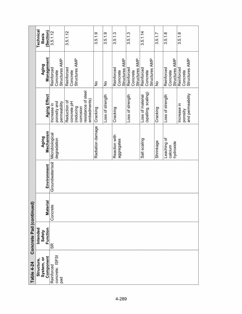
4-289
Tabl
e 4-
24
Con
cret
e Pa
d (con
tinued)
Stru
ctur
e,
Syst
em, o
r C
ompo
nent
Inte
nded
Sa
fety
Fu
nctio
n M
ater
ial
Envi
ronm
ent
Agin
g M
echa
nism
Ag
ing
Effe
ct
Agin
g M
anag
emen
t
Tech
nica
l B
asis
(S
ectio
n)
Rei
nfor
ced
conc
rete
: IS
FSI
pad
SR
Con
cret
e G
roun
dwat
er/s
oil
Mic
robi
olog
ical
de
grad
atio
n In
crea
se in
po
rosi
ty a
nd
perm
eabi
lity
Rei
nfor
ced
Con
cret
e St
ruct
ures
AM
P
3.5.
1.12
Red
uctio
n of
co
ncre
te p
H
(redu
cing
co
rrosi
on
resi
stan
ce o
f ste
el
embe
dmen
ts)
Rei
nfor
ced
Con
cret
e St
ruct
ures
AM
P
3.5.
1.12
Rad
iatio
n da
mag
e C
rack
ing
No
3.5.
1.9
Loss
of s
treng
th
No
3.5.
1.9
Rea
ctio
n w
ith
aggr
egat
es
Cra
ckin
g R
einf
orce
d C
oncr
ete
Stru
ctur
es A
MP
3.5.
1.3
Loss
of s
treng
th
Rei
nfor
ced
Con
cret
e St
ruct
ures
AM
P
3.5.
1.3
Salt
scal
ing
Loss
of m
ater
ial
(spa
lling,
sca
ling)
R
einf
orce
d C
oncr
ete
Stru
ctur
es A
MP
3.5.
1.14
Shrin
kage
C
rack
ing
No
3.5.
1.7
Leac
hing
of
calc
ium
hy
drox
ide
Loss
of s
treng
th
Rei
nfor
ced
Con
cret
e St
ruct
ures
AM
P
3.5.
1.8
Incr
ease
in
poro
sity
an
d pe
rmea
bilit
y
Rei
nfor
ced
Con
cret
e St
ruct
ures
AM
P
3.5.
1.8
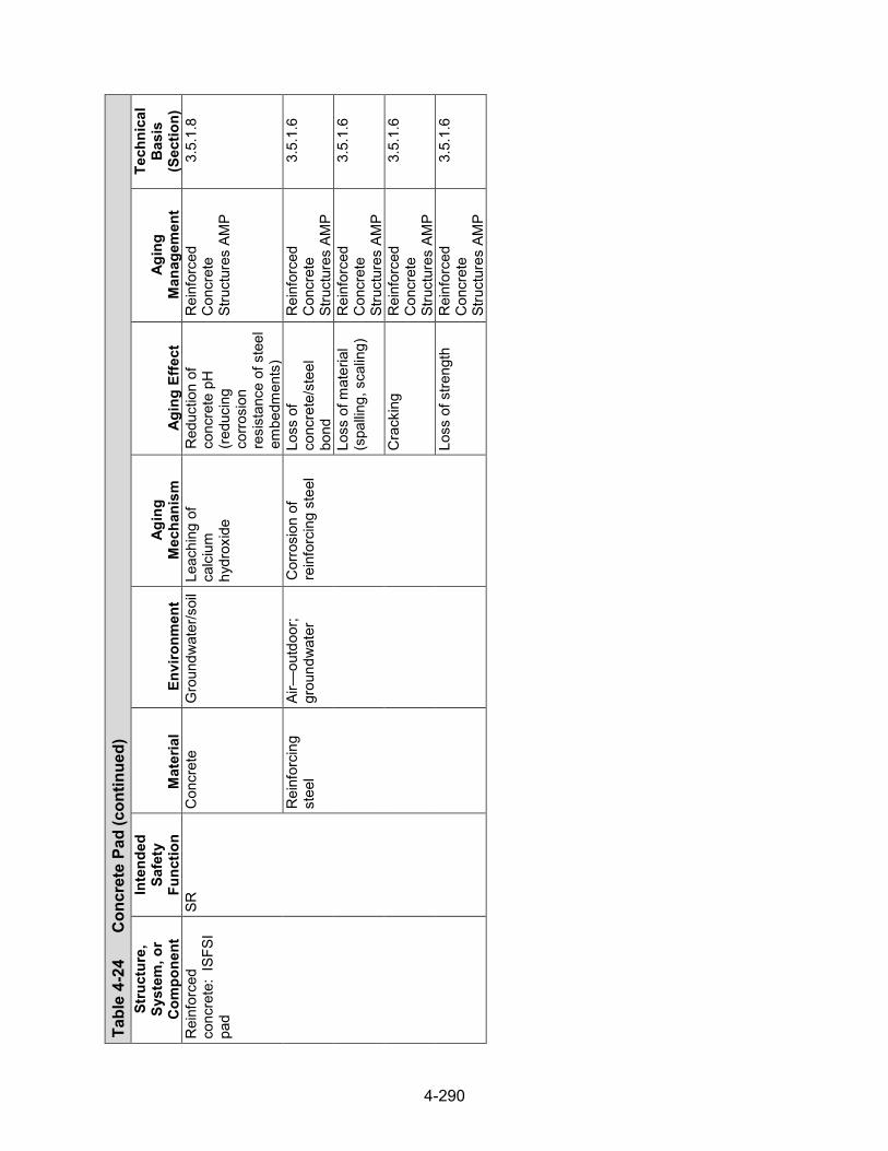
4-290
Tabl
e 4-
24
Con
cret
e Pa
d (con
tinued)
Stru
ctur
e,
Syst
em, o
r C
ompo
nent
Inte
nded
Sa
fety
Fu
nctio
n M
ater
ial
Envi
ronm
ent
Agin
g M
echa
nism
Ag
ing
Effe
ct
Agin
g M
anag
emen
t
Tech
nica
l B
asis
(S
ectio
n)
Rei
nfor
ced
conc
rete
: IS
FSI
pad
SR
Con
cret
e G
roun
dwat
er/s
oil
Leac
hing
of
calc
ium
hy
drox
ide
Red
uctio
n of
co
ncre
te p
H
(redu
cing
co
rrosi
on
resi
stan
ce o
f ste
el
embe
dmen
ts)
Rei
nfor
ced
Con
cret
e St
ruct
ures
AM
P
3.5.
1.8
Rei
nfor
cing
st
eel
Air—
outd
oor;
grou
ndw
ater
C
orro
sion
of
rein
forc
ing
stee
l Lo
ss o
f co
ncre
te/s
teel
bo
nd
Rei
nfor
ced
Con
cret
e St
ruct
ures
AM
P
3.5.
1.6
Loss
of m
ater
ial
(spa
lling,
sca
ling)
R
einf
orce
d C
oncr
ete
Stru
ctur
es A
MP
3.5.
1.6
Cra
ckin
g R
einf
orce
d C
oncr
ete
Stru
ctur
es A
MP
3.5.
1.6
Loss
of s
treng
th
Rei
nfor
ced
Con
cret
e St
ruct
ures
AM
P
3.5.
1.6
4-291
4.8 Spent Fuel Assemblies
4.8.1 Spent Fuel Assembly Description
Dry storage systems are designed to store a wide range of SNF assemblies in a dried and inerted (helium) atmosphere. This section provides a general description of the PWR and BWR spent fuel assembly components.
4.8.2 Fuel Cladding and Assembly Hardware
Pressurized-water reactor fuel assemblies
While there are a number of fuel assembly design variants for PWRs, the assemblies mainly consist of the top nozzle, fuel rods, spacer grids, guide thimble tubes, and bottom nozzle. The various components of a typical 17 × 17 PWR fuel assembly are shown in Figure 4-30. Each fuel rod consists of enriched uranium dioxide pellets inserted into a cladding tube. The cladding tube is then capped with Zircaloy end plugs and seal welded at both ends to confine the fuel pellets and fission gases. The fuel cladding, fabricated from zirconium-based alloys, including Zircaloy-4, ZIRLO™, and M5®, provides a confinement barrier.
The structural support of the fuel assembly is provided by the top and bottom nozzles, the spacer grid assemblies, and the guide thimbles. Guide tubes, fabricated from zirconium-based alloys, are the main structural members of the fuel assembly. They also provide channels for insertion of a rod cluster control assembly, a neutron source assembly, a burnable poison assembly, or a thimble plug assembly, depending on the position of the particular fuel assembly in the core. The bottom of the guide tube is fitted with an end plug with a flow port, which is then fastened into the bottom nozzle. Both the top and bottom nozzles are made of either stainless steel or Inconel, which also serve as structural members of the fuel assembly. The spacer grid assemblies provide support for the fuel cladding tubes. Two types of grid assemblies, fabricated from zirconium-based alloys or Inconel, are used in the fuel assemblies.
Boiling-water reactor fuel assemblies
Similar to the case for PWRs, there are a number of fuel assembly design variants for BWRs. The main components include the (i) upper tie plate, (ii) fuel rods, (iii) spacer grids, (iv) water rods, (v) channel, and (vi) lower tie plate, as shown in Figure 4-31 for the GE14 BWR fuel assembly in a 10 × 10 fuel rod array. Two types of fuel rods are used in the GE14 fuel bundles: standard rods and tie rods. The fuel rods are hollow cladding tubes fabricated from Zircaloy-2 filled with uranium dioxide pellets. Zircaloy end plugs are welded into place to seal the ends of the fuel rods. The tie rods differ from the standard fuel rods in that the end plugs are threaded into the tie plates. They hold the fuel bundle together and support the weight of the fuel bundle during fuel handling operations.
In the BWR fuel assembly, fuel bundles are enclosed in open-ended, square tubes (also called channels). The channels made of zirconium-based alloys are ducts for coolant flow that prevent lateral flow of coolant among the fuel assemblies operating at different power levels. Both the upper and lower tie plates are fabricated from stainless steel. The upper tie plate provides alignment and support for the fuel rods at the top of the fuel bundle, while the lower tie plate positions the fuel rods laterally. The spacer grids, fabricated from zirconium-based alloys or Inconel, hold the fuel rods in the proper location so that optimum fuel spacing is maintained.

4-292
Figure 4-30 Typical Pressurized-water Reactor Fuel Assembly (NRC, 2002)
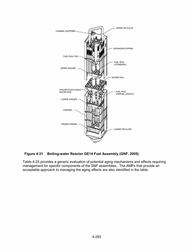
4-293
Figure 4-31 Boiling-water Reactor GE14 Fuel Assembly (GNF, 2005)
Table 4-25 provides a generic evaluation of potential aging mechanisms and effects requiring management for specific components of the SNF assemblies. The AMPs that provide an acceptable approach to managing the aging effects are also identified in the table.

4-294
Tab
le 4
-25
Spen
t Fue
l Ass
embl
ies
Stru
ctur
e,
Syst
em, o
r C
ompo
nent
Inte
nded
Sa
fety
Fu
nctio
n M
ater
ial
Envi
ronm
ent
Agin
g M
echa
nism
Ag
ing
Effe
ct
Agin
g M
anag
emen
t
Tech
nica
l B
asis
(S
ectio
n)
Fuel
rod
clad
ding
C
O, C
R,
RE,
SH
, SR
, TH
*
Zirc
oniu
m-b
ased
al
loy
(Zirc
aloy
-2,
Zirc
aloy
-4,
ZIR
LOTM
, or M
5®)
Hel
ium
O
xida
tion
Loss
of l
oad
bear
ing
capa
city
No
3.6.
1.6
Pitti
ng c
orro
sion
Lo
ss o
f m
ater
ial
No
3.6.
1.7
Gal
vani
c co
rrosi
on
Loss
of
mat
eria
l N
o 3.
6.1.
8
Stre
ss c
orro
sion
cr
acki
ng
Cra
ckin
g N
o 3.
6.1.
9
Hyd
ride
reor
ient
atio
n Lo
ss o
f duc
tility
H
igh-
Burn
up F
uel M
onito
ring
and
Asse
ssm
ent A
MP
or a
su
ppor
ting
anal
ysis
†
3.6.
1.1
Del
ayed
hyd
ride
crac
king
C
rack
ing
No
3.6.
1.2
Ther
mal
Cre
ep
Cha
nges
in
dim
ensi
ons
Hig
h-Bu
rnup
Fue
l Mon
itorin
g an
d As
sess
men
t AM
P or
a
supp
ortin
g an
alys
is†
3.6.
1.3
Low
-tem
pera
ture
cr
eep
Cha
nges
in
dim
ensi
ons
No
3.6.
1.4
Rad
iatio
n em
britt
lem
ent
Loss
of
stre
ngth
N
o 3.
6.1.
10
Fatig
ue
Cra
ckin
g N
o 3.
6.1.
11
Mec
hani
cal
over
load
C
rack
ing
No
3.6.
1.5
† H
ydrid
e re
orie
ntat
ion
and
ther
mal
cre
ep a
re n
ot e
xpec
ted
to re
sult
in c
ladd
ing
failu
res
or re
conf
igur
atio
n of
the
fuel
if th
e de
sign
bas
es a
re c
onsi
sten
t with
the
acce
ptan
ce c
riter
ia in
ISG
-11,
Rev
isio
n 3
(NR
C, 2
003)
. H
owev
er, c
onfir
mat
ory
evid
ence
for d
ry s
tora
ge p
erio
ds b
eyon
d 20
yea
rs is
exp
ecte
d to
be
gath
ered
and
ev
alua
ted
per t
he H
igh-
Burn
up F
uel M
onito
ring
and
Asse
ssm
ent A
MP.
Alte
rnat
ivel
y, a
n ap
plic
ant m
ay p
erfo
rm d
efen
se-in
-dep
th a
naly
ses,
ass
umin
g cr
edib
le
reco
nfig
urat
ion
(See
Sec
tions
3.6
.1.1
and
3.6
.1.3
).
*Saf
ety
Func
tions
: C
onfin
emen
t (C
O),
Subc
ritic
ality
(CR
), R
etrie
vabi
lity
(RE)
, Rad
iatio
n Sh
ield
ing
(SH
), St
ruct
ural
Inte
grity
(SR
), Th
erm
al/H
eat R
emov
al (T
H)

4-295
Tab
le 4
-25
Spen
t Fue
l Ass
embl
ies (con
tinued)
Stru
ctur
e,
Syst
em, o
r C
ompo
nent
Inte
nded
Sa
fety
Fu
nctio
n M
ater
ial
Envi
ronm
ent
Agin
g M
echa
nism
Ag
ing
Effe
ct
Agin
g M
anag
emen
t
Tech
nica
l B
asis
(S
ectio
n)
Gui
de tu
bes
(PW
R) o
r w
ater
ch
anne
ls
(BW
R)
CR
, RE,
Zi
rcon
ium
-bas
ed
allo
y H
eliu
m
Cre
ep
Cha
nges
in
dim
ensi
ons
No
3.6.
2.1
Hyd
ridin
g C
hang
es in
di
men
sion
s N
o 3.
6.2.
2
Rad
iatio
n em
britt
lem
ent
Loss
of
stre
ngth
N
o 3.
6.1.
10
Fatig
ue
Cra
ckin
g N
o 3.
6.1.
11
Spac
er g
rids
CR
, RE,
SR
, TH
Zi
rcon
ium
-bas
ed
allo
y H
eliu
m
Cre
ep
Cha
nges
in
dim
ensi
ons
No
3.6.
2.1
Hel
ium
H
ydrid
ing
Cha
nges
in
dim
ensi
ons
No
3.6.
2.2
Rad
iatio
n em
britt
lem
ent
Loss
of
stre
ngth
N
o 3.
6.1.
10
Fatig
ue
Cra
ckin
g N
o 3.
6.1.
11
Inco
nel
Hel
ium
C
reep
C
hang
e in
di
men
sion
s N
o 3.
6.2.
1
Gen
eral
cor
rosi
on
Loss
of
mat
eria
l N
o 3.
6.2.
3
Stre
ss c
orro
sion
cr
acki
ng
Cra
ckin
g N
o 3.
6.2.
4
Rad
iatio
n em
britt
lem
ent
Loss
of
stre
ngth
N
o 3.
6.1.
10
Fatig
ue
Cra
ckin
g N
o 3.
6.1.
11
Low
er a
nd
uppe
r end
fit
tings
CR
, RE,
SR
St
ainl
ess
stee
l H
eliu
m
Cre
ep
Cha
nge
in
dim
ensi
ons
No
3.6.
2.1
Gen
eral
cor
rosi
on
Loss
of
mat
eria
l N
o 3.
6.2.
3
Stre
ss c
orro
sion
cr
acki
ng
Cra
ckin
g N
o 3.
6.2.
4
Rad
iatio
n em
britt
lem
ent
Loss
of
stre
ngth
N
o 3.
6.1.
10
SR
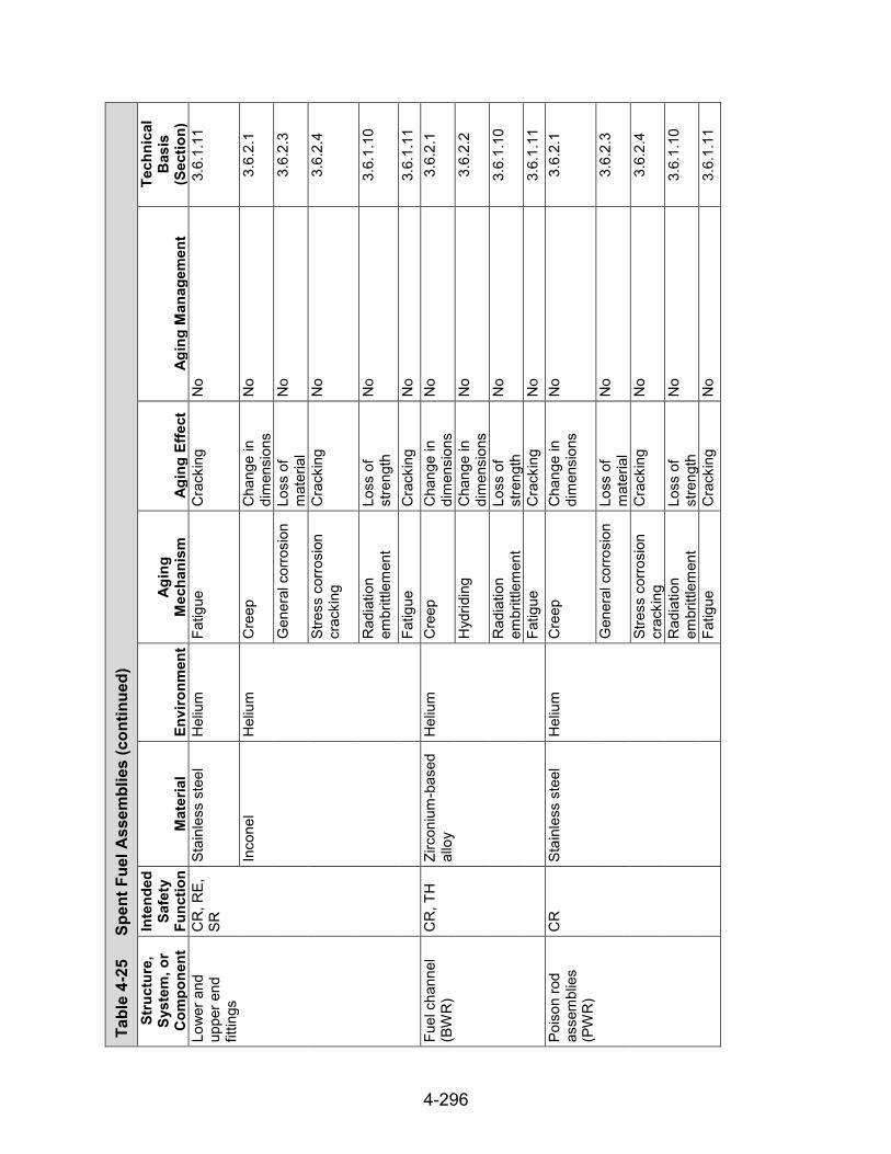
4-296
Tab
le 4
-25
Spen
t Fue
l Ass
embl
ies (con
tinued)
Stru
ctur
e,
Syst
em, o
r C
ompo
nent
Inte
nded
Sa
fety
Fu
nctio
n M
ater
ial
Envi
ronm
ent
Agin
g M
echa
nism
Ag
ing
Effe
ct
Agin
g M
anag
emen
t
Tech
nica
l B
asis
(S
ectio
n)
Low
er a
nd
uppe
r end
fit
tings
CR
, RE,
SR
St
ainl
ess
stee
l H
eliu
m
Fatig
ue
Cra
ckin
g N
o 3.
6.1.
11
Inco
nel
Hel
ium
C
reep
C
hang
e in
di
men
sion
s N
o 3.
6.2.
1
Gen
eral
cor
rosi
on
Loss
of
mat
eria
l N
o 3.
6.2.
3
Stre
ss c
orro
sion
cr
acki
ng
Cra
ckin
g N
o 3.
6.2.
4
Rad
iatio
n em
britt
lem
ent
Loss
of
stre
ngth
N
o 3.
6.1.
10
Fatig
ue
Cra
ckin
g N
o 3.
6.1.
11
Fuel
cha
nnel
(B
WR
) C
R, T
H
Zirc
oniu
m-b
ased
al
loy
Hel
ium
C
reep
C
hang
e in
di
men
sion
s N
o 3.
6.2.
1
Hyd
ridin
g C
hang
e in
di
men
sion
s N
o 3.
6.2.
2
Rad
iatio
n em
britt
lem
ent
Loss
of
stre
ngth
N
o 3.
6.1.
10
Fatig
ue
Cra
ckin
g N
o 3.
6.1.
11
Pois
on ro
d as
sem
blie
s (P
WR
)
CR
St
ainl
ess
stee
l H
eliu
m
Cre
ep
Cha
nge
in
dim
ensi
ons
No
3.6.
2.1
Gen
eral
cor
rosi
on
Loss
of
mat
eria
l N
o 3.
6.2.
3
Stre
ss c
orro
sion
cr
acki
ng
Cra
ckin
g N
o 3.
6.2.
4
Rad
iatio
n em
britt
lem
ent
Loss
of
stre
ngth
N
o 3.
6.1.
10
Fatig
ue
Cra
ckin
g N
o 3.
6.1.
11

4-297
4.9 References
EPRI. “Industry Spent Fuel Storage Handbook.” Report 1021048. Palo Alto, California: Electric Power Research Institute. July 2010.
FuelSoutions. “FuelSoutions W21 Canister Storage Final Safety Analysis Report.” Docket No. 72-1026, Revision 5. ADAMS Accession No. ML071510213. April 2007a.
_____. “FuelSoutions W74 Canister Storage Final Safety Analysis Report.” Docket No. 72-1026, Revision 6. ADAMS Accession No. ML071510213. April 2007b.
_____. “FuelSoutions Storage System Final Safety Analysis Report.” Docket No. 72-1026. Revision 4. ADAMS Accession No. ML071510207. April 2007c.
GNF. “GE14 Fuel Assembly Mechanical Design Report.” NEDC–33236. Wilmington, North Carolina: Global Nuclear Fuel. ADAMS Accession No. ML053540338. 2005.
Holtec International. “Final Safety Analysis Report for the HI‐STORM 100 Cask System.” Non-Proprietary. Docket No. 72-1014. HI-20024444. Rev. 11. ADAMS Accession No. ML13246A042. August 1, 2013.
_____. “Final Safety Analysis Report for the Holtec International Storage, Transport, and Repository Cask System (HI-STAR 100 Cask System).” HI-2012610, Rev. 0, Vol I of II. Holtec International. ADAMS Accession No. ML072410190. March 2001.
NAC International. “MAGNASTOR, Final Safety Analysis Report,” Non-Proprietary Version. Docket No. 72-1025. Rev. 15A. ADAMS Accession No. ML15225A469. July 2015.
_____. Retrieved from http://www.nacintl.com/magnastor. 2014.
_____. “Final Safety Analysis Report for the UMS Universal Storage System.” Docket No. 72-1015, Rev 3. ADAMS Accession No. ML051290397. March 2004.
_____. “Final Safety Analysis Report for the NAC Multi-Purpose Canister System.” Non-Proprietary. Docket No. 72-1025. Rev. 0. ADAMS Accession No. ML073551117. April 2000.
NRC. “Safety Evaluation Report for License Renewal: Calvert Cliffs Nuclear Power Plant Independent Spent Fuel Storage Installation.” ADAMS Accession No. ML14274A038. Washington, DC: U.S. Nuclear Regulatory Commission. October, 2014.
_____. Interim Staff Guidance 11, “Cladding Considerations for the Transportation and Storage of Spent Fuel.” Rev. 3. ADAMS Accession No. ML033230335. Washington, DC: U.S. Nuclear Regulatory Commission. 2003.
_____. “Westinghouse Systems Course R–304P.” ADAMS Accession No. ML023030412. Washington, DC: U.S. Nuclear Regulatory Commission. 2002.
_____. “Safety Evaluation Report for the TN‐32 Dry Storage Cask.” Washington, DC: U.S. Nuclear Regulatory Commission. November 1996.

4-298
Pacific Nuclear Fuel Services, Inc. “Topical Report for the NUTECH Horizontal Modular Storage System for Irradiated Nuclear Fuel NUHOMS‐24P.” NUH–002.0103, Rev. 2A, Volume I. San Jose, California: Pacific Nuclear Fuel Services, Inc. ADAM Accession No. ML110730769. April 1991.
Transnuclear Inc. “Certificate of Compliance Renewal Application for the Standardized NUHOMS System.” Rev. 0. ADAMS Accession No. ML14309A343. Columbia, Maryland: Transnuclear, Inc. November 4, 2014.
_____. “Updated Final Safety Analysis Report for the Standardized NUHOMS Modular Storage System for Irradiated Nuclear Fuel.” NUH–003.0103, Rev. 10, Volume 1 and 3 (Appendix M). Columbia, Maryland: Transnuclear, Inc. February 2008.
_____. “Final Safety Analysis Report for the TN‐68 Dry Storage Cask.” Amendment 1, Rev. 0. Hawthorne, New York: Transnuclear, Inc. January 2005.
_____. “Final Safety Analysis Report for the Standardized NUHOMS Modular Storage System for Irradiated Nuclear Fuel.” NUH–003.0103, Rev. 8, Volume 1 and 3 (Appendix M). ADAMS Accession Nos. ML042110421 and ML051040570. Hawthorne, New York: Transnuclear, Inc. June 2004.
_____. “Final Safety Analysis Report for the Standardized Advanced NUHOMS Modular Storage System for Irradiated Nuclear Fuel.” ANUH–01.0150, Rev. 0, Volume 1. ADAMS Accession No. ML050410252 (Cover through Section 3.6.3). Fremont, CA: Transnuclear, Inc. February 2003.
5-1
5 TIME-LIMITED AGING ANALYSES
5.1 Introduction
Renewal applicants are required to reevaluate all aging-related calculations or analyses involving time-limited assumptions that were contained in the original design bases (e.g., fatigue analyses, corrosion wastage calculations). These evaluations are designated as time-limited aging analyses (TLAAs), and Title 10 of the Code of Federal Regulations (10 CFR) 72.3, “Definitions,” defines them as those calculations and analyses meeting all six of the following criteria:
(1) Involve SSCs important to safety within the scope of the specific-license renewal, asdelineated in Subpart F of 10 CFR Part 72, or within the scope of the spent fuel storageCoC renewal, as delineated in Subpart L of 10 CFR Part 72, respectively.
(2) Consider the effects of aging.
(3) Involve time-limited assumptions defined by the current operating term.
(4) Were determined to be relevant by the specific licensee or certificate holder in making asafety determination.
(5) Involve conclusions or provide the basis of conclusions related to the capability of SSCsto perform their intended safety functions.
(6) Are contained or incorporated by reference in the design bases.
5.2 Review
NUREG-1927, Revision 1, “Standard Review Plan for Renewal of Specific Licenses and Certificates of Compliance for Dry Storage of Spent Nuclear Fuel” (NRC, 2016), provides detailed staff guidance for the review of TLAAs.
The NRC reviewer should use the final safety analysis report (FSAR) and other documents that detail the design bases and confirm that the renewal applicant did not omit any TLAAs submitted as part of the approved design bases. In some cases, the original analyses may have been performed as part of a code design but not explicitly discussed in the FSAR. Thus, the reviewer must identify and review any design codes and standards associated with a storage system to ensure that any required analyses are captured in the applicant’s TLAAs. Table 5-1 identifies some examples of fatigue analyses that are incorporated into the design codes for the dry storage system designs this report evaluates.
The reviewer also should ensure that the applicant addresses any design bases calculations that use materials properties that may be time dependent. For example, aluminum alloys used in some fuel baskets can lose strength over time at elevated temperatures (see Section 3.2.3.7), and this may affect the performance of the fuel basket in a cask tipover analysis. If the original design bases calculations did not adequately account for such material property changes through the period of extended operation, the analyses should be updated.

5-2
The reviewer should ensure that the applicant has appropriately dispositioned an identified TLAA by using one of the following methods:
• Demonstrate that the existing analysis remains valid for the period of extendedoperation, has already considered the requested period of extended operation, andconcludes that the structure, system, or component (SSC) will continue to perform itsintended function through the end of the requested period of extended operation.
• Revise or update the existing analysis to demonstrate that it has been projected to theend of the requested period of extended operation and concludes that the SSC willcontinue to perform its intended function through the end of the requested period ofextended operation.
• Manage the effects of aging on the SSC for the requested period of extended operationthrough an aging management program.
Table 5-1 Examples of Fatigue Analyses Contained within Storage System Design Bases
System SSC Fatigue Evaluation Criteria
(ASME Code Section III, Division 1 (ASME, 2007))
Standardized and Advanced NUHOMS®*
DSC Confinement NB-3222.4
Transfer Cask NC-3219
HI-STORM 100, HI-STAR 100
MPC Confinement NB-3222.4
Fuel Basket NG-3222.4
HI-STAR Overpack Helium Boundary
NB-3222.4
TN-32 & 68 Confinement Boundary NB-3222.4
Fuel Basket NB-3222.4
NAC-UMS, MPC, and MAGNASTOR
Canister Confinement NB-3222.4
Fuel Basket NG-3222.4
FuelSolutionsTM
Canister Confinement NB-3222.4
Fuel Basket NG-3222.4
Transfer Cask NC-3219
5.3 References
NRC. NUREG–1927, “Standard Review Plan for Renewal of Specific Licenses and Certificates of Compliance for Dry Storage of Spent Nuclear Fuel.” Revision 1. Washington, DC: U.S. Nuclear Regulatory Commission. ADAMS Accession No. ML16179A148. 2016.

5-3
ASME. Boiler and Pressure Vessel Code, Section III, Division 1, “Rules for Construction of Nuclear Facility Components,” Division 1, Subsection NB, “Class 1 Components,” Subsection NC, “Class 2 Components,” and Subsection NG, “Core Support Structures”; American Society of Mechanical Engineers. 2007.


6-1
6 EXAMPLE AGING MANAGEMENT PROGRAMS
6.1 Introduction
The example aging management programs (AMPs) presented in this chapter and listed in Table 6-1 below describe a generically acceptable approach to managing the credible aging effects that were identified in the technical bases discussions in Chapter 3 and the aging management review tables in Chapter 4. AMPs monitor and control the degradation of structures, systems, and components (SSCs) within the scope of renewal, so that aging effects will not result in a loss of intended functions during the period of extended operation. An AMP includes all activities that are credited for managing aging mechanisms or effects for specific SSCs. An effective AMP prevents, mitigates, or detects the aging effects and provides for the prediction of the extent of the effects of aging and timely corrective actions before there is a loss of intended function.
If an applicant credits these generic AMPs in the renewal application, the NRC staff should ensure that the applicant demonstrates that the design features, environmental conditions, and operating experience for the subject independent spent fuel storage installation (ISFSI) or dry storage system (DSS) are bounded by those evaluated in this report. Otherwise, the staff should ensure that the applicant augments the AMPs as appropriate to address the impact of unique design or operating parameters.
Table 6-1 Example Aging Management Programs
Section AMP
6.5 Localized Corrosion and Stress Corrosion Cracking of Welded Stainless Steel Dry Storage Canisters
6.6 Reinforced Concrete Structures
6.7 Monitoring of Metallic Surfaces
6.8 Bolted Cask Seal Leakage Monitoring
6.9 Transfer Casks
6.10 High-Burnup Fuel Monitoring and Assessment
6.2 Alternative Approaches
An applicant may propose alternative approaches to manage the effects of aging. In its review of alternative AMPs, the staff should use the guidance in NUREG–1927, Revision 1, “Standard Review Plan for Renewal of Specific Licenses and Certificates of Compliance for Dry Storage of Spent Nuclear Fuel” (NRC, 2016). As described in greater detail in NUREG–1927, an AMP generally should contain the following 10 elements:
(1) Scope of program: the specific SSCs and subcomponents covered by the AMP and theintended functions to be maintained, in addition to stating the specific materials,environments, and aging mechanisms and effects to be managed
(2) Preventive actions: actions to prevent aging or mitigate the rates of aging for SSCs

6-2
(3) Parameters monitored or inspected: the specific parameters that will be monitored orinspected and a description of how those parameters will be capable of identifyingdegradation before a loss of intended function
(4) Detection of aging effects: the inspection and monitoring details, including method ortechnique, frequency, sample size, data collection, and timing of inspections
(5) Monitoring and trending: how data will be evaluated and trended to ensure timelycorrective actions
(6) Acceptance criteria: the criteria against which the need for corrective action willbe evaluated
(7) Corrective actions: The measures to be taken when the acceptance criteria are not met,including root cause determination and prevention of recurrence, as appropriate
(8) Confirmation process: processes in place to verify that preventive actions are adequateand that appropriate corrective actions have been completed and are effective
(9) Administrative controls: processes in place that provide a formal review and approvalprocess for activities related to the AMP (e.g., inspector requirements, instrumentcalibration)
(10) Operating experience: a review of operational experience that supports thedetermination that the AMP is capable of maintaining SSC functions in the period ofextended operation
The reviewer should examine the applicant’s proposed 10 elements to verify that the program is capable of managing the specific aging mechanisms and effects identified by the aging management review (AMR). The reviewer should recognize that an applicant may develop AMPs following a different format or style. For such reviews, the NRC staff should ensure that sufficient detail (i.e., supporting technical bases) is provided in the alternative format in comparison with the 10 AMP elements of this guidance.
An applicant may credit existing site maintenance and inspection activities to manage the effects of aging. In such cases, the reviewer should ensure that the design bases documentation describes those activities with sufficient detail ensure that the 10 AMP elements are fully addressed.
6.3 Learning Aging Management
As described in NUREG–1927, the reviewer should ensure that the application includes provisions to conduct periodic future reviews of operating experience to confirm the effectiveness of the AMPs or identify a need to enhance or modify an AMP. The reviewer also should verify that the applicant: (1) references a specific system to be used to obtain, aggregate, and enter site-specific, design-specific, and industrywide operating experience, and (2) discusses how it intends to provide timely reporting of operating experience to this system.
If an applicant follows this approach, the reviewer should ensure that the description of the periodic assessments includes specific performance criteria (e.g., program-specific performance indicators for each of the 10 AMP elements) and proposed actions based on the assessment
6-3
findings. The reviewer should also ensure that the timing of the assessments appropriately considers the rate of aging degradation and the anticipated availability of data from industry initiatives.
Nuclear Energy Institute (NEI) 14-03, “Format, Content, and Implementation Guidance for Dry Cask Storage Operations-Based Aging Management,” Revision 2, provides a proposed framework for learning AMPs through the use of “tollgates” (NEI, 2016). NEI 14-03 defines “tollgates” as periodic points within the period of extended operation when licensees would be required to evaluate aggregate feedback and perform and document a safety assessment that confirms the safe storage of spent fuel. At the time of publication of this report, the NRC staff was continuing its review of NEI 14-03, Revision 2, for proposed NRC endorsement. However, until a time when NEI 14-03 may be endorsed by the NRC, Section 3.6.1.10 of NUREG–1927, Revision 1, provides guidance to reviewers on ensuring AMP effectiveness.
6.4 References
NEI. “Format, Content and Implementation Guidance for Dry Cask Storage Operations-Based Aging Management for Dry Cask Storage.” NEI 14-03, Rev. 2. ADAMS Accession No. ML16356A210. Nuclear Energy Institute. 2016.
NRC. NUREG–1927, “Standard Review Plan for Renewal of Specific Licenses and Certificates of Compliance for Dry Storage of Spent Nuclear Fuel.” Revision 1. Washington, DC: U.S. Nuclear Regulatory Commission. 2016.

6-4
6.5 Localized Corrosion and Stress Corrosion Cracking of Welded Stainless Steel Dry Storage Canisters
Welded stainless steel canisters are used in the majority of the DSSs in the United States for spent nuclear fuel (SNF) from commercial power reactors at both specific-licensed and general-licensed ISFSIs. The canisters are the primary confinement boundary during storage. While there are no known operational occurrences of aging or localized corrosion of welded stainless steel canisters, operational experience with nuclear reactors that were located close to an open ocean or bay has shown that pitting corrosion, crevice corrosion, and chloride-induced stress corrosion cracking (CISCC) can occur in welded stainless steel components as a result of atmospheric deposition and deliquescence of chloride-containing salts. Laboratory and natural exposure tests suggest that CISCC can occur with sufficient surface chloride concentrations and that, with those concentrations of chloride, crack propagation rates can be of engineering significance for welded stainless steel canisters during the period of extended operation.
Based on reactor operating experience, as well as laboratory and field testing, localized corrosion and CISCC are potential aging mechanisms for welded stainless steel canisters. Environments where chloride-containing salts may be deposited on welded stainless steel canisters include coastal locations near salt water and locations that are close to cooling towers or roads that are salted. The Electric Power Research Institute (EPRI) has developed aging management guidance to address the potential for CISCC of welded stainless steel canisters (Fuhr et al., 2017). In addition, the American Society of Mechanical Engineers Boiler and Pressure Vessel Code (ASME Code), Section XI, has formed a task group to develop a code case to establish the requirements for inservice inspection and acceptance criteria for DSS canisters (Code Case N-860) that may follow the recommendations of the EPRI aging management guidance. However, the development of a consensus-based code case for inservice inspection of DSS canisters may take several years to complete. To address potential aging effects as a result of localized corrosion cracking and stress corrosion cracking (SCC) in the absence of an acceptable code case, the NRC has provided an example AMP for welded stainless steel canisters used in DSSs that relies on guidance from existing consensus codes for inservice inspection of nuclear power plant components. Elements of an NRC staff-developed example AMP are described in Table 6-2. Alternatives to the example AMP in Table 6-2 may be proposed in renewal applications.
The example AMP is based on the inspection of canisters within their overpacks. Inspection delivery systems have been demonstrated in actual inspections of dry storage system canisters. To date, the examination of canisters in service has been limited to visual examination methods. Although visual examination can identify visual indications of aging, surface or volumetric examination methods are needed to characterize some aging mechanisms such as pitting or CISCC. Tools are being developed to deliver surface and volumetric examination methods (Chu and Renshaw, 2016; Renshaw, 2017a). In addition, storage system manufacturers have developed systems to examine canisters during transfer operations that may use multiple nondestructive examination (NDE) methods (Renshaw, 2017b).
Although testing and development of surface and volumetric NDE delivery systems for the inspection of dry storage system canisters are expected to make advances in the near future, the NRC staff recognizes that advanced systems may still have access limitations. If NDE methods cannot be used to characterize aging effects, the licensee should propose alternative assessment methods, analyses, or mitigation methods to ensure that the important-to-safety functions of the storage system are maintained throughout the period of extended operation.

6-5
Table 6-2 Example Aging Management Program for Localized Corrosion and Stress Corrosion Cracking of Welded Stainless Steel Dry Storage Canisters
Element Description 1. Scope of
ProgramExamination of welded stainless steel dry storage canister confinement boundary external surfaces for atmospheric deposits, localized corrosion, and SCC.
Examinations should focus on accessible canister welds, weld heat-affected-zone areas, and known areas of the canister to which temporary supports or attachments were attached by welding and subsequently removed (based on available fabrication records) with the following attributes:
• locations where a crevice is formed on the canister surface• horizontal (±30-degree) surfaces where deposits may
accumulate at a faster rate compared to vertical surfaces• canister surfaces that are cold relative to the average surface
temperature• canister surfaces with higher amounts of atmospheric deposits
2. PreventiveActions
None; AMP is for condition monitoring. However, DSS canister designs may include preventive actions such as fabrication procedures and surface modification methods to impart compressive residual stresses on the canister welds and weld heat-affected zones to reduce the potential for SCC. Preventive actions may also include the use of DSS canister confinement boundary materials that are resistant to localized corrosion and SCC. For such cases the preventive actions described should be supported with an analysis and data demonstrating the preventive actions are effective.
3. ParametersMonitored/Inspected
Parameters monitored or inspected should include:
• visual evidence of discontinuities and imperfections such aslocalized corrosion, including pitting corrosion, crevice corrosionand SCC of the canister welds and weld heat-affected zones
• size and location of localized corrosion and SCC• appearance and location of deposits on the canister surfaces
4. Detection ofAging Effects
Visually examine deposits on the canister surfaces and identify corrosion products that may be indicators of localized corrosion and SCC in the welds and weld heat-affected zones. Visual examination instrumentation with demonstrated sizing and depth measurement capability may be useful in the determination of the size and depth of pits open to the surface. Visual examination may also detect the presence of cracks originating from pits. However, the ability to detect cracks on clean metal surfaces using visual examination methods is dependent on several factors and can be difficult for tight crack opening displacements (Cumblidge et al., 2004, 2007).

6-6
Table 6-2 Example Aging Management Program for Localized Corrosion and Stress Corrosion Cracking of Welded Stainless Steel Dry Storage Canisters (continued)
Element Description The presence of significant corrosion product accumulation may also interfere with the identification of SCC using visual examination methods.
Volumetric examination is necessary to characterize SCC. Volumetric examination of pits and areas immediately adjacent to pits is necessary when pits are located within 25 mm [1 in] of a through thickness weld or within 25 mm [1 in] of an area where an temporary attachment was known to be located.
Visual Examination
Pitting and crevice corrosion that is open to the surface can potentially be detected by visual testing (ASME Code Section V, Table A-110). Because of the high neutron and gamma radiation fields near the surface of the stainless steel dry storage canisters, direct visual examination may not be possible. Visual examination procedures should follow ASME Code Section V, Article 9 and ASME Code Section XI, Article IWA-2200 for VT-1 and VT-3 examinations (ASME, 2007) and BWRVIP-03 (Selby, 2005) for enhanced visual (EVT-1) examinations.
Additional assessment is necessary for suspected areas of localized corrosion and SCC. In these cases, the severity of degradation should be assessed, including the dimensions of the affected area and the depth of penetration with respect to the thickness of the canister. For accessible areas, remote visual examination meeting the requirements for VT-1 Examination (ASME Code Section XI, IWA-2211) may be used to determine the type of degradation present (e.g., pitting corrosion or SCC) and the location of degradation.
Volumetric Examination
Examinations to characterize the extent and severity of localized corrosion and SCC should be conducted using surface or volumetric examination methods consistent with the requirements of ASME Code Section XI, IWB-2500, for category B-J components (ASME, 2007).
If volumetric examination methods are not available to assess visual indications of aging, alternative assessment methods, analyses, and mitigation methods should be evaluated to ensure that the important-to-safety functions of the welded stainless steel canister are maintained throughout the period of extended operation.

6-7
Table 6-2 Example Aging Management Program for Localized Corrosion and Stress Corrosion Cracking of Welded Stainless Steel Dry Storage Canisters (continued)
Element Description Sample Size
For sites conducting a canister examination, there should be a minimum of one canister examined at each site. Preference should be given to the canisters with the greatest susceptibility for localized corrosion or SCC. Factors to be considered include older and colder canisters with the greatest potential for the accumulation and deliquescence of deposited salts that may promote localized corrosion and SCC, types of systems used at the site, canister location with respect to potential sources of atmospheric deposits, system design, and operational experience. Industry guidance on evaluating susceptibility has been published by the EPRI (Fuhr et al., 2015).
Justification for not conducting inspections for localized corrosion or SCC should be provided on a case-by-case basis for each ISFSI site where welded stainless steel canisters are in use. Acceptable justification may be based on a comparison of susceptibility for the ISFSI location versus at least two other ISFSI sites determined to have greater susceptibility but that showed no evidence of localized corrosion or SCC in inspections completed within 5 years of the time of the assessment. The justification must consider the full range of available ISFSI susceptibility assessments and welded stainless steel canister examination results.
Data Collection
Canister Examination: documentation of the examination of the canister, location, and appearance of deposits and an assessment of the suspect areas where corrosion products were observed as described in corrective actions
Bounding Analysis: a complete listing of other sites considered, susceptibility assessments for those sites, and results of examinations conducted at those sites, as well as a justification for not including other sites where examinations showed evidence of localized corrosion or SCC
Frequency
The frequency of inspection should be determined based on the localized corrosion and SCC susceptibility of both the site and the canisters in service, aggregated operational experience of similar storage system canisters and previous site specific examination results

6-8
Table 6-2 Example Aging Management Program for Localized Corrosion and Stress Corrosion Cracking of Welded Stainless Steel Dry Storage Canisters (continued)
Element Description Timing of Inspections
Initial inspections are performed before storage systems enter their period of extended operation or in accordance with an alternative schedule justified in the application (e.g., crediting preapplication inspections or allowing additional time when the initial storage term of a system ends when a license or certificate of compliance (CoC) is in timely renewal—see NUREG-1927, Section 3.6.3).
Alternative Approaches
Alternative detection methods or techniques may be provided. For these cases:
• The method or technique should be adequate and proven to becapable of evaluating the condition of the external surface of thecanister against the acceptance criteria for the detection oflocalized corrosion and SCC.
• The proposed intervals for inspection or monitoring areconsistent with applicable site-specific, design-specific, orindustrywide operating experience and should have sufficientfrequency to ensure that the confinement function will bemaintained until the next scheduled inspection.
• The data collection methods should be sufficient for evaluatinglocalized corrosion and SCC and should reference specificmethods to be used for data acquisition, including anyapplicable consensus codes and standards.
5. Monitoring andTrending
Monitoring and trending methods are in accordance with ASME Code Section XI evaluation criteria.
Monitoring and trending methods reference plans/procedures are used to do the following:
• Establish a baseline before the period of extended operation orin accordance with an alternative schedule justified in theapplication
• Track trending of parameters or effects not corrected following aprevious inspection including— the locations and size of any areas of localized corrosion
or SCC — the disposition of canisters with identified aging effects
and the results of supplemental canister inspections

6-9
Table 6-2 Example Aging Management Program for Localized Corrosion and Stress Corrosion Cracking of Welded Stainless Steel Dry Storage Canisters (continued)
Element Description
• the appearance of the canister, particularly at welds and increvice locations, documented with images and video that willallow comparison in subsequent examinations
• changes to the size and number of any rust-colored stains as aresult of iron contamination of the surface in subsequentinspections
6. AcceptanceCriteria
No indications of localized corrosion pits, etching, crevice corrosion, SCC, red-orange-colored corrosion products emanating from crevice locations, or red-orange-colored corrosion products in the vicinity of canister fabrication welds, closure welds, and welds associated with temporary attachments during canister fabrication.
Flaws identified may be assessed in accordance with the acceptance standards identified in ASME Code Section XI, IWB-3514.
Indications Requiring Additional Evaluation
Although shop and handling procedures include controls to prevent iron contamination of the stainless steel surfaces, contamination does occur and is usually identified by rust-colored surface deposits. Iron contamination can exacerbate CISCC in stainless steels in hot-humid environments located in close proximity to a chloride source. In accessible locations of welds and weld heat-affected zones, removal of the deposits and rust stains that reveal undamaged material (i.e., absence of pits, crack, localized attack, or etching) and the original machining/grinding marks on the stainless steel welds and weld heat-affected zones may be used to confirm that localized corrosion or SCC has not been initiated.
Indications of interest in locations on the canister surface susceptible to SCC—which include areas adjacent to fabrication welds, closure welds, locations where temporary attachments may have been welded to and subsequently removed from the stainless steel dry storage canister, and the weld heat-affected zones—subject to additional examination and disposition include the following:
• localized corrosion pits, crevice corrosion, SCC, or etching• accumulations of red-orange-colored corrosion products• red-orange-colored corrosion products or red-orange-colored
corrosion tubercles with deposit accumulations• red-orange-corrosion products present at the mouth of a crevice
Confirmed or suspected areas of crevice corrosion, pitting corrosion, and SCC may be assessed in accordance with the acceptance criteria identified in ASME Code Section XI, IWB-3640. Alternative acceptance criteria may be provided. For example, a licensee or
Monitoring and trending should also include:
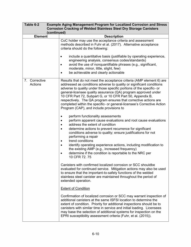
6-10
Table 6-2 Example Aging Management Program for Localized Corrosion and Stress Corrosion Cracking of Welded Stainless Steel Dry Storage Canisters (continued)
Element Description CoC holder may use the acceptance criteria and assessment methods described in Fuhr et al. (2017). Alternative acceptance criteria should do the following:
• include a quantitative basis (justifiable by operating experience,engineering analysis, consensus codes/standards)
• avoid the use of nonquantifiable phrases (e.g., significant,moderate, minor, little, slight, few)
• be achievable and clearly actionable
7. CorrectiveActions
Results that do not meet the acceptance criteria (AMP element 6) are addressed as conditions adverse to quality or significant conditions adverse to quality under those specific portions of the specific- or general-licensee quality assurance (QA) program approved under 10 CFR Part 72, Subpart G, or 10 CFR Part 50, Appendix B, respectively. The QA program ensures that corrective actions are completed within the specific- or general-licensee’s Corrective Action Program (CAP), and include provisions to
• perform functionality assessments• perform apparent cause evaluations and root cause evaluations• address the extent of condition• determine actions to prevent recurrence for significant
conditions adverse to quality; ensure justifications for notperforming a repair
• trend conditions• identify operating experience actions, including modification to
the existing AMP (e.g., increased frequency)• determine if the condition is reportable to the NRC per
10 CFR 72. 75
Canisters with confirmed localized corrosion or SCC shouldbe evaluated for continued service. Mitigation actions may also be used to ensure that the important-to-safety functions of the welded stainless steel canister are maintained throughout the period of extended operation.
Extent of Condition
Confirmation of localized corrosion or SCC may warrant inspection of additional canisters at the same ISFSI location to determine the extent of condition. Priority for additional inspections should be to canisters with similar time in service and initial loading. Licensees may base the selection of additional systems for inspection on the EPRI susceptibility assessment criteria (Fuhr, et al. (2015)).

6-11
Table 6-2 Example Aging Management Program for Localized Corrosion and Stress Corrosion Cracking of Welded Stainless Steel Dry Storage Canisters (continued)
Element Description 8. Confirmation
ProcessThe confirmation process will be commensurate with the specific or general licensee QA program approved under 10 CFR Part 72, Subpart G, or 10 CFR Part 50, Appendix B. The QA program ensures that the confirmation process includes provisions to preclude repetition of significant conditions adverse to quality.
The confirmation process describes or references procedures to:
• determine follow-up actions to verify effective implementation ofcorrective actions
• monitor for adverse trends due to recurring or repetitive findingsor observations
9. AdministrativeControls
The administrative controls are in accordance with the specific- or general-licensee QA program approved under 10 CFR Part 72, Subpart G, or 10 CFR Part 50, Appendix B, respectively. The QA program ensures that administrative controls include provisions that define:
• instrument calibration and maintenance• inspector requirements• record retention requirements• document control
The administrative controls describe or reference:
• methods for reporting results to NRC per 10 CFR 72.75• frequency for updating an AMP based on site-specific,
design-specific, and industrywide operational experience10. Operating
ExperienceThe AMP references and evaluates applicable operating experience, before renewal, and will continue to do so as new operating experience is developed and made available after renewal, including:
• internal and industrywide condition reports• internal and industrywide corrective action reports• vendor-issued safety bulletins• NRC generic communications• applicable U.S. Department of Energy (DOE) or industry
initiatives (e.g., EPRI- or DOE-sponsored inspections)
The AMP clearly identifies any degradation in the referenced operating experience as either age related or event driven, with proper justification for that assessment. Past operating experience supports the adequacy of the proposed AMP, including the method/technique, acceptance criteria, and frequency of inspection.

6-12
Table 6-2 Example Aging Management Program for Localized Corrosion and Stress Corrosion Cracking of Welded Stainless Steel Dry Storage Canisters (continued)
Element Description The AMP references the methods for capturing operating experience from other ISFSIs with similar in-scope SSCs.
CISCC of austenitic stainless steels is a known degradation mechanism for aqueous environments; however, operational experience in aqueous environments is not directly applicable in assessing the potential for atmospheric CISCC for austenitic stainless steel dry storage canisters. Atmospheric CISCC of austenitic stainless steels has been reported in a range of industries, including welded stainless steel components and piping in operating nuclear power plants.
Spent Fuel Storage
EPRI has evaluated the effects of operational parameters and environmental conditions on the CISCC susceptibility of welded stainless steel dry storage canisters (Fuhr et al., 2015). In addition, EPRI has developed a crack growth rate model using data from published literature (Chu, 2014). The EPRI model was used to calculate the time required for a crack to grow through-wall. The ability of the canister to tolerate a through-wall flaw was assessed against structural limit criteria using typical canister loads. EPRI has also published a summary of the NDE tools, including examination delivery systems and inspection systems, developed by dry storage system manufacturers (Chu and Renshaw, 2016; Renshaw, 2017a; 2017b). Additional development, testing, and verification of the capabilities of these tools and inspection systems are expected to continue over the next few years. Inspections of dry storage canisters after 20 years in service have been conducted at ISFSI sites. EPRI and Sandia National Laboratories reports (Waldrop et al., 2014, 2016; Bryan and Enos, 2014) detail the inspections conducted at nuclear power plant ISFSIs . The inspections did not identify any evidence of localized corrosion but did determine some amount of chloride-containing salts to be present. Corrosion products believed to be related to iron contamination were identified at the Calvert Cliffs ISFSI. Field trials of the inspection system delivery systems have been performed at three operating ISFSIs in 2015–2017 (Renshaw, 2017a). A spent fuel canister at the operating ISFSI at Rancho Seco was examined in 2017 using a remote inspection system to support the Rancho Seco ISFSI renewal application (NRC, 2017).
Operating Power Reactors
EPRI summarizes the operational experience with CISCC, including events, at San Onofre, Turkey Point, St. Lucie, and Koeberg (South Africa) with CISCC and assesses the operational experience with the EPRI model for CISCC propagation in EPRI-3002008193, “Aging
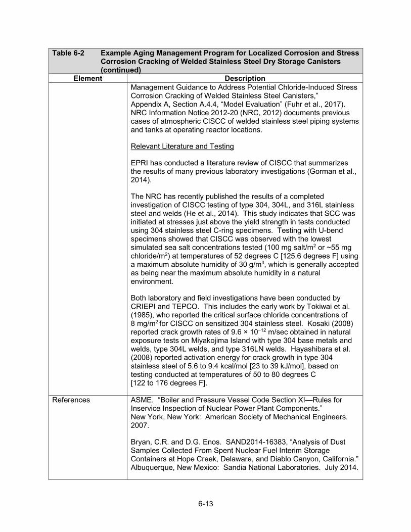
6-13
Table 6-2 Example Aging Management Program for Localized Corrosion and Stress Corrosion Cracking of Welded Stainless Steel Dry Storage Canisters (continued)
Element Description Management Guidance to Address Potential Chloride-Induced Stress Corrosion Cracking of Welded Stainless Steel Canisters,” Appendix A, Section A.4.4, “Model Evaluation” (Fuhr et al., 2017). NRC Information Notice 2012-20 (NRC, 2012) documents previous cases of atmospheric CISCC of welded stainless steel piping systems and tanks at operating reactor locations.
Relevant Literature and Testing
EPRI has conducted a literature review of CISCC that summarizes the results of many previous laboratory investigations (Gorman et al., 2014).
The NRC has recently published the results of a completed investigation of CISCC testing of type 304, 304L, and 316L stainless steel and welds (He et al., 2014). This study indicates that SCC was initiated at stresses just above the yield strength in tests conducted using 304 stainless steel C-ring specimens. Testing with U-bend specimens showed that CISCC was observed with the lowest simulated sea salt concentrations tested (100 mg salt/m2 or ~55 mg chloride/m2) at temperatures of 52 degrees C [125.6 degrees F] using a maximum absolute humidity of 30 g/m3, which is generally accepted as being near the maximum absolute humidity in a natural environment.
Both laboratory and field investigations have been conducted by CRIEPI and TEPCO. This includes the early work by Tokiwai et al. (1985), who reported the critical surface chloride concentrations of 8 mg/m2 for CISCC on sensitized 304 stainless steel. Kosaki (2008) reported crack growth rates of 9.6 × 10⁻¹² m/sec obtained in natural exposure tests on Miyakojima Island with type 304 base metals and welds, type 304L welds, and type 316LN welds. Hayashibara et al. (2008) reported activation energy for crack growth in type 304 stainless steel of 5.6 to 9.4 kcal/mol [23 to 39 kJ/mol], based on testing conducted at temperatures of 50 to 80 degrees C [122 to 176 degrees F].
References ASME. “Boiler and Pressure Vessel Code Section XI—Rules for Inservice Inspection of Nuclear Power Plant Components.” New York, New York: American Society of Mechanical Engineers. 2007.
Bryan, C.R. and D.G. Enos. SAND2014-16383, “Analysis of Dust Samples Collected From Spent Nuclear Fuel Interim Storage Containers at Hope Creek, Delaware, and Diablo Canyon, California.” Albuquerque, New Mexico: Sandia National Laboratories. July 2014.
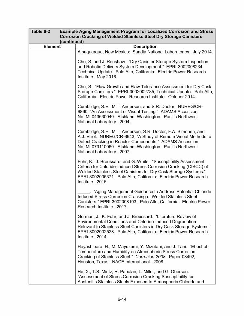
6-14
Table 6-2 Example Aging Management Program for Localized Corrosion and Stress Corrosion Cracking of Welded Stainless Steel Dry Storage Canisters (continued)
Element Description Albuquerque, New Mexico: Sandia National Laboratories. July 2014.
Chu, S. and J. Renshaw. “Dry Canister Storage System Inspection and Robotic Delivery System Development.” EPRI-3002008234, Technical Update. Palo Alto, California: Electric Power Research Institute. May 2016.
Chu, S. “Flaw Growth and Flaw Tolerance Assessment for Dry Cask Storage Canisters.” EPRI-3002002785, Technical Update. Palo Alto, California: Electric Power Research Institute. October 2014.
Cumblidge, S.E., M.T. Anderson, and S.R. Doctor. NUREG/CR-6860, “An Assessment of Visual Testing.” ADAMS Accession No. ML043630040. Richland, Washington. Pacific Northwest National Laboratory. 2004.
Cumblidge, S.E., M.T. Anderson, S.R. Doctor, F.A. Simonen, and A.J. Elliot. NUREG/CR-6943, “A Study of Remote Visual Methods to Detect Cracking in Reactor Components.” ADAMS Accession No. ML073110060. Richland, Washington. Pacific Northwest National Laboratory. 2007.
Fuhr, K., J. Broussard, and G. White. “Susceptibility Assessment Criteria for Chloride-Induced Stress Corrosion Cracking (CISCC) of Welded Stainless Steel Canisters for Dry Cask Storage Systems.” EPRI-3002005371. Palo Alto, California: Electric Power Research Institute. 2015.
_____. “Aging Management Guidance to Address Potential Chloride-Induced Stress Corrosion Cracking of Welded Stainless Steel Canisters,” EPRI-3002008193. Palo Alto, California: Electric Power Research Institute. 2017.
Gorman, J., K. Fuhr, and J. Broussard. “Literature Review of Environmental Conditions and Chloride-Induced Degradation Relevant to Stainless Steel Canisters in Dry Cask Storage Systems.” EPRI-3002002528. Palo Alto, California: Electric Power Research Institute. 2014.
Hayashibara, H., M. Mayuzumi, Y. Mizutani, and J. Tani. “Effect of Temperature and Humidity on Atmospheric Stress Corrosion Cracking of Stainless Steel.” Corrosion 2008. Paper 08492, Houston, Texas: NACE International. 2008.
He, X., T.S. Mintz, R. Pabalan, L. Miller, and G. Oberson. “Assessment of Stress Corrosion Cracking Susceptibility for Austenitic Stainless Steels Exposed to Atmospheric Chloride and

6-15
Table 6-2 Example Aging Management Program for Localized Corrosion and Stress Corrosion Cracking of Welded Stainless Steel Dry Storage Canisters (continued)
Element Description Non-Chloride Salts.” NUREG/CR-7170. ADAMS Accession No. ML14051A417. Washington, DC. U.S. Nuclear Regulatory Commission, February 2014,
Kosaki, A. “Evaluation Method of Corrosion Lifetime of Conventional Stainless Steel Canister Under Oceanic Air Environment.” Nuclear Engineering and Design. Vol. 238. pp. 1233–1240. 2008.
NRC. “Information Notice 2012-20: “Potential Chloride-Induced Stress Corrosion Cracking of Austenitic Stainless Steel and Maintenance of Dry Cask Storage System Canisters.” ADAMS Accession No. ML12319A440. Washington, DC: U.S. Nuclear Regulatory Commission. 2012.
NRC. “Summary of August 4, 2017, Meeting with Sacramento Municipal Utility District to Discuss the Upcoming Submittal of the Application for Renewal of the Rancho Seco ISFSI License.” ADAMS Accession No. ML17236A490. Washington, DC: U.S. Nuclear Regulatory Commission. 2017.
Renshaw, J. “Inspection and Delivery System Development and Field Trials for Dry Canister Storage System Evaluation.” EPRI-3002010621. Palo Alto, California: Electric Power Research Institute. November, 2017a.
_____. “Extended Storage Collaboration Program (ESCP): Nondestructive Evaluation Subcommittee—Industry Progress Report.” EPRI-3002010617, Final Report. Palo Alto, California: Electric Power Research Institute. October 2017b.
Selby, G. “BWR Vessel and Internals Project, Reactor Pressure Vessel and Internals Examination Guidelines.” EPRI 1011689, TR-105696-R8 (BWRVIP-03) Rev. 8. Palo Alto, California: Electric Power Research Institute. 2005.
Tokiwai, M., H. Kimura, and H. Kusanagi. “The Amount of Chlorine Contamination for Prevention of Stress Corrosion Cracking in Sensitized Type 304 Stainless Steel.” Corrosion Science. Vol. 25, Issue 8–9. pp. 837–844. 1985.
Waldrop, K., C. Bryan, D. Enos, “Diablo Canyon Stainless Steel Dry Storage Canister Inspection,” EPRI-3002002822, Palo Alto, CA: EPRI, 2016.

6-16
Table 6-2 Example Aging Management Program for Localized Corrosion and Stress Corrosion Cracking of Welded Stainless Steel Dry Storage Canisters (continued)
Element Description Waldrop, K., W. Bracey, K. Morris, C. Bryan, and D. Enos. “Calvert Cliffs Stainless Steel Dry Storage Canister Inspection.” EPRI-1025209. Palo Alto, California: Electric Power Research Institute. 2014.

6-17
6.6 Reinforced Concrete Structures
An example AMP for reinforced concrete structures is provided below. The AMP consists of condition monitoring, performance monitoring, and mitigation and prevention activities. The program includes periodic visual inspections by personnel qualified to monitor reinforced concrete for applicable aging effects, such as those described in the American Concrete Institute (ACI) guides ACI 349.3R-02, ACI 201.1R-08, and American National Standards Institute/American Society of Civil Engineers guidelines (ANSI/ASCE) 11-99. Identified aging effects are evaluated against acceptance criteria derived from the design bases or industry guides and standards, including ACI 349, ACI 318, ACI 349.3R-02 and ASME Code Section XI, Subsection IWL.
The program also includes periodic sampling and testing of groundwater and the need to assess the impact of any changes in its chemistry on below-grade concrete structures. Additional activities include radiation surveys to ensure the shielding functions of the concrete structure are maintained and daily inspections to ensure the air convection vents are not blocked (per the requirements of the approved design bases). The program also includes provisions where modifications may be appropriate.
Maintenance Activities
An applicant may credit maintenance activities conducted in accordance with the final safety analysis report (FSAR) for the general area walkdowns described in this AMP, provided that these activities meet all 10 elements of this AMP.
Radiation Surveys
Radiation surveys of each loaded DSS are initially obtained near the DSSs in accordance with TS requirements for the respective license and CoC. Radiation monitoring is also conducted on a continuing basis as part of a radiological environmental monitoring program to ensure continued compliance with the annual dose limits in 10 CFR 72.104(a). However, this monitoring is generally not conducted near DSSs after loading and placement on the ISFSI support pad in a manner that allows for monitoring for concrete degradation of the individual storage systems. Additionally, radiation surveys and monitoring are performed to support compliance with 10 CFR Part 20 requirements for maintaining occupational exposures within regulatory limits and as low as is reasonably achievable and for establishing controlled areas for radiation protection purposes. Surveys are used to determine area radiation levels and controls for radiation worker permits. Thus, the purpose of these surveys is focused on occupational exposures, not identifying degradation of an individual storage system’s concrete due to aging effects. Nevertheless, an applicant may proposed to demonstrate that the radiation surveys and monitoring conducted at its site are capable of ensuring that the shielding performance of the concrete overpacks is maintained per the approved design basis. Such a proposal should include a description of the surveys and monitoring, including when and how they are performed, and justification of how they are sufficient to identify degradation of the shielding performance due to aging effects for individual storage systems.
Alternatively, the staff has determined that, if supported by a technical justification, visual inspections of the concrete per ACI 349.3R-02 may be an acceptable alternative approach to managing loss of shielding due to concrete degradation. The use of this approach should be supported by a shielding evaluation that demonstrates that the ACI 349.3R-02 acceptance criteria (developed to assess structural performance) are sufficiently conservative to provide for
6-18
timely identification of concrete degradation and corrective actions before a loss of shielding performance. The staff performed generic shielding evaluations for several storage system designs and identified instances where the use of visual inspections in lieu of radiation surveys may be justified (NRC, 2019). An applicant may reference the NRC evaluations, provided that (1) the applicant can justify that the NRC evaluations apply to, or are bounding for, theapplicant’s design, including consideration of the assumptions and system parameters (bothdesign and contents) used in the NRC evaluations and (2) the NRC evaluations indicate that theuse of visual inspections for that design would be sufficiently conservative for ensuring against aloss of shielding performance.

6-19
Table 6-3 Example Aging Management Program for Reinforced Concrete Structures
Element Description 1. Scope of Program The scope of the program includes the following aging management
activities: 1. general area walkdowns of all reinforced concrete structures2. visual inspection of above-grade (readily accessible, normally
inaccessible) and below-grade (underground) areas of asubset of the reinforced concrete structures
3. groundwater chemistry monitoring program to identifyconditions conducive to the following below-grade(underground) aging mechanisms:• corrosion of embedded steel• chemical attack (chloride- and sulfate-induced
degradation)4. radiation surveys1 to:
• ensure compliance with 10 CFR 72.104 (i.e., doseequivalent requirements beyond the controlled areaduring normal and off-normal conditions of storage)
• monitor performance of the concrete as aneutron/gamma shield at near-system locations as anindicator of concrete degradation
The program provides means to adequately identify the following aging effects, as described in ACI 349.3R-02 (ACI, 2010) and SEI/ASCE 11-99 (SEI/ASCE, 2000):
• cracking or loss of material (spalling, scaling) due to Freezeand thaw degradation
• cracking, loss of material (spalling, scaling), loss of strengthand reduction of concrete pH (corrosion resistance of steelreinforcement) due to aggressive chemical attack
• cracking and loss of strength due to reaction with aggregates• cracking, loss of material, and loss of strength due to corrosion
of embedded steel• increase in porosity/permeability, loss of strength, and
reduction in concrete pH due to leaching of calcium hydroxide• cracking due to differential settlement• loss of material (spalling, scaling) due to salt scaling• loss of material (spalling, scaling), loss of strength, increased
porosity and permeability, and reduction in concrete pH
1See the AMP introduction. The NRC reviewer should consider the design features of the DSS when determining if radiation surveys can be excluded from the scope of this AMP on a case-by-case basis. For example, internal surfaces of a concrete overpack may be permanently blocked by a steel liner, which may prevent assessing the condition of those concrete surfaces by remote visual inspection. The NRC reviewer should evaluate any engineering justification and/or operating experience to determine if visual inspections of readily accessible and normally inaccessible (i.e., not permanently blocked) surfaces can adequately characterize the condition of the structure and provide reasonable assurance that the intended functions will be maintained.

6-20
Table 6-3 Example Aging Management Program for Reinforced Concrete Structures (continued)
Element Description (corrosion resistance of steel reinforcement) due to microbiological degradation
Additional site-specific AMPs may be required for the following scenarios:
• A dewatering system is used to prevent long-term settlement.• The design bases include embedded aluminum
subcomponents without a protective insulating coating.• Protective coatings are relied upon to manage the effects of
aging for a subcomponent.
2. Preventive Actions Preventive actions include continuance of inspections to ensure that air inlet/outlet vents are not blocked and/or temperature monitoring, if applicable, to ensure design temperature limits are not exceeded and thermal dehydration of the concrete remains noncredible during the period of extended operation. These inspections would be part of the approved design bases and be continued for the sample size and inspection frequency identified in the respective technical specification (TS).
Additional preventive actions are not required for structures designed and fabricated in accordance with ACI 318 (ACI, 2011) or ACI 349 (ACI, 2007a), as specified in the design bases. Otherwise, a site-specific AMP may be required.
3. ParametersMonitored orInspected
For general area walkdowns and visual inspections, the parameters monitored or inspected quantify the following aging effects:
• cracking• loss of material (spalling, scaling)• increased porosity/permeability
AMP procedures reference the following parameters for characterizing the above aging effects, as appropriate, per the acceptance criteria:2
• affected surface area• geometry/depth of defect• cracking, crazing, delaminations, drummy areas• curling, settlements or deflections• honeycombing, bug holes• popouts and voids• exposure of embedded steel
2The terminology is consistent with ACI standard CT-13 (ACI, 2013b).
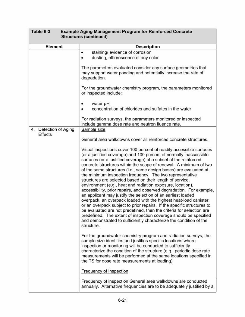
6-21
Table 6-3 Example Aging Management Program for Reinforced Concrete Structures (continued)
Element Description • staining/ evidence of corrosion• dusting, efflorescence of any color
The parameters evaluated consider any surface geometries that may support water ponding and potentially increase the rate of degradation.
For the groundwater chemistry program, the parameters monitored or inspected include:
• water pH• concentration of chlorides and sulfates in the water
For radiation surveys, the parameters monitored or inspected include gamma dose rate and neutron fluence rate.
4. Detection of AgingEffects
Sample size
General area walkdowns cover all reinforced concrete structures.
Visual inspections cover 100 percent of readily accessible surfaces (or a justified coverage) and 100 percent of normally inaccessible surfaces (or a justified coverage) of a subset of the reinforced concrete structures within the scope of renewal. A minimum of two of the same structures (i.e., same design bases) are evaluated at the minimum inspection frequency. The two representative structures are selected based on their length of service, environment (e.g., heat and radiation exposure, location), accessibility, prior repairs, and observed degradation. For example, an applicant may justify the selection of an earliest loaded overpack, an overpack loaded with the highest heat-load canister, or an overpack subject to prior repairs. If the specific structures to be evaluated are not predefined, then the criteria for selection are predefined. The extent of inspection coverage should be specified and demonstrated to sufficiently characterize the condition of the structure.
For the groundwater chemistry program and radiation surveys, the sample size identifies and justifies specific locations where inspection or monitoring will be conducted to sufficiently characterize the condition of the structure (e.g., periodic dose rate measurements will be performed at the same locations specified in the TS for dose rate measurements at loading).
Frequency of inspection
Frequency of inspection General area walkdowns are conducted annually. Alternative frequencies are to be adequately justified by a

6-22
Table 6-3 Example Aging Management Program for Reinforced Concrete Structures (continued)
Element Description
valid technical basis (e.g. engineering justification, operational experience data).
The schedule for visual inspections is commensurate with ACI 349.3R-02 (ACI, 2010). Visual inspections of above-grade (both readily accessible and normally inaccessible) areas are conducted at least once every 5 years, at a minimum. Alternative frequencies are to be be adequately justified by a valid technical basis (e.g., engineering justification, operational experience data).
Visual inspections of below-grade (underground) areas are opportunistic; inspections are performed when excavations occur for any reason.
The frequency for monitoring groundwater chemistry is justified (e.g., quarterly, semiannually) based on an adequate technical basis (e.g., site-specific operating experience, engineering justification).
The frequency for radiation surveys is justified (e.g., quarterly) based on an adequate technical basis (e.g. engineering justification, operating experience).
Method or technique
General area walkdowns do not required any special visual equipment.
Visual inspections of readily accessible areas are performed with feeler gauges, crack comparators, or other suitable visual quantification methods in accordance with the acceptance criteria in ACI 349.3R-02 (ACI, 2010).
Visual inspections of normally inaccessible areas are performed using a remote inspection system that has been qualified for the specific DSS and site-specific characteristics. Procedures for remote visual inspections should be demonstrated to ensure the acceptance criteria in ACI 349.3R-02 are achievable; procedure attributes should include, for example, equipment resolution and lighting requirements and should reference applicable standards when possible. The area available for inspection by remote techniques varies by the SSC and the storage system design. As a result, the AMP should establish a minimum inspection coverage, considering accessibility and the capability to sufficiently characterize the condition of normally inaccessible SSCs.

6-23
Table 6-3 Example Aging Management Program for Reinforced Concrete Structures (continued)
Element Description Groundwater chemistry is characterized using a chemical analysis method with a valid measurement range and adequate resolution and sensitivity. Procedures for groundwater chemistry analyses should be demonstrated to ensure that the acceptance criteria in ASME Code Section XI, Subsection IWL, are achievable
Radiation surveys are performed using calibrated neutron and gamma detectors with valid energy ranges, in accordance with the acceptance criteria (see Element 6).
Data collection
Data collection for visual inspections is commensurate with consensus standards and guides (see ACI 224.1R (ACI, 2007b) for quantitative analysis (crack width, extent), ACI 562, (ACI, 2013a), ACI 364.1R (ACI, 2007c)).
Data from all walkdown, inspection and monitoring activities, including evidence of degradation and its extent and location, shall be documented on a checklist or inspection form. The results of the general area walkdowns and visual inspections shall be documented, including, as appropriate, descriptions of observed aging effects and supporting sketches, photographs, or video.
Corrective actions from AMP activities shall also be documented. An adequate clearinghouse is used for documenting inspection and monitoring operating experience.
Timing
Initial inspections are performed before storage systems enter their period of extended operation or in accordance with an alternative schedule justified in the application (e.g., crediting preapplication inspections or allowing additional time when the initial storage term of a system ends when a license or CoC is in timely renewal—see NUREG–1927, Section 3.6.3).
5. Monitoring andTrending
Monitoring and trending methods are commensurate with consensus defect evaluation guides and standards, as appropriate (see ACI 201.1R (ACI, 2008a), ACI 207.3R (ACI, 2008b), ACI 364.1R (ACI, 2007c), ACI 562 (ACI, 2013a), or ACI 224.1R (ACI, 2007b) for crack evaluation), or site-approved procedures consistent with the specific- or general-licensee QA program approved under 10 CFR Part 72, Subpart G, or 10 CFR Part 50, Appendix B, respectively.
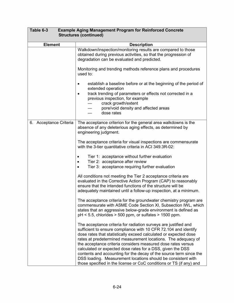
6-24
Table 6-3 Example Aging Management Program for Reinforced Concrete Structures (continued)
Element Description Walkdown/inspection/monitoring results are compared to those obtained during previous activities, so that the progression of degradation can be evaluated and predicted.
Monitoring and trending methods reference plans and procedures used to:
• establish a baseline before or at the beginning of the period ofextended operation
• track trending of parameters or effects not corrected in aprevious inspection, for example— crack growth/extent — pore/void density and affected areas — dose rates
6. Acceptance Criteria The acceptance criterion for the general area walkdowns is the absence of any deleterious aging effects, as determined by engineering judgment.
The acceptance criteria for visual inspections are commensurate with the 3-tier quantitative criteria in ACI 349.3R-02:
• Tier 1: acceptance without further evaluation• Tier 2: acceptance after review• Tier 3: acceptance requiring further evaluation
All conditions not meeting the Tier 2 acceptance criteria are evaluated in the Corrective Action Program (CAP) to reasonably ensure that the intended functions of the structure will be adequately maintained until a follow-up inspection, at a minimum.
The acceptance criteria for the groundwater chemistry program are commensurate with ASME Code Section XI, Subsection IWL, which states that an aggressive below-grade environment is defined as pH < 5.5, chlorides > 500 ppm, or sulfates > 1500 ppm.
The acceptance criteria for radiation surveys are justified and sufficient to ensure compliance with 10 CFR 72.104 and identify dose rates that statistically exceed calculated or expected dose rates at predetermined measurement locations. The adequacy of the acceptance criteria considers measured dose rates versus calculated or expected dose rates for a DSS, given the DSS contents and accounting for the decay of the source term since the DSS loading. Measurement locations should be consistent with those specified in the license or CoC conditions or TS (if any) and

6-25
Table 6-3 Example Aging Management Program for Reinforced Concrete Structures (continued)
Element Description locations where dose rates were calculated in the FSAR and likely measured at the time of loading.
Alternative acceptance criteria should be reviewed on a case-by-case basis. For such cases, the acceptance criteria shall:
• include a quantitative basis (justifiable by operatingexperience, engineering analysis, consensus codes andstandards)
• avoid use of nonquantifiable phrases (e.g., significant,moderate, minor, little, slight, few)
• be achievable and clearly actionable
7. Corrective Actions Results that do not meet the acceptance criteria are addressed as conditions adverse to quality or significant conditions adverse to quality under those specific portions of the specific- or general-licensee QA program approved under 10 CFR Part 72, Subpart G, or 10 CFR Part 50, Appendix B, respectively. The QA program ensures that corrective actions are completed within the specific- or general-licensee’s Corrective Action Program (CAP), and include provisions to
• perform functionality assessments• perform apparent cause evaluations, and root cause
evaluations• address the extent of condition• determine actions to prevent recurrence for significant
conditions adverse to quality; ensure justifications for notperforming a repair
• trend conditions• identify operating experience actions, including modifications
to the existing AMP (e.g., increased frequency)• determine if the condition is reportable to the NRC per
10 CFR 72.75Corrective actions shall be consistent with applicable consensus rehabilitation guides or standards, unless an engineering justification is provided (e.g., for cracking: ACI 224.1R, ACI 562, ACI 364.1R, and ACI RAP Bulletins; for spalling/scaling: ACI 562, ACI 364.1R, ACI 506R, and ACI RAP Bulletins).
8. ConfirmationProcess
The confirmation process is commensurate with the specific- or general-licensee QA program approved under 10 CFR Part 72, Subpart G, or 10 CFR Part 50, Appendix B, respectively. The QA program ensures that the confirmation process includes provisions to preclude repetition of significant conditions adverse to quality.

6-26
Table 6-3 Example Aging Management Program for Reinforced Concrete Structures (continued)
Element Description The confirmation process describes or references procedures to:
• determine follow-up actions to verify effective implementationof corrective actions
• monitor for adverse trends due to recurring or repetitivefindings or observations.
9. AdministrativeControls
The administrative controls are in accordance with the specific- or general-licensee QA program approved under 10 CFR Part 72, Subpart G, or 10 CFR Part 50, Appendix B, respectively. The QA program ensures that the administrative controls include provisions that define:
• instrument calibration and maintenance• general area walkdown and inspector requirements
(commensurate with ACI 349.3R-02)• record retention requirements• document control
The administrative controls describe or reference:
• methods for reporting results to the NRC per 10 CFR 72.75• frequency for updating the AMP based on industrywide
operational experience
10. OperatingExperience
Structures monitoring programs using the acceptance criteria in ACI 349.3R-02 (ACI, 2010) have proven effective for aging management of concrete structures in nuclear power plants during their period of extended operation (NRC, 2010b). NUREG–1522 documents the results of a survey sponsored in 1992 by the Office of Nuclear Reactor Regulation to obtain information on the types of distress in the concrete and steel structures and components, the type of repairs performed, and the durability of the repairs. Licensees who responded to the survey reported cracking, scaling, and leaching of concrete structures. The degradation was attributed to drying shrinkage, Freeze and thaw, and abrasion. The NUREG also describes the results of NRC staff inspections at six plants. The staff observed concrete degradation, corrosion of component support members and anchor bolts, cracks and other deterioration of masonry walls, and groundwater leakage and seepage into underground structures. The observed and reported degradations were more severe at coastal plants than those observed in inland plants, as a result of brackish and sea water. Previous reactor license renewal applicants reported similar degradation and corrective actions taken through their structures monitoring program.

6-27
Table 6-3 Example Aging Management Program for Reinforced Concrete Structures (continued)
Element Description NRC Information Notice 2011-20 (NRC, 2011) documents the occurrence of alkali-silica reaction (ASR)-induced concrete degradation of a seismic Category 1 below-grade structure at the Seabrook Station power plant. The concrete used in the structure passed all industry standard ASR screening tests (ASTM, 2007, 2012) at the time of construction; however, ASR-induced degradation was identified in August 2010. The licensee completed a prompt operability determination that concluded margins to the design limits remained such that the structural integrity of the building continued to be demonstrated.
NRC Information Notice 2013-07 documents the occurrence of Freeze and thaw cracking near the anchor blockout holes on the roof of horizontal storage modules (HSMs) at an ISFSI in Idaho. The cracking led to water migration into the concrete, resulting in efflorescence of calcium carbonate deposits. The degradation of the roofslabs was not related to age-related degradation but to a design feature leading to water accumulation. More extensive visual inspections of the HSMs also revealed map cracking on the vertical wall surfaces, random and radial cracking at the door edges in base units, and spalling at the bottom edge of shield walls. The licensee conducted nondestructive and destructive examination, which revealed adequate concrete quality and compressive strength.
Additional visual inspections of concrete structures in DSSs have been conducted at the Calvert Cliffs ISFSI (Gellrich, 2012) and the Palisades ISFSI. Remote visual inspections of two HSMs at the Calvert Cliffs ISFSI revealed efflorescence of the concrete and the formation of calcium carbonate stalactites in the 2-inch gap between the heat shield and the concrete ceiling. These stalactites were attributed to water ingress through the outlet vent stack. A condition report was issued that did not identify an operability issue. Inspections of the exterior surfaces of a ventilated concrete cask (VCC) and the concrete support pad at the Palisades ISFSI revealed bugholes exceeding pre-established acceptance criteria and requiring grout repair, and a void at the interface between the VCC bottom plate and the vertical VCC concrete wall. No conditions were identified to compromise the intended functions of the VCC. Walkdowns and visual inspections of readily accessible surfaces of concrete overpacks and HSMs are generally conducted during the initial storage period, although the acceptance criteria may vary from those in ACI 349.3R.02 (ACI, 2010). The NRC reviewer should evaluate relevant inspection results included in the renewal application, based on design and environmental similarities, and

6-28
Table 6-3 Example Aging Management Program for Reinforced Concrete Structures (continued)
Element Description evaluate if activities in this generic AMP should be augmented as a result of those inspections.
References ACI. ACI 506R-05, “Guide to Shortcrete.” American Concrete Institute. 2005.
_____. ACI 349-06, “Code Requirements for Nuclear Safety-Related Concrete Structures.” American Concrete Institute. 2007a.
_____. ACI 224.1R-07, “Causes, Evaluation, and Repair of Cracks in Concrete Structures.” American Concrete Institute. 2007b.
_____. ACI 364.1R-07, “Guide for Evaluation of Concrete Structures before Rehabilitation.” American Concrete Institute. 2007c.
_____. ACI 201.1R-08, “Guide for Conducting a Visual Inspection of Concrete in Service.” American Concrete Institute. 2008a.
_____. ACI 207.3R-94, “Practices for Evaluation of Concrete in Existing Massive Structures for Service Conditions.” American Concrete Institute. 2008b.
_____. ACI 349.3R-02, “Evaluation of Existing Nuclear Safety-Related Concrete Structures.” American Concrete Institute. 2010.
_____. ACI 318-11, “Building Code Requirements for Structural Concrete.” American Concrete Institute. 2011.
_____. ACI 562-13, “Code Requirements for Evaluation, Repair, and Rehabilitation of Concrete Buildings.” American Concrete Institute. 2013a.
_____. ACI CT-13, “ACI Concrete Terminology.” American Concrete Institute. 2013b.
_____. ACI 349.3R-18, “Report on Evaluation and Repair of Existing Nuclear Safety-Related Concrete Structures.” American Concrete Institute. 2018.
ASME Boiler and Pressure Vessel Code, Section XI, Subsection IWL (2013), “Requirements for Class CC Concrete Components of Light-Water-Cooled Plants”
ASTM International. ASTM C289, “Standard Test Method for Potential Alkali-Silica Reactivity of Aggregates (Chemical Method).”

6-29
Table 6-3 Example Aging Management Program for Reinforced Concrete Structures (continued)
Element Description West Conshohocken, Pennsylvania: American Society for Testing and Materials. 2007.
_____. ASTM C295, “Standard Guide for Petrographic Examination of Aggregates for Concrete.” West Conshohocken, Pennsylvania: American Society for Testing and Materials. 2012.
Gellrich, G. “Calvert Cliffs Nuclear Power Plant.” Letter to U.S. Nuclear Regulatory Commission, Response to Request for Supplemental Information. RE: Calvert Cliffs Independent Spent Fuel Storage Installation License Renewal Application (TAC No. L24475). ADAMS Accession No. ML12212A216. 2012.
NRC. “Standard Review Plan for Spent Fuel Dry Storage Facilities.” NUREG–1567, Rev. 0. Washington, DC. ADAMS Accession No. ML003686776. 2000.
_____. “Standard Review Plan for Spent Fuel Dry Storage Systems at a General License Facility,” NUREG–1536, Rev. 1. Washington, DC. ADAMS Accession No. ML091060180. 2010a.
_____. “Generic Aging Lessons Learned (GALL) Report,” NUREG–1801, Rev. 2, Washington DC. ADAMS Accession No. ML103490041. 2010b.
_____. “Information Notice 2011-20, Concrete Degradation by Alkali-Silica Reaction.” Washington, DC. U.S. Nuclear Regulatory Commission. ADAMS Accession No. ML112241029. 2011.
_____. “Standard Review Plan for Renewal of Specific Licenses and Certificates of Compliance for Dry Storage of Spent Nuclear Fuel,” NUREG–1927, Rev. 1. Washington, DC. ADAMS Accession No. ML16179A148. 2016.
_____. “Study of the ACI 349.3R-02 Tier 2 (i.e., Section 5.2.1) Criteria Impacts on Dose Rates for Several Spent Nuclear Fuel Dry Storage System Designs.” Washington, DC. ADAMS Accession No. ML19072A031. 2019.
SEI/ASCE 11-99, “Guideline for Structural Condition Assessment of Existing Buildings.” 2000.

6-30
6.7 Monitoring of Metallic Surfaces
An example AMP for monitoring of metallic surfaces is provided below. The AMP manages all metallic surfaces that are directly exposed to outdoor air, concrete, or are sheltered within DSS overpacks, except for stainless steel storage canisters and transfer casks, which are addressed by other AMPs. The AMP is a condition monitoring program that consists of periodic visual inspections to monitor for corrosion, wear, cracking, and loss of preload (bolting).

6-31
Table 6-4 Example Aging Management Program for Monitoring of Metallic Surfaces
Element Description
1. Scope ofProgram
This program manages the effects of aging for the external surfaces of steel and stainless steel components that are directly exposed to outdoor air or are sheltered within DSS overpacks (e.g., NUHOMS HSM, HI-STORM). The scope of the program includes metallic overpack exterior surfaces, dry storage canister support structures, access doors, vents, heat shields, embedments and anchorages, bolting, and other components important to safety. The scope of this program does not include stainless steel dry storage canisters housed within overpacks, transfer casks, or the top closure (confinement) boundary of bolted casks. The Localized Corrosion and Stress corrosion Cracking of Welded Stainless Steel Dry Storage Canisters AMP manages the effects of aging for stainless steel canisters. The Transfer Casks AMP manages the effects of aging of all transfer cask components. The Bolted Cask Seal Leakage Monitoring AMP manages the effects of aging on the integrity of the top confinement boundary of bolted spent fuel storage casks. Periodic visual inspections monitor for general and localized corrosion, wear, cracking, and loss of preload (bolting). An additional AMP may be necessary to manage protective coatings that perform an important-to-safety function.
2. PreventiveActions
This program is a condition monitoring program to detect evidence of degradation. It does not provide guidance for the prevention of aging.
3. ParametersMonitored/Inspected
This program monitors the condition of external metallic surfaces to identify general corrosion, localized corrosion, wear, and loss of preload of bolted connections. Localized corrosion of stainless steels may be a precursor to SCC. Parameters monitored or inspected for external metallic surfaces include:
• visual evidence of discontinuities, imperfections, and ruststaining indicative of corrosion, SCC, and wear
• visual evidence of loose or missing bolts, physical displacement,and other conditions indicative of loss of preload
• visual evidence of coating degradation (e.g., blisters, cracking,flaking, delamination) indicative of corrosion of the base metal
4. Detection ofAging Effects
Inspections are performed by personnel qualified in accordance with site procedures and programs to perform the specified task. Visual inspections follow site procedures that are demonstrated to be capable of evaluating conditions against the acceptance criteria. Procedure attributes should include, for example, equipment resolution, lighting

6-32
Table 6-4 Example Aging Management Program for Monitoring of Metallic Surfaces (continued)
Element Description
standards, distance, surface coverage, and assessment of base metal when coating degradation is present. Readily Accessible Surfaces Inspections cover 100 percent of normally accessible surfaces, including the external surfaces of metallic overpacks, bolting, lightning protection system components, access doors, vents, and other metallic components. Normally Inaccessible Surfaces Opportunistic visual inspections are performed with remote inspection techniques on metallic surfaces within overpacks that are accessed during inspections of dry storage canisters, including heat shields, canister support structures, and other metallic components. The condition of metallic surfaces in contact with concrete (i.e., overpack/cask bottoms) are assessed with visual inspections on a justified frequency. The area available for inspection by remote techniques varies by the SSC and the storage system design. As a result, the AMP should establish a minimum inspection coverage, considering accessibility and the capability to sufficiently characterize the condition of normally inaccessible SSCs. Sample Size The readily accessible exterior metallic surfaces of all casks and overpacks are inspected. The inspections of normally inaccessible surfaces within overpacks is opportunistic; inspections are performed whenever the overpacks are accessed for dry storage canister inspections. Overpack and cask bottoms are inspected on a justified sample size. Frequency Inspections of readily accessible surfaces are conducted at least once every 5 years. Normally inaccessible surfaces within overpacks are inspected when those surfaces are accessed during remote inspections of dry storage canisters. Overpack and cask bottoms are inspected on a justified frequency. Data Collection Data from the examination, including evidence of degradation and its extent and location, shall be documented on a checklist or inspection form. The results of the inspection shall be documented, including descriptions of observed aging effects and supporting sketches,
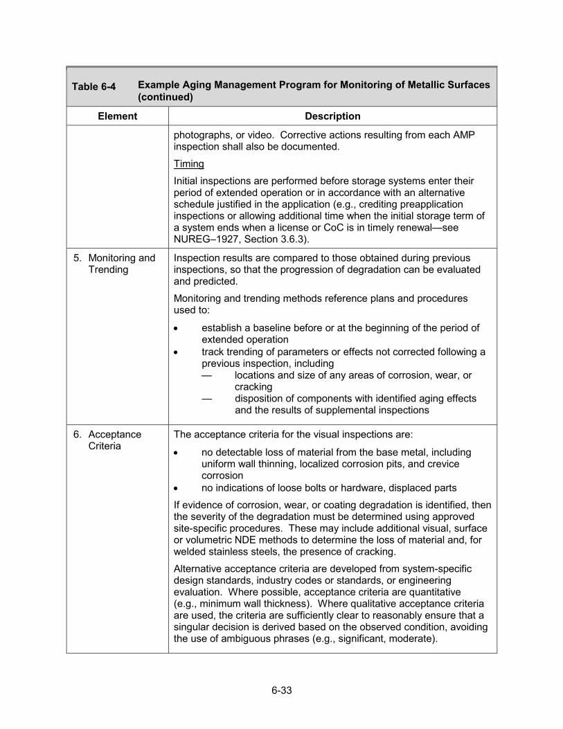
6-33
Table 6-4 Example Aging Management Program for Monitoring of Metallic Surfaces (continued)
Element Description
photographs, or video. Corrective actions resulting from each AMP inspection shall also be documented. Timing Initial inspections are performed before storage systems enter their period of extended operation or in accordance with an alternative schedule justified in the application (e.g., crediting preapplication inspections or allowing additional time when the initial storage term of a system ends when a license or CoC is in timely renewal—see NUREG–1927, Section 3.6.3).
5. Monitoring andTrending
Inspection results are compared to those obtained during previous inspections, so that the progression of degradation can be evaluated and predicted. Monitoring and trending methods reference plans and procedures used to:
• establish a baseline before or at the beginning of the period ofextended operation
• track trending of parameters or effects not corrected following aprevious inspection, including— locations and size of any areas of corrosion, wear, or
cracking — disposition of components with identified aging effects
and the results of supplemental inspections
6. AcceptanceCriteria
The acceptance criteria for the visual inspections are:
• no detectable loss of material from the base metal, includinguniform wall thinning, localized corrosion pits, and crevicecorrosion
• no indications of loose bolts or hardware, displaced partsIf evidence of corrosion, wear, or coating degradation is identified, then the severity of the degradation must be determined using approved site-specific procedures. These may include additional visual, surface or volumetric NDE methods to determine the loss of material and, for welded stainless steels, the presence of cracking. Alternative acceptance criteria are developed from system-specific design standards, industry codes or standards, or engineering evaluation. Where possible, acceptance criteria are quantitative (e.g., minimum wall thickness). Where qualitative acceptance criteria are used, the criteria are sufficiently clear to reasonably ensure that a singular decision is derived based on the observed condition, avoiding the use of ambiguous phrases (e.g., significant, moderate).

6-34
Table 6-4 Example Aging Management Program for Monitoring of Metallic Surfaces (continued)
Element Description
EPRI technical reports, Technical Report (TR)-1007933, “Aging Assessment Field Guide” (EPRI, 2003), and TR-1009743, “Aging Identification and Assessment Checklist: Mechanical Components” (EPRI, 2004), provide general guidance for the evaluation of materials and the development of criteria for their acceptance when performing visual inspections.
7. CorrectiveActions
Results that do not meet the acceptance criteria are addressed as conditions adverse to quality or significant conditions adverse to quality under those specific portions of the specific- or general-licensee QA program approved under 10 CFR Part 72, Subpart G, or 10 CFR Part 50, Appendix B, respectively. The QA program ensures that corrective actions are completed within the specific- or general-licensee’s Corrective Action Program (CAP), and include provisions to
• perform functionality assessments• perform apparent cause evaluations and root cause evaluations• address the extent of condition• determine actions to prevent recurrence for significant conditions
adverse to quality; ensure justifications for not performing a repair• trend conditions• identify operating experience actions, including modification to
the existing AMP (e.g., increased frequency)• determine if the condition is reportable to the NRC per
10 CFR 72.75
8. ConfirmationProcess
The confirmation process is commensurate with the specific- or general-licensee QA program approved under 10 CFR Part 72, Subpart G, or 10 CFR Part 50, Appendix B, respectively. The QA program ensures that the confirmation process includes provisions to preclude repetition of significant conditions adverse to quality.
The confirmation process describes or references procedures to:
• determine follow-up actions to verify effective implementation ofcorrective actions
• monitor for adverse trends due to recurring or repetitive findingsor observations.
9. AdministrativeControls
The administrative controls are addressed through those portions of the specific- or general-licensee QA program that are used to meet 10 CFR Part 72, Subpart G, or 10 CFR Part 50, Appendix B.

6-35
Table 6-4 Example Aging Management Program for Monitoring of Metallic Surfaces (continued)
Element Description
10. OperatingExperience
External surface inspections through system inspections and walkdowns in support of the Maintenance Rule (10 CFR Part 50.65) have proven effective in maintaining the material condition of nuclear power plant systems. Calvert Cliffs performed inspections of the interior of two NUHOMS horizontal storage modules in support of the site’s ISFSI license renewal application (Gellrich, 2012). The two modules were in operation for almost 16 and 19 years at the time of the inspection, and there was evidence of localized water intrusion into the HSM interior. In general, the canister support beams and rails were found to be in good condition with coatings largely intact. However, areas of general corrosion were observed on specific steel supports that had previously been determined to have been coated improperly. This condition was determined not to challenge the function of the supports.
DOE conducted a similar inspection of the interior of a horizontal storage module for a system that stores fuel from Three Mile Island Unit 2 (DOE, 2013, 2017). The module was in operation for about 13 years, and the steel support structures within the module exhibited intact coatings and no evidence of significant corrosion.
References DOE. Presentation Slides for Meeting Between the U.S. Department of Energy and U.S. NRC, “Site-Specific License Renewal for the Three Mile Island, Unit 2 (TMI-2) Independent Spent Fuel Storage Installation (ISFSI).” ADAMS Accession No. ML13353A611. Washington, DC: U.S. Department of Energy. September 25, 2013. _____. “TMI-2 Independent Spent Fuel Storage Installation Application for 10 CFR 72 Specific License Renewal.” ADAMS Accession No. ML17089A501. Washington, DC: U.S. Department of Energy. March 6, 2017. EPRI. EPRI Technical Report 1007933, “Aging Assessment Field Guide.” Palo Alto, California: Electric Power Research Institute. December 2003. _____. EPRI Technical Report 1009743, “Aging Identification and Assessment Checklist–Mechanical Components.” Palo Alto, California: Electric Power Research Institute. August 27, 2004. Gellrich, G. “Calvert Cliffs Nuclear Power Plant.” Letter to U.S. Nuclear Regulatory Commission, Response to Request for Supplemental Information. RE: Calvert Cliffs Independent Spent Fuel Storage Installation License Renewal Application (TAC No. L24475). ADAMS Accession No. ML12212A216. July 27, 2012.

6-36
6.8 Bolted Cask Seal Leakage Monitoring
This AMP manages the aging of portions of bolted casks that employ leakage monitoring to verify the integrity of the top confinement boundary. The program relies on existing pressure monitoring systems to assess the integrity of cask closure seals. The program also performs periodic visual inspections of normally inaccessible components under the cask protective cover to monitor for corrosion, coating degradation, loose bolts, and evidence of water intrusion.

6-37
Table 6-5 Example Aging Management Program for Bolted Cask Seal Leakage Monitoring
Element Description
1. Scope ofProgram
This program is used to manage the aging effects on the integrity of the top confinement boundary of bolted spent fuel storage casks to ensure that timely and appropriate corrective actions can be taken to maintain the safe storage conditions of the casks. The aging effects include loss of material as a result of corrosion of the sealing surfaces, O-rings, and bolts; loss of strength due to thermal aging and change in dimension due to creep of the metallic O-rings that results in loss of sealing forces; and loss of preload of the closure bolts. The specific components and systems that are typically managed by this program include the shield lid, primary lid, closure lid, protective covers, O-ring assemblies, and associated bolts and welds. The types of bolted cask designs covered by the program include TN‐24, ‐32, ‐40, and ‐68; NAC‐S/T (I26), -C28 S/T, -I28 S/T, and ‐STC, CASTOR V/21 and X/33; and Westinghouse MC-10 bolted casks. The program relies on continuous pressure-leakage monitoring to verify the integrity of the confinement boundary. In addition, the program relies on periodic visual inspections for evidence of aging that may affect the intended function of the identified SSCs and subcomponents.
2. PreventiveActions
Preventive actions include compliance with the NRC’s ISGs on the materials selection for fabrication, design, and testing of casks, as described in NRC ISG-5, “Confinement Evaluation” (NRC, 1999); ISG-15, “Materials Evaluation” (NRC, 2001); and ISG-25, “Pressure and Helium Leakage Testing of the Confinement Boundary of Spent Fuel Dry Storage Systems” (NRC, 2010).
3. ParametersMonitored/Inspected
The program relies on existing pressure-monitoring systems to assess the integrity of the cask closure seals. To verify the integrity of the seal assemblies in the bolted casks, these systems continuously monitor pressure: • between the metallic seal assemblies in the TN‐24, ‐32, ‐40,
and ‐68; NAC‐S/T (I26), -C28 S/T, -I28 S/T, and ‐STC,CASTOR V/21 and X/33 casks, and
• inside the cask cavity in the MC-10 casks.Parameters monitored/inspected for closure seal components include: • visual evidence of loss of material from general, localized, and
galvanic corrosion• visual evidence of coating degradation that could indicate
corrosion of the base metal

6-38
Table 6-5 Example Aging Management Program for Bolted Cask Seal Leakage Monitoring (continued)
Element Description
• visual evidence of clearances and physical displacements inbolted joints indicative of loss of preload or failed or missingcomponents
• visual evidence of water intrusion under the protective cover
4. Detection ofAging Effects
Aging effects may be revealed by: • overpressure and pressure loss (leakage)• water intrusion under protective covers• physical displacement, surface discontinuities, and
imperfections indicative of loss of preload and corrosion.Method or Technique The program credits the pressure-monitoring system, which continuously monitors the pressure between the seal assemblies in the TN‐24, ‐32, ‐40, and ‐68; NAC‐S/T (I26), -C28 S/T, -I28 S/T, and ‐STC, CASTOR V/21 and X/33 metal casks and inside the cask cavity of the MC-10 casks. Continuous monitoring with a pressure alarm provides a means for early detection of aging effects on the seal assemblies. Direct or remote VT-3 visual examination, as described in ASME Code Section XI, Article IWA-2213 (ASME, 2007), shall be performed and evaluated by personnel qualified in accordance with the requirements of IWE-2330. Frequency Pressure-monitoring systems provide continuous monitoring of the bolted cask seal integrity. Checks of system operation shall be conducted, in accordance with the established requirements for these systems. Inspection and calibration of the components of the overpressure leakage-monitoring systems shall be performed in accordance with manufacturer specifications. Opportunistic inspections of the overpressure leakage monitoring systems shall be conducted when the protective cover plate is removed for other inspection or maintenance actions. Visual VT-3 inspection of the normally inaccessible top sealing components in the confinement boundary, after removing the protective cover, shall be conducted on a justified frequency. This includes the condition of externally accessible surfaces of the bolts, protective covers, and protective coatings. In addition, opportunistic inspections of the top confinement boundary subcomponents shall be conducted when the protective cover is removed for other inspection or maintenance actions.

6-39
Table 6-5 Example Aging Management Program for Bolted Cask Seal Leakage Monitoring (continued)
Element Description
Sample Size
• pressure-monitoring system: all casks• visual inspection of normally inaccessible surfaces: as justifiedData CollectionData from the examination, including the condition of the coating, locations and areas of coating degradation, and corrosion of any exposed steel surfaces shall be collected and documented on a checklist or visual inspection form. The results of the inspection shall be documented and include descriptions of observed aging effects and accompanied with sketches and/or photographs. Video coverage may also be used to document the inspection. Corrective actions resulting from each AMP inspection shall also be documented. Timing of Inspections Initial inspections are performed before storage systems enter their period of extended operation or in accordance with an alternative schedule justified in the application (e.g., crediting preapplication inspections or allowing additional time when the initial storage term of a system ends when a license or CoC is in timely renewal—see NUREG–1927, Section 3.6.3).
5. Monitoring andTrending
The pressure-monitoring data are trended to provide early detection of aging effects that result in leakage and to indicate when corrective action needs to be taken to maintain safe storage conditions. The results of visual inspections are documented, including evidence of corrosion of subcomponents, failure of protective coatings, and physical displacement of subcomponents of the cask-sealing system. Locations of all areas of degradation are documented to allow a direct comparison to prior inspection results. The inspection results will be documented and trended to identify aging-related degradation, the need for supplemental inspections, mitigation actions, and repair or replacement of subcomponents affected by aging. Corrective actions will be recorded and trended to evaluate the effectiveness of the actions taken.
6. AcceptanceCriteria
Pressure readings should be within the range stated by the certificate of compliance (CoC) holder’s, general licensee’s, or site-specific licensee’s TS. Casks with pressure-monitoring systems in the alarmed condition do not meet the acceptance criteria. The CoC holder’s, general licensee’s, or site-specific licensee’s TS contain

6-40
Table 6-5 Example Aging Management Program for Bolted Cask Seal Leakage Monitoring (continued)
Element Description
pressure-monitoring alarm response procedures that include criteria and specifications for corrective actions and response. For the cask-sealing subcomponents, the acceptance criteria for visual inspections are the absence of: • coating degradation, including blistering, peeling or flaking• visual indication of corrosion on steel surfaces normally
protected by a coating• loose or missing hardware• displaced subcomponents or partsIf coating degradation and corrosion are identified, then the severity of corrosion must be determined using approved site-specific or general licensee procedures. These may include additional visual, surface, or volumetric NDE methods to determine the loss of material. Corrosion that results in a loss of material that does not meet the design specifications is not acceptable for continued service and must be repaired or replaced.
7. CorrectiveActions
Results that do not meet the acceptance criteria are addressed as conditions adverse to quality or significant conditions adverse to quality under those specific portions of the specific- or general-licensee QA program approved under 10 CFR Part 72, Subpart G, or 10 CFR Part 50, Appendix B, respectively. The QA program ensures that corrective actions are completed within the specific- or general-licensee’s Corrective Action Program (CAP), and include provisions to:
• perform functionality assessments• perform apparent cause evaluations and root cause evaluations• address the extent of condition• determine actions to prevent recurrence for significant
conditions adverse to quality; ensure justifications for notperforming a repair
• trend conditions• identify operating experience actions, including modification to
the existing AMP (e.g., increased frequency)• determine if the condition is reportable to the NRC per
10 CFR 72.75
Once the low‐pressure alarm is triggered, troubleshooting of the pressure leakage should be performed and, if necessary, an engineering evaluation conducted to determine whether the degradation of the seal assemblies requires immediate correction.

6-41
Table 6-5 Example Aging Management Program for Bolted Cask Seal Leakage Monitoring (continued)
Element Description
8. ConfirmationProcess
The confirmation process is commensurate with the specific- or general-licensee QA program approved under 10 CFR Part 72, Subpart G, or 10 CFR Part 50, Appendix B, respectively. The QA program ensures that the confirmation process includes provisions to preclude repetition of significant conditions adverse to quality.
The confirmation process describes or references procedures to:
• determine follow-up actions to verify effective implementation ofcorrective actions
• monitor for adverse trends due to recurring or repetitive findingsor observations.
9. AdministrativeControls
The pressure-leakage monitoring system is periodically checked to ensure the system is functioning properly. Maintenance, calibration, and replacement of pressure transducers are performed in accordance with manufacturer requirements. The administrative controls will be commensurate with the specific or general licensee QA program and consistent with 10 CFR Part 72, Subpart G, or 10 CFR Part 50, Appendix B. The QA program ensures that inspections, evaluations, and corrective actions are completed in accordance with the specific or general licensee’s CAP. The requirements of 10 CFR Part 72, Appendix G, and 10 CFR Part 50, Appendix B, are acceptable to address the corrective actions, confirmation process, and administrative controls.
10. OperatingExperience
Existing Operational Experience Helium leakage in two of the TN-68 bolted casks at Peach Bottom was detected in October 2010 (NRC, 2013). The root cause analyses indicated that the leakage in one cask was caused by a material defect in the weld plug that provides sealing of the drilled inter‐seal passageway associated with the drain port penetration of the cask lid. The defective welds were repaired in accordance with the ASME Code and cask design requirements. In the other cask, leakage existed in the cask main lid outer closure seal. The seal leakage was caused by galvanic corrosion at the interface between the aluminum‐clad cask lid seal and the stainless steel clad cask body sealing surface of the outer portion of the cask lid seal. The corrosion resulted from water infiltration through the access plate in the protective cover. The primary corrective actions involved improving the access plate design and developing a method for verifying protective cover seal integrity. Additional corrective actions included a change to the torqueing process for the lid bolts and ensuring that the access plate gaskets and O-rings were inspected at

6-42
Table 6-5 Example Aging Management Program for Bolted Cask Seal Leakage Monitoring (continued)
Element Description
installation. Corrosion of the TN-32 lid bolts and outer metallic lid seals has been observed in the Surry ISFSI owing to external water intrusion near the lid bolts and outer metallic seals, resulting in five seal replacements. One seal on a CASTOR X/33 cask has also been replaced at Surry (Virginia Electric and Power Company, 2002). An inspection was carried out in 2011 on the lead cask TN-40 01 at Prairie Island in conjunction with the license renewal application for the ISFSI (Schimmel, 2012). The components inspected included the carbon steel cask bottom and underlying concrete pad; the cask shell, lid, lid bolts, and trunnions; and the top neutron shield enclosure and shield bolts. In addition, the cask protective cover was removed to permit visual inspection of the protective cover, bolts, and seal; the access cover and bolts; and the overpressure tank, isolation valve and tubing, port cover, and port cover bolts. The only significant degradation observed was disbondment of approximately 25 percent of the protective coating on the bottom of the cask, minor uniform general corrosion at the upper trunnions, and a very minor rust coating on the stainless steel portions of the containment flange. In addition, the protective cover was found to have thin uniform corrosion on the flange sealing surface on the outer side of the O-ring and minor corrosion at the cover bolt holes, and the cask access cover had minor rust spots on the outside at the bolt holes. The protective cover Viton O-ring was in good condition and was not replaced, and the access cover gasket was also in good condition but was replaced. The protective cover on TN-40 cask number 13 was also removed to permit a visual inspection. Here, all components were found to be in good condition, and the only degradation noted was minor rust stains on the protective coating directly below the access cover from corrosion products dripping off the access cover. An inspection of an MC-10 cask was performed after about 20 years in service at Surry (Virginia Electric and Power Company, 2006). Twelve knurled nuts, which fasten the closure cover to the cask, were removed for inspection. While there was some oxidation of the outer O-ring edge, the O-ring seal surface and the areas underneath theclosure cover had no cracks or indications of degradation.Stress relaxation and leakage tests on Helicoflex metallic seals, which are used in the CASTOR and TN cask designs, have been conducted in Germany at temperatures from room temperature to 150 degrees C [302 degrees F]. These tests found that the pressure force on the seal and its elastic recovery (or usable resilience) decrease approximately linearly when plotted against the logarithm of time, but usable lives beyond 40 years with acceptable leak rates are extrapolated. Corrosion tests were also initiated on this same seal

6-43
Table 6-5 Example Aging Management Program for Bolted Cask Seal Leakage Monitoring (continued)
Element Description
design in 2001 with borated (2,400 ppm) water or a NaCl solution (10−3 mol) between the inner and outer jackets of the seal, and no increase in leakage rate has been detected to date (Völzke et al., 2012; Völzke et al., 2013). In addition, the behavior of elastomer seals at low temperature (below room temperature) has been studied to determine the minimum temperature at which these materials can function in DSS applications (Wolff et al., 2013).
References ASME. “Boiler and Pressure Vessel Code Section XI—Rules for Inservice Inspection of Nuclear Power Plant Components.” New York, New York: American Society of Mechanical Engineers. 2007. Code of Federal Regulations. Title 10, Energy, Part 72, “Licensing Requirements for the Independent Storage of Spent Nuclear Fuel, High-Level Radioactive Waste, and Reactor-Related Greater than Class C Waste.” Washington, DC: Office of the Federal Register. 2015a Code of Federal Regulations. Title 10, Energy, Part 50, “Domestic Licensing of Production and Utilization Facilities.” Washington, DC: Office of the Federal Register. 2015b. NRC. “Confinement Evaluation.” Interim Staff Guidance-5. Rev. 1. Washington, DC: U.S. Nuclear Regulatory Commission. 1999. _____. “Materials Evaluation.” Interim Staff Guidance-15. ADAMS Accession No. ML010100170. Washington, DC: U.S Nuclear Regulatory Commission. 2001. _____. “Pressure and Helium Leakage Testing of the Confinement Boundary of Spent Fuel Dry Storage Systems.” Interim Staff Guidance-25. ADAMS Accession No. ML101970493. Washington, DC: U.S. Nuclear Regulatory Commission. 2010. _____. “Premature Degradation of Spent Fuel Storage Cask Structures and Components from Environmental Moisture.” Information Notice 2013-07. Washington, DC: U.S. Nuclear Regulatory Commission. 2013. Schimmel, M. “Prairie Island Independent Spent Fuel Storage Installation, Attachment 1 to Letter to U.S. Nuclear Regulatory Commission, Responses to Requests for Supplemental Information, RE: Prairie Island Independent Spent Fuel Storage Installation License Renewal Application.” (TAC No. L24592). ADAMS Accession No. ML12065A073. 2012. Virginia Electric and Power Company. “Surry Independent Spent Fuel Storage Installation License Renewal Application.” Docket No.

6-44
Table 6-5 Example Aging Management Program for Bolted Cask Seal Leakage Monitoring (continued)
Element Description
72–2. Richmond, Virginia: Virginia Electric and Power Company. April 29, 2002. _____. “Surry Independent Spent Fuel Storage Installation Completion of License Renewal Inspection Requirement.” Docket No. 72–2, License Number SNM‐2501. Richmond, Virginia: Virginia Electric and Power Company. August 22, 2006. Völzke, H. and D. Wolff. “Spent Fuel Storage in Dual Purpose Casks Beyond the Original Design Basis.” Proceedings of the International High‐Level Radioactive Waste Management Conference (IHLRWMC) April 28–May 2, 2013. La Grange Park, IL: American Nuclear Society. 2013. Völzke, H., U. Probst, D. Wolff, S. Nagelschmidt, and S. Schultz. “Seal and Closure Performance in Long Term Storage.” Proceedings of the PSAM11 & ESREL 2012 Conference, Helsinki, Finland. 2012. Wolff, D., M. Jaunich, and W. Stark. “Investigating the Performance of Rubber Seals at Low Temperatures.” Proceedings of the International High‐Level Radioactive Waste Management Conference (IHLRWMC) April 28–May 2, 2013. La Grange Park, IL: American Nuclear Society. 2013.

6-45
6.9 Transfer Casks
This AMP manages all transfer cask subcomponents. This is a condition monitoring program that performs periodic visual inspections of accessible cask internal and external surfaces to monitor for corrosion, wear, and loss of preload (bolting). Steel neutron shield water jackets are monitored for wall thickness or inspected for through-wall leakage.

6-46
Table 6-6 Example Aging Management Program for Transfer Casks
Element Description
1. Scope ofProgram
This program manages loss of material due to corrosion and wear to ensure that this aging effect does not challenge the capability of the transfer casks to fulfill structural support, radiation shielding, and heat transfer functions. Visual inspections are performed on the accessible internal and external surfaces of steel transfer cask subcomponents that are exposed to indoor and outdoor air environments. Inaccessible steel surfaces in contact with water neutron shielding are evaluated with volumetric wall thickness measurements or inspections for through-wall leakage. If not addressed with a fatigue analysis, this AMP also includes inspections of trunnions for cracking. An additional AMP may be required to manage protective coatings that perform an important-to-safety function.
2. PreventiveActions
This program is a condition-monitoring program to detect evidence of degradation. It does not provide guidance for prevention of aging.
3. ParametersMonitored/Inspected
This program monitors the condition of internal and external steel surfaces to identify general, pitting, crevice, and galvanic corrosion, and wear. The condition of inaccessible steel internal surfaces that are continuously or intermittently exposed to a liquid neutron shield are monitored from the external side of the shield shell. Parameters monitored or inspected for accessible surfaces include: • visual evidence of surface discontinuities and imperfections
indicative of corrosion• visual evidence of coating degradation (e.g., blisters, cracking,
flaking, delamination) indicative of corrosion of the base metalParameters monitored or inspected to evaluate inaccessible steel surfaces exposed to a liquid neutron shield include either: • wall thickness• visual evidence of leakage on external surfacesIf trunnions are not addressed with a fatigue analysis, trunnion surfaces are monitored for the presence of cracks.
4. Detection ofAging Effects
Normally Accessible Surfaces Visual inspections are performed in accordance with the ASME Code Section XI, Article IWA-2213, for VT-3 examinations. The inspections cover 100 percent of the normally accessible steel cask surfaces, including the cask exterior, cask interior cavity, lid surfaces, and the cask bottom (during lifting or down ending).
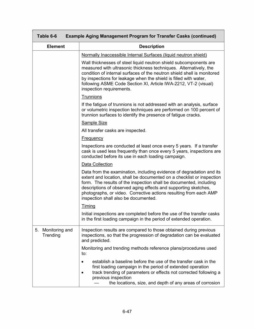
6-47
Table 6-6 Example Aging Management Program for Transfer Casks (continued)
Element Description
Normally Inaccessible Internal Surfaces (liquid neutron shield) Wall thicknesses of steel liquid neutron shield subcomponents are measured with ultrasonic thickness techniques. Alternatively, the condition of internal surfaces of the neutron shield shell is monitored by inspections for leakage when the shield is filled with water, following ASME Code Section XI, Article IWA-2212, VT-2 (visual) inspection requirements. Trunnions If the fatigue of trunnions is not addressed with an analysis, surface or volumetric inspection techniques are performed on 100 percent of trunnion surfaces to identify the presence of fatigue cracks. Sample Size All transfer casks are inspected. Frequency Inspections are conducted at least once every 5 years. If a transfer cask is used less frequently than once every 5 years, inspections are conducted before its use in each loading campaign. Data Collection Data from the examination, including evidence of degradation and its extent and location, shall be documented on a checklist or inspection form. The results of the inspection shall be documented, including descriptions of observed aging effects and supporting sketches, photographs, or video. Corrective actions resulting from each AMP inspection shall also be documented. Timing Initial inspections are completed before the use of the transfer casks in the first loading campaign in the period of extended operation.
5. Monitoring andTrending
Inspection results are compared to those obtained during previous inspections, so that the progression of degradation can be evaluated and predicted. Monitoring and trending methods reference plans/procedures used to: • establish a baseline before the use of the transfer cask in the
first loading campaign in the period of extended operation• track trending of parameters or effects not corrected following a
previous inspection— the locations, size, and depth of any areas of corrosion
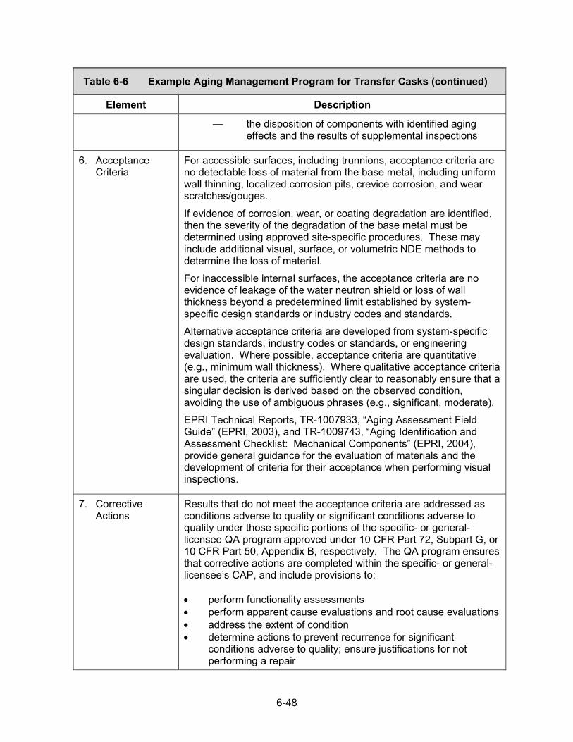
6-48
Table 6-6 Example Aging Management Program for Transfer Casks (continued)
Element Description
— the disposition of components with identified aging effects and the results of supplemental inspections
6. AcceptanceCriteria
For accessible surfaces, including trunnions, acceptance criteria are no detectable loss of material from the base metal, including uniform wall thinning, localized corrosion pits, crevice corrosion, and wear scratches/gouges. If evidence of corrosion, wear, or coating degradation are identified, then the severity of the degradation of the base metal must be determined using approved site-specific procedures. These may include additional visual, surface, or volumetric NDE methods to determine the loss of material. For inaccessible internal surfaces, the acceptance criteria are no evidence of leakage of the water neutron shield or loss of wall thickness beyond a predetermined limit established by system-specific design standards or industry codes and standards. Alternative acceptance criteria are developed from system-specific design standards, industry codes or standards, or engineering evaluation. Where possible, acceptance criteria are quantitative (e.g., minimum wall thickness). Where qualitative acceptance criteria are used, the criteria are sufficiently clear to reasonably ensure that a singular decision is derived based on the observed condition, avoiding the use of ambiguous phrases (e.g., significant, moderate). EPRI Technical Reports, TR-1007933, “Aging Assessment Field Guide” (EPRI, 2003), and TR-1009743, “Aging Identification and Assessment Checklist: Mechanical Components” (EPRI, 2004), provide general guidance for the evaluation of materials and the development of criteria for their acceptance when performing visual inspections.
7. CorrectiveActions
Results that do not meet the acceptance criteria are addressed as conditions adverse to quality or significant conditions adverse to quality under those specific portions of the specific- or general-licensee QA program approved under 10 CFR Part 72, Subpart G, or 10 CFR Part 50, Appendix B, respectively. The QA program ensures that corrective actions are completed within the specific- or general-licensee’s CAP, and include provisions to:
• perform functionality assessments• perform apparent cause evaluations and root cause evaluations• address the extent of condition• determine actions to prevent recurrence for significant
conditions adverse to quality; ensure justifications for notperforming a repair
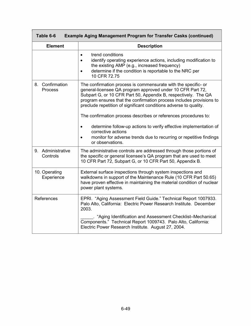
6-49
Table 6-6 Example Aging Management Program for Transfer Casks (continued)
Element Description
• trend conditions• identify operating experience actions, including modification to
the existing AMP (e.g., increased frequency)• determine if the condition is reportable to the NRC per
10 CFR 72.75
8. ConfirmationProcess
The confirmation process is commensurate with the specific- or general-licensee QA program approved under 10 CFR Part 72, Subpart G, or 10 CFR Part 50, Appendix B, respectively. The QA program ensures that the confirmation process includes provisions to preclude repetition of significant conditions adverse to quality.
The confirmation process describes or references procedures to:
• determine follow-up actions to verify effective implementation ofcorrective actions
• monitor for adverse trends due to recurring or repetitive findingsor observations.
9. AdministrativeControls
The administrative controls are addressed through those portions of the specific or general licensee’s QA program that are used to meet 10 CFR Part 72, Subpart G, or 10 CFR Part 50, Appendix B.
10. OperatingExperience
External surface inspections through system inspections and walkdowns in support of the Maintenance Rule (10 CFR Part 50.65) have proven effective in maintaining the material condition of nuclear power plant systems.
References EPRI. “Aging Assessment Field Guide.” Technical Report 1007933. Palo Alto, California: Electric Power Research Institute. December 2003. _____. “Aging Identification and Assessment Checklist–Mechanical Components.” Technical Report 1009743. Palo Alto, California: Electric Power Research Institute. August 27, 2004.

6-50
6.10 High-Burnup Fuel Monitoring and Assessment
An example of a High Burnup (HBU) Fuel1 Monitoring and Assessment Program is provided below. This is a licensee program that monitors and assesses data and other information regarding the performance of uncanned (undamaged or intact cladding) HBU fuel (hereafter referred to as HBU fuel) to confirm that the design-basis HBU fuel configuration (i.e., the assumed configuration in the DSS safety analyses) is maintained during the period of extended operation. This example HBU Fuel Monitoring and Assessment Program relies on a surrogate demonstration program to provide data on HBU fuel performance. Guidance for determining if a surrogate demonstration program can provide the data to support a licensee’s HBU Fuel Monitoring and Assessment Program is given in Appendix D of NUREG–1927, Revision 1 (NRC, 2016). Although this example focuses on the use of a surrogate demonstration program, a licensee may use alternative approaches that are appropriately justified, including the use of test or research results and safety analyses for the fuel, to demonstrate that the DSS’s intended functions continue to be met during the period of extended operation.
The aging management review is not expected to identify any aging effects that could lead to fuel reconfiguration, as long as the HBU fuel is stored in a dry inert environment, temperature limits are maintained, and thermal cycling is limited. Short-term testing (i.e., laboratory scale testing up to a few months) and scientific analyses examining the performance of HBU fuel have provided a foundation for the technical basis that storage of HBU fuel in the period of extended operation may be performed safely and in compliance with regulations. However, there has been relatively little operating experience, to date, with dry storage HBU fuel.
Therefore, the purpose of a HBU Fuel Monitoring and Assessment Program is to monitor and assess data and other information regarding HBU fuel performance to confirm there is no degradation of HBU fuel that would result in an unanalyzed configuration during the period of extended operation. The following description of an example HBU Fuel Monitoring and Assessment Program presents the applicable information in a format using each element of an effective AMP, to provide a framework for such a monitoring and assessment program.
1These are fuel assemblies with discharge burnup greater than 45 gigawatt-days per metric ton of uranium (GWd/MTU).

6-51
Table 6-7 Example Aging Management Program for High-Burnup Fuel Monitoring and Assessment
Element Description 1. Scope of the
ProgramThe scope of the program provides a description of (i) the characteristics and properties of the HBU fuel as assumed in the DSS design bases, (ii) the surrogate demonstration program that will be used to provide data on the applicable design-bases HBU fuel performance, and (iii) how the parameters of the surrogate demonstration program are applicable to the design-bases HBU fuel. Aging effects will be determined for material/environment combinations per an alternative surrogate demonstration program meeting the guidance in Appendix D of NUREG–1927, Revision 1 (NRC, 2016). Example language to address this “scope of the program” element follows: Fuel stored in a [define cask/canister model] is limited to an assembly average burnup of [define design-bases limit] GWd/MTU. The cladding materials for the HBU fuel are [define types of cladding], and the fuel is stored in a dry helium environment. HBU fuel was first placed into dry storage in a [define cask/canister model] on [start date of storage term of first storage of HBU fuel]. The program relies on the joint EPRI and DOE HBU Dry Storage Cask Research and Development Project (HDRP) (EPRI, 2014), conducted in accordance with the guidance in Appendix D of NUREG–1927, Revision 1, as a surrogate demonstration program that monitors the performance of HBU fuel in dry storage. The HDRP is a program designed to collect data from an SNF storage system containing HBU fuel in a dry helium environment. The program entails loading and storing an AREVA TN-32 bolted lid cask (the “Research Project Cask”) at Dominion Virginia Power’s North Anna Power Station with intact HBU fuel (of nominal burnups ranging between 50 GWd/MTU and 55 GWd/MTU). The fuel to be used in the program includes four kinds of cladding (Zircaloy-4, low-tin Zircaloy-4, ZIRLOTM, and M5TM). The Research Project Cask is licensed to the temperature limits contained in ISG-11, Rev. 3 (NRC, 2003), and loaded such that the fuel cladding temperature is as close to the limit as practicable. [If an alternative surrogate demonstration program is used, provide a description of the program.] The parameters of the surrogate demonstration program are applicable to the design-bases HBU fuel, as the (i) maximum burnup of the design-bases HBU fuel [define value] is less than the burnup of the fuel in the surrogate demonstration program [define value], (ii) the cladding type of the design-bases HBU fuel [define type] isthe same as the surrogate demonstration program [define type], and(iii) the temperatures in the surrogate demonstration program [definevalues] bound the design bases temperature/heat load of the loadedsystems [define values]. If the above criteria cannot be met, a
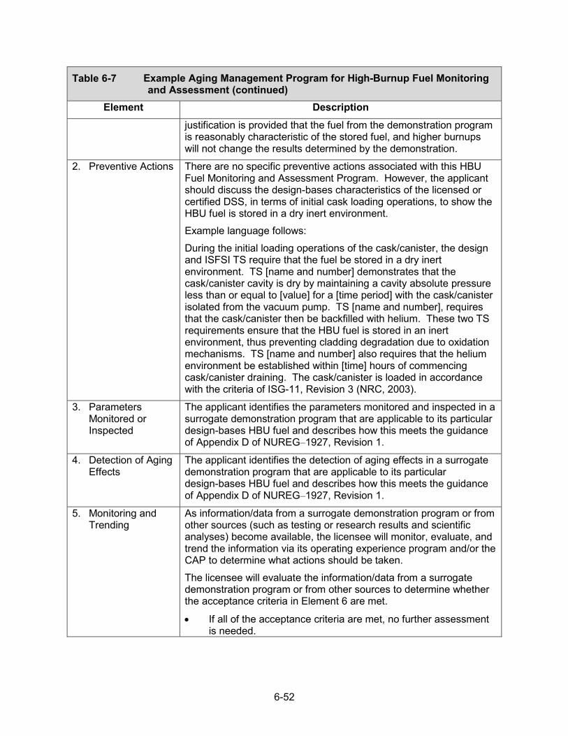
6-52
Table 6-7 Example Aging Management Program for High-Burnup Fuel Monitoring and Assessment (continued)
Element Description justification is provided that the fuel from the demonstration program is reasonably characteristic of the stored fuel, and higher burnups will not change the results determined by the demonstration.
2. Preventive Actions There are no specific preventive actions associated with this HBU Fuel Monitoring and Assessment Program. However, the applicant should discuss the design-bases characteristics of the licensed or certified DSS, in terms of initial cask loading operations, to show the HBU fuel is stored in a dry inert environment. Example language follows: During the initial loading operations of the cask/canister, the design and ISFSI TS require that the fuel be stored in a dry inert environment. TS [name and number] demonstrates that the cask/canister cavity is dry by maintaining a cavity absolute pressure less than or equal to [value] for a [time period] with the cask/canister isolated from the vacuum pump. TS [name and number], requires that the cask/canister then be backfilled with helium. These two TS requirements ensure that the HBU fuel is stored in an inert environment, thus preventing cladding degradation due to oxidation mechanisms. TS [name and number] also requires that the helium environment be established within [time] hours of commencing cask/canister draining. The cask/canister is loaded in accordance with the criteria of ISG-11, Revision 3 (NRC, 2003).
3. ParametersMonitored orInspected
The applicant identifies the parameters monitored and inspected in a surrogate demonstration program that are applicable to its particular design-bases HBU fuel and describes how this meets the guidance of Appendix D of NUREG–1927, Revision 1.
4. Detection of AgingEffects
The applicant identifies the detection of aging effects in a surrogate demonstration program that are applicable to its particular design-bases HBU fuel and describes how this meets the guidance of Appendix D of NUREG–1927, Revision 1.
5. Monitoring andTrending
As information/data from a surrogate demonstration program or from other sources (such as testing or research results and scientific analyses) become available, the licensee will monitor, evaluate, and trend the information via its operating experience program and/or the CAP to determine what actions should be taken. The licensee will evaluate the information/data from a surrogate demonstration program or from other sources to determine whether the acceptance criteria in Element 6 are met. • If all of the acceptance criteria are met, no further assessment
is needed.

6-53
Table 6-7 Example Aging Management Program for High-Burnup Fuel Monitoring and Assessment (continued)
Element Description
• If any of the acceptance criteria are not met, the licensee mustconduct additional assessments and implement appropriatecorrective actions (see Element 7).
Formal evaluations of the aggregate information from a surrogate demonstration program and other available domestic or international operating experience (including data from monitoring and inspection programs, NRC-generated communications, and other information) will be performed at specific points in time during the period of extended operation, as delineated in Table B-4 of NUREG–1927, Revision 1.
6. AcceptanceCriteria
The HBU Fuel Monitoring and Assessment Program acceptance criteria are: • hydrogen content–Maximum hydrogen content of the cover gas
over the approved storage period should be extrapolated fromthe gas measurements to be less than the design-bases limitfor hydrogen content.
• moisture content–The moisture content in the cask/canister,accounting for measurement uncertainty, should be less thanthe expected upper-bound moisture content per thedesign-bases drying process1.
• fuel condition/performance2–NDE (e.g., fission gas analysis)and destructive examination (e.g., to obtain data on creep,fission gas release, hydride reorientation, cladding oxidation,and cladding mechanical properties) should confirm thedesign-bases fuel condition (i.e., no changes to the analyzedfuel configuration considered in the safety analyses of theapproved design bases).
The applicant should provide information on the design-bases characteristics of the DSS, with regard to these criteria. The applicant should reference the source of specific values, or explain any assumptions made, for defining design-bases characteristics of the fuel condition/performance.
1The applicant will need to provide the expected upper-bound moisture content based on its design-bases drying process. If the design-bases drying process involves a vacuum drying method of evacuating a cask/canister to less than or equal to 3 torr and maintaining a constant pressure for 30 minutes after the cask/canister is isolated from the vacuum pump, the expected water content is about 0.43 gram-mole. (See NRC, 2010.) 2While it is not a fuel performance criterion, the spatial distribution and time history of the temperature must be known to evaluate the relationship between the performance of the rods in a surrogate demonstration program and the HBU fuel rod behavior expected in the cask.

6-54
Table 6-7 Example Aging Management Program for High-Burnup Fuel Monitoring and Assessment (continued)
Element Description 7. Corrective Actions The corrective actions are in accordance with the specific or general
licensee QA program and consistent with 10 CFR Part 72, Subpart G, or 10 CFR Part 50, Appendix B, respectively. Corrective actions should be implemented if data from a surrogate demonstration program or other sources of information indicate that any of the HBU Fuel Monitoring and Assessment Program acceptance criteria (in Element 6) are not met. If any of the acceptance criteria are not met, the licensee will:
• assess fuel performance (impacts on fuel and changes to fuelconfiguration), including any consequences ofabove-design-basis moisture levels on potential degradation ofthe fuel assembly
• assess the design-bases safety analyses, consideringdegraded fuel performance (and any changes to fuelconfiguration), to determine the ability of the DSS to continue toperform its intended functions under normal, off-normal, andaccident conditions.
The licensee will determine what corrective actions should be taken to:
• manage fuel performance, if any• manage impacts related to degraded fuel performance to
ensure that all intended functions for the DSS are met.In addition, the licensee will obtain the necessary NRC approval in the appropriate licensing/certification process for modification of the design bases to address any conditions outside of the approved design bases.
8. ConfirmationProcess
The confirmation process is commensurate with the specific- or general-licensee QA program approved under 10 CFR Part 72, Subpart G, or 10 CFR Part 50, Appendix B, respectively. The QA program ensures that the confirmation process includes provisions to preclude repetition of significant conditions adverse to quality.
The confirmation process describes or references procedures to:
• determine follow-up actions to verify effective implementation ofcorrective actions
• monitor for adverse trends due to recurring or repetitivefindings or observations.
9. AdministrativeControls
The administrative controls are in accordance with the specific or general licensee QA program and consistent with 10 CFR Part 72, Subpart G, or 10 CFR Part 50, Appendix B, respectively. The QA

6-55
Table 6-7 Example Aging Management Program for High-Burnup Fuel Monitoring and Assessment (continued)
Element Description program ensures that the administrative controls include provisions that define: • formal review and approval processes• record retention requirements• document control
10. OperatingExperience
The program references and evaluates applicable operating experience, including: • internal and industrywide condition reports• internal and industrywide corrective action reports• vendor-issued safety bulletins• NRC Information Notices• applicable DOE or industry initiatives (e.g., HDRP)• applicable research (e.g., Oak Ridge National Laboratory
studies on bending responses of the fuel, Argonne NationalLaboratory and Central Research Institute of Electric PowerIndustry studies on hydride reorientation effects)
The review of operating experience clearly identifies any HBU fuel degradation as either age related or event driven, with proper justification for that assessment. Past operating experience supports the adequacy of the HBU Fuel Monitoring and Assessment Program. Surrogate demonstration programs with storage conditions and fuel types similar to those in the licensed/certified DSS that meet the guidance in Appendix D of NUREG–1927, Revision 1, are a viable method to obtain operating experience. New data/research on fuel performance from both domestic and international sources that are relevant to the licensed/certified HBU fuel in the DSS should be evaluated on a periodic basis.
References EPRI. “HBU Dry Storage Cask Research and Development Project Final Test Plan.” DOE Contract No.: DE-NE-0000593. Palo Alto, California: Electric Power Research Institute. 2014. NRC. “NRC Interim Staff Guidance 11, “Cladding Considerations for the Transportation and Storage of Spent Fuel.” Rev. 3. ADAMS Accession No. ML033230335. Washington, DC: U.S. Nuclear Regulatory Commission. November 17, 2003. _____. NUREG–1536, “Standard Review Plan for Spent Fuel Dry Storage Systems at a General License Facility.” Rev. 1. ADAMS Accession No. ML101040620. Washington, DC. U.S. Nuclear Regulatory Commission. 2010. _____. NUREG–1927, “Standard Review Plan for Renewal of Specific Licenses and Certificates of Compliance for Dry Storage of

6-56
Table 6-7 Example Aging Management Program for High-Burnup Fuel Monitoring and Assessment (continued)
Element Description Spent Nuclear Fuel.” Revision 1. ADAMS Accession No. ML16179A148. Washington, DC: U.S. Nuclear Regulatory Commission. 2016.

NRC FORM 335
(12-2010)
U.S. NUCLEAR REGULATORY COMMISSION 1. REPORT NUMBER
NRCMD 3.7
BIBLIOGRAPHIC DATA SHEET
(See mstruct,ons on the reverse)
2. TITLE AND SUBTITLE
Managing Aging Processes in Storage (MAPS) Report
Final Report
5. AUTHOR(S)
(Assigned by NRC, Add Vol., Supp., Rev.,
and Addendum Numbers, if any.]
NUREG-2214
3. DATE REPORT PUBLISHED
MONTH
July
4. FIN OR GRANT NUMBER
6. TYPE OF REPORT
Technical
YEAR
2019
7. PERIOD COVERED ( Inclusive Dates)
8. PERFORMING ORGANIZATION - NAME AND ADDRESS (If NRC, provide Division, Office or Region, U. S. Nuclear Regulatory Commission, and mailing address; if
contractor, provide name and mailing address.)
Division of Spent Fuel Management Office of Nuclear Material Safety and Safeguards U.S. Nuclear Regulatory Commission
Washington, DC 20555-0001
9. SPONSORING ORGANIZATION - NAME AND ADDRESS (lfNRC, type "Same as above", if contractor, provide NRC Division, Office or Region, U.S. Nuclear Regulatory
Commission, and mailing address.)
Same as above
10. SUPPLEMENTARY NOTES
11. ABSTRACT (200 words or less)
This Managing Aging Processes in Storage (MAPS) Report provides guidance for the U.S. Nuclear Regulatory Commission (NRC)technical reviewer. It establishes a technical basis for the safety review of renewal applications for specific licenses of independent
spent fuel storage installations and Certificates of Compliance for dry storage systems, as codified in Title 10 of the Code of FederalRegulations (10 CFR) Part 72, "Licensing Requirements for the Independent Storage of Spent Nuclear Fuel, High-Level RadioactiveWaste, and Reactor-Related Greater Than Class C Waste."
The MAPS Report evaluates known aging degradation mechanisms to determine if they could affect the ability of dry storage system components to fulfill their safety functions in the 20- to 60-year period of extended operation. The guidance also provides examples
of aging management programs that are considered generically acceptable to address the credible aging mechanisms to ensure that the design bases of dry storage systems will be maintained. An applicant for a renewed license or certificate of compliance may reference the information in the MAPS Report to support its aging management review and proposed aging management programs.
12. KEY WORDS/DESCRIPTORS (List words or phrases that will assist researchers in locating the report.)
Dry Storage SystemAging ManagementSpent Fuel
NRC FORM 335 (12-2010)
13 AVAILABILITY STATEMENT
unlimited
14. SECURITY CLASSIFICATION
(This Page)
unclassified
(This Report)
unclassified
15. NUMBER OF PAGES
16. PRICE


NU
REG
-2214 Final
Managing Aging Processes In Storage (M
APS) Report
July 2019


![Whirlpool Awe 2214 [ET]](https://img.pdfslide.us/doc/110x75/552aed114a795932118b45d7/whirlpool-awe-2214-et.jpg)